Loading ...
Using the heater
WARNING: DO NOT USE THE HEATER UNTIL THE FEET ARE
FITTED CORRECTLY.
The product is intended for occasional use as a portable unit. Please ensure
the feet are securely tted before the product is used. Once the feet have
been installed simply plug in and switch on at the wall socket.
There are various control options available with various combinations
comprising of thermostat, switched, timer & indicating neons.
Please note – the element has been coated with a protective lm which
will burn off during the rst few minutes of use and may cause a small
amount of fuming. This is quite normal – the fumes are non-toxic and will
quickly disappear.
We recommend that you open a window to ventilate the room when using
the heater for the rst time.
Positioning the heater
Always ensure that the heater is stood on a rm, level base near to, but
not directly beneath, a suitable mains supply socket.
Ensure that curtains and furniture are not positioned close to the chosen
position, as this would create a potential re hazard.
Product Assembly
WARNING: THE HEATER SHOULD NEVER BE USED WITHOUT THE
FEET SECURELY FITTED.
WARNING: ONLY THE SCREWS SUPPLIED WITH THIS PRODUCT
SHOULD BE USED TO MOUNT THE FOOT. A MAXIMUM SCREW
LENGTH OF 10MM SHOULD BE USED.
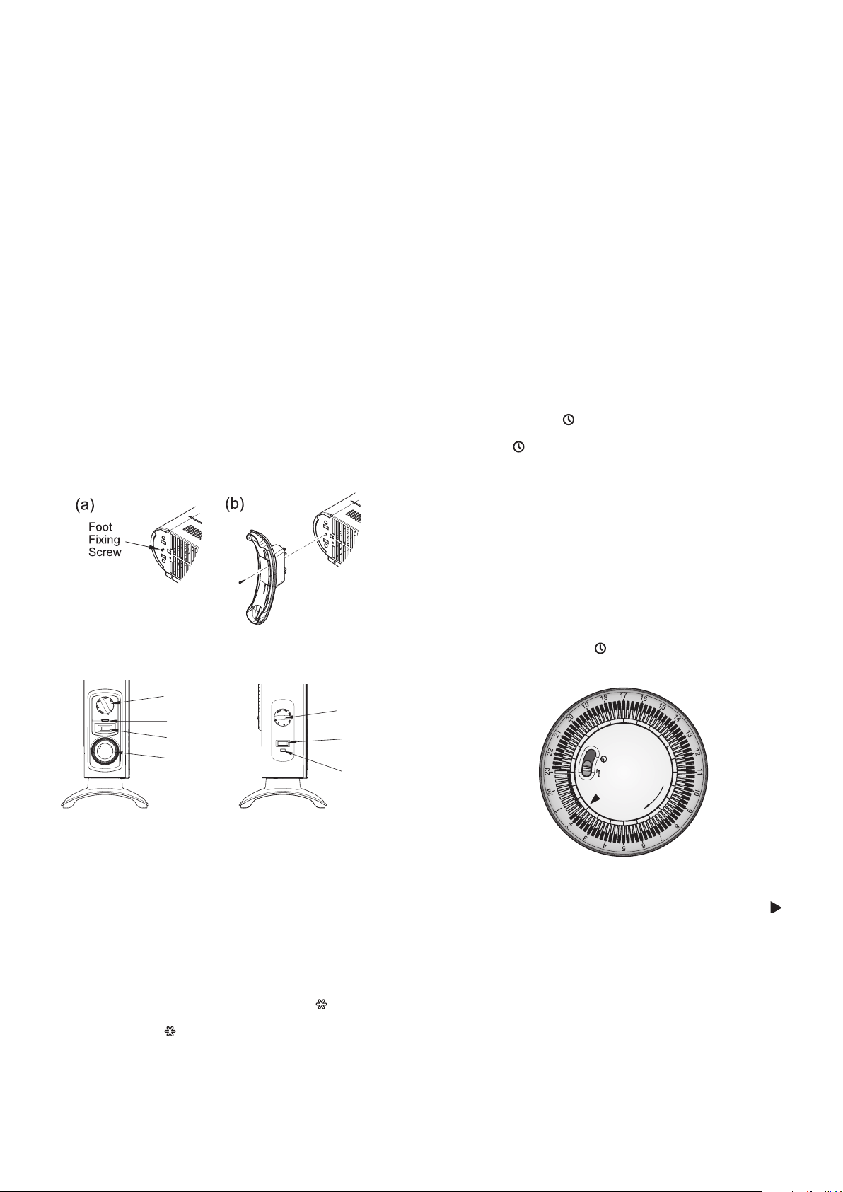
Lay the heater on its back so the underneath of the product is accessible.
Locate and remove the foot xing screw - see Fig. 2(a). Clip the foot in
place and secure using the foot xing screw - see Fig. 2(b).
Controls
Model 403TSTi
Model 403TSF
Heat selector
switch
Thermostat
knob
Neon
Mechanical
Timer
Control
switch
Thermostat
knob
Neon
Thermostat (all models)
The thermostat controls the heat output according to the room temperature.
This ensures that the heater will not produce heat unnecessarily when the
room is warm.
To set the temperature you require, gradually turn the thermostat knob
clockwise until the desired temperature is reached. Allow some time
between increments for the room temperature to stabilise.
Alternatively to heat a cold room quickly, turn the thermostat knob to the
Max position. When the room has reached the desired temperature, turn
the thermostat knob anti-clockwise until the thermostat clicks off. The heater
will then automatically maintain this room temperature.
The thermostat also has a frost protection setting marked ‘ ’. This setting is
useful in areas such as garages to prevent frost damage. If the thermostat is
set to its minimum setting ‘ ’, the heater will cycle ON and OFF to maintain
a temperature of approximately 5°C to help protect against frosty conditions.
Fig. 2
Fig. 3
Switches (selected models)
Some models are supplied with selector switches . There are two switch
types, one is an on/off switch and the other is a heat selection switch.
Depending on model either one or both switch may be included. The switch
operation is as follows.
On/ Off: O - Off
I - On
Heat selection I - Low heat
II - High heat
403TS Operation
This model contains an On/Off switch and a heat selection switch and
operates as follows.
When O/I switch is in position O the product is off regardless of any other
setting. When O/I switch is in position I and the I/II switch is in the I position
there is a low heat output from the product. When O/I switch is in position
I and the I/II switch is in the II position there is a high heat output from the
product. The indicator neon is always on when the product is connected
to the mains supply.
403TSTi Operation
This model contains a heat selection switch and an electro-mechanical
timer and operates as follows.
When the timer is switched to I and the I/II switch is in position I there is
a low heat output from the product. When the timer is switched to I and
the I/II switch is in position II there is a high heat output from the product.
When the timer is in the ‘ ’ position and the I/II switch is in position I there
is a low heat output from the product when the timer is set on. When the
timer is in the ‘ ’ position and the I/II switch is in position II there is a high
heat output from the product when the timer is set on. The indicator neon
is always on when the product is connected to the mains supply.
Mechanical Timer (403TSTi)
Note: The timer clock will only operate when the product is connected to
the mains supply
Operation modes
There are two operating modes on the timer, Manual operation and Auto
operation. The operation mode is set using the slide switch on the timer
- see g4.
Manual operation (Position - I)
This setting allows power to the product uninterrupted by the timer,
however other product controls will continue to function as normal.
Auto operation (Position - )
This setting allows the heater to be controlled by the timer. The product
will be switched on and off depending on the pre-set timer program.
Setting the time of day
To set the time of day, rotate the timer dial clockwise (indicated by the
arrow) until the correct time of day is opposite the reference mark -
see Fig. 4. The 24-hour clock is used ; e.g. 4 pm is ‘16’ (16:00hrs).
Setting the ‘Auto’ ON and OFF times
To set the timer :
1. Using your nger tip or the tip of a pencil, push in as many
segments as necessary around the dial, according to the times you
don’t require heat – see Fig. 5. Each segment pushed in switches
the heater OFF for that part of the hour. All other segments will be
ON. For example, Fig. 5 shows the timer set to switch the heater
OFF between 11pm and 1.45am.
2. You can select as many ON periods as you like, within the 24-hour
day. The settings will repeat every day until changed.
3. To change ON and OFF times, simply push in any ‘ON’ segments
you wish to cancel and pull out new ‘ON’ segments as required.
Fig. 4
Fig. 5
Loading ...
Loading ...