Loading ...
229 109
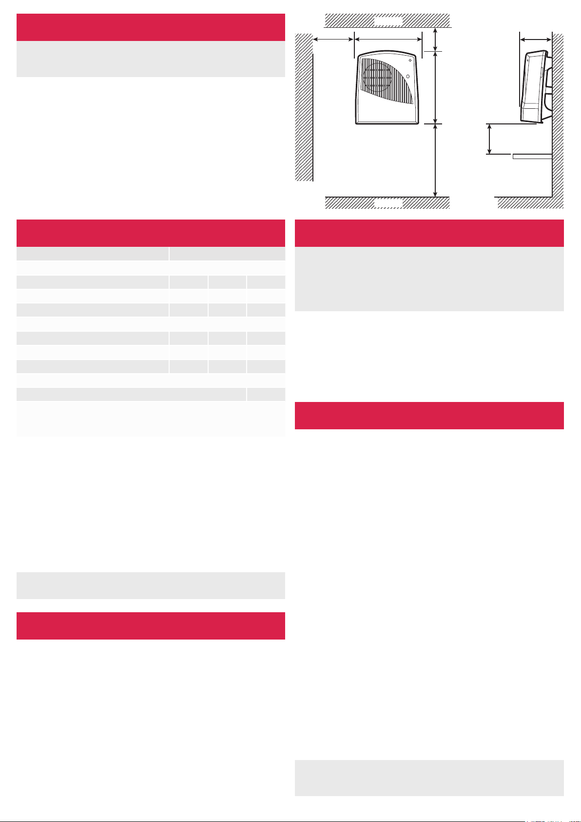
300
Min
900
Min
Shelf
600
Min
242
250
Min
Ceiling
Floor
Dimensions (millimetres)
Model Specification
FX20VE: 1 or 2kW + electronic run-back timer
Fig. 1
Safety
Thermal Cut-Out & Electronic overheating protection
For your safety, this appliance is fitted with a thermal cut-out and
also an electronic overheat protection device. In the event that the
product overheats, these devices will switch the heater o automatically.
To bring the heater back into operation, remove the cause of overheating,
then turn o the electrical supply to the heater for a few minutes.
When the heater has cooled suciently reconnect and switch on the
heater. If the heater does not re activate it is possible that the fuselink
has triggered, see Fuse link.
Fuse Link
A thermal fuse link is provided as an added safety feature. If the fuse
link operates and opens circuit it is the result of abnormal overheating
within the appliance. To ensure the future safe operation of the heater,
please contact Dimplex Customer Services
Model Identifier(s) FX20VE
Heat output
Nominal heat output Pnom 2.0 kW
Minimum heat output (indicative) Pmin 1.0 kW
Maximum continuous heat output Pmax,c 2.0 kW
Auxillary electricity Consumption
At nominal heat ourput elmax 0.0 kW
At minimum heat output elmin 0.0 kW
In standby mode elSB 0.002 kW
type of heat output/room temperature control
With electronic 30 minute runback timer Yes
Contact details
Glen Dimplex Heating and Ventilation, Millbrook House,
Grange Drive, Hedge End, Southampton, SO30 2DF
General
NOTE: The switch has been factory set for 1kW operation.
If additional output is required, 2kW can be set on installation.
The heater has a loading of 2kW. It is designed for permanent wall
mounting and is suitable for operation on A.C. electricity supply having
the same voltage as shown on the rating label. The heater is fitted
with an internally mounted selector switch which on installation of the
heater allows a choice of 1kW or 2kW output to suit the dimensions of
the room to be heated.
In rooms of less than 9 – 11 cubic m. (350 - 400 cubic ft.) 1kW output
should be selected, otherwise nuisance tripping of the thermal overload
cut-out may occur. The heater is fitted with an internally mounted selector
switch which on installation of the heater allows a choice of 1kW or 2kW
output to suit the dimensions of the room to be heated.
Installation Procedure
WARNING: Minimum clearances must be adhered to when
mounting the heater.
Supply cable is not supplied with this appliance and it
should therefore be installed by a competent electrician
in accordance with the latest IEE wiring regulations.
Before undertaking installation work, ensure the electricity supply is
disconnected from any relevant fixed wiring.
The supply circuit must be adequate for the input of the appliance and
must be protected with a 13A fuse. A suitable termination to the fixed
wiring of the premises must be provided adjacent to the final position of
the appliance through a double pole switch having a contact separation
of at least 3mm in all poles.
It is essential to observe minimum wall mounting clearances - see Fig.
1. The appliance should be fitted horizontally, with the cable entry at
the top and grille at the bottom. It must be mounted not less than
900mm above the floor with a clearance of at least 600mm to any
shelf or projecting surface below the heater and not less than 300mm
below the ceiling or other projecting surface. It must also be not less
than 250mm from an adjacent projecting surface. For most eective
heating performance, the heater should be mounted at the minimum
height : i.e. 900mm above the floor. Care must be taken to ensure that
when in use, the air stream is not obstructed. The appliance is secured
to the wall with three screws, two through keyhole slots and one
through a hole to hold the appliance firmly in position (see Fig. 2)
1. Remove the top cover from the appliance by removing the two screws
securing the top cover and hinging it back.
2. Mark the position of the two keyhole slots (see Fig. 2 for dimensions)
on the wall and drill and plug for the two suitable screws.
3. Partially insert the two screws, then hang the appliance on the screws.
Mark the position of the third hole. This is used to secure the product.
4. Remove the appliance and drill and plug for the third screw.
5. Remount the appliance on the wall using the two keyhole slots.
6. Feed the supply cord or wires through the inlet at the top rear of the
appliance leaving sucient free length to connect to the terminal
block.
7. Make electrical connections to the terminal block ensuring that the
live connection is made to the terminal marked ‘L’ and the neutral
connection to the terminal marked ‘N’ (see Fig. 2 detailed view).
8. Fix the product inplace by inserting and tightening the third screw.
Fix mains cable securely using the products cable clamp
9. Set the selector switch to provide either 1kW or 2kW output.
10. Replace the top cover and screws.
The appliance is now ready for use and the electricity supply can be
reinstated.
Installation
WARNING: This product should never be operated without the
top cover correctly installed. In this case, a replacement product or
element would be required.
Loading ...
Loading ...