Loading ...
Loading ...
Loading ...
5
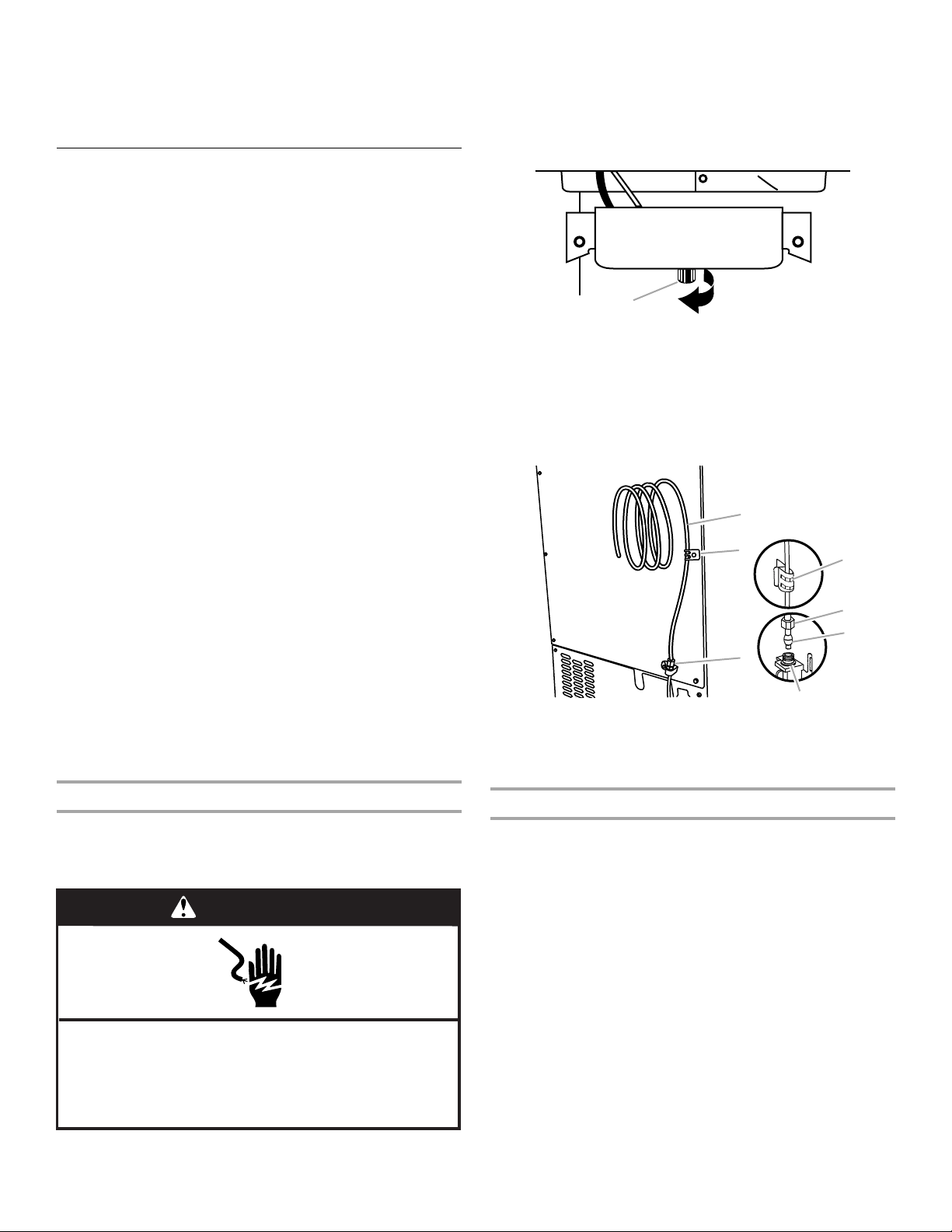
8. Install the water supply tube clamp around the water supply
line to reduce strain on the coupling.
9. Turn shutoff valve ON.
10. Check for leaks. Tighten any connections (including
connections at the valve) or nuts that leak.
Drain Pump Installation
(on some models)
NOTES:
■ Connect drain pump to your drain in accordance with all state
and local codes and ordinances.
■ It may be desirable to insulate drain tube thoroughly up to
drain inlet to minimize condensation on the drain tube.
Insulated tube kit Part Number W10365792 is available for
purchase.
■ Drain pump is designed to pump water to a maximum height
of 10 ft (3 m). Use only Whirlpool approved drain pump kit
Part Number 1901A.
■ Do not connect the outlet end of the drain tube to a closed
pipe system to keep drain water from backing up into the ice
maker.
Kit Contains:
■ Drain pump kit Part Number 1901A
■ ⁵⁄₈" I.D. x 5¹⁄₈" drain tube (ice maker bin to drain pump
reservoir inlet)
■ ¹⁄₂" I.D. x 10 ft (3 m) drain tube hose (drain pump discharge to
household drain)
■ ⁵⁄₁₆" I.D. x 32" (81 cm) vent tube (drain pump reservoir vent to
ice maker cabinet back)
■ Cable clamps (secures vent tube to back of ice maker) (3)
■ #8-32 x ³⁄₈" pump mounting screws (secures drain pump to
baseplate and clamps to back of ice maker) (5)
■ ⁵⁄₈" small adjustable hose clamp (secures vent to drain pump)
■ ⁷⁄₈" large adjustable hose clamp, (secures drain tube to ice
maker bin and drain pump reservoir inlet) (3)
■ Rear panel (2)
■ Instruction sheet
If Ice Maker Is Currently Installed
NOTE: If ice maker is not installed, please proceed to “Drain
Pump Installation” section.
1. Push the selector switch to the OFF position.
2. Unplug ice maker or disconnect power.
3. Turn off water supply. Wait 5 to 10 minutes for the ice to fall
into the storage bin. Remove all ice from bin.
4. Unscrew the drain cap from the bottom of the water pan
located inside the storage bin. Allow water to drain
completely. Replace drain cap. See “Drain Cap” illustration.
Drain Cap
5. If ice maker is built into cabinets, pull ice maker out of the
opening.
6. Disconnect water supply line. See “Water Supply Line”
illustration.
Water Supply Line
Drain Pump Installation
NOTE: Do not kink, smash or damage tubes or wires during
installation.
1. Unplug ice maker or disconnect power.
2. Remove rear panel. See “Rear Panel” illustration for 5 screw
locations. Pull rear panel away from the drain tube and
discard.
WARNING
Electrical Shock Hazard
Disconnect power before servicing.
Replace all parts and panels before operating.
Failure to do so can result in death or electrical shock.
A. Drain cap
A.
¹⁄₄
" copper tubing
B. Cable clamp
C.
¹⁄₄
" compression nut
D. Ferrule (sleeve)
E. Ice maker connection
A
B
C
D
E
A
C
B
Loading ...
Loading ...
Loading ...