3
Important Safety Information
8
Installation Instructions
Important Electrical Safety
Window Installation
Through-the-Wall Installation
4
Operating Instructions
The Controls on Your Air Conditioner
Care of Product
24
Helpful Information
Things That Are Normal
25
If Something Goes Wrong
Before You Call for Service
GE Service Numbers
Warranty
GE Appliances
Air Conditioner
Owner’s Manual
Standard and Easy Mount
Cool Only:
AJCS 06 LZ
AJCS 08, 10 AZ
Heat/Cool:
AJES 06 LS
AJES 08 AS
AJES 10 DS
Heat Pump:
AJHS 08 AS
GE Answer Center
®
800.626.2000
49-7362-1
2-98 CG
Welcome to the GE family. We’re
proud of our quality products and
we believe in dependable service.
You’ll see it in this easy-to-use
manual and you’ll hear it in the
friendly voices of our customer
service department.
Best of all, you’ll experience
these values each time you enjoy
the comfort of your air conditioner.
That’s important, because your
new air conditioner will be part of
your family for a long time.
Welcome
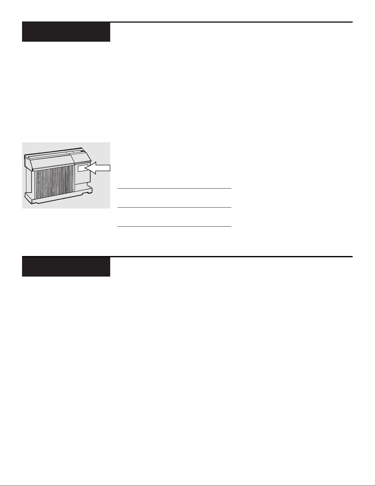
Write down the model and serial
numbers here.
They are on a label
on the front of the control box
behind the front grille.
Model number
Serial number
Date of purchase
Staple your receipt to the inside back
cover of this manual. You will need it
to obtain service under warranty.
Start Here!…Before using your air conditioner
Need Help?
Read this manual.
It contains
instructions to help you use and
maintain your air conditioner
properly.
Save time and money.
Check the
section titled “If Something Goes
Wrong” before calling. This sec-
tion helps you to solve common
problems that might occur.
If you do need service, you can
relax knowing help is only a
phone call away. A list of toll-free
customer service numbers is
included in the back of this book.
Or call the
GE Answer Center
®
at 800.626.2000,
24 hours a day,
7 days a week.
Help us
help you
800.626.2000
Before you call for service,
there are a few things you
can do to help us serve you
better.
2
IMPORTANT SAFETY INFORMATION
READ ALL SAFETY INFORMATION
BEFORE USING
• This air conditioner must be
properly installed in accordance
with the Installation Instructions
before it is used.
• Repair or replace immediately
all electric service cords that have
become frayed or otherwise
damaged.
• Turn the mode control to
OFF
and
unplug your air conditioner before
making any repairs.
NOTE:
We strongly recommend
that any servicing be performed by
a qualified individual.
Because most 2-prong outlets are
not grounded, we strongly advise
against using an adapter plug.
However, a temporary connection
may be made where local codes
permit and if the 2-prong wall out-
let is properly grounded.
When you plug the adapter in,
make sure the larger prong goes
into the larger slot to provide the
proper polarity for the power cord.
FOR PROPER GROUNDING:
1 Screw the adapter to the outlet,
using the outlet cover screw.
2 Ground the outlet through the house
wiring.
When disconnecting the power
cord from the adapter, hold the
adapter close to the outlet while
pulling the plug out. If this is not
done, the grounding connector is
likely to break with repeated use.
If the grounding connector breaks,
DO NOT USE
the air conditioner
until a proper ground has again
been made.
Adapter Plug
This is a temporary method.
UL-listed adapters are avail-
able at most hardware stores.
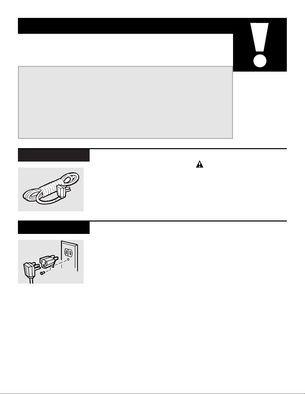
The use of an extension cord is not
recommended. However, if an
extension cord is required to reach
the nearest wall receptacle, use only
a UL-listed, 3-wire, grounded, 14
gauge, 15A, 125V appliance exten-
sion cord.
CAUTION:
DO NOT use an extension cord with
any of the 208/230-volt models.
Extension Cord
SAVE THESE INSTRUCTIONS
3
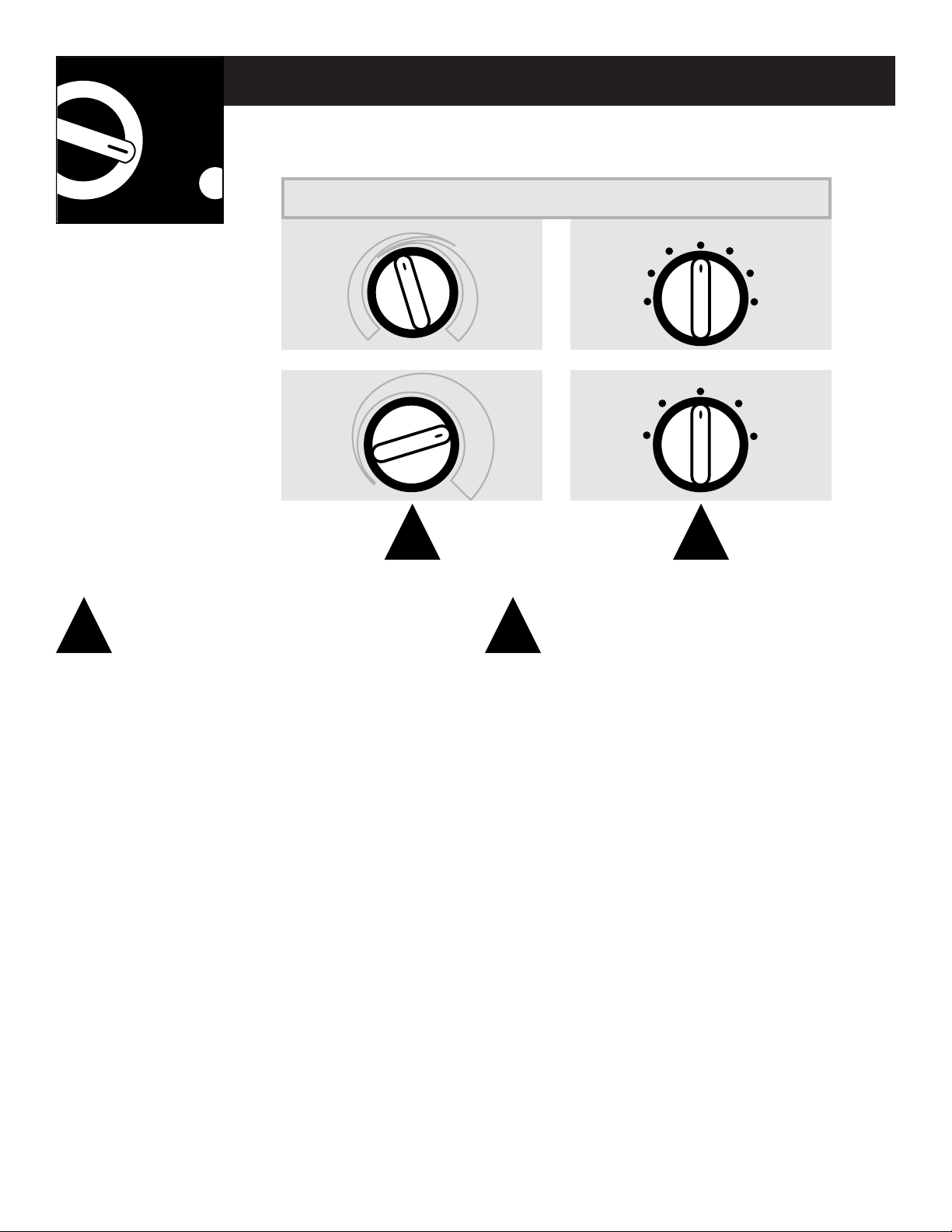
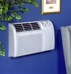
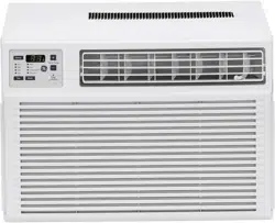
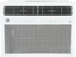
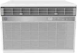
Your model will look like one of these.
4
The temp control is used to maintain the
room temperature. The compressor will cycle
on and off to keep the room at the same level
of comfort. When you turn the knob to
COOLER
(blue) the indoor air will become cooler. Turn
the knob to
WARMER
(red) and the indoor air
will become warmer.
HEAT PUMP MODELS
When the outdoor temperature is lower than
25
°F., heat is provided by the electric heater in
the air conditioner instead of by the heat pump.
NOTE:
The electric resistance heater in the 115-volt
heat pump model operates during defrost when
the outdoor coil temperature is below 36°F. It is
not intended to provide full heat capability.
HIGH COOL
and
LOW COOL
provide cooling with
different fan speeds.
HIGH HEAT
and
LOW HEAT
provide heating with
different fan speeds.
LOW FAN
or
HIGH FAN
provides air circulation
and filtering without cooling or heating.
NOTE:
If you move the switch from a cool or heat setting
to OFF or to a fan setting, wait at least 3 minutes
before switching back to a cool or heat setting.
A 3-minute delay is automatically provided on the
Heat/Cool and Heat Pump models.
Operating Instructions
The
controls
on your
air
conditioner
21
Temp Control Mode Control
1 2
TEMP CONTROLS MODE CONTROLS
OFF
LOW
FAN
HIGH
FAN
HIGH
COOL
LOW
COOL
OFF
LOW
FAN
HIGH
FAN
HIGH
HEAT
HIGH
COOL
LOW
COOL
LOW
HEAT
C
O
O
L
E
R
W
A
R
M
E
R
C
O
O
L
E
R
5
Cooling/Heating Descriptions
FOR NORMAL COOLING
OR HEATING
Select
HIGH COOL
or
HIGH
HEAT
with the thermostat
at mid point.
FOR MAXIMUM COOLING
Select
HIGH COOL
with the
thermostat at maximum
cool.
FOR MAXIMUM HEATING
Select
HIGH HEAT
with the
thermostat at maximum
heat.
FOR QUIETER &
NIGHTTIME COOLING
Select
LOW COOL
or
LOW
HEAT
with the thermostat
at mid point.
3 4 5 6
Each position equals
approximately 3° F.
Limits
heat
temp
Limits
cool
temp
OPEN
CLOSE
On Heat/Cool models, the fan switch lever is
located in a hole through the control panel. To
reach it, you need to remove the front grille.
Use a small screwdriver to change the setting.
Cool only models have a rocker switch on the
front of the control box.
When set at
CYCLE
(down) the fan cycles on and
off when cooling or heating. When set at
CONT
(continuous, up) the fan runs all the time. The
unit is shipped in the
CONT
setting.
The vent control is located behind the front
grille. When set at
CLOSE
, only the air inside the
room will be circulated and conditioned. You
may adjust it by removing the front grille. When
set at
OPEN
, some inside air is exhausted out-
side.
NOTE:
The vent lever is taped in the
CLOSE
position when it leaves the factory. Remove
the tape before using.
53
Fan Switch Vent Control
Limiting the maximum and minimum settings
prevents users from turning the control to the
extreme heat or cool positions.
The normal range of the temp control is approx-
imately 60° F to 85° F. The control range may be
narrowed by the use of the temperature limiting
screws located behind the control panel.
Horizontal louvers on the front grille let you
control the air direction up and down.
Remove the front grille to adjust the vertical
louvers side-to-side to direct the air left or right.
64
Temperature Limiting Air Direction
Features and appearance may vary.
6
Operating Instructions
Care & Cleaning
Turn the air conditioner off and
remove the plug from the wall out-
let before cleaning.
To clean, use water and a mild
detergent. Do not use bleach or
abrasives.
Grille and Case
The coils on the outdoor side of
the air conditioner should be
checked regularly. It is necessary to
remove the chassis from the wall
case to inspect them. Dirt build-up
occurs on the surface which is not
visible from the outside. If they are
clogged with dirt or soot they may
be professionally steam cleaned, a
service available through your GE
service outlet.
Outdoor Coils
The front grille can be removed
for more thorough cleaning or
to make the model and serial
numbers accessible.
To remove:
Pull out from the bottom and lift
up from the tabs on the top of the
case.
To replace:
Hook the tabs on the front grille
even with the tabs on the front of
the case and snap into place.
Front Grille
1
1
2
2
Tab
Grille
Tab
Grille

Turn the air conditioner off before
cleaning.
The most important thing you can
do to maintain the air conditioner
is to clean the filter at least every 30
days. Clogged filters reduce cool-
ing, heating and airflow.
Keeping the filter clean will:
• Decrease cost of operation.
• Save energy.
• Prevent clogged heat exchanger
coils.
• Reduce the risk of premature
component failure.
To clean the air filter:
• Vacuum off the heavy soil.
• Run water through the filter
from the back side.
• Dry thoroughly before replacing.
Carefully pull the tab forward, up
and out.
Replace the clean filter by pushing
it back into place.
CAUTION:
DO NOT operate the air conditioner
without the filter in place. If a filter
becomes torn or damaged it should
be replaced immediately.
Operating without the filter in
place or with a damaged filter will
allow dirt and dust to reach the
indoor coil and reduce the cooling,
heating, airflow and efficiency of
the unit.
Replacement filters are available
from your salesperson, GE dealer,
GE Service and Parts Center
or authorized Customer Care®
servicers.
Air Filter
FRONT
FRONT
Operating Tip:
To maintain optimum
performance, clean
the filter at least
every 30 days.
Dirty filter—Needs cleaning
Clogged filter—Greatly
reduces cooling, heating
and airflow.
7
8
• For personal safety, this air conditioner must be
properly grounded.
• It is important to have the wall outlet and circuit
checked by a qualified electrician if there is any
doubt as to whether a proper ground exists.
• Follow National Electrical Code (NEC) or local
codes and ordinances.
CAUTION:
•
Do not, under any circumstances, cut or remove
the third (ground) prong from the power cord.
•
Do not change the plug on the power cord of this
air conditioner.
•
Aluminum house wiring may present special
problems—consult a qualified electrician.
We recommend that the 230/208-volt, 60 Hz
models be installed on their own single branch
circuit supplying 230/208-volt a.c., protected
with a time delay fuse or circuit breaker.
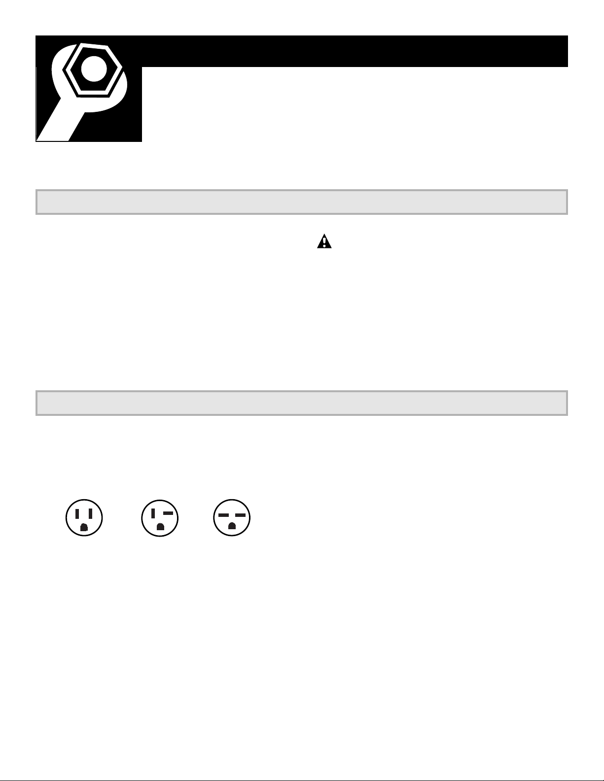
PPaarraalllleell PPeerrppeennddiiccuullaarr TTaannddeemm
115V. 230/208V. 230/208V.
15 Amp. 20 Amp. 15Amp.
This is recommended for best performance and
to prevent overloading house or apartment
wiring circuits, which could cause a possible fire
hazard from overheating wires.
The 115-volt models require a 115/120-volt a.c.,
60 Hz grounded outlet protected with a 15-amp
time delay fuse or circuit breaker.
The 3-prong grounding plug minimizes the possi-
bility of electric shock hazard.
If the wall outlet
you plan to use is only a 2-prong outlet, it is your
responsibility to have it replaced with a properly
grounded 3-prong wall outlet.
Important Notes
Installation Instructions
Important Electrical Safety–Read Carefully
Installer: Leave these instructions with the appliance.
Owner: Keep these instructions for future use.
Electrical Requirements
Before you begin AJES and AJHS models have filler panels. Directions begin below.
The installation instructions for AJCS models with accordion curtains
begin on page 17.
IMPORTANT:
Be sure to remove the shipping pad inside the air conditioner next to the compressor.
• Phillips-head
screwdriver
• Wood saw
• Adjustable wrench
• Ruler or tape
measure
• Scissors or knife
• Pencil
• Level
• Drill
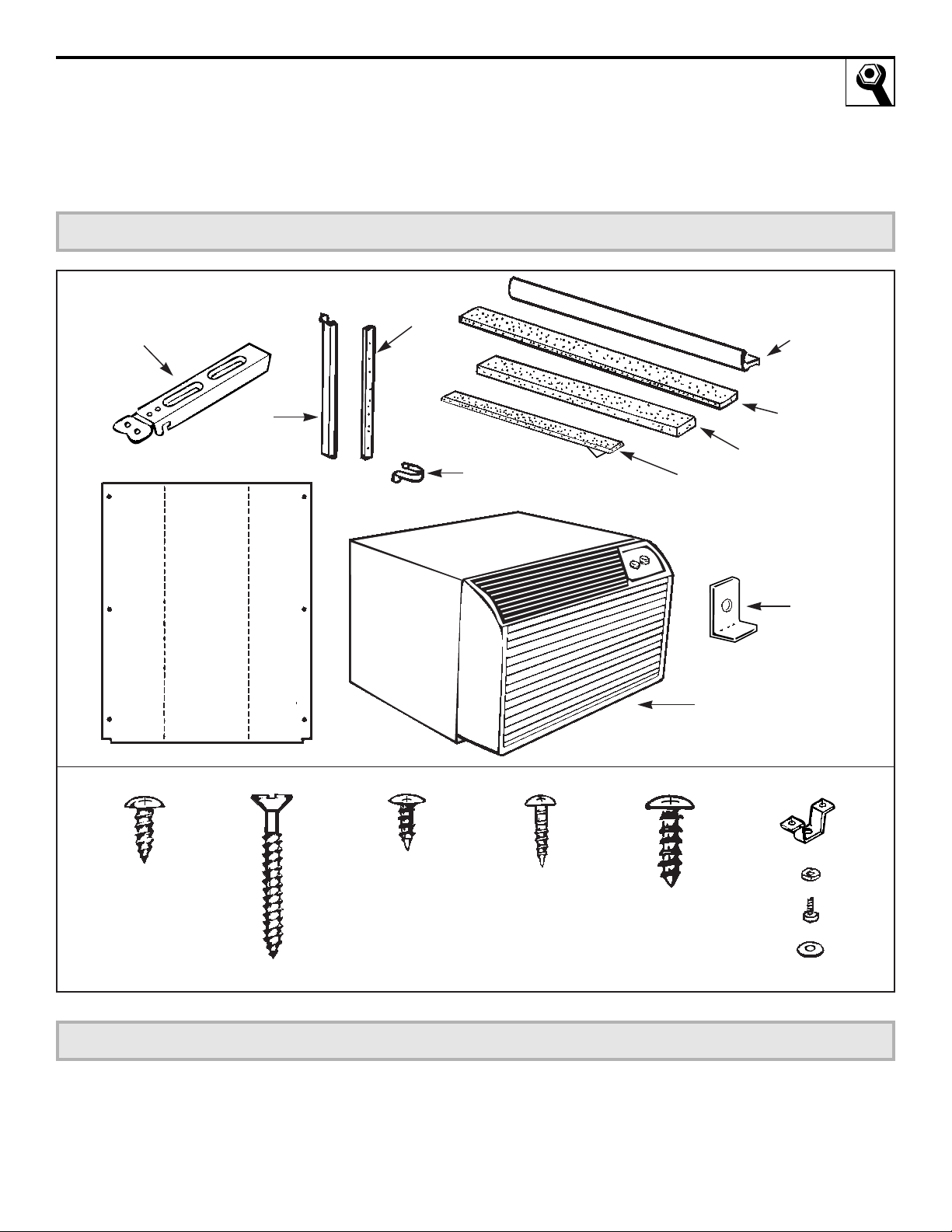
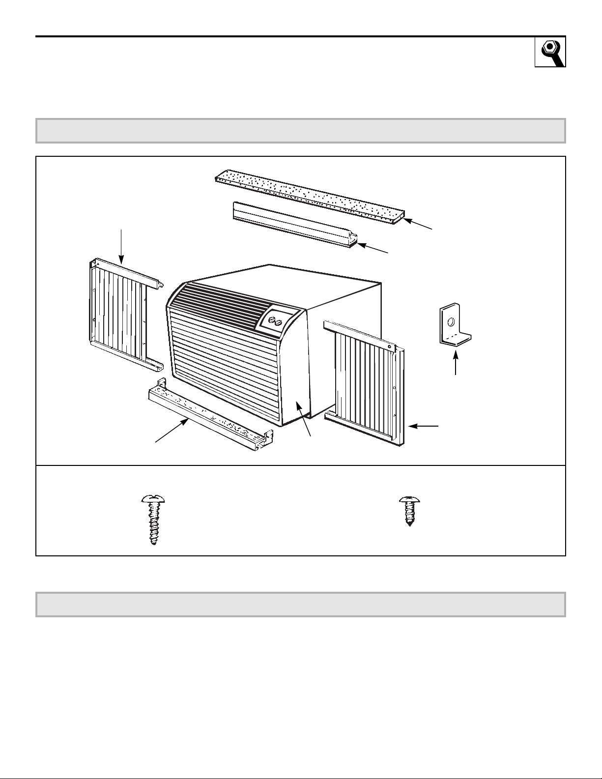
Air conditioner
Type B (2) Type C (painted) (6) Type D (2) Type E (4)
Support bracket hardware
Spacer (2)
Lock nut (2)
Adjusting bolt (2)
Large washer (2)
Type A (9)
Sill support
bracket (2)
2 angles
(left and right
hand)
Case
side
gasket
(2)
Spring
clip (4)
Window
locking
bracket
Foam top
window gasket
Case top gasket
Vinyl window
gasket
Bottom window gasket
Filler
Panels
Cut
panels
and
discard
center
piece
B
Right
side
(holes
are on
the left)
A
Left
side
(holes
are on
the right)
Parts Included for AJES & AJHS Models
Tools Needed
9
10
Installation Instructions
Read completely, then follow step-by-step
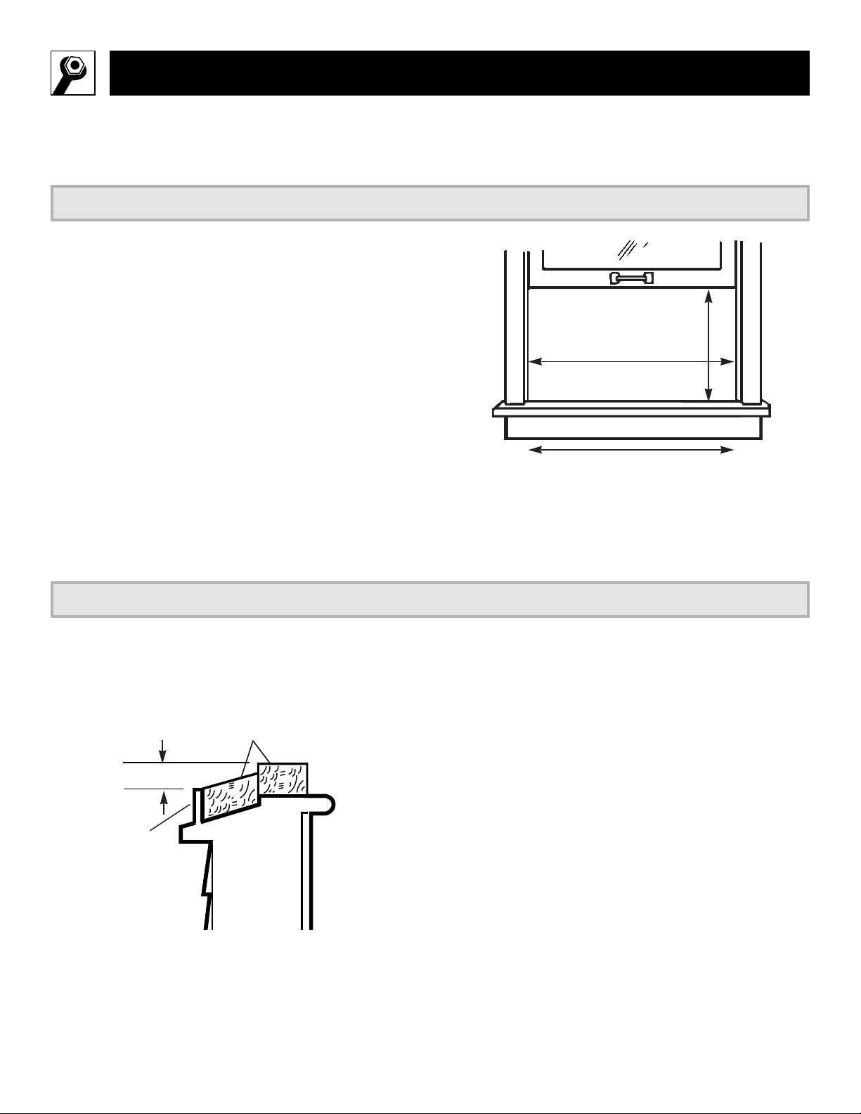
• These instructions are for a standard double-
hung window. You will need to modify them for
other types of windows.
• The air conditioner can be installed without
the filler panels if needed to fit in a narrow
window. See the window opening dimensions
to the right.
• All supporting parts must be secured to firm
wood, masonry or metal.
• The electrical outlet must be within reach of
the power cord.
A storm window frame will not allow the air
conditioner to tilt towards the outside and will
keep it from draining properly. To adjust for this,
attach a piece of wood to the sill and the stool.
WOOD PIECES:
WIDTH:
2²
LENGTH:
Long enough to fit inside the window
frame.
THICKNESS:
To determine the thickness, place a
piece of wood on the stool to make it 1/2² higher
than the top of the storm window frame.
Attach securely with nails or screws provided by
the installer.
Window opening dimensions are for a standard double-hung
window.
17² min.
31² to 43²
(With filler panels)
26
1
¤
4
² min.
(Without filler panels)
1/2² higher
than frame
Stool
Sill
Storm window
frame
Wood
Window Requirements
1
Storm Window Requirements
2
1
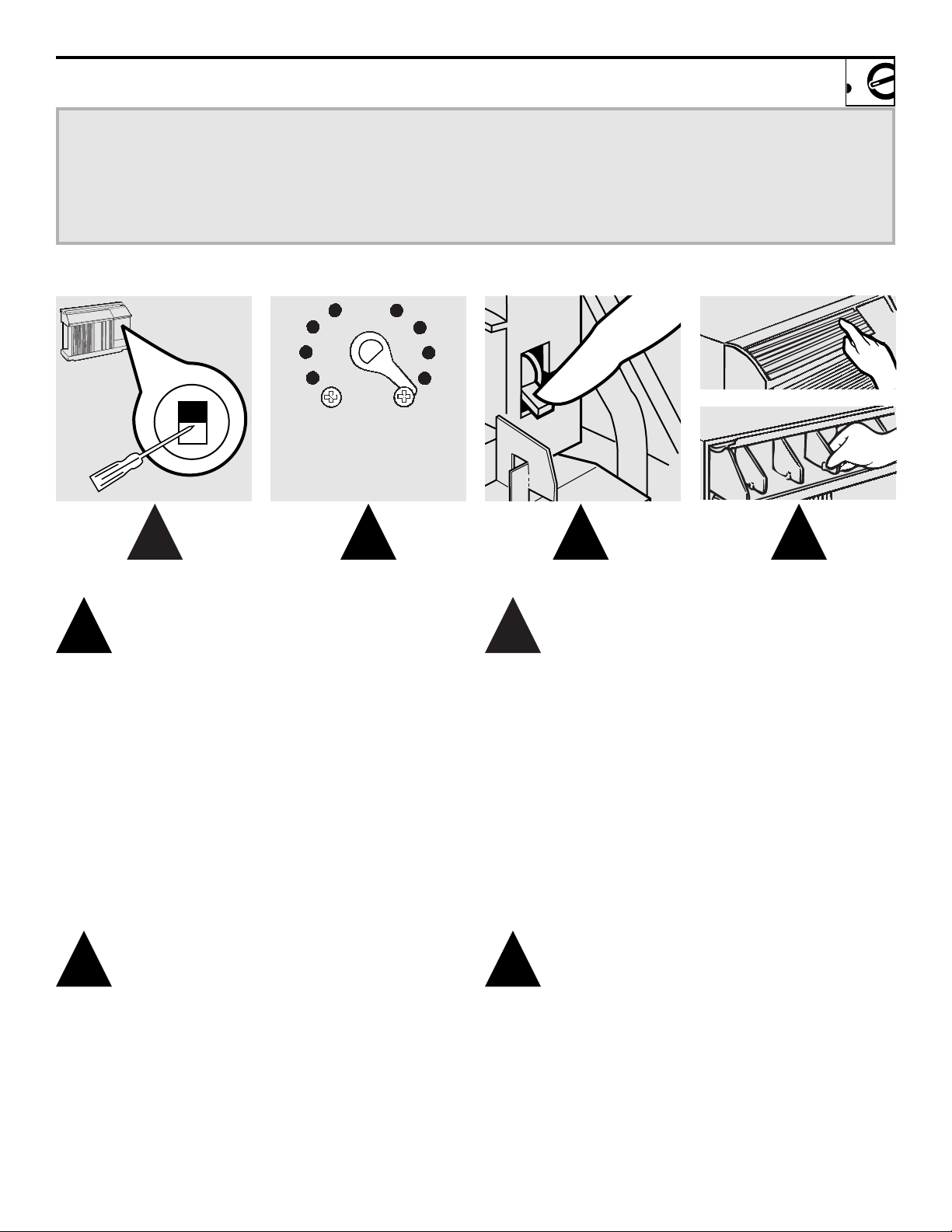
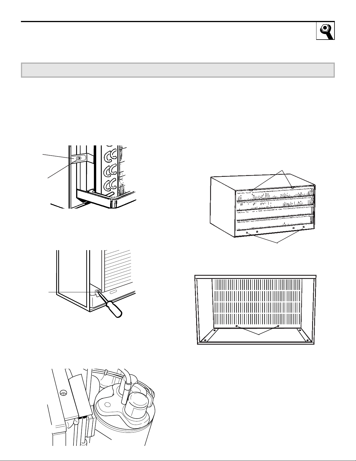
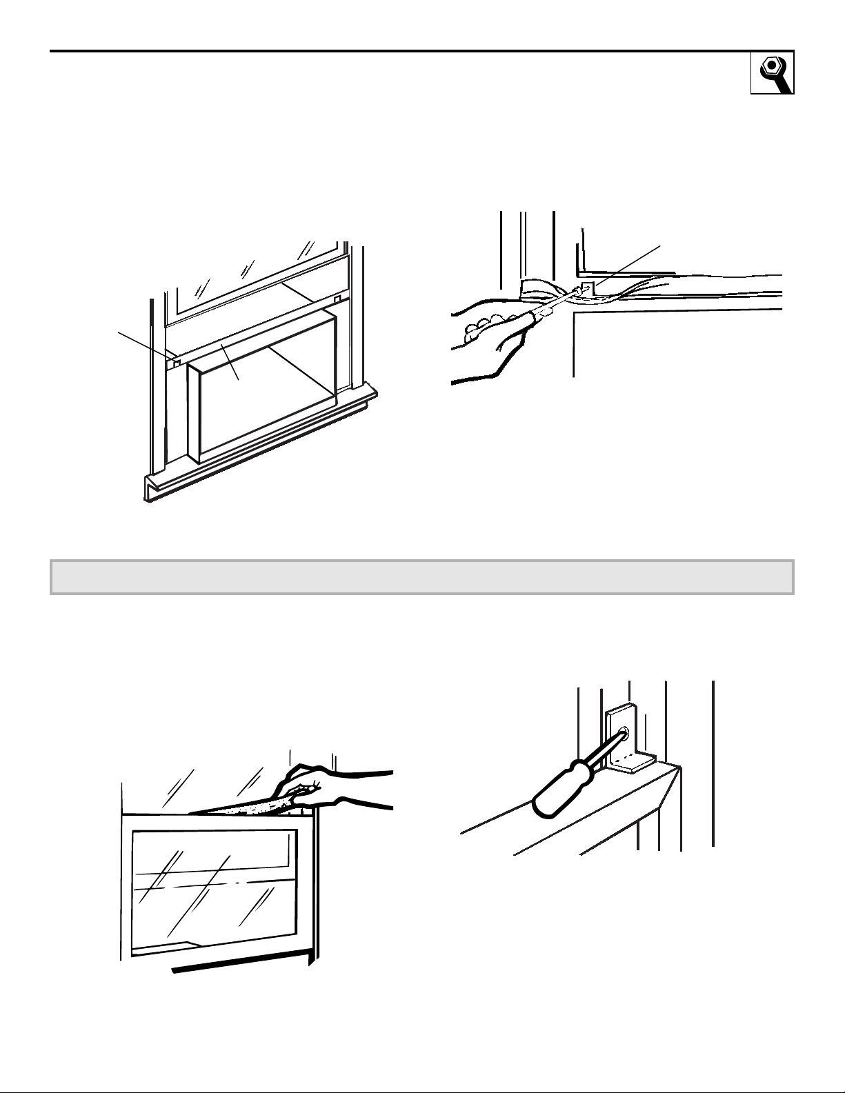
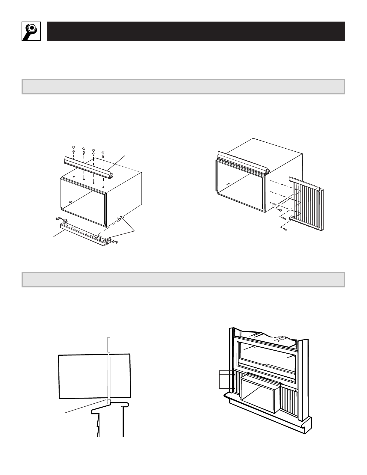
Remove the front grille. See the Care and
Cleaning section.
2
Find the locking plate located on the front
left side.
3
Remove the screw and the locking plate to
unlock the air conditioner.
4
Remove and discard the shipping screw on the
back of the air conditioner to allow removal of
the air conditioner from the case.
5
Pull the bottom corners of the air conditioner
and slide it out of the case.
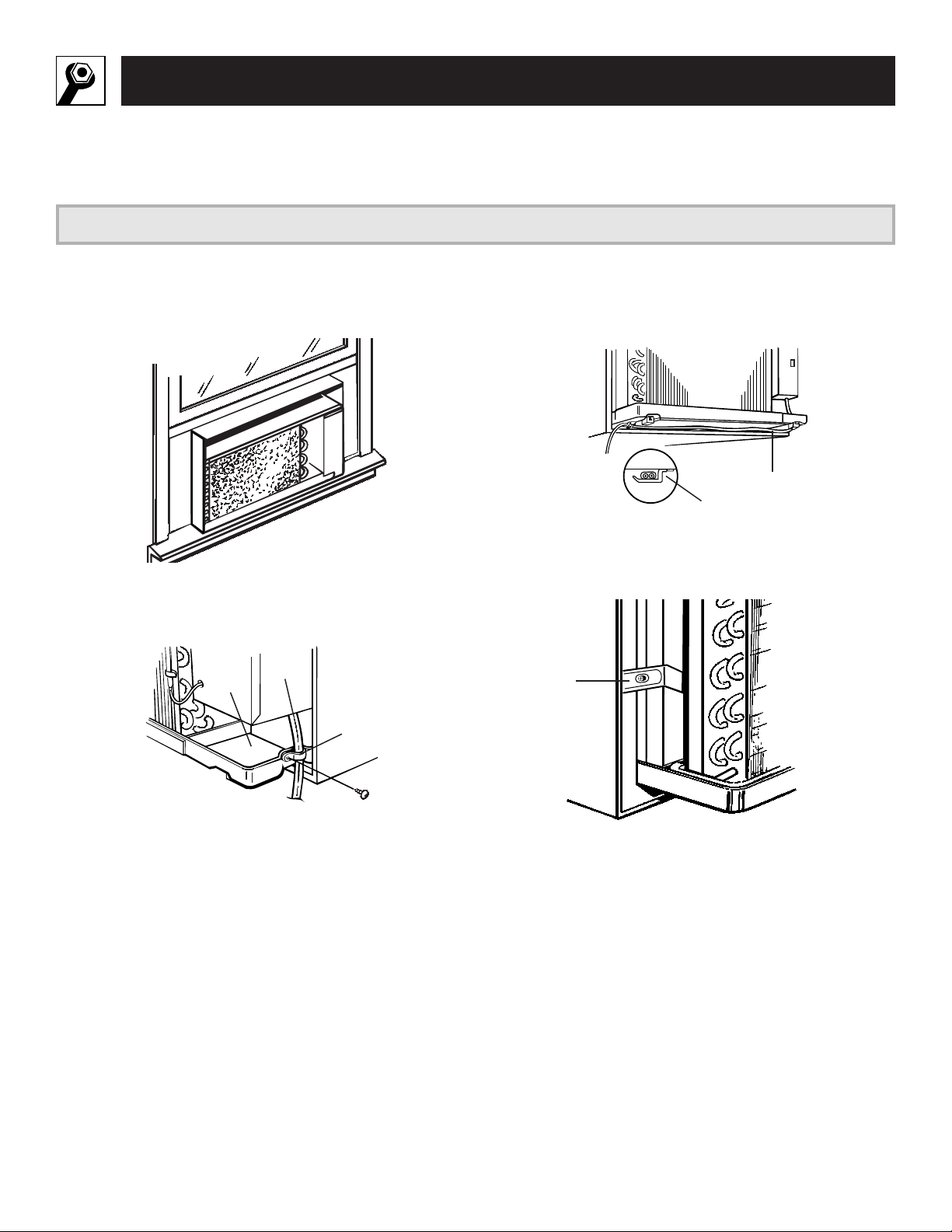
6
Remove the shipping pad inside the air
conditioner next to the compressor.
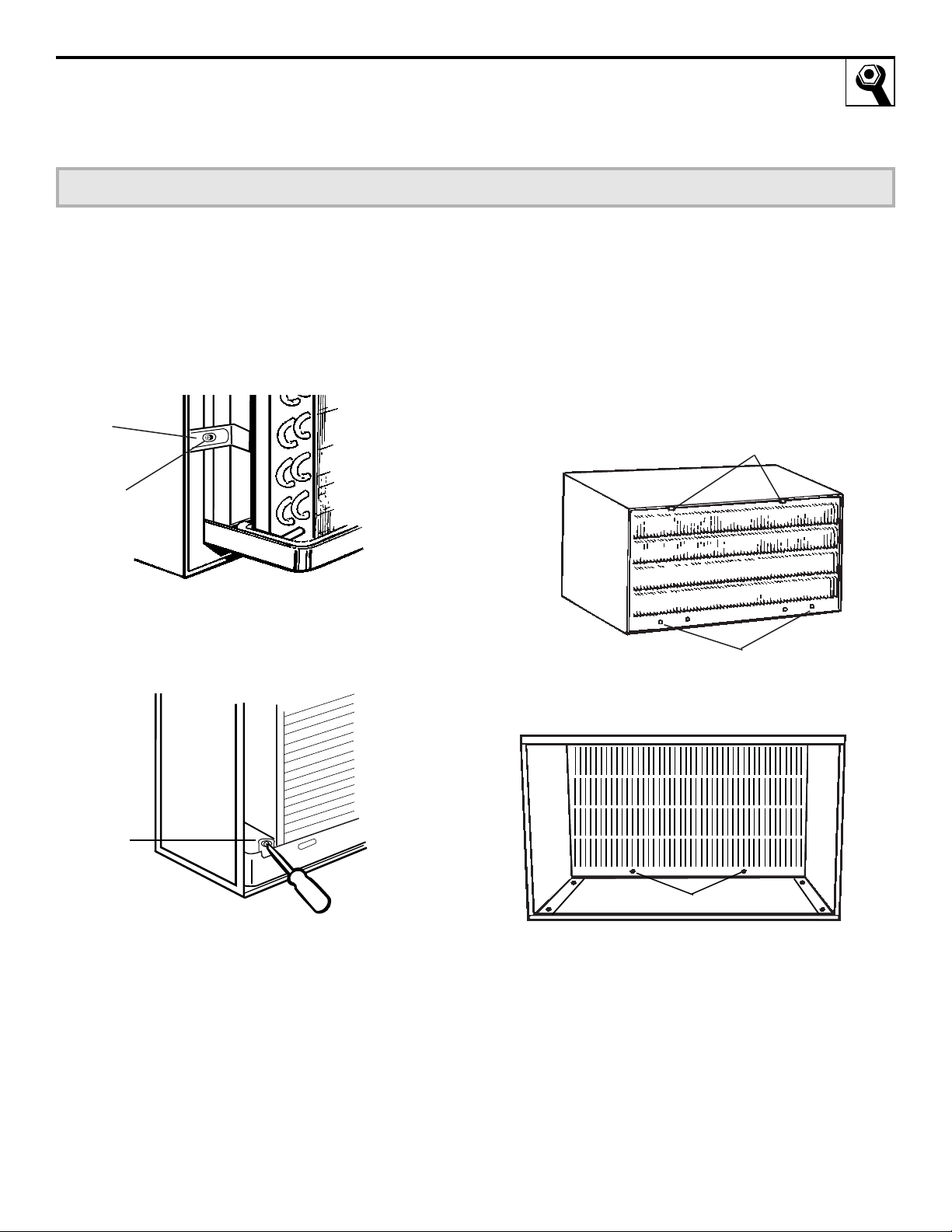
7
Remove the rear grille that is taped to the back
of the case. Remove the packet of screws taped
to the back of the grille. While holding the
grille at a 45° angle, insert it into the clips at
the top of the case and push the bottom in.
Keep slight upward pressure on the grille until
it fits flush with the bottom of the case.
If attaching the grille from the outside of the
case use the 2 long screws.
If attaching the grille on the inside of the case
use the 2 short screws.
REMOVE SHIP PAD!
REMOVE TAPE ON
VENT LEVER!
Clips
Insert the 2 long screws on the outside
Insert the 2 short screws on the inside
Locking
plate
Remove
screw
Remove
screw
Shipping pad
Remove the Air Conditioner From the Case
3
11

Installation Instructions
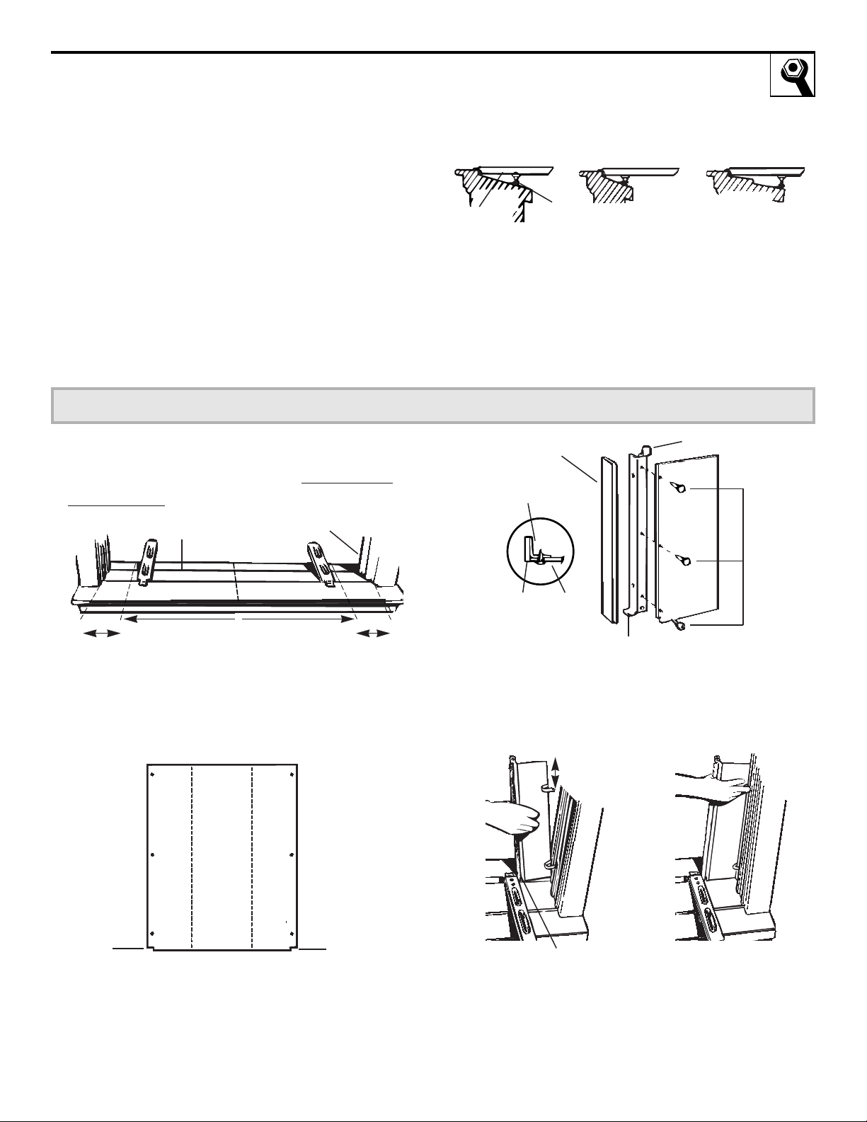
1
Assemble the sill supports. Do not fully tighten
the spacer mounting screws at this time.
2
Before attaching the sill supports, place them
on the window stool. Select the spacer position
that will place the spacer near the outermost
point on the sill. Tighten the spacer mounting
screws.
3
Turn the bolts and tighten the lock nuts to
make the sill supports level or tilt down 1/8
²
to the outside. Line up the “V” notch with
12
3
¤
8
² marks. Drill pilot holes and attach the
sill supports.
1
Mark the centerline of the stool. Measure
from the centerline 13
3
¤
8
² on both sides for the
panel cuts.
2
Measure 12
3
¤
8
² from the centerline on both
sides for the sill support brackets.
Large washer
Spacer
Type B
Type E
Spacer mounting screws
Type (A)
(For use with wood sills)
Adjusting bolt
Lock nut
Sill support
Bolt
Sill
Stool
Prepare the Window
4
Install the Sill Supports
5
Stool
Sill
Centerline
12
3
¤
8
²
13
3
¤
8
²
Centerline
Sill support
“V” notch
Screws are in
position
12
Measure, Cut and Install the Filler Panels
NOTES:
• On narrow sills, there may not be enough room
to use the lock nut.
• A deep offset sill may require a longer adjusting
bolt than the standard hex head bolt provided.
• On wood sills use the large washer between the
bolt head and the sill. This prevents the bolt
from digging into the wood.
1
Measure from the edge of the panel marks
(see
Prepare the Window
) to the inside of the
window track on each side. (A and B)
2
Mark the A and B measurements on each side
of the filler panel board. Cut the panels and
discard the center piece. Note position of the
notches.
3
Put together the panel assemblies. Remove
the paper backing from the case side gasket
and attach it to the angle. Push a pencil point
through the gaskets to locate the holes in
the angles.
4
Install the panels in the window. Place the
spring clips 3² from the top and the bottom.
Squeeze and push the clips to fit in the
window track and the tab into the sill support.
6
Sill
A B
Window track
Width of the air conditioner
(panel marks)
Left
side
Notch
Right
side
13
3
¤
8
² 13
3
¤
8
²
B
Right
side
of
window
(holes
are on
the
left)
A
Left
side
of
window
(holes
are on
the
right)
Filler
Panels
Cut
panels
and
discard
center
piece
Gasket
Gasket
Angle
Angle
Panel
Tab
Type C
(painted
screws)
Hook the tab into
the sill support
3²
Sill support
Spacer
Average sill Narrow sill Offset sill (such as
brick or stone)
13
Notch
Installation Instructions
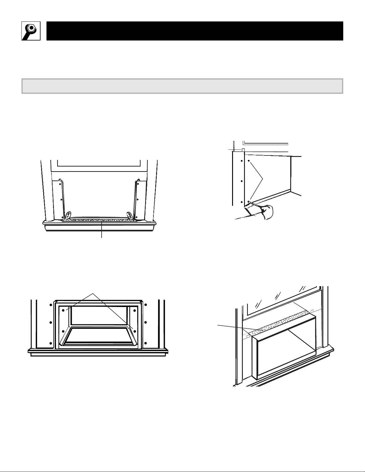
1
Peel off the backing from the bottom window
gasket.
2
Place the gasket on the stool and over the
brackets, even with the rear edge, sticky side
down.
3
Carefully slide the empty case into the window
until the holes in the case line up with the
holes in the panel angles.
NOTES:
• The case should have a 1/8² minimum tilt
toward the outside.
• Be sure the seal gasket and panel gaskets
remain in position and do not roll with the case.
4
Lower the window so it fits behind the panel
tabs. Insert the 4 type A screws through the
holes in the case and into the panel angles,
2 on each side.
5
With the window closed, mark where the
window sash meets the case.
6
Peel off the backing from the case top gasket.
7
Hold on to the case, open the window, and
place the gasket along the mark on the case.
Install the Case in the Window
7
Bottom window gasket
Case holes
Panel
tabs
Case
screws
Put the gasket on
top of the case
where the window
will close.
14
15
7
Place the vinyl window gasket over the case top
gasket. Insert the panel tabs through the slits in
the gasket. Cut the gasket on each side to the
width of the window.
8
Close the window tightly on the vinyl gasket.
Bend the gasket forward to expose the panel
tabs. Drill pilot holes into the window sash.
Panel tab
Vinyl window
gasket
Attach the panel tab to
the window on each side
with a type D screw.
Install the Window Gasket and the Locking Bracket
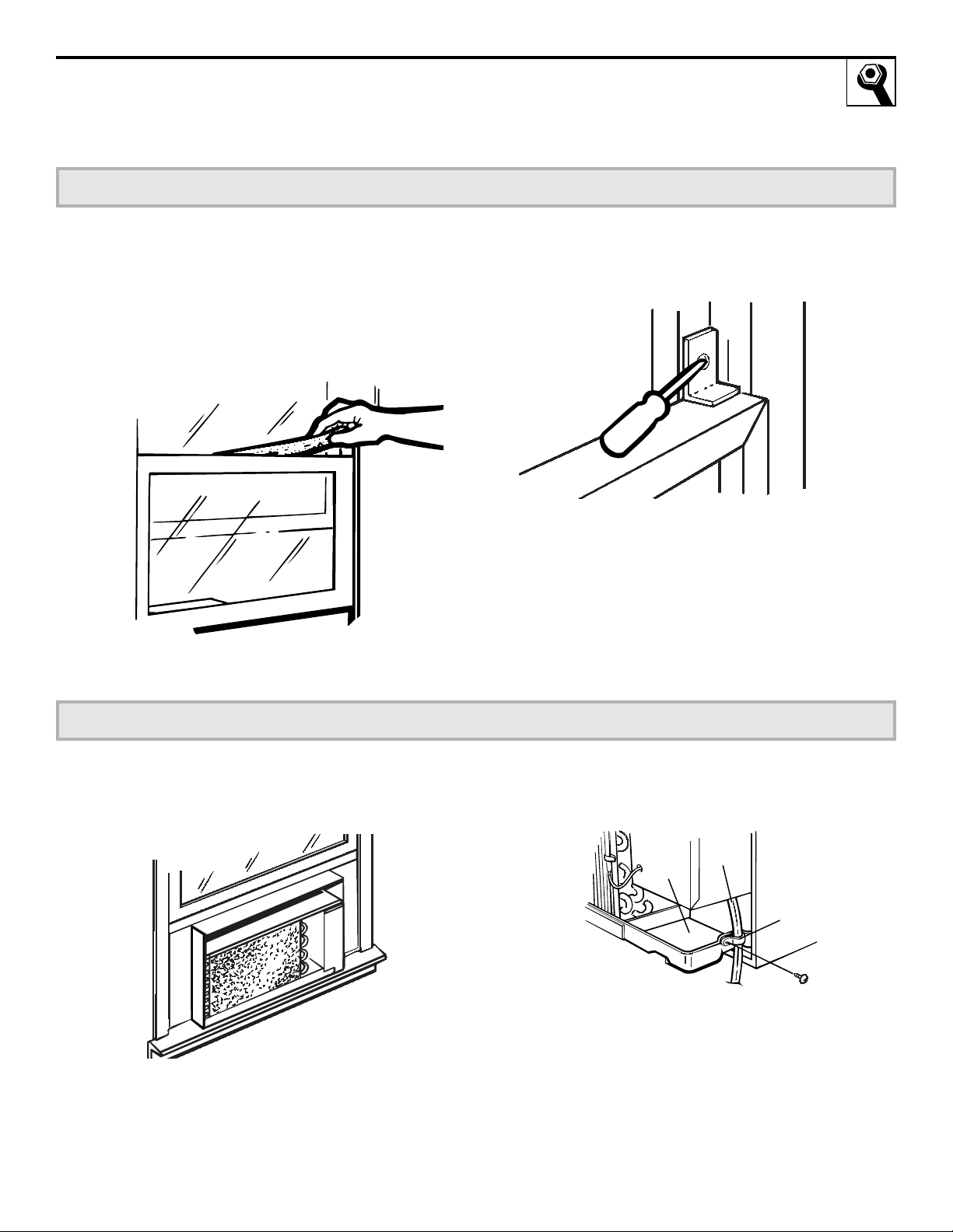
1
Cut the foam top window gasket to the window
width.
2
Stuff the foam between the glass and the
window to prevent air and insects from getting
into the room.
3
Attach the window locking bracket with 1 type
E screw.
8
16
Installation Instructions
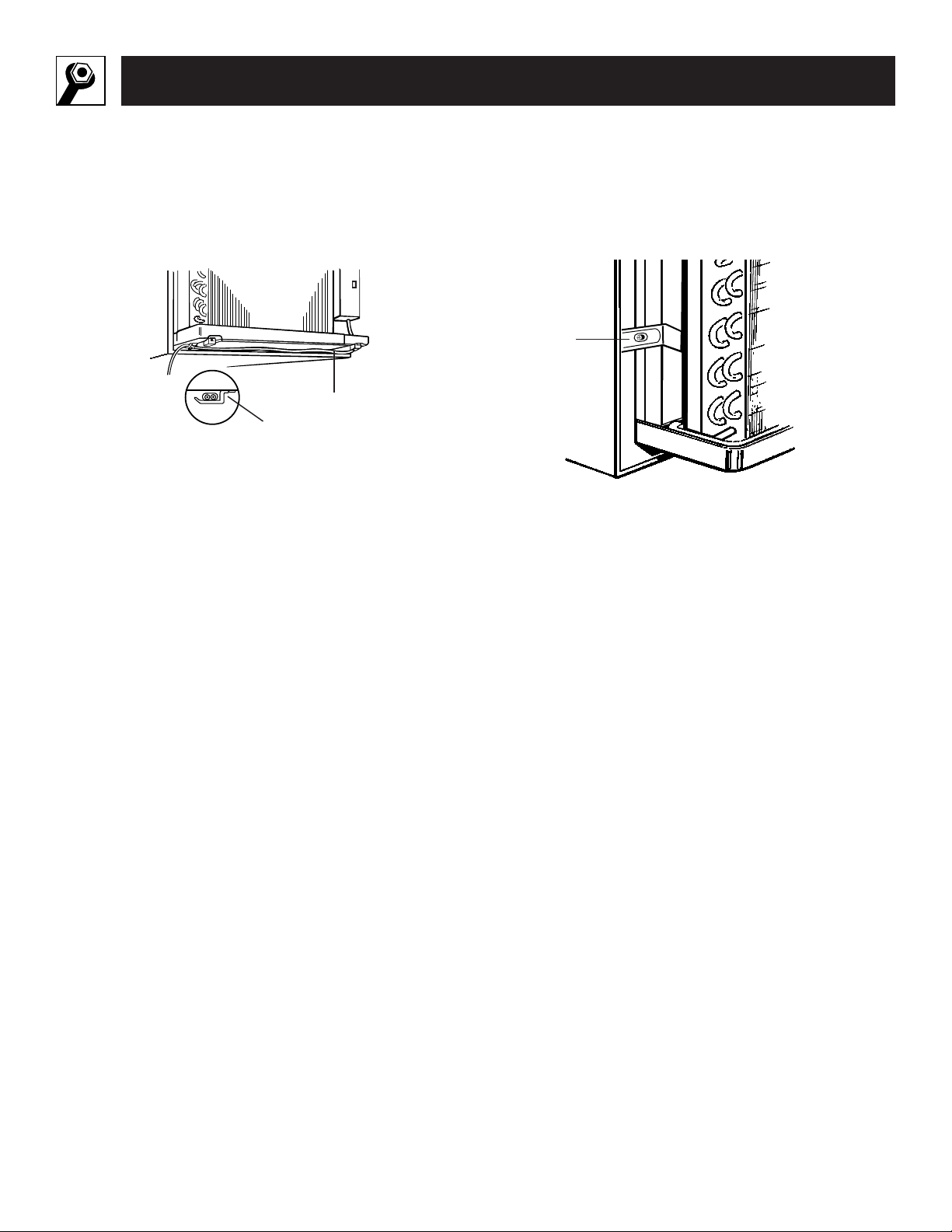
Replace the Air Conditioner in the Case
1
Carefully slide the air conditioner back into
the case.
2
Attach the power cord to the base pan with
the clamp.
3
When the wall outlet is to the left, extend the
cord under the unit and hold it in place with
the clamp.
4
Reinstall the locking plate with the tab behind
the wall case flange. Tighten the screw.
5
Reattach the front grille. An opening for the
power cord is on the bottom of the front grille.
6
Fill holes and cracks with caulking provided by
the installer.
9
Power
cord
Clamp
Base
pan
Power cord
Clamp
Locking
plate
For models with accordion curtains
Parts Included
Air conditioner
Type A (6) Type B (15)
Window
locking
bracket
Foam top window gasket
Top mounting rail
Accordion curtain
(left)
Accordion curtain
(right)
Sill channel
• Phillips-head screwdriver
• Ruler or tape measure
• Level
• Scissors or knife
• Pencil
• Drill
Tools Needed
17

18
Installation Instructions
Read carefully, then follow step-by-step
• These instructions are for a standard double-
hung window. You will need to modify them for
other types of windows.
• The air conditioner can be installed without
the accordion curtains if needed to fit in a
narrow window. See the window opening
dimensions to the right.
• All supporting parts must be secured to firm
wood, masonry or metal.
• The electrical outlet must be within reach of
the power cord.
Window opening dimensions are for a standard double-hung
window.
17² min.
29² to 49²
(With accordion curtains)
26
1
¤
4
² min.
(Without accordion curtains)
Window Requirements
1
A storm window frame will not allow the air
conditioner to tilt towards the outside and will
keep it from draining properly. To adjust for this,
attach a piece of wood to the sill and the stool.
WOOD PIECES:
WIDTH:
2²
LENGTH:
Long enough to fit inside the window
frame.
THICKNESS:
To determine the thickness, place a
piece of wood on the stool to make it 1/2² higher
than the top of the storm window frame.
Attach securely with nails or screws provided by
the installer.
1/2² higher
than frame
Stool
Sill
Storm window
frame
Wood
Storm Window Requirements
2
1
Remove the front grille. See the Care and
Cleaning section.
2
Find the locking plate located on the front
left side.
3
Remove the screw and the locking plate to
unlock the air conditioner.
4
Remove and discard the shipping screw on the
back of the air conditioner to allow removal of
the air conditioner from the case.
5
Pull the bottom corners of the air conditioner
and slide it out of the case.
6
Remove the rear grille that is taped to the back
of the case. Remove the packet of screws taped
to the back of the grille. While holding the
grille at a 45° angle, insert it into the clips at
the top of the case and push the bottom in.
Keep slight upward pressure on the grille until
it fits flush with the bottom of the case.
If attaching the grille from the outside of the
case use the 2 long screws.
If attaching the grille on the inside of the case
use the 2 short screws.
Clips
Insert the 2 long screws on the outside
Insert the 2 short screws on the inside
Locking
plate
Remove
screw
Remove
screw
Remove the Air Conditioner From the Case
3
19
20
Installation Instructions
Read carefully, then follow step-by-step
1
Install the top mounting rail with type B screws.
2
Attach the sill channel with type B screws.
Align the holes on the bracket of the sill
channel with the holes in the case.
3
Slide the right and left accordion curtains into
the top mounting rail and sill channel. Secure
with type B screws.
1
Open the window and center the case in the
window. Lower the window behind the top
mounting rail. This should provide a 1/8
² tilt
toward the outside.
2
Extend curtains and drill pilot holes in the side
of the window and the window sash. Attach the
curtains with 3 screws on each side.
Prepare the Case
4
Install the Case in the Window
5
Align
holes
Mounting rail
Sill channel
Place the sill
channel into
the stool offset.
Case should have
a slight tilt down
to the outside.
Type A
screws
21
Install the Window Gasket and the Locking Bracket
6
1
Cut the foam top window gasket to the window
width.
2
Stuff the foam between the glass and the
window to prevent air and insects from getting
into the room.
3
Attach the window locking bracket with 1 type
B screw.
Replace the Air Conditioner in the Case
1
Carefully slide the air conditioner back into
the case.
2
Attach the power cord to the base pan with the
clamp.
7
Power
cord
Clamp
Base
pan
22
Installation Instructions
3
When the wall outlet is to the left, extend the
cord under the unit and hold it in place with
the clamp.
4
Reinstall the locking plate with the tab behind
the wall case flange. Tighten the screw.
5
Reattach the front grille. An opening for the
power cord is on the bottom of the front grille.
6
Fill holes and cracks with caulking provided by
the installer.
Power cord
Clamp
Locking
plate
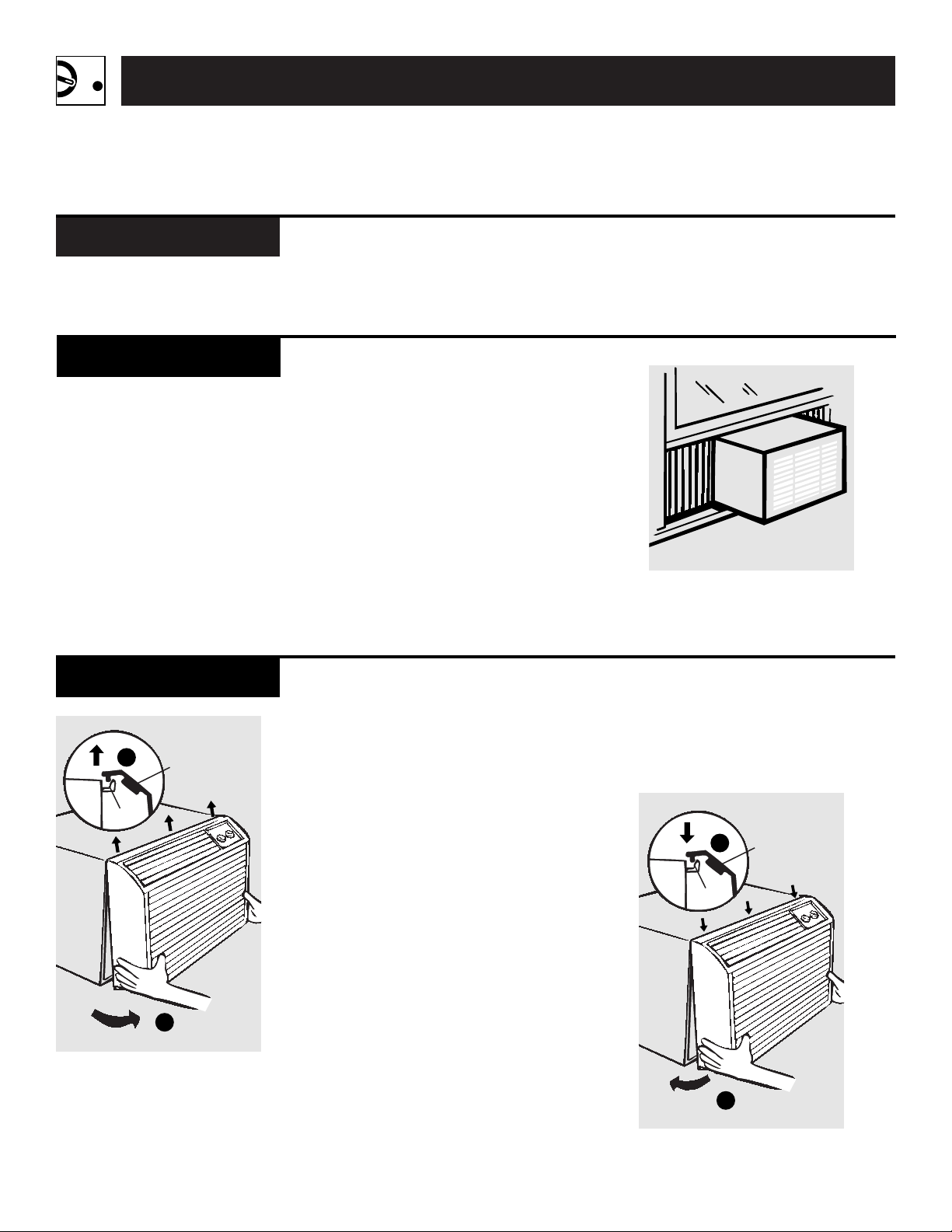
Through-the-Wall Installation
Make certain a wall receptacle is available close to
the hole location or make arrangements to install
a receptacle.
The cord length for the 115-volt models is 72
² to
the right and 47² to the left. For the 230/208-volt
models the cord length is 65² to the right and 39²
to the left.
The air conditioner wall case may be installed
flush with the inside wall or flush with the outside
wall.
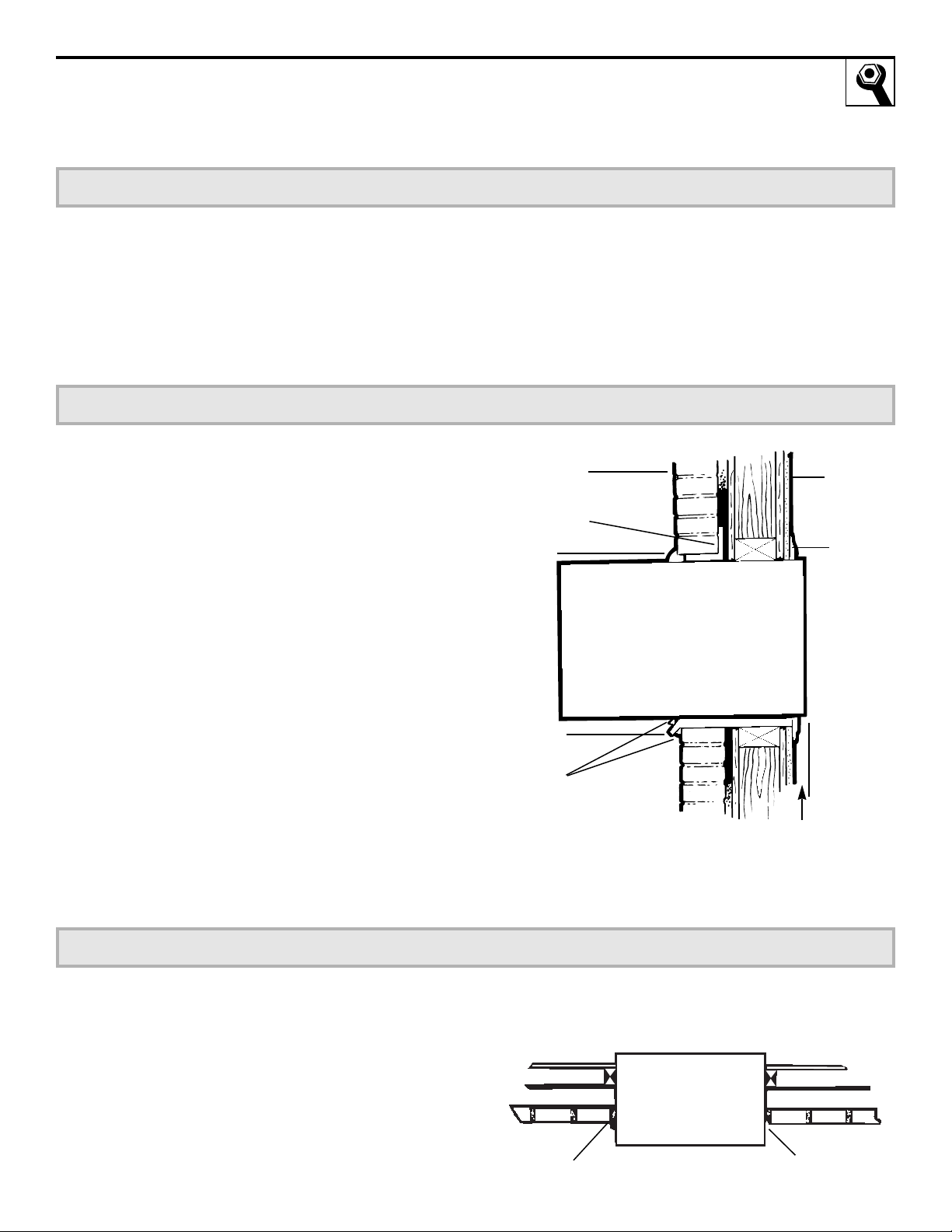
The finished sides of the opening should be
structural wall members.
Lintel
—Use a lintel in brick veneer and brick and
block types of wall to support the bricks or blocks
above the opening. Do not allow the wall case to
be used in lieu of a lintel.
Flashing
—Install flashing (drip rail) as shown to
prevent water from dripping inside the wall and
down the outside of the building.
Preparation of the Opening in the Wall
1
Support Requirements for the Air Conditioner
2
Mortar between the case and the brick all around
the case may be undercut at about 45° for
improved caulking.
Mortar and Caulking
3
Plaster
line
Trim
molding
(if desired)
Flashing
(Drip rail)
Brick veneer
Lintel angle
(if required)
Caulking
(on all
4 sides
on the
outside
of the
case)
Caulking
(above &
below the
flashing)
1/4² min. extension
inside the wall from
the trim moulding
Roomside
Caulking
Undercut
mortar
Top of
case
Outside
Inside
23

24
Helpful Information
Things That Are Normal
You may hear a pinging noise caused by water being picked up
and thrown against the condenser on rainy days or when the
humidity is high. This design feature helps remove moisture
and improve efficiency.
You may hear the thermostat click when the compressor cycles
on and off.
Water will collect in the base pan during high humidity or on rainy
days. The water may overflow and drip from the outdoor side
of the unit.
The fan may run even when the compressor is not.
Noise Explanation
"CLICK"
D R I P
WHIR!
P
I
N
G
!

25
Air Conditioner
Doesn’t Start
Air Conditioner Does
Not Cool or Heat as
it Should
The air conditioner • Make sure the air conditioner plug is
is unplugged pushed completely into the outlet.
The fuse is blown/circuit • Check the house fuse/circuit breaker
breaker is tripped box and replace fuse or reset the
breaker.
Power failure
• If power failure occurs, turn the mode
control to
OFF
. When power is restored,
wait 3 minutes to restart the air conditioner
to prevent tripping of the compressor
overload.
• There is a protective time delay (up to 3
minutes) in the heat/cool and heat pump
models. Wait 3 minutes for the air
conditioner to resume heating or cooling.
Problem Possible Causes What to Do
Air Conditioner
Freezing Up
Ice blocks the airflow • Set the mode control at
HIGH FAN
or
and stops the air conditioner
HIGH COOL
with the temperature at a
from cooling the room warmer setting.
Airflow is restricted
• Make sure there are no curtains, blinds
or furniture blocking the front of the
air conditioner.
The temperature control • Turn the knob to a warmer or cooler setting.
may not be set high The coolest setting provides maximum
or low enough cooling. The warmest setting provides
maximum heating on models with heat.
The air filter is dirty • Clean the filter at least every 30 days.
See the Care and Cleaning section.
The room may have been hot • When the air conditioner is first turned on
or cold you need to allow time for the room to
cool down or warm up.
Cold air is escaping • Check for open furnace floor registers and
cold air returns.
• Set the exhaust vent in the closed position.
Cooling coils have iced up • See freezing up below.
If Something Goes Wrong
Before You Call for Service

26
Notes

Notes
27

28
Notes

29
General Electric Company
Warranty Registration Department
P.O. Box 34070
Louisville, KY 40232-4070
GE Service Protection Plus
™
GE, a name recognized worldwide for quality and dependability, offers you Service
Protection Plus
™
—comprehensive protection on all your appliances—No Matter
What Brand!
Benefits Include:
• Backed by GE
• All brands covered
• Unlimited service calls
• All parts and labor costs included
• No out-of-pocket expenses
• No hidden deductibles
• One 800 number to call
You will be completely satisfied with our service protection or you may request your money back
on the remaining value of your contract. No questions asked. It’s that simple.
Protect your refrigerator, dishwasher, washer and dryer, range, TV, VCR and much more—any brand!
Plus there’s no extra charge for emergency service and low monthly financing is available. Even icemaker
coverage and food spoilage protection is offered. You can rest easy knowing that all your valuable
household products are protected against expensive repairs.
Place your confidence in GE and call us in the U.S. toll-free at 800-626-2224
for more information.
*All brands covered, up to 20 years old, in the continental U.S.
We’ll Cover Any Appliance.
Anywhere. Anytime.*
Please place in envelope and mail to:
✁
Cut here
Consumer Product Ownership Registration
Model Number Serial Number
Important
Mail
Today!
GE Appliances
General Electric Company
Louisville, Kentucky 40225
First
Name
Mr. ■■ Ms. ■■ Mrs. ■■ Miss ■■
Street
Address
City
State
Date Placed
In Use
Month
Day Year
Zip
Code
Apt. #
Last
Name
Phone
Number
_ _
Consumer Product Ownership Registration
Dear Customer:
Thank you for purchasing our product and thank you for placing your
confidence in us. We are proud to have you as a customer!
Follow these three steps to protect your new appliance investment:
Complete and
mail your Consumer
Product Ownership
Registration today.
Have the peace of
mind of knowing we
can contact you in
the unlikely event of
a safety modification.
After mailing
the registration
below, store this
document in a safe
place. It contains
information you
will need should
you require service.
Our service number
is 800-GE-CARES
(800-452-2737).
Read your Owner’s
Manual carefully.
It will help you
operate your new
appliance properly.
If you have questions,
or need more
information call the
GE Answer Center
®
800.626.2000.
Important: If you did not get a registration card with your product,
detach and return the form below to ensure that your
product is registered.
1
2 3
Model Number Serial Number
✁
Cut here

800.626.2000
TDD
800-833-4322
GE Service Numbers
We’ll be there!
Open 24 hours a day,
7 days a week.
GE Answer Center
®
800-GE-CARES
(800-432-2737)
We provide expert repair service,
scheduled at a time that’s
convenient for you.
Our factory-trained technicians
know your appliance inside and out—
so most repairs can be handled in
just one visit.
In-Home Repair Service
800-626-2224
With a service contract GE
Consumer Service will still be there
after your warranty expires.
With a multiple-year contract,
you’re assured of future service at
today’s prices.
Service Contracts
800-626-2002
Individuals qualified to service
their
own appliances can have
parts or accessories sent directly
to their home.
VISA, MasterCard and Discover
cards are accepted.
Care and cleaning instructions con-
tained in this manual cover proce-
dures to be performed by any user.
Other servicing generally should be
referred to qualified service per-
sonnel. Caution must be exercised,
since improper servicing may cause
unsafe operation.
Parts and Accessories
If for some reason you
are not happy with the
service you receive, here
are three steps to follow
for further help.
First,
contact the people who ser-
viced your appliance. Explain why
you are not pleased.
Next,
if you are still not pleased,
write all the details—including
your phone number—to:
Consumer Relations
GE Appliances
Louisville, KY 40225
Finally,
if your problem is still
not resolved, write:
Major Appliance
Consumer Action Program
20 North Wacker Drive
Chicago, IL 60606
Further Service
31

Printed in China
AJCS06 AJES08 AJES10
AJES06 AJHS08
AJCS08 AJCS10
What Is Not
Covered
FULL ONE-YEAR WARRANTY
For one year from date of original pur-
chase, we will provide, free of charge,
parts and service labor in your home to
repair or replace
any
part of the room air
conditioner that fails because of
a manu-
facturing defect.
FULL FIVE-YEAR WARRANTY
For five years from the date of original
purchase, we will provide, free of charge,
parts and service labor in your home to
repair or replace any part of the sealed refrig-
erating system (the compressor, condenser,
evaporator and all connecting tubing)
that fails because of a manufacturing
defect.
This warranty is extended to the original purchaser and any succeeding owner for products purchased for home use
within the USA. In Alaska, the warranty excludes the cost of shipping or service calls to your home.
Some states do not allow the exclusion or limitation of incidental or consequential damages. This warranty gives you
specific legal rights, and you may also have other rights which vary from state to state. To know what your legal
rights are in your state, consult your local or state consumer affairs office or your state’s Attorney General.
Staple sales slip or cancelled check here. Proof of original purchase
date is needed to obtain service under warranty.
For service, call 800-GE-CARES.
AIR
CONDITIONER
WARRANTY
What Is Covered
• Service trips to your home to teach
you how to use the product.
• Improper installation.
If you have an installation problem,
or if the air conditioner is of
improper cooling capacity for the
intended use, contact your dealer
or installer. You
are responsible for
providing adequate
electrical
connecting facilities.
• Replacement of house fuses or reset-
ting
of circuit breakers.
• In commercial locations labor neces-
sary to move the unit to a location
where it is accessible for service by an
individual technician.
• Failure of the product resulting from
modifications to the product or due
to unreasonable use including failure
to provide reasonable and necessary
maintenance.
•
Failure due to corrosion on models not
corrosion-protected.
•
Damage to product caused by improp-
er power supply voltage, accident,
fire,
floods or acts of God.
•
Incidental or consequential damage to
personal property caused by possible
defects with this air conditioner.
Warrantor: General Electric Company. Louisville, KY 40225