Loading ...
Loading ...
Loading ...
7
INSTALLATION INSTRUCTIONS
Prepare Location
■ It is recommended that the vent system be installed before
hood is installed.
■ Before making cutouts, make sure there is proper clearance
within the ceiling or wall for exhaust vent.
■ Check your ceiling height and the hood height maximum
before you select your hood.
1. Disconnect power.
2. Determine which venting method to use: roof, wall, or non-
vented.
3. Select a flat surface for assembling the range hood. Place
covering over that surface.
4. Using 2 or more people, lift range hood onto covered surface.
Range Hood Mounting Screws Installation
1. Determine and mark the centerline on the wall where the
canopy hood will be installed.
2. Select a mounting height between a minimum of
24" (61.0 cm) for an electric cooking surface, a minimum of
27" (68.6 cm) for a gas cooking surface, and a suggested
maximum of 36" (91.4 cm) above the range to the bottom of
the hood. Mark a reference line on the wall.
3. Tape template in place, aligning the template centerline and
bottom of template with hood bottom line and with the
centerline marked on the wall.
4. Mark centers of the fastener locations through the template
to the wall.
IMPORTANT: All canopy mounting screws must be installed
into wood where possible. If there is no wood to screw into,
additional wall framing supports may be required, or use the
(4) 10 x 60 mm wall anchors and 5.4 x 75 mm screws.
Remove the template.
5. For wood, drill
3
/
16
" (4.8 mm) pilot holes at all locations where
screws are being installed into wood.
For wall anchors, drill
7
/
16
" (10 mm) holes at all locations
where wall anchors are being used.
6. For wood, install (2) 5 x 45 mm mounting screws. Leave a
1
/
4
" (6.4 mm) gap between the wall and the back of the screw
head to slide range hood into place.
For wall anchors, install the 10 x 60 mm wall anchors and
install the 5.4 x 75 mm screws into the wall anchors. Tighten
until the wall anchors are secure. Back the screws out
1
/
4
" (6.4 mm).
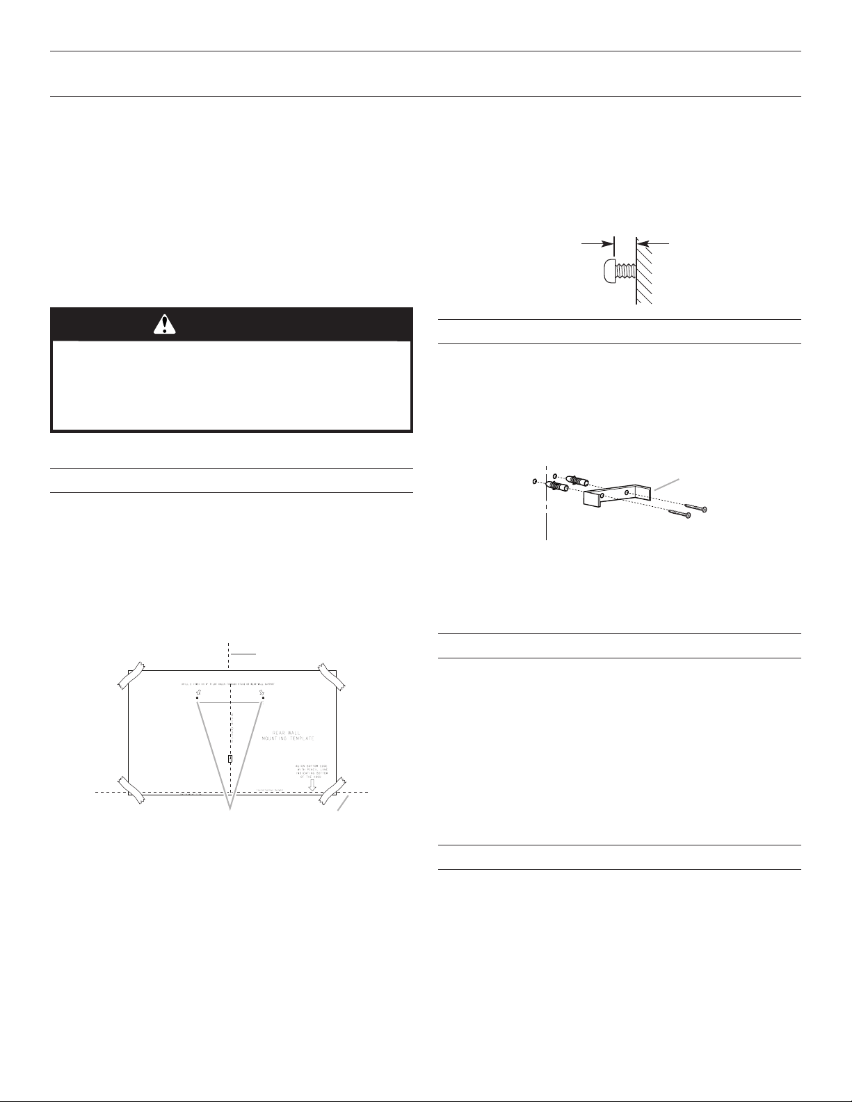
Vent Cover Support Bracket Installation
Installations using telescoping upper and lower vent cover
assembly
1. Position vent cover bracket on wall about
1
/
8
" (3.0 mm) away
from the ceiling.
2. Mark the hole locations.
3. Drill (2)
3
/
8
" (9.5 mm) holes for 8 x 40 mm wall anchors and
insert anchors flush with the wall.
4. Attach vent cover support bracket to wall.
Complete Preparation
1. Determine and make all necessary cuts in the wall for the
vent system. Install the vent system before installing the
hood. See the “Venting Requirements” section.
2. Determine the required height for the home power supply
cable and drill a 1
1
/
4
" (3.2 cm) hole at this location.
3. Run the home power supply cable according to the National
Electrical Code or CSA Standards and local codes and
ordinances. There must be enough
1
/
2
" conduit and wires
from the fused disconnect (or circuit breaker) box to make
the connection in the hood’s electrical terminal box.
NOTE: Do not reconnect power until installation is complete.
4. Use caulk to seal all openings.
Install In-Line Smart Kit - Optional
NOTE: Your range hood can work with either an internal or an
inline (external) blower motor system. An optional In-Line Smart
Kit (purchased separately) allows the blower motor that comes
with this range hood to be installed in a location other than
inside the range hood cavity.
CAUTION: To reduce the risk of fire and electric shock, install
this range hood only with the In-Line Smart Kit manufactured by
Whirlpool, Part Number W10692945.
For installation see the In-Line Smart Kit installation instructions.
See the “Assistance or Service” section to order.
WARNING
Excessive Weight Hazard
Use two or more people to move and install
range hood.
Failure to do so can result in back or other injury.
Vertical Centerline
C
L
LLAW RAER
ETALPMET GNITNUOM
EGDE MOTTOB NGILA
ENIL LICNEP HTIW
MOTTOB GNITACIDNI
DOOH EHT FO
thgieH noitallatsnI
TROPPUS LLAW RAER RO SDUTS HGUORHT SELOH TOLIP "61/3 )OWT( 2 LLIRD
eniL latnoziroH
A
C
B
A. Centerline
B. Fastener locations
C. Mounting height reference
¹⁄₄"
(6.4 mm)
A
B
C
D
A. 8 x 40 mm wall anchors
B. Centerline on wall
C. Vent cover support bracket
D. 5 x 45 mm screws
Loading ...
Loading ...
Loading ...