Loading ...
Loading ...
Loading ...
6
Request change-over injectors from our customer service
deparment (refer injector chart below for sizes).
Before conversion the cooktop must be disconnected from the
electricity and gas valves must be turned to the OFF position.
Changing the nozzles of the rapid, semi-rapid
and auxiliary burners on the cooktop
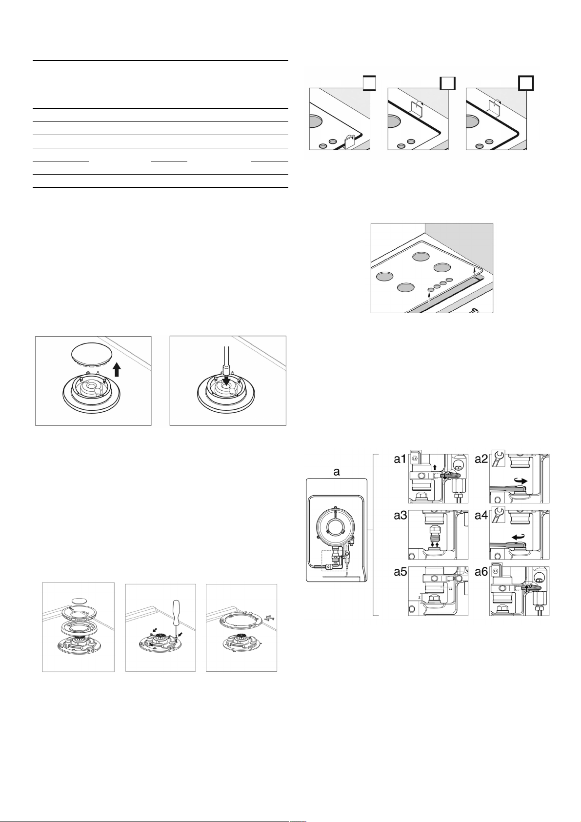
1. Remove the pan supports, burner covers and diffusers.
2. Change the nozzles using the spanner provided by our
Service Centre (code 424699), taking special care to ensure
that the nozzle does not fall when it is removed from the
burner or when fitted.
Ensure that it is completely tightened in order to guarantee
the seal.
Note: it is not necessary to adjust the primary air control on
these burners.
Changing double flame burner tips
The glass panel and frame are fixed to the rest of the cooktop
using a clip mounting system. The following steps must be
taken to remove the glass panel and frame:
1. Remove all the burner covers and pan supports.
2. Release the front clip fixing the appliance to the kitchen unit
by removing the screw.
3. Loosen the screws on the burners and remove the control
knobs from their respective housings.
Use the disassembly lever 483196 available from our Service
Centre. To release the front clips, apply the lever in the area
shown in figures below according to the cooktop model.
Never use the lever on glass edges which have no trim or
frame!
To release the rear clips, carefully raise the entire glass panel
and frame.
Changing the outer flame nozzle
1. Loosen the clamp screw to release the bushing by moving it
backwards to access the main nozzle easily. Fig. a1.
2. Remove the outer flame nozzle by turning it towards the left.
Fig. a2-a3.
3. Screw in the new outer flame nozzle. Fig. a3-a4.
4. Adjust the distance of the airflow adjusting bushing L2
according to the value -Z-. Fig. a5.
5. Tighten the clamp screw. Fig. a6.
Changing the inner flame nozzle
1. Unscrew the part M3 from the threaded part M2; to do this,
hold the threaded part in the opposite direction.
2. Remove the pipe from the part M2. Fig. b2.
3. Disassemble the assembly of parts M2 and M4 from part M1.
Fig. b3-b4.
4. Remove the inner flame nozzle M4 from part M2. Fig. b5-b6.
5. Screw in the new inner flame nozzle M4. Fig. b6-b7.
Natural Gas Propane Gas
Burner Hourly Gas
Consumption
(MJ)
Injector
mark
Hourly Gas
Consumption
(MJ)
Injector
mark
Auxiliary 4,80 97 3,50 53
Semi-rapid 8,10 130 6,00 70
Rapid 11,60 157 8,50 83
Wok (inner)
22,00
65
20,00
47
Wok (outer) 215 115
Distanze “Z“ 11 12
Loading ...
Loading ...
Loading ...