Loading ...
Loading ...
Loading ...
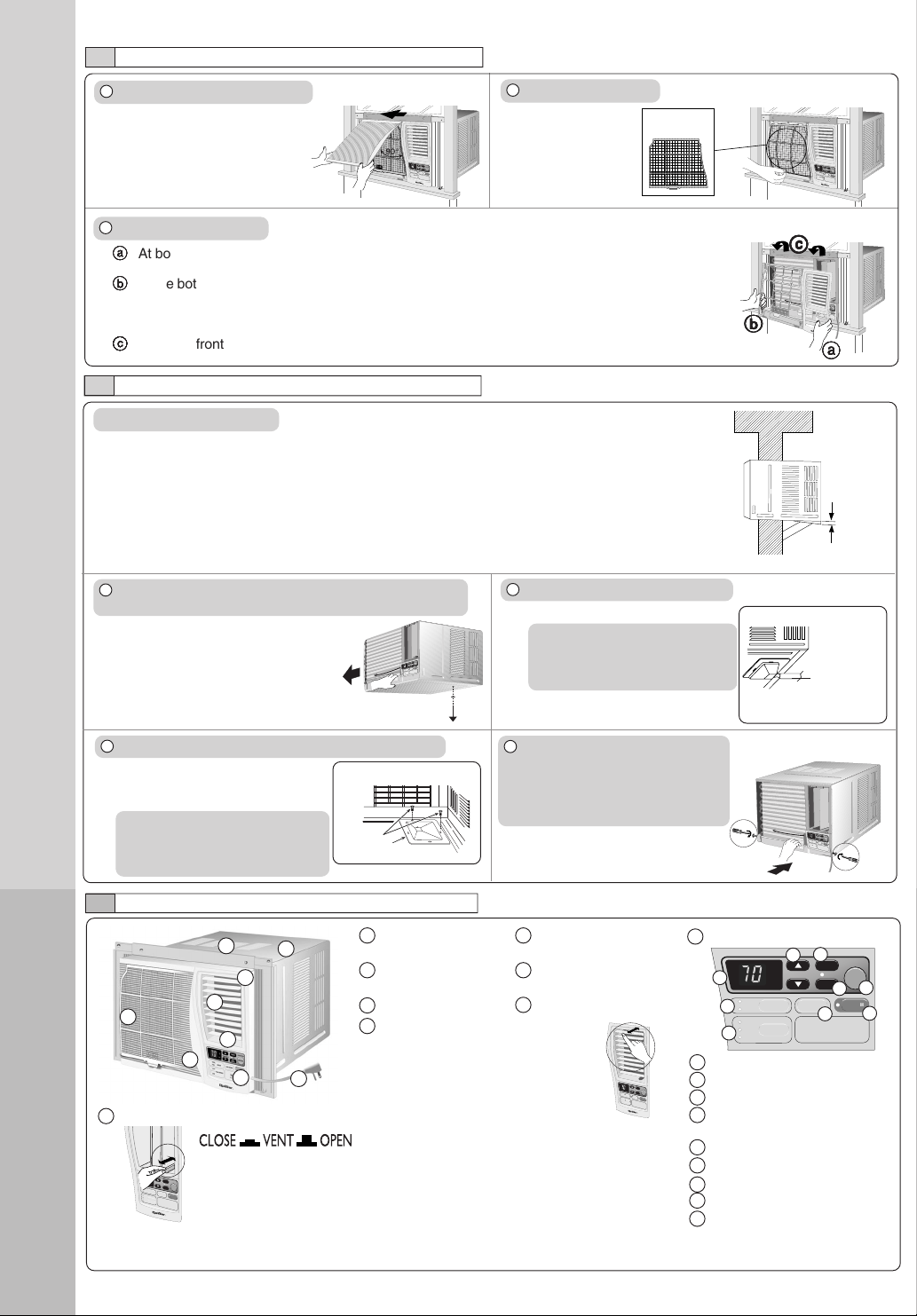
1 Air inlet louver 4 Air filter (behind the
front intake grille)
2 Cabinet 5 Front intake
grille
3 Power cord 6 Front grille
7 Vertical airflow direction vane
(Airflow direction adjustment up-
down).
The vertical airflow direction vane
is controlled by rotating the
horizontal vane forward or backward.
2
AIR CONDITIONER INSTALLATION
3
PART IDENTIFICATION
REMOVAL OF FRONT GRILLE
1 Remove the front intake grille.
Pull up the front intake
grille about 90° and slide
it slightly to the left to
unhook the tabs.
2 Remove the air filter.
Tilt up and pull
out the air filter
by the holder.
3 Remove the front grille.
aa
aa
a
At bottom right side of the front grille, press inward on cabinet near the power cord, and pull
the grille outward to the right until right tab releases.
bb
bb
b
At the bottom left side, push inward on cabinet and pull the grille outward to the left to release
the left tab.
Do not pull the bottom edge toward you more than 3 inches to prevent the two top tabs from
damage.
cc
cc
c
Slide the front grille upwards to free the two top tabs from slots at the top of the cabinet.
HOW TO ATTACH THE DRAIN PAN (OPTIONAL)
Maximum
13/32”
Condensed water
This air conditioner employs a “Slinger-Up System” which is designed to splash the condensed
water on the condenser coil for maximum cooling efficiency, thus producing a splashing sound.
If the splashing sound annoys you, you can provide an outside drainage by using the following
procedure which may, however, cause a small loss of performance.
Note: The cabinet should be installed tilted slightly lower to the rear for necessary condensate
drainage. (Max. 13/32”)
Condensed water drainage
1 Remove the rubber plug and slide the chassis out from
the cabinet.
Remove the
rubber plug
O
F
F
/O
N
O
P
E
RA
T
IO
N
T
E
M
P
/
T
I
M
E
R
C
O
O
L
F
A
N
H
I
G
H
M
E
D
L
O
W
M
O
D
E
F
A
N
S
P
E
E
D
S
E
T
TIM
E
R
S
E
T
/
C
A
N
C
E
L
A
I
R
S
W
I
N
G
E
C
O
N
O
M
Y
hr
°F
W
ire
le
s
s
R
e
m
o
t
e
C
o
n
t
r
o
l
2 Install the optional drain pan (part no. CWH40175).
Screws
INTERNAL VIEW
Drain pan (optional)
Install the drain pan at the right
corner of the cabinet using 2
screws (part no. CWG86C733).
3 Connect a drain hose (optional).
Fit the drain hose to the drain pan.
Under-side view with drain
pan and hose in place.
Drain hose
(not included)
4 Slide the chassis back into the
cabinet.
Reinstall the cabinet screws.
Secure the cabinet to chassis by
using screws.
Note
The drain pan (part no.
CWH40175) can be obtained
from nearest service center.
MAIN UNIT
O
F
F
/
O
N
O
P
E
R
A
T
I
O
N
T
E
M
P
/
T
I
M
E
R
C
O
O
L
F
A
N
H
IG
H
M
E
D
L
O
W
M
OD
E
F
A
N
S
P
E
E
D
S
E
T
T
IM
E
R
SET/
CANCEL
A
IR
S
W
IN
G
EC
O
N
O
M
Y
h
r
°
F
W
ireless
R
e
m
o
te
C
o
n
tro
l
9 Touch control panel
OFF/ON
OPERATION
TEMP/TIMER
COOL
FAN
HIGH
MED
LOW
MODE
FAN SPEED
SET
TIMER
SET/
CANCEL
AIR SWING
ECONOMY
hr
°F
Wireless
Remote Control
a Display Panel
b MODE selection pad
c FAN SPEED selection pad
d TEMPERATURE/TIMER
setting pad
e TIMER pad
f Timer SET/CANCEL pad
g OPERATION OFF/ON pad
h AIR SWING pad
i ECONOMY pad
a
b
c
d
e
f
g
h
i
Note
Drain hose or tubing can be
purchased locally to satisfy your
particular needs.
TYPES OF SIGNAL SOUND
One long “Beep” and one short “Beep”. (Sound from the main unit.)
EXTERNAL VIEW
1
2
3
4
5
6
8
7
9
O
F
F
/
O
N
O
P
E
R
A
T
I
O
N
T
E
M
P
/
T
IM
E
R
C
O
O
L
F
A
N
H
I
G
H
M
E
D
L
O
W
M
O
D
E
F
A
N
S
P
E
E
D
S
E
T
T
I
M
E
R
S
E
T
/
C
A
N
C
E
L
A
I
R
S
W
I
N
G
E
C
O
N
O
M
Y
h
r
°F
W
ir
e
le
s
s
R
e
m
o
t
e
C
o
n
t
r
o
l
Air filter
O
F
F/
O
N
O
P
E
R
A
T
I
O
N
T
E
M
P
/T
IM
E
R
C
O
O
L
F
A
N
H
I
G
H
M
E
D
L
O
W
M
O
D
E
F
A
N
S
P
E
E
D
S
E
T
T
I
M
E
R
S
E
T
/
C
A
N
C
E
L
A
I
R
S
W
I
N
G
E
C
O
N
O
M
Y
h
r
°
F
W
i
r
e
l
e
s
s
R
e
m
o
t
e
C
o
n
t
r
o
l
aa
aa
a
bb
bb
b
cc
cc
c
O
F
F
/
O
N
OP
E
R
A
T
I
O
N
T
E
M
P
/
T
I
M
E
R
C
O
O
L
F
A
N
H
I
G
H
M
E
D
L
O
W
M
O
D
E
F
A
N
S
P
E
E
D
S
E
T
TIM
E
R
S
E
T
/
C
A
N
C
E
L
A
I
R
S
W
I
N
G
E
C
O
N
O
M
Y
hr
°F
Wireless
R
e
m
o
t
e
C
o
n
t
r
o
l
O
F
F
/
O
N
OP
E
R
AT
IO
N
T
E
M
P
/
T
I
M
E
R
C
OOL
F
AN
HIGH
ME
D
LOW
M
ODE
FAN SPE
ED
S
E
T
T
I
M
E
R
S
E
T
/
C
A
N
C
E
L
AIR SWING
E
C
O
N
O
M
Y
h
r
°F
W
ir
e
le
s
s
R
em
ot
e C
ont
ro
l
8 Ventilation lever
The ventilation lever must be in the CLOSE position in order to
maintain the best cooling conditions. When fresh air is necessary
in the room, set the ventilation lever to the OPEN position. The
damper is opened and room air is drawn out.
OFF/ON
O
P
E
R
A
T
I
O
N
T
E
M
P
/T
IM
E
R
COOL
FAN
HIGH
MED
LOW
MODE
FAN SPEED
S
E
T
TIMER
S
E
T
/
C
A
N
C
E
L
AIR SWING
E
C
O
N
O
M
Y
h
r
°F
Wireless
Remote Control
HQ-2102/2122UH (EN) 9/12/03, 2:12 PM4
Loading ...
Loading ...
Loading ...