NSTALLATION NSTRUCTIONS FOR YOUR NEW
#00KFOP
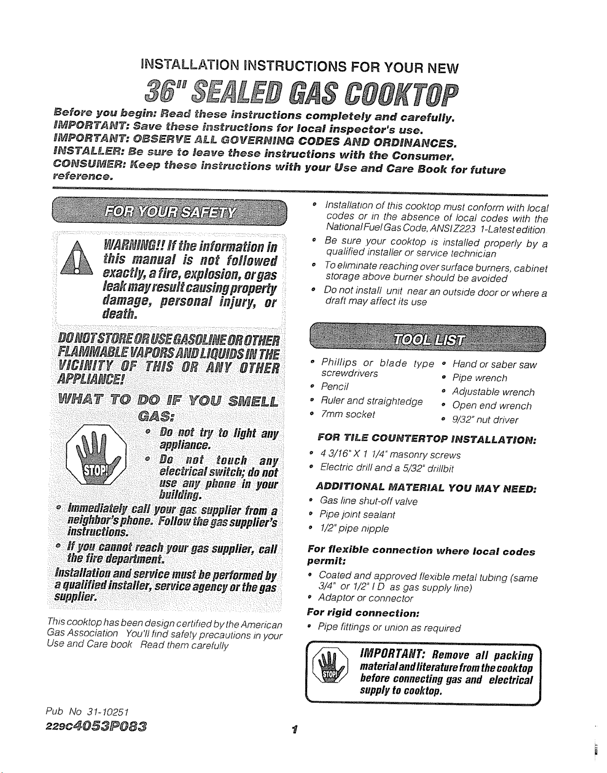
Before you begin: F_ead these instructions completely and carefully.
#MPORTANT: Save these _nstructions for local inspector's use.
NMPORTANT: OBSERVE ALL GOVERN!ING CODES AND ORDBNANCES.
gHSTALLEF_: Be sure *o Heave *hese instructions with *he Consumer.
CONSUMER: Keep these _nstructions with your Use and Care Book for future
reference,
WARtII; 8!!iftheinformationin
!
o Installation of this cooktop must conform with local
codes or in the absence of local codes with the
National Fuel Gas Code, ANSI Z223 1-Latest edition
,' Be sure .Four cooktop is installed properly by a
qualified installer or service technician
o To ehminate reaching over surface burners, cabinet
storage above burner should be avoided
o Do not install unit near an outside door or where a
draft may affect its use
This cooktop has been design certihed by the American
Gas Association You'll find safe(y precautions in your
Use and Care book Read them carefully
Pub No 31-I025!
229c4053P083 t
o Phillips or blade type o Hand or saber saw
screwdrivers o Pipe wrench
o Pencil o Adjustable wrench
o Ruler and straightedge o Open end wrench
o 7mm socket o 9/32" nut driver
O
t}
FOR TILE COUNTERTOP INSTALLATION:
4 3/!6"X 1 1/4" mason(y screws
Electric drill and a 5/32" drillbit
ADDRTIONAK MATERIAL YOU MAY NEED:
Gas fine shut-off valve
o Pipe joint sealant
o 1/2"pipenipple
For flexible connection where local codes
permit:
o Coated and approved flexible metal tubing (same
3/4" or I/2" t D as gas supply line)
Adaptor or connector
For rigid connection:
o Pipe fittings or union as required
iMPORTANT: Remove "ail packing _
material and literature from thecooMop |
before connecting gas and electrical|
supply to cooktop. |
Fig, 3
This appliance must be electrically grounded.
Check with your local codes which apply in your area
ff no local codes apply, the Nationa! Electrical Code,
ANSI/NFPA No FO-Latest Edition must be followed
Write to
NA T#O£_AL FHRE PROTECTION
ASSOCHA T#ON
BA TTERYMARCH PARK
QURNCY_ MA 02269
Be sure the instaltahon of this cooktop Ina mobile home
conforms with the Manufactured Home Construction
and Safety Standard, Title 24 CFR, Part 3280 If this
standard does not apply, you must follow the standard
for Manufactured Home Instatlations ANSI A225 1and
Manufactured Home Installahons, Site and Communities
and ANSI/NFPA 50 IA or with local codes You can get
a copy of the Federal Standard by writing
Office of Mobile Home Standards
HUD Building
45t 7*h Street_ S. W.
_lashir_gton_ D.C. 240_10
I
i 3 314"MIN,..-......_
30" MINo CLEARANCE
TO CABINET TO SIDE WALL
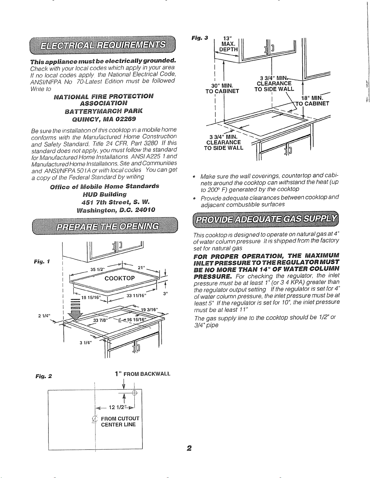
,, Make sure the wall coverings, countertop and cabi-
nets around the cooktop can withstand the heat (up
to 200 ° F) generated by the cooktop
o Provide adequate clearances between cooktop and
adjacent combushble surfaces
Fig,
2 114"
3 114"
t9 3116"
This cooktop is designed to operate on natural gas at 4"
of water column pressure It is shipped from the factory
set for natural gas
FOR PROPER OPERA TRON, THE MAXIMUM
BNLET PRESSURE TO THE REGULATOR MUST
BE NO MORE THAN t4" OF WATER COLUMN
PRESSURE, For checking the regulator, the inlet
pressure must be at least 1"(or 3 4 KPA) greater than
the regulator output setting If the regulator is set for 4"
of water column pressure, the infet pressure must be at
least 5" tf the regulator is set for 10" the inlet pressure
must be at least 11"
The gas supply line to the cooktop should be 1/2" or
3/4"pipe
Fig. 2
1" FROM BACKWALL
I
I /P_,
_ FROMCUTOUT
_ CENTER LINE
5
!
2
11.Connect the cooktop to the gas supply line
2. NEVER REUSEAN OLDCONNECTOR WHEN
nNSTALLBNG A NEW UNIT.
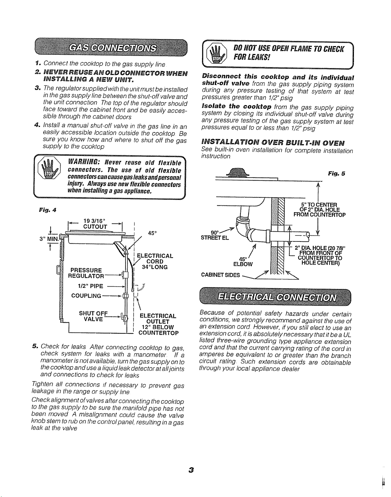
3. The regulator supplied with the unit must be installed
in the gas supply line between the shut-off valve and
the unit connection The top of the regulator should
face toward the cabinet front and be easily acces-
sible through the cab/net doors
4o fnstafl a manual shut-off valve in the gas fine in an
easily accessible location outside the cooktop Be
sure you know how and where to shut off the gas
supply to the cooktop
W4,N Na" ,..,, o,.
connectors. The use of old flexible
connectorscancausegasleaksandpersonal
injury. Alwaysusenew flexible connectors
Fig. 4
19 3/16"
CUTOUT --_
PRESSURE
45°
ELECTRICAL
CORD
34"LONG
1/2" PIPE
COUPLING ------_!
SHUT OFF
J
V
,\
ELECTRICAL
OUTLET
12" BELOW
COUNTERTOP
5. Check for leaks After connecting cooktop to gas,
check system for leaks with a manometer If a
manometer is not available, turn the gas supply on to
the cooktop and use a fiquid leak detector at alljoints
and connections to check for leaks
Tighten aft connections if necessary to prevent gas
leakage in the range or supply #ne
Check alignment of valves after connecting the cooktop
to the gas supply to be sure the manifold pipe has not
been moved A misalignment could cause the valve
knob stem to rub on the control panet, resulting in a gas
leak at the valve
NoT OpEN TO
....... .............. ...:.......::._.. J
Disconnect _his cooktop and its individual
shut.off valve from the gas supply piping system
during any pressure testing of that system at test
pressures greater than 1/2" psig
gsolate the cooktop from the gas supply piping
system by closing its individual shut-off valve during
any pressure testing of the gas suppty System at test
pressures equal to or less than I/2" psig
INSTAI.I.A TNON OVER BUH.T=IN OVEN
See built-in oven installation for complete installation
instruction
Fig. 5
5"TOCENTER
OF2" DIP.HOLE
FROMCOUNTERTOP
STREETEL
ELBOW
CABINETSIDES_
2" DIA.HOLE (207/8"
FROM FRONT OF
COU_Zl"ERTOPTO
HOLE CENTER)
Because of potential safety hazards under certain
conditions, we strongly recommend against the use of
an extension cord, However, if you still elect to use an
extension cord, it is absolutely necessary that it be a UL
listed three-wire grounding type appliance extension
cord and that the current carrying rating of the cord in
amperes be equivalent to or greater than the branch
circuit rating, Such extension cords are obtainable
through your local appliance dealer
3
i p Rso At rHiS,PP, MOST, i
PROP ,t,,OUNO O.
L ......................... J
An adequate electrical supply and outlet must be used
to operate the electrical parts of your cooktop
t. The power cord of this appliance is equipped with
a three-prong (grounding) plug which must be
used with a properly grounded three-hole outlet
with a standard t20 Volt, 60 cycle AC household
curren t
#
3o
tf you do not have a three-hole grounded outlet,
l_ave a qualified electrician change your old one
A grounding adaptor wil! be needed to convert the
old one until the outlet can be replaced Thismethod
Jsonly temporary, and a qualified electncian should
test it to be sure it meets requirements
insure proper
ground and
firm connection
before use
Fig. 6
Where a standard two-prong wall receptacle is encoun-
tered it is the personal responsibility and obligation of
the customer tohave itreplaced with a property grounded
three-prong wall receptacle
,o.0,-.
groundingprongfromcooktopcord. Failure j
to provideproperpolarizationmay create a
L. -- hazardouscondition. _)
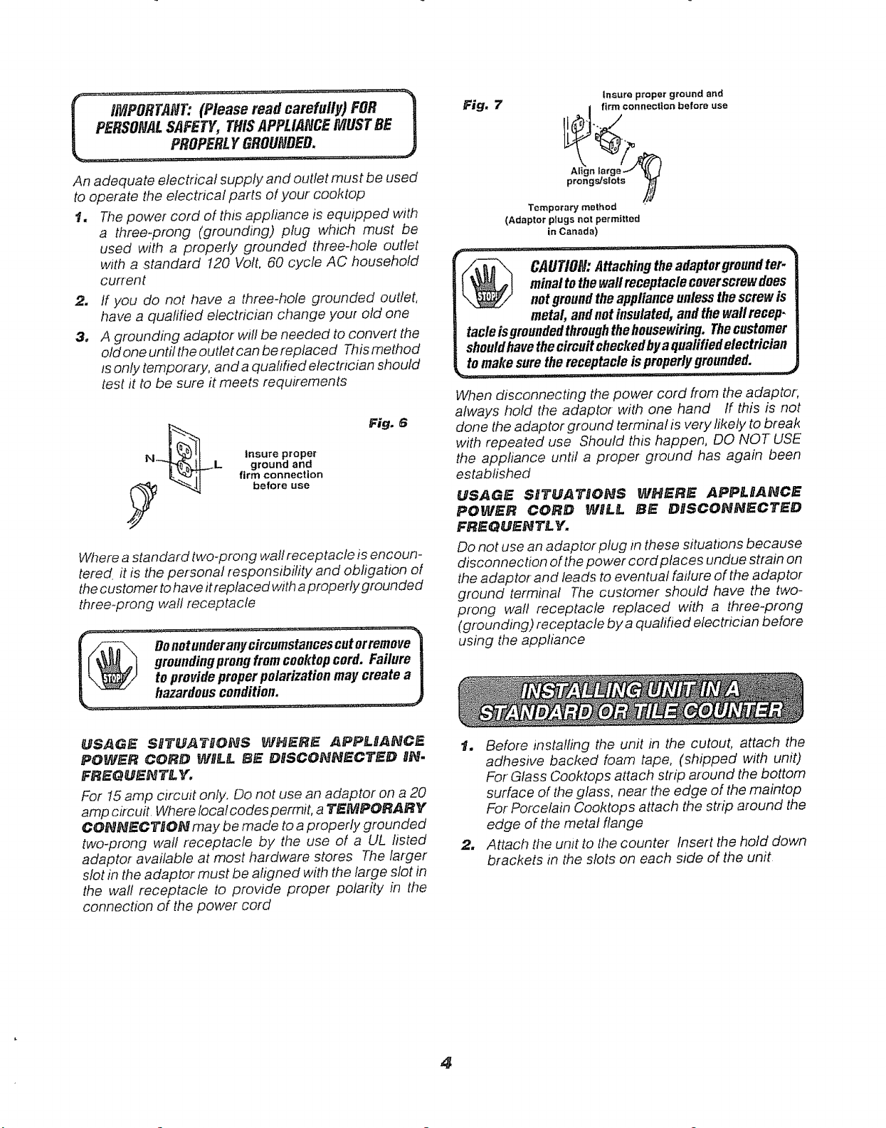
Fig. 7
Insure proper ground and
_[A_lt_n firm connection before use
large_
prongs/slots _
Temporary mBthod
(Adaptor plugs not permitted
in Canada)
CAUTION:Attachingtheadaptorgroundter-
minaltothewali receptaclecoverscrewdoes
not groundtheapplianceunlessthescrewis
metal,andnotinsulated,andthewallrecep-
tacleisgroundedthroughthehousewiring.Thecustomer
shouldhavethecircuitcheclcedbya qualifiedelectrician
tomake surethereceptacleisproperlygrounded.
When disconnecting the power cord from the adaptor,
always hold the adaptor with one hand ff this is not
done the adaptor ground terminal is very likely to break
with repeated use Should this happen, DO NOT USE
the appliance until a proper ground has again been
established
USAGE SITUATI'IIONS _AfHt_RIE APPL[L_NCE
POWER CORD WHL_. BE DIISCONNECTED
FR[_QUENT'L. Y.
Do not use an adaptor plug In these situations because
disconnection of the power cord ptaces undue strain on
the adaptor-and leads to eventual failure of the adaptor
ground terminal The customer should have the two-
prong wall receptacle replaced with a three-prong
(grounding) receptacle by a qualihed electrician before
using the appliance
USAOE SITUAT[ION$ WH[_RE ._PPg.IJANC_
POWER CORD WP_.fLBE DISCONNECTED IN.
FREG_J_N_& Y',
For 15amp circuit only. Do not use an adaptor on a 20
amp circuit. Where local codes permit, a _'_PORARY
CONNeCTiON may be made to a properly grounded
two-prong wall receptacle by the use of a UL listed
adaptor available at most hardware stores The larger"
slot in the adaptor must be aligned with the large slot in
the wall receptacle to provide proper polarity in the
connection of the power cord
_. Before installing the unit in the cutout, attach the
adhesive backed foam tape, (shipped with unit)
For Glass Cooktops attach strip around the bottom
surface of the glass, near the edge of the maintop
For Porcelain Cooktops attach the strip around the
edge of the metal flange
2, Attach the unit to the counter Insert the hold down
brackets in the slots on each side of the unit
4
Use the screws supplied to attach unit to counter as
shown The unit must rest on the metal flange around the
burner box and not on the glass
Fig. 8
Theelectrode ofthesparkigniter isexposed-"
and themixertubemayhavesharpedges.Be
careful not to push any cooktop controls
whilethetopof theburnerisremoved.Donot
remove the top or touch the electrode of any burner
while another burner is turned on. Electrical shock
might result,
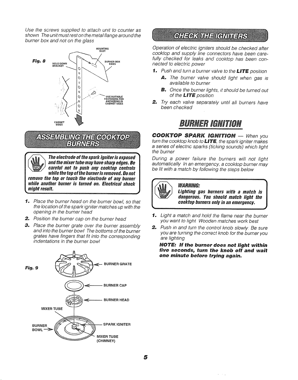
1. Place the burner head on the burner bowl, so that
the location of the spark igniter matches up with the
opening in the burner head
.2. Position the burner cap on the burner head
3. Place the burner grate over the burner assembly
and into the burner bowl Thebottoms of the burner
grates have fingers that fit into the corresponding
indentations in tt_eburner bowl
Fig. 9
•,_-.-.BURNER GRATE
Operation of electric igniters should be checked after
cooktop and supply fine connectors have been care-
fully checked for leaks and cooktop t_as been corn
nected to electric power
t. Push and turn a burner valve to the LITE position
A. The burner valve should light when gas is
available to burner
m
B, Once the burner lights, it should be turned out
of the JLITE position
Try each valve separately until all burners have
been checked
BURNERIG/VifiOt@
COOKTOP SPARK IGNITBON _ When you
turn the cooktop knob to n-ITE, the spark igniter makes
a series of electric sparks (ticking sounds) which light
the burner
During a power failure the burners will not light
automatically In an emergency a cooktop burner may
be fit with a match by following the steps below
J_ _trlJ Lighting gas burners with a match is
J \_[/ dangerous. You should match light the
cooktopburnersonlyin an emergency
L ..........................
2.
Light a match and hold the flame near the burner
you want to light Wooden matches work best
Push in and turn the control knob slowly Be sure
you are turning the correct knob for the burner you
are lighting
NOTE: nf the burner does net light within
five secendsj turn the knob off and wait
one minute before trying again.
MIXER TUBE
BURNER HEAD
(CHIMNEY)
5
ABOUT7HEBUR ERF AMES
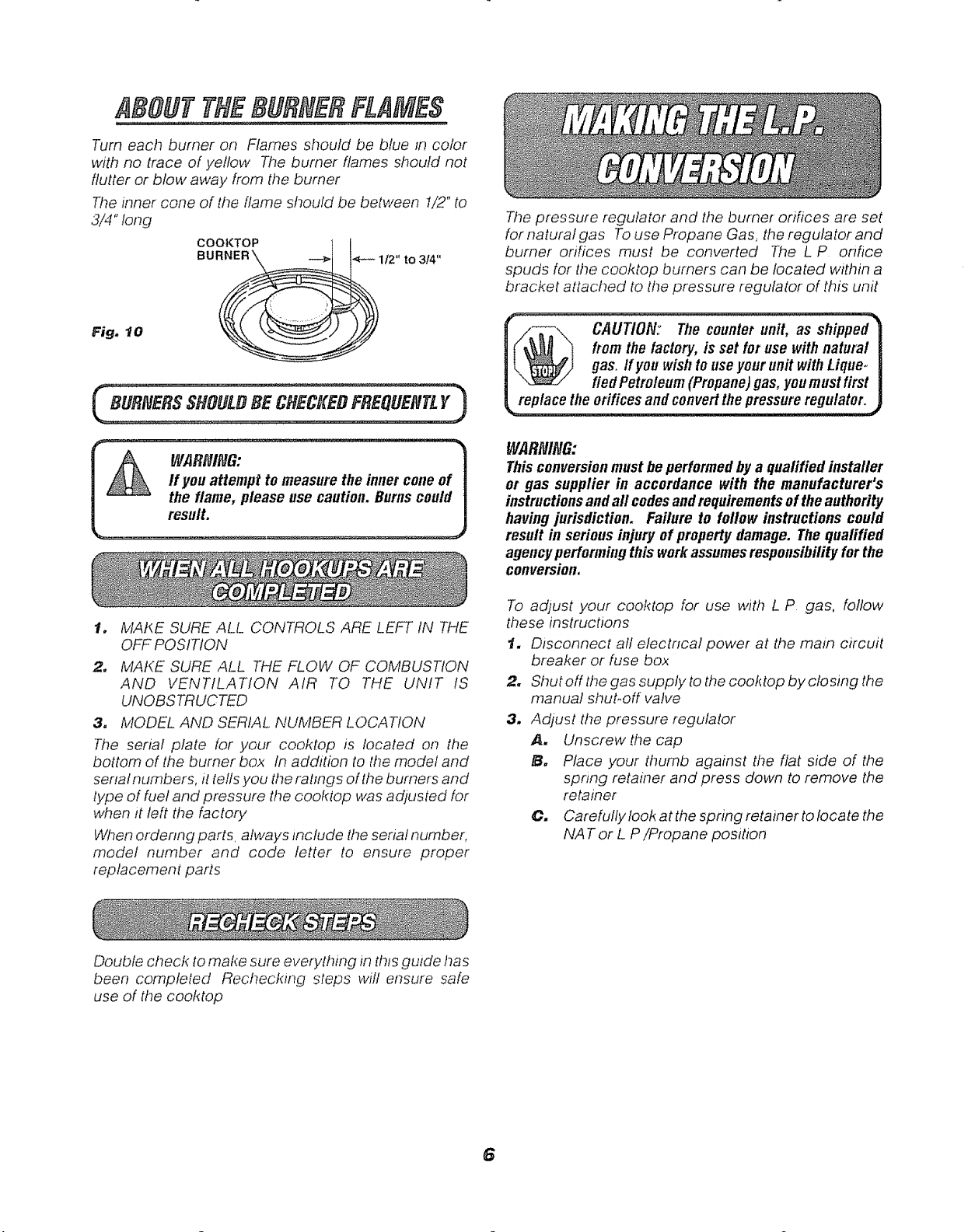
Turn each burner on Flames should be blue in color
with no trace of ye!low The burner flames should not
flutter or blow away from the burner
The inner cone of the flame should be between 1/2" to
3/4" long
Fig. 1/0
COOKTOP t
BURNER \ _ _ 1f2" to 3t4"
! _ If you attempt tomeasure the inner coneof !
J_ the flame, please use caution. Burnscould J
L result.
1, MAfIE SURE ALL CONTROLS ARE LEFT IN THE
OFF POSITION
2. MAKE SURE ALL THE FLOW OF COMBUSTION
AND VENTILATION AIR TO THE UNIT IS
UNOBSTRUCTED
3. MODEL AND SERIAL NUMBER LOCATION
The serial plate for your cooktop is located on the
bottom of the burner box In addition to the model and
senal numbers, it tefls you the ratings of the burners and
type of fuel and pressure the cooktop was adjusted for
when it left the factory
When ofdenng parts always include the serial number,
model number and code letter to ensure proper
replacement parts
The pressure regulator and the burner orifices are set
for natural gas Touse Propane Gas, the regulator and
burner orifices must be converted The L P onfice
spuds for the cooktop burners can be located within a
bracket attached to tt_epressure regulator of this unit
, ,ll , , i
_ /-Z3.\ CAUTION: The counter unit, as shipped_
! (_ _'_ from the factory,is set for use withnatural
J_ gas, If you wish to useyour unit withLique.
J fledPetroleum(Propane)gas,youmustfirst
replace theorificesand convertthepressureregulator.
WARNING'.
Thisconversionmustbeperformedbya qualified installer
or gas supplier in accordance with the manufacturer's
instructionsandall codesandrequirementsof theauthority
having jurisdiction. Failure to follow instructions could
result in serious injury ofproperty damage. The qualified
agency performingthis workassumesresponsibilityfor the
conversion.
To ad]ust your cooktop for use with L P gas, follow
these instructions
1. Disconnect all electrical power at the main circuit
breaker or fuse box
2. Shut off the gas supply to the cooktop by closing the
manual shuboff valve
3. Adjust the pressure regulator
A. Unscrew the cap
B. Place your thumb against the flat side of the
spnng retainer and press down to remove the
retainer
C. Carefully look at the spring retainer to locate the
NAT or L P/Propane position
Double check to make sure everything in this guide has
been completed Rechecking steps will ensure safe
use of the cooktop
6
D. Turn the spring retainer over so
L P/Propane is showing on the bottom
E. Snap the retainer back into position
Fig. 11
CAP GASKET
/
PRESSURE REGULATOR
that
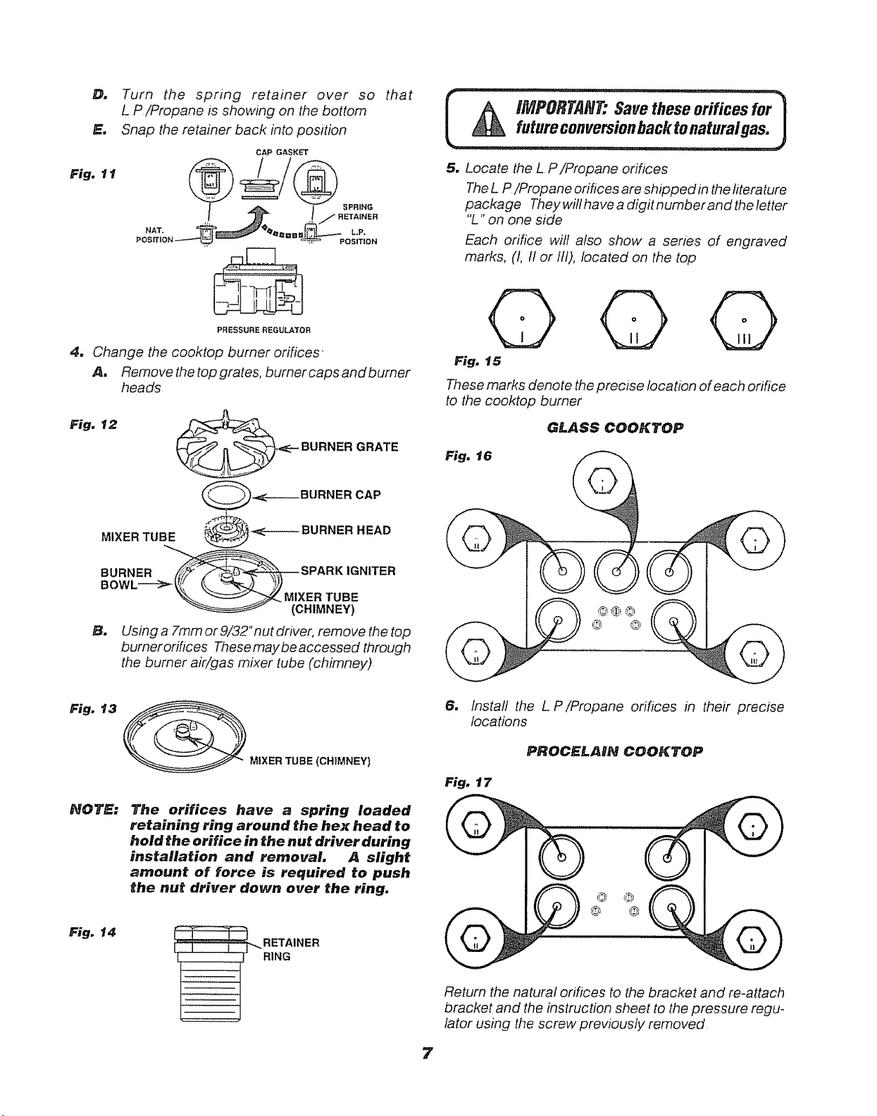
4. Change the cooktop burner orifices
A. Remove the top grates, burner caps and burner
heads
Fig. 12
GRATE
CAP
MIXER TUBE
HEAD
BURNER IGNITER
BOWL_
TUBE
(CHIMNEY)
B. Using a 7mm or 9/32" nut driver, remove the top
burner orifices These may be accessed through
the burner air/gas mixer tube (chimney)
Fig. t3
_ MtXER TUBE (CHIMNEY)
NOTE:
The orifices have a spring loaded
retaining ring around the hex head to
hold fhe orifice in the nut driver during
installation and removal A slight
amount of force is required to push
the nut driver down over the ring.
Fig, 14
RETAINER
RING
( _ IMPOflTAfl_" $a' tflese#rifices for1
futureconversionbacktonaturalgas. J
5, Locate the L P/Propane orifices
TheL P/Propane orifices are shipped in the literature
package They will have a digit number and the letter
"L" on one side
Each orifice will also show a series of engraved
marks, (I, fl or Iff), located on the top
000
Fig. 15
These marks denote the precise location of each orifice
to the cooktop burner
GLASS COOKTOP
Fig. I/6
@@©
@ @
6. tnstafl the L P/Propane orifices in their precise
locations
PROCELAHN COOKTOP
Fig, 17
7
© @
@ @
Return the natural orifices to the bracket and re-attach
bracket and the instruction sheet to the pressure regu-
lator using the screw previously removed
.,Tlo :
[ 1_] be madebefore turningon the burner. Fail. |
J \_ uretodoso couldresultin serious injury. Be|
J surepressureregulatorhas beenconverted|
L_asdescribedin step21 oJ
Oncetheconversioniscompleteandchecked
ok, fill out the LPsticker and include your
name, organizationand date conversion was
made, Apply the sticker near the cooktop
gas inlet opening to alert others in the future that
thisappliancehasbeen converted toLP.ff converting
backtonaturalgasfromLP,please removethesticker
soothersknowtheapplianceisset tousenaturalgas.
t. Turn all bumers full on and check the flames
f
Am
Fig, 18
They should be blue in color with no trace of
yellow Foreign particles in the gas line may
cause an orange flame at first, but this will soon
disappear
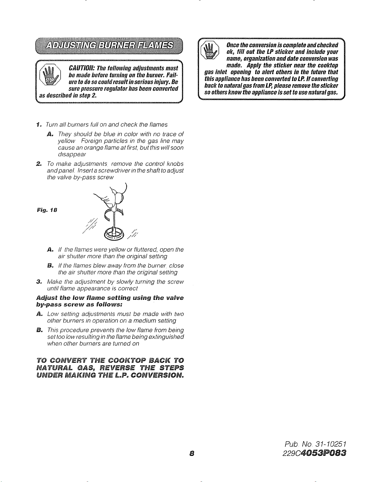
To make adjustments, remove the control knobs
and pane!. Insert a screwdriver in the shaft toadjust
the valve by*pass screw
A. 1/ the flames were yellow or fluttered, open the
air shutter more than the original setting
B. tf the flames blew away from the burner close
the air shutter more than the original setting
3, Make the adjustment by slowly turning the screw
until flame appearance is correct
Adjust the low flame setting using the valve
by-pass screw as follows:
A. Low setting adjustments must be made with two
other burners in operation on a medium setting
B. This procedure prevents the low flame from being
set too low resulting in the flame being e;_tinguished
when other burners are turned on
TO CONVERt" THE C00KTOP BACK TO
NATUF_AL, GAS_ REVERSE THE STEPS
UNDER MAKgNG THE LP. CONVERSHON,
8
Pub, No. 3I-I0251
229C4053P083
RNSTRUCCDONES PARA LA INSTALACION DE SU NUEVA
An_es de empezaro Lea es_as ins_rucciones comple_a y cuidadosamen_e,
#MPORTAMTE .Guarde es'*asins*ruccionespara eluso deP inspectorHocaL
EMPGRTAMTE o CUMPLA CON TODOS LOS COD#GOS V ORDE#4ANZAS V#GEMTES.
Ho#_ agins*a_ador.Asegurese de dejar es*as Ms*rucciones con eHconsu_idor.
Norm a# consumBdor °Gu_yde estas instruccionescon su ManuaN de Use V Cuidsdo
para _'eferencia_u_ura.
A ADVEP,TE_tCIA_._. Si ia
#Bformaci##en este manual
n# se sigue exactamente,
po_Maresu#arenunincendi#
o una ezplosi#a que cause dafio a
iaprepiedad, #efidaspersenales #
muefte.
_, La instatacid_n de esta cubierta debe cumptir con tos
codigos locates o en la ausencia de codigo tocaies con
et National Fuel Gas Code, ANSI Z223 l-Latest edition
,, AsegOrese que su estufa sea mstalada adecuadamente
por un instalador competente opor un tecnico de servic_o
o Para ehminar tener que tomar algo pot sobre los
quemadores de ta superhcie, no guarde cosas en tos
gabinetes que estan sobre ettos
_, Do not mstafl unit near oan outside door or where a draft
may affect its use
@.UE:HACER ,_H H_EELE: @AS¢
_i:_ tmte de ence_de_,_iny#n
aparate e_#ctrico.
_nmediatam_#teHameasu ahastecedor de
s d_sde e_tel_ao de un veciuo,:::Siga las
tmCdo.eS _es. atmstecedorde
d_as, iiame_ la _ompafiia debomberos,
_a iasta_a#i_ay e_serWcieldebe hacersepor
a#astecedorde _aso
El disez_o de esta cubierta para cocinar ha sido
certificado por la Asoctacion de Gas Americana Usted
encontrara precauc_ones de seguridad en su hbro de
Uso y Cuidado L#alas cu_dadosamente
Pub No 31-10251
22_c4_53P_83
o
o
Destomfltadores Phittips o de
cabeza plana
Lap_z
Regta
Soquete de 7mm
Sierra manuat o etectrica
o Llave inglesa para
caherias
• Llave tnglesa ajustabte
o Llave inglesa abierta
,, Atomfllador de tuercas
de 9/32
PARA INSTALACION EP# UN MESON DE
B_LDOSA:
,, 4 torni!los para cemento de 3/16" _ 1 1/4"
o Taladro el#ctnco y barreno de 5/32"
MZ&TER_ALES _D_C_ONALES GUE PODR_A
NECESITAR:
o Vbivula de c_erre para la Ifnea del gas
o Se!lo para/as uniones de caF_erfas
o Tubo de 1/2"
Para conexiones flex_b_es deride _as
permi_an los cddigos iocales;
,' Tuberfa de metal flexible (3/4"o 1/2" _gua/ que I D
como la linea del gas)
o Adaptador o unidn
Para conexi_n rigida:
° Encajes para tuberias que se requieran
I
I_PORTAHT: Remove all pac/dng_
materialandfiteraturefromthecooktop
before connecting gas and electrical _
supply to cooMop. J
Este aparato debe hacer tierra.
Consutte los cddigos locales que se aptican en su Area
FiG. 3
13"PROFUNDIDADMAX,
Si no existen cddigos locales, debe cumplir con el
National Electrical Code, ANSf/NFPA No 70-Latest
Edition Escriba a
NATIONAL FIRE PROTECTION
ASSOCIATION
BA TTERYMARCN PARK
QUINCY, MA 02269
Asegdrese que la instatacidn de esta cubierta para
cocinar en una casa mdvil curnpta con el Manufactured
Home Construction and Safety Standard, Title 24 CFR,
Part 3280 Siesta norma no es aplicable, usted debe
cumpfir con las normas para Manufactured Home
Installations I982 (Manufactured Home Site,
Communities and Set-ups, ANSI A225 1-Latest Edition)
o cddigos locales Escriba a
Office of Mobile Home Standards
NUD Building
451 7th Street, S.W.
Washington, D.C. 24010
i
30"MINAL
GAP_INETE
!
I
I
I
3 3t4"MIN.DE
ESPACIOA PAREDDELLADO
3314"t_lN.DE
ESPACIOA PARED
J
18"MIN,
ALGABINETE
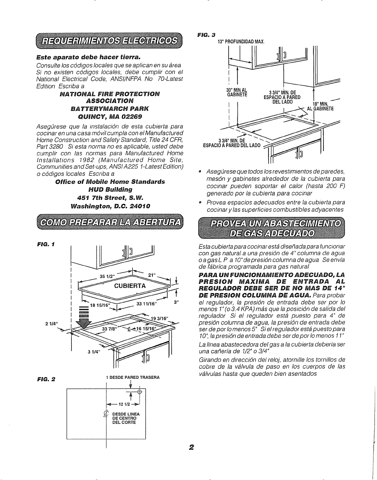
o Asegdrese que todos losreveshmientos deparedes,
mesdn y gabinetes alrededor de la cubierta para
cocinar pueden soportar el calof (hasta 200 F)
generado pot la cubierta pata cocinar
° Provea espacios adecuados entre la cubierta para
cocinar y las superficies combustibles adyacentes
FIG. t
2 114"
FIG. 2
3116"
3 114"
1DESDE PARED TRASERA
_.._121/2_t
I ESDELtNEA
DECENTRO
DELCORTE
Esta cubierta para cocinar est# dise#ada para funcionar
con gas natural a una pfesidn de 4" columna de agua
o a gas L P a lO"de presidn cotumna de agua Se envfa
de f_brica progfamada para gas natural
PARA UN FUNCIONAMtENTO ADECUADO, LA
PRESTON MAXIMA DE ENTRAIDA AL
REGULADOR DEBE SER DE NO MAS DE 14"
DE PRESTON CO&UMNA DE AGUA. Para probar
el regulador; ta presidn de entrada debe set por 1o
menos t "(o 3.4 KPA) m_s que la posicidn de safida del
regulador Si et regutador esta puesto para 4" de
presidn columna de agua, ta presidn de entrada debe
ser de pot Iomenos 5" Si etregulador estb puesto para
t0", lapfesidn de entrada debe ser de por lo menos 11"
La finea abastecedofa def gas a fa cubierta deberia ser
una cat_eria de I/2" o 3/4"
Girando en direccidn def reloj, atornilte los torniflos de
cobre de la v#Ivula de paso en los cuerpos de las
vblvufas hasta que queden bien asentados
2
2,
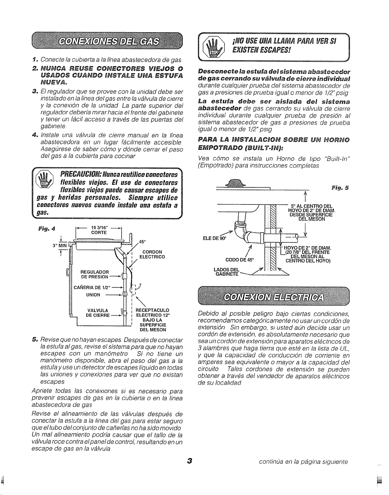
Conecte la cubierta a la Ifnea abastecedora de gas
NUNCA REUSE CONECTORES VIEJOS 0
USADOS CUANDO INSTALE UNA EESTUFA
NUEVA.
3. Elregulador que se provee con la unidad debe ser
instalado en la Ifnea del gas entre la vblvula de cierre
y la conezidn de la unidad La parte superior del
regulador deberfa m_rarhacia el frente del gabinete
y tener un facil acceso a trav#s de las puertas del
gabinete
4, tnstale una v_lvula de cierre manual en la Ifnea
abastecedora en un lugar fbcilmente accesible
Asegdrese de saber cdmo y ddnde cerrar el paso
del gas a ia cubierta para cocinar
PRECAUCION:flunca reutiliceconectores
flexibles viejos. El uso de conectores
flexibles viejos puede causar escapes de
gas y heridas personales. Siempre utilice
conectores nuevos cuando instale una estufa a
_gas,
Fig, 4
L_
3"M_Nt
T-
19 3116"
CORTE
VALVULA
q
45 _
CORDON
ELECTR|CO
.I
\
RECEPTACULO
ELECTRICO12"
BAJO LA
SUPERFICIE
DEL MESON
5, Revise que no hayan escapes Despu#s de conectar
la estufa al gas, revise el sistema para que no hayan
escapes con un mandmetro Si no tiene un
mandmetro disponible, abra e! paso del gas a ta
estufa y use un detector de escapes lfquido en todas
las uniones y conexiones para vet que no existan
escapes
Apriete todas las conexlones si es necesano para
prevenir escapes de gas en la cubierta o en la lfnea
abastecedora de gas
Revise el afineamiento de las v_lvulas despu#s de
conectar la estufa a ia hhea del gas para estar seguro
que et tubo del conjunto de ca_erfas no ha sido mowdo
Un ma! alineamiento podrfa causar que el tal!o de la
vblvula roce contra el panel de control, resultando en un
escape de gas en la v#lvula
,.NoUSE.AMApA'RAVERSl1
EXISTEN ESCAPESv
Desconecte la es_tufa del sistema abastecedor
de gas cerrando su v_ivula de cierre individual
durante cualquier prueba del sistema abastecedor de
gas a presiones de prueba igual o menor de 1/2"psig
La estufa debe set aislada dei s_stema
abastecedor de gas cerrando su v_lvula de cierre
individual durante cualquier prueba de presidn al
sistema abastecedor de gas a presiones de prueba
iguat o menor de 1/2" pslg
PARA LA INSTALACBON SOBRE UN HOR_O
EMPOTRADO (BU#L T.gN):
Yea cOmo se instala un Homo de tipo "Built-In"
(Empotrado) para instrucciones completas
.............. Fig. 5
I
t
Debido at posible pefigro bajo ciertas condiciones,
recomendamos categdricamente no usar un cor ddn de
extensidn Sin embargo, s_usted a#n decide usar un
corddn de eztensidn, es absolutamente necesario que
sea un corddn de extens_dn para aparatos el#ctncos de
3 alambres que haga tierra que est# en la lista de UL,
y que la capacidad de conduccidn de corriente en
amperes sea equivalente o mayor a la capacidad del
circuito Tales cordones de eztensiOn se pueden
obtener a trav#s de! vendedor de aparatos el_ctricos
de su localidad
3
continua en la pbgina siguiente
i -
' MPORTANTE: (Per favor lea cuidadosamente)
PARA SE SEGURIDADPERSOHAL,ESTEAPARATO |
DEBE TilERRAADECUADAMENTE. _)
2.
3.
El corddn el#ctrico de este aparato esta equipado
con un enchufe de tres patas (para hacer tierra) el
cuat se debe usar con un recept_cuto de tfes
hoyos que haga tierra adecuadamente con
corriente altema normal de casa de 120 voltios, 60
ciclos
Si no tiene un recept_culo de tres hoyos que haga
tierra, haga que un efectricista cafificado efantiguo
Se necesitar_ un adaptador que haga tierra para
convert# el antiguo hasta que etrecept_culo pueda
set reemplazado Este m#todo es sdlo provisorio,
y un electncista profesionat deberia probarfo para
estar seguro que cumpte con los requerimientos
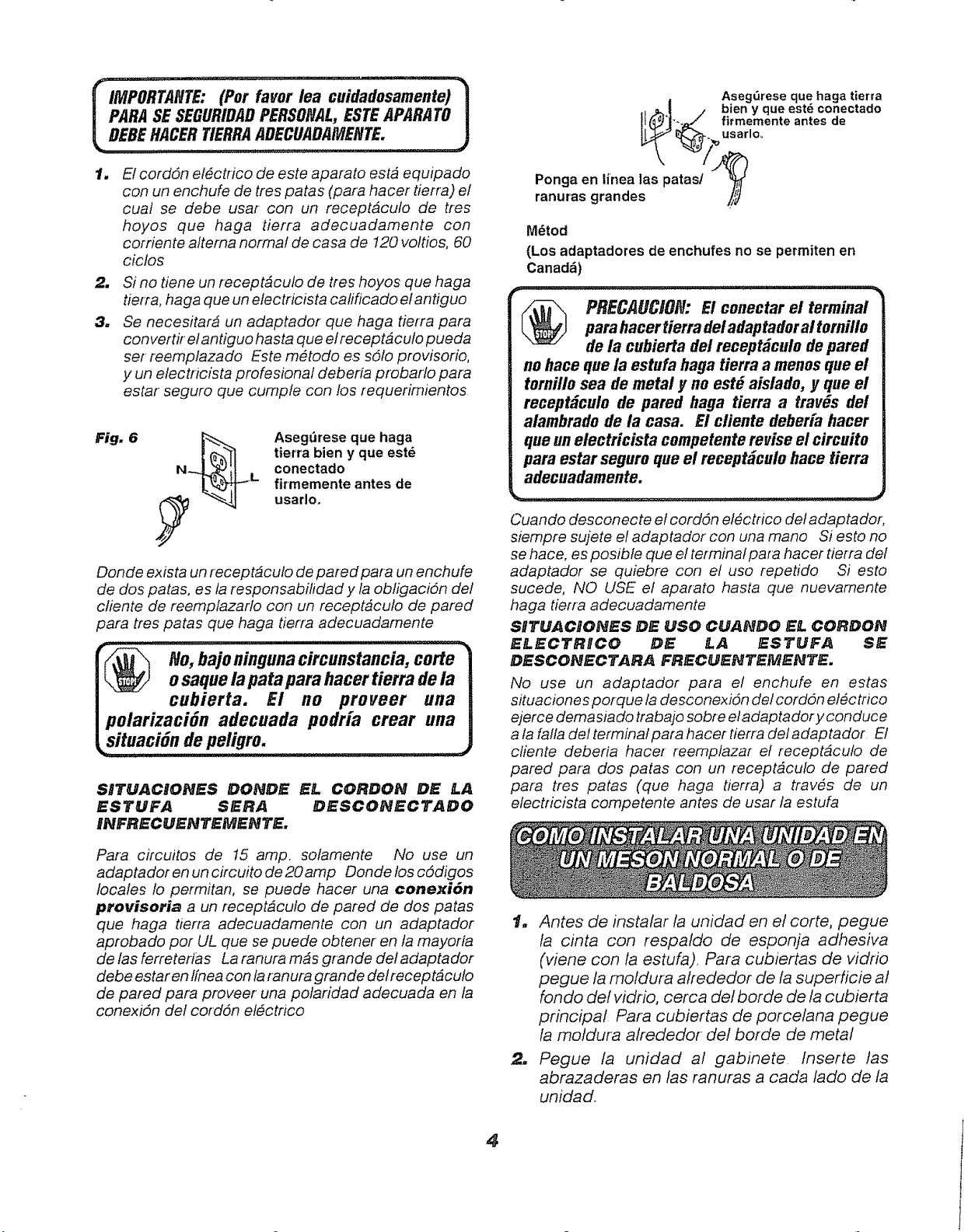
Fig. 6 Aseg_rese que haga
tierra bien y que estd
conectado
firmemente antes de
usarlo.
Donde exista un receptaculo de pared pafa un enchufe
de dos patas, es fa responsabilidad y ta obfigacidn del
cfiente de reemplazarlo con un recept_culo de pared
oara tres paras que haga tierra adecuadamente
No,bajoningunacircunstancia,corte
osaquelapataparahacertierradela I
cubierta. E! no proveer una J
polarizaciSn adecuada podrfa crear una J
situaci#n depeligro.
SITUACIONES DONDE EL CORDON DE LA
ESTUFA SERA DESCONECTADO
|NFRECUENTEMENTE.
Pata circuitos de 15 amp, solamente No use un
adaptador en un circuito de 2Oamp Donde tos cddigos
locales Io permitan, se puede hacer una ¢onexi_n
provisoria a un tecept_culo de pared de dos patas
que haga tierza adecuadamente con un adaptador
aprobado por UL que se puede obtener en ta mayoria
de fas ferretenas La ranura m#s gtande del adaptador
debe estar en lfnea con taranufa grande del recept_culo
de pared para proveer una pofaridad adecuada en la
conexidn del cor ddn et6ctrico
, Aseg_rese que haga tierra
Jk _ / bien yque estd conectado
I! _r_],. _/- fitmemente antes de
[LL_ I_. usarlo_
Ponga en linea las patas/
ranuras grandes _/
Mdtod
(Los adaptadores de enchufes no se permiten en
Canada)
PRECAUCIOH: E1conectar el terminal
para hacertierra del adaptador al tomillo
de la cubierta del recept_culo de pared
no hace que la estufa haga tierra a menos que el
tormTIosea de metal y no est6 aislado, y que el
recept_culo de pared haga tierra a trav6s del
alambrado de la casa. E1cliente deberfa hacer
que un electricista cempetente revise el circuito
para estar seguro que el recept_culo hace tierra
adecuadamente,
Cuando desconecte et corddn et#ctrico def adaptador;
siempre sujete el adaptador con una mano Si esto no
se hace, es posibfe que el terminat para hacer tierra del
adaptador se quiebre con el uso repetido Si esto
sucede, NO USE el aparato hasta que nuevamente
haga tierra adecuadamente
SHTUACIONES DE USO CUANDO EL CORDON
ELECT'RICO /_)E £A ESTUFA SE
DESCONECTARA FRECUENTEMENTE.
No use un adaptador para el enchufe en estas
situacione sporque la de sconexidn del corddn et#ctrico
ejerce demasiado trabajo sobre eladaptador yconduce
a ta falta del terminalpara hacer tierra deladaptador El
cliente deberia hacet reemptazar el recept_culo de
pared para dos patas con un recept_culo de pared
para tres paras (que haga tierra) a tray, s de un
electficista competente antes de usar la estufa
ta
Antes de instafar ta unidad en et corte, pegue
la cinta con respafdo de esponja adhesiva
(viene con fa estufa), Para cubiertas de vidrio
pegue la motdura alrededor de la superficie al
rondo def vidrio, cerca def borde de la cubierta
principal Para cubiertas de porcelana pegue
la motdura afrededor del borde de metal
Pegue fa unidad al gabinete fnserte tas
abrazaderas en tas ranuras a cada lado de ta
unidad.
4
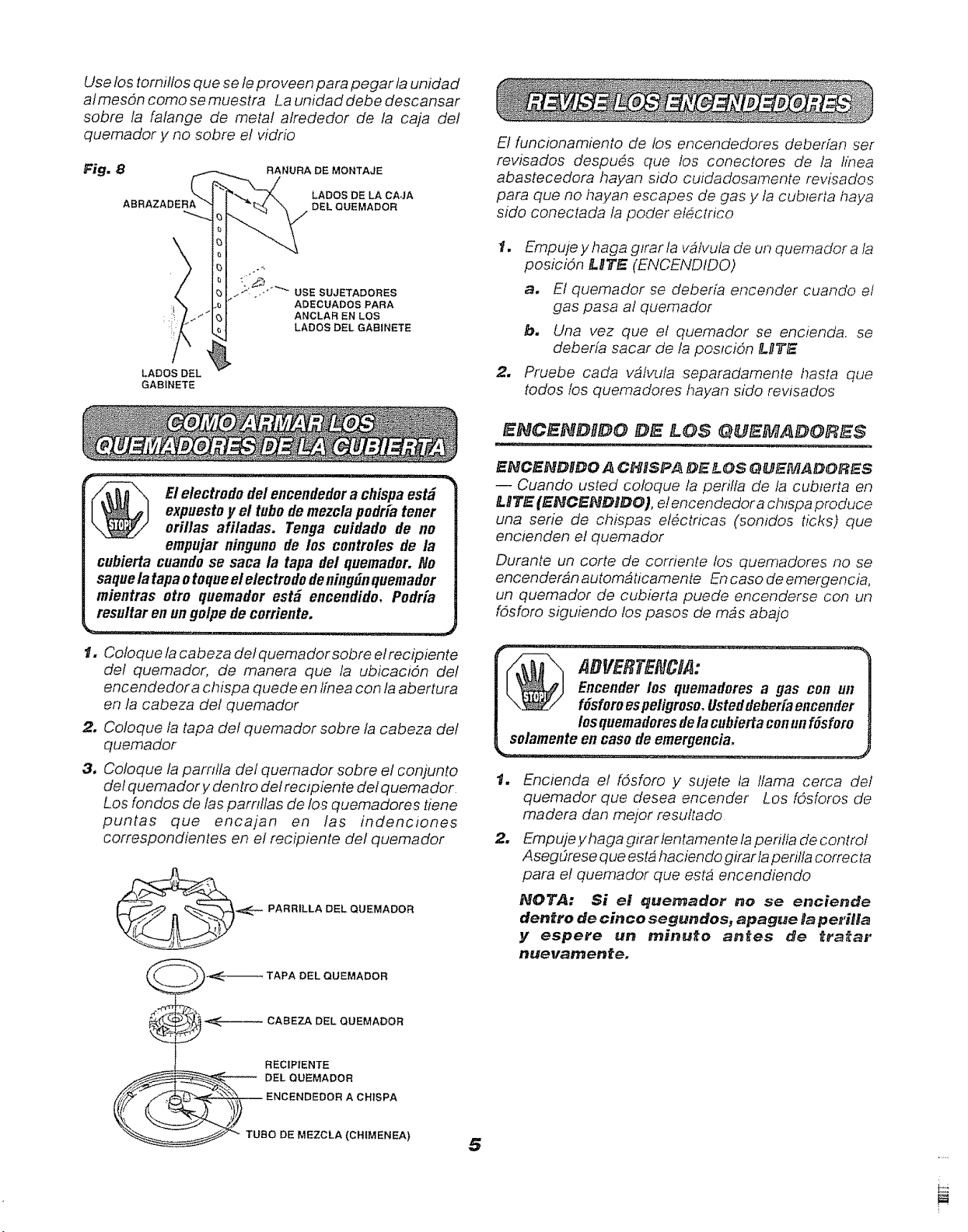
Use los tornillos que se le proveen para pegar la unidad
almesdn coma se muestra La unidad debe descansar
sabre la falange de metal alrededor de la caja del
quemador y no sabre e! vidrio
LADES DEL
GABINETE
RANURA DE MONTAJE
LADES DE LA CAJA
DEL QUEMADOR
_'["_'"'_"USE SUJETADORES
ADECUADOSPARA
ANCLAR EN LOS
LADES DEL GABINETE
El funcionamiento de los encendedores deberian ser
revisados despu#s que los conectores de la iinea
abastecedora hayan side cuidadosamente revisados
para que no t_ayan escapes de gas y ia cublerta haya
side conectada la poder electrico
t. Empuje y haga gJrar la va/vula de un quemador ala
posicidn LaTE (ENCENDIOO)
a. El quemador se deberfa encender cuando el
gas pasa al quemador
b. Una vez que el quemador se encienda, se
deberfa sacar de ia postciOn LH'FE
2. Pruebe cada v#tvuta separadamente haste que
redes los quemadores hayan side rewsados
_ l electrode de/encendedor a chispaest_ _
expuesta y el tuba demezclapodrfa tuner
orillas afiladas. Tenga cuidado de no
empujar ninguno de los controles de la
cubierta cuando se saca la tape de/quemador. No
saquelatapeotoqueelelectrododening_nquemador
mientras otto quemador est_ enceodido, Podrfa
resultar enungolpe de corriente.
t. Cotoque la cabeza del quemador sobre el recipiente
dei quemador, de manera que ta ubicacidn del
encendedor a chispa quede en lfnea con la abertura
en ta cabeza det quemador
2. Coloque la tapa del quemador sabre la cabeza del
quemador
3. Coloque la parntla del quemador sabre el conjunto
dei quemador vdentro dei recipiente del quemador
Los fondus de las parnllas de los quemadores tiene
puntas que encajan en las indenciones
correspondientes en el recipiente del quemador
PARRILLA DEL QUEMADOR
_TAPA DEL QUEMADOR
_CABEZADELQUEMADOR
RECIPIENTE
_ DEL QUEMADOR
ENCEEP#DHDO DE LGS GUEMADO_ES
ENCEND#DO A CHnSP,_ DE LaS G UEMADORES
-- Cuando usted coloque la penlla de la cubterta en
LtlTE (ENCENDBDO), etencendedor achispa produce
una serie de chispas el_ctricas (somdos ticks) que
encienden el quemador
Durante un carte de corriente los quemadores no se
encenderbn automaticamente En caso de emergencia,
un quemador de cubierta puede encenderse con un
fdsforo siguiendo los pesos de mbs abajo
ABVERTENCIA: }
_J Encender los quemadoresa gas con un
\ _/ fSsforoespeligroso,Usteddeber[aencender
losquemadoresdelacubiertaconunfSsforo
solamente en case deemergencia.
lw
2_
Encienda el fdsforo y sujete la llama cerca del
quemador que desea encender Los fdsforos de
madera dan meier resultado
Empuje y haga girar lentamente la perilta de control
Asegdrese que esta hacienda girar la perilla correcta
para el quemador que esta encendiendo
NOTA: Si el quemador no se enciende
dentro de cinco segundos, apague la periHa
y espere un rninuto an_es de tra_ar
nuevamente,
5
!
ACE_CA DE LAS LLAMAS DE_LOS
QUEMADORES
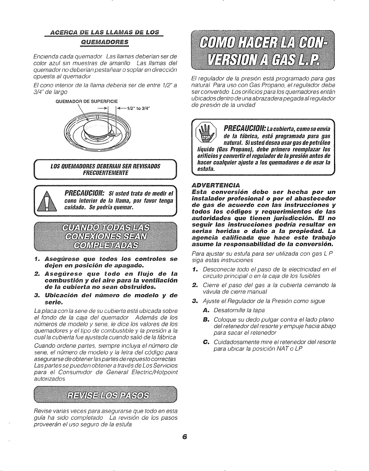
Encienda cada quemador Las llamas deberian ser de
color azul sin muestras de amarillo Las llamas def
quemador no deberian pestaf}ear o soplar en direccidn
opuesta al quemador
El cono interior de la llama deberia ser de entre I/2" a
3/4" de largo
QUEMADOR DE SUPERFIClE
<_1t2" to 314"
LOSQUEIV/ADORESDEBERIANSERREVISADOS
TEMEHTE
1. Aseg(arese que todos los con,roles se
dejen en posici6n de apagado.
2. Aseg_rese que *odo en flujo de la
cornbus*i6n y dei aire para #a ventilaci6n
de la cubierta no sean obs*ruidos.
3. Ubicaci6n de! n_mero de rnodelo y de
serie.
La plata con la sene de su cubierta esta ubicada sobfe
el rondo de la ca]a del quemador Adem_s de los
ndmeros de modelo y sene, te dice los valores de los
quemadores y el tipo de combustlble y la presidn a ia
cual la cubierta rue a/ustada cuando safid de la fbbrica
Cuando ordene partes, s/empre incluya el ndmero de
serle, et ndmero de modeio y la letra del cddigo para
asegurarse de obtener fas partes de repuesto correctas
Las partes se pueden obtener a trav#s de Los Servicios
para el Consumldor de General Electric/Hotpoint
autorizados
Revise varias veces para asegurarse que todo en esta
El regulador de la presidn esta programado para gas
natural Para uso con Gas Propano, e! regulador debe
ser convertido Los oriflcios para los quemadores entbn
ubicados dentro de una abrazadera pegada al regulador
de pres/dn de la unidad
PRECAUCION: Lacubierta,comoseenvia
de la f#brica, est_ programada para gas
natural. Siusteddeseausargasdepetr61eo
Ifquido (Gas Propano), debe primero reemplazar los
orificiosy convertirel reguladordela presiSnantesde
hacer cualquier ajuste a los quemadoreso densar la
estufa.
ADVERTENCIA
Esta conversi6n debe ser hecha por un
instalador profesional o por el abas*ecedor
de gas de acuerdo con las instrucciones y
*odos los cSdigos Y requerimientos de las
au*oridades que *ienen jurisdicci6n. El no
seguir las instrucciones podria resul*ar en
serias heridas o da_o a la propiedad. La
agencia calificada que hace este trabajo
asume ia responsabilidad de la conversion.
Para a]ustar su estufa para set utilizada con gas L P
siga estas instruciones
11. Desconecte todo el paso de la electricidad en el
circuito principal o en ia ca/a de los fusibles
2. Cierre el paso de! gas a la cubierta cerrando la
vavula de cierre manual
Ajuste el Regulador de la Presid)n como sigue
A. DesatomJlle la tapa
B. Coloque su dedo pulgar contra el lado piano
del retenedor del resorte y empuje hacia aba]o
para sacar el retenedor
C. Cuidadosamente mire el retenedor del resorte
para ubicar la posicidn NAT o LP
gufa ha sido completado La revisidn de los pasos
proveer&n el uso segufo de fa estufa
Dm
E,
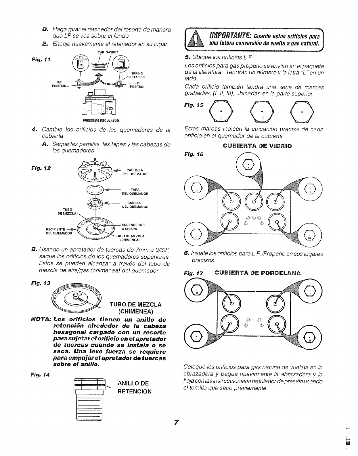
Fig. 1t
Haga girar el retenedor del resorte de manera
que LP se vea sobre el fondo
Encaje nuevamente el retenedor en su lugar
CAP GASKET
PRESSURE REGULATOR
4_
Cambie _s onficios de _s quemadores de
cub_r_
iA. Saque las parrillas, las tapas y las cabezas de
los quemadores
Fig. 12
,,,,,_ PARR_LLA
DEL QUEMADOR
_.,_ TAPA
DEL QUEMADOR
CABEZA
,_"_ DEL QUEMADOR
TUBO
DE MF.ZCLA
RECIPIENT_-.->_,_(l_:i._--_..:J _) AC.iSPA
OEL QUEMADOR _'__ TUBO DE I'_F..ZCLA
B. Usando un apretador de tuercas de 7mm o 9/32",
saque los orificios de los quemadores superiores
Estos se pueden alcanzar a trav_s del tubo de
mezcla de aire!gas (chimenea) del quemador
Fig, 13
/MPORTAHTE:Guardeestos ofificios para_
una futura conversiSnde vuelta a gasnatural.J
5. Ubique los orificios L P
Los onhcios para gas propano se envfan en el paquete
de la literatura Tendran un ndmero y la letra "L "en un
lado
Cada orihcio tambl_n tendrb una serie de maroas
grabadas, (1.If, tlt), ubicadas en la parte superior
C} 0
Estas mamas indlcan la ubicacidn precisa de cada
onficio en el quemador de la cublerta
CUBI]ERTA DE VI]DRIIO
Fig. 16
6. lnstale los orificios para L P iPropano en sus lugares
precisos
Fig. 17 CUBBERTA Dt_ PORCF.ILANA
TUBO DE MEZCLA
(CHIMENEA)
NOTA: Los orificios tienen un anillo de
retenci6n alrededor de la cabeza
hexagonal cargado con un resorte
para sujetar el orificio en el apretador
de tuercas cuando se ins_ala o se
saca. Una leve fuerza se requiere
para empujar el apretador de tuercas
sobre el anillo.
Fig. f4
ANILLO DE
RETENCION
Coloque los orificios para gas natural de vuelata en la
abrazadera y pegue nuevamente la abrazadera y la
hoja con ias instruccionesal regulador de pres_dn usando
el tomillo que sacd previamente
7
p ocnoN.
[ _1 Lossiguientesajustessedebenhacerantes
"_ deencender el quemador. Sino los hace
podrfa resuitar en heridas de gravedad.
Asegdrese que el regulador de la presiSn ha sido
convertido.
lw
Encienda completamente todos los quemadores y
revise tas llamas
A_ Deberian set de color azul sin muestras de
amarillo Las partibulas extra,as en la linea del
gas podrfan causar una llama anaranjada al
pnncipio, pero esto desaparecer_ pronto
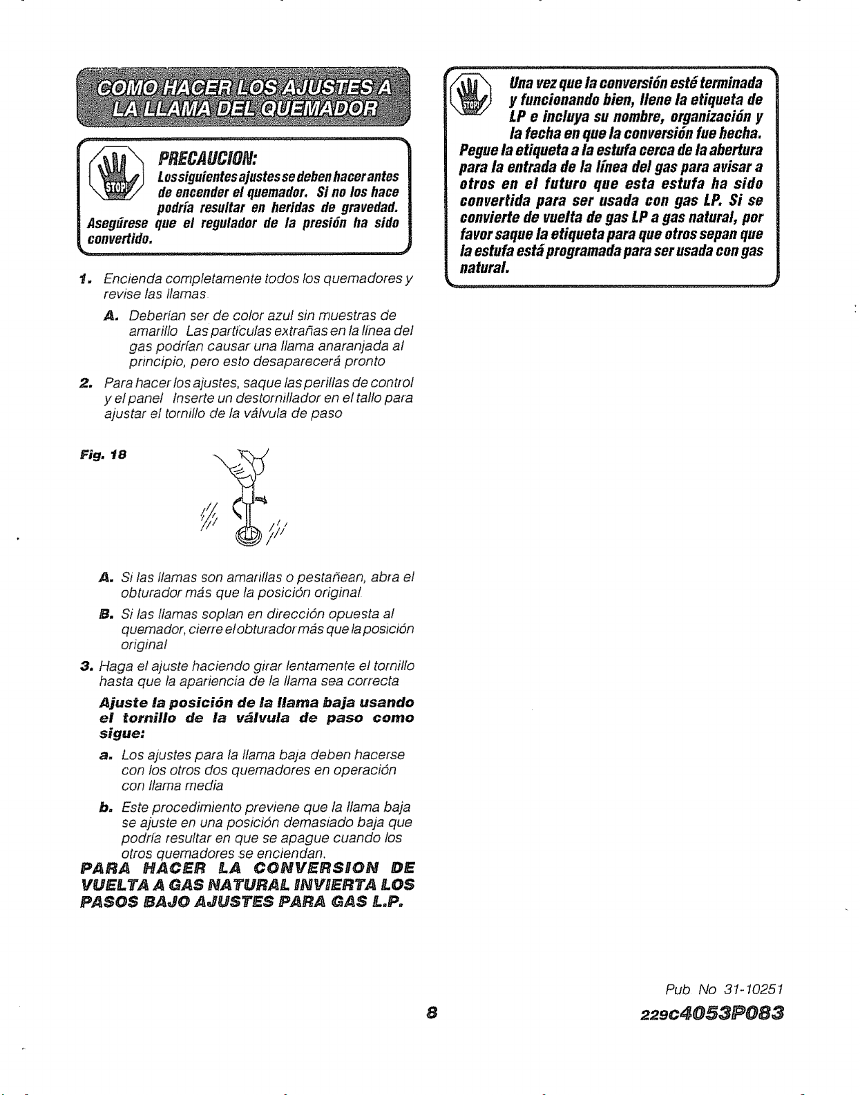
Para hacer tos ajustes, saque fas perillas de con#ol
y etpanel lnserte un destomitlador en el taflo para
ajustar el tomillo de la v_fvula de paso
Unavezquela conversiGnest6terminada
y funcionando bien, Ilene la etiqueta de
LP e incluya su hombre, organizacio'n y
la fecha en que la conversion rue hecha.
Pegue la etiqueta a la estufa cerca de la abertura
para la entrada de la Ifnea del gas para avisar a
otros en el futuro que esta estufa ha sido
convertida para set usada con gas LP. Si se
convierte de vuelta de gas LP a gas natural, pot
favor saque la etiqueta para que otros sepan que
la estufa est_ programada para ser usada con gas
natural.
Fig. t8
A. Si /as llamas son amarillas o pesta4ean, abra el
obturador m_s que ta posicidn original
B. Si las llamas soptan en direccidn opuesta al
quemador, cierre etobtutador mas que laposicidn
original
3. Haga el ajuste haciendo girar tentamente el tomillo
hasta que fa apariencia de la llama sea correcta
Ajuste la posici6n de la llama baja usando
el tornillo de la v_lvula de paso como
smgue.
a. Los ajustes para la llama baja deben hacerse
con los otros dos quemadores en operacidn
con llama media
b. Este procedirmento previene que fa llama baja
se ajuste en una posicidn demasiado ba]a que
podria resuttar en que se apague cuando los
otros quemadores se enciendan.
PARA HACER LA CONVERSION DE
VUELT"A A GAS NATURAL INVNERTA LOS
PASOS BAJO AJUSTES P.,_RA GAS L.P.
8
Pub No 3 I- 1025 I
229c4053P083