2019
OWNER’S MANUAL
RANGER® 150 EFI
WARNING
Operating, servicing, and maintaining a passenger vehicle or off-road
vehicle can expose you to chemicals including engine exhaust, carbon
monoxide, phthalates, and lead, which are known to the State of California
to cause cancer and birth defects or other reproductive harm. To minimize
exposure, avoid breathing exhaust, do not idle the engine expect as
necessary, service your vehicle in a well-ventilated area and wear gloves
or wash your hands frequently when servicing your vehicle.
For more information go to www.P65Warnings.ca.gov/passenger-vehicle.
!
WARNING
Read, understand, and follow all of the instructions and safety
precautions in this manual and on all product labels.
Failure to follow the safety precautions
could result in serious injury or death.
For videos and more information
about a safe riding experience with
your Polaris vehicle, scan this QR
code with your smartphone.
!

2019 Owner’s Manual
RANGER 150 EFI

POLARIS®, RANGER®, and POLARIS GENERAL™ are trademarks of
POLARIS Industries Inc.
Copyright 2018 Polaris Industries Inc. All information contained within this
publication is based on the latest product information at the time of
publication. Due to constant improvements in the design and quality of
production components, some minor discrepancies may result between the
actual vehicle and the information presented in this publication. Depictions
and/or procedures in this publication are intended for reference use only. No
liability can be accepted for omissions or inaccuracies. Any reprinting or
reuse of the depictions and/or procedures contained within, whether whole or
in part, is expressly prohibited.
The original instructions for this vehicle are in English. Other languages are
provided as translations of the original instructions.
Printed in China
9929225

Messages . . . . . . . . . . . . . . . . . . . . . 5
Introduction . . . . . . . . . . . . . . . . . . . . 7
Safety . . . . . . . . . . . . . . . . . . . . . . . 9
Features and Controls . . . . . . . . . . . . . . 25
Instrument Cluster . . . . . . . . . . . . . . . . 33
Operation . . . . . . . . . . . . . . . . . . . . 59
Emission Control Systems . . . . . . . . . . . . . 69
Maintenance . . . . . . . . . . . . . . . . . . 71
Specifications . . . . . . . . . . . . . . . . . . 109
Polaris Products . . . . . . . . . . . . . . . . . 113
Troubleshooting . . . . . . . . . . . . . . . . . 115
Warranty . . . . . . . . . . . . . . . . . . . . 133
Maintenance Log . . . . . . . . . . . . . . . . 141
3

4

MESSAGES
PARENTS
We believe your children should have the opportunity to enjoy the POLARIS
riding experience along with you. We encourage you to teach your children to
ride safely, and to help ensure the future of recreational sports, please teach
them to show respect for our environment and for the rights of others while
operating the vehicle.
This vehicle is not a toy and can be hazardous to operate. We've provided this
owner’s manual and an instructional video to help you and your children learn
about the safe operation and care of your new POLARIS vehicle. Before your
children drive or ride in the vehicle, please read and make sure they read this
owner’s manual. Watch the instructional video with them. Make sure all
operators and passengers understand and follow all of the instructions and
warnings contained in this owner’s manual and video. Make sure they
understand that the vehicle must be used under adult supervision at all times.
After reading this owner’s manual and watching the video, help your child
practice the New Operator Driving Procedures outlined in this manual..
Never allow a child under age 10 to operate or ride as a passenger in this
vehicle. Children differ in skills, physical abilities and judgement. Please
supervise the use of the vehicle at all times. Permit continued use only if you
determine that your child has the ability and maturity to operate safely.
For your child’s safety, be sure your child can reach and operate all RANGER®
150 controls, including steering wheel, accelerator and brake pedals, and
ignition switch. Make sure your child is not too tall to ride safely in this vehicle.
See page 12.
The vehicle’s speed control system allows adults to limit vehicle speed for new
and inexperienced operators. Please see page 50 for more information.
The preventive maintenance program outlined in this manual is designed to
ensure that all critical components on your child's vehicle are thoroughly
inspected at specific intervals. Always follow all of the instructions and
recommendations in this manual to ensure the vehicle remains in safe operating
condition at all times.
This POLARIS vehicle is not designed for adult use. Serious damage may occur
if the maximum weight capacity is exceeded. Refer to vehicle labels and to the
Specifications chapter for the maximum weight capacity.
5
MESSAGES

YOUNG OPERATORS
Before you ride your new POLARIS vehicle, there are some important things
that you need to know. You must learn how to keep yourself and those around
you safe while you're riding.
Your parents and POLARIS want you to be safe while you enjoy riding your new
vehicle, and that's why it’s very important that you read this owner’s manual and
watch the instructional video. Make sure you understand and follow all of the
instructions and warnings in this owner’s manual and video. Ask your parents to
explain anything you don't understand.
Your safety and the safety of others is the most important thing to think about at
all times. Pay attention when you see this symbol:
This is the safety alert symbol. When you see this symbol on your vehicle or in
this manual it means PAY ATTENTION because you could die or be seriously
injured if you don't follow the instructions.
After reading this owner’s manual and watching the video, complete the New
Operator Driving Procedures. Show your parent that you understand how to
drive safely.
Enjoy riding your new POLARIS vehicle!
6
MESSAGES
INTRODUCTION
SAFETY SYMBOLS AND SIGNAL WORDS
The following signal words and symbols appear throughout this manual and on
your vehicle. Your safety is involved when these words and symbols are used.
Become familiar with their meanings before reading the manual.
DANGER
DANGER indicates a hazardous situation which, if not avoided, WILL result in
death or serious injury.
WARNING
SAFETY ALERT WARNING indicates a hazardous situation which, if not
avoided, COULD result in serious injury.
CAUTION
SAFETY ALERT CAUTION indicates a hazardous situation which, if not
avoided, COULD result in minor to moderate injury.
CAUTION
CAUTION indicates special precautions that must be taken to avoid vehicle
damage or property damage.
IMPORTANT
IMPORTANT provides key reminders during disassembly, assembly, and
inspection of components.
NOTICE
NOTICE provides key information by clarifying instructions.
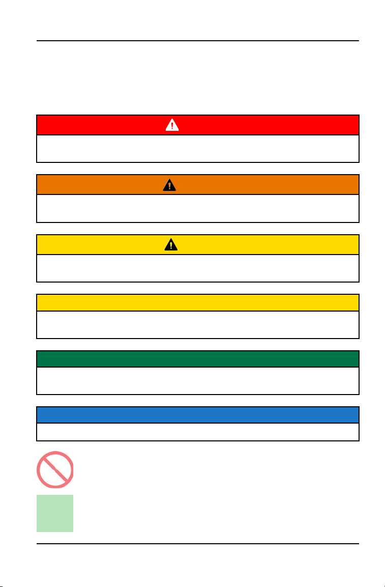
The Prohibition Safety Sign indicates an action NOT to take in order
to avoid a hazard.
The Mandatory Action Sign indicates an action that NEEDS to be
taken to avoid a hazard.
7
INTRODUCTION
VEHICLE IDENTIFICATION NUMBERS
Record your vehicle's identification numbers and key number in the spaces
provided. Remove the spare key and store it in a safe place. An ignition key can
be duplicated only by ordering a POLARIS key blank (using your key number)
and mating it with one of your existing keys. The ignition switch must be
replaced if all keys are lost.
The VIN can be found stamped on a plate
q
riveted to the left frame rail on the
left side wheel well of the ORV.
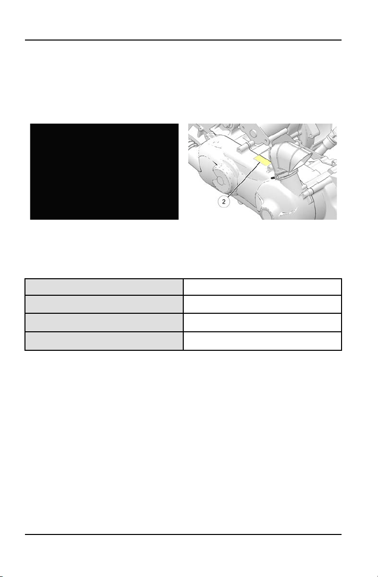
The engine serial number
w
can be found on the clutch-side of the engine case.
Vehicle Model Number:
Vehicle Identification Number (VIN):
Engine Serial Number:
Key Number
8
INTRODUCTION

SAFETY
EQUIPMENT MODIFICATIONS
Your POLARIS vehicle is designed to provide safe operation when used as
directed.
WARNING
Modifying this vehicle in any way can change the top speed, stability and
handling performance of this vehicle. Modifications that increase speed,
decrease stability or change performance may present a greater risk to
inexperienced or younger operators and could result in loss of control and
serious injury or death. Use only POLARIS-approved accessories to modify
this vehicle. Review all vehicle changes with your child prior to operating.
The POLARIS limited warranty on your POLARIS vehicle will be terminated if
any non-POLARIS-approved equipment and/or modifications have been added
to the vehicle that increase speed or power.
EUROPEAN VIBRATION AND NOISE
The driver-perceived noise and hand/arm and whole body vibration levels of this
machinery is measured per EN 15997.
The operating conditions of the machinery during testing:
The vehicles were in like-new condition. The environment was controlled as
indicated by the test procedure(s).
The uncertainty of vibration exposure measurement is dependent on many
factors, including:
• Instrument and calibration uncertainty
• Variations in the machine such as wear of components
• Variation of machine operators such as experience or physique
• Ability of the worker to reproduce typical work during measurements
• Environmental factors such as ambient noise or temperature
9
SAFETY
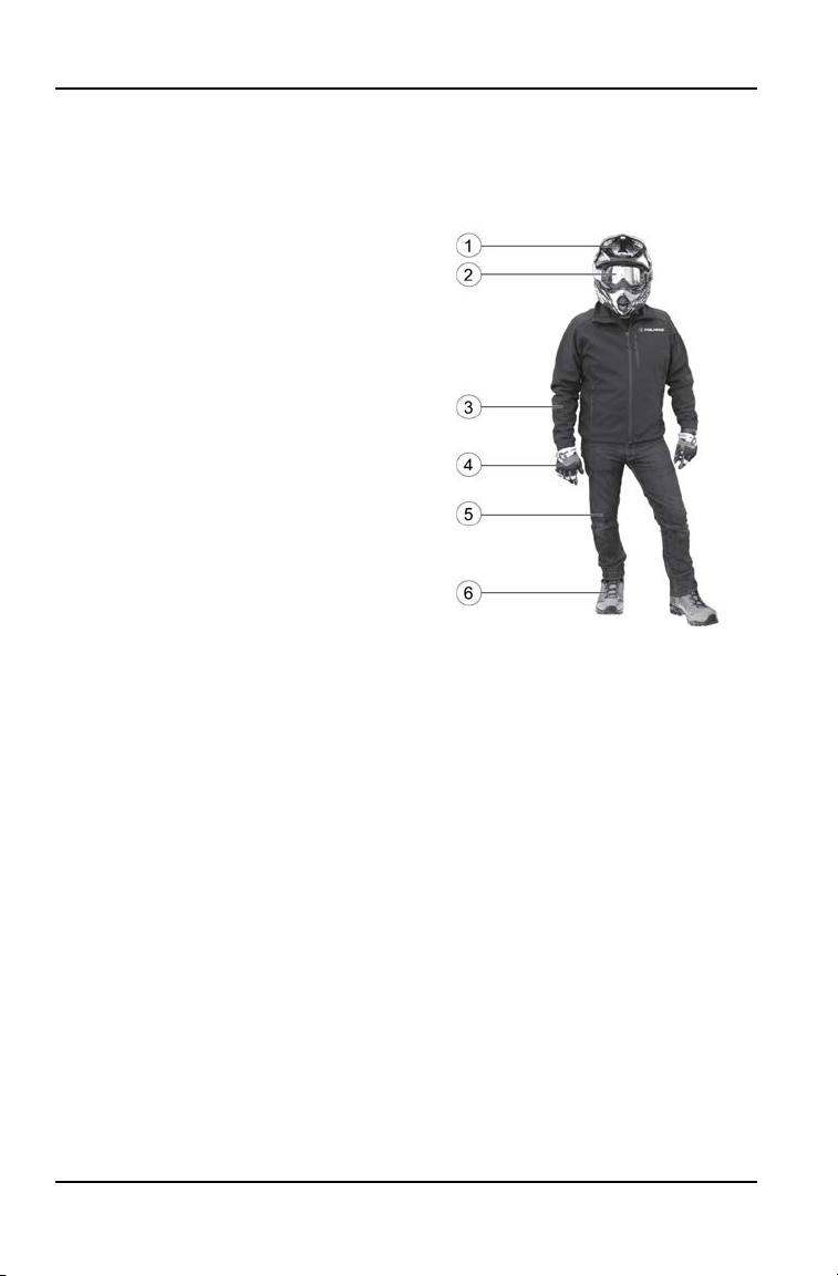
SAFE RIDING GEAR
Protective gear reduces the chance of injury.
The driver and passenger must wear:
q
Helmet
w
Eye protection
e
Long-sleeve shirt
r
Gloves
t
Long pants
y
Over-the-ankle boots
HELMET
Wearing a helmet can prevent a severe head injury. Whenever riding this
POLARIS vehicle, always wear a helmet that meets or exceeds established
safety standards. Always buckle and pull straps tight to ensure the helmet is
secured.
Parents should verify that the provided helmets fit properly. If a helmet doesn't
fit, parents should obtain one in the proper size.
Approved helmets in the USA and Canada bear a U.S. Department of
Transportation (DOT) label.
Approved helmets in Europe, Asia and Oceania bear the ECE 22.05 label. The
ECE mark consists of a circle surrounding the letter E, followed by the
distinguishing number of the country which has granted approval. The approval
number and serial number will also be displayed on the label.
EYE PROTECTION
Do not depend on eyeglasses or sunglasses for eye protection. Whenever riding
this POLARIS vehicle, always wear shatterproof goggles or use a shatterproof
helmet face shield. POLARIS recommends wearing approved Personal
Protective Equipment (PPE) bearing markings such as VESC 8, V-8, Z87.1, or
CE. Make sure protective eye wear is kept clean.
10
SAFETY
CLOTHING
Wear long sleeves and long pants to protect arms and legs.
GLOVES
Wear gloves for comfort and for protection from sun, cold weather and other
elements.
BOOTS
Wear sturdy over-the-ankle boots for support and protection. Never ride a
POLARIS vehicle with bare feet or sandals.
RIDER COMFORT
Under certain operating conditions, heat generated by the engine and exhaust
system can elevate temperatures in the driver and passenger cab area. The
condition occurs most frequently when a vehicle is being operated in high
ambient temperatures at low speeds and/or high load conditions for an extended
period of time. The use of certain windshield, roof and/or cab systems may
contribute to this condition by restricting airflow. Any discomfort due to heat
buildup in this area can be minimized by wearing proper riding apparel and by
varying speeds to increase airflow.
SAFETY WARNINGS
WARNING
Failure to operate this vehicle properly can result in a collision, loss of control,
accident or rollover, which may result in serious injury or death. Heed all safety
warnings outlined in this section of the owner’s manual and in the safety DVD
provided with your vehicle.
Be sure to read all of the following warnings about driving hazards and how to
avoid them. These warnings are provided for your child's safety. Be sure to
explain to your young driver that the hazards outlined in this section of this
owner’s manual MUST be avoided at all times. See the OPERATION section
of this owner’s manual for proper operating procedures.
FOR MORE INFORMATION ABOUT SAFETYcall POLARIS at 1–800–342–
3764.
11
SAFETY
OPERATING WITHOUT INSTRUCTION
Operating this vehicle without proper instruction
increases the risk of an accident. The operator
and the supervising adult must understand how
to operate the vehicle properly in different
situations and on different types of terrain.
All operators must read and understand this
owner’s manual and all warning and instruction
labels before operating the vehicle. Never allow a
guest to operate this vehicle until the guest has
read this manual and all product labels.
AGE RESTRICTIONS
This vehicle is for recreational use by young
operators under adult supervision ONLY.
Operation is prohibited for anyone under age 10.
Never operate with a passenger under age 10.
All riders must be able to sit with backs against
the seat, both feet flat on the floor and both
hands on the steering wheel (if driving) or on a
passenger hand hold.
RIDER HEIGHT
Some riders may be too tall to ride safely in this
vehicle. Do not operate or ride in this vehicle if
the clearance between the top of your helmet
and the overhead cab frame is less than 2
inches (5 cm).
12
SAFETY
FAILURE TO INSPECT BEFORE OPERATING
Failure to inspect and verify that the vehicle is in
safe operating condition before operating
increases the risk of an accident.
Always inspect the vehicle before each use to
make sure it's in safe operating condition.
Always follow the inspection and maintenance
procedures and schedules described in this
owner’s manual.
PROTECTIVE APPAREL
Riding in this vehicle without wearing an
approved helmet and protective eyewear
increases the risk of serious injury in the event of
an accident.
Operator and passenger must always wear an
approved helmet that fits properly and eye
protection (goggles or face shield).
USING ALCOHOL OR DRUGS
Riding in this vehicle after consuming alcohol or
drugs could adversely affect operator judgment,
reaction time, balance and perception.
Never consume alcohol or drugs before or while
operating or riding in this vehicle.
13
SAFETY
SEAT BELTS
Riding in this vehicle without wearing the seat belt increases the risk of serious
injury in the event of rollover, loss of control, other accident or sudden stop. Seat
belts may reduce the severity of injury in these circumstances. Riders must wear
seat belts at all times. Always make sure the seat belts are secured for both the
operator and passenger before riding.
CAB NETS
Riding in this vehicle without using the cab nets (or doors, if equipped) increases
the risk of serious injury or death in the event of an accident or rollover. Always
use the cab nets (or doors) while riding in this vehicle. Always keep hands and
feet inside the vehicle at all times.
CARRYING A PASSENGER
Never carry a passenger until you have operated this vehicle for at least four
hours and have completed the New Operator Driving Procedures outlined in this
manual.
CARRYING MULTIPLE PASSENGERS
A passenger must always be seated in a
passenger seat with seat belt secured. Carrying
more than one passenger in this vehicle can
affect the operator’s ability to steer and operate
the controls, which increases the risk of loss of
control and accident or rollover. Never carry
more than one passenger in this vehicle.
OPERATING ON PUBLIC ROADS
Operating this vehicle on public streets, roads or
highways could result in a collision with another
vehicle. Never operate this vehicle on any public
street, road or highway, including dirt and gravel
roads (unless designated for off-highway use).
14
SAFETY
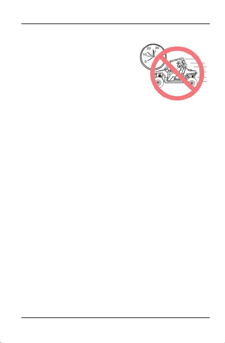
OPERATING AT EXCESSIVE SPEEDS
Operating this vehicle at excessive speeds
increases the operator's risk of losing control.
Always operate at a speed that's appropriate for
the terrain, the visibility and operating conditions,
your skills and experience and your passengers’
skills and experience.
OPERATING ON PAVEMENT
This vehicle's tires are designed for off-road use only, not for use on pavement.
Operating this vehicle on paved surfaces (including sidewalks, paths, parking
lots and driveways) may adversely affect the handling of the vehicle and may
increase the risk of loss of control and accident or rollover. Avoid operating the
vehicle on pavement. If it's unavoidable, travel slowly, travel short distances and
avoid sudden turns or stops.
TURNING IMPROPERLY
Turning improperly could cause loss of traction, loss of control, accident or
rollover. Always follow proper procedures for turning as described in this owner’s
manual.
Never turn abruptly or at sharp angles. Never turn at high speeds. Practice
turning at slow speeds before attempting to turn at faster speeds.
PHYSICAL CONTROL OF THE VEHICLE
Removing hands from the steering wheel or hand holds or removing feet from
the floor while riding increases the risk of loss of control and accident or rollover.
The operator should always keep both hands on the steering wheel during
operation. A passenger should always be seated in the passenger seat with
both feet on the floor and with both hands securely grasping the hand holds.
Always keep hands and feet inside the vehicle at all times.
15
SAFETY

JUMPS AND STUNTS
Exhibition driving increases the risk of an
accident or rollover. DO NOT do power slides,
“donuts”, jumps or other driving stunts. Avoid
exhibition driving.
DRIVING DOWNHILL IMPROPERLY
Driving down a hill improperly could cause loss of control or rollover. Always
follow proper procedures for driving down a hill as described in this owner’s
manual.
IMPROPER HILL CLIMBING
Improper hill climbing could cause loss of control or rollover. Use extreme
caution when operating on hills. Always follow proper procedures for hill climbing
as described in this owner’s manual. Never operate the vehicle on hills steeper
than 15 degrees.
STALLING WHILE CLIMBING A HILL
Stalling or rolling backwards while climbing a hill could cause a rollover. Maintain
a steady speed when climbing a hill.
If you lose all forward speed:
Apply the brakes gradually until the vehicle is fully stopped. Place the
transmission in reverse and slowly allow the vehicle to roll straight downhill while
applying light brake pressure to control speed.
CROSSING HILLSIDES
Driving on a sidehill is not recommended. Improper procedure could cause loss
of control or rollover. Avoid crossing the side of any hill unless absolutely
necessary.
If crossing a hillside is unavoidable, always follow proper procedures as
described in this owner’s manual.
16
SAFETY
OPERATING IN UNFAMILIAR TERRAIN
Failure to use extra caution when operating on
unfamiliar terrain could result in an accident or
rollover.
Unfamiliar terrain may contain hidden rocks,
bumps, or holes that could cause loss of control
or rollover.
Travel slowly and use extra caution when
operating on unfamiliar terrain. Always be alert to
changing terrain conditions.
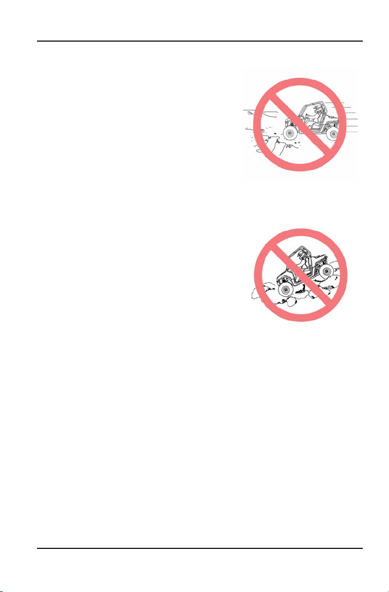
OPERATING ON SAND OR SLIPPERY TERRAIN
Operating on sand or on excessively rough,
slippery or loose terrain could cause loss of
traction, loss of control, accident or rollover.
Always use extra caution when operating on
sand or on rough, slippery or loose terrain. Do
not operate on excessively rough, slippery or
loose terrain.
OPERATING IMPROPERLY IN REVERSE
Improperly operating in reverse could result in a collision with an obstacle or
person. Always follow proper operating procedures as outlined in this manual.
Before shifting into reverse gear, always check for obstacles or people behind
the vehicle. When it's safe to proceed, back slowly.
IMPROPER TIRES AND MAINTENANCE
Operating this vehicle with improper tires or with improper or uneven tire
pressure could cause loss of control, accident or rollover.
Always use the size and type of tires specified for your vehicle. Always maintain
proper tire pressure as described in this owner's manual and on safety labels.
17
SAFETY
OPERATING OVER OBSTACLES
Improperly operating over obstacles could cause
loss of control or rollover.
Before operating in a new area, check for
obstacles. Avoid operating over large obstacles
such as rocks and fallen trees. If unavoidable,
use extreme caution and always follow proper
operating procedures as outlined in this manual.
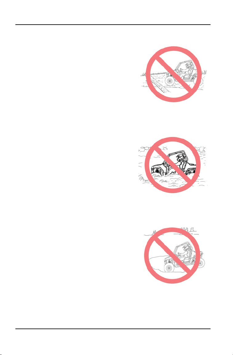
OPERATING THROUGH WATER
Operating through deep or fast-flowing water can
cause loss of traction, loss of control, rollover or
accident. Never operate in fast-flowing water or
in water that exceeds the floor level.
Always follow proper procedures for operating in
water as described in this owner’s manual.
Wet brakes may have reduced stopping ability.
After leaving water, test the brakes. Apply them
lightly several times while driving slowly. The
friction will help dry out the pads.
OPERATING ON FROZEN BODIES OF WATER
Operating on frozen bodies of water can result in
the vehicle and/or riders falling through the ice.
Never operate this vehicle on a frozen body of
water.
18
SAFETY

OVERLOADING THE VEHICLE
Overloading the vehicle or carrying/towing loads may cause changes in stability
and handling, which could cause loss of control or an accident.
• Never tow objects with this vehicle.
• Never exceed the maximum weight capacity for this vehicle.
OPERATING A DAMAGED VEHICLE
Operating a damaged vehicle can result in an accident. After any rollover or
other accident, have a qualified service dealer inspect the entire machine for
possible damage, including (but not limited to) seat belts, rollover protection
devices, brakes, throttle and steering systems.
EXPOSURE TO EXHAUST
Engine exhaust fumes are poisonous and can cause loss of consciousness or
death in a short time. Never start the engine or let it run in an enclosed area.
Operate this vehicle only outdoors or in well-ventilated areas.
HOT EXHAUST SYSTEMS
WARNING
Exhaust system components are very hot during and after use of the vehicle.
Hot components can cause burns and fire. Do not touch hot exhaust system
components. Always keep combustible materials away from the exhaust
system.
Use caution when traveling through tall grass, especially dry grass. Always
inspect the underside of the vehicle and areas near the exhaust system after
driving through tall grass, weeds, brush and other tall ground cover. Promptly
remove any grass or debris clinging to the vehicle.
19
SAFETY

UNAUTHORIZED USE OF THE VEHICLE
Leaving the keys in the ignition can lead to unauthorized use of the vehicle by
someone under the age of 10 or without proper training. This could result in an
accident or rollover. Always remove the ignition key when the vehicle is not in
use.
REFUELING
Gasoline is highly flammable and is explosive under certain conditions. Always
exercise extreme caution whenever handling gasoline.
• Never allow a child to refuel or handle gasoline.
• Always stop the engine when refueling.
• Always refuel outdoors or in a well ventilated area.
• Do not smoke or allow open flames or sparks in or near the refueling area or
where gasoline is stored.
• Never refuel while a person is in the vehicle.
• Do not over fill the tank. Do not fill the tank neck.
• If gasoline spills on your skin or clothing, immediately wash it off with soap
and water and change clothing.
20
SAFETY

SAFETY LABELS AND LOCATIONS
Warning labels have been placed on the vehicle for your protection. Read and
follow the instructions of the labels on the vehicle carefully. If any of the labels
depicted in this manual differ from the labels on your vehicle, always read and
follow the instructions of the labels on the vehicle.
If an informational or graphic label becomes illegible or comes off, contact your
POLARIS dealer to purchase a replacement. Replacement safety labels are
provided by POLARIS at no charge. The part number is printed on the label.
FUEL TRANSPORT WARNING (7186122)
The fuel transport warning
w
is
located in the cargo box.
WARNING
NEVER carry fuel or other flammable
liquids on this vehicle. Failure to follow
this instruction could lead to serious
burn injuries or death.
PASSENGER WARNING (7187451)
WARNING
The passenger warning
e
is located in
the cargo box.
• Never carry passengers in cargo
box.
• Passengers can be thrown off. This
can cause serious injury or death.
21
SAFETY

GENERAL WARNING (7187447)
WARNING
The General Use Warning
q
is located on the dashboard.
Operation of this vehicle by children
under the age of 10 increase the risk
of severe injury or death.
Adult supervision required for children
under age 16.
NEVER permit children under age 10
to operate this vehicle.
NEVER permit a passenger whose
feet cannot touch the floor.
LOCATE AND READ OWNER’S
MANUAL. FOLLOW ALL
INSTRUCTIONS AND WARNINGS. IF
OWNER’S MANUAL IS MISSING,
CONTACT A POLARIS DEALER FOR
A REPLACEMENT.
WARNING
Improper vehicle use can result in SEVERE INJURY or DEATH
NEVER allow vehicle to be Operated:
• without all occupants first viewing and understanding the safety video and
warning labels.
• with more than one passenger.
• on hills steeper than 15˚.
• on paved surfaces - pavement may seriously affect handling and control.
• with non-Polaris approved accessories - they may seriously affect stability.
• at speeds that are too fast for the operators skills, the conditions and/or the
terrain.
ALWAYS require Operator and/or Passenger to:
• wear seat belts, grab hand holds (passenger) and plant feet firmly on the floor.
• secure cab nets.
• keep hands and feet inside vehicle.
• use an approved helmet and protective gear for all occupants.
• avoid quick turns of the steering wheel and driving stunts such as jumps,
donuts or power slides.
• reduce speed and use extra caution when carrying a passenger.
22
SAFETY
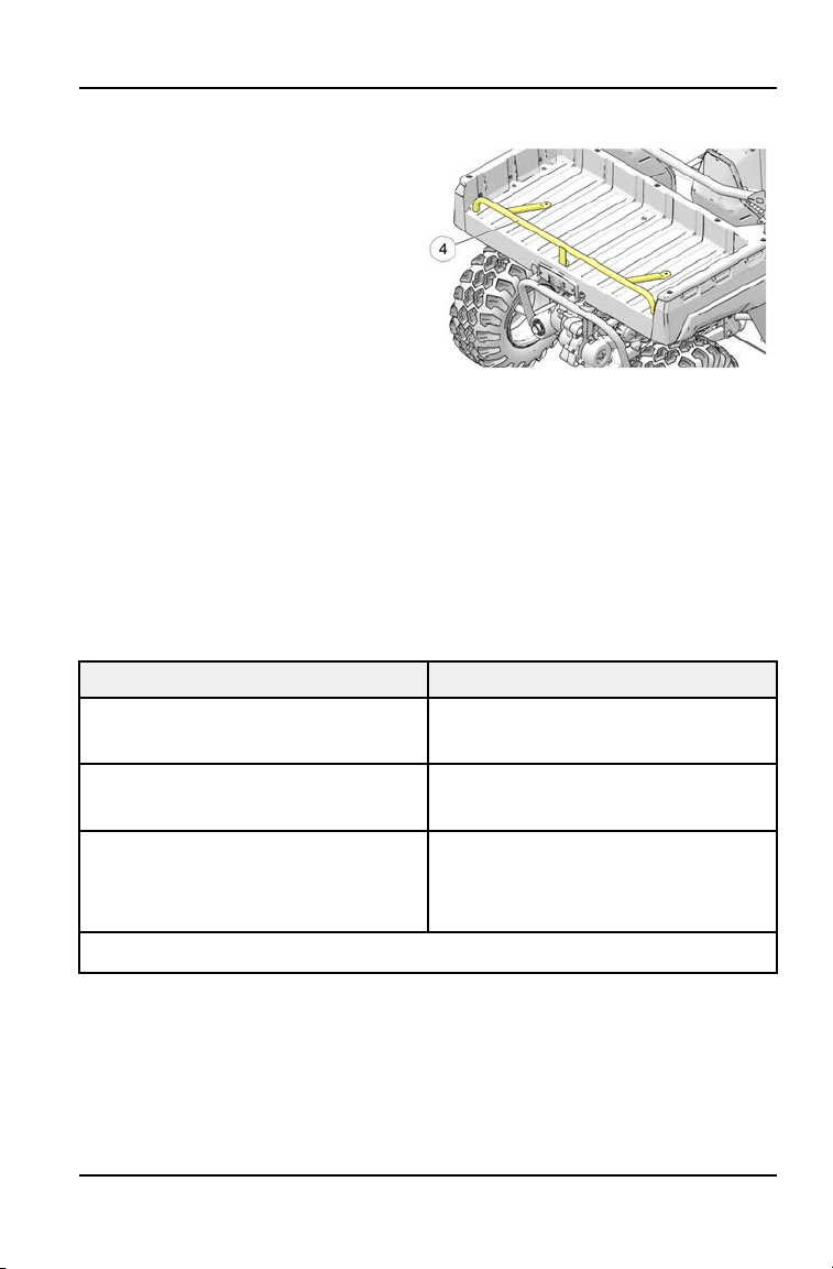
BOX BAR WARNING (7189280)
The box bar warning
r
is located on
the box bar.
WARNING
NEVER tow, sit on, or hang from rack,
bumper, or cargo bed.
NEVER remove bumper. May result in
severe injury or death.
TIRE PRESSURE WARNING (7189047)
WARNING
IMPROPER TIRE PRESSURE OR OVERLOADING CAN CAUSE LOSS OF
CONTROL RESULTING IN SERIOUS INJURY OR DEATH.
• Reduce speed and allow greater distance for braking when carrying cargo.
• Overloading or carrying tall, off-center, or unsecured loads will increase your
risk of losing control. Loads should be centered and carried as low as possible
in box.
• For stability on rough or hilly terrain, reduce speed and cargo.
RANGER RANGER 150
MAXIMUM CARGO BOX LOAD 50 lbs.
(23 kg)
TIRE PRESSURE IN PSI (KPa) FRONT 5 (34.4)
REAR 5 (34.4)
MAXIMUM WEIGHT CAPACITY
INCLUDES WEIGHT OF
OPERATOR, PASSENGER,CARGO,
AND ACCESSORIES.
375 lbs.
(170 kg)
Read Operation & Maintenance Manual for more detailed loading information.
23
SAFETY

24

FEATURES AND CONTROLS
COMPONENT LOCATIONS
Your vehicle is equipped with cab nets on both sides of the vehicle. Cab nets
must be used by both operator and passenger at all times. Promptly replace
worn or damaged cab nets with new cab nets, available from your authorized
POLARIS dealer. The vehicle illustrated below is shown without cab nets only to
allow component identification. Always use the cab nets.
q
Console
y
Hip Bar
w
Headlights
u
Cab Frame
e
Taillights
i
Cargo Box
r
Steering Wheel
o
Fuel Tank Cap
t
Passenger Hand-hold
a
Rear Box Bar
25
FEATURES AND CONTROLS
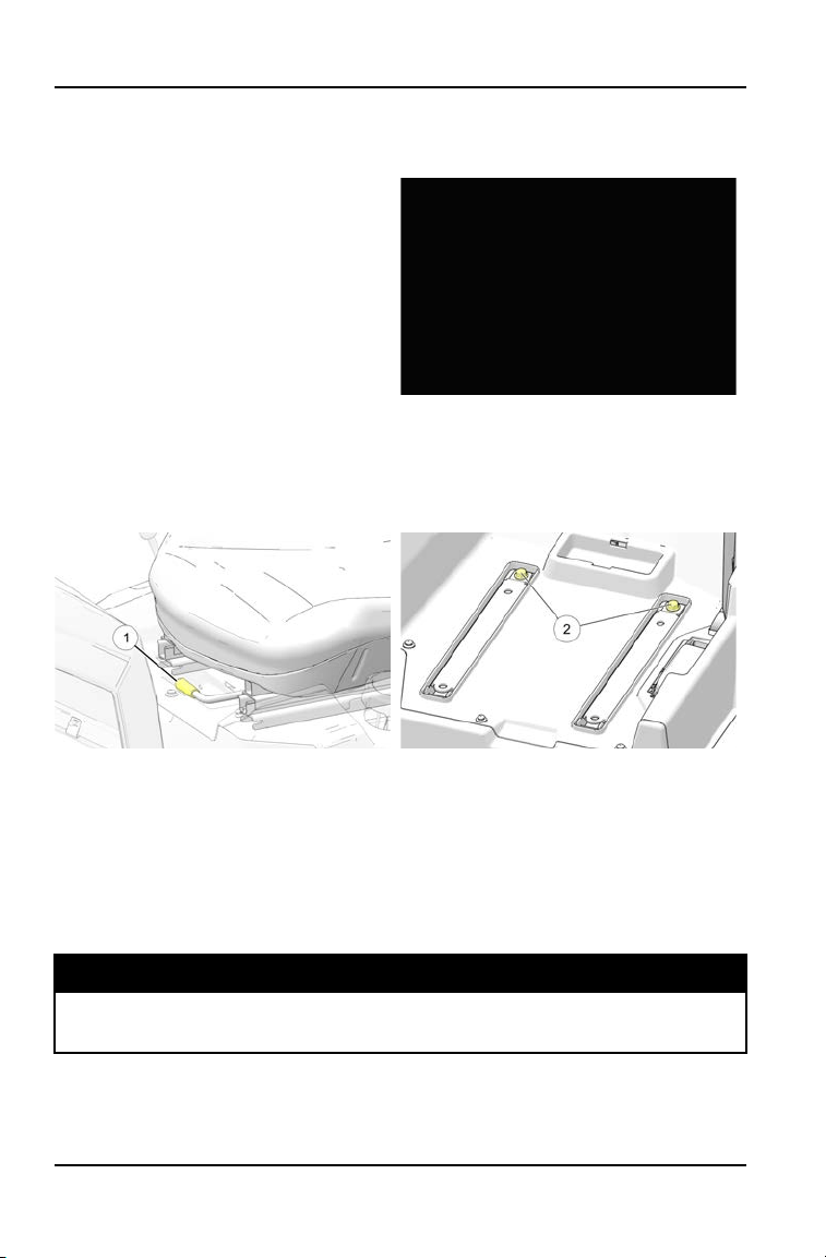
SEATS
DRIVER’S SEAT ADJUSTMENT
1. Lift the seat latch lever located
under the right front edge of the
driver’s seat.
2. While holding the lever upward,
slide the seat forward or rearward
to the desired position, then
release the lever.
3. Slide the seat forward and
rearward to ensure the latch is
engaged. Before operating the
vehicle, always make sure both
seats are securely installed.
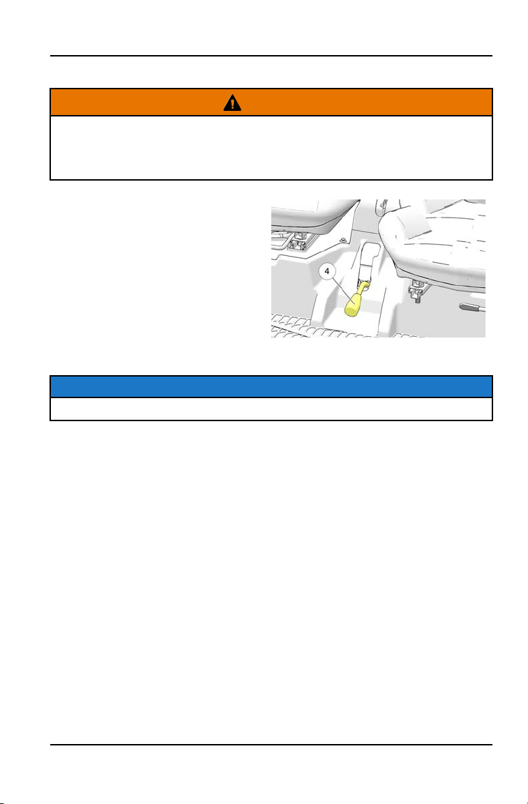
SEAT REMOVAL
1. Lift up the seat latch lever
q
located under the right front edge of the seat.
2. While holding the lever upward, slide the seat completely forward.
3. Remove the two fasteners
w
securing the seat slides to the frame.
4. Remove the seat from the vehicle.
5. Reverse this procedure to reinstall the seat.
TORQUE
Seat Fasteners:
30 ft-lbs (41 Nm)
26
FEATURES AND CONTROLS
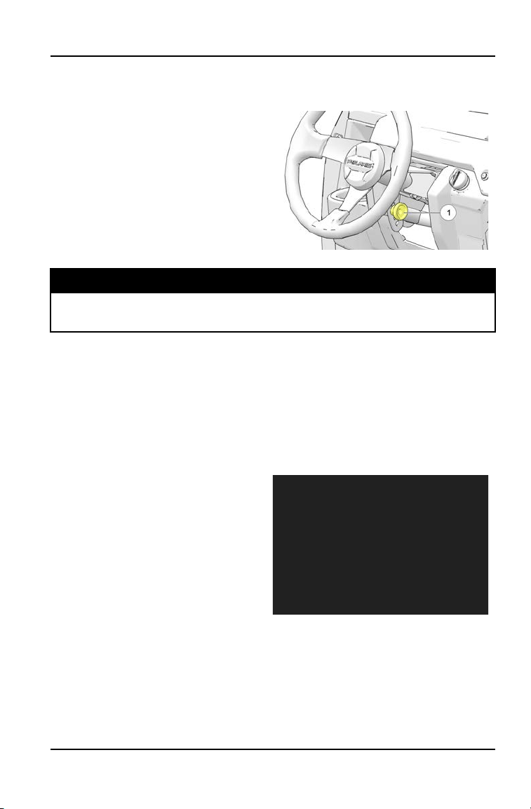
STEERING WHEEL
The steering wheel can be adjusted upward or downward for rider preference.
1. Loosen the steering wheel
adjustment bolt
q
.
2. Move the steering wheel upward or
downward to the desired position.
3. Tighten the bolt to specification.
TORQUE
Steering Wheel Adjustment Bolt:
10 ft. lbs. (13.5 Nm)
SEAT BELTS
This POLARIS vehicle is equipped with three-point lap and diagonal seat belts
for the operator and passenger. Always make sure the seat belts are secured for
both the operator and passenger before riding. The driver’s seat belt is equipped
with a seat belt interlock. Vehicle speed will be limited if the seat belt is not
secured.
To wear the seat belt properly, do the following:
1. Pull the seat belt latch downward
and across your chest toward the
buckle at the inner edge of the
seat. The belt should fit snugly
across your hips and diagonally
across your chest. Make sure the
belt is not twisted.
2. Push the latch plate into the buckle
until it clicks.
3. Release the strap, it will self-
tighten.
4. Press the red release latch on the
buckle to release the seat belt.
27
FEATURES AND CONTROLS

TIP
The position of the shoulder strap can be adjusted to the height of the operator.
Have an adult relocate the mounting bolt
q
to a different position, making sure
the nut and bolt are tightened securely.
TORQUE
Seat Belt Mounting Bolt:
30 ft-lbs (40.6 Nm)
SEAT BELT INSPECTION
Inspect all seat belts for proper operation before each use of the vehicle.
1. Push the latch plate into the buckle until it clicks. The latch plate must slide
smoothly into the buckle. A click indicates that it's securely latched.
2. Push the red release latch in the middle of the buckle to make sure it
releases freely.
3. Pull each seat belt completely out and inspect the full length for any damage,
including cuts, wear, fraying or stiffness. If any damage is found, or if the seat
belt does not operate properly, have the seat belt system checked and/or
replaced by an authorized dealer.
4. To clean dirt or debris from the seat belts, sponge the straps with mild soap
and water. Do not use bleach, dye or household detergents.
CAB NETS
Riding in this vehicle without using the cab nets increases the risk of serious
injury or death in the event of an accident or rollover.
Cab nets must be used by both operator and passenger at all times. Make sure
all latches are secure before operating the vehicle.
Always inspect cab nets for tightness, wear and damage before each use of the
vehicle. Use the strap adjusters to tighten any loose straps. Promptly replace
worn or damaged cab nets with new cab nets, available from your authorized
POLARIS dealer.
28
FEATURES AND CONTROLS
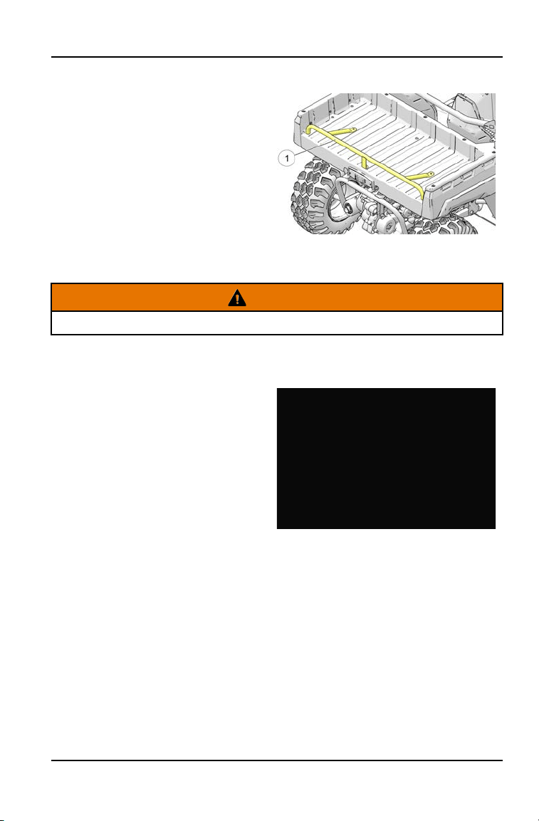
REAR BOX BAR
This vehicle is equipped with a barrier
q
to discourage passengers from
riding in the cargo area and to
decrease the risk of injury due to falls
or entanglement with the vehicle. This
barrier is an essential safety
component and should never be
removed or altered. Passengers
should never ride in the cargo area,
and removal or alteration of this barrier
could cause serious injury or death.
FUEL CAP
WARNING
Never allow a child to refuel or handle gasoline.
The fuel tank filler cap
q
is located on the right-hand side of the vehicle near the
passenger seat.
When refueling, always use either
leaded or unleaded gasoline with a
minimum pump octane number of 87
R+M/2 octane. Non-ethanol fuel is
recommended.
Do not use fuel with ethanol content
greater than 10 percent, such as E-85
fuel.
29
FEATURES AND CONTROLS
IGNITION SWITCH
The ignition switch
w
is a three-
position, key-operated switch. Use the
ignition switch to start the engine. See
page 61 for starting procedures.
The key can be removed from the
switch when it is in the OFF position.
OFF
The engine is off. Electrical circuits are off, except
accessory 12V.
LIGHTS ON
Electrical circuits are on. Electrical equipment can be
used.
START
Turn the key to the START position to engage the
electric starter. The key returns to the ON position
when released.
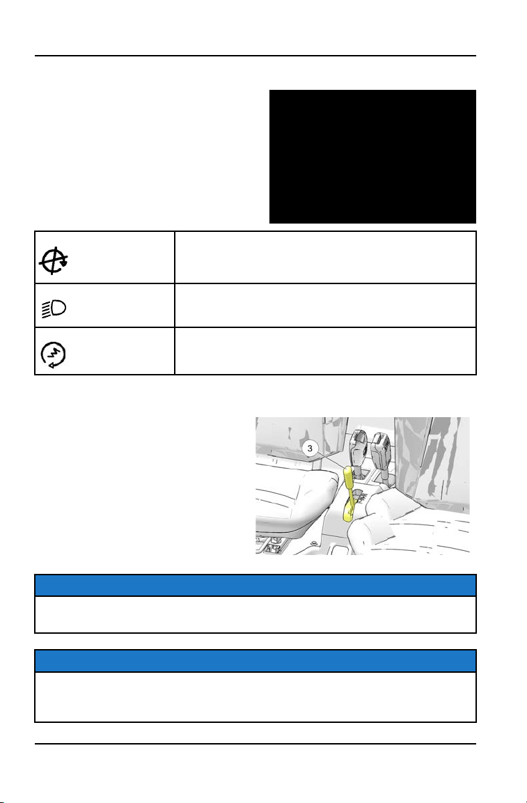
GEAR SELECTOR
The gear selector
e
is located
between the seats. To change gears,
stop the vehicle, and with the engine
idling, move the lever to the desired
gear. Do not attempt to shift gears with
engine speed above idle or while the
vehicle is moving.
F: Forward
N: Neutral
R: Reverse
TIP
Maintaining shift linkage adjustment is important to assure proper transmission
function. Your POLARIS dealer can assist in resolving any shifting problems.
NOTICE
Do not attempt to shift the transmission while the vehicle is moving. This could
damage the transmission. Always shift when the vehicle is stationary and the
engine is at idle.
30
FEATURES AND CONTROLS
PARKING BRAKE
WARNING
Operating the vehicle while the parking brake is engaged could cause an
accident resulting in serious injury or death. It could also result in driveline or
engine damage. Always be sure to disengage the parking brake before
operating the vehicle.
1. Apply the brakes.
2. When the vehicle is fully stopped,
pull the parking brake lever
r
rearward as far as possible to set
the parking brake.
3. Stop the engine.
4. To release the parking brake, apply
the brakes and push the lever
toward the passenger seat and
forward.
TIP
Always set the parking brake whenever the vehicle is left unattended.
31
FEATURES AND CONTROLS

BRAKE/THROTTLE PEDAL
BRAKE PEDAL
Depress the brake pedal
q
to slow or stop the vehicle. Apply the brakes while
starting the engine.
THROTTLE PEDAL
Push the throttle pedal
w
down to increase engine speed. Spring pressure
returns the pedal to the rest position when released. Always check that the
throttle pedal returns normally before starting the engine.
32
FEATURES AND CONTROLS
INSTRUMENT CLUSTER
OVERVIEW
NOTE
The use of a high pressure washer may damage the instrument cluster. Wash
the vehicle by hand or with a garden hose using mild soap. Do not use alcohol
to clean the instrument cluster. Do not allow insect sprays to contact the lens.
Immediately clean off any gasoline that splashes on the instrument cluster.
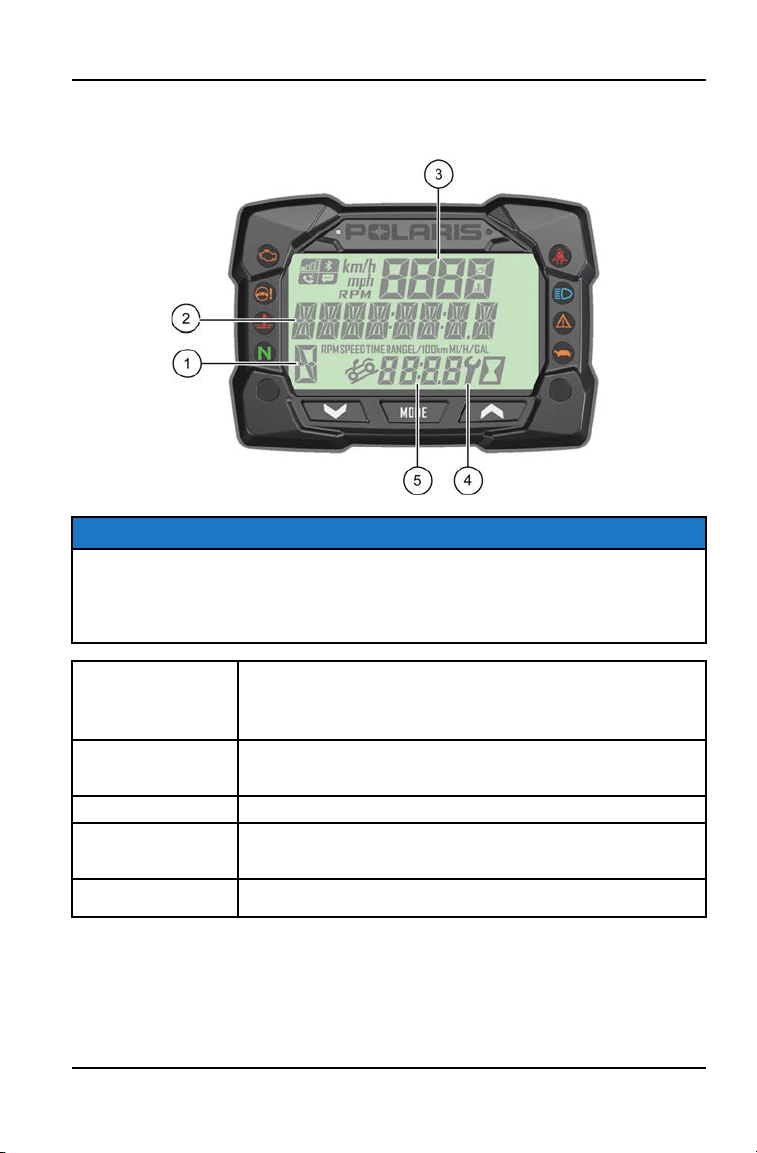
q
Gear Indicator
H = High Gear
L = Low Gear
R = Reverse Gear
– = Gear Signal Error (or shifter between gears)
w
Display Area 2
This area displays odometer, trip meter, trip meter 2, voltage, engine
temperature, engine hour meter, programmable service hour interval,
ground speed, engine RPM, GeoFence status, or speed limit status.
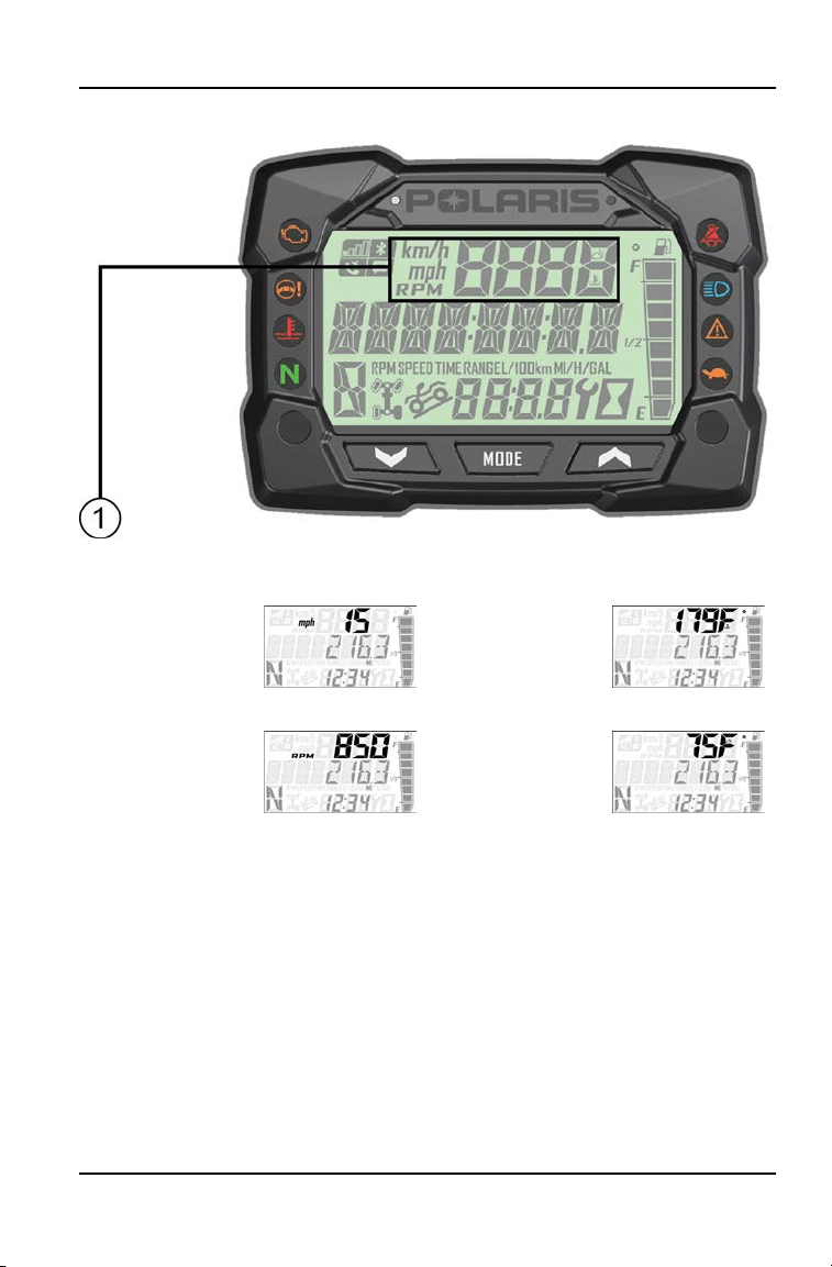
e
Display Area 1
This area displays engine RPM, ground speed, or coolant temperature.
r
Service Indicator
A flashing wrench symbol alerts the operator that the preset service
interval has been reached. Your POLARIS dealer can provide scheduled
maintenance. See page 44 for more information.
t
Clock
The clock displays time in a 12-hour or 24-hour format. See page 40 for
more information.
33
INSTRUMENT CLUSTER
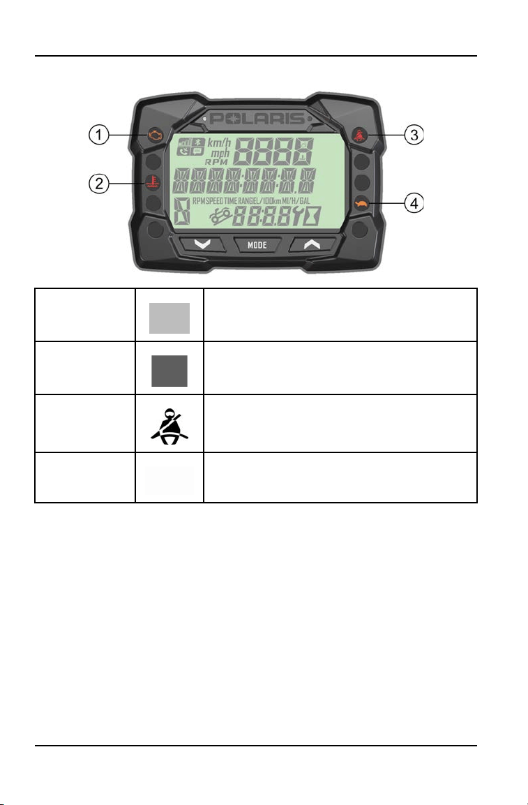
INDICATOR LAMPS
q
Check Engine
This indicator appears if an EFI-related fault occurs. Do not
operate the vehicle if this warning appears. Serious engine
damage could result. Your authorized POLARIS dealer can
assist.
w
Engine Hot
This lamp illuminates to indicate an overheated engine. If the
indicator flashes, a severe overheating condition exists.
e
Helmet/Seat Belt
This lamp flashes for several seconds when the key is turned
to the ON position. The lamp is a reminder to wear helmet and
seat belt before operating.
r
Performance
Limited
This lamp flashes when vehicle has reached top speed set by
GeoFence or max speed setting. Lamp illuminates when
GeoFencing or max speed is enabled. Lamp remains off
when GeoFencing and max speed settings are disabled.
34
INSTRUMENT CLUSTER

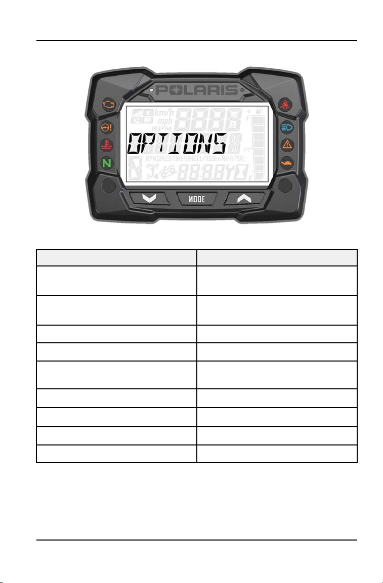
OPTIONS MENU
Press and hold the MODE button to enter the Options Menu.
OPTIONS MENU NOTES
Diagnostic Codes Only displays if fault codes are
present or stored
Youth Menu Set passcode, maximum speed, and
GeoFence settings.
Units - Distance Select MPH or KPH
Units - Temp Select between °F and °C
Clock Select between 12H or 24H, and set
time
Backlight Color Select between Blue or Red
Backlight Level Set backlight brightness level
Service Hours View/Set Service hours
Exit Menu Exit
37
INSTRUMENT CLUSTER
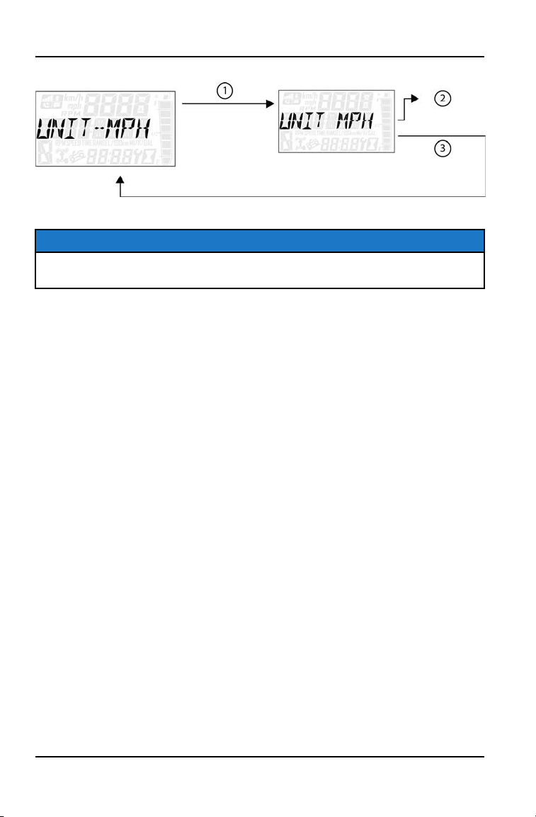
UNIT SELECTION DISTANCE
1. Press and hold the MODE button to enter the Options Menu.
NOTICE
“OPTIONS” will display on the screen for 3 seconds before showing first menu
item.
2. Select “Units-Distance” from the Options Menu by pressing the MODE
button.
Reference the image shown above:
q
Press the MODE button.
w
Toggle the Up/Down Buttons to change the units (MPH or KPH)
e
With the correct unit displayed, Press the mode button which will set
the unit and return to the Options Menu.
3. To exit the Options Menu the user can select Exit Menu function from
Options Menu, can hold Mode Button and exit out of Options Menu, or not
press any button for 10 seconds, which will exit out of the Options Menu.
38
INSTRUMENT CLUSTER

UNIT SELECTION TEMPERATURE
1. Press and hold the MODE button to enter the Options Menu.
NOTICE
“OPTIONS” will display on the screen for 3 seconds before showing first menu
item.
2. Select “Units - Temp” from the Options Menu by pressing the MODE button.
Reference the image shown above:
q
Press the MODE button.
w
Toggle the Up/Down Buttons to change the units (°F or °C)
e
With the correct unit displayed, Press the mode button which will set
the unit and return to the Options Menu.
3. To exit the Options Menu the user can select Exit Menu function from
Options Menu, can hold Mode Button and exit out of Options Menu, or not
press any button for 10 seconds, which will exit out of the Options Menu.
39
INSTRUMENT CLUSTER
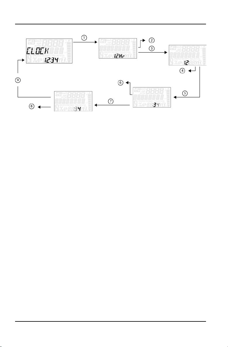
1. Press and hold the MODE button to enter the Options Menu.
NOTICE
“OPTIONS” will display on the screen for 3 seconds before showing first menu
item.
2. Select “Clock” from the Options Menu by pressing the MODE button.
Reference the image shown above:
q
Press the MODE button.
w
Toggle the Up/Down Buttons to change the units (12H or 24H)
e
With the correct unit displayed, Press the mode button which will set
the unit.
r
Toggle the Up/Down Buttons to change the units (Cycles Hours)
t
With the correct unit displayed, Press the mode button which will set
the unit.
y
Toggle the Up/Down Buttons to change the units (Cycles 10s of
Minutes)
u
With the correct unit displayed, Press the mode button which will set
the unit.
i
Toggle the Up/Down Buttons to change the units (Cycles 1s of
Minutes)
o
With the correct unit displayed, Press the mode button which will set
the unit and return to the Options Menu.
3. To exit the Options Menu the user can select Exit Menu function from
Options Menu, can hold Mode Button and exit out of Options Menu, or not
press any button for 10 seconds, which will exit out of the Options Menu.
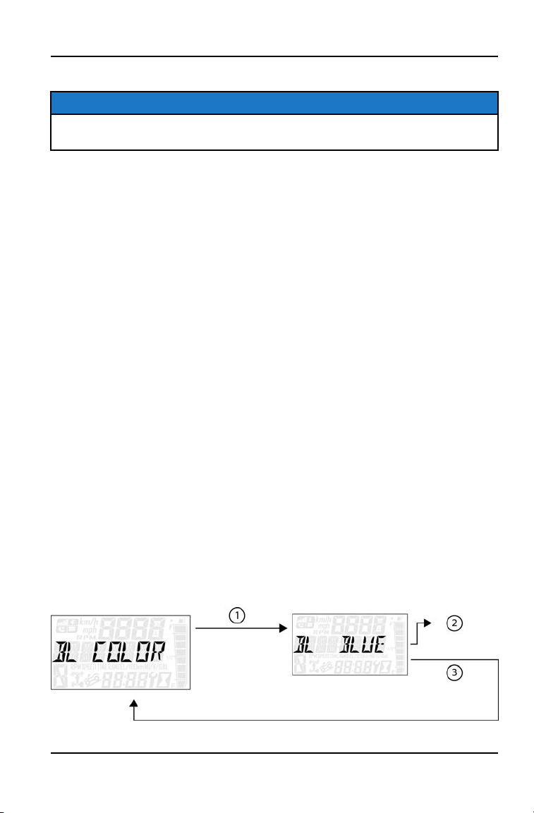
BACK LIGHT COLOR
41
INSTRUMENT CLUSTER

1. Press and hold the MODE button to enter the Options Menu.
NOTICE
“OPTIONS” will display on the screen for 3 seconds before showing first menu
item.
2. Select “Backlight Color” from the Options Menu by pressing the MODE
button.
Reference the image shown above:
q
Press the MODE button.
w
Toggle the Up/Down Buttons to change the units (Blue or Red)
e
With the correct unit displayed, Press the mode button which will set
the unit and return to the Options Menu.
3. To exit the Options Menu the user can select Exit Menu function from
Options Menu, can hold Mode Button and exit out of Options Menu, or not
press any button for 10 seconds, which will exit out of the Options Menu.
42
INSTRUMENT CLUSTER
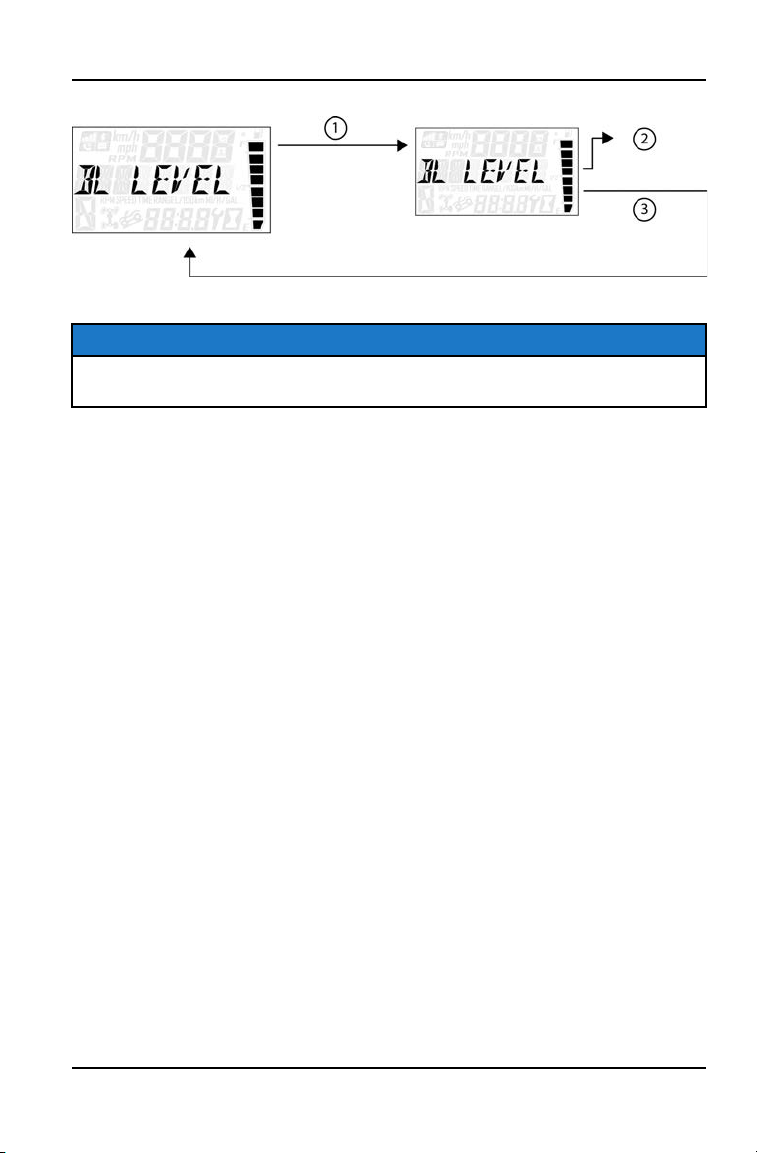
BACK LIGHT LEVEL
1. Press and hold the MODE button to enter the Options Menu.
NOTICE
“OPTIONS” will display on the screen for 3 seconds before showing first menu
item.
2. Select “Backlight Level” from the Options Menu by pressing the MODE
button.
Reference the image shown above:
q
Press the MODE button.
w
Toggle the Up/Down Buttons to change the units (Increase or De-
crease Level)
e
With the correct unit displayed, Press the mode button which will set
the unit and return to the Options Menu.
3. To exit the Options Menu the user can select Exit Menu function from
Options Menu, can hold Mode Button and exit out of Options Menu, or not
press any button for 10 seconds, which will exit out of the Options Menu.
43
INSTRUMENT CLUSTER
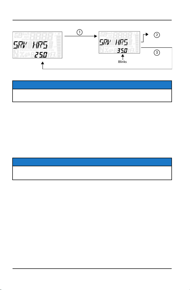
SERVICE HOURS
1. Press and hold the MODE button to enter the Options Menu.
NOTICE
“OPTIONS” will display on the screen for 3 seconds before showing first menu
item.
2. Select “Service Hours” from the Options Menu by pressing the MODE button.
Reference the image shown above:
q
Press the MODE button.
w
Toggle the Up/Down Buttons to change the units (0, 5, 10, - 95,100)
e
With the correct unit displayed, press the MODE button, which will set
the unit and return you to the Options Menu.
NOTICE
To reset service hours after they have counted down to "0.0", reselect the
existing setpoint or select a new service hour value.
3. To exit the Options Menu the user can select Exit Menu function from
Options Menu, can hold Mode Button and exit out of Options Menu, or not
press any button for 10 seconds, which will exit out of the Options Menu.
44
INSTRUMENT CLUSTER
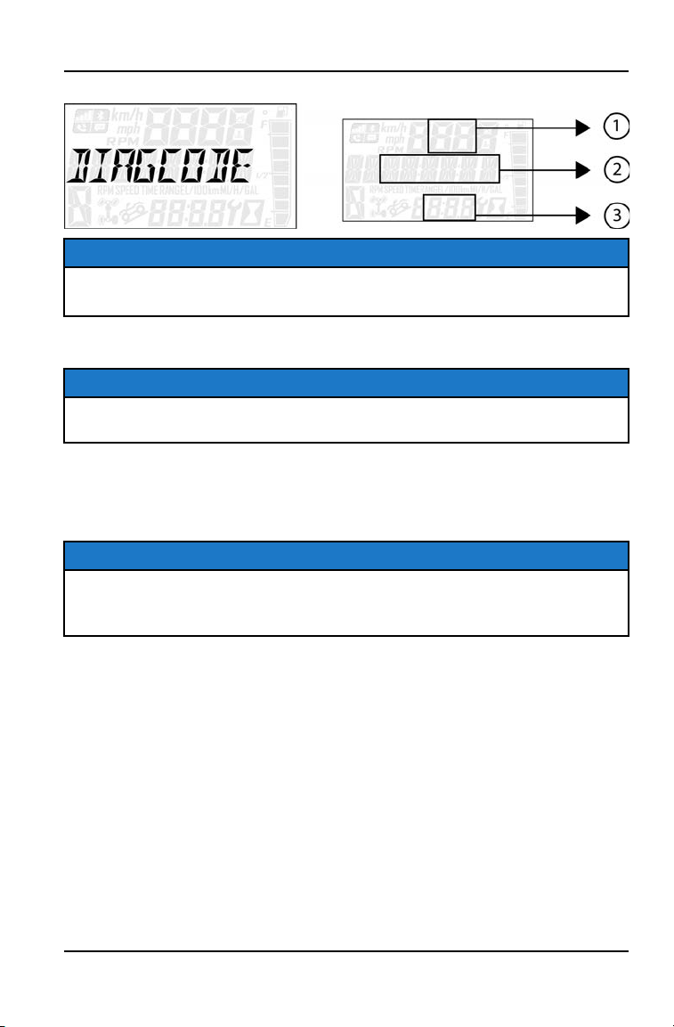
DIAGNOSTIC CODE
NOTICE
Diagnostic Code Screen will show available MIL that has come on during that
ignition cycle.
1. Press and hold the MODE button to enter the Options Menu.
NOTICE
“OPTIONS” will display on the screen for 3 seconds before showing first menu
item.
2. Select “Diagnostic Codes” from the Options Menu by pressing the MODE
button.
Toggle the Up/Down Buttons to cycle through Code(s).
NOTICE
This option will only be available if a fault code was set or is active during the
current ignition key 'on' cycle. Turning off the ignition will clear any save fault
codes from the gauge.
Reference the image shown above:
q
Area A will Display FMI (XX)
w
Area B will Display SPN (XXXXXX)
e
Clock Area will Display Count (XXX)
3. To exit the Options Menu the user can select Exit Menu function from
Options Menu, can hold Mode Button and exit out of Options Menu, or not
press any button for 10 seconds, which will exit out of the Options Menu.
45
INSTRUMENT CLUSTER
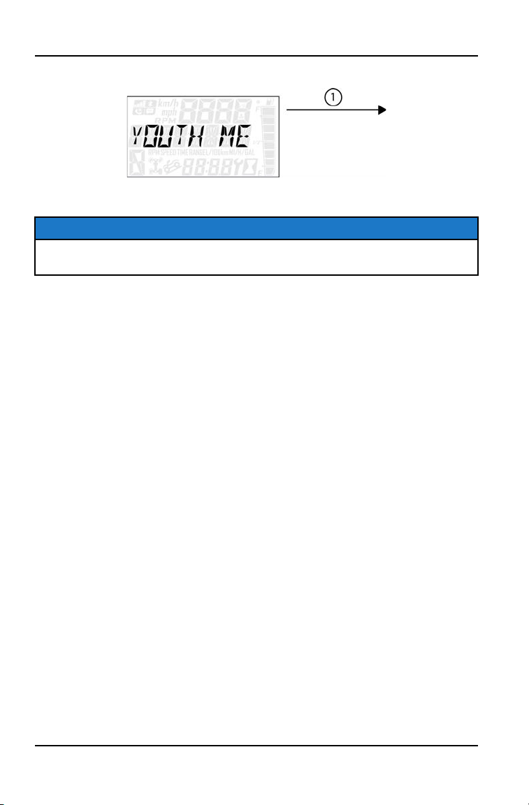
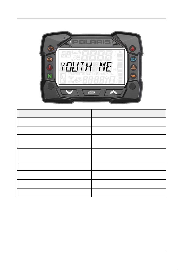
YOUTH MENU
1. Press and hold the MODE button to enter the Options Menu.
NOTICE
“OPTIONS” will display on the screen for 3 seconds before showing first menu
item.
2. Select “Youth Menu” from the Options Menu by pressing the MODE button.
Reference the image shown above:
q
Press the MODE button.
46
INSTRUMENT CLUSTER
YOUTH MENU
YOUTH MENU NOTES
Maximum Speed Set maximum Speed
GeoFence Enable/Disable GeoFence
Inside GeoFence Speed Set inside Geofence maximum
vehicle speed
Outside GeoFence Speed Set outside GeoFence maximum
vehicle speed
Require PIN to start Enable/Disable PIN to start vehicle
Start PIN delay Enable/Disable PIN delay
Change PIN Change PIN
Exit Youth Menu Exit
47
INSTRUMENT CLUSTER
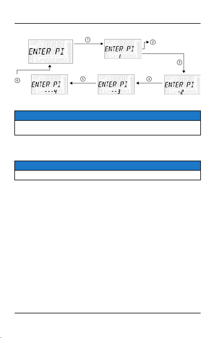
ENTER PIN
1. Press and hold the MODE button to enter the Options Menu.
NOTICE
“OPTIONS” will display on the screen for 3 seconds before showing first menu
item.
2. Select “Youth Menu” by pressing the MODE button.
3. Enter PIN.
NOTICE
If PIN is lost or displaced please contact your Polaris dealer for assistance.
4. To exit the Youth Menu the user can select Exit Menu function from Youth
Menu, can hold MODE button and exit out of Youth Menu, or not press any
button for 10 seconds, which will exit out of the Options Menu.
48
INSTRUMENT CLUSTER

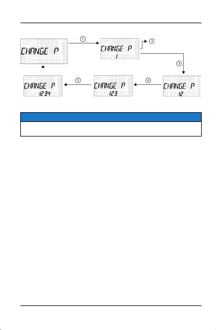
CHANGE PIN
To change the PIN, do the following:
1. Press and hold the MODE button to enter the Options Menu.
2. Select “Youth Menu” by pressing the MODE button.
3. Enter PIN.
4. Select “CHANGE PIN” from the Youth Menu by pressing the MODE button.
Reference the image shown above:
q
Press the MODE button.
w
Toggle the Up/Down buttons to increase/decrease the first digit of
the PIN.
e
With the first digit of the PIN displayed, Press the MODE button
which will set the digit and move to the 2nd digit.
r
Toggle the Up/Down buttons to increase/decrease the 2nd digit of
the PIN. Press MODE button to set 2nd digit and move on to the
3rd digit.
t
Toggle the Up/Down buttons to increase/decrease the 3rd digit of
the PIN. Press MODE button to set 3rd digit and move on to the
4th digit.
y
Press the MODE button to set the 4th digit and enter the Youth
Menu.
5. To exit the Youth Menu the user can select Exit Menu function from Youth
Menu, can hold MODE button and exit out of Youth Menu, or not press any
button for 10 seconds, which will exit out of the Options Menu.
49
INSTRUMENT CLUSTER
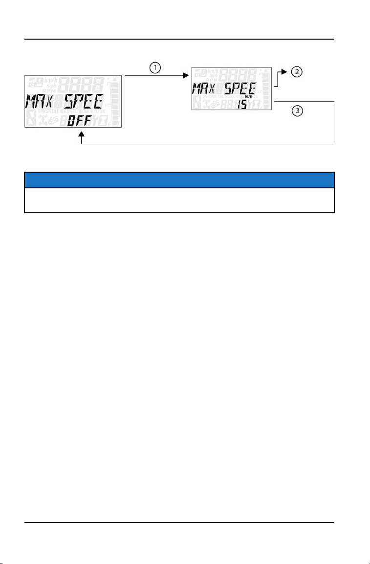
MAX SPEED
1. Press and hold the MODE button to enter the Options Menu.
NOTICE
“OPTIONS” will display on the screen for 3 seconds before showing first menu
item.
2. Select “Youth Menu” by pressing the MODE Button.
3. Enter PIN.
4. Select “Max Speed” from the Youth Menu by pressing the MODE button.
Reference the image shown above:
q
Press the MODE button.
w
Toggle the Up/Down Buttons to increase/decrease Max Speed
(range: 10–29).
e
With the desired Max Speed displayed, press the MODE button
which will set the Max Speed and return to the Youth Menu.
5. To exit the Youth Menu the user can select Exit Menu function from Youth
Menu, can hold MODE Button and exit out of Youth Menu, or not press any
button for 10 seconds, which will exit out of the Options Menu.
50
INSTRUMENT CLUSTER
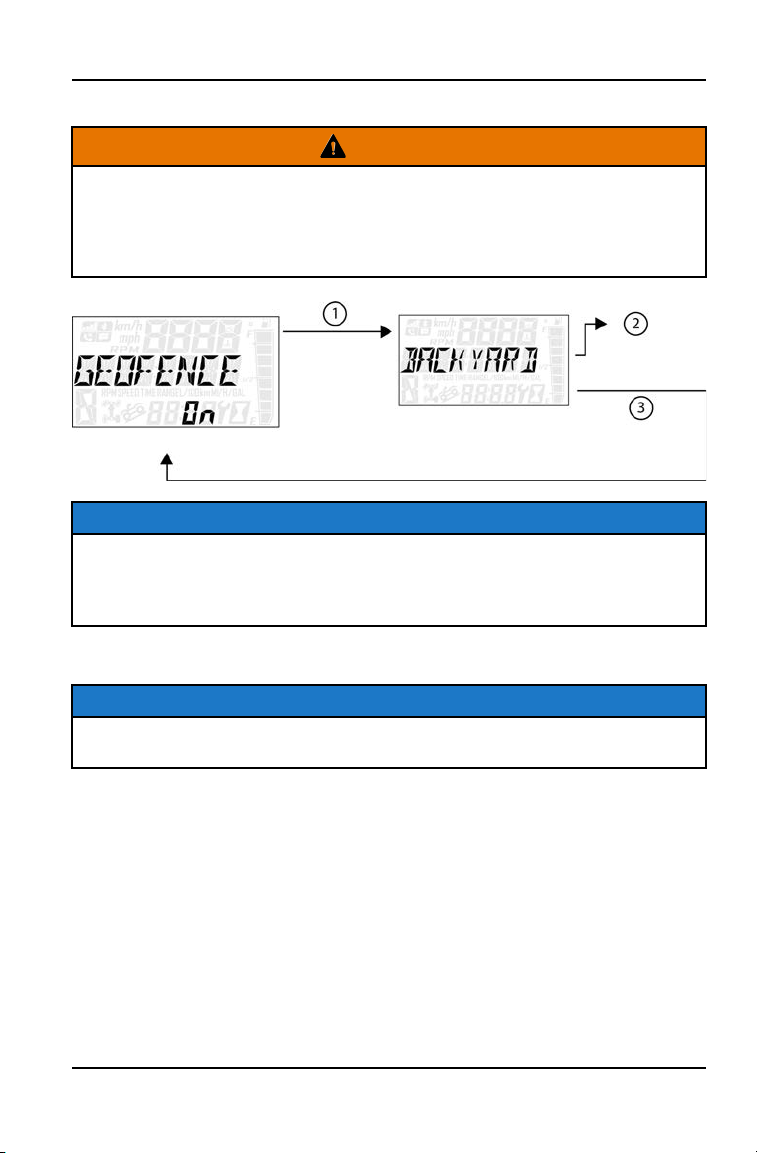
GEOFENCE
WARNING
If your Ranger 150 is equipped with Youth Ride Command, this technology is
not a replacement for adult supervision. GPS accuracy can vary by region, so
make certain to give adequate distance for geofence boundaries to
accommodate this variation. A geofence will not stop the vehicle. It will only
slow to the adult entered speed limit.
NOTICE
To use the geofence features, first download the Polaris Ride Command™ app
and sign up. Turning the geofence on and off and changing the speeds can be
done through the vehicle display once a geofence boundary has been created
through the Ride Command app.
1. Press and hold the MODE button to enter the Options Menu.
NOTICE
“OPTIONS” will display on the screen for 3 seconds before showing first menu
item.
2. Select “Youth Menu” by pressing the MODE button.
3. Enter PIN.
51
INSTRUMENT CLUSTER
4. Select “GEOFENCE” from the Youth Menu by pressing the MODE button.
Reference the image shown above:
q
Press the MODE button.
w
Toggle the Up/Down buttons to cycle through options (On/Off).
e
With the desired option displayed, press the MODE button which
will set function and return to the Youth Menu.
5. To exit the Youth Menu the user can select Exit Menu function from Youth
Menu, can hold Mode Button and exit out of Youth Menu, or not press any
button for 10 seconds, which will exit out of the Options Menu.
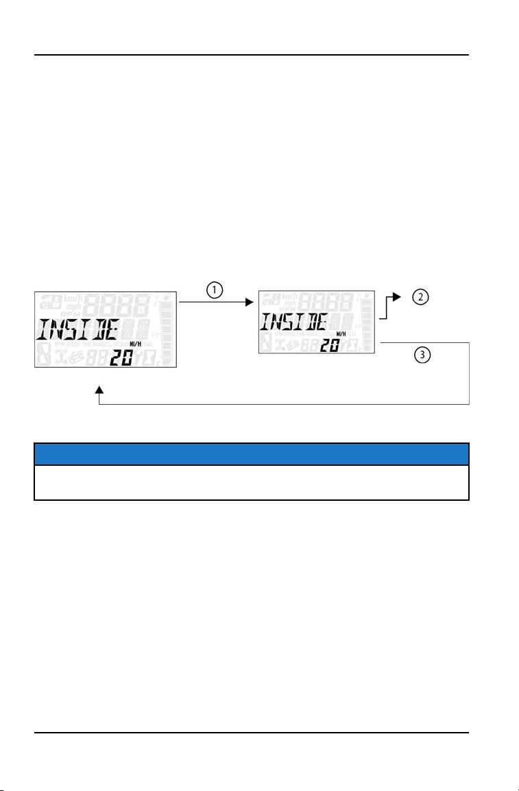
INSIDE GEOFENCE SPEED
1. Press and hold the MODE button to enter the Options Menu.
NOTICE
“OPTIONS” will display on the screen for 3 seconds before showing first menu
item.
2. Select “Youth Menu” by pressing the MODE button.
3. Enter PIN.
52
INSTRUMENT CLUSTER

4. Select “INSIDE” from the Youth Menu by pressing the MODE button.
Reference the image shown above:
q
Press the MODE button.
w
Toggle the Up/Down buttons to increase/decrease Inside
GeoFence Maximum Speed (range: 10–29).
e
With the desired speed displayed, press the MODE button which
will set the Inside GeoFence Speed and return to the Youth Menu.
5. To exit the Youth Menu the user can select Exit Menu function from Youth
Menu, can hold MODE button and exit out of Youth Menu, or not press any
button for 10 seconds, which will exit out of the Options Menu.
53
INSTRUMENT CLUSTER
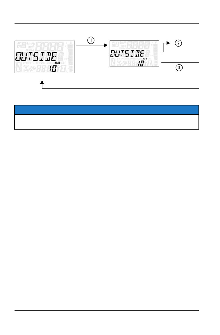
OUTSIDE GEOFENCE SPEED
1. Press and hold the MODE button to enter the Options Menu.
NOTICE
“OPTIONS” will display on the screen for 3 seconds before showing first menu
item.
2. Select “Youth Menu” by pressing the MODE button.
3. Enter PIN.
4. Select “OUTSIDE” from the Youth Menu by pressing the MODE button.
Reference the image shown above:
q
Press the MODE button.
w
Toggle the Up/Down Buttons to increase/decrease Outside
GeoFence Maximum Speed (range: 10–29).
e
With the desired speed displayed, press the mode button which
will set the Outside GeoFence Speed and return to the Youth
Menu.
5. To exit the Youth Menu the user can select Exit Menu function from Youth
Menu, can hold Mode button and exit out of Youth Menu, or not press any
button for 10 seconds, which will exit out of the Options Menu.
54
INSTRUMENT CLUSTER
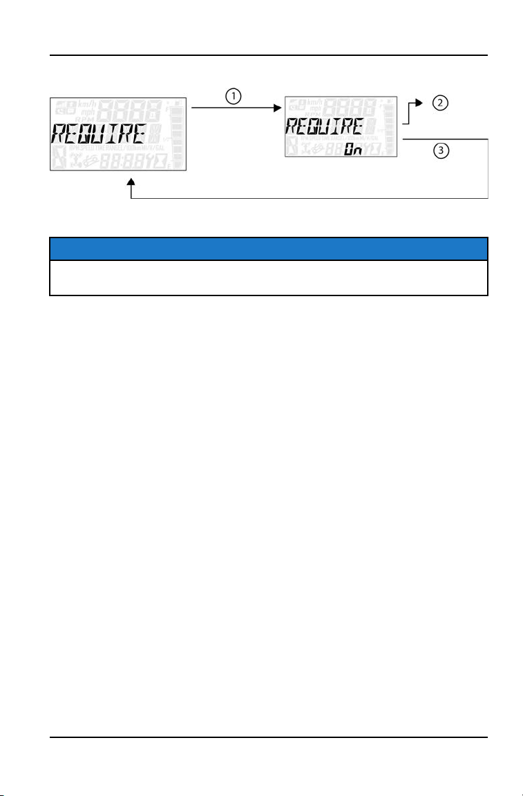
REQUIRE PIN TO START
1. Press and hold the MODE button to enter the Options Menu.
NOTICE
“OPTIONS” will display on the screen for 3 seconds before showing first menu
item.
2. Select “Youth Menu” by pressing the MODE button.
3. Enter PIN.
4. Select “REQUIRE PIN TO START” from the Youth Menu by pressing the
MODE button.
Reference the image shown above:
q
Press the MODE button.
w
Toggle the Up/Down buttons to enable/disable requiring PIN to
start vehicle.
e
With the desired option displayed, press the MODE button which
will set the function and return to the Youth Menu.
5. To exit the Youth Menu the user can select Exit Menu function from Youth
Menu, can hold MODE button and exit out of Youth Menu, or not press any
button for 10 seconds, which will exit out of the Options Menu.
55
INSTRUMENT CLUSTER
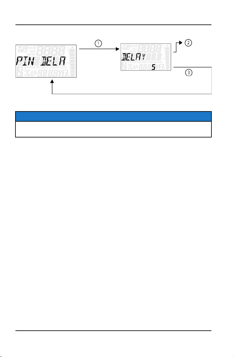
START PIN DELAY
1. Press and hold the MODE button to enter the Options Menu.
NOTICE
“OPTIONS” will display on the screen for 3 seconds before showing first menu
item.
2. Select “Youth Menu” by pressing the MODE button.
3. Enter PIN.
4. Select “PIN DELAY” from the Youth Menu by pressing the MODE button.
Reference the image shown above:
q
Press the MODE button.
w
Toggle the Up/Down buttons to enable/disable PIN Delay.
e
With the desired option displayed, press the MODE button which
will set the function and return to the Youth Menu.
5. To exit the Youth Menu the user can select Exit Menu function from Youth
Menu, can hold Mode Button and exit out of Youth Menu, or not press any
button for 10 seconds, which will exit out of the Options Menu.
56
INSTRUMENT CLUSTER
CHANGE PIN
1. Press and hold the MODE button to enter the Options Menu.
NOTICE
“OPTIONS” will display on the screen for 3 seconds before showing first menu
item.
2. Select “Youth Menu” by pressing the MODE button.
3. Enter PIN.
4. Select “CHANGE PIN” from the Youth Menu by pressing the MODE button.
Reference the image shown above:
q
Press the MODE button.
w
Toggle the Up/Down buttons to increase/decrease the first digit of
the new PIN.
e
With the desired first digit of the new PIN displayed, Press the
MODE button which will set the digit and move to the 2nd digit.
r
Toggle the Up/Down Buttons to increase/decrease the 2nd digit of
the new PIN. Press MODE button to set 2nd digit and move on to
the 3rd digit.
t
Toggle the Up/Down Buttons to increase/decrease the 3rd digit of
the new PIN. Press MODE button to set 3rd digit and move on to
the 4th digit.
5. Press the MODE button to set the 4th digit and exit.
6. To exit the Youth Menu the user can select Exit Menu function from Youth
Menu, can hold Mode button and exit out of Youth Menu, or not press any
button for 10 seconds, which will exit out of the Options Menu.
57
INSTRUMENT CLUSTER

58
OPERATION
WARNING
Failure to operate the vehicle properly can result in a collision, loss of control,
accident or rollover, which may result in serious injury or death. Read and
understand all safety warnings outlined in the safety section of this owner’s
manual.
VEHICLE BREAK-IN PERIOD
The break-in period for your new vehicle is the first 20 hours of operation, or the
time it takes to use the first 2 tanks full of gasoline. No single action on your part
is as important as a proper break-in period. Careful treatment of a new engine
will result in more efficient performance and longer life for the engine. Perform
the following procedures carefully.
NOTICE
Excessive heat build-up during the first 3 hours of operation will damage close-
fitted engine parts and drive components. Do not operate at full throttle or high
speeds during the first 3 hours of use.
BRAKE SYSTEM BREAK-IN
Apply only moderate braking force for the first 50 stops. Aggressive or overly
forceful braking when the brake system is new could damage brake pads and
rotors.
PVT BREAK-IN (CLUTCHES/BELT)
A proper break-in of the clutches and drive belt will ensure a longer life and
better performance. Break in the clutches and belt by operating at slower
speeds during the break-in period as recommended. Pull only light loads. Avoid
aggressive acceleration and high speed operation during the break-in period.
If a belt fails, always clean any debris from the PVT intake and outlet duct and
from the clutch and engine compartments when replacing the belt.
KNOW YOUR RIDING AREA/TREAD LIGHTLY
Familiarize yourself with all laws and regulations concerning the operation of this
vehicle in your area. Respect the environment in which you ride your vehicle.
Find out where the designated riding areas are by contacting your POLARIS
dealer, a local riding club, or local officials.
Help keep our trails open for recreational vehicle use. As an off-road enthusiast,
you represent the sport and can set a good example (or a poor example) for
others to follow. Tread lightly. Operate with respect for the terrain, avoid littering,
and always stay on the designated trails.
59
OPERATION

PRE-RIDE INSPECTION
Failure to inspect and verify that the vehicle is in safe operating condition before
operating increases the risk of an accident. Always inspect the vehicle before
each use to make sure it's in safe operating condition.
ITEM REMARKS PAGE
Brake system/pedal travel Ensure proper operation page 89
Brake fluid Ensure proper level page 89
Front suspension Inspect, lubricate if necessary page 77
Rear suspension Inspect, lubricate if necessary page 77
Steering Ensure free operation -
Tires Inspect condition and pressure page 94
Wheels/fasteners Inspect, ensure fastener tightness page 94
Frame nuts, bolts, fasteners Inspect, ensure tightness -
Drive Belt Inspect, ensure installed correctly -
Fuel and oil Ensure proper levels page 78
Throttle Ensure proper operation page 32
Indicator lights/switches Ensure proper operation page 34
Intake pre-filters Inspect, clean -
Daytime Running Lights (LED) Check operation -
Brake light/tail lamps Check operation -
Seat Latch Push down on the seat back to ensure the latch
is secure
-
Seat Belt Check length of belt for damage, check latches
for proper operation
page 27
Cab Doors (If equipped) Check doors and latches for wear or damage. -
60
OPERATION

STARTING THE ENGINE
1. Position the vehicle on a level surface outdoors or in a well ventilated area.
2. Sit in the driver's seat and fasten the seat belt. Secure the cab nets.
3. Place the transmission in NEUTRAL and apply the PARKING BRAKE.
4. Apply the brakes. Do not press the throttle pedal while starting the engine.
5. Turn the ignition key past the ON/RUN position to START. Engage the starter
for a maximum of five seconds. Release the key when the engine starts.
6. If the engine does not start within five seconds, return the ignition switch to
the OFF position and wait five seconds. Repeat steps 5 and 6 until the
engine starts.
7. Vary the engine RPM slightly with the throttle to aid in warm up until the
engine idles smoothly.
NOTICE
Operating the vehicle immediately after starting could cause engine damage.
Allow the engine to warm up for several minutes before operating the vehicle.
STOPPING THE ENGINE
1. Release the throttle pedal completely and brake to a complete stop.
2. Place the transmission in NEUTRAL and apply the PARKING BRAKE.
3. Turn the engine off.
4. Slowly release the brake pedal and make sure the transmission is in PARK
before exiting the vehicle.
WARNING
A rolling vehicle can cause serious injury. Always place the transmission in
PARK when stopping the engine.
COLD WEATHER OPERATION
If the vehicle is used year-round, check the oil level frequently. A rising oil level
could indicate the accumulation of contaminates such as water or excess fuel in
the bottom of the crankcase. Water in the bottom of the crankcase can lead to
engine damage and must be drained. Water accumulation increases as outside
temperature decreases.
61
OPERATION

BRAKING
1. Release the throttle pedal completely. (When the throttle pedal is released
completely and engine speed slows to near idle, the vehicle has no engine
braking.)
2. Press on the brake pedal evenly and firmly. Practice starting and stopping
(using the brakes) until you're familiar with the controls.
PARKING THE VEHICLE
1. Stop the vehicle on a level surface. When parking inside a garage or other
structure, be sure that the structure is well ventilated and that the vehicle is
not close to any source of flame or sparks, including any appliance with pilot
lights.
2. Place the transmission in NEUTRAL and apply the PARKING BRAKE.
3. Turn the engine off.
4. Slowly release the brake pedal.
5. Remove the ignition key to prevent unauthorized use.
PARKING ON AN INCLINE
Avoid parking on an incline if possible. If it's unavoidable, follow these
precautions:
1. Apply the brakes.
2. Place the transmission in NEUTRAL and apply the PARKING BRAKE.
3. Turn the engine off.
4. Slowly release the brake pedal.
5. Block the rear wheels on the downhill side.
62
OPERATION

HAULING CARGO
WARNING
Overloading the vehicle or carrying or towing cargo improperly can alter
vehicle handling and may cause loss of control or brake instability. Always
follow these precautions when hauling cargo:
• Never exceed the stated load capacity for this vehicle.
• REDUCE SPEED AND ALLOW GREATER DISTANCES FOR BRAKING
WHEN HAULING CARGO.
• NEVER EXCEED THE MAXIMUM WEIGHT CAPACITY of the vehicle.
When determining the weight you are adding to the vehicle, include the
weight of the operator, accessories, and loads in the rack or box. The
combined weight of these items must not exceed the maximum weight
capacity.
• Always load the cargo box with the load centered and as low as possible.
• When operating over rough or hilly terrain, reduce speed and cargo to
maintain stable driving conditions.
• Always operate the vehicle with extreme care when hauling loads.
• SECURE ALL LOADS BEFORE OPERATING. Unsecured loads can create
unstable operating conditions, which could result in loss of control of the
vehicle.
• OPERATE ONLY WITH STABLE AND SAFELY ARRANGED LOADS. When
handling off-centered loads that cannot be centered, securely fasten the
load and operate with extra caution.
• HEAVY LOADS CAN CAUSE BRAKING AND CONTROL PROBLEMS. Use
extreme caution when applying brakes with a loaded vehicle. Avoid terrain
or situations that may require backing downhill.
• USE EXTREME CAUTION when operating with loads that extend over the
rack sides. Stability and maneuverability may be adversely affected, causing
vehicle rollover.
• Carrying a passenger in the cargo box could result in a fall from the vehicle
or contact with moving components. Never allow a passenger to ride in the
cargo box.
63
OPERATION

DRIVING PROCEDURES
NEW OPERATOR DRIVING PROCEDURES
1. Read and understand the owner's manual and all warning and instruction
labels before operating this vehicle.
2. Visit the Recreational Off-Highway Vehicle Association web site and take the
free on-line training course. Visit www.rohva.org or call 866-267-2751.
Hands-on training is also available through ROHVA.
3. Perform the pre-ride inspection.
4. Do not carry cargo during this period.
5. Select an open area that allows room to familiarize yourself with vehicle
operation and handling.
6. The driver and passenger must wear helmet, eye protection, gloves, long-
sleeve shirt, long pants, over-the-ankle boots and seat belt at all times.
7. Sit in the driver's seat and fasten the seat belt.
8. Always make sure all cab nets are closed and latched when riding in this
vehicle.
9. Place the transmission in NEUTRAL.
10.Start the engine and disengage the parking brake.
11. Apply the brakes and shift into gear.
12.Check your surroundings and determine your path of travel.
13.Keeping both hands on the steering wheel, slowly release the brakes and
depress the throttle with your right foot to begin driving.
14.Drive slowly at first. On level surfaces, practice starting, stopping, turning,
maneuvering, using the throttle and brakes and driving in reverse. Learn how
the vehicle handles when making both left and right turns at a slow speed.
15.Increase speed only after mastering all maneuvers at a slow speed.
16.After you become skilled at making turns and begin to operate at faster
speeds, follow these precautions:
• Avoid sharp turns.
• Never turn while applying heavy throttle.
• Never make abrupt steering maneuvers.
• Operate at speeds appropriate for your skills, the conditions and the
terrain.
• DO NOT do power slides, “donuts”, jumps or other driving stunts.
64
OPERATION

DRIVING WITH A PASSENGER
1. Perform the pre-ride inspection.
2. Make sure all passengers are at least 10 years of age and tall enough to
comfortably and safely sit in the passenger seat with the seat belt secured,
put both feet on the floor and grasp the hand hold.
3. Make sure passenger is wearing helmet, eye protection, gloves, long-sleeve
shirt, long pants and over-the-ankle boots.
4. Make sure passenger secures their seat belt.
5. Make sure all cab nets are properly secured.
6. Do not carry more than the recommended number of passengers for your
vehicle.
7. Allow a passenger to ride only in a passenger seat.
8. Slow down. Always travel at a speed appropriate for your skills, your
passenger’s skills, and operating conditions. Avoid unexpected or
aggressive maneuvers that could cause discomfort or injury to a passenger.
9. Vehicle handling may change with a passenger and/or cargo on board. Allow
more time and distance for braking.
10.Always follow all operating guidelines as outlined on safety labels and in this
manual.
65
OPERATION
DRIVING ON SLIPPERY SURFACES
WARNING
Skidding or sliding can cause loss of control or rollover (if tires regain traction
unexpectedly). When operating on slippery surfaces such as ice or loose
gravel, reduce speed and use extra caution to reduce the chance of skidding or
sliding out of control. Do not operate on excessively slippery surfaces.
When driving on slippery surfaces such as wet trails, loose gravel, or ice, be
alert for the possibility of skidding and sliding. Follow these precautions when
encountering slippery conditions:
1. Do not operate on excessively rough, slippery or loose terrain.
2. Slow down before entering slippery areas.
3. Maintain a high level of alertness, reading the trail and avoiding quick, sharp
turns, which can cause skids.
4. Correct a skid by turning the steering wheel in the direction of the skid. Never
apply the brakes during a skid.
DRIVING OVER OBSTACLES
Follow these precautions when operating over obstacles:
1. Always check for obstacles before operating in a new area.
2. Look ahead and learn to read the terrain. Be constantly alert for hazards
such as logs, rocks and low hanging branches.
3. Travel slowly and use extra caution when operating on unfamiliar terrain. Not
all obstacles are immediately visible.
4. Move the drive mode switch to low mode if needed.
5. Avoid operating over large obstacles such as large rocks and fallen trees. If
unavoidable, use extreme caution and operate slowly.
6. Always have all passengers dismount and move away from the vehicle
before operating over an obstacle that could cause a rollover.
66
OPERATION

DRIVING UPHILL
Whenever traveling uphill, follow these precautions:
1. Avoid excessively steep hills.
2. Always travel straight uphill.
3. Keep both feet on the floor.
4. Always check the terrain carefully before ascending any hill. Never climb hills
with excessively slippery or loose surfaces.
5. Proceed at a steady rate of speed and throttle opening. Never open the
throttle suddenly.
6. Never go over the crest of a hill at high speed. An obstacle, a sharp drop, or
another vehicle or person could be on the other side of the hill.
DRIVING DOWNHILL
When driving downhill, follow these precautions:
1. Avoid excessively steep hills.
2. Always descend a hill with the direction selector switch on forward. Never
descend a hill with the switch on neutral.
3. Drive straight downhill. Avoid descending a hill at an angle, which would
cause the vehicle to lean sharply to one side. Travel straight downhill when
possible.
4. Slow down.
5. Apply the brakes slightly to aid in slowing.
DRIVING ON A SIDEHILL (SIDEHILLING)
Driving on a sidehill is not recommended. Improper procedure could cause loss
of control or rollover. Avoid crossing the side of any hill unless absolutely
necessary.
If crossing a sidehill is unavoidable, follow these precautions:
1. Slow down.
2. Exercise extreme caution.
3. Avoid crossing the side of a steep hill.
67
OPERATION

DRIVING THROUGH WATER
Your vehicle can drive through shallow
water. Make sure the water is no
deeper than the floor of the vehicle.
Follow these precautions when driving
through water:
1. Check water depth. Never drive
through water that is deeper than
the floor level.
2. After driving through water, test the
brakes. Apply the lightly several
times while driving slowly. The
Friction will help dry out the pads.
NOTE
Major engine damage can result if the vehicle is not thoroughly inspected after
operation in water. Perform the services outlined in the maintenance chart.
Give special attention to engine oil, transmission oil, and all grease fittings.If
your vehicle becomes immersed or is operated in water that exceeds the floor
level, service is required before starting the engine. Your Polaris dealer can
provide this service. If it’s impossible to bring the vehicle in before starting the
engine, perform the services outlined on page 93, and take the vehicle in for
service at the first opportunity.
DRIVING IN REVERSE
Follow these precautions when operating in reverse:
1. Always check for obstacles or people behind the vehicle. Always inspect left
and right fields of vision before backing.
2. Always avoid backing downhill.
3. Back slowly.
4. Apply the brakes lightly for stopping.
5. Avoid turning at sharp angles.
6. Never open the throttle suddenly.
68
OPERATION

EMISSION CONTROL SYSTEMS
NOISE EMISSION CONTROL SYSTEM
Do not modify the engine, intake or exhaust components, as doing so may affect
compliance with U.S.A. EPA noise control requirements (40 CFR 205) and local
noise level requirements.
OPERATION ON PUBLIC LANDS IN THE U.S.A.
Your vehicle has a spark arrester that was tested and qualified to be in
accordance with the USFS standard 5100-1C. Federal law requires that this
spark arrester be installed and functional when the vehicle is operated on public
lands.
Operation of off-road vehicles on public lands in the U.S.A. is regulated by 43
CFR 420. Violations are subject to monetary penalties. Federal regulations can
be viewed online at www.gpoaccess.gov/ecfr/.
CRANKCASE EMISSION CONTROL SYSTEM
This engine is equipped with a closed crankcase system. Blow-by gases are
forced back to the combustion chamber by the intake system. All exhaust gases
exit through the exhaust system.
EXHAUST EMISSION CONTROL SYSTEM
Exhaust emissions are controlled by engine design. An electronic fuel injection
(EFI) system controls fuel delivery. The engine and EFI components are set at
the factory for optimal performance and are not adjustable.
The emissions label is located on the inside of the lower left frame tube (below
driver’s foot area).
ELECTROMAGNETIC INTERFERENCE
This spark ignition system complies with Canadian ICES-002.
This vehicle complies with the EMC requirements of UN ECE Regulation 10.
Non-ionizing Radiation: This vehicle emits some electromagnetic energy.
People with active or non-active implantable medical devices (such as heart
monitoring or controlling devices) should review the limitations of their device
and the applicable electromagnetic standards and directives that apply to this
vehicle.
69
EMISSION CONTROL SYSTEMS

70

MAINTENANCE
PERIODIC MAINTENANCE
Any qualified repair shop or person may maintain, replace or repair the emission
control devices or systems on your vehicle. An authorized POLARIS dealer can
perform any service that may be necessary for your vehicle. POLARIS also
recommends POLARIS parts for emissions-related service, however equivalent
parts can be used.
It is a potential violation of the Clean Air Act if a part supplied by an aftermarket
parts manufacturer reduces the effectiveness of the vehicle’s emission controls.
Tampering with emission controls is prohibited by federal law.
Owners are responsible for performing the scheduled maintenance identified in
this owner’s manual.
Careful periodic maintenance will help keep your vehicle in the safest, most
reliable condition. Inspection, adjustment and lubrication of important
components are explained in the periodic maintenance chart.
Inspect, clean, lubricate, adjust and replace parts as necessary. When
inspection reveals the need for replacement parts, genuine POLARIS parts are
available from your POLARIS dealer. Equivalent parts may be used for
emissions-related service.
Service and adjustments are important for proper vehicle operation. If you’re not
familiar with safe service and adjustment procedures, a qualified dealer can
perform these operations.
Vehicles subjected to heavy or severe use patterns must be inspected and
serviced more frequently.
SEVERE USE DEFINITION
• Frequent immersion in mud, water or sand
• Frequent or prolonged operation in dusty environments
• Short trip cold weather operation
• Racing or race-style high RPM use
• Prolonged low speed, heavy load operation
• Extended idle
Pay special attention to the oil level. A rise in oil level during cold weather can
indicate contaminants collecting in the oil sump or crankcase. Change oil
immediately if the oil level begins to rise. Monitor the oil level, and if it continues
to rise, discontinue use and determine the cause. Your dealer can assist.
71
MAINTENANCE
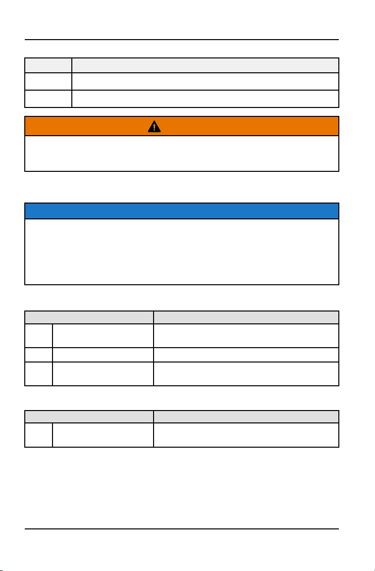
MAINTENANCE CHART KEY
SYMBOL DESCRIPTION
XU Perform these procedures more often for vehicles subjected to severe use.
D Have an authorized dealer or other qualified person perform these services.
WARNING
Improperly performing the procedures marked with a D could result in
component failure and lead to serious injury or death. Have an authorized
dealer or other qualified person perform these services.
MAINTENANCE INTERVALS
NOTE
The maintenance interval charts outline required maintenance and inspection
based on estimated vehicle engine hours / miles. Each table states the number
of hours / miles that service is required on the vehicle. Some items or
components may need to be serviced more often due to severe use, such as
operation in water or under severe loads. When the vehicle goes beyond 400
hours, return to the 25 hours chart and start the interval process over.
5 HOUR / BREAK-IN SERVICE
ITEM REMARKS
XU
Engine Oil Change
(Break-in)
Perform a break-in oil change at one month
Drive Chain (Break-in) Adjust and lubricate
XU
D
Brake pad wear (Break-
in)
Inspect periodically
10 HOUR / 100 MILE (160 KM) SERVICE
ITEM REMARKS
D
Valve Clearance
(Break-in)
Valve lash adjustment: Every 50 hours after
first 10–hour adjustment
72
MAINTENANCE
25 HOUR / 250 MILE (400 KM) SERVICE
ITEM REMARKS
Fuel System
Inspect; cycle key to pressurize fuel pump;
check lines and fittings for leaks and abrasion
Battery
Check terminals; clean; test
XU
Engine Oil Change
50 HOUR / 500 MILE (800 KM) SERVICE
ITEM REMARKS
XU
Fuel System
Inspect; cycle key to pressurize fuel pump;
check lines and fittings for leaks and abrasion
Battery
Check terminals; clean; test
XU Main Gearcase Oil
Inspect level; change yearly
XU
Engine Oil Change
D Valve Clearance
Valve lash adjustment: Every 40 hours after
first 10-hour adjustment
XU General Lubrication
Lubricate all fittings, pivots, cables, etc.
Shift Linkage Inspect, lubricate, adjust
XU
Steering
Lubricate
XU
Front Suspension
Lubricate
XU
Rear Suspension
Lubricate
Throttle Body Intake
Duct
Inspect duct for proper sealing/air leaks
75 HOUR / 750 MILE (1200 KM) SERVICE
ITEM REMARKS
Fuel System
Inspect; cycle key to pressurize fuel pump;
check lines and fittings for leaks and abrasion
Battery
Check terminals; clean; test
XU Main Gearcase Oil
Inspect level; change yearly
XU
Engine Oil Change
73
MAINTENANCE

100 HOUR / 1000 MILE (1600 KM) SERVICE
ITEM REMARKS
Battery
Check terminals; clean; test
XU
Transmission (Main
Gearcase)
Replace transmission fluid
XU
Engine Oil Change
D Valve Clearance
Valve lash adjustment
XU General Lubrication
Lubricate all fittings, pivots, cables, etc.
Shift Linkage Inspect, lubricate, adjust
D
Steering
Lubricate
XU
Front Suspension
Lubricate
XU
Rear Suspension
Lubricate
Throttle Body Intake
Duct
Inspect duct for proper sealing/air leaks
D
Fuel System / Filter
Cycle key to pressurize fuel pump; check for
leaks at fill cap, fuel lines/rail and fuel pump;
replace lines every two years
XU
Spark Plug Inspect; replace as needed
XU
Engine Mounts Inspect
Exhaust Muffler / Pipe Inspect
XU
Wiring
Inspect for wear, routing, security; apply
dielectric grease to connectors subjected to
water, mud, etc.
D
Clutches (Drive and
Driven)
Inspect; clean; replace worn parts
Drive belt
Inspect; replace as needed
D
Front wheel bearings Inspect; replace as needed
125 HOUR / 1250 MILE (2000 KM) SERVICE
ITEM REMARKS
Fuel System
Inspect; cycle key to pressurize fuel pump;
check lines and fittings for leaks and abrasion
Battery
Check terminals; clean; test
XU Main Gearcase Oil
Inspect level; change yearly
XU
Engine Oil Change
74
MAINTENANCE
150 HOUR / 1500 MILE (2400 KM) SERVICE
ITEM REMARKS
XU
Fuel System
Inspect; cycle key to pressurize fuel pump;
check lines and fittings for leaks and abrasion
Battery
Check terminals; clean; test
XU Main Gearcase Oil
Inspect level; change yearly
XU
Engine Oil Change
D Valve Clearance
Valve lash adjustment
XU General Lubrication
Lubricate all fittings, pivots, cables, etc.
Shift Linkage Inspect, lubricate, adjust
D
Steering
Lubricate
XU
Front Suspension
Lubricate
XU
Rear Suspension
Lubricate
Throttle Body Intake
Duct
Inspect duct for proper sealing/air leaks
175 HOUR / 1750 MILE (2800 KM) SERVICE
ITEM REMARKS
Fuel System
Inspect; cycle key to pressurize fuel pump;
check lines and fittings for leaks and abrasion
Battery
Check terminals; clean; test
XU Main Gearcase Oil
Inspect level; change yearly
XU
Engine Oil Change
200 HOUR / 2000 MILE (3200 KM) SERVICE
ITEM REMARKS
Battery
Check terminals; clean; test
XU Main Gearcase Oil
Inspect level; change yearly
XU
Engine Oil Change
D Valve Clearance
Valve lash adjustment
XU General Lubrication
Lubricate all fittings, pivots, cables, etc.
Shift Linkage Inspect, lubricate, adjust
D
Steering
Lubricate
XU
Front Suspension
Lubricate
XU
Rear Suspension
Lubricate
75
MAINTENANCE

ITEM REMARKS
Throttle Body Intake
Duct
Inspect duct for proper sealing/air leaks
D
Fuel System / Filter
Cycle key to pressurize fuel pump; check for
leaks at fill cap, fuel lines/rail and fuel pump;
replace lines every two years
XU
Spark Plug Inspect; replace as needed
XU
Engine Mounts Inspect
Exhaust Muffler / Pipe Inspect
XU
Wiring
Inspect for wear, routing, security; apply
dielectric grease to connectors subjected to
water, mud, etc.
XU
Clutches (Drive and
Driven)
Inspect; clean; replace worn parts
Drive belt
Inspect; replace as needed
D
Front wheel bearings Inspect; replace as needed
D Brake fluid
Change every two years
225 HOUR / 2250 MILE (3600 KM) SERVICE
ITEM REMARKS
Fuel System
Inspect; cycle key to pressurize fuel pump;
check lines and fittings for leaks and abrasion
Battery
Check terminals; clean; test
XU Main Gearcase Oil
Inspect level; change yearly
XU
Engine Oil Change
250 HOUR / 2500 MILE (4000 KM) SERVICE
ITEM REMARKS
XU
Fuel System
Inspect; cycle key to pressurize fuel pump;
check lines and fittings for leaks and abrasion
Battery
Check terminals; clean; test
XU Main Gearcase Oil
Inspect level; change yearly
XU
Engine Oil Change
D Valve Clearance
Valve lash adjustment
XU General Lubrication
Lubricate all fittings, pivots, cables, etc.
Shift Linkage Inspect, lubricate, adjust
76
MAINTENANCE

ITEM REMARKS
D
Steering
Lubricate
XU
Front Suspension
Lubricate
XU
Rear Suspension
Lubricate
Throttle Body Intake
Duct
Inspect duct for proper sealing/air leaks
LUBRICATION RECOMMENDATIONS
Check and lubricate all components at the intervals outlined in the Periodic
Maintenance Chart beginning on page 72, or more often under severe use, such
as wet or dusty conditions. Items not listed in the chart should be lubricated at
the general lubrication interval.
ITEM LUBE METHOD
Engine Oil PS-4 5W-50 4-Cycle Oil See page 78
Brake Fluid DOT 4 Brake Fluid See page 90
Transmission Oil
(Main Gearcase)
AGL Gearcase Lubricant &
Transmission Fluid
See page 80
Drive Chain POLARIS Chain Lube or
SAE 80/90
See page 82
A-Arm Pivots POLARIS All Season Grease or grease conforming to NLGI
No. 2 Grease at general lubrication interval, also after
washing vehicle or driving in water.XU Steering Arm Pivots
XU Perform these procedures more often for vehicles subjected to severe use.
77
MAINTENANCE
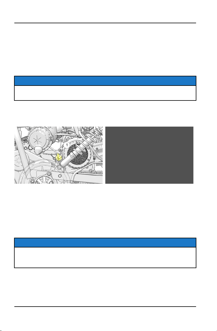
ENGINE OIL
OIL RECOMMENDATIONS
Always check and change the engine oil at the intervals outlined in the Periodic
Maintenance Chart beginning on page 72. POLARIS recommends the use of
POLARIS PS-4 5W-50 4-Cycle Oil for this vehicle. Oil may need to be changed
more frequently if POLARIS oil is not used. Do not use automotive oil. See page
113 for the part numbers of POLARIS products.
NOTICE
Mixing brands or using a non-recommended oil may cause serious engine
damage. Always use the recommended oil. Never substitute or mix oil brands.
OIL CHECK
Maintain the oil level within the safe range on the dipstick. Do not overfill.
q
Dipstick
w
Safe Range
1. Position the vehicle on a level surface.
2. Remove the dipstick. Wipe it dry with a clean cloth.
3. Reinstall the dipstick completely.
4. Remove the dipstick and check the oil level.
TIP
A rising oil level between checks in cool weather driving can indicate
contaminants such as gas or moisture collecting in the crankcase. If the oil
level is over the full/safe mark, change the oil immediately.
5. Add the recommended oil as needed.
6. Reinstall the dipstick.
78
MAINTENANCE
OIL CHANGE
1. Position the vehicle on a level surface. Set the parking brake.
2. Clean the area around the pre-filter plug.
3. Start the engine. Allow it to idle for two to three minutes.
4. Stop the engine.
WARNING
Hot oil can cause burns to skin. Do not allow hot oil to contact skin.
5. Place a drain pan under the engine crankcase.
6. Remove the pre-filter plug. Allow the oil to drain completely.
7. Wash the oil pre-filter screen with solvent to remove debris. Allow the screen
to air dry.
8. Clean the pre-filter plug. Install a new sealing washer on the plug. The
sealing surfaces on the plug and crankcase should be clean and free of
burrs, nicks or scratches.
9. Reassemble the pre-filter screen and spring to the pre-filter plug.
10.Reinstall the pre-filter drain plug. Torque to 11 ft. lbs. (15 Nm).
11. Remove the dipstick. Add 37 oz. (1.1 liters) of the recommended oil. Do not
overfill. See the specifications section for capacities.
12.Reinstall the dipstick.
13.Start the engine. Allow it to idle for one to two minutes.
14.Stop the engine and inspect for leaks.
15.Check the oil level. Add oil as needed to bring the level to the upper mark on
the dipstick.
16.Dispose of used oil properly.
79
MAINTENANCE
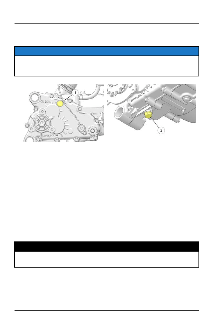
TRANSMISSION
TRANSMISSION OIL CHANGE
NOTE
Maximum transmission fluid volume cannot exceed 25oz. (750ml). Fill / check
method is not fill to spill. Follow Fluid Change Procedure to verify transmission
is filled with fluid. Do not overfill.
Always change the fluid at the intervals outlined in the Periodic Maintenance
Interval Chart. Polaris recommends the use of AGL Gearcase Lubricant and
Transmission Fluid for this vehicle. The fill plug
q
is located on the side of the
transmission gearcase. Access the fill plug on the right-hand side of the
gearcase. The drain plug
w
is located on the bottom of the transmission
gearcase. Access the drain plug from the bottom of the vehicle.
To change the transmission fluid, do the following:
1. Remove the fill plug.
2. Place a drain pan under the transmission drain plug.
3. Remove drain plug
w
and allow lubricant to drain completely.
4. Clean the drain plug magnetic surface.
5. Reinstall the drain plug and torque to specification.
TORQUE
Transmission Fill / Drain Plug:
14 ft-lbs (19 Nm)
80
MAINTENANCE

6. Add the recommended amount of lubricant through the fill plug hole
q
. Do
NOT overfill or fill to the bottom of the fill plug hole.
FLUID CAPACITY
Recommended Transmission Lubricant:
Polaris AGL
Capacity:
25 oz. (750 ml)
7. Reinstall the fill plug and torque to specification.
TORQUE
Transmission Fill / Drain Plug:
14 ft-lbs (19 Nm)
8. Check for leaks. Dispose of used lubricant properly.
81
MAINTENANCE
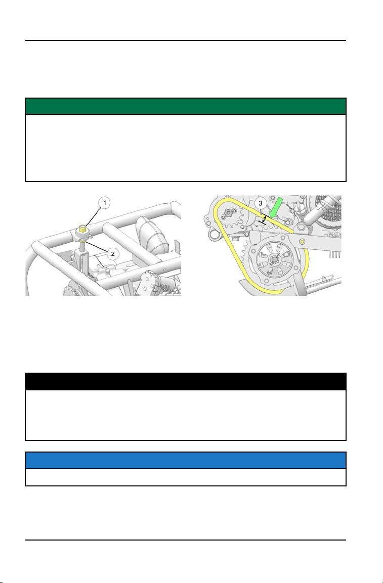
DRIVE CHAIN LUBRICATION AND ADJUSTMENT
Lubricate the drive chain with Polaris chain spray lube or an approved chain lube
at the interval specified in the Periodic Maintenance Chart. Lubricate more often
under severe use, such as in dirty or wet conditions.
IMPORTANT
Washing the drive chain with a high pressure washer or solvents can cause
premature wear and chain failure. Do not use a high pressure washer or
gasoline to clean the drive chain. Operating the vehicle with improper rear
drive chain deflection can result in severe damage to the transmission and
drive components. Always make sure the chain adjusted within the stated
specifications.
1. Loosen upper nut
q
on the chain tensioner bracket.
2. Turn lower nut
w
clockwise in 1/2 turn increments, then turn upper nut until
tight. Follow this procedure until chain is at proper tension. To check for
proper tension, press the down on the middle of the chain with thumb using
22 lbs (100N) of force. Chain deflection
e
should be within specification.
MEASUREMENT
Chain Deflection:
Using 22 lbs (100N) of force
New Chain: 3/16 - 13/32” (5 - 10 mm)
Broken In Chain: 13/32 - 19/32” (10 - 15 mm)
NOTE
A new chain will stretch after the vehicle is used for a period of time.
3. Repeat these steps until chain is adjusted to desired deflection.
82
MAINTENANCE
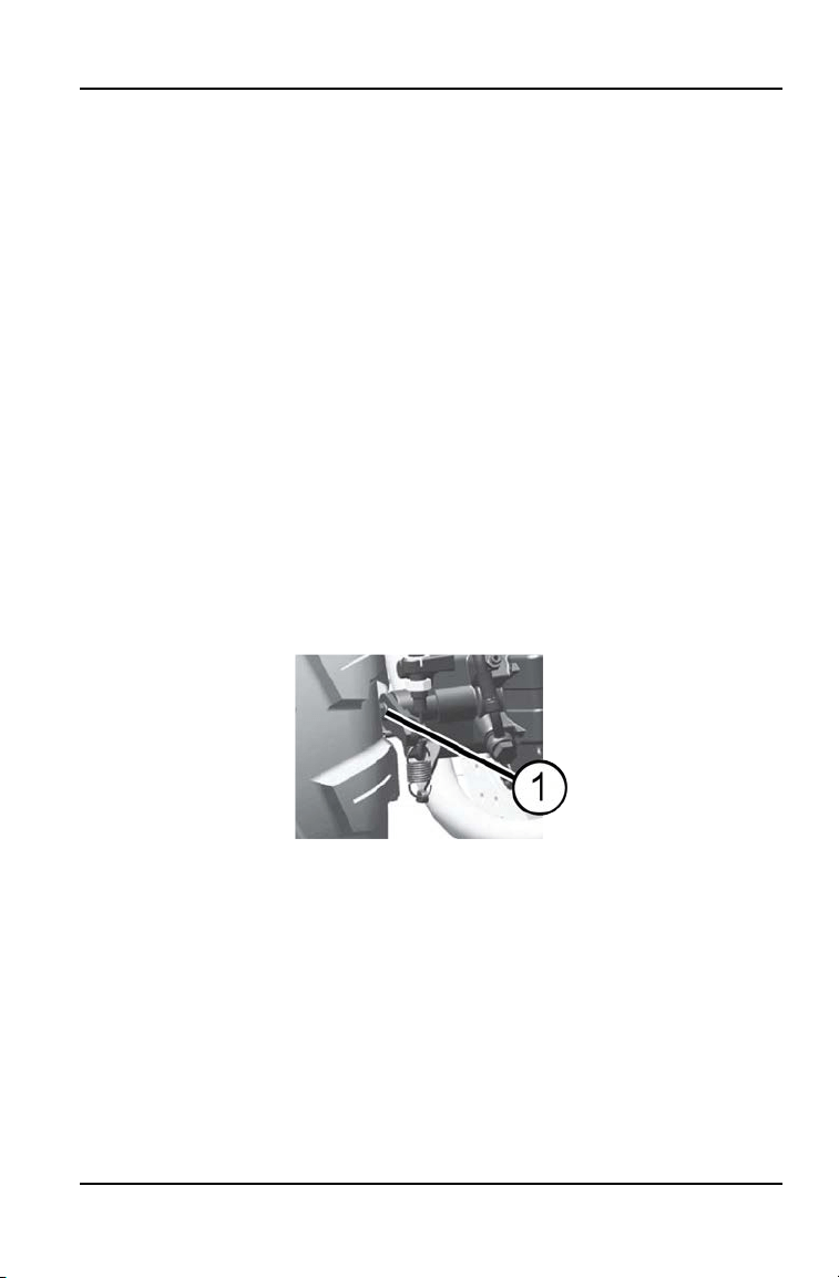
PARKING BRAKE
PARKING BRAKE CABLE FREEPLAY ADJUSTMENT
1. Inspect and perform any needed service on the brake pads before adjusting
parking brake cable freeplay.
2. Make sure the parking brake is NOT set (the lever should be in the DOWN
position).
3. Pull the brake cable back to inspect freeplay between the cable end and the
caliper bracket. Freeplay should be 1/16" - 1/8" (1.5-3 mm).
4. To adjust freeplay, loosen the jam nut. Turn the in-line adjuster nut outward to
decrease freeplay. Turn the adjuster nut inward to increase freeplay.
5. Tighten the jam nut against the adjuster nut.
PARKING BRAKE ADJUSTMENT
1. Inspect and perform any needed service on the brake pads before adjusting
the parking brake.
2. Position the vehicle on a level surface. Place the transmission in neutral.
3. Carefully elevate the rear of the vehicle slightly. Use an appropriate lift.
4. Loosen the jam nut on the parking brake adjustment bolt
q
.
5. While rotating the rear wheels by hand, tighten the adjustment bolt until
significant brake drag is detected. Then back the adjustment bolt out 1/4
turn.
6. Hold the adjustment bolt in place and tighten the jam nut securely against the
lever arm.
7. Check parking brake lever movement. Verify that the rear wheels rotate
freely with the parking brake off (lever in DOWN position) and that the vehicle
will not move when the parking brake is applied (lever in UP position).
8. Verify that the park brake lever stays in the UP position when the brake is
fully applied.
83
MAINTENANCE
SPARK PLUG
SPARK PLUG GAP/TORQUE
Electrode Gap New Plug Torque Used Plug Torque
0.6-0.7 mm
9-11 ft. lbs.
(12-15 Nm)
17-20 ft. lbs.
(23-27 Nm)
NOTICE
Spark plug condition is indicative of engine operation. The spark plug firing end
condition should be read after the engine is warmed up and the vehicle is
driven at higher speeds. Immediately check the spark plug for correct color.
WARNING
A hot exhaust system and engine can cause burns. Wear protective gloves
when removing a spark plug for inspection.
SPARK PLUG CONDITION
Normal Plug
The normal insulator tip is gray, tan or light brown. There will be few combustion
deposits. The electrodes are not burned or eroded. This indicates the proper
type and heat range for the engine and the service.
TIP
The tip should not be white. A white insulator tip indicates overheating, caused
by use of an improper spark plug or incorrect throttle body adjustments.
Wet Fouled Plug
The wet fouled insulator tip is black. A damp oil film covers the firing end. There
may be a carbon layer over the entire nose. Generally, the electrodes are not
worn. General causes of fouling are excessive oil, use of non-recommended
injection oil or incorrect throttle body adjustments.
84
MAINTENANCE
SPARK PLUG REMOVAL AND REPLACEMENT
1. Remove the spark plug cap
q
.
2. Using the spark plug wrench
provided in the tool kit, remove the
plug by rotating it counter-
clockwise.
3. Reverse the procedure for spark
plug installation. Torque to
specification.
CONSTANT VARIABLE TRANSMISSION
(CVT) SYSTEM
WARNING
Failure to comply with the instructions in this warning can result in severe injury
or death.
Do not modify any component of the CVT system. Doing so may reduce its
strength so that a failure may occur at a high speed. The CVT system has been
precision balanced. Any modification will cause the system to be out of
balance, creating vibration and additional loads on components.
• Always follow all recommended maintenance procedures. See your
POLARIS dealer, or other qualified person, for service and repair
assistance.
• This CVT system is intended for use on POLARIS products only. Do not
install it in any other product.
• Always make sure the CVT housing is securely in place during operation.
CVT DRYING
NOTE
After operating in water, the vehicle’s CVT system should be checked
immediately. Use the following instructions to dry it out before operating.
85
MAINTENANCE
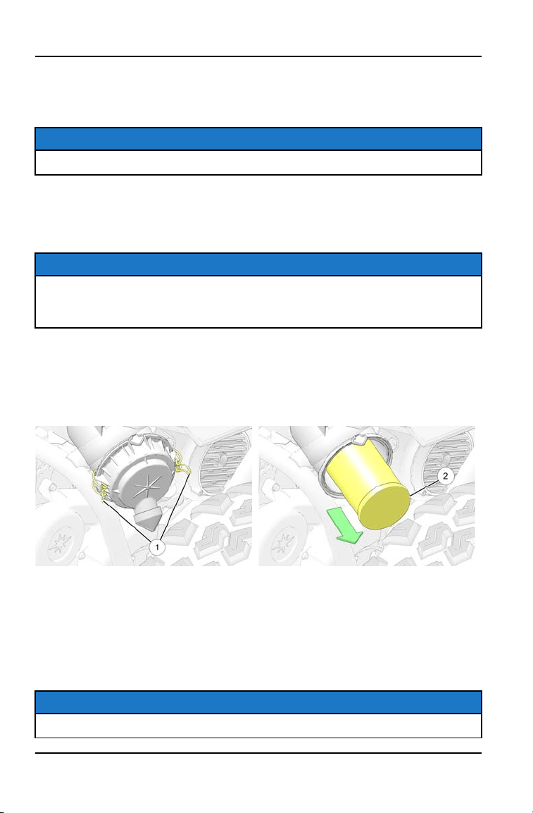
1. Shift the transmission to neutral. Set the parking brake.
2. Start the engine. Apply varying throttle for 10-15 seconds to expel the
moisture and air-dry the belt and clutches.
NOTE
Do not hold the throttle pedal wide open for more than 5 seconds.
3. Allow the engine RPM to return to idle, then shift the transmission into gear.
4. Test the CVT system for belt slippage. If the belt slips, repeat the process or
remove the outer clutch cover to inspect the CVT system.
NOTE
If the vehicle has ingested a large amount of water into the CVT system and
has not been operated for a period of time, be sure to check the CVT system
components for water damage.
AIR FILTER
Inspect the air filter at the intervals outlined in the Periodic Maintenance Chart.
In extremely dusty conditions, air filter replacement will be required more often.
Access the air box near the right rear wheel.
1. Disengage the two cover latches
q
.
2. Unlatch the cover and carefully remove it from the air box.
3. Remove the filter
w
.
4. Inspect the air box for oil or water deposits. Wipe away any deposits with a
clean shop towel.
NOTE
If the filter has been soaked with fuel or oil it must be replaced.
86
MAINTENANCE

5. Inspect the air filter and replace if necessary.
NOTE
DO NOT attempt to clean the air filter with compressed air .
6. Place the air filter into the air box and reinstall the air box cover.
NOTE
Make sure the tabs are properly positioned into the hinge. Ensure the O-ring is
installed inside the lid properly.
7. Engage the cover latches.
87
MAINTENANCE
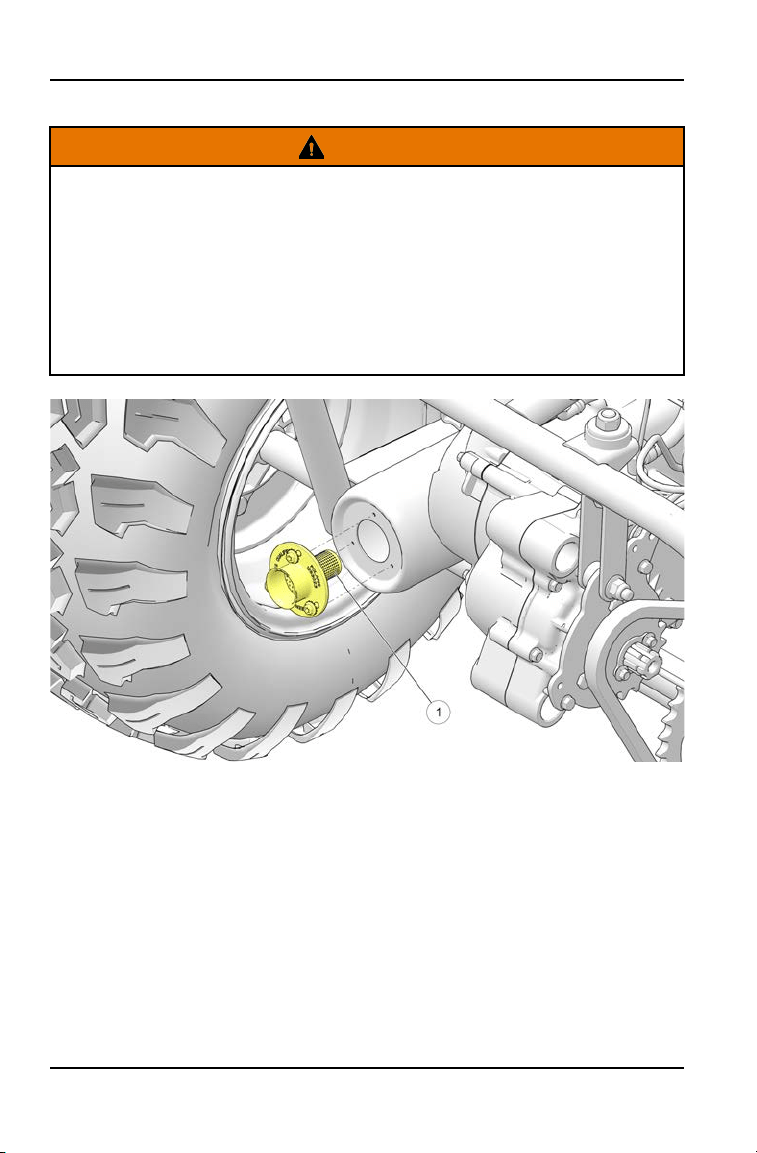
SPARK ARRESTER
WARNING
Failure to heed the following warnings while servicing the spark arrester could
result in serious injury or death.
• Do not perform service on the spark arrester while the system is hot. Allow
components to cool sufficiently before proceeding.
• Wear eye protection and gloves.
• Never operate without the spark arrestor.
• Never run the engine in an enclosed area. Exhaust contains poisonous
carbon monoxide gas.
To remove accumulated carbon, clean the spark arrester at the intervals
recommended in the Periodic Maintenance Chart beginning on page 72.
1. Remove the 3 bolts and remove the arrester
q
from the end of the muffler.
2. Use a non-synthetic brush to clean the arrester screen. A synthetic brush
may melt if components are warm. If necessary, blow debris from the screen
with compressed air.
3. Inspect the screen for wear and damage. Replace the arrester if damage is
found.
4. Reinstall the arrester.
5. Torque the bolts to 7 ft. lbs. (9.5 Nm).
88
MAINTENANCE
BRAKES
The front and rear brakes are hydraulic disc type brakes activated by the brake
pedal.
Always check brake pedal travel and the brake fluid reservoir level before each
use of the vehicle. When applied, the brake pedal should feel firm. Any
sponginess would indicate a possible fluid leak or low brake fluid level, which
must be corrected before riding.
If you discover any irregularities in brake system operation, including excessive
pedal travel, contact your dealer for proper diagnosis and repairs.
WARNING
Operating the vehicle with a spongy brake pedal can result in loss of braking,
which could cause an accident resulting in severe injury or death. Never
operate the vehicle with a spongy-feeling brake pedal.
BRAKE INSPECTION
1. Check the brake system for fluid leaks.
2. Check the brake pedal for excessive travel or a spongy feel.
3. Check the brake pads
q
for wear, damage and looseness.
4. Inspect the brake pad wear surface for excessive wear.
5. Change pads when the friction material is worn to .04" (1 mm)
w
.
6. Check the surface condition of the brake discs
e
. Measure the thickness.
Replace a disc if the thickness is less than .170” (4.32 mm).
7. Check brake system hoses and fittings for cracks, deterioration, abrasion
and leaks. Tighten any loose fittings and replace any worn or damaged parts.
89
MAINTENANCE
BRAKE FLUID
Inspect the level of the brake fluid before each operation. If the fluid level is low
add DOT 4 brake fluid only. See page 113 for the part numbers of POLARIS
products.
WARNING
After opening a bottle of brake fluid, always discard any unused portion. Never
store or use a partial bottle. Brake fluid is hygroscopic, meaning it rapidly
absorbs moisture from the air. The moisture causes the boiling temperature of
the brake fluid to drop, which can lead to early brake fade and the possibility of
accident or severe injury.
Change the brake fluid every two years and any time the fluid becomes
contaminated, the fluid level is below the minimum, or if the type and brand of
the fluid in the reservoir are unknown. Access the brake fluid reservoir through
the left front wheel well.
1. Position the vehicle on a level surface.
2. Place the transmission in neutral. Set the parking brake.
3. View the brake fluid level in the reservoir
q
. The level should be between the
maximum
w
and minimum
e
level lines. Add brake fluid as needed.
4. Apply the brake forcefully for a few seconds and check for fluid leakage
around the fittings.
STEERING WHEEL INSPECTION
Check the steering wheel for specified freeplay and smooth operation at the
intervals outlined in the Periodic Maintenance Chart.
1. Position the vehicle on level ground.
2. Lightly turn the steering wheel left and right.
3. There should be 0.8"-1.0" (20-25 mm) of freeplay.
4. If there is excessive freeplay or strange noises, or the steering feels rough or
"catchy," have the steering system inspected by an authorized POLARIS
dealer or other qualified service facility before operating the vehicle.
90
MAINTENANCE
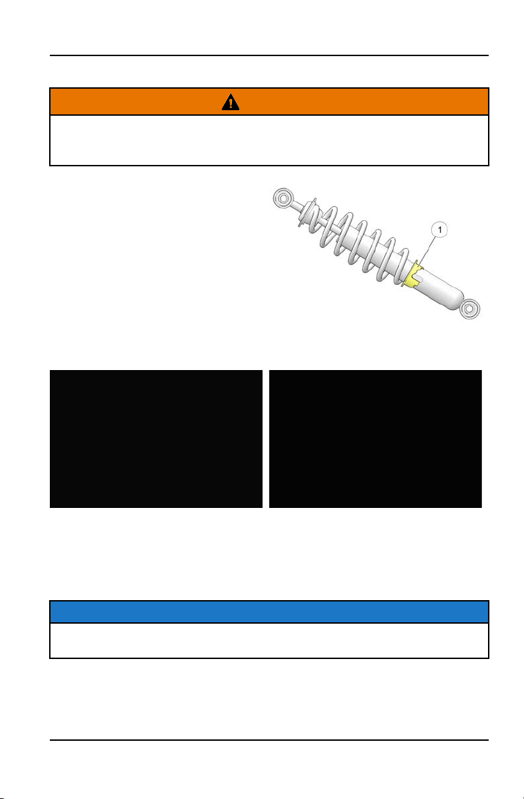
SHOCK SPRING ADJUSTMENT
WARNING
Uneven adjustment may cause poor handling of the vehicle, which could result
in an accident. Always adjust both the left and right spring preloads equally or
have your POLARIS dealer perform the adjustments.
The front and rear shock absorber
springs are adjustable to increase or
decrease spring tension. Rotate the
adjuster
q
either clockwise or
counter-clockwise to make
adjustments. Always apply the same
adjustment setting to all four wheels.
WHEEL TOE ALIGNMENT
1. Place machine on a smooth level surface and set steering wheel in a straight
ahead position. Secure the steering wheel in this position.
2. Place a chalk mark on the center line of the front tires approximately 10″
(25.4 cm) from the floor or as close to the hub/axle center line as possible
q
.
NOTE
It is important the height of both marks be equally positioned to get an accurate
measurement.
3. Measure the distance between the marks and record the measurement. Call
this measurement “2”.
91
MAINTENANCE
4. Rotate the tires 180° by moving the vehicle forward. Position chalk marks
facing rearward, even with the hub/axle center line.
5. Again measure the distance between the marks and record. Call this
measurement “3”. Subtract measurement “3” from measurement “2”. The
difference between measurements “2” and “3” is the vehicle toe alignment.
The recommended vehicle toe tolerance is 0 to 1/8” (0 to 3.2 mm) toe out.
This means the measurement at the front of the tire
w
is 0 to 1/8” (0 to 3.2
mm) wider than the measurement at the rear
e
.
MEASUREMENT
Wheel Toe-Out:
0 to 1/8" (0 to 3.2 mm)
If toe alignment is incorrect, repeat steps 3-5 of “Wheel Toe Alignment
Inspection”, but instead measure the distance between each wheel and the
vehicle center. This will tell you which tie rod needs adjusting.
NOTE
Be sure steering wheel is straight ahead before determining which tie rod
needs adjustment.
CAUTION
During tie rod adjustment, it is very important that the following precautions be
taken when tightening tie rod end jam nuts.
If the rod end is positioned incorrectly it will not pivot, and may break.
WHEEL TOE ALIGNMENT
1. Hold tie rod end to keep it from rotating.
2. Loosen jam nuts at both end of the tie rod.
92
MAINTENANCE

3. Shorten or lengthen the tie rod until alignment is as required to achieve the
proper toe setting as specified in above.
IMPORTANT
When tightening the tie rod end jam nuts, the rod ends must be held parallel to
prevent rod end damage and premature wear. Damage may not be
immediately apparent if done incorrectly.
4. After alignment is complete, torque jam nuts to specification.
TORQUE
Tie Rod Jam Nut:
13 ft-lbs (18 Nm)
VEHICLE IMMERSION
NOTICE
If your vehicle becomes immersed, major engine damage can result if the
machine is not thoroughly inspected. Take the vehicle in for service before
starting the engine. Your POLARIS dealer can provide this service.
If it’s impossible to take your vehicle to a dealer before starting it, follow the
steps outlined below.
1. Move the vehicle to dry land.
2. Check the air box. If water is present, dry the air box and replace the filter
with a new filter. Thoroughly dry the air pre-filter..
3. Remove the air box drain plug to drain any water. Reinstall the drain plug
securely.
4. Remove the spark plug.
5. Turn the engine over several times using the electric start.
6. Dry the spark plug and reinstall it, or install a new plug.
7. Attempt to start the engine. If necessary, repeat the drying procedure.
8. Take the vehicle in for service as soon as possible, whether you succeed in
starting it or not. Your POLARIS dealer can provide the required service.
9. If water has been ingested into the transmission follow the procedure in the
Constant Variable Transmission (CVT) System section for details on drying.
93
MAINTENANCE
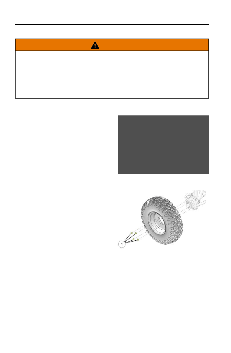
TIRES
WARNING
Operating your vehicle with worn tires will increase the possibility of skidding,
loss of control and an accident, which could result in serious injury or death.
Always replace tires when the tread depth measures 1/8” (3 mm) or less.
Improper tire inflation or the use of non-standard size or type of tires may
adversely affect vehicle handling, which could result in vehicle damage or
personal injury. Always maintain proper tire pressure. Always use POLARIS
approved size and type of tires for this vehicle when replacing tires.
TIRE TREAD DEPTH
Always replace tires when tread depth
is worn to 1/8” (3 mm) or less.
WHEEL REMOVAL
1. Position the vehicle on a level
surface.
2. Apply the parking brake and stop
the engine.
3. Loosen the wheel nuts slightly. If
wheel hub removal is required,
remove the wheel cap, cotter pin
and loosen the hub nut slightly.
4. Elevate the appropriate side of the
vehicle by placing a suitable stand
under the frame.
5. Remove the wheel nuts
q
and
remove the wheel.
94
MAINTENANCE

WHEEL INSTALLATION
WARNING
Improperly installed wheels can adversely affect tire wear and vehicle
handling, which can result in serious injury or death. Always ensure that all
nuts are torqued to specification. Do not service axle nuts that have a cotter pin
installed. Your dealer can assist.
1. Verify the parking brake is still applied.
2. Place the wheel in the correct position on the wheel hub
t
. Be sure the
valve stem
w
is toward the outside and rotation arrows on the tire point
toward forward rotation.
3. Install the wheel nuts
q
and finger tighten.
4. Carefully lower the vehicle to the ground.
5. Torque the wheel nuts and/or hub nut
e
to the proper torque specification.
TORQUE
Wheel Lug Nuts:
30 ft-lbs (41 Nm)
Hub Castle Nuts:
Front: 60 ft-lbs (81 Nm)
Rear: 85 ft-lbs (115 Nm)
6. If hub nut was removed, install a new cotter pin after the hub nut has been
tightened. If the holes do not line up, turn the hub nut until the cotter pin
r
can be installed.
95
MAINTENANCE
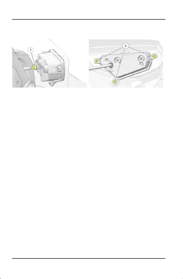
BATTERY
WARNING
Battery electrolyte is poisonous. It contains sulfuric acid. Serious burns can
result from contact with skin, eyes or clothing.
Antidote:
External: Flush with water.
Internal: Drink large quantities of water or milk. Follow with milk of magnesia,
beaten egg, or vegetable oil. Call physician immediately.
Eyes: Flush with water for 15 minutes and get prompt medical attention.
Batteries produce explosive gases. Keep sparks, flame, cigarettes, etc. away.
Ventilate when charging or using in an enclosed space. Always shield eyes
when working near batteries. KEEP OUT OF REACH OF CHILDREN.
Your vehicle may have either a sealed battery, which requires little maintenance,
or a conventional battery. A sealed battery can be identified by its flat covers on
the top of the battery. A conventional battery has six filler caps on the top of the
battery.
Always keep battery terminals and connections free of corrosion. If cleaning is
necessary, remove the corrosion with a stiff wire brush. Wash with a solution of
one tablespoon baking soda and one cup water. Rinse well with tap water and
dry off with clean shop towels. Coat the terminals with dielectric grease or
petroleum jelly. Be careful not to allow cleaning solution or tap water into a
conventional battery.
WARNING
Improperly connecting or disconnecting battery cables can result in an
explosion and cause serious injury or death. When removing the battery,
always disconnect the negative (black) cable first. When reinstalling the
battery, always connect the negative (black) cable last.
BATTERY FLUID (CONVENTIONAL BATTERY)
A poorly maintained battery will
deteriorate rapidly. Check the
battery fluid level often. Maintain the
fluid level between the upper
q
and
lower level
w
marks.
Add only distilled water. Tap water
contains minerals that are harmful to
a battery.
97
MAINTENANCE
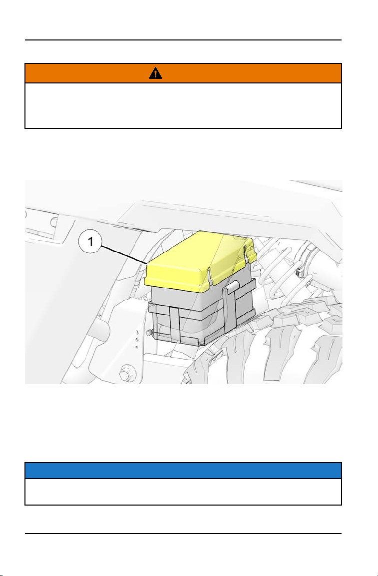
BATTERY REMOVAL
WARNING
Improperly connecting or disconnecting battery cables can result in an
explosion and cause serious injury or death. When removing the battery,
always disconnect the negative (black) cable first. When reinstalling the
battery, always connect the negative (black) cable last.
To remove the battery, do the following:
1. Through the rear left wheel well undo the battery cover strap and remove the
battery cover
q
.
2. Disconnect the brown (negative) battery cable(s).
3. Disconnect the red (positive) battery cable(s).
4. Carefully lift the battery out of the vehicle.
5. Inspect the rubber battery cover gasket for damage or wear.
NOTICE
If electrolyte spills, immediately wash it off with a solution of one tablespoon
baking soda and one cup water to prevent damage to the vehicle.
98
MAINTENANCE
BATTERY INSTALLATION
Using a new battery that has not been fully charged can damage the battery and
result in a shorter life. It can also hinder vehicle performance. Follow instructions
in the Battery Charging (Conventional Battery) section before installing the
battery.
An optional extreme use battery may be available for your model. If the
performance of the factory-installed battery is inadequate due to operation in
extreme cold or due to extended use of multiple electrical accessories, your
dealer can assist. Your dealer can provide any installation procedures that may
differ for an extreme use battery.
1. Ensure that the battery is fully charged.
2. Place the battery in the battery holder.
3. On conventional batteries, install the battery vent tube (sealed batteries do
not have a vent tube). The vent tube must be free of obstructions and
securely installed. Route the tube away from the frame and vehicle body to
prevent contact with electrolyte.
WARNING
Battery gases could accumulate in an improperly installed vent tube and cause
an explosion, resulting in serious injury or death. Always ensure that the vent
tube is free of obstructions and is securely installed as recommended.
4. Coat the terminals with dielectric grease or petroleum jelly.
5. Connect and tighten the red (positive) cable first.
6. Connect and tighten the black (negative) cable last.
7. Install the battery hold-down strap and tighten the screws.
8. Verify that cables are properly routed.
9. Reinstall the seat.
99
MAINTENANCE
BATTERY STORAGE
Whenever the vehicle is not used for a period of three months or more, remove
the battery from the vehicle, ensure that it's fully charged, and store it out of the
sun in a cool, dry place. Check battery voltage each month during storage and
recharge as needed to maintain a full charge.
TIP
Battery charge can be maintained by using a POLARIS Battery Tender charger
or by charging about once a month to make up for normal self discharge.
Battery Tender can be left connected during the storage period, and will
automatically charge the battery if the voltage drops below a predetermined
point.
BATTERY CHARGING (CONVENTIONAL BATTERY)
1. Remove the battery from the vehicle to prevent damage from leaking or
spilled electrolyte during charging.
2. Charge the battery with a charging output no larger than 1/10 of the battery’s
amp/hr rating. Charge as needed to raise the specific gravity to 1.270 or
greater.
3. Reinstall the battery. Make sure the positive terminal is toward the front of the
vehicle.
BATTERY CHARGING (SEALED BATTERY)
The following battery charging instructions apply only to the installation of a
sealed battery. Read all instructions before proceeding with the installation of
this battery.
The sealed battery is already filled with electrolyte and has been sealed and fully
charged at the factory. Never pry the sealing strip off or add any other fluid to this
battery.
The single most important thing about maintaining a sealed battery is to keep it
fully charged. Since the battery is sealed and the sealing strip cannot be
removed, you must use a voltmeter or multimeter to measure DC voltage.
WARNING
An overheated battery may explode, causing severe injury or death. Always
watch charging times carefully. Stop charging if the battery becomes very
warm to the touch. Allow it to cool before resuming charging.
For a refresh charge, follow all instructions carefully.
100
MAINTENANCE
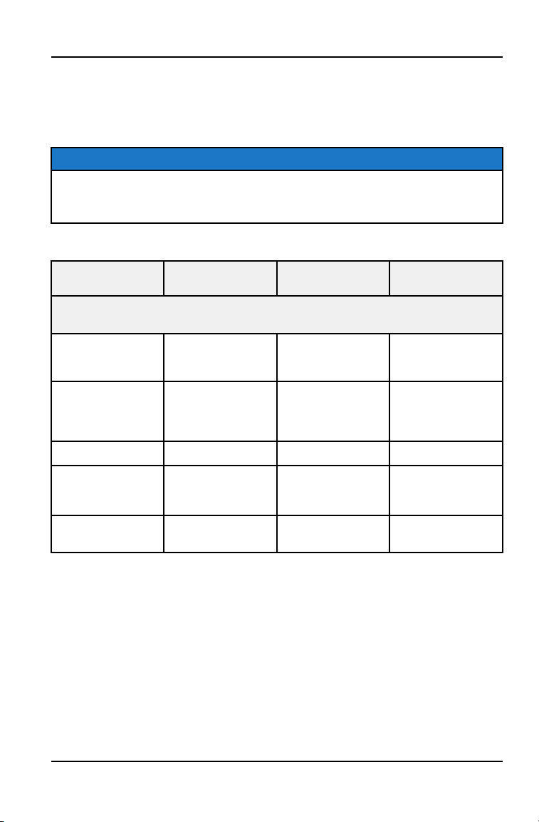
1. Check the battery voltage with a voltmeter or multimeter. A fully charged
battery will register 12.8 V or higher.
2. If the voltage is less than 12.8 volts, recharge the battery at 1.2 amps or less
until battery voltage is 12.8 or greater.
TIP
When using an automatic charger, refer to the charger manufacturer's
instructions for recharging. When using a constant current charger, use the
guidelines below for recharging.
Always verify battery condition before and 1-2 hours after the end of charging.
STATE OF
CHARGE
VOLTAGE ACTION CHARGE TIME*
*(USING CONSTANT CURRENT CHARGER @ STANDARD AMPS SPECIFIED ON
TOP OF BATTERY)
100% 12.8-13.0 volts None, check at 3
mos. from date of
manufacture
None required
75%-100% 12.5-12.8 volts May need slight
charge, if no
charge given,
check in 3 months
3-6 hours
50%-75% 12.0-12.5 volts Needs charge 5-11 hours
25%-50% 11.5-12.0 volts Needs charge At least 13 hours,
verify state of
charge
0%-25% 11.5 volts or less Needs charge with
desulfating charger
At least 20 hours
101
MAINTENANCE

CLEANING AND STORAGE
WASHING THE VEHICLE
Keeping your POLARIS vehicle clean will not only improve its appearance but it
can also extend the life of various components.
NOTE
High water pressure may damage components. POLARIS recommends
washing the vehicle by hand or with a garden hose, using mild soap.
NOTE
Certain products, including insect repellents and chemicals, will damage
plastic surfaces. Do not allow these types of products to contact the vehicle.
The best and safest way to clean your POLARIS vehicle is with a garden hose
and a pail of mild soap and water.
1. Use a professional-type washing cloth, cleaning the upper body first and the
lower parts last.
2. Rinse with clean water frequently.
3. Dry surfaces with a chamois to prevent water spots.
WASHING TIPS
• Avoid the use of harsh cleaners, which can scratch the finish.
• Do not use a power washer to clean the vehicle.
• Do not use medium to heavy duty compounds on the finish.
• Always use clean cloths and pads for cleaning and polishing. Old or reused
cloths and pads may contain dirt particles that will scratch the finish.
• Grease all zerk fittings immediately after washing. Allow the engine to run for
a while to evaporate any water that may have entered the engine or exhaust
system.
If a high pressure water system is used for cleaning (not recommended),
exercise extreme caution. The water may damage components and could
remove paint and labels. Avoid directing the water stream at the following items:
• Wheel bearings
• Radiator
• Transmission seals
• Brakes
• Cab and body panels
• Labels and decals
• Electrical components and wiring
• Air intake components
102
MAINTENANCE

If an informational or graphic label becomes illegible or comes off, contact your
POLARIS dealer, or other qualified person, to purchase a replacement.
Replacement safety labels are provided by POLARIS at no charge.
POLISHING THE VEHICLE
POLARIS recommends the use of common household aerosol furniture polish
for polishing the finish on your POLARIS vehicle. Follow the instructions on the
container.
POLISHING TIPS
• Avoid the use of automotive products, some of which can scratch the finish of
your vehicle.
• Always use clean cloths and pads for cleaning and polishing. Old or reused
cloths and pads may contain dirt particles that will scratch the finish.
103
MAINTENANCE

CHROME WHEEL CARE (IF EQUIPPED)
Proper maintenance will protect chrome wheels from corrosion, preserve wheel
life and ensure a “like new” appearance for many years. Chrome wheels
exposed to road salt (or salt in the air in coastal areas) are more susceptible to
corrosion if not properly cleaned. Clean chrome wheels more often if they're
exposed to salt or other corrosive elements.
1. Wash chrome wheels frequently. Use a mild detergent. Never use abrasive
cleaners on plated or painted surfaces.
2. Rinse well with clear water. Soap, detergents, salt, dirt, mud and other
elements can cause corrosion.
3. Polish the clean chrome wheels periodically. Use an automotive grade
chrome polish.
4. Routinely and liberally apply a weather resistant wax to each polished
chrome wheel. Choose a product suitable for chrome finishes. Read and
follow the product labels and instructions.
REMOVING CORROSION
If light rust is found on the chrome finish, use steel wool (#0000-OTT grade) to
remove it. Gently rub the affected areas with the steel wool until the corrosion
has been removed. Clean and polish the wheel as outlined above.
104
MAINTENANCE

STORAGE TIPS
NOTICE
Starting the engine during the storage period will disturb the protective film
created by fogging and damage could occur. Never start the engine during the
storage period.
CLEAN THE EXTERIOR
Make any necessary repairs and clean the vehicle as recommended.
STABILIZE THE FUEL
1. Fill the fuel tank.
2. Add POLARIS Carbon Clean Fuel Treatment or POLARIS Fuel Stabilizer or
equivalent fuel treatments or stabilizers. Follow the instructions on the
container for the recommended amount. Carbon Clean removes water from
fuel systems, stabilizes fuel and removes carbon deposits from pistons,
rings, valves and exhaust systems.
3. Allow the engine to run for 15-20 minutes to allow the stabilizer to disperse
through the entire fuel delivery system.
OIL AND FILTER
Change the oil and filter. See the Engine Oil section.
AIR FILTER / AIR BOX
Replace the air filter. See Maintenance Chapter. Clean the air box.
FLUID LEVELS
Inspect the fluid levels. Add or change fluids as recommended in the Periodic
Maintenance Chart.
• Rear gearcase fluid
• Transmission fluid
• Brake fluid (change every two years and any time the fluid looks dark or
contaminated)
INSPECT AND LUBRICATE
Inspect all cables and lubricate all areas of the vehicle as recommended in the
Periodic Maintenance Chart.
105
MAINTENANCE

FOG THE ENGINE
1. Treat the fuel system with POLARIS Carbon Clean or other equivalent fuel
treatment. Follow the instructions on the container. Start the engine. Allow it
to idle for several minutes so the Carbon Clean reaches the injectors. Stop
the engine.
2. Remove the spark plug and add 2-3 tablespoons of engine oil. To access the
plug holes, use a section of clear 1/4” hose and a small plastic squeeze
bottle filled with the pre-measured amount of oil. Do this carefully! If you miss
the plug holes, oil will drain from the spark plug cavities into the hole at the
front of the cylinder head, and appear to be an oil leak.
3. Reinstall the spark plug. Torque to specification.
4. Apply dielectric grease to the inside of each spark plug cap. Do not reinstall
the cap onto the plug at this step.
5. Turn the engine over several times. Oil will be forced in and around the
piston rings and ring lands, coating the cylinder with a protective film of fresh
oil.
6. Reinstall the spark plug caps.
7. If POLARIS fuel system additive is not used, fuel tank, fuel lines, and
injectors should be completely drained of gasoline.
STORAGE AREA / COVERS
Be sure the storage area is well ventilated. Cover the vehicle with a genuine
POLARIS cover. Do not use plastic or coated materials. They do not allow
enough ventilation to prevent condensation, and may promote corrosion and
oxidation.
106
MAINTENANCE
REMOVAL FROM STORAGE
1. Check the battery electrolyte level and charge the battery if necessary. Install
it in the vehicle. Make sure the battery vent hose is routed properly and that
it's not pinched or restricted in any way.
2. Make sure spark plugs are tight.
3. Fill the fuel tank with fuel.
4. Check all the points listed in the Daily Pre-Ride Inspection. Tightness of the
bolts, nuts and other fasteners should be checked by an authorized dealer or
other qualified service facility.
5. Lubricate at the intervals outlined in the Periodic Maintenance Chart.
WARNING
Engine exhaust contains poisonous carbon monoxide and can cause loss of
consciousness or death. Never run an engine in an enclosed area.
107
MAINTENANCE
TRANSPORTING THE VEHICLE
Follow these procedures when transporting the vehicle.
1. Apply the brakes.
2. Place the transmission in PARK. Stop the engine.
3. Slowly release the brake pedal and make sure the transmission is in PARK
before exiting the vehicle.
4. Remove the key to prevent loss during transporting.
5. Secure the fuel cap and seat. Ensure that the seat is attached correctly and
is not loose.
WARNING
Cargo and other loose vehicle parts may fly off while transporting this vehicle.
Secure or remove all cargo, and inspect the unit for loose parts prior to
transport. For high-speed trailering, it is recommended to remove the safety
flag.
6. Using suitable straps or rope, always secure the vehicle to the trailer using
the designated tie down points (front and rear).
TIE-DOWN LOCATIONS
q
Front tie-down points
w
Rear tie-down points
108
MAINTENANCE

SPECIFICATIONS
RANGER 150 EFI
VEHICLE DIMENSIONS
Length 85" (215.9 cm)
Width
48" (121.9 cm)
Height 58" (147.3 cm)
Wheel Base
65” (165 cm)
Ground Clearance
8” (20.2 cm)
Minimum Turning Radius 90” (228.6 cm)
Gross Vehicle Weight 1048 lbs (475 kg)
Dry Weight 673 lbs (305 kg)
Rear Rack/Box Capacity 50 lb (23 kg)
Max. Weight Capacity
375 lbs (170 kg)
(Driver + Cargo)
ENGINE
Platform
Single Cylinder, Air/Oil Cooled 4-Stroke
Engine Displacement (cc)
150 cc
Number of Cylinders
1
Bore & Stroke (mm)
57.8 x 57.4 mm
Compression Ratio
9.5:1
Engine Idle Speed
1500 RPM
Engine Max Engine Speed (Fuel
Cutoff)
7500 RPM
Cooling System
Air + Oil
Overheat Warning
N/A
Lubrication
PS-4 Synthetic 5W-50 4-Cycle Oil
Engine Oil Requirement /
Capacity
35.5 oz. / 1050 ml
Exhaust System Single Headpipe / Single Silencer
109
SPECIFICATIONS

FUEL SYSTEM
Throttle Body / Size
Bosch / 32 mm
Fuel Delivery Electronic Fuel Pump (in tank)
Fuel Pressure
4 bar / 58 psi (400 kPa)
Fuel Capacity 2.5 gal / 9.5
Fuel Requirements 87 Octane (minimum)
ELECTRICAL
Alternator Output 11.5 AMP @ 4000 RPM
Voltage Regulator
3 Phase, 35 AMP
Head Lights
2 - Single Beam Daytime Running
Lamps (DRL)
Tail / Brake Lights Single Tail Light
Ignition Timing Non-Adjustable
Spark plug / Gap NGK CR7HSA / .024 - .028 (0.6 - 0.7 mm)
Battery / Model / AH / CCA
Yuasa / YTX9/ 9AH / 120
Relays
(Located in Relay/Fuse Box)
EFI
Fuel Pump
Fuses
(Located in Relay/Fuse Box)
Main Fuse: 20 Amp
EFI: 15 Amp
Lights: 10 Amp
Brake LT: 10 Amp
Spare: 10 Amp
Spare: 15 Amp
Spare: 20 Amp
110
SPECIFICATIONS
DRIVETRAIN
Transmission Type
Automatic CVT F/N/R
Transmission
Fluid Type / Fluid Capacity
Polaris AGL
25 oz. (750 ml)
Drive Chain - Type / # Links
50 x 52
STEERING / SUSPENSION
Toe Out 0-1/8 in. / 0-3.2mm
Front Suspension
Strut
Front Travel
5.1” (13 cm)
Rear Suspension Swing-arm Dual Shocks
Rear Travel
6” (15.2 cm)
Shock Preload Adjustment
Cam Adjustable
(Factory Setting -Softest)
WHEELS / BRAKES
Front Wheel Size
10 x 5.5 Stamped Steel
Front Tire Model / Size P3018 / 22 x 7-10
Rear Wheel Size
10 x 8 Stamped Steel
Rear Tire Model / Size P3018 / 22 x 10-10
Tire Air Pressure
Front
5 psi (34.4 kPa)
Rear
5 psi (34.4 kPa)
Brakes
Front Wheel Hydraulic Disc
Rear Axle Hydraulic Disc
Brake Fluid Polaris DOT 4 Brake Fluid
CLUTCH SETTINGS
ALTITUDE
SHIFT
WEIGHT
DRIVE
SPRING
DRIVEN
SPRING
Meters
(Feet)
0-3000
(0-10,000)
No changes for high altitude.
3000+
(10,000+)
111
SPECIFICATIONS

112

POLARIS PRODUCTS
ENGINE LUBRICANT
PART NUMBER DESCRIPTION
2870791 Fogging Oil (12 oz. Aerosol)
2876244 PS-4 Synthetic 5W-50 4-Cycle Oil (qt./.95
l)
2876245 PS-4 Synthetic 5W-50 4-Cycle Oil (gal./
3.8 l)
GEARCASE / TRANSMISSION LUBRICANTS
PART NUMBER DESCRIPTION
2878068 AGL Full Synthetic Gearcase Lubricant &
Transmission Fluid (qt./.95 l)
2878069 AGL Full Synthetic Gearcase Lubricant &
Transmission Fluid (gal./3.8 l)
2872348 Chain Lube, Aerosol
GREASE / SPECIALIZED LUBRICANTS
PART NUMBER DESCRIPTION
2871312 Grease Gun Kit, Premium All Season
2871322 All Season Grease (3 oz./89 ml cartridge)
2871423 All Season Grease (14 oz./414 ml
cartridge)
2871329 Dielectric Grease (Nyogel™)
ADDITIVES / MISCELLANEOUS
PART NUMBER DESCRIPTION
2871326 Carbon Clean
2870652 Fuel Stabilizer
2872189 DOT 4 Brake Fluid
2871956 Loctite™ 565 Thread Sealant
2859044 POLARIS Battery Tender™ Charger
113
POLARIS PRODUCTS

114

TROUBLESHOOTING
DRIVE BELT WEAR/BURN
POSSIBLE CAUSE SOLUTION
Driving at low RPM or ground
speed
Drive at a higher speed.
Insufficient warm-up at low
ambient tempera- tures
Warm the engine at least 5 minutes. With the transmission in
neutral, apply small amount of throttle in short bursts, 5 to 7
times. The belt will become more flexible and prevent belt
burning.
Slow/easy clutch engage-
ment
Use the throttle quickly and effectively.
Belt slippage from water or
snow ingestion into the CVT
system
Dry out the PVT Prevent water from entering the PVT inlet and
outlet ducts. Inspect clutch seals for damage if repeated leaking
occurs.
Clutch malfunction Your POLARIS dealer can assist.
Poor engine performance Check for fouled plug or foreign material in gas tank or fuel lines.
Your POLARIS dealer can assist.
Wrong or missing belt Install the recommended belt.
Improper break-in Always break in a new belt and/or clutch.
ENGINE DOESN’T TURN OVER
POSSIBLE CAUSE SOLUTION
Low battery voltage Recharge the battery to 12.8 VDC
Loose battery connections Check all connections and tighten
Loose solenoid connections Check all connections and tighten
ENGINE TURNS OVER, FAILS TO START
POSSIBLE CAUSE SOLUTION
Out of fuel Refuel
Water is present in fuel Drain the fuel system and refuel
Old or non-recommended fuel Replace with fresh recommended fuel
Fouled or defective spark plug Inspect plug and replace if necessary
No spark to spark plug Inspect plug and replace if necessary
Water or fuel in crankcase Your POLARIS dealer can assist
115
TROUBLESHOOTING

POSSIBLE CAUSE SOLUTION
Clogged Fuel Filter Your POLARIS dealer can assist
Low battery voltage Recharge the battery to 12.8 VDC
Mechanical failure Your POLARIS dealer can assist
ENGINE BACKFIRES
POSSIBLE CAUSE SOLUTION
Weak spark from spark plug Inspect, clean and/or replace spark plug
Incorrect spark plug gap or
heat range
Set gap to specs or replace plug
Old or non-recommended fuel Replace with fresh recommended fuel
Incorrectly installed spark plug
wires
Your POLARIS dealer can assist
Mechanical failure Your POLARIS dealer can assist
Loose ignition connections Check all connections and tighten
Water present in fuel Replace with fresh recommended fuel
Exhaust system leak Your POLARIS dealer can assist
ENGINE PINGS OR KNOCKS
POSSIBLE CAUSE SOLUTION
Poor quality or low
octane fuel
Replace with recommended fuel
Incorrect ignition timing Your authorized dealer can assist
Incorrect spark plug gap
or heat range
Set gap to specs or replace plugs
ENGINE RUNS IRREGULARLY, STALLS OR MISFIRES
POSSIBLE CAUSE SOLUTION
Fouled or defective spark plug
(s)
Inspect, clean and/or replace spark plugs
Worn or defective spark plug
wires
Your POLARIS dealer can assist
Incorrect spark plug gap or
heat range
Set gap to specs or replace plugs
116
TROUBLESHOOTING

POSSIBLE CAUSE SOLUTION
Loose ignition connections Check all connections and tighten
Water present in fuel Replace with new fuel
Low battery voltage Recharge battery to 12.8 VDC
Kinked or plugged fuel tank
vent line
Inspect and replace
Incorrect fuel Replace with recommended fuel
Clogged air filter Inspect and clean or replace
Reverse speed limiter
malfunction
Your POLARIS dealer can assist
Electronic throttle control
malfunction
Your POLARIS dealer can assist
Other mechanical failure Your POLARIS dealer can assist
POSSIBLE LEAN
FUEL CAUSE
SOLUTION
Low or contaminated
fuel
Add or change fuel, clean the fuel system
Low octane fuel Replace with recommended fuel
Clogged air filter Your POLARIS dealer can assist
Incorrect fuel Replace with recommended fuel
POSSIBLE RICH FUEL
CAUSE
SOLUTION
Fuel is very high octane Replace with lower octane fuel
Stopping/starting
without adequate warm-
up
Allow engine to warm up before operating and/or
stopping
Incorrect fuel Replace with recommended fuel
Clogged air filter Inspect and clean or replace
117
TROUBLESHOOTING

ENGINE STOPS OR LOSES POWER
POSSIBLE CAUSE SOLUTION
Out of fuel Refuel, cycle key to ON position three times for 5 seconds each,
then start
Kinked or plugged fuel vent
line
Inspect and replace
Water is present in fuel Replace with new fuel
Fouled or defective spark plug
(s)
Inspect, clean and/or replace spark plugs
Worn or defective spark plug
wires
Your POLARIS dealer can assist
Incorrect spark plug gap or
heat range
Set gap to specs or replace plug
Loose ignition connections Check all connections and tighten
Low battery voltage Recharge the battery to 12.8 VDC
Incorrect fuel Replace with fresh recommended fuel
Clogged air filter Inspect and clean or replace
Electronic throttle control
malfunction
Your POLARIS dealer can assist
Other mechanical failure Your POLARIS dealer can assist
118
TROUBLESHOOTING

DIAGNOSTIC TROUBLE CODES
SPN FMI COMPONENT P-CODE CONDITION
DISPLAYED ON
INSTRUMENT
CLUSTER
DISPLAYED ON
DIGITAL WRENCH
DIAGNOSTIC
SOFTWARE
29 3
Accelerator
Position 2
P1228 Voltage Above Normal, Or Shorted
To High Source
29 4 P1227 Voltage Below Normal, Or Shorted
To Low Source
51 3
Throttle
Position Sensor
1
P0123 Voltage Above Normal, Or Shorted
To High Source
51 4 P0122 Voltage Below Normal, Or Shorted
To Low Source
84 2
Vehicle Speed
Sensor
P0503 Data Erratic, Intermittent Or Incorrect
91 3
Accelerator
Position 1
P0228 Voltage Above Normal, Or Shorted
To High Source
91 4 P0227 Voltage Below Normal, Or Shorted
To Low Source
96 2
Fuel Level
Signal
P0461 Data Erratic, Intermittent Or Incorrect
96 3 P0463 Voltage Above Normal, Or Shorted
To High Source
96 4 P0462 Voltage Below Normal, Or Shorted
To Low Source
96 16 P1462 Data Valid But Above Normal
Operating Range - Moderately
Severe Level
96 18 P1463 Data Valid But Below Normal
Operating Range - Moderately
Severe Level
102 3
Manifold
Absolute
Pressure
Sensor
P0108 Voltage Above Normal, Or Shorted
To High Source
102 4 P0107 Voltage Below Normal, Or Shorted
To Low Source
105 0
Intake Air
Temperature
Sensor
P1111 Data Valid But Above Normal
Operational Range - Most Severe
Level
105 3 P0113 Voltage Above Normal, Or Shorted
To High Source
119
TROUBLESHOOTING

SPN FMI COMPONENT P-CODE CONDITION
DISPLAYED ON
INSTRUMENT
CLUSTER
DISPLAYED ON
DIGITAL WRENCH
DIAGNOSTIC
SOFTWARE
105 4 P0112 Voltage Below Normal, Or Shorted
To Low Source
108 3
Barometric
Pressure
Sensor
P2229 Voltage Above Normal, Or Shorted
To High Source
108 4 P2228 Voltage Below Normal, Or Shorted
To Low Source
110 0
Engine
Temperature
Sensor
P1217 Data Valid But Above Normal
Operational Range - Most Severe
Level
110 2 P0116 Data Erratic, Intermittent Or Incorrect
110 3 P0118 Voltage Above Normal, Or Shorted
To High Source
110 4 P0117 Voltage Below Normal, Or Shorted
To Low Source
110 10 P0119 Abnormal Rate Of Change
110 15 P1116 Data Valid But Above Normal
Operating Range - Least Severe
Level
110 16 P0217 Data Valid But Above Normal
Operating Range - Moderately
Severe Level
110 17 P0128 Data Valid But Below Normal
Operating Range - Least Severe
Level
168 0
System Power
P1562 Data Valid But Above Normal
Operational Range - Most Severe
Level
168 1 P1563 Data Valid But Below Normal
Operational Range - Most Severe
Level
168 2 P0561 Data Erratic, Intermittent Or Incorrect
168 3 P0563 Voltage Above Normal, Or Shorted
To High Source
168 4 P0562 Voltage Below Normal, Or Shorted
To Low Source
190 31
Engine Speed
P121C Condition Exists
120
TROUBLESHOOTING

SPN FMI COMPONENT P-CODE CONDITION
DISPLAYED ON
INSTRUMENT
CLUSTER
DISPLAYED ON
DIGITAL WRENCH
DIAGNOSTIC
SOFTWARE
523 2
Gear Sensor
Signal
P0914 Data Erratic, Intermittent Or Incorrect
523 4 P0916 Voltage Below Normal, Or Shorted
To Low Source
523 9 P1914 Abnormal Update Rate
527 31
Cruise Control
Panel Switches
P153D Condition Exists
636 2
Crankshaft
Position Sensor
P0335 Data Erratic, Intermittent Or Incorrect
637 8
Camshaft
Position Sensor
P0340 Abnormal Frequency Or Pulse Width
Or Period
651 3
Injector 1
(Front) (MAG)
(SDI Port
Injector)
P0262 Voltage Above Normal, Or Shorted
To High Source
651 4 P1262 Voltage Below Normal, Or Shorted
To Low Source
651 5 P0261 Current Below Normal Or Open
Circuit
652 3
Injector 2
(Rear) (PTO)
(SDI Port
Injector)
P0265 Voltage Above Normal, Or Shorted
To High Source
652 4 P1265 Voltage Below Normal, Or Shorted
To Low Source
652 5 P0264 Current Below Normal Or Open
Circuit
677 3
Starter
Solenoid Driver
Circuit
P0617 Voltage Above Normal, Or Shorted
To High Source
677 4 P0616 Voltage Below Normal, Or Shorted
To Low Source
677 5 P0615 Current Below Normal Or Open
Circuit
731 1
Knock Sensor 1
P0326 Data Valid But Below Normal
Operational Range - Most Severe
Level
746 3
Rear
Differential
Output (Turf)
P1692 Voltage Above Normal, Or Shorted
To High Source
746 4 P1693 Voltage Below Normal, Or Shorted
To Low Source
121
TROUBLESHOOTING

SPN FMI COMPONENT P-CODE CONDITION
DISPLAYED ON
INSTRUMENT
CLUSTER
DISPLAYED ON
DIGITAL WRENCH
DIAGNOSTIC
SOFTWARE
746 5 P1691 Current Below Normal Or Open
Circuit
876 3
AC Compressor
Clutch Relay
P0647 Voltage Above Normal, Or Shorted
To High Source
876 4 P0646 Voltage Below Normal, Or Shorted
To Low Source
876 5 P0645 Current Below Normal Or Open
Circuit
1071 3
Fan Relay
Driver Circuit
P1482 Voltage Above Normal, Or Shorted
To High Source
1071 4 P1483 Voltage Below Normal, Or Shorted
To Low Source
1071 5 P1481 Current Below Normal Or Open
Circuit
1127 0
Boost Pressure
Sensor
P0234 Data Valid But Above Normal
Operational Range - Most Severe
Level
1127 2 P0236 Data Erratic, Intermittent Or Incorrect
1127 3 P0238 Voltage Above Normal, Or Shorted
To High Source
1127 4 P0237 Voltage Below Normal, Or Shorted
To Low Source
1127 31 P1234 Condition Exists
1213 3
Malfunction
Indicator Lamp
P1653 Voltage Above Normal, Or Shorted
To High Source
1213 4 P1652 Voltage Below Normal, Or Shorted
To Low Source
1213 5 P1651 Current Below Normal Or Open
Circuit
1268 3
Ignition Coil
Primary Driver
1 (Front) (MAG)
P1353 Voltage Above Normal, Or Shorted
To High Source
1269 3
Ignition Coil
Primary Driver
2 (Rear) (PTO)
P1354 Voltage Above Normal, Or Shorted
To High Source
122
TROUBLESHOOTING

SPN FMI COMPONENT P-CODE CONDITION
DISPLAYED ON
INSTRUMENT
CLUSTER
DISPLAYED ON
DIGITAL WRENCH
DIAGNOSTIC
SOFTWARE
1347 3
Fuel Pump
Driver Circuit
P0232 Voltage Above Normal, Or Shorted
To High Source
1347 4 P0231 Voltage Below Normal, Or Shorted
To Low Source
1347 5 P0230 Current Below Normal Or Open
Circuit
1557 3
Fan Driver 2
P0694 Voltage Above Normal, Or Shorted
To High Source
1557 4 P0693 Voltage Below Normal, Or Shorted
To Low Source
1557 5 P0481 Current Below Normal Or Open
Circuit
1856 3
Seat Belt
Switch
B1150 Voltage Above Normal, Or Shorted
To High Source
1856 4 B1250 Voltage Below Normal, Or Shorted
To Low Source
1856 5 B1350 Current Below Normal Or Open
Circuit
1856 31 Condition Exists
2629 3
Engine
Turbocharger 1
Compressor
Outlet
Temperature
P1235 Voltage Above Normal, Or Shorted
To High Source
2629 4 P1236 Voltage Below Normal, Or Shorted
To Low Source
3056 2
Oxygen Sensor
Bank 1 Sensor
1
P0130 Data Erratic, Intermittent Or Incorrect
3056 3 P0132 Voltage Above Normal, Or Shorted
To High Source
3056 4 P0131 Voltage Below Normal, Or Shorted
To Low Source
3056 5 P1134 Current Below Normal Or Open
Circuit
3056 12 P113A Bad Intelligent Device Or
Component
3597 3
ECU Output
Supply Voltage
1
P16A2 Voltage Above Normal, Or Shorted
To High Source
123
TROUBLESHOOTING

SPN FMI COMPONENT P-CODE CONDITION
DISPLAYED ON
INSTRUMENT
CLUSTER
DISPLAYED ON
DIGITAL WRENCH
DIAGNOSTIC
SOFTWARE
3597 4 P16A1 Voltage Below Normal, Or Shorted
To Low Source
3598 3
ECU Output
Supply Voltage
2
P16A9 Voltage Above Normal, Or Shorted
To High Source
3598 4 P16A8 Voltage Below Normal, Or Shorted
To Low Source
3599 3
ECU Output
Supply Voltage
3
P17AA Voltage Above Normal, Or Shorted
To High Source
3599 4 P17AB Voltage Below Normal, Or Shorted
To Low Source
65590 7
Cylinder Misfire
P0314 Mechanical System Not Responding
Or Out Of Adjustment
65591 7
Cylinder 1
Misfire
P0301 Mechanical System Not Responding
Or Out Of Adjustment
65592 7
Cylinder 2
Misfire
P0302 Mechanical System Not Responding
Or Out Of Adjustment
65613 2
ETC
Accelerator
Position Sensor
Outputs 1 & 2
Correlation
P1135 Data Erratic, Intermittent Or Incorrect
520194 2
Throttle
Release Signal
P1553 Data Erratic, Intermittent Or Incorrect
520194 3 P1555 Voltage Above Normal, Or Shorted
To High Source
520194 4 P1554 Voltage Below Normal, Or Shorted
To Low Source
520194 7 P1552 Mechanical System Not Responding
Or Out Of Adjustment
520198 3
Throttle
Position Sensor
2
P0223 Voltage Above Normal, Or Shorted
To High Source
520198 4 P0222 Voltage Below Normal, Or Shorted
To Low Source
520200 2
Rollover Sensor
(Tipover)
P1501 Data Erratic, Intermittent Or Incorrect
520200 3 P1503 Voltage Above Normal, Or Shorted
To High Source
124
TROUBLESHOOTING

SPN FMI COMPONENT P-CODE CONDITION
DISPLAYED ON
INSTRUMENT
CLUSTER
DISPLAYED ON
DIGITAL WRENCH
DIAGNOSTIC
SOFTWARE
520200 4 P1502 Voltage Below Normal, Or Shorted
To Low Source
520200 14 P1504 Special Instructions
520202 3
Canister Purge
Valve
Voltage Above Normal, Or Shorted
To High Source
520202 4 P0445 Voltage Below Normal, Or Shorted
To Low Source
520202 5 Current Below Normal Or Open
Circuit
520203 3
Front Wheel
Back Drive
(Active Descent
System)
P1686 Voltage Above Normal, Or Shorted
To High Source
520203 4 P1687 Voltage Below Normal, Or Shorted
To Low Source
520203 5 P1685 Current Below Normal Or Open
Circuit
520204 15
Fuel Correction
Front
P0172 Data Valid But Above Normal
Operating Range - Least Severe
Level
520204 17 P0171 Data Valid But Below Normal
Operating Range - Least Severe
Level
520205 15
Fuel Correction
Rear
P0175 Data Valid But Above Normal
Operating Range - Least Severe
Level
520205 17 P0174 Data Valid But Below Normal
Operating Range - Least Severe
Level
520206 2
Reverse Alarm
P1684 Data Erratic, Intermittent Or Incorrect
520206 3 P1682 Voltage Above Normal, Or Shorted
To High Source
520206 4 P1683 Voltage Below Normal, Or Shorted
To Low Source
520206 5 P1681 Current Below Normal Or Open
Circuit
520207 3
All Wheel Drive
Control Circuit
P1835 Voltage Above Normal, Or Shorted
To High Source
125
TROUBLESHOOTING

SPN FMI COMPONENT P-CODE CONDITION
DISPLAYED ON
INSTRUMENT
CLUSTER
DISPLAYED ON
DIGITAL WRENCH
DIAGNOSTIC
SOFTWARE
520207 4 P1834 Voltage Below Normal, Or Shorted
To Low Source
520207 5 P1836 Current Below Normal Or Open
Circuit
520208 3
Chassis Relay
P1614 Voltage Above Normal, Or Shorted
To High Source
520208 4 P1613 Voltage Below Normal, Or Shorted
To Low Source
520208 5 P1611 Current Below Normal Or Open
Circuit
520209 2
Oxygen Sensor
Heater 1
P0135 Data Erratic, Intermittent Or Incorrect
520209 3 Voltage Above Normal, Or Shorted
To High Source
520209 4 P0031 Voltage Below Normal, Or Shorted
To Low Source
520209 5 Current Below Normal Or Open
Circuit
520210 2
Oxygen Sensor
Heater 2
P0141 Data Erratic, Intermittent Or Incorrect
520210 3 P0038 Voltage Above Normal, Or Shorted
To High Source
520210 4 P0037 Voltage Below Normal, Or Shorted
To Low Source
520210 5 P0036 Current Below Normal Or Open
Circuit
520211 3
Idle Speed
P0507 Voltage Above Normal, Or Shorted
To High Source
520211 4 P0506 Voltage Below Normal, Or Shorted
To Low Source
520211 7 Mechanical System Not Responding
Or Out Of Adjustment
520268 3
Idle Air Control
M17 Stepper
Pin 3
P1519 Voltage Above Normal, Or Shorted
To High Source
520268 4 P1518 Voltage Below Normal, Or Shorted
To Low Source
126
TROUBLESHOOTING

SPN FMI COMPONENT P-CODE CONDITION
DISPLAYED ON
INSTRUMENT
CLUSTER
DISPLAYED ON
DIGITAL WRENCH
DIAGNOSTIC
SOFTWARE
520268 5 P1515 Current Below Normal Or Open
Circuit
520269 3
Idle Air Control
M17 Stepper
Pin 4
P1529 Voltage Above Normal, Or Shorted
To High Source
520269 4 P1528 Voltage Below Normal, Or Shorted
To Low Source
520269 5 P1525 Current Below Normal Or Open
Circuit
520270 3
Idle Air Control
M17 Stepper
Pin 6
P1539 Voltage Above Normal, Or Shorted
To High Source
520270 4 P1538 Voltage Below Normal, Or Shorted
To Low Source
520270 5 P1535 Current Below Normal Or Open
Circuit
520271 3
Idle Air Control
M17 Stepper
Pin 1
P1509 Voltage Above Normal, Or Shorted
To High Source
520271 4 P1508 Voltage Below Normal, Or Shorted
To Low Source
520271 5 P1505 Current Below Normal Or Open
Circuit
520275 31
Accelerator
Position/Brake
Position
Interaction
P150A Condition Exists
520276 2
Throttle
Position Sensor
(1 or 2
Indeterminable)
P150C Data Erratic, Intermittent Or Incorrect
520276 12 P150B Bad Intelligent Device Or
Component
520277 2
Throttle Body
Control - Power
Stage
P151A Data Erratic, Intermittent Or Incorrect
520277 3 P150D Voltage Above Normal, Or Shorted
To High Source
520277 4 P150E Voltage Below Normal, Or Shorted
To Low Source
520277 8 P151B Abnormal Frequency Or Pulse Width
Or Period
127
TROUBLESHOOTING

SPN FMI COMPONENT P-CODE CONDITION
DISPLAYED ON
INSTRUMENT
CLUSTER
DISPLAYED ON
DIGITAL WRENCH
DIAGNOSTIC
SOFTWARE
520279 31
Throttle Body
Control -
Adaption
Aborted
P151D Condition Exists
520280 31
Throttle Body
Control - Limp
Home Position
Check Failed
P151E Condition Exists
520281 31
Throttle Body
Control -
Mechanical
Stop Adaptation
Failure
P152A Condition Exists
520282 31
Throttle Body
Control -
Repeated
Adaptation
Failed
P152B Condition Exists
520283 3
Throttle Body
Control
P152C Voltage Above Normal, Or Shorted
To High Source
520283 4 P152D Voltage Below Normal, Or Shorted
To Low Source
520284 31
Throttle Body
Control -
Position
Deviation Fault
P152E Condition Exists
520285 2
Brake Switch (1
or 2
Indeterminable)
P153E Data Erratic, Intermittent Or Incorrect
520286 31
ECU Monitoring
Error
P1540 Condition Exists
520287 31
ECU Monitoring
Error (Level 3)
P1541 Condition Exists
520288 31
ECU Monitoring
of Injection Cut
Off (Level 1)
P1542 Condition Exists
520289 31
ECU Monitoring
of Injection Cut
Off (Level 2)
P1543 Condition Exists
128
TROUBLESHOOTING

SPN FMI COMPONENT P-CODE CONDITION
DISPLAYED ON
INSTRUMENT
CLUSTER
DISPLAYED ON
DIGITAL WRENCH
DIAGNOSTIC
SOFTWARE
520305 31
Throttle Body
Control -
Requested
Throttle Angle
Not Plausible
P1530 Condition Exists
520306 31
ECU ADC Fault
- No Load
P1531 Condition Exists
520307 31
ECU ADC Fault
- Voltage
P1532 Condition Exists
520308 31
Accelerator
Sensor Sync
Fault - Sensor
Diff Exceeds
Limit
P1533 Condition Exists
520309 31
ECU Fault -
ICO
P1534 Condition Exists
520311 31
ECU Fault -
Hardware
Disruption
P1537 Condition Exists
520329 9
Operator
Switch Status
(pOSS1)
P1063 Abnormal Update Rate
520331 3
Knock Sensor
Positive Line
P1327 Voltage Above Normal, Or Shorted
To High Source
520331 4 P1328 Voltage Below Normal, Or Shorted
To Low Source
520332 3
Knock Sensor
Negative Line
P132A Voltage Above Normal, Or Shorted
To High Source
520332 4 P132B Voltage Below Normal, Or Shorted
To Low Source
520333 2
Oxygen Sensor
Bank 1 Sensor
2(3057
Duplicate)
P1136 Data Erratic, Intermittent Or Incorrect
520333 3 P1137 Voltage Above Normal, Or Shorted
To High Source
520333 4 P1138 Voltage Below Normal, Or Shorted
To Low Source
520333 5 P3136 Current Below Normal Or Open
Circuit
129
TROUBLESHOOTING

SPN FMI COMPONENT P-CODE CONDITION
DISPLAYED ON
INSTRUMENT
CLUSTER
DISPLAYED ON
DIGITAL WRENCH
DIAGNOSTIC
SOFTWARE
520333 12 P1139 Bad Intelligent Device Or
Component
520336 31
ECU Monitoring
(Pedal Map
Mismatch)
P1545 Condition Exists
520338 31
Gross Air Leak
P2279 Condition Exists
520341 3
Wastegate
Solenoid Driver
P0243 Voltage Above Normal, Or Shorted
To High Source
520341 4 P0246 Voltage Below Normal, Or Shorted
To Low Source
520341 5 P0245 Current Below Normal Or Open
Circuit
520342 15
Idle Fuel
Correction
Bank 1
P116C Data Valid But Above Normal
Operating Range - Least Severe
Level
520342 17 P116D Data Valid But Below Normal
Operating Range - Least Severe
Level
520343 15
Idle Fuel
Correction
Bank 2
P116E Data Valid But Above Normal
Operating Range - Least Severe
Level
520343 17 P116F Data Valid But Below Normal
Operating Range - Least Severe
Level
520344 15
Adaptive Fuel
Correction
Bank 1
P0170 Data Valid But Above Normal
Operating Range - Least Severe
Level
520344 17 P1170 Data Valid But Below Normal
Operating Range - Least Severe
Level
520345 15
Adaptive Fuel
Correction
Bank 2
P0173 Data Valid But Above Normal
Operating Range - Least Severe
Level
520345 17 P1173 Data Valid But Below Normal
Operating Range - Least Severe
Level
520346 31
Upstream O2
Sensor Signals
Swapped
P1416 Condition Exists
130
TROUBLESHOOTING

SPN FMI COMPONENT P-CODE CONDITION
DISPLAYED ON
INSTRUMENT
CLUSTER
DISPLAYED ON
DIGITAL WRENCH
DIAGNOSTIC
SOFTWARE
520467 31
Momentary
Driveline Left
Press
P071A Condition Exists
520468 31
Momentary
Driveline Right
Press
P071D Condition Exists
520496 3
Intercooler
Pump Driver
Circuit
P107D Voltage Above Normal, Or Shorted
To High Source
520496 4 P107C Voltage Below Normal, Or Shorted
To Low Source
520496 5 P107E Current Below Normal Or Open
Circuit
520624 3
AC Condenser
Fan Relay
P15F5 Voltage Above Normal, Or Shorted
To High Source
520624 4 P15F4 Voltage Below Normal, Or Shorted
To Low Source
520624 5 P15F3 Current Below Normal Or Open
Circuit
520625 3
Alternator
Charge Disable
Relay
P1D45 Voltage Above Normal, Or Shorted
To High Source
520625 4 P1D44 Voltage Below Normal, Or Shorted
To Low Source
520625 5 P1D42 Current Below Normal Or Open
Circuit
524067 2
Drive Mode
Select Switch
P153C Data Erratic, Intermittent Or Incorrect
524067 3 P153A Voltage Above Normal, Or Shorted
To High Source
524067 4 P153B Voltage Below Normal, Or Shorted
To Low Source
524072 31
Foot On Cruise
Control Switch
P154D Condition Exists
524079 31
Cruise Control
Input
Checksum
U0405 Condition Exists
131
TROUBLESHOOTING

SPN FMI COMPONENT P-CODE CONDITION
DISPLAYED ON
INSTRUMENT
CLUSTER
DISPLAYED ON
DIGITAL WRENCH
DIAGNOSTIC
SOFTWARE
524080 31
Cruise Control
Input Message
Counter
U1405 Condition Exists
524081 31
Foot On Cruise
Control Input
Message
Counter
U1407 Condition Exists
524082 31
Foot On Cruise
Control Input
Checksum
U1406 Condition Exists
524145 31
Reverse
Override Switch
P188C Condition Exists
132
TROUBLESHOOTING

WARRANTY
LIMITED WARRANTY
POLARIS Industries Inc., 2100 Highway 55, Medina, MN 55340 (POLARIS)
gives a SIX MONTH LIMITED WARRANTY on all components of your POLARIS
vehicle against defects in material or workmanship. POLARIS further warrants
that the spark arrester in this product will meet the efficiency requirements of
USFS standard 5100-1C for at least 1000 hours when subjected to normal use
and when maintenance and installation are in accordance with POLARIS
recommendations.
This warranty covers parts and labor charges for repair or replacement of
defective parts and begins on the date of purchase by the original retail
purchaser. This warranty is transferable to another owner during the warranty
period through a POLARIS dealer, or other qualified person, but any such
transfer will not extend the original term of the warranty. The duration of this
warranty may vary by international region based upon local laws and
regulations.
REGISTRATION
At the time of sale, the Warranty Registration Form must be completed by your
dealer and submitted to POLARIS within ten days of purchase. Upon receipt of
this registration, POLARIS will record the registration for warranty. No
verification of registration will be sent to the purchaser as the copy of the
Warranty Registration Form will be your proof of warranty coverage. If you have
not signed the original registration and received the customer copy, please
contact your dealer immediately. NO WARRANTY COVERAGE WILL BE
ALLOWED UNLESS YOUR VEHICLE IS REGISTERED WITH POLARIS. Initial
dealer preparation and set-up of your vehicle is very important in ensuring
trouble-free operation. Purchasing a machine in the crate or without proper
dealer set-up will void your warranty coverage.
133
WARRANTY

WARRANTY COVERAGE AND EXCLUSIONS
LIMITATIONS OF WARRANTIES AND REMEDIES
This POLARIS limited warranty excludes any failures that are not caused by a
defect in material or workmanship. THIS WARRANTY DOES NOT COVER
CLAIMS OF DEFECTIVE DESIGN. This warranty also does not cover acts of
God, accidental damage, normal wear and tear, abuse or improper handling.
This warranty also does not cover any vehicle, component, or part that has been
altered structurally, modified, neglected, improperly maintained or used for
racing, competition or purposes other than for which it was designed.
This warranty excludes damages or failures resulting from improper lubrication;
improper engine timing; improper fuel; surface imperfections caused by external
stress, heat, cold or contamination; operator error or abuse; improper
component alignment, tension, adjustment or altitude compensation; snow,
water, dirt or other foreign substance ingestion/contamination; improper
maintenance; modified components; use of aftermarket or unapproved
components, accessories, or attachments; use of unapproved software or
calibration; unauthorized repairs; or repairs made after the warranty period
expires or by an unauthorized repair center.
This warranty excludes damages or failures caused by abuse, accident, fire, or
any other cause other than a defect in materials or workmanship and provides
no coverage for consumable components, general wear items, or any parts
exposed to friction surfaces, stresses, environmental conditions and/or
contamination for which they were not designed or not intended, including but
not limited to the following items:
• Wheels and tires
• Suspension components
• Brake components
• Seat components
• Clutches and components
• Steering components
• Batteries
• Light bulbs/Sealed beam lamps
• Filters
• Lubricants
• Bushings
• Finished and unfinished surfaces
• Carburetor/Throttle body
components
• Engine components
• Drive belts
• Hydraulic components and fluids
• Circuit breakers/Fuses
• Electronic components
• Spark plugs
• Sealants
• Coolants
• Bearings
134
WARRANTY

LUBRICANTS AND FLUIDS
1. Mixing oil brands or using non-recommended oil may cause engine damage.
We recommend the use of POLARIS engine oil.
2. Damage or failure resulting from the use of non-recommended lubricants or
fluids is not covered by this warranty.
This warranty provides no coverage for personal loss or expense, including
mileage, transportation costs, hotels, meals, shipping or handling fees, product
pick-up or delivery, replacement rentals, loss of product use, loss of profits, or
loss of vacation or personal time.
THE EXCLUSIVE REMEDY FOR BREACH OF THIS WARRANTY SHALL BE,
AT POLARIS' OPTION, REPAIR OR REPLACEMENT OF ANY DEFECTIVE
MATERIALS, COMPONENTS, OR PRODUCTS. THE REMEDIES SET FORTH
IN THIS WARRANTY ARE THE ONLY REMEDIES AVAILABLE TO ANY
PERSON FOR BREACH OF THIS WARRANTY. POLARIS SHALL HAVE NO
LIABILITY TO ANY PERSON FOR INCIDENTAL, CONSEQUENTIAL OR
SPECIAL DAMAGES OF ANY DESCRIPTION, WHETHER ARISING OUT OF
EXPRESS OR IMPLIED WARRANTY OR ANY OTHER CONTRACT,
NEGLIGENCE, OR OTHER TORT OR OTHERWISE. THIS EXCLUSION OF
CONSEQUENTIAL, INCIDENTAL, AND SPECIAL DAMAGES IS
INDEPENDENT FROM AND SHALL SURVIVE ANY FINDING THAT THE
EXCLUSIVE REMEDY FAILED OF ITS ESSENTIAL PURPOSE.
THE IMPLIED WARRANTY OF FITNESS FOR A PARTICULAR PURPOSE IS
EXCLUDED FROM THIS LIMITED WARRANTY. ALL OTHER IMPLIED
WARRANTIES (INCLUDING BUT NOT LIMITED TO THE IMPLIED
WARRANTY OF MERCHANTABILITY) ARE LIMITED IN DURATION TO THE
ABOVE SIX MONTH WARRANTY PERIOD. POLARIS DISCLAIMS ALL
EXPRESS WARRANTIES NOT STATED IN THIS WARRANTY. SOME STATES
DO NOT PERMIT THE EXCLUSION OR LIMITATION OF INCIDENTAL OR
CONSEQUENTIAL DAMAGES OR ALLOW LIMITATIONS ON THE DURATION
OF IMPLIED WARRANTIES, SO THE ABOVE LIMITATIONS MAY NOT APPLY
TO YOU IF INCONSISTENT WITH CONTROLLING STATE LAW.
HOW TO OBTAIN WARRANTY SERVICE
If your vehicle requires warranty service, you must take it to a POLARIS
Servicing Dealer. When requesting warranty service you must present your copy
of the Warranty Registration Form to the dealer. (THE COST OF
TRANSPORTATION TO AND FROM THE DEALER IS YOUR
RESPONSIBILITY.) POLARIS suggests that you use your original selling dealer;
however, you may use any POLARIS Servicing Dealer to perform warranty
service.
135
WARRANTY

EXPORTED PRODUCTS
EXCEPT WHERE SPECIFICALLY REQUIRED BY LAW, THERE IS NO
WARRANTY OR SERVICE BULLETIN COVERAGE ON THIS PRODUCT IF IT
IS SOLD OUTSIDE THE COUNTRY OF THE SELLING DEALER'S
AUTHORIZED LOCATION. This policy does not apply to products that have
received authorization for export from POLARIS. Dealers may not give
authorization for export. You should consult an authorized dealer to determine
this product's warranty or service coverage if you have any questions. This
policy does not apply to products registered to government officials or military
personnel on assignment outside the country of the selling dealer's authorized
location. This policy does not apply to Safety Bulletins.
NOTICE
If your product is registered outside of the country where it was purchased and
you have not followed the procedure set above, your product will no longer be
eligible for warranty or service bulletin coverage of any kind, other than safety
bulletins. Products registered to government officials or military personnel on
assignment outside of the country where the product was purchased will
continue to be covered by the Limited Warranty.
Please work with your dealer to resolve any warranty issues. Should your dealer
require any additional assistance, they will contact the appropriate person at
POLARIS.
This warranty gives you specific legal rights, and you may also have other rights
which vary from state to state or in different countries. If any of the above terms
are void because of federal, state, local law, all other warranty terms will remain
in effect.
For questions call POLARIS Customer Assistance:
United States & Canada: 1-800-POLARIS (1-800-765-2747)
French: 1-800-268-6334
U.S.A. EPA EMISSIONS LIMITED WARRANTY
This emissions limited warranty is in addition to the POLARIS standard limited
warranty for your vehicle. POLARIS Industries Inc. warrants that at the time it is
first purchased, this emissions-certified vehicle is designed, built and equipped
so it conforms with applicable U.S. Environmental Protection Agency emission
regulations. POLARIS warrants that the vehicle is free from defects in materials
and workmanship that would cause it to fail to meet these regulations.
The warranty period for off road vehicles 100cc or greater emissions-certified
vehicles starts on the date of purchase by original retail purchaser and continues
for a period of 500 hours of engine operation, 5000 kilometers (3100 miles) of
vehicle travel, or 30 calendar months from the date of purchase, whichever
comes first. The warranty period for ATVs less than 100cc emissions-certified
vehicles starts on the date of purchase by original retail purchaser and continues
for a period of 250 hours of engine operation, 2500 kilometers (1550 miles) of
136
WARRANTY

vehicle travel, or 30 calendar months from the date of purchase, whichever
comes first. This EPA emissions warranty period is extended for at least as long
as the standard factory warranty that Polaris provides on the vehicle as a whole.
The EPA emissions warranty period does not further extend if you purchase
additional warranty coverage in the form of a service contract or other paid
warranty extension, but emission-related parts may be covered subject to the
terms of any such paid service contract or paid warranty extension.
This emissions limited warranty covers components whose failure increases the
vehicle's regulated emissions, and it covers components of systems whose only
purpose is to control emissions. Repairing or replacing other components not
covered by this warranty is the responsibility of the vehicle owner. This
emissions limited warranty does not cover components whose failure does not
increase the vehicle's regulated emissions.
For exhaust emissions, emission-related components include any engine parts
related to the following systems:
• Air-induction system
• Fuel system
• Ignition system
• Exhaust gas recirculation systems
The following parts are also considered emission-related components for
exhaust emissions:
• Aftertreatment devices
• Crankcase ventilation valves
• Sensors
• Electronic control units
137
WARRANTY

The following parts are considered emission-related components for evaporative
emissions:
• Fuel Tank
• Fuel Cap
• Fuel Line
• Fuel Line Fittings
• Clamps*
• Pressure Relief Valves*
• Control Valves*
• Control Solenoids*
• Electronic Controls*
• Vacuum Control Diaphragms*
• Control Cables*
• Control Linkages*
• Purge Valves
• Vapor Hoses
• Liquid/Vapor Separator
• Carbon Canister
• Canister Mounting Brackets
• Carburetor Purge Port Connector
*As related to the evaporative emission control system.
Emission-related components also include any other part whose only purpose is
to reduce emissions or whose failure will increase emissions without significantly
degrading engine/equipment performance. The exclusive remedy for breach of
this limited warranty shall be, at the exclusive option of POLARIS, repair or
replacement of any defective materials, components or products. THE
REMEDIES SET FORTH IN THIS LIMITED WARRANTY ARE THE ONLY
REMEDIES AVAILABLE TO ANY PERSON FOR BREACH OF THIS
WARRANTY. POLARIS SHALL HAVE NO LIABILITY TO ANY PERSON FOR
INCIDENTAL, CONSEQUENTIAL OR SPECIAL DAMAGES OF ANY
DESCRIPTION, WHETHER ARISING OUT OF EXPRESS OR IMPLIED
WARRANTY OR ANY OTHER CONTRACT, NEGLIGENCE OR OTHER TORT
OR OTHERWISE. THIS EXCLUSION OF CONSEQUENTIAL, INCIDENTAL,
AND SPECIAL DAMAGES IS INDEPENDENT FROM AND SHALL SURVIVE
ANY FINDING THAT THE EXCLUSIVE REMEDY FAILED OF ITS ESSENTIAL
PURPOSE.
ALL IMPLIED WARRANTIES (INCLUDING BUT NOT LIMITED TO ANY
IMPLIED WARRANTIES OF MERCHANTABILITY AND FITNESS FOR A
PARTICULAR PURPOSE) ARE LIMITED IN DURATION TO THE WARRANTY
PERIOD DESCRIBED HEREIN. POLARIS DISCLAIMS ALL EXPRESS
WARRANTIES NOT STATED IN THIS WARRANTY. Some states do not allow
limitations on how long an implied warranty lasts, so the above limitation may
not apply if it is inconsistent with the controlling state law.
This limited warranty excludes failures not caused by a defect in material or
workmanship. This limited warranty does not cover damage due to accidents,
abuse or improper handling, maintenance or use. This limited warranty also
does not cover any engine that has been structurally altered, or when the vehicle
has been used in racing competition. This limited warranty also does not cover
physical damage, corrosion or defects caused by fire, explosions or other similar
causes beyond the control of POLARIS.
138
WARRANTY

Owners are responsible for performing the scheduled maintenance identified in
the owner's manual. POLARIS may deny warranty claims for failures that have
been caused by the owner's or operator's improper maintenance or use, by
accidents for which POLARIS has no responsibility, or by acts of God.
Any qualified repair shop or person may maintain, replace, or repair the
emission control devices or systems on your vehicle. An authorized POLARIS
dealer, or other qualified person, can perform any service that may be necessary
for your vehicle. POLARIS also recommends POLARIS parts, however
equivalent parts may be used for such service. It is a potential violation of the
Clean Air Act if a part supplied by an aftermarket parts manufacturer reduces the
effectiveness of the vehicle's emission controls. Tampering with emission
controls is prohibited by federal law.
CALIFORNIA RESIDENTS
Certain POLARIS Off-Road Vehicles are available in 49-state and 50-state
versions. Only the 50-state models are certified for sale in California. The 50-
state models available for sale in California are identified by the letter “B” in the
ninth position of the model number (e.g., R16RTE87B). The POLARIS 50-state
models are designed and built with features such as a reduced cargo box
capacity. Any modifications to these features may be a violation of the applicable
California regulations and may void this limited emissions warranty offered by
the manufacturer.
If you have any questions regarding your warranty rights and responsibilities,
please contact POLARIS Customer Assistance:
United States & Canada: 1-800-POLARIS (1-800-765-2747)
French: 1-800-268-6334
139
WARRANTY

140


142

A
Age Restrictions ........................ 12
Air Filter................................... 86
Air Filter / Air Box..................... 105
B
Battery .................................... 97
Charging ............................ 100
Battery Charging (Conventional
Battery)................................ 100
Battery Fluid (Conventional
Battery).................................. 97
Battery Installation ..................... 99
Battery Removal........................ 98
Battery Storage ....................... 100
Boots ...................................... 11
Box Bar Warning ....................... 23
Brake Fluid............................... 90
Brake Inspection ....................... 89
Brake System Break-in ............... 59
Brake/Throttle Pedal .................. 32
Brakes .................................... 89
Braking ................................... 62
Break-in Period ......................... 59
C
Cab Nets ............................ 14, 28
Carrying a Passenger................. 14
Carrying Multiple Passengers....... 14
Chrome Wheel Care (if
equipped)............................. 104
Clean the Exterior .................... 105
Clothing................................... 11
Cold Weather Operation.............. 61
Component Locations............. 25-26
Constant Variable
Transmission (CVT) System ....... 85
Crankcase Emission Control
System .................................. 69
Crossing Hillsides ...................... 16
D
Daytime Running Light
Replacement ......................... 96
Diagnostic Trouble Codes ..........119
Drive Belt Wear/Burn.................115
Drive Chain
Adjustment............................ 82
Lubrication ............................ 82
Driver’s Seat Adjustment............. 26
Driving Downhill ........................ 67
Driving Downhill Improperly ......... 16
Driving in Reverse ..................... 68
Driving on a Sidehill ................... 67
Driving on Slippery Surfaces ........ 66
Driving Over Obstacles ............... 66
Driving Through Water................ 68
Driving Uphill ............................ 67
Driving with a Passenger............. 65
E
Electromagnetic Interference ....... 69
Emissions Limited Warranty....... 136
Engine Backfires ......................116
Engine Doesn’t Turn Over ..........115
Engine Lubricant ......................113
Engine Runs Irregularly, Stalls
or Misfires .............................116
Engine Stopping........................ 61
Engine Stops or Loses Power .....118
Engine Turns Over, Fails to
Start.....................................115
Equipment Modifications ............... 9
Exhaust Emission Control
System .................................. 69
Exported Products ................... 136
Exposure to Exhaust .................. 19
Eye Protection .......................... 10
F
Failure to Inspect Before
Operating ............................... 13
Fluid Levels............................ 105
Fog the Engine ....................... 106
143

Fuel Cap.................................. 29
Fuel Stabilizer......................... 105
Fuel Transport Warning............... 21
G
Gear Selector ........................... 30
Gearcase / Transmission
Lubricants .............................113
General Warning ....................... 22
Gloves .................................... 11
Grease / Specialized
Lubricants .............................113
H
Hauling Cargo........................... 63
Helmet .................................... 10
Hot Exhaust Systems ................. 19
How To Obtain Warranty
Service ................................ 135
I
Ignition Switch .......................... 30
Improper Hill Climbing ................ 16
Improper Tires and Maintenance... 17
Inspect and Lubricate ............... 105
Instrument Cluster
Back Light Color ..................... 41
Back Light Level ..................... 43
Change PIN .......................... 57
Clock ................................... 40
Diagnostic Code..................... 45
Display Area 1 ....................... 35
Display Area 2 ....................... 36
Enter PIN.............................. 48
GeoFence............................. 51
Indicator Lamps ..................... 34
Inside GeoFence Speed .......... 52
Maximum Speed .................... 50
Options Menu ........................ 37
Outside GeoFence Speed ........ 54
Overview .............................. 33
PIN Delay ............................. 56
Require PIN to Start ................ 55
Service Hours ........................ 44
Unit Selection Distance ............ 38
Unit Selection Temperature....... 39
Youth Menu ........................... 46
J
Jumps and Stunts ...................... 16
K
Know Your Riding Area/Tread
Lightly ................................... 59
L
Limited Warranty ..................... 133
M
Maintenance Intervals ................ 72
Maintenance Log..................... 141
Maintenance, Periodic ................ 71
N
New Operator Driving
Procedures............................. 64
Noise Emission Control System .... 69
O
Obstacles ................................ 66
Oil and Filter ........................... 105
Oil Change............................... 79
Oil Check................................. 78
Operating a Damaged Vehicle...... 19
Operating at Excessive Speeds .... 15
Operating Improperly in Reverse... 17
Operating in Unfamiliar Terrain ..... 17
144

Operating on Frozen Bodies of
Water .................................... 18
Operating on Pavement .............. 15
Operating on Public Roads .......... 14
Operating on Sand or Slippery
Terrain ................................... 17
Operating Over Obstacles ........... 18
Operating Through Water ............ 18
Operating Without Instruction ....... 12
Operation on Public Lands in
the U.S.A................................ 69
Overloading the Vehicle .............. 19
P
Parking Brake ...................... 31, 83
Parking Brake Adjustment ........... 83
Parking the Vehicle .................... 62
Passenger Warning ................... 21
Periodic Maintenance Chart ......... 71
Physical Control of the Vehicle ..... 15
Polishing the Vehicle ................ 103
Pre-Ride Inspection ................... 60
Protective Apparel ..................... 13
PVT Break-in (Clutches/Belt) ....... 59
R
RANGER 150 EFI
Specifications........................ 109
Rear Box Bar ............................ 29
Refueling ................................. 20
Registration, Warranty .............. 133
Removal from Storage .............. 107
Removing Corrosion ................ 104
Reverse Operation..................... 68
Rider Comfort ........................... 11
Rider Height ............................. 12
S
Safe Riding Gear....................... 10
Safety Labels and Locations ........ 21
Safety Symbols ........................... 7
Safety Warnings........................ 11
Seat Belt Inspection ................... 28
Seat Belts ........................... 14, 27
Shock Spring Adjustment ............ 91
Signal Words .............................. 7
Spark Arrester .......................... 88
Spark Plug ............................... 84
Stabilize the Fuel..................... 105
Stalling While Climbing a Hill ........ 16
Starting the Engine .................... 61
Steering Wheel ......................... 27
Stopping the Engine ................... 61
Storage ................................. 105
Storage Area .......................... 106
T
Tire Pressure Warning ................ 23
Tire Tread Depth ....................... 94
Tires ....................................... 94
Transmission
Oil Change............................ 80
Transporting the Vehicle............ 108
U
Unauthorized Use of the Vehicle ... 20
Using Alcohol or Drugs ............... 13
V
Vehicle Identification Numbers ....... 8
Vehicle Immersion ..................... 93
W
Warning Symbols ........................ 7
Washing the Vehicle................. 102
Wheel Installation ...................... 95
Wheel Removal......................... 94
Wheel Toe Adjustment................ 91
145


For your nearest Polaris dealer,
call 1-800-POLARIS (765-2747)
or visit www.polaris.com
Polaris Industries Inc.
2100 Highway 55
Medina, MN 55340
Part No. 9929225 Rev 03
Printed in China