Use a new CSA approved gas supply line. Install a shut-off valve.
Do not connect a natural gas water heater to an L.P. gas supply.
Do not connect an L.P. gas water heater to a natural gas supply.
Failure to follow these instructions can result in death, explosion, or carbon monoxide poisoning.
Gas Requirements
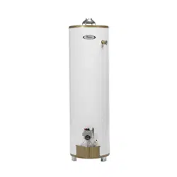
IMPORTANT: Read the data plate to be sure the water heater is made for the type of gas you will be using in your home. This information will be found on the data plate located near the gas control valve/thermostat. If the information does not agree with the type of gas available, do not install or light. Call your dealer.
NOTE: An odorant is added by the gas supplier to the gas used by this water heater. This odorant may fade over an extended period of time. Do not depend upon this odorant as an indication of leaking gas.
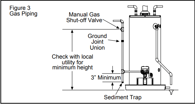
Gas Piping
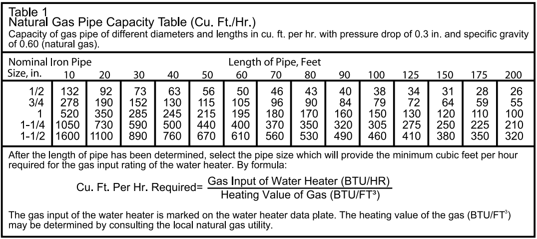
The gas piping must be installed according to all local and state codes or, in the absence of local and state codes, the “National Fuel Gas Code”, ANSI Z223.1(NFPA 54)-current edition. Table 1 provides a sizing reference for commonly used gas pipe materials. Consult the “National Fuel Gas Code” for the recommended gas pipe size of other materials. Refer to Figure 3
NOTE: When installing gas piping, apply approved pipe joint compound.
Install a readily accessible manual shut-off valve in the gas supply line as recommended by the local utility. Know the location of this valve and how to turn off the gas to this unit.
Install a sediment trap (if not already incorporated as part of the water heater) as shown. The sediment trap must be no less than three inches long for the accumulation of dirt, foreign material, and water droplets.
Install a ground joint union between the gas control valve/thermostat and the manual shut-off valve. This is to allow easy removal of the gas control valve/ thermostat.
Turn the gas supply on and check for leaks. Test all connections by brushing on an approved noncorrosive leak-detection solution. Bubbles will show a leak. Correct any leak found.
Gas Pressure
IMPORTANT: The gas supply pressure must not exceed the maximum supply pressure as stated on the water heater’s data plate. The minimum supply pressure is for the purpose of input adjustment.
Gas Pressure Testing
IMPORTANT: This water heater and its gas connection must be leak tested before placing the appliance in operation.
If the code requires the gas lines to be tested at a pressure exceeding 14” W.C., the water heater and its manual shutoff valve must be disconnected from the gas supply piping system and the line capped.
If the gas lines are to be tested at a pressure less than 14” W.C., the water heater must be isolated from the gas supply piping system by closing its manual shut-off valve.
U.L. recognized fuel gas and carbon monoxide (CO) detectors are recommended in all applications and should be installed using the manufacturer’s instructions and local codes, rules, or regulations.
NOTE: Air may be present in the gas lines and could prevent the pilot from lighting on initial start-up. The gas lines should be purged of air by a qualified person after installation of the gas piping system. While purging the gas piping system of air, make sure that the fuel is not spilled in the area of the water heater installation, or any source of ignition. If the fuel is spilled while purging the piping system of air follow the “WHAT TO DO IF YOU SMELL GAS” instructions on the cover of this manual.
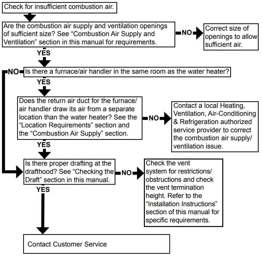
Combustion Air Supply and Ventilation
WARNING: Carbon Monoxide Hazard
Water heater must be vented to outdoors.
Vent must be installed by a qualified person using the installation instructions.
Examples of a qualified person include: gas technicians, authorized gas company personnel, and authorized service persons.
Failure to follow these instructions can result in death or carbon monoxide poisoning.
IMPORTANT: Air for combustion and ventilation must not come from a corrosive atmosphere. Any failure due to corrosive elements in the atmosphere is excluded from warranty coverage.
The following types of installation (not limited to the following) will require outdoor air for combustion due to chemical exposure and may reduce but not eliminate the presence of corrosive chemicals in the air:
beauty shops
photo processing labs
buildings with indoor pools
water heaters installed in laundry, hobby, or craft rooms
water heaters installed near chemical storage areas
Combustion air must be free of acid-forming chemicals such as sulfur, fluorine, and chlorine. These elements are found in aerosol sprays, detergents, bleaches, cleaning solvents, air fresheners, paint, and varnish removers, refrigerants, and many other commercial and household products. When burned, vapors from these products form highly corrosive acid compounds. These products should not be stored or used near the water heater or air inlet.
Combustion and ventilation air requirements are determined by the location of the water heater. The water heater may be located in either an open (unconfined) area or in a confined area or small enclosure such as a closet or small room. Confined spaces are areas with less than 50 cubic feet for each 1,000 BTU/HR of the total input for all gas-using appliances.
Unconfined Space
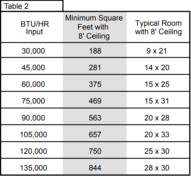
A water heater in an unconfined space uses indoor air for combustion and requires at least 50 cubic feet for each 1,000 BTU/HR of the total input for all gas appliances. The table below shows a few examples of the minimum square footage (area) required for various BTU/HR inputs.
IMPORTANT:
The area must be open and be able to provide the proper air requirements to the water heater. Areas that are being used for storage or contain large objects may not be suitable for water heater installation.
Water heaters installed in open spaces in buildings with unusually tight construction may still require outdoor air to function properly. In this situation, outside air openings should be sized the same as for a confined space.
Modern home construction usually requires supplying outside air into the water heater area.
Confined Space
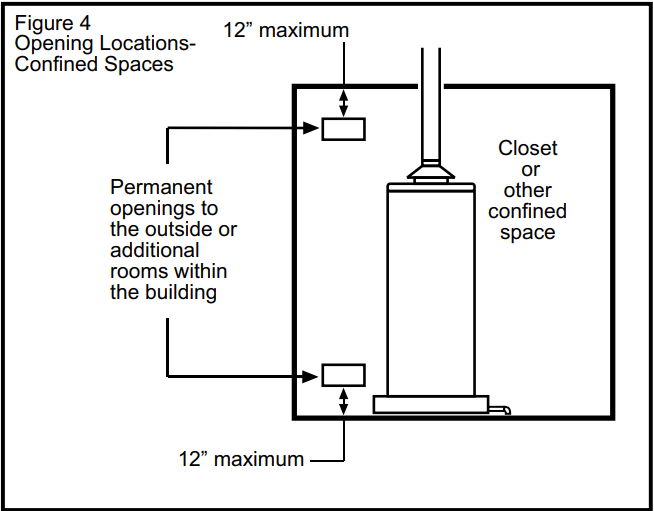
For the correct and proper operation of this water heater, ample air must be supplied for the combustion, ventilation, and dilution of flue gases. Small enclosures and confined areas must have two permanent openings so that sufficient fresh air can be drawn from outside of the enclosure. One opening shall be within 12 inches of the top and one within 12 inches of the bottom of the enclosure as shown in Figure 4.
The size of each opening (free area) is determined by the total BTU/HR input of all gas utilization equipment (i.e., water heaters, furnaces, clothes dryers, etc.) and the method by which the air is provided. The BTU/HR input can be found on the water heater data plate. Additional air can be provided by two methods:
All air from inside the building.
All air from outdoors.
All Air from Inside the Building
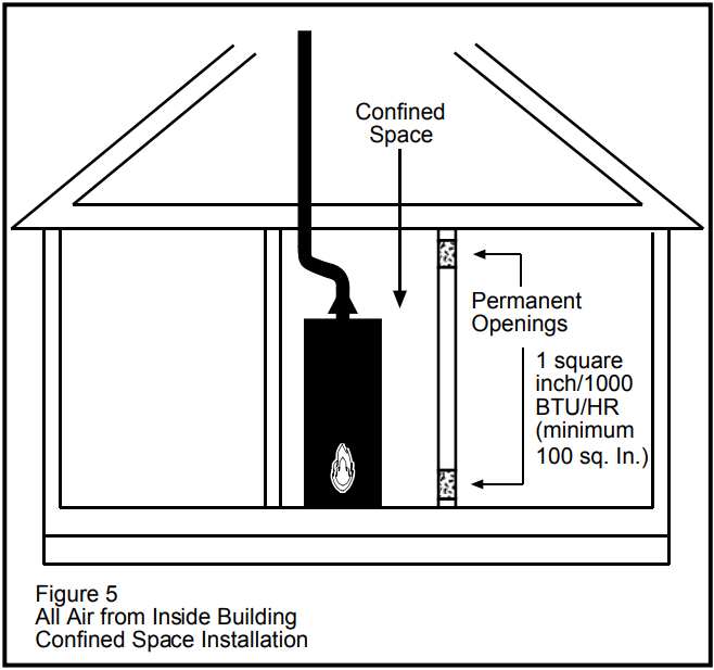
When additional air is to be provided to the confined area from additional room(s) within the building, the total volume of the room(s) must be of sufficient size to properly provide the necessary amount of fresh air to the water heater and other gas utilization equipment in the area. If you are unsure that the structure meets this requirement, contact your local gas utility company or other qualified agency for a safety inspection.
Each of the two openings shall have a minimum free area of 1 square inch per 1,000 BTU/HR of the total input rating of all gas utilization equipment in the confined area, but not less than 100 square inches (Figure 5).
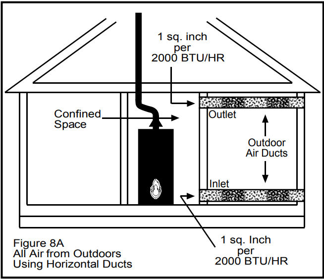
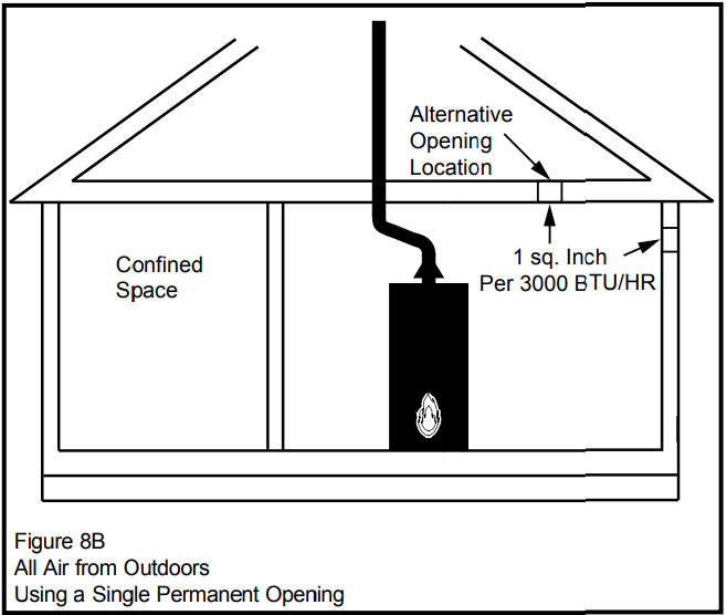
All Air from Outdoors
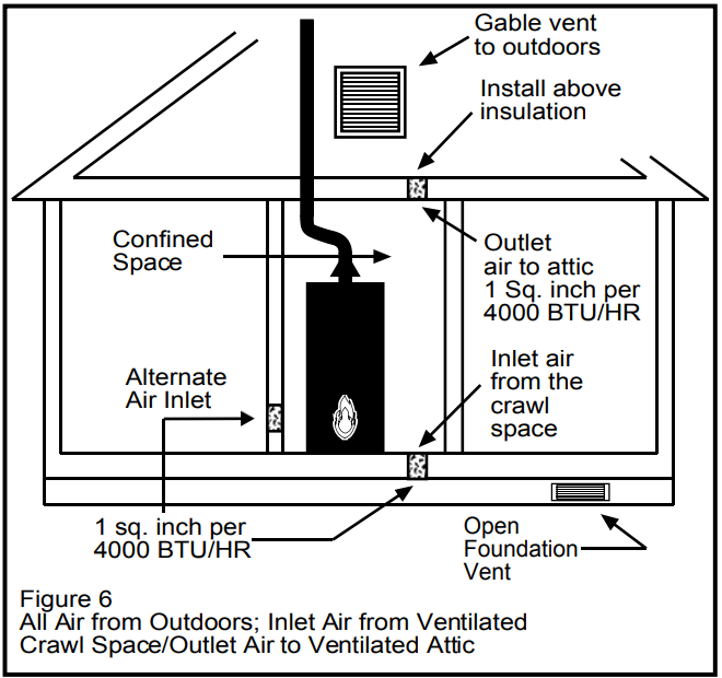
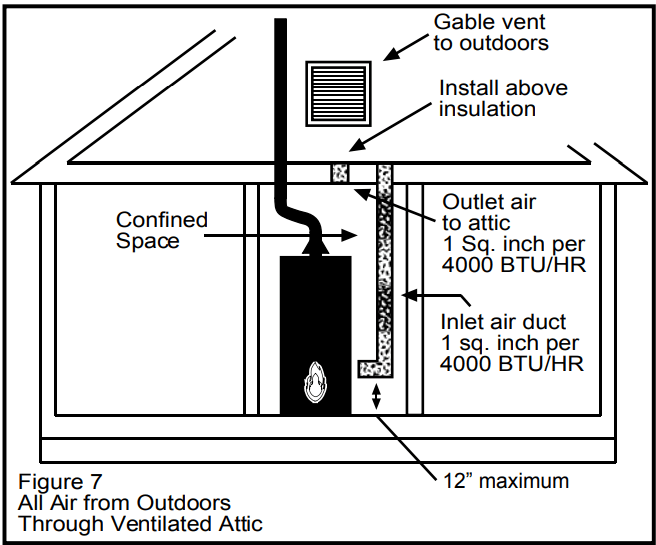
Outdoor fresh air can be provided to a confined area either directly or by the use of vertical and horizontal ducts. The fresh air can be taken from the outdoors or from crawl or attic spaces that freely communicate with the outdoors. Attic or crawl spaces cannot be closed and must be properly ventilated to the outside.
Ductwork must be of the same cross-sectional area as the free area of the opening to which they connect. The minimum dimension of rectangular air ducts cannot be less than three inches.
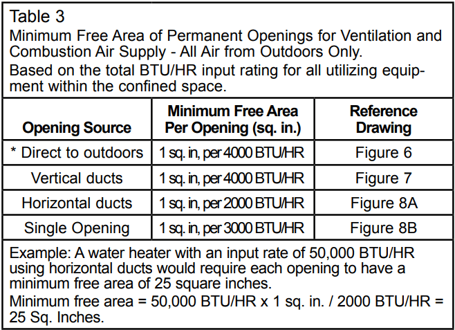
The size of each of the two openings is determined by the method in which the air is to be provided. Refer to Table 3 to calculate the minimum free area for each opening. Figures 6, 7, and 8 are typical examples of each method.
Louvers and Grilles
In calculating free area for ventilation and combustion air supply openings, consideration must be given to the blocking effect of protection louvers, grilles, and screens. These devices can reduce airflow, which in turn may require larger openings to achieve the required minimum free area. Screens must not be smaller than 1/4” mesh. If the free area through a particular design of louver or grille is known, it should be used in calculating the specified free area of the opening. If the design and free area are not known, it can be assumed that most wood louvers will allow 20 - 25% of free area while metal louvers and grilles will allow 60 - 75% of free area.
Louvers and grilles must be locked open or interconnected with the equipment so that they are opened automatically during equipment operation. Keep louvers and grilles clean and free of debris or other obstructions.
* These openings connect directly with the outdoors through a ventilated attic, a ventilated crawl space, or through an outside wall.
Consult the local codes of your area for specific ventilation and combustion air requirements.
Vent Pipe System
This water heater uses a non-direct, single-pipe vent system to remove exhaust gases created by the burning of fossil fuels. Air for combustion is taken from the immediate water heater location or is ducted in from the outside (see “Combustion Air Supply and Ventilation” section).
This water heater must be properly vented for the removal of exhaust gases to the outside atmosphere. Correct installation of the vent pipe system is mandatory for the proper and efficient operation of this water heater and is an important factor in the life of the unit.
The vent pipe must be installed according to all local and state codes or, in the absence of local and state codes, the “National Fuel Gas Code”, ANSI Z223.1(NFPA 54)-current edition. The vent pipe installation must not be obstructed so as to prevent the removal of exhaust gases to the outside atmosphere.
IMPORTANT: The use of vent dampers is not recommended by the manufacturer of this water heater. Although some vent dampers are certified by CSA International, this certification applies to the vent damper device only and does not mean they are certified for use on this water heater.
U.L. recognized fuel gas and carbon monoxide (CO) detectors are recommended in all applications and should be installed using the manufacturer’s instructions and local codes, rules, or regulations.
IMPORTANT: If you lack the necessary skills required to properly install this venting system, you should not proceed, but get help from a qualified person.
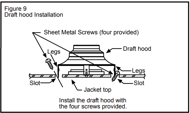
Draft Hood Installation
Align the legs of the draft hood with the slots provided. Insert the legs and secure the draft hood to the water heater’s top with the four screws provided as shown in Figure 9. Do not alter the draft hood in any way. If you are replacing an existing water heater, be sure to use the new draft hood supplied with the water heater.
Vent Pipe Size
It is important that you follow the guidelines in these instructions for sizing a vent pipe system. If a transition to a larger vent size is required, the vent transition connection must be made at the draft hood outlet.
Vent Connectors
Type B, Double wall, U.L. Listed Vent Pipe.
Single wall Vent Pipe.
Maintain the manufacturer’s specified minimum clearance from combustible materials when using type B double wall vent pipe.
Vent connectors made of type B, double wall vent pipe material may pass through walls or partitions constructed of combustible material if the minimum listed clearance is maintained.
Maintain a six inch minimum clearance from all combustible materials when using single wall vent pipe.
IMPORTANT: Single wall vent pipe cannot be used for water heaters located in attics and may not pass through attic spaces, crawl spaces or any confined or inaccessible location. A single wall metal vent connector cannot pass through any interior wall.
When installing a vent connector, please note the following:
Install the vent connector avoiding unnecessary bends, which create resistance to the flow of vent gases.
Install without dips or sags with an upward slope of at least 1/4-inch per foot.
Joints must be fastened by sheet metal screws or other approved means. It must be supported to maintain clearances and prevent separation of joints and damage.
The length of the vent connector cannot exceed 75% of the vertical vent height.
The vent connector must be accessible for cleaning, inspection, and replacement.
Vent connectors cannot pass through any ceiling, floor, firewall, or fire partition.
It is recommended (but not mandatory) that a minimum 12 inches of vertical vent pipe be installed on the draft hood prior to any elbow in the vent system to improve conditions for positive flow of venting gases.
IMPORTANT: Existing vent systems must be inspected for obstructions, corrosion, and proper installation.
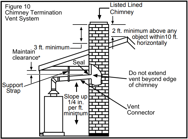
Chimney Connection
IMPORTANT: Before connecting a vent to a chimney, make sure the chimney passageway is clear and free of obstructions. The chimney must be cleaned if previously used for venting solid fuel appliances or fireplaces. Also consult local and state codes for proper chimney sizing and application or, in the absence of local and state codes, the “National Fuel Gas Code”, ANSI Z223.1(NFPA 54)-current edition.
The connector must be installed above the extreme bottom of the chimney to prevent potentially blocking the flue gases.
The connector must be firmly attached and sealed to prevent it from falling out.
To aid in removing the connector, a thimble or slip joint may be used.
The connector must not extend beyond the inner edge of the chimney as it may restrict the space between it and the opposite wall of the chimney (Figure 10).
Do not terminate the vent connector in a chimney that has not been certified for this purpose. Some local codes may prohibit the termination of vent connectors in a masonry chimney.
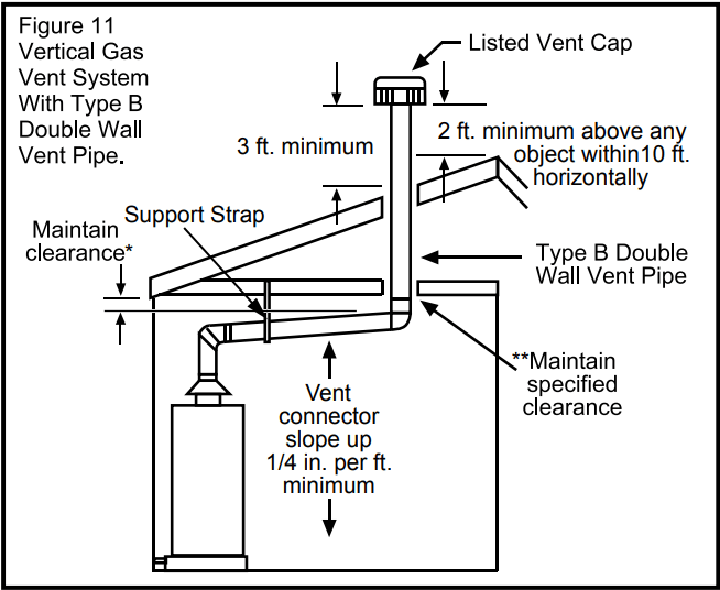
Vertical Exhaust Gas Vent
Vertical exhaust gas vents must be installed with U.L. listed type B vent pipe according to the vent manufacturer’s instructions and the terms of its listing.
It must be connected to the water heater’s draft hood by a listed vent connector or by directly originating at the draft hood opening.
Vertical gas vents must terminate with a listed cap or other roof assembly and be installed according to their manufacturer’s instructions.
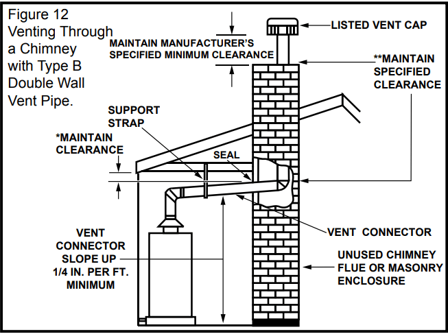
Gas vents must be supported to prevent damage, joint separation, and maintain clearances to combustible materials (Figures 11 and 12).
* Maintain vent pipe clearance requirements to local, state and/or the “National Fuel Gas Code”, ANSI Z223.1(NFPA 54)-current edition.
** NFPA 211, Standard for Chimneys, Fireplaces, Vents, and Solid Fuel-Burning Appliances states that these chimneys are intended to be installed in accordance with the installation instructions provided with each chimney support assembly. Minimum air space clearance to combustible materials should be maintained as marked on the chimney sections.
IMPORTANT: This gas vent must be terminated in a vertical position to facilitate the removal of the burnt gases. An unused chimney flue or masonry enclosure may be used as a passageway for the installation of a gas vent (Figure 12).
Common (combined) venting is allowable with vertical type B vent systems and lined masonry chimneys as long as proper draft for the water heater is established under all conditions of operation.
IMPORTANT: Do not common vent this water heater with any power vented appliance.
Figures 10-12 are examples of vent pipe system installations and may or may not be typical for your specific application. Consult the “National Fuel Gas Code”, NFPA 54, ANSI Z223.1-current edition and the guidelines set forth by prevailing local codes.
Water System Piping
Piping Installation
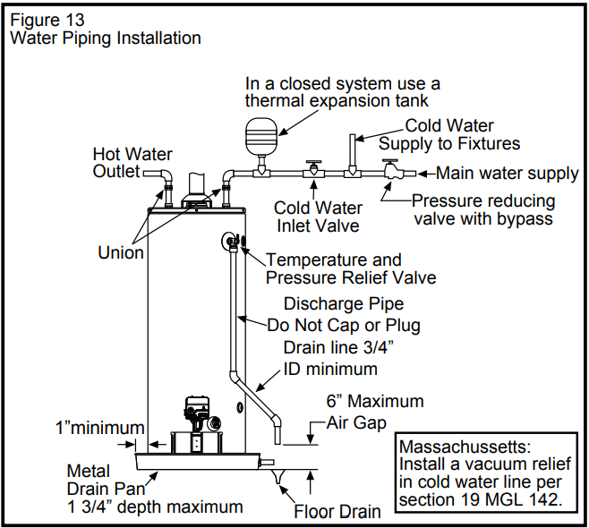
Piping, fittings, and valves should be installed according to the installation drawing (Figure 13). If the indoor installation area is subject to freezing temperatures, the water piping must be protected by insulation.
The water supply pressure should not exceed 80 psi. If this occurs, a pressure reducing valve with a bypass should be installed in the cold water inlet line. This should be placed on the supply to the entire house in order to maintain equal hot and cold water pressures.
IMPORTANT: Heat cannot be applied to the water fittings on the heater as they may contain nonmetallic parts. If solder connections are used, solder the pipe to the adapter before attaching the adapter to the hot and cold water fittings.
IMPORTANT: Always use a good grade of joint compound and be certain that all fittings are drawn up tight.
1. Install the water piping and fittings as shown in Figure 13. Connect the cold water supply (3/4” NPT) to the fitting marked “C”. Connect the hot water supply (3/4” NPT) to the fitting marked “H”.
IMPORTANT: Some models may contain energy saving heat traps to prevent the circulation of hot water within the pipes. Do not remove the inserts within the heat traps.
2. The installation of unions in both the hot and cold water supply lines is recommended for ease of removing the water heater for service or replacement.
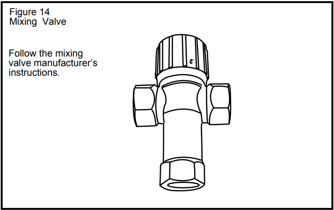
3. The manufacturer of this water heater recommends installing a mixing valve at each point of use. See Figure 14. These valves reduce the point-of-use temperature of the water by mixing cold and hot water and are readily available for use.
4. If installing the water heater in a closed water system, install an expansion tank in the cold water line as specified under “Closed System/Thermal Expansion” section.
5. Install a shut-off valve in the cold water inlet line. It should be located close to the water heater and be easily accessible. Know the location of this valve and how to shut off the water to the heater.
6. A temperature and pressure relief valve must be installed in the opening marked “Temperature and Pressure (T & P) Relief Valve” on the water heater. A discharge line must be added to the opening of the T&P Relief Valve. Follow the instructions under “Temperature and Pressure Relief Valve” section.
7. After piping has been properly connected to the water heater, remove the aerator at the nearest hot water faucet. Open the hot water faucet and allow the tank to completely fill with water. To purge the lines of any excess air, keep the hot water faucet open for 3 minutes after a constant flow of water is obtained. Close the faucet and check all connections for leaks.
Please note the following:
The system should be installed only with piping that is suitable for potable (drinkable) water such as copper, CPVC, or polybutylene. This water heater must not be installed using iron piping or PVC water piping.
Use only pumps, valves, or fittings that are compatible with potable water.
Use only full flow ball or gate valves. The use of valves that may cause excessive restriction to water flow is not recommended.
Use only 95/5 tin-antimony or other equivalent solder. Any lead based solder must not be used.
Piping that has been treated with chromates, boiler seal, or other chemicals must not be used.
Chemicals that may contaminate the potable water supply must not be added to the piping system.
Closed System/Thermal Expansion
WARNING: Explosion Hazard
If the temperature and pressure relief valve is dripping or leaking, have a qualified person replace it.
Examples of a qualified person include: licensed plumbers, authorized gas company personnel, and authorized service personnel.
Do not plug valve.
Do not remove valve.
Failure to follow these instructions can result in death, or explosion.
As water is heated, it expands (thermal expansion). In a closed system, the volume of water will grow. As the volume of water grows, there will be a corresponding increase in water pressure due to thermal expansion. Thermal expansion can cause premature tank failure (leakage). This type of failure is not covered under the limited warranty. Thermal expansion can also cause intermittent temperature-pressure relief valve operation: water discharged from the valve due to excessive pressure build up. The temperature-pressure relief valve is not intended for the constant relief of thermal expansion. This condition is not covered under the limited warranty.
A properly-sized thermal expansion tank should be installed on all closed systems to control the effects of thermal expansion. Contact a plumbing service agency or your retail supplier regarding the installation of a thermal expansion tank.
Temperature & Pressure Relief Valve
WARNING: Explosion Hazard
If the temperature and pressure relief valve is dripping or leaking, have a qualified person replace it.
Examples of a qualified person include: licensed plumbers, authorized gas company personnel, and authorized service personnel.
Do not plug valve.
Do not remove valve.
Failure to follow these instructions can result in death, or explosion.
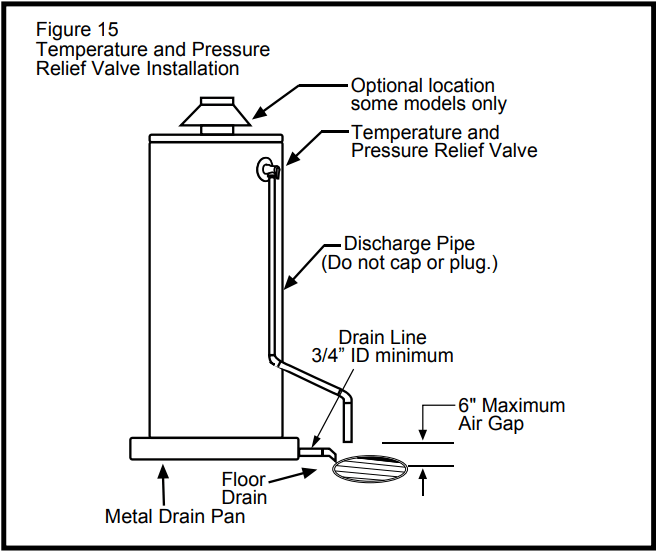
For protection against excessive pressures and temperatures, a temperature and pressure relief valve must be installed in the opening marked “T & P RELIEF VALVE” (see Figure 15). This valve must be design certified by a nationally recognized testing laboratory that maintains periodic inspection of the production of listed equipment or materials as meeting the requirements for Relief Valves and Automatic Shut-off Devices for Hot Water Supply Systems, ANSI Z21.22. The function of the temperature and pressure relief valve is to discharge water in large quantities in the event of excessive temperature or pressure developing in the water heater. The valve’s relief pressure must not exceed the working pressure of the water heater as stated on the data plate.
IMPORTANT: Only a new temperature and pressure relief valve should be used with your water heater. Do not use an old or existing valve as it may be damaged or not adequate for the working pressure of the new water heater. Do not place any valve between the relief valve and the tank.
The Temperature & Pressure Relief Valve:
Must not be in contact with any electrical part.
Must be connected to an adequate discharge line.
Must not be rated higher than the working pressure shown on the data plate of the water heater.
The Discharge Line:
Must not be smaller than the pipe size of the relief valve or have any reducing coupling installed in the discharge line.
Must not be capped, blocked, plugged or contain any valve between the relief valve and the end of the discharge line.
Must terminate a maximum of six inches above a floor drain or external to the building. In cold climates, it is recommended that the discharge pipe be terminated at an adequate drain inside the building.
Must be capable of withstanding 250°F (121°C) without distortion.
Must be installed to allow complete drainage of both the valve and discharge line.
Special Applications
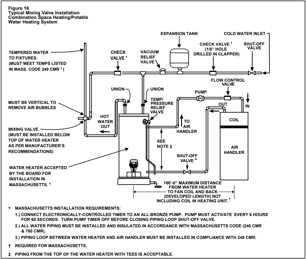
Combination Space Heating/Potable Water System
Some water heater models are equipped with inlet/outlet tappings suitable for combination water (potable) heating and space heating and not suitable for space heating applications only. If this water heater is to be used to supply both space heating and domestic potable (drinking) water, the instructions listed below must be followed.
Be sure to follow the manual(s) shipped with the air handler system.
This water heater is not to be used as a replacement for an existing boiler installation.
Do not use with piping that has been treated with chromates, boiler seal or other chemicals and do not add any chemicals to the water heater piping.
If the space heating system requires water temperatures in excess of 120°F, a mixing valve or an antiscald device should be installed per its manufacturer’s instructions in the domestic (potable) hot water supply to limit the risk of scald injury. Also, install mixing valves at each point of use.
Pumps, valves, piping and fittings must be compatible with potable water.
A properly installed flow control valve is required to prevent thermosiphoning. Thermosiphoning is the result of a continuous flow of water through the air handler circuit during the off cycle. Weeping (blow off) of the temperature and pressure relief valve (T & P) or higher than normal water temperatures are the first signs of thermosiphoning.
The domestic hot water line from the water heater should be vertical past any mixing valve or supply line to the air handler to remove air bubbles from the system. Otherwise, these bubbles will be trapped in the air handler heat exchanger coil, reducing the efficiency.
Do not connect the water heater to any system or components previously used with non-potable water heating appliances when used to supply potable water.
NOTE: Water heaters covered by this manual are suitable for combination water (potable) heating and space heating, but not suitable for space heating applications only.
Some jurisdictions may require a backflow preventer in the incoming cold water line. This may cause the temperature and pressure relief valve on the water heater to discharge or weep due to expansion of the heated water. A diaphragm-type expansion tank suitable for potable water will normally eliminate this weeping condition. Please read and follow the manufacturer’s instructions for the installation of such tanks.
Solar Installation
If this water heater is used as a solar storage heater or as a backup for the solar system, the water supply temperatures to the water heater tank may be in excess of 120°F. A mixing valve or other temperature limiting valve must be installed in the water supply line to limit the supply temperature to 120°F. Also, install mixing valves at each point of use. The unit must be set to Standard Mode (See Operating the Temperature Control System section).
NOTE: Solar water heating systems can often supply water with temperatures exceeding 180°F and may result in water heater malfunction.
Operating Your Water Heater
Lighting Instructions
WARNING: Explosion Hazard
Replace view port if glass is missing or damaged.
Failure to do so can result in death, explosion or fire.
Lighting the Pilot:
Read and follow the lighting instructions on the water heater’s label.
Turn the Control Knob to Pilot. Press the Knob in fully and hold it in. (The knob will travel in about 1/4-inch if it is set to Pilot correctly.)
Click the Igniter button continuously for up to 90 seconds or until the Status Light begins to blink. If the Status Light does not begin to blink after 90 seconds, STOP. Wait 10 minutes before attempting to relight the Pilot. Repeat these steps 2-3 times, if necessary.
The circuitry in this gas valve requires that you wait 10 minutes between lighting attempts. If the Status Light blinks, release the Control Knob and turn it to the desired setting. (“Hot” is approximately 120°F.)
If the Status Light Does Not Blink:
Wait 10 minutes before another lighting attempt.
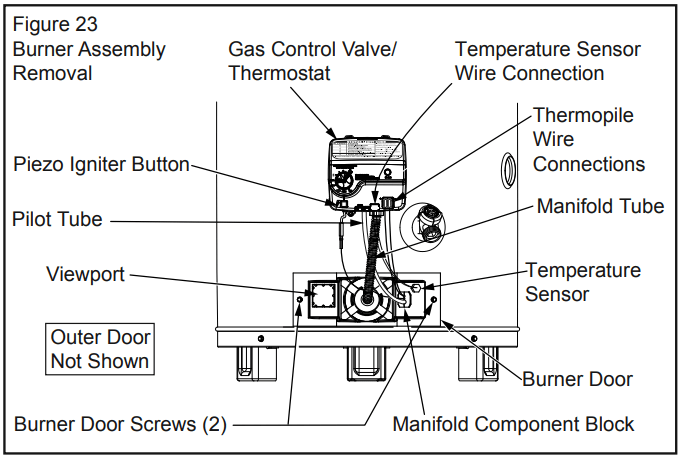
If the Status Light did not blink, repeat the lighting procedure by following the lighting instructions on the water heater’s label. Remove the outer door. The Control Knob must be set to Pilot and held in continuously while clicking the igniter button (about once per second for up to 90 seconds). To observe the Pilot, remove the outer door and look through the view port (sight glass). See Figure 23.
Continue clicking the Igniter button (for up to 90 seconds) until Pilot lights.
Once the Pilot is lit, continue to hold the Control Knob in until the Status Light begins to blink.
Release Control Knob and set Knob to desired temperature setting. (“Hot” is approximately 120°F.)
Replace the outer door.
If the Pilot Does Not Light:
1. Wait 10 minutes before another lighting attempt. If the pilot does not light, the Igniter may not be sparking or the unit may not be getting gas (or for a new installation, there may still be air in the gas line).
Each time you click the igniter button, you should be able to see the spark by looking through the view port. See Figure 23. (You may have to darken the room lights to see the spark.) You do not have to push the Control Knob in to check the Igniter button. Simply look through the sight glass while clicking the Igniter button and look for a spark. If you can’t see a spark when the Igniter button is clicked, check the wiring connections from the Igniter button and make sure that they are tight.
2. If you see the Igniter spark, try relighting the pilot by following the instructions on the water heater’s label. Ensure that the gas supply is turned on. There may be air in the gas line, and several lighting attempts may be needed to completely fill the line with gas and successfully light the pilot.
If the Pilot Lights but the Status Light Does Not Blink:
If the pilot lights, continue to hold the Control Knob in until the Status Light blinks. If the pilot is lit and remains lit for 90 seconds and the Status Light still does not blink, the thermopile connections may be loose or the thermopile may be defective.
Check the wiring connections from the thermopile to the gas control valve/thermostat. Ensure that all wiring connections are tight. See Figure 23.
Wait 10 minutes and try to light the Pilot according to the instructions on the water heater’s label.
While clicking the Igniter button continuously, the Control Knob must be set to Pilot and held in until the Status Light blinks. Once the Status Light blinks, release the Control Knob and set the Knob to the desired temperature setting. (“Hot” is approximately 120°F.)
Checking the Draft
WARNING: Burn Hazard. Do not touch vent. Doing so can result in burns.
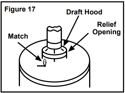
After successfully lighting the water heater, allow the unit to operate for 15 minutes and check the draft hood relief opening for proper draft. Make sure all other appliances in the area are operating and all doors are closed when performing the draft test. Pass a match flame around the relief opening of the draft hood. A steady flame drawn into the opening indicates proper draft. If the flame flutters or is blown out, combustion products are escaping from the relief opening. If this occurs, do not operate the water heater until proper adjustments or repairs are made to the vent pipe system and/or air supply requirements.
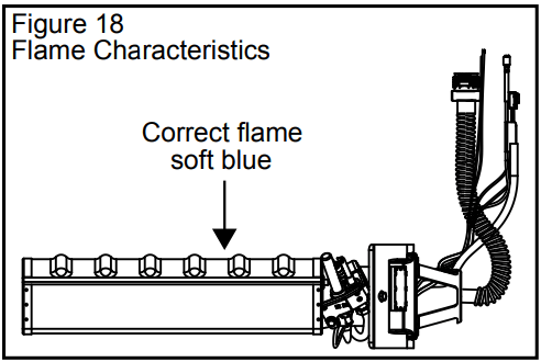
Burner Flames
Inspect the burner flames through the viewport. Flames should be very small with a blue haze and small amounts of yellow or orange at the edges. After several minutes of operation, the burner screen may glow red. If large flames are observed at any time, shut-off unit and call a qualified person.
Water Temperature Stacking
Stacking occurs when a series of short draws of hot water (3 gallons or less) are taken from the water heater tank. This causes increased cycling of the burner and can result in increased water temperatures at the hot water outlet.
This water heater’s temperature control has been designed to accurately regulate the water temperature. However, under certain operating conditions, the water temperature may temporarily exceed the dial setting. Consequently, in addition to setting the temperature no higher than 120°F, we recommend the installation of a mixing valve at each point of use to further reduce the risk of scald injury. These devices can be obtained from a plumbing service agency or your retail supplier.
Emergency Shut Down
IMPORTANT: Should overheating occur or the gas supply fails to shut off, turn off the water heater’s manual gas control valve and call a qualified person.
Water Temperature Regulation
WARNING:
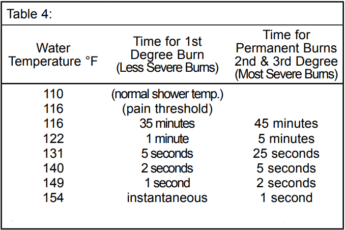
Water temperature over 125°F can cause severe burns instantly or death from scalds.
Children, disabled and elderly are at highest risk of being scalded.
Feel water before bathing or showering.
Temperature limiting valves are available.
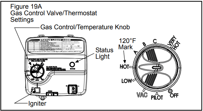
The thermostat is adjusted to the pilot position when it is shipped from the factory. Water temperature can be regulated by moving the temperature dial to the preferred setting. The preferred starting point is 120°F at the “HOT” setting. Align the knob with the desired water temperature as shown in Figure 19A. There is a hot water scald potential if the thermostat is set too high.
NOTE: Temperatures shown on the gas control valve/ thermostat are approximates. The actual temperature of the heated water may vary.
IMPORTANT: Adjusting the thermostat past the 120°F bar on the temperature dial will increase the risk of scald injury. Hot water can produce first degree burns within:
NOTE: During low demand periods when hot water is not being used, a lower thermostat setting will reduce energy losses and may satisfy your normal hot water needs. If hot water use is expected to be more than normal, a higher thermostat setting may be required to meet the increased demand. When leaving your home for extended periods (vacations, etc.) turn the temperature dial to the vacation (VAC) setting. This will maintain the water at low temperatures with minimum energy losses and prevent the tank from freezing during cold weather.
Operating the Temperature Control System
Water Temperature Adjustment
The water temperature setting can be adjusted from 55°F to 155°F. Turn the Gas Control/Temperature Knob to the desired setting/temperature.
NOTE: The temperatures indicated are approximates. The actual temperature of the heated water may vary. Also, some models are certified for 180°F outlet temperatures. See the Data Plate on the front of the water heater for the maximum outlet temperature.
Operating Modes and Settings
The gas control valve has two different operating modes:
Standard and Vacation. Standard mode allows you to adjust the water temperature to your desired setting.
Vacation (VAC) mode sets the thermostat at approximately 55°F and is recommended when not using hot water for an extended period of time. The VAC setting also reduces energy losses and keeps the tank from freezing during cold weather, but it can cause a Hydrogen gas build up in the water system.
NOTE: The actual temperature of the water in most installations will be greater than 55°F due to the surrounding environment and the pilot flame.
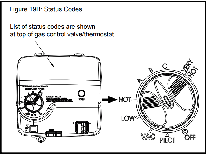
Status Light Codes
Normal Flashes:
0 Flashes: Indicates Control Off/Pilot Out.
1 Flash: Indicates Normal Operation.
Continuous Light indicates the gas control valve/thermostat is shutting down.
Diagnostic Flashes: If the water heater is not working, look for the following diagnostic flashes after lighting the pilot.
2 Flashes: Indicates thermopile voltage is low.
4 Flashes: Indicates overheat failure.
5 Flashes: Indicates water temperature sensor failure.
7 Flashes: Indicates electronic control failure.
8 Flashes: See “Status Light Code Troubleshooting Chart.”
9 Flashes: Indicates chamber temperature sensor circuit is open or shorted.
10 Flashes: Indicates an LDO occurrence was detected in the combustion chamber (contaminants).
Operational Conditions
Condensation
Moisture from the products of combustion condenses on the tank surface and the outside jacket of the water heater and forms drops of water which may fall onto the burner or other hot surfaces. This will produce a “sizzling” or “frying” noise.
NOTE: This condensation is normal and should not be confused with a leaking tank. Condensation may increase or decrease at different times of the year.
High efficient energy saver water heaters will produce larger amounts of condensation on initial start-up or when a large amount of hot water is being used. NOTE: Do not confuse this with a “tank leak”. Once the water reaches a temperature of 120°F and the tank warms up (usually 1-2 hours), the condensation will stop.
IMPORTANT: It is always recommended that a suitable metal drain pan be installed under the water heater to protect the area from water damage resulting from normal condensation production, a leaking tank or piping connections. Under no circumstances is the manufacturer to be held responsible for any water damage in connection with this water heater.
Water Heater Sounds
During the normal operation of the water heater, sounds or noises may be heard. These noises are common and may result from the following:
Normal expansion and contraction of metal parts during periods of heat-up and cool-down.
Condensation causes sizzling and popping within the burner area and should be considered normal.
Sediment buildup in the tank bottom will create varying amounts of noise and may cause premature tank failure. Drain and flush the tank as directed under “Draining and Flushing”.
Smoke/Odor
The water heater may give off a small amount of smoke and odor during the initial start-up of the unit. This is due to the burning off of oil from metal parts of a new unit and will disappear after a few minutes of operation.
Safety Shut-off
This water heater is designed to automatically shut-off in the event of the following:
The pilot flame is extinguished for any reason.
The water temperature exceeds 189°F (87°C).
Excessive contaminants in the combustion chamber.
The ignition of flammable vapors.
A thermopile is used to determine if a pilot flame is present and will shut off the gas supply to the main burner and pilot if the flame is absent. This unit is also equipped with a combustion chamber temperature sensor that will shut off the gas supply to the burner if poor combustion is sensed (caused by a blocked vent or insufficient combustion air). If the gas control valve/thermostat shuts off the gas supply, check the diagnostic flash code and refer to the “Status Light Code Troubleshooting Chart.” If necessary, also refer to the “Troubleshooting Chart.”
IMPORTANT: Correct any issues prior to resetting the gas control valve/thermostat.
Reset the system by following these steps:
Turn the temperature adjustment knob to OFF.
Unplug the thermopile plug from the gas control valve/thermostat.
Wait for about three minutes.
Plug the thermopile plug back into the gas control valve/thermostat.
Turn the temperature adjustment knob to PILOT and restart the water heater.
A temperature limit switch or ECO (Energy Cut Off) sensor located in the gas control valve\thermostat is used to shut off the water heater if the water temperature exceeds 189°F (87°C).
The Diagnostic Status Light will flash a code indicating an “Overheat Failure” (4 Flashes). See “Operating the Temperature Control System.” If the ECO has functioned the gas control valve/thermostat should be replaced by a qualified person. Contact your local dealer for service information.
Anode Rod/Water Odor
Each water heater contains at least one anode rod, which will slowly deplete (due to electrolysis) prolonging the life of the water heater by protecting the glass-lined tank from corrosion. Adverse water quality, hotter water temperatures, high hot water usage, hydronic heating devices, and water softening methods can increase the rate of anode rod depletion. Once the anode rod is depleted, the tank will start to corrode, eventually developing a leak.
Certain water conditions will cause a reaction between the anode rod and the water. The most common complaint associated with the anode rod is a “rotten egg smell” produced from the presence of hydrogen sulfide gas dissolved in the water.
IMPORTANT: Do not remove this rod permanently as it will void any warranties. A special anode rod may be available if water odor or discoloration occurs.
NOTE: This rod may reduce but not eliminate water odor problems. The water supply system may require special filtration equipment from a water conditioning company to successfully eliminate all water odor problems.
Artificially softened water is exceedingly corrosive because the process substitutes sodium ions for magnesium and calcium ions. The use of a water softener may decrease the life of the water heater tank.
The anode rod should be inspected after a maximum of three years and annually thereafter until the condition of the anode rod dictates its replacement.
NOTE: Artificially softened water requires the anode rod to be inspected annually.
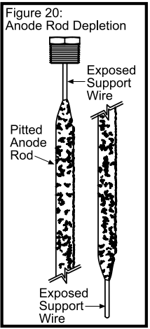
The following are typical (but not all) signs of a depleted anode rod:
The majority of the rods diameter is less than 3/8”.
Significant sections of the support wire (approx. 1/3 or more of the anode rod’s length) are visible.
If the anode rod show signs of either or both it should be replaced. NOTE: Whether re-installing or replacing the anode rod, check for any leaks and immediately correct if found.
In replacing the anode:
Turn off gas supply to the water heater.
Shut off the water supply and open a nearby hot water faucet to depressurize the water tank.
Drain approximately 5 gallons of water from tank. (Refer to “Draining and Flushing” for proper procedures). Close drain valve.
Remove old anode rod.
Use Teflon® tape or approved pipe sealant on threads and install new anode rod.
Turn on water supply and open a nearby hot water faucet to purge air from water system.
Check for any leaks and immediately correct any if found.
Restart the water heater as directed in this manual. See the Repair Parts Illustration for anode rod location.
Maintenance of Your Water Heater
Draining and Flushing
It is recommended that the tank be drained and flushed every 6 months to remove sediment which may build up during operation. The water heater should be drained if being shut down during freezing temperatures. To drain the tank, perform the following steps:
Turn off the gas to the water heater at the manual gas shut-off valve.
Open a nearby hot water faucet until the water is no longer hot.
Close the cold water inlet valve.
Connect a hose to the drain valve and terminate it to an adequate drain or external to the building.
Open the water heater drain valve and allow all of the water to drain from the tank. Flush the tank with water as needed to remove sediment.
Close the drain valve, refill the tank, and restart the heater as directed in this manual.
If the water heater is going to be shut down for an extended period, the drain valve should be left open.
IMPORTANT: Condensation may occur when refilling the tank and should not be confused with a tank leak.
Routine Preventative Maintenance
At least annually, a visual inspection should be made of the venting and air supply system, piping systems, main burner, pilot burner, and Flame-trap. Check the water heater for the following:
Obstructions, damage, or deterioration in the venting system. Make sure the ventilation and combustion air supplies are not obstructed.
Build up of soot and carbon on the main burner and pilot burner. Check for a soft blue flame.
Leaking or damaged water and gas piping.
Presence of flammable or corrosive materials in the installation area.
Presence of combustible materials near the water heater.
After servicing this water heater, check to make sure it is working properly. (See Operating Your Water Heater section of this manual.)
IMPORTANT: If you lack the necessary skills required to properly perform this visual inspection, you should not proceed, but get help from a qualified person.
Temperature and Pressure Relief Valve
WARNING: Explosion Hazard
If the temperature and pressure relief valve is dripping or leaking, have a qualified person replace it.
Examples of a qualified person include: licensed plumbers, authorized gas company personnel, and authorized service personnel.
Do not plug valve.
Do not remove valve.
Failure to follow these instructions can result in death, or explosion.
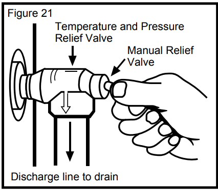
Manually operate the temperature and pressure relief valve at least once a year to make sure it is working properly. To prevent water damage, the valve must be properly connected to a discharge line which terminates at an adequate drain. Standing clear of the outlet (discharged water may be hot), slowly lift and release the lever handle on the temperature and pressure relief valve to allow the valve to operate freely and return to its closed position. If the valve fails to completely reset and continues to release water, immediately shut off the manual gas control valve and the cold water inlet valve and call a qualified person.
WARNING! .When manually operating the temperaturepressure relief valve, make sure that no one is in front of or around the discharge outlet. The water may be extremely hot and could cause severe burns. Also ensure that the water discharge will not cause property damage.
Replacement Parts
IMPORTANT: The following maintenance procedures are for the Flame Lock® Safety System components and should be performed by a qualified person.
Replacement parts may be ordered through your plumber or the local distributor. Parts will be shipped at prevailing prices and billed accordingly. When ordering replacement parts, always have the following information ready:
model, serial, and product number
type of gas
item number
parts description
Removing the Burner Door Assembly
Turn off the gas to the water heater at the manual shut-off valve (Figure 3).
Turn the gas control/temperature knob to the “OFF” position (Figure 19).
Remove the outer door.
Remove the two screws (1/4” nut driver) securing the burner door assembly to the combustion chamber (Figure 23).
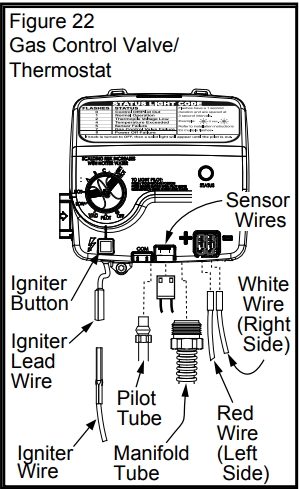
Disconnect the pilot tube (7/16” wrench), the igniter wire from the igniter lead wire, and manifold tube (3/4” wrench) at the gas control valve/thermostat. Disconnect the sensor wires (lift white lever outward, then gently pull the plug downward). Also, use needle nose pliers to disconnect the red (+) and white (-) thermopile wires from the gas control valve/thermostat. See Figures 22 & 23.
Grasp the manifold tube and push down slightly to free the manifold, pilot tube, and thermopile.
Carefully remove the burner door assembly from the burner compartment.
NOTE: Be sure not to damage internal parts.
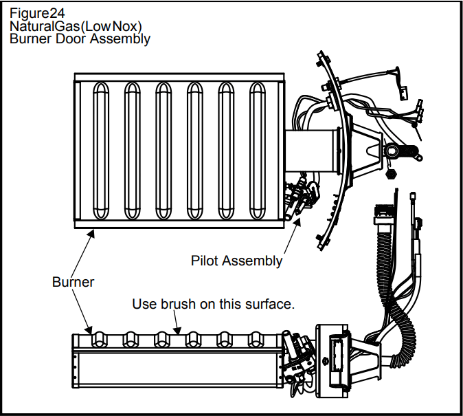
Natural Gas Burner (Ultra Low Nox)
Check the burner to see if it is dirty or clogged. The burner may be cleaned with soft paint brush (Figure 24). Do not use a wire brush or any tool that may damage the burner screen. Important: Do not use the burner if the burner screen is damaged. NOTE: Damage may be rips or holes in the burner screen. Discoloration is normal.
Replacing the Pilot/Thermopile Assembly
1. Remove the burner assembly as directed previously.
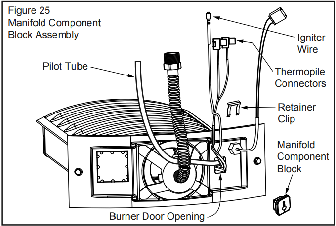
2. Lift the retainer clip straight up from the back of the manifold component block (using a flat-blade screwdriver), then remove the manifold component block from the burner door assembly (Figure 25).
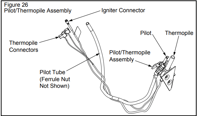
3. Locate and remove the phillips screw attaching the pilot to the pilot bracket, then pull the pilot/thermopile assembly (including the igniter wire) out of the burner door assembly.
4. Using a 7/16” wrench, loosen the nut securing the pilot tube to the pilot assembly (right-hand threads).
5. Pull the pilot tube from the pilot assembly (Figure 26).
IMPORTANT: Be careful not to bend or alter the position of the pilot assembly components.
6. Using the old pilot tube as a guide, bend the new pilot tube to match the old one. Make only the bends closest to the pilot before going to the next step.
7. Reconnect the pilot tube and tighten the nut securing it to the pilot assembly. To prevent any bending of the pilot bracket, use pliers to hold the pilot assembly bracket while tightening the pilot nut.
IMPORTANT: Keep the pilot orifice in the pilot when making the connection. DO NOT operate the water heater without the pilot orifice installed.
8. Push the new pilot assembly connectors through the opening in the burner door (See Figure 25).
9. Attach the pilot assembly to the Burner Door Assembly.
10. Position the new thermopile wires through the top opening of the manifold component block (Figure 25). Be sure that the igniter wire is positioned through the middle opening of the manifold component block. Position the pilot tube through the bottom opening of the manifold component block.
11. See “Replacing the Burner Door Assembly”
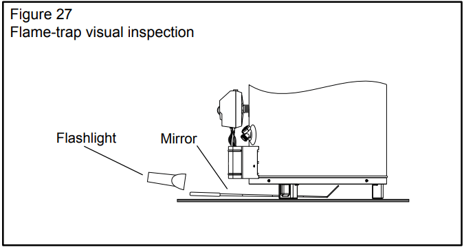
External Inspection & Cleaning of the Flame-trap
Although not likely to occur, if debris collects on the flametrap, use a vacuum, compressed air, or a soft bristle brush to remove it.
NOTE: If unable to inspect or clean the flame trap from underneath, follow the “Cleaning the Combustion Chamber and Flame-trap” section instructions.
Cleaning the Combustion Chamber and Flame-trap
Follow procedure outlined in “Removing the Burner Door Assembly”.
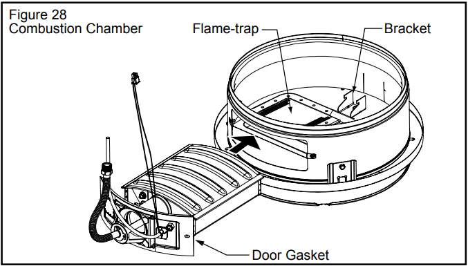
Use a vacuum cleaner/shop vac to remove all loose debris in the combustion chamber (Figure 28). Use compressed air to clear any dust or debris that may have accumulated in the flame-trap.
Reassemble following the procedure under “Replacing the Burner Door Assembly”.
Replacing the Burner Door Assembly
WARNING: Explosion Hazard
Tighten both burner door screws securely.
Remove any fiberglass between gasket and combustion chamber.
Replace viewport if glass is missing or damaged.
Replace manifold component block if missing or removed.
Replace door gasket if damaged.
Failure to follow these instructions can result in death, explosion, or fire.
Check the door gasket for damage or imbedded debris prior to installation.
Inspect the viewport for damage and replace as required.
Insert the burner assembly into the burner compartment, making sure that the burner assembly sits firmly against the burner bracket inside the combustion chamber (Figure 28).
Inspect the door gasket and make sure there is no fiberglass insulation between the gasket and the combustion chamber.
Replace the two screws which secure the burner assembly to the combustion chamber and tighten securely. There should be no space between the gasket part of the burner door and combustion chamber. IMPORTANT: Do not operate the water heater if the door gasket does not create a seal between the burner door and the combustion chamber.
Reconnect the manifold tubing (3/4” wrench), pilot tubing (7/16” wrench), temperature sensor wires, and thermopile wires to the gas control valve/thermostat. (See Figure 22 for the correct position of the thermopile wires.) Do not cross-thread or apply any thread sealant to the fittings.
Reconnect the igniter wire.
Turn the gas supply on
Check for leaks by brushing on an approved noncorrosive leak detection solution. Bubbles forming indicate a leak. Correct any leak found. IMPORTANT: All leaks must be fixed immediately.
Replace the outer door.
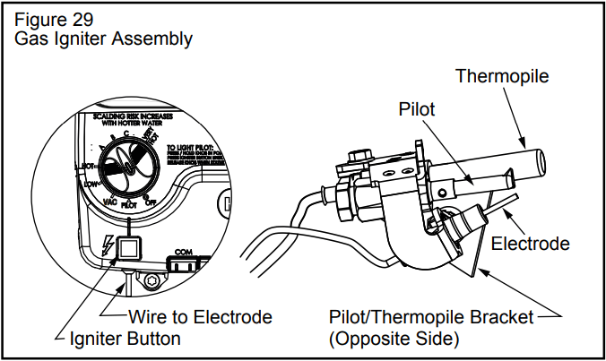
Piezoelectric Igniter System
The piezoelectric igniter system consists of the igniter button, electrode, and wire. The pilot is ignited by an electric spark generated when the igniter button is pressed. (See Figure 29). Use only factory authorized piezoelectric igniter parts for replacement.
Testing the Igniter System
Turn off the gas to the water heater at the manual gas shutoff valve. Watch the electrode tip while activating the igniter. A visible spark should jump from the electrode. To avoid shock, do not touch the burner or any metal part on the pilot or pilot assembly. If no spark is visible, check the wire connections and make sure the electrode is not broken.
Replace the igniter if defective. Dirt and rust on the pilot or electrode tip can prevent the igniter spark. Wipe clean with a damp cloth and dry completely. Rust can be removed from the electrode tip and metal surfaces by lightly sanding with an emery cloth or fine grit sandpaper.
Removing and Replacing the Gas Control Valve/Thermostat
Removing the Gas Control Valve/Thermostat:
Turn the gas control/temperature knob to the “OFF” position (Figure 19A).
Turn off the gas at the manual shut-off valve on the gas supply pipe (Figure 3).
Drain the water heater. Refer to the section on “Draining and Flushing” and follow the procedure.
Disconnect the igniter wire from the igniter lead wire. Disconnect the temperature sensor wire, then use needle nose pliers to disconnect the red (+) and white (-) thermopile wires. Disconnect the pilot tube (7/16” wrench) and manifold tube (3/4” wrench) at the gas control valve/thermostat (Figure 22).
Refer to “Gas Piping” (Figure 3) and disconnect the ground joint union in the gas piping. Disconnect the remaining pipe from the gas control valve/thermostat.
To remove the gas control valve/thermostat, thread a 4” section of gas pipe into the inlet and use it to turn the gas control valve/thermostat (counterclockwise.) Do not use a pipe wrench or equivalent to grip body. Damage may result. Do not insert any sharp objects into the inlet or outlet connections. Damage to the gas control valve/thermostat may result.
Gas Control Valve/Thermostat:
To replace the gas control valve/thermostat, reassemble in reverse order. When replacing the gas control valve/ thermostat, thread a 4” section of gas pipe into the inlet and use it to turn the gas control valve/thermostat (clockwise.) DO NOT OVER TIGHTEN, damage may result.
Be sure to use approved Teflon® tape or pipe joint compound on the gas piping connections and fitting on the back of the gas control valve that screws into tank.
Be sure to remove the pilot ferrule nut from the new gas control valve/thermostat.
Turn the gas supply on and check for leaks. Test the water heater by brushing on an approved noncorrosive leak detection solution. Bubbles forming indicate a leak. Correct any leak found.
Be sure tank is completely filled with water before lighting and activating the water heater.
If additional information is required, reference the number on the cover of this manual for service information.
Flame Lock® Safety System Operational Checklist
Burner door gasket properly sealed.
Viewport not damaged or cracked.
Flame-trap free of debris and undamaged.
Manifold component block properly installed.
No leaks at pilot and manifold connection.
Burner door screws securely tightened.
Troubleshooting
PROBLEM
POSSIBLE CAUSE(S)
CORRECTIVE ACTION
BURNER WILL NOT IGNITE
1. Pilot not lit
2. Thermostat set too low
3. No gas
4. Dirt in the gas lines
5. Pilot line clogged
6. Main burner line clogged
7. Non-functioning thermopile
8. Non-functioning thermostat
9. Heater installed in a confined area
1. Light pilot
2. Turn temp. dial to desired temperature
3. Check with gas utility company
4. Notify utility-install trap in gas line
5. Clean, locate source and correct
6. Clean, locate source and correct
7. Replace thermopile
8. Replace thermostat
9. Provide fresh air ventilation
SMELLY WATER
1. Sulfides in the water
1. Replace the anode with a special anode
BURNER FLAME YELLOWLAZY
1. Insufficient secondary air
2. Low gas pressure
3. Flue clogged
4. Main burner line clogged
5. Heater installed in a confined area
6. Obstruction in main burner orifice
1. Provide ventilation to water heater
2. Check with gas utility company
3. Clean, locate source and correct
4. Clean, locate source and correct
5. Proper fresh air ventilation
6. Clean or replace orifice
PILOT WILL NOT LIGHT OR REMAIN LIT
1. Non-functioning igniter
2. Thermopile connection loose
3. Air in gas line
4. Proper Lighting Sequence not followed. Gas Control / Temperature Knob was not held in for sufficient time.
5. Low gas pressure
6. No gas
7. Dirt in gas lines
8. Cold drafts.
9. ECO switch open
10. Pilot line or orifice clogged
11. Non-functioning thermopile
12. Air for combustion obstructed
13. Flammable vapors incident, Flame Lock® function utilized
1. Replace igniter pilot assembly
2. Seat connector firmly in socket
3. Bleed the air from the gas line
4. Do not attempt to relight if the status light is lit and the pilot flame is not visible through the view port. Wait until the status light is no longer lit, then follow lighting instructions on the water heater.
5. Check with gas utility company
6. Check with gas utility company
7. Notify utility-install sediment trap in gas line
8. Locate source and correct.
9. Replace gas control valve/thermostat
10. Clean, locate source and correct
11. Replace thermopile
12. See maintenance section for inspection and cleaning of flame trap
13. Replace water heater, eliminate flammable vapors source.
HIGH OPERATION COSTS
1. Thermostat set too high
2. Sediment or lime in tank
3. Water heater too small for job
4. Wrong piping connections
5. Leaking faucets
6. Gas leaks
7. Wasted hot water
8. Long runs of exposed piping
9. Hot water piping in exposed wall
1. Set temperature dial to lower setting
2. Drain/flush-provide water treatment if needed
3. Install adequate heater
4. Correct piping-dip tube must be in cold inlet
5. Repair faucets
6. Check with utility-repair at once
7. Advise customer
8. Insulate piping
9. Insulate piping
INSUFFICIENT HOT WATER
1. Thermostat set too low
2. Sediment or lime in tank
3. Water heater too small
4. Wrong piping connections
5. Leaking faucets
6. Wasted hot water
7. Long runs of exposed piping
8. Hot water piping in outside wall
9. Low gas pressure
1. Turn temperature dial to desired setting
2. Drain/flush-provide water treatment if needed
3. Install adequate heater
4. Correct piping-dip tube must be in cold inlet
5 Repair faucets
6. Advise customer
7. Insulate piping
8. Insulate piping
9. Check with gas utility company
SLOW HOT WATER RECOVERY
1. Insufficient secondary air
2. Flue clogged
3. Low gas pressure
4. Improper calibration
5. Thermostat set too low
6. Water heater too small
7. Wrong piping connections
8. Wasted hot water
1. Provide ventilation to water heater. Check flue way, flue baffle, and burner
2. Clean flue, locate source and correct
3. Check with gas utility company
4. Replace thermostat
5. Turn temperature dial to desired setting
6. Install adequate heater
7. Correct piping-dip tube must be in cold inlet
8. Advise customer
DRIP FROM RELIEF VALVE
1. Excessive water pressure
2. Heater stacking
3. Closed water system
1. Use a pressure reducing valve and relief valve
2. Lower the thermostat setting
3. See “Closed System/Thermal Expansion”
THERMOSTAT FAILS TO SHUT-OFF
1. Thermostat not functioning properly
2. Improper calibration
1. Replace thermostat
2. Replace thermostat
COMBUSTION ODORS
1. Insufficient secondary air
2. Flue clogged
3. Heater installed in a confined area
1. Provide ventilation to water heater. Check flue way, flue baffle, and burner
2. Clean, locate source and correct
3. Provide fresh air ventilation
SMOKING AND CARBON FORMATION (SOOTING)
1. Insufficient secondary air
2. Low gas pressure
3. Flue clogged
4. Thermostat not functioning properly
5. Heater installed in a confined area
6. Burner flame yellow-lazy
1. Provide ventilation to water heater. Check flue way, flue baffle, burner
2. Check with gas utility company
3. Clean, locate source and correct
4. Replace thermostat 5. Provide fresh air ventilation
6. See “Burner Flame Yellow-Lazy”
CONDENSATION
1. Temperature setting too low
1. Increase the temperature setting
BURNER FLAME FLOATS AND LIFTS OFF PORTS
1. Orifice too large
2. High gas pressure
3. Flue clogged
4. Cold drafts
1. Replace with correct orifice
2. Check with gas utility company
3. Clean flue and burner-locate source and correct
4. Locate source and correct
BURNER FLAME TOO HIGH
1. Orifice too large
1. Replace with correct orifice
PILOT FLAME TOO SMALL
1. Pilot line or orifice clogged 2. Low gas pressure
1. Clean, locate source and correct
2. Check with gas utility company
STATUS LIGHT CODE TROUBLESHOOTING
LED STATUS
PROBLEM
CORRECTIVE ACTION
0 FLASHES (LED NOT LIT)
Pilot light is not lit. Not enough power (millivolts) to keep it lit.
Follow the lighting instructions on the front of the water heater and record any diagnostic codes. See “Status Light Codes” section.
1 FLASH (EVERY 3 SECONDS)
Normal operation
No corrective action necessary
2 FLASHES
Insufficient power (millivolts) to the gas control valve/thermostat.
1. Check all wiring connections. If problem persists proceed to step 2.
2. Replace the thermopile. See “Replacing the Pilot/Thermopile Assembly.”
4 FLASHES
High water temperature has activated the over heat sensor.
Replace the gas control valve/thermostat. See “Removing and Replacing the Gas Control Valve/ Thermostat.”
5 FLASHES
Water temperature sensor failure
Replace the gas control valve/thermostat. See “Removing and Replacing the Gas Control Valve/ Thermostat.”
7 FLASHES
Gas Control Valve/Thermostat failure.
Replace the gas control valve/thermostat. See “Removing and Replacing the Gas Control Valve/ Thermostat.”
8 FLASHES
This condition only appears if the gas control/temperature knob has been turned off and the thermopile continued to produce electric power. This condition can occur if the thermopile does not cool down as quickly as expected when the unit is shut off. This condition can also occur if the gas control/ temperature knob has been turned off and the pilot continues to operate because the pilot valve is stuck in the open position.
Make sure that the gas control valve/thermostat knob is set to OFF. Wait one minute. Remove the outer door. Look through the sight glass for a pilot flame. If a pilot flame is observed with the gas control valve/thermostat knob set to the OFF position, the pilot valve is stuck open. Turn the main gas supply OFF. Replace the gas control valve/thermostat. For instructions, see “Removing and Replacing the Gas Control Valve/Thermostat.”
If the pilot flame is not observed when the gas control valve/thermostat knob is set to the OFF position, wait 10 minutes for the thermopile to cool, then attempt to relight the pilot by following the lighting instructions on the water heater’s label. If this condition returns, replace the gas control valve/thermostat. See “Removing and Replacing the Gas Control Valve/Thermostat” for instructions.
9 FLASHES
Combustion chamber temperature sensor circuit is open or shorted
1. Check all connections. If the problem persists, proceed to step 2.
2. Replace the temperature sensor. (Temperature sensor replacement must be performed by a qualified person.) If the problem persists, proceed to step 3.
3. Replace the gas control valve/thermostat. For instructions, see “Removing and Replacing the Gas Control Valve/Thermostat.”
10 FLASHES
LDO occurrence was detected in the combustion chamber (contaminants)
1. Reset the system by following these steps: 1.) Turn the temperature adjustment knob to OFF. 2.) Unplug the thermopile plug from the gas control valve/thermostat. 3.) Wait for about three minutes. 4.) Plug the thermopile plug back into the gas control valve/ thermostat. 5.) Turn the temperature adjustment knob to PILOT and restart the water heater as directed in this manual. If the problem persists, proceed to step 2.
2. Follow the procedure outlined in “Cleaning the Combustion Chamber and Flame-Trap.” If the problem persists, proceed to step 3.
3. Shut off the gas supply to the water heater
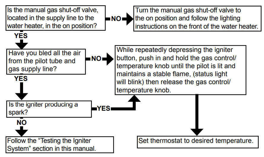
PILOT LIGHT TROUBLESHOOTING
Section A: Pilot light will not light (new installation).