Loading ...
Loading ...
Loading ...
EN12
After unpacking the product, check for any damage during transport. In case of problems, contact the dealer or the After-Sales Service.
PREPARING THE CABINET FOR FITTING
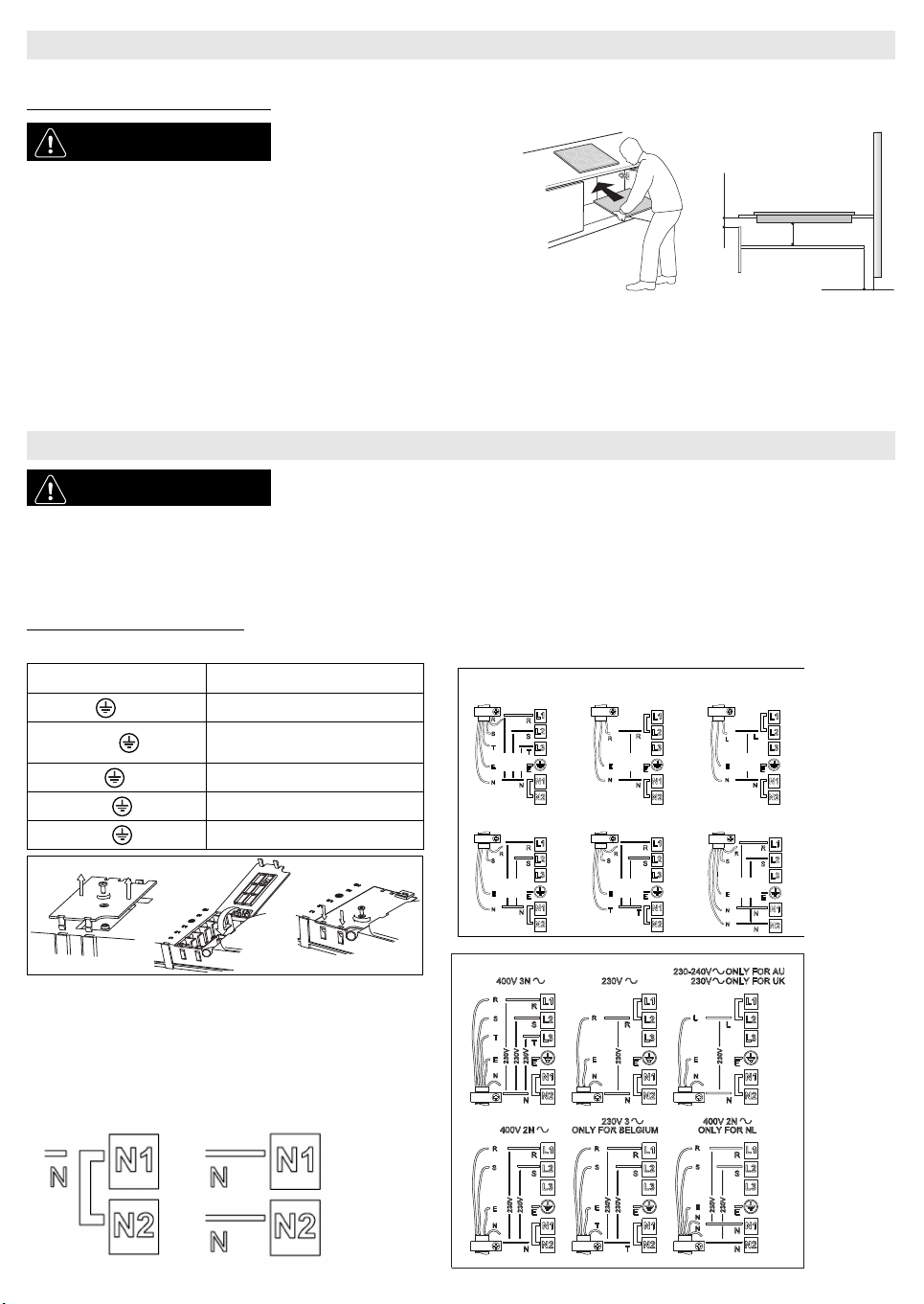
Connection to the terminal block
For the electrical connection, use an H05RR-F cable as specified in the table below.
INSTALLATION
WARNING
- Install a separator panel under
the hob.
- The lower part of the product
must not be accessible after
installation.
- In case of installation of an
undertop oven, do not interpose
the separator panel.
• The distance between the underside of the appliance and the separator panel must respect the dimensions given in the figure.
• In order to ensure the correct operation of the product, do not obstruct the minimum required clearance between the hob and the top of the unit (min. 5 mm).
• If an oven is installed beneath the hob, make sure the oven is equipped with a cooling system.
• Do not install the hob above a dishwasher or washing-machine, so that the electronic circuits do not come into contact with steam or moisture which could
damage them.
• To remove the hob from the worktop use a screw driver (not supplied) unlocking the springs from the bottom side of the appliance.
ELECTRICAL CONNECTION
WARNING
- Disconnect the appliance from the power supply.
- Installation must be carried out by qualified personnel who know the current safety and
installation regulations.
- The manufacturer declines all liability for injury to persons or animals and for damage to property resulting from failure to observe the
regulations provided in this chapter.
- The power cable must be long enough to allow the hob to be removed from the worktop.
- Make sure the voltage specified on the dataplate located on the bottom of the appliance is the same as that of the home.
Wires Number x size
230 V ~ +
3 X 4 mm
2
(3X2.5 mm
2
Domino)
230-240 V ~ +
3 X 4 mm
2
(Australia only)
(3X2.5 mm
2
Domino)
230 V 3 ~ +
4 x 1.5 mm
2
400 V 3N ~ +
5 x 1.5 mm
2
400 V 2N ~ +
4 x 1.5 mm
2
Important:
- Based on the wiring diagram (see figure) either keep or remove the metal
jumpers between the screws on the terminal block L1-L2 and N1-N2.
- Make sure all six screws on the terminal block are tightened after
connecting the cables.
-Example of jumper present (left) or removed (right). See the wiring diagram
for details (the jumpers can be between L1-L2 and between N1-N2).
min 5 mm
min 20 mm
min 5 mm
230-240 V ~ (Australia only)
230 V ~ (UK only)
230 V 3 ~ (Belgium only) 400 V 2N ~ (Holland only)
DOMINO
CBA
Loading ...
Loading ...
Loading ...