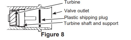
Remove plastic shipping plug and wire from valve outlet.
NOTE: Be sure the turbine and support are firmly in place in the valve outlet. Blow into the valve port and observe the turbine for free rotation.
TURN OFF WATER SUPPLY
Close the main water supply valve, located near the well pump or water meter.
Open all faucets to drain all water from house pipes.
NOTE: Be sure not to drain water from the water heater, as damage to the water heater elements could result.
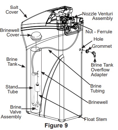
INSTALL BRINE TANK OVERFLOW ADAPTER
Install the brine tank overflow grommet and adapter in the 13/16” diameter hole in the back of the salt storage tank sidewall, (see Figure 9).
NOTE: The brine tank overflow adapter accepts either 1/2” or 3/8” I.D. hose.
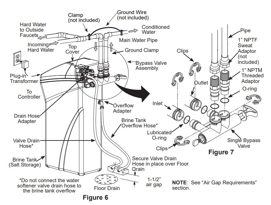
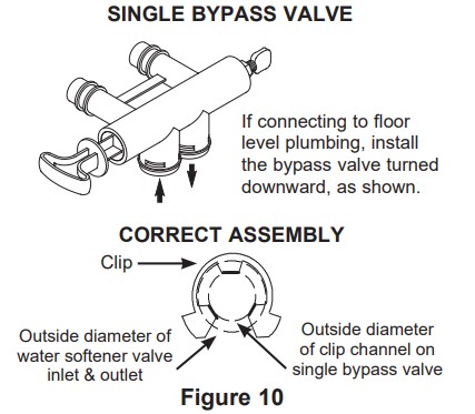
INSTALL THE BYPASS VALVE
NOTE: For easier installation, remove the top cover. Release 2 clips at rear of cover. Rotate cover forward and lift up.
Remove two clips from the water softener valve inlet and outlet ports and visually check and remove any debris, (see Figure 7).
Make sure the turbine assembly spins freely in the”out” port of the valve, (see Figure 8).
If not already done, put a light coating of silicone grease (provided) on the single bypass valve o-rings, (see Figure 7).
Push the single bypass valve into the softener valve as far as it will go. Snap the two large holding clips into place, from the top down, (see Figure 7 and 10).
IMPORTANT: Be sure the clips snap firmly into place so the single bypass valve will not pull out.
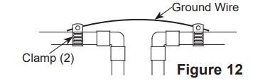
INSTALLING THE GROUND WIRE
NOTE: If your house plumbing is plastic, it would not be used as a grounding path, and this step should be skipped.
IMPORTANT: A copper or galvanized cold water pipe is often used to ground electrical outlets in the home. Grounding protects you from electrical shock. The water softener may have broken this ground path. To restore connection, install a 12”-long, 6-gauge copper wire across and tightly clamp using UL-approved 1/2”–1” bronze grounding clamps at both ends as shown (Figure 12). Zinc clamps should not be used on copper plumbing. Wire and clamps may be purchased separately from your local hardware store.
Clean copper pipe and ends of wire with emery paper. Bare wire is recommended. If insulated wire is used, is should be stripped 3/4” at each end before cleaning with emery paper.
Attach bronze clamps to pipe. Tighten screws.
Attach to clamps as shown. Tighten screws.
NOTE: If you are installing a sediment filter or other item(s) into the plumbing system, along with the water softener, be sure to restore electrical continuity across all removed metal pipe sections.
INSTALL BRINE TANK (SALT STORAGE) OVERFlOW HOSE
Measure, cut to needed length and connect the 3/8”drain line (provided) to the salt storage tank overflow elbow and secure in place with a hose clamp.
Route the hose to the floor drain, or other suitable drain point no higher than the drain fitting on the salt storage tank (This is a gravity drain). If the tank overfills with water, the excess water flows to the drain point. Cut the drain line to the desired length and route it neatly out of the way.
IMPORTANT: For proper operation of the water softener, do not connect the water softener valve drain tubing to the salt storage tank overflow hose
RINSE OUT CARBON FINES
Small particles of carbon filtration material are generated during manufacturing and shipping. These particles will exit the media tank with the first water that flows through the softener. These carbon “fines” are not harmful, but give the water a gray color and should be rinsed down the drain before any water from the softener is directed to the home’s faucets or water heater.
ADD WATER AND SALT TO THE SALT STORAGE TANK
EXCESSIVE WEIGHT HAZARD: Use two or more people to move and lift salt bags. Failure to do so can result in back or other injuries.
Using a container, add about three gallons of clean water into the salt storage tank.
Add salt to the storage tank. Use nugget, pellet or coarse solar salts with less than 1% impurities.
PLUG IN THE WATER SOFTENER
Plug the water softener into an electrical outlet that is not controlled by a switch.
Replace the top cover.
Replace the salt hole cover.
NOTE: The water heater is filled with hard water and,as hot water is used, it will refill with conditioned water. In a few days, the hot water will be fully conditioned. To have fully conditioned hot water immediately, wait until the initial recharge is over. Then, drain the water heater(following instructions for water heater) until water runs cold.
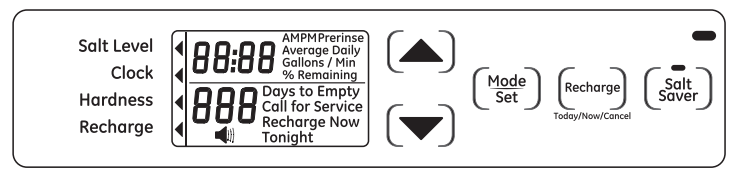
Programming the Water Softener
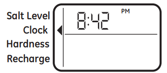
When the transformer is plugged into the electrical outlet, a model code and test number (example: J3.4 & H31) are shown in the display. Then, “12:00 PM” begins to flash. An arrow is displayed next to CLOCK on the face plate decal.
CONTROL OPERATION:
• CONTROL SETTINGS REQUIRED upon initial installation and after an extended power outage.
• Use the MODE/SET button to scroll arrow to desired control function set.
• After the mode is selected use the UP and DOWN buttons to change the settings of the control.
• Press the MODE/SET button to accept changes.
• A “beep” sounds while pressing buttons for control programming. One beep signals a change in the control display. Repeated beeps mean the control will not accept a change from the button you have pressed, and you should select another button.
SET TIME OF DAY
1. Press MODE/SET button until the arrow points to CLOCK.
2. Press the UP or DOWN buttons to set the present time. UP moves the display ahead; DOWN sets the time back. Be sure AM and PM is correct.
NOTE: Press buttons and quickly release to slowly advance the display one number at a time. Hold the buttons down for fast advance.
3. When the correct time is shown in the display, press MODE/SET to accept.
SET WATER HARDNESS NUMBER
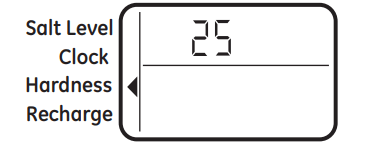
1. Press the MODE/SET button until the arrow points to HARDNESS. A flashing 25 will appear in the display.
2. Press the UP or DOWN buttons to set your water hardness number.
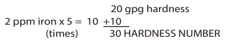
NOTE: If your water supply contains iron, compensate for it by adding to the water hardness number. For example, assume your water is 20 gpg hard and contains 2 ppm iron. Add 5 to the hardness number for each 1 ppm or iron. In this example, you would use 30 for your hardness number.
3. When the display shows your water hardness (in grains per gallon), press MODE/SET to accept.
You can get the grains per gallon (gpg) hardness of your water supply from a water analysis laboratory. If you are on a municipal supply, call your local water department. Or call Legend Technical Services, an independent laboratory, to request a water hardness test kit at 1.800.949.8220, Option 4. If your report shows hardness in parts per million (ppm) or milligrams per liter (mg/l), simply divide by 17.1 to get the equivalent number of grains per gallon.
SET RECHARGE (STARTING) TIME
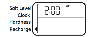
1. Press the MODE/SET button until the arrow points to RECHARGE.
NOTE: A flashing 2:00 AM (factory default) should show in the display. This is a good time for recharge to start (takes about 2 hours) in most households because water is not in use. HARD WATER is bypassed to house faucets during recharge.
If no change is needed, go to step 3. To Change the recharge starting time, follow step 2.
2. Press UP or DOWN button to set the desired recharge start time. Be sure to observe the AM or PM as you did when setting the time of day.
3. Press the MODE/SET button to accept.
FEATURE: OTHER DATA DISPLAY
These models have an option to have the run display indicate different information. The information displayed on the top half of the display can be changed to one of the following by pressing UP or DOWN buttons:
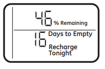
• CAPACITY REMAINING – This is the percentage of water softening capacity remaining. Immediately after a regeneration, 100% shows. As water is used, the percentage will decrease until the next regeneration. During regenerations, the percentage increments upward. When present time is displayed, press the DOWN button; % Remaining will appear in the display. The value shown is between 0 and 100 percent. This value is based on current operating capacity. Pressing the UP button will return the screen to the previous display.
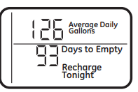
• AVERAGE DAILY GALLONS – The figure displayed is the average gallons of water used by the household each day over the past seven-day period. Press the DOWN button again to display the Average Daily Gallons. Average Daily Gallons will appear in the display. This value is updated every night at midnight. Pressing the UP button will return the screen to the previous display.
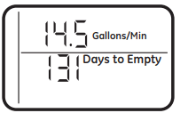
• FLOW RATE, GPM – When using soft water, this display shows the flow rate passing through the softener (in gallons per minute). Zero shows if water is not passing through the softener. Press the DOWN button again to display the flow rate. Gallons/Min will appear in the display. This value is updated every 1»2 second. Pressing the UP button will return the screen to the previous display. Pressing the DOWN button will return the screen to the present time display.
Care and cleaning
ADJUSTING YOUR WATER HARDNESS
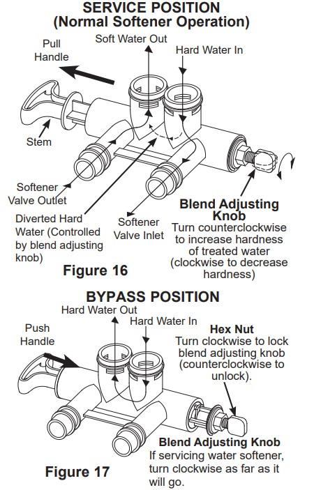
The blend adjusting knob (Figure 16) gives the ability to finely adjust hardness of the treated water leaving the water softener. If slightly harder water is desired than is normally delivered by the water softener, the blend adjusting knob can divert a small stream of hard water and blend it with the soft water entering the home. The amount of water diverted is controlled by turning a blend adjusting knob on the end cap of the valve stem.
NOTE: To get full performance from your water softener leave blending valve in the factory closed position.
To make adjustments to water hardness:
Hold bypass handle to keep the valve stem from rotating (see Figure 16). Loosen hex nut on blend adjustment knob by turning the hex nut counterclockwise (see Figure 17).
TO INCREASE HARDNESS: With the bypass in the service position (see Figure 16) hold the handle to keep the valve stem from rotating and turn the blend adjusting knob counterclockwise up to 2 turns from the closed position. It is recommended that adjustments be made in quarter turn increments over several weeks until the desired hardness is achieved. NOTE: Once an adjustment is made to the blend valve knob the change in water hardness at the homes faucets or shower heads may take several days to be noticed. This delay is due to the large amounts of already conditioned water in the pipes and water heater that must be exchanged before a change in hardness can be noticed. Have the water tested to determine the actual water hardness.
TO DECREASE HARDNESS: With the bypass in the service position (see Figure 16) hold the handle to keep the valve stem from rotating and turn the blend adjusting knob clockwise. When the knob will not turn anymore, hard water is no longer being blended into the soft water.
Once the desired hardness is achieved tighten the hex nut (see Figure 17) clockwise until it comes in contact with the bypass stem.
NOTE: To meet the water softener performance specifications and reduction of barium and radium claims the adjustable hardness must be kept in the “OFF” position. The off position is achieved when the blend adjusting knob is fully rotated clockwise until it stops
CHECKING THE SALT STORAGE LEVEL and REFILL
Brine (salt dissolved in water) is needed for each and every recharge. The water for making brine is metered into the salt storage area by the water softening system valve and control. However, you must keep the tank supplied with salt.
ADDING SALT
Lift the salt hole cover and check the salt storage level frequently. If the water softener uses all the salt before you refill it, you will experience hard water. Until you have established a refilling routine, check the salt every two or three weeks. Always add if less than 1/4 full. Be sure the brinewell cover is on.
NOTE: if using potassium chloride (KCI), do not fill above level 4 on the brinewell decal.
NOTE: In humid areas, it is best to keep the salt storage level lower, and to refill more often to avoid salt “bridging”.
Recommended Salt: Nugget, pellet or coarse solar salts with less than 1% impurities.
Salt Not Recommended: Rock salt, high in impurities, block, granulated table, ice melting, ice cream making salts, etc.
CLEANING IRON OUT OF THE WATER SOFTENING SYSTEM
Your water softening system takes hardness minerals (calcium and magnesium) out of the water. Also, it can control some (see the Specification Guidelines section) “clear water” iron. With clear water iron, water from a faucet is clear when first put into a glass. After 15 to 30 minutes, the water begins to cloud or turn rust colored. A water softening system will not remove any iron that makes the water cloudy or rusty as it comes from the faucet (called red water iron). To take red water iron out of water, or over the maximum of clear water iron, an iron filter or other equipment is needed. GE Appliances recommends using Super Iron Out® to clean your resin bed if your iron content is high. Use Super Iron Out® with every 40lb. bag of salt as preventative maintenance against rust build up. Clean the bed at least every six months, or more often if iron appears in the soft water between cleanings.
IMPORTANT: It is important to mix the resin bed cleaner with water (following the manufacturer’s instructions), pour it into the brinewell (see Figure 9) and recharge the softener immediately. Do not pour the resin bed cleaner in with the salt, as it will not be as effective in cleaning the resin, and can cause damage to the softener if it is left in the brine tank for an extended period due to the corrosive gases that are formed.
Routine Maintenance
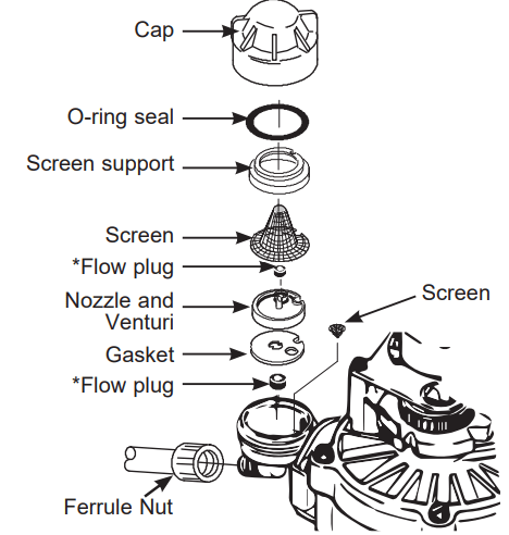
CLEANING THE NOZZLE AND VENTURI ASSEMBLY
A clean nozzle and venturi is needed for the water softening system to work properly. This small unit makes the suction to move brine from the salt storage area to the resin tank during recharge. If it becomes plugged with sand, dirt, etc., the water softening system will not work and you will get hard water.
To get to the nozzle and venturi, remove the water softening system top cover. Be sure the water softening system is in service cycle (no water pressure at nozzle and venturi). Then, while holding the nozzle and venturi housing with one hand, remove the cap. Lift out the screen support and screen, then the nozzle and venturi. Wash and rinse the parts in warm water until clean. If needed, use a small brush to remove iron or dirt. Also check and clean the gasket.
NOTE: Some models have a small flow plug located in the nozzle and venturi, and/or a small cone shaped screen in the housing. Be sure to check and clean these parts, if your model is so equipped.
Carefully replace all parts in the correct order. Lightly lubricate the o-ring seal with clean silicone grease or petroleum jelly and place in position. Install and tighten the cap, by hand only. Do not overtighten the cap.
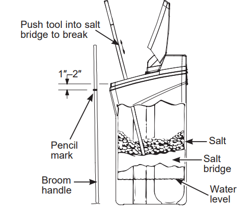
BREAKING A SALT BRIDGE
Sometimes, a hard crust or salt bridge forms in the salt storage area. It is usually caused by high humidity or the wrong kind of salt. When the salt bridges, an empty space forms between the water and salt. Then salt will not dissolve in the water to make brine.
If the brine tank is full of salt, it is hard to tell if you have a salt bridge. Salt is loose on top, but the bridge is under it. The following is the best way to check for a salt bridge.
Salt should be loose all the way to the bottom of the tank. Take a broom handle or like tool, and carefully push it down into the salt, working it up and down. If the tool strikes a hard object (be sure it’s not the bottom or sides of the tank), it’s most likely a salt bridge. Carefully break the bridge with the tool. Do not pound on the walls of the tank. To help dissolve the salt bridge pour one gallon of warm water (not hot) into the tank. If the wrong kind of salt made the bridge, take it out. Then fill the tank with nugget or pellet salt only. In humid areas, it is best to fill with less salt, more often to prevent a salt bridge from forming.
IMPORTANT: Be sure small holes in the gasket are centered directly over the small holes in the nozzle and venturi housing.
* Install with numbered side up, concave side down.
Before you call for service
Troubleshooting Tips
Save time and money! Review the chart on this page first and you may not need to call for service.
Problem
Possible Cause
What to do
No soft water
Faucet or fixture where sample was taken not plumbed to soft water. NOTE: Be sure sample is from a faucet that does not mix soft and hard water. For example, a single lever kitchen faucet, if the cold side is plumbed to hard water.
To conserve salt, the installer may have isolated some fixtures (outside faucets, toilets, etc.) from soft water. From the outlet of the water softening system, trace the water flow path in the house plumbing. If soft water is not directed to a faucet or fixture where wanted, consult a plumber.
No salt in the brine tank or salt bridged
Check for a salt bridge or, if the tank is empty, refill with recommended salt. Press (for 3 seconds) the RECHARGE button to start an immediate recharge and restore soft water supply.
External power supply unplugged at wall outlet or power cable to softener not connected. Fuse blown or circuit breaker popped on circuit to electrical outlet. Electrical outlet on a circuit that can continuously be switched off
Check for a loss of electrical power to the water softening system, due to any of these conditions and correct as needed. With the power supply restored, observe the faceplate time display and read Programming the Control section. NOTE: the electrical outlet for the softener should be live so it cannot be accidentally switched off.
Manual bypass valve in bypass position
Be sure the bypass valve stem is positioned properly, with the handle in the OUT position.
Blending valve in open position
Turn blending valve clockwise to closed position.
Valve drain hose pinched, plugged, elevated too high or otherwise restricted
Any restriction in the drain hose may prevent proper operation of the nozzle and venturi and reduce or prevent brine draw during recharge.
Nozzle and venturi dirty, incorrectly assembled or damaged
Refer to Cleaning the Nozzle and Venturi Assembly instructions. With water pressure to the water softening system off, take the nozzle assembly apart. Inspect, clean and replace as needed. Any foreign particle(s), scratches, nicks, etc. in the passages can prevent operation. Be sure holes in the gasket are centered over holes in the housing.
Water hard sometimes
Using hot water while the water softening system is regenerating
Avoid using hot water during water softening system recharge because the water heater will refill with hard water. See Automatic Hard Water Bypass During Recharge section.
Control HARDNESS number setting too low
Press MODE/SET button until arrow points to HARDNESS. Be sure the number shown is the same as the actual grains per gallon hardness of your water supply. See Programming the Control section if a change in setting is needed.
Grains of hardness in your water supply have increased
Water hardness can change over time, especially in well water. To check, have the water tested by a water analysis laboratory or call your local water department. Adjust the Hardness number setting as needed.
Water feels slippery after installation of water softener
Absence of hardness minerals
This is normal. Hardness in water gives it the abrasive feel you may have been accustomed to. The slippery feel is the clean feel of soft water.
See the Adjusting your Water Hardness section.
Water Softener not using any salt
Water softening system is a “demand” unit
Does not use much salt to regenerate - very efficient.
Possible salt bridge
See the Breaking a Salt Bridge section.
Possible plugged nozzle and venturi
See the Cleaning the Nozzle and Venturi Assembly section.
Water is blue color after water softener was installed
Acidic water in copper plumbing
Have the water tested at once.
Water softener not regenerating
Meter turbine stuck
See the Manually Initiated Electronics Diagnostics section for troubleshooting procedures.
Call for service.
Sensor wire not plugged into the control
See the Manually Initiated Electronics Diagnostics section for troubleshooting procedures.
Call for service
No power to unit
Check the circuit breaker or fuses.
Mechanical defect
Call for service.
Cloudiness on glassware (automatic dishwashers)
Combination of soft water and too much detergent
This is called etching and is permanent. To prevent this from happening, use less detergent if you have soft water. Wash glassware in the shortest cycle that will get them clean.
Excessive/high level of water in brine tank
Valve drain hose pinched, plugged, elevated too high or otherwise restricted
A restriction in this drain hose may prevent proper operation of the nozzle and venturi and reduce or prevent brine draw during recharge.
Drain lines connected together
Separate drain lines.
Nozzle and venturi dirty, incorrectly assembled or damaged.
Refer to Cleaning the Nozzle and Venturi Assembly instructions. With water pressure to the water softening system off, take the nozzle assembly apart. Inspect, clean and replace as needed. Any foreign particle(s), scratches, nicks, etc. in the passages can prevent operation. Be sure holes in the gasket are centered over holes in the housing
Salty tasting or brown/yellow colored water after installation
Unit not sanitized
Complete Sanitization Procedures.
At completion of recharge cycle (approx. 2 hours), run water from faucets to purge the salty water.
Low water pressure
Check pressure:
Drain height 8’ or less, pressure should be minimum 20 psi.
Drain height above 8’, pressure should be minimum 50 psi.
Restricted drain hose
Clean and reconnect hose.
Check for kinks in drain line
Brown/yellow colored water
Unit was idle for a period of time
Complete the Sanitization Procedures.
Resin beads showing up in drinking water
Cracked distributor or unit plumbed backwards
Check softener “IN & OUT” plumbing is correct.
Call for service.
Sounds you might hear
Running water from the unit into a drain during recharge
This is normal.
Water has air bubbles and is cloudy
Air in system after installation
Will go away after it runs for a while.
Blue light Flashing
When power applied to the system
If “DAYS TO EMPTY” is flashing
Control needs to be programmed (a power outage may have occurred)
Low salt level, less than 15 days
See the Programming the Control section.
Fill with salt.
Reset salt level.
Error Codes on Control
Wiring may have worked loose in the control
Unplug external power supply.
Remove control cover, release clips on side.
Check for loose/incorrect wiring connections to electronic board or switch. Reconnect as required.

 is displayed next to CLOCK on the face plate decal.
 and DOWN
  buttons to change the settings of the control.