SIMPLY CLEVER
OWNER´S MANUAL
OWNER´S MANUAL
ŠKODA Rapid Spaceback

5JJ012720AE

Preface
You have opted for a ŠKODA – our sincere thanks for your confidence in us.
The description of the vehicle operation, important information about safety, vehicle care, mainte-
nance and self-help, as well as technical vehicle data, are given in this manual.
Some functions and vehicle systems are operated via Infotainment.
Please do not just read this Owner's Manual, but also read the Infotainment manual carefully. The pro-
cedure in accordance with the two manuals is a prerequisite for the correct use of the vehicle.
When using the vehicle, the general binding country-specific legal requirements (e.g. for transporting
children, deactivating the airbag, tyre use, road traffic, etc.) must always be observed.
We hope you enjoy driving your ŠKODA, and wish you a pleasant journey at all times.
Your ŠKODA AUTO a.s. (hereinafter referred to as ŠKODA or manufacturer)
5JJ012720AE

Table of Contents
Board literature 4
Notes 5
Structure and more information about the
Owner´s Manual 6
Abbreviations
Safety
Passive Safety 8
General information 8
Correct and safe seated position 8
Seat belts 11
Using seat belts 11
Inertia reels and belt tensioners 13
Airbag system 14
Description of the airbag system 14
Airbag overview 15
Deactivating airbags 18
Transporting children safely 19
Child seat 19
Fastening systems 22
Using the system
Cockpit 27
Overview
26
Instruments and Indicator Lights
28
Instrument cluster
28
Indicator lights
31
Information system
39
Driver information system
39
Driving data (Multifunction display)
40
MAXI DOT display
42
Service interval display 46
SmartGate 47
Unlocking and opening 49
Unlocking and locking 49
Anti-theft alarm system 54
Luggage compartment lid 55
Window operations 56
Lights and visibility 59
Lights 59
Interior lighting 63
Visibility 64
Windscreen wipers and washers 65
Rear mirror 67
Seats and head restraints 69
Seats and head restraints 69
Seat features 70
Transporting and practical equipment 73
Useful equipment 73
Tablet holder 80
Luggage compartment and transport of
cargo 81
Variable loading floor in the luggage
compartment (Estate) 86
Roof rack 89
Heating and ventilation 90
Heating, manual air conditioning system,
Climatronic 90
Driving
Starting-off and Driving 95
Starting and stopping the engine using the
key 95
Starting and stopping the engine at the push
of the button 97
START-STOPsystem 99
Brakes and parking 101
Manual gear changing and pedals 103
Automatic gearbox 104
Running-in and economical driving 106
Avoiding damage to your vehicle 108
Assist systems 109
General information 109
Braking and stabilisation systems 109
Parking assistance (ParkPilot) 112
Speed control system 114
Front Assist 116
Fatigue detection 119
Tyre pressure monitoring 119
Hitch and trailer 121
Hitch 121
Trailer 126
General Maintenance
Care and maintenance 130
Service work, adjustments and technical
alterations 130
Washing vehicle 133
Cleaning vehicle exterior 134
Interior care 138
Inspecting and replenishing 140
Fuel
140
Engine compartment 143
Engine oil 146
Coolant 148
Brake fluid 149
Vehicle battery 150
Wheels 154
Tyres and wheel rims 154
Winter operation 158
2
Table of Contents

Do-it-yourself
Emergency equipment and self-help 160
Emergency equipment 160
Changing a wheel 161
Puncture set 165
Jump-starting 168
Towing the vehicle 169
Remote control 171
Emergency unlocking/locking 172
Replacing windscreen wiper blades 173
Fuses and light bulbs 174
Fuses 174
Replacing bulbs 177
Technical data
Technical data
183
Basic vehicle data 183
Vehicle-specific details per engine type 188
Index
3
Table of Contents

Board literature
You always find these Owner´s Manualand the Service Plan in the on-board
literature for your vehicle.
Depending on the equipment, the on-board literature can also contain The ra-
dio instruction manual or Manual of the navigation systemand in some coun-
tries also the brochure On the road.
Owner´s Manual
These Owner´s Manual apply to all body variants of the vehicle and all related
model versions as well as all equipment levels.
This owner's manual describes all possible equipment variants without identi-
fying them as special equipment, model variants or market-dependent equip-
ment. Consequently, this vehicle does not contain all of the equipment com-
ponents described in this Owner's Manual.
The level of equipment in your vehicle refers to your purchase contract for the
vehicle. For questions regarding the scope of equipment, please contact a
ŠKODA Partner, if required.
The Pictures in this manual are for illustrative purposes only. The illustrations
can differ in minor details from your vehicle; they are only intended to provide
general information.
ŠKODA AUTO a.s. pursues a policy of constant product and model develop-
ment. Changes in terms of supply scope are possible at any time with regard to
design, equipment and technology. The information listed in this operating
manual corresponds to the information available at the time of going to press.
Therefore legal claims cannot be made based on the technical data, illustra-
tions and information contained in this Owner's Manual.
We recommend that the web pages that are referred to in this Owner's Man-
ual are displayed using the classic view. If the web pages are displayed using
the mobile view, they may not contain all necessary information.
Service schedule
The service plan includes the documentation of the vehicle handover informa-
tion with regard to warranty and service events.
Infotainment Owner's Manual
The Infotainment Owner's Manual contains a description of the Infotainment
operating controls, as well as, possibly, some functions and vehicle systems.
On The Move Brochure
The On The Move brochure contains the importer's customer service number
and the service number in the individual countries as well as the emergency
numbers.
Online user manuals
Fig. 1
This QR code opens a web page with a model overview of the ŠKODA brand.
The page can also be accessed by entering the following address in the web
browser.
http://www.skoda-auto.com/en/mini-apps/owners-manuals/
▶
Select the desired model - a menu with the user manuals is displayed.
▶
Select the construction period as well as the language.
▶
Select the desired manual - it can be displayed either online or in pdf format.
4
Board literature

Notes
Terms used
The on-board literature contains the following terms relating to the service
work for your vehicle.
- a workshop that carries out specialist service tasks for
ŠKODA vehicles. A specialist garage can be a ŠKODA partner, a ŠKODA
service partner or an independent workshop.
- a workshop that has been contractually authorized
by the manufacturer or its sales partner to perform service tasks on
ŠKODA vehicles and to sell ŠKODA Genuine Parts.
- a company that has been authorized by the manufacturer
or its sales partner to sell new ŠKODA vehicles and, when applicable, to
service them using ŠKODA Genuine Parts and sell ŠKODA Genuine Parts.
Explanation of symbols
An overview of the symbols used in the instruction manual and a brief explan-
ation of their meaning.
Reference to the introductory module of a chapter with important infor-
mation and safety warnings
Continuation of the module on the next page
Situations in which the vehicle must be stopped as soon as possible
® Trademark
Telephone operation in the MAXI DOT display
Text display in the segment display
WARNING
Texts with this symbol draw attention to threats of a serious accident, in-
jury or loss of life.
CAUTION
Texts with this symbol draw attention to the risk of vehicle damage or possible
inoperability of some systems.
For the sake of the environment
Texts with this symbol contain information on environmental protection as
well as tips for economical operation.
“Specialist garage”
“ŠKODA service partner”
“ŠKODA partner”
Note
Texts with this symbol contain additional information.
5
Notes

Structure and more information about the Owner´s
Manual
Structure of the manual
The operating manual is hierarchically divided into the following areas.
■
Section (e.g. Safety) - the title of the Section is always indicated at the lower
left side
■
Main chapters (e.g. Airbag System) - the title of the main chapter is always
indicated at the lower right side
■
Chapter (e.g. Airbag Overview)
■
Introduction to the topic – Module Overview within the chapter, in-
troductory information about the chapter content, notes that apply to
the entire chapter, if relevant
■
Module (e.g. Front Airbags)
Information Search
When searching for information in the Owner´s Manual, we recommend using
the Index at the end of the manual.
Direction indications
All direction indications such as “left”, “right”, “front”, “rear” relate to the for-
ward direction of travel of the vehicle.
Units
The volume, weight, speed and length data are given in metric units, unless
otherwise indicated.
Display
In this owner's manual, the screen on the MAXI DOT display is used as the dis-
play illustration, provided nothing is otherwise stated.
6
Structure and more information about the Owner´s Manual

Abbreviations
Abbreviation Definition
rpm Engine revolutions per minute
A2DP
a Bluetooth software profile for a one-way transfer of audio
data
ABS Anti-lock brake system
AG Automatic gearbox
AGM Vehicle battery type
TCS Traction control
CO
2
Carbon dioxide
COC Declaration of conformity
DPF Diesel particle filter
DSG Automatic double clutch gearbox
EDL Electronic differential lock
ECE Economic Commission for Europe
EPC EPC fault light
ESC Electronic Stability Control
ET Rim depth
EU European Union
GSM Global System for Mobile communications
HBA Hydraulic brake assist
HHC Uphill start assist
KESSY Keyless unlocking, starting and locking
kW Kilowatt, measuring unit for output
LED Lighting element type
MCB Multi-collision brake
MDI Inputs for connecting external devices
MFD Multifunction display
MG Manual gearbox
MPI Gasoline engine with a multi-point fuel injection
N1
Panel van intended exclusively or mainly for the transporta-
tion of goods
Abbreviation Definition
Nm Newton meter, measuring unit for the engine torque
PIN personal identification number
SIM card a card for the identification of the mobile network operator
TDI CR
Diesel engine with turbo charging and common rail injection
system
TSA Trailer stabilisation
TSI Petrol engine with turbo charging and direct injection
VIN Vehicle identification number
W Watt, unit of power
Wi-Fi wireless data network
7
Abbreviations

Safety
Passive Safety
General information
Introduction
This chapter contains information on the following subjects:
Before setting off
8
Driving safety 8
In this section of the instructions you will find important information, tips and
notes on the subject of passive safety.
We have combined everything here which you should be familiar with, for ex-
ample, regarding seat belts, airbags, safety of children and anything similar.
You can find further information on safety concerning you and those travelling
with you in the following chapters of this Owner's Manual.
The complete on-board literature should therefore always be in the vehicle.
This applies in particular, if you rent out or sell the vehicle.
Before setting off
For your own safety and the safety of the people travelling with you, please
pay attention to the following points before setting off.
▶
Ensure that the lighting and the turn signal system are functioning properly.
▶
Ensure that the function of the wipers and the condition of the wiper blades
are free of any defects.
▶
Ensure that all of the windows offer good visibility to the outside.
▶
Adjust the rear-view mirror so that vision to the rear is guaranteed.
▶
Ensure that the mirrors are not covered.
▶
Check the tyre inflation pressure.
▶
Check the engine oil, brake fluid and coolant level.
▶
Secure all items of luggage.
▶
Do not exceed the permissible axle loads and permissible gross weight of the
vehicle.
▶
Close all doors as well as the bonnet and boot lid.
▶
Ensure that no objects can obstruct the pedals.
▶
Protect children in suitable child seats with correctly fastened seat belts
» page 19, Transporting children safely.
▶
Adopt the correct seated position » page 8, Correct and safe seated posi-
tion. Tell your passengers to assume the correct seated position.
Driving safety
The driver is fully responsible for himself and passengers, especially children. If
your driving safety is effected, you place yourself and the oncoming traffic at
risk.
The following guidelines must therefore be observed.
▶
Do not become distracted from concentrating on the traffic situation, (e.g. by
your passengers or mobile phone calls).
▶
Never drive when your driving ability is impaired, (e.g. due to medication, al-
cohol or drugs).
▶
Keep to the traffic regulations and the permissible speed limit.
▶
Always adjust the driving speed to the road, traffic and weather conditions.
▶
Take regular breaks on long journeys (at least every two hours).
The following list contains instructions for the Passenger which, if not ob-
served, may cause serious injuries or death.
▶
Do not lean against the dash panel.
▶
Do not put your feet on the dash panel.
The following list contains instructions for all Passengers which, if not ob-
served, may cause serious injuries or death.
▶
Do not sit only on the front part of the seat.
▶
Do not sit facing to the side.
▶
Do not lean out of the window.
▶
Do not put your limbs out of the window.
▶
Do not put your feet on the seat cushion.
Correct and safe seated position
Introduction
This chapter contains information on the following subjects:
Correct seat position of the driver 9
Adjusting the steering wheel position
9
Correct seated position for the front passenger
10
Correct seated position for the passengers in the rear seats
10
8
Safety
WARNING
■
The front seats and all head restraints must be adjusted to match the
body size at all times and the seat belt must always be fastened properly to
provide the most effective levels of protection to the passengers.
■
Each occupant must correctly fasten the seat belt belonging to the seat.
Children must be fastened » page 19, Transporting children safely with a
suitable restraint system.
■
By sitting incorrectly, the occupant is risking life-threatening injuries.
■
The seat backrests must not be tilted too far back when driving, as this
will impair the function of the seat belts and of the airbag system – risk of
injury!
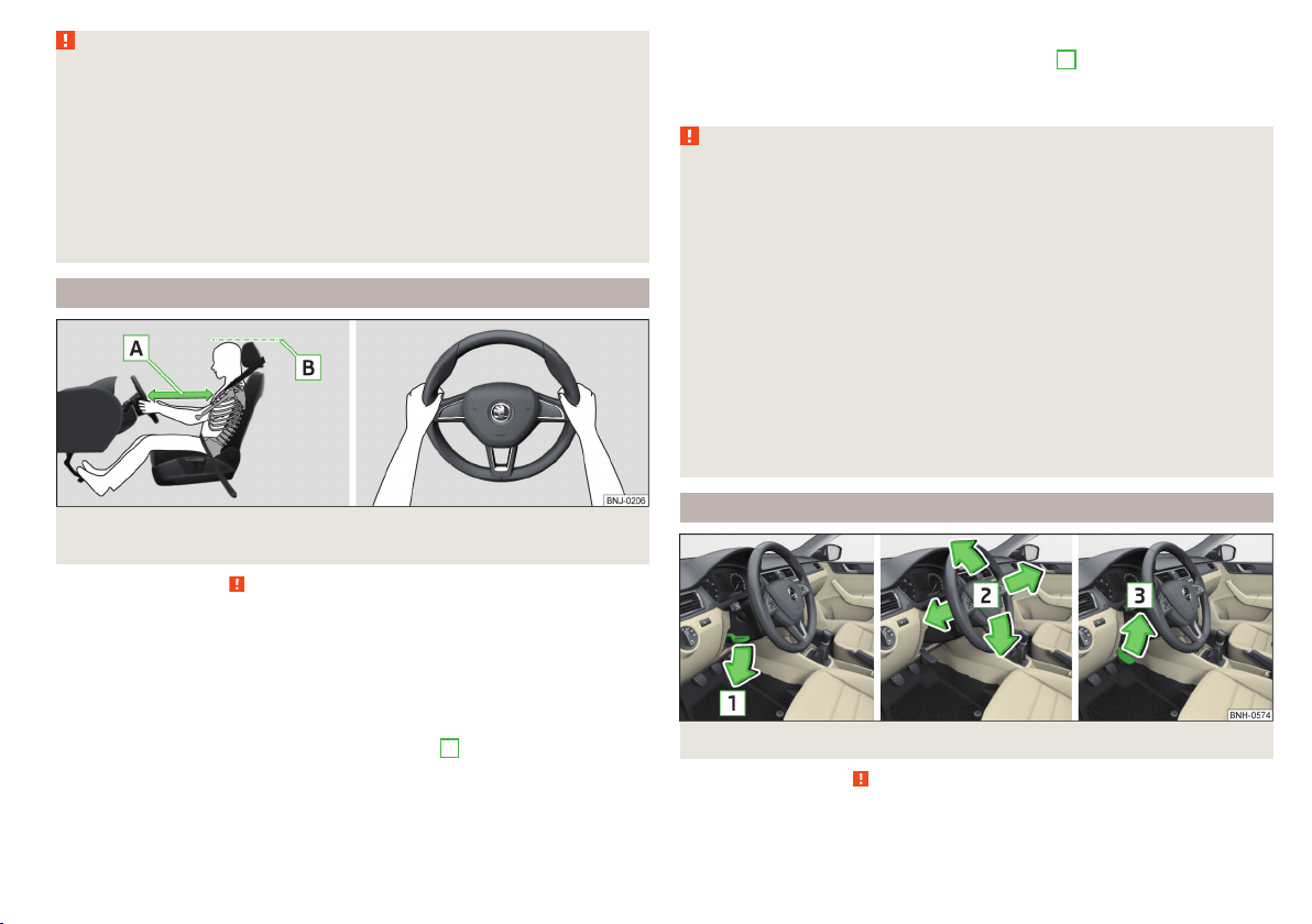
Correct seat position of the driver
Fig. 2 Correct seated position for the driver/correct steering wheel posi-
tion
Read and observe
on page 9 first.
For your own safety and to reduce the risk of injury in the event of an accident,
the following instructions must be observed.
Adjust the driver’s seat in the forward/back direction so that the pedals
can be fully depressed with slightly bent legs.
Adjust the seat backrest so that the highest point of the steering wheel
can be reached with your arms at a slight angle.
Adjust the steering wheel so that the distance
A
between the steering
wheel and your chest is at least 25 cm » Fig. 2.
Adjust the head restraint so that the top edge of the head restraint is at
the same level as the upper part of your head
B
» Fig. 2 (not for seats
with integrated head restraint).
Correctly fasten the seat belt » page 11, Using seat belts.
WARNING
■
Always assume the correct seated position before setting off and do not
change this position while driving. Also advise your passengers to adopt
the correct seated position and not to change this position while the car is
moving.
■
Maintain a distance of at least 25 cm to the steering wheel. Not maintain-
ing this minimum distance will mean that the airbag system will not be able
to properly protect you – hazard!
■
When driving, hold the steering wheel with both hands firmly on the out-
er edge in the “9 o'clock” and “3 o'clock” position » Fig. 2. Never hold the
steering wheel in the “12 o'clock” position or in any other way (e.g. in the
middle, inner edge of the steering wheel or similar). In such cases, you
could severely injure the arms, hands and head when the driver airbag is
deployed.
■
Ensure that there are no objects in the driver's footwell as they may get
caught behind the pedals when driving or applying the braking. You would
then no longer be able to operate the clutch, brake or acceleration pedals.
Adjusting the steering wheel position
Fig. 3 Adjusting the steering wheel position
Read and observe on page 9 first.
The height and forward/back position of the steering wheel can be adjusted.
9
Passive Safety

›
Swing the safety lever under the steering wheel in the direction of arrow
1
» Fig. 3.
›
Adjust the steering wheel to the desired position. The steering wheel can be
adjusted in direction of arrow
2
.
›
Pull the holder until it stops in arrow direction
3
.
WARNING
■
Never adjust the steering wheel when the vehicle is moving only when
the vehicle is stationary!
■
The safety lever must be locked so that the steering wheel cannot acci-
dentally change position – risk of accident!
Correct seated position for the front passenger
Read and observe on page 9 first.
For passenger safety and to reduce the risk of injury in an accident, the follow-
ing instructions must be observed.
Position the front passenger seat back as far as possible. The front pas-
senger must maintain a distance of at least 25 cm to the dash panel so
that the airbag offers the greatest possible safety if it is deployed.
Adjust the head restraint so that the top edge of the head restraint is at
the same level as the upper part of your head
B
» Fig. 2 on page 9 (not for
seats with integrated head restraint).
Correctly fasten the seat belt » page 11, Using seat belts.
In exceptional cases the front passenger airbag can be deactivated
» page 18, Deactivating airbags.
WARNING
■
Maintain a distance of at least 25 cm to the dash panel. Not maintaining
this minimum distance will mean that the airbag system will not be able to
properly protect you – hazard!
■
Always keep your feet in the footwell when the car is being driven – nev-
er place your feet on the instrument panel, out of the window or on the
surface of the seats! You will be exposed to increased risk of injury if it be-
comes necessary to apply the brake or in the event of an accident. If an air-
bag is deployed, you could suffer fatal injuries by adopting an incorrect
seated position!
Correct seated position for the passengers in the rear seats
Read and observe on page 9 first.
To reduce the risk of injury in the event of a sudden braking manoeuvre or an
accident, the occupants on the rear seats must observe the following.
Adjust the head restraint such that the top edge of the head restraint is at
the same level as the upper part of the head
B
» Fig. 2 on page 9.
Correctly fasten the seat belt » page 11, Using seat belts.
Use a suitable child restraint system if transporting children in the vehicle
» page 19, Transporting children safely.
10
Safety

Seat belts
Using seat belts
Introduction
This chapter contains information on the following subjects:
The physical principle of a frontal collision 12
Correct routing of seat belt 12
Fastening and unfastening seat belts 13
Seat belts that are fastened correctly offer good protection in the event of an
accident. They reduce the risk of an injury and increase the chance of survival
in the event of a major accident.
Properly fastened seat belts hold occupants to correctly set seats in the right
seat position.
Particular safety aspects must be observed when transporting children in the
vehicle » page 19.
WARNING
■
Fasten your seat belt before each journey – even when driving in town!
This also applies to other passengers - there is a danger of injury!
■
Maximum seat belt protection is only achieved if you are correctly seated
» page 8, Correct and safe seated position.
■
The seat backrests of the front seats must not be tilted too far to the rear
otherwise the seatbelts can lose their effectiveness.
WARNING
Information on the correct routing of the belt
■
Always ensure that the webbing of the seat belts is properly routed. Seat
belts which are not correctly adjusted can themselves cause injuries even
in minor accidents.
■
Adjust the height of the belt in such a way that the shoulder part of the
belt is roughly positioned across the middle of your shoulder – on no ac-
count across your neck.
WARNING (Continued)
■
A seat belt which is hanging too loose can result in injuries as your body is
moved forward by the kinetic energy produced in an accident and is then
suddenly held firm by the belt.
■
The belt webbing must not run across solid or fragile objects (e.g. specta-
cles, ball-point pens, bunches of keys etc.). Such objects can cause injury.
WARNING
Information on dealing with the safety belts
■
The belt webbing must not be jammed in-between at any point or twis-
ted, or chafe against any sharp edges.
■
Make sure you do not catch the seat belt in the door when closing it.
WARNING
Information on the proper use of the safety belts
■
No two persons (also not children) should ever use a single seat belt to-
gether.
■
The lock tongue should only be inserted into the lock which is the correct
one for your seat. Wrong use of the safety belt will reduce its capacity to
protect and the risk of injury increases.
■
The slot of the belt tongue must not be blocked, otherwise the belt
tongue will not lock in place properly.
■
Many layers of clothing and loose clothing (e. g. a winter coat over a jack-
et) do not allow you to be correctly seated and impairs proper operation of
the seat belts.
■
Do not use clamps or other objects to adjust seat belts (e.g. for shorten-
ing the belts for smaller persons).
■
The seat belts for the rear seats can only fulfil their function reliably
when the seat backrests are correctly locked into position » page 72.
WARNING
Information on the care and maintenance of the safety belts
■
The belt webbing must always be kept clean. Soiled belt webbing may im-
pair proper operation of the inertia reel » page 140.
■
The seat belts must not be removed or changed in any way. Do not at-
tempt to repair the seat belts yourself.
11
Seat belts
WARNING (Continued)
■
Check the condition of all the seat belts on a regular basis. If any damage
to the seat belts, seat belt connections, inertia reel or the lock is detected,
the relevant seat belt must be replaced by a specialist garage.
■
Damaged seat belts which have been subjected to stress in an accident
and were therefore stretched, must be replaced – this is best done by a
specialist garage. The anchorage points of the belts must also be inspec-
ted. The anchorage points for the belts should also be checked.
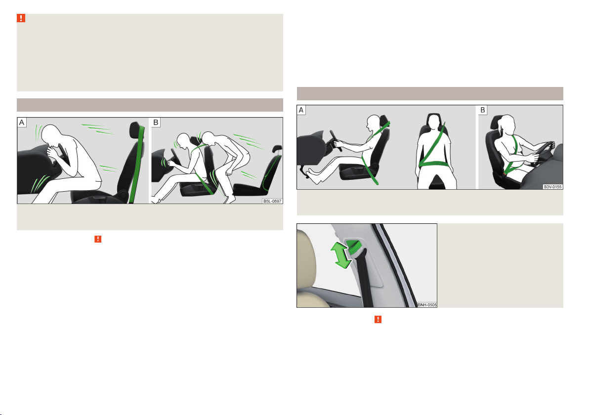
The physical principle of a frontal collision
Fig. 4 Driver without a fastened seat belt/rear seat passenger without a
fastened seat belt
Read and observe on page 11 first.
As soon as the vehicle is moving, so-called kinetic energy (the energy of mo-
tion) is produced both in terms of the car as well as in terms of the occupants.
The magnitude of this kinetic energy depends essentially on the speed at
which the vehicle is travelling and on the weight of the vehicle including the
occupants.
Doubling the speed of the vehicle from 25 km/h up to 50 km/hour increases
the kinetic energy four times.
For example, a person's weight of 80 kg “increases” at 50 km/h to 4.8 tons
(4,800 kg).
In the event of a frontal collision, occupants of the car not wearing a seat belt
are thrown forward and strike parts of the interior of the car, such as the
steering wheel, dash panel, windscreen in ways which cannot be controlled
» Fig. 4 -
. In certain circumstances you could even be thrown out of the vehi-
cle, which could cause life threatening or even fatal injuries.
A rear seat passenger who has not fastened their seat belt is a danger not on-
ly to himself but also for those seated at the front » Fig. 4 –
.
Correct routing of seat belt
Fig. 5
Routing of belt webbing over the shoulders and the lap belt/Rout-
ing of belt webbing for an expectant mother
Fig. 6
Front seat: Seat belt height ad-
juster
Read and observe on page 11 first.
It is important that the belt is properly routed to ensure seat belts offer the
maximum protection.
12
Safety
The shoulder part of the seat belt must never run across the neck but must
roughly run over the middle of the shoulder and fit snugly against the chest.
The lap part of the belt must run across the pelvis, must not be positioned
across the stomach and must always fit snugly » Fig. 5 -
.
Seat belt height adjusters for front seats
The seat belt height adjuster makes it possible to adjust the routing of the
front seat belts in the area of the shoulder to the body size.
›
Press the height adjuster and move to the desired position » Fig. 6.
›
Then pull firmly on the belt to ensure that the seat belt height adjuster has
correctly locked in place.
Seat belts with pregnant women
Expectant women must also always wear a seat belt. This is the only way of
ensuring optimal protection for the unborn child.
With pregnant women, the lap part of the belt must be positioned as low as
possible on the pelvis to avoid exerting any pressure on the lower abdomen
» Fig. 5 -
.
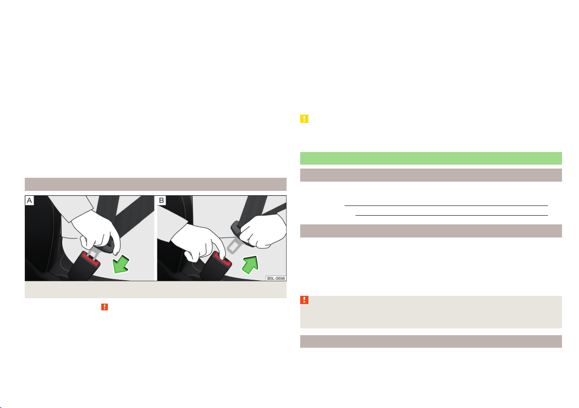
Fastening and unfastening seat belts
Fig. 7 Fastening/unfastening the seat belt
Read and observe on page 11 first.
Before using the seat belts the following conditions must be met.
Correctly set head restraint (not for seats with integrated head restraint).
Correctly adjusted seat (applies for the front seats).
Correctly adjusted steering wheel (applies to the Driver's seat ).
Fasten
›
Use the lock tongue to slowly pull the webbing over your chest and pelvis.
›
Insert the lock tongue into the belt buckle for the seat » Fig. 7 -
until it
audibly clicks into place.
›
Pull on the belt to check that it has engaged correctly in the lock.
Release
Release the seat belt only when the vehicle is stationary.
›
Press the red button in the belt buckle » Fig. 7 -
; the lock tongue pops out.
›
Manually guide the belt back so that it is easier to fully roll up the webbing,
the seat belt does not twist.
CAUTION
When releasing the seatbelt ensure that the tongue of the lock does not dam-
age the door trim or other parts of the interior.
Inertia reels and belt tensioners
Introduction
This chapter contains information on the following subjects:
Inertia reels 13
Belt tensioners
13
Inertia reels
Each seat belt is equipped with an inertia reel. When pulling slowly on the seat
belt, the belt can move freely.
When pulling sharply on the seat belt, the movement is locked by the inertia
reel. The belts also lock when full braking, when the car accelerates, when
driving downhill and when cornering.
WARNING
If the seat belt does not lock when pulling sharply on it, have it inspected
immediately by a specialist garage.
Belt tensioners
Safety for the driver and front passenger wearing their seat belts is enhanced
by the belt tensioners fitted to the inertia reels of the front three-point seat
belts.
13
Seat belts

If there is a collision the seat belts are tightened by the belt tensioner so that
unwanted body motion is prevented.
The three-point seat belts are automatically tensioned in the event of a frontal
or rear collision of a certain severity.
The front seat belts are automatically tensioned in the event of a side collision
of a certain severity.
Belt tensioners are not activated in the event of minor frontal, side or rear-
end collisions, in the case of a roll-over and also not in accidents in which no
major forces are produced.
WARNING
■
Any work on the belt tensioner system including removal and installation
of system components because of other repair work, must only be carried
out by a specialist garage.
■
If the belt tensioners have been deployed, it is then necessary to replace
the entire system.
Note
■
The belt tensioners can also be deployed if the seat belts are not fastened.
■
Smoke is generated when the belt tensioners are deployed. This is not an in-
dication of a fire in the vehicle.
Airbag system
Description of the airbag system
Introduction
This chapter contains information on the following subjects:
System description 15
Airbag deployment 15
The airbag system supplements the fastened seat belts and provides addition-
al occupant protection in severe frontal and side collisions.
The functional status of the airbag system is indicated by the indicator light
in the instrument cluster » page 34.
WARNING
■
An airbag can only offer you optimal protection in combination with a
fastened seat belt.
■
The airbag is not a substitute for the seat belt, but instead forms part of
the complete passive vehicle safety concept.
■
To ensure passengers are protected with the greatest possible effect
when the airbag is deployed, the front seats must be correctly adjusted to
match the body size » page 8, Correct and safe seated position.
■
If you do not fasten the seat belts when driving, lean too far forward or
adopt an incorrect seated position, you are exposing yourself to increased
risk of injury in the event of an accident.
WARNING
Information on the use of the airbag system
■
If there is a fault, have the airbag system checked immediately by a spe-
cialist garage. Otherwise, there is a risk of the airbag not being activated in
the event of an accident.
■
No modifications of any kind may be made to parts of the airbag system.
■
Any work on the airbag system including the installation and removal of
system components due to other repair work (e.g. removal of the steering
wheel) must only be carried out by a specialist garage.
■
Never make any changes to the front bumper or the bodywork.
■
Do not manipulate individual parts of the airbag system, as this might re-
sult in the airbag being deployed.
■
The airbag system must then be replaced if the airbag has been deployed.
14
Safety
System description
Read and observe on page 14 first.
The inflation of the airbag is carried out in a fraction of a second.
When the airbags are deployed, they fill with gas and inflate.
A grey white or red, non-harmful gas is released when the airbag is inflated.
This is perfectly normal and is not an indication of a fire in the vehicle.
Depending on the vehicle equipment, the airbag system consists of the
following parts.
▶
Front airbag for the driver and the front passenger » page 15.
▶
Side airbags » page 16.
▶
Head airbags » page 17.
▶
Airbag warning light in the instrument cluster » page 34.
▶
Key switch for the front passenger airbag » page 18.
▶
Warning light for the front passenger airbag in the middle of the dash panel
» page 18.
Airbag deployment
Read and observe
on page 14 first.
The airbag system is only functional when the ignition is switched on.
Triggering conditions
It is not possible to generally determine which deployment conditions apply to
the airbag system in every situation. An important role is played by factors
such as the type of object that the vehicle hits (hard/soft), the impact angle,
vehicle speed etc.
A decisive factor for the deployment of the airbags is the deceleration which
occurs. If the vehicle deceleration which occurs and is measured during the
collision remains below the prescribed reference values specified in the control
unit, the airbags are not deployed although the vehicle may well suffer severe
damage to the bodywork as a consequence of the accident.
The following airbags will be deployed in the event of a severe frontal
collision.
▶
Driver’s front airbag.
▶
Front passenger airbag.
The following airbags will be deployed in the event of a severe side collision.
▶
Front side airbag on the side of the accident.
▶
Head airbags on the side of the accident.
When an airbag is deployed, the following events occur.
▶
The interior light comes on (if the automatic operation of the interior light is
switched on - switch
).
▶
The hazard warning lights are switched on.
▶
All the doors are unlocked.
▶
The fuel supply to the engine is interrupted.
When there is no air bag deployment?
With minor frontal and side collisions, rear collision, overturning of the vehicle
or vehicle roll-over there is no airbag deployment.
Airbag overview
Introduction
This chapter contains information on the following subjects:
Front airbags
15
Side airbags 16
Head airbags 17
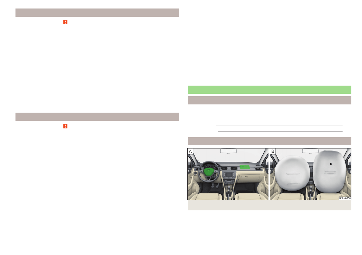
Front airbags
Fig. 8 Locations of the airbags / gas filled airbags
15
Airbag system
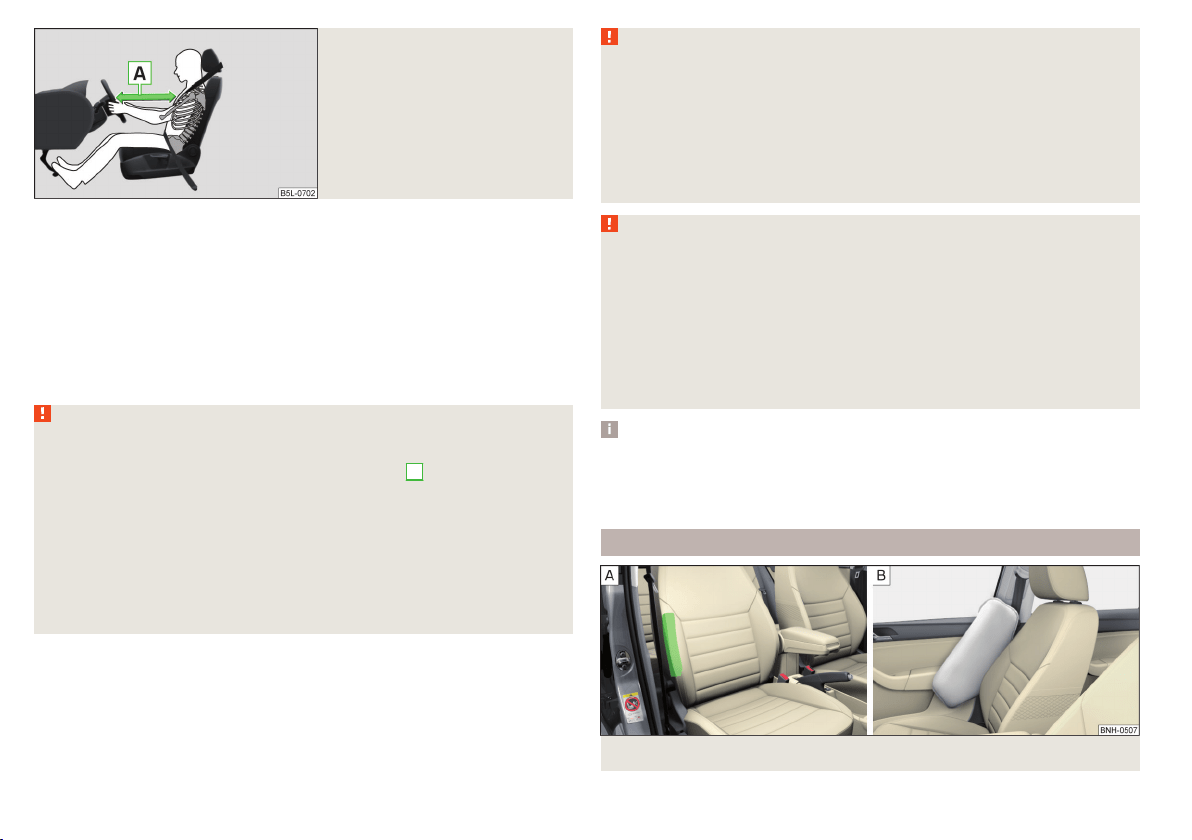
Fig. 9
Safe distance to steering wheel
In the event of a severe frontal collision, the front airbags offer additional pro-
tection for the head and chest area of the driver and front passenger.
The driver's front airbag is located in the steering wheel, the front passenger
airbag is located in the instrument panel above the glove compartment » Fig. 8
-
.
The airbags inflate in front of the driver and front passenger when they are
deployed » Fig. 8 -
. The forward movement of the driver and of the front
passenger is cushioned when they make contact with the fully inflated airbag
and the risk of injury to head and chest is thus reduced.
WARNING
Information on correct seated position
■
For the driver and front passenger, it is important to maintain a distance
of at least 25 cm to the steering wheel or dashboard
A
» Fig. 9. Not main-
taining this minimum distance will mean that the airbag system will not be
able to properly protect you – hazard! The front seats and the head re-
straints must always also be correctly adjusted to match the body size of
the occupant.
■
The airbag develops enormous forces when triggered, which can lead to
injuries if the sitting position or seated position is not correct.
■
There must not by any further persons, animals or objects positioned be-
tween the front seated occupants and the deployment area of the airbag.
WARNING
Front airbag and transporting children
■
Never transport children on the front seat of a vehicle without using a
proper restraint system. If airbags are deployed in the event of an accident,
the child might suffer severe or even fatal injuries!
■
The front passenger airbag must be deactivated if using a rear-facing
child seat on the front passenger seat » page 18, Deactivating airbags. If
this is not done, there is a risk of the child suffering severe or even fatal
injuries if the front passenger airbag is deployed.
WARNING
General information
■
The steering wheel and the surface of the airbag module in the dash pan-
el on the passenger side must not have stickers attached, be covered or
modified in any other way. These parts should only be cleaned with a cloth
that is dry or has been moistened with water. No objects (such as cup hold-
ers, mobile phone mounts, etc.) are to be attached to the covers of the air-
bag modules or be located within their immediate vicinity.
■
Never place objects on the surface of the front passenger airbag module
in the dash panel.
Note
■
In vehicles with head airbags, the lettering can be seen on the steering
wheel.
■
In vehicles with front passenger airbags, the lettering
is located on the
dash panel on the passenger side.
Side airbags
Fig. 10 Location of the side airbag in the driver's seat / gas-filled airbag
16
Safety
In the event of severe side collisions, the side airbags provide additional pro-
tection for the upper body (chest, stomach and pelvis) of passengers in the ve-
hicle.
The side airbags are housed in the upholstery of the front seat backrests
» Fig. 10 -
.
The load of the occupants is cushioned when plunging into the fully inflated
airbag » Fig. 10 -
the risk of injury to the entire upper body (chest, stomach
and pelvis) is reduced on the side facing the door.
WARNING
Information on correct seated position
■
Your head should never be positioned in the deployment area of the side
airbag. You might suffer severe injuries in the event of an accident. This ap-
plies in particular to children who are transported without using a suitable
child safety seat » page 21, Child safety and side airbag.
■
There must not be any further persons, animals or objects positioned be-
tween the occupants and the deployment area of the airbag. No accesso-
ries, such as cup holders, should be attached to the doors.
■
If children adopt an incorrect seated position when travelling, they may
be exposed to an increased risk of injury in the event of an accident. This
can result in serious injuries » page 19, Child seat.
WARNING
■
Do not place any objects within the deployment area of the side airbags –
risk of injury!
■
Ensure that there are no excessive forces, such as violent knocks, kicks
etc., impact on the backrests of the seats otherwise the system may be
damaged. The side airbags would not be deployed in such a case!
■
Any seat or protective covers which you fit to the driver or front passen-
ger seats must only be of the type expressly authorized by ŠKODA. In view
of the fact that the airbag inflates out of the backrest of the seat, use of
non-approved seat or protective covers would considerably impair the pro-
tective function of the side airbag.
■
Any damage to the original seat covers in the area of the side airbag mod-
ule must be repaired immediately by a specialist garage.
■
The airbag modules in the front seats must not display any damage,
cracks or deep scratches. It is not permissible to use force in order to open
the modules.
Note
In vehicles with side airbags a label with the lettering is located on the
front seat backrests.
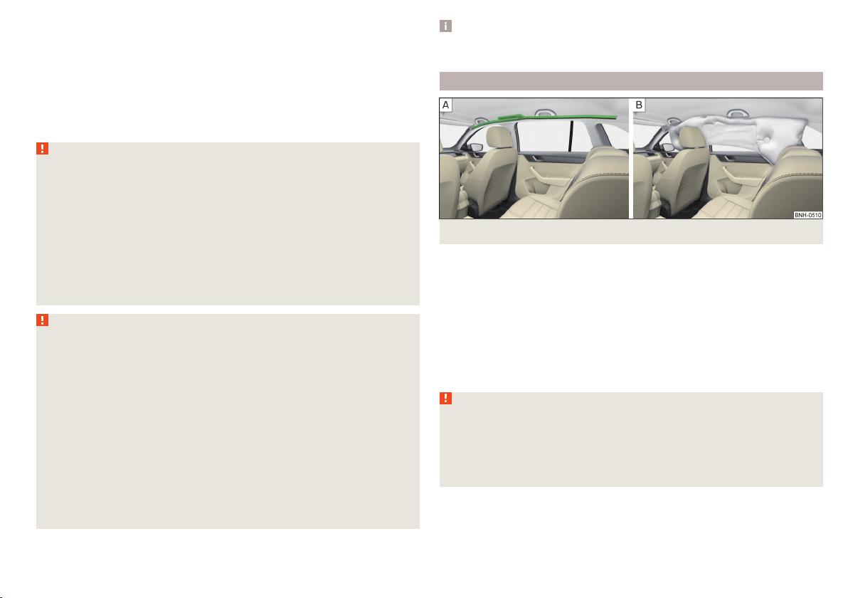
Head airbags
Fig. 11 Location of the head airbag/gas-filled head airbag
In the event of a severe side collision, the head airbags offer additional protec-
tion for the head and neck area of passengers.
The head airbags are positioned above the doors on both sides of the vehicle
interior » Fig. 11 -
.
When deployed, the airbag covers the window area of the front and rear doors,
as well as the area of the door pillar » Fig. 11 -
.
Head impact with interior parts is reduced by the inflated head airbag. The re-
duction in any impact to the head and the resultant minimizing of any move-
ments of the head additionally reduce the risk of injuries to the neck area.
WARNING
■
There must not be any objects in the deployment area of the head air-
bags which might prevent the airbags from inflating properly.
■
Only hang light items of clothing on the hooks fitted in the vehicle. Never
leave any heavy or sharp-edged objects in the pockets of the items of
clothing. Additionally, clothes hangers must not be used to hang up items
of clothing.
17
Airbag system
WARNING (Continued)
■
The installation of impermissible accessories in the vicinity of the head
airbags can considerably impair the protection offered by the head airbag in
the event of it being deployed. When the deployed head airbag is inflated,
parts of the accessories fitted could be thrown into the interior of the car
and injure the occupants » page 130.
■
When objects are attached to the sun visor, the visor can not be pivoted
to the side windows. This might result in injuries to the occupants if the
head airbag is deployed.
■
There must not be any further persons, animals or objects positioned be-
tween the occupants and the deployment area of the airbag. In addition,
none of the occupants should lean their head out of the window when driv-
ing, or extend their arms and hands out of the window.
Note
In vehicles with head airbags, the lettering can be seen on the B column
cladding.
Deactivating airbags
Introduction
This chapter contains information on the following subjects:
Deactivating airbags 18
Deactivating the front passenger airbag 18
Deactivating airbags
If you sell your vehicle, provide the complete vehicle documentation to the
new owner. Please note that the information relating to the possibility of de-
activating the front passenger airbag must be included!
If an airbag in the vehicle is to be turned off, then the buyer is to draw atten-
tion to this fact!
Deactivating an airbag should be considered in cases such as the ones below.
▶
If a rear-facing child seat must be used on the front passenger seat
» page 19, Transporting children safely.
▶
If it is not possible to maintain a distance of at least 25 cm between the mid-
dle of the steering wheel and chest, despite the driver's seat being correctly
adjusted.
▶
If special attachments are required in the area of the steering wheel because
of a physical disability.
▶
If different seats have been fitted (e.g. orthopaedic seats without side air-
bags).
The front passenger airbag can be switched off with the key-operated switch
» Fig. 12 on page 18 -
.
We recommend that you ask a ŠKODA service partner to deactivate any other
airbags.
Deactivation indicator
Display of the airbag deactivation » page 34,
Airbag system.
Note
A ŠKODA service partner will be able to inform you which, if any, of your vehi-
cle's airbags can or must be deactivated.
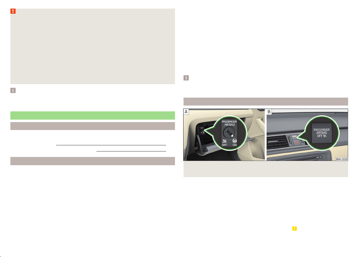
Deactivating the front passenger airbag
Fig. 12
Key-operated switch for the front passenger airbag / warning
light for front seat passenger airbag deactivation
Only the front passenger airbag is deactivated with the key switch.
Key switch positions » Fig. 12 -
Passenger front airbag deactivated
Passenger front airbag activated
Switch off
›
Switch off the ignition.
›
Open the storage box on the front passenger's side.
›
Fold the key bit out completely for the radio key » .
›
Carefully insert the key into the key slot in the key switch as far as the stop.
18
Safety

›
Use the key to turn the slot of the key switch » Fig. 12 carefully into the
position .
›
Pull the key out of the slot in the key switch » .
›
Close the storage box on the front passenger's side.
›
Check that the warning light
1)
under the text
» Fig. 12-
lights up after the ignition is switched on.
Switching on
›
Switch off the ignition.
›
Open the storage box on the front passenger's side.
›
Fold the key bit out completely for the radio key » .
›
Carefully insert the key into the key slot in the key switch as far as the stop.
›
Use the key to turn the slot of the key switch » Fig. 12
carefully into the
position
.
›
Pull the key out of the slot in the key switch » .
›
Close the storage box on the front passenger's side.
›
Check that the warning light
under the text
» Fig. 12 -
does not illuminate after the ignition is switched on.
WARNING
■
The driver is responsible for whether the airbag is switched on or switch-
ed off.
■
Only switch off the airbag when the ignition is switched off! Otherwise a
fault can occur in the system for deactivating the airbag.
■
If the
warning light is flashing, the front passenger airbag will not
be deployed in an accident! Have the airbag system checked by a specialist
garage immediately.
■
Do not leave the key inserted in the key-operated switch while driving -
vibrations can cause the key to turn in the slot and switch on the airbag!
The airbag could be triggered unexpectedly in an accident - it may result in
injury or death!
CAUTION
An insufficiently folded out key bit can damage the key switch!
Transporting children safely
Child seat
Introduction
This chapter contains information on the following subjects:
Use of a child seat on the front passenger seat 20
Use of the child seat in the front passenger seat 21
Child safety and side airbag 21
Classification of child seats 21
Use of child seats fastened with a seat belt 21
To avoid serious injury or death children are always to be in an appropriate
child safety seat with regards to height, weight, and age.
For safety reasons, we recommend that you always transport child seats on
the rear seats.
Child seats complying with the ECE-R 44 Economic Commission for Europe
standard must be used.
Child seats that comply with the ECE-R 44 standard are identified with a test
mark that cannot be removed: a capital E in a circle, with the test number be-
low.
With child safety seats in groups 2 and 3, make sure that the loop-around fit-
tings attached to the child seat headrest is positioned in front of or at the
same height as the loop-around fittings on the B pillar on the passenger side.
WARNING
■
One should never carry children, and also not babies! - on one's lap.
■
Never leave children unattended in the vehicle. Certain outside climatic
conditions can cause life-threatening temperatures in the vehicle.
■
The child must be secured in the vehicle during the entire journey! Other-
wise, the child would be thrown through the vehicle in the event of an acci-
dent, causing fatal injuries to both the child and other occupants.
1)
The warning light comes on for a few seconds after the ignition is switched on, goes out for about
1 second and then comes on again.
19
Transporting children safely
WARNING (Continued)
■
Children are exposed to an increased risk of injury in the event of an acci-
dent if they lean forward or adopt an incorrect seated position when the
vehicle is moving. This particularly applies to children who are transported
on the front passenger seat as they can suffer severe, or even fatal injuries
if the airbag system is deployed!
■
Pay particular attention to the information provided by the manufacturer
of the child safety seat regarding the correct routing of the belt. Seat belts
which are not correctly adjusted can themselves cause injuries even in mi-
nor accidents.
■
Safety belts must be checked to ensure that they are running properly.
One should also ensure that the belt is not damaged by sharp-edged fit-
tings.
■
The front passenger airbag must be deactivated if using a rear-facing
child seat on the front passenger seat. Further information » page 20,
Use of a child seat on the front passenger seat.
■
When installing the child seat on the back seat, the corresponding front
seat must be adjusted so that there is no contact between the front seat
and the child seat or the child being transported in a child seat.
CAUTION
■
When installing a child seat in which the child faces forward, adjust the head
restraints so that they are as high as possible.
■
If the head restraints still prevent the child seat from being installed, even in
the highest position, you will need to remove them » page 70. After remov-
ing the child seat, refit the head restraints.
Note
We recommend that you use child seats from ŠKODA Original Accessories.
These child seats were developed and also tested for use in ŠKODA vehicles.
They meet the ECE-R 44 standard.
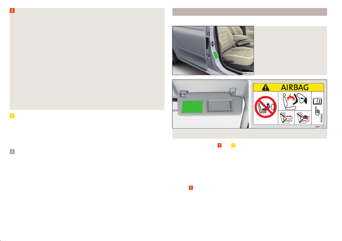
Use of a child seat on the front passenger seat
Does not apply to Taiwan
Fig. 13
Sticker on the B column on the
front passenger side
Fig. 14
Front passenger sun visor / label
Read and observe and on page 19 first.
Never use a rear-facing child restraint system on a seat which is protected by
an active airbag positioned in front. This could cause serious or fatal injury to
the child.
The following instructions must be followed when using a child seat on the
front passenger seat.
▶
The front passenger airbag must be deactivated if using a rear-facing child
seat » .
▶
If possible, adjust the front passenger seat backrest so that it is as vertical,
so as to ensure secure contact between the passenger seat backrest and the
back of the child seat.
▶
If possible, move the front passenger seat backwards so that there is no con-
tact between the front passenger seat and the child seat behind it.
▶
Set the height-adjustable front passenger seat as high up as possible.
20
Safety
▶
Set the front passenger seat belt as high up as possible.
▶
When using a child seat where there is a height adjuster in the upper area,
the height of the passenger seat belt is to be set so that the belt is not
“kinked” in the height adjuster. In the event of an accident, there is the risk
of injury to the neck of the child carried due to the seat belt!
WARNING
■
Never use a rear-facing child seat on the front passenger seat if the pas-
senger airbag is activated. This child safety seat is positioned in the deploy-
ment area of the front passenger airbag. The airbag may cause the child se-
vere, or even fatal injuries, in the event of it being deployed.
■
This fact is also indicated by the label that can be found in one of the fol-
lowing locations.
■
On the B-column on the front passenger side » Fig. 13. The sticker is
visible upon opening the front passenger door.
■
On the front passenger's sun visor. In some countries, the sticker is lo-
cated on the front seat passenger's sun visor » Fig. 14.
■
As soon as the rear-facing child seat is no longer being used on the pas-
senger seat, the front passenger airbag should be re-activated again.
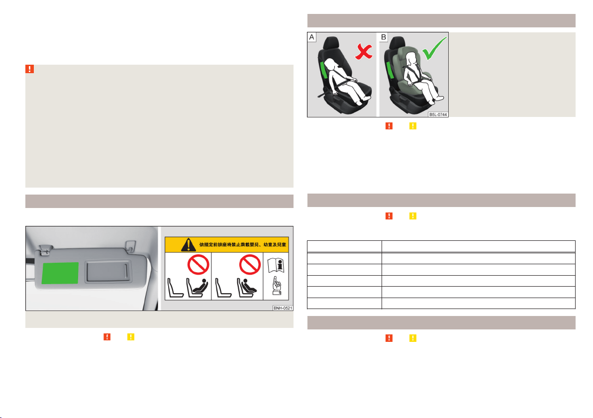
Use of the child seat in the front passenger seat
Applies to Taiwan
Fig. 15 Front passenger sun visor / label
Read and observe and on page 19 first.
No babies, infants or children are to be carried on the passenger seat.
This is also clearly stated on the sticker which is located on the front passen-
ger side sun visor » Fig. 15.
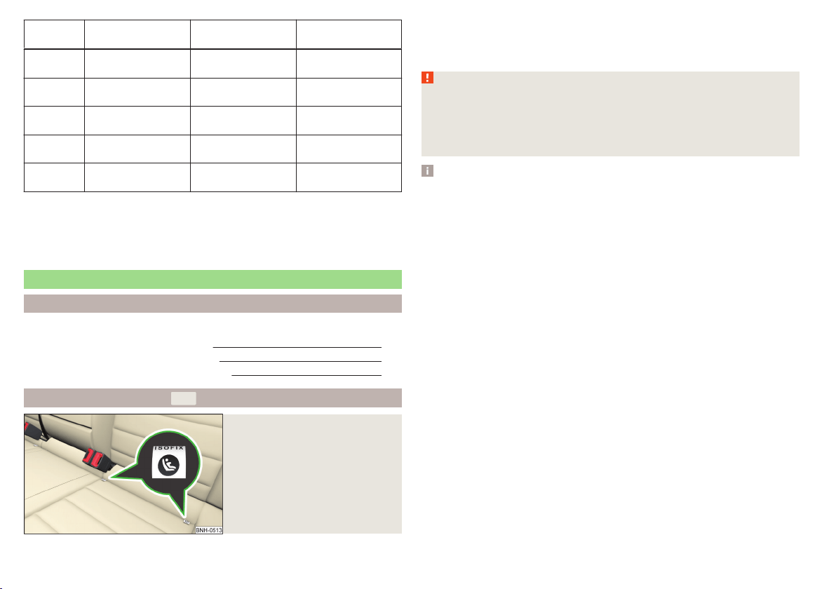
Child safety and side airbag
Fig. 16
Incorrect seated position of a
child who is not properly secured
– risk from the side airbag/Child
properly protected by safety seat
Read and observe and on page 19 first.
The child must not be positioned in the deployment area of the side airbag
» Fig. 16 -
.
There must be sufficient room between the child and the deployment area of
the side airbag to ensure that the airbag can provide as much protection as
possible » Fig. 16 -
.
Classification of child seats
Read and observe
and on page 19 first.
Classification of child seats according to the ECE-R 44 standard.
Group Weight of the child
0 up to 10 kg
0+ up to 13 kg
1 9-18 kg
2 15-25 kg
3 22-36 kg
Use of child seats fastened with a seat belt
Read and observe
and on page 19 first.
Overview of the usability of child seats fastened with a seat belt on each of
the seats in accordance with the ECE-R 16 standard.
21
Transporting children safely
Group
Front passenger
seat
Rear seats
External
Rear seat
Centre
0
up to 10 kg
U U U
0+
up to 13 kg
U U U
1
9-18 kg
U U U
2
15-25 kg
U U U
a)
3
22-36 kg
U U U
a)
a)
If the middle rear seat is not provided with a headrest, then a child seat of Group 2 or 3 is only to be used
if this has its own built-in headrest. If the child seat of Group 2 or 3 does not have its own built-in head-
rest, the child seat must be attached to the outer rear seat.
“Universal” child seat category - a child seat designed to be attached to
the seat using the seat belt.
Fastening systems
Introduction
This chapter contains information on the following subjects:
Attachment points of the
-system
22
Use of child seats with the
-system
23
Attachment points of the
-system
24
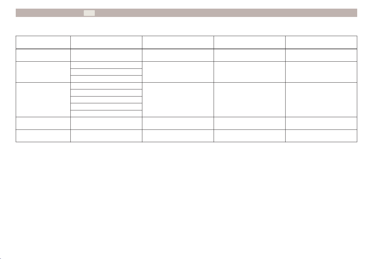
Attachment points of the
-system
Fig. 17
Labels of the system
U
is a system for securing child seats quickly and safely.
There are two locking eyes between the rear exterior seats for fixing the child
in place using the
-system » Fig. 17.
WARNING
■
Always refer to the instructions from the manufacturer of the child seat
when installing and removing a child seat with the -system.
■
Never attach other child seats, belts or objects to the attachment points
eyes intended for the installation of a child seat with the
-system – risk
of death!
Note
■
A child seat fitted with the system can only be mounted in a vehicle fit-
ted with a system if the child seat has been approved for this type of ve-
hicle. Further information is available from a ŠKODA Partner.
■
Child seats with the
-system can be purchased from ŠKODA Original Ac-
cessories.
22
Safety
Use of child seats with the -system
Overview of the usefulness of child seats fastened with the -system on
each of the seats in accordance with the ECE-R 16 standard.
Group
Size class of
the child seat
a)
Front passenger seat Outer rear seats Rear seat middle
0
up to 10 kg
E X IL-SU X
0+
up to 13 kg
E
X IL-SU XD
C
1
9-18 kg
D
X
IL-SU
IUF
X
C
B
B1
A
2
15-25 kg
- X IL-SU X
3
22-36 kg
- X IL-SU X
a)
The size category is shown on the label attached to the child seat.
IL-SU The seat is suited for installation of a -child seat with the “Semi-Universal” approval. The “Semi-Universal” category means that the child seat with
the
-system is approved for your vehicle. Observe the list of vehicles that comes with the child seat.
IUF The seat is suitable for the installation of a -child seat with the approval “Universal” and attachment with the -system belt.
X The seat is not fitted with -system attachment points.
23
Transporting children safely
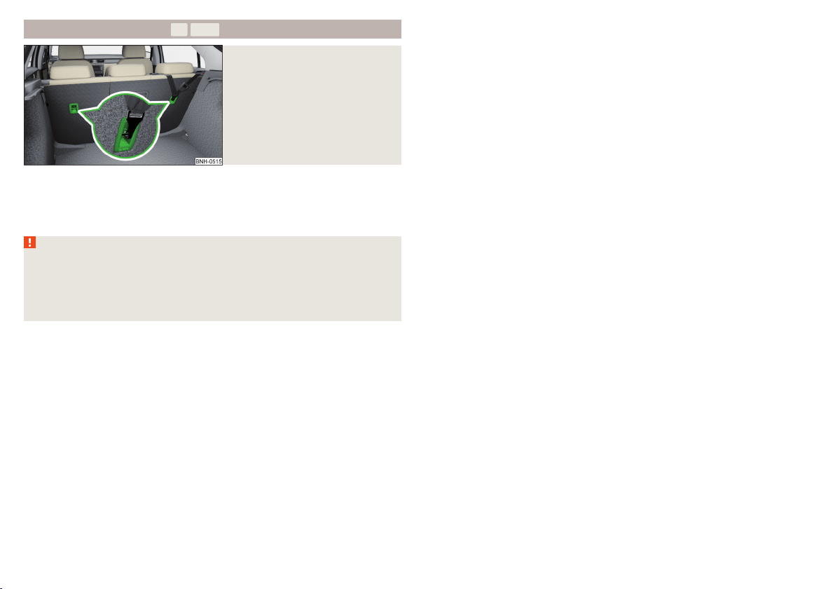
Attachment points of the -system
Fig. 18
Attachment points of the
-system
is a fastening system, which restricts the movement of the upper part
of the child seat.
The anchor eyelets for attaching the belt for a child seat with the
-sys-
tem are located on the rear side of the outer rear seat backrests » Fig. 18.
WARNING
■
Always refer to the instructions from the manufacturer of the child seat
when installing and removing a child seat with the -system.
■
Only use child seats with the
-system on the seats with the lock-
ing eyes.
■
Only ever attach one belt from the child seat to a locking eye.
24
Safety

25
Transporting children safely
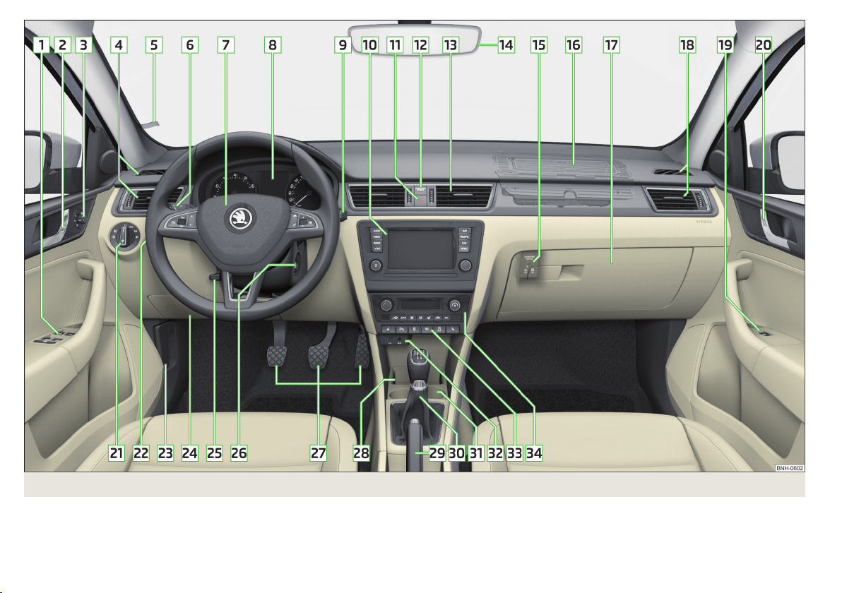
Fig. 19 Cockpit
26
Using the system

Using the system
Cockpit
Overview
Electric power windows 56
Door opening lever 53
Electric exterior mirror adjustment 68
Air outlet vents 94
Parking ticket holder 74
Operating lever (depending on specification):
▶
Indicators, main and dipped beam, headlight flasher 60
▶
Cruise control system
114
Steering wheel (depending on equipment):
▶
With horn
▶
With driver’s front airbag 15
▶
With buttons for the operation of the information system
39
Instrument cluster 28
Operating lever (depending on specification):
▶
Windscreen wiper and washer system 66
▶
Information system
39
Infotainment » User manual for Infotainment
Button for hazard warning light system 62
Warning light for the front passenger airbag 18
Air outlet vents 94
Interior rear-view mirror 67
Key switch for switching off the front passenger airbag (in front
passenger storage compartment) 18
Front passenger airbag 15
Storage compartment on the front passenger side 78
Air outlet vents 94
Front passenger door power window 56
Door opening lever 53
Light switch 59
Headlight range control (in the dashboard) 59
Bonnet release lever 144
1
2
3
4
5
6
7
8
9
10
11
12
13
14
15
16
17
18
19
20
21
22
23
Fuse box 175
Steering wheel adjustment lever 9
Depending on specification:
▶
Ignition lock 96
▶
Starter button 97
Pedals 103
Storage compartment 74
Handbrake lever 102
Depending on specification:
▶
Gearshift lever (manual gearbox) 103
▶
Selector lever (automatic gearbox) 104
Depending on specification:
▶
Cup holder 74
▶
Multimedia holder
77
▶
Ashtrays
75
AUX and MDI input (AUX and USB) 80
Bar with keys depending on the equipment fitted:
▶
Seat heater on the front left seat
70
▶
Traction control (TCS) 110
▶
Parking aid 112
▶
Central locking system 51
▶
Rear window heater 64
▶
START STOP 99
▶
Seat heater on the front right seat 70
Depending on equipment fitted:
▶
Operating controls for the heating 91
▶
Operating controls for the manual air conditioning system
91
▶
Operating controls for Climatronic 92
Note
The layout of the controls on right-hand drive vehicles differs partially from
that shown in » Fig. 19. The symbols on the controls and switches are the
same as for left-hand drive models.
24
25
26
27
28
29
30
31
32
33
34
27
Cockpit
Instruments and Indicator Lights
Instrument cluster
Introduction
This chapter contains information on the following subjects:
Overview 28
Revolution counter 29
Display 29
Coolant temperature gauge 29
Fuel gauge 30
Counter for distance driven 30
Setting the clock 31
The instrument cluster gives the driver basic information such as the current
speed, engine speed, the state of some vehicle systems and the like.
If there is a fault in the instrument cluster, the following message will appear
in the display.
Error: instrument cluster. Workshop!
COMBI-INSTRUM_ WORKSHOP
Seek help from a specialist garage.
WARNING
Concentrate fully at all times on your driving! As the driver you are fully re-
sponsible for road safety.
Note
■
If the message
SAFE CP
appears in the instrument cluster display, the compo-
nent protection for the instrument cluster is active. Further information
» page 132, Component protection.
■
With the ignition switched on the instruments are also illuminated. The
brightness of the instrument illumination is set automatically depending on
the ambient lighting throughout.
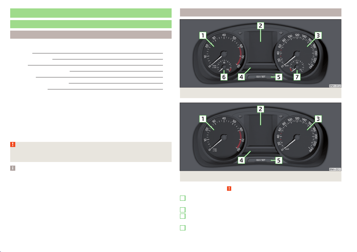
Overview
Fig. 20 Instrument cluster - Version 1
Fig. 21 Instrument cluster - Version 2
Read and observe on page 28 first.
Engine revolutions counter » page 29
▶
with warning lights » page 31
Display » page 29
Speedometer
▶
with warning lights » page 31
Bar with warning lights » page 31
1
2
3
4
28
Using the system
Button for:
▶
Setting the time » page 31
▶
Reset counter for distance travelled (trip) » page 30
▶
Displaying the distance and days until the next service interval
» page 46
Coolant temperature gauge » page 29
Fuel gauge » page 30
Revolution counter
Read and observe on page 28 first.
The tachometer
1
» Fig. 20 on page 28 or » Fig. 21 on page 28 shows the ac-
tual engine speed per minute.
The beginning of the red scale range of the tachometer indicates the maxi-
mum permitted engine speed of a driven-in and operating warm engine.
You should shift into the next highest gear before the red scale of the revolu-
tion counter is reached, or select mode D on the automatic gearbox.
The gear recommendation is important to note in order to maintain the opti-
mum engine speed » page 39.
CAUTION
The pointer of the tachometer must reach the red area for only a short time -
there is a risk of engine damage!
Display
Fig. 22
Display types
5
6
7
Read and observe on page 28 first.
Display types » Fig. 22
MAXI DOT display
Segment display
The following information will be displayed.
▶
Exterior temperature information
▶
Distance travelled » page 30
▶
Time » page 31
▶
Warning lights » page 31
▶
Information system data » page 39
▶
Fuel gauge
1)
» page 30
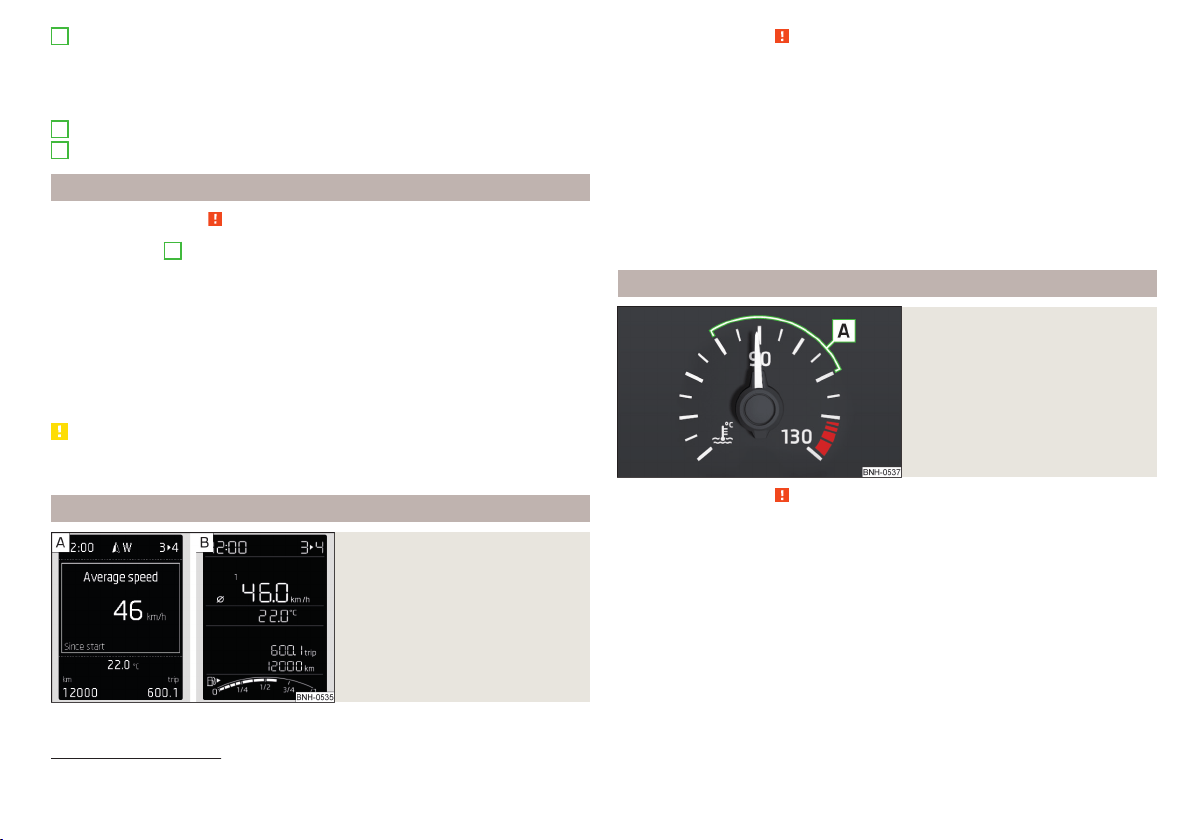
Coolant temperature gauge
Fig. 23
Coolant temperature gauge
Read and observe on page 28 first.
Applies to cars with the instrument cluster - Version 1 » Fig. 20 on page 28.
The display » Fig. 23 provides information on the engine coolant temperature.
The display only works if the ignition is switched on.
Cold range
If the pointer is still in the left area of the scale, this indicates that the engine
has not yet reached its operating temperature. Avoid high speeds, full throttle
and high engine loads. This prevents possible damage to the engine.
1)
Applies only to the segment display (instrument cluster - version 2).
29
Instruments and Indicator Lights
The operating range
The engine has reached its operating temperature as soon as the pointer
moves into the middle of the scale
A
» Fig. 23.
High temperature range
If the pointer reaches the red area of the scale, the coolant temperature is too
high.
CAUTION
■
Additional headlights and other attached components in front of the air inlet
impair the cooling efficiency of the coolant.
■
Never cover the radiator - there is a risk of the engine overheating.
Note
On vehicles with the multifunction display, the coolant temperature can be
shown on the display by the corresponding driving data entry being selected
» page 40, Information overview.
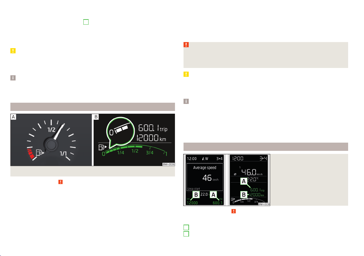
Fuel gauge
Fig. 24 Fuel gauge: Version 1/version 2
Read and observe
on page 28 first.
Fuel gauge types » Fig. 24
Display in the instrument cluster - Version 1
In the display of the instrument cluster - Version 2
The display provides information on the fuel level in the container.
The display only works if the ignition is switched on.
The fuel tank has a capacity of about 55 litres.
The reserve zone is indicated by the red area of the scale » Fig. 24 - or by
displaying only the last two segments of the scale » Fig. 24 - in the magnify-
ing glass.
The warning light lights up when the amount of fuel reaches the reserve zone
» page 35.
WARNING
For the vehicle systems to function correctly, and thus for safe driving,
there must be sufficient fuel in the tank. Never drain the fuel tank com-
pletely – risk of accident!
CAUTION
Never drive until the fuel tank is completely empty! The irregular supply of fuel
can cause misfiring. This can result in considerable damage to parts of the en-
gine and the exhaust system.
Note
■
After filling up, it can occur that during dynamic driving (e.g. numerous
curves, braking, driving downhill and climbing a steep hill) the fuel gauge indi-
cates approx. a fraction less. When stopping or during less dynamic driving, the
fuel gauge displays the correct fuel level again. This is not a fault.
■
The arrow
next to the icon
within the fuel gauge displays the installation
location of the fuel filler on the right-hand side of the vehicle.
Counter for distance driven
Fig. 25
Display: MAXI DOT display / Seg-
ment display
Read and observe on page 28 first.
Display » Fig. 25
Counter for the distance travelled since the last reset (trip)
Odometer
A
B
30
Using the system
Reset counter for distance travelled (trip)
›
Press button
A
» Fig. 26 on page 31.
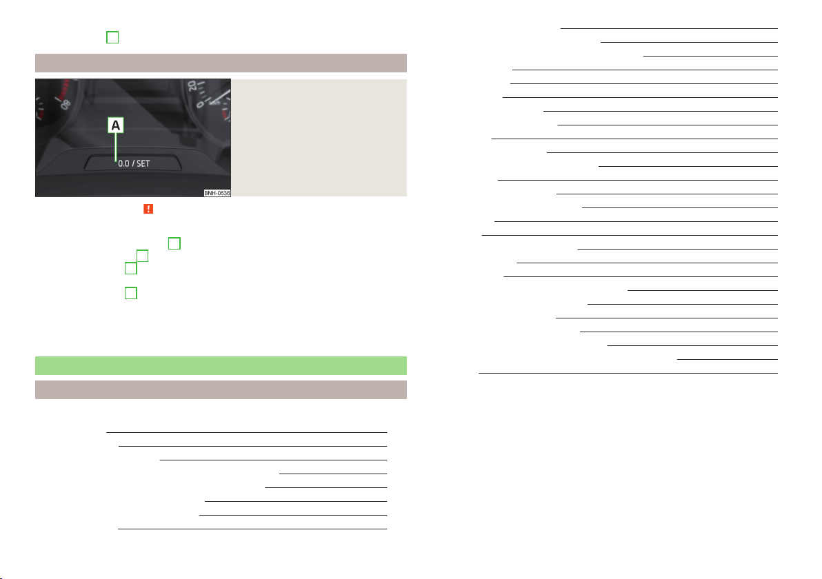
Setting the clock
Fig. 26
Button in the instrument cluster
Read and observe on page 28 first.
›
Switch on the ignition.
›
Press and hold the button
A
» Fig. 26 until the
Time
is shown in the display.
›
Release the button
A
and the system switches to the hour setting function.
›
Press the button
A
again and set the hours.
›
Wait around 4 seconds - the system switches to the minutes setting.
›
Press the button
A
again and set the minutes.
›
Wait around 4 seconds - the system switches to the start setting.
The time can also be set in the Infotainment » Owner´s Manual Infotainment,
chapter Device settings.
Indicator lights
Introduction
This chapter contains information on the following subjects:
Handbrake 32
Brake system 32
Seat belt warning light 32
Power steering/steering lock (KESSY system) 32
Stability control (ESC) / Traction control (TCS) 33
Traction control system (TCS) off 33
Anti-lock braking system (ABS) 33
Rear fog light 34
Emission control system 34
Glow plug system (diesel engine) 34
Engine performance check (petrol engine) 34
Airbag system 34
Tyre pressure 34
Fuel reserve 35
Turn signal system
35
Trailer turn signal lights 35
Fog lights 35
Cruise control system 35
Brake pedal (automatic gearbox) 35
Main beam 36
Automatic transmission 36
Rear seat belt warning light 36
Alternator 36
Coolant 36
Engine oil pressure too low 37
Engine oil level 37
Lamp failure 37
Diesel particulate filter (diesel engine) 37
Windscreen washer fluid level 38
START-STOP system 38
Display of a low temperature 38
Distance warning (Front Assist) 38
Advance warning/emergency brake (Front Assist) 38
Service 38
The warning lights in the instrument cluster indicate certain functions or
faults.
Some warning lights can be accompanied by acoustic signals and messages in
the display of the instrument cluster.
After switching on the ignition, some warning lights light up briefly as a func-
tion test.
If the tested systems are OK, the corresponding warning lights go out a few
seconds after switching on the ignition or after starting the engine.
31
Instruments and Indicator Lights

Warning lights in the display
Depending on the importance the warning light (danger) or (warning) illu-
minate along with some of the warning lights in the list with the warning
lights
4
» Fig. 20 on page 28 and » Fig. 21 on page 28.
WARNING
■
Ignoring illuminated indicator lights and related messages or instructions
in the instrument cluster display may lead to serious personal injury or
damage to the vehicle.
■
If you have to stop for technical reasons, then park the vehicle at a safe
distance from the traffic, switch off the engine and switch on the hazard
warning lights » page 62. Place the warning triangle at the prescribed dis-
tance.
■
The engine compartment of your car is a hazardous area. The following
warning instructions must be followed at all times when working in the en-
gine compartment » page 143, Engine compartment.
Handbrake
Read and observe
on page 32 first.
illuminates – the hand brake is applied.
An acoustic signal will sound if you drive the vehicle above 5 km/h while the
handbrake is still on.
Release the handbrake!
RELEASE HANDBRAKE
Brake system
Read and observe on page 32 first.
illuminates – the brake fluid level in the braking system is too low.
Brake fluid: owner's manual!
BRAKE FLUID PLEASE CHECK
›
Stop the vehicle, switch off the engine, and check the level of the brake fluid
» page 150.
WARNING
■
If the warning light illuminates simultaneously with warning light
» page 33, Anti-lock braking system (ABS), do not continue your
journey! Seek help from a specialist garage.
■
A fault to the ABS system or the braking system can increase the vehi-
cle's braking distance – risk of accident!
Seat belt warning light
Read and observe
on page 32 first.
illuminates - the driver or front passenger has not fastened their seat belt.
At a speed of more than approximately 25 km/h the warning light
flashes
and an audible warning sounds at a time.
If the seat belt is not fastened by the driver or front passenger during the next
approx. 2 seconds, the warning signal is deactivated and the warning light
lights up permanently.
Power steering/steering lock (KESSY system)
Read and observe
on page 32 first.
Fault in the power steering
illuminates – this indicates a complete failure of the power steering and the
steering assist has failed (significantly higher steering forces).
illuminates – this indicates a partial failure of the power steering and the
steering forces can be greater.
Seek help from a specialist garage.
Steering lock defect (KESSY system)
An audible signal sounds as a warning.
flashes
Steering lock faulty. Stop!
STOP VEHICLE STEERING FAULTY
Park the vehicle, and
stop driving. After switching off the ignition, it is no
longer possible to lock the steering, to activate the electrical components (e.g.
Infotainment etc.), to switch on the ignition again and to start the engine. Seek
help from a specialist garage.
32
Using the system

flashes
Steering lock: Workshop!
STEERING WORKSHOP
Seek help from a specialist garage.
Steering column lock not unlocked (System KESSY)
flashes
Move the steering wheel!
MOVE STEERING WHEEL
▶
Move the steering wheel slightly back and forth, thereby facilitating unlock-
ing the steering lock.
If the steering does also not unlock then, the help of a specialist garage is re-
quired.
Disconnecting the vehicle battery
If the vehicle's battery has been disconnected and reconnected, the indicator
light
can come on after switching on the ignition.
The warning light should go out after driving a short distance.
If, after the motor is restarted and a short drive, the indicator light does not go
out, there is a system error.
Seek help from a specialist garage.
Stability control (ESC) / Traction control (TCS)
Read and observe on page 32 first.
flashes – the ESC or TCS is currently being activated.
illuminates – there is an ESC or TCS fault.
ESC or TCS fault
illumi-
nates
Error: stabilisation control (ESC)
ESC ERROR
or
illumi-
nates
Error: traction control
ASR ERROR
Seek help from a specialist garage.
If the warning light
comes on after starting the engine, the TCS may be
switched off for technical reasons.
▶
Switch the ignition off and on again.
If the warning light does not illuminate after you switch the engine back on,
the ASR is fully functional again.
Disconnecting the vehicle battery
If the vehicle's battery has been disconnected and reconnected, the indicator
light
comes on after switching on the ignition.
The warning light should go out after driving a short distance.
If, after a short drive, the indicator light does not go out, there is a system er-
ror.
Seek help from a specialist garage.
For more information on the ESC system » page 110, Stability Control (ESC) or
TCS system » page 110, Traction control (TCS).
Traction control system (TCS) off
Read and observe on page 32 first.
illuminates – the TCS system is disabled.
Anti-lock braking system (ABS)
Read and observe
on page 32 first.
illuminates – there is an ABS fault.
Error: ABS
ABS ERROR
The vehicle will only be braked by the normal brake system without the ABS.
Seek help from a specialist garage.
WARNING
■
If the warning light illuminates simultaneously with warning light
» page 32, Brake system, do not continue your journey! Seek help
from a specialist garage.
■
A fault to the ABS system or the braking system can increase the vehi-
cle's braking distance – risk of accident!
33
Instruments and Indicator Lights

Rear fog light
Read and observe on page 32 first.
illuminates – the rear fog light is switched on.
Emission control system
Read and observe on page 32 first.
illuminates – there is a fault in the emission control system. The system
makes possible operation emergency mode - there may be a noticeable reduc-
tion in engine performance.
Seek help from a specialist garage.
Glow plug system (diesel engine)
Read and observe on page 32 first.
flashes – there is a fault in the engine management system. The system
makes possible operation emergency mode - there may be a noticeable reduc-
tion in engine performance.
There is a fault in the glow plug system if the warning light
does not come
on or illuminates continuously.
Seek help from a specialist garage.
Engine performance check (petrol engine)
Read and observe on page 32 first.
illuminates – there is a fault in the engine management system. The system
makes possible operation emergency mode - there may be a noticeable reduc-
tion in engine performance.
Seek help from a specialist garage.
Airbag system
Read and observe on page 32 first.
System fault
illuminates – there is a fault in the airbag system.
Error: airbag
AIRBAG ERROR
Seek help from a specialist garage.
The front passenger airbag has been disabled with the key switch
Illuminates for around 4 seconds after the ignition has been switched on.
under the letters
in the middle of the dash panel illumi-
nates after switching on the ignition » page 18.
One of the airbags or a belt tensioner has been disabled by the diagnostic
tool
illuminates for approximately 4 seconds after the ignition is switched on
and then flashes for approximately 12 seconds.
Airbag/ belt tensioner deactivated.
AIRBAG/ BELT TENSIONER OFF
WARNING
When a fault in the airbag system occurs, there is a risk of the system not
being triggered in the event of an accident. Therefore, this must be
checked immediately by a specialized garage.
Tyre pressure
Read and observe
on page 32 first.
Change of tyre pressure values
illuminates – there was a pressure change in one of the tyres.
An audible signal sounds as a warning.
›
Immediately reduce speed and avoid sudden steering and braking manoeu-
vres.
›
Stop the vehicle, turn the ignition off and check the tyres and their inflation
pressure » page 155.
›
Correct the tyre pressure, if necessary or replace the affected wheel
» page 161 or use the repair kit » page 165.
›
Store the tyre pressure values in the system » page 120.
System fault
flashes for approximately 1 minute and remains lit – there may be a fault in
the tyre pressure monitoring system.
›
Stop the vehicle, turn the ignition off and start the engine again.
34
Using the system

If the warning light flashes after starting the engine again, there is a system
error.
Seek help from a specialist garage.
Disconnecting the vehicle battery
If the vehicle's battery has been disconnected and reconnected, the indicator
light
comes on after switching on the ignition.
The warning light should go out after driving a short distance.
If, after a short drive, the indicator light does not go out, there is a system er-
ror.
Seek help from a specialist garage.
Other incidents
The illumination of the warning light
can have the following reasons.
▶
The vehicle is loaded on one side. Distribute loads as evenly as possible.
▶
The wheels of one axle are loaded more heavily (e.g. when towing a trailer or
when driving uphill or downhill).
▶
Snow chains are mounted.
▶
A wheel has been changed.
CAUTION
Under certain circumstances (e.g. sporty style of driving, wintry or unpaved
roads) the warning light in the instrument cluster may be delayed or not
light up at all.
Fuel reserve
Read and observe on page 32 first.
illuminates – the fuel level in the fuel tank is at the reserve level (approxi-
mately 7 litres).
Please refuel. Range: ...
km
PLEASE REFUEL RANGE …
km
An audible signal sounds as a warning.
Note
The text in the display goes out after refuelling and driving a short distance.
Turn signal system
Read and observe on page 32 first.
flashes – the left turn signal is switched on.
flashes – the right turn signal is switched on.
If there is a fault in the turn signal system, the warning light flashes at twice
its normal rate. This does not apply when towing a trailer.
When the hazard warning light system is switched on, this will cause all of the
turn signal lights as well as both warning lights to flash.
Trailer turn signal lights
Read and observe on page 32 first.
flashes – the trailer turn signal lights are switched on.
If a trailer is hitched and the warning light
is not flashing, one of the trailer
turn signal lights has failed.
An example message in the display of the instrument cluster
Trailer: check left turn signal!
TRAILER TURN SIG_ CHECK LEFT
Check the trailer bulbs.
Fog lights
Read and observe on page 32 first.
illuminates – the fog lights are switched on.
Cruise control system
Read and observe on page 32 first.
illuminates – the vehicle speed is regulated by the cruise control system.
Brake pedal (automatic gearbox)
Read and observe on page 32 first.
illuminates – apply the brake.
35
Instruments and Indicator Lights

Main beam
Read and observe on page 32 first.
illuminates – the main beam or the headlight flasher is switched on.
Automatic transmission
Read and observe on page 32 first.
Gearbox overheated
The warning light
is only shown in the MAXI DOTdisplay.
illumi-
nates
Gearbox overheated. Stop! Owner's manual!
STOP VEHICLE GEARBOX OVERHEAT
illumi-
nates
Gearbox overheated.
GEARBOX OVERHEATED
▶
do not continue to drive! Stop the vehicle and turn off the engine.
You can continue your journey as soon as the warning light disappears.
If the warning light does not go out, do not continue driving. Seek help from a
specialist garage.
Transmission problem
The warning light
is only shown in the MAXI DOTdisplay.
illumi-
nates
Gearbox faulty. Workshop!
GEARBOX FAULTY WORKSHOP
illumi-
nates
Error: gearbox. Reverse gear not available.
GEARBOX ERROR REV_ GEAR NOT AVAIL
illumi-
nates
Error: gearbox
GEARBOX ERROR
Seek help from a specialist garage.
Rear seat belt warning light
Read and observe
on page 32 first.
illuminates – a rear seat belt is not fastened.
illuminates – a rear seat belt is fastened.
When the seat belt is fastened/unfastened, the particular light lights up briefly
and indicates the current belt status!
Alternator
Read and observe on page 32 first.
illuminates – the battery is not being charged whilst the engine is running.
Seek help from a specialist garage.
CAUTION
If in addition to the light the light lights up while driving, stop driving -
risk of engine damage! Switch off the engine and seek assistance from a spe-
cialist garage.
Coolant
Read and observe
on page 32 first.
Coolant level too low
illumi-
nates
Check coolant! Owner's manual!
ENGINE COOLANT PLEASE CHECK
▶
Stop the vehicle, switch off the engine, and check the coolant level
» page 148, Checking the coolant level.
If the coolant level is within the specified range and the warning light
illumi-
nated again after ignition on, then there may be a malfunction of the cooling
fan.
▶
Switch off the ignition.
▶
Check the fuse for the radiator fan, replace if necessary.
If the coolant level and the fan fuse are OK and the warning light
illuminates
again after ignition on
do not continue to drive!
Seek help from a specialist garage.
Coolant temperature too high
illumi-
nates
Engine overheat. Stop! Owner's manual!
ENGINE OVERHEAT STOP
▶
Stop the vehicle and turn off the engine.
▶
Continue your journey only after the warning light
has disappeared.
36
Using the system

Engine oil pressure too low
Read and observe on page 32 first.
flashes – the engine oil pressure is too low.
Oil pressure: Stop vehicle! Owner's manual!
STOP VEHICLE OIL PRESSURE
›
Stop the vehicle, switch off the engine, and check the engine oil level.
Even if the oil level is correct,
do not drive any further if the warning light is
flashing. Also do not leave the engine running at an idling speed.
Seek help from a specialist garage.
CAUTION
If for some reason, it is not possible to top up the engine oil, do not contin-
ue driving! Switch off the engine and seek assistance from a specialist garage.
Engine oil level
Read and observe
on page 32 first.
Engine oil level too low
illumi-
nates
Oil level: add oil!
ADD OIL
▶
Stop the vehicle, switch off the engine, and check the engine oil level, top up
if necessary.
The warning light will go out if the bonnet is left open for more than 30 sec-
onds. If no engine oil has been replenished, the warning light will come on
again after driving about 100 km.
Engine oil level too high
illumi-
nates
Reduce oil level!
OIL LEVEL TOO HIGH
▶
Stop the vehicle, switch off the engine, and check the engine oil level.
In the event of a high oil level, seek assistance from a specialist garage.
Fault on the engine oil level sensor
illumi-
nates
Oil sensor: workshop!
OIL SENSOR WORKSHOP
Seek help from a specialist garage.
CAUTION
If for some reason, it is not possible to top up the engine oil, do not contin-
ue driving! Switch off the engine and seek assistance from a specialist garage.
Lamp failure
Read and observe on page 32 first.
illuminates – one of the lamps is defective. A message will appear con-
cerning the affected lamp.
An example message in the display of the instrument cluster
Check right dipped headlight beam!
DIPPED HEADLIGHT CHECK RIGHT
Diesel particulate filter (diesel engine)
Read and observe
on page 32 first.
The diesel particulate filter separates the soot particles from the exhaust. The
soot particles collect in the diesel particulate filter where they are burnt on a
regular basis.
Illuminates – the filter is clogged with soot.
To clean the filter, and where traffic conditions permit » , drive as follows for
at least 15 minutes or until the indicator light
goes out.
Gear 4 or gear 5 engaged (automatic gearbox: Position D/S).
Vehicle speed at least 70 km/h.
Engine speed between 1,800-2,500 rpm.
If the filter is properly cleaned, the warning light
extinguishes.
If the filter is not properly cleaned, the warning light
does not go out and
the warning light
begins to flash.
Particulate filter: owner's manual!
PARTICLE FILTER OWNER MANUAL
Seek help from a specialist garage.
37
Instruments and Indicator Lights

WARNING
■
Always adjust the speed and driving style to the actual weather, road, ter-
rain and traffic conditions.
■
The diesel particulate filter reaches very high temperatures - there is a
fire hazard and serious injury could be caused. Therefore, never stop the
vehicle at places where the underside of your vehicle can come into contact
with flammable materials such as dry grass, undergrowth, leaves, spilled
fuel or such like.
CAUTION
■
As long as the warning light illuminates, one must take into account an
increased fuel consumption and a power reduction of the engine.
■
Using diesel fuel with increased sulphur content can significantly reduce the
service life of the diesel particle filter. A ŠKODA Partner will be able to tell you
which countries use diesel fuel with increased sulphur content.
Note
We encourage you to avoid constant short journeys. This will improve the com-
bustion process of the soot particles in the diesel particulate filter.
Windscreen washer fluid level
Read and observe
on page 32 first.
illuminates – the windscreen washer fluid level is too low.
Add washer fluid!
WASHER FLUID PLEASE TOP UP
›
Fill up the windscreen washer fluid.
START-STOP system
Read and observe
on page 32 first.
The warning lights
indicates the state of the START STOP system
» page 99, START-STOPsystem.
Display of a low temperature
Read and observe on page 32 first.
illuminates – the outside temperature is below +4 °C.
WARNING
Even at temperatures of around +4 °C, black ice may still be on the road
surface! You should therefore not only rely on the outside temperature dis-
play for accurate information as to whether there is ice on the road.
Distance warning (Front Assist)
Read and observe on page 32 first.
illuminates – the safe distance to the vehicle in front is below the mini-
mum.
The warning light
is only shown in the MAXI DOTdisplay.
Information on the Front Assist system» page 116.
Advance warning/emergency brake (Front Assist)
Read and observe
on page 32 first.
illuminates – the system has recognized the risk of a collision or automati-
cally triggered an emergency braking manoeuvre.
Information on the Front Assist system» page 116.
Service
Read and observe on page 32 first.
illuminates – message regarding a due service appointment » page 46,
Service interval display.
38
Using the system
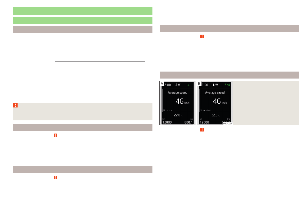
Information system
Driver information system
Introduction
This chapter contains information on the following subjects:
Door, luggage compartment or bonnet warning 39
Overspeed warning at 120 km/h 39
Auto-check control 39
Gear recommendation 39
Depending on the vehicle's equipment, the information system vie the display
of the instrument cluster provides the following information.
▶
Driving data (multifunction display) » page 40.
▶
Data relating to the Maxi DOT display » page 42.
▶
Service interval display » page 46.
▶
Selector lever positions for an automatic gearbox » page 104.
▶
Information and alerts in the Assist systems » page 109.
WARNING
Concentrate fully at all times on your driving! As the driver you are fully re-
sponsible for the operation of your vehicle.
Door, luggage compartment or bonnet warning
Read and observe on page 39 first.
If at least one door is open, or the boot or bonnet is open, the display indicates
the relevant open door or boot/bonnet.
An acoustic signal will also sound if you drive the vehicle above 6 km/h when a
door is open.
Overspeed warning at 120 km/h
Read and observe
on page 39 first.
This function only applies to certain countries.
An audible warning signal will sound when the vehicle speed exceeds 120
km/h. The audible warning signal is switched off when the vehicle speed falls
below 120 km/h.
Auto-check control
Read and observe on page 39 first.
Certain functions and conditions of individual vehicle systems are checked
continuously when the ignition is switched on.
As long as the faults are not rectified the messages are always shown. After
they are displayed for the first time, the warning lights
(danger) or
(warn-
ing) continue to be indicated without information for the driver.
Gear recommendation
Fig. 27
Information on the selected
gear / Gear recommendation
Read and observe on page 39 first.
A suitable gear is engaged, if necessary, a recommendation to shift to high or
lower gear is displayed.
A suitably engaged gear helps to reduce the fuel consumption and assist the
service life and reliability of the engine.
Display » Fig. 27
Optimal gear engaged
Recommended gear
Recommended gear
Besides showing the engaged gear, the arrow icon
and the recommended
gear are displayed.
For instance, if
appears in this display, this means it is recommended that
you shift from gear 3 to gear 4.
39
Information system
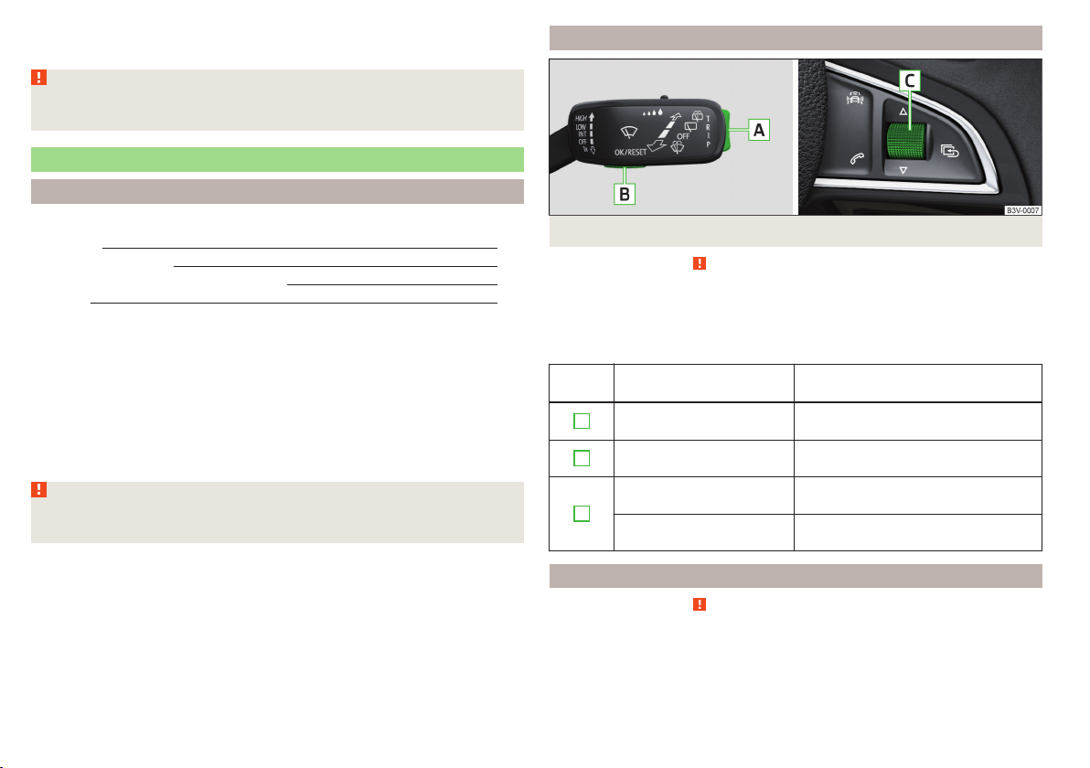
For vehicles with automatic transmission the recommended gear will be
shown provided the mode for manual switching (Tiptronic) is selected.
WARNING
The driver is always responsible for selecting the correct gear in different
driving situations, such as overtaking.
Driving data (Multifunction display)
Introduction
This chapter contains information on the following subjects:
Operation
40
Information overview
40
Warning when exceeding the set speed 41
Memory 42
The driving data display is only possible with the ignition switched on.
After the ignition is switched on, the function that was last selected before
switching off the ignition is displayed.
For vehicles with a MAXI DOT display, the menu item
Driving data
must be selec-
ted and confirmed in the main menu » page 42, MAXI DOT display.
The setting of the units and the switching on / off the display of some infor-
mation is available possible in the Infotainment » Owner´s Manual Infotain-
ment, chapter CAR - Vehicle Settings.
WARNING
Concentrate fully at all times on your driving! As the driver you are fully re-
sponsible for the operation of your vehicle.
Operation
Fig. 28 Buttons/dial: on the control lever/multifunction steering wheel
Read and observe
on page 40 first.
The selection as well as the settings of the data values can be operated with
the buttons on the operating lever as well as on the multi-function steering
wheel » Fig. 28.
Description of the operation
Button /
dial
Action Operation
A
Briefly press at the top
or down
Select data / set data values
B
Press briefly
View information / confirm specifica-
tion
C
Turn upwards or down-
wards
Select data / set data values
Press briefly
View information / confirm specifica-
tion
Information overview
Read and observe on page 40 first.
Overview of driving data (depending on the vehicle equipment).
Range
The detail provides information about the distance in km, that can be travelled
with the current tank and with the same driving style.
40
Using the system

If you drive more efficiently this value can increase.
Average fuel consumption
The indication is calculated continuously since the last deletion of the memory.
After erasing the memory, no data will appear for the first 100 m driven.
Current fuel consumption
You can use this information to adapt your driving style to the desired fuel
consumption.
When the vehicle is stationary or slowly moving the fuel consumption is dis-
played in l/h (on models for some countries the following appears --,- km/l).
Oil temperature
If the engine oil temperature is in the range of 80-110 °C, the engine operating
temperature has been reached.
If the oil temperature is lower than 80 °C or above 110 °C, avoid high engine
revs, full throttle and high engine loads.
If the oil temperature is lower than 50 °C or if there is a fault in the system for
checking the oil temperature
are displayed instead of the oil temperature.
Warning against excessive speeds
Set the speed limit, for example, for the maximum permissible speed in town
» page 41.
Current driving speed
The display is identical to the display on the speedometer.
Average speed
The indication is calculated continuously since the last deletion of the memory.
After erasing the memory, no data will appear for the first 300 m driven.
Distance travelled
The distance travelled since the memory was last erased is displayed.
The maximum distance indicated is 9,999 km. The indicator is automatically
set back to zero if this period is exceeded.
Driving time
The time travelled since the memory was last erased is displayed.
The maximum distance indicated is 99 hours and 59 minutes. The indicator is
automatically set back to zero if this period is exceeded.
Coolant temperature
If the engine oil temperature is in the range 80-110 °C, the engine operating
temperature is reached.
If the temperature lies below 80 °C or above 110 °C, avoid high engine revs, full
throttle and high engine loads.
Warning when exceeding the set speed
Read and observe on page 40 first.
The system offers the possibility to set a speed limit beyond which an audible
alarm will sound and the following warning message appears.
Speed ... exceeded.
SPEED TOO HIGH
Adjust the speed limit while the vehicle is stationary
›
Select the menu item
Warning at
at (
) or
(
) and confirm.
›
Set the desired speed limit.
›
Confirm the set value, or wait several seconds; your settings will be saved
automatically.
The speed limit can be set in 5 km/h intervals.
Adjusting the speed limit while the vehicle is moving
›
Select the menu item
Warning at
at (
) or
(
) and confirm.
›
Drive at the desired speed.
›
Confirm the current speed as the speed limit.
The set speed limit can be manually adjusted later if needed.
Deactivate speed limit
›
Select the menu item
Warning at
at (
) or
(
) and confirm.
›
Confirm the stored value of the speed limits.
The speed limit will be disabled.
The set driving mode remains stored even after switching the ignition on and
off. After a gap between driving exceeding 2 hours, the pre-set speed limit is
deactivated.
41
Information system
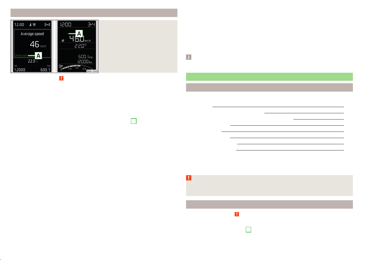
Memory
Fig. 29
Memory display: MAXI DOT dis-
play (
) / Segment display (
)
Read and observe on page 40 first.
Following driving data is stored in three locations.
▶
Average fuel consumption.
▶
Distance driven.
▶
Average speed.
▶
Driving time.
Display of the selected memory in the display at position
A
» Fig. 29.
Since start
(
) or “1” (
)
The memory collates the driving information from the moment the ignition is
switched on until it is switched off.
New data will also flow into the calculation of the current driving information if
the trip is continued within 2 hours after switching off the ignition.
If the trip is interrupted for more than 2 hours, the memory is automatically
erased.
Long-term
(
) and “2” (
)
The memory gathers driving information from any number of individual jour-
neys up to a total of 99 hours and 59 minutes driving or 9,999 kilometres driv-
en.
The indicator is automatically set back to zero if one of the indicated values is
exceeded.
Since refuel
(
) or “3” (
)
The memory gathers driving information since the last refuelling.
The memory is erased automatically the next time you fill up.
Select memory
▶
Select the driving data information desired.
▶
Confirm details again to select the desired memory.
Resetting
▶
Select the driving data information desired.
▶
Select the desired memory.
▶
Reset the selected memory with a long acknowledgement (holding pressed).
Note
Disconnecting the vehicle battery will delete all memory data.
MAXI DOT display
Introduction
This chapter contains information on the following subjects:
Main menu 42
Operation using the operating lever
43
Operation using the multifunction steering wheel
43
Menu item
Navigation
44
Menu item
Audio
44
Menu item
Telephone
45
Menu item
Assist systems
45
Compass point display
45
The MAXI DOT display (hereinafter referred to as the display) is a user interface
which, depending on the equipment configuration, delivers information about
the Infotainment, the multifunction display, the assistance systems, etc.
WARNING
Concentrate fully at all times on your driving! As the driver you are fully re-
sponsible for the operation of your vehicle.
Main menu
Read and observe
on page 42 first.
Call up the main menu
›
Press and hold the button
A
on the operating lever » Fig. 30 on page 43.
or
42
Using the system
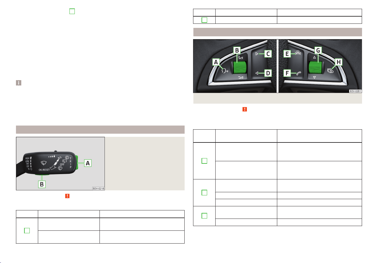
›
Press and hold the dial
G
on the multifunction steering wheel » Fig. 31 on
page 43.
Main menu items (depending on vehicle equipment)
■
Driving data
» page 40
■
Assist systems
» page 45
■
Navigation
» page 44
■
Audio
» page 44
■
Telephone
» page 45;
■
Vehicle
» page 39, Auto-check control
The menus can be opened using the buttons on the control lever » Fig. 30 on
page 43 or on the multi-function steering wheel » Fig. 31 on page 43.
Note
■
If warning messages are displayed, these messages must first be confirmed
to access the main menu.
■
The travel mode can be set in the Infotainment » Owner´s Manual Infotain-
ment, chapter Vehicle settings (SET-UP button).
■
For vehicles without Infotainment, the display language can only be adjusted
by a specialist garage.
Operation using the operating lever
Fig. 30
Buttons: on the operating lever
Read and observe on page 42 first.
Description of the operation by means of the buttons on the operating lever
Button Action Operation
A
Briefly press at the top
or down
Switch between menu items / menus
Press and hold at the top
or down
Display main menu
Button Action Operation
B
Press briefly Confirm menu item / menu
Operation using the multifunction steering wheel
Fig. 31
Buttons/dials: on the multifunction steering wheel
Read and observe on page 42 first.
Description of the operation by means of the buttons/dials on the multi-
function steering wheel
Button /
dial
Action Operation
A
Press briefly
Voice control on/off / Sound off /on
(applies to vehicles without voice con-
trol)
Press and hold button
Activate the voice control of
theSmartLink
a)
function (if supported
by the connected device)
B
Press briefly
Switch sound on/off / Switch track
playback on/off
Turn up Increase volume
Turn down Decrease volume
C
Press briefly
To the next radio channel or change
to the playback track
Press and hold button Fast forward within the track
43
Information system
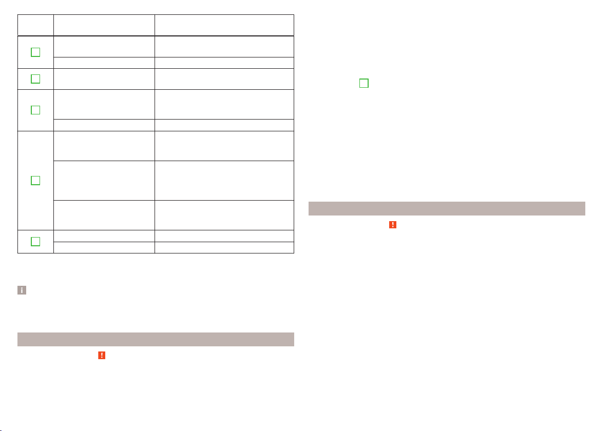
Button /
dial
Action Operation
D
Press briefly
to the previous radio channel or
change to the playback track
b)
Press and hold button Fast reverse within the track
E
Press briefly
Select menu item
Assist systems
» page 45
F
Press briefly
Take the call / end the call / Menu
Tel-
ephone
display / display call list / call
the selected contact
Press and hold button Reject call / Redial last call
G
Press briefly
Confirm menu item / menu / Repeat
the last navigation announcement or
clarify / interrupt traffic report
Turn up
Previous menu item / track
b)
/ Show
available list (e.g. list of available
channels, list of the last destinations,
call list)
Turn down
Next menu item / track / View availa-
ble list (e.g. List of available channels,
list the last destinations, call list)
H
Press briefly Return to a previous level in the menu
Press and hold button Display main menu
a)
» Infotainment Owner's Manual
b)
Valid for pressing within about 4 s from the beginning of the given track. Pressing after about 4 seconds
from the beginning of the track, starts the playback from the beginning of the track.
Note
Depending on equipment not all functions may be available. The system can
indicate this fact by a text message in the display of the instrument cluster or
in the Infotainment display.
Menu item
Navigation
Read and observe on page 42 first.
Select menu item
Navigation
›
Select and confirm
Navigation
in the main menu.
Route guidance takes place
Graphical driving recommendations and other route and destination informa-
tion are displayed after selection.
No route guidance is carried out
A compass/vehicle symbol is shown to display the current vehicle position in
relation to the compass after selection.
Then turn dial
G
» Fig. 31 on page 43 on the multifunction steering wheel to
display the
Last destinations
menu.
The menu shows the
Home address
menu item and a list of recent destinations.
When you select one of the menu items, the destination name and the follow-
ing items are displayed.
■
OK
- Start navigation
■
Cancel
- Return to the Navigation menu – the compass/vehicle symbol will be
displayed
If the home address is not defined when the menu item
Home address
is selec-
ted, the following message appears:
Please enter the home address on the infotain-
ment system.
Menu item
Audio
Read and observe on page 42 first.
Select menu item
Audio
›
Select and confirm
Audio
in the main menu.
The following information can be displayed in the display.
■
Radio
■
Currently played station (name/frequency):
■
The selected frequency range (e.g. FM) optionally with the number of the
station button (e.g. FM3), if the station is stored in the memory list
■
List of available station (if more than 5 stations can be received);
■
TP traffic announcements.
■
Media
■
Name of the track being played, if necessary, further information regarding
title (e.g. artist, album name), if this information is stored as a so called ID3
tag on the audio source.
44
Using the system
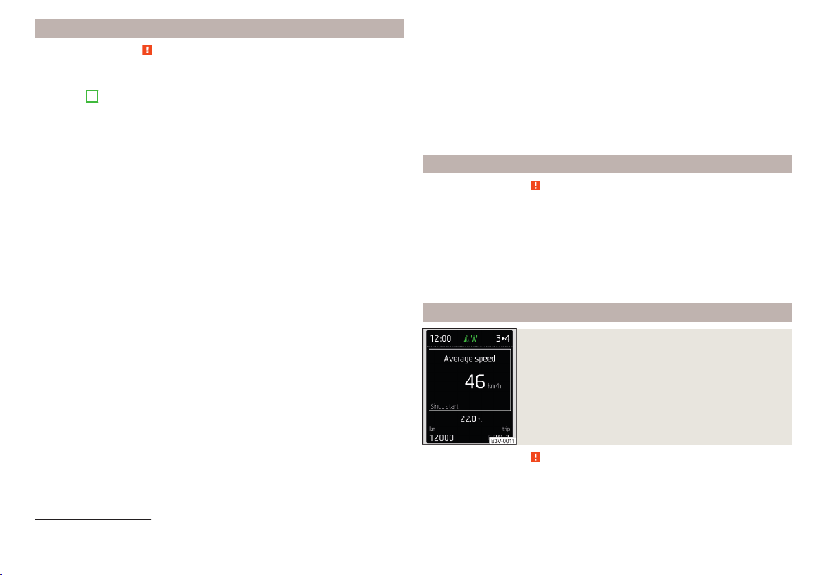
Menu item
Telephone
Read and observe on page 42 first.
Select menu item
Telephone
›
Select and confirm
Telephone
in the main menu.
›
Turn dial
G
» Fig. 31 on page 43.
The system displays a call list.
If the call list includes no entries, the following message appears
No entries avail-
able.
The following symbols are displayed next to each entry in the call list.
Incoming call
Outgoing call
Missed call
Outgoing call
■
Cancel
- Ends the call
Incoming call
■
Answer
– Answer incoming call
■
Reject
– Reject incoming call
■
Ignore
- Mute the ringer (this option is only available if there is no other call)
Ongoing conversation or conference call
■
Hang up
- End a call
■
Hold
– Hold a call
■
Continue
– Continue held call
■
Mic. off
– Microphone off
■
Mic. on
– Microphone on
■
Private
– Switch the call to the telephone
■
Hands-free
– Toggles the call to the device
Ongoing and held call
■
Hang up
– End an ongoing call
■
Call wait.
– Switch to a held call
■
Conference
– Make a conference call
1)
■
Mic. off
– Microphone off
■
Mic. on
– Microphone on
■
Private
– Switch ongoing call to the telephone
■
Hands-free
– Switch ongoing call to the device
Symbols in the display
Charge status of the telephone battery
1)
Signal strength
1)
A telephone is connected to the unit
Missed calls (if there are several missed calls, the number of calls is shown
next to the symbol)
Switch-off microphone
Menu item
Assist systems
Read and observe on page 42 first.
Select menu item
Assist systems
›
Select and confirm
Assist systems
in the main menu.
or
›
Press the button on the
multi-function steering wheel .
In the
Assist systems
menu item, the Front Assist system can be activated/deac-
tivated.
Compass point display
Fig. 32
Compass display
Read and observe on page 42 first.
Applies to vehicles with factory-installed navigation system.
1)
This function is only supported by some mobile phones.
45
Information system
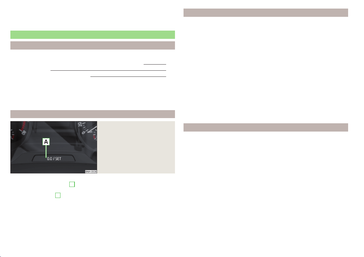
In the display when the ignition is on, an arrow symbol as well as an abbrevia-
tion for the corresponding direction (in relation to the current direction of trav-
el) are displayed » Fig. 32.
Service interval display
Introduction
This chapter contains information on the following subjects:
Displaying the distance and days until the next service interval 46
Service messages 46
Resetting the service interval display 46
The service interval display shows the time and mileage to the next service
event.
The information regarding the service intervals can be found in the service
schedule.
Displaying the distance and days until the next service interval
Fig. 33
Button in the instrument cluster
›
Switch on the ignition.
›
Press and hold the button
A
» Fig. 33 until the
Service
is shown in the dis-
play.
›
Release the button
A
.
In the display the symbol
appears for 4 seconds and the following message
for the kilometre or days to the next service appointment.
Oil service … / … Inspection … / …
OIL SERV_ IN … OR … INSPECT_ IN … OR …
Service messages
Messages before reaching the scheduled service date
Before the next service date has been reached, the symbol
as well as a mes-
sage about the mileage or days until the next service event appears in the dis-
play after switching on the ignition.
Messages upon reaching scheduled service date
Once the service interval is reached, the icon
appears in the display after the
ignition is switched on, as well as the following message, for example.
Oil service now!
OIL SERVICE NOW
or
Inspection now!
INSPECTION NOW
or
Oil service and inspection now!
OIL SERVICE + INSP_ NOW
Resetting the service interval display
We recommend that the display reset is completed by a specialist garage.
We recommend that you do not reset the service interval display yourself. In-
correctly setting the service interval display could cause problems to the vehi-
cle.
Variable service interval
For vehicles with variable service intervals, after resetting the oil change serv-
ice display in a specialist garage, the values of the new service interval are dis-
played, which are based on the previous operating conditions of the vehicle.
These values are then continuously matched according to the actual operating
conditions of the vehicle.
46
Using the system
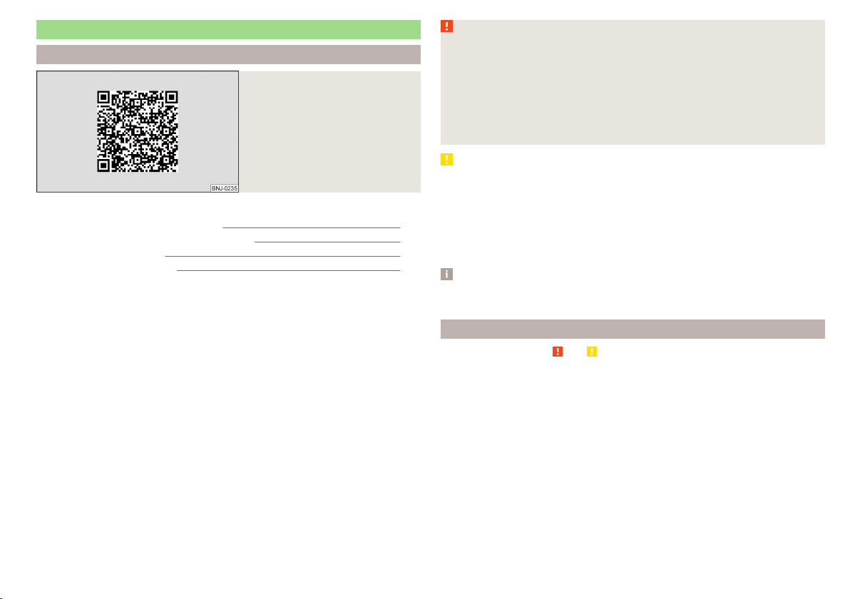
SmartGate
Introduction
Fig. 34
ŠKODA websites
This chapter contains information on the following subjects:
Connection to SmartGate using Wi-Fi 47
Connection to SmartGate using Wi-Fi Direct 48
SmartGate web interface 48
Password/PIN code change 49
SmartGate is a system that transmits certain driving data (such as fuel con-
sumption, speed or similar) via Wi-Fi or Wi-Fi Direct.
The ŠKODA compatible communications device (e.g. phone, tablet, notebook)
offer the possibility to further transmit the received data.
More information on available applications, a list of compatible communication
devices and information about SmartGate, can be found on the following
ŠKODA website » Fig. 34.
http://www.skoda-auto.com
WARNING
■
The general binding country-specific regulations for operating communi-
cation devices in the vehicle must be observed.
■
Never leave a communication device in the deployment area of an airbag,
on a seat, on the dash panel or any another area, from which it can be
thrown during a sudden braking manoeuvre, an accident or a collision - risk
of injury!
■
Never connect or disconnect a communication device while driving - risk
of accident!
CAUTION
■
To increase the access security to the transmitted vehicle data, once the
ŠKODA application has been started, you are requested to change the pass-
word/PIN code if the default password/PIN code has not yet been changed
» page 49, Password/PIN code change. It is not possible to start the ŠKODA
application without having made this change.
■
ŠKODA accepts no responsibility for any problems caused by incompatibility
or improper functioning of the communication devices.
Note
The ŠKODA applications, support communications devices with the Android
operating system version 4.x.x and later and iOS 7.x.x and higher.
Connection to SmartGate using Wi-Fi
Read and observe
and on page 47 first.
Connecting to an Android communication device
›
Switch on the ignition.
›
Switch on the Wi-Fi on the communication device to be connected.
›
Start the SmartGate application using the communication device to be con-
nected.
›
Then follow the instructions in the manual, which are included in the
SmartGate application.
With SmartGate, a maximum of four communication devices can be connected
simultaneously using Wi-Fi, with as many launched ŠKODA applications as re-
quired.
47
Information system

Connecting to an iOS communication device
›
Switch on the ignition.
›
Switch on the Wi-Fi on the communication device to be connected.
›
Allow the communication device to be connected to search for available Wi-
Fi networks (see the Owner's Manual for the communication device to be
connected).
›
In the menu of the detected networks select “SmartGate_...”
1)
or “DIRECT
SmartGate_...”
1 )
.
›
Enter the password » page 49.
With SmartGate, a maximum of four communication devices can be connected
simultaneously using Wi-Fi. In these communication devices, up to four ŠKODA
applications can be started simultaneously.
Disconnection
Disconnection is possible in one of the following ways.
›
Switch off the ignition for longer than 5 seconds (for vehicles with a starter
button, switch off the engine and open the driver's door).
›
End the connection in the SmartGate application.
›
Switch off the Wi-Fi on the connected communication device.
Automatic connection
If the communication device has previously already been connected with
SmartGate, then the connection is automatically restored under the following
conditions.
The ignition is switched on.
The Wi-Fi on the communication device to be connected is switched on.
The communication device to be connected has stored the password re-
quired for the connection check.
Connection to SmartGate using Wi-Fi Direct
Read and observe and on page 47 first.
This type of connection is intended for communication devices running the
Android operating system.
Connection set-up
›
Switch on the ignition.
›
Start the SmartGate application using the communication device to be con-
nected.
›
Then follow the instructions in the manual, which are included in the
SmartGate application.
With SmartGate, a maximum of two communication devices can be connected
simultaneously using Wi-Fi Direct, with as many launched ŠKODA applications
as required.
If you want to connect to SmartGate in another vehicle, you must first end the
existing connection to the SmartGate application and then re-establish the
connection.
Disconnection
Disconnection is possible in one of the following ways.
›
Switch off the ignition for longer than 5 seconds (for vehicles with a starter
button, switch off the engine and open the driver's door).
›
End the connection in the SmartGate application.
›
Switch off the Wi-Fi on the connected communication device.
Automatic connection
If the communication device has previously already been connected with
SmartGate, then the connection is automatically restored after the ignition is
started.
SmartGate web interface
Read and observe and on page 47 first.
SmartGate parameters can be set in the SmartGate web interface.
The following address must be entered in the web browser of the connected
communication device via Wi-Fi.
HTTP://192.168.123.1
The setting changes are only effective after pressing the “Save” button and
then the “Reboot” button.
1)
The last 6 characters of the vehicle identification number of your vehicle are displayed at position ....
48
Using the system

Password/PIN code change
Read and observe and on page 47 first.
The factory set password for the Wi-Fi connection is the complete vehicle
identification number (upper case); the factory set PIN code for the Wi-Fi Direct
connection is the last 6 digits of the vehicle identification number.
After changing the password/PIN, the connection to SmartGate must be re-es-
tablished on the communication device to be connected using the new pass-
word or new PIN code.
If the password/PIN code is still set to the preset factory password/PIN code,
you are requested to change the password/PIN code after starting the ŠKODA
application. Without changing the password/PIN code, you are unable to use
the application.
Changing the password for the Wi-Fi connection
›
Open the SmartGate web interface.
›
In the “WPA / WPA2 key:” menu item, enter the new password (8 to 63 al-
phanumeric characters and special characters, upper and lower case).
›
Confirm the password change by tapping on the “Save” button.
›
Restart SmartGate by tapping on the “Reboot”
1)
button.
Changing the PIN code for the Wi-Fi Direct connection
›
Open the SmartGate web interface.
›
In the “WiFi Direct PIN:” menu item, enter the new PIN code (6 digits).
›
Confirm the PIN code change by tapping on the “Save” button.
›
Restart SmartGate by tapping on the “Reboot”
1)
button.
Note
If you have forgotten your password/PIN code for connecting to SmartGate,
SmartGate must be reset to the factory settings in a specialised workshop.
Unlocking and opening
Unlocking and locking
Introduction
This chapter contains information on the following subjects:
With the key on the lock cylinder unlock / lock 50
Unlocking/locking with the remote control key 50
Unlocking / locking - KESSY 51
Locking and unlocking the vehicle with the central locking button 51
Safe securing system 52
Individual settings 52
Opening/closing a door 53
Child safety lock 53
Malfunctions 53
Your car is equipped with a central locking system.
The central locking system allows you to lock and unlock all doors, the fuel fill-
er flap and boot lid at the same time. The functions of the central locking sys-
tem can be individually adjusted » page 52.
After unlocking, depending on vehicle equipment and setting the following is
valid for the central locking.
▶
The turn signal lights flash twice as confirmation that the vehicle has been
unlocked.
▶
The doors, the boot lid and the fuel filler flap are unlocked.
▶
The interior lamp illuminates.
▶
The SafeLock system is switched off.
▶
The indicator light in the driver door stops flashing.
▶
The anti-theft alarm system is deactivated.
After locking, depending on vehicle equipment and setting the following is
valid for the central locking.
▶
The turn signal lights flash once as confirmation that the vehicle has been
locked.
▶
The doors, the boot lid and the fuel filler flap are locked.
▶
The interior lamp goes out.
▶
The SafeLock system is switched on.
1)
If the “Reboot” interface is not displayed, you must manually restore the web browser display.
49
Unlocking and opening
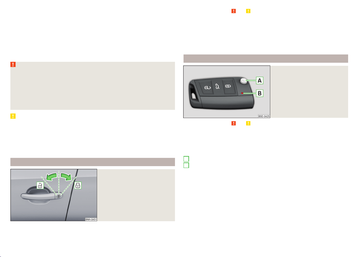
▶
The warning light in the driver door begins flashing.
▶
The anti-theft alarm system is activated.
If the doors or the boot lid remain open after the vehicle doors have been
locked, the turn signal lights do not flash until they have been closed.
Protection against unwanted vehicle unlocking
If you unlock the vehicle and do not open a door or the boot lid within the next
45 seconds, the vehicle will lock again automatically and the SafeLock system
or anti-theft alarm system will be switched on.
WARNING
■
Never leave the key in the vehicle when you exit the vehicle. Unauthor-
ized persons, such as children, for example, could lock the car, turn on the
ignition or start the engine - there is a danger of injury and accidents!
■
When leaving the vehicle, never leave persons who are not completely in-
dependent, such as children, unattended in the vehicle. These individuals
might not be able to leave the vehicle on their own or to help themselves.
Can be fatal at very high or very low temperatures!
CAUTION
■
Each key contains electronic components; therefore it must be protected
against moisture and severe shocks.
■
Keep the groove of the keys absolutely clean. Impurities (textile fibres, dust,
etc.) have a negative effect on the functionality of the locking cylinder and ig-
nition lock.
■
If the driver's door has been opened, the vehicle cannot be locked.
With the key on the lock cylinder unlock / lock
Fig. 35
Left side of the vehicle: Turning
the key for unlocking and locking
the vehicle
Read and observe and on page 50 first.
The key allows you to unlock or lock the vehicle via the lock cylinder in the
driver's door.
Unlocking/locking the vehicle with the key » Fig. 35
Unlocking the vehicle
Locking the vehicle
Unlocking/locking with the remote control key
Fig. 36
Remote control key
Read and observe and on page 50 first.
Function and description of the key » Fig. 36
Unlocking the vehicle
Locking the vehicle
Unlocking / locking the boot lid
Button for the fold out / fold in of the key
Warning light for the battery condition
If the red warning light does not flash when you press a button on the key,
the battery is discharged.
Unlocking / locking the boot lid
By pressing briefly symbol key
the boot lid unlocks.
Press and hold the symbol key
to release the lid (partially opened).
If the lid is unlocked or released with the key symbol
on the key, then the
lid is automatically locked after closing. You can set a lock delay » page 55.
A
B
50
Using the system
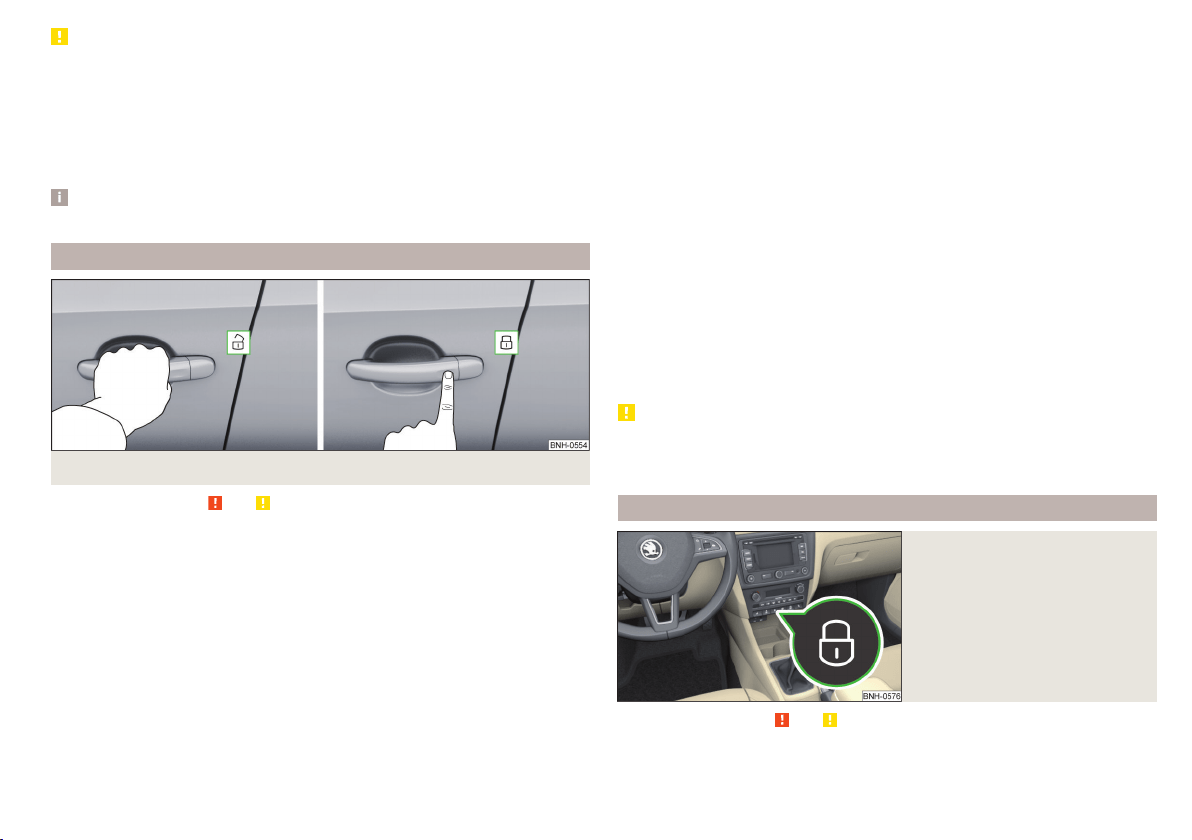
CAUTION
■
Operation of the remote control may temporarily be affected by signal inter-
ference from transmitters close to the car and which operate in the same fre-
quency range (e.g. mobile phone, TV transmitter).
■
The operating range of the remote control key is approx. 30 m. But this range
of the remote control can be reduced if the batteries are weak.
■
The battery must be replaced if the central locking does react to the remote
control at less than around 3 metres away » page 171.
Note
The remote control will operate only when visual contact with the vehicle.
Unlocking / locking - KESSY
Fig. 37 The front door handle
Read and observe and on page 50 first.
The KESSY system (Keyless Entry Start Exit System) enables unlocking and
locking of the vehicle without actively using the remote control key » Fig. 37.
The sensors for unlocking or locking are located in the handle of the front
door.
Unlocking
Locking
When unlocking or locking the vehicle, the key must be at a maximum distance
of approximately 1.5 m from the front door handle.
Locking
On vehicles fitted with automatic gearbox, the selector lever must be moved
into the position P before unlocking.
The vehicle cannot be locked if the ignition has not been turned off.
After locking the car, it is not possible to unlock within the next 2 seconds by
touching the door handle. This can be used to check whether the vehicle is
locked.
Protection against inadvertently locking the key in the vehicle
If one of the doors is closed only after locking the vehicle and the key with
which the vehicle was locked remains in the passenger compartment, the ve-
hicle will be unlocked automatically. After unlocking the vehicle again, the turn
signal lights will flash four times. If no door is opened within 45 seconds, the
vehicle is automatically locked again.
If the boot lid is closed only after locking the vehicle and the key with which
the vehicle was locked remains in the luggage compartment, the lid will be un-
locked (partially opened). The turn signal lights flash four times as an indica-
tion that the boot lid has been unlocked again. The luggage compartment lid
remains released(partially open).
The following message is shown in the information cluster display.
Key in vehicle.
KEY IN VEHICLE
CAUTION
■
Some types of gloves can affect the unlocking or locking device in the door
handle.
■
After leaving the car there is no automatic locking.
Locking and unlocking the vehicle with the central locking button
Fig. 38
Central locking button
Read and observe and on page 50 first.
When the vehicle has not been locked from outside and no door is open the
button
» Fig. 38 can be used to unlock or lock the vehicle.
51
Unlocking and opening

The locking is shown by the illuminated symbol .
The central locking system also operates if the ignition is switched off.
The following applies after locking.
▶
Opening the doors and the boot lid from the outside is not possible.
▶
The doors can be unlocked and opened from the inside by a single pull on the
opening lever of the respective door.
WARNING
Doors locked from the inside make it difficult for rescuers to get into the
vehicle in an emergency – risk to life!
Safe securing system
Read and observe
and on page 50 first.
As soon as the vehicle is locked from the outside, the safe lock prevents open-
ing the doors from the inside.
This function is pointed out by the following message on the display of the in-
strument cluster after switching out the ignition.
Check SAFELOCK! Owner's manual!
CHECK SAFELOCK
After locking the vehicle, the warning light in the driver's door flashes for
around 2 seconds in quick succession, afterwards it begins to flash evenly at
longer intervals.
Switching off
The safe lock can be switched off in one of the following ways.
▶
By locking twice within 2 seconds.
▶
By disabling the button for interior monitoring and anti-towing » page 54.
The indicator light in the driver door flashes for about 2 seconds fast, goes out
and starts to flash at longer intervals after about 30 seconds.
If the vehicle is locked and the safe securing system is switched off, the door
can be opened separately from the inside by a single pull on opening lever.
The SafeLock switches on the next time the vehicle is locked.
WARNING
If the car is locked and the safe securing system activated, no people must
remain in the car as it will then not be possible to either unlock a door or
open a window from the inside. The locked doors make it more difficult for
rescuers to get into the vehicle in an emergency – risk to life!
Individual settings
Read and observe and on page 50 first.
The following functions of the central locking can be set in the Infotainment
» Owner´s Manual Infotainment, chapter CAR - Vehicle Settings or be set by a
specialist company.
Opening a single door
The function allows you to unlock only the driver's door and the fuel filler flap
with the radio remote control. KESSY makes possible the release of individual
doors as well as the fuel filler flap, depending on the area in which the key is
located. The other doors and the boot lid are only unlocked when the unlock-
ing is repeated.
Unlocking a vehicle side door
This function enables you to unlock both doors on the driver's side and the
fuel filler flap with the radio remote control unit. KESSY makes possible the re-
lease of both doors on one side as well as the fuel filler flap, depending on the
area in which the key is located. The other doors and the boot lid are only un-
locked when the unlocking is repeated.
Unlock all doors
The function allows you to unlock all doors, the boot lid and the fuel filler flap.
Automatic locking/unlocking
This function allows you to lock all doors and the boot lid from a speed of
about 15 km/h. The button in the handle of the boot lid is deactivated.
Renewed automatic unlocking of all doors as well as the luggage compartment
door when removing the ignition key or by opening any of the doors. In vehi-
cles with the system KESSY this is when any door is opened.
The vehicle can also be unlocked by pressing the central locking button
» page 51.
52
Using the system
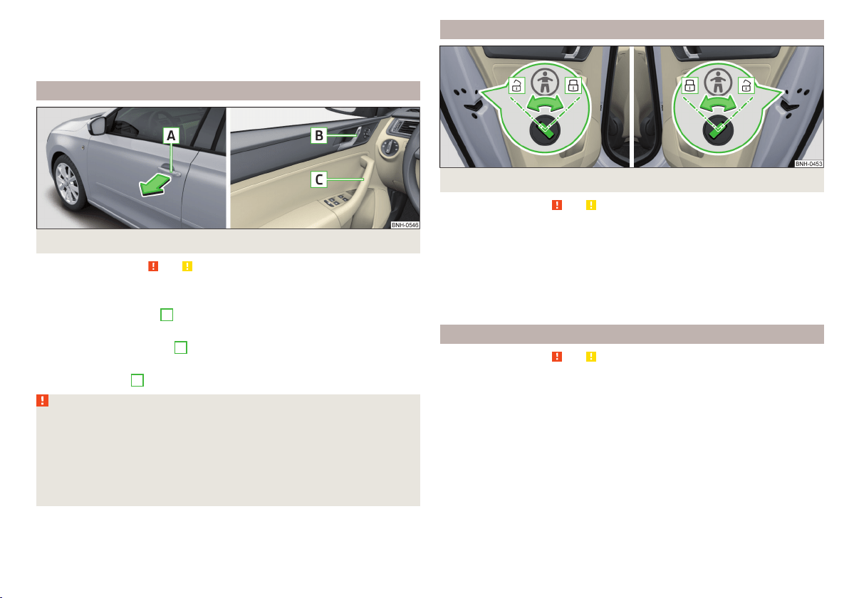
Acoustic signals when locking / unlocking
For vehicles with an anti-theft alarm system, the acoustic signals can be ena-
bled / disabled in the Infotainment » Owner´s Manual Infotainment, chap-
ter CAR - Vehicle Settings or be set by a specialist garage.
Opening/closing a door
Fig. 39
Door handle/door opening lever
Read and observe and on page 50 first.
Opening from the outside
›
Unlock the vehicle.
›
Pull on the door handle
A
in the direction of the arrow » Fig. 39.
Opening from the inside
›
Pull on door opening lever
B
of the door and push the door away from you.
Closing from the inside
›
Grasp pull handle
C
and close the door.
WARNING
■
Make sure that the door has closed correctly as it can open suddenly
while driving – risk of death!
■
Only open and close the door when there is no one in the opening/closing
range – risk of injury!
■
An opened door can close automatically if there is a strong wind or the
vehicle is on an incline – risk of injury!
■
Never drive with the doors open - there is a risk of death!
Child safety lock
Fig. 40 Rear door: Child safety system switch on / off
Read and observe
and on page 50 first.
The child safety lock prevents the rear door from being opened from the in-
side. The door can only be opened from the outside.
Switching the child safety system on/off » Fig. 40
Switching on
Switching off
You can switch the child safety lock on and off using the vehicle key.
Malfunctions
Read and observe and on page 50 first.
Fault with the central locking
If the indicator light in the driver's door initially flashes quickly for around 2
seconds, and then lights up for 30 seconds without interruption before flash-
ing again slowly, you will need to seek the assistance of a specialist garage.
In the event of a fault in the central locking system, only the driver's door can
be locked or unlocked with the key. The other doors and the boot lid can be
locked or unlocked manually.
▶
Locking door » page 172.
▶
Unlocking the boot lid » page 172.
53
Unlocking and opening
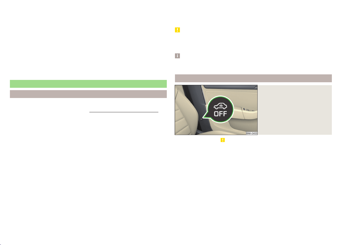
Failure of the system KESSY
If the following message is displayed in the display of the instrument cluster,
then help is required from a specialist company.
Keyless access system faulty.
KEYLESS ACCESS SYSTEM FAULTY
Key battery discharged
If the voltage of the key battery is too low, the following message appears in
the display of the instrument cluster.
Change the key battery!
KEY BATTERY PLEASE CHANGE
Replace the battery » page 171.
Anti-theft alarm system
Introduction
This chapter contains information on the following subjects:
Interior monitor and towing protection
54
The anti-theft alarm system (hereinafter referred to as the alarm system) in-
creases protection against theft and break-in attempts into the vehicle.
The alarm system is activated automatically approximately 30 seconds after
the vehicle is locked. This is automatically disabled after release.
The alarm system triggers audible and visual signals if an attempt is made to
break into the vehicle (hereafter referred to as alarm).
Triggering the alarm
The alarm is triggered when the following unauthorized actions are carried out
on the locked vehicle.
▶
Opening the bonnet.
▶
Opening the boot lid.
▶
Opening the doors.
▶
Manipulation of the ignition lock.
▶
Towing the vehicle.
▶
Movement in the vehicle.
▶
Sudden and significant voltage drop of the electrical system.
▶
Uncoupling the trailer.
If the driver's door of a vehicle is unlocked and opened by the lock cylinder,
then the alarm is triggered.
Switching off the alarm
The alarm is turned off by pressing the button on the key or switching on
the ignition.
CAUTION
Before leaving the vehicle, it must be checked that all of the windows, doors
and the sliding/tilting roof are locked in order to ensure the full functionality of
the anti-theft alarm system.
Note
The alarm system has its own power source. The working life of the power
supply source is 5 years.
Interior monitor and towing protection
Fig. 41
Button for interior monitor and
towing protection
Read and observe on page 54 first.
The interior monitor detects movements inside the locked vehicle and then
triggers the alarm.
The anti-towing detects tilts in the locked vehicle and then triggers the alarm.
Deactivate the interior monitor and the towing protection if there is a possibili-
ty of the alarm being triggered by movements (e.g. by children or animals)
within the vehicle interior or if the vehicle has to be transported (e.g. by train
or ship) or towed.
Deactivation
›
Switch off the ignition.
›
Open the driver door.
›
Press the symbol key
on the B column of the driver's side » Fig. 41.
The illumination of the symbol
in the button changes from red to orange.
›
Lock the vehicle within 30 seconds.
54
Using the system
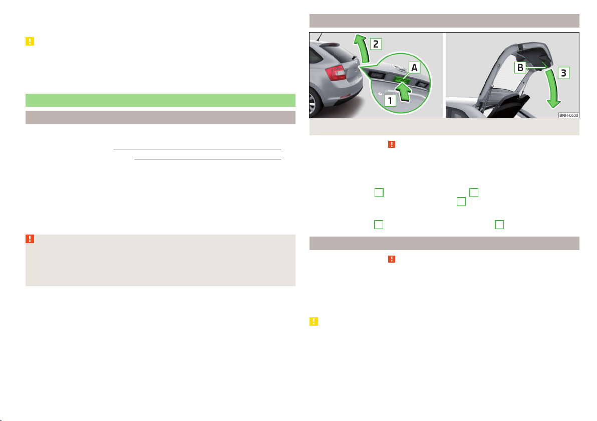
By disabling the interior monitoring and the anti-towing the safe lock is
switched off.
CAUTION
The opened glasses storage compartment reduces the effectiveness of the in-
terior monitor. To ensure the full functionality of the interior monitor, the
glasses storage compartment must always be closed before locking the vehi-
cle.
Luggage compartment lid
Introduction
This chapter contains information on the following subjects:
Boot lid opening/closing
55
Delayed locking of the boot lid
55
When closing the boot lid does do not press on the rear window.
Ensure that the lock is properly engaged after closing the boot lid.
The function of the button in the grip above the licence plate is deactivated
when starting off or at a speed of 5 km/hour or more for vehicles with central
locking. The function is restored after the vehicle stops and the door is
opened.
WARNING
■
Never drive with the boot lid open or unlatched, as otherwise exhaust
gases may get into the interior of the vehicle – risk of poisoning!
■
Make sure that when closing the boot lid, no body parts are crushed -
there is danger of injury!
Boot lid opening/closing
Fig. 42 Opening / closing tailgate
Read and observe
on page 55 first.
After unlocking the vehicle, the boot lid can be opened with the button in the
handle above the number plate.
Opening
›
Press the button
A
in the direction of arrow
1
» Fig. 42.
›
Raise the lid in the direction of the arrow
2
.
Closing
›
Grasp the mount
B
and lift in the direction of arrow
3
.
Delayed locking of the boot lid
Read and observe on page 55 first.
If the boot lid is unlocked with the symbol key
on the key, then the door is
automatically locked after closing.
The period after which the boot lid is locked automatically can be extended by
a specialist garage.
CAUTION
There is a risk of unwanted entry into the vehicle before the boot lid is locked
automatically. We therefore recommend locking the vehicle with the symbol
key
on the key.
55
Unlocking and opening
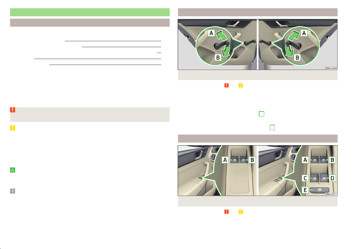
Window operations
Introduction
This chapter contains information on the following subjects:
Mechanical window lefter
56
Electric WindowsElectric Windows 56
Opening the windows in the front passenger door and in the rear doors 57
Force limit 58
Operational faults 58
The window can be operated mechanically by means of the handle attached to
the respective door panel.
Depending on equipment the windows can be operated electrically from the
following locations; the window in the front doors or all windows from the
driver's seat and also via the buttons for the windows in the passenger door or
the rear doors.
WARNING
The windows should nevertheless be closed carefully – risk of injury!
CAUTION
■
In the event that the windows are frozen, first of all eliminate the ice
» page 136, Windows and external mirrors and only then operate the electri-
cal power windows. Otherwise, the window sealing and the electrical power
window mechanism could be damaged.
■
Make sure that the windows are closed whenever you leave the locked vehi-
cle.
For the sake of the environment
At high speeds you should keep the windows closed to prevent unnecessarily
high fuel consumption.
Note
When driving always use the existing heating, air conditioning and ventilation
system for ventilating the interior of the vehicle. If the windows are opened,
dust as well as other dirt can get into the vehicle and in addition the wind
noise is more at certain speeds.
Mechanical window lefter
Fig. 43 Window operation: left/right
Read and observe
and on page 56 first.
Using the respective window crank only one window can be operated mechan-
ically.
Opening
›
Lift the crank in the direction of arrow
A
» Fig. 43.
Closing
›
Turn the crank in the direction of the arrow
B
» Fig. 43.
Electric WindowsElectric Windows
Fig. 44
Buttons for window-openers: Version 1/version 2
Read and observe and on page 56 first.
The electrical power windows can only be operated when the ignition is
switched on.
56
Using the system
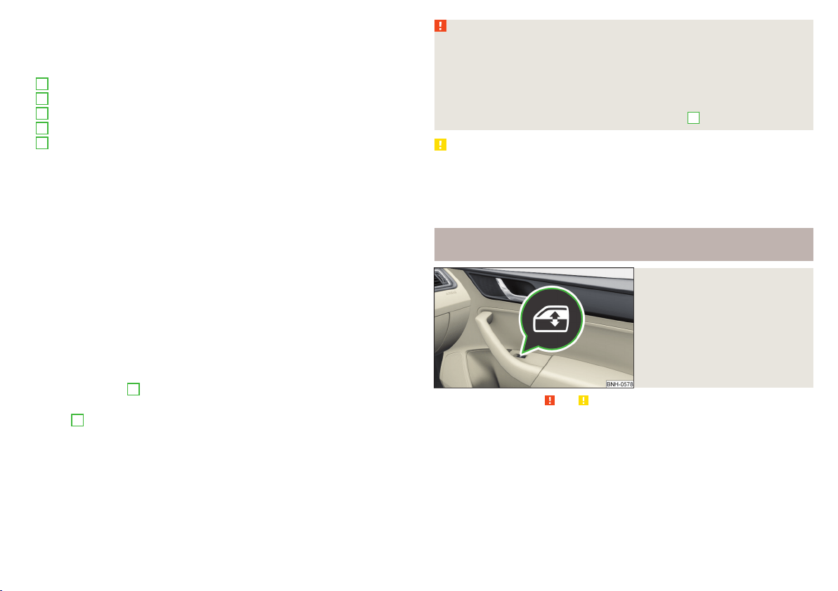
Depending on the equipment configuration, the front windows - Variant 1 or
the front and rear windows - Variant 2 be operated with the door buttons
» Fig. 44.
Electric power window buttons » Fig. 44
Left front door
Right front door
Left rear door
Right rear door
Disable / enable the buttons in the rear doors
Opening
›
Lightly press the appropriate button down and hold it until the window has
moved into the desired position.
Releasing the button causes the window to stop.
The driver's window can be completely opened automatically by briefly press-
ing the button as far as it will go. When pressed again or after withdrawing the
button, the window will stop.
Closing
›
Pull gently on the top edge of the corresponding button and hold until the
window has moved into the desired position.
Releasing the button causes the window to stop.
The driver's window can also be fully closed automatically by pulling the but-
ton up to the stop. When drawn again or after pressing the button, the win-
dow will stop.
Disable / enable the buttons in the rear doors
›
Press the button
E
» Fig. 44.
When the buttons are disabled in the rear doors, the warning light
in the
button
E
illuminates.
The window lift mechanism is equipped with protection against overheating.
Repeated opening and closing of the window can cause this mechanism to
overheat. If this happens, it will not be possible to operate the window for a
short time. You will be able to operate the window again as soon as the over-
heating protection has cooled down.
A
B
C
D
E
WARNING
■
Power windows in the driver's door and the rear doors are equipped with
a force limiter » page 58. If there is an obstacle, the closing process is
stopped and the window goes down by several centimetres. However, the
windows should be closed carefully – risk of injury!
■
If the rear seats are accommodating people who are not completely inde-
pendent, e.g. children, it is recommended that for safety reasons the but-
tons in the rear doors are disabled with the button
E
.
CAUTION
■
In the winter, ice on the window may cause greater resistance as the win-
dow is closed. The window will stop and open again by several centimetres.
■
Keep the windows clean to ensure the correct functionality of the electric
windows.
■
Always close the sliding/tilting roof before disconnecting the battery.
Opening the windows in the front passenger door and in the rear
doors
Fig. 45
Window winder button
Read and observe and on page 56 first.
There is a button in the front passenger door and in the rear doors for that
window.
Opening
›
Lightly press and hold the button until the window has moved into the de-
sired position.
Releasing the button causes the window to stop.
57
Unlocking and opening

Closing
›
Pull gently on the top edge of the button and hold it until the window has
moved into the desired position.
Releasing the button causes the window to stop.
Force limit
Read and observe and on page 56 first.
If there is an obstacle, the closing process is stopped and the window goes
down by several centimetres.
If the obstacle prevents the window from being closed during the next 10 sec-
onds, the closing process is interrupted once again and the window goes down
by several centimetres.
If you attempt to close the window again within 10 seconds of the window be-
ing moved down for the second time, even though the obstacle was not yet
been removed, the closing process is only stopped. During this time it is not
possible to automatically close the window. The force limiter is still switched
on.
The force limiter is only switched off if you attempt to close the window again
within the next 10 seconds - the window will now close with full force!
If you wait longer than 10 seconds, the force limiter is switched on again.
WARNING
The front passenger window with the electric power window » Fig. 45 on
page 57has no force limiter. The window should nevertheless be closed
carefully – risk of injury!
Operational faults
Read and observe and on page 56 first.
If the battery has been disconnected and reconnected, it is possible that the
automatic window lifter will not operate. The system must be activated.
Activation sequence:
›
Switch on the ignition.
›
Pull the top edge of the button and close the window.
›
Release the button.
›
Pull the relevant button upwards again for approx. 1 seconds, and keep it
pressed down.
58
Using the system
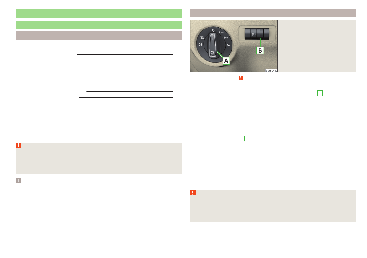
Lights and visibility
Lights
Introduction
This chapter contains information on the following subjects:
Operating the light function 59
Daytime running lights(DAY LIGHT) 60
Turn signal and main beam 60
Automatic driving lamp control 61
Front and rear fog lights 61
Fog lights with the CORNER function 62
COMING HOME / LEAVING HOME 62
Hazard warning light system 62
Parking light 63
Driving abroad 63
Unless otherwise stated, the lights only work when the ignition is switched on.
The layout of the controls on right-hand drive vehicles differs partially from
that shown in » Fig. 46 on page 59. The symbols which mark the individual
positions of the controls are identical.
WARNING
The automatic driving lamp control only operates as a support and
does not release the driver from his responsibility to check the lights and, if
necessary, to switch on the light depending on the prevailing light condi-
tions.
Note
■
The headlights may mist up temporarily. When the driving lights are switched
on, the light outlet surfaces are free from mist after a short period, although
the headlight lenses may still be misted up in the peripheral areas. This mist
has no influence on the life of the lighting system.
■
If the visibility is poor and the lights are not on (except daytime running light)
the brightness of the instrument lighting reduces to alert the driver to switch
on the lights in due time.
■
The brightness of the instrument lighting with the lights on (except daytime
running lights) can be set in the Infotainment » Owner´s Manual Infotainment,
chapter CAR - Vehicle Settings.
Operating the light function
Fig. 46
Light switch and control dial for
headlight range adjustment
Read and observe on page 59 first.
Switching lights on and off
Depending on the equipment configuration, the light switch
A
» Fig. 46 can be
turned to one of the following positions.
Switching off lights (except daytime running lights)
Switching lights on/off automatically » page 61
Switching on the side light or parking light » page 63
Switch on low beam
Headlight range control
Turning the rotary switch
B
» Fig. 46 from position to
gradually activates the
headlight beam control, thereby shortening the beam of light.
The positions of the width of illumination correspond approximately to the fol-
lowing car load.
Front seats occupied, boot empty
All seats occupied, boot empty
All seats occupied, boot loaded
Driver seat occupied, boot loaded
WARNING
Always adjust the headlight range control to meet the following conditions.
■
The vehicle does not dazzle other road users, especially oncoming vehi-
cles.
■
The beam range is sufficient for safe driving.
59
Lights and visibility
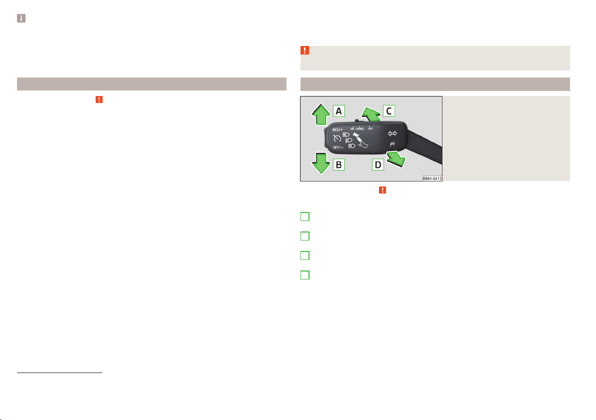
Note
■
The light switch is in position or and the ignition is turned off, the low
beam is switched off automatically
1)
and the status light is lit. The side light is
switched off when the ignition key is removed, for vehicles with the start but-
ton after switching off the ignition and opening the driver's door.
■
If there is a fault in the light switch, the low beam comes on automatically.
Daytime running lights(DAY LIGHT)
Read and observe on page 59 first.
The daytime running light (hereinafter referred to as "function") lights the
front and rear vehicle area (only valid for some countries).
The lights are switched on automatically if the following conditions are met.
The light switch is in the position
or
.
The ignition is switched on.
The function is activated.
Activating/deactivating function on vehicles with Infotainment
The function can be disabled/enabled in the Infotainment » Owner´s Manual
Infotainment, chapter CAR - vehicle settings.
Deactivating on vehicles without Infotainment
›
Switch off the ignition.
›
Pull the indicator / main beam lever towards the steering wheel, push down
and hold in this position.
›
Switch on the ignition.
›
Wait until the left turn signal light flashes 4 times.
›
Switch off the ignition – an audible signal sounds which confirms the deacti-
vation of the function.
›
Release the turn signal stalk.
Activating on vehicles without Infotainment
›
Switch off the ignition.
›
Pull the indicator / main beam lever towards the steering wheel, push up and
hold in this position.
›
Switch on the ignition.
›
Wait until the right turn signal light flashes 4 times.
›
Switch off the ignition – an audible signal sounds which confirms the activa-
tion of the function.
›
Release the turn signal stalk.
WARNING
Always switch on the low beam when visibility is poor.
Turn signal and main beam
Fig. 47
Operating lever: Turn signal and
main beam operation
Read and observe on page 59 first.
Operating lever positions » Fig. 47
When the right turn signal light is switched on, the warning light flashes in
the instrument cluster
When the left turn signal light is switched on, the warning light flashes in
the instrument cluster
When the main beam is switched on (spring setting), the warning light illu-
minates in the instrument cluster
Switching off main beam / switching on headlamp flasher (spring-loaded
position)
The main beam can only be switched on when the low beam lights are on.
The headlight flasher can be operated even if the ignition is switched off.
The turn signal light switches itself off automatically when driving around a
curve or after making a turn.
A
B
C
D
1)
Does not apply to the position , as long as the conditions are met for the COMING HOME function
» page 62.
60
Using the system
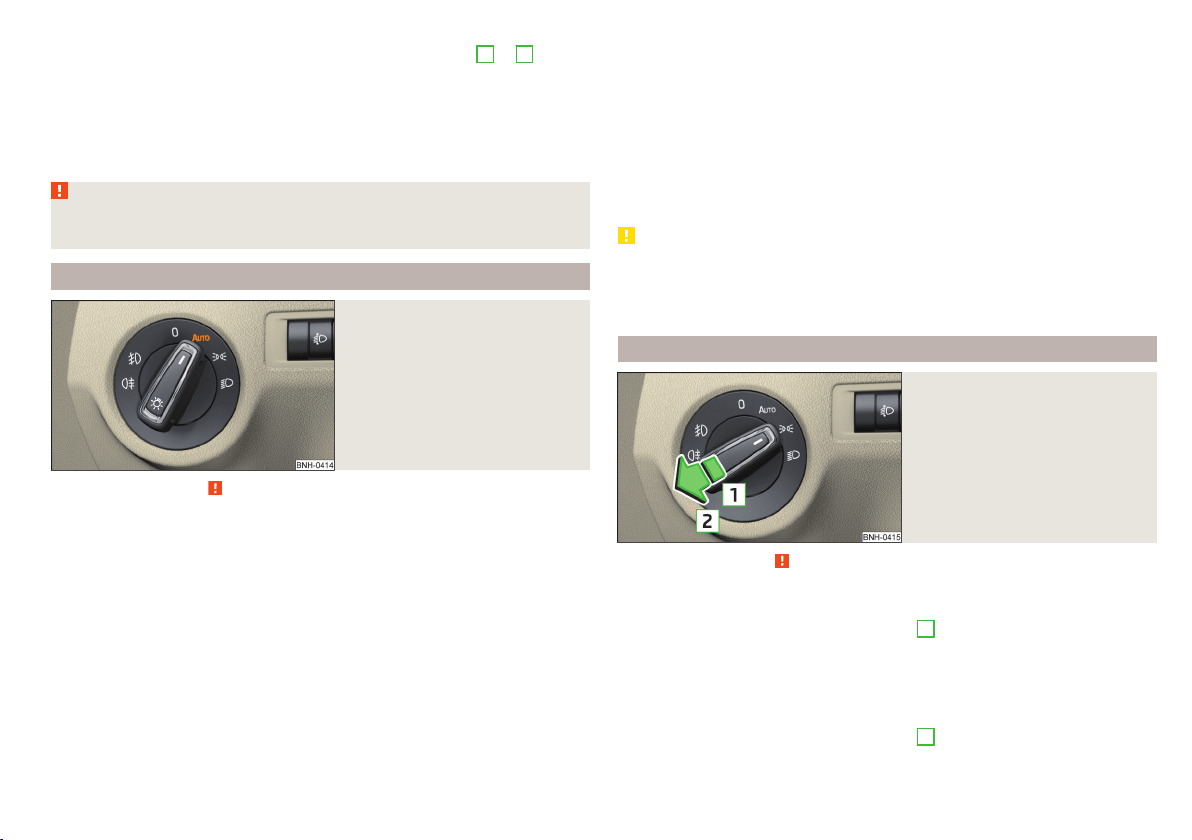
“Convenience turn signal”
When the control lever is lightly pressed to the pressure point
A
or
B
then
the respective turn-signal lamp flashes three times.
If during the “comfort flashing” the operating lever in the opposite side is
pressed, then the blinking stops.
The “Lane change flash” can be activated/deactivated in the Infotainment
» Owner´s Manual Infotainment, chapter CAR - vehicle settings.
WARNING
Only turn on the main beam or the headlight flasher if other road users will
not be dazzled.
Automatic driving lamp control
Fig. 48
Light switch: AUTO position
Read and observe on page 59 first.
The light switch is in position
» Fig. 48 then depending on the equipment
the automatic switch on / off the lights corresponding to the light or weather
conditions (rain) takes place.
The sensitivity of the sensor for the determination of the ambient light can be
adjusted in the infotainment » Owner´s Manual Infotainment, chapter CAR -
vehicle settings.
If the light switch is in position
, the lettering
illuminates next to the
light switch. If the light is switched on automatically, the symbol
next to the
light switch also illuminates.
Automatic driving light control during rain
The low beam lights are switched on automatically if the following conditions
are met.
The function is activated.
The light switch is in the position
.
The windscreen wipers are on for more than 15 s.
The light turns off about 4 minutes after turning off the wipers.
Automatic headlight control in rain can be activated or deactivated in the Info-
tainment » Owner´s Manual Infotainment, chapter CAR - Vehicle settings.
CAUTION
Poorer visibility is detected by a sensor mounted below the windscreen in the
holder of the inside mirror or in the control panel. Do not attach any stickers or
similar objects in front of the sensor in order to avoid impairing the function or
its reliability.
Front and rear fog lights
Fig. 49
Light switch – switch on front
and rear fog lights
Read and observe on page 59 first.
Switching the fog lights on/off
›
Turn the light switch to position
,
or
» Fig. 49.
›
When you pull the light switch to position
1
, the warning light
in the in-
strument cluster illuminates.
Switching off takes place in reverse order.
Switching the rear fog light on/off
›
Turn the light switch to position
,
or
» Fig. 49.
›
When you pull the light switch to position
2
, the warning light
in the in-
strument cluster illuminates.
61
Lights and visibility
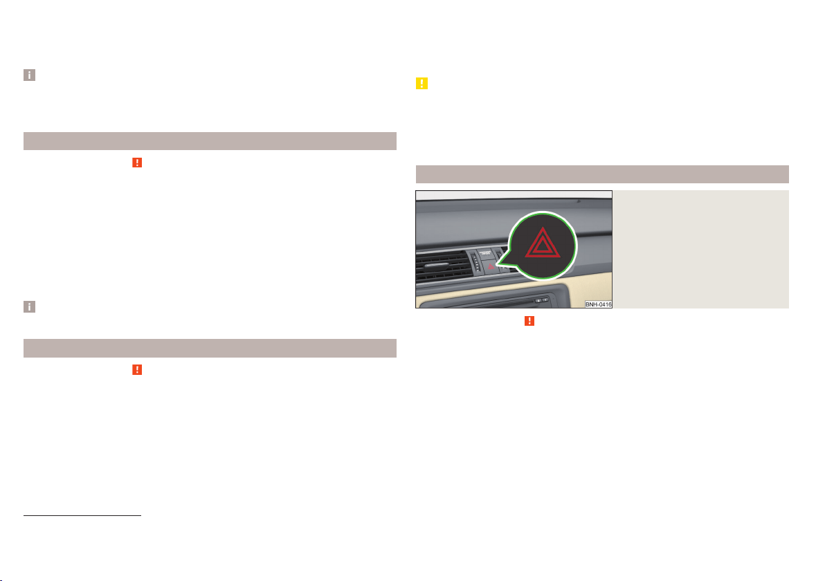
Switching off takes place in reverse order.
If the vehicle is not fitted with front fog lights, the rear fog light is switched on
by pulling out the light switch to the only possible setting.
Note
While driving with an accessory connected to the trailer socket (e.g. trailer,
bike carrier) only the equipment is illuminated by the fog light. The towing de-
vice must be installed at the factory or from the ŠKODA original accessories.
Fog lights with the CORNER function
Read and observe on page 59 first.
The function CORNER provides better illumination of the nearby environment
when turning, manoeuvring or anything similar.
The function automatically switches on the fog lights on each side of the ve-
hicle, if the following conditions are met.
The turn signal is switched on or the front wheels are turned sharply
1)
.
The vehicle speed is below 40 km/h.
The low beam is switched on.
The fog lights are not switched on.
Note
The two fog lights are switched on when you shift into the reverse gear.
COMING HOME / LEAVING HOME
Read and observe on page 59 first.
The function COMING HOME ensures that the vehicle's environment is illumi-
nated after switching off the ignition and opening the driver's door.
The function LEAVING HOME ensures that the vehicle's environment is illumi-
nated after unlocking the vehicle with the radio remote control unit.
The function switches the light on only if there is poorer visibility and the light
switch is in the position
.
Enabling / disabling and setting functions
The functions and setting of the lighting duration can be activated or deactiva-
ted in the Infotainment system » Owner´s Manual Infotainment, chap-
ter CARVehicle settings.
CAUTION
■
Poorer visibility is detected by a sensor mounted below the windscreen in
the holder of the inside mirror or in the control panel. Do not attach any stick-
ers or similar objects in front of the sensor in order to avoid impairing the func-
tion or its reliability.
■
If this option is always enabled, then the battery is heavily loaded.
Hazard warning light system
Fig. 50
Button for hazard warning light
system
Read and observe on page 59 first.
The hazard warning lights make other road users aware of your vehicle.
The function switches on all indicators.
Switching on/off
›
Press the button
» Fig. 50.
When you turn it on the warning light
flashes in the button and at the same
time the warning lights
in the instrument cluster.
The hazard warning light system can also be operated if the ignition is switch-
ed off.
If one of the airbags is deployed, the hazard warning light system will switch
on automatically.
1)
If both switch-on conditions are conflicting, for example, if the front wheels are turned to the left and
the right turn signal light is switched on, the turn signal light has the higher priority.
62
Using the system
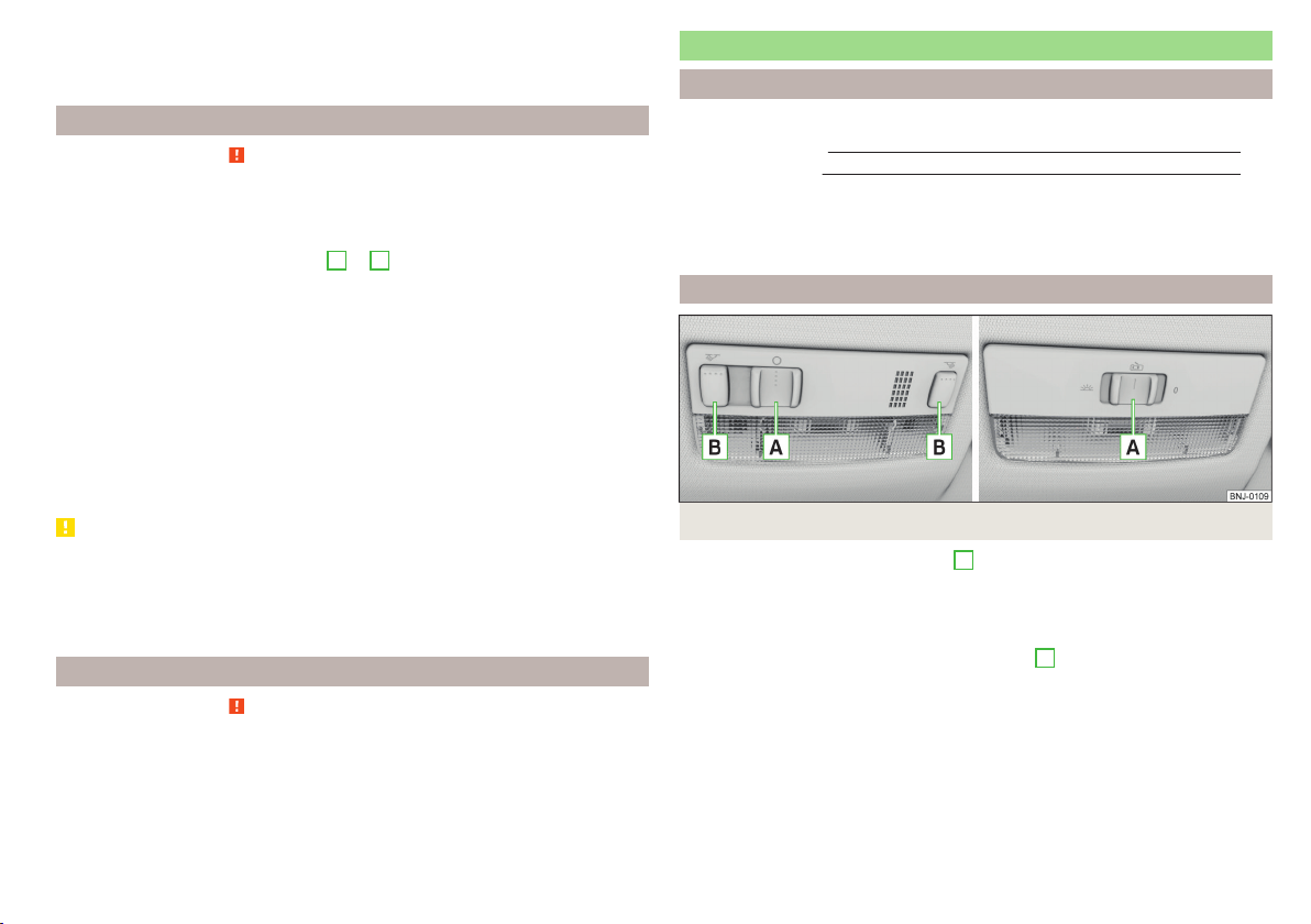
When the hazard warning system is on and the indicator light is switched on
(e.g. when turning), the hazard warning lights are switched off temporarily and
only the turn signal flashes on the relevant side of the vehicle.
Parking light
Read and observe on page 59 first.
The side light is provided for lighting of the parked vehicle.
Switching on the side light
on one side
›
Switch off the ignition.
›
Press the control lever to position
A
or
B
as far as the stop » Fig. 47 on
page 60.
The parking lights on the right or left side of the vehicle are turned on.
Switching on the side light on both sides
›
With the ignition switched on turn the light switch to position
.
›
Switch off the ignition.
›
Lock the vehicle.
After pulling out the ignition key and opening the driver's door, an audible
warning sounds.
After a few seconds or after closing the driver's door, the audible alarm is
turned off, but the parking lights will remain switched on.
CAUTION
■
Turning on the parking light means the battery is heavily loaded.
■
The parking light cannot be turned off automatic due to the low battery
charge level.
■
If the two-sided parking lights are switched on when the ignition is off, then
there is no automatic switching off of the parking light.
Driving abroad
Read and observe
on page 59 first.
When driving in countries with opposing traffic system (traffic on the
left/right), your headlights may dazzle oncoming traffic. In order to avoid this,
the headlights must be adjusted at a specialist garage.
Interior lighting
Introduction
This chapter contains information on the following subjects:
Front interior light
63
Rear interior light 64
The inner lighting also works if the ignition is switched off.
The light turns off automatically 10 minutes after switching off the ignition or
opening a door unless otherwise specified.
Front interior light
Fig. 51 Operation of the front light: Version 1/version 2
Positions of the sliding light switch
A
» Fig. 51
Switching on
Switching off
Automatic operation
Switch for switching the reading lamps on/off
B
» Fig. 51
Reading lamp left
Reading lamp right
Automatic operation of the lamp – position
The system is turned on when any of the following is present.
▶
The vehicle is unlocked.
▶
One of the doors is opened.
▶
The ignition key is removed.
63
Lights and visibility
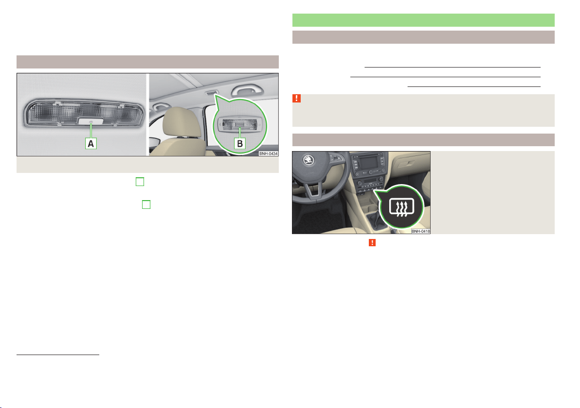
The system is turned off when any of the following is present.
▶
The vehicle is locked.
▶
The ignition is switched on.
▶
About 30 seconds after all the doors have been closed.
Rear interior light
Fig. 52
Interior lights at the rear: Version 1/version 2
Rear lights - Option 1: press switch
A
» Fig. 52
Switching on/off
Rear lights - Option 2: move the lens
B
» Fig. 52
Switching on
Switching off
Automatic operation
1)
Rear light - version 1
The rear light is operated together with the front light
2)
.
▶
When the front lighting is switched on, the rear lighting also turns on auto-
matically.
▶
When the front lighting is switched off, the rear lighting can be turned on/off
as required.
Visibility
Introduction
This chapter contains information on the following subjects:
Rear window heater
64
Front sun visors 65
Sun screen of the panoramic roof 65
WARNING
Make sure that the view outside is not covered by ice, snow, mist or other
objects.
Rear window heater
Fig. 53
Dash panel: Button for rear win-
dow heater
Read and observe on page 64 first.
The heating for quick defrosting and ventilation of the rear window.
The heating can be activated with the ignition on.
The heating is turned on after the engine has started.
Button for the heating in the centre console » Fig. 53
Activate/deactivate the heated rear window
When the heater is activated, a lamp lights up inside the button.
The heater automatically switches off after approximately 7 minutes.
1)
In this position, apply the same rules to the rear interior light as for the front interior light » page 63.
2)
This function only applies to certain countries. In some countries, the light at the rear is controlled inde-
pendently from the light at the front.
64
Using the system
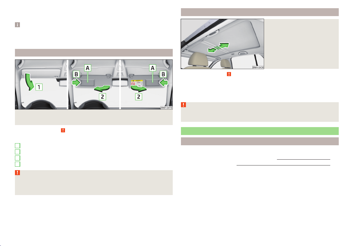
If the engine is switched off when the heating is on and turned back on again
within 10 minutes, the heating is continued.
Note
■
If the on-board voltage decreases, the heating switches off automatically
» page 153, Automatic load deactivation.
■
If the light is flashing inside the button the heater is off due to low battery.
Front sun visors
Fig. 54 Fold down the cover / swivel cover to the door and slide the mir-
ror cover
Read and observe on page 64 first.
Operation and description of the sun visor » Fig. 54
Fold down the cover
Swivel cover towards the door
Make-up mirror with cover
Slide mirror cover
WARNING
When objects are attached to the sun visor, the visor can not be pivoted to
the side windows. This might result in injuries to the occupants if the head
airbag is deployed.
1
2
A
B
Sun screen of the panoramic roof
Fig. 55
Open sun screen
Read and observe on page 64 first.
The sunshade protects against the blazing sun.
The sunshade of the panoramic roof can be opened manually in the direction
of arrow or closed in the opposite direction of the arrow » Fig. 55.
WARNING
When operating the sun blind, proceed with caution to avoid causing crush-
ing injuries – risk of injury!
Windscreen wipers and washers
Introduction
This chapter contains information on the following subjects:
Activating the windscreen wipers and washers
66
Headlight cleaning system 67
The windshield wipers and the windshield washer system only operate if the
ignition is switched on.
Winter setting of the windscreen wiper
If the windscreen wipers are in rest position, they cannot be folded out from
the windscreen. For this reason we recommend adjusting the windscreen wip-
ers in winter so that they can be folded out from the windscreen easily.
▶
Switch on the windscreen wipers.
▶
Switch off the ignition.
65
Lights and visibility
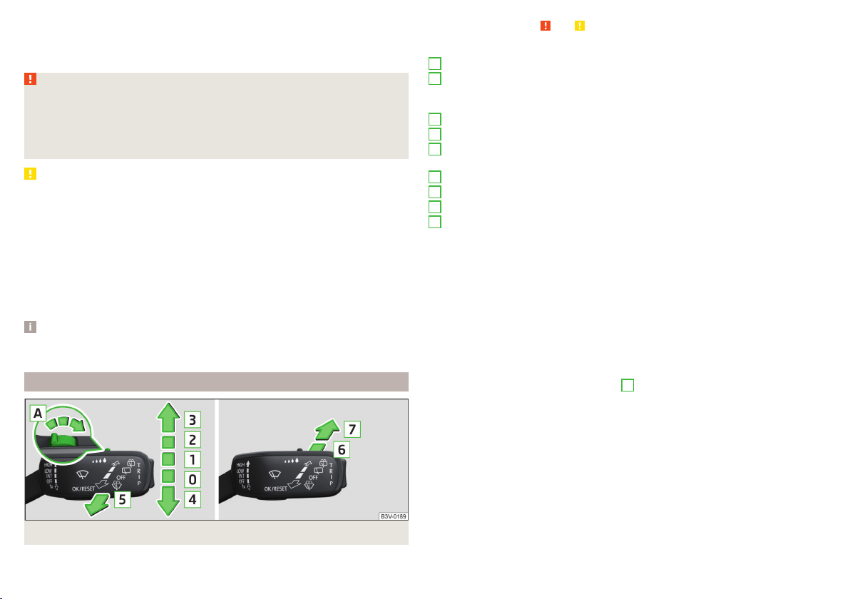
The windscreen wipers remain in the position in which they were when
switching off the ignition.
The service position can also be used as a winter position » page 173.
WARNING
■
Properly maintained windscreen wiper blades are essential for clear visi-
bility and safe driving » page 173.
■
Do not use the windscreen washer system at low temperatures, without
heating the windscreen beforehand. The window washer fluid could other-
wise freeze on the windscreen and restrict the view to the front.
CAUTION
■
In cold temperatures and during the winter, check before switching on the
ignition that the wiper blades are not frozen to the windscreen. If the wind-
screen wipers are switched on when the blades are frozen to the windscreen,
this may damage both the blades and windscreen wiper motor!
■
Carefully peel frozen wiper blades off the windscreen.
■
Remove snow and ice from the windscreen wipers before driving.
■
If the windscreen wipers are handled carelessly, there is a risk of damage to
the windscreen.
■
Do not switch on the ignition if the front wiper arms are retracted. The wiper
arms could damage the paint of the bonnet.
Note
Depending on vehicle equipment, the windscreen washer jets can be heated
automatically after starting the engine.
Activating the windscreen wipers and washers
Fig. 56 Operation of windscreen wiper and washer: front/rear
Read and observe and on page 66 first.
Operating lever positions
Wipers off
Depending on specification:
▶
Interval windscreen wiping
▶
Automatic windscreen wiping in rain
Slow windscreen wiping
Rapid windscreen wiping
Flick windscreen wiping/service position of the wiper arms (spring-loa-
ded position)
Spraying and wiping the windscreen (spring-loaded position)
Wiping the rear window
Spraying and wiping the rear window (spring-loaded position)
Depending on specification:
▶
To set the wiper interval for the windscreen
▶
Sensitivity setting of the automatic wiping with rain
By setting the switch in the direction of the arrow wipers sweep more of-
ten.
Spraying and wiping the windscreen
After releasing the operating lever, the wipers will make from 1 to 3 wiper
strokes.
Spraying and wiping the rear window
After releasing the operating lever, the wipers will make from 1 to 3 wiper
strokes.
The operating lever remains in position
6
.
Automatic windscreen wiping in rain
The function can be enabled/disabled in the Infotainment » Owner´s Manual
Infotainment, chapter CAR - vehicle settings.
Automatic rear wiper
After selecting reverse gear and when the windshield wiper is switched on,
the speed of the windshield wiper is transferred to the dependent intermittent
wiper of the rear window.
Depending on the equipment, the function can be enabled / disabled in the In-
fotainment » Owner´s Manual Infotainment, chapter CAR - Vehicle Settings or
at a specialist garage.
0
1
2
3
4
5
6
7
A
66
Using the system
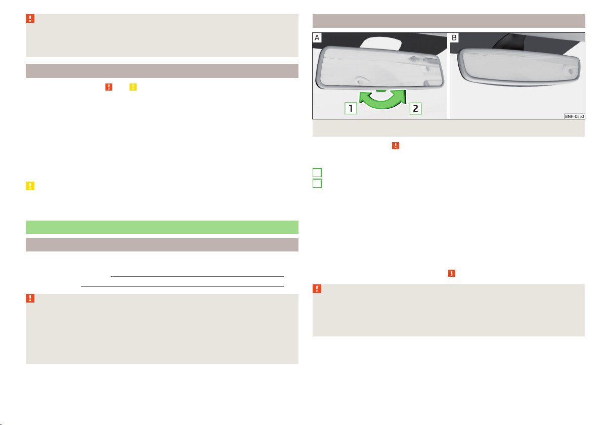
WARNING
Automatic wiping during rain is only a support. The driver is not released
from the responsibility to set the function of the windscreen wipers man-
ually depending on the visibility conditions.
Headlight cleaning system
Read and observe and on page 66 first.
To clean the headlights, the headlamp is also sprayed after every ten squirts.
The headlight washer system works under the following conditions.
The ignition is switched on.
The low beam is switched on.
The outside temperature is about -11° C to +36° C.
To ensure the correct functioning of the system, even in winter, this needs to
be regularly cleared of snow and ice, e.g. free with a de-icing spray.
CAUTION
Never remove the nozzles from the headlight cleaning system by hand – risk of
damage!
Rear mirror
Introduction
This chapter contains information on the following subjects:
Interior mirror dimming
67
Exterior mirror
68
WARNING
■
Convex (curved outward) or aspheric exterior mirrors increase the field of
vision. They do, however, make objects appear smaller in the mirror. These
mirrors are therefore only of limited use for estimating distances to the fol-
lowing vehicles.
■
Whenever possible use the interior mirror for estimating the distances to
the following vehicles.
Interior mirror dimming
Fig. 57 Interior mirror: manual dimming/auto-darkening
Read and observe
on page 67 first.
Mirrors with manual dimming » Fig. 57 -
Basic position of the mirror
Mirror blackout
Mirror with automatic dimming
After starting the engine, the mirror darkens » Fig. 57 -
automatically.
The mirror dimming is controlled by the light incident on the sensors on the
front and back of the mirror.
When the interior lights are switched on or the reverse gear is engaged, the
mirror always moves back into the basic position (not dimmed).
Do not attach external devices (e.g. navigation systems) on to the windscreen
or in the vicinity of the interior mirror » .
WARNING
■
The illuminated display of an external navigation device can lead to op-
erational faults to the automatic dimming interior mirror – risk of accident.
■
Automatic mirror dimming operates only properly if the light striking the
sensors is not affected by other objects.
1
2
67
Lights and visibility
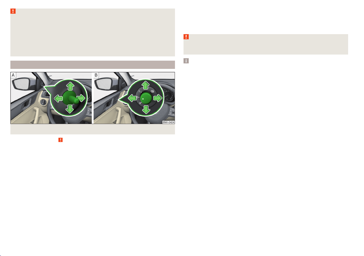
WARNING
The mirrors with automatic dimming contain an electrolyte liquid which can
escape if mirror glass is broken.
■
The leaking electrolytic fluid can irritate the skin, eyes and breath appara-
tus.
■
If your eyes or skin come into contact with the electrolytic fluid, immedi-
ately wash the affected area for a few minutes long with a lot of water. If
necessary get medical assistance.
Exterior mirror
Fig. 58 Exterior mirror controls: mechanical/electrical
Read and observe
on page 67 first.
Adjust the position
The mirror can be adjusted to the desired position by moving the knob in the
direction of the arrow » Fig. 58.
The movement of the mirror surface is identical to the movement of the rotary
knob.
Electrically-adjustable mirrors
The knob can be moved (depending on vehicle equipment) into the following
positions » Fig. 58 -
.
Adjust the left mirror
Adjust the right mirror
Switch off mirror control
Mirror heater
The mirror heating only works when the engine is running.
Folding in the exterior mirrors
The whole exterior mirror can be manually folded towards the side windows.
To put it back into its original position, it should be folded back from the side
window until it audibly clicks into place.
WARNING
Do not touch the exterior mirror surfaces, if the exterior mirror heating is
switched on - hazard of burning.
Note
If the electrical mirror setting fails at any time, the mirrors can be adjusted by
hand by pressing on the edge of the mirror surface.
68
Using the system
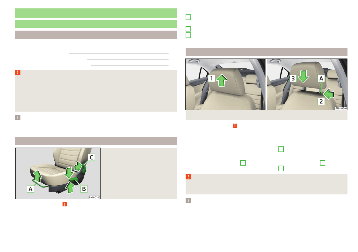
Seats and head restraints
Seats and head restraints
Introduction
This chapter contains information on the following subjects:
Adjusting the front seats 69
Head restraints - adjusting height 69
Headrests - removing and installing 70
WARNING
■
Only adjust the driver's seat when the vehicle is stationary – risk of acci-
dent!
■
Caution when adjusting the seat! You may suffer injuries or bruises as a
result of adjusting the seat without paying proper attention.
■
Do not carry any objects on the front passenger seat, except objects de-
signed for this purpose (e.g. child seats) – risk of accident!
Note
After a certain time, play can develop within the adjustment mechanism of the
backrest angle.
Adjusting the front seats
Fig. 59
Control elements on the seat
Read and observe on page 69 first.
The seats can be adjusted by the respective operating element being pulled or
pressed in the direction of arrows.
Control elements on the seat » Fig. 59
Adjusting the seat in the longitudinal direction (after releasing the control
lever must lock audibly)
Adjusting height of seat
Adjust the tilt of the backrest (during adjustment, release the backrest and
select the required tilt using your back)
Head restraints - adjusting height
Fig. 60
Head restraints: move up/move down
Read and observe on page 69 first.
Adjustment of the head rest heights is the same in the front and rear.
Move upwards
›
Push the headrest in the direction of arrow
1
» Fig. 60.
Move downwards
›
Press the locking button
A
and hold it in the direction of arrow
2
» Fig. 60.
›
Push the headrest in the direction of arrow
3
.
WARNING
Please note the following points about the head restraint settings
» page 8, Correct and safe seated position.
Note
In sports seats, the head restraints are integrated into the seat backs and can-
not be adjusted in height.
A
B
C
69
Seats and head restraints
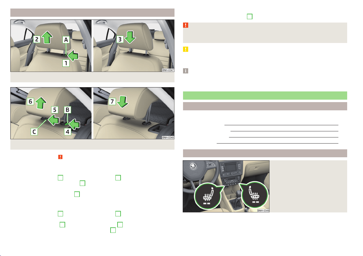
Headrests - removing and installing
Fig. 61 Front head restraints: removal/installation
Fig. 62 Rear head restraints: removal/installation
Read and observe on page 69 first.
Front restraint
›
Pull the restraint out of the seat backrest as far as the stop.
›
Press locking button
A
in the direction of arrow
1,
and pull out the head re-
straint in the direction of arrow
2
» Fig. 61.
›
To re-insert the head restraint, push it far enough down into the seat back-
rest in the direction of arrow
3
until the locking button clicks into place.
Rear restraint
›
Pull the restraint out of the seat backrest as far as the stop.
›
Press locking button
B
in the direction of arrow
4
, while at the same time
using a flat-headed screwdriver with a max. width of 5 mm to press the lock-
ing button in opening
C
in the direction of arrow
5
» Fig. 62.
›
Remove the restraint in the direction of arrow
6
.
›
To re-insert the head restraint, push it far enough down into the seat back-
rest in the direction of arrow
7
until the locking button clicks into place.
WARNING
Please note the following points about the head restraint settings
» page 8, Correct and safe seated position.
CAUTION
Store the head restraints that were removed in such a way that they are not
damaged or soiled.
Note
In sports seats, the head restraints are integrated into the seat backrests and
cannot be removed.
Seat features
Introduction
This chapter contains information on the following subjects:
Front seat heating
70
Front armrest setting
71
Rear armrest setting
71
Seat backrests
72
Front seat heating
Fig. 63
Buttons for heating the front
seats
The seat backrests and seats can be heated electrically.
The heat output can be adjusted with the ignition on.
The heater is turned on after the engine has started.
70
Using the system
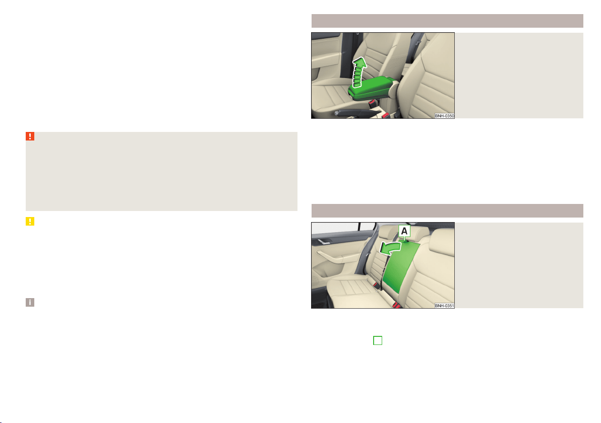
Buttons for the seat heating » Fig. 63
Left seat heating
Right seat heating
Switching on
›
Press button
or
» Fig. 63.
Pressing once switches the seat heating on at its maximum level - Level 2.
With repeated pressing of the switch, the intensity of the heating is reduced
until it is switched off.
The level of the seat heating is indicated by the number of illuminated warning
lights in the switch.
WARNING
If you have a subdued pain and/or temperature sensitivity, e.g. through
medication, paralysis or because of chronic illness (e.g. diabetes), we rec-
ommend not to use the seat heating. There may be difficult to heal burns. If
the seat heating is used, we recommend to make regular breaks in your
journey when driving long distances, so that the body can recuperate from
the stress of the journey. Please consult your doctor, who can evaluate
your specific condition.
CAUTION
The following instructions must be observed to avoid damage to the seats.
■
Do not kneel on the seats or otherwise apply concentrated pressure to them.
■
Do not turn on any of the seat heaters if seats are not occupied.
■
Do not switch on the relevant seat heating if the seats have objects attached
to or placed on them, for example a child seat, a bag, etc.
■
When there are additional protective covers or protective covers mounted on
each of the seats, do not turn the seat heating on.
Note
■
If the heaters for the rear seats are set to their highest intensity - level 2,
they are automatically switched down to level 1 after 10 minutes.
■
If the on-board voltage decreases, the seat heating switches off automati-
cally » page 153, Automatic load deactivation.
Front armrest setting
Fig. 64
Raise armrest
The armrest is adjustable in height.
Raise
›
Lift the armrest in the direction of arrow into one of the five locking positions
» Fig. 64.
Folding down
›
Raise the armrest in the direction of the arrow until it stops » Fig. 64.
›
Fold down the rear armrest.
Rear armrest setting
Fig. 65
Fold down armrest
The armrest can be folded down to increase comfort.
Lowering / raising
›
Pull on the loop
A
and fold down the armrest forward in the direction of the
arrow » Fig. 65.
Raising takes place in reverse order.
71
Seats and head restraints
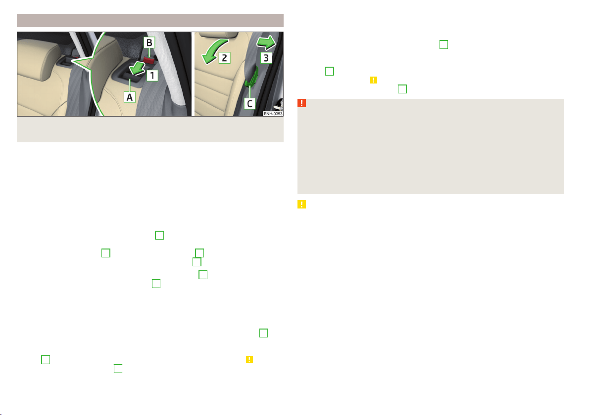
Seat backrests
Fig. 66 Folding the seat backrest forwards/standby position of the seat
belt
The rear seat backrest can be folded forwards to increase the size of the lug-
gage compartment. The seat backrests can also be folded forward individually
on vehicles with divided rear seats.
Before folding the seat backrests forwards, adjust the position of the front
seats in such a way that they are not damaged by the folded seat backrests.
If the front seats are too far back, we recommend that you have the rear head
restraints removed before the seat backrests are folded forward » page 70.
Folding the seat backrest forwards
›
Insert the belt buckle latching element
C
of the seat belt into the opening in
the side panel - ready position » Fig. 66.
›
Press the release lever
A
in the direction of arrow
1
.
›
Remove the backrest in the direction of the arrow
2
.
In the undivided seat back, insert the buckle tongues
C
into the two outer
belts and the press the release handles
A
on both sides of the seat back si-
multaneously.
Fold back split seat backrest
›
If you removed the head restraint, you need to reinsert it with the backrest
tilted slightly forwards.
›
Pull the rear outer seat belt to the side panel in the direction of arrow
3
» Fig. 66.
›
Then push the seat backrest back into the upright position until the securing
knob
A
clicks into place – check by pulling on the seat backrest » .
›
Make sure that the red pin
B
is hidden.
Fold back undivided seat backrest
›
If you removed the head restraints, you need to reinsert them with the back-
rest tilted slightly forwards.
›
Insert the belt buckle latching elements
C
of the outer belts into the open-
ings in the side panel - ready position » Fig. 66.
›
Then push the seat backrest back into the upright position until the release
levers
A
on either side of the seat back click into place – check by pulling on
the seat backrest » .
›
Make sure that the red pins
B
on both sides of the seat back are not visible.
WARNING
■
In occupied rear seats make sure that the respective seat backrests are
properly engaged.
■
After folding back the seat back, the seat belts must be ready for use.
■
The seat backrests must be securely locked in position so that no objects
in the luggage compartment can slide into the passenger compartment on
sudden braking – risk of injury.
■
When transporting objects in the luggage compartment that has been en-
larged by folding the backrest forward, ensure the safety of the passengers
transported on the other rear seats.
CAUTION
Ensure that the seat belts are not damaged when operating the seat backr-
ests. Under no circumstances must the rear seat belts be jammed by the fol-
ded back seat backrests.
72
Using the system
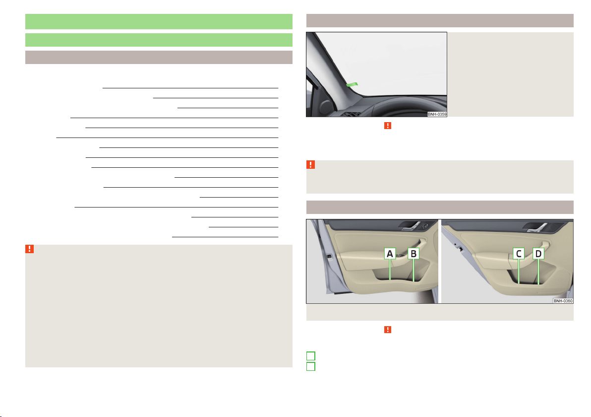
Transporting and practical equipment
Useful equipment
Introduction
This chapter contains information on the following subjects:
Car park ticket holder 73
stowage compartments in the doors 73
Storage compartment in the centre console 74
Cup holders 74
Cigarette lighter 75
Ashtray 75
12-Volt power outlet 75
Waste container 76
Multimedia holder 77
Storage compartment in the front arm rest 77
Glasses compartment 78
Storage compartment on the front passenger side 78
Clothes hook 79
Storage pockets on the backs of the front seats 79
Storage pockets on the inner sides of the front seats 79
AUX and MDI inputs (AUX and USB inputs) 80
WARNING
■
Do not place anything on the dash panel. These objects might slide or fall
down when driving (when accelerating, cornering or with an incorrect driv-
ing action) and may distract you from concentrating on the traffic – there is
the risk of an accident.
■
When driving, ensure that no objects from the centre console or from oth-
er storage compartments can get into the driver's footwell. You would not
be able to brake, operate the clutch pedal or accelerate - danger of causing
an accident!
■
No objects should be placed in the storage compartments nor in the
drinks holders; the vehicle occupants could be endangered if there is sud-
den braking or the vehicle collides with something.
■
Ash, cigarettes, cigars and the like. may only be placed in the ashtray!
Car park ticket holder
Fig. 67
Parking ticket holder
Read and observe on page 73 first.
The parking permitted holder » Fig. 67 is designed e.g. for attaching car park-
ing tickets.
WARNING
The attached note has to always be removed before starting off in order
not to restrict the driver's vision.
stowage compartments in the doors
Fig. 68
Storage compartments: in the front door/in the rear door
Read and observe on page 73 first.
Storage compartments » Fig. 68
Storage compartment in the front door
Bottle storage compartment with a capacity of max. 1.5 l in the front door
A
B
73
Transporting and practical equipment
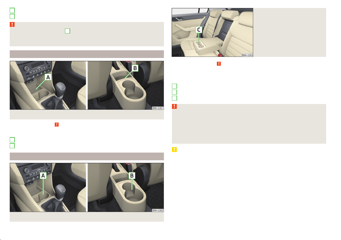
Storage compartment in the rear door
Bottle storage compartment with a capacity of max. 0.5 l in the rear door
WARNING
The storage compartment
A
» Fig. 68 is to be used exclusively for storing
objects which do not project out because there is the danger of limiting the
operating range of the side airbags.
Storage compartment in the centre console
Fig. 69 Non-lockable compartment, front / rear
Read and observe
on page 73 first.
Non-lockable compartment » Fig. 69
In the front centre console
In the rear centre console
Cup holders
Fig. 70 Cup holder at the front/rear
C
D
A
B
Fig. 71
Cup holder in rear armrest
Read and observe on page 73 first.
Two beverage containers can be placed into the cup holder.
Positioning of the holders » Fig. 70 and » Fig. 71
In the front centre console
In the rear centre console
In the rear armrest
WARNING
■
Do not use any cups or beakers which are made of brittle material (e.g.
glass, porcelain). This could lead to injuries in the event of an accident.
■
Never put hot cups in the cup holder. If the vehicle moves, they may spill –
risk of scalding!
■
No objects should be placed in the holders that might endanger the vehi-
cle's occupants if the vehicle brakes suddenly or the vehicle is in collision.
CAUTION
Do not leave open beverage containers in the cup holder during the journey.
There is a risk of spilling e.g. when braking which may cause damage to the
electrical components or seat upholstery.
A
B
C
74
Using the system
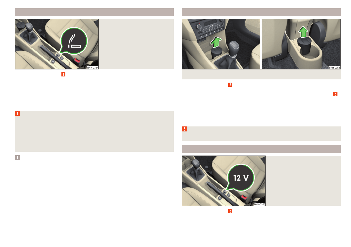
Cigarette lighter
Fig. 72
Cigarette lighter
Read and observe on page 73 first.
Use
›
Press the igniter in as far as the stop
» Fig. 72.
›
Wait until the igniter pops out.
›
Remove the glowing igniter and use immediately.
›
Place the cigarette lighter back into the socket.
WARNING
■
The cigarette lighter also works if the ignition is switched off. When leav-
ing the vehicle, never leave persons who are not completely independent,
such as children, unattended in the vehicle. These could operate the lighter
and get burned, start a fire or damage the interior.
■
Take care when using the cigarette lighter! Improper usage can cause
burns.
Note
The cigarette lighter socket can also be used as a 12 volt socket.
Ashtray
Fig. 73 Remove front / rear ashtray
Read and observe
on page 73 first.
The ashtray can be used for discarding ash, cigarettes, cigars and the like » .
Removing/inserting
›
When removing, do not hold the ashtray on the cover.
›
Pull out the ashtray in the direction of the arrow » Fig. 73.
Insertion takes place in reverse order.
WARNING
Never place hot or flammable objects in the ashtray – risk of fire!
12-Volt power outlet
Fig. 74
Cover of the 12 volt power outlet
Read and observe on page 73 first.
Use
›
Remove the socket cover » Fig. 74.
75
Transporting and practical equipment
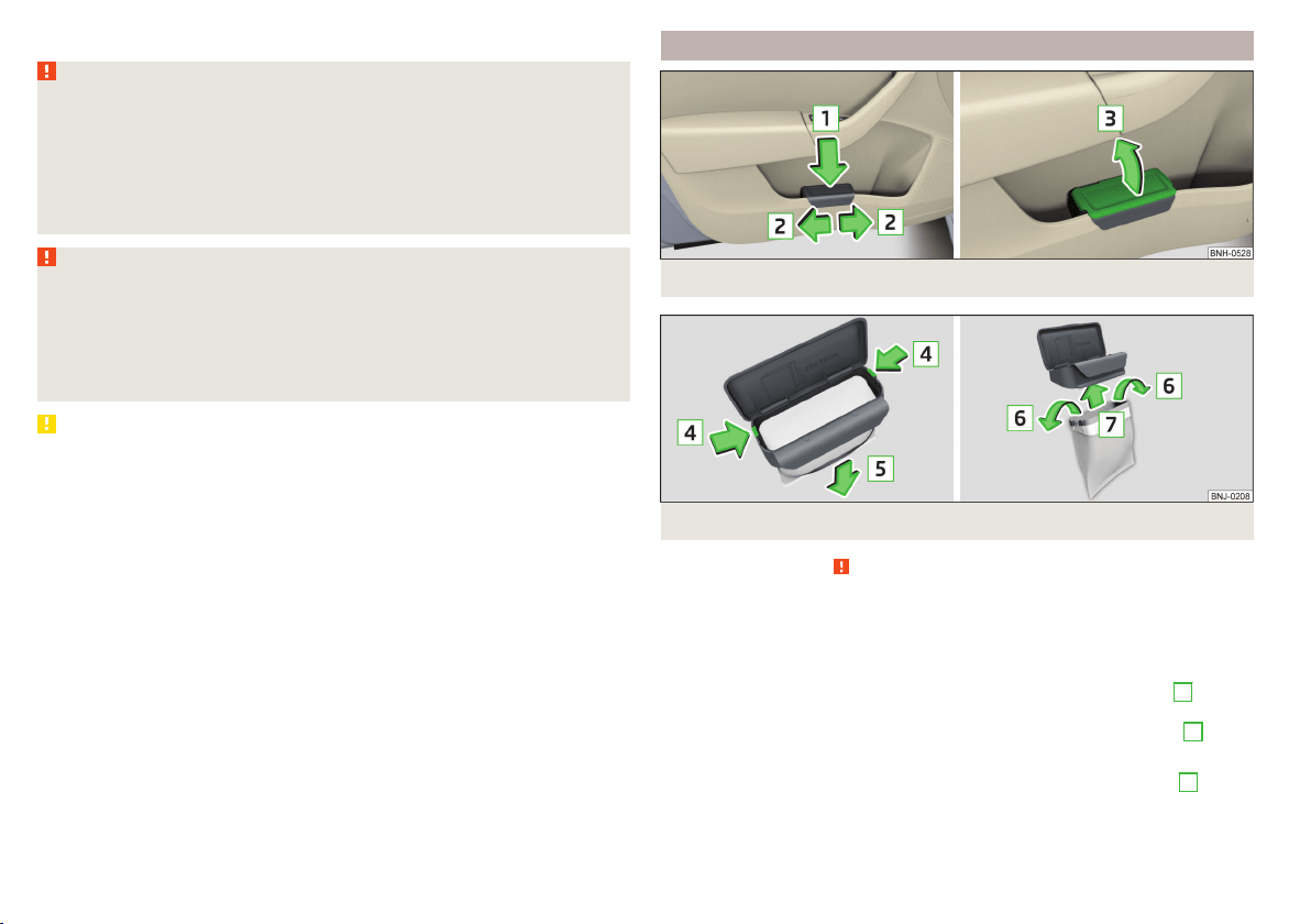
›
Connect the plug for the electrical appliance to the socket.
WARNING
Instructions for devices connected to the socket.
■
Safely stow away all devices during the journey to prevent them from be-
ing thrown around the interior in the event of a sudden braking manoeuvre
or an accident – risk of death!
■
The devices may warm up during operation – risk of injury or fire! If the
device becomes too hot, switch it off and disconnect it from the power sup-
ply immediately.
WARNING
When using the socket the following notes are to be observed.
■
The socket also operates if the ignition is switched off. When leaving the
vehicle, never leave persons who are not completely independent, such as
children, unattended in the vehicle.
■
Improper use of the power sockets and the electrical accessories can
cause fires, burns and other serious injuries.
CAUTION
■
The socket can only be used for the connection of approved electrical acces-
sories with a total power consumption of up to 120 watts, otherwise the elec-
trical system of the vehicle may be damaged.
■
Connecting appliances when the engine is not running will drain the battery
of the vehicle!
■
Switch off the devices connected to the power sockets before you switch
the ignition on or off and before starting the engine, to avoid damage from
voltage fluctuations.
Waste container
Fig. 75 Waste container: inserting and moving/opening
Fig. 76 Replacing bags
Read and observe on page 73 first.
The waste container can be inserted into the storage compartment in the
door.
Insert waste container
›
Position the waste container at the front edge of the slot.
›
Push the waste container to the back in the direction of the arrow
1
» Fig. 75.
›
Move the waste container in the direction of the arrows as required
2
.
Remove the waste container
›
Remove the waste container in the opposite direction to the arrow
1
» Fig. 75.
76
Using the system
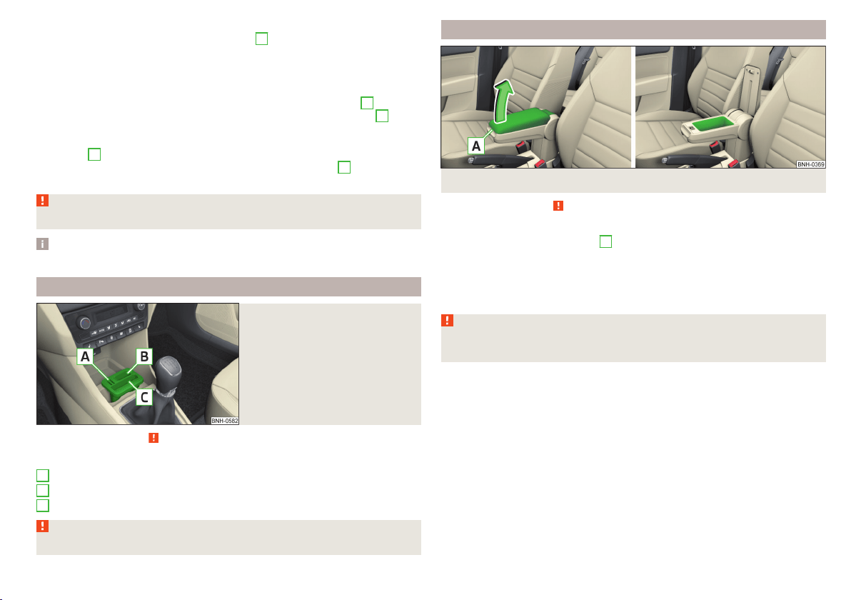
Open/close waste container
›
Remove the cover in the direction of arrow
3
» Fig. 75.
Closing takes place in reverse order.
Replace bags
›
Remove the waste container from the slot.
›
Press the two locking lugs on the frame in the direction of arrow
4
» Fig. 76.
›
Pull the bag together with the frame down in the direction of arrow
5
.
›
Remove the bag from the frame.
›
Pull the new bag through the frame and pull it over the frame in the direction
of arrow
6
.
›
Place the bag containing the frame in the direction of arrow
7
into the con-
tainer body, so that the two lugs engage audibly to the frame.
WARNING
Never use the waste container as an ashtray - risk of fire!
Note
We recommend that you use 20x30 cm bags.
Multimedia holder
Fig. 77
Multimedia holder
Read and observe on page 73 first.
Multimedia holder » Fig. 77
Storage compartment for storing two coins
Storage compartment for storing the vehicle key
Storage compartment for storing a mobile phone
WARNING
Never use the multimedia holder as an ashtray - risk of fire!
A
B
C
Storage compartment in the front arm rest
Fig. 78 Storage compartment / open storage compartment
Read and observe
on page 73 first.
Opening
›
Grasp the armrests in the area
A
» Fig. 78.
›
Lift the lid of the storage box in the direction of the arrow.
Closing
›
Fold the lid of the storage box back in the opposite direction to the arrow
» Fig. 78, until it audibly clicks into place.
WARNING
The storage compartment must always be closed when driving for safety
reasons.
77
Transporting and practical equipment
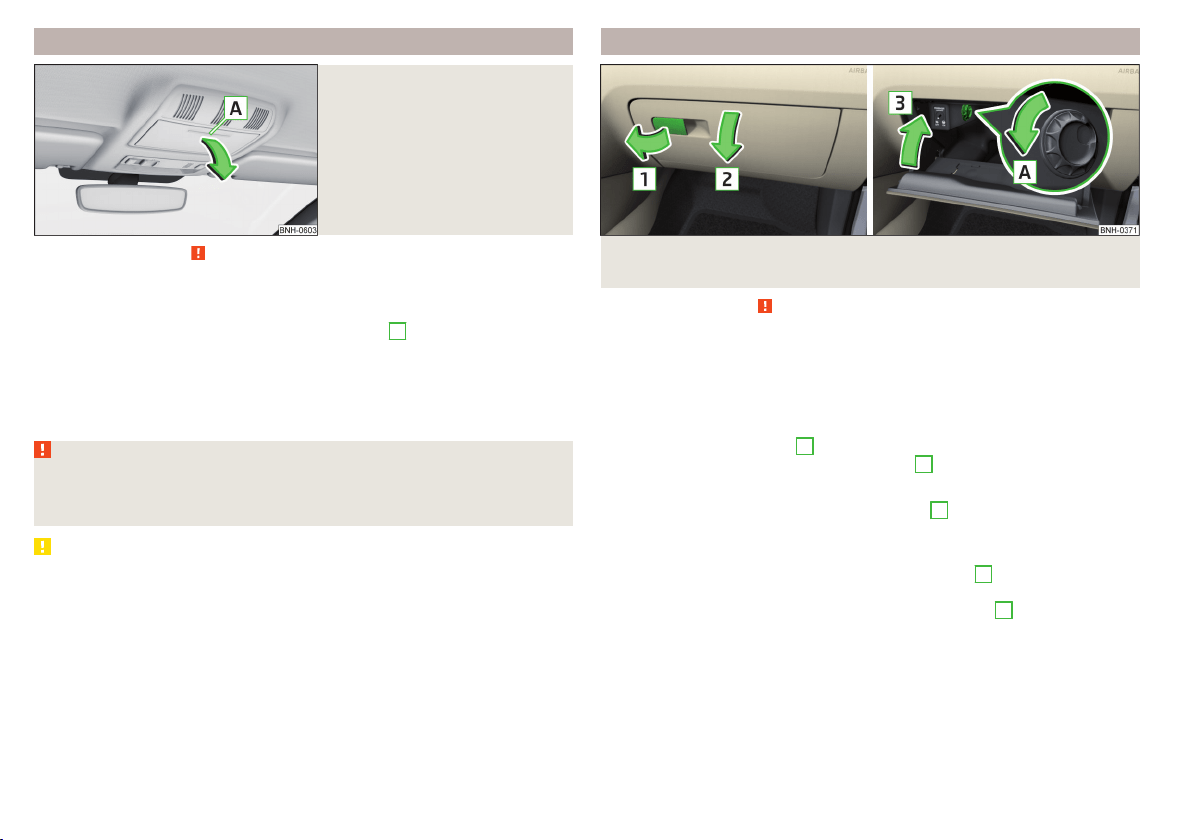
Glasses compartment
Fig. 79
Opening the glasses storage box
Read and observe on page 73 first.
The maximum permissible load of the glasses compartment is 250 g.
Opening
›
Press on the lid of the glasses storage box in area
A
» Fig. 79.
The box folds in the direction of the arrow.
Closing
›
Move the compartment in the opposite direction to that of the arrow» Fig. 79
until it audibly clicks in place.
WARNING
The compartment must only be opened when removing or inserting the
glasses and is otherwise kept closed - it could cause a restricted view to
the outside or to an injury!
CAUTION
■
Do not put any heat-sensitive objects in the glasses storage box - with high
temperatures there is risk of damage.
■
The box must be closed before leaving and locking the vehicle – risk of im-
pairment to the functions of the anti-theft alarm system.
Storage compartment on the front passenger side
Fig. 80 Open storage compartment / close storage compartment and
open air supply
Read and observe
on page 73 first.
There is enough space in the storage compartment for a bottle of a with a ca-
pacity max. 1 l.
The storage compartment is equipped with an inner light that illuminates
when opening and closing the storage compartment.
Opening
›
Pull the handle to position
1
» Fig. 80 in the direction of the arrow.
›
Open the cover in the direction of the arrow
2
.
Closing
›
Screw in the filler cap in the direction of arrow
3
until it audibly clicks into
place » Fig. 80.
Air supply operation
›
By turning the rotary switch in the direction of arrow
A
until it stops, the air
supply is opened » Fig. 80.
›
By turning the rotary switch opposite direction of arrow
A
until it stops the
air supply is closed.
Opening the air supply when the air conditioning system is switched on allows
cooled air to flow into the storage compartment.
Opening the air inlet when the air conditioning system is on causes fresh or in-
terior air to flow into the storage compartment.
78
Using the system
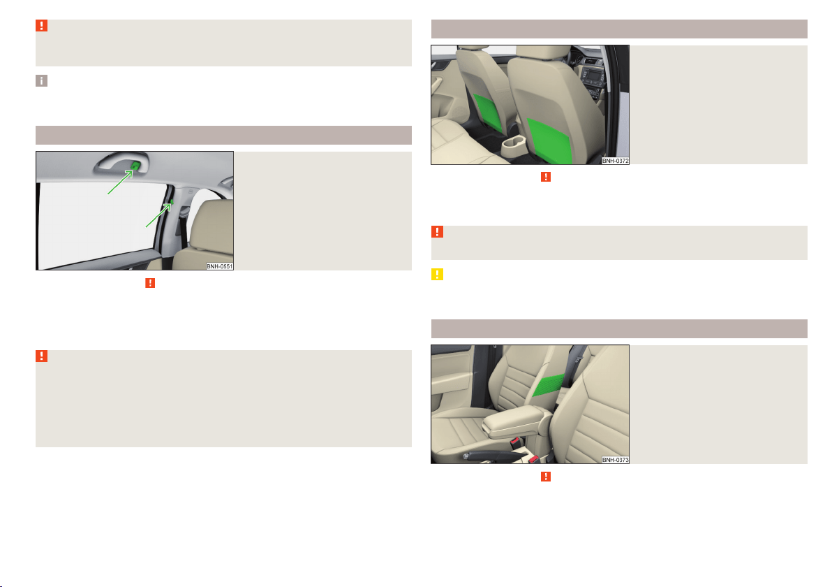
WARNING
The storage compartment must always be closed when driving for safety
reasons.
Note
If not using the air supply in the storage compartment we recommend that you
leave the air supply closed.
Clothes hook
Fig. 81
Clothes hooks
Read and observe on page 73 first.
The clothes hooks are located on the middle door pillars of the vehicle and on
the handle of the headliner above each of the rear doors » Fig. 81.
The maximum permissible load of each of the hooks is 2 kg.
WARNING
■
Never leave any heavy or sharp-edged objects in the pockets of the items
of clothing hung up.
■
To hang the clothes do not use hangers - there is a risk of limiting the ef-
fectiveness of head airbags.
■
Ensure that any clothes hanging from the hooks do not impair your vision
to the rear.
Storage pockets on the backs of the front seats
Fig. 82
Map pockets
Read and observe on page 73 first.
The storage pockets » Fig. 82 are intended for the storage of maps, maga-
zines, etc.
WARNING
Never put heavy items in the map pockets – risk of injury!
CAUTION
Never put large objects into the map pockets, e.g. bottles or objects with sharp
edges - risk of damaging the pockets and seat coverings.
Storage pockets on the inner sides of the front seats
Fig. 83
Storage pocket
Read and observe on page 73 first.
The storage pockets are located on the inner sides of the front seats » Fig. 83.
The storage pockets are used for storage of small and light objects, such as
mobile phones and the like.
79
Transporting and practical equipment
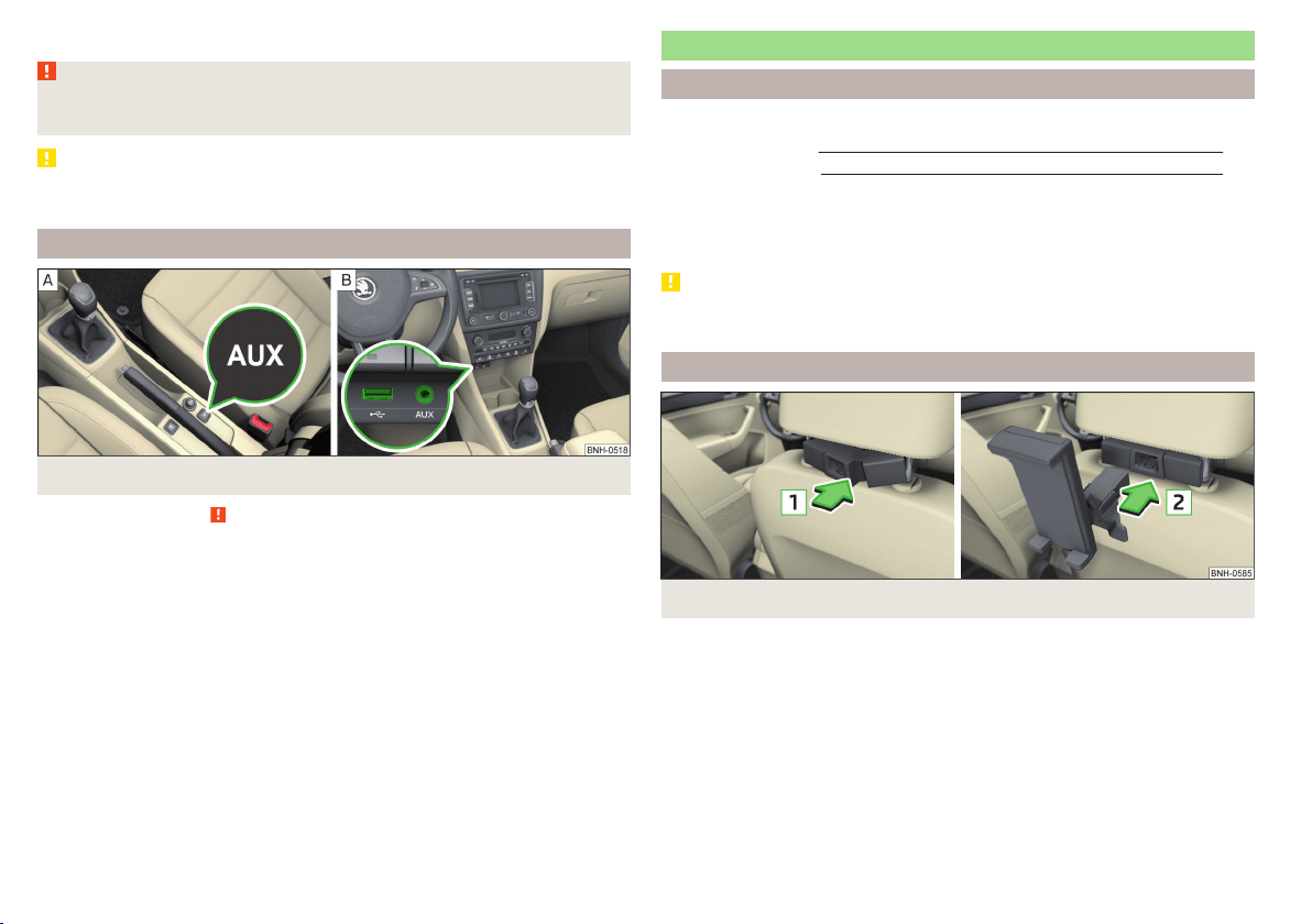
The maximum permissible load of each of the pockets is 150 g.
WARNING
Do not exceed the maximum permissible load of the pockets. Heavy objects
are not secured sufficiently – risk of injury!
CAUTION
Never put large objects into the map pockets, e.g. bottles or objects with sharp
edges - risk of damaging the pockets and seat coverings.
AUX and MDI inputs (AUX and USB inputs)
Fig. 84 Installation locations of the inputs: AUX / MDI (AUX and USB)
Read and observe on page 73 first.
The vehicle may have AUX or MDI inputs (AUX and USB) for connecting exter-
nal sources.
The USB input is above the storage compartment in the front centre console
» Fig. 84 -
and is identified by the symbol
.
The AUX input is marked with the lettering
and is in one of the locations
listed below depending on equipment.
▶
Between the seats in the front centre console » Fig. 84 -
.
▶
Above the storage box of the front centre console » Fig. 84 –
.
Additional information» Owner´s Manual Infotainment.
Tablet holder
Introduction
This chapter contains information on the following subjects:
Installing/removing
80
Handling the holder 81
External devices (e.g. tablet, smartphone, etc.) measuring min. 122 mm and
max. 195 mm can be secured in the holder.
The maximum permissible load of the holder is 750 g.
CAUTION
Never exceed the maximum permissible load of the holder - there is a risk of
damage or functional impairment.
Installing/removing
Fig. 85
Positioning the adapter/installing the holder
80
Using the system
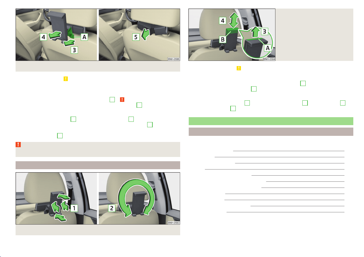
Fig. 86 Removing the holder/removing the adapter
Read and observe on page 80 first.
Installing
›
Attach the opened adapter to the guide rods of the headrest » Fig. 85.
›
Clip in the adapter in the direction of arrow
1
» .
›
Clip the holder into the adapter in the direction of arrow
2
.
Removing
›
Pull on the locking strap
A
in the direction of arrow
3
» Fig. 86.
›
Remove the holder from the bracket in the direction of arrow
4
.
›
Press the adapter and remove it from the guide rods of the head rest in the
direction of arrow
5
.
WARNING
Clip in the adapter carefully - there is a risk of injuring your finger.
Handling the holder
Fig. 87 Tilting and rotating the holder
Fig. 88
Adjusting the holder size
Read and observe on page 80 first.
Tilting and rotating the holder
The holder may be tilted 30° in the direction of arrow
1
and rotated through
360° in the direction of arrow
2
» Fig. 87.
Adjusting the holder size
›
Pull out the securing tab
A
in the direction of arrow
3
and move part
B
in
direction of arrow
4
to the desired position » Fig. 88.
Luggage compartment and transport of cargo
Introduction
This chapter contains information on the following subjects:
Fastening elements
82
Fixing nets 83
Multifunction pocket 83
Hooks 83
Luggage compartment cover 84
“Parking position” of the boot cover 84
Storage compartment in the boot 85
Storage net bag 85
Cargo elements 85
Floor covering on both sides 86
Class N1 vehicles 86
81
Transporting and practical equipment
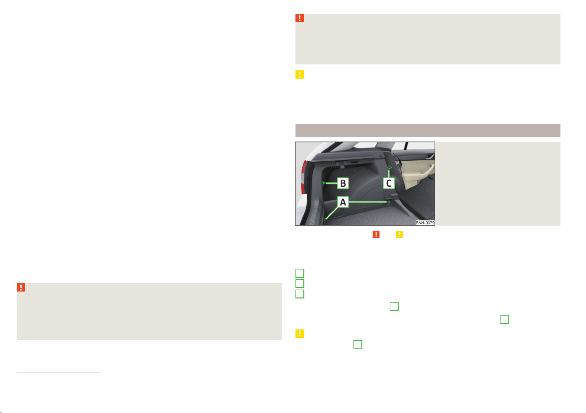
When transporting cargo the following the instructions must be adhered to
▶
When transporting heavy objects, the driving characteristics change due to
the shift in centre-of-gravity. The speed and style of driving must be adjus-
ted accordingly.
▶
The cargo is stowed in the luggage compartment. To prevent this from mov-
ing it should be secured with suitable lashing straps to the lashing eyes or
secured with fixing nets.
▶
Distribute loads as evenly as possible.
▶
Place heavy objects as far forward as possible.
▶
The transported items must be stowed in such a way that no objects are able
to slip forward on sudden driving or braking manoeuvres – risk of injury!
▶
Tyre pressure is to match the load.
▶
When transporting loads in the luggage compartment that has been en-
larged by folding the rear seats forward, ensure the safety of the passengers
transported on the other rear seats .
In the event of an accident, even small and light objects gain so much kinetic
energy that they can cause severe injuries.
The magnitude of the kinetic energy is dependent on the speed at which the
vehicle is travelling and the weight of the object.
Example: In the event of a frontal collision at a speed of 50 km/h, an object
with a weight of 4.5 kg produces an energy, which corresponds to 20 times its
own weight. This means that it results in a weight of approx. 90 kg “ ”.
Luggage compartment light
The warning light turns on when tailgate is opened.
The warning light turns off when the tailgate is closed.
If the boot lid is open and the ignition switched off, the light will extinguish
automatically after around 10 minutes.
WARNING
■
Never exceed the maximum permissible load of the respective fasteners,
nets, hooks etc. as heavy objects are not e sufficiently secured - there is a
risk of injury!
■
If the cargo is tied down with unsuitable or damaged lashing straps, inju-
ries can occur in the event of braking manoeuvres or accidents.
WARNING (Continued)
■
Loose cargo can be thrown forward during a sudden manoeuvre or in case
of an accident and can injure the occupants or other road users.
■
Loose cargo could hit a deployed airbag and injure occupants – danger of
death!
CAUTION
■
Never exceed the maximum permissible load of the respective fasteners,
nets, hooks etc. - these could be damaged.
■
Please ensure that the heating elements for the rear window heater are not
damaged as a result of abrasive objects.
Fastening elements
Fig. 89
Fasteners
Read and observe and on page 82 first.
The fasteners are located on both sides of the luggage compartment.
Overview of the fasteners » Fig. 89
Lashing eyes for securing cargo, fastening nets and multifunction pocket
Fastener for securing fastening nets and multifunction pocket
Lashing eye for securing fastening nets and multifunction pocket
The upper front lashing eye
C
is located behind the folding rear seat backrest.
The maximum permissible load of the individual lashing eyes
A
is 350 kg.
CAUTION
The lashing eyes
A
cannot be used for attaching bags and nets when the var-
iable loading floor is in the upper position » page 87
1)
.
A
B
C
1)
Applies to vehicles with a variable loading floor.
82
Using the system
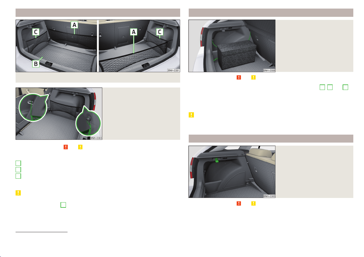
Fixing nets
Fig. 90 Fastening examples for nets
Fig. 91
Fastening a vertical pocket
Read and observe and on page 82 first.
Fastening examples for nets » Fig. 90 and » Fig. 91
Horizontal pocket
Floor net
Vertical pocket
The maximum permissible load of each of the nets is 1.5 kg.
CAUTION
■
Do not place any sharp objects in the nets – risk of net damage.
■
The lashing eyelets
A
» Fig. 89 on page 82 cannot be used for attaching
nets, when the variable loading floor is in the upper position » page 87
1)
.
A
B
C
Multifunction pocket
Fig. 92
Securing the multifunction pock-
et
Read and observe and on page 82 first.
The pocket » Fig. 92 can be secured to the fastening elements
A
,
B
and
C
» Fig. 89 on page 82.
The maximum permissible load for the pocket attached to the fastening ele-
ment is 3 kg.
CAUTION
In vehicles with a variable loading floor, it is not possible to secure the pocket
to the fastening elements.
Hooks
Fig. 93
Hooks
Read and observe and on page 82 first.
One hook for attaching small items of luggage, such as bags etc., is provided
on each side of the luggage compartment. » Fig. 93.
1)
Applies to vehicles with a variable loading floor.
83
Transporting and practical equipment
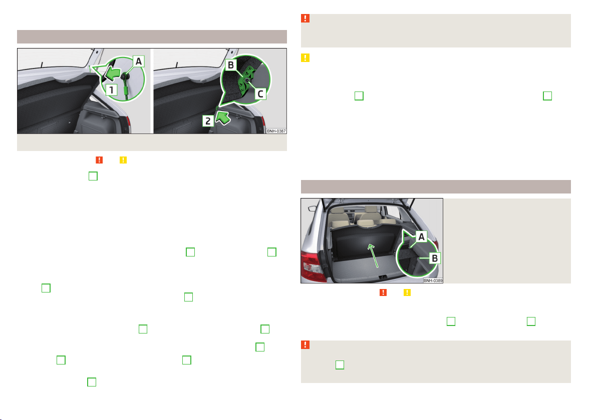
The maximum permissible load of the hook is 7.5 kg.
Luggage compartment cover
Fig. 94 Remove the luggage compartment cover
Read and observe and on page 82 first.
If the support straps
A
» Fig. 94 are attached to the boot lid, then opening the
lid will raise the boot lid cover (hereafter referred to as the cover).
If you want to carry bulky goods, the cover can be removed from the vehicle
and if required can be stored behind the rear seat backrest in the “Park posi-
tion” » Fig. 95 on page 84.
The maximum permissible load of the cover is 1 kg.
Removing
›
On both sides of the boot lid unhook the straps
A
in direction of arrow
1
» Fig. 94.
›
Hold the raised cover.
›
Press on the two sides to the underside of the cover in the region of the
studs
C
.
›
Remove the cover in the direction of the arrow
2
.
Installing
›
Place the cover on the contact surfaces of the side trim panel.
›
Position the mounts on the cover
B
onto the side trim panel via pins
C
» Fig. 94.
›
On both sides, press on the top of the cover in the area of the studs
C
.
The fixture
B
must lock into place on the studs
C
on both sides of the lug-
gage compartment.
›
Hook in the straps
A
on both sides of the boot lid.
WARNING
No objects should be placed on the cover. This could endanger the vehicle
occupants during sudden braking or vehicle impact.
CAUTION
■
When closing the boot lid, jamming and damage to the cover or the side trim
panel can occur if handled incorrectly. The following guidelines must be ob-
served.
■
The holders
B
on the cover must be resting completely on the pins
C
on
the side panel » Fig. 94.
■
The items which are transported must not exceed the height of the cover.
■
The cover must not be jammed in the surrounding seal of the luggage com-
partment lid when it is in the raised position.
■
There must be no object in the gap between the cover in the raise position
and the rear backrest.
■
After removing the cover, store it in such a way that it cannot be damaged or
soiled.
“Parking position” of the boot cover
Fig. 95
Luggage compartment cover
stowed behind the rear seats
Read and observe and on page 82 first.
The boot cover can be stowed behind the seat backrest.
›
Slide the dismantled cover between bolt
A
and contact surface
B
of the
side panel » Fig. 95.
WARNING
When adjusting the “parking position”, the boot cover must be between
the bolt
A
and the rear seat backrest - risk of damaging the rear seat
backrest and the boot cover.
84
Using the system
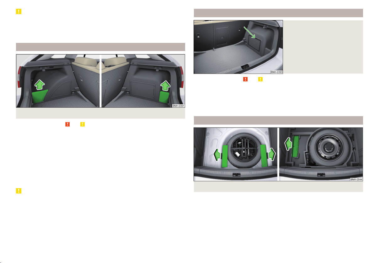
CAUTION
■
Before setting the “parking position” of the luggage compartment cover, the
variable loading floor must be put in the upper or lower position» page 86.
■
If the luggage compartment cover is in the “parking position”, the “parking
position” of the variable loading floor cannot be set » page 88.
Storage compartment in the boot
Fig. 96 Remove the tray cover on the left / right
Read and observe and on page 82 first.
The compartment covers can be removed to increase the size of the luggage
compartment.
The storage compartments are designed for storing small objects of up to
1.5 kg. in weight in total.
Removing/inserting
›
Grasp the top part of the cover and remove it in the direction of the arrow
» Fig. 96.
Insertion takes place in reverse order.
CAUTION
When handling the storage compartment cover, ensure that it and/or the lug-
gage compartment trim is not damaged.
Storage net bag
Fig. 97
Meshed pocket for storage
Read and observe and on page 82 first.
The meshed pocket for storage is located on the right-hand side of the boot
» Fig. 97.
The meshed pocket for storage is designed for storing small objects of up to
1.5 kg. in weight in total.
Cargo elements
Fig. 98 Remove cargo element: Version 1/version 2
85
Transporting and practical equipment
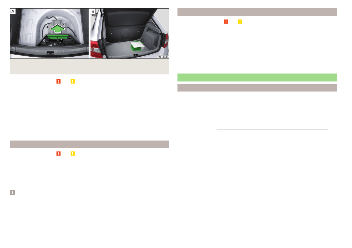
Fig. 99 Remove cargo element: Version 3 / Mounting example of the car-
go using the cargo elements
Read and observe and on page 82 first.
The Cargo elements can be stored under the floor in the boot.
The cargo element is designed for attaching and securing objects with a maxi-
mum total weight of 8 kg.
Usage of Cargo elements
›
Remove the cargo elements in direction of arrow » Fig. 98 or » Fig. 99 -
.
›
Attach the Cargo elements with Velcro as close as possible to the rear seats
on the floor of the luggage compartment » Fig. 99 -
or attach to the fabric
side of the double-sided floor covering.
Floor covering on both sides
Read and observe and on page 82 first.
You can fit a double-sided floor covering in the luggage compartment.
One side of the double-sided floor covering is made of fabric, the other side is
washable (easy to maintain).
The washable side is used to transport wet or dirty items.
Note
For easier turning of the covering, use the loop attached.
Class N1 vehicles
Read and observe and on page 82 first.
In class N1 vehicles that are not fitted with a protective grille, a lashing set that
complies with the EN 12195 standard (1 - 4) must be used for fastening the
load.
Proper functioning of the electrical installation is essential for safe vehicle op-
eration. It is important to ensure that the electrical installation is not damaged
during the adjustment process or when the storage area is being loaded and
unloaded.
Variable loading floor in the luggage compartment (Estate)
Introduction
This chapter contains information on the following subjects:
Setting in the upper position
87
Setting in the lower position
87
Removing/inserting
88
Folding up/down
88
“Parking position”
88
The variable loading floor can be set to the upper or lower position.
The maximum permissible load of the variable loading floor is 75 kg. For the
transport of heavy loads, adjust the variable loading floor to the lower position
or remove it from the vehicle.
For easier handling of the spare tire, for example, the variable loading floor can
be set to two positions » page 88, Folding up/down and » page 88, “Park-
ing position”.
86
Using the system
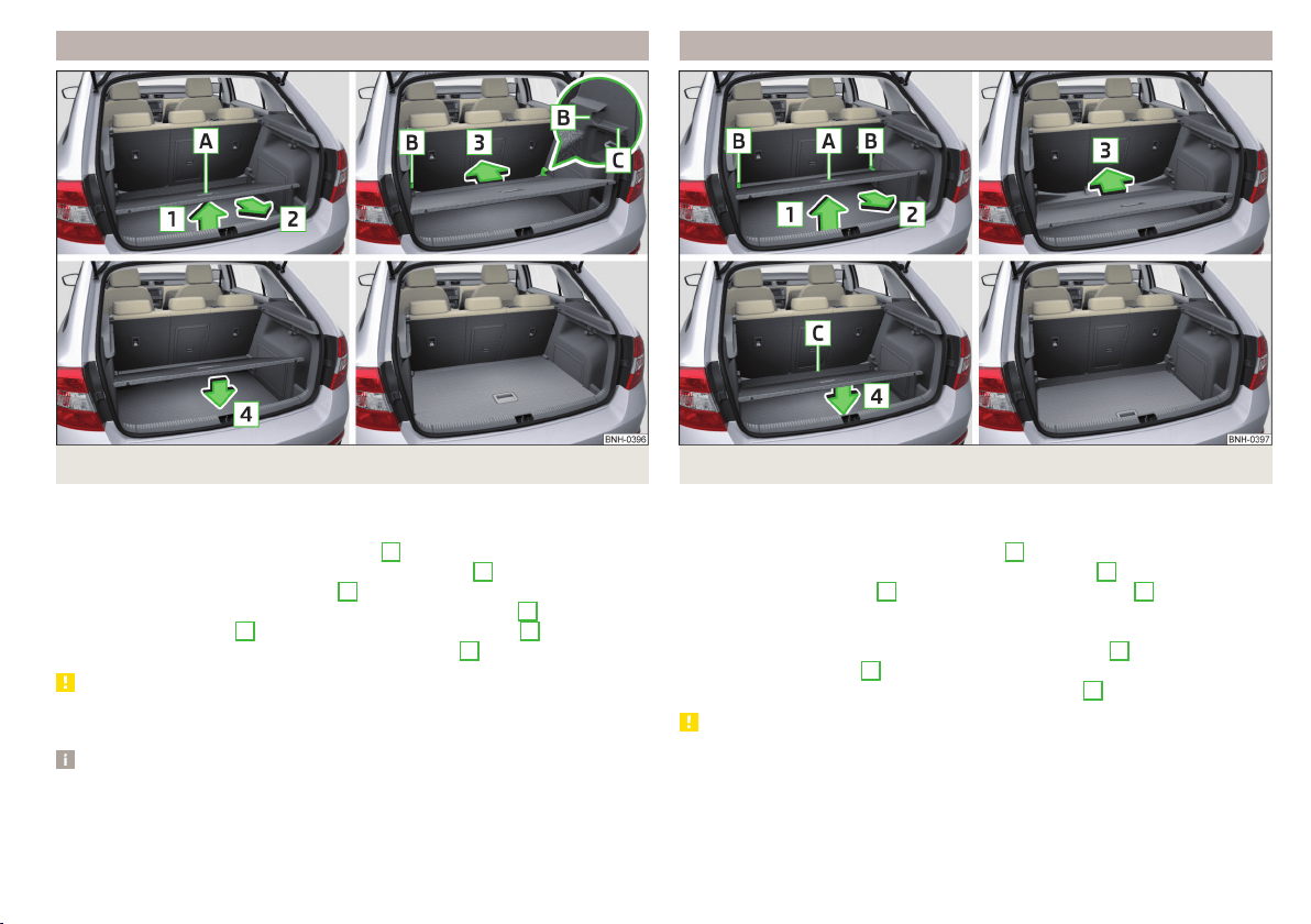
Setting in the upper position
Fig. 100 Set the variable loading floor to the upper position
The variable loading floor in the lower position can be set to the upper position
as follows.
›
Grasp the variable loading floor at handle
A
» Fig. 100.
›
Lift the variable loading floor in the direction of arrow
1
and move partially
backwards in the direction of arrow
2
.
›
Lift the variable loading floor at the front, place onto corner
C
and slide in
the direction of arrow
3
until it clicks into place in brackets
B
.
›
Place the variable loading floor in direction of arrow
4
.
CAUTION
The variable loading floor cannot be set in the upper position when the lug-
gage compartment cover is in the “park position” » page 84.
Note
When in the upper position there is space for storing items underneath the
variable loading floor.
Setting in the lower position
Fig. 101 Set the variable loading floor to the lower position
The variable loading floor in the upper position can be set to the lower position
as follows.
›
Grasp the variable loading floor at handle
A
» Fig. 101.
›
Lift the variable loading floor in the direction of arrow
1
and partially move
in the direction of arrow
2
until it detaches from brackets
B
.
›
Place the variable loading floor onto the floor covering of the luggage com-
partment while tilted forward.
›
Push the variable loading floor in the direction of arrow
3
as far as it will go,
and until its front part
C
is raised.
›
Place the variable loading floor in direction of arrow
4
.
CAUTION
The variable loading floor cannot be set in the lower position when the lug-
gage compartment cover is in the “park position” » page 84.
87
Transporting and practical equipment
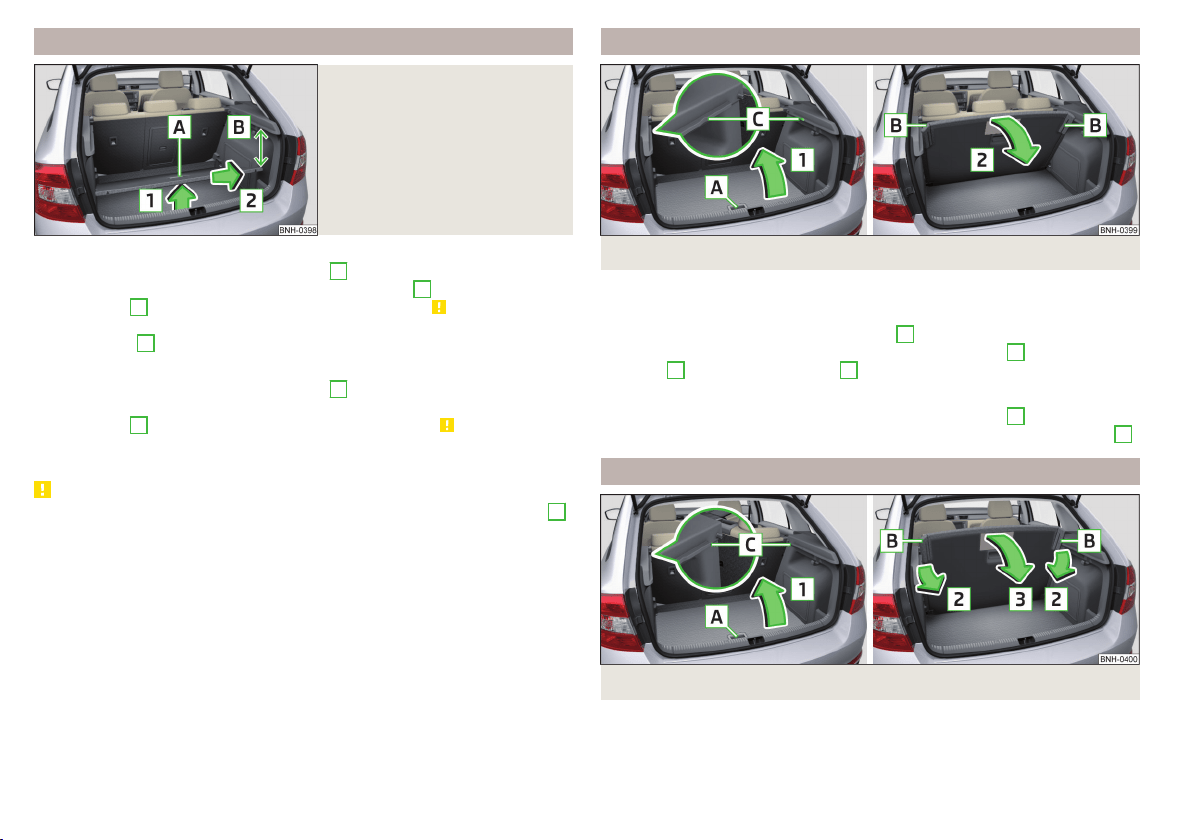
Removing/inserting
Fig. 102
Remove variable loading floor
Removing
›
Grasp the variable loading floor at handle
A
» Fig. 102.
›
Lift the variable loading floor in the direction of arrow
1
until its rear area is
about 15 cm
B
below the luggage compartment cover » .
›
Remove the variable loading floor from the vehicle by moving it in the direc-
tion of arrow
2
.
Inserting
›
Grasp the variable loading floor at handle
A
» Fig. 102.
›
Insert variable loading floor into the vehicle with the front portion tilted
about 15 cm
B
beneath the luggage compartment cover» .
›
Then follow the same steps as when setting the upper position » page 87 or
the lower position » page 87 .
CAUTION
■
When removing or inserting the variable loading floor, a distance of 15 cm
B
» Fig. 102 underneath the boot cover must be adhered to - risk of damaging
the boot lid seal.
■
The variable loading floor cannot be placed in the vehicle when the luggage
compartment cover is in the “park position” » page 84.
■
After removing the variable cargo floor, place it down in such a way that it
cannot be damaged or soiled.
Folding up/down
Fig. 103 Fold up/fold down variable loading floor
The variable loading floor can be folded up in both positions (upper and lower).
Folding up
›
Grasp the variable loading floor at handle
A
» Fig. 103.
›
Lift the variable loading floor in the direction of the arrow
1
until the folding
corners
B
lock into place in area
C
.
Folding down
›
Grasp the variable loading floor in the middle or at handle
A
» Fig. 103.
›
Unlock the variable loading floor by pulling it in the direction of the arrow
2
.
“Parking position”
Fig. 104
Set parking position / fold down from the parking position
The variable loading floor can only be in set to the “parking position” when it is
in the lower position » page 87 and the luggage compartment cover has been
taken out » page 84.
88
Using the system
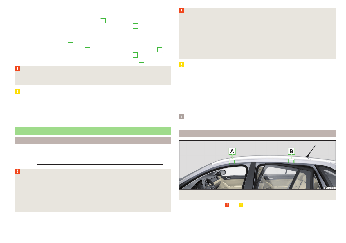
Folding up
›
Remove the luggage compartment cover from the vehicle » page 84.
›
Grasp the variable loading floor at handle
A
» Fig. 104.
›
Lift the variable loading floor in the direction of the arrow
1
until the folding
corners
B
lock into place in area
C
.
Folding down
›
Push the folding corners
B
» Fig. 104 on both sides of the variable loading
floor in the direction of the arrow
2
and release these from positions
C
.
›
Grasp the variable loading floor in the middle or at handle
A
.
›
Fold down the variable loading floor in the direction of arrow
3
.
WARNING
The variable loading floor in the “parking position” restricts the driver's
view at the back.
CAUTION
■
The variable loading floor can only be in set to the “parking position” when it
is in the lower position and the luggage compartment cover has been taken
out.
■
If the variable loading floor is in the “parking position”, the “parking position”
on the luggage compartment cover cannot be set » page 84.
Roof rack
Introduction
This chapter contains information on the following subjects:
fixing points for base support 89
Roof load 90
WARNING
When transporting cargo the following the instructions must be adhered
to.
■
The items being transported on the roof rack must always be securely at-
tached – risk of accident!
■
Always secure the load with appropriate and undamaged lashing straps
or tensioning straps.
■
Distribute the load evenly over the roof rack system.
WARNING (Continued)
■
When transporting heavy objects or objects which take up a large area on
the roof rack system, handling of the car may change as a result of the dis-
placement of the centre of gravity. The style of driving and speed must
therefore be adapted to the current circumstances.
■
Avoid abrupt and sudden driving/braking manoeuvres.
■
The permissible roof load, permissible axle loads and permissible total ve-
hicle weight must not be exceeded under any circumstance – risk of acci-
dent!
CAUTION
■
On models fitted with an electrical sliding/tilting roof, ensure that the slid-
ing/tilting roof does not strike any items of luggage transported on the roof
when tilting.
■
Ensure that the boot lid does not hit the roof load when opened.
■
The height of the vehicle changes after mounting a roof luggage rack system
including the load that is being transported. Compare the vehicle height with
available clearances, such as underpasses and garage doors.
■
Ensure the roof aerial is not impaired by the load being transported.
Note
We recommend that you use a roof rack from ŠKODA Original Accessories.
fixing points for base support
Fig. 105 Attachment points
Read and observe and on page 89 first.
The mounting points are located on both sides of the vehicle.
89
Transporting and practical equipment

Arrangement of the mounting points » Fig. 105
Front attachment points
Rear attachment points
The mounting and dismounting of the basic carrier is carried out according to
the instructions provided.
Roof load
Read and observe and on page 89 first.
Do not exceed the permissible roof load of 75 kg, this includes the carrier sys-
tem.
The full permissible roof load cannot be used if a roof rack system with a lower
load carrying capacity is used. The maximum capacity of the carrier system
should never be exceeded.
A
B
Heating and ventilation
Heating, manual air conditioning system, Climatronic
Introduction
This chapter contains information on the following subjects:
Heating and manual air conditioning 91
Climatronic (automatic air conditioning) 92
Climatronic - automatic mode 93
Air distribution control 93
Air outlet vents 94
The heating and air conditioning ventilate and heat the vehicle interior. The air
conditioning system also cools and dehumidifies the vehicle interior.
The heating effect is dependent upon the coolant temperature, thus full heat
output only occurs when the engine has reached its operating temperature.
The cooling system only operates if the following conditions are met.
The cooling system is switched on.
The engine is running.
The outside temperature is above approx. +2 °C.
The blower is switched on.
If the cooling system is switched on, the temperature and air humidity drops in
the vehicle. The cooling system prevents the windows from misting up during
winter months.
It is possible to briefly activate re-circulated air mode to enhance the cooling
effect » page 93.
Health protection
To reduce health risks (e.g. common colds), the following instructions for the
use of the cooling system are to be observed.
▶
The difference between the indoor temperature and the outdoor air temper-
ature should not be greater than about 5 ° C.
▶
The cooling system is to be turned off about 10 minutes before the end of
the journey.
▶
Once a year, disinfection of the manual air conditioner or the Climatronic is to
be carried out by a specialist company.
90
Using the system
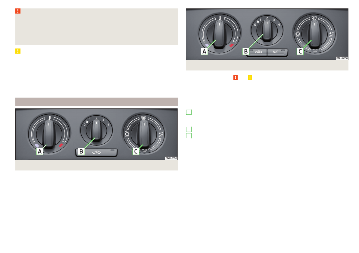
WARNING
■
For your own safety and that of other road users, ensure that all the win-
dows are free of ice, snow and misting. The blower should always be on to
prevent the windows from misting up.
■
Under certain circumstances, air at a temperature of about 5 °C can flow
out of the vents when the cooling system is switched on.
CAUTION
■
The air inlet in front of the windscreen must be free from ice, snow or leaves,
for example, to ensure that the heating and cooling system works properly.
■
After switching on the cooling Condensation from the evaporator of the air
conditioning may drip down and form a puddle below the vehicle. This is not a
leak!
■
If the coolant temperature is too high, the cooling system is switched off to
ensure that the engine cools down.
Heating and manual air conditioning
Fig. 106 Heating Controls
Fig. 107 Controls of the manual air conditioning
Read and observe and on page 91 first.
Individual functions can be set or switched on by turning the rotary switch or
pressing the respective button. When the function is switched on, the indica-
tor light in the button lights up.
Functions of the individual control elements » Fig. 106 and » Fig. 107
Set the temperature
▶
Lower the temperature
▶
Increase the temperature
Set the blower speed (Level 0: Fan off, Level 4: Highest speed)
Set the direction of the air outlet » page 94
▶
Air flow to the windows
▶
Air flow to the upper body
▶
Air flow to the footwell
▶
Air flow to the windows and the footwell
Switch recirculation on/off » page 93
Switch the cooling system on/off
Information on the cooling system
The cooling system operates only if the following conditions are met
» page 90.
The warning light in the button
» Fig. 107 lights up after activation, even if
not all of the conditions for the function of the cooling system have been met.
By lighting up of the warning light in the button, the operational readiness of
the cooling system is signalled.
A
B
C
91
Heating and ventilation
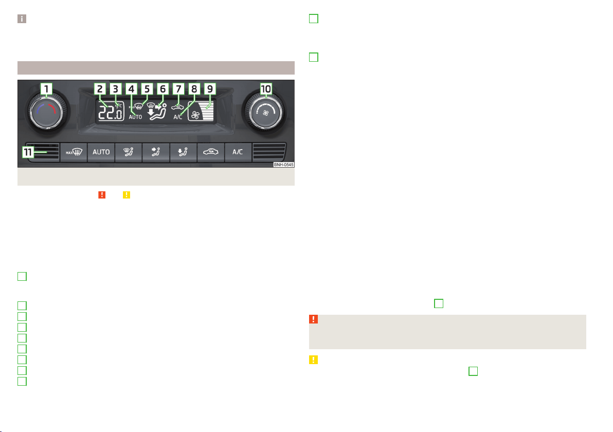
Note
During operation of the manual air conditioning, an increase in engine idle
speed may occur under certain circumstances in order to ensure sufficient
heating comfort.
Climatronic (automatic air conditioning)
Fig. 108 Controls the Climatronic
Read and observe and on page 91 first.
The Climatronic in automatic mode ensures the best-possible setting of the
temperature of the out-flowing air, the blower stage and air distribution.
Individual functions can be set or switched on by turning the rotary switch or
pressing the respective button. When this function is switched on, the corre-
sponding icon appears in the display.
Functions of the individual control elements and display indicators » Fig. 108
Set the temperature
▶
Lower the temperature
▶
Increase the temperature
Selected temperature
Degrees Celsius or Fahrenheit
Automatic operation of the air conditioning system is switched on
Intensive windshield defroster switched on
Direction of air flow
Recirculated air mode activated
Cooling system activated
Set blower speed
1
2
3
4
5
6
7
8
9
Set the blower speed (the set blower speed is indicated by the corre-
sponding number of segments in the display)
▶
Turn to the left: Reduce speed up to turning off the Climatronic
▶
Turn to the right: Increase speed
Interior temperature sensor
Switching the intensive windshield defroster on/off - when this function
is switched on, the warning light illuminates in the button
Switching automatic mode on
Switching the airflow to the windows on and off
Switching the airflow to the upper body on and off
Switching the airflow to the footwell on and off
Switch recirculation on/off » page 93
Switch the cooling system on/off
After the cooling system is switched off, only the ventilation function remains
active, whereby the lowest temperature that can be reached is the outside
temperature.
Setting temperature
The temperature can be set between +16 °C and +29 °C. The temperature is
regulated automatically within this range.
If
illuminates in the display, then the Climatronic is working with maximum
cooling (temperature setting below +16°C).
If
illuminates in the display, then the Climatronic is working with maximum
heating (temperature setting above +29°C).
There is no automatic temperature control in the two end positions.
Switching between Celsius and Fahrenheit
Press buttons
and
simultaneously and hold for about 2 seconds.
The desired temperature unit (item
3
» Fig. 108) appears on the display.
WARNING
■
Do not switch off the Climatronic system for longer than necessary.
■
Switch on the Climatronic system as soon as the windows mist up.
CAUTION
Do not cover the interior temperature sensor
11
» Fig. 108 as this could impair
the functioning of the Climatronic.
10
11
92
Using the system

Note
■
As soon as the windscreen mists up, press the symbol button . Press the
button once the windscreen has demisted.
■
During operation of the Climatronic, an increase in engine idle speed can oc-
cur under certain circumstances in order to ensure adequate heating comfort.
Climatronic - automatic mode
Read and observe and on page 91 first.
The automatic mode is used in order to maintain a constant temperature and
to demist the windows in the interior of the car.
To switch on press the
button. The display shows
(pos.
4
» Fig. 108
on page 92).
Automatic mode can be switched off by pressing one of the buttons for the air
distribution or by increasing/decreasing the blower speed. The temperature is
nevertheless regulated.
Air distribution control
Read and observe
and on page 91 first.
The recirculation mode prevents contaminated outside air getting into the In-
terior of the vehicle.
In recirculated air mode air is sucked out of the interior of the vehicle and then
fed back into the interior.
Switching on/off
›
Press the
button.
Heating and manual air conditioning system
If the air distribution control is set to position
when the recirculation modes
is switched on, the recirculated-air mode is switched off. Recirculated air mode
can be switched on again from this setting by repeatedly pressing the symbol
button
.
Climatronic
With the recirculated-air mode switched on the symbol
appears in the dis-
play.
The symbol
disappears from the display after turning off the air recircula-
tion.
Depending on the moisture conditions in the vehicle interior the air recircula-
tion may shut-down automatically.
WARNING
The recirculation system cannot be switched on for a longer period of time,
because there is no supply of fresh air from the outside. “Stale air” may re-
sult in fatigue in the driver and occupants, reduce attention levels and also
cause the windows to mist up. The risk of having an accident increases.
Switch off recirculated air mode as soon as the windows start to mist up.
CAUTION
We recommend not smoking in the vehicle when the recirculating air operation
is switched on. The smoke sucked from inside the vehicle is deposited on the
evaporator of the air conditioner. This produces a permanent odour when the
air conditioning system is operating which can only be eliminated through con-
siderable effort and expense (replacement of compressor).
Note
If recirculated air mode is switched on for around 15 minutes, the symbol
will begin to flash in the Climatronic display as a sign that the recirculated air
mode is switched on long-term. If the recirculated air mode is not switched off,
the symbol flashes for around 5 minutes.
93
Heating and ventilation
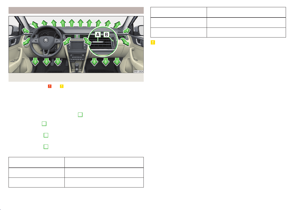
Air outlet vents
Fig. 109 Air outlet vents
Read and observe and on page 91 first.
The direction of airflow can be adjusted using the air outlet vents 3, 4
» Fig. 109, the outlets can be opened and closed individually.
Changing the direction of air flow
›
To change the height of the air flow, turn the horizontal fins upward or
downward using the movable adjuster
A
» Fig. 109.
›
To adjust the lateral direction of the air flow, turn the vertical fins with the
movable adjuster
A
to the left or to the right.
Opening
›
Turn the regulator
B
upwards » Fig. 109.
Closing
›
Turn the regulator
B
downwards » Fig. 109.
Overview of the available settings for adjusting the direction of the air outlet
Set the direction of the air
outlet
Active air vents » Fig. 109
1, 2, 4
1, 2, 4, 5
Set the direction of the air
outlet
Active air vents » Fig. 109
3, 4
4, 5
CAUTION
To ensure that the heating, the manual air conditioning and the Climatronic
systems work properly, do not block up the air outlet vents with any objects.
94
Using the system

Driving
Starting-off and Driving
Starting and stopping the engine using the key
Introduction
This chapter contains information on the following subjects:
Electronic immobilizer
95
Steering lock locking / unlocking 96
Turn ignition on / off and start the engine 96
Stopping the engine 96
With the key in the ignition, the ignition can be switched on and off and the
engine can be started / stopped.
WARNING
■
While driving with the engine stopped, the ignition must always be
switched on » page 96, Turn ignition on / off and start the engine.
■
With the ignition off, the steering may lock » page 96 - danger of an
accident!
■
Do not withdraw the ignition key from the ignition lock until the vehicle
has come to a stop » page 103, Parking. Otherwise, the steering may lock -
danger of an accident!
■
Never leave the key in the vehicle when you exit the vehicle. Unauthor-
ized persons, such as children, for example, could lock the car, turn on the
ignition or start the engine - there is a danger of injury, accidents and dam-
age!
■
Never leave the vehicle unattended with the engine running - there is
risk of accident, damage or theft!
■
Never switch off the engine before the vehicle is stationary – risk of acci-
dent!
WARNING
■
Never (e.g. in garages) run the engine in a closed place - there is the dan-
ger of poisoning and death!
■
Do not leave any items (e.g. cloths or tools) in the engine compartment.
This presents a fire hazard and the risk of engine damage.
■
Never cover the engine with additional insulation material (e.g. with a
cover) – risk of fire!
CAUTION
■
Only start the engine when the engine and the vehicle are stationary - there
is a danger of starter and engine damage!
■
Do not push-start the engine – risk of damaging the engine and the catalytic
converter. The battery from another vehicle can be used as a jump-start aid
» page 168.
Note
Do not warm up the engine while the vehicle is stationary. If possible, start
your journey as soon as the engine has started. Through this, the engine rea-
ches its operating temperature faster.
Electronic immobilizer
Read and observe
and on page 95 first.
The electronic immobiliser (hereinafter referred to as the immobiliser) makes
the attempted theft or unauthorised use of your vehicle more difficult.
An electronic chip is integrated in the head of the key. The immobiliser is deac-
tivated with the aid of this chip when the key is inserted in the ignition lock.
As soon as the ignition key is removed from the ignition lock, the immobiliser is
automatically activated.
Operational problems
If the immobiliser components in the key fail, it is not possible to start the en-
gine. A corresponding message appears in the display of the instrument clus-
ter to explain that the immobiliser is active.
To start, use the other vehicle key or seek help from a specialist garage.
95
Starting-off and Driving
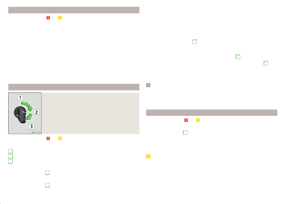
Steering lock locking / unlocking
Read and observe and on page 95 first.
The steering lock (steering lock) deters any attempted theft of your vehicle.
Locking
›
Withdraw the ignition key.
›
Turn the steering wheel to the left or right until the steering lock clicks into
place.
Unlocking
›
Insert the key into the ignition lock.
›
Switch on the ignition » page 96.
The steering lock is unlocked.
If the ignition switch cannot be turned on, then turn the steering wheel back
and forth slightly and thereby unlock the steering lock.
Turn ignition on / off and start the engine
Fig. 110
Positions of the vehicle key in the ignition lock
Read and observe and on page 95 first.
Positions of the vehicle key in the ignition lock » Fig. 110
Ignition switched off, engine switched off
Ignition switched on
Starting engine
Switching ignition on/off
›
Turn key to position
2
.
The ignition is switched on.
›
Turn key to position
1
.
1
2
3
The ignition is switched off.
Procedure for starting the engine
›
Firmly apply the handbrake.
›
For vehicles with manual transmission, shift gear stick to neutral, depress
the clutch pedal and hold it there until the engine starts.
›
On vehicles with automatic transmission, place the selector lever in position
P or N and depress the brake pedal until the engine starts.
›
Turn the key into position
3
as far as it will go - the engine's starting proce-
dure will commence (do not touch the accelerator).
›
Release the key, the engine will start automatically.
After letting go, the vehicle key will return to position
2
.
If the engine does not start within 10 seconds, turn the key to position
1
. Re-
peat the start-up process after approx. half a minute.
For vehicles with diesel engines the glow plug warning light
goes on during
starting. The engine can be started after the indicator light goes out.
Note
■
The engine running noises may louder at first be louder for a short time after
starting the cold engine. This is quite normal and is not an operating problem.
■
You should not switch on any major electrical components during the heat-
ing period otherwise the vehicle battery will be drained unnecessarily.
Stopping the engine
Read and observe and on page 95 first.
›
Stop the vehicle » page 103, Parking.
›
Turn key to position
1
» Fig. 110 on page 96.
The engine and the ignition are switched off simultaneously.
For vehicles with automatic transmission, the ignition key can only be removed
if the selector lever is in position P .
CAUTION
Do not switch the engine off immediately at the end of your journey after the
engine has been operated over a prolonged period at high loads but leave it to
run at an idling speed for about 1 minute. This prevents any possible accumula-
tion of heat when the engine is switched off.
96
Driving
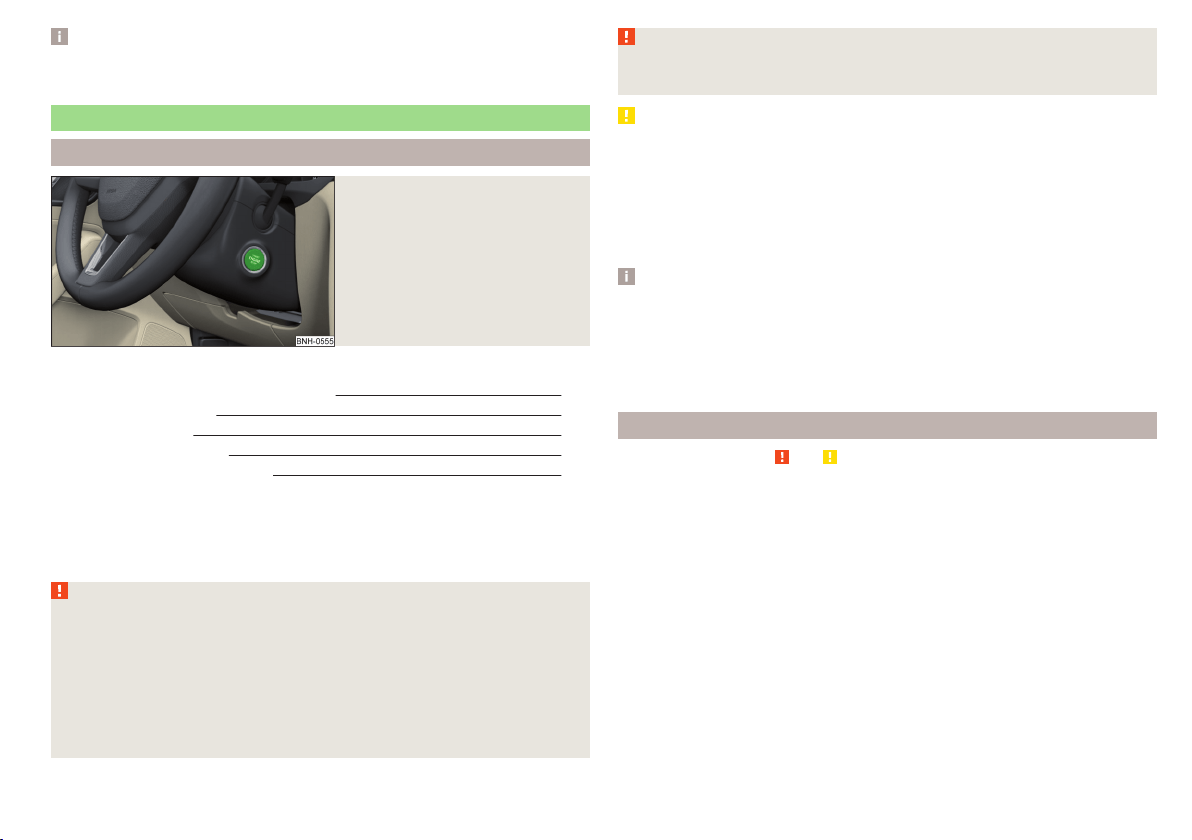
Note
After switching off the ignition, the radiator fan can intermittently continue to
operate for approx. 10 minutes.
Starting and stopping the engine at the push of the button
Introduction
Fig. 111
Starter button (
)
This chapter contains information on the following subjects:
Steering column lock locking / unlocking 97
Switch ignition on / off 98
Starting the engine 98
Switching off the engine 98
Problems with the engine start 99
The ignition can be switched on and off and the engine can be started / stop-
ped with the starter button » Fig. 111.
The key must be in the vehicle to unlock the steering, start the vehicle and
drive.
WARNING
■
Never leave the key in the vehicle when you exit the vehicle. Unauthor-
ized persons, such as children, for example, could lock the car, turn on the
ignition or start the engine - there is a danger of injury, accidents and dam-
age!
■
Never leave the vehicle unattended with the engine running - there is a
risk of theft etc!
■
Never switch off the engine before the vehicle is stationary – risk of acci-
dent!
WARNING
Never (e.g. in garages) run the engine in a closed place - there is the danger
of poisoning and death!
CAUTION
■
The system can recognize the valid key, even if it has been accidentally left
on the vehicle roof - there is danger of loss or damage to the key!
■
Only start the engine when the engine and the vehicle are stationary - there
is a danger of starter and engine damage!
■
Do not push-start the engine – risk of damaging the engine and the catalytic
converter. The battery from another vehicle can be used as a jump-start aid
» page 168.
Note
■
Do not warm up the engine while the vehicle is stationary. If possible, start
your journey as soon as the engine has started. Through this, the engine rea-
ches its operating temperature faster.
■
The system is protected against inadvertently switching off the engine while
driving, this means that the engine can only be switched off in an emergency
» page 98.
Steering column lock locking / unlocking
Read and observe
and on page 97 first.
The steering lock (steering lock) deters any attempted theft of your vehicle.
Locking
›
Switch off the engine.
›
Open the driver door.
The steering lock is locked automatically.
If the driver's door is opened and the ignition is switched off afterwards, the
steering is only locked after the vehicle has been locked.
Unlocking
›
Open the driver's door and get into the vehicle.
›
Close the driver's door.
The steering is locked automatically.
97
Starting-off and Driving

Under certain circumstances (e.g. after switching off the ignition and opening
the driver's door), the steering is enabled only when the ignition is switched on
or the engine is started.
WARNING
Never let the vehicle roll with locked steering lock - risk of accident!
Switch ignition on / off
Read and observe
and on page 97 first.
›
Press the button » Fig. 111 on page 97 briefly.
The ignition is switched on or off.
On vehicles fitted with a manual transmission, the clutch pedal must not be
depressed while switching the ignition on or off, otherwise the system would
try to start.
On vehicles fitted with a automatic transmission, the brake pedal must not be
depressed while switching the ignition on or off, otherwise the system would
try to start.
If the driver's door is opened while the ignition is on, an audible signal sounds
and the following message appears in the instrument cluster display.
Ignition switched on.
IGNITION STILL ON
When leaving the vehicle always switch off the ignition.
Starting the engine
Read and observe and on page 97 first.
Procedure for starting the engine
›
Firmly apply the handbrake.
›
For vehicles with manual transmission, shift gear stick to neutral, depress
the clutch pedal and hold it there until the engine starts.
›
On vehicles with automatic transmission, place the selector lever in position
P or N and depress the brake pedal until the engine starts.
›
Press the starter button » Fig. 111 on page 97 briefly – the engine starts auto-
matically.
In vehicles with diesel engines the glow plug warning light lights up after
pressing the button. The engine can be started after the indicator light goes
out.
Note
■
The engine running noises may louder at first be louder for a short time after
starting the cold engine. This is quite normal and is not an operating problem.
■
You should not switch on any major electrical components during the heat-
ing period otherwise the vehicle battery will be drained unnecessarily.
Switching off the engine
Read and observe and on page 97 first.
Switching off
›
Stop the vehicle
» page 103, Parking.
›
Press the button » Fig. 111 on page 97 briefly.
The engine and the ignition are switched off simultaneously.
Emergency shut-down
If necessary and in exceptional cases, the engine may even be turned off while
driving.
›
Press the starter button » Fig. 111 on page 97 for longer than 1 second or
twice within 1 second.
After the emergency stop of the motor, the steering lock will remain unlocked.
CAUTION
Do not switch the engine off immediately at the end of your journey after the
engine has been operated over a prolonged period at high loads but leave it to
run at an idling speed for about 1 minute. This prevents any possible accumula-
tion of heat when the engine is switched off.
Note
After switching off the ignition, the radiator fan can intermittently continue to
operate for approx. 10 minutes.
98
Driving
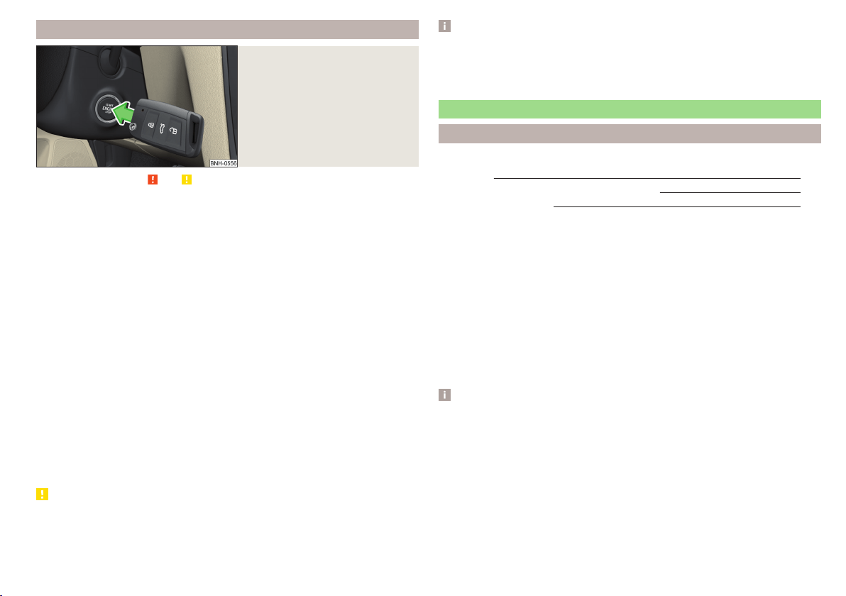
Problems with the engine start
Fig. 112
Starting the engine - Press the
button with the key
Read and observe and on page 97 first.
The key in the vehicle cannot be verified
If the key in the vehicle cannot be verified, then engine cannot be started by
pressing a button.
One of the following messages are shown in the information cluster display.
Key not detected. Owner's manual!
Key not found.
NO KEY
The reasons for this may be.
▶
The battery in the key is almost out of charge.
▶
The key is malfunctioning.
▶
There is interference in the signal between the system and the key (strong
electromagnetic field).
Try to start the engine by pressing the knob with the key » Fig. 112.
System fault
If the following message appears on the display of the instrument cluster,
there is a system malfunction.
Keyless access system faulty.
KEYLESS ACCESS SYSTEM FAULTY
Try to start the engine by pressing the knob with the key » Fig. 112.
CAUTION
The key can only be verified if it is in the vehicle. It is therefore not always nec-
essary to know where the key is.
Note
■
When attempting to start, the key bit must be pointed towards the button
» Fig. 112.
■
If engine fails to start after pressing the button with the key, seek specialist
help.
START-STOPsystem
Introduction
This chapter contains information on the following subjects:
Operation
100
Manually deactivating/activating the system 101
Information messages
101
The START STOPsystem (hereinafter referred to as the system) reduces
CO
2
emissions and harmful emissions, and saves fuel.
If the system determine that the engine is not needed when the vehicle stops
(e.g. at the traffic lights), it turns off the engine and starts it again when mov-
ing off.
The system function depends on many factors. Some of them are down to the
driver, while others are systemic and can neither be influenced nor identified.
For this reason, the system may react differently in situations which seem
identical from the driver's perspective.
The system is automatically activated every time the ignition is switched on
(even when it has previously been manually deactivated with the
button).
Note
If the engine has stopped due to the system, the ignition remains switched on.
99
Starting-off and Driving
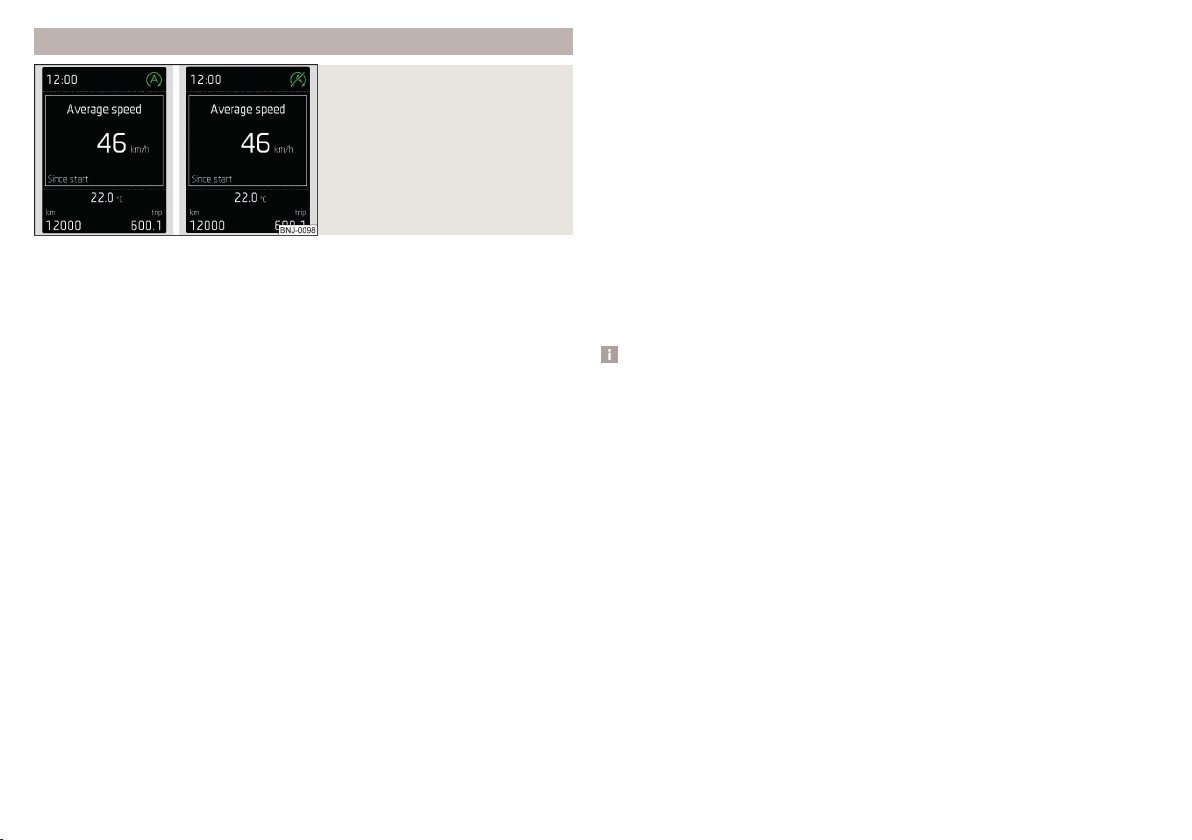
Operation
Fig. 113
Display
Vehicles with manual transmission
The engine is automatically switched off as soon as the vehicle comes to a
halt, the shift lever is moved into neutral and the clutch pedal is released.
The engine is automatically started as soon as the clutch pedal is depressed.
Vehicles with automatic transmission
The engine is automatically switched off as soon as the vehicle comes to a
halt and the brake pedal is operated.
The engine is automatically started as soon as the brake pedal is released.
Requirements for the system to function correctly
The following conditions must be met for the system to function correctly.
The driver's door is closed.
The driver has fastened the seat belt.
The bonnet is closed.
The driving speed was higher than 4 km/h after the last stop.
No trailer is coupled.
System status
The system status is shown in the display when the vehicle comes to a halt
» Fig. 113.
The engine is switched off automatically; when moving off, the ignition
process will be initiated automatically.
The engine is not switched off automatically.
Reasons for the engine running
It may be essential for the engine to keep running when the vehicle comes to
a halt, for the following reasons.
▶
The engine temperature for the proper function of the system has not yet
been reached.
▶
The charge state of the vehicle battery is too low.
▶
The current consumption is too high.
▶
High air-conditioning or heating capacity (high fan speed, big difference be-
tween the desired and actual interior temperature).
When the engine is shut-down automatically and the system detects that the
engine is required such as when the brake pedal is pressed repeatedly then
the system automatically starts the engine.
Infotainment display
Information about the current status of the system can be displayed in the In-
fotainment display » Owner´s Manual Infotainment, chapter CAR - Vehicle set-
tings (CAR button).
Note
■
If the vehicle remains outdoors for a long time in minus temperatures or in
direct sunlight, it can take several hours until the internal temperature of the
vehicle battery reaches a suitable temperature for proper operation of the
START STOP system.
■
If the driver's seat belt is removed for more than approx. 30 seconds or the
driver's door is opened during stop mode, the engine will have to be started
manually.
■
No automatic engine shut-down takes place when a vehicle with automatic
transmission is moving at low speed (e.g. during a traffic jam) and remains sta-
tionary after pressing the brake pedal lightly. Automatic engine shut-down
takes place if you press the brake pedal down with more force.
■
For vehicles with automatic transmission there is no automatic engine shut-
down when the system detects a manoeuvring action due to a large steering
angle.
100
Driving
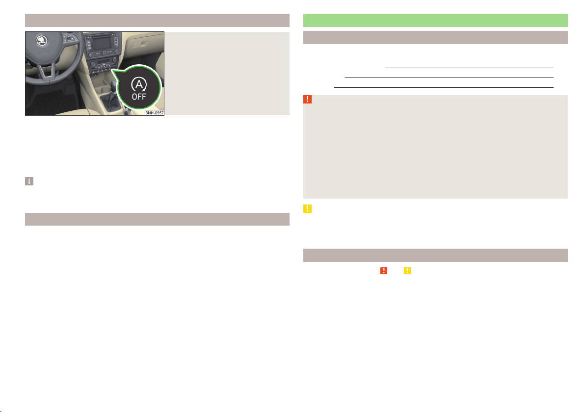
Manually deactivating/activating the system
Fig. 114
Button for the START-STOP sys-
tem
Deactivating/activating
›
Press the symbol
» Fig. 114button.
When system is deactivated, the warning light in the button illuminates.
If the system is deactivated, it will be reactivated automatically after the igni-
tion has been switched off and on.
Note
If the system is deactivated when the engine is turned off automatically, then
the automatic start process takes place.
Information messages
The warning symbols are shown in the instrument cluster display.
Start the engine manually!
START MANUALLY
If for example the driver's seat belt is stored, the engine must be started man-
ually.
On vehicles with the starter button the ignition is turned off by the first press
of the start button, only after pressing for the second time is the start process
initiated.
Error: start-stop system
START STOP ERROR
A system error is present. Seek help from a specialist garage.
Brakes and parking
Introduction
This chapter contains information on the following subjects:
Information on braking
101
Handbrake 102
Parking 103
WARNING
■
Greater physical effort is required for braking when the engine is switch-
ed off – risk of accident!
■
The clutch pedal must be actuated when braking on a vehicle with man-
ual transmission, when the vehicle is in gear and at low revs. Otherwise,
the functionality of the brake system may be impaired – risk of accident!
■
When leaving the vehicle never leave persons leave unattended in the
vehicle who could release the brake. The vehicle could then start to move –
risk of accident!
■
Observe the recommendations on the new brake pads » page 106, New
brake pads.
CAUTION
Never let the brakes slip with light pressure on the pedal if braking is not nec-
essary. This causes the brakes to overheat and can also result in a longer brak-
ing distance and excessive wear.
Information on braking
Read and observe and on page 101 first.
Wear-and-tear
The wear of the brake pads is dependent on the operating conditions and driv-
ing style.
The brake pads wear more quickly if a lot of journeys are completed in towns
and over short distances or if a very sporty style of driving is adopted.
Under these severe conditions, the thickness of the brake pads must also be
checked by a specialist garage between service intervals.
101
Starting-off and Driving
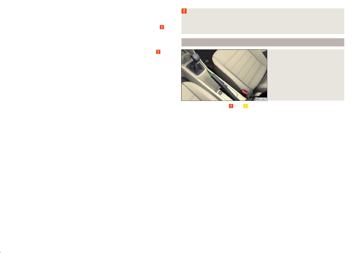
Wet roads or road salt
The performance of the brakes can be delayed as the brake discs and brake
pads may be moist or have a coating of ice or layer of salt on them in winter.
The brakes are cleaned and dried by applying the brakes several times » .
Corrosion
Corrosion on the brake discs and dirt on the bake pads occur if the vehicle has
been parked for a long period and if you do not make much use of the braking
system. The brakes are cleaned by applying the brakes several times » .
Long or steep slopes
Before travelling a long distance with a steep gradient, reduce speed and shift
into the next lowest gear. As a result, the braking effect of the engine will be
used, reducing the load on the brakes. Any additional braking should be com-
pleted intermittently, not continuously.
Emergency brake display
If the brakes are applied in full and the vehicle systems evaluate the situation
as dangerous for the traffic following behind, the brake light flashes automati-
cally.
After the speed was reduced below around 10 km/h or the vehicle was stop-
ped, the brake light stops flashing and the hazard warning light system
switches on. The hazard warning light system is switched off automatically af-
ter accelerating or driving off again.
Faults in the brake surface
If it is found that the braking distance has suddenly become longer and that
the brake pedal can be depressed further, the brake system may be faulty.
Visit a specialist garage immediately and adjust your style of driving appropri-
ately, as you will not know the exact extent of the damage.
Low brake fluid level
An insufficient level of brake fluid may result in problems in the brake system.
The level of the brake fluid is monitored electronically » page 32,
Brake sys-
tem.
Brake booster
The brake booster increases the pressure generated with the brake pedal. The
brake booster only operates when the engine is running.
WARNING
Only apply the brakes for the purpose of drying and cleaning the brake
discs if the traffic conditions permit this. Do not place any other road users
in jeopardy.
Handbrake
Fig. 115
Handbrake
Read and observe and on page 101 first.
The hand brake is used when stopping and parking for securing the vehicle
against unwanted movement.
Apply
›
Pull the handbrake lever firmly upwards.
Releasing
›
Pull the handbrake lever up slightly and at the same time push in the locking
button » Fig. 115.
›
Move the lever right down while pressing the lock button.
The handbrake warning light
illuminates when the handbrake is applied,
provided the ignition is on.
A warning signal sounds if the vehicle is inadvertently driven off with the
handbrake applied.
The following message is shown in the information cluster display.
Release the handbrake!
RELEASE HANDBRAKE
The handbrake warning is activated if the vehicle is driven at a speed of more
than around 5 km/h for more than 3 seconds.
102
Driving

WARNING
Please note that the handbrake must be fully released. A handbrake which
is only partially released can result in the rear brakes overheating. This can
have a negative effect on the operation of the brake system – risk of acci-
dent!
Parking
Read and observe and on page 101 first.
When stopping and parking, look for a place with a suitable surface » .
Only carry out the activities while parking in the specified order.
›
Bring the vehicle to a stop and depress the brake pedal.
›
Firmly apply the handbrake.
›
On vehicles with automatic transmission, place the selector lever in the P
position.
›
Switch off the engine.
›
For vehicles with manual transmission, select gear 1 or reverse gear R.
›
Release the brake pedal.
WARNING
The parts of the exhaust system can become very hot. Therefore, never
stop the vehicle at places where the underside of your vehicle can come in-
to contact with flammable materials such as dry grass, undergrowth,
leaves, spilled fuel or such like. - Risk of fire and serious injury can occur!
Manual gear changing and pedals
Introduction
This chapter contains information on the following subjects:
Manual gear changing 103
Pedals 103
Manual gear changing
Fig. 116
Gearshift pattern of 5 gear or
6 gear manual gearbox
The gearshift pattern for the individual gear positions is shown on the gear
lever » Fig. 116.
The gear shift indicator must be observed when changing gear » page 39.
Always depress the clutch pedal all the way down. This prevents uneven wear
to the clutch.
Engaging reverse gear
›
Stop the vehicle.
›
The clutch pedal must be fully depressed.
›
Move the shift lever to the idle position, switch and press down.
›
Move the shift lever fully to the left and then forward into the Rposition
» Fig. 116.
The reversing lights will come on once the reverse gear is engaged, provided
the ignition is on.
WARNING
Never engage reverse gear when driving – risk of accident!
CAUTION
■
If not in the process of changing gear, do not leave your hand on the gear
shift lever while driving. The pressure from the hand can cause the gear shift
mechanism to wear excessively.
■
When stopping on a slope, never try to hold the vehicle using the clutch and
the accelerator pedal – this may lead to damage to the clutch.
Pedals
The operation of the pedals must not be hindered under any circumstances!
103
Starting-off and Driving
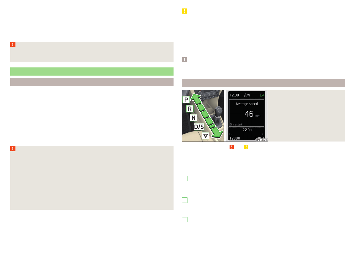
In the driver's foot well, only a foot mat, which is attached to the two corre-
sponding attachment points, may be used.
Only use factory-supplied foot mats or foot mats from the range of
ŠKODAOriginal Accessories, which are fitted to two required attachment
points.
WARNING
No objects may be placed in the driver's foot well – risk due to obstruction
or limitation of pedal operation!
Automatic gearbox
Introduction
This chapter contains information on the following subjects:
Modes and use of selector lever 104
Selector lever lock 105
Manual shifting (Tiptronic) 105
Starting-off and driving 106
The automatic transmission performs automatic gear changes.
The modes for the automatic transmission can be adjusted by the driver by
means of the selector lever.
WARNING
■
Never accelerate when the mode for moving forward is set with the se-
lector lever - there is a risk of accident!
■
Never move the selector lever to mode R or P when driving – risk of acci-
dent!
■
If the vehicle is in the mode selected D, S, R or Tiptronic and the engine
stops when at idle speed, then the brake pedal must be pressed. Even
when the engine is idling, the power transmission is never completely in-
terrupted – the vehicle crawls forward.
■
When leaving the vehicle, the selector lever is always to be put in the P
mode. Otherwise, the vehicle could be set in motion - risk of accident.
CAUTION
■
If the selector lever is moved to mode N while driving, the accelerator pedal
must be released and you will need to wait until the engine has reached its
idling speed before moving the selector lever to a forward driving mode again.
■
When the outdoor temperature is below -10 ° C, the selector lever, when
starting, must always be in P mode.
■
When stopping on a slope, never try to keep the vehicle in position by using
the accelerator pedal – this may lead to gear damage.
Note
After the ignition is switched off, the ignition key can only be withdrawn if the
selector lever is in the position P.
Modes and use of selector lever
Fig. 117
Selector lever/display
Read and observe and on page 104 first.
When the ignition is switched on, the gearbox mode and the currently selected
gear are indicated in the display » Fig. 117.
The following modes can be selected with the selector lever » Fig. 117.
P
– Parking mode
The driven wheels are locked mechanically in this mode.
Parking mode must only be selected when the vehicle is stationary.
R
– Reverse gear
Reverse gear can only be engaged when the vehicle is stationary and the en-
gine is at idling speed.
N
– Neutral
The power transmission to the drive wheels is interrupted in this mode.
104
Driving
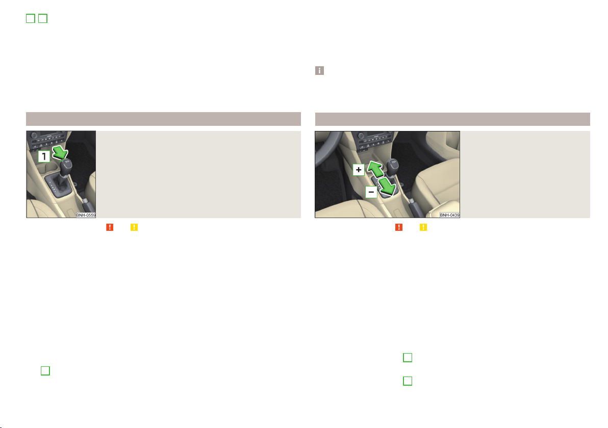
D
/
S
- mode for driving forward (Normal program) / mode for driving
forward (Sport program)
The system switches from one mode to the other by moving the selector lever
into the spring-loaded position
» Fig. 117.
In mode D or S, the forward gears are shifted automatically depending on the
engine load, the operation of the accelerator pedal, the vehicle speed, and the
selected driving mode .
In mode S, the forward gears are shifted automatically up and down at higher
engine speeds than in mode D.
Selector lever lock
Fig. 118
Shift lock button
Read and observe and on page 104 first.
The selector lever is locked in modes P and N to prevent the forwards travel
mode from being selected accidentally and setting the vehicle in motion.
The selector lever is only locked when the vehicle is stationary and at speeds
up to 5 km/h.
The selector lever lock is indicated by the illumination of the warning light
.
The selector lever is not locked when quickly moving across the position N
(e.g. from R to D/S). This, for example, helps to rock out a vehicle that is stuck,
e.g. in a bank of snow. The selector lever lock will engage if the lever is in posi-
tion N for more than approx. 2 seconds without the brake pedal being de-
pressed.
Releasing selector lever from mode P or N (selector lever lock)
›
Press the brake pedal and the lock button at the same time in the direction
of
1
» Fig. 118 .
Just depress the brake pedal, if you would like to change from the mode N to
D/S.
Defective selector lever lock
If the selector lever lock is defective or its power supply is interrupted (e.g. dis-
charged vehicle battery, faulty fuse), the selector lever can no longer be moved
out of position P in the normal manner and the vehicle can no longer be driven.
The selector lever must be emergency released » page 172.
Note
If you want to move the selector lever from mode P to mode D/S or vice versa,
move the selector lever quickly. This prevents modes R or N from being acci-
dentally selected.
Manual shifting (Tiptronic)
Fig. 119
Selector lever
Read and observe and on page 104 first.
Tiptronic mode makes it possible to manually shift gears on the selector lever.
This mode can be selected both while stopping and while driving.
The currently selected gear is indicated in the » Fig. 117 on page 104display.
The gear shift indicator must be observed when changing gear » page 39.
Switching to manual shifting
›
Push the gear selector from position D/S towards the right, or left in a right-
hand drive vehicle.
When switching to the manual shifting while driving, the current gear is main-
tained.
Shifting up gears
›
Push the selector lever
+
» Fig. 119 forwards.
Shifting down gears
›
Push the selector lever
-
» Fig. 119 backwards.
105
Starting-off and Driving

Note
■
It may be beneficial, for example, when travelling downhill, to use manual
shifting of gears. Shifting to a lower gear reduces the load on the brakes and
hence the wear on the brakes » page 101.
■
When accelerating, the gearbox automatically shifts up into the higher gear
just before the maximum permissible engine speed is reached.
■
If a lower gear is selected, the gearbox does not shift down until there is no
risk of the engine over-revving.
Starting-off and driving
Read and observe and on page 104 first.
Starting off
›
Start the engine.
›
Firmly depress and hold the brake pedal.
›
Press the lock button in the direction of
1
» Fig. 118 on page 105 and hold.
›
Move the selector lever into the desired position » page 104 and then release
the lock button.
›
Release the brake pedal and accelerate.
Stopping (while the car is moving)
›
Depress the brake pedal and bring the vehicle to a stop.
›
Keep holding the brake pedal until driving is resumed.
The selector lever position N does not have to be selected when stopping for a
short time, such as at a cross roads.
Kick-down
The kick-down function allows you to achieve the maximum acceleration of
your vehicle while driving.
When the accelerator pedal is fully depressed, the kick-down function is acti-
vated in any forward driving mode.
The gearbox shifts down one or more gears depending on the vehicle speed
and engine speed, and the vehicle accelerates.
The gearbox does not shift up into the highest gear until the engine has
reached its maximum revolutions for this gear range.
WARNING
Rapid acceleration, particularly on slippery roads, can lead to loss of vehicle
control – risk of accident!
Running-in and economical driving
Introduction
This chapter contains information on the following subjects:
Running-in
106
Tips for economical driving 106
DriveGreen function 107
The fuel consumption, degree of pollution and vehicle wear depend on driving
style, road condition, weather conditions and the like.
Running-in
Driving in the engine
The engine has to be run in during the first 1,500 kilometres. During this peri-
od, the driving style decides on the quality of the driving-in process.
During the first 1,000 km, we recommend not driving faster than 3/4 of the
maximum permissible engine speed, not to drive at full throttle and not to use
a trailer.
In the range of 1,000 to 1,500 kilometres, the engine load can be increased up
to the maximum permitted engine speed.
New tyres
New tyres must firstly be “run in”, as they do not offer optimal grip at first.
Therefore, drive with special care for the first 500 km or so.
New brake pads
New brake pads have to first “grind in” because these do not initially have the
best possible braking effect.
Therefore, drive with special care for the first 200 km or so.
Tips for economical driving
To achieve the lowest possible fuel consumption, the following instructions
must be observed.
Looking ahead when driving
Avoid unnecessary acceleration and braking.
Change gear in an energy saving and timely manner
Observe the recommended gear » page 39.
106
Driving
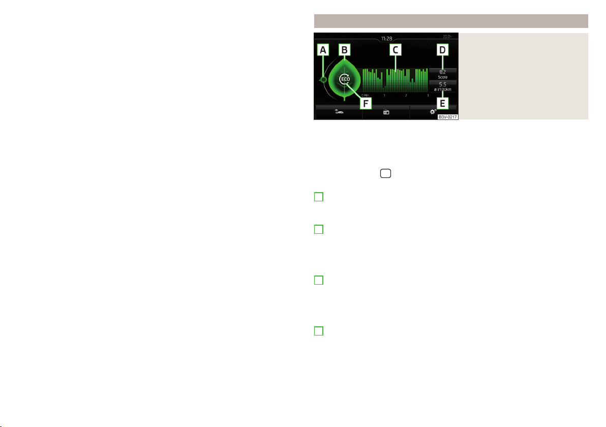
Avoid full throttle and high speeds
Fuel consumption can be reduced by half if only three-quarters of the possible
top speed of your vehicle is used.
Reducing idling
If the vehicle is fitted with the START - STOP system there is an automatic re-
duction of the idling. If the engine is stopped on vehicles without START-STOP
system, such as when waiting in a traffic jam, the fuel economy is already
greater after 30 - 40 s than the fuel quantity which is required for engine re-
start.
Avoid short distances
When driving a short distance of less than about 4 km, the engine cannot
reach its operating temperature. As long as the engine has not reached oper-
ating temperature, the fuel consumption is significantly higher than with the
engine hot.
Pay attention to the correct tyre inflation pressure being maintained
Further information » page 155.
Avoid unnecessary ballast
Per 100 kg of weight, consumption increases by about 0.3 l/100 km. At a speed
of 100 - 120 km/h, a vehicle fitted with a roof rack cross member without a load
will use about 10 % more fuel than normal due to the increased aerodynamic
drag.
Saving electricity
Only turn on electrical consumers (e.g. seat, window and mirror heating and
the like) for as long as necessary.
Use the cooling system economically
The air conditioning system compressor uses power from the engine when in
cooling mode, which will affect the fuel consumption.
It recommended to open the windows or the doors of a vehicle for which the
interior has been strongly heated through the effect of direct sunlight in order
to allow the heated air to escape.
The cooling system should not be on if the windows are open.
DriveGreen function
Fig. 120
Shown in the infotainment dis-
play
The DriveGreen function (hereinafter referred to as DriveGreen) evaluates the
driving efficiency based on the information with regard to driving style. Useful
tips for reducing fuel consumption are also offered.
DriveGreen can be displayed on the Infotainment as follows.
›
Press the button
in the Infotainment and then in the display the function
keys one after the other
,
DriveGreen
.
A
driving liquid display
With the driving is liquid the display is near the green dot. When accelerating
or braking, the indicator moves down or up.
B
“Green leaf”
The leaf margin shown in green shows with a few seconds, the current drive
efficiency. When driving economically there are several green layers on the
edge of the leaf. When driving less economically, no green colour appears and
the leaf can disappear completely.
C
Graphical review summary
The evaluation of the driving economy during the last 3 minutes or 1.5 minutes
(depending on type of Infotainment) is shown like a beam in 5-second incre-
ments. The current status is shown on the left and moves gradually to the
right. The higher the green bars, the more economic the driving style is.
D
Scoring
In the function key, the evaluation of driving efficiency is shown from the start
in the range from 0 to 100 points. The higher the indicated value, the more
economic the driving style is.
When you press the function key, a detailed assessment showing the driving
efficiency during the last 30 minutes is shown.
107
Starting-off and Driving
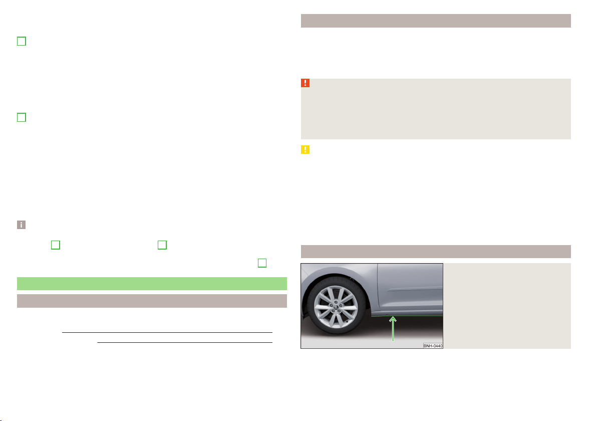
If the trip from the start, takes less than 30 minutes, then the assessment
takes in information from the previous trip (the bars are shown in dark green).
E
Average fuel consumption
In the function key, the average fuel consumption from the start is displayed.
When you press the function key a detailed overview of the average fuel con-
sumption during the last 30 minutes is shown.
If the trip from the start, takes less than 30 minutes, then the average fuel
consumption takes in information from the previous trip (the bars are shown in
dark green).
F
Symbols in the display
The display may show the following four symbols, which give information on
the current driving style.
Ecological trip
The current speed has a negative effect on fuel consumption.
The driving is not liquid, drive with anticipation.
Recommended gear.
Tips for reducing fuel consumption
When tapping the “Page” the display shows useful tips on how to reduce fuel
consumption. These tips can to be helpful to drive more economically.
Note
■
Resetting the single-trip memory “from start” also resets the average con-
sumption
E
and the driving assessment
D
.
■
With some Infotainment types changing the units for the fuel consumption
indicator causes the resetting of the average fuel consumption values
E
.
Avoiding damage to your vehicle
Introduction
This chapter contains information on the following subjects:
Driving Tips 108
Driving through water
108
This section of the manual contains important information on preventing dam-
age to the vehicle while driving.
Driving Tips
Only drive on such roads and in such terrain, which match the vehicle parame-
ters » page 183, Technical data as well as your driving skills.
The driver is always responsible for deciding whether the vehicle can handle
travelling in the given terrain.
WARNING
■
Always adjust your driving to the current terrain and weather conditions.
Excessive speed or incorrect driving manoeuvres can cause damage to the
vehicle and lead to serious injuries.
■
Combustible objects such as dry leaves or twigs caught under the base of
the vehicle could ignite on hot vehicle parts - risk of fire!
CAUTION
■
Pay attention to the ground clearance of the vehicle! When driving over ob-
jects which are larger than the ground clearance, the vehicle can get damaged.
■
Any objects that get trapped under the vehicle floor must be removed as
soon as possible. These objects can damage the fuel lines, the brake system,
seals and other parts of the vehicle.
■
Drive slowly in unknown terrain and watch out for unexpected obstacles,
such as potholes, rocks, stumps, etc.
■
Check up on confusing sections of unpaved roads before travelling on them
and consider whether such travelling is possible without risk.
Driving through water
Fig. 121
Maximum permissible water lev-
el when driving through water
The following instructions must be observed if vehicle damage is to be avoided
when driving through water (e.g. flooded roads).
108
Driving

›
Therefore, always determine the depth of the water before driving through
water.
The water level must not reach above the web of the lower beam » Fig. 121.
›
Do not drive any faster than at a walking speed.
At a higher speed, a water wave can form in front of the vehicle which can
cause water to penetrate into the engine's air induction system or other parts
of the vehicle.
›
Never stop in the water, do not reverse and do not switch the engine off.
CAUTION
■
Should water penetrate into the intake system of the engine, there is a
threat of serious damage being incurred by the engine parts!
■
When driving through water, some vehicle parts such as chassis, electrics or
transmissions can be severely damaged.
■
Oncoming vehicles can generate water waves which can exceed the permis-
sible water level for your vehicle.
■
Potholes, mud or rocks can be hidden under the water, making it difficult or
impossible to drive through water.
■
Do not drive through salt water, as the salt can cause corrosion. A vehicle
coming into contact with salt water is to be thoroughly rinsed with fresh wa-
ter.
Assist systems
General information
Introduction
WARNING
The following general information regarding the use of assistance systems
must be observed.
■
The assistance systems only serve to support the driver and do not re-
lieve the driver of the responsibility for driving the vehicle.
■
The increased safety provision, as well as the increased occupant protec-
tion provided by the assistance systems must not tempt you to take risks -
risk of accident!
■
Adjust the speed and driving style to the current visibility, weather, road
and traffic conditions.
■
The assistance systems have physical and system-related limitations. For
this reason, the driver may experience some undesired or delayed system
responses in certain situations. You should therefore always be alert and
ready to intervene!
■
Only enable, disable or set the assistance systems so that you have the
car fully under control in every traffic situation - risk of accident!
Braking and stabilisation systems
Introduction
This chapter contains information on the following subjects:
Stability Control (ESC) 110
Anti-lock braking system (ABS) 110
Traction control (TCS) 110
Electronic Differential Lock (EDL) 111
Brake Assist (HBA) 111
Hill Start Assist (HHC) 111
Multi collision brake (MCB) 111
Trailer stabilization system (TSA) 111
This chapter describes the functions of the brake and stabilization systems.
The error display is in Chapter » page 31, Indicator lights.
109
Assist systems
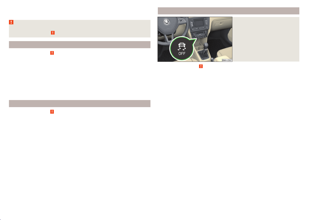
The brake and stabilization systems are automatically activated each time the
ignition is switched on, unless otherwise indicated.
WARNING
The general information relating to the use of assistance systems must be
observed » page 109, in section Introduction.
Stability Control (ESC)
Read and observe
on page 110 first.
The ESC improves vehicle stability in dynamic driving situations, such as when
the vehicle starts to skid.
The ESC monitors whether the desired direction of the current vehicle motion
is occurring. In case of any deviation (e.g. over-steer), the ESC automatically
brakes individual wheels to maintain the desired direction.
During an intervention of the system, the warning light
flashes in the instru-
ment cluster.
Anti-lock braking system (ABS)
Read and observe
on page 110 first.
ABS prevents the wheels from locking when braking. Thereby, it helps the
driver to maintain control of the vehicle.
The intervention of the ABS is noticeable from the pulsating movements of
the brake pedal which is accompanied by noises.
When the ABS system is active, do not brake periodically or reduce the pres-
sure on the brake pedal.
Traction control (TCS)
Fig. 122
System button: Activating/deac-
tivating TCS
Read and observe on page 110 first.
TCS prevents the spinning of the wheels of the driven axle. TCS reduces the
drive power transmitted to the wheels in the case of slipping wheels. Thereby,
for example, driving on road surfaces with low grip is made easier.
During a TCS intervention, the indicator light
flashes in the instrument clus-
ter.
Activating/deactivating TCS
The activation or deactivation of TCS can be done, depending on equipment, in
one of the following ways.
▶
Infotainment » Owner´s Manual Infotainment, chapter CAR - vehicle set-
tings.
▶
By briefly pressing the symbol key
» Fig. 122.
The warning light illuminates in the instrument cluster when the TCS is deacti-
vated
.
The TCS should normally always be enabled. The system should be deactivated
only in the following situations, for example.
▶
When driving with snow chains.
▶
When driving in deep snow or on a very loose surface.
▶
When “rocking a car free” when it has become stuck.
110
Driving

Electronic Differential Lock (EDL)
Read and observe on page 110 first.
EDL prevents the turning of the respective wheel of the driven axle. EDL
brakes the spinning wheel, if necessary, and transmits the driving force to the
other driving wheel. Driving becomes easier on road surfaces with different
traction under each wheel of the driven axle.
The EDL switches off automatically in order to avoid excessive heat generation
on the brake of the wheel being braked. Once the brakes have cooled down,
there is an automatic re-activation of EDL.
Brake Assist (HBA)
Read and observe on page 110 first.
The HBA increases the braking effect and helps to reduce the braking dis-
tance.
The HBA is activated by the very quick operation of the brake pedal. In order to
achieve the shortest possible braking distance, the brake pedal must be ap-
plied firmly until the vehicle has come to a standstill.
The HBA function is automatically deactivated when the brake pedal is re-
leased.
Hill Start Assist (HHC)
Read and observe on page 110 first.
When driving on slopes, HHC allows you to move your foot from the brake ped-
al to the accelerator pedal without having to use the handbrake.
The system holds the brake pressure produced by the activation of the brake
pedal for approx. 2 seconds after the brake pedal is released.
The HHC is active from a 5% slope if the driver's door is closed. HHC is only ev-
er active on slopes when in forward or reverse start off.
Multi collision brake (MCB)
Read and observe on page 110 first.
The MCB helps to decrease speed after a collision through automatic braking
interventions and to stabilize the vehicle. This reduces the risk of a subse-
quent crash due to uncontrolled vehicle movement.
The automatic brake interventions can take place only if the following condi-
tions are met.
There was a front, side and rear-end collision of a certain severity.
The impact speed was higher than approx. 10 km/h.
The brakes, the ESL and other required electrical systems remain function-
al after impact.
The accelerator pedal is not actuated.
Trailer stabilization system (TSA)
Read and observe
on page 110 first.
The TSA helps the combination stable in situations where the trailer sways
and then the whole trailer combination.
TSA brakes the individual wheels of the towing vehicle in order to damp the
rocking motion of the entire vehicle combination.
The following conditions are required for the correct TSA function.
The trailer was shipped from the factory or purchased from the ŠKODA
genuine accessories.
The trailer is electrically connected to the towing vehicle by means of the
trailer socket.
The TCS is activated.
The speed is higher than approx. 60 km/h.
Further information » page 121, Hitch and trailer.
111
Assist systems
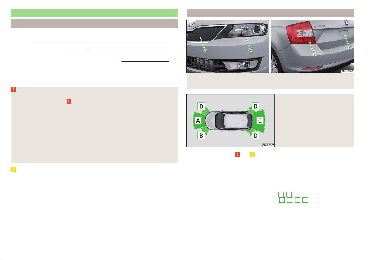
Parking assistance (ParkPilot)
Introduction
This chapter contains information on the following subjects:
Function
112
Display in the Infotainment display 113
Activation / deactivation 113
Automatic system activation when moving forward 114
Park Assist (hereinafter referred to as the system) draws attention via acoustic
signals or the Infotainment display when manoeuvring around obstacles in the
vicinity of the vehicle.
WARNING
■
The general information relating to the use of assistance systems must
be observed » page 109, in section Introduction.
■
Moving persons or objects may not be recognised by the system sensors.
■
Under certain circumstances, surfaces of certain objects and types of
clothing cannot reflect the system signals. For this reason, such people or
objects may not be recognised by the system sensors.
■
External noise sources may affect the signals of the system sensors. Un-
der adverse conditions, this may cause objects or people not to be recog-
nised by the system.
■
Before reversing, you should make sure that there are no small obstacles,
such as rocks, thin posts, trailer draw-bars etc. in front or behind your vehi-
cle. Such obstacles may not be recognised by the system sensors.
CAUTION
■
Keep the system sensors » Fig. 123 on page 112 clean, snow-and ice-free and
do not cover with any objects of any kind, otherwise the system functioning
may be impaired.
■
Under adverse weather conditions (heavy rain, water vapour, very low or
high temperatures, etc.), the system function may be limited - “incorrect recog-
nition of obstacle”.
■
Accessories additionally installed on the vehicle rear, such as bicycle carriers,
can impair the system function.
Function
Fig. 123 Installation position of the sensors on the left side of the vehicle:
front/rear
Fig. 124
Sampled areas and range of the
sensors
Read and observe and on page 112 first.
The system uses ultrasound waves to calculate the distance between the
bumper and an obstacle. The ultrasonic sensors are, depending on vehicle
equipment,, located in the back or in the front bumper » Fig. 123.
Depending on the equipment, the following system versions can exist
» Fig. 124.
▶
Version 1: warns of obstacles in the areas
C
,
D
.
▶
Version 2: warns of obstacles in the areas
A
,
B
,
C
,
D
.
112
Driving
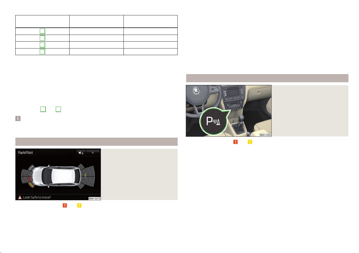
Approximate range of sensors (in cm)
Area » Fig. 124 Version 1
(3 sensors)
Version 2
(7 sensors)
A
- 120
B
- 60
C
160 160
D
60 60
Audible signals
The interval between the acoustic signals becomes shorter as the clearance is
reduced. A continuous tone sounds from a distance of approx. 30 cm - danger
area. From this moment on do not continue driving!
The acoustic signals can be set in the Infotainment» Owner´s Manual Infotain-
ment , chapter CAR - Vehicle Settings .
Towing a trailer
When towing, or when another accessory is connected to the trailer socket on-
ly the areas
A
and
B
» Fig. 124 are active in the system.
Note
The signal tones for front obstacle recognition are factory-set to be higher
than for rear obstacle recognition.
Display in the Infotainment display
Fig. 125
Display
Read and observe and on page 112 first.
Function keys and obstacle warning » Fig. 125
Depending on the Infotainment type: Switching off park assistant dis-
play.
Switching audible parking signals on/off.
Message:
Look! Safe to move?
Colour of an object detected in the collision area (the distance to the
obstacle is less than 30 cm).
Stop driving in the direction of the ob-
stacle!
Colour of an object detected in the manoeuvring area (the distance to
the obstacle is more than 30 cm).
Colour of an object detected in the outside the manoeuvring area (the
distance to the obstacle is more than 30 cm).
System failure (there is no indication of obstacles).
Activation / deactivation
Fig. 126
System key (option 2)
Read and observe and on page 112 first.
Activation
The activation of the system is initiated when the reverse gear is engaged, or
vehicles with the Variant 2, also by pressing the symbol key
» Fig. 126.
This is confirmed by a short acoustic signal (the symbol
in the button lights
up).
Deactivation
On vehicles with Version 1, the system can be deactivated by moving out of re-
verse gear.
For vehicles with Version 2, the system is deactivated by pressing the symbol
button
or automatically at a speed over 10 km/h (the symbol
in the but-
ton goes out).
113
Assist systems
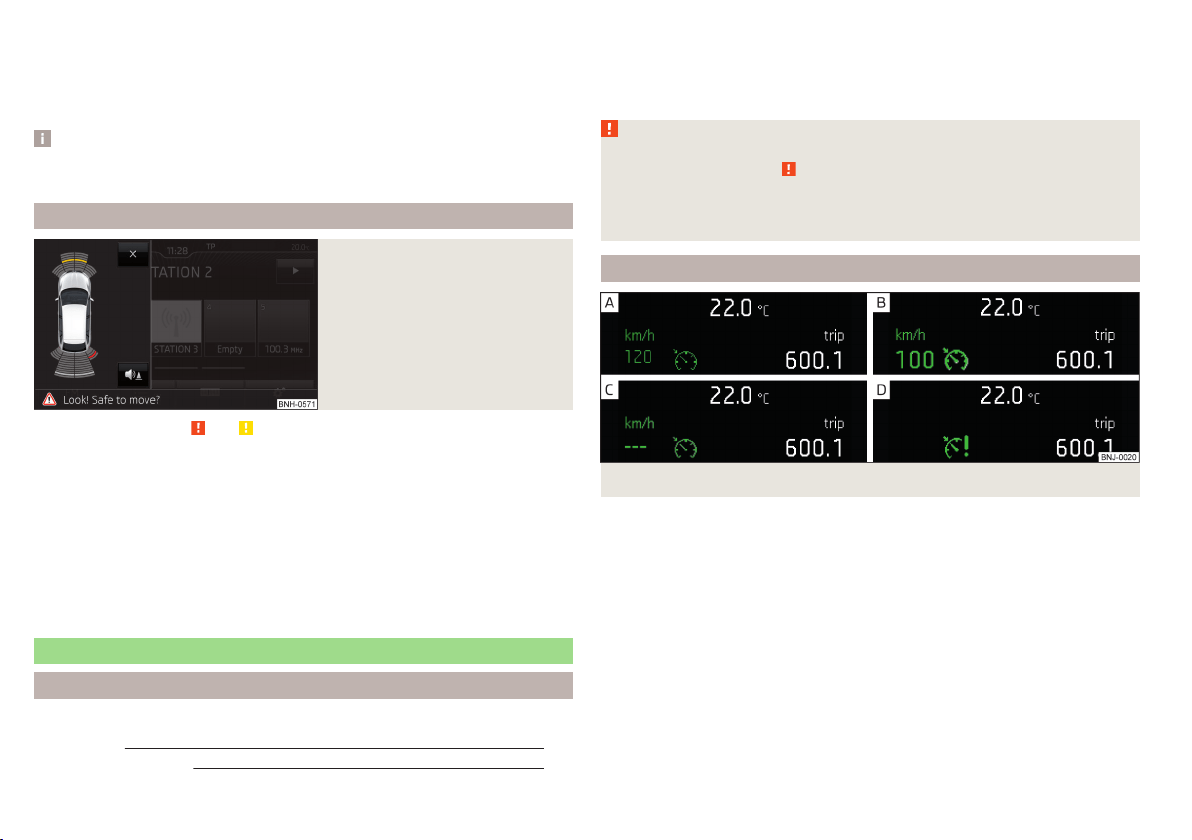
Displaying an error
If a warning signal sounds for about 3 seconds after activating the system and
there is no obstacle close to your car, this indicates a system fault. The fault is
also indicated by the symbol
flashing in the button. Seek help from a spe-
cialist garage.
Note
The system can only be activated with the symbol key at a speed of below
approx. 15 km / hr.
Automatic system activation when moving forward
Fig. 127
Infotainment display: Display
with automatic activation
Read and observe and on page 112 first.
The automatic system activation occurs when moving forward at a speed be-
low 10 km / h when the vehicle approaches an obstacle.
After activation, the following is shown in the left pane of the Infotainment
display » Fig. 127.
Acoustic signals are sounded as of a distance from the obstacle of around
50 cm.
The automatic display can be enabled or disabled in the Infotainment » Owner
´s Manual Infotainment, chapter CAR - vehicle settings.
Speed control system
Introduction
This chapter contains information on the following subjects:
Functioning
114
Operating Description 115
The Cruise Control System (CCS) maintains a set speed without you having to
actuate the accelerator pedal.
The status where the CCS maintains the speed is referred to hereinafter as the
control.
WARNING
■
The general information relating to the use of assistance systems must
be observed » page 109, in section Introduction.
■
After pressing the clutch pedal, no interrupted control occurs! For exam-
ple, if a different gear is engaged and the clutch pedal is released, control is
continued.
Functioning
Fig. 128 MAXI DOT display: Examples of status displays the CCS
114
Driving
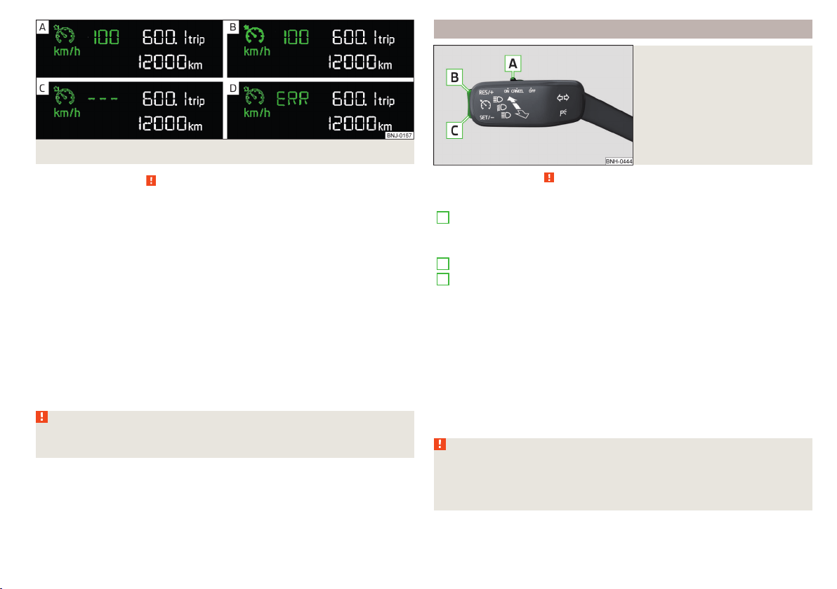
Fig. 129 Segment display: Examples of status displays the CCS
Read and observe on page 114 first.
CCS status displays » Fig. 128, » Fig. 129
Speed set, but control is inactive.
Control is active.
No speed set.
System fault - seek assistance from a specialist garage immediately.
Basic requirements for starting the control
The CCS is activated.
On vehicles with a manual transmission, the second gear or higher is en-
gaged.
On vehicles with an automatic transmission, the selector lever is in the
D/S position or in the Tiptronic position.
The current speed is higher than approx. 20 km/h.
This is only possible within the range which is permitted by the power output
and braking power of the engine.
WARNING
If the engine power and engine braking effect is insufficient to maintain
the set speed, vehicle operation must be taken over!
Operating Description
Fig. 130
Cruise control system controls
Read and observe on page 114 first.
Overview of the CCS controls » Fig. 130
A
Deactivate CCS (delete set speed)
Interrupt control (sprung position)
Activate CCS (control deactivated)
B
Take control again
a)
/ Increase speed
C
Start control / reduce speed
a)
If no speed is set the current speed is adopted.
At the start of the regulation the CCS regulates the vehicle to the current
speed, and this speed is shown on the instrument cluster display. The warning
light
illuminates in the instrument cluster.
Automatic control interruption
Automatic control interruption occurs if any of the following conditions are
met.
▶
The brake pedal is operated.
▶
When one of the brake assist systems (e.g. ESC) intervenes.
▶
Through an airbag deployment.
WARNING
■
Always deactivate the cruise control system after use to prevent the sys-
tem being switched on unintentionally.
■
Control may only be resumed if the set speed is not too high for the cur-
rent traffic conditions.
115
Assist systems
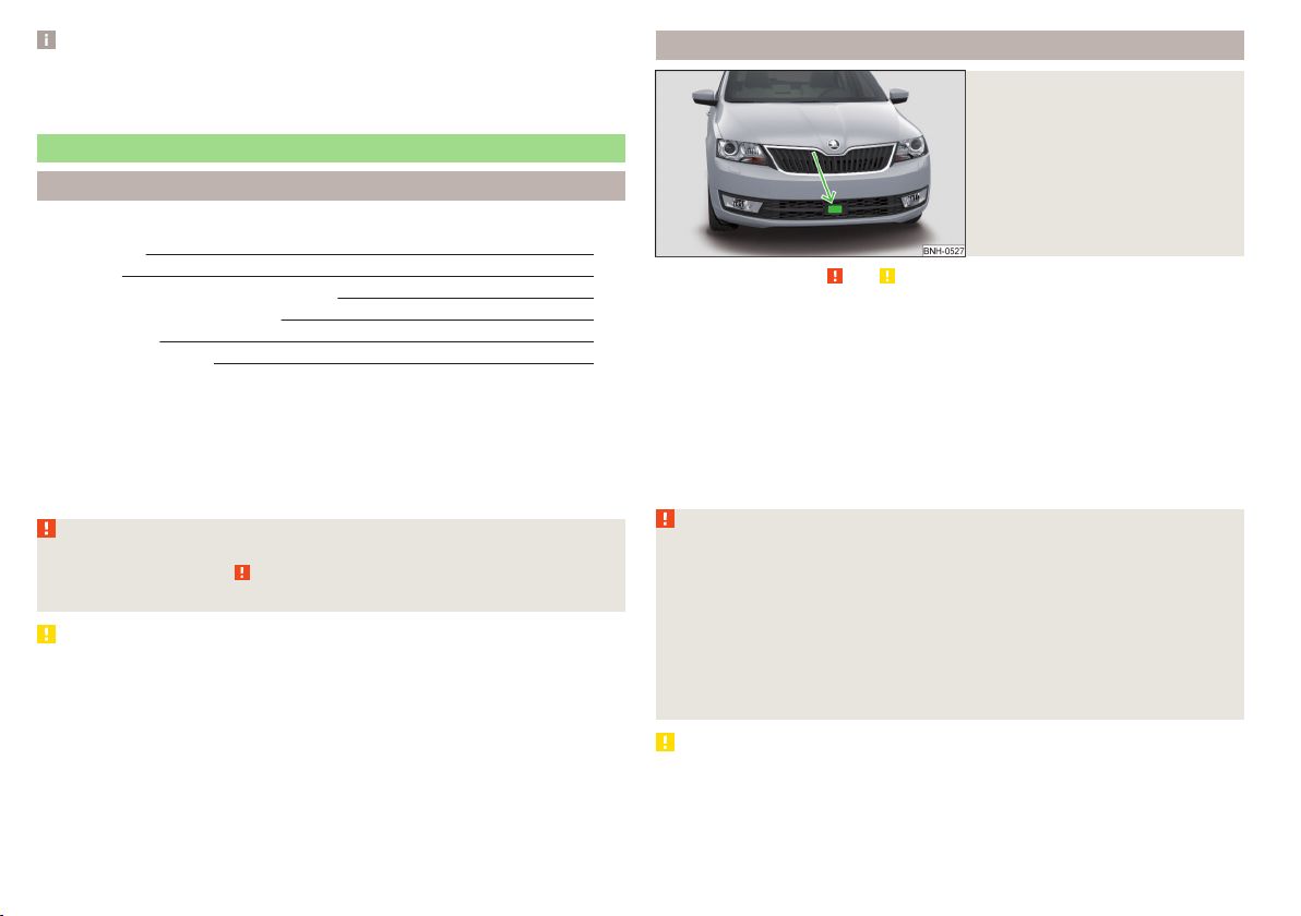
Note
During control, speed can be increased by pressing the accelerator pedal. Re-
leasing the accelerator pedal will cause the speed to drop again to the set
speed.
Front Assist
Introduction
This chapter contains information on the following subjects:
Radar sensor
116
Operation 117
Distance warning (dangerous distance) 117
Warning and automatic braking
117
Disable/enable
118
Information messages
118
The Front Assist (hereinafter referred to as the system) warns you of the dan-
ger of a collision with a vehicle or another obstacle in front of the vehicle, and
tries to avoid a collision or mitigate its consequences by automatically applying
the brakes where necessary.
The area in front of the vehicle is monitored by a radar sensor » Fig. 131 on
page 116.
WARNING
■
The general information relating to the use of assistance systems must
be observed » page 109, in section Introduction.
■
The system does not respond to crossing or oncoming objects.
CAUTION
In case of failure of more than one brake light on the vehicle or on the electri-
cally connected trailer, the system becomes unavailable.
Radar sensor
Fig. 131
Mounting location of the radar
sensor
Read and observe and on page 116 first.
The radar sensor » Fig. 131(hereinafter referred to as the sensor) may detect
objects by emitting and receiving electromagnetic waves.
The sensor function may be impaired in the events of one of the following.
▶
The sensor is soiled by mud, snow and the like.
▶
The area in front and around the sensor is obscured by labels, auxiliary lights
and similar.
▶
When visibility is poor, (e.g. fog, heavy rain, thick snowfall).
If the sensor is dirty or covered, the corresponding message appears on the
display of the instrument cluster » page 118, Information messages.
WARNING
■
If you suspect that the sensor is damaged, deactivate the system. Have
the sensor checked by a specialist garage.
■
The sensor can become misaligned by collisions or by damage to the front
of the vehicle, the wheel arch or the underside of the vehicle. This can lead
to impaired function of the sensor - risk of accidents! Have the sensor
checked by a specialist garage.
■
The area in front and around the sensor should not be obscured by labels,
auxiliary lights and similar. This can lead to impaired function of the sensor
- risk of accidents!
CAUTION
Remove the snow with a brush and the ice with a solvent-free de-icer.
116
Driving
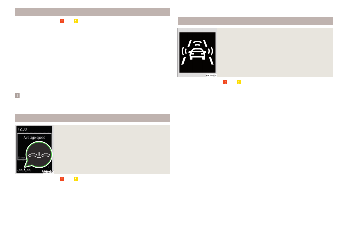
Operation
Read and observe and on page 116 first.
The system support is provided in the following manner.
▶
Alerts you about a dangerous proximity to the vehicle ahead.
▶
Warns you of an impending collision.
▶
Prepares the brakes for emergency braking prior to a detected danger.
▶
Assists with a brake action triggered by the driver.
▶
If the driver fails to respond to a detected danger, an automatic braking ac-
tion is performed.
The system can work only if the following basic conditions are met.
The system is activated.
The TCS is activated » page 110, Traction control (TCS).
The vehicle is moving forwards at a speed of more than approx. 5 km/h.
Note
The system can be impaired or may not be available, for example when driving
in “sharp ”curves or with an ESC engagement » page 110.
Distance warning (dangerous distance)
Fig. 132
Symbols in the instrument cluster: Note (dangerous
proximity)
Read and observe and on page 116 first.
The display of the distance warning is for vehicles with MAXI DOT display.
If a safe interval to the vehicle ahead falls below a minimum the display of the
instrument cluster shows the symbol
» Fig. 132.
Immediately increase the proximity if the current traffic situation allows you
to do so!
The proximity at which the warning is displayed depends on the current speed.
The warning may occur when driving between about 60 km/h and 210 km/h.
Warning and automatic braking
Fig. 133
Symbols in the instrument cluster: Warning or emer-
gency braking at low speed
Read and observe and on page 116 first.
Emergency braking at low speed
In a driving speed range of about 5 km/h to about 30 km/h the automatic brak-
ing action is not preceded by a warning. With an immediate impact hazard au-
tomatic braking is done with the breaking force increasing in stages.
With automatic braking the symbol appears
» Fig. 133 in the display.
Advance warning
If the system detects a risk of collision, the symbol
» Fig. 133 appears in the
display and you will hear an acoustic signal.
At the same time, the braking system is prepared for possible emergency brak-
ing.
The pre-warning display can occur in the following situations.
▶
If there is a risk of collision with a moving obstacle in a driving speed range of
about 30 km/h to about 210 km/h.
▶
There is a risk of a collision with a stationary moving obstacle in a vehicle
speed range of approximately 30 km/h to about 85 km/h.
With a warning the brake pedal must be pressed or the moving obstacle is to
be avoided!
Acute alert
If the driver does not react to the advance warning, the system briefly applies
the brake automatically via an active brake intervention to draw attention to
the potential danger of a collision again.
117
Assist systems
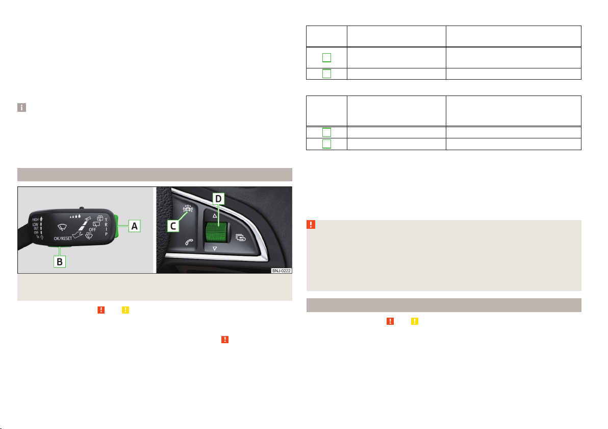
Automatic Braking
If the driver fails to respond to the acute warning, the system starts to apply
the brakes automatically with increasing stopping power in several stages.
Brake assist
If the driver brakes inadequate with an impending collision, the system auto-
matically increases braking force.
The braking assistance only occurs as long as the brake pedal is being firmly
pressed down.
Note
■
If an automatic brake intervention is triggered by the system, the pressure in
the brake system increases and the brake pedal cannot be operated with the
normal pedal stroke.
■
The automatic braking interventions can be cancelled by pressing the accel-
erator pedal or by steering intervention.
Disable/enable
Fig. 134 Buttons/dial: on the control lever/on the multifunction steering
wheel
Read and observe and on page 116 first.
The system is automatically activated each time the ignition is switched on.
The system should only be disabled in exceptional cases » .
On vehicles with the MAXI DOT display, the system can be activated / deactiva-
ted in the main menu in menu item
Assist systems
» page 42.
Deactivation / activation in vehicles with segment display
Button
» Fig. 134
Action Operation
A
Press and hold at the top
or down
Show Front Assist menu item
B
Press briefly Confirm entry (disable / enable)
Deactivation / activation in vehicles with multi-function steering wheel
Button /
dial
» Fig. 134
Action Operation
C
Press briefly Show Front Assist menu item
D
Press briefly Confirm entry (disable / enable)
Disable / enable and setting in the Infotainment
In the Infotainment the entire system or the functions warning and distance
warning can be disabled / enabled » Owner´s Manual Infotainment, chap-
ter CAR - Vehicle Settings.
f the distance-warning function was deactivated before the ignition was
switched off, it remains deactivated after the ignition is switched on again.
WARNING
In the following situations, Front Assist should be switched off for safety
reasons.
■
When the vehicle is being towed away.
■
When the vehicle is on a rolling test bench.
■
If an unfounded warning or a system action was taken.
■
When on a truck, or a car ferry service or similar.
Information messages
Read and observe
and on page 116 first.
The warning symbols are shown in the instrument cluster display.
Front Assist: no sensor view.
FRONT ASSIST NO SENSOR VIEW
The sensor is soiled or covered.
118
Driving

Stop the car, switch off the engine and clean the sensor or eliminate the dis-
turbance causing the lack of visibility » Fig. 131 on page 116.
If after engine start the message persists, then the help of a professional or-
ganisation is required.
Front Assist not available.
FRONT ASSIST NOT AVAILABLE
The system is not available for an unknown reason.
Stop the vehicle, switch off the engine and then start it again.
If after engine start the message persists, then the help of a professional or-
ganisation is required.
Fatigue detection
Introduction
This chapter contains information on the following subjects:
Function
119
Information messages 119
The fatigue detection system (hereinafter referred to as the system) recom-
mends the driver takes a break from driving when driver fatigue can be detec-
ted due to the driver's steering behaviour.
WARNING
■
The general information relating to the use of assistance systems must
be observed » page 109, in section Introduction.
■
For the driving ability is always the driver's responsibility. Never drive if
you feel tired.
■
The system may not detect all cases where a break is needed.
■
Therefore, take regular, sufficient breaks during long trips.
■
There will be no system warning during the so-called micro-sleep.
Note
■
In some situations, the system may evaluate the driving incorrectly and thus
mistakenly recommend a break (e.g. sporty driving, adverse weather condi-
tions or poor road conditions).
■
The system is designed primarily for use on motorways.
Function
Read and observe on page 119 first.
From the start of the journey, the system evaluates steering behaviour. If,
while driving, there have been changes in the steering behaviours that are
evaluated by the system as indicating possible fatigue, a break recommenda-
tion is issued.
The system evaluates steering behaviour and recommends a break at speeds
of 65 - 200 km/h.
The system detects a break from driving when one of the following condi-
tions is met.
▶
The vehicle is stopped and the ignition switched off.
▶
The vehicle is stopped, the seat belt removed and the driver's door opened.
▶
The vehicle is stopped for more than 15 minutes.
If none of these conditions are met or if the driving style is not changed, the
system recommends a driving break again after 15 minutes.
The system can be activated or deactivated in the Infotainment » Owner´s
Manual Infotainment, chapter CAR - vehicle settings.
Information messages
Read and observe
on page 119 first.
The icon appears and the following message for a few seconds in the display
of the instrument cluster
and the following message.
Driver alert.
Take a break!
DRIVER ALERT TAKE A BREAK
An audible signal is also emitted.
Tyre pressure monitoring
Introduction
This chapter contains information on the following subjects:
Save tyre pressure values 120
Save tyre pressure values and infotainment display 120
Save tyre pressure values by pressing a button 121
119
Assist systems
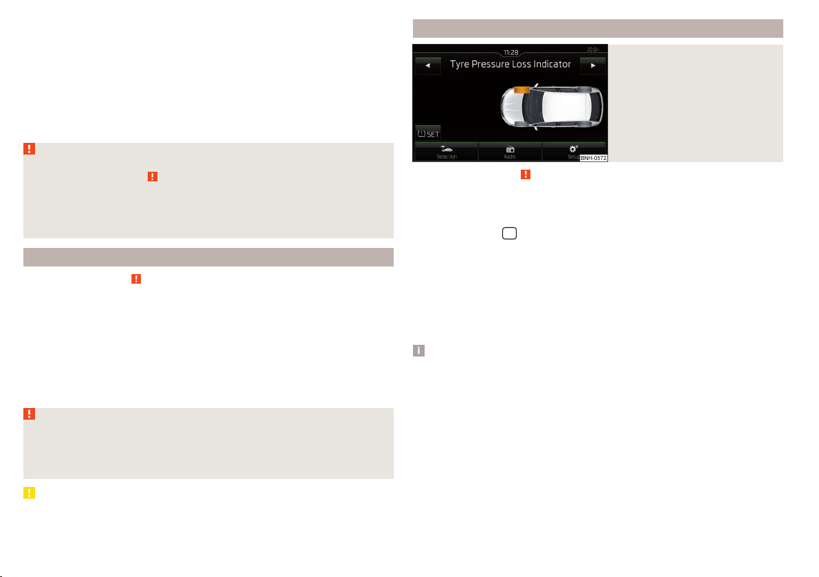
The tyre pressure monitoring function (hereinafter referred to as the system)
monitors the tyre pressure while driving.
When changing the tyre inflation pressure, the warning light illuminates
in
the instrument cluster and an audible signal is heard.
Information on the procedure for the notification of change of tyre inflation
pressure » page 34.
The system can only function properly if the tyres have the prescribed inflation
pressure and this pressure values are stored in the system.
WARNING
■
The general information relating to the use of assistance systems must
be observed » page 109, in section Introduction.
■
Having the correct tyre inflation pressure is always the driver's responsi-
bility. Tyre pressure should be checked regularly » page 155.
■
The system cannot warn in case of very rapid tyre inflation pressure loss,
e.g. in case of sudden tyre damage.
Save tyre pressure values
Read and observe
on page 120 first.
The tyre pressure values are always stored in the system, if one of the follow-
ing events occurs.
▶
Change of tyre inflation pressure.
▶
Change one or more wheels.
▶
Change in position of a wheel on the vehicle.
▶
The warning light
in the instrument cluster.
The storage of the tyre pressure values depends on equipment, either in the
infotainment or by pressing a button.
WARNING
Before storing the pressures, the tyres must be inflated to the specified in-
flation pressure » page 155. When storing incorrect pressure values, the
system could possibly not issue any warnings, even with a too low tyre
pressure.
CAUTION
The tyre pressure values are to be saved every 10,000 km or once annually to
ensure correct system functioning.
Save tyre pressure values and infotainment display
Fig. 135
Button for storing the pressure
values/Example of the display:
the system indicates a tyre pres-
sure change in the front right
tyre
Read and observe on page 120 first.
›
Inflate all the tyres to the specified pressure.
›
Switch on the ignition.
›
The Infotainment switches on.
›
Press the button
in the Infotainment and then in the display the function
keys one after the other
,
Vehicle status
.
›
By using the function keys
select the Tyre Pressure Loss Indicator menu
item.
›
Press the function key
SET
» Fig. 135.
In addition, follow the instructions that appear on the display.
A message in the display informs about the storage of the tyre pressure val-
ues.
Note
When a warning light in the instrument cluster appears, the affected tyre
can be displayed on the infotainment » Fig. 135.
120
Driving
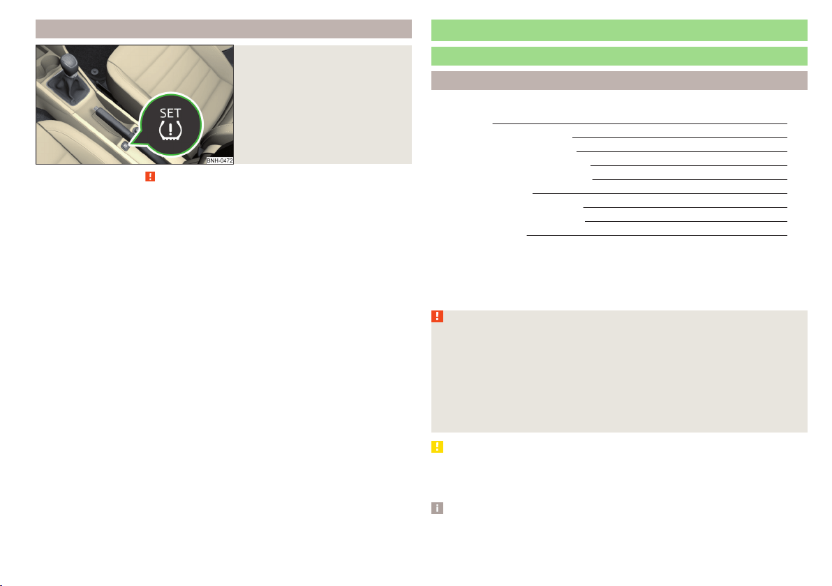
Save tyre pressure values by pressing a button
Fig. 136
Key for storing the pressure val-
ues
Read and observe on page 120 first.
›
Inflate all the tyres to the specified pressure.
›
Switch on the ignition.
›
Press the symbol key
» Fig. 136 and hold it down.
The warning light
in the instrument cluster illuminates.
An acoustic signal and the control indicator provide information about the
storage of the tyre pressure values.
›
Release the symbol key
.
Hitch and trailer
Hitch
Introduction
This chapter contains information on the following subjects:
Description 122
Adjusting the ready position 122
A correctly set ready position 123
Assembling the tow bar – Step 1 123
Assembling the tow bar – Step 2 124
Check proper fitting 124
Removing the tow bar – Step 1 125
Removing the tow bar – Step 2 125
Mount accessories 126
The maximum trailer draw-bar load is 50 kg.
The draw bar load information on the type plate of the towing device is merely
a test value for the towing device. The vehicle-specific information is detailed
in the vehicle documents.
WARNING
■
Check that the tow bar is seated correctly and is secured in the mounting
recess before the start of every journey.
■
Do not use the ball head, if it is not correctly inserted into the mounting
recess and secured.
■
Do not use the towing equipment if it is damaged or incomplete.
■
Do not modify or adapt the towing device in any way.
■
Keep the mounting recess of the towing equipment clean at all times.
Such dirt prevents the ball head from being attached securely.
CAUTION
■
Take care with the ball bar - there is a risk of paint damage to the bumper.
■
When the tow bar is removed always place the cover onto the mounting re-
cess - there is a danger of soiling the mounting recess.
Note
■
Operation and maintenance of hitch » page 137.
■
Tow the vehicle by means of the detachable ball rod » page 171.
121
Hitch and trailer
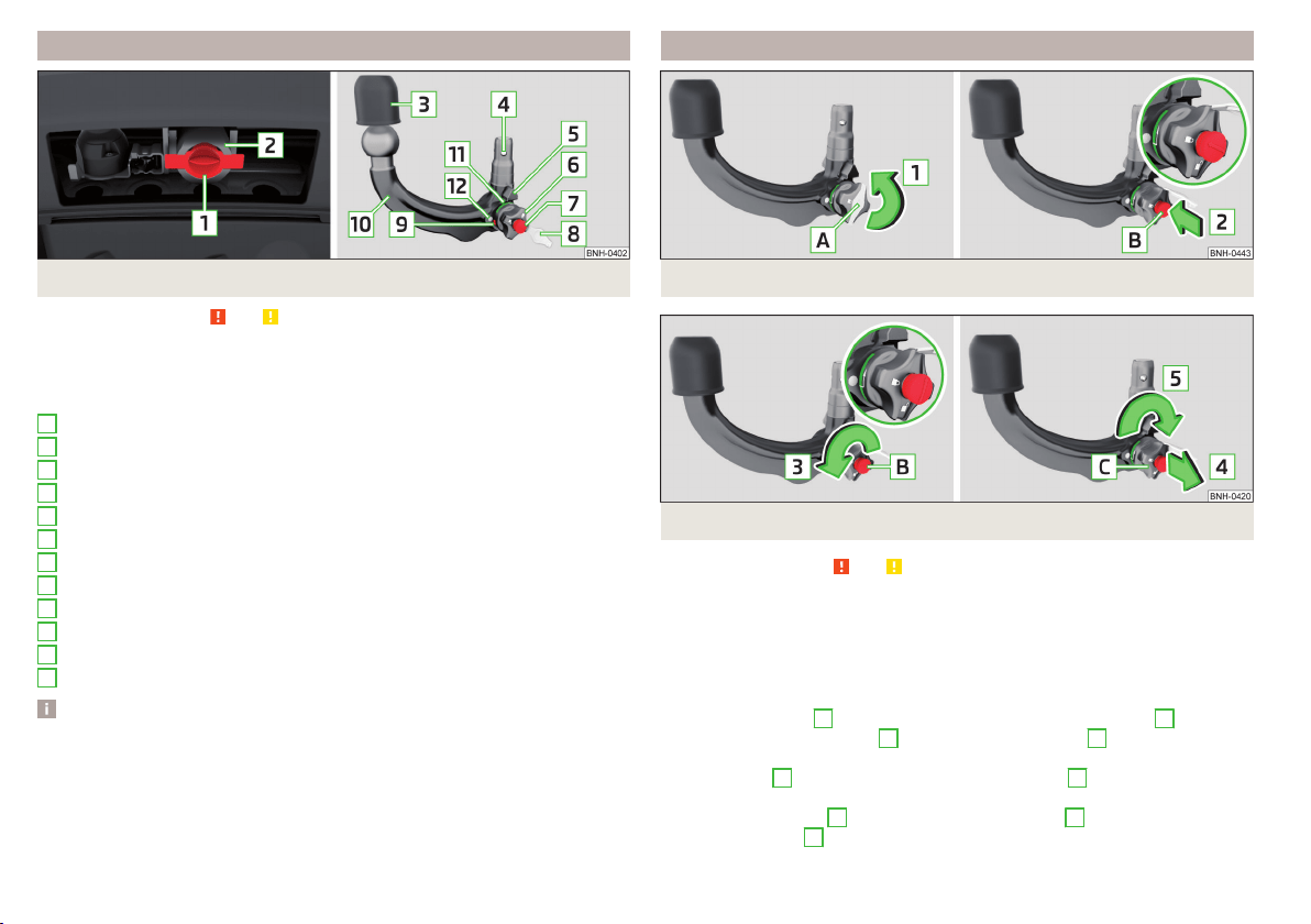
Description
Fig. 137 Carrier for the towing device / tow bar
Read and observe
and on page 121 first.
The ball head can be removed and is kept in the spare wheel well or in a com-
partment for the spare wheel in the luggage compartment.
Support for the towing hitch and tow bar » Fig. 137
Cap
Mounting recess
Protective cap
Locking ball
Centering
Hand wheel
Key
Lock cap
Red marking on the hand wheel
Tow bar
Green marking on the hand wheel
White marking on tow bar
Note
On the bottom of the key is a code number. We advise you to take a not of this
number. If you lose a key, please contact a specialist garage which will be able
to use this code number to provide you with a new one.
1
2
3
4
5
6
7
8
9
10
11
12
Adjusting the ready position
Fig. 138 Remove cap from the lock / insert key into the lock
Fig. 139 Setting the ready position
Read and observe and on page 121 first.
The tow bar must be set prior to installation to the standby position
» page 123, A correctly set ready position.
If this is not in the ready position, then this must be set to the standby posi-
tion as follows.
›
Grip the tow bar below the protective cap.
›
Remove the cover
A
from the lock in the direction of the arrow
1
» Fig. 138.
›
Insert the key into the lock
B
in the direction of arrow
2,
so that the arrow
on the key symbol
shows.
›
Turn the key
B
to the stop in the direction of arrow
3,
so that the arrow on
the key symbol
» Fig. 139 shows.
›
Pull the hand wheel
C
in the direction of the arrow
4
and turn in the direc-
tion of the arrow
5
to the stop.
122
Driving
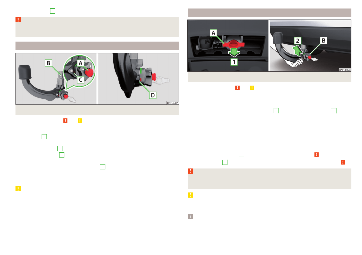
The hand wheel
C
remains locked in this position.
WARNING
If the tow bar cannot be correctly placed in the ready position, then it must
not be used.
A correctly set ready position
Fig. 140 Ready position
Read and observe
and on page 121 first.
Correctly adjusted standby position » Fig. 140
The key
A
is in the unlocked position - the arrow on the key points to the
symbol
.
The locking ball
B
can be pushed fully into the tow bar.
The red marking
C
on the hand wheel points to the white marking on the
ball bar.
There is a clear gap of approx. 4 mm
D
between the hand wheel and the
tow bar.
The ball bar is thus set ready for installation.
CAUTION
When in the ready position, the key cannot be removed from the lock.
Assembling the tow bar – Step 1
Fig. 141 Remove cap for receiving shaft / use ball bar
Read and observe and on page 121 first.
Preliminary work
Before installing the tow bar the following work must be carried out.
›
Remove the end cap for receiving shaft
A
in the direction of arrow
1
» Fig. 141.
The tow bar must be set to the standby position » page 123, A correctly set
ready position. If this is not in the standby position, then it must be set to the
standby position » page 122, Adjusting the ready position.
Fitting
›
Grip the tow bar from underneath » Fig. 141 and insert into the mounting re-
cess in arrow direction
2
until you hear it click into place » .
The hand wheel
B
rotates back automatically and rests on the ball rod » .
WARNING
Do not hold the hand wheel with your hand when attaching the ball bar -
there is a risk of finger injury.
CAUTION
If the tow bar is not in the ready position, it cannot be fitted in the mounting
recess.
Note
Store the cover of the mounting recess in a suitable place in the luggage com-
partment store after removal.
123
Hitch and trailer
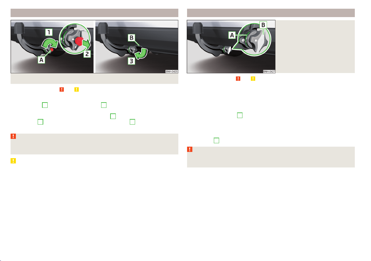
Assembling the tow bar – Step 2
Fig. 142 Secure the lock and remove key / place cap on lock
Read and observe
and on page 121 first.
›
First perform step 1 of the tow bar assembly » page 123.
›
Turn the key
A
in the direction of arrow
1,
so that the arrow on the key
symbol
» Fig. 142 shows.
›
Remove the key in the direction of the arrow
2
.
›
Fit the cap
B
on the lock in the direction of the arrow
3
.
›
Check that the tow bar is securely attached » page 124.
WARNING
■
After fitting the tow bar, always secure the lock and remove the key.
■
The tow bar must not be operated with the key inserted.
CAUTION
After removing the key, always replace the cover on the lock – there is a risk of
the lock getting dirty.
Check proper fitting
Fig. 143
Correctly secured ball head
Read and observe and on page 121 first.
Check that the tow bar is fitted properly before each use.
Correctly secured tow bar » Fig. 143
The tow bar does not come out of the mounting recess even after heavy
“shaking”.
The green marking
A
on the hand wheel points to the white marking on
the tow bar.
The hand wheel lies flush with the tow bar - there is no gap.
The lock is locked and the key is removed.
The cap
B
is on the lock.
WARNING
Do not use the towing hitch unless the tow ball has been properly locked –
risk of accident.
124
Driving
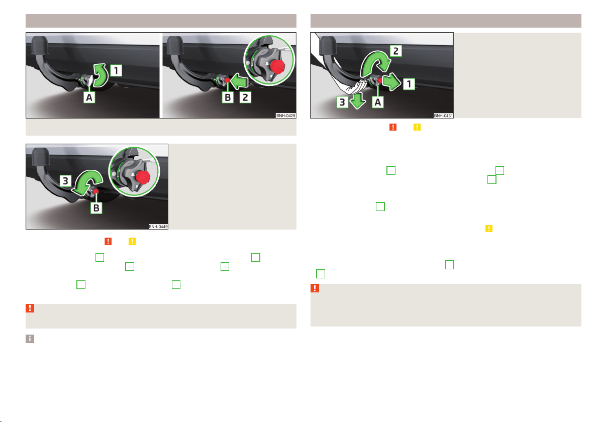
Removing the tow bar – Step 1
Fig. 144 Remove cap from the lock / insert key into the lock
Fig. 145
Unlock lock
Read and observe and on page 121 first.
›
Remove the cover
A
from the lock in the direction of the arrow
1
» Fig. 144.
›
Insert the key into the lock
B
in the direction of arrow
2,
so that the arrow
on the key symbol
shows.
›
Turn the key
B
in the direction of arrow
3,
so that the arrow on the key
symbol
» Fig. 145 shows.
WARNING
Never remove the tow bar while the trailer is still coupled.
Note
We recommend putting the protective cover onto the ball head before remov-
ing the tow bar.
Removing the tow bar – Step 2
Fig. 146
Release tow bar
Read and observe and on page 121 first.
Removing
›
To begin with, follow the first step for the ball rod assembly
» page 125.
›
Grasp the ball bar from below » Fig. 146.
›
Pull the hand wheel
A
in the direction of the arrow
1
.
›
Turn the hand wheel in the direction of the arrow
2
to the stop, and hold in
this position.
›
Remove the tow bar from the mounting recess downwards and in the direc-
tion of the arrow
3
.
At the same time, the ball head latches into the ready position and is thus
ready to be re-inserted into the mounting recess » .
Subsequent steps
After removing the tow bar the following work must be carried out.
›
Fit the cover for the mounting recess
A
in the opposite direction to arrow
1
» Fig. 141 on page 123.
WARNING
Never allow the tow bar to remain unsecured in the boot. This could cause
damage on sudden braking and could put the safety of the occupants at
risk!
125
Hitch and trailer
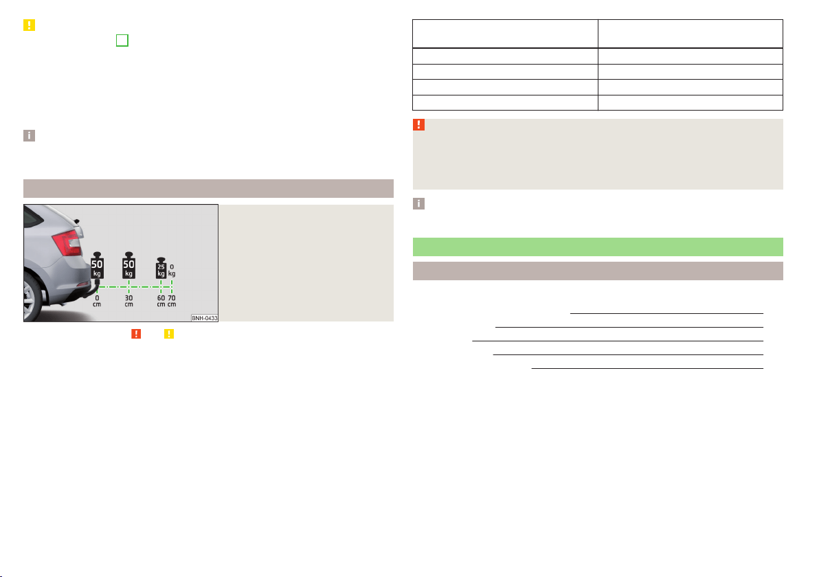
CAUTION
■
If the hand wheel
A
is not turned all the way to the stop, then it will return
to its initial position when the tow bar is removed and will rest on the tow bar
and not engage into the ready position. The ball head then needs to be
brought into this position before the next time it is fitted » page 122, Adjusting
the ready position.
■
The mounting recess must be closed with the cover following removal. This
prevents foreign bodies from getting into the mounting recess.
Note
Clean any dirt from the tow bar before stowing it away in the box with the ve-
hicle tool kit.
Mount accessories
Fig. 147
Representation of the maximum
permissible level of the ball head
of the towing hitch and the per-
missible total weight of the ac-
cessories including the load de-
pending on the load centre of
gravity
Read and observe and on page 121 first.
An accessory can be mounted on the ball head of the towing hitch (e.g. bicycle
carrier).
If this accessory is used, the maximum permissible overhang of the ball head
of the towing hitch and the permissible gross vehicle weight of the accesso-
ries including load are to be checked.
The maximum permissible overhang of the ball head of the towing hitch is 70
cm » Fig. 147.
The total permitted weight of the accessory including load changes with in-
creasing distance of the centre of gravity of the load from the ball head of the
towing hitch.
Distance of the centre of gravity of
the load from the ball head
Permissible total weight of the ac-
cessory, including load
0 cm 50 kg
30 cm 50 kg
60 cm 25 kg
70 cm 0 kg
WARNING
■
Never exceed the permissible gross weight of the accessory including
load - there is a risk of damaging the towing device.
■
Never exceed the permissible protrusion of the ball head including towing
device - there is a risk of damaging the towing device.
Note
We recommend that you use accessories from ŠKODA Original Accessories.
Trailer
Introduction
This chapter contains information on the following subjects:
Attaching and detaching trailers 127
Loading a trailer 127
Trailer load 128
Towing a trailer 128
Anti-theft alarm system 128
The trailer can be hitched to the ball head of the towing device.
126
Driving
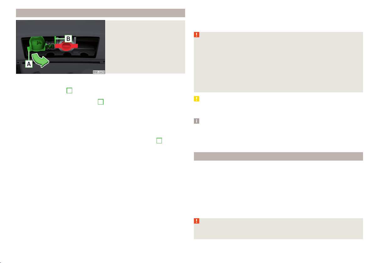
Attaching and detaching trailers
Fig. 148
Swivel out the 13-pin power
socket, safety eyelet
Connect and disconnect
›
Install the tow bar.
›
Lift off protective cap
3
» Fig. 137 on page 122 towards the top.
›
Place the trailer onto the ball.
›
Grip the 13-pin socket on the handle
A
and swing out in the direction of the
arrow » Fig. 148.
›
Insert the trailer cable into the 13-pin socket.
If the trailer that is to be towed has a 7-pin connector, you can use a suitable
adapter from ŠKODA Original Accessories to establish a connection to the elec-
tricity.
›
Hook the breakaway cable of the trailer to the security lock slot
B
.
The breakaway cable of the trailer must sag in all trailer positions relative to
the vehicle (sharp curves, reversing and the like).
Uncoupling takes place in reverse order.
Exterior mirrors
You should have additional exterior mirrors fitted if you are not able to see the
traffic behind the trailer with the standard rear-view mirrors.
Headlights
The front of the vehicle may lift up when a trailer is being towed and the head-
lights may dazzle other road users.
Adjust the headlights using the headlight beam control » page 59.
Power to the trailer power grid
For the electrical connection between the vehicle and trailer, the power for the
trailer power grid is supplied by the vehicle.
The power supply works with ignition on or off.
With the ignition off, the battery of the towing vehicle is discharged by activa-
ted consumers.
At low charge state of the vehicle battery power to the trailer is interrupted.
WARNING
■
Improperly connected trailer electrical installations may cause accidents
or serious injury due to electric shock.
■
Work on the electrical system must only be carried out by specialist ga-
rages.
■
Never directly connect the trailer's electrical system with the electrical
connections for the tail lights or other current sources.
■
After coupling the trailer and connecting up the power socket, check the
rear lights on the trailer to ensure they are working.
■
Never use the safety eyelet for towing!
CAUTION
Improperly connected trailer electrical installations may cause malfunction of
the entire vehicle electronics.
Note
■
The total power consumption of all the connected consumers on the trailer
must not exceed 350 watts.
■
Coat the ball head of the towing device with a suitable grease whenever
necessary.
Loading a trailer
Distribution of the cargo
Distribute the cargo in the trailer in such a way that heavy items are located as
close to the trailer axle as possible. Secure the items from slipping.
The distribution of the weight is very poor if your vehicle is unladen and the
trailer is laden. Maintain a particularly low speed if you cannot avoid driving
with this combination.
Tyre pressure
Correct the tyre inflation pressure on your vehicle for a “full load” » page 155.
WARNING
A sliding cargo can significantly adversely affect stability and driving safety
- there is a risk of accident!
127
Hitch and trailer
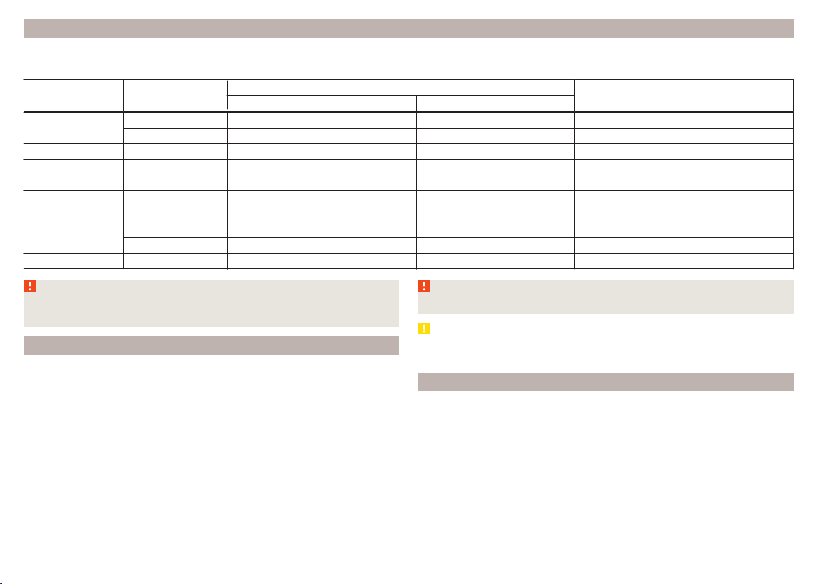
Trailer load
The permissible trailer load must not be exceeded under any circumstances.
Permissible trailer load
Engine Gearbox
Permissible trailer load, braked (kg)
Permissible trailer load, unbraked (kg)
Gradients of up to 12 % Gradients of up to 8 %
1.2 l/66 kW TSI
MG 900 1000 580
DSG 900 1000 590
1.2 l/81 kW TSI MG 1100 1200 590
1.4 l/92 kW TSI
DSG 1200 1200 600
DSG (Green tec) 1200 1200 610
1.6 l./81 kW MPI
MG 1000 1100 580
AG 1000 1100 600
1.4 l/66 kW TDI CR
MG 1000 1100 610
DSG 1000 1100 620
1.6 l/85 kW TDI CR MG 1200 1200 630
WARNING
The maximum permissible axle and draw-bar load and the permissible
weight of the trailer must not exceed - this could cause an accident!
Towing a trailer
Driving speed
For safety reasons, do not drive faster than 80 km/h when towing a trailer.
Immediately reduce your speed as soon as even the slightest swaying of the
trailer is detected. Never attempt to stop the trailer from “swaying” by acceler-
ating.
Brakes
Apply the brakes in good time! If the trailer is fitted with a trailer brake, apply
the brakes gently at first, then brake firmly. This will avoid brake jolts resulting
from the trailer wheels locking.
On downhill sections shift down a gear in good time to also use the engine as
a brake.
WARNING
Always drive particularly carefully with the trailer.
CAUTION
If you tow a trailer frequently, you should also have your vehicle inspected be-
tween service intervals.
Anti-theft alarm system
When the vehicle is locked, the alarm is activated when the electrical connec-
tion to the trailer is interrupted.
Always switch off the anti-theft alarm system before a trailer is coupled or un-
coupled » page 54.
Conditions for including a trailer in the anti-theft alarm system.
The vehicle is factory-fitted with an anti-theft alarm system and towing
device.
The trailer is electrically connected to the towing vehicle by means of the
trailer socket.
128
Driving

The electrical system of the vehicle and trailer is functional.
The vehicle is locked and the anti-theft alarm system is activated.
CAUTION
For technical reasons, trailers with rear LED lights cannot be connected to the
anti-theft alarm system.
129
Hitch and trailer

General Maintenance
Care and maintenance
Service work, adjustments and technical alterations
Introduction
This chapter contains information on the following subjects:
Vehicle operating under different weather conditions
130
Statutory checks 130
ŠKODA Service Partners 131
ŠKODA Original parts 131
ŠKODA Original accessories
131
Spoiler 132
Component protection 132
Airbags 132
Acceptance and recycling of used vehicles 133
The instructions and guidelines from ŠKODA AUTO a.s. must be observed when
carrying out any modifications, repairs or technical alterations to your vehicle.
Adhering to these instructions and guidelines helps ensure road safety and
helps keep your vehicle in a good technical condition. After carrying out modifi-
cations, repairs or technical alterations, the vehicle will comply with German
road transport regulations (StVO).
Always consult a ŠKODA Partner » page 131 before buying accessories or
parts, or before carrying out any modifications, repairs or technical alterations
to your vehicle.
WARNING
■
Work on your vehicle, which has been carried out unprofessionally, can
cause operational faults – risk of accident!
■
Interference on the electronic components and their software can lead to
operational faults. This interference can also impair not directly affected
systems because of the networking of the electronic components. The op-
erational safety of the vehicle may be at significant risk and can lead to in-
creased wear of parts.
For the sake of the environment
Technical documents regarding alterations carried out on the vehicle must be
kept by the vehicle user in order to be handed over to the recyclers at a later
date. This ensures that the vehicle is recycled in an environmentally sound
manner.
Note
■
We recommend only having these modifications, repairs and technical
changes performed by a specialist garage.
■
Any damage caused by technical alterations made without the approval of
the manufacturer is excluded from the warranty » Service schedule.
■
The ŠKODA Partner accepts no liability for products that have not been ap-
proved by ŠKODA AUTO a.s. even though these may be products with an op-
erational approval or that have been approved by a government testing insti-
tute.
■
We advise you only to use ŠKODA Original Accessories and ŠKODA Original
Parts which have been expressly approved for use on your vehicle. Reliability,
safety and suitability for your vehicle are guaranteed with these.
■
ŠKODA Original Accessories and ŠKODA Original Parts can be purchased from
ŠKODA Partners, who will also perform the professional assembly of the pur-
chased parts.
Vehicle operating under different weather conditions
Read and observe
on page 130 first.
If you would like to operate your vehicle in countries other than those with its
intended weather conditions, you should contact a ŠKODA Partner.
He will advise you if certain precautions need to be taken to ensure the full
functioning of the vehicle as well as to prevent damage.
This involves, for example, the coolant, battery replacement and the like.
Statutory checks
Read and observe on page 130 first.
Many countries have legislation requiring the operational reliability and road
worthiness and/or exhaust gas properties of a vehicle to be tested at specific
intervals. These tests can be carried out by workshops or testing stations that
have been legally authorised for this purpose.
130
General Maintenance

The ŠKODA Service Partners are up-to-date on the legally required tests and
will prepare the vehicle for the tests as part of a service operation if required,
or will be responsible for carrying out these tests. The specialist garages can
carry out the specified tests directly, if required by the customer, if they are
authorised to do so. This saves you time and money.
Even if you want to take your vehicle to an officially approved test centre for
prior checking in preparation of a legally required test, we recommend that you
consult the service consultant of your ŠKODA Service Partner beforehand.
Based on their appraisal, the service consultant will tell you which areas you
should focus on in order to ensure that your vehicle will pass the technical test
without any problems. This allows you to avoid additional expenses resulting
from a possible subsequent test.
ŠKODA Service Partners
Read and observe on page 130 first.
ŠKODA Service Partners are equipped with modern, specially developed tools
and equipment. Here, trained specialists have access to a comprehensive
range of ŠKODA Original Parts and ŠKODA Original Accessories for carrying out
modifications, repairs and technical alterations.
All ŠKODA service partners operate according to the latest guidelines and in-
structions from ŠKODA AUTO a.s. All service and repair work is therefore car-
ried out on time and to the appropriate quality. Adhering to these guidelines
and instructions helps ensure road safety and helps keep your vehicle in a
good technical condition.
ŠKODA Service Partners are therefore properly prepared to service your vehicle
and to provide quality work. We therefore advise you to have all modifications,
repairs and technical alterations to your vehicle carried out by a ŠKODA Service
Partner.
ŠKODA Original parts
Read and observe
on page 130 first.
We recommend the use of ŠKODA Genuine Parts for your vehicle, as these
parts are approved by ŠKODA AUTO a.s. They correspond precisely to the
ŠKODA AUTO a.s. regulations with regard to design, dimensional accuracy and
material, and are identical to the components used in series production.
ŠKODA AUTO a.s. is able to vouch for the safety, suitability and long service life
of these products. We therefore recommend that you only use ŠKODA Genuine
Parts.
ŠKODA AUTO a.s. supplies the market with a complete range of ŠKODA Genu-
ine Parts - not only while the model is still in production but for at least 15
years after the end of series production for wear parts and at least 10 years
after the end of series production for all other vehicle parts.
ŠKODA Service Partners are liable for any defects of ŠKODA Genuine Parts for
a period of 2 years after sale in accordance with the materials defect liability,
unless agreed otherwise in the purchase agreement. You should keep the ap-
proved warranty certificate and the invoices for these components for this pe-
riod of time, so that the commencement of the term can be verified.
Body repairs
ŠKODA vehicles are designed so that if any damage occurs to the body, it is on-
ly necessary to replace those parts that are actually damaged.
However, before you decide to have damaged body parts replaced, you should
first of all contact your specialist garage to determine whether or not the parts
can also be repaired. Repairs to body parts are usually cheaper.
ŠKODA Original accessories
Read and observe on page 130 first.
If you wish to fit accessories to your vehicle, you should remember the follow-
ing.
We recommend that you use ŠKODA Genuine Accessories in your vehicle.
ŠKODA AUTO a.s. has selected these accessories to ensure that they are relia-
ble, safe and suitable for your particular vehicle. Although we constantly moni-
tor the market, we are not able to assess or vouch for other products even
though in some instances such parts may have operational approval or may
have been approved by a nationally recognised testing laboratory.
All accessory products are subjected to a challenging process in the areas of
technical development (technical testing) and quality inspection (customer
testing) and the product only becomes a ŠKODA Genuine Accessory if all tests
are passed.
Our ŠKODA Genuine Accessories service also includes expert advice and pro-
fessional fitting if required by the customer.
131
Care and maintenance

ŠKODA Service Partners are liable for any defects of ŠKODA Genuine Accesso-
ries for a period of 2 years after installation or delivery in accordance with the
materials defect liability, unless agreed otherwise in the purchase agreement
or any other agreements. You should keep the approved warranty certificate
and the invoices for these accessories for this period of time, so that the com-
mencement of the term can be verified.
ŠKODA Service Partners also stock a range of suitable car care products and all
parts that are subject to natural wear-and-tear, such as tyres, batteries, bulbs
and wiper blades.
Note
The accessories authorised by the company ŠKODA AUTO a.s. will be offered
by the ŠKODA Partners in all countries where the company ŠKODA AUTO a.s.
has a sales and after-sales service network. This will usually be in the form of a
printed catalogue of ŠKODA Genuine Accessories, in the form of separate prin-
ted brochures or in the form of ŠKODA Genuine Accessories on the ŠKODA
Partner websites.
Spoiler
Read and observe on page 130 first.
If your new vehicle is fitted with a spoiler on the front bumper in combination
with the spoiler on the luggage compartment lid, then the following instruc-
tions must be adhered to.
▶
For safety reasons, the vehicle must only be fitted with a spoiler on the front
bumper in combination with the associated spoiler on the luggage compart-
ment lid.
▶
This kind of spoiler cannot be left on the front bumper either on its own, in
combination with another spoiler not on the luggage compartment lid or in
combination with an unsuitable spoiler on the luggage compartment lid.
▶
We recommend that you consult the ŠKODA Service Partner for any repairs
to or replacement, addition or removal of spoilers.
WARNING
■
If work on your vehicle's spoilers is not carried out properly, this can lead
to operational faults - risk of accident and serious injuries!
■
If a front spoiler, full wheel trim, etc. is mounted retrospectively, it must
be ensured that the air supply to the front wheel brakes is not reduced.
The front brakes may overheat, which can have a negative impact on the
functioning of the braking system – risk of accident!
Component protection
Read and observe on page 130 first.
Some electronic vehicle components (such as the instrument cluster) are fac-
tory-equipped with component protection.
Component protection has been developed as a protection mechanism for the
following situations.
▶
Impairment of factory- or garage-fitted electronic components after installa-
tion in another vehicle (for example, after a theft).
▶
Impairment of electronic components used outside the vehicle.
▶
The possibility of a legitimate installation or change of electronic compo-
nents for repairs at a specialist garage.
The activated component protection can be realized by functional limitations
of the specific electronic component. Seek help from a specialist garage.
Airbags
Read and observe
on page 130 first.
WARNING
■
Modifications, repairs and technical alterations that have been carried out
unprofessionally can cause damage and operational faults, and can also se-
riously impair the effectiveness of the airbag system – risk of accident and
fatal injury!
■
A change to the vehicle's wheel suspension, including the use of non-ap-
proved wheels and tyre combinations, can alter the functioning of the air-
bag system - risk of accident and fatal injury!
WARNING
Information on the use of the airbag system
■
Never install any airbag parts into the vehicle that have been removed
from old cars or have been recycled.
■
Never install damaged airbag parts in the vehicle. The airbags may then
not be deployed properly or even at all in the event of an accident.
132
General Maintenance

WARNING
■
No modifications of any kind may be made to parts of the airbag system.
■
Any work on the airbag system including the installation and removal of
system components due to other repair work (e.g. removal of the steering
wheel) must only be carried out by a specialist garage.
■
Never make any changes to the front bumper or the bodywork.
■
It is prohibited to manipulate individual parts of the airbag system, as this
might result in the airbag being deployed.
■
The protective function of the airbag system is sufficient for only one ac-
cident. The airbag system must then be replaced if the airbag has been de-
ployed.
Acceptance and recycling of used vehicles
Read and observe
on page 130 first.
ŠKODA meets the requirements of the brand and its products with regard to
protecting the environment and the preserving resources. All new ŠKODA ve-
hicles are 95% recyclable.
Note
You can find more detailed information about the trade-in and recycling of old
cars from a specialist garage.
Washing vehicle
Introduction
This chapter contains information on the following subjects:
Washing by hand 133
Automatic car wash systems
134
Washing with a high-pressure cleaner
134
The best way to protect your vehicle against harmful environmental influences
is frequent washing.
The longer insect residues, bird droppings, road salt and other aggressive de-
posits remain on the paintwork of your vehicle, the more detrimental their de-
structive effect can be. High temperatures, such as those caused by intensive
sun's rays, accentuate this caustic effect.
It is essential to also thoroughly clean the underside of the vehicle at the end
of the winter.
WARNING
When washing your vehicle in the winter: Water and ice in the braking sys-
tem can affect the braking efficiency – risk of accident!
CAUTION
The temperature of the water used for cleaning must not exceed 60 °C – risk
of damaging the vehicle.
For the sake of the environment
Only wash the vehicle at washing bays intended for this purpose.
Washing by hand
Read and observe
and on page 133 first.
Soak the dirt with plenty of water and rinse as well as possible.
Clean the vehicle with a soft sponge, a washing glove or a washing brush.
Work from the top to the bottom – starting with the roof.
For stubborn dirt, agents specifically intended for this purpose are to be used.
Wash out the sponge or washing glove thoroughly at short intervals.
Clean wheels, door sills and similar parts last. Use a second sponge for such
areas.
Give the vehicle a good rinse after washing it and dry it off using a chamois
leather.
WARNING
Protect your hands and arms from sharp-edged metal parts when cleaning
the underfloor or the inside of the wheel housings or the wheel trims – risk
of cuts!
CAUTION
■
Only apply slight pressure when cleaning the vehicle's paintwork.
■
Do not wash your vehicle in bright sunlight – risk of paint damage.
133
Care and maintenance

Automatic car wash systems
Read and observe and on page 133 first.
The usual precautionary measures must be taken before washing the vehicle
in an automatic car wash system (e.g. closing the windows and the sliding/tilt-
ing roof etc.).
If your vehicle is fitted with any particular attached parts, such as a spoiler,
roof rack system etc., it is best to consult the operator of the car wash system
beforehand.
After an automatic wash with wax treatment, the lips of the wipers should be
cleaned with cleaning agents specially designed for the purpose, and then de-
greased.
CAUTION
■
Before driving through a car wash fold in the exterior mirrors - there is a risk
of damage.
■
For vehicles with roof antenna the antenna rod should be unscrewed before
driving through a car wash - there is a risk of damage.
Washing with a high-pressure cleaner
Read and observe
and on page 133 first.
When washing the vehicle with a high-pressure cleaner, the instructions for
use of the equipment must be observed. This applies in particular to the pres-
sure used and to the spraying distance.
Maintain a sufficiently large distance to the parking aid sensors and soft mate-
rials such as rubber hoses or insulation material.
CAUTION
■
The films should not be washed with any high-pressure cleaners - risk of
damage » page 135.
■
Do not aim the water jet directly at the lock cylinders or the door or opening
joints when washing the vehicle in the winter – there is a risk of freezing.
■
The sensors of the parking aid can be sprayed only for a short time and there
must be a minimum distance of 10 cm - there is a risk of damage.
Cleaning vehicle exterior
Introduction
This chapter contains information on the following subjects:
Vehicle paint work
135
Films 135
Plastic parts 135
Rubber seals 136
Chrome and anodized parts 136
Windows and external mirrors 136
Headlight glasses 136
Door closing cylinder 137
Cavity protection 137
Jack 137
Wheels 137
Towing device and mounting recess 137
Under-body protection 138
Wiper blades 138
We recommend using vehicle care products from ŠKODA Original Accessories.
These are available from ŠKODA Partners. The usage instructions on the pack-
age must be observed.
WARNING
■
Vehicle care products may be harmful to your health if not used according
to the instructions.
■
Always keep the vehicle care products safe from people who are not com-
pletely independent, e.g. children - there is a danger of poisoning!
■
Protect your hands and arms from sharp-edged metal parts when clean-
ing the underfloor, the inside of the wheel housings or the wheel trims –
risk of cuts!
CAUTION
■
Do not use any insect sponges, rough kitchen sponges or similar cleaning
products – risk of damaging the paintwork surface.
■
Cleaners that contain solvents can damage the material being cleaned.
134
General Maintenance

Note
Due to the special tools and knowledge required, and to avoid any potential
problems with the cleaning and care of your vehicle's exterior, we recommend
that the cleaning and care of your vehicle be carried out by a ŠKODA Service
Partner.
Vehicle paint work
Read and observe and on page 134 first.
Preserving the vehicle paintwork
A thorough wax treatment provides the vehicle's paintwork with highly effec-
tive protection against harmful environmental influences.
The vehicle must be treated with a high-quality hard wax polish at the latest,
when no more drops form on the clean paintwork.
A new layer of a high-quality hard wax polish can be applied to the clean body-
work after it has dried thoroughly.
Even if you use a wax preserver regularly, we still recommend that you treat
the paintwork of the vehicle at least twice a year with hard wax.
Polishing
Polishing is necessary if the vehicle's paintwork has become unattractive and
if it is no longer possible to achieve a gloss with wax preservatives.
If the polish does not contain any preserving elements, the paint must be trea-
ted with a preservative afterwards.
CAUTION
■
Paint damage is to be repaired immediately.
■
Never apply wax to the windows.
■
Mat painted or plastic parts must not be treated with polishing products or
hard waxes.
■
Do not polish the paintwork in a dusty environment - risk of paint scratches.
■
Do not apply any paint care products to door seals or window guides.
■
If possible, do not apply any paint care products to parts of the bodywork
that come into contact with door seals or window guides.
Films
Read and observe and on page 134 first.
Cleaning
Films (e.g. roof, decorative, protective films, etc.) must be cleaned more care-
fully than the vehicle paint.
The films may not be washed with a high-pressure cleaner.
Only wash the films with a soft cloth, mild soap solution and clean, warm wa-
ter.
Service life
Environmental influences (e.g. sunlight, humidity, air pollution, rockfall) affect
the life of the films.
Sunlight may also affect the strength of the film colour.
Films will age and become brittle – this is entirely normal; this is not a fault.
CAUTION
■
Never use aggressive cleaning agents or chemical solvents for the glued sur-
faces with films - there is a danger of film damage.
■
Never use dirty cloths or chemical solvents for the glued surfaces with films -
there is a danger of damaging the film.
■
In the winter months, do not use an ice scraper to remove ice and snow from
the areas with films. Do not use any other objects to remove frozen layers of
snow or ice – risk of film damage.
■
Do not polish the films - risk of damage!
■
When transporting a load on the roof rack (e.g. roof box or similar), there is
an increased risk of film damage (e.g. of chipping from the secured load).
Plastic parts
Read and observe
and on page 134 first.
Clean plastic parts with a damp cloth.
If this method does not completely clean the plastic parts, use cleaning prod-
ucts specially designed for this purpose.
CAUTION
Do not use paint care products on plastic parts.
135
Care and maintenance
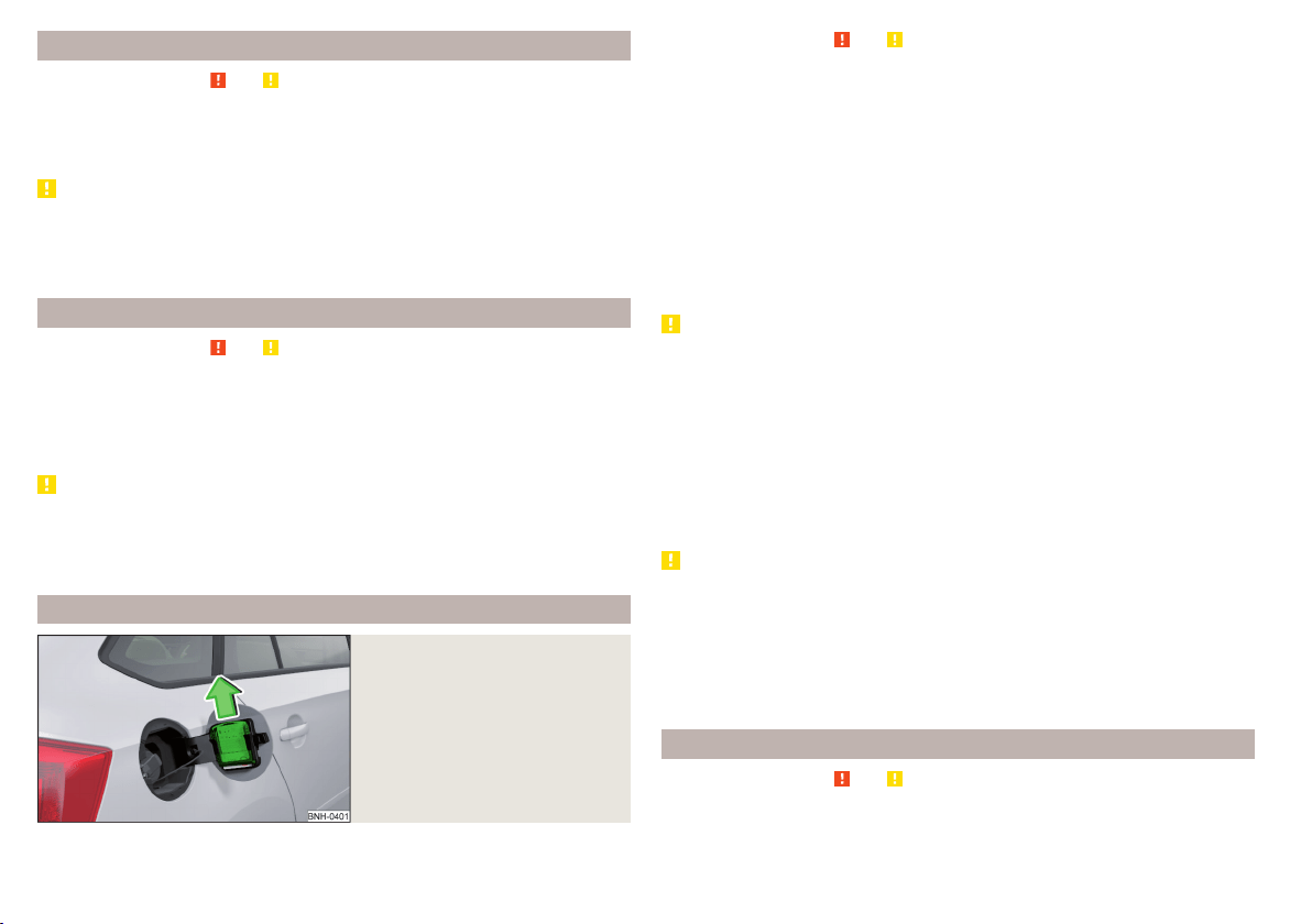
Rubber seals
Read and observe and on page 134 first.
All door seals and window guides are factory-treated with a colourless matt
varnish layer to prevent the freezing of painted body parts and to protect
against driving noise.
CAUTION
■
Do not treat the door seals and window guides with any products whatsoev-
er.
■
Applying additional treatments to the seals can corrode the protective coat-
ing, and driving noise may occur.
Chrome and anodized parts
Read and observe
and on page 134 first.
First clean the chrome parts and anodized parts with a damp cloth and then
polish them with a soft, dry cloth.
If this method does not completely clean the parts, use cleaning products spe-
cially designed for this purpose.
CAUTION
■
Do not polish the chrome parts and anodized parts in a dusty environment -
risk of surface scratches.
■
Never use aggressive cleaning agents or chemical solvents for these parts -
there is risk of damage.
Windows and external mirrors
Fig. 149
Fuel filler flap: Remove ice scra-
per
Read and observe and on page 134 first.
Removing snow and ice
Use a plastic ice scraper for removing snow and ice from the windows and mir-
rors.
The ice scraper can be found on the inside of the fuel filler flap.
›
Open the fuel filler flap.
›
Slide out the ice scraper in the direction of the arrow » Fig. 149.
Cleaning windows
Regularly clean windows from the inside with clean water.
Dry the glass surfaces with a clean chamois leather or a cloth intended for this
purpose.
CAUTION
Instructions for removing snow and ice
■
The ice scraper should not be moved forward and backward but in one direc-
tion to avoid any damage to the surface of the glass.
■
Snow or ice that is contaminated with coarse dirt such as fine gravel, sand or
salt must not be removed from the windows and mirrors – there is a risk of
damage to the surface of the windows and mirrors.
■
Do not remove snow or ice from glass parts using warm or hot water – risk of
cracks forming in the glass.
■
Make sure that when removing snow and ice from the windows, the labels
attached to the vehicle by the factory are not damaged.
CAUTION
Information for cleaning windows
■
Do not clean the inside of the windows with sharp-edged objects or corro-
sive and acidic cleaning agents – there is a risk of damaging the heating ele-
ments or window aerial.
■
When drying the windows after washing the vehicle, do not use window
leathers that have been used to polish the bodywork. Residues of preserva-
tives in the window leather can make the window dirty and reduce visibility.
Headlight glasses
Read and observe and on page 134 first.
Clean plastic front headlight lenses using clean, warm water and soap.
136
General Maintenance

CAUTION
■
The headlights are never to be wiped dry - there is a risk of damaging the
protective lacquer and the headlight glass subsequently developing cracks.
■
Do not use sharp objects to clean the glasses - there is a risk of damaging
the protective lacquer and the headlight glasses subsequently developing
cracks.
■
Do not use any aggressive cleaning or chemical solvent products to clean the
headlights – risk of damaging the headlight lenses.
Door closing cylinder
Read and observe and on page 134 first.
Specific products must be used for de-icing door lock cylinders.
CAUTION
Make sure that as little water as possible gets into the locking cylinder when
washing the vehicle - there is a risk of freezing the lock cylinder!
Cavity protection
Read and observe and on page 134 first.
All the cavities of your vehicle which are at risk from corrosion are protected
for life by a layer of protective wax applied in the factory.
This wax protection does not need to be inspected or re-applied.
If any small amount of wax flow out of the cavities at high temperatures, these
must be removed with a plastic scraper and the stains cleaned using a petrole-
um cleaner.
WARNING
Safety regulations should be observed when using petroleum cleaner to re-
move wax – risk of fire!
Jack
Read and observe and on page 134 first.
The jack is maintenance-free.
If necessary, the moving parts of the jack should be lubricated with a suitable
lubricant.
Wheels
Read and observe and on page 134 first.
Wheel rims
Also thoroughly wash the wheel rims when washing the vehicle on a regular
basis.
Regularly remove salt and brake abrasion, otherwise the rim material will be
corroded.
Light alloy wheels
After washing thoroughly, treat the wheel rims with a protective product for
light alloy wheels.
For the treatment of wheel rims do not use products which may cause damage
to the paint on the rims.
CAUTION
■
Damage to the paint layer on the wheel rims must be touched up immediate-
ly.
■
Severe layers of dirt on the wheels can also result in wheel imbalance. This
may show itself in the form of a wheel vibration which is transmitted to the
steering wheel which, in certain circumstances, can cause premature wear of
the steering. This means it is necessary to remove the dirt.
Towing device and mounting recess
Read and observe
and on page 134 first.
Close the mounting recess with the cover to prevent any dirt from getting in.
If dirt is present, clean the inner surfaces of the mounting recess and treat
with a suitable preservative.
Always check the ball head before hitching a trailer. Apply a suitable grease, if
necessary.
Use the protective cover when stowing away the tow bar, in order to stop the
boot from getting dirty.
CAUTION
Apply grease to the inner part of the mounting recess. Make sure you do not
remove any grease.
137
Care and maintenance

Under-body protection
Read and observe and on page 134 first.
The underside of your vehicle is already permanently protected by the factory
against chemical and mechanical influences.
It is not possible to guarantee that the protective coating will not suffer any
damage as the vehicle is driven.
We recommend having the protective coating underneath the vehicle and the
chassis checked — preferably before the beginning of winter and at the end of
winter.
WARNING
Never use additional under-body protection or anti-corrosion agents for ex-
haust pipes, catalytic converters, diesel particle filters or heat shields.
When the engine reaches its operating temperature, these substances may
ignite - risk of fire!
Wiper blades
Read and observe
and on page 134 first.
Clean the wiper blades regularly with a glass cleaner. The wiper blades should
be cleaned with a sponge or cloth if they are heavily soiled by insect residues,
for example.
The wiper blades can become soiled with wax residues after washing in auto-
matic vehicle wash systems for example.
Interior care
Introduction
This chapter contains information on the following subjects:
Natural leather 138
Artificial leather, materials and Alcantara
®
139
Seat covers 140
Safety belts 140
We recommend using vehicle care products from ŠKODA Original Accessories.
These are available from ŠKODA Partners. The usage instructions on the pack-
age must be observed.
WARNING
■
Vehicle care products may be harmful to your health if not used according
to the instructions.
■
Always keep the vehicle care products safe from people who are not com-
pletely independent, e.g. children - there is a danger of poisoning!
■
Air fresheners and scents can be hazardous to heath when the tempera-
ture inside the vehicle is high.
CAUTION
■
Be sure to check clothing for colour fastness to avoid any damage or visible
stains on the material (leather), panels and textiles.
■
Remove fresh stains such as those from ball-point pens, ink, lipstick, shoe
polish, etc., from the material (leather), panels and textiles as quickly as possi-
ble.
■
Do not attach scents or air fresheners to the dash panel – there is a risk of
damage to the dash panel.
■
Do not attach any stickers to the filaments or glass antenna - there is risk of
damage.
■
Do not clean the roof panelling with a brush – risk of damage to the surface
of the panelling.
■
Cleaners that contain solvents can damage the material being cleaned.
■
Apply only a small amount of the cleaning and care product.
Note
Due to the special tools and knowledge required, and to avoid any potential
problems with the cleaning and care of the interior of your vehicle, we recom-
mend that cleaning and care of the interior of your vehicle be carried out by a
ŠKODA service partner.
Natural leather
Read and observe
and on page 138 first.
The leather needs, depending on the strain placed on it, regular cleaning and
maintenance.
138
General Maintenance

Dust and dirt in pores and creases cause abrasions on the surface and lead to
premature embrittlement of the leather surface. Therefore, they must be re-
moved regularly at short intervals with a cloth or vacuum cleaner.
Clean soiled leather surfaces with a water-dampened cotton or woollen cloth
and then dry with a clean, dry cloth » .
Clean severely soiled areas with a cloth soaked in a mild soap solution (2 ta-
blespoons of neutral soap to 1 litre of water).
To remove stains, use a cleaning agent specially designed for this purpose.
Treat the leather periodically with a suitable leather protector and use a skin
care cream with light blocker and impregnation after each cleaning.
CAUTION
■
Ensure that no part of the leather is soaked through during cleaning and that
no water gets into the seams! Otherwise, the leather could become brittle or
cracked.
■
Avoid leaving the vehicle for lengthy periods in bright sunlight to prevent the
leather from bleaching. If the vehicle is parked in the open for lengthy periods,
protect the leather from direct sunlight by covering it.
■
The use of an additional mechanical steering wheel lock may damage the
leather surface of the steering wheel.
■
Some clothing materials, e.g. dark denim, do not have sufficient colour fast-
ness. This can cause damage or clearly visible discolouration to seat covers,
even when used correctly. This applies particularly to light-coloured seat cov-
ers. This does not relate to a fault in the seat cover, but rather to poor colour
fastness of the clothing textiles.
■
Sharp-edged objects on items of clothing such as zip fasteners, rivets, sharp-
edged belts etc. may leave permanent scratches or signs of rubbing on the
surface or damage these. Such damage cannot be subsequently recognised as
a justified complaint.
Note
When using the vehicle, minor visible changes may occur to the leather parts
of the covers (e.g. wrinkles or creases) as a result of the stress applied to the
covers.
Artificial leather, materials and Alcantara
®
Read and observe and on page 138 first.
Artificial leather
Clean artificial leather with a damp cloth.
If this method does not completely clean the artificial leather, use a mild soap
solution or cleaning products specially designed for this purpose.
Fabric
Clean upholstery cover materials and cloth trims on doors, boot cover, etc. us-
ing specific cleaning agents, e.g., dry foam.
Use a soft sponge, brush, or commercially available microfibre cloth.
Use a cloth and a cleaning agent specifically designed for this purpose to clean
the roof trim.
Remove any lumps on the cover fabric and any fabric residue using a brush.
Remove stubborn hair using a “cleaning glove”.
Alcantara
®
Dust and dirt in pores, creases and seams may chafe and damage the surface.
Therefore, they must be removed regularly at short intervals with a cloth or
vacuum cleaner.
Minor changes in colour caused by use are normal.
CAUTION
■
For Alcantara
®
seat covers, do not use any solvents, floor wax, shoe cream,
stain remover, leather cleaners or similar agents.
■
Avoid leaving the vehicle in bright sunlight for long periods of time in order
to stop the artificial leather, materials or Alcantara
®
from bleaching. During ex-
tended periods of standing outdoors, protect artificial leather, fabrics or Alcan-
tara
®
by covering.
■
Some clothing materials, e.g. dark denim, do not have sufficient colour fast-
ness. This can cause damage or clearly visible discolouration to seat covers,
even when used correctly. This applies particularly to light-coloured seat cov-
ers. This does not relate to a fault in the seat cover, but rather to poor colour
fastness of the clothing textiles.
139
Care and maintenance

Seat covers
Read and observe and on page 138 first.
Electrically heated seats
Use a specific cleaning agent such as dry foam or similar to clean the covers.
» .
Seats without seat heating
Thoroughly vacuum the seat covers with a vacuum cleaner before cleaning.
Clean the seat covers with a damp cloth or cleaning products specially de-
signed for this purpose.
Indented points arising on the fabrics by everyday use, can be removed by
brushing against the direction of hair with a damp brush.
Always clean all parts of the covers, so that there are no visible edges. Then
allow the seat to dry completely.
CAUTION
■
Do not clean the covers of electrically heated seats either with water or with
other liquids - there is a risk of damaging the seat heating system.
■
Regularly remove dust from the seat covers using a vacuum cleaner.
■
Electrically heated seats must not be dried after cleaning by switching on the
heater.
■
Do not sit on wet seats - risk of seat deformation.
■
Always clean the seats “from seam to seam”.
Safety belts
Read and observe
and on page 138 first.
Wash dirty seat belts with mild soapy water.
Remove coarse dirt with a soft brush.
WARNING
■
The seat belts must not be removed for cleaning.
■
Never clean the seat belts chemically as chemical cleaning products could
destroy the fabric.
■
The seat belts must not be allowed to come into contact with corrosive
liquids (e.g. acids).
■
The seat belts must be fully dried before being rolled up.
Inspecting and replenishing
Fuel
Introduction
This chapter contains information on the following subjects:
Petrol and diesel refuelling 141
Lead-free petrol 141
Diesel fuel 142
The correct fuel grades for your vehicle are specified on the inside of the fuel
filler flap » Fig. 150 on page 141.
WARNING
■
The operating instructions of the refuelling system must always be fol-
lowed.
■
Do not smoke when refuelling and do not use a mobile phone.
■
The fuel and fuel vapours are explosive - it can be fatal!
CAUTION
■
Never drive until the fuel tank is completely empty! The irregular supply of
fuel can cause misfiring, which can result in damage to parts of the engine and
the exhaust system.
■
Immediately remove any fuel that has spilled onto the vehicle's paintwork –
risk of paint damage.
■
If the vehicle was not purchased in the country where it was intended to be
operated, you should check whether the fuel specified by the manufacturer is
offered in the country where the vehicle will be operated. You should also per-
haps check whether the manufacturer has recommended a different fuel for
operation of the vehicle in the corresponding country. If no prescribed fuel is
available, then you must check whether it is permitted by the manufacturer to
operate the vehicle with another fuel type.
140
General Maintenance
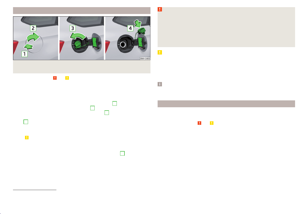
Petrol and diesel refuelling
Fig. 150 Open fuel filler flap / unscrew tank cap / place the tank cap on
the fuel filler flap
Read and observe
and on page 140 first.
Refuelling can be done if the following conditions are met.
The vehicle is unlocked.
The engine and the ignition are switched off.
›
Press on the fuel filler flap in the direction of the arrow
1
» Fig. 150.
›
Open the flap in the direction of the arrow
2
.
›
Unscrew the tank cap in the direction of the arrow
3
.
›
Remove the tank cap and place on top of the fuel filler flap in direction of ar-
row
4
.
›
Insert the pump nozzle into the fuel filler tube as far as it will go.
The fuel tank is full just as soon as the pump nozzle switches off for the first
time » .
›
Remove the pump nozzle from the fuel filler neck and put it back in the
pump.
›
Screw in the tank cap in the opposite direction of the arrow
3
until it audibly
clicks into place.
›
Close the fuel filler flap until it clicks into place.
Check that the fuel filler flap is closed properly.
WARNING
Instructions for filling the reserve canister
■
Never fill the reserve can inside the vehicle.
■
Never place the reserve can on the vehicle.
■
Always place the reserve can on the floor.
■
We do not recommend carrying any fuel canisters in your vehicle for safe-
ty reasons. In the event of an accident, these canisters can become dam-
aged and fuel may escape – risk of fire!
CAUTION
■
The fuel tank is full as soon as the pump nozzle switches off for the first
time, provided the nozzle has been operated properly. Do not continue refuel-
ling.
■
Be careful when filling diesel fuel from the spare canister and then do this
slowly and cautiously – danger of contaminating the body.
Note
The fuel tank has a capacity of about 55 litres, containing a reserve of approx.
7 litres.
Lead-free petrol
The correct fuel grades for your vehicle are specified on the inside of the fuel
filler flap.
Read and observe
and on page 140 first.
The vehicle can only be operated with unleaded petrol that meets the EN 228
1)
standard.
All petrol engines can be operated using petrol that contains at most 10% bio-
ethanol (E10).
Unleaded petrol 95/min. 92 and 93 RON/ROZ
We recommend using unleaded fuel with an octane rating of 95 RON. Unlea-
ded petrol with the octane ratings 92 or 93 RON can also be used, but may re-
sult in a slight loss in performance and slightly increased fuel consumption.
Unleaded petrol min. 95 RON / ROZ
Use unleaded fuel with the octane rating 95 RON or higher.
1)
In Germany also DIN 51626-1 or E10 for unleaded petrol with octane number 91 or 95 or DIN 51626-2 or E5
for unleaded petrol with octane number 95 and 98.
141
Inspecting and replenishing

In an emergency petrol with the octane ratings 91, 92 and/or 93 RON can also
be used, but may result in a slight loss in performance and slightly increased
fuel consumption. Continue driving at medium engine speeds and minimum
engine load » .
Refuel using petrol of the prescribed octane number as soon as possible.
Unleaded petrol 98/(95) RON / ROZ
We recommend using unleaded fuel with an octane rating of 98 RON or higher.
Unleaded petrol 95 RON can also be used but this results in a slight loss in per-
formance and slightly increased fuel consumption.
In an emergency petrol with the octane ratings 91, 92 and/or 93 RON can also
be used, but may result in a slight loss in performance and slightly increased
fuel consumption. Continue driving at medium engine speeds and minimum
engine load » .
Refuel using petrol of the prescribed octane number as soon as possible.
Fuel additives
Unleaded petrol in accordance with the EN 228 standard
1)
meets all the condi-
tions for a smooth-running engine. We therefore recommend that no fuel ad-
ditives are used. This can result in considerable damage to parts of the engine
or the exhaust system.
CAUTION
■
Even one filling of the tank with petrol that does not meet the standards can
lead to serious damage to parts of the exhaust system!
■
If a fuel other than unleaded fuel which complies to the above mentioned
standards (e.g. leaded petrol) is put in the tank by mistake, do not start the en-
gine or switch on the ignition. Extensive damage to engine parts can occur.
CAUTION
■
If petrol with a lower octane number than the one prescribed is used do not
drive with a high engine speed. A high engine load can severely damage en-
gine components.
■
Even in the event of an emergency, petrol of a lower octane number than 91
RON must not be used, otherwise the engine can be severely damaged.
CAUTION
In no case may fuel additives with metal components be used, especially not
with manganese or iron content. There is a risk of causing severe damage to
parts of the engine or exhaust system.
CAUTION
Fuels with metal components, such as LRP (lead replacement petrol) should
not be used. There is a risk of causing severe damage to parts of the engine
or exhaust system.
Note
■
Unleaded petrol that has a higher octane number than that required by the
engine can be used without limitations.
■
The use of petrol with an octane rating higher than 95 RON in does not re-
sult in either a noticeable increase in power nor lower fuel consumption in ve-
hicles for which unleaded petrol 95/min 92 or 93 RON is specified.
■
On vehicles using prescribed unleaded petrol of min. 95 RON, the use of pet-
rol with a higher octane number than 95 RON can increase the power and re-
duce fuel consumption.
Diesel fuel
The correct fuel grades for your vehicle are specified on the inside of the fuel
filler flap.
Read and observe
and on page 140 first.
The vehicle can only be operated with diesel fuel that meets the EN 590
2)
standard.
All diesel engines can be operated using diesel fuel with at most 7% bio-diesel
(B7)
3)
.
Operation in winter – Winter-grade diesel fuel
In the cold season, only use “winter-grade diesel fuel” which will still operate
properly even at a temperature of -20 °C.
1)
In Germany also DIN 51626-1 or E10 for unleaded petrol with octane number 91 or 95 or DIN 51626-2 or E5
for unleaded petrol with octane number 95 and 98.
2)
In Germany also DIN 51628, in Austria ÖNORM C 1590, in Russia GOST R 52368-2005 / EN 590:2004.
3)
In Germany according to the DIN 52638 standard, in Austria ÖNORM C 1590, in France EN 590.
142
General Maintenance

It is often the case in countries with different climatic conditions that diesel
fuels available have a different temperature characteristic. ŠKODA Partners
and filling stations in the relevant country will be able to provide you with in-
formation regarding the diesel fuels available.
Diesel fuel additives
The diesel fuel in accordance with the prescribed standards meets all the con-
ditions for a smooth running engine. We therefore recommend that no diesel
fuel additives are used. This can result in considerable damage to parts of the
engine or the exhaust system.
CAUTION
■
Just filling the tank once with diesel fuel that does not comply with the
standard, can cause severe damage to parts of the engine, the fuel and ex-
haust system.
■
If a different fuel other than diesel fuel, which complies to the above men-
tioned standards (e.g. petrol) is used, do not start the engine or switch on the
ignition! Extensive damage to engine parts can occur.
■
Water which has collected in the fuel filter can cause engine faults.
CAUTION
■
The vehicle cannot be operated with biofuel RME, therefore this fuel must
not be filled in the tank and used for driving the vehicle. The use of biofuel
RME can cause considerable damage to parts of the engine or fuel system.
■
Do not mix any fuel additives, so-called “flow improvers” (petrol and similar
agents) into the diesel. This can result in considerable damage to parts of the
engine or the exhaust system.
Engine compartment
Introduction
This chapter contains information on the following subjects:
Opening and closing the bonnet
144
Engine compartment overview 145
Radiator fan 145
Windscreen washer system 145
WARNING
Injuries or scolding or risks of accident or fire may occur when working in
the engine compartment. For this reason, it is essential to comply with the
warning instructions outlined below and with the general applicable safety
rules. The engine compartment of your car is a hazardous area!
WARNING
Instructions before beginning work in the engine compartment
■
Turn off the engine and remove the ignition key.
■
Firmly apply the handbrake.
■
For vehicles with manual transmission the lever into the neutral position.
■
On vehicles with automatic transmission, shift the selector lever into the
P position.
■
Allow the engine to cool.
■
Never open the bonnet if you can see steam or coolant escaping from the
engine compartment – risk of scalding! Wait until no more steam or coolant
is escaping.
WARNING
Information for working in the engine compartment
■
Keep all people, especially children, away from the engine compartment.
■
Never touch the radiator fan. The fan might suddenly start running!
■
Do not touch any hot engine parts – risk of burns!
WARNING
Information for working in the engine compartment with the engine run-
ning
■
Pay particular attention to moving engine parts, e.g. V-ribbed belt, gener-
ator, radiator fan - danger to life!
■
Never touch the electric wiring on the ignition system.
■
Avoid short circuits in the electrical system, particularly on the vehicle's
battery.
■
Always make sure that no jewellery, loose clothing or long hair can get
caught in rotating engine parts – risk to life! Always remove any jewellery,
tie back long hair and wear tight fitting clothing before completing any
work.
143
Inspecting and replenishing
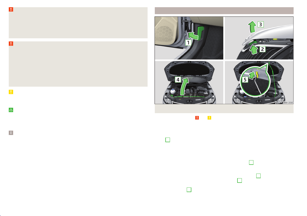
WARNING
Information for working on the fuel system or the electrical system
■
Always disconnect the vehicle battery from the electrical system.
■
Do not smoke.
■
Never work near open flames.
■
Always have a functioning fire extinguisher nearby.
WARNING
■
Read and observe the information and warning instructions on the fluid
containers.
■
Keep the working fluids in sealed original containers and safe from peo-
ple who are not completely independent, e.g. children.
■
Never spill operating fluids over the hot engine - risk of fire.
■
If you intend to work underneath the vehicle, you must secure the vehicle
from rolling away and support it with suitable supporting blocks; the car
jack is not sufficient – risk of injury!
CAUTION
Always top up using the correct specification of fluids. This may result in major
operating problems and also vehicle damage!
For the sake of the environment
In view of the requirements for the environmentally friendly disposal of fluids
and the special tools and knowledge required for such work, we recommend
that fluids be changed by a specialist garage.
Note
■
Please consult a specialist garage for any questions relating to fluids.
■
Fluids with the proper specifications can be purchased from the ŠKODA Origi-
nal Accessories or from the ŠKODA Genuine Parts ranges.
Opening and closing the bonnet
Fig. 151 Opening the bonnet
Read and observe and on page 143 first.
Open flap
›
Open the driver door.
›
Pull the release lever underneath the dash panel in the direction of the ar-
row
1
» Fig. 151.
Before opening the bonnet, ensure that the arms of the windscreen wipers
are correctly in place against the windscreen, otherwise the paintwork on the
flap could be damaged.
›
Press the release lever in the direction of the arrow
2
.
The flap is then unlocked.
›
Grasp the bonnet catch and lift in the direction of arrow
3
.
›
Remove the lid prop in the direction of arrow
4
from the holder.
›
Secure the open flap inserting the end of the post into the opening in the di-
rection of arrow
5
.
144
General Maintenance
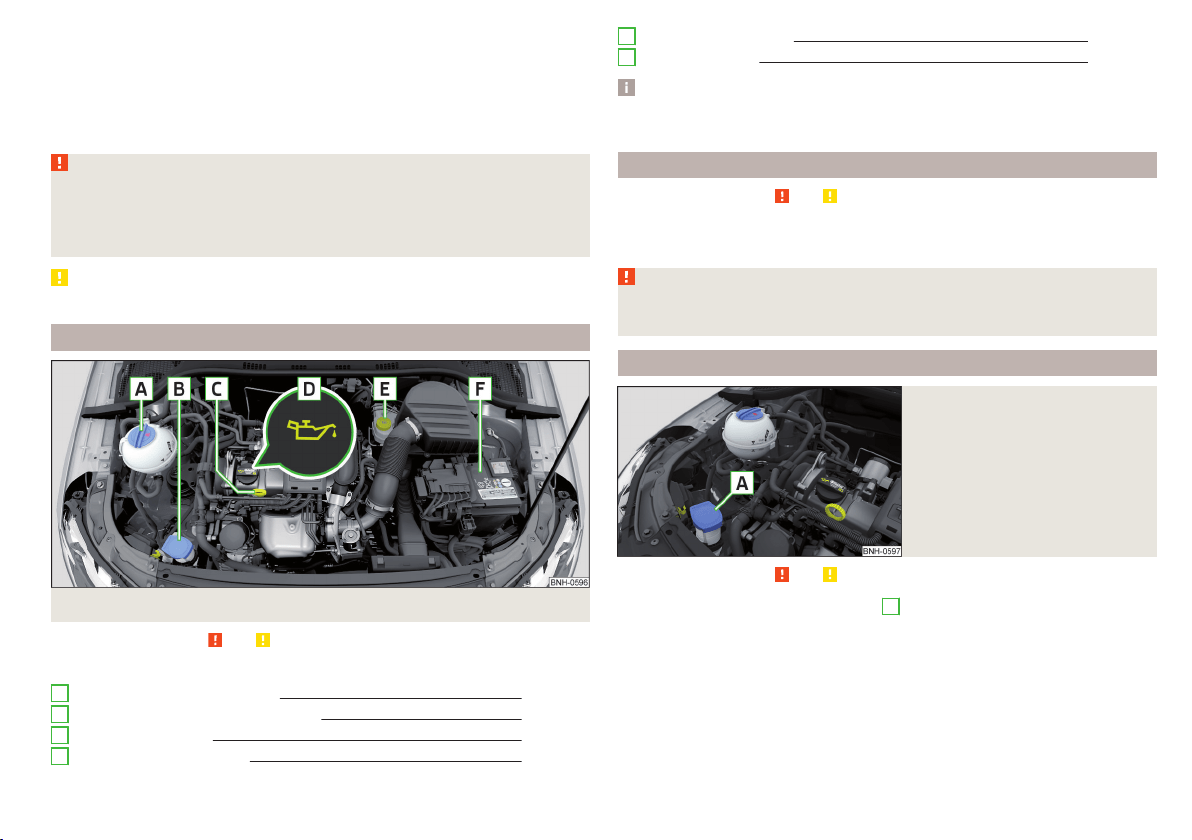
Close the flap
›
Lift the bonnet.
›
Decouple the bonnet support and press into the holder designed to hold it.
›
Let the bonnet drop into the lock carrier lock from a height of around 20 cm –
do not push it in!
Check that the bonnet is closed properly.
WARNING
■
If you notice that the lock is not properly engaged while driving, stop the
vehicle immediately and close the bonnet – risk of accident!
■
Make sure that when closing the bonnet, no body parts are crushed -
there is danger of injury!
CAUTION
Never open the bonnet by the locking lever » Fig. 151.
Engine compartment overview
Fig. 152 Principle sketch: Engine compartment
Read and observe and on page 143 first.
Layout of the engine compartment » Fig. 152
Coolant expansion reservoir 148
Windscreen washer fluid reservoir 145
Engine oil dipstick 147
Engine oil filler opening 147
A
B
C
D
Brake fluid reservoir 150
Vehicle battery 150
Note
The location of the inspection points in the engine compartment of petrol and
diesel engines is practically identical.
Radiator fan
Read and observe and on page 143 first.
The radiator fan is powered by an electric motor. Operation is controlled ac-
cording to the temperature of the coolant.
WARNING
After switching off the ignition, the fan may intermittently continue to op-
erate for approx. 10 minutes.
Windscreen washer system
Fig. 153
Windscreen washer fluid reser-
voir
Read and observe and on page 143 first.
The windscreen washer fluid reservoir
A
is located in the engine compart-
ment » Fig. 153.
The cleaning fluid is provided for the cleaning of the front and rear window as
well as the headlight.
E
F
145
Inspecting and replenishing

The capacity of the reservoir is about 3.5 litres or about 5.4 litres on vehicles
that have a headlight cleaning system
1)
.
Clear water is not sufficient to intensively clean the windscreen and head-
lights. We recommend using clean water together with a screen cleaner from
the range of ŠKODA Original Accessories (with anti-freeze in winter), which
will remove any stubborn dirt.
In winter, the washing water should always be mixed with antifreeze even if
the vehicle has heated windscreen washer nozzles.
Under exceptional circumstances, methylated spirits can also be used if no
screen cleaner with anti-freeze is available. The concentration of methylated
spirits must not be more than 15 %. The anti-freeze protection at this concen-
tration is sufficient only to -5 °C.
CAUTION
■
Under no circumstances must radiator anti-freeze or other additives be add-
ed to the windscreen washer fluid.
■
If the vehicle is fitted with a headlight cleaning system, only cleaning prod-
ucts which do not attack the polycarbonate coating of the headlights must be
added to the windscreen washer fluid.
■
Do not remove the filter from the windscreen washer fluid reservoir when re-
filling, as this may cause contamination of the liquid transportation system,
leading in turn to a windscreen washer system malfunction.
Engine oil
Introduction
This chapter contains information on the following subjects:
Specification 146
Checking the oil level
147
Replenishing
147
The engine has been factory-filled with a high-grade oil that can be use
throughout the year - except in extreme climate zones.
The engine oils are undergoing continuous further development. Thus the in-
formation stated in this Owner's Manual is only correct at the time of publica-
tion.
ŠKODA Service Partners are informed about the latest changes by the manu-
facturer. We therefore recommend that the oil change be completed by a
ŠKODA Service Partner.
The specifications (VW standards) stated in the following can be indicated sep-
arately or together with other specifications on the bottle.
The engine oil should be changed after specified service intervals » page 46.
WARNING
The engine compartment of your car is a hazardous area. The following
warning instructions must be followed at all times when working in the en-
gine compartment » page 143.
CAUTION
Do not pour any additives into the engine oil – risk of serious damage to the
engine parts.
Note
■
Before a long drive we recommend that you purchase and carry with you en-
gine oil which complies with the specification for your vehicle.
■
We recommend that you use oils from ŠKODA Original Accessories.
■
If your skin has come into contact with oil, it must be washed thoroughly.
Specification
Read and observe
and on page 146 first.
Vehicles with variable service intervals
Petrol engines Specification
1.2 l/66, 81 kW TSI
VW 504 00
1.4 l/92 kW TSI
Diesel engines
a)
Specification
1.4 l/66 kW TDI CR
VW 507 00
1.6 l/85 kW TDI CR
a)
Engine oil VW 505 01 can optionally be used in diesel engines without a DPF.
1)
In some countries, 5.4 l. applies for both variants.
146
General Maintenance
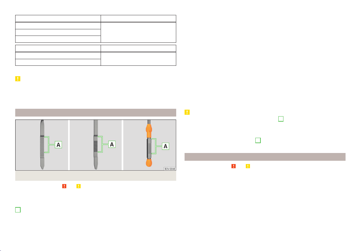
Vehicles with fixed service intervals
Petrol engines Specification
1.2 l/66, 81 kW TSI
VW 502 001.4 l/92 kW TSI
1.6 l./81 kW MPI
Diesel engines
a)
Specification
1.4 l/66 kW TDI CR
VW 507 00
1.6 l/85 kW TDI CR
a)
Engine oil VW 505 01 can optionally be used in diesel engines without a DPF.
CAUTION
■
In an emergency, another engine oil to be refilled. To prevent damage to the
engine, a maximum of 0.5 litres only of the following engine oils may be used:
■
For petrol engine models: ACEA A3/ACEA B4 or API SN, (API SM);
■
For diesel engine models: ACEA C3 or API CJ-4.
Checking the oil level
Fig. 154
Principle sketch: Dipstick
Read and observe and on page 146 first.
The dipstick indicates the engine oil level .
Dipstick » Fig. 154
The oil level must be within this range.
The oil can be checked and topped up, if the following conditions are satisfied.
The vehicle is standing on a horizontal surface.
The engine operating temperature is reached.
A
The engine is turned off.
The bonnet is open.
Checking the level
›
Wait a few minutes until the engine oil flows back into the oil trough.
›
Pull out the dipstick.
›
Wipe the dipstick with a clean cloth and insert it again to the stop.
›
Pull the dipstick out again and check the oil level.
›
Re-insert the dipstick.
The engine consumes a little oil. The oil consumption may be as much as 0.5
l/1 000 km depending on your style of driving and the conditions under which
you operate your vehicle. Consumption may be slightly higher than this during
the first 5 000 km.
The oil level must be checked at regular intervals.
In case of low oil level, the instrument cluster display shows a warning light
as well as the relevant notification » page 37. Check the oil level using the dip-
stick as soon as possible. Add oil accordingly.
CAUTION
■
The oil level must never be above the range
A
» Fig. 154 - risk of damage to
the motor as well as the exhaust system.
■
If for some reason, it is not possible to top up the engine oil,
do not contin-
ue driving! Switch off the engine and seek assistance from a specialist garage.
■
If the oil level is above the range
A
,
do not continue to drive! Switch off
the engine and seek assistance from a specialist garage.
Replenishing
Read and observe and on page 146 first.
›
Unscrew the cap of the engine oil filler opening » Fig. 152 on page 145.
›
Replenish the oil in portions of 0.5 litres in accordance with the correct speci-
fications » page 146.
›
Check the oil level » page 147.
›
Screw the lid of the engine oil filler closed carefully.
›
Pull the dipstick out as far as the stop.
147
Inspecting and replenishing
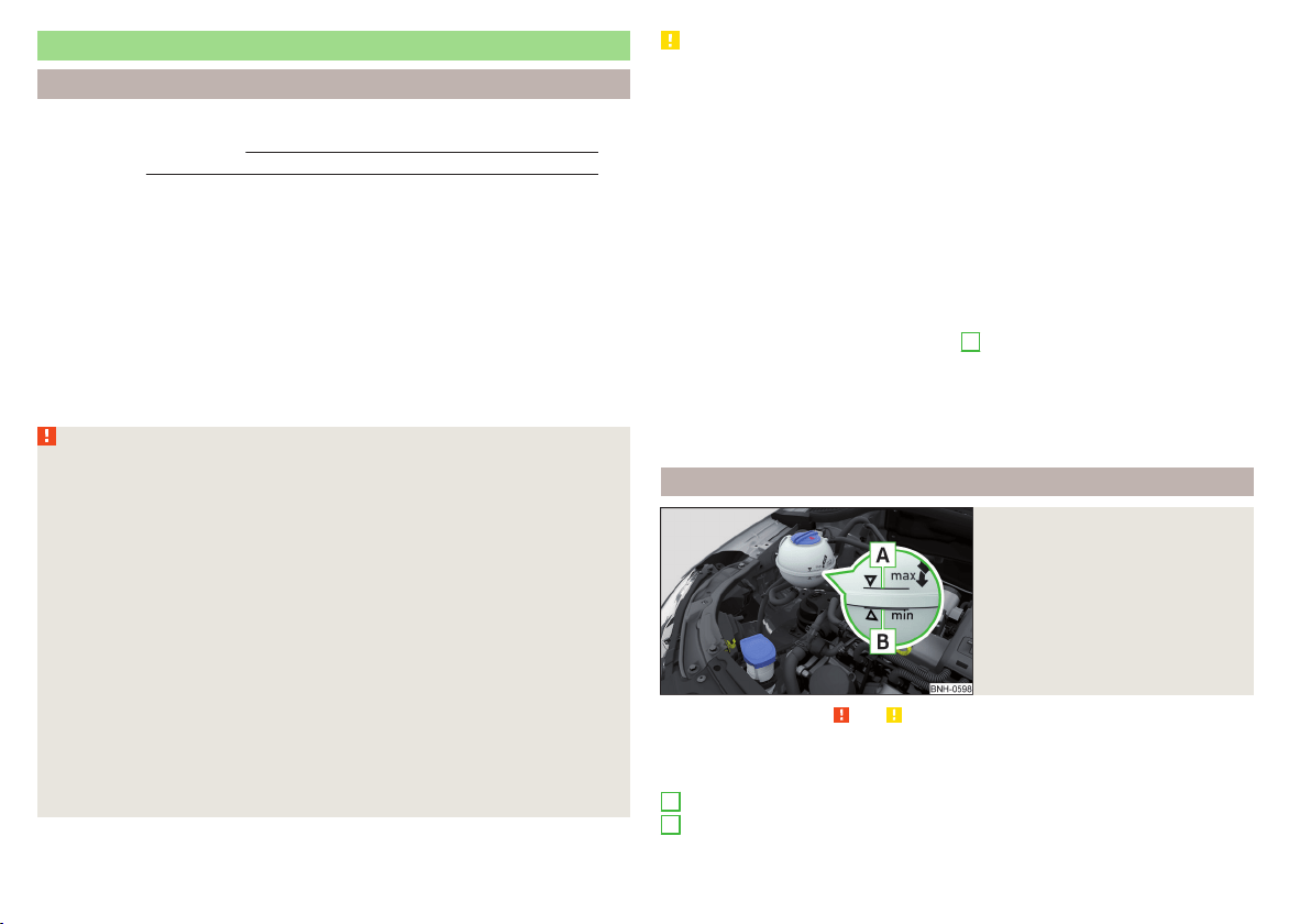
Coolant
Introduction
This chapter contains information on the following subjects:
Checking the coolant level
148
Replenishing 149
The coolant provides cooling for the motor.
It consists of water and coolant additive with additives that protect the cooling
system against corrosion and prevents furring.
The coolant additive in the coolant must be at least 40%.
The coolant additive may be increased to a maximum of 60%.
The correct mixing ratio of water and coolant additive is to be checked if nec-
essary by a specialist garage or is to be restored if necessary.
The description of the coolant is shown in the coolant expansion reservoir
» Fig. 155 on page 148.
WARNING
The engine compartment of your car is a hazardous area. The following
warning instructions must be followed at all times when working in the en-
gine compartment » page 143.
■
The coolant is harmful to health.
■
Avoid contact with the coolant.
■
Coolant vapours are harmful to health.
■
Never open the end cover of the coolant expansion reservoir while the
engine is still warm. The cooling system is pressurised!
■
When opening the end cover of the coolant expansion reservoir, cover it
with a cloth to protect your face, hands and arms from hot steam or hot
coolant.
■
If any coolant splashes into your eyes, immediately rinse out your eyes
with clear water and contact a doctor as soon as possible.
■
Always keep the coolant in the original container, safe from people who
are not completely independent, especially children - there is a danger of
poisoning!
■
If coolant is swallowed, consult a doctor immediately.
■
Never spill operating fluids over the hot engine - risk of fire.
CAUTION
■
Do not continue if for some reason it is not possible to fill with coolant un-
der the current circumstances! Switch off the engine and seek assistance from
a specialist garage.
■
If the expansion tank is empty, do not top up with coolant. The system could
ventilate - there is a risk of engine damage,
do not continue driving! Switch
off the engine and seek assistance from a specialist garage.
■
The concentration of coolant additive in the coolant must never be under
40%.
■
Over 60% of coolant additive in the coolant reduces the antifreeze protec-
tion and cooling effect.
■
A coolant additive that does not comply with the correct specification can
significantly reduce the corrosion protection of the cooling system.
■
Any faults resulting from corrosion may cause a loss of coolant and can con-
sequently result in major engine damage.
■
Do not fill the coolant above the mark
A
.» Fig. 155 on page 148
■
If an error occurs, leading to the engine overheating, the help of a professio-
nal garage is to be sought - there is a risk of serious engine damage occurring.
■
Additional headlights and other attached components in front of the air inlet
impair the cooling efficiency of the coolant.
■
Never cover the radiator - there is a risk of the engine overheating.
Checking the coolant level
Fig. 155
Coolant expansion reservoir
Read and observe and on page 148 first.
The coolant expansion bottle is located in the engine compartment.
Coolant expansion reservoir » Fig. 155
Mark for the maximum permissible coolant level
Mark for the lowest permissible coolant level
A
B
148
General Maintenance

The coolant level should be kept between the marks
A
and
B
.
The coolant can be checked and topped up, if the following conditions are sat-
isfied.
The vehicle is standing on a horizontal surface.
The engine is turned off.
The engine is not heated.
The bonnet is open.
Checking the level
›
Check the coolant level in the coolant expansion tank » Fig. 155.
If the engine is warm, the test result may be inaccurate. The level can also be
above the mark
A
» Fig. 155.
In the event of an insufficient coolant level, a warning light
is displayed in
the instrument cluster as well as the relevant notification » page 36. We still
recommend inspecting the coolant level directly at the reservoir from time to
time.
Loss of coolant
A loss of coolant is first and foremost an indication of a leak in the cooling sys-
tem. Do not merely top up the coolant. Have the cooling system checked by a
specialist garage.
Replenishing
Read and observe and on page 148 first.
The coolant expansion tank must always contain a small amount of coolant
» page 148,
in section Introduction.
›
Place a cloth over the cap of the coolant expansion tank and unscrew the
cap carefully.
›
Replenishing the coolant.
›
Turn the cap until it clicks into place.
Do not use an alternative additive if the specified coolant is not available. In
this case, use just water and have the correct mixing ratio of water and cool-
ant additive restored by a specialist garage as soon as possible.
Only top up with new coolant.
Brake fluid
Introduction
This chapter contains information on the following subjects:
Checking the brake fluid level
150
Specification 150
The brake fluid reservoir is located in the engine compartment » Fig. 156 on
page 150.
WARNING
■
The engine compartment of your car is a hazardous area. The following
warning instructions must be followed at all times when working in the en-
gine compartment » page 143.
■
Do not use used brake fluid - the function of the brake system may be im-
paired – risk of accident!
CAUTION
■
Do not continue your journey if the fluid level has dropped below the “MIN”
marking » Fig. 156 on page 150, do not continue to drive - risk of accidents!
Seek help from a specialist garage.
■
Brake fluid damages the paintwork of the vehicle.
Note
■
The brake fluid is changed as part of a compulsory inspection service.
■
We recommend using brake fluids from the ŠKODA Original Accessories
range.
149
Inspecting and replenishing
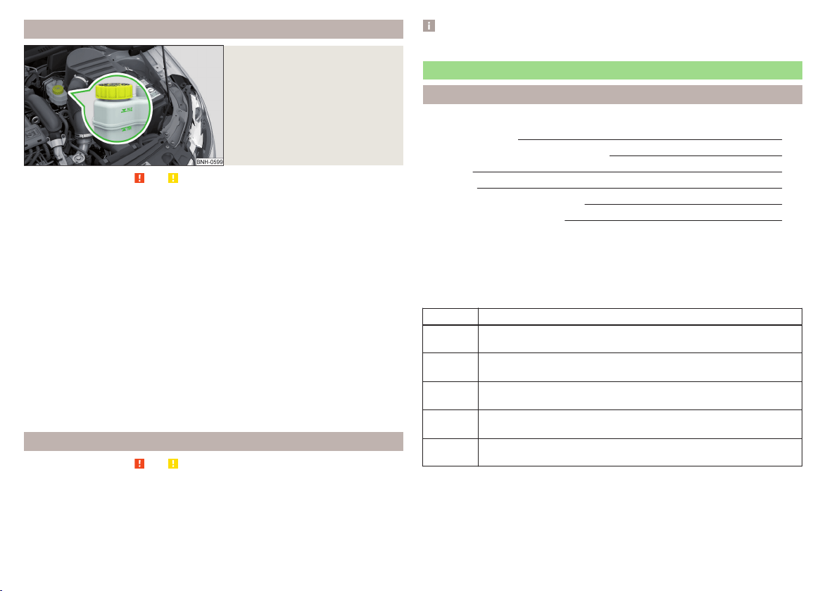
Checking the brake fluid level
Fig. 156
Brake fluid reservoir
Read and observe and on page 149 first.
The fluid can be checked if the following conditions are met.
The vehicle is standing on a horizontal surface.
The engine is turned off.
The bonnet is open.
Checking the level
›
Check the level of brake fluid in the reservoir » Fig. 156.
The level must be between the “MIN” and “MAX” markings.
A slight drop in the fluid level results when driving due to normal wear-and-
tear and automatic adjustment of the brake pads.
There may be an indication of a leak in the brake system, however, if the fluid
level drops significantly within a short time or if it drops below the “MIN” mark-
ing.
Too low brake fluid level is indicated by the warning light
lighting up in the
instrument cluster as well as the relevant notification being displayed
» page 32,
Brake system.
Specification
Read and observe
and on page 149 first.
To ensure the optimal functioning of the braking system, only use a brake fluid
meeting the standard VW 501 14 (this standard meets the requirements of
FMVSS 116 DOT4).
Note
We recommend using brake fluids from the ŠKODA Genuine Accessories range.
Vehicle battery
Introduction
This chapter contains information on the following subjects:
Opening the cover
151
Checking the battery electrolyte level 152
Charging 152
Replacing 153
Disconnecting and reconnecting
153
Automatic load deactivation
153
The vehicle battery represents a power source for the motor to start and for
the supply of electrical consumers in the car.
Depending on the engine, the vehicle battery is either in the engine compart-
ment or the luggage compartment.
Warning symbols on the vehicle battery
Symbol Meaning
Always wear eye protection!
Battery acid is severely caustic. Always wear gloves and eye pro-
tection!
Keep fire, sparks, open flames and lit cigarettes well clear of the
vehicle battery!
When charging the vehicle battery, a highly explosive gas mixture
is produced!
Keep children away from the vehicle battery!
150
General Maintenance
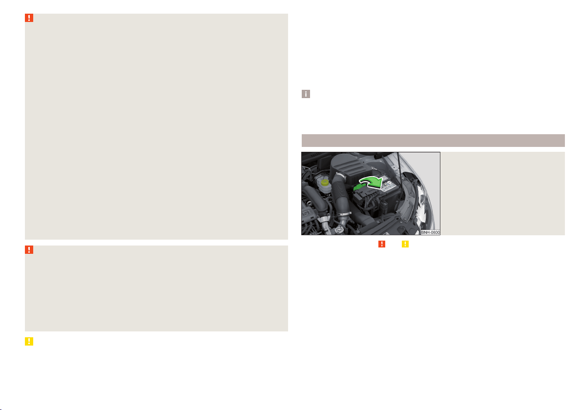
WARNING
There is risk of injuries, poisoning, chemical burns, explosions or fire when
working on the battery and on the electrical system. It is essential to com-
ply with the general applicable safety rules as well as the warning instruc-
tions outlined below.
■
Keep the vehicle battery away from people who are not completely inde-
pendent, especially children.
■
Do not tilt the battery otherwise battery electrolyte may flow out of the
battery vent openings.
■
Protect your eyes by wearing safety goggles or a face shield – risk of
blindness!
■
Always wear protective gloves, eye and skin protection when handling
the vehicle battery.
■
The battery acid is strongly corrosive and must, therefore, be handled
with the greatest of care.
■
Corrosive fumes in the air irritate the air passages and lead to conjunctivi-
tis and inflammation of the air passages in the lungs.
■
Battery acid corrodes dental enamel and, if it comes into contact with the
skin, causes deep wounds that take a long time to heal.
■
If any battery acid comes into contact with your eyes, rinse the affected
eye immediately with clean water for several minutes and consult a doctor
immediately!
■
Splashes of acid on your skin or clothes should be neutralised as soon as
possible using soap suds and then rinsed with plenty of water.
■
If you swallow battery acid, consult a doctor immediately!
WARNING
■
The use of open flames and light should be avoided.
■
Smoking and radio triggering activities should be avoided.
■
Never use a damaged vehicle battery – risk of explosion!
■
Never charge a frozen or thawed vehicle battery – risk of explosion and
chemical burns!
■
Replace a frozen vehicle battery.
■
Never jump-start vehicle batteries with insufficient acid levels – risk of
explosion and chemical burns.
CAUTION
■
Improper handling of the vehicle battery may cause damage.
■
Ensure that battery acid does not come into contact with the bodywork – risk
of damage to the paintwork.
■
If the vehicle has not been driven for more than 3-4 weeks, the battery will
discharge. Prevent the battery from discharging by disconnecting the battery's
negative terminal
or continuously charging the battery with a very low
charging current.
■
Do not place the battery in direct daylight in order to protect the vehicle bat-
tery housing from the effects of ultra-violet light.
■
If the vehicle is frequently used for making short trips, the vehicle battery
will not have time to charge up sufficiently and may discharge.
Note
■
We recommend having all work on the vehicle battery carried out by a spe-
cialist garage.
■
You should replace batteries older than 5 years.
Opening the cover
Fig. 157
Battery cover
Read and observe and on page 151 first.
The battery is located in the engine compartment.
›
Open the cover in the direction of the arrow.
The battery cover is installed in reverse order.
151
Inspecting and replenishing
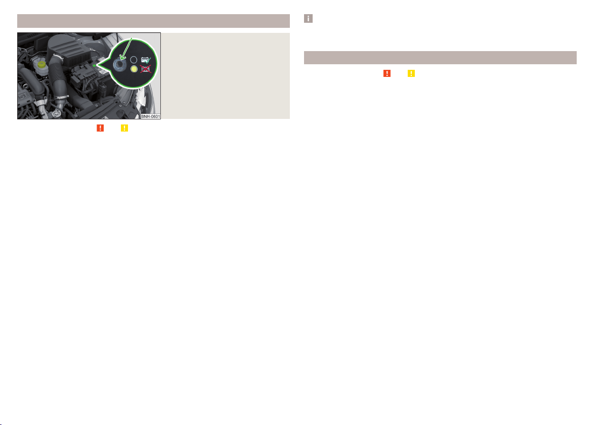
Checking the battery electrolyte level
Fig. 158
Vehicle battery: Electrolyte level
indicator
Read and observe and on page 151 first.
On vehicles with a vehicle battery fitted with a colour indicator, the electrolyte
level can be determined by looking at the change in colour of this display.
Air bubbles can influence the colour of the indicator. For this reason carefully
knock on the indicator before carrying out the check.
Check
Black colour – electrolyte level is correct.
Colourless or light yellow colour – electrolyte level too low, the battery must
be replaced.
For technical reasons, on vehicles with the description “AGM”, the electrolyte
level cannot be checked.
Vehicles with the START STOPsystem are fitted with a battery control unit for
checking the energy level for recurring engine starts.
We recommend that you have the acid level checked regularly by a specialist
garage, especially in the following cases.
▶
High external temperatures.
▶
Longer day trips.
▶
After each charge.
Winter time
The vehicle battery only has a proportion of the starting power in lower tem-
peratures. A discharged vehicle battery may already freeze at temperatures
just below 0 °C.
We therefore recommend that you have the battery checked and, if necessary,
recharged by a specialist garage before the start of the winter.
Note
The battery acid level is also checked regularly by a specialist garage as part of
the inspection service.
Charging
Read and observe and on page 151 first.
A properly charged vehicle battery is essential for reliably starting the engine.
A charging operation can be performed if the following conditions are satis-
fied.
The engine is turned off.
The ignition is switched off.
All consumers are turned off.
The bonnet is open.
“Fast charging” with high currents
›
Disconnect both battery cables (first of all “negative”, then “positive”).
›
Attach the terminal clamps of the charger to the battery terminals (red =
“positive”, black = “negative”).
›
Plug the mains cable of the charger into the power socket and switch on the
device.
›
After charging has been successful: Switch off the charger and remove the
mains cable from the power socket.
›
Only then disconnect the charger's terminal clamps.
›
Reconnect the cables to the battery (first “positive”, then “negative”).
Charging with low voltages
It is not necessary to disconnect the cables from the battery if you recharge
the vehicle battery, for example from a mini-charger.
Refer to the instructions of the charger manufacturer.
A charging current of 0.1 multiple of the total vehicle battery capacity (or low-
er) must be used until full charging is achieved.
The vent plugs of the vehicle battery should not be opened for charging.
152
General Maintenance
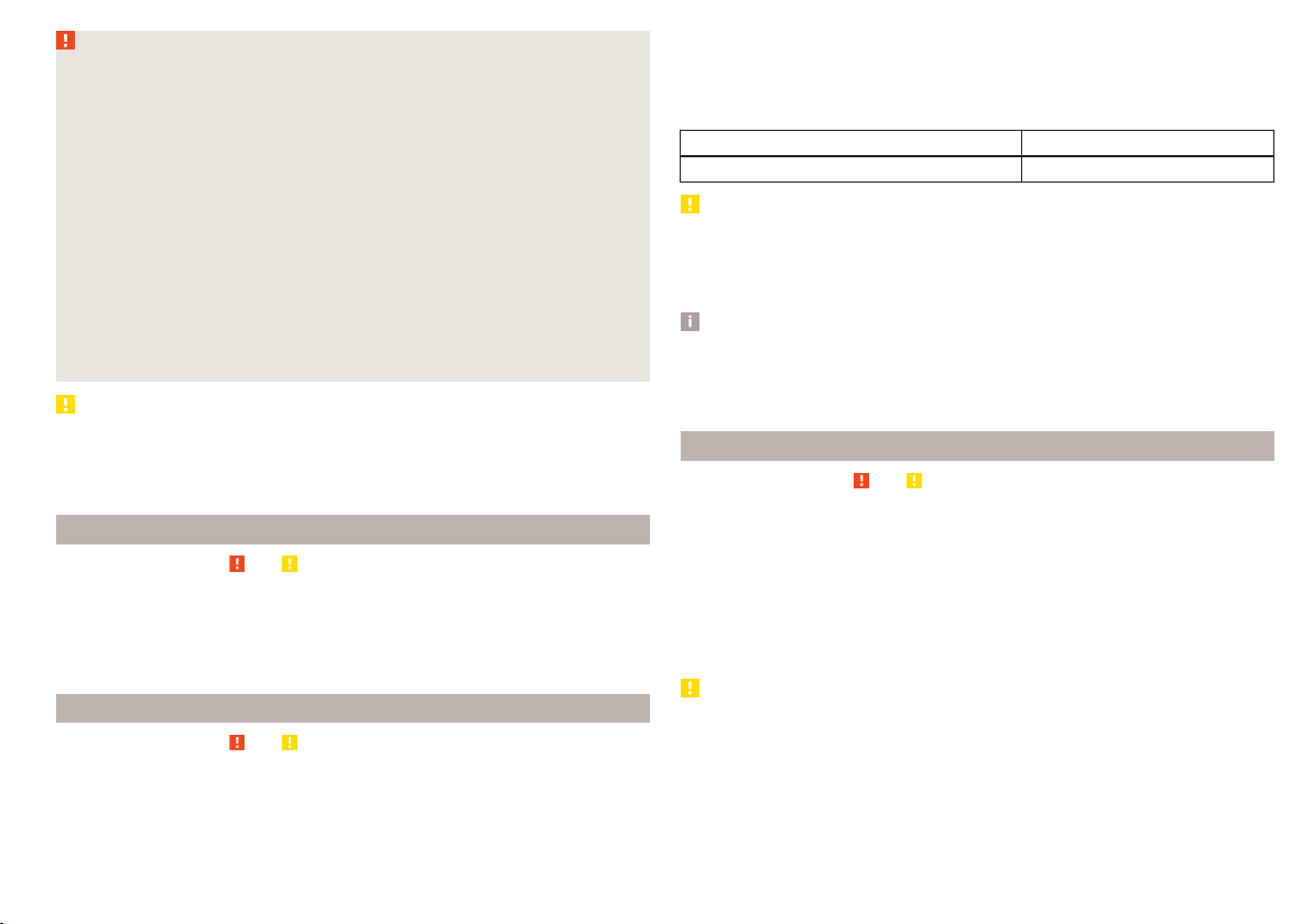
WARNING
■
When you charge a battery, hydrogen is released, and a highly explosive
gas mixture is also produced. An explosion can be caused through sparkling
over during unclamping or loosening of the cable plug while the ignition is
on.
■
Creating a bridge between the poles on the battery (e.g. with metal ob-
jects - cables) creates a short circuit - risk of damage to the battery, explo-
sion and burning of the battery, jets of acid spurting out.
■
Avoid creating sparks when working with cables and electrical devices.
Strong sparking represents a risk of injury.
■
Before carrying out any work on the electrical system, switch off the en-
gine, the ignition and all electrical consumers and disconnect the negative
terminal
.
■
“Quick-charging” the vehicle battery is dangerous and requires a special
charger and specialist knowledge.
■
We therefore recommend that vehicle batteries be “rapidly charged” by a
specialist garage.
CAUTION
On vehicles with the START/STOP system, the pole terminal of the charger
must not be connected directly to the negative terminal of the vehicle battery,
but only to the engine earth » page 168, Jump-starting using the battery from
another vehicle.
Replacing
Read and observe and on page 151 first.
The new vehicle battery must have the same capacity, voltage, current and
size as the original battery. Suitable vehicle battery types can be purchased
from a specialist garage.
We recommend you have the battery replaced by a specialist garage.
Disconnecting and reconnecting
Read and observe
and on page 151 first.
Disconnecting
›
Switch off the ignition.
›
First, disconnect the negative terminal
first, then the positive
terminal
of the battery.
Connecting
›
First, connect the positive first, then the negative battery terminal.
After disconnecting and re-connecting the vehicle battery, the following func-
tions or devices are partially or completely inoperative.
Function / device Commissioning
Time settings » page 31
CAUTION
■
Disconnect the vehicle battery only with the ignition turned off - there is a
risk of damaging the electrical system of the vehicle.
■
Under no circumstances must the battery cables be connected incorrectly –
risk of a cable fire.
Note
■
After disconnecting and re-connecting the vehicle battery, we recommend
having the vehicle checked by a specialist to ensure that the full functionality
of all electrical systems is guaranteed.
■
The data of the multi-function display will be reset.
Automatic load deactivation
Read and observe
and on page 151 first.
The vehicle's electrical system automatically prevents the battery from dis-
charging when the battery is being heavily used. This manifests itself by the
following.
▶
The idling speed is raised to allow the generator to deliver more electricity to
the electrical system.
▶
Where necessary, large convenience consumers such as seat heaters and
rear window heaters have their power limited or are shut off completely in
the event of an emergency.
CAUTION
■
Despite such intervention by the vehicle electric system management, the
vehicle battery may be drained. For example, when the ignition is switched on
a long time with the engine turned off or the side or parking lights are turned
on during longer parking.
■
Consumers that are supplied via a 12-V power socket can cause the vehicle
battery to discharge when the ignition is switched off.
153
Inspecting and replenishing

Note
Driving comfort is not impaired by consumers being deactivated. The driver is
often not aware of it having taken place.
Wheels
Tyres and wheel rims
Introduction
This chapter contains information on the following subjects:
Notes on using wheels 154
Tyre pressure 155
Tyre wear 156
Tyre wear indicator and wheels exchange 156
Tyre damage 157
Unidirectional tyres 157
Spare wheel 157
Spare wheel 157
Tyre label 158
Only use tyres or wheel rims that have been approved by ŠKODA for your mod-
el of vehicle.
WARNING
For reasons of driving safety, do not replace tyres individually.
Note
■
We recommend that any work on the wheels or tyres is carried out by a spe-
cialist garage.
■
We recommend that you use wheel rims, tyres, full wheel trims and snow
chains from ŠKODA Original Accessories.
Notes on using wheels
Read and observe
on page 154 first.
During the first 500 km, new tyres do not offer optimum grip and appropriate
care should therefore be taken when driving.
Always fit the tyres with the deeper tread depth to the front wheels.
Tyre storage
Identify disassembled tyres so that the previous direction of rotation can be
maintained if the tyres are reassembled.
154
General Maintenance
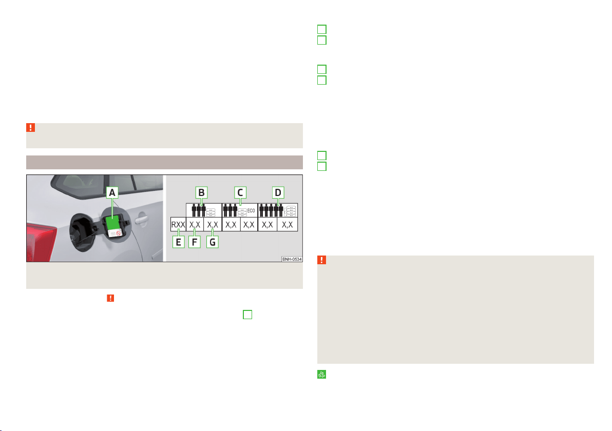
Always store wheels or tyres in a cool, dry place that is as dark as possible.
Tyres which are not fixed to a wheel trim should be stored upright.
Tyre age
Tyres age and lose their original characteristics, even if they are not being
used. The service life of the tyres is 6 years. Therefore, we recommend not us-
ing tyres that are older than 6 years.
Wheel bolts
Wheels and wheel bolts are matched to each other in terms of design. We rec-
ommend that you use wheel rims and wheel bolts from ŠKODA Original Acces-
sories.
WARNING
Never use tyres if you do not know anything about the condition and age.
Tyre pressure
Fig. 159 Label with a table of tyre sizes and tyre pressure value / inflate
tyres
Read and observe on page 154 first.
The prescribed tyre inflation is on the sticker with pictograms
A
» Fig. 159 (for
some countries, the pictograms are replaced with a text).
Tyre pressure is always to match the load.
Inflation pressure for half load
Inflation pressure for environmentally-friendly operation
As a result of pressure level adaption to this value, the fuel consumption
and pollutant emissions may fall slightly.
Inflation pressure for full load
Tyre diameter in inches
These details are intended only as information for the specified tyre pres-
sure and does not list approved tyre sizes for your vehicle.
The approved tyre sizes for your vehicle are listed in the vehicle's technical
documentation (the so called COC document) and this also states the dec-
laration of conformity.
The approved tyre diameter for your vehicle is also provided with the vehi-
cle data » page 183.
Tyre pressure value on the front axle
Tyre pressure value on the rear axle
Check tyre pressures
Check the tyre pressure, including that of the emergency or spare wheel, at
least once a month and also before setting off on a long journey.
Always check the inflation pressure when the tyres are cold. Do not reduce the
higher pressure on warm tyres.
In vehicles with tyre pressure monitoring tyre pressure values are to be stored
every time the tyre pressure changes » page 119.
WARNING
■
Having the correct tyre inflation pressure is always the driver's responsi-
bility.
■
Too low or too high inflation pressure impairs handling.
■
If the inflation pressure is too low, the tyre will have to overcome a higher
rolling resistance. This will cause a significant increase in the temperature
of the tyre, especially at higher speeds. This can result in tread separation
and a tyre blow out.
■
In the event of very fast tyre inflation pressure loss, such as a sudden tyre
failure, an attempt should be made to bring the vehicle carefully to a stop
without sudden steering movements and without any hard braking.
For the sake of the environment
Tyres that are insufficiently inflated increase your fuel consumption.
B
C
D
E
F
G
155
Wheels
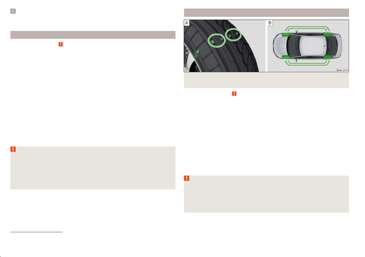
Note
The declaration of conformity (COC document), can be obtained from a ŠKODA
1)
partner.
Tyre wear
Read and observe on page 154 first.
Tyre wear depends on the pressure, driving style, and other circumstances.
Attention to the following notes may affect tyre wear.
Driving style
Fast cornering, sharp acceleration and braking increase the wear of your tyres.
Wheel balance
The wheels of a new vehicle are balanced. When driving, however, there are a
range of factors that may result in an imbalance. This may become apparent by
a “vibration” in the steering. If this is the case, have the wheels checked by a
specialist garage.
Have the wheels likewise rebalanced after replacing the tyres.
Setting the vehicle geometry
Incorrect wheel alignment at the front or rear leads to excess wear on the
tyres and impairs driving safety. With a distinctive tyre wear, we recommend
that you check the setting of the vehicle geometry in a specialist workshop.
WARNING
■
An incorrect wheel alignment at the front or rear impairs handling.
■
Unusual vibrations or pulling of the vehicle to one side could be a sign of
tyre damage. If there is any suspicion that a wheel is damaged, immediately
reduce your speed and stop! If no external tyre damage is evident, drive
slowly and carefully to the nearest specialist garage to have the vehicle
checked.
Tyre wear indicator and wheels exchange
Fig. 160 Principle sketch: Replace tyre tread with wear indicators /
wheels
Read and observe
on page 154 first.
Wear indicators
The base of the tread of the tyres contains has a 1.6 mm high wear indicator
» Fig. 160 -
. In some countries, different tyre wear rates may apply.
Markings on the walls of the tyres through the letters “TWI”, triangular sym-
bols or other symbols identify the position of the wear indicators.
Exchanging the wheels
For uniform wear on all tyres, we recommend that you change the wheels ev-
ery 10 000 km according to the scheme » Fig. 160-
. You will then obtain ap-
proximately the same life for all the tyres.
After a wheel has been replaced, the tyre pressure has to be adjusted.
In vehicles with tyre pressure monitoring, save tyre pressure values» page 120.
WARNING
■
You must have your tyres replaced with new ones at the latest when the
wear indicators have been worn down.
■
Worn tyres impair necessary adhesion to the road surface, particularly at
high speeds on wet roads. This could lead to “aquaplaning” (uncontrolled
vehicle movement – “swimming” on a wet road surface).
1)
Only valid for some countries and some models.
156
General Maintenance

Tyre damage
Read and observe on page 154 first.
We recommend checking your tyres and wheel rims for damage (punctures,
cuts, splits and bulges, etc.) on a regular basis.
Remove any foreign objects in the tyre tread immediately (e.g. small stones).
Foreign bodies which have penetrated into the tyre (e.g. screws or nails)
should not be removed and seek help from a specialist garage.
WARNING
Never drive with damaged tyres – there is the risk of an accident occurring.
CAUTION
The tyres must be protected from contact with substances such as oil, grease
and fuel, which could damage them. If the tyres come into contact with these
substances, then we recommend you have this checked out in a specialist
workshop.
Unidirectional tyres
Read and observe on page 154 first.
The direction of rotation of the tyres is marked by arrows on the wall of the
tyre.
The indicated direction of rotation must be adhered to in order to ensure the
optimal characteristics of these tyres.
These characteristics mainly relate to the following.
▶
Increased driving stability.
▶
Reduced risk of aquaplaning.
▶
Reduced tyre noise and tyre wear.
Spare wheel
Read and observe
on page 154 first.
The size of the spare wheel is identical to that of the vehicle factory installed
wheels.
After changing the spare wheel, the tyre pressure should be adjusted.
In vehicles with tyre pressure monitoring, save tyre pressure values» page 120.
WARNING
■
If, you get a puncture and a spare tyre has to be mounted with opposite
direction of rotation, then drive carefully. The best properties of the tyre
are no longer present in this situation.
■
If the dimensions or design of the spare wheel differ from the tyres fitted
to the vehicle (e.g. winter tyres or low-profile tyres), it must only be used
briefly in the event of a puncture and if an appropriately cautious style of
driving is adopted.
■
Never use the temporary spare wheel if it is damaged.
Spare wheel
Read and observe
on page 154 first.
A yellow warning label is always displayed on the rim of the temporary spare
wheel.
Please note the following if you intend to use the temporary spare wheel.
▶
The warning label must not be covered after installing the wheel.
▶
Be particularly observant when driving.
▶
The spare is inflated to the maximum inflation pressure for the vehicle
» page 155.
▶
The tyre inflation pressure of the spare wheel 125/70 R16 is 4.2 bar.
▶
Only use this temporary spare wheel to reach the nearest specialist garage,
since it is not intended for permanent use.
If you need to use a spare wheel, make sure to fit a standard wheel of the ap-
propriate dimensions and design as soon as possible.
In vehicles with tyre pressure monitoring, save tyre pressure values» page 120.
WARNING
■
Never drive with more than one temporary spare wheel mounted!
■
Only use the temporary spare wheel when absolutely necessary.
■
Avoid accelerating at full throttle, sharp braking and fast cornering.
■
The snow chains cannot be used on the temporary spare wheel.
■
If the dimensions or design of the temporary spare wheel differ from the
tyres fitted, never drive faster than 80 km/h (or 50 mph).
■
Never use the emergency spare wheel if it is damaged.
■
Observe the instructions on the warning sign of the temporary spare
wheel.
157
Wheels

Tyre label
Read and observe on page 154 first.
Only use radial tyres of the same type, size (rolling circumference) and tread
pattern on one axle on all four wheels.
When mounting new tyres the tyres have to be replaced axle by axle.
Explanation of tyre markings
For example, 225/50R 17 91 Tmeans:
225 Tyre width in mm
50 Height/width ratio in %
R Code letter for the type of tyre – Radial
17 Diameter of wheel in inches
91 Load index
T Speed symbol
The date of manufacture is stated on the tyre wall (possibly on the inside).
For example DOT ... 10 15... means that the tyre was manufactured in the 10th
week of the year 2015.
Load index
The load index indicates the maximum permissible load for each individual
tyre.
Load index
83 84 85 86 87 88
Load
(In kg)
487 500 515 530 545 560
Speed symbol
The maximum speed symbol indicates the maximum permissible vehicle speed
with fitted tyres in each category.
Speed
symbol
S T U H V W
Maximum
speed
(in km/h)
180 190 200 210 240 270
WARNING
■
Never exceed the maximum permissible load bearing capacity of moun-
ted tyres.
■
Never exceed the maximum permissible speed for the mounted tyres.
Winter operation
Introduction
This chapter contains information on the following subjects:
Winter tyres
158
Snow chains 159
Do not use alloy rims with bevelled or polished surfaces during the winter. The
rim surface does not have sufficient corrosion protection and could be perma-
nently damaged (e.g. through grit).
Winter tyres
The handling of your vehicle will be significantly improved when driving on
wintry roads if you fit winter tyres (labelled M+S).
To get best possible handling, winter tyres must be fitted to all four wheels.
The minimum tread depth must be 4 mm.
Fit the summer tyres on again in good time as they provide better handling
properties, a shorter braking distance, less tyre noise, and reduced tyre wear
on roads which are free of snow and ice as well as at temperatures above 7 °C.
Speed symbol
Winter tyres (marked with M+S and a peak/snowflake symbol
) of a lower
speed category can be used provided that the permissible maximum speed of
these tyres is not exceeded even if the possible maximum speed of the vehicle
is higher.
On vehicles with the infotainment system with key
the speed limit can be
set for winter tyres » Owner´s Manual Infotainment, chapter CAR - Adjust ve-
hicle systems.
For other vehicles with the MAXI DOT display there is the possibility to have
the speed limit set for winter tyres in a specialist workshop.
158
General Maintenance
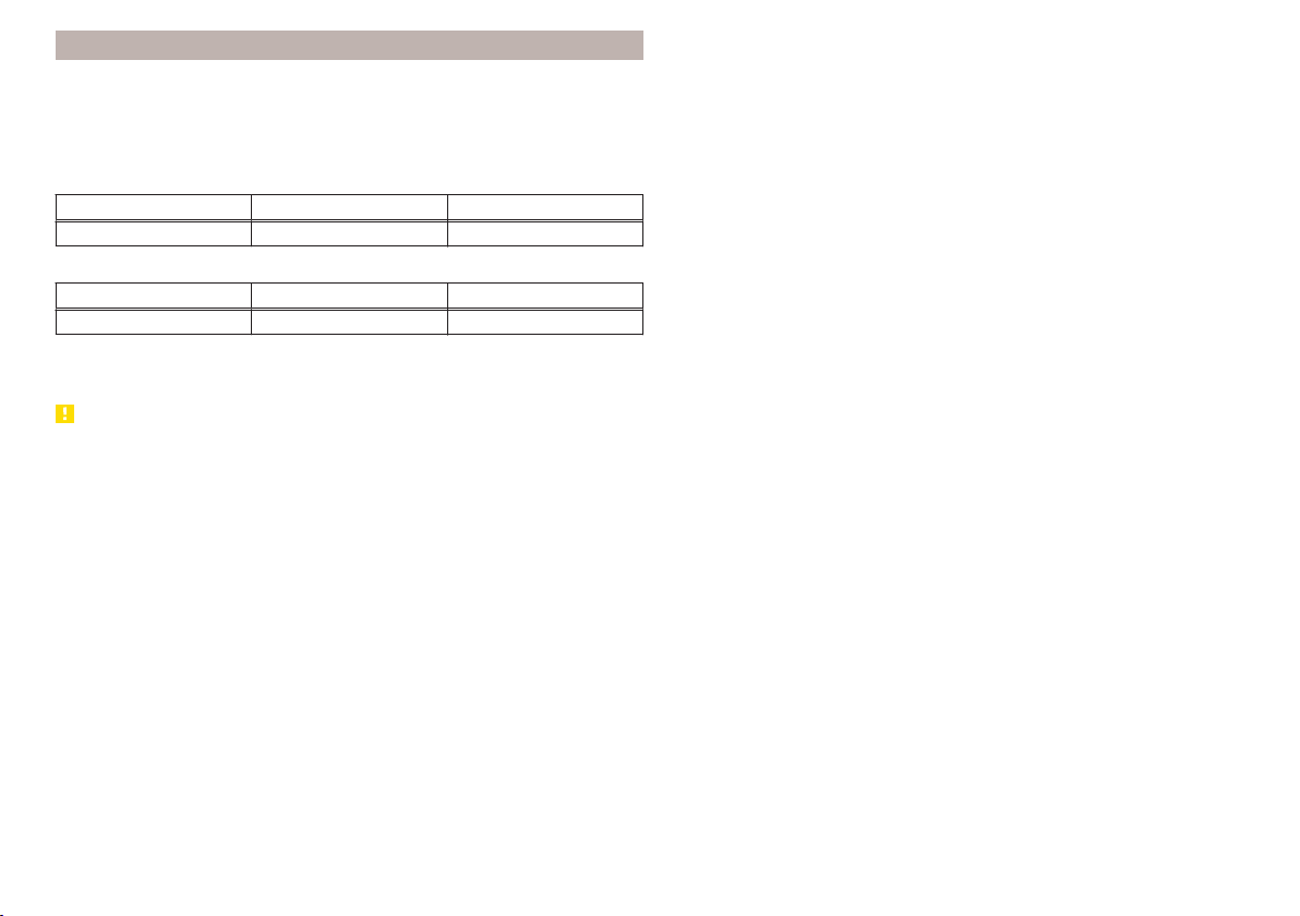
Snow chains
When driving in wintry road conditions, snow chains improve not only traction,
but also the braking performance.
Snow chains must only be mounted on the front wheels.
It is only permissible to fit snow chains with the following wheel/tyre combina-
tions.
Rim size Impression depth D Tyre size
5J x 14 35 mm 175/70 R14
Only fit snow chains with links and locks not larger than 9 mm.
Rim size Impression depth D Tyre size
6J x 15 38 mm 185/60 R15
Only fit snow chains with links and locks not larger than 12 mm.
Remove the full wheel trims before installing the snow chains » page 162.
CAUTION
The chains are to be removed when driving on snow-free paths. They would
otherwise cause loss of performance and damage the tyres.
159
Wheels
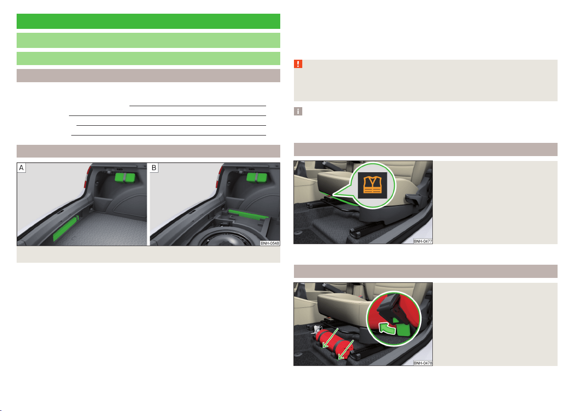
Do-it-yourself
Emergency equipment and self-help
Emergency equipment
Introduction
This chapter contains information on the following subjects:
First aid kit and warning triangle
160
reflective vest 160
fire extinguisher 160
Vehicle tool kit 161
First aid kit and warning triangle
Fig. 161 Placing of the first-aid kit and the warning triangle
The following information is for the first aid kit and warning triangle from the
ŠKODA Original accessories valid.
For another first aid kit and warning triangle the storage compartments may
possibly be too small.
First-aid box
The first-aid box can be attached by a strap to the right-hand side of the boot
» Fig. 161.
Warning triangle – version 1
The warning triangle can be attached to the rear wall trim panel with rubber
straps » Fig. 161 -
.
Warning triangle – version 2
On vehicles with the vehicle battery in the boot warning triangle can be stow-
ed in a box under the floor covering in the luggage compartment » Fig. 161 -
,
Pay attention to the expiration date of the first-aid kit.
WARNING
The first-aid kit and warning triangle must always be secured safely so that
they do not come loose when making an emergency braking or in a vehicle
collision which could cause injuries to occupants.
Note
We recommend using a first-aid kit from ŠKODA Original Accessories, which
are available from a ŠKODA Partner.
reflective vest
Fig. 162
Storage compartment for the re-
flective vest
The reflective vest can be stored in a bracket under the driver's seat » Fig. 162.
fire extinguisher
Fig. 163
Fire extinguisher
160
Do-it-yourself
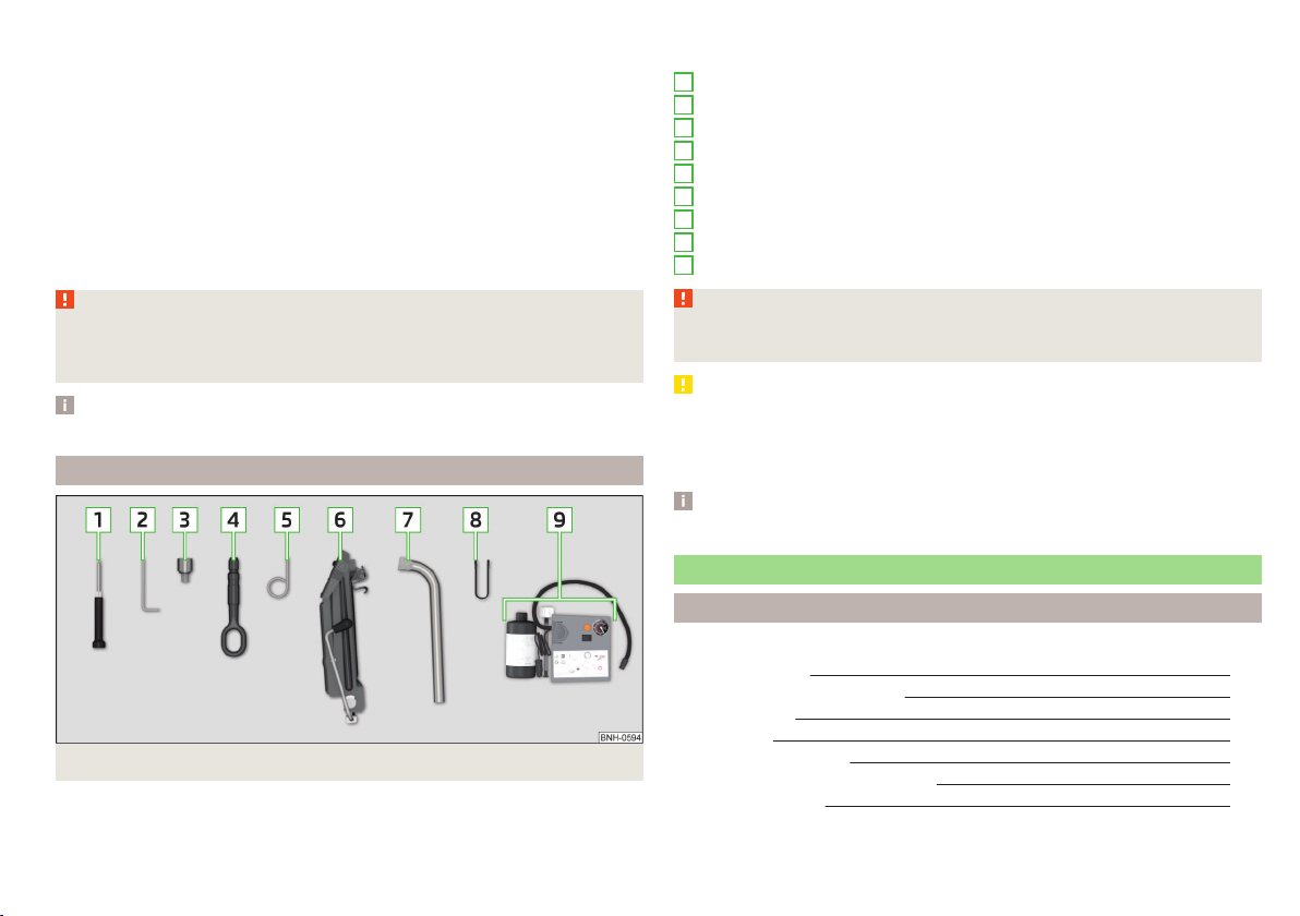
The fire extinguisher is attached by two straps in a holder underneath the driv-
er's seat.
Removing/attaching
›
Loosen the two straps by pulling the buckles in the direction of the arrow
» Fig. 163.
›
Remove the fire extinguisher.
›
For mounting, fit the fire extinguisher back into the holder and secure it with
straps.
Please read the instructions which are attached to the fire extinguisher.
Pay attention to the expiration date of the fire extinguisher. Proper function-
ing of the fire extinguisher is not assured once it has passed its expiry date.
WARNING
The fire extinguisher must always be secured safely so that they do not
come loose when making an emergency braking or in a vehicle collision
which could cause injuries to occupants.
Note
The fire extinguisher is part of the scope of delivery in certain countries only.
Vehicle tool kit
Fig. 164 Vehicle tool kit
The tool kit is housed in a box in the spare or emergency wheel compartment
or in this storage space.
Depending on the equipment, not all the components listed in the on-board
tool kit have to be contained in it.
Screwdriver
Spanner for removing and installing the tail light
Adapter for anti-theft wheel bolts
Towing eyelet
Clamps for removing the wheel trims
Jack with sign
Wheel wrench
Extraction pliers for wheel bolt caps
Breakdown kit
WARNING
The factory-supplied lifting jack is only intended for your model of vehicle.
Under no circumstances attempt to lift heavier vehicles or other loads.
CAUTION
■
Screw the jack back into the starting position before storing in the box with
the tool kit.
■
Ensure that the vehicle tool kit is safely secured in the boot.
■
Ensure that the box is always secured with the strap.
Note
The declaration of conformity is included with the jack or the log folder.
Changing a wheel
Introduction
This chapter contains information on the following subjects:
Preliminary work 162
Removing/stowing the wheel
162
Full wheel trim
162
Wheel bolts
163
Anti-theft wheel bolts
163
Loosening/tightening wheel bolts
163
Raising the vehicle
164
1
2
3
4
5
6
7
8
9
161
Emergency equipment and self-help

Remove the wheel / fix 165
Follow-up work 165
For your own safety and the safety of the passengers, the following instruc-
tions must be observed before changing a wheel on the road.
Switch on the hazard warning lights system.
Place the warning triangle at the prescribed distance.
Park the vehicle as far away as possible from the flowing traffic.
Choose a location with a flat, solid surface.
Have all the occupants get out. The passengers should not stand on the
road (instead they should remain behind a crash barrier, for instance) while
the wheel is being changed.
Preliminary work
Before changing the wheel, the following work must be carried out.
›
Switch off the engine.
›
For vehicles with manual transmission select gear 1.
›
On vehicles with automatic transmission, place the selector lever in the P
position.
›
Firmly apply the handbrake.
›
Uncouple trailer, if attached.
Removing/stowing the wheel
Fig. 165
Take out the wheel
The spare wheel is located in a well under the floor covering in the boot and is
fixed in place with a special bolt » Fig. 165.
Take out the wheel
›
Open the boot lid.
›
Lift up the floor in the luggage compartment.
›
Loosen the retaining belt and take out the box with the tool kit.
›
Unscrew the nut in direction of arrow » Fig. 165.
›
Take out the wheel.
Stow the wheel
›
Place the wheel into the wheel well with the wheel rim pointing downward.
On vehicles with the vehicle battery in the boot, lay down the wheel with the
outer face upward.
›
Pull the fixing band through the opposite holes in the wheel rim.
›
Screw on the nut in the opposite direction to the arrow » Fig. 165 until the
wheel is safely secured.
›
Replace the box with the tool kit into the emergency or spare wheel and se-
cure it with the tape.
›
Fold back the floor in the luggage compartment.
›
Close the boot lid.
Full wheel trim
Before removing the wheel bolts, remove the wheel cover.
Removing
›
Hook the clamp found in the vehicle tool kit » page 161 into the reinforced
edge of the wheel trim.
›
Push the wheel wrench through the clamp, support on the tyre and pull off
the wheel trim.
Installing
›
Press the wheel trim onto the wheel rim at the designated valve opening.
›
Then press the trim into the wheel rim until its entire circumference locks
correctly in place.
Notes from the factory or from the ŠKODA Original accessory delivered trim.
▶
When using an anti-theft wheel bolt, make sure that this has been fitted ac-
cording to the position marked on the back of the wheel cover position.
▶
On the back of the wheel cover, the position for the anti-theft wheel bolt is
marked by means of a symbol. If the wheel cover is set outside the position
marked for the anti-theft wheel bolt, there is a risk of damaging the wheel
cover.
If wheel trims are fitted, an adequate flow of air must be assured in order to
cool the brake system.
162
Do-it-yourself
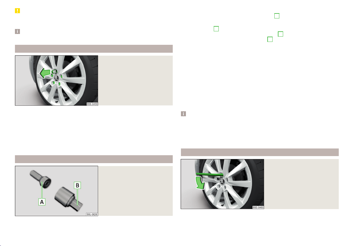
CAUTION
Use the pressure of your hand only, do not strike the full wheel trim! The cover
could be damaged.
Note
We recommend that you use wheel trims from ŠKODA Original Accessories.
Wheel bolts
Fig. 166
Remove the cap
Before removing the wheel bolts, remove the covering caps.
Removing
›
Push the extraction pliers » page 161 sufficiently far onto the cap until the
inner catches of the pliers are positioned at the collar of the cap.
›
Remove the cap in the direction of the arrow » Fig. 166.
Installing
›
Push the cap onto the wheel bolt up to the stop.
Anti-theft wheel bolts
Fig. 167
Principle sketch: Anti-theft
wheel bolt with adapter
The anti-theft wheel bolts protect the wheels from theft. These can only be
loosened or tightened with the use of adapter
B
» Fig. 167.
›
Remove the full wheel trim or the caps of the wheel bolts.
›
Insert adapter
B
» Fig. 167 with the toothed side all the way into the inner
teeth in the head of the anti-theft wheel bolts
A
.
›
Push the wheel wrench onto the adapter
B
up to the stop.
›
Loosen or tighten the wheel bolt » page 163.
›
Remove the adapter.
›
Replace the wheel trim or the caps.
To be equipped for a possible wheel change, the adapter for the anti-theft
wheel bolts must always be kept in the vehicle. The adapter is stowed in the
tool kit.
The position of the anti-theft wheel bolt is marked on the back of the wheel
cover with every ŠKODA supplied original equipment hub cap or directly at the
factors.
When using an anti-theft wheel bolt, make sure that this has been fitted ac-
cording to the position marked on the back of the wheel cover position.
Note
■
Note the code number which is embossed both on the adapter and also on
the end of each anti-theft wheel bolt. This number can be used to purchase a
replacement adapter from ŠKODA Genuine Parts if required.
■
The anti-theft wheel bolt set and adapter can be purchased from a ŠKODA
Partner.
Loosening/tightening wheel bolts
Fig. 168
Changing a wheel: Loosening the
wheel bolts
Before removing the wheel bolts, the caps for the wheel bolts must be pulled
off.
163
Emergency equipment and self-help
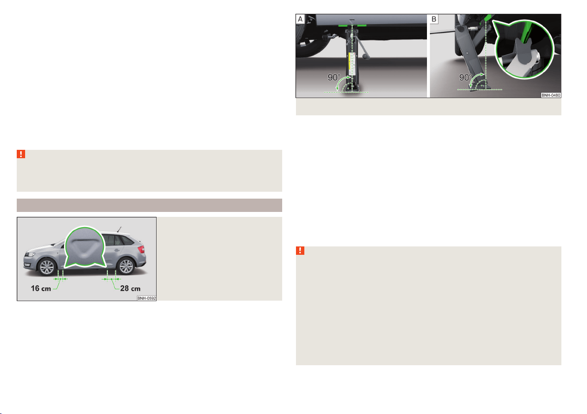
Releasing
›
Push the wheel wrench onto the wheel bolt to the stop.
Use the appropriate adapter for undoing the anti-theft wheel bolts » page 163.
›
Grasp the end of the wrench and turn the bolt about one turn in the direction
of the arrow » Fig. 168.
Tightening
›
Push the wheel wrench onto the wheel bolt to the stop.
Use the appropriate adapter for tightening the anti-theft wheel bolts
» page 163.
›
Grasp the end of the wrench and turn the bolt against the direction of the
arrow » Fig. 168 until it is tight.
After tightening the wheel bolts, the covering caps must be replaced.
WARNING
If it proves difficult to undo the bolts, carefully apply pressure to the end of
the wrench with your foot. Keep hold of the vehicle when doing so, and
make sure you keep your footing.
Raising the vehicle
Fig. 169
Jacking points for positioning
lifting jack
Fig. 170 Principle sketch: Attach lifting jack
In order to raise the vehicle, the jack from the tool kit is to be used.
Position the car jack at the jacking point closest to the flat tyre .
The mounting points are located on the metal bar of the lower sill on the un-
derside of your vehicle. The positions of these are embossed by means of
markings on the side surface of the lower sill » Fig. 169.
›
Support the base plate of the jack with its full area resting on level ground
and ensure that the jack is located in a vertical position at the jacking point
» Fig. 170 -
.
›
Position the lifting jack below the jacking point with the crank and move it up
until its claw encloses the web » Fig. 170 -
.
›
Continue turning up the jack until the wheel is just about lifted off the
ground.
WARNING
■
If the wheel has to be changed on a slope, first of all block the opposite
wheel with a stone or similar object to prevent the vehicle from unexpect-
edly rolling away.
■
Secure the base plate of the lifting jack with suitable means to prevent
possible moving. A soft and slippery ground under the base plate may move
the lifting jack, causing the vehicle to fall down. It is therefore always nec-
essary to place the lifting jack on a solid surface or use a wide and stable
base. Use a non-slip base (e.g. a rubber foot mat) if the surface is smooth,
such as cobbled stones, tiled floor, etc.
■
Only attach the lifting jack to the attachment points provided for this pur-
pose.
■
Always raise the vehicle with the doors closed.
164
Do-it-yourself

WARNING (Continued)
■
Never position any body parts, such as arms or legs under the vehicle,
while the vehicle is raised with a lifting jack.
■
When the vehicle is raised, never start the engine.
CAUTION
It is important to ensure that the jack is correctly attached to the web of the
lower fork leg, otherwise there is a risk of damage to the vehicle occurring.
Remove the wheel / fix
When changing a wheel, the following instructions must be followed.
›
Remove the full wheel trim or the caps of the wheel bolts.
›
First of all slacken the anti-theft wheel bolt and then the other wheel bolts.
›
Jack up the vehicle until the wheel that needs changing is clear of the
ground.
›
Unscrew the wheel bolts and place them on a clean surface (cloth, paper,
etc.).
›
Remove the wheel carefully.
›
Attach the wheel and slightly screw on the wheel bolts.
›
Lower the vehicle.
›
Alternately tighten wheel bolts opposite (diagonally) with the wheel wrench.
Tighten the anti-theft wheel bolt last.
›
Replace the wheel trim or the caps.
When fitting unidirectional tyres, ensure that the direction of rotation is cor-
rect » page 157.
All bolts must be clean and must turn easily.
If it is established when changing a wheel that the wheel bolts are corroded
and difficult to move, then these must be replaced.
Under no circumstances grease or oil the wheel bolts!
WARNING
Undo the wheel bolts only a little (about one turn) provided that the vehicle
has not yet been jacked up. Otherwise the wheel could become loose and
fall off.
Follow-up work
After changing the wheel, the following work must be carried out.
›
Stow the replaced wheel in the wheel well and secure it with a special screw.
›
Stow the tool kit in the space provided and secure using the band.
›
Check the tyre pressure on the installed wheel as soon as possible.
›
Have the tightening torque of the wheel bolts checked with a torque wrench
as soon as possible.
After changing the wheel, the tyre pressure should be adjusted. In vehicles
with tyre pressure monitoring, save tyre pressure values» page 120.
Replace the damaged wheel or consult a specialist garage about repair op-
tions.
The prescribed tightening torque of the wheel bolts is 120 Nm.
WARNING
■
If the wheel bolts are tightened to a too low tightening torque, the rim
can come loose when the car is moving. A tightening torque which is too
high can damage the bolts and threads and this can result in permanent
deformation of the contact surfaces on the rim.
■
Drive cautiously and only at a moderate speed until the tightening torque
has been checked.
Puncture set
Introduction
This chapter contains information on the following subjects:
Components of the puncture repair kits 166
General information 166
Preparations for using the breakdown kit 167
Sealing and inflating the tyre 167
Notes for driving with tyre repaired 167
Use the breakdown kit to reliably repair tyre damage caused by foreign bodies
or a puncture with diameters up to approx. 4 mm.
A repair made using the breakdown kit is never intended to replace a perma-
nent repair on the tyre. Its purpose is to get you to the nearest specialist ga-
rage.
165
Emergency equipment and self-help
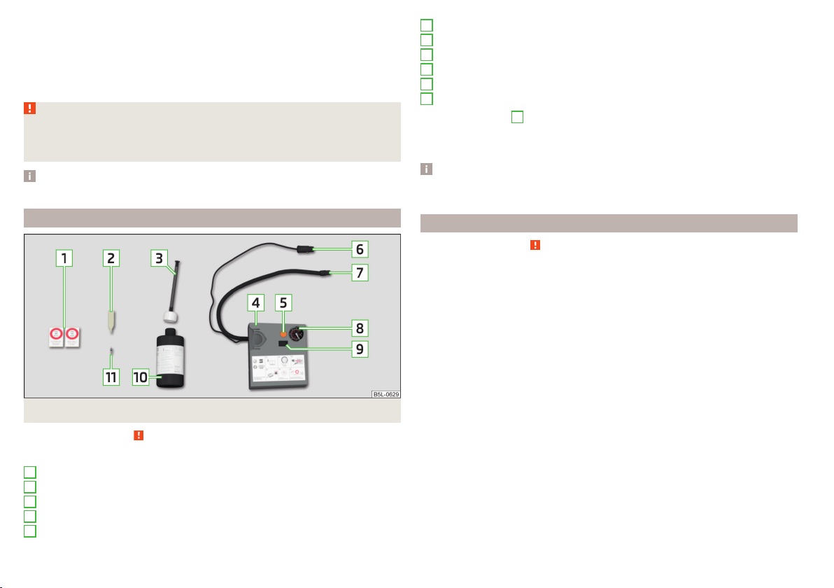
The wheel must not be removed during repair.
Do not remove foreign bodies, which have penetrated the wheel profile from
the tyre (e.g. screws or nails).
Immediately replace the tyre that was repaired using the breakdown kit, or
consult a specialist garage about repair options.
WARNING
■
The sealant is hazardous to heath. Remove immediately if it comes into
contact with the skin.
■
Observe the manufacturer's usage instructions for the breakdown kit.
Note
A new bottle of sealant can be purchased from ŠKODA Original Parts.
Components of the puncture repair kits
Fig. 171 Principle sketch: Components of the breakdown kit
Read and observe
on page 166 first.
Kit components » Fig. 171
Sticker with speed designation “max. 80 km/h”/“max. 50 mph”
Valve remover
Inflation hose with plug
Air compressor
Button for releasing the tyre pressure
1
2
3
4
5
12 volt cable connector
Tyre inflation hose
Tyre inflation pressure indicator
ON and OFF switch
Tyre inflator bottle with sealant
Replacement valve core
The valve remover
2
has a slot at its lower end which fits into the valve core.
The kit is located in a box under the floor covering in the luggage compart-
ment. This contains a sealing means and an air compressor.
Note
The declaration of conformity is included with the air compressor or the log
folder.
General information
Read and observe on page 166 first.
For your own safety and the safety of your passengers, the following instruc-
tions must be observed before carrying out a wheel repair on the road.
Switch on the hazard warning lights system.
Place the warning triangle at the prescribed distance.
Park the vehicle as far away as possible from the flowing traffic.
Choose a location with a flat, solid surface.
Have all the occupants get out. The passengers should not stand on the
road (instead they should remain behind a crash barrier, for instance) while
the wheel is being changed.
The breakdown kit must not be used under the following circumstances.
▶
The rim is damaged.
▶
The outside temperature is below -20 ° C.
▶
The cut or puncture is larger than 4 mm.
▶
The tyre wall is damaged.
▶
After the expiration date (see inflation bottle).
6
7
8
9
10
11
166
Do-it-yourself

Preparations for using the breakdown kit
Read and observe on page 166 first.
The following preparatory work must be carried out before using the puncture
repair kit.
›
Switch off the engine.
›
For vehicles with manual transmission select gear 1.
›
On vehicles with automatic transmission, place the selector lever in the P
position.
›
Firmly apply the handbrake.
›
Check that you can carry out the repairs with the breakdown kit » page 166,
General information.
›
Uncouple trailer, if attached.
›
Remove the breakdown kit from the boot.
›
Stick the sticker
1
» Fig. 171 on page 166 on the dashboard in the driver's
field of view.
›
Unscrew the valve cap.
›
Use the valve remover
2
to unscrew the valve core and place it on a clean
surface (rag, paper, etc.).
Sealing and inflating the tyre
Read and observe
on page 166 first.
Sealing
›
Forcefully shake the tyre inflater bottle
10
» Fig. 171 on page 166 back and
forth several times.
›
Firmly screw the inflation hose
3
onto the tyre inflater bottle
10
. The film on
the cap is pierced automatically.
›
Remove the plug from the inflation hose
3
and plug the open end fully onto
the tyre valve.
›
Hold the bottle
10
with the bottom facing upwards and fill all of the sealing
agent from the tyre inflater bottle into the tyre.
›
Remove the filler plug from the tyre valve.
›
Screw the valve core back into the tyre valve using the valve remover
2
.
Inflating
›
Screw the tyre inflation hose
7
» Fig. 171 on page 166 of the air compressor
firmly onto the tyre valve.
›
For vehicles with manual transmission the lever into the neutral position.
›
On vehicles with automatic transmission, place the selector lever in the P
position.
›
Start the engine and run it in idle.
›
Plug the connector
6
into the 12-volt socket » page 75.
›
Switch on the air compressor with the ON and OFF switch
9
.
›
Allow the air compressor to run until a pressure of 2.0 - 2.5 bar is achieved.
Maximum run time of 8 minutes » .
›
Switch off the air compressor.
›
If you cannot reach an air pressure of 2.0 - 2.5 bar, unscrew the tyre inflation
hose
7
from the tyre valve.
›
Drive the vehicle 10 metres forwards or backwards to allow the sealing agent
to “distribute” in the tyre.
›
Firmly screw the tyre inflation hose
7
back onto the tyre valve and repeat
the inflation process.
›
Switch off the air compressor.
›
Remove the tyre inflation hose
7
from the tyre valve.
Once a tyre inflation pressure of 2.0 - 2.5 bar is achieved, you can continue the
journey.
WARNING
■
If the tyre cannot be inflated to at least. 2.0 bar, the damage is too great.
The sealing agent cannot be used to seal the tyre. Do not continue to
drive! Seek help from a specialist garage.
■
The tyre inflation hose and air compressor may get hot as the tyre is be-
ing inflated – there is a risk of burning.
CAUTION
Switch off the air compressor after running 8 minutes at the latest – there is a
risk of overheating! Allow the air compressor to cool a few minutes before
switching it on again.
Notes for driving with tyre repaired
Read and observe on page 166 first.
The inflation pressure of the repaired tyre must be checked after driving for 10
minutes.
If the tyre pressure is 1.3 bar or less
›
Do not continue to drive! The tyre cannot be properly sealed with the
breakdown kit.
167
Emergency equipment and self-help
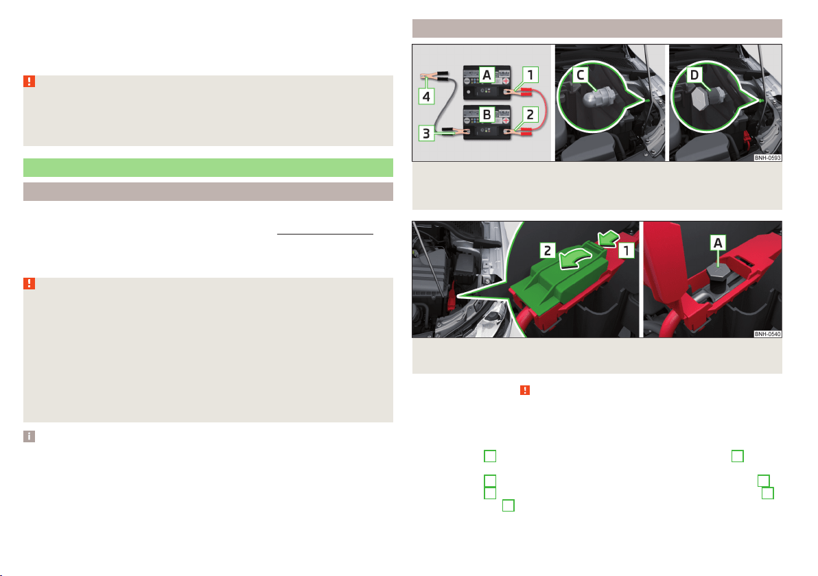
If the tyre pressure is 1.3 bar or more
›
Set the tyre pressure back to the correct value.
›
Continue driving carefully to the nearest specialist garage at a maximum
speed of 80 km/h (50 mph).
WARNING
■
A tyre filled with sealant has the same driving characteristics as a stand-
ard tyre.
■
Do not drive faster than 80 km/h (50 mph).
■
Avoid accelerating at full throttle, sharp braking and fast cornering.
Jump-starting
Introduction
This chapter contains information on the following subjects:
Jump-starting using the battery from another vehicle
168
The battery of another vehicle can be used to jump-start your vehicle if the en-
gine will not start because the battery is flat.
WARNING
■
Pay attention to the warning instructions relating to working in the en-
gine compartment » page 143.
■
A discharged vehicle battery may already freeze at temperatures just be-
low 0 °C. If the battery is frozen, do not jump start with the battery of an-
other vehicle – there is a risk of explosion!
■
Keep any sources of ignition (naked flame, smouldering cigarettes, etc.)
away from the battery – risk of explosion!
■
Never jump-start vehicle batteries with insufficient acid levels – risk of
explosion and chemical burns.
■
The vent screws of the battery cells must be tightened firmly.
Note
We recommend you buy jump-start cables from a car battery specialist.
Jump-starting using the battery from another vehicle
Fig. 172 A – discharged battery, B – power-providing battery / C - earthing
point of the engine / D - earthing point of vehicles with the vehicle bat-
tery in the luggage compartment
Fig. 173 Positive terminal on vehicles with the vehicle battery in the lug-
gage compartment
Read and observe on page 168 first.
The starting process using the battery of another vehicle requires the use of
jumper cables.
The jump-start cables must be attached in the following sequence.
›
Attach clamp
1
to the positive terminal of the discharged battery
A
» Fig. 172.
›
Attach clamp
2
to the positive terminal of the battery supplying power
B
.
›
Attach clamp
3
to the negative terminal of the battery supplying power
B
.
›
Attach the clamp
4
to a solid metal component firmly connected to the en-
gine block or to the engine block itself.
168
Do-it-yourself
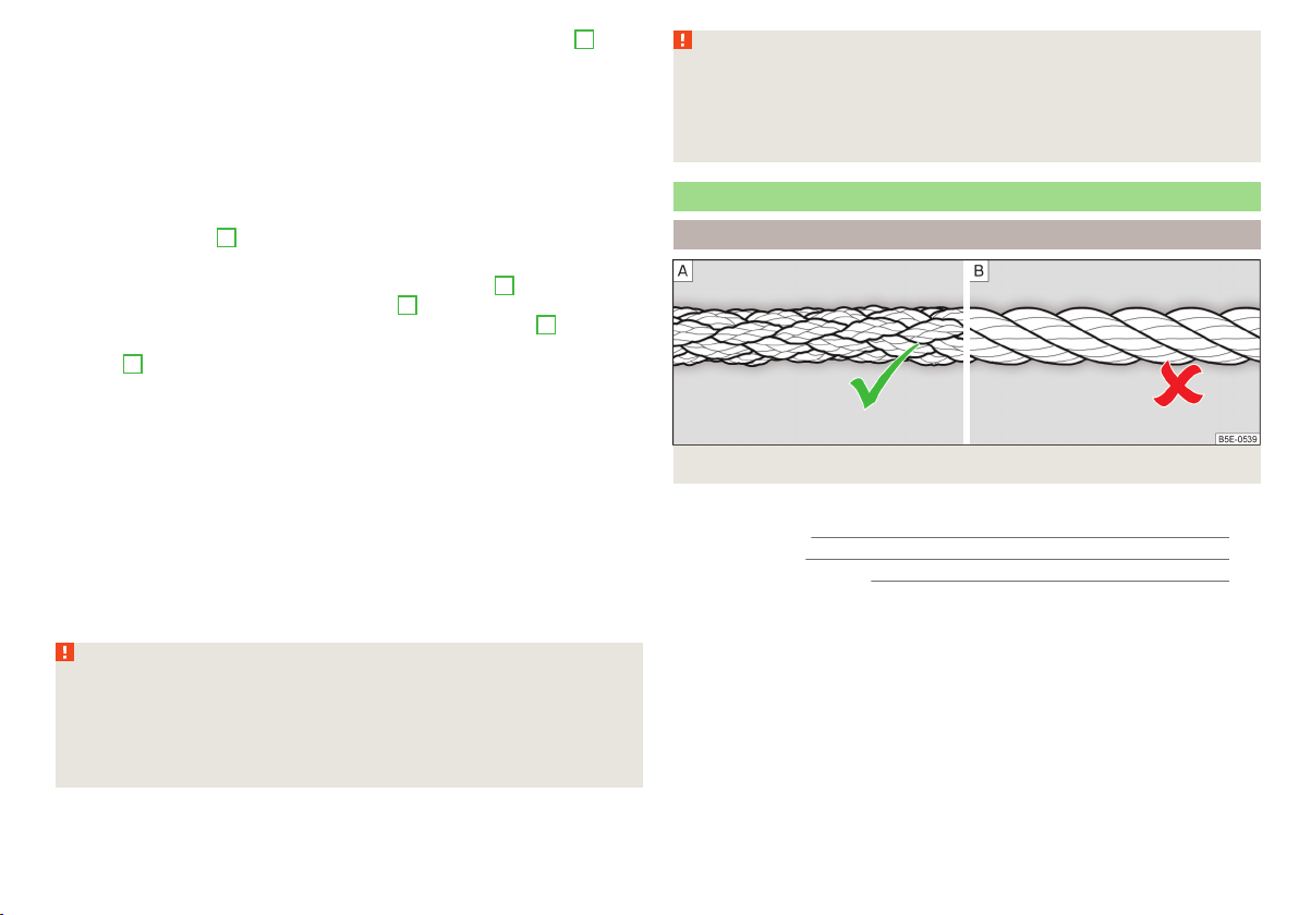
The jump-start cable must be connected to the engine earthing point
C
» Fig. 172 only on vehicles with the START-STOP system.
Starting engine
›
Start the engine on the vehicle providing the power and allow it to idle.
›
Start the engine of the vehicle with the discharged battery.
›
If the engine does not start, halt the attempt to start the engine after 10 sec-
onds and wait for 30 seconds before repeating the process.
›
Remove the jump start cables in the reverse order as attachment.
Engines in vehicles with the vehicle battery in the boot
The positive terminal
A
is located under a cover in the engine compartment
» Fig. 173.
›
Unlock the retainer tab on the cover in direction of arrow
1
.
›
Open the cover in the direction of the arrow
2
.
›
Clamp the positive terminal of the jumper cable to the position
A
» Fig. 173.
›
Clamp the negative terminal of the jumper cable to the earthing point of the
engine
D
» Fig. 172 or to a metal part firmly connected to the engine block or
directly to the engine block.
›
Remove the jump start cables in the reverse order as attachment.
Both batteries must have a rated voltage of 12 V. The capacity (Ah) of the bat-
tery supplying the power must not be significantly less than the capacity of
the discharged battery in your vehicle.
Jump-start cables
Only use jump-start cables which have an adequately large cross-section and
insulated terminal clamps. Observe the instructions of the jumper lead manu-
facturer.
Positive cable – colour coding in the majority of cases is red.
Negative cable – colour coding in the majority of cases is black.
WARNING
■
Do not clamp the jump-start cable to the negative terminal of the dis-
charged battery. There is the risk of detonating gas seeping out of the bat-
tery being ignited by the strong spark resulting from the engine being star-
ted.
■
The non-insulated parts of the terminal clamps must never touch each
other – there is a risk of short circuit!
WARNING (Continued)
■
The jump-start cable connected to the positive terminal of the battery
must not come into contact with electrically conducting parts of the vehicle
– there is a risk of short circuit!
■
Route the jump-start cables so that they cannot be caught by any rotat-
ing parts in the engine compartment.
Towing the vehicle
Introduction
Fig. 174 Braided tow rope / Spiral tow rope
This chapter contains information on the following subjects:
Front towing eye 170
Rear towing eye 171
Vehicles with a tow hitch 171
For towing a braided tow rope is to be used » Fig. 174-
.
When towing, the following guidelines must be observed.
Vehicles with manual transmission may be towed in with a tow bar or a tow
rope or with the front or rear wheels raised.
Vehicles with automatic transmission may be towed in with a tow bar or a tow
rope or with the front wheels raised. If the vehicle is raised at the rear, the au-
tomatic gearbox will be damaged! If possible, the vehicle should be towed with
the engine running or at least with the ignition on.
Driver of the tow vehicle
›
Engage the clutch gently when starting off or depress the accelerator partic-
ularly gently if the vehicle is fitted with an automatic gearbox.
169
Emergency equipment and self-help

›
Only then approach correctly when the rope is taut.
The maximum towing speed is 50 km/h.
Driver of the towed vehicle
›
Switch on the ignition so that the steering wheel is not locked and so that
the turn signal lights, windscreen wipers and windscreen washer system can
be used.
›
Take the vehicle out of gear or move the selector lever into position N if the
vehicle is fitted with an automatic gearbox.
Please note that the brake servo unit and power steering only operate if the
engine is running. If the engine is not running, significantly more physical force
is required to depress the brake pedal and steer the vehicle.
If using a tow rope, ensure that it is always kept taught.
General information for the towing process
Both drivers should be familiar with the problems which might possibly occur
while a vehicle is being towed. Unskilled drivers should not attempt to tow an-
other vehicle or to be towed in one.
The vehicle must be transported on a special breakdown vehicle or trailer if it
is not possible to tow the vehicle in the way described or if the towing dis-
tance is greater than 50 km.
If the gearbox no longer contains any oil, your vehicle must only be towed with
the front axle raised clear of the ground or on a breakdown vehicle or trailer.
To protect both vehicles when tow-starting or towing, the tow rope should be
elastic. Thus only plastic fibre rope or a rope made out of a similarly elastic ma-
terial should be used.
Attach the tow rope or the tow bar to the towing eyes » page 170 or
» page 171 to the detachable ball head of the towing equipment » page 121.
WARNING
■
When towing, exercise increased caution.
■
For towing no spiral tow rope is to be used » Fig. 174- , the towing eye
may unscrew out of the vehicle - there is a risk of accidents.
■
The tow rope should not be twisted - there is a risk of accidents.
CAUTION
■
Do not start engine by towing - there is a risk of damaging the engine parts.
The battery from another vehicle can be used as a jump-start aid » page 168,
Jump-starting.
■
There is always a risk of excessive stresses and damage resulting at the
points to which you attach the tow rope or tow bar when you attempt to tow a
vehicle which is not standing on a paved road.
Note
We recommend using a tow rope from ŠKODA Original Accessories, which is
available from a ŠKODA Partner.
Front towing eye
Fig. 175 Removing the cap/installing the towing eye
Read and observe and on page 170 first.
Removing/installing the cap
›
Press on the cap in the direction of the arrow
1
» Fig. 175.
›
Remove the cap in the direction of the arrow
2
.
›
After unscrewing the cap of the towing eye, insert the cap in the region of
the arrow
1
and then press the opposite side of the cap.
The cap must engage firmly.
Removing/installing the towing eye
›
Manually screw the towing eye as far as it will go in the direction of the ar-
row
3
» Fig. 175» .
For tightening purposes, we recommend, for example, using the wheel
wrench, towing eye from another vehicle or a similar object that can be pushed
through the eye.
170
Do-it-yourself
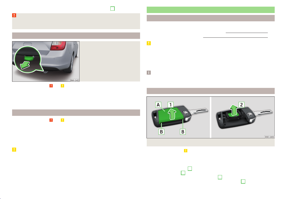
›
Unscrew the towing eye against the direction of the arrow
3
.
WARNING
The towing eye must always be screwed in fully and firmly tightened, oth-
erwise the towing eye can tear when towing or tow-starting.
Rear towing eye
Fig. 176
Rear towing eye
Read and observe and on page 170 first.
The rear towing eye is located below the bumper on the right.
Remove the protective cap before using the towing eye. » Fig. 176. Replace the
protective cap after using the towing eye.
Vehicles with a tow hitch
Read and observe and on page 170 first.
For vehicles with a factory-fitted towing device, the pre-installed detachable
tow-bar may be used » page 121, Hitch.
Towing the vehicle using the towing device is a viable alternative solution to
using the towing eye.
CAUTION
The detachable ball rod and/or the vehicle can be damaged if an unsuitable
tow bar is used.
Remote control
Introduction
This chapter contains information on the following subjects:
Replacing the battery in the remote control key
171
Synchronising the remote control 172
CAUTION
■
The replacement battery must have the same specification as the original
battery.
■
We recommend having faulty rechargeable batteries replaced by a ŠKODA
service partner.
■
Pay attention to the correct polarity when changing the battery.
Note
If a key has an affixed decorative cover, this will be destroyed when the bat-
tery is replaced. A replacement cover can be purchased from a ŠKODA Partner.
Replacing the battery in the remote control key
Fig. 177 Remove cover/take out battery
Read and observe on page 171 first.
The battery change is carried out as follows.
›
Flip out the key.
›
Undo the battery cover
A
» Fig. 177 with your thumb or by using a flat
screwdriver in area
B
.
›
Open the battery in the direction of arrow
1
.
›
Remove the discharged battery in the direction of arrow
2
.
171
Emergency equipment and self-help
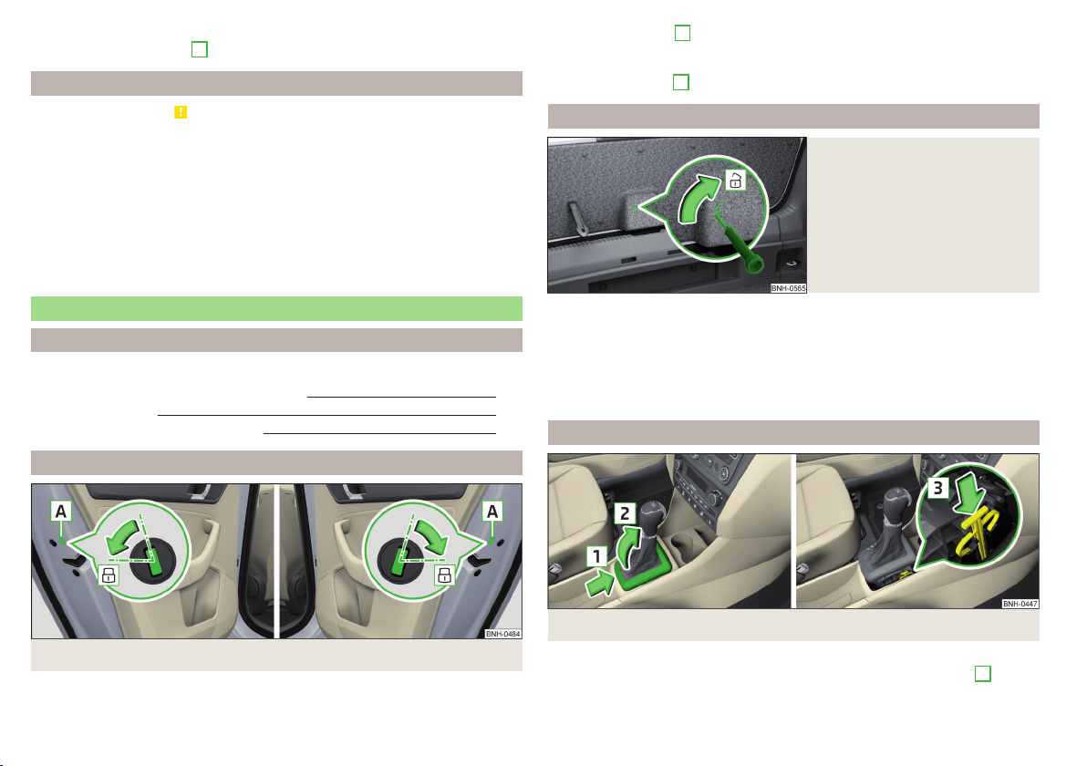
›
Insert the new battery.
›
Insert the battery cover
A
and press it down until it clicks audibly into place.
Synchronising the remote control
Read and observe on page 171 first.
If the vehicle does not unlock when pressing the remote control, the key may
not be synchronised. This can occur when the buttons on the remote control
key are actuated a number of times outside of the operative range of the
equipment or the battery in the remote control key has been replaced.
Synchronise the key as follows.
›
Press any button on the remote control key.
›
Unlock the door with the key in the lock cylinder within 1 minute of pressing
the button.
Emergency unlocking/locking
Introduction
This chapter contains information on the following subjects:
Locking the door without a locking cylinder
172
Unlock the boot lid
172
Selector lever-emergency unlocking
172
Locking the door without a locking cylinder
Fig. 178
Emergency locking: Left/right rear door
An emergency locking mechanism, which is only visible after opening the door,
is located on the face side of the doors which have no locking cylinder.
›
Remove the cover
A
» Fig. 178.
›
Insert the vehicle key into the slot and turn in the direction of the arrow
(sprung position).
›
Replace the cover
A
.
Unlock the boot lid
Fig. 179
Unlocking the boot lid
The boot lid can be unlocked manually.
›
Fold the rear seat backrest forward » page 72.
›
Insert a screwdriver or similar tool into the recess in the trim » Fig. 179 as far
as the stop.
›
Unlock the lid by moving it in the direction of the arrow.
›
Open the boot lid.
Selector lever-emergency unlocking
Fig. 180 Selector lever-emergency unlocking
›
Firmly apply the handbrake.
›
With one hand on the edge of the cover, push in direction of arrow
1
» Fig. 180.
172
Do-it-yourself
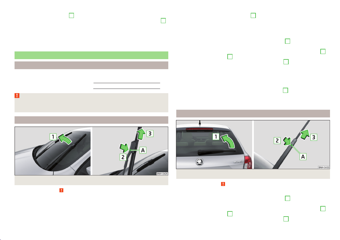
›
At the same time lift the cover on the selector lever gaiter with the other
hand in direction of arrow
2
.
›
With one finger, push the yellow plastic element in the direction of arrow
3
down to the stop.
›
At the same time, press the locking button in the selector lever and move
the selector lever to position N.
If the selector lever is moved again to position P, it is once again blocked.
Replacing windscreen wiper blades
Introduction
This chapter contains information on the following subjects:
Replacing the windscreen wiper blades 173
Replacing the rear window wiper blade 173
WARNING
Replace the windscreen wiper blades once or twice a year for safety rea-
sons. These can be purchased from a ŠKODA Partner.
Replacing the windscreen wiper blades
Fig. 181 Windscreen wiper blade
Read and observe on page 173 first.
Before replacing the windscreen wiper blade, put the windscreen wiper arms
into the service position.
Service position for changing wiper blades
›
Close the bonnet.
›
Switch the ignition on and off again.
›
Place the operating lever in position
4
» page 66, Activating the windscreen
wipers and washers.
The windscreen wiper arms move into the service position.
Removing the wiper blade
›
Lift the wiper arm from the window in the direction of
1
» Fig. 181.
›
Tilt the wiper blade to the stop in the same direction.
›
Hold the upper part of the wiper arm and press the securing mechanism
A
in the direction of arrow
2
.
›
Remove the wiper blade in the direction of the arrow
3
.
Attaching the windscreen wiper blade
›
Push the windscreen wiper blade to the stop until it locks into place.
›
Check that the windscreen wiper blade is correctly attached.
›
Fold the windscreen wiper arm back to the windscreen.
›
Turn on the ignition and press the lever into position
4
» page 66, Activat-
ing the windscreen wipers and washers.
The windscreen wiper arms move into the home position.
Replacing the rear window wiper blade
Fig. 182 Rear window wiper blade
Read and observe
on page 173 first.
Removing the wiper blade
›
Lift the wiper arm from the window in the direction of
1
» Fig. 182.
›
Tilt the wiper blade to the stop in the same direction.
›
Hold the upper part of the wiper arm and press the securing mechanism
A
in the direction of arrow
2
.
›
Remove the wiper blade in the direction of the arrow
3
.
173
Emergency equipment and self-help
Attaching the windscreen wiper blade
›
Push the windscreen wiper blade to the stop until it locks into place.
›
Check that the windscreen wiper blade is correctly attached.
›
Fold the windscreen wiper arm back to the windscreen.
Fuses and light bulbs
Fuses
Introduction
This chapter contains information on the following subjects:
Fuses in the dash panel 175
Assignment of the fuses in the dash panel 175
Fuses in the engine compartment 176
Fuse assignment in the engine compartment 177
Individual electrical circuits are protected by fuses.
Switch off the ignition and the corresponding power consuming device before
replacing a fuse.
Find out which fuse belongs to the component that is not operating
» page 175, Assignment of the fuses in the dash panel or » page 177, Fuse
assignment in the engine compartment.
Colour coding of fuses
Fuse colour Maximum amperage
purple 3
light brown 5
dark brown 7.5
red 10
blue 15
yellow/blue 20
white 25
green/pink 30
green 40
red 50
WARNING
Always read and observe the warning notes before completing any work in
the engine compartment » page 143, Engine compartment.
174
Do-it-yourself
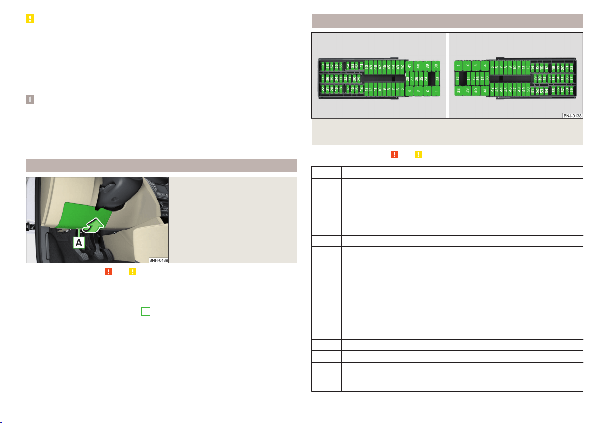
CAUTION
■
“Never repair” fuses, and do not replace them with fuses of a higher amper-
age – risk of fire! This may also cause damage at other points in the electrical
system.
■
If a newly inserted fuse blows again after a short time, have the electrical
system checked as quickly as possible by a specialist garage.
■
A blown fuse is recognisable by the molten metal strip. Replace the faulty
fuse with a new one of the same amperage.
Note
■
We recommend always carrying replacement fuses in the vehicle. A box of
replacement fuses and bulbs can be purchased from ŠKODA Genuine Accesso-
ries.
■
There can be several power-consuming devices for one fuse.
■
Multiple fuses may exist for a single power-consuming device.
Fuses in the dash panel
Fig. 183
Remove the fuse box cover.
Read and observe and on page 174 first.
The fuses are located on the bottom of the dash panel behind a cover.
Replacing fuses
›
Grip the fuse box cover at point
A
and take-out in the direction of arrow
» Fig. 183.
›
Remove the plastic clip from the holder in the fuse box cover.
›
Place the clip on the respective fuse and pull this fuse out.
›
Insert a new fuse.
›
Replace the bracket at the original position.
›
Insert the top edge of the cover into the dash panel first.
Carefully push the cover in.
Assignment of the fuses in the dash panel
Fig. 184 Schematic representation of the fuse box for vehicles with left-
hand steering/right-hand steering
Read and observe
and on page 174 first.
No. Power consumer
1 Left light
2 Central locking system
3 Relay for ignition
4 Right light
5 Power windows - driver
6 Central control unit - interior lights
7 Horn
8 Towing hitch - left light
9
Operating lever beneath the steering wheel, engine control unit (on-
ly without KESSY), automatic gearbox (only without KESSY), selector
lever of the automatic transmission (only without KESSY), ESC (only
without KESSY), towing equipment (only without KESSY), power
steering (only without KESSY)
10 Power windows - rear left
11 Headlight cleaning system
12 Radio, navigation display
13 Taxi preparation
14
Operating lever under the steering wheel, light switch, ignition key
removal lock (automatic gearbox), headlight flasher, SmartGate, rain
sensor
175
Fuses and light bulbs
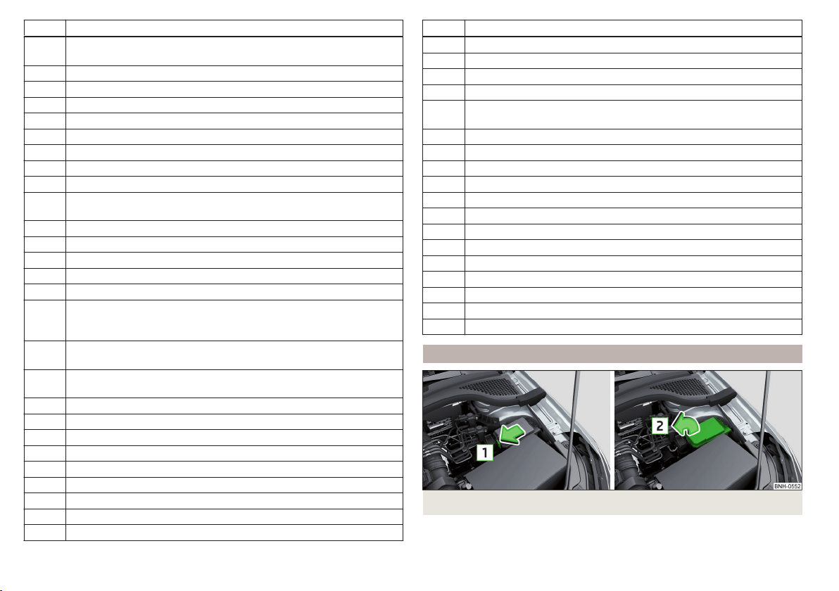
No. Power consumer
15
Air conditioning system, selector lever of the automatic gearbox, di-
agnosis terminal
16 Instrument cluster
17 Alarm system, horn
18 Not assigned
19 Not assigned
20 Not assigned
21 Not assigned
22 Front- and rear windscreen wiper system
23 Heated front seats
24
Blower fan for air conditioning system, heating, air conditioning,
heating
25 Not assigned
26 Switch for front seat heating
27 Rear window wiper
28 Not assigned
29 airbag
30
Electric power windows, light switches, reverse light switches, air
conditioning system, Park Assist, exterior mirror, power feed for cen-
tre button strip, power feed for side button strip, interior mirror
31
Fuel pump, radiator fan, cruise control, coil of the relay for the front
and rear windscreen wipers
32
Diagnostic terminal, headlight range control, operating lever under
the steering wheel, interior lighting
33 Coil on starter relay, clutch pedal switch
34 Heated windscreen washer jets
35 Not assigned
36 Not assigned
37 Radar
38 Not assigned
39 Electrical auxiliary heating system
40 Not assigned
41 Rear window heater
No. Power consumer
42 Power windows - front passenger
43 Towing hitch - contact in the socket
44 Cigarette lighter, 12-volt power socket
45 Power windows - rear right
46
Front and rear window washer, operating lever under the steering
wheel
47 Towing hitch - contact in the socket
48 Towing hitch - right light
49 Fuel pump
50 Radio
51 Heating of the external mirror
52 KESSY
53 Steering lock (KESSY)
54 ABS or ESC
55 Not assigned
56 Not assigned
57 Not assigned
58 Not assigned
59 Not assigned
Fuses in the engine compartment
Fig. 185 Cover for the fuse box - variant 1
176
Do-it-yourself
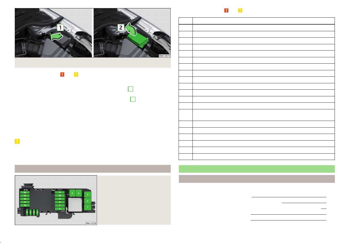
Fig. 186 Cover for the fuse box - variant 2
Read and observe and on page 174 first.
Replacing fuses
›
Press the lock button on the cover in direction of arrow
1
» Fig. 185 or
» Fig. 186.
›
Raise the cover and remove in the direction of the arrow
2
.
›
Remove the plastic clip from the holder in the fuse box cover.
›
Replace the appropriate fuse.
›
Replace the bracket at the original position.
›
Place the cover on top of the fuse box.
›
Push in the locking button on the cover and lock.
The cover must engage securely.
CAUTION
The cover for the fuse box in the engine compartment must always be re-
placed correctly. Water may get into the fuse box if the cover is not replaced
properly - there is a risk of damage to the vehicle!
Fuse assignment in the engine compartment
Fig. 187
Fuses
Read and observe and on page 174 first.
No. Power consumer
1 Radiator fan
2 Glow plug system
3 ABS or ESC
4 Auxiliary electric heating - circuit 2
5 Auxiliary electric heating - circuit 3
6 Automatic gearbox
7 Engine control unit
8 Windscreen wipers
9 Central control unit, battery data module
10 ABS or ESC
11 Not assigned
12 Engine components
13 Brake pedal switch
14 Engine components, coil for the fuel pump relay, radiator fan, cooling
pump
15 Engine control unit
16 Starter
17 Engine control unit
18 Engine components, coils of the relay for auxiliary electric heater
19 Lambda probe
20 Glow plug system, crankcase ventilation heater
Replacing bulbs
Introduction
This chapter contains information on the following subjects:
Bulb arrangement in the headlights
178
Replacing the high beam bulb (halogen headlights) 179
Replacing bulb for main beam, daytime running lights and parking light 179
Changing the front turn signal bulb 180
Replacing the bulb for the fog light 180
177
Fuses and light bulbs
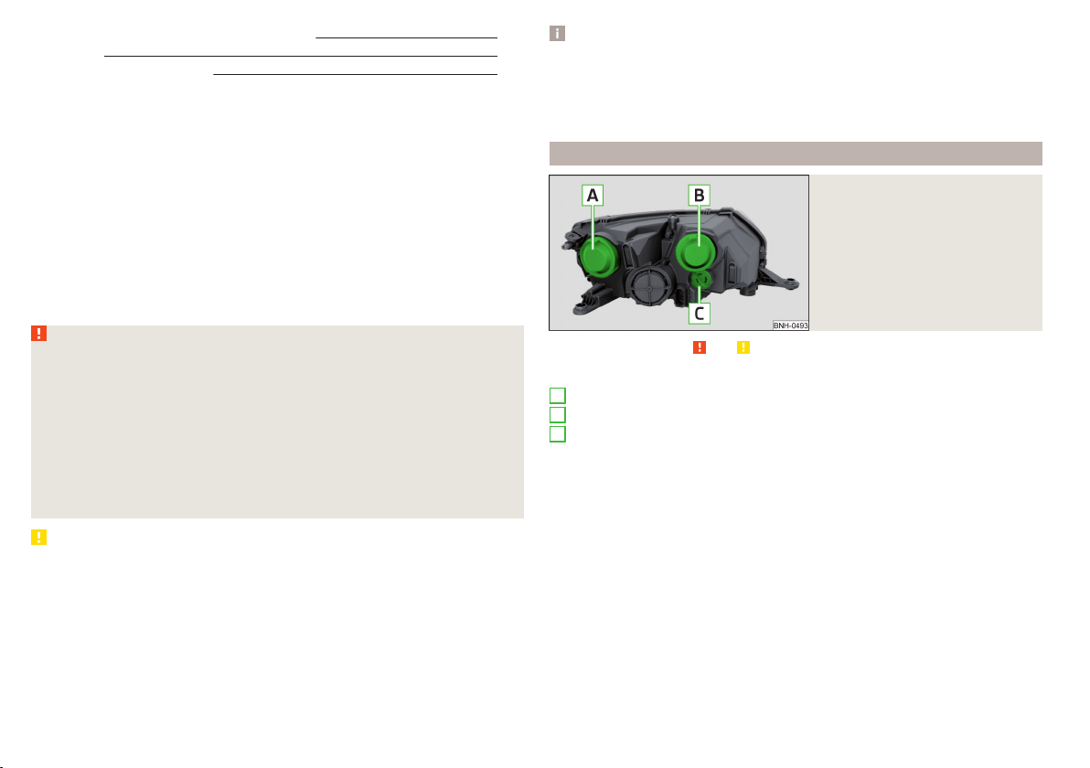
Replacing the bulb for the licence plate light 181
Rear Light 181
Replacing bulbs in rear light 182
Some manual skills are required to change a bulb. For this reason, we recom-
mend having bulbs replaced by a specialist garage or seeking other expert help
in the event of any uncertainties.
▶
Switch off the ignition and the relevant lights before replacing a bulb.
▶
Faulty bulbs must only be replaced with the same type of bulbs. The designa-
tion is located on the light socket or the glass bulb.
A stowage compartment for replacement bulbs is located in a plastic box in
the spare wheel or underneath the floor covering in the boot.
We recommend having the headlight settings checked by a specialist garage
after replacing a bulb in the low, high or fog beam.
In case of failure of a xenon gas discharge lamp or an LED diode, visit a special-
ist garage.
WARNING
■
Always read and observe the warning notes before completing any work
in the engine compartment » page 143.
■
Accidents can be caused if the road in front of the vehicle is not suffi-
ciently illuminated and the vehicle cannot or can only be seen with difficul-
ty by other road users.
■
H7 and H15 bulbs are pressurised and may burst when changing the bulb -
risk of injury! We therefore recommended wearing gloves and safety
glasses when changing a bulb.
■
Do not carry out any work on the Xenon gas discharge lamps - risk of
death!
CAUTION
■
Do not take hold of the glass bulb with naked fingers (even the smallest
amount of dirt reduces the working life of the light bulb). Use a clean cloth,
napkin, or similar.
■
The protective cap of the bulb must always be properly inserted into the
headlamp. Water and dirt may get into the headlamp if the cover is not re-
placed properly - there is a risk of damage to the headlamp!
Note
■
This Owner's Manual only describes the replacement of bulbs where it is pos-
sible to replace the bulbs on your own without any complications arising. Other
bulbs must be replaced by a specialist garage.
■
We recommend that a box of replacement bulbs always be carried in the ve-
hicle. Replacement bulbs can be purchased from ŠKODAOriginal Accessories.
Bulb arrangement in the headlights
Fig. 188
Principle sketch: Headlights
Read and observe and on page 178 first.
Bulb arrangement » Fig. 188
Low beam or low beam with xenon gas discharge lamp
Main beam, separate daytime running lights, and parking light
Turn signal light (at the front)
A
B
C
178
Do-it-yourself
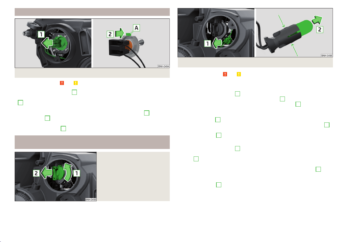
Replacing the high beam bulb (halogen headlights)
Fig. 189 Changing the bulb for the low beam
Read and observe
and on page 178 first.
›
Remove the protective cap
A
» Fig. 188 on page 178.
›
Remove the socket with the bulb by jiggling it out in the direction of arrow
1
» Fig. 189.
›
Remove the connector.
›
Insert the connector with the new bulb in the direction of arrow
2
so that
the fixing lug
A
fits the bulb into the recess on the reflector.
›
Attach the connector.
›
Fit the protective cap
A
» Fig. 188 on page 178.
Replacing bulb for main beam, daytime running lights and parking
light
Fig. 190
Replacing the bulb for main
beam and separate daytime run-
ning lights
Fig. 191 Change the light bulb for the parking light
Read and observe and on page 178 first.
Removing/replacing the bulb for main beam and separate daytime running
lights
›
Remove the protective cap
B
» Fig. 188 on page 178.
›
Pull the holder until it stops in the arrow direction
1
» Fig. 190.
›
Remove the socket with the bulb in the direction of arrow
2
.
›
Change the bulb in the socket.
›
Insert the socket with the new bulb into the headlight in the opposite direc-
tion to the arrow
2
.
›
Turn the socket with the new bulb in the opposite direction to the arrow
1
until it stops.
›
Fit protective cap
B
» Fig. 188 on page 178 Insert.
Removing/replacing the bulb for the parking light
›
Remove the protective cap
B
» Fig. 188 on page 178.
›
Remove the bulb holder with the bulb by jiggling it out in the direction of the
arrow
1
» Fig. 191.
›
Grasp the lamp socket at the places marked by arrows.
›
Remove the faulty bulb from the holder in the direction of the arrow
2
.
›
Insert a new bulb in the bulb holder up to the stop.
›
Replace the bulb holder in the headlamp with the bulb.
›
Fit protective cap
B
» Fig. 188 on page 178 Insert.
179
Fuses and light bulbs
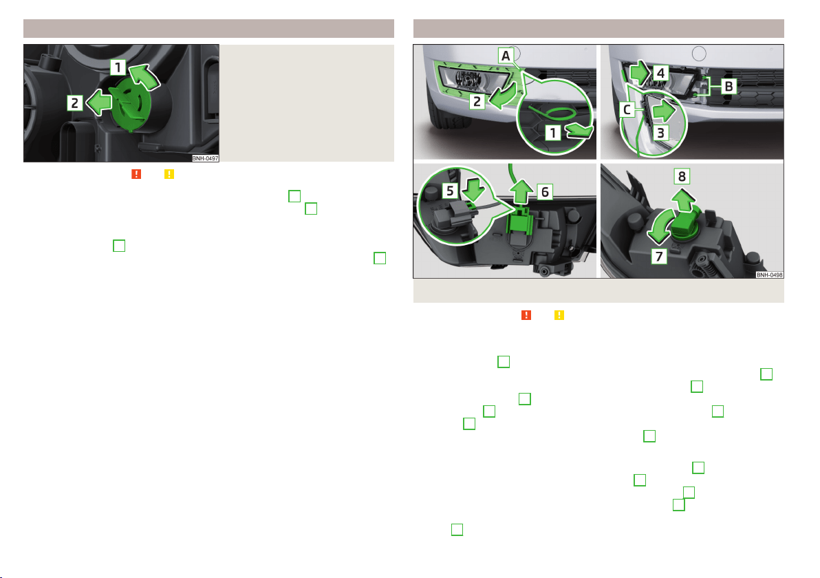
Changing the front turn signal bulb
Fig. 192
Changing the bulb for the front
turn signal light
Read and observe and on page 178 first.
›
Turn the socket with the bulb in the direction of arrow
1
» Fig. 192.
›
Remove the socket with the bulb in the direction of arrow
2
.
›
Change the bulb in the socket.
›
Insert the socket with the new bulb into the headlight in the opposite direc-
tion to the arrow
2
.
›
Turn the socket with the new bulb in the opposite direction to the arrow
1
until it stops.
Replacing the bulb for the fog light
Fig. 193 Remove the number plate light / replace the bulb
Read and observe and on page 178 first.
Remove the protective grille and headlight
›
Insert the clamps for removing the full wheel covers » page 161, Vehicle tool
kit into opening
A
» Fig. 193.
›
Loosen the protective grille by pulling the hook in the direction of arrow
1
.
›
Remove the protective grille in the direction of the arrow
2
.
›
Unscrew the screws
B
with the screwdriver from the tool kit.
›
With the key
2
» page 161, Vehicle tool kit unlock the locking
C
in direction
of arrow
3
.
›
Remove the headlight in the direction of arrow
4
.
Replacing the light bulb
›
Press the latch on the connector in the direction of arrow
5
.
›
Remove the key in the direction of the arrow
6
.
›
Pull the lamp holder until it stops in the arrow direction
7
.
›
Remove the lamp holder in the direction of the arrow
8
.
›
Insert the new bulb into the headlight and turn counter to the direction of
arrow
7
as far as the stop.
180
Do-it-yourself
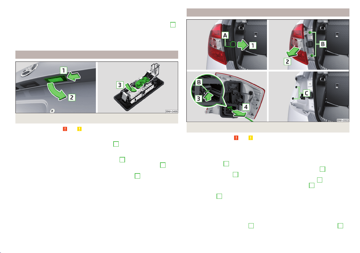
›
Attach the connector.
Refit the headlight and grille
›
Replace the fog light by inserting it in the opposite direction of the arrow
4
» Fig. 193 and tightening.
›
Insert the protective grille and carefully press it in.
The protective grille must engage firmly.
Replacing the bulb for the licence plate light
Fig. 194
Remove the number plate light/replace the bulb
Read and observe and on page 178 first.
›
Open the boot lid.
›
Push in the lamp in the direction of the arrow
1
» Fig. 194.
The lamp comes loose.
›
Swivel out the lamp in the direction of the arrow
2
and remove it.
›
Remove the faulty bulb from the holder in the direction of the arrow
3
.
›
Insert a new bulb into the holder.
›
Reinsert the lamp in the opposite direction to the arrow
1
.
›
Push on the light until the spring clicks into place.
Check that the light is securely inserted.
Rear Light
Fig. 195 Remove light / pull out connector
Read and observe and on page 178 first.
Removing
›
Open the boot lid.
›
Insert the clamps for removing the full wheel covers » page 161, Vehicle tool
kit into opening
A
» Fig. 195.
›
Remove the cover by pulling the hook in the direction of arrow
1
.
›
Unscrew the screws
B
with the key from the tool kit.
›
Grasp the lamp and carefully remove in the direction of arrow
2
.
›
Press the latch on the connector in the direction of arrow
3
.
›
Carefully remove the connector from the tail lamp assembly in the direction
of the arrow
4
.
Fitting
›
Insert the bulb holder into the lamp.
The lock on the plug must be inserted securely.
›
Insert the lamp with the pin
B
» Fig. 196 on page 182 into the recesses
C
» Fig. 195 in the body.
181
Fuses and light bulbs
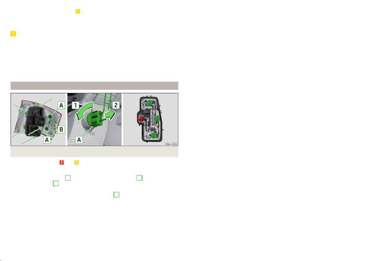
›
Carefully push the cover in » .
›
Screw the tail lamp into place and install the cover.
The cover must engage securely.
CAUTION
■
Ensure that the cable bundle does not become pinched between the body
and the lamp when it is being refitted – risk of damage to the electrical instal-
lation and risk of water ingress.
■
If you are not sure whether the cable bundle has become pinched, we recom-
mend that you have the light connection checked by a specialist garage.
■
Ensure that the vehicle paintwork and the tail lamp are not damaged when
removing and installing the tail lamp.
Replacing bulbs in rear light
Fig. 196 Outer part of the lamp/inner part of the lamp
Read and observe and on page 178 first.
Outer part of the lamp
›
Rotate the lamp socket
A
» Fig. 196 in direction of arrow
1
and remove in
direction of arrow
2
from the lamp housing.
›
Changing the lamp, reinsert the holder with the bulb into the lamp housing
and turn in the opposite direction of the arrow
1
to the stop.
Inner parts of the lamp
›
Unlock the bulb holder using the marked area with arrows » Fig. 196 and re-
move the bulb holder from the light.
›
Turn the respective bulb counter clockwise until it stops.
›
Remove the holder from the lamp.
›
Insert a new bulb into the holder and turn in a clockwise direction to the
stop.
›
Insert the bulb holder in the tail lamp assembly.
The lamp holder must engage firmly.
182
Do-it-yourself
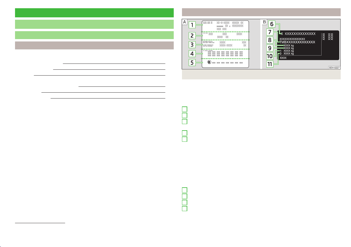
Technical data
Technical data
Basic vehicle data
Introduction
This chapter contains information on the following subjects:
Vehicle characteristics
183
Operating weight 184
Payload 184
Measurement of fuel consumption and CO
2
emissions according to ECE
Regulations and EU Directives
184
Dimensions 186
Departure angle 187
The details given in the vehicle's technical documentation always take prece-
dence over the details in the Owner's Manual.
The listed performance values were determined without performance-reduc-
ing equipment, e.g. air conditioning system.
The values given have been determined in accordance with regulations and in
conditions prescribed by legal or technical provisions for determining the oper-
ating and technical data of vehicles.
Vehicle characteristics
Fig. 197 Vehicle data sticker/type plate
Vehicle data sticker
The vehicle data sticker » Fig. 197 -
is located on the base of the luggage
compartment and is also stuck into the service schedule.
The vehicle data sticker contains the following data.
Vehicle identification number (VIN)
Vehicle type
Gearbox code/paint number/interior equipment/engine output/engine
code
Partial vehicle description
Approved tyre diameter in inches
1)
The approved tyres and rim sizes for your vehicle are listed in the vehicle's
technical documentation (the so called COC document) and this also states the
declaration of conformity.
Type plate
The type plate » Fig. 197 -
is located at the bottom of the B-pillar on the
right-hand driver's side.
The type plate contains the following data.
Manufacturer
Vehicle identification number (VIN)
Maximum permissible gross weight
Maximum permissible towed weight (towing vehicle and trailer)
1
2
3
4
5
6
7
8
9
1)
Only valid for some countries.
183
Technical data
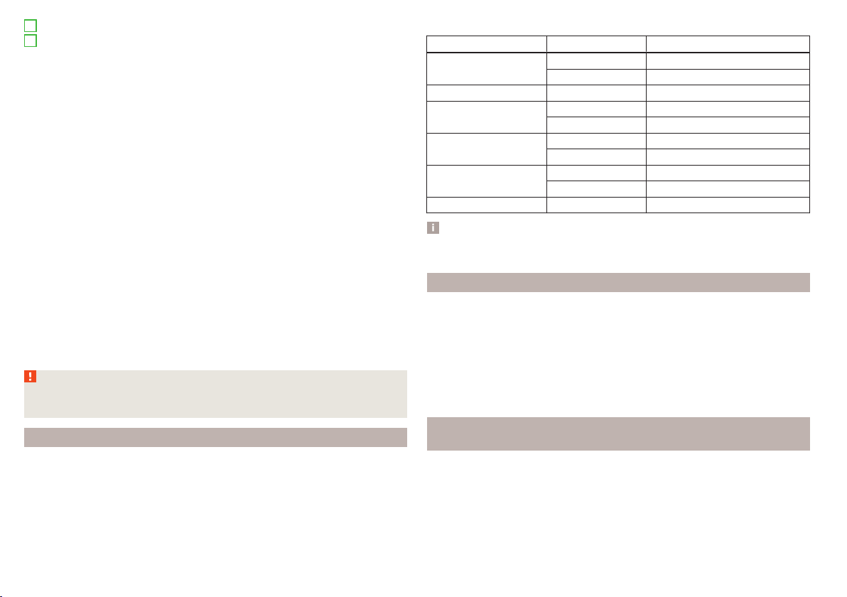
Maximum permissible front axle load
Maximum permissible rear axle load
Vehicle identification number (VIN)
The vehicle identification number - VIN (vehicle body number) is stamped into
the engine compartment on the right hand suspension strut dome. This num-
ber is also located on a sign on the lower left hand edge below the windscreen
(together with a VIN bar code), and on the type plate.
The VIN number can also be displayed in the Infotainment » Owner´s Manual
Infotainment, chapter CAR - vehicle settings.
Engine number
The engine number (three-digit identifier and serial number) is stamped on the
engine block.
Supplementary Information (applies to Russia)
The full type approval number of the means of transport is indicated in the
registration documents, field 17.
Maximum permissible towed weight
The listed maximum allowable trailer weight is only valid for altitudes up to
1000 m above sea level.
The engine output falls as altitude increases, as does the vehicle's climbing
power. Therefore, for every additional 1,000 m in height (or part), the maximum
permissible towed weight must be reduced by 10%.
The towed weight is made up of the actual weights of the loaded towing vehi-
cle and the loaded trailer.
WARNING
Do not exceed the specified maximum permissible weights – risk of acci-
dent and damage!
Operating weight
The value represents the lightest possible vehicle weight without any addi-
tional equipment that would add to the weight, e.g. air conditioning, spare
wheel.
The specified operating weight is for orientation purposes only.
The operating weight also contains the weight of the driver (75 kg), the weight
of the operating fluids, the tool kit, and a fuel tank filled to 90 % capacity.
10
11
Operating weight
Engine Gearbox Operating weight (kg)
1.2 l/66 kW TSI
MG 1160
DSG 1194
1.2 l/81 kW TSI MG 1180
1.4 l/92 kW TSI
DSG 1212
DSG (Green tec) 1221
1.6 l./81 kW MPI
MG 1160
AG 1200
1.4 l/66 kW TDI CR
MG 1229
DSG 1250
1.6 l/85 kW TDI CR MG 1275
Note
If required, you can find out the precise weight of your vehicle at a specialist
garage.
Payload
It is possible to calculate the approximate maximum payload from the differ-
ence between the permissible total weight and the operating weight.
The payload consists of the following weights.
▶
The weight of the passengers.
▶
The weight of all items of luggage and other loads.
▶
The weight of the roof, including the roof rack system.
▶
The weight of the equipment that is excluded from the operating weight.
▶
Trailer draw-bar load when towing a trailer (max. 50 kg).
Measurement of fuel consumption and CO
2
emissions according to
ECE Regulations and EU Directives
The data on fuel consumption and CO
2
emissions were not available at the
time of going to press.
The data on fuel consumption and CO
2
emissions are given on the ŠKODA
websites or in the sales and technical vehicle documentation.
The measurement of the intra-urban cycle begins with a cold start of the en-
gine. Afterwards urban driving is simulated.
184
Technical data

In the extra-urban driving cycle, the vehicle is accelerated and decelerated in
all gears, corresponding to daily routine driving conditions. The driving speed
varies between 0 and 120 km/h.
The calculation of the combined fuel consumption considers a weighting of
about 37 % for the intra-urban cycle and 63 % for the extra-urban cycle.
Note
■
The fuel consumption and emission levels given on the ŠKODA websites or in
the commercial and technical vehicle documentation have been established in
accordance with rules and under conditions that are set out by legal or techni-
cal rules for the determination of operational and technical data of motor vehi-
cles.
■
Depending on the extent of the equipment, the driving style, traffic condi-
tions, weather influences and vehicle condition, consumption values can in
practice result in fuel economy figures in the use of the vehicle that differ from
the fuel consumption values listed on the ŠKODA websites or in the commer-
cial and technical vehicle documentation.
185
Technical data
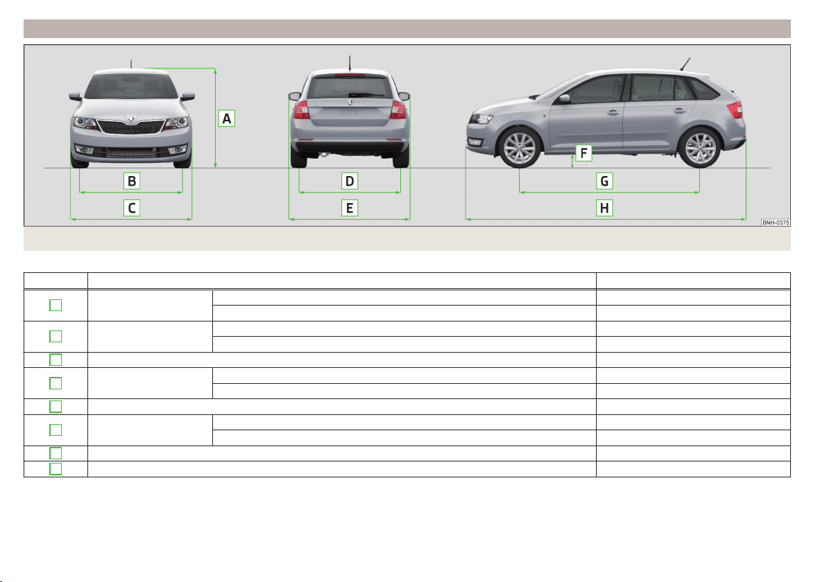
Dimensions
Fig. 198 Principle sketch: Vehicle dimensions
Vehicle dimensions for operating weight without driver (in mm)
» Fig. 198 Specification Value
A
Height
Basic dimension 1459
Vehicles with off-road package 1472
B
Front track
Basic dimension 1457
Vehicles with the 1.2 l/66 kW TSI and 1.4 l/66 kW TDI CR engine 1463
C
Width 1706
D
Rear track
Basic dimension 1494
Vehicles with the 1.2 l/66 kW TSI and 1.4 l/66 kW TDI CR engine 1500
E
Width including exterior mirror 1940
F
Clearance
Basic dimension 134
Vehicles with off-road package 141
G
Wheel base 2602
H
Length 4304
186
Technical data
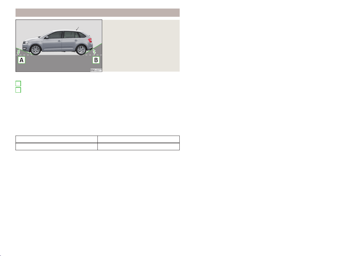
Departure angle
Fig. 199
Principle sketch: Departure an-
gle
Angle » Fig. 199
Overhang angle, front
Overhang angle, rear
Departure angle
The values shown indicate the maximum incline of an embankment, up which
the vehicle can drive at a slow speed without collision of the bumper or under-
body.
The values listed correspond to the maximum axle load, front or back.
Overhang angle (°)
Overhang angle, front Overhang angle, rear
13.8 16.5
A
B
187
Technical data

Vehicle-specific details per engine type
Introduction
This chapter contains information on the following subjects:
1.2 ltr. / 66 kW TSI engine 188
1.2 ltr. / 81 kW TSI engine 188
1.4 ltr./92 kW TSI engine 189
1.6 l/81 kW MPI engine 189
1.4 l/66 kW TDI CR engine 189
1.6 l/85 kW TDI CR engine 189
The specified values have been determined in accordance with rules and under conditions set out by legal or technical requirements for determining operational
and technical data for motor vehicles.
The emissions standard is detailed in the technical vehicle documentation as well as in the certificate of conformity (COC document), which can be obtained from
a ŠKODA partner
a)
.
a)
Only valid for some countries and some models.
1.2 ltr. / 66 kW TSI engine
Output (kW/rpm) 66/4400
Maximum torque (Nm/rpm) 160/1400-3500
Number of cylinders/displacement (cm
3
) 4/1197
Gearbox MG DSG
Top speed (km/h) 184 184
Acceleration 0-100 km/h (s) 11.2 11.3
1.2 ltr. / 81 kW TSI engine
Output (kW/rpm) 81/4600
Maximum torque (Nm/rpm) 175/1400-4000
Number of cylinders/displacement (cm
3
) 4/1197
Gearbox MG
Top speed (km/h) 198
Acceleration 0-100 km/h (s) 9.7
188
Technical data

1.4 ltr./92 kW TSI engine
Output (kW/rpm) 92/5000
Maximum torque (Nm/rpm) 200/1400-4000
Number of cylinders/displacement (cm
3
) 4/1395
Gearbox DSG
Top speed (km/h) 205
Acceleration 0-100 km/h (s) 8.9
1.6 l/81 kW MPI engine
Output (kW/rpm) 81/5800
Maximum torque (Nm/rpm) 155/3800
Number of cylinders/displacement (cm
3
) 4/1598
Gearbox MG AG
Top speed (km/h) 193 189
Acceleration 0-100 km/h (s) 10.2 11.5
1.4 l/66 kW TDI CR engine
Output (kW/rpm) 66/3500
Maximum torque (Nm/rpm) 230/1750-2500
Number of cylinders/displacement (cm
3
) 3/1422
Gearbox MG DSG
Top speed (km/h) 183 183
Acceleration 0-100 km/h (s) 11.6 11.7
1.6 l/85 kW TDI CR engine
Output (kW/rpm) 85/3500
Maximum torque (Nm/rpm) 250/1500-3000
Number of cylinders/displacement (cm
3
) 4/1596
Gearbox MG
Top speed (km/h) 198
Acceleration 0-100 km/h (s) 9.9
189
Technical data

Index
A
abroad
lead-free petrol 141
Abroad
Headlights 63
ABS
Operation 110
Warning light 33
Acceptance and recycling of used vehicles 133
Accessories 130
Adjusting
Exterior mirror
68
head restraints 69
Seat 69
Steering wheel 9
Adjusting the seats 8
Adjustment
Beam range 59
Advance warning/emergency braking
Warning light 38
Air-conditioning system
Air outlet vents 94
Airbag 14
Deactivating 18
Deactivating the front passenger airbag 18
Deployment 15
Front airbag 15
Head airbag 17
Modifications and damage to the airbag system 132
Side airbag 16
Warning light 34
Airbag system 14
Air conditioning 90
Air distribution control 93
Climatronic 92
Manual air conditioning 91
Air distribution control 93
Air outlet vents 94
Alarm
Enable/disable 54
Switch off 54
Trailer 128
Triggering 54
Alcantara
cleaning 139
Anodized parts
Refer to vehicle maintenance 136
Anti-lock braking system (ABS) 110
Anti-theft alarm system
Enable/disable 54
Trailer 128
Anti-theft wheel bolts 163
Armrest
Front 71
Rear 71
artificial leather 139
Ashtray 75
Assembling the
tow bar, Step 1 123
tow bar, Step 2 124
Assist systems 109
Auto-check control 39
Automatic driving lamp control 61
Automatic gearbox 104
Selector lever-emergency unlocking 172
Selector lever lock 105
Starting-off and driving 106
Tiptronic 105
Using the selector lever 104
Automatic gearbox modes 104
Automatic load deactivation 153
automatic transmission
selector lever lock defect 105
Automatic transmission
Kick-down 106
Malfunctions 36
Selector lever lock 105
Warning light 36
Warning messages 36
AUX 80
Avoiding damage to your vehicle 108
B
Bags
on the backs of the front seats 79
Ball head
Check fitting 124
Ready position 122, 123
Battery
In the remote control key 171
Belts 11
Belt tensioners 13
Bonnet
Closing 144
Opening 144
Boot
Cargo element 85
Class N1 vehicles 86
Hooks 83
See Boot lid 55
Storage compartments 85
Boot cover
Parking position 84
Boot lid
automatic locking
55
Closing 55
Opening 55
Brake Assist (HBA) 111
Brake booster 102
brake fluid
specification 150
Brake fluid 149
Checking 150
Information messages 32
190
Index

Brake pedal (automatic gearbox)
Warning light 35
Brakes
Brake booster 102
Brake fluid 150
Braking and stabilisation systems 109
Handbrake 102
Information messages 32
Running-in 106
Warning light 32
Brakes and parking 101
Brake system 109
Braking
Information on braking 101
Button CAR
see Infotainment 4
Button in driver's door
electric windows 56
C
Car care
Jack 137
Car computer
see multifunction display 40
Care and maintenance 130
Cargo element 85
Car park 103
Car park ticket holder
73
Carrier
Roof rack 89
Cavity protection 137
Central locking 49
Problems 53
Central locking button 51
Change
Engine oil 146
light bulb in tail light 181
Changing
bulbs 177
Front turn signal bulb 180
Wheels 161
Changing a wheel
Follow-up work 165
Preliminary work 162
Changing wheels
Wheel removal and fix 165
Charging a vehicle battery 152
Check
Fit ball head properly 124
Checking
Battery electrolyte level 152
Brake fluid 150
Coolant 148
Engine oil 147
Oil level 147
Windscreen washer fluid 145
Checks
Statutory checks 130
Children and safety 19
Child safety
Side airbag 21
Child safety lock 53
Child seat
Classification 21
ISOFIX 22
on the front passenger seat 20
TOP TETHER 24
Use of child seats 21
Use of ISOFIX child seats 23
Chrome parts
Refer to vehicle maintenance 136
Cigarette lighter 75
Clean
Anodized parts 136
Chrome parts 136
Cleaning
Alcantara 139
and maintaining belts 140
artificial leather 139
headlight glasses 136
materials 139
natural leather 138
plastic parts 135
seats covers of the electrically heated seats 140
wheels 137
Cleaning safety
belt 140
Cleaning seat
covers 140
Cleaning the interior
artificial leather 139
Seat covers 140
Cleaning the vehicle exterior
Cavity protection 137
Decorative films 135
Door locking cylinder 137
Headlight glasses 136
Protective films 135
Towing device 137
Under-body protection 138
wheels 137
Windows and external mirrors 136
Cleaning vehicle 133
Cleaning vehicle exterior 134
Anodized parts 136
Chrome parts 136
Plastic parts 135
Rubber seals 136
Vehicle paint work 135
Wiper blades 138
Clean interior
Safety belt 140
Climatronic
air distribution control 93
Automatic mode 93
Operating elements 92
Clothes hook 79
191
Index

Cockpit
12-Volt power outlet 75
Ashtray 75
Cigarette lighter 75
General view 27
Lights 63
storage compartments 73
useful equipment 73
COMING HOME 62
compartments 73
Component protection 132
Components of the puncture repair kits 166
Computer
see multifunction display 40
convenience turn signal 61
Coolant 148
Checking 148
Replenishing 149
Temperature gauge 29
Warning light 36
Warning messages 36
CORNER
see Headlights with CORNER function 62
Correct routing of seat belt
12
Correct seated position 8
Front passenger 10
Rear seats 10
Correct seat position
Driver 9
Counter for distance driven 30
cruise control
operation 114
operation description 115
Cruise control system
Warning light 35
Cup holders 74
D
DAY LIGHT
See Daytime running lights 60
Daytime running lights 60
Dazzle
see sun screen of the panoramic roof 65
De-icing
windows
136
Deactivating an airbag 18
Decorative films 135
Defrosting rear window 64
Delayed locking of the boot lid
see boot lid 55
Departure angle 187
Diesel
refer to Fuel 142
Diesel fuel
Operation in winter 142
Diesel particulate filter 37
information messages 37
Digital Clock 31
Dipstick 147
Disconnecting and reconnecting
vehicle battery 153
Display 29
Compass points 45
Coolant temperature
29
Fuel supply 30
Gear changes 39
Service intervals 46
Disposal
Acceptance and recycling of used vehicles 133
Distance driven 30
Distance warning
Warning light 38
Door
Child safety lock 53
Closing 53
Emergency locking 172
Opening 53
Door warning 39
Drive
Driving through water 108
DriveGreen 107
Driving
Emissions 184
Fuel consumption 184
Maximum speed 188
through water 108
driving data
operation 40
E
Economical driving
Tips 106
EDL 111
Electrical power windows
Button in the rear doors 57
Electric power windows
Operational faults 58
Electric Windows 56
Button in driver's door 56
Electronic Differential Lock (EDL) 111
Electronic immobilizer 95
Emergency
Changing a wheel
161
Hazard warning light system 62
Jump-starting 168
Locking the door without a locking cylinder 172
Selector lever-unlocking 172
Switch off the engine by pressing a button 98
Towing the vehicle 169
Towing the vehicle using the tow hitch 171
tyre repair 165
emergency equipment
reflective vest 160
192
Index

Emergency equipment
Fire extinguisher 160
First aid kit 160
Jack 161
Vehicle tool kit 161
Warning triangle 160
Emergency wheel
Stow 162
Emission control system
Warning light 34
Emissions 184
Engine
Running-in 106
Starting the engine 98
Warning messages 36
Engine compartment 143
Brake fluid 150
Overview 145
Vehicle battery 150
Engine number 183
engine oil
specification 146
Engine oil 146
change 146
Checking 147
Replenishing 147
Warning light 37
EPC
Warning light 34
ESC
Operation 110
Warning light 33
F
Fastening elements 82
Fatigue detection 119
Function 119
Information messages 119
Films 135
Fire extinguisher 160
First aid kit 160
Flashing 60
Floor covering
in the luggage compartment 86
Fog lights
Warning light 35
Fog Lights 61
Footmats 103
refer to footmats 103
Force limit
Power windows 58
Front airbag 15
Front Assist 116
Disable/enable 118
Distance warning 117
Information messages 118
Operation 117
Radar sensor 116
Warning and automatic braking 117
Warning light 38
fuel
lead-free petrol 141
Fuel 140
Diesel 142
Fuel gauge 30
refer to Fuel 140
Refuelling 141
Warning light 35
Fuel consumption 184
Fuel reserve
Warning light 35
Fuses
Assignment 174
Assignment of fuses in the dash panel 175
Colour coding 174
Fuse assignment in the engine compartment 177
Replacing 174
Fuses in the engine compartment
Assignment 177
G
Gear change
Gear recommendation 39
Information on the selected gear 39
Gear changing
Gear stick 103
General view
Cockpit
27
Genuine parts 131
Glasses compartment 78
Glow plug system
Warning light 34
H
Handbrake
102
Warning light 32
Hazard warning light system 62
HBA 111
Head airbag 17
Headlight cleaning system
Headlight cleaning system 67
Headlights
Bulb arrangement 178
Driving abroad 63
Headlight cleaning system 67
Headlights with CORNER function 62
Head restraints 69
Adjust height 69
Headrest,
removing and installing 70
Heating 90
Air distribution control 93
Controls 91
Exterior mirror 68
Rear window 64
Seats 70
Heating rear window 64
HHC 111
193
Index

Hill Start Assist (HHC) 111
Hitch 121
Drawback load 121
Hooks 83
Horn 27
I
Ice scrapers 136
Ignition lock 96
Immobilizer 95
Indicator lights 31
Individual settings
Locking 52
Unlocking 52
Inertia reels 13
Information system 39
Compass point display 45
Door warning 39
Gear recommendation 39
MAXI DOT display 42
Multifunction display 40
operation 40
Service interval display 46
Information system operation 40
Infotainment 4
Instrument cluster 28
Auto-check control 39
Counter for distance driven
30
Display 29
Fuel gauge 30
Indicator lights 31
Overview 28
Revolution counter 29
see instrument cluster 28
Temperature gauge 29
Interior care 138
Natural leather 138
interior light
Front 63
Interior monitor 54
iPad holder
Behind the headrests 80
Handling 80
ISOFIX 22
J
Jack 161
Maintenance 137
Jacking points
Raise vehicle 164
Jump-starting 168
K
KESSY
Locking
51
Unlocking 51
Key
Lock 50
Start the engine 96
Stopping the engine 96
Switch off the ignition 96
Switch on the ignition 96
Unlock 50
L
Lamp failure
Warning light 37
Lamps
Warning light 37
Leather
Natural leather care 138
LEAVING HOME 62
Lever
Main beam 60
Turn signal 60
Windscreen wipers 66
Light
COMING HOME / LEAVING HOME 62
Daytime running lights 60
Fog Lights 61
Headlights with CORNER function 62
Parking light 63
Rear fog light 61
Lighting
Luggage compartment 81
Lights 59
Automatic driving lamp control 61
Beam range adjustment 59
Cockpit 63
Hazard warning light system 62
Headlight flasher 60
Indicator lights 31
Low beam 59
Main beam 60
Parking light 59
Replacing bulbs 177
switching on/off 59
Turn signal 60
Load 184
Lock
Key 50
Locking
Individual settings 52
KESSY 51
Remote control 50
Locking and unlocking the vehicle from the in-
side 51
Locking the door without a locking cylinder
Emergency 172
Low beam 59
Low temperature warning indicator
Warning light 38
Low tyre pressure warning
refer to the tyre pressure monitoring 119
194
Index

Luggage compartment 81
Cover 84
Fastening elements 82
Fixing nets 83
floor covering on both sides 86
Lighting 81
unlock manually 172
Unlock the boot lid 172
Variable loading floor 86
Luggage compartment cover 84
Luggage compartment lid 55
Luggage Storage
Storage net bag 85
M
Main beam 60
Warning light 36
Maintenance
see vehicle care 135
Manual air conditioning
Air distribution control 93
Controls 91
Manual gear changing
see Gear changing 103
MAXI DOT
See MAXI DOT display 42
MAXI DOT display 42
Main menu
42
Menu item assist systems 45
Menu item Audio 44
Menu item navigation 44
Menu item telephone 45
Operation 43
Maximum
permissible weights 183
Maximum speed 188
MCB 111
MDI 80
Mechanical window lifter
open and close 56
Mechanical window lifters 56
Media
see Infotainment 4
Mirror
Exterior mirror 68
Interior mirror 67
Make-up 65
Modifications 130
Modifications and technical alterations
Airbags 132
Service 131
Spoiler 132
Multi-function display
operation 40
Multi collision brake (MCB) 111
Multifunction display
Functions 40
Information 40
Memory 42
Multifunction pocket 83
Multifunction steering wheel
Operation 43
Multimedia
AUX 80
USB 80
Multimedia holder 77
N
N1
86
Nameplate 183
Navigation
see Infotainment 4
Nets 83
Notes for driving with tyre repaired 167
Notes on using wheels 154
O
Oil
See Engine oil 147
Warning messages 37
Oil pressure
Warning messages 37
On-board computer
see multifunction display
40
Operating weight 184
Operation in winter
Diesel fuel 142
Vehicle battery 152
Original accessories 131
Overview
Engine compartment 145
Indicator lights 31
P
Parking
103
Parking assistance 112
Parking aid
Automatic system activation when moving for-
ward 114
Function 112
Parking assistance 112
Activation / deactivation 113
Display in the Infotainment display 113
Parking light 59
Park Pilot 112
Park the vehicle
see Parking 103
Passive safety
Before setting off 8
Driving safety 8
Passive Safety 8
Pedals 103
Footmats 103
Petrol
see fuel 141
195
Index

Phone
see Infotainment 4
Plastic parts 135
Pocket
in the luggage compartment 83
Pockets
on the inner sides of the front seats 79
Polishing vehicle paint work
see vehicle care 135
Power outlet
12 V 75
Power steering/steering lock (KESSY system)
Warning light 32
Power windows 56
Button in the front passenger door 57
Practical equipment
12-Volt power outlet 75
Reflective vest 160
Practical features
Pockets on the backs of the front seats 79
Pockets on the inner sides of the front seats 79
Waste container 76
Protective films 135
Puncture set 165
R
Radiator fan 145
Radio
see Infotainment
4
Raise vehicle 164
Rear
interior light 64
Rear fog light 61
Warning light 34
Rear mirror 67
Exterior mirror 68
Rear view mirror
Interior mirror 67
Refuelling 141
Fuel 141
Remote control
Locking 50
Replacing the battery 171
Synchronisation process 172
Unlocking 50
Remote control key
Replacing the battery 171
Removing the
tow bar, Step 1 125
tow bar, Step 2 125
Repairs and technical alterations 130
Replacement parts 130
Replacing
Bulb for main beam, daytime running lights and
parking light 179
Bulb for the fog light 180
Bulb for the licence plate light 181
Bulb in rear light 182
Fuses 174
Fuses in the dash panel 175
Fuses in the engine compartment 176
High beam bulb (halogen headlights) 179
Rear window wiper blade 173
Vehicle battery 153
windscreen wiper blades 173
Replenishing
Coolant 149
Engine oil 147
Windscreen washer fluid 145
Revolution counter 29
Roof
Load 90
Roof rack 89
mounting points 89
Roof load 90
Rubber seals 136
Running-in
Brake linings 106
Engine 106
Tyres 106
S
SAFE
See Safe securing system
52
SAFELOCK
See Safe securing system 52
Safe securing system 52
Safety 8
Child safety 19
Child safety seats 19
Correct seated position 8
Head restraints 69
ISOFIX 22
TOP TETHER 24
Save electrical energy 106
Save fuel 106
Seals
Vehicle care 136
Seat
Adjusting 69
Seat belt
height adjustment 12
Warning light 32, 36
Seat belts
11
Belt tensioners 13
fastening and unfastening 13
Inertia reels 13
The physical principle of a frontal collision 12
Seat features 70
Seats
Front armrest 71
Head restraints 69
Heating 70
Rear armrest 71
Seat backrests 72
Seats and head restraint 69
196
Index

Selector lever
Refer to Selector lever 104
Selector lever lock (automatic gearbox)
Warning light 35
Service 131
Service interval display 46
Warning light 38
Setting
Lower position of the variable loading floor 87
Seat belt height 12
seats and head restraints 69
Upper position of the variable loading floor 87
Settings
Interior mirror 67
Setting the
Clock 31
Side airbag 16
SmartGate
Connection by searching for a Wi-Fi network 47
introductory information 47
Password/PIN code change 49
Setting 48
Wi-Fi Direct 48
SmartLink
see Infotainment 4
Snow chains 159
Spare wheel 157
Remove 162
Stow 162
Speed control system 114
Speed symbol
Refer to Wheels 158
Spoiler 132
Stabilisation system 109
Stability Control (ESC) 110
Staring engine
Jump-starting 168
START-STOP 99
Jump-starting 168
Manually deactivating/activating the system 101
operation 100
Warning light 38
START-STOP system 99
Starter button
Problems with the engine start 99
Steering column lock locking 97
Steering column lock unlocking 97
Switching off the engine 98
Switch off the ignition 98
Switch on the ignition 98
Starting and stopping the engine at the push of
the button 97
Starting and stopping the engine using the key 95
Starting engine
Jump-starting 168
Starting the engine
Starter button 98
START STOP
Information messages 101
Start the engine
Key 96
Steering column lock locking
Starter button 97
Steering column lock unlocking
Starter button 97
Steering lock locking
Key 96
Steering lock unlocking
Key 96
Steering wheel
correct posture 9
setting 9
Stop
see Parking 103
Stopping the engine
Key 96
Storage 73
Storage compartment
Glasses compartment 78
in the boot 85
in the centre console 74
in the front arm rest 77
on the front passenger side 78
Storage compartments 73
Storage net bag 85
Stowage
compartments in the doors 73
Sun visors 65
Switching off the engine
Starter button 98
Switch light on/off 59
Switch off the ignition
Key 96
Starter button 98
Switch on the ignition
Key 96
Starter button 98
T
Tablet holder
Behind the headrests 80
Handling 80
Taking care of your vehicle
Automatic car wash system 134
High-pressure cleaner 134
Washing by hand 133
Wash system 134
TCS
Operation
110
Warning light 33
Technical data 183
Time 31
Tiptronic 105
Tools 161
TOP TETHER 24
Towing 169
Towing a trailer 128
197
Index

Towing device
Accessories 126
Description 122
Operation and maintenance 137
Towing eye
Front 170
Rear 171
Towing protection 54
Towing the vehicle 169
Traction control (TCS) 110
Trailer 126
13-pin socket 127
connection and disconnection 127
Load 128
Loading 127
Safety eye 127
Towing a trailer 128
Trailer operation 121
Trailer stabilization system (TSA) 111
Transmission
Warning messages 36
Transport
Luggage compartment 81
Roof rack 89
Transporting 73
Transporting children safely 19
TSA 111
Turn signal 60
Turn signal system
Warning light 35
Tyre
Damage 157
Explanation of the label 158
see wheels 158
Tyre load-bearing capacity
Refer to Wheels 158
Tyre pressure 155
Warning light 34
Tyre pressure monitoring 119
Display 34
Infotainment display 120
Save tyre pressure values 120
Save tyre pressure values - button 121
Save tyre pressure values - Infotainment 120
Tyre repair
General notes 166
Preparations 167
Pressure test 167
Sealing and inflating the tyre 167
Tyres 154
new 106
Tyre pressure 155
Wear and tear 156
Wear indicators 156
Tyre size 158
see wheels 158
U
Under-body
Vehicle care 138
Under-body protection 138
Unlock
Key 50
Unlocking
Individual settings 52
KESSY
51
Remote control 50
Unlocking and locking 49
USB 80
Used vehicles
Acceptance and recycling 133
Useful equipment
Ashtray 75
Car park ticket holder 73
Cigarette lighter 75
Clothes hook 79
Cup holders 74
Glasses compartment 78
Multimedia holder 77
Storage compartment 73
Using the selector lever 104
V
Variable loading floor 86
Folding up 88
Inserting
88
Lower position 87
Parking position 88
Removing 88
Upper position 87
Vehicle battery
Automatic load deactivation 153
charging 152
Checking the battery electrolyte level 152
Cover 151
Operation in winter 152
Replacing 153
Safety instructions 150
Warning light 36
Vehicle care
Alcantara 139
Anodized parts 136
Artificial leather 139
Cavity protection 137
Chrome parts 136
Cleaning vehicle exterior 134
Cleaning wheels
137
Decorative and protective films 135
Door locking cylinder 137
Headlight glasses 136
Interior care 138
Maintenance 135
Materials 139
Natural leather 138
Plastic parts 135
Polishing vehicle paint work 135
Rubber seals 136
Safety belt 140
Seat covers 140
198
Index

Under-body protections 138
washing 133
Vehicle condition
see Auto-check control 39
Vehicle data sticker 183
Vehicle data sticker and nameplate
Vehicle data sticker and nameplate 183
Vehicle dimensions 186
Vehicle height 186
Vehicle Identification Number (VIN) 183
Vehicle length 186
Vehicle tool kit 161
Vehicle width 186
vest
holder for reflective vest 160
VIN
Vehicle Identification Number 183
Visibility 64
Visors
See front sun visors 65
W
Warning triangle 160
warning when speeding 41
Washing
Automatic car wash system 134
by hand
133
High-pressure cleaner 134
Washing vehicles 133
Waste container 76
Weather conditions 130
Wheel bolts
Anti-theft wheel bolts 163
Caps 163
Loosening and tightening 163
Wheel rims 154
Wheels
Age of wheels 154
Changing 161
Driving style 156
Full trim 162
General information 154
Load index 158
Snow chains 159
Speed symbol 158
Storage of wheels 154
Tyre damage 157
Tyre pressure 155
Tyre size 158
Tyre wear 156
Tyre wear indicator 156
Unidirectional tyres 157
Wheel balance 156
Wheels exchange 156
Winter tyres 158
Wi-Fi
Connection 47
Password 47
Password change 49
Setting 48
Wi-Fi Direct
Connection 48
Password change 49
Setting 48
Window wiper
Replacing the rear window wiper blade 173
Windscreen washer fluid
Checking 145
Replenishing 145
Warning light 38
Winter 145
Windscreen washer system 145
Windscreen wipers 66
Windscreen wipers
Activating 66
Replacing the windscreen wipers 173
Windscreen washer fluid 145
Windscreen wipers and washers 65
Winter operation 158
De-icing windows 136
Snow chains 159
Winter tyres 158
Winter tyres
See Wheels 158
Wiper blades 138
Service position of the windscreen wiper arms 173
Wipers
Maintaining wiper blades 138
199
Index

200
Index

201
Index

202
Index

Reprinting, reproduction, translation, or any other use, either in whole or in
part, is not permitted without the written consent of ŠKODA AUTO a.s.
ŠKODA AUTO a.s. expressly reserves all rights relating to copyright laws.
Subject to change.
Issued by: ŠKODA AUTO a.s.
© ŠKODA AUTO a.s. 2015
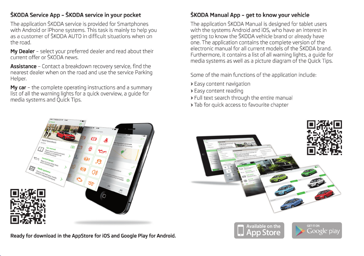


www.skoda-auto.com
Návod k obsluze
Rapid Spaceback anglicky 11.2015
S57.5610.05.20
5JJ012720AE
5JJ012720AE