This is User Manual of Security Light
SAFETY
Read all safety warnings and instructions.
Failure to follow the warnings and instructions may result in electric shock, fire and/or serious injury.
Save all warnings and instructions for future reference.
- Keep installation area clean. Cluttered areas invite accidents.
- Observe installation area conditions. Keep work area well lit during installation.
- Check for damaged parts. Before using any product, any part that appears damaged should be carefully checked to determine that it will operate properly and perform its intended function. Check for any broken or damaged parts and any other conditions that may affect its operation. Replace or repair damaged or worn parts immediately. Do not use the Security Light if any switch does not turn on and off properly.
- Replacement parts and accessories. When servicing, use only identical replacement parts. Use of any other parts will void the warranty.
- Check hardware and assembled parts after assembling. All connections should be tight and hardware tightened.
- Keep children away. Mount the Light, Solar Panel, and Cord out of children’s reach.
- Dress properly. Protective, electrically nonconductive clothes and nonskid footwear are recommended when working with the Solar Powered Security Light. Wear restrictive hair covering to contain long hair.
- Use eye protection. Wear ANSI-approved impact safety goggles when setting up this product.
- Maintain products with care. Keep the Solar Powered Security Light clean for better and safer performance. Inspect the Light periodically. If damaged, have it repaired by a qualified technician.
- Do not overreach. Keep proper footing and balance at all times. If a ladder is to be used during installation, it should be supported by an assistant.
- Do not set up the Solar Powered Security Light if under the influence of alcohol or drugs. Read warning labels on prescriptions to determine if your judgement or reflexes are impaired while taking drugs. If there is any doubt, do not set up the Light.
- Have your power tool serviced by a qualified repair person using only identical replacement parts. This will ensure that the safety of the power tool is maintained.
- The warnings, precautions, and instructions discussed in this instruction manual cannot cover all possible conditions and situations that may occur. It must be understood by the operator that common sense and caution are factors which cannot be built into this product, but must be supplied by the operator.
- Contains Li-Ion battery. Battery must be recycled or disposed of properly. Do not open, crush, heat above 140°F or incinerate.
SPECIFICATIONS
| Lamp |
100 SMD LEDs |
| Battery Pack |
3.7V Li-Ion Battery, 2500 mAh |
SETUP
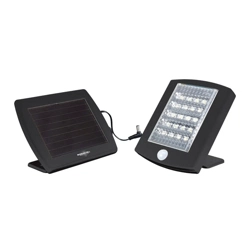
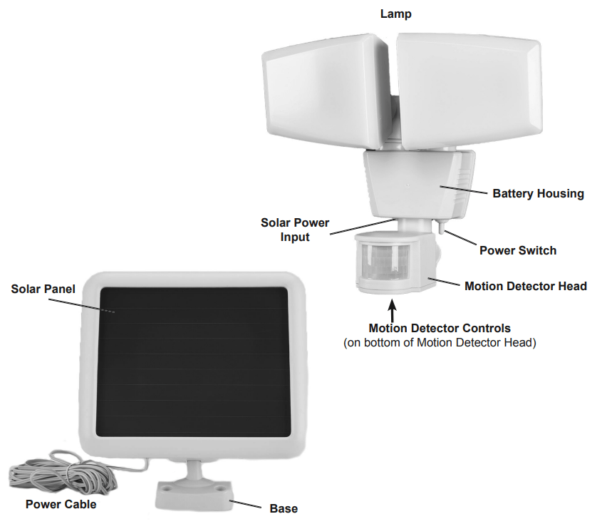
1. Decide where to place the Lamp and Solar Panel.
a. The Solar Panel is equipped with a 15 foot long Solar Power Cable, so the Lamp and Solar Panel can be installed up to 15 feet apart.
b. The Solar Panel must be set in a location that receives full, direct sunlight, a minimum of 8 hours a day. Ideally, the Solar Panel should be angled slightly toward the South (northern hemisphere).
2. Mount the Solar Panel:
a. Place the Solar Panel in the desired location, adjusting the unit to best fit the surface.
WARNING! TO AVOID INJURY FROM ELECTRIC SHOCK, verify the installation surface has no hidden utility lines before drilling or driving screws.
b. Using the Solar Panel’s base as a template, mark the hole locations to install the panel. Set the Solar Panel aside.
c. Drill holes for the enclosed mounting Anchors.
d. Insert the Anchors into the holes and attach Solar Panel in place with the Screws.
3. Mount the Lamp:
a. Locate the unit 6 to 8 feet above ground on a solid surface capable of supporting the Lamp and secure enough so that it will not move when exposed to vibrations or wind. The unit must be high enough to allow for motion detection and light distribution.
WARNING! TO AVOID INJURY FROM ELECTRIC SHOCK, verify the installation surface has no hidden utility lines before drilling or driving screws.
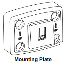
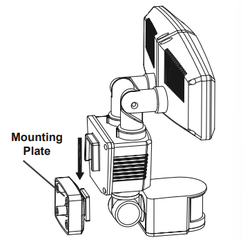
b. Using the Mounting Plate as a template, mark the hole locations to install the Lamp.
c. Mount plate against a wall with ridge pointing up and out. Lamp will slide onto ridge.
d. Drill holes for the enclosed Anchors.
e. Insert the Anchors into the holes and attach Mounting Plate in place with the Screws.
f. Slide Lamp onto the Mounting Plate and position lights as needed. Each light moves independently.
4. Carefully route the Power Cable from the Solar Panel to the Lamp and plug it into the Solar Power Input on the Lamp’s Battery Housing.
5. Adjust the Motion Detector Head by moving it left or right so that it faces the area where movement will occur. Move it up or down using the screw located on the neck of the Motion Detector Head.
OPERATION
Initial Battery Charging
|
Before the Security Light can operate properly, the battery needs to be fully charged. To charge the battery:
- Turn OFF the Power Switch.
- Expose the Solar Panel to 3 DAYS OF FULL DIRECT SUNLIGHT to fully charge the battery.
- After charging, turn the Power Switch to Auto. The Lamp will illuminate for a short time when first switched to Auto. This indicates that the unit is working properly.
|
|
 |
Power Switch
|
The Power Switch, located under the Battery Housing of the Lamp, has three settings:
- AUTO: The Lamp will illuminate automatically when motion is detected by the Motion Sensor Head.
- OFF: Center position is power off.
- ON: The Lamp stay illuminated functioning as a normal light.
|
|
 |
Motion Detector Control Knobs
|
The Security Light has three different Control Knobs on the underside of the Motion Detector Head. They control the Motion Detector Head’s sensor. They are: a. Sensor’s sensitivity to motion (SENS)
b. Light duration (TIME)
c. Sensitivity to light level (LUX)
NOTE: After each adjustment, walk the detection area to verify the adjustment made.
|
|
 |
SENS (Sensitivity)
The SENS Adjusting Knob sets the level of sensitivity of the Motion Detector Head.
The Motion Detector Head is most sensitive to movement across the detection zone, rather than movement toward or away from the Motion Detector Head.
Turn the SENS dial anywhere between the minimum and maximum settings to adjust the level of sensitivity needed.
Note: Sensitivity is affected by the ambient air temperature. If it is hot outside, the sensor may have difficulty detecting changes in heat. In cold temperatures, the sensitivity is increased and may need to be adjusted.
|
Minimum Position
Turn the dial counterclockwise to the minimum setting (-). Ideal for hot summer conditions or when nuisance tripping is a problem. If the light is activated by small animals or rapid changes in heat, reduce sensitivity by turning the knob counterclockwise towards the minimum setting.
|
|
 |
|
Maximum Position
Turn the dial clockwise to the maximum setting (+). Ideal for cold winter conditions or to maximize range.
|
|
 |
TIME (Light Duration)
The TIME Adjusting Knob sets how long the Lamp will stay illuminated after motion is no longer detected by the sensor.
|
Minimum Position
Turn the dial counterclockwise to the minimum for the Lamp stay illuminated for 10 seconds after motion is no longer detected.
|
|
 |
|
Mid Range
Adjust the dial between the Minimum and Maximum, to choose any time between 10 and 100 seconds, for the Lamp to stay illuminated after motion is no longer detected.
|
|
 |
|
Maximum Position
Turn the dial clockwise to the maximum for the Lamp to stay illuminated for 110 seconds after motion is no longer detected.
|
|
 |
LUX (Light Level)
The LUX Adjusting Knob tells the sensor the level of darkness that must be reached before the Lamp illuminates.
|
Minimum Position
Turning the dial counterclockwise to the minimum setting lowers the sensor level. The sensor will only trigger the Lamp to illuminate at dusk or when it is dark out. This is the ideal position for general evening and night operation.
|
|
 |
|
Maximum Position
Turning the dial clockwise to the maximum setting increases the sensor level. The Lamp will illuminate in most situations ranging from dark to daylight.
|
|
 |
Note: If the Security Light is not operating at night due to interference from a street light or other interference, turn the LUX knob towards the maximum setting. Adjust the dial as needed between the minimum and maximum settings to achieve the desired level of sensitivity.
Testing the Light
- After the battery is charged and the control Knobs are set, walk slowly around the detection area.
- The sensor detects infrared radiation given off by a person or animal. This triggers the Lamp to illuminate. The light should go on in the area that you set up the Security Light to monitor.
- Adjust the Knobs and sensor, then re-test until the unit functions as desired.
- Repeat the test procedure as needed when weather and/or temperature changes.
MAINTENANCE
Cleaning, Maintenance, and Lubrication
1. BEFORE EACH USE, inspect the general condition of the unit. Check for:
- leaking, swollen, or cracked battery,
- loose hardware,
- misalignment or binding of parts,
- cracked or broken parts, and
- any other condition that may affect its safe operation.
2. AFTER USE, wipe external surfaces of the unit with clean cloth.
3. Keep Solar Panel free of dirt and debris to maintain optimum efficiency in recharging the battery.
Battery Removal and Disposal
- The battery is located inside the Lamp assembly.
- Turn the Lamp off and remove the screws on the back.
- Disconnect the battery and remove it from the Lamp.
- Contains Li-Ion battery. Battery must be recycled or disposed of properly. Do not open, crush, heat above 140°F or incinerate.
TROUBLESHOOTING
| Problem |
Possible Causes |
Likely Solutions |
| Light won’t turn on. |
1. Power is not on. |
1. Check that Power Switch is set to ON or AUTO. |
| 2. Solar Power Cable connection is loose. |
2. Plug in firmly at back of Battery Housing. |
3. LUX control is set too close to maximum light  . . |
3. Turn LUX knob towards dark light  . . |
4. Motion sensor not
detecting movement. |
4. Adjust angle and direction of Motion Detector Head, and increase sensitivity (SENS). |
| 5. Battery pack not fully charged. |
5. Keep Solar Panel clean and allow unit to charge in full direct sunlight for 3 days with the Power Switch OFF. |
| Light turns on during day. |
LUX control is set too close to sun light . |
Turn LUX knob towards dark light . |
| Light flashes on and off with clicking sounds. |
Low battery |
With Power Switch set to OFF, allow unit to charge in full direct sunlight for 3 days before further use. |
| Light stays “ON”. |
1. Duration time setting too long. |
1. Turn TIME knob counterclockwise to reduce the time the light stays on. |
| 2. Frequent changes in heat being detected. |
2. Check sensing area for possible heat sources such as air vents, vehicles or objects in wind. Reposition the Motion Detector Head if needed, and turn SENS Knob counterclockwise to lower sensitivity. |
| 3. Power Switch set to ON. |
3. Set Power Switch to AUTO. |
| Light turns ON and OFF. |
1. Changes in heat are being detected from a fixed heat source or moving object. |
1. Check sensing area for possible heat sources such as air vents, vehicles or objects in wind. Reposition the Motion Detector Head. |
| 2. Sudden temperature change due to storms or high winds. |
2. Turn Power Switch “OFF” until storm passes. Mount in a sheltered location. |
| WARNING: Follow all safety precautions whenever diagnosing or servicing the tool. Disconnect Battery and Charger power supply before service. |
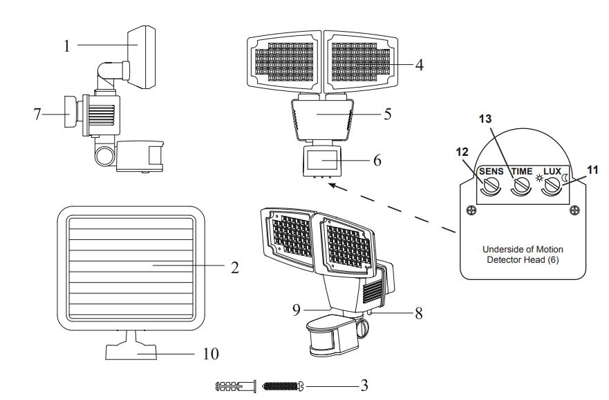
PARTS LIST AND DIAGRAM
| Part |
Description |
Qty |
| 1 |
Lamp |
1 |
| 2 |
Solar Panel |
1 |
| 3 |
Mounting Screw and Anchor |
8 |
| 4 |
LED Panel |
2 |
| 5 |
Battery Housing |
1 |
| 6 |
Motion Detector Head |
1 |
| 7 |
Mounting Plate |
1 |
| 8 |
Mounting Plate |
1 |
| 9 |
Solar Power Input |
1 |
| 10 |
Solar Panel Mounting Bracket |
1 |
| 11 |
LUX Adjusting Knob |
1 |
| 12 |
SENS Adjusting Knob |
1 |
| 13 |
TIME Adjusting Knob |
1 |
| 14 |
Battery (not shown) |
1 |
| 15 |
Solar Power Cable (not shown) |
1 |