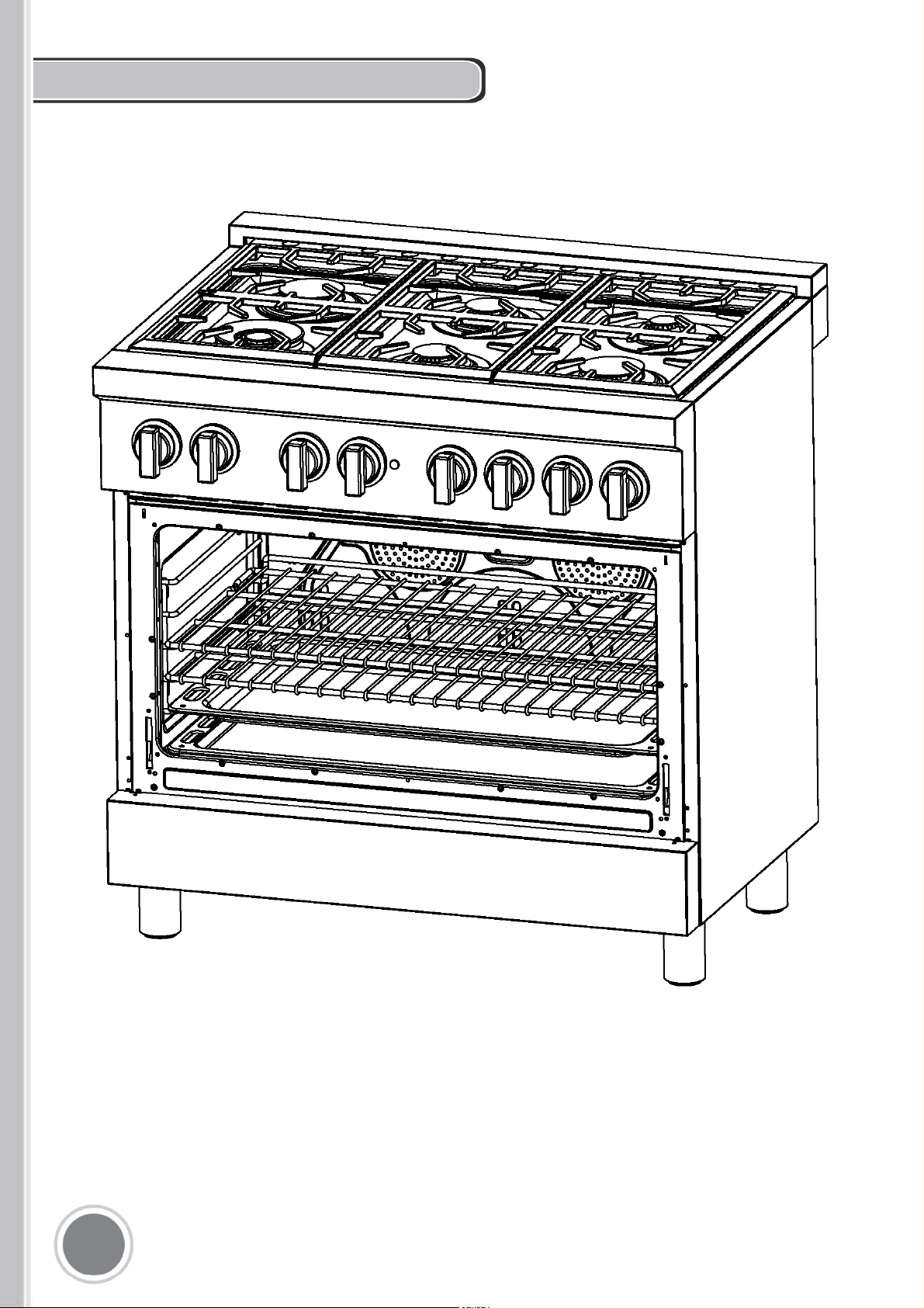
PROFESSIONAL STYLE
DUAL FUEL RANGE
COS-DFR
SERIES
Installation Guide
&
User's Manual
This manual is made with 100 % recycled paper.
Electronic version of this manual is available at:
www.cosmoappliances.com
Thank you for your purchase. We know that
you have many brands and products to
choose from and we are honored to know
that you have decided to take one of our
products into your home and hope that you
enjoy it.
Our appliances are designed according to
the strictest safety and performance
standards for the North American market.
We follow the most advanced
manufacturing philosophy. Each appliance
leaves the factory after thorough quality
inspections and testing. Our distributors
and our service partners are ready to
answer any questions you may have
regarding how to install, use and care for
your range.
We hope that this manual will help you learn
to use the product in the safest and most
effective manner and care for it so that it
may give you the highest satisfaction in
cooking for years to come. f you hae any
uestions or concerns please contact the
dealer from whom you purchased it or
contact our Customer upport at
.
The manual also includes directions for the
professional installer that will install the
product in your home. We recommend using
trained personnel for professional
installation.
Please keep this manual for future use
Thank You
1
IMPORTANT SAFETY INFORMATION
PLEASE READ AND FOLLOW THESE IMPORTANT
INSTRUCTIONS FOR THE SAFETY OF YOUR HOME
AND OF THE PEOPLE LIVING IN IT.
Save this Manual for local electrical inspector's use.
Read and save these instructions for future reference.
Observe all governing codes, ordinances and regulations.
WARNING!
If the information in this manual is not followed
exactly, a fire or explosion may result causing
property damage, personal injury, or death.
-Do not store or use gasoline or other flammable
substances in the vicinity of this or any other
appliance.
WHAT TO DO IF YOU SMELL GAS :
•Do not light any appliance.
•Do not touch any electrical switch.
•Do not use any phone in your building.
•Immediately call your gas supplier from a
neighbour's phone. Follow the gas
supplier's instructions closely.
•If you cannot reach your gas suppliers, call
the fire department.
- Installation and service must be performed by
a qualified installer, service agency or the gas
supplier.
In Massachusetts: All gas products must be installed
by a "Massachusetts" licensed plumber or gasfitter.
A "T" handle type manual gas valve must be
installed in the gas line connected to this appliance.
WARNING
use this appliance as a space
heater to heat or warm the room. oin
so may result in caron monoide
poisonin and oerheatin o the oen.
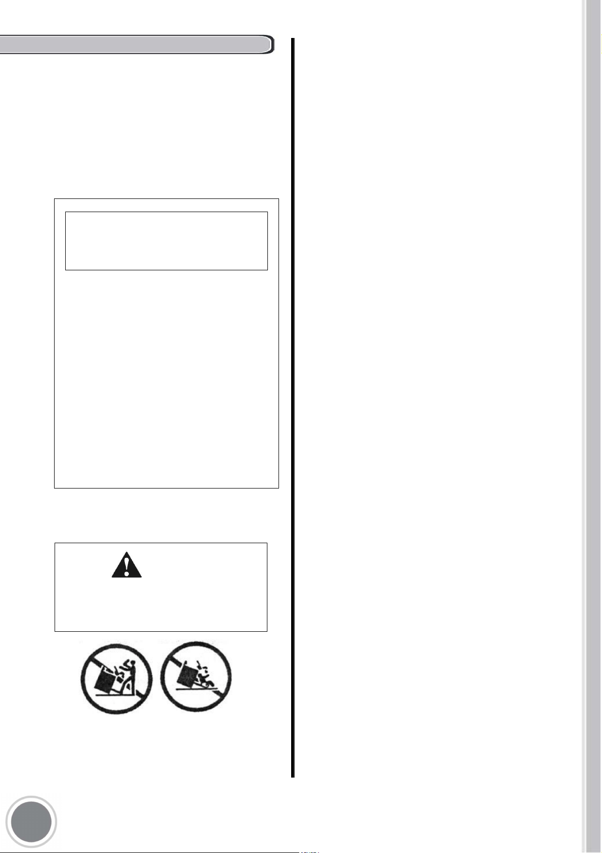
Warning!
This rane can tip. nury to persons could
result. nstall antitip deice shipped with
rane. ee nstallation nstructions.
WARNING
Read this instruction booklet before installing and
using the appliance,
The manufacturer will not be responsible for any
damage to property or to persons caused by incorrect
installation or improper use of the appliance.
The manufacturer reserves the right to make changes to its
products when considered necessary and useful, without
affecting the essential safety and operating characteristics.
This appliance has been designed for
non-professional, domestic use only.
Do not use this appliance to heat a room.
Do not place any pot or pan on the open oven door.
The door is made of glass and it can break if loaded
with a weight.
Before beginning installation, please read these
instructions completely and carefully.
Do not remove permanently affixed labels, warnings, or
plates from the product. This may void the warranty.
Please observe all local and national codes and
ordinances.
Please ensure the range is properly grounded.
The installer should leave these instructions with the
consumer who should retain for local inspector's use and
for future reference.
The plug should always be accessible.
Installation must conform with local codes or in the
absence of codes, the National Fuel Gas Code
NSIZ223.1/NFPA54. Electrical installation must be in
accordance with the National Electrical Code,
ANSI/NPA70 - latest edition and/or local codes. IN
CANADA: Installation must be in accordance with the
current CAN/CGA-fe 149.1 National Gas Installation Code
or CAN/CGA-B 149.2, Propane Installation Code and/or
local codes. Electrical installation must be in accordance
with the current CSA C22.1 Canadian Electrical Codes
Part 1 and/or local codes.
Installation of any gas-fired equipment should be made by
a licensed plumber. A manual gas shut-off valve must be
installed in the gas supply line ahead of the oven in the gas
flow for safety and ease of service.
WARNING
This appliance shall not be installed with a ventilation
system that blows air downward toward the
range/rangetop/cooktop; this type of ventilation system
may cause ignition and combustion problem with the gas
appliance resulting in a personal injury or unintended
operation.
WARNING
An air curtain or other overhead range/rangetop/cooktop
hood, which operates by blowing a downward airflow
onto a range/rangetop/cooktop, shall not be used/
installed in conjunction with this gas range/rangetop/
cooktop.
3
2
06
07
08
09
09
10
11
15
17
19
19
20
21
23
25
32
34
34
35
35
37
3
TABLE OF CONTENTS

WARRANTY AND SERVICE
(FOFSBM$POEJUJPOT
B8BSSBOUZEPFTOPUDPWFSGBJMVSFBTSFTVMUPGNJTVTFBCVTFSVTUPSDPSSPTJPO
TQJMMFEMJRVJETPSGPSFJHOPCKFDUTGPVOEJOTJEFUIFVOJUSFQBJSPGEBNBHFDBVTFECZ
BDDJEFOU
UIFGUGJSFGMPPEFYUFSOBMDBVTFTTVDIBTCVUOPUMJNJUFEUPCMPXGVTFTJOBEFRVBUF
FMFDUSJDBM
QPXFSXBUFSBOEHBTMJOFTCFZPOEUIFFRVJQNFOUPSBOZVTFPGUIFQSPEVDUOPU
BVUIPSJ[FE
CZUIFNBOVGBDUVSFS
C5IFNBYJNVNMJBCJMJUZPGUIFXBSSBOUZGPSQSPEVDUSFQMBDFNFOUPSSFQBJSTIBMMOPU
FYDFFE
UIFPSJHJOBMQVSDIBTFQSJDFPGUIFQSPEVDU
D$PTNPSFTFSWFTUIFSJHIUUPSFQBJSPSSFQMBDFUIFDPWFSFEQSPEVDUXJUIBDPNQBSBCMF
GFBUVSFNPEFMPGMJLFLJOE
E8BSSBOUZEPFTOPUDPWFSEFUFSJPSBUJPOPGUIFBQQFBSBODFPGUIFQSPEVDUBOZ
DPTNFUJD
QBSUTVDIBTQBJOUQPSDFMBJOHMBTTEFOUTTDSBUDIFTDIJQTSVTUPSQFFMJOH
F"OZEBNBHFSFTVMUJOHGSPNVOBVUIPSJ[FESFQMBDFNFOUQBSUTJNQSPQFSTFSWJDFPS
NPEJGJDBUJPOTNBEFUPUIFDPWFSFEQSPEVDUBSFOPUDPWFSFE
G$PTNPJTSFMFBTFEGSPNBMMMJBCJMJUZEVFUPJOEJSFDUDPOTFRVFOUJBMPSJODJEFOUBM
EBNBHFT
For full warranty details on this product please visit:
http://www.cosmoappliances.com/warranty
TO RECEIVE WARRANTY SERVICE, YOUR
PRODUCT MUST BE REGISTERED. TO REGISTER, VISIT:
WWW.COSMOAPPLIANCES.COM/WARRANTY
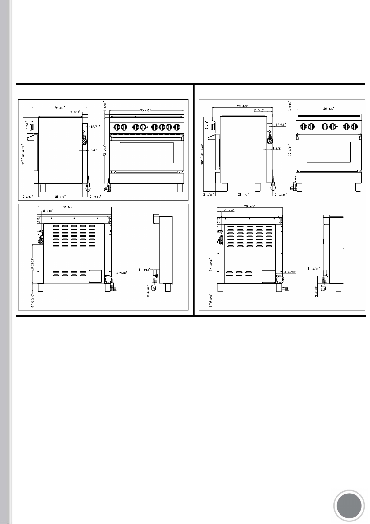
RODUCT SPECIFICATIONS
Dimensions ( front, side and back)
M 366
M 30
If you own a 48" or 60" model, please contact us or visit our website to obtain
these specifications.
WARNING!
BEFORE INSTALLATION
This appliance shall only be installed by an
authorized professional.
This appliance shall be installed in accordance
with the manufacturer's installation instructions.
This appliance must be installed in accordance
with the standards of the country where it will
be installed. The installation of this appliance
must conform to local codes and ordinances. In
the absence of local codes, Installations must
conforms to American National Standards,
National Fuel Gas Code ANSI Z223.1 - latest
edition/NFPA 54 or B 149.1.
The appliance, when installed, must be
electrically grounded in accordance with local
codes or, in the absence of local codes, with the
National Electrical Code, ANSI/NFPA 70.
If local codes permit, a flexible metal appliance
connection with the new AGA or CGA certified
design, max. 5 feet (1,5 m) long, 3/4" I.D. is
recommended for connecting this appliance to
the gas supply line. Do not bend or damage the
flexible connector when moving the appliance.
This appliance must be used with the pressure
regulator provided. The regulator shall be
properly installed in order to be accessible when
the appliance is installed in its final location. The
pressure regulator must be set for the type of
gas to be used. The pressure regulator has 3/4"
female pipe thread. The appropriate fitting must
be determined based on the size of your gas
supply line, the flexible metal connector and the
shutoff valve.
The appliance must be isolated from the gas
supply piping system by closing its individual
manual shutoff valve during any pressure
testing of the gas supply piping system at test
pressures equal to or less than 34 PSI (13,8 w.c.
pr 3,5 kPa).
All opening and holes in the wall and floor, back
and under the appliance shall be sealed before
installation of the appliance.
A manual valve shall be installed in an
accessible location in the gas line external to
the appliance for the purpose of turning on or
shutting off gas to the appliance
Do not use aerosol sprays in the vicinity of
this appliance while it is in operation
ROOM VENTILATION: An exhaust fan may be
used with the appliance; in each case it shall be
installed in conformity with the appropriate
national and local standards. Exhaust hood
operation may affect other vented appliances; in
each case it shall be installed in conformity with
the appropriate national and local standards.
This appliance is shipped from the factory for
use with natural gas. Propane Conversion Kit
must be purchased separately. For use with
propane LP gas please follow the conversion
procedure described on pg. 17.
The maximum inlet gas supply pressure
incoming to the gas appliance pressure
regulator is 34 PSI (13,8 w.c. pr 3,5 kPa).
The minimum gas supply pressure for checking
the regulator setting shall be at least 1" w.c. (249
Pa) above the inlet specified manifold pressure
to the appliance (this operating pressure is 4"
w.c. (1.00 kPa) for Natural Gas and 11" w.c. (2.75
kPa for LP Gas).
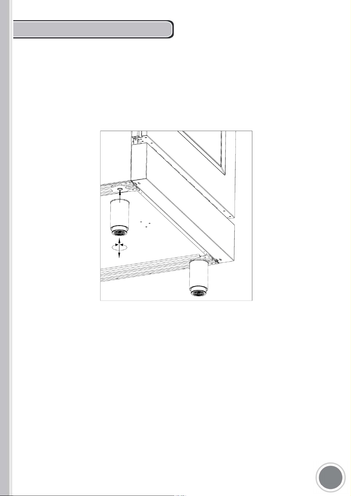
INSTALLING THE LEGS
The ranges must only be used with the
legs properly installed.
Four height-adjustable legs are shipped
with the range in the polystyrene container
situated over the appliance.
Before installing the legs, position the
appliance near its final location as the legs
are not suitable for moving the appliance
over long distances.
After unpacking the range, raise it enough
to insert the legs in the appropriate
receptacles situated on the lower part of the
appliance. Lower the range gently to keep
any undue strain from legs and mounting
hardware. If possible use a pallet or lift jack
instead of tilting the unit.
Adjust leg height to the desired level by
twisting the inside portion of the leg
assembly until the proper height is reached.
Check with a level that the cooktop is
perfectly level.
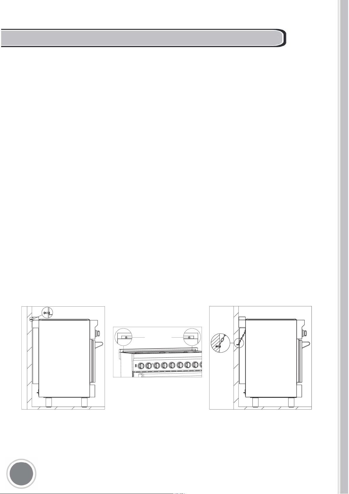
1)
The anti-tip bracket shipped with the range must be properly secured to
the rear wall as shown in the picture below.The height of the bracket
from the floor must be determined after the range legs have been
adjusted to the desired height and after the range has been levelled.
Measure the distance from the floor to the bottom of the anti-tip bracket
receptacle on the back of the appliance.
Position the two anti-tip brackets on the wall at the desired height
plus 1/8" (0.32 cm). The brackets must be placed at 2 - 5/16" (6.0 cm)
from each side of the range. The distance between the two bracket
is 25 - 1/4" (64.1 cm). Secure the brackets to the wall with appropriate
hardware. Slide the range against the wall until the brackets are fully
inserted into their receptacles on the back of the range.
Check to see that the Anti-Tip device is installed properly. Grasp the top
rear edge of the range and carefully attempt to tilt it forward. Verify that
the Anti-Tip device is engaged.
2) Or, use the anti-tip chain, and tighten up with fixed screw on the wall,
and when the wall not suitable for installation, the chain shall be fixed to
the cabinet structure.
INSTALLING THE ANTI-TIP SAFETY DEVICE
9
INSTALLATION REQUIREMENTS
A properly grounded and electrical receptacle
Type NEMA 14-50R should be installed; refer
to ELECTRICAL CONNECTION section page
11.
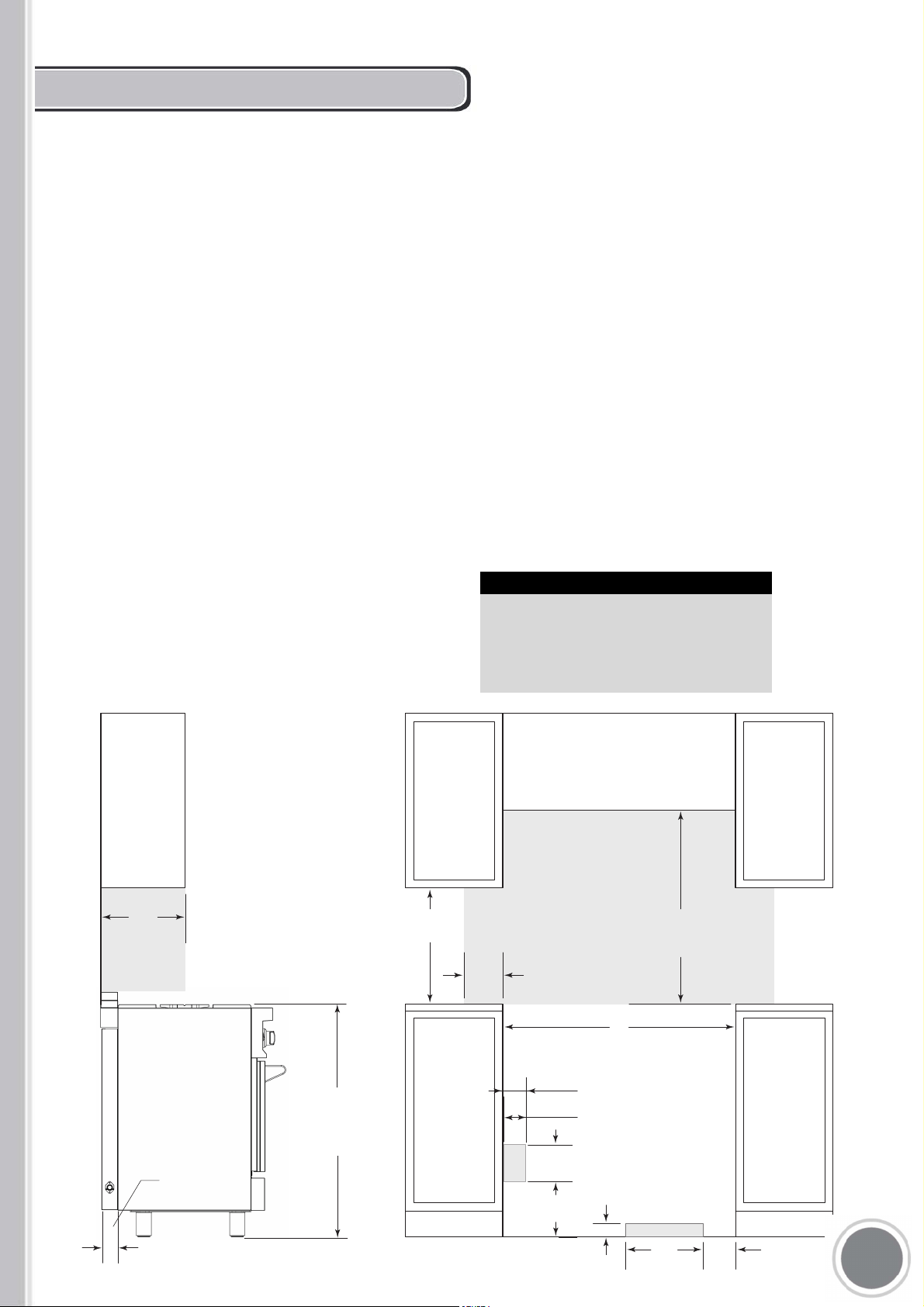
INTLLTION ENT TO
ITHEN INET
This range may be installed directly
adjacent to existing countertop high
cabinets (36" or 91.5 cm from the floor).
For the best look, the worktop should be level with
the cabinet countertop. This can be accomplished
by raising the unit using the adjustment spindles
on the legs.
e ll lol ode eee
An agency-approved, properly-sized manual
shut-off valve should be installed no higher than 3"
(7.6 cm) above the floor and no less than 2" (5 cm)
and no more than 8" (20.3 cm) from the right side
(facing product).
To connect gas between shut-off valve and
regulator, use agency-approved, properly sized
flexible or rigid pipe. Check all local code
requirements.
ATTENTION: the range CANNOT be installed
directly adjacent to kitchen walls, tall cabinets, tall
appliances, or other vertical surfaces above 36"
(91.4 cm) high. The minimum side clearance in
such cases is 6" (15.2 cm).
Wall cabinets with minimum side clearance must
be installed 30" above the countertop
with countertop height between 35 " (90.2 cm)
and 37 " (94.6 cm). The maximum depth of wall
cabinets above the range shall be 13" (33.0 cm)
OPENING WIDTH
COOKING RANGE
W
30"Model
30"(757)
36"Model
36"(910)
48"Model
48"(1215)
60"Model
60"(1520)
RANGE
3 23"
(82)
FRONT VIEW
30"
(762)
6"
(152)
(65)
(930)
T
O
COOKING
SURFACE
W
OPENING WIDTH
30"
(762)
TO
36"
(914)
TO BOTTOM OF
VENTILATION HOOD
*
E
LOCATION OF GAS AND
ELECTRICAL EXTENDS
ON FLOOR
SIDE VIEW
.
13"
(330)
3 15"
(80)
.
12"
(305) GAS
5"
(127)
2"
(51)
G
5
3
/
4
"
(146)
(250)
9
3
/
4
"
36
3
/
5
"
2
3
/5"
1
/
2
1
/
4
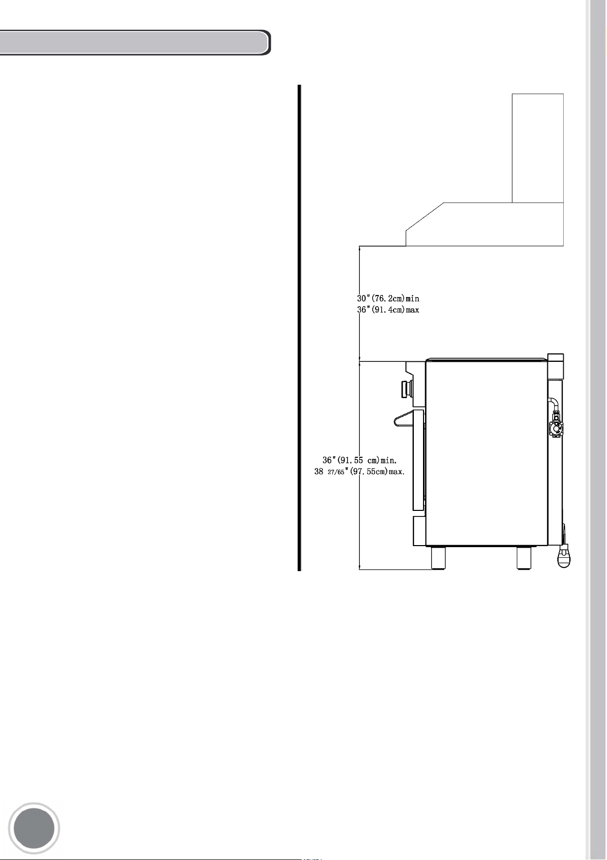
EXHAUST HOOD INSTALLATION
For maximum performance, the height of the bottom
of the hood from the worktop should be between 30"
(76.2 cm) and 36" (91.4 cm). This would typically
result in the bottom of the hood being 61 1/2" (156.2
cm) to 67 1/2" (171.5 cm) above the floor. These
measurements provide for safe and efficient
operation of the hood.
Before installation of the exhaust hood, consult local
or regional building and installation codes for
additional specific clearance requirements.
Refer to the range hood installation instructions
provided by the manufacturer for additional
information.
To eliminate the risk of burns or fire by reaching
over heated surface units, cabinet storage space
located above the surface units should be avoided.
If cabinet storage is to be provided, the risk can be
reduced by installing a range hood. These hoods
have been designed to work in conjunction with the
range and have the same finish for a perfect look.
1
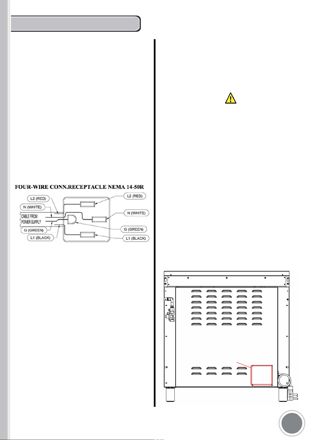
ELECTRICAL CONNECTION
The appliance shall be connected to a single phase
electric line rated at 120/208Vac or 120/240Vac
and 60Hz frequency.
Electric power rating:
- 120/208Vac: 10 A max
- 120/240Vac: 12 A max
Heating elements power rating:
- Oven bake element = 1500 Watt
- Oven circular element = 3200 Watt
- Oven broil element = 2850 Watt
Install a suitable electric power supply receptacle
connection type NEMA 14-50R able to support a
load of at least 30 A (per line) according to local
code requirements. For four wires power
supply connection system see diagram below.
- Connect the GROUND receptacle terminal to the
incoming GROUND (GREEN) electrical supply wire
M
e o
Check your local code for which of the options below
should be used in grounding the receptacle power
suppliy connections.
e oeo
- Connect the L1 receptacle terminal to the
incoming BLACK electrical supply wire(L1-hot
wire)
- Connect the L2 receptacle terminal to the
incoming RED electrical supply wire (L2-hot
wire)
- Connect the NEUTRAL receptacle terminal to
the incoming NEUTRAL (WHITE) electrical
supply wire
When electrical connection,
please refer to the rating label, the rating
label locat near the entrance of power
supply cord.
11
Rating label.
Electrical Grounding
This appliance is equipped with a four-prong plug for
your protection against shock hazard and should be
plugged directly into a properly grounded receptacle, do
not cut or remove the prong from this plug.
Disconnect electrical power at the circuit breaker box
or fuse box before installing the appliance.
Provide appropriate ground for the appliance. Use
copper conductors only.
WARNING
DO NOT USE EXTENSION CORDS WITH
THIS APPLIANCE AS IT MAY RESULT IN
FIRE, ELECTRIC SHOCK OR OTHER
type of PERSONAL INJURY.
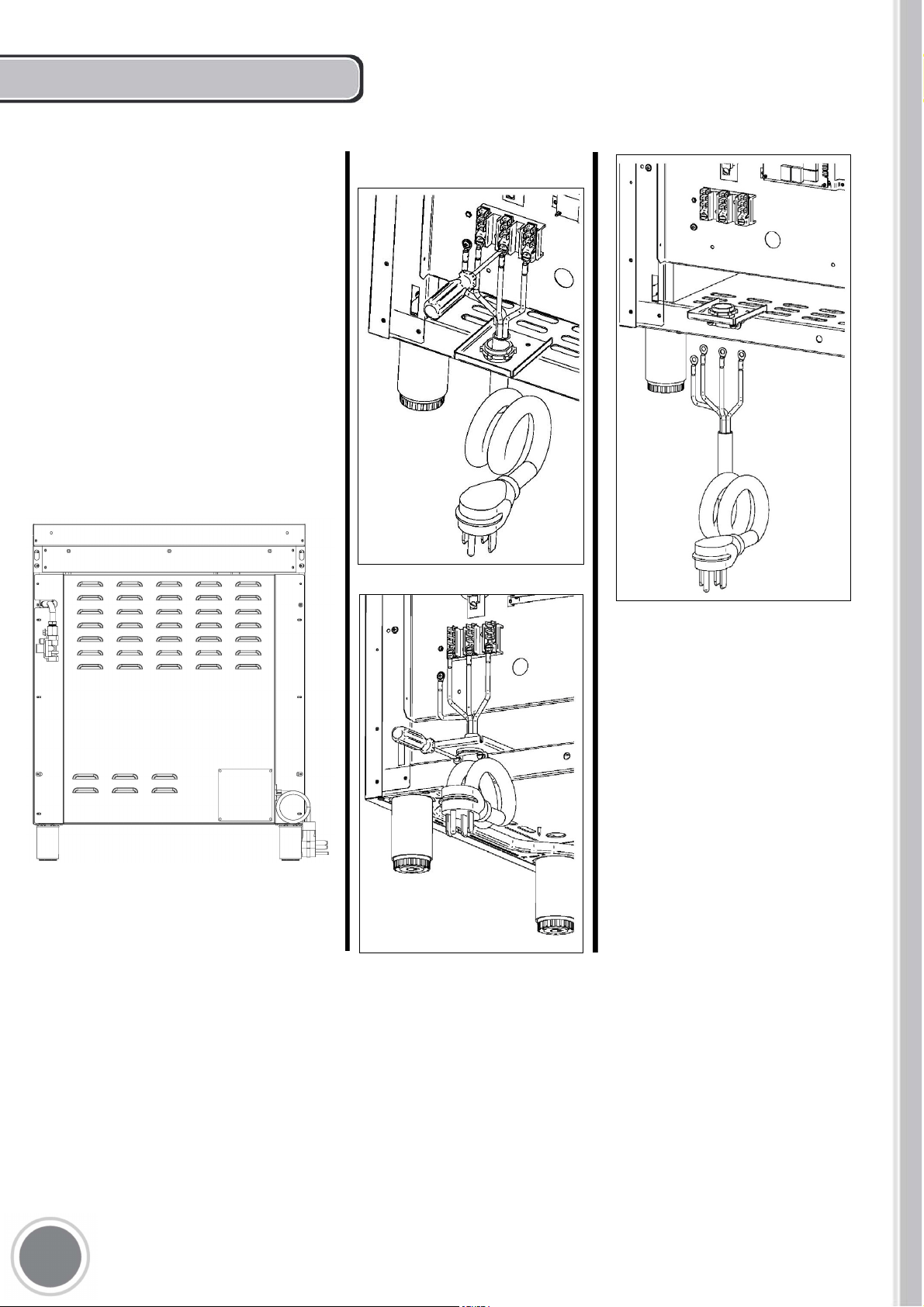
The appliance is equipped at the factory with an
electric supply cord set 4 wires type with ring
terminals (L1, L2, N, Ground) suitabl e for range
use UL/CSA listed type SRDT/DRT 2x6AWG (L1,
L2)+2x8AWG (N, G) rated 300V, 40 or 50A with
fused plug type NEMA 14‐50P; cable length 1,5
m.;incasethesupplycordsetmustbereplaced,it
shall be replaced with anidentical set having the
same technical specs and following carefully the
instructionsanddiagramsbelow:
1) Disconnect appliance f rom electrical power
supplyreceptacle
2) Slideouttheappliancefrominstallationplace
toaccesstobackenclosurepanel
3) Remove back enclosure panel by removing
the6screwsasshownbelow
4)
Loosestrainreliefbyunscrewingthetwo
strainrelief'sscrewsasindiagram.
5)
Remove damaged supply cord set by taking
off the 4 electrical connection screws (block L1,
N,L2andGroundscrew,seediagram)
6) Insert the new supply cord set in the strain
relief and lock it with two strain relief's
screwsinsuitableposition.
7) FixwelltheringterminalsG,L1,N,L2ofthe
new supply cord set asshown in diagram
withits4screws
8) Re‐install the back enclosure panel with 6
screws
9) Slide the appliance back into itsproper
location
10) Re‐connect the appliance to the electrical
power.
12
POWER CORD REPLACEMENT
ELECTRICAL GROUNDING
This appliance is equipped with a four-prong plug
for your protection against shock hazard and
should be plugged directly into a properly
grounded receptacle. Do not cut or remove the
prong from this plug
WARNING!
ELECTRICAL SHOCK HAZARD
Disconnect electrical power at the circuit
breaker box or fuse box before installing the
appliance.
Provide appropriate ground for the applaince.
Use copper conductors only.
Failure to follow these instructions could resilt
in serious injury or death
CAUTION
Label all wires prior to disconnecting when
servicing controls. Wiring errors can cause
improper and dangerous operation.
Verify proper operation after servicing
13
LOCATION OF APPLIANCE PLATES
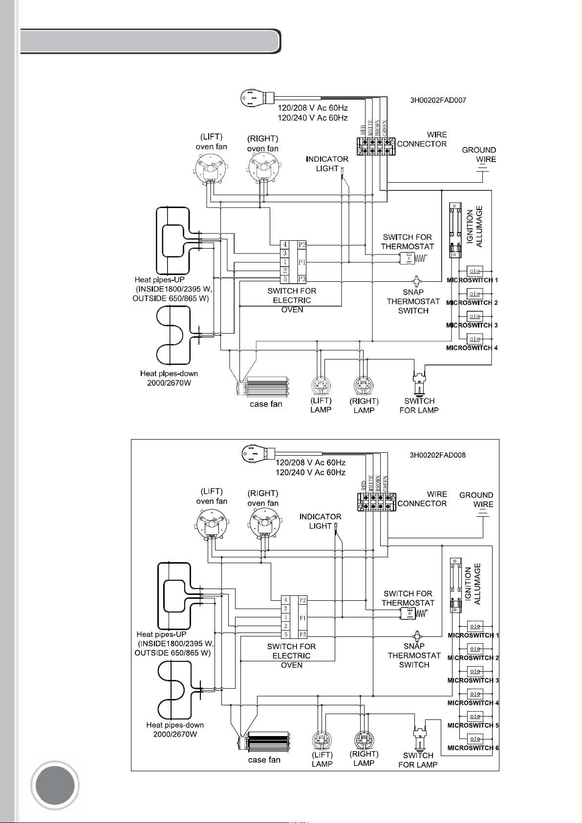
30 INCH MODEL WIRING DIAGRAM
1
If you own a 48" or 60" model, please contact us or visit our website to
obtain this diagram.
36 INCH MODEL WIRING DIAGRAM
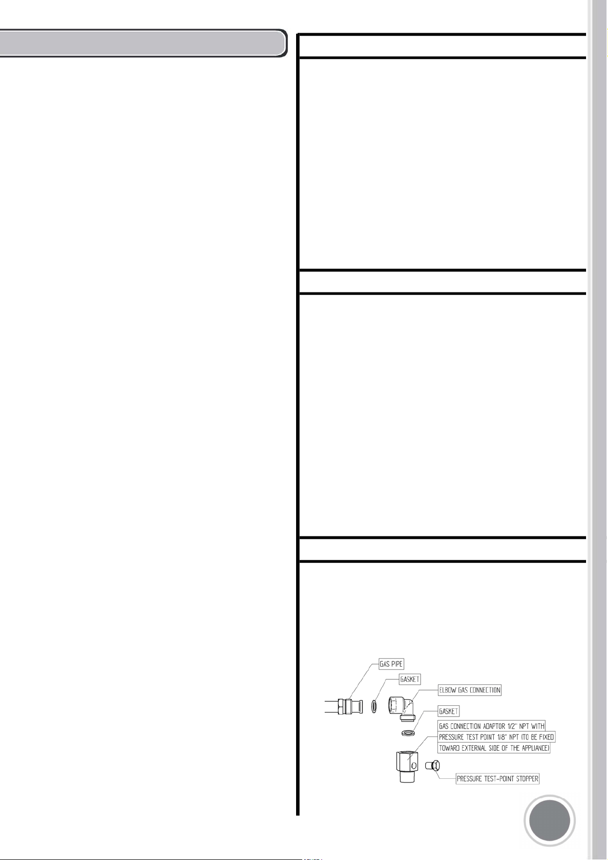
GAS CONNECTION
To avoid gas leaks, the pressure test-point stopper
valve and gasket supplied with the range must be
installed on the gas fitting at the back of the range
according to the diagram below.
M
All gas connections must comply with national
and local codes. The gas supply line (service)
must be the same size or greater than the inlet
line of the appliance. This range uses a 1/2"
NPT inlet (see drawing below for details of gas
connection). On all pipe joints use appropriate
sealant resistant to gas.
This range can be used with Natural or
LP/Propane gas. The range is shipped from the
factory for use with natural gas.
For LP/propane household installation, the
appliance must be converted by the dealer, by a
factory-trained professional or by a qualified
licensed plumber or gas service company.
Gas conversion is important for safe and
effective use of the appliance. It is the
responsibility of the dealer and the owner of the
range to perform the appropriate gas
conversion following the directions of the
manufacturer.
THE GAS CONVERSION PROCEDURE IS
DESCRIBED IN THIS MANUAL AND IN
THE PACKAGE CONTAINING THE
CONVERSION NOZZLES SHIPPED WITH
EVERY RANGE.
Please provide the service person with this
manual before work is started on the range.
WARNING!
DO NOT USE AN OPEN FLAME WHEN
CHECKING FOR LEAKS!
THIS VALVE IS NOT SHIPPED WITH
THE APPLIANCE AND MUST BE
SUPPLIED BY THE INSTALLER.
The manual shut-off valve must be installed
in the gas service line between the gas
hook-up on the wall and the appliance inlet,
in a position where it can be reached quickly
in the event of an emergency.
In Massachusetts: A T handle type manual
gas valve must be installed in the gas
supply line to this appliance.
In case of installation with flexible couplings
and/or quick-disconnect fittings, the installer
must use a heavy-duty, AGA
design-certified commercial flexible
connector of at least 1/2" (1.3 cm) ID NPT
(with suitable strain reliefs) in compliance
with ANSI Z21.41 and Z21.69 standards.
In Massachusetts: The unit must be
installed with a 36" (3-foot) long flexible gas
connector.
In Canada: use CAN 1-6.10-88 metal
connectors for gas appliances and CAN
1-6.9 M79 quick disconnect device for use
with gas fuel.
Leak testing of the appliance shall be
conducted according to the manufacturer's
instructions. Before placing the oven into
operation, always check for leaks with soapy
water solution or other acceptable method.
Check for gas leakage with soapy water
solution or other acceptable methods in all gas
connections installed between inlet gas pipe of
the appliance, gas regulator, till to the manual
shut-off valve.
1
Manifold pressure should be checked with a
manometer and comply with the values indicated
below:
Natural gas -> 4.0" W.c.P.
LP/Propane -> 10.0" W.C.P.
Incoming line pressure upstream from the
regulator must be 1" W.c.P. higher than the
manifold pressure in order to check the regulator.
The regulator used on this range can withstand a
maximum input pressure of 1/2 PSI (13.8" w.c. or
3,5 kPa) If the line pressure exceeds that amount,
a step-down regulator is required.
The appliance, its individual shut-off valve, and
the pressure regulator must be disconnected from
the gas line during any pressure testing of that
system at pressures in excess of 1/2 PSI (13.8"
w.c. or 3,5 kPa).
The individual manual shut-off valve must be in the
OFF position during any pressure testing of the
gas supply piping system at test pressures equal
to or less than 1/2 PSI (13.8" w.c. or 3,5 kPa).
Before carrying any service disconnect
the appliance from gas appliance from final install
have access to the appliance for proper servicing
intervention.
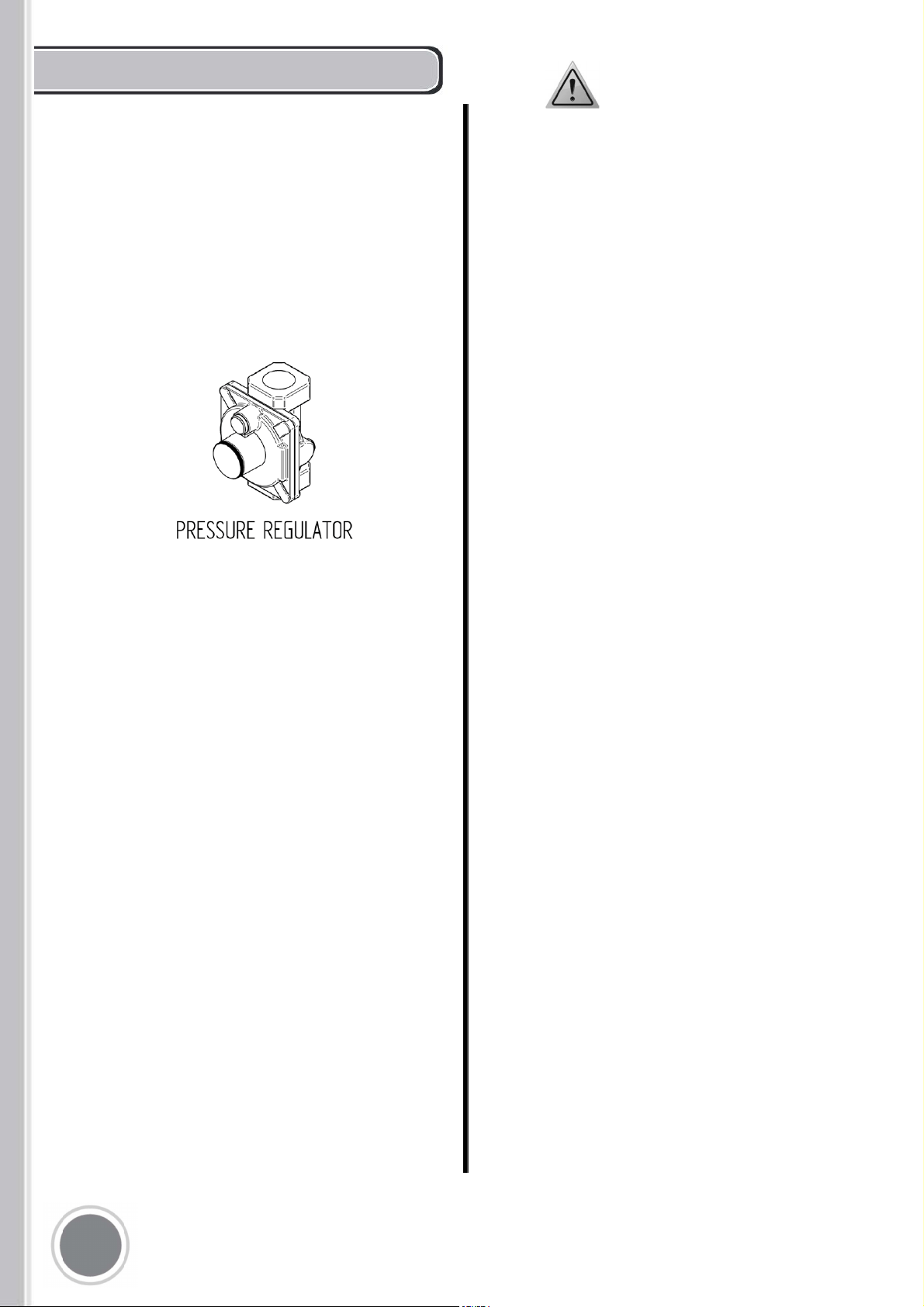
PRESSURE REGULATOR
Since service pressure may fluctuate with
local demand, every gas cooking appliance
must be equipped with a pressure regulator
on the incoming service line for safe and
efficient operation.
The pressure regulator shipped with the
appliance has two female threads 34" NPT.
The regulator shall be installed properly in
order to be accessible when the appliance
is installed in its final position.
GAS CONVERSION
WARNING!
Before carrying out this operation,
disconnect the appliance from gas
and electricity.
Gas conversion shall be conducted by a
factory- trained professional.
Call the customer service hotline to identify a
factory-trained professional near your home.
The gas conversion procedure for this range
includes 6 steps:
1. Pressure regulator
2. Surface burners
3. Adjustment of minimum setting
The conversion is not completed if all 6 steps
have not been concluded properly.
Before performing the gas conversion, locate
the package containing the replacement nozzle
shipped with every range. IMPORTANT: Each
nozzle has a number indicating its flow
diameter printed on the body. Consult the table
on page 20 for matching nozzles to burners.
Save the nozzles removed from the range for
future use.
1
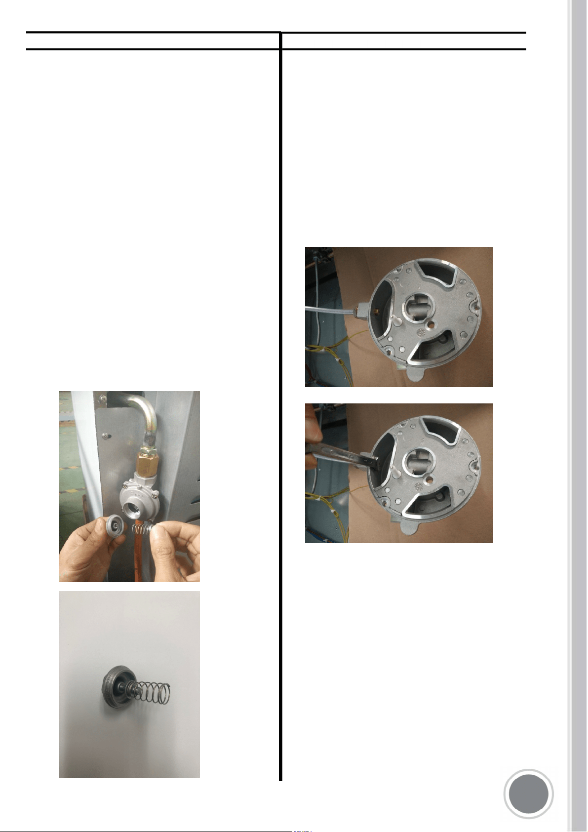
STEP 1: PRESSURE REGULATOR
The pressure regulator supplied with the
appliance is a convertible type pressure
regulator for use with Natural Gas at a
nominal outlet pressure of 4" w.c. or LP gas
at a nominal outlet pressure of 11" w.c. and
it is pre-arranged from the factory to operate
with one of these gas/pressure as indicated
in the labels affixed on the appliance,
package and Instruction booklet.
To convert the regulator for use with other
liquid propane LP gas:
1.
Unscrew by hand the upper cap of the
regulator, remove the silver plastic
attachment from the cap, reverse its
direction and screw it again firmly
against the cap. Once reversed, the
spring should be facing out, as shown
below.
2.
Screw by hand the metal cap in the
To replace the nozzles of the
surface burners, lift up the burners and
unscrew the nozzles shipped with the
range using a 7 mm (socket wrench).
Replace nozzles using the conversion kit.
Contact us at 1-888-784-3108 or go to
www.cosmoappliances.com to pur-
chase a conversion kit. Each nozzle has
a number indicating its flow diameter
printed on the body. Consult the table on
page 22 for matching nozzles to burners.
2
1
LP GAS
POSITION
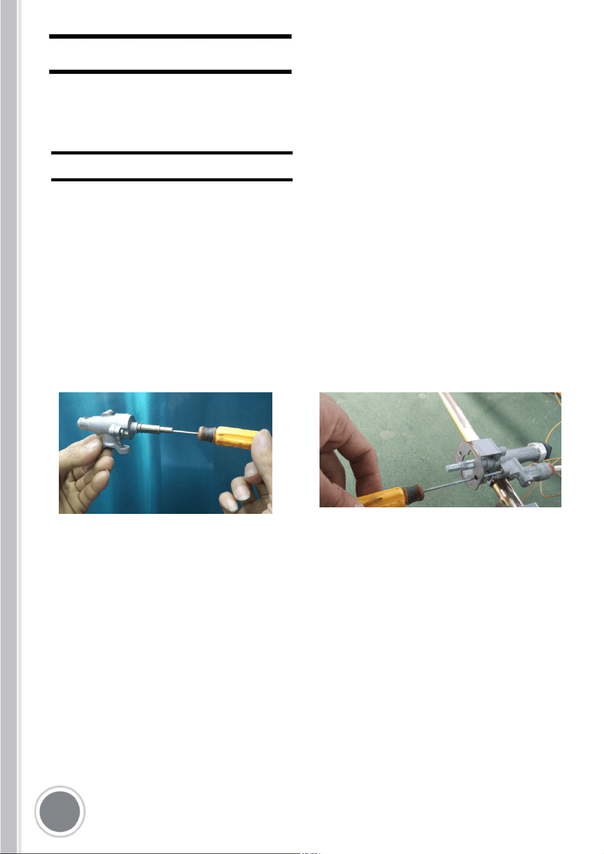
STEP 3: MINIMUM FLAME ADJUSTMENT
WARNING!
These adjustments should be made only for
use of the appliance with natural gas. For
use with liquid propane gas, the choke
screw must be fully turned in a clockwise
direction.
SURFACE BURNERS
1. Light one burner at a time and set the to
the MINIMUM position(small flame).
2. Remove the knob.
3. The range is equipped with a safety valve.
Using a small-size slotted screwdriver,
locate the choke valve on the valve body
and turn the choke screw to the right or left
until the burner flame is adjusted to desired
minimum.
4.
Make sure that the flame does not go
out when
1
INSTALLATION CHECKLIST
FINAL PREPARATION
1. Is the range mounted on its legs?
2. Is the back guard securely connected?
3. Has the anti-tip device been properly
installed?
4. Does the clearance from the side
cabinets comply with the manufacturers
directions?
5. Is the electricity properly grounded?
6. Is the gas service line connected
following the directions of the
manufacturer?
7. Have all the proper valves, stoppers and
gasket been installed between the
range and the service line?
8. Has the gas connection been checked
for leaks?
9. Has the range been set for the type of
gas available in the household?
10. Does the flame appear sharp blue, with
no yellow tipping, shooting or flame
lifting?
11. Has the minimum setting for all burners
been adjusted?
All stainless steel body parts should be
wiped with hot, soapy water and with a
liquid stainless steel cleanser.
If build-up occurs, do not use steel wool,
abrasive cloths, cleaners, or powders! If it is
necessary to scrape stainless steel to
remove encrusted materials, soak with hot,
wet cloths to loosen the material, then use a
wood or nylon scraper. Do not use a metal
knife, spatula, or any other metal tool to
scrape stainless steel! Scratches are almost
impossible to remove.
Before using the oven for food preparation,
wash the cavity thoroughly with a warm
soap and water solution to remove film
residues and any dust or debris from
installation, then rinse and wiped dry.
1

M
Take care of resettin all cootop /
oven/broiler burners controls in OFF
position after use of the appliance.
WARNING!
Proper Installation. Be sure your appliance
is properly installed and grounded by a
qualified technician.
Do not leave children alone. Children
should not be left alone or unattended in
area where appliance is in use. They
should never be allowed to sit or stand on
any part of the appliance.
Wear proper apparel. Loose-fitting or
hanging garments should never be worn
while using the appliance.
User servicing. Do not repair or replace any
part of the appliance unless specifically
recommended in the manual. All other
servicing should be referred to a qualified
technician. Use only dry potholders. Moist
or damp potholders on hot surfaces may
result in burns from steam. Do not let
potholder touch hot heating elements.
Do not use a towel or other bulky cloth.
Do not to cover the holes inside the oven
with aluminium foil.
Do not to cover the worktop with aluminium
foil.
Do not store any flammable object or
objects under pressure in the storage
compartment.
Keep the area of operation of the range
free from combustible materials, gasoline
and other flammable vapours and liquid.
Do not use aerosol sprays in the vicinity of
the
appliance while cooking.
Do not sit or step on the oven door.
Do not use oven compartment for
storage.
Use Care When Opening Door.
L hot air or steam escape before
removing or replacing food
Do not heat unopened food containers.
Build-up of pressure may cause container
to burst and result in injury.
Keep oven vent ducts unobstructed.
Always place oven racks in desired location
when oven is cool. If rack must be moved
while oven is hot, do not let potholder
contact hot heating element in oven.
Do not clean oven door gasket. The door
gasket is essential for a good seal. Care
should be taken not to rub, damage, or
move the gasket.
Do not use oven cleaning products. No
commercial oven cleaner or oven liner
protective coating of any kind should be
used in or around any part of the oven.
Clean only parts listed in manual.
Do not use water on greasefires.
Smother fire or flames or use dry chemical
or foam-type extinguisher.
Do not store dangerous or flammable
materials in the cabinets above the
appliance, since this may result in a
potential fire hazard.
Do not use the appliance for space heating.
Never Use Your Appliance for Warming or
Heating the Room.
CAUTION: Do not store items of interest to
children in cabinets above a range or on the
backguard of a range – children climbing on
the range to reach items could be seriously
injured.
The cook-top and surfaces facing the cook-top
may be hot even though they are dark in color.
Areas near these may become hot enough to
cause burns. During and after use, do not touch,
or let clothing or other flammable materials
contact the cook-top and surfaces facing
the cook-top until they have had sufficient time
to cool.
DO NOT TOUCH HEATING ELEMENTS OR
INTERIOR SURFACES OF OVEN –Heating
elements may be hot even though they are
dark in color.Inerior surfaces of an oven
become hot enough to cause burns. During
and after use, do not touch, or let clothing or
other flammable materials contact heating
elements or interior surfaces of oven until they
have had sufficient time to cool. Other surfaces
of oven until they have had sufficient time to cool.
Other surfaces of the appliance may become hot
enough to cause burns – among these surfaces
are: oven vent openings and surfaces near these
openings, oven doors, and windows of oven
doors.
2
USER MANUAL
M
The use of a gas cooking appliance
generates heat and humidity in the room
where it is installed. Proper ventilation in the
room is needed. Make sure the kitchen is
equipped with a range hood of appropriate
power (400 CFM minimum). Activate the
exhaust fan/range hood when possible.
Intensive and continuous use of the
appliance may require additional ventilation,
for example by opening a window.
Do not use an extension cord to connect
this appliance. If the power supply cord
is too short, have a qualified electrician or
serviceman install an outlet near the
appliance
WARNING
Child or adult can tip the range and be
killed. Verify the anti-tip device has been
properly installed and engaged.
Ensure the anti-tip device is re-engaged
when the range is moved.
Do not operate the range without the
anti-tip device in place and engaged.
Failure to do so can result in death or
serious burns to children or adults.
21

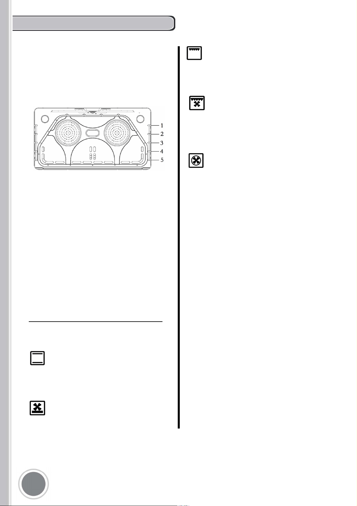
SURFACE BURNER LAYOUT
1. Small Burner
2. Medium burn er
3. Rapid burner
4. Dual burner (Power burner)
SURFACE COOKING
Burner position (in this case front
right burner).
Maximum temperature setting
/Recommended control knob
position for burner ignition
Minimum temperature sett ing
(*)Appliance whith worktop gas valves
alternative type
22
M
Take care of resettin all cootop /
oven/broiler burners controls in OFF
position after use of the appliance.
SURFACE BURNER OPERATION
To activate the electric ignition, simply turn
the control knob counter-clockwise to
maximum power(*position).Press the knob
to start the flow of gas and the ignition spark.
The spark will released at the metal tip of
the white ceramic pin located on the side of
the burner. Once the flame is on , release
the control knob gently.
If the flame turns off, repeat the above
procedure.
ATTENTION: do not ignite burners if the
black burner cap is not installed or not
centred. The flame will be irregular.
M
Manual ignition is always possible even
when the power is cut off or in the event of
power failure. Turn the control knob
counter-clockwise to the MAXIMUM
position. Light the flame with a kitchen
lighter or with a mach.
23
TIPS FOR USING BURNERS CORRECTLY
IMPORTANT
A worktop/oven/broiler
burner controls OFF position after use of the
appliance.
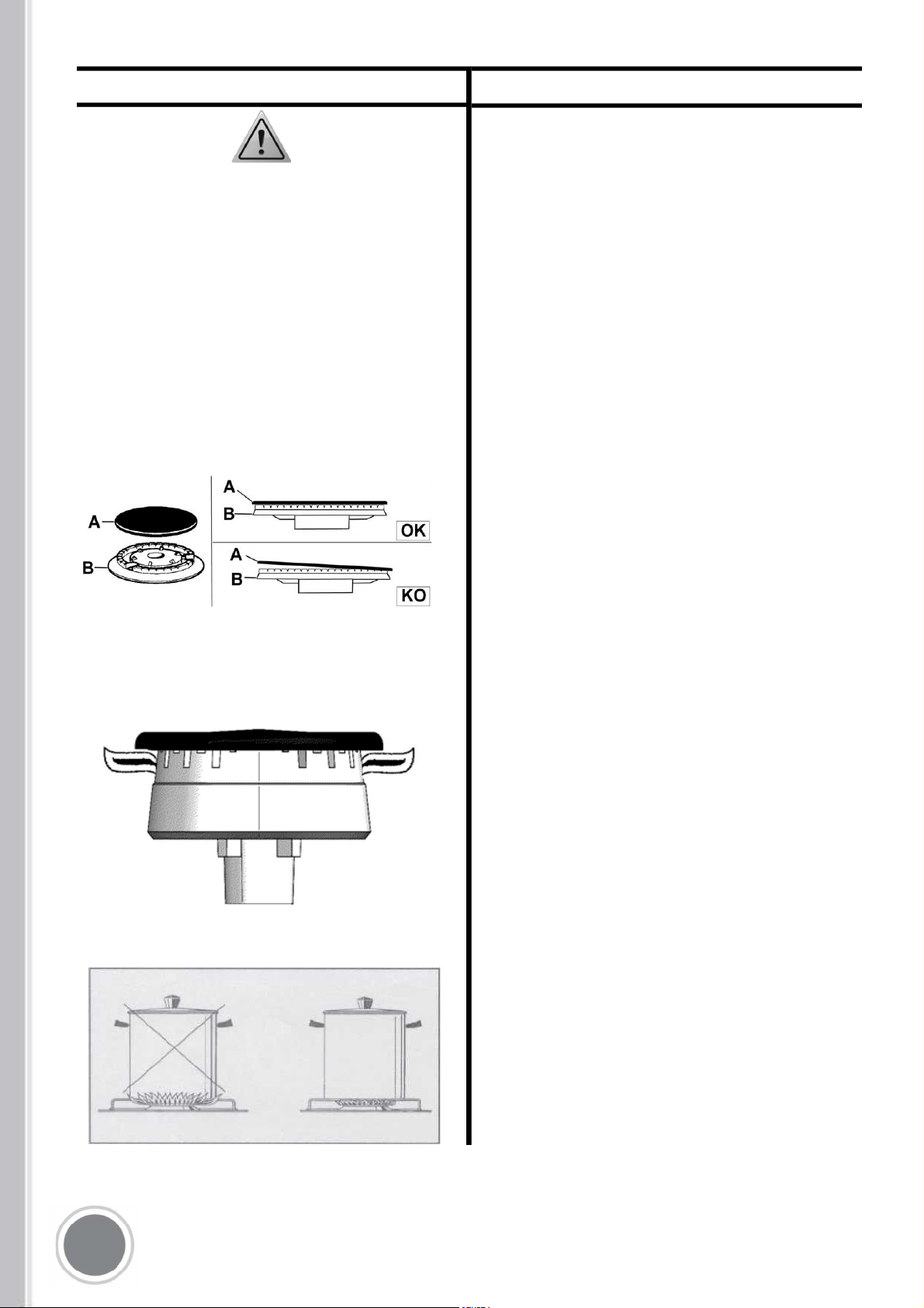
TIPS FOR USING PANS CORRECTLY
AENION!
Always ensure that bottom and handles of
pans do not protrude from the worktop.
When cooking with flammable fat such as
oil, do not leave the range unattended.
Use pots of the appropriate size on each
burner following the indication of the
diagram below.
1. Always check that the burner caps are
properly installed before operation.
2. Verify that the flame of the worktop
burners be completely blue and with
regular aspect as shown below.
3. Always adjust the burner flame so it does
not extend beyond the edge of the pan.
Burner Recommended pan size inches (mm)
Small 3%"-51/2"(90 -140)
Medium 51/2"-101/4"(140 - 260)
Large 71/8"-101/4" (180-260)
Dual burner 82/3"-101/4" (220 - 260)
When boiling liquids, turn the knob to the
MINIMUM position once boiling is
reached to avoid overflow..
Always use pots with matching lid.
Dry the bottom of pans before operation.
Use pots with a flat, thick bottom (except
for wok cooking).
: always use the wok
adapter supplied with the range. Wok pan
external diameter shall not be smaller
than 10" (25cm) and larger than 16"
(40cm).
8"3/*/(
,&&1$)*-%3&/"5"4"'&%*45"/$&
'30.5)&"11-*"/$&%63*/(
01&3"5*0/%0/05"--08$)*-%3&/
5001&3"5&5)&"11-*"/$&
2
Use Care When Opening Door. Let hot air or
steam escape before removing or replacing
food.
Do Not Heat Unopened Food Containers.
Buildup of pressure may cause container to
burst and result in injury.
Keep Oven Vent Ducts unobstructed.
Placement of Oven Racks. Always place oven
racks in desired location while oven is cool. If
rack must be moved while oven is hot, do not let
potholder contact hot heating element in oven.
Do Not Clean Door Gasket. The door gasket is
essential for a good seal. Care should be taken
not to rub, damage, or move the gasket
Do Not Use Oven Cleaners. No commercial
oven cleaner or oven liner protective coating of
any kind should be used in or around any part of
the oven.
Clean Only Parts Listed in manual.
Before Cleaning the Oven. Remove broiler pan
and other utensils.
M
In case of electric power failure reset
oven/broiler controls in off position and not
attempt to use oven/broiler till electric power
has been restored.
Do not store items of interest to children in
cabinets above a range or on the back guard of
a range - children climbing on the range to reach
items could be seriously injured.
DO NOT TOUCH HEATING ELEMENTS OR
INTERIOR SURFACE OF OVEN Heating
elements may be hot even though are dark in
colour. Interior surfaces of an oven become hot
enough to cause burns. During and after use, do
not touch, or let clothing or other flammable
materials come into contact with the heating
elements or
interior surfaces of oven until
they have had sufficient time to cool. Other
surfaces of the appliance may become hot
enough to cause burns, for example, oven
vent openings and surfaces near these
openings, oven doors, oven glass window.
M
M M
M
Me e o l oo oo
oeole e ool o
oo e e o e le
SOS
OVEN NCIONS SEECOR
2
To keep the oven as clean as possible, cook m
on the tray.
USING THE OVEN
The ranges are equipped with commercial
grade shelves and an enamel cooking tray.
Shelves are mounted on the appropriate guides
situated on the sides of the oven compartment.
Insert the shelf between top and bottom guide in
any of the 5 positions available.
When available, always follow recipe book
directions. Personal experience will help to
determine any variations in the values reported
in the table. In any case, it is recommended to
follow the instructions of the specific recipe
being used.
When using the oven for the first time it should
be operated for 15-30 minutes at a temperature
of about 500° F without cooking anything inside
in order to eliminate any moisture and odours
from the internal insulation.
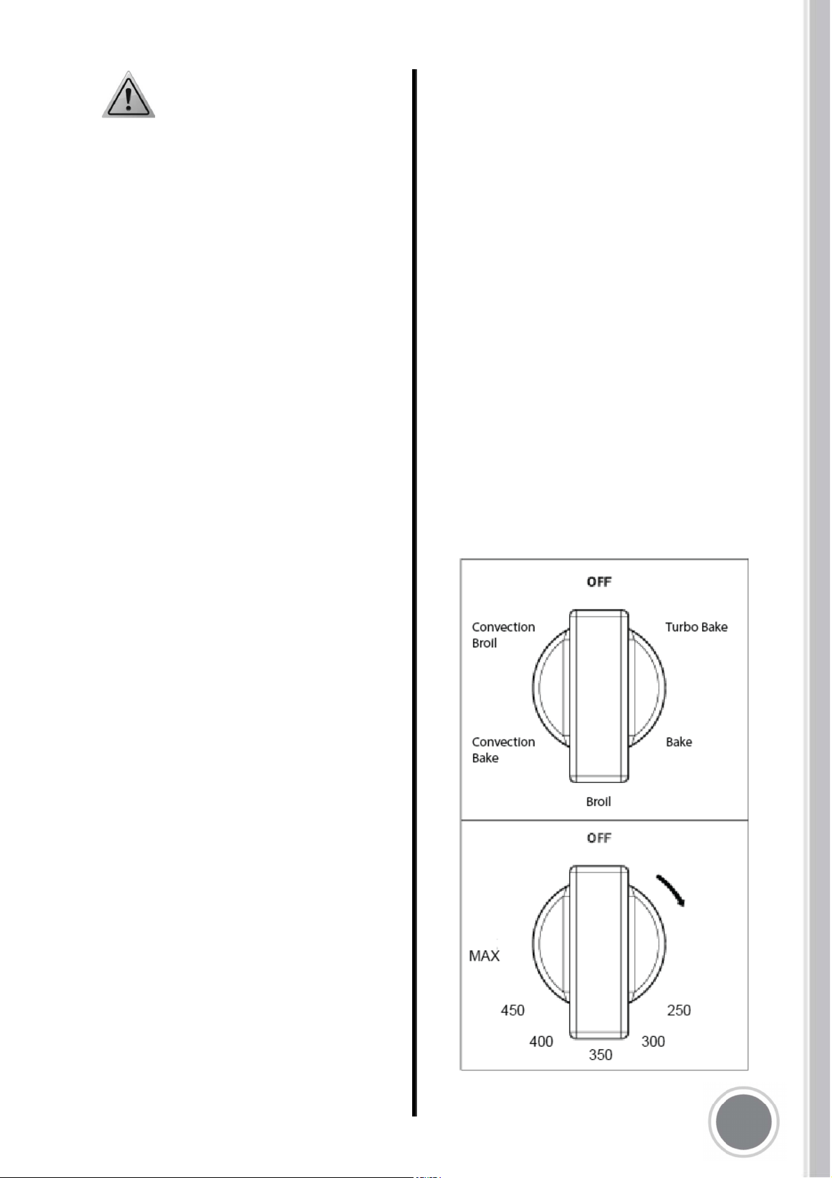
OVEN FUNCTION SELECTOR
The oven has 8 functions defined for the
following operations:
BROIL - (Broiler heating element) to
be used with temperature selector at
500°F for broiling
CONVECTION BROIL - (Broiler
heating element + fan) to be used
with temperature selector at 500°F for
convection broiling
CONVECTION BAKE - (Circular heating
element + fan) to be used with oven
temperature from 0 to 500°F
BAKE - (Broiler + Bottom heating
elements) to be used with oven
temperature from 100° to 500°F
TURBO - (Circular + Bottom heating
elements+ fan) to be used with oven
temperature from 100° to 500°F
2

USING THE OVEN
BAKE
OVEN LIGHT
The appliance is equipped with two oven lamps
that light up when the oven door is opened or each
time the oven is in operation. They are turned off
during the cleaning cycle.
COOLING FANS
The appliance is equipped with two cooling fan
motors that activate when the oven is in operation
for cooking or cleaning, except in case of
DEHYDRATE and PROOFING functions. In
stand-by condition (both selector in OFF position)
the cooling fan motors operate if oven temperature
exceeds approximately 430°F/220°C and stop
automatically when oven temperature drops below
approximately 285-360°F/140- 180°C.
FRONT INDICATOR LIGHT
This appliance is equipped with an indicator
light on
the front panel:
The indicator light will be lit whe
n the oven is
heating. Once the oven reaches set temperature,
the light will dim. The light will be completely OFF
when both the oven temperature selection knob
and the oven function selector knob are in the
"OFF" position.
OVEN CONVECTION FAN
The appliance is equipped with an oven fan
mounted inside a circular heating element,
protected by a fan shield on the back of the oven
cavity; it operates each time that the oven
operates in the functions ROASTING, TURBO,
CONVECTION BROIL, CONVECTION BAKE
and DEHYDRATE.
PREHEATING THE OVEN
Preheat the oven before baking. The oven does
not need to be preheated for large pieces of
meat or poultry. See your recipe for preheating
recommendation. Preheating time depends on
the temperature setting and the number of racks
in the oven.
GETTING THE BEST RESULTS
Minimize opening the door.
Choose the right size bake ware.
Use the bake ware recommended in the recipe.
Store the broiler pans outside the oven: extra
pans without food affect the browning and
cooking.
Browning can depend from the type of pan used:
-For tender, golden brown crusts, use light
non-stick anodized or shiny metal pans.
-For brown crisp crusts, use dark non-
stick/anodized or dark, dull metal utensils
or glass bake ware. These may require
lowering the bake temperature 25°F.
BAKEWARE TYPE
Metal bake ware (with or without a non-stick
finish), heat-proof glass, glass ceramic, pottery,
or other utensils are suitable for the oven.
Suitable cookie sheets have a small lip on one
side only. Heavy sheets or those with lips on
more than one side may affect the baking time.
BAKE RACK POSITIONS
Rack level positions in the oven are numbered
as in the diagram on page 25.
ONE RACK BAKING - The Bake mode is best for
baking on one rack with rack level 3 and 4 used for
most baked items. When baking tall items, rack level
4 may be used. Pies are best baked on rack level 4
or 5 to ensure the bottom of the crust is done without
over-browning the top. When large pieces of meat or
poultry are roasted such as a prime rib of beef or a
turkey, rack level 4 is the preferred rack.
TWO RACK BAKING - Rack levels 3 and 5
may be
used when baking on two levels. Cookies and
biscuits can be cooked properly using these two
racks. Casserole dishes may al so be baked
using
these two
levels.
2
CONVECTION
COOKING WITH CONVECTION
There are many advantages to cooking with
convection. In the convection system, a fan in the
back of the oven moves heated air evenly around
the oven. The moving air provides even heat so
foods can be placed on any rack level with
consistent results and without having to rotate the
pans. Convection also enables cooking
simultaneously on multiple racks.
throughout the oven cavity for all uses. Multiple
rack use is possible for baking large amounts of
food. When roasting, cool air is quickly replaced -
searing meats on the outside and retaining more
juices and natural flavour on the inside with less
shrinkage
BAKE
Full power heat is radiated from the bake
element in the bottom of the oven and partial
power is radiated from the top element. Air is
circulated by the fan in the rear of the oven.
Any food cooked uncovered will brown evenly
and form a nice crust. Foods in covered dishes
(casseroles, pot roast) or delicate custards are
not suitable for convection cooking.
CONVECTION BAKE & TURBO
Time can be saved by baking an entire batch of
cookies at the same time. The cookies will bake
evenly and be done all at once. The baking time
may be shorter due to the warm circulating air.
For small items such as cookies, check to see if
they are done one to two minutes before the recipe
time. For larger baked items such as cakes, check
five to six minutes before the time indicated on the
recipe.
Convection cooking of meat and poultry will result
in foods that are brown and crispy on the outside
and moist and juicy on the inside. Large meat or
poultry items may cook up to 30 minutes less than
the suggested time so check them so they will not
be over baked. A meat thermometer or an instant
read thermometer will provide more accurate
results than the "minute per pound" method. The
larger the piece of meat or poultry, the more time
you will save.
Converting Conventional Baking to Convection
Cooking - To convert most recipes for baked items
(cookies, cakes, pies, etc.), reduce the oven
temperature by 25°F. For meats and poultry, use
the temperature recommended in recipes and
cooking charts.
d
ee e e
Preheat the oven before baking. The oven does
not need to be preheated for large pieces of meat
or poultry. See your recipe for preheating
recommendation. Preheating time depends on
the temperature setting and the number of racks
in the oven.
eee e
When using Convection Bake, reduce the
temperature recommended in the recipe by 25°F.
When roasting meats, check internal temperature
prior to time recommended by recipe to prevent
over cooking. When roasting meats in convection
mode, do not reduce temperature setting.
odeo
It is normal for a certain amount of moisture to
evaporate from the food during any cooking
process The amount depends on the moisture
content of the food. The moisture will condense on
any surface cooler than, the inside of the oven,
such as the control panel.
Large Main Oven One Rack Baking When baking
on one rack, best results are obtained in the bake
mode (see Bake).
When roasting a turkey or a large piece of meat,
convection bake may be used. Rack 4 is the most
appropriate rack.
Two Rack Baking
Racks 4 and 2 are most appropriate when using the
convection bake mode. Round cake pans should
be staggered on racks 4 and 2. Rectangular (9 x
13) cake pans and cookie sheets should be placed
on rack 4 directly under the one on rack 2.
Low, shallow bake ware should be used with
convection cooking. This allows the heated air
to properly move around the food. Pans with
high sides or pans that are covered are not
suitable for convection cooking because high
sides or lids prohibit the warm air from
circulating around the food
BAKE
The rear and bottom elements operate at full
power. Air is circulated by the fan for even
heating. Use this setting to reduce pre-heating
time of the oven or for recipes which require
uniform cooking with strong heat from bottom
such as pizza and focaccia bread.
2
This may be used for cakes, cookies, biscuits and
other foods for which two rack baking is desirable.
When several casseroles, frozen pies or cakes are to
be baked, use racks 4 and 2.
These two racks can also be used for a large
oven meal.
ee e
Aluminium bake ware gives the best browning
results.
Cookie sheets with only two sides give the best
results. Aluminium commercial half-sheets or
professional cooking utensils may be used but
baking times may be increased.
lee
For better browning, utensils such as cookie sheets.
Rectangular baking pans should be placed
crosswise on the rack with the shorter side facing
right and left to allow better air flow.
When baking on more than one rack, cookie sheets
and rectangular (9 x 13) cake pans should not be
staggered; round cake pans should be staggered.
Settings for BAKE/CONVECTION and
BAKE/CONVECTION/TURBO cooking
modes
These cooking modes are for baking, roasting or
warming using one or two racks.
1. Select BAKE/CONVECTION or BAKE/
CONVECTION/TURBO using the Selector
switch.
2. Set the oven temperature using the oven
temperature control knob (not over Tmax=500*F
setting position). If using CONVECTION, set the
oven control knob 25°F below temperature
suggested in the recipe.
Do no change recipe temperature if
roasting meats or poultry.
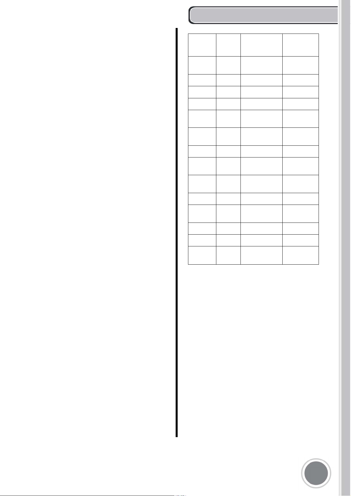
BAKING RECOMMENDATIONS
.
FOOD PAN
SIZE
CONTROL
TEMPERATURE
SETTING
TOTAL
SUGGESTED
COOKING
TIME
Cookies
12„X15'
Cookie
Sheet
375*
8 to 12 minutes
Layer
Cakes
8"or
9'Round
350*
25 to 35
minutes
Sheet
Cakes
9'x13”
Pan
350*
30 to 40
minutes
Bunt
Cakes
12 Cup 325*
60 to 75
minutes
Brownies or
Bar Cookies
9"x9"
Pan
325*
20 to 25
minutes
Biscuits
12"x15"
Cookie
Sheet
425* or Package
Directions
10 to 15
minutes
Quick
Bread
8"x4" Loaf
Pan
350*
55 to 70
minutes
Muffins
12 cup
Muffin Pan
425*
14 to 19
minutes
Fruit Pies
9“
Diamete
r
425*
35 to 45
minutes
Fruit
Cobblers
9"x9"
Pan
'400*
25 to 30 mi nut
os
Yeast
Bread,
Loaves
8
H
x4” Loaf
Pan
375*
25 to 30
minutes
Dinner
Rolls
9”x13"
Pan
400*
12 to 18
minutes
Cinnamon
Rolls
9”x13”
Pan
375
25 to 30
minutes
Yeast
Cotter and
Cake
12"x15“
Cookie
Sheet
400*
20 to 30
minutes
2
FOOD
PREPARATION
APPROXIMATE DRYING
TIME (hrs)
TEST FOR DONENESS
Fruit
Apples
Dipped in 1/4 cup lemonjuiee and 2
clips water; 1/4" slices
11-15 Slightly pliable
Bananas
Dipped in 1/4 cup lemonjuiee and 2
cups water; 1/4" slices
10-15 Soft, pliable
Cherries
Wash and towel dry. For fresh
cherries, remove pits
10-15 Pliable, leathery, chewy
Orange peels and slices
1/4" slices of orange, orange part of
shin thinly peeled from oranges
Pee Is: 2-4 Slices: 12-16
Orange peel: dry and brittle.
Orange slices: skins are dry and brittle,
fruit is slightly
Pineapple rings Towel dried
Canned: 9-13 Fresh: a-12
Sott and pliable
Strawberries
Wash and towel dry. Sliced 1/2"
thick, akin (outside} down on rack
12-17
Dry, brittle
Vegetable
Peppers
Wash and towel dry. Remove
membrane of peppers, coarsely
chopped about 1
H
pieces
16-20
Leathery with no moisture inside
Mushrooms
Wash and towel dry. Cut off slem
end. Cut into 1/8" slices
7-12 Tough and leathery, dry
Tomatoes
Wash and towel dry Cut thin slices,
1/6" thick, drain well.
16-23
Dry, brick red Colour
Hertjs
Oregano Sage parsley And
thyme And fennel
Rinse and dry with paper towel
3-5 Cnsp and brittle
Basil
Use basil leaves 3 to 4 inches from
lop. Spray with water, shake off
moisture and pal dry
3-5
Crisp and brittle
31

Select CONVECTION BROIL to brown food slightly
also on the bottom side. This mode is preferred for
browning food on both side that is too delicate for
turning such as fish. The degree of browning of each
side might be different.
CONVECTION BROIL
1. Place oven rack in desired position.
2.
Set Selector Switch to BROIL or CONVECTION
BROIL.
3. Set oven temperature control knob to BROILER or
CONVECTION BROILER setting corresponding to
500° F fixed BROILER setting (not over Tmax=500°
F orunder 450° F setting position).
4. Wait until PRE-HEATING light turns off, after
approximately 5-6 minutes
5. Place food in oven at desired rack position as
referencedon Page 26.
6.
Close oven door. The door should be closed
throughout
BROIL / CONVECTION BROIL
o ol
Broiling requires constant exposure to high,
intense heat. Only the upper element heats in
the BROILER mode.
It is recommended that you preheat the broil
element before starting to cook. Preheat until the
"PRE-HEATING" light turns off (about 5-6 minutes).
100°F. Turn and cook the second side to desired
internal temperature.
el
A porcelain enamel broil pan is included with the range.
Use matal or glass-ceramic bake ware when browning
casseroles, main dishes, or bread. DO NOT use
hear-proof glass or pottery. This type of glassware cannot
withstand the intense hear of the broil element.
ol Me eoee
To more accurately define the preparation of thick steaks
or chops (at least 1 1/2 inches thick), use a meat
thermometer. Insert the point of the thermometer into the
side of the meat reaching the center of the steak or chop.
For rare steaks, cook the first side to 90°F. For medium or
well done steaks, cook the first side to
e e e el
Defrost food before broiling.
Keep oven door closed during broiling.
Steaks should be more than 1" thick if rare meat is
desired. Use convection broil if steaks are over
1-1/2 inches thick. Turn food over once after half
cooking time. It is not necessary to turn very thin
food (ham slices, fillets of fish, etc.). Liver slices
must be turned over regardless of thickness.
Use a timer. Set it for the minimum time and check
the food.
Center food directly under the broiling element for
best browning.
oo
Before turning on the oven, place the rack in the
desired position. After preheating the broiler,
center the broil pan under the broil element.
2 - Use this rack position when broiling beef
steaks, ground meat patties, ham steak and lamb
chops 1 inch or less thick. Also use when browning
food.
3 - Use this rack position when broiling meat 1 1/8
inches or more thick, fish, poultry, pork chops,
ham steaks 1 inch or more thick.
3 or 4 - Use this rack when broiling chicken
quarters or halves.
32
BROILING AND ROASTING RECOMMENDATIONS
FOOD ITEM
RACK
OVEN MODE
FUNCTION
SELECTOR
CONTROL
TEMPERATURE
SETTING
SELECTOR
APPROXIMATE
SPECIAL
INSTRUCTIONS AND
TIPS
BEEF
Ground Beef
Patties, Vt thick
2
Broiler or convection
Broiler
500°
15 to 20 minutes
Broil until no pink in
center
T-Bone Steak
2
Broiler or convection
Broiler
12 to 20 minutes
Time depends on
rareness of steak
Flank Steak
2
Broiler or convection
Broiler
12 to 20 minutes Rare to Medium Rare
Eye of Round
Roast
3
20 to 25 min/lb
Small roasts take more
minutes per pound;
reduce time by using
Convection Bake
PORK Loin Roast
3
Bake or Convection
bake
20 to 25 min/lb
Cook until juices are
clear
POULTRY Boneless
Skinless Chicken
Breasts
2
Broiler or convection
Broiler
20 to 25 minutes
Cook until juices are
clear
Chicken Thighs
3
Broiler or convection
Broiler
25 to 30 minutes
Remove skin; Cook until
juices are clear
Half Chickens
3
Broiler or convection
Broiler
30 to 45 minutes
Turn with tongs; Cook
until juices are clear
Roast Chicken
4
Bake or Convection
bake
350°
75 to 90 minutes
Do not stuff; reduce time
by using Convection
Bake
Turkey
4
Bake or Convection
bake
325°
20 to 25 min/lb
Do not stuff; reduce time
by using Convection
Bake
33
500°
500°
Bake or Convection
bake
500°
500°
500°
325°
325°
AINAINING OR RANGE
WARNING!
Disconnect power before servicing unit.
To replace the oven light bulb, unscrew the
protection cap that projects out inside the
oven.
NOTE: Touching the bulb with fingers may cause
the bulb to burn out. Always use protective glove or
use a cloth to remove the bulb.
ATTENTION
During cleaning operation never move the
appliance from its foreseen original installation
position.
ATTENTION!
Never use abrasive cleaners!
Scratches on the stainless steel surfaces are
permanent.
Do not clean the range when hot!
Cleaning after installation: use a stainless steel
cleaning product or wipe to eliminate the glue
residues of the blue protection film after
removal.
Cleaning the worktop: periodically clean the burner
heads, the cast iron pan supports and the burner
caps using warm water. Remove burned food and fat
residues with a rubber spatula . If food residue
prevent the smooth operation of the control knobs,
call the customer service hotline to schedule service
by a factory-trained professional.
Cleaning stainless steel: for best results use a
stainless steel cleaner product with a soft sponge or
wipe. Alternatively use a soft sponge or cloth with a
warm soap and water solution. Never use abrasive
powders or liquids!
Cleaning the burner caps: lift the burner caps from
the burner heads and wash them in a warm soap and
water solution. Dry thoroughly before using them
again. Before reinstalling them on the burner head,
check that the gas flow holes are not clogged with
food residues or cleaning product residues.
Cleaning Enamel: enamelled parts should be
cleaned frequently with warm soap and water
solution applied with a soft sponge or wipe.
Never use abrasive powders or liquids! Do not leave
acid or alkaline substances on the enamelled parts
(such as vinegar, lemon juice, salt, tomato sauce,
etc.). Use a rubber spatula to remove fat residues.
Cleaning glass door: clean the glass using a non-
abrasive sponge or wipe with a warm soap and warm
water solution. Use a rubber spatula to remove fat
residues.
ATTENTION: while cleaning the door, avoid spillage
of food residues and cleaning products in the venting
holes situated on the top side of the door. To clean
the inside of the oven door, call a factory-trained
professional.
ATTENTION: for further details about cleaning of the
appliance, please contact your appliance retailer.
3
TROUBLESHOOTING GUIDE
3
CauseBaking Problem
Food browns unevenly
•
Oven not preheated
•
Aluminum foil on oven rack or oven bottom
•
Baking utensil too large for recipe
•
Pans touching each other or oven walls
Food too brown on bottom
•
Oven not preheated
•
Using glass, dull or darkened metal pans
•
Incorrect rack position
•
Pans touching each other or oven walls
Food is dry or has shrunk
excessively
•
Oven temperature too high
•
Baking time too long
•
Oven door opened frequently
•
Pan size too large
Food is baking or roasting too
slowly
•
Oven temperature too low
•
Oven not preheated
•
Oven door opened frequently
•
Tightly sealed with aluminum foil
•
Pan size too small
Pie crusts do not brown on
bottom or crust is soggy
•
Baking time not long enough
•
Using shiny steel pans
•
Incorrect rack position
•
Oven temperature is too low
Cakes pale, at and may not be
done inside
•
Oven temperature too low
•
Incorrect baking time
•
Cake tested too soon
•
Oven door opened too often
•
Pan size may be too large
Cakes high in middle with crack
on top
•
Oven temperature too high
•
Baking time too long
•
Pans touching each other or oven walls
•
Incorrect rack position
•
Pan size too small
Pie crust edges too brown
•
Oven temperature too high
•
Edges of crust too thin
TROUBLESHOOTING GUIDE
3
PROBLEM POSSIBLE CAUSE
Burner will
not ignite
There is no power to
the cooktop
SOLUTION
Replace fuse or reset circuit breaker.
Burner
will not
operate
First time use. Air
still in the gas line.
Control knob is not
set correctly.
Turn on any one of the surface burner knobs
to release air from the gas lines.
Push in knob before turning to a setting.
The burner port is
clogged.
Clean burner port opening using a sti, nylon
toothbrush or a straightened paper clip.
Burner
Flames are
uneven,
yellow and/
or noisy
Burner port(s) are
clogged.
Clean burner port opening using a sti, nylon
toothbrush or a straightened paper clip.
Burner caps are not
positioned properly.
Place burner caps so that the alignment pins
are properly aligned with the slots.
Propane gas is being
used.
The range should be converted to LP gas by
a qualied technician.
Burner
ame is too
high or too
low
Cooktop gas supply
is not correct.
Ensure the range is set for the correct
gas type. It is factory set for natural gas. If
connected to LP gas the burners should be
converted to LP gas with the orice/injector
kit supplied and the pressure regulator
converted to the LP gas setting by a qualied
technician.
The gas pressure is
not correct.
Make sure the pressure regulator is installed
correctly and the gas line pressure is correct.
See Installation Instructions.
Burner
makes
popping
noises
The burner is wet. Allow the burner to dry before using.
The burner cap and/
or gas spreader
is not positioned
correctly.
Place burner caps so that the alignment pins
are properly aligned with the slots.
Excessive
heat
around
cookware
on cooktop
The cookware is not
the proper size for
the burner.
Use cookware with a bottom surface
approximately the same size as the cooking
area and burner. Cookware should not
extend more than 1” (2.5 cm) outside the
cooking area. Adjust the ame so that it
does not come up around the cookware.
Improper
installation.
Gases not
flowing.
Turn the manual gas shut-off valve on.
Installer should make sure regulator is
correctly oriented (arrow towards unit).
TROUBLESHOOTING GUIDE
3
POSSIBLE CAUSE SOLUTIONPROBLEM
Oven is not
heating
No power to the
oven
Reset the circuit breaker or replace the
fuse in the electrical box to your oven.
Oven control not
turned on
Make sure the oven temperature has
been selected and timer is not "OFF".
Oven is not
cooking evenly
Not using the correct
bake ware or oven
rack position
Refer to cook charts for recommended
rack position. Always reduce recipe
temperature by 25 °F (15 °C) when
baking with Convention Bake mode.
Broil does
not work.
Knob settings are not
in the correct
positions.
Make sure oven temperature
selection knob is set to " BROIL" and
timer is not set to "OFF"
Cooling fan
continues to
run after oven
is turned o
The electronic
components have
not yet cooled
suciently
The fan will turn o automatically
when the electronic components have
cooled suciently.
Oven light is
not working
properly
Light bulb loose or
burned-out.
Reinsert or replace the light bulb.
Touching the bulb with ngers may
cause the bulb to burn out.
Oven light
stays on
Door is not closing
completely
Check for obstruction in oven door.
Check to see if hinge is bent or door
switch broken.
Cannot remove
lens cover
Soil build-up around
the lens cover.
Wipe lens cover area with a clean, dry
towel prior to attempting to remove
the lens cover.
Heat blowing out
from the front
of oven.
Oven cavity
ventilation on
The oven cavity ventilation is
operating until the oven is sufficiently
cooled. This is normal.
Excessive
Moisture
When using bake mode, preheat
the oven rst. Convection Bake and
Convection Roast will eliminate any
moisture in the oven.
Porcelain Chips
Porcelain interior
is bumped by oven
racks
When removing and replacing oven
racks, always tilt racks upward and do
not force them to avoid chipping the
porcelain.
FOR MORE HELP, VISIT OR CALL THE CUSTOMER
SUPPORT LINE AT 1-888-784-3108.
The rating tag shows the model and serial number of your range. It is located under the front
edge of the range cooktop, and is visible when the oven door is open (see illustration)
A= Rating tag(s) located under front edge of cooktop
B= Wiring / schematic diagram placed behind backside panel and on installation booklet
3
OCAION O AIANCE AGS
B
A
MODEL
DATE INSTALLED
DEALER
INSTALLER
3
You can contact our customer support by
emailing staff@cosmokitchenproducts.com,
calling 1(888)784-3108, or submitting a
support ticket online at
cosmoappliances.com/support
IMPORTANT APPLIANCE INFORMATION