Loading ...
Loading ...
Loading ...
241If and when
Jump leads
Jump leads must comply with standard DIN 72553 (see manufacturer's doc-
umentation). The wire cross section must be at least 25 mm
2
for petrol en-
gines and at least 35 mm
2
for diesel engines.
Note
● The vehicles must not touch each other, otherwise electricity could flow
as soon as the positive terminals are connected.
● The discharged battery must be properly connected to the vehicle elec-
trical system.
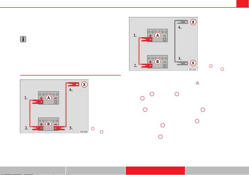
How to jump start: description
Fig. 169 Diagram for
connecting jump leads if
the vehicle providing as-
sistance the current is
not fitted with the Start-
Stop system: flat battery
A
and battery providing
current
B
.
Fig. 170 Diagram for
connecting jump leads if
the vehicle providing as-
sistance is fitted with the
Start-Stop system: flat
battery
A
and battery
providing current
B
.
Jump lead terminal connections
1. Switch off the ignition of both vehicles ⇒
.
2. Connect one end of the red jump lead to the positive terminal
⇒ fig. 169
+
or ⇒ fig. 170
+
of the vehicle with the flat bat-
tery
A
.
3. Connect the other end of the red jump lead to the positive ter-
minal
+
in the vehicle providing assistance
B
.
4. On vehicles with no Start-Stop system, connect one end of the
black jump lead to the negative terminal
-
in the vehicle pro-
viding assistance
B
⇒ fig. 169.
5. On vehicles with the Start-Stop system, connect one end of the
black jump lead
X
to a suitable ground terminal, to a solid
metal part bolted to the engine block or to the engine block it-
self ⇒ fig. 170.
Safety First Operating Instructions Practical Tips Technical Specifications
Loading ...
Loading ...
Loading ...