

www.lg.com
24CAV37K
CLOUD(LED LCD) MONITOR MODEL
Owner's Manual
CLOUD MONITOR
LED LCD MONITOR
(LED MONITOR*)
Please read this manual carefully before operating
your set and retain it for future reference.
*LG LED Monitors are LCD Monitors with LED Backlighting.

WARNING: This product contains chemicals known to the State of California to cause cancer and birth defects or other
reproductive harm. Wash hands after handling.

2
ENG
English
Table of Contents
TABLE OF CONTENTS
3 ASSEMBLING AND
PREPARING
3 Unpacking
4 Parts and buttons
5 Lifting and moving the Monitor
5 Setting Up the Monitor set
5 - Attaching the Stand Base
6 - Mounting on a table
6 - Adjusting the angle
7 - Adjusting the stand height
7 - Using the Kensington locking device
8 - Detaching the stand base
8 - Using the cable holder
8 - Detaching the stand body
9 - Swivel stand
9 - Using the Pivot function
10 - Installing the wall mount plate
10 - Mounting on a wall
12 USING THE MONITOR SET
12 Connecting Input Signal Cable
12 - D-SUB IN connection - PC
13 - DVI connection
14 Connecting LAN/Peripherals
14 - LAN connection
15 - Peripheral device connection
16 - Self Image Adjustment
17 CUSTOMIZING SETTINGS
18 Customizing Settings
18 - Menu Settings
19 - Picture
20 - Color
21 - Display
22 - Others
23 - Volume
24 TROUBLESHOOTING
26 PRODUCT SPECIFICATION
27 Preset Mode
27 Indicator
28 PROPER POSTURE
28 Proper posture for using the monitor
29 USING CLOUD SOLUTION
3
ENG
English
ASSEMBLING AND PREPARING
ASSEMBLING AND PREPARING
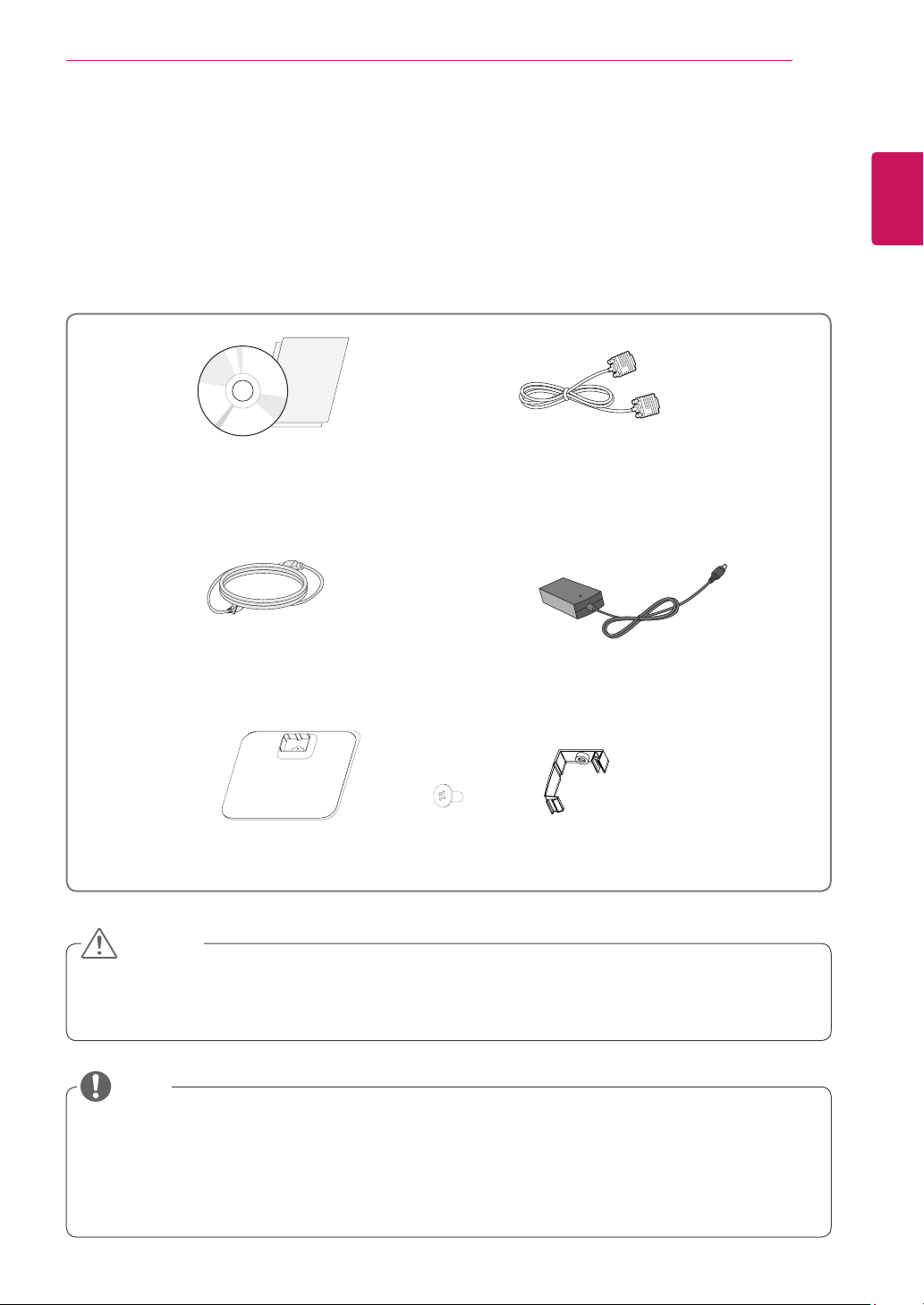
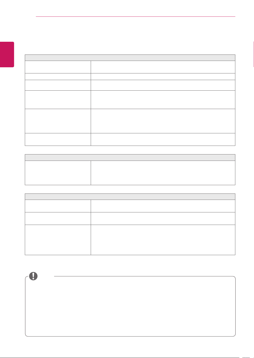
Unpacking
Please check whether all the components are included in the box before using the product. If there are
missing components, contact the retail store where you purchased the product. Note that the product and
components may look different from those shown here.
Only use an approved LG power adapter.
Damage caused by other power adapters is not covered by warranty.
Note that the components may look different from those shown here.
Without prior notice, all information and specifications in this manual are subject to change to improve
the performance of the product.
To purchase optional accessories, visit an electronics store or online shopping site or contact the retail
store where you purchased the product.
Power Cord
User Manual/Card
CAUTION
NOTE
D-SUB Cable
(This cable is not included in all
countries.)
Stand Base
One Screw
Cable Holder
AC-DC Adapter
4
ENG
English
ASSEMBLING AND PREPARING
1
1
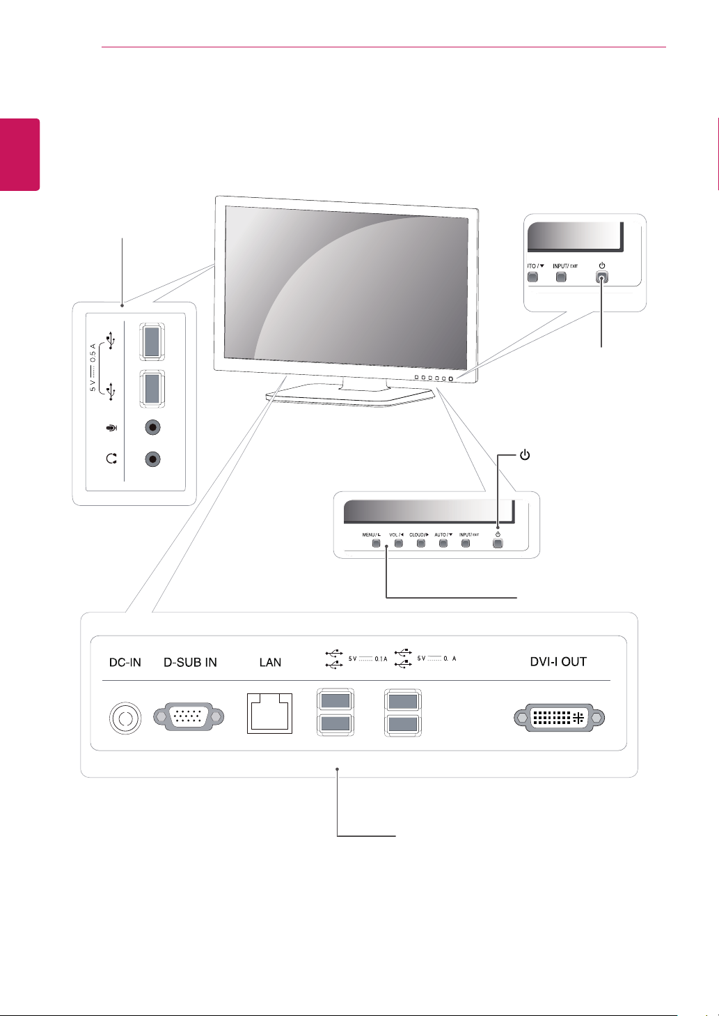
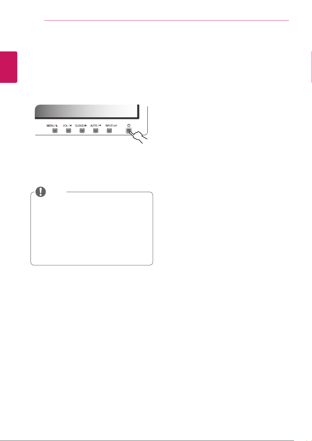
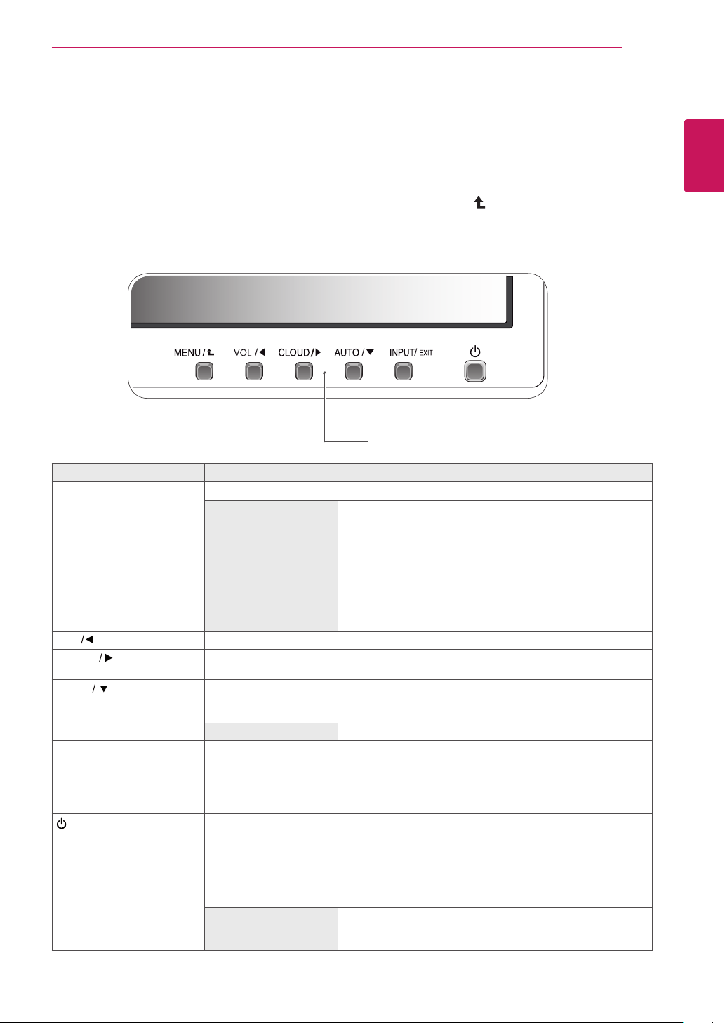
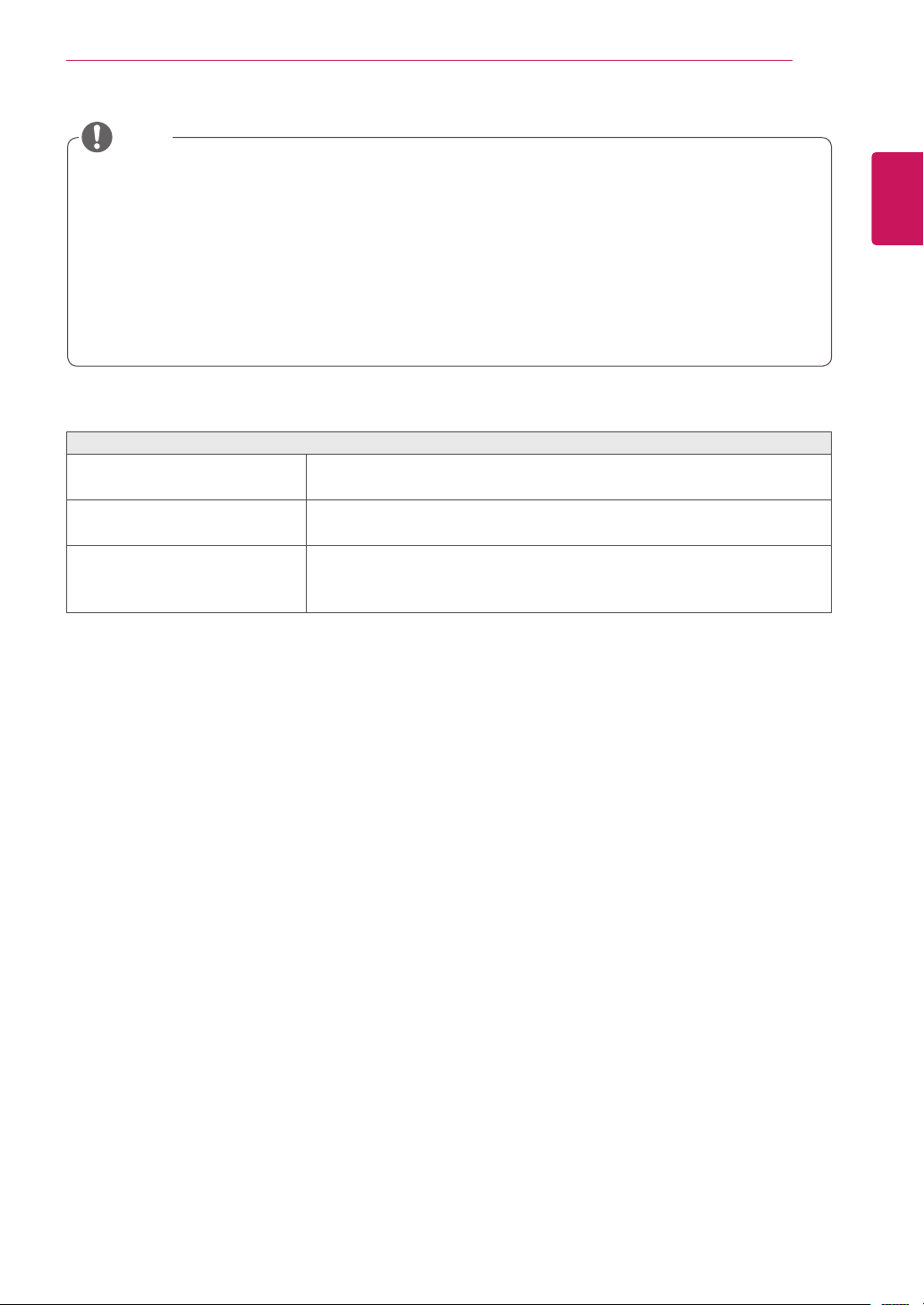
Parts and buttons
Power Indicator
LED On : Power is on
LED Off: Power is off
Front Side Buttons
Input Connectors (See p.12 to 15)
(Power Button)
Input Connectors
(See p.15 )
5
ENG
English
ASSEMBLING AND PREPARING
Setting Up the Monitor set
Attaching the Stand Base
1
Place the monitor's screen face down.
To protect the screen from scratches, cover
the surface with a soft cloth.
3
Using a coin, turn the screw clockwise to se-
cure
the
stand base.
2
Check the
position (at the front and rear)
of
the stand body,
then
mount the
stand base
on
the
stand body
as shown in the figure.
CAUTION
Stand Body
Stand Base
Stand Base
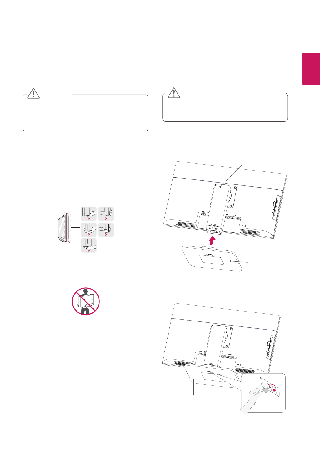
Lifting and moving the
Monitor
Please heed the following information when
moving the monitor.
Avoid touching the screen at all times, as this
may result in damage to the screen or pixels .
CAUTION
It is recommended to move the Monitor in
the box or packing material that the Monitor
originally came in.
Before moving or lifting the Monitor,
disconnect the power cord and all cables.
Hold the top and bottom of the Monitor frame
firmly. Make sure not to hold the transparent
part area.
When holding the Monitor, the screen should
face away from you to prevent the screen
from scratches.
When transporting the Monitor, do not
expose the Monitor to jolts or excessive
vibration.
When transporting the Monitor, keep the
Monitor upright, never turn the Monitor on its
side, or tilt towards the left or right.
6
ENG
English
ASSEMBLING AND PREPARING
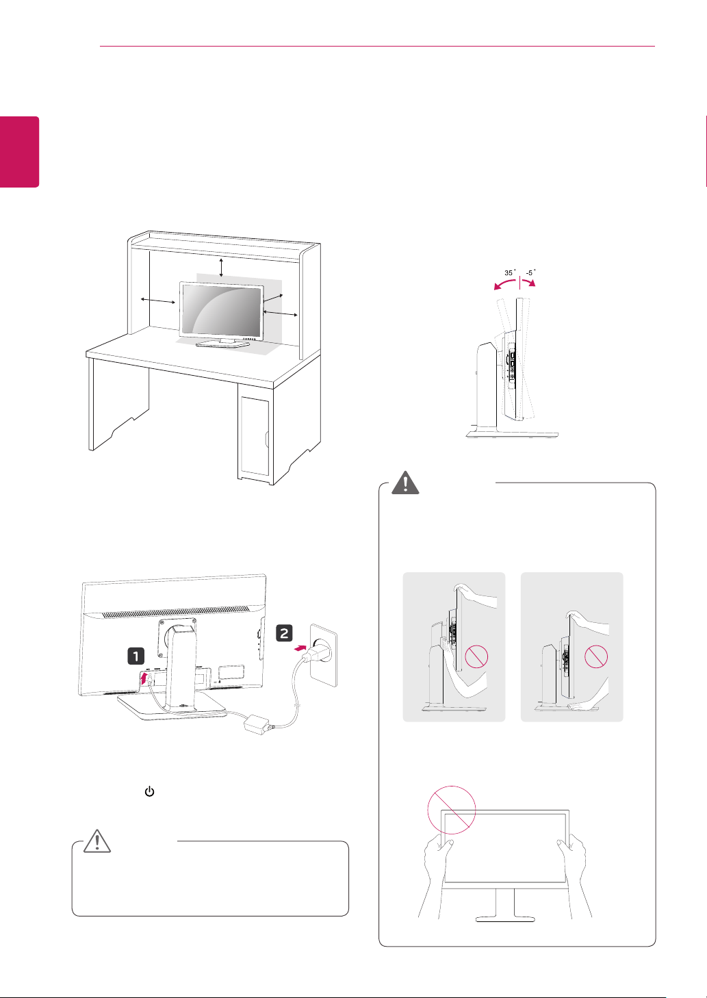
Adjusting the angle
1
Place the monitor mounted on the stand base
in an upright position.
2
Adjust the angle of the screen. The angle of
the screen can be adjusted up to 5° forwards
and 35° backwards for a comfortable viewing
experience.
y
To avoid injury to the fingers when adjusting
the screen, do not hold the lower part of the
monitor's frame as illustrated below.
y
Be careful not to touch or press the screen
area when adjusting the angle of the monitor.
WARNING
Mounting on a table
1
Lift the monitor and place it on the table in an
upright position.
Install at least 3.94 inches away from the wall
to ensure sufficient ventilation.
2
Connect the adaptor to the monitor, then plug
the power cord into the wall outlet.
3
Press the (Power) button on the front of the
monitor to turn on the monitor.
3.94 inches
3.94 inches
3.94 inches
3.94 inches
y
Unplug the power cord prior to moving or
installing the monitor. There is risk of electric
shock.
CAUTION
Front SideRear Side
7
ENG
English
ASSEMBLING AND PREPARING
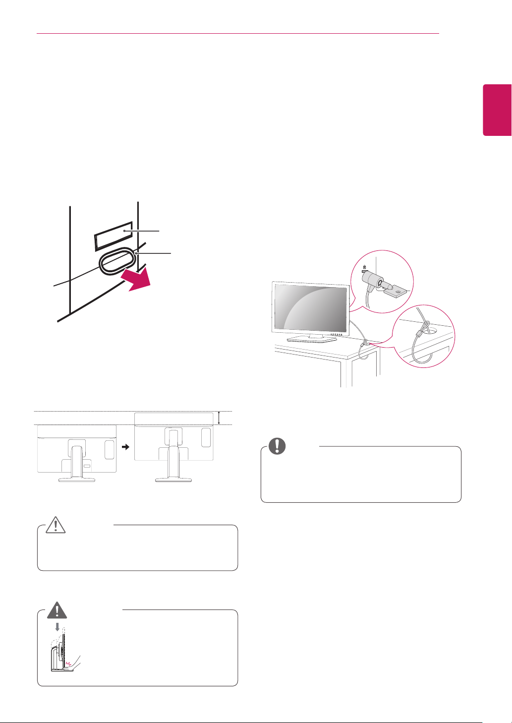
Using the Kensington locking
device
The connector for the Kensington lock is located
on the rear of the monitor.
For more information on installation and usage,
refer to the Kensington lock user manual or visit
the website at http://www.kensington.com.
Connect the monitor to the table with the Kensing-
ton lock cable.
y
Using the Kensington lock is optional. The
accessories can be purchased at your local
electronics store.
NOTE
y
Once the pin is removed, it is not necessary
to re-insert it to adjust the height.
Adjusting the stand height
1
Place the monitor mounted on the stand base
in an upright position.
2
Remove the tape attached at the bottom rear
of the stand body, then pull out the locking
pin.
3
The height can be adjusted up to
5.12 inches.
y
Do not put your finger be-
tween the screen and the
base (chassis) when adjust-
ing the screen's height.
CAUTION
WARNING
5.12 inches
Tape
Locking Pin
Stand Body

8
ENG
English
ASSEMBLING AND PREPARING
Detaching the stand body
1
Place the monitor's screen face down. To
protect the screen from scratches, cover the
surface with a soft cloth.
2
Using a screwdriver, remove the four screws
and detach the stand from the monitor.
y
The components appearing in the illustra-
tions may look different from the actual prod-
uct.
y
Do not carry the monitor upside-down as this
may cause it to fall off its stand, resulting in
damage or injury.
y
To avoid damaging the screen when lifting
or moving the monitor, only hold the stand or
the plastic cover. This avoids putting unnec-
essary pressure on the screen.
y
Only remove the tape and the locking pin
when the monitor is mounted on the stand
base and is in an upright position. Otherwise,
the stand body may protrude, which may
lead to injury.
Detaching the stand base
1
Place the monitor's screen face down.
To protect the screen from scratches, cover the
surface with a soft cloth.
2
Using a coin, turn the screw in the stand base
counterclockwise. Detach the stand base from
the stand body.
CAUTION
Stand Body
Stand Base
Using the cable holder
NOTE
The holes are used for wall mount bracket.
Varies depending upon your country or
model.
y
The holes are used for wall mount bracket.
y
Varies depending upon your country or
model.
NOTE
NOTE
The holes are used for wall mount bracket.
Varies depending upon your country or
model.
Fix the Knob (Cable holder) to the
Hole(Hingebody).
1
2
3
Use one screw to fix the Cable Holder and
monitor set.
Close the Cable holder.
9
ENG
English
ASSEMBLING AND PREPARING
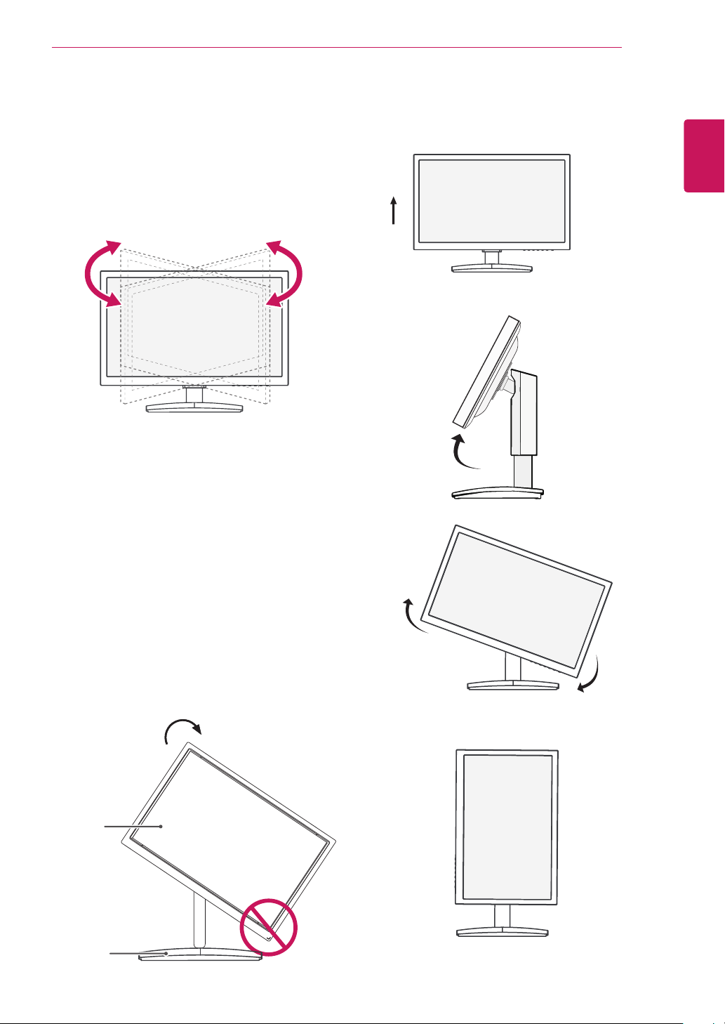
Swivel stand
y
Image shown may differ from your Monitor
set.
1
Swivel 355 degrees and adjust the angle of the
Monitor set to suit your view.
1
Lift the monitor to its highest height to utilize
the Pivot function.
Using the Pivot function
The pivot function allows you to rotate the screen
90 degrees clockwise.
2
Landscape & Portrait : You can rotate the panel
90° clockwise. Please be cautious and avoid
contact between the monitor head and the
Stand Base when rotating the screen to access
the Pivot function. If the monitor head touches
the Stand Base, then the Stand Base could
crack.
Head
section
Stand
section
3
Be careful with the cables when rotating the
screen.
10
ENG
English
ASSEMBLING AND PREPARING
3.94 inches
3.94 inches
3.94 inches
3.94 inches
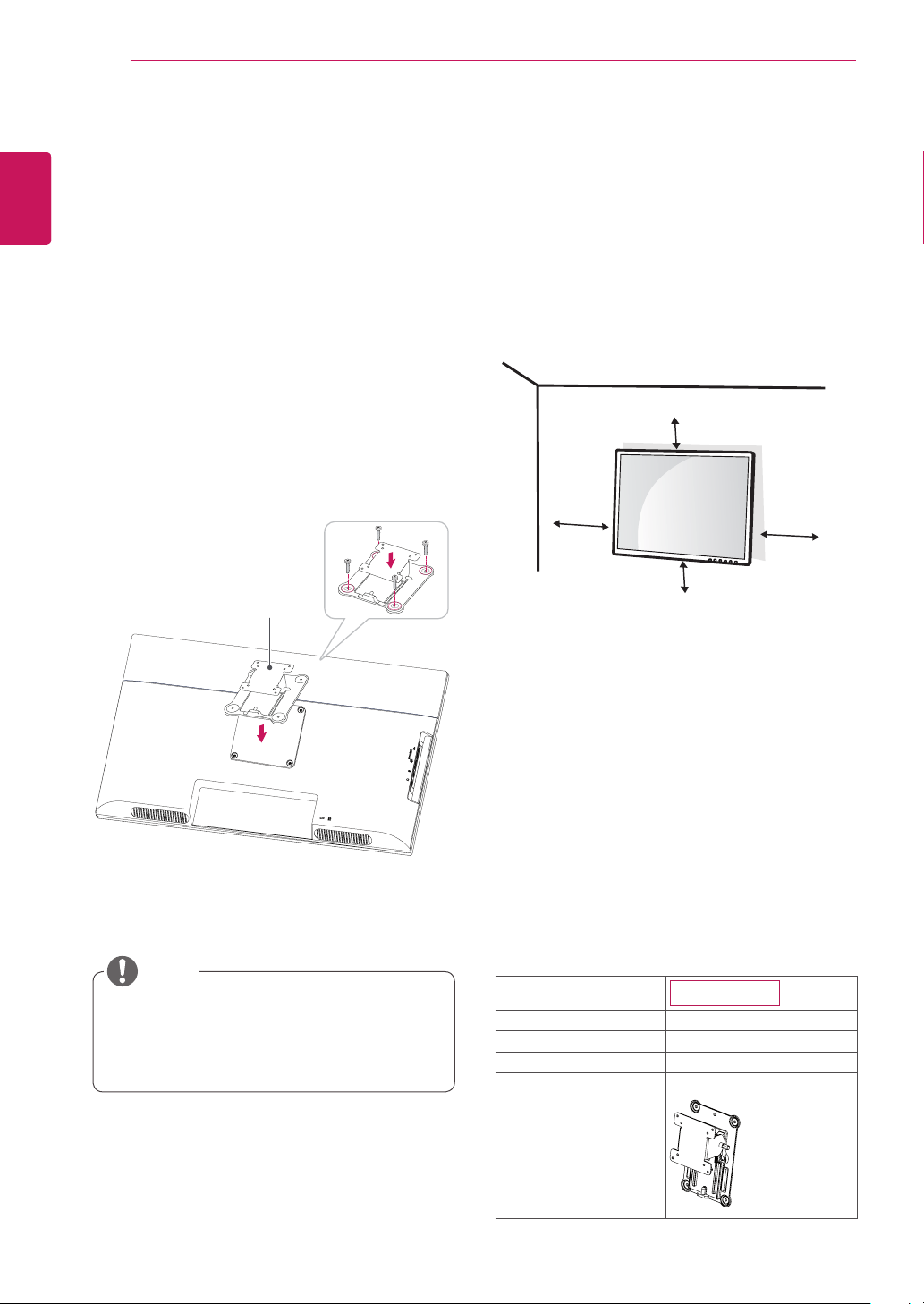
If you intend to mount the Monitor set to a wall,
attach Wall mounting interface (optional parts) to
the back of the set.
When you install the Monitor set using a wall
mounting interface (optional parts), attach it
carefully so it will not drop.
1 If you use screw longer than standard, the moni-
tor might be damaged internally.
2 If you use improper screw, the product might be
damaged and drop from mounted position.
In this case, LG Electronics is not responsible
for it.
Mounting on a wall
Install the monitor at least 3.94 inches away from
the wall and leave about 3.94 inches of space at
each side of the monitor to ensure sufficient ven-
tilation. Detailed installation instructions can be
obtained from your local retail store. Please refer
to the manual to install and set up a tilting wall
mounting bracket.
Installing the wall mount plate
This monitor has a VESA compatible mount on the
back. Most mounts will require an LG mounting
plate.
1
Place the monitor's screen face down. To
protect the screen from scratches, cover the
surface with a soft cloth.
2
Place the wall mount plate on the monitor and
align it with the screw holes on the monitor.
3
Using a screwdriver, tighten the four screws to
fix the plate onto the monitor.
y
The wall mount plate is sold separately.
y
For more information on the installation, refer
to the wall mount plate's installation guide.
NOTE
Wall Mount Plate
Model
24CAV37K
Wall Mount (A x B)
100 x 100
Stand Screw
M4
Number of screws
4
Wall Mount Plate
(Optional)
RW120
11
ENG
English
ASSEMBLING AND PREPARING
Disconnect the power cord first, and then
move or install the Monitor set. Otherwise
electric shock may occur.
If you install the Monitor set on a ceiling or
slanted wall, it may fall and result in severe
injury.
Use only an authorized LG wall mount
and contact the local dealer or qualified
personnel.
Do not over tighten the screws as this may
cause damage to the Monitor set and void
your warranty.
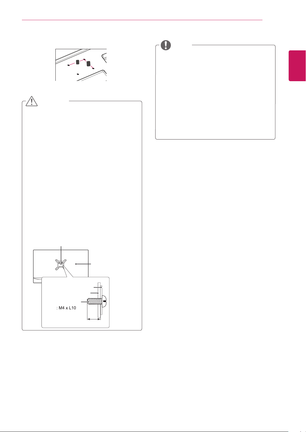
Use only screws and wall mounts that
meet the VESA standard. Any damages
or injuries by misuse or using an improper
accessory are not covered by the warranty.
Screw length from outer surface of back
cover should be under 8mm.
Use the screws that are listed on the VESA
standard screw specifications.
The wall mount kit will include an installation
manual and necessary parts.
The wall mount bracket is optional. You can
obtain additional accessories from your local
dealer.
The length of screws may differ depending
on the wall mount. Be sure to use the proper
length.
For more information, refer to the
instructions supplied with the wall mount.
CAUTION
NOTE
Back Cover
Wall mount Pad
Wall mount Pad
Back Cover
Standard screw
Max.8mm
VESA (A x B)
A
B
Wall Mount (A x B)
12
ENG
English
USING THE MONITOR SET
USING THE MONITOR SET
Connecting Input Signal Cable
This monitor supports the *Plug and Play
feature.
*Plug and Play: A feature that allows you to
add a device to your computer, without having
to reconfigure anything or install any manual
drivers.
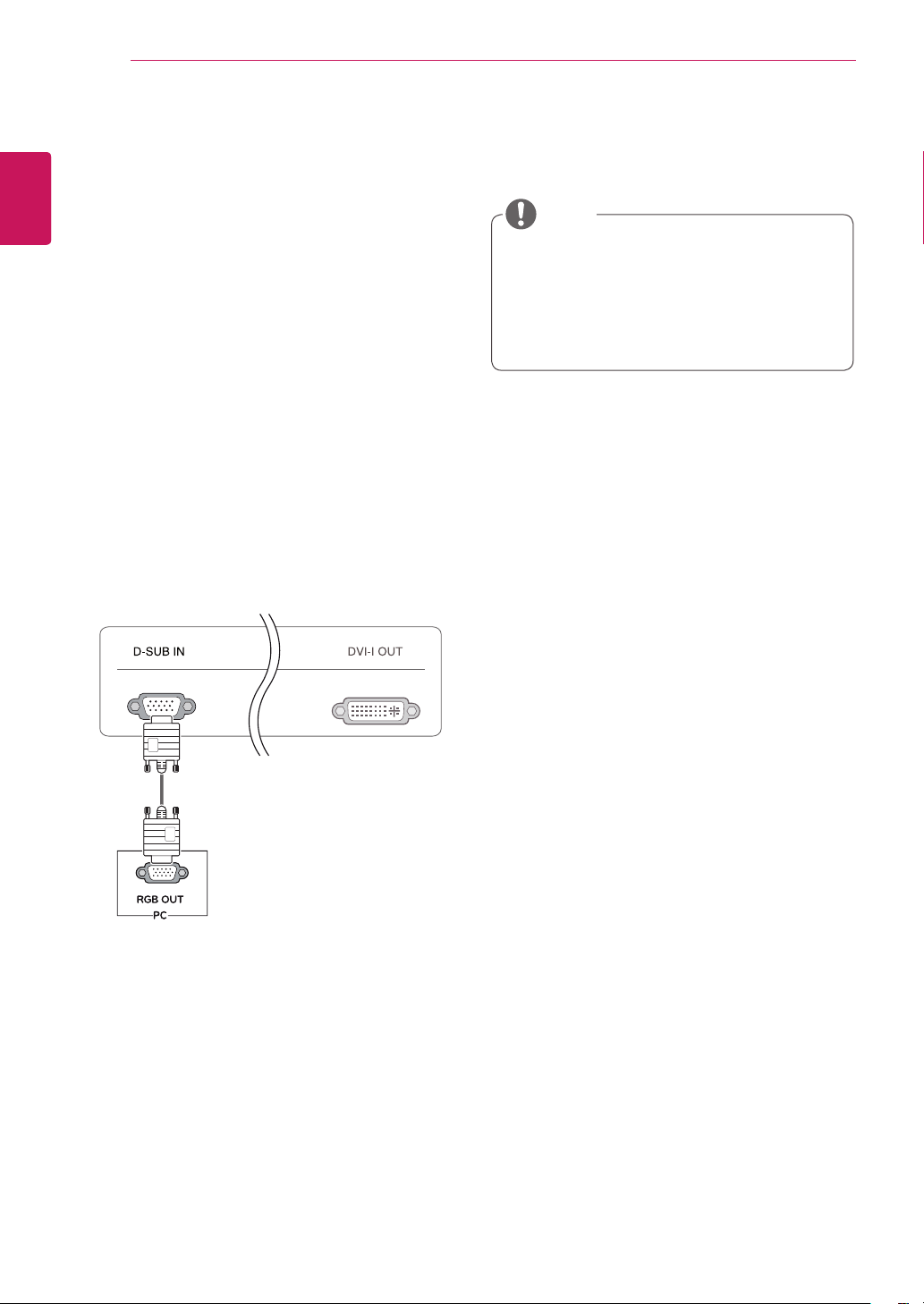
D-SUB IN connection - PC
D-SUB IN transfers analog video signals from the
PC to the monitor.
Connect the monitor to the PC using the provided
15-pin D-SUB signal cable as illustrated below.
NOTE
RGB IN
MONITOR
Apple Adapter
An adapter may be needed for Apple
computers. This adapter can be purchased
from Apple.
13
ENG
English
USING THE MONITOR SET
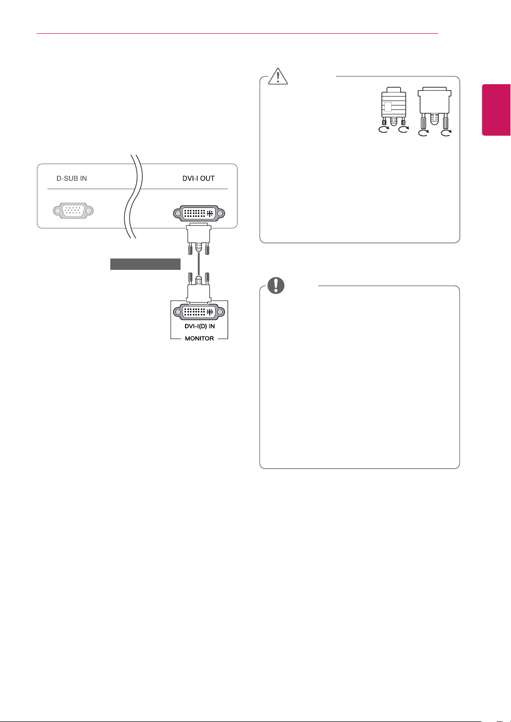
DVI connection
Transfers digital video signals from the Cloud Mon-
itor to an extended monitor.
Connect the Cloud Monitor to an extended monitor
using a DVI cable.
To connect the monitor to a computer, use
the appropriate signal cable (LAN and D-
SUB).
A converter can be used to convert the DVI-I
input signal to D-SUB input signal.
When connecting the power cord to the out-
let, use a grounded (3-hole) multi-socket or a
grounded wall outlet.
The monitor may flicker when turned on in an
area of low temperature. This is normal.
Sometimes red, green or blue spots may ap-
pear on the screen. This is normal.
Connect the input signal
cable and tighten in the
direction of the arrow. To
prevent disconnection
secure the cable tightly.
Do not press on the screen for a prolonged
time. This may cause image distortion.
Do not display a still image on the screen
for a prolonged time. This may cause image
retention. If possible, use the screen saver.
CAUTION
NOTE
(sold separately)
14
ENG
English
USING THE MONITOR SET
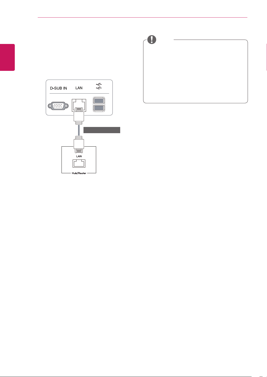
Connecting LAN/Peripherals
LAN connection
Connect the router or switch to the monitor using a
LAN cable as illustrated below.
The LAN cable is sold separately.
The following LAN cable type can be used:
Standard: IEEE 802.3 ETHERNET
If a device is connected into the earphone
out port via a LAN cable, you can adjust the
volume with the volume icon on PC taskbar.
Connect the LAN cable and the peripheral
devices prior to booting up the PC.
NOTE
(sold separately)
15
ENG
English
USING THE MONITOR SET
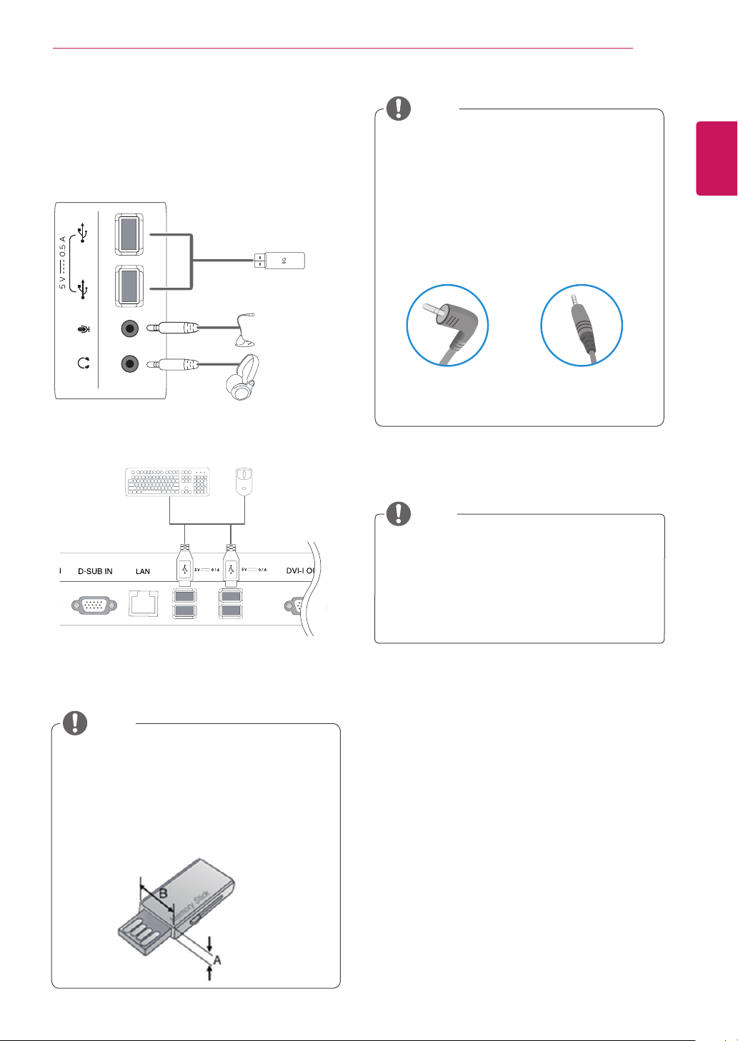
Peripheral devices are sold separately.
The USB ports on the left and bottom of the
monitor can be used to connect the key-
board, mouse, and other USB devices.
Cables with angled plugs may have clear-
ance issues, use straight plugs when pos-
sible.
Angle Type Straight Type
Peripheral device connection
Connect peripheral devices to the monitor using
USB, microphone and headphone ports.
NOTE
NOTE
Headphones, speakers or microphone may
not work normally, depending on the server
PC settings.
Virtual solutions may affect the functions or
speed of the specific USB storage device.
Left
Bottom
1
1
1
1
When the user use the USB devices to con-
nect the top and bottom ports at the same
time, Please refer the below depth and length
of USB for optimal connection.
NOTE
A ≤ 8.5 mm B ≤ 18 mm
16
ENG
English
USING THE MONITOR SET
What is "Self Image Adjustment"? This func-
tion runs when the monitor is connected for
the first time and performs automatic image
adjustment for each signal (only available for
analog [D-SUB input] signals) to provide an
optimal screen display.
Self Image Adjustment
Press the power button on the front to turn on
the monitor. When powered on, the
"Self Image
Adjustment"
function will run automatically (only
available for analog [D-SUB input] signals).
NOTE
17
ENG
English
CUSTOMIZING SETTINGS
CUSTOMIZING SETTINGS
1
Press the desired button on the bottom of the Monitor set.
2
Change the value of the menu item by pressing the buttons on the bottom of the Monitor set.
To return to the upper menu or set other menu items, use the up arrow ( ) button.
3
Select
EXIT
to leave the OSD menu.
Monitor set Buttons
Button Description
MENU Activates the main menu.
OSD Lock/Unlock
Functions
This function allow you to lock the current control settings, so
that they cannot be inadvertently changed.
Press and hold the MENU button for several seconds. Then
OSD of “OSD Lock” will appear. After that, user can select
lock or unlock by pressing left/right button.
If user selects the “Lock” icon by pressing the “OK” button,
the message “OSD Locked” will appear. Otherwise, “OSD
Unlocked” will appear. After selecting the “Lock”, If you want
to change to Unlock, you can push the “MENU” button for
several seconds. The message “OSD Unlocked” will appear.
VOL
Adjust the volume of the monitor.(only works in Cloud mode)/the left arrow key.
CLOUD
Disconnects the connection when the key is pressed for a few seconds while in Cloud
mode;the right arrow key.
AUTO To adjust the monitor settings, press the AUTO button on the MONITOR SETUP OSD
menu (only supported for analog signal).
For optimal screen display, use the following resolution.
Optimal Resolution 1920 x 1080
INPUT Allows selection of the input signal.
If you connect the monitor to a computer using a D-SUB cable, select either the
CLOUD or D-SUB input signal.
The initial input signal is D-SUB.
EXIT Exits the OSD menu.
(Power Button)
D-SUB Input: Power On/Off
CLOUD Input
Monitor Off: Press the power button once then the monitor will be turned off after 5
seconds.
CLOUD Off: Press the power button twice then the monitor and CLOUD connection
will be disabled.
CLOUD On: Press the power button.
Power Indicator The power indicator stays white if the display is running
properly (On Mode). If the display is in Sleep Mode, the
power indicator blinks white.
18
ENG
English
CUSTOMIZING SETTINGS
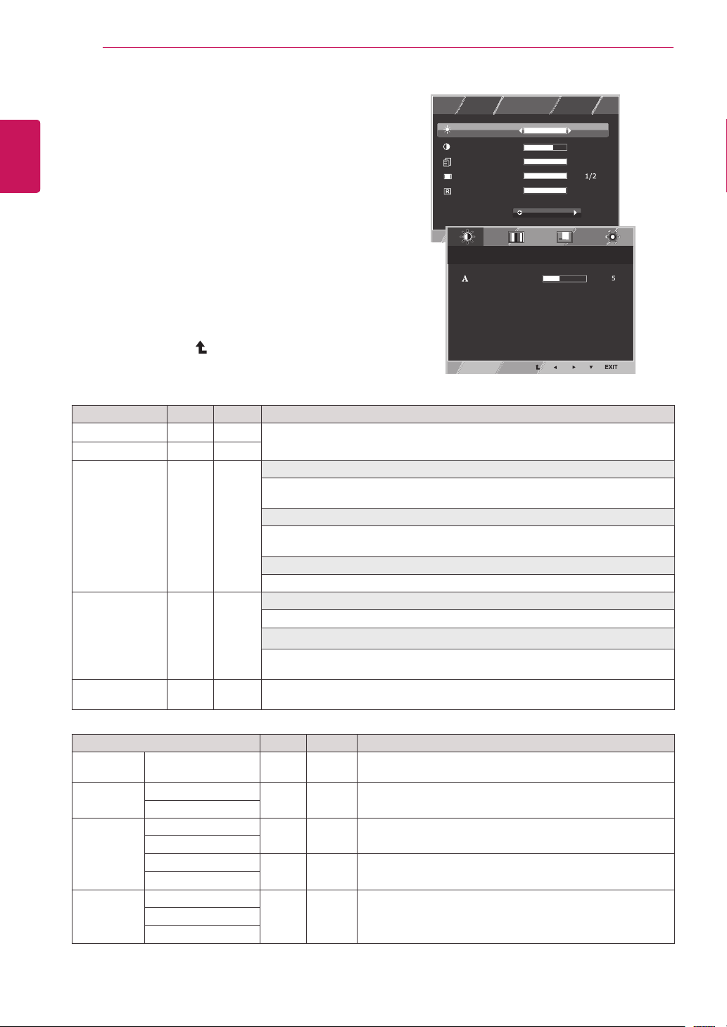
Customizing Settings
Menu Settings
1
Press
MENU
button on the bottom of the Monitor set
to display the
Menu
OSD.
2
Set the options by pressing the ◄ or ► or ▼
buttons.
3
Select the "
Next Menu
" button to enter the more
option settings.
4
Select
EXIT
to leave the OSD menu.
To return to the upper menu or set other menu items,
use the up arrow ( ) button.
Each option is explained below.
Menu > Next Menu
D-SUB CLOUD Description
Picture
Sharpness
● ●
To adjust the clearness of the screen .
Color Gamma
● ●
To customize the color of the screen
Color Temp
Display Horizontal
●
To adjust the position of the screen
Vertical
Clock
●
To improve the clarity and stability of the screen
Phase
Others Language
● ●
To customize the screen status for a user's operating
environment
Cloud
Power Indicator
CLOUD:
Using PC via a network.
Menu
D-SUB CLOUD Description
Brightness
● ●
To adjust the brightness, contrast of the screen
Contrast
● ●
Reader Mode
● ●
Reader 1
It is a mode that the screen is adjusted to the best for the newspaper. If you want
screen more bright, you can control brightness in Menu OSD.
Reader 2
It is a mode that the screen is adjusted to the best for the cartoon. If you want
screen more bright, you can control brightness in Menu OSD.
Reader Off
It is a mode that reader mode is off.
Wide/Original
● ●
Wide
Switch to full screen mode according to input image signal.
Original
Change the input image signal ratio to original.
* This function works only if input resolution is lower than Monitor set ratio (16:9).
Reset
● ●
Restore all factory default settings. Press the
◄
,
►
buttons to reset
immediately.
Reader Mode
3/3
70
100
1/2
Reset
Wide / Original
Brightness
Contrast
Menu
Menu > Next Menu > Picture
Sharpness
Menu > Next Menu > Color
Gamma
Color Temp
Red
Green
Blue
Menu > Next Menu > Display
Horizontal
Vertical
Clock
Phase
Menu > Next Menu > Others
Language
Cloud
Power Indicator
Volume
Off
Wide
No
Next Menu
Gamma 1
Custom
English
Off
Off
19
ENG
English
CUSTOMIZING SETTINGS
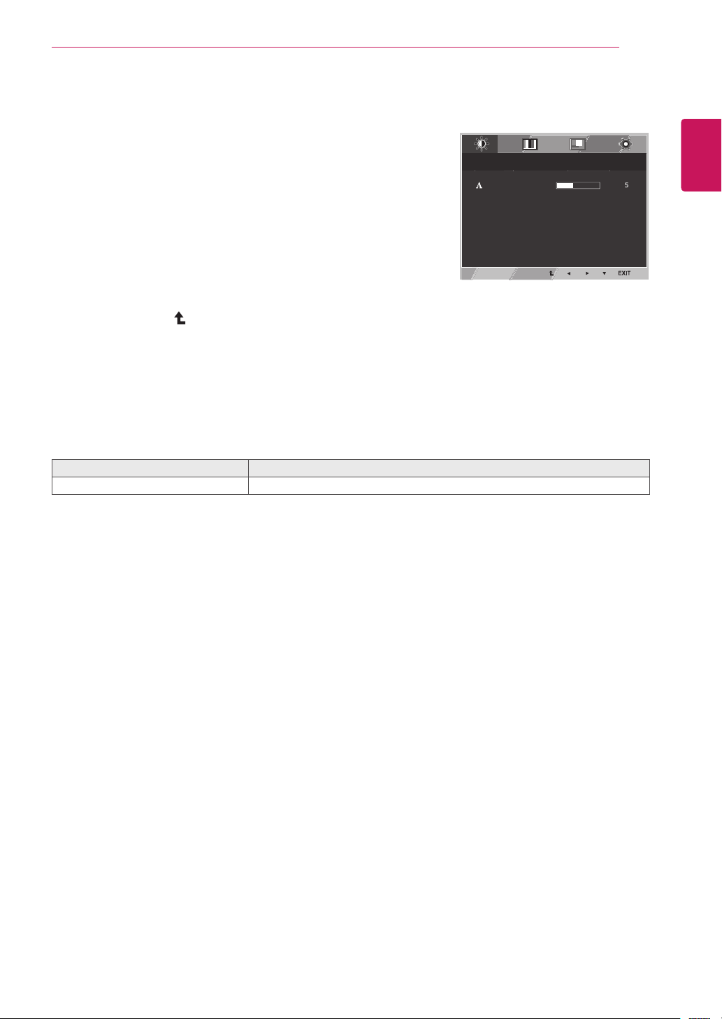
Picture
1
Press
Menu
button on the bottom of the Monitor set
to display the
Menu
OSD.
2
Select the "
Next Menu
" button to enter the more
option settings.
3
Enter to
Picture
by pressing the ▼ button.
4
Set the options by pressing the ◄ or ► buttons.
5
Select
EXIT
to leave the OSD menu.
To return to the upper menu or set other menu items,
use the up arrow ( ) button.
Each option is explained below.
Menu > Next Menu > Picture
Description
Sharpness
To adjust the clearness of the screen.
Reader Mode
3/3
70
100
1/2
Reset
Wide / Original
Brightness
Contrast
Menu
Menu > Next Menu > Picture
Sharpness
Menu > Next Menu > Color
Gamma
Color Temp
Red
Green
Blue
Menu > Next Menu > Display
Horizontal
Vertical
Clock
Phase
Menu > Next Menu > Others
Language
Cloud
Power Indicator
Volume
Off
Wide
No
Next Menu
Gamma 1
Custom
English
Off
Off
20
ENG
English
CUSTOMIZING SETTINGS
Color
1
Press
MENU
button on the bottom of the Monitor set
to display the
Menu
OSD.
2
Select the "
Next Menu
" button to enter the more
option settings.
3
Select
Color
by pressing the ► button.
4
Enter to
Color
by pressing the ▼ button.
5
Set the options by pressing the ◄ or ► or ▼
buttons.
6
Select
EXIT
to leave the OSD menu.
To return to the upper menu or set other menu items,
use the up arrow ( ) button.
Each option is explained below.
Reader Mode
3/3
70
100
1/2
Reset
Wide / Original
Brightness
Contrast
Menu
Menu > Next Menu > Picture
Sharpness
Menu > Next Menu > Color
Gamma
Color Temp
Red
Green
Blue
Menu > Next Menu > Display
Horizontal
Vertical
Clock
Phase
Menu > Next Menu > Others
Language
Cloud
Power Indicator
Volume
Off
Wide
No
Next Menu
Gamma 1
Custom
English
Off
Off
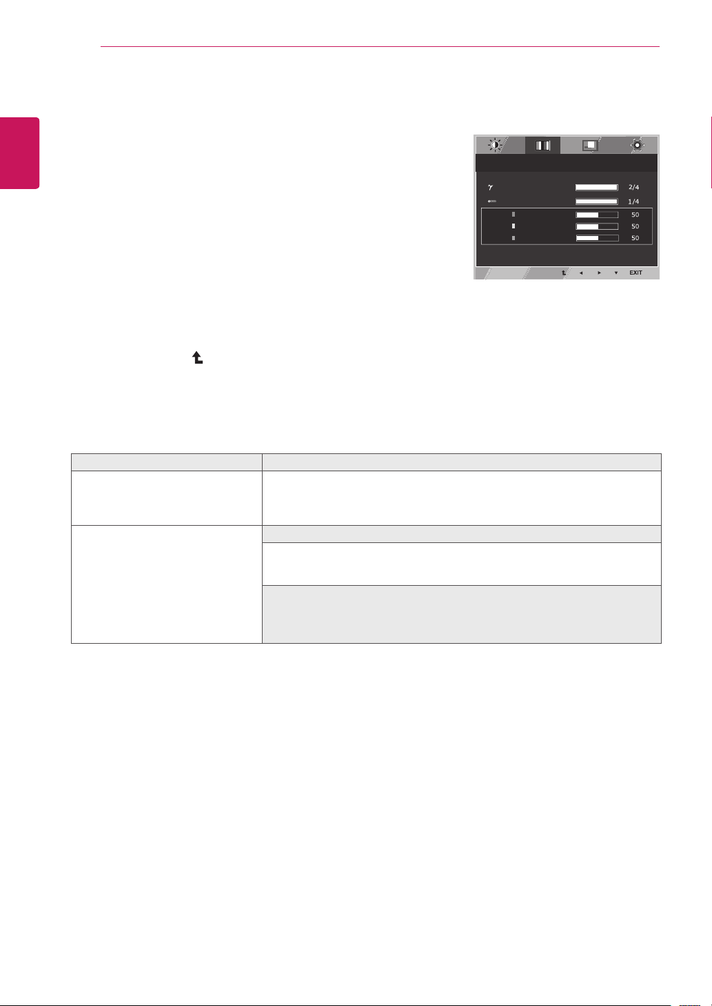
Menu > Next Menu > Color Description
Gamma Set your own gamma value. : Gamma 0, Gamma 1, Gamma 2, Off on
the monitor, high gamma values display whitish images and low gamma
values display blackish images.
If user don't want adjusted gamma, user can select Gamma off.
Color Temp Custom
• Red:
Set your own red color levels.
• Green:
Set your own green color levels.
• Blue:
Set your own blue color levels.
Select the screen color.
Warm:
Set the screen to warm color temperature (more red).
Medium:
Set the screen to medium color temperature.
Cool:
Set the screen to cool color temperature (more blue).
21
ENG
English
CUSTOMIZING SETTINGS
Display
1
Press
MENU
button on the bottom of the Monitor set
to display the
Menu
OSD.
2
Select the "
Next Menu
" button to enter the more
option settings.
3
Select
Display
by pressing the ► button.
4
Enter to
Display
by pressing the ▼ button.
5
Set the options by pressing the ◄ or ► or ▼
buttons.
6
Select
EXIT
to leave the OSD menu.
To return to the upper menu or set other menu items,
use the up arrow ( ) button.
Each option is explained below.
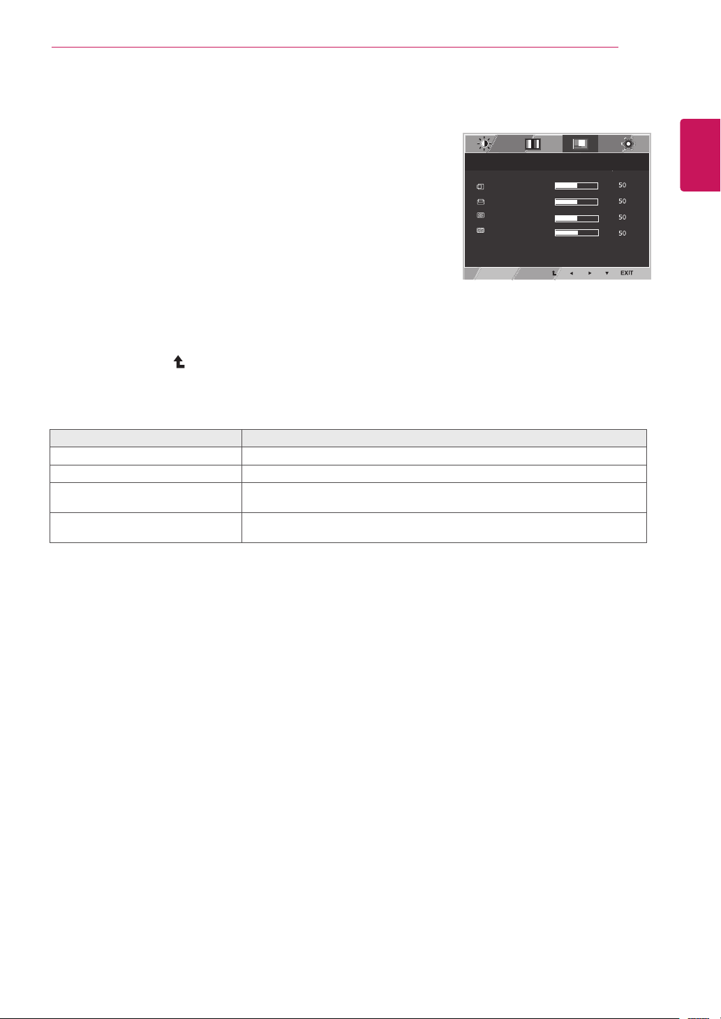
Menu > Next Menu > Display
Description
Horizontal
To move image left and right.
Vertical
To move image up and down.
Clock
To minimize any vertical bars or stripes visible on the screen background.The
horizontal screen size will also change.
Phase
To adjust the focus of the display. This item allows you to remove any horizontal
noise and clear or sharpen the image of characters.
Reader Mode
3/3
70
100
1/2
Reset
Wide / Original
Brightness
Contrast
Menu
Menu > Next Menu > Picture
Sharpness
Menu > Next Menu > Color
Gamma
Color Temp
Red
Green
Blue
Menu > Next Menu > Display
Horizontal
Vertical
Clock
Phase
Menu > Next Menu > Others
Language
Cloud
Power Indicator
Volume
Off
Wide
No
Next Menu
Gamma 1
Custom
English
Off
Off
Only available in D-SUB input mode.
22
ENG
English
CUSTOMIZING SETTINGS
Others
1
Press
MENU
button on the bottom of the Monitor set
to display the
Menu
OSD.
2
Select the "
Next Menu
" button to enter the more
option settings.
3
Select
Others
by pressing the ► button.
4
Enter to
Others
by pressing the ▼ button.
5
Set the options by pressing the ◄ or ► or ▼
buttons.
6
Select
EXIT
to leave the OSD menu.
To return to the upper menu or set other menu items,
use the up arrow ( ) button.
Each option is explained below.
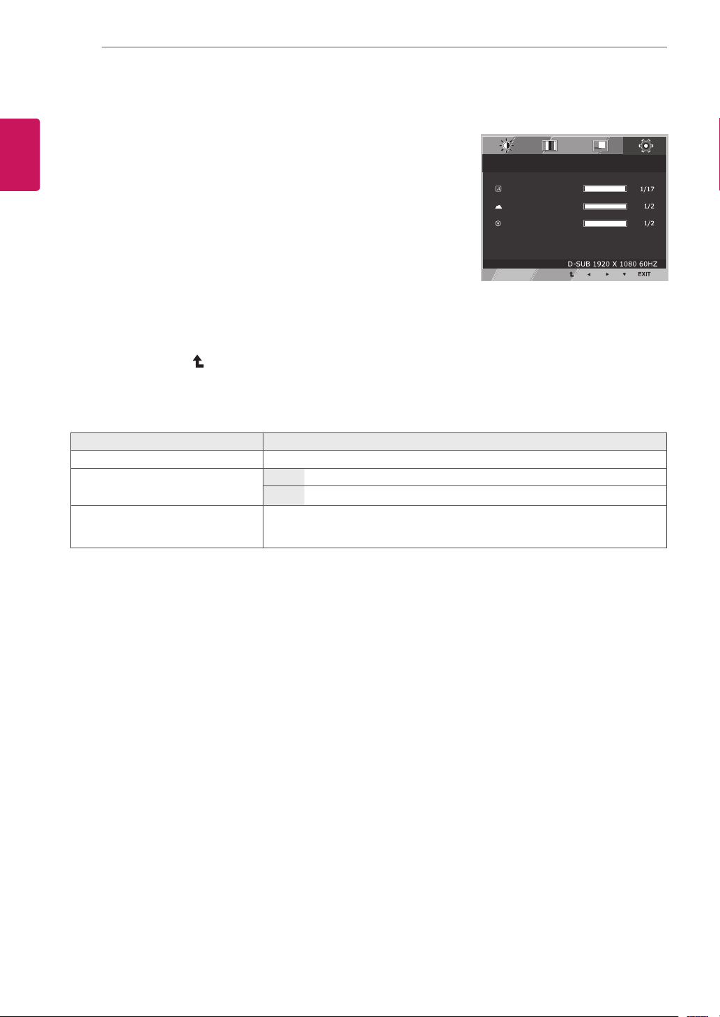
Menu > Next Menu > Others
Description
Language
To choose the language in which the control names are displayed.
Cloud
Off
CLOUD is disabled in D-SUB input mode.
On
CLOUD is enabled in D-SUB input mode.
Power
Indicator
Use this function to set the power indicator on the bottom side of the monitor to
On or Off.If you set Off, it will go off.
If you set On at any time, the power indicator will automatically be turned on.
Reader Mode
3/3
70
100
1/2
Reset
Wide / Original
Brightness
Contrast
Menu
Menu > Next Menu > Picture
Sharpness
Menu > Next Menu > Color
Gamma
Color Temp
Red
Green
Blue
Menu > Next Menu > Display
Horizontal
Vertical
Clock
Phase
Menu > Next Menu > Others
Language
Cloud
Power Indicator
Volume
Off
Wide
No
Next Menu
Gamma 1
Custom
English
Off
Off
23
ENG
English
CUSTOMIZING SETTINGS
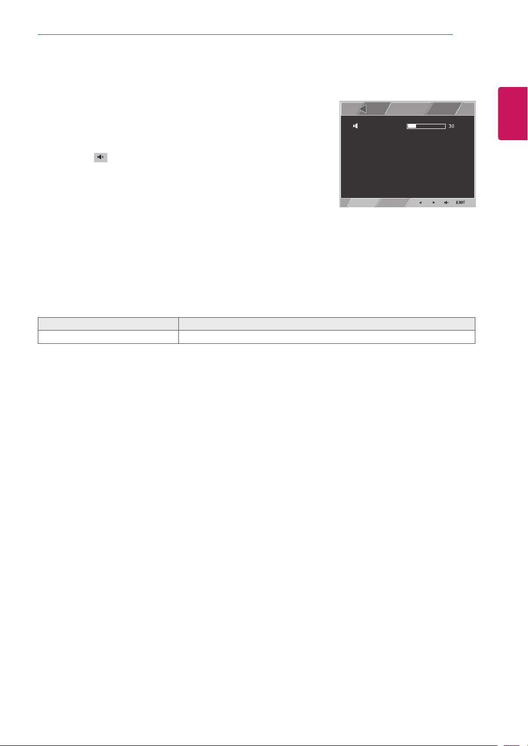
Volume
1
Press the
VOL
button at the bottom of the monitor to
display the
VOL
OSD menu.
2
Press the ◄ or ► button to adjust the volume.
3
Press the button to enable or disable Mute.
4
Select
EXIT
to leave the OSD menu.
Each option is explained below.
Volume
Description
Volume
Adjusts the volume (only available in CLOUD input mode).
Reader Mode
3/3
70
100
1/2
Reset
Wide / Original
Brightness
Contrast
Menu
Menu > Next Menu > Picture
Sharpness
Menu > Next Menu > Color
Gamma
Color Temp
Red
Green
Blue
Menu > Next Menu > Display
Horizontal
Vertical
Clock
Phase
Menu > Next Menu > Others
Language
Cloud
Power Indicator
Volume
Off
Wide
No
Next Menu
Gamma 1
Custom
English
Off
Off
24
ENG
English
Troubleshooting
TROUBLESHOOTING
Vertical Frequency:
In order to display an image, the screen must be refreshed dozens of times per
second like a fluorescent lamp. The number of times the screen is refreshed per second is called
vertical frequency or refresh rate and is represented by Hz.
Horizontal Frequency:
The time it takes to display one horizontal line is called the horizontal cycle.
The number of horizontal lines displayed in one second
can be calculated by dividing one by the horizontal cycle. This is called horizontal frequency and is
represented by kHz.
NOTE
Check the following before calling for service.
No image appears
Is the power cord of the display
connected?
Check and see if the power cord is connected properly to the power
outlet.
Is the power indicator light on?
Press the Power button.
Is the power on and the power
indicator White?
Adjust the brightness and the contrast.
Is the power indicator flickering?
If the display is in power saving mode, try moving the mouse or
pressing any key on the keyboard to bring up the screen.
Try to turn on the PC.
Do you see an "OUT OF RANGE"
message on the screen?
This message appears when the signal from the PC (video card) is
out of horizontal or vertical frequency range of the display. See the
'Specifications' section of this manual and configure your display
again.
Is the No Signal message being
displayed?
This is displayed when the signal cable between the PC and the
monitor is missing or disconnected. Check the cable and reconnect it.
Do you see a "OSD LOCKED" message on the screen?
Do you see “OSD LOCKED” when
you push MENU button?
You can secure the current control settings, so that they cannot be
inadvertently changed. You can unlock the OSD controls at any time
by pushing the MENU button for several seconds: the message “OSD
UNLOCKED” will appear.
Display image is incorrect
Display Position is incorrect.
Press the
AUTO
button to automatically adjust your display image to
the ideal setting.
On the screen background, vertical
bars or stripes are visible.
Press the
AUTO
button to automatically adjust your display image to
the ideal setting.
Any horizontal noise appearing in
any image or characters are not
clearly portrayed.
Press the
AUTO
button to automatically adjust your display image to
the ideal setting.
Check
Control Panel ► Display ► Settings
and adjust the display
to the recommended resolution or adjust the display image to the ideal
setting. Set the color setting higher than 24 bits (true color).
25
ENG
English
Troubleshooting
Check if the video card's resolution or frequency is within the range allowed by the monitor and set to
the recommended (optimal) resolution in
Control Panel >
Display > Settings.
Failing to set the video card to the recommended (optimal) resolution may result in blurred text, a
dimmed screen, a truncated display area or misalignment of the display.
The configuration procedure may differ depending on your computer and/or operating system. Also,
some video cards may not support certain resolutions. If this is the case, contact the computer or
video card manufacturer for assistance.
The AUTO option is only available for D-SUB (analog) signals.
The display color is abnormal.
Does the display color appear dis-
colored (16 color)?
Set the color to 24 bit (true color) or higher. In Windows, go to Control
Panel > Display > Settings > Color Quality.
Does the display color appear un-
stable or in monochrome?
Check if the signal cable is connected properly. Re-connect the cable
or re-insert the PC's video card.
Are there spots on the screen?
When using the monitor, pixilated spots (red, green, blue, white or
black) may appear on the screen. This is normal for the LCD screen.
It is not an error nor is it related to the monitor's performance.
NOTE
26
ENG
English
Product Specication
PRODUCT SPECIFICATION
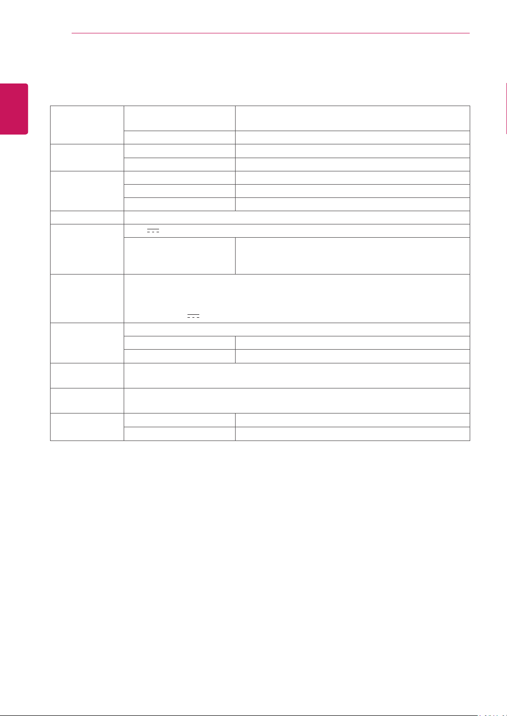
LCD Screen Type TFT (Thin Film Transistor)
LCD (Liquid Crystal Display) Screen
Pixel Pitch 0.2745 mm x 0.2745 mm
Resolution Maximum Resolution 1920 x 1080 @ 60 Hz
Recommended Resolution 1920 x 1080 @ 60 Hz
Video Signal Horizontal Frequency 30 kHz to 69 kHz
Vertical Frequency 57 Hz to 63 Hz
Synchronization Separate Sync
Input Connector 15-pin D-SUB (Analog)
Power 19 V
2.3 A
Power Consumption:
CLOUD/D-SUB
On Mode: 24 W(D-sub)/29 W(CLOUD)
Power Saving Mode ≤ 0.5 W(CLOUD mode:5.5 W)
Off Mode ≤ 0.5 W
AC/DC Adapter Type DA-48F19, manufactured by Asian Power Devices Inc.
Or type LCAP35,manufactured by LIEN CHANG ELECTRONIC ENTERPRISE
Or type PA-1650-43,manufactured by LITE-ON TECHNOLOGY CORPORATION
OUTPUT: 19 V
2.53 A
Dimension/
Weight
Monitor Size (Width x Height x Depth)
With Stand 56.9 cm x 39.0 cm x 25.9 cm
Without Stand 56.9 cm x 34.2 cm x 5.1 cm
Weight (Without
Packaging)
5.5 kg
Stand Angle
Adjustment
Forwards/Backwards: -5° to 35° (Monitor)
Environment
Condition
Operating Condition Temperature: 0°C to 40°C; Humidity: Less than 80%
Storing Condition Temperature: -20°C to 60°C; Humidity: Less than 85%
The specifications are subject to change without notice.
27
ENG
English
Product Specication
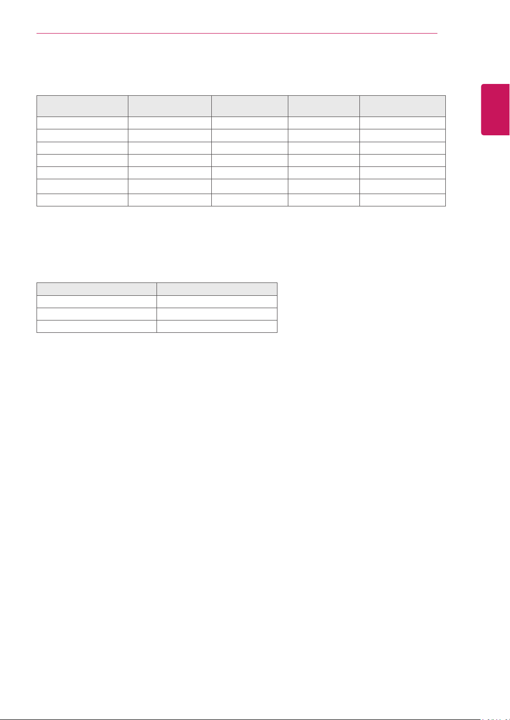
Preset Mode
Display Modes
(Resolution)
Horizontal
Frequency (kHz)
Vertical
Frequency (Hz)
Polarity (H/V) Remark
720 x 400 31.468 70.08 -/+
640 x 480 31.469 59.94 -/-
800 x 600 37.879 60.317 +/+
1024 x 768 48.363 60 -/-
1280 x 1024 63.981 60.02 +/+
1680 x 1050 65.290 59.954 -/+
1920 x 1080 67.5 60 +/+ Recommended Mode
Indicator
Mode LED Color
On Mode White
Sleep Mode Blinking White
Off Mode Off
28
ENG
English
Proper Posture
PROPER POSTURE
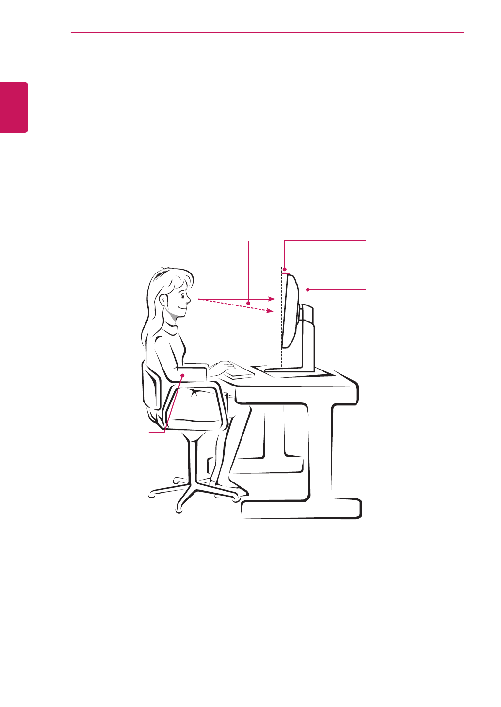
Proper posture for using the monitor
Adjust the angle so that the screen is slightly lower than your eyes.
Using the monitor for a prolonged period of time can cause eye fatigue. Take a 10-minute break every
hour.
The stand is designed to best support the monitor when the optimal conditions are selected.
Adjust the angle of the monitor from -5° to 35° to obtain the best view of the screen.
You should be
looking
slightly down at
the screen.
Place your hands gently
on the keyboard,
keeping your arms bent at
the elbows
and extended horizontally
in front of you.
Adjust the angle
from -5° to 35°
so that there is no re-
flection
or glare from the
screen.
29
ENG
English
Using CLOUD Solution
USING CLOUD SOLUTION
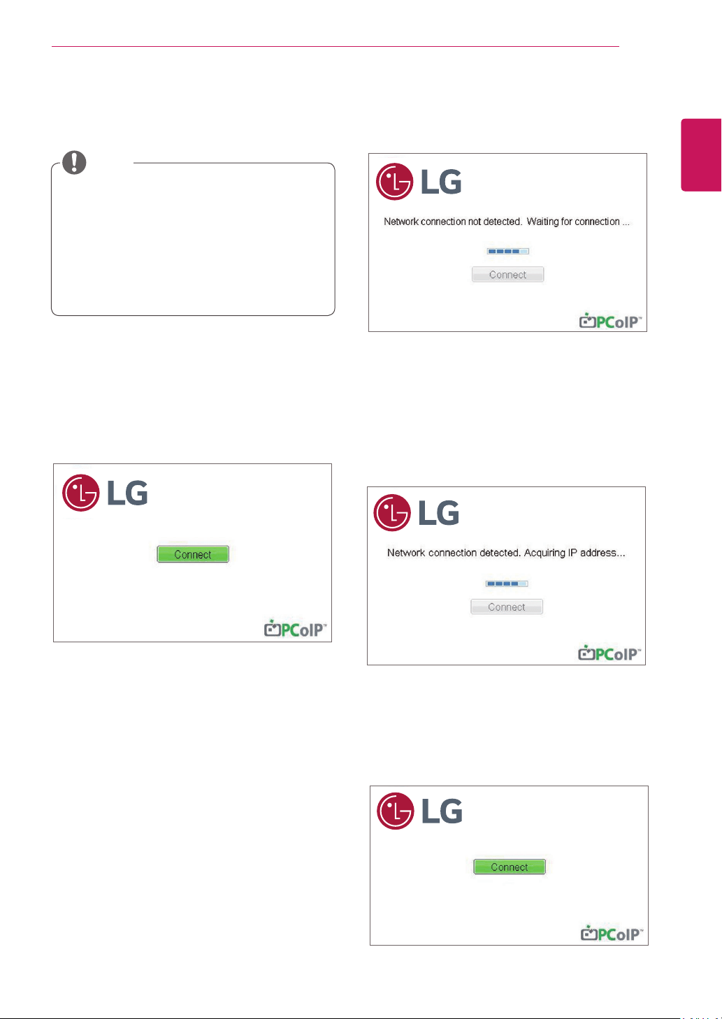
If the network is connected and IP is being ac-
quired, the message "Network connection detect-
ed. Acquiring IP address …" is displayed on the
Connection screen. Figure 2-3 shows the message
displayed when the network is ready and the IP is
being acquired.
The below is the Connection screen displayed
when network is completely ready.
If the network is not properly connected (e.g., dur-
ing portal boot up), or connection is being created,
the "Network connection lost. Waiting for connec-
tion …" message is displayed on the Connection
screen.
Figure 2-2 shows the message displayed when the
network is not ready.
<Figure 2-1: OSD Connect Screen>
<Figure 2-3: Acquiring the IP after Network Con-
nected>
Connect Screen
The Connect screen is shown during start-up,
except when the portal has been configured for a
managed start-up or auto-reconnect. The logo dis-
played above the Connect button can be changed
by uploading a replacement image via the admin
interface.
<Figure 2-2: Network Not Ready>
NOTE
Menus and functions in CLOUD mode may
be slightly different depending on the firm-
ware version.You can download the user
manual for each version from the Teradici
homepage: http://techsupport.teradici.com
To check the firmware version, see page
<51>.
<Figure 2-4: Network Ready>
30
ENG
English
Using CLOUD Solution
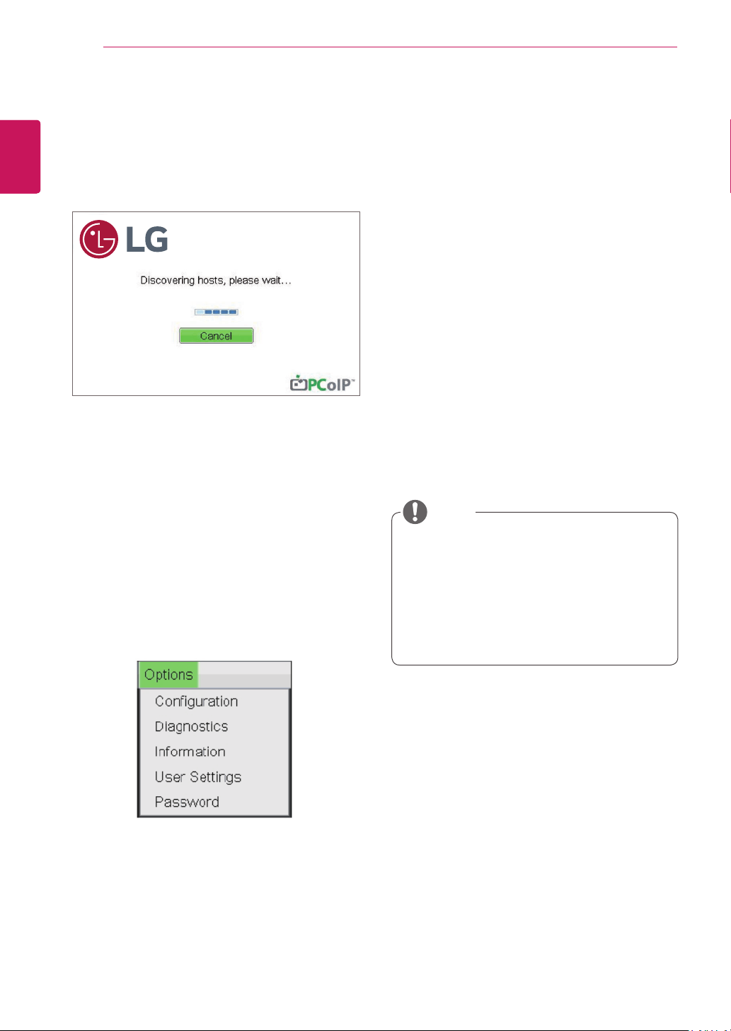
<Figure 2-5: OSD Connect Screen (Connecting)>
OSD Options Menu
Selecting the Options menu will produce a list of
selections. The OSD Options menu contains:
Configuration
Diagnostics
Information
User Settings
Password
Selecting one of the options will produce a settings
window.
Some PCoIP devices have their password
protection disabled and can be logged into
the management web page or access the
OSD parameters without a password. The
login page and the OSD's password protec-
tion can be enabled in the PCoIP manage-
ment console.
NOTE
If you select the Connect button, the connection
session is started. When the connection is pend-
ing, the "Discovering hosts, please wait…" mes-
sage is displayed on the OSD local GUI.When the
connection is established, the OSD local GUI will
disappear and be replaced by the session image.
<Figure 2-6: OSD Options Menu>
Configuration Window
In the Configuration window, the administrator can
access the window tabs that contain the settings to
configure and manage the portal environment.
The Configuration window has the following tabs:
Network
IPv6
SCEP
Label
Discovery
Session
Language
Power
Display
Access
Audio
Reset
Each tab contains OK, Cancel and Apply buttons
to allow the administrator to apply or cancel the
modified settings as well as the Advanced button
for advanced settings.
31
ENG
English
Using CLOUD Solution
In order to utilize the FQDN feature, a DNS
server, configured properly with DHCP option
81, must be used.
Gateway
The Gateway field contains the gateway IP ad-
dress of the device. If DHCP is disabled, this field
is required. If DHCP is enabled, this field cannot be
edited.
Primary DNS Server
The Primary DNS Server field contains the primary
DNS IP address of the device. This field is option-
al. If DHCP is enabled, this field cannot be edited.
Secondary DNS Server
The Secondary DNS Server field contains the sec-
ondary DNS IP address of the device. This field is
optional. If the DHCP is enabled, this field cannot
be edited.
Domain Name
The Domain Name field contains the domain name
used, e.g. "domain local". This field is optional. It speci-
fies on which domain the host or portal operates.
FQDN
The FQDN field represents the Fully Qualified Do-
main Name of the host or portal. The default value is
PCoIP-host-MAC or PCoIP-portal-MAC, where MAC
is the MAC address of the host or portal. If there is
a domain name, it will be added to the FQDN in the
format of PCoIP-host-MAC.domain.local
Ethernet Mode
The Ethernet Mode field specifies the portal's Eth-
ernet mode.
The available options are as follows.
Auto
100 Mbps Full-Duplex
10 Mbps Full-Duplex
Enable 802.1X Security
Enable this field for each of your remote worksta-
tion cards and zero clients if your network uses
802.1x security to ensure that only authorized
devices access the network.
NOTE
The network parameters can also be con-
figured using the Webpage Administration
Interface.
NOTE
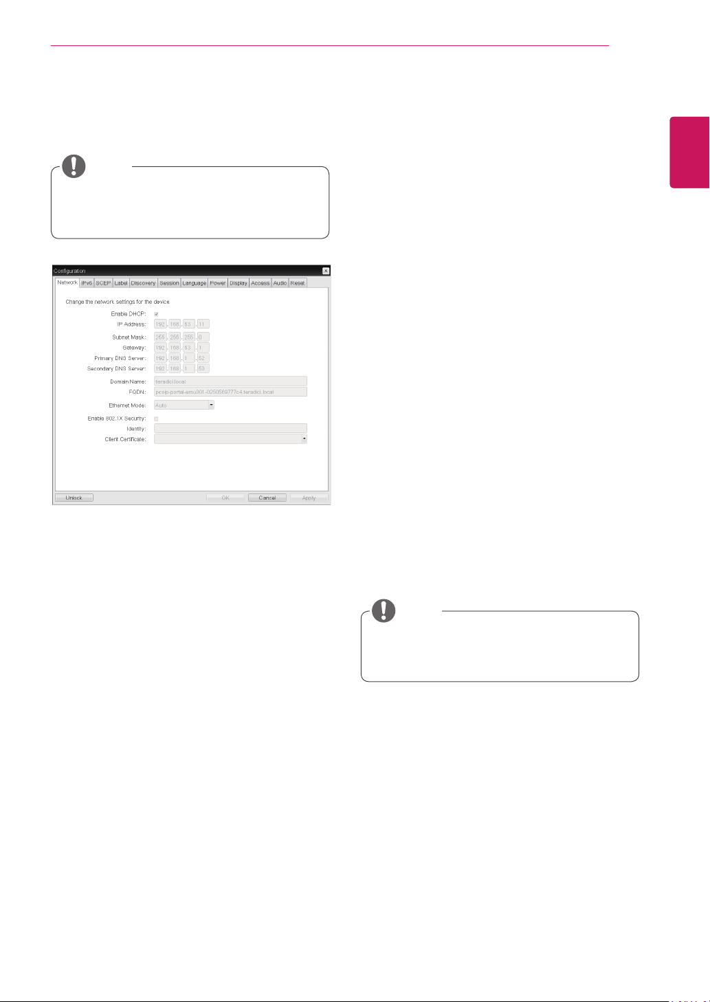
Network Tab
The Network tab allows the administrator to config-
ure the portal network parameters.
<Figure 2-7: Network Configuration>
Enable DHCP
If the Enable DHCP option is selected, a device will
be connected to the DHCP server. that allocates
the IP address, subnet mask, gateway IP address,
and DNS server. If this option is disabled, the
above parameters must be configured manually.
IP Address
The IP Address field contains the IP address of the
device. If DHCP is disabled, this field is required.
If DHCP is enabled, this field cannot be edited.
This field must contain the correct IP address. If an
incorrect IP address is provided, an OSD message
is displayed prompting the administrator to provide
the correct the IP address.
Subnet Mask
The Subnet Mask field contains the subnet mask
of the device. If DHCP is disabled, this field is
required. If DHCP is enabled, this field cannot be
edited. This field must have the correct subnet
mask. If an incorrect subnet mask is provided, an
OSD message is displayed prompting the adminis-
trator to provide the correct the subnet mask.
32
ENG
English
Using CLOUD Solution
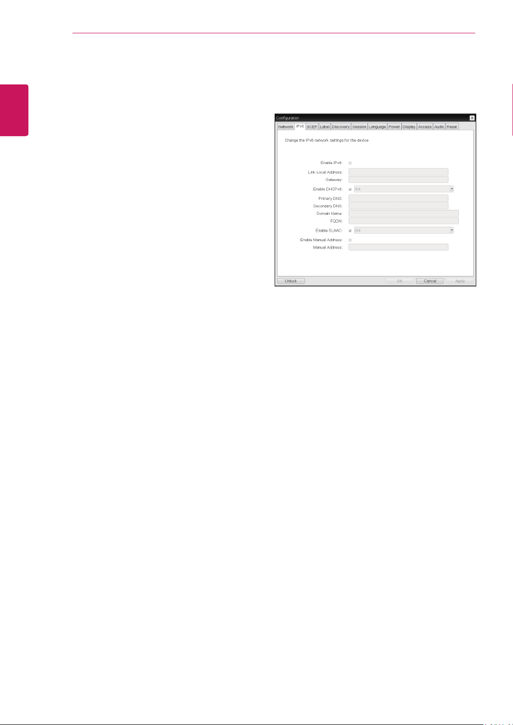
<Figure 2-8: IPv6 Configuration>
IPv6 Tab
The IPv6 tab is used when the portal is connected
to the network configured with the IP v6.
Enable IPv6
If you select Enable IPv6, the portal in use can be
connected to the network configured with the IPv6.
Link Local Address
The Link Local Address field is automatically filled
with the IP address of a device.
Gateway
The Gateway field contains the gateway IP ad-
dress of the device. Enter the gateway address to
be used by a device.
Enable DHCPv6
To assign the Dynamic Host Configuration Protocol
version 6 (DHCPv6) of a device select the Enable
DHCPv6 field.
Primary DNS Server
The Primary DNS Server field contains the pri-
mary DNS IP address of the device. This field is
optional. If DHCPv6 is enabled, this field cannot be
edited.
Identity
Enter the identity string used to identify your device
to the network.
Client Certificate
Click Choose to select the client certificate you
want to use for your 802.1x devices.
The list of certificates that appears includes the
certificate uploaded from the Certificate Upload
page that contain a private key.
If another network device (for example, a switch) is
configured to operate under 10 Mbps Full-Duplex,
100Mbps Full-Duplex or 1GbpsFull-Duplex, the
administrator should always set the Ethernet Mode
field to Auto; and if the device is to operate under
only one speed out of multiple settings, select ei-
ther 10 Mbps Full-Duplex or 100 Mbps Full-Duplex.
33
ENG
English
Using CLOUD Solution
Secondary DNS Server
The Secondary DNS Server field contains the sec-
ondary DNS IP address of the device. This field is
optional. If DHCPv6 is enabled, this field cannot
beedited.
Domain Name
The Domain Name field contains the domain name
used, e.g. "domain local". This field is optional. It
specifies on which domain the host or portal oper-
ates.
FQDN
The FQDN field represents the Fully Qualified Do-
main Name of the host or portal. The default value
is PCoIP-host-MAC or PCoIP-portal-MAC, where
MAC is the MAC address of the host or portal. If
there is a domain name, it will be added to the
FQDN in the format of PCoIP-host-MAC.domain.
local.
Enable SLAAC
Select the Enable SLAAC field to use the stateless
auto-configuration of the device.
Enable Manual Address
Select the Enable Manual Address field to enter
the device address manually.
Manual Address
In the Manual Address field, enter the IP address
manually.
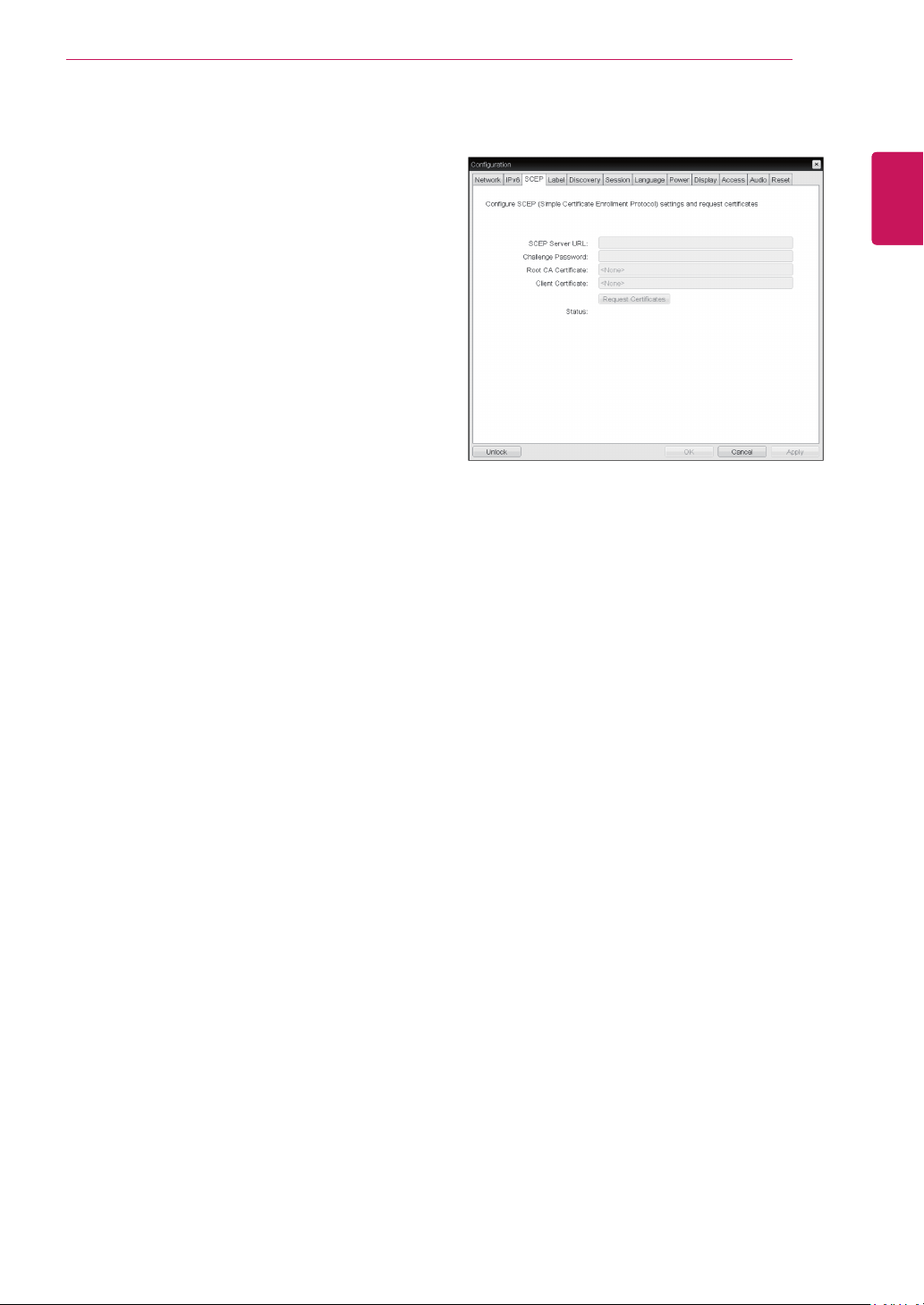
SCEP Tab
SCEP Server URL
Enter the URL for the SCEP server that is config-
ured to issue certificates for the device.
Challenge Password
Enter the password to present to the SCEP server.
Root CA Certificate
Displays the name of the root CA certificate that
has been installed in the device.
Client Certificate
Displays the name of the client certificate that has
been installed in the device.
Status
Displays the status of the request (e.g., in prog-
ress, successful, failed)
<Figure 2-9: SCEP Configuration>
34
ENG
English
Using CLOUD Solution
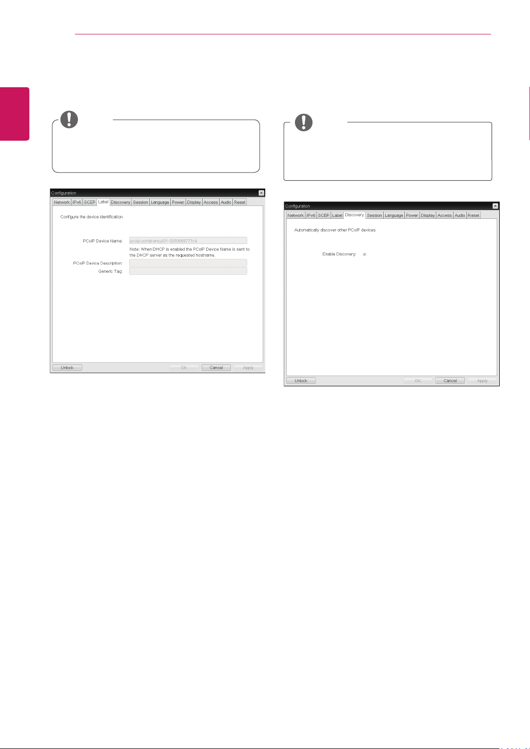
<Figure 2-9: Label Configuration>
Label Tab
The Label tab allows the administrator or host to
add customized information to the portal.
The portal label parameters can also be con-
figured using the Webpage Administration
Interface.
PCoIP Device Name
In the PCoIP Device Name field, the administrator
can specify a logical name to the host or portal.
The default value is PCoIP-host-MAC or PCoIP-
portal-MAC, where MAC is the MAC address of the
host or portal.
PCoIP Device Description
In the PCoIP Device Description field, the administra-
tor can add specific information, such as the endpoint
location, or add a description to the host or portal.
This field cannot be used in the PCoIP firmware and
accessibility is strictly limited to the administrator.
Generic Tag
In the Generic Tag field, the administrator can add a
generic tag to the host or portal.
This field cannot be used in the PCoIP firmware and
accessibility is strictly limited to the administrator.
NOTE
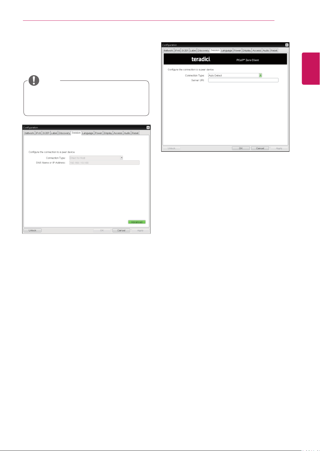
Enable Discovery
If the Enable Discovery option is selected, a device
will use SLP Discovery to dynamically locate the
peer device without requiring any information about
the location of the device in the network. This
means that the configuration and maintenance
work in a complicated system can be significantly
reduced.
As SLP Discovery requires a multicast-enabled
router, the recommended search structure is DNS-
SRV Discovery.
<Figure 2-11: Discovery Configuration>
Discovery Tab
The Discovery tab allows the administrator to eas-
ily find a portal in the PCoIP system.
The Discovery parameters can also be con-
figured using the Webpage Administration
Interface.
NOTE
<Figure 2-10: Label Configuration>
35
ENG
English
Using CLOUD Solution
<Figure 2-12: Session Configuration>
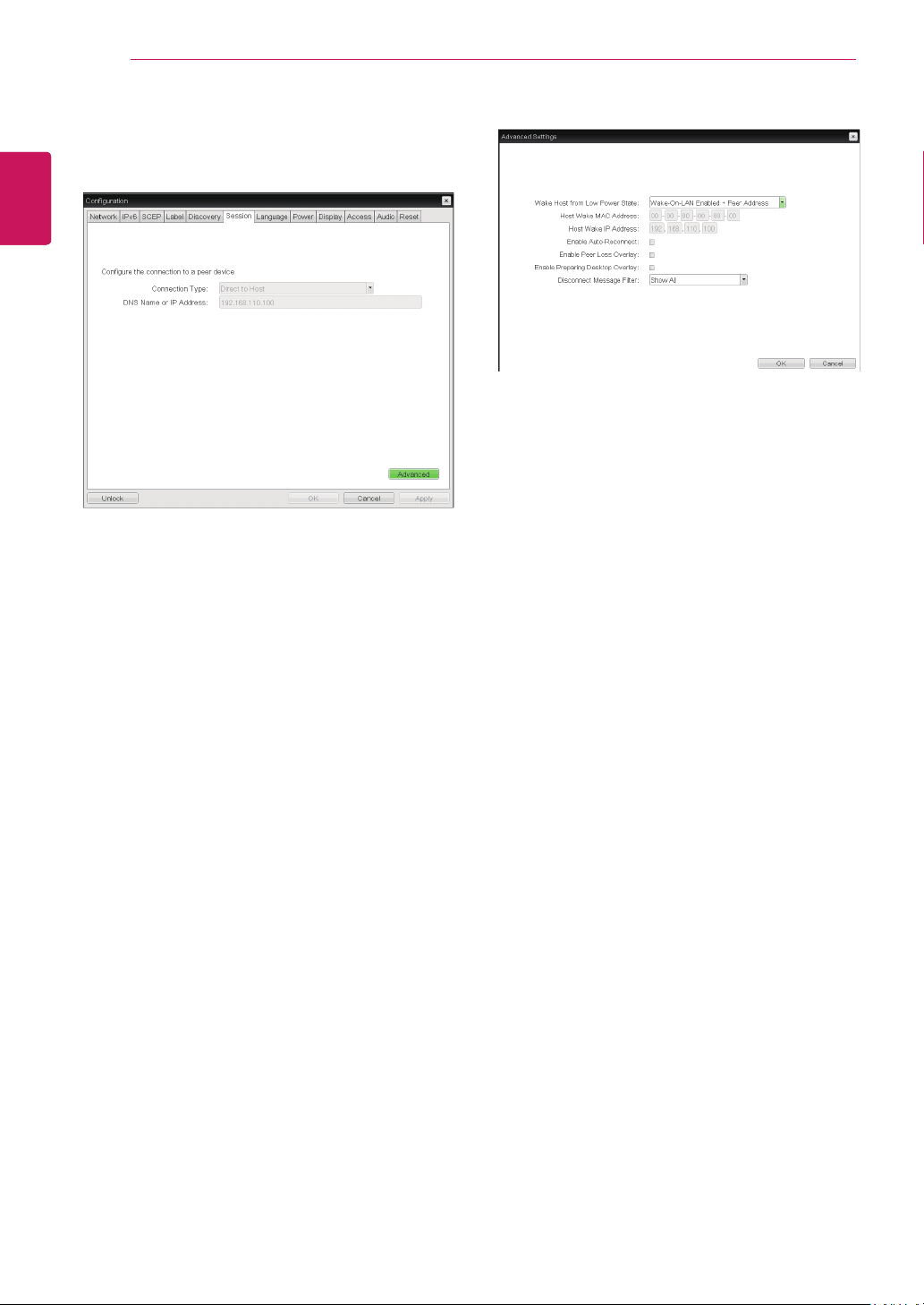
Session Tab
The Session tab allows the administrator to set the
method to connect the device to a peer device.
The Session parameters can also be con-
figured using the Webpage Administration
Interface.
NOTE
Connection Type
The Connection Type field allows the user to select
the device to be connected with the portal.
The Connection Type field has following options:
Auto Detect
Direct to Host
Direct to Host + SLP Host Discovery
PCoIP Connection Manager
PCoIP Connection Manager + Auto-Logon
View Connection Server
View Connection Server + Auto-Logon
View Connection Server + Kiosk
View Connection Server + Imprivata OneSign
Connection Management Interface
<Figure 2-13: Auto Detect Setting>
Auto Detect
This connection type automatically detects which
broker protocol a connection server is using so us-
ers in a mixed environment do not have to manu-
ally reconfigure the session type each time they
switch brokers.
Server URI
Enter the Uniform Resource Identifier (URI) of the
current connection broker.
36
ENG
English
Using CLOUD Solution
Wake Host from Low Power State
Select whether to use the host’s MAC address or
IP address when configuring the Wake-On-LAN
feature for a client. This feature wakes up the host
when the user presses the client’s remote PC
button or clicks the connect button on the connect
window.
Host Wake MAC Address
Enter the host’s MAC address to complete the host
wake up configuration when Wake-On-LAN En-
abled + Peer Address or Wake-On-LAN Enabled +
Custom Address is selected. This client will send
a “Magic packet” to this MAC address to wake the
host computer from a low power state.
Host Wake IP Address
Enter the host’s IP address to complete the host
wake up configuration when Wake-On-LAN En-
abled + Custom Address is selected. This client will
send a “Magic packet” to this IP address to wake
the host computer from a low power state.
<Figure 2-15: Advanced Settings for Direct to
Host>
Direct to Host
You can view the screen of the host PC by estab-
lishing 1:1 connection between the PCI host card
connected to the host PC through the entered IP
address of the host PC and the portal.
DNS Name or IP Address
Enter the DNS name or IP address of the host PC.
<Figure 2-14: Direct to Host Setting>
See below for information how to set for each op-
tion.
37
ENG
English
Using CLOUD Solution
<Figure 2-16: Direct to Host + SLP Host Discovery Set-
tings>
This setting is provided only for the client.
NOTE
Enable Peer Loss Overlay
The "Connection Lost" message is displayed.The
display is the same as in the VDI environ-ment.
The default is Disable.
This setting is provided only for the client.
NOTE
Enable Preparing Desktop Overlay
If this option is selected, the "Preparing Desk-top"
message is displayed on the screen when the user
is logged in.
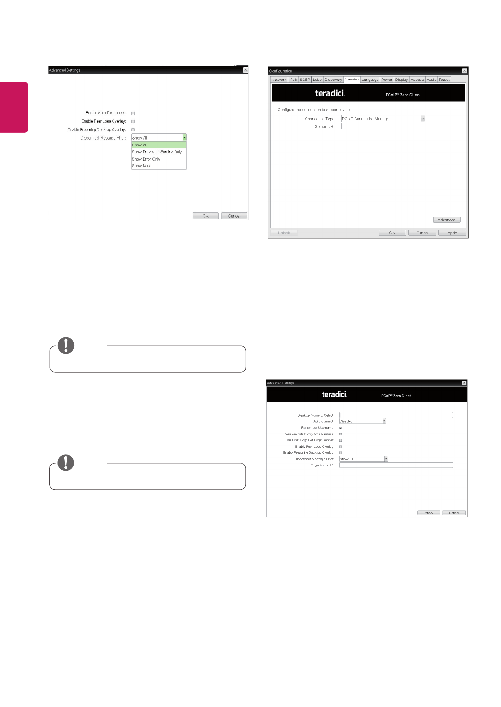
Disconnect Message Filter
This option determines the type of message to
display when a session is disconnected.
- Show All: Shows all the error messages.
- Show Error and Warning Only: Shows the
error and warning messages only.
- Show Error Only: Shows the error messages
only.
- Show None: Shows nothing.
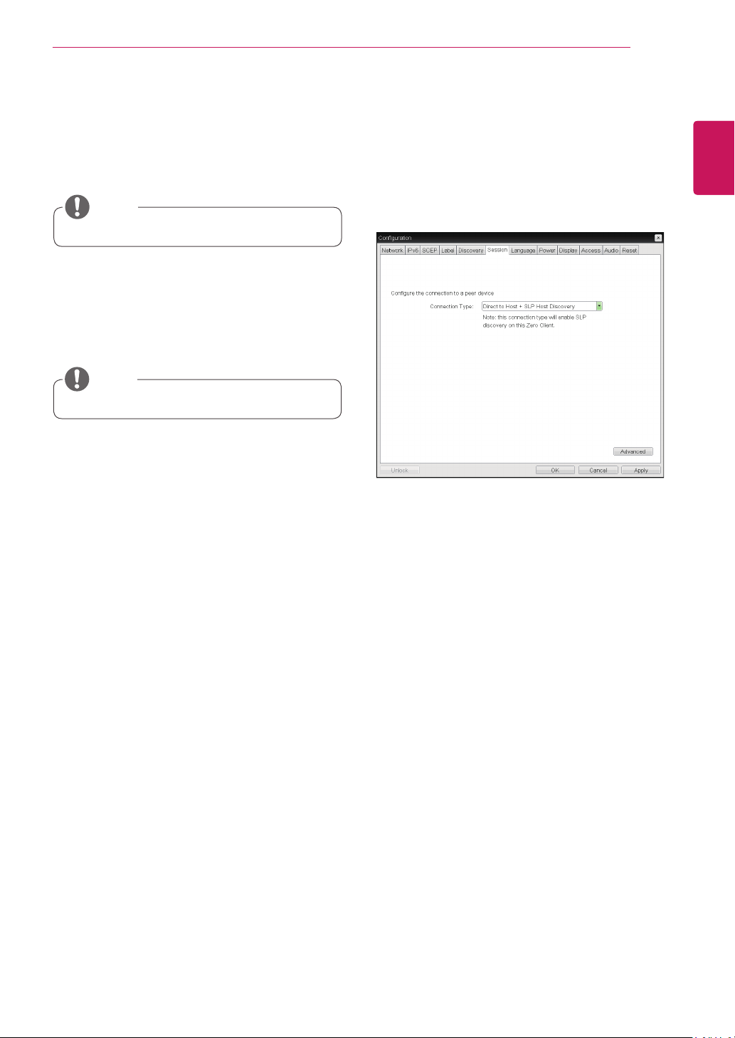
Direct to Host + SLP Host Discovery
You can view the screen of the host PC by discov-
ering the host PC within the network and estab-
lishing 1:1 connection between the PCI host card
connected to the host PC and the portal.
Enable Auto-Reconnect
If this option is selected, reconnection is attempted
automatically when a session is disconnected or
the user is logged off.
38
ENG
English
Using CLOUD Solution
<Figure 2-17: Advanced Settings for Direct to Host
+ SLP Host Discovery>
Enable Auto-Reconnect
If this option is selected, reconnection is attempted
automatically when a session is disconnected or
the user is logged off.
This setting is provided only for the client.
NOTE
Enable Peer Loss Overlay
The "Connection Lost" message is displayed.The
display is the same as in the VDI environ-ment.
The default is Disable.
This setting is provided only for the client.
NOTE
Enable Preparing Desktop Overlay
If this option is selected, the "Preparing Desk-top"
message is displayed on the screen when the user
is logged in.
Disconnect Message Filter
This option determines the type of message to
display when a session is disconnected.
- Show All: Shows all the error messages.
- Show Error and Warning Only: Shows the
error and warning messages only.
- Show Error Only: Shows the error messages
only.
- Show None: Shows nothing.
<Figure 2-18: PCoIP Connection Manager Setting>
PCoIP Connection Manager
This option can configure the client to use a PCoIP
Connection Manager as the PCoIP session broker.
Server URI
Enter the Uniform Resource Identifier (URI) for the
PCoIP Connection Manager.
<Figure 2-19: Advanced Setting for PCoIP Con-
nection Manager Setting>
39
ENG
English
Using CLOUD Solution
Desktop Name to Select
Enter the name of the pool/desktop which the user
client uses upon starting a session.
Auto Connect
If this option is enabled, the selected VMware View
Connection Server is automatically connected
when the user client is powered on.
If the Auto Connect option is enabled, you should
turn the user client off and turn it on again at least
once.
Remember Username
If this option is selected, the username which
is previously used to access the VMware View
Connection Server is automatically entered in the
username field.
Auto Launch if Only One Desktop
If this option is selected, connection is established
to the desktop when there is only one virtual desk-
top that a user wants to access.
Use OSD logo for View banner
If this option is enabled, you can change the OSD
logo of PCoIP during the login.
Enable Peer Loss Overlay
If this option is selected, the "Network Connection
Lost" message is displayed on the screen when it
is confirmed that the network is disconnected. The
display is the same as in the VDI environment. The
default is Disable.
Enable Preparing Desktop Overlay
If this option is selected, the "Preparing Desktop"
message is displayed on the screen when the user
is logged in.
Disconnect Message Filter
This option determines the type of message to
display when a session is disconnected.
- Show All: Shows all the error messages.
- Show Error and Warning Only: Shows the error
and warning messages only.
- Show Error Only: Shows the error messages
only.
- Show None: Shows nothing.
Organization ID
Enter an organization ID for the company. This
field accepts any UTF-8 character.
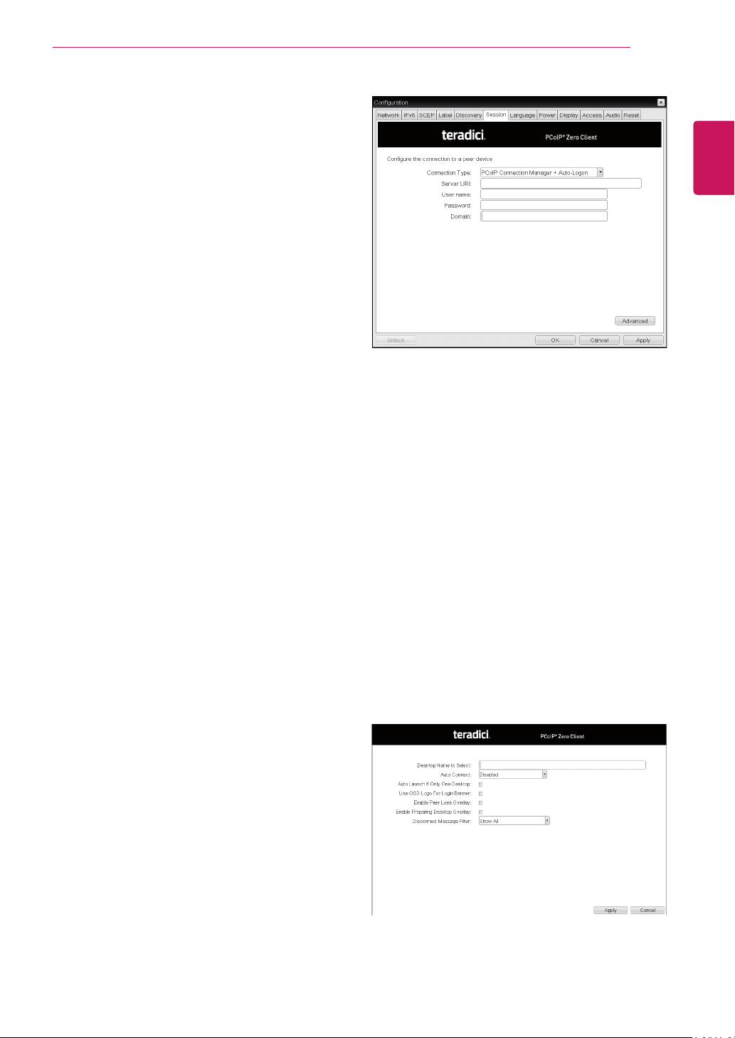
<Figure 2-20: PCoIP Connection Manager + Auto-
Logon Setting>
PCoIP Connection Manager + Auto-Logon
This option can configure a client to automatically
enter a user’s login details when a PCoIP Connec-
tion Manager is used as the PCoIP session broker.
Server URI
Enter the Uniform Resource Identifier (URI) for the
PCoIP Connection Manager.
Username
Enter the username for the client.
Password
Enter the password for the client.
Domain
Enter the domain name.
<Figure 2-21: Advanced Setting for PCoIP Con-
nection Manager + Auto-Logon Setting>
40
ENG
English
Using CLOUD Solution
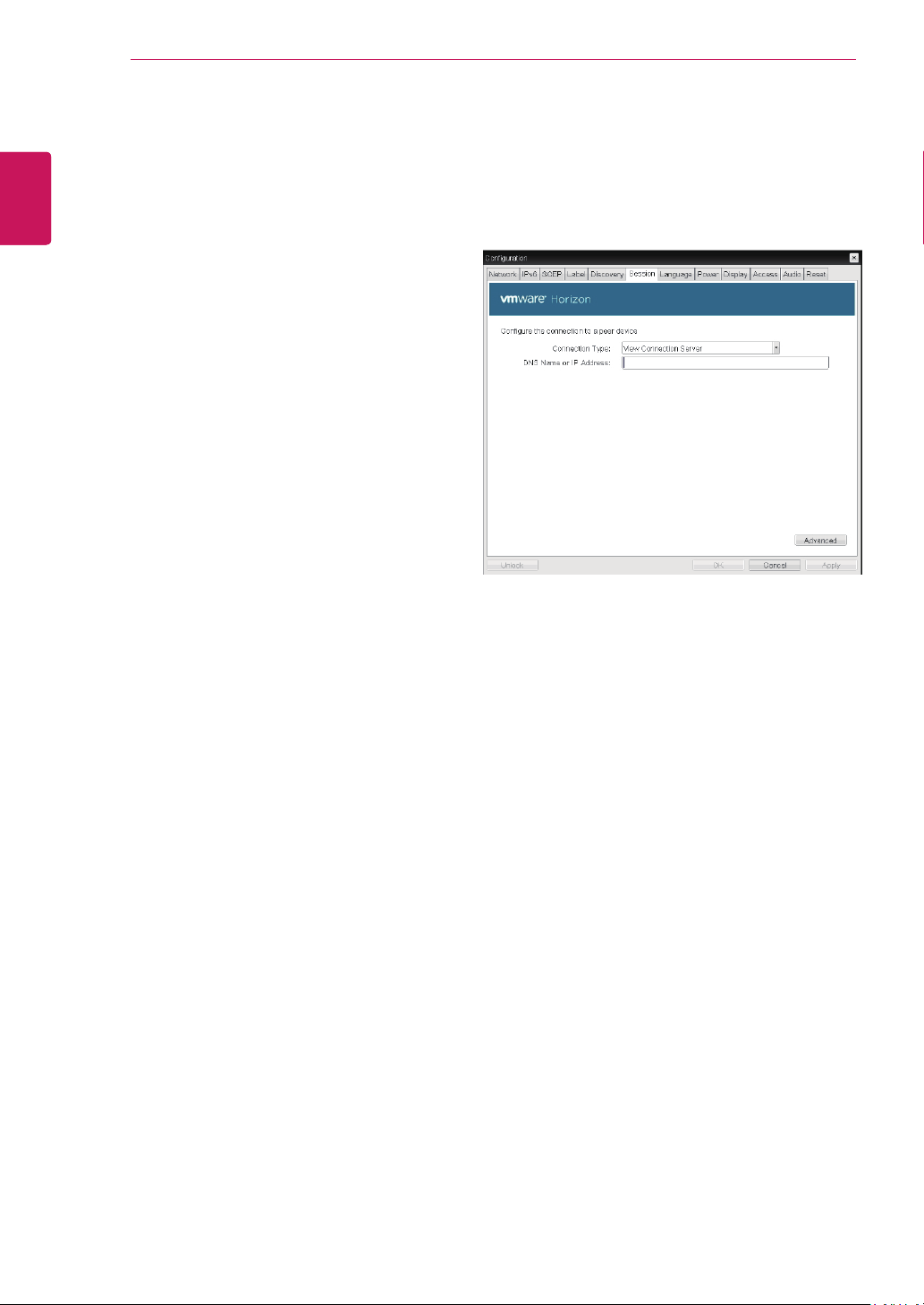
<Figure 2-22: View Connection Server Setting>
View Connection Server
In the Session tab, you can select to enable the
user client to access the VMware View Connec-
tionServer. To do this, select View Connection
Server for Connection Type.
DNS Name or IP Address
Enter the DNS name or IP address of the VM-
ware View Connection Server.
Desktop Name to Select
Enter the name of the pool/desktop which the user
client uses upon starting a session.
Auto Connect
If this option is enabled, the selected VMware View
Connection Server is automatically connected
when the user client is powered on.
If the Auto Connect option is enabled, you should
turn the user client off and turn it on again at least
once.
Auto Launch if Only One Desktop
If this option is selected, connection is established
to the desktop when there is only one virtual desk-
top that a user wants to access.
Use OSD logo for View banner
If this option is enabled, you can change the OSD
logo of PCoIP during the login.
Enable Peer Loss Overlay
If this option is selected, the "Network Connection
Lost" message is displayed on the screen when it
is confirmed that the network is disconnected. The
display is the same as in the VDI environment. The
default is Disable.
Enable Preparing Desktop Overlay
If this option is selected, the "Preparing Desktop"
message is displayed on the screen when the user
is logged in.
Disconnect Message Filter
This option determines the type of message to
display when a session is disconnected.
- Show All: Shows all the error messages.
- Show Error and Warning Only: Shows the error
and warning messages only.
- Show Error Only: Shows the error messages
only.
- Show None: Shows nothing.
41
ENG
English
Using CLOUD Solution
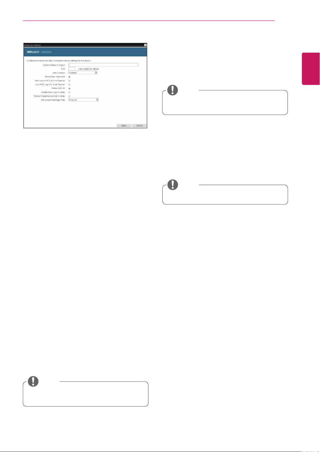
Desktop Name to Select
Enter the name of the pool/desktop which the
user client uses upon starting a session.
Port
For the default setting, leave the port field empty.
When the VMware View Connection Server uses
the SSL authentication, enter 443 in the Port field.If
the server where a user tries to access uses a port
other than a general port, enter the port.
Auto Connect
If this option is enabled, the selected VMware View
Connection Server is automatically connected
when the user client is powered on.
If the Auto Connect option is enabled, you should
turn the user client off and turn it on again at least
once.
Remember Username
If this option is selected, the username which is
previously used to access the VMware View
Connection Server is automatically entered in the
username field.
Auto Launch if Only One Desktop
If this option is selected, connection is established
to the desktop when there is only one virtual desk-
top that a user wants to access.
Use OSD logo for View banner
If this option is enabled, you can change the OSD
logo of PCoIP during the login.
<Figure 2-23: Advanced Settings for View Connec-
tion Server>
Prefer GSC-IS
If this option is selected, the GCS-IS interface
is used when a smart card supports more than
one interface. If the smart card supports only one
interface, it is not used.
The OSD logo can be uploaded using the
Webpage Administration Interface.
NOTE
This setting is provided only when a smart
card is used.
NOTE
Enable Peer Loss Overlay
If this option is selected, the "Network Connection
Lost" message is displayed on the screen when it
is confirmed that the network is disconnected.
The display is the same as in the VDI environ-
ment. The default is Disable.
Enable Preparing Desktop Overlay
If this option is selected, the "Preparing Desk-
top" message is displayed on the screen when the
user is logged in.
Disconnect Message Filter
This option determines the type of message to
display when a session is disconnected.
- Show All: Shows all the error messages.
- Show Error and Warning Only: Shows the
error and warning messages only.
- Show Error Only: Shows the error messages
only.
- Show None: Shows nothing.
This setting is provided only for the client.
NOTE
42
ENG
English
Using CLOUD Solution
Desktop Name to Select
Enter the name of the pool/desktop which the
user client uses upon starting a session.
Port
For the default setting, leave the port field empty.
When the VMware View Connection Server uses
the SSL authentication, enter 443 in the Port field.If
the server where a user tries to access uses a port
other than a general port, enter the port.
Auto Connect
If this option is enabled, the selected VMware View
Connection Server is automatically connected
when the user client is powered on.
If the Auto Connect option is enabled, you should
turn the user client off and turn it on again at least
once.
Auto Launch if Only One Desktop
If this option is selected, connection is established
to the desktop when there is only one virtual desk-
top that a user wants to access.
Use OSD logo for View banner
If this option is enabled, you can change the OSD
logo of PCoIP during the login.
<Figure 2-25: Advanced Settings for View Connec-
tion Server with Auto-Logon>
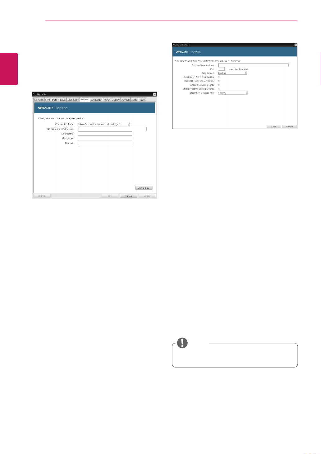
View Connection Server with Auto-Logon
In the Session tab, you can select to enable the
user client to automatically access the VMware
View Connection Server.To do this, select View
Connection Server with Auto-Logon for Connection
Type.
<Figure 2-24: View Connection Server with Auto-
Logon Setting>
DNS Name or IP Address
Enter the DNS name or IP address of the VM-
ware View Connection Server.
Username
Enter the username for the user client.
Password
Enter the password for the user client.
Domain
Enter the domain name.
The OSD logo can be uploaded using the
Webpage Administration Interface.
NOTE
43
ENG
English
Using CLOUD Solution
Enable Peer Loss Overlay
If this option is selected, the "Network Connection
Lost" message is displayed on the screen when it
is confirmed that the network is disconnected.
The display is the same as in the VDI environ-
ment. The default is Disable.
Enable Preparing Desktop Overlay
If this option is selected, the "Preparing Desk-
top" message is displayed on the screen when the
user is logged in.
Disconnect Message Filter
This option determines the type of message to
display when a session is disconnected.
- Show All: Shows all the error messages.
- Show Error and Warning Only: Shows the
error and warning messages only.
- Show Error Only: Shows the error messages
only.
- Show None: Shows nothing.
This setting is provided only for the client.
NOTE
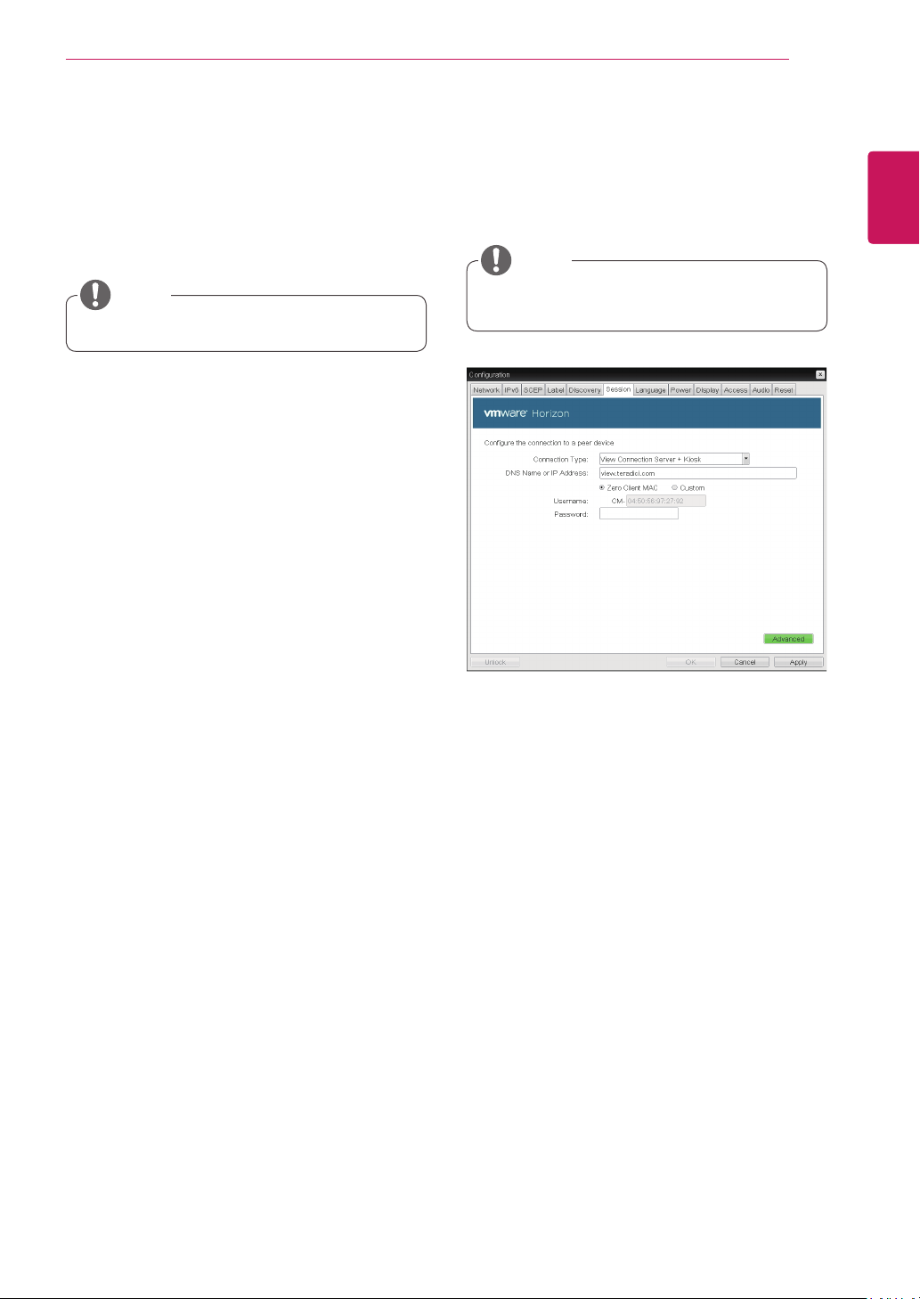
<Figure 2-26: View Connection Server + Kiosk
Setting>
View Connection Server + Kiosk
Select View Connection Server + Kiosk to use
the kiosk mode. You can configure the View Con-
nection Server + Kiosk mode using the Webpage
Administration Interface.
You cannot use the kiosk mode by connect-
ing to the host PC.
NOTE
DNS Name or IP Address
Enter the DNS name or IP address of the VM-
ware View Connection Server.
Username
Select the type of username that matches the de-
vice name used in the VMware View Con-
nection Server.
Password
Enter the password for the user client.
44
ENG
English
Using CLOUD Solution
<Figure 2-27: Advanced Setting for View Connec-
tion Server + Kiosk>
<Figure 2-28: View Connection Server + Imprivata One-
Sign Connection Setting>
Port
For the default setting, leave the port field empty.
When the VMware View Connection Server uses
the SSL authentication, enter 443 in the Port field.
If the server where a user tries to access uses a
port other than a general port, enter the port.
Use OSD logo for View banner
If this option is enabled, you can change the OSD
logo of PCoIP during the login.
The OSD logo can be uploaded using the
Webpage Administration Interface.
NOTE
Enable Peer Loss Overlay
If this option is selected, the "Network Connection
Lost" message is displayed on the screen when it
is confirmed that the network is disconnected.
The display is the same as in the VDI environ-
ment. The default is Disable.
This setting is provided only for the client.
NOTE
Enable Preparing Desktop Overlay
If this option is selected, the "Preparing Desk-
top" message is displayed on the screen when the
user is logged in.
Disconnect Message Filter
This option determines the type of message to
display when a session is disconnected.
- Show All: Shows all the error messages.
- Show Error and Warning Only: Shows the
error and warning messages only.
- Show Error Only: Shows the error messages
only.
- Show None: Shows nothing.
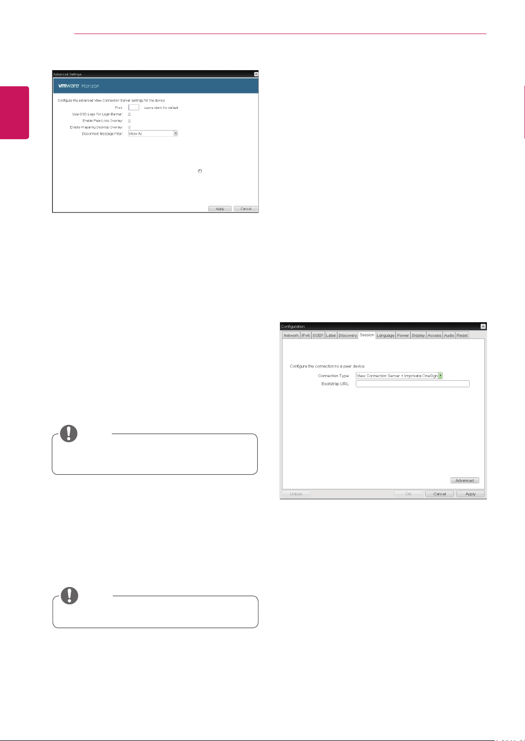
View Connection Server + Imprivata OneSign
Connection
Select View Connection Server + Imprivata One-
sign Connection to use the Imprivata One-
sign Connection for the client authentication.
Bootstrap URL
Enter the IP address or FQDN information of the
server which performs the OneSign au-
thentication.
45
ENG
English
Using CLOUD Solution
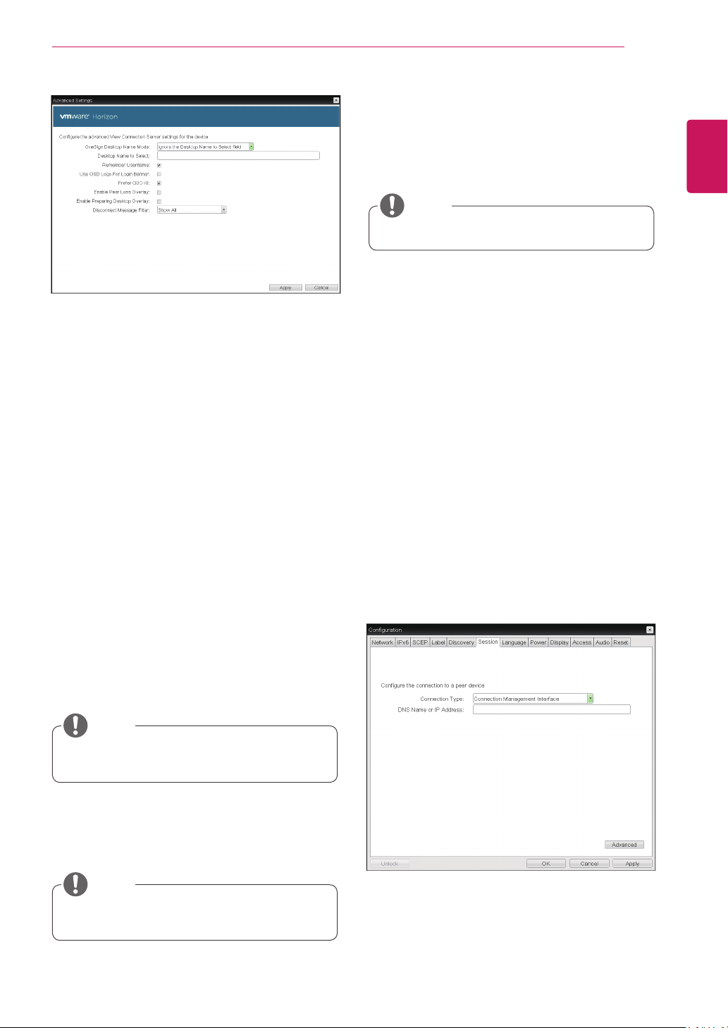
<Figure 2-29: Advanced Settings for View Connec-
tion Server + Imprivata OneSign Connection>
Onesign Desktop Name Mode
Select whether the Desktop Name to Select prop-
erty is used in OneSign Mmode :
Ignore the Desktop Name to Select field
Use the Desktop Name to Select field if set
Desktop Name to Select
Enter the desktop name. When the desktop pool
list includes a pool with this name, the client will
immediately start a session with that pool.
Remember Username
If this option is selected, the username which is
previously used to access the VMware View
Connection Server is automatically entered in the
username field.
Use OSD logo for View banner
If this option is enabled, you can change the OSD
logo of PCoIP during the login.
The OSD logo can be uploaded using the
Webpage Administration Interface.
NOTE
Prefer GSC-IS
If this option is selected, the GCS-IS interface
is used when a smart card supports more than
one interface. If the smart card supports only one
interface, it is not used.
This setting is provided only when a smart
card is used.
NOTE
Enable Peer Loss Overlay
If this option is selected, the "Network Connection
Lost" message is displayed on the screen when it
is confirmed that the network is disconnected.
The display is the same as in the VDI environ-
ment. The default is Disable.
This setting is provided only for the client.
NOTE
Enable Preparing Desktop Overlay
If this option is selected, the "Preparing Desk-
top" message is displayed on the screen when the
user is logged in.
Disconnect Message Filter
This option determines the type of message to
display when a session is disconnected.
- Show All: Shows all the error messages.
- Show Error and Warning Only: Shows the
error and warning messages only.
- Show Error Only: Shows the error messages
only.
- Show None: Shows nothing.
Connection Management Interface
In the Connection Management Interface setting,
you can manage the connection by entering the IP
address for connection management instead of us-
ing the IP address of the VMware View Connection
Server and can select to enable or disabled the
management interface.
<Figure 2-30: Connection Management Interface
Setting>
DNS Name or IP Address
Enter the DNS name or IP address of the VMware
View Connection Server.
46
ENG
English
Using CLOUD Solution
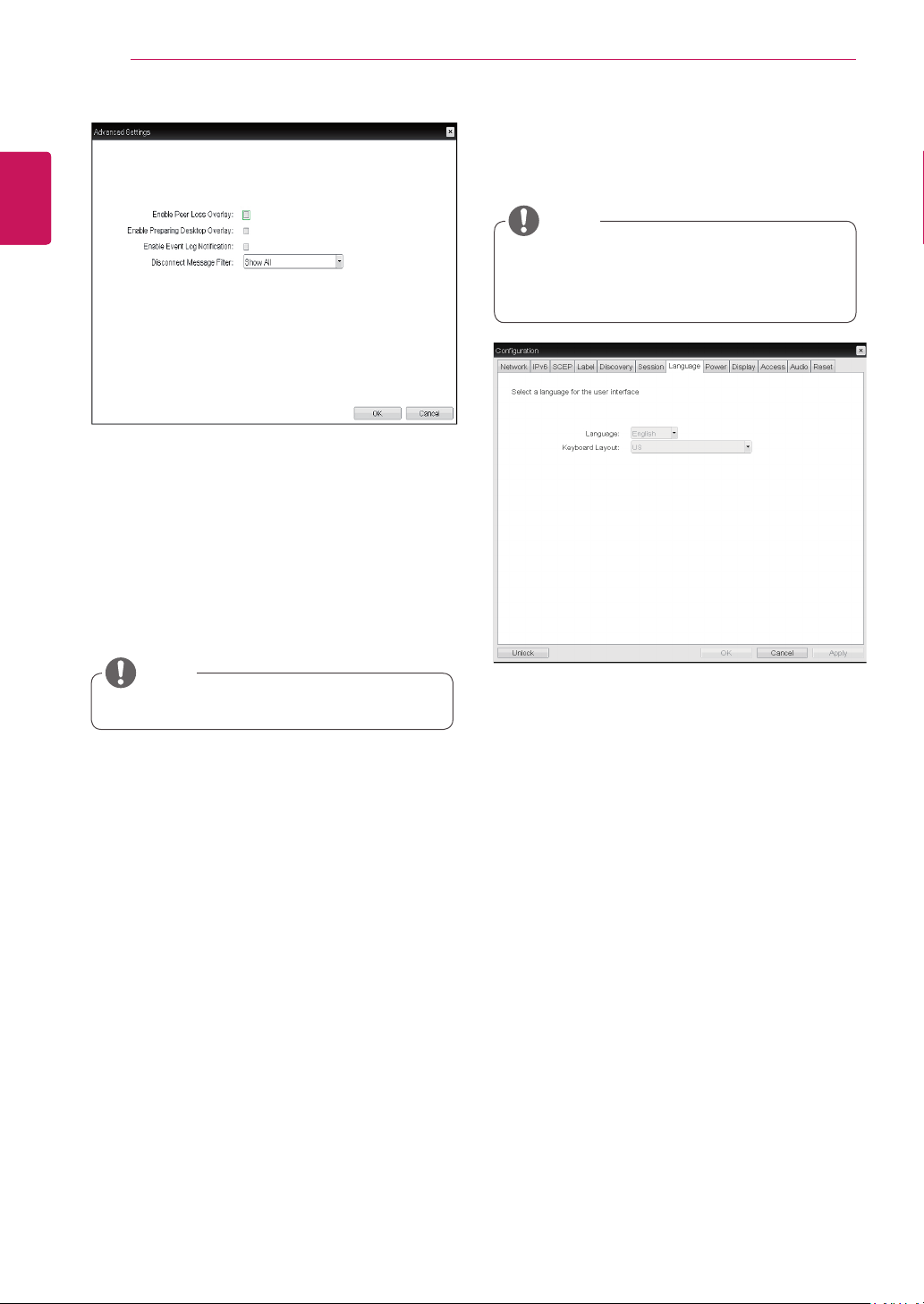
Language
The Language field is used to set the display
language of the OSD and the user level event log
messages.
Keyboard Layout
The Keyboard Layout field allows the administrator
to modify the keyboard layout.
<Figure 2-32: Language Configuration>
Language Tab
The Language tab allows the administrator to set
the OSD language.
The Language parameters can also be con-
figured using the Webpage Administration
Interface.
NOTE
<Figure 2-31: Advanced Settings for Connection
Management Interface>
Enable Peer Loss Overlay
If this option is selected, the "Network Connection
Lost" message is displayed on the screen when it
is confirmed that the network is disconnected.
The display is the same as in the VDI environ-
ment. The default is Disable.
This setting is provided only for the client.
NOTE
Enable Preparing Desktop Overlay
If this option is selected, the "Preparing Desk-
top" message is displayed on the screen when the
user is logged in.
Enable Event Log Notification
With this option, you can select whether to allow
the host and client device to send their event log
information to the Connection Management Server.
Disconnect Message Filter
This option determines the type of message to
display when a session is disconnected.
- Show All: Shows all the error messages.
- Show Error and Warning Only: Shows the
error and warning messages only.
- Show Error Only: Shows the error messages
only.
- Show None: Shows nothing.
47
ENG
English
Using CLOUD Solution
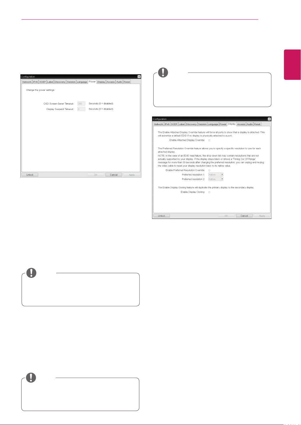
OSD Screen-Saver Timeout
Configure the number of seconds to wait after
a period of inactivity(i.e., no keyboard or mouse
action) before the client puts its attached displays
into low power mode.
Valid values are 10 to 9999, or use 0 to disable the
feature.
<Figure 2-33: Power Configuration>
<Figure 2-34: Display Configuration>
Display Tab
The Display tab allows the user to configure the
EDID function of the monitor.
The Enable display override function can be
used when the EDID function of the monitor
is not running.
NOTE
Display Suspend Timeout
Configure the number of seconds to wait after
a period of inactivity(i.e., no keyboard or mouse
action) before the client puts its attached displays
into low power mode.
Valid values are 10 to 14400 seconds, or use 0 to
disable the feature.
This timeout only applies when the device is
not in session.
NOTE
This timeout only applies when the device is
in session.
NOTE
Enable Attached Display Override
This option is intended for legacy systems. It con-
figures the client to send default EDID information
to the host when a monitor cannot be detected or
is not attached to the client.
Enable Preferred Resolution Override
Enable this option when a display is attached but
cannot be detected by the system, and you want to
specify a preferred resolution for the display.
Enable Display Cloning
This option is only available for the TERA2321
zero client. Enable the display cloning option if you
want the secondary display to mirror the primary
display.
Power Tab
The Power Tab allows the user to configure time-
out and power settings for the client.
48
ENG
English
Using CLOUD Solution
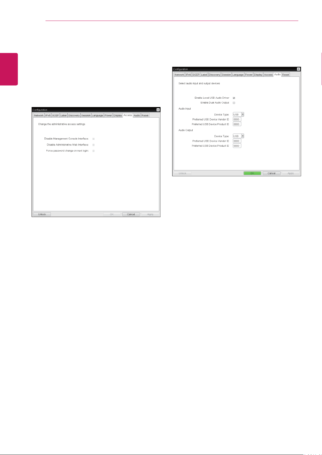
<Figure 2-35: Access Configuration>
Disable Management Console Interface
When enabled, the management console interface
is disabled, and the device cannot be accessed or
managed by the MC.
Disable Administrative Web Interface
When enabled, the device cannot be accessed or
managed using the AWI.
Force password change on next login
When enabled, the administrative password must
be changed the next time either the AWI or OSD is
accessed. The new password may be blank.
Enable Local USB Audio Driver
This option locally terminates any USB audio de-
vices that are attached to the zero client.
<Figure 2-36: Audio Configuration>
Access Tab
This Access tab lets you prevent the device from
being managed by the MC and lets you disable
administrative access to the device’s AWI. It also
provides an option to force an administrative
password change the next time the AWI or OSD is
accessed.
Audio Tab
This Audio tab lets you configure audio options for
the device.
49
ENG
English
Using CLOUD Solution
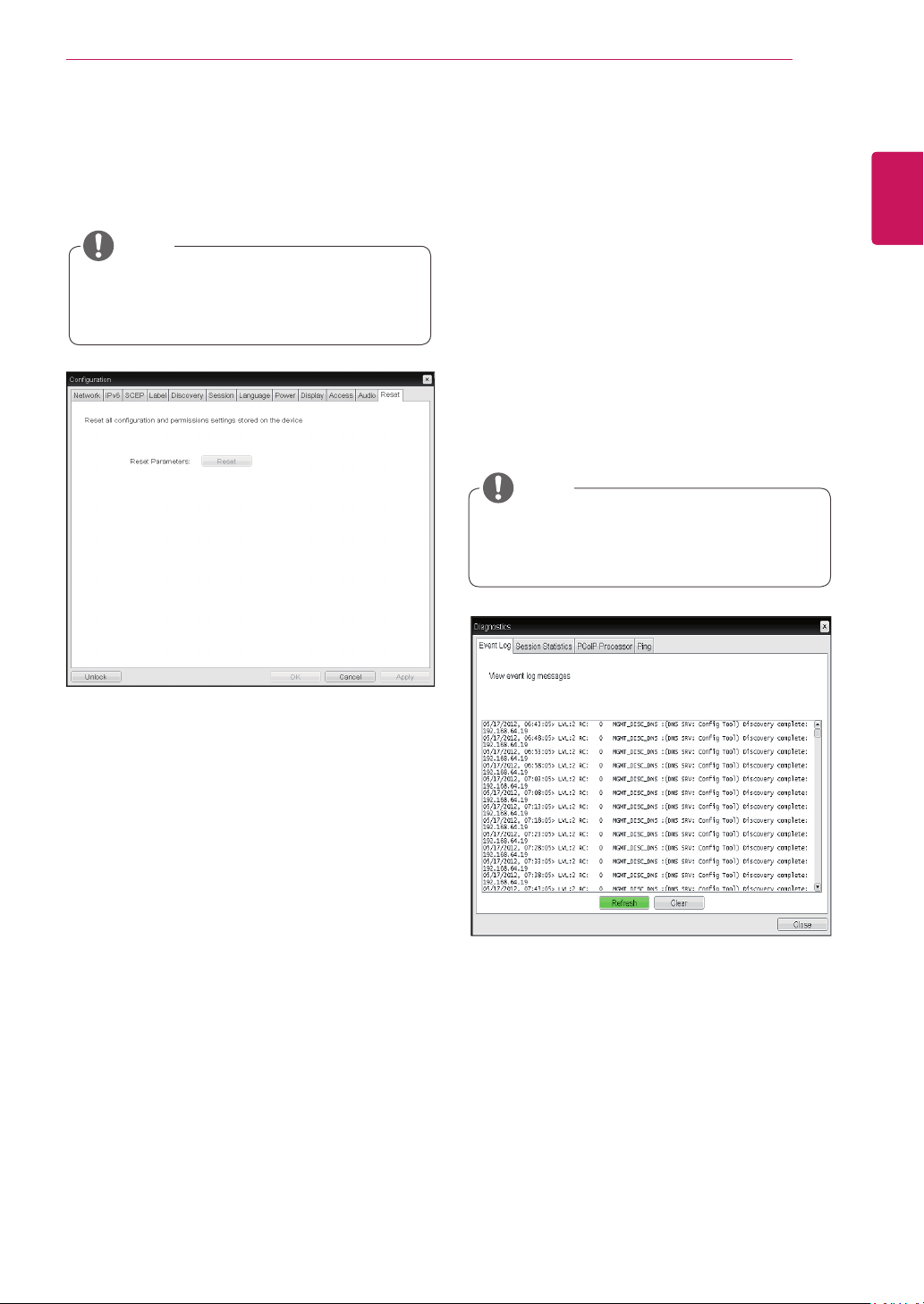
Reset Parameters
Pressing the Reset Parameters button will reset all
settings and options to the factory default settings.
When this button is pressed, an OSD message is
displayed. This is to prompt the administrator and
prevent accidental reset.
<Figure 2-37: Reset>
Reset Tab
The Reset tab allows the administrator to reset all
configurable parameters stored in Flash.
The Reset function can also be accessed
through the Webpage Administration Inter-
face.
NOTE
Event Log
Session Statistics
PCoIP Processor
Ping
Each tab has the Close button to close the window.
Diagnostics Window
In the Diagnostics window, the administrator can
access the window tab to diagnose the portal. The
Diagnostics window has the following tabs:
View Event Log Message
The View Event Log Message field displays the log
messages accompanied by the timestamp informa-
tion. The following two buttons are available:
Refresh
The Refresh button refreshes the displayed event
log messages.
Clear
The Clear button clears all event log messages.
<Figure 2-38: Event Log>
Event Log Tab
The Event Log tab allows the administrator to view
and delete the event log messages from the portal.
The event log (regardless of the quantity)
can also be reset using the Webpage Admin-
istration Interface.
NOTE
50
ENG
English
Using CLOUD Solution
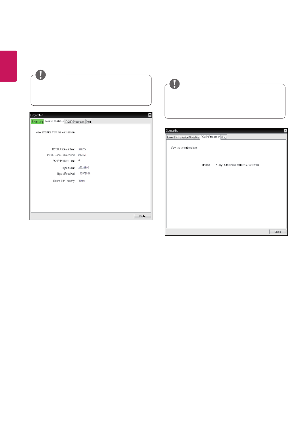
PCoIP Packets Statistics
PCoIP Packets Sent
The PCoIP Packets Sent field shows the total
number of PCoIP packets sent from the portal
to the host in the last active session.
PCoIP Packets Received
The PCoIP Packets Received field shows the
total number of PCoIP packets received from
the host to the portal in the last active session.
PCoIP Packets Lost
The PCoIP Packets Lost field shows the total
number of PCoIP packets lost in the last ac-
tive session.
<Figure 2-39: Session Statistics>
Session Statistics Tab
The Session Statistics tab allows the administrator
to view the PCoIP specific statistics of the last ac-
tive PCoIP session from the portal.
Bytes Statistics
Bytes Sent
The Bytes Sent field shows the total number
of bytes sent in the last active session.
Bytes Received
The Bytes Received field shows the total
number of bytes received in the last active
session.
Round Trip Latency
The Round Trip Latency field shows the total
round-trip PCoIP system (e.g. from the portal to
the host, then back to the portal) and the network
latency in milliseconds (+/- 1 ms).
The session statistics (regardless of the
quantity) can also be viewed using the Web-
page Administration Interface.
NOTE
<Figure 2-40: PCoIP Processor>
PCoIP Processor Tab
The PCoIP Processor tab allows the administrator
to view the portal PCoIP processor's uptime since
its last booting.
The PCoIP Processor Uptime can also be
viewed using the Webpage Administration
Interface.
NOTE
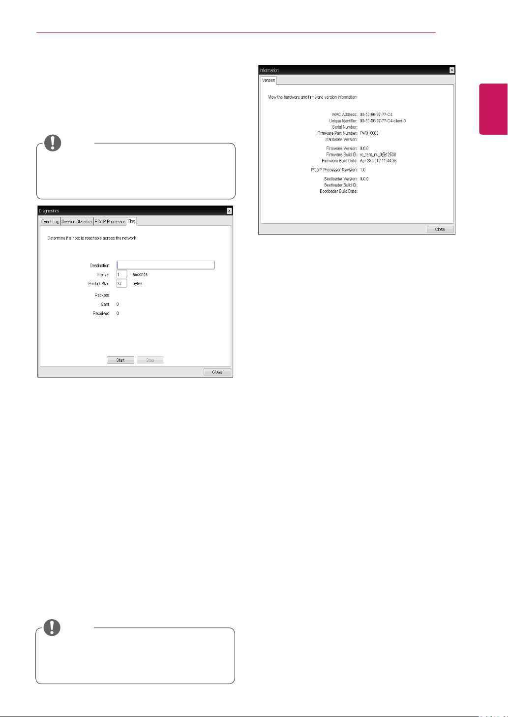
51
ENG
English
Using CLOUD Solution
Ping Settings
Destination
The IP address or FQDN to perform the ping
test.
Interval
The interval between the ping packets.
Packet Size
The size of the ping packet.
Packets
Sent
The number of ping packets sent.
Received
The number of ping packets received.
<Figure 2-41: Ping>
Ping Tab
The Ping tab allows the administrator to perform a
ping test to the device and check if it can reach the
overall IP network. This is useful to check whether
the device can reach the host.
The Ping tab has no corresponding menu in
to the Webpage Administration Interface of
Section 1.
NOTE
VPD Information
The Vital Product Data (VPD) is information that
uniquely identifies each portal or host.
MAC Address
The portal MAC address
Unique Identifier
The portal ID
Serial Number
The portal serial number
Firmware Part Number
The part number of the PCoIP firmware
Hardware Version
The portal hardware version
Firmware Information
The Firmware Information shows the details of the
current PCoIP firmware.
Firmware Version
The current PCoIP firmware version
Firmware Build ID
The current PCoIP firmware revision code
Firmware Build Date
The current PCoIP firmware build date
<Figure 2-42: Version>
Information Window
In the Information window, the administrator can
access the Version tab that contains the device
related information.
The version information can also be viewed
using the Webpage Administration Interface.
NOTE
Boot Loader Information
The Boot Loader Information shows the details of
the current PCoIP boot loader.
Boot Loader Version
The current PCoIP boot loader version
Boot Loader Build ID
The current PCoIP boot loader revision code
Boot Loader Build Date
The current PCoIP boot loader build date
PCoIP Processor Revision
This shows the PCoIP processor's revision code.
TERA1x00 Revision A silicone is denoted by 0.0
and TERA1x00 Revision B silicone is denoted by
1.0.
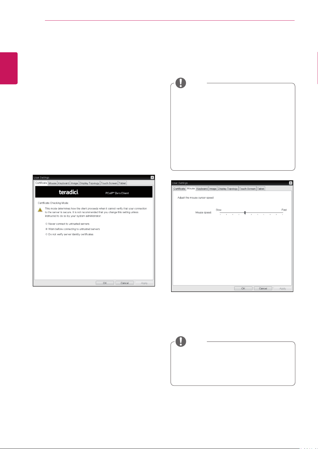
52
ENG
English
Using CLOUD Solution
User Settings Window
In the User Settings window, the administrator can
access the tab to select the mouse and keyboard
and define the PCoIP image quality.
The User Settings window has the following tabs:
Certificate
Mouse
Keyboard
Image
Display Topology
Touch Screen
Tablet
Mouse Speed
The Mouse Speed field allows the user to set the
portal's mouse cursor speed.
<Figure 2-44: Mouse>
Mouse Tab
The Mouse tab allows the user to modify the OSD
and RDP session's mouse cursor speed setting.
The OSD mouse cursor speed setting does
not affect the mouse cursor settings when
a PColP session is active unless the Local
Keyboard Host Driver function is being used
(see PColP Host Software User Guide for
more information).
The Mouse tab has no corresponding menu
in the Webpage Administration Interface of
Section 1.
The Mouse Speed can also be configured via
the PCoIP Host Software. For more informa-
tion on using the PCoIP Host Software, refer
to the PCoIP Host Software User Guide.
NOTE
NOTE
<Figure 2-43: Certificate>
Certificate Tab
The Certificate tab allows user to specify the client
behavior for when a user cannot check the secure
connection to a server.
Never connect to untrusted servers
Configures the client to reject the connection if a
trusted, valid certificate is not installed.
Warn before connecting to untrusted servers
Configures the client to display a warning if an
unsigned or expired certificate is encountered, or
when the certificate is not self-signed and the client
trust store is empty.
Do not verify server identity certificates
Configures the client to allow all connections.

53
ENG
English
Using CLOUD Solution
Keyboard Repeat Delay
The Keyboard Repeat Delay field allows the user
to set the portal's keyboard repeat delay.
Keyboard Repeat Rate
The Keyboard Repeat Rate field allows the user to
set the portal's keyboard repeat rate.
Repeat Settings Test Box
The Repeat Settings Test Box allows the user to
test the selected keyboard settings.
<Figure 2-45: Keyboard>
Keyboard Tab
The Keyboard tab allows the user to modify the
OSD and RDP session's keyboard repeat setting.
The OSD keyboard setting does not affect
the keyboard settings when a PColP session
is active unless the Local Keyboard Host
Driver function is being used (see PColP
Host Software User Guide for more informa-
tion).
The Keyboard tab has no corresponding
menu in the Webpage Administration Inter-
face of Section 1.
NOTE
Minimum Image Quality
The Minimum Image Quality slider allows the ad-
ministrator to make compromises between image
quality and frame rate when network bandwidth
is limited. Sometimes, lower-quality images at a
higher frame rate may be required, while at other
times, higher-quality images at a lower frame rate
may be preferred.
In environments where the network bandwidth is
limited, moving the slider towards Reduced en-
sures higher frame rates;
moving the slider towards Perception-Free ensures
higher image quality. When network bandwidth is
not limited, the PCoIP system will maintain percep-
tion-free quality regardless of the Minimum Image
Quality setting.
<Figure 2-46: Image>
Image
The Image tab allows a user to change the image
settings on the PCoIP system.
The Image parameters can also be con-
figured using the Webpage Administration
Interface.
NOTE
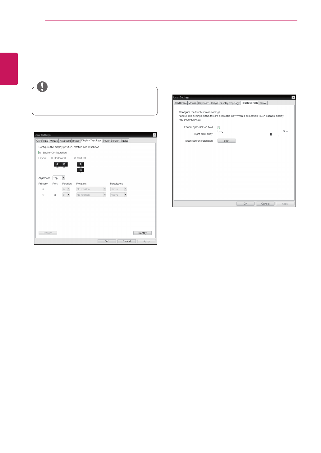
54
ENG
English
Using CLOUD Solution
Display Topology Tab
The Display Topology tab allows the user to specify
the position and alignment of a connected second-
ary monitor.
It is applicable when the VMware View Con-
nection Server version is 4.5 or later.
NOTE
<Figure 2-47: Display Topology>
Enable Configuration
When this option is selected, you can set the
display position and alignment. You can save the
settings by clicking the Apply or OK button, and
the settings will be reset if you initialize the monitor
set.
Display Layout
This option allows the user to specify the direction
of monitor connection: vertical or horizontal.
Alignment
This option allows the user to specify the align-
ment position of the monitor to be connected when
there is a resolution difference between the two
monitors.
Primary
This option allows the user to change the primary/
secondary settings of the connected monitor.
Touch Screen Tab
The Touch Screen tab allows the user to specify
the touch sensitivity and alignment when the moni-
tor supports the touch screen function.
<Figure 2-48: Touch Screen>
Enable right click on hold
If this option is selected, clicking and holding the
touch screen for several seconds works the same
as the mouse right click.
Right Click Delay
This option allows the user to make moving the
pointer position work the same as the mouse right
click. You can also specify the distance to move
(from Long to Short).
Touch screen calibration
The alignment of a touch screen is started when
clicking the Start button.
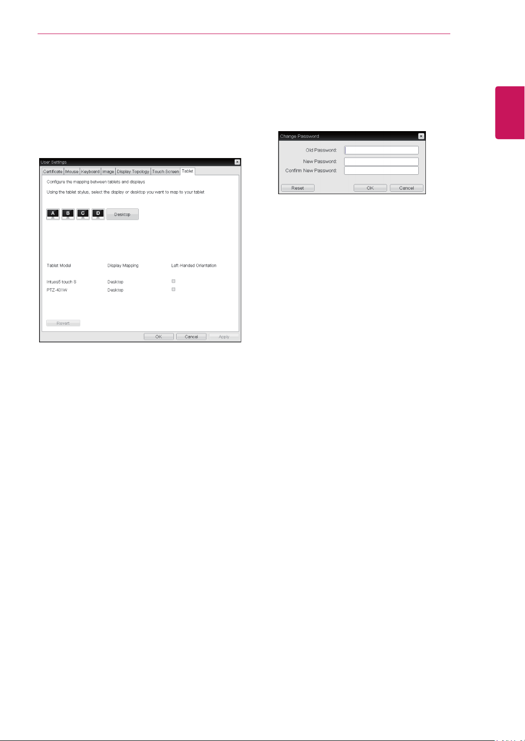
55
ENG
English
Using CLOUD Solution
<Figure 2-50: Password Configuration>
Old Password
This field must match the current administrative
password before you can update the password.
New Password
The new administrative password or both the AWI
and the local OSD GUI.
Confirm New Password
This field must match the New Password field for
the change to take place.
Password Tab
This Password tab lets you update the local ad-
ministrative password for the device.
Tablet Tab
The Tablet tab lets you selects whether an at-
tached Wacom tablet is mapped to the entire
desktop or to a specific attached monitor. It also
lets you specify whether the tablet operates in a
left-handed or right-handed orientation.
<Figure 2-49: Tablet>
Display and Desktop icons
This section shows the number of displays that are
currently attached to the zero client.
When just one monitor is attached, only the desk-
top icon appears in this area, and any attached
tablets are mapped to the entire desktop.
Tablet Model
Shows the model number of each attached Wacom
tablet.
Display Mapping
Shows the current mapping configuration for each
attached tablet.(A, B, C or D, or Desktop).
Left-Handed Orientation
To configure the tablet for a left-handed orientation:
1. Using either a mouse or the tablet’s stylus,
select the tablet’s Left-Handed Orientation check
box.
2. Click Apply.
3. Rotate the tablet 180 degree before using it.
Revert
Reverts the tablet settings to the last applied con-
figuration.
To revert table mappings to their default
setting(Desktop), unplug a monitor and then recon-
nect it to the zero client. Applying topology chang-
es will also clear the tablet configuration and set it
to default.

MODEL
SERIAL
Make sure to read the Safety Precautions before
using the product.
Keep the Owner’s Manual (CD) in an accessible
place for future reference.
The model and serial number of the SET is
located on the back and one side of the SET.
Record it below should you ever need service.
To obtain the source code under GPL, LGPL,
MPL and other open source licenses, that is
contained in this product, please visit http://
opensource.lge.com .
In addition to the source code, all referred
license terms, warranty disclaimers and
copyright notices are available for download.
LG Electronics will also provide open source
code to you on CD-ROM for a charge covering
the cost of performing such distribution (such
as the cost of media, shipping and handling)
upon email request to opensource@lge.com.
This offer is valid for three (3) years from the
date on which you purchased the product.
*above information is only for USA FCC Regulatory
Declaration of Conformity
Trade Name: LG
Model : 24CAV37K
Responsible Party: LG Electronics Inc.
Address : 1000 Sylvan Ave. Englewood Cliffs
NJ 07632 U.S.A
TEL: 201-266-2534

