User Manual GE - General Electric AZ39H12DADM1 Heat Pump Unit
Care and cleaning
Room Cabinet and Case
Turn the Zoneline off and disconnect the power supply. To clean, use water and a mild detergent. Do not use bleach or abrasives. Some commercial cleaners may damage the plastic parts.
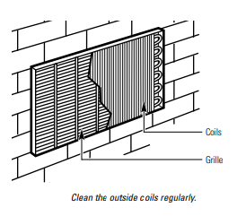
Outdoor Coils
The coils on the outdoor side of the Zoneline should be checked regularly. If they are clogged with dirt or soot, they may be professionally steam cleaned, a service available through your GE service outlet. You will need to remove the unit to inspect the coils because the dirt buildup occurs on the inside.
Base Pan
In some installations, dirt or other debris may be blown into the unit from the outside and settle in the base pan (the bottom of the unit)
In some areas of the United States, a “gel-like” or “slime-like” substance may be seen in the base pan. Check it periodically and clean, if necessary.
Ventilation Filter
If the vent door is open, clean the vent filter twice a year or as required.
Turn the Zoneline off before cleaning.
To remove the vent filter:
-
Remove the room cabinet. See the To Remove the Room Cabinet section.
-
Remove the four screws securing the unit flanges to the case.
-
Slide the unit from the wall case.
-
Grasp the vent filter tab and pull the filter out by sliding it to the right.
To clean the vent filter:
-
Run water through the filter from the back side.
-
Dry thoroughly before replacing.
Air Filters
Turn the Zoneline off before cleaning.
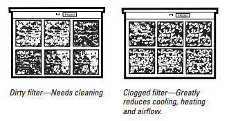
The most important thing you can do to maintain the Zoneline is to clean the filter at least every 30 days. Clogged filters reduce cooling, heating and air flow.
Keeping these filters clean will:
- Decrease cost of operation.
- Save energy.
- Prevent clogged heat exchanger coils
- Reduce the risk of premature component failure.
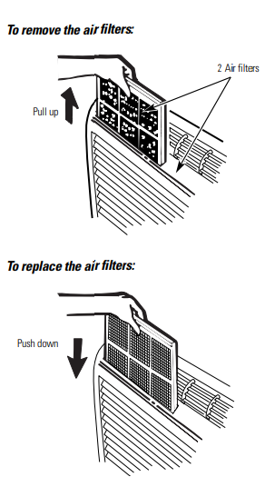
To clean the air filters:
- Vacuum off the heavy soil.
- Run water through the filters from the back side.
- Dry thoroughly before replacing.
NOTE: The air filters are interchangeable and will fit in either the right or left side.
Installation Instructions
BEFORE YOU BEGIN
Read these instructions completely and carefully
- IMPORTANT – Save these instructions for local inspector’s use.
- IMPORTANT – Observe all governing codes and ordinances.
- Note to Installer – Be sure to leave these instructions with the owner.
- Note to Owner – Keep these instructions for future reference
- Proper installation is the responsibility of the installer.
- Product failure due to improper installation is not covered under the Warranty
IMPORTANT ELECTRICAL SAFETY—READ CAREFULLY
- Follow the National Electrical Code (NEC) or local codes and ordinances.
- For personal safety, this Zoneline must be properly grounded.
- Protective devices (fuses or circuit breakers) acceptable for Zoneline installations are specified on the nameplate of each unit.
- Do not use an extension cord with this unit.
- Aluminum building wiring may present special problems—consult a qualified electrician.
- When the unit is in the OFF position, there is still voltage to the electrical controls.
- Disconnect the power to the unit before servicing by:
- Removing the power cord (if it has one) from the wall receptacle.
- Removing the branch circuit fuses or turning the circuit breakers off at the panel.
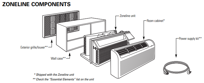
ZONELINE COMPONENTS
REPLACING AN EXISTING UNIT?
Use the correct wall case
This unit is designed to be installed in a GE plastic or insulated metal wall case. This minimizes condensation from forming on the room side of the case.
If the current wall case is not insulated, you can reduce the possibility of condensation forming by installing insulation kit RAK901L, available where you purchased the unit.
NOTE: There are several extra holes in the unit side flanges for installation in wall cases other than GE. To avoid damaging the flange insulation, the installer should use an awl or other sharp tool to puncture the insulation in the appropriate holes before installing the attachment screws.
Use the correct outdoor grille
You should use the outdoor grilles shown on the “Essential Elements” label on the top of the unit.
- If an existing grille is not replaced, capacity and efficiency will be reduced and the unit may fail to operate properly or fail prematurely. A deflector kit, RAK40, may be used with grilles that were not designed for your new GE Zonelines. The RAK40 contains air deflectors and gaskets that mount to the unit to direct the hot exhaust air away from the air intake to allow the unit to function properly. The grille must have a 65% minimum free area.
- Any vertical deflectors in the existing rear grille should be removed to decrease condenser air recirculation that can cause the unit to “short-cycle” and lead to premature component failure.
Use the correct power cord
Local codes may require the use of arc fault or leakage current detection devices on 230/208-volt installations.
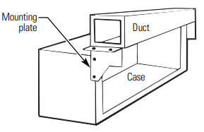
Replacing a ducted unit
- New ducted installation:
If this unit is to be installed in a new ducted application using a duct adapter kit, the kit must be installed before the unit is placed in the wall case. The installation instructions are packed with the kit.
- Existing ducted installation:
Replacement of an existing ducted unit may require different components. Request this information from your sales representative.
HOW TO CONNECT
- Remove the room cabinet.
- Connect to electrical power.
- Review the following steps for applicable supply voltages.
- Reinstall the room cabinet.
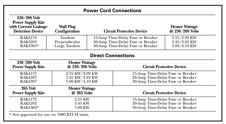
POWER CORD CONNECTION
A power supply kit must be used to supply power to the Zoneline unit. The appropriate kit is determined by the voltage, the means of electrical connection and the amperage of the branch circuit.
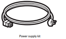
Connections of 208 or 230-volt circuits may be with a power supply kit or a junction box kit.
All wiring, including installation of the receptacle, must be in accordance with the NEC and local codes, ordinances and regulations. Local codes may require the use of an arc fault or leakage current detection device on the power cord. Be sure to select the correct cord for your installation.
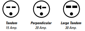
|
Branch Circuit and Unit Amperage Rating |
Proper GE Power Cord with LCDI Device |
|
15 |
RAK3153 |
|
20 |
RAK3203 |
|
30 |
RAK3303* |
DIRECT CONNECTION
Order the following Kit for 230/208-volt direct connection as required:
|
Branch Circuit and Unit Amperage Rating |
Power Supply Accessory |
Power Supply Kit |
|
15 |
RAK4002A |
RAK4157 |
|
20 |
RAK4002A |
RAK4207 |
|
30 |
RAK4002A |
RAK4307 |
Skip to the “MAKE ELECTRICAL CONNECTION TO THE UNIT” section.
265 VOLT ELECTRICAL CONNECTION OPTIONS
A. FOR SUBBASE INSTALLATION
Electrical subbase kits are available to provide a flexible enclosure for direct connection.
|
Branch Circuit and Unit Amperage Rating |
Proper GE Subbase Kit |
Power Supply Kit |
|
15 |
RAK204E15 |
RAK5172 |
|
20 |
RAK204E20 |
RAK5202 |
|
30 |
RAK204E30 |
RAK5302 |
The instructions provided with the selected subbase kit must be carefully followed. It is the responsibility of the installer to ensure the connection of components is done in accordance with these instructions and all electrical codes.
B. FOR DIRECT CONNECT INSTALLATION
If an electrical subbase is not used, direct connection to branch circuit wiring inside the provided junction box must be done in accordance with the following steps. Order the following Kit for 265-volt direct connection as required:
|
Branch Circuit and Unit Amperage Rating |
Power Supply Kit |
|
15 |
RAK5157 |
|
20 |
RAK5207 |
|
30 |
RAK5307 |
Proceed to the “MAKE ELECTRICAL CONNECTION TO THE UNIT” section
MAKE ELECTRICAL CONNECTION TO THE UNIT
A. REMOVE JUNCTION BOX
- Remove the junction box cover by removing the front two screws.
- Remove the junction box by removing the top and bottom rear screws. Note how the tabs on the lower left side of the junction box serve to hold the side in place. This will help when the box is being reinstalled.
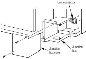
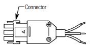
B. CONNECT THE CORDSET
Plug the connector, provided in the Direct Connect Kit, fully into place in the unit mating connector. Be sure the locking tabs at the sides are engaged.
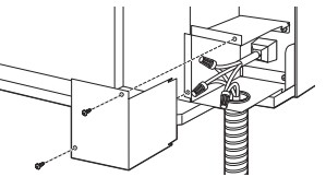
C. ATTACH CONDUIT
- Use the round knockout at the bottom of the junction box to attach conduit coming from the branch circuit. Remove the knockout, attach the conduit and bring wires into the junction box. Leave 6″ of wire free at the end of the conduit to allow connections to be made
- If a fuse and fuseholder are to be used, the knockout at the top of the box is for mounting a Buss Fuseholder. Be sure the fuse and fuseholder are of the same rating as the branch circuit. Leadwires at the fuse can be either soldered in place or attached using UL-listed 1/4″ female (receptacle) crimp connectors. Follow local codes.

D. REINSTALL JUNCTION BOX
Reinstall the junction box by engaging the left tabs on the lower right face of the unit, aligning the screw holes at the top and bottom and driving the two screws until secure. Be sure that all wire leads are inside the box and not pinched between the box and the unit. The green insulated ground wire from the unit MUST be connected to the branch circuit ground wire.
Make all wire connections by using appropriate UL-listed electrical connectors and techniques (black to black, white to white and green to green).
E.REINSTALL JUNCTION BOX COVER
- Carefully tuck all wires and connections back inside the junction box. Be sure there are no loose connections or stray uninsulated wires exposed
- Place the junction box cover in place. Replace the two screws removed earlier and tighten securely
POWER CONNECTION CHART
INSTALLING THE ZONELINE
A. INSTALL THE WALL CASE AND EXTERIOR GRILLE
The RAB71 series or RAB77 wall case must be properly installed per instructions packed with the case.
- Remove the corrugated stiffener and the outdoor protective panel. Use the slit in the outdoor panel as a handhold and push out.
- Install the exterior grille from the room side following instructions packed with the grille.
Insulated Wall Case
This unit is designed to be installed in a GE plastic or an insulated steel wall case. This minimizes condensation from forming on the room side of the case.
The RAB71 series wall cases are insulated. Insulation kit RAK901L is available for use with RAB77 or existing uninsulated wall cases when needed.
NOTE: For installation with a subbase or duct adapter, see the instructions packed with those kits.
B. PREPARE THE UNIT
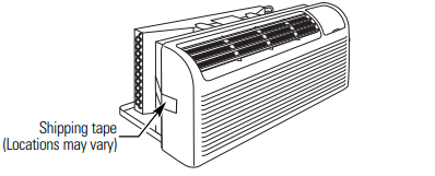
- Carefully remove shipping tape and foam shipping blocks from the room cabinet, compressor and vent door. There may be multiple blocks and pieces of shipping tape that need to be removed.
- Remove the room cabinet by pulling it out at the bottom to release it (1), then lift it up to clear the rail along the unit top (2).

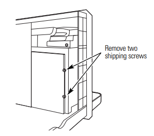
- If vent door is to be operational, remove shipping screws from the front side of the vent door, if present.
C. INSTALL THE UNIT INTO THE WALL CASE
Slide the unit into the wall case and secure with four screws through the unit flange holes.
NOTE: There are several extra holes in the unit side flanges for installation in wall cases other than GE. To avoid damaging the flange insulation, the installer should use an awl or other sharp tool to puncture the insulation in the appropriate holes before installing the attachment screws.
D. REPLACE THE ROOM CABINET
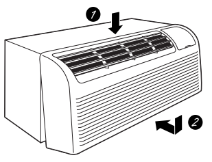
Reinstall the room cabinet by hooking the top over the rail along the unit top (1), then pushing it in at the bottom (2).
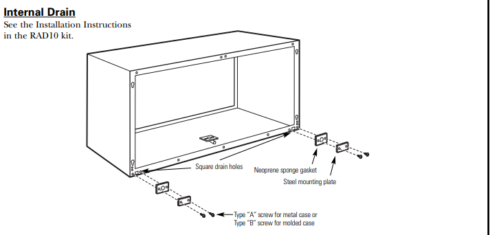
OPTIONAL—DRAIN KIT INSTALLATION
Dry Air 25 Series models are designed to improve dehumidification by 25%. Since more moisture will be removed from the air, there is a greater possibility that water will drip from the wall case than with a standard unit. To prevent this water from dripping onto external building walls, we recommend the use of RAD10 Drain Kit.