User Manual for Gas Cooktop
Installation and connection
Statutory requirements
This installation must conform with the following:
■ Manufacturer’s Installation instructions
■ Local Gas Fitting Regulations
■ Municipal Building Codes
■ Refer to AS/NZS 5601.1 for Gas Installations
■ S.A.A. Wiring Code
■ Local Electrical Regulations
■ Any other statutory regulations
Preparing to install
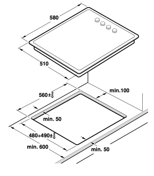
Refer to AS/NZS 5601.1 for piping size details. These built-in cooktops are intended to be inserted in a benchtop cutout.
Only an officially authorised technician should connect the appliance.
Before you begin, turn off the gas and electricity supply.
Before connecting the unit, check whether the local connection conditions (type of gas) are compatible with the unit’s setting. Observe any special conditions imposed by local suppliers (utilities). The specifications of this cooktop are stated on the data label located on the bottom of the cooktop base.
A duplicate data label is supplied for adhesion to an accessible location near the hotplate if the data label on the base of the hotplate cannot be accessed when the hotplate is installed.
Clearances
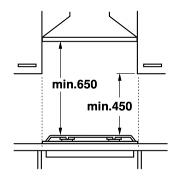
A range hood fitted above the top must be installed according to the installation instructions for the range hood. A minimum distance of 650 mm is required for a range hood and 750 mm for an exhaust fan.
Any adjoining wall surface situated within 200 mm from the edge of any hob burner must be a suitable noncombustible material for a height of 150 mm for the entire length of the hob. Any combustible construction above the hotplate must be at least 650 mm above the top of the burner and no construction shall be within 450 mm above the top of the burner.
A minimum depth of 50 mm from the top of the worktop surface must be provided for the appliance.
If the base of the hotplate can be touched, a protecting shield must be fitted.
The shield must be at least 10 mm from the lowest part of the hotplate and must be capable of withstanding the appliance temperatures. Minimum thickness of benchtop is 30 mm.
After installation of the shield the clearance around the top and sides of shield will allow adequate ventilation. Ensure the side and top clearances are not obstructed.
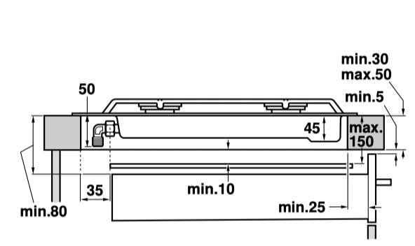
If an oven is positioned below the cooktop the barrier does not need to be fitted, but a space of 35 mm must be maintained between the underside of the cooktop and the top of the oven.
Installation of cooktop into the kitchen bench
Side clearances: If the distance measured from the periphery of the nearest burner to any vertical surface is less than 200 mm, the surface shall be protected in accordance with clauses 6.10.1.2 of AS/NZS 5601.1.
For cutout dimensions and clearances see Preparing to install.
Installation procedure:
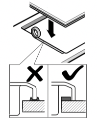
The adhesive seal provided prevents leaks. Adhere it to the work surface around the cut-out. It must be adhered around the edge of the area cut out.
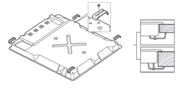
Fitting the appliance onto the kitchen unit:
1. Place the cooktop in the correct position then loosen each of the clips so that they all turn freely (it is not necessary to completely undo them).
2. Insert and centre the cooktop.
Press the sides of the cooktop until it is supported around its entire perimeter.
3. Turn the clips and tighten them fully.
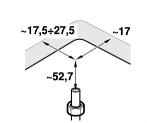
The position of the clips depends on how thick the work surface is.
Connection Electrical
An electrical 10 amp socket needs to be within 1 m of the hotplate to allow electrical connection. The socket must remain accessible after installation of the appliance.
Important notes:
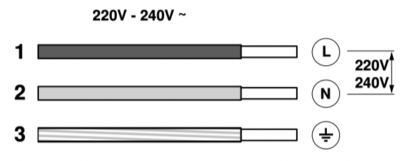
■ This appliance is connected to the mains (240 VAC) by means of the connecting lead which must be fixed to the kitchen unit to prevent it from coming into contact with hot parts of the cooktop (or an oven installed underneath) and remain accessible after installation of the cooktop. When making this connection make sure that the lead cannot come into contact with hot parts of the cooktop.
■ This appliance must be earthed. When connecting the cooktop ensure that the earth wire is connected first and that all wires are connected to the correct terminals.
Gas
During the planning stage, consider the position of supply connections.
The cooktop must be connected to the gas supply with upstream connection of an isolation valve in accordance with the respectively valid regulations. We recommend that the isolation valve be fitted prior to the cooktop to enable isolation of cooktop from gas supply. The valve must be easily accessible at all times.
To find out the factory set gas type, see bottom of cooktop next to gas connection.
Remove plastic cap from gas supply line prior to installation.
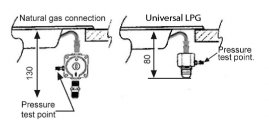
Fit regulator (N.G.) or a test point (Universal LPG) directly to the R 1/2’’ connection.
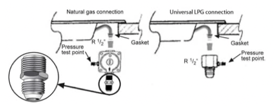
Direction of gas flow is indicated on the rear of the regulator.
For position of the inlet connection refer Preparing to install:
Use pipe compound or thread sealant, properly theaded pipes and careful assembly procedure so that there is no cross threading, etc., which might cause damage or leakage.
Make sure that all connections peformed are free of leakage. The manufacturer does not accept any liability for leakage on connections performed by the installer or if the L-tube is moved or twisted.
There are two ways to carry out the connection to the main gas line:
■ The hotplate can be connected with rigid pipe as specified in AS/NZS 5601.1
■ Flexible Hose: If installing with a hose assembly, it must comply with AS/NZS 1869, 10 mm ID, class B or D, no more than 1.2 m long and installed in accordance with AS/NZS 5601.1. Ensure that the hose does not contact the hot surfaces of the hotplate, oven, dishwasher or any other appliance that may be installed underneath or next to the hotplate. The hose should not be subjected to abrasion, kinking or permanent deformation and should be able to be inspected along its entire length with the cooktop in the installed position. Unions compatible with the hose fittings must be used and all connections tested for gas leaks.
The supply connection point shall be accessible with the appliance installed.
WARNING: Ensure that the hose assembly is restrained from accidental contact with the flue outlet of an underbench oven.
To set the pressure (NG 1.0 kPa) operate the wok and auxiliary burners on full.
Before Leaving- Check all connections for gas leaks with soap and water. DO NOT use a naked flame for detecting leaks. Ignite all burners both individually and concurrently to ensure correct operation of gas valves, burners and ignition. Turn gas taps to low flame position and observe stability of the flame for each burner individually and all together. Adhere the duplicate data plate to an accessible location near the hotplate. When satisfied with the hotplate, please instruct the user on the correct method of operation. In case the appliance fails to operate correctly after all checks have been carried out, refer to the authorised service provider in your area.
It should be expressly noted that we cannot accept any liability for direct or indirect damage caused by wrong connection, leakage or improper installation. When being repaired, the appliance must always be disconnected from the mains supply; if required, notify our customer service.
Converting the cooktop from Nat. Gas to Universal LPG
To change injectors
All work involved in installation, setting and adaptation to a different gas type must be carried out by authorised personnel from our Service Centre and must comply with current regulations and the conditions laid down by the local gas company.
Request change-over injectors from our customer service deparment (refer injector chart below for sizes).
|
Burner
|
Natural gas
|
Universal LPG
|
|
Hourly Gas Consumption (MJ)
|
Injector mark
|
Hourly Gas Consumption (MJ)
|
Injector mark
|
|
Auxiliary
|
3,80
|
90
|
3,50
|
50
|
|
Semi-rapid
|
6,50
|
118
|
6,00
|
67
|
|
Miniwok
|
13,00
|
118
|
12,00
|
68
|
|
Wok 4 kW
|
15,00
|
182
|
13,50
|
100
|
Before conversion the cooktop must be disconnected from the electricity and gas valves must be turned to the OFF position.
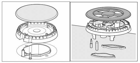
Changing the nozzles of the burners on the cooktop
1. Remove the pan supports, burner covers and diffusers.
2. Change the nozzles using the spanner provided by our Service Centre (code 340847, for double and triple flame burners code 340808), taking special care to ensure that the nozzle does not fall when it is removed from the burner or when fitted.
Ensure that it is completely tightened in order to guarantee the seal.
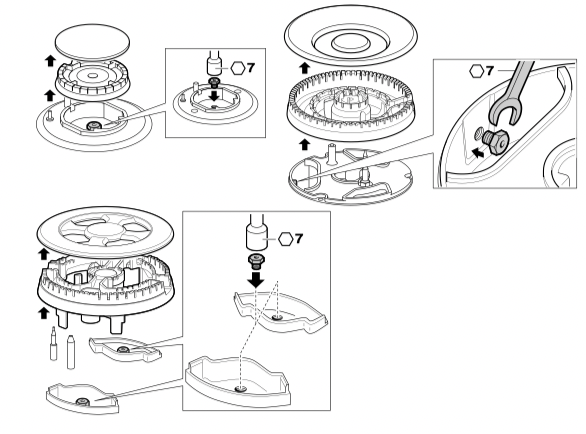
Adjustment of the taps
1. Set the control knobs to minimum.
2. Remove the control knobs from the taps. It has a flexible rubber valve reinforcing ring. Press with the tip of the screwdriver to access the tap's adjusting screw.
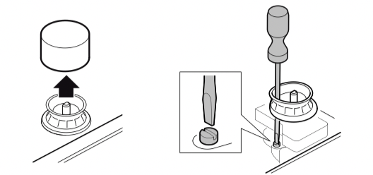
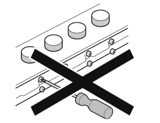
Never remove the valve reinforcing ring. The valve reinforcing rings guarantee the watertightness of the appliance's interior from liquids and dirt, which might otherwise prevent its correct operation.
3.Adjust the minimum ring setting by turning the by-pass screw using a flat head screwdriver.
To adjust the minimum flame for N.G. replace the control knob onto the spindle, light the gas and turn the control knob to the small flame position. Screw the adjustment screw anti-clockwise to estabilish a minimum stable flame position. The flame should remain alight and not burn back to the injector when the valve is turned quickly from ‘Full On’ to the “Minimum flame” position and back a few times. To adjust the minimum flame position for ULPG the screw must be fully tightened down clockwise.
If the by-pass screw cannot be accessed, disassemble the grease drip tray, which is fixed to the rest of the hob using a clip and screw mounting system. The following steps must be taken to remove it:
1.Remove all pan supports, burner caps, diffusers and control knobs.
2.Loosen the screws on the burners.
3.To assemble the grease splash tray again, proceed in the reverse order to removal.
It is important that all the seals are refitted to form a seal.
Never remove the tap spindle. In the event of a malfunction, change the whole tap.
Important: After finishing, stick the sticker, indicating the new gas type, close to the specifications plate.
Operating the appliance
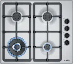
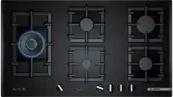
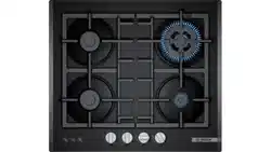
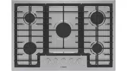
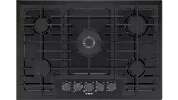
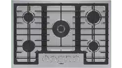
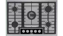
Burner locations
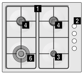
1 Pan supports
2 Control knobs
3 Auxiliary burner (up to 1 kW)
4 Semi-rapid burner (up to 1.75 kW)
5 Miniwok burner (up to 3.3 kW)
6 Wok burner (up to 4 kW)
Accessories
Depending on the model, the hob may include the following accessories. These can also be acquired from the Technical Assistance Service.
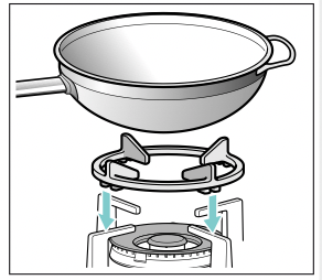
Additional support for woks Only when using cookware with a domed base on wok burners.
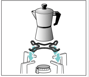
Additional support for espresso makers Only when using cookware with a base less than 12 cm in diameter on the smallest burner.
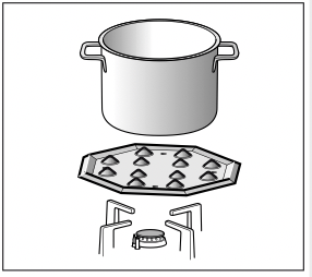
Simmer Plate This accessory has been designed to reduce the level of heat at the lowest power setting. Place the accessory directly on the pan support with the cones facing upwards, never directly over the burner. Centre the pan over the accessory.
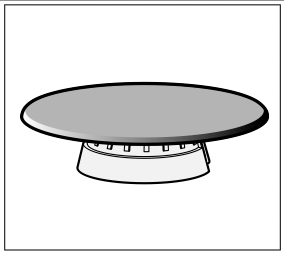
Simmer Cap Burner specially designed to cook at minimum power. In order to use it, remove the auxiliary burner and replace it with the Simmer Cap burner.
Code
HEZ298114 Additional coffee maker support
HEZ298105 Simmer Plate
HEZ298104 Simmer Cap
The manufacturer accepts no liability if these accessories are not used or are used incorrectly.
Operation
Remove the plastic covering used to protect the stainless steel before using the appliance (depending on the model). If any traces of adhesive remain on the printed areas, remove them with a wet cloth.
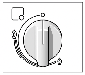
There are indications to show which burner each control knob operates.
It is essential to ensure that all the burner parts and pan supports are correctly installed for the appliance to work correctly. Do not swap the burner caps around.
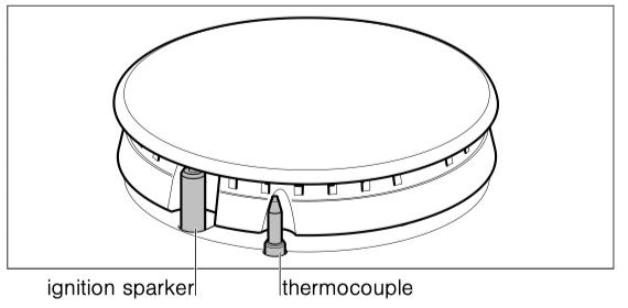
Switching on automatically
If your hob can be switched on automatically (ignition sparkers):
1. Press the chosen burner control knob and turn it anticlockwise to the maximum power setting. While the control knob is still pressed down, sparks are produced on all burners. The flame ignites.
2. Release the control knob.
3. Turn the control knob to the required setting.
If it does not come on, turn the control knob to the off setting and repeat the steps above. This time, press and hold the control knob for longer (up to 10 seconds).
Warning – Risk of deflagration!
If after 15 seconds the flame does not ignite, switch off the burner and open a nearby window or door. Wait at least one minute before trying to switch the burner back on.
Safety system
Depending on the model, your hob may have a safety system (thermocouple) that prevents the flow of gas if the burners accidentally switch off.
To ensure that this device is active:
1. Switch on the burner as usual.
2. Without releasing the control knob, press and hold it down firmly for 4 seconds after lighting the flame.
Switching off a burner
Turn the corresponding control knob clockwise to the 0 setting.
Power levels
The progressive control knobs can be used to control the power needed, from minimum to maximum power.
|
Setting
|
 |
Control off
|
|
Large flame
|
 |
Maximum capacity or aperture and electricity on
|
|
Economy flame
|
 |
inimum capacity or aperture
|
Warnings
It is normal to hear a soft whistling noise while the burner is operating.
When first used, it is normal for the burner to give off odours. This does not pose any risk and does not indicate a malfunction. They will disappear in time.
An orange-coloured flame is normal. This is caused by the presence of dust in the atmosphere, spilt liquids, etc.
If the burner flames are accidentally blown out, switch off the burner operating control knob and do not try to relight it for at least 1 minute.
A few seconds after the burner is switched off, a sound (thud) will be produced. This is not a fault - this means that the safety device is no longer operating.
Keep the burner as clean as possible. If the ignition sparkers are dirty they will not light properly. Clean them periodically using a small non-wire brush. Bear in mind that the ignition sparkers must not suffer any serious impacts.
Use “Large” setting to bring the pan to the boil, then adjust the flame between “Large flame” and “Economy flame” to maintain the required pan temperature.
Important:
The use of a cooktop leads to the production of heat and moisture in the kitchen. For this reason make sure that the room is properly ventilated. Keep natural ventilation openings, such as windows, open or provide a mechanical ventilation device (e.g. a range hood or overhead exhaust fan). An orangy flame is normal and simply indicates the presence of salt in the atmosphere (from cooking). If the flame has yellow patches, this is not a fault (of any kind).
Cooking recommendation
|
Burner
|
Very high - High
|
Medium
|
Low
|
|
Wok burner
|
Boiling, steaming, griddling, toasting, paellas, Asian food (wok).
|
Reheating and keeping things hot: cooked and pre-cooked dishes
|
|
Semi-rapid burner
|
Steamed potatoes, fresh vegetables, vegetable stews, pasta
|
Reheating, keeping things hot and making tasty casseroles
|
|
Auxiliary burner
|
Cooking: casse- roles, rice pudding, caramel
|
Defrosting and slow cooking: vegetables, fruit and fro- zen products
|
Melting: but- ter, chocolate, jelly
|
Do not place anything, eg. flame tamer, asbestos mat, between pan and pan support as serious damage to the appliance may result.
Do not remove the pan support and enclose the burner with a wok stand as this will concentrate and deflect heat onto the hotplate.
Do not use large pots or heavy weights which can bend the pan support or deflect flame onto the hotplate.
Cooking pans
Suitable pans
The chart below gives the correct pan usage for each burner.
|
Burner
|
Minimum diameter of the cookware base
|
Maximum diameter of the cookware base
|
|
Wok burner
|
22 cm
|
-
|
|
Semi-rapid burner
|
14 cm
|
20 cm
|
|
Auxiliary burner
|
12 cm
|
16 cm
|
The cookware must not overhang the edge of the hob.
Precautions for use
Note: When using certain pots or pans, a slight and temporary deformation of the steel cooking surface may occur. This is normal and does not affect the functionality of the appliance.
The following advice is intended to help you save energy and prevent pan damage:
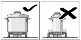
Use pans which are the right size for each burner. Do not use small pans on large burners. The flame must not touch the sides of the pan.

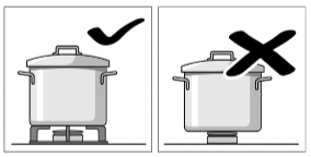
Do not use damaged pans, which do not sit evenly on the hob. Pans may tip over. Only use pans with a thick, flat base.

Do not cook without using a lid and make sure the lid is properly fitted. This wastes energy.
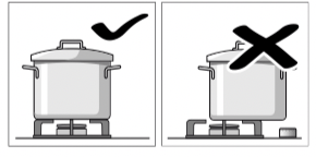
Always centre the pan over the burner, not to one side. Otherwise it could tip over. Do not place large pans on the burners near the control knobs. These may be damaged by the very high temperatures.
Place the pans on the pan supports, never directly on the burner.
Make sure that the pan supports and burner caps are correctly positioned before using the appliance.
Pans should be placed on the hob carefully.
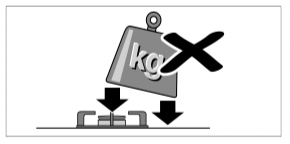
Do not strike the hob and do not place excessive weight on it.
Cleaning and maintenance
Cleaning
Once the appliance is cool, use a sponge to clean it with soap and water.
After each use, clean the surface of the respective burner parts once they have cooled down. If any residue is left (baked-on food, drops of grease etc.), however little, it will become stuck to the surface and more difficult to remove later. The holes and grooves must be clean for the flame to ignite properly.
The movement of some pans may leave metal residue on the pan supports.
Clean the burners and pan supports using soapy water and scrub with a non-wire brush.
If the pan supports are fitted with rubber rests, ensure that these are also cleaned. The rests may come loose and the pan support may scratch the hob.
Always dry the burners and pan supports completely. Water droplets or damp patches on the hob at the start of cooking may damage the enamel.
After cleaning and drying the burners, make sure the burner caps are correctly positioned on the diffuser.
Caution!
■ Do not remove the control elements when cleaning the appliance. The appliance may be damaged if moisture finds its way inside.
■ Do not use steam cleaners. This could damage the hob.
Maintenance
Always clean off any liquid as soon as it is spilt. This will prevent food remains from sticking to the hob surface and you will save yourself any unnecessary effort.
Do not leave acidic liquids (e.g. lemon juice, vinegar, etc.) on the hob.
Due to the high temperatures endured, the wok burner and the stainless steel zones (grease drip tray, burner outline, etc.) can change colour. This is normal. After each use, clean these areas with a product that is suitable for stainless steel.
It is recommended that the cleaning product available from our Technical Assistance Service (code 464524) is used regularly.
Service
DO NOT MODIFY THIS APPLIANCE.
Only authorized personnel from the Service Centre are qualified to work on the appliance.
Sometimes certain faults detected can be easily resolved. Before calling the Technical Assistance Service, bear in mind the following advice:
|
Fault
|
Possible cause
|
Solution
|
|
The general electrical system is malfunctioning.
|
Defective fuse.
|
Check the fuse in the main fuse box and change it if it is damaged.
|
|
The automatic safety switch or circuit breaker has tripped.
|
Check the main control panel to see if the automatic safety switch or circuit breaker has tripped.
|
|
The automatic switching on function does not work.
|
There may be food or cleaning products stuck between the ignition sparkers and the burners.
|
The space between the ignition sparker and the burner must be clean.
|
|
The burners are wet.
|
Dry the burner caps carefully.
|
|
The burner caps are not correctly positioned.
|
Check that the burner caps are correctly positioned.
|
|
The appliance is not earthed, is poorly connected or the earthing is faulty.
|
Contact the installation technician.
|
|
The burner flame is not uni- form.
|
The burner components are not correctly positioned.
|
Correctly place the parts on the appropriate burner.
|
|
The grooves on the burner are dirty.
|
Clean the grooves on the burner.
|
|
The gas flow is not normal or there is no gas.
|
The gas supply is blocked by gas taps.
|
Open all gas taps.
|
|
If the gas is supplied from a gas cylinder, check that it is not empty.
|
Change the gas cylinder.
|
|
The kitchen smells of gas.
|
A gas tap has been left on.
|
Turn off the taps.
|
|
Incorrect coupling of gas cylinder.
|
Check that the coupling is sound.
|
|
Possible gas leak.
|
Shut off the gas supply, ventilate the premises and imme- diately notify an authorised installation technician to check and certify the installation. Do not use the appliance until ensuring that there is no gas leak in the installation or appliance itself.
|
|
The burner immediately switches off after releasing the control knob.
|
The control knob was not held down for long enough.
|
Once the burner is on, hold the control knob down a few seconds longer.
|
|
The grooves on the burner are dirty.
|
Clean the grooves on the burner.
|
Any of the following are considered to be abnormal operation and may require servicing:
■ Yellow tipping of the cooktop burner flame.
■ Sooting up of cooking utensils.
■ Burners not lighting properly.
Gas valves, which are difficult to turn in case the appliance fails to operate correctly, contact the authorised service provider in your area.
Wiring diagram
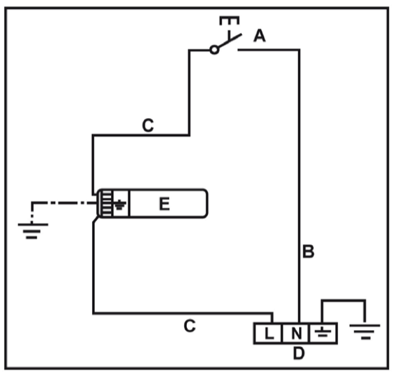
A Switch
B Blue wire
C Brown wire
D Terminal
E Ignition module