Loading ...
Loading ...
Loading ...
5 - Mechanical joint/Universal joints.
Move the oven towards the universal joints.
be left so that the universal joints can be
manually connected to the oven. Remove
the gum or adhesive tape from all the
universal joints and connect them to the
6 - Mounting the oven.
Push the oven right to the back and use
the 2 screws to secure it to the side walls
test.
The controls received with the oven with
the gas symbols must be placed on the
Switch on the gas of the cooking hob and
burners stay alight after switching them
on and releasing the control knobs.
(Thermocouple safety burners) Turn the
controls from maximum to minimum to
check the stability of the flame.
Oven removal:
If the oven needs to be removed to:
regulate the minimum point of the tap
fittings, adjust the length of the universal
joints or for a new mounting, the following
steps must be taken:
(situated on both sides of the oven behind
the door, in front of the oven unit, side
walls).
50 mm. Only remove the oven the required
distance in order to access the rear part
of the control panel. If you continue to
remove the oven, the universal joints in
the tap fittings area may come loose.
actuators.
unit. If necessary (for example with a high
base board in the kitchen unit) it may be
necessary to remove the electrical
connection and the earth wire.
If the universal joint has come away from
the tap fitting or actuator spindle, it must
be refitted:
a) Securing the universal joint to the
actuator:
The position of the narrow and wide pivots
of the universal joint needs to be taken
into consideration.
b) If the plastic piece of the tap fitting
spindle falls off: reconnect it but take into
account the correct position of the spindle
with a "D" shape and tighten it firmly.
Changing gas type
All operations with regard to the installation,
control and adaptation to another type of
gas must be carried out by authorised
personnel from our Technical
Assistance Service and comply with the
current regulations and requirements of
the gas companies.
IMPORTANT: Before you begin, turn
off the gas and electricity supply to the
appliance.
Before connecting up the appliance to
the installation, first check that it has been
adjusted for the type of gas that is to be
supplied. Our cooking hobs leave the
f
actory set to function with the type of gas
that is indicated on the specifications plate.
Provided that your country's domestic
legislation permits it, this cooking hob may
be adapted to function with other types of
gas. To do so, follow these steps:
A) Change of rapid, semi-rapid and
auxiliary burner tips.
1 - Remove the pan supports, cover
and casing of the burner.
2 - Change the burner tips using a 7
mm socket spanner and tighten them as
firmly as possible to ensure they are
With these burners the air does not have
to be adjusted.
B) Adjusting the reduced
consumption of the taps of the cooking
hob burners.
2 - Remove the oven or control module
sequence.
3 - Remove the 3 body universal joint
array from its position in the tap shank.
well as ignition switches, the flow adjusting
and bearing in mind that:
For 28-30/37 mbar Propane and
Butane Gas, the screw must be tightened
as firmly as possible.
For 50 mbar Butane Gas, change the
by-pass.
Place the sticker indicating that the
appliance's gas supply has been changed
close to the specifications plate.
actions, put the parts back together again.
Never take the tap spindle apart. In
the event of a malfunction, change the
GB
Put these instructions in a safe place for future reference
For Natural Gas, turn the screw
whole tap.
anti-
clockwise to the correct hotplate burner
gas output. The flame must be stable and
as small as possible. Check:
- the stability of the flame when changing
- the stability of the flame against draughts,
the hotplate burner setting between maxi-
mum and minimum,
- that there is no flame back draught.
1 - Set the taps to minimum.
7 - Completion of installation and working
1 - Remove the controls knobs.
2 - Remove the oven mounting screws
3 - Remove the oven carefully, approx.
4 -Remove the universal joints from the
5 - Remove the oven from the kitchen
6 -Special cases with the universal joints:
(see Fig. 9) A gap of approx. 50mm must
actuators. See Fig.9.
of the kitchen unit (Fig. 10).
spindles. Figure 11.
operate the burners. (Fig. 12). Check the
correctly sealed. Figure 13.
Figure 14 according to the disassembly
Figure 15 depending on the model
4 - If the cooking hob has safety as
5 - Operate the flow adjusting screw,
6 -
7 - Once you have completed these
screw must always be visible. Fig. 15.
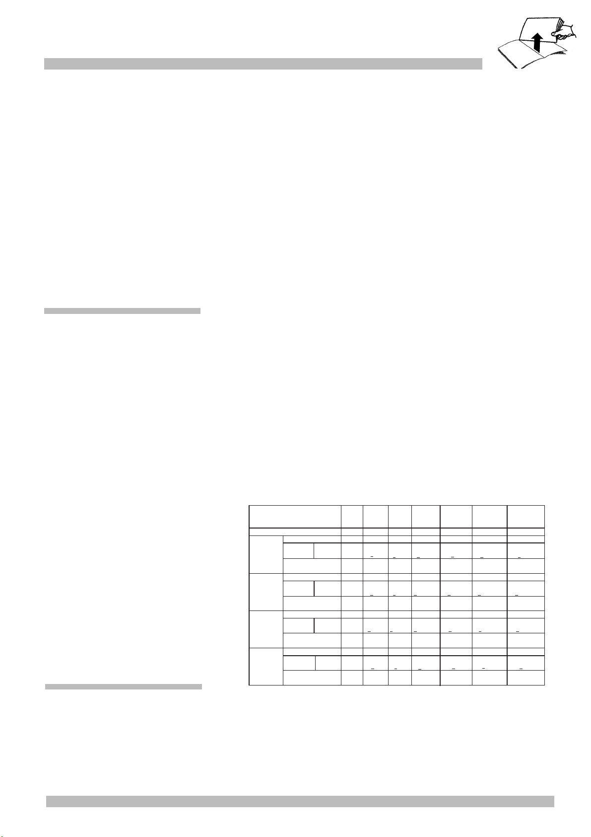
GAS
TYPE
G -31
PROPANE
G- 30
BUTANE
G -20
NATURAL
G -25
NATURAL
Gas pressure for use
Rapid
burner
Injector make
Consumption
(Hs)
Pressure 15ºC
1,013 mbar
Semi-rapid
burner
Auxiliary
burner
Triple flame
burner
m
3
/h
m
3
/h
m
3
/h
m
3
/h
g/h
g/h
g/h
g/h
mbar
kW
kW
kW
kW
37
85
3
-
214
67
1,75
-
125
50
1
0,33
71
97
3,6
1,26
-
257
-
29
85
3
0,6
-
218
67
1,75
-
127
50
1
0,33
73
97
3,6
-
261
-
20
115
3
0,5
0,286
-
100
1,75
0,167
-
72
1
0,33
-
140
3,6
0,343
0,095
-
3
0,5
0,333
-
1,75
0,194
-
1
0,33
-
3,6
0,399
0,111
-
Nominal
reduced
1,26 1,26 1,26
The burners must be used with the type
of gas that is indicated on the specifications
plate
Injector make
Consumption
(Hs)
Pressure 15ºC
1,013 mbar
Nominal
reduced
Injector make
Consumption
(Hs)
Pressure 15ºC
1,013 mbar
Nominal
reduced
Injector make
Consumption
(Hs)
Pressure 15ºC
1,013 mbar
Nominal
reduced
G -20
NATURAL
25
<
110
3
0,5
0,286
-
91
1,75
0,167
-
68
1
0,33
-
124
3,6
0,343
0,095
-
1,26
<
<
<
<
<
< < < <
< <
BURNER FEATURES
G- 30
BUTANE
3
0,6
-
218
1,75
0,35
-
127
1
0,33
73
3,6
-
261
-
1,26
<
<
<
0,6 0,6
50
0,6
74
58
43
75
0,5
20
132
100
0,5
73
150
0,5
<
<
<
<
<
<
<
<
<
TABLE 1
Loading ...
Loading ...
Loading ...