User Manual Ceiling Fan
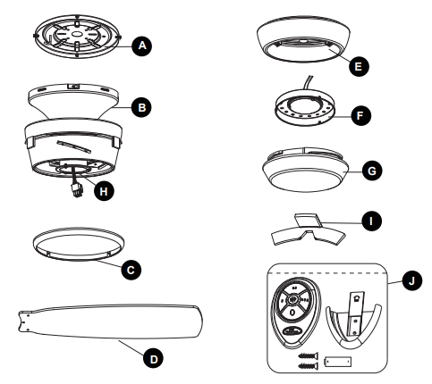
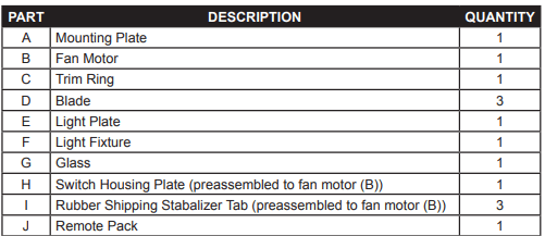
PACKAGE CONTENTS
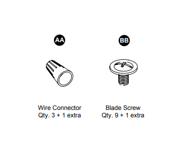
HARDWARE CONTENTS
PREPARATION
Before beginning assembly of product, make sure all parts are present. Compare parts with package contents list and hardware contents list. If any part is missing or damaged, do not attempt to assemble the product.
Estimated Assembly Time: 45 minutes.
Tools Required for Assembly (not included): Phillips screwdriver, step ladder, electrical tape, pliers, wire cutters, wire strippers.
Helpful Tools (not included): Electrical circuit tester.
READ AND SAVE THESE INSTRUCTIONS
Please read and understand this entire manual before attempting to assemble, operate or install the product.
- When using an existing outlet box, be sure the box is securely attached to the building structure and can support the full weight of the fan, so to avoid potential serious injury or death.
- All wiring must be in accordance with the National Electrical Code “ANSI/NFPA 70” and local electrical codes. Electrical installation should be performed by a qualified licensed electrician.
- After making the wire connections, the wires should be spread apart with the grounded conductor and the equipment-grounding conductor on one side of the outlet box and the ungrounded conductor on the other side of the outlet box.
- All set screws must be checked and retightened during and before installation.
- Splices after being made should be turned upward and pushed carefully up into the outlet box;
- Disconnect the electrical supply circuit to the fan before installing kit.
- Electrical diagrams are for reference only.
- The net weight of this fan including the light kit is: 15.7 lbs.
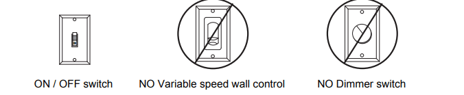
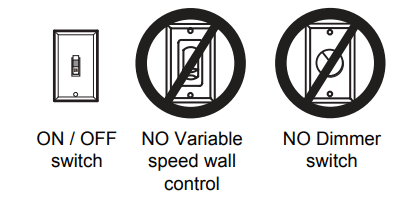
- ELECTRIC SHOCK HAZARD - Do not install this fan with variable speed wall control or wall-mounted dimmer switch. It will permanently damage the fan’s remote control receiver and cause the fan’s functions to fail.
- FIRE, ELECTRIC SHOCK OR PERSONAL INJURY HAZARD - To reduce the risk of fire, electric shock, or personal injury, mount to an outlet box marked “ACCEPTABLE FOR FAN SUPPORT OF 35.1 lbs OR LESS” and use the mounting screws provided with the outlet box. Most outlet boxes commonly used for the support of lighting fixtures are not acceptable for fan support and may need to be replaced. Consult a qualified licensed electrician if in doubt.
WARNING
- ELECTRIC SHOCK HAZARD - To reduce the risk of electric shock, this fan must be installed with an isolating wall control/switch.
- ELECTRIC SHOCK HAZARD - To reduce the risk of electric shock, make sure the electricity has bee turned off at the circuit breaker or fuse box before beginning installation.
- PERSONAL INJURY HAZARD - To reduce the risk of injury to persons, install fan so the blades are 7 ft. (2.1m) above the floor.
CAUTION
- PERSONAL INJURY HAZARD - To reduce the risk of personal injury, do not bend the blade brackets when installing the brackets, balancing the blades, or cleaning the fan. DO NOT insert foreign objects in between the rotating fan blades.
This equipment has been tested and found to comply with the limits for a Class B digital device, pursuant to Part 15 of the FCC Rules. These limits are designed to provide reasonable protection against harmful interference in a residential installation. This equipment generates, uses and can radiate radio frequency energy and, if not installed and used in accordance with the instructions, may cause harmful interference to radio communications. However, there is no guarantee that interference will not occur in a particular installation. If this equipment does cause harmful interference to radio or television reception, which can be determined by turning the equipment off and on, the user is encouraged to try to correct the interference by one or more of the following measures:
- Reorient or relocate the receiving antenna.
- Increase the separation between the equipment and receiver.
- Connect the equipment into an outlet on a circuit different from that to which the receiver is connected.
- Consult the dealer or an experienced radio/TV technician for help.
CAUTION: Any changes or modifications not expressly approved by the grantee of this device could void the user’s authority to operate the equipment.
This device complies with Part 15 of the FCC Rules. Operation is subject to the following two conditions:
(1) This device may not cause harmful interference, and (2) this device must accept any interference received, including interference that may cause undesired operation.
ASSEMBLY INSTRUCTIONS
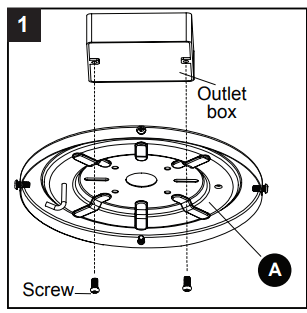
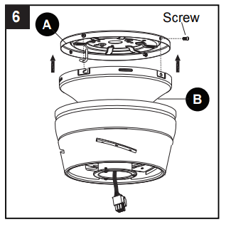
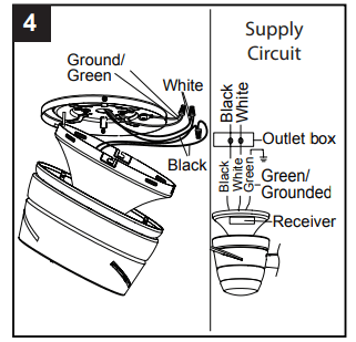
- Attach mounting plate (A) to outlet box (not included) using two screws (not included). Securely tighten two outlet box screws. Pull black, white, and grounded wires out of outlet box and through the hole in the mounting plate (A).
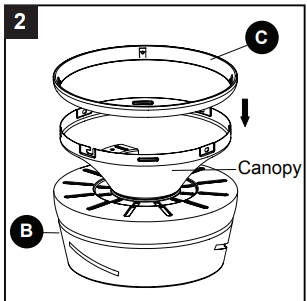
- Place trim ring (C) over canopy, and lay it on fan motor (B).
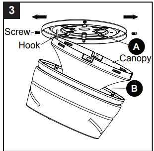
- Loosen two preassembled screws across from each other on the mounting plate (A). Remove and save remaining two preassembled screws. Hang fan motor (B) on mounting plate (A) hook using one of the non-slotted holes in the canopy.
-
- IMPORTANT: Do NOT use this fan with a dimmer switch or variable speed wall control. Using a dimmer switch or variable speed wall control will damage the fan.
-
- Connect the BLACK wire from the fan to the BLACK wire from the ceiling. Connect the WHITE wire from the fan, to the WHITE wire from the ceiling. Connect all GROUND (GREEN) wires from the fan together to the GREEN/BARE wire from ceiling. Connecting the GREEN/GROUND wires is conducive to receive the signal of the remote control.
- NOTE: The BLACK wire is the hot power for the fan and light kit. The WHITE wire is common for fan and light kit. GREEN wire is the ground wire. lf the household wires are different colors than referred to above, stop immediately and consult a professional electrician to determine proper wiring.
-
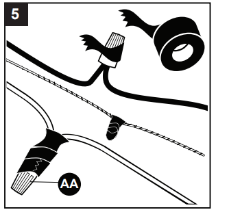
- Twist wire ends together and screw wire connectors (AA) on in a clockwise direction. Tape wire connectors (AA) and wires together with electrical tape (not included).
-
- Hardware Used
- Align keyhole slots on the fan motor (B) with the protruding screw heads on the mounting plate (A). Lift the fan motor (B) up to the mounting plate (A), making sure not to break any wire connections. Rotate the fan motor (B) clockwise until the screw heads fully engage into keyhole slots. Insert the previously removed screws (Step 3, page 6) and securely tighten all the screws.
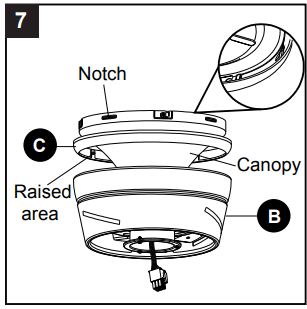
- Align the notches on the fan motor (B) canopy with raised areas inside the trim ring (C). Pop the trim ring (C) into the canopy.
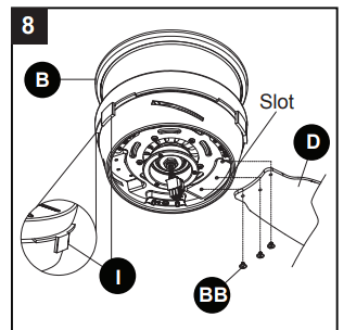
- Remove and discard preassembled rubber shipping stabilizer tabs (I) from fan motor (B). Insert blade (D) into slot on fan motor (B). Secure blade (D) with three blade screws (BB). Repeat for remaining blades (D) and blade screws (BB).
-
- Hardware Used

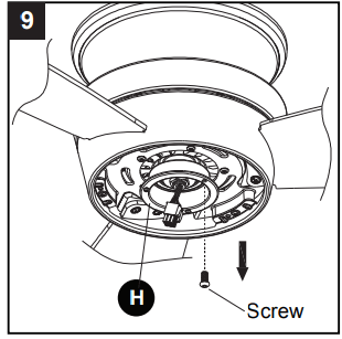
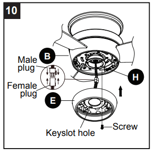
- Loosen two screws from switch housing plate (H). Remove and save remaining screw.
- Connect the 9-pin plug exiting the bottom of the fan motor (B) to the 9-pin plug from the light plate (E). Be sure plugs snap together completely. Attach light plate (E) to switch housing plate (H). Align keyholes, then twist to lock. Replace previously removed screw (Step 9, page 8) and securely tighten all screws.
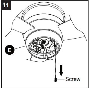
- Loosen two preassembled screws from light plate (E). Remove and save remaining preassembled screw from light plate (E).
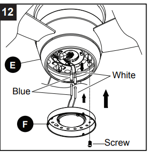
- Connect the WHITE wire from the light plate (E) to the WHITE wire from the light fixture (F). Connect the BLUE wire from the light plate (E) to the BLUE wire from the light fixture (F). Align the keyhole slots on the light fixture and the light plate (E), and twist to lock. Replace the previously removed screw (Step 11, page 9) and securely tighten all of the screws.
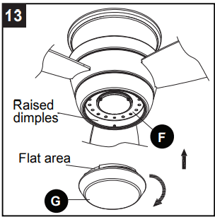
- Align the three flat areas on the top flange of the glass (G) with the three raised dimples in the light fixture (F). Insert the glass (G) into the light fixture (F), then turn the glass (G) clockwise until it stops.
- CAUTION: Avoid touching the LED with your bare hands. Be sure the power is off and the glass and LED are cool before cleaning the fixture.
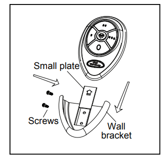
- OPTIONAL: If desired, the wall bracket in remote pack (J) can be installed to house the remote control. Remove the small plate preassembled on the wall bracket and use the screws in remote pack (J) to secure the wall bracket at desired mounting location. Replace the small plate, then rest the remote control from remote pack (J) into wall bracket.
OPERATING INSTRUCTIONS
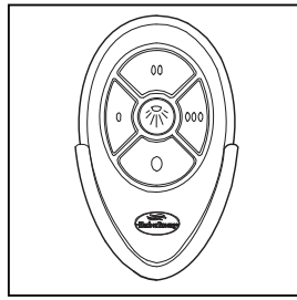
REMOTE CONTROL:
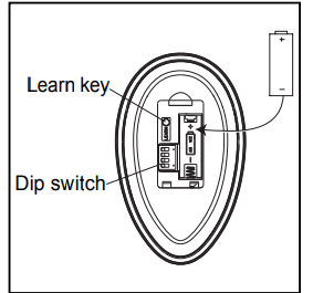
NOTE: If you have more than one remote controlled fan installed in the same location, you may want to change the frequency of the remote control to avoid any possible interference between remote controls. To change the frequency of the remote control, change the dip switch settings as described below:
- Install Battery/Learning Process:
- Remove the battery cover from the back of the remote found in the remote pack (J). Insert the battery from the remote pack (J) into the remote; ensure polarity of battery matches the polarity indicated in the battery compartment -- positive (+) to positive (+) and negative (-) to negative (-). Replace the battery cover. If you need to change the dip switches in the remote control due to a potential interference issue, slide the dip switches to your choice of either up or down -- the factory setting is up. Within 30 seconds of turning the fan’s power on, press and hold the “Learn” button on the remote control for 1 second. Once the receiver has detected the set frequency, the light of the fan will blink twice. Replace the battery cover. To confirm the remote control and receiver have paired successfully press any of the fan speed control buttons on the remote control.
- Fan Speed Control/Dimmer:
- 0 Low speed
- 0 0 Medium speed
- 0 0 0 High speed
 Turns fan off Turns light on or off
- NOTE: For the DIMMER function, press and hold the light button. Light will dim. Release the button when light is at desired level.
- NOTE: This remote control has a memory function. The receiver stores the fan speed and light setting when the fan is turned off. When fan is turned on again, it starts with the most recent settings.
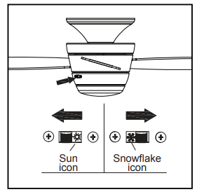
- Reverse Switch:
- When the season changes ,you may want to change the direction the fan blades spin. To switch between clockwise and counterclockwise rotation, flip the fan reversal switch.
- WARNING: Wait for fan to stop before reversing switch.
- In warmer weather, counterclockwise rotation creates a downward airflow, which cools the air. Push the switch LEFT and see a Sun icon.
- In cooler weather, clockwise rotation creates an upward airflow, which moves hot air from the ceiling into the room. Push the switch RIGHT and see a Snowflake icon.
CARE AND MAINTENANCE
- IMPORTANT: Shut off main power supply before beginning any maintenance.
- Do not use water or detergents when cleaning the fan or fan blades. A dry dust cloth or lightly dampened cloth will be suitable for most cleaning.
- At least twice a year, tighten all screws and lower canopy to check mounting bracket screws and downrod assembly.
- Clean fan housing with only a soft brush or lint-free cloth to avoid scratching the finish. Clean blades with a lint-free cloth. You may occasionally apply a light coat of furniture polish to blades for added protection.
- Total fixture wattage is 17.5 watts; do not attempt to replace LEDs.
- Battery replacement: Use an A23 12-volt alkaline battery for the remote control.
TROUBLESHOOTING
PROBLEM, POSSIBLE & CAUSE CORRECTIVE ACTION
- Fan blades do not move.
- . The power is off or the fuse is blown.
- Turn the power on or check fuse.
- Turn power off. Loosen motor housing; check all the connections.
- Noisy operation.
- Blades are loose.
- Cracked blade.
- Tighten all blade screws.
- Replace blades (call customer service).
- Excessive wobbling.
- The blades are loose.
- The fan is not securely mounted
- Tighten all blade screws.
- Turn power off. Carefully loosen the canopy and remount securely
- Remote control malfunction.
- No sound after the fan power is on.
- No flash on transmitter LED.
- The remote control does not work.
- Please check if the power supply is connected properly and main power is on.
- Please check if the battery is installed into the remote control. Make sure the battery is installed properly. One side of the battery is positive and the other is negative.
- Sync the remote control to the receiver following the steps described in step 1 on page 11. Make sure power to the fan is off before beginning the sync process.
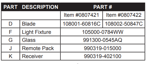
REPLACEMENT PARTS LIST
For replacement parts, call our customer service department at 1-800-643-0067, 8 a.m. - 6 p.m., EST, Monday - Thursday, 8 a.m. - 5 p.m., EST, Friday.