Loading ...
Loading ...
Loading ...
5
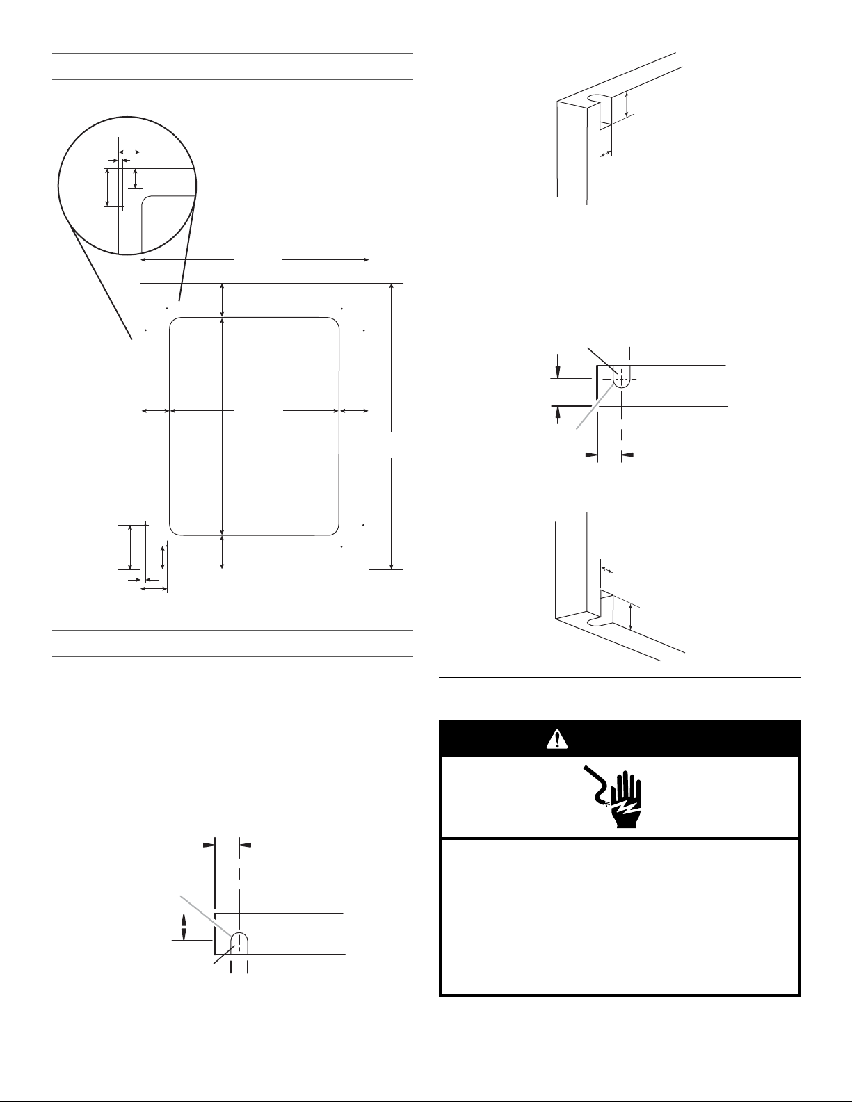
Overlay Frame Dimensions—Rear View
1. Create a custom overlay frame using the dimensions shown.
Door Hinge Holes
■ The views of the top and bottom hinge pin hole show a right-
hand hinge. Mirror the image for a left-hand hinge.
■ We recommend using a C-clamp and two pieces of scrap
wood (front and back) to help reinforce the overlay frame
when drilling the hinge pin holes.
1. Using a ³⁄₈" brad point doweling drill bit, drill a hole, ¹⁄₄" (7 mm)
deep, into the top of the overlay frame for the top hinge pin.
Remove the excess wood, surrounding the hole, by using the
rotary tool to complete the hinge depression as shown.
Top View
2. Using a ³⁄₈" brad point doweling drill bit, drill a hole,
³⁄₈" (10 mm) deep, in the bottom of the overlay frame for
the bottom hinge pin. Remove the excess wood, surrounding
the hole, by using the rotary tool to complete the hinge
depression, as shown.
Bottom View
Electrical Requirements
Before you move your beverage center into its final location, it is
important to make sure you have the proper electrical
connection.
A. Diameter ³
⁄₈
" (9.0 mm)
22³⁄₄"
(57.8 cm)
4
⁵⁄₈"
(11.7 cm)
2
³⁄₈"
(6.1 cm)
¹⁄₂"
(1.4 cm)
2
³⁄₄"
(7.0 cm)
3¹⁄₂"
(9.0 cm)
3"
(7.7 cm)
Top
Hole
Reverse Side
Bottom
23³⁄₄"
(60.3 cm)
29¹³⁄₁₆"
(75.8 cm)
17³⁄₄"
(45.0 cm)
3"
(7.7 cm)
3
¹⁄₂"
(9.0 cm)
2³⁄₄"
(7.0 cm)
¹⁄₂"
(1.4 cm)
4
⁷⁄₈"
(12.4 cm)
2
11
⁄
16
"
(6.8 cm)
A
Back Surface
Front Surface
³⁄₈" (9,0 mm)
¹⁄₂" (13.5 mm)
¹⁄₂" (13.5 mm)
Depth
¹⁄₄"
(7.0 mm)
A. Diameter ³
⁄₈
" (10.0 mm)
¹⁄₄"
(7 mm)
³⁄₈" (9 mm)
Front
Front Surface
Back Surface
Depth
³⁄₈" (10.0 mm)
¹⁄₂" (13.5 mm)
A
³⁄₈"
(
10.0 mm)
¹⁄₂
" (13.5 mm)
³⁄₈" (10.0 mm)
³⁄₈" (10.0 mm)
Front Surface
Electrical Shock Hazard
Plug into a grounded 3 prong outlet.
Do not remove ground prong.
Do not use an adapter.
Do not use an extension cord.
Failure to follow these instructions can result in death,
fire, or electrical shock.
WARNING
Loading ...
Loading ...
Loading ...