Loading ...
Loading ...
Loading ...
10
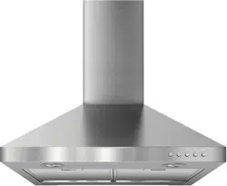
Make Electrical Connection
1. Disconnect power.
2. Remove terminal box cover using a T10 Torx
®
drive
(or the T10 adapter provided) to remove screws.
3. Remove the knockout in the terminal box and install
a UL listed or CSA approved ¹⁄₂" strain relief.
4. Run home power supply cable through strain relief
into terminal box.
5. Use UL listed wire connectors and connect black
wires (E) together.
6. Use UL listed wire connectors and connect white
wires (D) together.
7. Connect green (or bare) ground wire from home power supply
to yellow-green ground wire (F) in terminal box using UL listed
wire connectors.
8. Tighten strain relief screw.
9. Install terminal box cover.
10. Check that all light bulbs are secure in their sockets.
11. Reconnect power.
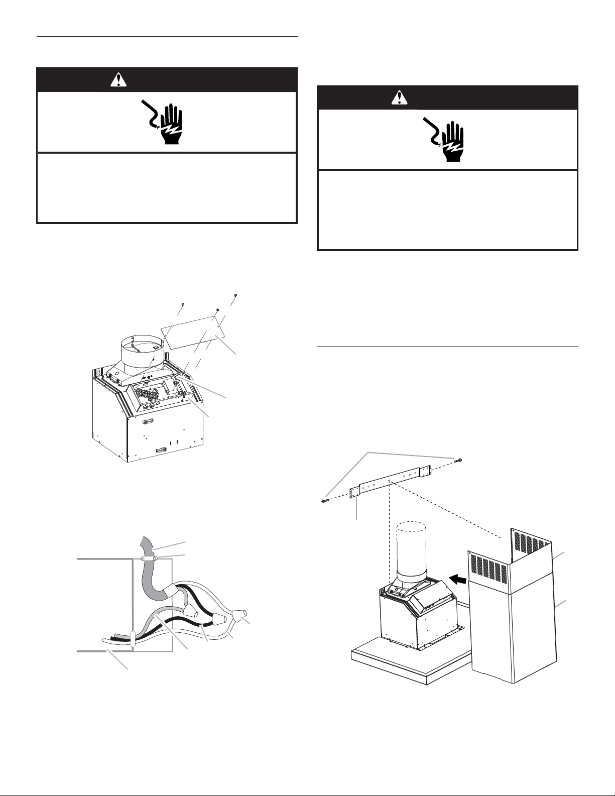
Install Vent Covers
When using both upper and lower vent covers, push lower
cover down onto hood and lift upper cover to ceiling. Install
with (2) 4.2 x 8 mm T20
®
screws using a T20
®
Torx
®
drive (or
T20
®
adapter provided) to tighten.
NOTE: For vented installations, upper vent cover may
be reversed to hide slots.
A. Terminal box
B. Knockout
C. Terminal box cover
A. Home power supply cable
B. UL listed or CSA approved strain relief
C. UL listed wire connectors
D. White wires
E. Black wires
F. Green (or bare) and yellow-green ground wires
G. Terminal box
WARNING
Electrical Shock Hazard
Disconnect power before servicing.
Replace all parts and panels before operating.
Failure to do so can result in death or electrical shock.
C
B
A
A
B
C
D
E
F
G
A. Upper vent cover
B. Lower vent cover
C. 4.2 x 8 mm screws
D. Bracket
WARNING
Electrical Shock Hazard
Electrically ground blower.
Connect ground wire to green and yellow ground wire
in terminal box.
Failure to do so can result in death or electrical shock.
A
B
C
D
Loading ...
Loading ...
Loading ...