Before you install the hob, write down the information below from the rating plate. The rating plate is on the bottom of the hob.
Model .......................................
PNC .........................................
Serial number ...........................
Provision for ventilation
Detailed recommendations are contained in the following British Standards Codes Of Practice: B.S. 6172/B.S. 5440, Par. 2 and B.S. 6891 Current Editions.
The hob should not be installed in a bed sitting room with a volume of less than 20 m³. If it is installed in a room of volume less than 5 m³ an air vent of effective area of 100 cm² is required. If it is installed in a room of volume between 5 m³ and 10 m³ an air vent of effective area of 50 cm² is required, while if the volume exceeds 11 m³ no air vent is required.
However, if the room has a door which opens directly to the outside no air vent is required even if the volume is between 5 m³ and 11 m³.
If there are other fuel burning appliances in the same room, B.S. 5440 Part 2 Current Edition, should be consulted to determine the requisite air vent requirements.
For appliances installed in the Republic of Ireland please refer to the NSAI- Domestic Gas Installation I.S. 813 Current Editions Table Four.
Location
The hob may be located in a kitchen, a kitchen/ diner or bed sitting room (with a volume greater than 20 m³), but not in a bathroom or shower room.
The minimum distance combustible material can be fitted above the hob in line with the edges of the hob is 400 mm. If it is fitted below 400 mm a space of 50 mm must be allowed from the edges of the hob.
For appliances installed in the Republic of Ireland please refer to NSAI- Domestic Gas Installation I.S 813 Current Edition Section 7- Permitted Locations of Appliance.
GAS CONNECTION
WARNING! Any gas installation must be carried out by a GAS SAFE REGISTER installer.
Make sure that, once the hob is installed, it is easily accessible for the engineer in the event of a breakdown.
The manufacturer will not accept liability, should the above instructions or any of the other safety instructions incorporated in this instruction booklet be ignored.
On the end of the shaft, which includes the G 1/2" threaded elbow, adjustment is fixed so that the washer is fitted between the components as shown in the diagram. Screw the parts together without using excessive force.
A. End of shaft with nut
B. Washer supplied with the appliance
C. Elbow supplied with the appliance
Connection to the gas supply should be with either rigid or semi-rigid pipe, i.e. steel or copper.
The connection should be suitable for connecting to R 1/2 (1/2 BSP male thread).
When the final connection has been made, it is essential that a thorough leak test is carried out on the hob and installation.
Make sure that the main connection pipe does not exert any strain on the hob.
If you use flexible metal pipes make sure that they agree to ISO 10380 and ISO 10807 standards. Be careful they do not come in touch with mobile parts or they are not squeezed. Also be careful when the hob is put together with an oven.
CAUTION! It is important to install the elbow correctly, with the shoulder on the end of the thread, fitted to the hob connecting pipe.
CAUTION! Failure to ensure the correct assembly will cause leakage of gas.
CAUTION! Make sure that the gas supply pressure of the appliance obeys the recommended values.
Rigid connection:
Carry out connection by using metal rigid pipes (copper with mechanical end).
INJECTORS REPLACEMENT
Remove the pan supports.
Remove the caps and crowns of the burner.
With a socket spanner 7 remove the injectors and replace them with the ones which are necessary for the type of gas you use (see table in "Technical Data" chapter).
Assemble the parts, follow the same procedure backwards.
Attach the label with the new type of gas supply near the gas supply pipe. You can find this label in the package supplied with the appliance.
If the supply gas pressure is changeable or different from the necessary pressure, you must fit an applicable pressure adjuster on the gas supply pipe.
ADJUSTMENT OF MINIMUM LEVEL
To adjust the minimum level of the burners:
1. Light the burner.
2. Turn the knob on the minimum position.
3. Remove the knob and the gasket.
WARNING! Pay attention not to damage the gasket. Do not use sharp tool to remove it.
4. With a thin screwdriver, adjust the bypass screw position (A).
5. If you change:
from natural gas G20 20 mbar to liquid gas, fully tighten the bypass screw in.
from liquid gas to natural gas G20 20 mbar, undo the bypass screw approximately 1/4 of a turn (1/2 of a turn for Multi Crown burner).
6. Reassemble the gasket and the knob.
WARNING! Make sure to place the gasket exactly in the original position.
WARNING! Make sure the flame does not go out when you quickly turn the knob from the maximum position to the minimum position.
ELECTRICAL CONNECTION
Do not pull the mains cable to disconnect the appliance. Always pull the mains plug (if applicable).
The appliance must not be connected with an extension cable, an adapter or a multiple socket. There is a risk of fire.
Do not let the power cable to heat up to a temperature of more than 90° C. The cable should be guided by means of clamps fixed to the side of the cabinet, in order to avoid any contact with the appliance beneath the cooktop
Make sure that there is access to the mains plug after the installation.
Electrical Requirements
Permanent electrical installation must agree with the latest I.E.E. Regulations and local Electricity Board regulations. For your own safety the installation must be done by a qualified electrician (e.g. your local Electricity Board, or a contractor who is on the roll of the National Inspection Council for Electrical Installation Contracting [NICEIC]).
The manufacturer refuses to be held responsible, if these safety measures are not abided by.
Supply connections
This hob has to be connected to 220-240 V (~ 50-60 Hz ) electricity supply.
The hob has a terminal block which is marked as follows:
L — Live terminal
N — Neutral terminal
or E — Earth terminal
Before carrying out the connection, make sure:
The limiter valve and the electrical system can take the appliance load (see the rating plate)
The supply system is equipped with an efficient earth connection in compliance with the current standards and regulations
The outlet or omnipolar switch used for connection is easily accessible with the appliance installed.
The appliance is supplied with a 3 core flexible power cable with a 3 amp plug. If it is necessary to change the fuse, use a 3 amp ASTA-approved (BS 1362) fuse.
A. Green and Yellow
B. 3 amp fuse
C. Brown
D. Cord clamp
E. Blue
The wires in the cord are coloured as follows:
Green and yellow
- Earth
Blue
- Neutral
Brown
- Live
WARNING! A cut off plug inserted into a 13 amp socket is a serious shock hazard. Ensure that the cut off plug is disposed of safely.
REPLACEMENT OF THE CONNECTION CABLE
The replacement of electric cable must be carried out exclusively by the service force centre or by personnel with similar competencies, in accordance with the current regulations.
To replace the connection cable use only H03V2V2-F T90 or equivalent type. Make sure that the cable section is applicable to the voltage load and the working temperature. The yellow/ green earth wire (B) must be approximately 2 cm longer than the live and neutral wire (A).
Connect the green and yellow (earth) wire to the terminal which is marked with the letter 'E', or the earth symbol , or coloured green and yellow.
Connect the blue (neutral) wire to the terminal which is marked with the letter 'N' or coloured blue.
Connect the brown (live) wire to the terminal which is marked with the letter 'L'. It must always be connected to the network phase. There must be no cut or stray strands of wire present. The cord clamp must be correctly attached to the outer sheath.
ASSEMBLY
1.
2.
3.
4.
If a furniture unit is installed at a distance of 400 mm above the hob, there must be a minimum safety distance of 50 mm to the left or right from the edge of the hob.
5.
6.
7.
8.
A. Supplied seal
B. Supplied brackets
9.
CAUTION! Install the appliance only on a worktop with flat surface.
POSSIBILITIES FOR INSERTION
The panel installed below the hob must be easy to remove and let an easy access in case a technical assistance intervention is necessary.
Kitchen unit with door or drawer
A. Removable panel
B. Space for connections
Kitchen unit with oven
The electrical connection of the hob and the oven must be installed separately for safety reasons and to let easy remove oven from the unit
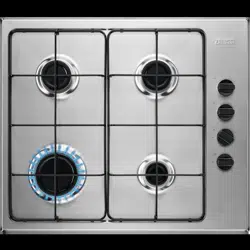
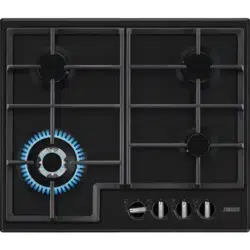
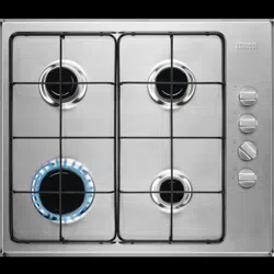
PRODUCT DESCRIPTION
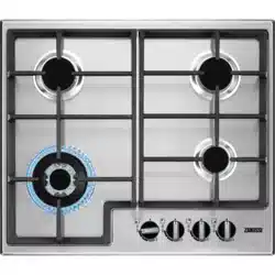
COOKING SURFACE LAYOUT
Semi-rapid burner
Multi Crown burner
Auxiliary burner
Control knobs
CONTROL KNOB
DAILY USE
WARNING! Refer to Safety chapters.
BURNER OVERVIEW
A. Burner cap
B. Burner crown
C. Ignition candle
D. Thermocouple
IGNITION OF THE BURNER
Always light the burner before you put on the cookware.
WARNING! Be very careful when you use open fire in the kitchen environment. The manufacturer declines any responsibility in case of the flame misuse.
Push the control knob down and turn it counterclockwise to the maximum gas supply position ( ).
Keep the control knob pushed for equal or less than 10 seconds. This lets the thermocouple warm up. If not, the gas supply is interrupted.
Adjust the flame after it is regular.
If after some tries the burner does not light, check if the crown and its cap are in correct positions.
WARNING! Do not keep the control knob pushed for more than 15 seconds. If the burner does not light after 15 seconds, release the control knob, turn it into off position and try to light the burner again after minimum 1 minute.
CAUTION! In the absence of electricity you can ignite the burner without electrical device; in this case approach the burner with a flame, turn the control knob counter-clockwise to maximum gas supply position and push it down. Keep the control knob pushed for equal or less than 10 seconds to let the thermocouple warm up.
If the burner accidentally goes out, turn the control knob to the off position and try to light the burner again after minimum 1 minute.
The spark generator can start automatically when you switch on the mains, after installation or a power cut. It is normal.
The hob is supplied with the progressive valves. They make the flame regulation more precise.
TURNING THE BURNER OFF
To put the flame out, turn the knob to the off position .
WARNING! Always turn the flame down or switch it off before you remove the pans from the burner.
HINTS AND TIPS
WARNING! Refer to Safety chapters.
COOKWARE
CAUTION! Do not use cast iron pans, clay or earthenware pots, grill or toaster plates. The stainless steel can become tarnished if it is too much heated.
WARNING! Do not put the same pan on two burners.
WARNING! Do not put unstable or damaged pots on the burner to prevent spills and injuries.
CAUTION! Make sure that the bottoms of pots do not stand too close to the control knob, otherwise the flame heats the control knob up.
CAUTION! Make sure that pot handles are not above the front edge of the cooktop.
CAUTION! Make sure that the pots are placed centrally on the burner in order to get the maximum stability and a lower gas consumption.
DIAMETERS OF COOKWARE
Use cookware with diameters applicable to the size of burners.
Burner
Diameter of cookware (mm)
Multi Crown
180 - 260
Semi-rapid
120 - 220
Auxiliary
80 - 180
CARE AND CLEANING
WARNING! Refer to Safety chapters.
GENERAL INFORMATION
Clean the hob after each use.
Always use cookware with a clean base.
Scratches or dark stains on the surface have no effect on how the hob operates.
Use a special cleaner suitable for the surface of the hob.
Stainless steel
Wash stainless steel parts with water, and then dry them with a soft cloth.
To remove burnt food, fat and stubborn stains let them soak in a small amount of mild detergent for a few minutes before cleaning.
Use cleaning products designed specifically for cleaning stainless steel in order to protect the steel surfaces.
Do not use cleaning products containing corrosive chemicals such as chlorides, do not clean the surface with disinfectants, stain or rust removers and immersion cleaners.
PAN SUPPORTS
The pan supports are not resistant to washing in a dishwasher. They must be washed by hand.
1. Remove the pan supports to easily clean the hob.
Be very careful when you replace the pan supports to prevent the hob top from damage.
2. The enamel coating occasionally can have rough edges, so be careful when you wash the pan supports by hand and dry them. If necessary, remove stubborn stains with a paste cleaner.
3. After you clean the pan supports, make sure that they are in correct positions.
4. For the burner to operate correctly, make sure that the arms of the pan supports are aligned with the centre of the burner.
CLEANING THE HOB
Remove immediately: melted plastic, plastic foil, sugar and food with sugar, otherwise, the dirt can cause damage to the hob. Take care to avoid burns.
Remove when the hob is sufficiently cool: limescale rings, water rings, fat stains, shiny metallic discoloration. Clean the hob with a moist cloth and a non-abrasive detergent. After cleaning, wipe the hob dry with a soft cloth.
To clean the enamelled parts, caps and crowns, wash them with warm soapy water and dry them carefully before you put them back on.
CLEANING THE SPARK PLUG
This feature is obtained through a ceramic ignition candle with a metal electrode. Keep these components well clean to prevent difficult lighting and check that the burner crown holes are not obstructed.
PERIODIC MAINTENANCE
Speak to your local Authorised Service Centre periodically to check the conditions of the gas supply pipe and the pressure adjuster, if fitted.
TROUBLESHOOTING
WARNING! Refer to Safety chapters.
WHAT TO DO IF...
Problem
Possible cause
Remedy
There is no spark when you try to activate the spark generator.
The hob is not connected to an electrical supply or it is connected incorrectly.
Check if the hob is correctly connected to the electrical supply
The fuse is blown.
Make sure that the fuse is the cause of the malfunction. If the fuse is blown again and again, contact a qualified electrician.
Burner cap and crown are placed incorrectly.
Place the burner cap and crown correctly.
The flame extinguishes immediately after ignition.
Thermocouple is not heated up sufficiently.
After lightning the flame, keep the knob pushed for equal or less than 10 seconds.
The flame ring is uneven.
Burner crown is blocked with food residues.
Make sure that the injector is not blocked and the burner crown is clean.
IF YOU CANNOT FIND A SOLUTION...
If you cannot find a solution to the problem yourself, contact your dealer or an Authorised Service Centre. Give the data from the rating plate. Make sure, you operated the hob correctly. If not the servicing by a service technician or dealer will not be free of charge, also during the warranty period. The instructions about the Service Centre and conditions of guarantee are in the guarantee booklet.
LABELS SUPPLIED WITH THE ACCESSORIES BAG
Stick the adhesive labels as indicated below:
A. Stick it on Guarantee Card and send this part (if applicable).
B. Stick it on Guarantee Card and keep this part (if applicable).
C. Stick it on instruction booklet.
TECHNICAL DATA
HOB DIMENSIONS
Width
594 mm
Depth
510 mm
BYPASS DIAMETERS
BURNER
Ø BYPASS 1/100 mm
Multi Crown
57
Semi-rapid
32
Auxiliary
28
OTHER TECHNICAL DATA
GAS BURNERS FOR NATURAL GAS G20 20 mbar
BURNER
NORMAL POWER kW
MINIMUM POWER kW
INJECTOR MARK
Multi Crown
4,0
1,4
146
Semi-rapid
2,0
0,45
96
Auxiliary
1,0
0,33
70
GAS BURNERS FOR LPG G30/G31 28-30/37 mbar
ENERGY EFFICIENCY
PRODUCT INFORMATION ACCORDING TO EU 66/2014
Model identification
ZGNN645K, ZGNN645X
Type of hob
Built-in hob
Number of gas burners
4
Energy efficiency per gas burner (EE gas burner)
Left rear - Semi-rapid
54.5%
Right rear - Semi-rapid
58.1%
Left front - Multi crown
59.7%
Right front - Auxiliary
not applicable
Energy efficiency for the gas hob (EE gas hob)
57.4%
EN 30-2-1: Domestic cooking appliances burning gas - Part 2-1 : Rational use of energy - General
ENERGY SAVING
Before use, make sure that the burners and pan supports are assembled correctly.
Use cookware with diameters applicable to the size of burners.
Center the pot on the burner.
When you heat up water, use only the amount you need.
If it is possible, always put the lids on the cookware.
When the liquid starts to boil, turn down the flame to barely simmer the liquid.
If it is possible, use a pressure cooker. Refer to its user manual.


 or E — Earth terminal

 , or coloured green and yellow.


 ).
). .
.