
ENGLISH
E-1
ENGLISH
Thank you for purchasing a Sharp air conditioner. Please read this manual carefully before
operating the product.
• PRECAUTIONS ...........................................E-1
• PART NAMES..............................................E-2
• USING THE REMOTE CONTROL ..............E-4
• BASIC OPERATION ....................................E-6
•
ADJUSTING THE AIR FLOW DIRECTION ..
E-8
• TIMER OPERATION....................................E-9
• ONE-HOUR OFF TIMER .............................E-11
CONTENTS
• AUXILIARY MODE ................................. E-11
• TEST RUN MODE .................................. E-12
• ADDITIONAL NOTES ON OPERATION E-13
• TIPS ON SAVING ENERGY................... E-13
• MAINTENANCE...................................... E-14
• BEFORE CALLING FOR SERVICE ....... E-15
• OPTION KIT............................................ E-16
PRECAUTIONS
LOCATION
» Install the unit in a place with minimal dust, fumes and moisture in the air.
REMOVAL
» Do not attempt to remove the unit. Consult your dealer or other qualified service personnel
for the removal of the unit.
This equipment complies with the requirements of Directives 89/336/EEC and 73/23/EEC as
amended by 93/68/EEC.
WARNING
1. Use a power supply with a 220-240 volt (±10%) rating.
Use of a power supply with improper voltage and frequency can result in equipment
damage and possible fire.
2. Open a window or door periodically to ventilate the room, especially when using gas
appliances.
3. Never insert objects into the unit. Inserting objects can result in injury due to the high speed
rotation of internal fans.
4. Do not pull the power cord. Pulling and misuse of the power cord can result in damage to
the unit and cause electrical shock.
5. When using the air conditioner in a room where infants, children, elderly people, or
bedridden or disabled people are present, make sure the room temperature is suitable for
them.
6. Make sure a fuse with the correct current rating is installed.
7. Follow the local rules and regulations for power cord cabling. Improper cable connection
can cause the power cord, plug and the electrical outlet to overheat and cause a fire.
8. For safety, turn off the circuit breaker or disconnect the power cord when the unit is not
used for an extended period of time.
This unit is designed for use in residences. Do not use for other applications such as
in a kennel or greenhouse to raise animals or grow plants.
Downloaded from www.ManualsFile.com manuals search engine
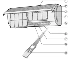
PART NAMES
E-2
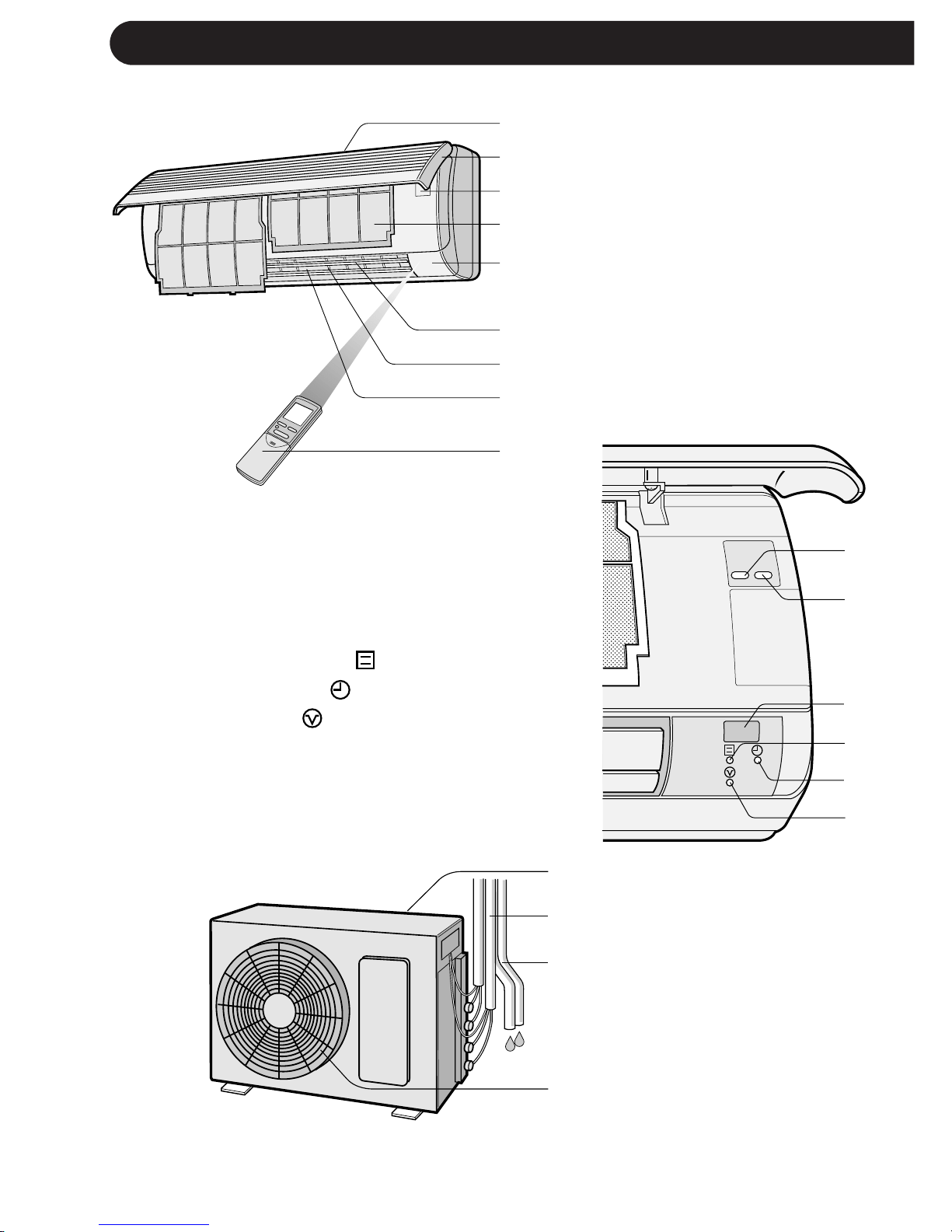
INDOOR UNIT
1 Inlet (Air)
2 Open Panel
3 Operation panel
4 Air Filters
5 Indicator Panel
6 Vertical Adjustment
Louvres
7 Horizontal Adjustment
Louvres
8 Outlet (Air)
9 Remote Control
To open the open panel, hold the bot-
tom corners of the open panel and
gently pull the panel outwards.
0 TEST RUN Button
q AUX. Button
w RECEIVER Window
e OPERATION Lamp (Red )
r TIMER Lamp (Yellow )
t BUSY Lamp (Red )
Blinks when the unit can not
operate due to the other unit
operating in different mode.
OUTDOOR UNIT
y Inlet (Air)
u Refrigerant Tube and
Interconnecting Cord
i Drainage Hose
o Outlet (Air)
NOTES:
1. Actual units may vary slightly from those shown above.
2. AE-M18AE-T is a multi-type outdoor unit and this unit is connected to two indoor units.
See the Installation Manual for detail installation instructions.
1
2
3
4
5
6
7
8
9
0
q
w
e
r
t
y
u
i
o
TEST
RUN AUX.
Downloaded from www.ManualsFile.com manuals search engine
ENGLISH
E-3
REMOTE CONTROL
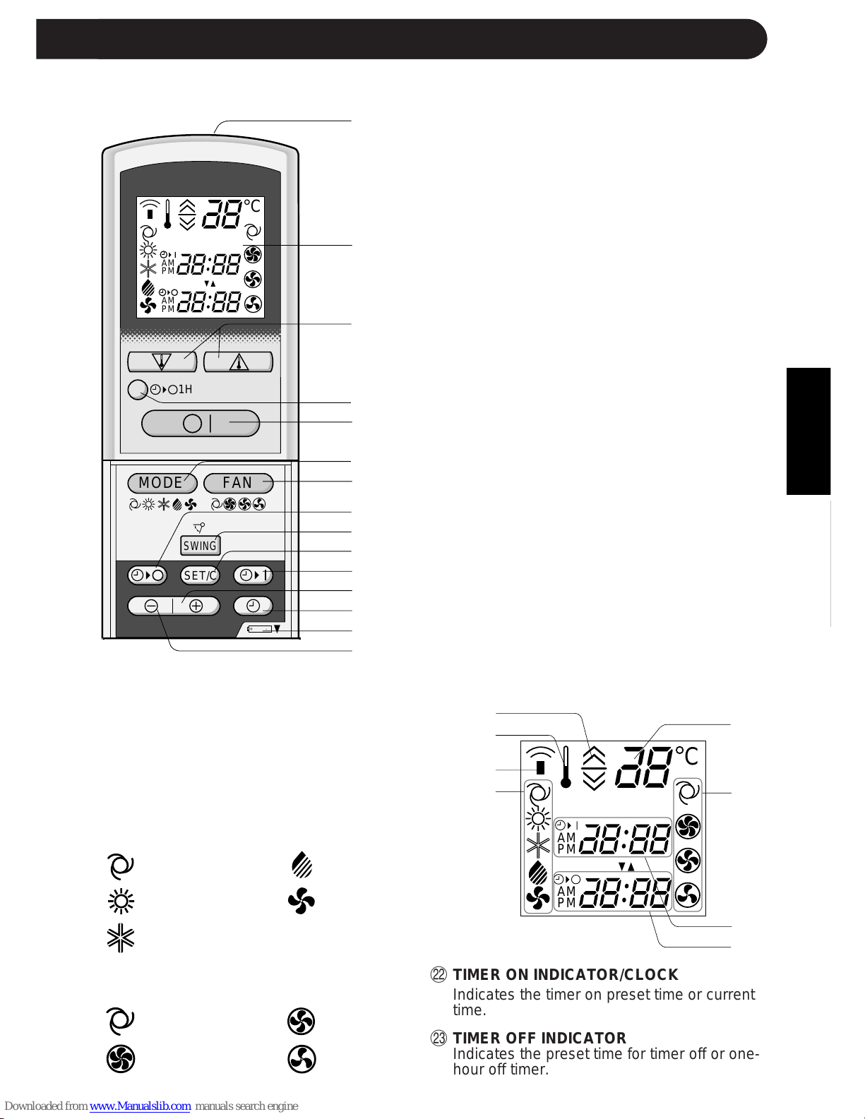
1 TRANSMITTER
2 DISPLAY (Liquid Crystal Display)
3 THERMO. (Thermostat) Button
4 ONE-HOUR OFF TIMER Button
5 ON/OFF Button
6 MODE Button
7 FAN Button
8 TIMER OFF Button (for setting the timer)
9 SWING Button
0 TIMER SET/CANCEL Button
q TIMER ON Button (for setting the timer)
w TIME ADVANCE Button
e CLOCK Button
r Indicates BATTERY COMPARTMENT is
below this mark
t TIME REVERSE Button
L.C.D. REMOTE CONTROL DISPLAY
y THERMOSTAT SETTING FOR AUTO
AND DRY MODES
u TEMPERATURE SYMBOL
i TRANSMITTING SYMBOL
o MODE SYMBOLS
:AUTO :DRY
:HEAT :FAN ONLY
:COOL
p TEMPERATURE INDICATOR
a FAN SPEED SYMBOLS
:AUTO :LOW
:HIGH :SOFT
1
2
3
4
5
6
7
8
9
0
q
w
e
r
t
y
u
i
o
p
a
s
d
,,
,,
@@
@@
ÀÀ
ÀÀ
,,
,,
@@
@@
ÀÀ
ÀÀ
,,
,,
@@
@@
ÀÀ
ÀÀ
,,
,,
@@
@@
ÀÀ
ÀÀ
,,
,,
@@
@@
ÀÀ
ÀÀ
,,
,,
@@
@@
ÀÀ
ÀÀ
,,
,,
@@
@@
ÀÀ
ÀÀ
,,
,,
@@
@@
ÀÀ
ÀÀ
,,
,,
@@
@@
ÀÀ
ÀÀ
,,
,,
@@
@@
ÀÀ
ÀÀ
,,
,,
@@
@@
ÀÀ
ÀÀ
,,
,,
@@
@@
ÀÀ
ÀÀ
,,
,,
@@
@@
ÀÀ
ÀÀ
,,
,,
@@
@@
ÀÀ
ÀÀ
,,
,,
@@
@@
ÀÀ
ÀÀ
,,
,,
@@
@@
ÀÀ
ÀÀ
,,
,,
@@
@@
ÀÀ
ÀÀ
,,
,,
@@
@@
ÀÀ
ÀÀ
,,
,,
@@
@@
ÀÀ
ÀÀ
+-
MODE
SWING
FAN
C
AM
PM
AM
PM
1H
SET/C
C
AM
PM
AM
PM
PART NAMES
s TIMER ON INDICATOR/CLOCK
Indicates the timer on preset time or current
time.
d TIMER OFF INDICATOR
Indicates the preset time for timer off or one-
hour off timer.
Downloaded from www.ManualsFile.com manuals search engine

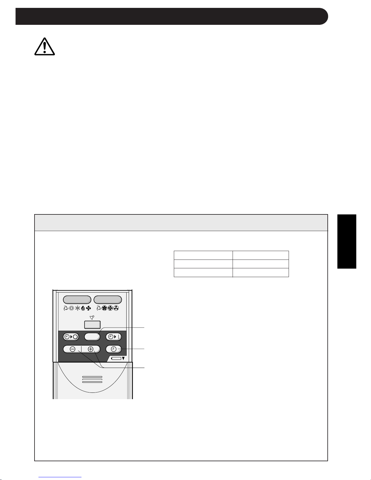
1 Remove the remote control
cover.
2 Insert batteries in the compart-
ment, making sure the ± and
— polarities are correctly
aligned.
» The display indicates "AM
6:00" when batteries are prop-
erly installed.
3 Reinstall the cover.
E-4
NOTES:
» The battery life is approximately one year in normal use.
» When you replace the batteries, always change both batteries, and make sure
they are the same type.
» If the remote control does not operate properly after replacing the batteries, take
out the batteries and reinstall them again after 30 seconds.
» If you will not be using the unit for a long time, remove the batteries from the
remote control.
Point the remote control towards the
unit’s signal receiver window and
press the desired button. The unit
generates a beep when it receives the
signal.
» Make sure there is no curtain or other
object between the remote control and
the unit.
» The remote control can send signals
from up to 7 metres away.
Remote control
cover
USING THE REMOTE CONTROL
INSTALLING BATTERIES Use two size-AAA (R03) batteries.
HOW TO USE THE REMOTE CONTROL
NOTE:
If two indoor units are installed in the same room, both units may operate at the same
time by the remote control signal. The units should be installed apart from the other as
much as possible. Transmit the signal directly toward the unit you wish to operate.
+
-
+
-
Downloaded from www.ManualsFile.com manuals search engine
ENGLISH
E-5
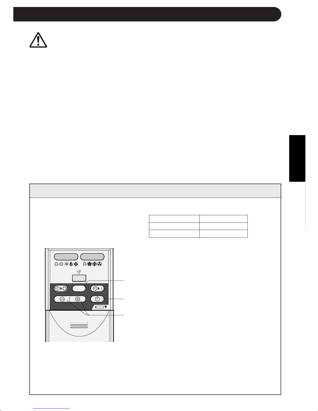
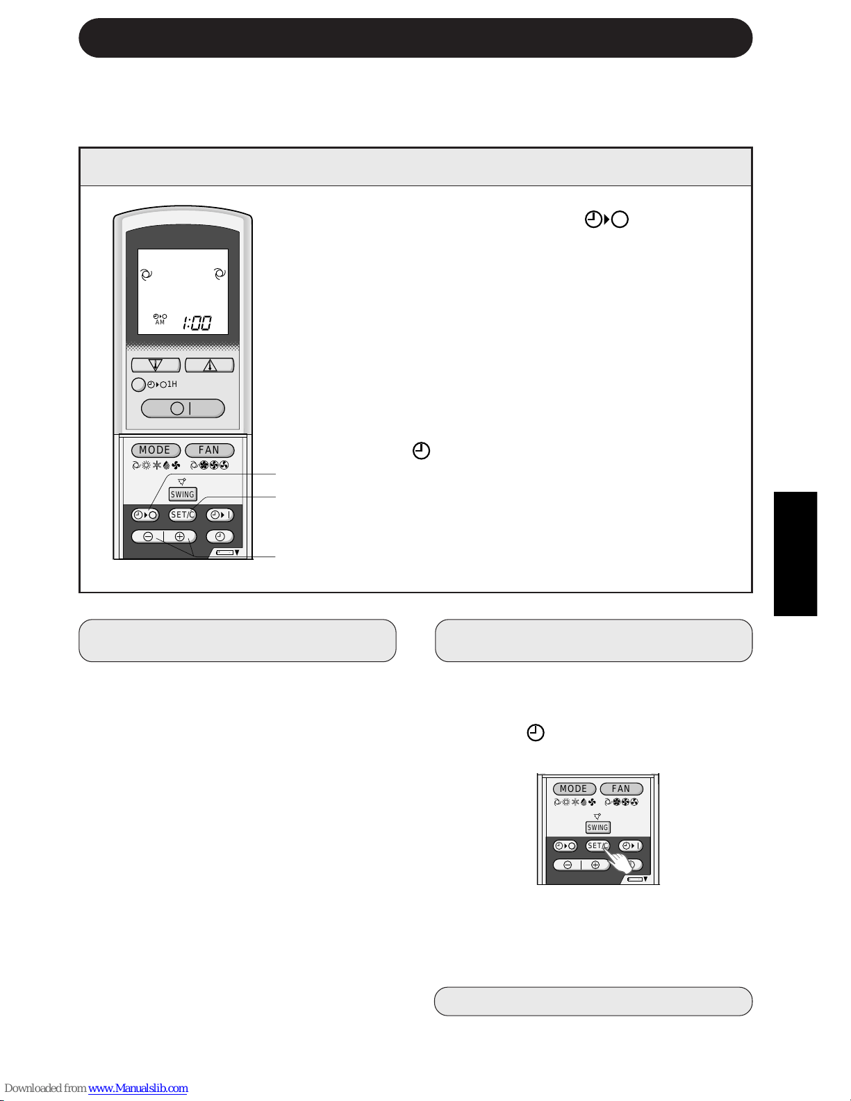
SETTING THE CURRENT CLOCK TIME
Example: 5 o'clock in the afternoon
Clock Display
12-hour mode PM 5:00
24-hour mode 17:00
1 To set to the 12-hour mode, press the
CLOCK button once in the first step.
To set to the 24-hour mode, press the
CLOCK button twice in the first step.
2 Press the TIME ADVANCE or REVERSE
button to set the current time.
» Keep the button pressed to advance
or reverse the time display quickly.
3 Press the SET/C button.
» The colon (:) blinks to indicate that the
clock is functioning.
NOTE:
» The current time cannot be set when the
timer is operating.
3
1
2
CAUTION
» Do not allow the signal receiver window to receive strong direct sunlight, since it can
adversely affect its operation. If the signal receiver window is exposed to direct sunlight,
close a curtain to block the light.
» Using a fluorescent lamp with a quick starter in the same room may interfere with
transmission of the signal.
» The unit can be affected by signals transmitted from the remote control of a television,
VCR or other equipment used in the same room.
» Do not leave the remote control in direct sunlight or near a heater. Also, protect the unit
and remote control from moisture and shock which can discolour or damage them.
Å|
Å|
Å{
Å{
+
-
MODE
SWING
FAN
SET/C
There are two clock modes: 12-
hour mode and 24-hour mode.
Downloaded from www.ManualsFile.com manuals search engine

,@À
,@À
,@À
,@À
,@À
,@À
,@À
,@À
,@À
,@À
,@À
,@À
,@À
,@À
,@À
,@À
,@À
,@À
,@À
+-
MODE
SWING
FAN
AM
1H
SET/C
Press the MODE button to select the operation
mode.
AUTO HEAT COOL DRY FAN ONLY
1
E-6
BASIC OPERATION
2
Press the ON/OFF button to start operation.
» The red OPERATION lamp (
) on the unit
will light.
3
Press the THERMO. button to set the desired
temperature.
1
4
5
2
3
» In the AUTO and
DRY mode, the indi-
cator bars represent
changes in tempera-
ture.
2°C higher
1°C higher
1°C lower
2°C lower
» In the COOL and HEAT mode, the tempera-
ture can be set within the range of 18 to 32
°C.
» In the FAN ONLY mode, the temperature
setting cannot be made.
Press the FAN button to set the desired fan
speed.
4
To turn off the unit, press the ON/OFF button
again.
» The red OPERATION lamp (
) on the unit
will turn off.
» In the DRY mode, the fan speed cannot be
changed.
» In the FAN ONLY mode, the fan speed can-
not be set to AUTO.
AUTO HIGH LOW SOFT
5
Downloaded from www.ManualsFile.com manuals search engine
ENGLISH
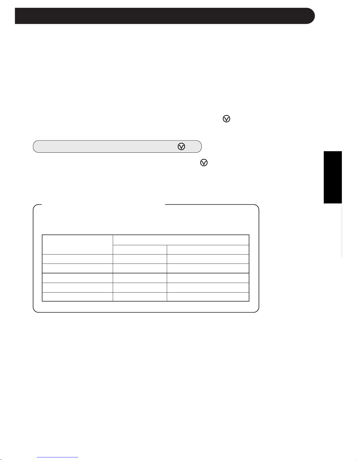
Automatic Operation
Mode Thermostat Setting
Below 21°C HEAT 23°C
21°C-24°C DRY Room Temp. at start-up
24°C-26°C COOL 24°C
26°C-28°C COOL 25°C
Above 28°C COOL 26°C
E-7
TIPS ABOUT AUTO MODE
In the AUTO mode, the temperature setting and mode are automatically
selected according to the room temperature when the unit is turned on.
Room temp. at opera-
tion start-up
NOTES:
This air conditioner is a multi-type, and two indoor units are connected to
one outdoor unit.
When the setting mode of one indoor unit differs from the other, the indoor
unit operated later may not work.
» When one indoor unit is operating in HEAT mode, the other unit can not operate
in COOL or DRY mode.
» When one indoor unit is operating in COOL or DRY mode, the other unit can not
operate in HEAT mode.
When the mode of the indoor unit later operated is different from
the one which is in operation, the red BUSY lamp
( )
of the
indoor unit later operated will blink.
How to reset the BUSY lamp
( )
There are two ways to reset the blinking BUSY lamp
(
)
.
Change the remote control's mode and send the same mode signal which
the other indoor unit is operating in, or push the ON/OFF button of the
remote control.
Downloaded from www.ManualsFile.com manuals search engine

E-8
COOL and DRY mode Horizontal air flow
FAN ONLY and HEAT mode
Diagonal air flow
ADJUSTING THE AIR FLOW DIRECTION
VERTICAL AIR FLOW
The air flow direction is automatically preset in each mode as follows for optimum
comfort:
HOW TO ADJUST THE AIR FLOW DIRECTION
COOL and DRY mode
FAN ONLY and HEAT mode
The adjustment range is
narrow in order to pre-
vent condensation from
dripping.
The range is wide so the
air flow can be directed
toward the floor.
Hold the horizontal adjustment
louvre levers as shown in the dia-
gram and adjust the air flow di-
rection. There are three louvre
levers.
Press the SWING button on the
remote control once.
» The vertical adjustment louvres
will change its angle continu-
ously within the range shown
in the diagram.
Press the SWING button again
when the vertical adjustment lou-
vres are at the desired position.
The louvres will stop moving
when the button is pressed.
Adjustment range
CAUTION
Never attempt to adjust the vertical adjustment louvres manually.
» Manual adjustment of the vertical adjustment louvres can cause the unit to malfunction
when the remote control is used for the adjustment.
» When the vertical adjustment louvres are positioned at the lowest position in the COOL or
DRY mode for an extended period of time, condensation may result.
HORIZONTAL AIR FLOW
Louvre levers
Downloaded from www.ManualsFile.com manuals search engine
ENGLISH
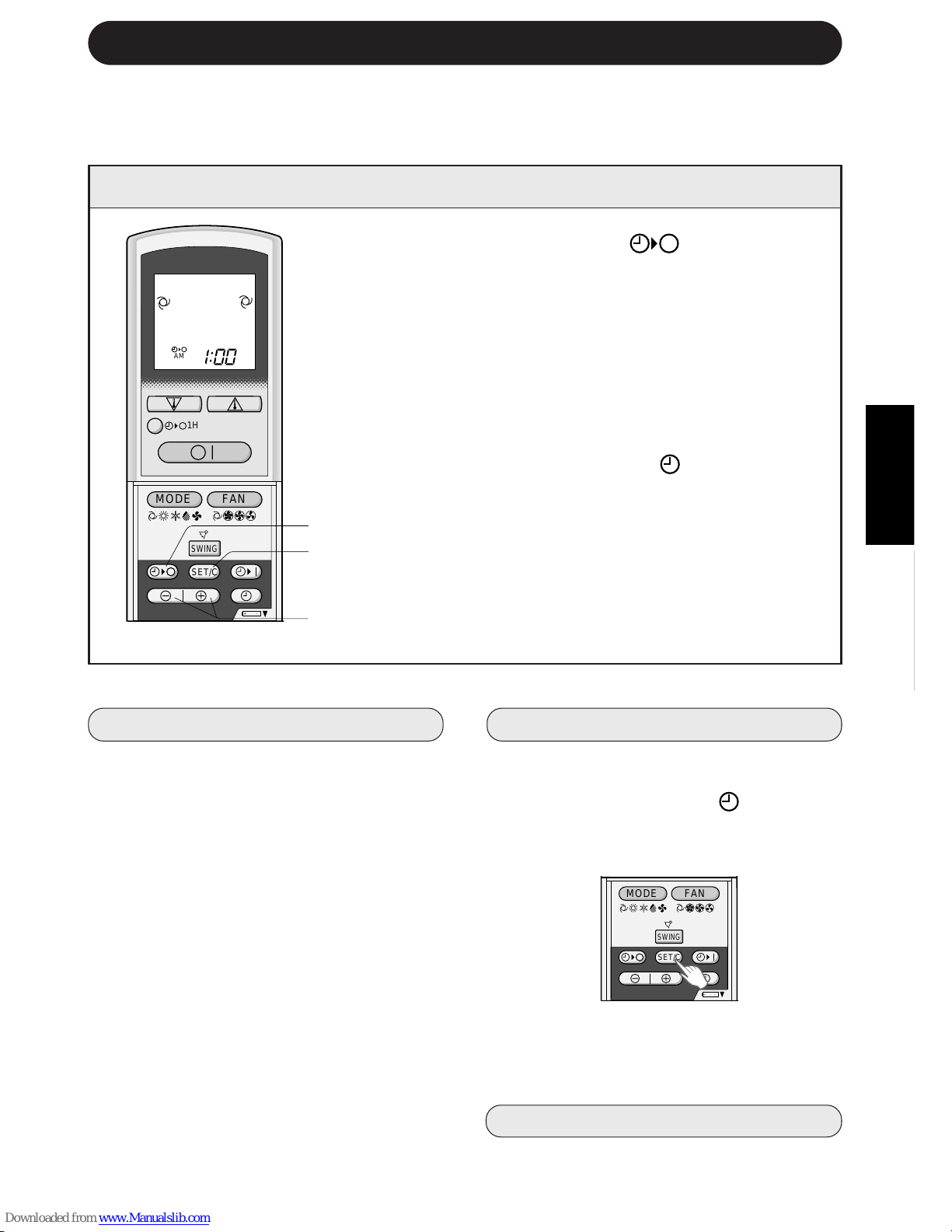
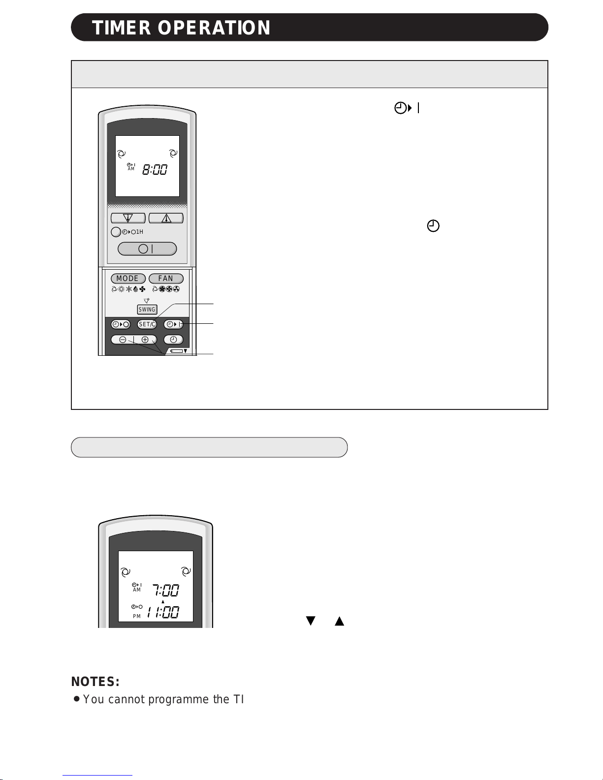
1 Press the TIMER OFF ( ) button.
2 The TIMER OFF indicator will blink; press the
TIME ADVANCE or REVERSE buttons to set
the desired time. (The time can be set in 10-
minute increments.)
3 Point the remote control at the signal receiver
window on the unit and press the TIMER SET
(SET/C) button.
» The yellow TIMER lamp ( ) on the unit will
light.
» The unit will generate a beep when it re-
ceives the signal.
NOTE:
Before setting the timer, make sure the clock is properly set with the current time.
E-9
TIMER OPERATION
TIMER OFF
When the TIMER OFF mode is set, the
temperature setting is automatically adjusted
to prevent the room from becoming
excessively hot or too cold while you sleep.
(Auto Sleep function)
COOL/DRY MODE:
» One hour after the time operation begins,
the temperature setting rises 1°C higher
than the original thermostat setting.
HEAT MODE:
» One hour after the timer operation begins,
the temperature setting drops 3°C lower
than the original thermostat setting.
NOTES:
»»
»»
» The Auto Sleep function will not activate
during the FAN ONLY mode.
»»
»»
» The temperature setting cannot be ad-
justed during the FAN ONLY mode.
2
3
1
TO CANCEL TIMER MODE
Press the TIMER CANCEL (SET/C) but-
ton.
» The yellow TIMER lamp (
) on the unit
will turn off.
» The current clock time will be displayed
on the remote control.
NOTE:
» If both TIMER ON and TIMER OFF are
set, the TIMER CANCEL button cancels
both settings.
TO CHANGE TIME SETTING
Cancel the TIMER seting first, then set it
again.
TIPS ABOUT TIMER OFF OPERATION
,@À
,@À
,@À
,@À
,@À
,@À
,@À
,@À
,@À
,@À
,@À
,@À
,@À
,@À
,@À
,@À
,@À
,@À
,@À
+
-
MODE
SWING
FAN
AM
1H
SET/C
+-
MODE
SWING
FAN
SET/C
Downloaded from www.ManualsFile.com manuals search engine
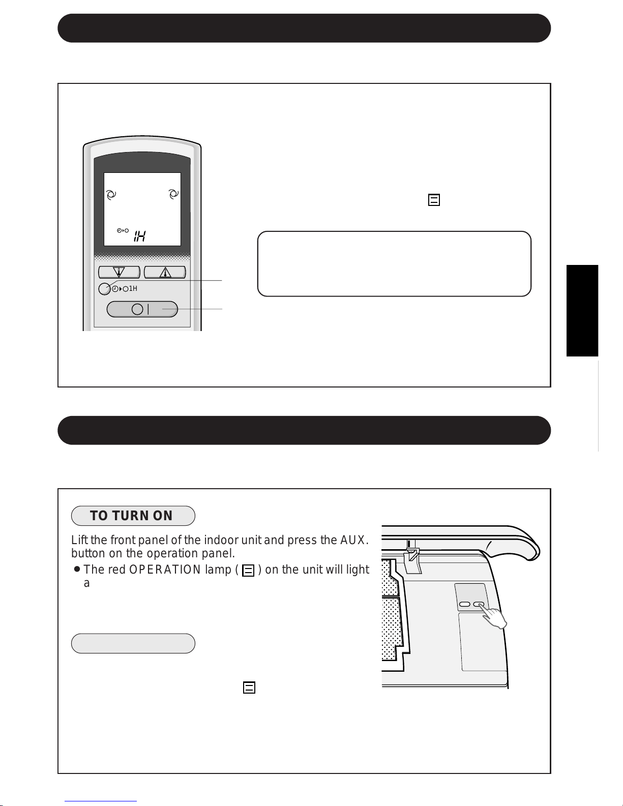
1 Press the TIMER ON ( ) button.
2 The TIMER ON indicator will blink. Press the TIME
ADVANCE or REVERSE button to set the desired
time. (The time can be set in 10-minute incre-
ments.)
3 Point the remote control at the signal receiver
window on the unit and press the TIMER SET
(SET/C) button.
» The yellow TIMER lamp (
) on the unit will
light.
» The unit will generate a beep when it receives
the signal.
4 Select the operation condition.
» The unit will turn on prior to the set time to allow
the room to reach the desired temperature by
the programmed time. (Awaking function)
E-10
TIMER ON
2
1
3
,@À
,@À
,@À
,@À
,@À
,@À
,@À
,@À
,@À
,@À
,@À
,@À
,@À
,@À
,@À
,@À
,@À
,@À
,@À
+-
MODE
SWING
FAN
AM
1H
SET/C
PM
AM
TIMER OPERATION
NOTES:
» You cannot programme the TIMER ON and TIMER OFF to operate the unit at different
temperatures or other settings.
» Either timer can be programmed to activate prior the other.
COMBINED USE OF ON AND OFF TIMERS
You can use the ON and OFF timers in combination.
Example:
To stop operation at 11:00 p.m. and resume operation
(with the same mode and temperature settings) to bring
the room temperature to the desired level by 7:00 a.m.
1 Set the TIMER OFF to 11:00 p.m. during operation.
2 Set the TIMER ON to 7:00 a.m.
The arrow ( or ) between the TIMER ON indicator and
the TIMER OFF indicator shows which timer will activate
first.
Downloaded from www.ManualsFile.com manuals search engine
ENGLISH
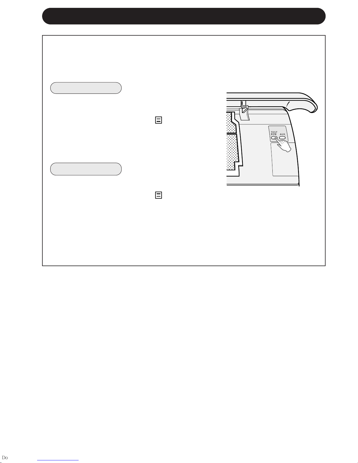
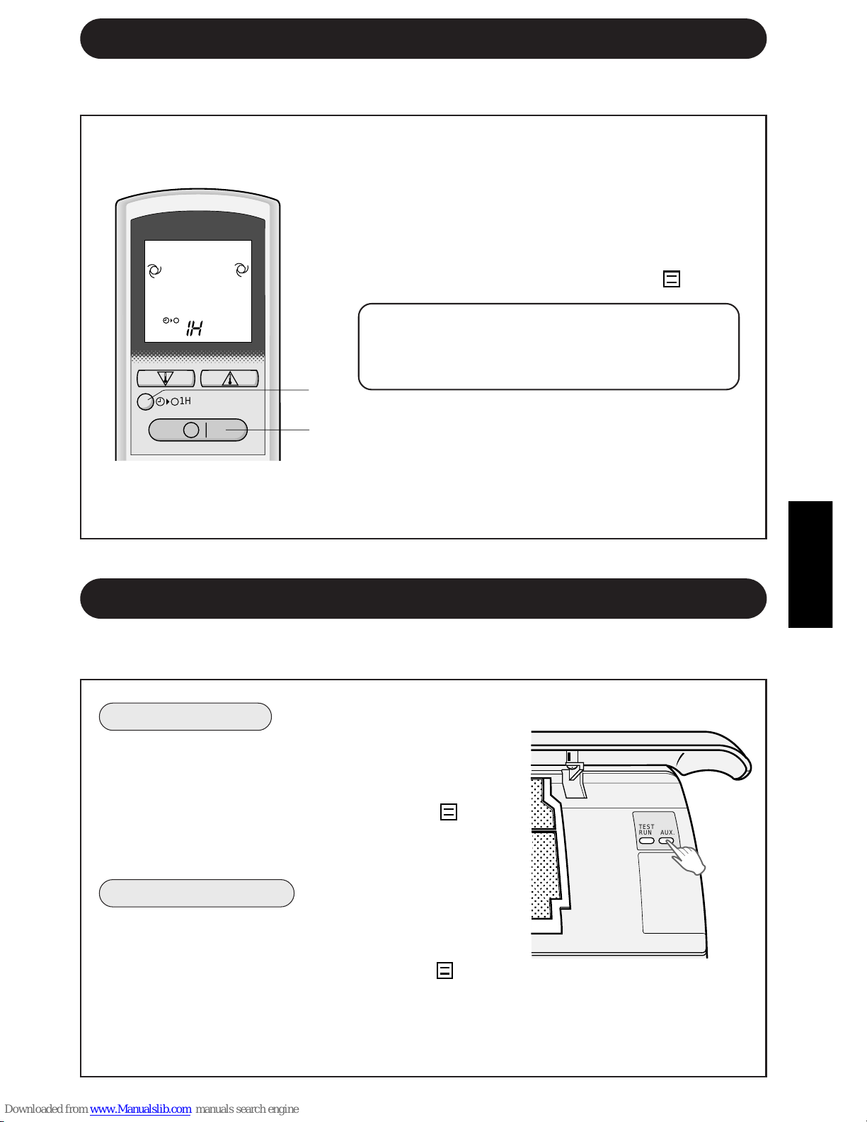
Use this mode when the remote control is not available.
1 Press the ONE-HOUR OFF TIMER button.
» The remote control displays “1 H”.
» The unit will stop operating after one hour.
2 To turn off the unit within an hour before the
ONE-HOUR OFF TIMER activates, press the
ON/OFF button.
» The OPERATION lamp (
) on the unit will
turn off.
If you wish to operate the unit for another
hour before the ONE-HOUR OFF TIMER
activiates, press the ONE-HOUR OFF TIMER
button again during operation.
NOTE:
» The ONE-HOUR OFF TIMER operation has pri-
ority over TIMER ON and TIMER OFF opera-
tions.
E-11
ONE-HOUR OFF TIMER
When the ONE-HOUR OFF TIMER is set, the unit will stop operating after one hour.
1
2
AUXILIARY MODE
,
,
@
@
À
À
,
,
@
@
À
À
,
,
@
@
À
À
,
,
@
@
À
À
,
,
@
@
À
À
,
,
@
@
À
À
,
,
@
@
À
À
,
,
@
@
À
À
,
,
@
@
À
À
,
,
@
@
À
À
,
,
@
@
À
À
,
,
@
@
À
À
,
,
@
@
À
À
,
,
@
@
À
À
,
,
@
@
À
À
,
,
@
@
À
À
,
,
@
@
À
À
,
,
@
@
À
À
,
,
@
@
À
À
1H
TO TURN ON
Lift the front panel of the indoor unit and press the AUX.
button on the operation panel.
» The red OPERATION lamp (
) on the unit will light
and the unit will start operating in the AUTO mode.
» The fan speed and temperature setting are set to
AUTO.
TO TURN OFF
Press the AUX. button on the operation panel again.
» The red OPERATION lamp (
) on the unit will turn
off.
NOTE:
» If the AUX. button is pressed during normal opera-
tion, the unit will turn off.
,,
,,,
,,
,
,,,
,,
TEST
RUN
AUX.
Downloaded from www.ManualsFile.com manuals search engine
E-12
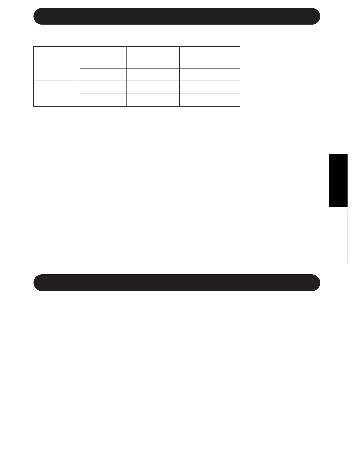
Use the test run mode only for a test operation. Do not use the test run mode for other
than operation testing since the thermostat control is inactive in this mode and the unit
remains in continuous operation.
Make sure the unit is turned off before conducting a test run.
TO TURN ON
Lift the front panel of the indoor unit and press the
TEST RUN button on the operation panel.
» The red OPERATION lamp (
) on the unit will
blink and the unit will start operating in the COOL
mode.
» The temperature setting is not set. (the compressor
runs continuously.)
TO TURN OFF
Press the AUX. button on the operation panel.
» The red OPERATION lamp (
) on the unit will
turn off.
NOTE:
» To conduct a heat mode test run, press the MODE
button on the remote control to set the unit in the
HEAT mode.
TEST RUN MODE
,,
,,,
,,
,
,,,
,,
TEST
RUN
AUX.
Downloaded from www.ManualsFile.com manuals search engine
ENGLISH
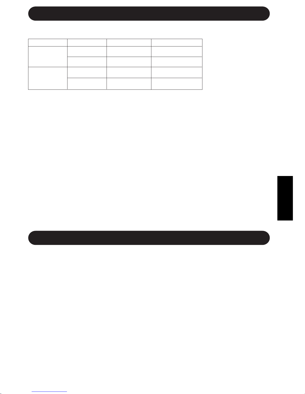
E-13
INDOOR TEMP. OUTDOOR TEMP.
COOLING
upper limit
32˚C D.B. 43˚C D.B.
23˚C W.B. -
lower limit
21˚C D.B. 21˚C D.B.
15˚C W.B. -
HEATING
upper limit
27˚C D.B. 24˚C D.B.
- 18˚C W.B.
lower limit
20˚C D.B. -8.5˚C D.B.
- -9.5˚C W.B.
ADDITIONAL NOTES ON OPERATION
OPERATING TEMPERATURE RANGE
» The built-in protective
device may prevent the
unit from operating when
used out of this range.
» Condensation may form
on the air outlet if the
unit operates continu-
ously in the COOL or
DRY mode when humid-
ity is over 80 percent.
D.B. = Dry-bulb W.B. = Wet-bulb
PREHEATING FUNCTION
In the HEAT operation, the indoor fan may not start for two to five minutes after the unit is turned on
to prevent cold air from blowing out of the unit.
DE-ICING FUNCTION
» When ice forms on the heat exchanger in the outdoor unit during the HEAT operation, the
automatic de-icer provides heat for about 5 to 10 minutes to remove the ice. During de-icing, the
inside and outside fans stop operating.
» After de-icing is completed, the unit automatically resumes operation in the HEAT mode.
HEATING EFFICIENCY
» The unit uses a heat pump to obtain heat from the outside air and releases it into the room. The
outside air temperature therefore greatly affects the heating efficiency.
» If the heating efficiency is reduced due to low outside temperatures, use an additional heater.
» It takes time to warm up and heat the entire room because of the forced air circulation system.
TIPS ON SAVING ENERGY
Below are some simple ways to save energy when you use your air conditioner.
SET THE CORRECT TEMPERATURE
» Setting the thermostat 1°C higher than the desired temperature in the COOL mode and 2°C lower
in the HEAT mode will save approximately 10 percent in power consumption.
» Setting the temperature lower than necessary during cooling operation will result in increased
power consumption.
BLOCK DIRECT SUNLIGHT AND PREVENT DRAFTS
» Blocking direct sunlight during cooling operation will reduce power consumption.
» Close the windows and doors during cooling opeation and heating operation.
SET PROPER AIR FLOW DIRECTION TO OBTAIN THE BEST AIR
CIRCULATION
KEEP FILTERS CLEAN TO ENSURE THE MOST EFFICIENT OPERATION
MAKE MOST OF THE TIMER OFF FUNCTION
DISCONNECT THE POWER CORD WHEN THE UNIT IS NOT USED FOR AN
EXTENDED PERIOD OF TIME
» The indoor unit still consumes a small amount of power when it is not operating.
WHEN A POWER FAILURE OCCURS
This air conditioner has a memory function to store settings when a power failure occurs.
After power recovery, the unit will automatically re-start in the same settings which were active before
the power failure, except for timer settings.
If the timers were set before a power failure, they will need to be re-set after power recovery.
Downloaded from www.ManualsFile.com manuals search engine

E-14
MAINTENANCE
CLEANING THE UNIT AND THE REMOTE CONTROL
» Wipe them with a soft cloth.
» Do not directly splash or pour water on them. Water can cause electrical shock or
equipment damage.
» Do not use hot water, thinner, abrasive powders or strong solvents.
Be sure to disconnect the power cord from the wall outlet or turn off the circuit
breaker before performing any maintenance.
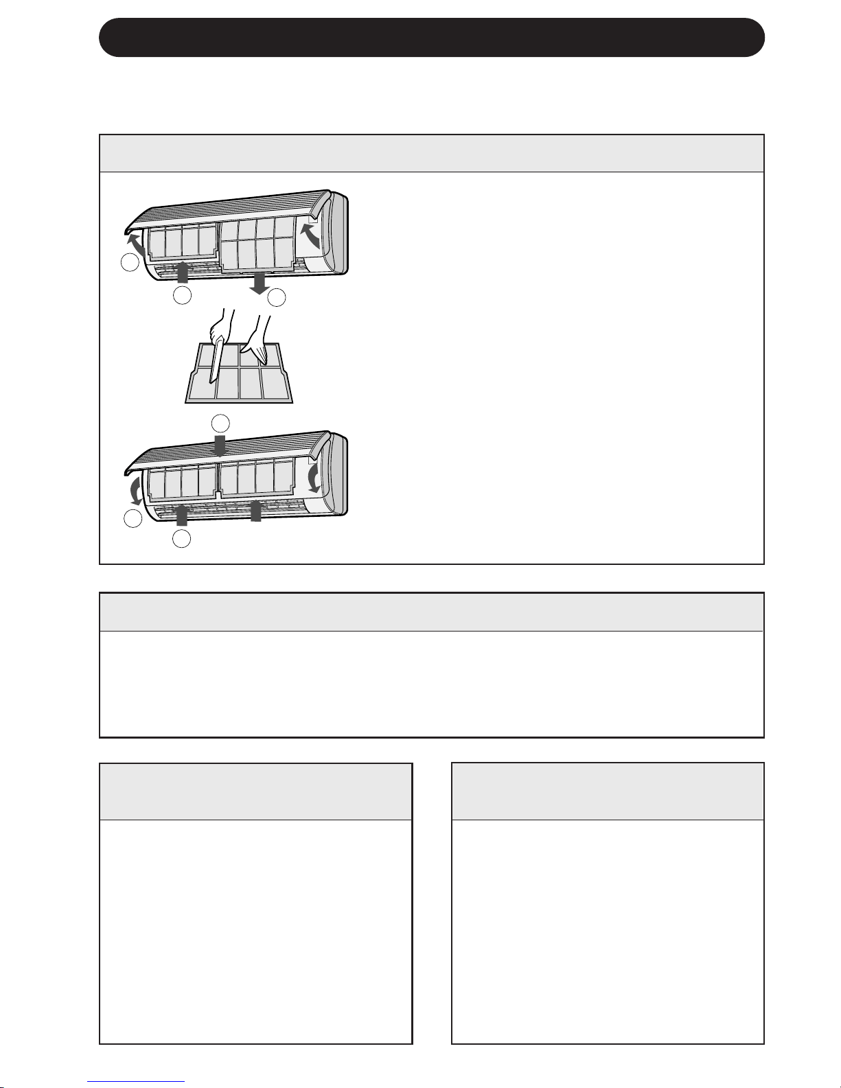
CLEANING THE FILTERS
The air filters should be cleaned every two weeks.
1 TURN OFF THE UNIT
2 REMOVE THE FILTERS
1 Open the front panel.
2 Push the air filters up slightly to unlock them.
3 Pull the air filters down to remove them.
3 CLEAN THE FILTERS
Use a vacuum cleaner to remove dust. If the
filters are dirty, wash them with warm water
and a mild detergent. Dry filters in the shade
before reinstalling.
4 REINSTALL THE FILTERS
1 Reinstall the filters in the original positions.
2 Close the front panel.
3 Push the centre part of the panel firmly to
lock it in place.
MAINTENANCE AFTER AIR
CONDITIONER SEASON
1 Operate the unit in the FAN
ONLY mode for about half a day
to allow the mechanism to thor-
oughly dry.
2 Stop the operation and unplug
the unit. Turn off the circuit
breaker, if you have one exclu-
sively for the air conditioner.
3 Clean the filters, then reinstall
them.
MAINTENANCE BEFORE
AIR CONDITIONER SEASON
1 Make sure that the air filters are
not dirty.
2 Make sure that nothing obstructs
the air inlet or outlet.
3 Check the outdoor mounting rack
periodically for wear and to make
sure it is firmly in place.
1
2
3
1
2
3
Downloaded from www.ManualsFile.com manuals search engine
ENGLISH
E-15
BEFORE CALLING FOR SERVICE
The following conditions do not denote equipment malfunctions
UNIT DOES NOT OPERATE
The unit will not operate if it is
turned on immediately after it is
turned off. The unit will not operate
immediately after the mode is
changed. This is to protect the
internal mechanisms. Wait 3
minutes before operating the unit.
UNIT DOES NOT SEND OUT
WARM AIR
The unit is preheating or de-icing.
CRACKING NOISE
The unit may produce a cracking
noise. This sound is generated by
the friction of the front panel and
other components expanding or
connecting due to a temperature
change.
UNIT DOES NOT OPERATE IN YOUR
REQUESTED MODE
» When one indoor unit is operating in
COOL mode, you can not operate the
other unit in HEAT mode. (OPERATION
lamp (
) will light up, but BUSY lamp
(
) will blink and HEAT mode operation
will not start.)
» When one indoor unit is operating in
HEAT mode, you can not operate the
other unit in COOL nor DRY mode. (OP-
ERATION lamp (
) will light up, but
BUSY lamp (
) will blink and only the
fan will rotate.)
IF THE UNIT FAILS TO COOL OR HEAT THE ROOM EFFECTIVELY
Check the outdoor unit to
make sure nothing is
blocking the air inlet or
outlet.
Check the thermostat is
for proper setting.
Make sure windows and
doors are closed tightly.
ODORS
Carpet and furniture odors that en-
tered into the unit and the air condi-
tioner's inner component odors at
the early stage of installation may
be sent out from the unit.
SWISHING NOISE
The soft, swishing noise is the sound of the
refrigerant flowing inside the unit.
WATER VAPOUR
» In the COOL and DRY operation, water
vapour can sometimes be seen at the air
outlet due to the difference between the
room air temperature and the air dis-
charged by the unit.
» In the HEAT operation, water vapour may
flow out of the outdoor unit during de-
icing.
If the unit appears to be malfunctioning, check the following points before calling for
service.
IF THE UNIT FAILS TO OPERATE
Check to see if the circuit breaker has tripped or the fuse has blown.
Check the filters. If dirty,
clean them.
A large number of people
in the room can prevent
the unit from achieving the
desired temeperature.
Check whether any
heat-generating appli-
ances are operating in
the room.
Downloaded from www.ManualsFile.com manuals search engine

IF THE UNIT FAILS TO RECEIVE THE REMOTE CONTROL SIGNAL
Check whether the re-
mote control batteries
have become old and
weak.
Try to send the signal again
with the remote control
pointed properly towards
the unit’s signal receiver
window.
Check whether the re-
mote control batteries
are installed with the
polarities properly
aligned.
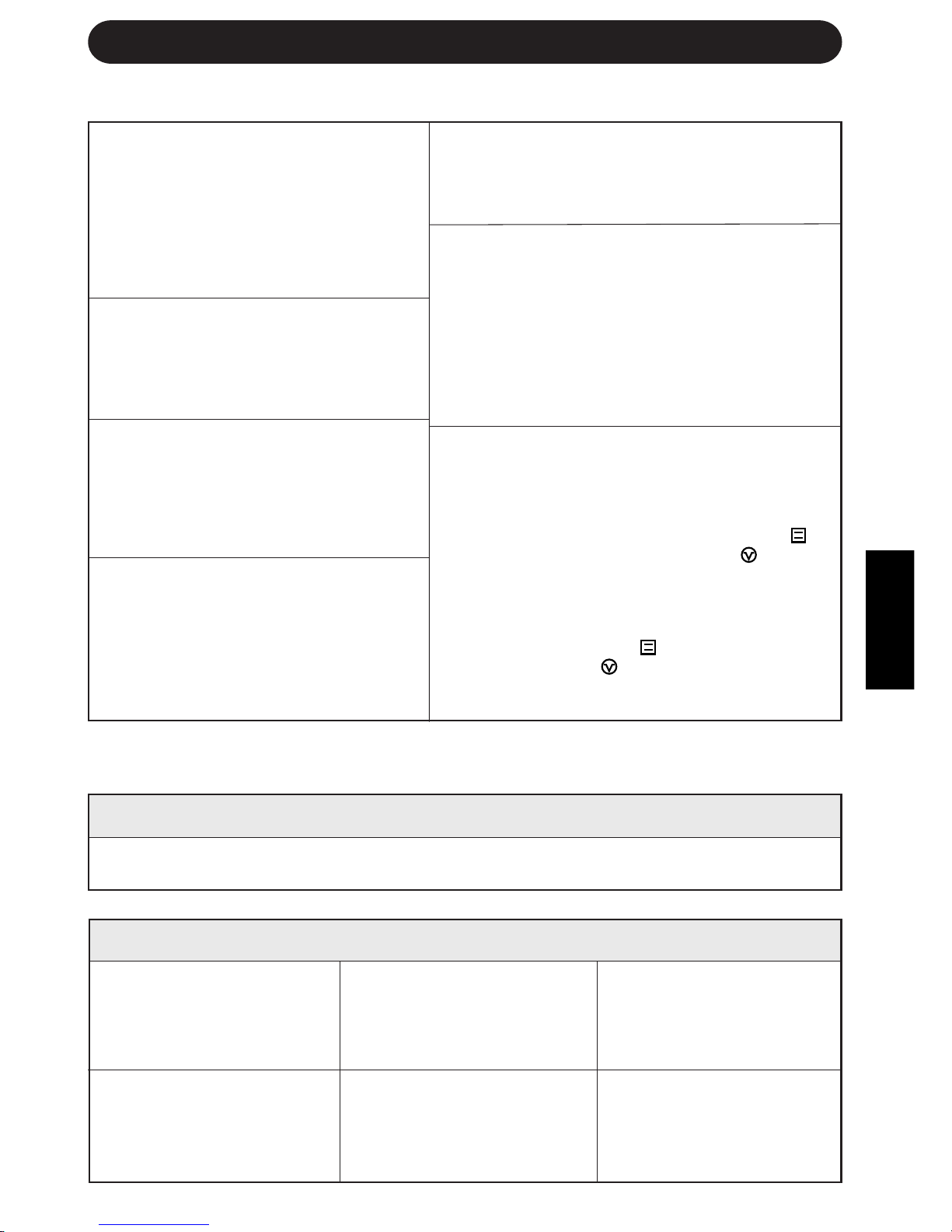
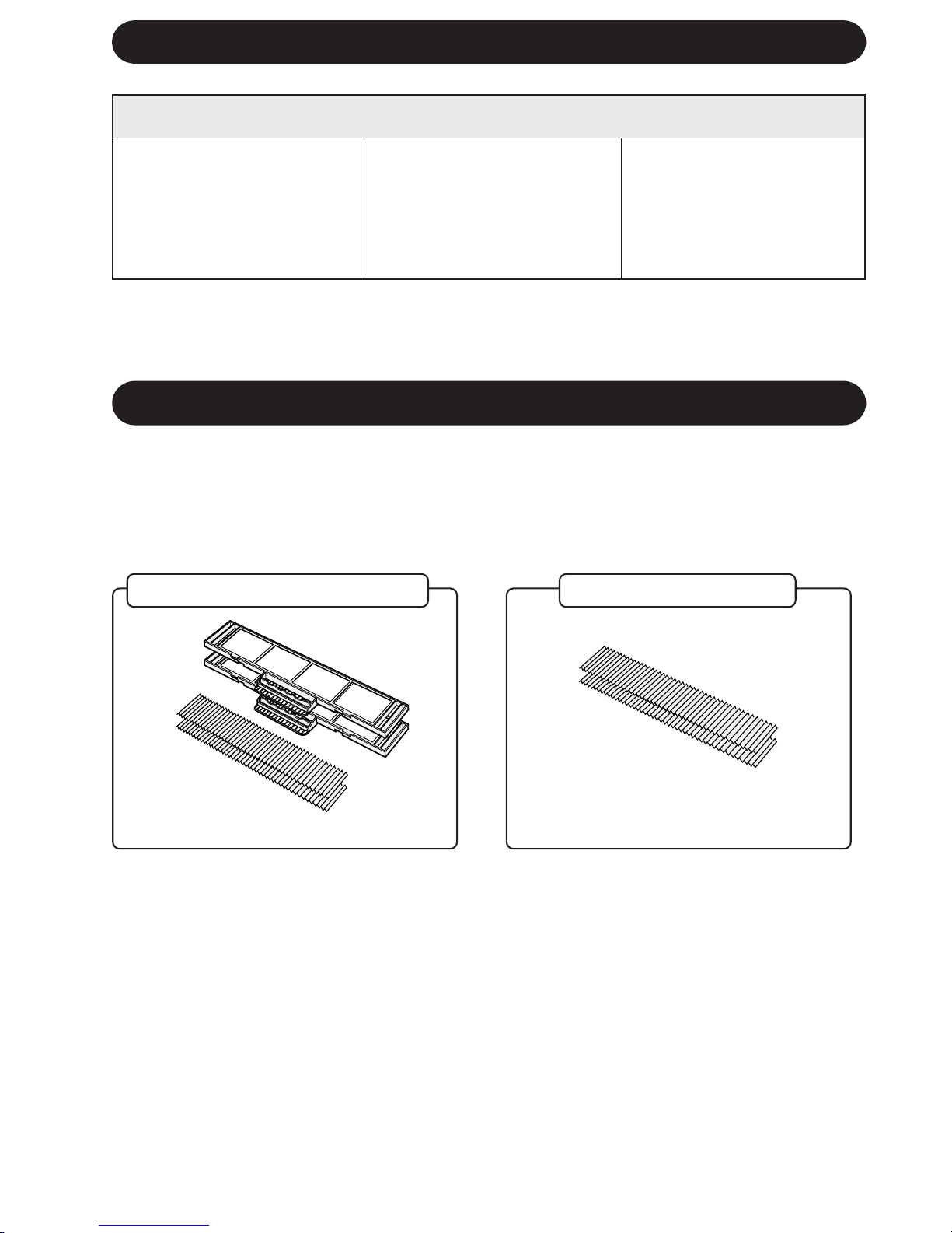
OPTION KIT
Air Purifying Filter Unit
Use of the air purifying filter unit will help remove dust from the air during operation.
Contact your dealer for the purchase of this option. Replacement air purifying filters are also
available.
Air Purifying Filter Unit
Replacement Filters
Type AZ-F954
Type AZ-F904
E-16
BEFORE CALLING FOR SERVICE
Downloaded from www.ManualsFile.com manuals search engine
TÜRKÇE
T-1
TÜRKÇE
Sharp klima satın aldıπınız için teµekkür ederiz. Lütfen, klimanızı çalıµtırmadan önce bu
kılavuzu dikkatle okuyun.
• ÖNLEMLER .................................................T-1
• PARÇALARIN ∑S∑MLER∑..............................T-2
• UZAKTAN KUMANDANIN KULLANIMI .......T-4
• TEMEL ∑ΩLET∑M ..........................................T-6
•
HAVA AKIΩ YÖNÜNÜN AYARLANMASI .....
T-8
• ZAMANLAYICI AYARI .................................T-9
• B∑R SAAT SONRA KAPANMA AYARI ........T-11
∑Ç∑NDEK∑LER
• YARDIMCI MOD ..................................... T-11
• TEST MODU ........................................... T-12
• ∑ΩLET∑MLE ∑LG∑L∑ ∑LAVE NOTLAR ........ T-13
•
ENERJ∑ TASARRUFUYLA ∑LG∑L∑ B∑LG∑LER ....
T-13
• BAKIM ..................................................... T-14
• SERV∑S ÇA∏IRMADAN ÖNCE .............. T-15
• OPS∑YON K∑T∑ ........................................ T-16
ÖNLEMLER
YERLEΩ∑M
•
Üniteyi havada toz, duman veya nemin en az olduπu yere kurun.
SÖKME
•
Üniteyi sökmeye çalıµmayın. Ünitenin sökülmesi için satıcınıza veya baµka uzman servis
personeline baµvurun.
Bu ekipman 93/68/EEC ile düzeltme getirilen 89/336/EEC ve 73/23/EEC yönergelerine uygun-
dur.
D∑KKAT
1. 220-240 V (± %10) deπerinde bir Ωebeke gerilimi kullanın.
Uygunsuz voltaj ve frekansa sahip bir Ωebeke geriliminin kullanılması ekipman hasarına
ve muhtemel bir yangına sebep olabilir.
2. Özellikle gazlı cihazlar kullanırken odayı havalandırmak için periyodik olarak bir pencere
veya kapı açın.
3. Ünite içine hiçbir cisim sokmayın. Cisim sokulması, dahili fanların yüksek devri nedeniyle
yaralanmaya sebep olabilir.
4. Güç kablosunu çekmeyin. Güç kablosunun çekilmesi veya hatalı kullanılması üniteye hasar
verebilir ve elektrik çarpmasına sebep olabilir.
5. Klimayı bebeklerin, çocukların veya yaµlı, yatalak ya da özürlü insanların bulunduπu bir
odada kullanırken oda sıcaklıπının onlar için uygun olmasına dikkat edin.
6. Uygun akım deπerine sahip bir sigorta takılı olmasına dikkat edin.
7. Güç kablosunun baπlanması için yerel kanunlara ve yönetmeliklere uyun. Uygunsuz
kablo baπlantısı güç kablosunun, fiµin ve elektrik prizinin aµırı ısınmasına ve yangına
sebep olabilir.
8. Emniyet amacıyla, ünite uzun süre kullanılmayacaπı zaman devre kesiciyi kapatın veya
güç kablosunu prizden çekin.
Bu ünite evlerde kullanım için tasarlanmıµtır. Hayvan veya bitki yetiµtirmek için ku-
lübe veya sera gibi yerlerde kullanmayın.
Downloaded from www.ManualsFile.com manuals search engine

PARÇALARIN ∑S∑MLER∑
T-2
∑Ç ÜN∑TE
1 Hava giriµi
2 Açılır panel
3 ∑µletim paneli
4 Hava filtreleri
5 Gösterge paneli
6 Düµey ayarlı kanatçıklar
7 Yatay ayarlı kanatçıklar
8 Hava çıkıµı
9 Uzaktan kumanda
Açılır paneli açmak için alt köµelerinden
tutun ve yavaµça yukarı doπru çekin.
0 TEST düπmesi
q YARDIMCI MOD düπmesi (Aux.)
w ALICI penceresi
e ∑ΩLET∑M lambası (Kırmızı )
r ZAMANLAYICI lambası (Sarı )
t MEΩGUL lambası (Kırmızı )
Diπer ünite farklı modda çalıµtıπı
için ünite çalıµamadıπında yanıp
söner.
DIΩ ÜN∑TE
y Hava giriµi
u Soπutma gazı borusu ve
ara baπlantı kablosu
i Drenaj hortumu
o Hava çıkıµı
NOTLAR:
1. Gerçek üniteler yukarıda gösterilenden biraz farklı olabilir.
2. AE-M18AE-T multi split tip bir d∂µ ünitedir ve bu ünite iki iç üniteye baπlanır. Detaylı montaj talimatı
için Montaj Kılavuzuna bakın.
1
2
3
4
5
6
7
8
9
0
q
w
e
r
t
y
u
i
o
TEST
RUN AUX.
Downloaded from www.ManualsFile.com manuals search engine
TÜRKÇE
T-3
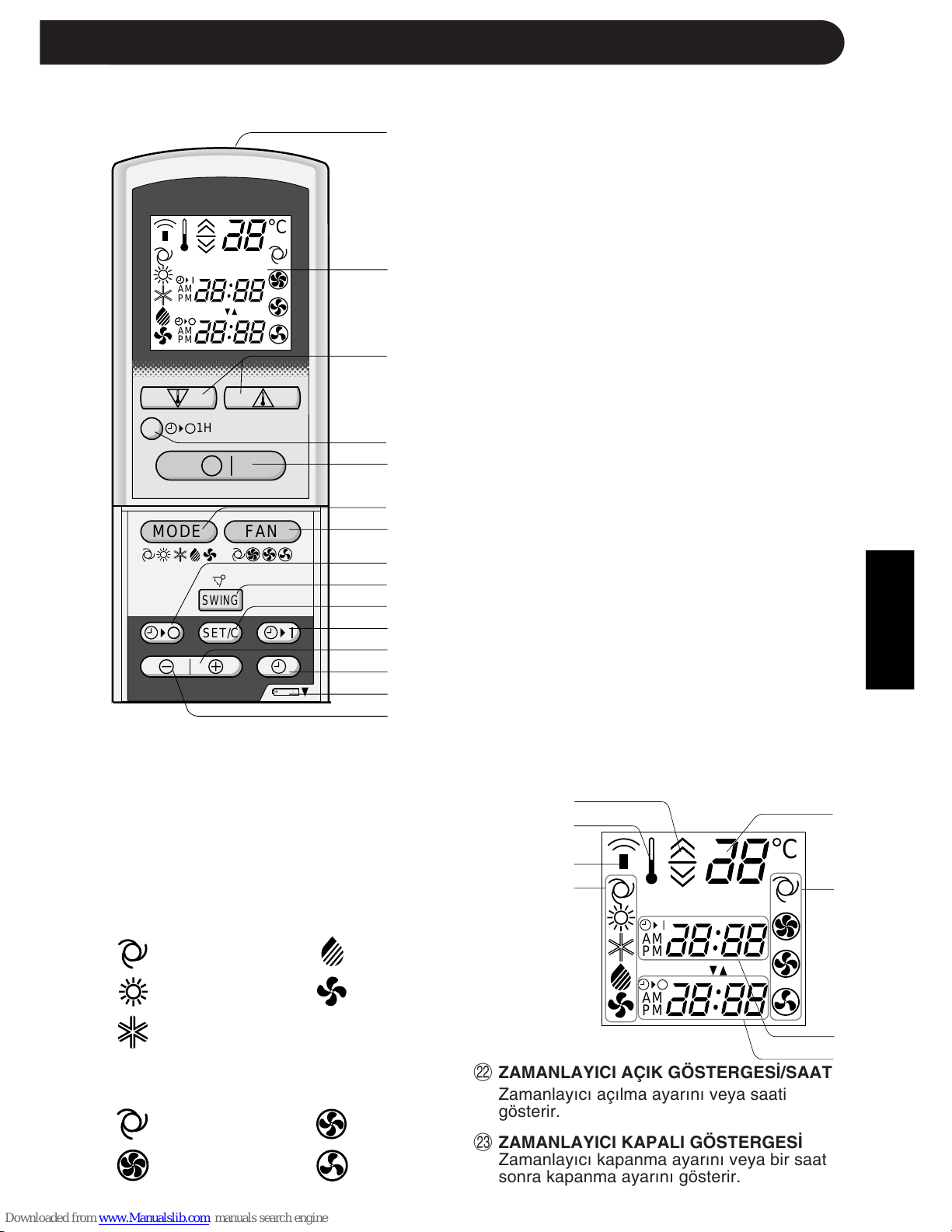
UZAKTAN KUMANDA
1 VER∑C∑
2 GÖSTERGE (Likit Kristal Gösterge)
3 TERMOSTAT düπmesi
4 B∑R SAAT SONRA KAPANMA düπmesi
5 AÇMA/KAPAMA düπmesi
6 MOD düπmesi
7 FAN düπmesi
8 ZAMANLAYICI KAPAMA düπmesi (saat
ayarı için)
9 SALINIM düπmesi
0 ZAMANLAYICI AYAR/∑PTAL düπmesi
q ZAMANLAYICI AÇMA düπmesi (saat
ayarı için)
w ZAMAN ∑LER∑ düπmesi
e SAAT düπmesi
r P∑L BÖLMES∑N∑N bu iµaretin altında
olduπunu gösterir
t ZAMAN GER∑ düπmesi
LCD UZAKTAN KUMANDA GÖSTERGES∑
y OTOMAT∑K VE NEM ALMA MODLARI
∑Ç∑N TERMOSTAT AYARI
u SICAKLIK SEMBOLÜ
i VER∑C∑ SEMBOLÜ
o MOD SEMBOLLER∑
:OTOMAT∑K :NEM ALMA
:ISITMA :SADECE FAN
:SO∏UTMA
p SICAKLIK GÖSTERGES∑
a FAN HIZI SEMBOLLER∑
:OTOMAT∑K :ORTA
:YÜKSEK :DÜΩÜK
1
2
3
4
5
6
7
8
9
0
q
w
e
r
t
y
u
i
o
p
a
s
d
,,
,,
@@
@@
ÀÀ
ÀÀ
,,
,,
@@
@@
ÀÀ
ÀÀ
,,
,,
@@
@@
ÀÀ
ÀÀ
,,
,,
@@
@@
ÀÀ
ÀÀ
,,
,,
@@
@@
ÀÀ
ÀÀ
,,
,,
@@
@@
ÀÀ
ÀÀ
,,
,,
@@
@@
ÀÀ
ÀÀ
,,
,,
@@
@@
ÀÀ
ÀÀ
,,
,,
@@
@@
ÀÀ
ÀÀ
,,
,,
@@
@@
ÀÀ
ÀÀ
,,
,,
@@
@@
ÀÀ
ÀÀ
,,
,,
@@
@@
ÀÀ
ÀÀ
,,
,,
@@
@@
ÀÀ
ÀÀ
,,
,,
@@
@@
ÀÀ
ÀÀ
,,
,,
@@
@@
ÀÀ
ÀÀ
,,
,,
@@
@@
ÀÀ
ÀÀ
,,
,,
@@
@@
ÀÀ
ÀÀ
,,
,,
@@
@@
ÀÀ
ÀÀ
,,
,,
@@
@@
ÀÀ
ÀÀ
+-
MODE
SWING
FAN
C
AM
PM
AM
PM
1H
SET/C
C
AM
PM
AM
PM
PART NAMES
s ZAMANLAYICI AÇIK GÖSTERGES∑/SAAT
Zamanlayıcı açılma ayarını veya saati
gösterir.
d ZAMANLAYICI KAPALI GÖSTERGES∑
Zamanlayıcı kapanma ayarını veya bir saat
sonra kapanma ayarını gösterir.
Downloaded from www.ManualsFile.com manuals search engine
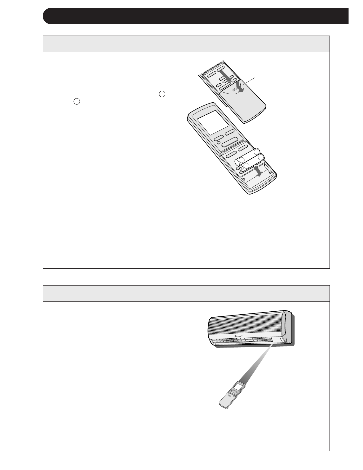
1 Uzaktan kumandanın kapaπını
çıkarın.
2 Pilleri bölmeye yerleµtirin; artı +
ve – kutupların doπru hizada ol-
masına dikkat edin.
•
Piller uygun µekilde takıldıπın-
da göstergede “AM 6:00” gö-
rülür.
3 Kapaπı yerine takın.
T-4
NOTLAR:
•
Pilin ömrü, normal kullanımda yaklaµık 1 yıldır.
•
Pilleri deπiµtirirken daima ikisini birlikte deπiµtirin ve aynı tipte olmasına dikkat
edin.
•
Piller deπiµtirildikten sonra uzaktan kumanda uygun µekilde çalıµmazsa pilleri
çıkarın ve 30 saniye sonra tekrar takın.
•
Üniteyi uzun süre kullanmayacaksanız pilleri uzaktan kumandadan çıkarın.
Uzaktan kumandayı ünitenin sinyal
alıcısına doπru tutun ve istediπiniz
düπmeye basın. Ünite sinyali aldıπında
bir bip sinyali verir.
•
Uzaktan kumanda ile ünite arasında
perde olmamasına dikkat edin.
•
Uzaktan kumanda 7 m mesafeye kadar si-
nyal gönderebilir.
Uzaktan kumanda
kapaπ∂
UZAKTAN KUMANDANIN KULLANIMI
P∑LLER∑N TAKILMASI ∑ki adet AAA (R03) ebadında pil kullanın.
UZAKTAN KUMANDA NASIL KULLANILIR
NOT:
Aynı odaya iki iç ünite takılırsa her iki ünite uzaktan kumandayla aynı anda çalıµtırılabilir.
Üniteler mümkün olduπunca birbirinden uzaπa monte edilmelidir. Sinyali doπrudan
çalıµtırmak istediπiniz üniteye gönderin.
+
-
+
-
Downloaded from www.ManualsFile.com manuals search engine
TÜRKÇE
T-5
SAAT∑N AYARLANMASI
Örnek: Öπleden sonra saat 5
Saat Gösterge
12 saatlik mod PM 5:00
24 saatlik mod 17:00
1 12 saatlik modu ayarlamak için birinci
basamakta SAAT düπmesine bir kez basın.
24 saatlik modu ayarlamak için birinci
basamakta SAAT düπmesine iki kez basın.
2 Saati ayarlamak için ZAMAN ∑LER∑ veya
GER∑ düπmesine basın.
•
Zamanı hızlı ileri veya geri almak için
düπmeyi basılı tutun.
3 ZAMANLAYICI AYAR/∑PTAL düπmesine
basın.
•
Saatin çalıµtıπını göstermek için iki
nokta (:) yanıp söner.
NOT:
•
Zamanlayıcı çalıµırken saat ayarlanamaz.
3
1
2
UYARI
•
Sinyal alıcısının güçlü direkt güneµ ıµıπı almasına izin vermeyin, çünkü çalıµmasını
olumsuz etkileyebilir. Sinyal alıcı, güçlü direkt güneµ ıµıπı alırsa ıµıπı kesmek için perde
kullanın.
•
Aynı odada hızlı çalıµtırma özelliπi olan bir floresan lamba kullanılması sinyal gönderimini
engelleyebilir.
•
Ünite, aynı odadaki bir televizyon, video cihazı veya baµka ekipmanların uzaktan
kumandasından gönderilen sinyallerden etkilenebilir.
•
Uzaktan kumandayı direkt güneµ ıµıπında veya bir ısıtıcı yakınında bırakmayın. Aynı
zamanda, üniteyi ve uzaktan kumandayı nemden ve darbeden de koruyun, rengini
attırabilir veya hasar verebilir.
Å|
Å|
Å{
Å{
+
-
MODE
SWING
FAN
SET/C
∑ki saat modu vardır: 12 saatlik
mod veya 24 saatlik mod.
Downloaded from www.ManualsFile.com manuals search engine
,@À
,@À
,@À
,@À
,@À
,@À
,@À
,@À
,@À
,@À
,@À
,@À
,@À
,@À
,@À
,@À
,@À
,@À
,@À
+-
MODE
SWING
FAN
AM
1H
SET/C
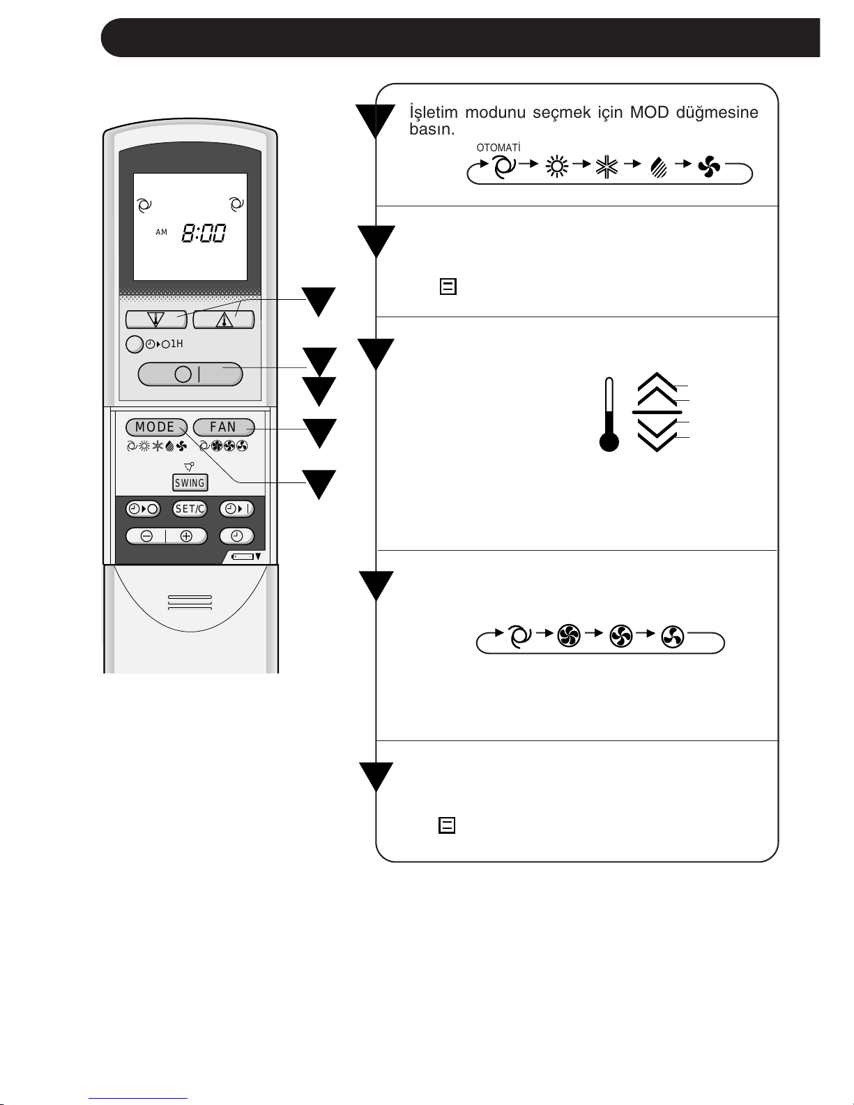
∑µletim modunu seçmek için MOD düπmesine
basın.
OTOMAT∑K ISITMA SO∏UTMA NEM ALMA SADECE FAN
1
T-6
TEMEL ∑ΩLET∑M
2
∑µletimi baµlatmak için AÇMA/KAPAMA düπme-
sine basın.
•
Ünite üzerindeki kırmızı ∑ΩLET∑M lambası
(
) yanar.
3
∑stenen sıcaklıπı ayarlamak için TERMOSTAT
düπmesine basın.
1
4
5
2
3
•
OTOMAT∑K ve NEM
ALMA modunda gös-
terge çubukları sıca-
klıktaki deπiµimi gös-
terir.
2°C daha yüksek
1°C daha yüksek
1°C daha düµük
2°C daha düµük
•
SO∏UTMA ve ISITMA modunda sıcaklık 18
ilâ 32°C’ aral∂π∂nda ayarlanabilir.
•
SADECE FAN modunda sıcaklık ayarı yapıla-
maz.
∑stenen fan hızını ayarlamak için FAN düπmesine
basın.
4
Üniteyi kapatmak için tekrar AÇMA/KAPAMA
düπmesine basın.
•
Ünite üzerindeki kırmızı ∑ΩLET∑M lambası
(
) söner.
•
NEM ALMA modunda fan hızı deπiµtirilemez.
•
SADECE FAN modunda fan hızı OTOMAT∑K’e
ayarlanamaz.
OTOMAT∑K YÜKSEK ORTA DÜSÜK
5
Downloaded from www.ManualsFile.com manuals search engine
TÜRKÇE
T-7
OTOMAT∑K MODU HAKKINDA B∑LG∑LER
OTOMAT∑K modunda sıcaklık ayarı ve modu, ünitenin devreye alındıπı
zamanki oda sıcaklıπına göre otomatik olarak seçilir.
Ünite devreye alındı-
πında oda sıcaklıπı
NOTLAR:
Bu klima multi-split tiptir ve bir d∂µ üniteye iki iç ünite baπlanır.
Bir iç ünitenin ayar modu diπerinden farklı olursa, sonradan devreye alınan
iç ünite çalıµmayabilir.
•
Bir iç ünite ISITMA modunda çalıµıyorsa diπer ünite SO∏UTMA veya NEM ALMA
modunda çalıµamaz.
•
Bir iç ünite SO∏UTMA veya NEM ALMA modunda çalıµıyorsa diπer ünite ISITMA
modunda çalıµamaz.
Sonradan devreye alınan iç ünitenin modu devredekinden farklı
olduπunda, sonradan devreye alınan dahili ünitenin kırmızı
MEΩGUL lambası (
) yanıp söner.
MEΩGUL lambasının (
) reset edilmesi
Yanıp sönen bir MEΩGUL lambası
( )
iki µekilde reset edilebilir.
Uzaktan kumandanın modunu deπiµtirin ve devrede bulunan diπer iç üniteyle
aynı mod sinyalini gönderin ya da uzaktan kumandanın AÇMA/KAPAMA
düπmesine basın.
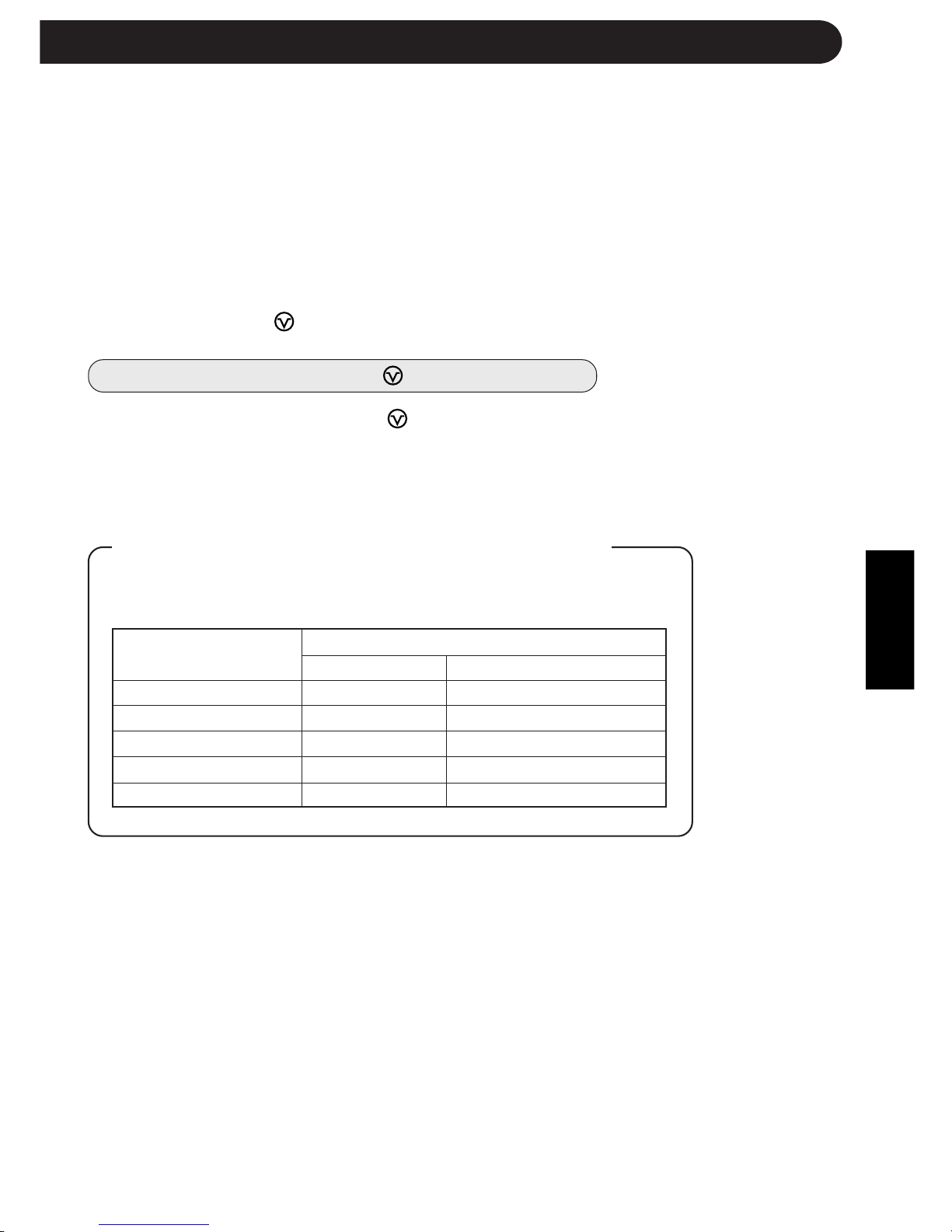
Otomatik ∑µletim
Mod Termostat Ayarı
21°C’ın altında ISITMA 23°C
21°C – 24°C NEM ALMA
Devreye almada oda sıcaklıπı
24°C – 26°C SO∏UTMA 24°C
26°C – 28°C SO∏UTMA 25°C
28°C’– üstünde SO∏UTMA 26°C
Downloaded from www.ManualsFile.com manuals search engine
T-8
SO∏UTMA ve NEM ALMA modu Yatay hava akıµı
SADECE FAN ve ISITMA modu Çapraz hava akıµı
HAVA AKIΩ YÖNÜNÜN AYARLANMASI
DÜΩEY HAVA AKIΩI
Optimum rahatlık için hava akıµ yönü her modda otomatik olarak ayarlanır:
HAVA AKIΩ YÖNÜNÜ AYARLAMA
SO∏UTMA ve
NEM ALMA modu
Damlama nedeniyle
yoπunlaµmayi önlemek
için ayar aralıπı dardır.
Hava akıµının zemine
doπru yönlendirilebil-
mesi için aralık geniµtir.
Yatay ayarlı kanatçık kollarını µe-
kildeki gibi tutun ve hava akıµ yö-
nünü ayarlayın. Üç kanatçık kolu
vardır.
Uzaktan kumanda üzerindeki SA-
LINIM düπmesine bir kez basın.
•
Düµey ayarlı kanatçıklar, açısını,
µekilde gösterilen aralıkta sürekli
deπiµtirir.
Düµey ayarlı kanatçıklar istenen
pozisyonda olduπunda tekrar
SALINIM düπmesine basın.
Düπ-
meye basıldıπında kanatçıkların
hareketi durur.
Ayar Aralıπı
UYARI
Düµey ayarlı kanatçıkları elle ayarlamaya çalıµmayın.
•
Düµey ayarlı kanatçıkların elle ayarlanması, ayar için uzaktan kumanda kullanıldıπında
ünitenin hatalı çalıµmasına sebep olabilir.
•
Düµeyayarlı kanatçıklar SO∏UTMA veya NEM ALMA modunda uzun süre en alçak
konumda tutulursa yoπunlaµma olabilir.
YATAY HAVA AKIΩI
Kanatçık kolları
SADECE FAN ve
ISITMA modu
Downloaded from www.ManualsFile.com manuals search engine
TÜRKÇE
1 ZAMANLAYICI KAPAMA ( ) düπmesine
basın.
2 ZAMANLAYICI KAPALI göstergesi yanıp söner;
ZAMAN ∑LER∑ veya GER∑ düπmelerine basarak
istenen zamanı ayarlayın. (Zaman 10 dakikalık
aralıklarla ayarlanabilir.)
3 Uzaktan kumandayı ünite üzerindeki sinyal
alıcıya doπru tutun ve ZAMANLAYICI AYAR
(SET/C) düπmesine basın.
•
Ünite üzerindeki sarı ZAMANLAYICI lambası
(
) yanar.
•
Ünite sinyali aldıπında bir bip sinyali verir.
NOT:
Zamanlayıcıyı ayarlamadan önce saatin uygun µekilde ayarlanmasına dikkat edin.
T-9
ZAMANLAYICI AYARI
ZAMANLAYICIYI KAPATMA
ZAMANLAYICIYI KAPAMA modu ayarlan-
dıπında siz uyurken odanın aµırı sıcak veya
soπuk olmasını önlemek için sıcaklık ayarı
otomatik olarak ayarlanır. (Otomatik Uyku
fonksiyonu)
SO∏UTMA/NEM ALMA MODU:
•
Zamanlayıcı devreye alındıktan 1 saat son-
ra sıcaklık ayarı orijinal termostat ayarından
1°C yukarı çıkar.
ISITMA MODU:
•
Zamanlayıcı devreye alındıktan 1 saat son-
ra sıcaklık ayarı orijinal termostat ayarından
3°C aµaπı iner.
NOTLAR:
•
SADECE FAN modunda Otomatik Uyku
fonksiyonu çalıµmaz.
•
SADECE FAN modunda sıcaklık ayarı
yapılamaz.
2
3
1
ZAMANLAYICI MODUNU ∑PTAL
ETMEK ∑Ç∑N
ZAMANLAYICI ∑PTAL (SET/C) düπmesine
basın.
•
Ünite üzerindeki sarı ZAMANLAYICI
lambası (
) söner.
•
Uzaktan kumanda üzerinde saat göste-
rilir.
NOT:
•
Hem ZAMANLAYICI AÇMA, hem de
ZAMANLAYICI KAPAMA ayarlanırsa
ZAMANLAYICI ∑PTAL düπmesi her iki
ayarı da iptal eder.
ZAMAN AYARINI DE∏∑ΩT∑RMEK
Önce ZAMANLAYICI ayarını iptal edin ve
sonra tekrar ayarlayın.
ZAMANLAYICIYI KAPAMA FONKS∑YONU
HAKKINDA B∑LG∑LER
,@À
,@À
,@À
,@À
,@À
,@À
,@À
,@À
,@À
,@À
,@À
,@À
,@À
,@À
,@À
,@À
,@À
,@À
,@À
+
-
MODE
SWING
FAN
AM
1H
SET/C
+-
MODE
SWING
FAN
SET/C
Downloaded from www.ManualsFile.com manuals search engine

1 ZAMANLAYICI AÇMA ( ) düπmesine basın.
2 ZAMANLAYICI AÇIK göstergesi yanıp söner.
ZAMAN ∑LER∑ veya GER∑ düπmesine basarak
istenen zamanı ayarlayın. (Zaman 10 dakikalık
aralıklarla ayarlanabilir.)
3 Uzaktan kumandayı ünite üzerindeki sinyal alıcıya
doπru tutun ve ZAMANLAYICI AYAR (SET/C) düπ-
mesine basın.
•
Ünite üzerindeki sarı ZAMANLAYICI lambası
(
) yanar.
•
Ünite sinyali aldıπında bir bip sinyali verir.
4 ∑µletim durumunu seçin.
•
Ünite ayarlanan zamandan önce devreye girerek
odanın programlanan zamanda istenen sıcaklıπa
ulaµmasına izin verir. (Uyanma fonksiyonu)
T-10
ZAMANLAYICIYI AÇMA
2
1
3
,@À
,@À
,@À
,@À
,@À
,@À
,@À
,@À
,@À
,@À
,@À
,@À
,@À
,@À
,@À
,@À
,@À
,@À
,@À
+-
MODE
SWING
FAN
AM
1H
SET/C
PM
AM
ZAMANLAYICI AYARI
NOTLAR:
•
ZAMANLAYICI AÇMA ve ZAMANLAYICI KAPAMA fonksiyonlarını, üniteyi farklı sıca-
klıklarda veya baµka ayarlarda çalıµtıracak µekilde programlayamazsınız.
•
Zamanlayıcıların her biri diπerinden daha önce devreye girecek µekilde programlanabilir.
ZAMANLAYICI AÇMA VE KAPAMA FONKS∑YONLARININ B∑RL∑KTE KULLANIMI
Zamanlayıcı açma ve kapama fonksiyonlarını birlikte kullanabilirsiniz.
Örnek:
∑µletimi öπleden sonra 11:00’de durdurmak ve sabah 7:00’a
kadar oda sıcaklıπını istenen seviyeye getirmek için iµletimi
tekrar baµlatmak (aynı mod ve sıcaklık ayarlarıyla):
1 ZAMANLAYICI KAPAMA’yı, ünite çalıµırken 11:00 p.m.’e
ayarlayın.
2 ZAMANLAYICI AÇMA’yı 7:00 a.m.’e ayarlayın.
ZAMANLAYICI AÇIK ve ZAMANLAYICI KAPALI göster-
geleri arasındaki ok ( veya ) hangi zamanlayıcının
önce devreye gireceπini gösterir.
Downloaded from www.ManualsFile.com manuals search engine
TÜRKÇE
AÇMAK ∑Ç∑N
∑ç ünitenin ön panelini kaldırın ve iµletim paneli üzerin-
deki YARDIMCI MOD (AUX.) yard∂mc∂ mod düπmesine
basın.
•
Ünite üzerindeki kırmızı ∑ΩLET∑M lambası ( ) yanar
ve ünite OTOMAT∑K modda çalıµmaya baµlar.
•
Fan hızı ve sıcaklık ayarı OTOMAT∑K’e ayarlanır.
KAPATMAK ∑Ç∑N
∑µletim paneli üzerindeki YARDIMCI MOD (AUX.) düπ-
mesine tekrar basın.
•
Ünite üzerindeki kırmızı ∑ΩLET∑M lambası ( ) söner.
NOT:
•
Normal çalıµma sırasında YARDIMCI MOD (AUX.)
düπmesine basılırsa ünite kapanır.
Uzaktan kumanda bulunmadıπı zaman bu modu kullanın.
1 B∑R SAAT SONRA KAPANMA düπmesine basın.
•
Uzaktan kumandada “1 H” görülür.
•
Ünite bir saat çalıµtıktan sonra durur.
2 B∑R SAAT SONRA KAPANMA AYARI devreye
girmeden üniteyi bir saat içinde kapatmak için
AÇMA/KAPAMA düπmesine basın.
•
Ünite üzerindeki ∑ΩLET∑M lambası ( ) söner.
Üniteyi, B∑R SAAT SONRA KAPANMA AYARI
devreye girmeden bir saat daha çalıµtırmak
isterseniz, ünite çalıµırken B∑R SAAT SONRA
KAPANMA düπmesine tekrar basın.
NOT:
•
B∑R SAAT SONRA KAPANMA AYARI, ZAMAN-
LAYICI AÇMA ve ZAMANLAYICI KAPAMA
fonksiyonlarına göre önceliπe sahiptir.
T-11
B∑R SAAT SONRA KAPANMA AYARI
B∑R SAAT SONRA KAPANMA AYARI devreye alındıπında ünite bir saat çalıµıp durur.
1
2
YARDIMCI MOD
,
,
@
@
À
À
,
,
@
@
À
À
,
,
@
@
À
À
,
,
@
@
À
À
,
,
@
@
À
À
,
,
@
@
À
À
,
,
@
@
À
À
,
,
@
@
À
À
,
,
@
@
À
À
,
,
@
@
À
À
,
,
@
@
À
À
,
,
@
@
À
À
,
,
@
@
À
À
,
,
@
@
À
À
,
,
@
@
À
À
,
,
@
@
À
À
,
,
@
@
À
À
,
,
@
@
À
À
,
,
@
@
À
À
1H
,,
,,,
,,
,
,,,
,,
TEST
RUN
AUX.
Downloaded from www.ManualsFile.com manuals search engine

T-12
Test modunu sadece test için kullanın. Test modunu iµletim testi haricinde bir amaçla
kullanmayın, çünkü bu modda termostat kumandası devrede deπildir ve ünite sürekli
iµletimde kalır.
Testten önce ünitenin kapalı olmasına dikkat edin.
AÇMAK ∑Ç∑N
∑ç ünitenin ön panelini kaldırın ve iµletim paneli üzerindeki
TEST düπmesine basın.
•
Ünite üzerindeki kırmızı ∑ΩLET∑M lambası ( ) yanıp
söner ve ünite SO∏UTMA modunda çalıµmaya
baµlar.
•
Sıcaklık ayarı yapılmaz. (Kompresör sürekli çalıµır.)
KAPATMAK ∑Ç∑N
∑µletim paneli üzerindeki YARDIMCI MOD düπmesine
tekrar basın.
•
Ünite üzerindeki kırmızı ∑ΩLET∑M lambası ( )
söner.
NOT:
•
Bir ısıtma modu testi yapmak için, uzaktan kuman-
da üzerindeki MOD düπmesine basarak üniteyi
ISITMA moduna alın.
TEST MODU
,,
,,,
,,
,
,,,
,,
TEST
RUN
AUX.
Downloaded from www.ManualsFile.com manuals search engine
TÜRKÇE
T-13
∑Ç SICAKLIK DIΩ SICAKLIK
SO∏UTMA
Üst limit
32°C K.T. 43°C K.T.
23°C Y.T. -
Alt limit
21°C K.T. 21°C K.T.
15°C Y.T. -
ISITMA
Üst limit
27°C K.T. 24°C K.T.
- 18°C Y.T.
Alt limit
20°C K.T. -8,5°C K.T.
- -9,5°C Y.T.
∑ΩLET∑MLE ∑LG∑L∑ ∑LAVE NOTLAR
ÇALIΩMA SICAKLI∏I ARALI∏I
•
Entegre koruma tertibatı,
bu aralık dıµında kulla-
nıldıπında ünitenin çalıµ-
masını önler.
•
Nem %80’in üzerinde ol-
duπunda ünite SO∏UT-
MA veya NEM ALMA
modunda sürekli çalıµır-
sa hava çıkıµında yoπun-
laµma olabilir.
K.T. = Kuru Termometre Y.T. = Yaµ Termometre
ÖNISITMA FONKS∑YONU
ISITMA iµletiminde, ünite açıldıktan sonra üniteden soπuk hava üflenmesini önlemek için dahili fan iki
ilâ beµ dakika çalıµmayabilir.
BUZ ÇÖZME FONKS∑YONU
•
D∂µ ünitenin ısı eµanjörü üzerinde buz olduπunda, ISITMA iµletimi sırasında otomatik buz çözücü 5
ilâ 10 dakika ısı temin ederek buzu çözer. Buz çözme sırasında dahili ve harici fanların çalıµması
durur.
•
Buz çözme tamamlandıktan sonra ünite otomatik olarak ISITMA modunda iµletimi tekrar baµlatır.
ISITMA VER∑M∑
•
Ünite, d∂µ havadan ısı elde etmek ve bu ısıyı odaya vermek için bir ısı pompası kullanır. Bu
nedenle, d∂µ hava sıcaklıπı ısıtma verimini büyük ölçüde etkiler.
•
Düµük d∂µ sıcaklıklar nedeniyle ısıtma verimi düµerse ilave bir ısıtıcı kullanın.
•
Cebri hava sirkülasyonu nedeniyle cihazın ısınması ve tüm odayı ısıtması zaman alır.
ENERJ∑ TASARRUFUYLA ∑LG∑L∑ B∑LG∑LER
Aµaπıda, klimanızı kullanırken enerji tasarrufu saπlamanın bazı basit yolları belirtilmiµtir.
DO∏RU SICAKLI∏I AYARLAYIN
•
Termostatın SO∏UTMA modunda istenen sıcaklıktan 1°C daha yükseπe ve ISITMA modunda da
2°C daha düµüπe ayarlanması yaklaµık %10’luk bir enerji tasarrufu saπlar.
•
Soπutmada sıcaklıπın istenenden daha düµük bir dereceye ayarlanması enerji tüketimini arttırır.
D∑REKT GÜNEΩ IΩI∏INI VE HAVA AKIMLARINI ÖNLEY∑N
•
Soπutma sırasında direkt güneµ ıµıπının önlenmesi enerji tüketimini azaltır.
•
Soπutma ve ısıtma sırasında pencereleri ve kapıları kapatın.
EN ∑Y∑ HAVA S∑RKÜLASYONUNU SA∏LAMAK ∑Ç∑N UYGUN HAVA AKIΩ
YÖNÜNÜ AYARLAYIN.
EN VER∑ML∑ ∑ΩLET∑M∑ SA∏LAMAK ∑Ç∑N F∑LTRELER∑ TEM∑Z TUTUN.
ZAMANLAYICI KAPATMA FONKS∑YONUNDAN AZAM∑ DERECEDE ∑ST∑FADE
ED∑N.
ÜN∑TE UZUN SÜRE KULLANILMAYACAKSA GÜÇ KAYNA∏INI KES∑N.
•
Dahili ünite çalıµmadıπı zaman da az miktarda güç harcar.
B∑R ELEKTR∑K KES∑NT∑S∑ OLDU∏UNDA
Bu ünite, bir elektrik kesintisi olduπunda ayarları hafızasında tutar. Elektrik tekrar geldiπinde, ünite,
zamanlayıcı ayarları hariç olmak üzere elektrik kesintisinden önceki ayarlarla otomatik olarak tekrar
çalıµır. Bir elektrik kesintisinden önce zamanlayıcı ayarlanmıµsa elektrik geldikten sonra bu ayarların
yeniden yapılması gerekir.
Downloaded from www.ManualsFile.com manuals search engine
T-14
BAKIM
ÜN∑TEN∑N VE UZAKTAN KUMANDANIN TEM∑ZLENMES∑
•
Yumuµak bir bezle silin.
•
Üzerlerine direkt olarak su sıçratmayın veya dökmeyin. Su elektrik çarpmasına
veya ekipman hasarına yol açabilir.
•
Sıcak su, tiner, aµındırıcı tozlar veya güçlü çözücüler kullanmayın.
Herhangi bir bakım uygulamadan önce güç kablosunu prizden çekin ve devre anah-
tar∂n∂ kapatın.
F∑LTRELER∑N TEM∑ZLENMES∑
Hava filtreleri iki haftada bir temizlenmelidir.
1 ÜN∑TEY∑ KAPATIN
2 F∑LTRELER∑ ÇIKARIN
1 Ön paneli açın.
2 Hava filtrelerini hafifçe yukarı iterek yerinden
kurtarın.
3 Hava filtrelerini aµaπı çekerek çıkarın.
3 F∑LTRELER∑ TEM∑ZLEY∑N
Elektrikli süpürgeyle tozunu alın. Filtreler kirliyse
ılık su ve yumuµak deterjanla yıkayın. Yerine
takmadan önce filtreleri gölgede kurutun.
4 F∑LTRELER∑ YER∑NE TAKIN
1 Filtreleri orijinal pozisyonunda yerine takın.
2 Ön paneli kapatın.
3 Panelin orta kısmını sıkıca iterek yerine
oturtun.
KL∑MA ∑ΩLET∑M SEZONUN-
DAN SONRA BAKIM
1 Mekanizmanın iyice kuruması
için üniteyi yaklaµık yarım gün
SADECE FAN modunda çalıµ-
tırın.
2 Üniteyi durdurun ve fiµini çekin.
Klima için ayrı bir devre kesiciniz
varsa bunu kapatın.
3 Filtreleri temizleyin ve tekrar yeri-
ne takın.
KL∑MA ∑ΩLET∑M SEZONUN-
DAN ÖNCE BAKIM
1 Hava filtrelerinin kirli olmamasına
dikkat edin.
2 Hava giriµinde ve çıkıµında engel
bulunmamasına dikkat edin.
3 Harici montaj zemininde periyo-
dik olarak aµınma kontrolü yapın
ve ünitenin yerinde saπlam dur-
duπundan emin olun.
1
2
3
1
2
3
Downloaded from www.ManualsFile.com manuals search engine
TÜRKÇE
T-15
SERV∑S ÇA∏IRMADAN ÖNCE
Aµaπıdaki koµullar ekipmanın hatalı çalıµtıπını göstermez.
ÜN∑TEN∑N ÇALIΩMAMASI
Ünite kapatıldıktan hemen sonra
açılırsa çalıµmaz. Ünite mod deπiµ-
tirildikten hemen sonra çalıµmaz.
Bu, dahili mekanizmaları korumak
içindir. Üniteyi çalıµtırmak için 3 da-
kika bekleyin.
ÜN∑TEN∑N SICAK HAVA
ÜFLEMEMES∑
Ünite önısıtma veya buz çözme
konumundadır.
ÇITIRTI
Ünite bir çıtırtı sesi çıkarabilir. Bu
ses, ön panelin sürtünmesinden ve
sıcaklık deπiµimi nedeniyle genleµen
veya baπlanan diπer elemanlardan
gelir.
ÜN∑TEN∑N ∑STENEN MODDA
ÇALIΩMAMASI
•
Bir dahili ünite SO∏UTMA modunda
çalıµırken diπer üniteyi ISITMA modunda
çalıµtıramazsınız. (∑ΩLET∑M lambası (
)
yanar, fakat MEΩGUL lambası (
) yanıp
söner ve ISITMA modu iµletimi baµlamaz.)
•
Bir dahili ünite ISITMA modunda çalı-
µırken diπer üniteyi SO∏UTMA veya
NEM ALMA modunda çalıµtıramazsınız
(∑ΩLET∑M lambası (
) yanar, fakat MEΩ-
GUL lambası (
) yanıp söner ve sadece
fan döner.)
ÜN∑TE ODAYI ETK∑N ΩEK∑LDE ISITMAZ YA DA SO∏UTMAZSA
Harici üniteyi kontrol
ederek hava giriµinin
veya çıkıµının tıkalı
olmadıπından emin olun.
Termostatın uygun ayarlı
olup olmadıπını kontrol
edin.
Pencerelerin ve kapıların
sıkı kapalı olmasına dik-
kat edin.
KOKULAR
Üniteden, üniteye giren halı veya
mobilya kokuları ve montajın ilk za-
manlarında klimanın iç parçaları-
nın kokuları gelebilir.
TISLAMA
Yumuµak tıslama sesi, ünitenin içinde akan
soπutma gazının sesidir.
SU BUHARI
•
SO∏UTMA ve NEM ALMA modunda ba-
zen odanın hava sıcaklıπı ile üniteden
çıkan havanın sıcaklıπı arasındaki fark
nedeniyle hava çıkıµında su buharı gö-
rülebilir.
•
ISITMA modunda, buz çözme sırasında
d∂µ üniteden dıµarı su buharı akıµı olabilir.
Ünite hatalı çalıµıyor gibi görünürse servis çaπırmadan önce aµaπıdaki hususları
kontrol edin.
ÜN∑TE ÇALIΩMAZSA
Filtreleri kontrol edin.
Kirliyse temizleyin.
Odada çok sayıda insan
bulunması ünitenin istenen
sıcaklıπa ulaµmasını önler.
Odada ısı üreten bir cihaz
bulunup bulunmadıπını
kontrol edin.
Devre kesicinin ya da sigortanın atmıµ olup olmadıπını kontrol edin.
Downloaded from www.ManualsFile.com manuals search engine
ÜN∑TE UZAKTAN KUMANDA S∑NYAL∑N∑ ALMAZSA
Uzaktan kumandanın pille-
rinin eski veya zayıf olup
olmadıπını kontrol edin.
Uzaktan kumandayı ünitenin
sinyal alıcısına doπru tutarak
tekrar sinyal göndermeyi de-
neyin.
Uzaktan kumandanın pille-
rinin kutuplarının uygun
yönde olup olmadıπını
kontrol edin.
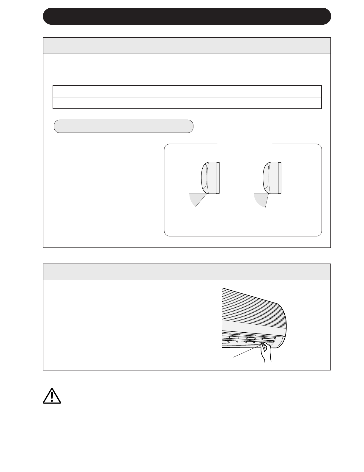
OPS∑YON K∑T∑
Hava Temizleme Filtre Ünitesi
Hava temizleme filtre ünitesinin kullanımı çalıµma sırasında havadaki tozların alınmasına
yardımcı olur. Bu opsiyonel parçayı satın almak için satıcınıza baµvurun. Yedek hava
temizleme filtreleri de temin edilebilir.
Hava Temizleme Filtre Ünitesi
Yedek Filtreler
Tip AZ-F954
Tip AZ-F904
T-16
SERV∑S ÇA∏IRMADAN ÖNCE
Downloaded from www.ManualsFile.com manuals search engine