
2005 Odyssey Online Reference Owner's Manual
Use these links (and links throughout this manual) to navigate through this reference.
For a printed owner's manual, click on authorized manuals or go to www.helminc.com.
Contents
Owner's Identification Form
Introduction..................................................................................................................................................... i
A Few Words About Safety ..........................................................................................................................ii
Your Vehicle at a Glance...............................................................................................................................4
Driver and Passenger Safety .......................................................................................................................7
Proper use and care of your vehicle's seat belts, and Supplemental Restraint System.
Instruments and Controls...........................................................................................................................59
Instrument panel indicator and gauge, and how to use dashboard and steering column controls.
Features.........................................................................................................................................................187
How
to operate the climate control system, the audio system, and other convenience features.
Before Driving ..............................................................................................................................
...............277
What gasoline to use, how to break-in your new vehicle, and how to load luggage and other cargo.
Driving...........................................................................................................................................................291
The proper way to start the engine, shift the transmission, and park, plus towing a trailer.
Maintenance.................................................................................................................................................313
T
he Maintenance Schedule shows you when you need to take your vehicle to the dealer.
Taking Care of the Unexpected...............................................................................................................355
This section covers several problems motorists sometimes experience, and how to handle them.
Technical Information...............................................................................................................................383
ID numbers,
dimensions, capacities, and technical information.
Warranty and Customer Relations (U.S. and Canada)......................................................................397
A summary of the warranties covering your new Honda, and how to contact us.
Authorized Manuals (U.S. only)...............................................................................................................401
How to order manuals and other technical literature.
Index .................................................................................................................................................................I
Service Information Summary
A summary of information you need when you pull up to the fuel pump.

This Owner’s Manual should be considered
a permanent part of the vehicle and should
remain with the vehicle when it is sold.
This Owner’s Manual covers all models of
the Odyssey. You may find descriptions of
equipment and features that are not on your
particular model.
The information and specifications included
in this publication were in effect at the time
of approval for printing. Honda Motor Co.,
Ltd. reserves the right, however, to
discontinue or change specifications or
design at any time without notice and
without incurring any obligation whatsoever.
Owner’s Identification
POUR CLIENTS CANADIEN
AVIS IMPORTANT: Si vous avez
besoin d’un Manuel du Conducteur
en français, veuillez demander à
votreconcessionnairede
commander le numéro de pièce
33SHJC00
OWNER
ADDRESS
V. I. N.
DELIVERY DATE
DEALER NAME DEALER NO.
ADDRESS
OWNER’S SIGNATURE
DEALER’S SIGNATURE
STREET
CITY STATE/PROVINCE ZIP CODE/
POSTAL CODE
(Date sold to original retail purchaser)
STREET
CITY STATE/PROVINCE ZIP CODE/
POSTAL CODE
Main Menu

One of the best ways to enhance the enjoyment of your new Honda is to
read this manual. In it, you will learn how to operate its driving controls and
convenience items. Afterwards, keep this owner’s manual in your vehicle so
youcanrefertoitatanytime.
Several warranties protect your new Honda. Read the warranty booklet
thoroughly so you understand the coverages and are aware of your rights
and responsibilities.
Maintaining your vehicle according to the schedules given in this manual
helps to keep your driving trouble-free while it preserves your investment.
When your vehicle needs maintenance, keep in mind that your Honda
dealer’s staff is specially trained in servicing the many systems unique to
your Honda. Your Honda dealer is dedicated to your satisfaction and will be
pleased to answer any questions and concerns.
California Proposition 65 Warning
This product contains or emits chemicals known to the State of
California to cause cancer and birth defects or other reproductive harm.
As you read this manual, you will
find information that is preceded by
a symbol. This
information is intended to help you
avoid damage to your Honda, other
property, or the environment.
Congratulations! Your selection of a 2005 Honda Odyssey was a wise
investment. It will give you years of driving pleasure.
Event Data Recorders
This vehicle is equipped with one or
more recording devices commonly
referred to as ‘‘event data recorders’’
or ‘‘sensing and diagnostic modules.’’
Introduction
WARNING:
i
Main Menu
−
−
−
−
−
−
Your safety, and the safety of others,
is very important. And operating this
vehicle safely is an important
responsibility.
To help you make informed
decisions about safety, we have
provided operating procedures and
other information on labels and in
this manual. This information alerts
you to potential hazards that could
hurt you or others.
Of course, it is not practical or
possible to warn you about all the
hazards associated with operating or
maintaining your vehicle. You must
use your own good judgement.
You will find this important safety information in a variety of forms,
including:
on the vehicle.
preceded by a safety alert symbol and one of
three signal words: , , or .
These signal words mean:
such as Important Safety Reminders or Important
Safety Precautions.
such as Driver and Passenger Safety.
This entire book is filled with important safety information please read it
carefully.
how to use this vehicle correctly and safely.
AFewWordsAboutSafety
Safety Labels
Safety Messages
Safety Headings
Safety Section
Instructions
DANGER WARNING CAUTION
ii
You WILL be KILLED or SERIOUSLY
HURT if you don’t follow instructions.
You CAN be KILLED or SERIOUSLY
HURT if you don’t follow instructions.
You CAN be HURT if you don’t follow
instructions.
Main Menu
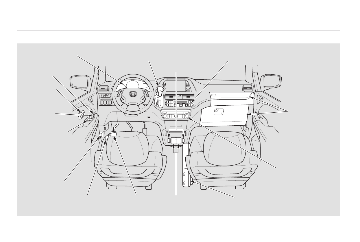
Your Vehicle at a Glance
4
AUDIO SYSTEM/
REAR ENTERTAINMENT
SYSTEM
PARKING BRAKE
PEDAL
FUEL FILL
DOOR RELEASE
HOOD RELEASE
HANDLE
POWER WINDOW
SWITCHES
POWER
DOOR LOCK
SWITCHES
INSTRUMENT PANEL INDICATORS
GAUGES
SHIFT LEVER
CLIMATE CONTROL SYSTEM
MIRROR
CONTROLS
ACCESSORY POWER
SOCKETS
(P.61, 62)
(P.71)
(P.137)
(P.182)
(P.171)
(P.180)
HEATING AND COOLING SYSTEM/
(P.188)
(P.279)
(P.280)
(P.199, 230)
(P.294)
CENTER TRAY
(P.168)
(P.163)
(P.169)
SEAT HEATER
SWITCHES
(P.160)
Seat Memory
Switches
(P.161)
GLOVE BOXES
Main Menu
*
*
To use the horn, press the pad around the ‘‘H’’ logo.:
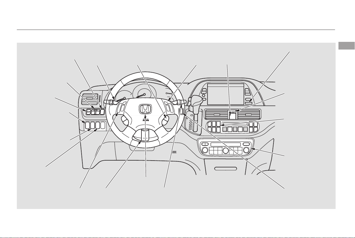
Your Vehicle at a Glance
Your Vehicle at a Glance
5
POWER SLIDING
DOOR SWITCHES
REAR WINDOW
DEFOGGER
STEERING WHEEL
ADJUSTMENT
CLOCK
LIGHT CONTROL
SWITCH
AUDIO SYSTEM/
REAR
ENTERTAINMENT
SYSTEM
STEERING WHEEL
AUDIO CONTROLS
PASSENGER
AIRBAG OFF
INDICATOR
POWER TAILGATE
SWITCH
HEADLIGHTS/
TURN SIGNALS
HAZARD WARNING
BUTTON
WINDSHIELD
WIPERS/WASHERS
VSA OFF
SWITCH
HORN
(P.142)
(P.139)
(P.228)
(P.127)
(P.121)
(P.183)
(P.126)
(P.33)
(P.227)
(P.126)
(P.122)
(P.271)
(P.302)
(P.199, 230)
PARKING SENSOR
SYSTEM SWITCH
(P.169)
(P.166)
DRIVER’S PEDAL
ADJUSTMENT SWITCH
MULTI-INFORMATION
DISPLAY SWITCHES
CRUISE
CONTROL
(P.264)
(P.75)
/
VSA OFF SWITCH
(P.302)
MOONROOF
Main Menu

6
Main Menu

−
This section gives you important
information about how to protect
yourself and your passengers. It
shows you how to use seat belts. It
explains how your airbags work. And
it tells you how to properly restrain
infants and children in your vehicle.
.........Important Safety Precautions . 8
.......Your Vehicle’s Safety Features . 9
.........Protecting Adults and Teens . 13
.....1. Close and Lock the Doors . 13
...........2. Adjust the Front Seats . 13
............3. Adjust the Seat-Backs . 14
...4. Adjust the Head Restraints . 15
5. Fasten and Position the Seat
.....................................Belts . 16
6. Maintain a Proper Sitting
................................Position . 19
.....Advice for Pregnant Women . 20
...Additional Safety Precautions . 20
Additional Information About Your
.................................Seat Belts . 22
..Seat Belt System Components . 22
......................Lap/Shoulder Belt . 22
Automatic Seat Belt
.............................Tensionners . 23
...............Seat Belt Maintenance . 23
Additional Information About Your
.....................................Airbags . 25
......Airbag System Components . 25
How Your Front Airbags
.........................................Work . 27
........................Advanced Airbag . 29
How Your Side Airbags
.........................................Work . 30
How Your Side Curtain Airbags
.........................................Work . 32
..How the SRS Indicator Works . 32
How the Side Airbag Off
......................Indicator Works . 33
How the Passenger Airbag
...............Off Indicator Works . 33
.............................Airbag Service . 34
...Additional Safety Precautions . 35
Protecting Children General
................................Guidelines . 36
All Children Must Be
...............................Restrained . 36
All Children Should Sit in a Back
...........................................Seat . 37
The Passenger’s Front Airbag
.........Can Pose Serious Risks . 37
If You Must Drive with
.....................Several Children . 39
If a Child Requires Close
..................................Attention . 39
...Additional Safety Precautions . 40
Protecting Infants and Small
...................................Children . 41
.......................Protecting Infants . 41
.........Protecting Small Children . 42
.....................Selecting a Child Seat . 43
....................Installing a Child Seat . 44
...............................With LATCH . 45
.........With a Lap/Shoulder Belt . 48
..............................With a Tether . 50
...........Protecting Larger Children . 51
...............Checking Seat Belt Fit . 52
..................Using a Booster Seat . 53
..When Can a Child Sit in Front . 53
...Additional Safety Precautions . 55
.............Carbon Monoxide Hazard . 56
...................................Safety Labels . 57
Driver and Passenger Safety
Driver and Passenger Safety
7
Main Menu

You’ll find many safety
recommendations throughout this
section, and throughout this manual.
Therecommendationsonthispage
are the ones we consider to be the
most important.
A seat belt is your best protection in
all types of collisions. Airbags are
designed to supplement seat belts,
not replace them. So even though
your vehicle is equipped with airbags,
make sure you and your passengers
always wear your seat belts, and
wear them properly (see page ).
Alcohol and driving don’t mix. Even
one drink can reduce your ability to
respond to changing conditions, and
your reaction time gets worse with
every additional drink. So don’t drink
and drive, and don’t let your friends
drink and drive, either.
While airbags can save lives, they
can cause serious or fatal injuries to
occupants who sit too close to them,
or are not properly restrained.
Infants, young children, and short
adults are at the greatest risk. Be
sure to follow all instructions and
warnings in this manual.
Children age 12 and under should
ride properly restrained in a back
seat, not in the front seat. Infants
andsmallchildrenshouldbe
restrained in a child seat. Larger
childrenshoulduseaboosteranda
lap/shoulder belt until they can use
the belt properly without a booster
(see page ).
Excessive speed is a major factor in
crash injuries and deaths. Generally,
the higher the speed, the greater the
risk, but serious injuries can also
occur at lower speeds. Never drive
faster than is safe for current
conditions, regardless of the
maximum speed posted.
Having a tire blowout or a
mechanical failure can be extremely
hazardous. To reduce the possibility
of such problems, check your tire
pressures and condition frequently,
and perform all regularly scheduled
maintenance (see page ).
16
36
315
Important Safety Precautions
Always Wear Your Seat Belt
Don’t Drink and Drive
Be Aware of Airbag Hazards
Restrain All Children
Control Your Speed
Keep Your Vehicle in Saf e
Condition
8
Main Menu
Table of Contents
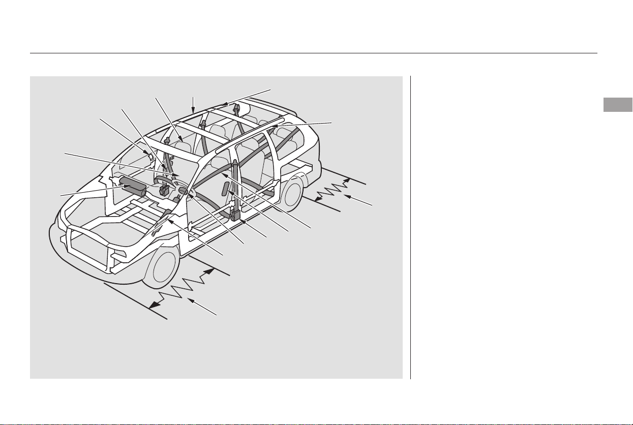
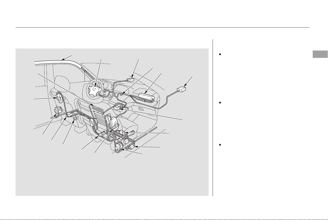
Your vehicle is equipped with many
features that work together to
protect you and your passengers
during a crash.
Some features do not require any
action on your part. These include a
strong steel framework that forms a
safety cage around the passenger
compartment; front and rear crush
zones; a collapsible steering column;
and tensioners that tighten the front
seat belts in a crash.
CONTINUED
Your Vehicle’s Safety Features
Driver and Passenger Safety
9
(1)
(2)
(2)
(3)
(4)
(5)
(6)
(7)
(8)
(8)
(7)
(9)
(9)
(11)
(10)
(1) Safety Cage
(2) Crush Zones
(3) Seats and Seat-Backs
(4) Head Restraints
(5) Collapsible Steering Column
(6) Seat Belts
(7) Front Airbags
(8) Side Airbags
(9) Side Curtain Airbags
(10) Front Seat Belt Tensioners
(11) Door Locks
Main Menu
Table of Contents
Your vehicle is equipped with seat
belts in all seating positions.
Your seat belt system also includes
an indicator on the instrument panel
to remind you and your passengers
to fasten your seat belts.
Seat belts are the single most
effectivesafetydeviceforadultsand
larger children. (Infants and smaller
children must be properly restrained
in child seats.)
Not wearing a seat belt properly
increases the chance of serious
injury or death in a crash, even
though your vehicle has airbags.
In addition, most states and all
Canadian provinces require you to
wear seat belts.
However, you and your passengers
can’t take full advantage of these
features unless you remain sitting in
a proper position and
. In fact, some safety
features can contribute to injuries if
they are not used properly.
When properly worn, seat belts:
Keep you connected to the vehicle
so you can take advantage of the
vehicle’s built-in safety features.
Help protect you in almost every
type of crash, including frontal,
side, and rear impacts and
rollovers.
The following pages explain how you
cantakeanactiveroleinprotecting
yourself and your passengers.
Your Vehicle’s Safety Features
Seat Belts
Why Wear Seat Belts
always wear
your seat belts
10
Not wearing a seat belt properly
increases the chance of serious
injury or death in a crash, even
though your vehicle has airbags.
Be sure you and your
passengers always wear seat
belts and wear them properly.
Main Menu
Table of Contents
CONTINUED
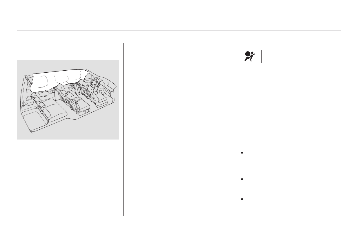
Your vehicle also has side airbags to
help protect the upper torso of the
driver or a front seat passenger
during a moderate to severe side
impact (see page for more
information on how your side airbags
work).
Your vehicle has a Supplemental
Restraint System (SRS) with front
airbags to help protect the heads and
chests of the driver and a front seat
passenger during a moderate to
severe frontal collision (see page
for more information on how
your front airbags work).
Help keep you from being thrown
against the inside of the vehicle
and against other occupants.
Keep you from being thrown out
of the vehicle.
Help keep you in a good position
should the airbags ever deploy. A
good position reduces the risk of
injury from an inflating airbag and
allows you to get the best
advantage from the airbag.
Of course, seat belts cannot
completely protect you in every
crash.Butinmostcases,seatbelts
can reduce your risk of serious
injury.
Always wear
your seat belt, and make sure you
wear it properly.
27
30
Your Vehicle’s Safety Features
Airbags
What you should do:
Driver and Passenger Safety
11
Main Menu
Table of Contents
The rest of this section gives more
detailed information about how you
can maximize your safety.
The most important things you need
to know about your airbags are:
They are designed to supplement
the seat belts.
To do
their job, airbags must inflate with
tremendous force. So while
airbags help save lives, they can
cause minor injuries or more
serious or even fatal injuries if
occupants are not properly
restrained or sitting properly.
Always wear
your seat belt properly, and sit
upright and as far back from the
steering wheel as possible while
allowing full control of the vehicle. A
front passenger should move their
seat as far back from the dashboard
as possible.
Your vehicle also has side curtain
airbags to help protect the heads of
the driver, front passenger, and
passengers in the outer rear seating
positions during a moderate to
severe side impact (see page for
more information on how your side
curtain airbags work).
Remember, however, that no safety
system can prevent all injuries or
deaths that can occur in a severe
crash, even when seat belts are
properly worn and the airbags deploy.
32
Your Vehicle’s Safety Features
Airbags do not replace seat belts.
Airbags offer no protection in rear
impacts, or minor frontal or side
collisions.
Airbags can pose hazards.
What you should do:
12
Main Menu
Table of Contents
−
After everyone has entered the
vehicle, be sure the doors and
tailgate are closed and locked.
Locking the doors reduces the
chance of someone being thrown out
of the vehicle during a crash, and it
helps prevent passengers from
accidentally opening a door and
falling out.
Locking the doors also helps prevent
an outsider from unexpectedly
opening a door when you come to a
stop.
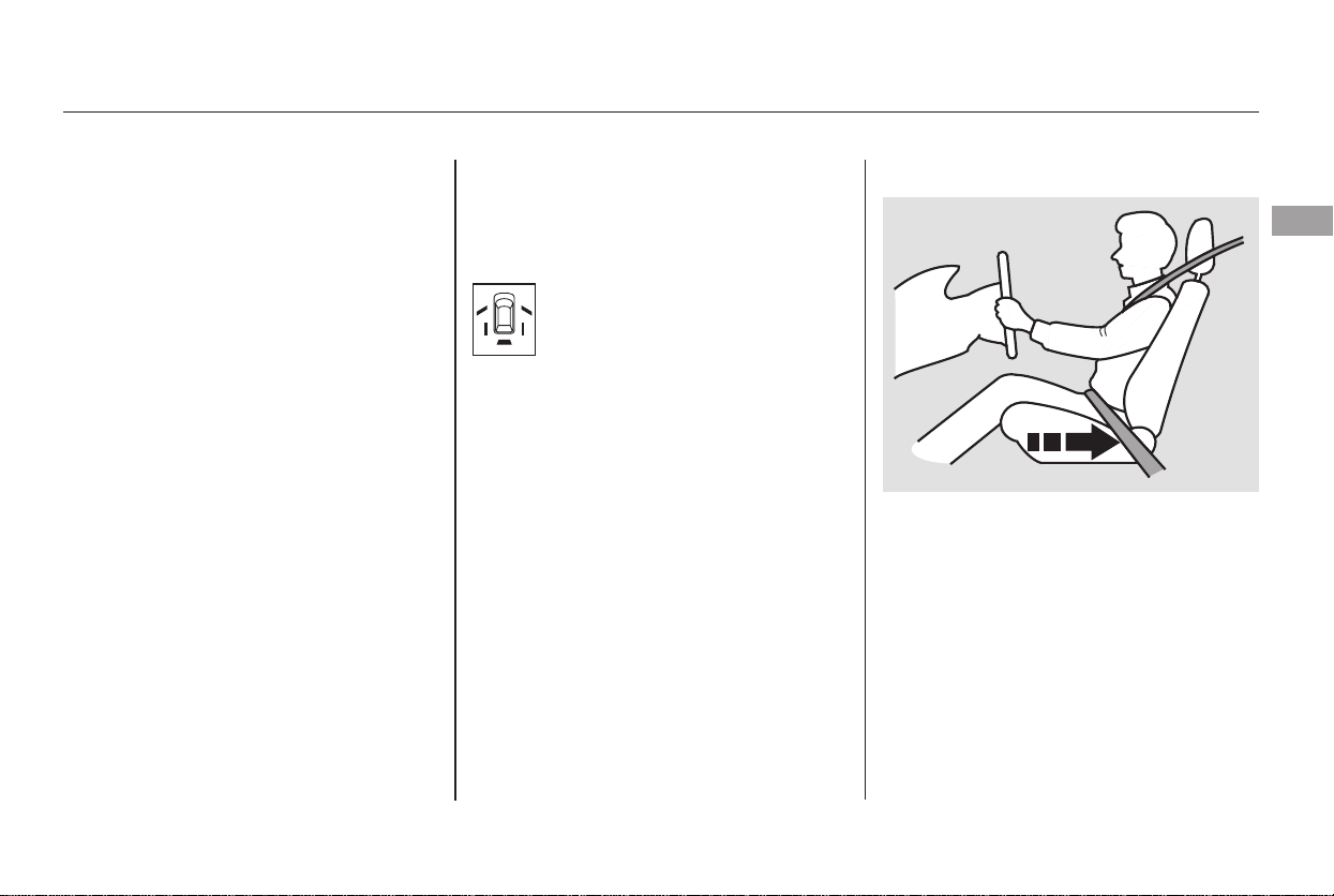
Adjust the driver’s seat as far to the
rear as possible while allowing you to
maintain full control of the vehicle.
Have a front passenger adjust their
seat as far to the rear as possible.
The following pages provide
instructions on how to properly
protect the driver, adult passengers,
and teenage children who are large
enough and mature enough to drive
or ride in the front.
See pages for important
guidelines on how to properly
protect infants, small children, and
larger children who ride in your
vehicle.
See page for how to lock the
doors, and page for how the door
and tailgate monitor indicator works.
Your vehicle has a door and
tailgate monitor indicator on
the instrument panel to
indicate when a specific door or the
tailgate is not tightly closed.
36 40
67
137
CONTINUED
Introduction Close and Lock the Doors Adjust the Front Seats1. 2.
Protecting Adults and Teens
Driver and Passenger Safety
13
Main Menu
Table of Contents
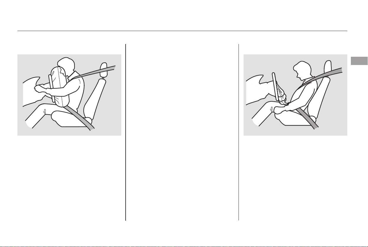
If you sit too close to the steering
wheel or dashboard, you can be
seriously injured by an inflating front
airbag, or by striking the steering
wheel or dashboard.
The National Highway Traffic Safety
Administration and Transport
Canada recommend that drivers
allow at least 10 inches (25 cm)
between the center of the steering
wheel and the chest.
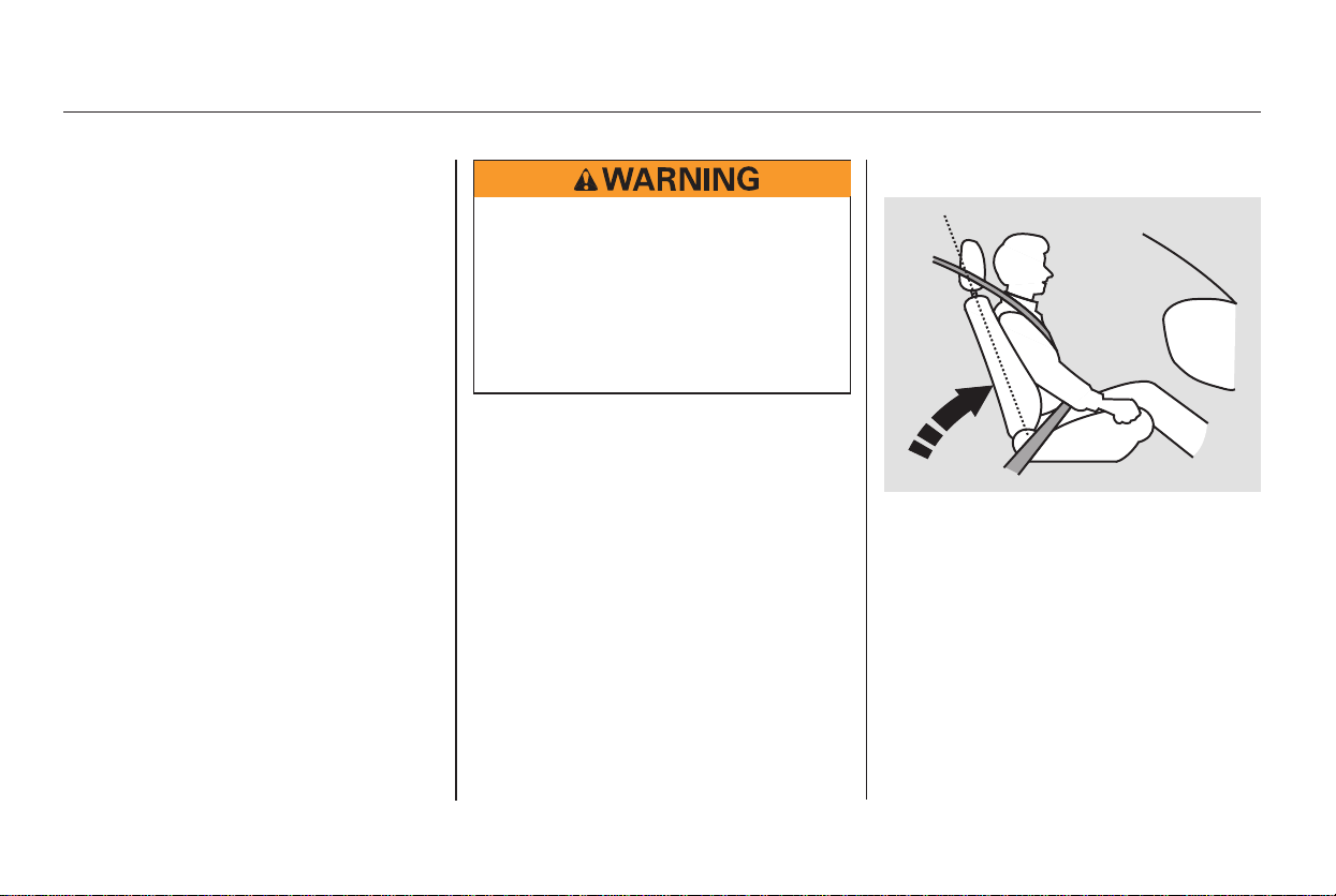
Adjust the driver’s seat-back to a
comfortable, upright position,
leaving ample space between your
chest and the airbag cover in the
center of the steering wheel.
Passengers with adjustable seat-
backs should also adjust their seat-
back to a comfortable, upright
position.
Once your seat is adjusted correctly,
rock it back and forth to make sure
the seat is locked in position.
See page for how to adjust the
front seats.
If you cannot get far enough away
from the steering wheel and still
reach the controls, we recommend
that you extend the adjustable driver’s
foot pedals (Touring model only, see
page ), or investigate whether
some type of adaptive equipment
may help.
169
149
Protecting Adults and Teens
Adjust the Seat-Backs3.
14
Sitting too close to a front
airbag can result in serious
injury or death if the front
airbags inflate.
Always sit as far back from the
front airbags as possible.
Main Menu
Table of Contents
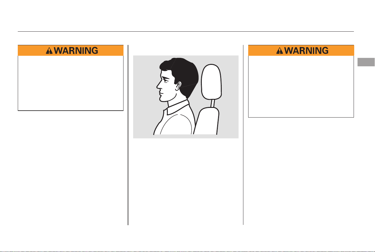
See page for how to adjust the
head restraints.
Properly adjusted head restraints
will help protect occupants from
whiplash and other crash injuries.Adjust the driver’s head restraint so
the back of your head rests against
the center of the restraint.
Have passengers with adjustable
head restraints adjust their restraints
properly as well. Taller persons
should adjust their restraint as high
as possible.
Reclining a seat-back so that the
shoulder part of the belt no longer
rests against the occupant’s chest
reduces the protective capability of
the belt. It also increases the chance
of sliding under the belt in a crash
and being seriously injured. The
farther a seat-back is reclined, the
greater the risk of injury.
See page for how to adjust the
seat-backs.
152
150
Protecting Adults and Teens
Adjust the Head Restraints4.
Driver and Passenger Safety
15
Improperly positioning head
restraints reduces their
effectiveness and you can be
seriously injured in a crash.
Make sure head restraints are
in place and positioned properly
before driving.
Reclining the seat-back too far
can result in serious injury or
death in a crash.
Adjust the seat-back to an
upright position, and sit well
back in the seat.
Main Menu
Table of Contents
If necessary, pull up on the belt again
to remove any slack, then check that
the belt rests across the center of
your chest and over your shoulder.
This spreads the forces of a crash
over the strongest bones in your
upper body.
If the seat belt touches or crosses
your neck, or if it crosses your arm
instead of your shoulder, you need to
adjust the seat belt anchor height.
Position the lap part of the belt as
low as possible across your hips,
then pull up on the shoulder part of
the belt so the lap part fits snugly.
This lets your strong pelvic bones
take the force of a crash and reduces
the chance of internal injuries.
Insert the latch plate into the buckle,
then tug on the belt to make sure the
belt is securely latched. Check that
the belt is not twisted, because a
twisted belt can cause serious
injuries in a crash.
The center seating position of the
third row has a detachable seat belt
anchor that can be unlatched and
released, to allow the seat to be
folded down. See page for how to
unlatch and relatch the seat belt
anchor.
The plus-one seat on EX models that
canbeinstalledinthecenterseating
position of the second row also has a
detachable seat belt anchor.
17
Protecting Adults and Teens
Fasten and Position the Seat
Belts
5.
16
Improperly positioning the seat
belts can cause serious injury
or death in a crash.
Make sure all seat belts are
properly positioned before
driving.
Main Menu
Table of Contents
CONTINUED
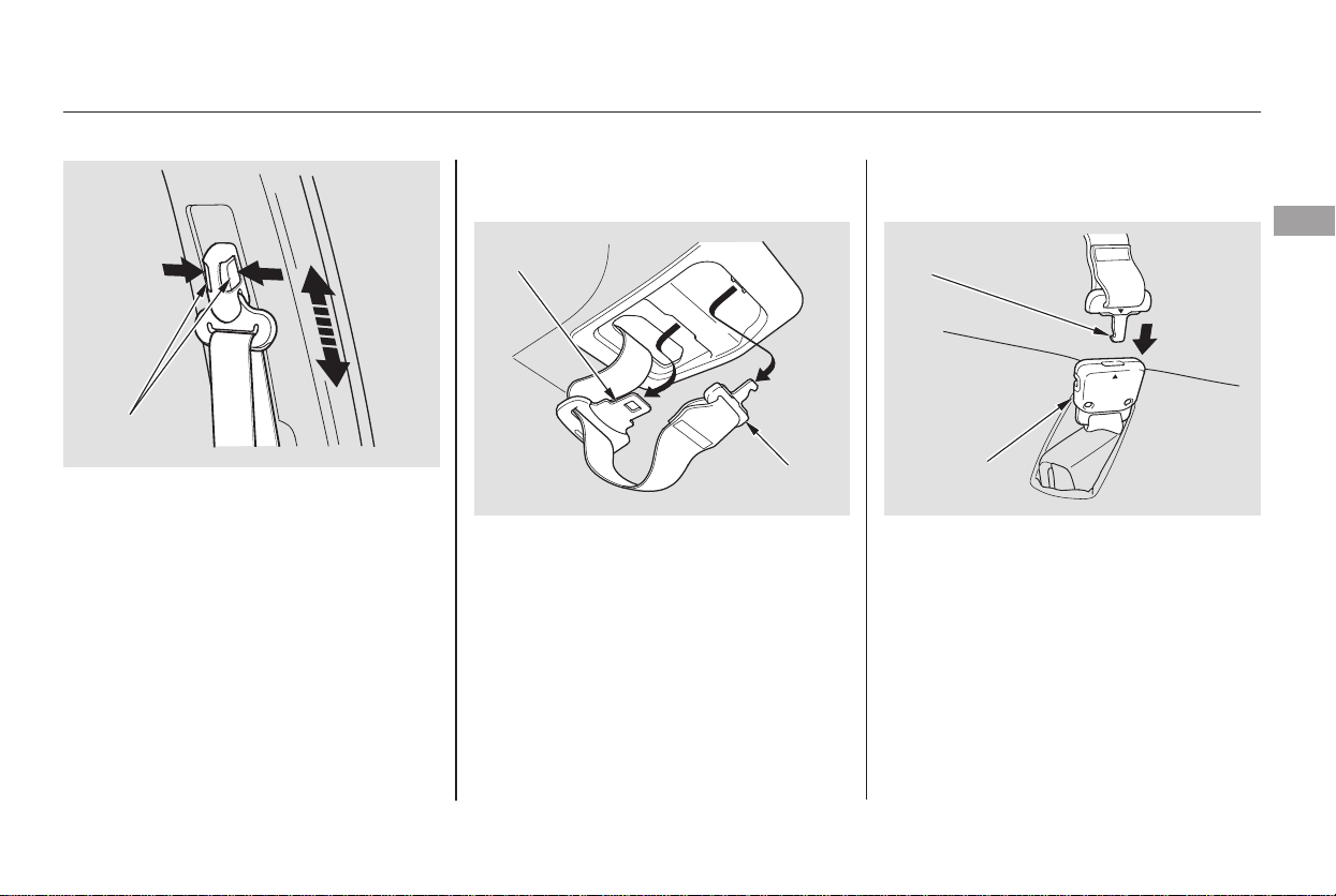
The front seats and second row seats
have adjustable seat belt anchors. To
adjust the height of an anchor,
squeeze the two release buttons, and
slide the anchor up or down as
needed (the anchor has four
positions).
Pull out the anchor latch and the
latch plate from each holding slot in
the ceiling, and pull out the seat belt
to extend it.
Insert the hook at the end of the
anchor latch into the anchor buckle
by lining up the triangle marks on
the anchor latch and buckle. Make
sure the belt is not twisted. Push the
anchor latch until it locks. Then
follow the procedure for fastening an
ordinary seat belt (see page ).16
The plus-one seat on EX model also has
this type of seat belt.
Protecting Adults and Teens
Using the Lap/Shoulder Belt in the
Center Position of the Third Row
Driver and Passenger Safety
17
RELEASE
BUTTONS
LATCH
PLATE
ANCHOR
LATCH
ANCHOR
LATCH
ANCHOR
BUCKLE
Main Menu
Table of Contents
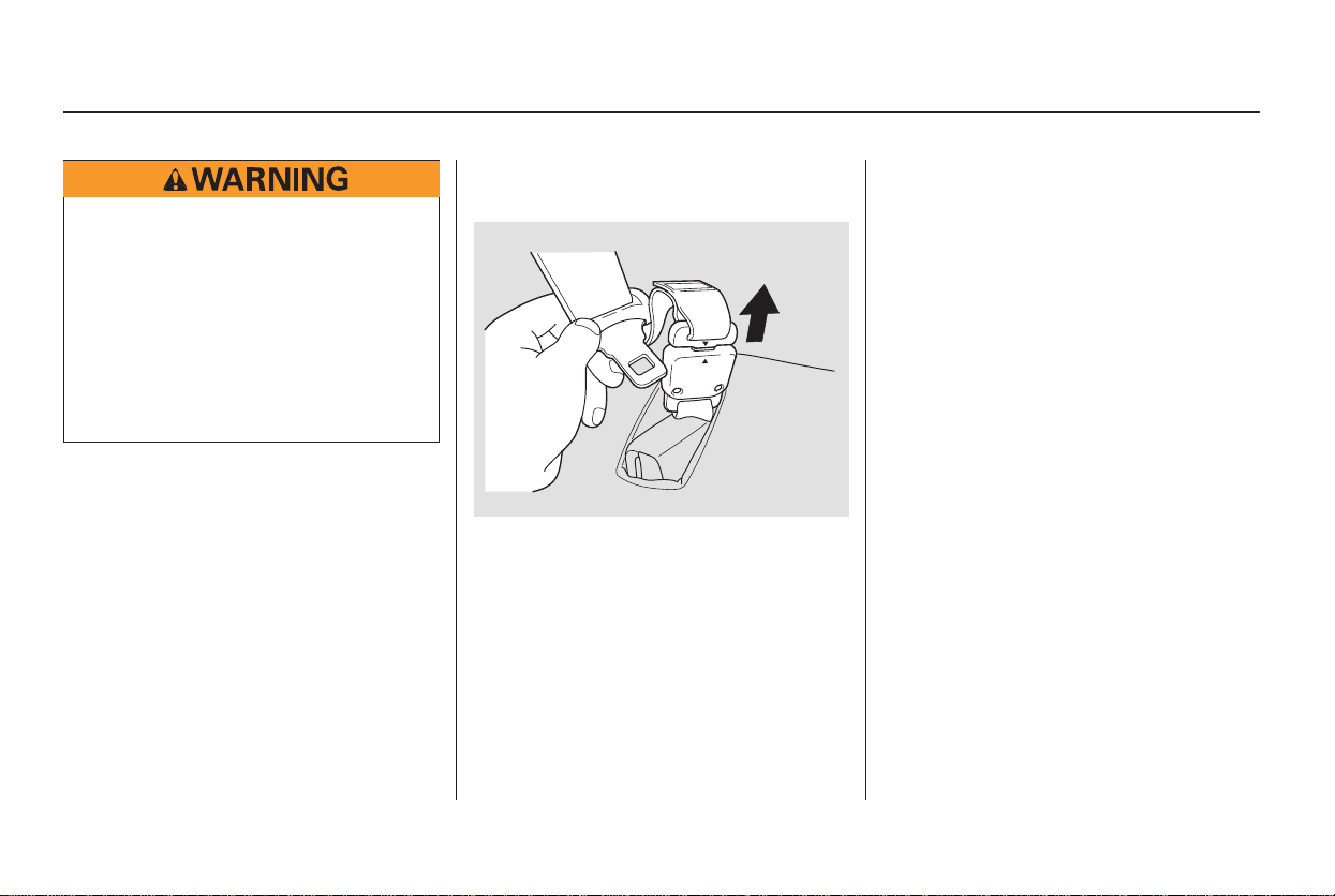
To unlatch the detachable seat belt
anchor before folding down the seat-
back, insert the latch plate into the
slot on the side of the anchor buckle
and allow the seat belt to retract.
Place the latch plate and anchor
latch into their holding slots in the
ceiling.
When the seat-back is returned to its
upright position, be sure to latch the
detachable seat belt anchor.
This could cause
very serious injuries in a crash.
If a seat belt does not seem to work
as it should, it may not protect the
occupant in a crash.
Using a seat
belt that is not working properly can
result in serious injury or death.
Have your dealer check the belt as
soon as possible.
See page for additional
information about your seat belts
and how to take care of them.
20
Protecting Adults and Teens
Never place the shoulder portion of a
lap/shoulder belt under your arm or
behind your back.
No one should sit in a seat with an
inoperative seat belt.
18
Using a seat belt with the
detachable seat belt anchor
unlatched increases the chance
of serious injury or death in a
crash.
Before using the seat belt,
make sure the detachable seat
belt anchor is correctly latched.
Main Menu
Table of Contents
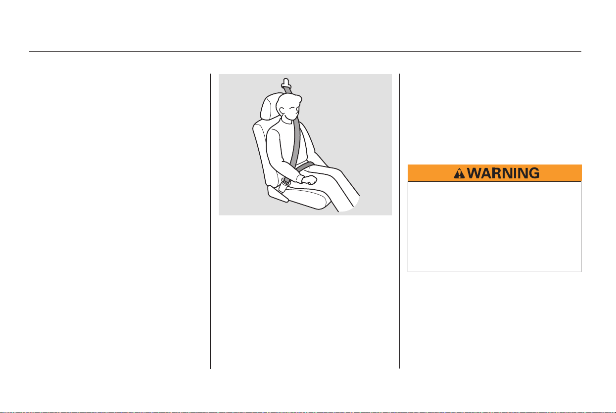
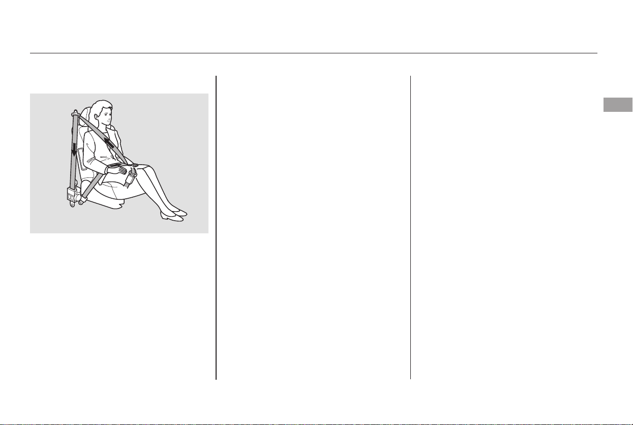
After all occupants have adjusted
their seats and put on seat belts, it is
very important that they continue to
sit upright, well back in their seats,
with their feet on the floor, until the
vehicle is parked and the engine is
off.
Sitting improperly can increase the
chance of injury during a crash. For
example, if an occupant slouches,
lies down, turns sideways, sits
forward, leans forward or sideways,
or puts one or both feet up, the
chance of injury during a crash is
greatly increased.
In addition, an occupant who is out of
position in the front seat can be
seriously or fatally injured in a crash
by striking interior parts of the
vehicle or being struck by an
inflating front airbag.
Protecting Adults and Teens
Maintain a Proper Sitting
Position
6.
Driver and Passenger Safety
19
Sitting improperly or out of
position can result in serious
injury or death in a crash.
Always sit upright, well back in
the seat, with your feet on the
floor.
Main Menu
Table of Contents
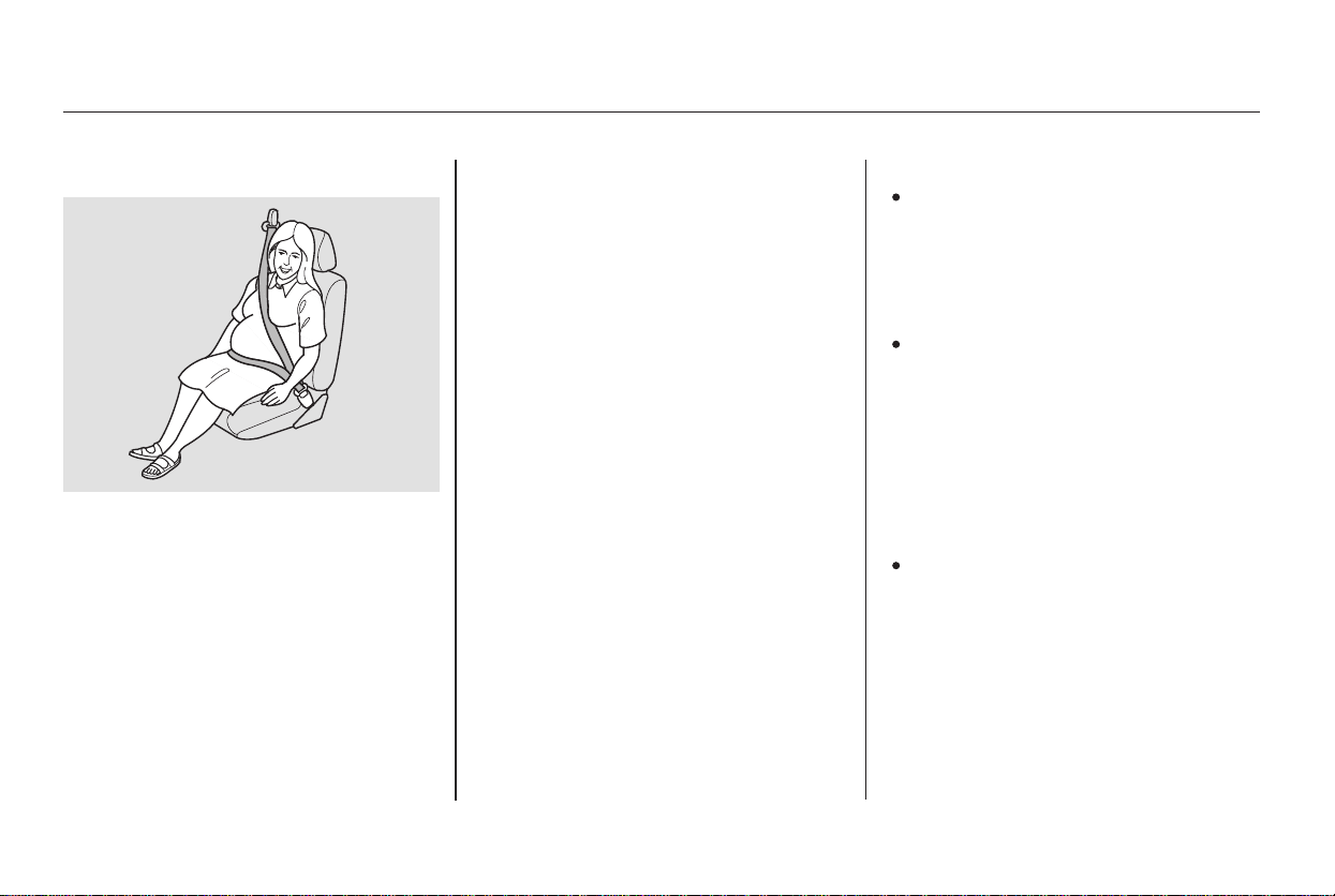
If you are pregnant, the best way to
protect yourself and your unborn
child when driving or riding in a
vehicle is to always wear a seat belt,
and keep the lap part of the belt as
low as possible across the hips.
When driving, remember to sit
upright and adjust the seat as far
back as possible while allowing full
control of the vehicle. When riding
as a front passenger, adjust the seat
as far back as possible.
This will reduce the risk of injuries
to both you and your unborn child
that can be caused by a crash or an
inflating front airbag.
Each time you have a checkup, ask
your doctor if it’s okay for you to
drive.
If they do, they
could be very seriously injured in a
crash.
A passenger who is not
wearing a seat belt during a crash
or emergency stop can be thrown
against the inside of the vehicle,
against other occupants, or out of
the vehicle.
If they do, they
could be very seriously injured in a
crash.
Protecting Adults and Teens
Advice for Pregnant Women Additional Safety Precautions
Never let passengers ride in the
cargo area or on top of a folded-
down back seat.
Passengers should not stand up or
change seats while the vehicle is
moving.
Two people should never use the
same seat belt.
20
Main Menu
Table of Contents

Devices intended to improve
occupant comfort or reposition the
shoulder part of a seat belt can
reduce the protective capability of
the seat belt and increase the
chance of serious injury in a crash.
Carrying hard or sharp
objects on your lap, or driving with
a pipe or other sharp object in
your mouth, can result in injuries
if your front airbag inflates.
If your
hands or arms are close to an
airbag cover, they could be injured
if the airbag inflates.
Objects on
the covers marked ‘‘SRS AIRBAG’’
could interfere with the proper
operation of the airbags or be
propelled inside the vehicle and
hurt someone if the airbags inflate.
If a side airbag
or a side curtain airbag inflates, a
cupholderorotherhardobject
attached on or near the door could
be propelled inside the vehicle and
hurt someone.
Protecting Adults and Teens
Do not put any accessories on seat
belts.
Do not place hard or sharp objects
between yourself and a front
airbag.
Keep your hands and arms away
from the airbag covers.
Do not attach or place objects on
the front airbag covers.
Do not attach hard objects on or
near a front door.
Driver and Passenger Safety
21
Main Menu
Table of Contents
Your seat belt system includes lap/
shoulder belts in all seating positions.
The front seat belts are also
equipped with automatic seat belt
tensioners.
The seat belt system
includes an indicator on the
instrument panel and a beeper to
remind you to fasten your seat belt.
If you turn the ignition switch to ON
(II) without fastening your belt, a
beeper will sound and the indicator
will flash. If you do not fasten your
seat belt before the beeper stops, the
indicator will stop flashing but
remain on.
If you continue driving without
fastening your seat belt, the beeper
will sound and the indicator will flash
again at regular intervals.
The lap/shoulder belt goes over
your shoulder, across your chest,
and across your hips.
To fasten the belt, insert the latch
plate into the buckle, then tug on the
belt to make sure the buckle is
latched (see page for how to
properly position the belt).
To unlock the belt, push the red
PRESSbuttononthebuckle.Guide
the belt across your body so that it
retracts completely. After exiting the
vehicle, be sure the belt is out of the
way and will not get closed in the
door.
All seat belts have an emergency
locking retractor. In normal driving,
the retractor lets you move freely in
your seat while it keeps some
tension on the belt. During a collision
or sudden stop, the retractor
automatically locks the belt to help
restrain your body.
The seat belts in all positions except
the driver’s have an additional
locking mechanism that must be
activated to secure a child seat (see
page ).
If the shoulder part of the belt is
pulled all the way out, the locking
mechanism will activate. The belt
will retract, but it will not allow the
passenger to move freely.
To deactivate the locking
mechanism, unlatch the buckle and
let the seat belt fully retract. To
refasten the seat belt, pull it out only
as far as needed.
16
48
Additional Information About Your Seat Belts
Seat Belt System Components Lap/Shoulder Belt
22
Main Menu
Table of Contents
For added protection, the front seat
belts are equipped with automatic
seat belt tensioners. When activated,
the tensioners immediately tighten
the belts to help hold the driver and
a front passenger in place.
The tensioners are designed to
activate primarily in frontal collisions,
andtheyshouldactivateinany
collision severe enough to cause
front-airbag inflation.
For safety, you should check the
condition of your seat belts regularly.
Honda provides a lifetime warranty
on seat belts for U.S. models. See
your
booklet for details.
Pull each belt out fully and look for
frays, cuts, burns, and wear. Check
that the latches work smoothly and
the belts retract easily. Any belt that
is not in good condition or working
properly will not provide good
protection and should be replaced as
soon as possible.The tensioners can also be activated
during a collision in which the front
airbags do not deploy. In this case,
the airbags would not be needed, but
the additional restraint could be
helpful.
When the tensioners are activated,
the seat belts will remain tight until
they are unbuckled in the normal
manner.
The tensioners are also designed to
activate when sensors detect side
impact and when your vehicle is
about to roll over (see page ).32
Honda Warranty Information
CONTINUED
Automatic Seat Belt Tensioners Seat Belt Maintenance
Additional Information About Your Seat Belts
Driver and Passenger Safety
23
Main Menu
Table of Contents
If a seat belt is worn during a crash,
it must be replaced by the dealer. A
belt that has been worn during a
crash may not provide the same level
of protection in a subsequent crash.
The dealer should also inspect the
anchors for damage and replace
them if needed. If the automatic seat
belt tensioners activate during a
crash, they must be replaced.
For information on how to clean the
seat belts, see page .343
Additional Information About Your Seat Belts
24
Not checking or maintaining
seat belts can result in serious
injury or death if the seat belts
do not work properly when
needed.
Check your seat belts regularly
and have any problem
corrected as soon as possible.
Main Menu
Table of Contents
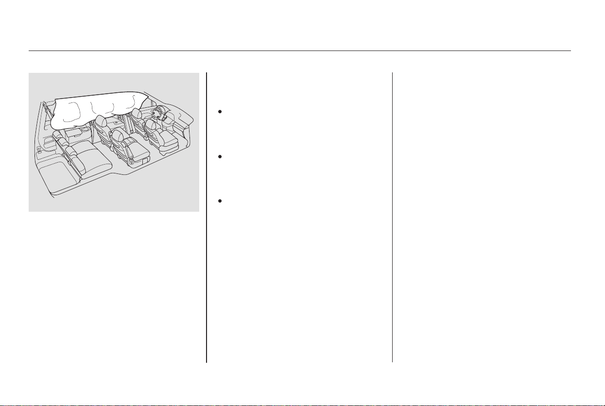
Your Airbag System includes:
Two SRS (Supplemental Restraint
System) front airbags. The driver’s
airbag is stored in the center of
the steering wheel; the front
passengers’airbagisstoredinthe
dashboard. Both are marked ‘‘SRS
AIRBAG’’ (see page ).
Two side airbags, one for the
driver and one for a front
passenger. The airbags are stored
in the outer edges of the seat-
backs. Both are marked ‘‘SIDE
AIRBAG’’ (see page ).
Two side curtain airbags, one for
each side of the vehicle. The
airbags are stored in the ceiling
above the side windows. All pillars
are marked ‘‘SIDE CURTAIN
AIRBAG’’ (see page ).
27
30
32
CONTINUED
Airbag System Components
Additional Information About Your Airbags
Driver and Passenger Safety
25
(3)
(4)
(1)
(8)
(9)
(2)
(7)
(5)
(10)
(6)
(12)
(5)
(4)
(11)
(9)
(11)
(13)
(8) Front Passenger’s Weight Sensors
(9) Front Impact Sensors
(10) Passenger Airbag Off Indicator
(11) Side Impact Sensors
(12) Occupant Position Detection
System (OPDS) Sensors
(1) Driver’s Front Airbag
(2) Passenger’s Front Airbag
(3) Control Unit
(4) Seat Belt Tensioners
(5) Side Airbags
(6) Side Curtain Airbag
(7) Driver’s Seat Position Sensor
(13) Rollover Sensor
Main Menu
Table of Contents

A driver’s seat position sensor that
monitors the distance of the seat
from the front airbag. If the seat is
too far forward, the airbag will
inflate with less force (see page
).
Automatic seat belt tensioners
(see page ).
Sensors that can detect a
moderate to severe front impact or
side impact.
Sensors that can detect whether a
child is in the passenger’s side
airbag path and automatically turn
the airbag off (see page ).
A sophisticated electronic system
that continually monitors and
records information about the
sensors, the control unit, the
airbag activators, the seat belt
tensioners, and driver and front
passenger seat belt use when the
ignition is in the ON (II) position.
Weight sensors that monitor the
weight on the front passenger’s
seat. These automatically turn off
the passenger’s front airbag if
they detect an infant or small child
maybeintheseat(seepage ).
An indicator on the instrument
panel that alerts you to a possible
problem with your airbags (see
page ).
Emergency backup power in case
your vehicle’s electrical system is
disconnected in a crash.
An indicator on the dashboard that
alerts you that the passenger’s
front airbag has been turned off
(see page ).
An indicator on the dashboard that
alerts you that the passenger’s
side airbag has been turned off
(see page ).
A rollover sensor that monitors
the degree and rate your vehicle
may roll over and automatically
deploy the side curtain airbags and
activate the front seat belt
tensioners if needed (see page ).
23
33
29
32
33
33
29
32
Additional Information About Your Airbags
26
Main Menu
Table of Contents
After inflating, the front airbags will
immediately deflate, so they won’t
interfere with the driver’s visibility,
or the ability to steer or operate
other controls.
During a frontal crash, your seat belt
restrains your lower body and torso,
and the airbag helps protect your
head and chest.
Although both airbags normally
inflate within a split second of each
other, it is possible for only one
airbag to deploy.
This can happen if the severity of a
collision is at the margin, or
threshold, that determines whether
or not the airbags will deploy. In
such cases, the seat belt will provide
sufficient protection, and the
supplemental protection offered by
the airbag would be minimal.
Only the driver’s airbag can deploy if
there is no passenger in the front
seat, or if the advanced airbag
system has turned the passenger’s
airbag off (see page ).
If you ever have a moderate to
severe frontal collision, sensors will
detect the vehicle’s rapid
deceleration.
If the rate of deceleration is high
enough, the control unit will instantly
inflate the driver’s and front
passenger’s airbags, at the time and
with the force needed. 33
CONTINUED
How Your Front Airbags Work
Additional Information About Your Airbags
Driver and Passenger Safety
27
Main Menu
Table of Contents

Your front airbags are also dual-
threshold airbags. Airbags with this
feature have two deployment
thresholds that depend on whether
or not the occupant is wearing a seat
belt.
If the occupant’s belt is ,
the airbag will deploy at a slightly
lower threshold, because the
occupant would need extra
protection.
It the occupant’s belt is , the
airbag will inflate at a slightly higher
threshold, when the airbag would be
needed to supplement the protection
provided by the seat belt.
Your front airbags are dual-stage
airbags. This means they have two
inflation stages that can be ignited
sequentially or simultaneously,
depending on crash severity.
In a crash, both stages
will ignite simultaneously to provide
the quickest and greatest protection.
In a crash, one stage will
ignite first, then the second stage
will ignite a split second later. This
provides longer airbag inflation time
with a little less force.
The total time for inflation and
deflation is one-tenth of a second, so
fast that most occupants are not
aware that the airbags deployed until
they see them lying in their laps.
After a crash, you may see what
looks like smoke. This is actually
powder from the airbag’s surface.
Although the powder is not harmful,
people with respiratory problems
mayexperiencesometemporary
discomfort. If this occurs, get out of
the vehicle as soon as it is safe to do
so.
Dual-Threshold Airbags
not latched
latched
Dual-Stage Airbags
more severe
less severe
Additional Information About Your Airbags
28
Main Menu
Table of Contents
CONTINUED
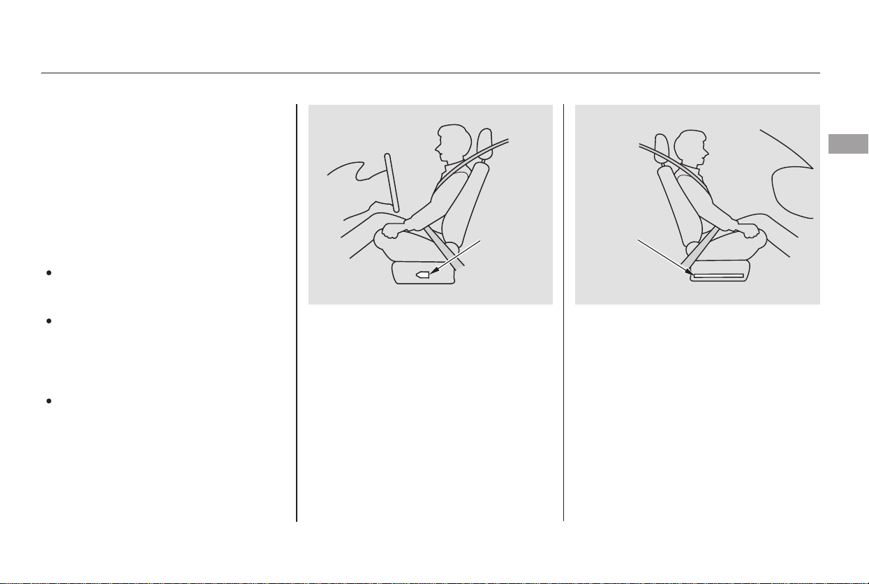
The driver’s advanced front airbag
system includes a seat position
sensor under the seat. If the seat is
too far forward, the airbag will
inflate with less force, regardless of
the severity of the impact.
Your front airbags are also advanced
airbags. The main purpose of this
feature is to help prevent airbag-
caused injuries to short drivers and
children who ride in front.
For both advanced airbags to work
properly:
Occupants must sit upright and
wear their seat belts properly.
Do not spill any liquids on or
under the seats, cover the sensors,
or put any cargo or metal objects
under the front seats.
Back-seat passengers should not
put their feet under the front seats.
Failure to follow these instructions
could damage the sensors or prevent
them from working properly.
If there is a problem with the sensor,
the SRS indicator will come on, and
the airbag will inflate in the normal
manner regardless of the driver’s
seating position.
The passenger’s advanced front
airbag system has weight sensors
under the seat. If the sensors detect
an infant or small child may be in the
seat, the system will automatically
turn the passenger’s front airbag off.
Additional Information About Your Airbags
Advanced Airbags
Driver and Passenger Safety
29
DRIVER’S
SEAT
POSITION
SENSOR
PASSENGER’S
SEAT WEIGHT
SENSOR
Main Menu
Table of Contents
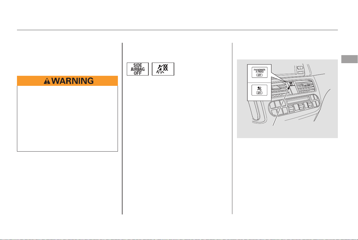
When the airbag is turned off, an
indicator in the center of the
dashboard will come on indicating
passenger airbag ‘‘OFF’’ (see page
).
If there is no passenger in the front
seat, the airbag will be off. However,
the Passenger Airbag Off indicator
will not come on.
To ensure that the passenger’s
advanced front airbag system will
work properly,
This includes:
A rear passenger pushing or
pulling on the back of the
passenger’s seat.
Moving the front seat forcibly
back against cargo on the seat or
floor behind it.
Hanging heavy items on the front
passenger seat, or placing heavy
items in the seat-back pocket.
If you ever have a moderate to
severe side impact, sensors will
detect rapid acceleration and signal
the control unit to instantly inflate
either the driver’s or the passenger’s
side airbag and activate the seat belt
tensioner.
33
Additional Information About Your Airbags
How Your Side Airbags Work
do not do anything
that would increase or decrease the
weight on the front passenger’s seat.
30
Main Menu
Table of Contents

Only one airbag will deploy during a
side impact. If the impact is on the
passenger’s side, the passenger’s
side airbag will deploy even if there
is no passenger.
To get the best protection from the
side airbags, front seat occupants
should wear their seat belts and sit
upright and well back in their seats.
To reduce the risk of injury from an
inflating side airbag, your vehicle has
an automatic cutoff system for the
passenger’s side airbag.
If the Side Airbag Off Indicator
comes on (see page ), have the
passenger sit upright. Once the
passenger is out of the airbag’s
deployment path, the system will
turn the airbag back on, and the
indicator will go out.
There will be some delay between
the moment the passenger moves
into or out of the airbag deployment
pathandwhentheindicatorcomes
on or goes off.
A front seat passenger should not
use a cushion or other object as a
backrest. It may prevent the cutoff
system from working properly.
Objects placed on the front
passenger seat can also cause the
side airbag to be shut off.
Thesideairbagmayalsoshutoffifa
short adult leans sideways, or a
larger adult slouches and leans
sideways into the airbag’s
deployment path.
Although Honda does not encourage
children to ride in front, this system
is designed to shut off the side
airbag if a child leans into the side
airbag’s deployment path.
33
Additional Information About Your Airbags
Side Airbag Cutoff System
Driver and Passenger Safety
31
Main Menu
Table of Contents
If the impact is on the passenger’s
side, the passenger’s side curtain
airbag will inflate even if there are no
occupants on that side of the vehicle.
When you turn the ignition switch to
ON (II), this indicator will come on
briefly then go out. This tells you the
system is working properly.
If the indicator comes on at any
other time, or does not come on at all,
you should have the system checked
by your dealer. For example:
The SRS indicator alerts
you to a potential problem
with your airbags or seat belt
tensioners.
If the SRS indicator does not come
on after you turn the ignition
switch to ON (II).
If the indicator stays on after the
engine starts.
If the indicator comes on or
flashesonandoffwhileyoudrive.
In a moderate to severe side impact,
sensors will detect rapid acceleration
and signal the control unit to
instantly inflate the side curtain
airbag and activate the seat belt
tensioner on the driver’s or the
passenger’s side of the vehicle.
A rollover sensor monitors the
degree and rate your vehicle may roll
over and automatically deploy the
side curtain airbags and activate the
front seat belt tensioners (see page
).
In a rollover toward the front
passenger’s side of the vehicle, both
side curtain airbags will inflate and
the front seat belt tensioners will
activate even if there are no
occupants on that side of the vehicle.
To get the best protection from the
side curtain airbags, occupants
should wear their seat belts and sit
upright and well back in their seats.
23
Additional Information About Your Airbags
In a Side Impact
In a Rollover
How Your Side Curtain Airbags
Work
How the SRS Indicator Works
32
Main Menu
Table of Contents
CONTINUED
This indicator
alerts you that the
passenger’s side
airbag has been automatically shut
off. It does mean there is a
problem with your side airbags.
This indicator alerts you that the
passenger’s front airbag is shut off
because weight sensors detect an
infant or small child may be in the
front passenger’s seat. It does not
mean there is a problem with the
airbag.
When you turn the ignition switch to
ON (II), the indicator should come
on briefly and then go off (see page
). If it doesn’t come on, stays on,
or comes on while driving without a
passenger in the front seat, have the
system checked.
If you see any of these indications,
the airbags and seat belt tensioners
may not work properly when you
need them.
64
Additional Information About Your Airbags
How the Side Airbag Off
Indicator Works
How the Passenger Airbag Off
Indicator Works
not
Driver and Passenger Safety
33
PASSENGER AIRBAG OFF
INDICATOR
U.S. Canada
Ignoring the SRS indicator can
result in serious injury or death
if the airbag systems or
tensioners do not work properly.
Have your vehicle checked by a
dealer as soon as possible if
the SRS indicator alerts you to
a possible problem.
Main Menu
Table of Contents

Even if your
airbags do not inflate, your dealer
should inspect the driver’s seat
position sensor and the front
passenger’s weight sensors to
make sure they are operating
properly.Any airbag
that has deployed must be
replaced along with the control
unit and other related parts. If a
front airbag inflates, the seat belt
tensioners must also be replaced.
Do not try to remove or replace
anyairbagbyyourself.Thismust
be done by your dealer or a
knowledgeable body shop.
Take your vehicle to an
authorized dealer as soon as
possible. If you ignore this
indication, your airbags may not
operate properly.
Your airbag systems are virtually
maintenance free, and there are no
parts you can safely service.
However, you must have your
vehicle serviced if:
If no one is riding in the front seat,
the airbag will be automatically shut
off. However, the indicator will not
come on.
If the indicator comes on with no
passenger in the front, or with an
adult in the seat, there may be a
problem with the advanced airbag
system. Have the vehicle checked by
the dealer as soon as possible.
The Passenger Airbag Off indicator
may also come on and off repeatedly
if total weight on the seat is near the
airbag cutoff threshold.
If this happens, have the passenger
ride properly restrained in a back
seat. If the passenger must ride in
front, move the seat as far to the
rear as possible, and have the
passenger sit upright and wear the
seat belt properly.
Additional Information About Your Airbags
If your vehicle has a moderate to
severe impact.
An airbag ever inflates.
The SRS indicator alerts you to a
problem.
Airbag Service
34
Main Menu
Table of Contents

Together, airbags and
seat belts provide the best
protection.
Tampering could cause
the airbags to deploy, possibly
causing very serious injury.
Improperly replacing
or covering front seat-back covers
can prevent your side airbags from
inflating during a side impact.
This could make the
driver’s seat position sensor or the
front passenger’s weight sensors
ineffective. If it is necessary to
remove or modify a front seat to
accommodate a person with
disabilities, first contact American
Honda at 800-999-1009.
Additional Safety Precautions
Donotattempttodeactivateyour
airbags.
Do not tamper with airbag
components or wiring for any
reason.
Do not cover or replace front seat-
back covers without consulting
your dealer.
Do not remove or modify a front
seat without consulting your
dealer.
Additional Information About Your Airbags
Driver and Passenger Safety
35
Main Menu
Table of Contents
−
−
−
Children depend on adults to protect
them. However, despite their best
intentions, many adults do not know
how to properly protect child
passengers.
If you have children, or ever need to
drive with a child in your vehicle, be
sure to read this section. It begins
with important general guidelines,
then presents special information for
infants, small children, and larger
children.
Each year, many children are injured
or killed in vehicle crashes because
they are either unrestrained or not
properly restrained. In fact, vehicle
accidents are the number one cause
of the death of children ages 12 and
under.
To reduce the number of child
deaths and injuries, every state and
Canadian province requires that
infants and children be properly
restrained when they ride in a
vehicle.
(see pages ).
(see pages ).
41 51
51 55
Protecting Children General Guidelines
All Children Must Be Restrained
Infants and small children must be
restrained in an approved child seat
that is properly secured to the
vehicle
Larger children must be restrained
with a lap/shoulder belt and ride on
a booster seat until the seat belt fits
them properly
36
Children who are unrestrained
or improperly restrained can be
seriously injured or killed in a
crash.
Any child too small for a seat
belt should be properly
restrained in a child seat. A
larger child should be properly
restrained with a seat belt and
use a booster seat if necessary.
Main Menu
Table of Contents

−
Front airbags have been designed to
help protect adults in a moderate to
severe frontal collision. To do this
the passenger’s front airbag is quite
large, and it can inflate with enough
force to cause very serious injuries.
According to accident statistics,
children of all ages and sizes are
safer when they are restrained in a
back seat. The National Highway
Traffic Safety Administration and
Transport Canada recommend that
all children age 12 and under be
properly restrained in a back seat.
Children who ride in back are less
likely to be injured by striking
interior vehicle parts during a
collision or hard braking. Also,
children cannot be injured by an
inflating front airbag when they ride
in the back.
Even though your vehicle has an
advanced front airbag system, which
can automatically turn the
passenger’s front airbag off (see
page ), please follow the
guidelines below.
If
the airbag inflates, it can hit the back
of the child seat with enough force
to kill or very seriously injure an
infant.
If the vehicle seat is
too far forward, or the child’s head is
thrown forward during a collision, an
inflating front airbag can strike the
child with enough force to kill or
very seriously injure a small child.
Whenever possible,
larger children should sit in the back
seat, on a booster seat if needed, and
be properly restrained with a seat
belt. (See page for important
information about protecting larger
children.)
51
29
The Passenger’s Front Airbag
Can Pose Serious Risks
All Children Should Sit in a Back
Seat
Infants
Never put a rear-facing child seat in
the front seat of a vehicle equipped
with a passenger’s front airbag.
Small Children
Placing a forward-facing child seat in
the front seat of a vehicle equipped
with a passenger’s front airbag can
be hazardous.
Larger Children
Children who have outgrown child
seats are also at risk of being injured
or killed by an inflating passenger’s
front airbag.
Protecting Children General Guidelines
Driver and Passenger Safety
37
Main Menu
Table of Contents
−
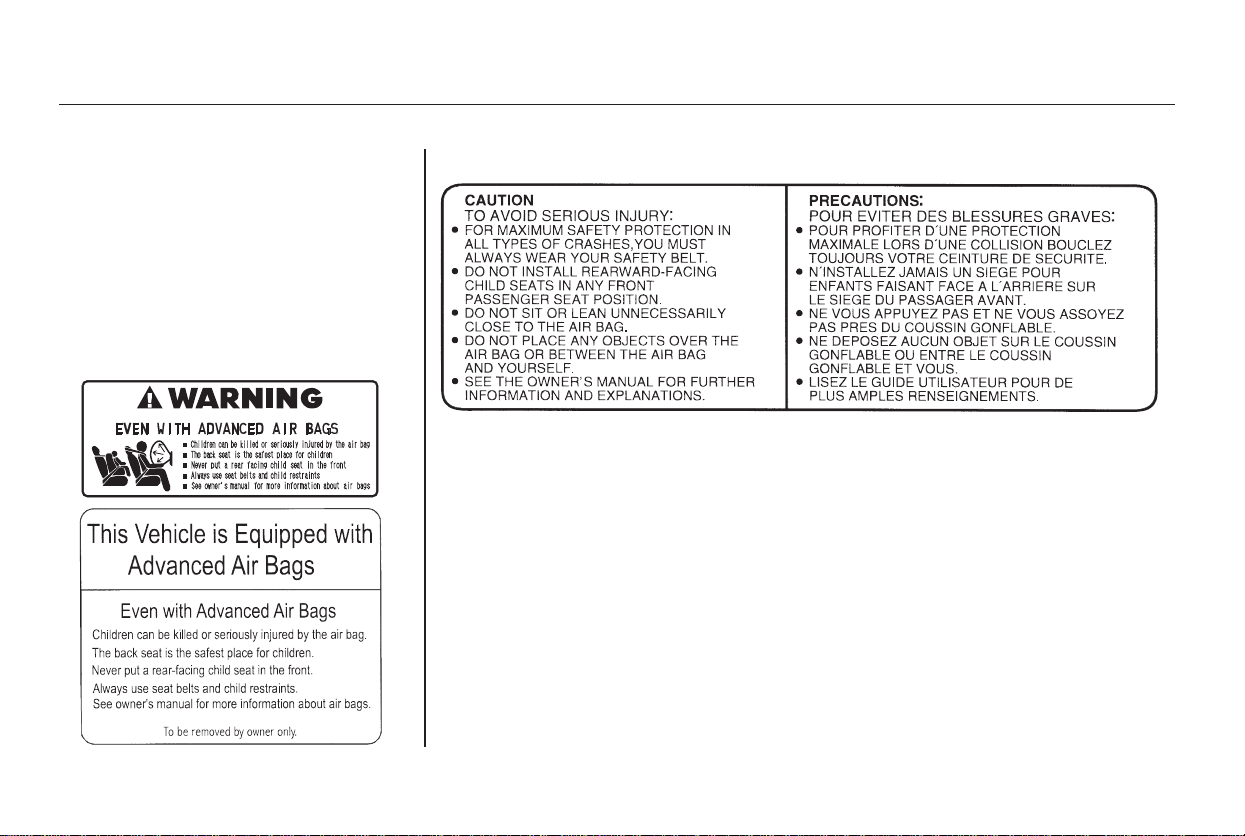
To remind you of the passenger’s
front airbag hazards, and that
children must be properly restrained
in a back seat, your vehicle has
warninglabelsonthedashboard
(U.S. models) and on the driver’s and
front passenger’s visors. Please read
and follow the instructions on these
labels.
Canadian Models
U.S. Models
Protecting Children General Guidelines
38
Main Menu
Table of Contents

−
Your vehicle has two rows of back
seats where children can be properly
restrained. If you ever have to carry
a group of children, and a child must
ride in front:
Many parents say they prefer to put
an infant or small child in the front
passenger seat so they can watch the
child, or because the child requires
attention.
Placing a child in the front seat
exposes the child to hazards in a
frontal collision, and paying close
attention to a child distracts the
driver from the important tasks of
driving, placing both of you at risk.
Place the largest child in the front
seat, provided the child is large
enough to wear the lap/shoulder
belt properly (see page ).
Move the vehicle seat as far to the
rear as possible (see page ).
Have the child sit upright and well
backintheseat(seepage ).
Make sure the seat belt is properly
positioned and secured (see page
).
If a child requires close physical
attention or frequent visual contact,
we strongly recommend that another
adult ride with the child in a back
seat. The back seat is far safer for a
child than the front.
52
13
19
16
If You Must Drive with Several
Children
If a Child Requires Close
Attention
Protecting Children General Guidelines
Driver and Passenger Safety
39
Main Menu
Table of Contents

−
During a crash, the
belt could press deep into the child
and cause serious or fatal injuries.
If they do, they
could be very seriously injured in a
crash.
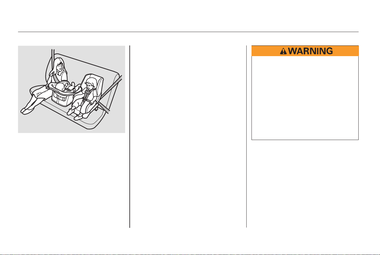
If you are not wearing a
seat belt in crash, you could be
thrown forward and crush the
child against the dashboard or a
seat-back. If you are wearing a
seat belt, the child can be torn
from your arms and be seriously
hurt or killed.
This can prevent children
from accidentally falling out (see
page ).
For example, infants and small
childrenleftinavehicleonahot
day can die from heatstroke. A
child left alone with the key in the
ignition can accidentally set the
vehicle in motion, possibly injuring
themselves or others.
Children
who play in vehicles can
accidentally get trapped inside.
Teach your children not to play in
or around vehicles.
Even very young
children learn how to unlock
vehicle doors, turn on the ignition
switch, and open the tailgate,
which can lead to accidental injury
or death.
Leaving children without
adult supervision is illegal in most
states and Canadian provinces,
and can be very hazardous.
This
will prevent unintended use of the
doors.
138
Never put a seat belt over yourself
and a child.
Never let two children use the
same seat belt.
Neverholdaninfantorchildon
your lap.
Use childproof door locks to
prevent children from opening the
doors.
Lock all doors and tailgate when
your vehicle is not in use.
Keep vehicle keys/remote
transmitters out of the reach of
children.
Do not leave children alone in a
vehicle.
Use the power sliding door main
switch to prevent children from
operating the sliding doors.
Additional Safety Precautions
Protecting Children General Guidelines
40
Main Menu
Table of Contents
An infant must be properly
restrained in a rear-facing, reclining
child seat until the child reaches the
seat maker’s weight or height limit
for the seat and the child is at least
one year old.
Only a rear-facing child seat provides
proper support for a baby’s head,
neck, and back.
Two types of seats may be used: a
seat designed exclusively for infants,
or a convertible seat used in the rear-
facing, reclining mode.
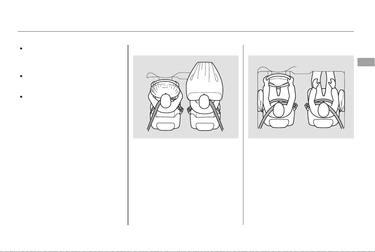
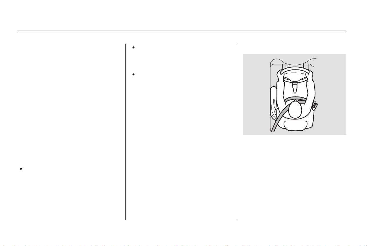
If placed
facing forward, an infant could be
very seriously injured during a
frontal collision.
If the passenger’s front airbag
inflates, it can hit the back of the
child seat with enough force to kill or
seriously injure an infant.
When properly installed, a rear-
facing child seat may prevent the
driver or a front passenger from
moving the seat as far back as
recommended, or from locking the
seat-back in the desired position.
Or, it can interfere with proper
operation of the passenger’s
advanced front airbag system.
A rear-facing child seat can be placed
in any seating position in the back
seat, but not in the front. Never put a
rear-facing child seat in the front
seat.
CONTINUED
Protecting Infants
Child Seat Type
Child Seat Placement
Do not put a rear-facing child seat in
a forward-facing position.
Protecting Infants and Small Children
Driver and Passenger Safety
41
Main Menu
Table of Contents
Of the different seats available, we
recommend those that have a five-
point harness system as shown.
In any situation, we strongly
recommend that you install the child
seat directly behind the front
passenger’s seat, move the seat as
far forward as needed, and leave it
unoccupied. Or, you may wish to get
a smaller rear-facing child seat.
A child who is at least one year old,
and who fits within the child seat
maker’s weight and height limits,
should be restrained in a forward-
facing, upright child seat.
We strongly recommend placing a
forward-facing child seat in a back
seat, not the front.
Even with advanced front airbags,
which can automatically turn the
passenger’s front airbag off (see
page ), a back seat is the safest
place for a small child.
29
Protecting Small Children
Child Seat Type
Child Seat Placement
Protecting Infants and Small Children
42
Placing a rear-facing child seat
in the front seat can result in
serious injury or death during a
collision.
Always place a rear-facing child
seat in the back seat, not the
front.
Main Menu
Table of Contents
When buying a child seat, you need
to choose either a conventional child
seat, or one designed for use with
the Lower Anchors and Tethers for
Children (LATCH) system.
Conventional child seats must be
secured to a vehicle with a seat belt,
whereas LATCH-compatible seats
are secured by attaching the seat to
hardware built into the two second-
row seat and the center seating
position of the third row.
In seating positions and vehicles not
equipped with LATCH, a LATCH-
compatible child seat can be installed
using a seat belt.
We also recommend selecting a
LATCH-compatible seat with a rigid,
rather than a flexible, anchor (see
page ).
Since LATCH-compatible child seats
are easier to install and reduce the
possibility of improper installation,
we recommend selecting this style.
If it is necessary to put a forward-
facing child seat in the front, move
the vehicle seat as far to the rear as
possible, be sure the child seat is
firmly secured to the vehicle, and the
child is properly strapped in the seat.
45
CONTINUED
Selecting a Child Seat
Protecting Infants and Small Children, Selecting a Child Seat
Driver and Passenger Safety
43
Placing a forward-facing child
seat in the front seat can result
in serious injury or death if the
front airbag inflates.
Ifyoumustplaceaforward-
facing child seat in front, move
the vehicle seat as far back as
possible, and properly restrain
the child.
Main Menu
Table of Contents

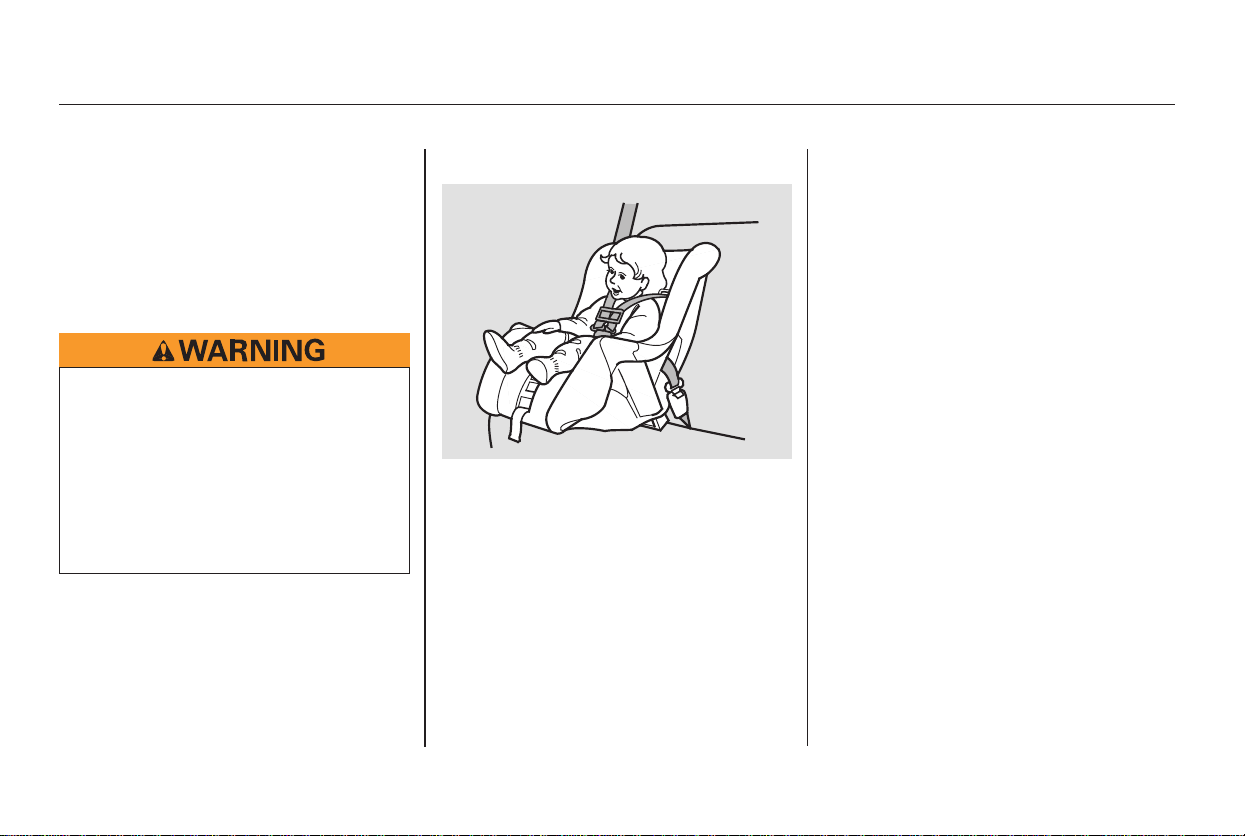
Whatever type of seat you choose, to
provide proper protection, a child
seat should meet three
requirements:
Look for FMVSS
213 or CMVSS 213 on the box.
Rear-facing for infants, forward-
facing for small children.
Before purchasing a conventional
child seat, or using a previously
purchased one, we recommend that
you test the seat in the specific
vehicle seating position, or positions,
where the seat will be used.
After selecting a proper child seat,
and a good place to install the seat,
there are three main steps in
installing the seat:
All child seats must be
secured to the vehicle with the lap
part of a lap/shoulder belt or with
the LATCH (Lower Anchors and
Tethers for Children) system. A
child whose seat is not properly
secured to the vehicle can be
endangered in a crash.
After installing a child
seat, push and pull the seat
forward and from side to side to
verify that it is secure.
A child seat secured with a seat belt
should be installed as firmly as
possible. However, it does not need
to be ‘‘rock solid.’’ Some side-to-side
movement can be expected and
should not reduce the child seat’s
effectiveness.
If the child seat is not secure, try
installing it in a different seating
position, or use a different style of
child seat that can be firmly secured.
Make sure the child is properly
strappedinthechildseat
according to the child seat maker’s
instructions. A child who is not
properly secured in a child seat
can be seriously injured in a crash.
The following pages provide
guidelines on how to properly install
a child seat. A forward-facing child
seat is used in all examples, but the
instructions are the same for rear-
facing child seats.
The child seat should meet U.S. or
Canadian Motor Vehicle Safety
Standard 213.
The child seat should be of the
proper type and size to fit the child.
The child seat should fit the
vehicle seating position (or
positions) where it will be used.
Properly secure the child seat to
the vehicle.
Make sure the child seat is firmly
secured.
Secure the child in the child seat.
1.
2.
3.
1.
2.
3.
Installing a Child Seat
Selecting a Child Seat, Installing a Child Seat
44
Main Menu
Table of Contents
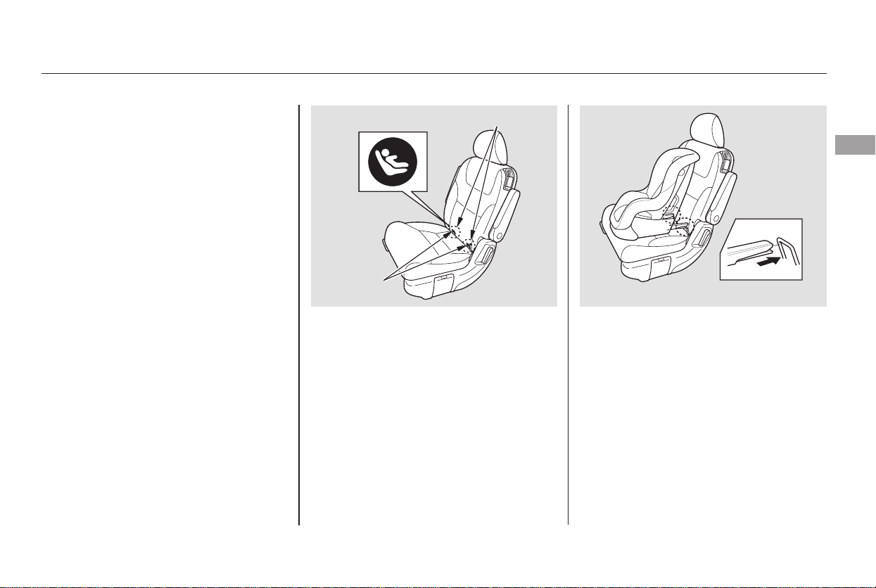
Place the child seat on the vehicle
seat, then attach the seat to the
lower anchors according to the
child seat maker’s instructions.
Your vehicle is equipped with
LATCH (Lower Anchors and
Tethers for Children) in the two
second row seats and the center
seating position of the third row.
The lower anchors are located
between the seat-back and seat
bottom, and are to be used only with
a child seat designed for use with
LATCH.
The location of each lower anchor is
indicated by a small button above the
anchor point.
Some LATCH-compatible seats
have a rigid-type connector as
shown above.
To install a LATCH-compatible child
seat in a second row seat:
Make sure there are no objects
near the anchors that could
prevent a secure connection
between the child seat and the
anchors.
Move the seat belt buckle or
tongue away from the lower
anchors.
1.
2.
3.
CONTINUED
Installing a Child Seat
Installing a Child Seat with
LATCH
Driver and Passenger Safety
45
RIGID TYPE
LOWERANCHORMARKS
LOWER
ANCHORS
Main Menu
Table of Contents
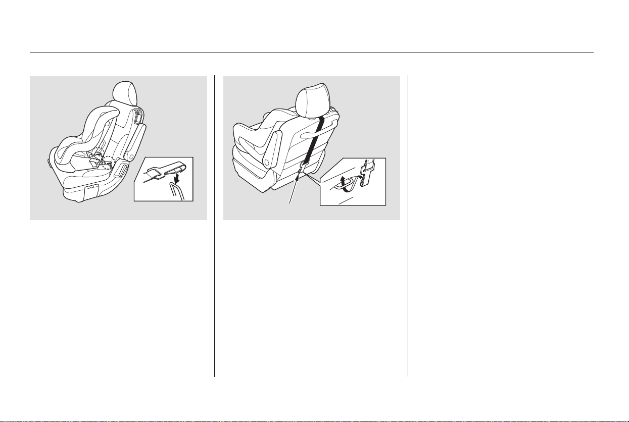
Whatever type you have, follow
the child seat maker’s instructions
for adjusting or tightening the fit.
Other LATCH-compatible seats have
a flexible-type connector as shown
above.
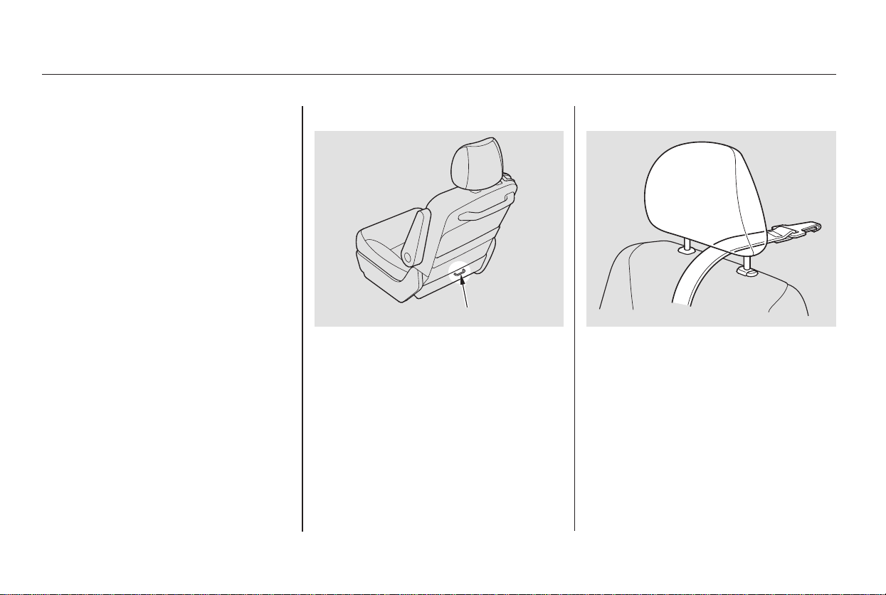
Lift the head restraint (see page
), then route the tether strap
through the legs of the head
restraint, over the seat-back,
making sure the strap is not
twisted.
Attach the tether strap hook to the
tether anchor, then tighten the
strap as instructed by the child
seat maker.
Push and pull the child seat
forward and from side to side to
verify that it is secure.
4.
5.
6.
7.
153
Installing a Child Seat
46
FLEXIBLE TYPE
ANCHOR
Main Menu
Table of Contents
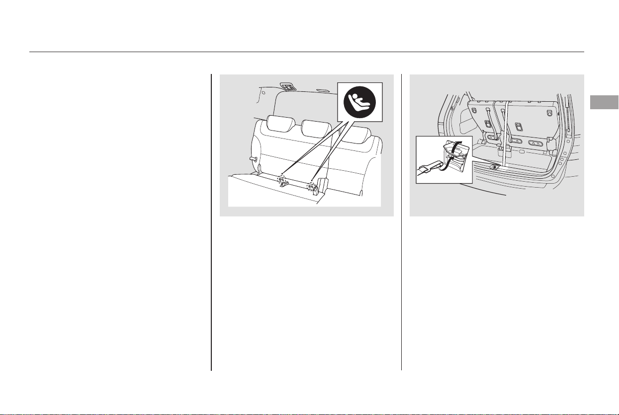
Remove the head restraint, then
route the tether strap over the
seat-back, making sure the strap is
not twisted.
Slide the anchor cover to open it,
then follow steps 6 and 7 of the
second row installation (see page
).
Followsteps1through4ofthe
second row installation (see pages
and ).
To install a LATCH-compatible child
seat in the center seating position of
the third row:
Unlatch the detachable seat belt
anchor and retract the seat belt all
the way into the ceiling. Place the
latch plate and anchor latch in
their holding slots (see page ).
1.
2. 3.
4.
46
45 46
18
Installing a Child Seat
Driver and Passenger Safety
47
Main Menu
Table of Contents
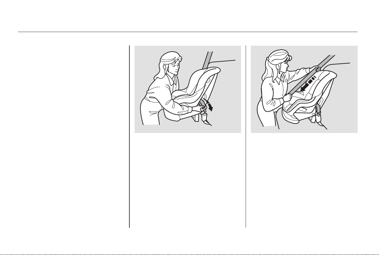
When not using the LATCH system,
all child seats must be secured to the
vehicle with the lap part of a lap/
shoulder belt.
With the child seat in the desired
seating position, route the belt
through the child seat according
to the seat maker’s instructions,
then insert the latch plate into the
buckle.
To activate the lockable retractor,
slowly pull the shoulder part of the
belt all the way out until it stops,
then let the belt feed back into the
retractor.
After the belt has retracted, tug on
it. If the belt is locked, you will not
be able to pull it out. If you can pull
thebeltout,itisnotlocked,and
you will need to repeat these steps.
In addition, the lap/shoulder belts in
all seating positions except the
driver’s have a locking mechanism
that must be activated to secure a
child seat.
If you intend to install a child seat in
the center seating position of the
thirdrow,makesurethedetachable
seat belt anchor is securely latched.
1. 2.
3.
Installing a Child Seat
Installing a Child Seat with a Lap/
Shoulder Belt
48
Main Menu
Table of Contents
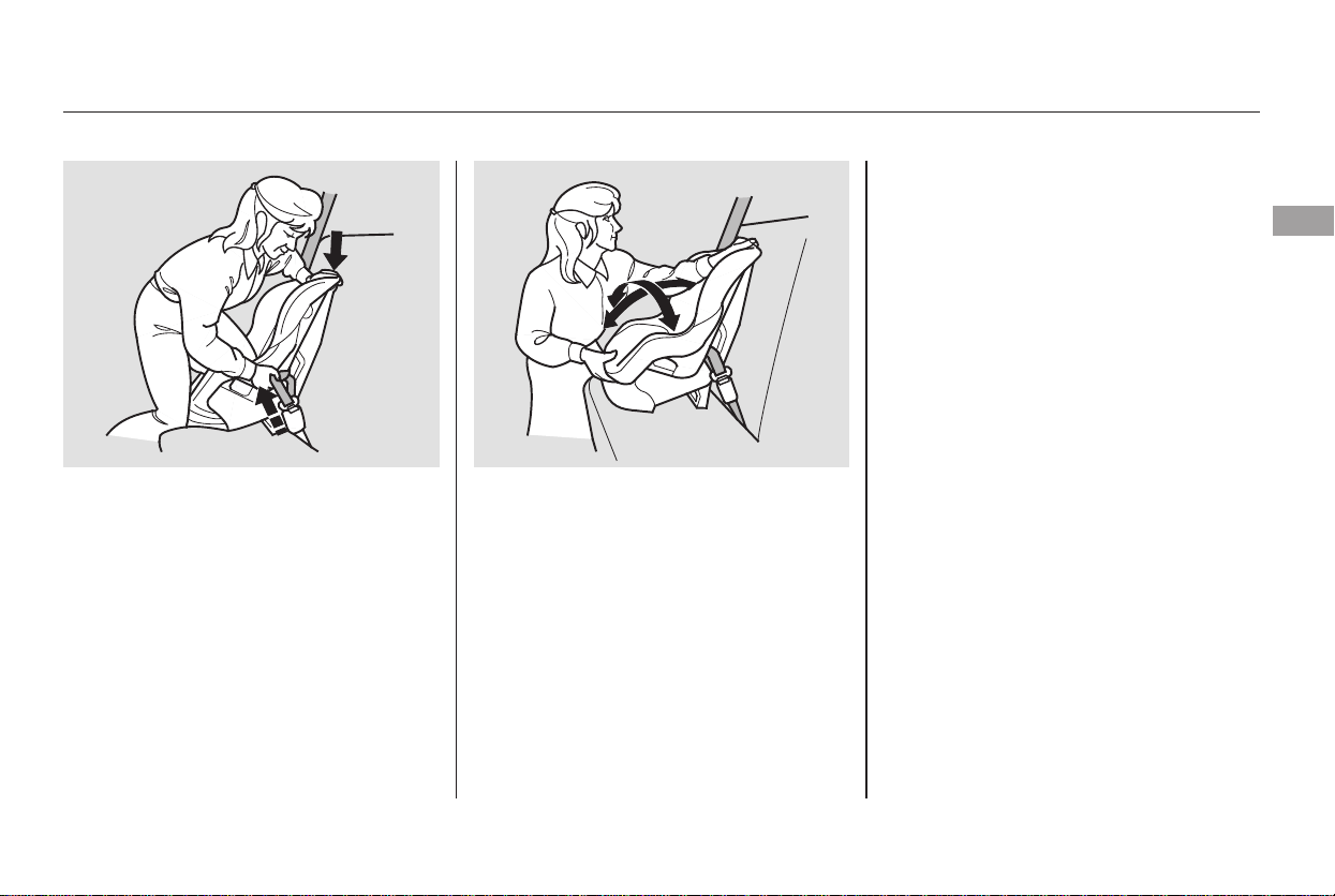
To remove slack, it may help to put
weight on the child seat, or push on
the back of the seat while pulling up
on the belt.
Push and pull the child seat
forward and from side-to-side to
verify that it is firmly secured. If
the child seat is not secure,
unlatch the belt, allow it to retract
fully, then repeat these steps.
To deactivate the locking
mechanism and remove a child seat,
unlatch the buckle, unroute the seat
belt, and let the belt fully retract.
After confirming that the belt is
locked, grab the shoulder part of
the belt near the buckle, and pull
up to remove any slack from the
lap part of the belt. Remember, if
the lap part of the belt is not tight,
the child seat will not be secure.
5.4.
Installing a Child Seat
Driver and Passenger Safety
49
Main Menu
Table of Contents
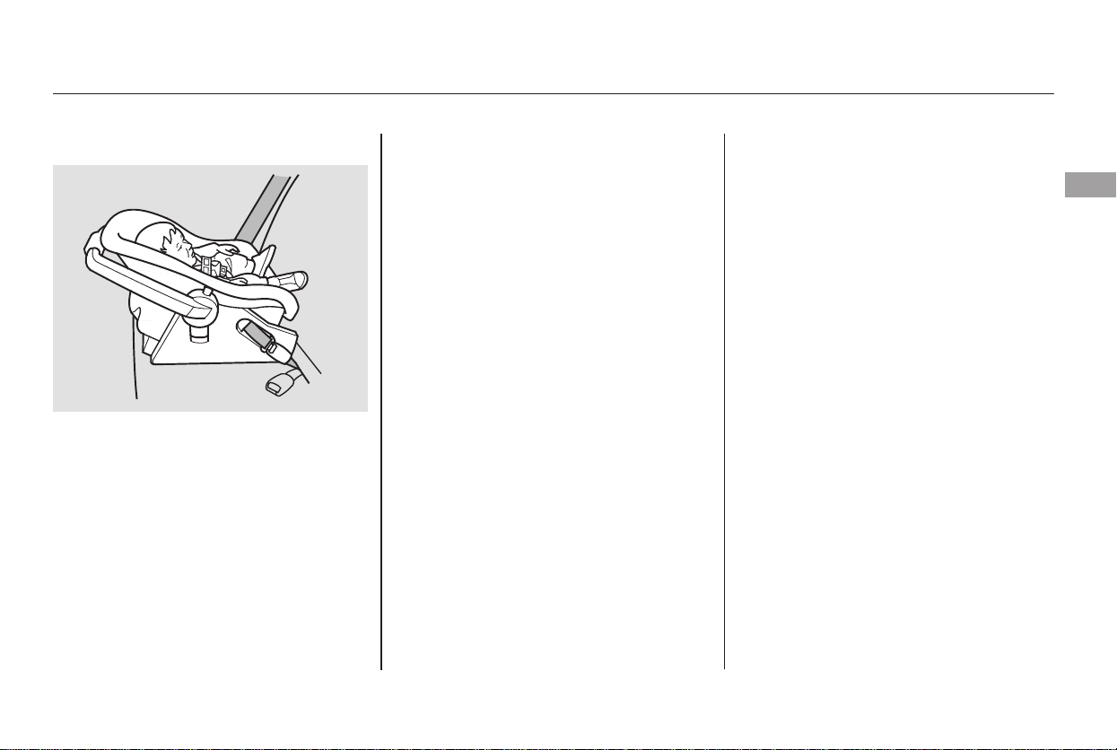
A child seat with a tether can be
installed in any seating position in
the second or the center seating
position of the third row.
Since a tether can provide additional
security, we recommend using a
tether whenever one is required or
available.
Each second row bucket seat has a
tether anchorage point at the bottom
of the seat-back.
After properly securing the child
seat (see page ), lift the head
restraint, then route the tether
strap over the seat-back and
through the head restraint legs.
1.
48
Installing a Child Seat
Installing a Child Seat with a
Tether
Second Row Installation
50
TETHER ANCHORAGE POINT
Main Menu
Table of Contents
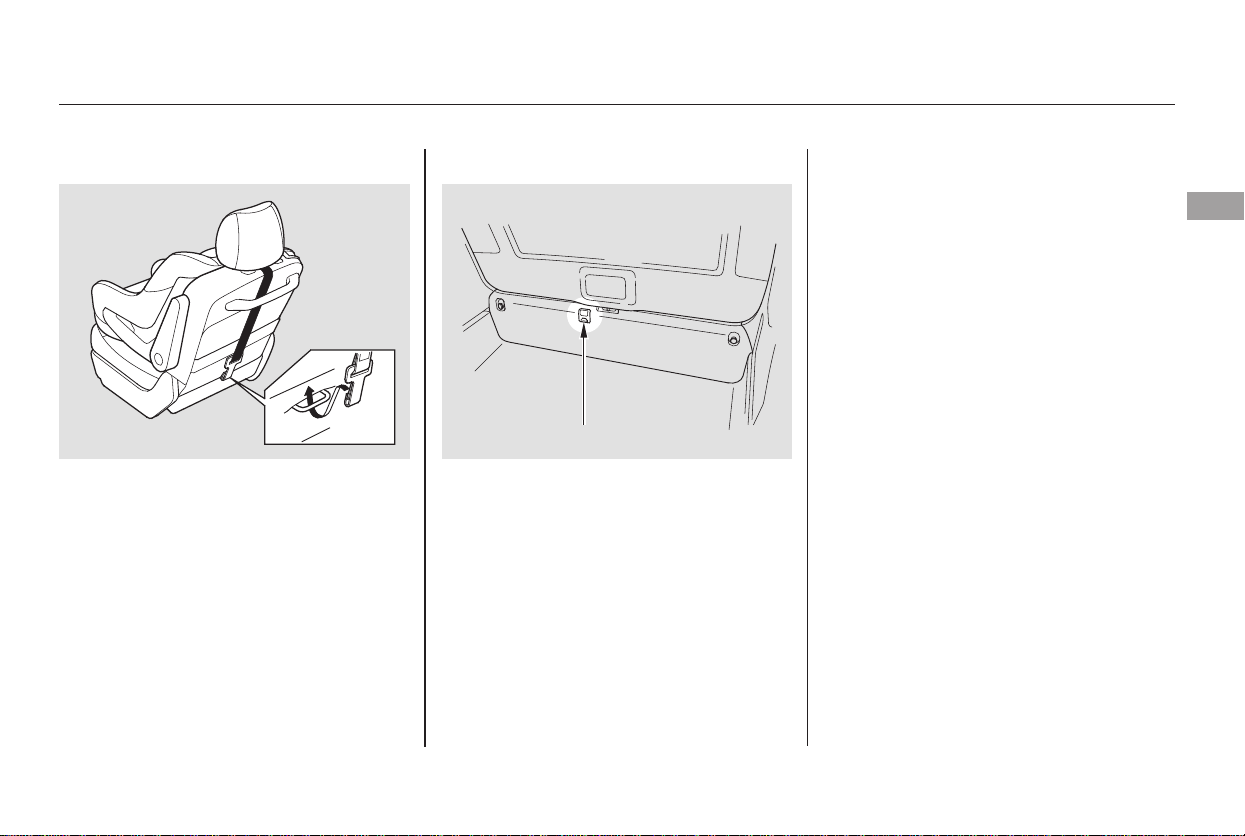
Attach the tether strap hook to the
anchor, making sure the strap is
not twisted.
Tighten the strap according to the
seat maker’s instructions.
The center seating position of the
third row has an anchorage point on
the tailgate sill.
Remove the bead restraint, then
route the tether strap over the
seat-back.
Slide the anchor cover to open it.
When a child reaches the
recommended weight or height limit
for a forward-facing child seat, the
child should sit in a back seat on a
booster seat and wear a lap/shoulder
belt.
The following pages give
instructions on how to check proper
seat belt fit, what kind of booster
seat to use if one is needed, and
important precautions for a child
who must sit in front.
Follow step 2 and 3 of the second
row installation.
2.
1.3.
2.
3.
CONTINUED
Third Row Installation
Protecting Larger Children
Installing a Child Seat, Protecting Larger Children
Driver and Passenger Safety
51
ANCHORAGE POINT
Main Menu
Table of Contents
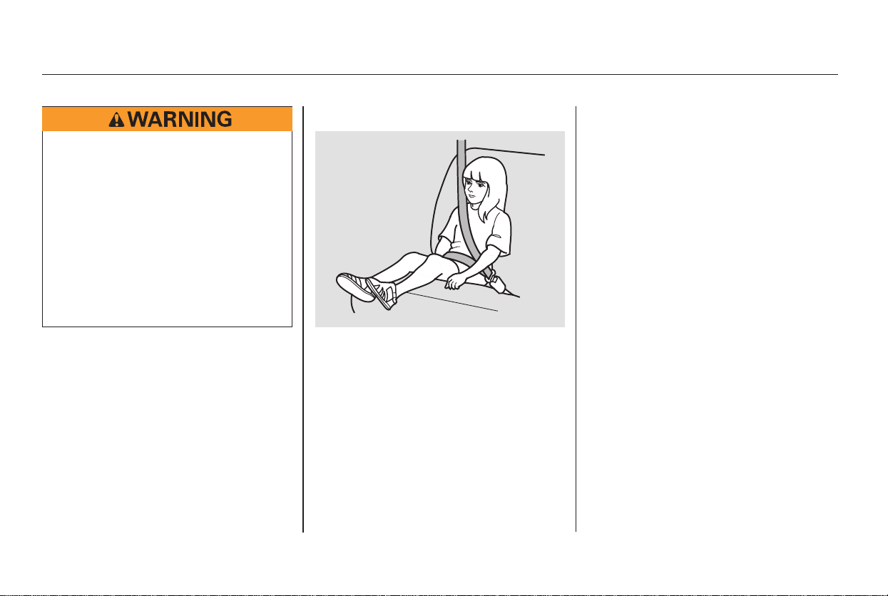
To determine if a lap/shoulder belt
properly fits a child, have the child
put on the seat belt, then ask
yourself:
Does the child sit all the way back
against the seat?
Do the child’s knees bend
comfortably over the edge of the
seat?
Does the shoulder belt cross
between the child’s neck and arm?
Is the lap part of the belt as low as
possible, touching the child’s
thighs?
Will the child be able to stay
seated like this for the whole trip?
If you answer yes to all these
questions, the child is ready to wear
the lap/shoulder belt correctly. If
you answer no to any question, the
child needs to ride on a booster seat.
1.
2.
3.
4.
5.
Protecting Larger Children
Checking Seat Belt Fit
52
Allowing a child age 12 or under
to sit in front can result in injury
or death if the passenger’s front
airbag inflates.
If a child must ride in front,
move the vehicle seat as far
back as possible, use a booster
seat if needed, have the child
sit up properly and wear the
seat belt properly.
Main Menu
Table of Contents
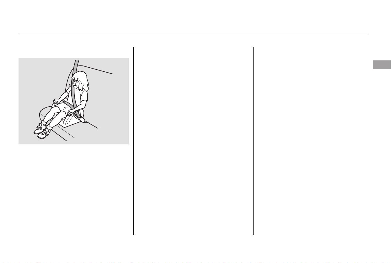
A child who has outgrown a forward-
facing child seat should ride in a
back seat and use a booster seat
until the lap/shoulder belt fits them
properly without the booster.
Some states also require children to
use a booster seat until they reach a
given age or weight (e.g., 6 years or
60lbs).Besuretocheckcurrent
laws in the state or states where you
intend to drive.
If a child who uses a booster seat
must ride in front, move the vehicle
seat as far to the rear as possible,
and be sure the child is wearing the
seat belt properly.
A child may continue using a booster
seat until the tops of their ears are
even with the top of the vehicle’s or
booster’s seat-back. A child of this
height should be tall enough to use
the lap/shoulder belt without a
booster seat.
Booster seats can be high-back or
low-back. Whichever style you select,
make sure the booster meets federal
safety standards (see page ) and
that you follow the booster seat
maker’s instructions.
The National Highway Traffic Safety
Administration and Transport
Canada recommend that all children
age 12 and under be properly
restrained in a back seat.
If the passenger’s airbag inflates in a
moderate to severe frontal collision,
the airbag can cause serious injuries
to a child who is unrestrained,
improperly restrained, sitting too
close to the airbag, or out of position.
A side airbag also poses risks. If any
part of a larger child’s body is in the
path of a deploying side airbag, the
child could receive possibly serious
injuries.
37
Protecting Larger Children
Using a Booster Seat When Can a Larger Child Sit in
Front
Driver and Passenger Safety
53
Main Menu
Table of Contents

If you decide that a child can safely
ride up front, be sure to:
Carefully read the owner’s manual,
and make sure you understand all
seat belt instructions and all safety
information.
Move the vehicle seat to the rear-
most position.
Have the child sit up straight, back
against the seat, and feet on or
near the floor.
Check that the child’s seat belt is
properly and securely positioned.
Supervise the child. Even mature
children sometimes need to be
reminded to fasten the seat belts
or sit properly.
Of course, children vary widely. And
while age may be one indicator of
when a child can safely ride in the
front, there are other important
factors you should consider.
Physically, a child must be large
enough for the lap/shoulder belt to
properly fit (see page ). If the seat
belt does not fit properly, with or
without the child sitting on a booster
seat, the child should not sit in front.
To safely ride in front, a child must
be able to follow the rules, including
sitting properly, and wearing the seat
belt properly throughout a ride.
52
Protecting Larger Children
Physical Size
Maturity
54
Main Menu
Table of Contents

This could result in
serious neck injuries during a crash.
This could cause
very serious injuries during a crash.
It also increases the chance that the
child will slide under the belt in a
crash and be injured.
Devices intended to improve a
child’s comfort or reposition the
shoulder part of a seat belt can make
the belt less effective and increase
the chance of serious injury in a
crash.
Protecting Larger Children
Additional Safety Precautions
Do not let a child wear a seat belt
across the neck.
Do not let a child put the shoulder
part of a seat belt behind the back or
under the arm.
Do not put any accessories on a seat
belt.
Driver and Passenger Safety
55
Main Menu
Table of Contents
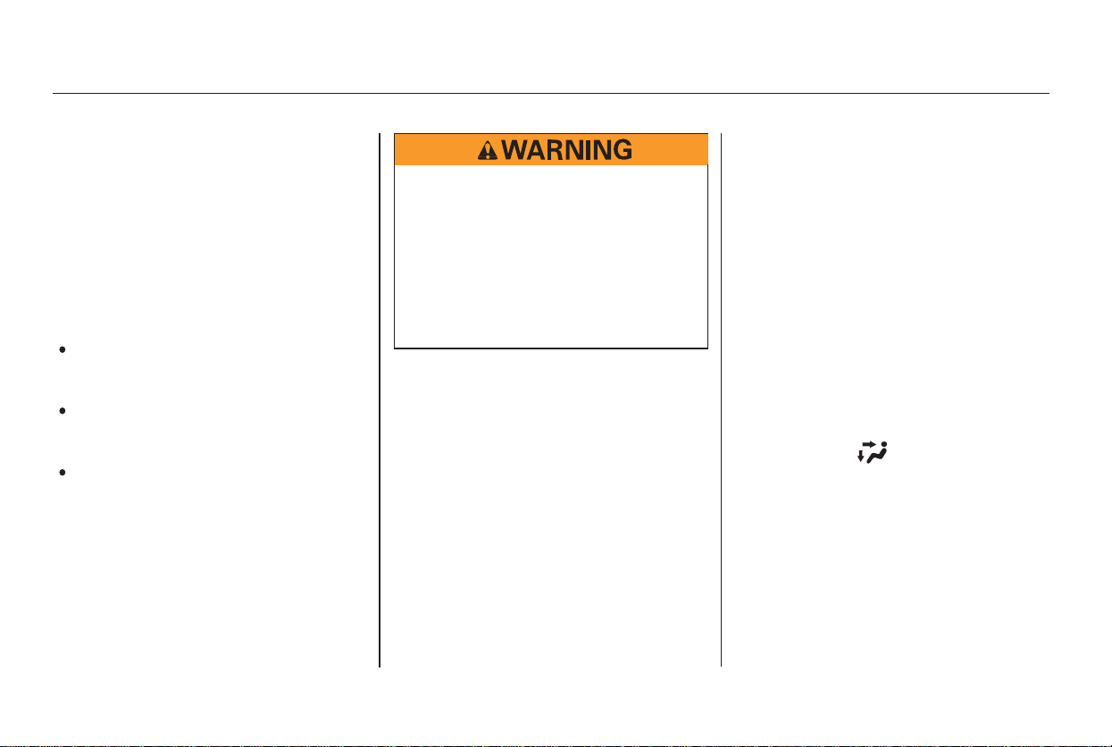
Your vehicle’s exhaust contains
carbon monoxide gas. You should
have no problem with carbon
monoxide entering the vehicle in
normal driving if you maintain your
vehicle properly.
High levels of carbon monoxide can
collect rapidly in enclosed areas,
such as a garage. Do not run the
engine with the garage door closed.
Even with the door open, run the
engine only long enough to move the
vehicle out of the garage.
With the tailgate open, air flow can
pull exhaust gas into your vehicle’s
interior and create a hazardous
condition. If you must drive with the
tailgate open, open all the windows
and set the heating and cooling
system/climate control system as
shown below.Have the exhaust system inspected
for leaks whenever:
If you must sit in your parked vehicle,
even in an unconfined area, adjust
the heating and cooling system/
climate control system as follows:
Select the fresh air mode.
Select the mode.
Turn the fan on high speed.
Set the temperature control to a
comfortable setting.
The vehicle is raised for an oil
change.
You notice a change in the sound
of the exhaust.
The vehicle was in an accident
that may have damaged the
underside.
1.
2.
3.
4.
Carbon Monoxide Hazard
56
Carbon monoxide gas is toxic.
Breathing it can cause
unconsciousness and even kill
you.
Avoid any enclosed areas or
activities that expose you to
carbon monoxide.
Main Menu
Table of Contents
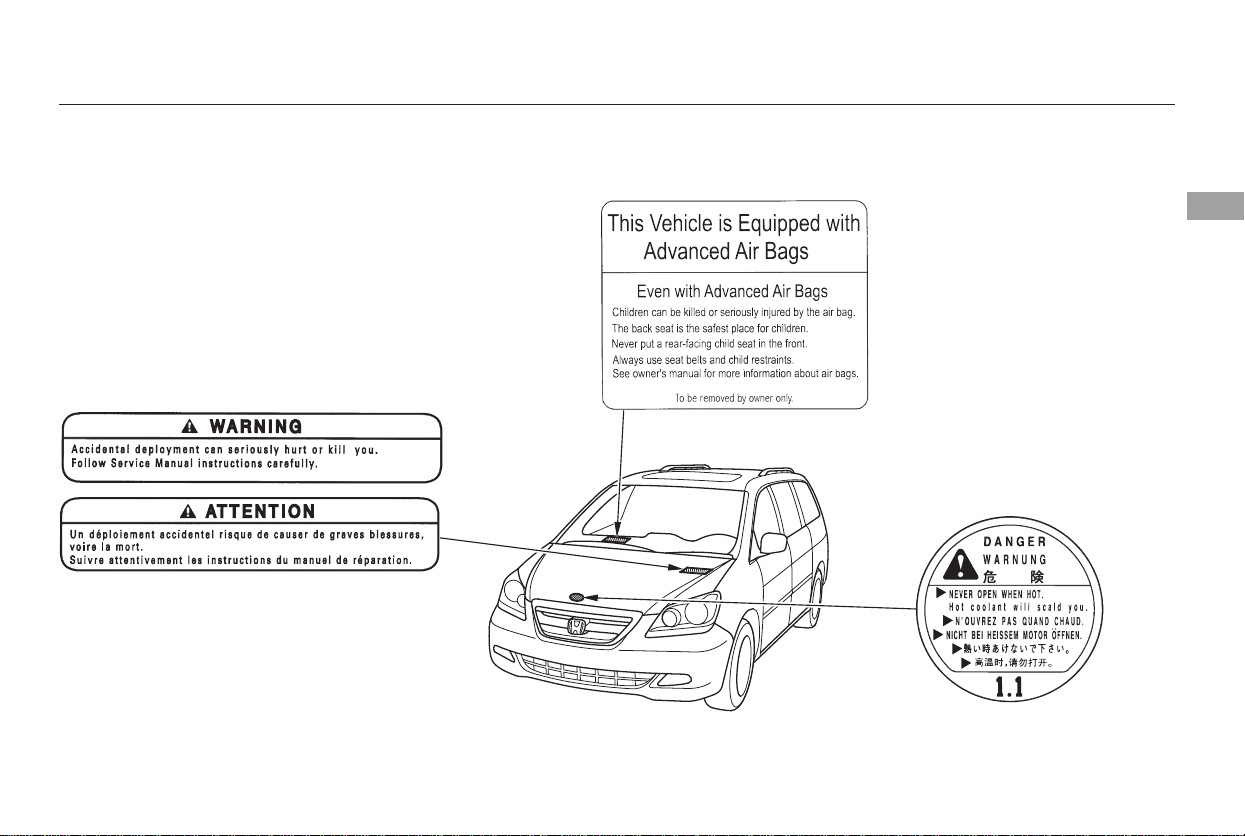
These labels are in the locations
shown. They warn you of potential
hazards that could cause serious
injury. Read these labels carefully.
If a label comes off or becomes hard
to read (except for the U.S.
dashboard label which is removed by
the owner), contact your dealer for a
replacement.
CONTINUED
U.S. models only
Safety Labels
Driver and Passenger Safety
57
RADIATOR CAP
HOOD
DASHBOARD
Main Menu
Table of Contents
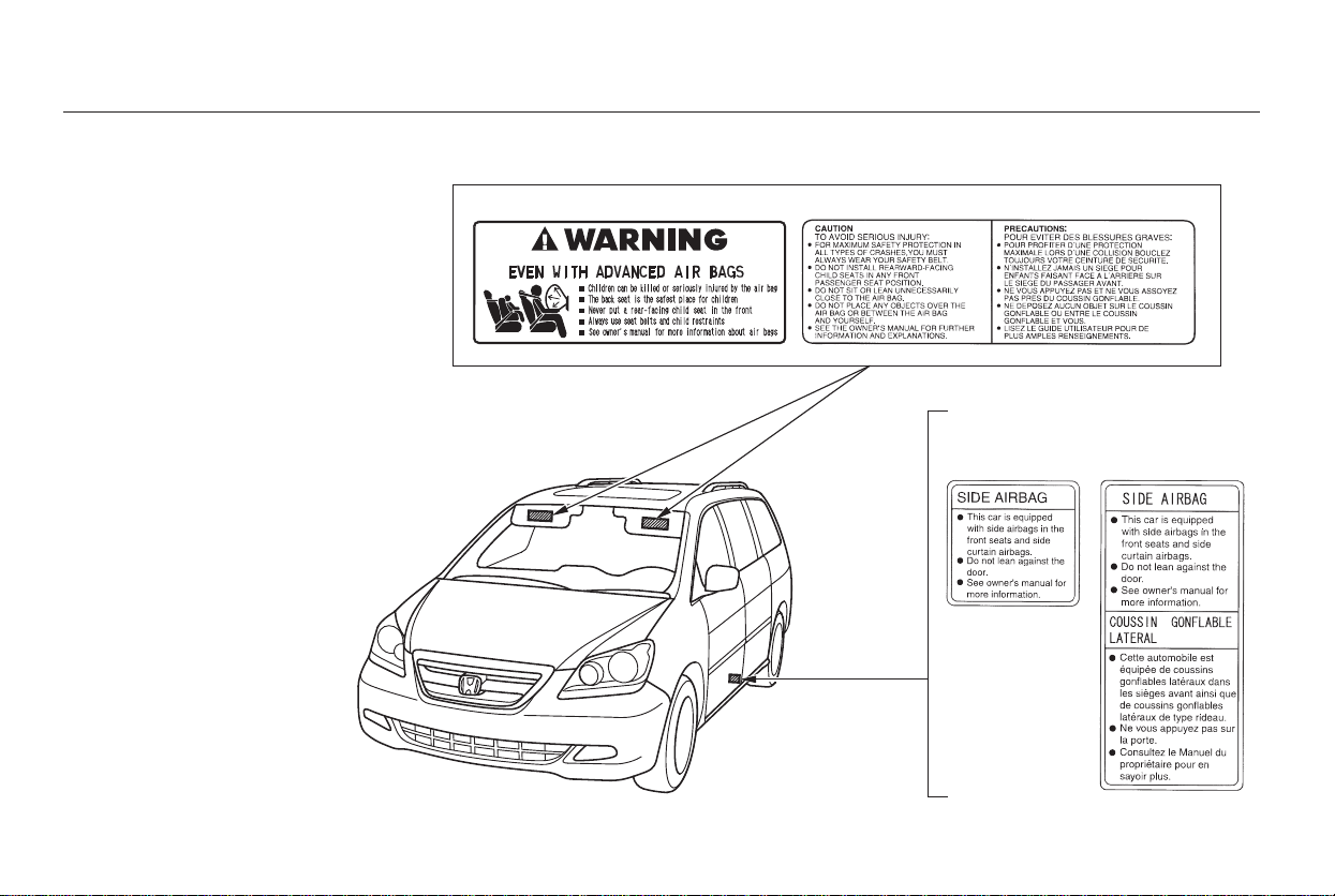
U.S. models Canadian models
Canadian modelsU.S. models
Safety Labels
58
SUN VISOR
DOORJAMB
Main Menu
Table of Contents

This section gives information about
the controls and displays that
contribute to the daily operation of
your vehicle. All the essential
controls are within easy reach.
...........................Control Locations . 60
............................Instrument Panel . 61
..........Instrument Panel Indicators . 63
.............................................Gauges . 71
.............Multi-Information Display . 74
Controls Near the Steering
.........................................Wheel . 120
Windshield Wipers and
.....................................Washers . 121
Rear Window Wiper and
.......................................Washer . 122
.........Turn Signal and Headlights . 122
......Instrument Panel Brightness . 125
...............Hazard Warning Button . 126
...............Rear Window Defogger . 126
........Steering Wheel Adjustment . 127
.............................Keys and Locks . 128
......................Immobilizer System . 129
..............................Ignition Switch . 130
.....................Remote Transmitter . 131
....................................Door Locks . 137
....................Power Door Locks . 137
............Childproof Door Locks . 138
......................................Tailgate . 138
..........................Power Tailgate . 139
.................................Sliding Doors . 142
...............................................Seats . 148
..................................Seat Heaters . 160
Driver’s Seat Position Memory
........................................System . 161
............................Power Windows . 163
.......................................Moonroof . 166
...........................................Mirrors . 167
...............................Parking Brake . 169
.Adjustable Driver’s Foot Pedals . 169
.........Interior Convenience Items . 170
..........Retractable Center Tray . 171
.....................Beverage Holders . 171
................Integrated Sunshade . 173
....................Sunglasses Holder . 174
................Conversation Mirror . 174
...................................Sun Visor . 175
............................Vanity Mirror . 175
...................Rear Compartment . 175
Removable Second Row
..................................Console . 176
...............In-Floor Storage Area . 177
......................Lower Glove Box . 180
......................Upper Glove Box . 180
...........................Center Pocket . 181
........Accessory Power Sockets . 182
.......................AC Power Outlet . 182
...............................Interior Lights . 183
Instruments and Controls
Instruments and Controls
59
Main Menu

Control Locations
60
AUDIO SYSTEM/
REAR ENTERTAINMENT
SYSTEM
PARKING BRAKE
PEDAL
FUEL FILL
DOOR RELEASE
HOOD RELEASE
HANDLE
POWER WINDOW
SWITCHES
POWER
DOOR LOCK
SWITCHES
INSTRUMENT PANEL INDICATORS SHIFT LEVER
MIRROR
CONTROLS
ACCESSORY POWER
SOCKETS
(P.61, 62)
GAUGES
(P.71)
(P.137)
(P.279)
(P.280)
(P.182)
(P.171)
(P.199, 230)
(P.180)
(P.188)
HEATING AND COOLING SYSTEM/
CLIMATE CONTROL SYSTEM
(P.294)
CENTER TRAY
(P.168)
(P.163)
(P.169)
SEAT HEATER
SWITCHES
(P.160)
GLOVE BOXES
Main Menu
Table of Contents
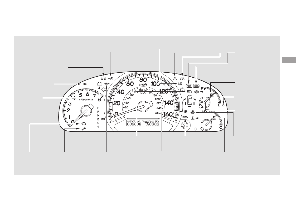
*
*
*
The U.S. instrument panel is shown. Differences for the Canadian models are noted in the text.
Instrument Panel
Instruments and Controls
61
SUPPLEMENTAL
RESTRAINT SYSTEM
INDICATOR
HIGH BEAM
INDICATOR
LOW OIL PRESSURE
INDICATOR
IMMOBILIZER
SYSTEM
INDICATOR
POWER SLIDING
DOOR INDICATOR
ANTI-LOCK BRAKE
SYSTEM INDICATOR
LOW FUEL
INDICATOR
DOOR AND
TAILGATE OPEN
INDICATOR
PARKING BRAKE AND
BRAKE SYSTEM
INDICATOR
SEAT BELT
REMINDER
INDICATOR
CHARGING
SYSTEM
INDICATOR
CRUISE CONTROL
MAIN INDICATOR
CRUISE CONTROL
INDICATOR
LIGHTS-ON INDICATOR
SIDE AIRBAG OFF
INDICATOR
(LX and EX models)
VSA ACTIVATION
INDICATOR
VEHICLE STABILITY ASSIST
SYSTEM INDICATOR
FUEL ECONOMY
INDICATOR
MALFUNCTION
INDICATOR
LAMP
(P.67)
(P.67)
(P.66)
(P.70)
(P.63)
(P.70)
(P.63)
(P.64)
(P.69)
(P.63)
(P.64)
(P.64)
(P.67)
(P.68)
(P.69)
(P.69)
(P.65)
(P.65)
(P.65)
(P.372)
MAINTENANCE
MINDER
INDICATOR
Main Menu
Table of Contents
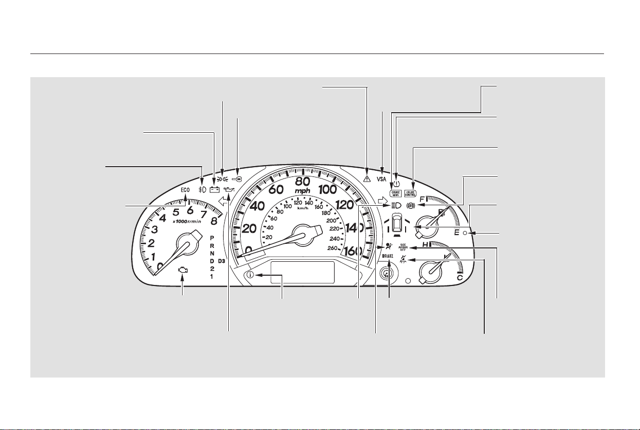
*
*
*
The U.S. instrument panel is shown. Differences for the Canadian models are noted in the text.
Instrument Panel
62
SEAT BELT REMINDER
INDICATOR
CRUISE CONTROL
INDICATOR
LOW TIRE PRESSURE
INDICATOR
FOG LIGHT
INDICATOR
CHARGING SYSTEM
INDICATOR
SUPPLEMENTAL
RESTRAINT SYSTEM
INDICATOR
CRUISE CONTROL
MAIN INDICATOR
PARKING BRAKE AND
BRAKE SYSTEM
INDICATOR
IMMOBILIZER
SYSTEM
INDICATOR
LIGHTS-ON
INDICATOR
LOW OIL
PRESSURE
INDICATOR
HIGH BEAM
INDICATOR
LOW FUEL
INDICATOR
DOOR AND TAILGATE
OPEN INDICATOR
VSA
ACTIVATION
INDICATOR
(Touring models)
FUEL ECONOMY
INDICATOR
VEHICLE STABILITY
ASSIST SYSTEM
INDICATOR
ANTI-LOCK BRAKE
SYSTEM INDICATOR
SIDE AIRBAG OFF
INDICATOR
MALFUNCTION
INDICATOR LAMP
SYSTEM
MESSAGE
INDICATOR
(P.66)
(P.63)
(P.69)
(P.70)
(P.372)
(P.63)
(P.70)
(P.69)
(P.64)
(P.64)
(P.64)
(P.63)
(P.68)
(P.67)
(P.65)
(P.65)
(P.69)
(P.66)
(P.69)
(P.65)
(P.67)
Main Menu
Table of Contents
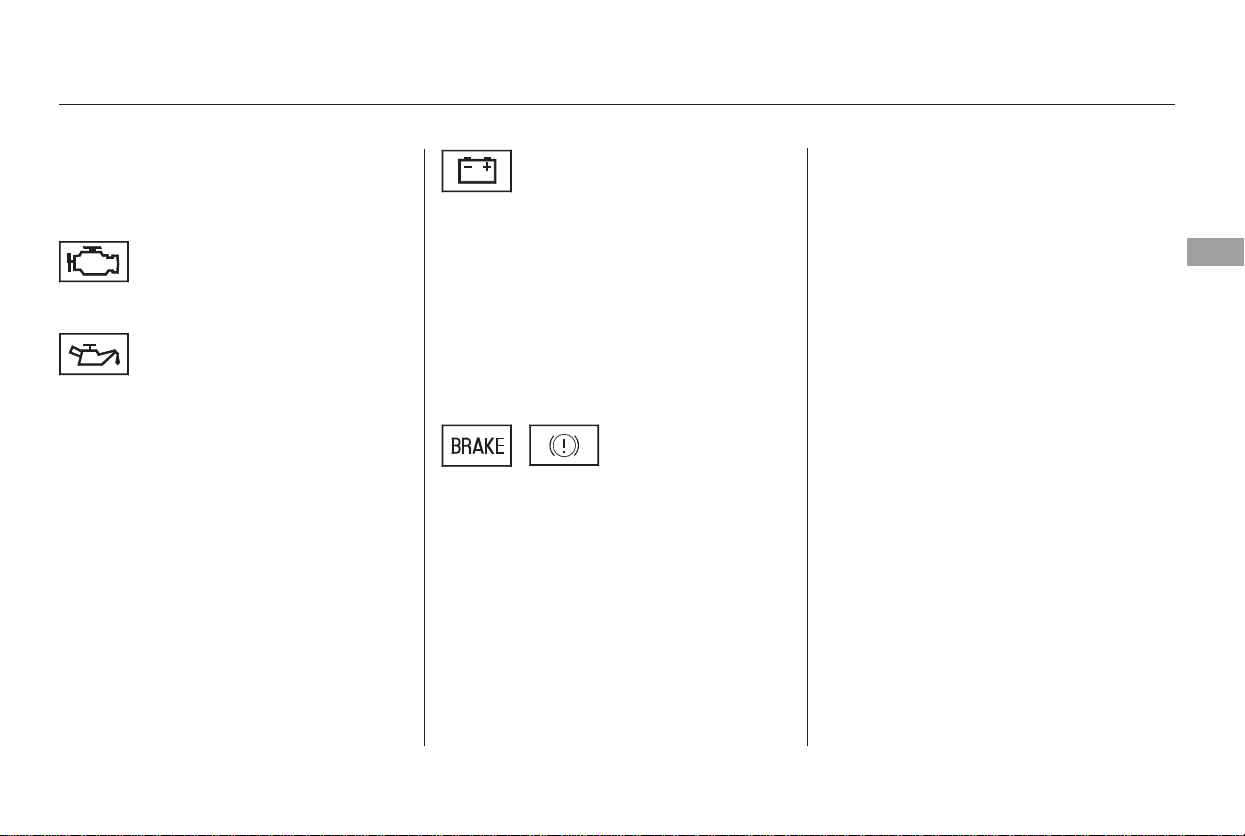
The instrument panel has many
indicators to give you important
information about your vehicle.
See page .
If this indicator comes on when the
engine is running, the battery is not
being charged. For more information,
see page .
On the Touring model, you will also
see a ‘‘CHECK CHARGING
SYSTEM’’ message in the multi-
information display.
On the Touring model, you will also
see a ‘‘CHECK ENGINE OIL
LEVEL’’ message in the multi-
information display.
The engine can be severely damaged
if this indicator flashes or stays on
when the engine is running. For
more information, see page .
This indicator has two functions:
Itcomesonwhenyouturnthe
ignition switch to ON (II). It is a
reminder to check the parking
brake. Driving with the parking
brake not fully released can
damage the brakes and tires.
If it stays on after you fully release
the parking brake while the engine
is running, or if it comes on while
driving, there could be a problem
with the brake system. For more
information, see page .
If you drive without releasing the
parking brake, a chime will sound.
On the Touring model, you will also
see a ‘‘RELEASE PARKING
BRAKE’’ message in the multi-
information display.
1.
2.
371
371
372
373
Malfunction Indicator
Lamp
Charging System
Indicator
Low Oil Pressure
Indicator
Parking Brake and Brake System
Indicator
Instrument Panel Indicators
Instruments and Controls
63
U.S. Canada
Main Menu
Table of Contents
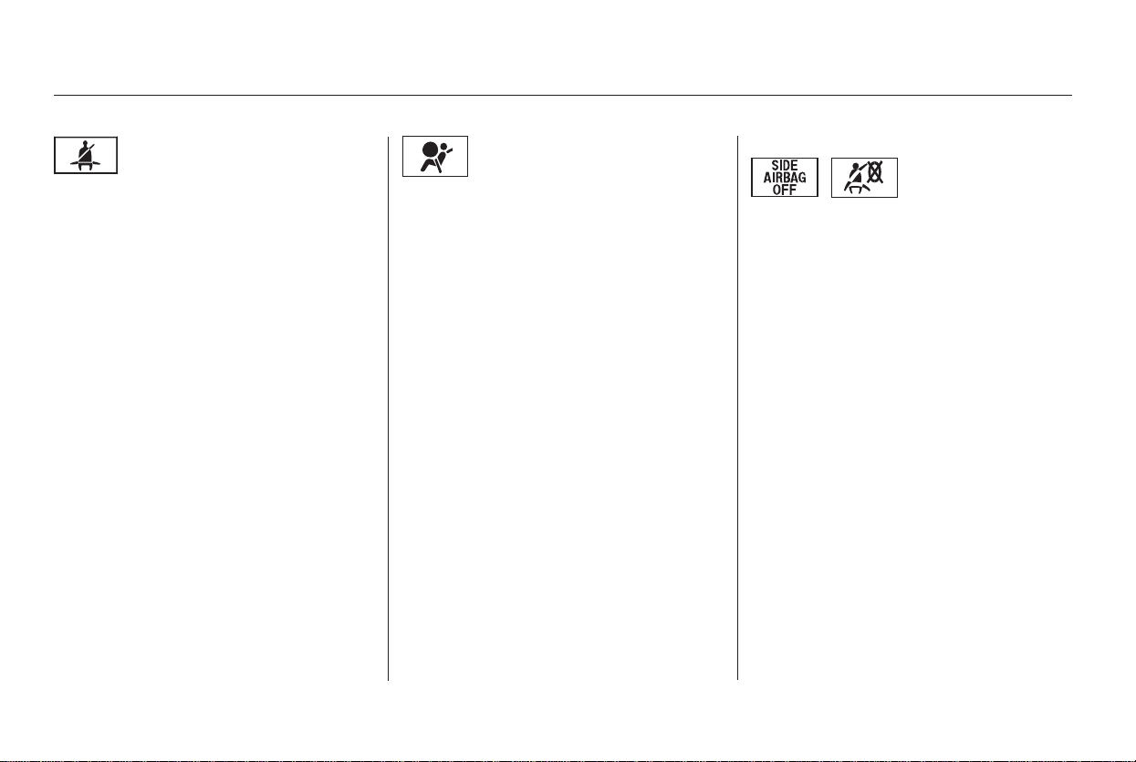
This indicator comes on when you
turn the ignition switch to ON (II). If
it comes on at any other time, it
indicates that the passenger’s side
airbag has automatically shut off.
For more information, see page .
On the Touring model, you will also
see a ‘‘PASSENGER SIDE AIRBAG
OFF’’ message in the multi-
information display.
On the Touring model, you will also
see a ‘‘CHECK AIRBAG SYSTEM’’
message in the multi-information
display.
This indicator comes on briefly when
you turn the ignition switch to ON
(II). If it comes on at any other time,
it indicates a potential problem with
your front airbags. This indicator will
also alert you to a potential problem
with your side airbags, passenger’s
side airbag automatic cutoff system,
side curtain airbags, automatic seat
belt tensioners, driver’s seat position
sensor, or the front passenger’s
weight sensors. For more
information, see page .
This indicator comes on when you
turn the ignition switch to ON (II). It
reminds you and your passengers to
fasten your seat belts. A beeper also
sounds if you have not fastened your
seat belt.
If you turn the ignition switch to ON
(II) before fastening your belt, the
beeper sounds and the indicator
flashes. If you do not fasten your
seat belt before the beeper stops, the
indicator stops flashing but remains
on.
If you continue driving without
fastening your seat belt, the beeper
sounds and the indicator flashes
again at regular intervals. On the
Touring model, you will also see a
‘‘FASTEN SEAT BELT’’ message in
the multi-information display.
32
33
Instrument Panel Indicators
Side Airbag Off
Indicator
Supplemental Restraint
System Indicator
Seat Belt Reminder
Indicator
64
U.S. Canada
Main Menu
Table of Contents
CONTINUED
This indicator has three functions:
It comes on as a reminder that you
have turned off the vehicle
stability assist (VSA) system.
It flashes when VSA is active (see
page ).
On the Touring model, you will
also see a ‘‘CHECK VSA
SYSTEM’’ message in the multi-
information display.
This indicator normally comes on for
a few seconds when you turn the
ignition switch to ON (II).
On the Touring model, you will also
see a ‘‘CHECK VSA SYSTEM’’
message in the multi-information
display.
For more information, see page .
Ifitcomesonandstaysonatany
other time or it does not come on
when you turn the ignition switch to
ON (II), there is a problem with the
VSA system. Take your vehicle to a
dealer to have it checked. Without
VSA, your vehicle still has normal
driving ability, but will not have VSA
traction and stability enhancement.
This indicator normally comes on for
a few seconds when you turn the
ignition switch to ON (II). See page
for more information.
It comes on along with the VSA
system indicator if there is a
problem with the VSA system.
This indicator normally comes on for
a few seconds when you turn the
ignition switch to ON (II), and when
the ignition switch is turned to
START (III). If it comes on at any
other time, there is a problem in the
ABS; have your vehicle checked at a
dealer. With the ABS indicator on,
your vehicle still has normal braking
ability but no anti-lock braking. For
more information, see page .
On the Touring model, you will also
see a ‘‘CHECK ABS SYSTEM’’
message in the multi-information
display.
1.
2.
3.
301
301
301
300
Instrument Panel Indicators
Vehicle Stability Assist
(VSA) System Indicator
VSA Activation IndicatorAnti-lock Brake System
(ABS) Indicator
Instruments and Controls
65
Main Menu
Table of Contents
This indicator normally comes on for
a few seconds when you turn the
ignition switch to ON (II).
If it comes on while driving, it means
that one or more of your vehicle’s
tires are extremely low on pressure.
You will also see a ‘‘LOW TIRE
PRESSURE’’ message on the multi-
information display. The multi-
information display will show you
which tire has lost the pressure and
how much pressure it has lost (see
page ).
If this happens, pull to the side of the
road when it is safe, check which tire
has lost pressure on the multi-
information display, and determine
the cause. If it is because of a flat tire,
have the flat tire repaired as soon as
possible. If two or more tires are
underinflated, call a professional
towing service (see page ). For
more information, see page .
Your vehicle has Michelin PAX tires.
Repair or replacement of PAX tires
must be done by a Honda dealer or
an authorized Michelin PAX system
dealer. For more information, see
page .
This indicator reminds you that the
exterior lights are on. It comes on
when the light switch is in either the
or position. If you turn the
ignition switch to ACCESSORY (I)
or LOCK (0) without turning off the
light switch, this indicator will
remain on. A reminder chime will
also sound when you open the driver’s
door.
On the Touring model, this indicator
also comes on when the light switch
is in AUTO and the lights turn on
automatically.
303
303
356
381
On U.S. Touring model only On EX and Touring models
Instrument Panel Indicators
Low Tire Pressure
Indicator
Lights On Indicator
66
Main Menu
Table of Contents
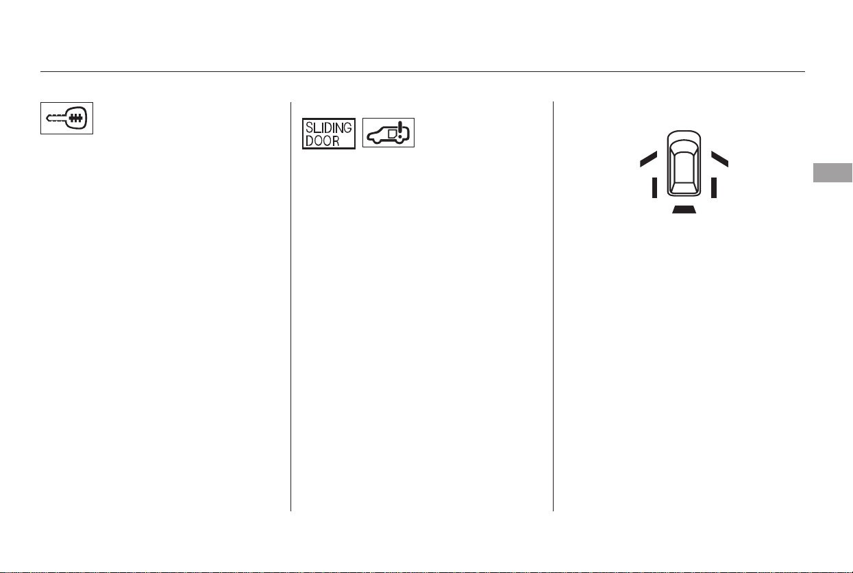
This indicator comes on for a few
seconds when you turn the ignition
switch to ON (II). It will go off if you
have inserted a properly-coded
ignition key. If it is not a properly-
coded key, the indicator will blink
and the engine will not start (see
page ).
This indicator also blinks several
times when you turn the ignition
switch from ON (II) to ACCESSORY
(I) or LOCK (0).
The appropriate light comes on in
this display if the tailgate or any door
is not closed tightly.
All the lights in the monitor come on
for a few seconds when you turn the
ignition switch to ON (II).
On the Touring model, you will also
see a ‘‘CHECK LEFT SLIDING
DOOR’’ or ‘‘CHECK RIGHT
SLIDING DOOR’’ message in the
multi-information display.
This indicator comes on for a few
seconds when you turn the ignition
switch to ON (II). If it comes on at
any other time, there is a problem in
the power sliding door system. With
this indicator on, move the main
switch on the dashboard to the OFF
position, and have the system
checked by your dealer as soon as
possible. You can still open or close
each sliding door manually. For
more information on the power
sliding doors, see page .
129
142
On EX model only
Instrument Panel Indicators
Immobilizer System
Indicator
Door and Tailgate Open Monitor
Power Sliding
Door Indicator
Instruments and Controls
67
U.S.
Canada
Main Menu
Table of Contents
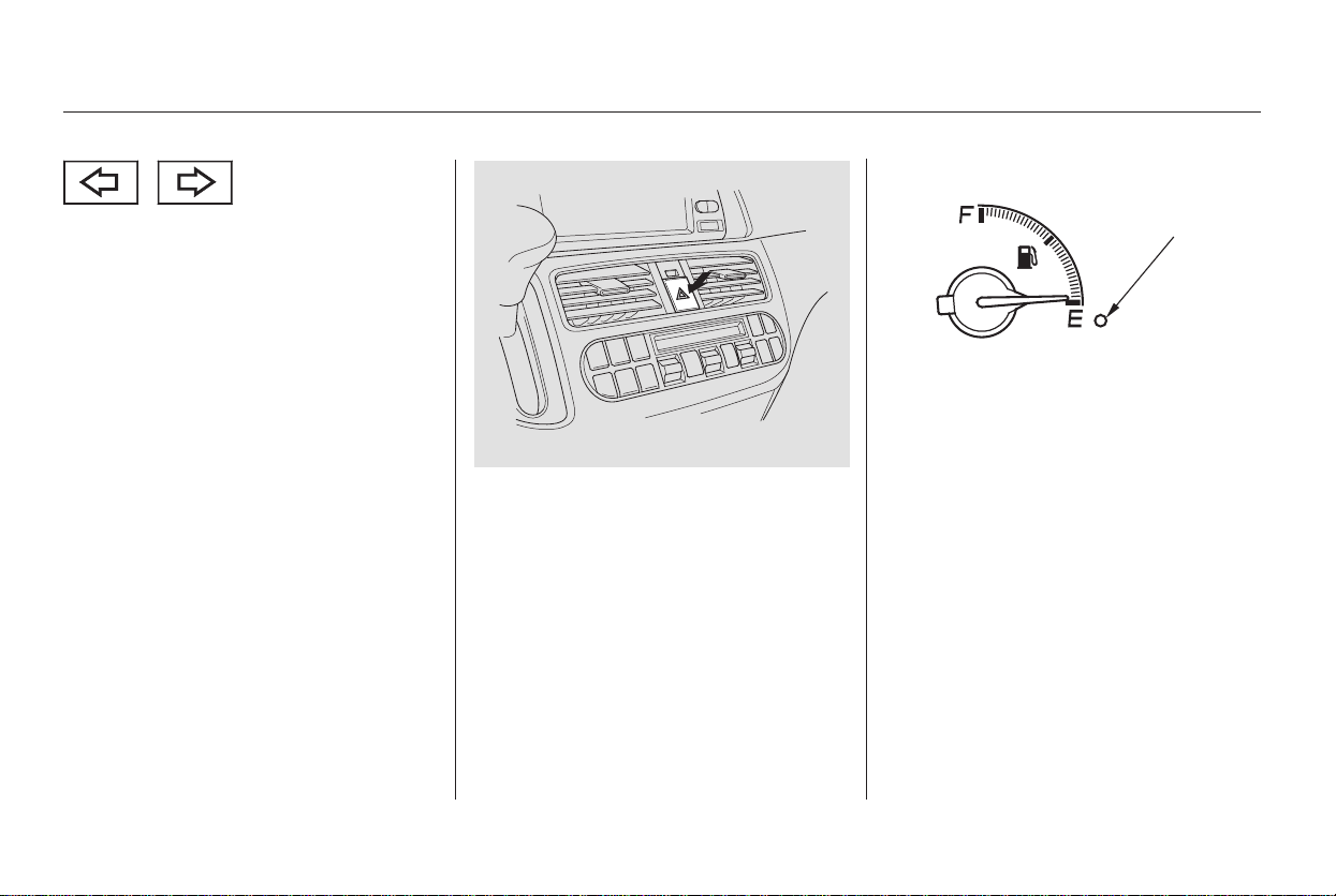
The left or right turn signal indicator
blinks when you signal a lane change
or turn. If the indicators do not blink
or blink rapidly, it usually means one
of the turn signal bulbs is burned out
(see page ). Replace the bulb as
soon as possible, since other drivers
cannot see that you are signaling.
This indicator comes on as a
reminder that you must refuel soon.
On the Touring model, you will also
see a ‘‘FUEL LOW’’ message in the
multi-information display.When you press the hazard warning
button, both turn signal indicators
and all turn signals on the outside of
the vehicle flash.
338
Instrument Panel Indicators
Turn Signal and
Hazard Warning
Indicators
Low Fuel Indicator
68
LOW FUEL
INDICATOR
Main Menu
Table of Contents
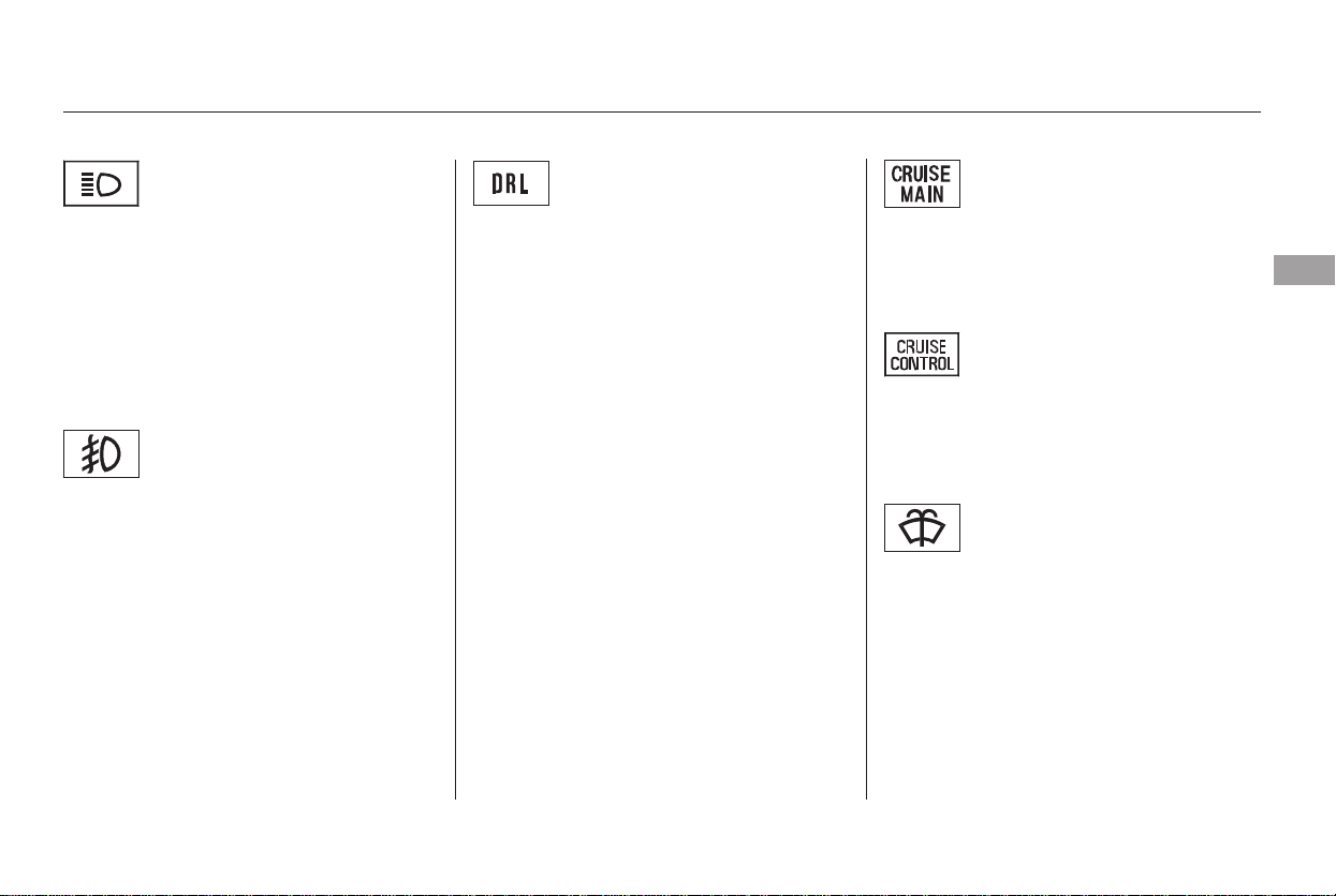
This indicator comes on when you
set the cruise control. See page
for information on operating the
cruise control.
This indicator comes on when the
washer fluid level is low. Add washer
fluidwhenyouseethisindicator
comes on (see page ).
On the Touring model, you will also
see a ‘‘WASHER FLUID LOW’’
message in the multi-information
display.
This indicator comes on with the
high beam headlights. For more
information, see page .
This indicator comes on when you
turn the ignition switch to ON (II)
with the headlight switch off and the
parking brake set. It should go off if
youturnontheheadlightsorrelease
the parking brake. If it comes on at
any other time, it means there is a
problem with the DRL. There may
also be a problem with the high
beam headlights.
On the Touring model, you will also
see a ‘‘CHECK DRL SYSTEM’’ in
the multi-information display.
This indicator comes on when you
turn on the cruise control system by
pressing the master button (see page
).
On Canadian models, this indicator
comes on with reduced brightness
when the daytime running lights
(DRL) are on (see page ).
This indicator comes on when you
turn on the fog lights. See page
for information on fog light
operation.
333
264
123
123
125
264
Canadian models only
Canadian models only
Touring model only
Instrument Panel Indicators
Cruise Control Indicator
Washer Level Indicator
Cruise Main IndicatorHigh Beam Indicator ‘‘Daytime Running
Lights’’ Indicator
Fog Light Indicator
Instruments and Controls
69
Main Menu
Table of Contents
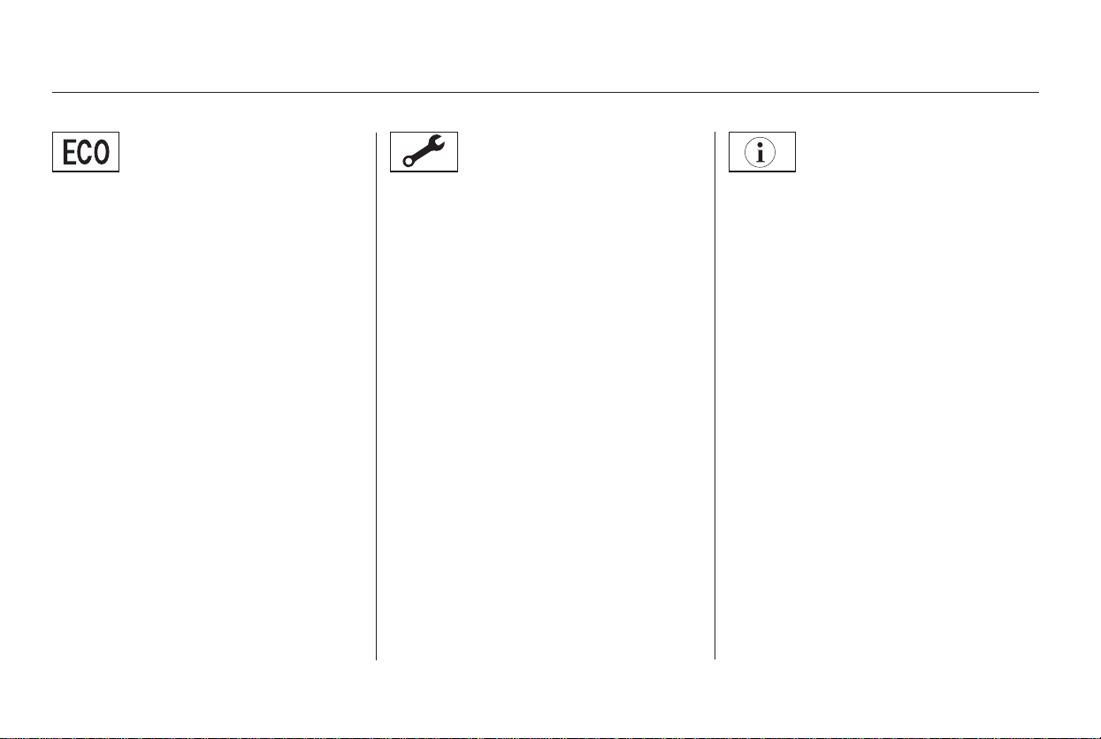
This indicator reminds you that the
maintenance main items and sub
items will be displayed in the
odometer/trip meter display. See
page for more information on
the maintenance minder.
This indicator comes on when there
is a system message in the multi-
information display. Press the INFO
button on the steering wheel to see
the message (see page ).
Most of the time, this indicator
comes on along with other indicators
in the instrument panel such as the
seat belt reminder indicator, SRS
indicator, VSA system indicator, etc.
While the engine is operating in its
most economical range, this
indicator comes on and stays on. It
goes off when your vehicle uses
extra fuel.
This indicator goes off when your
dealer resets it after completing the
required maintenance service.
79315
On LX and EX models
On Touring model
On EX with leather and Touring models
Instrument Panel Indicators
System Message
Indicator
Fuel Economy
Indicator
Maintenance MINDER
Indicator
70
Main Menu
Table of Contents
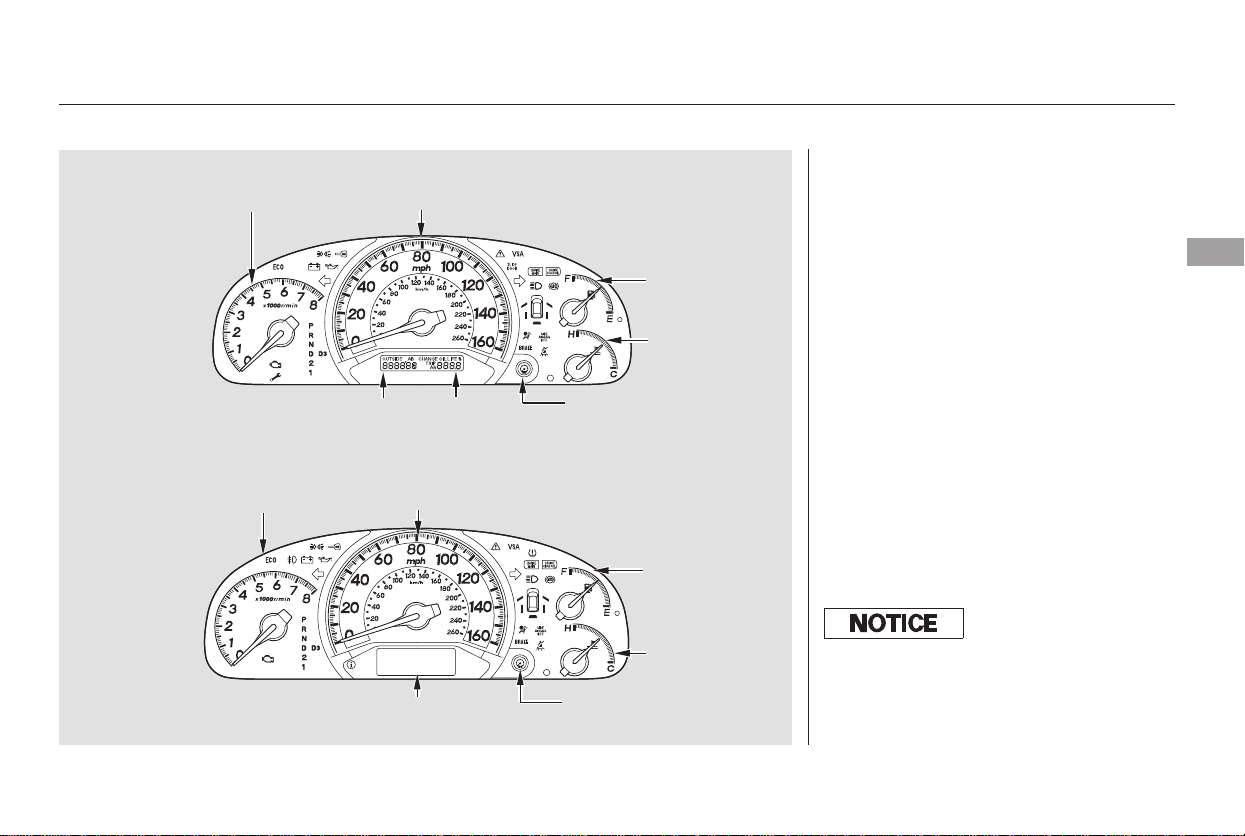
This shows how much fuel you have.
It may show slightly more or less
than the actual amount. The needle
returns to the bottom after you turn
off the ignition.
This shows the temperature of the
engine’s coolant. During normal
operation, the pointer should rise to
about the middle of the gauge. In
severe driving conditions, the pointer
may rise to the upper zone. If it
reaches the red (hot) mark, pull
safely to the side of the road. For
instructions and precautions on
checking the engine’s cooling
system, see page .369
Temperature Gauge
Fuel Gauge
Gauges
Instruments and Controls
71
SPEEDOMETER
FUEL GAUGE
SPEEDOMETER
ODOMETER/OUTSIDE
TEMPERATURE
TEMPERATURE
GAUGE
FUEL GAUGE
MULTI-INFORMATION
DISPLAY
TEMPERATURE
GAUGE
TACHOMETER
TACHOMETER
TRIP METER
LX and EX models
Touring model
TRIP METER
SELECT/RESET
KNOB
TRIP METER SELECT/
RESET KNOB
Avoid driving with an extremely low
f uel level. Running out of f uel could
cause the engine to misf ire, damaging
the catalytic converter.
Main Menu
Table of Contents

The odometer shows the total
distance your vehicle has been
driven. It measures miles in U.S.
models and kilometers in Canadian
models. It is illegal under U.S.
federal law and Canadian provincial
regulations to disconnect, reset, or
alter the odometer with the intent to
change the number of miles or
kilometers indicated.
This indicator displays the outside
temperature in Fahrenheit (U.S.
models) or Centigrade (Canadian
models). To see the outside
temperature, press and release the
Select/Reset button until the
temperature is displayed.
The temperature sensor is in the
front bumper. The temperature
reading can be affected by heat
reflection from the road surface,
engine heat, and the exhaust from
surrounding traffic. This can cause
an incorrect temperature reading
when your speed is under
19 mph (30 km/h). When you start
your trip, the sensor is not fully
acclimatized, therefore it may take
several minutes until the proper
temperature is displayed.
This meter shows the number of
miles (U.S.) or kilometers (Canada)
driven since you last reset it.
There are two trip meters: Trip A
and Trip B. Switch between these
displays and the outside temperature
display by pressing the Select/Reset
knob repeatedly.
Each trip meter works independently,
so you can keep track of two
different distances.
To reset a trip meter, display it and
then press and hold the Select/Reset
knob until the number resets to ‘‘0.0.’’
Both trip meters will reset if the
vehicle’s battery goes dead or is
disconnected.
If equipped
Gauges
Odometer Outside Temperature IndicatorTrip Meter
72
Main Menu
Table of Contents

In certain weather conditions,
temperature readings near freezing
(32°F, 0°C) could mean that ice is
forming on the road surface.
On the Touring model, the odometer,
trip meter, and the outside
temperature indicator are displayed
in the multi-information display. See
page for more information.
(Odometer/trip meter message)
If the system still detects a loose or
missing fuel cap, the Malfunction
Indicator Lamp (MIL) comes on.
Turn the engine off and check or
retighten the fuel cap at least 3 clicks.
The MIL goes out after 3 days of
normal driving once the cap is
tightened or replaced. If it does not
go out, have your dealer inspect the
vehicle. For more information, see
page .
If your fuel cap is loose or missing, a
‘‘CHECK FUEL CAP’’ message
appears as text in the odometer/trip
meter display after you start the
engine. Turn the engine off and
confirm the fuel cap is installed. If it
is, loosen the cap, then retighten it at
least 3 clicks. When you restart the
engine, the message appears again.
To clear the message, press and hold
the select/reset button until the
message is replaced in the
odometer/trip meter display.
372
77
On LX and EX models
Gauges
Check Fuel Cap Indicator
Instruments and Controls
73
Main Menu
Table of Contents

The multi-information display in the
instrument panel displays various
information and messages when the
ignition switch is in the ON (II)
position. Some of the messages help
you operate your vehicle more
comfortably.
Others help to keep you aware of the
periodic maintenance your vehicle
needs for continued trouble-free
driving.
When you unlock and open the
driver’s door with the key, the
display shows ‘‘Welcome DRIVER 1’’
or ‘‘Welcome DRIVER 2’’ depending
on which remote transmitter was
used last. (The driver’s ‘‘ID’’ is
detected by the transmitter.)
If you use the remote transmitter to
unlock the driver’s door, the display
shows ‘‘Welcome DRIVER 1’’ or
‘‘Welcome DRIVER 2’’ depending on
which remote transmitter you use,
and the driver’s seat moves to the
positionstoredinthattransmitter.
When you turn the ignition switch to
LOCK (0) and remove the key from
the ignition switch, the display
shows ‘‘Goodbye.’’
There are four types of messages;
normal display messages, engine oil
life and maintenance messages,
system messages, and PAX system
warning messages.
You can also customize some vehicle
control settings to your liking with
the multi-information display and the
two buttons on the steering wheel
(see page ).89
On Touring model only
Normal Display Messages
Multi-Information Display
74
Main Menu
Table of Contents
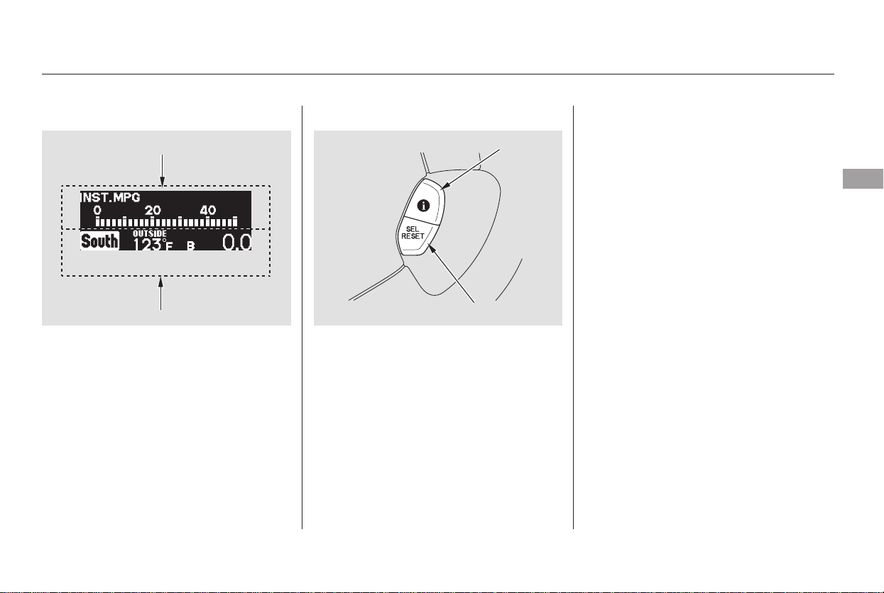
If you press the INFO button when
‘‘AVERAGE SPEED’’ is displayed,
the display changes to ‘‘TIRE
PRESSURE’’ using both segments.
This display is a part of tire pressure
monitoring system (TPMS). See
page for more information.
The multi-information display
consists of an upper segment and a
lower segment. Each segment can
display two lines of messages.
In normal display mode, the upper
segment displays trip computer and
tire pressures, and the lower
segment displays the compass,
odometer, trip meter, outside
temperature, and engine oil life.
In normal display mode, the upper
display is blank when you turn the
ignition switch to ON (II). Then each
time you press the INFO button, the
trip computer changes from ‘‘INST.
MPG’’ to ‘‘RANGE’’ to ‘‘ELAPSED
TIME’’ to ‘‘AVERAGE SPEED’’ and
then to ‘‘AVERAGE FUEL A’’ or
‘‘AVERAGE FUEL B’’ as shown on
the next page.
Pressing the INFO button again
brings the display back to the initial
display of the trip computer ‘‘INST.
MPG.’’
303
CONTINUED
Multi-Information Display
Instruments and Controls
75
LOWER SEGMENT
UPPER SEGMENT
INFO BUTTON
SEL RESET BUTTON
Main Menu
Table of Contents
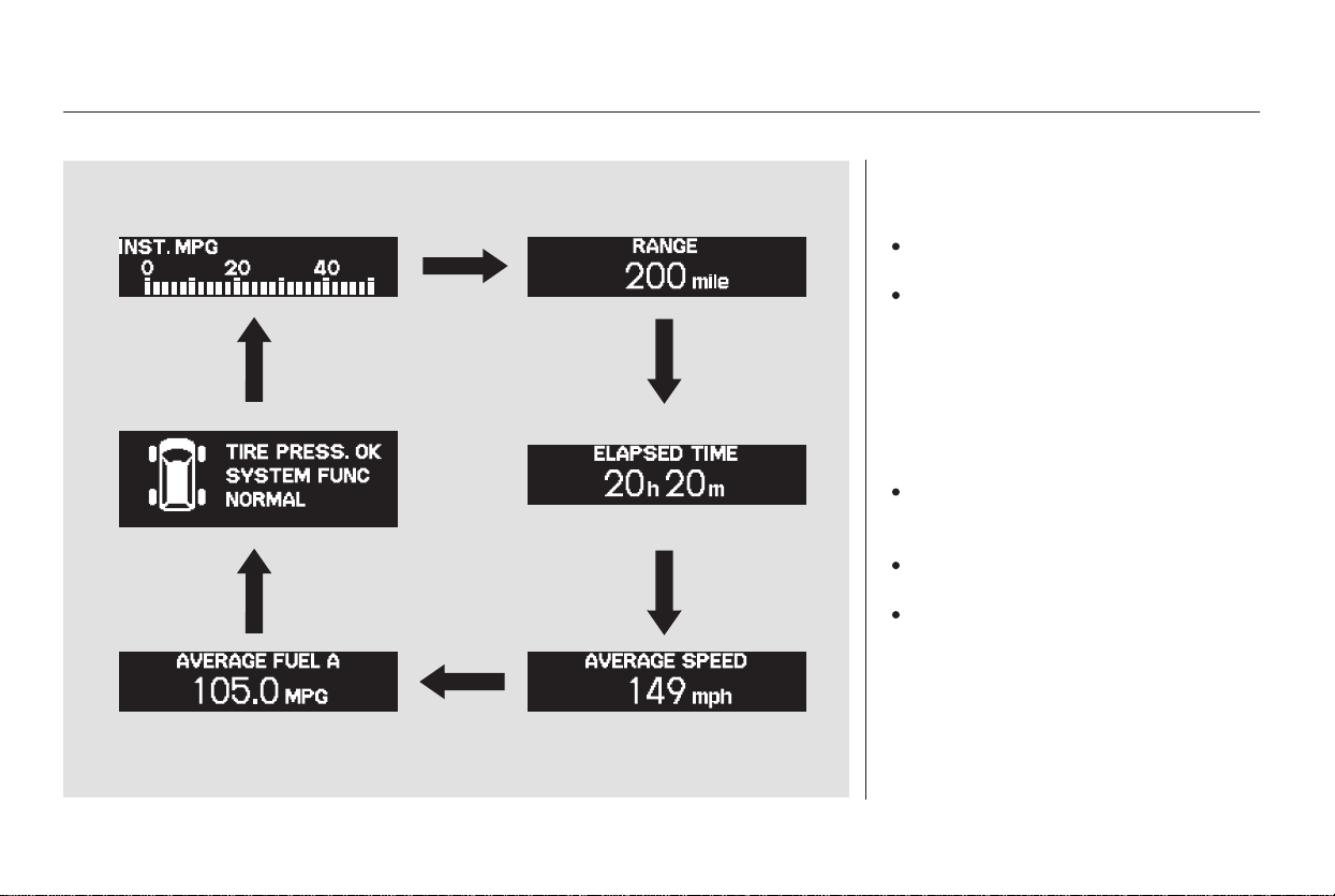
Messages in the trip computer
include:
INST.MPG:Yourvehicle’s
current fuel mileage.
RANGE: The estimated distance
you can travel on the fuel
remaining in the tank.
This distance is estimated from
the fuel economy you received
over the last several miles, so it
will vary with changes in speed,
traffic, etc.
To reset the values in the trip
computer, press the Select/Reset
button, and hold it for about 1
second.
AVERAGE FUEL A/AVERAGE
FUEL B: Your vehicle’s average
fuel economy since you last reset
the trip computer.
AVERAGE SPEED: The average
speed you are traveling.
ELAPSED TIME: The time
traveled since you last reset the
trip computer.
Multi-Information Display
76
Main Menu
Table of Contents
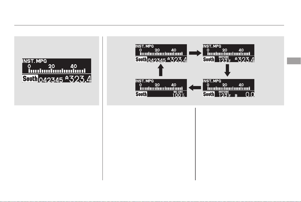
The initial display in the lower
segment is shown above. Each time
you press the SEL/RESET button on
the steering wheel, the display
changes from ‘‘Odometer/Trip
Meter’’ to ‘‘Outside Temperature/
Trip Meter’’ to ‘‘Engine Oil Life’’, and
then back to the initial display as
showninthenextcolumn.
In the lower left corner of the display,
a compass indicates which direction
your vehicle is pointed.
While a trip meter is displayed, you
can change the display between
‘‘TRIP A’’and ‘‘TRIP B’’ by pressing
the Select/Reset knob in the
instrument panel (see page ). To
reset a trip meter, display it, and
press and hold the Select/Reset
knob until the number reset to ‘‘0.0.’’
‘‘AVERAGE FUEL A’’ or
‘‘AVERAGE FUEL B’’ will be
displayed when average fuel
economy is selected in the upper
segment depending on which trip
meter(TRIPAorTRIPB)is
displayed in the lower segment.
72
Multi-Information Display
Trip Meter
Instruments and Controls
77
Main Menu
Table of Contents
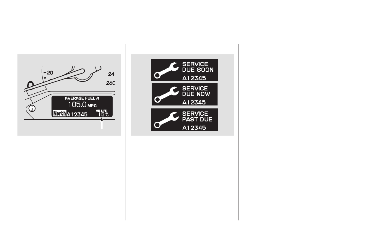
This shows the remaining life of the
engine oil. It shows 100% after the
engine oil is replaced and the display
is reset. The engine oil life is
calculated based on engine operating
conditions and accumulated engine
revolutions.
When the engine oil life reaches 15
percent, the display shows
‘‘SERVICE DUE SOON’’ and the
code for the maintenance items to be
performed.
When the engine oil life reaches 5
percent, the display shows
‘‘SERVICE DUE NOW’’ along with
the same maintenance items.
Have your dealer do the indicated
maintenance as soon as you see this
message, and have them reset the
display after completing the service.
If you do not perform the indicated
maintenance or do not reset the
display, the message changes to
‘‘SERVICE PAST DUE’’ when the
engine oil life becomes 0 percent.
These messages appear on the multi-
information display each time you
turn the ignition switch to ON (II).
For details on engine oil life and
maintenance messages, refer to page
.
Also refer to page for important
maintenance safety precautions.
317
314
Maintenance MessagesEngine Oil Life
Multi-Information Display
78
ENGINE OIL LIFE
Main Menu
Table of Contents
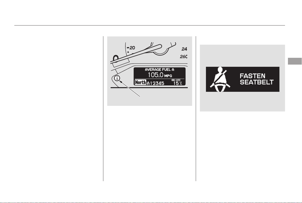
If there is a problem with your
vehicle, for example, the engine oil
level is low or a door is not fully
closed, the multi-information display
will show you the problem. It does
this by interrupting the current
message with one or more messages.
Most of the messages are displayed
for about 5 seconds, and then the
current message returns. Some
messages stay on until the problem
is corrected.
These messages also trigger the
appropriate indicator(s) on the
instrument panel and cause the
system message indicator to come
on. The system message indicator
does not go off until the problem(s)
are corrected.
Fasten Seat Belt
The following pages describe each
system message that can be
displayed.
In addition to the seat belt reminder
indicator in the instrument panel, the
multi-information display interrupts
the current display and shows
‘‘FASTEN SEAT BELT’’ if you do
notfastenyourseatbeltwhile
driving. This message remains
displayed if you ignore it and do not
wear your seat belt while the vehicle
is moving.
CONTINUED
System Messages
Multi-Information Display
Instruments and Controls
79
SYSTEM MESSAGE
INDICATOR
Main Menu
Table of Contents
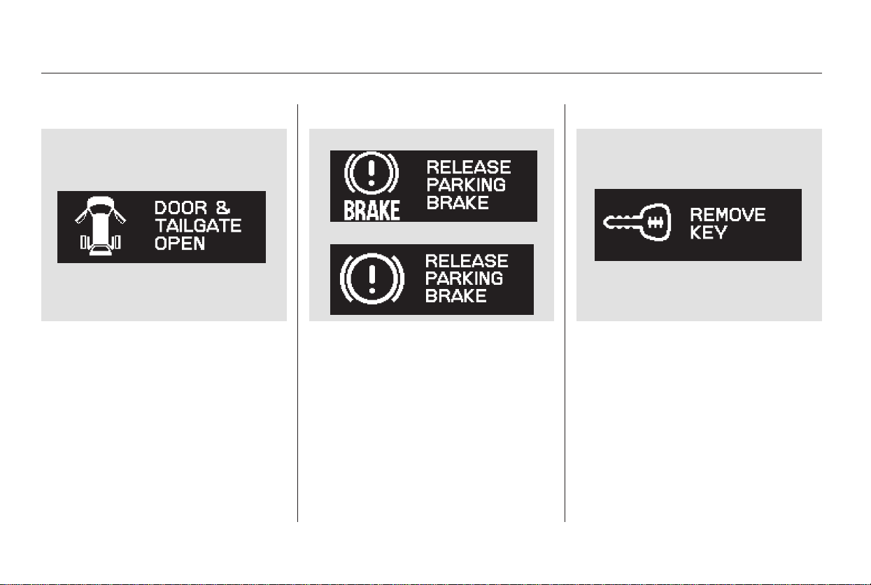
Door and Tailgate Open
If the tailgate or any door(s) is not
closed tightly, the display reminds
you to close the tailgate or the
door(s) before you start driving.
This display continues until you
close the door(s) or the tailgate.
Pressing the INFO button on the
steering wheel momentarily change
the display to the normal display, but
it will come back after 5 seconds.
Release Parking Brake
If you start driving without releasing
the parking brake, the multi-
information display interrupts the
current display and shows
‘‘RELEASE PARKING BRAKE.’’
This message continues, and a
chime sounds, until you release the
parking brake, or the vehicle speed
slows down to less than 0.5 mph (0.8
km/h).
If you leave the key in the ignition
switch in the LOCK (0) or
ACCESSORY (I) position and open
the driver’s door, you will see
‘‘REMOVE KEY’’ in the display and
hear a reminder beeper.
Remove Key
Multi-Information Display
80
U.S.
Canada
Main Menu
Table of Contents

Brake Fluid Low
If the brake fluid level is at or below
theMINmarkonthesideofthe
brake fluid reservoir in the engine
compartment, you will see ‘‘BRAKE
FLUID LOW.’’ If you see this
message, have the brake system
checked by your dealer (see page
).
Check Fuel Cap The CHECK FUEL CAP message
should go off after tightening the
fuel cap, turning the ignition switch
off and on, then driving over 30 mph
(48 km/h) for at least 45 seconds.
Due to different driving conditions, it
may take a few driving trips to make
the message go off.
If a loose or missing fuel cap was not
the cause of the CHECK FUEL CAP
message coming on, the message
will turn off and the Malfunction
Indicator Lamp will come on. If this
happens, have your vehicle checked
by your dealer as soon as possible.
If the fuel fill cap is missing or not
tightened properly, you will see
‘‘CHECK FUEL CAP.’’ Make sure
the fuel cap is installed and tightened
at least 3 clicks.
373
CONTINUED
Multi-Information Display
Instruments and Controls
81
U.S
Canada
Main Menu
Table of Contents
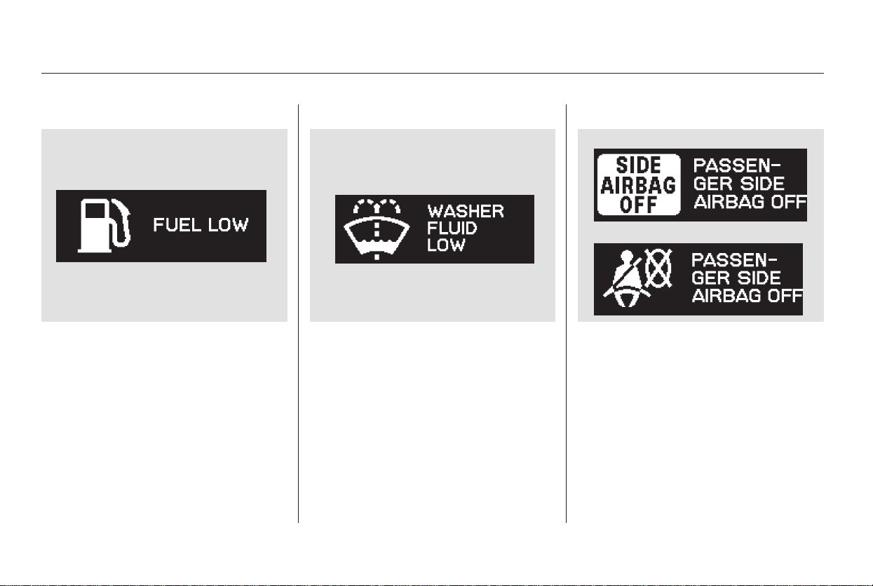
Fuel Low
If the level of the fuel in the tank
gets low, you will see ‘‘FUEL LOW’’
in the display, and you must refuel
soon. The low fuel indicator in the
instrument panel will also come on.
Washer Fluid Low Passenger Side Airbag Off
If the passenger’s side airbag has
automatically shut off, you will see
‘‘PASSENGER SIDE AIRBAG OFF’’
in the multi-information display. See
page for more information.
If the fluid level in the windshield
washer reservoir gets low, you will
see ‘‘WASHER FLUID LOW’’ in the
multi-information display.
33
Multi-Information Display
82
U.S.
Canada
Main Menu
Table of Contents
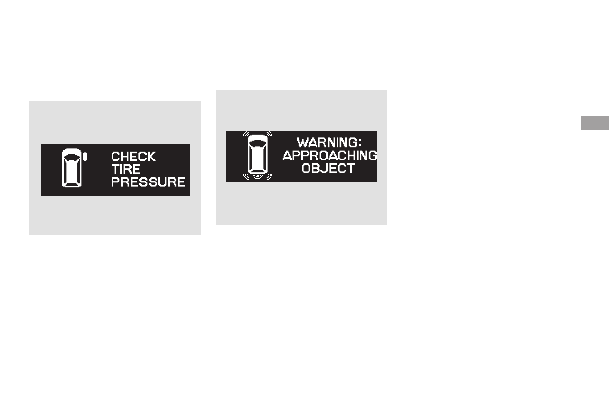
Check Tire Pressure Warning: Approaching Object
This message, and the indicator to
the left of the message, is a part of
the parking sensor system. If you are
approaching too close to an object,
you will see ‘‘WARNING
APPROACHING OBJECT’’ in the
display and hear a beeper. See page
for more information.
The following messages indicate
various problems in your vehicle’s
systems.
If one or more of your vehicle tires
are low on pressure, you will see a
‘‘CHECK TIRE PRESSURE’’
message in the display. See page
for more information on the tire
pressure monitoring system (TPMS).
303
271
CONTINUED
On U.S. Touring model only
Multi-Information Display
Instruments and Controls
83
Main Menu
Table of Contents
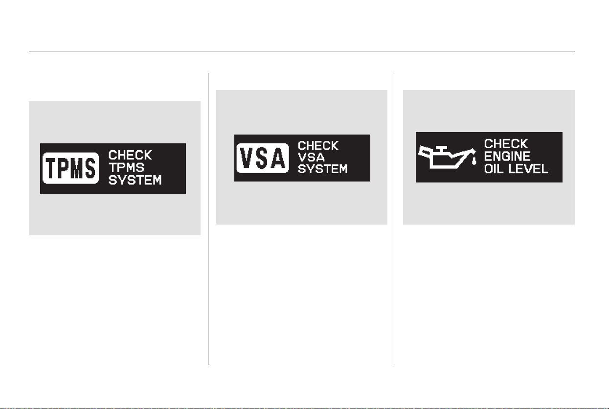
Check TPMS System
If there is a problem with the vehicle
stability assist (VSA) system, you
will see ‘‘CHECK VSA SYSTEM’’ in
the multi-information display. If you
see this message, have the VSA
system checked by your dealer (see
page ).
If the engine oil is very low or has
lost pressure, you will see ‘‘CHECK
ENGINE OIL LEVEL’’ in the multi-
information display. You will also see
the low oil pressure indicator in the
instrument panel flashing or staying
on. If you see this message, you
should take immediate action since
serious engine damage is possible.
Follow the procedure on page .
Check Engine Oil LevelCheck VSA System
If there is a problem in the tire
pressure monitoring system (TPMS),
you will see ‘‘CHECK TPMS
SYSTEM’’ in the multi-information
display. If you see this message, the
TPMS is not monitoring tire
pressures. Have the TPMS checked
by your dealer as soon as possible
(see page ).
301
303 371
On U.S. Touring model only
Multi-Information Display
84
Main Menu
Table of Contents
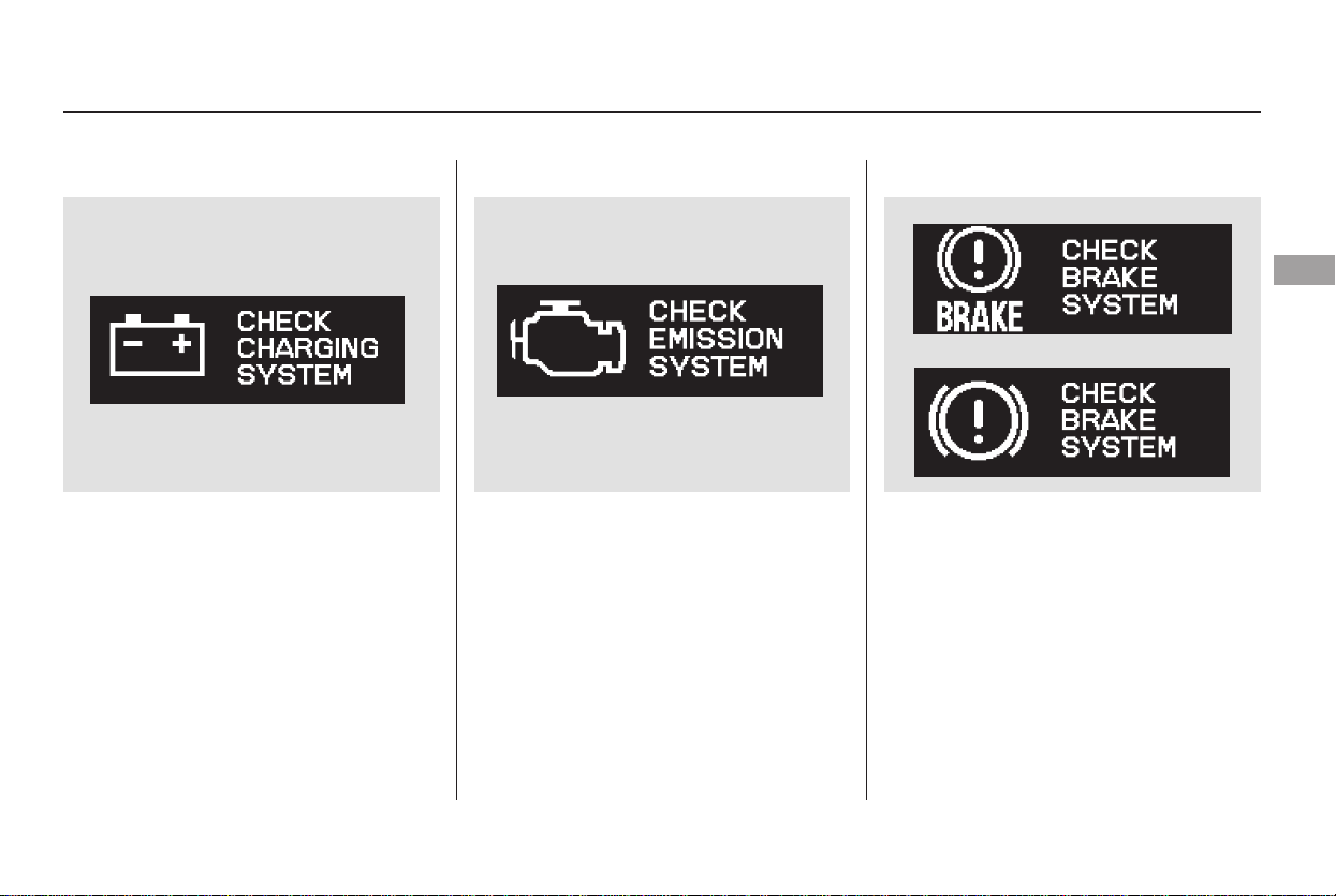
Check Charging System
If you see ‘‘CHECK CHARGING
SYSTEM’’ in the multi-information
display, it means the battery is not
being charged. See page for
more information.
Check Emission System
If you see ‘‘CHECK EMISSION
SYSTEM’’ in the multi-information
display, it means one of the engine’s
emission systems may have a
problem. Have your vehicle checked
by a dealer (see page ).
If there is a problem with the brake
system, you will see ‘‘CHECK
BRAKE SYSTEM’’ in the multi-
information display. The parking
brake and brake system indicator in
the instrument panel will also come
on. See page for more
information.
Check Brake System
371
372
373
CONTINUED
Multi-Information Display
Instruments and Controls
85
U.S.
Canada
Main Menu
Table of Contents
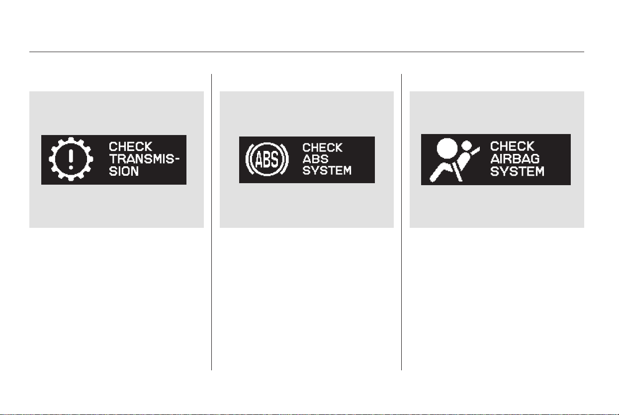
Check Transmission
If there is a problem with the
automatic transmission, you will see
‘‘CHECK TRANSMISSION’’ in the
multi-information display. Avoid
rapid acceleration, and have the
transmission checked by a dealer as
soon as possible.
If there is a problem in the anti-lock
brake system (ABS), you will see
‘‘CHECKABSSYSTEM’’inthe
multi-information display. If you see
this message, have your vehicle
checked by a dealer (see page ).
Check ABS System Check Airbag System
If there is a problem with your front
airbags, side airbags, passenger’s
side airbag automatic cutoff system,
automatic seat belt tensioners, or
side curtain airbags, you will see
‘‘CHECK AIRBAG SYSTEM’’ in the
multi-information display. Take your
vehicle to a dealer as soon as
possible (see page ).
300
32
Multi-Information Display
86
Main Menu
Table of Contents
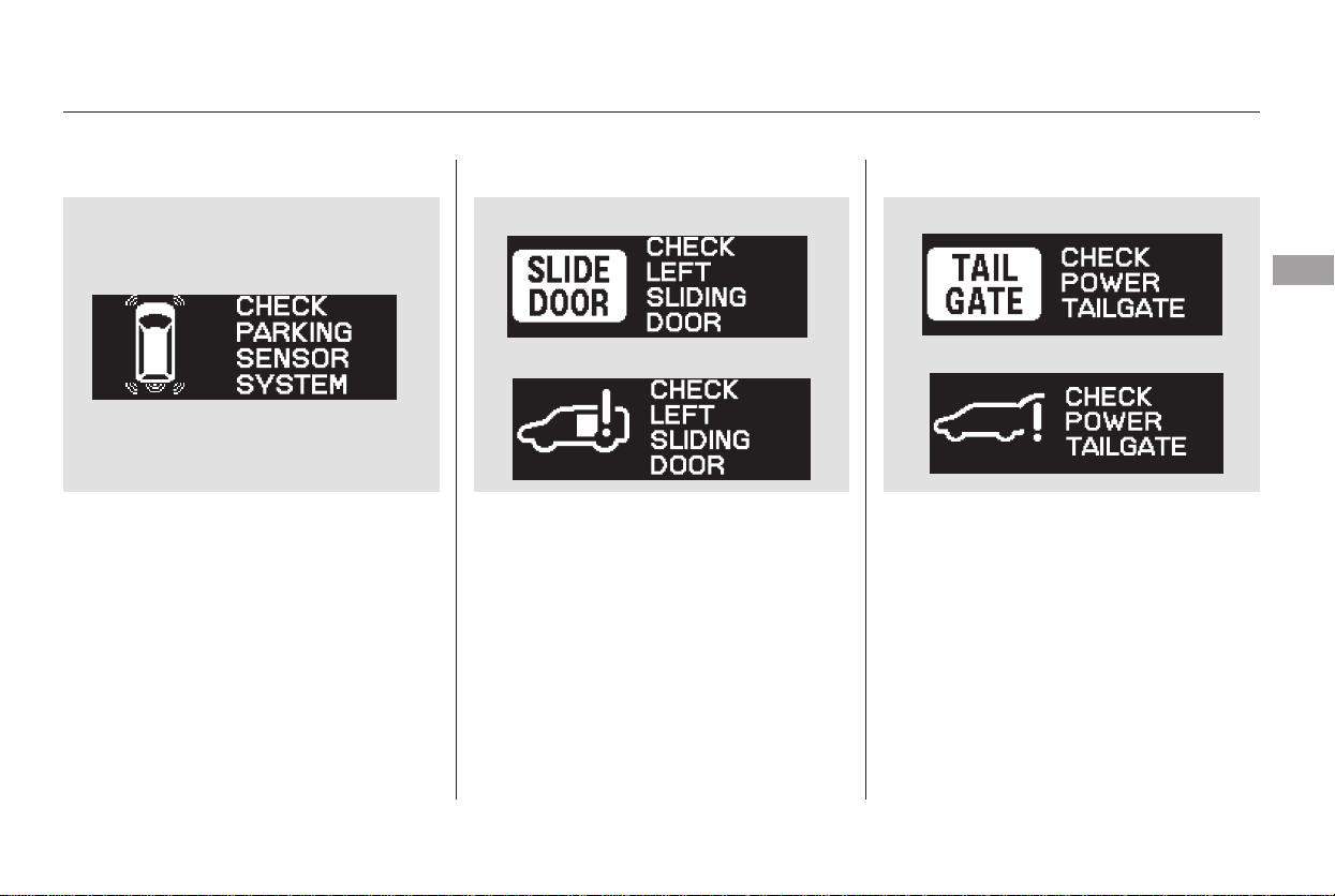
Check Parking Sensor System
If there is a problem with the
parking sensor system, the multi-
information display shows a
‘‘CHECK PARKING SENSOR
SYSTEM’’ message. See page
for more information.
Check Left/Right Sliding Door
If there is a problem in the power
sliding door, the multi-information
display shows ‘‘CHECK LEFT
SLIDING DOOR’’ or ‘‘CHECK
RIGHT SLIDING DOOR.’’ See page
for more information.
If there is a problem with the power
tailgate, the display shows ‘‘CHECK
POWER TAILGATE.’’ See page
for more information.
Check Power Tailgate
271
139
147
CONTINUED
Multi-Information Display
Instruments and Controls
87
U.S.
Canada
U.S.
Canada
Main Menu
Table of Contents
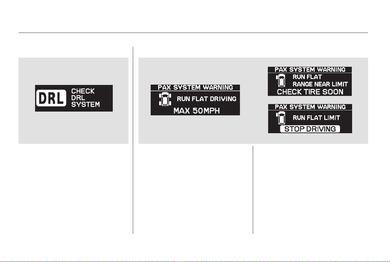
Check DRL System
If there is a problem with the
Daytime Running Light (DRL)
System, you will see ‘‘CHECK DRL
SYSTEM’’ in the multi-information
display. If you see this message,
have your vehicle checked by a
dealer.
For more information, see page .
Your vehicle is equipped with the
Michelin PAX system. The PAX
system uses the multi-information
display to show you one of three
messages while you are driving with
a flat tire.
356
Canadian model only U.S. Touring model only
PAX Warning Messages
Multi-Information Display
88
Main Menu
Table of Contents
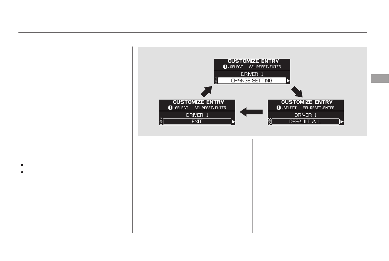
You can also use the trip meter
SELECT/RESET knob in the
instrument panel to select and enter
your selections while the multi-
information display is in the
customizing mode. Turn the knob to
select a setting and press it to enter
your selection.
UsetheINFObuttononthesteering
wheel to see the settings, and the
SEL/RESET button to enter your
selections.
If you want the settings as they were
when the vehicle left the factory,
select ‘‘DEFAULT ALL,’’ as
described on page .
If you want to change any vehicle
control settings, select ‘‘CHANGE
SETTING,’’ and follow the
instructions on page .
EverytimeyoupresstheINFO
button, the display cycles from
‘‘CHANGE SETTING,’’ ‘‘DEFAULT
ALL,’’ ‘‘EXIT,’’ and then back to
‘‘CHANGE SETTING’’ as shown in
the next column.
You can customize some vehicle
control settings for ‘‘DRIVER 1’’ and
‘‘DRIVER 2’’ separately. If ‘‘DRIVER
1’’ or ‘‘DRIVER 2’’ is not displayed,
customizing is not possible.
DEFAULT ALL
CHANGE SETTING
The first customizing menu is:
To enter the customizing mode, the
vehicle must be stopped and the
transmission must be in Park. Press
andholdtheINFObuttononthe
steering wheel for about 3 seconds
while the multi-information display is
in its normal message mode.
90
92
Customized Settings
Multi-Information Display
Instruments and Controls
89
Main Menu
Table of Contents
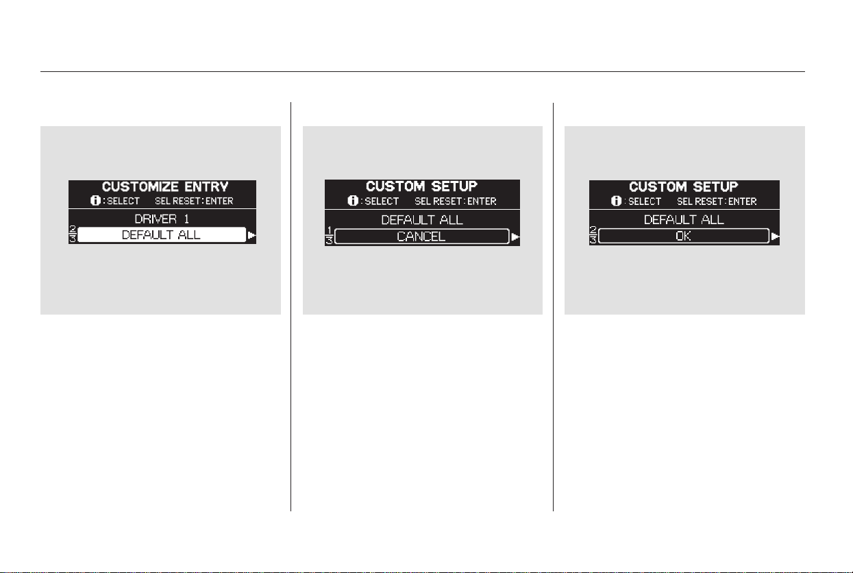
If you want to set the customizable
vehicle control settings to the default
setting, press the INFO button on
the steering wheel until ‘‘DEFAULT
ALL’’ is displayed.
To set the default settings again,
press the SEL/RESET button. The
display changes as shown above.
Press the SEL/RESET button again
to select ‘‘DEFAULT ALL.’’
If you want cancel ‘‘DEFAULT ALL,’’
press the INFO button, and you will
see ‘‘CANCEL.’’ Press the SEL/
RESET button, and the display goes
back to CUSTOMIZE ENTRY.
DEFAULT ALL
Multi-Information Display
90
Main Menu
Table of Contents
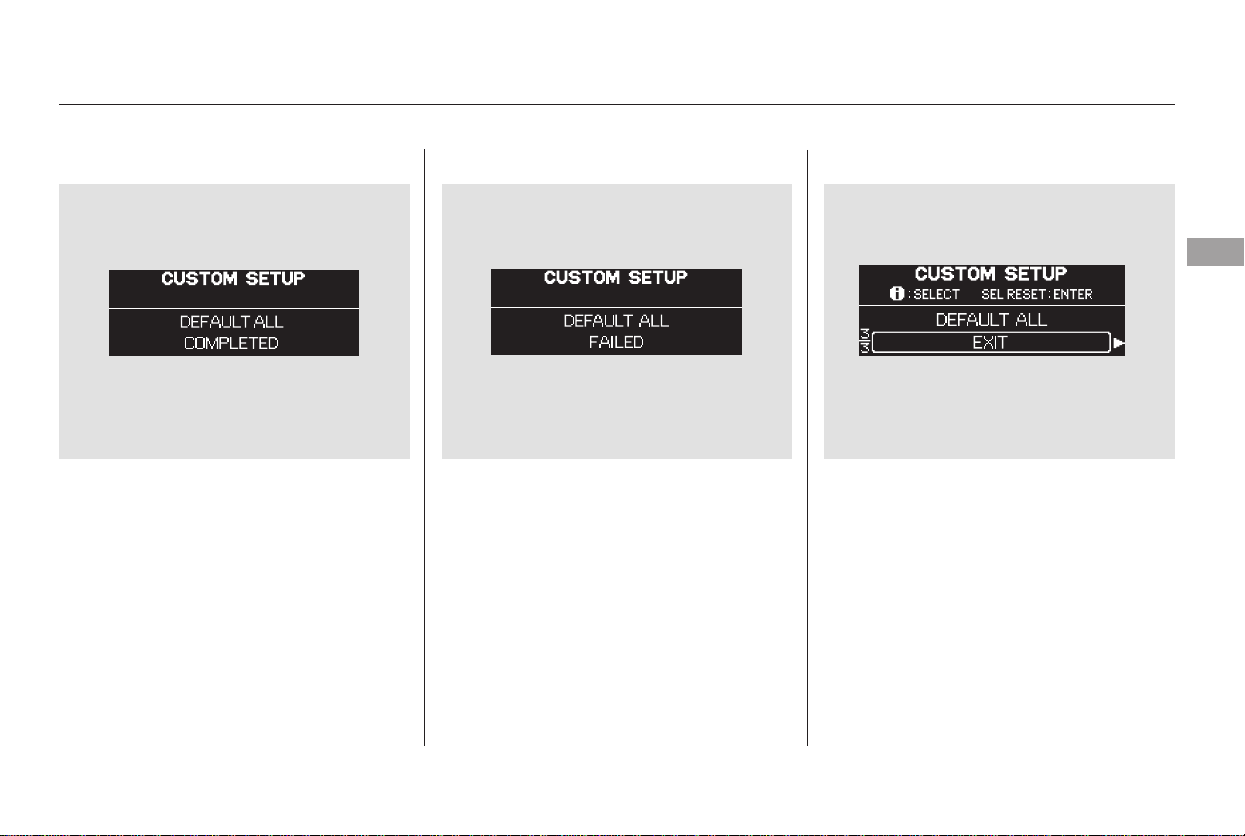
When DEFAULT ALL is completed
successfully, you will see the above
display for several seconds, and the
display will return to ‘‘CUSTOMIZE
ENTRY.’’
If DEFAULT ALL is not completed
successfully, you will see the above
display for several seconds, then the
display goes back to the normal
message mode. Repeat the
procedure to select DEFAULT ALL.
To exit ‘‘DEFAULT ALL,’’ press the
INFO button until you see ‘‘EXIT,’’
then press the SEL/RESET button.
Multi-Information Display
Instruments and Controls
91
Main Menu
Table of Contents

You can customize some of the
vehicle control settings to your
preference. Here are the settings
you can customize.
METER SET UP
POSITION SET UP
LIGHTING SET UP
DOOR/WINDOW SET UP
WIPER SET UP
While the multi-information display
is showing ‘‘CHANGE SETTING,’’
press the SEL/RESET button. The
display will change to the initial
display of CUSTOMIZE GROUP.
Then, each time you press the INFO
button, the display changes as shown
in the next column.
Press the INFO button until you see
the setup you want to customize, and
press the SEL/RESET button to
enter your selection.
Change Setting
Multi-Information Display
92
Press SEL/RESET button
Main Menu
Table of Contents
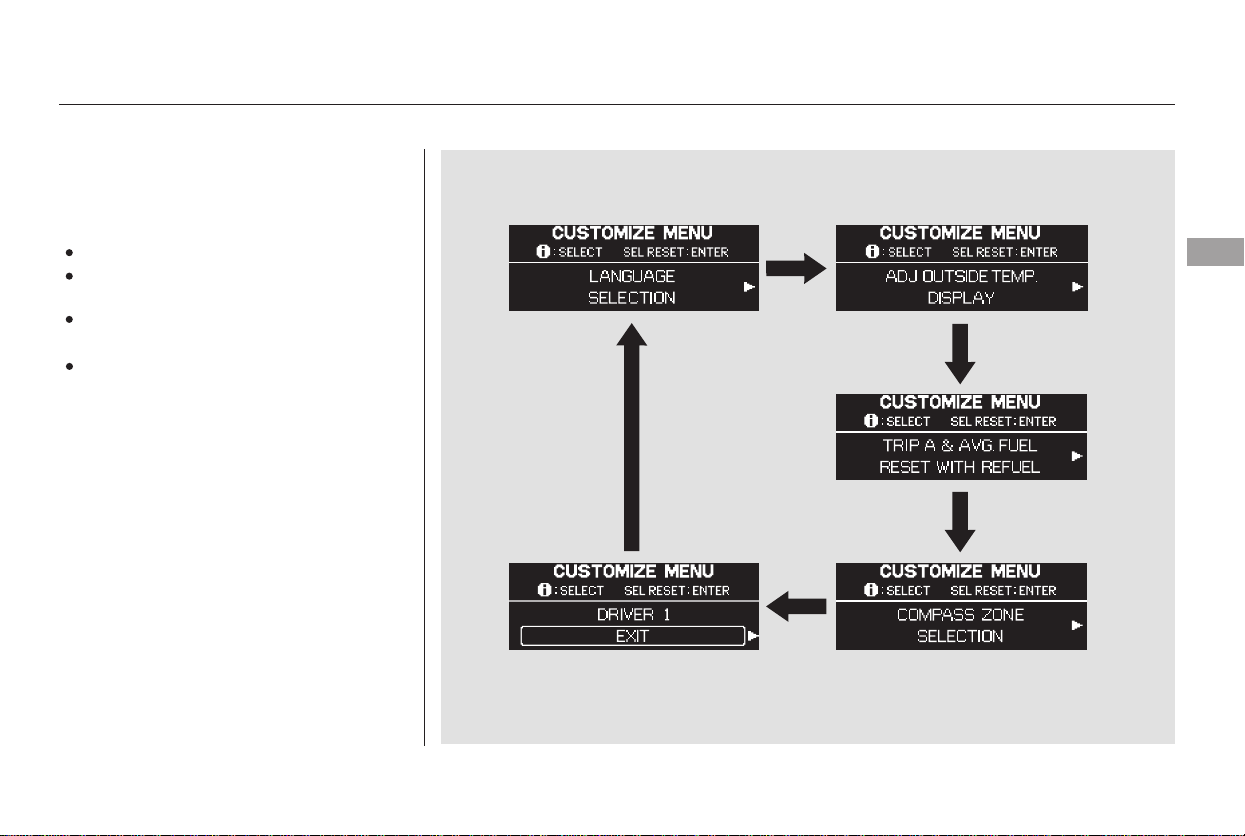
There are four custom settings items
in the Meter Setup:
LANGUAGE SELECTION
ADJUST OUTSIDE TEMP.
DISPLAY
TRIP A & AVG. FUEL A RESET
with REFUEL
COMPASS ZONE SELECTION
While ‘‘METER SETUP’’ is displayed,
press the SEL/RESET button on the
steering wheel. Then, press the
INFO button repeatedly. Each time
you press the INFO button, the
display changes as shown.
To customize a setting, press the
INFO button repeatedly until you see
the setting, and press the SEL/
RESET button. Then, follow the
procedures described on the
following pages.
Meter Setup
Multi-Information Display
Instruments and Controls
93
Main Menu
Table of Contents
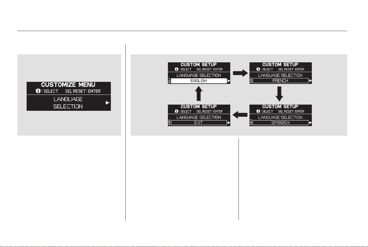
While the multi-information display
is showing ‘‘METER SETUP,’’ press
the SEL/RESET button on the
steering wheel. The display changes
to ‘‘LANGUAGE SELECTION.’’
Press the SEL/RESET button again
to enter the language selection mode.
There are three selectable languages,
English, French, and Spanish. Each
time you press the INFO button, the
display changes as shown.
Select the language you want by
pressing the INFO button, and press
the SEL/RESET button to enter
your selection.
Language Selection
Multi-Information Display
94
Main Menu
Table of Contents
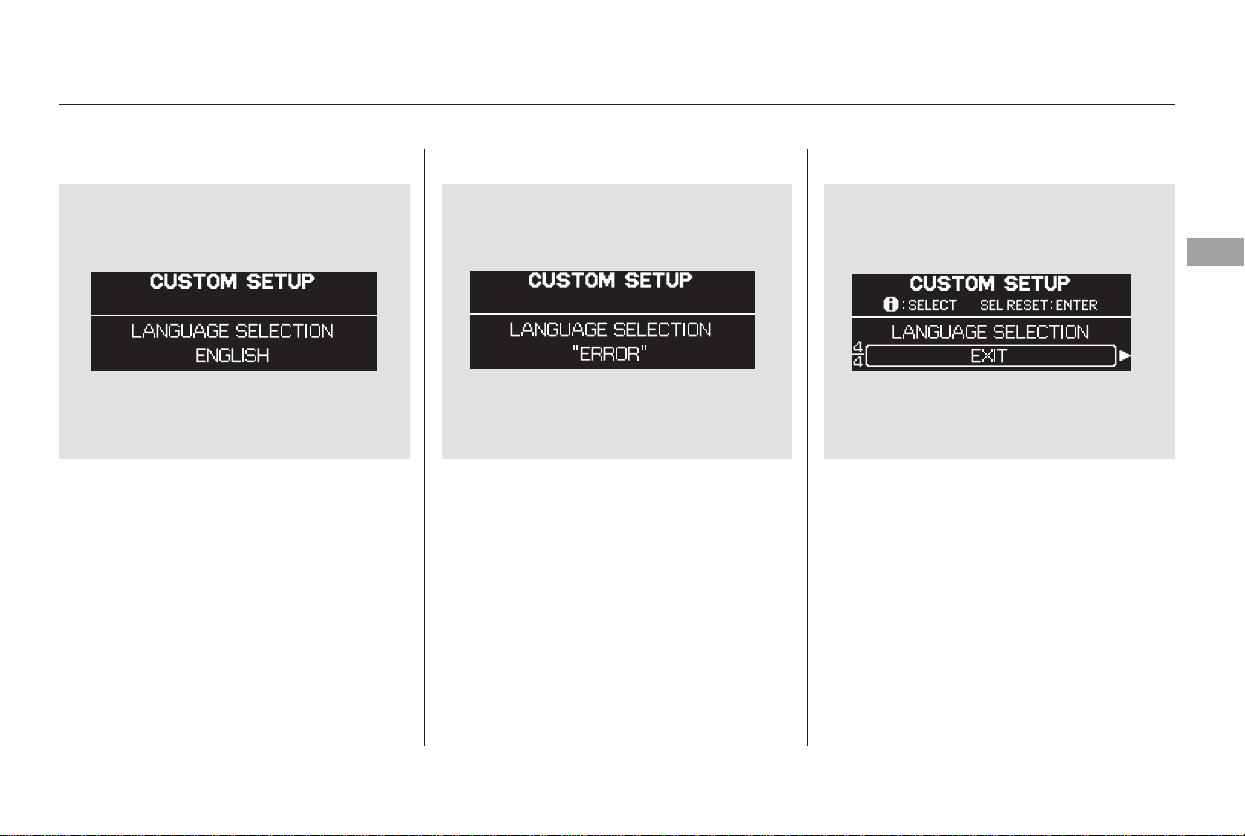
When language selection is
successfully completed, the display
changes to the screen shown above
for several seconds, then goes back
to ‘‘CUSTOMIZE MENU.’’
If you fail to select a language
properly, you will see the above
display for several seconds, then the
display goes back to ‘‘CUSTOMIZE
MENU.’’ Repeat the setup.
To exit ‘‘LANGUAGE SELECTION,’’
press the INFO button repeatedly
until you see ‘‘EXIT,’’ and press the
SEL/RESET button. The display
goes back to ‘‘CUSTOMIZE MENU.’’
All the messages in the multi-
information display will be in the
language you selected.
CONTINUED
Multi-Information Display
Instruments and Controls
95
Main Menu
Table of Contents
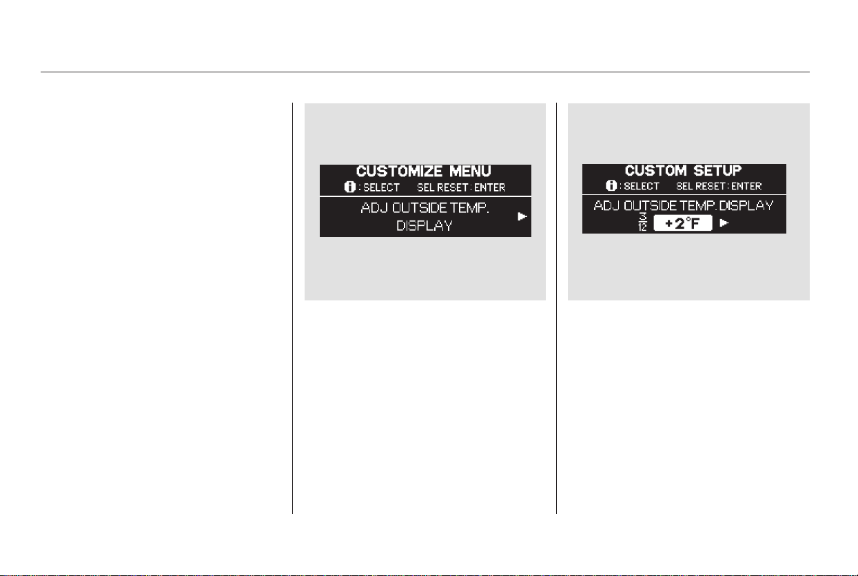
While the multi-information display
shows ‘‘METER SETUP,’’ press the
SEL/RESET button on the steering
wheel. The display changes to the
‘‘CUSTOMIZE MENU.’’ Press the
INFO button twice, and you will see
‘‘ADJ. OUTSIDE TEMP. DISPLAY’’
as shown above.
Press the SEL/RESET button. The
display changes as shown above.
The highlighted number is the
current adjustment above or below
the outside temperature. Press the
INFO button repeatedly until the
appropriate number appears, and
press the SEL/RESET button to
enter your selection.
If you sometimes find that the
temperature reading is always
several degrees below or above the
actual temperature, adjust it as
described on the following pages.
Outside Temperature Display
Adjustment
Multi-Information Display
96
Main Menu
Table of Contents
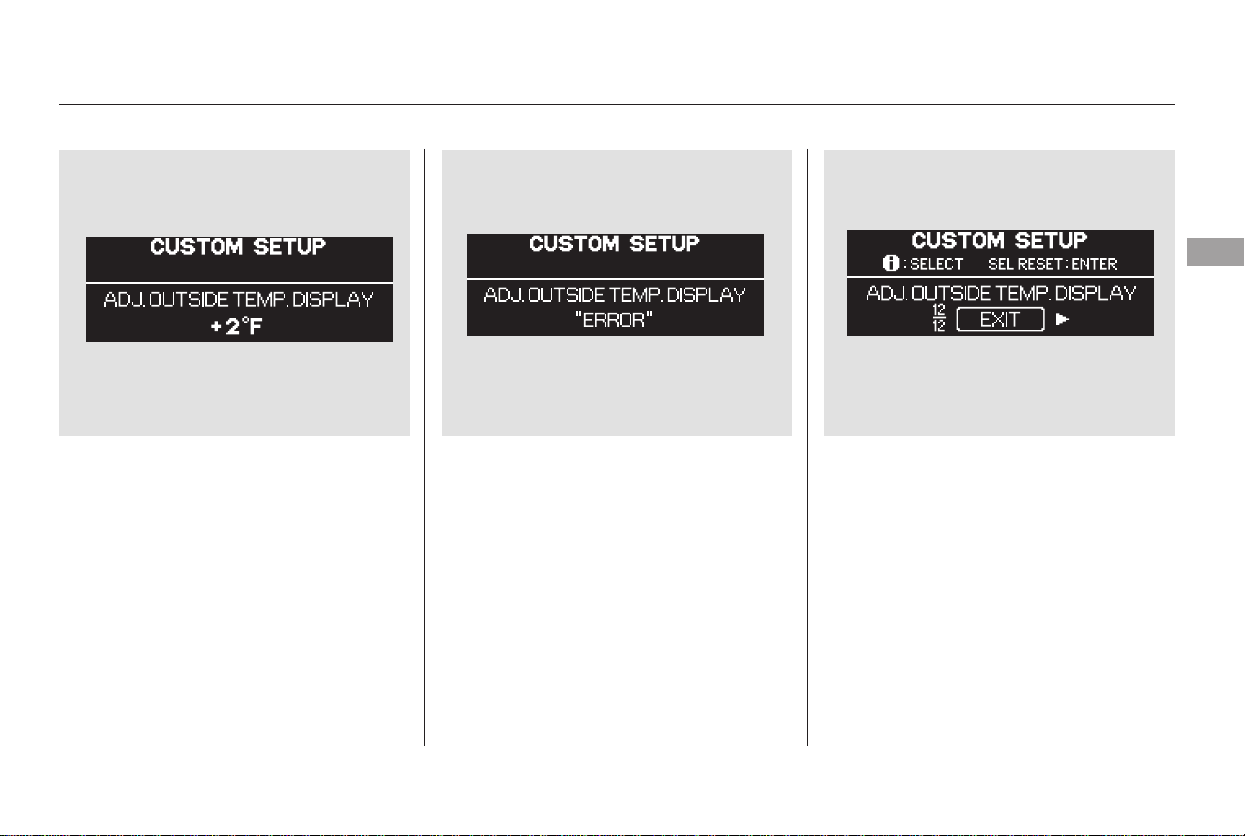
When your selection is successfully
entered, you will see the above
display for several seconds, and then
the display changes to ‘‘EXIT.’’
If you fail to enter the desired
adjustment properly, you will see the
above display for several seconds,
then the display goes back to
‘‘CUSTOMIZE MENU.’’ Repeat the
adjustment.
To exit ‘‘ADJUST OUTSIDE TEMP.
DISPLAY,’’ press the INFO button
until you see ‘‘EXIT,’’ and press the
SEL/RESET button. The display
goes back to ‘‘CUSTOMIZE MENU.’’
CONTINUED
Multi-Information Display
Instruments and Controls
97
Main Menu
Table of Contents
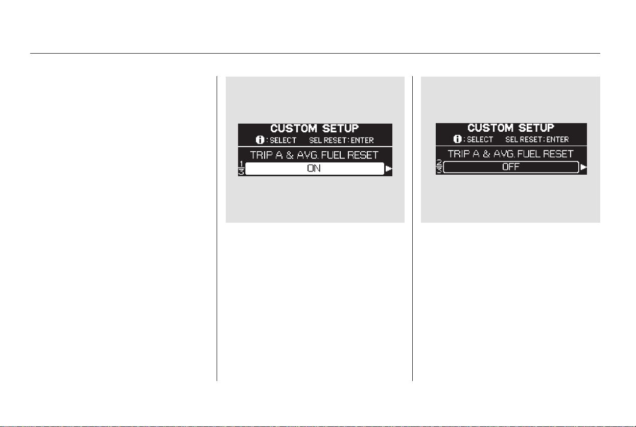
To cause ‘‘Trip meter A’’ and
‘‘Average Fuel Economy’’ to reset
every time you refuel your vehicle,
adjust it as described on the
following pages.
While the multi-information display
shows ‘‘METER SETUP’’ of the
‘‘CUSTOMIZE GROUP,’’ press the
SEL/RESET button on the steering
wheel. The display changes to
‘‘CUSTOMIZE MENU.’’ Press the
INFO button repeatedly until you see
‘‘TRIP A & AVG. FUEL RESET
WITH FUEL’’ in the lower segment
as shown above.
Press the SEL/RESET button. The
display changes as shown above.
The lower segment changes
between ‘‘ON’’ and ‘‘OFF’’ each time
you press the INFO button. Enter
your selection by pressing the SEL/
RESET button.
Trip A & Avg. Fuel Reset with Refuel
Multi-Information Display
98
Main Menu
Table of Contents
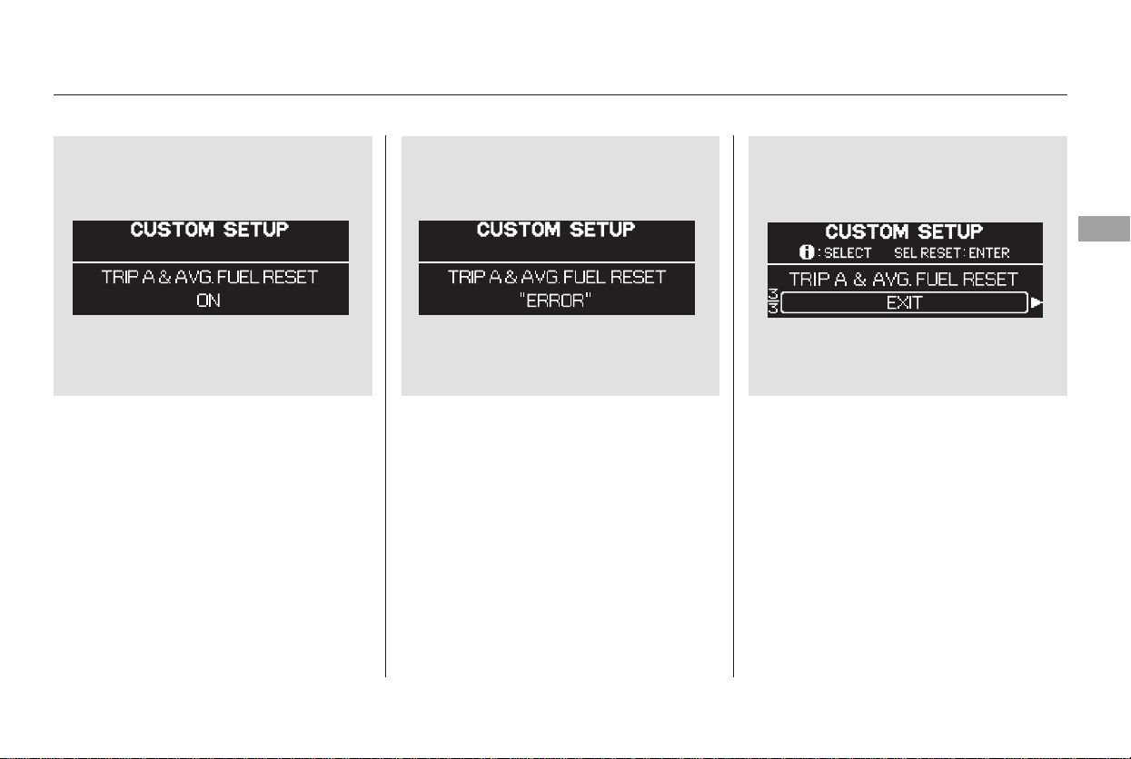
When your selection is successfully
entered, you will see the above
display for several seconds, and then
the display goes back to
‘‘CUSTOMIZE MENU.’’
If you fail to enter your selection,
you will see the above display for
several seconds, then the display
goes back to ‘‘CUSTOMIZE MENU.’’
Repeat the setup.
To exit ‘‘TRIP A & AVG. FUEL
WITH REFUEL,’’ press the INFO
button until you see ‘‘EXIT,’’ and
press the SEL/RESET button. The
display goes back to ‘‘CUSTOMIZE
MENU.’’
CONTINUED
Multi-Information Display
Instruments and Controls
99
Main Menu
Table of Contents
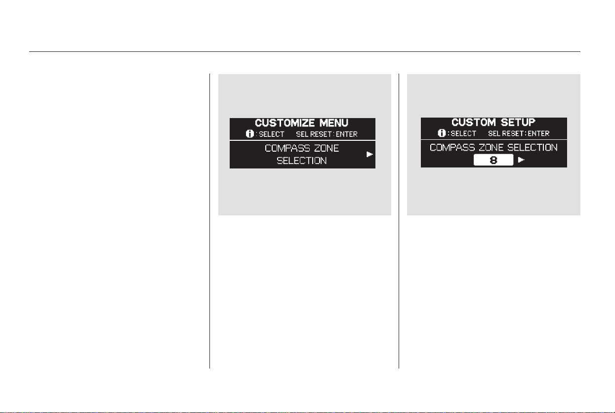
While the multi-information display
shows ‘‘METER SETUP,’’ press the
SEL/RESET button on the steering
wheel. The display changes to the
‘‘CUSTOMIZE MENU.’’ Press the
INFO button repeatedly until you see
‘‘COMPASS ZONE SELECTION’’ in
the lower segment as shown above.
Press the SEL/RESET button. The
display changes as shown above.
The highlighted ‘‘- -’’ display in the
lower segment is the zone number; it
changes from ‘‘1’’ thru ‘‘15’’ each
time you press the INFO button.
In most areas, there is a variation
between magnetic north and true
north. Zone selection is required so
the compass can compensate for this
variation. To check and select the
zone set into the compass, do the
procedure on the following pages.
On models without Navigation System
Compass Zone Selection
Multi-Information Display
100
Main Menu
Table of Contents
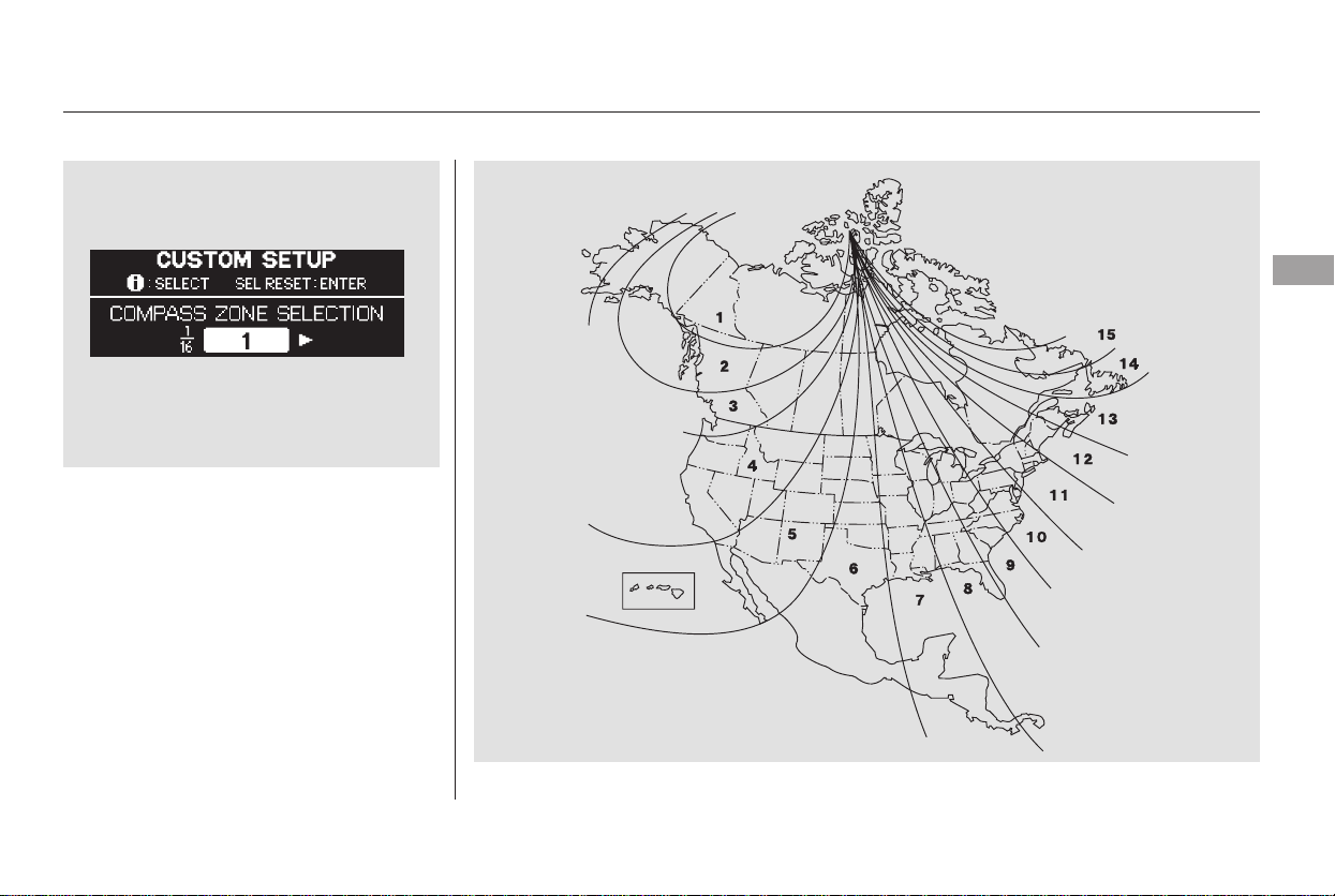
Find the zone for your area on the
map shown in the next column.
Press the INFO button until you see
your zone number in the lower
segment. Then press the SEL/
RESET button to enter your zone
number.
CONTINUED
Multi-Information Display
Instruments and Controls
101
Main Menu
Table of Contents
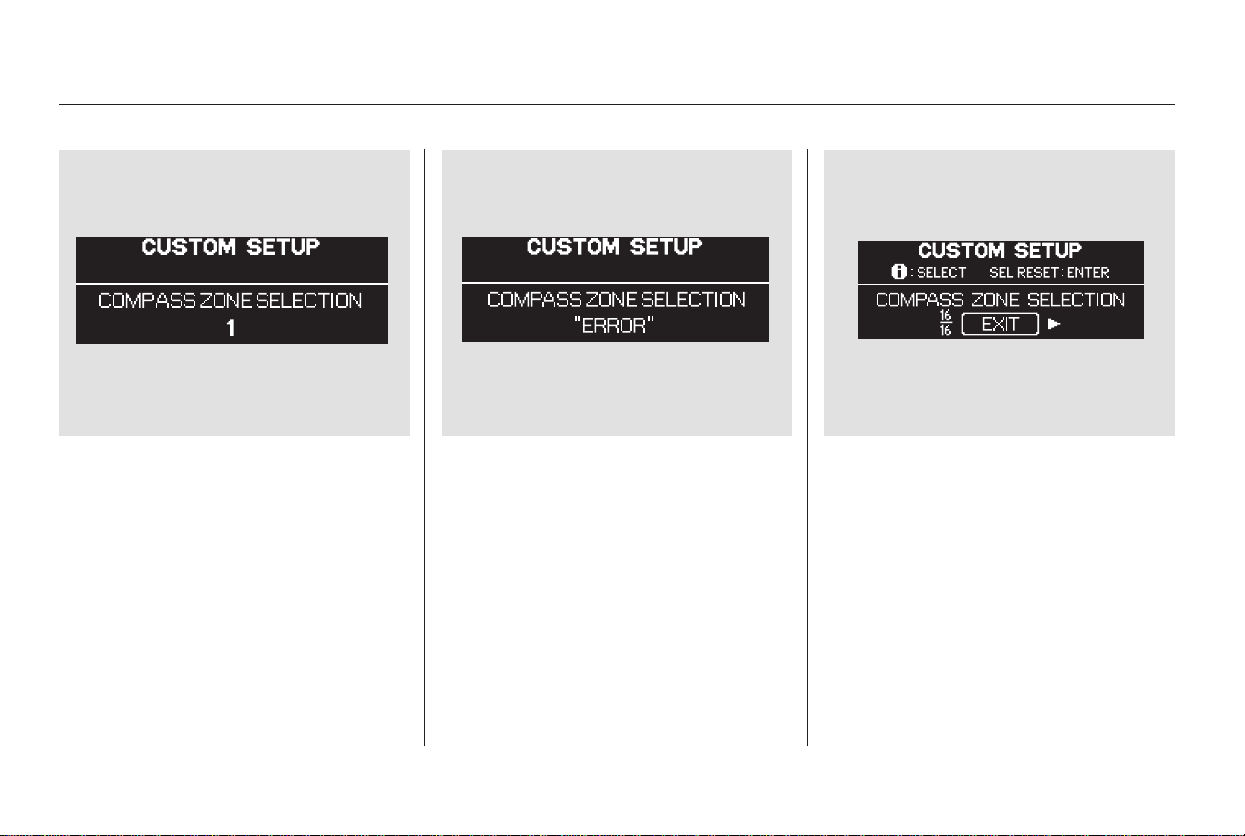
If you fail to enter your zone number,
you will see the above display for
several seconds, then the display
goes back to ‘‘CUSTOMIZE MENU.’’
Repeat the setup.
To exit ‘‘COMPASS ZONE
SELECTION,’’ press the INFO
button until you see ‘‘EXIT,’’ and
press the SEL/RESET button. The
display goes back to ‘‘CUSTOMIZE
MENU.’’
When your zone number is
successfully entered, you will see the
above display for several seconds,
then the display changes to
‘‘CUSTOMIZE MENU.’’
Multi-Information Display
102
Main Menu
Table of Contents
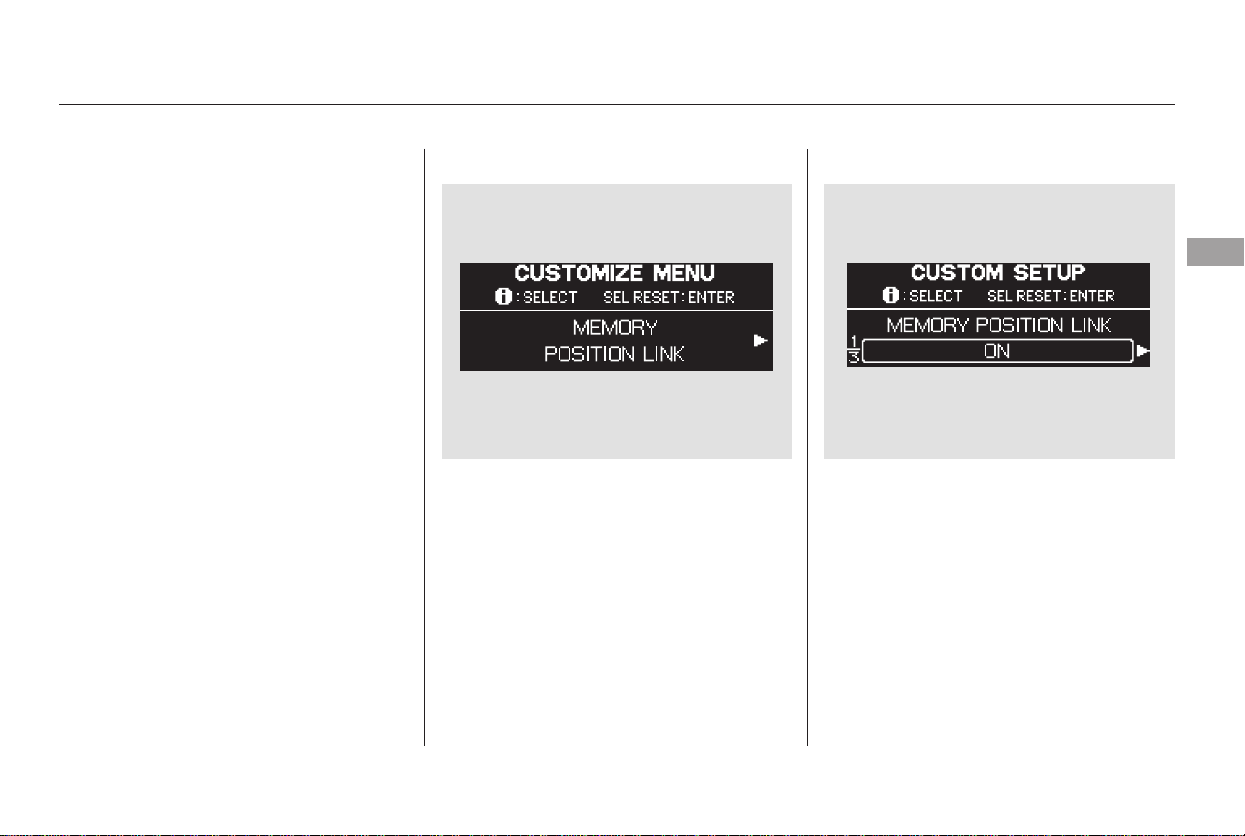
While the multi-information display
shows ‘‘POSITION SETUP,’’ press
the SEL/RESET button on the
steering wheel. The display changes
to ‘‘MEMORY POSITION LINK’’ as
shown above.
Press the SEL/RESET button. The
display changes as shown above.
Each time you press the INFO
button, the display changes between
‘‘MEMORY POSITION LINK ON’’
and ‘‘MEMORY POSITION LINK
OFF.’’
When ‘‘MEMORY POSITION
LINK’’ is set to ‘‘ON,’’ the driver’s
seat moves to the position stored in
memory when you open the driver’s
door after unlocking it with the
remote transmitter.
Refer to page to set the seat
position memory. Also refer to page
forremotetransmitteruse.135
161
CONTINUED
Position Setup
Memory Position Setup
Multi-Information Display
Instruments and Controls
103
Main Menu
Table of Contents
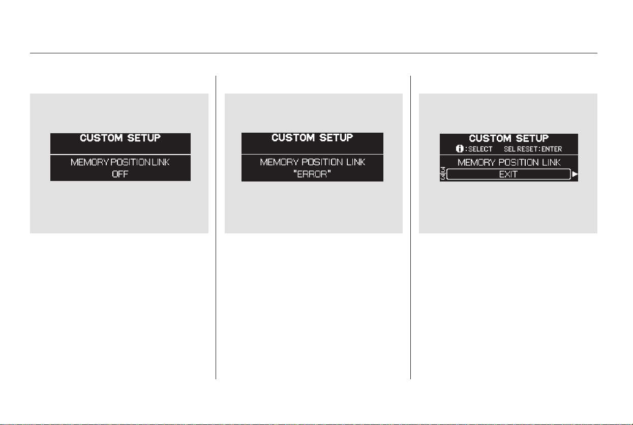
Select ‘‘ON’’ or ‘‘OFF ’’ by pressing
the INFO button, and enter your
selection by pressing the SEL/
RESET button.
When your selection is entered, you
will see the above display for several
seconds, then the display goes back
to ‘‘CUSTOMIZE MENU.’’
If you fail to enter your selection,
you will see the above display for
several seconds, and the display goes
back to ‘‘CUSTOMIZE MENU.’’
Repeat the setup.
To exit ‘‘MEMORY POSITION
LINK,’’ press the INFO button until
you see ‘‘EXIT,’’ then press the SEL/
RESET button.
Multi-Information Display
104
Main Menu
Table of Contents
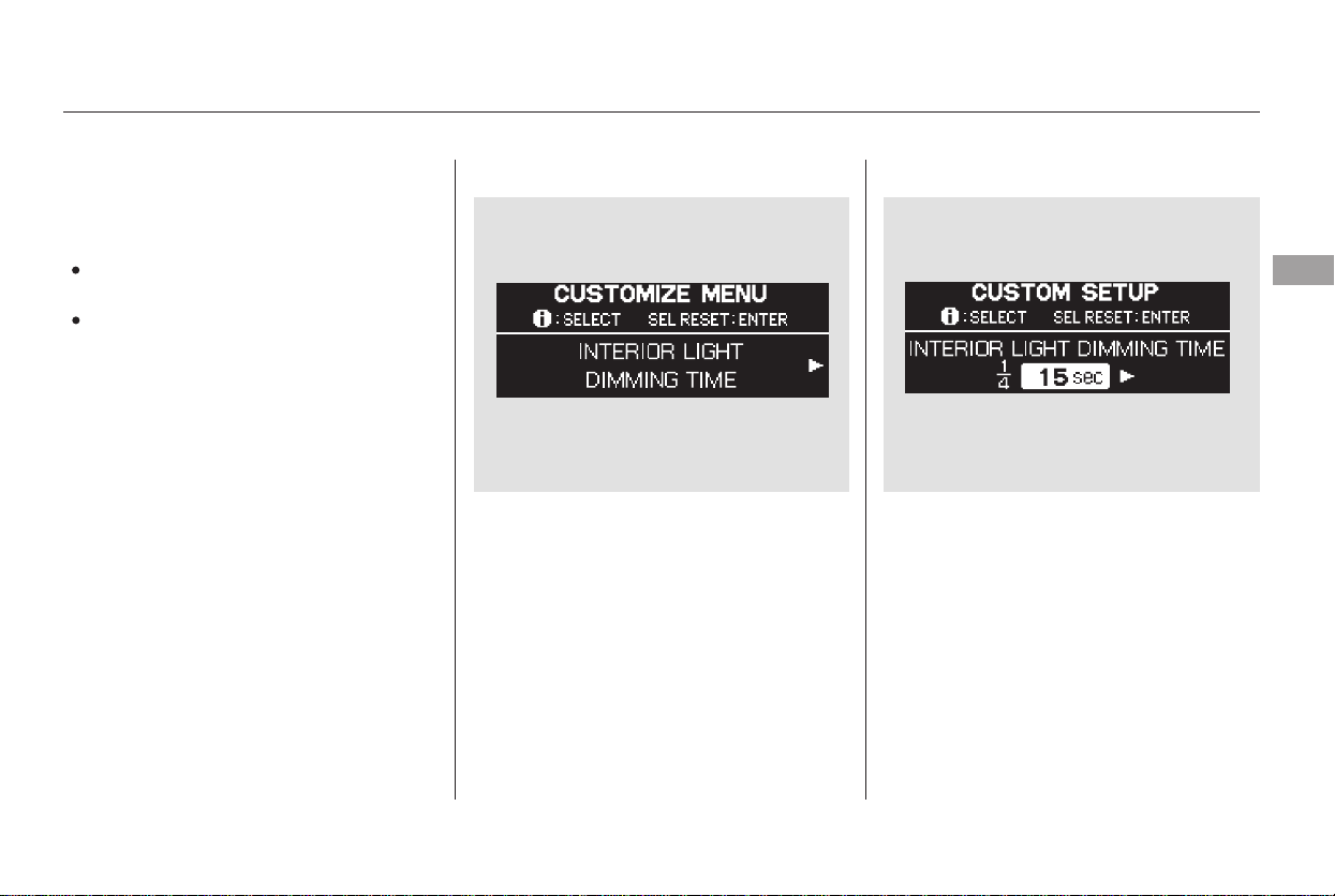
There are two custom settings in the
Lighting Setup:
The interior lights fade out when you
close all doors and the tailgate. You
can change the time that the interior
lights fade out.
While the multi-information display
shows ‘‘LIGHTING SETUP,’’ press
the SEL/RESET button on the
steering wheel. The display changes
to ‘‘INTERIOR LIGHT DIMMING
TIME’’ as shown above.
Press the SEL/RESET button. The
display changes as shown above.
Each time you press the INFO
button, the highlighted number
changes from ‘‘15 sec,’’ to ‘‘30 sec,’’
andthento‘‘60sec.’’
INTERIOR LIGHT
DIMMING TIME
HEADLIGHT AUTO OFF TIMER
While the ‘‘LIGHTING SETUP’’ is
displayed, press the SEL/RESET
buttononthesteeringwheel.The
display changes between
‘‘INTERIOR LIGHT DIMMING
TIME’’ and ‘‘HEADLIGHT AUTO
OFF TIMER.’’
CONTINUED
Lighting Setup
Interior Light Dimming Time
Multi-Information Display
Instruments and Controls
105
Main Menu
Table of Contents
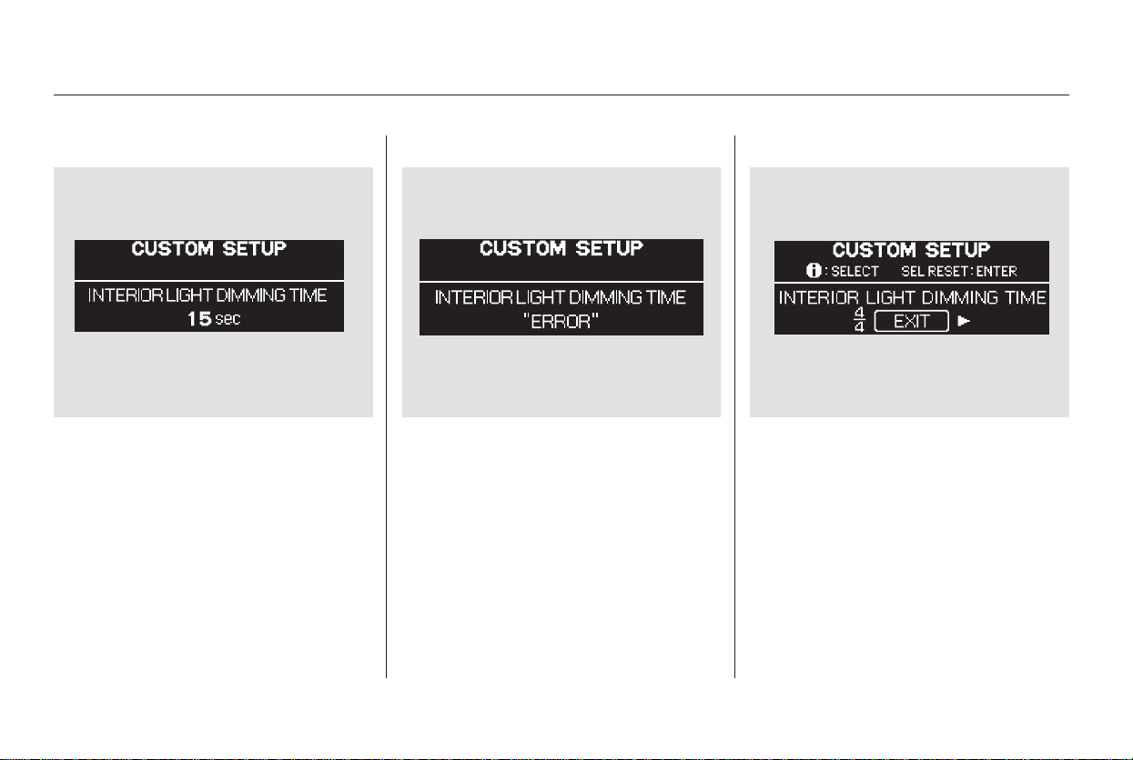
Press the INFO button repeatedly
until the desired time appears, then
press the SEL/RESET button to
enter your selection.
When your selection is entered, you
will see the above display for several
seconds, and then the display goes
back to ‘‘CUSTOMIZE MENU.’’
If you fail to enter your selection,
you will see the above display for
several seconds, and the display goes
back to ‘‘CUSTOMIZE MENU.’’
Repeat the setup.
To exit ‘‘INTERIOR LIGHT
DIMMING TIME,’’ press the INFO
button until you see ‘‘EXIT,’’ then
press the SEL/RESET button.
Multi-Information Display
106
Main Menu
Table of Contents
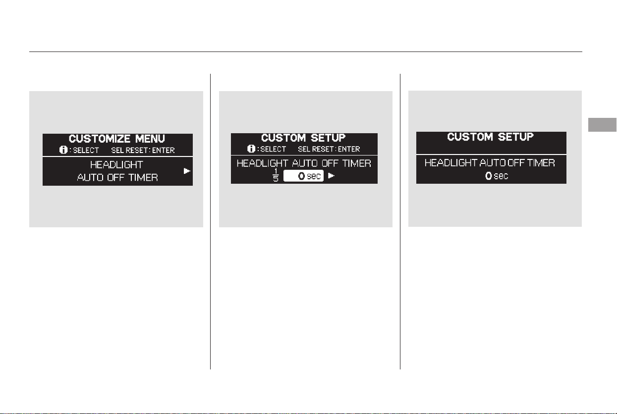
While the multi-information display
shows ‘‘LIGHTING SETUP,’’ press
the SEL/RESET button on the
steering wheel. Then press the
INFO button to display
‘‘HEADLIGHT AUTO OFF TIMER’’
as shown above.
Press the SEL/RESET button. The
display changes as shown above.
Each time you press the INFO
button, the highlighted number
changes from ‘‘0 sec,’’ to ‘‘15 sec,’’ to
‘‘30 sec,’’ and then to ‘‘60 sec.’’
Press the INFO button repeatedly
until the desired time appears, then
press the SEL/RESET button to
enter your selection.
When your selection is entered, you
will see the above display for several
seconds, and then the display goes
back to ‘‘CUSTOMIZE MENU.’’
CONTINUED
Headlight Auto Off Timer
Multi-Information Display
Instruments and Controls
107
Main Menu
Table of Contents
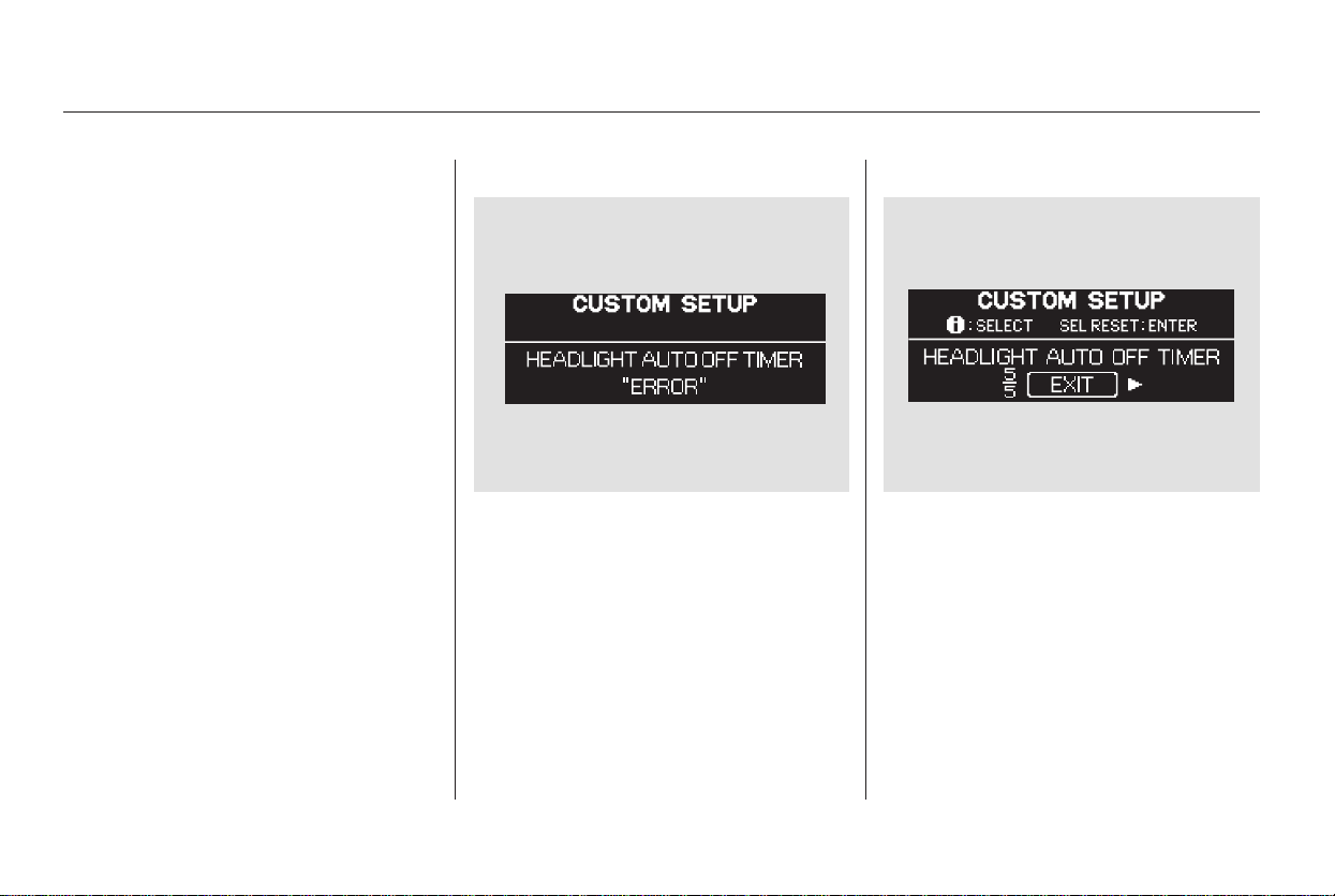
The headlights, parking lights,
taillights, and license plate light turn
off after the selected time when you
remove the key from the ignition
switch and close the driver’s door.
If you fail to enter your selection,
you will see the above display for
several seconds, and the display goes
back ‘‘CUSTOMIZE MENU.’’ Repeat
the setup.
To exit ‘‘HEADLIGHT AUTO OFF
TIMER,’’ press the INFO button
until you see ‘‘EXIT,’’ then press the
SEL/RESET button.
Multi-Information Display
108
Main Menu
Table of Contents
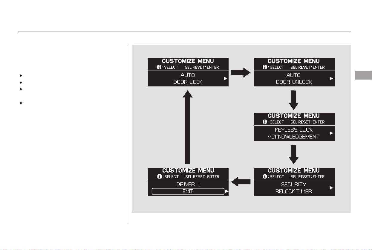
There are four custom settings in
the Door and Window Setup:
While the multi-information display
shows ‘‘DOOR, WINDOW SETUP,’’
press the SEL/RESET button on the
steering wheel. Each time you press
the INFO button, the display
changesasshowninthenext
column.
AUTO DOOR LOCK
AUTO DOOR UNLOCK
KEYLESS LOCK
ACKNOWLEDGEMENT
SECURITY RELOCK TIMER
To customize a setting, press the
INFO button repeatedly until you see
the setting you want to customize,
and press the SEL/RESET button.
Then follow the procedures
described on the following pages.
Door and Window Setup
Multi-Information Display
Instruments and Controls
109
Main Menu
Table of Contents
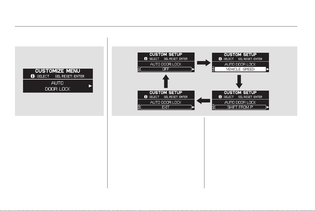
To customize the auto door locking
feature, do this:
While the multi-information display
shows ‘‘DOOR·WINDOW SETUP,’’
press the SEL/RESET button on the
steering wheel. The display changes
to ‘‘AUTO DOOR LOCK’’ as shown
above.
Press the SEL/RESET button again,
then press the INFO button. Each
time you press the INFO button, the
display changes from ‘‘OFF,’’ to
‘‘VEHICLE SPEED,’’ to ‘‘SHIFT
FROM P,’’ and then to ‘‘EXIT’’ as
shown above.
Therearethreepossiblesettings:
OFF: The auto door lock is
deactivated all the time.
SHIFT FROM P: The doors lock
whenever you move the shift lever
out of P.
VEHICLE SPEED: The doors lock
when the vehicle speed reaches 10
mph (16 km/h).
Auto Door Lock
Multi-Information Display
110
Main Menu
Table of Contents
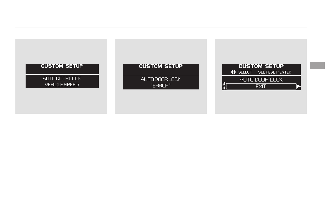
Press the INFO button repeatedly
until the desired condition appears,
then press the SEL/RESET button
to enter your selection.
When your selection is entered, you
will see the above display for several
seconds, and then the display goes
back to ‘‘CUSTOMIZE MENU.’’
If you fail to enter your selection,
you will see the above display for
several seconds, and the display goes
back to ‘‘CUSTOMIZE MENU.’’
Repeat the setup.
To exit ‘‘AUTO DOOR LOCK,’’
press the INFO button until you see
‘‘EXIT,’’ then press the SEL/RESET
button.
CONTINUED
Multi-Information Display
Instruments and Controls
111
Main Menu
Table of Contents
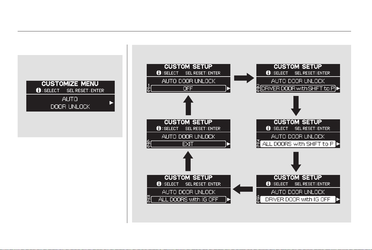
To customize the auto door
unlocking feature, do this:
While the multi-information display
shows ‘‘DOOR·WINDOW SETUP,’’
press the SEL/RESET button on the
steering wheel. Then press the
INFO button once. The display
changes to ‘‘AUTO DOOR
UNLOCK’’ as shown above.
Auto Door Unlock
Multi-Information Display
112
Main Menu
Table of Contents
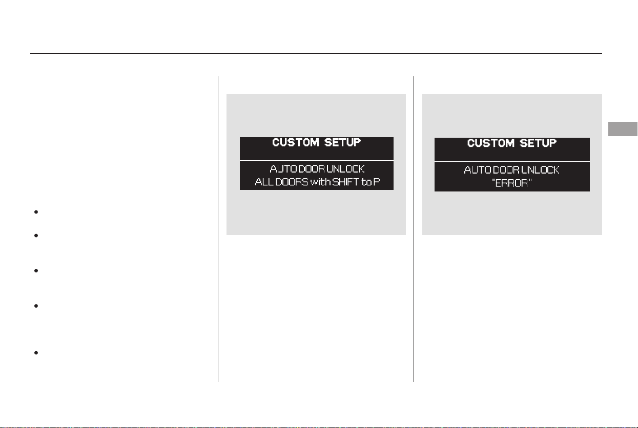
Press the SEL/RESET button again
to enter ‘‘Auto Door Unlock,’’ then
press the INFO button. Each time
you press the INFO button, the
display changes from ‘‘OFF,’’ to
‘‘DRIVER DOOR with SHIFT to P,’’
to ‘‘ALL DOORS with SHIFT to P,’’
to ‘‘DRIVER DOOR with IG OFF,’’
andthento‘‘EXIT’’asshownonthe
previous page.
If you fail to enter your selection,
you will see the above display for
several seconds, and the display goes
back to ‘‘CUSTOMIZE MENU.’’
Repeat the setup.
To exit ‘‘AUTO DOOR UNLOCK,’’
press the INFO button until you see
‘‘EXIT,’’ then press the SEL/RESET
button.
Press the INFO button repeatedly
until the desired condition appears,
and press the SEL/RESET button to
enter your selection.
When your selection is entered, you
will see the above display for several
seconds, and then the display goes
back to ‘‘CUSTOMIZE MENU.’’
OFF: The auto door unlock is
deactivated all the time.
DRIVER DOOR with SHIFT to P:
The driver’s door unlocks when
you move the shift lever to P.
ALL DOORS with SHIFT to P: All
doors unlock when you move the
shift lever to P.
DRIVER DOOR with IG OFF: The
driver’s door unlocks when you
turn the ignition switch to LOCK
(0).
ALL DOORS with IG OFF: All
doors unlock when you turn the
ignition switch to LOCK (0).
CONTINUED
Multi-Information Display
Instruments and Controls
113
Main Menu
Table of Contents
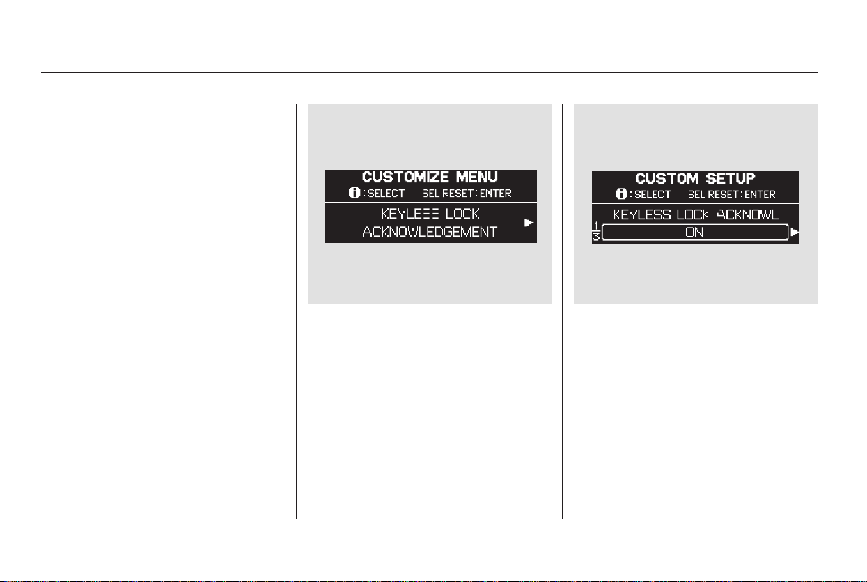
When you push the LOCK button on
the remote transmitter, some
exterior lights flash, and a beeper
sounds when you push the LOCK
button again within 5 seconds to
verify that the doors and the tailgate
arelockedandthesecuritysystem
has set (see page ). You can
customize the exterior lights not to
flash and the beeper not to sound.
While the multi-information display
shows ‘‘DOOR·WINDOW SETUP,’’
press the SEL/RESET button on the
steering wheel. Then press the
INFO button repeatedly until you see
‘‘KEYLESS LOCK
ACKNOWLEDGMENT’’ as shown
above.
Press SEL/RESET button, then
press the INFO button.
Each time you press the INFO
button, the display changes to ‘‘ON,’’
to ‘‘OFF,’’ then to ‘‘EXIT.’’
Select ‘‘ON’’ or ‘‘OFF’’ by pressing
the INFO button, and enter your
selection by pressing the SEL/
RESET button.
133
Keyless Lock Acknowledgment
Multi-Information Display
114
Main Menu
Table of Contents
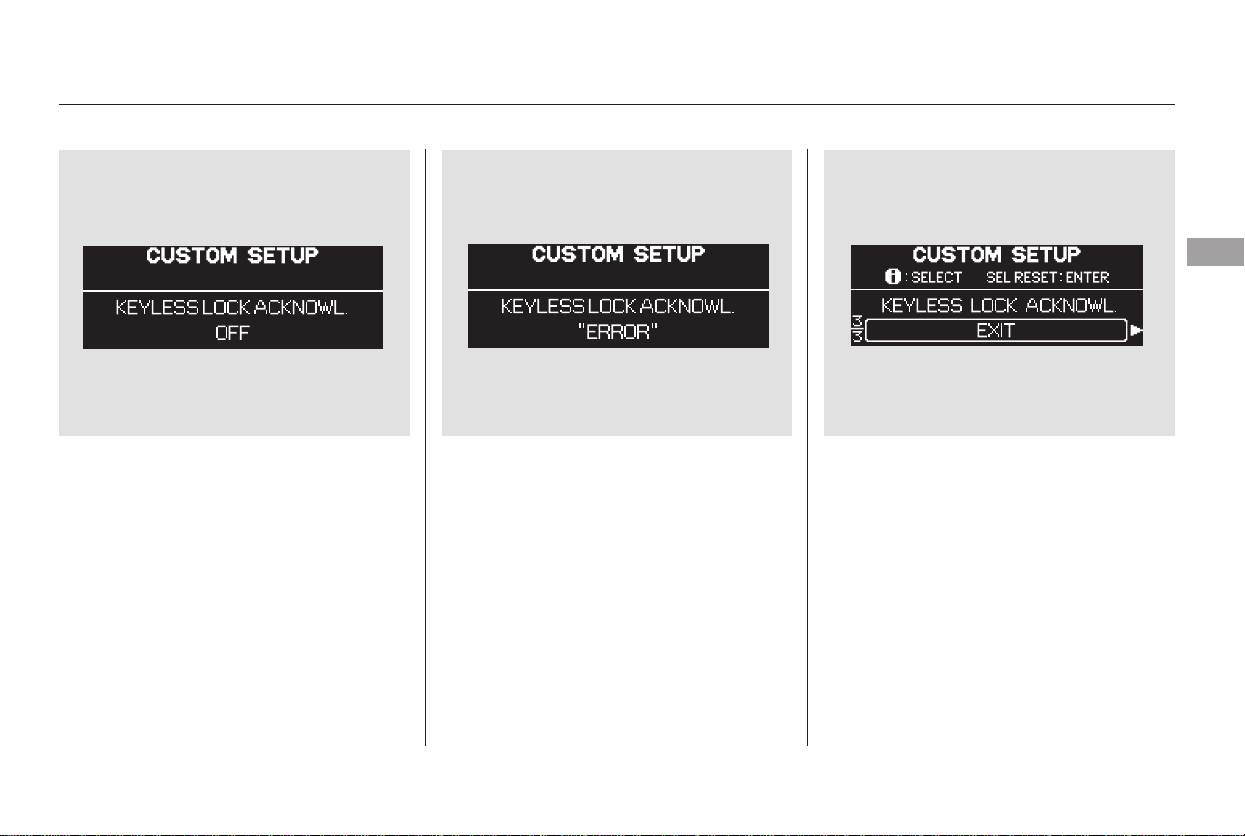
When your selection is entered, you
will see the above display for several
seconds, and then the display
changes to ‘‘CUSTOMIZE MENU.’’
To exit ‘‘KEYLESS LOCK
ACKNOWLEDGMENT,’’ press the
INFO button until you see ‘‘EXIT,’’
then press the SEL/RESET button.
If you fail to enter your selection,
you will see the above display for
several seconds, and the display goes
back to ‘‘CUSTOMIZE MENU.’’
Repeat the setup.
CONTINUED
Multi-Information Display
Instruments and Controls
115
Main Menu
Table of Contents
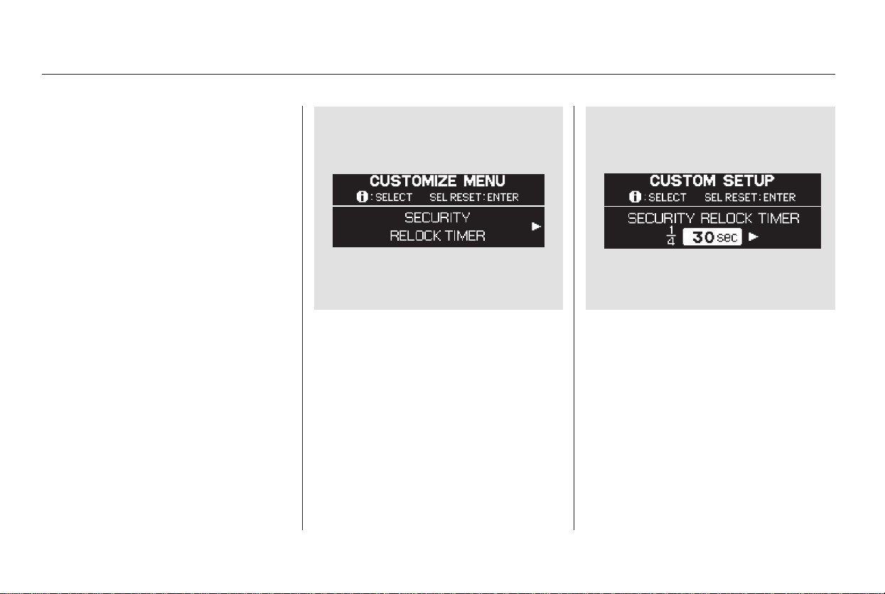
If you unlock the doors and the
tailgate with the remote transmitter,
but do not open any of the doors or
thetailgatewithin30seconds,the
doors and the tailgate automatically
relock and the security system sets.
You can change this relock time
from 30 seconds to 60 or 90 seconds.
While the multi-information display
shows ‘‘DOOR·WINDOW SETUP,’’
press the SEL/RESET button on the
steering wheel. Then press the
INFO button repeatedly until you see
‘‘SECURITY RELOCK TIMER’’ as
shown above.
Press the SEL/RESET button, then
press the INFO button.
Each time you press the INFO
button, the time changes from ‘‘30
sec,’’ to ‘‘60 sec,’’ and then to ‘‘90 sec.’’
Security Relock Timer
Multi-Information Display
116
Main Menu
Table of Contents

Select the desired relock time by
pressing the INFO button, and enter
your selection by pressing the SEL/
RESET button.
If you fail to enter your selection,
you will see the above display for
several seconds, and the display goes
back to ‘‘CUSTOMIZE MENU.’’
Repeat the setup.
When your selection is entered, you
will see the above display for several
seconds, and then the display goes
back to ‘‘CUSTOMIZE MENU.’’
To exit ‘‘SECURITY RELOCK
TIMER,’’ press the INFO button
until you see ‘‘EXIT,’’ then press the
SEL/RESET button.
Multi-Information Display
Instruments and Controls
117
Main Menu
Table of Contents

With ‘‘WIPER SETUP’’ shown on the
multi-information display, press the
SEL/RESET button on the steering
wheel. The display changes to
‘‘FRONT WIPER ACTION’’ as
shown above.
Press the SEL/RESET button, then
press the INFO button.
Each time you press the INFO
button, the display changes from
‘‘WITH VEH SPD,’’ to
‘‘INTERMITTENT,’’ and then to
‘‘EXIT.’’
Press the INFO button to select
‘‘WITH VEH SPD’’ or
‘‘INTERMITTENT,’’ and enter your
selection by pressing the SEL/
RESET button.
When ‘‘WIPER SETUP’’ is shown on
the multi-information display, the
action of the windshield wipers can
be changed. To do this, refer to the
following procedure.
Wiper Setup
Front Wiper Action
Multi-Information Display
118
Main Menu
Table of Contents
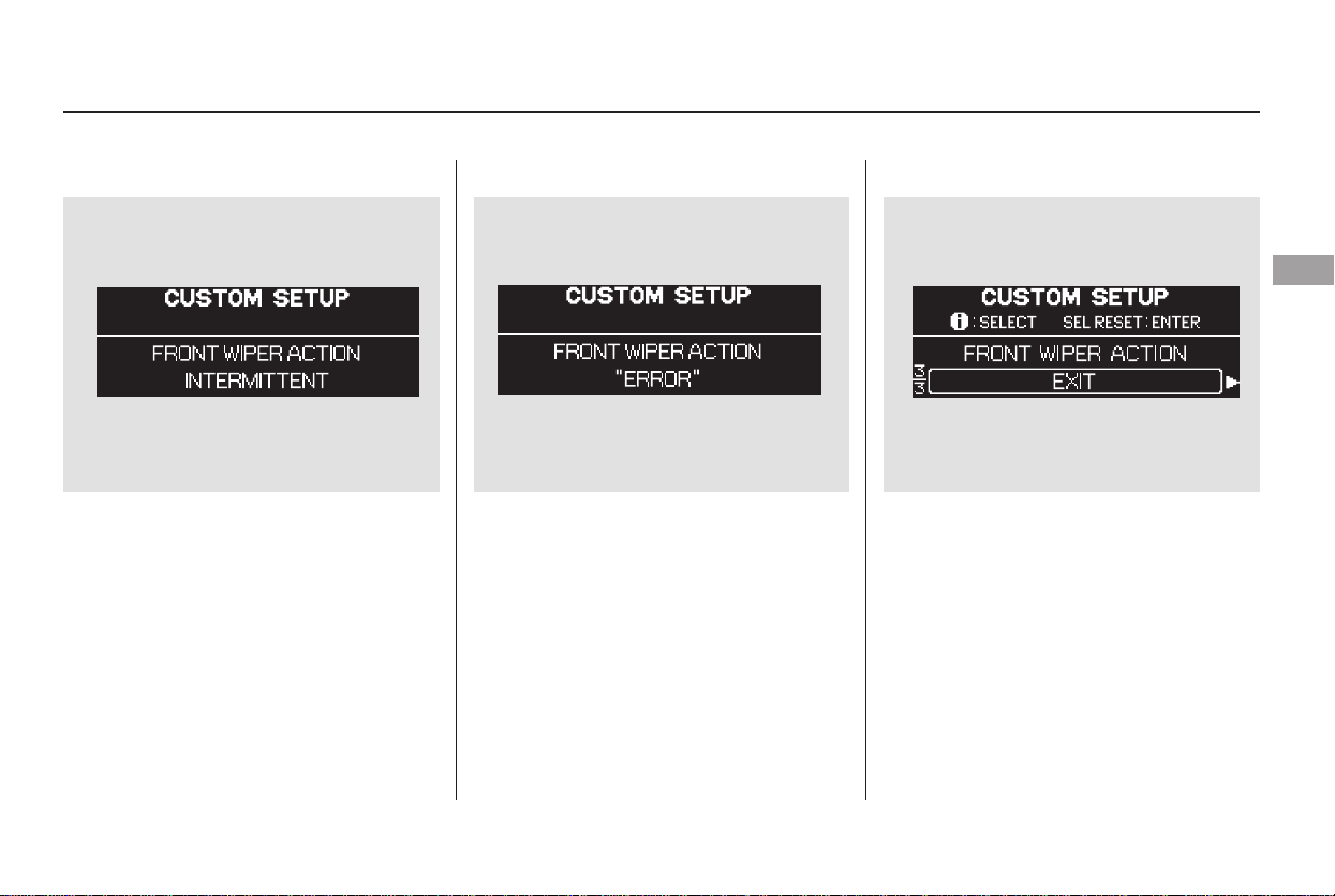
If you set the front wiper action to
‘‘WITH VEH SPD,’’ the front wipers
run intermittently and the wiper
interval is varied automatically
according to the vehicle’s speed
when the wiper switch is in the
‘‘INT’’position. If you set it to
‘‘INTERMITTENT,’’ the wipers run
at regular intervals.
When your selection is entered, you
will see the above display for several
seconds, and then the display goes
back to ‘‘CUSTOMIZE MENU.’’
To exit ‘‘FRONT WIPER ACTION,’’
press the INFO button until you see
‘‘EXIT,’’ then press the SEL/RESET
button.If you fail to enter your selection,
you will see the above display for
several seconds, and the display goes
back to ‘‘CUSTOMIZE MENU.’’
Repeat the setup.
Multi-Information Display
Instruments and Controls
119
Main Menu
Table of Contents
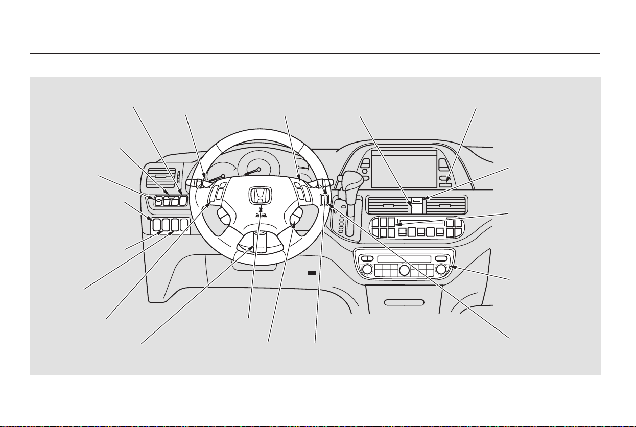
*
*
To use the horn, press the pad around the ‘‘H’’ logo.:
Controls Near the Steering Wheel
120
POWER SLIDING
DOOR SWITCHES
REAR WINDOW
DEFOGGER
STEERING WHEEL
ADJUSTMENT
CRUISE
CONTROL
CLOCK
LIGHT CONTROL
SWITCH
AUDIO SYSTEM/
REAR
ENTERTAINMENT
SYSTEM
STEERING WHEEL
AUDIO CONTROLS
PASSENGER
AIRBAG OFF
INDICATOR
POWER TAILGATE
SWITCH
HEADLIGHTS/
TURN SIGNALS
HAZARD WARNING
BUTTON
WINDSHIELD
WIPERS/WASHERS
VSA OFF
SWITCH
HORN
(P.142)
(P.139)
(P.271)
(P.302)
(P.228)
(P.127)
(P.121)
(P.122)
(P.264)
(P.126)
(P.227)
(P.33)
(P.126)
(P.199, 230)
(P.183)
PARKING SENSOR
SYSTEM SWITCH
DRIVER’S PEDAL
ADJUSTMENT SWITCH
(P.169)
(P.166)
(P.75)
MULTI-INFORMATION
DISPLAY SWITCHES
VSA OFF SWITCH
/
(P.302)
MOONROOF
Main Menu
Table of Contents
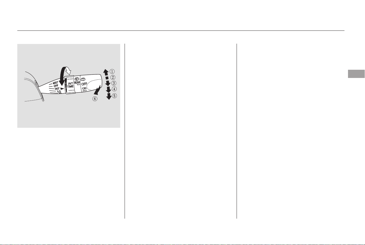
−
−
−
−
−
−
MIST
OFF
INT Intermittent
LO Low speed
HI High speed
Windshield Washers
Push the right lever up or down to
select a position.
The wipers run at high speed
until you release the lever.
The wipers are not activated.
The length of the wipe
interval is varied
automatically according to
the vehicle’s speed. Vary
the delay by turning the
INT TIME ring.
Ifyouturnittotheshortest
delay, the wipers will
change to low speed
operation when the vehicle
speed exceeds 12 mph
(20 km/h).
The wipers run at high speed.
The wipers run at low speed.
:Pullthewiper
control lever toward you and
hold it. The washers spray
until you release the lever.
The wipers run at low speed,
then complete one more
sweep after you release the
lever.
You can customize some windshield
wiper settings. See page for
more information.
1.
2.
3.
4.
5.
6.
118
On Touring model
MIST:
OFF:
INT
HI
LO
Windshield Washer
Windshield Wipers and Washers
Instruments and Controls
121
Main Menu
Table of Contents
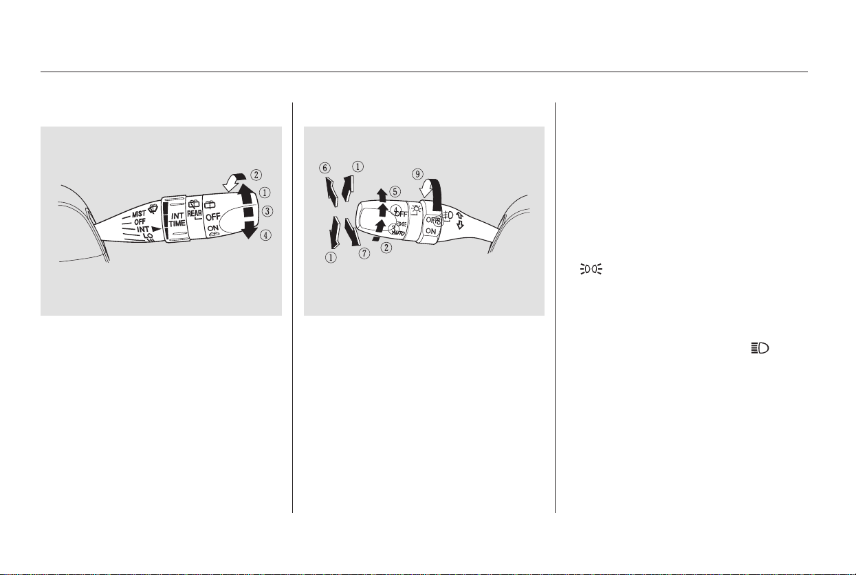
−
−
Push down on the
left lever to signal a left turn and up
to signal a right turn. To signal a lane
change, push lightly on the lever and
hold it. The lever will return to
center when you release it or
complete a turn.
Turning the switch to the ‘‘ ’’
position turns on the headlights. If
you leave the lights on with the
ignition switch in ACCESSORY (I)
or LOCK (0), you will hear a
reminder chime when you open the
driver’s door.
Rotating the
switch on the left lever to the
‘‘ ’’ position turns on the parking
lights, taillights, instrument panel
lights, side-marker lights, and rear
license plate lights.
Turn signal
Off
Parking and indicator lights
AUTO (Touring model only)
Headlights on
High beams
Flashhighbeams
Fog lights off (Touring model
only)
Fog lights on (Touring model
only)
Rotate the switch clockwise to
turn the rear window wiper ON.
Hold past ON to turn the window
wiper on and the window washer
on.
OFF
Rotate the switch
counterclockwise to spray the
window washer without activating
the wiper.
1.
2.
3.
4.
5.
6.
7.
8.
9.
1.
2.
3.
4.
Turn Signal
Headlights On
Turn Signal and HeadlightsRear Window Wiper and Washer
Windshield Wipers and Washers, Turn Signal, Headlights
122
Main Menu
Table of Contents

−
−
When the light switch is in the
‘‘ ’’ or ‘‘ ’’ position, the
lights on indicator comes on as a
reminder. This indicator stays on if
you leave the light switch on and
turn the ignition switch to the
ACCESSORY (I) or LOCK (0)
position.
To switch from low
beams to high beams, push the left
lever forward until you hear a click.
The blue high beam indicator will
come on (see page ). Pull it back
to return to low beams. To flash the
high beams, pull the lever back
lightly, then release it. The high
beams will stay on as long as you
hold the lever back.
Turn the fog lights on and off by
turning the switch next to the
headlight switch.
To turn on the automatic lighting,
turn the light switch to AUTO at any
time. The lights will come on
automatically when the outside light
level becomes low (at dusk, for
example). The lights on indicator
comesonasareminder.Thelights
and indicator turn off automatically
when the system senses high
ambient light.
The automatic lighting
feature turns on the headlights, all
other exterior lights, and the
instrument panel lights when it
senses low ambient light.
You can use the fog lights only when
the headlights are on low beam.
The lights turn off automatically
when you turn the ignition switch to
LOCK (0). To turn them on again,
either turn the ignition switch to ON
(II), or turn the light switch to .
Even with the automatic lighting
feature turned on, we recommend
thatyouturnonthelightsmanually
when driving at night or in a dense
fog, or when you enter dark areas
such as long tunnels or parking
structures.
Do not leave the light switch in
AUTO if you will not be driving the
vehicle for an extended period (a
weekormore).Youshouldalsoturn
off the lights if you plan to leave the
engine idling or the engine off for a
long time.
69
CONTINUED
On Touring model
Touring model only
High Beams
Fog Lights
AUTO
Headlights
Instruments and Controls
123
Main Menu
Table of Contents
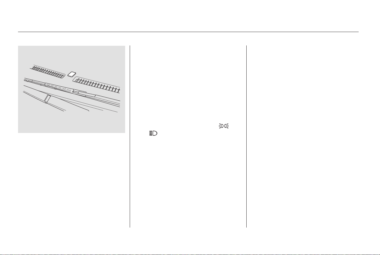
*
*
*
If you unlock the door, but do not
open it within 15 seconds, the lights
go off. With the driver’s door open,
you will hear a lights-on reminder
chime.
The lights turn on again when you
unlock or open the driver’s door.
On the Touring model, this time is
changeable. See page for how to
select and set the time.
This turns off the headlights,
parking lights, taillights, side marker
lights, license plate lights, and
instrument panel lights within 15
seconds of removing the key from
the ignition switch and closing the
driver’s door.
This feature activates if you leave
the headlight switch in the ‘‘ ’’
or ‘‘ ’’ position, remove the key,
then open and close the driver’s door.
If you remove the key from the
ignition switch with the headlight
switch on, but do not open the door
and get out, the lights turn off after
10 minutes.
The automatic lighting feature is
controlledbyasensorlocatedontop
of the dashboard. Do not cover this
sensor or spill liquids on it.
107
On EX and Touring models only
Automatic Lighting Off Feature
Headlights
124
Main Menu
Table of Contents
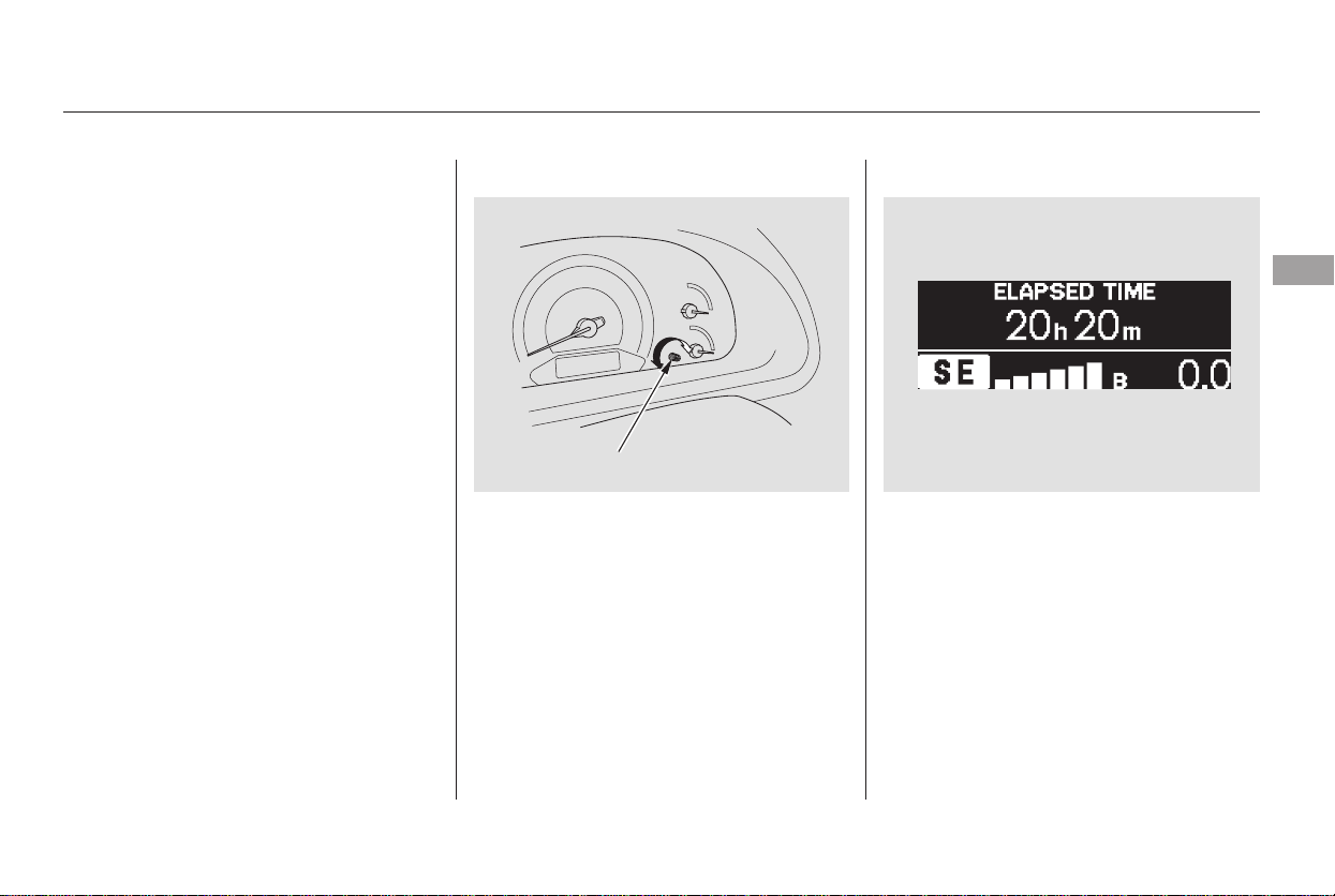
The level of brightness is shown on
the multi-information display on the
Touring model or in the odometer/
trip meter display on LX and EX
models while you adjust it. It goes
out 5 seconds after you finish
adjusting.
The knob on the instrument panel
controls the brightness of the instru-
ment panel lights. Turn the knob to
adjust the brightness.
With the headlight switch off, the
high beam headlights and the high
beam indicator come on with
reduced brightness when you turn
the ignition switch to ON (II) and
release the parking brake. They
remain on until you turn the ignition
switch off, even if you set the
parking brake.
The headlights revert to normal
operation when you turn them on
with the switch.
Instrument Panel BrightnessDaytime Running Lights
(Canadian Models)
Headlights, Instrument Panel Brightness
Instruments and Controls
125
BRIGHTNESS LEVEL
SELECT/RESET KNOB
Touring model shown
Main Menu
Table of Contents
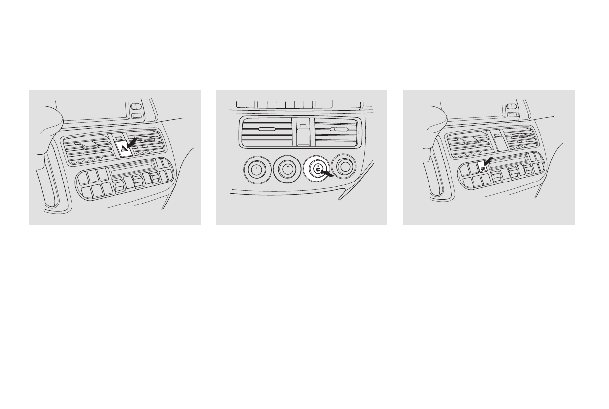
Push the red button between the
center air vents to turn on the hazard
warning lights (four-way flashers).
This causes all four outside turn
signals and both indicators in the
instrument panel to flash. Use the
hazard warning lights if you need to
park in a dangerous area near heavy
traffic, or if your vehicle is disabled.
The defogger wires on the inside of
the rear window can be accidentally
damaged. When cleaning the glass,
always wipe side-to-side.
Make sure the rear window is clear
and you have good visibility before
starting to drive.
The rear window defogger will clear
fog, frost, and thin ice from the
window. Push the defogger button to
turn it on and off. The indicator in
the button comes on to show the
defogger is on. It shuts off when you
turn off the ignition. You have to
turn the defogger on again when you
restart the vehicle.
Hazard Warning Button Rear Window Defogger
Hazard Warning Button, Rear Window Defogger
126
LX model
EX and Touring models
Main Menu
Table of Contents
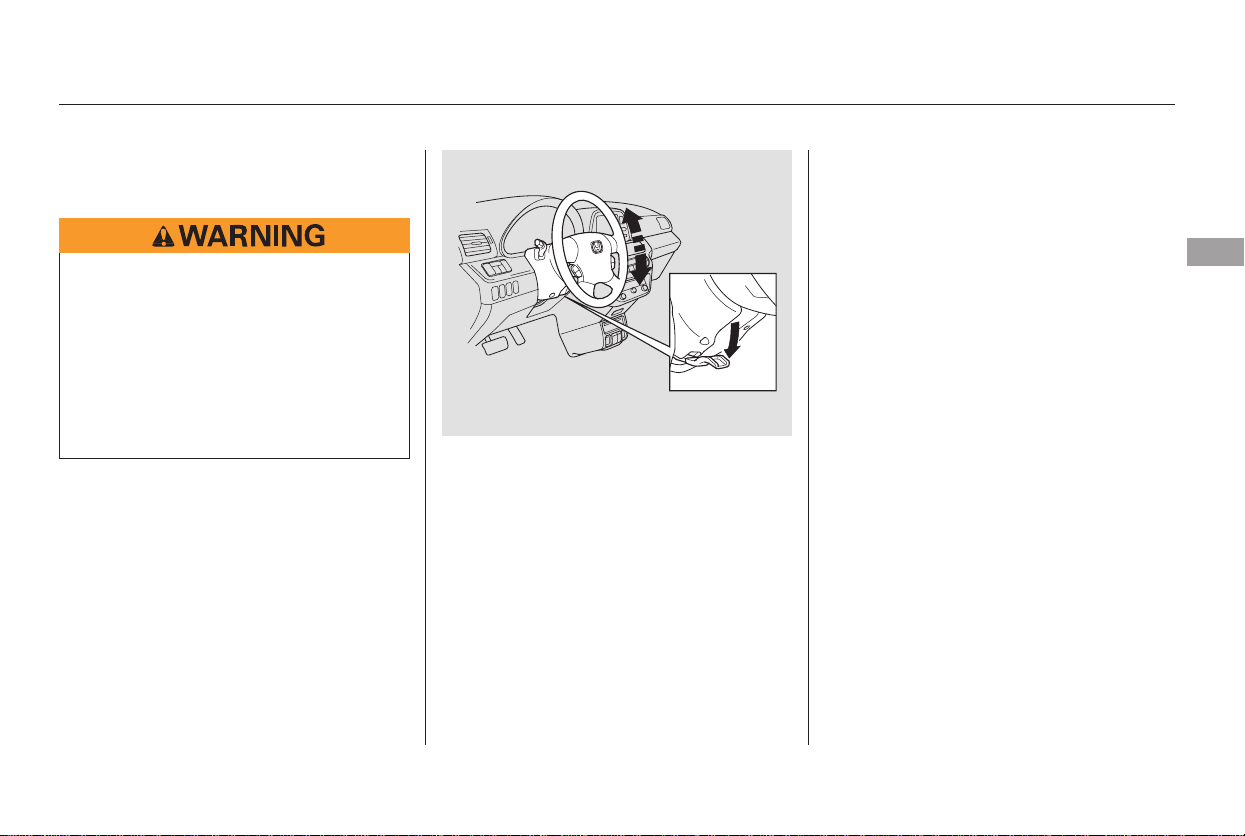
Make any steering wheel adjustment
before you start driving.
Push the lever under the steering
column all the way down.
Move the steering wheel so it
points toward your chest, not
toward your face. Make sure you
can see the instrument panel
gauges and indicators.
Push the lever up to lock the
steering wheel in position.
Make sure you have securely
locked the steering wheel in place
by trying to move it up and down.
3.
4.
1.
2.
Steering Wheel Adjustment
Instruments and Controls
127
Adjusting the steering wheel
position while driving may
cause you to lose control of the
vehicle and be seriously injured
inacrash.
Adjust the steering wheel only
when the vehicle is stopped.
Main Menu
Table of Contents
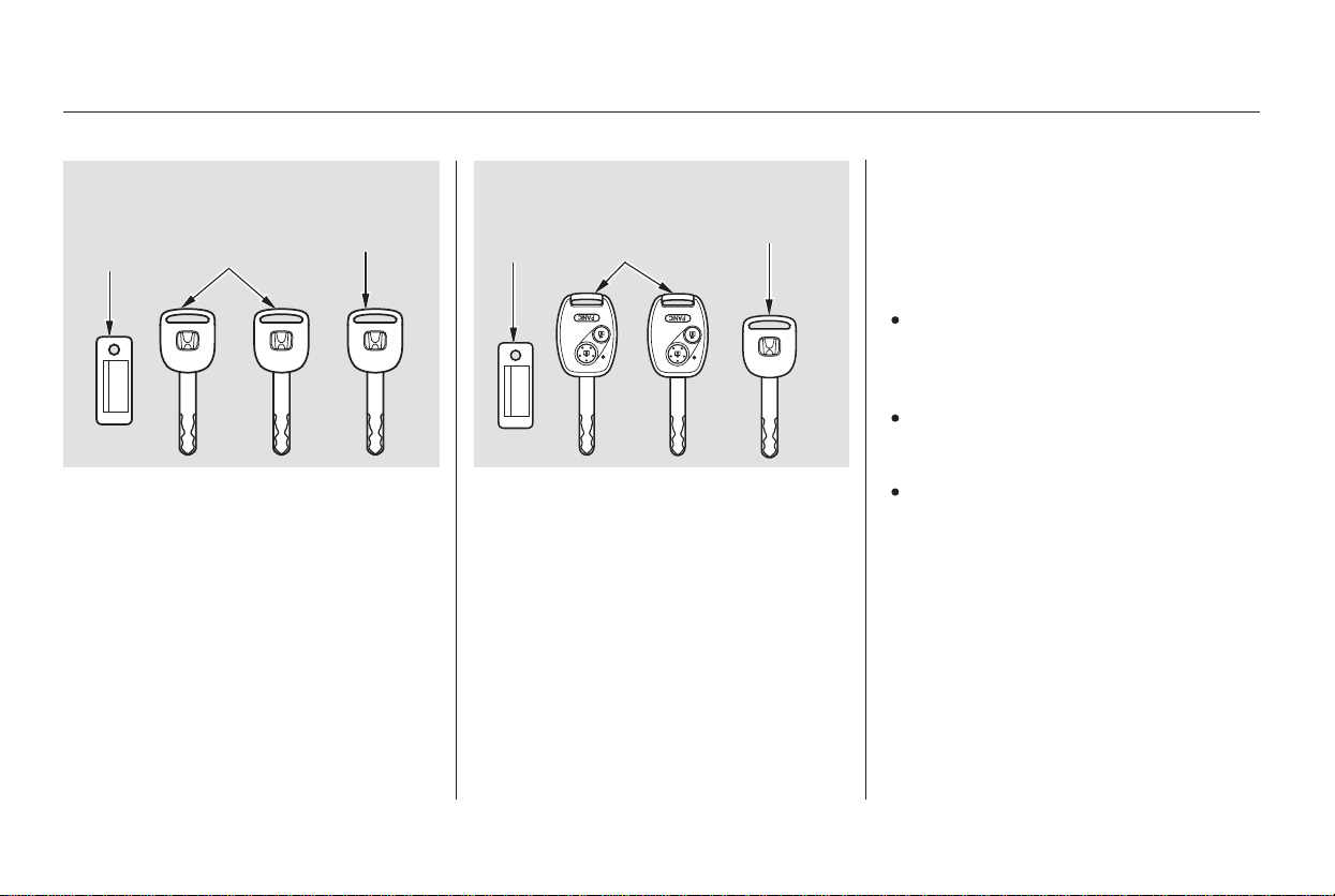
These keys contain electronic
circuits that are activated by the
Immobilizer System. They will not
work to start the engine if the
circuits are damaged.
Protect the keys from direct
sunlight, high temperature, and
high humidity.
Donotdropthekeysorsetheavy
objects on them.
Keep the keys away from liquids.
If they get wet, dry them
immediately with a soft cloth.
The master key fits all the locks on
your vehicle. The valet key works
only in the ignition and the door
locks. You can keep the glove box
locked when you leave your vehicle
and the valet key at a parking facility. The keys do not contain batteries.
Do not try to take them apart.
Youshouldhavereceivedakey
number tag with your keys. You will
need this key number if you ever
have to get a lost key replaced. Use
only Honda-approved key blanks.
On EX and Touring models
Keys and Locks
128
MASTER
KEYS
(BLACK)
VALET KEY
(GRAY)
KEY
NUMBER
TAG
LX model
EX and Touring models
MASTER
KEYS
(BLACK)
VALET KEY
(GRAY)
KEY
NUMBER
TAG
Main Menu
Table of Contents

The system may not recognize your
key’s coding if another immobilizer
key or other metal object (i.e. key
fob) is near the ignition switch when
you insert the key.
If the system repeatedly does not
recognize the coding of your key,
contact your dealer.
Do not attempt to alter this system
or add other devices to it. Electrical
problems could result that may make
your vehicle undriveable.
If you have lost your key and you
cannot start the engine, contact your
dealer.
The immobilizer system protects
your vehicle from theft. If an
improperly-coded key (or other
device) is used, the engine will not
start.
When you turn the ignition switch to
ON (II), the immobilizer system
indicator should come on for a few
seconds, then go out. If the indicator
starts to blink, it means the system
does not recognize the coding of the
key. Turn the ignition switch to
LOCK (0), remove the key, reinsert
it, and turn the switch to ON (II)
again.
As required by the FCC:
This device complies with Part 15 of the
FCC rules. Operation is subject to the
following two conditions: (1) This device
may not cause harmful interference, and
(2) this device must accept any
interference received, including
interference that may cause undesired
operation.
Changes or modifications not expressly
approved by the party responsible for
compliance could void the user’s
authority to operate the equipment.
This device complies with Industry
Canada Standard RSS-210.
Operation is subject to the following two
conditions: (1) this device may not cause
interference, and (2) this device must
accept any interference that may cause
undesired operation of the device.
Immobilizer System
Instruments and Controls
129
Main Menu
Table of Contents
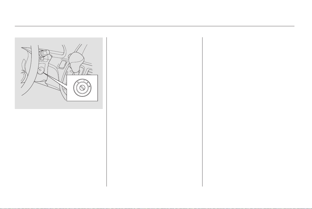
−−
−
−
Use this position
only to start the engine. The switch
returns to ON (II) when you let go of
the key.
You will hear a reminder beeper if
you leave the key in the ignition
switch in the LOCK (0) or
ACCESSORY (I) position and open
the driver’s door. Remove the key to
turn off the beeper.
TheshiftlevermustbeinPark
before you can remove the key from
the ignition switch.
The ignition switch has four
positions: LOCK (0), ACCESSORY
(I), ON (II), and START (III).
You can insert or
remove the key only in this position.
To turn the key, the shift lever must
be in Park, and you must push the
key in slightly.
If the front wheels are turned, the
anti-theft lock may make it difficult
to turn the key. Firmly turn the
steering wheel to the left or right as
you turn the key.
You can
operate the audio system and the
accessory power sockets in this
position.
This is the normal key
position when driving. Several of the
indicators on the instrument panel
come on as a test when you turn the
ignition switch from ACCESSORY
(I) to ON (II).
START (III)LOCK (0)
ACCESSORY (I)
ON (II)
Ignition Switch
130
Main Menu
Table of Contents
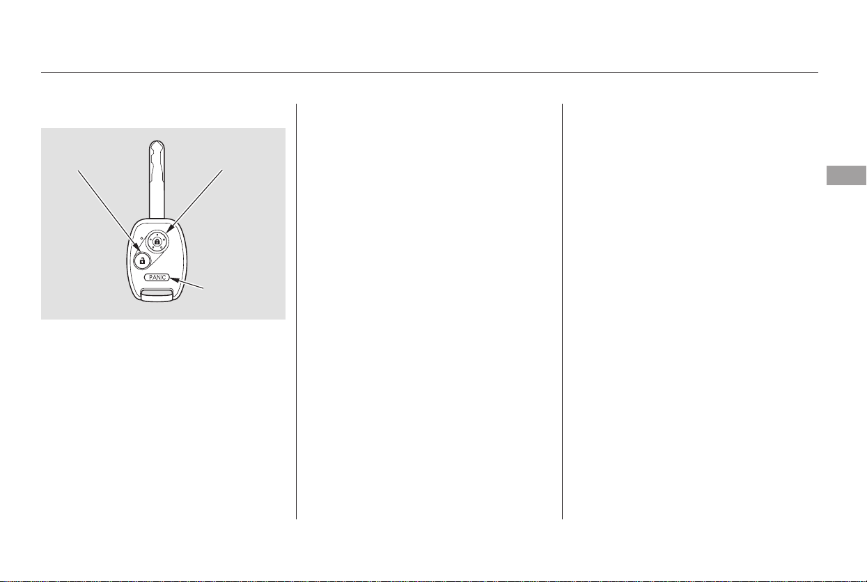
−
−−
Press this button once to
lock all doors and the tailgate. Some
exterior lights will flash. When you
push LOCK button twice within 5
seconds, you will hear a beep to
verify that the doors and the tailgate
are locked. You cannot lock the
doors and the tailgate if any door or
the tailgate is not fully closed or if
the key is in the ignition switch.
Press this button once
to unlock the driver’s door. Press it
twice to unlock the other doors and
the tailgate. Some exterior lights will
flash twice each time you press the
button. If you do not open any door
orthetailgatewithin30seconds,
they will automatically relock.
Press and hold this
button for about 1 second to attract
attention; the horn will sound and
the exterior lights will flash for about
30 seconds. To cancel panic mode,
press any other button on the remote
transmitter or turn the ignition
switch to ON (II).
Refertopage forhowtotake
care of your remote transmitter.
When you press the UNLOCK
button, the front and rear individual
map lights, depending on their
switch positions, will come on (see
page ). If you do not open any
door or the tailgate, the lights stay
on for about 30 seconds, then go out.
If you relock the doors and the
tailgate with the remote transmitter
before 30 seconds have elapsed, the
lights will go off immediately.
135
183
CONTINUED
On LX model
LOCK
UNLOCK PANIC
Remote Transmitter Care
Remote Transmitter
Instruments and Controls
131
UNLOCK
BUTTON
LOCK
BUTTON
PANIC
BUTTON
Main Menu
Table of Contents
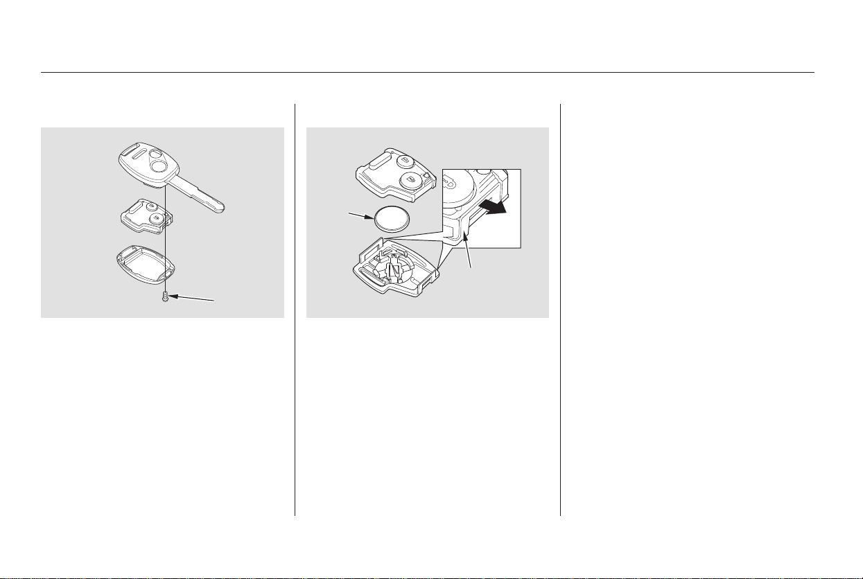
+
If it takes several pushes on the
button to lock or unlock the doors
and the tailgate, replace the battery
as soon as possible.
Battery type: CR1616
To replace the battery:
Remove the screw at the base of
the transmitter with a small
Phillips-head screwdriver.
Separate the transmitter by prying
its middle seam with your
fingernail.
Inside the transmitter, separate
the inner cover from the keypad
by releasing the two tabs on the
cover.
Remove the old battery from the
back of the inner cover, and note
the polarity. Make sure the
polarity of the new battery is the
same ( side facing down), then
insert it into the back of the cover.
3.
4.
1.
2.
Replacing the Transmitter Battery
Remote Transmitter
132
SCREW
BATTERY
TAB
Main Menu
Table of Contents
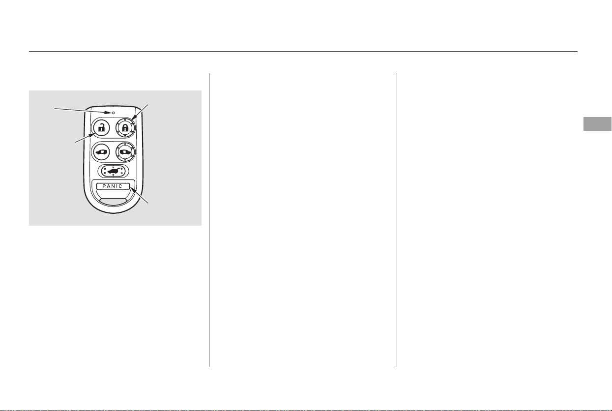
−
−
−Press this button once to
lock all doors and the tailgate. Some
exterior lights will flash. When you
push LOCK twice within 5 seconds,
you will hear a beep to verify that the
doors and the tailgate are locked and
the security system has set.
Press this button once
to unlock the driver’s door. Press it
twice to unlock the other doors and
the tailgate. Some exterior lights will
flash twice each time you press the
button.
If you do not open any doors or the
tailgate within 30 seconds, they will
automatically relock and the security
system sets.
If you press the LOCK button and
the PASSENGER’S SIDE SLIDING
DOOR button at the same time for
about 1 second, the LED in the
remote transmitter will blink twice,
and all doors and the tailgate will
unlock simultaneously when you
press the UNLOCK button. To
cancel this feature, press the LOCK
button and the PASSENGER’S SIDE
SLIDING DOOR button at the same
time. The LED will blink once.
On the Touring model, you can
change this setting (see page ).
When you press the UNLOCK
button, the front and rear individual
map lights, depending on their
switch positions, will come on (see
page ). If you do not open any
door or the tailgate, the lights stay
on for about 30 seconds, then go out.
If you relock the doors and the
tailgate with the remote transmitter
before 30 seconds have elapsed, the
lights will go off immediately.
Press and hold this
button for about 1 second to attract
attention; the horn will sound and
the exterior lights will flash for about
30 seconds. To cancel panic mode,
press any other button on the remote
transmitter or turn the ignition
switch to ON (II).
116
183
On EX and Touring models
LOCK
UNLOCK
PANIC
Remote Transmitter
Instruments and Controls
133
LED
LOCK
BUTTON
PANIC
BUTTON
UNLOCK
BUTTON
Main Menu
Table of Contents
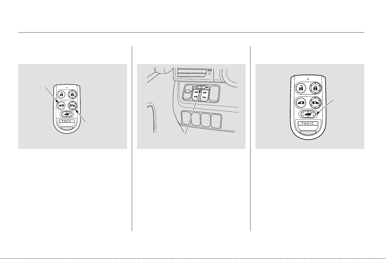
If the power sliding door MAIN
switch on the dashboard is in the
OFF position, you cannot open or
close the sliding doors with the
remote transmitter.
You can open or close the power
tailgate with the remote transmitter
when the doors are unlocked. Press
andholdtheTAILGATEbuttonto
open or close the power tailgate.
When the tailgate begins to move,
you will hear a beep, and some front
and rear lights will flash.
You can open or close each sliding
door with the remote transmitter
when the doors are unlocked. Push
andholdtherightbuttontoopenor
close the passenger’s side door, and
the left button to open or close the
driver’s side door.
On Touring model only
Opening or Closing the Power
Sliding Doors
Opening or Closing the Power
Tailgate
Remote Transmitter
134
DRIVER’S
SIDE SLIDING
DOOR
BUTTON
POWER SLIDING DOOR
MAIN SWITCH
TAILGATE
BUTTON
PASSENGER’S
SIDE
SLIDING
DOOR
BUTTON
Main Menu
Table of Contents
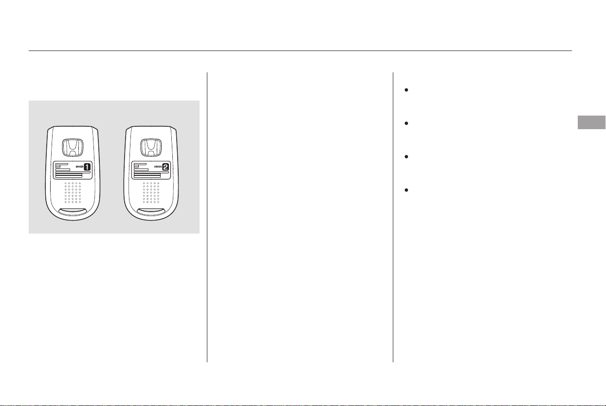
Each remote transmitter activates
the driver’s seat position memory
system and customized vehicle
control settings (see page ).
When you open the driver’s door
after unlocking it with the remote
transmitter, the driver’s seat moves
to the positions stored in memory.
You will hear two beeps when the
movement is completed.
The driver’s seat position memory
activation (Driver 1, Driver 2) is
shownonthebackofeach
transmitter. Make sure you store
your seat position in the memory
that is activated by the transmitter
you normally carry.
You can turn off driver’s seat
position memory activation with the
remote transmitter. Press and hold
the LOCK and UNLOCK buttons at
thesametime.TheLEDinthe
remote transmitter will blink twice.
Then release the buttons, and press
the UNLOCK button.
Avoid dropping or throwing the
transmitter.
Protect the transmitter from
extreme temperature.
Do not immerse the transmitter in
any liquid.
If you lose a transmitter, the
replacement needs to be
reprogrammed by your dealer.
Most of the customized settings will
return to the default settings.
To turn it back on, repeat this
procedure. The LED will come on
for 1 second to indicate the feature
has been turned on.
89
On Touring model only
Recalling a Memorized Seat
Position
Remote Transmitter Care
Remote Transmitter
Instruments and Controls
135
With Driver 2
With Driver 1
Main Menu
Table of Contents
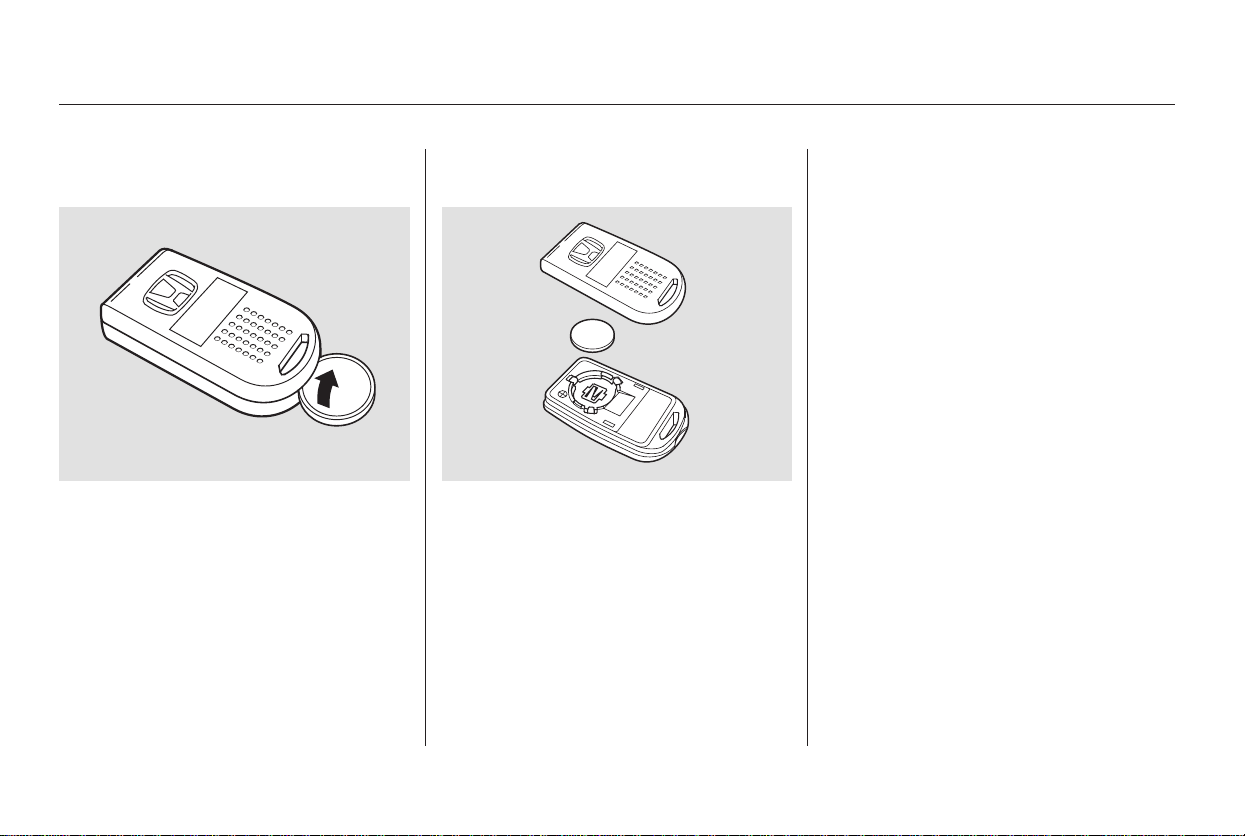
+
If it takes several pushes on the
button to lock or unlock the doors
and the tailgate, replace the battery
as soon as possible.
Battery type: CR2025
To replace the battery, separate the
halfs by carefully prying on the edge
with a coin. Remove the old battery,
and insert a new battery with the
side facing up. Snap the two halves
of the transmitter case back together.
As required by the FCC:
This device complies with Part 15 of the
FCC rules. Operation is subject to the
following two conditions: (1) This device
may not cause harmful interference, and
(2) this device must accept any
interference received, including
interference that may cause undesired
operation.
Changes or modifications not expressly
approved by the party responsible for
compliance could void the user’s
authority to operate the equipment.
This device complies with Industry
Canada Standard RSS-210.
Operation is subject to the following two
conditions: (1) this device may not cause
interference, and (2) this device must
accept any interference that may cause
undesired operation of the device.
Replacing the Transmitter
Battery
Remote Transmitter
136
Main Menu
Table of Contents
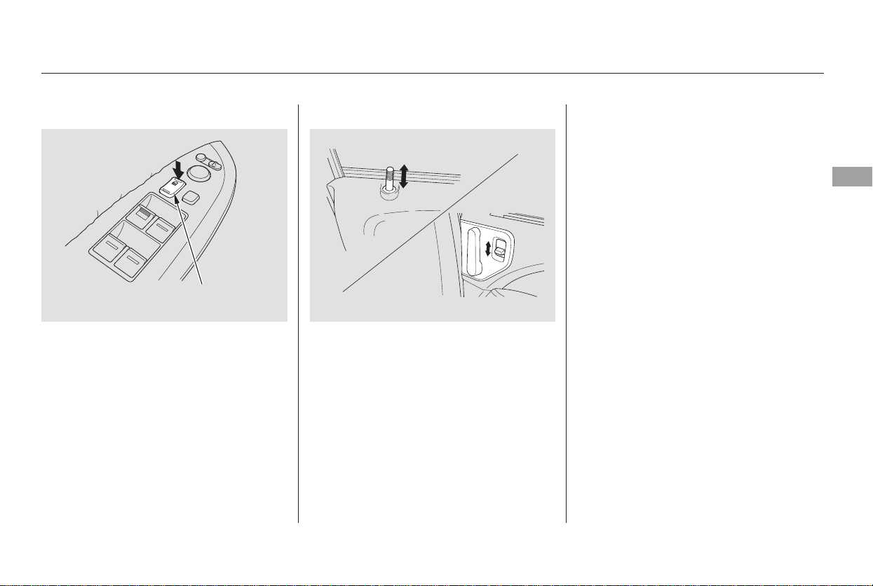
To lock the doors and the tailgate,
press the front of the master door
lock switch on either front door,
pressthelocktabonthedriver’s
door, or use the outside lock on the
driver’s door.
Pressing the rear of the master door
lock switch will unlock all doors and
the tailgate.
The lock tab on any door locks and
unlocks that door.
All doors and the tailgate can be
locked from the outside by using the
key in the driver’s door. To unlock
only the driver’s door, insert the key,
turn the key, and release it. The
remaining doors and the tailgate
unlock when you turn the key a
second time within a few seconds.
With the driver’s door open and the
key in the ignition, both master door
lock switches are disabled. They are
not disabled if the driver’s door is
closed. Pushing the front of the
master door lock switch on the open
passenger’s door will lock all doors
and the tailgate.
Power Door Locks
Lockout Prevention
Door Locks
Instruments and Controls
137
MASTER DOOR
LOCK SWITCH
Lock
Main Menu
Table of Contents
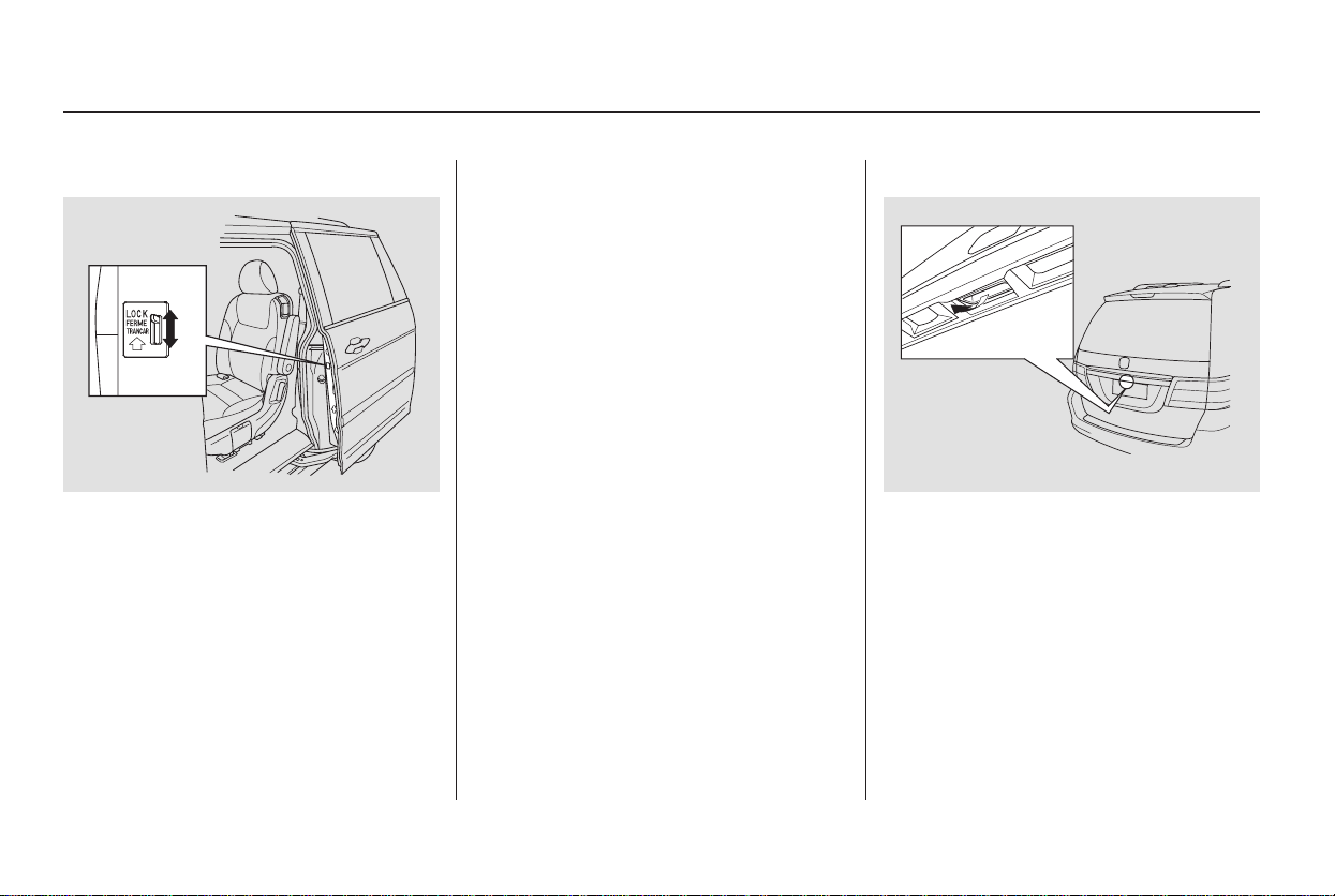
The childproof door locks are
designed to prevent children seated
in the rear from accidentally opening
the rear sliding doors. Each door has
a lock lever near the edge. With the
lever in the LOCK position, the door
cannot be opened from the outside
regardless of the position of the lock
tab. To open the door, pull the lock
tab up and use the outside door
handle.
With the childproof door locks on,
automatic operation with the inside
door handle is disabled.
To open the tailgate, pull the handle,
then lift up. To close the tailgate, use
the inner handle to pull it down, then
press down on the back edge.
Keep the tailgate closed at all times
while driving to avoid damaging the
tailgate and to prevent exhaust gas
from getting into the interior. See
on page
.56
On EX and Touring models
LX and EX models
Childproof Door Locks Tailgate
Carbon Monoxide Hazard
Door Locks
138
Main Menu
Table of Contents
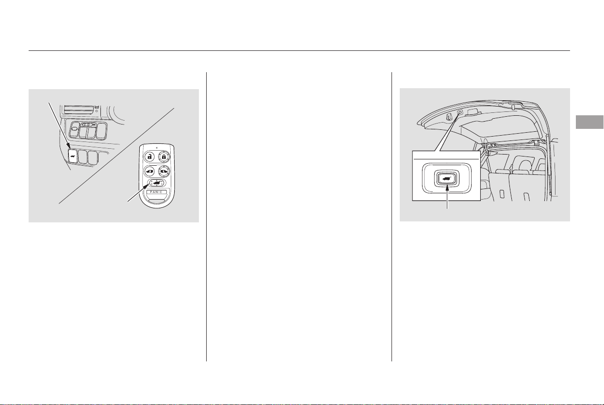
The tailgate can be opened and
closed with the remote transmitter
or the switch on the dashboard when
both front doors are unlocked.
The tailgate can also be closed by
pressing the button on the tailgate. If
you press the button again while the
tailgate is closing, you will hear three
beeps, and the tailgate will stop
moving, reverse direction, and stop
at the fully opened position.
Press and hold the tailgate button on
the remote transmitter or the
dashboard switch for about 1 second
to open or close the tailgate. Each
time you press the button on the
remote transmitter or the dashboard
switch, you will hear a beep.
If you push the same button or
switch again while the tailgate is
opening or closing, you will hear
three beeps, and the tailgate will stop
moving, reverse direction, and stop
at the fully opened or closed position.
To open or close the tailgate
manually, see page .138
CONTINUED
On Touring model only
Power Tailgate
Door Locks
Instruments and Controls
139
DASHBOARD SWITCH
TAILGATE
BUTTON
TAILGATE SWITCH
Main Menu
Table of Contents
The power tailgate has an auto-
reverse feature. If it meets
resistance while opening or closing,
it will beep three times and reverse
direction. However, the tailgate may
not reverse immediately. Always
make sure passengers and objects
are clear of the tailgate before
opening or closing it.
Also check that passengers,
especially children, do not have their
hands on the edge of the tailgate or
on the tailgate still. The auto reverse
featurestopsworkingwhenthe
tailgate is about to latch so the motor
can pull the tailgate shut.
If your vehicle’s battery is
disconnected, goes dead, or the fuse
is removed while the tailgate is fully
open, the power tailgate needs to be
reset. After connecting the battery
or installing the fuse, close the
tailgate fully by hand.
The power tailgate may not open or
close under the these conditions:
Whenthetailgateortheroofis
covered with snow or ice.
Do not install any accessories on the
tailgate. It may cause the tailgate not
to function properly. If there is snow
or ice on the tailgate, make sure to
remove it before you operate the
tailgate.
If you pull the tailgate release handle
while the tailgate is opening or
closing, it will stop moving. You need
to open or close it the rest of the way
manually.
The tailgate has sensors on both
sides. Be careful not to damage them.
If the sensors are damaged, the
power tailgate does not function
properly.
When the vehicle is swayed in a
strong wind.
The vehicle is parked on a steep
hill.
Auto-Reverse
Door Locks
140
Closing a power tailgate while
anyone is in the path of the
tailgate can cause serious
injury.
Make sure everyone is clear
before closing the power
tailgate.
Main Menu
Table of Contents
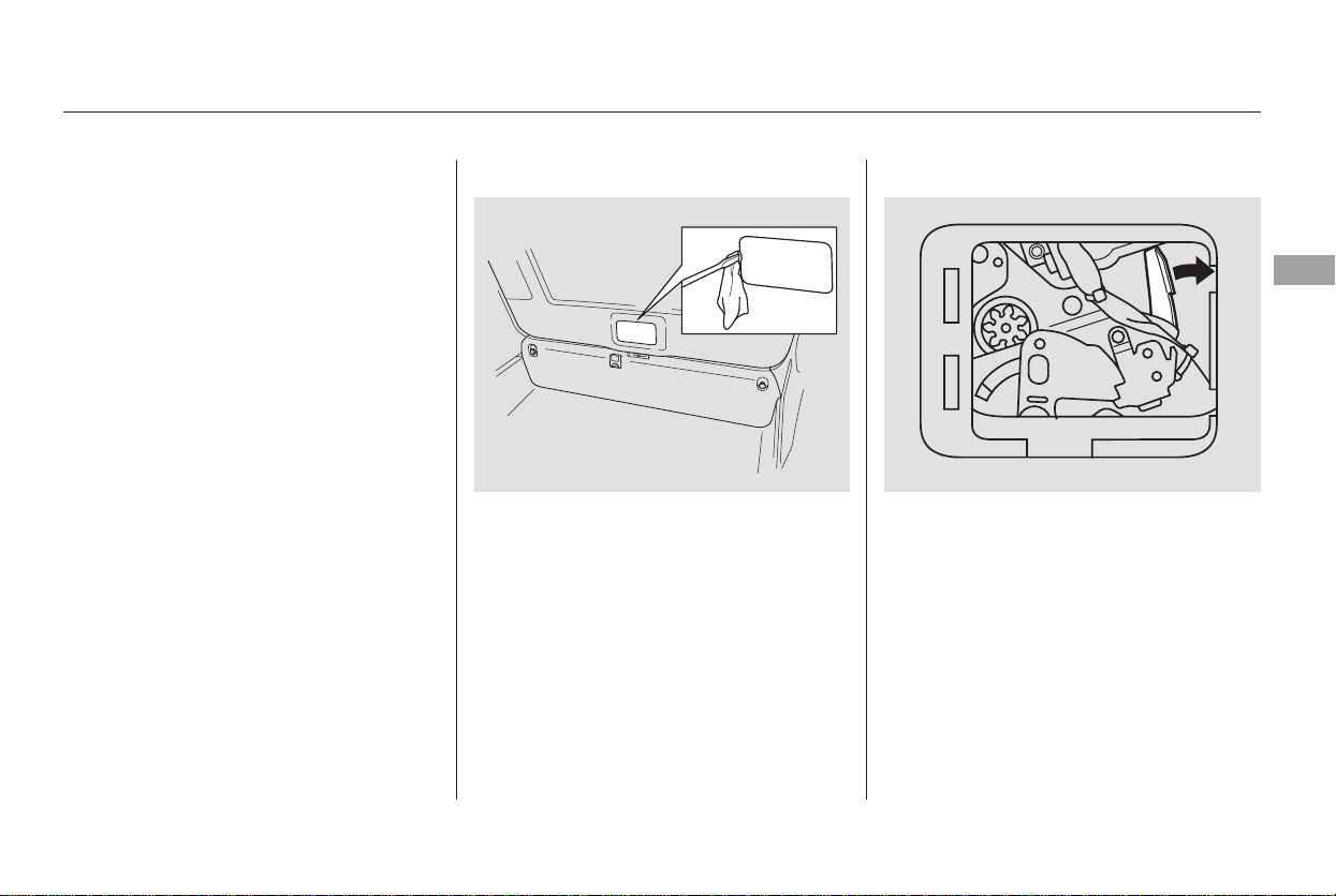
Push the release lever to the right as
shown.
If you need to unlock the tailgate
manually, it means there is a
problem with the tailgate. Have the
vehicle checked by your dealer.
Use a small flat-tipped screwdriver to
remove the cover on the back of the
tailgate.
If the power door lock system cannot
unlock the tailgate, unlock it
manually.
If you try to drive off with the
tailgate not closed completely, a
beeper sounds and a ‘‘DOOR &
TAILGATE OPEN’’ message is
shown on the multi-information
display.
Keep the tailgate closed at all times
while driving to avoid damaging the
tailgate and to prevent exhaust gas
from getting into the interior. See
on page
.
If there is a problem in the power
tailgate system, you will see a
‘‘CHECK POWER TAILGATE’’
message on the multi-information
display. Have the system checked by
your dealer.
With this message shown in the
multi-information display, you can
still open or close the tailgate
manually.
56
CONTINUED
On Touring model only
Unlocking the Tailgate
Carbon Monoxide Hazard
Door Locks
Instruments and Controls
141
Main Menu
Table of Contents
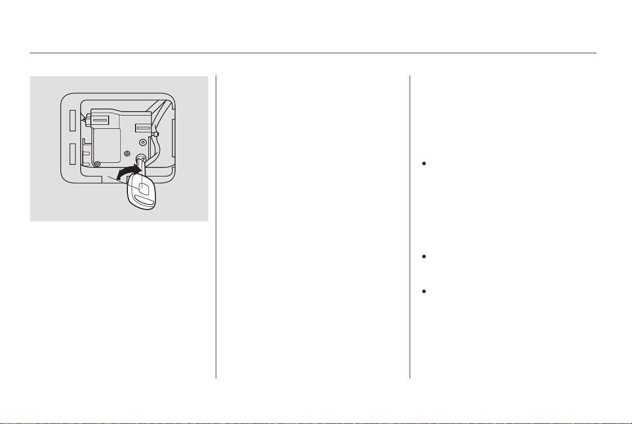
To open, pull the inside or outside
door handle, and slide the door back.
It will latch in the fully open position.
When opening from the inside, the
childproof door lock must be
unlocked.
To close, pull either handle, and slide
the door closed. Make sure the door
is closed and latched securely before
driving, and all passengers are clear
of the sliding doors before closing
them.
Ifyoucannotopenthetailgate,
remove the cover on the back of the
tailgate(seepage ).Usethekey
to unlock the tailgate as shown, then
pull the outer handle to open the
tailgate.
The doors are electrically powered
and can be operated with the remote
transmitter, the door handles, or the
dashboard switches. To operate the
doors:
When opening a sliding door, it stops
about halfway if the window is open
morethan3in(8cm).Ifthevehicle
is facing downhill, the sliding door
will slam shut when you release the
door handle. Always close the
window fully before opening the
sliding door.
The shift lever must be in Park or
Neutral. To operate the doors with
the shift lever in Neutral, the
ignition switch must be in the ON
(II) position with the brake pedal
pressed or the parking brake
applied.
TheMAINswitchmustbeinthe
ON position.
The doors must be unlocked.
141
LX model
On EX and Touring models
On LX and EX models
Power Sliding DoorsOpening and Closing Manual
Sliding Doors
Door Locks, Sliding Doors
142
Main Menu
Table of Contents
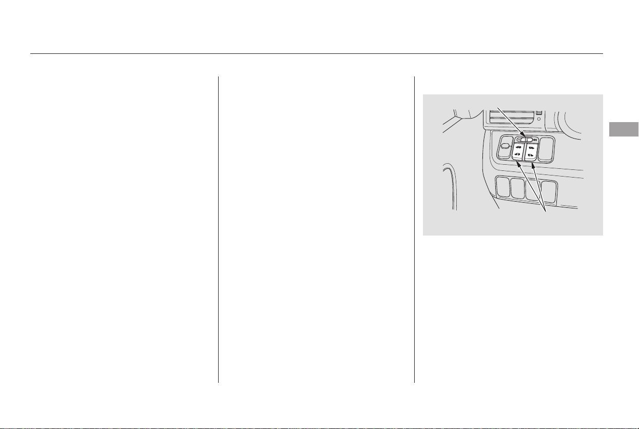
CONTINUED
When the shift lever is in Park:
When the shift lever is in Neutral and
the ignition switch is in the ON position:
If you shift out of Park while a door
is closing, you will hear a beep until
the door closes.
If you shift out of Park while a door
is opening, you will hear a
continuous tone and the door will
stop moving. Stop the vehicle and
close the door.
If you shift out of Neutral or release
the brake pedal or the parking brake
while a door is closing, you will hear
a beep until the door closes.
If you shift out of Neutral or release
the brake pedal or the parking brake
while a door is opening, you will hear
a continuous tone and the door will
stop moving. Stop the vehicle and
close the door.
To open the door with the inside
door handle, pull the handle
backward. Push it forward to close
the door. If you pull backward or
push forward on the door handle
while a door is opening or closing,
the door stops moving. Pull
backward or push forward to open or
close the door fully.
To open or close the door with the
outside door handle, pull the door
handle. If you pull the door handle
while a door is opening or closing,
the door stops moving. If you pull the
door handle again, the door will open
fully.
The dashboard switches to the left
of the steering column allow you to
open or close the power sliding doors.
The MAIN switch on the dashboard
controls power to the sliding doors.
Sliding Doors
Door Handles Dashboard Switches
Instruments and Controls
143
POWER SLIDING DOOR MAIN SWITCH
POWER SLIDING
DOOR SWITCHES
Main Menu
Table of Contents
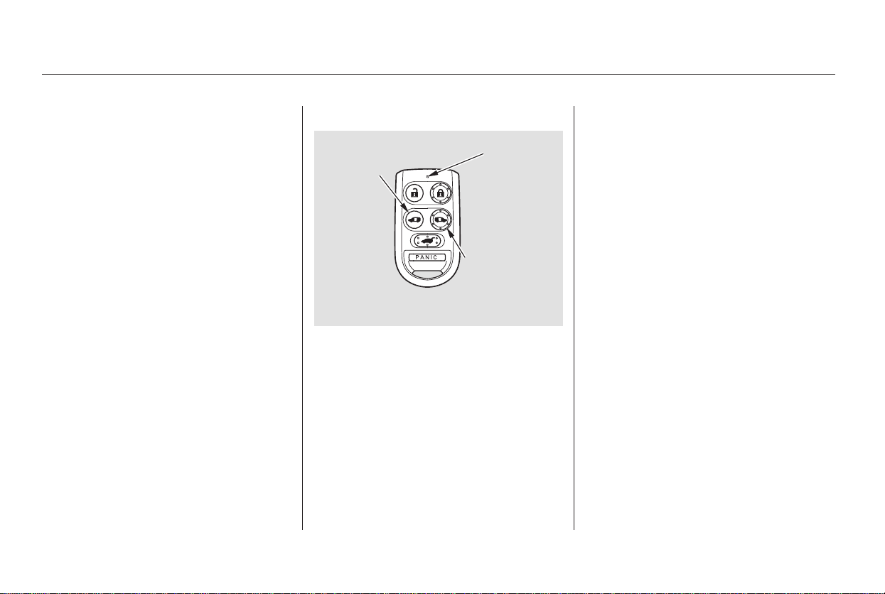
To open a power sliding door, push
and release the bottom of the
appropriate switch. If you forget to
unlock the door, you will hear three
beeps. Unlock the door and try again.
To close a sliding door, push and
release the top of the switch.
To stop a door, push either the top or
bottom of the switch. The door will
stop and you will hear three beeps.
Push the switch again to resume
movement.
When the MAIN switch is in the
OFF position, you have to operate
the doors manually.
To open and close a power sliding
door, press and hold the appropriate
button for at least 1 second. If you
forget to unlock the door, you will
hear three beeps. Unlock the door,
and try again.
Each power sliding door has an auto-
reverse feature. If a door meets
resistance while closing, it will beep
three times and reverse direction.
However, the door may not reverse
immediately and may cause some
bruising or discomfort. Always make
sure passengers and objects are
clear of the doors before closing
them.
If a rear window is open more than
3 in (8 cm), the power sliding door is
designed to stop about halfway to
avoid accidents. If this happens,
close the door with the door handles,
the dashboard switch, or the remote
transmitter. Close the window and
open the sliding door. Make sure the
window is fully closed before you
operate the power sliding door.
To stop movement, push the
appropriate door button; you will
hear three beeps. Push and hold the
same button again for at least 1
second and the door will reverse
direction.
Sliding Doors
Remote Transmitter Auto-Reverse
144
DRIVER’S
SIDE
SLIDING
DOOR
BUTTON
PASSENGER’S
SIDE
SLIDING
DOOR
BUTTON
LED
Main Menu
Table of Contents
You can manually open or close the
sliding doors. The MAIN switch
must be in the OFF position. To
open a door, pull the inside or
outside door handle, and slide the
door back. It will latch in the fully
open position. To close, pull either
handle and slide the door forward.
When the door is almost closed, the
auto-closer will pull the door shut.
Before operating the sliding doors,
check that passengers, especially
children, do not have their hands on
the edge of the sliding door or on the
door pillar. The auto-reverse motor
stops working when the door is
about to latch so the auto-closer can
pull the door shut.
If there is an obstacle in the door sill,
the power sliding door may not open
or close properly. When removing
the obstacle from the door sill, make
sure to turn off the main switch on
the dashboard.
When replacing a flat tire, make sure
to turn off the power sliding door
main switch on the dashboard.
Do not allow anyone to step on the
lower arm of the sliding door while
the door is open. This could damage
the sliding door mechanism.
Whenyoudrivewithchildreninyour
vehicle, use the childproof door
locks (see page ). This will
prevent children from opening the
doors accidentally.
Do not put any item in the door
pocket sticks out from the pocket. It
can prevent the doors from opening
or closing properly, and damage the
vehicle body.
138
On all models
On EX and Touring models
Sliding Doors
Manually Opening/Closing the
Power Sliding Door
Important Sliding Door
Precautions
Instruments and Controls
145
Closing a sliding door while any
part of a passenger is in the
door’s path can cause serious
injury.
Make sure all passengers are
clear of the doorway before
closing a sliding door.
Main Menu
Table of Contents

When you release the fuel fill door,
the driver’s side sliding door
automatically locks so it cannot open
and interfere with the fuel door. If a
passenger attempts to unlock the
door by cycling the lock knob several
times, the door can be opened.
If a passenger needs to get out while
you are refueling, instruct that
person to exit on the passenger’s
side.
When you close the fuel fill door, the
driver’s side sliding door unlocks if it
was unlocked when you opened the
fuel fill door.
If you open the fuel fill door while
the driver’s side sliding door is
opening, the sliding door stops. If
this happens, the door must be
operated manually.
When parking facing downhill, make
sure the doors are latched in the
fully open position, and then hold the
door open for your passengers. Do
not pull the inside or outside door
handle, or the door will slam shut.
Make sure the main switch on the
dashboard is in the ON position.
When parking facing downhill on a
steep grade, the power sliding doors
may not open or close as they do
normally.
If you leave the vehicle on a steep
downhill with a power sliding door
half open and the engine off, the
magnetic lock will turn off after 30
minutes and the sliding door will
automatically open or close. In this
case you will hear a continuous tone.
If your vehicle is facing a downhill,
do not turn the main switch to OFF
while the door is opening because
thedoormayslamshut.
On EX and Touring models
On EX and Touring models
Sliding Doors
Refueling Parking on a Hill
146
Main Menu
Table of Contents
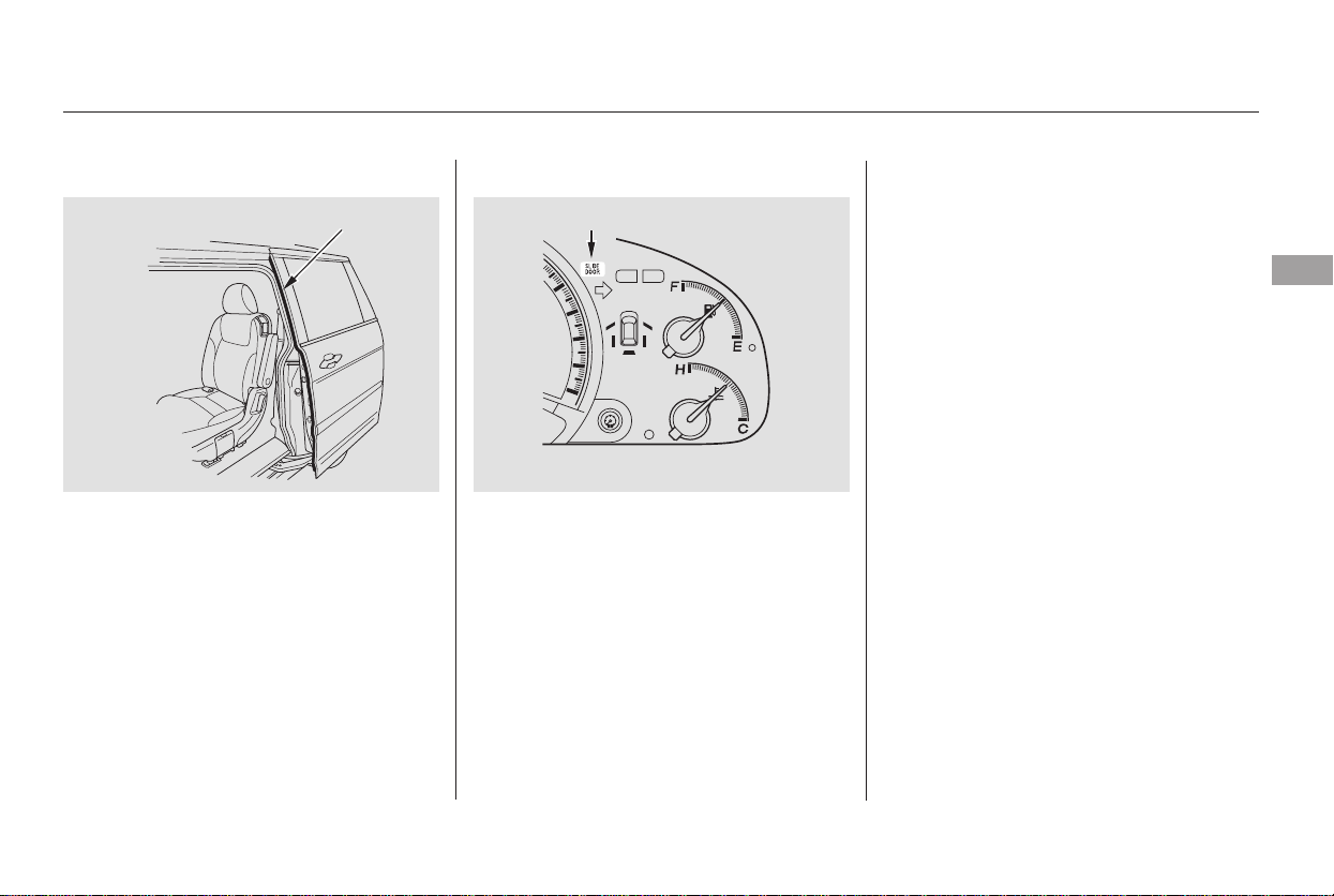
If the battery is disconnected or goes
dead, close the sliding door
completely by hand. If it still does
not operate properly after the
battery is reconnected, have your
vehicle checked by a dealer.
If there is a problem in the power
sliding door system, you will see a
‘‘CHECK LEFT SLIDING DOOR’’
message or ‘‘CHECK RIGHT
SLIDING DOOR’’ message in the
multi-information display (see page
). If this message stays on, turn
the MAIN switch to OFF, and have
the system inspected by your dealer.
If the power sliding door indicator
comesonandstayson,thereisa
problem in the system. Turn the
MAIN switch to OFF, and have the
system inspected by a dealer.
Each sliding door has a pinch sensor
on the front edge. Do not damage
this sensor, or the power sliding door
may not operate properly.
87
On Touring model
On EX and Touring models On EX model
Sliding Doors
Power Sliding Door ProblemsPinch Sensor
Instruments and Controls
147
PINCH SENSOR
POWER SLIDING DOOR INDICATOR
U.S. indicator shown
Main Menu
Table of Contents
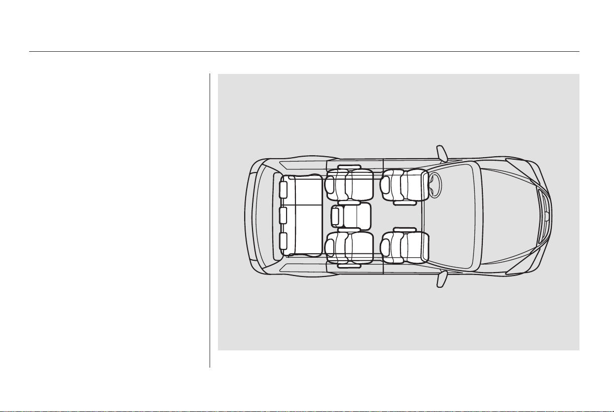
There are bucket seats with
armrests for two front passengers,
bucket seats with armrests for two
passengers in the second row, and a
bench seat for three passengers in
the third row.
For greater cargo capacity, the seats
in the second row can be removed,
andthebenchseatinthethirdrow
can be folded into the floor.
The EX model has a stowable second
rowplus-oneseatthatcanbe
installed between the second row
bucket seats when needed. The plus-
one seat can also be used as a second
rowcenterconsole,orstoredinthe
floor storage area. For more
information, see page .156
Passenger Seating
Convertible Second Row Bucket
Seats
Seats
148
Main Menu
Table of Contents
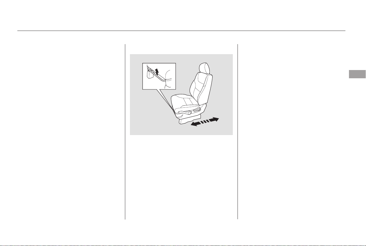
−
The front passenger’s seat, and the
seats in the second and third rows
adjust manually.
Make all seat adjustments before
you start driving.
The EX and Touring models have a
power adjustable driver’s seat. The
LX model has manual driver’s seat
adjustments.
To adjust the seat forward and
backward, pull up on the bar under
the seat cushion’s front edge. Move
the seat to the desired position and
releasethebar.Trytomovetheseat
to make sure it is locked in position.
To adjust the bucket seats in the
second row, pull up the bar on the
front of the seat bottom.
The third row seats do not adjust
forward and backward.
See pages for important safety
information and warnings about how to
properly position the seats and seat-
backs.
13 15
CONTINUED
Manual Seat Adjustments
Seats
Instruments and Controls
149
Main Menu
Table of Contents
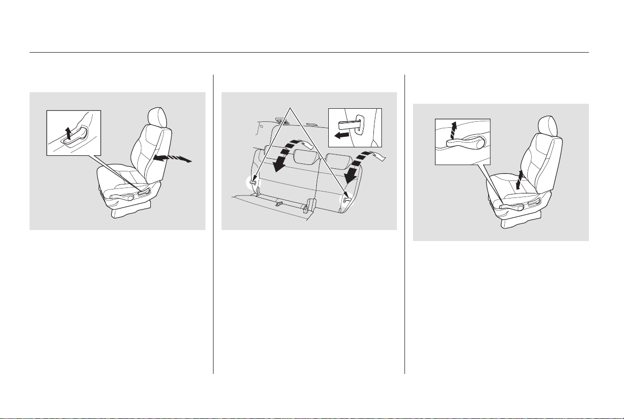
To change the seat-back angle of the
bucket seats in the second row, pull
forwardontheleverontheoutside
of the seat-back.
To change the seat-back angle of the
front seat, pull up on the lever on the
outside of the seat bottom.
The left and right halves of the third
seat-back can be adjusted separately.
To adjust the angle, pull the
adjustment strap on the outside of
each seat-back, move the seat-back
to the desired position, and release
the adjustment strap. Let the seat-
back latch in the new position.
The height of your driver’s seat is
adjustable. Pull up the lever on the
outside of the seat cushion to raise
the seat bottom or push the lever
down to lower the seat cushion.
Make all adjustments before you
start driving.
On LX model
Driver’s Seat Manual Height
Adjustment
Seats
150
ADJUSTMENT STRAP
Main Menu
Table of Contents
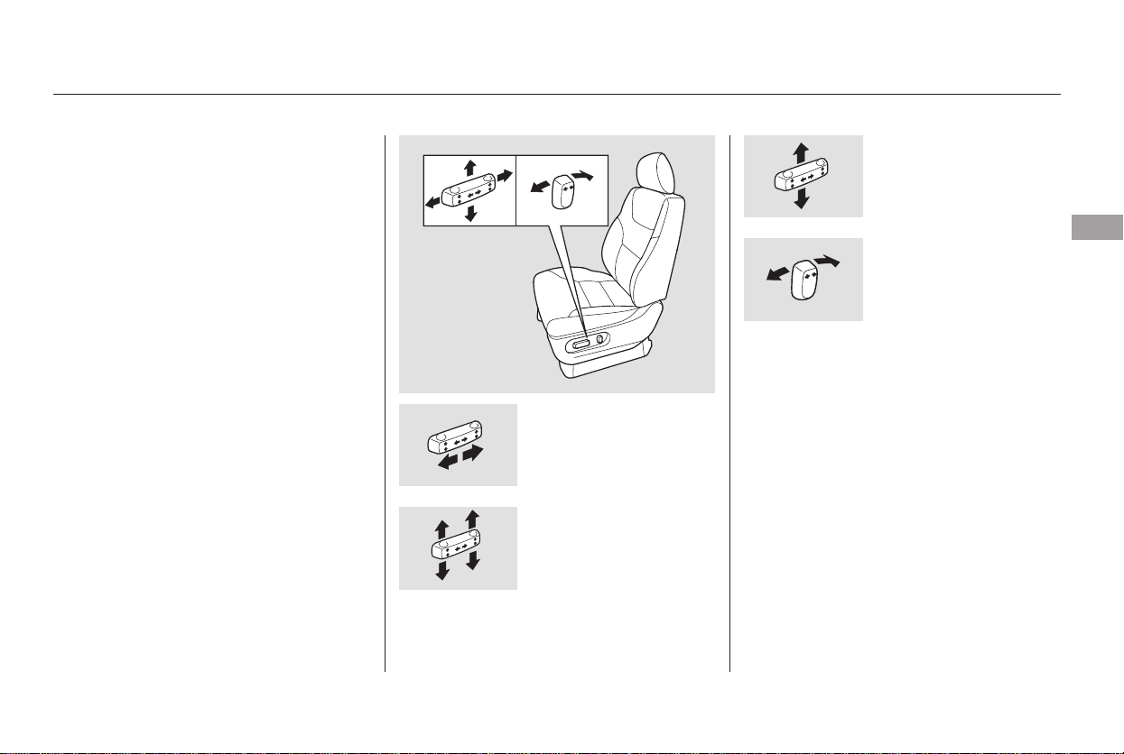
−
Moves the seat
forward and
backward.
Raises or lowers the
seat.
The controls for the adjustable
driver’s power seat are on the
outside edge of the seat bottom. You
can adjust the power seat with the
ignition switch in any position. Make
all seat adjustments before you start
driving.
Moving the long horizontal switch
adjusts the seat bottom in several
directions. The seat bottom adjusts
in the direction you move the switch.
The short vertical switch adjusts the
seat back angle.
Moves the front of
the seat up or down
and the rear of the
seat up or down.
Adjusts the seat-
back angle forward
or backward.
See pages for important safety
information and warnings about how to
properly position the seats and seat-
backs.
On EX and Touring models
13 15
Power Seat Adjustments
Seats
Instruments and Controls
151
Main Menu
Table of Contents
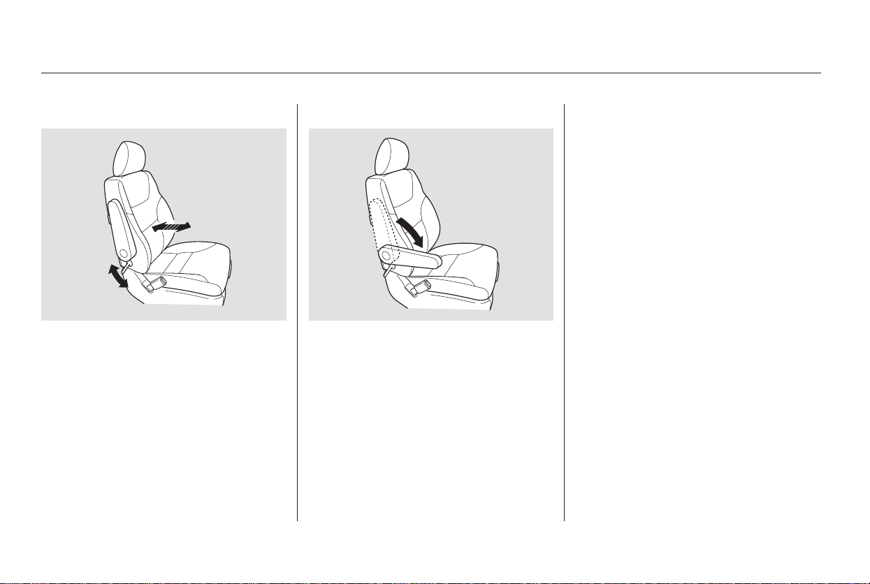
See page for important safety
information and a warning about how to
properly position the head restraints.
On EX and Touring models
15
On EX with Leather and Touring models
Your vehicle is equipped with head
restraints in all seating positions to
help protect you and your
passengers from whiplash and other
injuries.
An armrest is located on each of the
frontseatsandoneachsideofthe
second row seats. Pivot it down to
use it. When you remove the bucket
seats in the second row, pivot the
armrests up out of the way.
To change the lumbar support, move
the lever on the right side of the
seat-back forward or backward.
Keep moving the lever forward or
backward until you find a suitable
position.
They are most effective when you
adjust them so the back of the
occupant’s head rests against the
center of the restraint.
Theangleofthearmrestoneach
front seat is adjustable. Pivot the
armrest down, and pull it up to the
desired angle.
Head RestraintsArmrestsDriver’s Lumbar Support
Seats
152
Main Menu
Table of Contents
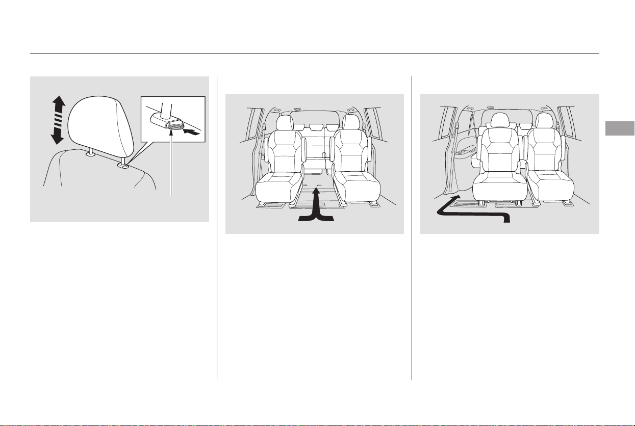
To get into or out of the third row
seat, walk between the second row
seats.
When the seat on the passenger’s
side is moved to the center, walk
through the passenger’s side to get
into or out of the third row seat.
All head restraints adjust for height.
You need both hands to adjust the
restraint. Do not attempt to adjust it
while driving. To raise it, pull upward.
To lower the restraint, push the
release button sideways, and push
the restraint down. On the Touring model, you need to
remove the second row console
before you can make this seat
adjustment.
CONTINUED
Third Seat Access
Seats
Instruments and Controls
153
RELEASE
BUTTON
Main Menu
Table of Contents
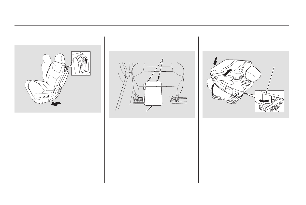
Unlock the seat from the floor by
pulling the lock release lever under
the seat cushion’s front edge and
lifting the rear of the seat.
Slide the seat toward the center of
the vehicle.
The second row bucket seat on the
passenger’s side can be moved to the
center to provide access to the third
row seat.
To get into or out of the third row
seat, pull up the release lever on the
shoulder of each second row bucket
seat. The seat-back will tilt forward
and the whole seat will slide forward.
Push the back of the seat down over
the floor hooks. Make sure the seat
is securely locked in place.
Remove the piece mat and the floor
cover from under the passenger’s
side bucket seat. To remove the
piece mat, unfasten the two buttons
on the rear edge.
Moving the Second Row Bucket
Seat
Seats
154
LOCK
RELEASE
LEVER
BUTTONS
PIECE MAT
Main Menu
Table of Contents
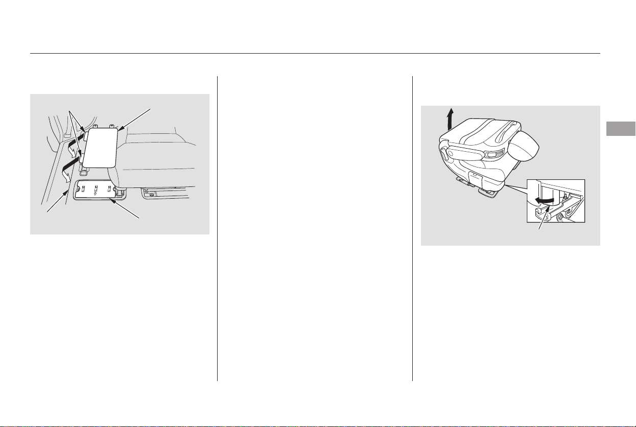
Both seats can be removed to give
more cargo capacity.
To remove a seat:
Make sure the seat is securely
locked in place before driving. A seat
thatisnotlockedinplacecouldfly
around and cause injury in a sudden
stop or crash.
Reversethisproceduretomovethe
seat back to the outside.
When the passenger’s side bucket
seat is in the outside position, and
theplus-oneseatorthesecondrow
console is not used, install the floor
mat and the piece mat over the
center floor anchors between the
bucket seats. Make sure to fasten
the buttons on the mat to the floor.
Install the floor covers over the outer
floor anchor and install the piece mat
over the floor cover. Insert the tabs
on the piece mat into the slit on the
floor. Fasten the buttons on the mat
to the floor. Pull up the seat-back angle
adjustment lever, and fold the seat-
back forward.
Unlock the seat from the floor by
pulling the lock release lever under
the seat cushion’s front edge and
lifting the rear of the seat.
Seats
Removing the Bucket Seats in the
Second Row
Instruments and Controls
155
LOCK RELEASE LEVER
PIECE MAT
SLIT COVER
TABS
Main Menu
Table of Contents

You can install the stowable plus-one
seat between the second row bucket
seats.
To reinstall the seat, hook the front
of the seat to the floor, then push the
backintothelocks.Makesureboth
the front and the back of the seat are
securely latched before driving.
Unhook the front of the seat from
the floor by pulling it back slightly,
then pivoting it upward.
Always remove an unsecured seat
from the vehicle before driving. A
seat that is not locked in place could
be thrown about and cause injury in
a sudden stop or crash.
On EX model only
Seats
Installing the Stowable Second
Row Plus-One Seat
156
Main Menu
Table of Contents
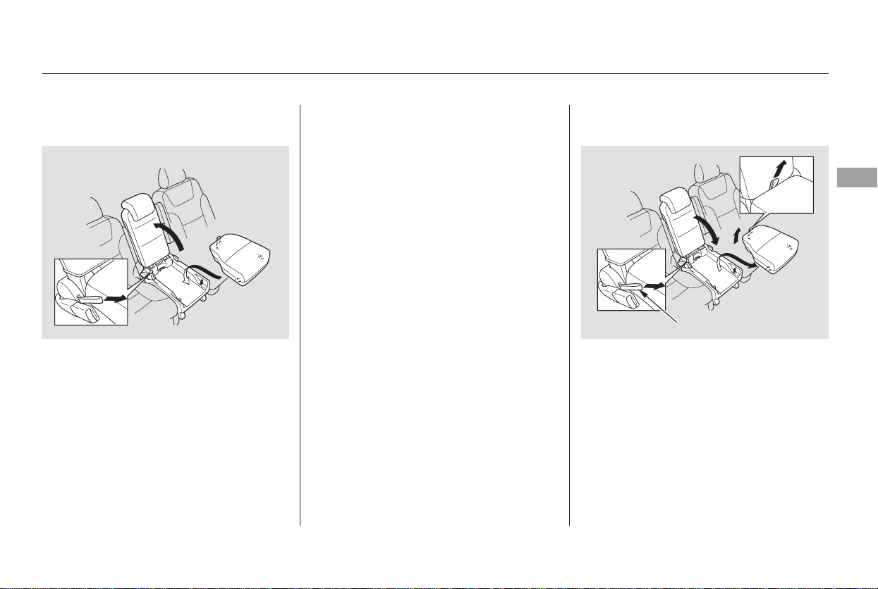
CONTINUED
To remove the seat, lower the head
restraint all the way down. Remove
the seat cushion by pulling the strap
on the seat cushion, and fold the
seat-back forward.
To install the stowable plus-one seat,
pull the leg folding lever to unfold
the leg, hook the front of the seat to
the floor, then push down the back
until it locks. Make sure both the
front and back of the seat are
securely latched. Pull up the seat-
back, and adjust the seat-back angle
to the desired position while pulling
the seat-back angle adjustment strap
on the outside of the seat bottom.
Install the seat cushion on the seat
bottom plate. To install the cushion,
hook the front of the cushion first,
then push down the rear until the
cushion is securely positioned.
To use the plus-one seat as a center
console, remove its seat cushion by
pulling up the seat cushion strap.
Then pivot the seat-back forward
until it is flat. Store the seat cushion
in the floor storage area.
Seats
Instruments and Controls
157
ANGLE ADJUSTMENT STRAP
Main Menu
Table of Contents
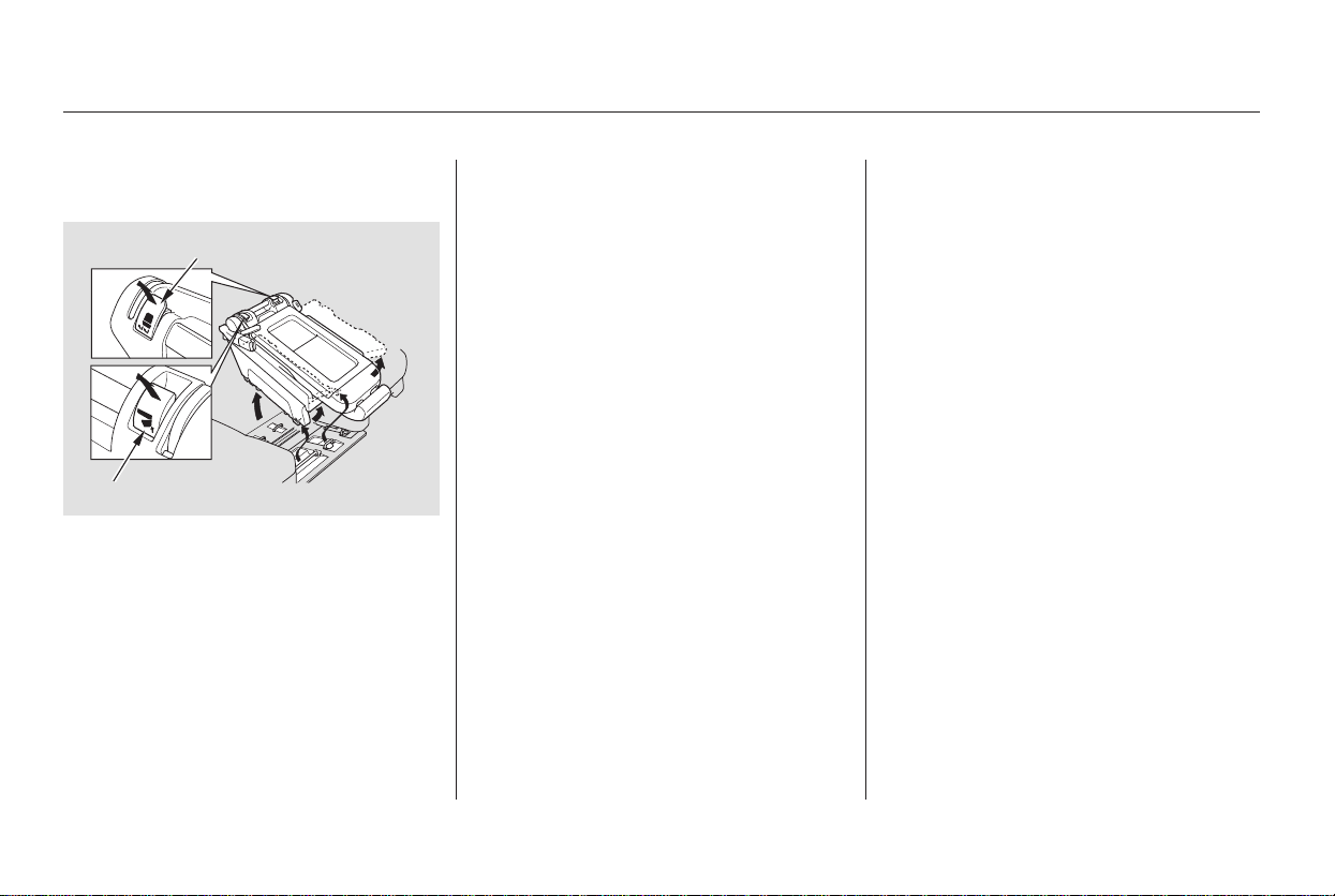
To create more cargo space, you can
fold the one-motion third row ‘‘Magic
Seat’’ into the floor recess.
Unlatch the detachable seat belt
anchor center seat belt, and let the
belt retract all the way into the
ceiling. Place the latch plate and
anchor latch into their holding
slots.
Lower the head restraints fully.
Always remove an unsecured seat
from the vehicle before driving. A
seat that is not locked in place could
be thrown about and cause injury in
a sudden stop or crash.
Thestowableplus-oneseatassembly
canbestoredinthefloorstorage
area between the front seats and the
secondrowseats.Todothis,remove
theLazySusanfromthefloor
storage area.
Unlock the seat from the floor by
pulling the lock release lever and the
leg folding lever on the bottom of the
seat-back, and lift the rear of the seat.
Unhook the front of the seat from
the floor by pulling it back slightly,
then pivoting it upward.
1.
2.
Seats
Folding the One-Motion Third
Row ‘‘Magic Seat’’
158
LOCK RELEASE LEVER
LEG FOLDING LEVER
Main Menu
Table of Contents
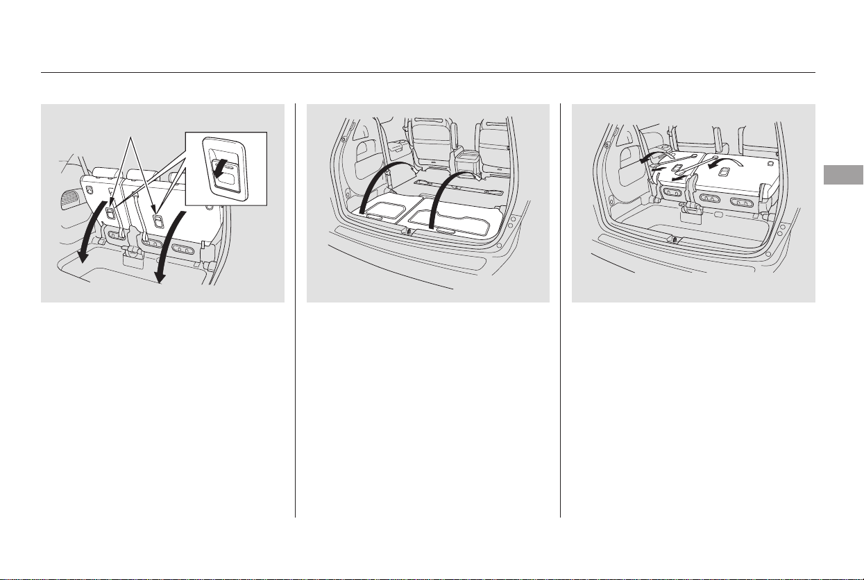
Pull the seat-back upright with the
strap. Make sure the seat is
securely locked.
To return the seat to the upright
position:
Pull the seat out of the recess by
pulling on the handle. Pivot the
seat forward all the way. The front
seat legs will automatically latch.
Pull the handle on each seat-back
to unlock the front seat legs.
Pivot the seat into the cargo area
floor recess.
Make sure all items in the cargo area
are secured. Loose items can fly
forward and cause injury if you have
to brake hard. See
on page .
1.
2.3.
4.
286
Seats
Carrying Cargo
Instruments and Controls
159
HANDLE
Main Menu
Table of Contents
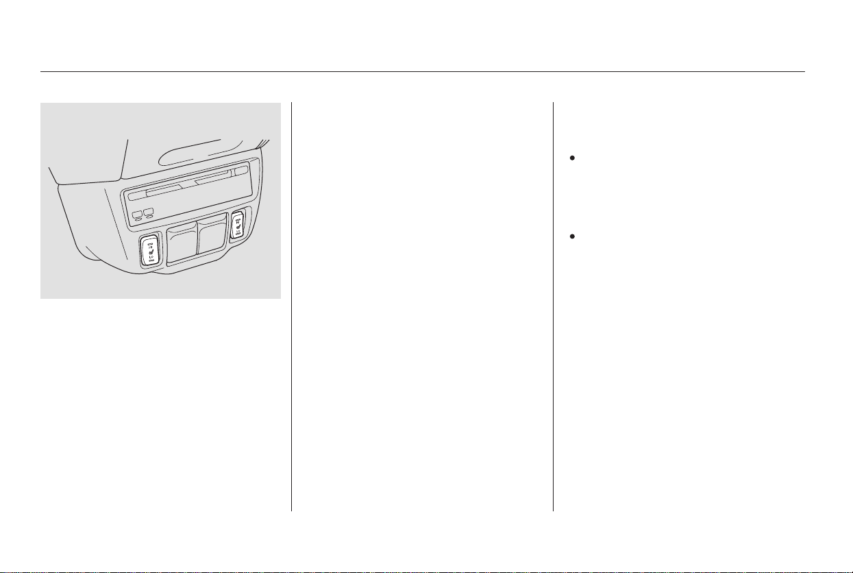
Follow these precautions when using
the seat heaters:
Use the HI setting only to heat the
seats quickly, because it draws
large amounts of current from the
battery.
If the engine is left idling for an
extended period, do not use the
seat heaters, even on the LO
setting. It can weaken the battery,
causing hard starting.
Both front seats are equipped with
seat heaters. The passenger seat
only has heaters in the seat bottom
because of the side airbag system.
The ignition switch must be in the
ON (II) position to use them. The
seat heater switches are located on
the dashboard above the center
pocket. Push the top of the switch,
HI, to rapidly heat up the seat.
After the seat reaches a comfortable
temperature, select LO by pushing
the bottom of the switch. This will
keep the seat warm.
In HI, the heater turns off when the
seat gets warm, and turns back on
after the seat’s temperature drops.
In LO, the heater does not cycle with
temperature change.
On EX with Leather and Touring models
Seat Heaters
160
Main Menu
Table of Contents
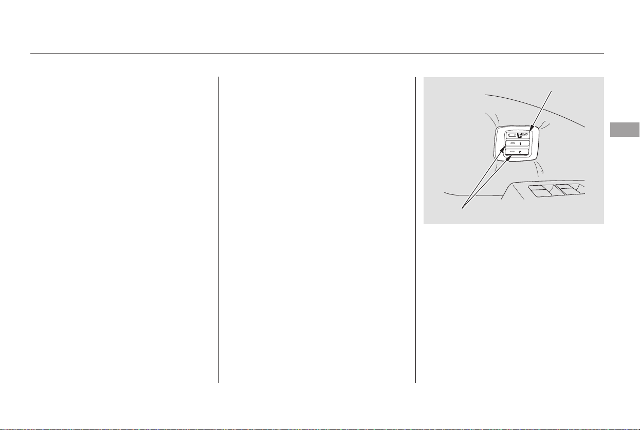
Your vehicle has a memory feature
for the driver’s seat position.
Two seat positions can be stored in
separate memories. You select a
memorized position by pushing the
appropriate button or appropriate
remote transmitter (Driver 1 or
Driver 2).
Press and release the MEMO
buttononthecontrolpanel.You
will hear a beep. Immediately
press and hold one of the memory
buttons (1 or 2) until you hear two
beeps. The indicator in the
memory button will come on. The
current driver’s seat position is
now stored.
Store a driver’s seat position only
when the vehicle is parked.
Turn the ignition switch to ON (II).
You cannot add a new seat
position in memory unless the
ignition switch is in the ON (II)
position. You can recall a
memorized position with the
ignition switch in any position.
Adjust the seat to a comfortable
position (see page ).
1.
2. 3.
151
CONTINUED
On Touring model only
Storing a Driver’s Seat Position in
Memory
Driver’s Seat Position Memory System
Instruments and Controls
161
MEMO BUTTON
MEMORY BUTTONS
Main Menu
Table of Contents
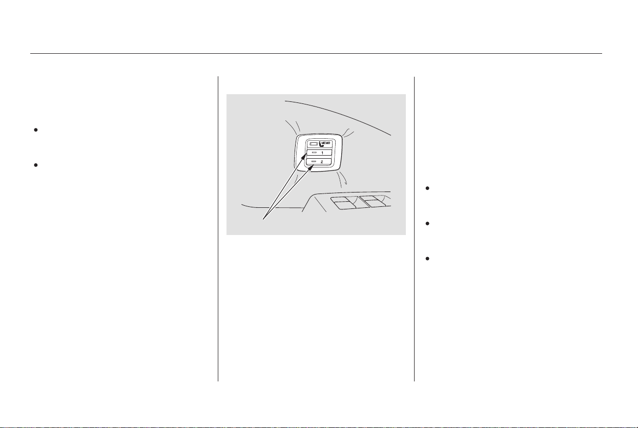
Doing any of the following after
pressing the MEMO button will
cancel the storing procedure.
Not pressing a memory button
within 5 seconds.
Readjusting the seat position.
Each memory button stores only one
seat position. Storing a new position
erases the previous position stored in
that button’s memory. If you want to
add a new position while retaining
the current one, use the other
memory button.
To select a memorized position, do
this:
Make sure the shift lever is in
Park. Press on the brake pedal.
Press the desired memory button
(1 or 2) until you hear a beep, then
release the button.
The system will move the driver’s
seat to the memorized position. The
indicator in the selected memory
button will flash during movement.
When the adjustment is complete,
you will hear two beeps, and the
indicator will stay on.
To stop the system’s automatic
adjustment, do any of these actions:
If desired, you can use the
adjustment switches to change the
seat position after it is in its
memorized position. If you change
the memorized position, the
indicator in the memory button will
go out. To keep this seat position for
later use, you must store it in the
driver’s seat position memory.
Shift out of Park.
Push any of the adjustment
switches for the seat.
Press any button on the control
panel: MEMO, 1, or 2.
1.
2.
Selecting a Memorized Position
Driver’s Seat Position Memory System
162
MEMORY BUTTONS
Main Menu
Table of Contents
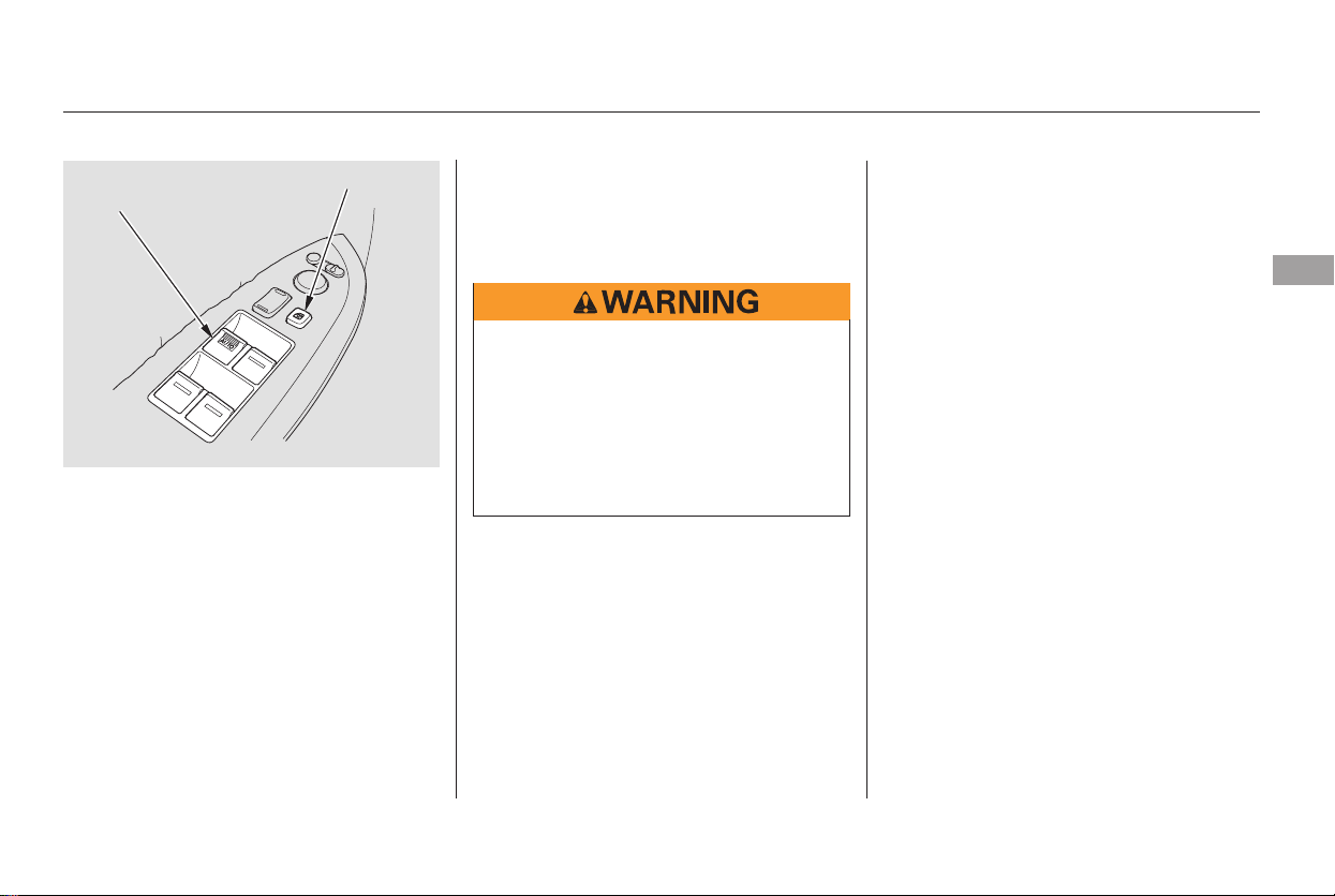
−
−
The windows will operate for up to
10 minutes after you turn off the
ignition switch. Opening either front
door cancels this function.
To open/close the driver’s
window, push the window switch
firmly down or up to the second
detent, and release it. The window
will automatically go up or down all
the way. To stop the window, pull/
push on the window switch briefly.
If the MAIN switch is OFF, the
passenger windows cannot be raised
or lowered. Keep the MAIN switch
offwhenyouhavechildreninthe
vehicle so they do not injure
themselves by operating the
windows unintentionally.
If the driver’s
window senses any obstacle while it
is closing automatically, it will
reverse direction and then stop. To
close the window, remove the
obstacle, then use the window switch
again.
Auto reverse stops sensing when the
window is almost closed. You should
always check that all passengers and
objects are away from the window
before closing it.
Turn the ignition switch to ON (II)
toraiseorloweranywindow.To
open the window, push the switch
down to the first detent and hold it.
Release the switch when you want
the window to stop. Pull back on the
switchandholdittoclosethe
window.
CONTINUED
AUTO
AUTO REVERSE
Power Windows
Instruments and Controls
163
MAIN SWITCH
DRIVER’S WINDOW
SWITCH
Closing a power window on
someone’s hands or fingers can
cause serious injury.
Make sure your passengers are
away from the windows before
closing them.
Main Menu
Table of Contents
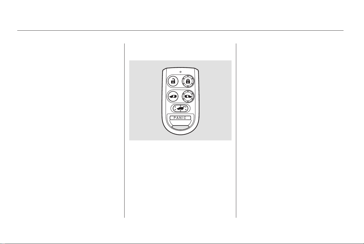
Start the engine. Push down and
hold the driver’s window switch
until the window is fully open.
Pull and hold the driver’s window
switch to close the window
completely, then hold the switch
for a second or two more.
Press the UNLOCK button a
second time, and hold it. The
passenger’s doors unlock, and all
four windows start to open. To
stop the windows, release the
button.
To open the windows further,
pressthebuttonagainandholdit.
If the windows stop before the
desired position, repeat steps 1
and 2.
You cannot close the windows with
the remote transmitter.
If your vehicle’s battery is
disconnected or goes dead, or the
driver’s window fuse is removed, the
AUTO REVERSE function will be
disabled. The power window system
needs to be reset after reconnecting
the battery or installing the fuse.
If the power windows do not operate
properly after resetting, have your
vehicle checked by your dealer.
Press the UNLOCK button once
to unlock the driver’s door.
You can open all of the windows
from the outside with the remote
transmitter.
1.
2.
3.
1.
2.
On EX and Touring models
Opening the Windows with the
Remote Transmitter
Power Windows
164
Main Menu
Table of Contents
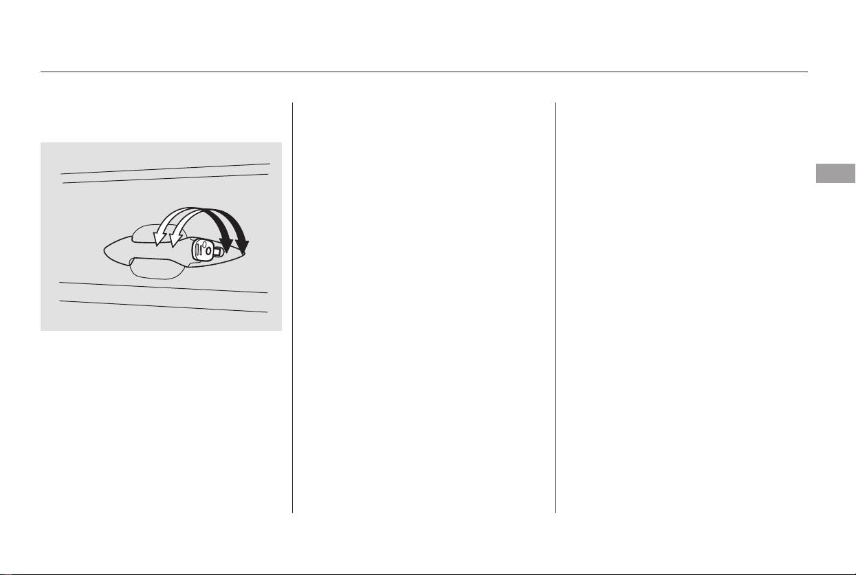
Turnthekeyclockwiseagain,and
hold it. All four windows start to
open. To stop the windows,
release the key.
To open the windows further, turn
andholdthekeyagain(within
15 seconds).
To close:
Insert the key in the driver’s door
lock.
Turn the key counterclockwise,
then release it.
Turn the key counterclockwise
again, and hold it. All four
windowsstarttoclose.Tostopthe
windows, release the key.
To close the windows further, turn
andholdthekeyagain(within
15 seconds).
If the windows stop before the
desired position, repeat steps 2 and 3.
Turn the key clockwise, then
release it.
Insert the key in the driver’s door
lock.
To open:
You can open and close the windows
with the key in the driver’s door lock.
1.
2.
3.
4.
1.
2.
3.
4.
On EX and Touring models
Opening/Closing the Windows
with the Key
Power Windows
Instruments and Controls
165
Open
Close
Main Menu
Table of Contents
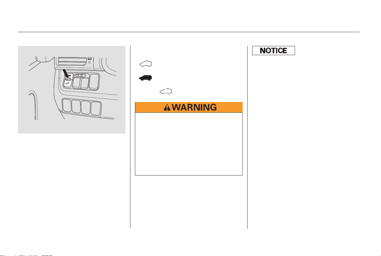
To tilt up the back of the moonroof,
press and hold the center button
( ). To close the moonroof,
press and hold the top of the switch
( ). To open the moonroof,
press and hold the bottom of the
switch ( ).
The moonroof has a key-off delay.
You can still open and close the
moonroof for up to 10 minutes after
you turn off the ignition. The key-off
delay cancels as soon as you open
either front door. You must then
turn the ignition to ON (II) for the
moonroof to operate.
The moonroof can be tilted up in the
back for ventilation, or it can be slid
back into the roof. Use the switch
under the left dashboard vent to
operate the moonroof. You must
turn the ignition switch to ON (II)
for the moonroof to operate.
On EX with Leather and Touring models
Moonroof
166
Opening or closing the
moonroof on someone’s hands
or fingers can cause serious
injury.
Make sure all hands and fingers
are clear of the moonroof
before opening or closing it.
If you try to open the moonroof in
below-f reezing temperatures, or when
it is covered with snow or ice, you can
damage the moonroof panel or its
motor.
Main Menu
Table of Contents
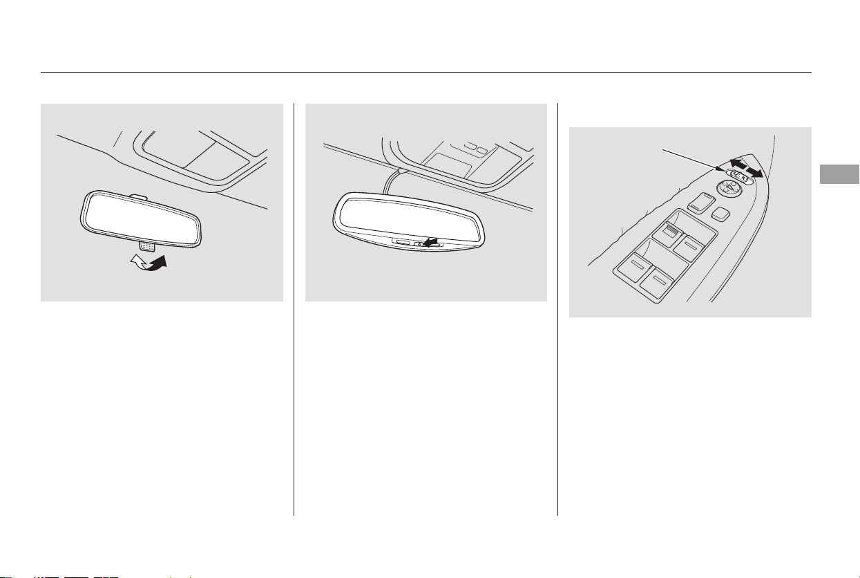
Keeptheinsideandoutsidemirrors
clean and adjusted for best visibility.
Be sure to adjust the mirrors before
you start driving.
The inside mirror has day and night
positions. The night position reduces
glare from headlights behind you.
Flip the tab on the bottom edge of
the mirror to select the day or night
position.
The inside mirror can automatically
darken to reduce glare. To turn on
this feature, press the button on the
bottom of the mirror. The AUTO
indicator comes on as a reminder.
When it is on, the mirror darkens
when it senses the headlights of a
vehicle behind you, then returns to
normal visibility when the lights are
gone. Press the button again to turn
off this sensing.
Turn the ignition switch to ON (II).
Move the selector switch to L
(driver’s side) or R (passenger’s
side).
1.
2.
CONTINUED
On Touring model
On LX and EX models
Mirrors
Adjusting the Power Mirrors
Instruments and Controls
167
SELECTOR SWITCH
Main Menu
Table of Contents
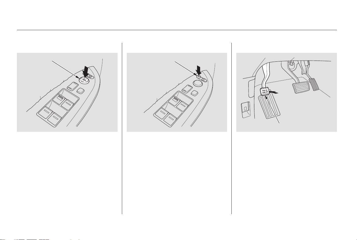
Push the appropriate edge of the
adjustment switch to move the
mirrorright,left,up,ordown.
When you finish, move the
selector switch to the center (off)
position. This turns the
adjustment switch off to keep your
settings.
The outside mirrors are heated to
remove fog and frost. With the
ignition switch in the ON (II)
position, turn on the heaters by
pressing the button. The indicator in
the button comes on as a reminder.
Press the button again to turn the
heaters off.
To apply the parking brake, push the
parking brake pedal down with your
foot. To release the parking brake,
push on the pedal again. The parking
brake indicator on the instrument
panel should go out when the
parking brake is fully released with
the engine running (see page ).
3.
63
On EX and Touring models
Mirrors
Parking Brake
168
ADJUSTMENT SWITCH
HEATED MIRROR BUTTON
PARKING BRAKE PEDAL
Main Menu
Table of Contents
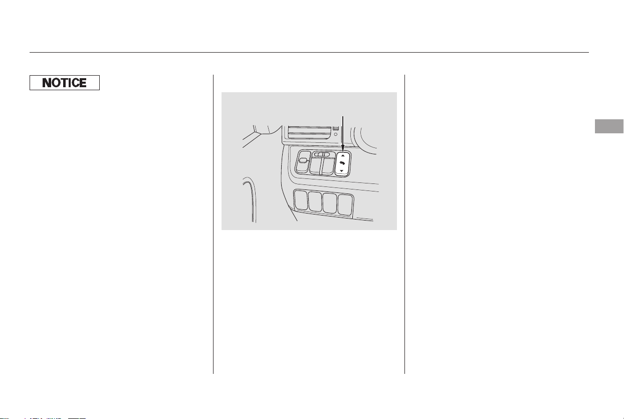
You can adjust the position of the
brake pedal, and accelerator pedal
when the shift lever is in the Park
position. Push the top of the
adjustment switch to move the
pedals forward, and the bottom to
move them backward.
To adjust the pedals:
Pushandholdthetopofthe
adjustment switch until pedals are
closest to you.
Adjust your seat and the steering
wheel so you can operate the
controls and steering wheel easily.
Pushandholdthebottomofthe
adjustment switch until pedals are
in the position you can press them
fully and comfortably.
Do not adjust the pedals with your
foot on or under either pedal.
1.
2.
3.
On Touring model only
Parking Brake, Adjustable Driver’s Foot Pedals
Adjustable Driver’s Foot Pedals
Instruments and Controls
169
PEDAL POSITION
ADJUSTMENT SWITCH
Driving the vehicle with the parking
brake applied can damage the rear
brakes and axles.
Main Menu
Table of Contents
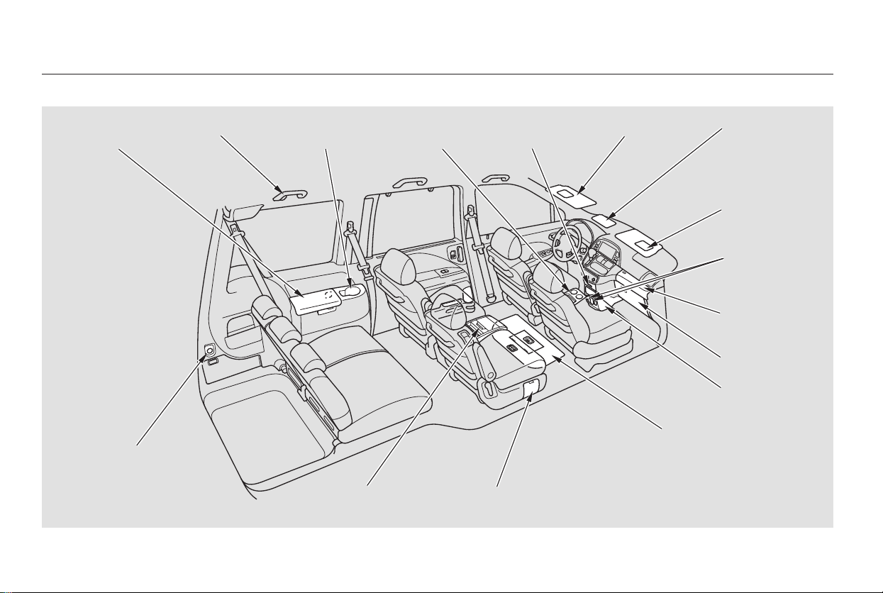
*
*
Interior Convenience Items
170
BEVERAGE HOLDER
VANITY
MIRROR
CENTER
POCKET
ACCESSORY
POWER
SOCKET
REAR
COMPARTMENT
COAT HOOK
SUN VISOR
ACCESSORY
POWER
SOCKET
: Touring model only
SUNGLASSES
HOLDER WITH
CONVERSATION
MIRROR
LOWER
GLOVE BOX
UPPER GLOVE
BOX
REMOVABLE SECOND
ROW CONSOLE
RETRACTABLE
CENTER TRAY
BEVERAGE
HOLDER
BEVERAGE
HOLDER
IN-FLOOR
STORAGE
Main Menu
Table of Contents
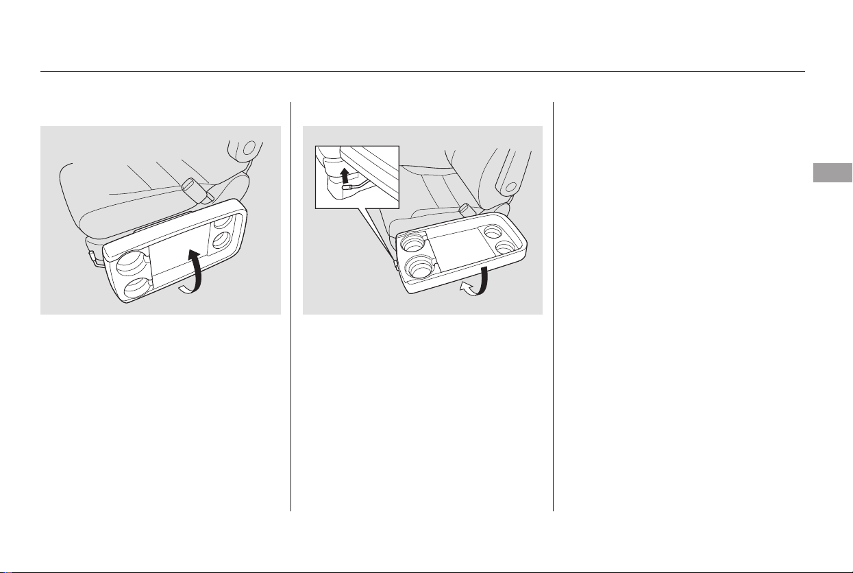
Be careful when you are using the
beverage holders. A spilled liquid
that is very hot can scald you or your
passengers. Spilled liquids can
damage the upholstery, carpeting,
and electrical components in the
interior.
To use the retractable center tray,
pull up the outside edge of the tray
until it latches. To store it, pull the
lever and lower the tray.
Sitting on or getting under the tray,
or putting heavy objects on the tray,
may damage or deform it.
Do not keep items on the tray while
driving. They may fall down or fly
around when you go around corners
or brake hard.
CONTINUED
Beverage HoldersRetractable Center Tray
Interior Convenience Items
Instruments and Controls
171
Main Menu
Table of Contents
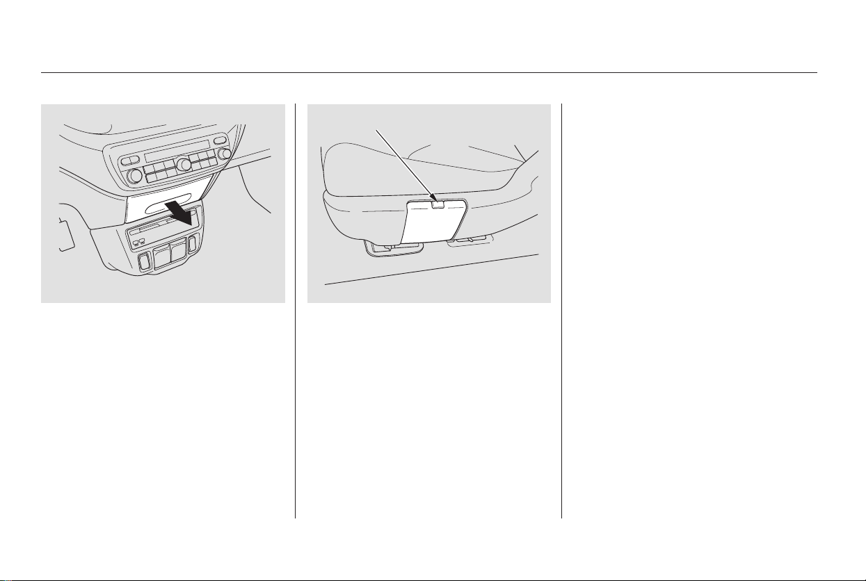
To protect the beverage holder, the
bottom tray is designed to break
away if you try to place a heavy
object on it. If this happens, hold the
edge of the bottom tray and pull it up
until you feel a detent.
Be careful not to damage an open
beverage holder when you get into
or out of the vehicle.
The beverage holders for the third
seat passengers are in the armrests
ontherearsidepanels.Each second row seat has a
beverage holder on the outside of
the seat cushion. To use the
beverage holder, push on the tab.
The beverage holder will swing open.
To close, pivot it up and push it in
until it latches.
To use the front beverage holder,
pull the handle.
Additional beverage holders for the
frontseatpassengersareinthe
retractable center tray.
Interior Convenience Items
172
TAB
Main Menu
Table of Contents
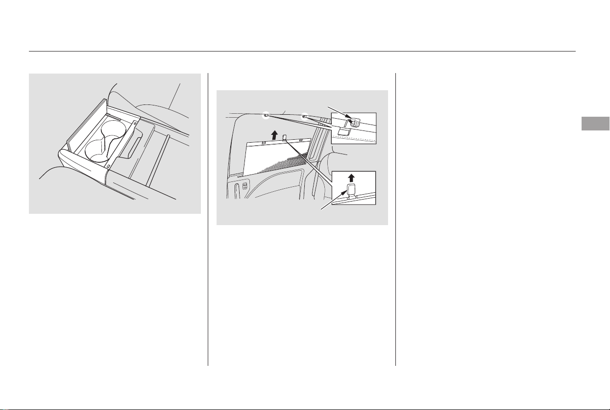
The removable second row console
has a beverage holder on the front.
To use the beverage holder, push on
the front lid. The lid will swing open.
To close, lower the lid, and push it
down until it latches.
Each rear sliding door has an
integrated sunshade. To use a
sunshade,holdthetabonthetop
and pull the sunshade all the way up.
Insert the holes on the sunshade into
the hooks on the window frame. To
store the shade, unhook it, and let it
retract all the way down.
The sunshades are intended for use
only when the windows are fully
closed. If a window is opened, the
shade can be blown off its hooks. As
the shade automatically retracts, it
could hit and hurt anyone sitting too
close to the window.
On Touring model
On EX and Touring models
Integrated Sunshades
Interior Convenience Items
Instruments and Controls
173
HOOK
TAB
Main Menu
Table of Contents
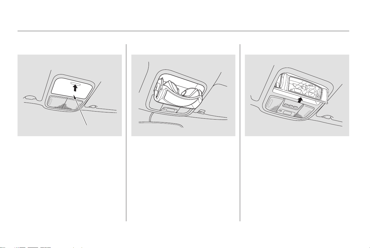
To open the sunglasses holder, push
on the front edge. Make sure the
holder is closed while you are driving.
Some larger styles of sunglasses
may not fit in the holder.
You may also store small items in
this holder. Make sure they are
small enough to let the holder close
and latch, and that they are not
heavy enough to cause the holder to
pop open while driving.
The sunglasses holder uses a convex
mirror for its bottom panel. You can
see all the vehicle passengers on this
mirror. To use the mirror, open the
sunglasses holder, push it to the first
detent, and release it.
To open the sunglasses holder, push
on the front edge. It will unlatch and
swing down. To close it, push it until
it latches. Make sure the holder is
closed while you are driving.
On EX and Touring models
Sunglasses Holder Conversation Mirror
Interior Convenience Items
174
SUNGLASSES HOLDER
Push
Main Menu
Table of Contents
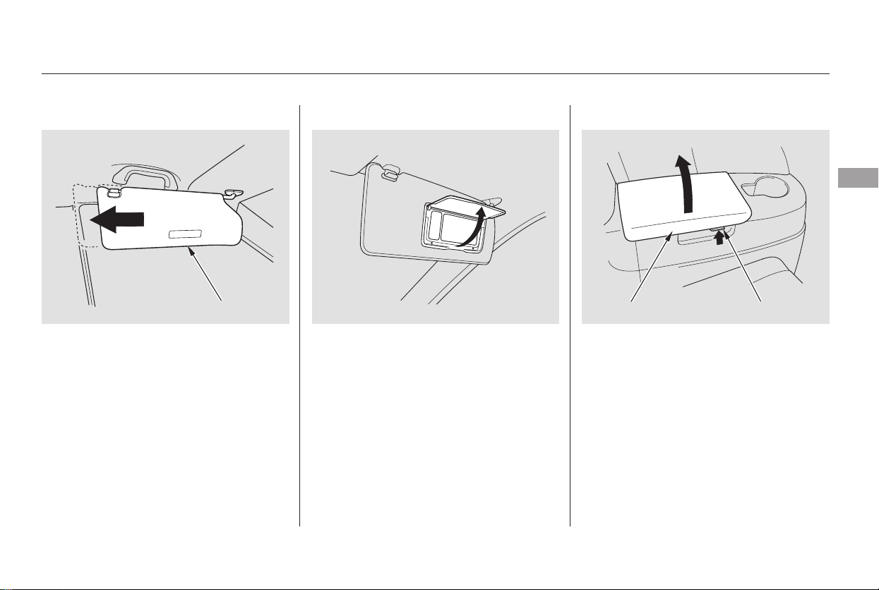
Pull up the vanity mirror cover to use
it. The lights come on only when the
parking lights are on.
To open the compartment, pull the
lever and lift the lid. To close, lower
the lid and push it down until it
latches.
To use the sun visor, pull it down.
Whenusingthesunvisorforthe
side window, remove the support rod
from the clip, and swing it out. In this
position, the sun visor can be
adjusted by moving it on its slider.
Make sure you put the sun visor
back in place when you are getting
into or out of the vehicle.
The vanity mirror light will not come
on if the sun visor is slid outward.
Sun Visor Vanity Mirror Rear Compartment
Interior Convenience Items
Instruments and Controls
175
REAR COMPARTMENT
LEVER
SUN VISOR
Main Menu
Table of Contents
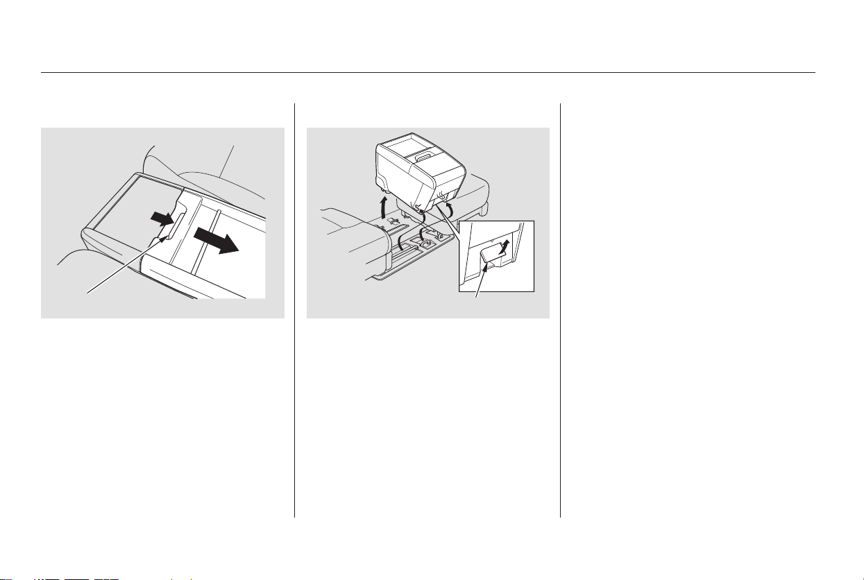
There is a removable console
between the second row bucket
seats.
To remove the console, pull up the
tab at the front edge to unlock the
rear of the console from the floor.
To reinstall the console, hook the
front of it to the floor, then push
down the back until it locks. Make
sure the console is securely locked in
place. A console that is not locked in
place could fly around and cause
injury in a sudden stop or crash.
If you remove the second seat center
console, store it in a safe place
outside the vehicle.
Unhook the front of the console
from the floor by pulling it back
slightly, then pivoting it upward.
To open the console, push the tab,
and slide the lid to the rear.
On Touring model only
Removable Second Row Console
Interior Convenience Items
176
TAB
TAB
Main Menu
Table of Contents
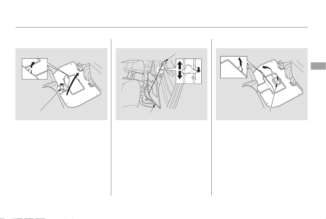
There is a large storage area under
the floor between the front seats and
the second row bucket seats.
To place or remove large items from
the storage area, pull off the carpet
near the second seat, and pull the
handle to open the large lid.
To place or remove small items from
the storage area, pull off the carpet
in the center of the lid, and pull the
handle to open the small lid.
On EX and Touring models, this
handle can be locked with the
master key.
To keep the lid open, attach the hook
to the grab rail on the back of the
front seat-back.
You can adjust the length of the
hook strap. Pull down the upper
edge of the stopper, and slide it up or
down.
CONTINUED
In-Floor Storage Area
Interior Convenience Items
Instruments and Controls
177
HANDLE
HOOK
LID
HANDLE
Main Menu
Table of Contents
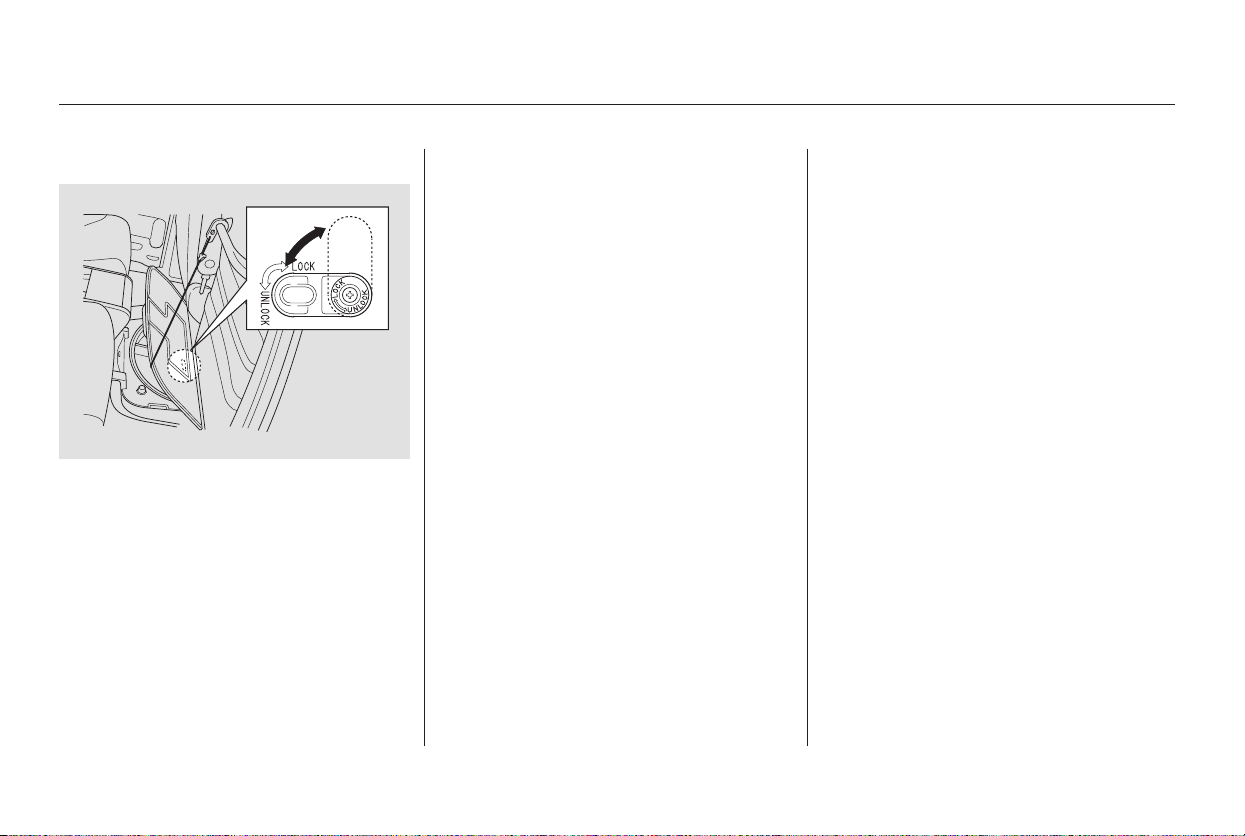
You can store items in the floor
storageareaupto22lbs(10kg).Do
not exceed this weight limit, or you
may damage the floor storage area.
Theinsideofthestorageareacan
get very hot. Do not store any items
that should be kept cool, or items
that can be easily damaged, warped,
or deformed by heat.
Dust, sand, etc., can accumulate in
the floor storage area. If you spill
liquid on the floor around the floor
storage area, it can get inside the
storage area, and the moisture can
be trapped inside. Always keep the
inside of the storage area dry and
clean.
To prevent items from being thrown
about the vehicle and possibly
hurting someone in an accident or
sudden stop, be sure the storage
area lids are securely closed before
driving away.
To lock the small lid, open the large
lid, and turn the lock knob clockwise.
Interior Convenience Items
178
Main Menu
Table of Contents
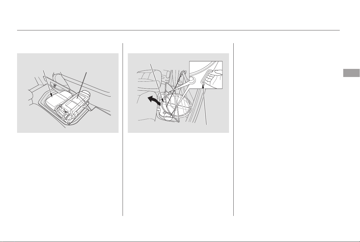
On EX and Touring models, the floor
storage area has a Lazy Susan inside
which makes it easier to find items
through the small lid.
TheLazySusancanberemoved.
When it is removed, a larger item,
such as the stowable second row
plus-one seat, can be stored.
To remove the Lazy Susan, open the
large lid. Attach the hook to the grab
rail on the back of the front seat to
keep the lid open. Hold the two
handles on the edge of the Lazy
Susan, and pull it out of the storage
area. Store the removed Lazy Susan
in a safe place outside the vehicle.
Do not place it on the vehicle floor or
seat, or in the cargo area. It can fly
around the interior in a crash.
The Lazy Susan can be damaged if it
is kept in a humid place. Always
store the Lazy Susan in a dry place
when it is removed.
Interior Convenience Items
Instruments and Controls
179
STOWABLE SECOND ROW
PLUS-ONE SEAT
LAZY SUSAN
HANDLE
Main Menu
Table of Contents
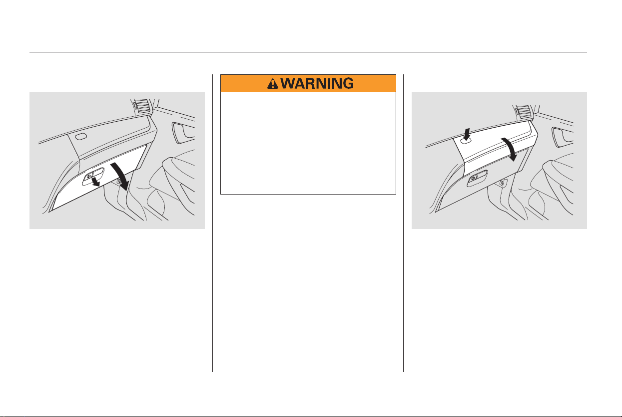
Open the upper glove box by
pressing the button. The lid will
swing open. Close it with a firm push.
Open the lower glove box by pulling
the bottom of the handle. Close it
with a firm push. Lock or unlock the
glove box with the master key.
Interior Convenience Items
LowerGloveBox UpperGloveBox
180
An open glove box can cause
serious injury to your passenger
inacrash,evenifthe
passenger is wearing the seat
belt.
Always keep the glove boxes
closed while driving.
Main Menu
Table of Contents
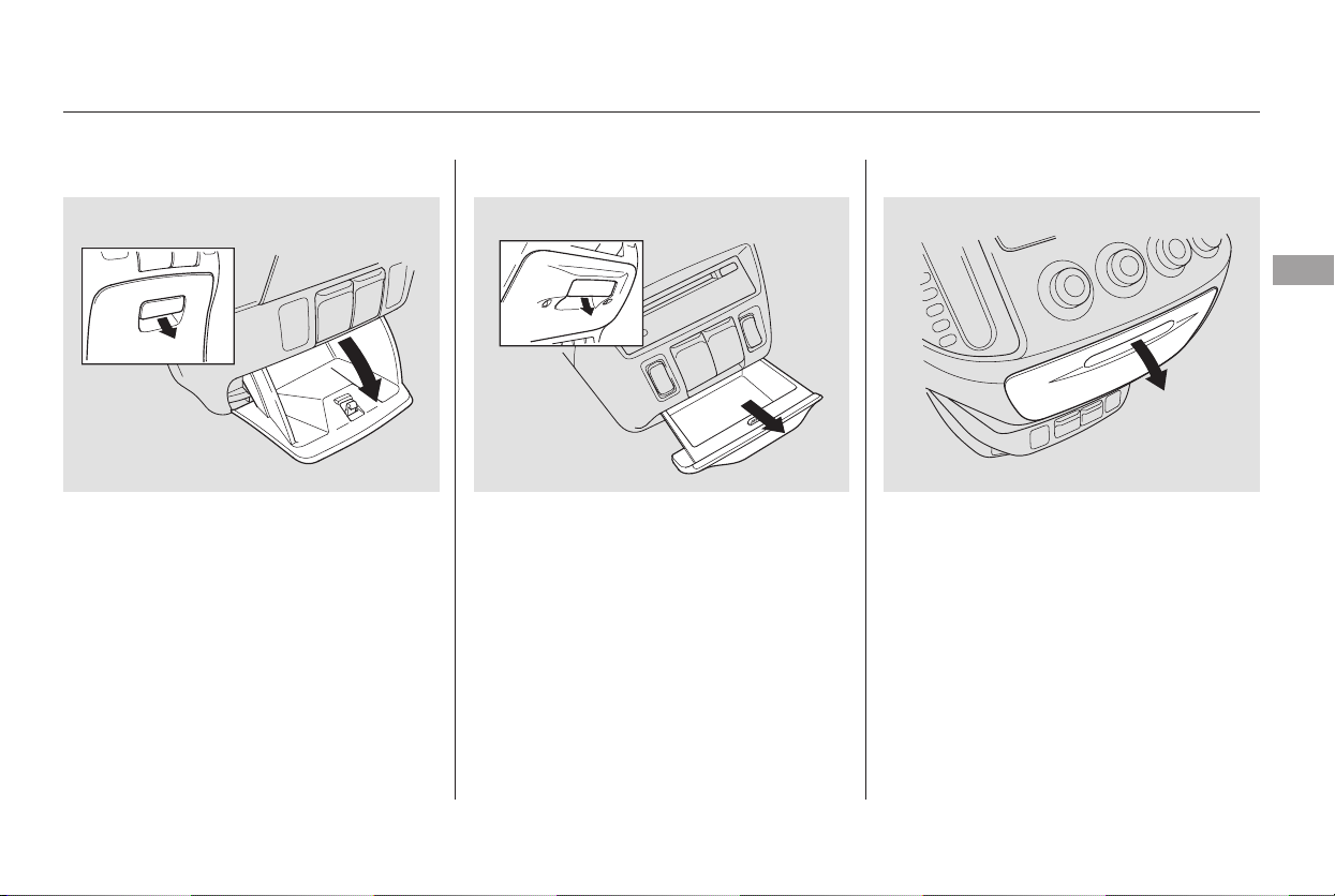
Open the center pocket by pulling
thehandle.Closeitwithafirmpush.
On vehicles without navigation
system, there is another pocket
under the heating and cooling
system control panel. Pull the handle
to open it. Close it with a firm push.
Center Pocket
Interior Convenience Items
Instruments and Controls
181
Vehicles without RES
Vehicles with RES
Main Menu
Table of Contents
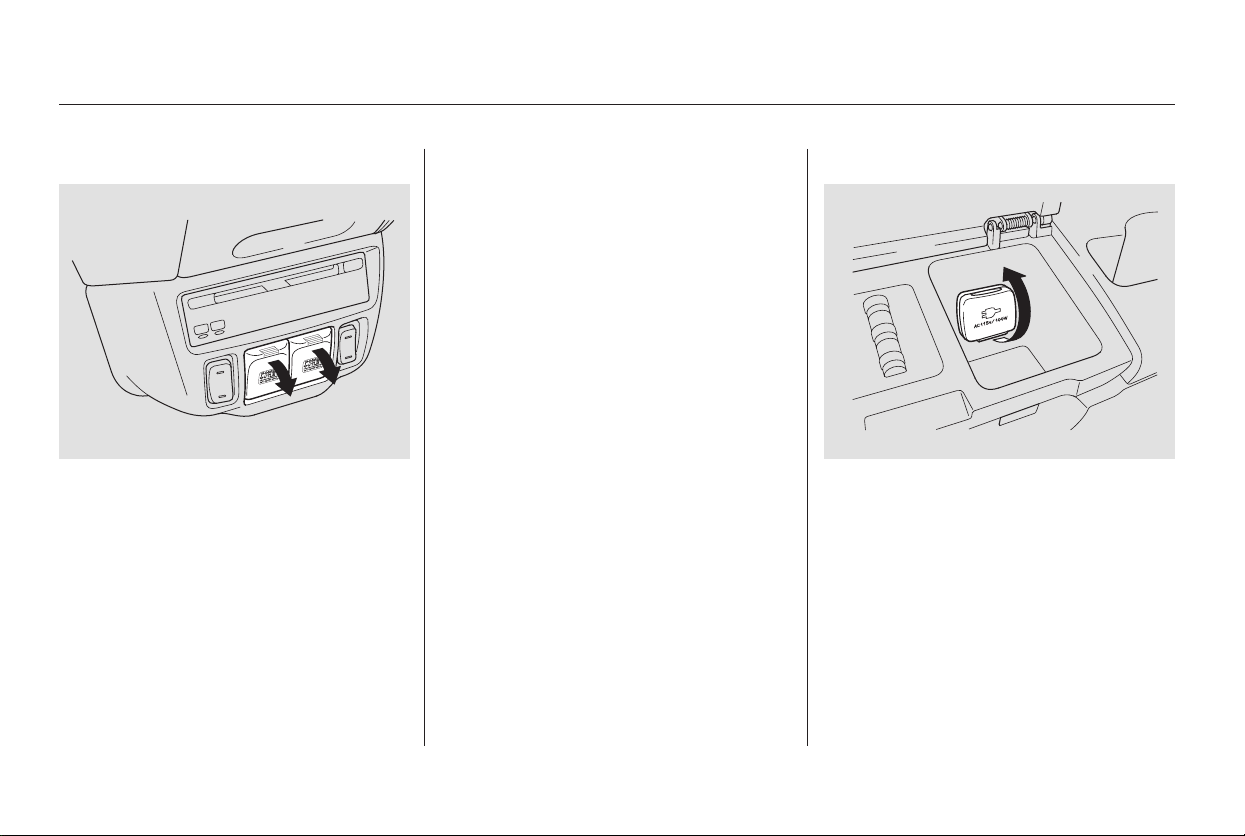
There are three accessory power
sockets in your vehicle. Two
accessory power sockets are above
the center pocket for the front seat
passengers, and another is on the
cargo area sidewall on the driver’s
side.
These sockets are intended to supply
power for 12 volt DC accessories
that are rated 120 watts or less (10
amps).
None of the sockets will power an
automotive type cigarette lighter
element. When more than one
socket is being used, the combined
power rating of the accessories
should be 120 watts or less
(10 amps).
There is a 115 volt AC power outlet
in the rear compartment on the
driver’s side. To use the AC power
outlet, open the rear compartment
lid and open the outlet cover. Insert
the plug into the receptacle slightly,
turn it 90° clockwise, then push in
the plug all the way.
Always run the engine when you use
the AC Power Outlet.
Accessory Power Sockets AC Power Outlet
Interior Convenience Items
182
Main Menu
Table of Contents
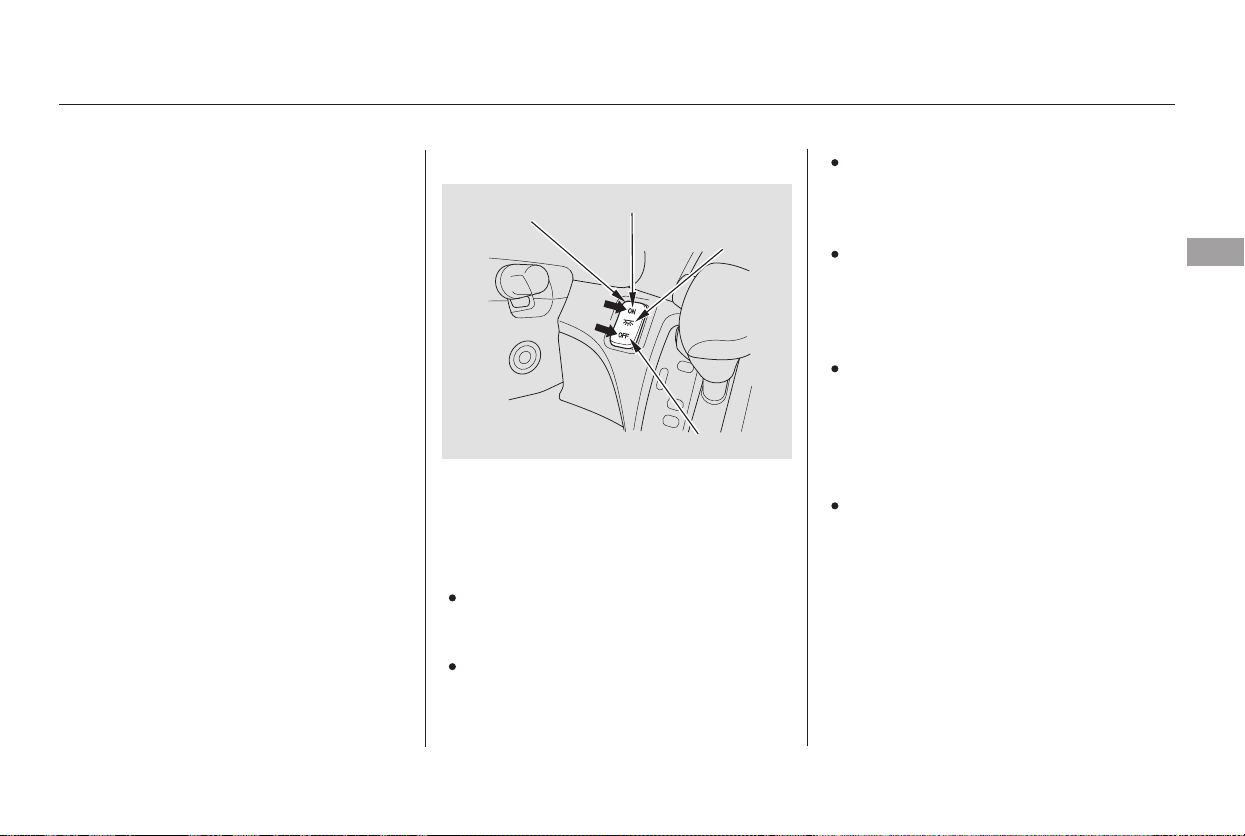
The individual map lights in the
second and third rows cannot be
turned on.
The cargo area light can be turned
on with the switch in the light.
Door
Activated
The light control switch has three
positions: OFF, Door Activated, and
ON.
OFF
None of the lights come on when a
door or the tailgate is opened.
The individual map lights in the
front can be turned on and off by
pressing the lenses.
The maximum capacity for this
power outlet is 115 volt AC at 100
watts or less. If you use an appliance
which requires more than 100 watts,
it automatically stops supplying the
power. If this happens, turn the
ignition switch off and turn it on
again.
The AC power outlet is not
designed for electric appliances
which require high initial peak
wattage such as cathode-ray tube
type televisions, refrigerators,
electric pumps, etc. It is also not
suitable for devices that process
precise data such as medical
equipment or measuring instruments.
Any appliances that require an
extremely stable power supply such
as microcomputer-controlled electric
blankets, touch sensor lamps, etc.,
should not be connected to this
outlet.
The individual map lights in the
front come on when any door is
opened. When the doors are
closed, each light can be turned on
and off by pressing the lenses.
The individual map lights in the
second and third rows come on
when any door is opened. When
the doors are closed, each light
canbeturnedonandoffby
pushingonthelens.
When the switch is in the
position:
When this switch is in the position:
CONTINUED
Light Control Switch
Interior Convenience Items, Interior Lights
Instruments and Controls
183
NOTE:
ON DOOR
ACTIVATED
POSITION
OFF
LIGHT CONTROL
SWITCH
Main Menu
Table of Contents
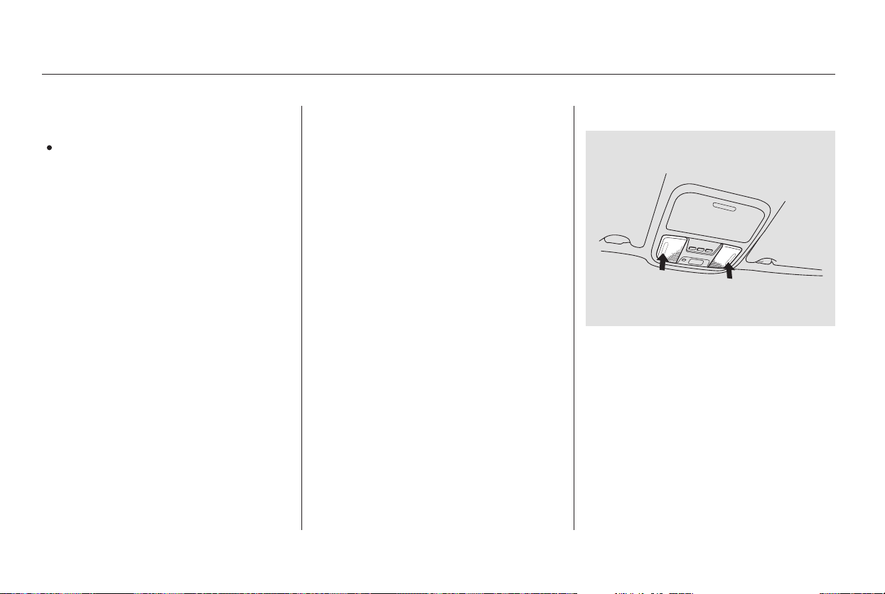
Turn on the front and rear individual
map lights by pushing the lens of
each light. Push the lens again to
turn it off. You can also operate
these lights with the light control
switch (see page ).
The lights go out about 30 seconds
after all the doors and the tailgate
are closed. They go out immediately
after all doors are locked.
With the light control switch in the
Door Activated position, all the
individual map lights come on when
you unlock the door with the remote
transmitter (see page ).
Withanydoororthetailgateleft
open, the lights stay on about 3
minutes, then go out.
ON
All the individual map lights come
onandstayonaslongasthe
switch remains in the ON position.
183
133
When the light control switch is in the
position:
On EX and Touring models
Individual Map Lights
Interior Lights
184
FRONT
Main Menu
Table of Contents
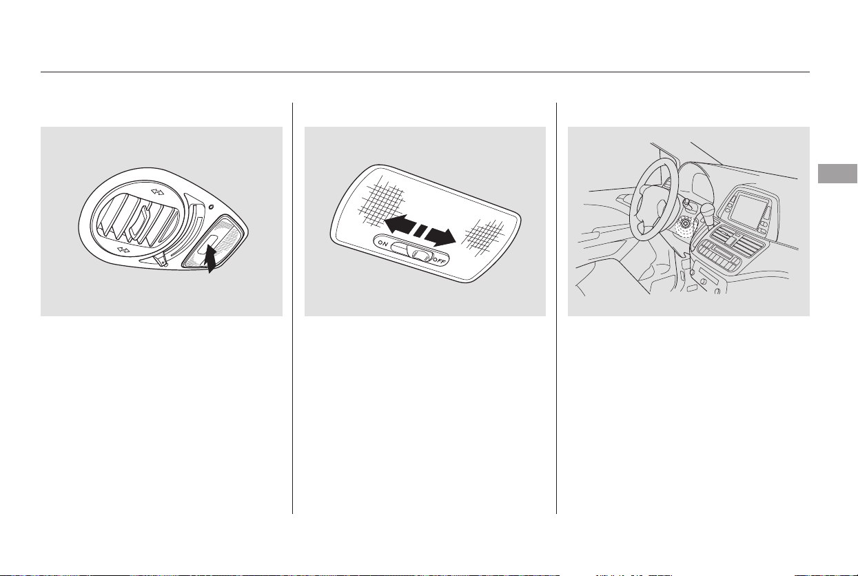
The ignition switch light comes on
when you open the driver’s door, and
stays on several seconds after you
close the door.
The cargo area light has a three-
position switch. In the OFF position,
the light does not come on. In the
center position, it comes on when
you open the tailgate. In the ON
position, it stays on continuously.
Ignition Switch LightCargo Area Light
Interior Lights
Instruments and Controls
185
OFF
ON
REAR
Main Menu
Table of Contents
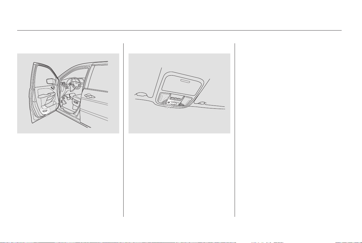
The courtesy lights in the front
doors come on when you open any
door.
The courtesy light between the map
lights comes on when you turn the
parking lights on. To adjust its
brightness, turn the Select/Reset
knob on the instrument panel.
Interior Lights
Courtesy Lights
186
Main Menu
Table of Contents

The standard audio system has
many features. This section de-
scribes those features and how to
use them. (If you selected an
optional audio system, refer to the
operating instructions that came
with it.)
The heating and air conditioning
systems in your vehicle provide a
comfortable driving environment in
all weather conditions.
The security system helps to dis-
courage vandalism and theft of your
vehicle.
Your vehicle has an anti-theft audio
system that requires a code number
to enable it.
.............Vents, Heating, and A/C . 188
Using Automatic Climate
...................................Control . 193
.........Using the Rear A/C Unit . 194
...................Rear Climate Control . 197
..............Climate Control Sensors . 198
..........Playing the AM/FM Radio . 199
............AM/FM Radio Reception . 205
...Playing the XM Satellite Radio . 207
..................................Playing a CD . 212
...................................CD Changer . 215
....................Protecting Your CDs . 221
.....CD Changer Error Messages . 222
...............................Playing a Tape . 223
.............Steering Wheel Controls . 228
.................Radio Theft Protection . 229
........Rear Entertainment System . 230
..............................Playable DVDs . 258
............................Security System . 263
...............................Cruise Control . 264
HomeLink Universal
................................Transceiver . 267
................Parking Sensor System . 271
.Rear View Camera and Monitor . 275
Features
Features
187
Main Menu
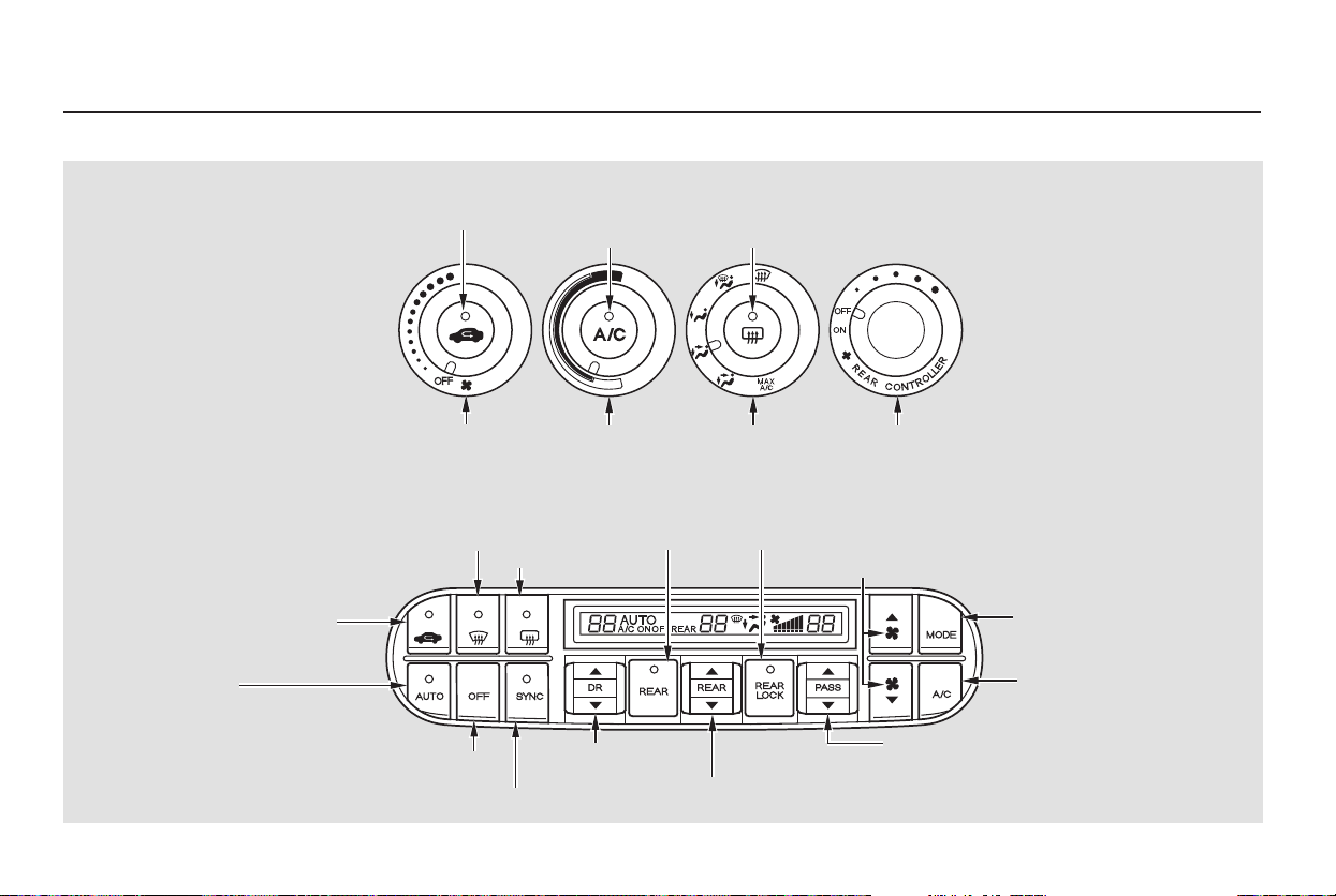
Vents, Heating, and A/C
LX model
EX/Touring models
188
RECIRCULATION
BUTTON
AIR CONDITIONING
BUTTON
REAR WINDOW
DEFOGGER BUTTON
FAN CONTROL
BUTTON
MODE
CONTROL
DIAL
MODE
BUTTON
AIR CONDITIONING
BUTTON
AUTO
BUTTON
RECIRCULATION
BUTTON
TEMPERATURE
CONTROL DIAL
REAR
CONTROLLER
DIAL
WINDSHIELD
DEFROSTER BUTTON
REAR WINDOW
DEFOGGER
BUTTON
REAR
BUTTON
REAR LOCK
BUTTON
FAN CONTROL BUTTONS
OFF BUTTON
SYNCHRO BUTTON
DRIVER’S SIDE
TEMPERATURE
CONTROL
SWITCH
PASSENGER’S SIDE
TEMPERATURE CONTROL SWITCH
REAR TEMPERATURE/FAN SPEED (EX model)
CONTROL SWITCH
Main Menu
Table of Contents

▲
▼
▲
▼
Turn the dial clockwise to increase
the fan speed and airflow. Turn the
dial counterclockwise to decrease it.
Press the button to increase
the fan speed and airflow. Press the
button to decrease it.
Turning this dial clockwise increases
the temperature of the airflow.
The driver’s side temperature and
the passenger’s side temperature can
be set separately. On the Touring
model, the rear passenger
compartment temperature can also
be set separately. Press the top ( )
of the appropriate temperature
control button to increase the
temperature of airflow. Press the
bottom ( ) of the button to
decrease it. Each set temperature is
shown in the display. When you turn
the A/C off, the system cannot
regulate the inside temperature if
you set the temperature control
below the outside temperature.
When you set the temperature to its
lower limit or its upper limit, it will be
displayed as ‘‘Lo’’ or ‘‘Hi’’.
When you press this button, the
indicator in the button comes on, and
the passenger’s side temperature
(and the temperature of the rear
passenger compartment on the
Touring model) is synchronized to
the driver’s side set temperature.
Changing the passenger’s side
temperature (or the temperature of
the rear passenger compartment on
the Touring model) makes the
indicator to go off, and takes the
system out of SYNC mode.
This button turns the air
conditioning on and off. On the LX
model, the indicator in the button is
on when the A/C is on. On the EX
and Touring models, you will see
A/C ON or A/C OFF in the display.
The outside air intakes for the
heating and cooling system are at
the base of the windshield. Keep this
area clear of leaves and other debris.
When the indicator in the button is
on, air from the vehicle’s interior is
sent throughout the system again.
When the indicator is off, air is
brought in from the outside of the
vehicle (fresh air mode).
CONTINUED
LX model
LX model
EX and Touring models
EX and Touring models
On EX and Touring models
Vents, Heating, and A/C
Fan Control
Temperature Control
Air Conditioning (A/C) Button
Recirculation Button
SYNC Button
Features
189
Main Menu
Table of Contents
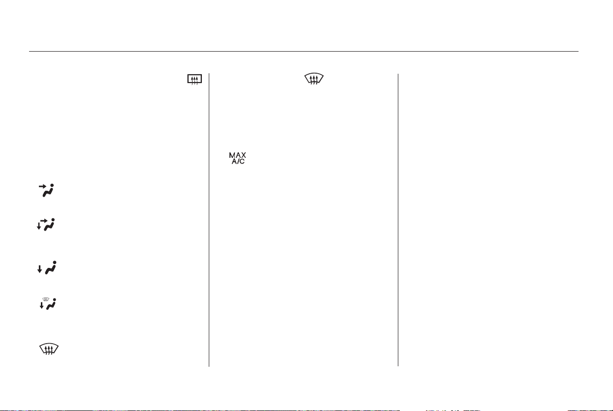
Air flows from the center
and corner vents in the dashboard.
Airflow is divided between
the vents in the dashboard and the
floor vents.
Air flows from the floor
vents.
Airflow is divided between
the floor vents and the defroster
vents at the base of the windshield.
This button turns the rear window
defogger on and off (see page ).
Use the mode control dial or button
to select the vents the air flows from.
Some air will flow from the
dashboard vents in all modes.
Air flows from the defroster
vents at the base of the windshield.
When you select , the system
automatically switches to fresh air
mode and turns on the A/C.
The passenger’s temperature cannot
be set separately from the driver’s.
When you want to change the
temperature of the rear passenger
compartment, press the REAR
button. The indicator in the button
comes on, and you can change the
temperature using the rear
temperature control button. When
you press the REAR LOCK button,
the indicator in the button comes on,
the rear A/C passenger control
panel is disabled, and you cannot
change any settings from it.
See page for how to operate the
rear passenger control panel.
You can change the fan speed of the
rear system from the front control
panel. Press the REAR button, the
indicator in the button comes on.
Push the rear fan control button up
or down to increase or decrease the
rear fan speed. When you press the
REAR LOCK button, the indicator in
the button comes on, and the rear
passenger control panel is disabled.
The system automatically
turns on the A/C and switches to
recirculation mode. Air flows from
the center and side vents in the
dashboard.
See page for how to operate the
rear passenger control panel.
196
197
126
On Touring model only
On LX model only
On EX model
Vents, Heating, and A/C
Rear Window Defogger Button
Mode Control
REAR/REAR LOCK Button
190
Main Menu
Table of Contents
CONTINUED
Air conditioning places an extra load
on the engine. Watch the engine
coolant temperature gauge (see page
). If it moves near the red mark,
turn off the A/C until the gauge
reads normally.
Press the A/C button. The
indicator in the button comes on
(LX model) or ‘‘A/C ON’’ is shown
in the display (EX and Touring
models)whenafanspeedis
selected.
Make sure the temperature is set
to the lower limit.
Select .
If the outside air is humid, select
recirculation mode. If the outside
air is dry, select fresh air mode.
you can
cool it down more rapidly by partially
opening the windows, turning on the
A/C, and setting the fan to
maximum speed in fresh air mode.
The flow-through ventilation system
draws in outside air, circulates it
through the interior, then exhausts it
through vents near the rear side
panels.
The heater uses engine coolant to
warm the air. If the engine is cold, it
will be several minutes before you
feel warm air coming from the
system.
Select and fresh air mode.
Set the fan to the desired speed.
Adjust the warmth of the air with
the temperature control dial or
buttons.
Set the temperature control dial or
button to the lower limit.
Make sure the A/C is off.
Select and fresh air mode.
Set the fan to the desired speed.
Set the fan to the desired speed.
1.
2.
3.
4.
5.
1.
2.
3.
1.
2.
3.
4.
71
If the interior is very warm,
Vents, Heating, and A/C
Using the A/CVentilation
Using the Heater
Features
191
Main Menu
Table of Contents

Air conditioning, as it cools, removes
moisture from the air. When used in
combination with the heater, it
makes the interior warm and dry.
To remove fog from the inside of the
windows: Select . The system
automatically switches to fresh air
mode and turns on the A/C.
The indicator in the A/C button
will not come on (LX model), or
the A/C ON indicator will not
come on (EX and Touring models).
Select .
Set the fan and temperature
controls to maximum level.This setting is suitable for all driving
conditions whenever the outside
temperature is above 32°F (0°C).
Switch the fan on.
Turn on the air conditioning.
Select and fresh air mode.
Adjust the temperature to your
preference.
Set the fan to high.
Select . The system
automatically switches to the fresh
air mode and turns on the A/C.
The indicator in the A/C button
will not come on (LX model), or
the A/C ON indicator will not
come on (EX and Touring models).
Adjust the temperature so the
airflow feels warm.
Select to help clear the
rear window.
When you switch to another mode
from , the A/C stays on.
Press the A/C button to turn it off.
To clear the windows faster, you can
close the dashboard corner vents by
rotating the wheel next to each vent.
This will send more warm air to the
windshield defroster vents. Once the
windshield is clear, select fresh air
mode to avoid fogging the windows.
For your safety, make sure you have
a clear view through all the windows
before driving.
1.
2.
3.
4.
1.
1.
2.
3.
4.
2.
3.
On U.S. vehicles
On U.S. vehicles
Vents, Heating, and A/C
Dehumidify the Interior To Defog and Defrost To Remove Exterior Frost or Ice
From the Windows
192
Main Menu
Table of Contents

If you set the temperature to its
lower or its upper limit, the system
runs at full cooling or heating only. It
does not regulate the interior
temperature.
Press the Auto button. The
indicator in the button comes on.
Set the desired temperature with
the temperature control button.
You will see AUTO in the system’s
display. You can set the driver’s
side temperature and passenger’s
side temperature (and the
temperature of the rear passenger
compartment on the Touring
model) separately. The system
automatically selects the proper
mix of conditioned and/or heated
air that will, as quickly as possible,
raise or lower the interior
temperature to your preference.
The automatic climate control
system adjusts the fan speed and
airflow levels to maintain the interior
temperature you select.
When you press a fan control button,
the fan is taken out of AUTO mode.
You can manually select various
functions of the climate control
system when it is in fully automatic
mode. All other features remain
automatically controlled. Making any
manual selection causes the word
AUTO in the display to go out.
Turn the fan speed and temperature
control dials all the way to the left,
and turn the rear controller dial to
OFF position.
To keep stale air and mustiness
from collecting, you should have
the fan running at all times.
Keep the system completely off
for short periods only.
Press the OFF button and REAR
button (indicator is off).
1.
2.
LX model
EX and Touring models
EX, and Touring models
Vents, Heating, and A/C
Using Automatic Climate Control To Turn Everything Off
Semi-automatic Operation
Features
193
Main Menu
Table of Contents
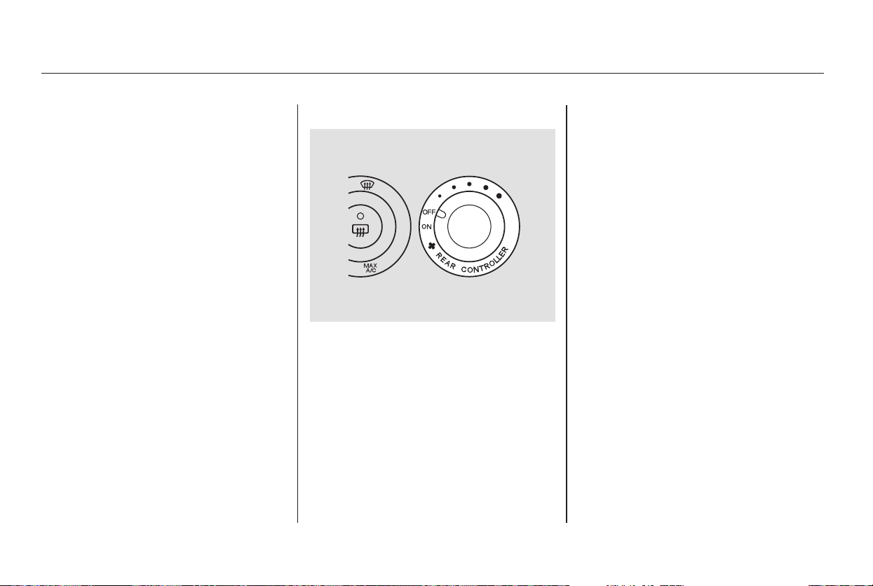
−
−
You can adjust the airflow of the rear
A/C unit with the rear controller dial
on the front control panel. The rear
passengers can also adjust the
direction and the amount of airflow
on the rear control panel.
No air flows to the rear
vents, and the rear control panel is
turned off.
The rear A/C passenger
control panel is enabled. A second
row passenger can then adjust the
fan speed, airflow, and temperature.
Turning the rear controller dial to
the right increases the rear fan
speed.
When you select a fan speed with the
rear controller dial, the rear control
panel is disabled.
You can adjust the temperature of
the rear A/C unit with the REAR
button and the rear temperature
control button on the front control
panel.
LX model
LX and EX models
Touring model
Vents, Heating, and A/C
Using the Rear A/C Unit
OFF
Rear Controller Dial ON
194
Main Menu
Table of Contents
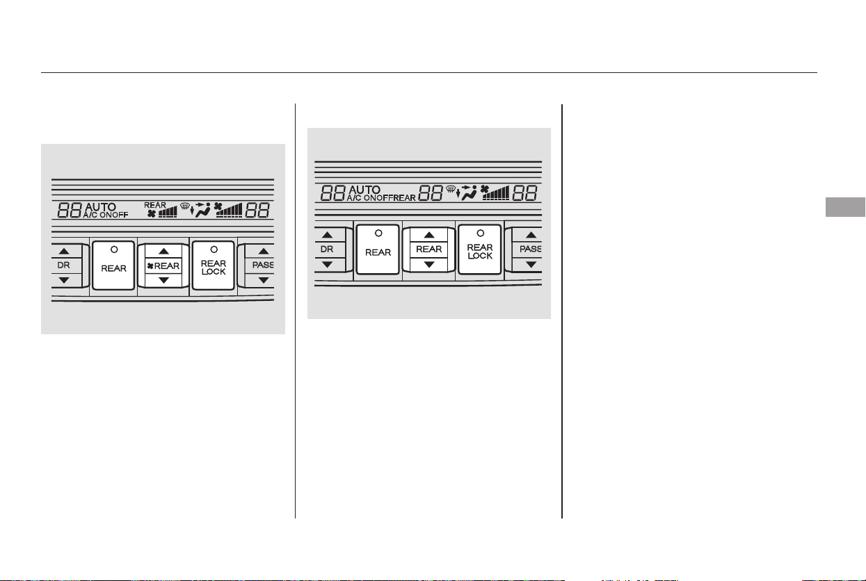
−
−
−
When the
indicator in this button is off, no air
flows to the rear vents, and the rear
control panel is turned off. When the
indicator in this button is on, the
temperature of the rear passenger
compartment can be adjusted with
the rear temperature control button.
A second row passenger can also
adjust the temperature, fan speed,
and airflow.
When the
indicator in this button is on, the rear
control panel is disabled, and the
rear system is controlled by the front
control panel.
When the
indicator in this button is off, no air
flows to the rear vents, and the rear
control panel is turned off. When the
indicator in this button is on, the fan
speed of the rear passenger
compartment can be adjusted with
the rear fan speed control button. A
second row passenger can also
adjust the temperature, fan speed,
and airflow.
Touring model
EX model
Vents, Heating, and A/C
REAR Button
REAR LOCK ButtonREAR A/C Controls
REAR Button
Features
195
Main Menu
Table of Contents
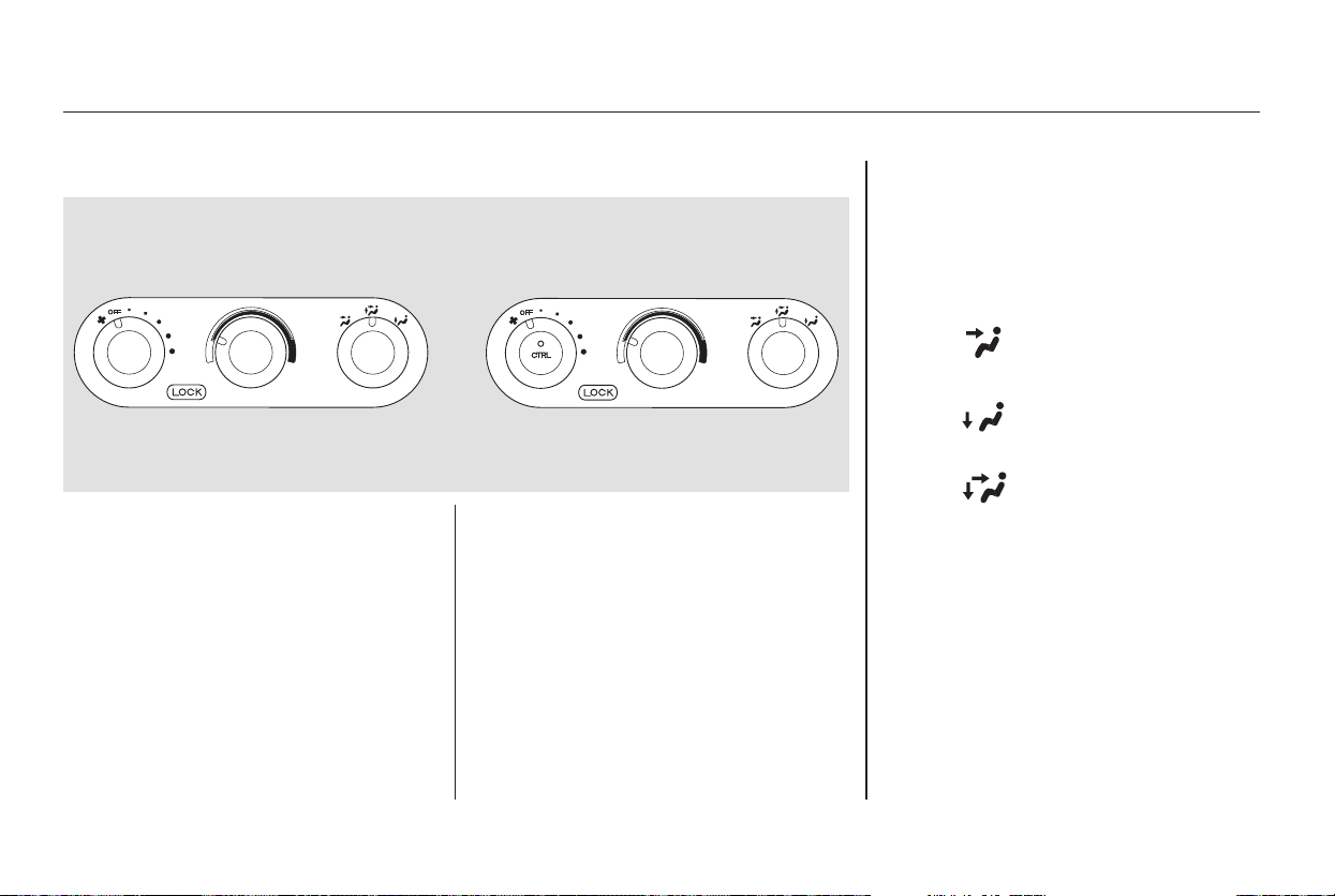
You can use the rear control panel
when the rear controller dial on the
front control panel is in the ON
position.
Turn the rear temperature control
dial clockwise to increase the
temperature of the airflow.
When is selected, air flows
from the rear floor vents.
When is selected, air flows
from the rear ceiling vents.
Select the vents the air flows from
with the mode control dial.
Turn the fan speed control dial
clockwise to increase fan speed and
airflow.
When is selected, airflow is
divided between the rear floor vents
and rear ceiling vents.You can use the rear control panel
when the indicator in the REAR
LOCK button on the front control
panel is off.
When you press the CTRL button in
the left dial, the indicator comes on,
and the fan speed is regulated by the
outer ring of the fan control dial.
LX model EX model
Rear Control Panel
Vents, Heating, and A/C
196
LX model
EX model
Main Menu
Table of Contents
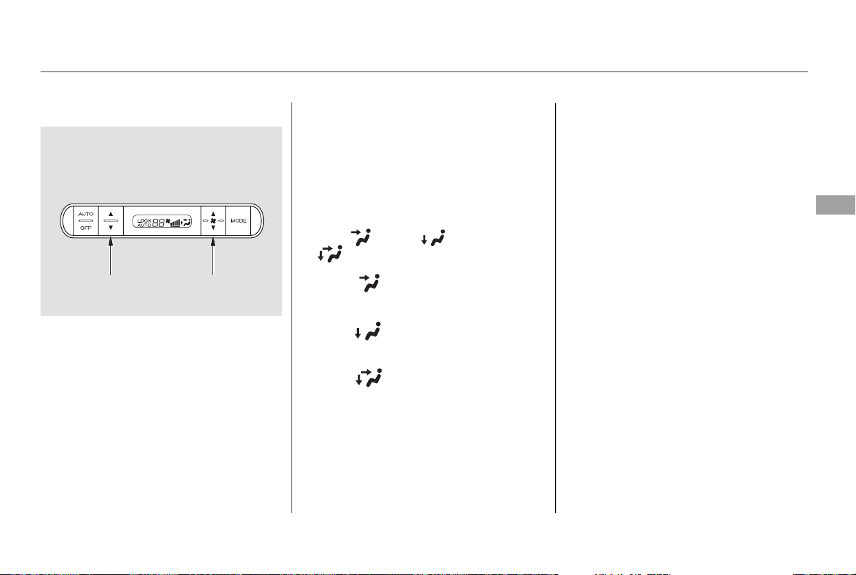
▲
▼
▲
▼
You can use the rear control panel
when the indicator in the REAR
LOCK button on the front control
panel is off.
Press the top ( ) of the
temperature control button to
increase the temperature of airflow,
and the bottom ( ) of the button to
decrease it. The temperature you
adjust is shown in the system display.
Press the top ( ) of the fan control
button to increase the fan speed and
airflow. Press the bottom ( ) of the
button to decrease it. The level of
the fan speed is shown in the display.
Each time you press the mode
button, the mode display changes
from , to , then to
.
When is selected, air flows
from the rear ceiling vents.
When is selected, air flows
from the rear floor vents.
Pressing the AUTO button puts the
system in automatic operation mode.
The rear system automatically
adjusts the fan speed and airflow
levels to maintain the selected
temperature of the rear passenger
compartment.
Pressing the OFF button shuts off
the rear climate control system.
When is selected, airflow is
divided between the rear floor vents
and rear ceiling vents.
Touring model
Rear Climate Control
Features
197
TEMPERATURE
BUTTON
FAN CONTROL
BUTTON
Touring model
Main Menu
Table of Contents
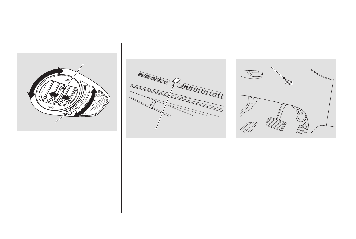
The direction and quantity of airflow
from each rear ceiling vent is
adjustable.
To adjust the direction of air coming
from a rear ceiling vent, move the
tab in the center of each vent back-
and-forth, and rotate the vent with
the tab. The lever next to each vent
can be opened and closed to regulate
the amount of airflow.
Theclimatecontrolsystemhasthree
sensors. A sunlight sensor is in the
top of the dashboard, and a
temperature sensor is next to the
steering column. There is also a rear
sensor on the rear sidewall near the
exhaust vent. Do not cover the
sensors or spill any liquid on them.
Sunlight and Temperature
Sensors
Rear Ceiling Vents
Rear Climate Control, Climate Control Sensors
198
SUNLIGHT SENSOR
TEMPERATURE SENSOR
TAB
LEVER
Main Menu
Table of Contents
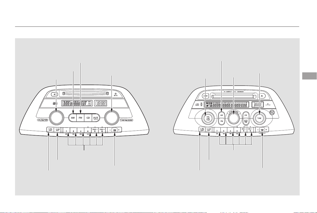
Playing the AM/FM Radio
LX model EX model without RES
Features
199
PWR/VOL
KNOB
TUNE/SOUND
KNOB
SCAN
BUTTON
SEEK BAR
PWR/VOL
KNOB
FM BUTTON
AM BUTTON
PRESET BUTTONS
AM/FM BUTTON
SCAN
BUTTON
SEEK BAR
PRESET BUTTONS
SOUND
KNOB
TUNE KNOB
AUTO SELECT
BUTTON
AUTO SELECT
BUTTON
Main Menu
Table of Contents
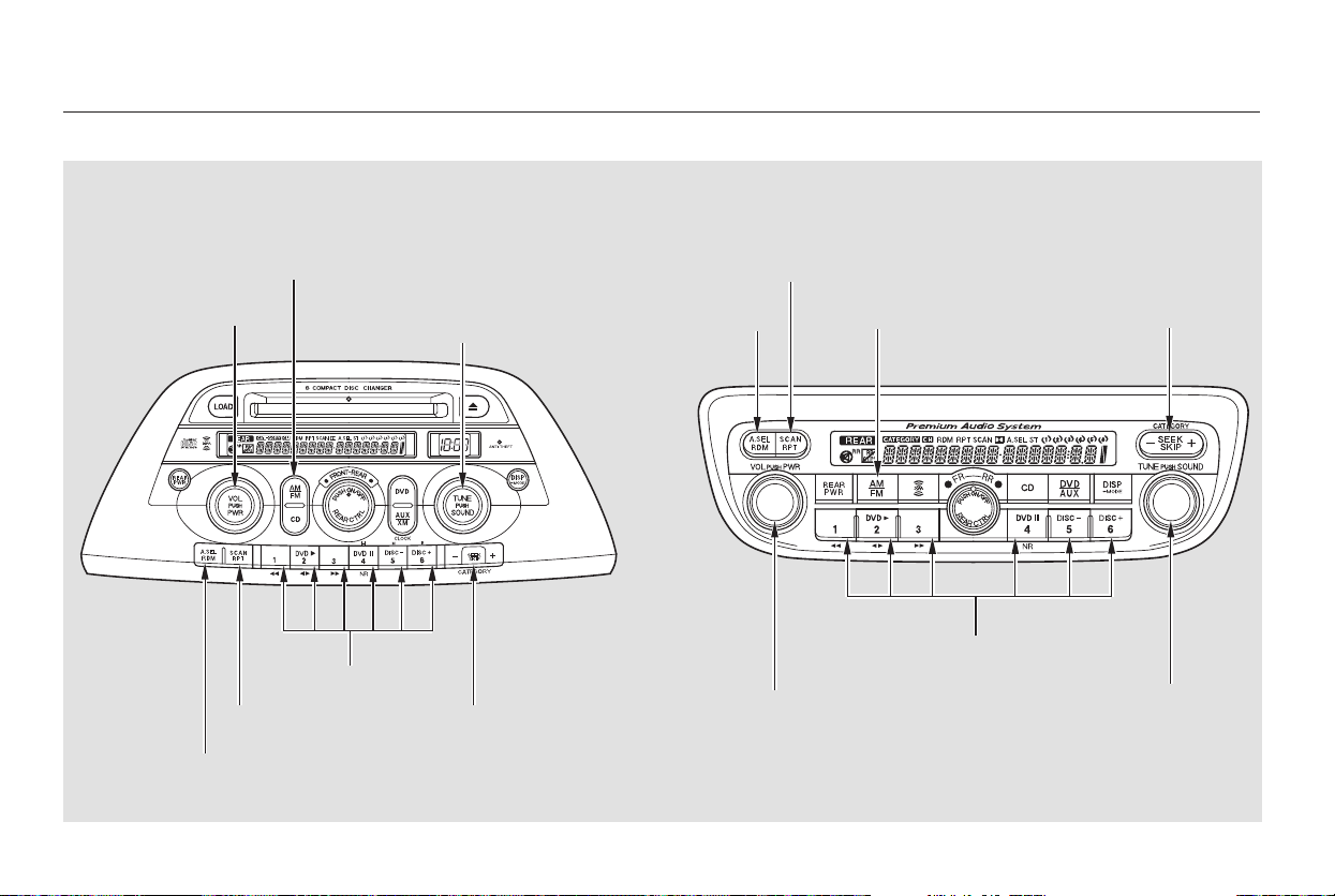
Playing the AM/FM Radio
EX and Touring models with
RES without Navigation System
Touring model with RES and
Navigation System
200
PWR/VOL
KNOB
TUNE/SOUND
KNOB
SEEK BAR
PWR/VOL
KNOB
SEEK BAR
AM/FM BUTTON
PRESET BUTTONS
SCAN
BUTTON
AM/FM BUTTON
SCAN BUTTON
TUNE/SOUND
KNOB
PRESET BUTTONS
AUTO SELECT
BUTTON
AUTO SELECT
BUTTON
Main Menu
Table of Contents

−
−
+−
−
−
The ignition switch must be in the
ACCESSORY (I) or ON (II) position.
Turn the system on by pushing the
PWR/VOL knob. Adjust the volume
by turning the same knob.
The band and frequency that the
radio was last tuned to is displayed.
To change bands, press the AM or
FM button, or AM/FM button. On
the FM band, ST will be displayed if
the station is broadcasting in stereo.
Stereo reproduction in AM is not
available.
Use the TUNE knob to
tune the radio to a desired frequency.
Turn the knob right to tune to a
higher frequency, or left to tune to a
lower frequency.
The SEEK function
searches up and down from the
current frequency to find a station
with a strong signal. To activate it
press the or side of the bar,
then release it.
Each preset button can
store one frequency on AM, and two
frequencies on FM.
Select the desired band, AM or
FM. FM1 and FM2 let you store
two frequencies with each preset
button.
UsetheTUNE,SEEK,orSCAN
function to tune the radio to a
desired station.
Repeat steps 1 through 3 to store a
total of six stations on AM and
twelve stations on FM.
You can use any of five methods to
find radio stations on the selected
band: the
preset buttons, and .
The SCAN function
samples all stations with strong
signals on the selected band. To
activate it, press the SCAN button,
then release it. You will see SCAN in
the display. The system will scan for
a station with a strong signal. When
it finds one, it will stop and play that
station for about 5 seconds.
If you do nothing, the system will
then scan for the next strong station
andplayitfor5seconds.Whenit
plays a station you want to listen to,
press the SCAN button again.
Pickapresetbutton,andholdit
until you hear a beep.
1.
2.
3.
4.
CONTINUED
TUNE
SEEK Preset
To Select a Station
TUNE,SEEK,SCAN,
AUTO SELECT
To Play the AM/FM Radio
SCAN
Playing the AM/FM Radio
Features
201
Main Menu
Table of Contents

−
−
−
The preset frequencies will be lost if
your vehicle’s battery goes dead, is
disconnected, or the radio fuse is
removed.
Press the A. SEL button. ‘‘A.SEL’’
flashes in the display, and the system
goes into scan mode for several
seconds. It stores the frequencies of
six AM, and twelve FM stations in
the preset buttons.
press the
A. SEL button. This restores the
presets you originally set.
Use the TRE/BAS
modes to adjust the tone to your
liking.
These two
modes adjust the strength of the
sound coming from each speaker.
BAL adjusts the side-to-side strength,
while FAD adjusts the front-to-back
strength.
You will see a ‘‘0’’ displayed after
pressing a preset button if auto
select cannot find a strong station for
every preset button.
If you do not like the stations auto
select has stored, you can store
other frequencies on the preset
buttons. Use the TUNE, SEEK, or
SCAN functions to find stations, then
store them in the preset buttons as
described.
Press the SOUND (TUNE) knob
repeatedly to display the bass (BAS),
treble (TRE), balance (BAL), and
fader (FAD) settings.
Eachmodeisshowninthedisplayas
it changes. Turn the SOUND
(TUNE) knob to adjust the setting to
your liking. When the level reaches
the center, you will see ‘‘ ’’ in
the display. The system will
automatically return the display to
the selected audio mode about 5
seconds after you stop adjusting a
mode.
If you are
traveling far from home and can no
longer receive your preset stations,
you can use the auto select feature to
find stations in the local area.
To turn off Auto Select,
Adjusting the Sound
Treble/Bass
Balance/Fader
AUTO SELECT
Playing the AM/FM Radio
202
Main Menu
Table of Contents
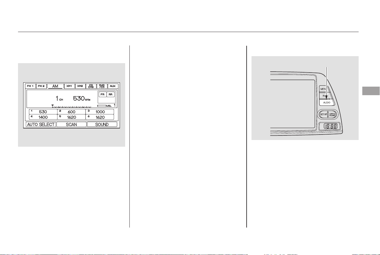
−
−
In addition to the knobs and buttons
on the radio control panel, you can
operate some of the radio controls
on the navigation system screen.
While you are listening to the radio,
you can change to another band by
pressing the AUDIO button next to
the navigation system screen, and
then touching the desired band icon
(FM1, FM2, or AM).
You can also adjust the sound from
the navigation screen.
To adjust the sound, push the
AUDIO DISPLAY button, then enter
the sound grid by touching the
SOUNDicononthedisplay.
AUTO SELECT, SCAN, and SEEK
are adjustable from the navigation
screen. For an explanation of these
functions, see pages and .
Touch the
AUTO SELECT icon to activate the
auto select function. You will see
AUTO SEL flashing in the upper
display.
Touch the SCAN icon to
activate the scan function. You will
see SCAN in the display. Touch the
icon again to deactivate it.
202201
CONTINUED
On models with Navigation System
Operating the Radio on the
Navigation System Screen
AUTO SELECT
SCAN
Adjusting the Sound
Playing the AM/FM Radio
Features
203
AUDIO DISPLAY BUTTON
Main Menu
Table of Contents
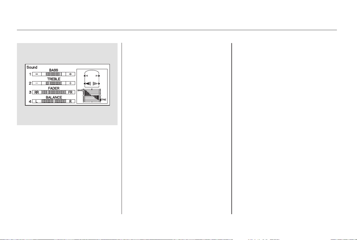
−
−
−+
You can use the instrument panel
brightness control knob to adjust the
illumination of the audio system (see
page ). The audio system
illuminates when the parking lights
are on, even if the radio is off.
These modes adjust
the strength of the sound coming
from each speaker. Left/Right
balance adjusts the side-to-side
strength, while Front/Rear fader
adjust the front-to-back strength. To
adjust the left/right balance, touch
the ‘‘L’’ or ‘‘R’’ icon.
To adjust the front/rear fader, touch
the ‘‘FR’’ or ‘‘RR’’ icon.
To adjust the treble
and bass, touch or on each
side of the treble or bass adjustment
bar. The adjustment bar shows you
the current setting.
To see the audio display when you
are finished adjusting the sound,
wait 5 seconds.
125
Audio System LightingLeft/Right Balance and Front/
Rear Fader
Treble/Bass
Playing the AM/FM Radio
204
Main Menu
Table of Contents
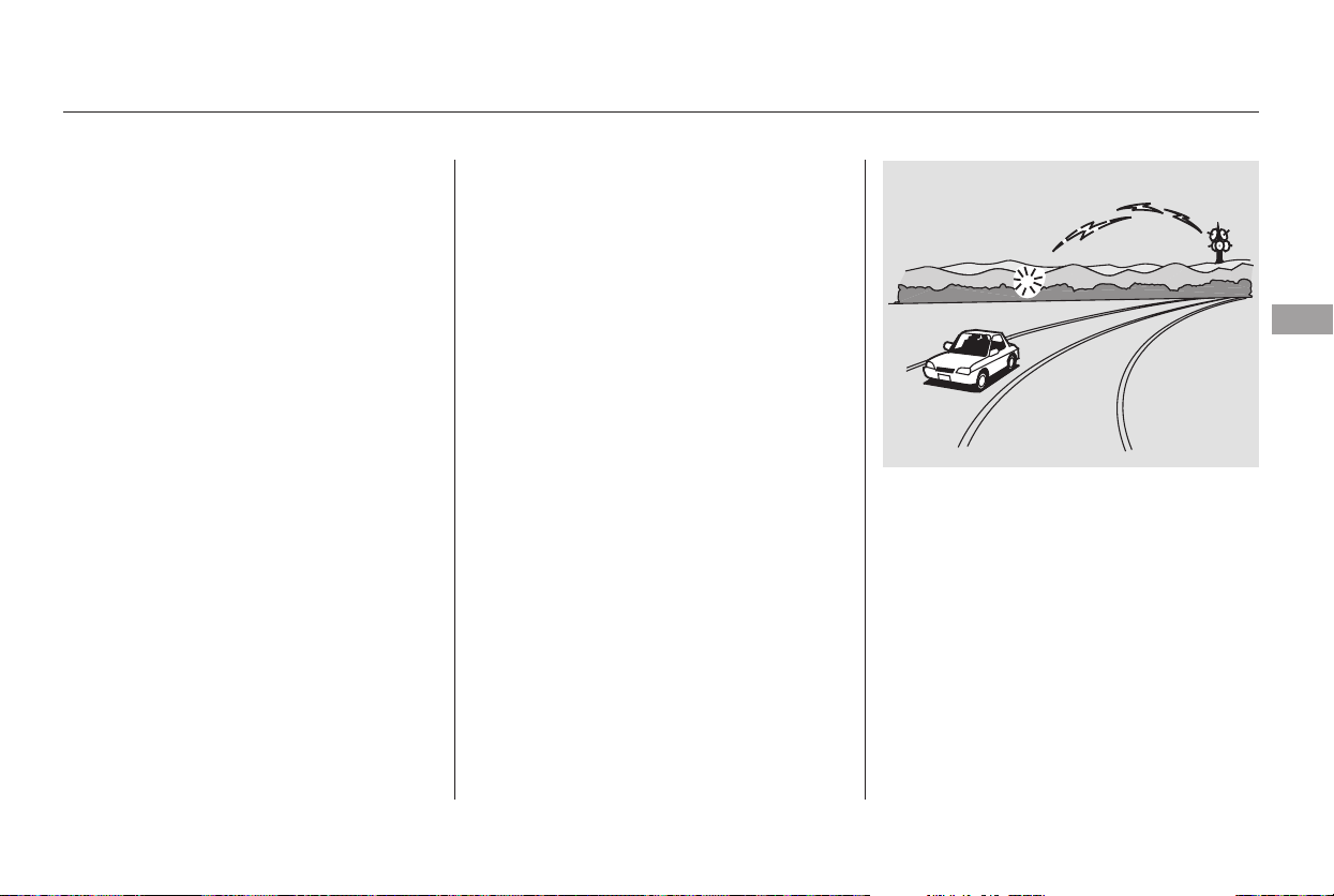
CONTINUED
The radio can receive the complete
AM and FM bands.
Those bands cover these frequen-
cies:
AM band: 530 to 1,710 kilohertz
FM band: 87.7 to 107.9 megahertz
Radio stations on the AM band are
assigned frequencies at least ten
kilohertz apart (530, 540, 550).
Stations on the FM band are
assigned frequencies at least 0.2
megahertz apart (87.9, 88.1, 88.3).
Stations must use these exact
frequencies. It is fairly common for
stations to round-off the frequency in
their advertising, so your radio could
display a frequency of 100.9 even
though the announcer may identify
the station as ‘‘FM101.’’
How well the radio receives stations
is dependent on many factors, such
as the distance from the station’s
transmitter, nearby large objects,
and atmospheric conditions.
A radio station’s signal gets weaker
as you get farther away from its
transmitter. If you are listening to an
AM station, you will notice the sound
volume becoming weaker and the
stationdriftinginandout.Ifyouare
listening to an FM station, you will
see the stereo indicator flickering off
and on as the signal weakens.
Eventually, the stereo indicator will
go off and the sound will fade
completely as you get out of range of
the station’s signal.
Driving very near the transmitter of
a station that is broadcasting on a
frequency close to the frequency of
the station you are listening to can
also affect your radio’s reception.
You may temporarily hear both
stations,orhearonlythestationyou
are close to.
Radio Frequencies Radio Reception
AM/FM Radio Reception
Features
205
Main Menu
Table of Contents
Radio signals, especially on the FM
band, are deflected by large objects
such as buildings and hills. Your
radio then receives both the direct
signal from the station’s transmitter,
and the deflected signal. This causes
the sound to distort or flutter. This is
a main cause of poor radio reception
in city driving.
Radio reception can be affected by
atmospheric conditions such as
thunderstorms, high humidity, and
even sunspots. You may be able to
receive a distant radio station one
day and not receive it the next day
because of a change in conditions.
Electrical interference from passing
vehicles and stationary sources can
cause temporary reception problems.
As required by the FCC:
Changes or modifications not expressly
approved by the party responsible for
compliance could void the user’s
authority to operate the equipment.
AM/FM Radio Reception
206
Main Menu
Table of Contents
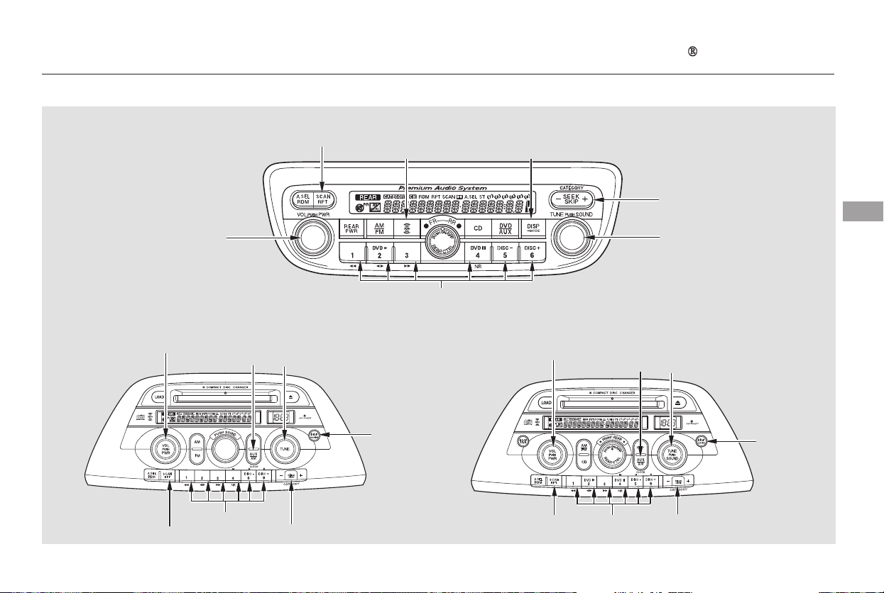
Playing the XM Satellite Radio
Features
Touring model with RES and
Navigation System
EX model without RES
EX and Touring models with
RES without Navigation System
207
PWR/VOL KNOB
PWR/VOL
KNOB
PWR/VOL
KNOB
XM RADIO
BUTTON
SCAN BUTTON
XM RADIO
BUTTON
CATEGORY BAR
TUNE KNOB
CATEGORY BAR
CATEGORY BAR
PRESET BUTTONS
PRESET
BUTTONS
TUNE KNOB
XM RADIO
BUTTON
TUNE KNOB
PRESET
BUTTONS
SCAN BUTTON
SCAN BUTTON
DISPLAY/MODE
BUTTON
DISPLAY/MODE
BUTTON
DISPLAY/
MODE
BUTTON
Main Menu
Table of Contents
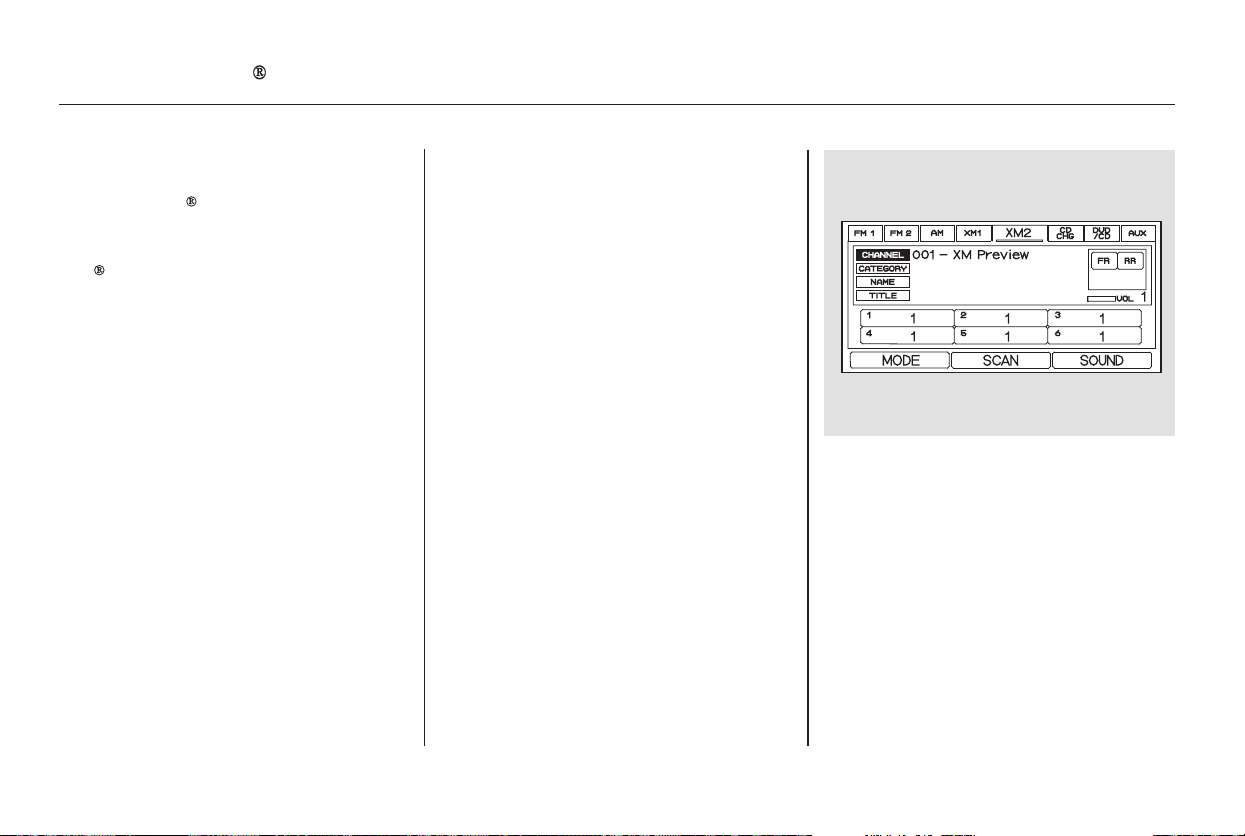
−
On the audio display, you will see the
selected CHANNEL (number),
CATEGORY, NAME (artist name),
and TITLE (music title).
Your audio system is capable of
receiving XM
Satellite Radio
anywhere in the United States,
except Hawaii and Alaska.
XM
is a registered trademark of
XM Satellite Radio, Inc.
XM radio receives signals from two
satellites to produce clear, high-
quality digital reception. It offers
many channels in several categories.
Along with a large selection of
different types of music, XM radio
allows you to view channel and
category selections in the display.
The navigation system screen also
shows all XM information when the
AUDIO button is pressed.
To listen to XM radio, turn the
ignition switch to ACCESSORY (I)
or ON (II). Push the PWR/VOL
knob to turn on the audio system,
and press the ‘‘XM’’ button. Adjust
the volume by turning the PWR/
VOL knob. The last channel you
listened to will show in the display.
You can also change to the XM radio
while you are listening to an FM
station, AM station, CD, etc., by
touching the XM1 or XM2 icon on
the audio display (navigation system
screen).
To switch between
channel mode and category mode,
press and hold the DISP/MODE
button until the mode changes.
In channel mode, you can select all
of the available channels. In category
mode, such as Jazz, Rock, Classical,
etc., you can select all of the
channels within that category.
Each time you press and release the
DISP/MODE button, the display
changes in the following sequence:
Channel name, channel number,
category, artist name, and music title.
You may experience periods when
XM Radio does not transmit the
artist’s name and song title
information. If this happens, there is
nothing wrong with your system.
U.S. EX and Touring models only
MODE
Operating the XM Radio
Playing the XM Satellite Radio
208
Main Menu
Table of Contents

−
−
−+
−
−
On models with a rear entertainment
system and a navigation system, you
cannot listen to XM Radio and a disc
at the same time. For example, when
XM Radio is playing on the front
speakers, you cannot listen to a disc
on the rear speakers, or vice versa.
The scan function gives
you a sampling of all channels while
in the channel mode. In the category
mode, only the channels within that
category are scanned. To activate
scan, press the SCAN/RPT button or
touch the SCAN icon on the audio
display. The system plays each
channel in numerical order for a few
seconds, then selects the next
channel. When you hear a channel
you want to continue listening to,
press the button or touch the icon
again.
Press either side of
the bar ( or ) to select another
category.
In the category mode, only channels
within that category can be selected.
In the channel mode, all channels
can be selected.
Use the TUNE knob, or the
CATEGORY or SCAN buttons to
tune to a desired channel. You can
also touch the SCAN icon on the
audio display.
Press the XM RADIO button.
Either XM1 or XM2 will show in
the display.
To store a channel:
Youcanstoreupto12
preset channels using the six preset
buttons or preset icons on the audio
display. Each button stores one
channel from the XM1 band and one
channel from the XM2 band.
The presets will be lost if your
vehicle’s battery goes dead, is
disconnected, or the radio fuse is
removed.
Once a channel is stored, press and
release the proper preset button
(icon) to tune to it.
Press the XM RADIO button again
or touch the other XM icon (XM1
or XM2) on the audio display.
Store the next six channels using
steps 2 and 3.
Repeat steps 2 and 3 to store the
first six channels.
Pick the preset button (icon) you
want for that channel. Press and
hold the button (icon) until you
hear a beep.
Turn the tune knob left or
right to select channels. In the
category mode, you can only select
channels within that category.
1.
2.
3.
4.
5.
Playing the XM Satellite Radio
SCAN
CATEGORY
Preset
TUNE
Features
209
Main Menu
Table of Contents
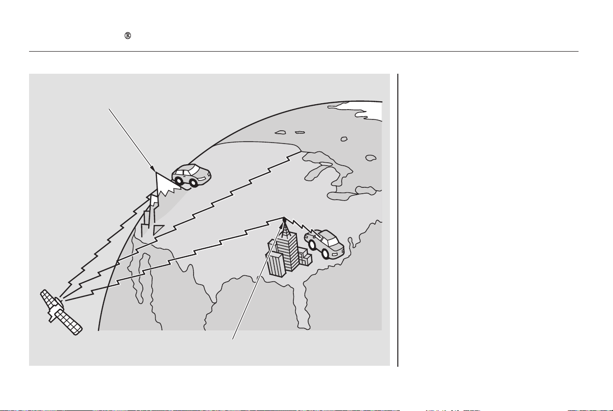
The XM satellites are in orbit over
the equator; therefore, objects south
of the vehicle may cause satellite
reception interruptions. To help
compensate for this, ground-based
repeaters are placed in major
metropolitan areas.
Satellite signals are more likely to be
blocked by tall buildings and
mountains the farther north you
travel from the equator.
Playing the XM Satellite Radio
210
Signal may be blocked by
mountains or large obstacles to
the south.
Signal weaker in
these areas.
SATELLITE
GROUND
REPEATER
Main Menu
Table of Contents

Depending on where you drive, you
may experience reception problems.
Interference can be caused by any of
these conditions:
Driving on the north side of a
large commercial truck on an
east/west road.
Driving in the tunnels.
Driving on a road beside a vertical
wall, steep cliff, or hill to the south
of you.
Driving on the lower level of a
multi-tiered road.
Driving on a single lane road
alongside dense trees taller than
50 ft. (15 m) to the south of you.
If your XM Radio service has expired
or you purchased your vehicle from
a previous owner, you can listen to a
sampling of the broadcasts available
on XM Satellite Radio. With the
ignition switch in the ACCESSORY
(I) or ON (II) position, push the
PWR/VOL knob to turn on the audio
system and press the XM RADIO
button. A variety of music types and
styles will play.
If you decide to purchase XM
Satellite Radio service, contact XM
Radio at , or at
1-800-852-9696. You will need to give
them your radio I.D. number and
your credit card number. To get your
radio I.D. number, turn the TUNE
knob until ‘‘0’’ appears in the display.
Your I.D. will appear in the display.
There may be other geographic
situations that could affect XM radio
reception.
After you’ve registered with XM
Radio, keep your audio system in the
satellite radio mode while you wait
for activation. This should take about
30 minutes.
While waiting for activation, make
sure your vehicle remains in an open
area with good reception. Once your
audio system is activated, ‘‘category’’
or ‘‘CH’’ will appear in the display,
andyou’llbeabletolistentoXM
radio broadcasts. XM Radio will
continue to send an activation signal
to your vehicle for at least 12 hours
from the activation request. If the
service has not been activated after
36 hours, contact XM Radio.
Driving on the north side of an
east/west mountain road
As required by the FCC:
Changes or modifications not expressly
approved by the party responsible for
compliance could void the user’s
authority to operate the equipment.
www.xmradio.com
Receiving Satellite Radio Service
Playing the XM Satellite Radio
Features
211
Main Menu
Table of Contents
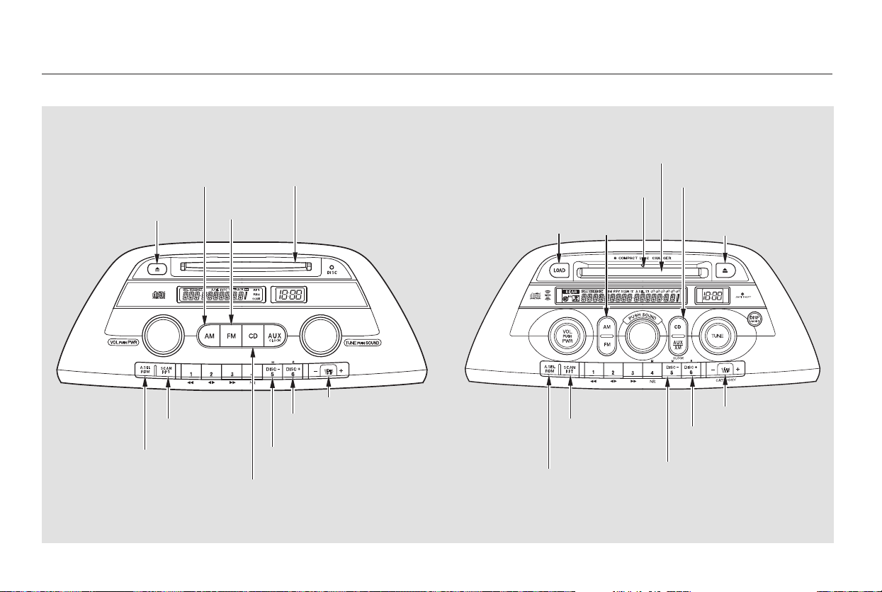
+
−
+
−
Playing a CD, CD Changer
LX model EX model without RES
212
AM
BUTTON
FM
BUTTON
CD SLOT
EJECT
BUTTON
RANDOM
BUTTON
REPEAT
BUTTON
CD BUTTON
DISC
BUTTON
DISC
BUTTON
REPEAT
BUTTON
DISC
BUTTON
DISC
BUTTON
CD BUTTON
EJECT
BUTTON
SEEK BAR
LOAD
INDICATOR
AM/FM
BUTTON
LOAD
BUTTON
SEEK BAR
RANDOM
BUTTON
CD SLOT
Main Menu
Table of Contents
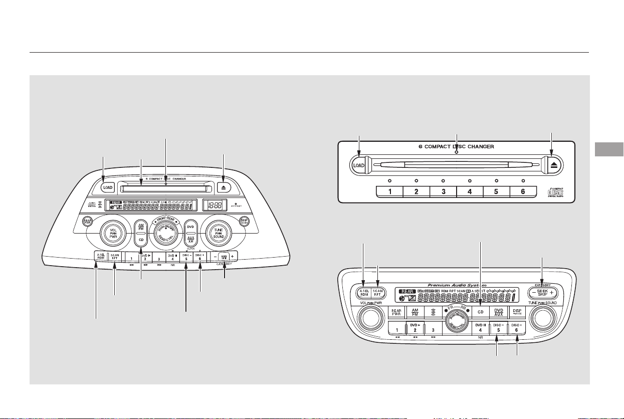
+
−
+−
Playing a CD, CD Changer
Features
Touring model with RES and
Navigation System
EX and Touring models with
RES without Navigation
System
213
SEEK BAR
EJECT
BUTTON
RANDOM
BUTTON
REPEAT
BUTTON
CD BUTTON
DISC
BUTTON
DISC
BUTTON
RANDOM
BUTTON
REPEAT
BUTTON
LOAD
INDICATOR
LOAD
BUTTON
CD SLOT
SEEK BAR
DISC BUTTONDISC BUTTON
LOAD
INDICATOR
LOAD
BUTTON
EJECT
BUTTON
CD BUTTON
Main Menu
Table of Contents
+
−
+−
−
−
With the ignition in the
ACCESSORY (I) or ON (II) position,
insert a CD into the CD slot. The
drive will pull the CD in the rest of
the way and begin to play it. You
operate the CD player with the same
controls used for the radio. The
number of the track playing is shown
in the display. The system will
continuously play a CD until you
change modes.
Each time you press and release the
side of the SKIP bar, the player
skips forward to the beginning of the
next track. Press and release the
side of the SKIP bar to skip
backward to the beginning of the
previous track.
To move rapidly within a track, press
and hold the or side of the
SKIP bar. You will see CUE or REW
in the display.
To continuously replay
a track, press and release the RPT
button. You will see RPT in the
display. Press the RPT button again
to turn it off.
This feature plays the
tracks in random order. To activate
Random Play, press and release the
RDM button. You will see RDM in
the display. This continues until you
press the RDM button again.
Press the eject button ( ) to
remove the CD. If you eject the CD,
but do not remove it from the slot,
the system will automatically reload
the CD after 15 seconds and put it in
pause mode. To begin playing, press
the CD button.
Press the AM or FM button to
switch to the radio while a CD is
playing. Press the CD button to play
the CD.
If you turn the system off while a CD
is playing, either with the PWR/VOL
knob or by turning off the ignition,
the CD will stay in the drive. When
youturnthesystembackon,theCD
will begin playing where it left off.
LX model
CD Player To Change Tracks (SKIP)
REPEAT
RANDOM
To Stop Playing a CD
Playing a CD, CD Player
214
Do not use CDs with adhesive labels.
The label can curl up and cause the CD
to jam in the unit.
Main Menu
Table of Contents
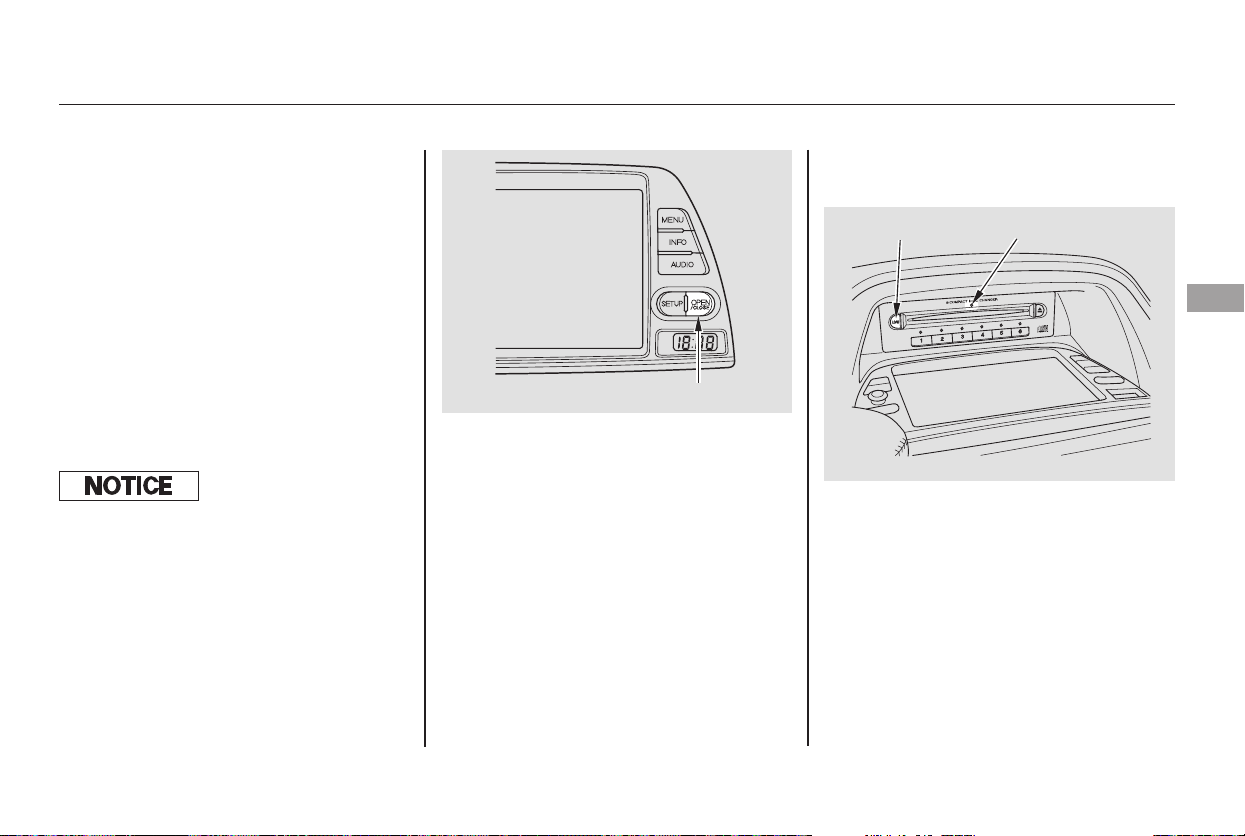
CONTINUED
Your audio system has an in-dash
CD changer that holds up to six CDs,
providing several hours of
continuous entertainment. You
operate this CD changer with the
same controls used for the radio.
To load CDs or operate the CD
changer, the ignition switch must be
in the ACCESSORY (I) or ON (II)
position.
The CD changer is behind the
navigation system screen. To use the
CD changer, press the OPEN button
beside the screen. The screen folds
back, and the CD changer appears.
To return the screen to the upright
position, press the OPEN button
again. Do not use the folded screen
as a tray. If you put a cup, for
example, on the screen, the liquid
inside the cup may spill on the
screen when you go over a bump. Press and hold the LOAD button
beside the CD slot until you see
‘‘LOADING’’ in the display, then
release the button.
To load multiple CDs in one
operation:
1.
On vehicles with navigation system
On vehicles with navigation systemEX and Touring models
Playing a CD, CD Changer
Operating the CD Changer Loading CDs in the Changer
Features
215
OPEN BUTTON
LOAD BUTTON LOAD INDICATOR
Do not use CDs with adhesive labels.
The label can curl up and cause the CD
to jam in the unit.
Main Menu
Table of Contents

To load a single CD:
TheindicatorsabovetheDisc
buttons of the empty positions will
blink, and the green load indicator
above the CD slot comes on.
Press and release the LOAD
button.
The system will load the CD, and
begin playing it.
If you press the LOAD button while
a CD is playing, the system will stop
playing that CD and start the loading
sequence. It will then play the CD
just loaded.
You can also load a CD into an empty
position while a CD is playing by
pressing the appropriate Disc button.
Select an empty Disc button (the
indicator above the button is off),
and press the button. The system
will stop playing the current CD and
start the loading sequence. It will
then play the CD just loaded.
Insert a CD into the CD slot.
Insert it only about halfway; the
drive will pull it in the rest of the
way. You will see ‘‘BUSY’’ in the
display. The CD load indicator
turns red and blinks as the CD is
loaded.
When LOADING appears again in
the display, insert the next CD into
the CD slot.
Repeat this until all six positions
are loaded. The system will then
begin playing the first CD loaded.
TheindicatorsabovetheDisc
buttons of the empty positions will
blink, and the green CD load
indicator comes on. When you see
‘‘LOAD’’ in the display, insert the
disc into the CD slot. Insert it only
about halfway; the drive will pull it
in the rest of the way.
If you stop loading CDs before all six
positions are filled, the system will
wait for 10 seconds, then stop the
load operation and begin playing the
last CD loaded.
2.
2.
3.
4.
5.
1.
3.
Playing a CD, CD Changer
216
Main Menu
Table of Contents

On vehicles without navigation system
To load multiple CDs in one
operation:
Press and hold the Load button
until you hear a beep and see
‘‘LOAD’’ in the display, then
release the button.
On the upper right side of the
display, the disc number for an
empty position will begin blinking,
and the green CD load indicator
will come on.
Insert the CD into the CD slot.
Insert it only about halfway; the
drive will pull it in the rest of the
way. You will see ‘‘BUSY’’ in the
display. The CD Loaded indicator
turns red and blinks as the CD is
loaded.
To load a single CD:
Press and release the LOAD
button.
When the disc number for an
empty position starts to blink and
the green CD load indicator comes
on, you will see LOAD in the
display. Insert the disc into the CD
slot. Insert it only about halfway,
the drive will pull it in the rest of
the way.
The system will load the CD, and
begin playing it.
Repeat this until all six positions
are loaded. The system will then
begin playing last CD loaded.
If you are not loading CDs into all six
positions, press the LOAD button
again after the last CD has loaded.
The system will begin playing the
last CD loaded.
If you stop loading CDs before all six
positions are filled, the system will
wait for ten seconds, then stop the
load operation and begin playing the
last CD loaded.
When LOAD appears again in the
display, insert the next CD into the
CD slot.
1.
1.
2.
3.
4.
5.
2.
3.
Playing a CD, CD Changer
Features
217
Main Menu
Table of Contents

−+
+
−
−
+
−
To move rapidly within a track, press
and hold the or side of the
SKIP bar. You will hear a beep and
the system will continue to move
through the track. Press the side
of the SKIP bar to move forward, or
the sidetomovebackward.
Release the bar when the system
reaches the point you want.
Select the CD changer by pressing
the CD button. You will see ‘‘CD’’ in
the display. The system will begin
playing the last selected disc in the
CD changer. You will see the disc
and track numbers displayed.
When that CD ends, the next CD in
the CD changer is loaded and played.
After the last CD finishes, the
system returns to CD 1.
You can use the SKIP bar while a
disc is playing to select passages and
change tracks.
To select a different CD, press the
appropriate preset button (1 6). If
youselectanemptypositioninthe
CD changer, the system will go into
the loading sequence.
Each time you press the side of
the SKIP bar, the system skips
forward to the beginning of the next
track. Press and release the side
to skip backward to the beginning of
the current track. Press it again to
skip to the beginning of the previous
track.
On models with a rear entertainment
system and a navigation system, you
cannot listen to a disc and XM Radio
at the same time. For example, when
a disc is playing on the front
speakers, you cannot listen to XM
Radio on the rear speakers, or vice
versa.
Playing a CD, CD Changer
To Play a CD To Change Tracks
218
Main Menu
Table of Contents

When you press and release the RPT
button or touch the TRACK RPT
icon on the upper display, the system
continuously replays the current
track. As a reminder, you will see
REPEAT (TRACK REPEAT) in the
display. To turn this feature off,
press the RPT button, or touch the
TRACK REPEAT icon again.
WhenyoupressandholdtheRPT
button until REPEAT is in the
display, or when you touch the DISC
RPTiconontheaudiodisplay,the
system continuously replays the
current disc. As a reminder, you will
see D-RPT (DISC RPT) in the
display.
WhenyoupressandholdtheSCAN
button until you see D-Scan in the
display, or when you touch the DISC
SCAN icon on the upper display, the
first track of the current CD plays
for about 10 seconds. You will see D-
SCAN in the display and DISC SCAN
in the upper display. To hear the rest
of the CD, press the SCAN button or
touch the DISC SCAN icon again,
within 10 seconds. If you don’t, the
system advances to the next disc,
plays about 10 seconds of it, and
continues throughout the rest of the
CDs the same way. When the
system reaches the last disc, DISC
SCAN is cancelled, and the CD plays
normally.
When you press the SCAN button or
touchtheTRACKSCANicononthe
upper display, the first track of the
current disc plays for about 10
seconds. You will see SCAN in the
upper display and in the audio
display. To hear the rest of the track,
press the SCAN button or touch the
TRACK SCAN icon again within 10
seconds. If you don’t, the system
advances to the next track, plays
about 10 seconds of it, and continues
through the rest of the tracks the
same way.
Playing a CD, CD Changer
Track Repeat
Disc Repeat
Disc ScanTrack Scan
Features
219
Main Menu
Table of Contents

When you press the RDM button or
touch the TRACK RANDOM icon on
the upper display, the system plays
the tracks of the current disc in
random order. You will see
RANDOM (TRACK RANDOM) in
the display. To turn this feature off,
press the RDM button (touch
TRACK RANDOM) again.
Operation of TRACK SCAN, DISC
SCAN, TRACK REPEAT, DISC
REPEAT, and TRACK RANDOM on
the upper display is possible only
when the audio display is in the
upright position.
To take the system out of CD mode,
press the AM/FM button or SAT
RADIO button (U.S. models). Each
time you press the AM/FM button,
the system changes to the next
mode (AM, FM1, or FM2). When
you return to CD mode by pressing
the CD button, play will continue
where it left off.
To eject all discs, press and hold the
eject button until the indicators
above the disc buttons blink.
To eject one disc, press and release
the eject button.
You can also eject discs when the
ignition switch is on or off:
When you press the eject button
while listening to the radio, or with
the audio system turned off, the disc
that was last selected is ejected.
After that disc is ejected, pressing
the eject button again will eject the
next disc in numerical order. By
doing this six times, you can remove
all the discs from the changer.
To remove the disc from the
changer,firstselectitbypressing
the appropriate disc button or
corresponding number on the preset
button. When that disc begins
playing, press the eject button.
If you do not remove the CD from
the slot, the system will reload the
CD after 15 seconds and put the CD
changer in pause mode. To begin
playing the CD, press the CD button.
To remove the disc that is currently
playing, press the eject button. You
will see ‘‘EJECT’’ in the display.
When you remove the disc from the
slot, the system automatically begins
the load sequence so you can load
another disc in that position. If you
do not load another CD, within 15
seconds, the system selects the
previous mode [AM, FM1, FM2, or
XM Radio (U.S. models)].
If you turn the system off while a CD
is playing, either with the PWR/VOL
knob or the ignition switch, play will
continue at the same point when you
turn it back on.
Playing a CD, CD Changer
Random Play
To Stop Playing a Disc
Removing CDs from the Changer
220
Main Menu
Table of Contents
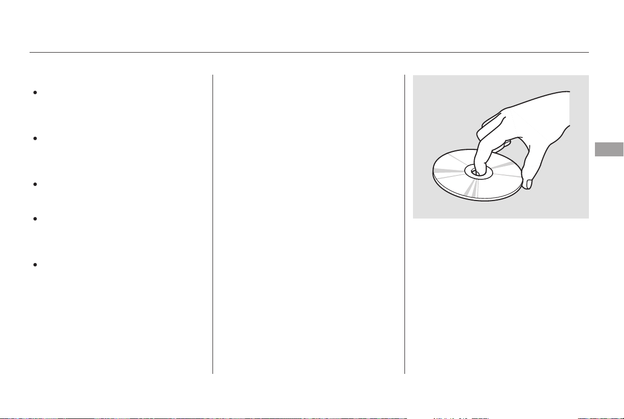
When using CD-R discs, use only
high quality CDs labeled for audio
use.
When recording a CD-R, the
recording must be closed for it to
be used.
CD-RW discs will not work in this
unit.
Play only standard round CDs.
Odd-shaped CDs may jam in the
driveorcauseotherproblems.
Handle your CDs properly to
prevent damage and skipping.
When a CD is not being played, store
it in its case to protect it from dust
and other contamination. To prevent
warpage, keep CDs out of direct
sunlight and extreme heat.
To clean a CD, use a clean soft cloth.
Wipe across the CD from the center
to the outside edge.
AnewCDmayberoughonthe
inner and outer edges. The small
plastic pieces causing this roughness
can flake off and fall on the re-
cording surface of the CD, causing
skipping or other problems. Remove
these pieces by rubbing the inner
and outer edges with the side of a
pencil or pen.
Handle a CD by its edges; never
touch either surface. Do not place
stabilizer rings or labels on the CD.
These, along with contamination
from fingerprints, liquids, and felt-tip
pens, can cause the CD to not play
properly, or possibly jam in the drive.
Never try to insert foreign objects in
the CD player or the CD changer.
General Information Protecting CDs
Protecting Your CDs
Features
221
Main Menu
Table of Contents
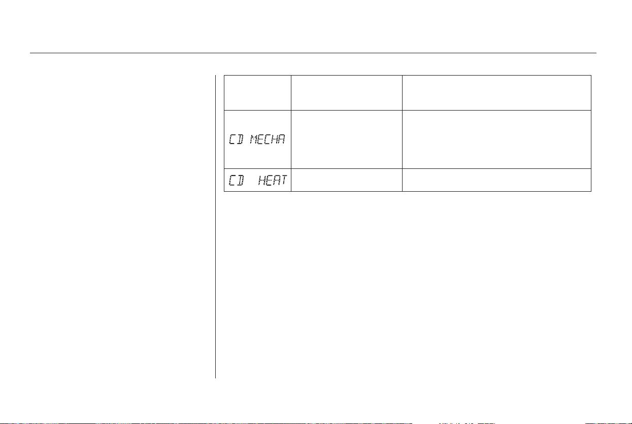
Message SolutionCause
If you see an error message in the
display while playing a CD, find the
cause in the chart to the right. If you
cannot clear the error message, take
the vehicle to your dealer.
Press the disc eject button, and remove the
disc(s). Check for an error indication. Insert
the disc(s) again. If the code does not disappear
orthedisc(s)cannotberemoved,consultyour
dealer.
Will disappear when the temperature returns to
normal.
Mechanical Error
High Temperature
CD Changer Error Messages
222
Main Menu
Table of Contents
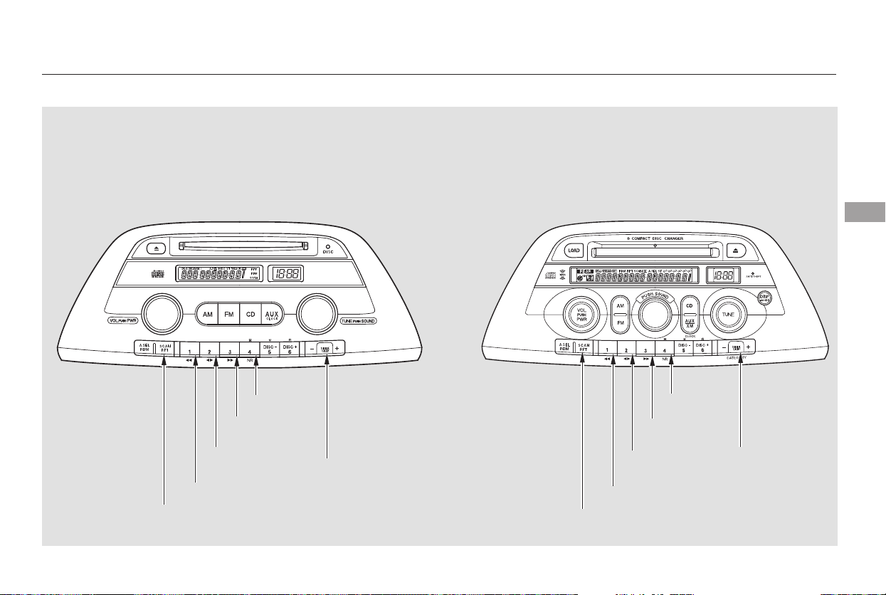
Playing a Tape
LX model EX model without RES
Features
223
FF BUTTON
SKIP BAR
PLAY/PROG
BUTTON
REW
BUTTON
NR BUTTON
REPEAT
BUTTON
FF BUTTON
PLAY/PROG
BUTTON
REW
BUTTON
REPEAT
BUTTON
SKIP BAR
NR BUTTON
Main Menu
Table of Contents
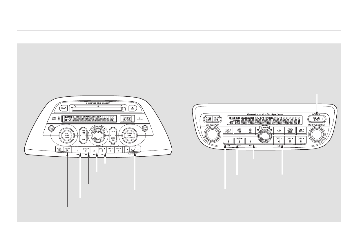
Playing a Tape
Touring model with RES and
Navigation System
EX and Touring models with
RES without Navigation
System
224
REPEAT
BUTTON
FF BUTTON
PLAY/PROG
BUTTON
REW
BUTTON
NR BUTTON
FF BUTTON
PLAY/PROG
BUTTON
REW
BUTTON
NR BUTTON
SKIP BAR
SKIP BAR
Main Menu
Table of Contents
▲
−
*
*
The ignition switch must be in the
ACCESSORY (I) or ON (II) position.
Make sure the open side of the tape
is facing right, then insert the tape
most of the way into the slot. The
system will pull the tape in the rest
of the way, and begin to play it.
The tape direction indicator will
come on to show you which side of
the tape is playing. The indicates
the side you inserted upward is now
playing. If you want to play the other
side, press the PLAY/PROG button.
When the player reaches the end of
the tape, it will automatically reverse
direction and play the other side.
Dolby noise reduction turns on
when you insert a tape. The
indicator will come on in the
display. If the tape was not recorded
in Dolby, turn it off by pressing the
NR button. Dolby remains off until
you press the NR button again.
To remove the tape, press the
EJECT button. If you want to turn
the player off, press the PWR/VOL
knob or turn off the ignition. The
tape will remain in the drive. When
youturnthesystembackon,the
tape will begin playing where it left
off.
To switch to the radio or CD player
while a tape is playing, press the AM
or FM button or AM/FM button, or
CD button. To change back to the
tape player, press the AUX button.
To rewind the tape,
push the REW button. You will see
REW in the display. To fast forward
the tape, push the FF button. You
will see FF displayed. Press the FF,
REW, or PLAY/PROG button to
take the system out of rewind or fast
forward.
CONTINUED
Dolby noise reduction is manufactured under
license from Dolby Laboratories Licensing
Corporation. ‘‘DOLBY’’ and the double-D symbol
are trademarks of Dolby Laboratories
Licensing Corporation.
Optional on all models
To Play a Tape
To Stop Playing a Tape
Tape Search Functions
FF/REW
Playing a Tape
Features
225
Main Menu
Table of Contents

−−
+
−
Press the side of the
SKIP bar to find the beginning of the
current song or passage. Press the
side of the SKIP bar to find the
beginning of a song or passage.
When the system reaches the
beginning of a song or passage, it
begins to play it.
Thetapeplayerpicksupdirtand
oxides from the tape. This
contamination builds up over time
and causes the sound quality to
degrade. To prevent this, you should
clean the player after every 30 hours
of use.
If you do not clean the tape player
regularly, it may eventually become
impossible to remove the
contamination with a normal
cleaning kit. Your dealer has a
cleaning kit available.
Use 100-minute or shorter tapes.
Tapes longer than that may break or
jam the drive.
If the tape is loose, tighten it by
turning the hub with a pencil or your
finger. If the label is peeling off,
remove it or it could cause the tape
to jam in the player. Never try to
insert a warped or damaged tape in
the player.
Store tapes in their cases to protect
them from dust and moisture. Never
place tapes where they will be
exposed to direct sunlight, high heat,
or high humidity. If a tape is exposed
to extreme heat or cold, let it reach a
moderate temperature before
inserting it into the player.
Never try to insert foreign objects
into the tape player.
Press the RPT button
to continuously play a song or
passage. You will see RPT displayed.
The track will repeat until you press
the RPT button again.
The SKIP and REPEAT
functions use silent periods on the
tape to find the end of a song or
passage. These features may not
work if there is almost no gap
between selections, a high noise
level, or a silent period in the middle
of a selection.
SKIP Caring for the Tape and Player
REPEAT
Playing a Tape
226
NOTE:
Main Menu
Table of Contents
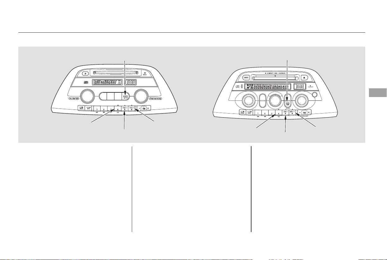
If your vehicle’s battery is
disconnected or goes dead, you will
need to set the clock. You can quickly set the time to the
nearest hour. If the displayed time is
before the half hour, pressing and
holding the CLOCK button, then
pressing the R (RESET) button sets
the clock back to the previous hour.
If the displayed time is after the half
hour, the clock sets forward to the
beginning of the next hour.
When you are finished, press the
CLOCK button again.
For example: 1:06 will reset to 1:00
1:52 will reset to 2:00
Press and hold the CLOCK button
until the clock flashes. Change the
hours by pressing the H button until
the numbers advance to the desired
time. Change the minutes by
pressing the M button until the
numbers advance to the desired time.
Refer to the Navigation system
manual for how to adjust the time.
On models with Navigation System
On models without Navigation System
Setting the Clock
LX model
EX model
Features
227
CLOCK BUTTON
H BUTTON
R BUTTON
M BUTTON
CLOCK BUTTON
H BUTTON
R BUTTON
M BUTTON
Main Menu
Table of Contents
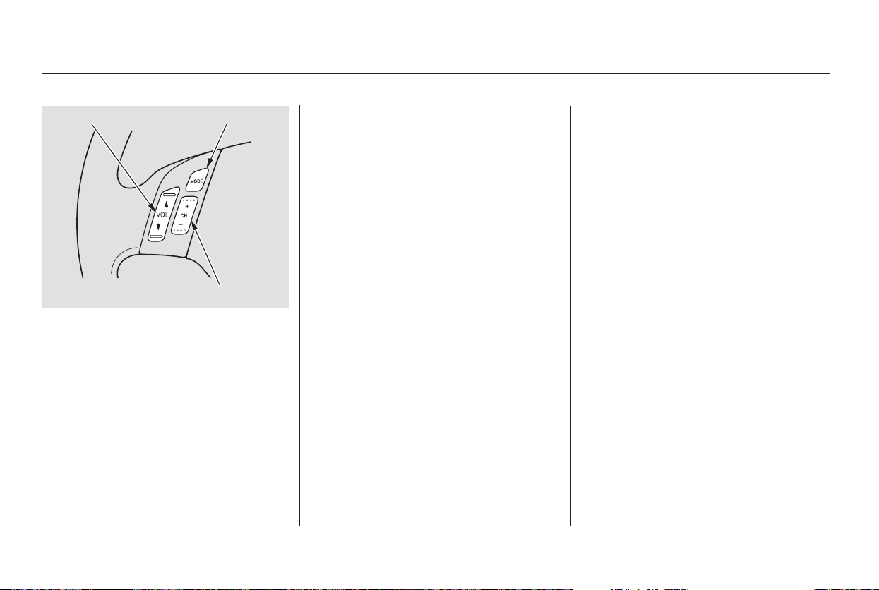
▲▼
+
−
+
−
+
−
The VOL button adjusts the volume
up ( ) or down ( ). Press the top
or bottom of the button and hold it
until the desired volume is reached,
then release it.
The MODE button changes the
mode. Pressing the button
repeatedly selects FM1, FM2, AM,
XM Radio (U.S. models), CD (if a
disc is loaded) or a tape (if the
optional tape player is installed and a
tape is loaded).
If you are listening to the radio, use
the CH button to change stations.
Each time you press the top ( ) of
the button, the system goes to the
next preset station on the band you
are listening to. Press the bottom
( ) to go back to the previous
station.
IfyouareplayingaCD,thesystem
skips to the beginning of the next
track each time you press the top
( ) of the CH button. Press the
bottom ( ) to return to the
beginning of the current track. Press
it again to return to the previous
track. You will see the disc and track
numbers in the display.
Three controls for the audio system
are mounted in the steering wheel
hub. These let you control basic
functions without removing your
hand from the steering wheel.
Ifyouareplayingatape,pressthe
top ( ) of the CH button to advance
to the next selection. Press the
bottom( )togobacktothe
previous selection. The system
senses a silent period, then goes
back to play mode.
On EX and Touring models
Steering Wheel Controls
228
MODE BUTTONVOL BUTTON
CH BUTTON
Main Menu
Table of Contents
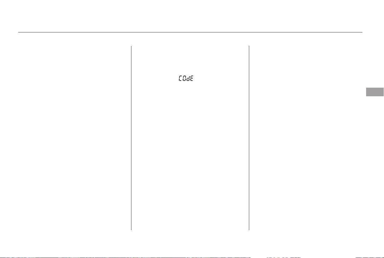
Your vehicle’s audio system will
disable itself if it is disconnected
from electrical power for any reason.
To make it work again, you must
enter a specific five-digit code with
the preset buttons. Because there
are hundreds of number
combinations possible from the five
digits, making the system work
without knowing the exact code is
nearly impossible.
Youshouldhavereceivedacardthat
lists your audio system code number
and serial number. It is best to store
this card in a safe place at home. In
addition, you should write the audio
system’s serial number in this
Owner’s Manual.
Ifyoushouldhappentolosethecard,
you must obtain the code number
from a Honda dealer. To do this, you
will need the system’s serial number.
If your vehicle’s battery is discon-
nected or goes dead, or the radio
fuse is removed, the audio system
will disable itself. If this happens,
youwillsee‘‘ ’’inthe
frequencydisplaythenexttimeyou
turn on the system. Use the preset
buttons to enter the five-digit code.
The code is located on the radio code
card included in your Owner’s
Manual kit. When it is entered
correctly, the radio will start playing.
If you make a mistake entering the
code, do not start over; complete the
five-digit sequence, then enter the
correct code. You have ten tries to
enter the correct code. If you are
unsuccessful in ten attempts, you
must then leave the system on for 1
hour before trying again.
You will have to store your favorite
stations in the preset buttons after
the system begins working. Your
original settings were lost when the
power was disconnected.
On EX and Touring models
Radio Theft Protection
Features
229
Main Menu
Table of Contents
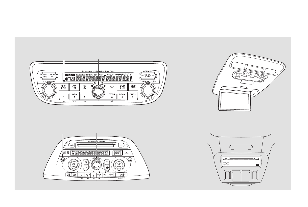
Rear Entertainment System
DVD Player
Models with Navigation System
Models without Navigation System
Overhead Screen Unit
230
REAR PWR BUTTON REAR CONTROL KNOB
REAR PWR BUTTON REAR CONTROL KNOB
Main Menu
Table of Contents

Press the REAR PWR button. To
turn on the rear controls (ceiling
panel/remote control), press the RR
CTRL knob. The system’s icon
shows in the upper display. Your
passengers can then operate the rear
system with the control panel in the
ceiling. The rear control panel can be
used as a remote control when it is
detached from the ceiling unit. Press
the RR CTRL knob again to turn the
rear controls off. You will see the
RearControlsOfficonintheupper
display.
The rear system selects the source it
waslastsetto.Ifthatsourcehas
been removed (the DVD has been
ejected from the player, for example),
you will see ‘‘DVD EJECT’’ in the
display. You must select another
source.
Whenyouturnonthesystem,the
rear speakers are automatically
turned off if the rear system selects
a different entertainment source
than the front system. You will see
the Rear Speakers Off icon in the
upper display. The sound for the rear
system is sent to the wireless
headphones.
Your vehicle is equipped with a rear
entertainment system that includes a
DVD player for the enjoyment of the
rear passengers.
With this system, the rear
passengers can enjoy a different
entertainment source (radio, CD
changer, DVD player, or optional
tape player) than the front seat
occupants. The audio is broadcast
through the supplied wireless
headphones.
Ifyouwanttoturntherearspeakers
on again, press and hold the REAR
PWR button until the Rear Speakers
Off icon goes off.
The rear speakers are
connected to the front system, so
they will always play the source that
the front system is set to.
The ignition switch must be in the
ACCESSORY (I) or ON (II) position
to operate the rear entertainment
system.
Available on EX with Leather and
Touring models
To Turn On the System Rear Speakers
Rear Entertainment System
Features
231
NOTE:
Main Menu
Table of Contents

To operate the rear entertainment
system from the front panel, turn the
RR CTRL knob clockwise. The
amber RR LED comes on to show
that the control panel is enabled.
If CDs are loaded in the CD changer,
select CD. If a CD is loaded in the
lower player, select DVD/AUX.
To play the radio, the buttons for the
front entertainment system have the
same functions.
The DVD player in your rear
entertainment system can play DVD
video discs and CDs.
Open the overhead screen by
pushing the OPEN button. The
screen will swing down part-way.
Pivot the screen the rest of the way.
If you pivot the screen too far
forward, past the second detent, the
display will turn off. Pivot the screen
back to the second or first detent to
turn the display back on. To close
the screen, pivot it up until it latches.
To Select Rear Entertainment
from the Front Control Panel
Operating the DVD Player from
the Front Control Panel
Rear Entertainment System
232
REAR CONTROL PANEL
OPEN BUTTON
OVERHEAD SCREEN
Main Menu
Table of Contents
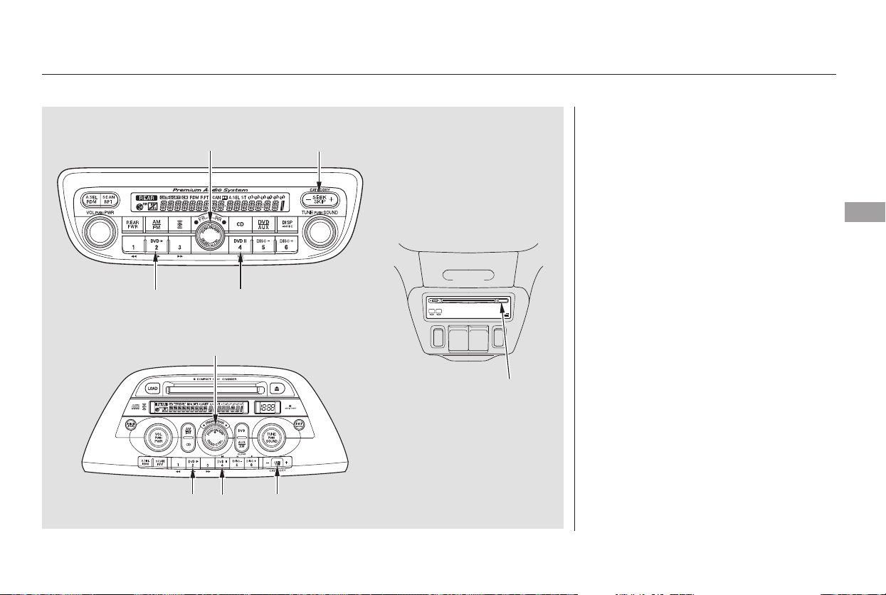
−
−
Turn the Rear CTRL knob clockwise.
The amber Rear LED comes on to
show that the control panel is now
enabled.
Insert a DVD into the DVD/CD
player below the front panel.
Push the DVD in halfway, the drive
will pull it in the rest of the way.
Press the PLAY button if
the DVD does not start playing
automatically.
Press the PAUSE button
to pause the DVD. Press the button
again or press PLAY to resume.
Pause works only with the DVD
player.
CONTINUED
PLAY
PAUSE
Rear Entertainment System
Features
Models with Navigation System
Models without Navigation System
233
EJECT
BUTTON
SEEK/SKIP BARREAR CTRL KNOB
PLAY BUTTON
PAUSE BUTTON
SEEK/SKIP BAR
REAR CTRL KNOB
PLAY BUTTON
PAUSE
BUTTON
Main Menu
Table of Contents

−
+
−
+
−
−Press and hold the
side to move forward; you will see
‘‘CUE’’ in the display. Press and hold
the sidetomovebackward;you
will see ‘‘REV’’ in the display.
Release the bar when the system
reaches the point you want.
Each time you press and release the
side of the SEEK/SKIP bar, the
system skips forward to the
beginning of the next track or
chapter. Press and release the
side of the bar to skip backward to
the beginning of the current track or
chapter. Press it again to skip to the
beginning of the previous track or
chapter.
Press the eject button to
remove the DVD from the drive.
To return front panel control to the
front audio system, turn the REAR
CTRL knob counterclockwise.
To turn on the rear entertainment
system from the rear control panel,
press the PWR button. Use the AM/
FM button, XM RADIO button (U.S.
models), CD button, DVD/AUX
button (U.S. models), or AUX button
(Canadian models) to select the
entertainment source. The selected
source will be shown in the display.
Make sure the rear control operation
has not been disabled with the REAR
CTRL knob on the front panel.
SEEK/SKIP EJECT
To Return to Front Audio
Controls
Using the Rear Control Panel
Rear Entertainment System
234
Main Menu
Table of Contents
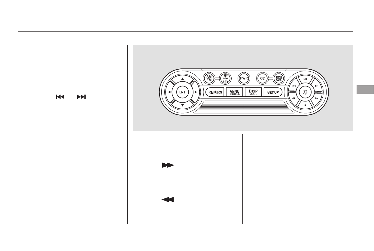
▲▼
▲
▼
▲▼
Use the and buttons to select a
station from the radio preset buttons.
Press the button to tune the radio
to a higher frequency, or press the
button to tune to a lower frequency.
Pressing the or button
causes the system to search up or
down the band for a station with a
strong signal. You will see SEEK in
the display.
Use the and buttons to select a
station from the radio preset buttons.
Press the button to search up
the channels in the channel mode.
The system will search up the
channels within the category when
the radio is in the category mode.
Press the button to search
down the channels in the channel
mode. The system will search down
the channels within the category
when the radio is in the category
mode.
CONTINUED
To Play the Radio from the Rear
Control Panel
To Play the XM Radio from the
Rear Control Panel
Rear Entertainment System
Features
235
Main Menu
Table of Contents
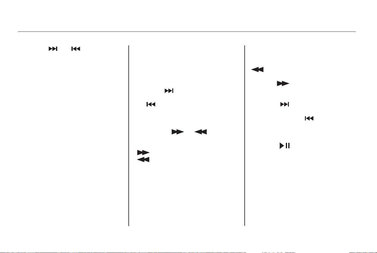
▲▼
Press the or button to
select another category.
Pressing and holding the DISP
button for more than 5 seconds will
change the search mode between
Channel Search and Category
Search. Each time you press and
release the DISP button, the display
above the rear control panel changes
in the following sequence: Channel
Number, Category Name, Music
Name, Artist Name, Channel Name,
and back to Channel Number.
If CDs are loaded in the CD changer,
select them by pressing the CD
button. If a CD is loaded in the DVD
player, press the DVD/AUX button.
To rewind the tape, push the
button. You will see REW in
the display. To fast forward the tape,
push the button. You will see
FF displayed.
Pressthe buttontofindthe
beginning of the current song or
passage. Press the button to
find the beginning of the next song
or passage.
Press the button to change the
tape direction.
Pressthe buttontoskiptothe
beginning of the next track. Press
the button to return to the
beginning of the current track.
To move rapidly within a track, press
andholdthe or button.
The system will continue to move
through the track. Press the
button to move forward, or the
button to move backward.
Release the button when the system
reaches the point you want.
If CDs are loaded in the CD changer
and the overhead screen is not open,
pressing the or button changes
the discs.
To Play a CD from the Rear
Control Panel
To Play the Optional Tape Player
from the Rear Control Panel
Rear Entertainment System
236
Main Menu
Table of Contents
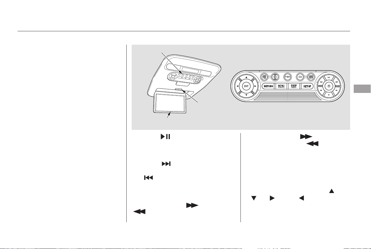
The video screen is for use by rear
seat passengers only. The driver and
front seat passenger should not try
to view the screen while driving.
Press the button when you
want to pause the DVD. Press this
button again to go back to PLAY.
Pressthe buttontoskiptothe
beginning of the next chapter. Press
the button to return to the
beginning of the current chapter.
To move rapidly within a chapter,
press and hold the or
button. The system will
continue to move through the
chapter. Press the button to
move forward, or the button to
move backward. Release the button
when the system reaches the point
you want.
ToselectthemenuontheDVD,
press the MENU/SCROLL button
(U.S. models) or MENU button
(Canadian models). Use the ,
, , and buttons to
move to the desired menu selection,
then press the ENT button to enter
your selection.
Open the overhead screen by
pushing the OPEN button. The
screen will swing down part-way.
Pivot the screen the rest of the way.
If you pivot the screen too far
forward, past the second detent, the
display will turn off. Pivot the screen
back to the second or first detent to
turn the display back on. To close
the screen, pivot it up until it latches.
To Play a DVD from the Rear
Control Panel
Rear Entertainment System
Features
237
REAR CONTROL PANEL
OPEN
BUTTON
OVERHEAD SCREEN
Main Menu
Table of Contents
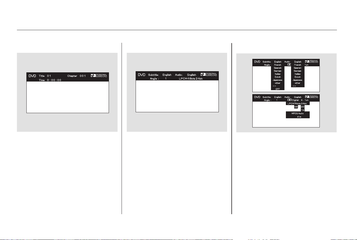
When you press the DISP button
while a DVD is playing, the title,
chapter, elapsed time, and personal
surround logo are displayed
(STATUS 1).
When you press the DISP button
again, the subtitle, audio, angle,
sound characteristics, and personal
surround logo are displayed
(STATUS 2).
To go back to play, press the DISP
button.
DISP Button
Rear Entertainment System
238
Main Menu
Table of Contents
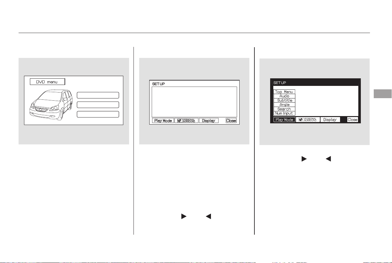
When you press the MENU button
while a DVD is playing, the DVD’s
main menu is displayed. To go back
to play, press the RETURN button.
When you press the SETUP button
while a DVD is playing, the DVD’s
setup menu is displayed at the
bottom of the screen. You can then
change various settings of play mode,
personal surround, and display. To
go back to play without changing any
setting, press the RETURN or
SETUP button, or select ‘‘Close’’ by
pressing the or button,
then press the ENT button.
When you select ‘‘Play Mode’’ by
pressing the or button, the
play mode setup menu is displayed
abovethe‘‘PlayMode’’icon.
CONTINUED
MENU Button System Messages
Play Mode
Rear Entertainment System
Features
239
Main Menu
Table of Contents
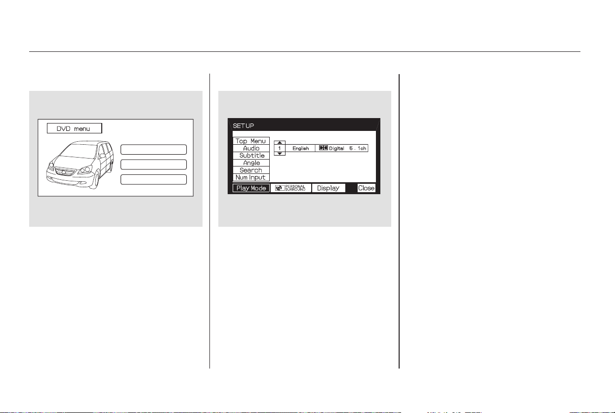
▼▲
▼▲
▼▲
Top Menu Audio
When you select ‘‘TOP MENU’’
using the or button, the DVD’s
title menu is displayed. This menu is
also displayed when you press the
MENU button while a DVD is not
playing.
When you select ‘‘Audio’’ from the
play mode setup menu by pressing
the or button, you will see a
submenu of the dubbed language.
The selectable languages vary from
DVD to DVD, and this feature may
notbeavailableonsomeDVDs.
Press the RETURN or ENT button
to go back to the play mode setup
menu.
Select the desired language by
pressing the or button. The
sound characteristics (Dolby Digital,
LPCM, MPEG Audio, dts) recorded
with the selected language are also
displayed next to the language.
To go back to play, press the return
button.
Rear Entertainment System
240
Main Menu
Table of Contents
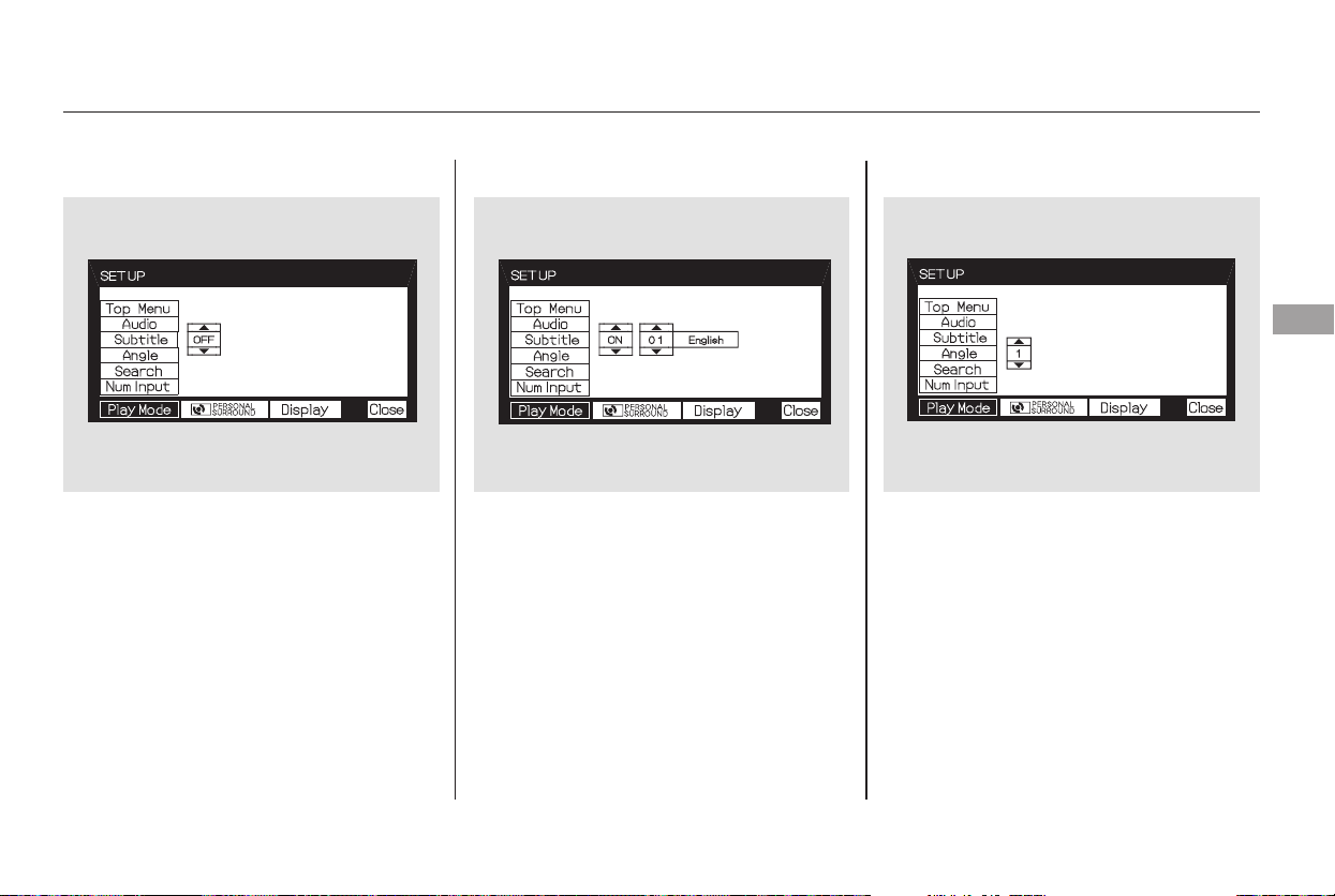
▼▲
▼
▲▼▲
▼▲
Subtitle Angle
To turn the subtitle on and off, select
‘‘Subtitle’’ from the setup menu by
pressing the or button. You will
see submenu ‘‘OFF’’ or ‘‘ON.’’ Select
‘‘OFF’’ or ‘‘ON’’ by pressing the or
button.
If more than one subtitle language is
available, you will see the language
currently selected when you select
‘‘ON’’ in the previous step.
Select the desired subtitle language
by pressing the or button.
Press the RETURN or ENT button
to go back to the play mode setup
menu.
On some DVDs, the scenes are
recorded by more than one camera,
giving different viewpoints of the
same scene. To change the angle,
select ‘‘Angle’’ from the setup menu.
Youwillseeasubmenuifthereare
different angles available.
Select the number on the submenu
by pressing the or button.
Press the RETURN or ENT button
to go back to the play mode setup
menu.
CONTINUED
Rear Entertainment System
Features
241
Main Menu
Table of Contents
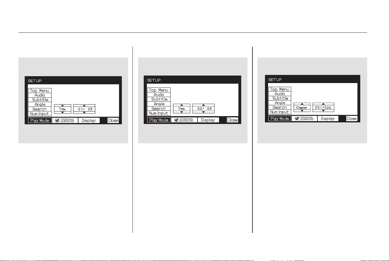
▼▲
▼▲
▼▲
▼
▲
Search
When you select the ‘‘Search’’ from
theplaymodesetupmenu,youwill
see the submenu shown above. In
the left submenu, you can select
between ‘‘Title’’ and ‘‘Chapter.’’ The
right submenu displays the current
title or chapter number and the total
number of titles or chapters.
To do a title search, select ‘‘Title’’ by
pressing the or button. Change
the number on the right submenu by
pressing the or button, and
press the ENT button to begin the
title search. If you press the
RETURN button, the display returns
totheplaymodesetupmenuwithout
doing the search.
To do a chapter search, select
‘‘Chapter’’ by pressing the or
button. Change the number on the
right submenu by pressing the or
button, and press the ENT button
to begin the chapter search. If you
press the RETURN button, the
display returns to the play mode
setup menu without doing the search.
Rear Entertainment System
242
Main Menu
Table of Contents
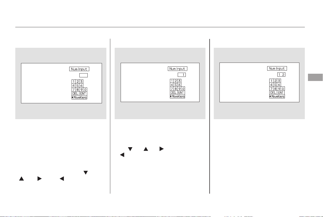
Num Input
A numerical command can be issued
to a DVD by inputting a two digit
number, and a button number can be
selected on the screen.
Select and enter the second digit
number the same way. The cursor
will automatically move to the ‘‘ENT’’
icon when you press the ENT button.
Press the ENT button to enter the
number command. To go back to the
DVD screen, press the RETURN
button.
Select the first digit number using
the , , , or
button, and enter it by pressing
the ENT button. If you want to
change the number, select ‘‘DEL,’’
and press the ENT button, then
select and enter the new number.
Select the ‘‘Num Input’’ from the play
mode setup menu. The screen will
change as shown above. If you select
the ‘‘Move Key’’ using the ,
, , or button, and
press the ENT button, the Num
Input display on the screen will
changefromtheleftsidetoright
side or right to left.
CONTINUED
Rear Entertainment System
Features
243
Main Menu
Table of Contents
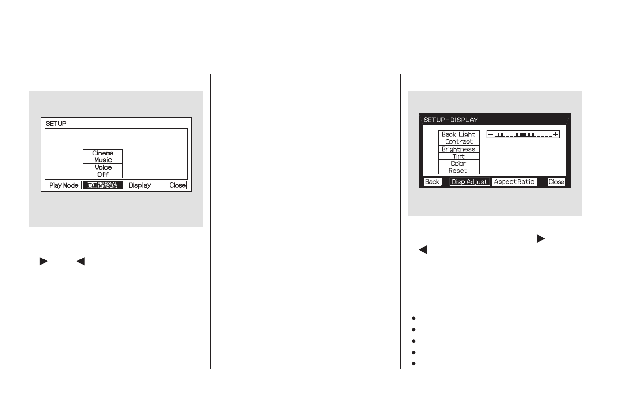
▼▲
When you select ‘‘PERSONAL
SURROUND’’ by pressing the
or button, the personal
surround setup menu is displayed
above the ‘‘PERSONAL
SURROUND’’ icon.
Selecting one of the sound effects,
Cinema,Music,orVoice,fromthe
personal surround menu allows you
to change the sound in your
headphones to match the disc you
are playing.
Select ‘‘Cinema,’’ ‘‘Music,’’ or ‘‘Voice’’
by pressing the or button, and
enter your selection by pressing the
ENT button. The ‘‘PERSONAL
SURROUND’’ logo is displayed in
the upper right corner of the screen.
If you select ‘‘Off,’’ the logo
disappears, and there will be no
special sound effect.
You can adjust these display
settings:
Back Light
Contrast
Brightness
Tint
Color
To adjust the display, select
‘‘Display’’ by pressing the or
button, and enter your
selection by pressing the ENT
button. The display changes as
shown above.
Personal Surround Display
Rear Entertainment System
244
Main Menu
Table of Contents
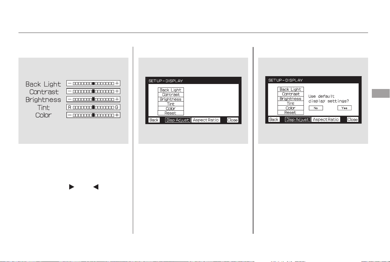
▼▲
▼▲
Select the quality you want to adjust
by pressing the or button, and
then pressing the ENT button. The
adjustment bar is displayed next to
the selected item. Adjust the setting
by pressing the or button.
When you are finished with your
adjustment, press the ENT button.
If you want to set the display to the
default setting, select ‘‘Reset’’ by
pressing the or button, and,
then pressing the ENT button.
The display changes as shown above.
Select ‘‘Yes,’’ and press the ENT
button. You will see the message
‘‘Default display settings applied’’ on
the display for 5 seconds.
Rear Entertainment System
Features
245
Main Menu
Table of Contents
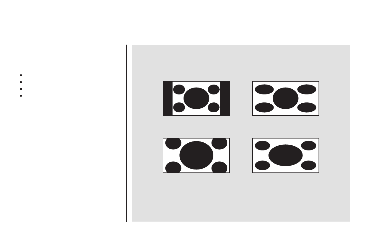
Screen Mode
You can set the screen mode to
these settings:
Normal
Wide
Zoom
Full
Rear Entertainment System
246
Normal Wide
Zoom Full
Main Menu
Table of Contents
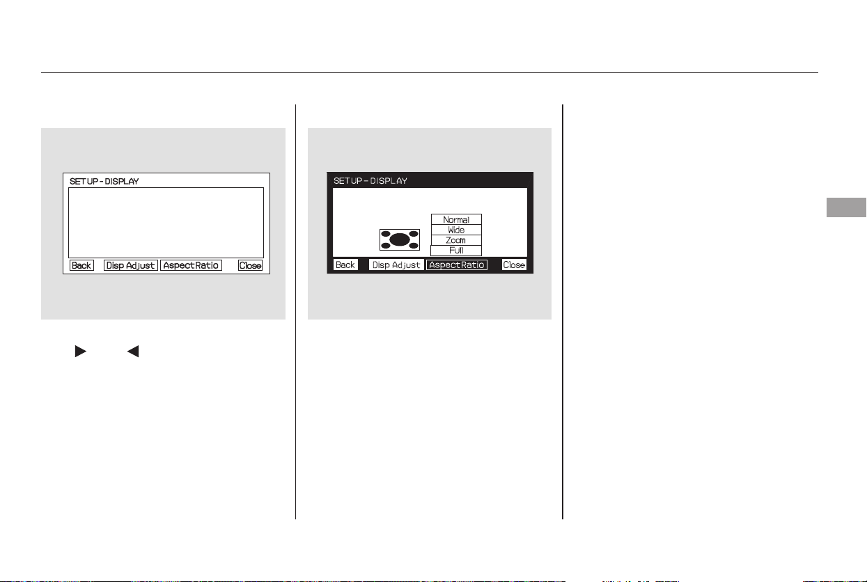
▼▲
Select the ‘‘Aspect Ratio’’ by pressing
the or button, then press
the ENT button.
The selectable setting menu is
displayed, and the current setting is
highlighted in blue.
Select the desired setting by
pressing the or button, then
press the ENT button.
The selected setting will be
highlighted in blue for one second,
and the screen returns to the play
mode in the selected setting.
CONTINUED
Rear Entertainment System
Features
247
Main Menu
Table of Contents
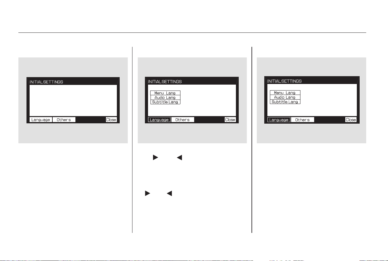
▼▲
When you press the SETUP button
on the rear control panel when a
DVD is not playing, the ‘‘INITIAL
SETTINGS’’ menu is displayed.
When you select ‘‘Language’’ with
the or button, the menu
shown above appears.
To retune to the stop or prestop
screen, select ‘‘Close’’ using the
or button, and then press
the ENT, or the SETUP button.
To select the language used in the
DISC menus, select ‘‘Menu Lang’’ by
pressing the or button. You will
see the submenu next to ‘‘Menu
Lang.’’
There are two selectable menus:
‘‘Language’’ and ‘‘Others.’’
Menu Language
INITIAL SETTINGS Menu INITIAL SETTINGS (Language)
Rear Entertainment System
248
Main Menu
Table of Contents
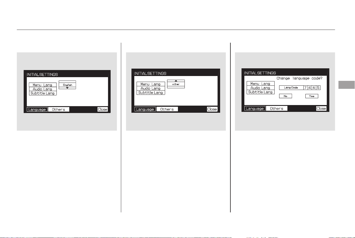
▼▲
Select the desired language by
pressing the or button, and
then pressing the ENT button.
The selectable languages are,
English, French, Spanish, German,
Italian, Dutch, and Japanese.
If you want another language than
those listed, you need to enter the
code number of the desired language.
Select ‘‘other,’’ and press the ENT
button. The display changes as
showninthenextcolumn.
If you select the ‘‘No,’’ and press the
ENT button, the display returns to
the initial screen of the ‘‘Language’’
menu.
CONTINUED
Rear Entertainment System
Features
249
Main Menu
Table of Contents
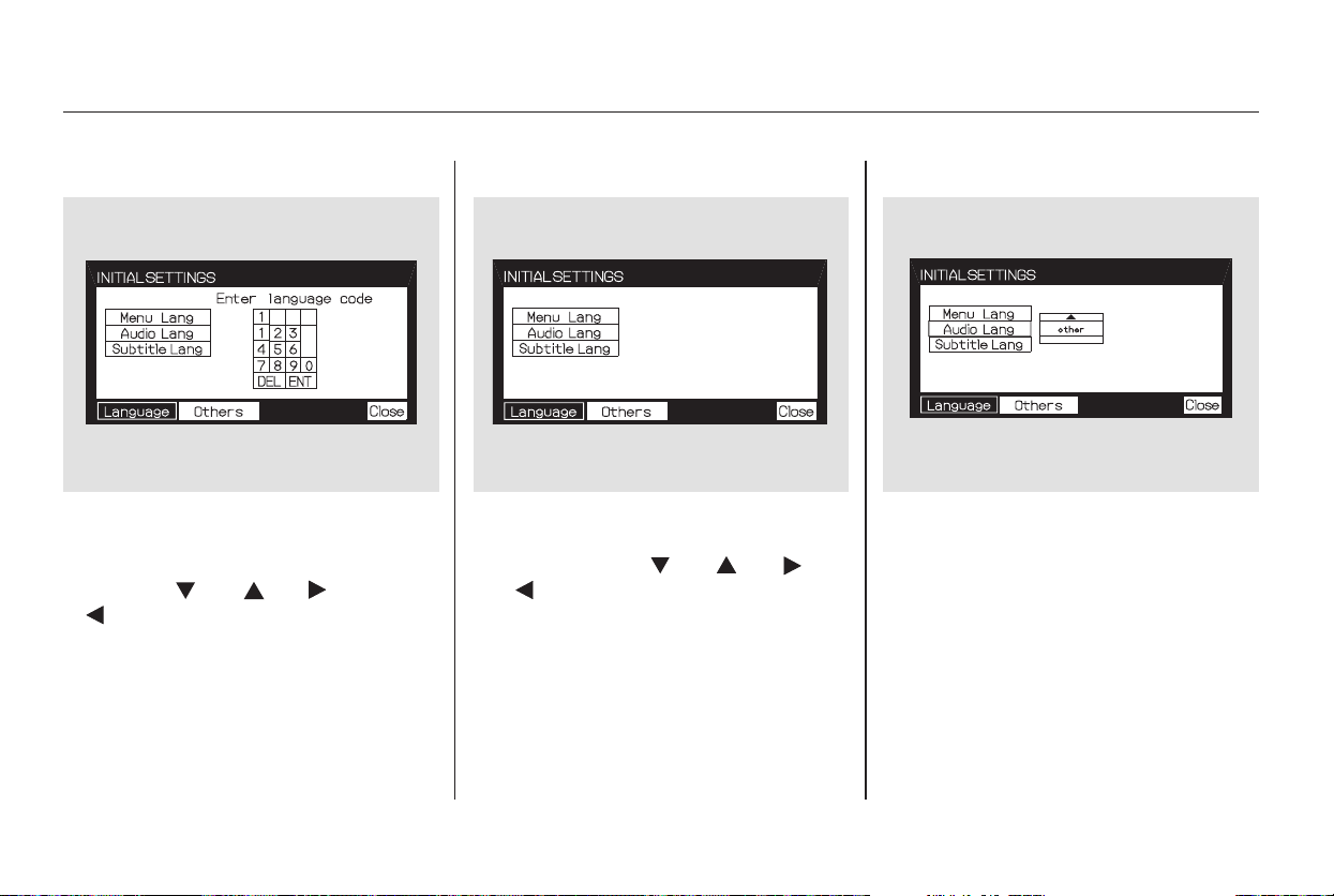
▼▲
Audio Language
If you select ‘‘Yes,’’ the display
changes to the language code input
mode. Select the first number digit
usingthe,,,or
button, and press the ENT
button to enter it. Repeat this until all
four digits are filled. When the
fourth digit is entered, the cursor
automatically moves to ‘‘ENT’’ on the
display. Press the ENT button on the
control panel to enter the new
language code.
If you made a mistake entering a
number digit, select ‘‘DEL’’ on the
display with the , , ,
or button, and press the ENT
buttononthecontrolpanel.Then
select and enter the correct number
digit as described. The display
returns to the initial ‘‘Language’’
menu screen.
You can select the dubbed language
before playing DVDs.
Select ‘‘Audio Lang’’ by pressing the
or button. You will see the
submenu next to ‘‘Audio Lang.’’
Follow the same instructions you
used to set the menu language.
Rear Entertainment System
250
Main Menu
Table of Contents
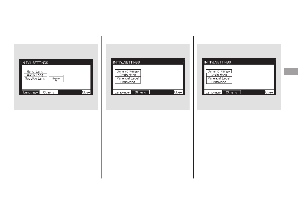
▼▲
Subtitle Language
You can select the subtitle language
before playing DVDs.
Select ‘‘Subtitle Lang’’ by pressing
the or button. You will see the
submenu next to the ‘‘Subtitle Lang.’’
When you select ‘‘Others’’ at the
bottom of the ‘‘INITIAL SETTINGS’’
screen, the above menu appears on
the screen.
Dynamic Range
‘‘Dynamic Range’’ reduces the
differences between the loud and
quiet sound levels throughout the
disc. When this is on, the louder
sounds are lowered, and quieter
sounds are increased.
Follow the same instructions you
used to set the menu language.
CONTINUED
INITIAL SETTINGS (Others)
Rear Entertainment System
Features
251
Main Menu
Table of Contents
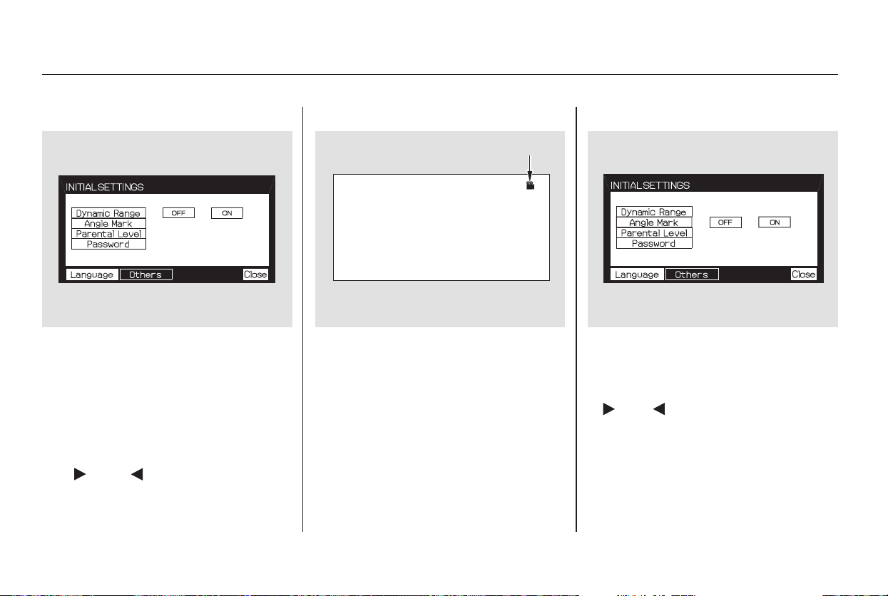
▼▲ ▼▲
When you select the ‘‘Dynamic
Range’’ by pressing the or
button, you will see the submenu
next to the ‘‘Dynamic Range’’ as
shown above.
To turn ‘‘Dynamic Range’’ on or off,
select ‘‘ON’’ or ‘‘OFF’’ by pressing
the or button, and then
press the ENT button.
Angle Mark
When you switch to another angle
while playing a DVD, the angle mark
is displayed in the upper right corner
of the screen.
You can set the system to display or
not display this angle mark.
Select ‘‘Angle Mark’’ by pressing the
or button. The above submenu
appears. If you want the angle mark
to be displayed, select ‘‘ON’’ with the
or button, and then press
the ENT button. The display returns
to the ‘‘Others’’ menu.
Rear Entertainment System
252
ANGLE MARK
Main Menu
Table of Contents
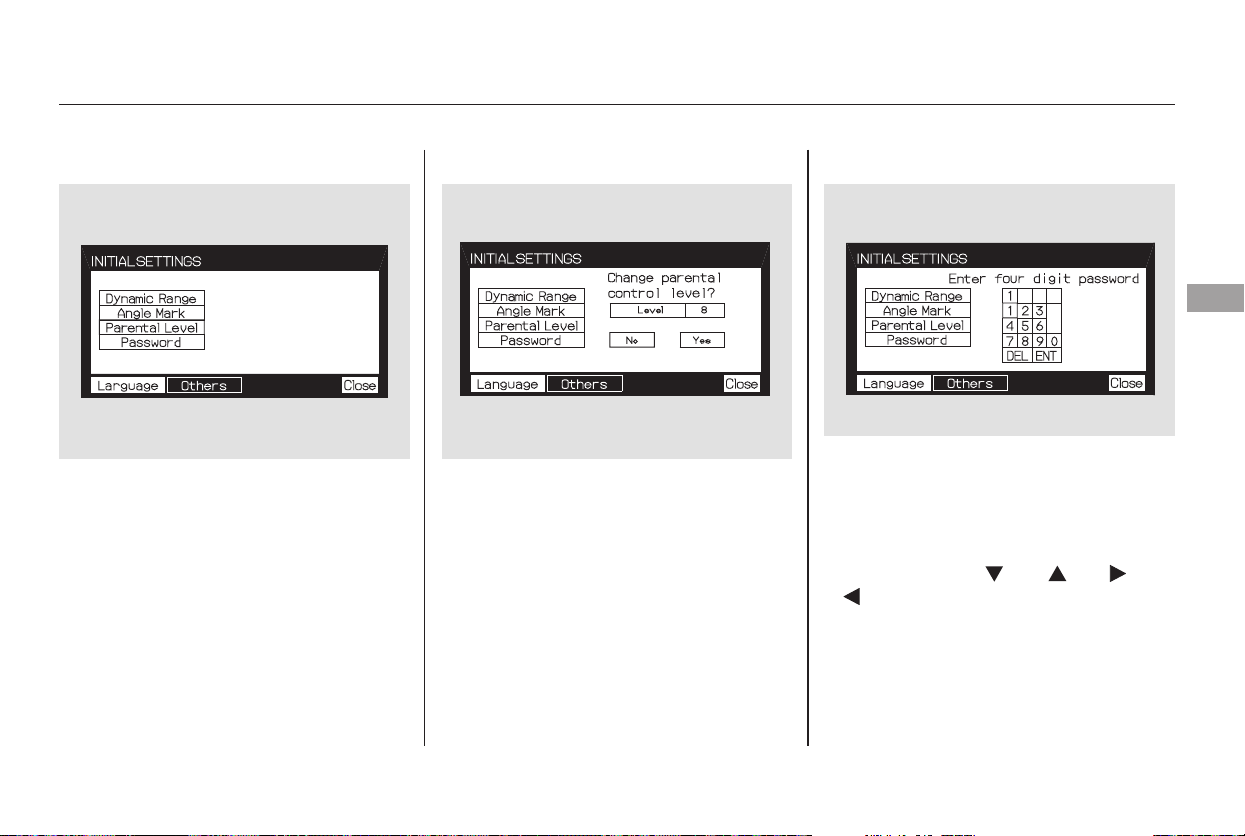
▼▲
Parental Control Level
You can place an auditory restriction
by changing the parental control
level. The higher the level number,
the lower the restriction.
Select ‘‘Parental Level’’ by pressing
the or button. You will see the
submenu shown above. If you select
‘‘No,’’ and press the ENT button, the
display returns to the ‘‘Others’’ menu.
When you select and enter ‘‘Yes,’’
the display changes as shown above.
To change the level, you need to
enter your four digit password.
Select the number for the first digit
by pressing the , , , or
button, and enter it by pressing
the ENT button. Repeat this until all
four digits are filled. When you enter
the fourth number, the cursor
automatically moves to ‘‘ENT’’ on the
display. Press the ENT button on the
control panel.
CONTINUED
Rear Entertainment System
Features
253
Main Menu
Table of Contents
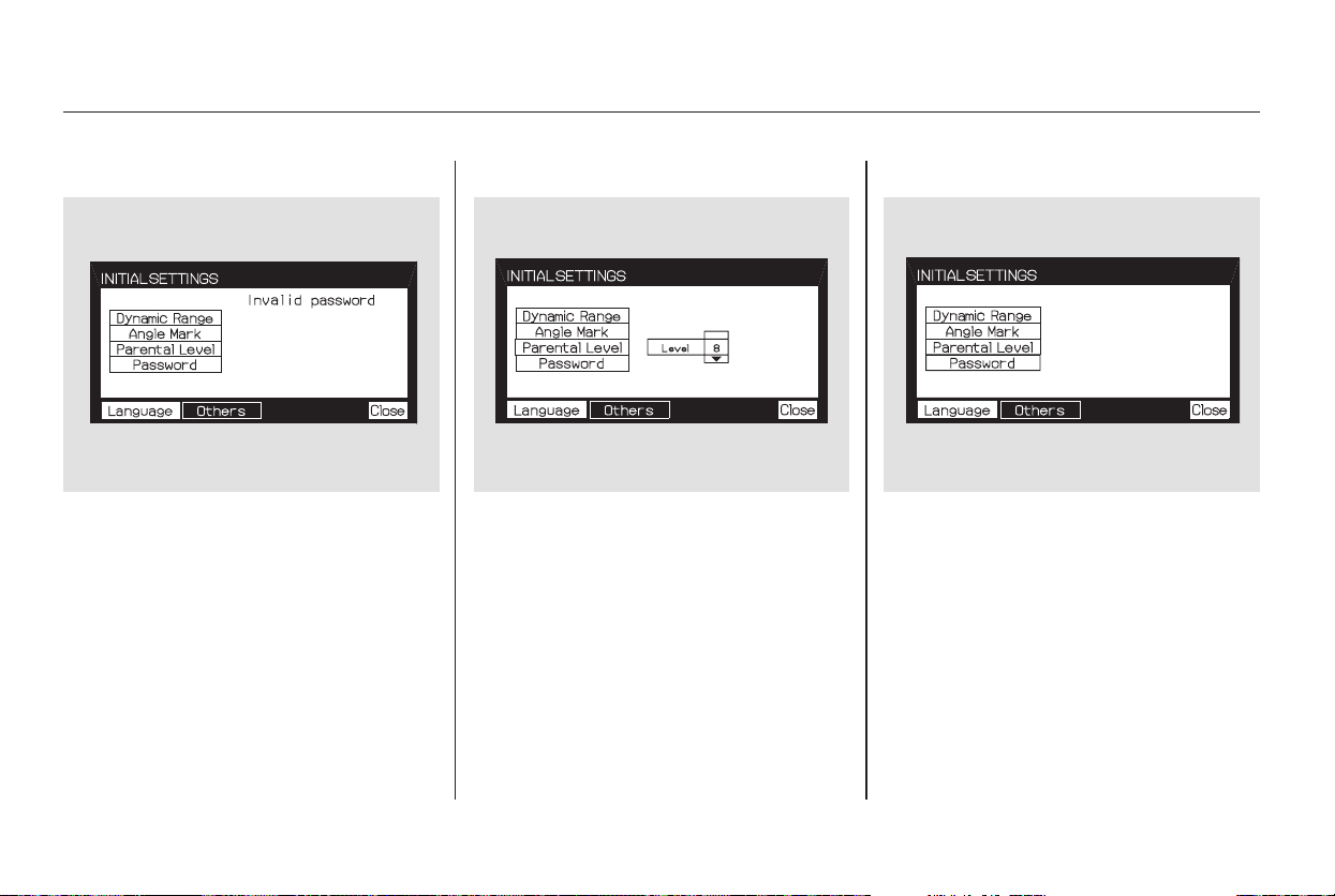
▼▲
If the system does not recognize the
password you entered, you will see
the above display. Repeat the
parental control level steps until you
enter the correct password.
If you enter the password correctly,
you can then change the parental
control level.
Once you correctly enter the
password, press the or button
to change the level, and then press
the ENT button to enter your
selection.
Changing the Password
The password was set to ‘‘1111’’
when the vehicle left the factory.
Rear Entertainment System
254
Main Menu
Table of Contents
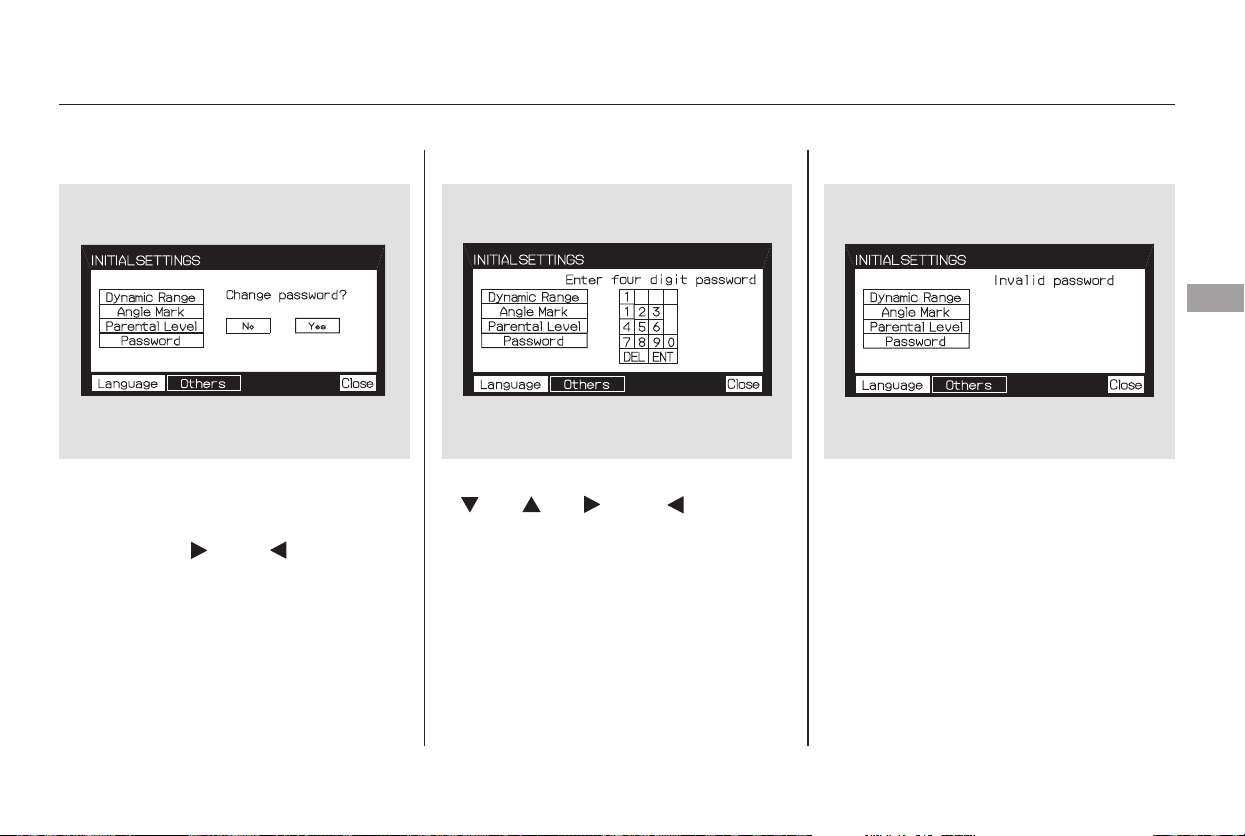
To change the password, select
‘‘Password.’’ You will see the above
menu displayed. Select ‘‘Yes’’ by
pressing the or button,
then press the ENT button.
If you select ‘‘No,’’ and press the
ENT button, the display returns to
the ‘‘Others’’ menu.
Select the first digit by pressing the
, , , or button,
and enter it by pressing the ENT
button. Repeat this until all four
digits are entered. When you enter
the fourth number, the cursor
automatically moves to ‘‘ENT’’ on the
display. Press the ENT button on the
control panel.
If the system does not recognize the
password you entered, you will see
the above display. Repeat the
password setting steps until you
enter the correct password.
CONTINUED
Rear Entertainment System
Features
255
Main Menu
Table of Contents
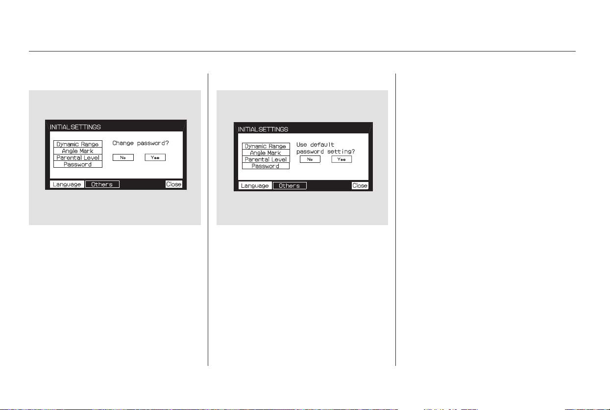
▲
If you forget the password, select
‘‘Password,’’ and press the button
10 times.
The display changes as shown above.
If you want to use the default
password (1111), select ‘‘Yes,’’ and
press the ENT button.
The message ‘‘Default password
setting applied’’ is displayed for
5 seconds.
Rear Entertainment System
256
Main Menu
Table of Contents
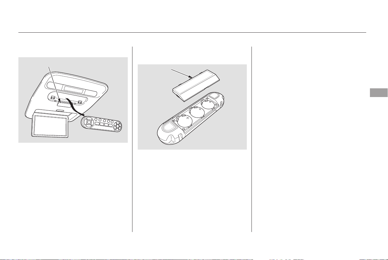
If it takes several pushes on the
button to operate the rear
entertainment system, have your
dealer replace the batteries as soon
as possible.
The rear control panel can be
detached from the ceiling unit and
used as a remote control. To remove
it from the ceiling unit, press the
release button. The control panel will
swing down partway. Pivot it down
further past the detent until it
detaches from the hinge. To reinstall
it, reverse the procedure.
Battery type: BR3032
As required by the FCC: This device
complies with Part 15 of the FCC rules.
Operation is subject to the following two
conditions: (1) This device may not
cause harmful interference, and (2) this
device must accept any interference
received, including interference that
may cause undesired operation.
Changes or modifications not expressly
approved by the party responsible for
compliance could void the user’s
authority to operate the equipment.
This device complies with Industry
Canada Standard RSS-210. Operation is
subject to the following two conditions:
(1) this device may not cause
interference, and (2) this device must
accept any interference that may cause
undesired operation of the device.
Remote Control Replacing the Remote Control
Batteries
Rear Entertainment System
Features
257
COVER
RELEASE BUTTON
Main Menu
Table of Contents

There are various types of DVDs
available. Some of them are not
compatible with your system.
Those packages or jackets should
also bear the designation of ‘‘1’’ or
‘‘ALL’’. DVD-ROMs cannot be played
in this system.
The tips on how to handle and
protect DVDs are basically the same
as those for compact discs. Refer to
‘‘Protecting Your CDs’’ on page .
The DVD player in your rear
entertainment system can play
DVDs and CDs bearing the above
marks on their packages or jackets.
221
Playable DVDs
Protecting DVDs
Rear Entertainment System
258
Main Menu
Table of Contents
If you see an error message in the
screen while operating the DVD
player,findthecauseinthechartto
the right. If you cannot clear the
message, take your vehicle to a
dealer.
SolutionMessage
Eject the disc and reinsert it.
Use a disc with the regional designation of ‘‘1’’ or ‘‘All’’.
The disc is not playable in this unit. Eject the disc, and insert a disc
compatible with this system.
Reinsert the disc, and increase the parental control level (see
pages 253 and 254 ).
ERROR F0
ERROR F2
Invalid region code
Invalid disc
Parental control active.
Change level to view.
DVD Player Error Messages
Rear Entertainment System
Features
259
Main Menu
Table of Contents
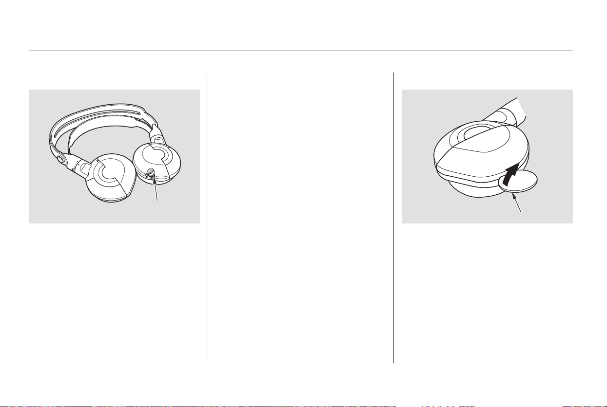
Each headphone uses one AAA
battery. The battery is under the
cover on the left earpiece. To
remove the cover, insert a coin in the
slot and twist it slightly to pry the
cover away from the earpiece. Pull
the cover outward, and pivot it out of
the way.
Some state and local government
agencies prohibit the use of
headphones by the driver of a motor
vehicle. Always obey applicable laws
and regulations.
The audio for the rear entertainment
system is sent to the wireless
headphones that come with the
system. When using the headphones,
make sure you wear them correctly:
L (left) and R (right) are marked on
the sides of the frame. The antennas
are in the front of the earpieces. If
you wear the headphones backwards,
the antennas will be aimed away
from the system, affecting the sound
quality and range.
To use the headphones, pivot the
earpieces outward. This turns them
on. To adjust the volume, turn the
dial on the bottom of the right
earpiece. When you remove the
headphones, the earpieces
automatically pivot inward, and the
headphones turn off. When not in
use, store the headphones in the
pocket of either front seat.
Rear Entertainment System
Replacing Batteries
Wireless Headphones
260
VOLUME
DIAL
TAB
Main Menu
Table of Contents
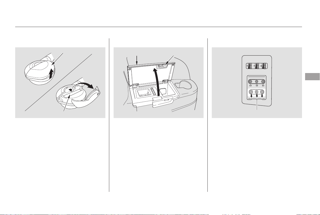
Auxiliary input jacks and headphone
connectors for the rear
entertainment system are under the
third seat armrest on the driver’s
side. To access these connectors,
open the cover by pulling up on the
lever.
The system will accept auxiliary
inputs from standard video games
and video equipment.
Some video game power supplies
may cause poor picture quality.
V=Videojack
L = Left audio jack
R = Right audio jack
Remove the battery. Install the new
battery in the earpice as shown in
the diagram next to the battery slot.
Slide the cover back into place on the
earpiece, then press down on the
back edge to lock it in place.
CONTINUED
Rear Entertainment System
Auxiliary Input Jacks
Features
261
COVER
BATTERY
ARMREST
LEVER
AUXILIARY INPUT JACKS
Main Menu
Table of Contents
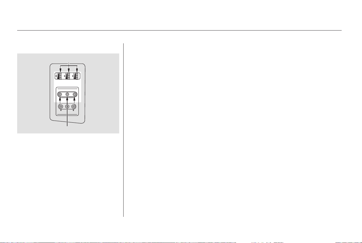
There are three headphone
connectors for the third seat
passengers. Each connector has its
own volume control.
Rear Entertainment System
262
VOLUME DIALS
HEADPHONE CONNECTORS
Main Menu
Table of Contents
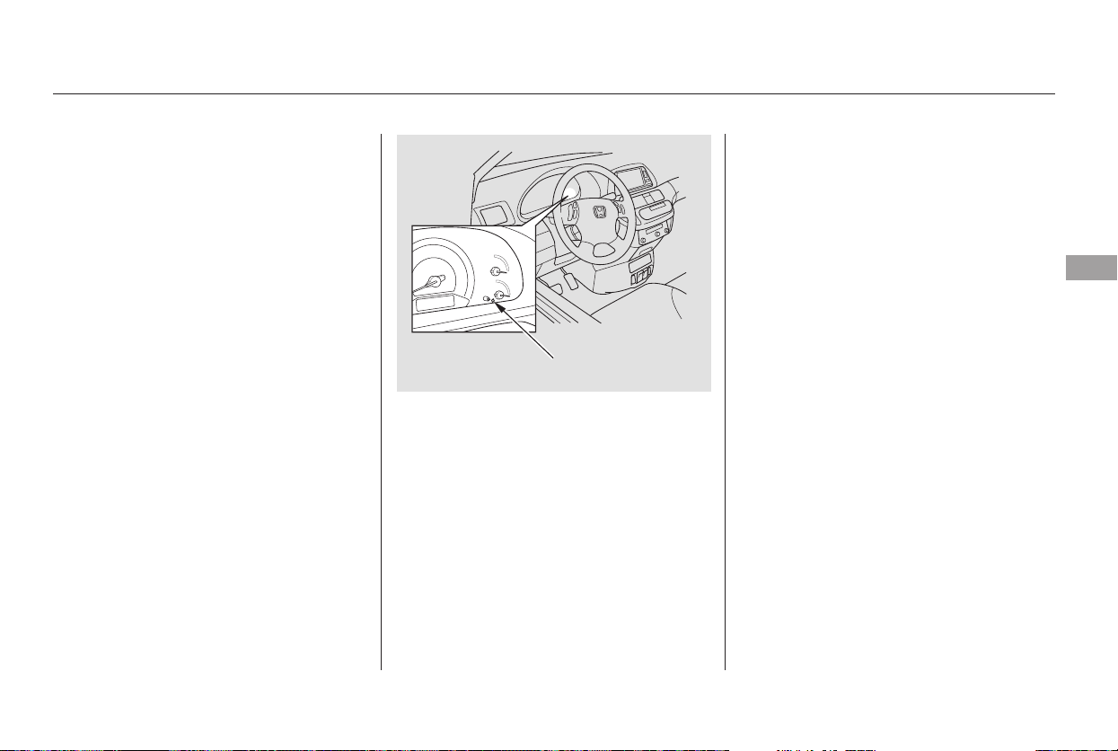
The security system automatically
sets 15 seconds after you lock the
doors, hood, and the tailgate. For the
system to activate, you must lock the
doorsandthetailgatefromthe
outside with the key, the lock tab,
the door lock switch, or the remote
transmitter. The security system
indicator in the instrument panel
starts blinking immediately to show
you the system is setting itself.
Once the security system is set,
opening any door, the tailgate, or the
hood without using the key or the
remote transmitter, will cause it to
alarm. It also alarms if the radio is
removed from the dashboard or the
wiring is cut.
The security system will not set if
the hood, tailgate, or any door is not
fully closed. If the system will not set,
check the Door and Tailgate Open
Monitor on the instrument panel
(see page ), to see if the doors
and the tailgate are fully closed.
Since it is not part of the monitor
display, manually check the hood.
Do not attempt to alter this system
or add other devices to it.
The security system helps to protect
your vehicle and valuables from theft.
The horn sounds and a combination
of headlights, parking lights, side
marker lights and taillights flashes if
someone attempts to break into your
vehicleorremovetheradio.This
alarm continues for 2 minutes, then
the alarm stops. To reset an
alarming system before the 2
minutes have elapsed, unlock either
front door with the key or the
remote transmitter.
67
On EX and Touring models
Security System
Features
263
SECURITY SYSTEM
INDICATOR
Main Menu
Table of Contents
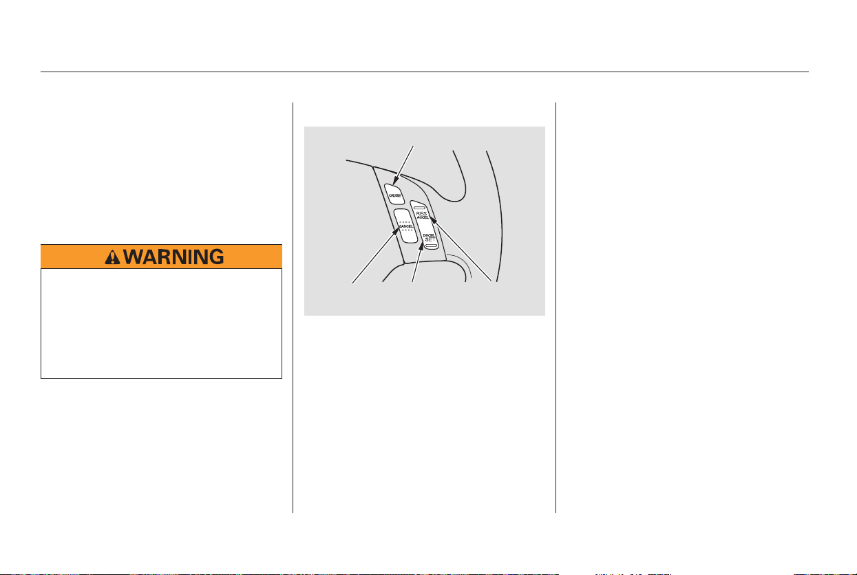
Press and release the DECEL/
SET button on the steering wheel.
The CRUISE CONTROL indicator
on the instrument panel comes on
to show the system is now
activated.
Cruise control allows you to maintain
asetspeedabove25mph(40km/h)
without keeping your foot on the
accelerator pedal. It should be used
for cruising on straight, open
highways. It is not recommended for
city driving, winding roads, slippery
roads, heavy rain, or bad weather.
When climbing a steep hill, the
automatic transmission may
downshifttoholdthesetspeed.
Accelerate to the desired cruising
speedabove25mph(40km/h).
Cruise control may not hold the set
speed when you are going up and
down hills. If your speed increases
going down a hill, use the brakes to
slow down to the desired speed. This
will cancel cruise control. To resume
the set speed, press the RES/
ACCEL button. The CRUISE
CONTROL indicator on the
instrument panel comes on.
Push the CRUISE button on the
steering wheel. The CRUISE
MAIN indicator on the instrument
panel comes on.
1.
2.
3.
Cruise Control
Using Cruise Control
264
DECEL/SET
BUTTON
CANCEL
BUTTON
RES/ACCEL
BUTTON
CRUISE BUTTON
Improper use of cruise control
canleadtoacrash.
Use cruise control only when
traveling on open highways in
good weather.
Main Menu
Table of Contents

CONTINUED
Press and hold the DECEL/SET
button. Release the button when
you reach the desired speed.
To slow down in very small
amounts, tap the DECEL/SET
button repeatedly. Each time you
do this, your vehicle will slow
down about 1 mph (1.6 km/h).
Tap the brake pedal lightly with
your foot. The CRUISE
CONTROL indicator on the
instrument panel goes out. When
the vehicle slows to the desired
speed, press the DECEL/SET
button.
Resting your foot on the brake pedal
causes cruise control to cancel.
You can increase the set speed in
any of these ways:
Press and hold the RES/ACCEL
button. When you reach the
desired speed, release the button.
Push the accelerator pedal,
accelerate to the desired speed,
and press the DECEL/SET button.
To increase the speed in very
small amounts, tap the RES/
ACCEL button. Each time you do
this, your vehicle will speed up
about 1 mph (1.6 km/h).
You can decrease the set speed in
any of these ways:
Even with cruise control turned on,
you can still use the accelerator
pedal to speed up for passing. After
completing the pass, take your foot
off the accelerator pedal. The vehicle
will return to the set speed.
Cruise Control
Changing the Set Speed
Features
265
Main Menu
Table of Contents
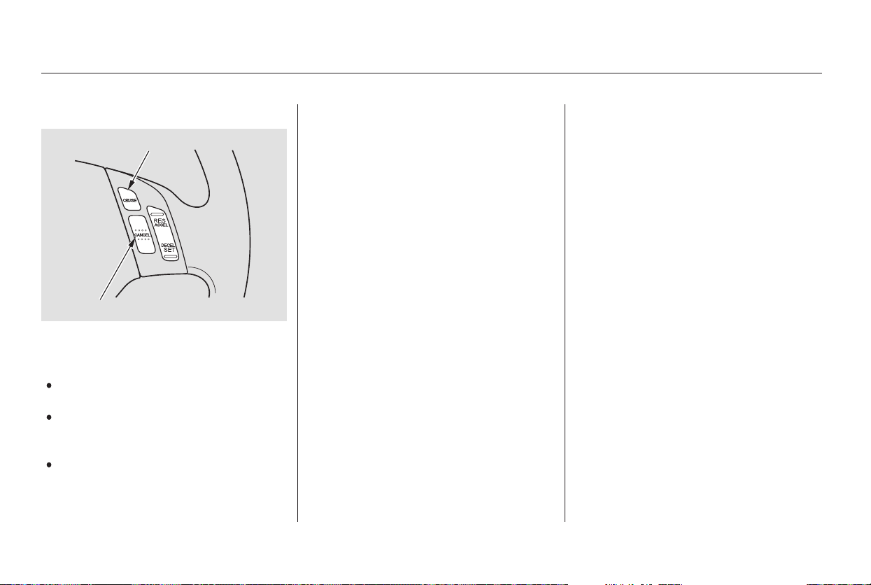
Tap the brake pedal.
Push the CANCEL button on the
steering wheel.
When you push the CANCEL button
or tap the brake pedal, the system
remembers the previously set speed.
To return to that speed, accelerate to
above25mph(40km/h),andthen
press and release the RES/ACCEL
button. The CRUISE CONTROL
indicator comes on. The vehicle
accelerates to the same speed as
before.
You can cancel cruise control in any
of these ways:
Pressing the CRUISE button turns
the system completely off and erases
the previous set speed.
Push the CRUISE button on the
steering wheel.
Cruise Control
Resuming the Set SpeedCancelling Cruise Control
266
CANCEL BUTTON
CRUISE BUTTON
Main Menu
Table of Contents

−The HomeLink Universal
Transceiver built into your vehicle
canbeprogrammedtooperateupto
three remote controlled devices
around your home, such as garage
doors, lighting, or home security
systems.
If you are training HomeLink to
operate a garage door or gate, you
should unplug the motor for that
device during training. Repeatedly
pressing the remote control button
could burn out the motor.
Always refer to the opening
instructions and safety information
that came with your garage door
opener or other equipment you
intend to operate with HomeLink. If
you do not have this information,
contact the manufacturer of the
equipment.
Todothis,pressandholdthetwo
outside buttons on the HomeLink
Transceiver for about 20 seconds, or
until the red indicator flashes.
Release the buttons, then go to step
1.
If you are training the second or
third buttons, go directly to step 1.
If you just
received your vehicle and have not
trained any of the buttons in
HomeLink before, you should erase
any previously learned codes before
training the first button.
HomeLink stores the code in a
permanent memory. There should
be no need to retrain HomeLink if
your vehicle’s battery goes dead or is
disconnected. If your garage door
opener was manufactured before
April 1982, you may not be able to
program HomeLink to operate it.
They do not have the safety feature
that causes the motor to stop and
reverse if an obstacle is detected
during closing, increasing the risk of
injury.
CONTINUED
On EX and Touring models
HomeLink Universal Transceiver
General Information
Training HomeLink
Important Safety Precautions
Before you begin
Features
267
Main Menu
Table of Contents
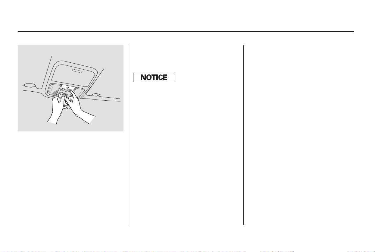
Unplug the garage door opener
motor from the house current.
Holdtheendofthegaragedoor
opener remote control 2 to 5
inches from HomeLink. Make
sure you are not blocking your
view of the red indicator in
HomeLink.
Press and hold the remote control
button and one of the HomeLink
buttons at the same time.
Plug in the garage door opener
motor, then test the HomeLink
button by pushing it. If the button
does not work, repeat the
procedure to train it again. If it still
does not work, you may have a
variable or rolling code garage
door opener. See if you do by
pressing and holding the
HomeLink button you just trained.
If the red indicator blinks for 2
seconds then stays on, you have a
rolling code garage door opener.
Go to ‘‘Training with a Rolling
Code System’’ (see page ).
Repeat these steps to train the
other two HomeLink buttons to
operate any other remotely
controlled devices around your
home (lighting, automatic gate,
security system, etc.).
When the red indicator flashes
rapidly, release both buttons.
HomeLink should have learned
the code from the remote control.
The red indicator in HomeLink
should begin flashing. It will flash
slowly at first, then rapidly.2.
3.
1.
4.
5.
7.
6.
269
HomeLink Universal Transceiver
268
The remote control you are training
f rom may stop transmitting af ter 2
seconds. This is not enough for
HomeLink to learn the code. Release
and press the button on the remote
control every 2 seconds until HomeLink
has learned the code.
Main Menu
Table of Contents
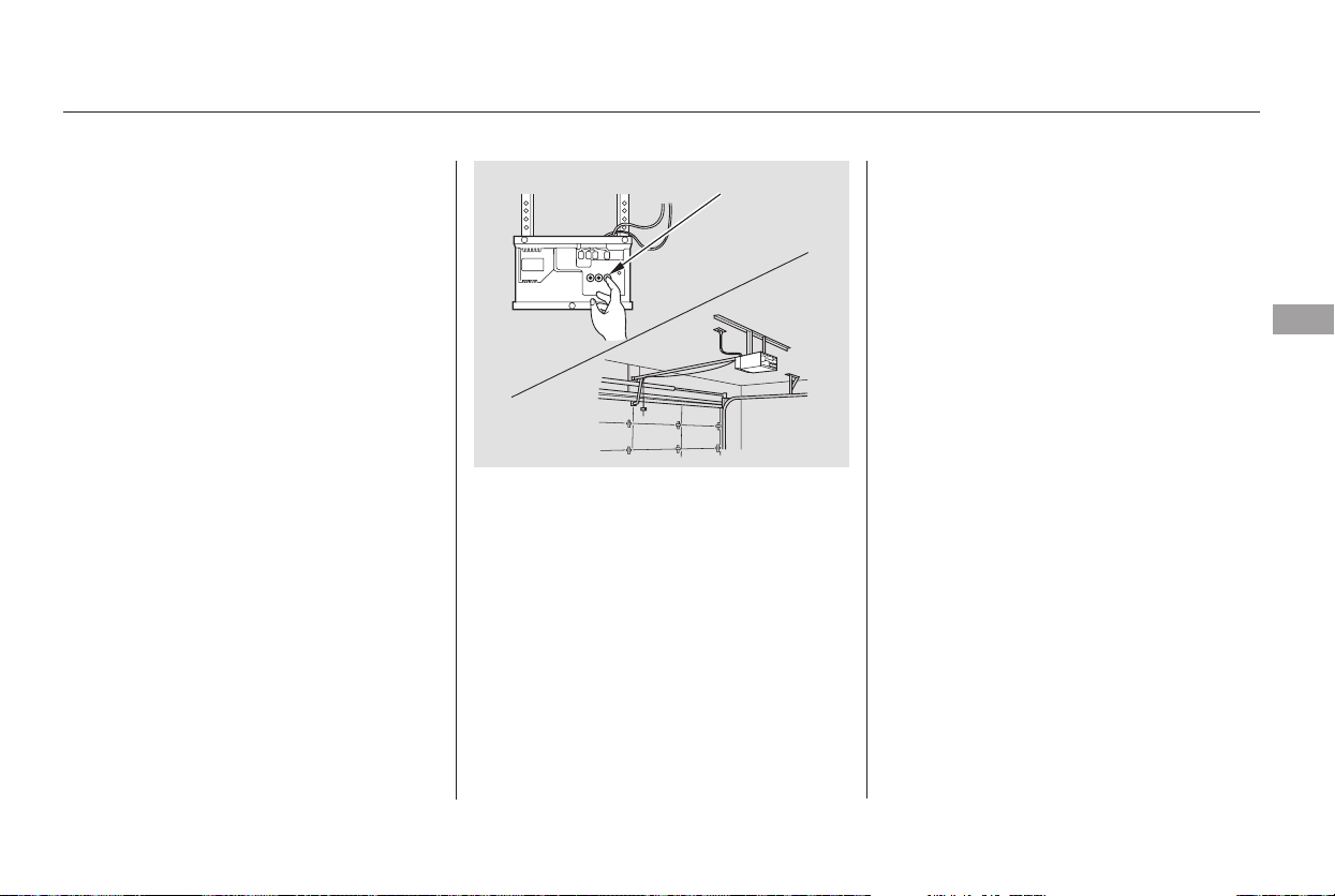
For security purposes, newer garage
door opening systems use a ‘‘rolling’’
or variable code. Information from
the remote control and the garage
door opener are needed before
HomeLink can operate the garage
door opener.
The ‘‘Training HomeLink’’
procedure trains HomeLink to the
proper garage door opener code.
The following procedure
synchronizes HomeLink to the
garage door opener so it sends and
receives the correct codes.
Make sure you have properly
completed the ‘‘Training
HomeLink’’ procedure.
Find the ‘‘Training’’ button on your
garage door opener unit. The
location will vary, depending on
the manufacturer.
Press and hold the button on
HomeLink for 3 to 4 seconds.
Press and hold the HomeLink
button again for 3 to 4 seconds.
This should turn off the training
indicator on the garage door
opener unit. (Some systems may
require you to press the button up
to three times.)
Press the HomeLink button again.
It should operate the garage door.
Press the training button on the
garage door opener unit until the
indicator next to the button comes
on. The indicator may blink, or
comeonandstayon.Youthen
have approximately 30 seconds to
complete the following steps.
6.
2.
4.
5.
1.
3.
Training With a Rolling Code
System
HomeLink Universal Transceiver
Features
269
TRAINING BUTTON
Main Menu
Table of Contents

Youshoulderaseallthreecodes
before selling the vehicle.
If you have problems with training
the HomeLink Universal Transceiver,
or would like information on home
products that can be operated by
HomeLink, call (800) 355-3515. On
the Internet, go to
www.homelink.com.
HomeLink
is a registered
trademark of Johnson Controls, Inc.
Toerasethecodesstoredinallthree
buttons, press and hold the two
outside buttons until the red
indicator begins to flash, then
release the buttons.
Totrainanalreadyprogrammed
HomeLink button with a new device,
you do not have to erase all the
memory. Train the selected button
over the existing memory code
following the steps under ‘‘Training
HomeLink’’.
As required by the FCC:
This device complies with Part 15 of the
FCC rules. Operation is subject to the
following two conditions: (1) This device
may not cause harmful interference, and
(2) this device must accept any
interference received, including
interference that may cause undesired
operation.
Changes or modifications not expressly
approved by the party responsible for
compliance could void the user’s
authority to operate the equipment.
This device complies with Industry
Canada Standard RSS-210.
Operation is subject to the following two
conditions: (1) this device may not cause
interference, and (2) this device must
accept any interference that may cause
undesired operation of the device.
HomeLink Universal Transceiver
Erasing Codes
Retraining a Button
Customer Assistance
270
Main Menu
Table of Contents
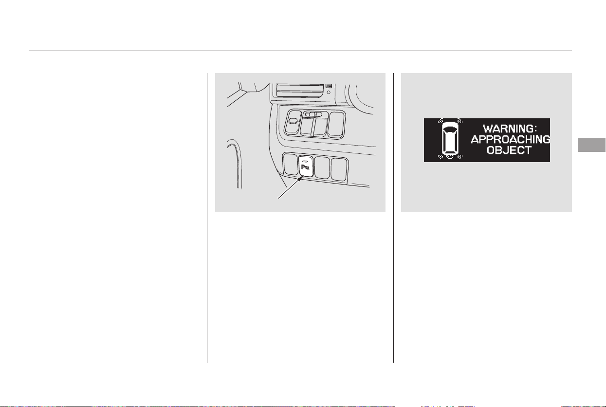
Your vehicle has a parking sensor
system. The system lets you know
theapproximatedistancebetween
your vehicle and most obstacles
while you are parking. When the
system is on and your vehicle is
nearinganobstacle,youwillhear
beeping and see parking messages in
the multi-information display.
To activate the system, push the
button on the dashboard with the
ignition in the ON (II) position. The
indicator in the button comes on
when the system is on. To turn the
system off, push the button again.
The system has two front corner
sensors, two rear corner sensors,
and a rear center sensor.
The rear center sensor works only
when the shift lever is in Reverse (R),
and the vehicle speed is less than 5
mph (8 km/h).
The corner sensors work only when
the shift lever is in any position other
than P and the vehicle speed is less
than 5 mph (8 km/h).
All obstacles may not always be
sensed. Even when the system is on,
you should look for obstacles near
yourvehicletomakesureitissafeto
park.
On Touring model
Parking Sensor System
Features
271
PARKING SENSOR SYSTEM BUTTON
MULTI-INFORMATION DISPLAY
Main Menu
Table of Contents
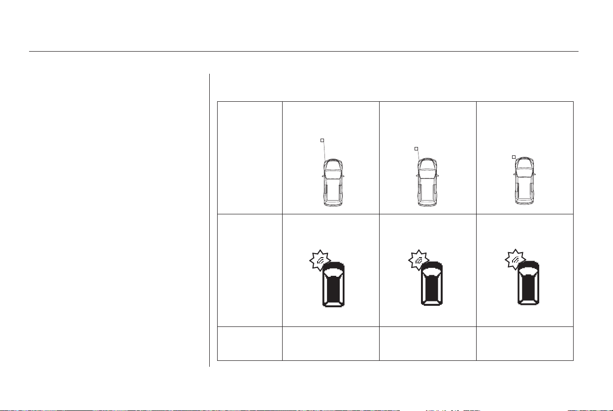
Example shown: Obstacle is at the left front of the vehicle
When the system senses an obstacle,
the appropriate indicator comes on,
and a beeper sounds as shown in the
following tables.
When you turn the system on, all
indicators come on in the multi-
information display, and a beeper
sounds once.
Distance
Beeper
About 16-20 in
(40-50 cm)
About 12-16 in
(30-40 cm)
Upper left
indicator stays on
Short beeps
Continuous
beep
Indicators
and
Messages
Very short beeps
About 12 in
(30 cm) or less
Upper left
indicator stays on
Upper left
indicator stays on
Parking Sensor System
Corner Sensor Operation
Multi-Information Display
Messages and Beeper Operation
272
Main Menu
Table of Contents
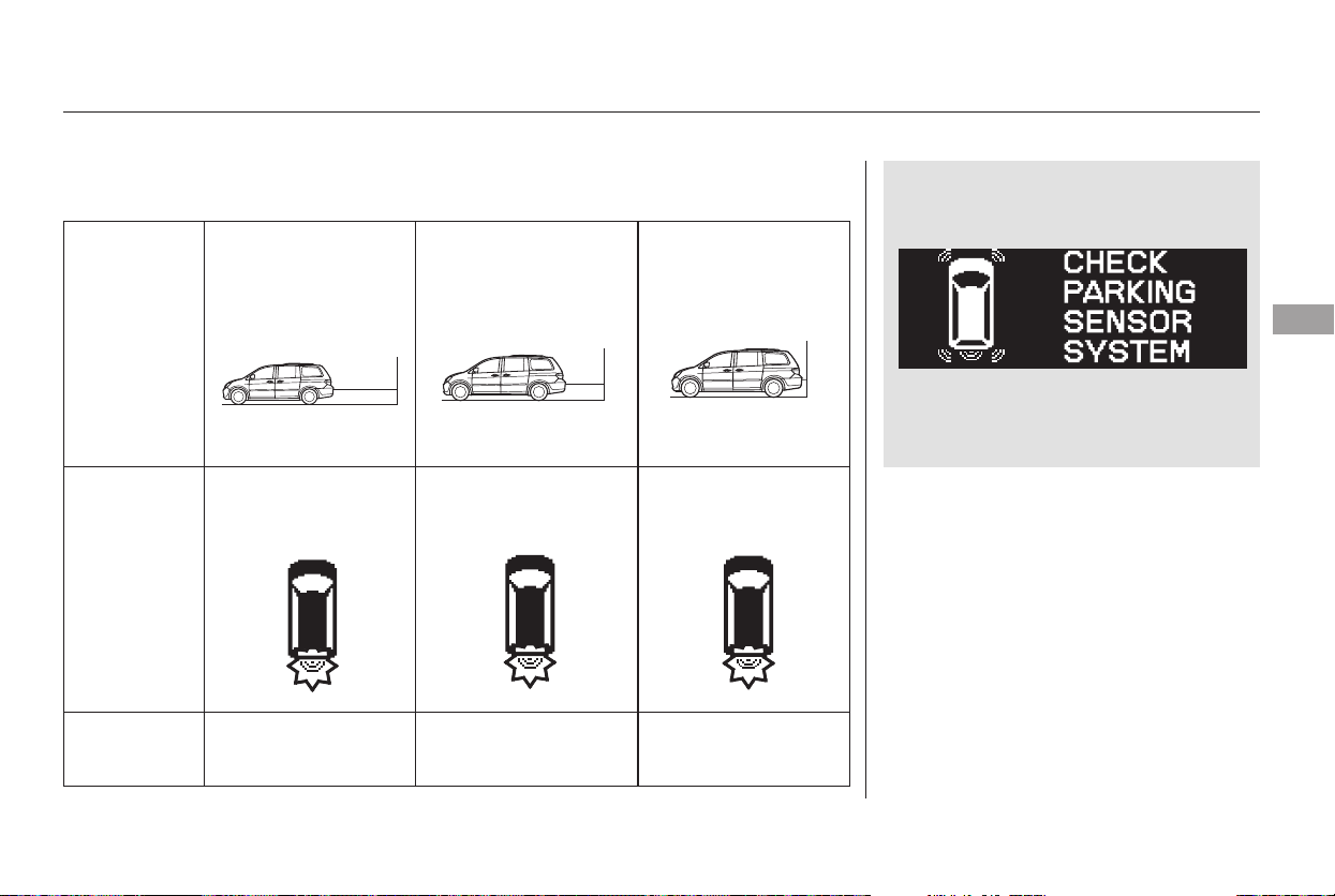
If the system develops a problem,
you will see a ‘‘CHECK PARKING
SENSOR SYSTEM’’ message in the
multi-information display, and a
beeper sounds continuously. Very
often, a sensor covered with mud, ice,
snow,etc.isthecauseofthis
message. Check the sensors first. If
the message stays on or the beeper
does not stop, have the system
checked by your dealer.
Distance
Beeper Short beeps
Continuous
beeps
Indicators
and
Messages
Very short beeps
Bottom
indicator stays on
About 40-70 in
(1-1.8 m)
About 24-40 in
(0.6-1 m)
About 24 in
(0.6 m) or less
Bottom
indicator stays on
Bottom
indicator stays on
CONTINUED
Parking Sensor System
Rear Center Sensor Operation
Features
273
Main Menu
Table of Contents
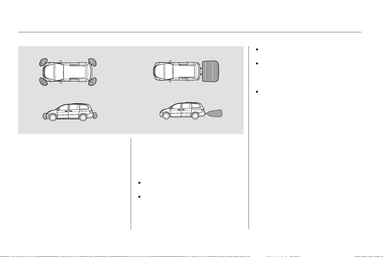
The range of the corner sensors and
the rear center sensor are limited.
Each corner sensor is capable of
sensing an obstacle only when your
vehicleis20in(50cm)orcloser.
The rear center sensor senses an
obstacle that is behind your vehicle
70 in (1.8 m) or closer.
Do not put any accessories on or
around the sensors.
The system may not function
properly under these conditions:
After the vehicle has been sitting
out in hot or cold weather.
When the system is affected by
some electrical equipment or
devices generating an ultrasonic
wave.
When operating the vehicle in bad
weather.
The system may not sense thin or
low objects, or sonic-absorptive
materials such as snow, cotton, or
sponge.
The system cannot sense objects
directly under the bumper.
The sensors are covered with
snow,ice,mud,etc.
When the vehicle is on a rough
road, on grass, or on a hill.
This device complies with Industry
Canada Standard RSS-210. Operation is
subject to the following two conditions:
(1) this device may not cause
interference, and (2) this device must
accept any interference that may cause
undesired operation of the device.
Canadian Owners:
Parking Sensor System
274
Within about 20 in (50 cm) Within about 70 in (1.8 m)
Main Menu
Table of Contents
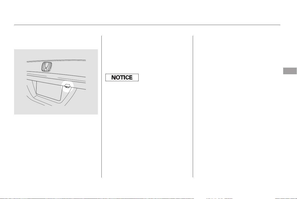
▼▲
When in reverse, the touch screen
and Navi ‘‘hard’’ buttons are locked
out, except the ‘‘ZOOM’’ button.
Touching the ‘‘ ’’ or ‘‘ ’’ button
allows you to adjust the brightness of
the rear view camera image.
Whenever you shift to R (Reverse)
with the ignition switch in the ON
(II) position, the rear view is shown
on the navigation system screen.
For the best picture, always keep the
rear view camera clean, and do not
cover the camera lens.
Since the rear view camera display
area is limited, you should always
back up slowly and carefully, and
look behind you for obstacles.
On EX with Leather and Touring
models
Rear View Camera and Monitor
Features
275
The camera brightness cannot be
adjusted by voice control.
Main Menu
Table of Contents

276
Main Menu

Before you begin driving your
vehicle, you should know what
gasoline to use and how to check the
levels of important fluids. You also
need to know how to properly store
luggage or packages. The
information in this section will help
you. If you plan to add any
accessories to your vehicle, please
read the information in this section
first.
..............................Break-in period . 278
...............................Gasoline Type . 278
.........Service Station Procedures . 279
....................................Refueling . 279
Opening and Closing the
.......................................Hood . 280
...................................Oil Check . 281
.............Engine Coolant Check . 282
...............................Fuel Economy . 283
........Improving Fuel Economy . 283
...Accessories and Modifications . 284
.............................Carrying Cargo . 286
Before Driving
Before Driving
277
Main Menu

Help assure your vehicle’s future
reliability and performance by paying
extra attention to how you drive
during the first 600 miles (1,000 km).
During this period:
Avoid full-throttle starts and rapid
acceleration.
Avoidhardbrakingforthefirst
200 miles (300 km).
Do not change the oil until the
scheduled maintenance time.
You should also follow these
recommendations with an
overhauled or exchanged engine, or
when the brakes are replaced.
Do not tow a trailer.
Your vehicle is designed to operate
on unleaded gasoline with a pump
octane number of 86 or higher. Use
of a lower octane gasoline can cause
a persistent, heavy metallic rapping
noise that can lead to engine damage.
We recommend quality gasolines
containing detergent additives that
help prevent fuel system and engine
deposits.
In addition, in order to maintain good
performance, fuel economy, and
emissions control, we strongly
recommend, in areas where it is
available, the use of gasoline that
does NOT contain manganese-based
fuel additives such as MMT.
If you notice any undesirable
operating symptoms, try another
service station or switch to another
brand of gasoline.
Some gasoline today is blended with
oxygenates such as ethanol or
MTBE. Your vehicle is designed to
operate on oxygenated gasoline
containing up to 10 percent ethanol
by volume and up to 15 percent
MTBE by volume. Do not use
gasoline containing methanol.
For further important fuel-related
information, please refer to your
.
Use of gasoline with these additives
may adversely affect performance,
and cause the malfunction indicator
lamp on your instrument panel to
come on. If this happens, contact
your dealer for service.
Break-in Period, Gasoline Type
Break-in Period Gasoline Type
Quick Start Guide
278
Main Menu
Table of Contents
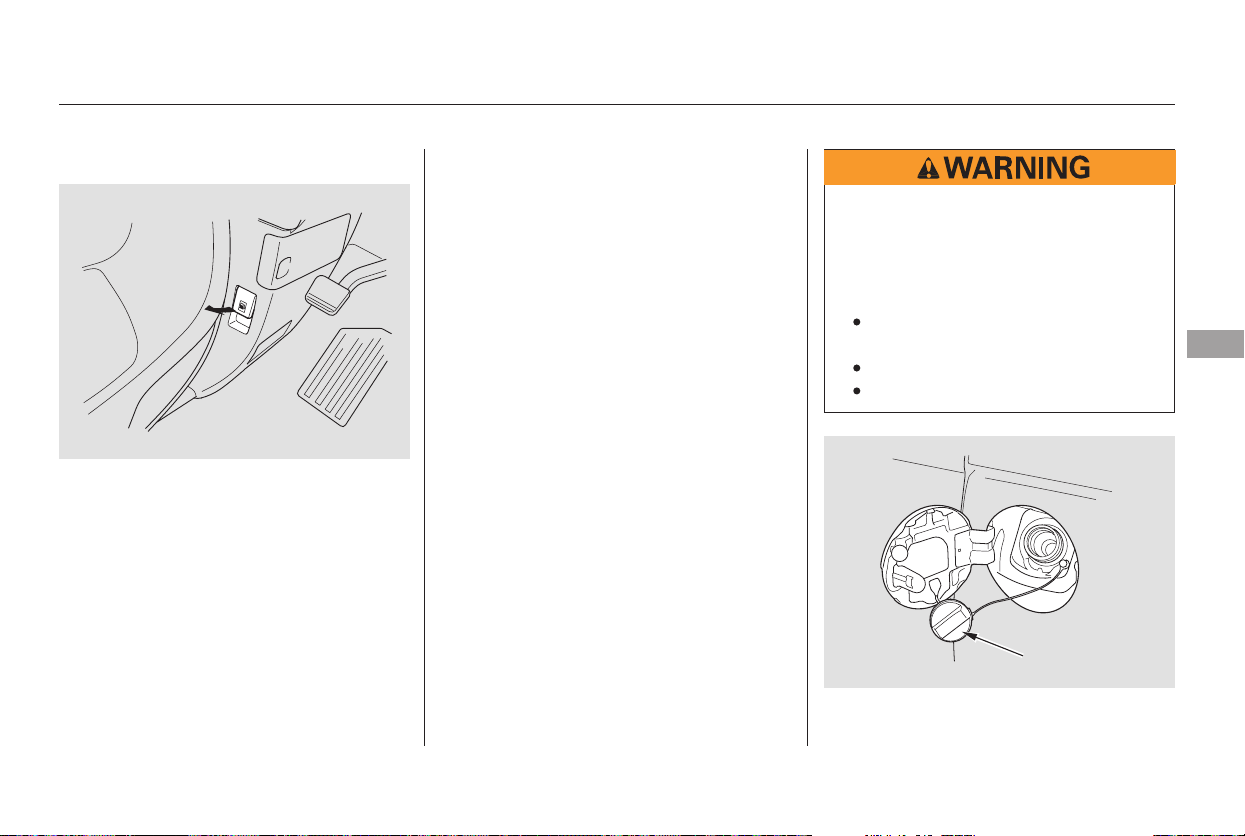
Before refueling, make sure the rear
sliding door on the driver’s side is
closed.
Park with the driver’s side closest
to the service station pump.
Stop filling the tank after the fuel
nozzle automatically clicks off. Do
not try to ‘‘top off’’ the tank. Leave
some room for the fuel to expand
with temperature changes.
even
though the tank is not full, there may
be a problem with your vehicle’s fuel
vapor recovery system. The system
helps keep fuel vapors from going
into the atmosphere. Consult your
dealer.
Open the fuel fill door by pulling
on the handle under the lower left
corner of the dashboard.
Remove the fuel fill cap slowly.
You may hear a hissing sound as
pressure inside the tank escapes.
The fuel fill cap is attached to the
fuel filler with a tether. Insert the
attachment on the fuel fill cap into
the slit on the fuel fill door.
1.
2.
3.
4.
CONTINUED
If the fuel nozzle keeps clicking off
Refueling
Service Station Procedures
Before Driving
279
FUEL FILL CAP
Gasoline is highly flammable
and explosive. You can be
burned or seriously injured
when handling fuel.
Stop the engine, and keep
heat, sparks, and flame away.
Handle fuel only outdoors.
Wipe up spills immediately.
Main Menu
Table of Contents
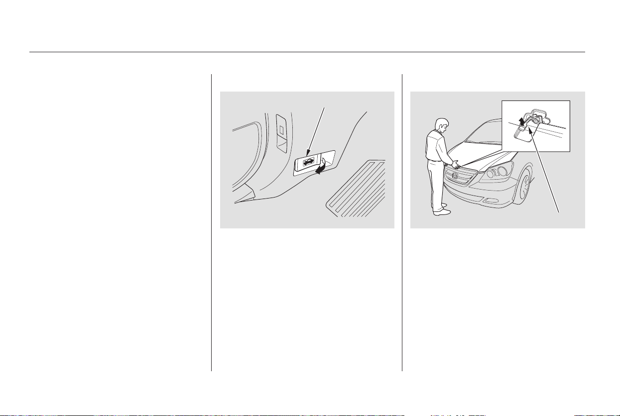
Park the vehicle, and set the
parking brake. Pull the hood
release handle located under the
lower left corner of the dashboard.
The hood will pop up slightly.
Put your fingers under the front
edge of the hood. The hood latch
handle is above the ‘‘H’’ logo. Pull
up on this handle until it releases
the hood. Lift the hood.
If the hood latch handle moves stiffly,
or you can open the hood without
lifting the handle, the mechanism
should be cleaned and lubricated.
Screw the fuel fill cap back on
until it clicks at least three times.
If you do not properly tighten the
cap, the malfunction indicator
lampmaycomeon(seepage ).
On the Touring model, you will
also see a ‘‘CHECK FUEL CAP’’
message on the multi-information
display.
Push the fuel fill door closed until
it latches.
1.
5.
6.
2.
372
Service Station Procedures
Opening and Closing the Hood
280
HOOD RELEASE HANDLE
LATCH
Main Menu
Table of Contents
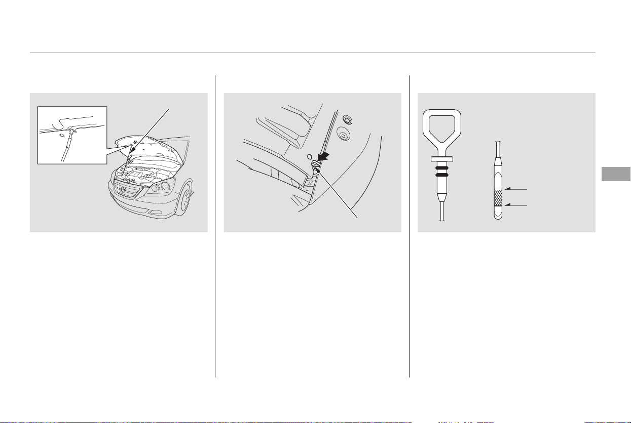
Wait a few minutes after turning the
engine off before you check the oil.
Remove the dipstick again, and
check the level. It should be
between the upper and lower
marks.
To close the hood, lift it up slightly to
remove the support rod from the
hole. Put the support rod back into
its holding clip. Lower the hood to
about a foot (30 cm) above the
fender, then let it drop. Make sure it
is securely latched.
Remove the dipstick (orange loop).
Wipe off the dipstick with a clean
cloth or paper towel.
Insert it all the way back in its hole.
Pull the support rod out of its clip
and insert the end into the hole on
thepassenger’ssideofthehood.
If it is near or below the lower mark,
see on page .
1.
3.
2.
3.
4.
328
Oil Check
Adding Engine Oil
Service Station Procedures
Before Driving
281
DIPSTICK
SUPPORT ROD
UPPER MARK
LOWER MARK
Main Menu
Table of Contents
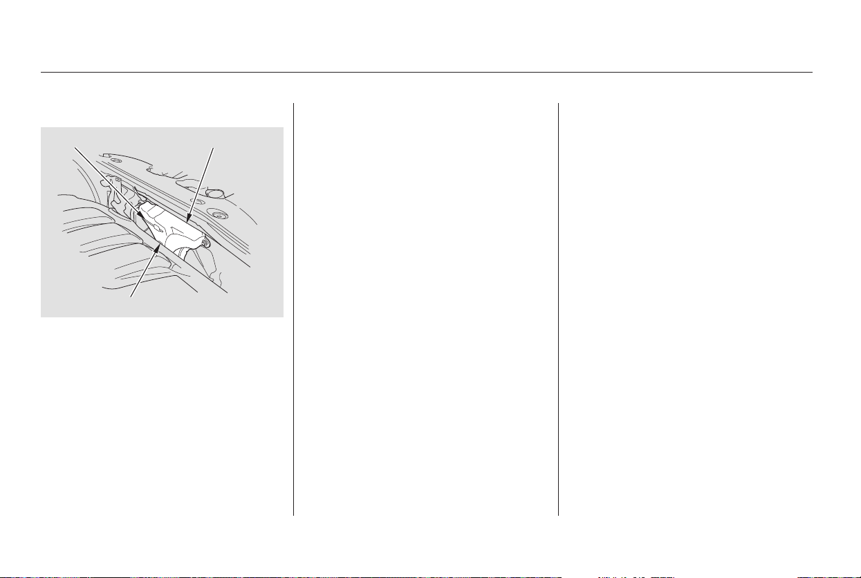
Look at the coolant level in the
radiator reserve tank. Make sure it is
between the MAX and MIN lines. If
it is below the MIN line, see
on page for
information on adding the proper
coolant.
Refer to
on page for information
about checking other items on your
vehicle.
323
331
Adding
Engine Coolant
Engine Coolant Check Owner’s Maintenance
Checks
Service Station Procedures
282
MAX RESERVE TANK
MIN
Main Menu
Table of Contents

Combine several short trips into
one.
The air conditioning puts an extra
load on the engine which makes it
usemorefuel.Usethefresh-air
ventilation when possible.
Always maintain your vehicle
according to the maintenance
messages. See
(page ).
an underinflated tire
causes more ‘‘rolling resistance,’’
which uses more fuel.
The build-up of snow or mud on
your vehicle’s underside adds
weight and rolling resistance.
Frequent cleaning helps your fuel
mileage and reduces the chance of
corrosion.
Drive moderately. Rapid
acceleration, abrupt cornering,
and hard braking use more fuel.
Always drive in the highest gear
possible.
Try to maintain a constant speed.
Everytimeyouslowdownand
speed up, your vehicle uses extra
fuel. Use cruise control when
appropriate.323
For example,
Fuel Economy
Improving Fuel Economy
Owner’s
Maintenance Checks
Before Driving
283
Main Menu
Table of Contents
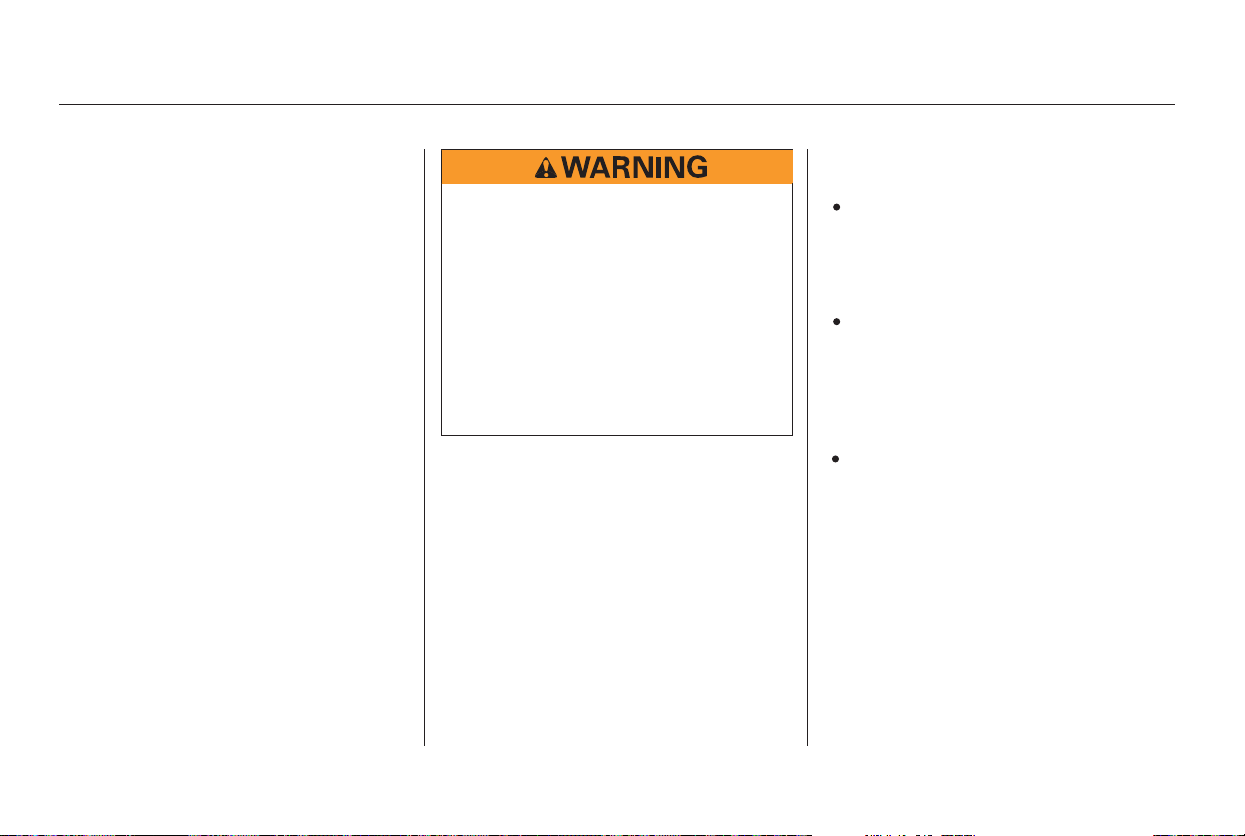
Your dealer has Honda accessories
that allow you to personalize your
vehicle. These accessories have
been designed and approved for your
vehicle, and are covered by warranty.
When properly installed, cellular
phones, alarms, two-way radios, and
low-powered audio systems should
not interfere with your vehicle’s
computer controlled systems, such
as your airbags and anti-lock brakes.
Before installing any accessory:
Make sure the accessory does not
obscure any lights, or interfere
with proper vehicle operation or
performance.
Modifying your vehicle, or installing
some non-Honda accessories, can
make it unsafe. Before you make any
modifications or add any accessories,
be sure to read the following
information.
Although non-Honda accessories
may fit on your vehicle, they may not
meet factory specifications, and
could adversely affect your vehicle’s
handling and stability (see page ).
Be sure electronic accessories do
not overload electrical circuits
(see page ) or interfere with
the proper operation of your
vehicle.
Before installing any electronic
accessory, have the installer
contact your dealer. If possible,
have your dealer inspect the final
installation.
285
376
Accessories
Accessories and Modifications
284
Improper accessories or
modifications can affect your
vehicle’s handling, stability, and
performance, and cause a
crash in which you can be hurt
or killed.
Follow all instructions in this
owner’s manual regarding
accessories and modifications.
Main Menu
Table of Contents

Some examples are:
Larger or smaller wheels and tires
can interfere with the operation of
your vehicle’s anti-lock brakes and
other systems.
Lowering the vehicle with a non-
Honda suspension kit that
significantly reduces ground
clearance can allow the
undercarriage to hit speed bumps
or other raised objects, which
could cause the airbags to deploy.
Raising your vehicle with a
non-Honda suspension kit can
affect the handling and stability.
Non-Honda wheels, because they
are a universal design, can cause
excessive stress on suspension
components.
Modifying your steering wheel or
any other part of your vehicle’s
safety systems could make the
systems ineffective.
If you plan to modify your vehicle,
consult your dealer.
See
on page .
Removing parts from your vehicle,
or replacing components with
non-Honda components could
seriously affect your vehicle’s
handling, stability, and reliability.
35
Modifying Your Vehicle
Additional Safety Precautions
Accessories and Modifications
Before Driving
285
Main Menu
Table of Contents
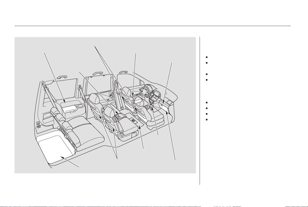
**
*
**
*
**
Your vehicle has several convenient
storage areas:
In-floor storage (with Lazy
Susan )
Glove box (upper and lower)
However, carrying too much cargo,
or improperly storing it, can affect
your vehicle’s handling, stability,
stopping distance, and tires, and
make it unsafe. Before carrying any
type of cargo, be sure to read the
following pages.
Roof-rack (if installed)
Rear compartment
Center pocket
Removable second row console
Rear cargo area, including the
second row seats when removed,
andthethirdrowseatwhenfolded
flat
Front door and seat-back pockets
: Touring model only
: EX and Touring models only
Carrying Cargo
286
REAR COMPARTMENT FRONT DOOR POCKET
SEAT-BACK POCKET
CARGO AREA
LOWER
GLOVE BOX
UPPER GLOVE
BOX
REMOVABLE
SECOND ROW
CONSOLE
CENTER
POCKET
SEAT-BACK POCKETS
IN-FLOOR STORAGE
(with Lazy Susan )
Main Menu
Table of Contents
×
−
The resulting figure equals the
available amount of cargo and
luggage load capacity.
If your vehicle will be towing a
trailer, the load from your trailer
will be transferred to your vehicle.
Consult this manual to determine
how this reduces the available
cargo and luggage load capacity of
your vehicle.
The maximum load for your vehicle
is:
Subtract the combined weight of
the driver and passengers from
the maximum load.
For example, If your vehicle is the
Touring model, and if there will be
five 150 lbs (70 kg) occupants in
your vehicle, the amount of available
cargo and luggage load capacity is
458 lbs (198 kg).
5 150 lbs (70 kg) = 750 lbs
(350 kg)
1,208 lbs (548 kg) 750 lbs (350 kg)
= 458 lbs (198 kg)
Determine the combined weight
of accessories, luggage, and cargo
beingloadedinthevehicle.The
weight may not safely exceed the
available cargo and luggage load
capacity calculated in step 4
[458 lbs (198 kg) in this example].
This figure includes, cargo,
accessories, and the tongue weight if
you are towing a trailer.
To determine the correct cargo and
luggage load limit:
Determine the combined weight
of the driver and passengers that
will be riding in your vehicle.
Locate the statement, ‘‘the
combined weight of occupants and
cargo should never exceed 1,208
lbs (548 kg)’’ on your vehicle’s
placard (on the driver’s doorjamb)
if your vehicle is the Touring
model, for example.
1.
2.
3.
4.
5.
6.
LX model: 1,349 lbs (612 kg)
EX model: 1,388 lbs (630 kg)
EX with Leather: 1,322 lbs (600 kg)
Touring model: 1,208 lbs (548 kg)
Carrying Cargo
Before Driving
287
Overloading or improper
loading can affect handling and
stability and cause a crash in
which you can be hurt or killed.
Follow all load limits and other
loading guidelines in this
manual.
Main Menu
Table of Contents

Store or secure all items that could
be thrown around and hurt
someone during a crash.
Be sure items placed on the floor
behind the front seats cannot roll
under the seats and interfere with
the pedals or seat operation.
Distribute cargo evenly on the
floor of the cargo area, placing the
heaviest items on the bottom and
as far forward as possible. Tie
down items that could be thrown
about the vehicle during a crash or
sudden stop.
If you carry large items that
prevent you from closing the
tailgate, exhaust gas can enter the
passenger area. To avoid the
possibility of
, follow the instructions
on page .
Keep the glove boxes closed while
driving. If either are open, a
passenger could be injured during
a crash or sudden stop.
If you place items near the rear
windows, be sure they are below
the bottom of the windows. If
cargo is higher, it could interfere
with proper operation of the side
curtain airbags.
If you carry any items on a roof
rack,besurethetotalweightof
the rack and the items does not
exceed 150 lb (68 kg).
If you use an accessory roof rack,
the roof rack weight limit may be
lower. Refer to the information that
came with your roof rack.
56
Carrying Items in the Passenger
Compartment
carbon monoxide
poisoning
Carrying Cargo in the Cargo Area
or on a Roof Rack
Carrying Cargo
288
Main Menu
Table of Contents
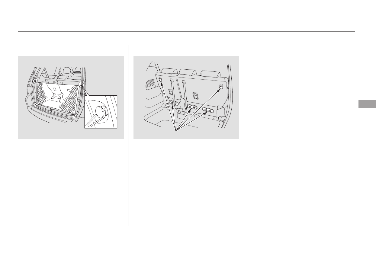
You can use the cargo net to secure
items in the cargo area, and store
small items between the two halves
of the net. To install the cargo net,
hook the loops on the four corners of
the net to the tabs at both sides of
the tailgate sill.
There are cargo hooks for plastic
grocery bags on the back of the third
row seat. They are designed to hold
light items. Heavy objects may
damage the hooks.
On EX and Touring models
Carrying Cargo
Cargo Net Cargo Hooks
Before Driving
289
CARGO HOOKS
Main Menu
Table of Contents

290
Main Menu

This section gives you tips on
starting the engine under various
conditions, and how to operate the
automatic transmission. It also
includes important information on
parking your vehicle, the braking
system, the vehicle stability assist
system, the tire pressure monitoring
system, and facts you need if you are
planning to tow a trailer.
........................Preparing to Drive . 292
.......................Starting the Engine . 293
..............Automatic Transmission . 294
..................................Parking Tips . 298
.............................Braking System . 299
...............Anti-lock Brakes (ABS) . 300
Vehicle Stability Assist (VSA)
........................................System . 301
Tire Pressure Monitoring System
......................................(TPMS) . 303
...........................Towing a Trailer . 306
Driving
Driving
291
Main Menu

Youshoulddothefollowingchecks
and adjustments before you drive
your vehicle.
Make sure all windows, mirrors,
and outside lights are clean and
unobstructed. Remove frost, snow,
or ice.
Check that the hood is fully closed.
Visually check the tires. If a tire
looks low, use a gauge to check its
pressure.
Check that any items you may be
carrying are stored properly or
fastened down securely.
Check the seat adjustment (see
page ).
Check the adjustment of the
inside and outside mirrors (see
page ).
Check the steering wheel
adjustment (see page ).
Make sure the doors and the
tailgate are securely closed and
locked.
Fasten your seat belt. Check that
your passengers have fastened
their seat belts (see page ).
When you start the engine, check
the gauges and indicators in the
instrument panel (see page ).
3.
2.
1.
4.
5.
6.
7.
8.
9.
10.
16
61
167
149
127
Preparing to Drive
292
Main Menu
Table of Contents
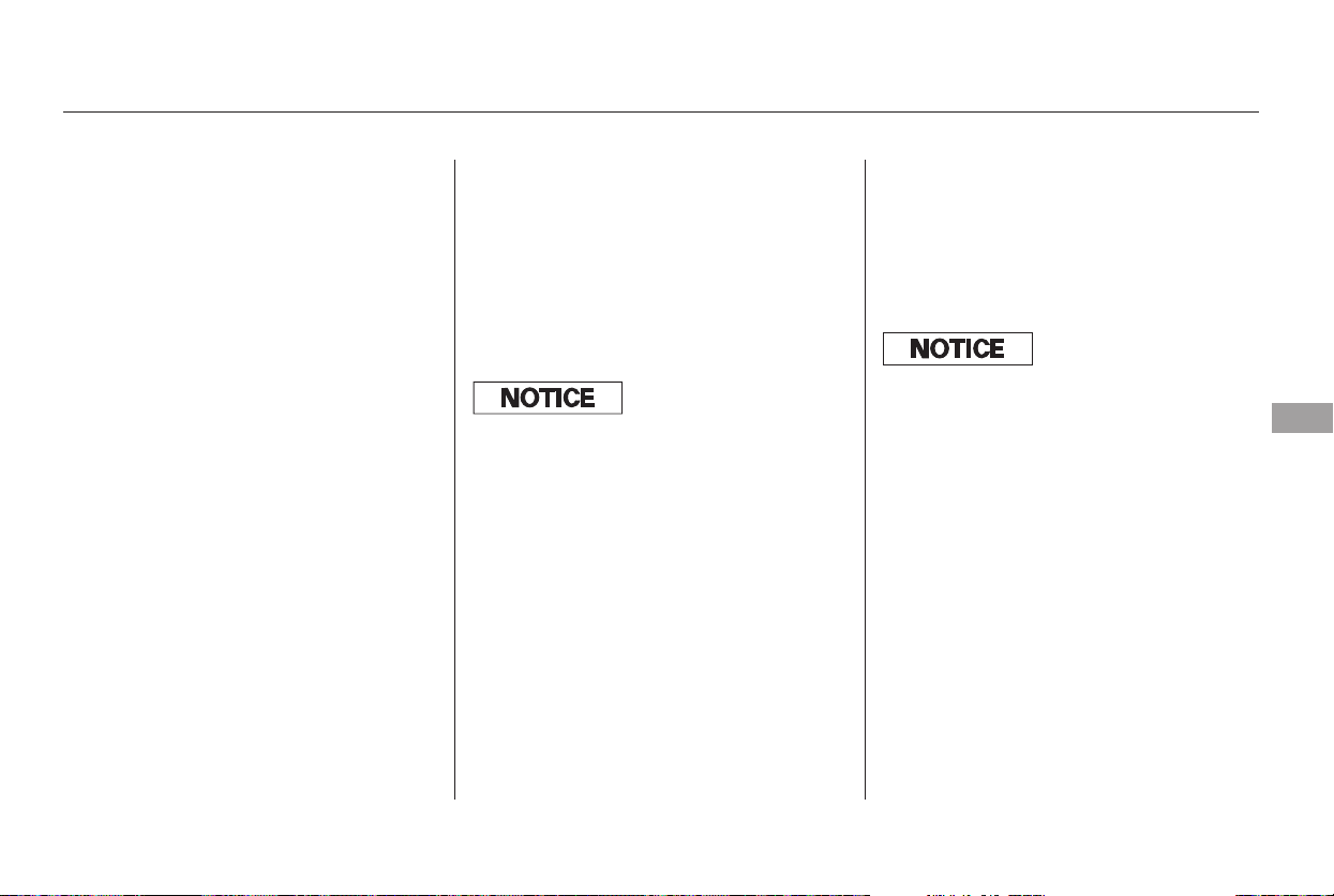
Apply the parking brake.
In cold weather, turn off all
electrical accessories to reduce
the drain on the battery.
Make sure the shift lever is in
Park. Press on the brake pedal.
If the engine fails to start, press
the accelerator pedal all the way
downandholdittherewhile
starting to clear flooding. If the
engine still does not start, return
to step 5.
Without touching the accelerator
pedal, turn the ignition key to the
START (III) position. Do not hold
the key in START for more than
15 seconds at a time. If the engine
does not start right away, pause
for at least 10 seconds before
trying again.
If the engine does not start within
15 seconds, or starts but stalls
right away, repeat step 4 with the
accelerator pedal pressed halfway
down. If the engine starts, release
pressure on the accelerator pedal
so the engine does not race.
5.
6.1.
2.
3.
4.
Starting the Engine
Driving
293
Immobilizer System
The engine is harder to start in cold
weather. Also, the thinner air f ound at
altitudes above 8,000 f eet (2,400
meters) adds to this problem.
The immobilizer system protects your
vehicle from thef t. If an improperly-
coded key (or other device) is used, the
engine’s f uel system is disabled. See
on page .129
Main Menu
Table of Contents
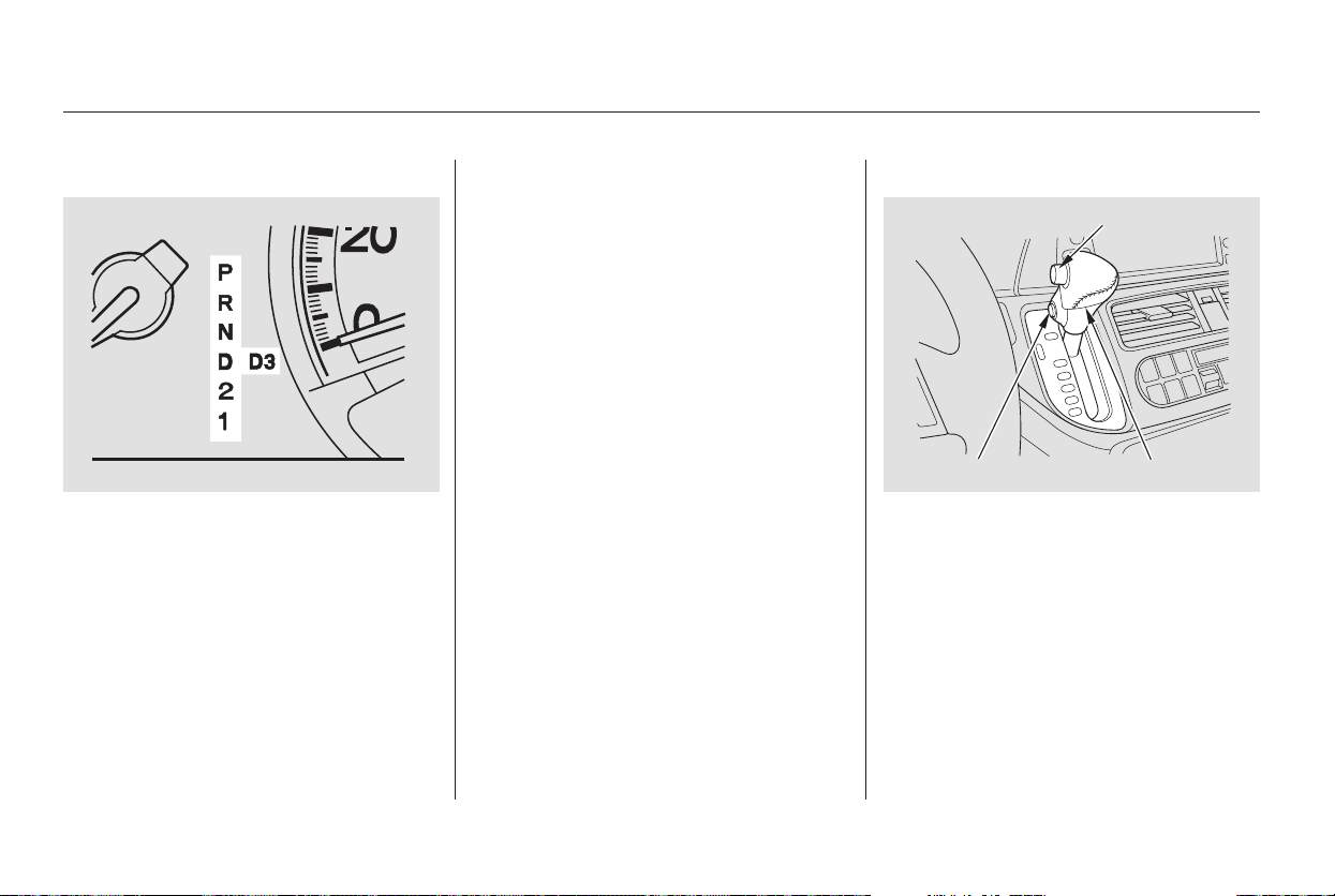
These indicators on the instrument
panel show which position the shift
lever is in.
The ‘‘D’’ indicator comes on for a
few seconds when you turn the
ignition switch to ON (II). If it
flashes while driving (in any shift
position), it indicates a possible
problem in the transmission.
If the malfunction indicator lamp
comes on along with the ‘‘D’’
indicator, there is a problem in the
automatic transmission control
system. Avoid rapid acceleration, and
have the transmission checked by
your dealer as soon as possible.
To shift from any position, press
firmly on the brake pedal and press
the release button on the side of the
shiftlever.Youcannotshiftoutof
Park when the ignition switch is in
the LOCK (0) or ACCESSORY (I)
position.
Automatic Transmission
Shift Lever Position Indicators Shifting
294
SHIFT LEVER
RELEASE BUTTON
D3 BUTTON
Main Menu
Table of Contents

−
−
−
−
This position mechani-
cally locks the transmission. Use
Park whenever you are turning off or
starting the engine. To shift out of
Park, you must press on the brake
pedal and have your foot off the
accelerator pedal. Press the release
button on the side of the shift lever
to move it.
If you have done all of the above and
still cannot move the lever out of
Park, see on
page .
Press the brake
pedal and press the release button to
shift from Park to Reverse. To shift
from Reverse to Neutral, come to a
completestopandthenshift.
Use Neutral if you
need to restart a stalled engine, or if
it is necessary to stop briefly with
the engine idling. Shift to the Park
position if you need to leave your
vehicle for any reason. Press on the
brake pedal when you are moving
the shift lever from Neutral to
another gear.
Use this position for
normal driving. The transmission
automatically selects a suitable gear
for your speed and acceleration. You
may notice the transmission shifting
up at higher speeds when the engine
is cold. This helps the engine warm
up faster.
297
CONTINUED
To shift from:
PtoR
RtoP
NtoR
Dto2
2to1
1to2
2toD
DtoN
NtoD
RtoN
DtoD
DtoD
Do this:
Press the brake pedal, and
press the release button.
Press the release button.
Move the lever.
Press the D button.
3
3
3
3
Park (P)
Shift Lock Release
Reverse (R)
Neutral (N)
Drive (D)
Automatic Transmission
Driving
295
Main Menu
Table of Contents

−
−
−
If you exceed the maximum speed
for the gear you are in, the engine
speed will enter into the tachometer’s
red zone. If this occurs, you may feel
the engine cut in and out. This is
caused by a limiter in the engine’s
computer controls. The engine will
run normally when you reduce the
RPM below the red zone.
To use D , press the
D button when the shift lever is in
the ‘‘D’’ position. This position is simi-
lartoD,exceptonlythefirstthree
gears are selected instead of all five.
Use D when towing a trailer in hilly
terrain, or to provide engine braking
when going down a steep hill. D can
also keep the transmission from
cycling between third and fourth
gears in stop-and-go driving.
This position locks
the transmission in second gear. It
does not downshift to first gear
when you come to a stop.
Use Second gear:
For more power when climbing.
To increase engine braking when
going down steep hills.
For starting out on a slippery
surface or in deep snow.
When driving downhill with a
trailer.
This position locks the
transmission in First gear. By upshift-
ing and downshifting through 1, 2,
and D, you can operate this
transmission much like a manual
transmission without a clutch pedal.
3
3
3
3
Automatic Transmission
Engine Speed LimiterDrive (D )
Second (2)
First (1)
3
296
Main Menu
Table of Contents
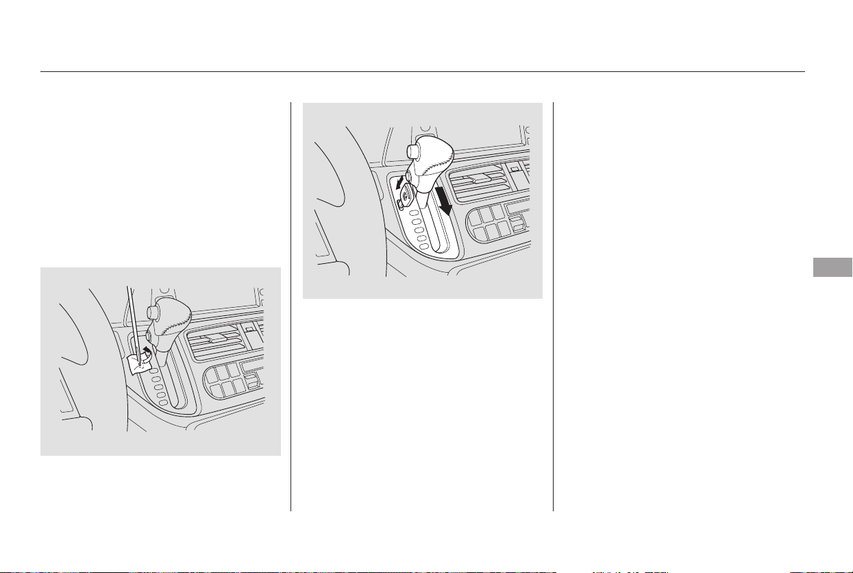
Do this if pushing on the brake pedal
and pressing the release button does
not shift the transmission out of
park:
Set the parking brake.
Make sure the ignition switch is in
the LOCK (0) position.
Put a cloth on the edge of the shift
lock release slot cover. Using a
small flat-tipped screwdriver or a
metal fingernail file, carefully pry
on the edge of the cover to remove
it.
Remove the key from the shift
lock release slot, then install the
cover. Press the brake pedal, and
restart the engine.
If you need to use the shift lock
release, it means your vehicle is
developing a problem. Have it
checked by your dealer.
Push down on the key while you
pull the shift lever towards you
and move it out of Park to Neutral.
Insert the key in the shift lock
release slot.
5.
6.
4.
3.
1.
2.
Automatic Transmission
Shift Lock Release
Driving
297
Main Menu
Table of Contents

Always use the parking brake when
you park your vehicle. Make sure
the parking brake is set firmly or
your vehicle may roll if it is parked
on an incline.
Set the parking brake before you put
the transmission in Park. This keeps
the vehicle from moving and putting
pressure on the parking mechanism
in the transmission.
If the vehicle is facing uphill, turn
the front wheels away from the
curb.
If the vehicle is facing downhill,
turn the front wheels toward the
curb.
Make sure the parking brake is
fully released before driving away.
Driving with the parking brake
partially set can overheat or
damage the rear brakes.
Make sure the moonroof and the
windows are closed.
Never park over dry leaves, tall
grass, or other flammable
materials. The hot three way
catalytic converter could cause
these materials to catch on fire.
Lock the doors and the tailgate.
Place any packages, valuables, etc.
in the cargo area, or take them
with you.
Turn off the lights.
Parking Tips
Parking
298
Main Menu
Table of Contents

Check the brakes after driving
through deep water. Apply the
brakes moderately to see if they feel
normal. If not, apply them gently and
frequently until they do. Be extra
cautious in your driving.
The hydraulic system that operates
the brakes has two separate circuits.
Each circuit works diagonally across
the vehicle (the left-front brake is
connected with the right-rear brake,
etc.). If one circuit should develop a
problem, you will still have braking
at two wheels.
If the brake pads need replacing, you
will hear a distinctive, metallic
screeching sound when you apply
the brake pedal. If you do not have
the brake pads replaced, they will
screech all the time. It is normal for
the brakes to occasionally squeal or
squeak when you apply them.
Your vehicle is equipped with disc
brakes at all four wheels. A power
assist helps reduce the effort needed
on the brake pedal. The anti-lock
brake system (ABS) helps you retain
steering control when braking very
hard.
Constant application of the brakes
when going down a long hill builds
up heat and reduces their effective-
ness. Use the engine to assist the
brakes by taking your foot off the
accelerator and downshifting to a
lower gear.
Resting your foot on the pedal keeps
the brakes applied lightly, builds up
heat, and reduces their effectiveness.
It also keeps your brake lights on all
the time, confusing drivers behind
you.
Braking System
Braking System Design
Brake Wear Indicators
Driving
299
Main Menu
Table of Contents
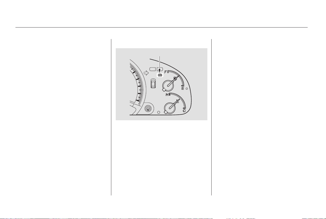
*
You should never pump the brake pedal.
Let the ABS work for you by always
keeping firm, steady pressure on the
brake pedal. This is sometimes
referred to as ‘‘stomp and steer.’’
You will feel a pulsation in the brake
pedal when the ABS activates, and
you may hear some noise. This is
normal: it is the ABS rapidly
pumpingthebrakes.Ondry
pavement, you will need to press on
thebrakepedalveryhardbeforethe
ABS activates. However, you may
feel the ABS activate immediately if
you are trying to stop on snow or ice.
If the ABS indicator comes on, the
anti-lock function of the braking
system has shut down. The brakes
still work like a conventional system,
but without anti-lock. You should
have your dealer inspect your vehicle
as soon as possible. on loose or
uneven surfaces, such as gravel or
snow, than a vehicle without anti-
lock.
Always steer moderately
when you are braking hard. Severe
or sharp steering wheel movement
can still cause your vehicle to veer
into oncoming traffic or off the road.
such as trying to take a
corner too fast or making a sudden
lane change.
it only helps with steering
control during braking.
The anti-lock brake system (ABS)
helps prevent the brakes from
locking up, and helps you retain
steering control by pumping the
brakes rapidly, much faster than a
person can do it.
Anti-lock Brakes (ABS)
ABS Indicator
A vehicle with ABS may require a
longer distance to stop
ABS cannot prevent a loss of
stability.
ABS will not prevent a skid that
results from changing direction
abruptly,
ABS does not reduce the time or
distance it takes to stop the
vehicle;
Important Saf ety Reminders
300
ABS INDICATOR
Main Menu
Table of Contents
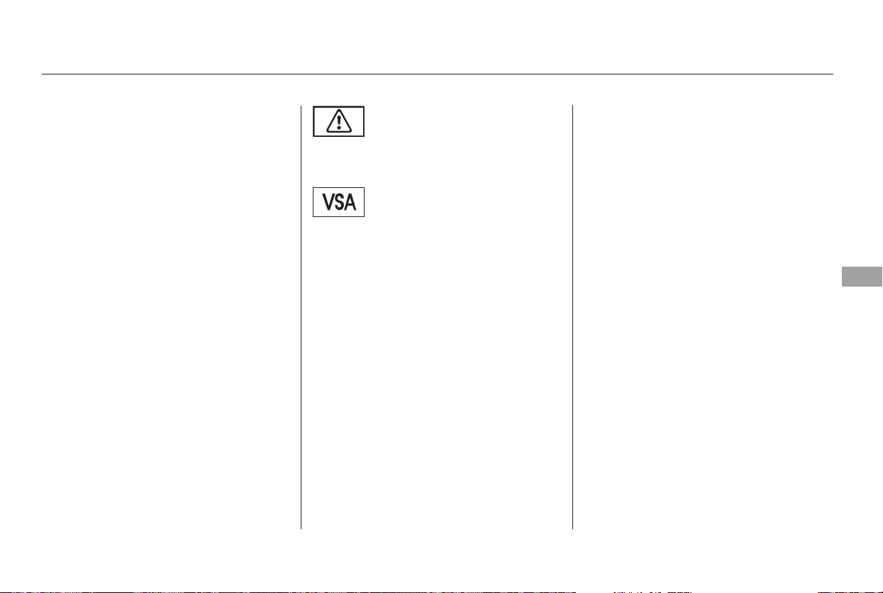
CONTINUED
If the VSA system indicator comes
on while driving, pull to the side of
theroadwhenitissafe,andturnoff
the engine. Reset the system by
restarting the engine. If the VSA
system indicator stays, or comes
back on while driving, have the VSA
system inspected by your dealer.
If the indicator does not come on
when the ignition switch is turned to
ON (II), there may be a problem
with the VSA system. Have your
dealer inspect your vehicle as soon
as possible.
You will also see a ‘‘CHECK VSA
SYSTEM’’ message on the multi-
information display if there is a
problem with the VSA system.
The vehicle stability assist (VSA)
system helps to stabilize the vehicle
during cornering if the vehicle turns
more or less than desired. It also
assists you in maintaining traction
while accelerating on loose or
slippery road surfaces. It does this
by regulating the engine’s output,
and by selectively applying the
brakes.
The VSA system cannot enhance the
vehicle’s driving stability in all
situations and does not control your
vehicle’s entire braking system. It is
still your responsibility to drive and
corner at reasonable speeds and to
leave a sufficient margin of safety.
When VSA activates, you may notice
that the engine does not respond to
the accelerator in the same way it
does at other times.
When VSA activates, you will see the
VSA activation indicator blink.
If the low tire pressure indicator
comes on (see page ), or the
multi-information display shows a
‘‘CHECK TPMS SYSTEM’’ message
(see page ), the VSA system
automatically turns on even if you
turn it off with the VSA OFF button.
66
84
On Touring model only
Vehicle Stability Assist (VSA) System
VSA Activation Indicator
VSA System Indicator
Driving
301
Main Menu
Table of Contents
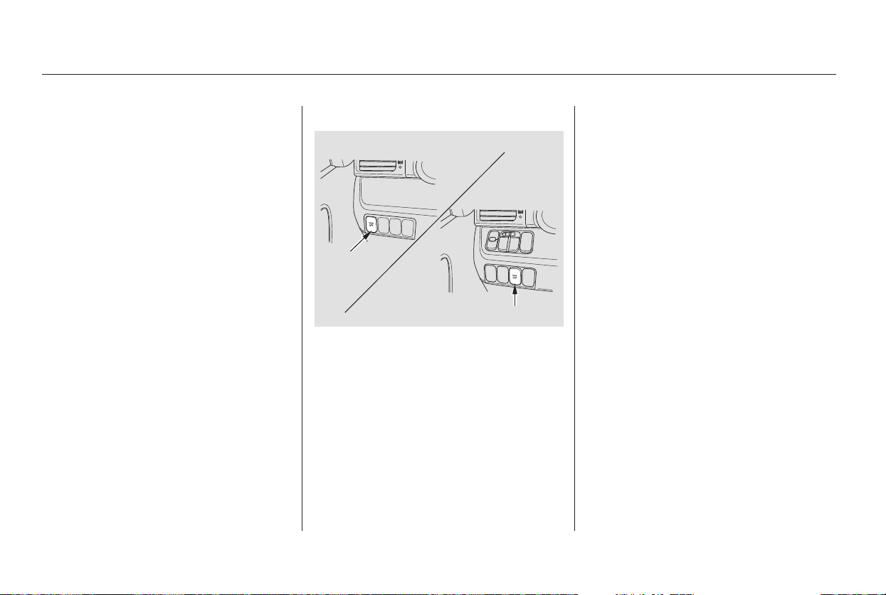
This button is under the driver’s side
vent. Press it to turn the VSA system
on or off.
VSA is turned on every time you
start the engine, even if you turned it
off the last time you drove the
vehicle.
Driving with varying tire or wheel
sizes may cause the VSA to
malfunction. When replacing tires,
make sure they are of the same size
and type as your original tires (see
page ).
Deactivate the VSA system if you
need to drive with the compact spare
tire installed (all models except U.S.
Touring).
If you install winter tires, make sure
they are the same size as those that
were originally supplied with your
vehicle. Exercise the same caution
during winter driving as you would if
your vehicle was not equipped with
VSA.
Without VSA, your vehicle still has
normal braking and cornering ability,
but it does not have VSA traction and
stability enhancement.
When VSA is off, the VSA activation
indicator comes on as a reminder.
349
Vehicle Stability Assist (VSA) System
VSA and Tire SizesVSA OFF Button
302
VSA OFF
SWITCH
VSA OFF SWITCH
LX and EX models
Touring model
Main Menu
Table of Contents
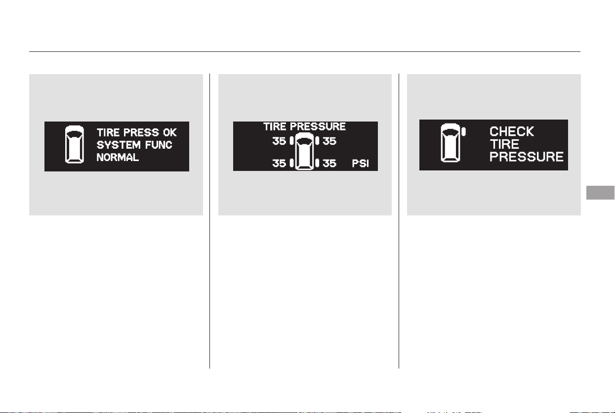
Your vehicle is equipped with a tire
pressure monitoring system (TPMS)
that turns on every time you start the
engine and monitors the pressure in
your tires while driving.
You will see the above display on the
multi-information display when you
turn the ignition switch to ON (II)
andpresstheINFObuttononthe
steering wheel six times.
To see the inflation pressures of all
four tires, press the SEL/RESET
buttononthesteeringwheel.The
display changes as shown above.
Each tire has its own pressure
sensor. If the air pressure of a tire
becomes significantly low, the
sensor in that tire immediately sends
a signal that causes the low tire
pressure indicator in the instrument
panel to come on. If this happens,
you will see which tire is losing the
pressure in the multi-information
display along with a ‘‘CHECK TIRE
PRESSURE’’ message.
CONTINUED
On U.S. Touring model only
Tire Pressure Monitoring System (TPMS)
Driving
303
Main Menu
Table of Contents
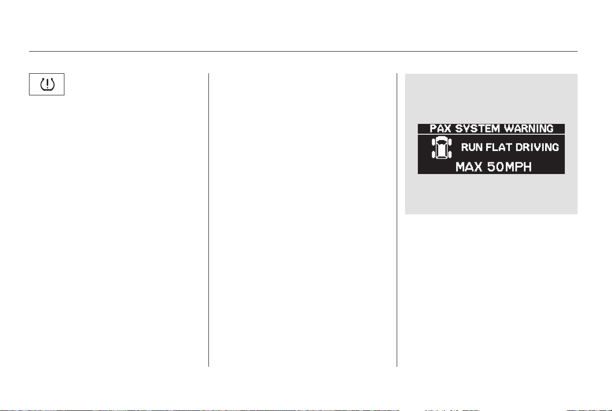
If a flat tire is causing the low tire
pressure indicator to come on, you
will see the above message in the
multi-information display.
It is possible that the pressures
shown in the multi-information
display and the pressures you
manually measure are slightly
different.
If the difference is significant and
you cannot make the low tire
pressure indicator and message in
the multi-information display go out
after inflating the tires to the
specified values, have your dealer
check the system as soon as possible.
When the low tire pressure indicator
is on, one or more of your tires is
significantly under-inflated. You
should stop and check your tires as
soon as possible, and inflate them to
the proper pressure as indicated on
the vehicle’s tire information placard.
Driving on a significantly under-
inflated tire causes the tire to
overheat and can lead to tire failure.
Under-inflation also reduces fuel
efficiency and tire tread life, and may
affect the vehicle’s handling and
stopping ability. Each tire, including
the spare should be checked
monthly when cold, and set to the
recommended inflation pressure as
specified in the vehicle placard and
owner’s manual (see page ).346
Tire Pressure Monitoring System (TPMS)
Low Tire Pressure
Indicator
304
Main Menu
Table of Contents
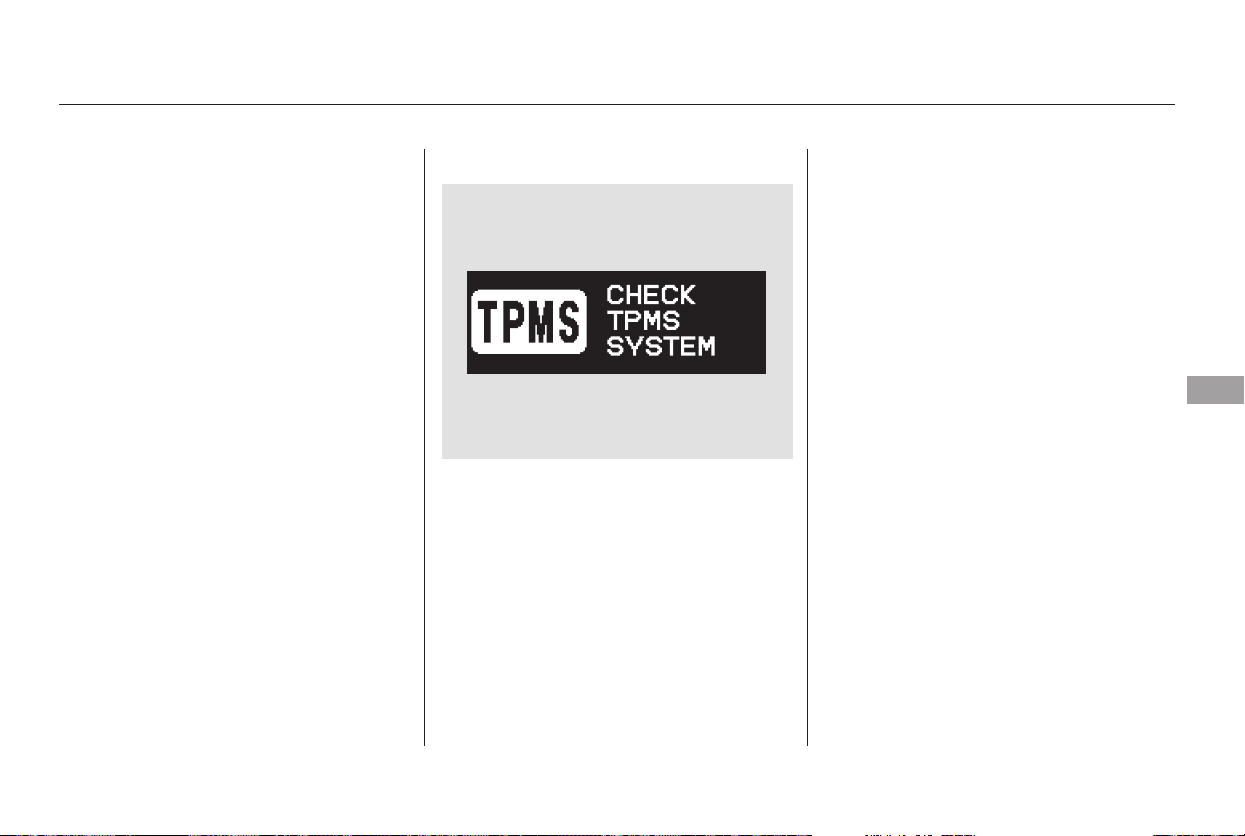
The tires on your vehicles are PAX
tires, and you cannot replace or
repair a flat tire. Replacement or
repair of tires must be performed by
a Honda dealer or an authorized
Michelin PAX system dealer.
If the low tire pressure indicator
comes on, or the multi-information
display shows a ‘‘CHECK TPMS
SYSTEM’’ message, the VSA system
automatically turns on even when
the VSA system is turned off by
pressing the VSA OFF button (see
page ). If this happens, you
cannot turn the VSA system off by
pressing the VSA OFF button again.
If there is a problem with the TPMS,
you will see the above message in
the multi-information display.
If you see this message, the system
is off and is not monitoring the tire
pressures. Have the system checked
by your dealer as soon as possible.
For more information on the
Michelin PAX system, refer to page
.
Because your vehicle is equipped
with the Michelin PAX system, you
can continue to drive up to about 125
miles (200 km). If you have a flat tire,
take your vehicle to the nearest
Honda dealer or authorized Michelin
PAX system dealer.
301
356
Tire Pressure Monitoring System (TPMS)
Changing a Tire with TPMS
TPMS System Failure
Driving
305
Main Menu
Table of Contents
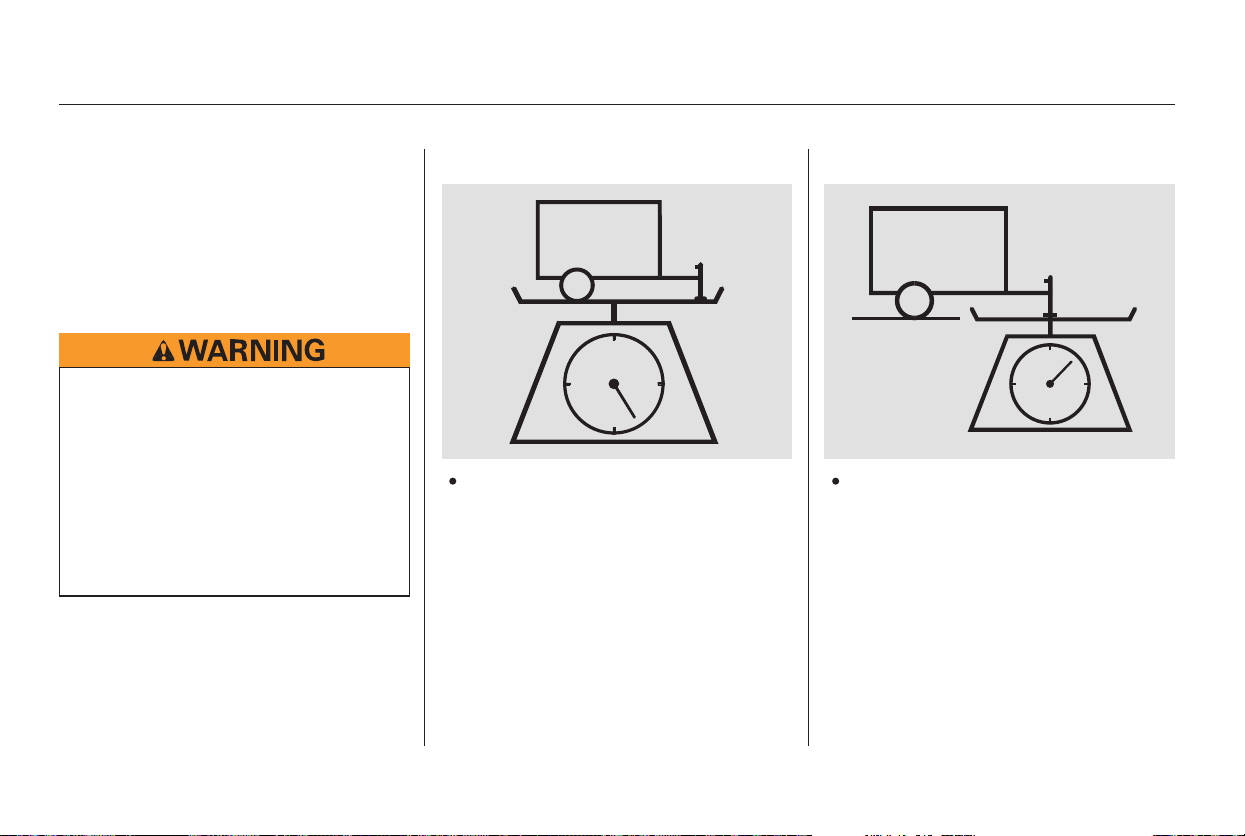
Your vehicle has been designed to
primarily carry passengers and their
cargo. You can also use it to tow a
trailer if you carefully observe the
load limits, use the proper equipment,
and follow the guidelines in this
section.
The
maximum allowable weight of the
trailer and everything in or on it
depends on several factors. See
page for the driving limits for
your towing situation. Towing a
load that is too heavy can seriously
affect your vehicle’s handling and
performance. It can also damage
the engine and drivetrain.
The weight that
the tongue of a fully-loaded trailer
puts on the hitch should be
approximately 10 percent of the
total trailer weight. Too much
tongue load reduces front-tire
traction and steering control. Too
little tongue load can make the
trailer unstable and cause it to
sway.
307
Towing a Trailer
Load Limits
Total Trailer Weight: Tongue Load:
306
Exceeding any load limit or
improperly loading your vehicle
and trailer can cause a crash in
which you can be seriously hurt
or killed.
Check the loading of your
vehicle and trailer carefully
beforestartingtodrive.
Main Menu
Table of Contents
*
*
*
**
*
*
*
*
Maximum Total Trailer Weight
Including driver. Based on 150 lbs (70 kg) per occupant.
Number of
Occupants
1
2
3
4
5
6
7
8
See page for information about fluid coolers.
Equipped with transmission cooler
and power steering fluid cooler
3,500 lbs (1,580 kg)
3,350 lbs (1,520 kg)
3,200 lbs (1,450 kg)
3,050 lbs (1,380 kg)
2,900 lbs (1,310 kg)
2,750 lbs (1,250 kg)
2,600 lbs (1,180 kg) 1,550 lbs (700 kg)
650 lbs (290 kg)
1:
2:
3:
4:
LX and EX models
Touring model
309
The maximum allowable weight of
the vehicle, all occupants, all cargo,
and the tongue load is 5,952 lbs
(2,700 kg).
The maximum allowable weight of
the fully loaded vehicle and trailer
is 8,410 lbs (3,815 kg) (see page
).
To achieve a proper tongue load,
start by loading 60 percent of the
load toward the front of the trailer
and 40 percent toward the rear, then
re-adjust the load as needed.
The maximum allowable weight of
the vehicle, all occupants, all cargo,
and the tongue load must not
exceed 2,833 lbs (1,285 kg) on the
front axle, and 3,197 lbs (1,450 kg)
on the rear axle.
386
1
3
2
34
Towing a Trailer
Gross Vehicle Weight Rating
(GVWR):
Gross Combined Weight Rating
(GCWR):
Gross Axle Weight Rating
(GAWR):
Driving
307
Main Menu
Table of Contents

The best way to confirm that vehicle
and trailer weights are within limits
is to have them checked at a public
scale.
Using a suitable scale or a special
tongue load gauge, check the tongue
load the first time you set up a
towing combination (a fully-loaded
vehicle and trailer), then recheck the
tongue load whenever the conditions
change.
If the total trailer weight is more
than 1,850 lbs (840 kg), you must
also use a weight distributing hitch.
This device transfers weight from
the vehicle’s rear wheels to the front
wheels, and to the trailer’s wheels.
Carefully follow the hitch maker’s
instructions for proper installation
and adjustment.
Always use safety chains when you
tow a trailer. Make sure the chains
are secured to the trailer and hitch,
and that they cross under the tongue
and can catch the trailer if it
becomes unhitched. Leave enough
slack to allow the trailer to turn
corners easily, but do not let the
chains drag on the ground.
Towing generally requires a variety
of supplemental equipment,
depending on the size of your trailer,
how much load you are towing, and
where you tow. To ensure the best
quality, we recommend that you
purchase Honda equipment
whenever possible.
Discuss your needs with your trailer
sales or rental agency, and follow the
guidelines in this section. Also make
sure that all equipment is properly
installed and meets federal, state,
province, and local regulations.
Any hitch used on your vehicle must
be properly bolted to the underbody,
using the six threaded holes
provided. A hitch and the required
fluid coolers designed especially for
your Odyssey can be obtained from
your Honda dealer.
Towing a Trailer
Checking Loads Towing Equipment and
Accessories
Weight Distributing Hitch
Safety Chains
Hitches
308
Main Menu
Table of Contents

CONTINUED
If you choose electric brakes, be
sure they are electrically actuated.
Do not attempt to tap into your
vehicle’s hydraulic system. No
matter how successful it may seem,
any attempt to attach trailer brakes
to your vehicle’s hydraulic system
will lower braking effectiveness and
create a potential hazard.
Trailer lights and equipment must
comply with federal, state, province,
and local regulations. Check the
requirements for the areas where
you plan to tow, and use only
equipment designed for your vehicle.
If the total trailer weight exceeds
2,000 lbs (900 kg), you should install
a sway control device to minimize
swaying that can occur in crosswinds
and in normal and emergency
driving maneuvers. Your trailer
maker can tell you what kind of sway
control you need and how to install it.
To help prevent overheating, a
transmission fluid cooler and a
power steering fluid cooler are
required for trailer towing. These
coolers are available only from your
Honda dealer.
Honda recommends that any trailer
having a total weight of 1,000 lbs
(450 kg) or more be equipped with
its own electric or surge-type brakes.
Seeyourtrailerdealerformore
information on installing electric
brakes.
Towing a Trailer
Trailer Brakes Trailer LightsSway Control
Transmission Fluid Cooler and
Power Steering Fluid Cooler
Driving
309
Main Menu
Table of Contents
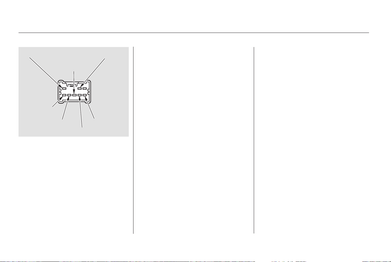
+
+
To use the trailer lighting connector,
you will need a wiring harness and
converter. This comes with the
Honda hitch (see page ), or it
may be obtained separately from
your dealer.
If you use a non-Honda trailer
lighting harness and converter, you
can get the connector and pins that
mate with the connector in your
vehicle from your dealer.
Since lighting and wiring vary by
trailer type and brand, you should
have a qualified technician install a
suitable connector between the
vehicle and the trailer. Improper
equipment or installation can cause
damage to your vehicle’s electrical
system and affect your vehicle
warranty.
When towing a trailer, we
recommend that you carry a full-size
spare wheel and tire for your vehicle
and trailer. If you use the compact
sparetirethatcamewithyour
vehicle, it could adversely affect
vehicle handling. See page for
proper tire size, page for how to
store a full size wheel and tire, and
page for information on
changing a flat tire.
Askyourtrailersalesorrental
agency if any other items are
recommended or required for your
towing situation.
Many states and provinces require
special outside mirrors when towing
a trailer. Even if they don’t, you
should install special mirrors if you
cannot clearly see behind you, or if
the trailer creates a blind spot.
Because of the Michelin PAX system,
youmustnotchangeaflattireby
yourself, or use a compact spare tire
on your vehicle.
Remember to unhitch the trailer
before changing a flat. Ask your
trailer sales or rental agency where
and how to store the trailer’s spare
tire.
Your vehicle has a trailer lighting
connector behind the right side
panel in the cargo area. Refer to the
drawing above for the purpose of
each pin.
308
349
364
360
U.S. Touring model
Spare Tires
Additional Towing Equipment
Towing a Trailer
310
GROUND
LEFT TURN SIGNAL
SMALL LIGHTS
B HAZARD
B HAC
RIGHT TURN
SIGNAL
SMALL LIGHTS
Main Menu
Table of Contents

When preparing to tow, and before
driving away, be sure to check the
following:
The vehicle has been properly
serviced, and the tires, brakes,
suspension, cooling system, and
lights are in good operating
condition.
The trailer has been properly
serviced and is in good condition.
All weights and loads are within
limits.
Thehitch,safetychains,andany
other attachments are secure.
All items in or on the trailer are
properly secured and cannot shift
while you drive.
Your vehicle tires and spare are
properly inflated, and the trailer
tires and spare are inflated as
recommended by the trailer
maker.
The added weight, length, and
height of a trailer will affect your
vehicle’s handling and performance,
so driving with a trailer requires
some special driving skills and
techniques.
Foryoursafetyandthesafetyof
others,taketimetopracticedriving
maneuvers before heading for the
open road, and follow the guidelines
below.
Drive slower than normal in all
driving situations, and obey posted
speed limits for vehicles with trailers.
Use the D position when towing a
trailer on level roads. Do not exceed
55 mph (88 km/h). At higher speeds,
the trailer may sway or affect vehicle
handling.
Towing a Trailer
Pre-Tow Checklist Driving Safely With a Trailer
Towing Speeds and Gears
Driving
311
Main Menu
Table of Contents

Maketurnsmoreslowlyandwider
than normal. The trailer tracks a
smaller arc than your vehicle, and it
canhitorrunoversomethingthe
vehicle misses. Allow more time and
distance for braking. Do not brake or
turn suddenly as this could cause the
trailer to jackknife or turn over.
When climbing hills, closely watch
your temperature gauge. If it nears
the red mark, turn the air
conditioning off, reduce speed and, if
necessary, pull to the side of the
road to let the engine cool.
If the automatic transmission shifts
frequently while going up a hill, shift
to D .
Always drive slowly and have
someone guide you when backing up.
Grip the of the steering
wheel; then turn the wheel to the left
to get the trailer to move to the left,
andturnthewheelrighttomovethe
trailer to the right.
Follow all normal precautions when
parking, including putting the
transmission in Park and firmly
setting the parking brake. Also, place
wheel chocks at each of the trailer’s
tires.
If you must stop when facing uphill,
use the foot brake or parking brake.
Do not try to hold the vehicle in
placebypressingontheaccelerator,
as this can cause the automatic
transmission to overheat.
When driving down hills, reduce
your speed, and shift down to 2nd
gear. Do not ‘‘ride’’ the brakes, and
remember, it will take longer to slow
downandstopwhentowingatrailer.
Crosswinds and air turbulence
caused by passing trucks can disrupt
your steering and cause trailer
swaying. When being passed by a
large vehicle, keep a constant speed,
and steer straight ahead. Do not try
to make quick steering or braking
corrections.
3
bottom
Towing a Trailer
Making Turns and Braking
Driving on Hills
Backing Up
Parking
Handling Crosswinds and Buff eting
312
Main Menu
Table of Contents

This section explains why it is
important to keep your vehicle well
maintained and how to follow basic
maintenance safety precautions.
......................Maintenance Safety . 314
....................Maintenance Minder . 315
....................Maintenance Record . 325
..............................Fluid Locations . 327
........................Adding Engine Oil . 328
.........Changing the Oil and Filter . 329
..............................Engine Coolant . 331
....................Windshield Washers . 333
....Automatic Transmission Fluid . 334
....................................Brake Fluid . 335
....................Power Steering Fluid . 336
....................................Timing Belt . 336
.............................................Lights . 337
................Cleaning the Seat Belts . 343
.....................................Floor Mats . 343
.................................Wiper Blades . 344
...............................................Tires . 346
...................Checking the Battery . 352
.............................Vehicle Storage . 353
This section also includes
instructions on how to read the
maintenance messages in the
odometer/trip meter display or
multi-Information display, a
maintenance record, and instructions
for simple maintenance tasks you
may want to take care of yourself.
If you have the skills and tools to
perform more complex maintenance
tasks on your vehicle, you may want
to purchase the service manual. See
page for information on how to
obtain a copy, or see your dealer.
401
Maintenance
Maintenance
313
Main Menu
To eliminate potential hazards, read
the instructions before you begin,
and make sure you have the tools
and skills required.
Do
not run the engine unless
instructed to do so.
Some of the most important safety
precautions are given here. However,
we cannot warn you of every
conceivable hazard that can arise in
performing maintenance. Only you
can decide whether or not you
should perform a given task.
Make sure your vehicle is parked
on level ground, the parking brake
is set, and the engine is off.
To clean parts, use a commercially
available degreaser or parts
cleaner, not gasoline.
To reduce the possibility of fire or
explosion, keep cigarettes, sparks,
and flames away from the battery
and all fuel-related parts.
Wear eye protection and
protective clothing when working
with the battery or compressed air.
Be sure there is
adequate ventilation whenever you
operate the engine.
Let the
engine and exhaust system cool
before touching any parts.
All service items not detailed in this
section should be performed by a
certified technician or other qualified
mechanic.
Maintenance Safety
Important Safety Precautions
Injury from moving parts.
Potential Vehicle Hazards
Carbon Monoxide poison from
engine exhaust.
Burns from hot parts.
314
Failure to properly follow
maintenance instructions and
precautions can cause you to
be seriously hurt or killed.
Always follow the procedures
and precautions in this owner’s
manual.
Improperly maintaining this
vehicle or failing to correct a
problem before driving can
cause a crash in which you can
be seriously hurt or killed.
Always follow the inspection,
maintenance recommendations,
and schedules in this owner’s
manual.
Main Menu
Table of Contents
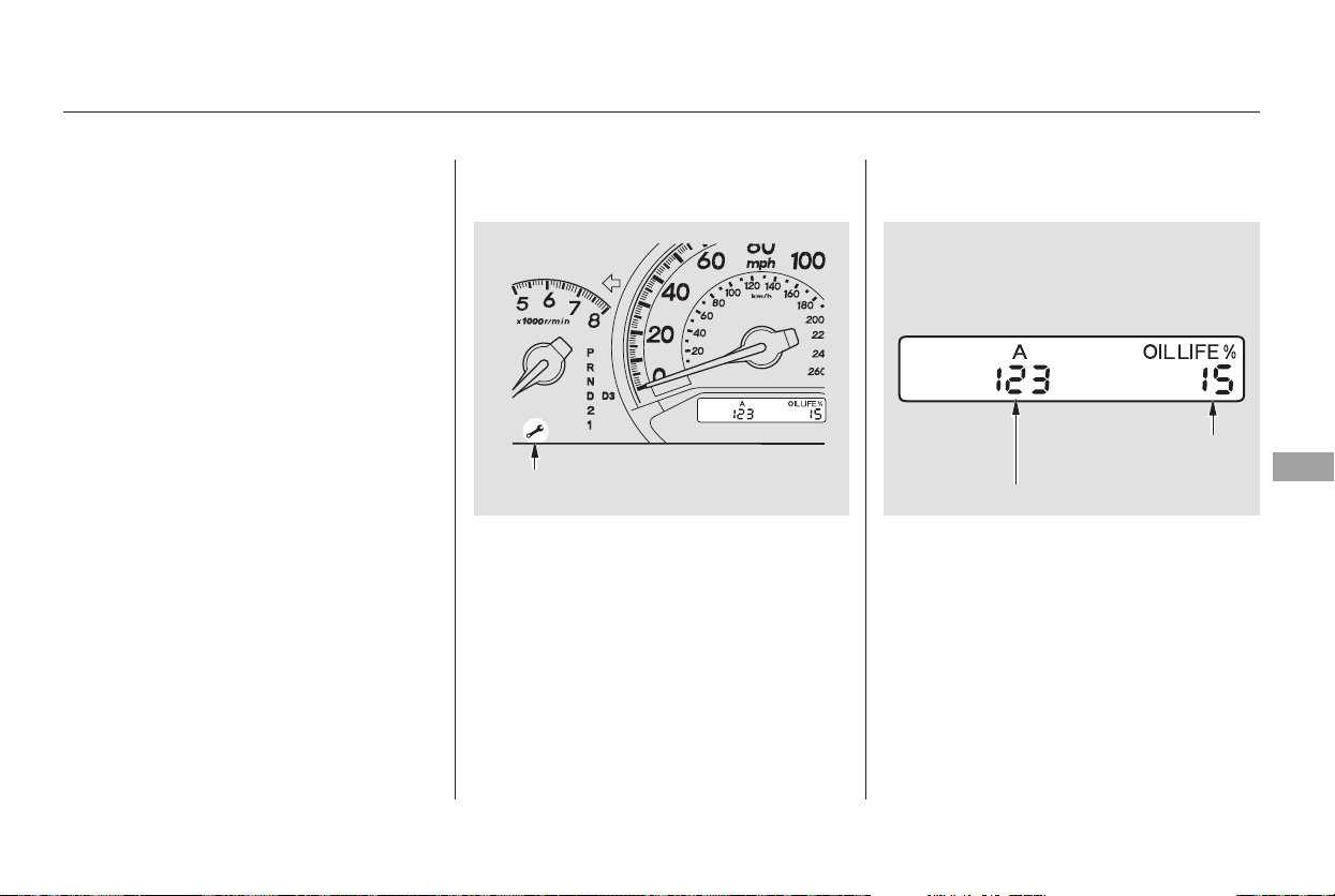
Your vehicle displays engine oil life
and maintenance service items in the
odometer/trip meter display on the
LX and EX models, or in the multi-
information display on the Touring
model, to show you when you should
have your dealer perform engine oil
replacement and indicated
maintenance service.
Based on the engine operating
conditions and accumulated engine
revolutions, the onboard computer in
your vehicle calculates the remaining
engine oil life and displays it as a
percentage. To see the current engine oil life,
turn the ignition switch to ON (II),
and push and release the SELECT/
RESET knob on the instrument
panel 3 times.
If the oil life is 15 percent or less,
you will see the oil life indicator for
several seconds every time you turn
the ignition switch to ON (II). The
maintenance minder indicator will
also come on, and the maintenance
item code(s) for other scheduled
maintenance items needing service
will be displayed next to the engine
oil life indicator.
CONTINUED
On LX and EX models
Maintenance Minder
Engine Oil Life Indicator
Maintenance
315
MAINTENANCE ITEM CODE
ENGINE OIL LIFE
INDICATOR
MAINTENANCE MINDER
INDICATOR
Main Menu
Table of Contents
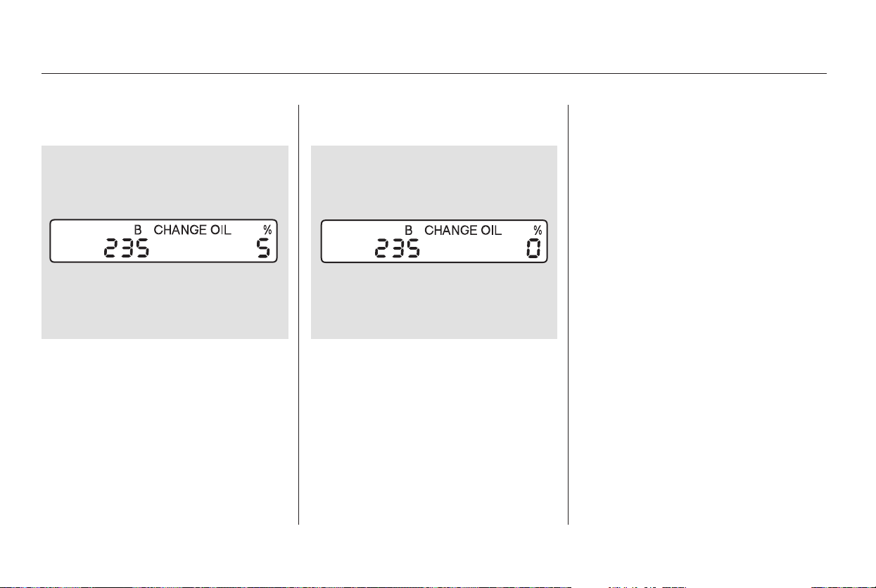
When the remaining engine oil life is
less than 5 percent, you will see a
‘‘CHANGE OIL’’ message in the
odometer/trip meter display, along
with the same maintenance item
code(s), every time you turn the
ignition switch to ON (II).
When the remaining engine oil life is
0 percent, you will see the above
display. In this display, the remaining
oil life indicator will be blinking. This
display comes on and stays on every
time you turn the ignition switch to
ON (II). When you see this message,
have the indicated maintenance
performed by your dealer as soon as
possible.
You can change the display to the
odometer, the trip meter, or the
outside temperature by pushing the
SELECT/RESET knob on the
instrument panel.
Maintenance Minder
316
Main Menu
Table of Contents
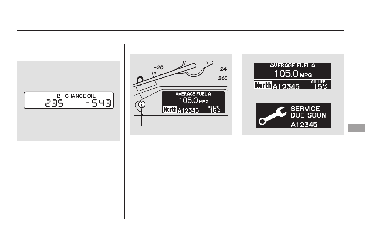
−
CONTINUED
When the remaining engine oil life is
15 percent or less, the display shows
a ‘‘SERVICE DUE SOON’’ message
along with the maintenance item
code(s) for other scheduled
maintenance items needing service.
To see the current engine oil life,
turn the ignition switch to ON (II),
then push and release the
SEL/RESET button on the steering
wheel three times.
If you still do not perform the
indicated maintenance, you will see a
negative mileage, for example
‘‘ 543,’’ blinking in the display. This
negative mileage means that you
should have performed the indicated
maintenance 543 miles ago.
Immediately have the indicated
maintenancedonebyyourdealer.
When you turn the ignition switch to
ON (II), the master warning
indicator will also come on.
On Touring model
Maintenance Minder
Maintenance
317
MASTER WARNING INDICATOR
Main Menu
Table of Contents
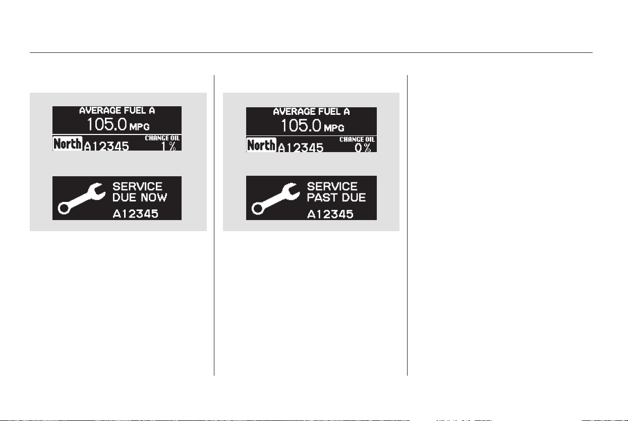
These messages will come on every
time you turn the ignition switch to
ON (II).
Immediately have the service
performed, and make sure to reset
the display as described on page .
You can change the display to the
odometer, the trip meter, or the
outside temperature by pushing the
SEL/RESET button on the steering
wheel.
When the remaining engine oil life is
less than 0 percent and you have not
done the required maintenance, you
will see the above display for several
seconds. In this display, ‘‘0’’ will be
blinking.
The display then changes to
‘‘SERVICE PAST DUE.’’
When the remaining engine oil life is
less than 5 percent, you will see the
above display. The display then
changes to ‘‘SERVICE DUE NOW.’’
Have the indicated maintenance
done as soon as possible.
320
Maintenance Minder
318
Main Menu
Table of Contents
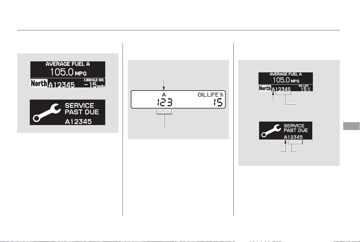
−
All the maintenance items displayed
in the odometer/trip meter or the
multi-information display are in code.
If you still do not get the indicated
maintenance done, you will see a
negative mileage, for example ‘‘ 15’’
blinking. This negative mileage
display means you should have done
the indicated maintenance 15 miles
ago. Immediately have the indicated
maintenancedonebyyourdealer.
For an explanation of the
maintenance codes, see page .324
Maintenance Minder
Maintenance Main Items and Sub
Items
Maintenance
319
MAINTENANCE SUB ITEM
MAINTENANCE
MAIN ITEM
MAINTENANCE
MAIN ITEM
MAINTENANCE
SUB ITEMS
MAINTENANCE
SUB ITEMS
MAINTENANCE MAIN ITEM
Touring model
LX and EX models
Main Menu
Table of Contents
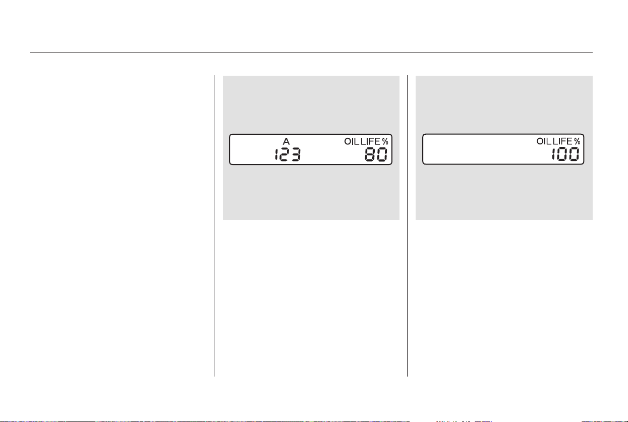
Press the SELECT/RESET knob
for more than 5 seconds. The
maintenance items code(s) will
disappear, and the engine oil life
will reset to ‘‘100.’’
Press the SELECT/RESET knob
for about 10 seconds. The engine
oil life and the maintenance item
code(s) will blink.
Your dealer will reset the display
after completing the required
maintenance service. You will see
‘‘OIL LIFE 100%’’ on the odometer/
trip meter display the next time you
turn the ignition switch to ON (II).
If maintenance service is done by
someone other than your dealer,
reset the maintenance minder as
follows:
Turn the ignition switch to ON (II).
Press the SELECT/RESET knob
until the engine oil life indicator is
displayed.
3. 4.
1.
2.
On LX and EX models
Maintenance Minder
Resetting the Engine Oil Life
Indicator
320
Main Menu
Table of Contents
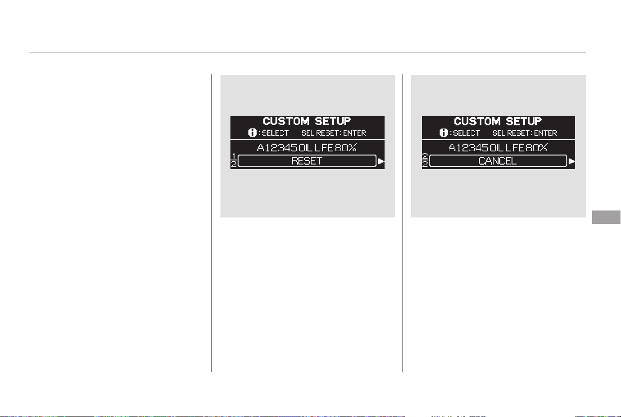
Press the SEL/RESET knob in the
instrument panel for about 10
seconds. The display will change
to the ‘‘CUSTOM SETUP’’ mode.
Turn the ignition switch to ON (II).
Press the SEL/RESET button on
the steering wheel until the engine
oil life is displayed.
Press the SEL/RESET button on
the steering wheel. The
maintenance item code(s) will
disappear, and the engine oil life
will reset to ‘‘100.’’
If you want to cancel resetting,
presstheINFObuttononthe
steering wheel. The display
changesasshown.PresstheSEL/
RESET button. This cancels the
resetting procedure, and the
screen returns to the normal
display mode.
3.
1.
2.
4.
5.
On Touring model
Maintenance Minder
Maintenance
321
Main Menu
Table of Contents
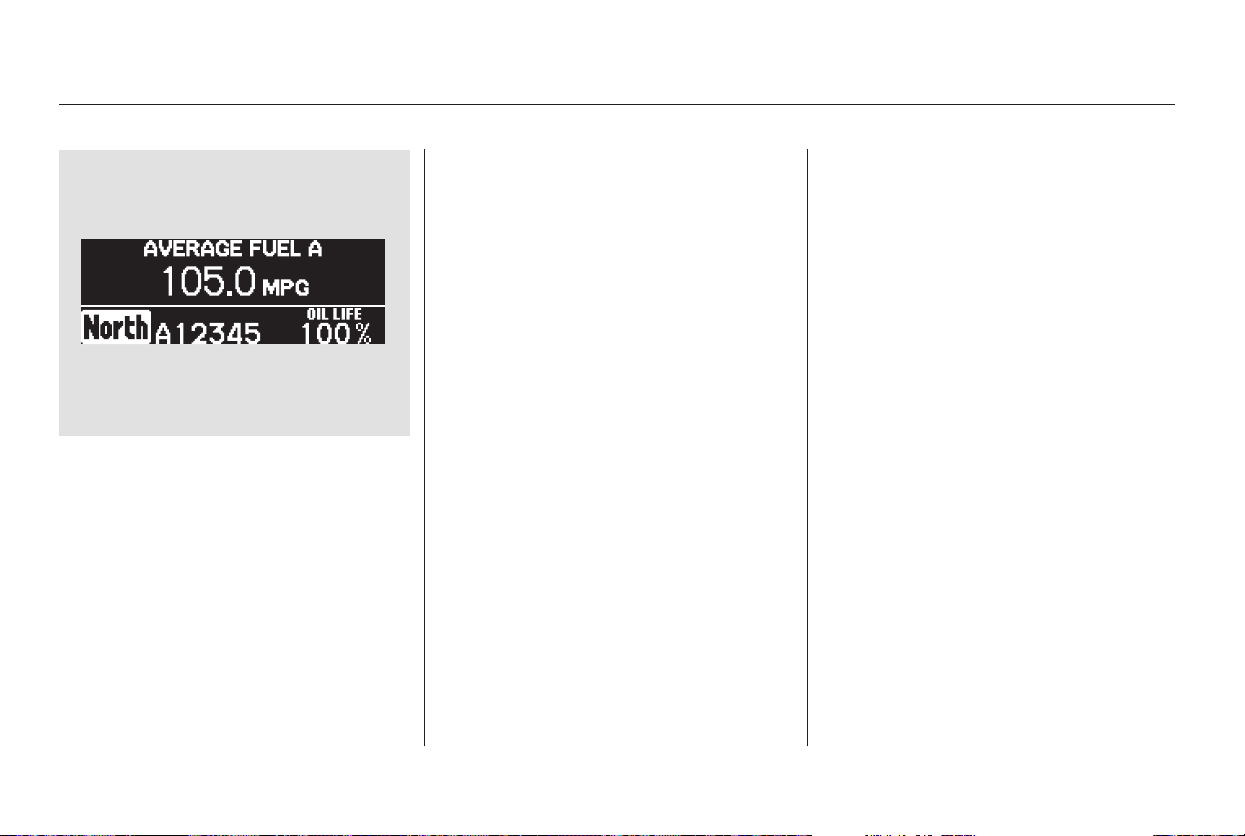
We recommend the use of Honda
parts and fluids whenever you have
maintenance done. These are
manufactured to the same high-
quality standards as the original
components, so you can be confident
of their performance and durability.
If you have the required service
done but do not reset the display, or
reset the display without doing the
service, the system will not show the
proper maintenance intervals. This
canleadtoseriousmechanical
problems because you will no longer
have an accurate record of when
maintenance is needed.
Your authorized Honda dealer
knows your vehicle best and can
provide competent, efficient service.
When you select ‘‘RESET’’ and
press the SEL/RESET button, the
multi-information display resets as
shown above.
However, service at a dealer is not
mandatory to keep your warranties
in effect. Maintenance may be done
by any qualified service facility or
person who is skilled in this type of
automotive service. Make sure to
have the service facility or person
reset the display as previously
described. Keep all receipts as proof
of completion, and have the person
who does the work fill out the
maintenance record. Check your
warranty booklet for more
information.6.
Maintenance Minder
Important Maintenance
Precautions
322
Main Menu
Table of Contents
−
−
−
−
−
−
#
U.S. Vehicles:
Youshouldcheckthefollowing
items at the specified intervals. If
you are unsure of how to perform
any check, turn to the appropriate
page listed.
Lights Check the operation of
the headlights, parking lights,
taillights, high-mount brake light,
and license plate lights monthly.
See page .
Engine coolant level Check the
radiator reserve tank every time
you fill the fuel tank. See page .
Engine oil level Check every
time you fill the fuel tank. See
page .
Automatic transmission Check
the fluid level monthly. See page
.
Brakes Check the fluid level
monthly. See page .
Tires Check the tire pressure
monthly. Examine the tread for
wear and foreign objects. See page
.
According to state and federal
regulations, failure to perform
maintenance on the items marked
with will not void your emissions
warranties. However, all
maintenance services should be
performed in accordance with the
intervals indicated by the odometer/
trip meter display or the multi-
information display.
281
282
334
335
347
337
Maintenance, replacement, or
repair of emissions control
devices and systems may be done
by any automotive repair
establishment or individual using
parts that are ‘‘certified’’ to EPA
standards.
Owner’s Maintenance Checks
Maintenance Minder
Maintenance
323
Main Menu
Table of Contents
#
*
#
#
#
*
Maintenance Minder
324
:
If the message ‘‘SERVICE DUE NOW’’ does not appear more than 12 months
after the display is reset, change the engine oil every year.
See information on maintenance and emissions warranty in the first column
on page .
Inspect idle speed every 160,000 miles (256,000 km).
Adjust the valves during services A, B, 1, 2, or 3 if they are noisy.
Independent of the maintenance messages in the multi-information
display, replace the brake fluid every 3 years.
NOTE:
1:
323
Maintenance Sub Items
Rotate tires
Replace air cleaner element
If you drive in dusty conditions, replace
every 15,000 miles (24,000 km).
Replace dust and pollen filter
If you drive primarily in urban areas that have high
concentrations of soot in the air from industry and
from diesel-powered vehicles, replace every 15,000
miles (24,000 km).
Inspect drive belt
Replace transmission fluid
Driving in mountainous areas at very low vehicle
speeds or trailer towing results in higher
transmission temperatures.
This requires transmission fluid changes more
frequently than recommended by the Maintenance
Minder. If you regulary drive your vehicle under these
conditions, have the transmission fluid changed
every 30,000 miles (48,000 km).
Replace spark plugs
Replace timing belt and inspect water pump
If you drive regularly in very high temperatures (over
110°F, 43°C), or in very low temperatures (under-20°F,
29°C), replace every 60,000 mile (U.S.)/100,000 km
(Canada)
Inspect valve clearance
Replace engine coolant
Maintenance Main Items
Replace engine oil
Replace engine oil and oil filter
Rotate tires
Inspect front and rear brakes
Check parking brake adjustment
Inspect these items:
Tie rod ends, steering gear box, and boots
Suspension components
Driveshaft boots
Brake hoses and lines (including ABS)
All fluid levels and condition of fluids
Exhaust system
Fuel lines and connections
A
B
Symbol Symbol
1
2
3
4
5
1
Maintenance Minder
Main Menu
Table of Contents
Maintenance Record
Maintenance
325
mi
mi
mi
mi
mi
mi
mi
mi
mi
mi
mi
mi
mi
mi
You or the servicing dealer can record all completed maintenance here. When maintenance is performed, record the mileage, circle the coded item(s)
completed, and write in any other non-coded items (such as brake fluid replacement) below the codes. Keep the receipts for all work done on your
vehicle.
Maintenance
Performed
AB12345
AB12345
AB12345
AB12345
AB12345
AB12345
AB12345
Signature
Date
Maintenance
Performed
AB12345
AB12345
AB12345
AB12345
AB12345
AB12345
AB12345
Signature
Date
Mileage
km
km
km
km
km
km
km
Mileage
km
km
km
km
km
km
km
Main Menu
Table of Contents
Maintenance Record
326
mi
mi
mi
mi
mi
mi
mi
mi
mi
mi
mi
mi
mi
mi
Maintenance
Performed
AB12345
AB12345
AB12345
AB12345
AB12345
AB12345
AB12345
Signature
Date
Maintenance
Performed
AB12345
AB12345
AB12345
AB12345
AB12345
AB12345
AB12345
Signature
Date
Mileage
km
km
km
km
km
km
km
Mileage
km
km
km
km
km
km
km
Main Menu
Table of Contents
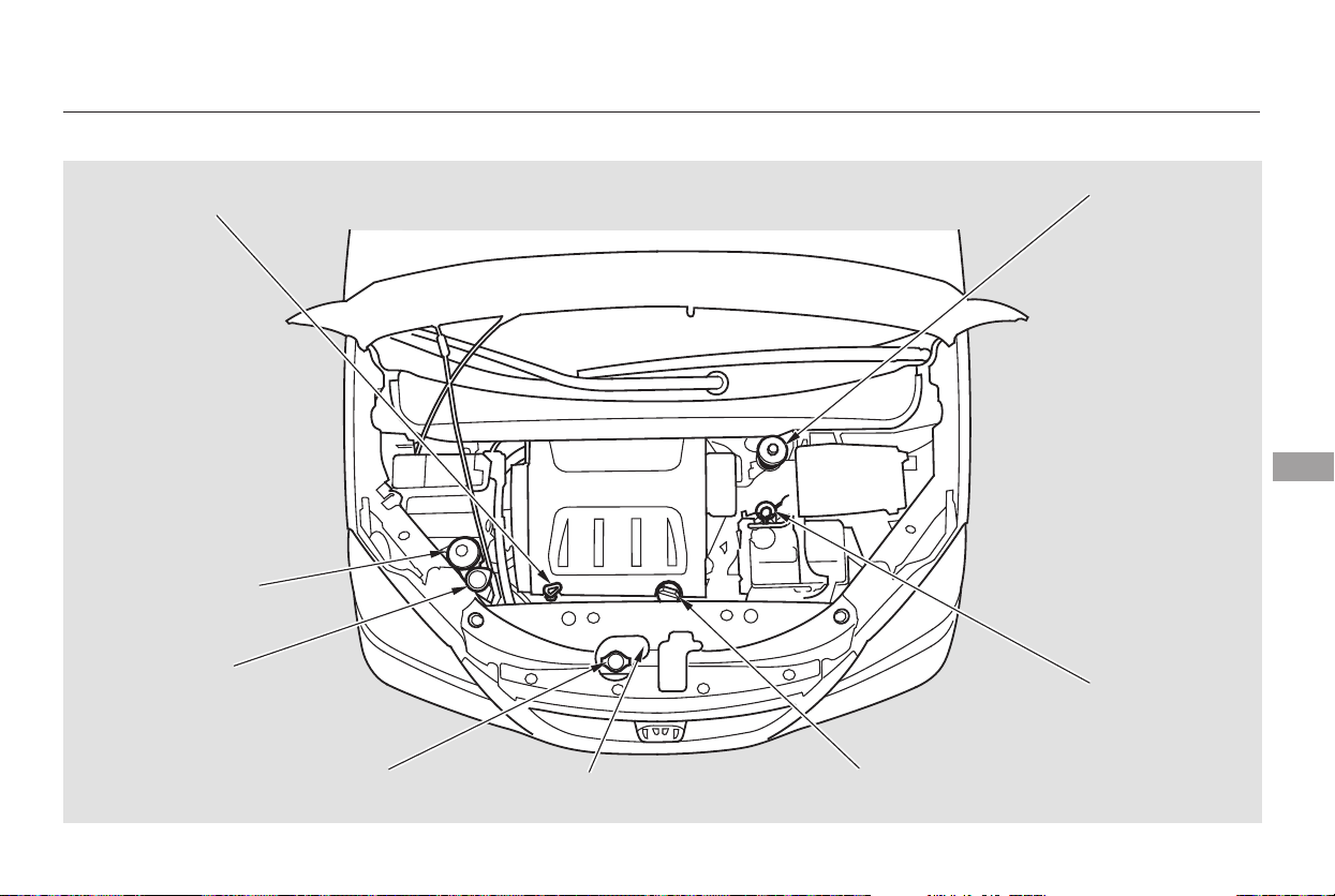
Fluid Locations
Maintenance
327
ENGINE OIL DIPSTICK
(Orange loop)
WASHER FLUID
(Blue cap)
POWER STEERING
FLUID (Red cap)
RADIATOR CAP
ENGINE OIL FILL CAP
AUTOMATIC
TRANSMISSION
FLUID DIPSTICK
(Yellow loop)
BRAKE FLUID
(Gray cap)
ENGINE COOLANT
RESERVOIR
Main Menu
Table of Contents
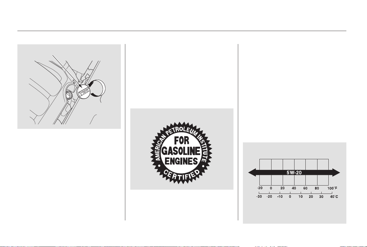
Unscrew and remove the engine oil
fill cap on top of the valve cover.
Pour in the oil slowly and carefully so
you do not spill. Clean up any spills
immediately. Spilled oil could
damage components in the engine
compartment.
Install the engine oil fill cap, and
tighten it securely. Wait a few
minutes, and recheck the oil level.
Do not fill above the upper mark; you
could damage the engine.
Oil is a major contributor to your
engine’s performance and longevity.
Always use a premium-grade 5W-20
detergent oil displaying the API
Certification Seal. This seal indicates
the oil is energy conserving, and that
it meets the American Petroleum
Institute’s latest requirements.
Honda Motor Oil is the preferred
5W-20 lubricant for your vehicle. It is
highly recommended that you use
Honda Motor Oil in your vehicle for
optimum engine protection. Make
sure the API Certification Seal says
‘‘For Gasoline Engines.’’
The oil viscosity or weight is
provided on the container’s label.
5W-20 oil is formulated for year-
round protection of your vehicle to
improve cold weather starting and
fuel economy.
Recommended Engine Oil
Adding Engine Oil
328
ENGINE OIL FILL CAP
Ambient Temperature
API CERTIFICATION SEAL
Main Menu
Table of Contents
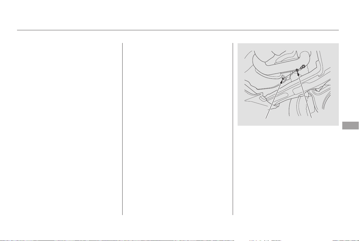
You may use a synthetic motor oil if
it meets the same requirements
given for a conventional motor oil: it
displays the API Certification Seal,
and it is the proper weight. You must
follow the oil and filter change
intervals shown on the odometer/
trip meter display or on the multi-
information display.
Always change the oil and filter
according to the maintenance
messages shown on the odometer/
trip meter display or on the multi-
information display. The oil and filter
collect contaminants that can dam-
age your engine if they are not
removed regularly.
Changing the oil and filter requires
special tools and access from
underneath the vehicle. The vehicle
should be raised on a service station-
type hydraulic lift for this service.
Unless you have the knowledge and
proper equipment, you should have
this maintenance done by a skilled
mechanic.
Run the engine until it reaches
normal operating temperature,
then shut it off.
Your vehicle’s engine does not
require any oil additives. Additives
may adversely affect engine or
transmission performance and
durability.
Open the hood, and remove the
engine oil fill cap. Remove the oil
drain bolt and washer from the
bottom of the engine. Drain the oil
into an appropriate container.
1.
2.
Synthetic Oil Changing the Oil and Filter
Engine Oil Additives
Adding Engine Oil, Changing the Oil and Filter
Maintenance
329
WASHER
DRAIN BOLT
Main Menu
Table of Contents
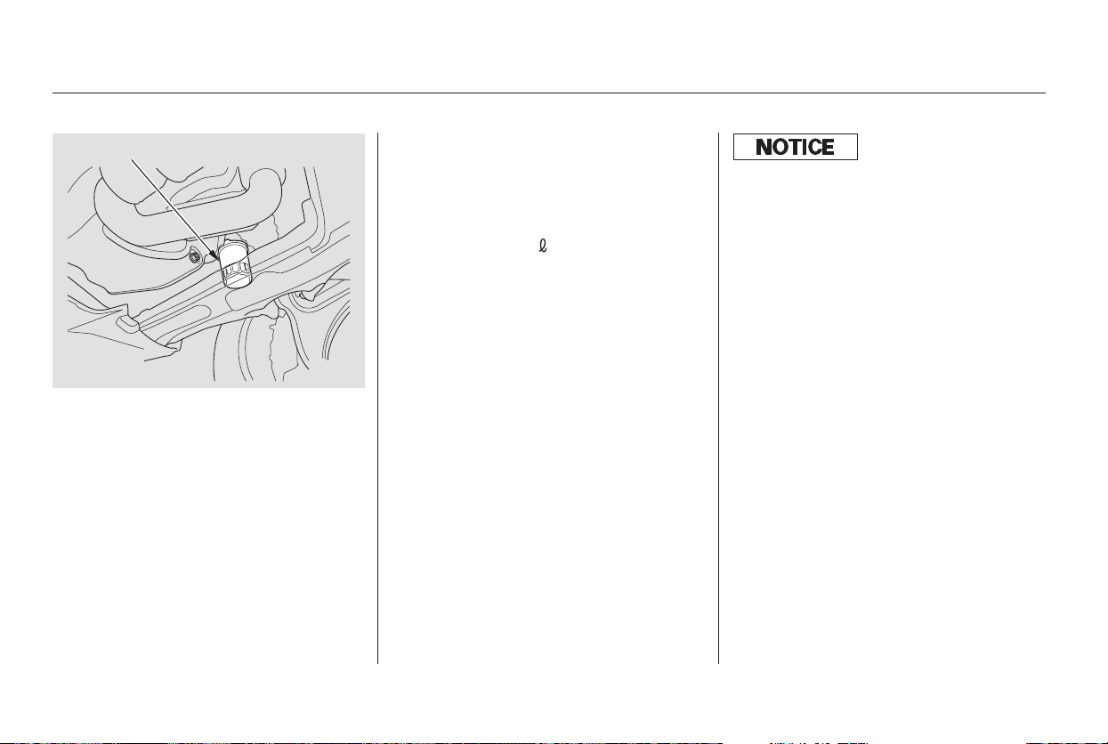
Refill the engine with the
recommended oil.
Engine oil change capacity
(including filter):
Replace the engine oil fill cap.
Start the engine. The oil pressure
indicator should go out within 5
seconds. If it does not, turn off the
engine, and check your work.
Let the engine run for several
minutes, then check the drain bolt
and oil filter for leaks.
Turn off the engine and let it sit
for several minutes, then check
the oil level on the dipstick. If
necessary, add more oil.
Install a new oil filter according to
the instructions that come with it.
Put a new washer on the drain bolt,
then reinstall the drain bolt.
Tighten the drain bolt to:
Remove the oil filter, and let the
remaining oil drain. A special
wrench (available from your
dealer) is required.
9.
8.
7.
6.
4.
5.
3.
Changing the Oil and Filter
330
OIL FILTER
4.5 US qt (4.3 )
29 lbf·ft (39 N·m , 4.0 kgf·m)
Improper disposal of engine oil can be
harmf ul to the environment. If you
change your own oil, please dispose of
the used oil properly. Put it in a sealed
container, and take it to a recycling
center. Do not discard it in a trash bin
or dump it on the ground.
Main Menu
Table of Contents
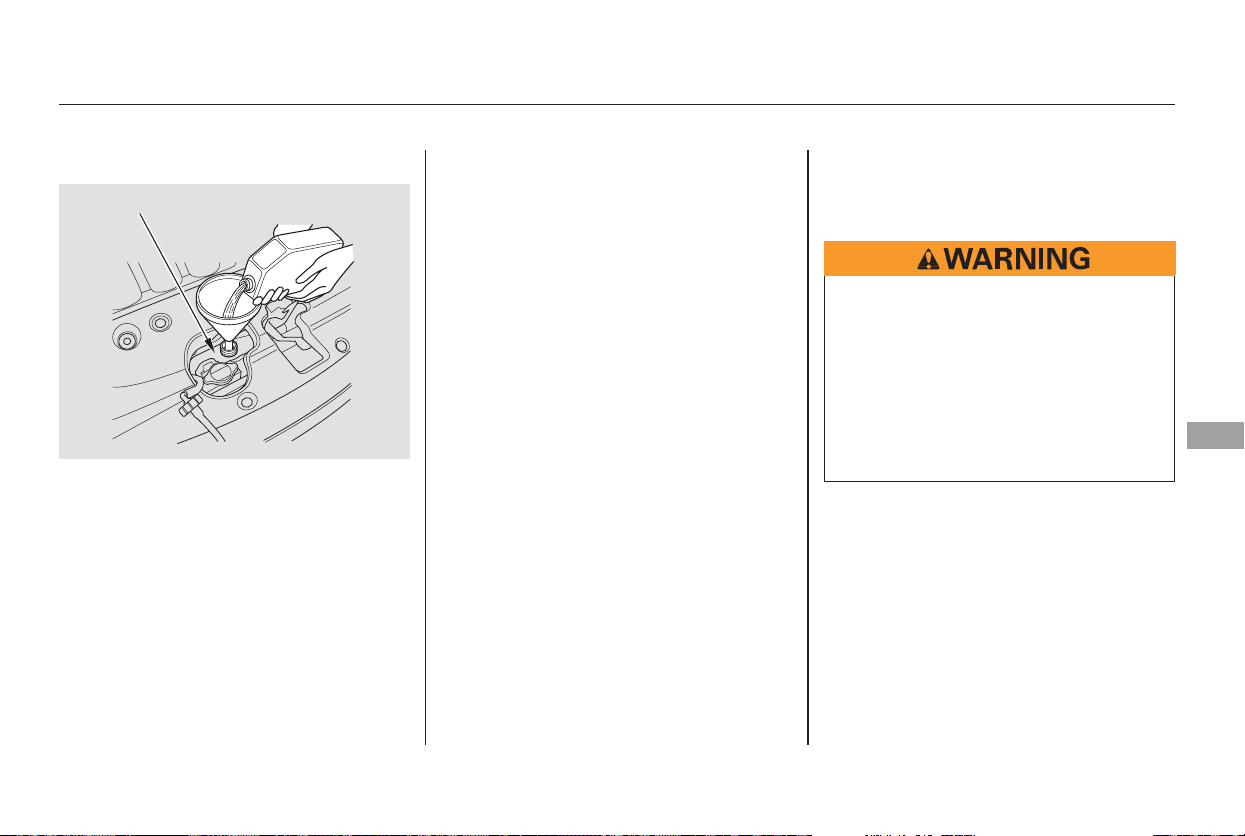
If the coolant level in the reserve
tank is at or below the MIN line, add
coolant to bring it up to between the
MIN and MAX lines. Inspect the
cooling system for leaks.
Always use Honda All Season
Antifreeze/Coolant Type 2. This
coolant is pre-mixed with 50 percent
antifreeze and 50 percent water.
Never add straight antifreeze or
plain water.
If Honda antifreeze/coolant is not
available, you may use another
major-brand non-silicate coolant as a
temporaryreplacement.Makesureit
is a high-quality coolant
recommended for aluminum engines.
Continued use of any non-Honda
coolant can result in corrosion,
causing the cooling system to
malfunction or fail. Have the cooling
system flushed and refilled with
Honda antifreeze/coolant as soon as
possible.
If the reserve tank is completely
empty, you should also check the
coolant level in the radiator.
CONTINUED
Adding Engine Coolant
Engine Coolant
Maintenance
331
RESERVE TANK
Removing the radiator cap
while the engine is hot can
cause the coolant to spray out,
seriously scalding you.
Always let the engine and
radiator cool down before
removing the radiator cap.
Main Menu
Table of Contents

When the radiator and engine are
cool, relieve any pressure in the
cooling system by turning the
radiator cap counterclockwise,
without pressing down.
Remove the radiator cap by
pushing down and turning
counterclockwise.
The coolant level should be up to
the base of the filler neck. Add
coolant if it is low.
Pour coolant into the reserve tank.
Fill it to halfway between the MAX
and MIN marks. Put the cap back
on the reserve tank.
Do not add any rust inhibitors or
other additives to your vehicle’s
cooling system. They may not be
compatible with the coolant or
engine components.
Put the radiator cap back on, and
tighten it fully.
Pour the coolant slowly and carefully
so you do not spill. Clean up any spill
immediately; it could damage
components in the engine
compartment.
3.
4.
5.
1.
2.
Engine Coolant
332
RADIATOR CAP
RESERVE TANK
Main Menu
Table of Contents
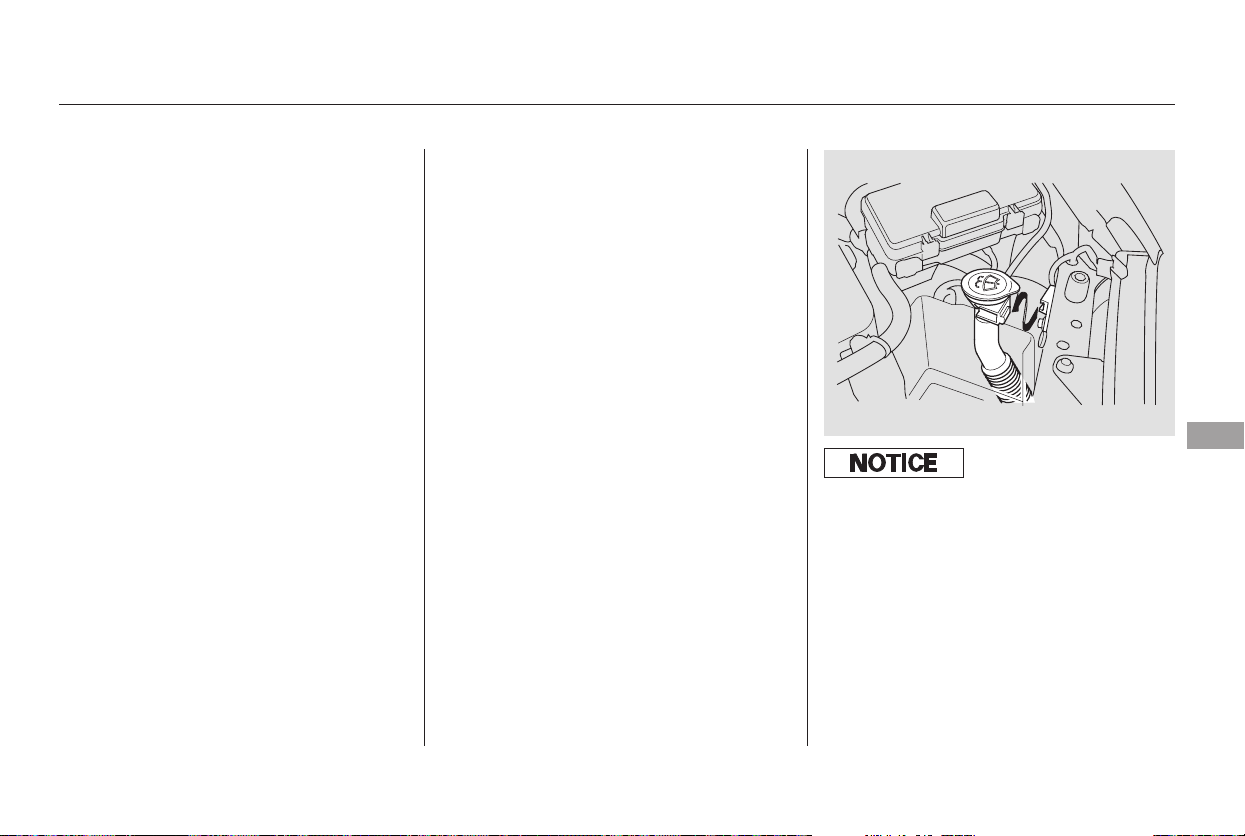
On Canadian models:
On the Touring model:
The low washer
level indicator comes on when the
level is low (see page ).
You will see a
‘‘WASHER FLUID LOW’’ message
on the multi-information display
when the level is low.
Fill the reservoir with a good-quality
windshield washer fluid. This
increases the cleaning capability and
prevents freezing in cold weather.
When you refill the reservoir, clean
the edges of the windshield wiper
blades with windshield washer fluid
on a clean cloth. This will help to
condition them.
Check the fluid level in the
windshield washer reservoir at least
monthly during normal use. This
reservoir supplies the windshield and
rear window washers.
Check the fluid level by removing
the cap and looking at the level
gauge attached to the cap.
69
Windshield Washers
Maintenance
333
Do not use engine antifreeze or a
vinegar/water solution in the
windshield washer reservoir. Antif reeze
can damage your vehicle’s paint, while
a vinegar/water solution can damage
the windshield washer pump. Use only
commercially-available windshield
washer f luid.
Main Menu
Table of Contents
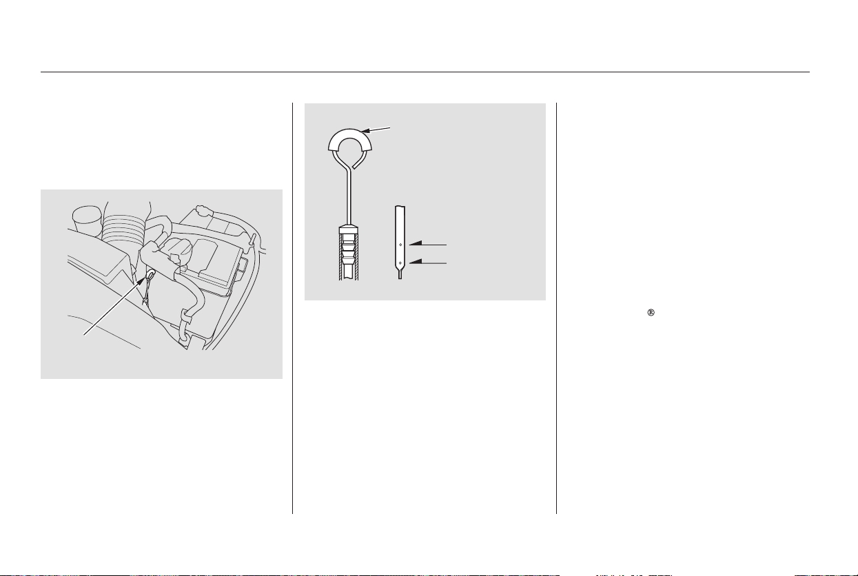
Pour the fluid slowly and carefully
so you do not spill any. Clean up
any spills immediately; it could
damage components in the engine
compartment.
Always use Honda ATF-Z1
(Automatic Transmission Fluid). If
it’s not available, you may use a
DEXRON
III automatic
transmission fluid as a temporary
replacement. However, continued
use can affect the shift quality.
Have the transmission flushed and
refilled with Honda ATF-Z1 as
soon as it is convenient.
Check the fluid level with the engine
at normal operating temperature.
Park the vehicle on level ground.
Shut off the engine.
Remove the dipstick (yellow loop)
from the transmission, and wipe it
with a clean cloth.
Insert the dipstick, all the way into
the transmission as shown.
If the level is below the lower
mark, remove the fill plug, and add
fluid to bring it to the upper mark.
Remove the dipstick, and check
the fluid level. It should be
between the upper and lower
marks.
5.
3.
4.
1.
2.
Automatic Transmission Fluid
334
DIPSTICK
UPPER MARK
LOWER MARK
DIPSTICK
Main Menu
Table of Contents
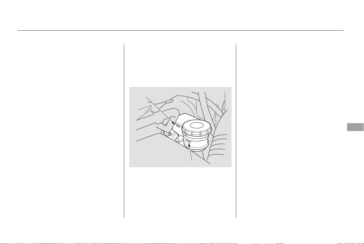
Always use Honda Heavy Duty
Brake Fluid DOT 3. If it is not
available, you should use only DOT 3
or DOT 4 fluid, from a sealed
container, as a temporary
replacement.
Using any non-Honda brake fluid can
cause corrosion and decrease the life
of the system. Have the brake
system flushed and refilled with
Honda Heavy Duty Brake Fluid
DOT 3 as soon as possible.
Pour the fluid slowly and carefully so
you do not spill any. Clean up any
spills immediately; it could damage
components in the engine
compartment.
Brake fluid marked DOT 5 is not
compatible with your vehicle’s
braking system and can cause
extensive damage.
Check the brake fluid level in the
reservoirs monthly.
The fluid level should be between
theMINandMAXmarksontheside
of the reservoir. If the level is at or
below the MIN mark, your brake
system needs attention. Have the
brake system inspected for leaks or
worn brake pads.
To thoroughly flush the transmission,
the technician should drain and refill
it with Honda ATF-Z1, then drive the
vehicle for a short distance. Do this
three times. Then drain and refill the
transmission a final time.
Insert the dipstick all the way back
into the transmission securely as
shown in the illustration.
The transmission should be drained
and refilled with new fluid when this
service is indicated on a maintenance
message on the odometer/trip meter
display or on the multi-information
display.
If you are not sure how to add fluid,
contact your dealer.
Replace the brake fluid according to
thetimerecommendationsinthe
maintenance minder schedule.
6.
Automatic Transmission Fluid, Brake Fluid
Brake Fluid
Maintenance
335
MAX
MIN
Main Menu
Table of Contents
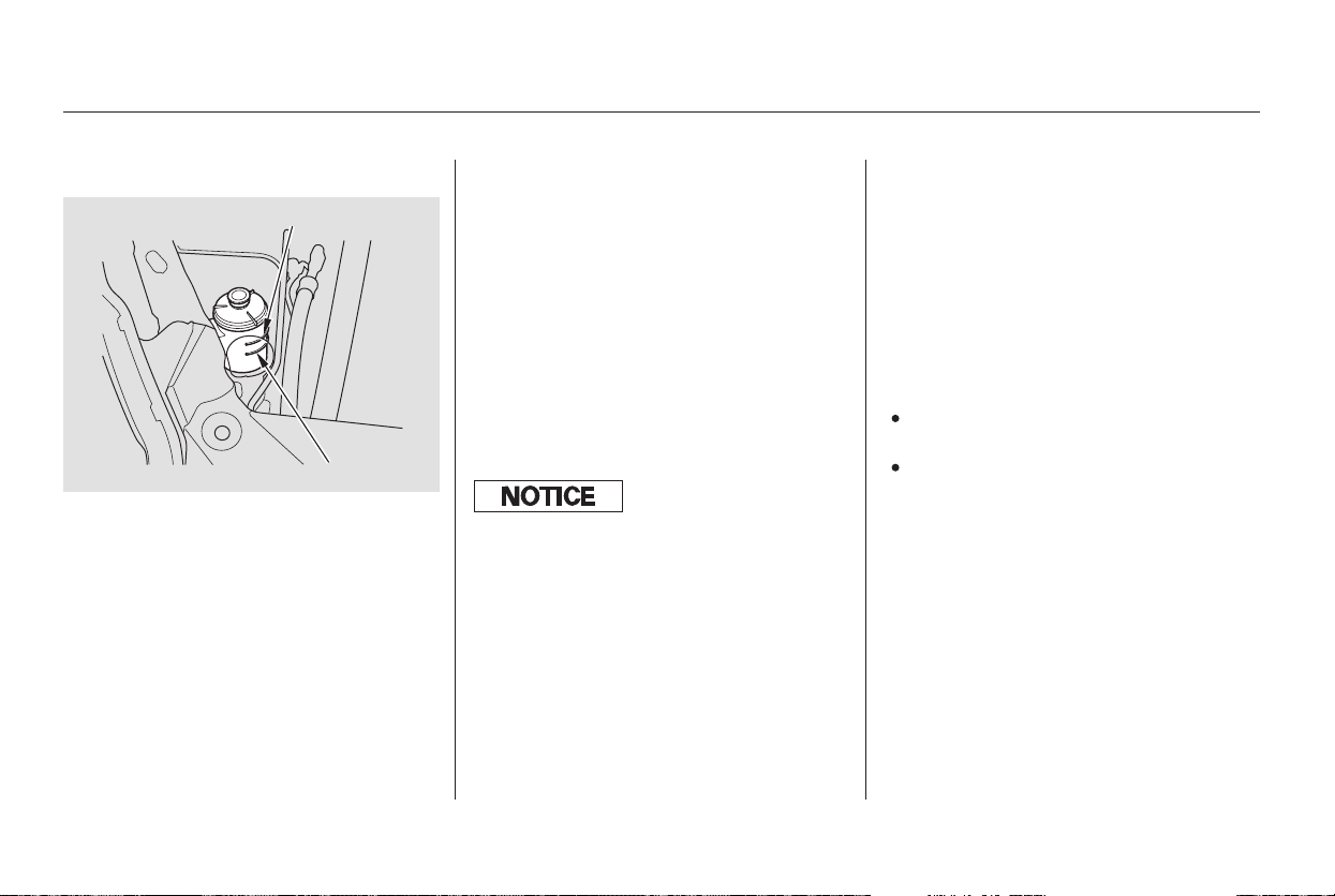
−−
Always use Honda Power Steering
Fluid. You may use another power
steering fluid as an emergency
replacement, but have the power
steering system flushed and refilled
with Honda PSF as soon as possible.
A low power steering fluid level can
indicate a leak in the system. Check
the fluid level frequently, and have
the system inspected as soon as
possible.
Replace the belt at 60,000 miles
(100,000 km) if you regularly drive
your vehicle in one or more of these
conditions:
In very high temperatures
(over 110°F, 43°C).
In very low temperatures
(under 20°F, 29°C).
Check the level on the side of the
reservoir when the engine is cold.
The fluid should be between the
UPPER LEVEL and LOWER LEVEL.
If not, add power steering fluid to the
UPPER LEVEL mark.
The timing belt should be replaced
at the intervals shown in the
maintenance minder schedule.
Pour the fluid slowly and carefully so
you do not spill. Clean up any spill
immediately; it could damage
components in the engine
compartment.
Power Steering Fluid Timing Belt
Power Steering Fluid, Timing Belt
336
UPPER LEVEL
LOWER LEVEL
Turning the steering wheel to f ull lef t
or right lock and holding it there can
damage the power steering pump.
Main Menu
Table of Contents
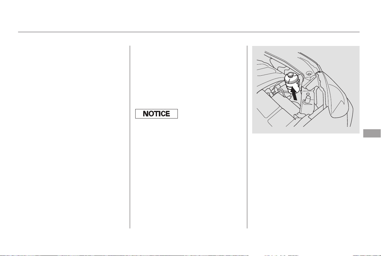
Your vehicle has halogen headlight
bulbs, two on each side. When
replacing a bulb, handle it by its base
and protect the glass from contact
with your skin or hard objects. If you
touch the glass, clean it with
denaturedalcoholandacleancloth.
The high beam headlight bulb and
the low beam headlight bulb are
replaced the same way.
Open the hood. To change the
high beam headlight bulb on the
passenger’s side, remove the
power steering fluid reservoir
from its holder by pulling it
straight up.
Theheadlightswereproperlyaimed
when your vehicle was new. If you
regularly carry heavy items in the
cargo area or pull a trailer,
readjustment may be required.
Adjustmentsshouldbedonebyyour
dealer or other qualified mechanic.
1.
CONTINUED
Lights
Headlight Aiming Replacing a Headlight Bulb
Maintenance
337
Halogen headlight bulbs get very hot
when lit. Oil, perspiration, or a scratch
on the glass can cause the bulb to
overheat and shatter.
Main Menu
Table of Contents
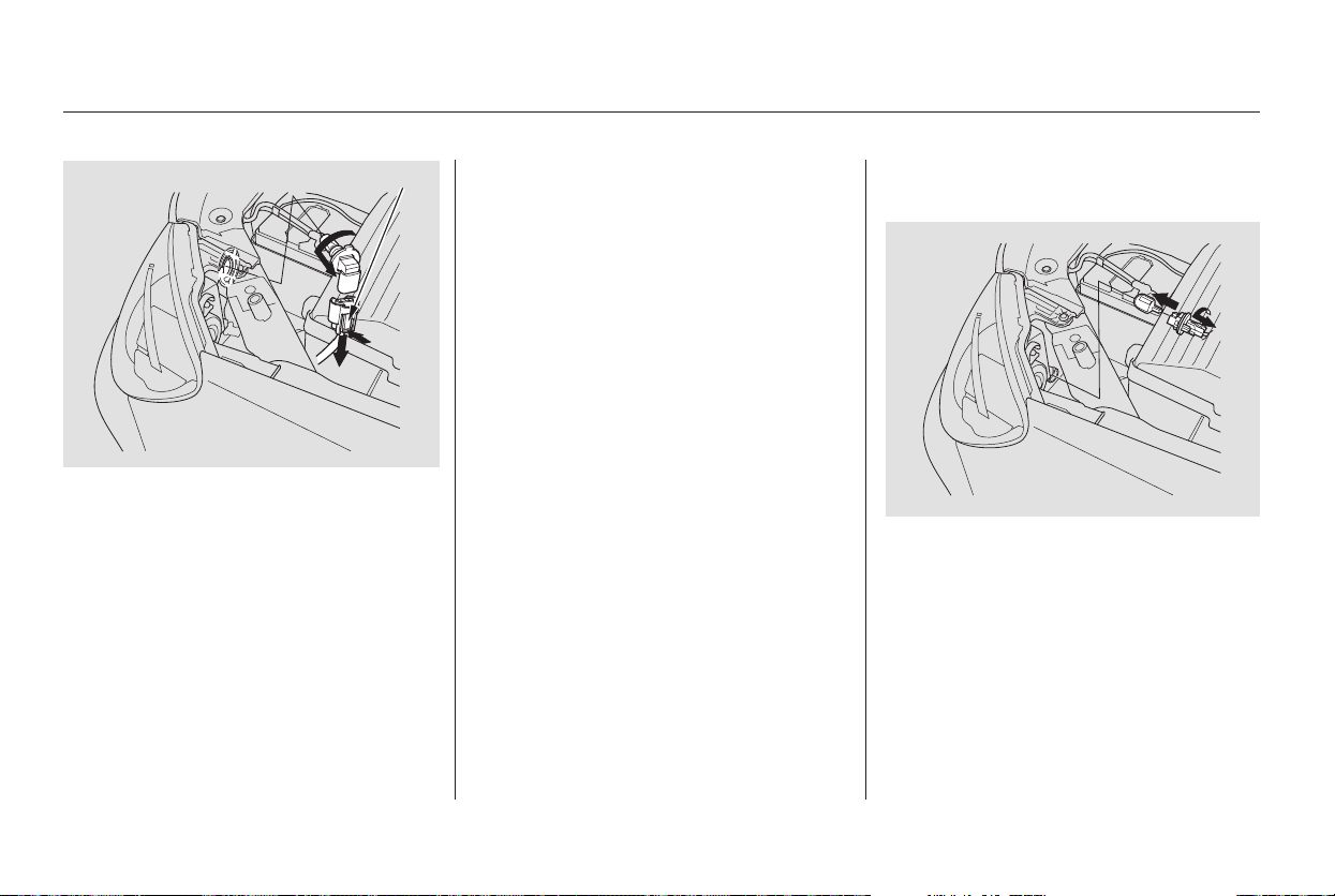
Remove the electrical connector
from the bulb by pushing on the
tab and pulling the connector
down.
Remove the bulb by turning it one-
quarter turn counterclockwise.
Open the hood. Remove the
socket from the headlight
assembly by turning it one-quarter
turn counterclockwise.
Pull the burned out bulb straight
out of its socket.
Push the new bulb straight into
the socket until it bottoms.
Push the electrical connector back
onto the bulb. Make sure it is on
all the way.
Turn on the headlights to test the
new bulb.
If you replaced the high beam
headlight bulb on the passenger’s
side, reinstall the power steering
fluid reservoir.
Insert the new bulb into the hole,
and turn it one-quarter turn clock-
wise to lock it in place.
5.
6.
7.
2.
3.
4.
2.
1.
Lights
Replacing a Front Turn Signal
Bulb
338
TAB
Main Menu
Table of Contents
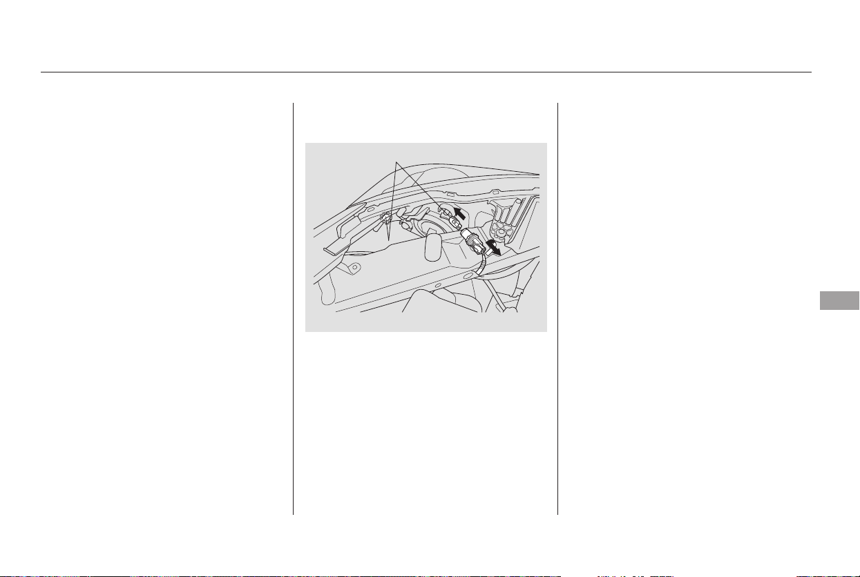
Insert the socket back into the
headlight assembly. Turn it
clockwise to lock it in place.
Turn on the lights to make sure
the new bulb is working.
Open the hood. Remove the
socket from the headlight
assembly by turning it one-quarter
turn counterclockwise.
Pull the bulb straight out of its
socket. Push the new bulb straight
into the socket until it bottoms.
Insert the socket back into the
headlight assembly. Turn it
clockwise to lock it in place.
Turn on the lights to make sure
the new bulb is working.
3.
4.
1.
2.
3.
4.
Lights
Replacing a Front Parking/Side
Marker Bulb
Maintenance
339
Main Menu
Table of Contents
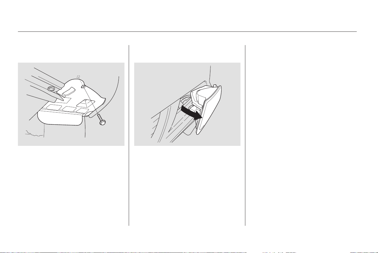
Use a wrench to remove the
mounting bolt from the underbody
through the hole in the splash
shield.
Remove the fog light assembly
from the bumper by pulling its
inner edge first, then the whole
assembly out of the bumper.
Remove the electrical connector
from the bulb by pushing on the
tab and pulling the connector
down.
Remove the bulb from the fog
light assembly by turning it one-
quarter turn counterclockwise.
Push the electrical connector onto
the new bulb.
Turn on the fog lights to test the
new bulb.
Reinstall the fog light assembly
into the bumper. Tighten the
mounting bolt.
Insert the new bulb into the
assembly and turn it one-quarter
turn clockwise to lock it in place.
1.
2.
3.
4.
5.
6.
7.
8.
Touring model only
Lights
Replacing a Front Fog Light Bulb
340
Main Menu
Table of Contents
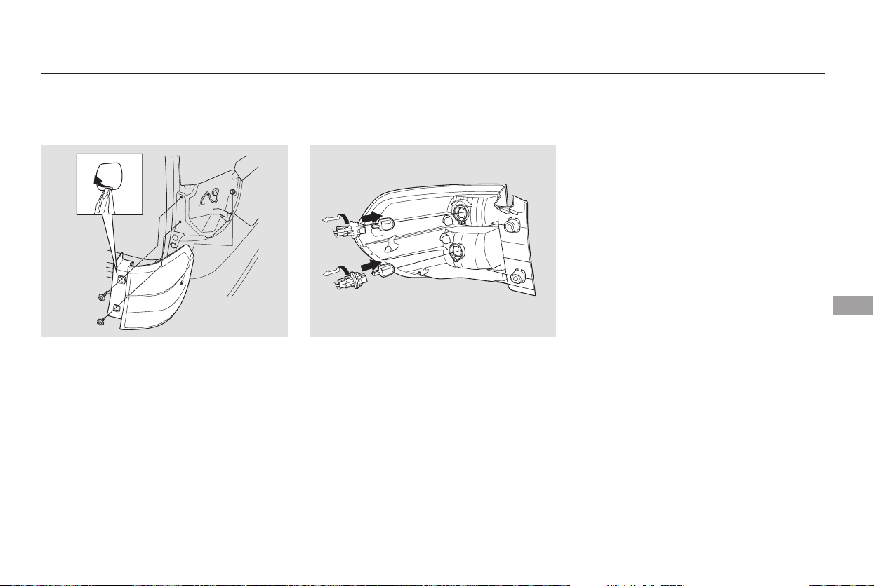
Remove the two bolt covers on the
rear pillar by prying on the bottom
edge with a flat-tip screwdriver.
Remove the bolts with a Phillips-
head screwdriver, and remove the
light assembly from the rear pillar.
Determine which of the two bulbs
is burned out: turn signal or
brake/taillight.
Remove the socket by turning it
one-quarter turn counterclockwise.
Push the new bulb straight into
the socket until it bottoms.
Test the lights to make sure the
new bulb is working.
Put the socket back into the light
assembly, and turn it clockwise to
lock it in place.
Install the rear light assembly in
the rear pillar. Tighten the two
bolts. Snap the bolt covers into
position.
Remove the bulb by pulling it
straight out of its socket.
2.
3.
5.
6.
7.
1.
4.
Lights
Replacing a Rear Turn Signal or
Brake Light Bulb
Maintenance
341
Main Menu
Table of Contents
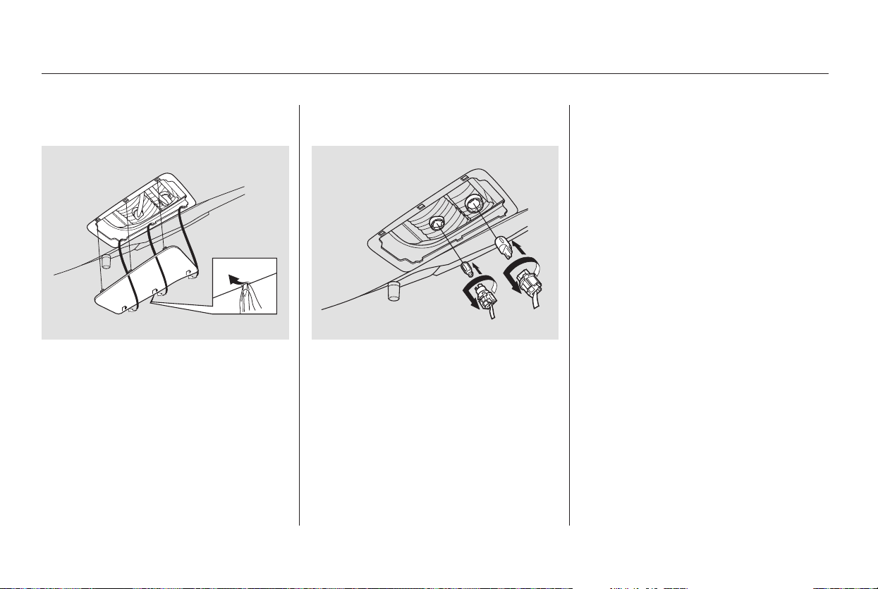
Remove the socket from the light
assembly by turning it one-quarter
turn counterclockwise.
Pull the bulb straight out of its
socket. Push a new bulb into the
socket until it bottoms. Reinstall
the assembly.
Testthelightstomakesurethe
new bulb is working.
Reinstall the light cover.
Determine which bulb is burned
out: taillight or back-up light.
Open the tailgate. Place a cloth on
the edge of the middle of the light
cover.
Remove the cover by carefully
prying on its edge.
1.
2.
3.
6.
4.
5.
Lights
Replacing a Taillight or Back-up
Light Bulb
342
Main Menu
Table of Contents
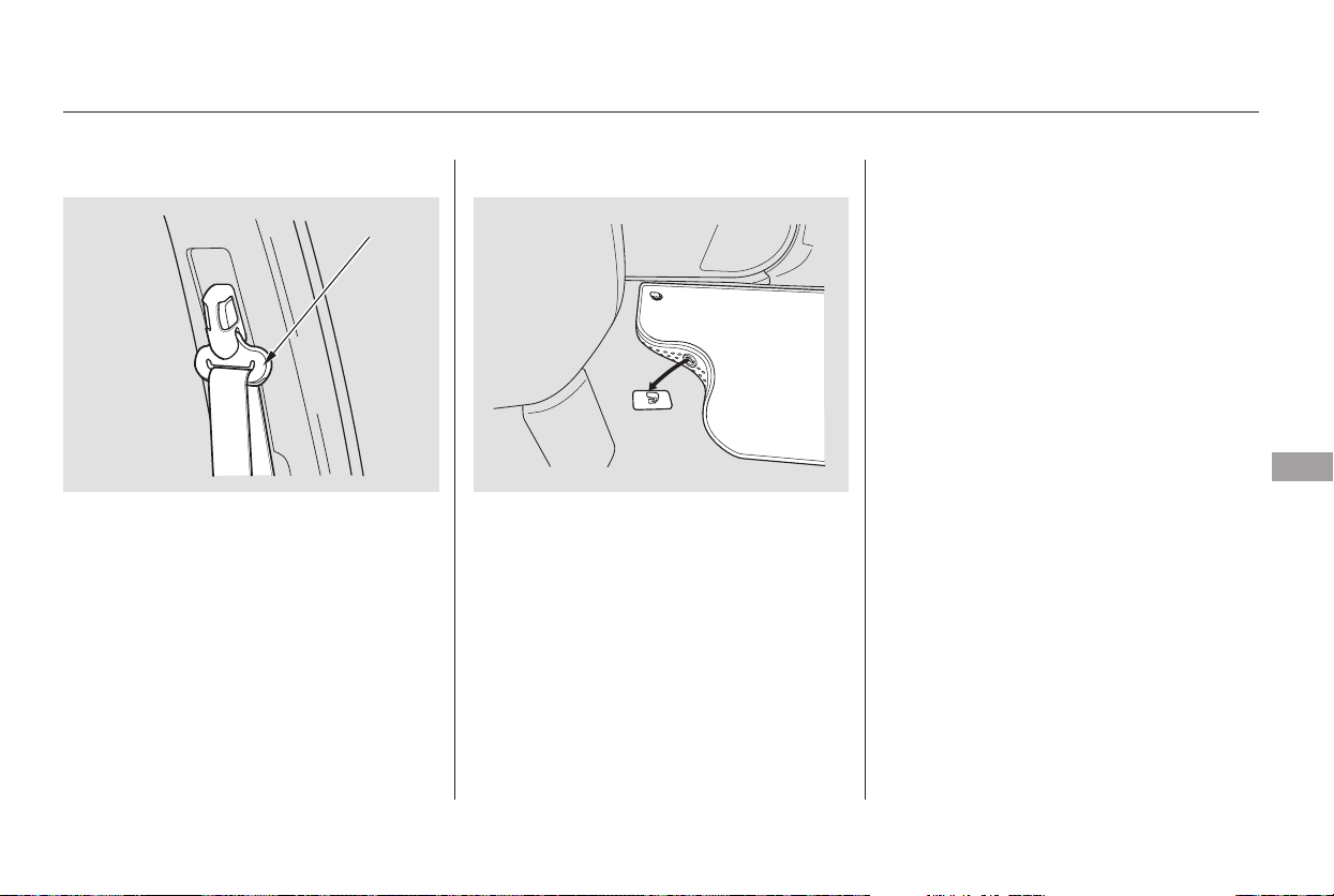
If your seat belts get dirty, use a soft
brush with a mixture of mild soap
and warm water to clean them. Do
not use bleach, dye, or cleaning
solvents. Let the belts air dry before
you use the vehicle.
Dirt build-up in the loops of the seat
belt anchors can cause the belts to
retract slowly. Wipe the insides of
the loops with a clean cloth
dampened in mild soap and warm
water or isopropyl alcohol.
The driver’s floor mat that came
with your vehicle hooks over the
floor mat anchor. This keeps the
floor mat from sliding forward and
possibly interfering with the pedals.
If you remove the driver’s floor mat,
make sure to re-anchor it when you
putitbackinyourvehicle.
If you use a non-Honda floor mat,
make sure it fits properly and that it
canbeusedwiththefloormat
anchors. Do not put additional floor
mats on top of the anchored mats.
Cleaning the Seat Belts, Floor Mats
Floor MatsCleaning the Seat Belts
Maintenance
343
LOOP
Main Menu
Table of Contents
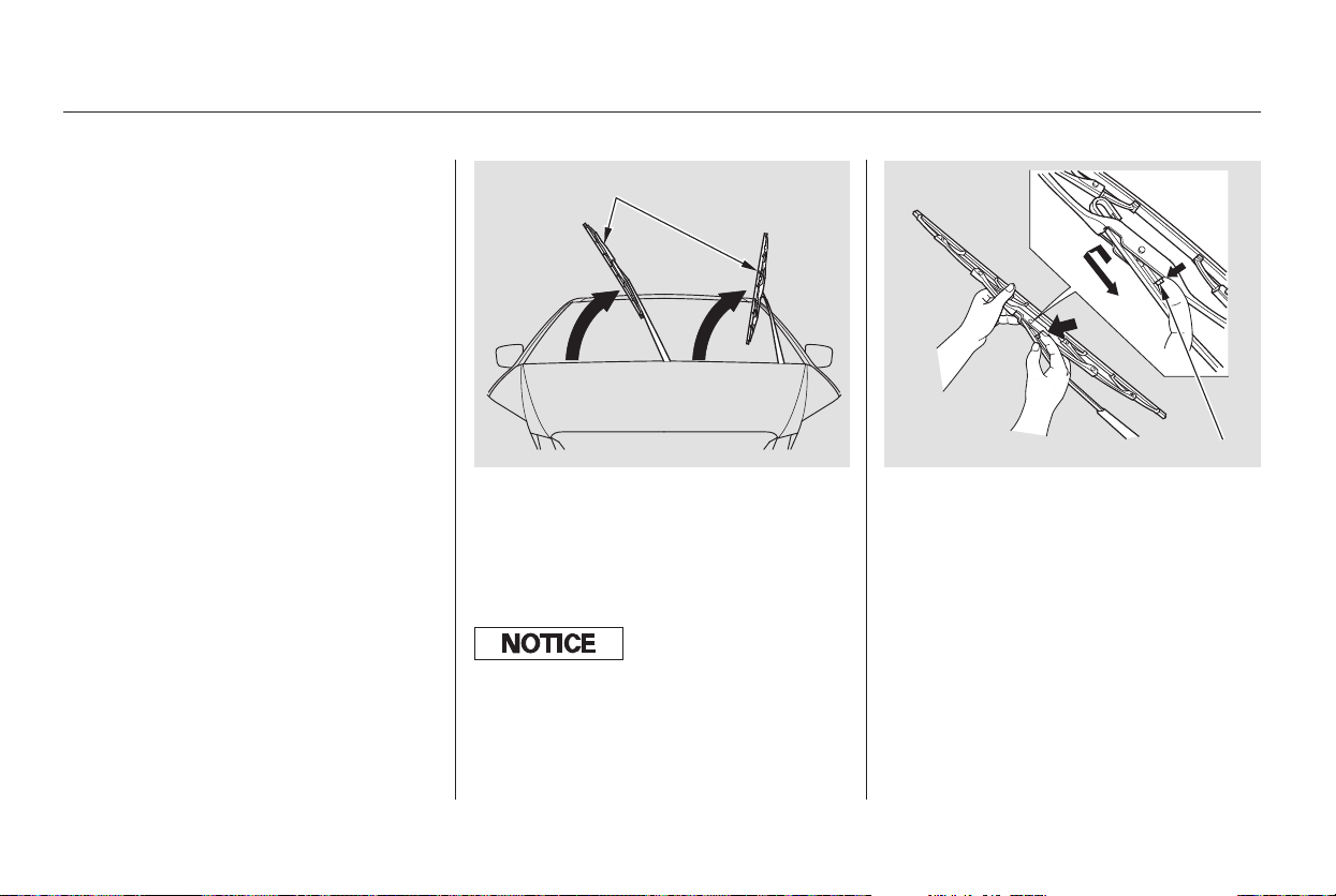
Disconnect the blade assembly
fromthewiperarmbypushingin
the lock tab. Hold the lock tab in
while you push the blade assembly
toward the base of the arm.
Check the condition of the wiper
blades at least every six months.
Replace them if you find signs of
cracking in the rubber, and areas
that are getting hard, or if they leave
streaks and unwiped areas when
used.
Raise the wiper arm off the
windshield.
Front windshield: Raise the driver’s
side first, then the passenger’s
side.
2.1.
Wiper Blades
344
WIPER ARMS
LOCK TAB
Do not open the hood when the wiper
arms are raised, or you will damage the
hood and the arms.
Main Menu
Table of Contents
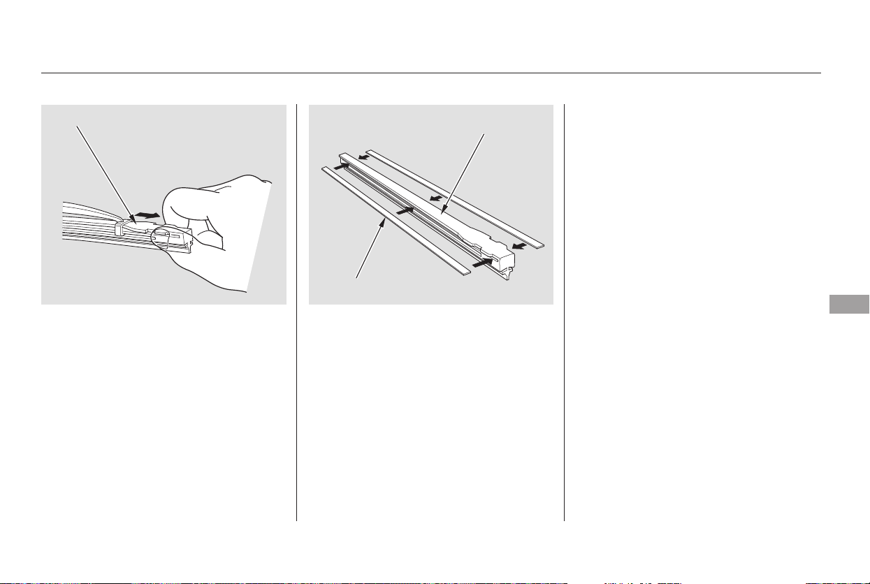
Remove the blade from its holder
by grasping the tabbed end of the
blade. Pull firmly until the tabs
come out of the holder.
Examine the new wiper blades. If
they have no plastic or metal
reinforcement along the back
edge, remove the metal
reinforcement strips from the old
wiper blade, and install them in
the slots along the edge of the new
blade.
Slide the new wiper blade into the
holder until the tabs lock.
Slide the wiper blade assembly
onto the wiper arm. Make sure it
locks in place.
Front windshield: Lower the
passenger’s side first, then the
driver’s side.
Lower the wiper arm against the
windshield.
6.
7.
4.
5.
3.
Wiper Blades
Maintenance
345
BLADE
BLADE
REINFORCEMENT
Main Menu
Table of Contents
To safely operate your vehicle, your
tires must be the proper type and
size, in good condition with adequate
tread, and correctly inflated.
The following pages give more
detailed information on how to take
care of your tires and what to do
when they need to be replaced.
Keeping the tires properly inflated
provides the best combination of
handling, tread life, and riding
comfort.
Underinflated tires wear unevenly,
adversely affect handling and fuel
economy, and are more likely to
fail from being overheated.
Overinflated tires can make your
vehicleridemoreharshly,are
more prone to damage from road
hazards, and wear unevenly.
The tire pressure monitoring system
(TPMS) warns you when a tire
pressure is low. See page for
more information.
We recommend that you visually
check your tires every day. If you
think a tire might be low, check it
immediately with a tire gauge.
Thecompactsparetirepressureis:
303
LX and EX
EX with Leather and Canadian
Touring models
Tire Size
Tire Size
Cold Tire Pressure for
Normal Driving
Front:
Rear:
Cold Tire Pressure for
Normal Driving
Front:
Rear:
On U.S. Touring model only
Tires
Inflation Guidelines
346
235/65R16 103T
33 psi (230 kPa ,
2.3 kgf/cm )
35 psi (240 kPa ,
2.4 kgf/cm
)
235/65R16 103T
35 psi (240 kPa ,
2.4 kgf/cm
)
35 psi (240 kPa ,
2.4 kgf/cm
)
60 psi (420 kPa , 4.2 kgf/cm )
Using tires that are excessively
worn or improperly inflated can
cause a crash in which you can
be seriously hurt or killed.
Follow all instructions in this
owner’s manual regarding tire
inflation and maintenance.
Main Menu
Table of Contents
CONTINUED
Excessive tread wear.
Cuts, splits, or cracks in the side
of the tire. Replace the tire if you
can see fabric or cord.
Youshouldgetyourowntire
pressure gauge and use it whenever
you check your tire pressures. This
will make it easier for you to tell if a
pressure loss is due to a tire problem
and not due to a variation between
gauges.
Bumps or bulges in the tread or
side of the tire. Replace the tire if
youfindeitheroftheseconditions.
Every time you check inflation, you
should also examine the tires for
damage, foreign objects, and wear.
Youshouldlookfor:
If you check the pressure when the
tires are hot [driven for several miles
(kilometers)], you will see readings 4
to6psi(30to40kPa,0.3to
0.4 kgf/cm ) higher than the cold
reading. This is normal; do not
release air to match the cold
pressure. The tires will be
underinflated.
Tubeless tires have some ability to
self-seal if they are punctured. You
should look closely for punctures if a
tire starts losing pressure.
For convenience, the recommended
tire sizes and cold air pressures are
on a label on the driver’s doorjamb.
Tire pressure for high speed driving
is the same as for normal driving.
For additional technical information,
see page .
Use a gauge to measure the air
pressure at least once a month. Even
tires that are in good condition may
lose one to two psi (10 to 20 kPa, 0.1
to 0.2 kgf/cm ) per month.
Remember to check the spare tire at
thesametime.
Check the air pressures when the
tires are cold. This means the
vehicle has been parked for at least
three hours, or driven less than 1
mile (1.6 km). Add or release air, if
needed, to match the recommended
cold tire pressures.
390
U.S. Touring model
Tire Size Cold Tire Pressure for
Normal Driving
Front:
Rear:
Tires
Tire Inspection
Maintenance
347
235-710R460A
104T
33 psi (230 kPa ,
2.3 kgf/cm
)
35 psi (240 kPa ,
2.4 kgf/cm
)
Main Menu
Table of Contents
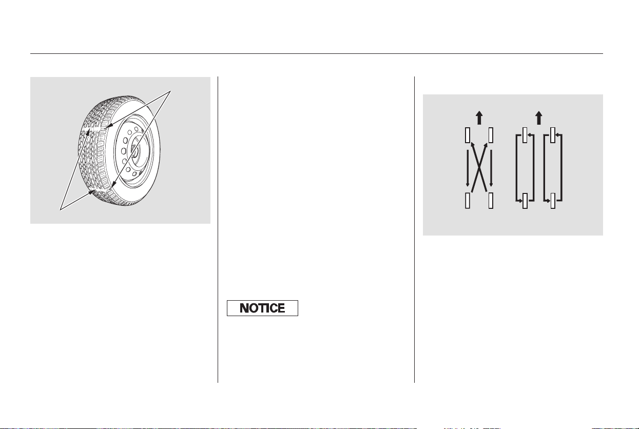
In addition to proper inflation,
correct wheel alignment helps to
decrease tire wear. If you find a tire
is worn unevenly, have your dealer
check the wheel alignment.
Have your dealer check the tires if
you feel a consistent vibration while
driving. A tire should always be
rebalanced if it is removed from the
wheel. When you have new tires
installed, make sure they are
balanced. This increases riding
comfort and tire life. For best results,
have the installer perform a dynamic
balance.
To help increase tire life and
distribute wear more evenly, rotate
the tires every 7,500 miles (12,000
km). Move the tires to the positions
showninthecharteachtimethey
are rotated. If you purchase
directional tires, rotate only front-to-
back.
Your vehicle’s tires have tread wear
indicators molded into the tread.
When the tread wears down to that
point, you will see a 1/2 inch (12.7
mm) wide band running across the
tread. This shows there is less than
1/16 inch (1.6 mm) of tread left on
the tire. A tire that is this worn gives
very little traction on wet roads. You
should replace the tire if you can see
the tread wear indicator in three or
more places around the tire.
On some models
Tires
Tire Maintenance Tire Rotation
348
Front Front
(For Non-directional
Tires and Wheels)
(For Directional
Tires and Wheels)
INDICATOR LOCATION MARKS
TREAD WEAR INDICATORS
Improper wheel weights can damage
your vehicle’s aluminum wheels. Use
only genuine Honda wheel weights f or
balancing.
Main Menu
Table of Contents
Replace your tires with radial tires of
the same size, load range, speed
rating, and maximum cold tire
pressure rating (as shown on the
tire’s sidewall). Mixing radial and
bias-ply tires on your vehicle can
reduce braking ability, traction, and
steering accuracy. Using tires of a
different size or construction can
cause the ABS to work inconsistently.
See page for DOT tire quality
grading information, and page
for tire size information.
Replacement wheels are available at
your dealer.
It is best to replace all four tires at
thesametime.Ifthatisnotpossible
or necessary, replace the two front
tires or two rear tires as a pair. If you
replace just the front tires, move the
rear tires to the front, and install the
new tires on the rear. Replacing just
onetirecanseriouslyaffectyour
vehicle’s handling.
If you ever replace a wheel, make
sure that the wheel’s specifications
match those of the original wheels.
Wheel:
Tire:
LX, and EX models
Touring model
LX, and EX models
Touring model
389
390
Replacing Tires Wheels and Tires
Tires
Maintenance
349
16x7J
235/65R16 103T
225 x 460A
235-710R460A 104T
Installing improper tires on your
vehicle can affect handling and
stability. This can cause a crash
in which you can be seriously
hurt or killed.
Always use the size and type of
tires recommended in this
owner’s manual.
Main Menu
Table of Contents

+Tires marked ‘‘M S’’ or ‘‘All
Season’’ on the sidewall have an all-
weather tread design suitable for
most winter driving conditions.
For the best performance in snowy
or icy conditions, you should install
snow tires or tire chains. They may
be required by local laws under
certain conditions.
When installing cables, follow the
manufacturer’s instructions, and
mount them as tight as you can.
Make sure they are not contacting
the brake lines or suspension. Drive
slowly with them installed. If you
hear them coming into contact with
the body or chassis, stop and
investigate. Remove them as soon as
you begin driving on cleared roads.
If you mount snow tires on your
vehicle, make sure they are radial
tires of the same size and load range
as original tires. Mount snow tires on
all four wheels. The traction
provided by snow tires on dry roads
maybelowerthanyouroriginaltires.
Check with the tire dealer for
maximum speed recommendations.
For snow tire information on the
Touring model, see page .
Because your vehicle has limited tire
clearance, mount only SAE Class ‘‘S’’
cable-type traction devices, with
rubber chain tensioners on the front
tires. Use traction devices only when
required by driving conditions or
local laws. Make sure they are the
correct size for your tires. Metal link-
type ‘‘chains’’ should not be used.
For tire chain information on the
Touring model, see page .
351
351
Tires
Winter Driving
Snow Tires
Tire Chains
350
Traction devices that are the wrong
size or improperly installed can
damage your vehicle’s brake lines,
suspension, body, and wheels. Stop
driving if they are hitting any part of
the vehicle.
Main Menu
Table of Contents

Your vehicle is equipped with the
Michelin PAX System which,
together with the Tire Pressure
Monitoring System (TPMS), enables
you to continue driving even if one or
more of your tires loses its pressure.
The tires and wheels on your vehicle
are specially designed for the PAX
system, and the PAX system is
specifically designed and fine-tuned
foryourvehicle.
Because of these reasons, use only
the wheels and tires designated in
this owner’s manual. Never mix PAX
system wheels or tires with
conventional wheels or tires.
There are no snow tires compatible
with the PAX system, and not all tire
chains are suitable for use on the
PAX system tires. To prevent tire
chain damage to your PAX system
tire or wheel, ensure that no part of
the chain contacts the PAX system.
Never use a tire repair agent in a
PAX system tire, and never repair
a PAX system tire by yourself.
Repair or replacement must be
done a Honda dealer or an
authorized Michelin PAX system
dealer.
Do not replace the PAX system tires
and wheels with conventional tires
andwheels.Doingsowoulddisable
the PAX system and the tire
pressure monitoring system (TPMS),
and may void your new vehicle
warranty.
If you must continue driving with a
flat tire, follow all the procedures
and precautions described on page
.356
On U.S. Touring model only
Tires
Michelin PAX System
Important Precautions
Maintenance
351
Main Menu
Table of Contents
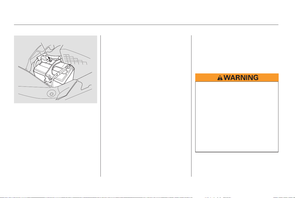
−
Check the condition of the battery
monthlybylookingatthetest
indicator window. The label on the
battery explains the test indicator’s
colors.
Check the terminals for corrosion (a
white or yellowish powder). To
remove it, cover the terminals with a
solution of baking soda and water. It
will bubble up and turn brown. When
this stops, wash it off with plain
water. Dry off the battery with a
cloth or paper towel. Coat the
terminals with grease to help prevent
future corrosion.
If additional battery maintenance is
needed, see your dealer or a
qualified technician.
Battery posts,
terminals, and related accessories
contain lead and lead compounds.
If you need to connect the battery to
a charger, disconnect both cables to
prevent damaging your vehicle’s
electrical system. Always disconnect
the negative ( ) cable first, and
reconnect it last.
WARNING:
Wash your hands after handling.
Checking the Battery
352
TEST INDICATOR WINDOW
The battery gives off explosive
hydrogen gas during normal
operation.
A spark or flame can cause the
battery to explode with enough
force to kill or seriously hurt you.
Wear protective clothing and a
face shield, or have a skilled
mechanic do the battery
maintenance.
Main Menu
Table of Contents
If you need to park your vehicle for
an extended period (more than one
month), there are several things you
should do to prepare it for storage.
Proper preparation helps prevent
deterioration and makes it easier to
get your vehicle back on the road. If
possible, store your vehicle indoors.
Fill the fuel tank.
Change the engine oil and filter.
Wash and dry the exterior
completely.
Cleantheinterior.Makesurethe
carpeting, floor mats, etc., are
completely dry.
Leave the parking brake off. Put
the transmission in Park.
Block the rear wheels.
If the vehicle is to be stored for a
longer period, it should be
supported on jackstands so the
tires are off the ground.
Leave one window open slightly (if
the vehicle is being stored
indoors).
Disconnect the battery.
Support the front and rear wiper
blade arms with a folded towel or
ragsotheydonottouchthe
windshield.
To minimize sticking, apply a
silicone spray lubricant to all door
and tailgate seals. Also, apply a
vehiclebodywaxtothepainted
surfaces that mate with the door
and tailgate seals.
Cover the vehicle with a
‘‘breathable’’ cover, one made
from a porous material such as
cotton. Non-porous materials, such
as plastic sheeting, trap moisture,
which can damage the paint.
If possible, periodically run the
engine until it reaches full
operating temperature (the
cooling fans cycle twice).
Preferably, do this once a month.
Vehicle Storage
Maintenance
353
Main Menu
Table of Contents

354
Main Menu

This section covers the more
common problems that motorists
experience with their vehicles. It
gives you information about how to
safely evaluate the problem and what
to do to correct it. If the problem has
stranded you on the side of the road,
you may be able to get going again.
If not, you will also find instructions
on getting your vehicle towed.
...............Driving with a Flat Tire . 356
......................Compact Spare Tire . 359
....................Changing a Flat Tire . 360
.............If the Engine Won’t Start . 366
Nothing Happens or the
Starter Motor Operates
........................Very Slowly . 366
The Starter Operates
................................Normally . 366
................................Jump Starting . 367
..............If the Engine Overheats . 369
.........Low Oil Pressure Indicator . 371
..........Charging System Indicator . 371
.......Malfunction Indicator Lamp . 372
...........................Readiness Codes . 372
...............Brake System Indicator . 373
..................Closing the Moonroof . 374
..............................................Fuses . 375
..............................Fuse Locations . 375
......................Emergency Towing . 381
Taking Care of the Unexpected
Taking Care of the Unexpected
355
Main Menu
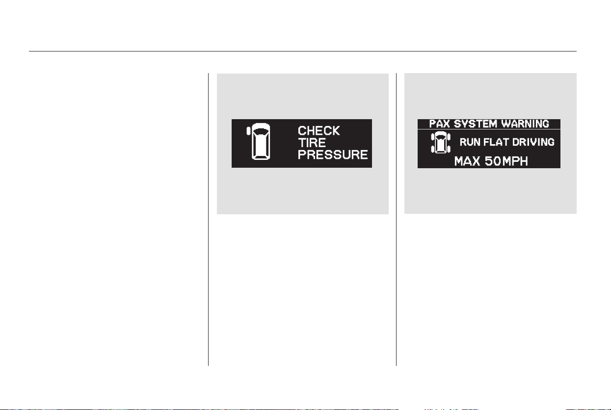
Your vehicle is equipped with the
Michelin PAX system. Since each
Michelin PAX system tire has an
inner support ring that allows it to
continue running without air, it may
be difficult to immediately judge
from its appearance if a tire is
punctured. Your vehicle is also
equipped with a tire pressure
monitoring system (TPMS), and this
system may be your first detection of
a flat tire. The TPMS monitors the air pressure
of all four tires whenever the ignition
switch is in the ON (II) position. It
will immediately sense if a tire starts
to lose its pressure, and give you
warning with the low tire pressure
indicator in the instrument panel and
a ‘‘CHECK TIRE PRESSURE’’
message on the multi-information
display. If the indicator and the
warning message do not come back
on again after you inflate the tire to
the specified value (see page ), it
was probably a natural loss of the air
pressure and you can continue
driving as before.
If the indicator and the message
come on again, you probably have a
flat tire. In this case, you will see a
‘‘PAX SYSTEM WARNING’’
message in the multi-information
display.
346
On U.S. Touring model only
Driving With a Flat Tire
Michelin PAX System
356
Main Menu
Table of Contents
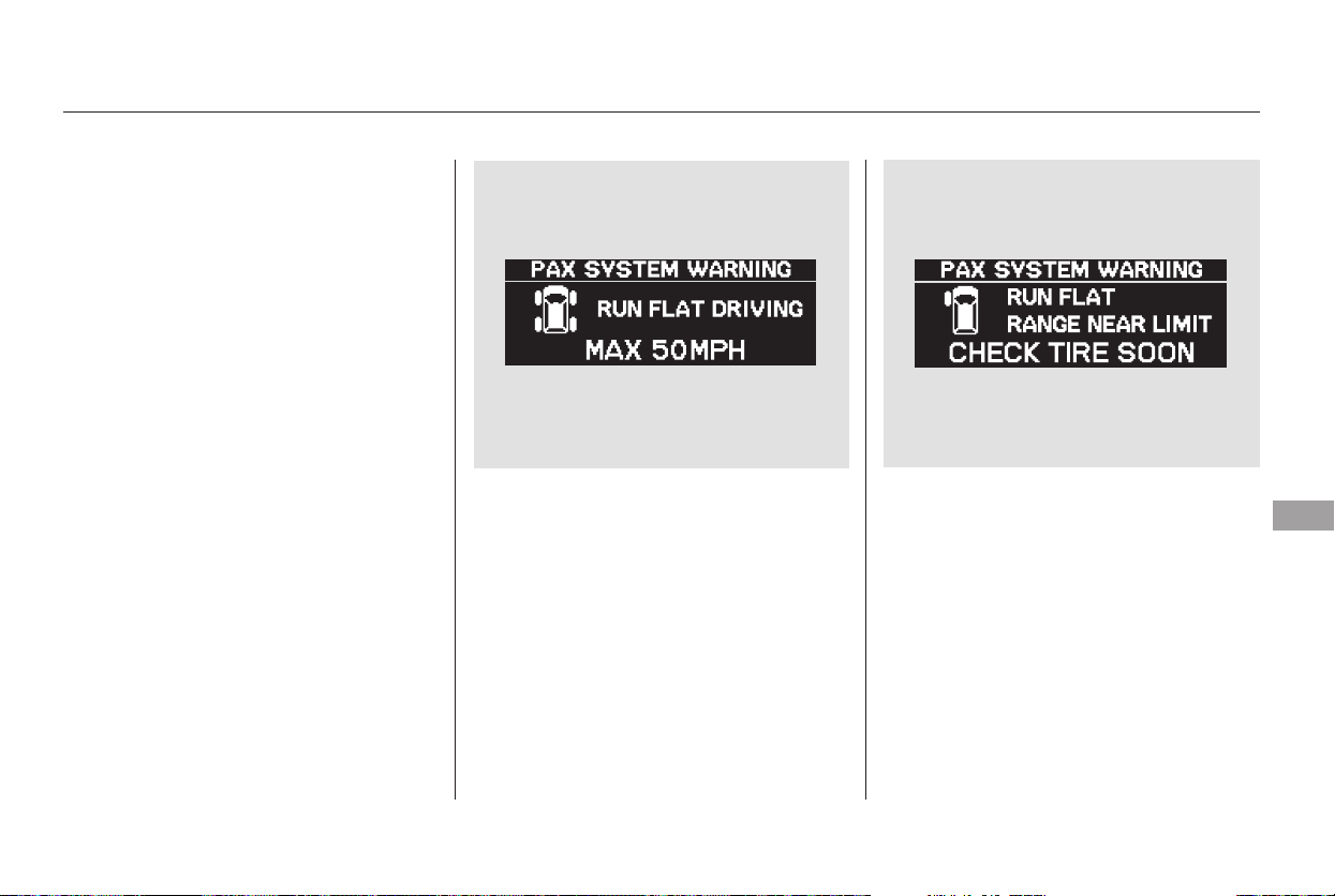
With the PAX system tires, you can
drive up to about 125 miles (200 km)
even if one or more of your tires are
punctured. This allows you to drive
to the nearest Honda dealer or
authorized Michelin PAX system
dealer to have the tire(s) repaired.
If you get a flat tire, never try to
repair it yourself, and never replace a
flat tire with a compact spare tire.
The above message shows that you
are driving your vehicle on a flat tire,
andshouldobservethe‘‘RUNFLAT
DRIVING’’ speed limit of 50 mph
(80 km/h). Drive to your nearest
Honda dealer or authorized Michelin
PAX system dealer, or call the PAX
help hotline at 1-877-PAXTIRE
(1-877-729-5473).
If the display changes to the above
message, it means that ‘‘RUN FLAT
DRIVING’’ is nearing the limit, and
you have to stop driving soon. Take
your vehicle to the nearest Honda
dealer or authorized Michelin PAX
system dealer as soon as possible.
Follow the instructions shown by the
multi-information display, and drive
very carefully.
CONTINUED
Driving With a Flat Tire
Taking Care of the Unexpected
357
Main Menu
Table of Contents
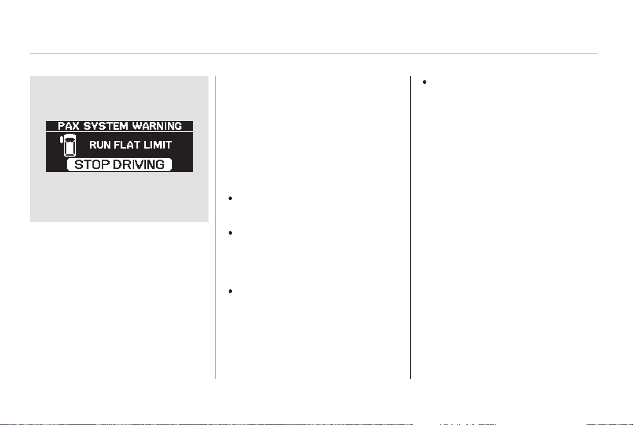
If you see the above message on the
multi-information display, you have
reached the limit of run flat driving,
and you should stop driving
immediately. Be aware that if you
continue to drive, the noise and
vibration level from the tire will
increase significantly, and the tire
may no longer be repairable.
Stop driving immediately when
you see a ‘‘RUN FLAT LIMIT
STOP DRIVING’’ message on the
multi-information display.
Continuous driving after this
message will make it impossible to
repair the tire.
If you cannot find a Honda dealer or
an authorized Michelin PAX system
dealer where you are driving, call the
PAX help hotline at 1-877-PAXTIRE
(1-877-729-8473).
Call a professional towing service
who can transport your vehicle on
flat-bed equipment. Never tow your
vehicle behind another vehicle with a
rope or chain. Flat-bed equipment is
the only way to transport your
vehicle.
Do not drive faster than 50 mph
(80 km/h).
Drive carefully. Your vehicle may
handle differently from when the
tires are properly inflated,
especially when cornering.
In its run flat mode, a PAX system
tire is somewhat noisier than when
it is fully inflated, this is normal.
Although your vehicle is capable of
runflatdriving,youshouldalways
observe the following:
Driving With a Flat Tire
Important Safety Precautions
358
Main Menu
Table of Contents
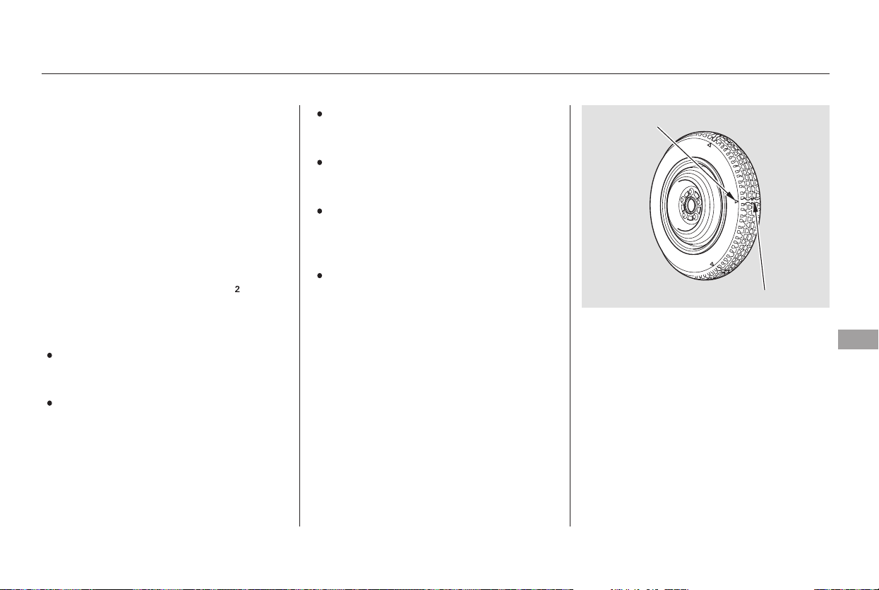
Replace the tire when you can see
the tread wear indicator bars. The
replacement should be the same size
and design tire, mounted on the
same wheel. The spare tire is not
designed to be mounted on a regular
wheel, and the spare wheel is not
designed for mounting a regular tire.
Do not mount snow chains on the
compact spare tire.
Turn off the VSA system (see
pages and ). Driving with
thecompactsparetiremay
activate the VSA.
Do not use your compact spare
tire on another vehicle unless it is
thesamemakeandmodel.
Do not use the compact spare tire
if you are towing a trailer.
This tire gives a harsher ride and
less traction on some road sur-
faces. Use greater caution while
driving.
Never exceed 50 mph (80 km/h)
under any circumstances.
Follow these precautions:
Check the inflation pressure of the
compact spare tire every time you
check the other tires. It should be
inflated to:
Use the compact spare tire as a
temporary replacement only. Get
your regular tire repaired or replaced,
and put it back on your vehicle as
soon as you can.
301 302
All models except U.S. Touring
Compact Spare Tire
Taking Care of the Unexpected
359
INDICATOR LOCATION MARK
TREAD WEAR INDICATOR BAR
60 psi (420 kPa , 4.2 kgf/cm )
Main Menu
Table of Contents
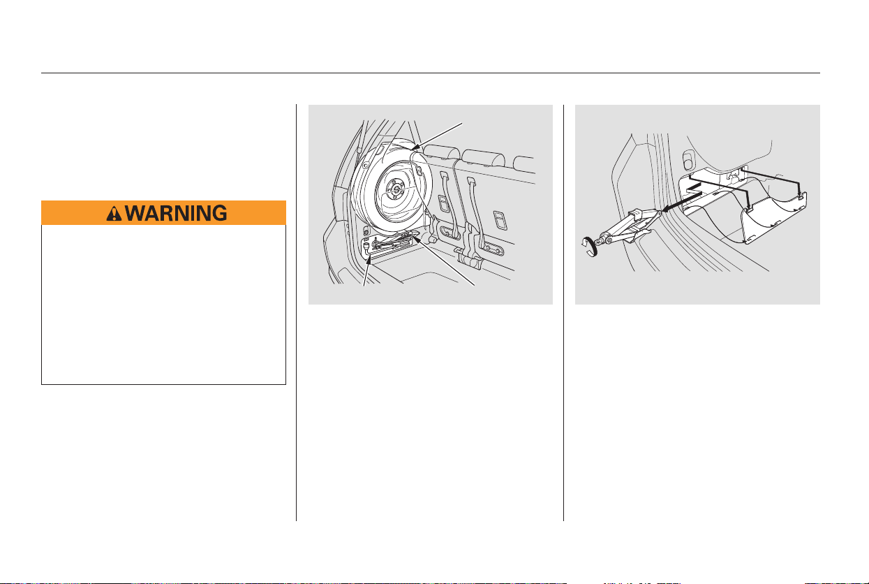
If you have a flat tire while driving,
stop in a safe place to change it.
Drive slowly along the shoulder until
you get to an exit or an area that is
far away from the traffic lanes.
Turn on the hazard warning lights,
and turn the ignition switch to
LOCK (0). Have all the
passengers get out of the vehicle
while you change the tire.
Park the vehicle on firm, level, and
non-slippery ground. Put the
transmission in Park. Apply the
parking brake. If you are towing a
trailer, unhitch the trailer.
The jack is behind a cover in the
cargo area on the driver’s side,
and tools are on the back of the
cover. Remove the cover by
pushing the tabs down and pulling
the cover out.
Turn the jack’s end
counterclockwise to loosen it, then
remove the jack.
2.
1. 3.
4.
Changing a Flat Tire
360
JACK
SPARE TIRE
TOOLS
The vehicle can easily roll off
the jack, seriously injuring
anyone underneath.
Follow the directions for
changing a tire exactly, and
never get under the vehicle
when it is supported only by the
jack.
Main Menu
Table of Contents
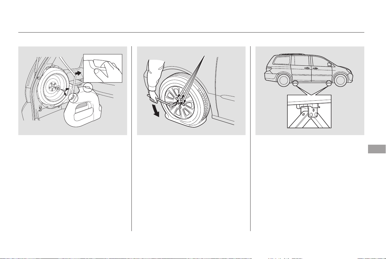
The spare tire is stored behind a
cover on the sidewall of the cargo
area on the driver’s side.
Remove the cover by holding the
two handles and pulling the cover
out.
Unscrew the wing bolt, and take
the spare tire out of its holder.
If you are changing a rear tire,
close the sliding door. Then turn
off the sliding door MAIN switch.
Loosen each wheel nut 1/2 turn
with the wheel nut wrench.
Placethejackunderthejacking
point nearest the tire you need to
change. Turn the end bracket
clockwise until the top of the jack
contacts the jacking point. Make
sure the jacking point tab is
restinginthejacknotch.
5.
6.
7.
8.
9.
CONTINUED
On EX model
Changing a Flat Tire
Taking Care of the Unexpected
361
WHEEL NUTS
Main Menu
Table of Contents
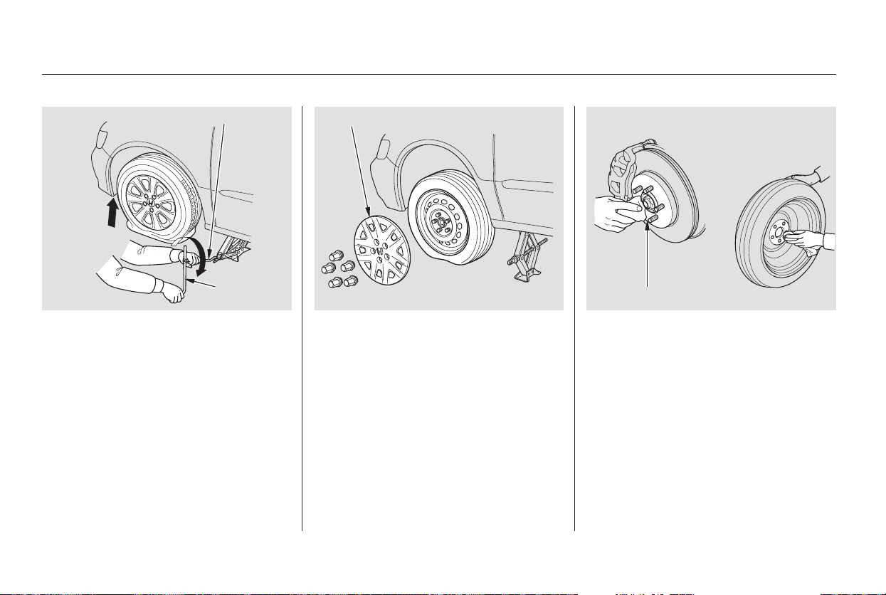
Use the extension and the wheel
nut wrench as shown to raise the
vehicle until the flat tire is off the
ground.
Remove the wheel nuts, then
remove the flat tire. Handle the
wheel nuts carefully; they may be
hot from driving. Place the flat tire
on the ground with the outside
surface facing up.
Do not attempt to forcibly pry the
wheel cover off with a screwdriver or
other tool. The wheel cover cannot
be removed without first removing
the wheel nuts.
Before mounting the spare tire,
wipe any dirt off the mounting
surface of the wheel and hub with
a clean cloth. Wipe the hub
carefully;itmaybehotfrom
driving.11.
10. 12.
On LX model
Changing a Flat Tire
362
WHEEL
WRENCH
EXTENSION
WHEEL COVER
HAB
Main Menu
Table of Contents
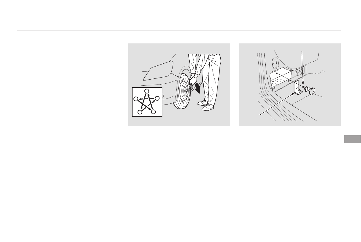
Tighten the wheel nuts securely in
the same crisscross pattern. Have
the wheel nut torque checked at
the nearest automotive service
facility.
Tighten the wheel nuts to:
Remove the bracket from the jack
storageareabyunscrewingthe
bracket mounting bolt.
Put the flat tire in the supplied
vinyl bag. This bag is in the jack
storage area.
You will find a u-shaped slit on the
carpet behind the seat bottom of
the third seat. Pull up the carpet at
the slit, and remove the plastic
screw with a coin.
Lower the vehicle to the ground,
and remove the jack.
Put on the spare tire. Put the
wheel nuts back on finger-tight,
then tighten them in a crisscross
pattern with the wheel nut wrench
until the wheel is firmly against
the hub. Do not try to tighten
them fully.
13.
14.
15. 17.
18.
16.
CONTINUED
Changing a Flat Tire
Taking Care of the Unexpected
363
BRACKET
BRACKET MOUNTING BOLT
94 lbf·ft (127 N·m , 13 kgf·m)
Main Menu
Table of Contents
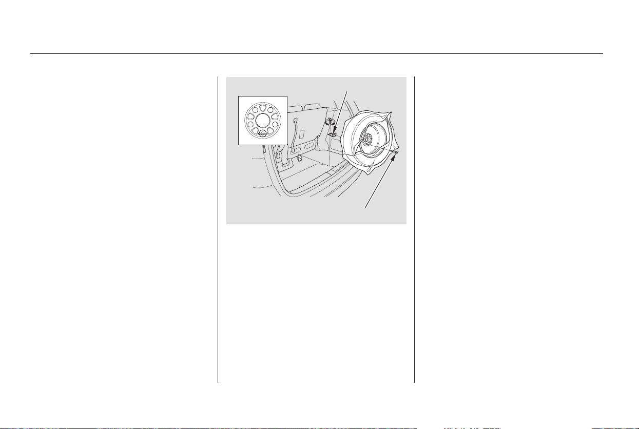
Adjust the seat-back of the third
seat to an upright position. Install
thebracketmountingboltonthe
attachment point as shown, and
tighten the bolt. Make sure the
bracket is securely locked.
Install the flat tire on the bracket
with the inside of the wheel facing
toward you. Install the tire
mounting wing bolt to the bracket
through one of the five wheel nut
holes as shown. Poke a hole in the
vinyl bag as needed. Secure the
flat tire by tightening the wing bolt.
Store the jack in its holder. To
store the jack, align the locator
stud in the holder with the hole in
the jack base. Turn the jack’s end
bracket clockwise to lock it in
place. Store the tools in the
holders on the back of the jack
storage cover.
Store the plastic screw in a
noticeable place.
Make sure to reinstall the plastic
screw after the flat tire is repaired
andinstalledonthevehicle.
Store the wheel cover in the spare
tire storage area.
19.
20.
21.
22.
23.
On LX model
Changing a Flat Tire
364
BRACKET
TIRE MOUNTING WING BOLT
Main Menu
Table of Contents
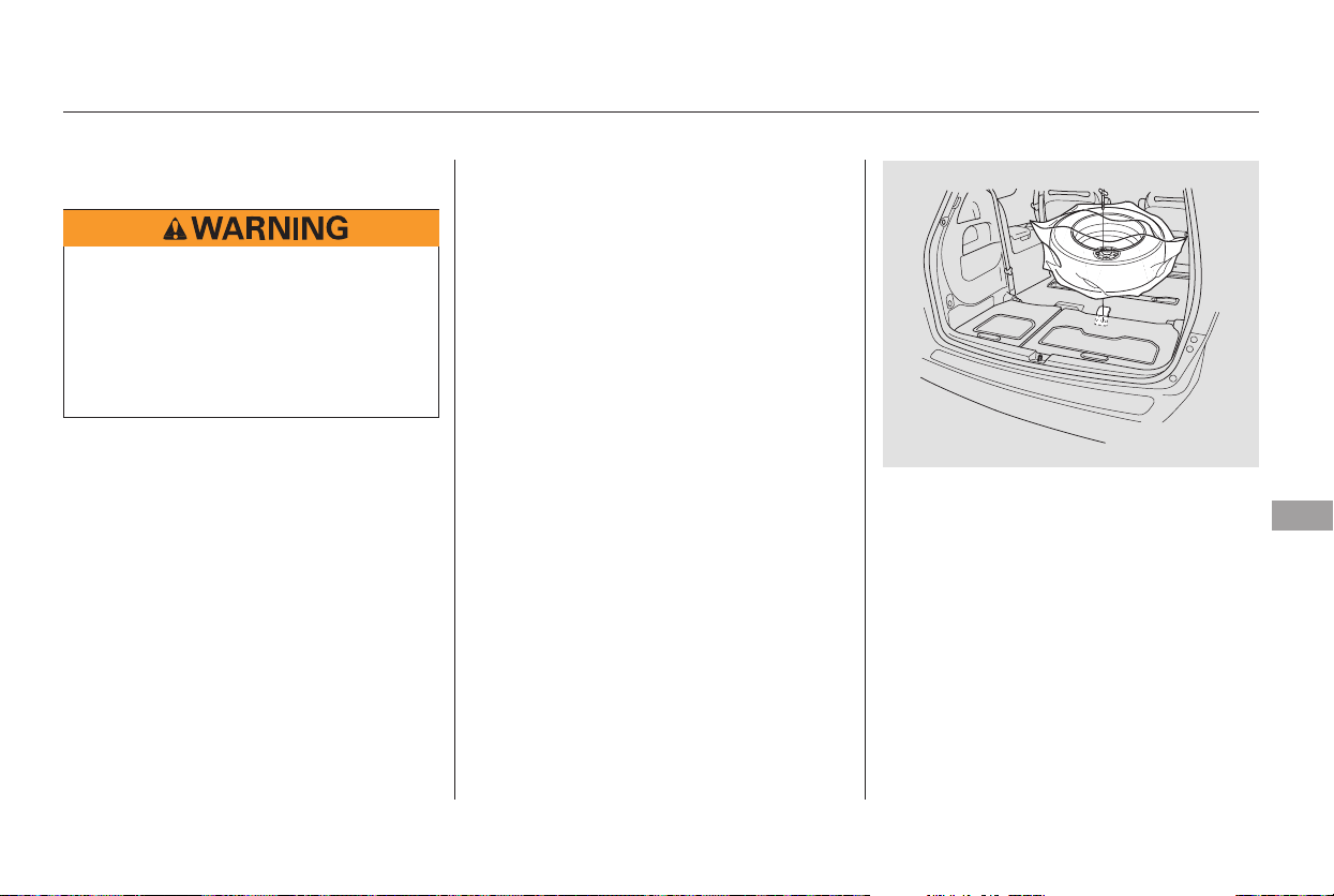
Place the flat tire face down on the
attachment point. Put the tire
mountingwingboltinthe
attachment point through one of
the five wheel nut holes as shown.
Poke holes in the vinyl bag. Secure
the flat tire by tightening the wing
bolt.
Follow step 21 through 24 on page
.
When the third seat is folded, the
flat tire is secured to the floor on top
of the folded seat.
Pull up the U-shaped carpet piece,
fold it, and tack the end under the
carpet.
Remove the plastic screw as
described in the previous
procedure.
Install the spare tire storage cover.
1.
3.
4.
2.
364
24.
Changing a Flat Tire
Storing a Flat Tire on the Folded
Third Seat
Taking Care of the Unexpected
365
Loose items can fly around the
interior in a crash and could
seriously injure the occupants.
Store the wheel, jack, and tools
securely before driving.
Main Menu
Table of Contents

Diagnosing why the engine won’t
start falls into two areas, depending
on what you hear when you turn the
key to START (III):
You hear nothing, or almost
nothing. The engine’s starter
motor does not operate at all, or
operates very slowly.
You can hear the starter motor
operating normally, or the starter
motor sounds like it is spinning
faster than normal, but the engine
does not start up and run.
When you turn the ignition switch to
START (III), you do not hear the
normal noise of the engine trying to
start. You may hear a clicking sound
or series of clicks, or nothing at all.
Check these things:
Check the transmission interlock.
The transmission must be in Park
orNeutralorthestarterwillnot
operate.
Turn the ignition switch to ON (II).
Turn on the headlights, and check
their brightness. If the headlights
areverydimordonotcomeonat
all, the battery is discharged. See
on page .
Turn the ignition switch to START
(III). If the headlights do not dim,
check the condition of the fuses. If
thefusesareOK,thereis
probably something wrong with
the electrical circuit for the
ignition switch or starter motor.
You will need a qualified
technician to determine the
problem (see
on page ).
If the headlights dim noticeably or
go out when you try to start the
engine, either the battery is
discharged or the connections are
corroded. Check the condition of the
battery and terminal connections
(see page ). You can then try
jump starting the vehicle from a
booster battery (see page ).
In this case, the starter motor’s
speed sounds normal, or even faster
than normal, when you turn the
ignition switch to START (III), but
the engine does not run.
Are you using the proper starting
procedure? Refer to
on page .
367
352
367
293
381
Nothing Happens or the Starter
Motor Operates Very Slowly
Jump Starting
Emergency Towing
The Starter Operates Normally
Starting the
Engine
IftheEngineWon’tStart
366
Main Menu
Table of Contents
Are you using a properly coded
key? An improperly coded key will
cause the immobilizer system
indicator in the instrument panel
to blink rapidly (see page ).
Do you have fuel? Check the fuel
gauge; the low fuel indicator may
not be working.
There may be an electrical
problem, such as no power to the
fuel pump. Check all the fuses
(see page ).
Ifyoufindnothingwrong,youwill
need a qualified technician to find
the problem. See
on page .
Although this seems like a simple
procedure, you should take several
precautions.
Open the hood, and check the
physical condition of the battery.
In very cold weather, check the
condition of the electrolyte. If it
seems slushy or frozen, do not try
jump starting until it thaws.
You cannot start your vehicle by
pushing or pulling it.
Turn off all the electrical acces-
sories: heater, A/C, climate
control, audio system, lights, etc.
Put the transmission in Neutral or
Park, and set the parking brake.
1.
2.
376
381
129
CONTINUED
Emergency
Towing
Jump Starting
To Jump Start Your Vehicle:
If the Engine Won’t Start, Jump Starting
Taking Care of the Unexpected
367
A battery can explode if you do
not follow the correct procedure,
seriously injuring anyone
nearby.
Keep all sparks, open flames,
and smoking materials away
from the battery.
If a battery sits in extreme cold, the
electrolyte inside can f reeze.
Attempting to jump start with a frozen
battery can cause it to rupture.
Main Menu
Table of Contents
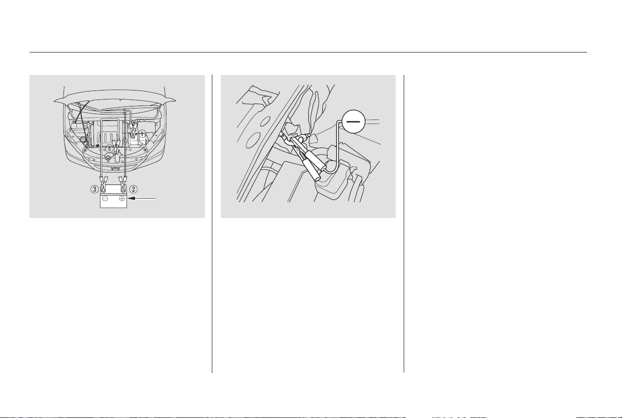
−
+
+
If the booster battery is in another
vehicle, have an assistant start
that vehicle and run it at a fast idle.
Start the vehicle. If the starter
motor still operates slowly, check
that the jumper cables have good
metal-to-metal contact.
Once the vehicle is running,
disconnect the negative cable from
your vehicle, then from the
booster battery. Disconnect the
positive cable from the vehicle,
and then from the booster battery.
Keep the ends of the jumper cables
away from each other and any metal
on the vehicle until everything is
disconnected. Otherwise, you may
cause an electrical short.
Connect the second jumper cable
to the negative ( ) terminal on
the booster battery. Connect the
other end to the grounding strap
as shown. Do not connect this
jumper cable to any other part of
the engine.
The numbers in the illustration
show you the order to connect the
jumper cables.
Connect one jumper cable to the
positive ( ) terminal on your
vehicle’s battery. Connect the
other end to the positive ( )
terminal on the booster battery.
4.
6.
7.
5.
3.
Jump Starting
368
BOOSTER
BATTERY
Main Menu
Table of Contents
The pointer of the vehicle’s
temperature gauge should stay in
the midrange. If it climbs to the red
mark, you should determine the
reason (hot day, driving up a steep
hill, etc.).
If your vehicle overheats, you should
take immediate action. The only
indication may be the temperature
gauge climbing to or above the red
mark. Or you may see steam or
spray coming from under the hood.
If you see steam and/or spray
coming from under the hood, turn
off the engine. Wait until you see
no more signs of steam or spray,
then open the hood.
If you do not see steam or spray,
leave the engine running, and
watch the temperature gauge. If
the high heat is due to overloading,
the engine should start to cool
down almost immediately. If it
does, wait until the temperature
gauge comes down to the midpoint,
then continue driving.
If the temperature gauge stays at
the red mark, turn off the engine.
Safely pull to the side of the road.
Put the transmission in Park, and
set the parking brake. Turn off all
accessories, and turn on the
hazard warning indicators.
1.
2.
3.
4.
IftheEngineOverheats
Taking Care of the Unexpected
369
Steam and spray from an
overheated engine can
seriously scald you.
Do not open the hood if steam
is coming out.
Driving with the temperature gauge
pointer at the red mark can cause
serious damage to your engine.
Main Menu
Table of Contents
Look for any obvious coolant leaks,
such as a split radiator hose.
Everything is still extremely hot,
so use caution. If you find a leak, it
must be repaired before you
continue driving (see
on page ).
If you do not find an obvious leak,
check the coolant level in the
radiator reserve tank. Add coolant
if the level is below the MIN mark.
If there was no coolant in the
reserve tank, you may need to add
coolant to the radiator. Let the
engine cool down until the pointer
reaches the middle of the tempera-
ture gauge, or lower, before check-
ing the radiator.
Using gloves or a large heavy
cloth, turn the radiator cap
counterclockwise, without pushing
down, to the first stop. After the
pressure releases, push down on
the cap, and turn it until it comes
off.
If the temperature stays normal,
check the coolant level in the
radiator reserve tank. If it has
gone down, add coolant to the
MAX mark. Put the cap back on
tightly.
Put the radiator cap back on
tightly. Run the engine, and watch
the temperature gauge. If it goes
back to the red mark, the engine
needs repair (see
on page ).
Start the engine, and set the
temperature control dial to
maximum (climate control to
FULL AUTO at 90°F/32°C). Add
coolant to the radiator up to the
base of the filler neck. If you do
not have the proper coolant
mixture available, you can add
plain water. Remember to have
the cooling system drained and
refilled with the proper mixture as
soon as you can.
5.
6.
7.
8.
9.
10.
11.
381
381
Emergency
Towing
Emergency
Towing
IftheEngineOverheats
370
Removing the radiator cap
while the engine is hot can
cause the coolant to spray out,
seriously scalding you.
Always let the engine and
radiator cool down before
removing the radiator cap.
Main Menu
Table of Contents
Safely pull off the road, and shut
off the engine. Turn on the hazard
warning indicators.
Let the vehicle sit for a minute.
Open the hood, and check the oil
level (see page ). An engine
very low on oil can lose pressure
during cornering and other driving
maneuvers.
If necessary, add oil to bring the
level back to the full mark on the
dipstick (see page ).
Start the engine, and watch the oil
pressure indicator. If it does not go
out within 10 seconds, turn off the
engine. There is a mechanical
problem that needs to be repaired
before you can continue driving
(see on page
).
You will also see a ‘‘CHECK
ENGINE OIL LEVEL’’ message in
the multi-information display when
this indicator comes on.
This indicator should never
come on when the engine is
running. If it starts flashing or stays
on, the oil pressure has dropped very
low or lost pressure. Serious engine
damage is possible and you should
take immediate action.
You will also see a ‘‘CHECK
CHARGING SYSTEM’’ message in
the multi-information display when
this indicator comes on.
Go to a service station or garage
where you can get technical
assistance.
Immediately turn off all electrical
accessories. Try not to use other
electrically operated controls such as
the power windows. Keep the engine
running; starting the engine will
discharge the battery rapidly.
If the charging system
indicator comes on brightly
when the engine is running, the
battery is not being charged.
1.
2.
3.
4.
281
328
381
On Touring model On Touring model
Low Oil Pressure Indicator
Emergency Towing
Charging System Indicator
Low Oil Pressure Indicator, Charging System Indicator
Taking Care of the Unexpected
371
Running the engine with low oil
pressure can cause serious mechanical
damage almost immediately. Turn of f
the engine as soon as you can safely get
the vehicle stopped.
Main Menu
Table of Contents
This indicator may also come on
along with the ‘‘D’’ indicator.
If your vehicle battery has been
disconnected or gone dead, these
codes are erased. It takes at least
three days of driving under various
conditions to set the codes again.
You will also see a ‘‘CHECK
EMISSION SYSTEM’’ message in
the multi-information display when
this indicator comes on.
Your vehicle has certain ‘‘readiness
codes’’ that are part of the on-board
diagnostics for the emissions
systems. In some states, part of the
emissions testing is to make sure
these codes are set. If they are not
set, the test cannot be completed.
To check if they are set, turn the
ignition switch to ON (II), without
starting the engine. The malfunction
indicator lamp will come on for 20
seconds. If it then goes off, the
readiness codes are set. If it blinks 5
times, the readiness codes are not
set. If possible, do not take your
vehicle for a state emissions test
until the readiness codes are set.
Refer to
for more information (see page ).
If the indicator remains on, or the
fuel cap was not loose or missing,
have your vehicle checked by a
dealer as soon as possible.
If you have recently refueled your
vehicle, the indicator could come on
because of a loose or missing fuel fill
cap. Tighten the cap until it clicks at
least three times. Tightening the cap
will not turn the indicator turn off
immediately; it takes at least three
days of normal driving.
If this indicator comes on
while driving, it means one
of the engine’s emissions control
systems may have a problem. Even
though you may feel no difference in
your vehicle’s performance,
continued operation may cause
serious damage.
395
On Touring model
Readiness Codes
Malfunction Indicator Lamp
State Emissions Testing
Malfunction Indicator Lamp, Readiness Codes
372
If you keep driving with the
malf unction indicator lamp on, you can
damage your vehicle’s emissions
controls and engine. Those repairs may
not be covered by your vehicle’s
warranties.
Main Menu
Table of Contents
However, if the brake pedal does not
feel normal, you should take
immediate action. A problem in one
part of the system’s dual circuit
design will still give you braking at
two wheels. You will feel the brake
pedal go down much farther before
the vehicle begins to slow down, and
you will have to press harder on the
pedal.
Slow down by shifting to a lower
gear, and pull to the side of the road
when it is safe. Because of the long
distance needed to stop, it is
hazardous to drive the vehicle. You
should have it towed and repaired as
soon as possible (see
on page ).
If you must drive the vehicle a short
distance in this condition, drive
slowly and carefully.
If the brake system indicator comes
on while driving, the brake fluid level
is probably low. Press lightly on the
brake pedal to see if it feels normal.
If it does, check the brake fluid level
thenexttimeyoustopataservice
station (see page ).
If the fluid level is low, take your
vehicle to a dealer, and have the
brake system inspected for leaks or
worn brake pads.
The brake system
indicator normally
comesonwhenyou
turn the ignition switch to ON (II),
and as a reminder to check the
parking brake. It will stay on if you
do not fully release the parking
brake.
If the ABS indicator and the VSA
indicator come on with the brake
system indicator, have the vehicle
inspected by your dealer
immediately.
You will also see a ‘‘CHECK BRAKE
SYSTEM’’ message on the multi-
information display when this
indicator comes on.335
381
On Touring model
Emergency
Towing
Brake System Indicator
Taking Care of the Unexpected
373
U.S. Canada
Main Menu
Table of Contents
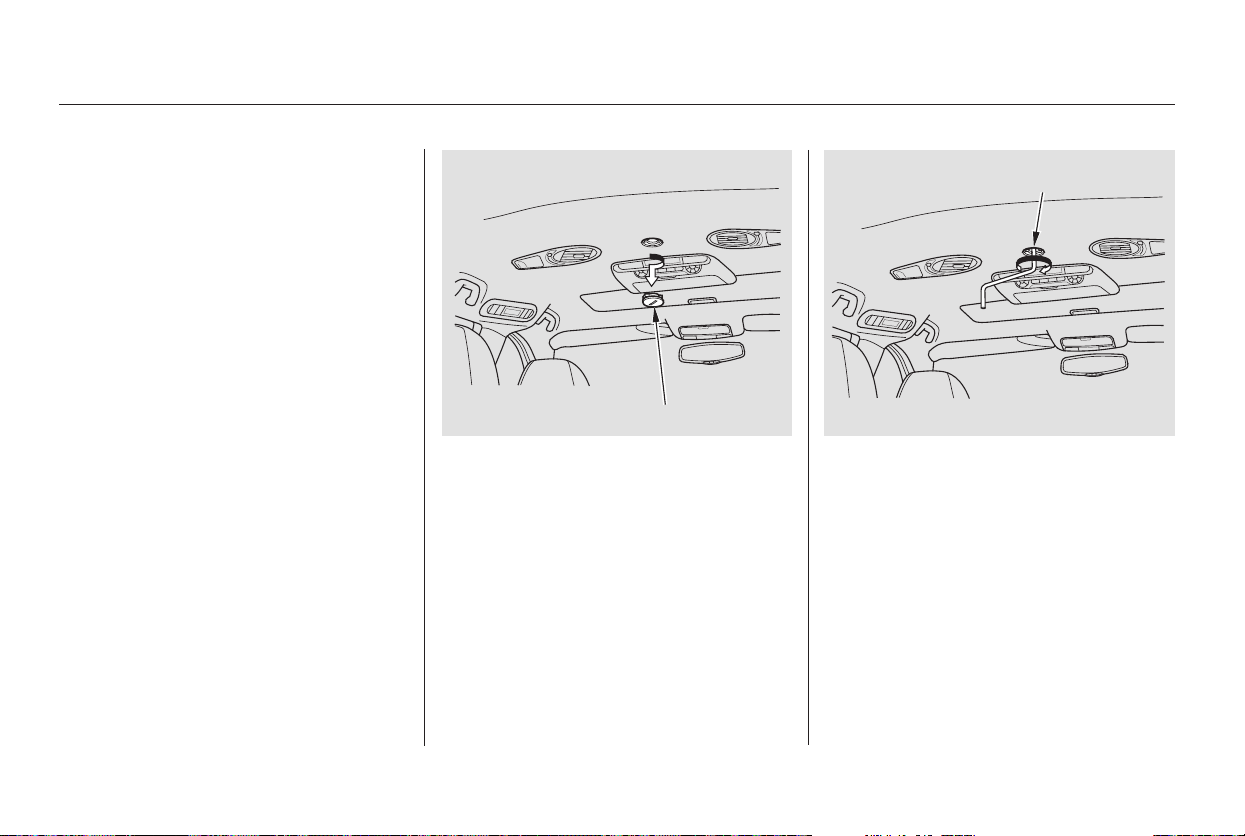
If the electric motor will not close
the moonroof, do the following:
Check the fuse for the moonroof
motor (see page ). If the fuse
is blown, replace it with one of the
same or lower rating.
Try closing the moonroof. If the
new fuse blows immediately or the
moonroof motor still does not
operate, you can close the
moonroof manually.
Get the moonroof wrench out of
the tool kit in the cargo area.
Use a screwdriver or coin to
remove the round plug in the
center of the headliner.
Insert the moonroof wrench into
the socket behind this plug. Turn
the wrench until the moonroof is
fully closed.
Remove the wrench. Reinstall the
round plug.
If you need to close the moonroof
manually, it means the moonroof
opening/closing function is
developing a problem. Have your
vehicle checked by your dealer.
4.
6.
5.
1.
2.
3.
379
Closing the Moonroof
374
ROUND PLUG
SOCKET
Main Menu
Table of Contents
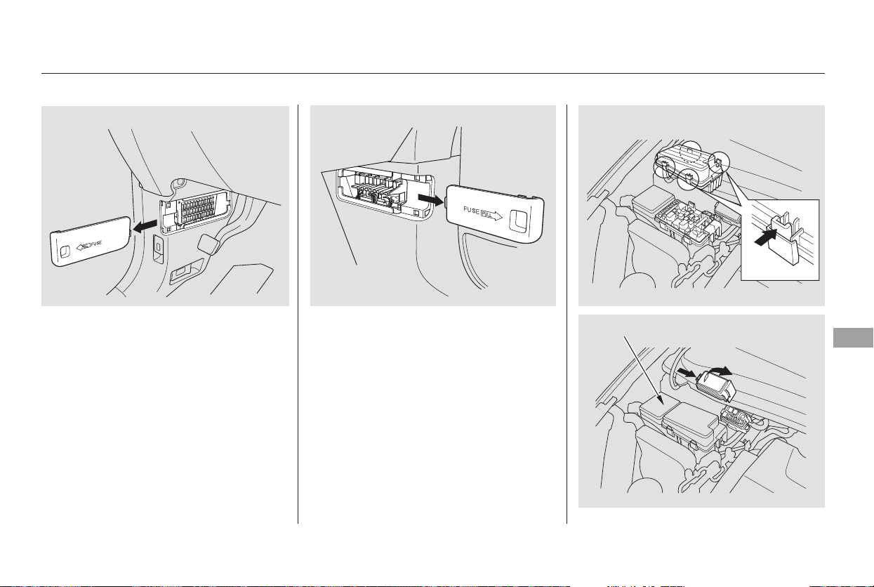
The vehicle’s fuses are contained in
four fuse boxes (three, if the vehicle
does not have a rear entertainment
system).
To open the passenger’s fuse box,
pull the right edge of the cover.
Theinteriorfuseboxesarelocated
under the dashboard on the driver’s
and passenger’s side.
The primary under-hood fuse box is
on the passenger’s side. To open it,
pushthetabsasshown.
The secondary under-hood fuse box
is behind the primary fuse box.
Fuses
Taking Care of the Unexpected
375
DRIVER’S SIDE INTERIOR
PASSENGER’S SIDE
INTERIOR
PRIMARY UNDER-HOOD FUSE BOX
SECONDARY UNDER-HOOD FUSE BOX
Main Menu
Table of Contents
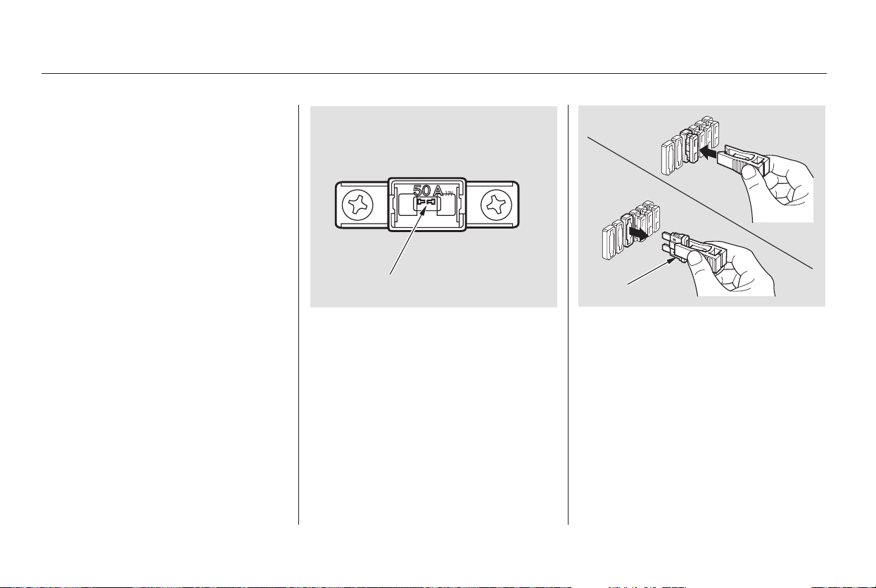
Check the smaller fuses in the
under-hood fuse box and all the
fuses in the interior fuse boxes by
pulling out each fuse with the fuse
puller provided in the primary
under-hood fuse box.
Turn the ignition switch to LOCK
(0). Make sure the headlights and
all other accessories are off.
Remove the cover from the fuse
box.
Check each of the large fuses in
the primary under-hood fuse box
by looking through the top at the
wire inside. Removing these fuses
requires a Phillips-head
screwdriver.
If something electrical in your
vehicle stops working, the first thing
youshouldcheckforisablownfuse.
Determine from the chart on pages
through , or the diagram on
thefuseboxlid,whichfuseorfuses
control that device. The diagram for
theinteriordriver’ssidefuseboxis
on the kick panel below the fuse box.
Check those fuses first, but check all
the fuses before deciding that a
blown fuse is the cause. Replace any
blown fuses, and check if the device
works.
1.
2.
3. 4.
378 380
Checking and Replacing Fuses
Fuses
376
FUSE
BLOWN
FUSE PULLER
Main Menu
Table of Contents
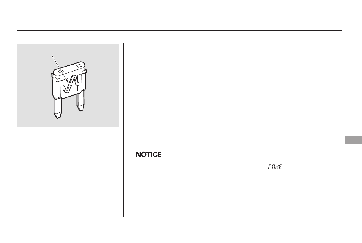
If the replacement fuse of the
same rating blows in a short time,
there is probably a serious
electrical problem with your
vehicle. Leave the blown fuse in
that circuit, and have your vehicle
checked by a qualified mechanic.
If the driver’s power window fuse is
removed, the AUTO feature of the
driver’s window will be disabled. You
should reset the AUTO feature (see
page ).
If the radio fuse is removed, the
audio system will disable itself. The
nexttimeyouturnontheradioyou
will see ‘‘ ’’ in the frequency
display. Use the preset buttons to
enter the five-digit code (see page
).
If you cannot drive the vehicle
without fixing the problem, and you
do not have a spare fuse, take a fuse
of the same rating or a lower rating
from one of the other circuits. Make
sureyoucandowithoutthatcircuit
temporarily (such as the accessory
power socket or radio).
If you replace the blown fuse with a
spare fuse that has a lower rating, it
might blow out again. This does not
indicate anything wrong. Replace the
fuse with one of the correct rating as
soon as you can.
Look for a burned wire inside the
fuse. If it is burned, replace the
fuse with one of the spare fuses of
thesameratingorlower.
5.
6.
162
229
CONTINUED
On EX, and Touring models
Fuses
Taking Care of the Unexpected
377
BLOWN
Replacing a f use with one that has a
higher rating greatly increases the
chances of damaging the electrical
system. If you do not have a
replacement f use with the proper
rating f or the circuit, install one with
a lower rating.
Main Menu
Table of Contents
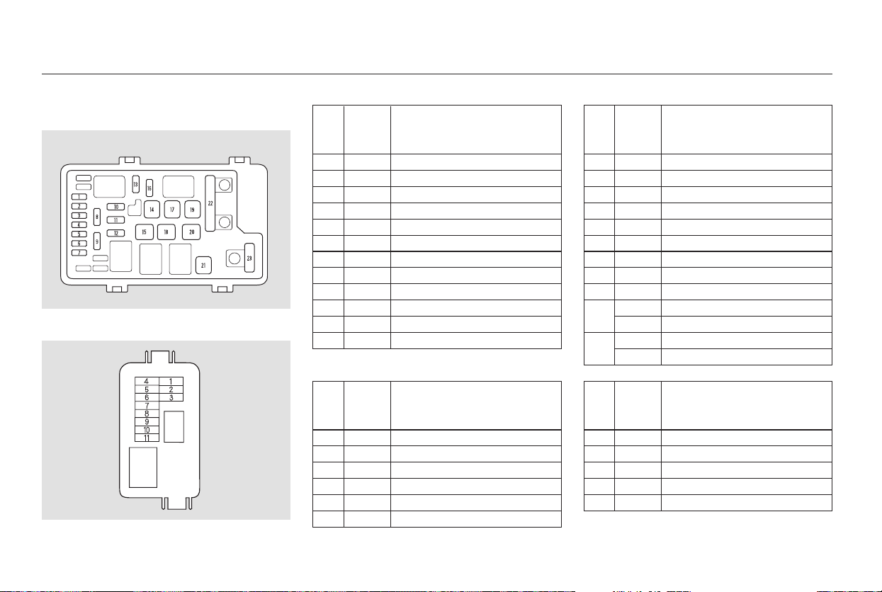
−
−
+
+
−
*
*
*
*
*
*
*
*
No. Amps. No.
No. Amps.
Circuits Protected Amps. Circuits Protected
No. Amps.Circuits Protected Circuits Protected
1
2
3
4
5
6
7
8
9
10
11
12
10 A
30 A
10 A
15 A
10 A
10 A
7.5 A
15 A
30 A
30 A
7.5 A
If equipped
13
14
15
16
17
18
19
20
21
22
23
If equipped
1
2
3
4
5
6
40 A
40 A
40 A
20 A
20 A
Left Headlight Low
Rear Defroster Coil
Left Headlight High
Small Lights
Right Headlight Low
Right Headlight High
Back Up
FI ECU
Condenser Fan
Not used
Cooling Fan
MG Clutch
20 A
30 A
40 A
15 A
30 A
30 A
30 A
40 A
40 A
70 A
120 A
50 A
40 A
Horn, Stop
Defroster
Back Up
Hazard
VSA Motor
VSA
Option 1
Option 2
Heater Motor
BASF/B
Battery
BIGIMain
Power Window
7
8
9
10
11
10 A
10 A
7.5 A
7.5 A
Not Used
Left Power Sliding Door
Right Power Sliding Door
Power Tailgate
Premium
AC Inverter
Front Fog Light
ACM
TPMS
Not Used
Rear Entertainment System
:
:
Fuse Locations
378
PRIMARY UNDER-HOOD FUSE BOX
SECONDARY UNDER-HOOD FUSE BOX
Main Menu
Table of Contents
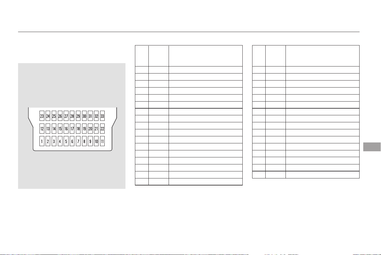
−
−−
−
*
**
*
**
**
**
**
**
No. Amps. No. Amps. Circuits ProtectedCircuits Protected
1
2
3
4
5
6
7
8
9
10
11
12
13
14
15
16
17
15 A
10 A
15 A
7.5 A
7.5 A
7.5 A
20 A
10 A
7.5 A
30 A
20 A
20 A
20 A
20 A
20 A
18
19
20
21
22
23
24
25
26
27
28
29
30
31
32
33
15 A
15 A
10 A
7.5 A
10 A
7.5 A
20 A
20 A
20 A
20 A
20 A
10 A
10 A
7.5 A
If equipped
IG PCU
IG Fuel Pump
IG Washer
IG Meter
IG SRS
IGP
Left Rear Window
Right Rear Window
Passenger’s Window
Driver’s Window
Moonroof
Not Used
IG HAC
Not Used
ACC
HAC Option
Not Used
IG Coil
Daytime Running Light
LAF
Radio
Interior Lights
Back Up
Door Lock
Front Accessory Socket
OPDS
IG, Wiper
Not Used
Left PSD Closer
Dr Power Seat Slide
ADJ Pedals
Dr Power Seat Recline
Power Tailgate Closer
:
:
Canadian models
Fuse Locations
Taking Care of the Unexpected
379
INTERIOR FUSE BOX
Driver’s Side
Front
Main Menu
Table of Contents
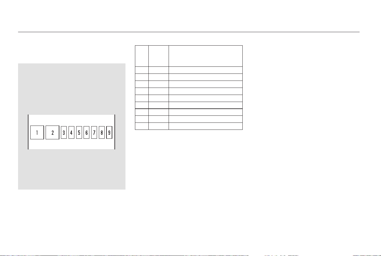
−
−
*
*
Amps.No. Circuits Protected
30 A
15 A
20 A
15 A
7.5 A
20 A
10 A
1
2
3
4
5
6
7
8
9
If equipped
Rear Blower
Not Used
DBW
Door Lock
Not Used
Heated Seat
Instrument Panel
Right Power Sliding Door
Accessory Sockets
:
Fuse Locations
380
INTERIOR FUSE BOX
Passenger’s Side
Main Menu
Table of Contents
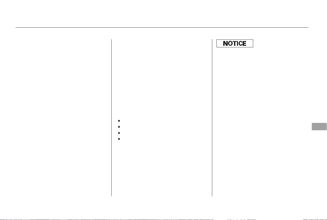
−
−If your vehicle needs to be towed,
call a professional towing service or
organization. Never tow your vehicle
with just a rope or chain. It is very
dangerous.
Therearetwowaystotowyour
vehicle.
The operator
loads your vehicle on the back of a
truck.
With the front wheels on the ground,
it is best to tow the vehicle no farther
than 50 miles (80 km), and keep the
speedbelow35mph(55km/h).
The tow
truck uses two pivoting arms that go
under the tires (front or rear) and lift
them off the ground. The other two
tires remain on the ground.
If, due to damage, your vehicle must
be towed with the front wheels on
the ground, do the following:
Release the parking brake.
Start the engine.
ShifttoD,thentoN.
Turn off the engine.
CONTINUED
Flatbed Equipment
Wheel-lift Equipment
This is the best way to
transport your vehicle, and it is
only way to transport a Touring
model.
This is
an acceptable way to tow your
vehicleexceptfortheTouring
model.
Emergency Towing
Taking Care of the Unexpected
381
Improper towing preparation will
damage the transmission. Follow the
above procedure exactly. If you cannot
shif t the transmission or start the
engine, your vehicle must be
transported with the f ront wheels of f
the ground.
Main Menu
Table of Contents
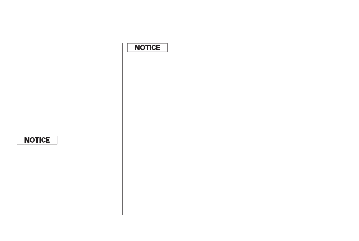
If you decide to tow your vehicle
with all four wheels on the ground,
make sure you use a properly-
designed and attached tow bar.
Prepare the vehicle for towing as
described previously, and leave the
ignition switched in the
ACCESSORY (I) position so the
steering wheel does not lock. Make
sure the radio and any items plugged
into the accessory power sockets are
turned off so they do not run down
the battery.
Emergency Towing
382
The steering system can be damaged if
the steering wheel is locked. Leave the
ignition switch in Accessory (I), and
make sure the steering wheel turns
f reely bef ore you begin towing.
Trying to lif t or tow your vehicle by the
bumpers will cause serious damage.
The bumpers are not designed to
support the vehicle’s weight.
Main Menu
Table of Contents

Thediagramsinthissectiongive
you the dimensions and capacities of
your vehicle, and the locations of the
identification numbers. It also
includes information you should
know about your vehicle’s tires and
emissions control systems.
................Identification Numbers . 384
................................Specifications . 386
DOT Tire Quality Grading
.......................(U.S Vehicles) . 388
Uniform Tire Quality
..................................Grading . 388
.................................Treadwear . 388
......................................Traction . 388
.............................Temperature . 389
.................................Tire Labeling . 390
.......................Emissions Controls . 392
.....................The Clean Air Act . 392
Crankcase Emissions Control
....................................System . 392
Evaporative Emissions Control
....................................System . 392
Onboard Refueling Vapor
................................Recovery . 392
...Exhaust Emissions Controls . 393
....................PGM-FI System . 393
Ignition Timing Control
................................System . 393
Exhaust Gas Recirculation
...................(EGR) System . 393
Three Way Catalytic
...........................Converter . 393
....................Replacement Parts . 393
..Three Way Catalytic Converter . 394
..............State Emissions Testing . 395
....Testing of Readiness Codes . 395
Technical Information
Technical Information
383
Main Menu
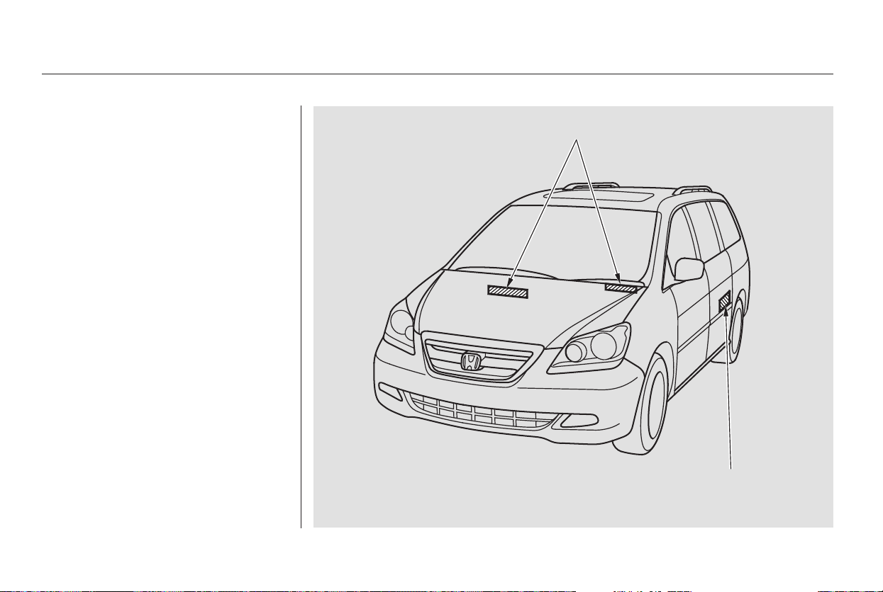
Your vehicle has several identifying
numbers in various places.
The vehicle identification number
(VIN) is the 17-digit number your
dealer uses to register your vehicle
for warranty purposes. It is also
necessary for licensing and insuring
your vehicle. The easiest place to
find the VIN is on a plate fastened to
the top of the dashboard. You can
seeitbylookingthroughthe
windshield on the driver’s side. It is
also on the certification label
attached to the driver’s doorjamb,
and is stamped on the engine
compartment bulkhead. The VIN is
also provided in bar code on the
certification label.
Identification Numbers
384
VEHICLE IDENTIFICATION NUMBER
CERTIFICATION LABEL
Main Menu
Table of Contents
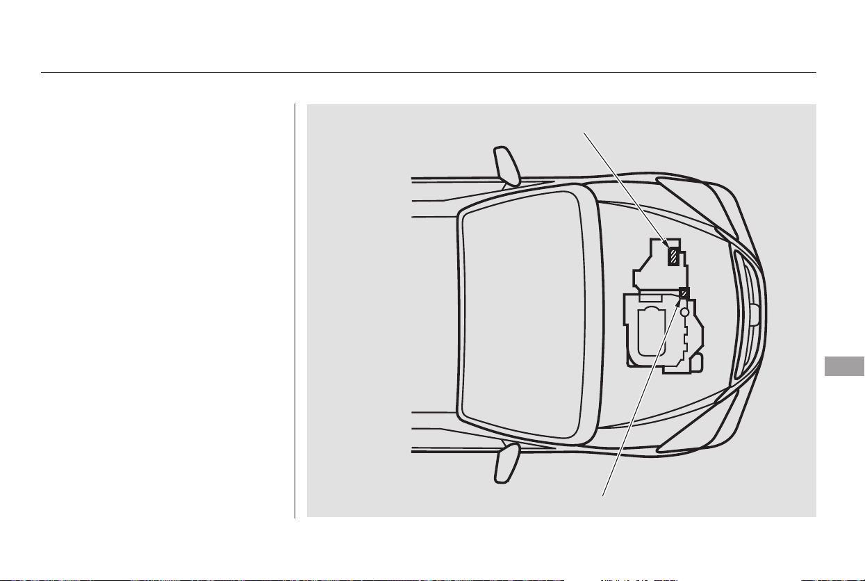
The engine number is stamped into
the engine block. It is on the front.
The transmission number is on a
label on the side of the transmission.
Identification Numbers
Technical Information
385
TRANSMISSION NUMBER
ENGINE NUMBER
Main Menu
Table of Contents
−−
*
*
*
*
*
*
*
*
Specifications
386
Dimensions
Weights
Capacities
Air Conditioning
Engine
201.0 in (5,106 mm)
77.1 in (1,958 mm)
66.8 in (1,697 mm)
66.7 in (1,694 mm)
118.1 in (3,000 mm)
68.8 in (1,748 mm)
70.0 in (1,778 mm)
8,210 lbs (9,815 kg)
Length
Width
Height
Wheelbase
Track
Gross vehicle weight rating
Gross combined weight
rating (GCWR)
See the tire information label atta-
ched to the driver’s doorjamb.
Excluding the oil remaining in the engine.
0.16 US gal (0.6
)
Including the coolant in the reserve tank and that remaining in the
engine.
Reserve tank capacity:
Fuel tank
Engine
coolant
Engine oil
Automatic
transmission
fluid
Windshield
washer
reservoir
4.8 US qt (4.5 )
2.6 US qt (2.5
)
8.5 US qt (8.0 )
3.3 US qt (3.1 )
5.3 US qt (5.0
)
4.2 US qt (4.0
)
4.5 US qt (4.3 )
2.48 US gal (9.4 )
1.85 US gal (7.0 )
Refrigerant type
Charge quantity
Lubricant type
32 34 oz (850 900 g)
ND-OIL8
HFC-134a (R-134a)
Water cooled 4-stroke
SOHC VTEC, 6-cylinder,
gasoline engine
Type
BorexStroke
Displacement
Compression ratio
Spark plugs
PKJ16DR-M11
IZFR5K-11
10.0 : 1
212 cu-in (3,471 cm
)
3.50 x 3.66 in (89.0 x 93.0 mm)
Front
Rear
1:LX
2 : EX, Touring
1:
2:
Change
Total
Change
Including
filter
Without
filter
Total
Change
Total
U.S. Vehicles
Canada Vehicles
Approx.
21 US gal (80
)
NGK:
DENSO:
1
2
1
2
Main Menu
Table of Contents
−
*
*
*
−
−
−
−
−
−
−
−
−
−
−
−
−
−
−
−
−
−
−
*
*
*
Specifications
Technical Information
387
Alignment
Tires
Fuses
Battery
Lights
60 W (HB3)12 V
12 V
21 W
51 W (HB4)
21 W
12 V
12 V
Toe-in
Camber
Caster
0.00 in (0.0 mm)
0.08 in (2.0 mm)
0°
0°30’
2°32’
Size
Pressure
235/65R16 103T
235-710R460A 104T
T135/80D17 103M
33 psi (230 kPa , 2.3 kgf/cm
)
12 V 35 W
60 psi (420 kPa , 4.2 kgf/cm )
35 psi (240 kPa , 2.4 kgf/cm )
35 psi (240 kPa , 2.4 kgf/cm )
12 V
12 V
12 V
12 V
12 V
21 W
21/5 W
21 W
12 V
12 V
12 V 2 W
12 V
12 V
1.5 CP
3CP
5W
16 W
5W
5W
Interior
Under-hood
See page 379 or the fuse label
attached to the dashboard.
See page 380 or the fuse label
attached to the inside of the fuse
box door under the dashboard.
See page 378 or the fuse box
cover.
Capacity
12 V
12 V
72 AH/20 HR
60 AH/5 HR
12 V
12 V
8W
4W(2CP)
Headlights
Front turn signal
Front fog lights
Front turn signal lights
Front parking/side marker
lights
Rear turn signal lights
Stop/Taillights
Taillights
Back-up lights
License plate light
High-mount brake light
Individual map lights
Vanity mirror lights
Cargo area light
Door courtesy light
Front
Rear
Front
Rear
Front
U.S. Touring model
Front/Rear
Spare
Front
Rear
Spare
(Amber)
(Amber)
Driver’s side
Passenger’s side
1:
2:
3:
LX, EX, and Canadian Touring models
EX with Leather and Canadian Touring models
Front
Rear
High
Low
1
2
3
Main Menu
Table of Contents

−The tires on your car meet all U.S.
Federal Safety Requirements. All
tires are also graded for treadwear,
traction, and temperature perform-
ance according to
Department of Transportation
(DOT) standards. The following
explains these gradings.
Quality grades can be found where
applicable on the tire sidewall
between the tread shoulder and the
maximum section width. For
example:
All passenger car tires must conform
to Federal Safety Requirements in
addition to these grades.
The treadwear grade is a compara-
tive rating based on the wear rate of
the tire when tested under controlled
conditions on a specified government
test course. For example, a tire
graded 150 would wear one and one-
half (1 1/2) times as well on the
government course as a tire graded
100. The relative performance of
tires depends upon the actual condi-
tions of their use, however, and may
depart significantly from the norm
due to variations in driving habits,
service practices, and differences in
road characteristics and climate.
The traction grades, from highest to
lowest, are AA, A, B, and C. Those
grades represent the tire’s ability to
stop on wet pavement as measured
under controlled conditions on
specified government test surfaces
of asphalt and concrete. A tire
marked C may have poor traction
performance.
Warning: The traction grade
assignedtothistireisbasedon
straight-ahead braking traction tests,
and does not include acceleration,
cornering, hydroplaning, or peak
traction characteristics.
DOT Tire Quality Grading (U.S. Vehicles)
Uniform Tire Quality Grading
Treadwear 200
Traction AA
Temperature A
Treadwear Traction AA, A, B, C
388
Main Menu
Table of Contents

−
The temperature grades are A (the
highest), B, and C, representing the
tire’s resistance to the generation of
heat and its ability to dissipate heat
when tested under controlled
conditions on a specified indoor
laboratory test wheel. Sustained high
temperature can cause the material
of the tire to degenerate and reduce
tire life, and excessive temperature
can lead to sudden tire failure. The
grade C corresponds to a level of
performance which all passenger car
tires must meet under the Federal
Motor Vehicle Safety Standard No.
109. Grades B and A represent
higher levels of performance on the
laboratory test wheel than the
minimum required by law.
Warning: The temperature grade for
this tire is established for a tire that
is properly inflated and not over-
loaded. Excessive speed, underinfla-
tion, or excessive loading, either
separately or in combination, can
cause heat buildup and possible tire
failure.
DOT Tire Quality Grading (U.S. Vehicles)
Temperature A,B,C
Technical Information
389
Main Menu
Table of Contents

−
−
−
−
−
−
−
−
−
−
−
−
The tires that came on your vehicle
have a number of markings. Those
you should be aware of are described
below.
Whenever tires are replaced, they
should be replaced with tires of the
same size. Following is an example
of tire size with an explanation of
what each component means.
Rim diameter in inches.
Load index (a numerical code
associated with the maximum
load the tire can carry).
Speed symbol (an
alphabetical code indicating
the maximum speed rating).
Tire Identification Number (TIN) is
a group of numbers and letters that
look like the following example TIN.
Date of manufacture.
Tire type code.
Manufacturer’s
identification mark.
This indicates that the tire
meets all requirements of
the U.S. Department of
Transportation.
Max Press The maximum air
pressurethetirecan
hold.
The maximum load the
tire can carry at
maximum air pressure.
Max Load
Tire width in millimeters.
Aspect ratio (the tire’s section
height as a percentage of its
width).
Tire construction code (R
indicates radial).
R
16
DOT
B97R
FW6X
2202
235
65
103
T
Tire Labeling
Tire Size
Tire Identification Number
Maximum Tire Pressure
Maximum Tire Load
390
235/65R16 103T
DOT B97R FW6X 2202
Main Menu
Table of Contents

The PAX system tires have different
markings from conventional tire
markings. Following is an example of
PAX system tire size with an
explanation of what each component
means.
Tire width in millimeters.
Outside diameter of the tire in
millimeters.
Tire construction code (R
indicates radial)
Nominal diameter at the rim
seat in millimeters.
Symmetric
Load index (a numerical code
associated with the maximum
load the tire can carry).
Speed symbol (an
alphabetical code indicating
the maximum speed rating).
A
235
710
R
460
104
T
Tire Labeling (PAX System Tires)
PAX System Tire Labeling
Technical Information
391
235-710R460A 104T
Main Menu
Table of Contents

*
*
The burning of gasoline in your
vehicle’s engine produces several by-
products. Some of these are carbon
monoxide (CO), oxides of nitrogen
(NOx) and hydrocarbons (HC).
Gasoline evaporating from the tank
also produces hydrocarbons. Con-
trolling the production of NOx, CO,
and HC is important to the environ-
ment. Under certain conditions of
sunlight and climate, NOx and HC
react to form photochemical ‘‘smog.’’
Carbon monoxide does not contri-
bute to smog creation, but it is a
poisonous gas.
The United States Clean Air Act
sets standards for automobile
emissions. It also requires that
automobile manufacturers explain to
owners how their emissions controls
workandwhattodotomaintain
them. This section summarizes how
the emissions controls work.
Scheduled maintenance is on pages
and .
In Canada, Honda vehicles comply
with the Canadian emission
requirements, as specified in an
agreement with Environment
Canada, at the time they are
manufactured.
Your vehicle has a positive
crankcase ventilation system. This
keeps gasses that build up in the
engine’s crankcase from going into
the atmosphere. The positive
crankcase ventilation valve routes
them from the crankcase back to the
intake manifold. They are then
drawn into the engine and burned.
As gasoline evaporates in the fuel
tank, an evaporative emissions
control canister filled with charcoal
adsorbs the vapor. It is stored in this
canister while the engine is off. After
the engine is started and warmed up,
the vapor is drawn into the engine
and burned during driving.
The onboard refueling vapor
recovery (ORVR) system captures
the fuel vapors during refueling. The
vapors are adsorbed in a canister
filled with activated carbon. While
driving, the fuel vapors are drawn
into the engine and burned off.
323
324
The Clean Air Act
Crankcase Emissions Control
System
Evaporative Emissions Control
System
Onboard Refueling Vapor
Recovery
Emissions Controls
392
Main Menu
Table of Contents

The exhaust emissions controls
include four systems: PGM-FI,
ignition timing control, exhaust gas
recirculation and three way catalytic
converter. These four systems work
together to control the engine’s
combustion and minimize the
amount of HC, CO, and NOx that
comes out the tailpipe. The exhaust
emissions control systems are
separate from the crankcase and
evaporative emissions control
systems.
The PGM-FI system uses sequential
multiport fuel injection.
It has three subsystems: air intake,
engine control, and fuel control. The
powertrain control module (PCM)
uses various sensors to determine
how much air is going into the
engine. It then controls how much
fuel to inject under all operating
conditions.
This system constantly adjusts the
ignition timing, reducing the amount
of HC, CO, and NOx produced.
The exhaust gas recirculation (EGR)
system takes some of the exhaust
gas and routes it back into the intake
manifold. Adding exhaust gas to the
air/fuel mixture reduces the amount
of NOx produced when the fuel is
burned.
The three way catalytic converter is
in the exhaust system. Through
chemical reactions, it converts HC,
CO, and NOx in the engine’s exhaust
to carbon dioxide (CO ), nitrogen
(N ), and water vapor.
The emissions control systems are
designed and certified to work to-
gether in reducing emissions to
levels that comply with the Clean Air
Act. To make sure the emissions
remain low, you should use only new
Honda replacement parts or their
equivalent for repairs. Using lower
qualitypartsmayincreasethe
emissions from your vehicle.
The emissions control systems are
covered by warranties separate from
the rest of your vehicle. Read your
warranty manual for more informa-
tion.
2
2
Exhaust Emissions Controls Replacement Parts
PGM-FI System
Ignition Timing Control System
Exhaust Gas Recirculation (EGR)
System
Three Way Catalytic Converter
Emissions Controls
Technical Information
393
Main Menu
Table of Contents
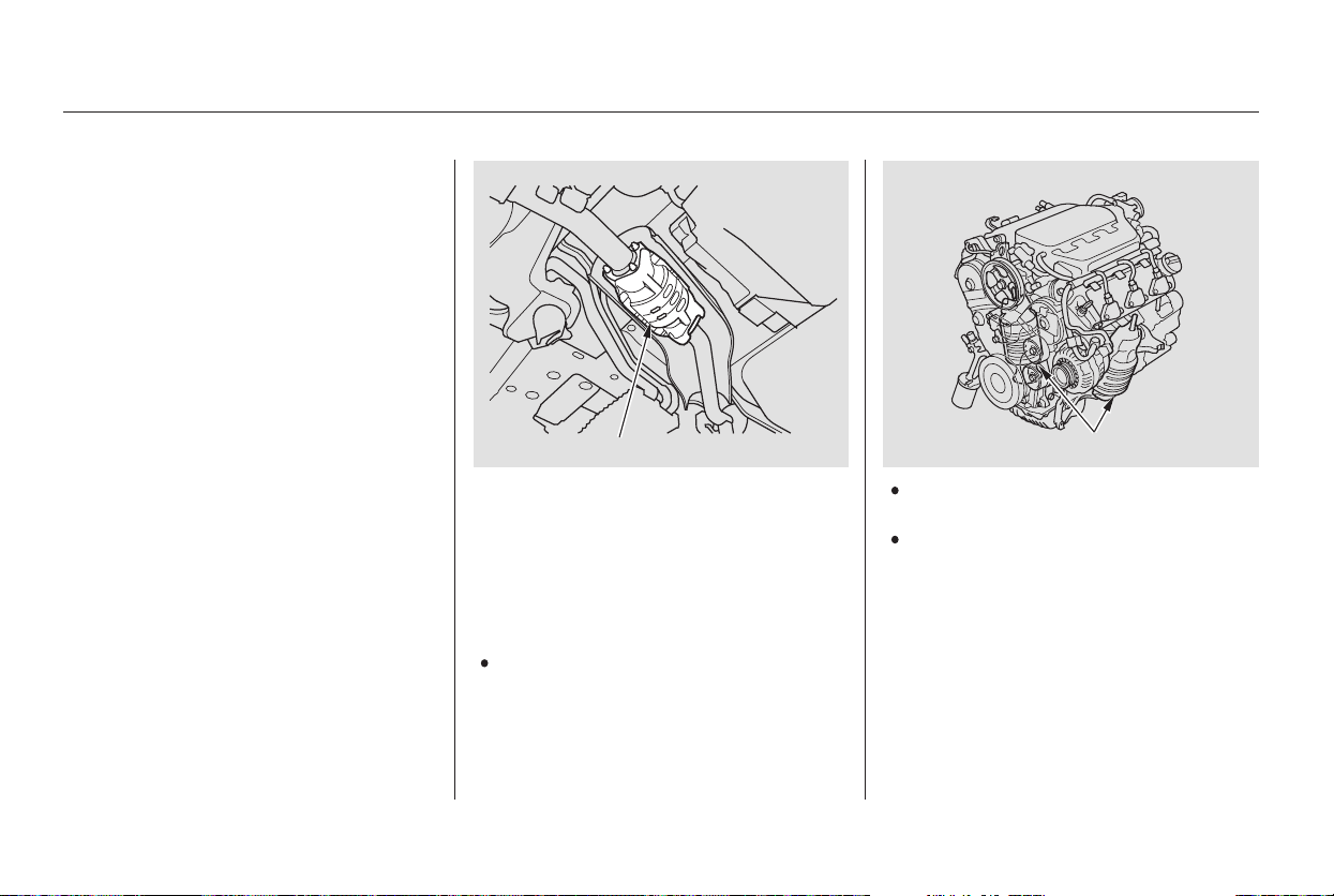
The three way catalytic converter
contains precious metals that serve
as catalysts, promoting chemical
reactions to convert the exhaust
gasses without affecting the metals.
The catalytic converter is referred to
as a three-way catalyst, since it acts
on HC, CO, and NOx. A replacement
unit must be an original Honda part
or its equivalent.
The three way catalytic converter
must operate at a high temperature
for the chemical reactions to take
place. It can set on fire any com-
bustible materials that come near it.
Parkyourvehicleawayfromhigh
grass, dry leaves, or other flamma-
bles.
A defective three way catalytic
converter contributes to air pollution,
and can impair your engine’s per-
formance. Follow these guidelines to
protect your vehicle’s three way
catalytic converter.
Always use unleaded gasoline.
Even a small amount of leaded
gasoline can contaminate the
catalyst metals, making the three
way catalytic converter ineffective.
Keep the engine tuned-up.
Have your vehicle diagnosed and
repaired if it is misfiring, back-
firing, stalling, or otherwise not
running properly.
Three Way Catalytic Converter
394
THREE WAY CATALYTIC CONVERTERS
THREE WAY CATALYTIC CONVERTER
Main Menu
Table of Contents
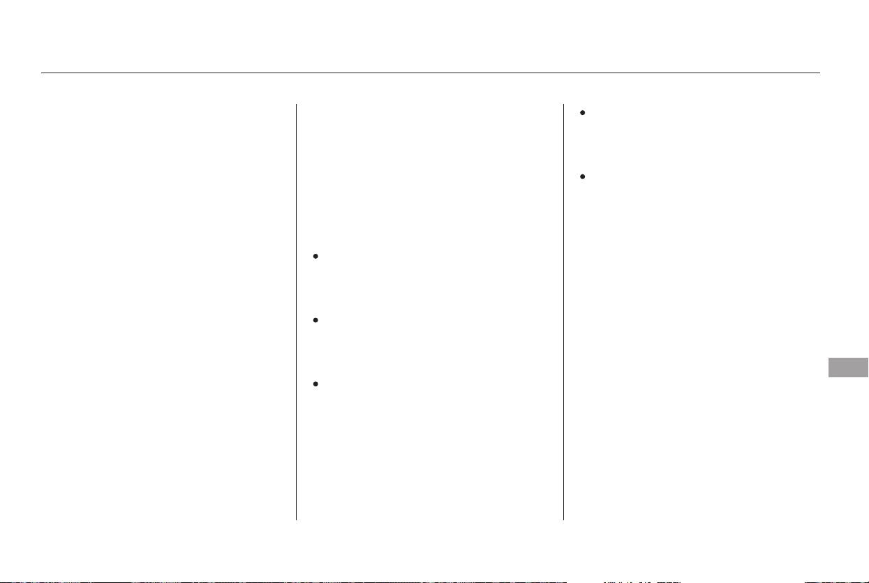
If you take your vehicle for a state
emissions test shortly after the
battery has been disconnected or
gone dead, it may not pass the test.
This is because of certain ‘‘readiness
codes’’ that must be set in the on-
board diagnostics for the emissions
systems. These codes are erased
when the battery is disconnected,
and set again only after several days
of driving under a variety of
conditions.
If the testing facility determines that
the readiness codes are not set, you
will be requested to return at a later
date to complete the test. If you must
get the vehicle retested within the
next two or three days, you can
condition the vehicle for retesting by
doing the following.
Make sure the gas tank is nearly,
but not completely full (around
3/4).
Without touching the accelerator
pedal, start the engine, and let it
idle for 20 seconds.
Keep the vehicle in Park
(automatic transmission). Increase
the engine speed to 2,000 rpm and
hold it there until the temperature
gauge rises to at least 1/4 of the
scale (approximately 3 minutes).
Make sure the vehicle has been
parked with the engine off for 6
hours or more.
Make sure the ambient
temperature is between 40° and
95°F.
CONTINUED
Testing of Readiness Codes
State Emissions Testing
Technical Information
395
Main Menu
Table of Contents

Then drive in city/suburban
traffic for at least 10 minutes.
When traffic conditions allow, let
the vehicle coast for several
seconds without using the
accelerator pedal or the brake
pedal.
Select a nearby lightly traveled
major highway where you can
maintain a speed of 50 to 60 mph
(80to97km/h)foratleast20
minutes. Drive on the highway in
D (A/T). Do not use the cruise
control. When traffic allows, drive
for 90 seconds without moving the
accelerator pedal. (Vehicle speed
may vary slightly; this is okay.) If
you cannot do this for a
continuous 90 seconds because of
traffic conditions, drive for at least
30 seconds, then repeat it two
more times (for a total of
90 seconds).
Stop the vehicle and turn the
ignition switch off. Leave the
vehicle for 30 minutes.
If the testing facility determines the
readiness codes are still not set, see
your dealer.
State Emissions Testing
396
Main Menu
Table of Contents


Honda dealership personnel are
trained professionals. They should
be able to answer all your questions.
If you encounter a problem that your
dealership does not solve to your
satisfaction, please discuss it with
the dealership’s management. The
service manager or general manager
can help. Almost all problems are
solved in this way.
If you are dissatisfied with the
decision made by the dealership’s
management, contact your Honda
Customer Service Office.
U.S. Owners:
Canadian Owners:
In Puerto Rico and the U.S. Virgin
Islands:
When you call or write, please give
us this information:
Vehicle Identification Number
(see page )
Name and address of the dealer
who services your vehicle
Date of purchase
Mileage on your vehicle
Your name, address, and tele-
phone number
A detailed description of the
problem
Name of the dealer who sold the
vehicle to you
384
Customer Service Information
398
CUSTOMER RELATIONS
RELATIONS AVEC LA CLIENTÉLE
American Honda Motor Co., Inc.
Automobile Customer Service
Mail Stop 500-2N-7A
1919 Torrance Boulevard
Torrance, California 90501-2746
Tel: (800) 999-1009
Honda Canada Inc.
715 Milner Avenue
Toronto, ON
M1B 2K8
Tel: 1-888-9-HONDA-9
Fax: Toll-free 1-877-939-0909
Toronto (416) 287-4776
Bella International
P.O. Box 190816
San Juan, PR 00919-0816
Tel: (787) 250-4327
Main Menu
Table of Contents

−
−
−
−
−
−
−
−
−
Your new vehicle is covered by these
warranties:
covers your new vehicle, except for
the battery, emissions control
systems, and accessories, against
defects in materials and
workmanship.
these two
warranties cover your vehicle’s
emissions control systems. Time,
mileage, and coverage are
conditional. Please read your
warranty manual for exact
information.
a seat
belt that fails to function properly is
coveredfortheusefullifeofthe
vehicle.
all exterior body panels are
covered for rust-through from the
inside for the specified time period
with no mileage limit.
covers all Honda
replacement parts against defects in
materials and workmanship.
provides
coverageforaslongasthepur-
chaser of the muffler owns the
vehicle.
provides prorated
coverage for a replacement battery
purchased from your dealer.
Restrictions and exclusions apply to
all these warranties. Please read the
2005 Honda Warranty Information
booklet that came with your vehicle
for precise information on warranty
coverages. Your vehicle’s original
tires are covered by their
manufacturer. Tire warranty infor-
mation is in a separate booklet.
Please refer to the 2005 Warranty
Manual that came with your vehicle.
this warranty gives up
to 100 percent credit toward a
replacement battery.
Honda accessories are covered
under this warranty. Time and
mileage limits depend on the type of
accessory and other factors. Please
read your warranty manual for
details.
Warranty Coverages
U.S. Owners
Canadian Owners
New Vehicle Limited Warranty
Emissions Control Systems Defects
Warranty and Emissions
Performance Warranty
Seat Belt Limited Warranty
Rust Perforation Limited Warranty
Replacement Parts Limited
Warranty
Replacement Muffler Lifetime
Limited Warranty
Replacement Battery Limited
Warranty
Original Equipment Battery Limited
Warranty
Accessory Limited Warranty
Warranty and Customer Relations
399
Main Menu
Table of Contents

If you believe that your vehicle has a
defect which could cause a crash or
could cause injury or death, you
should immediately inform the
National Highway Traffic Safety
Administration (NHTSA) in addition
to notifying American Honda Motor
Co., Inc.
If NHTSA receives similar com-
plaints, it may open an investigation,
and if it finds that a safety defect
exists in a group of vehicles, it may
order a recall and remedy campaign.
However, NHTSA cannot become
involved in individual problems
between you, your dealer, or
American Honda Motor Co., Inc.
To contact NHTSA, you may either
call the Auto Safety Hotline toll-free
at 1-800-424-9393 (or 366-0123 in
Washington D.C. area) or write to:
NHTSA, U.S. Department of
Transportation, Washington,
D.C. 20590. You can also obtain
other information about motor
vehicle safety from the Hotline.
Reporting Safety Defects (U.S. Vehicles)
400
Main Menu
Table of Contents
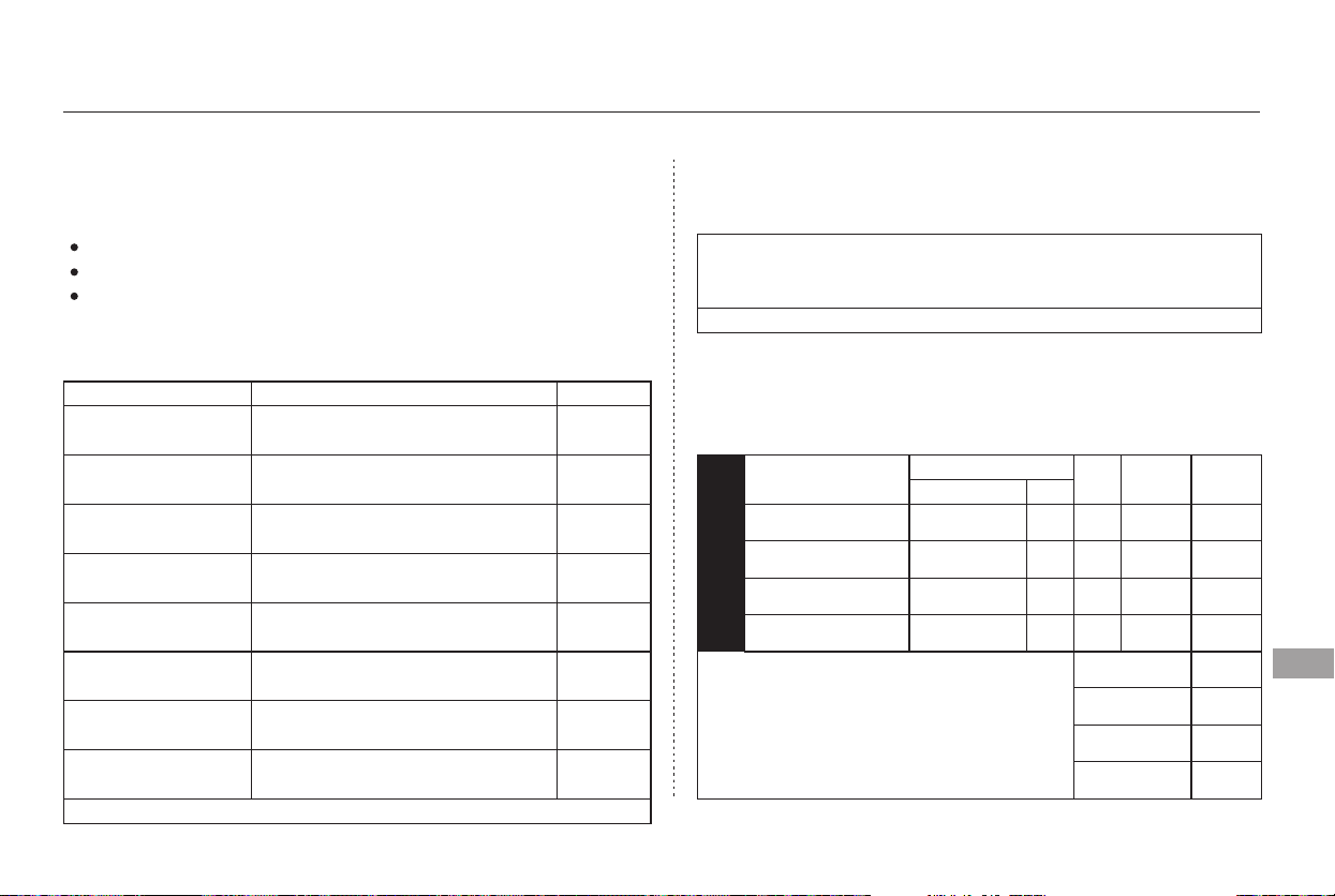
−
*
*
*
*
2
0
0
5
H
O
N
The publications shown below can be purchased from Helm
Incorporated. You can order in any of three ways:
If you are interested in other years or models, contact Helm Inc.
at 1-800-782-4356.
Detach and mail the order form on the right half of this page
Call Helm Inc. at 1-800-782-4356
Go online at
Valid only for sales within the United States. Canadian
owners should contact their authorized Honda dealer.
(credit card orders only)
Authorized Manuals
Purchasing Factory Authorized Manuals (U.S. only)
Authorized Manuals
401
ORDER TOLL FREE: 1-800-782-4356
OR
(NOTE: For Credit Card Holder Orders Only)
MINIMUM CREDIT CARD PURCHASE $10.00
61SHJ00
61SHJ00EL
61SHJ30
31SHJ600
31SHJ700
31SHJM00
31SHJQ00
HON-R
$70.00
$50.00
$44.00
$34.00
$29.00
$12.00
$12.00
FREE
Form Description
2005 Honda Odyssey
Service Manual
2005 Honda Odyssey
Electrical Troubleshooting Manual
2005 Honda Odyssey
Body Repair Manual
2005 Honda Odyssey
Owner’s Manual
2005 Honda Odyssey
Navigation System Owner’s Manual
2005 Honda Odyssey
Honda Service History
2005 Honda Odyssey
Quick Start Guide
Order Form for Previous Years-
Indicate Year and Model Desired
Publication Form Number Price Each
PUBLICATION NUMBER
VEHICLE MODEL
Name Year
Qty
Price
Each
Total
Price
GRAND TOTAL
HANDLING CHARGE
Mich. Purchases
Add 6% Sales Tax
TOTAL MATERIAL
$6.95
Monday-Friday 8:00 A.M. 6:00 P.M. EST
By completing this form you can order the materials desired. You can
pay by check or money order, or charge to your credit card. Mail to
Helm Incorporated at the address shown on the back of the order form.
Prices are subject to change without
notice and without incurring obligation.
Orders are mailed within 10 days. Please
allow adequate time for delivery.
Prices are subject to change without notice and without incurring obligation.
www. helminc. com
Main Menu
Table of Contents
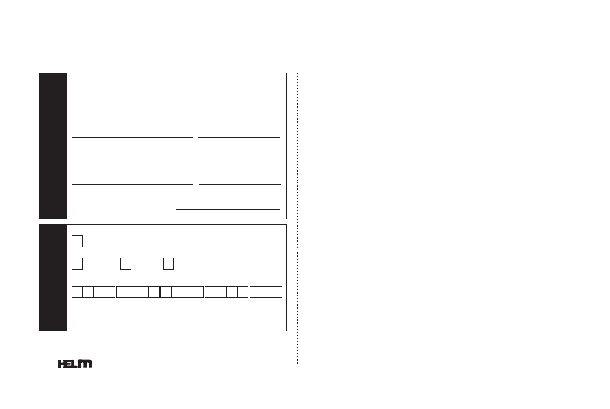
−
−
−
S
H
I
P
T
O
P
A
Y
M
E
N
T
This manual covers maintenance and recommended
procedures for repair to engine and chassis components.
It is written for the journeyman mechanic, but is simple
enough for most mechanically-inclined owners to under-
stand.
This manual complements the service manual by
providing in-depth troubleshooting information for each
electrical circuit in your vehicle.
This manual describes the procedures involved in the
replacement of damaged body parts.
Authorized Manuals
Service Manual:
Electrical Troubleshooting Manual:
Body Repair Manual:
402
NOTE: Dealers and Companies please provide dealer or company name,
and also the name of the person to whose attention the shipment should
be sent. For purchases outside U.S.A. please write to the address shown
below for a quotation.
P.O. BOX 07280·DETROIT, MICHIGAN 48207·1-800-782-4356
Customer Name
Attention
Apartment Number
State & Zip Code
City
Daytime Telephone Number
Check or money order enclosed payable to Helm Inc U.S. funds only.
Do not send cash
Master
Card
VISA Check here if your billing address is different
from the shipping address shown above.
Account Number
Expiration: Mo. Yr.
CUSTOMER SIGNATURE
DATE
Street Address No P.O. Box Number
()
These Publications cannot be returned for credit without receiving advance authorization within 14
days of delivery. On returns, a restocking fee may be applied against the original order.
Main Menu
Table of Contents

CONTINUED
....................................Accessories . 284
ACCESSORY (Ignition Key
.....................................Position) . 130
............Accessory Power Sockets . 182
...........................AC Power Outlet . 182
....................Additives, Engine Oil . 329
Adjustable Driver’s Foot
.........................................Pedals . 169
...............AdvancedAirbagSystem .29
.............................Airbag (SRS) . 11, 25
..............Air Conditioning System . 188
.............Rear A/C Control . 194, 197
.......................Air Outlets (Vents) . 191
.......................Air Pressure, Tires . 346
.......................Alcohol in Gasoline . 278
......................................Antifreeze . 331
Anti-lock Brakes (ABS)
...............................Indicator . 65, 300
...................................Operation . 300
..............Anti-theft, Audio System . 229
Anti-theft Steering Column
............................................Lock . 130
........................................Armrests . 152
...............Audio Controls, Remote . 228
................................Audio System . 199
...Automatic Seat Belt Tensioners . 23
.Automatic Lighting Off Feature . 124
.............Automatic Speed Control . 264
..............Automatic Transmission . 294
..........................Capacity, Fluid . 386
...............Checking Fluid Level . 334
.......................................Shifting . 294
Shift Lever Position
...............................Indicators . 294
................Shift Lever Positions . 294
....................Shift Lock Release . 297
Battery
Charging System
...........................Indicator . 63, 371
............................Jump Starting . 367
..............................Maintenance . 352
............................Specifications . 387
..............................Before Driving . 277
..................................Belts, Seat . 10, 22
.........................Beverage Holders . 171
..................................Booster Seats . 53
Brakes
...........Anti-lock System (ABS) . 300
.............Break-in, New Linings . 278
....................Bulb Replacement . 341
...........................................Fluid . 335
.......................................Parking . 169
.................System Indicator . 63, 373
........................Wear Indicators . 299
.............................Braking System . 299
.................Break-in, New Vehicle . 278
Brightness Control, Instruments. 125
......................Brights, Headlights . 122
Bulb Replacement
..........................Back-up Lights . 342
..............................Brake Lights . 341
................Front Parking Lights . 339
........Front Side Marker Lights . 339
...........Front Turn Signal Light . 338
.................................Headlights . 337
.........................Rear Bulbs . 341, 342
............Rear Turn Signal Light . 341
............................Specifications . 387
..............................Bulbs, Halogen . 337
Index
A
B
INDEX
I
Main Menu

*
................DANGER, Explanation of . ii
...................................Dashboard . 4, 60
..............Daytime Running Lights . 125
Daytime Running Lights
.......................................Indicator . 69
.................................Dead Battery . 367
............Defects, Reporting Safety . 400
..............Defogger, Rear Window . 126
..............Defrosting the Windows . 192
....................................Dimensions . 386
.............Dimming the Headlights . 122
................................Cancel Button . 266
............................Capacities Chart . 386
.............Carbon Monoxide Hazard . 56
..........................Cargo Area Light . 185
.................................Cargo Hooks . 289
....................Cargo, How to Carry . 286
......................................Cargo Net . 289
..............CAUTION, Explanation of . ii
.........................................CD Care . 221
...................................CD Changer . 215
.......CD Changer Error Message . 222
.......................................CD Player . 212
...............................Center Pocket . 181
...................................Center Tray . 171
........................Certification Label . 384
.................................Chains, Tires . 350
Changing Oil
........................................How to . 329
......................................When to . 315
....................Changing a Flat Tire . 360
...Charging System Indicator . 63, 371
............Checklist, Before Driving . 292
................Childproof Door Locks . 138
.....................................Child Safety . 36
..............................Booster Seats . 53
...................................Child Seats . 43
.....Important Safety Reminders . 40
..........................................Infants . 41
..........................Larger Children . 51
.........................................LATCH . 45
......................Risks with Airbags . 37
.............................Small Children . 42
.........................................Tethers . 51
........Where Should A Child Sit? . 37
.......................................Child Seats . 43
......LATCH Anchorage System . 45
..........Tether Anchorage Points . 50
Cleaning
...................................Seat Belts . 343
...............Climate Control System . 193
..............................................Clock . 227
.....................Code, Audio System . 229
........................CO in the Exhaust . 392
............Cold Weather, Starting in . 293
......................Compact Spare Tire . 359
...............Consumer Information . 398
.............Controls, Instruments and . 59
....................Conversation Mirror . 174
Coolant
........................................Adding . 331
....................................Checking . 282
.........................Proper Solution . 331
...................Temperature Gauge . 71
Crankcase Emissions Control
........................................System . 392
................Cruise Control Indicator . 69
............Cruise Control Operation . 264
...................................Cup Holders . 171
.............Customer Service Office . 398
Index
C
D
II
Main Menu
CONTINUED
Dipstick
..........Automatic Transmission . 334
..................................Engine Oil . 281
........................Directional Signals . 122
........Disc Brake Wear Indicators . 299
.....................Disposal of Used Oil . 330
Doors
............Locking and Unlocking . 137
..................Lockout Prevention . 137
..............Manual Sliding Doors . 142
..............................Monitor Light . 67
....................Power Door Locks . 137
.................Power Sliding Doors . 142
..........DOT Tire Quality Grading . 388
...........Driver and Passenger Safety . 7
Driver’s Seat Position Memory
........................................System . 161
...........................................Driving . 291
....................................Economy . 283
....................DVD Error Message . 259
...................................DVD Player . 230
..............................Economy, Fuel . 283
..................................Emergencies . 355
.............Battery, Jump Starting . 367
...........Brake System Indicator . 373
................Changing a Flat Tire . 360
.....Charging System Indicator . 371
..................Checking the Fuses . 376
..............Closing the Moonroof . 374
...........Driving with a Flat Tire . 356
.......Hazard Warning Flashers . 126
............................Jump Starting . 367
.....Low Oil Pressure Indicator . 371
...Malfunction Indicator Lamp . 372
..................Overheated Engine . 369
.......................................Towing . 381
.........................Emergency Brake . 169
....................Emergency Flashers . 126
......................Emergency Towing . 381
.......................Emissions Controls . 392
.............Emissions Testing, State . 395
Engine
....Coolant Temperature Gauge . 71
..............Engine Speed Limiter . 296
.........................If It Won’t Start . 366
Malfunction Indicator
................................Lamp . 63, 372
........Oil Pressure Indicator . 63, 371
..............Oil, What Kind to Use . 328
...............................Overheating . 369
............................Specifications . 387
.......................................Starting . 293
.Evaporative Emissions Controls . 392
...............................Exhaust Fumes . 56
Exhaust Gas Recirculation
........................................System . 393
Expectant Mothers, Use of Seat
........................................Belts by . 20
...................................Fan, Interior . 189
Features, Comfort and
..............................Convenience . 187
....................Filling the Fuel Tank . 279
......................................Filters, Oil . 329
...........Flashers, Hazard Warning . 126
...................Flat Tire, Changing a . 360
.....................................Floor Mats . 343
.......................Floor Storage Area . 177
Index
E
F
INDEX
III
Main Menu

Fluids
..........Automatic Transmission . 334
..........................................Brake . 335
..........................Power Steering . 336
................Windshield Washers . 121
FM Stereo Radio
...................................Reception . 205
.................Folding the Third Seat . 158
........................Four-way Flashers . 126
............................Front Airbags . 11, 27
......................................Front Seat . 148
....................................Adjusting . 149
.......................................Heaters . 160
...................................Airbags . 11, 27
.................................................Fuel . 278
......................Fill Door and Cap . 279
...........................................Gauge . 71
................Octane Requirement . 278
....................................Refueling . 279
........................Reserve Indicator . 68
.....................Fuses, Checking the . 376
...............Gas Mileage, Improving . 283
.........................................Gasoline . 278
...............Fuel Reserve Indicator . 68
...........................................Gauge . 71
................Octane Requirement . 278
....................................Refueling . 279
................Gas Station Procedures . 279
Gauges
...Engine Coolant Temperature . 71
...............................................Fuel . 71
...............................Speedometer . 71
.................................Tachometer . 71
GAWR (Gross Axle Weight
.......................................Rating) . 307
GCWR (Gross Combined Weight
.......................................Rating) . 307
......................................Glove Box . 180
GVWR (Gross Vehicle Weight
.......................................Rating) . 307
.............Halogen Headlight Bulbs . 337
............Hazard Warning Flashers . 126
.....................................Headlights . 122
........................................Aiming . 337
............Automatic Lighting Off . 124
.........Daytime Running Lights . 125
..................High Beam Indicator . 69
.......................Reminder Chime . 122
........Replacing Halogen Bulbs . 337
.................................Turning on . 122
...................................Headphones . 260
............................Head Restraints . 152
...............................Heated Mirror . 168
...................................Heater, Seat . 160
.....................Heating and Cooling . 188
.............High Altitude, Starting at . 293
...............High-Low Beam Switch . 122
HomeLink Universal
................................Transceiver . 267
.......................Hood, Opening the . 280
...........................................Horn .5,120
...Identification Number, Vehicle . 384
Ignition
............................................Keys . 128
.........................................Switch . 130
............Timing Control System . 393
......................Immobilizer System . 129
.........Important Safety Precautions . 8
Index
H
I
G
IV
Main Menu
CONTINUED
................................................Keys . 128
.........................................Indicators . 63
......ABS (Anti-lock Brake) . 65, 300
Brake (Parking and Brake
...........................System) . 63, 373
................Charging System . 63, 371
.............................Cruise Control . 69
DRL (Daytime Running
.....................................Lights) . 69
.....................................Fog Light . 69
.............................Fuel Economy . 70
...................................High Beam . 69
.......Key (Immobilizer System) . 67
.....................................Lights On . 66
......................................Low Fuel . 68
................Low Oil Pressure . 63, 371
......................Low Tire Pressure . 66
...............Maintenance Required . 70
.....................Side Airbag Off . 33, 64
.........................................SRS . 32, 64
.........................System Message . 70
Turn Signal and Hazard
...................................Warning . 68
Vehicle Stability Assist
..........................(VSA) System . 65
............................VSA Activation . 65
..............................Washer Level . 69
..................Individual Map Lights . 184
...............................Infant Restraint . 41
......................................Infant Seats . 43
......LATCH Anchorage System . 45
...........................Lower Anchors . 45
..........Tether Anchorage Points . 50
...................Inflation, Proper Tire . 346
...................In-Floor Storage Area . 177
.................................Inside Mirror . 167
.............................Inspection, Tire . 347
........................Instrument Panel . 4, 60
......Instrument Panel Brightness . 125
....................Integrated Sunshade . 173
...............................Interior Lights . 183
........................................Introduction . i
.................Jacking up the Vehicle . 361
.......................................Jack, Tire . 360
................................Jump Starting . 367
.......................Label, Certification . 384
...............Lane Change, Signaling . 122
..................Lap/Shoulder Belts . 17, 22
...........LATCH Anchorage System . 45
.....................................Lazy Susan . 179
....................Light Control Switch . 183
Lights
....................Bulb Replacement . 337
.......................................Indicator . 63
.......................................Interior . 183
.......................................Parking . 122
................................Turn Signal . 122
............................Load Limits . 287, 306
....LOCK (Ignition Key Position) . 130
Locks
.....Anti-theft Steering Column . 130
............................Fuel Fill Door . 279
..................................Glove Box . 180
..................Lockout Prevention . 137
...............................Power Door . 137
.............................Sliding Doors . 142
......................................Tailgate . 138
Index
J
K
L
INDEX
V
Main Menu
........................Low Coolant Level . 282
.........................Low Fuel Indicator . 68
...Low Oil Pressure Indicator . 63, 371
................................Lower Anchors . 45
..........................Lower Glove Box . 180
...Lubricant Specifications Chart . 386
...........Luggage Net (Cargo Net) . 289
...........Luggage, Storing (Cargo) . 286
..................................Maintenance . 313
................................Minder . 315-324
...Owner Maintenance Checks . 323
.................................Record . 325-326
......................Required Indicator . 70
..........................................Safety . 314
.Malfunction Indicator Lamp . 63, 372
...................Manual Sliding Doors . 142
...............................Meters, Gauges . 71
..................Michilen PAX System . 356
........................Mirrors, Adjusting . 167
.................................Modifications . 284
...............Modifying Your Vehicle . 284
.......................................Moonroof . 166
Moving the Second Row Bucket
.............................................Seat . 154
.............Multi-Information Display . 74
...................Neutral Gear Position . 295
..................New Vehicle Break-in . 278
...................NOTICE, Explanation of . i
...............Numbers, Identification . 384
...Octane Requirement, Gasoline . 278
.........................................Odometer . 72
...............................Odometer, Trip . 72
Oil
........................Change, How to . 329
......................Change, When to . 315
......................Checking Engine . 281
..............Pressure Indicator . 63, 371
Selecting Proper Viscosity
......................................Chart . 328
.........ON (Ignition Key Position) . 130
Onboard Refueling Vapor
....................................Recovery . 392
............................Outside Mirrors . 167
....................Overheating, Engine . 369
.......Owner Maintenance Checks . 323
.........................Oxygenated Fuels . 278
............Panel Brightness Control . 125
........................Park Gear Position . 295
...........................................Parking . 298
...............................Parking Brake . 169
Parking Brake and Brake
.................System Indicator . 63, 373
...............................Parking Lights . 122
................Parking Sensor System . 271
..Parking Over Things that Burn . 298
....Passenger Airbag Off Indicator . 33
...................................PAX System . 356
.............................PGM-FI System . 393
........................Power Door Locks . 137
Power Sliding Doors
.......................................Indicator . 67
...................................Operation . 142
.....................................Switches . 143
...............Power Socket Locations . 182
..............................Power Tailgate . 139
Index
M
N
O
P
VI
Main Menu

*
CONTINUED
............................Power Windows . 163
.........Pregnancy, Using Seat Belts . 20
.........Protecting Adults and Teens . 14
...Additional Safety Precautions . 20
.....Advice for Pregnant Women . 20
........................Protecting Children . 36
.......................Protecting Infants . 41
.......Protecting Larger Children . 51
.........Protecting Small Children . 42
Using Child Seats with
.....................................Tethers . 50
.............................Using LATCH . 45
...................Radiator Overheating . 369
.............Radio/CD Sound System . 199
...........................Readiness Codes . 372
............Rear Audio Control Panel . 234
...............................Rear A/C Unit . 194
........Rear Entertainment System . 230
Rear Lights, Bulb
......................Replacement . 341, 342
...Rearview Camera and Monitor . 275
..........................Rear View Mirror . 167
...............Rear Window Defogger . 126
Rear Window Wiper and
.......................................Washer . 122
.....Reclining the Seat Backs . 150, 151
.........Reclining the Second Seats . 150
..............Reclining the Third Seat . 150
.......................Reminder Indicators . 64
................Remote Audio Controls . 228
................Remote Control (RES) . 257
.....................Remote Transmitter . 131
Removable Second Row
......................................Console . 176
........Removing the Second Seats . 155
Replacement Information
................Engine Oil and Filter . 329
..........................................Fuses . 376
................................Light Bulbs . 337
................................Timing Belt . 336
...........................................Tires . 349
.............................Wiper Blades . 344
Replacing Seat Belts After a
............................................Crash . 23
Reserve Tank,
.................Engine Coolant . 282, 331
..............Retractable Center Tray . 171
..................Reverse Gear Position . 295
......................................Roof Rack . 288
................................Rotation, Tire . 348
................................Safety Belts . 10, 22
.........Safety Defects, Reporting . 400
.................................Safety Features . 9
.........................................Airbags . 11
.....................................Seat Belts . 10
.............Safety Labels, Location of . 57
...............................Safety Messages . ii
...................................Seat Belts . 10, 22
...............Additional Information . 22
Automatic Seat Belt
...............................Tensioners . 23
.....................................Cleaning . 343
......................Lap/Shoulder Belt . 22
................................Maintenance . 23
Reminder Indicator and
................................Beeper . 22, 64
................................Replacement . 23
...................System Components . 22
...............Use During Pregnancy . 20
...Wearing a Lap/Shoulder Belt . 16
..................................Seat Heaters . 160
Index
S
R
INDEX
VII
Main Menu

*
.....................................Tachometer . 71
..........................................Tailgate . 138
...............................Opening the . 138
...................Open Monitor Light . 67
..Taillights, Changing Bulbs . 341, 342
...............................................Seats . 148
......................Adjustments . 149, 151
..........Drivers Lumbar Support . 152
.............Folding the Third Seat . 158
........................Head Restraints . 152
Installing the Stowable Second
...............Row Plus-One Seat . 156
.....Manual Height Adjustment . 150
....................Passenger Seating . 148
.......Reclining the Second Seat . 150
..........Reclining the Third Seat . 150
....Removing the Second Seats . 155
.....................Third Seat Access . 153
............................Security System . 263
Sensors
Front Passenger’s Weight
.....................................Sensors . 29
....Driver’s Seat Position Sensor . 29
...............................Serial Number . 384
...........................Service Intervals . 315
...........................Service Manual . 401
...........Service Station Procedure . 279
..........................Setting the Clock . 227
...Shift Lever Position Indicators . 294
........................Shift Lock Release . 297
..............................Side Airbags . 11, 30
..........................Off Indicator . 33, 64
Side Marker Lights, Bulb
..............................Replacement . 339
.............................Signaling Turns . 122
.................................Sliding Doors . 142
.....................................Snow Tires . 350
................................Sound System . 199
Spare Tire
......................................Inflating . 359
............................Specifications . 387
....................................Spark Plugs . 387
....................Specifications Charts . 386
................................Speed Control . 264
...................................Speedometer . 71
..........SRS, Additional Information . 25
...Additional Safety Precautions . 35
.............................Airbag Service . 34
..How the SRS Indicator Works . 32
How Your Airbags
............................Work . 27, 30, 32
........................SRS Components . 25
.............................SRS Indicator . 32, 64
..START (Ignition Key Position) . 130
.......................Starting the Engine . 293
In Cold Weather at High
..................................Altitude . 293
................With a Dead Battery . 367
..............State Emissions Testing . 395
........Steam Coming from Engine . 369
Steering Wheel
................................Adjustment . 127
...........Anti-theft Column Lock . 130
.................................Buttons . 75, 228
...................Stereo Sound System . 199
....................Storing Your Vehicle . 353
Stowable Second Row Plus-One
.............................................Seat . 156
........................Sunglasses Holder . 174
........................................Sun Visor . 175
Supplemental Restraint System
......................................Servicing . 34
.........................SRS Indicator . 32, 64
...................System Components . 25
..................................Synthetic Oil . 329
Index
T
VIII
Main Menu

*
CONTINUED
.Taking Care of the Unexpected . 355
Technical Descriptions
.....Emissions Control Systems . 392
Three Way Catalytic
...............................Converter . 393
.......................Temperature Gauge . 71
........Temperature, Inside Sensor . 198
...................Tensioners, Seat Belts . 23
..............Tether Anchorage Points . 50
............................Theft Protection . 229
..Three Way Catalytic Converter . 393
................Tilt the Steering Wheel . 127
..........................Time, Setting the . 227
....................................Timing Belt . 336
....................................Tire Chains . 350
.........Tire, How to Change a Flat . 360
...............................................Tires . 346
..............................Air Pressure . 346
...................................Balancing . 348
.........................Checking Wear . 347
..........................Compact Spare . 359
......DOT Tire Quality Grading . 388
......................................Inflation . 346
..................................Inspection . 347
.....................................Labeling . 390
...................................Replacing . 349
......................................Rotating . 348
...........................................Snow . 350
............................Specifications . 387
................................Tire Chains . 350
...................Tools, Tire Changing . 360
Towing
.....................................A Trailer . 306
................Emergency Wrecker . 381
....Equipment and Accessories . 308
.....................Weight Limit . 287, 306
.............................Trailer Loading . 308
......................Trailer Towing Tips . 311
Transmission
...............Checking Fluid Level . 334
...........................Fluid Selection . 334
..............Identification Number . 384
.............Shifting the Automatic . 294
.....................................Treadwear . 388
.................................Trip Meter . 72, 77
..................................Turn Signals . 122
Unexpected, Taking Care
..........................................of the . 355
....Uniform Tire Quality Grading . 388
........................Unleaded Gasoline . 278
...........................Upper Glove Box . 180
.......Used Oil, How to Dispose of . 330
................................Vanity Mirror . 176
.........Vehicle Capacity Load . 287, 306
......................Vehicle Dimensions . 386
....Vehicle Identification Number . 384
.............................Vehicle Storage . 353
.....................................Ventilation . 191
.................................................VIN . 384
..................................Viscosity, Oil . 328
.............WARNING, Explanation of . ii
.........Warning Labels, Location of . 57
..................Warranty Coverages . 399
Washer, Windshield
........Checking the Fluid Level . 333
............................Level Indicator . 69
...................................Operation . 121
Index
U
V
W
INDEX
IX
Main Menu

*
Wheels
.............Adjusting the Steering . 127
............Alignment and Balance . 348
..........................Compact Spare . 359
......................................Wrench . 362
Windows
.............................Auto Reverse . 163
................Operating the Power . 163
.........................Rear, Defogger . 126
Windshield
.....................................Cleaning . 121
...................................Defroster . 192
.....................................Washers . 121
Wipers, Windshield
.......................Changing Blades . 344
...................................Operation . 121
Rear Windshield Wiper and
...................................Washer . 122
..................Wireless Headphones . 260
....................................Worn Tires . 347
.....Wrecker, Emergency Towing . 381
:U.S.only
Index
X
Main Menu

Service Information Summary
Gasoline:
Fuel Tank Capacity:
Recommended Engine Oil:
Automatic Transmission Fluid:
Power Steering Fluid:
Brake Fluid:
Tire Pressure (measured cold):
4.5 US qt (4.3
)
Unleaded gasoline, pump octane
number of 86 or higher.
API Premium grade 5W-20
detergent oil (see page ).
Oil change capacity (including
filter):
Honda ATF-Z1 (Automatic
Transmission Fluid) preferred, or
aDEXRON
III ATF as a
temporary replacement (see page
).
Honda Power Steering Fluid
preferred, or another brand of
power steering fluid as a
temporary replacement. Do not
use ATF (see page ).
Honda Heavy Duty Brake Fluid
DOT 3 preferred, or a DOT 3 or
DOT 4 brake fluid as a temporary
replacement (see page ).
35 psi (240 kPa , 2.4 kgf/cm
)
Rear:
33 psi (230 kPa , 2.3 kgf/cm
)
Front:
Front:
35 psi (240 kPa , 2.4 kgf/cm
)
Rear:
35 psi (240 kPa , 2.4 kgf/cm
)
Compact Spare Tire:
60 psi (420 kPa , 4.2 kgf/cm
)
334
336
335
328
LX, EX, and U.S. Touring models:
EX with Leather and Canadian
Touring models:
21 US gal (80
)
Main Menu