Loading ...
Loading ...
Loading ...
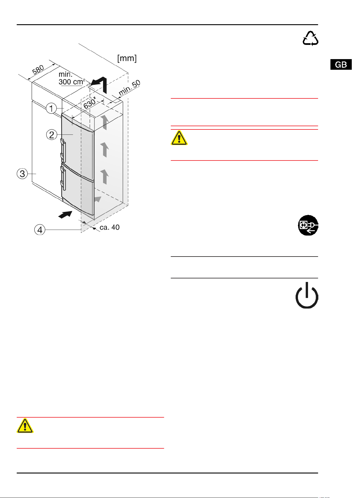
4.5 Insertion into a row of kitchen units
Fig. 12
(1) Stack cabinet (3) Kitchen cabinet
(2) Appliance (4) Wall
x
For appliances supplied with wall spacers, the measurement
increases by 35 mm (see 4.2) .
The appliance can be inserted into a row of kitchen units. To
match the appliance
Fig. 12 (2)
to the height of the row of units,
a suitable stack cabinet
Fig. 12 (1)
can be fitted above the
appliance.
When installing with kitchen units (max. depth 580 mm), the
appliance can be positioned directly next to the kitchen cabinet
Fig. 12 (3)
. The appliance will project by 34 mm
x
at the sides
and 50 mm
x
in the centre of the appliance in relation to the
kitchen cabinet front.
Ventilation requirements:
-
At the back of the stack cabinet there has to be a ventilation
duct of at least 50 mm depth throughout the width of the
stack cabinet.
-
The ventilation space under the ceiling has to be at least
300 cm
2
.
-
the larger the ventilation space, the more energy-saving the
appliance is in operation.
If the appliance is installed with the hinges next to a wall
Fig. 12 (4)
, the distance between appliance and wall has to be
at least 40 mm. This corresponds to the projection of the
handle when the door is open.
4.6 Disposing of packaging
WARNING
Danger of suffocation due to packing material and plastic film!
u
Do not allow children to play with packing material.
The packaging is made of recyclable materials:
-
corrugated board/cardboard
-
expanded polystyrene parts
-
polythene bags and sheets
-
polypropylene straps
-
nailed wooden frame with polyethylene panel*
u
Take the packaging material to an official collecting point.
4.7 Connecting the appliance
NOTICE
Risk of damage to the electronic control system!
u
Do not use stand-alone inverters (conversion of d.c. to a.c./
three-phase) or energy saving plugs.
WARNING
Fire and overheating hazard!
u
Do not use extension cables or multiple socket outlets.
The type of current (alternating current) and voltage at the
installation site have to conform with the data on the type plate
(see Appliance at a glance).
The socket must be properly earthed and fused. The tripping
current for the fuse must be between 10 A and 16 A.
The socket must be easily accessible so that the appliance can
be quickly disconnected from the supply in an emergency. It
must be outside the area of the rear of the appliance.
u
Check the electrical connection.
u
Plug in the power plug.
4.8 Switching on the appliance
Note
u
To switch on the entire appliance it is necessary only to
switch on the freezer compartment.
Switch on the appliance approx. 2 hours before
adding frozen food for the first time.
Do not load food to be frozen before the tempera-
ture display reads -18 °C.
4.8.1 Switching on the freezer compartment
u
Press On/Off button, freezer compartment
Fig. 3 (10)
.
w
The temperature display of the BioFresh compartment indi-
cates the current temperature inside.
w
The temperature display of the freezer compartment and the
alarm symbol flash until the temperature is sufficiently low. If
the temperature is above 0 °C, dashes flash. If it is below,
the current temperature flashes.
w
If “DEMO” is displayed, demo mode is activated. Please
contact the after sales service.
4.8.2 Switching on the BioFresh compartment
u
Press the On/Off button, BioFresh compartment
Fig. 3 (2)
.
w
The temperature display shines.
w
The interior light is on when the door is open.
Putting into operation
* Depending on model and options 9
Loading ...
Loading ...
Loading ...