CS78421-548-754
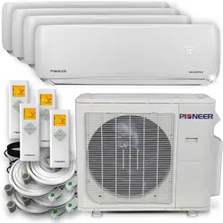
DUCTLESS MINI SPLIT SYSTEM AIR CONDITIONER / HEAT PUMP
IMPORTANT NOTICE:
Please read this manual carefully before installing
or operating your new air conditioning system.
Be sure to save this manual for future reference.
Installation
Manual
WAS / WYS Series
WAS: Cooling Only Version
WYS: Cooling and Heating Version
Inverter+ and Inverter++ Models
For 9,000-36,000 BTU/hr Systems
®
®
WiFi Ready
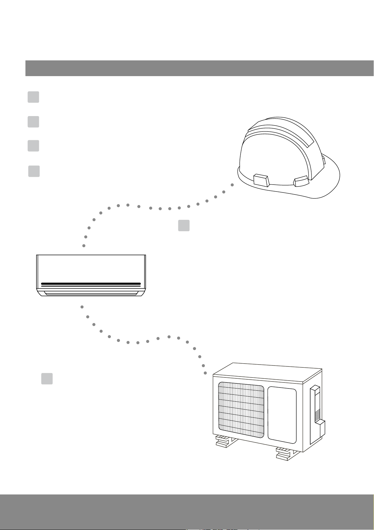
Table of Contents
Installation Manual
Indoor Unit Installation........ 11
1. Select installation location.......................... 11
2. Attach mounting plate to wall....................
12
3. Drill wall hole for connective piping............
12
4. Prepare refrigerant piping...........................
14
5. Connect drain hose....................................
15
6. Connect signal cable..................................
17
7. Wrap piping and cables..............................
18
8. Connect indoor power wire.......................
18
9. Mount indoor unit.....................................
18
Outdoor Unit Installation...
20
8
1. Select installation location.................. 20
2. Install drain joint................................
21
3. Anchor outdoor unit..........................
22
4. Connect signal and power cables....... 23
Safety Precautions........................... 4
0
1
5
Accessories........................................ 6
2
4
Unit Components................................... 10
3
Indoor Unit Installation Summary..........
Refrigerant Piping Connection........ 25
A. Note on Pipe Length................................................ 25
B. Connection Instructions –Refrigerant Piping............. 25
1. Cut pipe..............................................................
25
2. Remove burrs......................................................
26
3. Flare pipe ends....................................................
26
4. Connect pipes.....................................................
27
Air Evacuation................... 29
1. Evacuation Instructions...................... 29
2. Note on Adding Refrigerant............... 30
Electrical and Gas Leak Checks........ 31
Test Run............................................ 32
European Disposal Guidelines........ 34
6
7
8
9
10
MC MC
Page 4
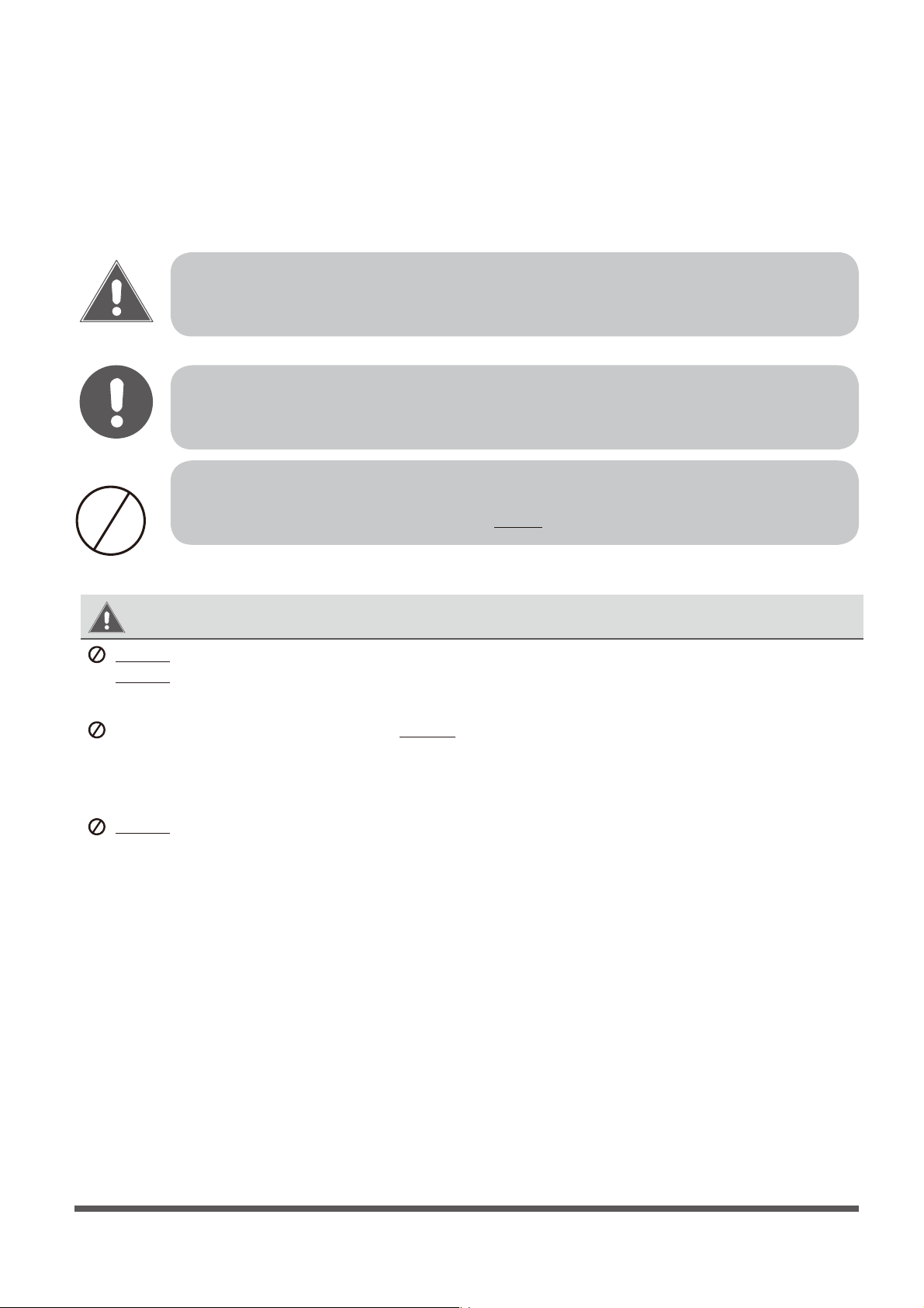
This symbol indicates that ignoring the related instructions may cause death,
or serious
injury.
This symbol indicates that ignoring the related instructions may cause moderate
injury
to nearby persons, and/or damage to your appliance or other property.
Safety Precautions
Read and Understand Safety Precautions Prior to Installation
Improper installation due to negligence of instructions may result in serious damage or injury.
The magnitude of potential damages or injuries is classified as either a WARNING or a CAUTION.
WARNING
CAUTION
WARNING
Do not power the system using an extension cable or smaller than specied gauge wiring.
Do not
Do not
share the electrical circuit with other appliances. Improper or insucient power supply
can cause undesirable operation, re, or electrical shock.
When connecting refrigerant piping, do not
let any substances or gases other than the specied
refrigerant enter the unit. The presence of other gases or substances will lower the unit’s capacity,
and can cause abnormally high pressure in the refrigeration cycle. This can also cause explosion and
injury , as well as permament equipment failure. Remember : No dust, humidity or air should be allowed to enter.
allow children to play with or around the air conditioner. Children near the unit must be
supervised at all times.
1.
Installation must be performed by a licensed and trained technician. Defective installation can
cause water leakage, electrical shock, or re. The usage of proper tools is a requirement.
2.
Installation must be performed according to the installation instructions. Improper installation can
cause water leakage, undesired performance, electrical shock, or re.
(In North America, installation must be performed in accordance with the requirements of NEC and
CEC, by authorized personnel only.)
3.
Contact a qualied and licensed HVAC technician for any repairs or maintenance of this unit.
4.
Only use the included accessories, parts, and specied items for installation. Using non-standard
parts can cause water leakage, electrical shock, re, and can cause total unit failure.
5.
Install the unit on top of a rm structure that can fully support it’s weight. If the chosen location cannot
support the unit’s weight, or the installation is not done properly, the unit may fall and cause
serious injury and damage.
This symbol indicates that you must never perform the action shown.
Page 5
WARNING
6.
For all electrical work, follow all local and national wiring standards, regulations, and especially this
Installation Manual. You must use an independent circuit and a dedicated breaker to supply power.
Do not connect other appliances to the same circuit. Insucient electrical capacity or defects in
electrical work can cause electrical shock or re.
7.
For all electrical work, use the specied cables. Connect cables tightly, and clamp them securely to
prevent external forces from damaging the terminals. Improper electrical connections can overheat
and cause re, and may also cause shock.
8.
9.
10.
11.
All wiring must be properly arranged to ensure that the control board cover can close properly. If
the control board cover is not closed properly, it can lead to corrosion and cause the connection
points on the terminal to heat up, catch re, or cause electrical shock.
This appliance can be used by children aged 8 years and above, as well as persons with reduced
physical, sensory, or mental capabilities, or lack of experience or knowledge, if they have been given
supervision or instruction concerning use of the appliance in a safe way, and understand the hazards
involved. Children shall not play with or near the appliance. Cleaning and user maintenance shall not be
done or attempted by children or untrained personnel without proper supervision.
CAUTION
For units that have an auxiliary electric heater, do not install the unit within 1 meter (3 feet) of
any combustible materials.
Do not
install the unit in a location that may be exposed to combustible gas leaks. If combustible
gas accumulates around the unit, it may cause re.
Do not operate your air conditioner in a highly humid space, such as bathrooms or laundry rooms.
Exposure to high humidity or water can cause electrical components to short circuit.
1.
The product must be properly grounded at the time of installation, else electrical shock may occur.
2.
Install drainage piping according to the instructions in this manual. Improper drainage may cause
water damage to your home and property.
Note about Fluorinated Gasses
1.
This air-conditioning unit contains fluorinated gasses. For specic information on the type of gas
and the amount, please refer to the relevant label on the unit itself.
2.
Installation, service, maintenance, and repair of this unit must be performed by a certified HVAC
technician.
3.
Product uninstallation and recycling must be performed by a certified HVAC technician.
4.
If the system has a leak-detection feature installed, it must be checked for leaks at least every 12
months.
5.
When the unit is being checked for leaks, proper logging and record-keeping of all checks is strongly
recommended.
In certain functional environments, such as kitchens, server rooms, etc., the use of specially designed
air-conditioning units is highly recommended. This is intended as a comfort cooling system.
If the supply cord is damaged, it must be replaced by a certied service agent or similarly qualied
technicians, in order to avoid a hazard.
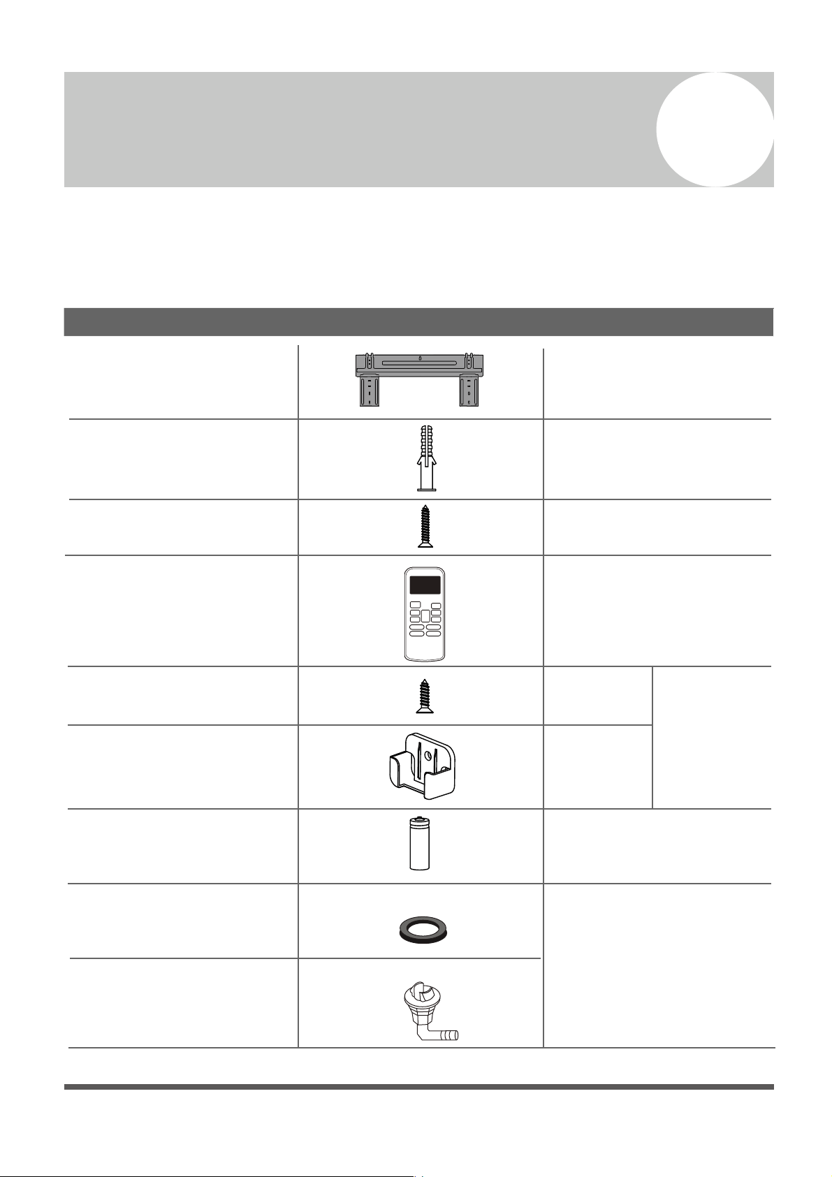
Name
Appearance Quantity
1
1
1
(for cooling & heating
models only)
(For the Outdoor Unit)
Clip anchor
Mounting plate xing
screw ST3.9 X 25
Remote controller
Fixing screw for remote
controller holder ST2.9 x 10
Remote controller holder
Dry battery AAA.LR03
Seal
Drain joint
Mounting plate
1
Accessories
The air conditioning system comes with the following accessories. Use all of the installation parts
and accessories to install the air conditioner. Improper installation may cause the equipment to
fail, or result in water leakage, electrical shock, or re.
5
5
2
1
Optional
Parts
2
Page 6
1
1
1
Owner’s manual
Installation manual
Remote controller
manual
SPLIT-TYPE ROOM AIR CONDITIONER
CS78421-548-754
IMPORTANT NOTE:
Read this manual carefully before installing
or operating your new air conditioning
unit. Make sure to save this manual for
future reference.
Owner’s Manual
SPLIT-TYPE ROOM AIR CONDITIONER
CS78421-548-754
IMPORTANT NOTE:
Read this manual carefully before installing
or operating your new air conditioning
unit. Make sure to save this manual for
future reference.
Installation Manual
Page 7
Name
Shape Quantity
Parts sold separately.
Consult your dealer about
pipe size.
Connecting pipe
assembly
(depending on capacity)
Liquid side
Gas side
Φ
6.35(1/ 4 in)
Φ9.52(3/8in)
Φ9.52(3/8in)
Φ12.7(1/2in)
Φ 16(5/ 8in)
IMPORTANT NOTE:
Read this manual carefully before installing
or operating your new air conditioning
unit. Make sure to save this manual for
future reference.
AIR CONDITIONER
REMOTE CONTROL LER MANUAL
Φ 19(3/ 4in)
Page 8
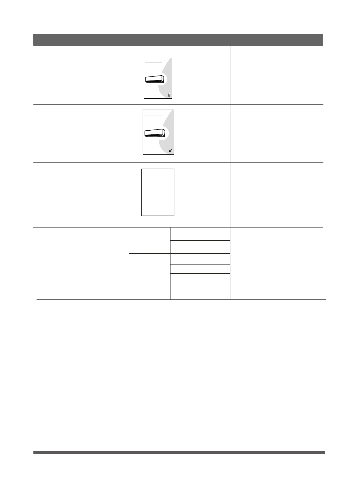
Indoor Unit Installation Summary
2
Installation
Overview
Select Installation Location
(Page 11)
Attach Mounting Plate
(Page 12)
Drill Wall Hole
(Page 12)
Determine Wall Hole Position
(Page 12)
1 2
3 4
8-12cm
(3-5 in)
2.0-2.6m
(80-100 in)
8-12cm
(3-5 in)
Min. 10-15cm
(4-6 in.)
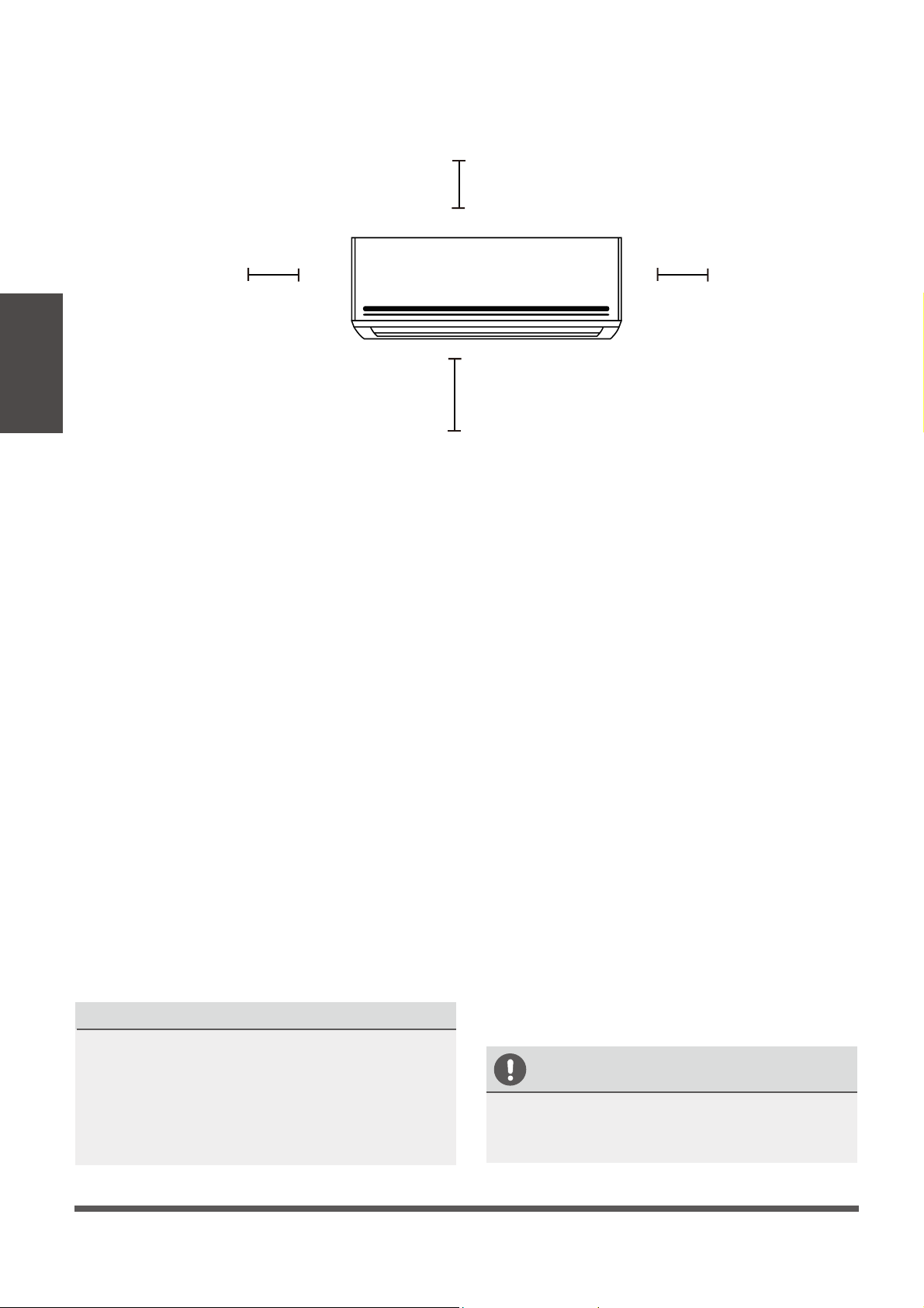
Recommended Clearances
Hole can be drilled on either left or right side
MUST BE PERFECTLY HORIZONTAL
Min. Min.
Optimally
Page 9
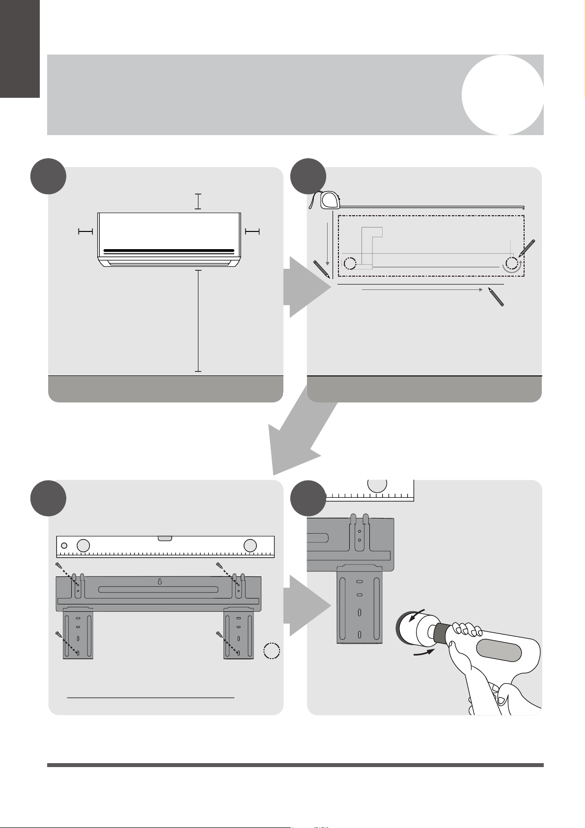
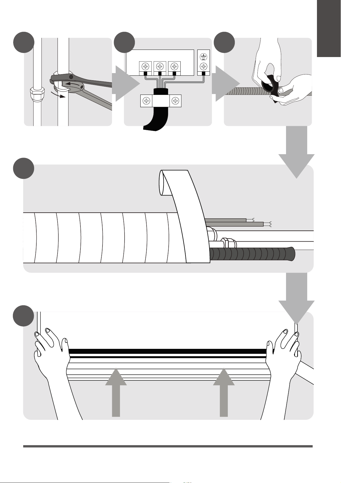
Mount the Indoor Unit
(Page 18)
STEP
8
Wrap Piping & Cables together
(Page 18)
123
Connect Piping
(Page 25)
Connect Wiring
(Page 17)
Prepare Drain Hose
(Page 14)
5 6 7
8
9
Installation
Overview
USE DOUBLE
(BACKUP)
WRENCES
Ground
Page 10
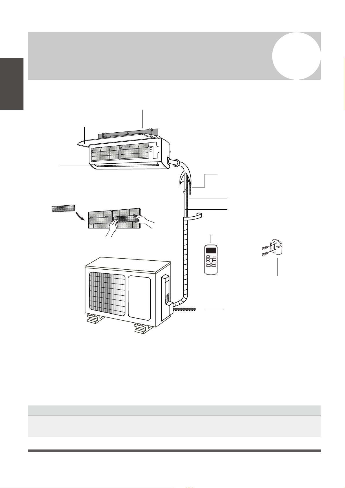
Unit Components
3
Installation
Overview
Fig. 2.1
NOTE ON ILLUSTRATIONS
Illustrations in this manual are strictly for explanatory purposes. The actual shape of your indoor unit
may be slightly dierent. The actual shape shall take precedence over graphical representations.
Wall Mounting Plate
Refrigerant Piping
Signal Cable
Remote Control
Drainage Pipe
Louver
Remote Control
Holder (Some Units)
Functional Filter
(On Front of Main Filter - Some Units)
Front Panel
Outdoor Unit
Power Cable
(Power Panel Housing)

Page 11
Indoor Unit Installation
4
Installation Instructions – Indoor
Unit
PRIOR TO INSTALLATION
Before installing the indoor unit, refer to the
label on the product box to make sure that the
system set is a matching set for capacity, voltage,
and eciency (indoor and outdoor).
Step 1: Select installation location
Before installing the indoor unit, you must
choose an appropriate location. The following
are standards that will help you choose
an appropriate location for the unit.
Proper installation locations meet the
following standards:
Good air circulation
Convenient drainage
Isolated enough to not cause disturbance
for other people
Firm and solid—the location will not vibrate
Strong enough to support the weight of the
unit
A location at least 1m (40 in) from all other
electrical devices (e.g., TV, radio, computer)
DO NOT install unit in the following
locations:
Near any sources of heat, steam, or
combustible gas
Near flammable items such as curtains or
clothing
Near any obstacle that might block air
circulation
Near doorways
In locations subjected to direct sunlight
NOTE ABOUT WALL HOLE:
There are multiple options for piping routes:
While choosing a location, be aware that you
should leave ample room for a wall hole (see
wall hole drilling for piping connection step)
for the signal cable and refrigerant piping
that connect the indoor and outdoor units.
The wall hole position for all piping can be
located at either the right or left side of the
indoor unit (while facing unit). Pipes can also
be routed out from either side, or the bottom.
Indoor Unit
Installation
Page 12
Refer to the following diagram to verify these recommended distances from walls and ceiling:
Step 2: Attach mounting plate to the wall
The mounting plate is the device on top of which
the indoor unit will be mounted.
1.
Remove the screw that attaches the mounting
plate to the back of the indoor unit.
2.
Place the mounting plate against the wall
in a location that meets the standards in
the “Select Installation Location” step. (See
“Mounting Plate Dimensions” for detailed
information on mounting plate sizes.)
3.
Drill holes for mounting screws in places that:
• have studs and can support the weight of
the unit
• correspond to screw holes in the mounting
plate
4.
Secure the mounting plate to the wall with
the screws provided.
5.
Make sure that the mounting plate is fully at
against the wall.
NOTE FOR CONCRETE OR BRICK WALLS:
If the wall is made of brick, concrete, or similar
material, drill 5mm-diameter (3/16 in-diameter)
holes in the wall and insert the provided sleeve
provided. Then, secure the mounting plate to
the wall by tightening the screws directly into
the clip anchors.
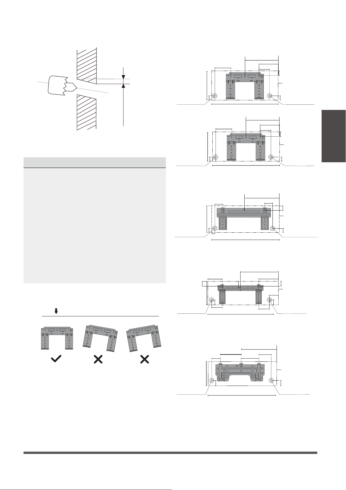
Step 3: Drill wall hole for connective piping
You must drill a hole in the wall for the refrigerant
piping, the drainage pipe, and the signal cable
that will connect the indoor and outdoor units.
1.
Determine the location of the wall hole based
on the position of the mounting plate. Refer
to “Mounting Plate Dimensions” on the
next page to help you determine the optimal
position. The wall hole should have a 65mm
(2.5in) diameter at least, and at a slight
downward angle to facilitate drainage.
Indoor Unit
Installation
Fig. 3.1
8-12cm (3-5in)
or more
2.0 m (80 in) or more
2.6 m (100 in) or less
8-12cm (3-5 in)
or more
10-15cm (4-6 in) or more
2.
3.
Place the protective sleeve in the hole. This
protects the edges of the hole and will help
seal it when you nish the installation process.
CAUTION
When drilling the wall hole, make sure to
avoid wires, plumbing, and other sensitive
components.
Using a 65mm (2.5 in) or 90mm(3.5 in)
(depending on models) core drill, drill a
hole in the wall. Make sure that the hole
is drilled at
a slight downward angle, so
that the outdoor end of the hole is lower
than the indoor end by about 5mm to 7mm
(3/16-5/16 in). This will ensure proper water
drainage. (See Fig. 3.2)
Page 13
W all
Indoor Outdoor
mm7-5
(3/16~5/16 in)
MOUNTING PLATE DIMENSIONS
Dierent models have dierent mounting plates.
To ensure that you have ample room to mount
the indoor unit, refer to the diagrams to the right
which show dierent types of mounting plates,
along with the following dimensions:
•
Width of the mounting plate
•
Height of the mounting plate
•
Width of indoor unit relative to the plate
•
Height of indoor unit relative to the plate
•
Recommended position of wall hole (both
to the left and right of the mounting plate)
•
Relative distances between the screw holes
Indoor Unit
Installation
Fig. 3.2
101mm (4 in)
179mm (7-1/16in)
136mm (5-3/8in)
37mm (1-1/2in)
290mm (11-3/8 in)
49mm (1-15/16in)
Right rear wall
hole 65mm (2-1/2in)
Indoor unit outline
722mm (28-1/2 in)
49mm (1-15/16 in)
192mm (7-1/2in)
232mm (9-1/8in)
426mm (16-3/4in)
128mm (5-1/16in)
43mm (1-3/4in)
297mm (11-3/4in)
Left rear wall
hole 65mm (2-1/2in)
Right rear wall
hole 65mm (2-1/2in)
Indoor unit outline
802mm (31-5/8in)
43mm (1-3/4in)
43mm (1-3/4in)
144mm (5-5/8in)
58mm (2-1/4in)
319mm (12-9/16in)
57mm (2-1/4in)
40mm (19/16in)
Right rear wall
hole 65mm (2-1/2in)
Model C
965mm (38in)
138mm (5.45in)
34mm (1-3/8in)
Indoor unit outline
219mm (8-5/8in)
553mm (21-3/4in)
300mm (11-3/4in)
335mm (13-1/4in)
Left rear wall
hole 65mm (2-1/2in)
Right rear wall
hole 65mm (2-1/2in)
Model D
1080mm (42-1/2in)
53.5mm
(2-1/16in)
47mm (1-7/8in)
76mm(3in)
53.5mm (2-1/16in)
47mm (1-7/8in)
149mm
(5-7/8in)
151mm (5-15/16in)
174.3mm (6-7/8in)
Indoor unit outline
172mm (6-3/4in)
362mm (14-1/4in)
Left rear wall
hole 65mm (2-1/2in)
Right rear wall
hole 65mm (2-1/2in)
Model E
1259mm (49-1/2in)
Indoor unit outline
52mm (2-1/16in)
389mm (15-1/4in)
332mm (13-1/16in)
257mm (10-1/8in)
644mm (25-3/8in)
52mm (2-1/16in)
Correct orientation of the Mounting Plate
517mm (20-3/8in)
348mm (13-3/4 in)
Φ
NOTE: When the gas side connective pipe is
16mm (5/8in) or more, the wall hole could
be 75mm (3 in). (for 24, 30, 36K Models).
Be sure to obtain perfect horizontal position
WS009-17 SEER
WS012-17 SEER
WS009-22 SEER
WS012-22 SEER
WS018-17 SEER
WS024-17 SEER
WS018-22 SEER
WS024-22 SEER
WS030-17 SEER
WS036-17 SEER
Left rear wall
hole 65mm (2-1/2in)
Left rear wall
hole 65mm (2-1/2in)
Page 14
CAUTION
Be extremely careful not to kink or damage the piping while bending them away from the
unit. Any dents or kinks in the piping will seriously aect the unit’s performance.
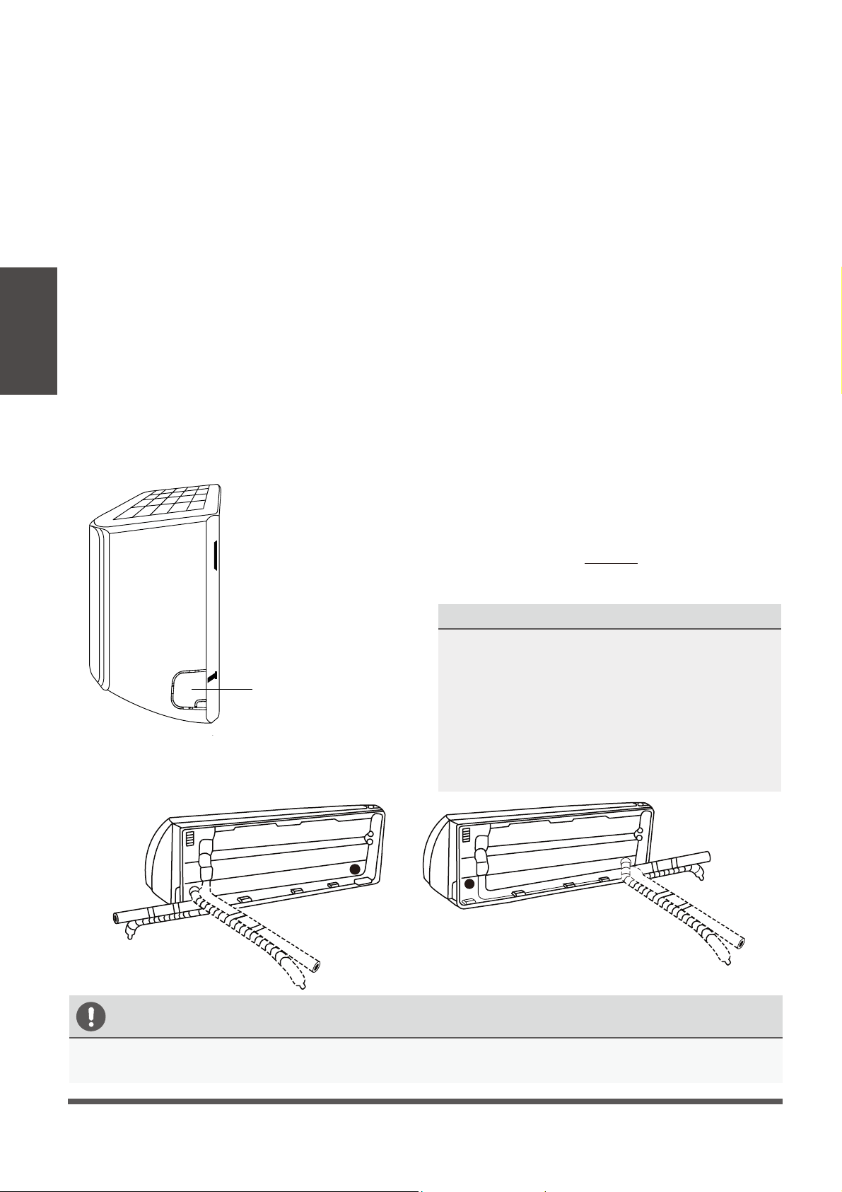
Step 4: Prepare refrigerant piping
The refrigerant piping is inside an insulating
sleeve attached to the back of the unit. You must
prepare the piping before passing it through the
hole in the wall. Refer to the “Refrigerant Piping
Connection” section of this manual for detailed
instructions on pipe flaring and flare torque
requirements, technique, etc.
1. Based on the position of the wall hole relative
to the mounting plate, choose the side from
which the piping will exit the unit.
2. If the wall hole is behind the unit, keep the
knock-out panel in place. If the wall hole is to
the side of the indoor unit, remove the plastic
knock-out panel from that side of the unit.
(See Fig. 3.3 ). This will create a slot through
which your piping can exit the unit. Use
needle nose pliers if the plastic panel is too
dicult to remove by hand.
3.
Use scissors to cut down the length of the
insulating sleeve to reveal about 15cm (6in)
of the refrigerant piping. This serves two
purposes:
• To facilitate the “Refrigerant Piping
Connection” process.
• To facilitate “Gas Leak Checks” and enable
you to check for dents or kinks.
4.
If existing connective piping is already
embedded in the wall, proceed directly to
the “Connect Drain Hose” step. If there is no
embedded piping, connect the indoor unit’s
refrigerant piping to the connective piping
that will join the indoor and outdoor units.
Refer to the “Refrigerant Piping Connection”
section of this manual for detailed instructions.
5.
Based on the position of the wall hole
relative to the mounting plate, determine the
necessary angle of your piping.
6.
Grip the refrigerant piping at the base of the
bend.
7.
Slowly, and with even pressure, bend the piping
towards the hole. Do not kink or damage the
piping during the process !!!! (CAUTION)
NOTE ON PIPING ANGLE
Refrigerant piping can exit the indoor unit from
four dierent angles:
•
Left-hand side
•
Left rear
•
Right-hand side
•
Right rear
Refer to
Fig. 3.4 for details.
Fig. 3.3
Fig. 3.4
Indoor Unit
Installation
Knock-out Panel
LEFT REAR
Most Recommended
but less common
LEFT HAND SIDE
Recommended
for side exit
RIGHT REAR
Less Recommended
but most common
RIGHT HAND SIDE
Not Recommended
unless absolutely needed

Page 15
Step 5:
Connect drain hose
By default, the drain hose is attached to the left-
hand side of unit (”left” when facing the back
of the unit). However, it can also be attached to
the right-hand side.
1.
To ensure proper drainage, attach the drain
hose on the same side that your refrigerant
piping exits the unit.
2.
Attach drain hose extension (sold
separately) to the end of drain hose.
3.
Wrap the connection point rmly with Teon
tape to create a good seal, and to prevent
leaks.
4.
For the portion of the drain hose that will
remain indoors, wrap it with foam pipe
insulation to prevent condensation.
5.
Remove the air filter and pour a small amount
of water into the drain pan to make sure that
water flows from the unit smoothly.
NOTE ON DRAIN HOSE
PLACEMENT
Make sure to arrange the drain hose
according to
Fig. 3.5 .
DO NOT
kink the drain hose.
DO NOT
create a water trap (siphon).
DO NOT
put the end of the drain hose
in water or in a container that will
collect water.
DUAL DRAIN HOLE LOCATIONS EXIST
The indoor unit has 2 drain connections on left and
right sides. Either one can be utilized. One side will
have a hose connected, while the other is plugged.
CORRECT
Make sure there are no
kinks, dents or siphons in
the drain hose, to ensure
proper drainage.
NOT CORRECT
Kink/siphon in the drain hose,
will create water traps.
NOT CORRECT
Do not place the end
of the drain hose in
water or in containers
that collect water. This
will prevent proper
drainage.
NOT CORRECT
Kink/siphon in the drain hose,
will create water traps.
Fig. 3.5
Fig. 3.6
Fig. 3.7
Fig. 3.8
Indoor Unit
Installation
Page 16
BEFORE PERFORMING ELECTRICAL WORK, READ THESE REGULATIONS
1.
All wiring must comply with local and national electrical codes, and must be installed by a
licensed electrician.
2.
All electrical connections must be made according to the Electrical Connection Diagram
located on the panels of the indoor and outdoor units.
3.
If there is a serious safety issue with the power supply, stop work immediately. Explain your
reasoning to the client, and suspend all installation until the safety issue is properly resolved.
4.
Power voltage should be within 90-110% of rated voltage. Insucient power supply can
cause malfunction, electrical shock, or re.
5.
Connect power through xed wiring, install a surge protector and a disconnect switch box,
and a dedicated circuit breaker with a capacity of 1.5 times the maximum current of the unit.
6.
A properly rated HACR-type fuse or circuit breaker that disconnects all poles and
has a contact separation of at least 1/8in (3mm) must be incorporated in the xed wiring. The
qualied technician must use an approved circuit breaker or fuse.
7.
Only connect the unit to an individual branch circuit. Do not connect another appliance
to that outlet. This equipment requires its own dedicated and protected circuit.
8.
Make sure to properly ground the air conditioner.
9.
Every wire must be rmly connected. Loose wiring can cause the terminal to overheat,
resulting in product malfunction and possible re.
10.
Do not let wires touch or rest against refrigerant tubing, the compressor, or any moving parts
within the unit.
11.
If the unit has an auxiliary electric heater, it must be installed at least 1 meter (40in) away
from any combustible materials.
Indoor Unit
Installation
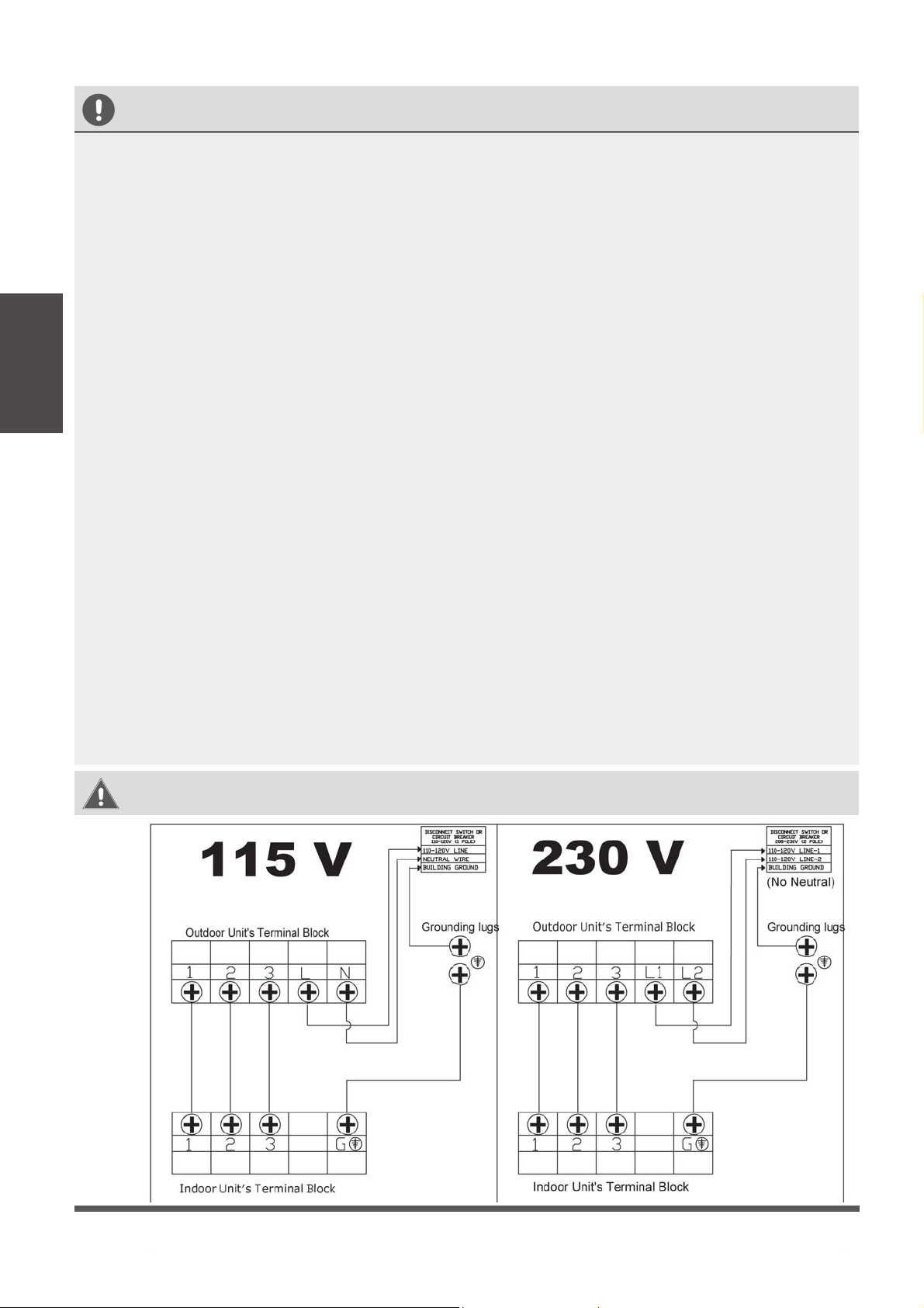
WARNING:
BEFORE PERFORMING ANY ELECTRICAL OR WIRING WORK, TURN OFF THE MAIN
POWER TO THE SYSTEM.
Simplied Wiring Diagrams
Page 17
Step 6: Connect signal cable
The signal cable enables communication between
the indoor and outdoor units. You must first
choose the right cable size before preparing it for
connection.
Cable Types
•
Outdoor Power Cable:
H07RN-F
•
Signal Cable: H07RN-F
Minimum Cross-Sectional Area of
Power and Signal Cables
Other Regions
Rated Current of
Appliance (A)
Nominal Cross-Sectional
Area (mm²)
> 3 and 6 0.75
> 6 and 10 1
> 10 and 16 1.5
> 16 and 25 2.5
> 25 and 32 4
> 32 and 40 6
CHOOSE THE RIGHT CABLE SIZE
The size of the power supply cable, signal
cable, fuse, and switch needed is determined
by the maximum current of the unit. The
maximum current is indicated on the nameplate
located on the side panel of the unit. Refer to
this nameplate to choose the right cable, fuse,
or switch.
TAKE NOTE OF FUSE SPECIFICATIONS
The air conditioner’s circuit board (PCB) is
designed with a fuse to provide overcurrent
protection. The specifications of the fuse
are printed on the circuit board, such as:
T3.15A/250VAC, T5A/250VAC, etc.
1.
Prepare the cable for connection:
a.
Using wire strippers, strip the rubber jacket
from both ends of signal cable to reveal
about 40mm (1.5 in) of the wires inside.
b.
Strip the insulation from the ends of the
wires.
c.
Using a wire crimper, crimp u-type lugs on
the ends of the wires, if needed.
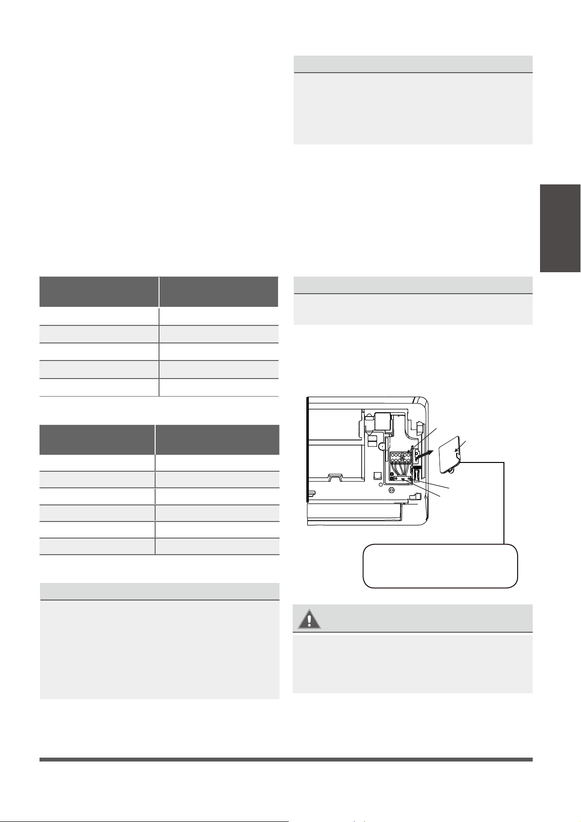
PAY ATTENTION TO MAKE GOOD CONTACT
While crimping wires, make sure to make good
electrical contact between the wire and terminal
2. O
pen the front panel of the indoor unit.
3.
Using a screwdriver, open the wire box cover
on the right side of the unit. This will reveal
the terminal block.
Terminal block
Wire cover
Screw
Cable clamp
WARNING
4.
Unscrew the cable clamp below the terminal
block and place it to the side.
5.
Facing the back of the unit, remove the plastic
panel on the bottom left-hand side.
Fig. 3.9
Indoor Unit
Installation
The Wiring Diagram is located
on the inside of the indoor unit’s
front panel or under this cover.
North America
Appliance Amps (A)
AWG
10 18
13 16
15 14
20 12
30 10
ALL WIRING MUST PERFORMED STRICTLY
IN ACCORDANCE WITH THE WIRING
DIAGRAM LOCATED ON THE INSIDE OF THE
INDOOR UNIT’S FRONT PANEL OR UNDER COVER.
Page 18
6. Feed the signal wire through this slot, from
the back of the unit to area near terminals.
7. Facing the front of the unit, attach 4 leads of
the signal wire to the 4 terminal positions
marked as 1-2-3-G (Ground). Note the color
of the wire used for each terminal, to connect
same wire to the same position at other end.
CAUTION
DO NOT MIX UP THE WIRES BETWEEN EACH ENDS
This is hazardous, and can cause the air
conditioning unit to malfunction.
8.
After checking to make sure every connection
is secure, use the cable clamp to fasten the
signal cable to the unit. Screw the cable clamp
down tightly.
9.
Replace the wire cover on the front of the
unit, and the plastic panel on the back.
NOTE ABOUT WIRING
Step 7: Wrap piping and cables
Before passing the piping, drain hose, and the
signal cable through the wall hole, you must
bundle them together to save space, protect
them by sealing the ends, and insulate them.
1.
Bundle the drain hose, refrigerant pipes, and
signal cable according to Fig. 3.10.
Indoor Unit
Space behind unit
Refrigerant piping
Drain hose
Signal wire
Insulation tape
DRAIN HOSE MUST BE ON BOTTOM
Make sure that the drain hose is at the bottom
of the bundle. Putting the drain hose at the
top of the bundle can cause the drain pan
to overflow, which can lead to fire or water
damage.
DO NOT INTERTWINE SIGNAL CABLE WITH
OTHER WIRES
While bundling these items together, do not
intertwine or cross the signal cable with any
other wiring.
2.
Using adhesive vinyl tape, attach the drain
hose to the underside of the refrigerant pipes.
3.
Using insulation tape, wrap the signal wire,
refrigerant pipes, and drain hose tightly
together. Double-check that all items are
bundled in accordance with Fig. 3.10.
DO NOT REMOVE DUST CAPS FROM THE PIPING
When wrapping the bundle, keep the ends of
the piping sealed well with the original dust caps
or using duct tape so that dust cannot enter inside.
Leave connection points accessible for leak
and electrical checking later (see next sections).
Step 8: Mount indoor unit
If you installed new connective piping to the
outdoor unit, do the following:
1.
If you have already passed the refrigerant
piping through the hole in the wall, proceed
to Step 4.
2.
Otherwise, double-check that the ends of the
refrigerant pipes are sealed to prevent dirt or
foreign materials from entering the pipes.
3.
Slowly pass the wrapped bundle of refrigerant
pipes, drain hose, and signal wire through the
hole in the wall.
4.
Hook the top of the indoor unit onto the upper
hooks of the mounting plate.
5.
Check that the unit is hooked rmly on mounting
plate by applying slight pressure to the left and
right-hand sides of the unit. The unit should
not jiggle or shift.
6.
Using even pressure, push the bottom half of
the unit toward the wall. Keep pushing evenly
until the unit snaps onto the hooks along the
bottom of the mounting plate.
7.
Again, check that the unit is firmly mounted
by applying slight pressure to the left and the
right-hand sides of the unit.
Fig. 3.10
Indoor Unit
Installation
THE WIRING CONNECTION PROCESS MAY
DIFFER SLIGHTLY BETWEEN UNITS.
8.
During this entire process, make sure that the
copper pipes, insulation materials, drain hose,
electrical wires are not stressed, bent, kinked,
or received any stresses or damaged otherwise.
Page 19
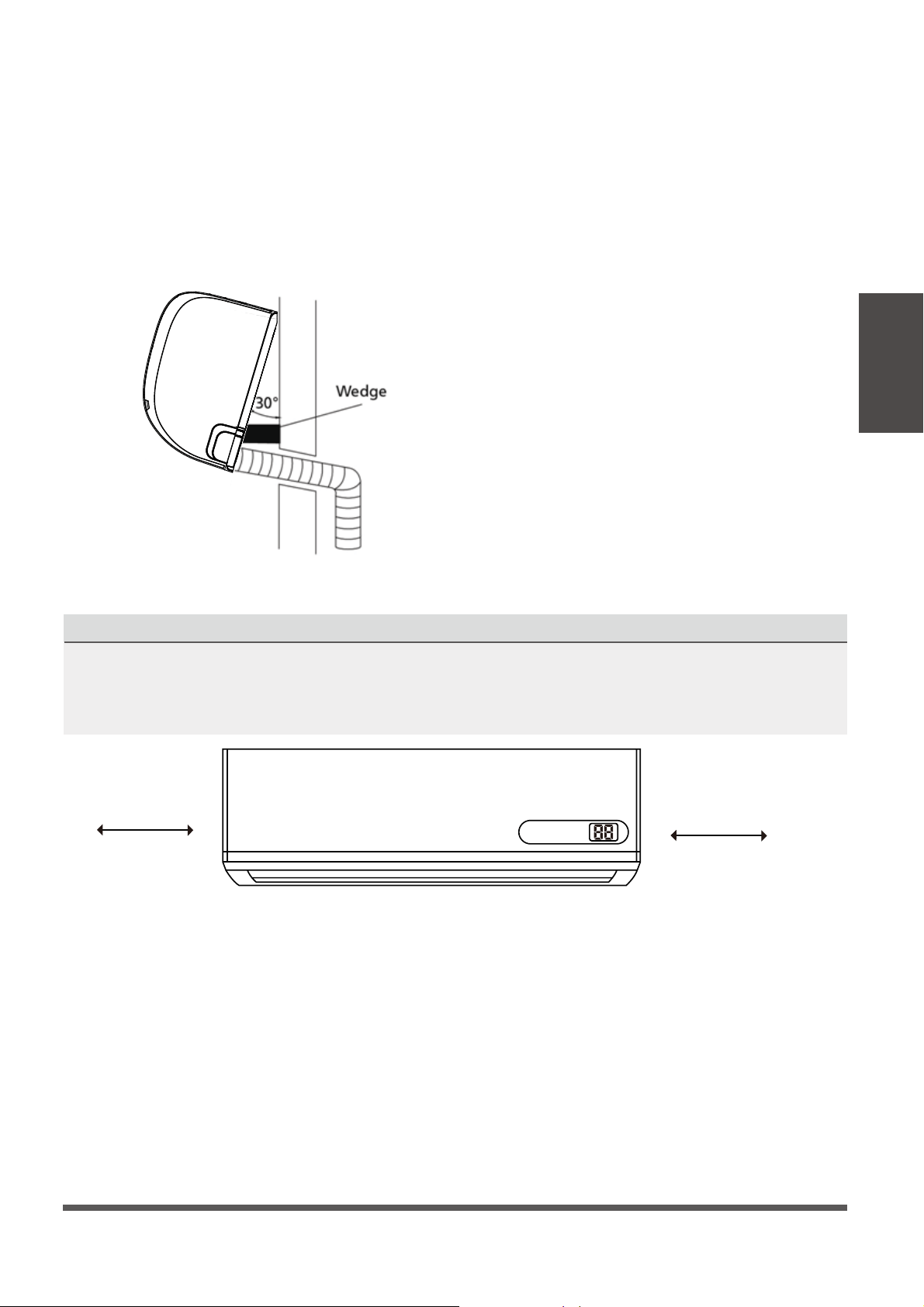
If refrigerant piping is already embedded in
the wall, do the following:
1.
Hook the top of the indoor unit onto the upper
hook of the mounting plate.
2.
Use a bracket or wedge to prop up the unit,
giving you enough room to connect the
refrigerant piping, signal cable, and drain
hose. Refer to Fig. 3.11 for an example.
Fig. 3.11
Fig. 3.12
Move to left or right
30-50 mm
(1-2 in)
30-50 mm
(1-2 in)
Indoor Unit
Installation
3.
Connect drain hose and refrigerant piping
(refer to “Refrigerant Piping Connection”
section of this manual for instructions).
4.
Keep pipe connection points exposed to
perform the leak test (refer to “Electrical
Checks and Leak Checks” section of this
manual).
5.
After the leak test, wrap the connection point
with insulation tape.
6.
Remove the bracket or wedge that is propping
up the unit.
7.
Using even pressure, push the bottom half of
the unit toward the wall. Keep pushing evenly
until the unit snaps onto the hooks along the
bottom of the mounting plate.
UNIT IS ADJUSTABLE
Keep in mind that the hooks on the mounting plate are smaller than the holes on the back of the
unit. If you find that you don’t have ample room to connect embedded pipes to the indoor unit, the
unit can be adjusted left or right by about 30-50mm (1-2 inches), depending on the model. (See
Fig. 3.12
.)
Page 20
Outdoor Unit Installation
5
Installation Instructions – Outdoor
Unit
Step 1: Select installation location
Before installing the outdoor unit, you must
choose an appropriate location. The following
are standards that will help you choose an
appropriate location for the unit.
Proper installation locations meet the
following standards:
Meets all spatial requirements shown in
“Installation Space Requirements” (Fig. 4.1)
Good air circulation and ventilation
Firm and solid—the location can support the
unit and will not vibrate
Noise from the unit will not disturb others
Protected from prolonged periods of direct
sunlight, rain, ooding.
DO NOT
install unit in the following locations:
Near an obstacle that will block air inlets
and outlets
Near a public street, crowded areas, or
where noise from the unit will disturb others
Near animals or plants that will be harmed
by hot or cold air discharge
Near any source of combustible gas
In a location that is exposed to large
amounts of dust or receiving high winds
In a location exposed to excessive amounts
of salty air due to sea body proximity
Fig. 4.1
Outdoor Unit
Installation
e
v
o
ba
)ni42
(
mc
0
6
60cm (24in)
on right
30cm (12in)
on left
200cm (80in)
in front
30cm (12in)
from back wall
(for slab mount)
(See Note!)
Additional note when using wall mounting brackets:
Please note that the rear clearance required as
shown in Fig 4.1 is not as strict when using wall
mounting brackets. Minimum rear clearance when
using wall mounting brackets is 10 cm (~4 inches).
When using
brackets, rear
clerance can
be as low as
10cm (4 in)
Page 21
SPECIAL CONSIDERATIONS FOR EXTREME
WEATHER
If the unit is exposed to heavy wind:
Install unit so that air outlet fan is at a 90°
angle to the direction of the wind. If needed,
build a barrier in front of the unit to protect it
from extremely heavy winds.
See Fig. 4.2 and Fig. 4.3 below.
Strong wind
Strong wind
Strong wind
If the unit is frequently exposed to heavy
rain or snow:
Build a shelter above the unit to protect
it from the rain or snow. Be careful not to
obstruct air flow around the unit.
If the unit is frequently exposed to salty air
(seaside):
Use specic-approved anti-corrosion coating sprays
on heat exchanger surface to resist corrosion.
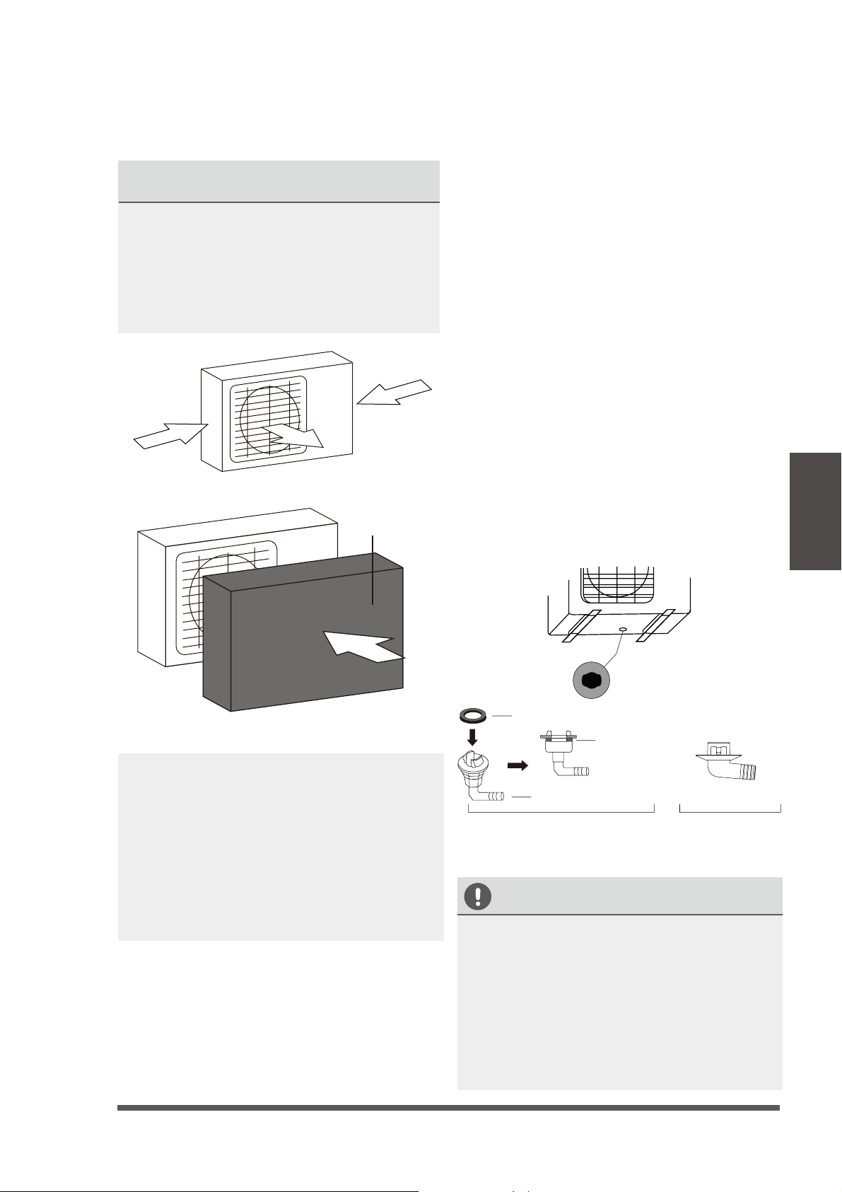
Step 2: Install drain joint
Heat pump units require a drain joint. Before
bolting the outdoor unit in place, you must install
the drain joint at the bottom of the unit. Note
that there are two dierent types of drain joints
depending on the type of outdoor unit.
If the drain joint comes with a rubber seal
(see Fig. 4.4 - A ), do the following:
1.
Fit the rubber seal on the end of the drain joint
that will connect to the outdoor unit.
2.
Insert the drain joint into the hole in the base
pan of the unit.
3.
Rotate the drain joint 90° until it clicks in place
facing the front of the unit.
4.
Connect a drain hose extension (included)
to the drain joint to redirect water from the
unit during heating mode.
If the drain joint doesn’t come with a rubber
seal (see Fig. 4.4 - B ), do the following:
1.
Insert the drain joint into the hole in the base
pan of the unit. The drain joint will click in
place.
2.
Connect a drain hose extension (included)
to the drain joint to redirect water from the
unit during heating mode.
Seal
Drain joint
(A) (B)
Base pan hole of
outdoor unit
Seal
IN COLD CLIMATES
In cold climates, make sure that the drain hose
is as vertical as possible to ensure swift water
drainage. If water drains too slowly, it can
freeze in the hose and ood inside unit.
Insulate the drain hose for cold climates to
prevent freezing. Frequently inspect the unit
to ensure it is not buried in snow, or the inside
is not lled up from heavy buildup of snow or
ice, which can prevent the fan from spinning.
Fig. 4.2
Fig. 4.3
Fig. 4.4
Outdoor Unit
Installation
Wind baffle
Page 22
If you are installing the unit on the ground or
on a concrete mounting platform, do the
following:
1. Mark the positions for four expansion bolts
based on dimensions in the “Unit Mounting
Dimensions” chart.
2. Pre-drill holes for expansion bolts.
3. Clean concrete dust away from holes.
4. Place a nut on the end of each expansion bolt.
5. Hammer expansion bolts into the pre-drilled
holes.
6. Remove the nuts from expansion bolts, and
place outdoor unit on bolts.
7. Put washer on each expansion bolt, then
replace the nuts.
8. Using a wrench, tighten each nut until snug.
WARNING
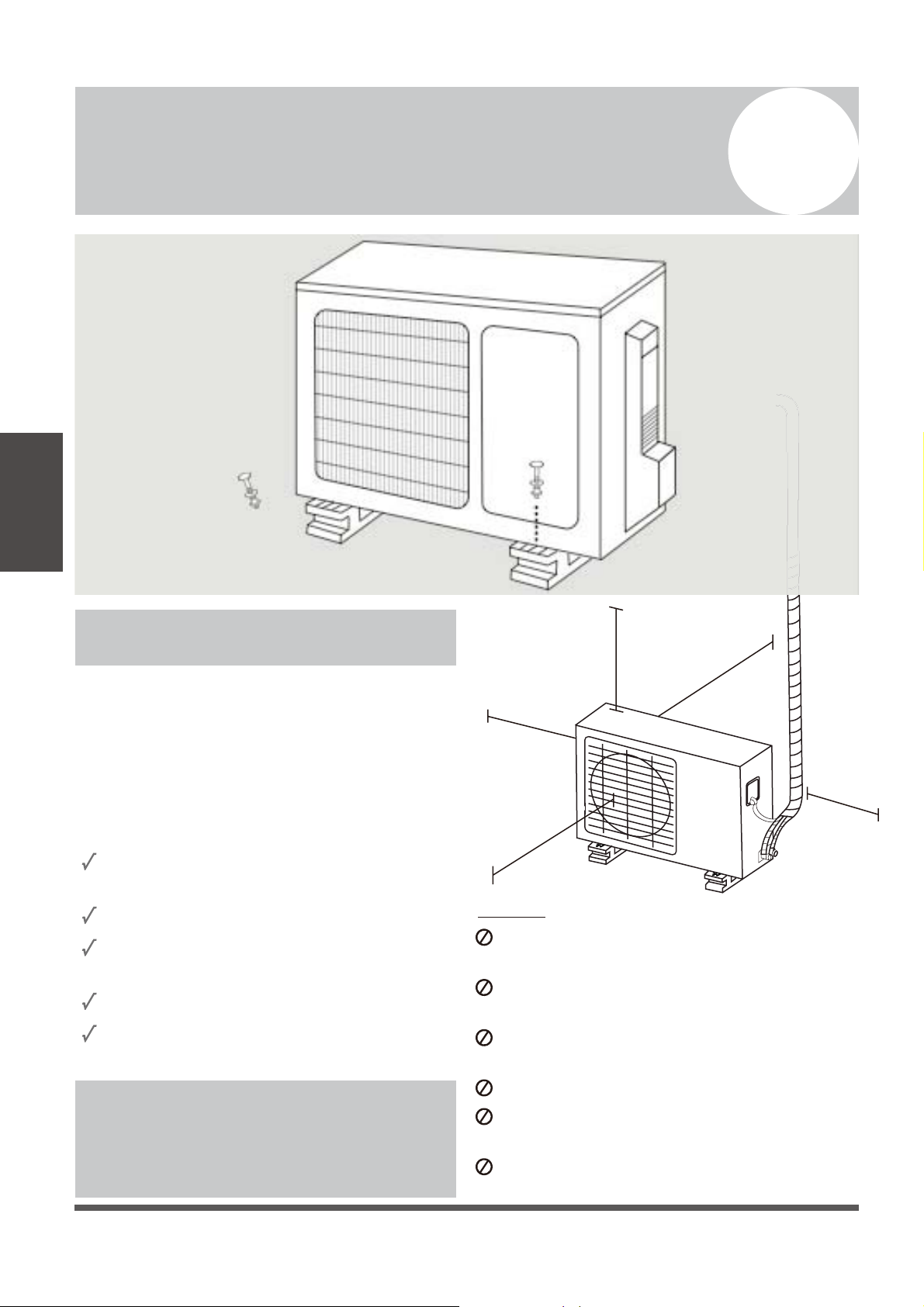
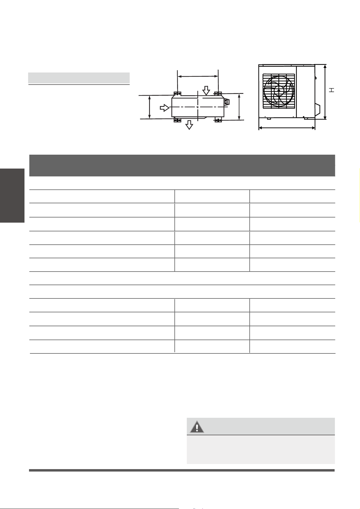
Step 3: Anchor the outdoor unit
The outdoor unit can be anchored
to the ground or to a wall-mounted
bracket.
UNIT MOUNTING DIMENSIONS
The following is a list of dierent
outdoor unit sizes and the distance
between their mounting feet.
Prepare the installation base of the
unit according to the dimensions
below.
W
A
B
D
Air inlet
Air outlet
Air inlet
Fig. 4.5
Outdoor Unit
Installation
WHEN DRILLING INTO CONCRETE, EYE
PROTECTION SHOULD BE WORN AT ALL
TIMES.
Outdoor Unit Dimensions (mm)
W x H x D (mm) & (in)
Mounting Dimensions
Distance A (mm) & (in) Distance B (mm) & (in)
24K BTU-22 SEER: 946x810x410 (37-1/4x31-7/8x16-1/4) 673 (26-1/2) 403 (15-7/8)
24K BTU-17 SEER: 845x702x363 (33-1/4x27-5/8x14-3/8)
540 (21-1/4)
350 (13-3/4)
9K BTU-17 SEER: 770x555x300 (30-3/8x21-7/8x11-7/8) 487 (19-1/4) 298 (11-3/4)
12K BTU-22 SEER: 800x554x333 (31-1/2x21-3/4x13-1/8) 514 (20-1/4) 340 (13-3/8)
12K BTU-17 SEER: 770x555x300 (30-3/8x21-7/8x11-7/8) 487 (19-1/4) 298 (11-3/4)
18K BTU-17 SEER: 770x555x300 (30-3/8x21-7/8x11-7/8) 487 (19-1/4) 298 (11-3/4)
9K BTU-22 SEER: 770x555x300 (30-3/8x21-7/8x11-7/8) 487 (19-1/4) 298 (11-3/4)
18K BTU-22 SEER: 845x702x363 (33-1/4x27-5/8x14-3/8)
540 (21-1/4)
350 (13-3/4)
30K BTU-17 SEER: 946x810x410 (37-1/4x31-7/8x16-1/4) 673 (26-1/2) 403 (15-7/8)
36K BTU-17 SEER: 946x810x410 (37-1/4x31-7/8x16-1/4) 673 (26-1/2) 403 (15-7/8)
17 SEER Inverter + Models
22 SEER Inverter ++ Models
Page 23
If you are installing the unit on a wall-mounting
bracket, do the following:
CAUTION
Before installing a wall-mounted unit, make
sure that the wall is made of solid brick,
concrete, or of similarly strong material. The
wall must be able to support at least four
times the weight of the unit.
1.
Mark the position of bracket holes based on
dimensions in the “Unit Mounting Dimensions”
chart.
2.
Pre-drill the holes for the expansion bolts.
3.
Clean dust and debris away from holes.
4.
Place a washer and nut on the end of each
expansion bolt.
5.
Thread expansion bolts through holes in
mounting brackets, put mounting brackets
in position, and hammer expansion bolts into
the wall.
6.
Check that the mounting brackets are level.
7.
Carefully lift unit and place its mounting feet
on brackets.
8.
Bolt the unit rmly to the brackets.
TO REDUCE VIBRATIONS OF WALL-
MOUNTED UNIT
If available, you can install the wall-mounted
unit with rubber gaskets to reduce vibrations
and noise transmitting into the structure.
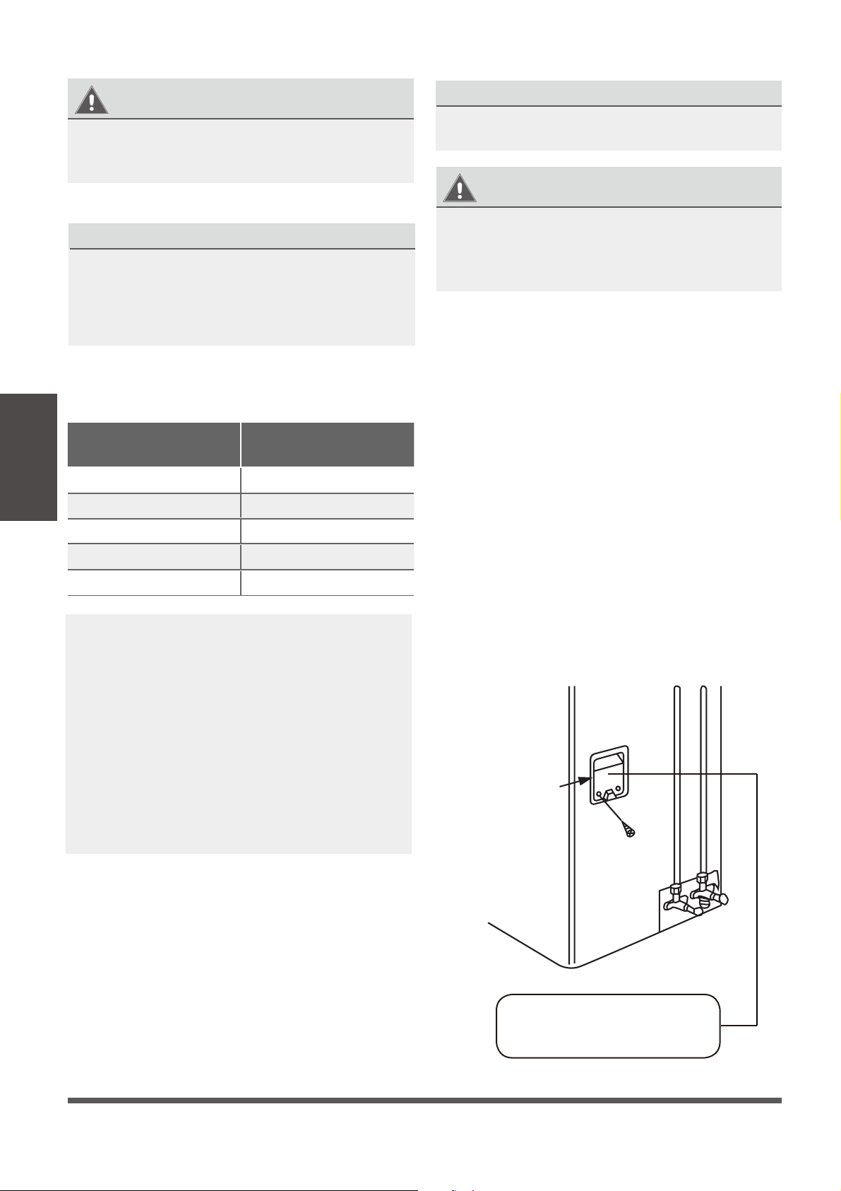
Step 4: Connect signal and power cables
The outside unit’s terminal block is protected by
an electrical wiring cover on the side of the unit.
A comprehensive wiring diagram is printed on
the inside of the wiring cover.
BEFORE PERFORMING
ANY ELECTRICAL WORK,
READ THESE REGULATIONS
1.
All wiring must comply with local and
national electrical codes, and must be
installed by a fully-licensed electrician.
2.
All electrical connections must be made
according to the Electrical Connection
Diagram located on the side panels of the
indoor and outdoor units.
3.
If there is a serious safety issue with the
power supply, stop work immediately. Explain
your reasoning to the client, and suspend all
installation of the unit until the safety issue is
properly resolved.
4.
Power voltage should be within 90-110% of
rated voltage. Insufficient power supply can
cause electrical shock or fire.
5.
Connect the power through xed wiring, install
a surge protector, and disconnect switch box.
Use a dedicated circuit breaker with a capacity
of 1.5 times the maximum current of the unit.
6.
A properly rated HACR-type fuse or circuit
breaker that disconnects all poles and has a
contact separation of at least 1/8in (3mm)
must be incorporated in the fixed wiring.
The qualified technician must use an
approved circuit breaker or switch.
7.
Only connect the unit to a dedicated individual
branch circuit breaker. Do not connect another
appliance to that same circuit.
8.
Be sure to properly ground the air
conditioner.
9.
Every wire must be rmly connected. Loose
wiring can cause the terminal to overheat,
resulting in product malfunction and possible
re.
10. Do not
let wires touch or rest against
refrigerant tubing, the compressor, or any other
moving parts within the unit.
11.
If the unit has an auxiliary electric heater, it
must be installed at least 1 meter (40in) away
from any combustible materials.
Outdoor Unit
Installation
Page 24
WARNING
1.
Prepare the cable for connection:
USE THE RIGHT CABLE
•
Outdoor Power Cable: H07RN-F
•
Signal Cable: H07RN-F
Minimum Cross-Sectional Area of
Power and Signal Cables
a. Using wire strippers, strip the rubber
jacket from both ends of cable to reveal
about 40mm (1.5 in) of the wires inside.
b. Strip the insulation from the ends of the
wires.
c. Using a wire crimper, crimp u-lugs on the
ends of the wires.
PA Y ATTENTION TO MAKE GOOD CONTACT
While crimping wires, make sure to make good
electrical contact between the wire and terminal
2.
Unscrew the electrical wiring terminal block
cover and place it to the side.
3.
Unscrew the cable clamp below the terminal
block and place it to the side.
4.
Attach 3 leads of the signal wire to 1-2-3 lugs
of the terminal block and ground wire to ground
lug on metal panel, to ensure a tight connection.
5.
After checking to make sure every connection
is secure, loop the wires around to prevent
rain water from owing into the terminal.
6.
Using the cable clamp, fasten the cable to the
unit. Screw the cable clamp down tightly.
7.
Insulate unused wires with PVC electrical tape.
Arrange them so that they do not touch any
electrical or metal parts.
8.
Replace the wire cover on the side of the unit,
and screw it into place.
Outdoor Unit
Installation
Cover
Outdoor Unit Wiring Diagram
is located on the inside of the
wire cover on the outdoor unit.
Fig. 4.6
BEFORE PERFORMING ANY ELECTRICAL
OR WIRING WORK, TURN OFF THE MAIN
POWER TO THE SYSTEM.
WARNING
ALL WIRING MUST PERFORMED STRICTLY
IN ACCORDANCE WITH THE WIRING
DIRGRAM LOCATED INSIDE THE OUTDOOR
UNIT S WIRING TERMINAL BLOCK COVER.
’
North America
Appliance Amps (A)
AWG
10 18
13 16
15 14
20 12
30 10
INDOOR UNIT TERMINAL POSITION #1 connects
to OUTDOOR UNIT TERMINAL POSITION #1.
INDOOR UNIT TERMINAL POSITION #2 connects
to OUTDOOR UNIT TERMINAL POSITION #2.
INDOOR UNIT TERMINAL POSITION #3 connects
to OUTDOOR UNIT TERMINAL POSITION #3.
INDOOR UNIT TERMINAL POSITION “GROUND”
connects to OUTDOOR UNIT GROUNDING LUG
Note: Some cables come with preinstalled
u-lugs from the factory.
Page 25
Refrigerant Piping Connection
6
Note on Pipe Length
The length of refrigerant piping will aect the performance and energy efficiency of the unit. Nominal
efficiency is tested on units with a pipe length of 5 meters (16 ft).
Refer to the table below for specifications on the maximum length and drop height of piping.
Maximum Length and Drop Height of Refrigerant Piping per Unit Model
Model Capacity (BTU/h) Max. Length (m) Max. Drop Height (m)
R410A Inverter Split Air
Conditioner
< 15,000 25 (80 ft) 10 (33 ft)
15,000 and < 24,000 30 (100 ft) 20 (66 ft)
24,000 and < 36,000 50 (165 ft) 25 (82 ft)
36,000 and 60,000 65 (215 ft) 30 (100 ft)
Connection Instructions –
Refrigerant Piping
Step 1: Cut pipes
When preparing refrigerant pipes, take extra care
to cut and flare them properly. This will ensure
efficient operation and minimize the need for
future maintenance.
1. Measure the distance between the indoor and
outdoor units.
2. Using a pipe cutter, cut the pipe a little longer
than the measured distance.
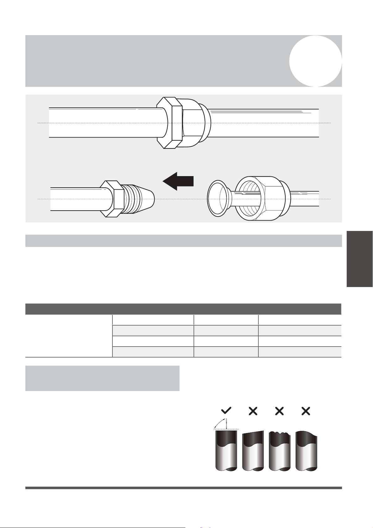
3. Make sure that the pipe is cut at a perfect 90°
angle. Refer to Fig. 5.1 for bad cut examples.
Oblique Rough Warped
90°
Fig. 5.1
Refrigerant
Piping
Connection
Page 26
DO NOT DEFORM PIPE
WHILE CUTTING
Be extra careful not to damage, kink, or
deform the pipe while cutting. This will
drastically reduce the eciency and capacity
of the unit and may cause internal damage.
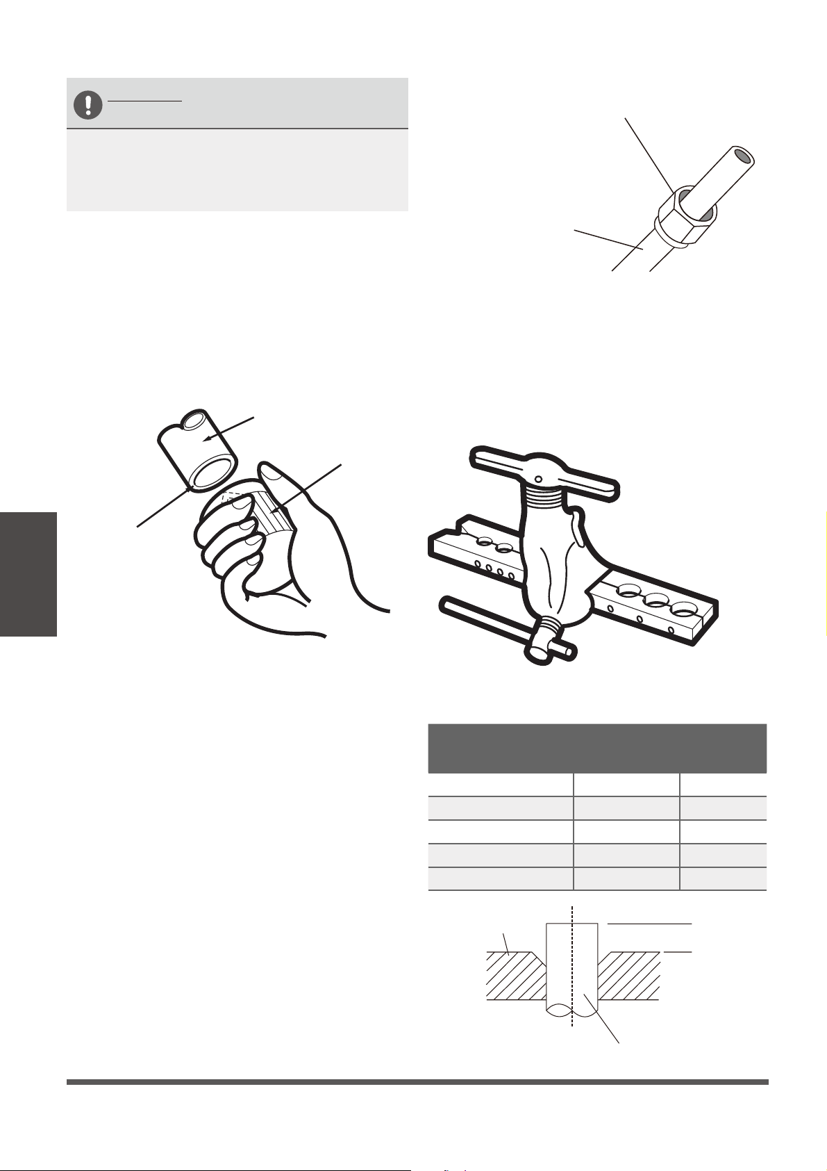
Step 2: Remove any burrs carefully.
Burrs can aect the air-tight seal of refrigerant
piping connection. They must be completely
removed. Follow steps below for proper deburring.
1.
Hold the pipe at a downward angle to prevent
burrs from falling into the pipe.
2.
Using a reamer or deburring tool, remove all
burrs from the cut section of the pipe.
Pipe
Reamer
Point down
Ensures no shavings
can fall inside of tubes
Step 3: Flare pipe ends
Proper flaring is essential to achieve an airtight
seal.
1.
After removing burrs from cut pipe, seal
the ends with PVC tape to prevent foreign
materials from entering the pipe.
2.
Sheath the pipe with insulating material.
3.
Place are nuts on both ends of pipe. Make
sure they are facing the correct direction,
because you can’t put them on or change
their direction after aring. See
Fig. 5.3 .
Flare nut
Copper pipe
4.
Remove PVC tape from ends of pipe when
ready to perform aring work.
5.
Clamp are form on the end of the pipe.
The end of the pipe must extend beyond the
edge of the are form in accordance with the
dimensions shown in the table below.
Fig. 5.2
Fig. 5.3
Fig. 5.4
Refrigerant
Piping
Connection
PIPING EXTENSION BEYOND FLARE FORM
Outer Diameter of
Pipe (mm)
A (mm)
Min. Max.
Ø 6.35 (Ø 1/4”) 0.7 (0.03”) 1.3 (0.05”)
Ø 9.52 ( Ø 3/8”) 1.0 (0.04”) 1.6 (0.06”)
Ø 12.7 ( Ø 1/2”) 1.0 (0.04”) 1.8 (0.07”)
Ø 16 ( Ø 5/8”)
Ø 19 ( Ø 3/4”)
2.0 (0.08”) 2.2 (0.09”)
2.0 (0.08”) 2.4 (0.1”)
Flare form
Pipe
A
Fig. 5.5
Page 27
6.
Place aring tool onto the form.
7.
Turn the handle of the aring tool clockwise
until the pipe is fully ared.
8.
Remove the aring tool and are form, then
inspect the end of the pipe for cracks and
successful, even aring.
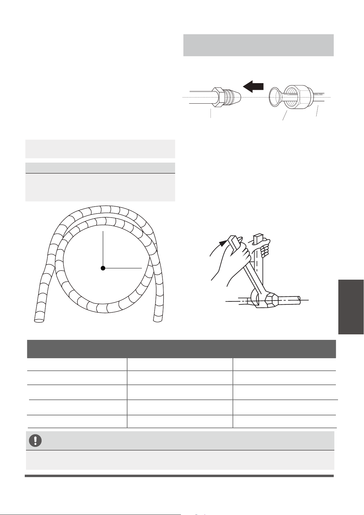
Step 4: Connect pipes
When connecting refrigerant pipes, be careful
not to use excessive torque, or to deform the
piping in any way. You should first connect the
low-pressure pipe, then the high-pressure pipe.
MINIMUM BEND RADIUS
When bending connective refrigerant piping,
the minimum bending radius is 10cm (4”). See
Fig.5.6.
≥10cm (4in)Radius
Instructions for Connecting Piping to
Indoor Unit
1.
Align the center of the two pipes that you will
connect. See Fig. 5.7
Indoor unit tubing Flare nut Pipe
2.
Tighten the are nut as tightly as possible by
hand.
3.
Using a spanner, grab the nut on the unit
tubing.
4.
While rmly holding the nut on the unit
tubing, use a torque wrench to tighten the
are nut according to the torque values in the
“Torque Requirements” table below. Loosen
the aring nut slightly, then tighten again.
Fig. 5.6
Fig. 5.7
Fig. 5.8
Refrigerant
Piping
Connection
TORQUE REQUIREMENTS
Outer Diameter of Pipe (mm) Tightening Torque (N•cm) Add. Tightening Torque (N•cm)
Ø 6.35 (Ø 1/4”) 1,500 (11 lb • ft) 1,600 (11.8 lb • ft)
Ø 9.52 (Ø 3/8”) 2,500 (18.4 lb • ft) 2,600 (19.2 lb • ft)
Ø 12.7 ( Ø 1/2”) 3,500 (25.8 lb•ft) 3,600 (26.6 lb•ft)
Ø 16 ( Ø 5/8”)
Ø 19 ( Ø 3/4”)
4,500 (33.2 lb•ft)
6,500 (47.9 lb•ft)
4,700 (34.7 lb•ft)
6,700 (49.4 lb•ft)
DO NOT USE EXCESSIVE TORQUE
Excessive force can break the nut or damage the refrigerant piping. You must not exceed the torque
requirements shown in the table above.
If provided by your supplier, apply leak guard
material on all ared mating surfaces.
Page 28
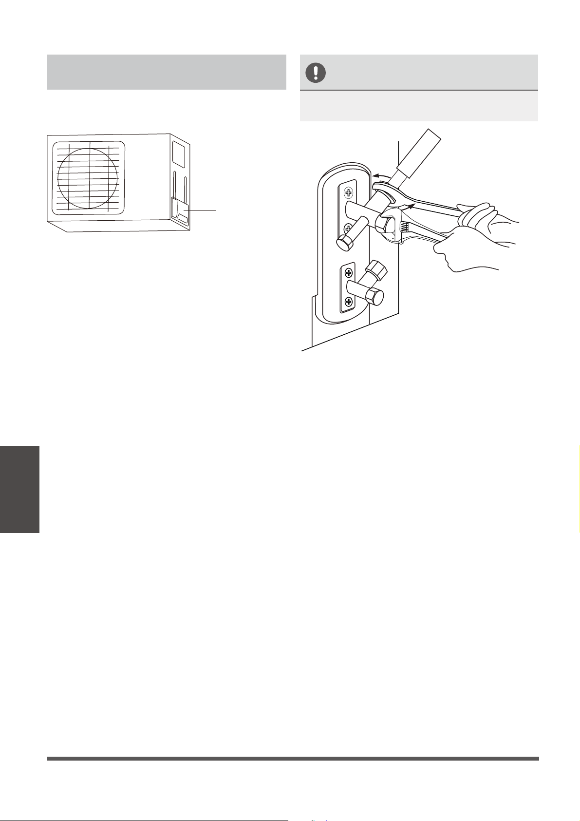
Instructions for Connecting Piping
to Outdoor Unit
1.
Unscrew the cover from the packed valve on
the side of the outdoor unit. (See Fig. 5.9)
Valve cover
2.
Remove protective caps from the valve ends.
3.
Align ared pipe end with each valve, and
tighten the are nut as tightly as possible by
hand.
4.
Using a spanner, grab the body of the valve.
Do not grab the nut that seals the service
valve. (See Fig. 5.10)
USE SPANNER TO GRAB THE
BODY OF THE SERVICE VALVE
Torque from tightening the are nut can snap
o other parts of valve.
5.
While rmly gripping the body of the valve,
use a torque wrench to tighten the are nut
according to the correct torque values.
6.
Loosen the aring nut slightly, then tighten
again.
7.
Repeat Steps 3 to 6 for the remaining pipe.
Fig. 5.9
Fig. 5.10
Refrigerant
Piping
Connection
Page 29
Air Evacuation
7
Preparations and Precautions
Air and foreign matter in the refrigerant circuit
can cause abnormal spikes in pressure, which
can damage the air conditioner, reduce its
efficiency, and cause injury. Use a vacuum pump
and manifold gauge to evacuate the line sets
circuit, removing any non-condensable gas and
moisture from the system.
Evacuation should be performed upon initial
installation or when the unit is relocated.
BEFORE PERFORMING EVACUATION
Check to make sure that both LIQUID
SIDE and GAS SIDE pipes between
the indoor and outdoor units are
connected properly in accordance with the
“Refrigerant Piping Connection” section of
this manual.
Check to make sure all wiring is connected
properly.
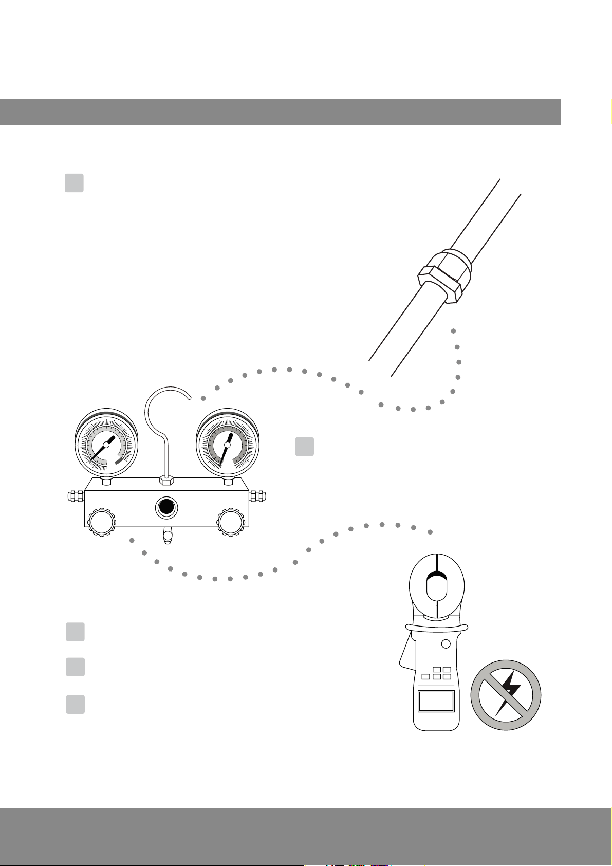
Evacuation Instructions
Before using the manifold gauge and vacuum
pump, read their operation manuals to familiarize
yourself with how to use them properly.
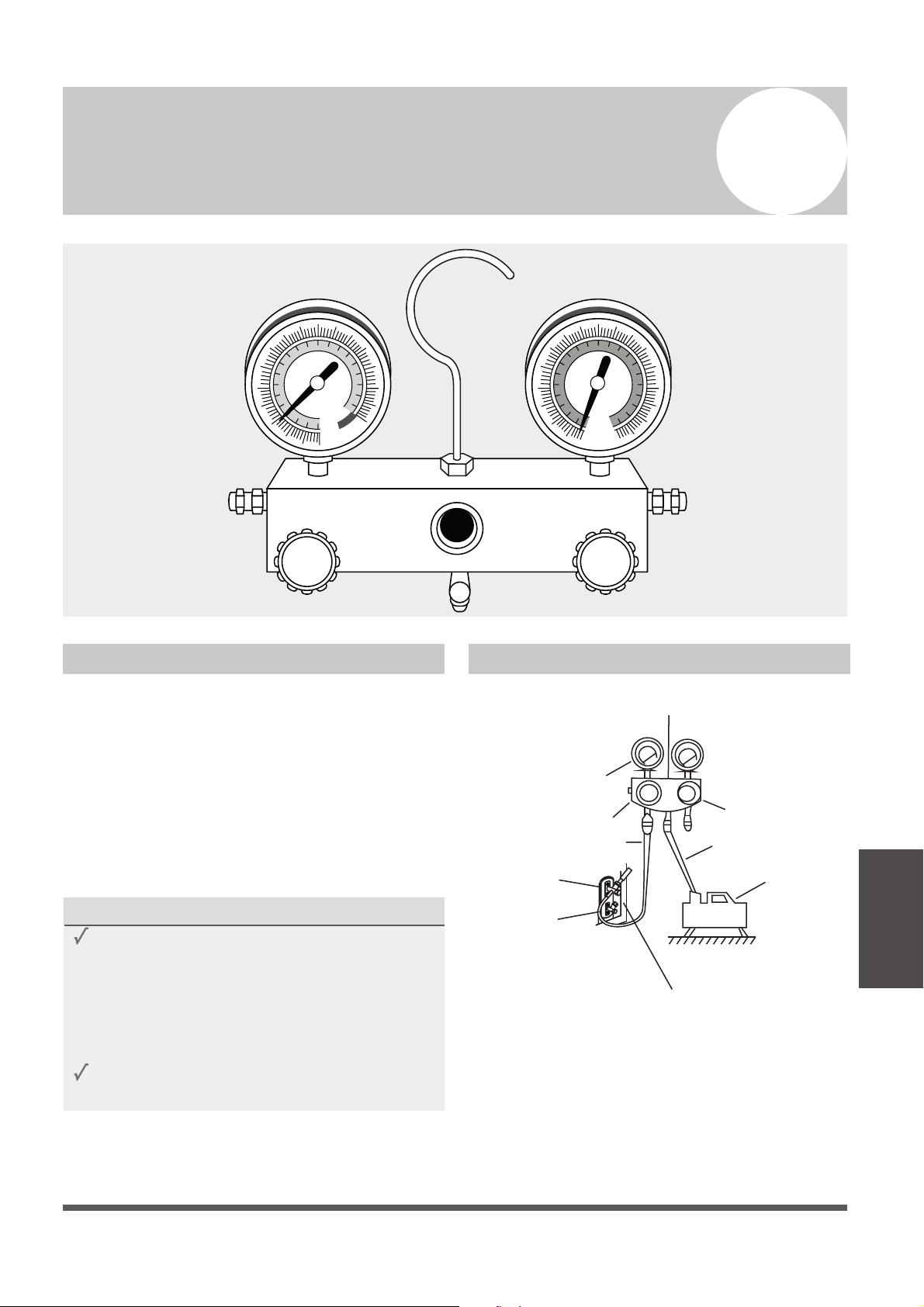
Manifold Gauge
Low pressure gauge
-76cmHg
Low pressure valve
High pressure
valve
Blue (low)hose
Yellow (middle) hose
Vacuum
pump
High pressure gauge
1.
2.
Connect yellow (middle) hose from the
manifold gauge to the vacuum pump.
MC MC
Fig. 6.1
Air Evacuation
BLUE (Low Pressure) Gauge RED (High Pressure) Gauge
BLUE (Low Pressure) Side of Manifold Gauge RED (High Pressure) Side of Manifold Gauge
Low Pressure Valve High Pressure Valve
YELLOW (Common) Side of Manifold Gauge
LARGE DIA (GAS)
Service Valve
SMALL DIA (LIQUID)
Service Valve
Outdoor Unit Service Valve Set (GAS and LIQUID Valves)
Connect the blue (low side) hose of the manifold
gauge to service port on the outdoor unit’s
GAS SIDE valve (use a 1/4” to 5/16”port adapter if
needed, which is sold separately)
Page 30
3.
4.
5.
6.
7.
8.
9.
10.
11.
Remove the charge hose from the service port.
12.
Using a hexagonal wrench, fully open both the
LIQUID and GAS pressure valves.
13.
Tighten valve caps on all three valves (Service
Port, Liquid Valve, Gas Valve) by hand.
Tighten further using a torque wrench if
needed.
OPEN VALVE STEMS GENTLY
When opening valve stems, turn the hexagonal
wrench, until it seats againt the stopper.
Do not try to force the valve to open further.
Note on Adding Refrigerant
ADDITIONAL REFRIGERANT PER PIPE LENGTH
Connective Pipe
Length (m)
Air Purging
Method
Additional Refrigerant
< Standard pipe length Vacuum Pump N/A
> Standard pipe
length
Vacuum Pump
Liquid Side: Ø 6.35 (ø 1/4”)
Gas side either
Ø 9.52 (ø 3/8”) or
Ø 12.7 (ø 1/2”)
Add for lengths beyond 5m (16 feet)
(Per additional meter): 15 g/m
(Per additional feet): 0.16 oz/ft
CAUTION
DO NOT mix refrigerant types. Use only the same type of refrigerant (R410a).
Air Evacuation
Some systems require additional charging depending on pipe lengths. The pipe length varies according
to locations of the indoor and outdoor units. The system has been factory charged with sucient R410a
refrigerant for the standard pipe length of 5m (16‘). The additional refrigerant to be charged can be
calculated using the following formula. This is necessary only if the length exceeds 7.5m (25 feet).
Liquid Side: Ø 9.52 (ø 3/8”)
Gas side either
Ø 15.87 (ø 5/8”) or
Ø 19.05 (ø 3/4”)
Add for lengths beyond 5m (16 feet)
(Per additional feet): 0.32 oz/ft
(Per additional meter): 30 g/m
Open the BLUE (Low Pressure) valve of Manifold
Gauge. Keep the RED (High Pressure) valve closed.
Turn the vacuum pump ON to start evacuating the
air from the line set and indoor unit circuits.
Run the vacuum pump for at least 15 minutes, or
until the Low Pressure Gauge reads -76cmHG
(-100 kPa or -30 In Hg). (Negative value)
Close the Blue (Low Pressure) valve of Manifold
Gauge, then turn the vacuum pump OFF.
Wait for 5 minutes, then check that there has
been no rise in Low Pressure Gauge reading.
If there is a rise (Vacuum Loss), refer to the
Gas Leak Check section for information
on how to check for leaks. If there is no
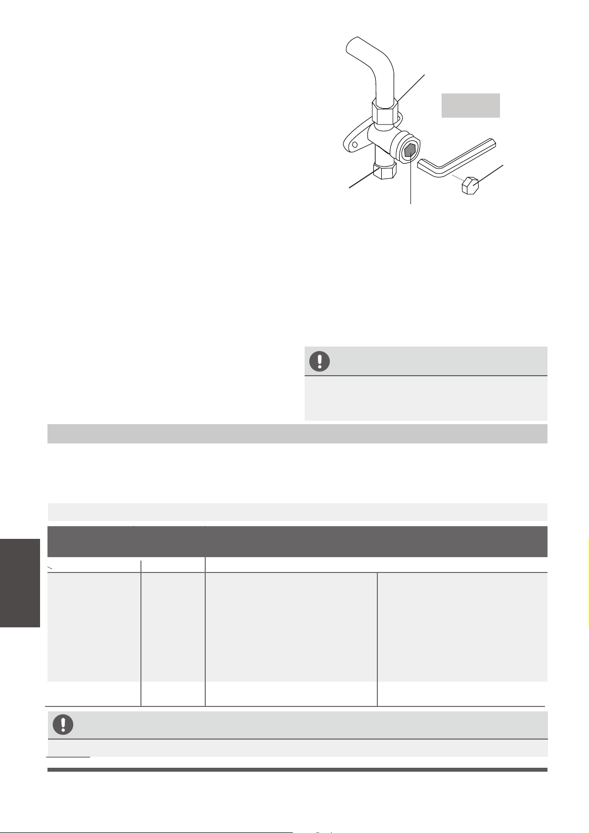
change in vacuum reading, unscrew the cap
from the LIQUID Side Service Valve (Fig. 6.2)
Insert hexagonal wrench into the service valve
(LIQUID Side Valve) and open the valve by
turning the wrench in a 1/4 counterclockwise
turn. Listen for sound of gas exiting the system,
then close the valve after 5 seconds.
Watch the Pressure Gauge for few minutes
to make sure that there is no drop in the
pressure value (Indicating a leak)
The Low Pressure Gauge should now show
a positive pressure value (Above Zero).
Flare nut
Hexagonal
Dust Cap
Copper Pipe from Indoor Unit
Service Port
(Only the GAS Side
Valve has this port)
Fig. 6.2
Valve Core

Page 31
Electrical and Gas Leak Checks
8
Electrical Safety Checks
After installation, confirm that all electrical wiring
is installed in accordance with local and national
regulations, and according to the Installation
Manual.
BEFORE TEST RUN
Check Grounding Work
Measure grounding resistance by visual detection
and with a grounding resistance tester. Grounding
resistance must be less than 4Ω.
Note: This may not be required for some
locations in the US.
DURING TEST RUN
Check for Electrical Leakage
During the Test Run, use an electroprobe and
multimeter to perform a comprehensive electrical
leakage test.
If electrical leakage is detected, turn o the unit
immediately and call a licensed electrician to find
and resolve the cause of the leakage.
Note: This may not be required for some
locations in the US.
Gas Leak Checks
There are two dierent methods to check for gas
leaks.
Soap and Water Method
Using a soft brush, apply soapy water or liquid
detergent to all pipe connection points on the
indoor unit and outdoor unit. The presence of
bubbles indicates a leak.
Leak Detector Method
If using leak detector, refer to the device’s
operation manual for proper usage instructions.
AFTER PERFORMING GAS LEAK CHECKS
After confirming that the all pipe connection
points DO NOT leak, replace the valve cover on
the outside unit.
Electrical and Gas
Leak Checks
WARNING – RISK OF
ELECTRIC SHOCK
ALL WIRING MUST COMPLY WITH LOCAL
AND NATIONAL ELECTRICAL CODES,
AND MUST BE INSTALLED BY A LICENSED
ELECTRICIAN.
Page 32
Test Run
9
Before Test Run
Only perform a test run after you have completed
the following steps:
•
Electrical Safety Checks – Confirm that
the unit’s electrical system is safe and
operating properly
•
Gas Leak Checks – Check all flare nut
connections and confirm that the system is
not leaking
•
Confirm that the gas and liquid (high and low
pressure) valves are fully open
Test Run Instructions
You should perform the Test Run for at least 30
minutes.
1.
Connect power to the unit.
2.
Press the ON/OFF button on the remote
controller to turn it on.
3.
Press the MODE button to scroll through the
following functions, one at a time:
•
COOL – Select lowest possible temperature
•
HEAT – Select highest possible temperature
4.
Let each function run for 5 minutes, and
perform the following checks:
List of Checks to Perform PASS/FAIL
No electrical leakage
Unit is properly grounded
All electrical terminals
properly covered
Indoor and outdoor units
are securely installed
All pipe connection
points do not leak
Outdoor
(2):
Indoor
(2):
Water drains properly
from drain hose (cooling)
All piping is properly
insulated
Unit performs COOL
function properly
Unit performs HEAT
function properly
Indoor unit louvers
rotate properly
Indoor unit responds to
remote controller
Test Run
Page 33
DOUBLE-CHECK PIPE CONNECTIONS
During operation, the pressure of the
refrigerant circuit will increase. This may
reveal leaks that were not present during your
initial leak check. Take time during the Test
Run to double-check that all refrigerant pipe
connection points are leak free. Refer to the
Gas Leak Check section for instructions.
5.
After the Test Run is successfully completed,
and you conrm that all checks points in “List
of Checks to Perform” have PASSED, do the
following:
a.
Using the remote control, return the unit
to normal operating temperature.
b.
Using insulation tape, wrap the indoor
refrigerant pipe connections that you
left uncovered during the indoor unit
installation process.
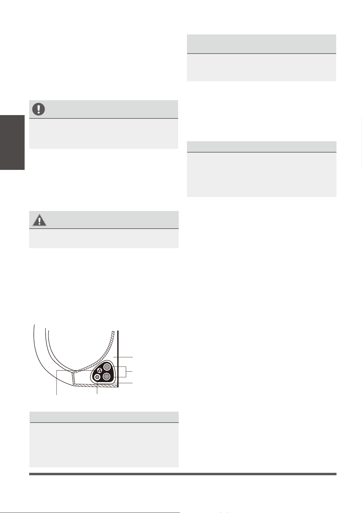
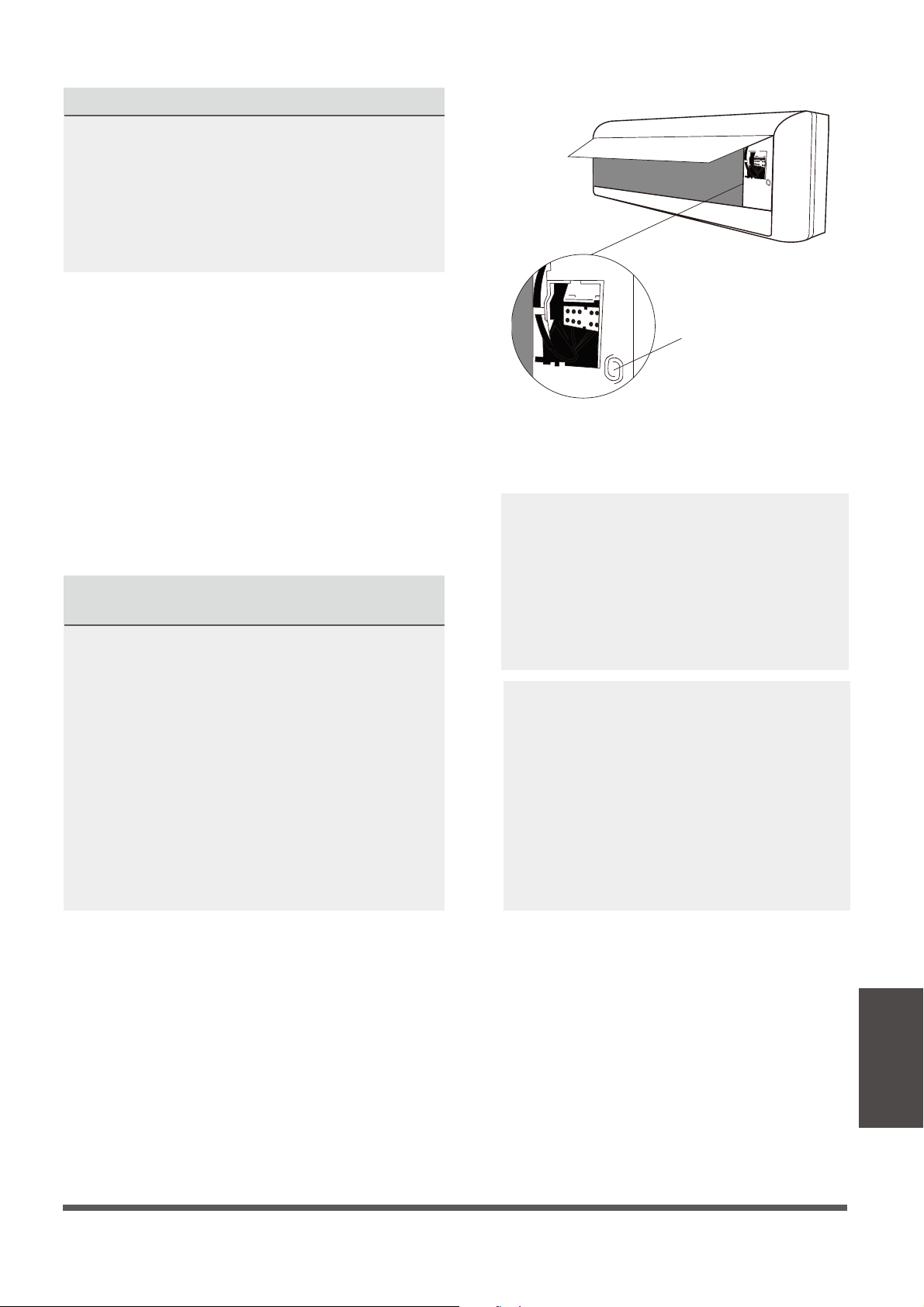
IF AMBIENT TEMPERATURE IS TOO LOW TO
RUN THE COOLING FUNCTION FOR TESTING
You cannot use the remote controller to turn
on the COOL function when the ambient
temperature is extremely low. In this instance,
you can use the MANUAL CONTROL button
to test the COOL function.
1.
Lift the front panel of the indoor unit, and
raise it until it clicks into place.
2.
The MANUAL CONTROL button is located
on the right-hand side of the unit. Press it 2
times to select the COOL function. See
Fig.8.1
.
3.
Perform the Test Run as normal.
Fig. 8.1
Test Run
Manual control button
The operating pressures of the system are
approximatey 4 times higher when the
HEAT mode is running. Therefore, it is
much easier to check for and locate any
refrigerant leaks while running the HEAT
mode. Slower leaks can also be detected
due to the higher pressures in the system.
System pressures change based on the
inside and outside air temperatures.
Usual range of pressures are (R410a):
a. Suction pressures in Cooling Mode:
120 to 155 PSI. Both copper pipes are
cold but do not exhibit any frosting.
b. Hot gas pressures in Heating Mode:
320 to 440 PSI. Both copper pipes are
hot, but the gas side is much hotter.
Note: Values are indicative only.
Page 34
European Disposal Guidelines
10
This appliance contains refrigerant and other potentially hazardous materials. When disposing of
this appliance, the law requires special collection and treatment. Do not dispose of this product as
household waste or unsorted municipal waste.
When disposing of this appliance, you have the following options:
• Dispose of the appliance at designated municipal electronic waste collection facility.
• When buying a new appliance, the retailer will take back the old appliance free of charge.
• The manufacturer will take back the old appliance free of charge.
• Sell the appliance to certied scrap metal dealers.
Special Notice
Disposing of this appliance improperly, or in other natural surroundings, endangers your health and is
bad for the environment. Hazardous substances may leak into the ground water and enter the food
chain. Please follow proper disposal protocol.
Disposal
Information
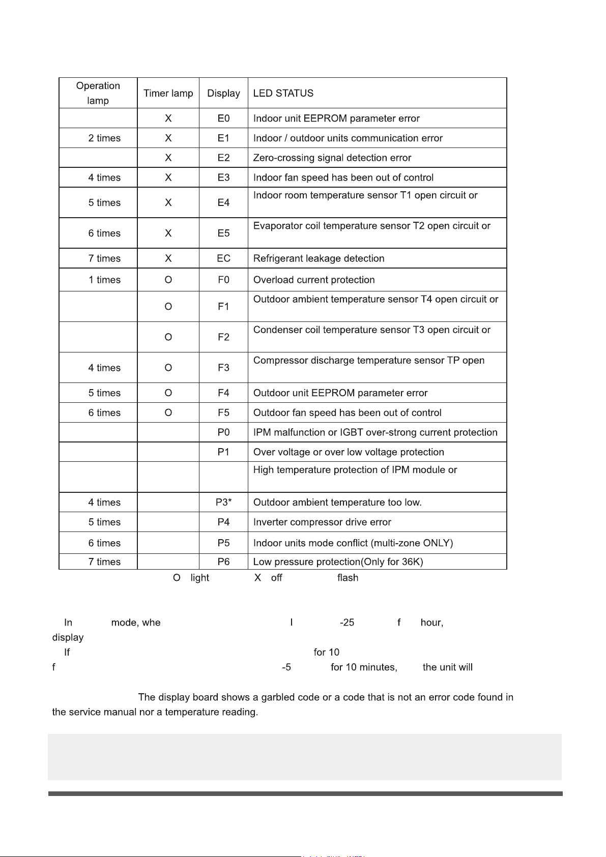
Indoor Unit Error Codes List
☆ 1 time
☆
☆ 3 times
☆
☆
short circuit
☆
short circuit
☆
☆
☆ 2 times
short circuit
☆ 3 times
short circuit
☆
circuit or short circuit
☆
☆
☆ 1 times ☆
☆ 2 times ☆
☆ 3 times ☆
P2
compressor shell top
☆ ☆
☆ ☆
☆ ☆
☆ ☆
( ) ( ) ☆( )
*P3
1) heating n the outdoor temperature is ower than °C (-13F) or 1 the indoor unit
error code P3. Low Ambient Protection.
2)
the outdoor temperature goes higher than -22°C (-8F) minutes and compressor has stopped
or 1 hour or outdoor temperature goes higher than °C (23F) then restart.
* Fault Symptom:
A more comprehensive service and diagnostics manual is available for service technicians.
Contact the manufacturer for download instructions.
Page 35

The design and specications of this product are subject to change without prior notice
as development continues. Consult with the sales agency or manufacturer for details.
Refer to the equipment nameplate for all other applicable specications.
CS368I-AB
16122000002333
20171221
is a registered trademark of Parker Davis HVAC International, Inc.
Parker Davis HVAC International, Inc.
2250 NW 102 Place, Doral, FL 33172 - USA
Tel : (305) 513-4488
Fax : (305) 513-4499
email : info@pd-hvac.com
Website: www.pd-hvac.com
Copyright 2017, Parker Davis HVAC International, Inc., All rights reserved.