Loading ...
Loading ...
Loading ...
BURNER NORMAL POWER kW
Natural Gas
INJECTOR MARK 1/100 mm Btu/h
Multi crown 3.4 136 11600
Top Oven 1.7 95 5804
Main Oven 1.7 95 5804
GAS CONNECTION
Use a flexible pipe in compliance with the
regulation in force. Make sure they do not come in
touch with mobile parts and are not squeezed.
WARNING! Only a qualified and
competent person can do the gas
installation.
Before you connect te gas, disconnect
the appliance from the electricity
supply or switch off the fuse in the
fuse box. Close the primary valve of
the gas supply.
Supply piping should not be less than
R3/8. Connection is made to the Rc
1/2 (1/2 “ B.S.P.) female threaded.
The entry pipe is located just below
the hob level on the rear left hand side
of the appliance.
The gas supply ramp is on the rear
side of the appliance.
WARNING! Only liquid sealants can
be used when the inlet gas pipe is
fitted i.e.: do not use the P.T.F.E.
sealant tape.
When the installation is complete,
carry out a gas tightness test and
make sure that the seal of each pipe
fitting does not leak.
Use flexible tubing, which comply with
the BS.669 current edition.
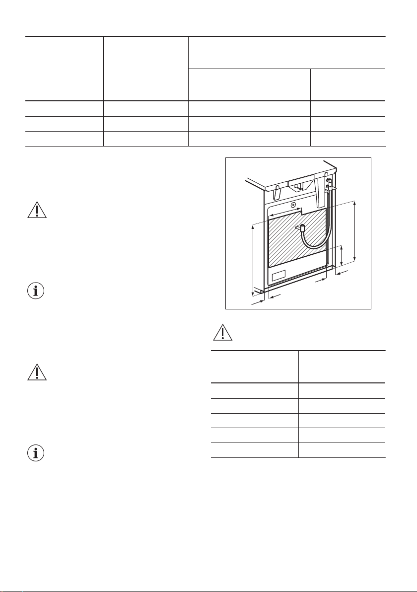
A
B
C
C
D
E
WARNING! The gas bayonet
connector must be in the marked area.
Dimension mm
A 250
B 680
C 50
D 250
E 580
PRESSURE TEST
The Rapid injector is used as a pressure test point.
1. Connect the pressure gauge to the Rapid
injector.
2. Examine the supply pressure by turning the
Rapid burner and one other burner fully on, and
lighting them. The pressure must be 20 mbar
for Natural Gas.
24
Loading ...
Loading ...
Loading ...