
RAV4_OM_OM0R024U_(U)
1
2
3
4
5
6
7
8
9
10
Pictorial index
Search by illustration
For safety
and security
Make sure to read through them
(Main topics: Child seat, theft deterrent system)
Vehicle status
information and
indicators
Reading driving-related information
(Main topics: Meters, multi-information display)
Before driving
Opening and closing the doors and windows,
adjustment before driving
(Main topics: Keys, doors, seats)
Driving
Operations and advice which are necessary for
driving
(Main topics: Starting engine, refueling)
Audio
Operating the Audio
(Main topics: Audio/visual, phone, Connected Services)
Interior features
Usage of the interior features
(Main topics: Air conditioner, storage features)
Maintenance
and care
Caring for your vehicle and maintenance
procedures
(Main topics: Interior and exterior, light bulbs)
When trouble
arises
What to do in case of malfunction and emergency
(Main topics: Battery discharge, flat tire)
Vehicle
specifications
Vehicle specifications, customizable features
(Main topics: Fuel, oil, tire inflation pressure)
For owners
Reporting safety defects for U.S. owners, and seat
belt and SRS airbag instructions for Canadian
owners
Index
Search by symptom
Search alphabetically

2
TABLE OF CONTENTS
For your information...................8
Reading this manual................12
How to search..........................13
Pictorial index ..........................14
1-1. For safe use
Before driving...................26
For safe driving ................27
Seat belts.........................29
SRS airbags.....................33
Front passenger occupant
classification system ......43
Exhaust gas precautions..48
1-2. Child safety
Riding with children..........49
Child restraint systems.....50
1-3. Emergency assistance
Safety Connect ................65
1-4. Theft deterrent system
Engine immobilizer system
.......................................70
Alarm................................73
2-1. Instrument cluster
Warning lights and indicators
.......................................76
Gauges and meters (with 4.2-
inch display)...................82
Gauges and meters (with 7-
inch display)...................85
Multi-information display..89
Fuel consumption information
.......................................99
3-1. Key information
Keys ..............................102
3-2. Opening, closing and lock-
ing the doors
Side doors.....................108
Back door......................114
Smart key system..........128
3-3. Adjusting the seats
Front seats ....................134
Rear seats.....................135
Driving position memory 137
Head restraints..............140
3-4. Adjusting the steering
wheel and mirrors
Steering wheel...............142
Inside rear view mirror...143
Digital Rear-view Mirror.145
Outside rear view mirrors
....................................154
3-5. Opening, closing the win-
dows and moon roof
Power windows .............156
Moon roof......................159
Panoramic moon roof....162
4-1. Before driving
Driving the vehicle.........169
Cargo and luggage........175
Vehicle load limits..........178
1
For safety and security
2
Vehicle status
information and
indicators
3
Before driving
4
Driving

3
TABLE OF CONTENTS
1
2
3
4
5
6
7
8
9
10
Trailer towing................. 179
Dinghy towing ............... 191
4-2. Driving procedures
Engine (ignition) switch (vehi-
cles without smart key sys-
tem)............................. 193
Engine (ignition) switch (vehi-
cles with smart key system)
.................................... 194
Automatic transmission. 199
Turn signal lever............ 202
Parking brake................ 203
Brake Hold .................... 206
4-3. Operating the lights and
wipers
Headlight switch............ 209
AHB (Automatic High Beam)
.................................... 212
Fog light switch ............. 215
Windshield wipers and
washer......................... 215
Rear window wiper and
washer......................... 218
4-4. Refueling
Opening the fuel tank cap
.................................... 220
4-5. Using the driving support
systems
Toyota Safety Sense 2.0223
PCS (Pre-Collision System)
.................................... 229
LTA (Lane Tracing Assist)
.................................... 237
RSA (Road Sign Assist) 247
Dynamic radar cruise control
with full-speed range...250
BSM (Blind Spot Monitor)
....................................260
Intuitive parking assist...270
PKSB (Parking Support
Brake)..........................277
Parking Support Brake func-
tion (static objects) ......282
Parking Support Brake func-
tion (rear-crossing vehicles)
....................................288
Rear view monitor system
....................................292
Toyota parking assist monitor
....................................300
Panoramic view monitor 313
Stop & Start system.......345
Driving mode select switch
....................................351
Multi-terrain Select (AWD
vehicles) ......................353
Snow mode switch (AWD
vehicles) ......................357
Downhill assist control sys-
tem ..............................358
Driving assist systems...360
4-6. Driving tips
Winter driving tips..........367
Utility vehicle precautions
....................................370
5-1. Basic function
Buttons overview...........375
Menu screen..................377
Status icon.....................378
“Setup” screen...............380
5
Audio

4
TABLE OF CONTENTS
5-2. Basic information before
operation
Initial screen.................. 381
Touch screen................. 382
Home screen................. 384
Entering letters and num-
bers/list screen operation
.................................... 385
Screen adjustment........ 388
Linking multi-information dis-
play and the system.... 389
5-3. Connectivity settings
Registering/Connecting a
Bluetooth
®
device ....... 390
Setting Bluetooth
®
details
.................................... 394
Wi-Fi
®
Hotspot.............. 402
5-4. Apple CarPlay/Android
Auto
Apple CarPlay
®
/Android Auto
.................................... 407
5-5. Other settings
General settings............ 414
Voice settings................ 418
Vehicle settings............. 419
5-6. Using the audio/visual sys-
tem
Quick reference............. 420
Some basics ................. 421
5-7. Radio operation
AM/FM/SiriusXM (SXM) radio
.................................... 425
5-8. Media operation
USB memory................. 432
iPod/iPhone
(Apple CarPlay)........... 434
Android Auto.................. 437
Bluetooth
®
audio ...........438
5-9. Audio/visual remote con-
trols
Steering switches..........442
5-10.Audio settings
Setup.............................444
5-11.Tips for operating the
audio/visual system
Operating information....446
5-12.Voice command system
operation
Voice command system 458
Command list ................461
5-13.Phone operation (Hands-
free system for cellular
phones)
Quick reference.............465
Some basics..................466
Placing a call using the
Bluetooth
®
hands-free sys-
tem ..............................470
Receiving a call using the
Bluetooth
®
hands-free sys-
tem ..............................473
Talking on the Bluetooth
®
hands-free system.......474
Bluetooth
®
phone message
function........................476
5-14.Phone settings
Setup.............................481
5-15.What to do if...
(Bluetooth
®
)
Troubleshooting.............491

5
TABLE OF CONTENTS
1
2
3
4
5
6
7
8
9
10
5-16.Connected Services over-
view
Connected Services...... 495
Type A: Function achieved by
using a smartphone or DCM
.................................... 496
Type B: Function achieved by
using DCM and the system
.................................... 498
Type C: Function achieved by
using DCM .................. 499
Type D: Function achieved by
using DCM and a smart-
phone.......................... 502
5-17.Connected Services opera-
tion
Toyota Apps .................. 504
5-18.Setup
Toyota Apps settings..... 508
6-1. Using the air conditioning
system and defogger
Manual air conditioning sys-
tem.............................. 510
Automatic air conditioning
system......................... 515
Heated steering wheel/seat
heaters/seat ventilators522
6-2. Using the interior lights
Interior lights list............ 525
6-3. Using the storage features
List of storage features . 528
Luggage compartment fea-
tures............................ 532
6-4. Using the other interior fea-
tures
Other interior features...537
Garage door opener......548
7-1. Maintenance and care
Cleaning and protecting the
vehicle exterior ............558
Cleaning and protecting the
vehicle interior .............561
7-2. Maintenance
Maintenance requirements
....................................564
General maintenance....565
Emission inspection and
maintenance (I/M) programs
....................................568
7-3. Do-it-yourself maintenance
Do-it-yourself service precau-
tions.............................569
Hood..............................571
Positioning a floor jack ..572
Engine compartment.....574
Tires ..............................581
Tire inflation pressure....595
Wheels ..........................597
Air conditioning filter......599
Wiper insert replacement
....................................601
Wireless remote control/elec-
tronic key battery.........604
Checking and replacing fuses
....................................607
Light bulbs.....................609
6
Interior features
7
Maintenance and care

6
TABLE OF CONTENTS
8-1. Essential information
Emergency flashers...... 618
If your vehicle has to be
stopped in an emergency
.................................... 618
If the vehicle is trapped in ris-
ing water...................... 619
8-2. Steps to take in an emer-
gency
If your vehicle needs to be
towed........................... 621
If you think something is
wrong .......................... 626
Fuel pump shut off system
.................................... 627
If a warning light turns on or a
warning buzzer sounds628
If a warning message is dis-
played.......................... 639
If you have a flat tire...... 642
If the engine will not start651
If you lose your keys ..... 653
If the electronic key does not
operate properly (vehicles
with smart key system) 653
If the vehicle battery is dis-
charged....................... 655
If your vehicle overheats659
If the vehicle becomes stuck
.................................... 661
9-1. Specifications
Maintenance data (fuel, oil
level, etc.)....................664
Fuel information.............676
Tire information .............678
9-2. Customization
Customizable features...688
9-3. Initialization
Items to initialize............699
10-1.For owners
Reporting safety defects for
U.S. owners.................702
Seat belt instructions for
Canadian owners (in
French)........................703
SRS airbag instructions for
Canadian owners (in
French)........................704
What to do if... (Troubleshoot-
ing) .............................714
Alphabetical Index ........717
8
When trouble arises
9
Vehicle specifications
10
For owners
Index

7
TABLE OF CONTENTS
1
2
3
4
5
6
7
8
9
10

8
Please note that this manual
applies to all models and
explains all equipment, including
options. Therefore, you may find
some explanations for equip-
ment not installed on your vehi-
cle.
All specifications provided in this
manual are current at the time of
printing. However, because of
the Toyota policy of continual
product improvement, we
reserve the right to make
changes at any time without
notice.
Depending on specifications,
the vehicle shown in the illustra-
tions may differ from your vehi-
cle in terms of equipment.
Approximately five hours after
the engine is turned off, you
may hear sound coming from
under the vehicle for several
minutes. This is the sound of a
fuel evaporation leakage check
and, it does not indicate a mal-
function.
A wide variety of non-genuine
spare parts and accessories for
Toyota vehicles are currently
available in the market. You
should know that Toyota does
not warrant these products and
is not responsible for their per-
formance, repair, or replace-
ment, or for any damage they
may cause to, or adverse effect
they may have on, your Toyota
vehicle.
This vehicle should not be modi-
fied with non-genuine Toyota
products. Modification with non-
genuine Toyota products could
affect its performance, safety or
durability, and may even violate
governmental regulations. In
addition, damage or perfor-
mance problems resulting from
the modification may not be cov-
ered under warranty.
The installation of a mobile two-
way radio system in your vehicle
could affect electronic systems
such as:
Multiport fuel injection sys-
tem/sequential multiport fuel
injection system
Toyota Safety Sense 2.0
For your information
Main Owner’s Manual
Noise from under vehicle
after turning off the engine
Accessories, spare parts
and modification of your
Toyota
Installation of a mobile
two-way radio system

9
Anti-lock brake system
SRS airbag system
Seat belt pretensioner system
Be sure to check with your
Toyota dealer for precautionary
measures or special instructions
regarding installation of a mobile
two-way radio system.
The vehicle is equipped with
sophisticated computers that will
record certain data, such as:
• Engine speed/ Electric motor
speed (traction motor speed)
• Accelerator status
• Brake status
• Vehicle speed
• Operation status of the driving
assist systems
• Images from the front camera
(available only when certain
safety systems are activated,
which varies depending on
the vehicle specifications).
The recorded data varies
according to the vehicle grade
level and options with which it is
equipped.
These computers do not record
conversations or sounds, and
only record images outside of
the vehicle in certain situations.
Data Transmission
Your vehicle may transmit the data
recorded in these computers to
Toyota without notification to you.
Data usage
Toyota may use the data recorded
in this computer to diagnose mal-
functions, conduct research and
development, and improve quality.
Toyota will not disclose the
recorded data to a third party
except:
• With the consent of the vehicle
owner or with the consent of the
lessee if the vehicle is leased
• In response to an official request
by the police, a court of law or a
government agency
• For use by Toyota in a lawsuit
• For research purposes where the
data is not tied to a specific vehi-
cle or vehicle owner
Recorded image information
can be erased by your Toyota
dealer.
The image recording function can
be disabled. However, if the func-
tion is disabled, data from when the
system operates will not be avail-
able.
To learn more about the vehi-
cle data collected, used and
shared by Toyota, please visit
www.toyota.com/privacyvts/
.
If your Toyota has Safety Con-
nect and if you have subscribed
to those services, please refer to
the Safety Connect Telematics
Subscription Service Agreement
Vehicle data recording
Usage of data collected
through Safety Connect
(U.S.mainland only)

10
for information on data collected
and its usage.
To learn more about the vehi-
cle data collected, used and
shared by Toyota, please visit
www.toyota.com/privacyvts/
.
This vehicle is equipped with an
event data recorder (EDR). The
main purpose of an EDR is to
record, in certain crash or near
crash-like situations, such as an
air bag deployment or hitting a
road obstacle, data that will
assist in understanding how a
vehicle’s systems performed.
The EDR is designed to record
data related to vehicle dynamics
and safety systems for a short
period of time, typically 30 sec-
onds or less.
The EDR in this vehicle is
designed to record such data
as:
How various systems in your
vehicle were operating;
Whether or not the driver and
passenger safety belts were
buckled/fastened;
How far (if at all) the driver
was depressing the accelera-
tor and/or brake pedal; and,
How fast the vehicle was trav-
eling.
These data can help provide a
better understanding of the cir-
cumstances in which crashes
and injuries occur.
NOTE: EDR data are recorded
by your vehicle only if a non-triv-
ial crash situation occurs; no
data are recorded by the EDR
under normal driving conditions
and no personal data (e.g.,
name, gender, age, and crash
location) are recorded. How-
ever, other parties, such as law
enforcement, could combine the
EDR data with the type of per-
sonally identifying data rou-
tinely acquired during a crash
investigation.
To read data recorded by an
EDR, special equipment is
required, and access to the
vehicle or the EDR is needed. In
addition to the vehicle manufac-
turer, other parties, such as law
enforcement, that have the spe-
cial equipment, can read the
information if they have access
to the vehicle or the EDR.
Disclosure of the EDR data
Toyota will not disclose the data
recorded in an EDR to a third party
except when:
• An agreement from the vehicle’s
owner (or the lessee for a leased
vehicle) is obtained
• In response to an official request
by the police, a court of law or a
government agency
• For use by Toyota in a lawsuit
However, if necessary, Toyota may:
• Use the data for research on
Event data recorder

11
vehicle safety performance
• Disclose the data to a third party
for research purposes without
disclosing information about the
specific vehicle or vehicle owner
The SRS airbag and seat belt
pretensioner devices in your
Toyota contain explosive chemi-
cals. If the vehicle is scrapped
with the airbags and seat belt
pretensioners left as they are,
this may cause an accident such
as fire. Be sure to have the sys-
tems of the SRS airbag and seat
belt pretensioner removed and
disposed of by a qualified ser-
vice shop or by your Toyota
dealer before you scrap your
vehicle.
Special handling may apply,
See www.dtsc.ca.gov/
hazardouswaste/perchlorate.
Your vehicle has components
that may contain perchlorate.
These components may include
the airbags, seat belt preten-
sioners, wireless remote control
batteries, and the batteries in
the tire pressure warning valve
and transmitters.
Scrapping of your Toyota
Perchlorate Material
WARNING
■ General precautions while
driving
Driving under the influence: Never
drive your vehicle when under the
influence of alcohol or drugs that
have impaired your ability to oper-
ate your vehicle. Alcohol and cer-
tain drugs delay reaction time,
impair judgment and reduce coor-
dination, which could lead to an
accident that could result in death
or serious injury.
Defensive driving: Always drive
defensively. Anticipate mistakes
that other drivers or pedestrians
might make and be ready to avoid
accidents.
Driver distraction: Always give
your full attention to driving. Any-
thing that distracts the driver, such
as adjusting controls, talking on a
cellular phone or reading can
result in a collision with resulting
death or serious injury to you,
your occupants or others.
■ General precaution regarding
children’s safety
Never leave children unattended
in the vehicle, and never allow
children to have or use the key.
Children may be able to start the
vehicle or shift the vehicle into
neutral. There is also a danger
that children may injure them-
selves by playing with the side
windows, the moon roof or the
panoramic moon roof, or other
features of the vehicle. In addi-
tion, heat build-up or extremely
cold temperatures inside the vehi-
cle can be fatal to children.
12
Reading this manual
Explains symbols used in
this manual
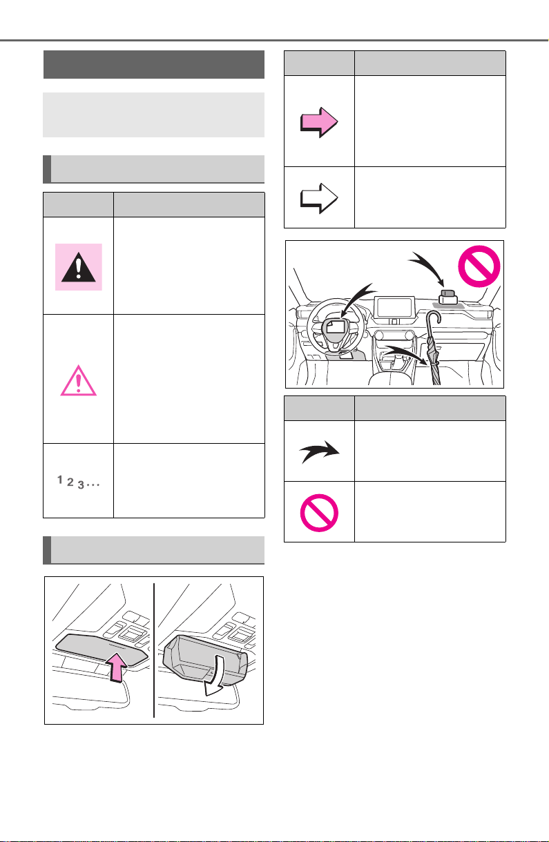
Symbols in this manual
Symbols Meanings
WARNING:
Explains something
that, if not obeyed,
could cause death or
serious injury to people.
NOTICE:
Explains something
that, if not obeyed,
could cause damage to
or a malfunction in the
vehicle or its equip-
ment.
Indicates operating or
working procedures.
Follow the steps in
numerical order.
Symbols in illustrations
Symbols Meanings
Indicates the action
(pushing, turning, etc.)
used to operate
switches and other
devices.
Indicates the outcome
of an operation (e.g. a
lid opens).
Symbols Meanings
Indicates the compo-
nent or position being
explained.
Means Do not, Do not
do this, or Do not let
this happen.
13
■ Searching by name
Alphabetical index: P.717
■ Searching by installation
position
Pictorial index: P. 14
■ Searching by symptom or
sound
What to do if... (Troubleshoot-
ing): P.714
■ Searching by title
Table of contents: P.2
How to search
14
Pictorial index
Pictorial index
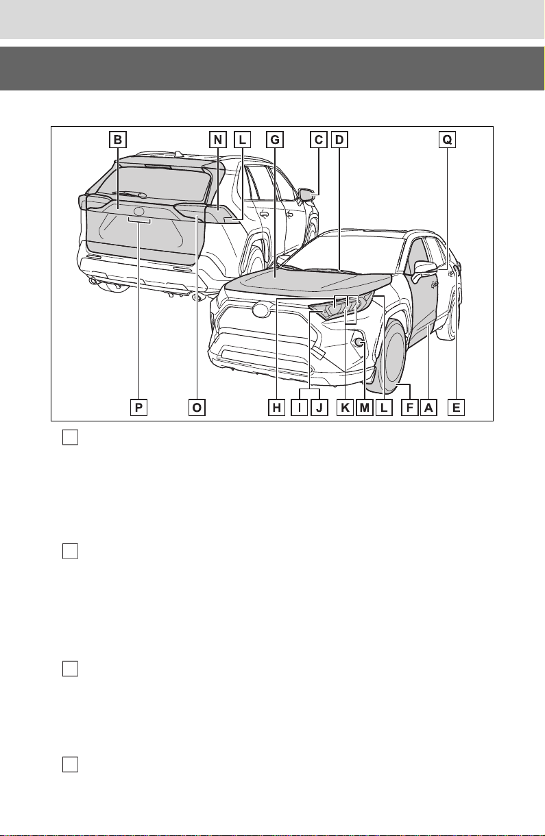
■Exterior
Side doors ..........................................................................P.108
Locking/unlocking ................................................................P.108
Opening/closing the side windows.......................................P.156
Locking/unlocking by using the key .............................P.109, 653
Warning messages ..............................................................P.639
Back door ........................................................................... P.114
Locking/unlocking ................................................................ P.115
Opening from inside the cabin
*
............................................ P.118
Opening from outside....................................................P.116, 118
Warning messages ..............................................................P.639
Outside rear view mirrors .................................................P.154
Adjusting the mirror angle....................................................P.154
Folding the mirrors...............................................................P.154
Defogging the mirrors
*
................................................. P.511, 517
Windshield wipers..............................................................P.215
A
B
C
D

15
Pictorial index
Precautions against winter season......................................P.367
To prevent freezing (windshield wiper de-icer)
*
....................P.520
Precautions against car wash
(Rain-sensing windshield wipers)
*
.......................................P.559
Replacing the wiper insert....................................................P.601
Fuel filler door....................................................................P.220
Refueling method.................................................................P.220
Fuel type/fuel tank capacity .................................................P.666
Tires.....................................................................................P.581
Tire size/inflation pressure ...................................................P.671
Winter tires/tire chain ...........................................................P.367
Checking/rotation/tire pressure warning system
*
.................P.581
Coping with flat tires.............................................................P.642
Hood....................................................................................P.571
Opening ...............................................................................P.571
Engine oil.............................................................................P.666
Coping with overheat...........................................................P.659
Warning messages ..............................................................P.639
Headlights...........................................................................P.209
Turn signal lights ...............................................................P.202
Parking lights .....................................................................P.209
Daytime running lights......................................................P.209
Side marker lights..............................................................P.209
Fog lights
*
...........................................................................P.437
Stop lights/tail lights/turn signal lights....................P.202, 209
Tail lights.............................................................................P.209
Back-up lights
Light bulbs of the exterior lights for driving
(Replacing method: P.609, Watts: P.675)
E
F
G
H
I
J
K
L
M
N
O

16
Pictorial index
Shifting the shift lever to R...................................................P.199
License plate lights............................................................P.209
Side turn signal lights
*
......................................................P.202
*
: If equipped
P
Q
17
Pictorial index
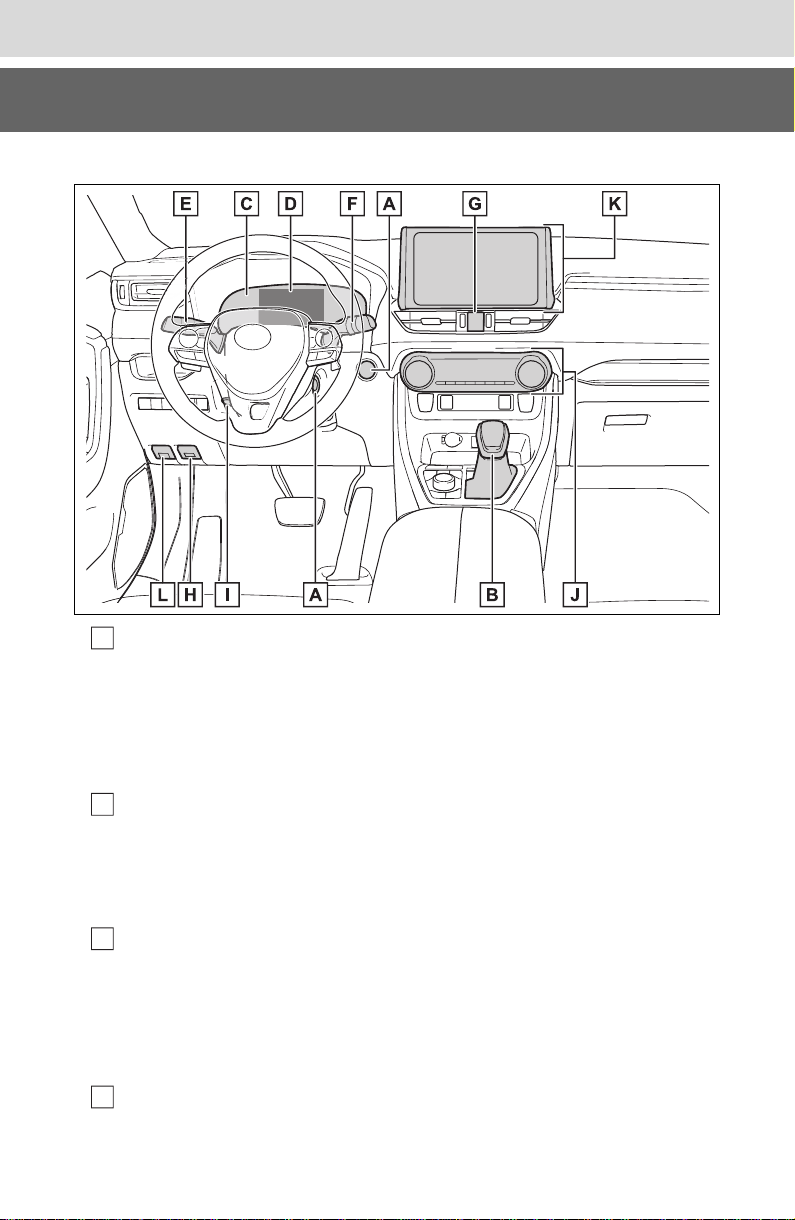
■Instrument panel
Engine switch.............................................................P.193, 194
Starting the engine/changing the modes .............P.193, 194, 197
Emergency stop of the engine.............................................P.618
When the engine will not start..............................................P.651
Warning messages ..............................................................P.639
Shift lever............................................................................P.199
Changing the shift position...................................................P.200
Precautions against towing..................................................P.621
When the shift lever does not move.....................................P.200
Meters .............................................................................P.82, 85
Reading the meters/adjusting the instrument panel
light ......................................................................P.82, 84, 85, 88
Warning lights/indicator lights ................................................P.76
When the warning lights come on........................................P.628
Multi-information display ....................................................P.89
Display ...................................................................................P.89
A
B
C
D

18
Pictorial index
When the warning messages are displayed ........................P.639
Turn signal lever.................................................................P.202
Headlight switch ................................................................P.209
Headlights/parking lights/tail lights/
license plate lights/daytime running lights............................P.209
Fog lights
*1
...........................................................................P.437
Windshield wiper and washer switch...............................P.215
Rear window wiper and washer switch ...........................P.218
Usage...........................................................................P.215, 218
Adding washer fluid..............................................................P.580
Warning messages ..............................................................P.639
Emergency flasher switch.................................................P.618
Hood lock release lever.....................................................P.571
Tilt and telescopic steering lock release lever................P.142
Adjustment...........................................................................P.142
Air conditioning system............................................P.510, 515
Usage...........................................................................P.510, 515
Rear window defogger................................................. P.511, 517
Audio
*1
................................................................................P.375
Audio Plus
*1, 2
Premium Audio
*1, 2
Fuel filler door opener lever..............................................P.221
*1
:If equipped
*2
:Refer to “NAVIGATION AND MULTIMEDIA SYSTEM OWNER’S MAN-
UAL”.
E
F
G
H
I
J
K
L
19
Pictorial index
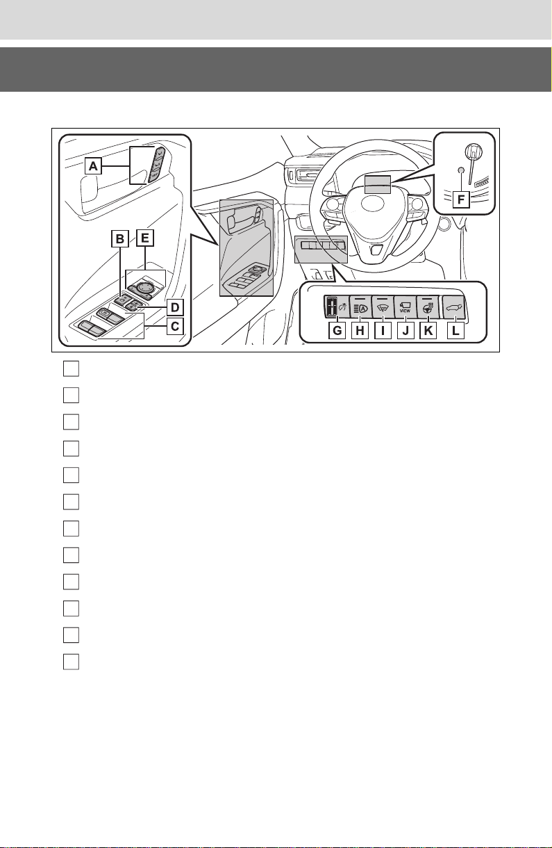
■Switches
Driving position memory switches
*
.................................P.137
Window lock switch...........................................................P.158
Power window switches....................................................P.156
Door lock switches ............................................................ P.112
Outside rear view mirror switches ...................................P.154
“ODO TRIP” switch........................................................P.84, 88
Instrument panel light control dial...............................P.84, 88
Automatic High Beam switch ...........................................P.212
Windshield wiper de-icer switch
*
.....................................P.520
Camera switch
*
...................................................................P.315
Heated steering wheel switch
*
..........................................P.522
Power back door switch
*
................................................... P.118
*
: If equipped
A
B
C
D
E
F
G
H
I
J
K
L

20
Pictorial index
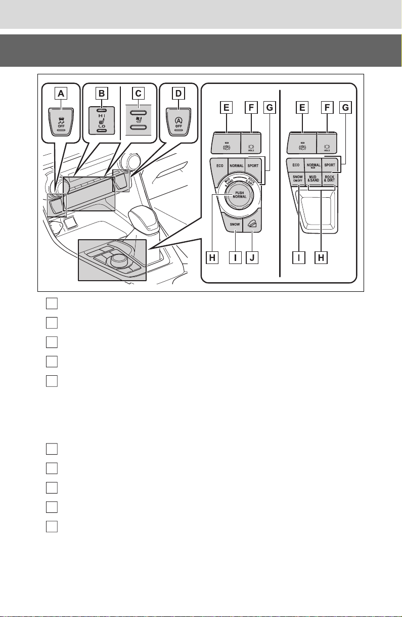
Meter control switches........................................................P.90
Vehicle-to-vehicle distance switch...................................P.255
Cruise control switches
Dynamic radar cruise control with full-speed range.............P.250
Audio remote control switches
*
.......................................P.442
LTA (Lane Tracing Assist) switch .....................................P.237
Phone switch
*
.....................................................................P.468
Talk switch
*
.........................................................................P.458
*
: Vehicles with Audio Plus or Premium Audio, refer to “NAVIGATION AND
MULTIMEDIA SYSTEM OWNER’S MANUAL”.
A
B
C
D
E
F
G
21
Pictorial index
VSC OFF switch .................................................................P.361
Front seat heater switches
*
...............................................P.522
Front seat heater/ventilator switches
*
.............................P.523
Stop & Start cancel switch
*
...............................................P.346
Parking brake switch.........................................................P.203
Applying/releasing................................................................P.203
Precautions against winter season......................................P.368
Warning buzzer/message ............................................P.634, 639
Brake hold switch ..............................................................P.206
Driving mode select switch...............................................P.351
Multi-terrain Select switch
*
...............................................P.353
SNOW mode switch
*
..........................................................P.357
“DAC” switch
*
....................................................................P.358
*
: If equipped
A
B
C
D
E
F
G
H
I
J
22
Pictorial index
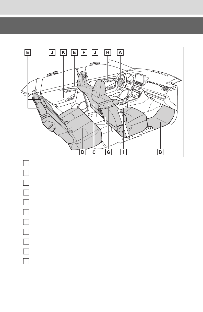
■Interior
SRS airbags..........................................................................P.33
Floor mats.............................................................................P.26
Front seats..........................................................................P.134
Rear seats...........................................................................P.135
Head restraints...................................................................P.140
Seat belts..............................................................................P.29
Console box .......................................................................P.529
Inside lock buttons ............................................................ P.112
Cup holders........................................................................P.529
Assist grips ........................................................................P.547
Rear seat heater switches
*
................................................P.522
*
: If equipped
A
B
C
D
E
F
G
H
I
J
K
23
Pictorial index
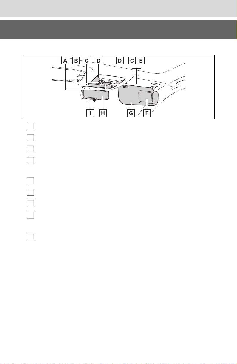
■Ceiling
“SOS” button
*1
.....................................................................P.65
Auxiliary box ......................................................................P.530
Moon roof switches
*1
.........................................................P.159
Interior lights
*2
...................................................................P.525
Personal lights ...................................................................P.526
Electronic sunshade switch
*1
...........................................P.162
Vanity mirrors.....................................................................P.537
Sun visors...........................................................................P.537
Inside rear view mirror
*1
....................................................P.143
Digital Rear-view Mirror
*1
..................................................P.145
Garage door opener switches
*1
........................................P.548
*1
:If equipped
*2
:The illustration shows the front, but they are also equipped in the rear.
A
B
C
D
E
F
G
H
I

24
Pictorial index

25
1
1
For safety and security
For safety and security
1-1. For safe use
Before driving.................26
For safe driving ..............27
Seat belts.......................29
SRS airbags...................33
Front passenger occupant
classification system ....43
Exhaust gas precautions48
1-2. Child safety
Riding with children........49
Child restraint systems...50
1-3. Emergency assistance
Safety Connect ..............65
1-4. Theft deterrent system
Engine immobilizer system
.....................................70
Alarm..............................73
26
1-1. For safe use
1-1.For safe use
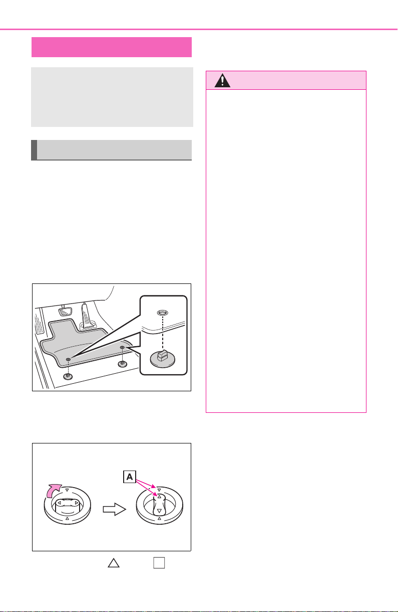
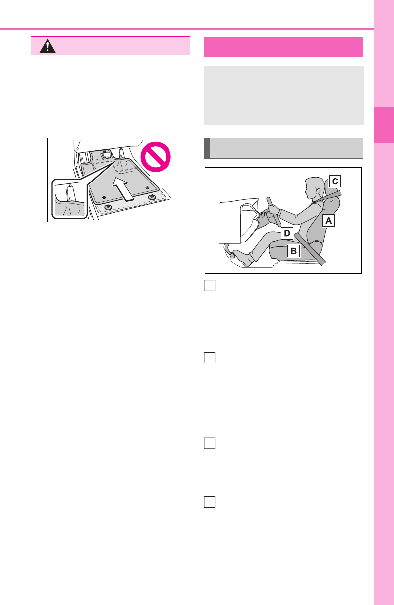
Use only floor mats designed
specifically for vehicles of the
same model and model year as
your vehicle. Fix them securely
in place onto the carpet.
1 Insert the retaining hooks
(clips) into the floor mat eye-
lets.
2 Turn the upper knob of each
retaining hook (clip) to secure
the floor mats in place.
Always align the marks .
The shape of the retaining hooks
(clips) may differ from that shown in
the illustration.
Before driving
Observe the following
before starting off in the
vehicle to ensure safety of
driving.
Installing floor mats
A
WARNING
Observe the following precau-
tions.
Failure to do so may cause the
driver’s floor mat to slip, possibly
interfering with the pedals while
driving. An unexpectedly high
speed may result or it may
become difficult to stop the vehi-
cle. This could lead to an acci-
dent, resulting in death or serious
injury.
■ When installing the driver’s
floor mat
● Do not use floor mats designed
for other models or different
model year vehicles, even if
they are Toyota Genuine floor
mats.
● Only use floor mats designed
for the driver’s seat.
● Always install the floor mat
securely using the retaining
hooks (clips) provided.
● Do not use two or more floor
mats on top of each other.
● Do not place the floor mat bot-
tom-side up or upside-down.
27
1-1. For safe use
1
For safety and security
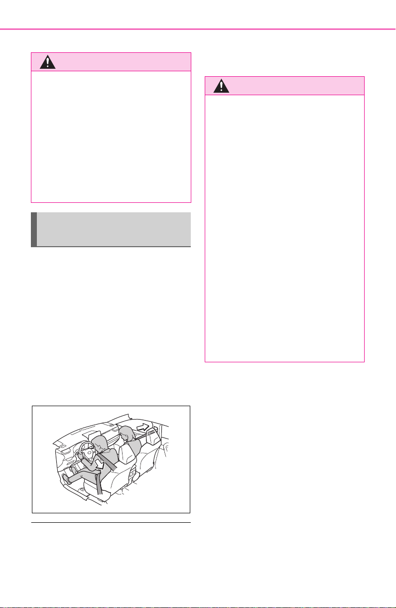
Adjust the angle of the seat-
back so that you are sitting
straight up and so that you do
not have to lean forward to
steer. (P.134)
Adjust the seat so that you
can depress the pedals fully
and so that your arms bend
slightly at the elbow when
gripping the steering wheel.
(P.134)
Lock the head restraint in
place with the center of the
head restraint closest to the
top of your ears. (P.140)
Wear the seat belt correctly.
(P.30)
WARNING
■ Before driving
● Check that the floor mat is
securely fixed in the correct
place with all the provided
retaining hooks (clips). Be espe-
cially careful to perform this
check after cleaning the floor.
● With the engine stopped and
the shift lever in P, fully depress
each pedal to the floor to make
sure it does not interfere with
the floor mat.
For safe driving
For safe driving, adjust the
seat and mirror to an appro-
priate position before driv-
ing.
Correct driving posture
A
B
C
D

28
1-1. For safe use
Make sure that all occupants are
wearing their seat belts before
driving the vehicle. (P. 3 0)
Use a child restraint system
appropriate for the child until the
child becomes large enough to
properly wear the vehicle’s seat
belt. (P.5 0 )
Make sure that you can see
backward clearly by adjusting
the inside rear view mirror (if
equipped), Digital Rear-view
Mirror (if equipped) and outside
rear view mirrors properly.
(P.143, 145, 154)
WARNING
Observe the following precau-
tions.
Failure to do so may result in
death or serious injury.
● Do not adjust the position of the
driver’s seat while driving.
Doing so could cause the driver
to lose control of the vehicle.
● Do not place a cushion between
the driver or passenger and the
seatback. A cushion may pre-
vent correct posture from being
achieved, and reduce the effec-
tiveness of the seat belt and
head restraint.
● Do not place anything under the
front seats.
Objects placed under the front
seats may become jammed in
the seat tracks and stop the
seat from locking in place. This
may lead to an accident and the
adjustment mechanism may
also be damaged.
● Always observe the legal speed
limit when driving on public
roads.
● When driving over long dis-
tances, take regular breaks
before you start to feel tired.
Also, if you feel tired or sleepy
while driving, do not force your-
self to continue driving and take
a break immediately.
Correct use of the seat
belts
Adjusting the mirrors
29
1-1. For safe use
1
For safety and security
Seat belts
Make sure that all occu-
pants are wearing their seat
belts before driving the
vehicle.
WARNING
Observe the following precautions
to reduce the risk of injury in the
event of sudden braking, sudden
swerving or an accident.
Failure to do so may cause death
or serious injury.
■ Wearing a seat belt
● Ensure that all passengers wear
a seat belt.
● Always wear a seat belt prop-
erly.
● Each seat belt should be used
by one person only. Do not use
a seat belt for more than one
person at once, including chil-
dren.
● Toyota recommends that chil-
dren be seated in the rear seat
and always use a seat belt
and/or an appropriate child
restraint system.
● To achieve a proper seating
position, do not recline the seat
more than necessary. The seat
belt is most effective when the
occupants are sitting up straight
and well back in the seats.
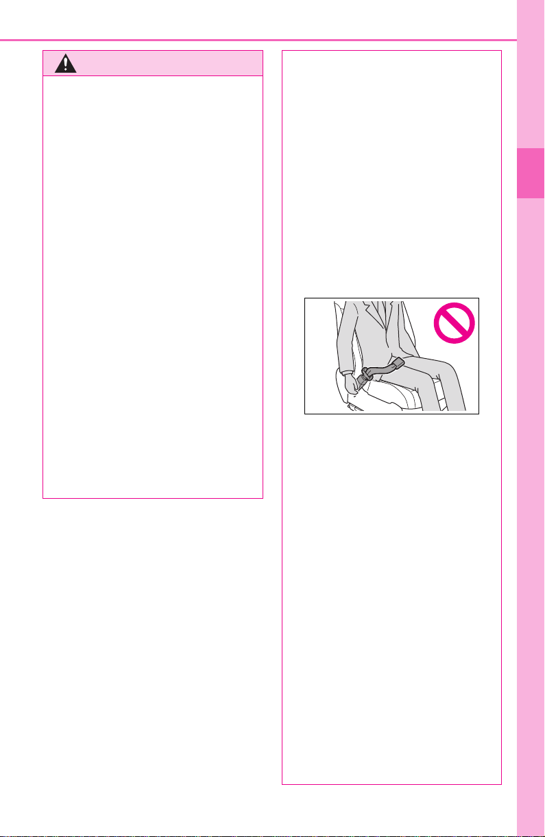
● Do not wear the shoulder belt
under your arm.
● Always wear your seat belt low
and snug across your hips.
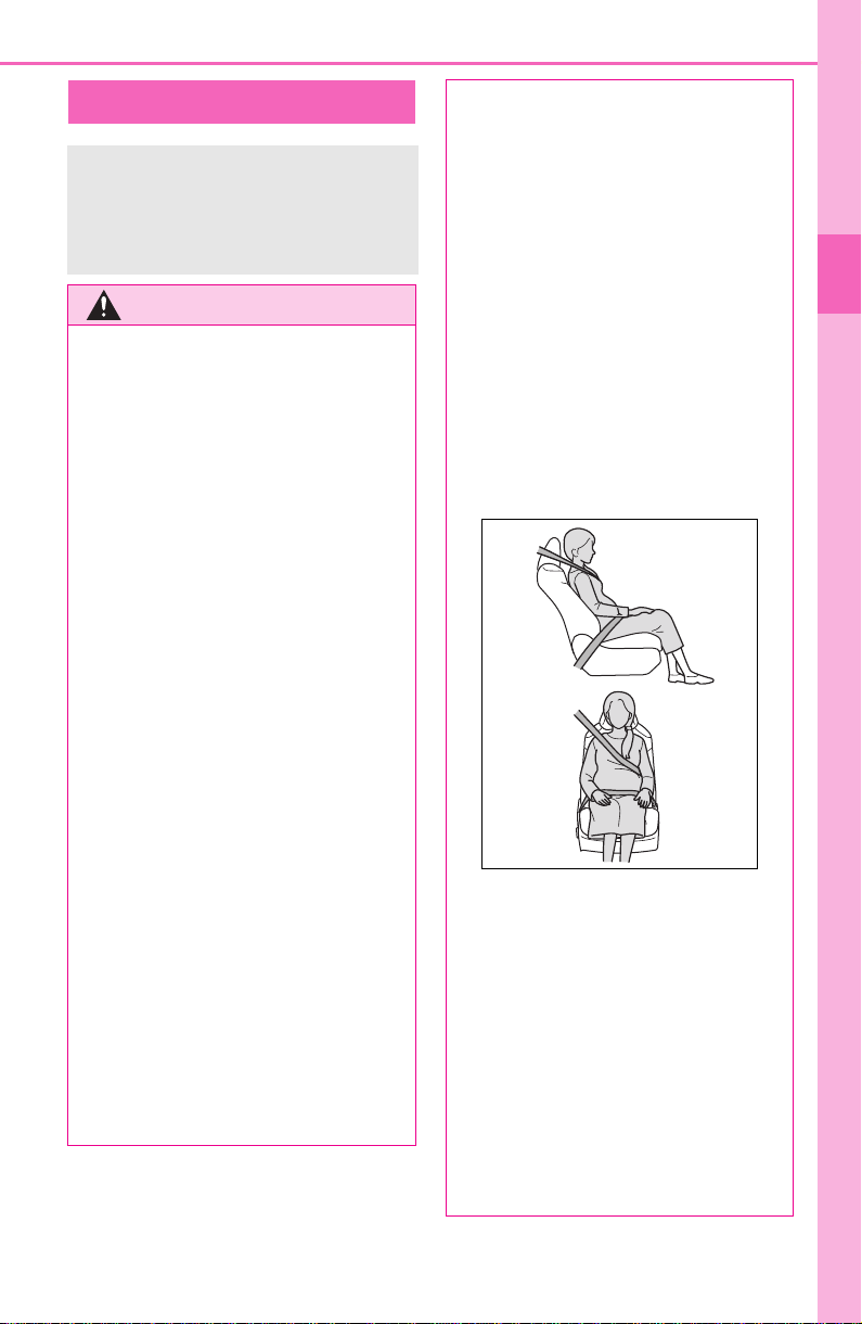
■ Pregnant women
Obtain medical advice and wear
the seat belt in the proper way.
(P.30)
Women who are pregnant should
position the lap belt as low as
possible over the hips in the same
manner as other occupants,
extending the shoulder belt com-
pletely over the shoulder and
avoiding belt contact with the
rounding of the abdominal area.
If the seat belt is not worn prop-
erly, not only the pregnant
woman, but also the fetus could
suffer death or serious injury as a
result of sudden braking or a colli-
sion.
■ People suffering illness
Obtain medical advice and wear
the seat belt in the proper way.
(P.30)
■ When children are in the vehi-
cle
P.5 8
■ Seat belt damage and wear
● Do not damage the seat belts
by allowing the belt, plate, or
buckle to be jammed in the
door.
30
1-1. For safe use
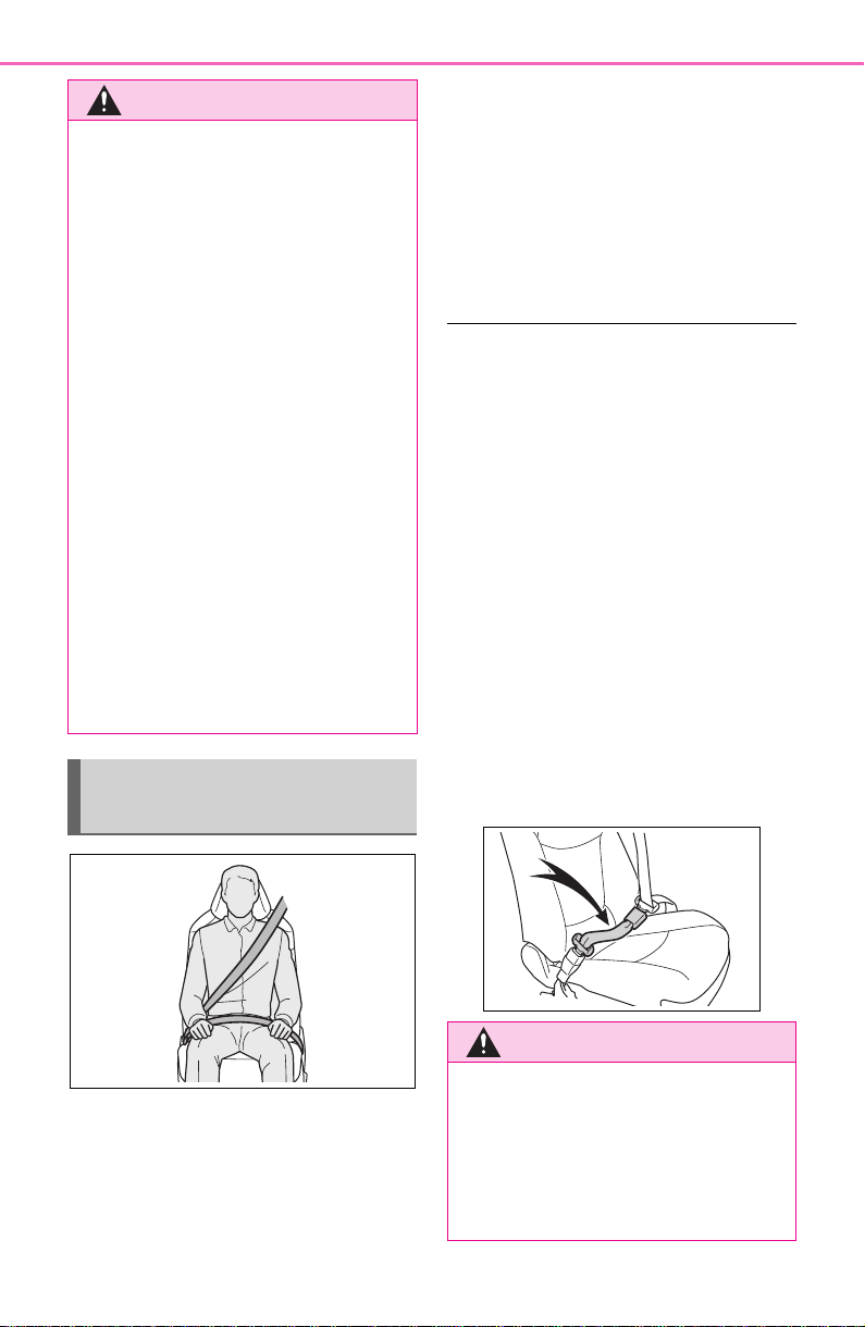
Extend the shoulder belt so
that it comes fully over the
shoulder, but does not come
into contact with the neck or
slide off the shoulder.
Position the lap belt as low as
possible over the hips.
Adjust the position of the
seatback.
Sit up straight and well back
in the seat.
Do not twist the seat belt.
■ Child seat belt usage
The seat belts of your vehicle were
principally designed for persons of
adult size.
● Use a child restraint system
appropriate for the child, until the
child becomes large enough to
properly wear the vehicle’s seat
belt. (P.5 0)
● When the child becomes large
enough to properly wear the vehi-
cle’s seat belt, follow the instruc-
tions regarding seat belt usage.
(P. 29)
■ Seat belt extender
If your seat belts cannot be fastened
securely because they are not long
enough, a personalized seat belt
extender is available from your
Toyota dealer free of charge.
WARNING
● Inspect the seat belt system
periodically. Check for cuts,
fraying, and loose parts. Do not
use a damaged seat belt until it
is replaced. Damaged seat belts
cannot protect an occupant
from death or serious injury.
● Ensure that the belt and plate
are locked and the belt is not
twisted.
If the seat belt does not function
correctly, immediately contact
your Toyota dealer.
● Replace the seat assembly,
including the belts, if your vehi-
cle has been involved in a seri-
ous accident, even if there is no
obvious damage.
● Do not attempt to install,
remove, modify, disassemble or
dispose of the seat belts. Have
any necessary repairs carried
out by your Toyota dealer. Inap-
propriate handling may lead to
incorrect operation.
Correct use of the seat
belts
WARNING
■ Using a seat belt extender
Observe the following precautions
to reduce the risk of injury in the
event of sudden braking, sudden
swerving or an accident.
Failure to do so may cause death
or serious injury.
31
1-1. For safe use
1
For safety and security
1 To fasten the seat belt, push
the plate into the buckle until
a click sound is heard.
2 To release the seat belt,
press the release button .
■ Emergency locking retractor
(ELR)
The retractor will lock the belt during
a sudden stop or on impact. It may
also lock if you lean forward too
quickly. A slow, easy motion will
allow the belt to extend so that you
can move around fully.
■ Automatic locking retractor
(ALR)
When a passenger’s shoulder belt is
completely extended and then
retracted even slightly, the belt is
locked in that position and cannot
be extended. This feature is used to
hold a child restraint system (CRS)
firmly. To free the belt again, fully
retract the belt and then pull the belt
out once more.
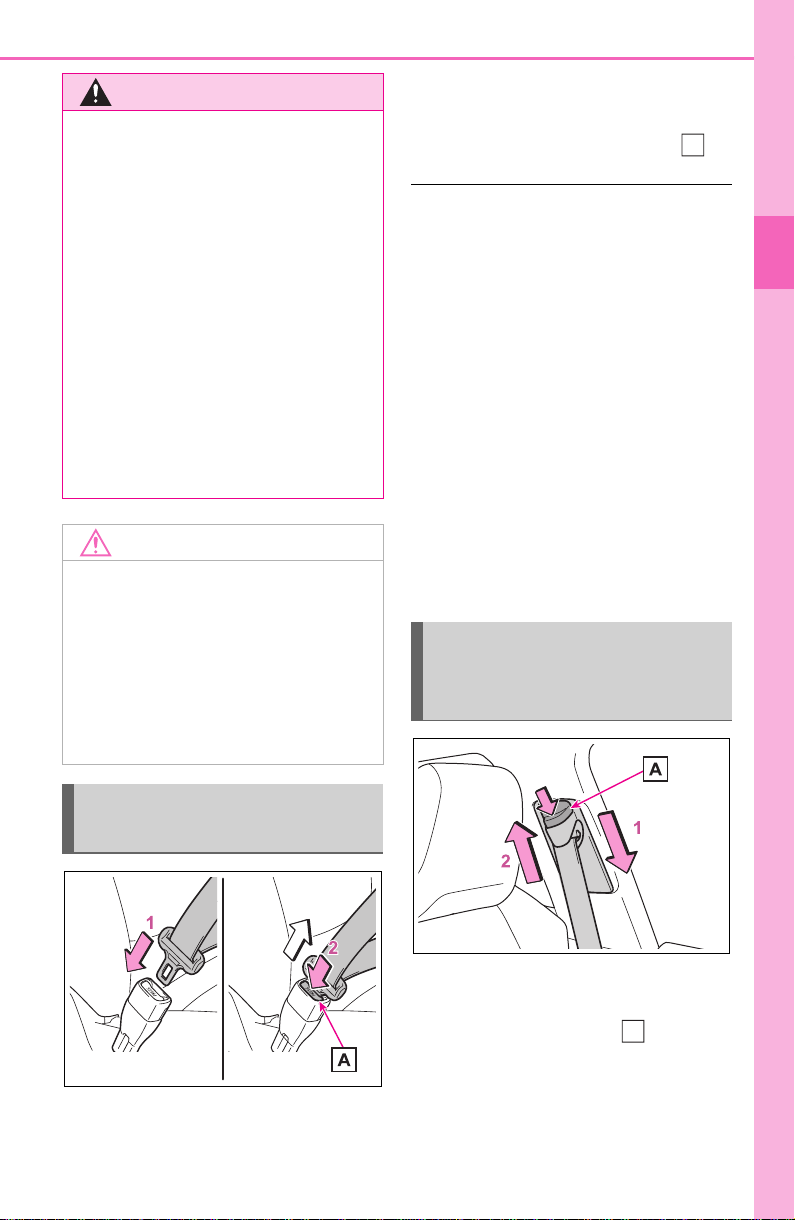
1 Push the seat belt shoulder
anchor down while pressing
the release button .
2 Push the seat belt shoulder
anchor up.
Move the height adjuster up and
down as needed until you hear a
WARNING
● Do not wear the seat belt
extender if you can fasten the
seat belt without the extender.
● Do not use the seat belt
extender when installing a child
restraint system because the
belt will not securely hold the
child restraint system, increas-
ing the risk of death or serious
injury in the event of an acci-
dent.
● The personalized extender may
not be safe on another vehicle,
when used by another person,
or at a different seating position
other than the one originally
intended.
NOTICE
■ When using a seat belt
extender
When releasing the seat belt,
press on the buckle release but-
ton on the extender, not on the
seat belt.
This helps prevent damage to the
vehicle interior and the extender
itself.
Fastening and releasing
the seat belt
Adjusting the seat belt
shoulder anchor height
(front seats)
A
A
32
1-1. For safe use
click.
The pretensioners help the seat
belts to quickly restrain the
occupants by retracting the seat
belts when the vehicle is sub-
jected to certain types of severe
frontal or side collision or a vehi-
cle rollover.
The pretensioners do not activate
in the event of a minor frontal
impact, a minor side impact or a
rear impact.
■ Replacing the belt after the pre-
tensioner has been activated
If the vehicle is involved in multiple
collisions, the pretensioner will acti-
vate for the first collision, but will not
activate for the second or subse-
quent collisions.
WARNING
■ Adjustable shoulder anchor
Always make sure the shoulder
belt is positioned across the cen-
ter of your shoulder. The belt
should be kept away from your
neck, but not falling off your shoul-
der. Failure to do so could reduce
the amount of protection in an
accident and cause death or seri-
ous injuries in the event of a sud-
den stop, sudden swerve or
accident.
Seat belt pretensioners
(front seats)
WARNING
■ Seat belt pretensioners
Observe the following precautions
to reduce the risk of injury in the
event of sudden braking, sudden
swerving or an accident.
Failure to do so may cause death
or serious injury.
● Do not place anything, such as
a cushion, on the front passen-
ger’s seat.
Doing so will disperse the pas-
senger’s weight, which prevents
the sensor from detecting the
passenger’s weight properly. As
a result, the seat belt preten-
sioner for the front passenger’s
seat may not activate in the
event of a collision.
● If the pretensioner has acti-
vated, the SRS warning light will
come on. In that case, the seat
belt cannot be used again and
must be replaced at your Toyota
dealer.
33
1-1. For safe use
1
For safety and security
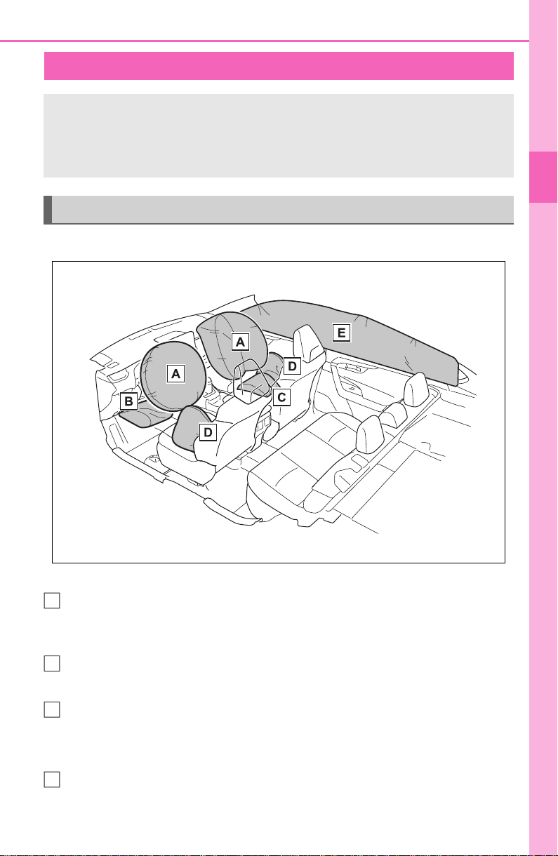
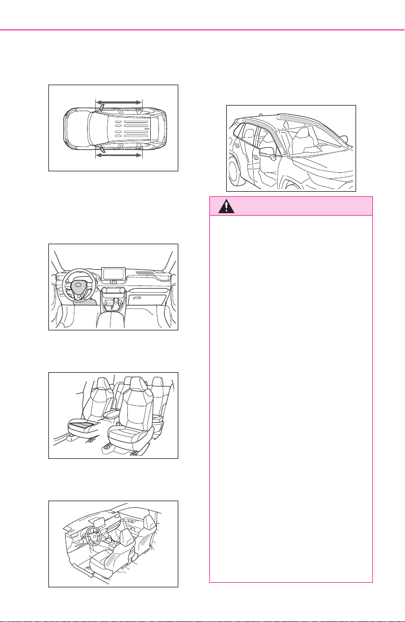
■ Location of the SRS airbags
SRS front airbags
SRS driver airbag/front passenger airbag
Can help protect the head and chest of the driver and front passenger from
impact with interior components
SRS knee airbag
Can help provide driver protection
SRS seat cushion airbag
Can help restrain the front passenger
SRS side and curtain shield airbags
SRS side airbags
Can help protect the torso of the front seat occupants
SRS airbags
The SRS airbags inflate when the vehicle is subjected to cer-
tain types of severe impacts that may cause significant injury
to the occupants. They work together with the seat belts to
help reduce the risk of death or serious injury.
SRS airbag system
A
B
C
D
34
1-1. For safe use
SRS curtain shield airbags
• Can help protect primarily the head of occupants in the outer seats
• Can help prevent the occupants from being thrown from the vehicle in the
event of vehicle rollover
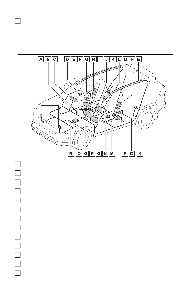
■ SRS airbag system components
Front impact sensors
“AIR BAG ON” and “AIR BAG OFF” indicator lights
Front passenger airbag
Side impact sensors (front door)
Curtain shield airbags
Seat belt pretensioners and force limiters
Side impact sensors (front)
Side airbags
Seat cushion airbag
Front passenger’s seat belt buckle switch
Side impact sensors (rear)
Driver’s seat belt buckle switch
Driver’s seat position sensor
E
A
B
C
D
E
F
G
H
I
J
K
L
M

35
1-1. For safe use
1
For safety and security
Driver airbag
Front passenger occupant classification system (ECU and sen-
sors)
Knee airbag
SRS warning light
Airbag sensor assembly
Your vehicle is equipped with ADVANCED AIRBAGS designed
based on the US motor vehicle safety standards (FMVSS208). The
airbag sensor assembly (ECU) controls airbag deployment based on
information obtained from the sensors etc. shown in the system
components diagram above. This information includes crash sever-
ity and occupant information. As the airbags deploy, a chemical
reaction in the inflators quickly fills the airbags with non-toxic gas to
help restrain the motion of the occupants.
■ If the SRS airbags deploy
(inflate)
● Slight abrasions, burns, bruising
etc., may be sustained from SRS
airbags, due to the extremely high
speed deployment (inflation) by
hot gases.
● A loud noise and white powder will
be emitted.
● Parts of the airbag module (steer-
ing wheel hub, airbag cover and
inflator) as well as the front seats,
parts of the front and rear pillars,
and roof side rails, may be hot for
several minutes. The airbag itself
may also be hot.
● The windshield may crack.
● The brakes and stop lights will be
controlled automatically. (P.361)
● The interior lights will turn on auto-
matically. (P.526)
● The emergency flashers will turn
on automatically. (P.618)
● Fuel supply to the engine will be
stopped. (P.627)
● For Safety Connect subscribers, if
any of the following situations
occur, the system is designed to
send an emergency call to the
response center, notifying them of
the vehicle’s location (without
needing to push the “SOS” button)
and an agent will attempt to speak
with the occupants to ascertain
the level of emergency and assis-
tance required. If the occupants
are unable to communicate, the
agent automatically treats the call
as an emergency and helps to dis-
patch the necessary emergency
services. (P.65)
• An SRS airbag is deployed.
• A seat belt pretensioner is acti-
vated.
• The vehicle is involved in a severe
rear-end collision.
■ SRS airbag deployment condi-
tions (SRS front airbags)
● The SRS front airbags will deploy
in the event of an impact that
exceeds the set threshold level
(the level of force corresponding
to an approximately 12-18 mph
[20-30 km/h] frontal collision with
a fixed wall that does not move or
deform).
However, this threshold velocity will
N
O
P
Q
R
36
1-1. For safe use
be considerably higher in the follow-
ing situations:
• If the vehicle strikes an object,
such as a parked vehicle or sign
pole, which can move or deform
on impact
• If the vehicle is involved in an
underride collision, such as a colli-
sion in which the front of the vehi-
cle underrides, or goes under, the
bed of a truck
● Depending on the type of collision,
it is possible that only the seat belt
pretensioners will activate.
● The SRS front airbags for the front
passenger will not activate if there
is no passenger sitting in the front
passenger seat. However, the
SRS front airbags for the front
passenger may deploy if luggage
is put in the seat, even if the seat
is unoccupied.
● The SRS seat cushion airbag on
the front passenger seat will not
operate if the occupant is not
wearing a seat belt.
■ SRS airbag deployment condi-
tions (SRS side and curtain
shield airbags)
● The SRS side and curtain shield
airbags will deploy in the event of
an impact that exceeds the set
threshold level (the level of force
corresponding to the impact force
produced by an approximately
3300 lb. [1500 kg] vehicle colliding
with the vehicle cabin from a
direction perpendicular to the
vehicle orientation at an approxi-
mate speed of 12 -18 mph [20 -30
km/h]).
● Both SRS curtain shield airbags
may deploy in the event of a
severe side collision.
● Both SRS curtain shield airbags
will deploy in the event of vehicle
rollover.
● Both SRS curtain shield airbags
may also deploy in the event of a
severe frontal collision.
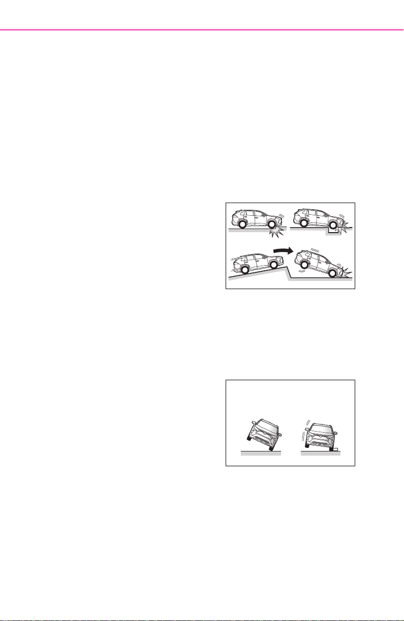
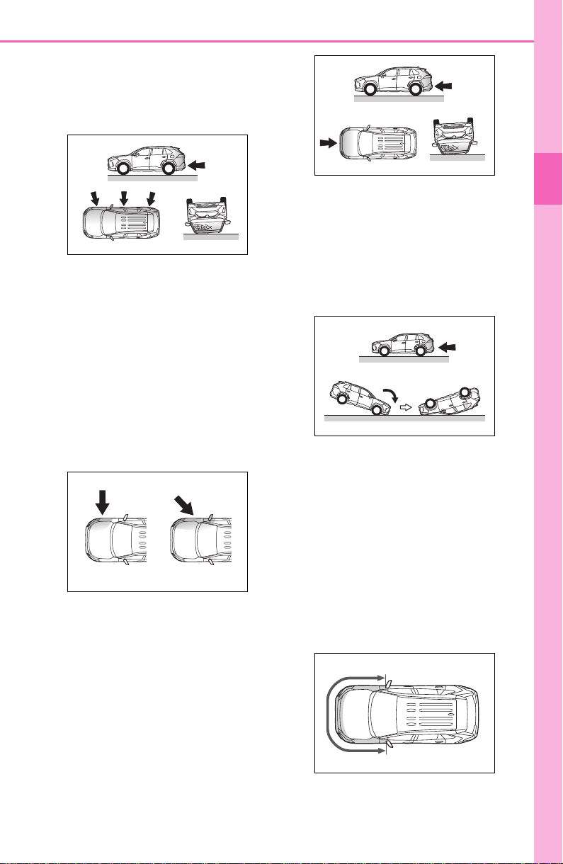
■ Conditions under which the
SRS airbags may deploy
(inflate), other than a collision
The SRS front airbags and SRS cur-
tain shield airbags may also deploy
if a serious impact occurs to the
underside of your vehicle. Some
examples are shown in the illustra-
tion.
● Hitting a curb, edge of pavement
or hard surface
● Falling into or jumping over a deep
hole
● Landing hard or falling
The SRS curtain shield airbags may
also deploy under the situations
shown in the illustration.
● The angle of vehicle tip-up is mar-
ginal.
● The vehicle skids and hits a curb
stone.
■ Types of collisions that may not
deploy the SRS airbags (SRS
front airbags)
The SRS front airbags do not gener-
ally inflate if the vehicle is involved
in a side or rear collision, if it rolls
over, or if it is involved in a low-
speed frontal collision. But, when-
ever a collision of any type causes
sufficient forward deceleration of the
vehicle, deployment of the SRS
37
1-1. For safe use
1
For safety and security
front airbags may occur.
● Collision from the side
● Collision from the rear
● Vehicle rollover
■ Types of collisions that may not
deploy the SRS airbags (SRS
side and curtain shield airbags)
The SRS side and curtain shield air-
bags may not activate if the vehicle
is subjected to a collision from the
side at certain angles, or a collision
to the side of the vehicle body other
than the passenger compartment.
● Collision from the side to the vehi-
cle body other than the passenger
compartment
● Collision from the side at an angle
The SRS side airbags do not gener-
ally inflate if the vehicle is involved
in a frontal or rear collision, if it rolls
over, or if it is involved in a low-
speed side collision.
● Collision from the front
● Collision from the rear
● Vehicle rollover
The SRS curtain shield airbags do
not generally inflate if the vehicle is
involved in a rear collision, if it
pitches end over end, or if it is
involved in a low-speed side or low-
speed frontal collision.
● Collision from the rear
● Pitching end over end
■ When to contact your Toyota
dealer
In the following cases, the vehicle
will require inspection and/or repair.
Contact your Toyota dealer as soon
as possible.
● Any of the SRS airbags have
been inflated.
● The front of the vehicle is dam-
aged or deformed, or was
involved in an accident that was
not severe enough to cause the
SRS front airbags to inflate.
● A portion of a door or its surround-
ing area is damaged, deformed or
has had a hole made in it, or the
38
1-1. For safe use
vehicle was involved in an acci-
dent that was not severe enough
to cause the SRS side and curtain
shield airbags to inflate.
● The pad section of the steering
wheel, dashboard near the front
passenger airbag or lower portion
of the instrument panel is
scratched, cracked, or otherwise
damaged.
● The front passenger’s seat cush-
ion surface is scratched, cracked,
or otherwise damaged.
● The surface of the seats with the
SRS side airbag is scratched,
cracked, or otherwise damaged.
● The portion of the front pillars, rear
pillars or roof side rail garnishes
(padding) containing the SRS cur-
tain shield airbags inside is
scratched, cracked, or otherwise
damaged.
WARNING
■ SRS airbag precautions
Observe the following precautions
regarding the SRS airbags.
Failure to do so may cause death
or serious injury.
● The driver and all passengers in
the vehicle must wear their seat
belts properly.
The SRS airbags are supple-
mental devices to be used with
the seat belts.
● The SRS driver airbag deploys
with considerable force, and
can cause death or serious
injury especially if the driver is
very close to the airbag. The
National Highway Traffic Safety
Administration (NHTSA)
advises:
Since the risk zone for the driver’s
airbag is the first 2 - 3 in. (50 - 75
mm) of inflation, placing yourself
10 in. (250 mm) from your driver
airbag provides you with a clear
margin of safety. This distance is
measured from the center of the
steering wheel to your breast-
bone. If you sit less than 10 in.
(250 mm) away now, you can
change your driving position in
several ways:
39
1-1. For safe use
1
For safety and security
WARNING
• Move your seat to the rear as
far as you can while still reach-
ing the pedals comfortably.
• Slightly recline the back of the
seat.
Although vehicle designs vary,
many drivers can achieve the
10 in. (250 mm) distance, even
with the driver seat all the way
forward, simply by reclining the
back of the seat somewhat. If
reclining the back of your seat
makes it hard to see the road,
raise yourself by using a firm,
non-slippery cushion, or raise
the seat if your vehicle has that
feature.
• If your steering wheel is adjust-
able, tilt it downward. This
points the airbag toward your
chest instead of your head and
neck.
The seat should be adjusted as
recommended by NHTSA above,
while still maintaining control of
the foot pedals, steering wheel,
and your view of the instrument
panel controls.
● If the seat belt extender has
been connected to the front
seat belt buckles but the seat
belt extender has not also been
fastened to the latch plate of the
seat belt, the SRS front airbags
will judge that the driver and
front passenger are wearing the
seat belt even though the seat
belt has not been connected. In
this case, the SRS front airbags
may not activate correctly in a
collision, resulting in death or
serious injury in the event of a
collision. Be sure to wear the
seat belt with the seat belt
extender.
● The SRS front passenger air-
bag also deploys with consider-
able force, and can cause death
or serious injury especially if the
front passenger is very close to
the airbag. The front passenger
seat should be as far from the
airbag as possible with the seat-
back adjusted, so the front pas-
senger sits upright.
● Improperly seated and/or
restrained infants and children
can be killed or seriously injured
by a deploying airbag. An infant
or child who is too small to use
a seat belt should be properly
secured using a child restraint
system. Toyota strongly recom-
mends that all infants and chil-
dren be placed in the rear seats
of the vehicle and properly
restrained. The rear seats are
safer for infants and children
than the front passenger seat.
(P.5 0)
40
1-1. For safe use
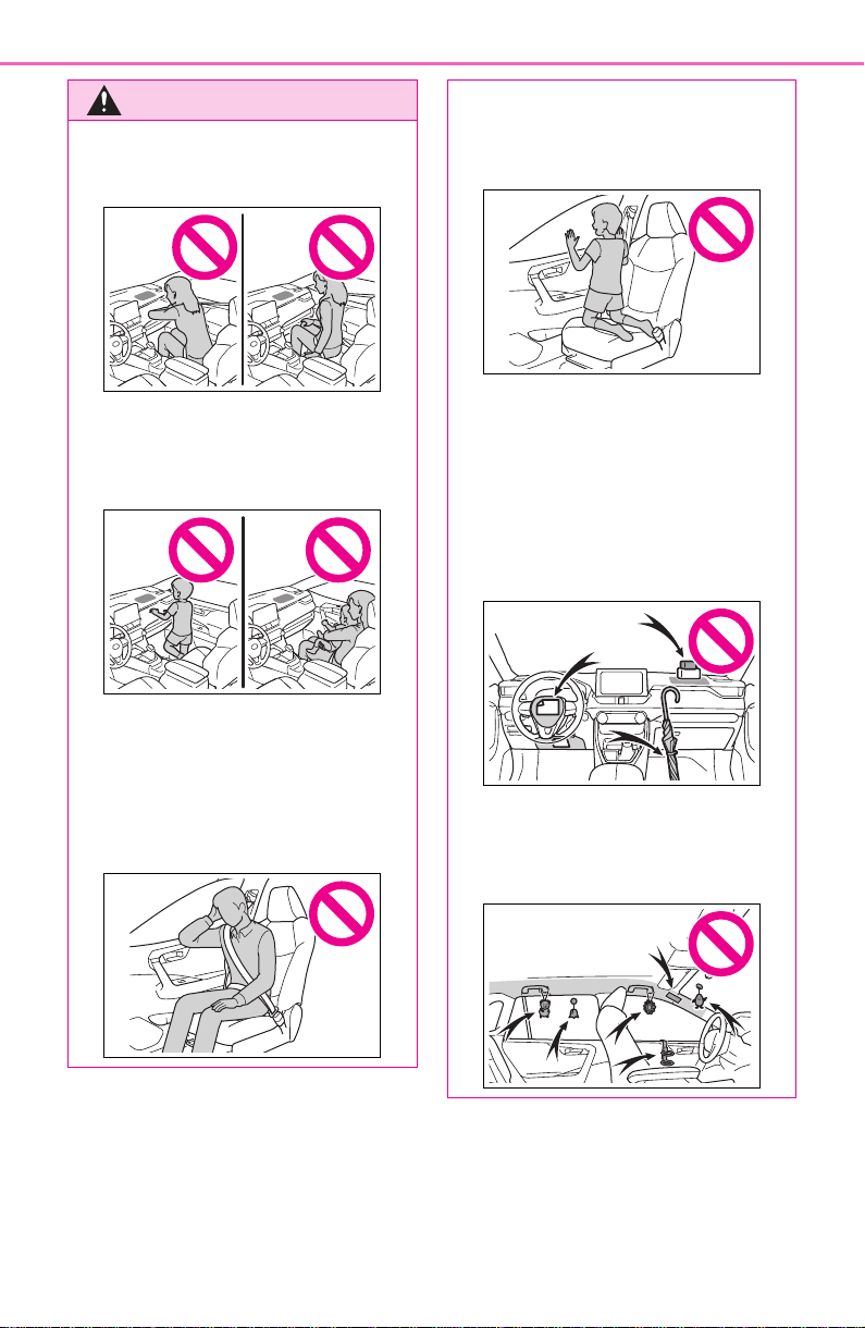
WARNING
● Do not sit on the edge of the
seat or lean against the dash-
board.
● Do not allow a child to stand in
front of the SRS front passenger
airbag unit or sit on the knees of
a front passenger.
● Do not allow the front seat occu-
pants to hold items on their
knees.
● Do not lean against the door,
the roof side rail or the front,
side and rear pillars.
● Do not allow anyone to kneel on
the passenger seat toward the
door or put their head or hands
outside the vehicle.
● Do not attach anything to or
lean anything against areas
such as the dashboard, steering
wheel pad and lower portion of
the instrument panel.
These items can become pro-
jectiles when the SRS driver,
front passenger and knee air-
bags deploy.
● Do not attach anything to areas
such as a door, windshield, side
windows, front or rear pillar, roof
side rail and assist grip.
41
1-1. For safe use
1
For safety and security
WARNING
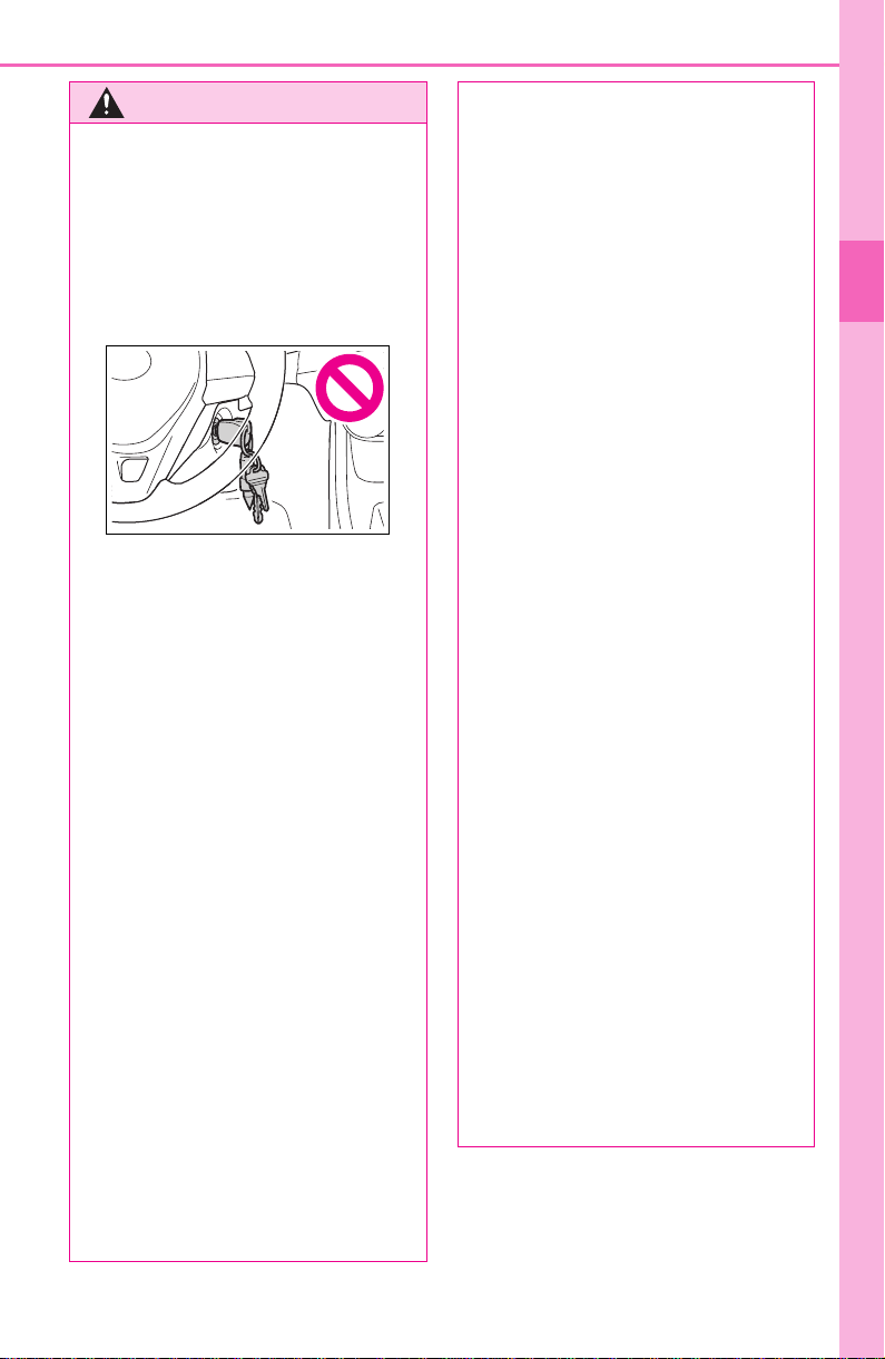
● Vehicles without smart key sys-
tem: Do not attach any heavy,
sharp or hard objects such as
keys and accessories to the
key. The objects may restrict the
SRS knee airbag inflation or be
thrust into the driver’s seat area
by the force of the deploying air-
bag, thus causing a danger.
● Do not hang coat hangers or
other hard objects on the coat
hooks. All of these items could
become projectiles and may
cause death or serious injury,
should the SRS curtain shield
airbags deploy.
● If a vinyl cover is put on the area
where the SRS knee airbag will
deploy, be sure to remove it.
● Do not use seat accessories
which cover the parts where the
SRS side airbags and SRS seat
cushion airbag inflate as they
may interfere with inflation of
the SRS airbags. Such acces-
sories may prevent the side air-
bags and seat cushion airbag
from activating correctly, disable
the system or cause the side
airbags and seat cushion airbag
to inflate accidentally, resulting
in death or serious injury.
● Do not strike or apply significant
levels of force to the area of the
SRS airbag components or the
front doors.
Doing so can cause the SRS
airbags to malfunction.
● Do not touch any of the compo-
nent parts immediately after the
SRS airbags have deployed
(inflated) as they may be hot.
● If breathing becomes difficult
after the SRS airbags have
deployed, open a door or side
window to allow fresh air in, or
leave the vehicle if it is safe to
do so. Wash off any residue as
soon as possible to prevent skin
irritation.
● If the areas where the SRS air-
bags are stored, such as the
steering wheel pad and front
and rear pillar garnishes, are
damaged or cracked, have
them replaced by your Toyota
dealer.
● Do not place anything, such as
a cushion, on the front passen-
ger’s seat. Doing so will
disperse the passenger’s
weight, which prevents the sen-
sor from detecting the passen-
ger’s weight properly. As a
result, the SRS front airbags for
the front passenger may not
deploy in the event of a colli-
sion.
■ Modification and disposal of
SRS airbag system compo-
nents
Do not dispose of your vehicle or
perform any of the following modi-
fications without consulting your
Toyota dealer. The SRS airbags
may malfunction or deploy
(inflate) accidentally, causing
death or serious injury.
● Installation, removal, disassem-
bly and repair of the SRS air-
bags

42
1-1. For safe use
WARNING
● Repairs, modifications, removal
or replacement of the steering
wheel, instrument panel, dash-
board, seats or seat upholstery,
front, side and rear pillars, roof
side rails, front door panels,
front door trims or front door
speakers
● Modifications to the front door
panel (such as making a hole in
it)
● Repairs or modifications of the
front fender, front bumper, or
side of the occupant compart-
ment
● Installation of a grille guard (bull
bars, kangaroo bar, etc.), snow
plows, winches or roof luggage
carrier
● Modifications to the vehicle’s
suspension system
● Installation of electronic devices
such as mobile two-way radios
and CD players
● Modifications to your vehicle for
a person with a physical disabil-
ity
43
1-1. For safe use
1
For safety and security
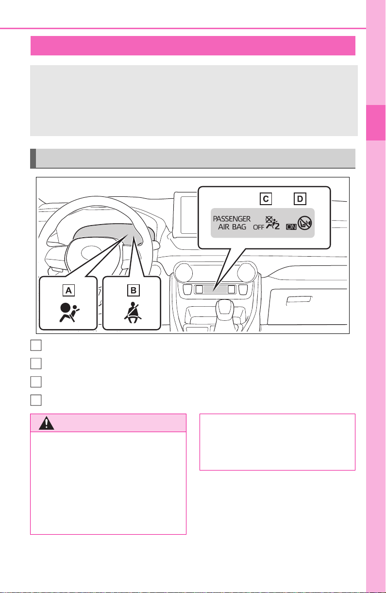
SRS warning light
Driver’s and front passenger’s seat belt reminder light
“AIR BAG OFF” indicator light
“AIR BAG ON” indicator light
Front passenger occupant classification system
Your vehicle is equipped with a front passenger occupant
classification system. This system detects the conditions of
the front passenger seat and activates or deactivates the front
passenger airbag and seat cushion airbag in the front passen-
ger side.
System components
A
B
C
D
WARNING
■ Front passenger occupant
classification system precau-
tions
Observe the following precautions
regarding the front passenger
occupant classification system.
Failure to do so may cause death
or serious injury.
● Wear the seat belt properly.
● Make sure the front passenger’s
seat belt plate has not been left
inserted into the buckle before
someone sits in the front pas-
senger seat.

44
1-1. For safe use
WARNING
● Make sure the “AIR BAG OFF”
indicator light is not illuminated
when using the seat belt
extender for the front passenger
seat. If the “AIR BAG OFF” indi-
cator light is illuminated, discon-
nect the extender tongue from
the seat belt buckle, and recon-
nect the seat belt. Reconnect
the seat belt extender after
making sure the “AIR BAG ON”
indicator light is illuminated. If
you use the seat belt extender
while the “AIR BAG OFF” indi-
cator light is illuminated, the
SRS airbags for the front pas-
senger will not activate, which
could cause death or serious
injury in the event of a collision.
● Do not apply a heavy load to the
front passenger seat or equip-
ment (e.g. seatback pocket).
● Do not put weight on the front
passenger seat by putting your
hands or feet on the front pas-
senger seat seatback from the
rear passenger seat.
● Do not let a rear passenger lift
the front passenger seat with
their feet or press on the seat-
back with their legs.
● Do not put objects under the
front passenger seat.
● Do not recline the front passen-
ger seatback so far that it
touches a rear seat. This may
cause the “AIR BAG OFF” indi-
cator light to be illuminated,
which indicates that the SRS
airbags for the front passenger
will not activate in the event of a
severe accident. If the seatback
touches the rear seat, return the
seatback to a position where it
does not touch the rear seat.
Keep the front passenger seat-
back as upright as possible
when the vehicle is moving.
Reclining the seatback exces-
sively may lessen the effective-
ness of the seat belt system.
● If an adult sits in the front pas-
senger seat, the “AIR BAG ON”
indicator light is illuminated. If
the “AIR BAG OFF” indicator is
illuminated, ask the passenger
to sit up straight, well back in
the seat, feet on the floor, and
with the seat belt worn correctly.
If the “AIR BAG OFF” indicator
still remains illuminated, either
ask the passenger to move to
the rear seat, or if that is not
possible, move the front pas-
senger seat fully rearward.
● When it is unavoidable to install
a forward-facing child restraint
system on the front passenger
seat, install the child restraint
system on the front passenger
seat in the proper order.
(P.5 3)
● Do not modify or remove the
front seats.
● Do not kick the front passenger
seat or subject it to severe
impact. Otherwise, the SRS
warning light may come on to
indicate a malfunction of the
front passenger occupant clas-
sification system. In this case,
contact your Toyota dealer
immediately.
45
1-1. For safe use
1
For safety and security
■ Adult
*1
WARNING
● Child restraint systems installed
on the rear seat should not con-
tact the front seatbacks.
● Do not use a seat accessory,
such as a cushion and seat
cover, that covers the seat
cushion surface.
● Do not modify or replace the
upholstery of the front seat.
● Adjust the front passenger seat
so that the head restraint does
not touch the ceiling. If the head
restraint is left in contact with
the ceiling, the system may not
detect the front passenger prop-
erly, leading to improper opera-
tion of the airbags.
Condition and operation in the front passenger occupant
classification system
Indicator/warn-
ing light
“AIR BAG ON” and “AIR BAG OFF”
indicator lights
“AIR BAG ON”
SRS warning light Off
Driver’s and front passenger’s seat
belt reminder light
Off
*2
or flashing
*3
Devices
Front passenger airbag Activated
Front passenger seat cushion airbag
Activated
*2
or
deactivated
*3

46
1-1. For safe use
■ Child
*4
■ Child restraint system with infant
*5
■ Unoccupied
Indicator/warn-
ing light
“AIR BAG ON” and “AIR BAG OFF”
indicator lights
“AIR BAG OFF”
or “AIR BAG
ON”
*4
SRS warning light Off
Driver’s and front passenger’s seat
belt reminder light
Off
*2
or flashing
*3
Devices
Front passenger airbag
Deactivated or
activated
*4
Front passenger seat cushion airbag
Deactivated or
activated
*2, 4
Indicator/warn-
ing light
“AIR BAG ON” and “AIR BAG OFF”
indicator lights
“AIR BAG OFF”
*6
SRS warning light Off
Driver’s and front passenger’s seat
belt reminder light
Off
*2
or flashing
*3
Devices
Front passenger airbag
Deactivated
Front passenger seat cushion airbag
Indicator/warn-
ing light
“AIR BAG ON” and “AIR BAG OFF”
indicator lights
“AIR BAG OFF”
SRS warning light
Off
Driver’s and front passenger’s seat
belt reminder light
Devices
Front passenger airbag
Deactivated
Front passenger seat cushion airbag

47
1-1. For safe use
1
For safety and security
■ There is a malfunction in the system
*1
:The system judges a person of adult size as an adult. When a smaller
adult sits in the front passenger seat, the system may not recognize
him/her as an adult depending on his/her physique and posture.
*2
:In the event the front passenger is wearing a seat belt.
*3
:In the event the front passenger does not wear a seat belt.
*4
:For some children, child in seat, child in booster seat or child in convert-
ible seat, the system may not recognize him/her as a child. Factors
which may affect this can be the physique or posture.
*5
:Never install a rear-facing child restraint system on the front passenger
seat. A forward-facing child restraint system should only be installed on
the front passenger seat when it is unavoidable. (P.53)
*6
:In case the indicator light is not illuminated, consult this manual on how
to install the child restraint system properly. (P.50)
Indicator/warn-
ing light
“AIR BAG ON” and “AIR BAG OFF”
indicator lights
“AIR BAG OFF”
SRS warning light
On
Driver’s and front passenger’s seat
belt reminder light
Devices
Front passenger airbag
Deactivated
Front passenger seat cushion airbag

48
1-1. For safe use
Exhaust gas precau-
tions
Harmful substance to the
human body is included in
exhaust gases if inhaled.
WARNING
Exhaust gases contain harmful
carbon monoxide (CO), which is
colorless and odorless. Observe
the following precautions.
Failure to do so may cause
exhaust gases to enter the vehicle
and may lead to an accident
caused by light-headedness, or
may lead to death or a serious
health hazard.
■ Important points while driving
● Keep the back door closed.
● If you smell exhaust gases in
the vehicle even when the back
door is closed, open the side
windows and have the vehicle
inspected at your Toyota dealer
as soon as possible.
■ When parking
● If the vehicle is in a poorly venti-
lated area or a closed area,
such as a garage, stop the
engine.
● Do not leave the vehicle with
the engine running for a long
time.
If such a situation cannot be
avoided, park the vehicle in an
open space and ensure that
exhaust fumes do not enter the
vehicle interior.
● Do not leave the engine running
in an area with snow build-up,
or where it is snowing. If snow-
banks build up around the vehi-
cle while the engine is running,
exhaust gases may collect and
enter the vehicle.
■ Exhaust pipe
The exhaust system needs to be
checked periodically. If there is a
hole or crack caused by corro-
sion, damage to a joint or abnor-
mal exhaust noise, be sure to
have the vehicle inspected and
repaired by your Toyota dealer.

49
1-2. Child safety
1
For safety and security
1-2.Child safety
Riding with children
Observe the following pre-
cautions when children are
in the vehicle.
Use a child restraint system
appropriate for the child,
until the child becomes
large enough to properly
wear the vehicle’s seat belt.
It is recommended that chil-
dren sit in the rear seats to
avoid accidental contact
with the shift lever, wiper
switch, etc.
Use the rear door child-pro-
tector lock or the window
lock switch to avoid children
opening the door while driv-
ing or operating the power
window accidentally.
(P.112, 158)
Do not let small children
operate equipment which
may catch or pinch body
parts, such as the power
window, hood, back door,
seats, etc.
WARNING
■ When children are in the vehi-
cle
Never leave children unattended
in the vehicle, and never allow
children to have or use the key.
Children may be able to start the
vehicle or shift the vehicle into
neutral. There is also a danger
that children may injure them-
selves by playing with the side
windows, the moon roof (if
equipped), the panoramic moon
roof (if equipped) or other features
of the vehicle. In addition, heat
build-up or extremely cold tem-
peratures inside the vehicle can
be fatal to children.

50
1-2. Child safety
Points to remember: P.50
Child restraint system: P.52
When using a child restraint sys-
tem: P.53
Child restraint system installa-
tion method
• Fixed with a seat belt: P.54
• Fixed with a child restraint
LATCH anchor: P.59
• Using an anchor bracket (for
top tether strap): P.61
The laws of all 50 states of the
U.S.A. as well as Canada now
require the use of child restraint
systems.
Prioritize and observe the
warnings, as well as the laws
and regulations for child
restraint systems.
Use a child restraint system
until the child becomes large
enough to properly wear the
vehicle’s seat belt.
Choose a child restraint sys-
tem that suits your vehicle
and is appropriate to the age
and size of the child.
Child restraint sys-
tems
Before installing a child
restraint system in the vehi-
cle, there are precautions
that need to be observed,
different types of child
restraint systems, as well as
installation methods, etc.,
written in this manual.
Use a child restraint system
when riding with a small child
that cannot properly use a
seat belt. For the child’s
safety, install the child
restraint system to a rear seat.
Be sure to follow the installa-
tion method that is in the oper-
ation manual enclosed with
the restraint system.
Table of contents
Points to remember
WARNING
■ When a child is riding
Observe the following precau-
tions.
Failure to do so may result in
death or serious injury.
● For effective protection in auto-
mobile accidents and sudden
stops, a child must be properly
restrained, using a seat belt or
child restraint system which is
correctly installed. For installa-
tion details, refer to the opera-
tion manual enclosed with the
child restraint system. General
installation instructions are pro-
vided in this manual.

51
1-2. Child safety
1
For safety and security
WARNING
● Toyota strongly urges the use of
a proper child restraint system
that conforms to the weight and
size of the child, installed on the
rear seat. According to accident
statistics, the child is safer when
properly restrained in the rear
seat than in the front seat.
● Holding a child in your or some-
one else’s arms is not a substi-
tute for a child restraint system.
In an accident, the child can be
crushed against the windshield
or between the holder and the
interior of the vehicle.
■ Handling the child restraint
system
If the child restraint system is not
properly fixed in place, the child or
other passengers may be seri-
ously injured or even killed in the
event of sudden braking, sudden
swerving, or an accident.
● If the vehicle were to receive a
strong impact from an accident,
etc., it is possible that the child
restraint system has damage
that is not readily visible. In
such cases, do not reuse the
restraint system.
● Make sure you have complied
with all installation instructions
provided with the child restraint
system manufacturer and that
the system is properly secured.
● Keep the child restraint system
properly secured on the seat
even if it is not in use. Do not
store the child restraint system
unsecured in the passenger
compartment.
● If it is necessary to detach the
child restraint system, remove it
from the vehicle or store it
securely in the luggage com-
partment.
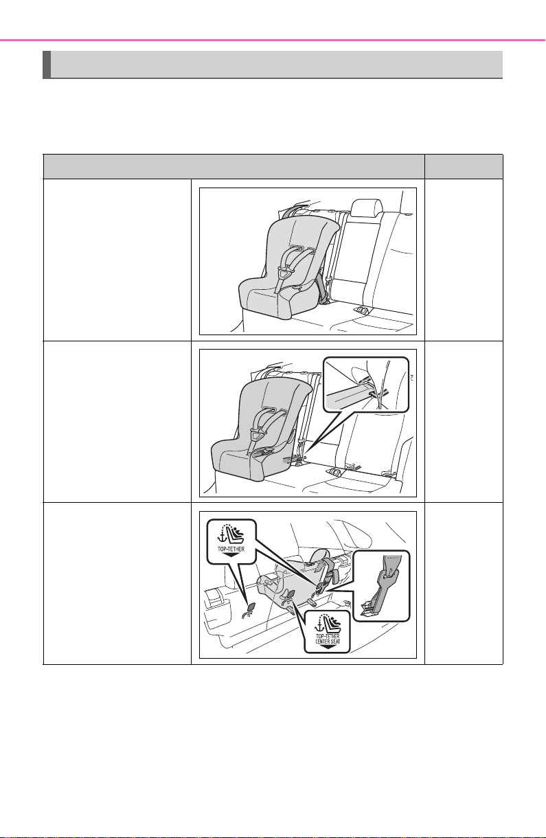
52
1-2. Child safety
■ Types of child restraint system installation methods
Confirm with the operation manual enclosed with the child restraint
system about the installation of the child restraint system.
Child restraint system
Installation method Page
Seat belt attachment P.5 4
Child restraint LATCH
anchors attachment
P.5 9
Anchor brackets (for
top tether strap) attach-
ment
P.6 1
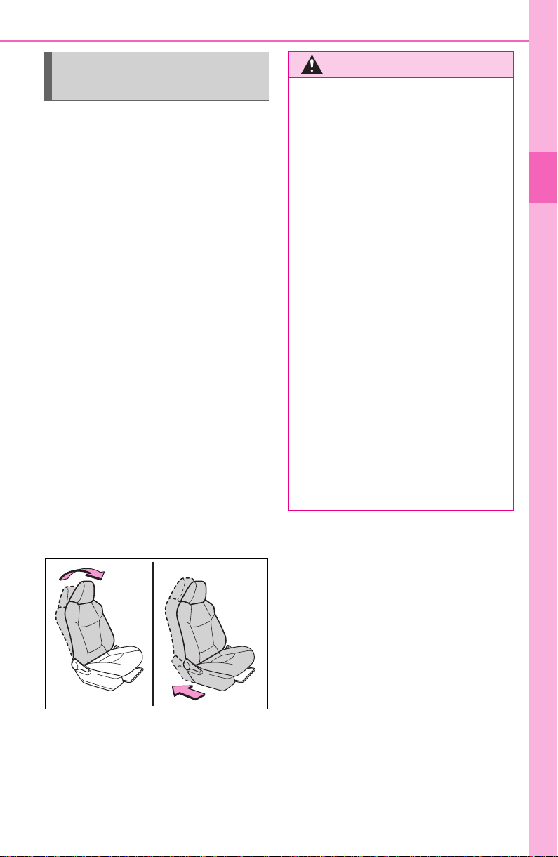
53
1-2. Child safety
1
For safety and security
■ When installing a child
restraint system to a front
passenger seat
For the safety of a child, install a
child restraint system to a rear
seat. When installing a child
restraint system to the front pas-
senger seat is unavoidable,
adjust the seat as follows and
install the child restraint system.
Adjust the seatback angle to
the most upright position.
Move the front seat fully rear-
ward.
If the head restraint interferes
with the child restraint system
installation and the head
restraint can be removed,
remove the head restraint.
Otherwise, put the head
restraint in the upper most
position.
When using a child
restraint system
WARNING
■ When using a child restraint
system
Observe the following precau-
tions.
Failure to do so may result in
death or serious injury.
● Never install a rear-facing child
restraint system on the front
passenger seat even if the “AIR
BAG OFF” indicator light is illu-
minated. In the event of an acci-
dent, the force of the rapid
inflation of the front passenger
airbag can cause death or seri-
ous injury to the child if the rear-
facing child restraint system is
installed on the front passenger
seat.
● A forward-facing child restraint
system may be installed on the
front passenger seat only when
it is unavoidable. A child
restraint system that requires a
top tether strap should not be
used in the front passenger seat
since there is no top tether strap
anchor for the front passenger
seat.
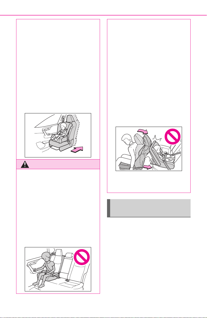
54
1-2. Child safety
A child restraint system for a
small child or baby must itself be
properly restrained on the seat
with the lap portion of the
lap/shoulder belt.
■ Installing child restraint
system using a seat belt
(child restraint lock func-
tion belt)
Install the child restraint system
in accordance to the operation
● A forward-facing child restraint
system may be installed on the
front passenger seat only when
it is unavoidable. When install-
ing a forward-facing child
restraint system on the front
passenger seat, adjust the seat-
back angle to the most upright
position, move the seat to the
rearmost position, even if the
“AIR BAG OFF” indicator light is
illuminated.
If the head restraint interferes
with the child restraint system
installation and the head
restraint can be removed,
remove the head restraint.
WARNING
● Do not allow the child to lean
his/her head or any part of
his/her body against the door or
the area of the seat, front or rear
pillars, or roof side rails from
which the SRS side airbags or
SRS curtain shield airbags
deploy even if the child is
seated in the child restraint sys-
tem. It is dangerous if the SRS
side and curtain shield airbags
inflate, and the impact could
cause death or serious injury to
the child.
● When a booster seat is
installed, always ensure that the
shoulder belt is positioned
across the center of the child’s
shoulder. The belt should be
kept away from the child’s neck,
but not so that it could fall off the
child’s shoulder.
● Use a child restraint system
suitable to the age and size of
the child and install it to the rear
seat.
● If the driver’s seat interferes
with the child restraint system
and prevents it from being
attached correctly, attach the
child restraint system to the
right-hand rear seat.
● Adjust the front passenger seat
so that it does not interfere with
the child restraint system.
Child restraint system
fixed with a seat belt

55
1-2. Child safety
1
For safety and security
manual enclosed with the child
restraint system.
■ Rear-facing Infant
seat/convertible seat
1 Adjust the rear seat.
If there is a gap between the child
restraint system and the seatback,
adjust the seatback angle until
good contact is achieved.
2 Place the child restraint sys-
tem on the rear seat facing
the rear of the vehicle.
3 Run the seat belt through the
child restraint system and
insert the plate into the
buckle. Make sure that the
belt is not twisted.
4 Fully extend the shoulder belt
and allow it to retract to put it
in lock mode. In lock mode,
the belt cannot be extended.
5 While pushing the child
restraint system down into
the rear seat, allow the shoul-
der belt to retract until the
child restraint system is
securely in place.
After the shoulder belt has
retracted to a point where there is
no slack in the belt, pull the belt to
check that it cannot be extended.
6 After installing the child
restraint system, rock it back
and forth to ensure that it is
installed securely. (P. 58 )
■ Forward-facing Convert-
ible seat
1 Adjust the seat.
When using the front passenger
seat: If installing the child restraint
system to the front passenger seat
is unavoidable, refer to P.53 for
front passenger seat adjustment.
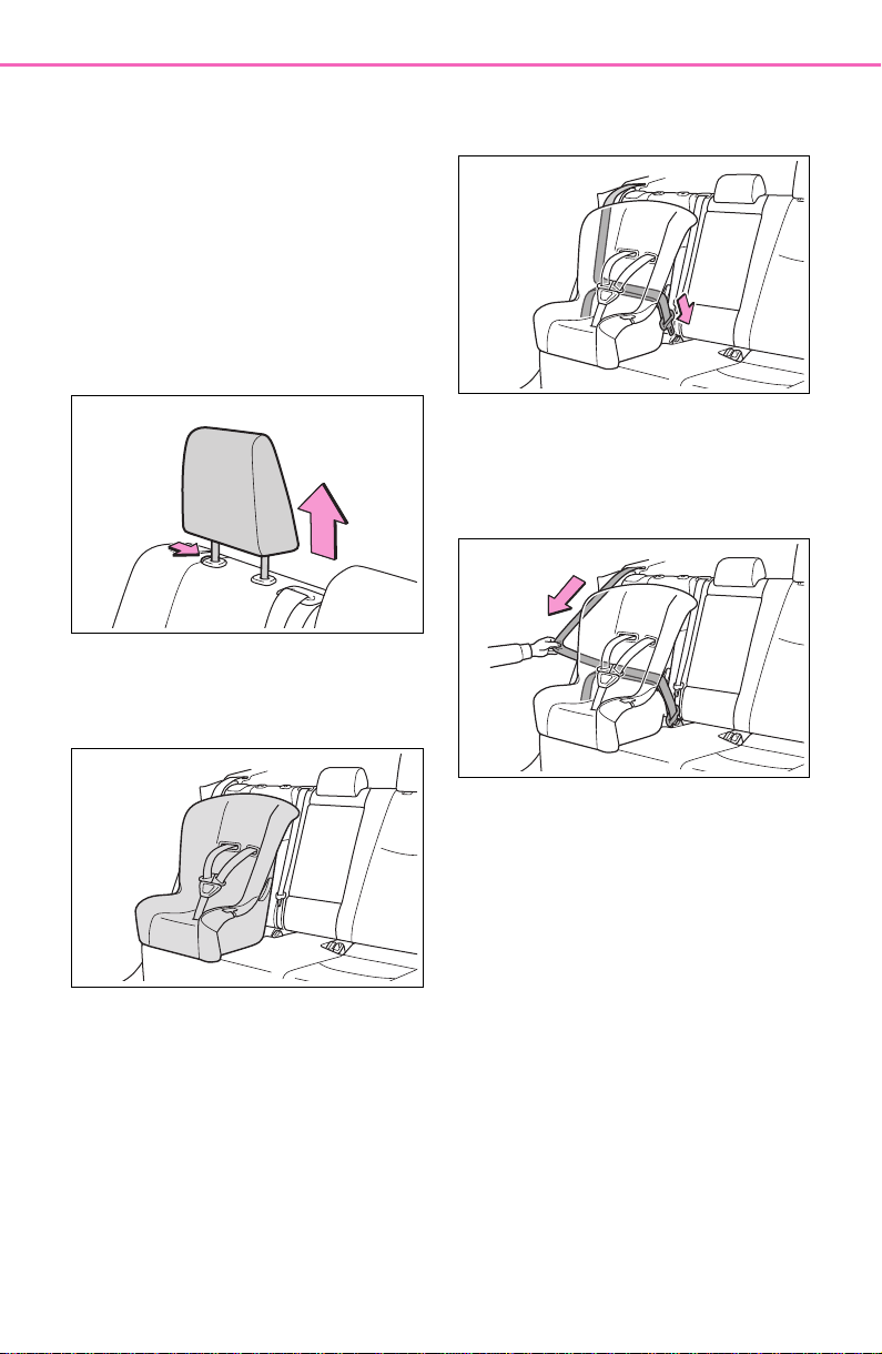
56
1-2. Child safety
When using the rear seat: If there is
a gap between the child restraint
system and the seatback, adjust
the seatback angle until good con-
tact is achieved.
2 If the head restraint interferes
with the child restraint system
installation and the head
restraint can be removed,
remove the head restraint.
(P.141)
3 Place the child restraint sys-
tem on the seat facing the
front of the vehicle.
4 Run the seat belt through the
child restraint system and
insert the plate into the
buckle. Make sure that the
belt is not twisted.
5 Fully extend the shoulder belt
and allow it to retract to put it
in lock mode. In lock mode,
the belt cannot be extended.
6 While pushing the child
restraint system into the rear
seat, allow the shoulder belt
to retract until the child
restraint system is securely in
place.
After the shoulder belt has
retracted to a point where there is
no slack in the belt, pull the belt to
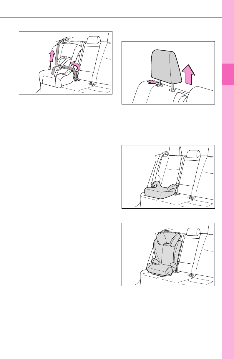
57
1-2. Child safety
1
For safety and security
check that it cannot be extended.
7 If the child restraint has a top
tether strap, follow the child
restraint manufacturer’s
operation manual regarding
the installation, using the top
tether strap to latch onto the
top tether strap anchor.
(P. 61 )
8 After installing the child
restraint system, rock it back
and forth to ensure that it is
installed securely. (P. 58 )
■ Booster seat
1 If installing the child restraint
system to the front passen-
ger seat is unavoidable, refer
to P.53 for front passenger
seat adjustment.
2 High back type: If the head
restraint interferes with your
child restraint system, and
the head restraint can be
removed, remove the head
restraint. (P.141)
3 Place the child restraint sys-
tem on the seat facing the
front of the vehicle.
Booster type
High back type
4 Sit the child in the child
restraint system. Fit the seat
belt to the child restraint sys-
tem according to the manu-
facturer’s instructions and
insert the plate into the
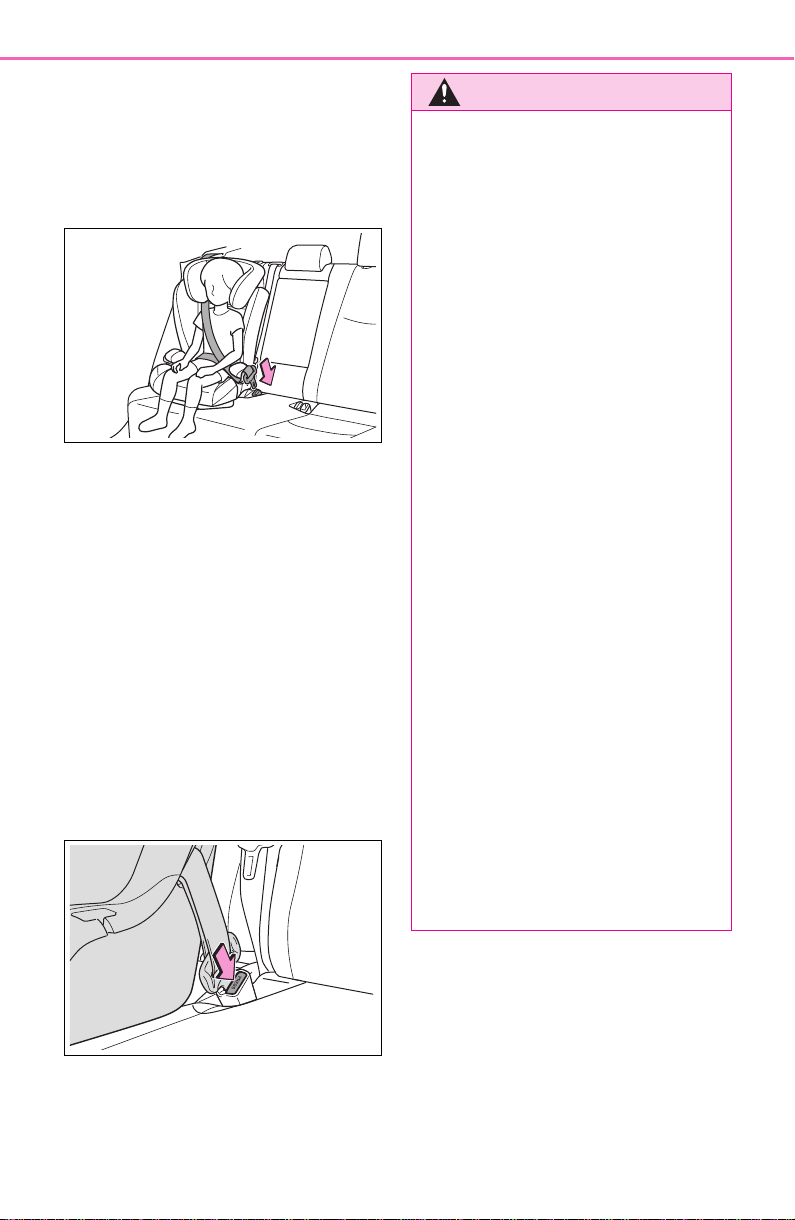
58
1-2. Child safety
buckle. Make sure that the
belt is not twisted.
Check that the shoulder belt is cor-
rectly positioned over the child’s
shoulder and that the lap belt is as
low as possible. (P. 2 9 )
■ Removing a child restraint
system installed with a seat
belt
Press the buckle release button
and fully retract the seat belt.
When releasing the buckle, the
child restraint system may spring
up due to the rebound of the seat
cushion. Release the buckle while
holding down the child restraint
system.
Since the seat belt automatically
reels itself, slowly return it to the
stowing position.
WARNING
■ When installing a child
restraint system
Observe the following precau-
tions.
Failure to do so may result in
death or serious injury.
● Do not allow children to play
with the seat belt. If the seat belt
becomes twisted around a
child’s neck, it may lead to
choking or other serious injuries
that could result in death.
If this occurs and the buckle
cannot be unfastened, scissors
should be used to cut the belt.
● Ensure that the belt and plate
are securely locked and the
seat belt is not twisted.
● Shake the child restraint system
left and right, and forward and
backward to ensure that it has
been securely installed.
● After securing a child restraint
system, never adjust the seat.
● When a booster seat is
installed, always ensure that the
shoulder belt is positioned
across the center of the child’s
shoulder. The belt should be
kept away from the child’s neck,
but not so that it could fall off the
child’s shoulder.
● Follow all installation instruc-
tions provided by the child
restraint system manufacturer.
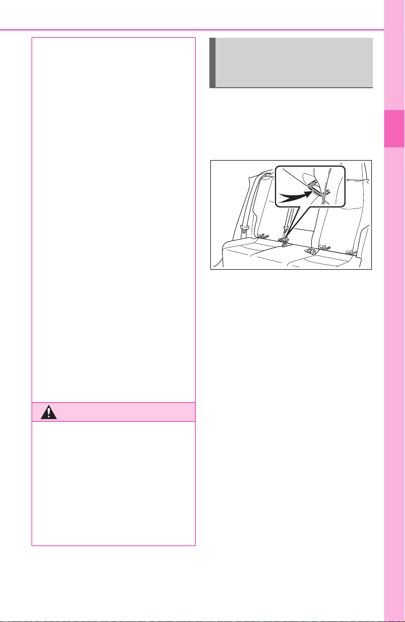
59
1-2. Child safety
1
For safety and security
■ Child restraint LATCH
anchors
LATCH anchors are provided for
the outboard rear seats.
■ When installing in the rear
outboard seats
Install the child restraint system
in accordance to the operation
manual enclosed with the child
restraint system.
1 Adjust the seat.
If there is a gap between the child
restraint system and the seatback,
adjust the seatback angle until
good contact is achieved.
2 If the head restraint interferes
with the child restraint system
installation and the head
restraint can be removed,
● When securing some types of
child restraint systems in rear
seats, it may not be possible to
properly use the seat belts in
positions next to the child
restraint without interfering with
it or affecting seat belt effective-
ness. Be sure your seat belt fits
snugly across your shoulder
and low on your hips. If it does
not, or if it interferes with the
child restraint, move to a differ-
ent position. Failure to do so
may result in death or serious
injury.
● When installing a child restraint
system in the center rear seat,
adjust both seatbacks at the
same angle. Otherwise, the
child restraint system cannot be
securely restrained and this
may cause death or serious
injuries in the event of sudden
braking, sudden swerving or an
accident.
■ When installing a booster
seat
To prevent the belt from going into
ALR lock mode, do not fully
extend the shoulder belt. ALR
mode causes the belt to tighten
only. This could cause injury or
discomfort to the child. (P. 3 1 )
WARNING
■ Do not use a seat belt
extender
If a seat belt extender is used
when installing a child restraint
system, the seat belt will not
securely hold the child restraint
system, which could cause death
or serious injury to the child or
other passengers in the event of
sudden braking, sudden swerv-
ing or an accident.
Child restraint system
fixed with a child restraint
LATCH anchor
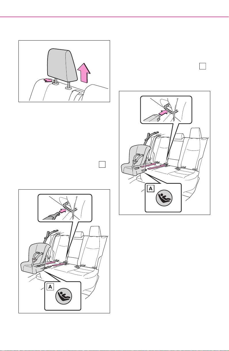
60
1-2. Child safety
remove the head restraint.
(P.141)
With flexible lower attach-
ments
3 Latch the hooks of the lower
attachments onto the LATCH
anchors.
For owners in Canada:
The symbol on a child
restraint system indicates
the presence of a lower con-
nector system.
With rigid lower attachments
3 Latch the buckles onto the
LATCH anchors.
For owners in Canada:
The symbol on a child
restraint system indicates
the presence of a lower con-
nector system.
4 If the child restraint has a top
tether strap, follow the child
restraint manufacturer’s
operation manual regarding
the installation, using the top
tether strap to latch onto the
top tether strap anchor.
(P.61)
5 After installing the child
restraint system, rock it back
and forth to ensure that it is
installed securely. (P. 58 )
A
A

61
1-2. Child safety
1
For safety and security
■ When installing in the rear
center seat
There are no LATCH anchors
behind the rear center seat.
However, the inboard LATCH
anchors of the outboard seats,
which are 17.3 in. (440 mm)
apart, can be used if the child
restraint system manufacturer’s
instructions permit use of those
anchors with the anchor spacing
stated.
Child restraint systems with rigid
lower attachments cannot be
installed in the center seat. This
type of child restraint system
can only be installed in the out-
board seat.
■ Laws and regulations pertain-
ing to anchors
The LATCH system conforms to
FMVSS225 or CMVSS210.2.
Child restraint systems conforming
to FMVSS213 or CMVSS213 speci-
fications can be used.
This vehicle is designed to conform
to SAE J1819.
■ Anchor brackets (for top
tether strap)
Anchor brackets are provided
for each rear seat.
Use anchor brackets when fix-
ing the top tether strap.
WARNING
■ When installing a child
restraint system
Observe the following precau-
tions.
Failure to do so may result in
death or serious injury.
● When using the LATCH
anchors, be sure that there are
no foreign objects around the
anchors and that the seat belt is
not caught behind the child
restraint system.
● Follow all installation instruc-
tions provided by the child
restraint system manufacturer.
● Never attach two child restraint
system attachments to the
same anchor. In a collision, one
anchor may not be strong
enough to hold two child
restraint system attachments
and may break.
If the LATCH anchors are
already in use, use the seat belt
to install a child restraint system
in the center seat.
● When securing some types of
child restraint systems in rear
seats, it may not be possible to
properly use the seat belts in
positions next to the child
restraint without interfering with
it or affecting seat belt effective-
ness. Be sure your seat belt fits
snugly across your shoulder
and low on your hips. If it does
not, or if it interferes with the
child restraint, move to a differ-
ent position. Failure to do so
may result in death or serious
injury.
● If the seat is adjusted, reconfirm
the security of the child restraint
system.
Using an anchor bracket
(for top tether strap)
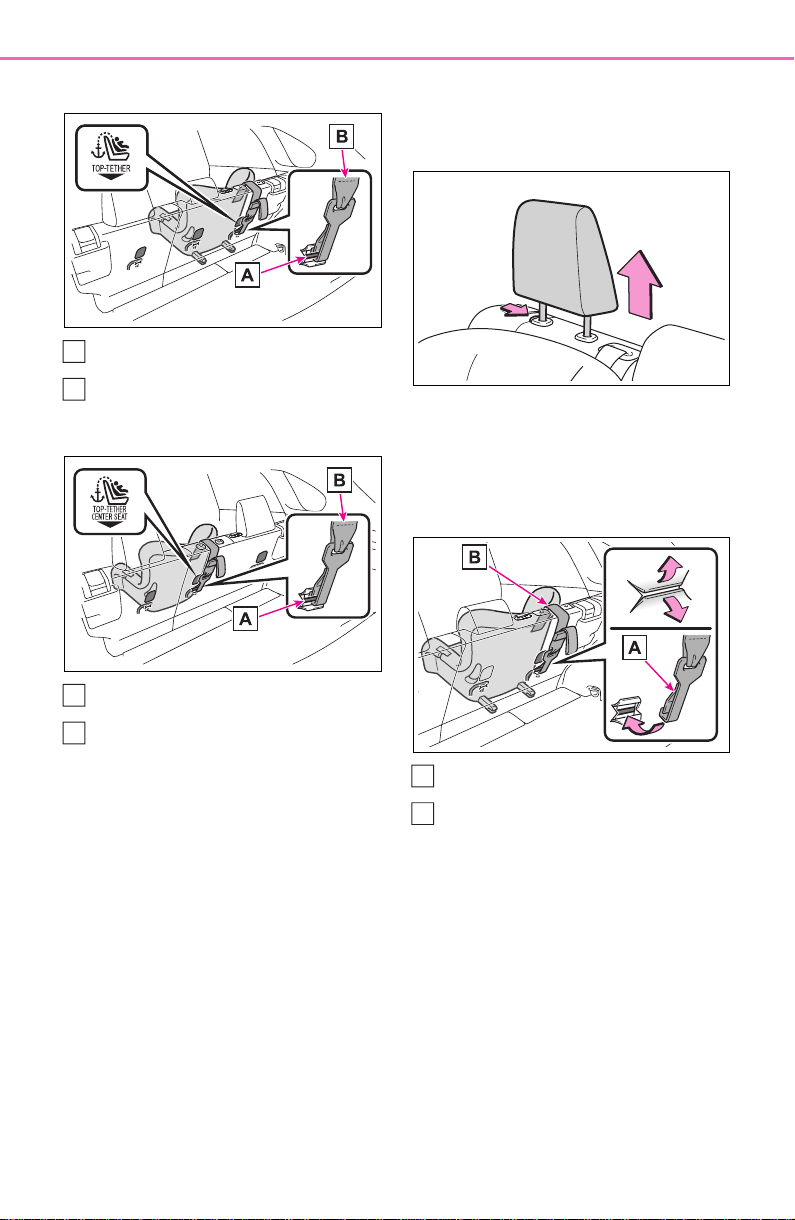
62
1-2. Child safety
Outboard rear seats
Anchor brackets
Top tether strap
Center rear seat
Anchor bracket
Top tether strap
■ Fixing the top tether strap
to the anchor bracket
Install the child restraint system
in accordance to the operation
manual enclosed with the child
restraint system.
Outboard rear seats
1 Remove the head restraint.
(P.141)
2 Latch the hook onto the
anchor bracket and tighten
the top tether strap.
Make sure the top tether strap is
securely latched. (P.5 8)
Hook
Top tether strap
3 If the head restraint does not
interfere with the child
A
B
A
B
A
B
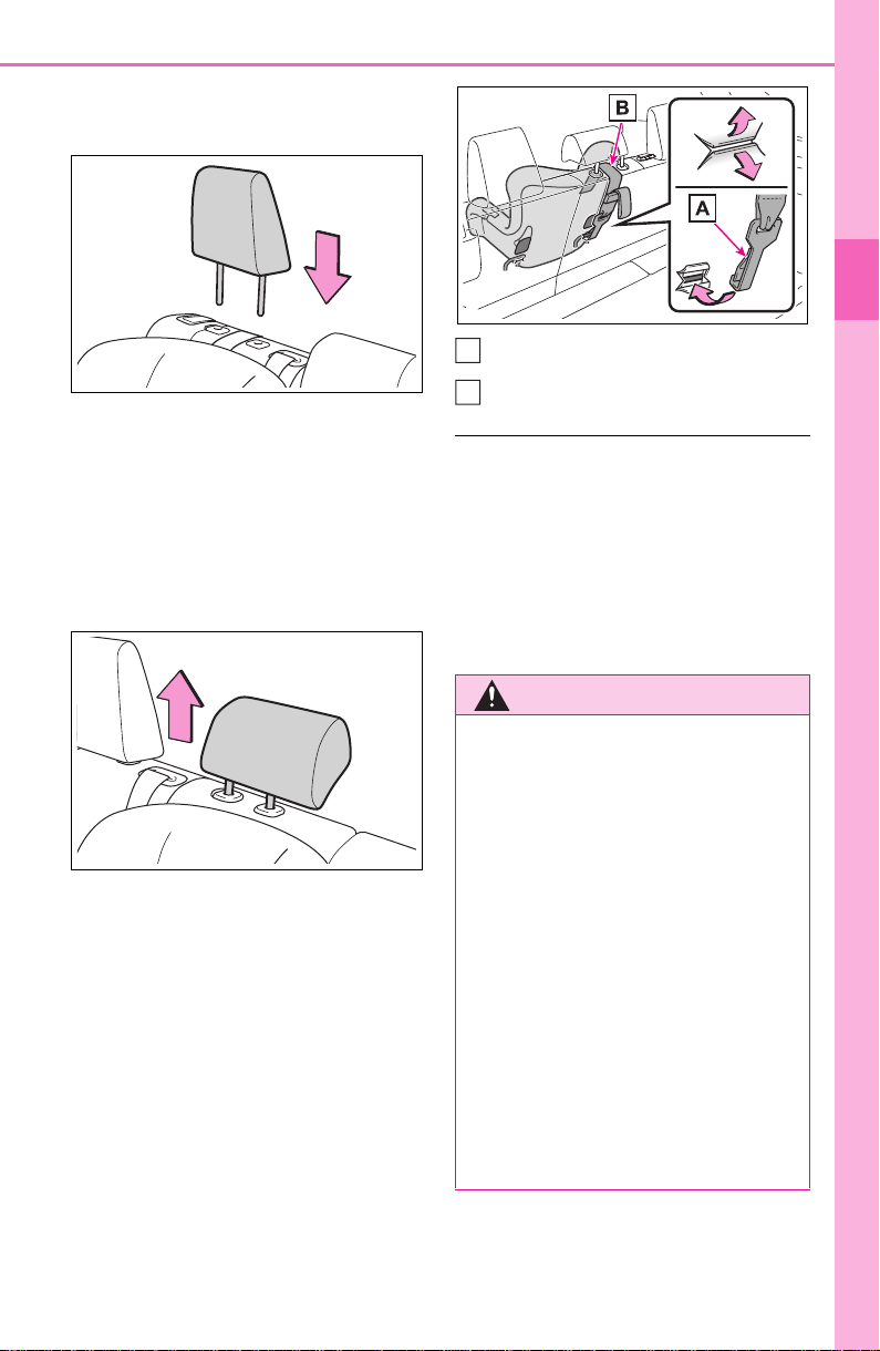
63
1-2. Child safety
1
For safety and security
restraint system installation,
install the head restraint.
Center rear seat
1 Adjust the head restraint to
the upmost position.
If the head restraint interferes with
your child restraint system, and the
head restraint can be removed,
remove the head restraint.
(P.141)
2 Latch the hook onto the
anchor bracket and tighten
the top tether strap.
Make sure the top tether strap is
securely latched.
When installing the child restraint
system with the head restraint
being raised, be sure to have the
top tether strap pass underneath
the head restraint.
Hook
Top tether strap
■ Laws and regulations pertain-
ing to anchors
The LATCH system conforms to
FMVSS225 or CMVSS210.2.
Child restraint systems conforming
to FMVSS213 or CMVSS213 speci-
fications can be used.
This vehicle is designed to conform
to SAE J1819.
WARNING
■ When installing a child
restraint system
Observe the following precau-
tions.
Failure to do so may result in
death or serious injury.
● Firmly attach the top tether
strap and make sure that the
belt is not twisted.
● Do not attach the top tether
strap to anything other than the
anchor bracket.
● After securing a child restraint
system, never adjust the seat.
● Follow all installation instruc-
tions provided by the child
restraint system manufacturer.
A
B

64
1-2. Child safety
WARNING
● Center rear seat: When install-
ing the child restraint system
with the head restraint being
raised, after the head restraint
has been raised and then the
anchor bracket has been fixed,
do not lower the head restraint.
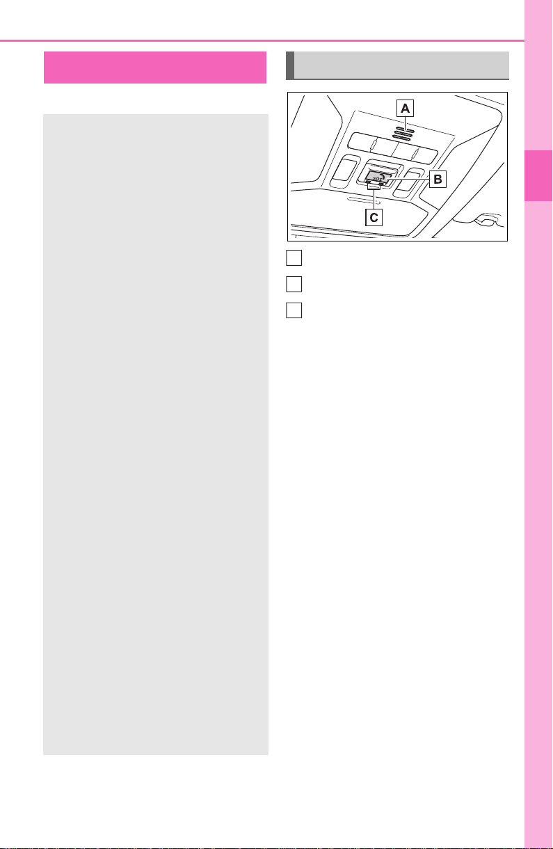
65
1-3. Emergency assistance
1
For safety and security
1-3.Emergency assistance
*
: If equipped
Microphone
“SOS” button
LED light indicators
Safety Connect
*
Safety Connect is a sub-
scription-based telematics
service that uses Global
Positioning System (GPS)
data and embedded cellular
technology to provide
safety and security features
to subscribers. Safety Con-
nect is supported by
Toyota’s designated
response center, which
operates 24 hours per day, 7
days per week.
Safety Connect service is
available by subscription on
select, telematics hardware-
equipped vehicles.
By using the Safety Connect
service, you are agreeing to
be bound by the Telematics
Subscription Service Agree-
ment and its Terms and
Conditions, as in effect and
amended from time to time,
a current copy of which is
available at Toyota.com in
the United States,
Toyotapr.com in Puerto Rico
and Toyota.ca in Canada. All
use of the Safety Connect
service is subject to such
then-applicable Terms and
Conditions.
System components
A
B
C

66
1-3. Emergency assistance
■ Certification for the Safety Connect
Subscribers have the following
Safety Connect services avail-
able:
Automatic Collision Notifica-
tion
*
Helps drivers receive necessary
response from emergency service
providers. (
P. 68)
*
: U.S. Patent No. 7,508,298 B2
Stolen Vehicle Location
Helps drivers in the event of vehicle
theft. (
P.6 8 )
Emergency Assistance Button
Services

67
1-3. Emergency assistance
1
For safety and security
(“SOS”)
Connects drivers to response-cen-
ter support. (
P. 68)
Enhanced Roadside Assis-
tance
Provides drivers various on-road
assistance. (
P.6 9)
After you have signed the
Telematics Subscription Service
Agreement and are enrolled,
you can begin receiving ser-
vices.
A variety of subscription terms
are available for purchase. Con-
tact your Toyota dealer, call the
following appropriate Customer
Experience Center or push the
“SOS” button in your vehicle for
further subscription details.
The United States
1-800-331-4331
Canada
1-888-869-6828
Puerto Rico
1-877-855-8377
■ Safety Connect Services Infor-
mation
● Phone calls using the vehicle’s
Bluetooth
®
technology will not be
possible when Safety Connect is
active and in use.
● Safety Connect is available begin-
ning Fall 2009 on select Toyota
models (in the contiguous United
States only). Contact with the
Safety Connect response center
is dependent upon the telematics
device being in operative condi-
tion, cellular connection availabil-
ity, and GPS satellite signal
reception, which can limit the abil-
ity to reach the response center or
receive emergency service sup-
port. Enrollment and Telematics
Subscription Service Agreement
are required. A variety of subscrip-
tion terms are available; charges
vary by subscription term selected
and location.
● Automatic Collision Notification,
Emergency Assistance and Stolen
Vehicle Location are available in
the United States, including
Hawaii and Alaska, Puerto Rico
and Canada, and Enhanced
Roadside Assistance are avail-
able in the United States, Puerto
Rico and Canada.
● Automatic Collision Notification,
Emergency Assistance, Stolen
Vehicle and Enhanced Road
Assistance are not available in the
U.S. Virgin Islands.
For vehicles first sold in the U.S.
Virgin Islands, no Safety Connect
services will function in or outside
the U.S. Virgin Islands.
● Safety Connect services are not
subject to section 255 of the Tele-
communications Act and the
device is not TTY compatible.
■ Languages
The Safety Connect response cen-
ter will offer support in multiple lan-
guages. The Safety Connect system
will offer voice prompts in English,
Spanish, and French. Please indi-
cate your language of choice when
enrolling.
■ When contacting the response
center
You may be unable to contact the
response center if the network is
busy.
Subscription

68
1-3. Emergency assistance
When the engine switch is
turned to ON, the red indicator
light comes on for 2 seconds
then turns off. Afterward, the
green indicator light comes on,
indicating that the service is
active.
The following indicator light pat-
terns indicate specific system
usage conditions:
Green indicator light on =
Active service
Green indicator light flashing
= Safety Connect call in pro-
cess
Red indicator light (except at
vehicle start-up) = System
malfunction (contact your
Toyota dealer)
No indicator light (off) =
Safety Connect service not
active
■ Automatic Collision Notifi-
cation
In case of either airbag deploy-
ment or severe rear-end colli-
sion, the system is designed to
automatically call the response
center. The responding agent
receives the vehicle’s location
and attempts to speak with the
vehicle occupants to assess the
level of emergency. If the occu-
pants are unable to communi-
cate, the agent automatically
treats the call as an emergency,
contacts the nearest emer-
gency services provider to
describe the situation, and
requests that assistance be sent
to the location.
■ Stolen Vehicle Location
If your vehicle is stolen, Safety
Connect can work with local
authorities to assist them in
locating and recovering the
vehicle. After filing a police
report, call the Customer Experi-
ence Center at 1-800-331-4331
in the United States, 1-877-855-
8377 in Puerto Rico or 1-888-
869-6828 in Canada, and follow
the prompts for Safety Connect
to initiate this service.
In addition to assisting law
enforcement with recovery of a
stolen vehicle, Safety-Connect-
equipped vehicle location data
may, under certain circum-
stances, be shared with third
parties to locate your vehicle.
Further information is available
at Toyota.com in the United
States, Toyotapr.com in Puerto
Rico and Toyota.ca in Canada.
■ Emergency Assistance But-
ton (“SOS”)
In the event of an emergency on
the road, push the “SOS” button
to reach the Safety Connect
response center. The answer-
Safety Connect LED light
Indicators
Safety Connect services

69
1-3. Emergency assistance
1
For safety and security
ing agent will determine your
vehicle’s location, assess the
emergency, and dispatch the
necessary assistance required.
If you accidentally press the “SOS”
button, tell the response-center
agent that you are not experiencing
an emergency.
■ Enhanced Roadside Assis-
tance
Enhanced Roadside Assistance
adds GPS data to the already
included warranty-based Toyota
roadside service.
Subscribers can press the
“SOS” button to reach a Safety
Connect response-center agent,
who can help with a wide range
of needs, such as: towing, flat
tire, fuel delivery, etc. For a
description of the Enhanced
Roadside Assistance services
and their limitations, please see
the Safety Connect Terms and
Conditions, which are available
at Toyota.com in the United
States, Toyotapr.com in Puerto
Rico and Toyota.ca in Canada.
Important! Read this informa-
tion before using Safety Con-
nect.
■ Exposure to radio fre-
quency signals
The Safety Connect system
installed in your vehicle is a low-
power radio transmitter and
receiver. It receives and also
sends out radio frequency (RF)
signals.
In August 1996, the Federal
Communications Commission
(FCC) adopted RF exposure
guidelines with safety levels for
mobile wireless phones. Those
guidelines are consistent with
the safety standards previously
set by the following U.S. and
international standards bodies.
ANSI (American National
Standards Institute) C95.1
[1992]
NCRP (National Council on
Radiation Protection and
Measurement) Report 86
[1986]
ICNIRP (International Com-
mission on Non-Ionizing Radi-
ation Protection) [1996]
Those standards were based on
comprehensive and periodic
evaluations of the relevant sci-
entific literature. Over 120 scien-
tists, engineers, and physicians
from universities, and govern-
ment health agencies and
industries reviewed the avail-
able body of research to
develop the ANSI Standard
(C95.1).
The design of Safety Connect
complies with the FCC guide-
lines in addition to those stan-
dards.
Safety information for
Safety Connect
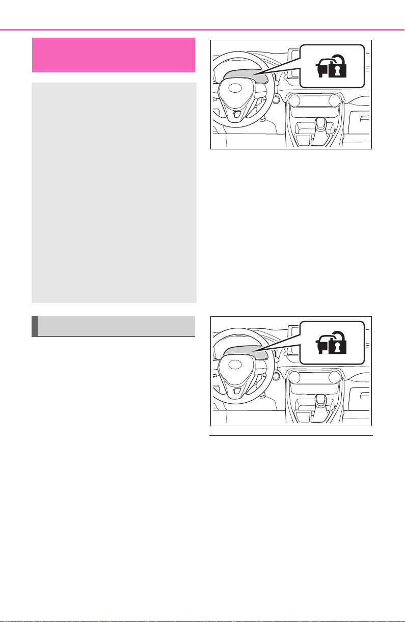
70
1-4. Theft deterrent system
1-4.Theft deterrent system
Vehicles without smart key
system
The indicator light flashes after
the key has been removed from
the engine switch to indicate
that the system is operating.
The indicator light stops flashing
after the registered key has
been inserted into the engine
switch to indicate that the sys-
tem has been canceled.
Vehicles with smart key sys-
tem
The indicator light flashes after
the engine switch has been
turned to OFF to indicate that
the system is operating.
The indicator light stops flashing
after the engine switch has been
turned to ACC or ON to indicate
that the system has been can-
celed.
■ System maintenance
The vehicle has a maintenance-free
type engine immobilizer system.
■ Conditions that may cause the
system to malfunction
● If the grip portion of the key is in
contact with a metallic object
● If the key is in close proximity to or
touching a key to the security sys-
tem (key with a built-in transpon-
der chip) of another vehicle
Engine immobilizer
system
The vehicle’s keys have
built-in transponder chips
that prevent the engine from
starting if a key has not
been previously registered
in the vehicle’s on-board
computer.
Never leave the keys inside
the vehicle when you leave
the vehicle.
This system is designed to
help prevent vehicle theft but
does not guarantee absolute
security against all vehicle
thefts.
Operating the system

71
1-4. Theft deterrent system
1
For safety and security
■ Certification for the engine immobilizer system
For vehicles sold in the U.S.A., Hawaii, American Samoa, Guam, Saipan
and Puerto Rico
For vehicles sold in Canada

72
1-4. Theft deterrent system
NOTICE
■ To ensure the system oper-
ates correctly
Do not modify or remove the sys-
tem. If modified or removed, the
proper operation of the system
cannot be guaranteed.
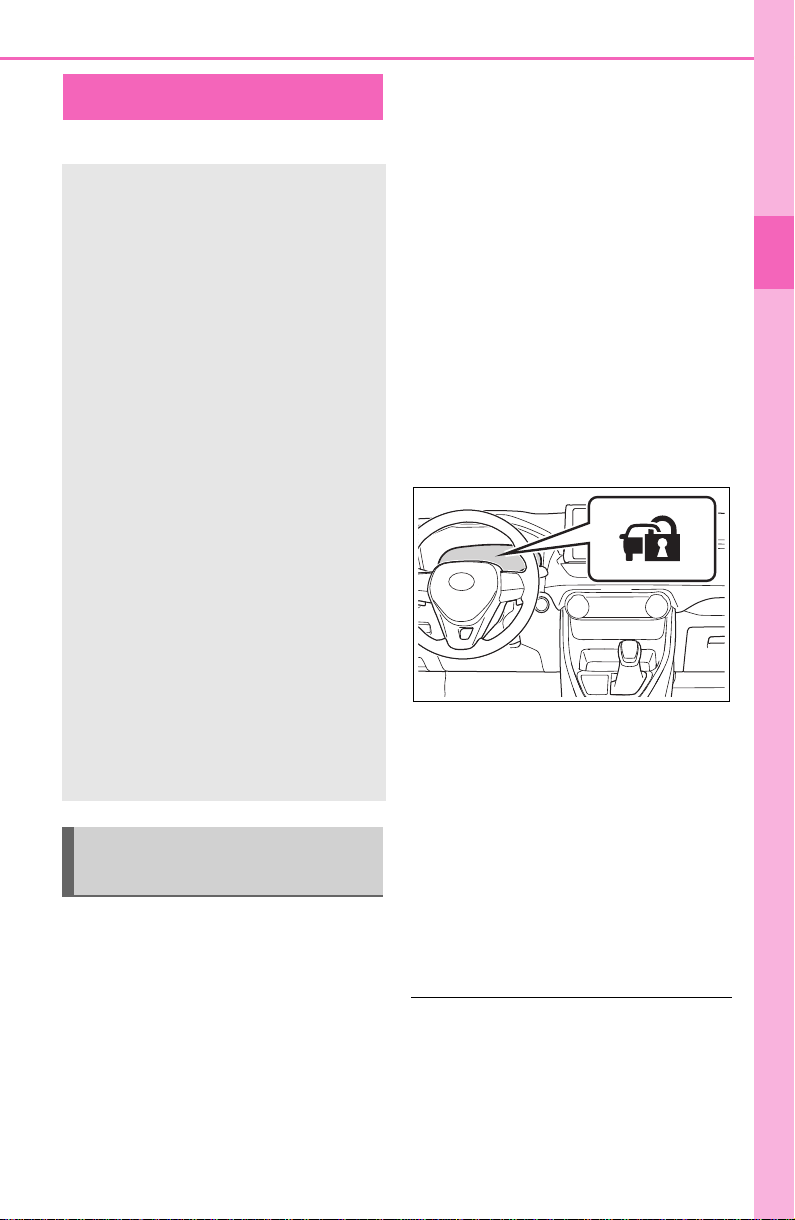
73
1-4. Theft deterrent system
1
For safety and security
*
: If equipped
■ Items to check before lock-
ing the vehicle
To prevent unexpected trigger-
ing of the alarm and vehicle
theft, make sure of the following:
Nobody is in the vehicle.
The side windows and moon
roof (if equipped) or pan-
oramic moon roof (if
equipped) are closed before
the alarm is set.
No valuables or other per-
sonal items are left in the
vehicle.
■ Setting
Close the doors and hood, and
lock all the doors. The system
will be set automatically after 30
seconds.
The security indicator changes from
being on to flashing when the sys-
tem is set.
■ Canceling or stopping
Do one of the following to deac-
tivate or stop the alarm:
Unlock the doors.
Turn the engine switch to
ACC or ON, or start the
engine. (The alarm will be
deactivated or stopped after a
few seconds.)
■ System maintenance
The vehicle has a maintenance-free
type alarm system.
■ Triggering of the alarm
The alarm may be triggered in the
following situations:
Alarm
*
The alarm uses light and
sound to give an alert when
an intrusion is detected.
The alarm is triggered in the
following situations when
the alarm is set:
Vehicles without smart key
system: A locked door is
unlocked or opened in any
way other than using the
wireless remote control or
key. (The doors will lock
again automatically.)
Vehicles with smart key sys-
tem: A locked door is
unlocked or opened in any
way other than using the
entry function, wireless
remote control or mechani-
cal key. (The doors will lock
again automatically.)
The hood is opened.
Setting/canceling/stop-
ping the alarm system
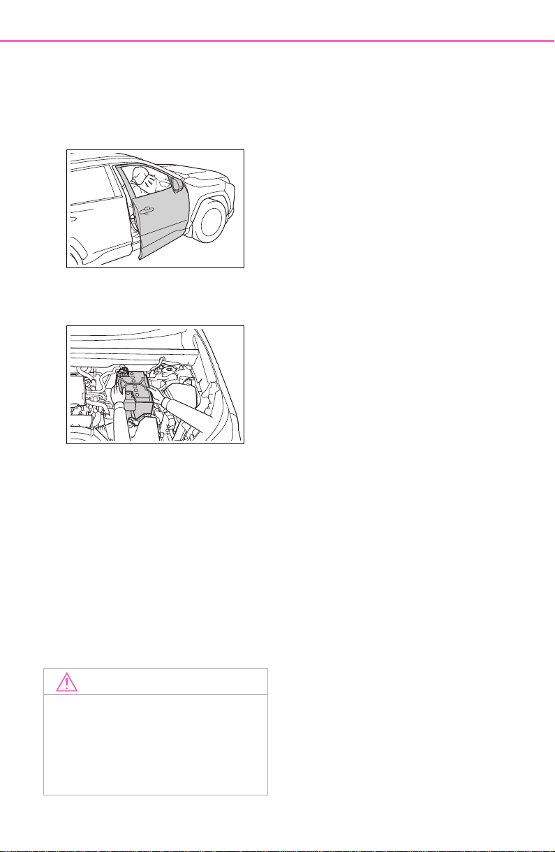
74
1-4. Theft deterrent system
(Stopping the alarm deactivates the
alarm system.)
● A person inside the vehicle opens
a door or hood, or unlocks the
vehicle using an inside lock but-
ton.
● The battery is recharged or
replaced when the vehicle is
locked. (P.655)
■ Alarm-operated door lock
In the following cases, depending
on the situation, the door may auto-
matically lock to prevent improper
entry into the vehicle:
● When a person remaining in the
vehicle unlocks the door and the
alarm is activated.
● While the alarm is activated, a
person remaining in the vehicle
unlocks the door.
● When recharging or replacing the
battery.
NOTICE
■ To ensure the system oper-
ates correctly
Do not modify or remove the sys-
tem. If modified or removed, the
proper operation of the system
cannot be guaranteed.

75
2
2
Vehicle status information and indicators
Vehicle status informa-
tion and indicators
2-1. Instrument cluster
Warning lights and indica-
tors...............................76
Gauges and meters (with
4.2-inch display)...........82
Gauges and meters (with
7-inch display).............85
Multi-information display 89
Fuel consumption informa-
tion ...............................99
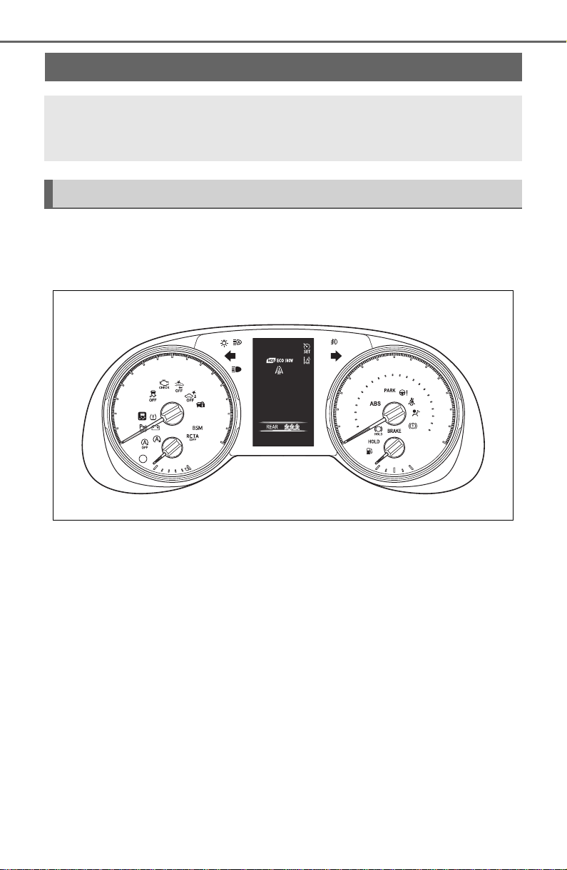
76
2-1. Instrument cluster
2-1.Instrument cluster
For the purpose of explanation, the following illustrations display all
warning lights and indicators illuminated.
■ With 4.2-inch display
The units used on the meters and some indicators may differ depending on
the target region.
■ With 7-inch display
The display of the speedometer can be selected from two types,
analog or digital. (P.9 4 )
Warning lights and indicators
The warning lights and indicators on the instrument cluster,
center panel and outside rear view mirrors inform the driver
of the status of the vehicle’s various systems.
Instrument cluster
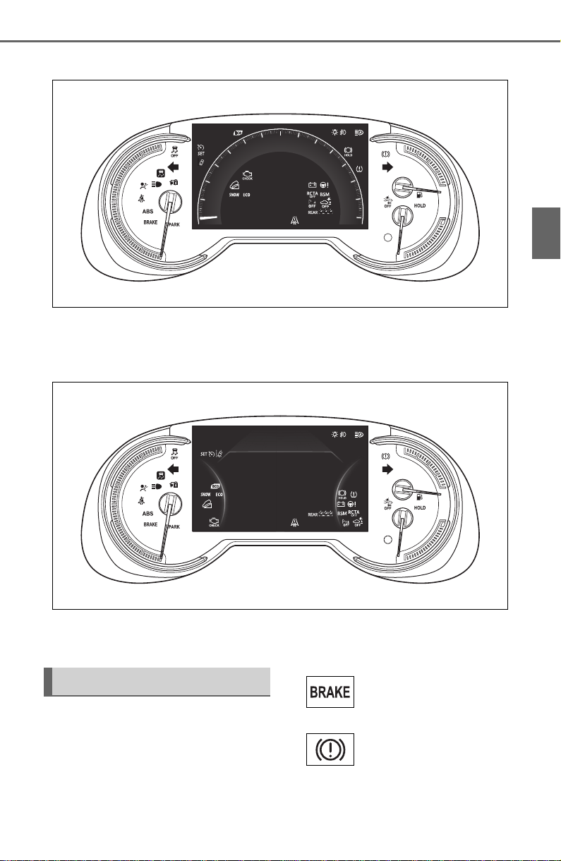
77
2-1. Instrument cluster
2
Vehicle status information and indicators
When analog speedometer is displayed
The units used on the meters and some indicators may differ depending on
the target region.
When digital speedometer is displayed
The units used on the meters and some indicators may differ depending on
the target region.
Warning lights inform the driver
of malfunctions in the indicated
vehicle’s systems.
Warning lights
(U.S.A.)
Brake system warn-
ing light
*1
(P.628)
(Canada)
(Red)
Brake system warn-
ing light
*1
(P.628)

78
2-1. Instrument cluster
*1
:These lights turn on when the
engine switch is turned to ON to
(Yellow)
Brake system warn-
ing light
*1
(P.628)
Charging system
warning light
*1
(P.628)
High coolant tempera-
ture warning light
*2
(P.629)
Low engine oil pres-
sure warning light
*2
(P.629)
(U.S.A.)
Malfunction indicator
lamp
*1
(P. 62 9)
(Canada)
Malfunction indicator
lamp
*1
(P. 62 9)
SRS warning light
*1
(P.629)
(U.S.A.)
ABS warning light
*1
(P.630)
(Canada)
ABS warning light
*1
(P.630)
(Red/yellow)
Electric power steer-
ing system warning
light
*1
(P.630)
(Flashes or
illuminates)
PCS warning light
*1
(P.630)
(Orange)
LTA indicator
(P.631)
(Flashes)
Stop & Start cancel
indicator
*1
(if
equipped) (P.631)
(Flashes)
Intuitive parking assist
OFF indicator
*3
(if
equipped) (P.631)
PKSB OFF indica-
tor
*1
(if equipped)
(P.632)
(Flashes)
RCTA OFF indicator
*1
(if equipped) (P.632)
Slip indicator light
*1
(P.632)
Brake Override Sys-
tem/Drive-Start Con-
trol/PKSB (if
equipped) warning
light
*2
(P.633)
(Flashes)
Brake hold operated
indicator
*1
(P.633)
(U.S.A.)
(Flashes)
Parking brake indica-
tor (P.634)
(Canada)
(Flashes)
Parking brake indica-
tor (P.634)
Tire pressure warning
light
*1
(if equipped)
(P.634)
Low fuel level warn-
ing light (P.634)
Driver’s and front pas-
senger’s seat belt
reminder light
(P.635)
Rear passengers’ seat
belt reminder light (if
equipped) (P.635)
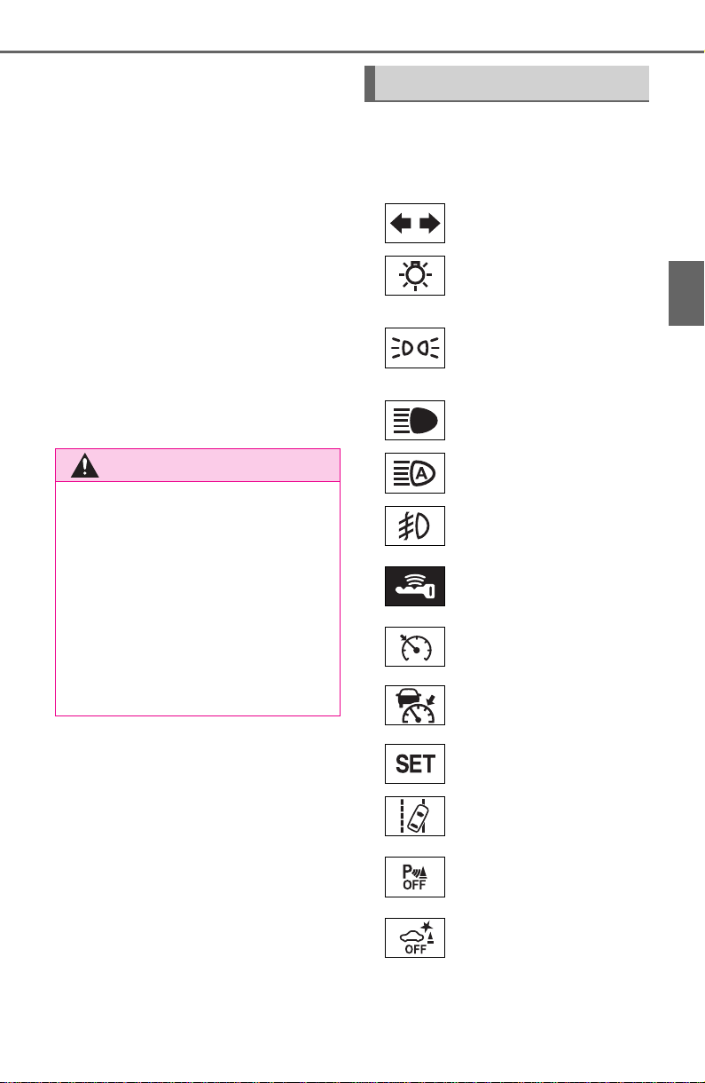
79
2-1. Instrument cluster
2
Vehicle status information and indicators
indicate that a system check is
being performed. They will turn
off after the engine is started, or
after a few seconds. There may
be a malfunction in a system if
the light does not come on, or
turn off. Have the vehicle
inspected by your Toyota dealer.
*2
:This light illuminates on the
multi-information display with a
message.
*3
:Intuitive parking assist OFF indi-
cator turns on when the engine
switch is turned to ON while the
Intuitive parking assist function is
on. It will turn off after a few sec-
onds.
The indicators inform the driver
of the operating state of the
vehicle’s various systems.
WARNING
■ If a safety system warning
light does not come on
Should a safety system light such
as the ABS and SRS warning light
not come on when you start the
engine, this could mean that
these systems are not available to
help protect you in an accident,
which could result in death or seri-
ous injury. Have the vehicle
inspected by your Toyota dealer
immediately if this occurs.
Indicators
Turn signal indicator
(P.202)
(U.S.A.)
Headlight indicator
(P.209)
(Canada)
Tail light indicator
(P.209)
Headlight high beam
indicator (P. 2 11)
Automatic High Beam
indicator (P.212)
Fog light indicator (if
equipped) (P.437)
Smart key system
indicator
*1
(if
equipped) (P.194)
Cruise control indica-
tor (P.250)
Dynamic radar cruise
control indicator
(P.250)
Cruise control “SET”
indicator (P.250)
LTA indicator
*2
(P.242)
Intuitive parking assist
OFF indicator
*3, 4
(if
equipped) (P.271)
PKSB OFF indicator
*3, 5
(if equipped) (
P.278)
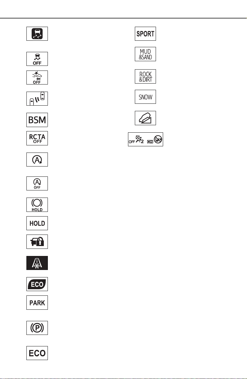
80
2-1. Instrument cluster
*1
:This light illuminates on the
multi-information display with a
message.
*2
:Depending on the operating con-
ditions of the system, the color
and state (illuminated/blinking) of
the indicator change.
*3
:The light comes on when the
system is turned off.
*4
:Intuitive parking assist OFF indi-
cator turns on when the engine
switch is turned to ON while the
Intuitive parking assist function is
on. It will turn off after a few sec-
onds.
*5
:These lights turn on when the
engine switch is turned to ON to
indicate that a system check is
being performed. They will turn
off after the engine is started, or
after a few seconds. There may
be a malfunction in a system if
the lights do not turn on, or turn
off. Have the vehicle inspected
by your Toyota dealer.
*6
:This light illuminates on the out-
(Flashes)
Slip indicator light
*5
(P. 36 1)
VSC OFF indicator
*3,
5
(P.362)
PCS warning light
*3, 5
(P. 23 1)
BSM outside rear view
mirror indicators
*5, 6
(if
equipped) (P.261)
BSM indicator (if
equipped) (P.261)
RCTA OFF indicator
*3, 5
(if equipped) (
P.261)
Stop & Start indica-
tor
*5
(if equipped)
(P. 34 5)
Stop & Start cancel
indicator
*3, 5
(if
equipped) (P.346)
Brake hold standby
indicator
*5
(P.206)
Brake hold operated
indicator
*5
(P.206)
Security indicator
(P.70, 73)
Low outside tempera-
ture indicator
*7
(P.83, 87)
Eco Driving Indicator
Light
*5
(P. 9 2 )
(U.S.A.)
Parking brake indica-
tor (P.203)
(Canada)
Parking brake indica-
tor (P.203)
Eco drive mode indi-
cator (P.351)
Sport mode indicator
(P.351)
Mud & sand mode
indicator (if equipped)
(P.354)
Rock & dirt mode indi-
cator (if equipped)
(P.354)
Snow mode indicator
(if equipped) (P.357)
Downhill assist control
system indicator
*5
(if
equipped) (P.358)
“AIR BAG ON/OFF”
indicator
*5, 8
(P. 43 )

81
2-1. Instrument cluster
2
Vehicle status information and indicators
side rear view mirrors.
*7
:When the outside temperature is
approximately 37°F (3°C) or
lower, the indicator will flash for
approximately 10 seconds, then
stay on.
*8
:This light illuminates on the cen-
ter panel.
■ BSM (Blind Spot Monitor) out-
side rear view mirror indicators
(if equipped)
In order to confirm operation, the
BSM outside rear view mirror indica-
tors illuminate in the following situa-
tions:
● When the engine switch is turned
to ON while the BSM function is
enabled on the screen of the
multi-information display.
● When the BSM function is
enabled on the screen of the
multi-information display while the
engine switch is in ON.
If the system is functioning correctly,
the BSM outside rear view mirror
indicators will turn off after a few
seconds.
If the BSM outside rear view mirror
indicators do not illuminate or do not
turn off, there may be a malfunction
in the system. If this occurs, have
the vehicle inspected by your Toyota
dealer.
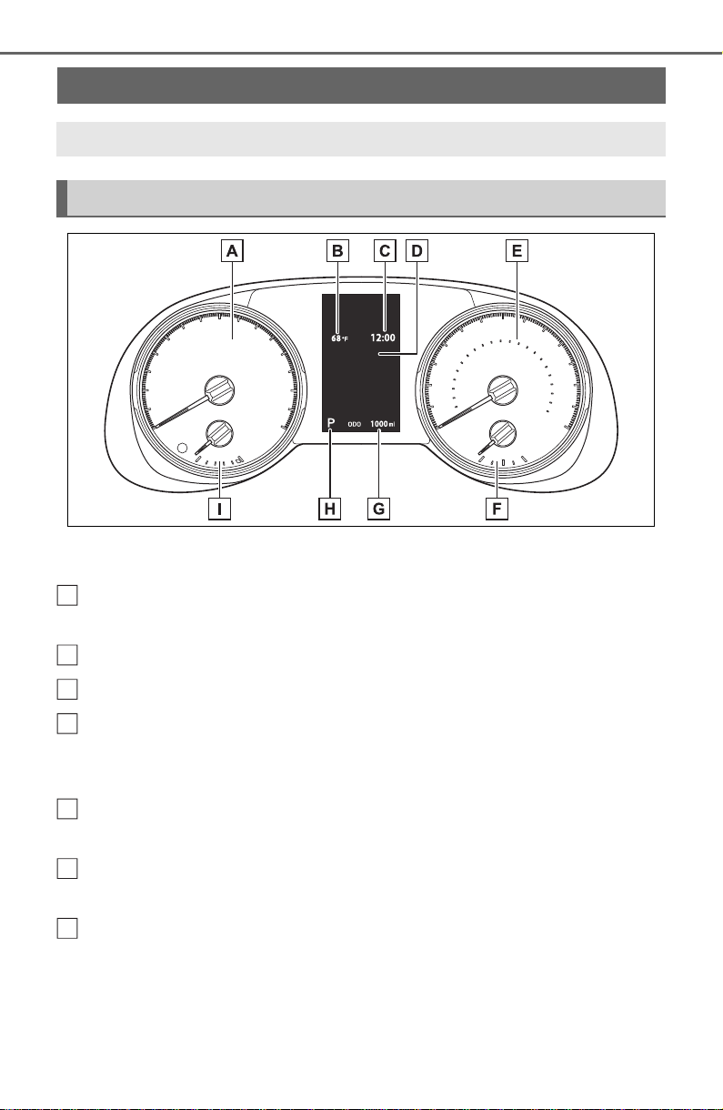
82
2-1. Instrument cluster
The units used on the meter and display may differ depending on the target
region.
Tachometer
Displays the engine speed in revolutions per minute
Outside temperature (P. 8 3)
Clock (P. 8 4)
Multi-information display
Presents the driver with a variety of driving-related data (P. 89 )
Displays warning messages if a malfunction occurs (P.639)
Speedometer
Displays the vehicle speed
Fuel gauge
Displays the quantity of fuel remaining in the tank
Odometer and trip meter
Odometer:
Displays the total distance that the vehicle has been driven
Trip meter:
Displays the distance the vehicle has been driven since the meter was last
Gauges and meters (with 4.2-inch display)
The meters display various drive information.
Meter display
A
B
C
D
E
F
G
83
2-1. Instrument cluster
2
Vehicle status information and indicators
reset. Trip meters “A” and “B” can be used to record and display different
distances independently.
Shift position and shift range indicator
Displays the selected shift position or selected shift range (P.199)
Engine coolant temperature gauge
Displays the engine coolant temperature
■ The meters and display illumi-
nate when
The engine switch is in ON.
■ Outside temperature display
● In the following situations, the cor-
rect outside temperature may not
be displayed, or the display may
take longer than normal to
change.
• When stopped, or driving at low
speeds (less than 12 mph [20
km/h])
• When the outside temperature
has changed suddenly (at the
entrance/exit of a garage, tunnel,
etc.)
● When “--” or “E” is displayed, the
system may be malfunctioning.
Take your vehicle to your Toyota
dealer.
● Displays the outside temperature
within the range of -40°F (-40°C)
to 122°F (50°C).
● When the outside temperature is
approximately 37°F (3°C) or
lower, the indicator will flash
for approximately 10 seconds,
then stay on.
■ Liquid crystal display
P.9 0
H
I
WARNING
■ The information display at
low temperatures
Allow the interior of the vehicle to
warm up before using the liquid
crystal information display. At
extremely low temperatures, the
display monitor may respond
slowly, and display changes may
be delayed.
For example, there is a lag
between the driver’s shifting and
the new gear number appearing
on the display. This lag could
cause the driver to downshift
again, causing rapid and exces-
sive engine braking and possibly
an accident resulting in death or
injury.
NOTICE
■ To prevent damage to the
engine and its components
● Do not let the indicator needle
of the tachometer enter the red
zone, which indicates the maxi-
mum engine speed.
● The engine may be overheating
if the engine coolant tempera-
ture gauge is in the red zone
(“H”). In this case, immediately
stop the vehicle in a safe place,
and check the engine after it
has cooled completely.
(P.659)
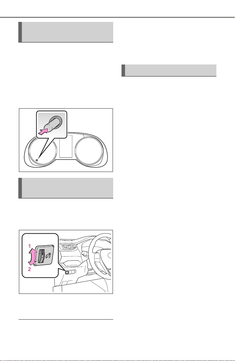
84
2-1. Instrument cluster
Switches the items of the odom-
eter, trip meter A and trip meter
B by pressing the “ODO TRIP”
switch.
When the trip meter is dis-
played, pressing and holding the
switch will reset the trip meter.
The brightness of the instrument
panel lights can be adjusted by
turning the dial.
1 Brighter
2 Darker
■ Instrument cluster brightness
adjustment
The instrument cluster brightness
levels when the tail lights are on and
off can be adjusted individually.
However, when the surroundings
are bright (daytime, etc.), turning on
the tail lights will not change the
instrument cluster brightness.
The clocks can be adjusted on
the audio system screen.
Vehicles with Audio
P.415
Vehicles with Audio Plus or
Premium Audio
Refer to “NAVIGATION AND
MULTIMEDIA SYSTEM
OWNER’S MANUAL”.
Using the “ODO TRIP”
switch
Instrument panel light
control
Adjusting the clock
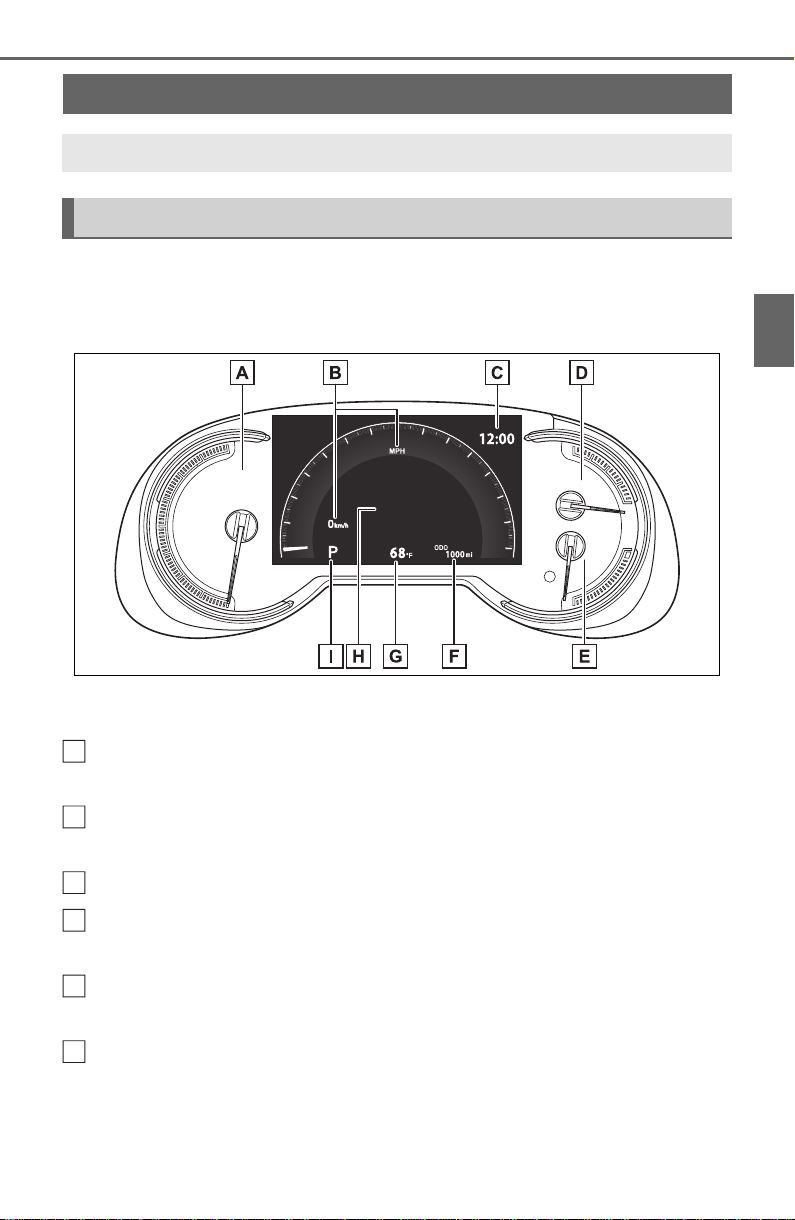
85
2-1. Instrument cluster
2
Vehicle status information and indicators
The display of the speedometer can be selected from two types,
analog or digital. (P.9 4 )
Analog speedometer
The units used on the meter and display may differ depending on the target
region.
Tachometer
Displays the engine speed in revolutions per minute
Speedometer
Displays the vehicle speed
Clock (P. 8 8)
Fuel gauge
Displays the quantity of fuel remaining in the tank
Engine coolant temperature gauge
Displays the engine coolant temperature
Odometer and trip meter
Odometer:
Displays the total distance that the vehicle has been driven
Trip meter:
Gauges and meters (with 7-inch display)
The meters display various drive information.
Meter display
A
B
C
D
E
F
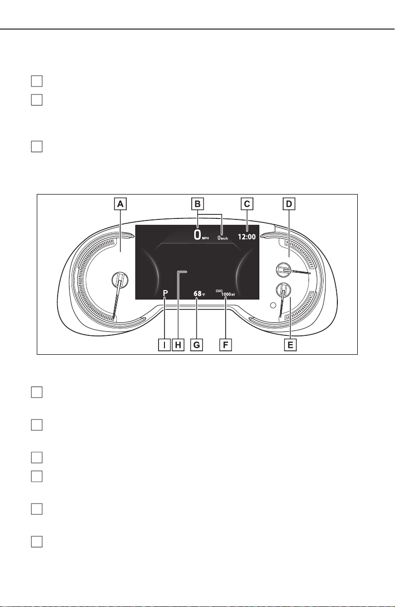
86
2-1. Instrument cluster
Displays the distance the vehicle has been driven since the meter was last
reset. Trip meters “A” and “B” can be used to record and display different
distances independently.
Outside temperature (P. 8 7)
Multi-information display
Presents the driver with a variety of driving-related data (P. 89 )
Displays warning messages if a malfunction occurs (P.639)
Shift position and shift range indicator
Displays the selected shift position or selected shift range (P.199)
Digital speedometer
The units used on the meter and display may differ depending on the target
region.
Tachometer
Displays the engine speed in revolutions per minute
Speedometer
Displays the vehicle speed
Clock (P. 8 8)
Fuel gauge
Displays the quantity of fuel remaining in the tank
Engine coolant temperature gauge
Displays the engine coolant temperature
Odometer and trip meter
Odometer:
Displays the total distance that the vehicle has been driven
G
H
I
A
B
C
D
E
F
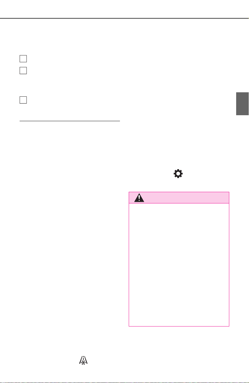
87
2-1. Instrument cluster
2
Vehicle status information and indicators
Trip meter:
Displays the distance the vehicle has been driven since the meter was last
reset. Trip meters “A” and “B” can be used to record and display different
distances independently.
Outside temperature (P. 8 3)
Multi-information display
Presents the driver with a variety of driving-related data (P. 89 )
Displays warning messages if a malfunction occurs (P.639)
Shift position and shift range indicator
Displays the selected shift position or selected shift range (P.199)
■ The meters and display illumi-
nate when
The engine switch is in ON.
■ When changing driving mode
● Speedometer color is changed fol-
lowing the selected driving mode.
(P.351)
● AWD models: Speedometer color
is changed following the selected
driving mode or Multi-terrain
Select mode. (P.351, 353)
■ Outside temperature display
● In the following situations, the cor-
rect outside temperature may not
be displayed, or the display may
take longer than normal to
change.
• When stopped, or driving at low
speeds (less than 12 mph [20
km/h])
• When the outside temperature
has changed suddenly (at the
entrance/exit of a garage, tunnel,
etc.)
● When “--” or “E” is displayed, the
system may be malfunctioning.
Take your vehicle to your Toyota
dealer.
● Displays the outside temperature
within the range of -40°F (-40°C)
to 122°F (50°C).
● When the outside temperature is
approximately 37°F (3°C) or
lower, the indicator will flash
for approximately 10 seconds,
then stay on.
■ Liquid crystal display
P. 9 0
■ Customization
Settings (e. g. meter display) can be
changed on the screen of the
multi-information display. (P. 94 )
G
H
I
WARNING
■ The information display at
low temperatures
Allow the interior of the vehicle to
warm up before using the liquid
crystal information display. At
extremely low temperatures, the
display monitor may respond
slowly, and display changes may
be delayed.
For example, there is a lag
between the driver’s shifting and
the new gear number appearing
on the display. This lag could
cause the driver to downshift
again, causing rapid and exces-
sive engine braking and possibly
an accident resulting in death or
injury.
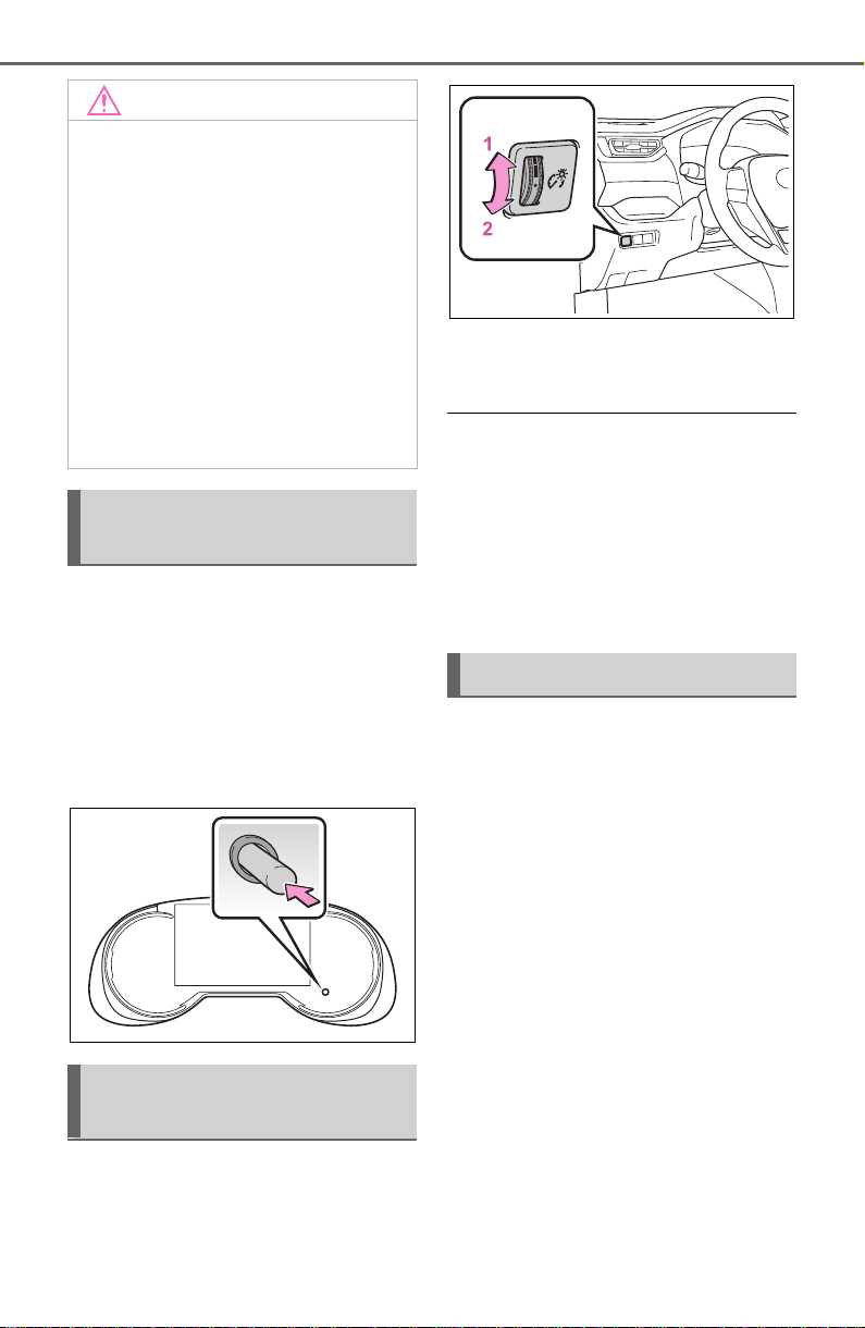
88
2-1. Instrument cluster
Switches the items of the odom-
eter, trip meter A and trip meter
B by pressing the “ODO TRIP”
switch.
When the trip meter is dis-
played, pressing and holding the
switch will reset the trip meter.
The brightness of the instrument
panel lights can be adjusted by
turning the dial.
1 Brighter
2 Darker
■ Instrument cluster brightness
adjustment
The instrument cluster brightness
levels when the tail lights are on and
off can be adjusted individually.
However, when the surroundings
are bright (daytime, etc.), turning on
the tail lights will not change the
instrument cluster brightness.
The clocks can be adjusted on
the audio system screen.
Vehicles with Audio
P.415
Vehicles with Audio Plus or
Premium Audio
Refer to “NAVIGATION AND
MULTIMEDIA SYSTEM
OWNER’S MANUAL”.
NOTICE
■ To prevent damage to the
engine and its components
● Do not let the indicator needle
of the tachometer enter the red
zone, which indicates the maxi-
mum engine speed.
● The engine may be overheating
if the engine coolant tempera-
ture gauge is in the red zone
(“H”). In this case, immediately
stop the vehicle in a safe place,
and check the engine after it
has cooled completely.
(P.659)
Using the “ODO TRIP”
switch
Instrument panel light
control
Adjusting the clock
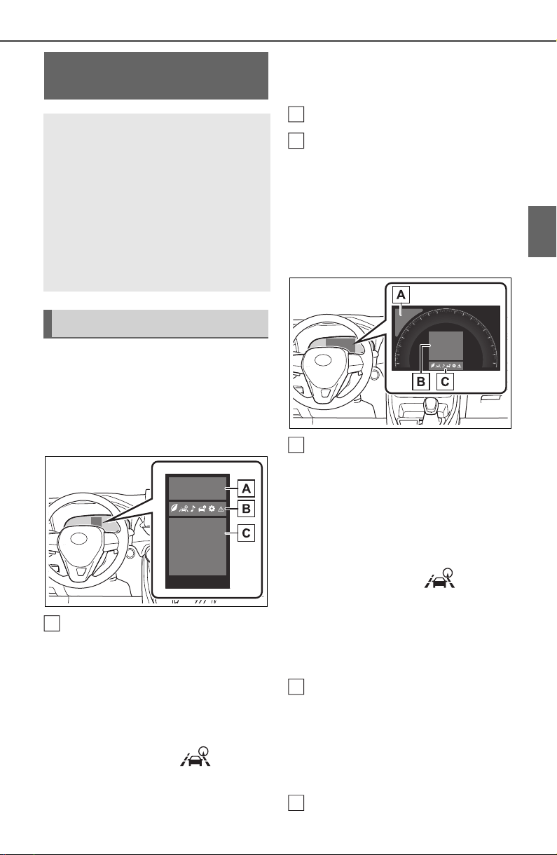
89
2-1. Instrument cluster
2
Vehicle status information and indicators
Following information is dis-
played on the multi-information
display.
■ Vehicles with 4.2-inch dis-
play
Driving support system infor-
mation
Displays recognized signs while the
RSA system (if equipped) is operat-
ing. (P.247)
Displays an image when the follow-
ing systems are operating and a
menu icon other than is
selected:
• LTA (Lane Tracing Assist)
(P.237)
• Dynamic radar cruise control with
full-speed range (P.250)
Menu icons (P. 9 0)
Information display area
A variety of information can be dis-
played by selecting a menu icon.
Additionally, warning or sugges-
tion/advice pop-up displays will be
displayed in some situations.
■ Vehicles with 7-inch display
Driving support system infor-
mation
Displays recognized signs while the
RSA system (if equipped) is operat-
ing. (P.247)
Displays an image when the follow-
ing systems are operating and a
menu icon other than is
selected:
• LTA (Lane Tracing Assist)
(P.237)
• Dynamic radar cruise control with
full-speed range (P.250)
Information display area
A variety of information can be dis-
played by selecting a menu icon.
Additionally, warning or sugges-
tion/advice pop-up displays will be
displayed in some situations.
Menu icons (P. 9 0)
Multi-information dis-
play
The multi-information dis-
play is used to display fuel
efficiency related informa-
tion and various types of
driving-related information.
The multi-information dis-
play can also be used to
change the display settings
and other settings.
Display contents
A
B
C
A
B
C
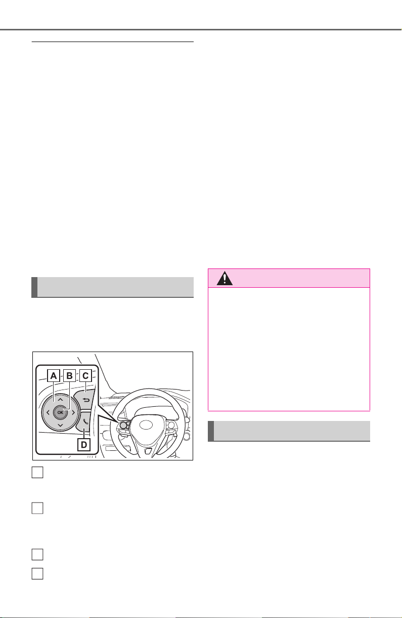
90
2-1. Instrument cluster
■ The multi-information display is
displayed when
The engine switch is in ON.
■ When changing driving mode
● Background color of the multi-
information display is changed fol-
lowing the selected driving mode.
(P.351)
● AWD models: Background color of
the multi-information display is
changed following the selected
driving mode or Multi-terrain
Select mode. (P.351, 353)
■ Liquid crystal display
Small spots or light spots may
appear on the display. This phenom-
enon is characteristic of liquid crys-
tal displays, and there is no problem
continuing to use the display.
The multi-information display is
operated using the meter control
switches.
Scroll the screen
*
/switch the
display
*
/move the cursor
Press: Enter/Set
Press and hold: Reset/Dis-
play customizable items
Return to the previous screen
Call sending/receiving and
history display (if equipped)
Linked with the hands-free
system, sending or receiving
call is displayed. For details
regarding the hands-free sys-
tem, refer to P.465 (vehicles
with Audio) or “NAVIGATION
AND MULTIMEDIA SYS-
TEM OWNER’S MANUAL”
(vehicles with Audio Plus or
Premium Audio).
*
: On screens where the screen can
be scrolled and the display can
be switched, a scroll bar or a
round icon that shows the num-
ber of registered screens is dis-
played.
Information related to each icon
can be displayed by selecting
the icon with the meter control
switches.
Some of the information may be
displayed automatically depending
on the situation.
Changing the display
A
B
C
D
WARNING
■ Caution for use while driving
For safety, avoid operating the
meter control switch while driving
as much as possible, and do not
look continuously at the multi-
information display while driving.
Stop the vehicle and operate the
meter control switch. Failure to do
so may cause a steering wheel
operation error, resulting in an
unexpected accident.
Menu icons
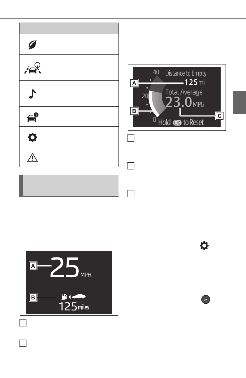
91
2-1. Instrument cluster
2
Vehicle status information and indicators
Select to display fuel consump-
tion data in various forms.
■ Speedometer display/Dis-
tance to empty (4.2-inch
display)
Speedometer display
Displays the vehicle speed.
Distance to empty
Displays the driving range with
remaining fuel. (P. 92 )
■ Fuel Economy
Following information is dis-
played.
Distance to empty
Displays the driving range with
remaining fuel. (P. 92 )
Current fuel economy
Displays the instantaneous current
fuel Economy.
Average fuel economy
Displays the average fuel economy
since the function was reset or the
average fuel economy after starting
or refueling.
*1, 2,3
The average fuel economy selected
by “Fuel Economy” on the
screen is displayed. (P.94)
*1
:Use the displayed fuel consump-
tion as a reference only.
*2
:Average fuel economy since the
function was reset can be reset
by pressing and holding .
*3
:Average fuel economy after
starting is reset each time the
engine stops.
Icon Display
Driving information dis-
play (P.91)
Driving support system
information display
(P.93)
Audio system-linked dis-
play (if equipped)
(P.93)
Vehicle information dis-
play (P.93)
Settings display (P.9 4 )
Warning message dis-
play (P.98)
Driving information dis-
play
A
B
A
B
C
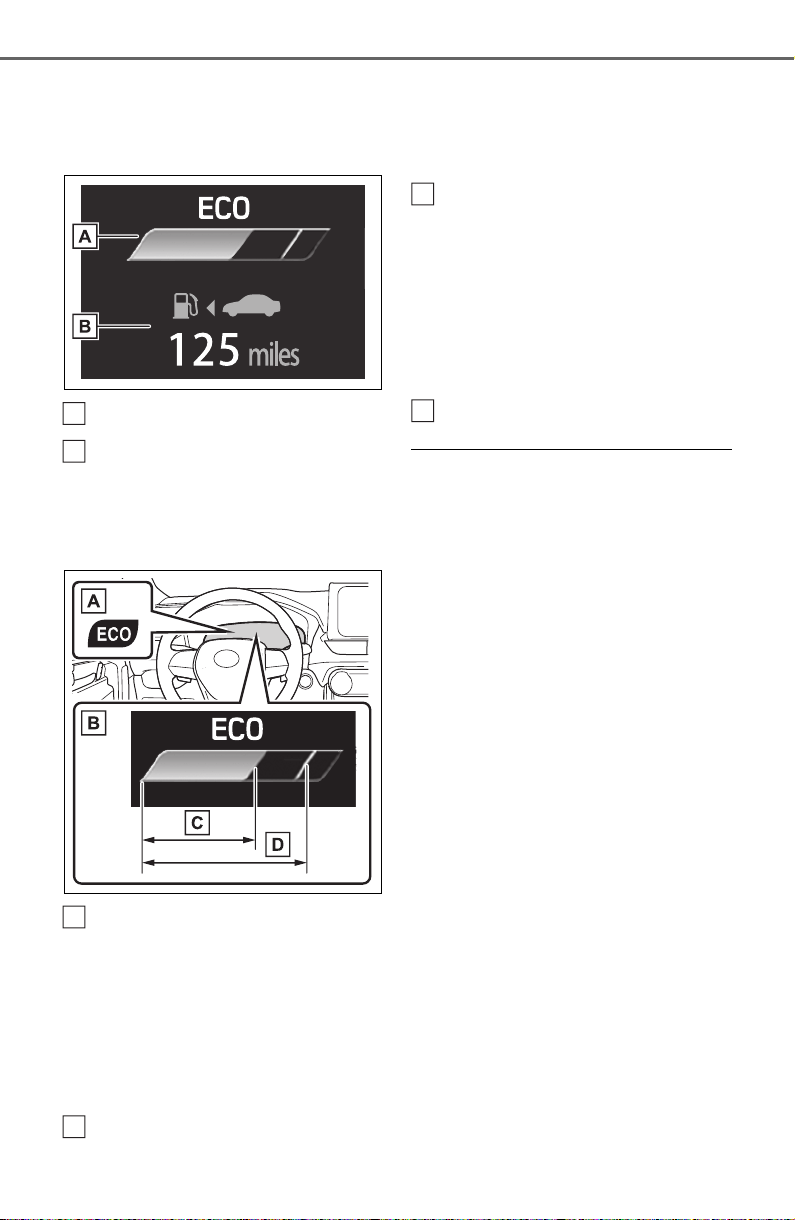
92
2-1. Instrument cluster
■ Eco Driving Indicator/Dis-
tance to empty
Display contents
Eco Driving Indicator
Distance to empty
Displays the driving range with
remaining fuel. (P.92)
Eco Driving Indicator
Eco Driving Indicator Light
During Eco-friendly acceleration
operation (Eco driving), the Eco
Driving Indicator Light will turn on.
When the acceleration exceeds
Zone of Eco driving, or when the
vehicle is stopped, the light turns
off.
Eco Driving Indicator Zone
Display
Suggests the Zone of Eco driving
with current Eco driving ratio based
on acceleration.
Eco driving ratio based on
acceleration
If the acceleration exceeds Zone of
Eco driving, the right side of Eco
Driving Indicator Zone Display will
illuminate.
At this time, the Eco Driving Indica-
tor Light will turn off.
Zone of Eco driving
■ Distance to empty
● This distance is computed based
on your average fuel consump-
tion. As a result, the actual dis-
tance that can be driven may differ
from that displayed.
● When only a small amount of fuel
is added to the tank, the display
may not be updated. When refuel-
ing, turn the engine switch off. If
the vehicle is refueled without
turning the engine switch off, the
display may not be updated.
● When “Refuel” is displayed, the
remaining fuel amount is low and
the distance that can be driven
with the remaining fuel cannot be
calculated.
Refuel immediately.
■ The ECO Driving indicator will
not operate when
Eco Driving Indicator will not oper-
ate in the following conditions:
● The shift lever is in any position
other than D.
● Neither normal mode nor Eco
drive mode is selected.
● The vehicle speed is approxi-
mately 80 mph (130 km/h) or
higher.
A
B
A
B
C
D

93
2-1. Instrument cluster
2
Vehicle status information and indicators
■ Driving support system
information display
Select to display the operational
status of the following systems:
LTA (Lane Tracing Assist)
(P.237)
Dynamic radar cruise control
with full-speed range
(P.250)
■ Navigation system-linked
display (if equipped)
Select to display the following
navigation system-linked infor-
mation.
Route guidance
Compass display (north-up
display/heading-up display)
Select to enable selection of an
audio source or track on the dis-
play.
■ Drive information
2 items that are selected using
the “Drive Info Items” setting
(average speed, distance and
total time) can be displayed ver-
tically.
The displayed information
changes according to the “Drive
Info Type” setting (since the sys-
tem was started or between
resets). (P. 9 4)
Use the displayed information as a
reference only.
Following items will be displayed.
“Trip”
• “Average Speed”: Displays the
average vehicle speed since
engine start
*
• “Distance”: Displays the distance
driven since engine start
*
• “Total Time”: Displays the elapsed
time since engine start
*
*
: These items are reset each time
the engine stops.
“Total”
• “Average Speed”: Displays the
average vehicle speed since the
display was reset
*
• “Distance”: Displays the distance
driven since the display was
reset
*
• “Total Time”: Displays the elapsed
time since the display was reset
*
*
: To reset, display the desired item
and press and hold .
Driving support system
information display
Audio system-linked dis-
play (if equipped)
Vehicle information dis-
play
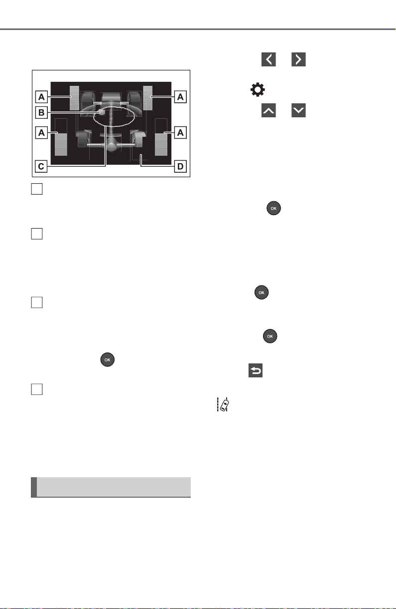
94
2-1. Instrument cluster
■ AWD system display (AWD
models)
Torque distribution display
Displays the drive status of each
wheel in 6 steps from 0 to 5.
G-force display
*
Displays the size and direction of
the G-force applied to the vehicle
via changes to the position of the
ball on the display.
Maximum G-force course
*
This item is linked with the G-force
display and the course of the past
movement of the ball is displayed.
Press and hold to reset the
record.
Wheel spin display
When a tire is spinning, its icon on
the display changes its color and
blinks.
*
: This item is displayed only when
driving mode is set to sport mode.
Vehicle settings and the content
displayed on the screen can be
changed by using the meter
control switches.
■ Setting procedure
1 Operate or of the
meter control switches and
select .
2 Operate or of the
meter control switches and
select the desired item.
• If the function is turned on and
off or the volume, etc. is
changed on the setting
screen, the setting is changed
each time is pressed.
• For functions that allow oper-
ation contents, display con-
tents, etc., of function to be
selected, the setting screen is
displayed by pressing and
holding . When the setting
screen is displayed, select the
setting or desired value (time,
etc.) with .
3 After changing the settings,
press of the meter control
switches.
■ LTA (Lane Tracing
Assist) (P.237)
Select to set up the following
items.
“Lane Center”
Select to enable/disable the lane
centering function.
“Steering Assist”
Select to enable/disable steering
wheel assistance.
“Sensitivity”
Settings display
A
B
C
D
95
2-1. Instrument cluster
2
Vehicle status information and indicators
Select to set the lane departure
alert sensitivity.
“Sway Warning”
Select to enable/disable the vehicle
sway warning.
“Sway Sensitivity”
Select to set the vehicle sway warn-
ing sensitivity.
■ PCS (Pre-Collision Sys-
tem) (P.229)
Select to set up the following
items.
PCS on/off
Select to enable/disable the pre-
collision system.
“Sensitivity”
Select to change the pre-collision
warning timing.
■ BSM (Blind Spot Moni-
tor) (if equipped) (P.260)
Select to set up the following
items.
BSM (Blind Spot Monitor)
on/off
Select to enable/disable the BSM
system.
“Brightness”
Select to switch the brightness of
the outside rear view mirror indica-
tors. (P.261)
“Sensitivity”
Select to change the alert timing for
an approaching vehicle.
■ (Intuitive parking
assist) (if equipped)
(P.270)
Select to set up the following
items.
Intuitive parking assist on/off
Select to enable/disable the Intui-
tive parking assist.
“Volume”
Select to set the volume of the
buzzer which sounds when the
Intuitive parking assist is operated.
■ RCTA (Rear Cross Traffic
Alert) (if equipped) (P.260)
RCTA (Rear Cross Traffic
Alert) on/off
Select to enable/disable the RCTA
system.
“Volume”
Select to change the RCTA buzzer
volume.
■ PKSB (Parking Sup-
port Brake System) (if
equipped) (P.277)
Select to enable/disable the
Parking Support Brake function.
■ RSA (Road Sign
Assist) (if equipped)
(P.247)
Select to set up the following
items.
Road Sign Assist on/off
Select to enable/disable the RSA
system.
“Notification method”

96
2-1. Instrument cluster
Select to change each notification
method used to warn the driver
when the system recognizes
excess speed, no overtaking and
no-entry sign.
“Notification Level”
Select to change each notification
level used to warn the driver when
the system recognizes a speed limit
sign.
■ Vehicle Settings
PBD (Power Back Door)
(if equipped) (P.118)
Select to set up the following items.
• System settings
Select to enable/disable the power
back door system.
• “Kick Sensor”
*
Select to enable/disable the kick
sensor.
• “Opening Adjustment”
Select the open position when
power back door is fully open.
•“Volume”
Select to set the volume of the
buzzer which sounds when the
power back door system operates.
*
: Vehicles with hands free power
back door
(Stop & Start system) (if
equipped) (P.345)
Select to set the length of time the
Stop & Start system will operate
when the “A/C” switch of the air
conditioning system is on.
“TPWS” (Tire Pressure Warn-
ing System) (if equipped)
(P.584)
• “Set Pressure”
Select to initialize the tire pressure
warning system.
• “Change Wheel” (except for mod-
els made in Japan
*
without tire
inflation pressure display func-
tion)
Select to register the ID codes of
the tire pressure sensors to the tire
pressure warning system.
• “Change Wheel” (for models
made in Japan
*
without tire infla-
tion pressure display function)
Select to change the tire pressure
warning system sensor ID code set.
To enable this function, a second
set of tire pressure warning system
sensor ID codes must be registered
by a Toyota dealer. For information
regarding changing the registered
ID code set, contact your Toyota
dealer.
*
: The country of production is writ-
ten on the Certification Regula-
tion label. (P.665)
“Scheduled Maintenance”
(P.565)
Select to reset the scheduled main-
tenance information (message indi-
cating maintenance is required and
distance until the next mainte-
nance) after all maintenance is per-
formed.
■ Settings
“Language”
Select to change the language on
the multi-information display.
“Units”
97
2-1. Instrument cluster
2
Vehicle status information and indicators
Select to change the units of mea-
sure displayed.
“Meter Type” (7-inch display)
Select to change the speedometer
display.
(Eco Driving Indicator
Light) (P.92)
Select to activate/deactivate the
Eco Driving Indicator Light.
(Driving information dis-
play settings)
Select to change the display on
Fuel Economy (P.91).
(Audio settings) (if
equipped)
Select to enable/disable
screen.
(Vehicle information dis-
play settings)
• “Display Contents”
Select to enable/disable the AWD
system display (P.94). (AWD
models)
• “Drive Info Type”
Select to change the drive informa-
tion type display between trip and
total. (P.9 3) .
• “Drive Info Items”
Select to set the items on the upper
and lower side of the drive informa-
tion screen. from three items, aver-
age speed, distance and total time.
“Pop-Up Display”
Select to enable/disable the follow-
ing pop-up displays, which may
appear in some situations.
• Intersection guidance display of
the navigation system-linked sys-
tem (if equipped)
• Incoming call display of the
hands-free phone system (if
equipped)
• Audio operation (if equipped)
• Volume operation (if equipped)
• Voice control (if equipped)
• Stop & Start system duration (if
equipped)
• Stop & Start system status (if
equipped)
“MID OFF”
A blank screen is displayed
“Default Settings”
Select to reset the meter display
settings.
■ Suspension of the settings dis-
play
● In the following situations, opera-
tion of the settings display will be
temporarily suspended.
• When a warning message
appears on the multi-information
display
• When the vehicle begins to move
● Settings for functions not
equipped to the vehicle are not
displayed.
● When a function is turned off, the
related settings for that function
are not selectable.

98
2-1. Instrument cluster
Select to display warning mes-
sages and measures to be
taken if a malfunction is
detected. (P.639)
Displays suggestions to the
driver in the following situations.
To select a response to a dis-
played suggestion, use the
meter control switches.
■ Suggestion to turn on the
headlights
If the headlight switch is in other
than or , and the vehicle
speed is 3 mph (5 km/h) or
higher for a certain amount of
time when the surroundings are
dark, a suggestion message will
be displayed.
■ Suggestion to turn off the
headlights
If the headlights are left on for a
certain amount of time after the
engine switch has been turned
off, a suggestion message will
be displayed.
When the headlight switch is in
the AUTO position: The mes-
sage asking if you wish to turn
the headlights off is displayed.
To turn the headlights off, select
“Yes”.
If the driver’s door is opened after
the engine switch is turned off, this
suggestion message will not be dis-
played.
■ Customization
The suggestion function can be
turned on/off. (Customizable fea-
tures: P.689)
WARNING
■ Cautions during setting up
the display
As the engine needs to be run-
ning during setting up the display,
ensure that the vehicle is parked
in a place with adequate ventila-
tion. In a closed area such as a
garage, exhaust gases including
harmful carbon monoxide (CO)
may collect and enter the vehicle.
This may lead to death or a seri-
ous health hazard.
NOTICE
■ During setting up the display
To prevent battery discharge,
ensure that the engine is running
while setting up the display fea-
tures.
Warning message display
Suggestion function
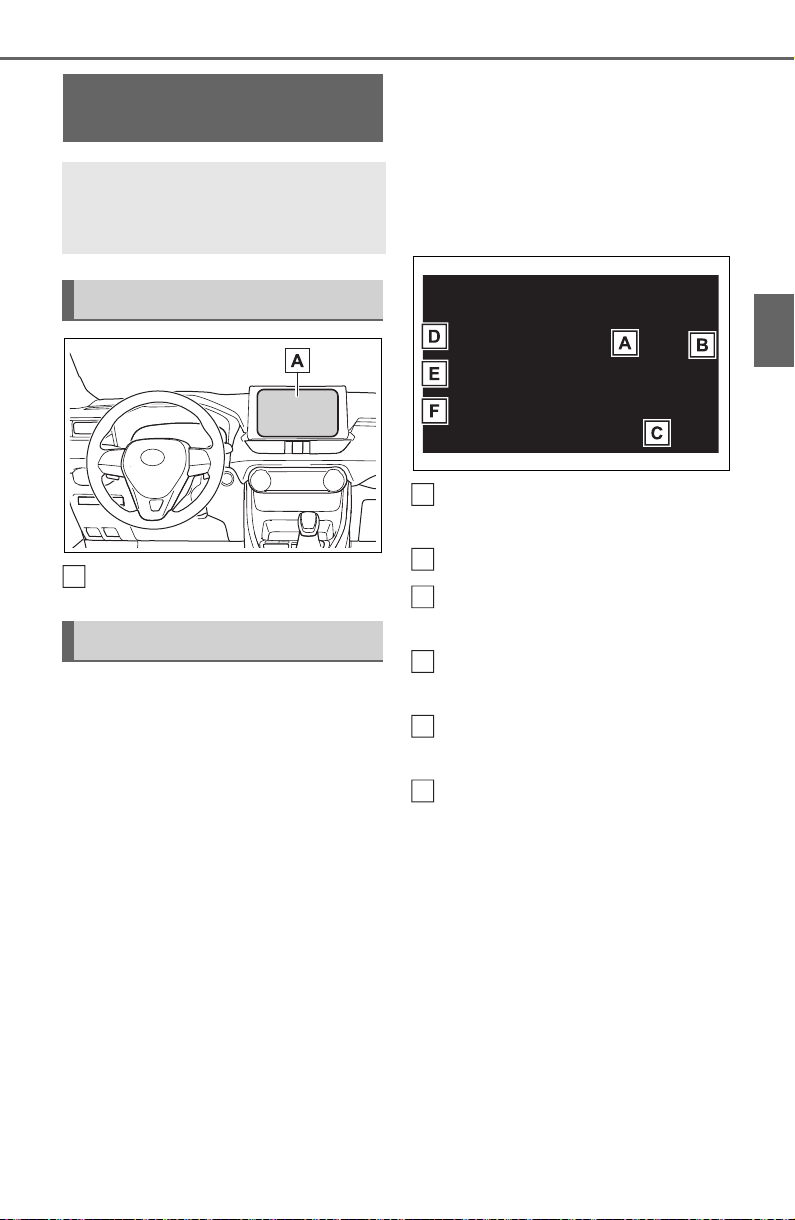
99
2-1. Instrument cluster
2
Vehicle status information and indicators
Audio system screen
■ Trip information
Audio or Audio Plus (vehicles
without Data Communication
Module)
1 Press the “MENU” button.
2 Select “Info” on the “Menu”
screen.
If the “History” screen is displayed,
select “Trip information”.
Audio or Audio Plus (vehicles
with Data Communication
Module)/Premium Audio
1 Press the “MENU” button.
2 Select “Info” on the “Menu”
screen.
3 Select “ECO” on the “Infor-
mation” screen.
If the “History” screen is displayed,
select “Trip information”.
The image is an example only, and
may vary slightly from actual condi-
tions.
Fuel consumption in the past
15 minutes
Current fuel consumption
Resetting the consumption
data
Average vehicle speed since
the engine was started
Elapsed time since the
engine was started
Cruising range (P.100)
Average fuel consumption for
the past 15 minutes is divided
by color into past averages and
averages attained since the
engine switch was last turned to
ON. Use the displayed average
fuel consumption as a refer-
ence.
Fuel consumption
information
The fuel consumption infor-
mation can be displayed on
the audio system screen.
System components
Consumption
A
A
B
C
D
E
F
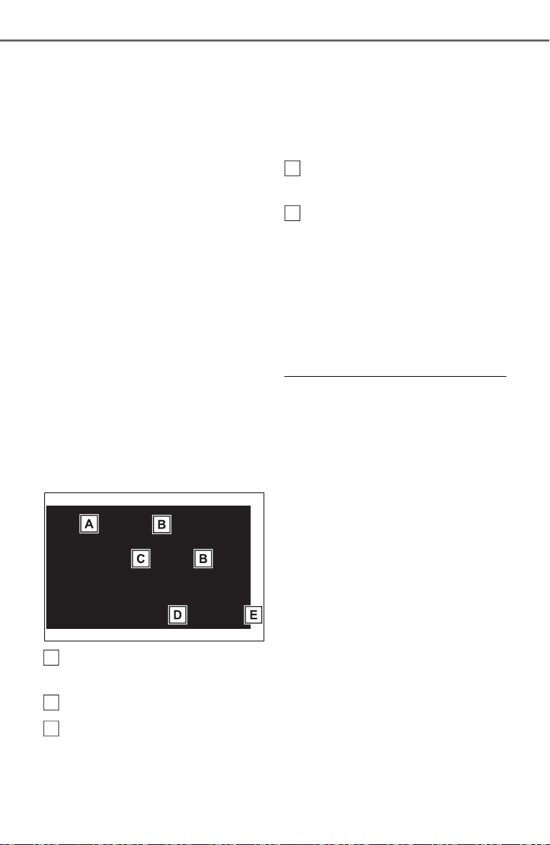
100
2-1. Instrument cluster
■ History
Audio or Audio Plus (vehicles
without Data Communication
Module)
1 Press the “MENU” button.
2 Select “Info” on the “Menu”
screen.
If the “Trip Information” screen is
displayed, select “History”.
Audio or Audio Plus (vehicles
with Data Communication
Module)/Premium Audio
1 Press the “MENU” button.
2 Select “Info” on the “Menu”
screen.
3 Select “ECO” on the “Infor-
mation” screen.
If the “Trip Information” screen is
displayed, select “History”.
The image is an example only, and
may vary slightly from actual condi-
tions.
Best recorded fuel consump-
tion
Latest fuel consumption
Previous fuel consumption
record
• Audio and Audio Plus:
Displays the daily average fuel con-
sumption. (Instead of the date, “Trip
1” through “Trip 5” will be dis-
played.)
• Premium Audio:
Displays the daily average fuel con-
sumption.
Updating the latest fuel con-
sumption data
Resetting the history data
The average fuel consumption
history is divided by color into
past averages and the average
fuel consumption since the last
time updated. Use the displayed
average fuel consumption as a
reference.
■ Updating the history data
Update the average fuel consump-
tion by selecting “Clip” to measure
the current fuel consumption again.
■ Resetting the data
The fuel consumption data can be
deleted by selecting “Clear”.
■ Cruising range
Displays the estimated maximum
distance that can be driven with the
quantity of fuel remaining.
This distance is computed based on
your average fuel consumption. As
a result, the actual distance that can
be driven may differ from that dis-
played.
A
B
C
D
E

101
3
3
Before driving
Before driving
3-1. Key information
Keys............................ 102
3-2. Opening, closing and
locking the doors
Side doors................... 108
Back door.................... 114
Smart key system ....... 128
3-3. Adjusting the seats
Front seats.................. 134
Rear seats................... 135
Driving position memory
.................................. 137
Head restraints............ 140
3-4. Adjusting the steering
wheel and mirrors
Steering wheel ............ 142
Inside rear view mirror 143
Digital Rear-view Mirror145
Outside rear view mirrors
.................................. 154
3-5. Opening, closing the win-
dows and moon roof
Power windows........... 156
Moon roof.................... 159
Panoramic moon roof.. 162
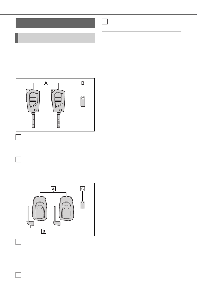
102
3-1. Key information
3-1.Ke y information
The following keys are provided
with the vehicle.
Vehicles without smart key
system
Master keys
Operating the wireless remote con-
trol function (P.104)
Key number plate
Vehicles with smart key sys-
tem
Electronic keys
• Operating the smart key system
(P.128)
• Operating the wireless remote
control function (P.104)
Mechanical keys
Key number plate
■ When riding in an aircraft
When bringing a key with wireless
remote control function onto an air-
craft, make sure you do not press
any buttons on the key while inside
the aircraft cabin. If you are carrying
the key in your bag etc., ensure that
the buttons are not likely to be
pressed accidentally. Pressing a
button may cause the key to emit
radio waves that could interfere with
the operation of the aircraft.
■ Key battery depletion
Vehicles without smart key system
● The standard battery life is 1 to 2
years.
● The battery will become depleted
even if the wireless key is not
used. The following symptoms
indicate that the wireless key bat-
tery may be depleted. Replace the
battery when necessary. (P.604)
• The wireless remote control does
not operate.
• The detection area becomes
smaller.
Vehicles with smart key system
● The standard battery life is 1 to 2
years.
● If the battery becomes low, an
alarm will sound in the cabin and a
message will be displayed on the
multi-information display when the
engine stops.
● To reduce key battery depletion
when the electronic key is to not
be used for long periods of time,
set the electronic key to the bat-
tery-saving mode. (P.129)
● As the electronic key always
receives radio waves, the battery
will become depleted even if the
electronic key is not used. The fol-
lowing symptoms indicate that the
electronic key battery may be
depleted. Replace the battery
when necessary.
Keys
Key types
A
B
A
B
C

103
3-1. Key information
3
Before driving
• The smart key system or the wire-
less remote control does not oper-
ate.
• The detection area becomes
smaller.
• The LED indicator on the key sur-
face does not turn on.
You can replace the battery by your-
self (P.604). However, as there is
a danger that the electronic key may
be damaged, it is recommended
that replacement is carried out by
your Toyota dealer.
● To avoid serious deterioration, do
not leave the electronic key within
3 ft. (1 m) of the following electri-
cal appliances that produce a
magnetic field:
•TVs
• Personal computers
• Cellular phones, cordless phones
and battery chargers
• Table lamps
• Induction cookers
■ If a message regarding the state
of the electronic key or engine
switch mode, etc. is shown
(vehicles with smart key sys-
tem)
To prevent trapping the electronic
key inside the vehicle, leaving the
vehicle carrying the electronic key
on your person without turning the
engine switch to OFF or other pas-
sengers from unintentionally taking
the key out of the vehicle, etc., a
message that prompts the user to
confirm the state of the electronic
key or engine switch mode may be
shown on the multi-information dis-
play. In those cases, follow the
instructions on the display immedi-
ately.
■ If “Key Battery Low Replace
Key Battery” is displayed on
the multi-information display
(vehicles with smart key sys-
tem)
The electronic key has a low battery.
Replace the electronic key battery.
(P.604)
■ Replacing the battery
P.604
■ Confirmation of the registered
key number
The number of keys already regis-
tered to the vehicle can be con-
firmed. Ask your Toyota dealer for
details.
■ If “A New Key has been Regis-
tered Contact Your Dealer for
Details” is displayed on the
multi-information display (vehi-
cles with smart key system)
This message will be displayed
each time the driver’s door is
opened when the doors are
unlocked from the outside for
approximately 10 days after a new
electronic key has been registered.
If this message is displayed but you
have not had a new electronic key
registered, ask your Toyota dealer to
check if an unknown electronic key
(other than those in your posses-
sion) has been registered.
NOTICE
■ To prevent key damage
● Do not drop the keys, subject
them to strong shocks or bend
them.
● Do not expose the keys to high
temperatures for long periods of
time.
● Do not get the keys wet or wash
them in an ultrasonic washer,
etc.
● Do not attach metallic or mag-
netic materials to the keys or
place the keys close to such
materials.
● Do not disassemble the keys.
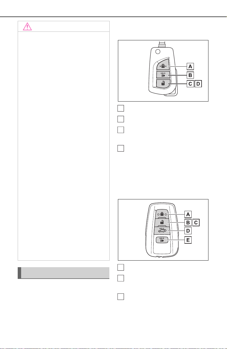
104
3-1. Key information
The keys are equipped with the
following wireless remote con-
trol:
Vehicles without smart key
system
Locks all the doors (P.108)
Sounds the alarm (P.105)
Unlocks all the doors
(P.108)
Opens the side windows
*
(P.108)
*
: This setting must be customized
at your Toyota dealer.
Vehicles with smart key sys-
tem
Locks all the doors (P.108)
Unlocks all the doors
(P.108)
Opens the side windows
*1
and the moon roof
*1, 2
or
panoramic moon roof
*1, 2
(P.108)
NOTICE
● Do not attach a sticker or any-
thing else to the surface of the
keys.
● Do not place the keys near
objects that produce magnetic
fields, such as TVs, audio sys-
tems and induction cookers.
● Do not place the keys near
medical electrical equipment
such as low-frequency therapy
equipment or microwave ther-
apy equipment, and do not
receive medical attention with
the keys on your person.
■ Carrying the electronic key
on your person (vehicles with
smart key system)
Carry the electronic key 3.9 in.
(10 cm) or more away from elec-
tric appliances that are turned on.
Radio waves emitted from electric
appliances within 3.9 in. (10 cm)
of the electronic key may interfere
with the key, causing the key to
not function properly.
■ In case of a smart key system
malfunction or other key-
related problems (vehicles
with smart key system)
P.6 53
■ When an electronic key is lost
(vehicles with smart key sys-
tem)
P.6 53
Wireless remote control
A
B
C
D
A
B
C
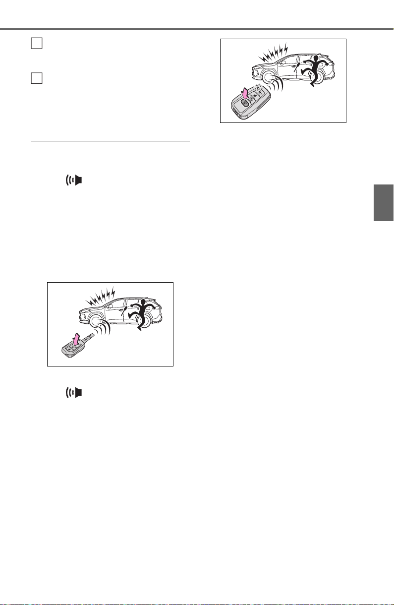
105
3-1. Key information
3
Before driving
Opens and closes the power
back door
*2
(P.118)
Sounds the alarm (P.105)
*1
:These settings must be custom-
ized at your Toyota dealer.
*2
:If equipped
■ Theft deterrent panic mode
Vehicles without smart key system
When is pressed for longer
than about 1 second, an alarm will
sound intermittently and the vehicle
lights will flash to deter any person
from trying to break into or damage
your vehicle.
To stop the alarm, press any button
on the key.
Vehicles with smart key system
When is pressed for longer
than about 1 second, an alarm will
sound intermittently and the vehicle
lights will flash to deter any person
from trying to break into or damage
your vehicle.
To stop the alarm, press any button
on the electronic key.
■ Conditions affecting operation
Vehicles without smart key system
The wireless remote control function
may not operate normally in the fol-
lowing situations.
● When the wireless key battery is
depleted
● Near a TV tower, electric power
plant, gas station, radio station,
large display, airport or other facil-
ity that generates strong radio
waves or electrical noise
● When carrying a portable radio,
cellular phone or other wireless
communication device
● When the wireless key is in con-
tact with, or is covered by a metal-
lic object
● When other wireless key (that
emits radio waves) is being used
nearby
● If window tint with a metallic con-
tent or metallic objects are
attached to the rear window
Vehicles with smart key system
P.129
D
E

106
3-1. Key information
■ Certification for wireless remote control
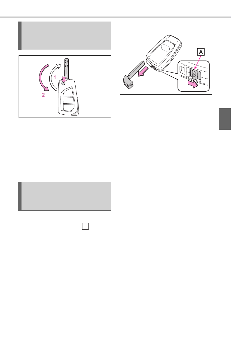
107
3-1. Key information
3
Before driving
1 Releasing
To release the key, press the but-
ton.
2 Folding
To stow the key back in its case,
push the key back to the stowed
position while pressing the button.
To take out the mechanical key,
slide the release lever and
take the key out.
The mechanical key can only be
inserted in one direction, as the key
only has grooves on one side. If the
key cannot be inserted in a lock cyl-
inder, turn it over and re-attempt to
insert it.
After using the mechanical key,
store it in the electronic key. Carry
the mechanical key together with
the electronic key. If the electronic
key battery is depleted or the entry
function does not operate properly,
you will need the mechanical key.
(P.653)
■ If you lose your keys
P.653
■ If a wrong key is used
The key cylinder rotates freely to
isolate inside mechanism.
Using the master key
(vehicles without smart
key system)
Using the mechanical key
(vehicles with smart key
system)
A
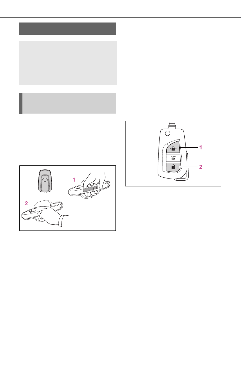
108
3-2. Opening, closing and locking the doors
3-2.Opening, closing and locking t he doors
■ Using the entry function
(vehicles with smart key
system)
Carry the electronic key to
enable this function.
1 Grip the driver’s door handle
to unlock the door. Holding
the driver’s door handle for
approximately 2 seconds
unlocks all the doors.
Grip the front passenger’s
door handle or rear door han-
dle (some models) to unlock
all the doors
*
.
Make sure to touch the sensor on
the back of the handle.
The doors cannot be unlocked for 3
seconds after the doors are locked.
*
: The door unlock settings can be
changed. (P.109)
2 Touch the lock sensor (the
indentation on the upper part
of the door handle) to lock
the doors.
Check that the door is securely
locked.
■ Using the wireless remote
control
Vehicles without smart key
system
1 Locks all the doors
Check that the door is securely
locked.
2 Unlocks all the doors
Pressing the button unlocks the
driver’s door. Pressing the button
again within 5 seconds unlocks the
other doors.
Press and hold to open the side
windows.
*
*
: This setting must be customized
at your Toyota dealer.
Side doors
The vehicle can be locked
and unlocked using the
entry function, wireless
remote control, key or door
lock switch.
Unlocking and locking the
doors from the outside
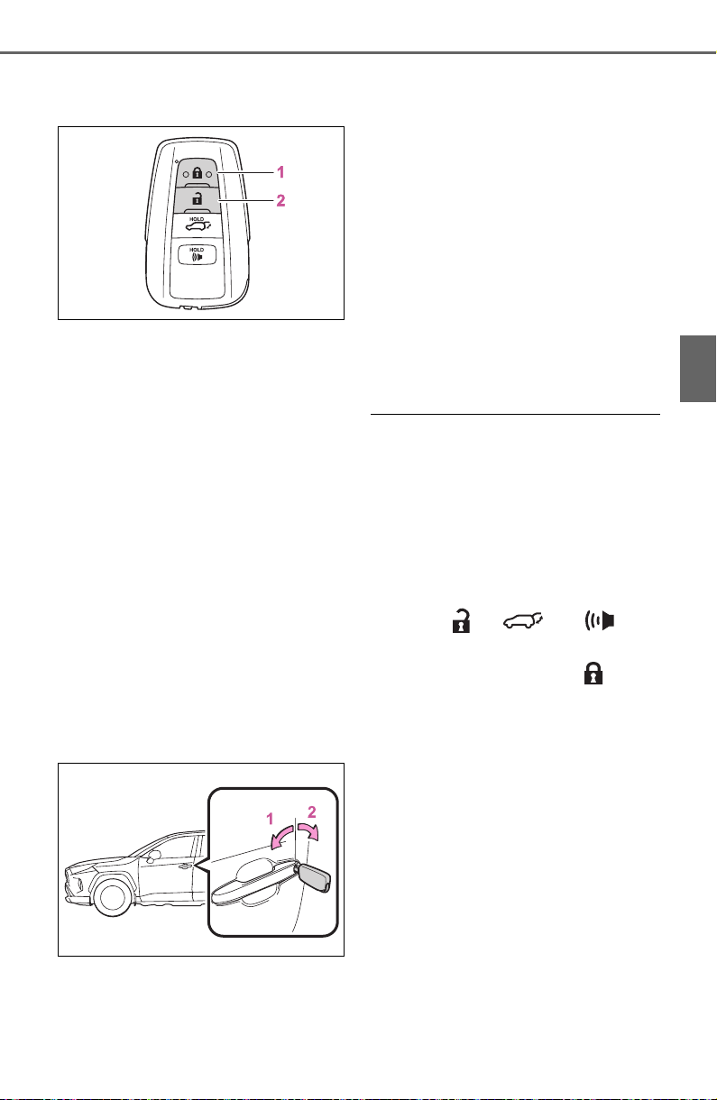
109
3-2. Opening, closing and locking the doors
3
Before driving
Vehicles with smart key sys-
tem
1 Locks all the doors
Check that the door is securely
locked.
2 Unlocks all the doors
Pressing the button unlocks the
driver’s door. Pressing the button
again within 5 seconds unlocks the
other doors.
Press and hold to open the side
windows and moon roof (if
equipped) or panoramic moon roof
(if equipped).
*
*
: This setting must be customized
at your Toyota dealer.
■ Using the key
Vehicles without smart key
system
1 Locks all the doors
Turn and hold to close the side win-
dows.
*
2 Unlocks all the doors
Turning the key unlocks the driver’s
door. Turning the key again within 5
seconds unlocks the other doors.
Turn and hold to open the side win-
dows.
*
*
: These settings must be custom-
ized at your Toyota dealer.
Vehicles with smart key sys-
tem
The doors can also be locked
and unlocked with the mechani-
cal key. (P.653)
■ Switching the door unlock func-
tion (vehicles with smart key
system)
It is possible to set which doors the
entry function unlocks using the
wireless remote control.
1 Turn the engine switch to OFF.
2 When the indicator light on the
key surface is not on, press and
hold , or for
approximately 5 seconds while
pressing and holding .
The setting changes each time an
operation is performed, as shown
below. (When changing the setting
continuously, release the buttons,
wait for at least 5 seconds, and
repeat step 2.)
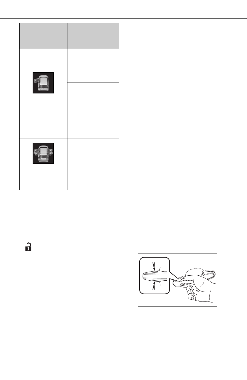
110
3-2. Opening, closing and locking the doors
Vehicles with alarm: To prevent
unintended triggering of the alarm,
unlock the doors using the wireless
remote control and open and close
a door once after the settings have
been changed. (If a door is not
opened within 60 seconds after
is pressed, the doors will be
locked again and the alarm will
automatically be set.)
In a case that the alarm is triggered,
immediately stop the alarm. (P.73)
■ Operation signals
Doors: A buzzer sounds and the
emergency flashers flash to indicate
that the doors have been
locked/unlocked using the entry
function or wireless remote control.
(Locked: Once; Unlocked: Twice)
Side windows and moon roof (if
equipped) or panoramic moon roof
(if equipped): A buzzer sounds to
indicate that the side windows and
moon roof or panoramic moon roof
are operating using the wireless
remote control.
■ Security feature
Vehicles without smart key system
If a door is not opened within
approximately 60 seconds after the
vehicle is unlocked using the wire-
less remote control, the security fea-
ture automatically locks the vehicle
again.
Vehicles with smart key system
If a door is not opened within
approximately 60 seconds after the
vehicle is unlocked using the entry
function or wireless remote control,
the security feature automatically
locks the vehicle again. (However,
depending on the location of the
electronic key, the key may be
detected as being in the vehicle. In
this case, vehicle may be unlocked.)
■ When the door cannot be
locked by the lock sensor on
the upper part of the door han-
dle (vehicles with smart key
system)
If the door will not lock even when
the topside sensor area is touched,
try touching both the topside and
underside sensor areas at the same
time.
When gloves are being worn,
remove the gloves.
■ Door lock buzzer (vehicles with
smart key system)
If an attempt to lock the doors using
the entry function or wireless remote
control is made when a door is not
fully closed, a buzzer sounds contin-
uously for 5 seconds. Fully close the
door to stop the buzzer, and lock the
Multi-informa-
tion dis-
play/Beep
Unlocking func-
tion
Exterior: Beeps 3
times
Interior: Pings
once
Holding the
driver’s door han-
dle unlocks only
the driver’s door.
Holding the pas-
senger’s door
handle or press-
ing the back door
opener switch
unlocks all the
doors.
Exterior: Beeps
twice
Interior: Pings
once
Holding a door
handle or press-
ing the back door
opener switch
unlocks all the
doors.

111
3-2. Opening, closing and locking the doors
3
Before driving
vehicle once more.
■ Setting the alarm (if equipped)
Locking the doors will set the alarm
system. (P. 7 3 )
■ Conditions affecting the opera-
tion of the smart key system or
wireless remote control
Vehicles without smart key system
P.105
Vehicles with smart key system
P.129
■ If the smart key system (if
equipped) or the wireless
remote control does not oper-
ate properly
● Vehicles with smart key system:
Use the mechanical key to lock
and unlock the doors. (P. 65 3)
● Replace the key battery with a
new one if it is depleted. (P.604)
■ If the battery is discharged
The doors cannot be locked and
unlocked using the smart key sys-
tem (if equipped) or wireless remote
control. Lock or unlock the doors
using the key (vehicles without
smart key system) or mechanical
key (vehicles with smart key sys-
tem). (P.109, 653)
■ Customization
Settings (e.g. unlocking function
using a key) can be changed.
(Customizable features: P.690)
WARNING
■ To prevent an accident
Observe the following precautions
while driving the vehicle.
Failure to do so may result in a
door opening and an occupant
could be thrown out of the vehicle,
resulting in death or serious injury.
● Ensure that all doors are prop-
erly closed and locked.
● Do not pull the inside handle of
the doors while driving.
Be especially careful for the
front doors, as the doors may
be opened even if the inside
lock buttons are in locked posi-
tion.
● Set the rear door child-protector
locks when children are seated
in the rear seats.
■ When opening or closing a
door
Check the surroundings of the
vehicle such as whether the vehi-
cle is on an incline, whether there
is enough space for a door to
open and whether a strong wind
is blowing. When opening or clos-
ing the door, hold the door handle
tightly to prepare for any unpre-
dictable movement.
■ When using the wireless
remote control, key or
mechanical key and operating
the power windows, moon
roof (if equipped) or pan-
oramic moon roof (if
equipped)
Operate the power window, moon
roof or panoramic moon roof after
checking to make sure that there
is no possibility of any passenger
having any of their body parts
caught in the side window, moon
roof or panoramic moon roof.
Also, do not allow children to
operate the wireless remote con-
trol, key or mechanical key. It is
possible for children and other
passengers to get caught in the
side window, moon roof or pan-
oramic moon roof.
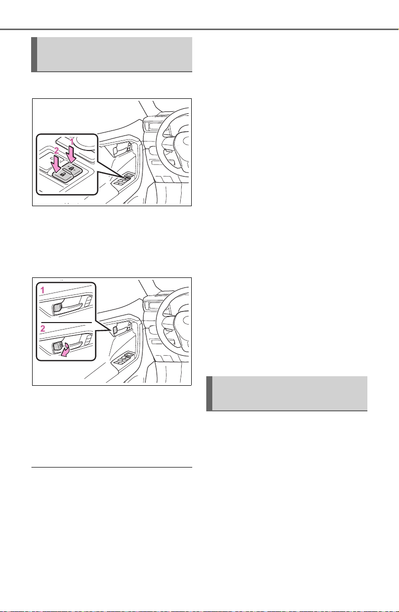
112
3-2. Opening, closing and locking the doors
■ Using the door lock switch
1 Locks all the doors
2 Unlocks all the doors
■ Using the inside lock but-
tons
1 Locks the door
2 Unlocks the door
The front doors can be opened by
pulling the inside handle even if the
lock buttons are in the lock position.
■ Locking the front doors from
the outside without a key
1 Move the inside lock button to
the lock position.
2 Close the door.
Vehicles without smart key system
The door cannot be locked if the key
is in the engine switch.
Vehicles with smart key system
The door cannot be locked if the
engine switch is in ACC or ON, or
the electronic key is left inside the
vehicle.
Depending on the position of the
electronic key, the key may not be
detected correctly and the door may
be locked.
■ Open door warning buzzer
If the vehicle speed reaches 3 mph
(5 km/h), a buzzer sounds to indi-
cate that the door(s) or the hood is
not fully closed.
The open door(s) or hood is dis-
played on the multi-information dis-
play.
■ When all the doors are locked
with the entry function (vehicles
with smart key system), wire-
less remote control or key
● The doors cannot be unlocked
with the door lock switch.
● The door lock switch can be reset
by unlocking all the doors with the
entry function (vehicles with smart
key system), wireless remote con-
trol or key.
The door cannot be opened
from inside the vehicle when the
lock is set.
Unlocking and locking the
doors from the inside
Rear door child-protector
lock
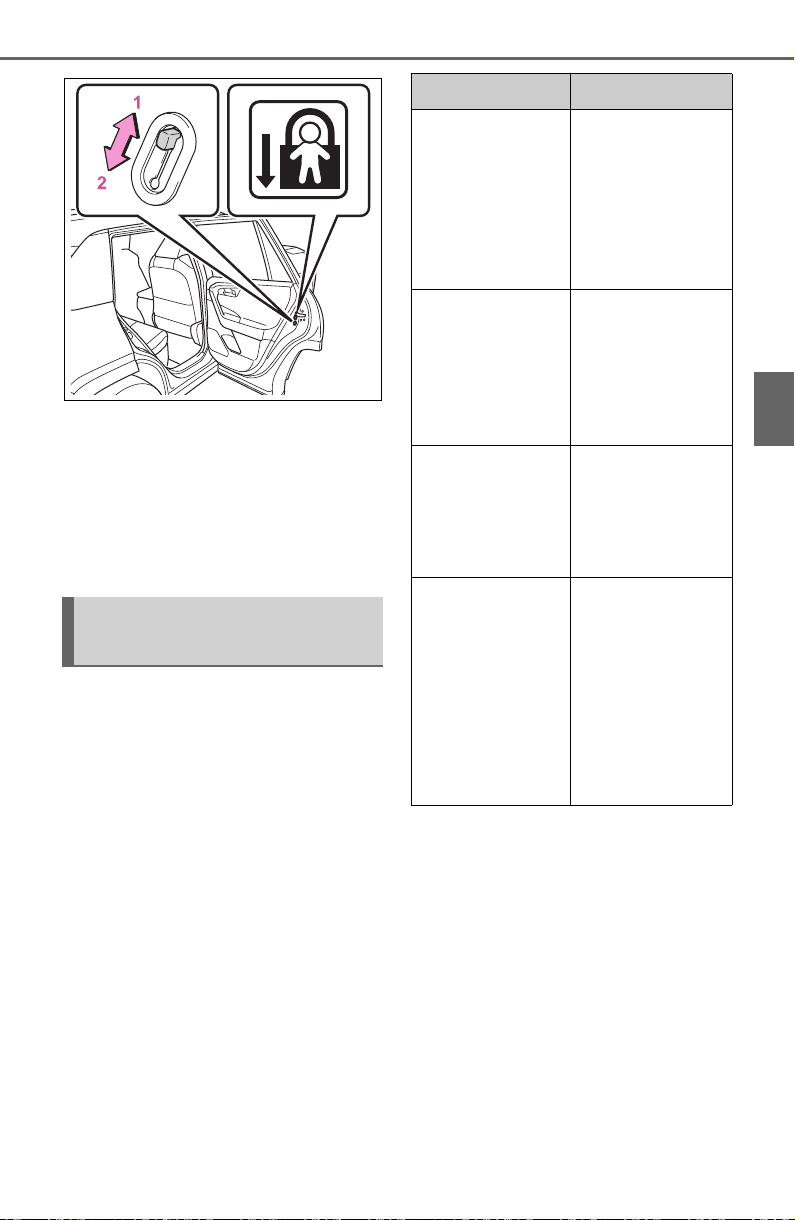
113
3-2. Opening, closing and locking the doors
3
Before driving
1 Unlock
2 Lock
These locks can be set to prevent
children from opening the rear
doors. Push down on each rear
door switch to lock both rear doors.
The following functions can be
set or canceled:
For instructions on customizing,
refer to P.688.
Automatic door locking
and unlocking systems
Function Operation
Speed linked
door locking
function
All doors are
automatically
locked when
vehicle speed is
approximately
12mph (20 km/h)
or higher.
Shift position
linked door lock-
ing function
All doors are
automatically
locked when
shifting the shift
lever to position
other than P.
Shift position
linked door
unlocking func-
tion
All doors are
automatically
unlocked when
shifting the shift
lever to P.
Driver’s door
linked door
unlocking func-
tion
All doors are
automatically
unlocked when
driver’s door is
opened within
approximately 45
seconds after
turning the
engine switch off.

114
3-2. Opening, closing and locking the doors
Back door
The back door can be
locked/unlocked and
opened/closed by the fol-
lowing procedures.
WARNING
Observe the following precau-
tions.
Failure to do so may result in
death or serious injury.
■ Before driving
● Make sure that the back door is
fully closed.
If the back door is not fully
closed, it may open unexpect-
edly while driving and hit near-
by objects or luggage in the lug-
gage compartment may be
thrown out, causing an acci-
dent.
● Do not allow children to play in
the luggage compartment.
If a child is accidentally locked
in the luggage compartment,
they could get heat exhaustion
or other injuries.
● Do not allow a child to open or
close the back door.
Doing so may cause the back
door to operate unexpectedly,
or cause the child’s hands,
head, or neck to be caught by
the closing back door.
■ Important points while driving
● Keep the back door closed
while driving.
If the back door is left open, it
may hit near-by objects or lug-
gage in the luggage compart-
ment may be thrown out,
causing an accident.
● Never let anyone sit in the lug-
gage compartment.
In the event of sudden braking,
sudden swerving or a collision,
they are susceptible to death or
serious injury.
■ Back door handles
Do not hang any object to the
back door handles.
If any object is hung, the back
door may suddenly shut, causing
parts of the body to be caught,
resulting in death or serious injury.
■ Operating the back door
Observe the following precau-
tions.
Failure to do so may cause parts
of the body to be caught, resulting
in death or serious injury.
● Remove any heavy loads, such
as snow and ice, from the back
door before opening it. Failure
to do so may cause the back
door to suddenly shut again
after it is opened.
● When opening or closing the
back door, thoroughly check to
make sure the surrounding area
is safe.
● If anyone is in the vicinity, make
sure they are safe and let them
know that the back door is
about to open or close.
● Use caution when opening or
closing the back door in windy
weather as it may move
abruptly in strong wind.
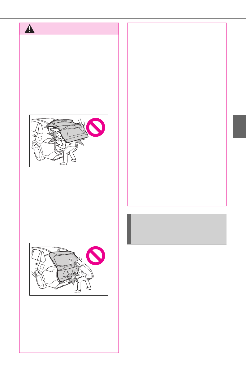
115
3-2. Opening, closing and locking the doors
3
Before driving
■ Using the entry function
(vehicles with smart key
system)
Carry the electronic key to
enable this function.
WARNING
● Vehicles without power back
door: The back door may sud-
denly shut if it is not opened
fully. It is more difficult to open
or close the back door on an
incline than on a level surface,
so beware of the back door
unexpectedly opening or closing
by itself. Make sure that the
back door is fully open and
secure before using the luggage
compartment.
● Vehicles with power back door:
The back door may suddenly
shut if it is not opened fully,
while on a steep incline. Make
sure that the back door is
secured before using the lug-
gage compartment.
● When closing the back door,
take extra care to prevent your
fingers, etc. from being caught.
● Vehicles without power back
door: When closing the back
door, make sure to press it
lightly on its outer surface. If the
back door handle is used to fully
close the back door, it may
result in hands or arms being
caught.
● Do not pull on the back door
damper stay (vehicles without
power back door) (P.118) or
back door spindle (vehicles with
power back door) (P.125) to
close the back door, and do not
hang on the back door damper
stay (vehicles without power
back door) or back door spindle
(vehicles with power back door).
Doing so may cause hands to
be caught or the back door
damper stay (vehicles without
power back door) or back door
spindle (vehicles with power
back door) to break, causing an
accident.
● Vehicles without power back
door: If a bicycle carrier or simi-
lar heavy object is attached to
the back door, it may suddenly
shut again after being opened,
causing someone’s hands,
head or neck to be caught and
injured. When installing an
accessory part to the back door,
using a genuine Toyota part is
recommended.
Unlocking and locking the
back door from the out-
side
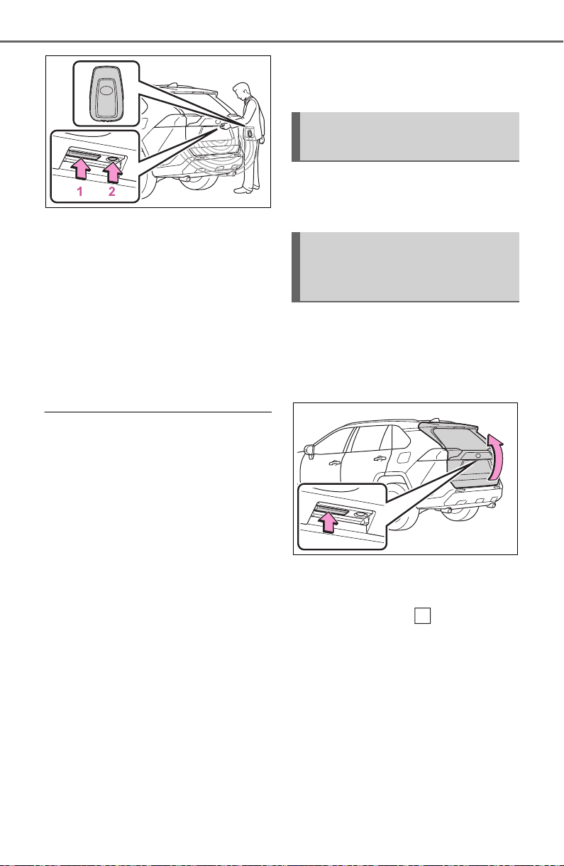
116
3-2. Opening, closing and locking the doors
1 Unlocks all the doors
The doors cannot be unlocked for 3
seconds after the doors are locked.
2 Locks all the doors
Check that the door is securely
locked.
■ Using the wireless remote
control
P. 1 08
■ Operation signals
A buzzer sounds and the emer-
gency flashers flash to indicate that
the doors have been
locked/unlocked using the entry
function (if equipped) or wireless
remote control. (Locked: once;
Unlocked: twice)
■ Security feature
Vehicles without smart key system
If a door is not opened within
approximately 60 seconds after the
vehicle is unlocked using the wire-
less remote control, the security fea-
ture automatically locks the vehicle
again.
Vehicles with smart key system
If a door is not opened within
approximately 60 seconds after the
vehicle is unlocked using the entry
function or wireless remote control,
the security feature automatically
locks the vehicle again. (However,
depending on the location of the
electronic key, the key may be
detected as being in the vehicle. In
this case, vehicle may be unlocked.)
■ Using the door lock switch
P. 11 2
■ Open
Raise the back door while
pressing up the back door
opener switch.
■ Close
Lower the back door using the
back door handle , and make
sure to push the back door
down from the outside to close
it.
Be careful not to pull the back door
sideways when closing the back
door with the handle.
Unlocking and locking the
back door from the inside
Opening/closing the back
door (vehicles without
power back door)
A
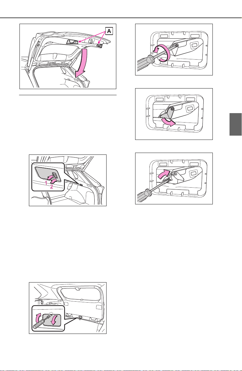
117
3-2. Opening, closing and locking the doors
3
Before driving
■ Luggage compartment light
The luggage compartment light
turns on when the back door is
opened with the luggage compart-
ment light switch on.
When the engine switch is turned to
OFF, the light will go off automati-
cally after 20 minutes.
1 On
2 Off
■ If the back door opener is inop-
erative
The back door can be unlocked
from the inside.
1 Remove the cover.
To prevent damage, cover the tip of
the screwdriver with a rag.
2 Loosen the screw.
3 Turn the cover.
4 Move the lever.
5 When installing, reverse the
steps listed.
■ Open door warning buzzer
P. 11 2

118
3-2. Opening, closing and locking the doors
■ Using the wireless remote
control
Press and hold the switch.
The power back door automatically
opens/closes.
Pressing the switch while the power
back door is opening/closing stops
the operation. When the switch is
pressed again during the halted
operation, the back door will per-
form the reverse operation.
■ Using the power back door
switch on the instrument
panel
Press and hold the switch.
The power back door automatically
opens/closes.
Unlock the back door before oper-
ating.
Pressing the switch while the power
back door is opening/closing stops
the operation. When the switch is
pressed again during the halted
operation, the back door will per-
form the reverse operation.
■ Using the back door opener
switch
When the back door is
unlocked: Press the back door
NOTICE
■ Back door damper stays
The back door is equipped with
damper stays that hold the back
door in place.
Observe the following precau-
tions.
Failure to do so may cause dam-
age to the back door damper stay,
resulting in malfunction.
● Do not attach any foreign
objects, such as stickers, plastic
sheets, or adhesives to the
damper stay rod.
● Do not touch the damper stay
rod with gloves or other fabric
items.
● Do not attach any accessories
other than genuine Toyota parts
to the back door.
● Do not place your hand on the
damper stay or apply lateral
forces to it.
Opening/closing the back
door (vehicles with power
back door)
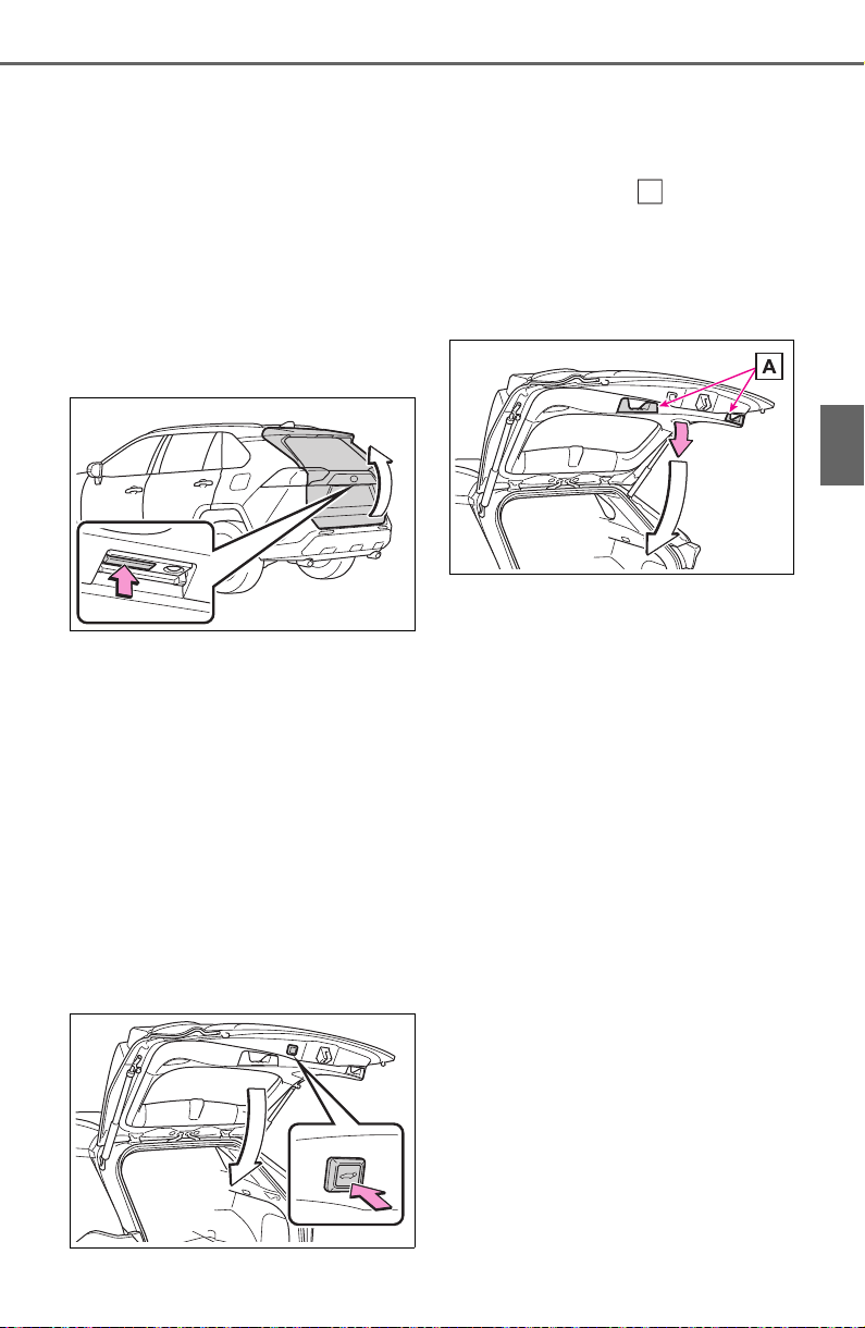
119
3-2. Opening, closing and locking the doors
3
Before driving
opener switch.
When the back door is locked:
While carrying the electronic key
on your person, press and hold
the back door opener switch.
The power back door automatically
opens.
Pressing the switch while the power
back door is opening/closing stops
the operation.
■ Using the power back door
switch on the back door
Press the switch.
The power back door automatically
closes.
Pressing the switch while the power
back door is operating will stop the
operation.
When the switch is pressed again
during the halted operation, the
back door will perform the reverse
operation.
■ Using the back door han-
dles
Lower the back door using the
back door handle .
The back door closing assist
(P.121) will be activated, and the
power back door will fully close
automatically.
■ Using the kick sensor (vehi-
cles with Hands Free Power
Back Door)
The Hands Free Power Back
Door enables automatic opening
and closing of the power back
door by putting your foot near
the lower center part of the rear
bumper and moving it away
from the rear bumper. When
operating the Hands Free
Power Back Door, make sure
that the engine switch is in OFF,
the kick sensor operation is
enabled (P.94) and you are
carrying an electronic key.
1 While carrying an electronic
key, stand within the smart
key system operation range,
approximately 11.8 to 19.7 in.
A

120
3-2. Opening, closing and locking the doors
(30 to 50 cm) from the rear
bumper.
Kick sensor
Hands Free Power Back
Door operation detection
area
Smart key system operation
detection area (P.128)
2 Perform a kick operation by
moving your foot to within
approximately 3.9 in. (10 cm)
of the rear bumper and then
pulling it back.
Perform the entire kick operation
within 1 second.
The back door will not start operat-
ing while a foot is detected under
the rear bumper.
Operate the Hands Free Power
Back Door without contacting the
rear bumper with your foot.
If another electronic key is in the
cabin or luggage compartment, it
may take slightly longer than nor-
mal for the operation to occur.
Kick sensor
Hands Free Power Back
Door operation detection
area
3 When the kick sensor detects
that your foot is pulled back,
a buzzer will sound and the
back door will automatically
fully open/close.
If a foot is moved under the rear
bumper while the back door is
opening/closing, the back door will
stop moving.
If a foot is moved under the rear
bumper again during the halted
operation, the back door will per-
form the reverse operation.
■ Luggage compartment light
The luggage compartment light
turns on when the back door is
opened with the luggage compart-
ment light switch on.
When the engine switch is turned to
OFF, the light will go off automati-
cally after 20 minutes.
A
B
C
A
B
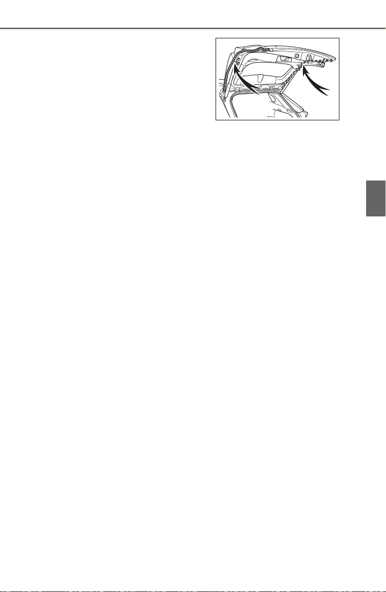
121
3-2. Opening, closing and locking the doors
3
Before driving
1 On
2 Off
■ Back door closer
In the event that the back door is left
slightly open, the back door closer
will automatically close it to the fully
closed position.
Whatever the state of the engine
switch, the back door closer oper-
ates.
■ Power back door operating con-
ditions
The power back door can automati-
cally open and close under the fol-
lowing conditions:
● When the power back door sys-
tem is enabled. (P.9 4)
● When the engine switch is in ON,
in addition to the above for the
opening operations, the back door
operates for any of the following
conditions:
• Parking brake is engaged
• The brake pedal is depressed
• The shift lever is in P.
■ Operation of the power back
door
● A buzzer sounds and the emer-
gency flashers flash twice to indi-
cate that the back door is
opening/closing.
● When the power back door sys-
tem is disabled, the power back
door does not operate but it can
be opened and closed by hand.
● When the power back door auto-
matically opens, if an abnormality
due to people or objects is
detected, operation will stop.
■ Jam protection function
Sensors are equipped on both sides
of the power back door. If anything
obstructs the power back door while
it is closing, the back door will auto-
matically operate in the opposite
direction or stop.
■ Fall-down protection function
While the power back door is open-
ing automatically, applying exces-
sive force to it will stop the opening
operation to prevent the power back
door from suddenly shutting.
■ Back door closing assist
If the back door is lowered manually
when the back door is stopped at an
open position, the back door will
fully close automatically.
■ Back door reserve lock function
This function is a function which
reserves locking of all doors, before-
hand, when the power back door is
open.
When the following procedure is
performed, all the doors except the
power back door are locked and
then power back door will also be
locked at the same time it is closed.
1 Close all doors, except the back
door.
2 During the power back door clos-
ing operation, lock the doors
using the smart key system from
the side doors (P.108) or the
wireless remote control.
(P.108)
A buzzer sounds and the emer-
gency flashers flash to indicate that
all the doors have been closed and
locked.
● If the electronic key is placed
inside the vehicle after starting a
close operation via the door
reserve lock function, the elec-
tronic key may become locked
inside the vehicle.
● If the power back door does not
fully close due to the operation of

122
3-2. Opening, closing and locking the doors
the jam protection function, etc.,
while the back door is automati-
cally closing after a door reserve
lock operation is performed, the
door reserve lock function is can-
celed and all the doors will unlock.
● Before leaving the vehicle, make
sure that all the doors are closed
and locked.
■ Kick sensor operating condi-
tions (vehicles with Hands Free
Power Back Door)
The Hands Free Power Back Door
will open/close automatically when
the following conditions are met:
● The kick sensor operation is
enabled (P.94)
● The engine switch is in OFF.
● The electronic key is within the
operational range. (P.128)
● A foot is put near the lower center
part of the rear bumper and
moved away from the rear
bumper.
The power back door may also be
operated by putting a hand, an
elbow, a knee, etc. near the lower
center part of the rear bumper and
moving it away from the rear
bumper. Make sure to put it close
enough to the center part of the
rear bumper.
■ Situations in which the Hands
Free Power Back Door may not
operate properly (vehicles with
Hands Free Power Back Door)
In the following situations, the
Hands Free Power Back Door may
not operate properly:
● When a foot remains under the
rear bumper
● If the rear bumper is strongly hit
with a foot or is touched for a while
If the rear bumper has been touched
for a while, wait for a short time
before attempting to operate the
Hands Free Power Back Door
again.
● When operated while a person is
too close to the rear bumper
● When an external radio wave
source interferes with the commu-
nication between the electronic
key and the vehicle (P.129)
● When the vehicle is parked near
an electrical noise source which
affects the sensitivity of the Hands
Free Power Back Door, such as a
pay parking spot, gas station,
electrically heated road, or fluo-
rescent light
● When the vehicle is near a TV
tower, electric power plant, radio
station, large display, airport or
other facility that generates strong
radio waves or electrical noise
● When a large amount of water is
applied to the rear bumper, such
as when the vehicle is being
washed or in heavy rain
● When mud, snow, ice, etc. is
attached to the rear bumper
● When the vehicle has been
parked for a while near objects
that may move and contact the
rear bumper, such as plants
● When an accessory is installed to
the rear bumper
If an accessory has been installed,
turn the Hands Free Power Back
Door (kick sensor) operation setting
off.
■ Preventing unintentional opera-
tion of the Hands Free Power
Back Door (vehicles with Hands
Free Power Back Door)
When an electronic key is in the
operation range, the Hands Free
Power Back Door may operate unin-
tentionally, so be careful in the fol-
lowing situations.
● When a large amount of water is
applied to the rear bumper, such
as when the vehicle is being
washed or in heavy rain
● When dirt is wiped off the rear
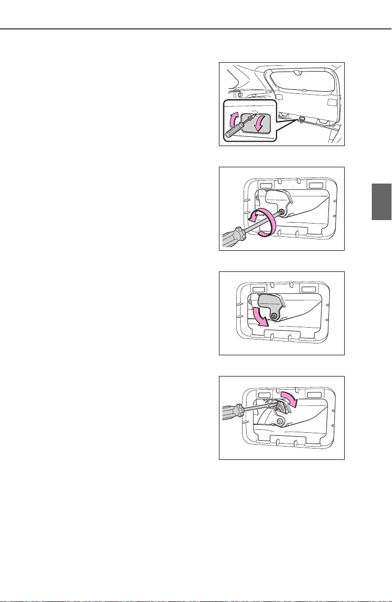
123
3-2. Opening, closing and locking the doors
3
Before driving
bumper
● When a small animal or small
object, such as a ball, moves
under the rear bumper
● When an object is moved from
under the rear bumper
● If someone is swinging their legs
while sitting on the rear bumper
● If the legs or another part of some-
one’s body contacts the rear
bumper while passing by the vehi-
cle
● When the vehicle is parked near
an electrical noise source which
affects the sensitivity of the Hands
Free Power Back Door, such as a
pay parking spot, gas station,
electrically heated road, or fluo-
rescent light
● When the vehicle is near a TV
tower, electric power plant, radio
station, large display, airport or
other facility that generates strong
radio waves or electrical noise
● When the vehicle is parked in a
place where objects such as
plants are near the rear bumper
● If luggage, etc. is set near the rear
bumper
● If accessories or a vehicle cover is
installed/removed near the rear
bumper
● When the vehicle is being towed
To prevent unintentional operation,
turn the Hands Free Power Back
Door (kick sensor) operation setting
off. (P.94)
■ When reconnecting the battery
To enable the power back door to
operate properly, close the back
door manually.
■ If the back door opener is inop-
erative
The back door can be unlocked
from the inside.
1 Remove the cover.
To prevent damage, cover the tip of
the screwdriver with a rag.
2 Loosen the screw.
3 Turn the cover.
4 Move the lever.
5 When installing, reverse the
steps listed.
■ Customization
Settings (e.g. power back door
opening angle) can be changed.
(Customizable features: P.692)
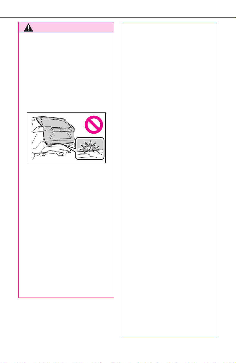
124
3-2. Opening, closing and locking the doors
WARNING
■ Back door closer
● In the event that the back door
is left slightly open, the back
door closer will automatically
close it to the fully closed posi-
tion. It takes several seconds
before the back door closer
begins to operate. Be careful
not to catch fingers or anything
else in the back door, as this
may cause bone fractures or
other serious injuries.
● Use caution when using the
back door closer as it still oper-
ates when the power back door
system is canceled.
■ Power back door
Observe the following precautions
when operating the power back
door.
Failure to do so may cause death
or serious injury.
● Check the safety of the sur-
rounding area to make sure
there are no obstacles or any-
thing that could cause any of
your belongings to get caught.
● If anyone is in the vicinity, make
sure they are safe and let them
know that the back door is
about to open or close.
● If the power back door system is
turned off while the back door is
operating automatically, the
automatic operation is stopped.
The back door then has to be
operated manually. Take extra
care when on an incline, as the
back door may open or close
unexpectedly.
● If the operating conditions of the
power back door are no longer
met, a buzzer may sound and
the back door may stop opening
or closing. The back door then
has to be operated manually.
Take extra care when on an
incline, as the back door may
open or close abruptly.
● On an incline, the back door
may suddenly shut after it
opens. Make sure the back door
is fully open and secure.
● In the following situations, the
power back door may detect an
abnormality and automatic
operation may be stopped. In
this case, the back door has to
be operated manually. Take
extra care when on an incline,
as the back door may open or
close abruptly.
• When the back door contacts an
obstacle
• When the battery voltage sud-
denly drops, such as when the
engine switch is turned to ON or
the engine is started during
automatic operation
● If a bicycle carrier or similar
heavy object is attached to the
back door, it may suddenly shut
again after being opened, caus-
ing someone’s hands, head or
neck to be caught and injured.
When installing an accessory
part to the back door, using a
genuine Toyota part is recom-
mended.
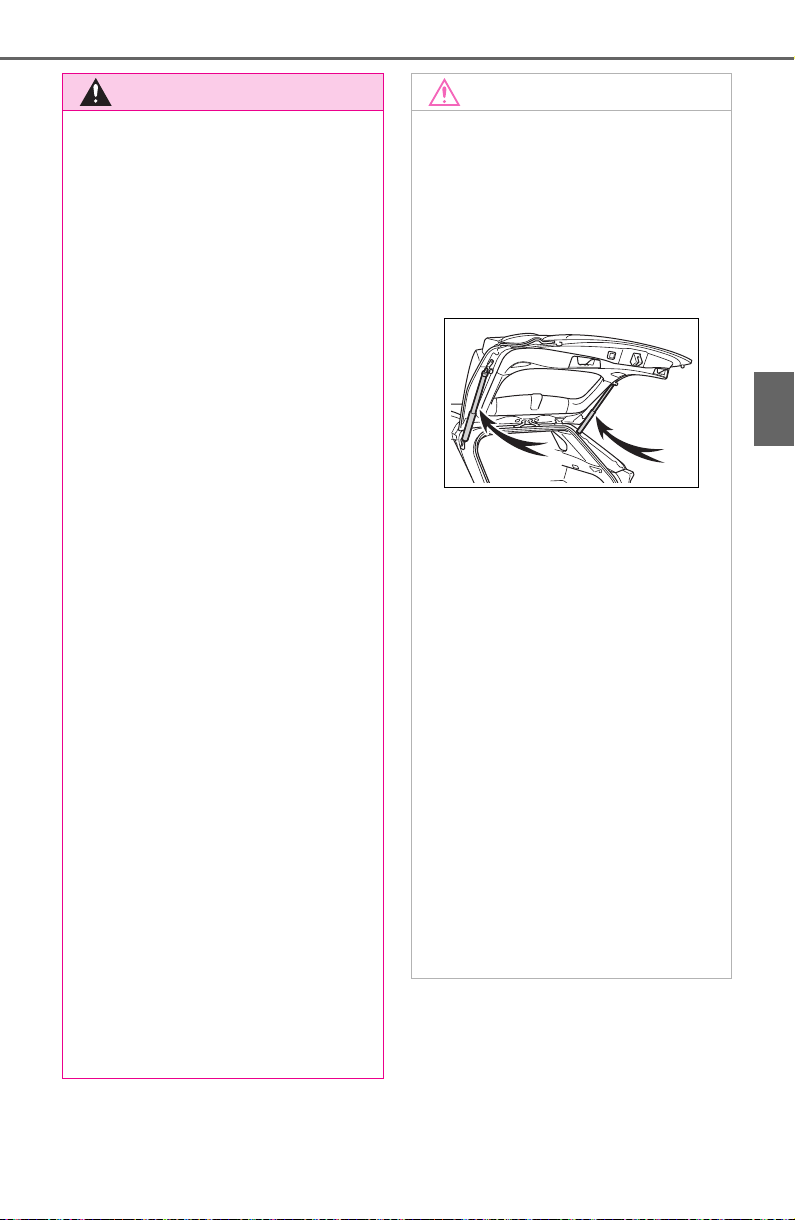
125
3-2. Opening, closing and locking the doors
3
Before driving
WARNING
■ Jam protection function
Observe the following precau-
tions.
Failure to do so may cause death
or serious injury.
● Never use any part of your body
to intentionally activate the jam
protection function.
● The jam protection function may
not work if something gets
caught just before the back door
fully closes. Be careful not to
catch fingers or anything else.
● The jam protection function may
not work depending on the
shape of the object that is
caught. Be careful not to catch
fingers or anything else.
■ Hands Free Power Back Door
(if equipped)
Observe the following precautions
when operating the Hands Free
Power Back Door.
Failure to do so may cause death
or serious injury.
● Check the safety of the sur-
rounding area to make sure
there are no obstacles or any-
thing that could cause any of
your belongings to get caught.
● When putting your foot near the
lower center part of the rear
bumper and moving it from the
rear bumper, be careful not to
touch the exhaust pipes until
they have cooled down suffi-
ciently, as touching hot exhaust
pipes can cause burns.
● Do not leave the electronic key
within the effective range
(detection area) of the luggage
compartment.
NOTICE
■ Back door spindles
The back door is equipped with
spindles that hold the back door in
place.
Observe the following precau-
tions.
Failure to do so may cause dam-
age to the back door spindle,
resulting in malfunction.
● Do not attach any foreign
objects, such as stickers, plastic
sheets, or adhesives to the
spindle rod.
● Do not touch the spindle rod
with gloves or other fabric items.
● Do not attach heavy accesso-
ries to the back door. When
attaching, ask your Toyota
dealer for details.
● Do not place your hand on the
spindle or apply lateral forces to
it.
■ To prevent back door closer
malfunction
Do not apply excessive force to
the back door while the back door
closer is operating. Applying
excessive force may cause the
back door closer to malfunction.

126
3-2. Opening, closing and locking the doors
NOTICE
■ To prevent damage to the
power back door
● Make sure that there is no ice
between the back door and
frame that would prevent move-
ment of the back door. Operat-
ing the power back door when
excessive load is present on the
back door may cause a mal-
function.
● Do not apply excessive force to
the back door while the power
back door is operating.
● Take care not to damage the
sensors (installed on the right
and left edges of the power
back door) with a knife or other
sharp object. If the sensor is
disconnected, the power back
door will not close automatically.
■ Hands Free Power Back Door
precautions (if equipped)
The kick sensor is located behind
lower center part of the rear
bumper. Observe the following to
ensure that the Hands Free
Power Back Door function oper-
ates properly:
● Keep the lower center part of
the rear bumper clean at all
times.
If the lower center part of the
rear bumper is dirty or covered
with snow, the kick sensor may
not operate. In this situation,
clean off the dirt or snow, move
the vehicle from the current
position and then check if the
kick sensor operates.
If it does not operate, have the
vehicle inspected by your
Toyota dealer.
● Do not apply coatings that have
a rain clearing (hydrophilic)
effect, or other coatings, to the
lower center part of the rear
bumper.
● Do not park the vehicle near
objects that may move and con-
tact the lower center part of the
rear bumper, such as grass or
trees.
If the vehicle has been parked
for a while near objects that
may move and contact the
lower center part of the rear
bumper, such as grass or trees,
the kick sensor may not oper-
ate. In this situation, move the
vehicle from the current position
and then check if the kick sen-
sor operates. If it does not oper-
ate, have the vehicle inspected
by your Toyota dealer.
● Do not subject the kick sensor
or its surrounding area to a
strong impact.
If the kick sensor or its sur-
rounding area has been sub-
jected to a strong impact, the
kick sensor may not operate
properly. If the kick sensor does
not operate in the following situ-
ations, have the vehicle
inspected by your Toyota
dealer.
• The kick sensor or its surround-
ing area has been subjected to
a strong impact.
• The lower center part of the rear
bumper is scratched or dam-
aged.
● Do not disassemble the rear
bumper.
● Do not attach stickers to the
rear bumper.
● Do not paint the rear bumper.
● If a bicycle carrier or similar
heavy object is attached to the
power back door, disable the
kick sensor. (P.94)
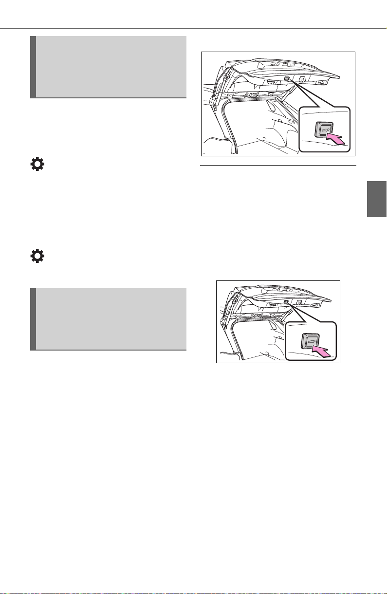
127
3-2. Opening, closing and locking the doors
3
Before driving
The settings of the power back
door system can be changed by
displaying the “Vehicle Set-
tings” - “PBD” screen from the
screen of the multi-informa-
tion display. (P. 94 )
The changed power back door set-
tings are not reset by turning the
engine switch to OFF. In order to
restore the original settings, they
need to be changed back on the
screen of the multi-information
display.
The open position of the power
back door can be adjusted.
1 Stop the back door in the
desirable position. (P. 11 8)
2 Press and hold the power
back door switch on the back
door for approximately 2 sec-
onds.
When the settings are completed,
the buzzer sounds 4 times.
When opening the back door the
next time, the back door will stop at
that position.
■ Canceling the adjusted open
position of the back door
Press and hold the power back door
switch on the back door for approxi-
mately 7 seconds.
After the buzzer sounds 4 times, it
sounds twice more. When the
power back door does the opening
operation the next time, the door will
open to the initial settings position.
■ Customization
The opening position can be set
with the multi-information display.
(P. 94 )
Priority for the stop position is given
to the last position set by either the
power back door switch on the back
door or multi-information display.
Changing settings of the
power back door system
(vehicles with power back
door)
Adjusting the open posi-
tion of the back door
(vehicles with power back
door)
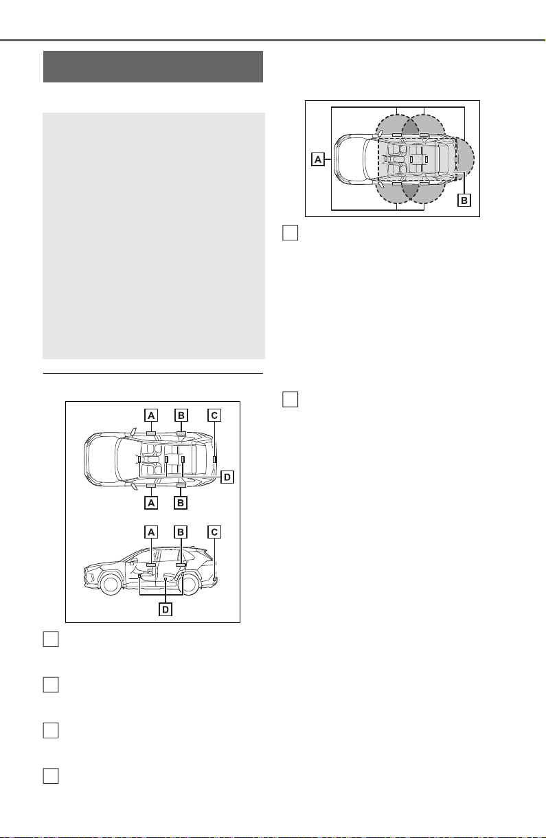
128
3-2. Opening, closing and locking the doors
*
: If equipped
■ Antenna location
Antennas outside the cabin
(front)
Antennas outside the cabin
(rear) (if equipped)
Antenna outside the luggage
compartment
Antennas inside the cabin
■ Effective range (areas within
which the electronic key is
detected)
When locking or unlocking the
doors
The system can be operated when
the electronic key is within about 2.3
ft. (0.7 m) of the front door handles,
rear door handles (if equipped) and
back door opener switch. (Only the
doors detecting the key can be
operated.)
When starting the engine or
changing engine switch modes
The system can be operated when
the electronic key is inside the vehi-
cle.
■ If an alarm sounds or a warning
message is displayed
An alarm sounds and warning mes-
sage displays shown on the multi-
information display are used to pro-
tect against unexpected accidents
or theft of the vehicle resulting from
erroneous operation. When a warn-
ing message is displayed, take
appropriate measures based on the
displayed message.
When only an alarm sounds, cir-
cumstances and correction proce-
dures are as follows.
Smart key system
*
The following operations
can be performed simply by
carrying the electronic key
on your person, for example
in your pocket. The driver
should always carry the
electronic key.
Locks and unlocks the side
doors (P.108)
Locks and unlocks the back
door (P.115)
Starts the engine (P.194)
A
B
C
D
A
B
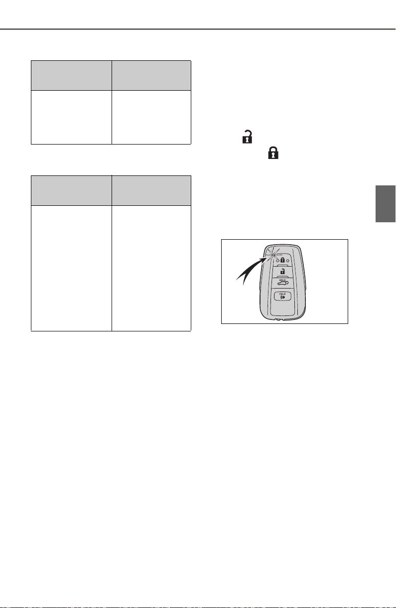
129
3-2. Opening, closing and locking the doors
3
Before driving
● When an exterior alarm sounds
once for 5 seconds
● When an interior alarm pings con-
tinuously
■ Battery-saving function
The battery-saving function will be
activated in order to prevent the
electronic key battery and the bat-
tery from being discharged while the
vehicle is not in operation for a long
time.
● In the following situations, the
smart key system may take some
time to unlock the doors.
• The electronic key has been left in
an area of approximately 6 ft. (2
m) of the outside of the vehicle for
10 minutes or longer.
• The smart key system has not
been used for 5 days or longer.
● If the smart key system has not
been used for 14 days or longer,
the doors cannot be unlocked at
any doors except the driver’s door.
In this case, take hold of the
driver’s door handle, or use the
wireless remote control or the
mechanical key, to unlock the
doors.
■ Turning an electronic key to
battery-saving mode
● When battery-saving mode is set,
battery depletion is minimized by
stopping the electronic key from
receiving radio waves.
Press twice while pressing
and holding .
Confirm that the electronic key indi-
cator flashes 4 times.
While the battery-saving mode is
set, the smart key system cannot be
used. To cancel the function, press
any of the electronic key buttons.
● Electronic keys that will not be
used for long periods of time can
be set to the battery-saving mode
in advance.
■ Conditions affecting operation
The smart key system uses weak
radio waves. In the following situa-
tions, the communication between
the electronic key and the vehicle
may be affected, preventing the
smart key system, wireless remote
control and engine immobilizer sys-
tem from operating properly.
(Ways of coping: P. 65 3)
● When the electronic key battery is
depleted
● Near a TV tower, electric power
plant, gas station, radio station,
large display, airport or other facil-
ity that generates strong radio
waves or electrical noise
● When the electronic key is in con-
Situation
Correction pro-
cedure
An attempt was
made to lock the
vehicle while a
door was open.
Close all of the
doors and lock
the doors again.
Situation
Correction pro-
cedure
The engine
switch was
turned to ACC
while the driver’s
door was open
(or the driver’s
door was opened
while the engine
switch was in
ACC).
Turn the engine
switch to OFF
and close the
driver’s door.

130
3-2. Opening, closing and locking the doors
tact with, or is covered by the fol-
lowing metallic objects
• Cards to which aluminum foil is
attached
• Cigarette boxes that have alumi-
num foil inside
• Metallic wallets or bags
•Coins
• Hand warmers made of metal
• Media such as CDs and DVDs
● When other wireless key (that
emits radio waves) is being used
nearby
● When carrying the electronic key
together with the following devices
that emit radio waves
• Portable radio, cellular phone,
cordless phone or other wireless
communication devices
• Another vehicle’s electronic key or
a wireless key that emits radio
waves
• Personal computers or personal
digital assistants (PDAs)
• Digital audio players
• Portable game systems
● If window tint with a metallic con-
tent or metallic objects are
attached to the rear window
● When the electronic key is placed
near a battery charger or elec-
tronic devices
● When parking in a coin-operated
parking lot (Radio waves used to
detect vehicles may affect the
smart key system.)
■ Note for the entry function
● Even when the electronic key is
within the effective range (detec-
tion areas), the system may not
operate properly in the following
cases:
• The electronic key is too close to
the window or outside door han-
dle, near the ground, or in a high
place when the doors are locked
or unlocked.
• The electronic key is on the instru-
ment panel, luggage cover or
floor, or in the door pockets or
glove box when the engine is
started or engine switch modes
are changed.
● Do not leave the electronic key on
top of the instrument panel or near
the door pockets when exiting the
vehicle. Depending on the radio
wave reception conditions, it may
be detected by the antenna out-
side the cabin and the door will
become lockable from the outside,
possibly trapping the electronic
key inside the vehicle.
● As long as the electronic key is
within the effective range, the
doors may be locked or unlocked
by anyone. However, only the
doors detecting the electronic key
can be used to unlock the vehicle.
● Even if the electronic key is not
inside the vehicle, it may be possi-
ble to start the engine if the elec-
tronic key is near the window.
● The doors may unlock if a large
amount of water splashes on the
door handle, such as in the rain or
in a car wash when the electronic
key is within the effective range.
(The doors will automatically be
locked after approximately 60 sec-
onds if the doors are not opened
and closed.)
● If the wireless remote control is
used to lock the doors when the
electronic key is near the vehicle,
there is a possibility that the door
may not be unlocked by the entry
function. (Use the wireless remote
control to unlock the doors.)
● Touching the door lock sensor
while wearing gloves may delay or
prevent lock operation. Remove
the gloves and touch the lock sen-
sor again.
● When the lock operation is per-
formed using the lock sensor, rec-
ognition signals will be shown up
to two consecutive times. After
this, no recognition signals will be
given.
● If the door handle becomes wet
while the electronic key is within

131
3-2. Opening, closing and locking the doors
3
Before driving
the effective range, the door may
lock and unlock repeatedly. In that
case, follow the following correc-
tion procedures to wash the vehi-
cle:
• Place the electronic key in a loca-
tion 6 ft. (2 m) or more away from
the vehicle. (Take care to ensure
that the key is not stolen.)
• Set the electronic key to battery-
saving mode to disable the smart
key system. (P.129)
● If the electronic key is inside the
vehicle and a door handle
becomes wet during a car wash, a
message may be shown on the
multi-information display and a
buzzer will sound outside the vehi-
cle. To turn off the alarm, lock all
the doors.
● The lock sensor may not work
properly if it comes into contact
with ice, snow, mud, etc. Clean
the lock sensor and attempt to
operate it again, or use the lock
sensor on the lower part of the
door handle.
● A sudden approach to the effec-
tive range or door handle may pre-
vent the doors from being
unlocked. In this case, return the
door handle to the original position
and check that the doors unlock
before pulling the door handle
again.
● If there is another electronic key in
the detection area, it may take
slightly longer to unlock the doors
after the door handle is gripped.
■ When the vehicle is not driven
for extended periods
● To prevent theft of the vehicle, do
not leave the electronic key within
6 ft. (2 m) of the vehicle.
● The smart key system can be
deactivated in advance. (P.691)
● Battery-saving mode can reduce
the power consumption of elec-
tronic keys. (P.129)
■ To operate the system properly
Make sure to carry the electronic
key when operating the system. Do
not get the electronic key too close
to the vehicle when operating the
system from the outside of the vehi-
cle.
Depending on the position and hold-
ing condition of the electronic key,
the key may not be detected cor-
rectly and the system may not oper-
ate properly. (The alarm may go off
accidentally, or the door lock pre-
vention may not operate.)
■ If the smart key system does
not operate properly
● Locking and unlocking the doors:
Use the mechanical key. (P.653)
● Starting the engine: P. 65 4
■ Customization
Settings (e.g. smart key system)
can be changed.
(Customizable features: P.691)
If the smart key system has been
deactivated in a customized setting,
refer to the explanations for the fol-
lowing operations.
● Locking and unlocking the doors:
Use the wireless remote control or
mechanical key. (P.108, 653)
● Starting the engine and changing
engine switch modes: P. 65 4
● Stopping the engine: P.196

132
3-2. Opening, closing and locking the doors
■ Certification for the smart key system
For vehicles sold in the U.S.A., Hawaii, American Samoa, Guam, Saipan
and Puerto Rico
For vehicles sold in Canada

133
3-2. Opening, closing and locking the doors
3
Before driving
WARNING
■ Caution regarding interfer-
ence with electronic devices
● People with implantable car-
diac pacemakers, cardiac
resynchronization therapy-
pacemakers or implantable car-
dioverter defibrillators should
maintain a reasonable distance
between themselves and the
smart key system antennas.
(P.128)
The radio waves may affect the
operation of such devices. If
necessary, the entry function
can be disabled. Ask your
Toyota dealer for details, such
as the frequency of radio waves
and timing of the emitted radio
waves. Then, consult your doc-
tor to see if you should disable
the entry function.
● Users of any electrical medical
device other than implantable
cardiac pacemakers, cardiac
resynchronization therapy-
pacemakers or implantable car-
dioverter defibrillators should
consult the manufacturer of the
device for information about its
operation under the influence of
radio waves.
Radio waves could have unex-
pected effects on the operation
of such medical devices.
Ask your Toyota dealer for details
on disabling the entry function.
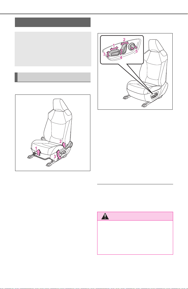
134
3-3. Adjusting the seats
3-3.Adjusting the seats
Manual seat
1 Seat position adjustment
lever
2 Seatback angle adjustment
lever
3 Vertical height adjustment
lever (driver’s side only)
Power seat (driver’s side
only)
1 Seat position adjustment
switch
2 Seatback angle adjustment
switch
3 Seat cushion (front) angle
adjustment switch
4 Vertical height adjustment
switch
5 Lumbar support adjustment
switch
■ When adjusting the seat
Take care when adjusting the seat
so that the head restraint does not
touch the ceiling.
Front seats
The seats can be adjusted
(longitudinally, vertically,
etc.). Adjust the seat to
ensure the correct driving
posture.
Adjustment procedure
WARNING
■ When adjusting the seat posi-
tion
● Take care when adjusting the
seat position to ensure that
other passengers are not
injured by the moving seat.
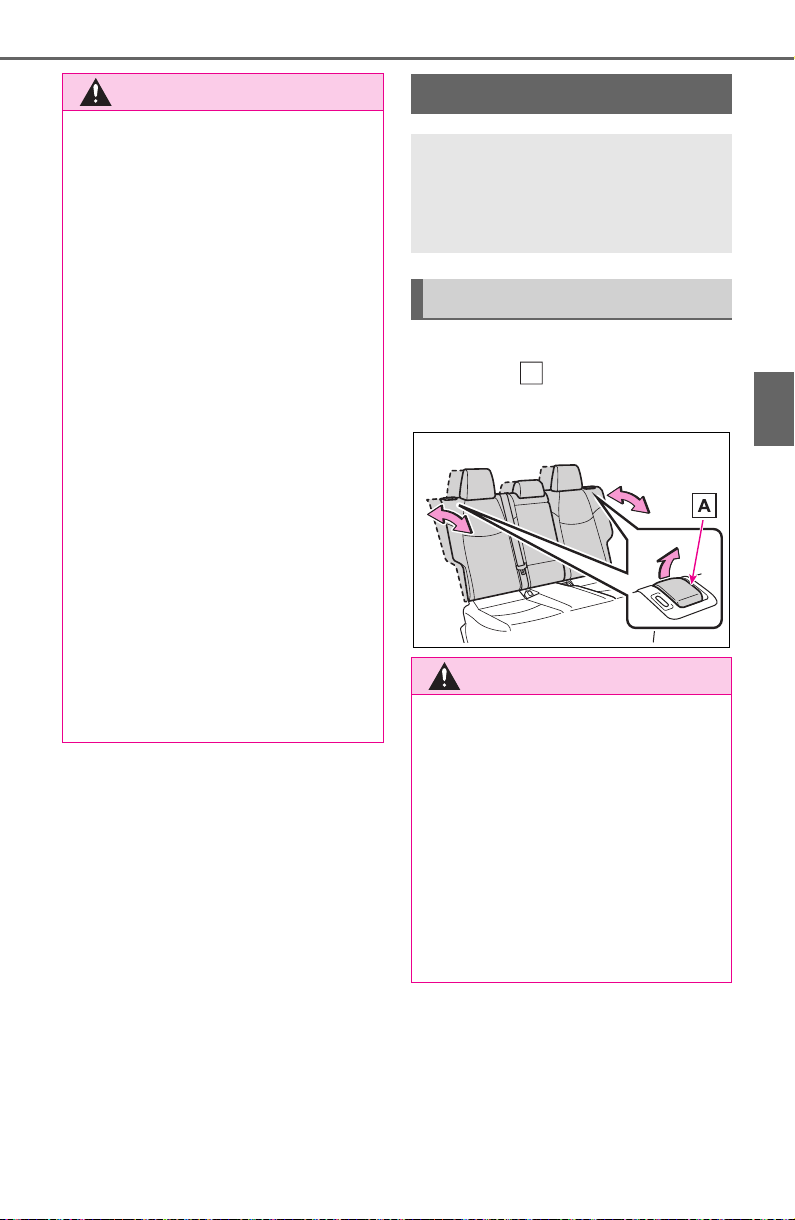
135
3-3. Adjusting the seats
3
Before driving
Pull the seatback angle adjust-
ment lever , and adjust the
seatback angle.
WARNING
● Do not put your hands under the
seat or near the moving parts to
avoid injury.
Fingers or hands may become
jammed in the seat mechanism.
● Make sure to leave enough
space around the feet so they
do not get stuck.
● Manual seat only: After adjust-
ing the seat, make sure that the
seat is locked in position.
■ Seat adjustment
To reduce the risk of sliding under
the lap belt during a collision, do
not recline the seat more than
necessary.
If the seat is too reclined, the lap
belt may slide past the hips and
apply restraint forces directly to
the abdomen, or your neck may
contact the shoulder belt, increas-
ing the risk of death or serious
injury in the event of an accident.
Adjustments should not be made
while driving as the seat may
unexpectedly move and cause
the driver to lose control of the
vehicle.
Rear seats
Reclining adjustments and
folding the seatbacks can
be done with lever opera-
tion.
Adjustment procedure
WARNING
■ When operating the seatback
Observe the following precau-
tions.
Failure to do so may cause death
or serious injury.
● Keep other passengers from
being hit with the seatback.
● Do not bring your hands close
to the moving parts or between
the seats, as well as do not let
any part of your body get
caught.
A
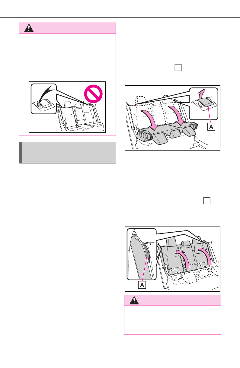
136
3-3. Adjusting the seats
■ Before folding down the
seatbacks
1 Park the vehicle in a safe
place.
Apply the parking brake (P.203)
and shift the shift lever to P.
(P.200)
2 Adjust the position of the
front seat and the angle of
the seatback. (P.134)
Depending on the position of the
front seat, if the seatback is folded
backward, it may interfere with the
operation of the rear seat.
3 Lift up and push down the
head restraints of the rear
outboard seats, and lower
the head restraint of the rear
center seat. (P.140)
4 Stow the armrest of the rear
seat if it is pulled out.
(P.547)
This step is not necessary when
operating the left side seat only.
■ Folding down the seat-
backs
While pulling the seatback angle
adjustment lever , fold the
seatback down.
■ Returning the rear seat-
backs
To avoid trapping the seat belt
between the seat and the inside
of the vehicle, pass the seat belt
outside the seat belt guide
and then return the seatback
securely to the locked position.
WARNING
● After adjusting the seat, make
sure that the seat is locked in
position.
If the seatback is not securely
locked, the red marking will be
visible. Make sure that the red
marking is not visible.
Folding down the rear
seatbacks
WARNING
Observe the following precau-
tions.
Failure to do so may result in
death or serious injury.
A
A
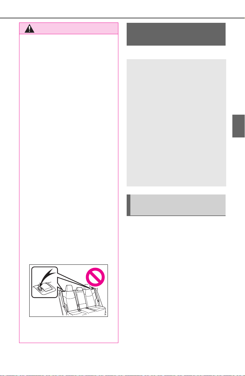
137
3-3. Adjusting the seats
3
Before driving
*
: If equipped
■ Recording procedure
1 Check that the shift lever is in
P.
2 Turn the engine switch to
ON.
3 Adjust the driver’s seat to the
desired positions.
4 While pressing the “SET” but-
ton, press button “1” or “2”
until the buzzer sounds.
If the selected button has already
been preset, the previously
recorded position will be overwrit-
WARNING
■ When folding the rear seat-
backs down
● Do not fold the seatbacks down
while driving.
● Stop the vehicle on level
ground, set the parking brake
and shift the shift lever to P.
● Do not allow anyone to sit on a
folded seatback or in the lug-
gage compartment while driv-
ing.
● Do not allow children to enter
the luggage compartment.
● Do not operate the rear seat if it
is occupied.
● Be careful not to get feet or
hands caught in the moving
parts or joints of the seats
during operation.
● Do not allow children to operate
the seat.
■ After returning the rear seat-
back to the upright position
● Make sure that the seatback is
securely locked in position by
lightly pushing it back and forth.
If the seatback is not securely
locked, the red marking will be
visible. Make sure that the red
marking is not visible.
● Check that the seat belts are
not twisted or caught in the
seatback.
Driving position mem-
ory
*
This feature automatically
adjusts the driver’s seat to
suit your preferences.
Your preferred driving posi-
tion (the position of the
driver’s seat) can be
recorded and recalled by
pressing a button.
Two different driving posi-
tions can be recorded into
memory.
Each electronic key can be
registered to recall your pre-
ferred driving position.
Recording/recalling a
driving position
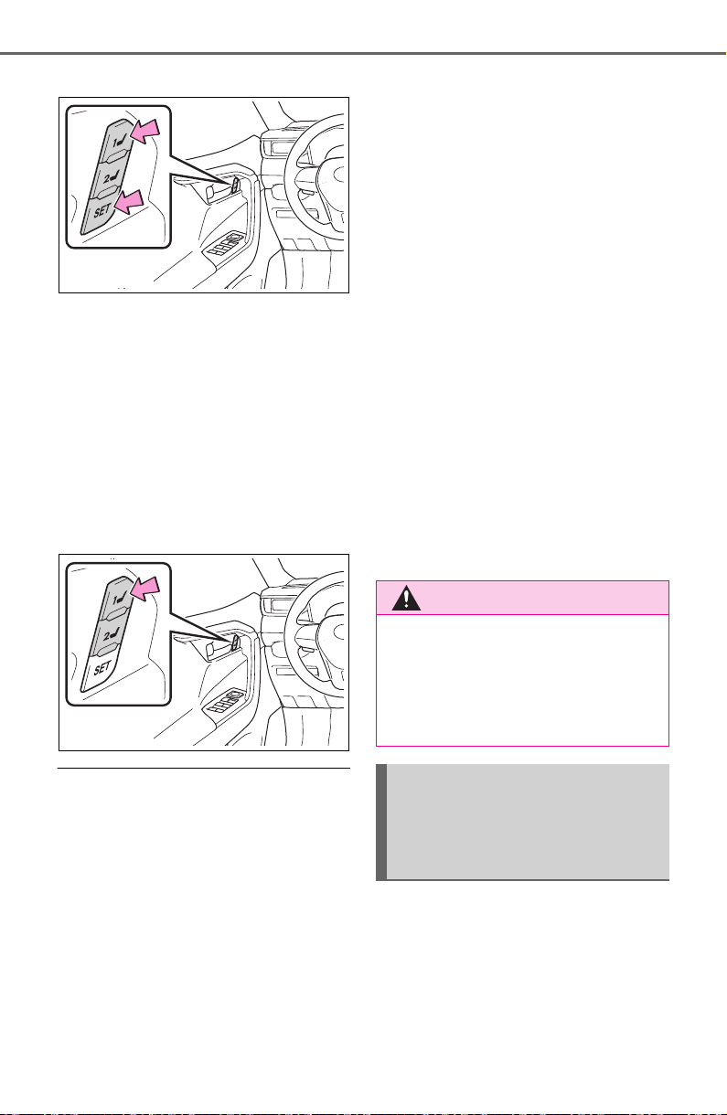
138
3-3. Adjusting the seats
ten.
■ Recall procedure
1 Check that the shift lever is in
P.
2 Turn the engine switch to
ON.
3 Press one of the buttons for
the driving position you want
to recall until the buzzer
sounds.
■ To stop the position recall oper-
ation part-way through
Perform any of the following:
● Press the “SET” button.
● Press button “1” or “2”.
● Operate any of the seat adjust-
ment switches.
■ Seat positions that can be
memorized (P.134)
The adjusted positions other than
the position adjusted by lumbar sup-
port switch can be recorded.
■ Operating the driving position
memory after turning the
engine switch to OFF
Recorded seat positions can be
activated up to 180 seconds after
the driver’s door is opened and
another 60 seconds after it is closed
again.
■ In order to correctly use the
driving position memory func-
tion
If a seat position is already in the
furthest possible position and the
seat is operated in the same direc-
tion, the recorded position may be
slightly different when it is recalled.
■ When recalling the driving posi-
tion
Take care when recalling the driving
position so that the head restraint
does not touch the ceiling.
■ If the battery is disconnected
The memorized positions are
erased.
■ Registering procedure
Record your driving position to
button “1” or “2” before perform-
ing the following:
Carry only the key you want to
register, and then close the
WARNING
■ Seat adjustment caution
Take care during seat adjustment
so that the seat does not strike
the rear passenger or squeeze
your body against the steering
wheel.
Registering/recall/cancel-
ing a driving position to
an electronic key (mem-
ory recall function)
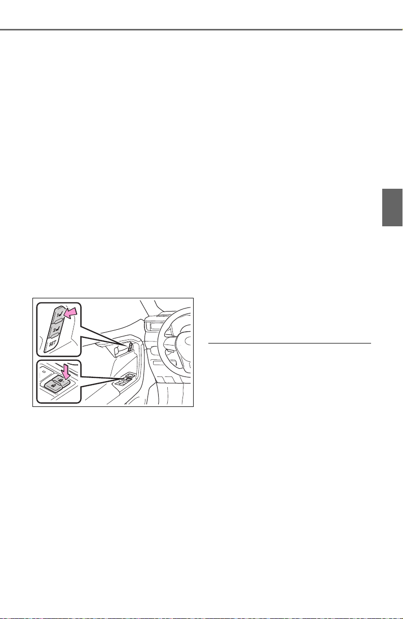
139
3-3. Adjusting the seats
3
Before driving
driver’s door.
If 2 or more keys are in the vehi-
cle, the driving position cannot
be recorded properly.
1 Check that the shift lever is in
P.
2 Turn the engine switch to
ON.
3 Recall the driving position
that you want to record.
4 While pressing the recalled
button, press and hold the
door lock switch (either lock
or unlock) until the buzzer
sounds.
If the button could not be regis-
tered, the buzzer sounds continu-
ously for approximately 3 seconds.
■ Recall procedure
Make sure that the doors are
locked before recalling the driv-
ing position.Carry the electronic
key that has been registered to
the driving position, and then
unlock and open the driver’s
door using the smart key system
or wireless remote control.
The driving position will move to the
recorded position.
If the driving position is in a position
that has already been recorded, the
seat will not move.
■ Cancelation procedure
Carry only the key you want to
cancel and then close the
driver’s door.
If 2 or more keys are in the vehi-
cle, the driving position cannot
be canceled properly.
1 Check that the shift lever is in
P.
2 Turn the engine switch to
ON.
3 While pressing the “SET” but-
ton, press and hold the door
lock switch (either lock or
unlock) until the buzzer
sounds twice.
If the button could not be canceled,
the buzzer sounds continuously for
approximately 3 seconds.
■ Recalling the driving position
using the memory recall func-
tion
● Different driving positions can be
registered for each electronic key.
Therefore, the driving position that
is recalled may be different
depending on the key being car-
ried.
● If a door other than the driver’s
door is unlocked with smart key
system, the driving position can-
not be recalled. In this case, press
the driving position button which
has been set.
■ Customization
Settings (e.g. the unlock door set-
tings of the memory recall function)
can be customized. (Customizable
features: P.693)
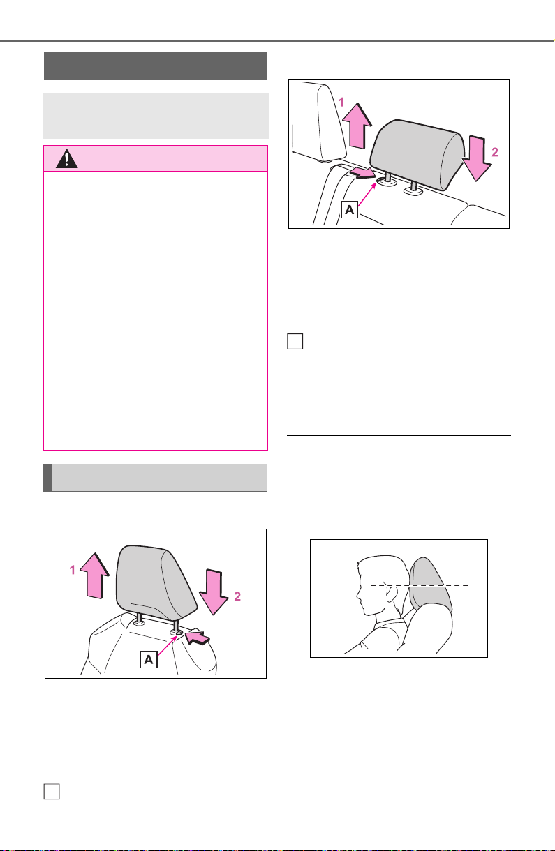
140
3-3. Adjusting the seats
■ Front seats
1 Up
Pull the head restraints up.
2 Down
Push the head restraint down while
pressing the lock release button
.
■ Center rear seat
1 Up
Pull the head restraints up.
2 Down
Push the head restraint down while
pressing the lock release button
.
■ Outboard rear seats
Head restraints cannot be
adjusted.
■ Adjusting the height of the head
restraints (front seats)
Make sure that the head restraints
are adjusted so that the center of
the head restraint is closest to the
top of your ears.
■ Adjusting the center rear seat
head restraint
Always raise the head restraint one
level from the stowed position when
using.
Head restraints
Head restraints are provided
for all seats.
WARNING
■ Head restraint precautions
Observe the following precautions
regarding the head restraints.
Failure to do so may result in
death or serious injury.
● Use the head restraints
designed for each respective
seat.
● Adjust the head restraints to the
correct position at all times.
● After adjusting the head
restraints, push down on them
and make sure they are locked
in position.
● Do not drive with the head
restraints removed.
Vertical adjustment
A
A
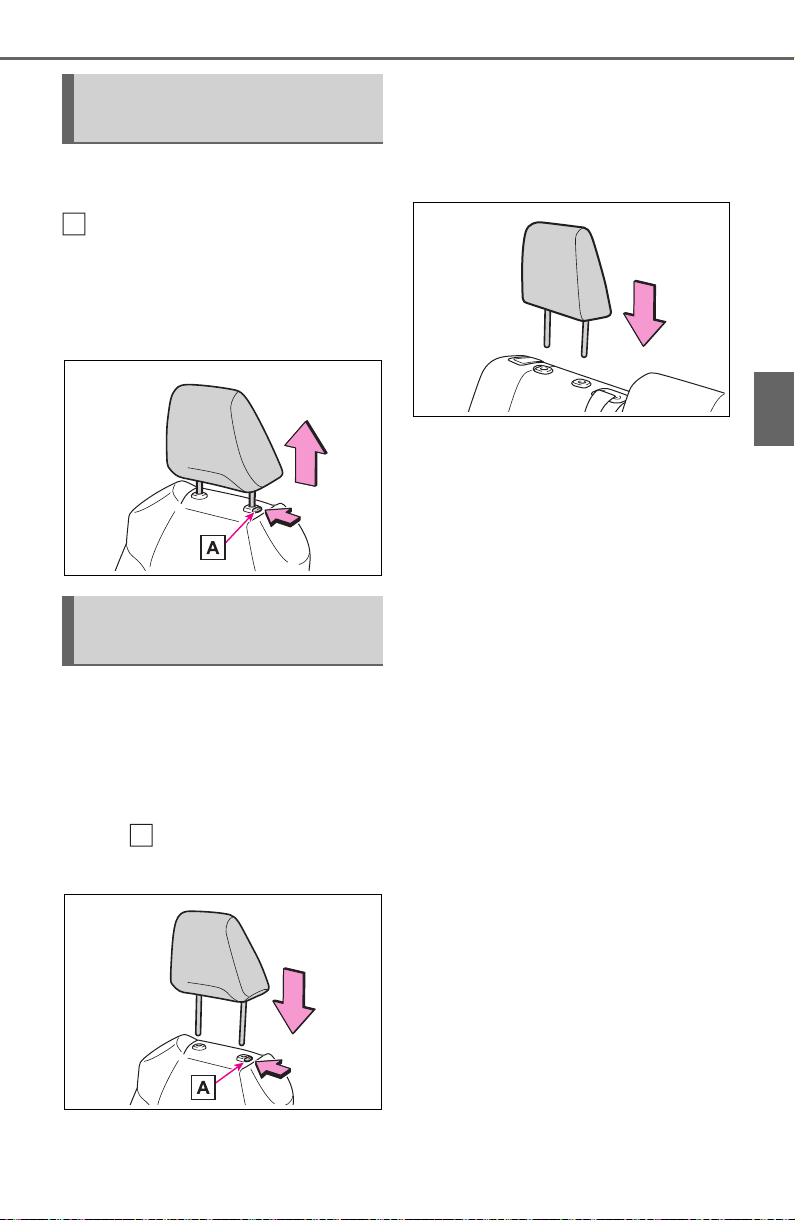
141
3-3. Adjusting the seats
3
Before driving
Pull the head restraint up while
pressing the lock release button
.
If the head restraint touches the
ceiling, making the removal difficult,
change the seat height or angle.
(P.134)
■ Front and center rear seats
Align the head restraint with the
installation holes and push it
down to the lock position.
Press and hold the lock release
button when lowering the
head restraint.
■ Outboard rear seats
Align the head restraint with the
installation holes and push it
down to the lowest lock position.
Removing the head
restraints
Installing the head
restraints
A
A
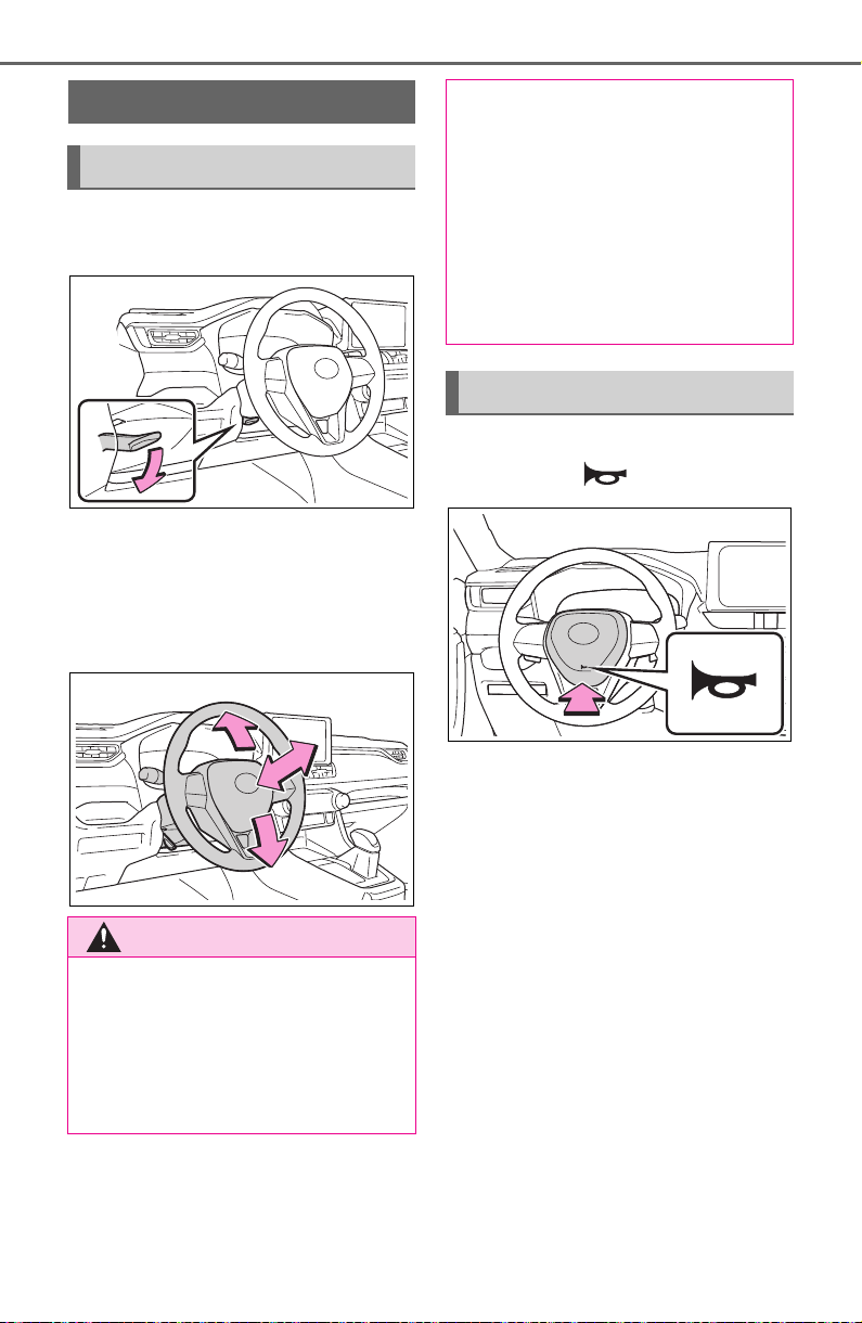
142
3-4. Adjusting the steering wheel and mirrors
3-4.Adjusting the steering wheel and mirrors
1 Hold the steering wheel and
push the lever down.
2 Adjust to the ideal position by
moving the steering wheel
horizontally and vertically.
After adjustment, pull the lever up
to secure the steering wheel.
To sound the horn, press on or
close to the mark.
Steering wheel
Adjustment procedure
WARNING
■ Caution while driving
Do not adjust the steering wheel
while driving.
Doing so may cause the driver to
mishandle the vehicle and cause
an accident, resulting in death or
serious injury.
■ After adjusting the steering
wheel
Make sure that the steering wheel
is securely locked.
Otherwise, the steering wheel
may move suddenly, possibly
causing an accident, and resulting
in death or serious injury. Also,
the horn may not sound if the
steering wheel is not securely
locked.
Sounding the horn
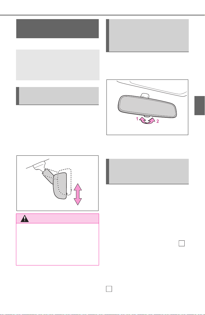
143
3-4. Adjusting the steering wheel and mirrors
3
Before driving
*
: If equipped
The height of the rear view mir-
ror can be adjusted to suit your
driving posture.
Adjust the height of the rear
view mirror by moving it up and
down.
Reflected light from the head-
lights of vehicles behind can be
reduced by operating the lever.
1 Normal position
2 Anti-glare position
Responding to the level of
brightness of the headlights of
vehicles behind, the reflected
light is automatically reduced.
Changing automatic anti-glare
function mode on/off
When the automatic anti-glare func-
tion is in ON mode, the indicator
illuminates.
The function will set to ON mode
each time the engine switch is
turned to ON.
Pressing the button turns the func-
tion to OFF mode. (The indicator
also turns off.)
Inside rear view mir-
ror
*
The rear view mirror’s posi-
tion can be adjusted to
enable sufficient confirma-
tion of the rear view.
Adjusting the height of
rear view mirror
WARNING
■ Caution while driving
Do not adjust the position of the
mirror while driving.
Doing so may lead to mishandling
of the vehicle and cause an acci-
dent, resulting in death or serious
injury.
Anti-glare function (vehi-
cles with manual anti-
glare inside rear view mir-
ror)
Anti-glare function (vehi-
cles with auto anti-glare
inside rear view mirror)
A
A
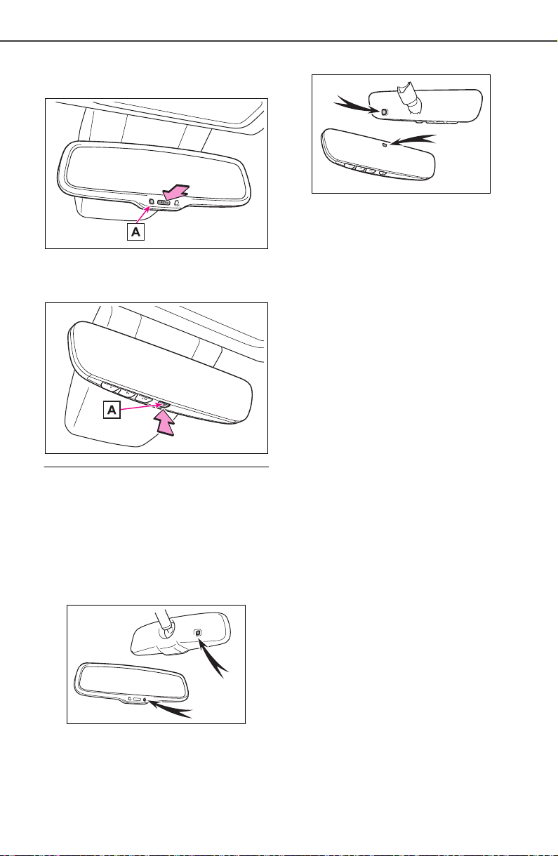
144
3-4. Adjusting the steering wheel and mirrors
Vehicles without garage door
opener
Vehicles with garage door
opener
■ To prevent sensor error (vehi-
cles with auto anti-glare inside
rear view mirror)
To ensure that the sensors operate
properly, do not touch or cover
them.
Vehicles without garage door
opener
Vehicles with garage door opener
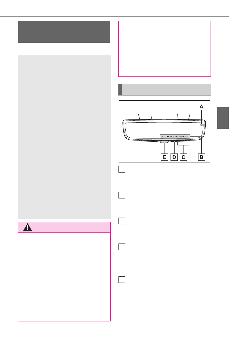
145
3-4. Adjusting the steering wheel and mirrors
3
Before driving
*
: If equipped
Camera indicator
Indicates that the camera is operat-
ing normally.
Icon display area
Displays icons, adjusting gauge,
etc. (P.147)
Select button
Press to change the setting of the
item you want to adjust.
Menu button
Press to display the icon display
area and select the item you want
to adjust.
Lever
Operate to change between digital
mirror mode and optical mirror
mode.
Digital Rear-view Mir-
ror
*
The Digital Rear-view Mirror
is a system that uses the
camera on the rear of the
vehicle and displays its
image on the display of the
Digital Rear-view Mirror.
The Digital Rear-view Mirror
can be changed between
optical mirror mode and dig-
ital mirror mode by operat-
ing the lever.
The Digital Rear-view Mirror
allows the driver to see the
rear view despite obstruc-
tions, such as the head
restraints or luggage, ensur-
ing rear visibility. Also, the
rear seats are not displayed
and privacy of the passen-
gers is enhanced.
WARNING
Observe the following precau-
tions.
Failure to do so may result in
death or serious injury.
■ Before using the Digital Rear-
view Mirror
● Make sure to adjust the mirror
before driving. (P. 14 7)
• Change to optical mirror mode
and adjust the position of the
Digital Rear-view Mirror so that
the area behind your vehicle
can be viewed properly.
• Change to digital mirror mode
and adjust the display settings.
● As the range of the image dis-
played by the Digital Rear-view
Mirror is different from that of
the optical mirror, make sure to
check this difference before
driving.
System components
A
B
C
D
E
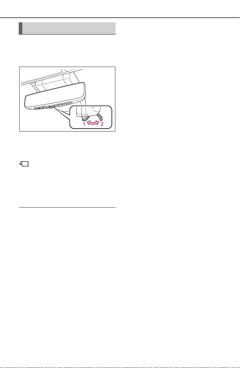
146
3-4. Adjusting the steering wheel and mirrors
Operate the lever to change
between digital mirror mode and
optical mirror mode.
1 Digital mirror mode
Displays an image of the area
behind the vehicle.
will illuminate in this mode.
2 Optical mirror mode
Turns off the display of the Digital
Rear-view Mirror allows it to be
used as an optical mirror.
■ Digital mirror mode operating
condition
The engine switch is turned to ON.
When the engine switch is changed
from ON to OFF or ACC, the image
will disappear after several seconds.
■ When using the Digital Rear-
view Mirror in digital mirror
mode
● If it is difficult to see the displayed
image due to light reflected off the
Digital Rear-view Mirror, the cam-
era being dirty, or if lights of a
vehicle behind your vehicle or the
displayed image are bothering
you, change to optical mirror
mode.
● When the back door is open, the
Digital Rear-view Mirror image
may not display properly. Before
driving, make sure the back door
is closed.
● If the display is difficult to see due
to reflected light, close the sun-
shade for the moon roof (if
equipped) or the electronic sun-
shade for the panoramic moon
roof (if equipped).
● Any of the following conditions
may occur when driving in the
dark, such as at night. None of
them indicates that a malfunction
has occurred.
• Colors of objects in the displayed
image may differ from their actual
color.
• Depending on the height of the
lights of the vehicle behind, the
area around the vehicle may
appear white and blurry.
• Automatic image adjustment for
brighter surrounding image may
cause flickering.
If it is difficult to see the displayed
image or flickering bothers you,
change to optical mirror mode.
● The Digital Rear-view Mirror may
become hot while it is in digital
mirror mode.
This is not a malfunction.
● Depending on your physical con-
dition or age, it may take longer
than usual to focus on the dis-
played image. In this case,
change to optical mirror mode.
● Do not let passengers stare at the
displayed image when the vehicle
is being driven, as doing so may
cause motion sickness.
■ When the system malfunctions
If the symbol shown in the illustra-
tion is displayed when using the
Digital Rear-view Mirror in digital
mirror mode, the system may be
malfunctioning. The symbol will dis-
appear in a few seconds. Operate
the lever, change to optical mirror
mode and have the vehicle
inspected by your Toyota dealer.
Changing modes
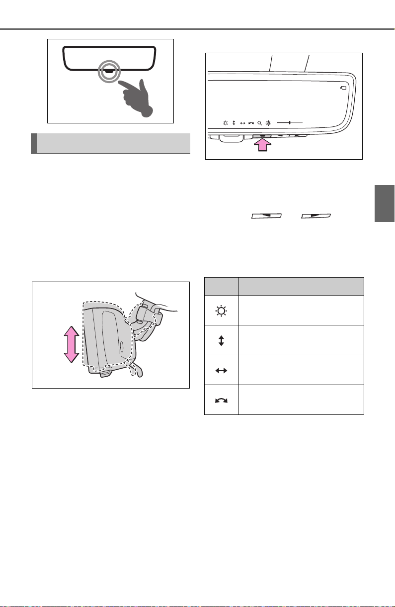
147
3-4. Adjusting the steering wheel and mirrors
3
Before driving
■ Adjusting the mirror height
The height of the rear view mir-
ror can be adjusted to suit your
driving posture.
Change to optical mirror mode,
adjusting the height of the rear
view mirror by moving it up and
down.
■ Display settings (digital mir-
ror mode)
Settings of the display in the dig-
ital mirror mode, on/off operation
of the automatic anti-glare func-
tion, etc. can be changed.
1 Press the menu button.
The icons will be displayed.
2 Press the menu button
repeatedly and select the
item you want to adjust.
3 Press or to
change the setting.
The icons will disappear if a button
is not operated for approximately 5
seconds or more.
Adjusting the mirror
Icons Settings
Select to adjust the bright-
ness of the display.
Select to adjust the area
displayed up/down.
Select to adjust the area
displayed to the left/right.
Select to adjust the angle of
the displayed image.
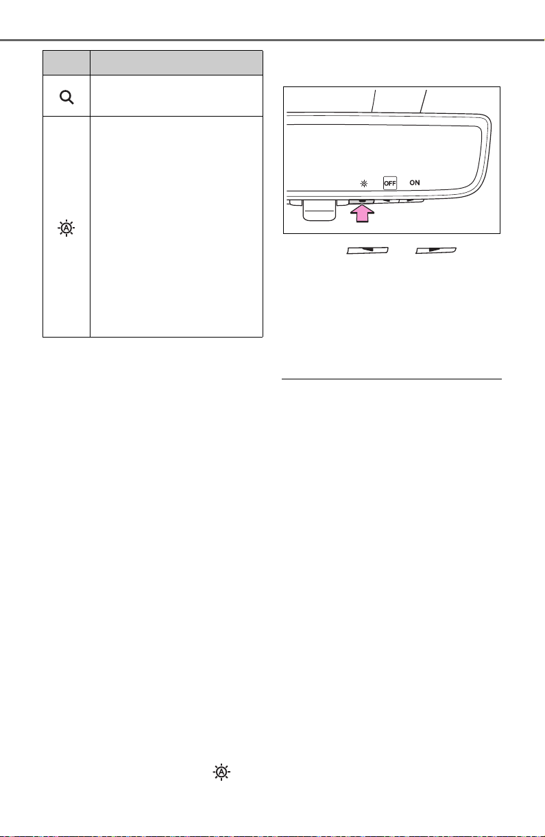
148
3-4. Adjusting the steering wheel and mirrors
*
: This is a function for the optical
mirror mode, however, the setting
can also be changed while using
the digital mirror mode.
■ Enabling/disabling the
automatic anti-glare func-
tion (optical mirror mode)
The automatic anti-glare func-
tion in the optical mirror mode
can be enabled/disabled. The
setting can be changed in both
the digital mirror mode and the
optical mirror mode.
When using the digital mirror
mode
P. 1 47
When using the optical mirror
mode
1 Press the menu button.
The icons will be displayed.
2 Press the menu button
repeatedly and select .
The setting display will be dis-
played.
3 Press or to
enable (ON)/disable (OFF)
the automatic anti-glare func-
tion.
The icons will disappear if a button
is not operated for approximately 5
seconds or more.
■ Adjusting the display (digital
mirror mode)
● If the displayed image is adjusted,
it may appear distorted. This is not
a malfunction.
● If the brightness of the Digital
Rear-view Mirror is set too high, it
may cause eye strain. Adjust the
Digital Rear-view Mirror to an
appropriate brightness. If your
eyes become tired, change to
optical mirror mode.
● The brightness of the Digital Rear-
view Mirror will change automati-
cally according to the brightness
of the area in front of your vehicle.
■ To prevent the light sensors
from malfunctioning
To prevent the light sensors from
malfunctioning, do not touch or
cover them.
Select to zoom in/out the
displayed image.
Select to enable/disable the
automatic anti-glare func-
tion.
*
Responding to the bright-
ness of the headlights of
vehicles behind, the
reflected light is automati-
cally adjusted.
The automatic anti-glare
function is enabled each
time the engine switch is
changed to ON.
Icons Settings
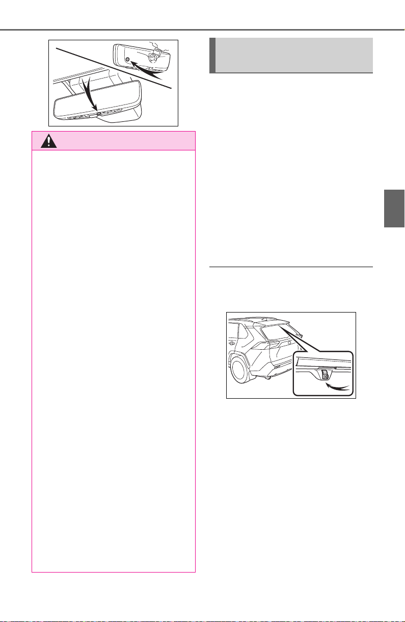
149
3-4. Adjusting the steering wheel and mirrors
3
Before driving
■ Cleaning the mirror surface
If the mirror surface is dirty, the
image on the display may be dif-
ficult to see.
Clean the mirror surface gently
using a soft dry cloth.
■ Cleaning the camera
If the camera lens is dirty, the
displayed image may not be
clear. In this case, clean it with a
soft cloth dampened with water
or a swab.
■ The camera
The camera for the Digital Rear-
view Mirror is located as shown.
WARNING
Observe the following precau-
tions.
Failure to do so may result in
death or serious injury.
■ While driving
● Do not adjust the position of the
Digital Rear-view Mirror or
adjust the display settings while
driving.
Stop the vehicle and operate
the Digital Rear-view Mirror
control switches.
Failure to do so may cause a
steering wheel operation error,
resulting in an unexpected acci-
dent.
● Always pay attention to the
vehicle’s surroundings.
The size of the vehicles and other
objects may look different when in
digital mirror mode and optical
mirror mode.
When backing up, make sure to
directly check the safety of the
area around your vehicle, espe-
cially behind the vehicle.
Additionally, if a vehicle
approaches from the rear in the
dark, such as at night, the sur-
rounding area may appear dim.
■ To prevent causes of fire
If the driver continues using the
Digital Rear-view Mirror while
smoke or odor comes from the
mirror, it may result in fire. Stop
using the system immediately and
contact your Toyota dealer.
Cleaning the Digital Rear-
view Mirror

150
3-4. Adjusting the steering wheel and mirrors
If you notice any of the following symptoms, refer to the following
table for the likely cause and the solution.
If the symptom is not resolved by the solution, have the vehicle
inspected by your Toyota dealer.
NOTICE
■ To prevent the Digital Rear-
view Mirror from malfunction-
ing
● Do not use detergents, such as
thinner, benzene, and alcohol to
clean the mirror. They may dis-
color, deteriorate or damage the
mirror surface.
● Do not smoke, use matches,
use cigarette lighters or allow
open flames near the mirror. It
may damage the mirror or
cause a fire.
● Do not remove, disassemble or
modify the mirror.
■ To prevent the camera from
malfunctioning
● Observe the following precau-
tions, otherwise the Digital
Rear-view Mirror may not oper-
ate properly.
• Do not strike or hit the camera
or subject it to a strong impact,
as the camera installation posi-
tion and angle may be changed.
• Do not remove, disassemble or
modify the camera.
• Do not allow an organic solvent,
car wax, window cleaner or
glass coating to adhere to the
camera. If this happens, wipe it
off as soon as possible.
• When cleaning the camera lens,
wipe the camera lens with a
damp soft cloth.
Do not strongly rub the camera
lens, as it may be scratched and
will not be able to transmit a
clear image.
• When applying colored film
(including transparent film) to
the rear window glass, do not
apply it to the area in front of the
camera.
If film is applied to the area in
front of the camera, the image
from the camera may not dis-
play properly.
● Do not subject the camera to a
strong impact as this could
cause a malfunction.
If this happens, have the vehicle
inspected by your Toyota dealer
as soon as possible.
If you notice any symptoms

151
3-4. Adjusting the steering wheel and mirrors
3
Before driving
Symptom Likely cause Solution
The image is difficult to
see.
The mirror surface is
dirty.
Clean the mirror surface
gently, using a soft dry
cloth.
Sunlight or headlights
are shining directly into
the Digital Rear-view
Mirror.
Change to optical mirror
mode.
(If the light is coming
through the moon roof [if
equipped] or panoramic
moon roof [if equipped],
close the sunshade or
electronic sunshade.)
• The vehicle is in a dark
area.
• The vehicle is near a
TV tower, broadcast-
ing station, electric
power plant, or other
location where strong
radio waves or electri-
cal noise may be pres-
ent.
• The temperature
around the camera is
extremely high/low.
• The ambient tempera-
ture is extremely low.
• It is raining or humid.
• Sunlight or headlights
are shining directly into
the camera lens.
• The vehicle is under
fluorescent lights,
sodium lights, mer-
cury lights, etc.
• Exhaust gas is
obstructing the cam-
era.
Change to optical mirror
mode.
(Change back to digital
mirror mode when the
conditions have
improved.)

152
3-4. Adjusting the steering wheel and mirrors
The image is difficult to
see.
The luggage in the lug-
gage compartment is
reflected off the rear win-
dow glass and obstruct-
ing the camera.
• Change to optical mir-
ror mode.
• Move the luggage to a
position where it does
not obstruct the cam-
era or cover it with a
black cloth to reduce
the amount it is
reflected off the rear
window glass.
The rear window glass is
fogged up.
Change to optical mirror
mode.
After defogging the rear
window using the rear
window defogger
(P.517), use the digi-
tal mirror mode again.
The outside of the rear
window glass is dirty.
Use the rear window
wiper to remove dirt.
The inside of the rear
window glass is dirty.
Wipe the inside of rear
window glass with a
damp soft cloth.
The image is out of
alignment.
The back door is not fully
closed.
Fully close the back
door.
The camera or its sur-
rounding area has
received a strong
impact.
Change to optical mirror
mode and have the vehi-
cle inspected by your
Toyota dealer.
The display is dim and
is displayed.
The system may be mal-
functioning.
Change to optical mirror
mode and have the vehi-
cle inspected by your
Toyota dealer.
goes off.
Symptom Likely cause Solution

153
3-4. Adjusting the steering wheel and mirrors
3
Before driving
is displayed.
The Digital Rear-view
Mirror is extremely hot.
(The display will gradu-
ally become more dim. If
the temperature contin-
ues to increase, the Digi-
tal Rear-view Mirror will
turn off.)
Reducing the cabin tem-
perature is recom-
mended to reduce the
temperature of the mir-
ror.
( will disappear when
the mirror becomes
cool.)
If does not disap-
pear even though the
mirror is cool, have the
vehicle inspected by
your Toyota dealer.
The lever cannot be
operated properly.
The lever may be mal-
functioning.
Change to optical mirror
mode and have the vehi-
cle inspected by your
Toyota dealer.
(To change to optical
mirror mode, press and
hold the menu button for
approximately 10 sec-
onds.)
Symptom Likely cause Solution
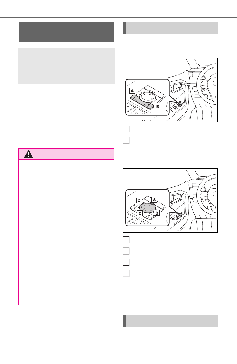
154
3-4. Adjusting the steering wheel and mirrors
■ Defogging the mirrors (if
equipped)
The outside rear view mirrors can
be cleared using the mirror defog-
gers. Turn on the rear window
defogger to turn on the outside rear
view mirror defoggers.
(P.511, 517)
1 To select a mirror to adjust,
press the switch.
Left
Right
2 To adjust the mirror, press
the switch.
Up
Right
Down
Left
■ Mirror angle can be adjusted
when
The engine switch is in ACC or ON.
Push the mirror back in the
direction of the vehicle’s rear.
Outside rear view mir-
rors
The rear view mirror’s posi-
tion can be adjusted to
enable sufficient confirma-
tion of the rear view.
WARNING
■ Important points while driving
Observe the following precautions
while driving.
Failing to do so may result in loss
of control of the vehicle and cause
an accident, resulting in death or
serious injury.
● Do not adjust the mirrors while
driving.
● Do not drive with the mirrors
folded.
● Both the driver and passenger
side mirrors must be extended
and properly adjusted before
driving.
■ When the mirror defoggers
are operating (if equipped)
Do not touch the rear view mirror
surfaces, as they can become
very hot and burn you.
Adjustment procedure
Folding the mirrors
A
B
A
B
C
D
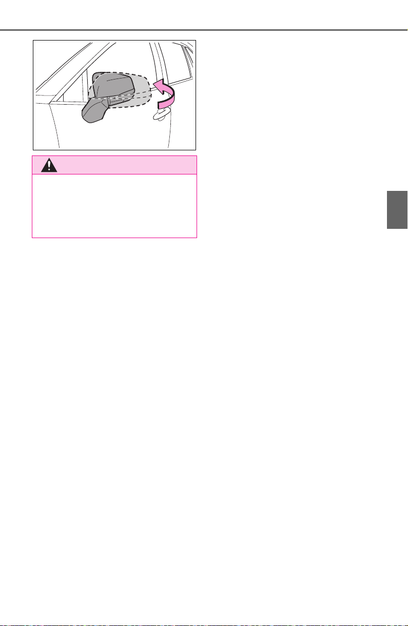
155
3-4. Adjusting the steering wheel and mirrors
3
Before driving
WARNING
■ When a mirror is moving
To avoid personal injury and mir-
ror malfunction, be careful not to
get your hand caught by the mov-
ing mirror.
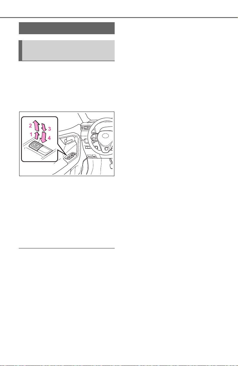
156
3-5. Opening, closing the windows and moon roof
3-5.Opening, closing the windows and moon roof
The power windows can be
opened and closed using the
switches.
Operating the switch moves the
side windows as follows:
1 Closing
2 One-touch closing
*
3 Opening
4 One-touch opening
*
*
: To stop the side window partway,
operate the switch in the opposite
direction.
■ The power windows can be
operated when
The engine switch is in ON.
■ Operating the power windows
after turning the engine off
The power windows can be oper-
ated for approximately 45 seconds
even after the engine switch is
turned to ACC or OFF. They cannot,
however, be operated once either
front door is opened.
■ Jam protection function
If an object becomes jammed
between the side window and the
window frame while the side window
is closing, side window movement is
stopped and the side window is
opened slightly.
■ Catch protection function
If an object becomes caught
between the door and side window
while the side window is opening,
side window movement is stopped.
■ When the power window cannot
be opened or closed
When the jam protection function or
catch protection function operates
unusually and the side window can-
not be opened and closed, perform
the following operations with the
power window switch of that door.
● Stop the vehicle. With the engine
switch in ON, within 4 seconds of
the jam protection function or
catch protection function activat-
ing, continuously operate the
power window switch in the one-
touch closing direction or one-
touch opening direction so that the
side window can be opened and
closed.
● If the side window cannot be
opened and closed even when
performing the above operations,
perform the following procedure
for function initialization.
1 Turn the engine switch to ON.
2 Pull and hold the power window
switch in the one-touch closing
direction and completely close
the side window.
3 Release the power window
switch for a moment, resume
pulling the switch in the one-
touch closing direction, and hold
it there for approximately 6 sec-
onds or more.
4 Press and hold the power win-
dow switch in the one-touch
opening direction. After the side
window is completely opened,
continue holding the switch for
an additional 1 second or more.
Power windows
Opening and closing the
power windows
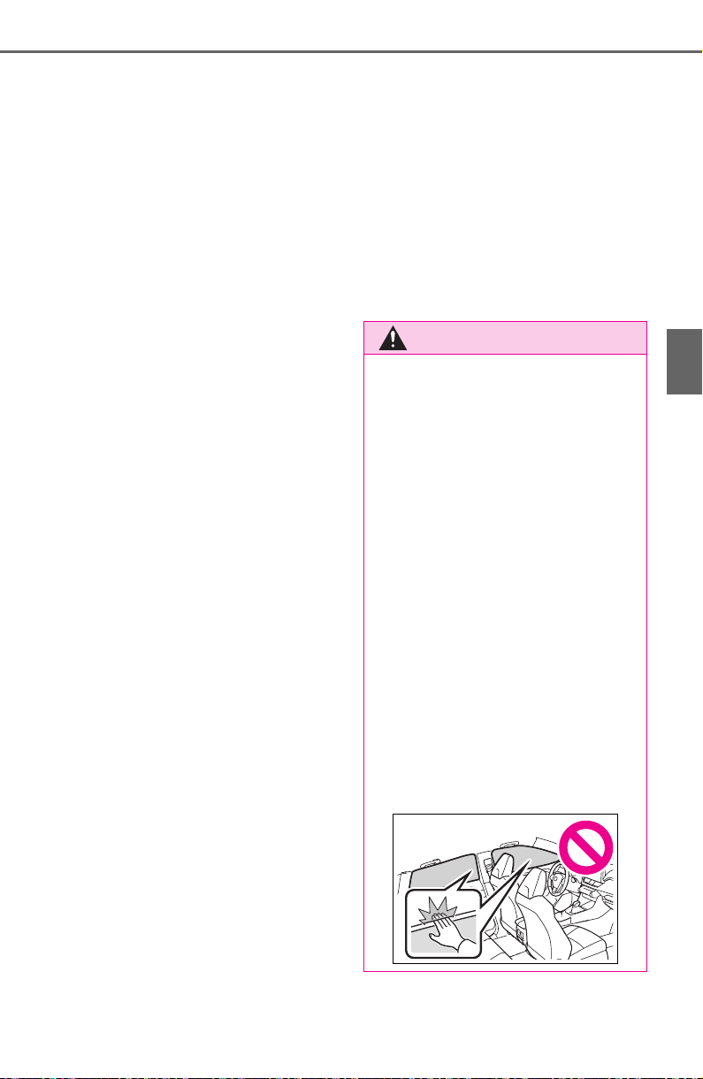
157
3-5. Opening, closing the windows and moon roof
3
Before driving
5 Release the power window
switch for a moment, resume
pushing the switch in the one-
touch opening direction, and
hold it there for approximately 4
seconds or more.
6 Pull and hold the power window
switch in the one-touch closing
direction again. After the side
window is completely closed,
continue holding the switch for a
further 1 second or more.
If you release the switch while the
side window is moving, start again
from the beginning.
If the side window reverses and
cannot be fully closed or opened,
have the vehicle inspected by your
Toyota dealer.
■ Door lock linked power window
operation
● The power windows can be
opened and closed using the key
(vehicles without smart key sys-
tem) or mechanical key (vehicles
with smart key system).
*
(P.109,
654)
● The power windows can be
opened using the wireless remote
control.
*
(P.108)
● Vehicles with alarm: The alarm
may be triggered if the alarm is set
and the power window is closed
using the door lock linked power
window operation function.
(P. 73 )
*
: These settings must be custom-
ized at your Toyota dealer.
■ Power window open reminder
function
Vehicles without smart key system
The buzzer sounds and a message
is shown on the multi-information
display when the key has been
removed from the engine switch and
the driver’s door is opened with the
power windows open.
Vehicles with smart key system
The buzzer sounds and a message
is shown on the multi-information
display when the engine switch is
turned to OFF and the driver’s door
is opened with the power windows
open.
■ Customization
Settings (e.g. linked door lock oper-
ation) can be changed. (Customiza-
ble features: P.693)
WARNING
Observe the following precau-
tions.
Failing to do so may result in
death or serious injury.
■ Closing the power windows
● The driver is responsible for all
the power window operations,
including the operation for the
passengers. In order to prevent
accidental operation, especially
by a child, do not let a child
operate the power windows. It is
possible for children and other
passengers to have body parts
caught in the power window.
Also, when riding with a child, it
is recommended to use the win-
dow lock switch. (P.158)
● Check to make sure that all pas-
sengers do not have any part of
their body in a position where it
could be caught when a power
window is being operated.
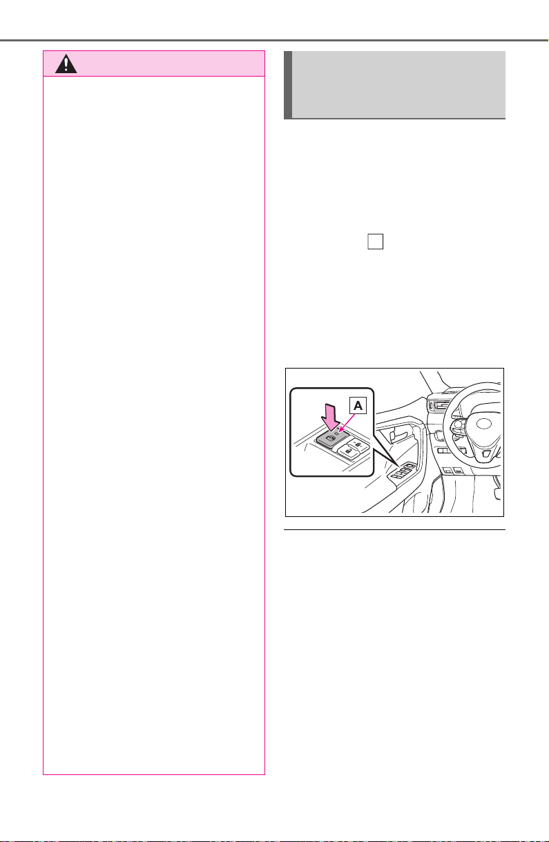
158
3-5. Opening, closing the windows and moon roof
This function can be used to
prevent children from acciden-
tally opening or closing a pas-
senger window.
Press the switch.
The indicator will come on and
the passenger windows will be
locked.
The passenger windows can still be
opened and closed using the
driver’s switch even if the lock
switch is on.
■ The window lock switch can be
operated when
The engine switch is in ON.
■ When the battery is discon-
nected
The window lock switch is disabled.
If necessary, press the window lock
switch after reconnecting the bat-
tery.
WARNING
● When using the wireless remote
control, key or mechanical key
and operating the power win-
dows, operate the power win-
dow after checking to make
sure that there is no possibility
of any passenger having any of
their body parts caught in the
side window. Also, do not let a
child operate the power window
by the wireless remote control,
key or mechanical key. It is pos-
sible for children and other pas-
sengers to get caught in the
power window.
● When exiting the vehicle, turn
the engine switch to OFF, carry
the key and exit the vehicle
along with the child. There may
be accidental operation, due to
mischief, etc., that may possibly
lead to an accident.
■ Jam protection function
● Never use any part of your body
to intentionally activate the jam
protection function.
● The jam protection function may
not work if something gets
jammed just before the side
window is fully closed. Be care-
ful not to get any part of your
body jammed in the side win-
dow.
■ Catch protection function
● Never use any part of your body
or clothing to intentionally acti-
vate the catch protection func-
tion.
● The catch protection function
may not work if something gets
caught just before the side win-
dow is fully opened. Be careful
not to get any part of your body
or clothing caught in the side
window.
Preventing accidental
operation (window lock
switch)
A
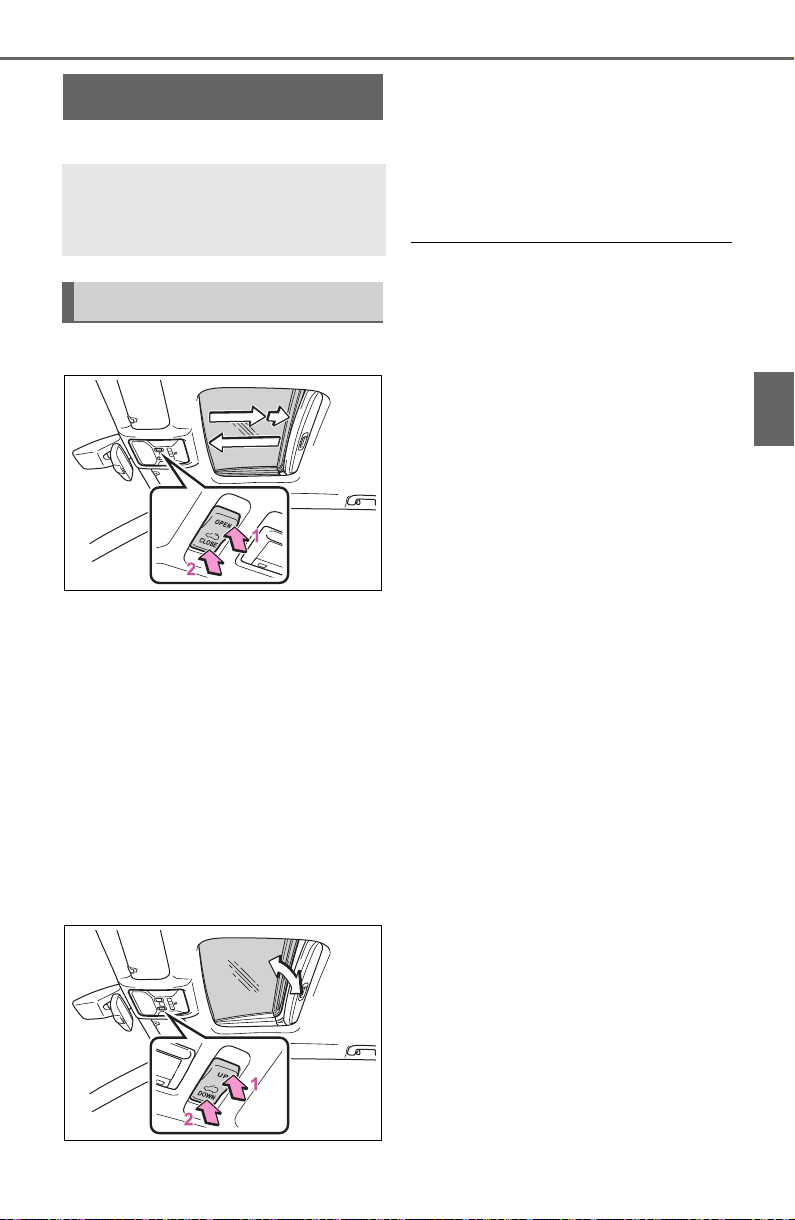
159
3-5. Opening, closing the windows and moon roof
3
Before driving
*
: If equipped
■ Opening and closing
1 Opens the moon roof
*
The moon roof stops slightly before
the fully open position to reduce
wind noise.
Press the switch again to fully open
the moon roof.
2 Closes the moon roof
*
*
: Lightly press either side of the
moon roof switch to stop the
moon roof partway.
■ Tilting up and down
1 Tilts the moon roof up
*
2 Tilts the moon roof down
*
*
: Lightly press either side of the
moon roof switch to stop the
moon roof partway.
■ The moon roof can be operated
when
The engine switch is in ON.
■ Operating the moon roof after
turning the engine off
The moon roof can be operated for
approximately 45 seconds after the
engine switch is turned to ACC or
OFF. It cannot, however, be oper-
ated once either front door is
opened.
■ Jam protection function
If an object is detected between the
moon roof and the frame while the
moon roof is closing or tilting down,
travel is stopped and the moon roof
opens slightly.
■ Sunshade
The sunshade can be opened and
closed manually. However, the sun-
shade will open automatically when
the moon roof is opened.
■ Door lock linked moon roof
operation
● The moon roof can be opened
and closed using the mechanical
key.
*
(P.654)
● The moon roof can be opened
using the wireless remote control.
*
(P.108)
● Vehicles with alarm: The alarm
may be triggered if the alarm is set
and the moon roof is closed using
the door lock linked moon roof
operation function. (P. 7 3 )
*
: These settings must be custom-
ized at your Toyota dealer.
Moon roof
*
Use the overhead switches
to open and close the moon
roof and tilt it up and down.
Operating the moon roof

160
3-5. Opening, closing the windows and moon roof
■ When the moon roof does not
close normally
Perform the following procedure:
1 Stop the vehicle.
2 Press and hold the “CLOSE”
switch.
*
The moon roof will close, reopen
and pause for approximately 10 sec-
onds. Then it will close again and
stop at the completely closed posi-
tion.
3 Check to make sure that the
moon roof is completely closed
and then release the switch.
*
: If the switch is released at the
incorrect time, the procedure will
have to be performed again from
the beginning.
If the moon roof does not fully close
even after performing the above
procedure correctly, have the vehi-
cle inspected by your Toyota dealer.
■ If the moon roof does not move
normally
If the moon roof does not open or
close normally or the automatic
opening function does not operate,
perform the following initialization
procedure.
1 Stop the vehicle.
2 Press and hold the “DOWN”
switch.
*
The moon roof will stop at the tilt-up
position. After that, it will open,
close, tilt up, tilt down, and stop at
the fully closed position.
3 Confirm that the moon roof has
completely stopped and release
the switch.
*
: If you release the switch while the
moon roof is moving, perform the
procedure again from the begin-
ning.
If, after performing the above proce-
dures correctly, the moon roof still
does not open or close normally or
the automatic opening function does
not operate, have the vehicle
inspected by your Toyota dealer.
■ Moon roof open reminder func-
tion
The buzzer sounds and a message
is shown on the multi-information
display when the engine switch is
turned to OFF and the driver’s door
is opened with the moon roof open.
■ Customization
Settings (e.g. linked door lock oper-
ation) can be changed. (Customiza-
ble features: P.693)
WARNING
Observe the following precau-
tions.
Failure to do so may cause death
or serious injury.
■ Opening the moon roof
● Do not allow any passengers to
put their hands or head outside
the vehicle while it is moving.
● Do not sit on top of the moon
roof.
■ Opening and closing the
moon roof
● The driver is responsible for
moon roof opening and closing
operations.
In order to prevent accidental
operation, especially by a child,
do not let a child operate the
moon roof. It is possible for chil-
dren and other passengers to
have body parts caught in the
moon roof.
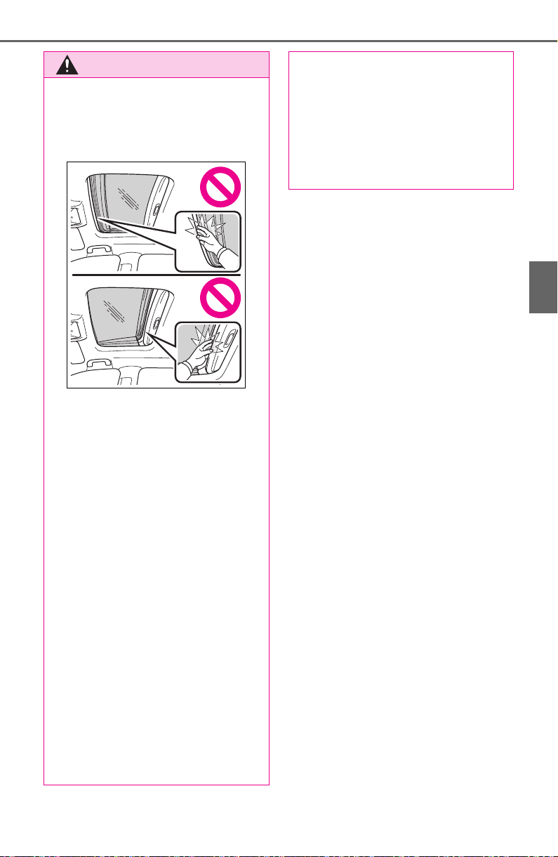
161
3-5. Opening, closing the windows and moon roof
3
Before driving
WARNING
● Check to make sure that all pas-
sengers do not have any part of
their body in a position where it
could be caught when the moon
roof is being operated.
● When using the wireless remote
control or mechanical key and
operating the moon roof, oper-
ate the moon roof after checking
to make sure that there is no
possibility of any passenger
having any of their body parts
caught in the moon roof. Also,
do not let a child operate moon
roof by the wireless remote con-
trol or mechanical key. It is pos-
sible for children and other
passengers to get caught in the
moon roof.
● When exiting the vehicle, turn
the engine switch to OFF, carry
the key and exit the vehicle
along with the child. There may
be accidental operation, due to
mischief, etc., that may possibly
lead to an accident.
■ Jam protection function
● Never use any part of your body
to intentionally activate the jam
protection function.
● The jam protection function may
not work if something gets
caught just before the moon
roof is fully closed. Also, the jam
protection function is not
designed to operate while the
switch is being pressed. Take
care so that your fingers, etc. do
not get caught.
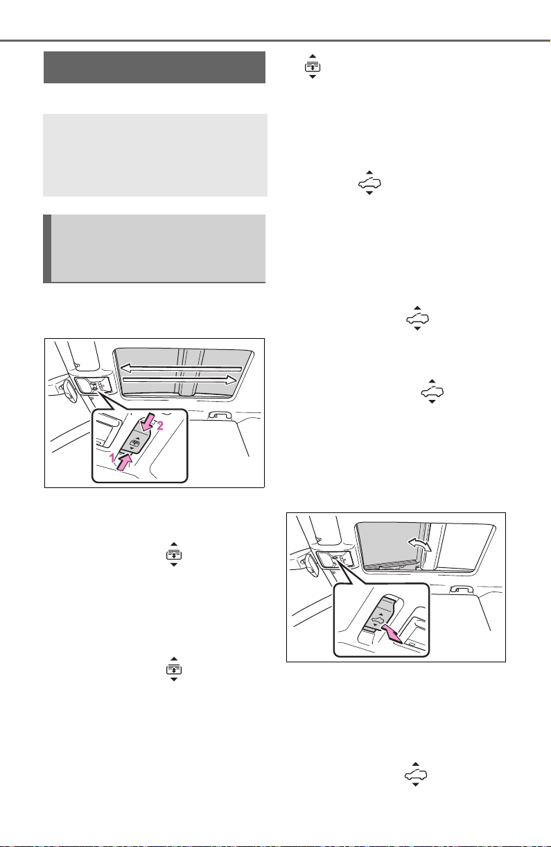
162
3-5. Opening, closing the windows and moon roof
*
: If equipped
■ Opening and closing the
electronic sunshade
1 Opens the electronic sun-
shade
*
Slide and hold the switch
backward. The electronic sunshade
will fully open automatically.
2 Closes the electronic sun-
shade
*
Slide and hold the switch for-
ward. The electronic sunshade will
fully close automatically.
If the panoramic moon roof is not
fully closed, it will close fully before
the electronic sunshade closes.
*
: Quickly slide and release the
switch in either direction to
stop the electronic sunshade
partway.
■ Tilting the panoramic moon
roof up and down
Press the switch to tilt the
panoramic moon roof up.
*
When the panoramic moon roof is
tilted up, the electronic sunshade
will open to the half-open position
of the roof.
*
: Lightly press the switch
again to stop the panoramic
moon roof partway.
Press and hold the switch
to tilt the panoramic moon roof
down.
The panoramic moon roof can be
tilted down only when it is in the tilt-
up position.
■ Opening and closing the
panoramic moon roof
Opens the panoramic moon
roof
*
Slide and hold the switch
Panoramic moon roof
*
Use the overhead switches
to operate the panoramic
moon roof and electronic
sunshade.
Operating the electronic
sunshade and panoramic
moon roof
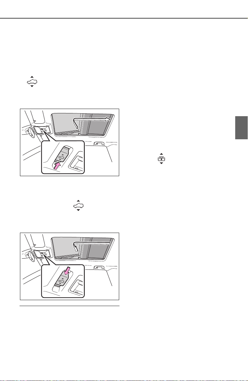
163
3-5. Opening, closing the windows and moon roof
3
Before driving
backward. The panoramic moon
roof and electronic sunshade will
open automatically.
The panoramic moon roof can be
opened from the tilt-up position.
*
: Quickly slide and release the
switch in either direction to
stop the panoramic moon roof
partway.
Closes the panoramic moon
roof
Slide and hold the switch for-
ward. The panoramic moon roof will
fully close automatically.
■ The panoramic moon roof can
be operated when
The engine switch is in ON.
■ Operating the panoramic moon
roof after turning the engine off
The panoramic moon roof and elec-
tronic sunshade can be operated for
approximately 45 seconds after the
engine switch is turned to ACC or
OFF. They cannot, however, be
operated once either front door is
opened.
■ Jam protection function
If an object is detected between the
panoramic moon roof and the frame
in the following situations, travel is
stopped and the panoramic moon
roof opens slightly.
● The panoramic moon roof is clos-
ing or tilting down.
● The electronic sunshade is clos-
ing.
■ Closing both the panoramic
moon roof and electronic sun-
shade
Slide the switch forward.
The electronic sunshade will close
to the half-open position and pause.
The panoramic moon roof will then
fully close. Then the electronic sun-
shade will fully close.
■ Door lock linked panoramic
moon roof operation
● The panoramic moon roof can be
opened and closed using the
mechanical key.
*
(P.654)
● The panoramic moon roof can be
opened using the wireless remote
control.
*
(P.108)
● Vehicles with alarm: The alarm
may be triggered if the alarm is set
and the panoramic moon roof is
closed using the door lock linked
panoramic moon roof operation
function. (P.73)
*
: These settings must be custom-
ized at your Toyota dealer.
■ When the panoramic moon roof
or electronic sunshade does
not close normally
Perform the following procedure:
1 Stop the vehicle.
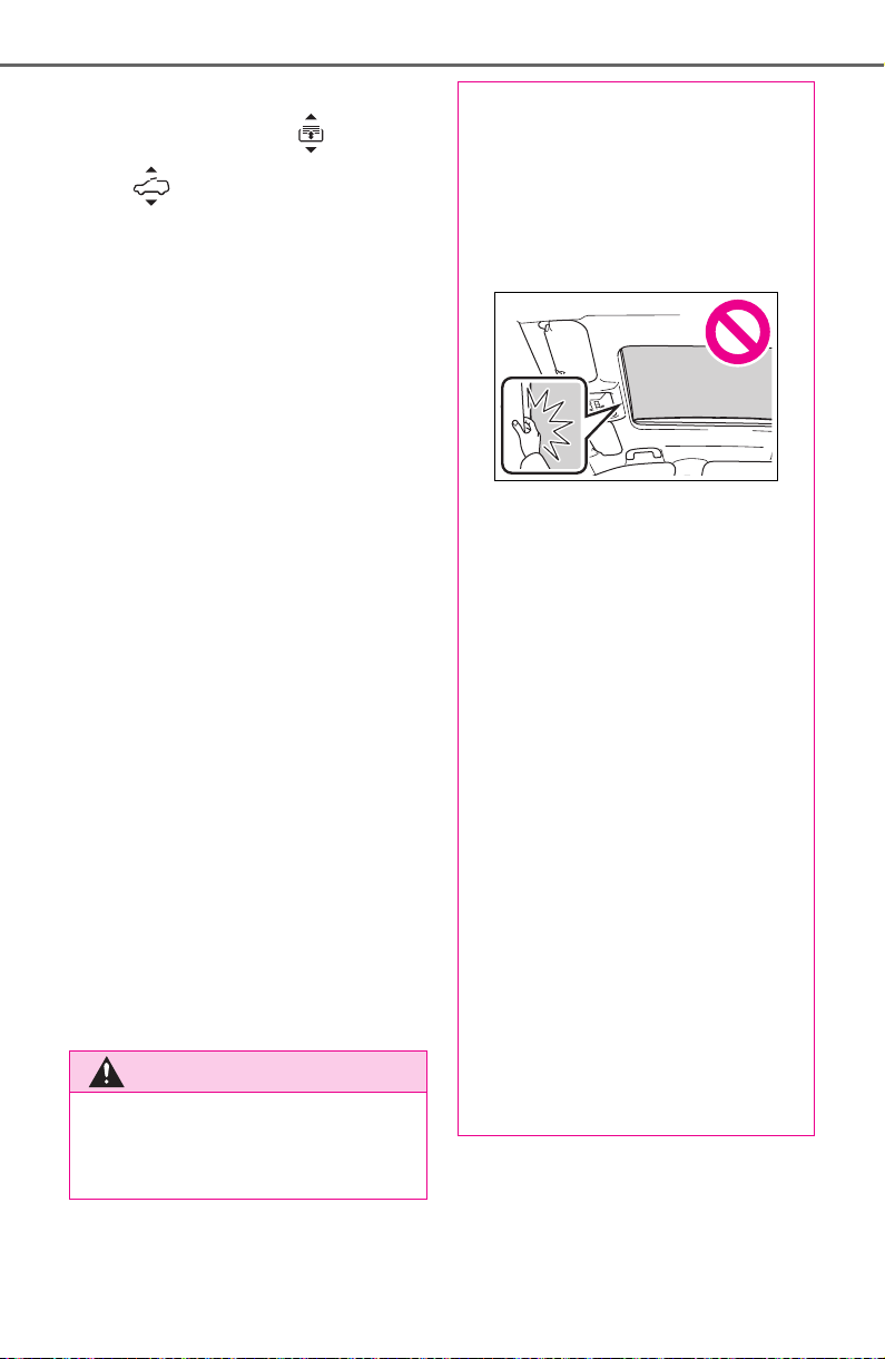
164
3-5. Opening, closing the windows and moon roof
2 Turn the engine switch to ON.
3 Slide and hold the switch
or switch forward. Continue
sliding and holding the switch for
approximately 10 seconds after
the panoramic moon roof or elec-
tronic sunshade closes and
reopens. The panoramic moon
roof and electronic sunshade will
start to close.
*
4 Check that the panoramic moon
roof and electronic sunshade are
fully closed and release the
switch.
*
: If the switch is released at the
incorrect time, the procedure will
have to be performed again from
the beginning.
If the panoramic moon roof or elec-
tronic sunshade does not fully close
even after performing the above
procedure correctly, have the vehi-
cle inspected by your Toyota dealer.
■ Panoramic moon roof open
reminder function
A buzzer sounds and a message is
shown on the multi-information dis-
play when the engine switch is
turned to OFF and the driver’s door
is opened with the panoramic moon
roof open.
■ Customization
Settings (e.g. linked door lock oper-
ation) can be changed. (Customiza-
ble features: P.693)
WARNING
Observe the following precau-
tions.
Failure to do so may result in
death or serious injury.
■ Opening and closing the elec-
tronic sunshade
● Check to make sure that all pas-
sengers do not have any part of
their body in a position where it
could be caught when the elec-
tronic sunshade is being oper-
ated.
● Do not let a child operate the
electronic sunshade. Closing
the electronic sunshade on
someone can cause death or
serious injury.
■ Opening the panoramic moon
roof
● Do not allow any passengers to
put their hands or head outside
the vehicle while it is moving.
● Do not sit on top of the pan-
oramic moon roof.
■ Opening and closing the pan-
oramic moon roof
● The driver is responsible for
panoramic moon roof opening
and closing operations.
In order to prevent accidental
operation, especially by a child,
do not let a child operate the
panoramic moon roof. It is pos-
sible for children and other pas-
sengers to have body parts
caught in the panoramic moon
roof.
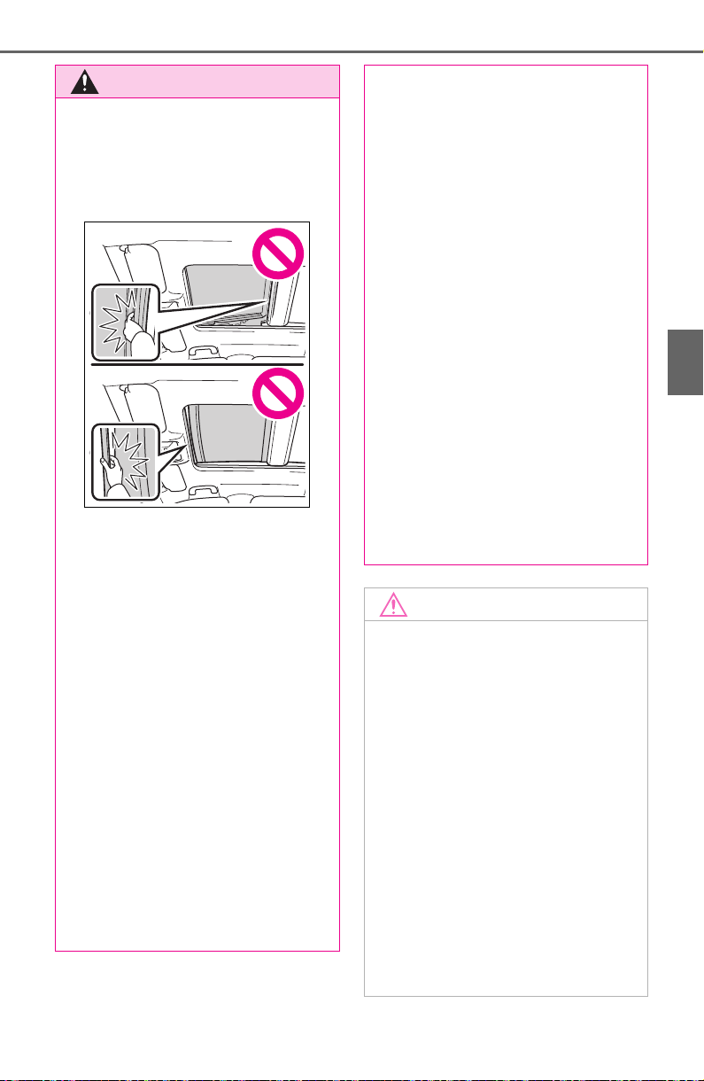
165
3-5. Opening, closing the windows and moon roof
3
Before driving
WARNING
● Check to make sure that all pas-
sengers do not have any part of
their body in a position where it
could be caught when the pan-
oramic moon roof is being oper-
ated.
● When using the wireless remote
control or mechanical key and
operating the panoramic moon
roof, operate the panoramic
moon roof after checking to
make sure that there is no pos-
sibility of any passenger having
any of their body parts caught in
the panoramic moon roof. Also,
do not let a child operate pan-
oramic moon roof by the wire-
less remote control or
mechanical key. It is possible for
children and other passengers
to get caught in the panoramic
moon roof.
● When exiting the vehicle, turn
the engine switch to OFF, carry
the key and exit the vehicle
along with the child. There may
be accidental operation, due to
mischief, etc., that may possibly
lead to an accident.
■ Jam protection function
● Never use any part of your body
to intentionally activate the jam
protection function.
● The jam protection function may
not work if something gets
caught just before the pan-
oramic moon roof or electronic
sunshade is fully closed. Also,
the jam protection function is
not designed to operate while
the switch is being pressed.
Take care so that your fingers,
etc. do not get caught.
■ To prevent burns or injuries
Do not touch the area between
the underside of the panoramic
moon roof and the electronic sun-
shade. Your hand may get caught
and you could injure yourself.
Also, if the vehicle is left in direct
sunlight for a long time, the under-
side of the panoramic moon roof
could become very hot and could
cause burns.
NOTICE
■ To prevent damage to the
panoramic moon roof
● Before opening the panoramic
moon roof, make sure that there
are no foreign objects, such as
stones or ice, around the open-
ing.
● Do not hit the surface or edge of
the panoramic moon roof with
hard objects.
■ After the vehicle has been
washed or rained on
Before opening the panoramic
moon roof, wipe any water off the
panoramic moon roof. Otherwise,
water may enter the cabin when
the panoramic moon roof is
opened.

166
3-5. Opening, closing the windows and moon roof

167
4
4
Driving
Driving
4-1. Before driving
Driving the vehicle....... 169
Cargo and luggage ..... 175
Vehicle load limits ....... 178
Trailer towing............... 179
Dinghy towing ............. 191
4-2. Driving procedures
Engine (ignition) switch
(vehicles without smart key
system)...................... 193
Engine (ignition) switch
(vehicles with smart key
system)...................... 194
Automatic transmission199
Turn signal lever.......... 202
Parking brake.............. 203
Brake Hold .................. 206
4-3. Operating the lights and
wipers
Headlight switch.......... 209
AHB (Automatic High
Beam)........................ 212
Fog light switch ........... 215
Windshield wipers and
washer....................... 215
Rear window wiper and
washer....................... 218
4-4. Refueling
Opening the fuel tank cap
.................................. 220
4-5. Using the driving support
systems
Toyota Safety Sense 2.0
.................................. 223
PCS (Pre-Collision System)
.................................. 229
LTA (Lane Tracing Assist)
.................................. 237
RSA (Road Sign Assist)
.................................. 247
Dynamic radar cruise con-
trol with full-speed range
.................................. 250
BSM (Blind Spot Monitor)
.................................. 260
Intuitive parking assist. 270
PKSB (Parking Support
Brake)........................277
Parking Support Brake func-
tion (static objects) ....282
Parking Support Brake func-
tion (rear-crossing vehi-
cles)...........................288
Rear view monitor system
.................................. 292
Toyota parking assist moni-
tor.............................. 300
Panoramic view monitor
.................................. 313
Stop & Start system .... 345
Driving mode select switch
.................................. 351

168
Multi-terrain Select (AWD
vehicles).................... 353
Snow mode switch (AWD
vehicles).................... 357
Downhill assist control sys-
tem............................ 358
Driving assist systems 360
4-6. Driving tips
Winter driving tips ....... 367
Utility vehicle precautions
.................................. 370

169
4-1. Before driving
4
Driving
4-1.Before driving
■ Starting the engine
P.193, 194
■ Driving
1 With the brake pedal
depressed, shift the shift
lever to D. (P.199)
2 Release the parking brake.
(P.203)
If the parking brake is in automatic
mode, the parking brake is
released automatically when shift-
ing the shift lever to any position
other than P. (P.204)
3 Gradually release the brake
pedal and gently depress the
accelerator pedal to acceler-
ate the vehicle.
■ Stopping
1 With the shift lever in D,
depress the brake pedal.
2 If necessary, set the parking
brake. (P.203)
If the vehicle is to be stopped for an
extended period of time, shift the
shift lever to P. (P.199)
■ Parking the vehicle
1 With the shift lever in D,
depress the brake pedal.
2 Set the parking brake
(P.203), and shift the shift
lever to P (P.199).
3 Turn the engine switch to
OFF to stop the engine.
4 Lock the door, making sure
that you have the key on your
person.
If parking on a hill, block the wheels
as needed.
■ Starting off on a steep
uphill
1 With the brake pedal
depressed, shift the shift
lever to D. (P.199)
2 Pull the parking brake switch
and parking brake is set man-
ually. (P.203)
3 Release the brake pedal and
gently depress the accelera-
tor pedal to accelerate the
vehicle.
Parking brake automatic release
function (P.205)
■ When starting off on a uphill
The hill-start assist control will acti-
vate. (P.360)
■ Driving in the rain
● Drive carefully when it is raining,
because visibility will be reduced,
the windows may become fogged-
up, and the road could be slippery.
● Drive carefully when it starts to
rain, as the road surface could be
especially slippery.
● Refrain from high speeds when
driving on an expressway in the
rain, because there may be a
layer of water between the tires
and the road surface, preventing
Driving the vehicle
The following procedures
should be observed to
ensure safe driving:
Driving procedure

170
4-1. Before driving
the steering and brakes from
operating properly.
■ Engine speed while driving
In the following conditions, the
engine speed may become high
while driving. This is due to auto-
matic up-shifting control or down-
shifting implementation to meet driv-
ing conditions. It does not indicate
sudden acceleration.
● The vehicle is judged to be driving
uphill or downhill
● When the accelerator pedal is
released
● When the brake pedal is
depressed while sport mode is
selected
■ Restraining the engine output
(Brake Override System)
● When the accelerator and brake
pedals are depressed at the same
time, the engine output may be
restrained.
● A warning message is displayed
on the multi-information display
while the system is operating.
(P.633)
■ Restraining sudden start (Drive-
Start Control)
● When the following unusual oper-
ation is performed, the engine out-
put may be restrained.
• When the shift lever is shifted from
R to D, D to R, N to R, P to D, or P
to R (D includes S) with the accel-
erator pedal depressed, a warning
message appears on the multi-
information display. If a warning
message is shown on the multi-
information display, read the mes-
sage and follow the instructions.
• When the accelerator pedal is
depressed too much while the
vehicle is in reverse.
● While Drive-Start Control is being
activated, your vehicle may have
trouble escaping from the mud or
fresh snow. In such case, deacti-
vate TRAC (P.361) to cancel
Drive-Start Control so that the
vehicle may be able to escape
from the mud or fresh snow.
● Drive-Start Control does not work
when Mud & Sand or Rock & Dirt
mode is selected for Multi-terrain
Select.
■ Breaking in your new Toyota
To extend the life of the vehicle,
observing the following precautions
is recommended:
● For the first 200 miles (300 km):
Avoid sudden stops.
● For the first 500 miles (800 km):
Do not tow a trailer.
● For the first 600 miles (1000 km):
• Do not drive at extremely high
speeds.
• Avoid sudden acceleration.
• Do not drive continuously in low
gears.
• Do not drive at a constant speed
for extended periods.
■ Operating your vehicle in a for-
eign country
Comply with the relevant vehicle
registration laws and confirm the
availability of the correct fuel.
(P.666)
WARNING
Observe the following precau-
tions.
Failure to do so may result in
death or serious injury.
■ When starting the vehicle
Always keep your foot on the
brake pedal while stopped with
the engine running. This prevents
the vehicle from creeping.

171
4-1. Before driving
4
Driving
WARNING
■ When driving the vehicle
● Do not drive if you are unfamil-
iar with the location of the brake
and accelerator pedals to avoid
depressing the wrong pedal.
• Accidentally depressing the
accelerator pedal instead of the
brake pedal will result in sudden
acceleration that may lead to an
accident.
• When backing up, you may twist
your body around, leading to a
difficulty in operating the pedals.
Make sure to operate the pedals
properly.
• Make sure to keep a correct
driving posture even when mov-
ing the vehicle only slightly. This
allows you to depress the brake
and accelerator pedals properly.
• Depress the brake pedal using
your right foot. Depressing the
brake pedal using your left foot
may delay response in an emer-
gency, resulting in an accident.
● Do not drive the vehicle over or
stop the vehicle near flammable
materials such as leaves, paper
or rags.
The exhaust system and
exhaust gases can be
extremely hot. These hot parts
may cause a fire if there is any
flammable material nearby.
● During normal driving, do not
turn off the engine. Turning the
engine off while driving will not
cause loss of steering or brak-
ing control, but the power assist
to these systems will be lost.
This will make it more difficult to
steer and brake, so you should
pull over and stop the vehicle as
soon as it is safe to do so.
However, in the event of an
emergency, such as if it
becomes impossible to stop the
vehicle in the normal way:
P.6 18
● Use engine braking (downshift)
to maintain a safe speed when
driving down a steep hill.
Using the brakes continuously
may cause the brakes to over-
heat and lose effectiveness.
(P.659)
● Do not adjust the position of the
steering wheel, the seat, or the
inside or outside rear view mir-
rors while driving.
Doing so may result in a loss of
vehicle control.
● Always check that all passen-
gers’ arms, head or other parts
of their body are not outside the
vehicle.
● Do not drive in excess of the
speed limit. Even if the legal
speed limit permits it, do not
drive over 85 mph (140 km/h)
unless your vehicle has high-
speed capability tires. Driving
over 85 mph (140 km/h) may
result in tire failure, loss of con-
trol and possible injury. Be sure
to consult a tire dealer to deter-
mine whether the tires on your
vehicle are high-speed capabil-
ity tires or not before driving at
such speeds.

172
4-1. Before driving
WARNING
■ When driving on slippery
road surfaces
● Sudden braking, acceleration
and steering may cause tire
slippage and reduce your ability
to control the vehicle.
● Sudden acceleration, engine
braking due to shifting, or
changes in engine speed could
cause the vehicle to skid.
● After driving through a puddle,
lightly depress the brake pedal
to make sure that the brakes
are functioning properly. Wet
brake pads may prevent the
brakes from functioning prop-
erly. If the brakes on only one
side are wet and not functioning
properly, steering control may
be affected.
■ When shifting the shift lever
● Do not let the vehicle roll back-
ward while the shift lever is in a
driving position, or roll forward
while the shift lever is in R.
Doing so may cause the engine
to stall or lead to poor brake and
steering performance, resulting
in an accident or damage to the
vehicle.
● Do not shift the shift lever to P
while the vehicle is moving.
Doing so can damage the trans-
mission and may result in a loss
of vehicle control.
● Do not shift the shift lever to R
while the vehicle is moving for-
ward.
Doing so can damage the trans-
mission and may result in a loss
of vehicle control.
● Do not shift the shift lever to a
driving position while the vehicle
is moving backward.
Doing so can damage the trans-
mission and may result in a loss
of vehicle control.
● Moving the shift lever to N while
the vehicle is moving will disen-
gage the engine from the trans-
mission. Engine braking is not
available when N is selected.
● Be careful not to shift the shift
lever with the accelerator pedal
depressed.
Shifting the shift lever to a gear
other than P or N may lead to
unexpected rapid acceleration
of the vehicle that may cause an
accident and result in death or
serious injury. Doing so can
damage the transmission and
may result in a loss of vehicle
control.
■ If you hear a squealing or
scraping noise (brake pad
wear limit indicators)
Have the brake pads checked and
replaced by your Toyota dealer as
soon as possible.
Rotor damage may result if the
pads are not replaced when
needed.
It is dangerous to drive the vehicle
when the wear limits of the brake
pads and/or those of the brake
discs are exceeded.
■ When the vehicle is stopped
● Do not race the engine.
If the vehicle is in any gear other
than P or N, the vehicle may
accelerate suddenly and unex-
pectedly, causing an accident.
● In order to prevent accidents
due to the vehicle rolling away,
always keep depressing the
brake pedal while the engine is
running, and apply the parking
brake as necessary.

173
4-1. Before driving
4
Driving
WARNING
● If the vehicle is stopped on an
incline, in order to prevent acci-
dents caused by the vehicle roll-
ing forward or backward, always
depress the brake pedal and
securely apply the parking
brake as needed.
● Avoid revving or racing the
engine.
Running the engine at high
speed while the vehicle is
stopped may cause the exhaust
system to overheat, which could
result in a fire if combustible
material is nearby.
■ When the vehicle is parked
● Do not leave glasses, cigarette
lighters, spray cans, or soft
drink cans in the vehicle when it
is in the sun.
Doing so may result in the fol-
lowing:
• Gas may leak from a cigarette
lighter or spray can, and may
lead to a fire.
• The temperature inside the
vehicle may cause the plastic
lenses and plastic material of
glasses to deform or crack.
• Soft drink cans may fracture,
causing the contents to spray
over the interior of the vehicle,
and may also cause a short cir-
cuit in the vehicle’s electrical
components.
● Do not leave cigarette lighters in
the vehicle. If a cigarette lighter
is in a place such as the glove
box or on the floor, it may be lit
accidentally when luggage is
loaded or the seat is adjusted,
causing a fire.
● Do not attach adhesive discs to
the windshield or windows. Do
not place containers such as air
fresheners on the instrument
panel or dashboard. Adhesive
discs or containers may act as
lenses, causing a fire in the
vehicle.
● Do not leave a door or window
open if the curved glass is
coated with a metallized film
such as a silver-colored one.
Reflected sunlight may cause
the glass to act as a lens, caus-
ing a fire.
● Always apply the parking brake,
shift the shift lever to P, stop the
engine and lock the vehicle.
Do not leave the vehicle unat-
tended while the engine is run-
ning.
If the vehicle is parked with the
shift lever in P but the parking
brake is not set, the vehicle may
start to move, possibly leading
to an accident.
● Do not touch the exhaust pipes
while the engine is running or
immediately after turning the
engine off.
Doing so may cause burns.
■ When taking a nap in the vehi-
cle
Always turn the engine off. Other-
wise, if you accidentally move the
shift lever or depress the acceler-
ator pedal, this could cause an
accident or fire due to engine
overheating. Additionally, if the
vehicle is parked in a poorly venti-
lated area, exhaust gases may
collect and enter the vehicle, lead-
ing to death or a serious health
hazard.

174
4-1. Before driving
WARNING
■ When braking
● When the brakes are wet, drive
more cautiously.
Braking distance increases
when the brakes are wet, and
this may cause one side of the
vehicle to brake differently than
the other side. Also, the parking
brake may not securely hold the
vehicle.
● If the brake booster device does
not operate, do not follow other
vehicles closely and avoid hills
or sharp turns that require brak-
ing.
In this case, braking is still pos-
sible, but the brake pedal
should be depressed more
firmly than usual. Also, the brak-
ing distance will increase. Have
your brakes fixed immediately.
● Do not pump the brake pedal if
the engine stalls.
Each push on the brake pedal
uses up the reserve for the
power-assisted brakes.
● The brake system consists of 2
individual hydraulic systems; if
one of the systems fails, the
other will still operate. In this
case, the brake pedal should be
depressed more firmly than
usual and the braking distance
will increase. Have your brakes
fixed immediately.
■ If the vehicle becomes stuck
(AWD models)
Do not spin the wheels exces-
sively when any of the tires is up
in the air, or the vehicle is stuck in
sand, mud, etc. This may damage
the driveline components or pro-
pel the vehicle forward or back-
ward, causing an accident.
NOTICE
■ When driving the vehicle
● Do not depress the accelerator
and brake pedals at the same
time during driving, as this may
restrain the engine output.
● Do not use the accelerator
pedal or depress the accelera-
tor and brake pedals at the
same time to hold the vehicle on
a hill.
■ Avoiding damage to vehicle
parts
● Do not turn the steering wheel
fully in either direction and hold
it there for an extended period
of time.
Doing so may damage the
power steering motor.
● When driving over bumps in the
road, drive as slowly as possible
to avoid damaging the wheels,
underside of the vehicle, etc.
■ If you get a flat tire while driv-
ing
A flat or damaged tire may cause
the following situations.
● It may be difficult to control your
vehicle.
● The vehicle will make abnormal
sounds or vibrations.
● The vehicle will lean abnor-
mally.
Hold the steering wheel firmly and
gradually depress the brake pedal
to slow down the vehicle.
Information on what to do in case
of a flat tire (P.642)

175
4-1. Before driving
4
Driving
NOTICE
■ When encountering flooded
roads
Do not drive on a road that has
flooded after heavy rain, etc.
Doing so may cause the following
serious damage to the vehicle:
● Engine stalling
● Short in electrical components
● Engine damage caused by
water immersion
In the event that you drive on a
flooded road and the vehicle is
flooded, be sure to have your
Toyota dealer check the following:
● Brake function
● Changes in quantity and quality
of oil and fluid used for the
engine, transaxle, transfer
(AWD vehicles), rear differen-
tial (AWD vehicles), etc.
● Lubricant condition for the pro-
peller shaft (AWD models),
bearings and suspension joints
(where possible), and the func-
tion of all joints, bearings, etc.
■ When parking the vehicle
Always set the parking brake, and
shift the shift lever to P. Failure to
do so may cause the vehicle to
move or the vehicle may acceler-
ate suddenly if the accelerator
pedal is accidentally depressed.
Cargo and luggage
Take notice of the following
information about storage
precautions, cargo capacity
and load.
WARNING
■ Things that must not be car-
ried in the luggage compart-
ment
The following things may cause a
fire if loaded in the luggage com-
partment:
● Receptacles containing gaso-
line
● Aerosol cans
■ Storage precautions
Observe the following precau-
tions.
Failure to do so may prevent the
pedals from being depressed
properly, may block the driver’s
vision, or may result in items hit-
ting the driver or passengers, pos-
sibly causing an accident.
● Stow cargo and luggage in the
luggage compartment when-
ever possible.
● Do not stack anything in the lug-
gage compartment higher than
the seatbacks.
● Do not place cargo or luggage
in or on the following locations.
• At the feet of the driver
• On the front passenger or rear
seats (when stacking items)
• On the luggage cover (if
equipped)
• On the instrument panel
• On the dashboard

176
4-1. Before driving
Cargo capacity depends on the
total weight of the occupants.
(Cargo capacity) = (Total load
capacity) - (Total weight of occu-
pants)
Steps for Determining Cor-
rect Load Limit
(1) Locate the statement “The
combined weight of occupants
and cargo should never exceed
XXX kg or XXX lbs.” on your
vehicle’s placard.
(2) Determine the combined
weight of the driver and passen-
gers that will be riding in your
vehicle.
(3) Subtract the combined
weight of the driver and passen-
gers from XXX kg or XXX lbs.
(4) The resulting figure equals
the available amount of cargo
and luggage load capacity.
For example, if the “XXX”
amount equals 1400 lbs. and
there will be five 150 lb passen-
gers in your vehicle, the amount
of available cargo and luggage
load capacity is 650 lbs. (1400 -
750 (5 150) = 650 lbs.)
(5) Determine the combined
weight of luggage and cargo
being loaded on the vehicle.
That weight may not safely
exceed the available cargo and
luggage load capacity calcu-
lated in Step 4.
(6) If your vehicle will be towing
a trailer, load from your trailer
will be transferred to your vehi-
cle. Consult this manual to
determine how this reduces the
available cargo and luggage
load capacity of your vehicle.
(P.178)
WARNING
● Secure all items in the occupant
compartment.
● When you fold down the rear
seats, long items should not be
placed directly behind the front
seats.
● Never allow anyone to ride in
the luggage compartment. It is
not designed for passengers.
They should ride in their seats
with their seat belts properly
fastened. Otherwise, they are
much more likely to suffer death
or serious bodily injury, in the
event of sudden braking, sud-
den swerving or an accident.
Capacity and distribution
WARNING
■ Capacity and distribution
● Do not exceed the maximum
axle weight rating or the total
vehicle weight rating.
● Even if the total load of occu-
pant’ weight and the cargo load
is less than the total load capac-
ity, do not apply the load
unevenly. Improper loading may
cause deterioration of steering
or braking control which may
cause death or serious injury.
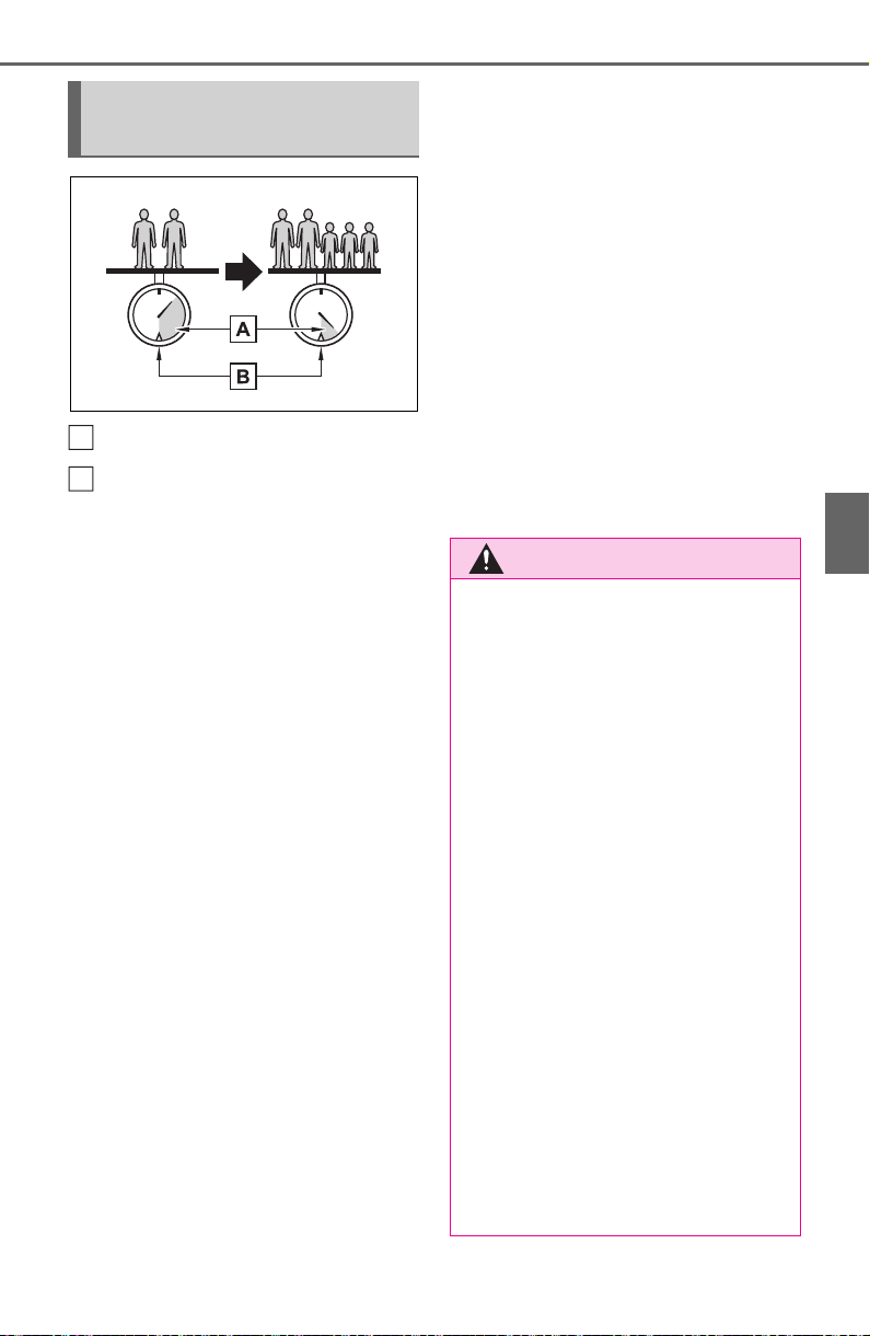
177
4-1. Before driving
4
Driving
Cargo capacity
Total load capacity (vehicle
capacity weight) (P.664)
When 2 people with the com-
bined weight of A lb. (kg) are rid-
ing in your vehicle, which has a
total load capacity (vehicle
capacity weight) of B lb. (kg),
the available amount of cargo
and luggage load capacity will
be C lb. (kg) as follows:
B
*2
lb. (kg) - A
*1
lb. (kg) = C
*3
lb.
(kg)
*1
:A = Weight of people
*2
:B = Total load capacity
*3
:C = Available cargo and luggage
load
In this condition, if 3 more passen-
gers with the combined weight of D
lb. (kg) get on, the available cargo
and luggage load will be reduced E
lb. (kg) as follows:
C lb. (kg) - D
*4
lb. (kg) = E
*5
lb.
(kg)
*4
:D = Additional weight of people
*5
:E = Available cargo and luggage
load
As shown in the example above,
if the number of occupants
increases, the cargo and lug-
gage load will be reduced by an
amount that equals the
increased weight due to the
additional occupants. In other
words, if an increase in the num-
ber of occupants causes an
excess of the total load capacity
(combined weight of occupants
plus cargo and luggage load),
you must reduce the cargo and
luggage on your vehicle.
Calculation formula for
your vehicle
A
B
WARNING
■ When loading cargo on the
roof luggage carrier (if
equipped)
Observe the following precau-
tions:
● Place the cargo so that its
weight is distributed evenly
between the front and rear
axles.
● If loading long or wide cargo,
never exceed the vehicle overall
length or width. (P.664)
● Before driving, make sure the
cargo is securely fastened on
the roof luggage carrier.
● Loading cargo on the roof lug-
gage carrier will make the cen-
ter of gravity of the vehicle
higher. Avoid high speeds, sud-
den starts, sharp turns, sudden
braking or abrupt maneuvers,
otherwise it may result in loss of
control or vehicle rollover due to
failure to operate this vehicle
correctly and result in death or
serious injury.

178
4-1. Before driving
■ Total load capacity and seating
capacity
These details are also described on
the tire and loading information
label. (P.595)
WARNING
● If driving for a long distance, on
rough roads, or at high speeds,
stop the vehicle now and then
during the trip to make sure the
cargo remains in its place.
● Do not exceed 176.4 lb. (80 kg)
cargo weight on the roof lug-
gage carrier.
NOTICE
■ When loading cargo on the
roof luggage carrier (if
equipped)
Be careful not to scratch the sur-
face of the moon roof (if
equipped) or the panoramic moon
roof (if equipped).
Vehicle load limits
Vehicle load limits include
total load capacity, seating
capacity, TWR (Trailer
Weight Rating) and cargo
capacity.
Total load capacity (vehicle
capacity weight): P.664
Total load capacity means the
combined weight of occu-
pants, cargo and luggage.
Seating capacity: 5 occu-
pants (Front 2, Rear 3)
Seating capacity means the
maximum number of occu-
pants whose estimated aver-
age weight is 150 lb. (68 kg)
per person.
TWR (Trailer Weight Rat-
ing): P.185, 664
TWR means the maximum
gross trailer weight (trailer
weight plus its cargo weight)
that your vehicle is able to tow.
Cargo capacity
Cargo capacity may increase
or decrease depending on the
weight and the number of
occupants.

179
4-1. Before driving
4
Driving
WARNING
■ Overloading the vehicle
Do not overload the vehicle. It
may not only cause damage to
the tires, but also degrade steer-
ing and braking ability, resulting in
an accident.
Trailer towing
Your vehicle is designed pri-
marily as a passenger-and-
load-carrying vehicle. Tow-
ing a trailer can have an
adverse impact on handling,
performance, braking, dura-
bility, and fuel consumption.
For your safety and the
safety of others, you must
not overload your vehicle or
trailer. You must also
ensure that you are using
appropriate towing equip-
ment, that the towing equip-
ment has been installed
correctly and used prop-
erly, and that you employ
the requisite driving habits.
Vehicle-trailer stability and
braking performance are
affected by trailer stability,
brake performance and set-
ting, trailer brakes, the hitch
and hitch systems (if
equipped).
To tow a trailer safely, use
extreme care and drive the
vehicle in accordance with
your trailer’s characteris-
tics and operating condi-
tions.

180
4-1. Before driving
■ Before towing
Check that the following conditions
are met:
● Ensure that your vehicle’s tires
are properly inflated. (P.671)
● Trailer tires are inflated according
to the trailer manufacturer’s rec-
ommendation.
● All trailer lights work as required
by law.
● All lights work each time you con-
nect them.
● The trailer ball is set at the proper
height for the coupler on the
trailer.
● The trailer is level when it is
hitched.
Do not drive if the trailer is not
level, and check for improper
tongue weight, overloading, worn
suspension, or other possible
causes.
● The trailer cargo is securely
loaded.
● The rear view mirrors conform to
all applicable federal, state/provin-
cial or local regulations. If they do
not, install rear view mirrors
appropriate for towing purposes.
Toyota warranties do not
apply to damage or mal-
function caused by towing a
trailer for commercial pur-
poses.
Contact your Toyota dealer for
further information about addi-
tional requirements such as a
towing kit, etc.
WARNING
■ Trailer towing precautions
To tow a trailer safely, use
extreme care and drive the vehi-
cle in accordance with the trailer’s
characteristics and operating con-
ditions. Failure to do so could
cause an accident resulting in
death or serious injury. Vehicle
stability and braking performance
are affected by trailer stability,
brake setting and performance,
and the hitch. Your vehicle will
handle differently when towing a
trailer.
■ To avoid accident or injury
● Do not exceed the TWR,
unbraked TWR, GCWR, GVWR
or GAWR.
● Vehicles with towing package: If
the gross trailer weight is over
2000 lb. (907 kg), a sway con-
trol device with sufficient capac-
ity is required.
● Adjust the tongue weight within
the appropriate range. Place
heavier loads as close to the
trailer axle as possible.
● Do not exceed 65 mph (104
km/h), the posted towing speed
limit or the speed limit for your
trailer as set forth in your trailer
owner’s manual, whichever is
lowest. Slow down sufficiently
before making a turn, in cross
winds, on wet or slippery sur-
face, etc. to help avoid an acci-
dent. If you experience a
vehicle-trailer instability from
reducing a certain speed, slow
down and make sure you keep
your vehicle speed under the
speed of which you experience
the instability.
● Do not make jerky, abrupt or
sharp turns.

181
4-1. Before driving
4
Driving
■ GCWR (Gross Combination
Weight Rating)
The maximum allowable gross
combination weight. The gross
combination weight is the sum
of the total vehicle weight
(including the occupants, cargo
and any optional equipment
installed on the vehicle) and the
weight of the trailer being towed
(including the cargo in the
trailer).
WARNING
● Do not apply the brakes sud-
denly as you may skid, resulting
in jackknifing and loss of vehicle
control. This is especially true
on wet or slippery surfaces.
● Do not exceed the trailer hitch
assembly weight, gross vehicle
weight, gross axle weight and
trailer tongue weight capacities.
● Do not use dynamic radar
cruise control with full-speed
range when towing.
● Slow down and downshift
before descending steep or long
downhill grades. Do not make
sudden downshifts while
descending steep or long down-
hill grades.
● Vehicle-trailer instability is more
likely on steep long downhills.
Before descending steep or
long downhill grades, slow
down and downshift. Do not
make sudden downshifts when
descending steep or long down-
hill grades. Avoid holding the
brake pedal down too long or
applying the brakes too fre-
quently. This could cause the
brakes to overheat and result in
reduced braking efficiency.
● Do not tow a trailer when the
compact spare tire is installed
on your vehicle.
■ When towing a trailer
Toyota recommends trailers with
brakes that conform to any appli-
cable federal and state/provincial
regulations.
● If the gross trailer weight
exceeds unbraked TWR, trailer
brakes are required. Toyota rec-
ommends trailers with brakes
that conform to all applicable
federal and state/provincial reg-
ulations.
● Never tap into your vehicle’s
hydraulic system, as this will
lower the vehicle’s braking
effectiveness.
● Never tow a trailer without using
a safety chain securely attached
to both the trailer and the vehi-
cle. If damage occurs to the
coupling unit or hitch ball, there
is danger of the trailer wander-
ing into another lane.
Towing related terms
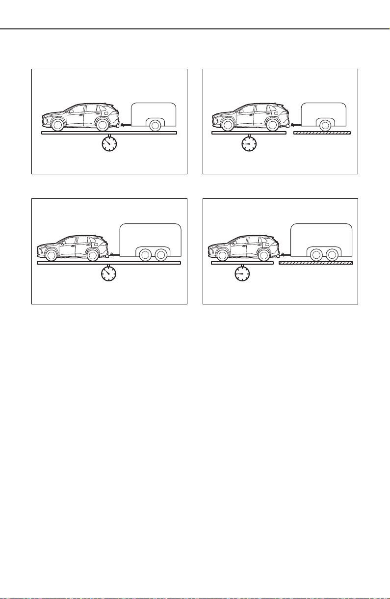
182
4-1. Before driving
Vehicles without towing pack-
age
Vehicles with towing package
■ GVWR (Gross Vehicle
Weight Rating)
The maximum allowable gross
vehicle weight. The gross vehi-
cle weight is the total weight of
the vehicle. When towing a
trailer, it is the sum of the vehicle
weight (including the occu-
pants, cargo and any optional
equipment installed on the vehi-
cle) and the tongue weight.
Vehicles without towing pack-
age
Vehicles with towing package
■ GAWR (Gross Axle Weight
Rating)
The maximum allowable gross
axle weight. The gross axle
weight is the load placed on
each axle (front and rear).
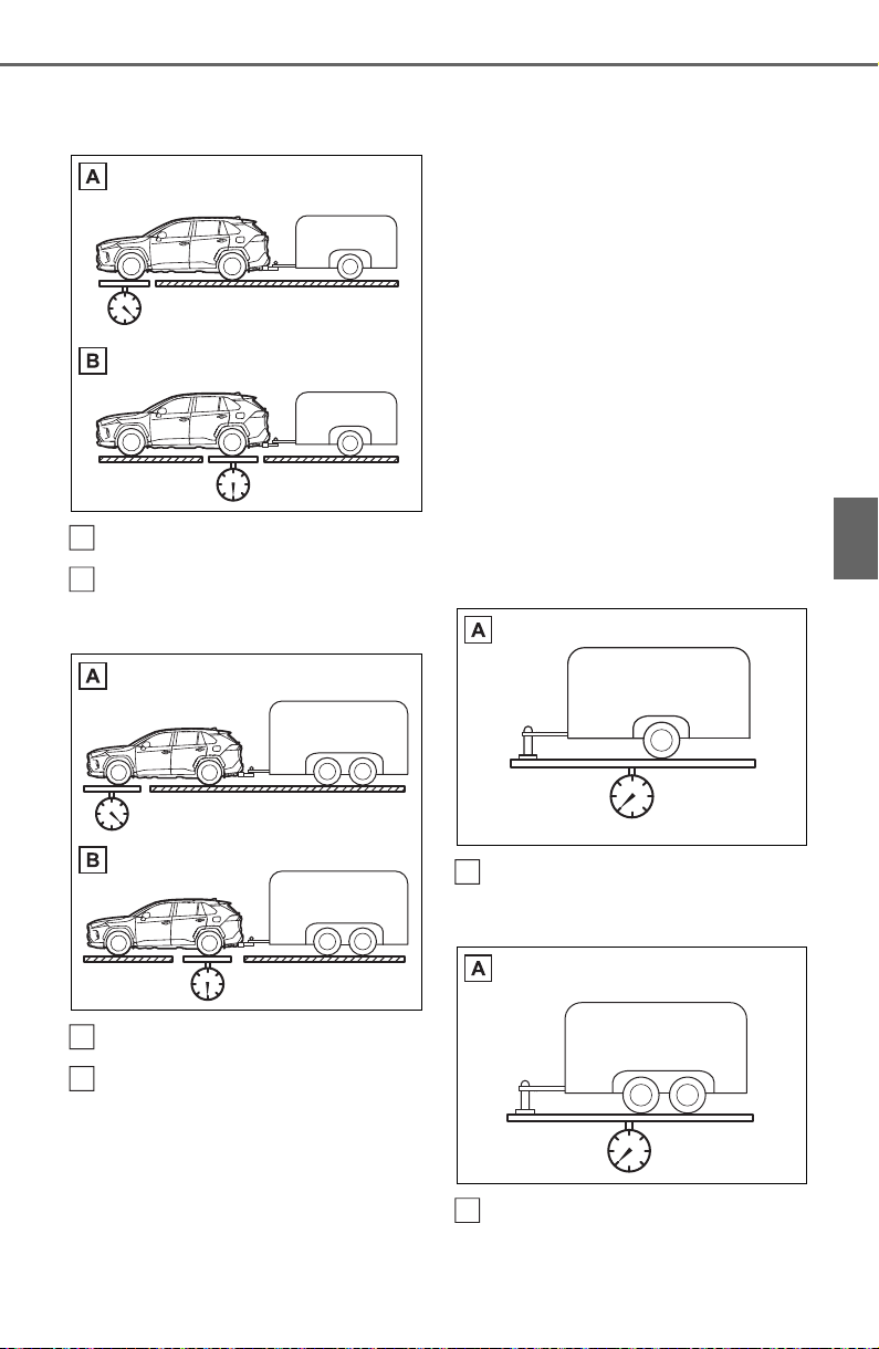
183
4-1. Before driving
4
Driving
Vehicles without towing pack-
age
Front GAWR
Rear GAWR
Vehicles with towing package
Front GAWR
Rear GAWR
■ TWR (Trailer Weight Rating)
The maximum allowable gross
trailer weight. The gross trailer
weight is the sum of the trailer
weight and the weight of the
cargo in the trailer.
TWR is calculated assuming
base vehicle with one driver,
one front passenger, towing
package (if available), hitch and
hitch systems (if required).
Additional optional equipment, pas-
sengers and cargo in the vehicle
will reduce the trailer weight rating
so as not to exceed GCWR, GVWR
and GAWR.
Vehicles with towing package: If the
gross trailer weight exceeds 3000
lb. (1360 kg), it is recommended to
use a trailer with 2 or more axles.
Vehicles without towing pack-
age
(With brakes)
Vehicles with towing package
(With brakes)
A
B
A
B
A
A
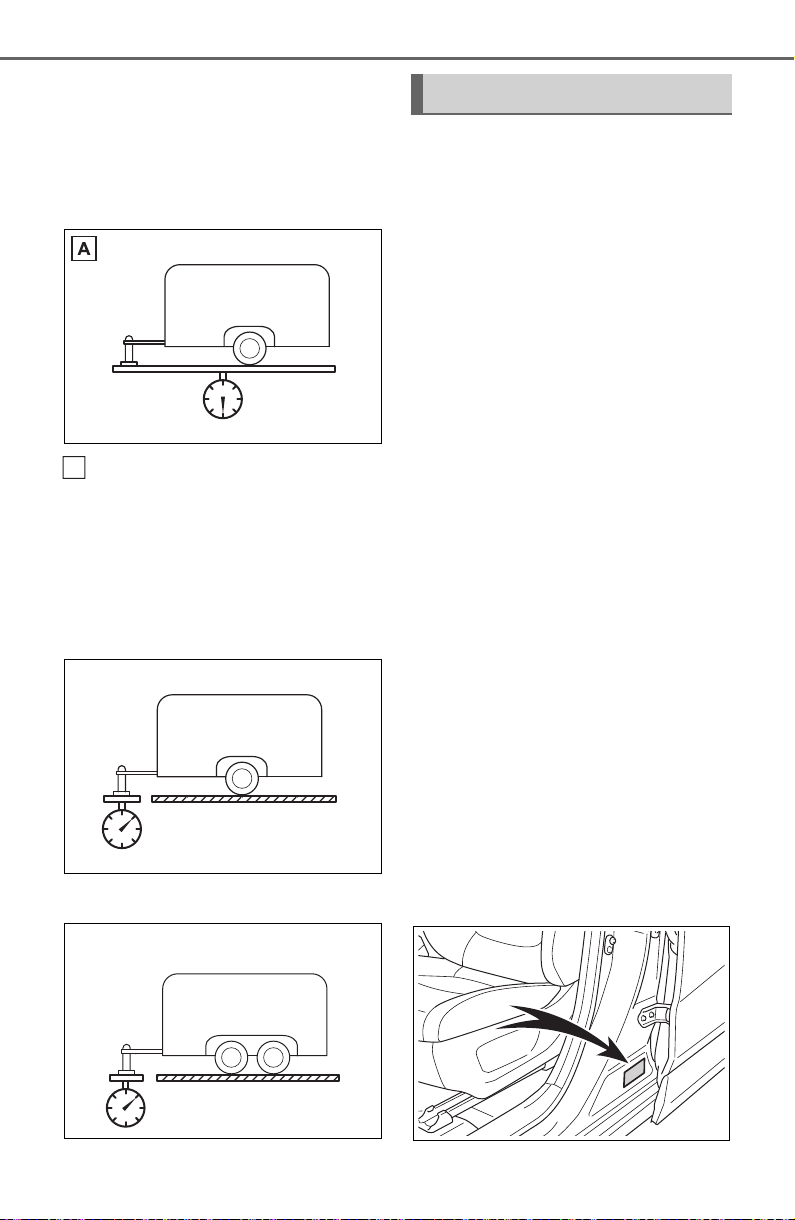
184
4-1. Before driving
■ Unbraked TWR (Unbraked
Trailer Weight Rating)
The trailer weight rating for tow-
ing a trailer without a trailer ser-
vice brake system.
(Without brakes)
■ Tongue Weight
The load placed on the trailer
hitch ball. (P.186)
Vehicles without towing pack-
age
Vehicles with towing package
The gross trailer weight must
never exceed the TWR
described below.
Without towing package
1500 lb. (680 kg)
With towing package
3500 lb. (1590 kg)
The gross combination weight
must never exceed the
GCWR described below.
Without towing package
Vehicles without Dynamic Torque
Vectoring AWD system: 6110 lb.
(2770 kg)
Vehicles with Dynamic Torque Vec-
toring AWD system: 6205 lb. (2815
kg)
With towing package
8205 lb. (3725 kg)
The gross vehicle weight
must never exceed the
GVWR indicated on the Certi-
fication Regulation Label.
The gross axle weight on
each axle must never exceed
the GAWR indicated on the
Certification Regulation Label.
A
Weight limits
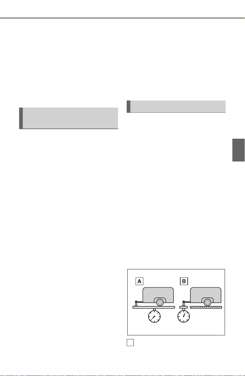
185
4-1. Before driving
4
Driving
If the gross trailer weight is
over the unbraked TWR,
trailer service brakes are
required.
Vehicles with towing package:
If the gross trailer weight is
over 2000 lb. (907 kg), a sway
control device with sufficient
capacity is required.
Confirm that the gross trailer
weight, gross combination
weight, gross vehicle weight,
gross axle weight and tongue
weight are all within the limits.
■ GCWR
*
Without towing package
Vehicles without Dynamic
Torque Vectoring AWD system:
6110 lb. (2770 kg)
Vehicles with Dynamic Torque
Vectoring AWD system: 6205 lb.
(2815 kg)
With towing package
8205 lb. (3725 kg)
*
: These models meet the tow-vehi-
cle trailering requirement of SAE
International per SAE J2807.
■ TWR
*
Without towing package
1500 lb. (680 kg)
With towing package
3500 lb. (1590 kg)
*
: These models meet the tow-vehi-
cle trailering requirement of SAE
International per SAE J2807.
■ Unbraked TWR
*
1000 lb. (450 kg)
*
: These models meet the tow-vehi-
cle trailering requirement of SAE
International per SAE J2807.
A recommended tongue
weight varies in accordance
with the types of trailers or
towing as described below.
To ensure the recommended
values shown below, the
trailer must be loaded by
referring to the following
instructions.
• Tongue Weight
The gross trailer weight should be
distributed so that the tongue
weight is 9% to 11%.
(Tongue weight /Gross trailer
weight x 100 = 9% to 11%)
Vehicles without towing pack-
age
Gross trailer weight
GCWR, TWR and
Unbraked TWR
Trailer Tongue Weight
A
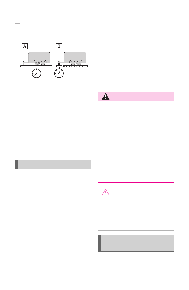
186
4-1. Before driving
Tongue weight
Vehicles with towing package
Gross trailer weight
Tongue weight
The gross trailer weight, gross
axle weight and tongue weight
can be measured with platform
scales found at a highway
weighing station, building supply
company, trucking company,
junk yard, etc.
Trailer hitch assemblies have
different weight capacities.
Toyota recommends the use of
Toyota hitch/bracket for your
vehicle. For details, contact your
Toyota dealer.
If you wish to install a trailer
hitch, contact your Toyota
dealer.
Use only a hitch that con-
forms to the gross trailer
weight requirement of your
vehicle.
Follow the directions supplied
by the hitch manufacturer.
Lubricate the hitch ball with a
light coating of grease.
Remove the hitch ball when-
ever you are not towing a
trailer. Remove the trailer
hitch if you do not need it.
After removing the hitch, seal
any mounting holes in the
vehicle body to prevent entry
of any substances into the
vehicle.
Use the correct trailer ball for
your application.
Hitch
B
A
B
WARNING
■ Hitch
Trailer hitch assemblies have dif-
ferent weight capacities estab-
lished by the hitch manufacturer.
Even though the vehicle may be
physically capable of towing a
higher weight, the operator must
determine the maximum weight
rating of the particular hitch
assembly and never exceed the
maximum weight rating specified
for the trailer-hitch. Exceeding the
maximum weight rating set by the
trailer-hitch manufacturer can
cause an accident resulting in
death or serious personal injuries.
NOTICE
■ When installing a trailer hitch
Use only the position recom-
mended by your Toyota dealer.
Do not install the trailer hitch on
the bumper; this may cause body
damage.
Selecting trailer ball (vehi-
cles with towing package)
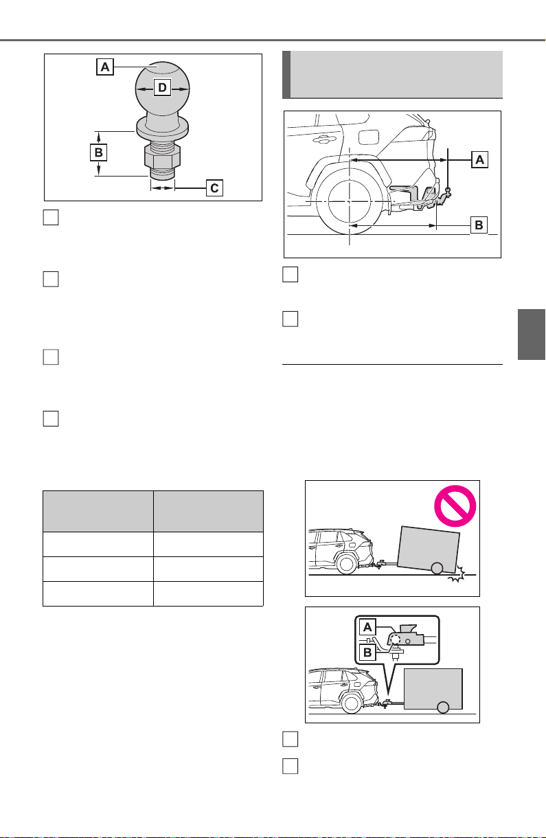
187
4-1. Before driving
4
Driving
Trailer ball load rating
Matches or exceeds the gross
trailer weight rating of the trailer.
Shank length
Protrudes beyond the bottom of the
lock washer and nut by at least 2
threads.
Shank diameter
Matches the ball mount hole diame-
ter size.
Ball diameter
Matches the size of the trailer cou-
pler. Most couplers are stamped
with the required trailer ball size.
Weight carrying ball position:
43.3 in. (1100 mm)
Hitch receiver pin hole posi-
tion: 38.1 in. (969 mm)
■ Matching trailer ball height to
trailer coupler height
No matter which class of tow hitch
applies, for a more safe trailer
hookup, the trailer ball setup must
be the proper height for the coupler
on the trailer.
Coupler
Trailer ball
Trailer class
Typical trailer
ball size
IV 2 5/16 in.
II and III 2 in.
I 1 7/8 in.
A
B
C
D
Positions for towing hitch
receiver and hitch ball
A
B
A
B

188
4-1. Before driving
Please consult your dealer
when installing trailer lights, as
incorrect installation may cause
damage to the vehicle’s lights.
Please take care to comply with
your state’s laws when install-
ing trailer lights.
Your vehicle will handle differ-
ently when towing a trailer. Help
to avoid an accident, death or
serious injury, keep the following
in mind when towing:
Speed limits for towing a
trailer vary by state or prov-
ince. Do not exceed the
posted towing speed limit.
Toyota recommends that the
vehicle-trailer speed limit is 65
mph (104 km/h) on a flat,
straight, dry road. Do not
exceed this limit, the posted
towing speed limit or the
speed limit for your trailer as
set forth in your trailer owner’s
manual, whichever is lowest.
Instability of the towing vehi-
cle-trailer combination (trailer
sway) increases as speed
increases. Exceeding speed
limits may cause loss of con-
trol.
Before starting out, check the
trailer lights, tires and the
vehicle-trailer connections.
Recheck after driving a short
distance.
Practice turning, stopping and
reversing with the trailer
attached in an area away
from traffic until you become
accustomed to the feel of the
vehicle-trailer combination.
Reversing with a trailer
attached is difficult and
requires practice. Grip the
bottom of the steering wheel
and move your hand to the
left to move the trailer to the
left. Move your hand to the
right to move the trailer to
right. (This is generally oppo-
site to reversing without a
trailer attached.) Avoid sharp
or prolonged turning. Have
someone guide you when
reversing to reduce the risk of
an accident.
As stopping distance is
increased when towing a
trailer, vehicle-to vehicle dis-
tance should be increased.
For each 10 mph (16 km/h) of
speed, allow at least one
vehicle and trailer length.
Avoid sudden braking as you
may skid, resulting in the
trailer jackknifing and a loss of
Connecting trailer lights
NOTICE
■ Do not directly splice trailer
lights
Do not directly splice trailer lights.
Directly splicing trailer lights may
damage your vehicle’s electrical
system and cause a malfunction.
Trailer towing tips

189
4-1. Before driving
4
Driving
vehicle control. This is espe-
cially true on wet or slippery
surfaces.
Avoid jerky starts or sudden
acceleration.
Avoid jerky steering and
sharp turns, and slow down
before making turn.
Note that when making a turn,
the trailer wheels will be
closer than the vehicle wheels
to the inside of the turn. Com-
pensate by making a wider
than normal turning radius.
Slow down before making a
turn, in cross winds, on wet or
slippery surfaces, etc.
Increasing vehicle speed can
destabilize the trailer.
Take care when passing other
vehicles. Passing requires
considerable distance. After
passing a vehicle, do not for-
get the length of your trailer,
and be sure you have plenty
of room before changing
lanes.
To maintain engine braking
efficiency and charging sys-
tem performance when using
engine braking, do not put the
transmission in D. If in the S
mode, the transmission shift
range position must be in 6 or
lower.
Instability happens more fre-
quently when descending
steep or long downhill grades.
Before descending, slow
down and downshift. Do not
make sudden downshifts
while descending steep or
long downhill grades.
Avoid holding the brake pedal
down too long or applying the
brakes too frequently. This
could cause the brakes to
overheat and result in
reduced braking efficiency.
Due to the added load of the
trailer, your vehicle’s engine
may overheat on hot days (at
temperatures over 85°F
[30°C]) when driving up a long
or steep grade. If the engine
coolant temperature gauge
indicates overheating, imme-
diately turn off the air condi-
tioning (if in use), pull your
vehicle off the road and stop
in a safe spot. (P.659)
Always place wheel blocks
under both the vehicle’s and
the trailer’s wheels when
parking. Apply the parking
brake firmly, and put the
transmission in P. Avoid park-
ing on a slope, but if unavoid-
able, do so only after
performing the following:
1 Apply the brakes and keep
them applied.
2 Have someone place wheel
blocks under both the vehi-
cle’s and trailer’s wheels.

190
4-1. Before driving
3 When the wheel blocks are in
place, release the brakes
slowly until the blocks absorb
the load.
4 Apply the parking brake
firmly.
5 Shift into P and turn off the
engine.
When restarting after parking
on a slope:
1 With the transmission in P,
start the engine. Be sure to
keep the brake pedal
depressed.
2 Shift into a forward gear. If
reversing, shift into R.
3 If the parking brake is in man-
ual mode, release the park-
ing brake. (P.203)
4 Release the brake pedal, and
slowly pull or back away from
the wheel blocks. Stop and
apply the brakes.
5 Have someone retrieve the
blocks.
■ Break-in schedule
If your vehicle is new or equipped
with any new power train compo-
nents (such as an engine, transmis-
sion, differential or wheel bearing),
Toyota recommends that you do not
tow a trailer until the vehicle has
been driven for over 500 miles (800
km).
After the vehicle has been driven for
over 500 miles (800 km), you can
start towing. However, for the next
500 miles (800 km), drive the vehi-
cle at a speed of less than 45 mph
(72 km/h) when towing a trailer, and
avoid full throttle acceleration.
■ Maintenance
● If you tow a trailer, your vehicle
will require more frequent mainte-
nance due to the additional load.
(See “Scheduled Maintenance
Guide” or “Owner’s Manual Sup-
plement”.)
● Retighten the fixing bolts of the
towing ball and bracket after
approximately 600 miles (1000
km) of trailer towing.
■ If trailer sway occurs
One or more factors (crosswinds,
passing vehicles, rough roads, etc.)
can adversely affect handling of
your vehicle and trailer, causing
instability.
● If trailer swaying occurs:
• Firmly grip the steering wheel.
Steer straight ahead.
Do not try to control trailer sway-
ing by turning the steering wheel.
• Begin releasing the accelerator
pedal immediately but very gradu-
ally to reduce speed.
Do not increase speed. Do not
apply vehicle brakes.
If you make no extreme correction
with the steering or brakes, your
vehicle and trailer should stabilize (if
enabled, Trailer Sway Control can
also help to stabilize the vehicle and
trailer.).
● After the trailer swaying has
stopped:
• Stop in a safe place. Get all occu-
pants out of the vehicle.
• Check the tires of the vehicle and
the trailer.
• Check the load in the trailer.
Make sure the load has not
shifted.
Make sure the tongue weight is
appropriate, if possible.
• Check the load in the vehicle.
Make sure the vehicle is not over-
loaded after occupants get in.
If you cannot find any problems, the
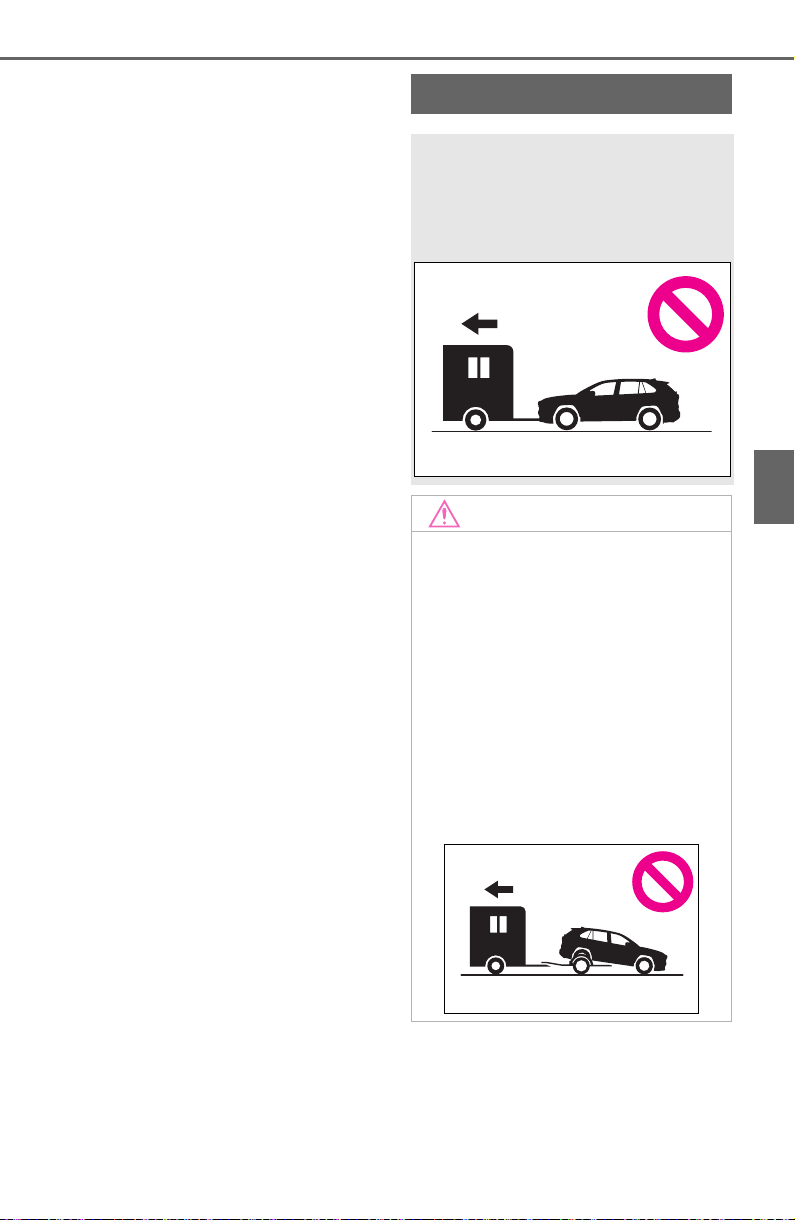
191
4-1. Before driving
4
Driving
speed at which trailer swaying
occurred is beyond the limit of your
particular vehicle-trailer combina-
tion. Drive at a lower speed to pre-
vent instability. Remember that
swaying of the towing vehicle-trailer
increases as speed increases.
Dinghy towing
Your vehicle is not designed
to be dinghy towed (with 4
wheels on the ground)
behind a motor home.
NOTICE
■ To avoid serious damage to
your vehicle
Do not tow your vehicle with 4
wheels on the ground.
■ To prevent causing serious
damage to the transmission
and AWD system (AWD mod-
els)
2WD models: Never tow this vehi-
cle from the rear with the front
wheels on the ground. This may
cause serious damage to the
transmission.
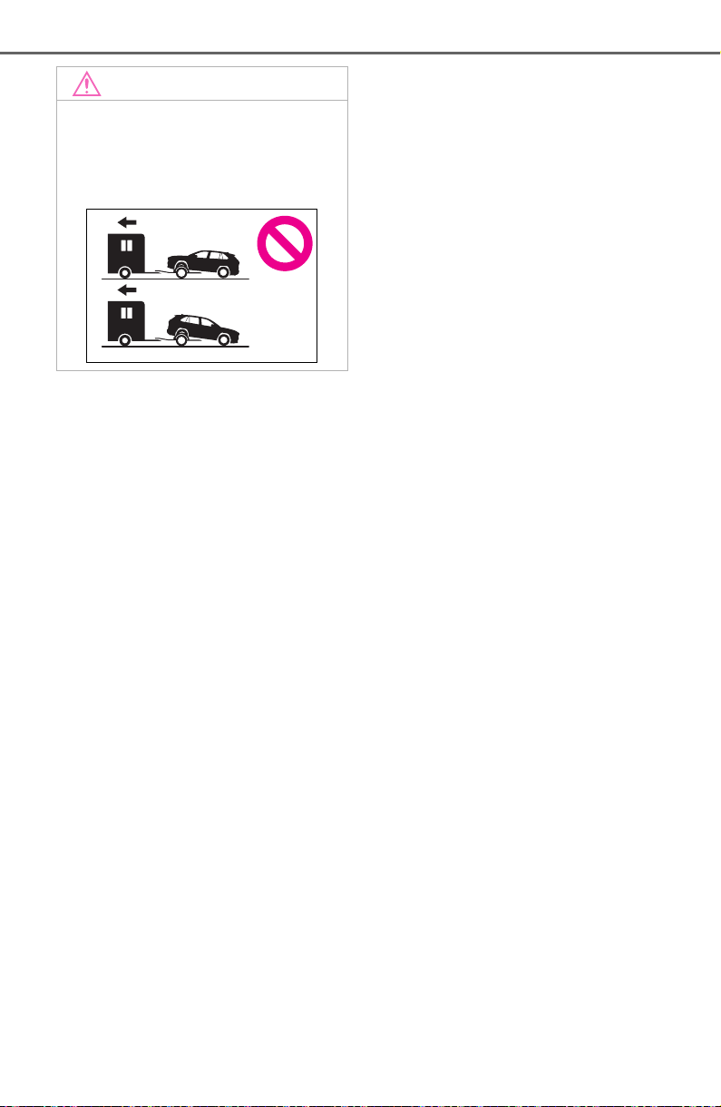
192
4-1. Before driving
NOTICE
AWD models: Never tow this vehi-
cle with any of the wheels on the
ground. This may cause serious
damage to the transmission and
AWD system.
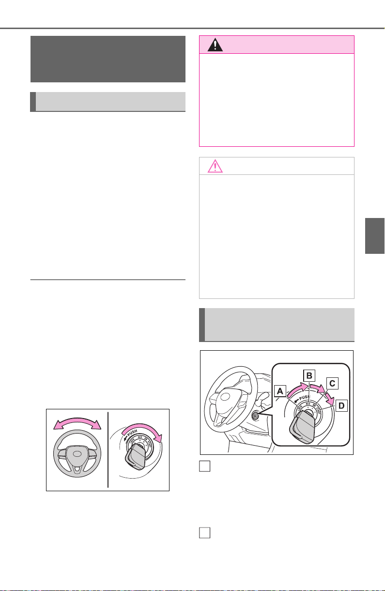
193
4-2. Driving procedures
4
Driving
4-2.Driving p rocedures
1 Pull the parking brake switch
to check that the parking
brake is set. (P.203)
The parking brake indicator will
come on.
2 Check that the shift lever is
set in P.
3 Firmly depress the brake
pedal.
4 Turn the engine switch to
START to start the engine.
■ If the engine does not start
The engine immobilizer system may
not have been deactivated. (P. 70 )
Contact your Toyota dealer.
■ When the steering lock cannot
be released
When starting the engine, the
engine switch may seem stuck in
OFF. To free it, turn the key while
turning the steering wheel slightly
left and right.
■ When “Check Fuel Cap” is dis-
played on the multi-information
display
P.221
OFF (“LOCK” position)
The steering wheel is locked and
the key can be removed. (The key
can be removed only when the shift
lever is in P.)
ACC (“ACC” position)
Some electrical components such
Engine (ignition)
switch (vehicles with-
out smart key system)
Starting the engine
WARNING
■ When starting the engine
Always start the engine while sit-
ting in the driver’s seat. Do not
depress the accelerator pedal
while starting the engine under
any circumstances.
Doing so may cause an accident
resulting in death or serious injury.
NOTICE
■ When starting the engine
● Do not crank the engine for
more than 30 seconds at a time.
This may overheat the starter
and wiring system.
● Do not race a cold engine.
● If the engine becomes difficult to
start or stalls frequently, have
your vehicle checked by your
Toyota dealer immediately.
Changing the engine
switch positions
A
B
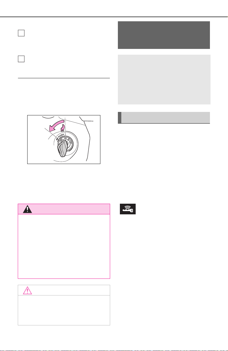
194
4-2. Driving procedures
as the audio system can be used.
ON (“ON” position)
All electrical components can be
used.
START (“START” position)
For starting the engine.
■ Turning the key from ACC to
OFF
1 Shift the shift lever to P.
2 Push in the key and turn it to
OFF.
■ Key reminder function
A buzzer sounds if the driver’s door
is opened while the engine switch is
in OFF or ACC to remind you to
remove the key.
1 Pull the parking brake switch
to check that the parking
brake is set. (P.203)
The parking brake indicator will
come on.
2 Check that the shift lever is
set in P.
3 Firmly depress the brake
pedal.
and a message will be dis-
played on the multi-information dis-
play.
If it is not displayed, the engine
cannot be started.
4 Press the engine switch
shortly and firmly.
When operating the engine switch,
one short, firm press is enough. It is
not necessary to press and hold the
switch.
The engine will crank until it starts
or for up to 30 seconds, whichever
is less.
Continue depressing the brake
pedal until the engine is completely
started.
The engine can be started from any
WARNING
■ Caution when driving
Do not turn the engine switch to
OFF while driving. If, in an emer-
gency and you must turn the
engine off while the vehicle is
moving, turn the engine switch
only to ACC to stop the engine.
An accident may result if the
engine is stopped while driving.
(P.618)
NOTICE
■ To prevent battery discharge
Do not leave the engine switch in
ACC or ON for long periods of
time without the engine running.
C
D
Engine (ignition)
switch (vehicles with
smart key system)
Performing the following
operations when carrying
the electronic key on your
person starts the engine or
changes engine switch
modes.
Starting the engine
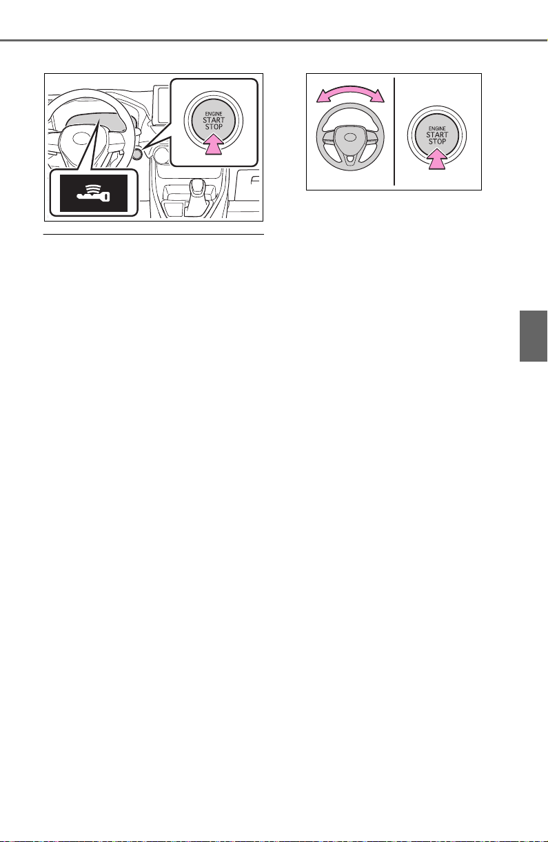
195
4-2. Driving procedures
4
Driving
engine switch mode.
■ If the engine does not start
● The engine immobilizer system
may not have been deactivated.
(P. 70 )
Contact your Toyota dealer.
● If a message related to start-up is
shown on the multi-information
display, read the message and fol-
low the instructions.
■ If the battery is discharged
The engine cannot be started using
the smart key system. Refer to
P.655 to restart the engine.
■ Electronic key battery depletion
P.102
■ Conditions affecting operation
P.129
■ Note for the entry function
P.130
■ Steering lock function
● After turning the engine switch to
OFF and opening and closing the
doors, the steering wheel will be
locked due to the steering lock
function. Operating the engine
switch again automatically can-
cels the steering lock.
● When the steering lock cannot be
released, “Push Engine Switch
while Turning Steering Wheel in
Either Direction” will be displayed
on the multi-information display.
Check that the shift lever is set in
P. Press the engine switch shortly
and firmly while turning the steer-
ing wheel left and right.
● To prevent the steering lock motor
from overheating, the operation of
motor may be suspended if the
engine is turned on and off repeat-
edly in a short period of time. In
this case, refrain from running the
engine. After about 10 seconds,
the steering lock motor will
resume functioning.
■ If there is a malfunction in the
smart key system
If “Smart Key System Malfunction”
is displayed on the multi-information
display, the system may be malfunc-
tioning. Have the vehicle inspected
by your Toyota dealer immediately.
■ When “Check Fuel Cap” is dis-
played on the multi-information
display
P.221
■ Electronic key battery
P.604
■ Operation of the engine switch
● If the switch is not pressed shortly
and firmly, the engine switch
mode may not change or the
engine may not start.
● If attempting to restart the engine
immediately after turning the
engine switch to OFF, the engine
may not start in some cases. After
turning the engine switch to OFF,
please wait a few seconds before
restarting the engine.
■ Customization
If the smart key system has been
deactivated in a customized setting,
refer to P.654.
196
4-2. Driving procedures
1 Stop the vehicle completely.
2 If the parking brake is in man-
ual mode, set the parking
brake. (P.203)
Check the parking brake indicator
is illuminated.
3 Shift the shift lever to P.
4 Press the engine switch
shortly and firmly.
The engine will stop, and the meter
display will be extinguished.
5 Release the brake pedal and
check that “ACCESSORY” or
“IGNITION ON” is not shown
on the multi-information dis-
play.
■ Automatic engine shut off fea-
ture
● The vehicle is equipped with a
feature that automatically shuts off
the engine when the shift lever is
in P with the engine running for an
extended period.
● The engine will automatically shut
off after approximately 1 hour if it
has been left running while the
shift lever is in P.
● The timer for the automatic engine
shut off feature will reset if the
brake pedal is depressed or if the
shift lever is in a position other
than P.
● After the vehicle is parked, if the
door is locked with the door lock
switch (P.112) from the inside or
the mechanical key (P.653) from
the outside, the automatic engine
shut off feature will be disabled.
The timer for the automatic engine
shut off feature will be re-enabled
if the driver’s door is opened.
WARNING
■ When starting the engine
Always start the engine while sit-
ting in the driver’s seat. Do not
depress the accelerator pedal
while starting the engine under
any circumstances.
Doing so may cause an accident
resulting in death or serious injury.
■ Caution while driving
If engine failure occurs while the
vehicle is moving, do not lock or
open the doors until the vehicle
reaches a safe and complete
stop. Activation of the steering
lock in this circumstance may lead
to an accident, resulting in death
or serious injury.
NOTICE
■ When starting the engine
● Do not race a cold engine.
● If the engine becomes difficult to
start or stalls frequently, have
your vehicle checked by your
Toyota dealer immediately.
■ Symptoms indicating a mal-
function with the engine
switch
If the engine switch seems to be
operating somewhat differently
than usual, such as the switch
sticking slightly, there may be a
malfunction. Contact your Toyota
dealer immediately.
Stopping the engine
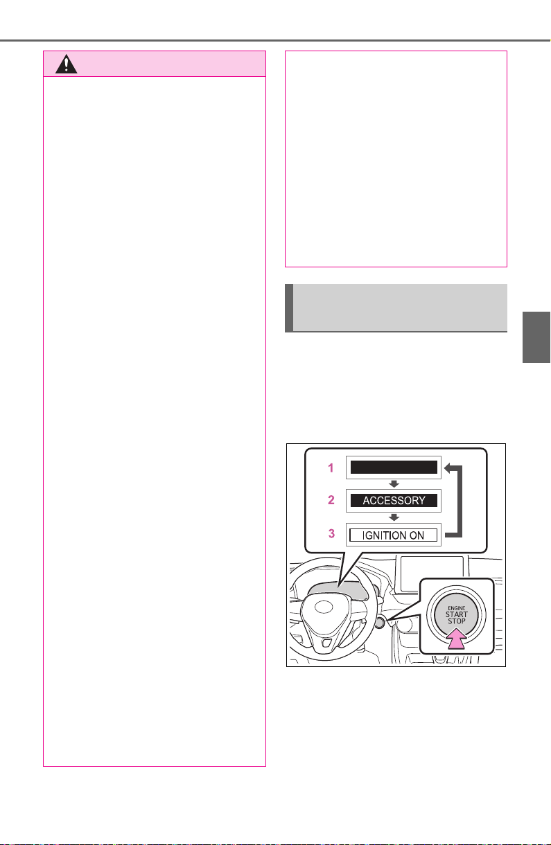
197
4-2. Driving procedures
4
Driving
Modes can be changed by
pressing the engine switch with
brake pedal released. (The
mode changes each time the
switch is pressed.)
1 OFF
*
The emergency flashers can be
used.
The multi-information display will
not be displayed.
2 ACC
WARNING
■ Stopping the engine in an
emergency
● If you want to stop the engine in
an emergency while driving the
vehicle, press and hold the
engine switch for more than 2
seconds, or press it briefly 3
times or more in succession.
(P.618)
However, do not touch the
engine switch while driving
except in an emergency. Turn-
ing the engine off while driving
will not cause loss of steering or
braking control, but the power
assist to these systems will be
lost. This will make it more diffi-
cult to steer and brake, so you
should pull over and stop the
vehicle as soon as it is safe to
do so.
● If the engine switch is operated
while the vehicle is running, a
warning message will be shown
on the multi-information display
and a buzzer sounds.
● When restarting the engine after
an emergency shutdown, shift
the shift lever to N and press the
engine switch shortly and firmly.
■ When parking
Exhaust gases include harmful
carbon monoxide (CO), which is
colorless and odorless. Observe
the following precautions.
Failure to do so may cause
exhaust gases to enter the vehicle
and may lead to an accident
caused by light-headedness, or
may lead to death or a serious
health hazard.
● If the vehicle is in a poorly venti-
lated area or a closed area,
such as a garage, stop the
engine.
● Do not leave the vehicle with
the engine running for a long
time. If such a situation cannot
be avoided, park the vehicle in
an open space and ensure that
exhaust fumes do not enter the
vehicle interior.
● Do not leave the engine running
in an area with snow build-up,
or where it is snowing. If snow-
banks build up around the vehi-
cle while the engine is running,
exhaust gases may collect and
enter the vehicle.
Changing engine switch
modes

198
4-2. Driving procedures
Some electrical components such
as the audio system can be used.
“ACCESSORY” will be displayed
on the multi-information display.
3 ON
All electrical components can be
used.
“IGNITION ON” will be displayed on
the multi-information display.
*
: If the shift lever is in a position
other than P when turning off the
engine, the engine switch will be
turned to ACC, not to OFF.
■ Auto power off function
If the vehicle is left in ACC for more
than 20 minutes or ON (the engine
is not running) for more than an
hour with the shift lever in P, the
engine switch will automatically turn
to OFF. However, this function can-
not entirely prevent battery dis-
charge. Do not leave the vehicle
with the engine switch in ACC or ON
for long periods of time when the
engine is not running.
If the engine is stopped with the
shift lever in a position other
than P, the engine switch will not
be turned to OFF but instead be
turned to ACC. Perform the fol-
lowing procedure to turn the
switch to OFF:
1 Check that the parking brake
is set.
2 Shift the shift lever to P.
3 Check that “ACCESSORY” is
displayed on the multi-infor-
mation display and then
press the engine switch
shortly and firmly.
4 Check that “ACCESSORY”
or “IGNITION ON” on the
multi-information display is
off.
NOTICE
■ To prevent battery discharge
● Do not leave the engine switch
in ACC or ON for long periods of
time without the engine running.
● If “ACCESSORY” or “IGNITION
ON” is displayed on the multi-
information display, the engine
switch is not in OFF. Exit the
vehicle after turning the engine
switch to OFF.
When stopping the engine
with the shift lever in a
position other than P
NOTICE
■ To prevent battery discharge
Do not stop the engine when the
shift lever is in a position other
than P. If the engine is stopped in
another shift lever position, the
engine switch will not be turned to
OFF but instead be turned to
ACC. If the vehicle is left in ACC,
battery discharge may occur.
199
4-2. Driving procedures
4
Driving
*1
:Shifting to the D position allows
the system to select a gear suit-
able for the driving conditions.
Setting the shift lever to the D
position is recommended for nor-
mal driving.
*2
:Selecting shift ranges using S
mode restricts the upper limit of
the possible gear ranges, con-
trols engine braking force, and
prevents unnecessary upshifting.
■ When driving with dynamic
radar cruise control with full-
speed range activated
Even when performing the following
actions with the intent of enabling
engine braking, engine braking will
not activate because dynamic radar
cruise control with full-speed range
will not be canceled.
● While driving in S mode, down-
shifting to 7, 6, 5, or 4. (P.201)
● When switching the driving mode
to sport mode while driving in D.
(P.351)
■ If “High Transmission Fluid
Temp See Owner’s Manual” is
displayed on the multi-informa-
tion display (AWD models)
Make sure to return to D position
driving and reduce speed by easing
off the accelerator pedal. Stop the
vehicle in a safe place, shift the shift
lever to P and let the engine idle
until the warning message goes out.
When the warning message goes
out, the vehicle can be driven again.
If the warning message does not go
out after waiting a while, have your
vehicle inspected by your Toyota
dealer.
■ Restraining sudden start (Drive-
Start Control)
P.170
■ AI-SHIFT
The AI-SHIFT automatically selects
the suitable gear according to driver
performance and driving conditions.
The AI-SHIFT automatically oper-
ates when the shift lever is in D.
(Shifting the shift lever to S cancels
the function.)
Automatic transmis-
sion
Select the shift position
depending on your purpose
and situation.
Shift position purpose
and functions
Shift
position
Objective or function
P
Parking the vehicle/start-
ing the engine
R Reversing
N Neutral
D
Normal driving
*1
S
S mode driving
*2
(P.201)
WARNING
■ When driving on slippery
road surfaces
Do not accelerate or shift gears
suddenly.
Sudden changes in engine brak-
ing may cause the vehicle to spin
or skid, resulting in an accident.
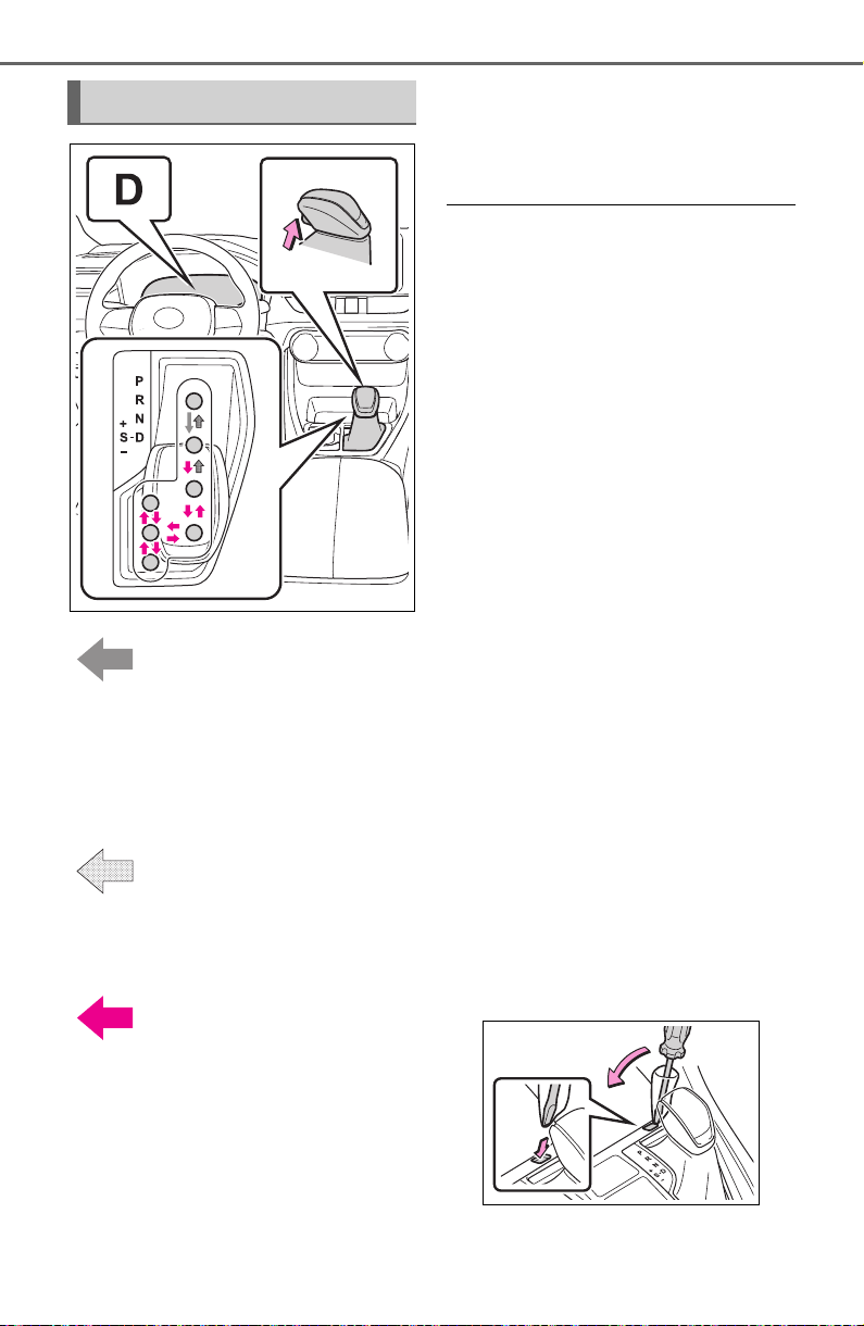
200
4-2. Driving procedures
While the engine switch
is in ON and the brake pedal
depressed
*
, shift the shift lever
while pushing the shift release
button on the shift knob.
Shift the shift lever while
pushing the shift release button
on the shift knob.
Shift the shift lever nor-
mally.
When shifting the shift lever
between P and D, make sure that
the vehicle is completely stopped.
*
: For the vehicle to be able to be
shifted from P, the brake pedal
must be depressed before the
shift release button is pushed. If
the shift release button is pushed
first, the shift lock will not be
released.
■ Shift lock system
The shift lock system is a system to
prevent accidental operation of the
shift lever in starting.
The shift lever can be shifted from P
only when the engine switch is in
ON, the brake pedal is depressed
and the shift release button is
pushed.
■ If the shift lever cannot be
shifted from P
First, check whether the brake pedal
is being depressed.
If the shift lever cannot be shifted
even though the brake pedal is
depressed and the shift release but-
ton is pushed, there may be a prob-
lem with the shift lock system. Have
the vehicle inspected by your Toyota
dealer immediately.
The following steps may be used as
an emergency measure to ensure
that the shift lever can be shifted.
Releasing the shift lock:
1 Pull the parking brake switch to
check that the parking brake is
set. (P.203)
2 Turn the engine switch to OFF.
3 Depress the brake pedal.
4 Pry the cover up with a flathead
screwdriver or equivalent tool.
To prevent damage to the cover,
cover the tip of the screwdriver
with a rag.
5 Press and hold the shift lock
override button and then push
Shifting the shift lever
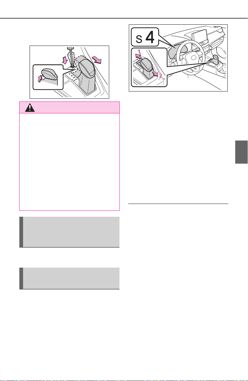
201
4-2. Driving procedures
4
Driving
the button on the shift knob.
The shift lever can be shifted
while both buttons are pressed.
P.351, 357
When the shift lever is in the S
position, the shift lever can be
operated as follows:
1 Upshifting
2 Downshifting
The selected shift range, from S1 to
S8 will be displayed on the multi-
information display.
The initial shift range in S mode
is set automatically to 4, 5 or 6
according to vehicle speed.
However, the initial shift range
may be set to 3 if AI-SHIFT has
operated while the shift lever
was in the D position. (P.199)
■ S mode
● You can choose from 8 levels of
accelerating force and engine
braking force.
● A lower shift range will provide
greater accelerating force and
engine braking force than a higher
shift range, and the engine revolu-
tions will also increase.
● To prevent the engine from over-
revving, upshifting may automati-
cally occur.
● To protect the automatic transmis-
sion, a function is adopted that
automatically selects a higher shift
range when the fluid temperature
is high.
● When the shift range is 7 or lower,
holding the shift lever toward “+”
sets the shift range to 8.
WARNING
■ To prevent an accident when
releasing the shift lock
Before pressing the shift lock
override button, make sure to set
the parking brake and depress the
brake pedal.
If the accelerator pedal is acci-
dentally depressed instead of the
brake pedal when the shift lock
override button is pressed and the
shift lever is shifted out of P, the
vehicle may suddenly start, possi-
bly leading to an accident result-
ing in death or serious injury.
Selecting the driving
mode and snow mode (if
equipped)
Changing shift ranges in
S mode
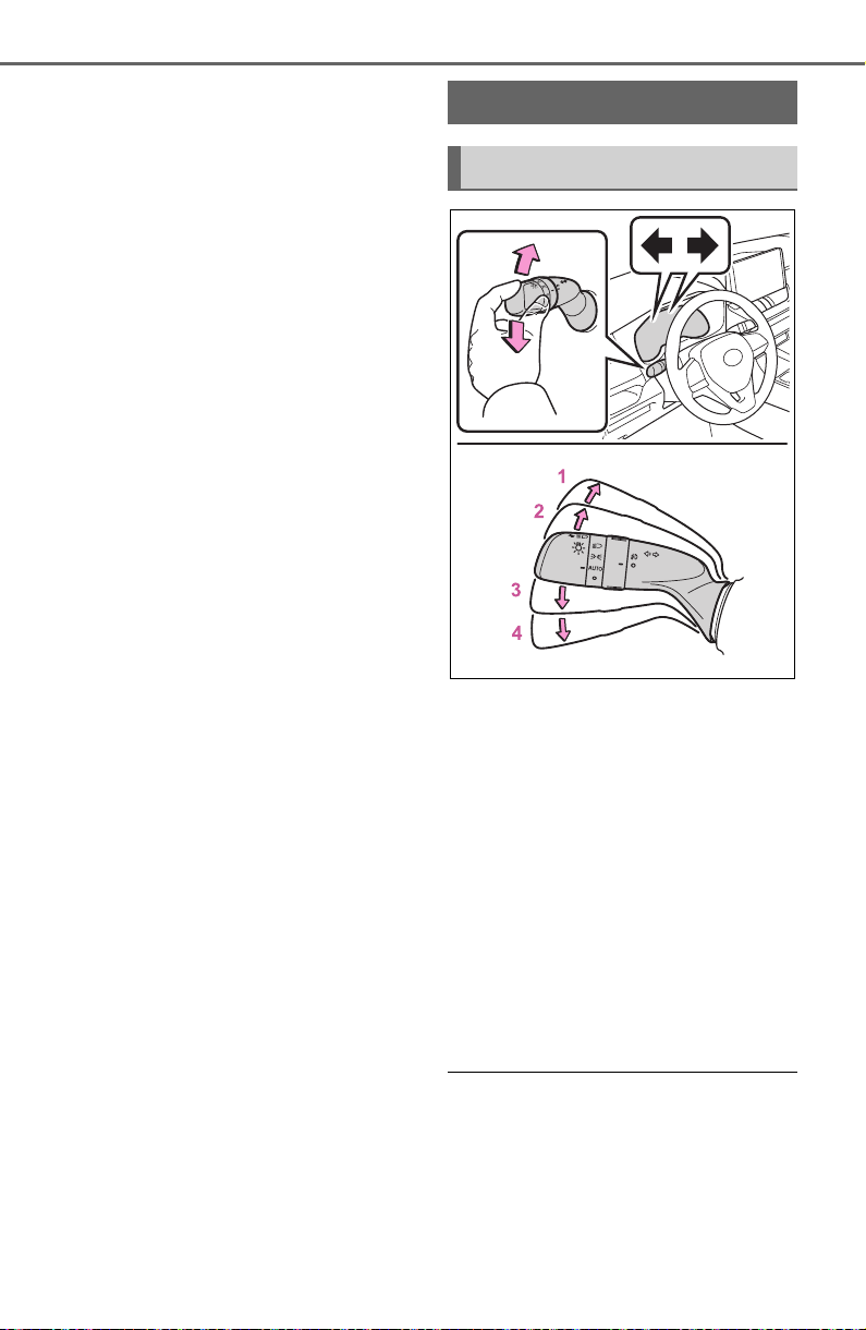
202
4-2. Driving procedures
■ Downshifting restriction warn-
ing buzzer
To help ensure safety and driving
performance, downshifting opera-
tion may sometimes be restricted. In
some circumstances, downshifting
may not be possible even when the
shift lever is operated. (A buzzer will
sound twice.)
■ If the “S” indicator does not
come on or the “D” indicator is
displayed even after shifting the
shift lever to S
This may indicate a malfunction in
the automatic transmission system.
Have the vehicle inspected by your
Toyota dealer immediately. (In this
situation, the transmission will oper-
ate in the same manner as when the
shift lever is in D.)
1 Right turn
2 Lane change to the right
(move the lever partway and
release it)
The right hand signals will flash 3
times.
3 Lane change to the left
(move the lever partway and
release it)
The left hand signals will flash 3
times.
4 Left turn
■ Turn signals can be operated
when
The engine switch is in ON.
■ If the indicator flashes faster
than usual
Check that a light bulb in the front or
rear turn signal lights has not
Turn signal lever
Operating instructions
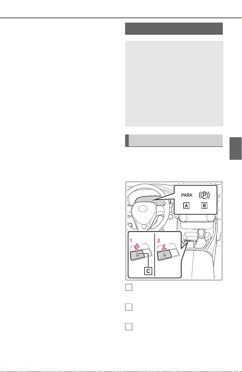
203
4-2. Driving procedures
4
Driving
burned out.
■ If the turn signals stop flashing
before a lane change has been
performed
Operate the lever again.
■ To discontinue flashing of the
turn signals during a lane
change
Operate the lever in the opposite
direction.
■ Using the manual mode
The parking brake can be set
and released manually.
Parking brake indicator light
(U.S.A.)
Parking brake indicator light
(Canada)
Parking brake switch indica-
tor
1 Pull the switch to set the
Parking brake
The parking brake can be
set or released automati-
cally or manually. In auto-
matic mode, the parking
brake can be set or released
automatically according to
shift lever operation. Also,
even in automatic mode, the
parking brake can be set or
released manually.
Operating instructions
A
B
C

204
4-2. Driving procedures
parking brake.
The parking brake indicator light
and parking brake switch indicator
will turn on.
Pull and hold the parking brake
switch if an emergency occurs and
it is necessary to operate the park-
ing brake while driving.
2 Push the switch to release
the parking brake.
• Operate the parking brake switch
while depressing the brake pedal.
• Parking brake automatic release
function (P.205)
Make sure that the parking brake
indicator light and parking brake
switch indicator turn off.
If the parking brake indicator
light and parking brake switch
indicator flash, operate the
switch again. (P.634)
■ Turning the automatic
mode on
While the vehicle is stopped,
pull and hold the parking brake
switch until a buzzer sounds and
a message is shown on the
multi-information display.
When the automatic mode is
turned on, the parking brake
operates as follows.
When the shift position is
shifted from P, the parking
brake will be released, and
the parking brake indicator
light and parking brake switch
indicator will turn off.
When the shift position is
shifted to P, the parking brake
will be set, and the parking
brake indicator light and park-
ing brake switch indicator will
turn on.
Operate the shift lever with the
vehicle stopped and the brake
pedal depressed.
■ Turning the automatic
mode off
While the vehicle is stopped and
depressing the brake pedal,
press and hold the parking
brake switch until a buzzer
sounds and a message is
shown on the multi-information
display.
■ Parking brake operation
● When the engine switch is not in
ON, the parking brake cannot be
released using the parking brake
switch.
● When the engine switch is not in

205
4-2. Driving procedures
4
Driving
ON, automatic mode (automatic
brake setting and releasing) is not
available.
■ Parking brake automatic
release function
The parking brake will be released
automatically when the accelerator
pedal is slowly depressed under the
following conditions:
● The driver’s door is closed
● The driver is wearing the seat belt
● The shift lever is in a forward or
reverse position.
● The malfunction indicator lamp or
brake system warning light is not
illuminated
If the automatic release function
does not operate, release the park-
ing brake manually.
■ If “Parking Brake Temporarily
Unavailable” is displayed on
the multi-information display
If the parking brake is operated
repeatedly over a short period of
time, the system may restrict opera-
tion to prevent overheating. If this
happens, refrain from operating the
parking brake. Normal operation will
return after about 1 minute.
■ If “Parking Brake Unavailable”
is displayed on the multi-infor-
mation display
Operate the parking brake switch. If
the message does not disappear
after operating the switch several
times, the system may be malfunc-
tioning. Have the vehicle inspected
by your Toyota dealer.
■ Parking brake operation sound
When the parking brake operates, a
motor sound (whirring sound) may
be heard. This does not indicate a
malfunction.
■ Parking brake indicator light
● Depending on the engine switch
position/mode, the parking brake
indicator light will turn on and stay
on as described below:
ON: Comes on until the parking
brake is released.
Not in ON: Stays on for approxi-
mately 15 seconds.
● When the engine switch is turned
off with the parking brake set, the
parking brake indicator light will
stay on for about 15 seconds. This
does not indicate a malfunction.
■ When the parking brake switch
malfunctions
Automatic mode (automatic brake
setting and releasing) will be turned
on automatically.
■ Parking the vehicle
P.169
■ Parking brake engaged warning
buzzer
A buzzer will sound if the vehicle is
driven with the parking brake
engaged. “Parking Brake ON” is dis-
played on the multi-information dis-
play (with the vehicle reaching a
speed of 5 km/h [3 mph]).
■ If the brake system warning
light comes on
P.628
■ Usage in winter time
P.367
WARNING
■ When parking the vehicle
Do not leave a child in the vehicle
alone. The parking brake may be
released unintentionally by a child
and there is the danger of the
vehicle moving that may lead to
an accident resulting in death or
serious injury.
■ Parking brake switch
Do not set any objects near the
parking brake switch. Objects
may interfere with the switch and
may lead the parking brake to
unexpectedly operate.
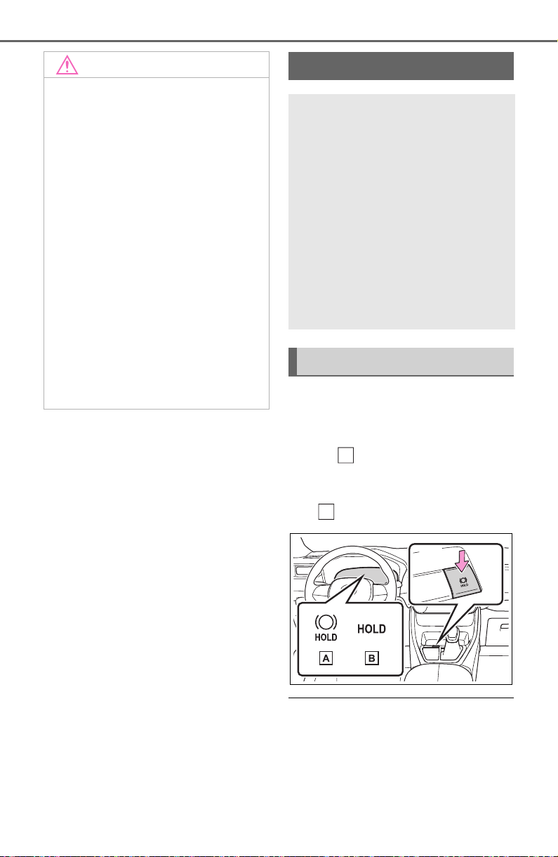
206
4-2. Driving procedures
Press the brake hold switch to
turn the brake hold system on
The brake hold standby indicator
(green) comes on. While the
system is holding the brake, the
brake hold operated indicator (yel-
low) comes on.
■ Brake hold system operating
conditions
The brake hold system cannot be
turned on in the following condi-
tions:
● The driver’s door is not closed.
NOTICE
■ When parking the vehicle
Before you leave the vehicle, shift
the shift position to P, set the park-
ing brake and make sure that the
vehicle does not move.
■ When the system malfunc-
tions
Stop the vehicle in a safe place
and check the warning messages.
■ When the parking brake can-
not be released due to a mal-
function
Driving the vehicle with the park-
ing brake set will lead to brake
components overheating, which
may affect braking performance
and increase brake wear. Have
the vehicle inspected by your
Toyota dealer immediately if this
occurs.
Brake Hold
The brake hold system
keeps the brake applied
when the shift lever is in D,
S or N with the system on
and the brake pedal has
been depressed to stop the
vehicle. The system
releases the brake when the
accelerator pedal is
depressed with the shift
lever in D or S to allow
smooth start off.
Enabling the system
A
B

207
4-2. Driving procedures
4
Driving
● The driver is not wearing the seat
belt.
If any of the conditions above are
detected when the brake hold sys-
tem is enabled, the system will turn
off and the brake hold standby indi-
cator light will go off. In addition, if
any of the conditions are detected
while the system is holding the
brake, a warning buzzer will sound
and a message will be shown on the
multi-information display. The park-
ing brake will then be set automati-
cally.
■ Brake hold function
● If the brake pedal is left released
for a period of about 3 minutes
after the system has started hold-
ing the brake, the parking brake
will be set automatically. In this
case, a warning buzzer sounds
and a message is shown on the
multi-information display.
● To turn the system off while the
system is holding the brake, firmly
depress the brake pedal and
press the button again.
● The brake hold function may not
hold the vehicle when the vehicle
is on a steep incline. In this situa-
tion, it may be necessary for the
driver to apply the brakes. A warn-
ing buzzer will sound and the
multi-information display will
inform the driver of this situation. If
a warning message is shown on
the multi-information display, read
the message and follow the
instructions.
■ When the parking brake is set
automatically while the system
is holding the brakes
Perform any of the following opera-
tions to release the parking brake:
● Depress the accelerator pedal.
(The parking brake will not be
released automatically if the seat
belt is not fastened.)
● Operate the parking brake switch
with the brake pedal depressed.
Make sure that the parking brake
indicator light goes off. (P.203)
■ When an inspection at your
Toyota dealer is necessary
When the brake hold standby indi-
cator (green) does not illuminate
even when the brake hold switch is
pressed with the brake hold system
operating conditions met, the sys-
tem may be malfunctioning. Have
the vehicle inspected at your Toyota
dealer.
■ If “Brake Hold Malfunction
Press Brake to Deactivate Visit
Your Dealer” or “Brake Hold
Malfunction Visit Your Dealer”
is displayed on the multi-infor-
mation display
The system may be malfunctioning.
Have the vehicle inspected by your
Toyota dealer.
■ Warning messages and buzzers
Warning messages and buzzers are
used to indicate a system malfunc-
tion or to inform the driver of the
need for caution. If a warning mes-
sage is shown on the multi-informa-
tion display, read the message and
follow the instructions.
■ If the brake hold operated indi-
cator flashes
P.633
WARNING
■ When the vehicle is on a
steep incline
When using the brake hold sys-
tem on a steep incline, exercise
caution. The brake hold function
may not hold the vehicle in such a
situation.

208
4-2. Driving procedures
WARNING
■ When stopped on a slippery
road
The system cannot stop the vehi-
cle when the gripping ability of the
tires has been exceeded. Do not
use the system when stopped on
a slippery road.
NOTICE
■ When parking the vehicle
The brake hold system is not
designed for use when parking
the vehicle for a long period of
time. Turning the engine switch off
while the system is holding the
brake may release the brake,
which would cause the vehicle to
move. When operating the engine
switch, depress the brake pedal,
shift the shift lever to P and set
the parking brake.
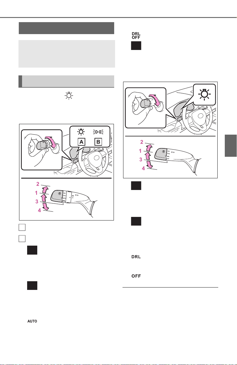
209
4-3. Operating the lights and wipers
4
Driving
4-3.Operating the lights and wipe rs
Operating the switch
turns on the lights as follows:
Type A
U.S.A.
Canada
1 The side marker, parking,
tail, license plate, instrument
panel lights, and daytime run-
ning lights (P.209) turn on.
2 The headlights and all
lights listed above (except
daytime running lights) turn
on.
3 The headlights, daytime
running lights (P.209) and
all the lights listed above turn
on and off automatically.
4 (U.S.A.) Off
(Canada) The daytime
running lights turn on.
(P.209)
Type B
1 The side marker, parking,
tail, license plate, instrument
panel lights, and daytime run-
ning lights (P.209) turn on.
2 The headlights and all
lights listed above (except
daytime running lights) turn
on.
3 The daytime running
lights turn on. (P.209)
4 Off
■ AUTO mode can be used when
The engine switch is in ON.
■ Daytime running light system
● The daytime running lights illumi-
nate using the same lights as the
low beam headlight lights, and illu-
minate dimmer than the low beam
headlight lights.
Headlight switch
The headlights can be oper-
ated manually or automati-
cally.
Turning on the headlights
A
B

210
4-3. Operating the lights and wipers
● To make your vehicle more visible
to other drivers during daytime
driving, the daytime running lights
turn on automatically when all of
the following conditions are met.
(The daytime running lights are
not designed for use at night.)
• The engine is running
• The parking brake is released
• The headlight switch is in the
(Canada only), , or
*
position
*
: When the surroundings are bright
The daytime running lights remain
on after they illuminate, even if the
parking brake is set again.
● For the U.S.A.: Daytime running
lights can be turned off by operat-
ing the switch.
● Compared to turning on the head-
lights, the daytime running light
system offers greater durability
and consumes less electricity, so
it can help improve fuel economy.
■ Headlight control sensor (if
equipped)
The sensor may not function prop-
erly if an object is placed on the sen-
sor, or anything that blocks the
sensor is affixed to the windshield.
Doing so interferes with the sensor
detecting the level of ambient light
and may cause the automatic head-
light system to malfunction.
■ Automatic light off system
● When the headlights are on: The
lights turn off 30 seconds after the
engine switch is turned to ACC or
OFF and a door is opened and
closed. (The lights turn off immedi-
ately if on the key is
pressed after all the doors are
closed.)
● When only the tail lights are on:
The tail lights turn off automati-
cally if the engine switch is turned
to ACC or OFF and the driver’s
door is opened.
To turn the lights on again, turn the
engine switch to ON, or turn the light
switch off once and then back to
or position.
■ Light reminder buzzer
Vehicles without smart key system
A buzzer sounds when the engine
switch is turned to ACC or OFF, the
key is removed and the driver’s door
is opened while the lights are turned
on.
Vehicles with smart key system
A buzzer sounds when the engine
switch is turned to ACC or OFF and
the driver’s door is opened while the
lights are turned on.
■ Windshield wiper linked head-
light illumination (if equipped)
When driving during daytime with
the headlight switch turned to , if
the windshield wipers are used, the
headlights will turn on automatically
after several seconds to help
enhance the visibility of your vehi-
cle.
■ Battery-saving function
In order to prevent the battery of the
vehicle from discharging, if the
headlights and/or tail lights are on
when the engine switch is turned to
OFF, the battery saving function will
operate and automatically turn off all
the lights after approximately 20
minutes.
When any of the following are per-
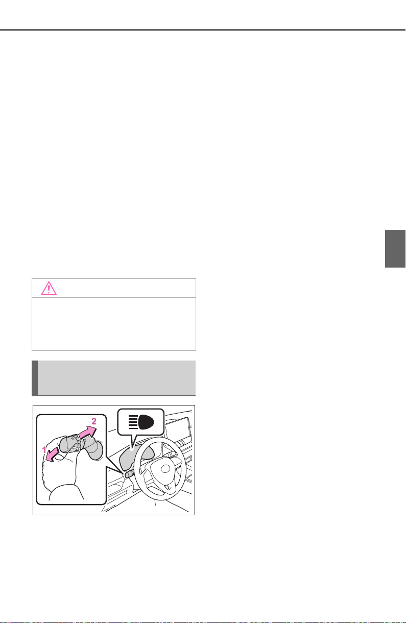
211
4-3. Operating the lights and wipers
4
Driving
formed, the battery-saving function
is canceled once and then reacti-
vated. All the lights will turn off auto-
matically 20 minutes after the
battery-saving function has been
reactivated:
● When the headlight switch is oper-
ated
● When a door is opened or closed
■ If “Headlight System Malfunc-
tion Visit Your Dealer” is dis-
played on the multi-information
display
The system may be malfunctioning.
Have the vehicle inspected by your
Toyota dealer.
■ Customization
Settings (e.g. light sensor sensitiv-
ity) can be changed.
(Customizable features: P.694)
1 With the headlights on, push
the lever away from you to
turn on the high beams.
Pull the lever toward you to the
center position to turn the high
beams off.
2 Pull the lever toward you and
release it to flash the high
beams once.
You can flash the high beams with
the headlights on or off.
NOTICE
■ To prevent battery discharge
Do not leave the lights on longer
than necessary when the engine
is not running.
Turning on the high beam
headlights
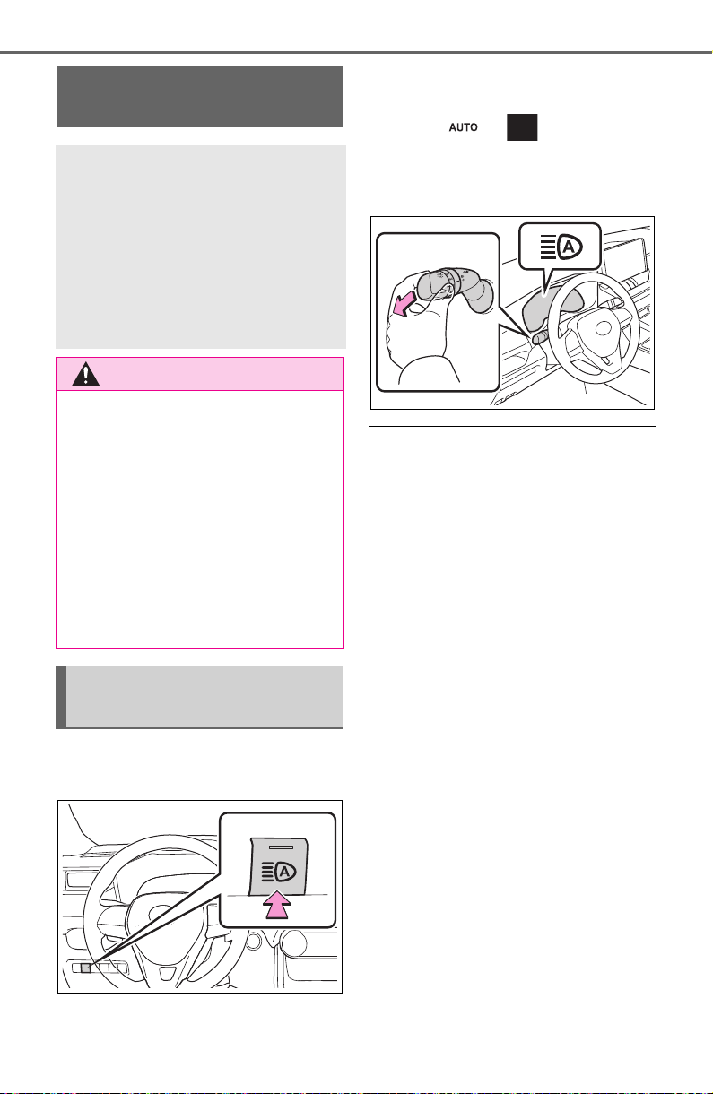
212
4-3. Operating the lights and wipers
1 Press the Automatic High
Beam switch.
2 Push the lever away from
you with the headlight switch
in the or position.
The Automatic High Beam indicator
will come on when the system is
operating.
■ High beam automatic turning
on or off conditions
● When all of the following condi-
tions are fulfilled, the high beam
will be automatically turned on
(after approximately 1 second):
• Vehicle speed is above approxi-
mately 21 mph (34 km/h) or more.
• The area ahead of the vehicle is
dark.
• There are no vehicles ahead with
headlights or tail lights turned on.
• There are few streetlights on the
road ahead.
● If any of the following conditions
are fulfilled, the high beam will be
automatically turned off:
• Vehicle speed drops below
approximately 17 mph (27 km/h).
• The area ahead of the vehicle is
not dark.
• Vehicles ahead have headlights or
tail lights turned on.
• There are many streetlights on the
road ahead.
■ Camera sensor detection infor-
mation
● The high beam may not be auto-
matically turned off in the following
situations:
• When oncoming vehicles sud-
denly appear from a curve
AHB (Automatic High
Beam)
The Automatic High Beam
uses an in-vehicle camera
sensor to assess the bright-
ness of streetlights, the
lights of vehicles ahead etc.,
and automatically turns the
high beam on or off as nec-
essary.
WARNING
■ Limitations of the Automatic
High Beam
Do not overly rely on the Auto-
matic High Beam. Always drive
safely, taking care to observe your
surroundings and turning the high
beam on or off manually if neces-
sary.
■ To prevent incorrect opera-
tion of the Automatic High
Beam system
Do not overload the vehicle.
Activating the Automatic
High Beam system

213
4-3. Operating the lights and wipers
4
Driving
• When the vehicle is cut in front of
by another vehicle
• When vehicles ahead are hidden
from sight due to repeated curves,
road dividers or roadside trees
• When vehicles ahead appear from
the faraway lane on a wide road
• When vehicles ahead have no
lights
● The high beam may be turned off
if a vehicle ahead that is using fog
lights without using the headlights
is detected.
● House lights, street lights, traffic
signals, and illuminated billboards
or signs may cause the high beam
to switch to the low beams, or the
low beams to remain on.
● The following factors may affect
the amount of time taken to turn
the high beam on or off:
• The brightness of headlights, fog
lights, and tail lights of vehicles
ahead
• The movement and direction of
vehicles ahead
• When a vehicle ahead only has
operational lights on one side
• When a vehicle ahead is a two-
wheeled vehicle
• The condition of the road (gradi-
ent, curve, condition of the road
surface etc.)
• The number of passengers and
amount of luggage
● The high beam may be turned on
or off when the driver does not
expect it.
● Bicycles or similar objects may not
be detected.
● In the situations shown below, the
system may not be able to accu-
rately detect surrounding bright-
ness levels. This may cause the
low beams to remain on or the
high beams to cause problems for
pedestrians, vehicles ahead or
other parties. In these cases,
manually switch between the high
and low beams.
• In bad weather (rain, snow, fog,
sandstorms, etc.)
• The windshield is obscured by
fog, mist, ice, dirt, etc.
• The windshield is cracked or dam-
aged
• The camera sensor is deformed or
dirty
• When the temperature of the cam-
era sensor is extremely high
• Surrounding brightness levels are
equal to those of headlights, tail
lights or fog lights
• When headlights or tail lights of
vehicles ahead are turned off,
dirty, changing color, or not aimed
properly
• When the vehicle is hit by water,
snow, dust, etc. from a preceding
vehicle
• When driving through an area of
intermittently changing brightness
and darkness
• When frequently and repeatedly
driving ascending/descending
roads, or roads with rough, bumpy
or uneven surfaces (such as
stone-paved roads, gravel roads,
etc.)
• When frequently and repeatedly
taking curves or driving on a wind-
ing road
• There is a highly reflective object
ahead of the vehicle, such as a
sign or mirror
• The back of a vehicle ahead is
highly reflective, such as a con-
tainer on a truck
• The vehicle’s headlights are dam-
aged or dirty, or are not aimed
properly
• The vehicle is listing or titling due
to a flat tire, a trailer being towed,
etc.
• The high beam and low beam are
repeatedly being switched
between in an abnormal manner
• The driver believes that the high
beam may be causing problems
or distress to other drivers or
pedestrians nearby
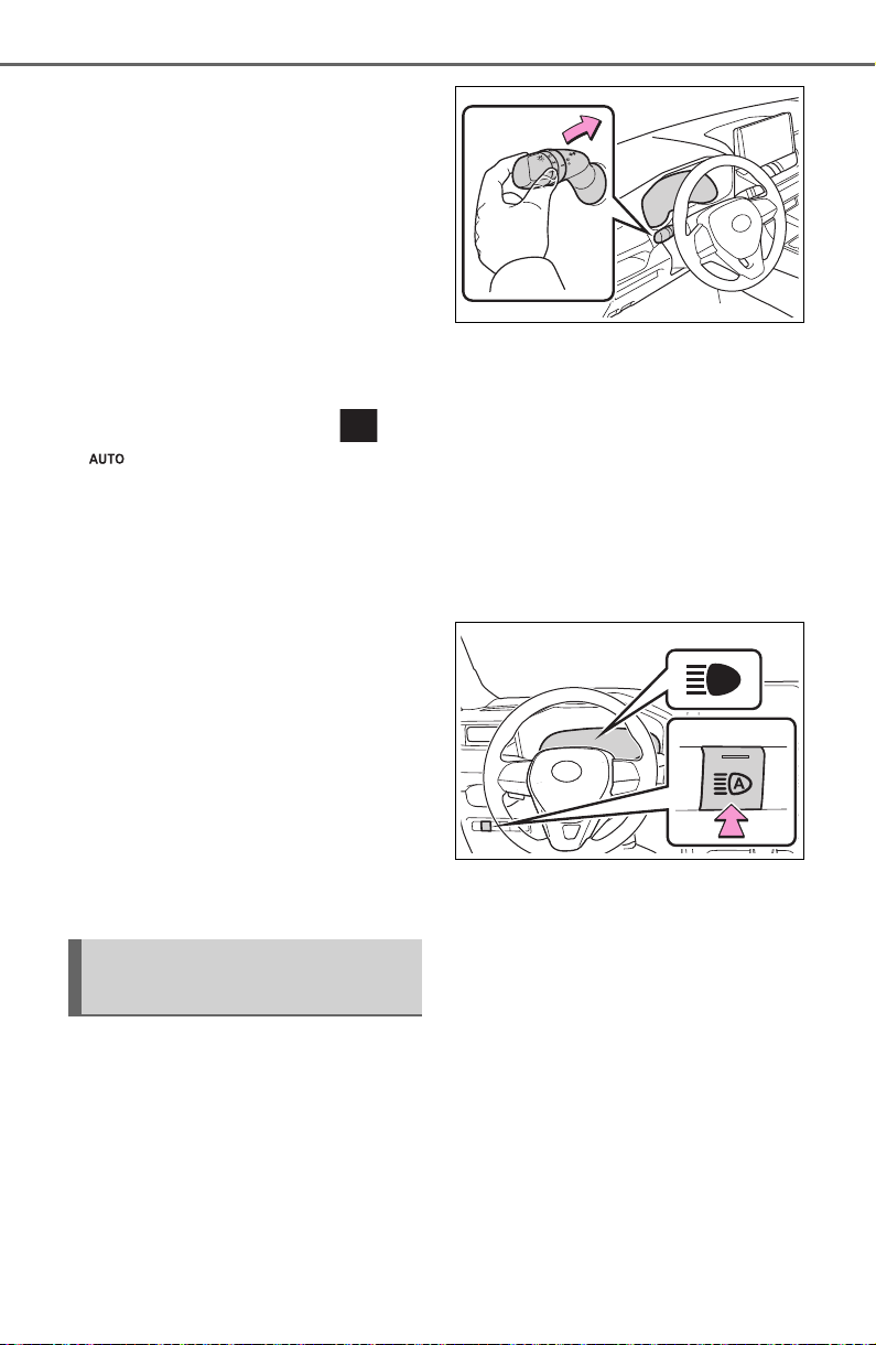
214
4-3. Operating the lights and wipers
■ If “Headlight System Malfunc-
tion Visit Your Dealer” is dis-
played on the multi-information
display
The system may be malfunctioning.
Have the vehicle inspected by your
Toyota dealer.
■ Temporarily lowering sensor
sensitivity
The sensitivity of the sensor can be
temporarily lowered.
1 Turn the engine switch off while
the following conditions are met.
● The headlight switch is in or
position.
● The headlight switch lever is in
high beam position.
● Automatic High Beam switch is
on.
2 Turn the engine switch to ON.
3 Within 60 seconds after step 2,
repeat pulling the headlight
switch lever to the original posi-
tion then pushing it to the high
beam position quickly 10 times,
then leave the lever in high beam
position.
4 If the sensitivity is changed, the
Automatic High Beam indicator
is turn on and off 3 times.
Automatic High Beam (headlights)
may turn on even when the vehicle
is stopped.
■ Switching to the low beam
Pull the lever to original position.
The Automatic High Beam indicator
will turn off.
Push the lever away from you to
activate the Automatic High Beam
system again.
■ Switching to the high beam
Press the Automatic High Beam
switch.
The Automatic High Beam indicator
will turn off and the high beam indi-
cator will turn on.
Press the switch to activate the
Automatic High Beam system
again.
Turning the high beam
on/off manually
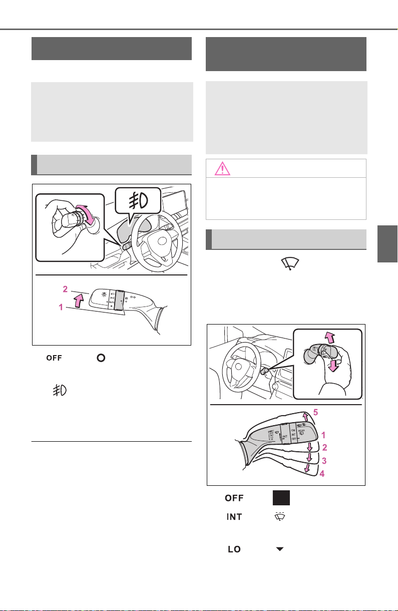
215
4-3. Operating the lights and wipers
4
Driving
*
: If equipped
1
*1
or
*2
Turns the
fog lights off
2 Turns the fog lights on
*1
:For the U.S.A.
*2
:For Canada
■ Fog lights can be used when
The headlights are on in low beam.
Operating the lever oper-
ates the wipers or washer as fol-
lows:
Intermittent windshield wipers
1
*1
or
*2
Off
2
*1
or
*2
Intermittent
operation
3
*1
or
*2
Low speed
operation
Fog light switch
*
The fog lights offer
improved visibility in diffi-
cult driving conditions,
such as in rain and fog.
Operating procedure
Windshield wipers and
washer
Operating the lever can
switch between automatic
operation and manual oper-
ation, or can use the
washer.
NOTICE
■ When the windshield is dry
Do not use the wipers, as they
may damage the windshield.
Operating the wiper lever
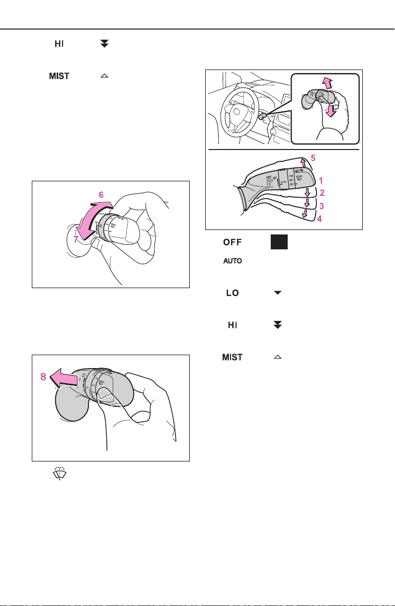
216
4-3. Operating the lights and wipers
4
*1
or
*2
High speed
operation
5
*1
or
*2
Temporary
operation
*1
:For the U.S.A.
*2
:For Canada
If equipped, wiper intervals can
be adjusted when intermittent
operation is selected.
6 Increases the intermittent
windshield wiper frequency
7 Decreases the intermittent
windshield wiper frequency
8 Washer/wiper dual
operation
Pulling the lever operates the wip-
ers and washer.
The wipers will automatically oper-
ate a couple of times after the
washer squirts.
Rain-sensing windshield wip-
ers
1
*1
or
*2
Off
2 Rain-sensing opera-
tion
3
*1
or
*2
Low speed
operation
4
*1
or
*2
High speed
operation
5
*1
or
*2
Temporary
operation
*1
:For the U.S.A.
*2
:For Canada
When “AUTO” is selected, the wip-
ers will operate automatically when
the sensor detects falling rain. The
system automatically adjusts wiper
timing in accordance with rain vol-
ume and vehicle speed.
The sensor sensitivity can be
adjusted when “AUTO” is
selected.
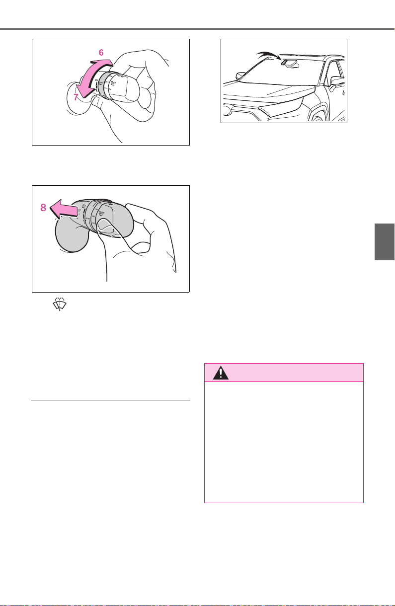
217
4-3. Operating the lights and wipers
4
Driving
6 Increases the sensitivity
7 Decreases the sensitivity
8 Washer/wiper dual
operation
Pulling the lever operates the wip-
ers and washer.
The wipers will automatically oper-
ate a couple of times after the
washer squirts.
■ The windshield wipers and
washer can be operated when
The engine switch is in ON.
■ Raindrop sensor (vehicles with
rain-sensing windshield wipers)
● The raindrop sensor judges the
amount of raindrops.
● If the wiper switch is turned to the
“AUTO” position while the engine
switch is in ON, the wipers will
operate once to show that “AUTO”
mode is activated.
● If the wiper sensitivity is adjusted
to higher, the wiper may operate
once to indicate the change of
sensitivity.
● If the temperature of the raindrop
sensor is 185°F (85°C) or higher,
or 5°F (-15°C) or lower, the auto-
matic operation may not occur. In
this case, operate the wipers in
any mode other than “AUTO”.
■ If no windshield washer fluid
sprays
Check that the washer nozzles are
not blocked if there is washer fluid in
the windshield washer fluid reser-
voir.
WARNING
■ Caution regarding the use of
windshield wipers in “AUTO”
mode (vehicles with rain-
sensing windshield wipers)
The windshield wipers may oper-
ate unexpectedly if the sensor is
touched or the windshield is sub-
ject to vibration in “AUTO” mode.
Take care that your fingers or any-
thing else does not become
caught in the windshield wipers.

218
4-3. Operating the lights and wipers
Operating the switch
operates the rear wiper as fol-
lows:
1
*1
or
*2
Off
2
*1
or
*2
Intermittent
operation
3
*1
or
*2
Normal oper-
ation
*1
:For the U.S.A.
WARNING
■ Caution regarding the use of
washer fluid
When it is cold, do not use the
washer fluid until the windshield
becomes warm. The fluid may
freeze on the windshield and
cause low visibility. This may lead
to an accident, resulting in death
or serious injury.
NOTICE
■ When the washer fluid tank is
empty
Do not operate the switch continu-
ally as the washer fluid pump may
overheat.
■ When a nozzle becomes
blocked
In this case, contact your Toyota
dealer.
Do not try to clear it with a pin or
other object. The nozzle will be
damaged.
■ To prevent battery discharge
Do not leave the wipers on longer
than necessary when the engine
is off.
Rear window wiper
and washer
Operating the lever can
switch between automatic
operation and manual oper-
ation, or can use the
washer.
NOTICE
■ When the rear window is dry
Do not use the wiper, as it may
damage the rear window.
Operating the wiper lever
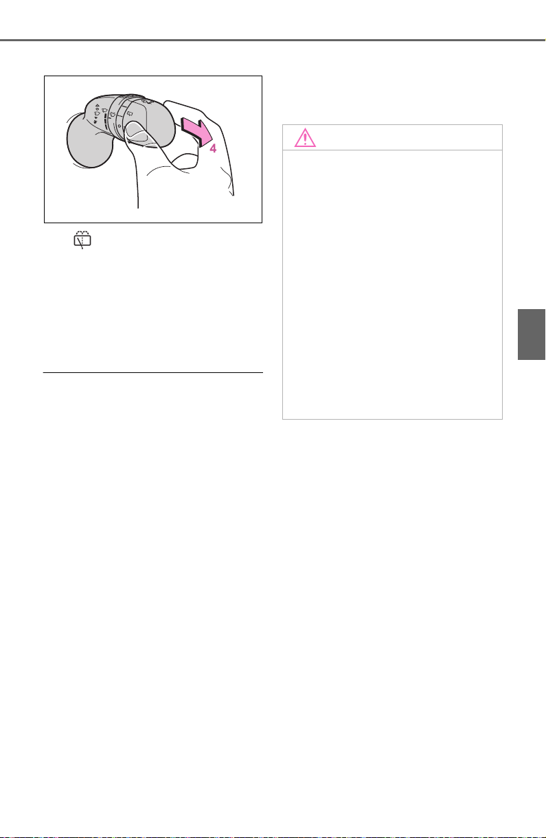
219
4-3. Operating the lights and wipers
4
Driving
*2
:For Canada
4 Washer/wiper dual
operation
Pushing the lever operates the
wiper and washer.
The wiper will automatically operate
a couple of times after the washer
squirts.
■ The rear window wiper and
washer can be operated when
The engine switch is in ON.
■ If no washer fluid sprays
Check that the washer nozzle is not
blocked if there is washer fluid in the
washer fluid reservoir.
■ Back door opening linked rear
window wiper stop function
When the rear window wiper is
operating, if the back door is opened
while the vehicle is stopped, opera-
tion of the rear window wiper will be
stopped to prevent anyone near the
vehicle from being sprayed by water
from the wiper. When the back door
is closed, wiper operation will
resume.
*
*
: The setting must be customized at
your Toyota dealer.
■ Reverse-linked rear window
wiper function
When the shift lever is shifted to R
when the front wipers are operating,
the rear window wiper will operate
once.
■ Customization
Setting of the reverse-linked func-
tion can be changed. (Customizable
features: P.695)
NOTICE
■ When the washer fluid tank is
empty
Do not operate the switch continu-
ally as the washer fluid pump may
overheat.
■ When a nozzle becomes
blocked
In this case, contact your Toyota
dealer.
Do not try to clear it with a pin or
other object. The nozzle will be
damaged.
■ To prevent battery discharge
Do not leave the wiper on longer
than necessary when the engine
is off.

220
4-4. Refueling
4-4.Refueling
Close all the doors and win-
dows, and turn the engine
switch to OFF.
Confirm the type of fuel.
■ Fuel types
P.676
■ Fuel tank opening for unleaded
gasoline
To help prevent incorrect fueling,
your vehicle has a fuel tank opening
that only accommodates the spe-
cial nozzle on unleaded fuel pumps.
■ If the malfunction indicator
lamp illuminates
The malfunction indicator lamp may
illuminate erroneously if refueling is
performed repeatedly when the fuel
tank is nearly full.
Opening the fuel tank
cap
Perform the following steps
to open the fuel tank cap:
Before refueling the vehi-
cle
WARNING
■ When refueling the vehicle
Observe the following precautions
while refueling the vehicle. Failure
to do so may result in death or
serious injury.
● After exiting the vehicle and
before opening the fuel door,
touch an unpainted metal sur-
face to discharge any static
electricity. It is important to dis-
charge static electricity before
refueling because sparks result-
ing from static electricity can
cause fuel vapors to ignite while
refueling.
● Always hold the grips on the
fuel tank cap and turn it slowly
to remove it.
A whooshing sound may be
heard when the fuel tank cap is
loosened. Wait until the sound
cannot be heard before fully
removing the cap. In hot
weather, pressurized fuel may
spray out of the filler neck and
cause injury.
● Do not allow anyone that has
not discharged static electricity
from their body to come close to
an open fuel tank.
● Do not inhale vaporized fuel.
Fuel contains substances that
are harmful if inhaled.
● Do not smoke while refueling
the vehicle.
Doing so may cause the fuel to
ignite and cause a fire.
● Do not return to the vehicle or
touch any person or object that
is statically charged. This may
cause static electricity to build
up, resulting in a possible igni-
tion hazard.
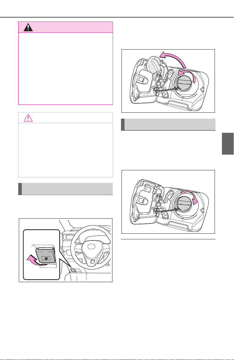
221
4-4. Refueling
4
Driving
1 Pull up the opener to open
the fuel filler door.
2 Turn the fuel tank cap slowly
to open it and put it into the
holder on the fuel filler door.
After refueling, turn the fuel tank
cap until you hear a click. Once
the cap is released, it will turn
slightly in the opposite direction.
■ When “Check Fuel Cap” is dis-
played on the multi-information
display
The fuel tank cap may be unfas-
tened or loose. Turn the engine
switch off, check the cap and tighten
it securely. If the message remains,
wait a few seconds and then turn
the engine switch off once again.
WARNING
■ When refueling
Observe the following precautions
to prevent fuel overflowing from
the fuel tank:
● Securely insert the fuel nozzle
into the fuel filler neck.
● Stop filling the tank after the fuel
nozzle automatically clicks off.
● Do not top off the fuel tank.
NOTICE
■ Refueling
Do not spill fuel during refueling.
Doing so may damage the vehi-
cle, such as causing the emission
control system to operate abnor-
mally or damaging fuel system
components or the vehicle’s
painted surface.
Opening the fuel tank cap
Closing the fuel tank cap

222
4-4. Refueling
WARNING
■ When replacing the fuel tank
cap
Do not use anything but a genu-
ine Toyota fuel tank cap designed
for your vehicle. Doing so may
cause a fire or other incident
which may result in death or seri-
ous injury.
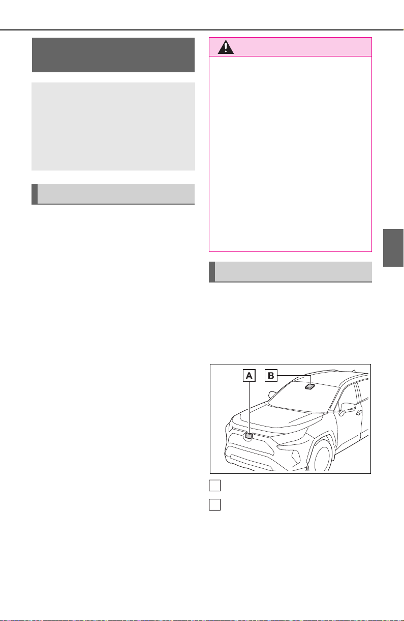
223
4-5. Using the driving support systems
4
Driving
4-5.Using the driving support systems
■ PCS (Pre-Collision System)
P. 2 29
■ LTA (Lane Tracing Assist)
P. 2 37
■ AHB (Automatic High
Beam)
P. 2 12
■ RSA (Road Sign Assist) (if
equipped)
P. 2 47
■ Dynamic radar cruise con-
trol with full-speed range
P. 2 50
Two types of sensors, located
behind the front grille and wind-
shield, detect information neces-
sary to operate the drive assist
systems.
Radar sensor
Front camera
Toyota Safety Sense
2.0
The Toyota Safety Sense 2.0
consists of the following
drive assist systems and
contributes to a safe and
comfortable driving experi-
ence:
Driving assist system
WARNING
■ Toyota Safety Sense 2.0
The Toyota Safety Sense 2.0 is
designed to operate under the
assumption that the driver will
drive safely, and is designed to
help reduce the impact to the
occupants and the vehicle in the
case of a collision or assist the
driver in normal driving condi-
tions.
As there is a limit to the degree of
recognition accuracy and control
performance that this system can
provide, do not overly rely on this
system. The driver is always
responsible for paying attention to
the vehicle’s surroundings and
driving safely.
Sensors
A
B

224
4-5. Using the driving support systems
WARNING
■ To avoid malfunction of the
radar sensor
Observe the following precau-
tions.
Otherwise, the radar sensor may
not operate properly, possibly
leading to an accident resulting in
death or serious injury.
● Keep the radar sensor and the
radar sensor cover clean at all
times.
Radar sensor
Radar sensor cover
If the front of the radar sensor or
the front or back of the radar sen-
sor cover is dirty or covered with
water droplets, snow, etc., clean
it.
Clean the radar sensor and radar
sensor cover with a soft cloth to
avoid damaging them.
● Do not attach accessories,
stickers (including transparent
stickers) or other items to the
radar sensor, radar sensor
cover or surrounding area.
● Do not subject the radar sensor
or its surrounding area to a
strong impact.
If the radar sensor, front grille,
or front bumper has been sub-
jected to a strong impact, have
the vehicle inspected by your
Toyota dealer.
A
B
● Do not disassemble the radar
sensor.
● Do not modify or paint the radar
sensor or radar sensor cover.
● In the following cases, the radar
sensor must be recalibrated.
Contact your Toyota dealer for
details.
• When the radar sensor or front
grille are removed and installed,
or replaced
• When the front bumper is
replaced
■ To avoid malfunction of the
front camera
Observe the following precau-
tions.
Otherwise, the front camera may
not operate properly, possibly
leading to an accident resulting in
death or serious injury.
● Keep the windshield clean at all
times.
• If the windshield is dirty or cov-
ered with an oily film, water
droplets, snow, etc., clean the
windshield.
• If a glass coating agent is
applied to the windshield, it will
still be necessary to use the
windshield wipers to remove
water droplets, etc. from the
area of the windshield in front of
the front camera.
• If the inner side of the wind-
shield where the front camera is
installed is dirty, contact your
Toyota dealer.
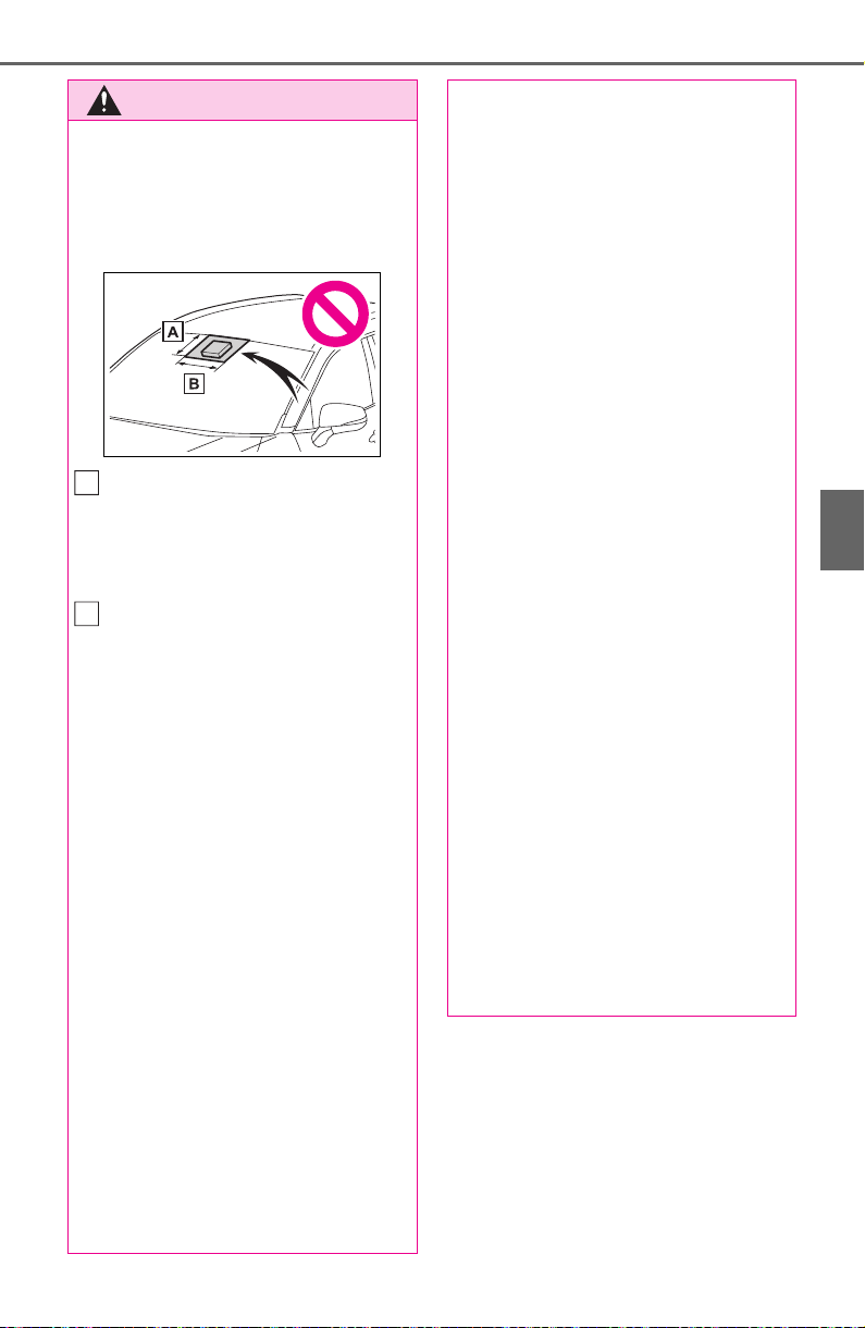
225
4-5. Using the driving support systems
4
Driving
WARNING
● Do not attach objects, such as
stickers, transparent stickers,
etc., to the outer side of the
windshield in front of the front
camera (shaded area in the
illustration).
From the top of the windshield
to approximately 0.4 in. (1 cm)
below the bottom of the front
camera
Approximately 7.9 in. (20 cm)
(Approximately 4.0 in. [10 cm]
to the right and left from the
center of the front camera)
● If the part of the windshield in
front of the front camera is
fogged up or covered with con-
densation, or ice, use the wind-
shield defogger to remove the
fog, condensation, or ice.
(P.511, 517)
● If water droplets cannot be
properly removed from the area
of the windshield in front of the
front camera by the windshield
wipers, replace the wiper insert
or wiper blade.
● Do not attach window tint to the
windshield.
● Replace the windshield if it is
damaged or cracked.
After replacing the windshield,
the front camera must be recali-
brated. Contact your Toyota
dealer for details.
A
B
● Do not allow liquids to contact
the front camera.
● Do not allow bright lights to
shine into the front camera.
● Do not dirty or damage the front
camera.
When cleaning the inside of the
windshield, do not allow glass
cleaner to contact the lens of
the front camera. Also, do not
touch the lens.
If the lens is dirty or damaged,
contact your Toyota dealer.
● Do not subject the front camera
to a strong impact.
● Do not change the installation
position or direction of the front
camera or remove it.
● Do not disassemble the front
camera.
● Do not modify any components
of the vehicle around the front
camera (inside rear view mirror,
etc.) or ceiling.
● Do not attach any accessories
to the hood, front grille or front
bumper that may obstruct the
front camera. Contact your
Toyota dealer for details.
● If a surfboard or other long
object is to be mounted on the
roof, make sure that it will not
obstruct the front camera.
● Do not modify the headlights or
other lights.

226
4-5. Using the driving support systems
■ Certification
For vehicles sold in the U.S.A., Hawaii, American Samoa, Guam, Saipan
and Puerto Rico
For vehicles sold in Canada

227
4-5. Using the driving support systems
4
Driving
■ If a warning message is displayed on the multi-information display
A system may be temporarily unavailable or there may be a malfunction in
the system.
● In the following situations, perform the actions specified in the table. When
the normal operating conditions are detected, the message will disappear
and the system will become operational.
If the message does not disappear, contact your Toyota dealer.
Situation Actions
When the area around a sensor is
covered with dirt, moisture (fogged
up, covered with condensation, ice,
etc.), or other foreign matter
To clean the part of the windshield in
front of the front camera, use the
windshield wipers or the windshield
defogger of the air conditioning sys-
tem (P.511, 517).

228
4-5. Using the driving support systems
● In the following situations, if the situation has changed (or the vehicle has
been driven for some time) and the normal operating conditions are
detected, the message will disappear and the system will become opera-
tional.
If the message does not disappear, contact your Toyota dealer.
• When the temperature around the radar sensor is outside of the opera-
tional range, such as when the vehicle is in the sun or in an extremely cold
environment
• When the front camera cannot detect objects in front of the vehicle, such
as when driving in the dark, snow, or fog, or when bright lights are shining
into the front camera
When the temperature around the
front camera is outside of the opera-
tional range, such as when the vehi-
cle is in the sun or in an extremely
cold environment
If the front camera is hot, such as
after the vehicle had been parked in
the sun, use the air conditioning sys-
tem to decrease the temperature
around the front camera.
If a sunshade was used when the
vehicle was parked, depending on its
type, the sunlight reflected from the
surface of the sunshade may cause
the temperature of the front camera
to become excessively high.
If the front camera is cold, such as
after the vehicle is parked in an
extremely cold environment, use the
air conditioning system to increase
the temperature around the front
camera.
The area in front of the front camera
is obstructed, such as when the
hood is open or a sticker is attached
to the part of the windshield in front
of the front camera.
Close the hood, remove the sticker,
etc. to clear the obstruction.
Situation Actions
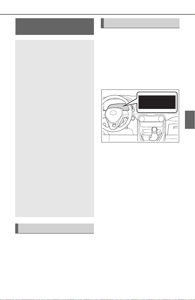
229
4-5. Using the driving support systems
4
Driving
The system can detect the fol-
lowing:
Vehicles
Bicyclists
Pedestrians
■ Pre-collision warning
When the system determines
that the possibility of a frontal
collision is high, a buzzer will
sound and a warning message
will be displayed on the multi-
information display to urge the
driver to take evasive action.
■ Pre-collision brake assist
When the system determines
that the possibility of a frontal
collision is high, the system
applies greater braking force in
relation to how strongly the
brake pedal is depressed.
■ Pre-collision braking
If the system determines that
the possibility of a frontal colli-
sion is extremely high, the
brakes are automatically applied
to help avoid the collision or
reduce the impact of the colli-
sion.
PCS (Pre-Collision Sys-
tem)
The pre-collision system
uses a radar sensor and
front camera to detect
objects (P.229) in front of
the vehicle. When the sys-
tem determines that the
possibility of a frontal colli-
sion with an object is high,
a warning operates to urge
the driver to take evasive
action and the potential
brake pressure is increased
to help the driver avoid the
collision. If the system
determines that the possi-
bility of a frontal collision
with an object is extremely
high, the brakes are auto-
matically applied to help
avoid the collision or help
reduce the impact of the
collision.
The pre-collision system can
be disabled/enabled and the
warning timing can be
changed. (P.231)
Detectable objects
System functions

230
4-5. Using the driving support systems
WARNING
■ Limitations of the pre-colli-
sion system
● The driver is solely responsible
for safe driving. Always drive
safely, taking care to observe
your surroundings.
Do not use the pre-collision sys-
tem instead of normal braking
operations under any circum-
stances. This system will not
prevent collisions or lessen col-
lision damage or injury in every
situation. Do not overly rely on
this system. Failure to do so
may lead to an accident, result-
ing in death or serious injury.
● Although this system is
designed to help avoid a colli-
sion or help reduce the impact
of the collision, its effectiveness
may change according to vari-
ous conditions, therefore the
system may not always be able
to achieve the same level of
performance.
Read the following conditions
carefully. Do not overly rely on
this system and always drive
carefully.
• Conditions under which the sys-
tem may operate even if there is
no possibility of a collision:
P.2 33
• Conditions under which the sys-
tem may not operate properly:
P.2 34
● Do not attempt to test the oper-
ation of the pre-collision system
yourself.
Depending on the objects used
for testing (dummies, card-
board objects imitating detect-
able objects, etc.), the system
may not operate properly, possi-
bly leading to an accident.
■ Pre-collision braking
● When the pre-collision braking
function is operating, a large
amount of braking force will be
applied.
● If the vehicle is stopped by the
operation of the pre-collision
braking function, the pre-colli-
sion braking function operation
will be canceled after approxi-
mately 2 seconds. Depress the
brake pedal as necessary.
● The pre-collision braking func-
tion may not operate if certain
operations are performed by the
driver. If the accelerator pedal is
being depressed strongly or the
steering wheel is being turned,
the system may determine that
the driver is taking evasive
action and possibly prevent the
pre-collision braking function
from operating.
● In some situations, while the
pre-collision braking function is
operating, operation of the func-
tion may be canceled if the
accelerator pedal is depressed
strongly or the steering wheel is
turned and the system deter-
mines that the driver is taking
evasive action.
● If the brake pedal is being
depressed, the system may
determine that the driver is tak-
ing evasive action and possibly
delay the operation timing of the
pre-collision braking function.
■ When to disable the pre-colli-
sion system
In the following situations, disable
the system, as it may not operate
properly, possibly leading to an
accident resulting in death or seri-
ous injury:
● When the vehicle is being towed
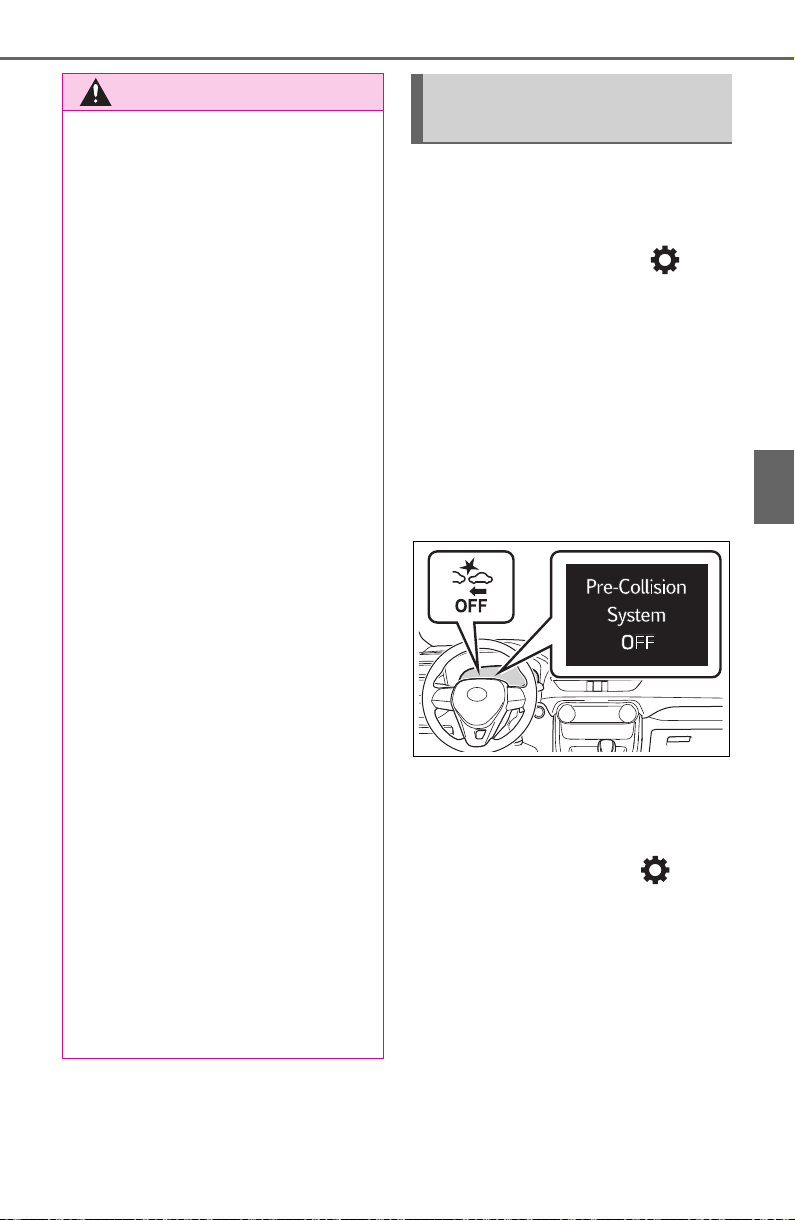
231
4-5. Using the driving support systems
4
Driving
■ Enabling/disabling the pre-
collision system
The pre-collision system can be
enabled/disabled on the
screen (P.94) of the multi-
information display.
The system is automatically
enabled each time the engine
switch is turned to ON.
If the system is disabled, the
PCS warning light will turn on
and a message will be displayed
on the multi-information display.
■ Changing the pre-collision
warning timing
The pre-collision warning timing
can be changed on the
screen (P.94) of the multi-
information display.
The warning timing setting is
retained when the engine switch is
turned to OFF. However, if the pre-
collision system is disabled and re-
enabled, the operation timing will
return to the default setting (mid-
dle).
WARNING
● When your vehicle is towing
another vehicle
● When transporting the vehicle
via truck, boat, train or similar
means of transportation
● When the vehicle is raised on a
lift with the engine running and
the tires are allowed to rotate
freely
● When inspecting the vehicle
using a drum tester such as a
chassis dynamometer or speed-
ometer tester, or when using an
on vehicle wheel balancer
● When a strong impact is applied
to the front bumper or front
grille, due to an accident or
other reasons
● If the vehicle cannot be driven in
a stable manner, such as when
the vehicle has been in an acci-
dent or is malfunctioning
● When the vehicle is driven in a
sporty manner or off-road
● When the tires are not properly
inflated
● When the tires are very worn
● When tires of a size other than
specified are installed
● When tire chains are installed
● When a compact spare tire or
an emergency tire puncture
repair kit is used
● If equipment (snow plow, etc.)
that may obstruct the radar sen-
sor or front camera is temporar-
ily installed to the vehicle
Changing settings of the
pre-collision system
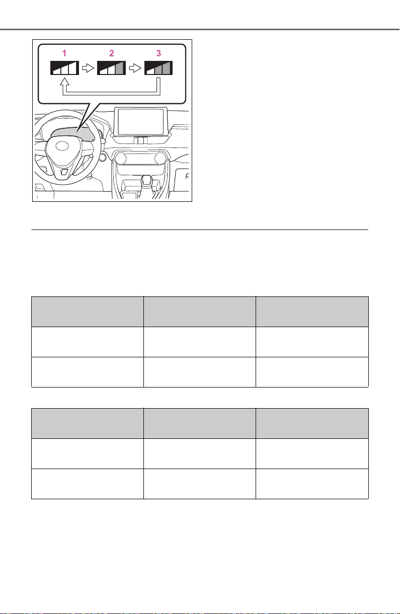
232
4-5. Using the driving support systems
1 Early
2 Middle
This is the default setting.
3 Late
■ Operational conditions
The pre-collision system is enabled and the system determines that the pos-
sibility of a frontal collision with a detected object is high.
Each function is operational at the following speed
● Pre-collision warning
● Pre-collision brake assist
Detectable objects Vehicle speed
Relative speed between
your vehicle and object
Vehicles
Approx. 7 to 110 mph
(10 to 180 km/h)
Approx. 7 to 110 mph
(10 to 180 km/h)
Bicyclists and pedestri-
ans
Approx. 7 to 50 mph (10
to 80 km/h)
Approx. 7 to 50 mph (10
to 80 km/h)
Detectable objects Vehicle speed
Relative speed between
your vehicle and object
Vehicles
Approx. 20 to 110 mph
(30 to 180 km/h)
Approx. 20 to 110 mph
(30 to 180 km/h)
Bicyclists and pedestri-
ans
Approx. 20 to 50 mph
(30 to 80 km/h)
Approx. 20 to 50 mph
(30 to 80 km/h)
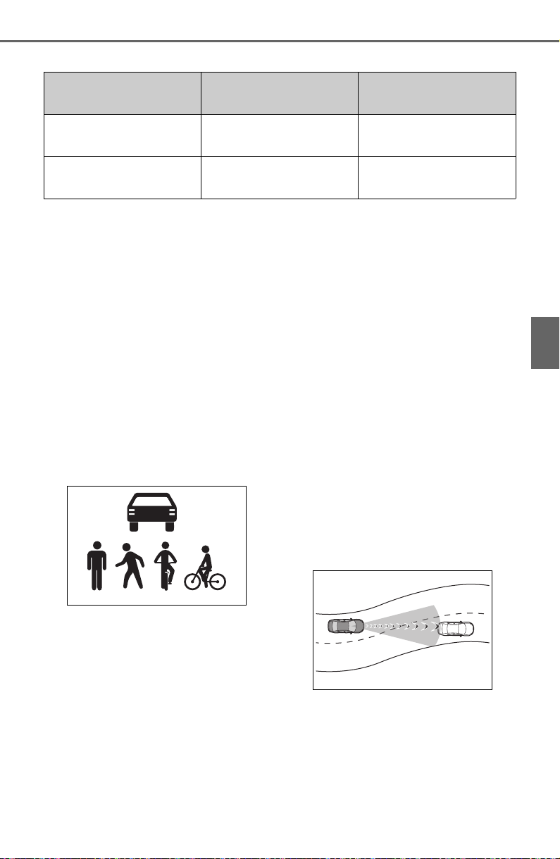
233
4-5. Using the driving support systems
4
Driving
● Pre-collision braking
The system may not operate in the following situations:
● If a battery terminal has been disconnected and reconnected and then the
vehicle has not been driven for a certain amount of time
● If the shift lever is in R
● When the VSC OFF indicator is illuminated (only the pre-collision warning
function will be operational)
■ Object detection function
The system detects objects based
on their size, profile, motion, etc.
However, an object may not be
detected depending on the sur-
rounding brightness and the motion,
posture, and angle of the detected
object, preventing the system from
operating properly. (P. 23 4)
The illustration shows an image of
detectable objects.
■ Cancelation of the pre-collision
braking
If either of the following occur while
the pre-collision braking function is
operating, it will be canceled:
● The accelerator pedal is
depressed strongly.
● The steering wheel is turned
sharply or abruptly.
■ Conditions under which the
system may operate even if
there is no possibility of a colli-
sion
● In some situations such as the fol-
lowing, the system may determine
that there is a possibility of a fron-
tal collision and operate.
• When passing a detectable object,
etc.
• When changing lanes while over-
taking a detectable object, etc.
• When approaching a detectable
object in an adjacent lane or on
the roadside, such as when
changing the course of travel or
driving on a winding road
• When rapidly closing on a detect-
able object, etc.
• When approaching objects on the
roadside, such as detectable
objects, guardrails, utility poles,
trees, or walls
• When there is a detectable object
or other object by the roadside at
Detectable objects Vehicle speed
Relative speed between
your vehicle and object
Vehicles
Approx. 7 to 110 mph
(10 to 180 km/h)
Approx. 7 to 110 mph
(10 to 180 km/h)
Bicyclists and pedestri-
ans
Approx. 7 to 50 mph (10
to 80 km/h)
Approx. 7 to 50 mph (10
to 80 km/h)
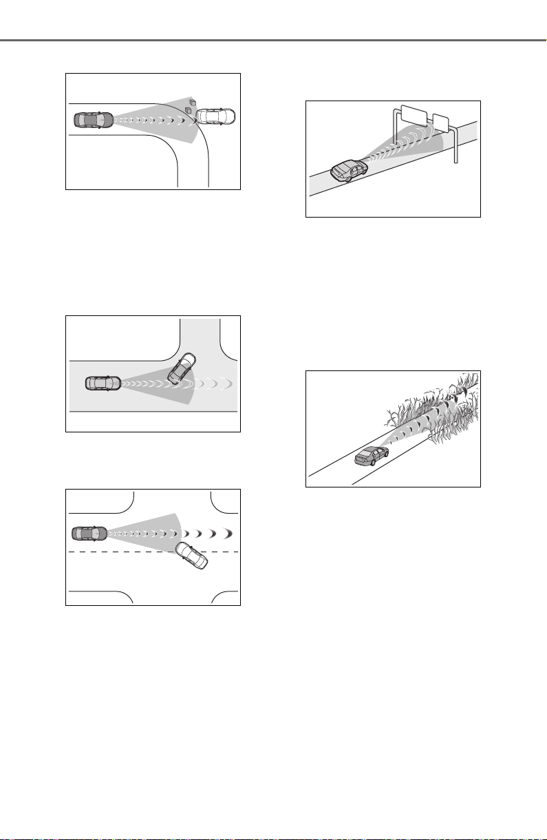
234
4-5. Using the driving support systems
the entrance of a curve
• When there are patterns or paint
in front of your vehicle that may be
mistaken for a detectable object
• When the front of your vehicle is
hit by water, snow, dust, etc.
• When overtaking a detectable
object that is changing lanes or
making a right/left turn
• When passing a detectable object
in an oncoming lane that is
stopped to make a right/left turn
• When a detectable object
approaches very close and then
stops before entering the path of
your vehicle
• If the front of your vehicle is raised
or lowered, such as when on an
uneven or undulating road surface
• When driving on a road sur-
rounded by a structure, such as in
a tunnel or on an iron bridge
• When there is a metal object
(manhole cover, steel plate, etc.),
steps, or a protrusion in front of
your vehicle
• When passing under an object
(road sign, billboard, etc.)
• When approaching an electric toll
gate barrier, parking area barrier,
or other barrier that opens and
closes
• When using an automatic car
wash
• When driving through or under
objects that may contact your
vehicle, such as thick grass, tree
branches, or a banner
• When driving through steam or
smoke
• When driving near an object that
reflects radio waves, such as a
large truck or guardrail
• When driving near a TV tower,
broadcasting station, electric
power plant, or other location
where strong radio waves or elec-
trical noise may be present
■ Situations in which the system
may not operate properly
● In some situations such as the fol-
lowing, an object may not be
detected by the radar sensor and
front camera, preventing the sys-
tem from operating properly:
• When a detectable object is
approaching your vehicle
• When your vehicle or a detectable
object is wobbling
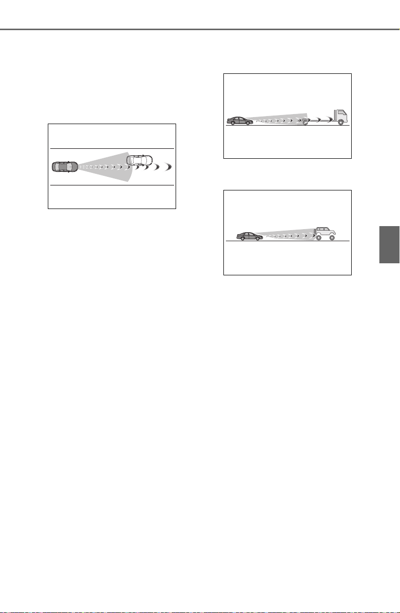
235
4-5. Using the driving support systems
4
Driving
• If a detectable object makes an
abrupt maneuver (such as sudden
swerving, acceleration or deceler-
ation)
• When your vehicle approaches a
detectable object rapidly
• When a detectable object is not
directly in front of your vehicle
• When a detectable object is near
a wall, fence, guardrail, manhole
cover, vehicle, steel plate on the
road, etc.
• When a detectable object is under
a structure
• When part of a detectable object
is hidden by an object, such as
large baggage, an umbrella, or
guardrail
• When multiple detectable objects
are close together
• If the sun or other light is shining
directly on a detectable object
• When a detectable object is a
shade of white and looks
extremely bright
• When a detectable object appears
to be nearly the same color or
brightness as its surroundings
• If a detectable object cuts or sud-
denly emerges in front of your
vehicle
• When the front of your vehicle is
hit by water, snow, dust, etc.
• When a very bright light ahead,
such as the sun or the headlights
of oncoming traffic, shines directly
into the front camera
• When approaching the side or
front of a vehicle ahead
• If a vehicle ahead is a motorcycle
• If a vehicle ahead is narrow, such
as a personal mobility vehicle
• If a preceding vehicle has a small
rear end, such as an unloaded
truck
• If a preceding vehicle has a low
rear end, such as a low bed trailer
• If a vehicle ahead has extremely
high ground clearance
• If a vehicle ahead is carrying a
load which protrudes past its rear
bumper
• If a vehicle ahead is irregularly
shaped, such as a tractor or side
car
• If a vehicle ahead is a child sized
bicycle, a bicycle that is carrying a
large load, a bicycle ridden by
more than one person, or a
uniquely shaped bicycle (bicycle
with a child seat, tandem bicycle,
etc.)
• If a pedestrian/or the riding height
of a bicyclist ahead is shorter than
approximately 3.2 ft. (1 m) or taller
than approximately 6.5 ft. (2 m)
• If a pedestrian/bicyclist is wearing
oversized clothing (a rain coat,
long skirt, etc.), making their sil-
houette obscure
• If a pedestrian is bending forward
or squatting or bicyclist is bending
forward
• If a pedestrian/bicyclist is moving
fast
• If a pedestrian is pushing a
stroller, wheelchair, bicycle or
other vehicle
• When driving in inclement weather
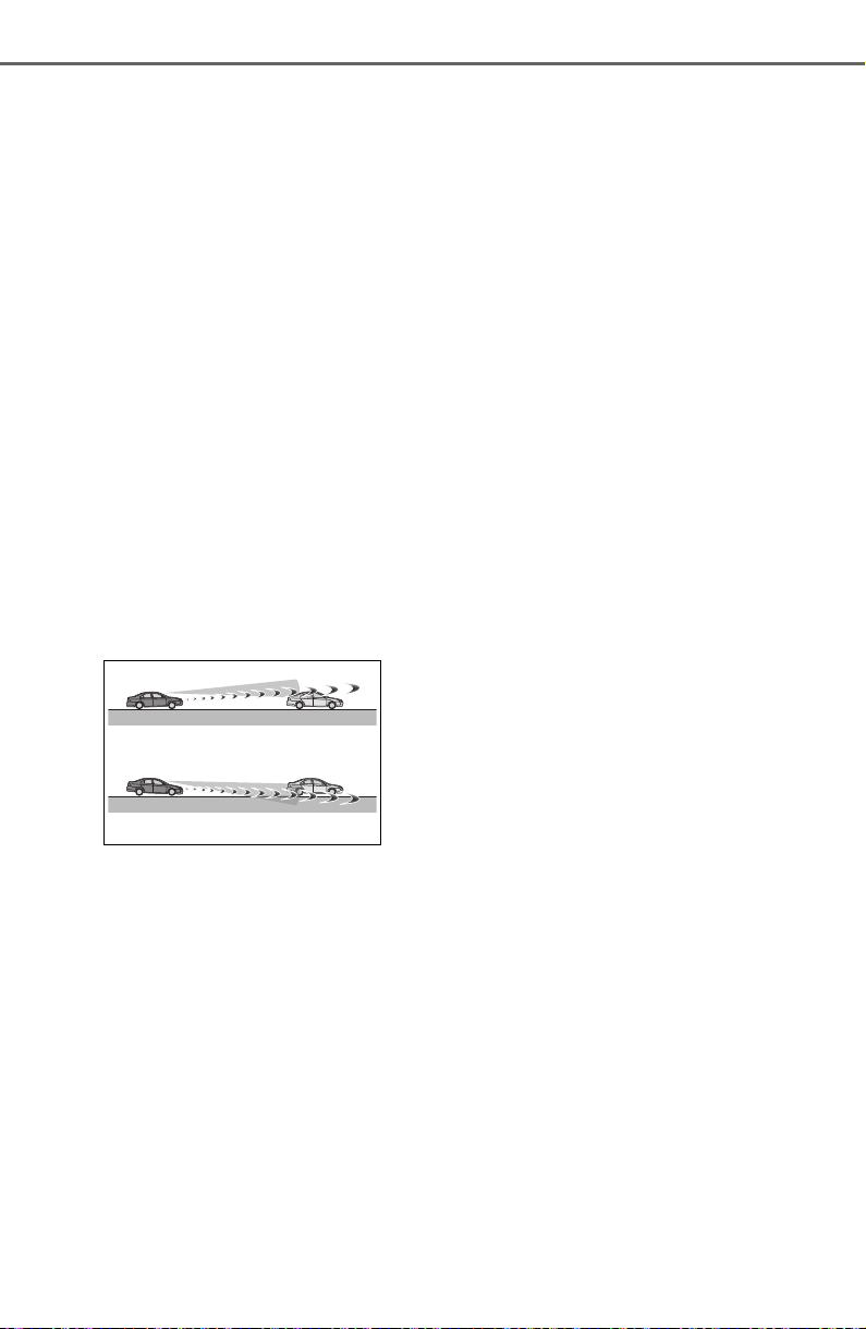
236
4-5. Using the driving support systems
such as heavy rain, fog, snow or a
sandstorm
• When driving through steam or
smoke
• When the surrounding area is dim,
such as at dawn or dusk, or while
at night or in a tunnel, making a
detectable object appear to be
nearly the same color as its sur-
roundings
• When driving in a place where the
surrounding brightness changes
suddenly, such as at the entrance
or exit of a tunnel
• After the engine has started the
vehicle has not been driven for a
certain amount of time
• While making a left/right turn and
for a few seconds after making a
left/right turn
• While driving on a curve and for a
few seconds after driving on a
curve
• If your vehicle is skidding
• If the front of the vehicle is raised
or lowered
• If the wheels are misaligned
• If a wiper blade is blocking the
front camera
• The vehicle is being driven at
extremely high speeds
• When driving on a hill
• If the radar sensor or front camera
is misaligned
● In some situations such as the fol-
lowing, sufficient braking force
may not be obtained, preventing
the system from performing prop-
erly:
• If the braking functions cannot
operate to their full extent, such as
when the brake parts are
extremely cold, extremely hot, or
wet
• If the vehicle is not properly main-
tained (brakes or tires are exces-
sively worn, improper tire inflation
pressure, etc.)
• When the vehicle is being driven
on a gravel road or other slippery
surface
■ If VSC is disabled
● If VSC is disabled (P.362), the
pre-collision brake assist and pre-
collision braking functions are also
disabled.
● The PCS warning light will turn on
and “VSC Turned Off Pre-Collision
Brake System Unavailable” will be
displayed on the multi-information
display.
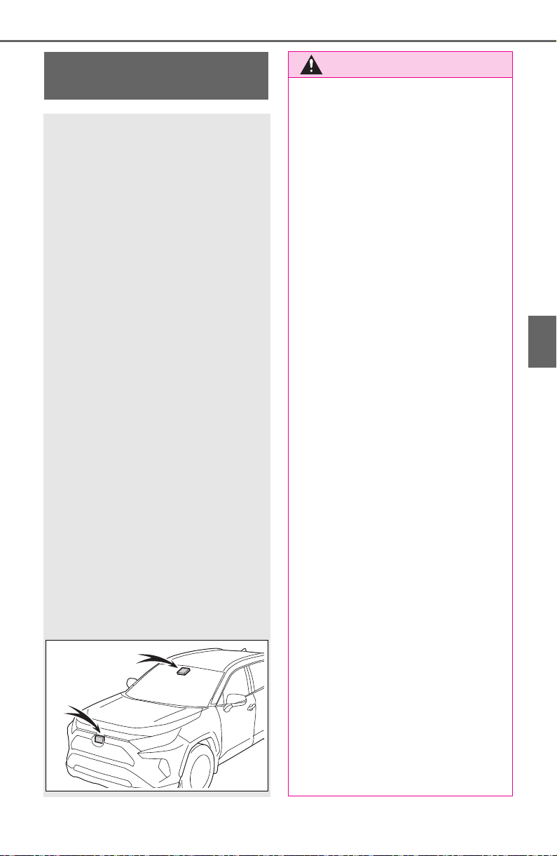
237
4-5. Using the driving support systems
4
Driving
LTA (Lane Tracing
Assist)
When driving on highways
and freeways with white
(yellow) lane lines, this
function alerts the driver
when the vehicle might
depart from its lane or
course
*
and provides assis-
tance by operating the
steering wheel to keep the
vehicle in its lane or
course
*
. Furthermore, the
system provides steering
assistance when dynamic
radar cruise control with
full-speed range is operat-
ing to keep the vehicle in its
lane.
The LTA system recognizes
white (yellow) lane lines or a
course
*
using the front cam-
era. Additionally, it detects
preceding vehicles using
the front camera and radar.
*
: Boundary between asphalt and
the side of the road, such as
grass, soil, or a curb
WARNING
■ Before using LTA system
● Do not rely solely upon the LTA
system. The LTA system does
not automatically drive the vehi-
cle or reduce the amount of
attention that must be paid to
the area in front of the vehicle.
The driver must always assume
full responsibility for driving
safely by paying careful atten-
tion to the surrounding condi-
tions and operating the steering
wheel to correct the path of the
vehicle. Also, the driver must
take adequate breaks when
fatigued, such as from driving
for a long period of time.
● Failure to perform appropriate
driving operations and pay care-
ful attention may lead to an
accident, resulting in death or
serious injury.
● When not using the LTA system,
use the LTA switch to turn the
system off.
■ Situations unsuitable for LTA
system
In the following situations, use the
LTA switch to turn the system off.
Failure to do so may lead to an
accident, resulting in death or
serious injury.
● Vehicle is driven on a road sur-
face which is slippery due to
rainy weather, fallen snow,
freezing, etc.
● Vehicle is driven on a snow-cov-
ered road.
● White (yellow) lines are difficult
to see due to rain, snow, fog,
dust, etc.
● Vehicle is driven in a temporary
lane or restricted lane due to
construction work.
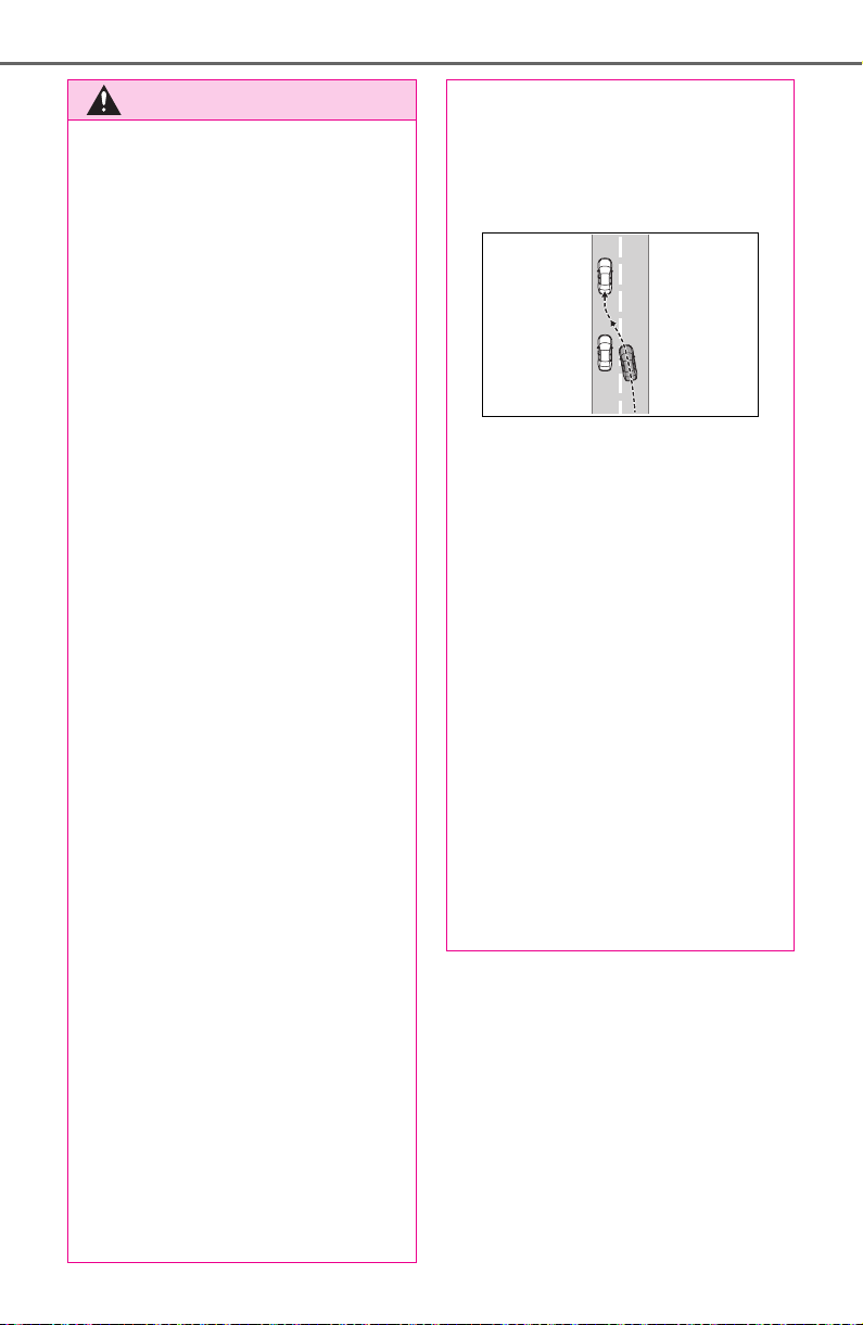
238
4-5. Using the driving support systems
WARNING
● Vehicle is driven in a construc-
tion zone.
● A spare tire, tire chains, etc. are
equipped.
● When the tires have been
excessively worn, or when the
tire inflation pressure is low.
● When tires of a size other than
specified are installed.
● Vehicle is driven in traffic lanes
other than that highways and
freeways.
● When your vehicle is towing a
trailer or during emergency tow-
ing
■ Preventing LTA system mal-
functions and operations per-
formed by mistake
● Do not modify the headlights or
place stickers, etc. on the sur-
face of the lights.
● Do not modify the suspension
etc. If the suspension etc. needs
to be replaced, contact your
Toyota dealer.
● Do not install or place anything
on the hood or grille. Also, do
not install a grille guard (bull
bars, kangaroo bar, etc.).
● If your windshield needs
repairs, contact your Toyota
dealer.
■ Conditions in which functions
may not operate properly
In the following situations, the
functions may not operate prop-
erly and the vehicle may depart
from its lane. Drive safely by
always paying careful attention to
your surroundings and operate
the steering wheel to correct the
path of the vehicle without relying
solely on the functions.
● When the follow-up cruising dis-
play is displayed (P.242) and
the preceding vehicle changes
lanes. (Your vehicle may follow
the preceding vehicle and also
change lanes.)
● When the follow-up cruising dis-
play is displayed (P.242) and
the preceding vehicle is sway-
ing. (Your vehicle may sway
accordingly and depart from the
lane.)
● When the follow-up cruising dis-
play is displayed (P.242) and
the preceding vehicle departs
from its lane. (Your vehicle may
follow the preceding vehicle and
depart from the lane.)
● When the follow-up cruising dis-
play is displayed (P.242) and
the preceding vehicle is being
driven extremely close to the
left/right lane line. (Your vehicle
may follow the preceding vehi-
cle and depart from the lane.)
● Vehicle is being driven around a
sharp curve.
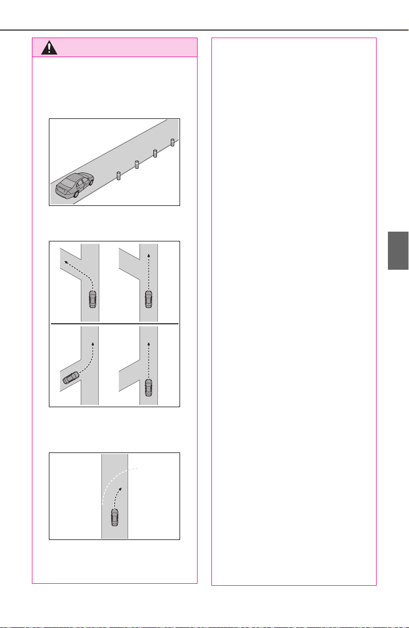
239
4-5. Using the driving support systems
4
Driving
WARNING
● Objects or patterns that could
be mistaken for white (yellow)
lines are present on the side of
the road (guardrails, reflective
poles, etc.).
● Vehicle is driven where the road
diverges, merges, etc.
● Repair marks of asphalt, white
(yellow) lines, etc. are present
due to road repair.
● There are shadows on the road
that run parallel with, or cover,
the white (yellow) lines.
● The vehicle is driven in an area
without white (yellow) lines,
such as in front of a tollgate or
checkpoint, or at an intersec-
tion, etc.
● The white (yellow) lines are
cracked, “Botts’ dots”, “Raised
pavement marker” or stones are
present.
● The white (yellow) lines cannot
be seen or are difficult to see
due to sand, etc.
● The vehicle is driven on a road
surface that is wet due to rain,
puddles, etc.
● The traffic lines are yellow
(which may be more difficult to
recognize than lines that are
white).
● The white (yellow) lines cross
over a curb, etc.
● The vehicle is driven on a bright
surface, such as concrete.
● If the edge of the road is not
clear or straight.
● The vehicle is driven on a sur-
face that is bright due to
reflected light, etc.
● The vehicle is driven in an area
where the brightness changes
suddenly, such as at the
entrances and exits of tunnels,
etc.
● Light from the headlights of an
oncoming vehicle, the sun, etc.
enters the camera.
● The vehicle is driven on a slope.
● The vehicle is driven on a road
which tilts left or right, or a wind-
ing road.
● The vehicle is driven on an
unpaved or rough road.
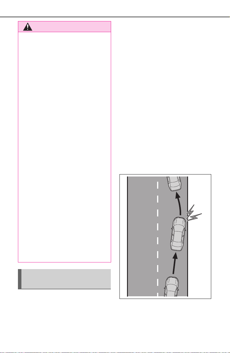
240
4-5. Using the driving support systems
■ Lane departure alert func-
tion
When the system determines
that the vehicle might depart
from its lane or course
*
, a warn-
ing is displayed on the multi-
information display, and a warn-
ing buzzer will sound to alert the
driver.
When the warning buzzer sounds,
check the area around your vehicle
and carefully operate the steering
wheel to move the vehicle back to
the center of the lane.
Vehicles with Blind Spot Monitor:
When the system determines that
the vehicle might depart from its
lane and that the possibility of a col-
lision with an overtaking vehicle in
the adjacent lane is high, the lane
departure alert will operate even if
the turn signals are operating.
*
: Boundary between asphalt and
the side of the road, such as
grass, soil, or a curb
■ Steering assist function
When the system determines
that the vehicle might depart
from its lane or course
*
, the sys-
WARNING
● The traffic lane is excessively
narrow or wide.
● The vehicle is extremely tilted
due to carrying heavy luggage
or having improper tire pres-
sure.
● The distance to the preceding
vehicle is extremely short.
● The vehicle is moving up and
down a large amount due to
road conditions during driving
(poor roads or road seams).
● When driving in a tunnel or at
night with the headlights off or
when a headlight is dim due to
its lens being dirty or it being
misaligned.
● The vehicle is struck by a cross-
wind.
● The vehicle is affected by wind
from a vehicle driven in a
nearby lane.
● The vehicle has just changed
lanes or crossed an intersec-
tion.
● Tires which differ by structure,
manufacturer, brand or tread
pattern are used.
● Snow tires, etc. are equipped.
● The vehicle is being driven at
extremely high speeds.
Functions included in LTA
system
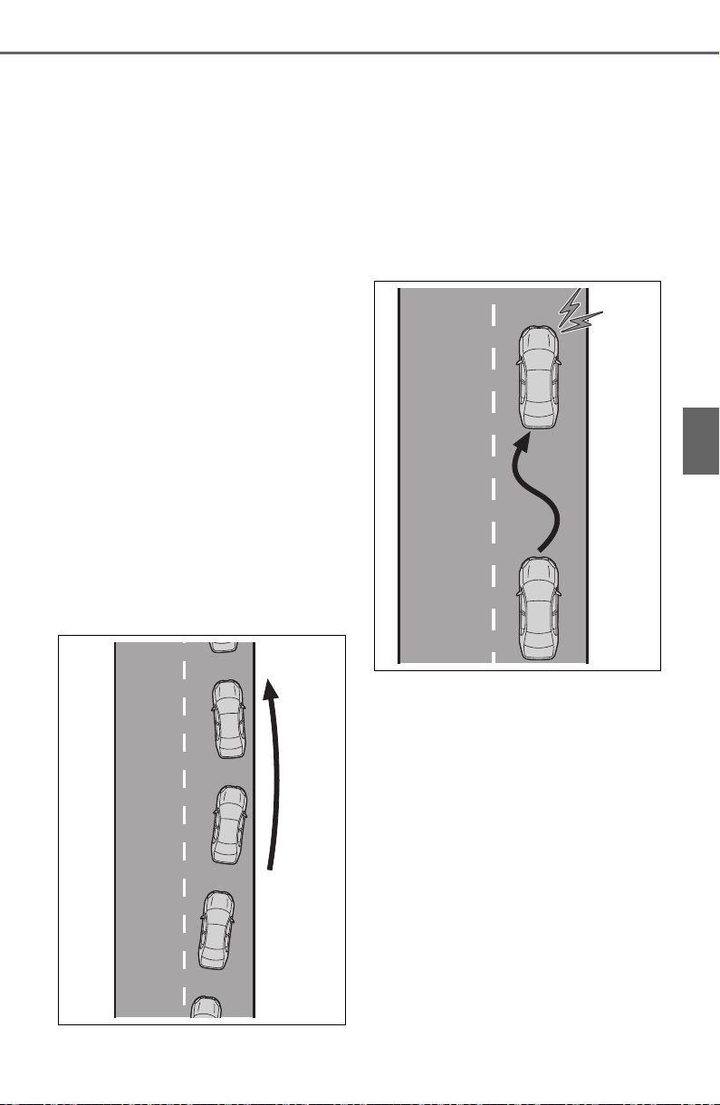
241
4-5. Using the driving support systems
4
Driving
tem provides assistance as nec-
essary by operating the steering
wheel in small amounts for a
short period of time to keep the
vehicle in its lane.
If the system detects that the steer-
ing wheel has not been operated
for a fixed amount of time or the
steering wheel is not being firmly
gripped, a warning is displayed on
the multi-information display and
the function is temporarily can-
celed.
Vehicles with Blind Spot Monitor:
When the system determines that
the vehicle might depart from its
lane and that the possibility of a col-
lision with an overtaking vehicle in
the adjacent lane is high, the steer-
ing assist function will operate even
if the turn signals are operating.
*
: Boundary between asphalt and
the side of the road, such as
grass, soil, or a curb
■ Vehicle sway warning func-
tion
When the vehicle is swaying
within a lane, the warning
buzzer will sound and a mes-
sage will be displayed on the
multi-information display to alert
the driver.
■ Lane centering function
This function is linked with
dynamic radar cruise control
with full-speed range and pro-
vides the required assistance by
operating the steering wheel to
keep the vehicle in its current
lane.
When dynamic radar cruise control
with full-speed range is not operat-
ing, the lane centering function
does not operate.
In situations where the white (yel-
low) lane lines are difficult to see or
are not visible, such as when in a
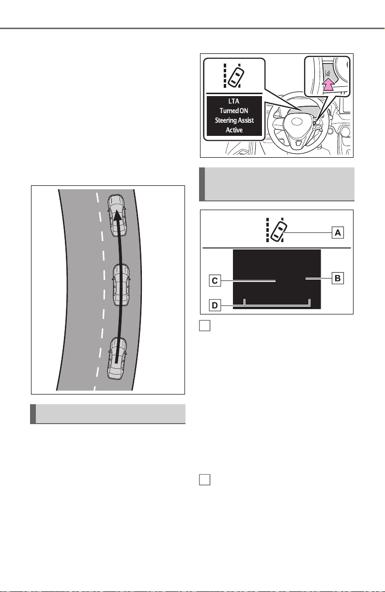
242
4-5. Using the driving support systems
traffic jam, this function will operate
to help follow a preceding vehicle
by monitoring the position of the
preceding vehicle.
If the system detects that the steer-
ing wheel has not been operated
for a fixed amount of time or the
steering wheel is not being firmly
gripped, a warning is displayed on
the multi-information display and
the function is temporarily can-
celed.
Press the LTA switch to turn the
LTA system on.
The LTA indicator illuminates and a
message is displayed on the multi-
information display.
Press the LTA switch again to
turn the LTA system off.
When the LTA system is turned on
or off, operation of the LTA system
continues in the same condition the
next time the engine is started.
LTA indicator
The illumination condition of the
indicator informs the driver of the
system operation status.
Illuminated in white: LTA system is
operating.
Illuminated in green: Steering wheel
assistance of the steering assist
function or lane centering function
is operating.
Flashing in orange: Lane departure
alert function is operating.
Operation display of steering
wheel operation support
Displayed when the multi-informa-
tion display is switched to the driv-
ing support system information
display.
Indicates that steering wheel assis-
Turning LTA system on
Indications on multi-infor-
mation display
A
B

243
4-5. Using the driving support systems
4
Driving
tance of the steering assist function
or lane centering function is operat-
ing.
Both outer sides of the lane are dis-
played: Indicates that steering
wheel assist of the lane centering
function is operating.
One outer side of the lane is dis-
played: Indicates that steering
wheel assist of the steering assist
function is operating.
Both outer sides of the lane are
flashing: Alerts the driver that their
input is necessary to stay in the
center of the lane (lane centering
function).
Follow-up cruising display
Displayed when the multi-informa-
tion display is switched to the driv-
ing support system information
display.
Indicates that steering assist of the
lane centering function is operating
by monitoring the position of a pre-
ceding vehicle.
When the follow-up cruising display
is displayed, if the preceding vehi-
cle moves, your vehicle may move
in the same way. Always pay care-
ful attention to your surroundings
and operate the steering wheel as
necessary to correct the path of the
vehicle and ensure safety.
Lane departure alert function
display
Displayed when the multi-informa-
tion display is switched to the driv-
ing support system information
display.
Inside of displayed lines is
white
Indicates that the system is recog-
nizing white (yellow) lines or a
course
*
. When the vehicle departs
from its lane, the white line dis-
played on the side the vehicle
departs from flashes orange.
Inside of displayed lines is
black
Indicates that the system is not able
to recognize white (yellow) lines or
a course
*
or is temporarily can-
celed.
*
: Boundary between asphalt and
the side of the road, such as
grass, soil, or a curb
■ Operation conditions of each
function
● Lane departure alert function
This function operates when all of
the following conditions are met.
C
D

244
4-5. Using the driving support systems
• LTA is turned on.
• Vehicle speed is approximately 32
mph (50 km/h) or more.
*1
• System recognizes white (yellow)
lane lines or a course
*2
. (When a
white [yellow] line or course
*2
is
recognized on only one side, the
system will operate only for the
recognized side.)
• Width of traffic lane is approxi-
mately 9.8 ft. (3 m) or more.
• Turn signal lever is not operated.
(Vehicles with Blind Spot Monitor:
Except when another vehicle is in
the lane on the side where the
turn signal was operated)
• Vehicle is not being driven around
a sharp curve.
• No system malfunctions are
detected. (P.246)
*1
:The function operates even if the
vehicle speed is less than
approximately 32 mph (50 km/h)
when the lane centering function
is operating.
*2
:Boundary between asphalt and
the side of the road, such as
grass, soil, or a curb
● Steering assist function
This function operates when all of
the following conditions are met in
addition to the operation conditions
for the lane departure alert function.
• Setting for “Steering Assist” in the
screen of the multi-information
display is set to “ON”. (P. 8 9 )
• Vehicle is not accelerated or
decelerated by a fixed amount or
more.
• Steering wheel is not operated
with a steering force level suitable
for changing lanes.
• ABS, VSC, TRAC and PCS are
not operating.
• TRAC or VSC is not turned off.
• Hands off steering wheel warning
is not displayed. (P.245)
● Vehicle sway warning function
This function operates when all of
the following conditions are met.
• Setting for “Sway Warning” in the
screen of the multi-information
display is set to “ON”. (P. 89 )
• Vehicle speed is approximately 32
mph (50 km/h) or more.
• Width of traffic lane is approxi-
mately 9.8 ft. (3 m) or more.
• No system malfunctions are
detected. (P.246)
● Lane centering function
This function operates when all of
the following conditions are met.
• LTA is turned on.
• Setting for “Steering Assist” and
“Lane Center” in the screen of
the multi-information display are
set to “ON”. (P. 89 )
• This function recognizes white
(yellow) lane lines or the position
of a preceding vehicle (except
when the preceding vehicle is
small, such as a motorcycle).
• The dynamic radar cruise control
with full-speed range is operating
in vehicle-to-vehicle distance con-
trol mode.
• Width of traffic lane is approxi-
mately 10 to 13 ft. (3 to 4 m).
• Turn signal lever is not operated.
• Vehicle is not being driven around
a sharp curve.
• No system malfunctions are
detected. (P.246)
• Vehicle does not accelerate or
decelerate by a fixed amount or
more.
• Steering wheel is not operated
with a steering force level suitable
for changing lanes.
• ABS, VSC, TRAC and PCS are
not operating.
• TRAC or VSC is not turned off.
• Hands off steering wheel warning
is not displayed. (P.245)
• The vehicle is being driven in the
center of a lane.
• Steering assist function is not
operating.

245
4-5. Using the driving support systems
4
Driving
■ Temporary cancelation of func-
tions
● When operation conditions are no
longer met, a function may be
temporarily canceled. However,
when the operation conditions are
met again, operation of the func-
tion is automatically restored.
(P.243)
● If the operation conditions
(P.243) are no longer met while
the lane centering function is
operating, the buzzer may sound
to indicate that the function has
been temporarily canceled.
■ Steering assist function/lane
centering function
● Depending on the vehicle speed,
lane departure situation, road con-
ditions, etc., the driver may not
feel the function is operating or
the function may not operate at
all.
● The steering control of the func-
tion is overridden by the driver’s
steering wheel operation.
● Do not attempt to test the opera-
tion of the steering assist function.
■ Lane departure alert function
● The warning buzzer may be diffi-
cult to hear due to external noise,
audio playback, etc.
● If the edge of the course
*
is not
clear or straight, the lane depar-
ture alert function may not oper-
ate.
● Vehicles with Blind Spot Monitor: It
may not be possible for the sys-
tem to determine if there is a dan-
ger of a collision with a vehicle in
an adjacent lane.
● Do not attempt to test the opera-
tion of the lane departure alert
function.
*
: Boundary between asphalt and
the side of the road, such as
grass, soil, or a curb
■ Hands off steering wheel warn-
ing
In the following situations, a warning
message urging the driver to hold
the steering wheel and the symbol
shown in the illustration are dis-
played on the multi-information dis-
play to warn the driver. The warning
stops when the system determines
that the driver holds the steering
wheel. Always keep your hands on
the steering wheel when using this
system, regardless of warnings.
● When the system determines that
the driver is driving without hold-
ing the steering wheel while the
system is operating
If the driver continues to keep their
hands off of the steering wheel, the
buzzer sounds, the driver is warned
and the function is temporarily can-
celed. This warning also operates in
the same way when the driver con-
tinuously operates the steering
wheel only a small amount.
● When the system determines that
the vehicle may not turn and
instead depart from its lane while
driving around a curve
Depending on the vehicle condition
and road conditions, the warning
may not operate. Also, if the system
determines that the vehicle is driv-
ing around a curve, warnings will
occur earlier than during straight-
lane driving.
● When the system determines that
the driver is driving without hold-
ing the steering wheel while the
246
4-5. Using the driving support systems
steering wheel assist of the steer-
ing assist function is operating.
If the driver continues to keep their
hands off of the steering wheel and
the steering wheel assist is operat-
ing, the buzzer sounds and the
driver is warned. Each time the
buzzer sounds, the continuing time
of the buzzer becomes longer.
■ Vehicle sway warning function
When the system determines that
the vehicle is swaying while the
vehicle sway warning function is
operating, a buzzer sounds and a
warning message urging the driver
to rest and the symbol shown in the
illustration are simultaneously dis-
played on the multi-information dis-
play.
Depending on the vehicle and road
conditions, the warning may not
operate.
■ Warning message
If the following warning message is
displayed on the multi-information
display and the LTA indicator illumi-
nates in orange, follow the appropri-
ate troubleshooting procedure. Also,
if a different warning message is
displayed, follow the instructions
displayed on the screen.
● “LTA Malfunction Visit Your
Dealer”
The system may not be operating
properly. Have the vehicle inspected
by your Toyota dealer.
● “LTA Unavailable”
The system is temporarily canceled
due to a malfunction in a sensor
other than the front camera. Turn
the LTA system off, wait for a little
while, and then turn the LTA system
back on.
● “LTA Unavailable at Current
Speed”
The function cannot be used as the
vehicle speed exceeds the LTA
operation range. Drive slower.
■ Customization
Function settings can be changed.
(P. 94 )
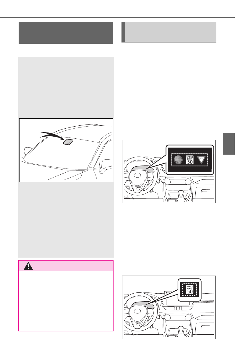
247
4-5. Using the driving support systems
4
Driving
*
: If equipped
When the front camera recog-
nizes a sign and/or information
of a sign is available from the
navigation system, the sign will
be displayed on the multi-infor-
mation display.
When the driving support sys-
tem information display is
selected, a maximum of 3
signs can be displayed.
(P.8 9 )
When a tab other than the
driving support system infor-
mation display is selected, the
following types of road signs
will be displayed. (P. 89)
• Speed limit sign
• Do Not Enter sign (when notifica-
tion is necessary)
RSA (Road Sign
Assist)
*
The RSA system recognizes
specific road signs using
the front camera and/or nav-
igation system (when speed
limit information is avail-
able) to provide information
to the driver via the display.
If the system judges that the
vehicle is being driven over
the speed limit, performing
prohibited actions, etc. in
relation to the recognized
road signs, it notifies the
driver using a notification
display and notification
buzzer.
WARNING
■ Before using the RSA
Do not rely solely upon the RSA
system. RSA is a system which
supports the driver by providing
information, but it is not a replace-
ment for a driver’s own vision and
awareness. Drive safely by
always paying careful attention to
the traffic rules.
Indication on the multi-
information display
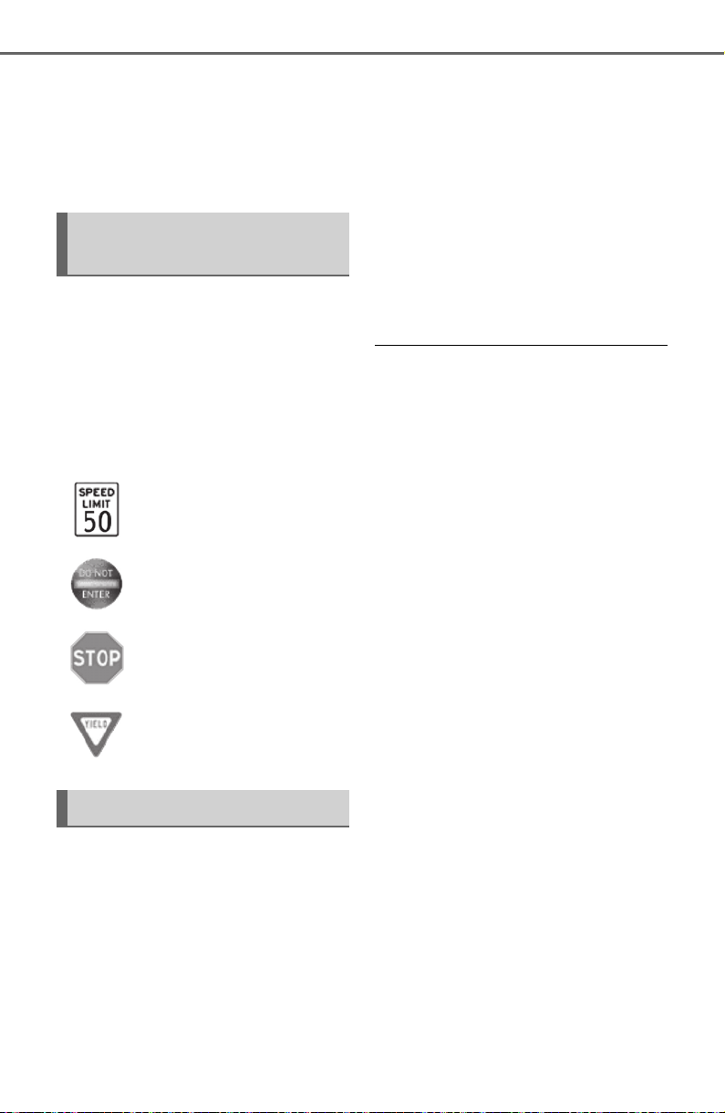
248
4-5. Using the driving support systems
If signs other than speed limit
signs are recognized, they will
be displayed in an overlapping
stack under the current speed
limit sign.
The following types of road
signs, including electronic signs
and blinking signs, are recog-
nized.
A non-official or a recently intro-
duced traffic sign may not be recog-
nized.
In the following situations, the
RSA system will notify the
driver.
When the vehicle speed
exceeds the speed notifica-
tion threshold of the speed
limit sign displayed, the sign
display will be emphasized
and a buzzer will sound.
When the RSA system recog-
nizes a do not enter sign and
determines that your vehicle
has entered a no-entry area,
the displayed sign will flash
and a buzzer will sound.
Depending on the situation, a
notification function may not
operate properly.
■ Setting procedure
P. 9 4
■ Automatic turn-off of RSA sign
display
In the following situations, displayed
speed limit and do not enter signs
will stop being displayed automati-
cally:
● A new sign is not recognized for a
certain distance.
● The road changes due to a left or
right turn, etc.
In the following situations, stop and
yield signs will stop being displayed
automatically:
● The system determines that your
vehicle has passed the sign.
● The road changes due to a left or
right turn, etc.
■ Conditions in which the func-
tion may not operate or detect
correctly
In the following situations, RSA
does not operate normally and may
not recognize signs, display the
incorrect sign, etc. However, this
does not indicate a malfunction.
● The front camera is misaligned
due to a strong impact being
applied to the sensor, etc.
● Dirt, snow, stickers, etc. are on the
windshield near the front camera.
● In inclement weather such as
Supported types of road
signs
Speed limit
Do Not Enter
Stop
Yield
Notification function

249
4-5. Using the driving support systems
4
Driving
heavy rain, fog, snow or sand
storms
● Light from an oncoming vehicle,
the sun, etc. enters the front cam-
era.
● The sign is dirty, faded, tilted or
bent, and if an electronic sign, the
contrast is poor.
● All or part of the sign is hidden by
the leaves of a tree, a pole, etc.
● The sign is only visible to the front
camera for a short amount of time.
● The driving scene (turning, lane
change, etc.) is judged incorrectly.
● Even if it is a sign not appropriate
for the currently traveled lane,
such a sign exists directly after a
freeway branches, or in an adja-
cent lane just before merging.
● Stickers are attached to the rear of
the preceding vehicle.
● A sign resembling a system com-
patible sign is recognized.
● Side road speed signs may be
detected and displayed (if posi-
tioned in sight of the front camera)
while the vehicle is traveling on
the main road.
● Roundabout exit road speed signs
may be detected and displayed (if
positioned in sight of the front
camera) while traveling on a
roundabout.
● The front of the vehicle is raised or
lowered due to the carried load.
● The surrounding brightness is not
sufficient or changes suddenly.
● When a sign intended for trucks,
etc. is recognized.
● The speed information displayed
on the meter and that displayed
on the navigation system may be
different due to the navigation sys-
tem using map data.
■ Speed limit sign display
If the engine switch was last turned
off while a speed limit sign was dis-
played on the multi-information dis-
play, the same sign displays again
when the engine switch is turned to
ON.
■ If “RSA Malfunction Visit Your
Dealer” is shown
The system may be malfunctioning.
Have the vehicle inspected by your
Toyota dealer.
■ Customization
Some functions can be customized.
(Customizable features: P. 94)
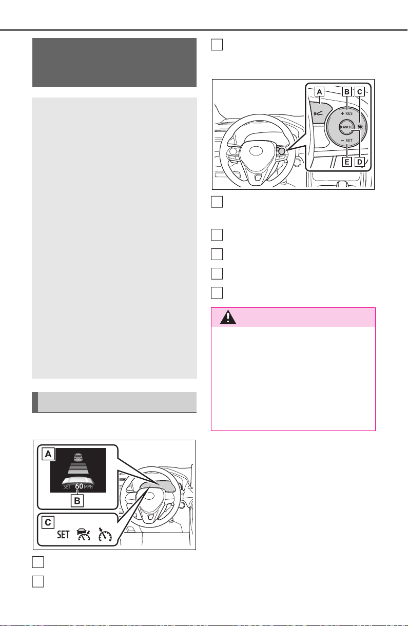
250
4-5. Using the driving support systems
■ Meter display
Multi-information display
Set speed
Indicators
■ Operation switches
Vehicle-to-vehicle distance
switch
“+RES” switch
Cruise control main switch
Cancel switch
“-SET” switch
Dynamic radar cruise
control with full-speed
range
In vehicle-to-vehicle dis-
tance control mode, the
vehicle automatically accel-
erates, decelerates and
stops to match the speed
changes of the preceding
vehicle even if the accelera-
tor pedal is not depressed.
In constant speed control
mode, the vehicle runs at a
fixed speed.
Use the dynamic radar
cruise control with full-
speed range on freeways
and highways.
Vehicle-to-vehicle distance
control mode (P.253)
Constant speed control
mode (P.257)
System Components
A
B
WARNING
■ Before using dynamic radar
cruise control with full-speed
range
● Driving safely is the sole
responsibility of the driver. Do
not rely solely on the system,
and drive safely by always pay-
ing careful attention to your sur-
roundings.
C
A
B
C
D
E

251
4-5. Using the driving support systems
4
Driving
WARNING
● The dynamic radar cruise con-
trol with full-speed range pro-
vides driving assistance to
reduce the driver’s burden.
However, there are limitations to
the assistance provided.
Read the following conditions
carefully. Do not overly rely on this
system and always drive carefully.
• When the sensor may not be
correctly detecting the vehicle
ahead: P.2 59
• Conditions under which the
vehicle-to-vehicle distance con-
trol mode may not function cor-
rectly: P.259
● Set the speed appropriately
depending on the speed limit,
traffic flow, road conditions,
weather conditions, etc. The
driver is responsible for check-
ing the set speed.
● Even when the system is func-
tioning normally, the condition of
the preceding vehicle as
detected by the system may dif-
fer from the condition observed
by the driver. Therefore, the
driver must always remain alert,
assess the danger of each situ-
ation and drive safely. Relying
solely on this system or assum-
ing the system ensures safety
while driving can lead to an
accident, resulting in death or
serious injury.
● Switch the dynamic radar cruise
control with full-speed range
setting to off, using the cruise
control main switch when not in
use.
■ Cautions regarding the driv-
ing assist systems
Observe the following precau-
tions, as there are limitations to
the assistance provided by the
system. Failure to do so may
cause an accident resulting in
death or serious injury.
● Assisting the driver to measure
following distance
The dynamic radar cruise control
with full-speed range is only
intended to help the driver in
determining the following distance
between the driver’s own vehicle
and a designated vehicle traveling
ahead. It is not a mechanism that
allows careless or inattentive driv-
ing, and it is not a system that can
assist the driver in low-visibility
conditions.
It is still necessary for driver to
pay close attention to the vehi-
cle’s surroundings.
● Assisting the driver to judge
proper following distance
The dynamic radar cruise control
with full-speed range determines
whether the following distance
between the driver’s own vehicle
and a designated vehicle traveling
ahead is within a set range. It is
not capable of making any other
type of judgement. Therefore, it is
absolutely necessary for the
driver to remain vigilant and to
determine whether or not there is
a possibility of danger in any
given situation.

252
4-5. Using the driving support systems
WARNING
● Assisting the driver to operate
the vehicle
The dynamic radar cruise control
with full-speed range does not
include functions which will pre-
vent or avoid collisions with vehi-
cles ahead of your vehicle.
Therefore, if there is ever any
possibility of danger, the driver
must take immediate and direct
control of the vehicle and act
appropriately in order to ensure
the safety of all involved.
■ Situations unsuitable for
dynamic radar cruise control
with full-speed range
Do not use dynamic radar cruise
control with full-speed range in
any of the following situations.
Doing so may result in inappropri-
ate speed control and could
cause an accident resulting in
death or serious injury.
● Roads where there are pedes-
trians, cyclists, etc.
● In heavy traffic
● On roads with sharp bends
● On winding roads
● On slippery roads, such as
those covered with rain, ice or
snow
● On steep downhills, or where
there are sudden changes
between sharp up and down
gradients
Vehicle speed may exceed the set
speed when driving down a steep
hill.
● At entrances to freeways and
highways
● When weather conditions are
bad enough that they may pre-
vent the sensors from detecting
correctly (fog, snow, sand-
storm, heavy rain, etc.)
● When there is rain, snow, etc.
on the front surface of the radar
or front camera
● In traffic conditions that require
frequent repeated acceleration
and deceleration
● When your vehicle is towing a
trailer or during emergency tow-
ing
● When an approach warning
buzzer is heard often
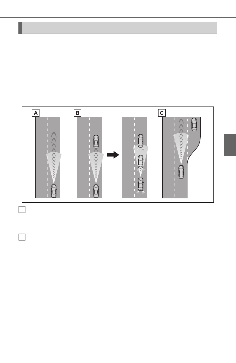
253
4-5. Using the driving support systems
4
Driving
This mode employs a radar to detect the presence of vehicles up to
approximately 328 ft. (100 m) ahead, determines the current vehicle-
to-vehicle following distance, and operates to maintain a suitable fol-
lowing distance from the vehicle ahead. The desired vehicle-to-vehi-
cle distance can also be set by operating the vehicle-to-vehicle
distance switch.
When driving on downhill slopes, the vehicle-to-vehicle distance may
become shorter.
Example of constant speed cruising
When there are no vehicles ahead
The vehicle travels at the speed set by the driver.
Example of deceleration cruising and follow-up cruising
When a preceding vehicle driving slower than the set speed
appears
When a vehicle is detected running ahead of you, the system automatically
decelerates your vehicle. When a greater reduction in vehicle speed is nec-
essary, the system applies the brakes (the stop lights will come on at this
time). The system will respond to changes in the speed of the vehicle
ahead in order to maintain the vehicle-to-vehicle distance set by the driver.
Approach warning warns you when the system cannot decelerate suffi-
ciently to prevent your vehicle from closing in on the vehicle ahead.
When the vehicle ahead of you stops, your vehicle will also stop (vehicle is
stopped by system control). After the vehicle ahead starts off, pressing the
“+RES” switch or depressing the accelerator pedal (start-off operation) will
resume follow-up cruising. If the start-off operation is not performed, system
Driving in vehicle-to-vehicle distance control mode
A
B
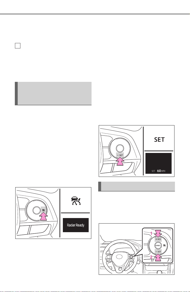
254
4-5. Using the driving support systems
control continues to keep your vehicle stopped.
When the turn signal lever is operated and your vehicle moves to a left lane
while driving at 50 mph (80 km/h) or more, the vehicle will quickly acceler-
ate to help to overtake a passing vehicle.
Example of acceleration
When there are no longer any preceding vehicles driving slower
than the set speed
The system accelerates until the set speed is reached. The system then
returns to constant speed cruising.
1 Press the cruise control main
switch to activate the cruise
control.
Dynamic radar cruise control indi-
cator will come on and a message
will be displayed on the multi-infor-
mation display. Press the switch
again to deactivate the cruise con-
trol.
If the cruise control main switch is
pressed and held for 1.5 seconds
or more, the system turns on in
constant speed control mode.
(P.257)
2 Accelerate or decelerate,
with accelerator pedal opera-
tion, to the desired vehicle
speed (at or above approxi-
mately 20 mph [30 km/h])
and press the “-SET” switch
to set the speed.
Cruise control “SET” indicator will
come on.
The vehicle speed at the moment
the switch is released becomes the
set speed.
To change the set speed, press
the “+RES” or “-SET” switch
until the desired set speed is
displayed.
C
Setting the vehicle speed
(vehicle-to-vehicle dis-
tance control mode)
Adjusting the set speed

255
4-5. Using the driving support systems
4
Driving
1 Increases the speed (Except
when the vehicle has been
stopped by system control in
vehicle-to-vehicle distance
control mode)
2 Decreases the speed
Fine adjustment: Press the switch.
Large adjustment: Press and hold
the switch to change the speed,
and release when the desired
speed is reached.
In the vehicle-to-vehicle dis-
tance control mode, the set
speed will be increased or
decreased as follows:
For the U.S. mainland and
Hawaii
Fine adjustment: By 1 mph (1.6
km/h)
*1
or 1 km/h (0.6 mph)
*2
each
time the switch is pressed
Large adjustment: Increases or
decreases in 1 mph (1.6 km/h)
*1
or
1 km/h (0.6 mph)
*2
increments for
as long as the switch is held
Except for the U.S. mainland
and Hawaii
Fine adjustment: By 1 mph (1.6
km/h)
*1
or 1 km/h (0.6 mph)
*2
each
time the switch is pressed
Large adjustment: Increases or
decreases in 5 mph (8 km/h)
*1
or 5
km/h (3.1 mph)
*2
increments for as
long as the switch is held
In the constant speed control
mode (P.257), the set speed
will be increased or decreased
as follows:
Fine adjustment: By 1 mph (1.6
km/h)
*1
or 1 km/h (0.6 mph)
*2
each
time the switch is pressed
Large adjustment: The speed will
continue to change while the switch
is held.
*1
:When the set speed is shown in
“MPH”
*2
:When the set speed is shown in
“km/h”
Pressing the switch changes the
vehicle-to-vehicle distance as
follows:
1 Long
2 Medium
3 Short
The vehicle-to-vehicle distance is
set automatically to long mode
when the engine switch is turned to
ON.
If a vehicle is running ahead of you,
the preceding vehicle mark will
also be displayed.
Changing the vehicle-to-
vehicle distance (vehicle-
to-vehicle distance con-
trol mode)
A
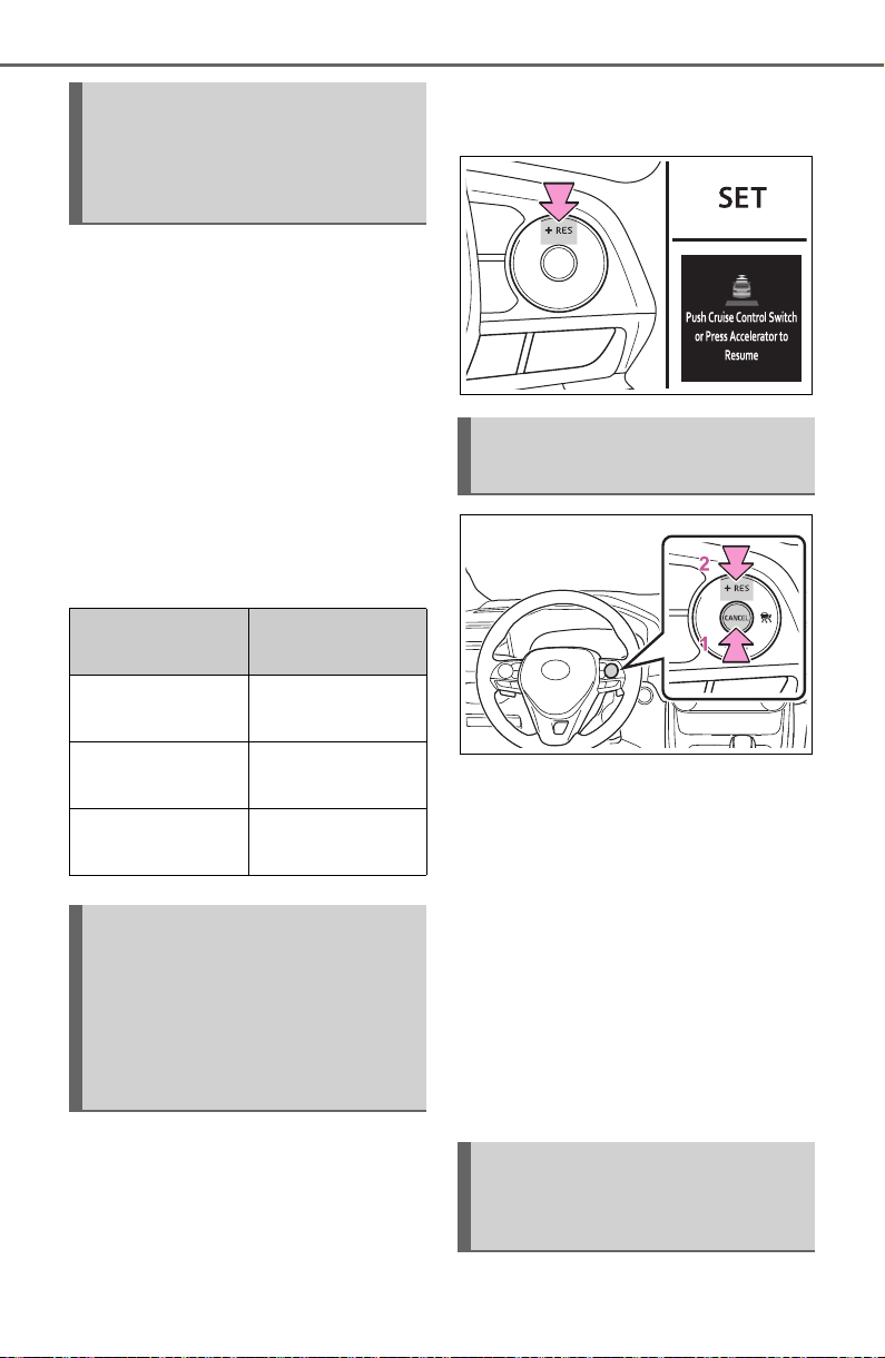
256
4-5. Using the driving support systems
Select a distance from the table
below. Note that the distances
shown correspond to a vehicle
speed of 50 mph (80 km/h).
Vehicle-to-vehicle distance
increases/decreases in accor-
dance with vehicle speed. When
the vehicle is stopped by system
control, the vehicle stops at a
certain vehicle-to-vehicle dis-
tance depending on the situa-
tion.
After the vehicle ahead of you
starts off, press the “+RES”
switch.
Your vehicle will also resume
follow-up cruising if the acceler-
ator pedal is depressed after the
vehicle ahead of you starts off.
1 Pressing the cancel switch
cancels the speed control.
The speed control is also canceled
when the brake pedal is depressed.
(When the vehicle has been
stopped by system control,
depressing the brake pedal does
not cancel the setting.)
2 Pressing the “+RES” switch
resumes the cruise control
and returns vehicle speed to
the set speed.
When your vehicle is too close
Vehicle-to-vehicle dis-
tance settings (vehicle-to-
vehicle distance control
mode)
Distance options
Vehicle-to-vehi-
cle distance
Long
Approximately
160 ft. (50 m)
Medium
Approximately
130 ft. (40 m)
Short
Approximately
100 ft. (30 m)
Resuming follow-up
cruising when the vehicle
has been stopped by sys-
tem control (vehicle-to-
vehicle distance control
mode)
Canceling and resuming
the speed control
Approach warning (vehi-
cle-to-vehicle distance
control mode)
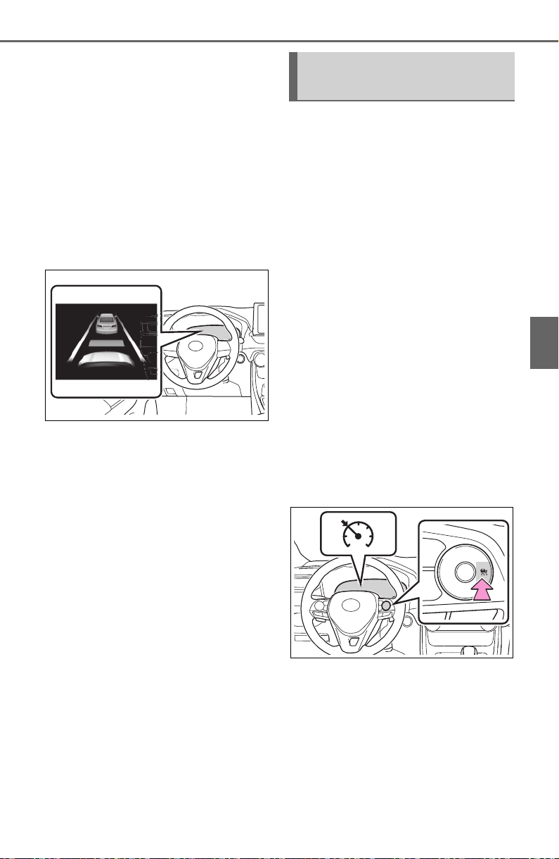
257
4-5. Using the driving support systems
4
Driving
to a vehicle ahead, and suffi-
cient automatic deceleration via
the cruise control is not possi-
ble, the display will flash and the
buzzer will sound to alert the
driver. An example of this would
be if another driver cuts in front
of you while you are following a
vehicle. Depress the brake
pedal to ensure an appropriate
vehicle-to-vehicle distance.
■ Warnings may not occur
when
In the following instances, warn-
ings may not occur even when
the vehicle-to-vehicle distance is
small.
When the speed of the pre-
ceding vehicle matches or
exceeds your vehicle speed
When the preceding vehicle is
traveling at an extremely slow
speed
Immediately after the cruise
control speed was set
When depressing the acceler-
ator pedal
When constant speed control
mode is selected, your vehicle
will maintain a set speed without
controlling the vehicle-to-vehi-
cle distance. Select this mode
only when vehicle-to-vehicle dis-
tance control mode does not
function correctly due to a dirty
radar, etc.
1 With the cruise control off,
press and hold the cruise
control main switch for 1.5
seconds or more.
Immediately after the switch is
pressed, the dynamic radar cruise
control indicator will come on. After-
wards, it switches to the cruise con-
trol indicator.
Switching to constant speed control
mode is only possible when operat-
ing the switch with the cruise con-
trol off.
2 Accelerate or decelerate,
with accelerator pedal opera-
tion, to the desired vehicle
speed (at or above approxi-
mately 20 mph [30 km/h])
and press the “-SET” switch
to set the speed.
Cruise control “SET” indicator will
Selecting constant speed
control mode
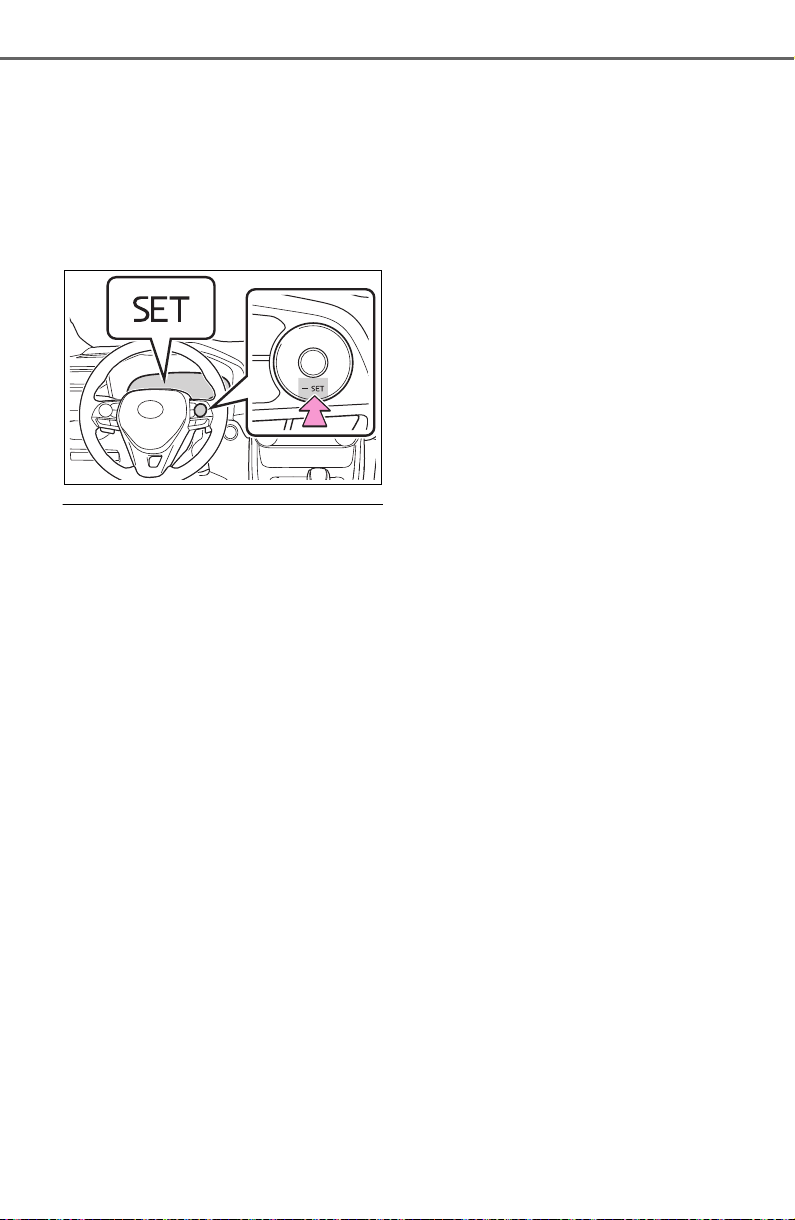
258
4-5. Using the driving support systems
come on.
The vehicle speed at the moment
the switch is released becomes the
set speed.
Adjusting the speed setting:
P.254
Canceling and resuming the speed
setting: P.2 5 6
■ Dynamic radar cruise control
with full-speed range can be set
when
● The shift lever is in D.
● The desired set speed can be set
when the vehicle speed is approx-
imately 20 mph (30 km/h) or more.
(However, when the vehicle speed
is set while driving at below
approximately 20 mph [30 km/h],
the set speed will be set to
approximately 20 mph [30 km/h].)
■ Accelerating after setting the
vehicle speed
The vehicle can accelerate by oper-
ating the accelerator pedal. After
accelerating, the set speed
resumes. However, during vehicle-
to-vehicle distance control mode,
the vehicle speed may decrease
below the set speed in order to
maintain the distance to the preced-
ing vehicle.
■ When the vehicle stops while
follow-up cruising
● Pressing the “+RES” switch while
the vehicle ahead stops will
resume follow-up cruising if the
vehicle ahead starts off within
approximately 3 seconds after the
switch is pressed.
● If the vehicle ahead starts off
within 3 seconds after your vehicle
stops, follow-up cruising will be
resumed.
■ Automatic cancelation of vehi-
cle-to-vehicle distance control
mode
Vehicle-to-vehicle distance control
mode is automatically canceled in
the following situations.
● VSC is activated.
● TRAC is activated for a period of
time.
● When the VSC or TRAC system is
turned off.
● The sensor cannot detect cor-
rectly because it is covered in
some way.
● Pre-collision braking is activated.
● The parking brake is operated.
● The vehicle is stopped by system
control on a steep incline.
● The following are detected when
the vehicle has been stopped by
system control:
• The driver is not wearing a seat
belt.
• The driver’s door is opened.
• The vehicle has been stopped for
about 3 minutes
If vehicle-to-vehicle distance control
mode is automatically canceled for
any reasons other than the above,
there may be a malfunction in the
system. Contact your Toyota dealer.
■ Automatic cancelation of con-
stant speed control mode
Constant speed control mode is
automatically canceled in the follow-
ing situations:
● Actual vehicle speed is more than
approximately 10 mph (16 km/h)
below the set vehicle speed.
● Actual vehicle speed falls below
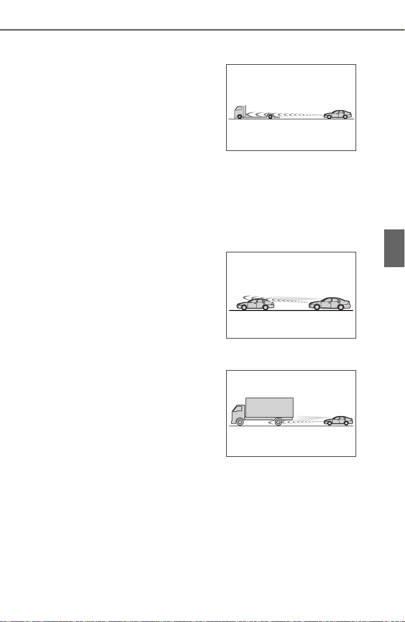
259
4-5. Using the driving support systems
4
Driving
approximately 20 mph (30 km/h).
● VSC is activated.
● TRAC is activated for a period of
time.
● When the VSC or TRAC system is
turned off.
● Pre-collision braking is activated.
If constant speed control mode is
automatically canceled for any rea-
sons other than the above, there
may be a malfunction in the system.
Contact your Toyota dealer.
■ Brake operation
A brake operation sound may be
heard and the brake pedal response
may change, but these are not mal-
functions.
■ Warning messages and buzzers
for dynamic radar cruise con-
trol with full-speed range
Warning messages and buzzers are
used to indicate a system malfunc-
tion or to inform the driver of the
need for caution while driving. If a
warning message is shown on the
multi-information display, read the
message and follow the instructions.
(P.227, 639)
■ When the sensor may not be
correctly detecting the vehicle
ahead
In the case of the following and
depending on the conditions, oper-
ate the brake pedal when decelera-
tion of the system is insufficient or
operate the accelerator pedal when
acceleration is required.
As the sensor may not be able to
correctly detect these types of vehi-
cles, the approach warning
(P.256) may not be activated.
● Vehicles that cut in suddenly
● Vehicles traveling at low speeds
● Vehicles that are not moving in the
same lane
● Vehicles with small rear ends
(trailers with no load on board,
etc.)
● Motorcycles traveling in the same
lane
● When water or snow thrown up by
the surrounding vehicles hinders
the detecting of the sensor
● When your vehicle is pointing
upwards (caused by a heavy load
in the luggage compartment, etc.)
● Preceding vehicle has an
extremely high ground clearance
■ Conditions under which the
vehicle-to-vehicle distance con-
trol mode may not function cor-
rectly
In the case of the following condi-
tions, operate the brake pedal (or
accelerator pedal, depending on the
situation) as necessary.
As the sensor may not be able to
correctly detect vehicles ahead, the
system may not operate properly.
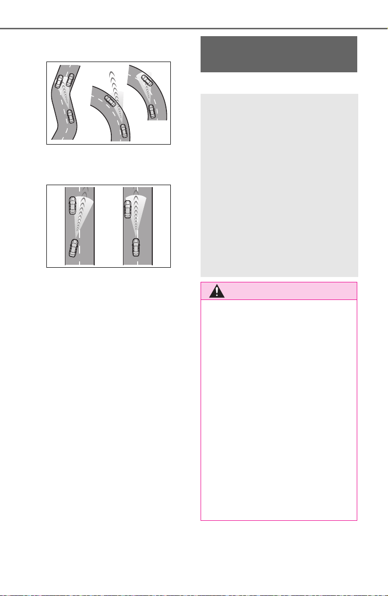
260
4-5. Using the driving support systems
● When the road curves or when the
lanes are narrow
● When steering wheel operation or
your position in the lane is unsta-
ble
● When the vehicle ahead of you
decelerates suddenly
● When driving on a road sur-
rounded by a structure, such as in
a tunnel or on a bridge
● While the vehicle speed is
decreasing to the set speed after
the vehicle accelerates by
depressing the accelerator pedal
*
: If equipped
BSM (Blind Spot Moni-
tor)
*
The Blind Spot Monitor is a
system that has 2 functions:
The BSM (Blind Spot Moni-
tor) function
Assists the driver in making a
decision when changing lanes
The RCTA (Rear Cross
Traffic Alert) function
Assists the driver when back-
ing up
These functions use the
same sensors.
WARNING
■ Cautions regarding the use of
the BSM function
The driver is solely responsible for
safe driving. Always drive safely,
taking care to observe your sur-
roundings.
The BSM function is a supple-
mentary function which alerts the
driver that a vehicle is in a blind
spot of the outside rear view mir-
rors or is approaching rapidly from
behind into a blind spot. Do not
overly rely on the BSM function.
As the function cannot judge if it is
safe to change lanes, over reli-
ance could lead to an accident
resulting in death or serious injury.
As the system may not function
correctly under certain condi-
tions, the driver’s own visual con-
firmation of safety is necessary.
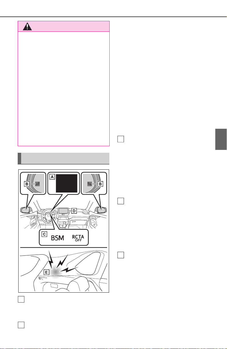
261
4-5. Using the driving support systems
4
Driving
Multi-information display
Turning the BSM function/RCTA
function on/off.
Outside rear view mirror indi-
cators
BSM function:
When a vehicle is detected in a
blind spot of the outside rear view
mirrors or approaching rapidly from
behind into a blind spot, the outside
rear view mirror indicator on the
detected side will illuminate. If the
turn signal lever is operated toward
the detected side, the outside rear
view mirror indicator will flash.
RCTA function:
When a vehicle approaching from
the right or left at the rear of the
vehicle is detected, both outside
rear view mirror indicators will flash.
BSM indicator/RCTA OFF
indicator
When the Blind Spot Monitor is
enabled, the BSM indicator illumi-
nates.
When the RCTA function is dis-
abled, the RCTA OFF indicator illu-
minates.
Monitor screen display
(RCTA function only)
If a vehicle approaching from the
right or left at the rear of the vehicle
is detected, the RCTA icon
(P.267) for the detected side will
be displayed.
RCTA buzzer (RCTA function
only)
If a vehicle approaching from the
right or left at the rear of the vehicle
is detected, a buzzer will sound
from behind the rear seat.
WARNING
■ Cautions regarding the use of
the RCTA function
The driver is solely responsible for
safe driving. Always drive safely,
taking care to observe your sur-
roundings.
The RCTA function is only a sup-
plementary function which alerts
the driver that a vehicle is
approaching from the right or left
at the rear of the vehicle. As the
RCTA function may not function
correctly under certain condi-
tions, the driver’s own visual con-
firmation of safety is necessary.
Over reliance on this function may
lead to an accident resulting
death or serious injury.
System components
A
B
C
D
E

262
4-5. Using the driving support systems
The BSM function and the
RCTA function can be
enabled/disabled on the
screen of the multi-information
display. (P. 94 )
■ Outside rear view mirror indica-
tors visibility
In strong sunlight, the outside rear
view mirror indicator may be difficult
to see.
■ Hearing the RCTA buzzer
The RCTA buzzer may be difficult to
hear over loud noises such as high
audio volume.
■ When “Blind Spot Monitor
Unavailable” or “Rear Cross
Traffic Alert Unavailable” is
shown on the multi-information
display
The sensor voltage has become
abnormal, or water, snow, mud, etc.,
may be built up in the vicinity of the
sensor area of the rear bumper.
(P.263)
Removing the water, snow, mud,
etc., from the vicinity of the sensor
area should return it to normal.
Also, the sensor may not function
normally when used in extremely
hot or cold weather.
■ When “Blind Spot Monitor Sys-
tem Malfunction Visit Your
Dealer” or “Rear Cross Traffic
Alert Malfunction Visit Your
Dealer” is shown on the multi-
information display
There may be a sensor malfunction
or misaligned. Have the vehicle
inspected at a Toyota dealer.
■ Customization
Some functions can be customized.
(P. 94 )
■ Certification for the Blind Spot Monitor
For vehicles sold in the U.S.A., Hawaii, American Samoa, Guam, Saipan
and Puerto Rico
Turning the BSM func-
tion/RCTA function on/off
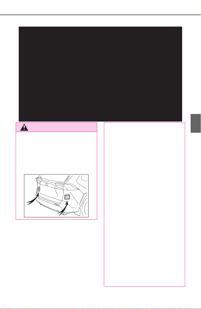
263
4-5. Using the driving support systems
4
Driving
For vehicles sold in Canada
WARNING
■ Handling the radar sensor
Blind Spot Monitor sensors are
installed inside the left and right
sides of the rear bumper respec-
tively. Observe the following to
ensure the Blind Spot Monitor can
function correctly.
● Keep the sensors and the sur-
rounding areas on the rear
bumper clean at all times.
If a sensor or its surrounding
area on the rear bumper is dirty
or covered with snow, the Blind
Spot Monitor may not operate
and a warning message
(P.262) will be displayed. In
this situation, clear off the dirt or
snow and drive the vehicle with
the operation conditions of the
BSM function (P.265) satis-
fied for approximately 10 min-
utes. If the warning message
does not disappear, have the
vehicle inspected by your
Toyota dealer.
● Do not subject a sensor or its
surrounding area on the rear
bumper to a strong impact.
If a sensor is moved even
slightly off position, the system
may malfunction and vehicles
may not be detected correctly.
In the following situations, have
your vehicle inspected by your
Toyota dealer.
• A sensor or its surrounding area
is subject to a strong impact.
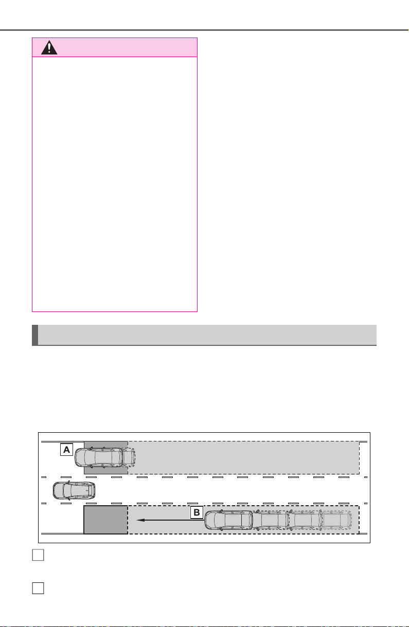
264
4-5. Using the driving support systems
■ Vehicles that can be detected by the Blind Spot Monitor
The BSM function uses radar sensors to detect the following vehi-
cles traveling in adjacent lanes and advises the driver of the pres-
ence of such vehicles via the indicators on the outside rear view
mirrors.
Vehicles that are traveling in areas that are not visible using the
outside rear view mirrors (the blind spots)
Vehicles that are approaching rapidly from behind in areas that
WARNING
• If the surrounding area of a sen-
sor is scratched or dented, or
part of them has become dis-
connected.
● Do not disassemble the sensor.
● Do not attach accessories,
stickers (including transparent
stickers), aluminum tape, etc. to
a sensor or its surrounding area
on the rear bumper.
● Do not modify the sensor or sur-
rounding area on the rear
bumper.
● If a sensor or the rear bumper
needs to be removed/installed
or replaced, contact your Toyota
dealer.
● Do not paint the rear bumper
any color other than an official
Toyota color.
The Blind Spot Monitor function
A
B
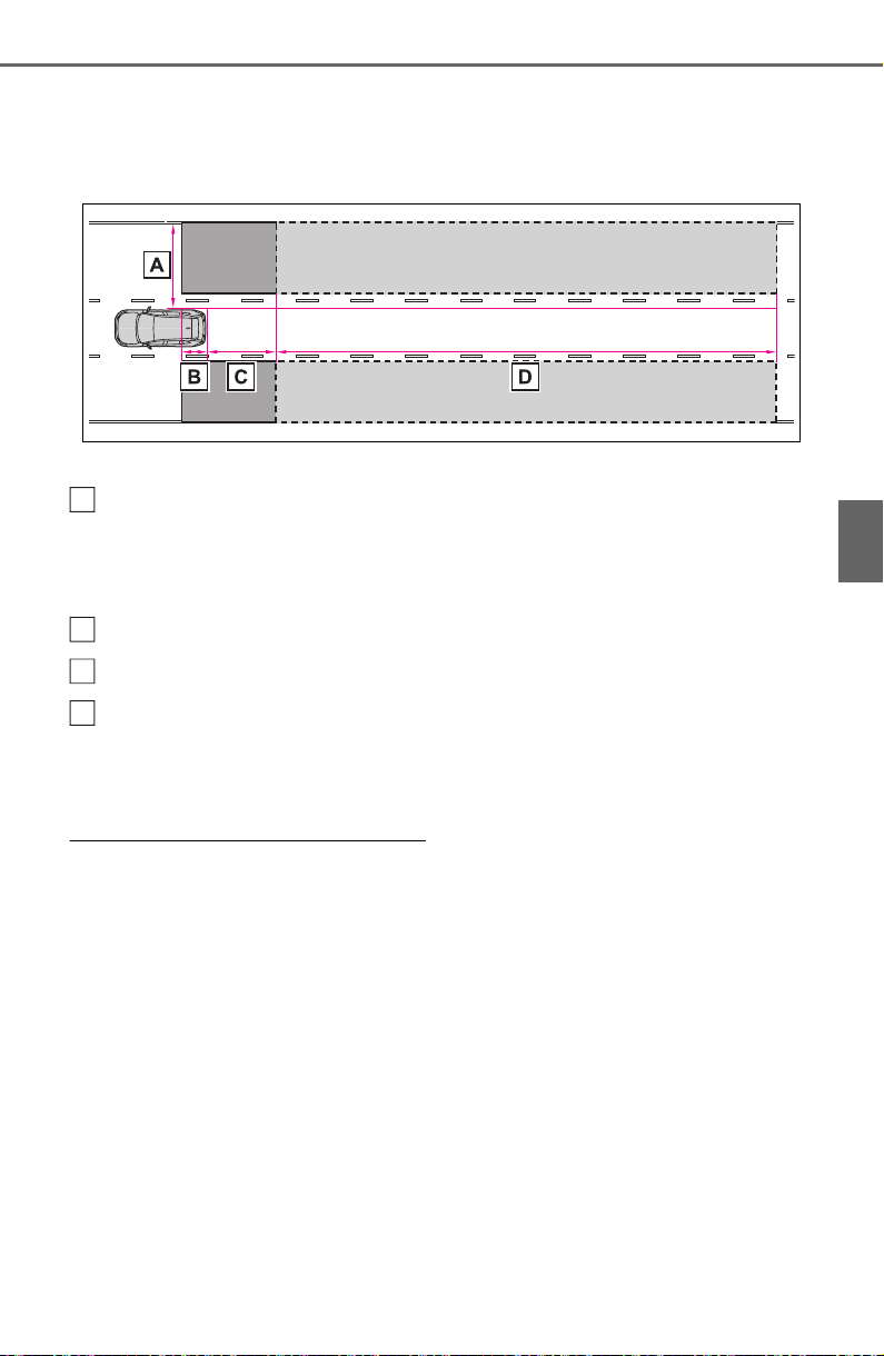
265
4-5. Using the driving support systems
4
Driving
are not visible using the outside rear view mirrors (the blind spots)
■ The BSM function detection areas
The areas that vehicles can be detected in are outlined below.
The range of each detection area is:
Approximately 1.6 ft. (0.5 m) to 11.5 ft. (3.5 m) from either side of
the vehicle
The area between the side of the vehicle and 1.6 ft. (0.5 m) from the side of
the vehicle cannot be detected.
Approximately 3.3 ft. (1 m) forward of the rear bumper
Approximately 9.8 ft. (3 m) from the rear bumper
Approximately 9.8 ft. (3 m) to 197 ft. (60 m) from the rear bumper
The greater the difference in speed between your vehicle and the detected
vehicle is, the farther away the vehicle will be detected, causing the outside
rear view mirror indicator to illuminate or flash.
■ The BSM function is operational
when
The BSM function is operational
when all of the following conditions
are met:
● The BSM function is on.
● The shift lever is in a position
other than R.
● The vehicle speed is greater than
approximately 10 mph (16 km/h).
■ The BSM function will detect a
vehicle when
The BSM function will detect a vehi-
cle present in the detection area in
the following situations:
● A vehicle in an adjacent lane over-
takes your vehicle.
● You overtake a vehicle in an adja-
cent lane slowly.
● Another vehicle enters the detec-
tion area when it changes lanes.
■ Conditions under which the
BSM function will not detect a
vehicle
The BSM function is not designed to
detect the following types of vehi-
cles and/or objects:
● Small motorcycles, bicycles,
pedestrians, etc.
*
● Vehicles traveling in the opposite
direction
● Guardrails, walls, signs, parked
vehicles and similar stationary
A
B
C
D

266
4-5. Using the driving support systems
objects
*
● Following vehicles that are in the
same lane
*
● Vehicles traveling 2 lanes away
from your vehicle
*
● Vehicles which are being over-
taken rapidly by your vehicle
*
: Depending on the conditions,
detection of a vehicle and/or
object may occur.
■ Conditions under which the
BSM function may not function
correctly
● The BSM function may not detect
vehicles correctly in the following
situations:
• When the sensor is misaligned
due to a strong impact to the sen-
sor or its surrounding area
• When mud, snow, ice, a sticker,
etc. is covering the sensor or sur-
rounding area on the rear bumper
• When driving on a road surface
that is wet with standing water
during bad weather, such as
heavy rain, snow, or fog
• When multiple vehicles are
approaching with only a small gap
between each vehicle
• When the distance between your
vehicle and a following vehicle is
short
• When there is a significant differ-
ence in speed between your vehi-
cle and the vehicle that enters the
detection area
• When the difference in speed
between your vehicle and another
vehicle is changing
• When a vehicle enters a detection
area traveling at about the same
speed as your vehicle
• As your vehicle starts from a stop,
a vehicle remains in the detection
area
• When driving up and down con-
secutive steep inclines, such as
hills, dips in the road, etc.
• When driving on roads with sharp
bends, consecutive curves, or
uneven surfaces
• When vehicle lanes are wide, or
when driving on the edge of a
lane, and the vehicle in an adja-
cent lane is far away from your
vehicle
• When an accessory (such as a
bicycle carrier) is installed to the
rear of the vehicle
• When there is a significant differ-
ence in height between your vehi-
cle and the vehicle that enters the
detection area
• Immediately after the BSM func-
tion/RCTA function are turned on
• When towing a trailer
● Instances of the BSM function
unnecessarily detecting a vehicle
and/or object may increase in the
following situations:
• When the sensor is misaligned
due to a strong impact to the sen-
sor or its surrounding area
• When the distance between your
vehicle and a guardrail, wall, etc.
that enters the detection area is
short
• When driving up and down con-
secutive steep inclines, such as
hills, dips in the road, etc.
• When vehicle lanes are narrow, or
when driving on the edge of a
lane, and a vehicle traveling in a
lane other than the adjacent lanes
enters the detection area
• When driving on roads with sharp
bends, consecutive curves, or
uneven surfaces
• When the tires are slipping or
spinning
• When the distance between your
vehicle and a following vehicle is
short
• When an accessory (such as a
bicycle carrier) is installed to the
rear of the vehicle
• When the vehicle throws up water
or snow behind.
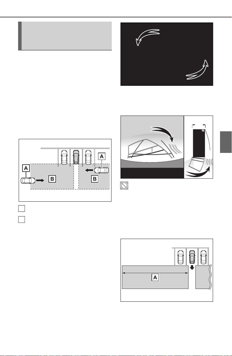
267
4-5. Using the driving support systems
4
Driving
■ Operation of the RCTA
function
The RCTA function uses radar
sensors to detect vehicles
approaching from the right or left
at the rear of the vehicle and
alerts the driver of the presence
of such vehicles by flashing the
outside rear view mirror indica-
tors and sounding a buzzer.
Approaching vehicles
Detection areas
■ RCTA icon display (if
equipped)
When a vehicle approaching
from the right or left at the rear
of the vehicle is detected, the
following will be displayed on
the navigation system (if
equipped) or multimedia sys-
tem (if equipped) screen.
When the Toyota parking
assist monitor (if equipped) is
displayed
When the panoramic view
monitor (if equipped) is dis-
played
: The RCTA function is mal-
functioning (P.262)
■ The RCTA function detec-
tion areas
The areas that vehicles can be
detected in are outlined below.
The buzzer can alert the driver of
faster vehicles approaching from
farther away.
The Rear Cross Traffic
Alert function (if
equipped)
A
B
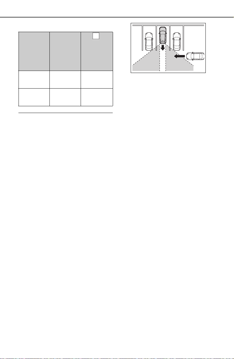
268
4-5. Using the driving support systems
Example:
■ The RCTA function is opera-
tional when
The RCTA function operates when
all of the following conditions are
met:
● The RCTA function is on.
● The shift lever is in R.
● The vehicle speed is less than
approximately 5 mph (8 km/h).
● The approaching vehicle speed is
between approximately 5 mph (8
km/h) and 17 mph (28 km/h).
■ Setting the buzzer volume
The buzzer volume can be adjusted
on the multi-information display.
(P. 9 4 )
■ Conditions under which the
RCTA function will not detect a
vehicle
The RCTA function is not designed
to detect the following types of vehi-
cles and/or objects.
● Vehicles approaching from directly
behind
● Vehicles backing up in a parking
space next to your vehicle
● Vehicles that the sensors cannot
detect due to obstructions
● Guardrails, walls, signs, parked
vehicles and similar stationary
objects
*
● Small motorcycles, bicycles,
pedestrians, etc.
*
● Vehicles moving away from your
vehicle
● Vehicles approaching from the
parking spaces next to your vehi-
cle
*
*
: Depending on conditions, detec-
tion of a vehicle and/or object may
occur.
■ Conditions under which the
RCTA function may not function
correctly
● The RCTA function may not detect
vehicles correctly in the following
situations:
• When the sensor is misaligned
due to a strong impact to the sen-
sor or its surrounding area
• When mud, snow, ice, a sticker,
etc. is covering the sensor or sur-
rounding area on the rear bumper
• When driving on a road surface
that is wet with standing water
during bad weather, such as
heavy rain, snow, or fog
• When multiple vehicles are
approaching with only a small gap
between each vehicle
• When a vehicle is approaching at
high speed
• When parking on a steep incline,
such as hills, a dip in the road, etc.
• When an accessory (such as a
bicycle carrier) is installed to the
rear of the vehicle
• When backing up on a slope with
a sharp change in grade
Approach-
ing vehicle
Speed
Approxi-
mate
alert dis-
tance
Fast
18 mph
(28 km/h)
65 ft. (20
m)
Slow
5 mph (8
km/h)
18 ft. (5.5
m)
A
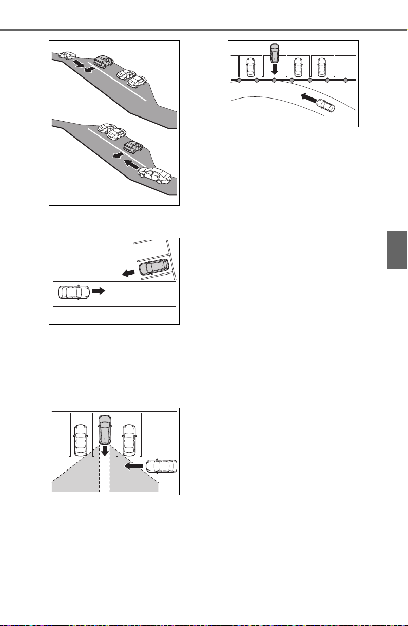
269
4-5. Using the driving support systems
4
Driving
• When backing out of a shallow
angle parking spot
• Immediately after the RCTA func-
tion is turned on
• Immediately after the engine is
started with the RCTA function on
• When towing a trailer
• When the sensors cannot detect a
vehicle due to obstructions
● Instances of the RCTA function
unnecessary detecting a vehicle
and/or object may increase in the
following situations:
• When a vehicle passes by the
side of your vehicle
• When the parking space faces a
street and vehicles are being
driven on the street
• When the distance between your
vehicle and metal objects, such as
a guardrail, wall, sign, or parked
vehicle, which may reflect electri-
cal waves toward the rear of the
vehicle, is short
• When an accessory (such as a
bicycle carrier) is installed to the
rear of the vehicle
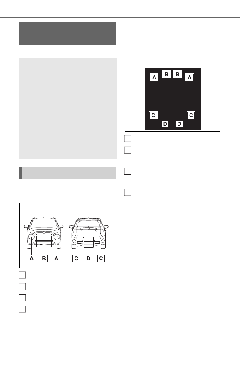
270
4-5. Using the driving support systems
*
: If equipped
■ Location and types of sen-
sors
Front corner sensors
Front center sensors
Rear corner sensors
Rear center sensors
■ Display (Multi-information
display)
When the sensors detect an
object, such as a wall, a graphic
is shown on the multi-informa-
tion display depending on the
position and distance to the
object.
Front corner sensor detection
Front center sensor detec-
tion
*1
Rear corner sensor detec-
tion
*2
Rear center sensor detec-
tion
*2
*1
:Displayed when the shift lever is
in a driving position
*2
:Displayed when the shift lever is
in R
■ Display (Audio system
screen)
When the sensors detect an
object, such as a wall, a graphic
is shown on the navigation sys-
tem (if equipped) or multimedia
system (if equipped) screen
depending on the positionand
distance to the object.
When the Toyota parking
assist monitor (if equipped) is
displayed
Intuitive parking
assist
*
The distance from your
vehicle to objects, such as a
wall, when parallel parking
or maneuvering into a
garage is measured by the
sensors and communicated
via the multi-information
display, navigation system
or multimedia system
screen and a buzzer. Always
check the surrounding area
when using this system.
System components
A
B
C
D
A
B
C
D
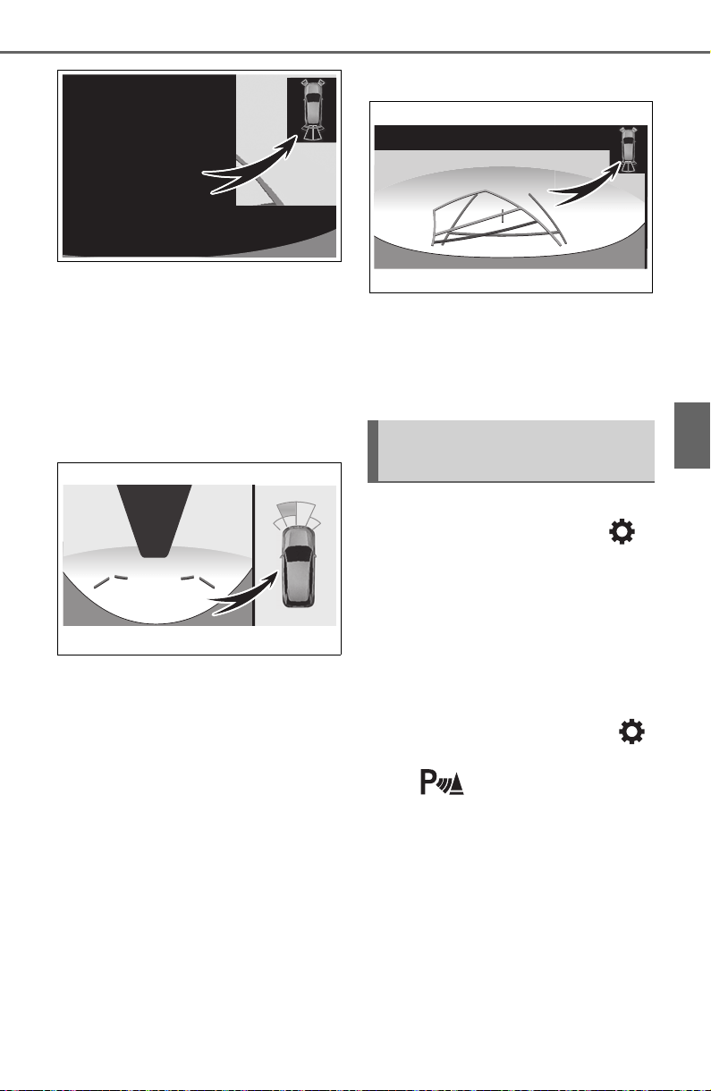
271
4-5. Using the driving support systems
4
Driving
A simplified image is displayed on
the upper corner of the screen
when an obstacle is detected.
When the panoramic view
monitor (if equipped) is dis-
played
Panoramic view
*
A graphic is shown when the
panoramic view monitor is dis-
played.
*
: A simplified image is displayed on
the upper corner of the screen
when an obstacle is detected
while magnified display is shown.
Except panoramic view
A simplified image is displayed
on the upper corner of the
screen when an obstacle is
detected.
The Intuitive parking assist can
be enabled/disabled on the
screen of the multi-information
display. (P.9 4)
When the intuitive parking assist
function is disabled, the intuitive
parking assist OFF indicator
(P.79) illuminates on the multi-
information display.
To re-enable the system, select
on the multi-information display,
select and turn it on.
If the system is disabled, it will
remain off even if the engine switch
is turned to ON after the engine
switch has been turned off.
Turning intuitive parking
assist on/off

272
4-5. Using the driving support systems
WARNING
■ Intuitive parking assist pre-
cautions
Observe the following precau-
tions.
Failing to do so may result in the
vehicle being unable to be driven
safely and possibly cause an acci-
dent.
● Do not use the sensor at
speeds in excess of 6 mph (10
km/h).
● The sensors’ detection areas
and reaction times are limited.
When moving forward or revers-
ing, check the areas surround-
ing the vehicle (especially the
sides of the vehicle) for safety,
and drive slowly, using the
brake to control the vehicle’s
speed.
● Do not install accessories near
the bumpers as those areas are
within the sensors’ detection
areas.
● The area directly under the
bumpers is not detected.
Thin posts or objects lower than
the sensor may not be detected
when approached, even if they
have been detected once.
■ When to disable the function
In the following situations, disable
the function as it may operate
even though there is no possibility
of a collision.
● The vehicle is equipped with a
commercial fender pole, wire-
less antenna or fog lights.
● The front or rear bumper or a
sensor receives a strong
impact.
● A non-genuine Toyota suspen-
sion (lowered suspension, etc.)
is installed.
● Towing eyelets (if equipped) are
installed.
● A backlit license plate is
installed.
■ When using the intuitive park-
ing assist
In the following situations, the
system may not function correctly
due to a sensor malfunction, etc.
Have the vehicle checked by your
Toyota dealer.
● The intuitive parking assist
operation display flashes or
shows continuously, and a
buzzer sounds when no objects
are detected.
● If the area around a sensor col-
lides with something, or is sub-
jected to strong impact.
● If the bumper or grille collides
with something.
● If the display flashes or is dis-
played continuously and a
buzzer does not sound, except
when the mute function has
been turned on.

273
4-5. Using the driving support systems
4
Driving
■ The system can be operated
when
● The engine switch is in ON.
● Intuitive parking assist function is
on.
● The vehicle speed is less than
about 6 mph (10 km/h).
● The shift lever is in a position
other than P.
■ If “Parking Assist Unavailable
Clean Parking Assist Sensor” is
displayed on the multi-informa-
tion display
A sensor may be covered with ice,
snow, dirt, etc. Remove the ice,
snow, dirt, etc., from the sensor to
return the system to normal.
Also, due to ice forming on a sensor
at low temperatures, a warning
message may be displayed or the
sensor may not be able to detect an
object. Once the ice melts, the sys-
tem will return to normal.
If a warning message is displayed
even if the sensor is clean, there
may be a sensor malfunction. Have
the vehicle inspected by your Toyota
dealer.
■ If “Parking Assist Unavailable”
is displayed on the multi-infor-
mation display
● Water may be continuously flow-
ing over the sensor surface, such
as in a heavy rain. When the sys-
tem determines that it is normal,
the system will return to normal.
● Initialization may not have been
performed after a battery terminal
was disconnected and recon-
nected. Initialize the system.
(P.273)
If this message continues to be
displayed even after initialization,
have the vehicle inspected by
your Toyota dealer.
■ If a battery terminal has been
disconnected and reconnected
The system needs to be initialized.
To initialize the system, drive the
vehicle straight ahead for 5 seconds
or more at a speed of approximately
22 mph (35 km/h) or more.
■ Sensor detection information
● The sensor’s detection areas are
limited to the areas around the
vehicle’s front and rear bumpers.
● The following situations may occur
during use.
• Depending on the shape of the
object and other factors, the
detection distance may shorten, or
detection may be impossible.
• Detection may be impossible if
static objects draw too close to the
sensor.
• There will be a short delay
between static object detection
and display (warning buzzer
sounds). Even at low speeds,
there is a possibility that the object
will come within 11.9 in. (30 cm)
before the display is shown and
the warning buzzer sounds.
• It might be difficult to hear the
buzzer due to the volume of the
audio system or air flow noise of
the air conditioning system.
WARNING
■ Notes when washing the vehi-
cle
Do not apply intensive bursts of
water or steam to the sensor
area.
Doing so may result in the sensor
malfunctioning.
● When using a high pressure
washer to wash the vehicle, do
not spray the sensors directly,
as doing so may cause a sensor
to malfunction.
● When using steam to clean the
vehicle, do not direct steam too
close to the sensors as doing so
may cause a sensor to malfunc-
tion.
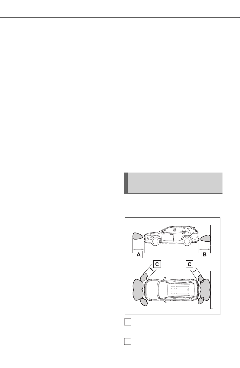
274
4-5. Using the driving support systems
• It may be difficult to hear the
sound of this system due to the
buzzers of other systems.
■ Conditions under which the
function may not function cor-
rectly
Certain vehicle conditions and the
surrounding environment may affect
the ability of a sensor to correctly
detect objects. Particular instances
where this may occur are listed
below.
● There is dirt, snow or ice on a sen-
sor. (Cleaning the sensors will
resolve this problem.)
● A sensor is frozen. (Thawing the
area will resolve this problem.)
In especially cold weather, if a
sensor is frozen the sensor dis-
play may be displayed abnormally,
or objects, such as a wall, may not
be detected.
● A sensor is covered in any way.
● When a sensor or the area around
a sensor is extremely hot or cold.
● On an extremely bumpy road, on
an incline, on gravel, or on grass.
● The vicinity of the vehicle is noisy
due to vehicle horns, motorcycle
engines, air brakes of large vehi-
cles, or other loud noises produc-
ing ultrasonic waves.
● There is another vehicle equipped
with parking assist sensors in the
vicinity.
● A sensor is coated with a sheet of
spray or heavy rain.
● If a sensor is hit by a large amount
of water, such as when driving on
a flooded road.
● If the vehicle is significantly tilted.
● The vehicle is approaching a tall
or curved curb.
● If objects draw too close to the
sensor.
■ Objects which may not be prop-
erly detected
The shape of the object may pre-
vent the sensor from detecting it.
Pay particular attention to the follow-
ing objects:
● Wires, fences, ropes, etc.
● Cotton, snow and other materials
that absorb sound waves
● Sharply-angled objects
● Low objects
● Tall objects with upper sections
projecting outwards in the direc-
tion of your vehicle
People may not be detected if they
are wearing certain types of cloth-
ing.
■ Certification (Canada only)
This ISM device complies with
Canadian ICES-001.
■ Detection range of the sen-
sors
Approximately 3.3 ft. (100
cm)
Approximately 4.9 ft. (150
Sensor detection display,
object distance
A
B
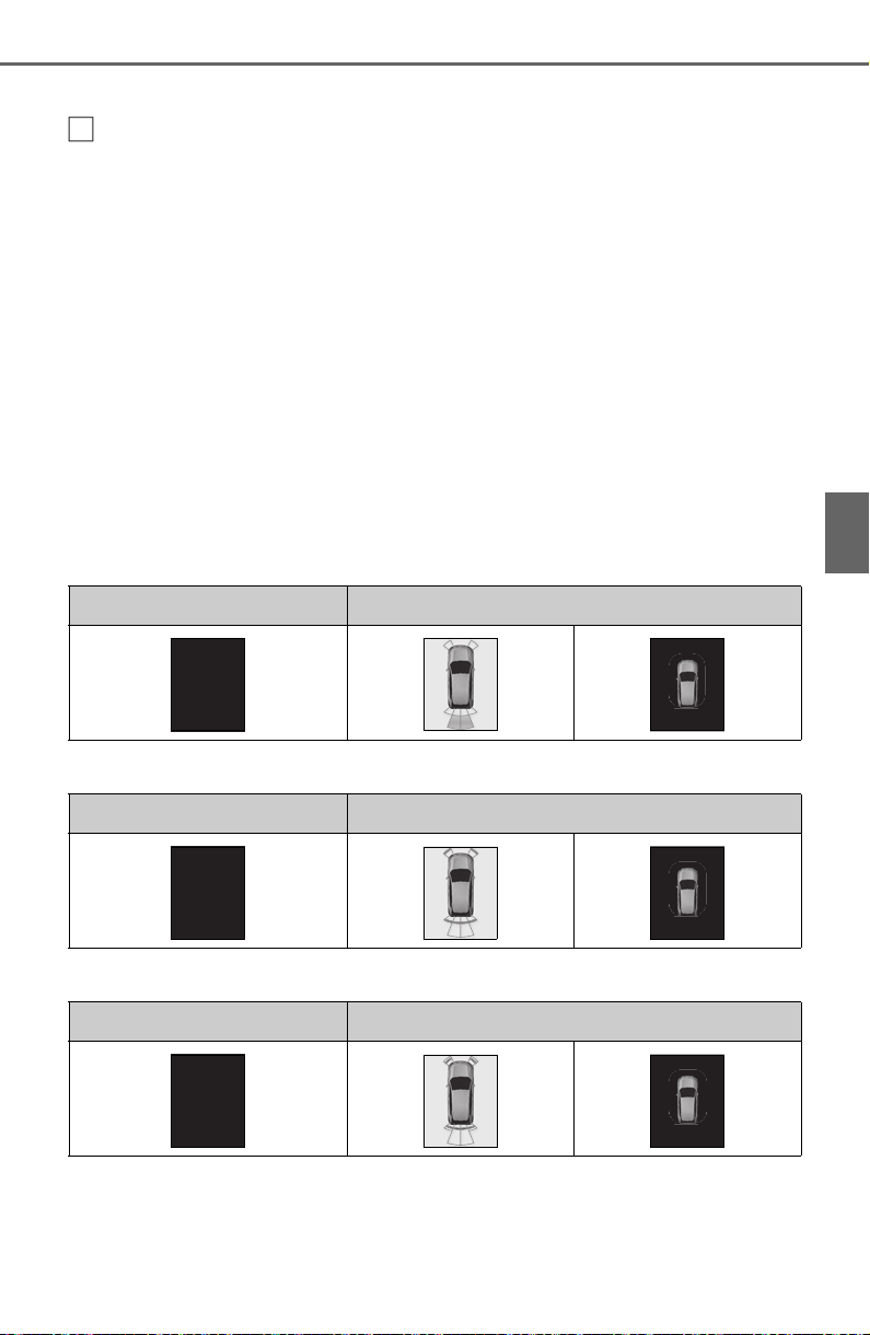
275
4-5. Using the driving support systems
4
Driving
cm)
Approximately 2.1 ft. (63 cm)
The diagram shows the detection
range of the sensors. Note that the
sensors cannot detect objects that
are extremely close to the vehicle.
The range of the sensors may
change depending on the shape of
the object, etc.
■ Distance display
When an object is detected by a sensor, the approximate distance to
the object will be displayed on the multi-information display, naviga-
tion system (if equipped) or multimedia system (if equipped) screen.
(As the distance to the object becomes short, the distance segments
may blink.)
The images may differ from that shown in the illustrations.
Approximate distance to object
• Front center sensor: 3.3 ft. (100 cm) to 2.1 ft. (63 cm)
• Rear center sensor: 4.9 ft. (150 cm) to 2.1 ft. (63 cm)
Approximate distance to object: 2.1 ft. (63 cm) to 1.6 ft. (48 cm)
Approximate distance to object: 1.6 ft. (48 cm) to 1.1 ft. (34 cm)
C
Multi-information display Navigation or multimedia system screen
Multi-information display Navigation or multimedia system screen
Multi-information display Navigation or multimedia system screen
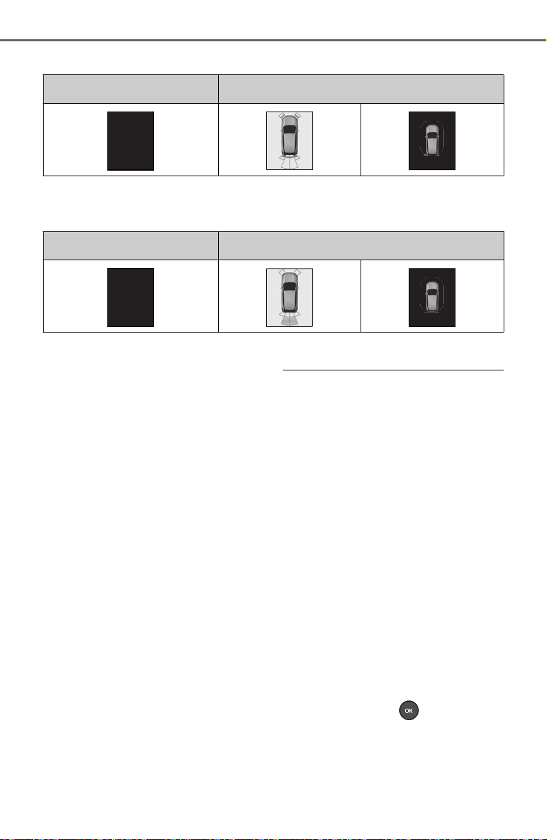
276
4-5. Using the driving support systems
Approximate distance to object: 1.1 ft. (34 cm) to 0.5 ft. (15 cm)
*
: The distance segments will blink slowly.
Approximate distance to object: Less than 0.5 ft. (15 cm)
*
: The distance segments will blink rapidly.
■ Buzzer operation and dis-
tance to an object
A buzzer sounds when the sen-
sors are operating.
The buzzer beeps faster as
the vehicle approaches an
object.
When the vehicle comes
within approximately 1.1 ft.
(34 cm) of the object, the
buzzer sounds continuously.
When 2 or more sensors
simultaneously detect a static
object, the buzzer sounds for
the nearest object.
Even when the sensors are
operating, the buzzer will be
muted in some situations.
(automatic buzzer mute func-
tion)
■ Muting the buzzer sound
● Automatic buzzer mute function
Even when the sensors are operat-
ing, the buzzer will be muted in the
following situations:
• The distance between the vehicle
and the detected object does not
become shorter (except when the
distance between the vehicle and
object is 1.1 ft. [34 cm] or less).
• Your vehicle is moving away from
the object.
• There are no detectable objects
entering the path of your vehicle.
However, if another object is
detected or the situation changes
while the buzzer is muted, the
buzzer begins sounding again.
● To mute the buzzer sound
The buzzer can be temporarily
muted by pressing of the meter
control switches while a suggestion
that says mute is available is shown
on the multi-information display.
● When the mute is canceled
Multi-information display
*
Navigation or multimedia system screen
Multi-information display
*
Navigation or multimedia system screen

277
4-5. Using the driving support systems
4
Driving
Mute will be automatically canceled
in the following situations.
• When the shift position is changed
• When the vehicle speed has
reached or exceeded a certain
speed
• When the Intuitive parking assist
is turned off once and turned on
again
• When the engine switch is turned
off once and turned to ON again
■ Customization
The buzzer volume can be adjusted
on the multi-information display.
(P. 9 4 )
*
: If equipped
■ Parking Support Brake
function (static objects)
P.282
■ Parking Support Brake
function (rear-crossing
vehicles) (if equipped)
P.288
PKSB (Parking Sup-
port Brake)
*
The Parking Support Brake
system consists of the fol-
lowing functions that oper-
ate when driving at a low
speed or backing up, such
as when parking. When the
system determines that the
possibility of a collision
with a detected object is
high, a warning operates to
urge the driver to take eva-
sive action. If the system
determines that the possi-
bility of a collision with a
detected object is extremely
high, the brakes are auto-
matically applied to help
avoid the collision or help
reduce the impact of the col-
lision.
PKSB (Parking Support
Brake) system
278
4-5. Using the driving support systems
The Parking Support Brake can
be enabled/disabled on the
screen of the multi-information
display. All of the Parking Sup-
port Brake functions (static
objects and rear-crossing vehi-
cles) are enabled/disabled
simultaneously. (P. 94 )
When the Parking Support Brake is
disabled, the PKSB OFF indicator
(P.79) illuminates on the multi-
information display.
To re-enable the system, select
on the multi-information display,
select and turn it on.
If the system is disabled, it will
remain off even if the engine switch
is turned to ON after the engine
switch has been turned off.
WARNING
■ Limitations of the Parking
Support Brake system
Do not overly rely on the system,
as doing so may lead to an acci-
dent.
Always drive while checking the
safety of the surroundings of the
vehicle.
Depending on the vehicle and
road conditions, weather, etc., the
system may not operate.
The detection capabilities of sen-
sors and radars are limited.
Always drive while checking the
safety of the surroundings of the
vehicle.
● The driver is solely responsible
for safe driving. Always drive
carefully, taking care to observe
your surroundings. The Parking
Support Brake system is
designed to provide support to
lessen the severity of collisions.
However, it may not operate in
some situations.
● The Parking Support Brake sys-
tem is not designed to stop the
vehicle completely. Additionally,
even if the system has stopped
the vehicle, it is necessary to
depress the brake pedal imme-
diately as brake control will be
canceled after approximately 2
seconds.
NOTICE
■ If “Parking Support Brake
Unavailable” is displayed on
the multi-information display
and the PKSB OFF indicator
is flashing
If this message is displayed
immediately after the engine
switch is changed to ON, operate
the vehicle carefully, paying atten-
tion to your surroundings. It may
be necessary to drive the vehicle
for a certain amount of time
before the system returns to nor-
mal. (If the system does not return
to normal after driving for a while,
clean the sensors and their sur-
rounding area on the bumpers.)
Enabling/Disabling the
Parking Support Brake

279
4-5. Using the driving support systems
4
Driving
If the engine output restriction
control or brake control oper-
ates, a buzzer will sound and a
message will be displayed on
the multi-information display,
navigation system (if equipped)
or multimedia system (if
equipped) screen, to alert the
driver.
Depending on the situation, engine
output restriction control will oper-
ate to either limit acceleration or
restrict output as much as possible.
Engine output restriction con-
trol is operating (acceleration
restriction)
Acceleration greater than a certain
amount is restricted by the system.
Navigation system (if equipped) or
multimedia system (if equipped)
screen: No warning displayed
Multi-information display: “Object
Detected Acceleration Reduced”
PKSB OFF indicator: Not illumi-
nated
Buzzer: Does not sound
Engine output restriction con-
trol is operating (output
restricted as much as possi-
ble)
The system has determined that
stronger-than-normal brake opera-
tion is necessary.
Navigation system (if equipped) or
multimedia system (if equipped)
screen: “BRAKE!”
Multi-information display: “BRAKE!”
PKSB OFF indicator: Not illumi-
nated
Buzzer: Short beep
Brake control is operating
The system determined that emer-
gency braking is necessary.
Navigation system (if equipped) or
multimedia system (if equipped)
screen: “BRAKE!”
Multi-information display: “BRAKE!”
PKSB OFF indicator: Not illumi-
nated
Buzzer: Short beep
Vehicle stopped by system
operation
The vehicle has been stopped by
brake control operation.
Navigation system (if equipped) or
multimedia system (if equipped)
screen: “Press Brake Pedal”
Multi-information display: “Switch to
Brake” (If the accelerator pedal is
not depressed, “Brake” will be dis-
played.)
PKSB OFF indicator: Illuminated
Buzzer: Short beep
If the Parking Support Brake
determines that a collision with a
detected object is possible, the
engine output will be restricted
to restrain any increase in the
vehicle speed. (Engine output
restriction control: See figure 2.)
Display and buzzer for
engine output restriction
control and brake control
System overview
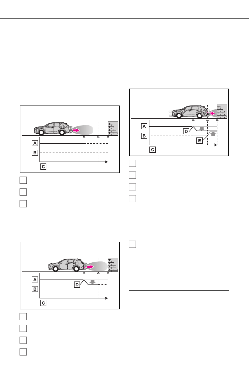
280
4-5. Using the driving support systems
Additionally, if the accelerator
pedal continues to be
depressed, the brakes will be
applied automatically to reduce
the vehicle speed. (Brake con-
trol: See figure 3.)
Figure 1: When the PKSB
(Parking Support Brake) is not
operating
Engine output
Braking force
Time
Figure 2: When engine out-
put restriction control oper-
ates
Engine output
Braking force
Time
Engine output restriction con-
trol begins operating (System
determines that possibility of
collision with detected object
is high)
Figure 3: When engine out-
put restriction control and
brake control operates
Engine output
Braking force
Time
Engine output restriction con-
trol begins operating (System
determines that possibility of
collision with detected object
is high)
Brake control begins operat-
ing (System determines that
possibility of collision with
detected object is extremely
high)
■ If the Parking Support Brake
has operated
If the vehicle is stopped due to oper-
ation of the Parking Support Brake,
the Parking Support Brake will be
disabled and the PKSB OFF indica-
tor will illuminate. If the Parking Sup-
port Brake operates unnecessarily,
brake control can be canceled by
depressing the brake pedal or wait-
A
B
C
A
B
C
D
A
B
C
D
E

281
4-5. Using the driving support systems
4
Driving
ing for approximately 2 seconds for
it to automatically be canceled.
Then, the vehicle can be operated
by depressing the accelerator pedal.
■ Re-enabling the Parking Sup-
port Brake
To re-enable the Parking Support
Brake when it is disabled due to
operation of the Parking Support
Brake, either enable the system
again (P.278), or turn the engine
switch off and then back to ON.
Additionally, if the object becomes
no longer in the traveling direction of
the vehicle or if the traveling direc-
tion of the vehicle changes (such as
changing from moving forward to
backing up, or from backing up to
moving forward), the system will be
re-enabled automatically.
■ If “Parking Support Brake
Unavailable” is displayed on
the multi-information display
and the PKSB OFF indicator is
flashing
● If this message is displayed, a
sensor on the front or rear bumper
may be dirty. Clean the sensors
and their surrounding area on the
bumpers.
● Initialization may not have been
performed after a battery terminal
was disconnected and recon-
nected. Initialize the system.
(P.281)
If this message continues to be
displayed even after initialization,
have the vehicle inspected by
your Toyota dealer.
■ If “Parking Support Brake
Unavailable” and “Parking
Assist Unavailable Clean Park-
ing Assist Sensor” are dis-
played on the multi-information
display and the PKSB OFF indi-
cator is flashing
● A sensor may be covered with ice,
snow, dirt, etc. In this case,
remove the ice, snow, dirt, etc.,
from the sensor to return the sys-
tem to normal. If this message is
shown even after removing dirt
from the sensor, or shown when
the sensor was not dirty to begin
with, have the vehicle inspected at
your Toyota dealer.
● A sensor may be frozen. Once the
ice melts, the system will return to
normal.
● Water may be continuously flow-
ing over the sensor surface, such
as in a heavy rain. When the sys-
tem determines that it is normal,
the system will return to normal.
■ If a battery terminal has been
disconnected and reconnected
The system needs to be initialized.
To initialize the system, drive the
vehicle straight ahead for 5 seconds
or more at a speed of approximately
22 mph (35 km/h) or more.
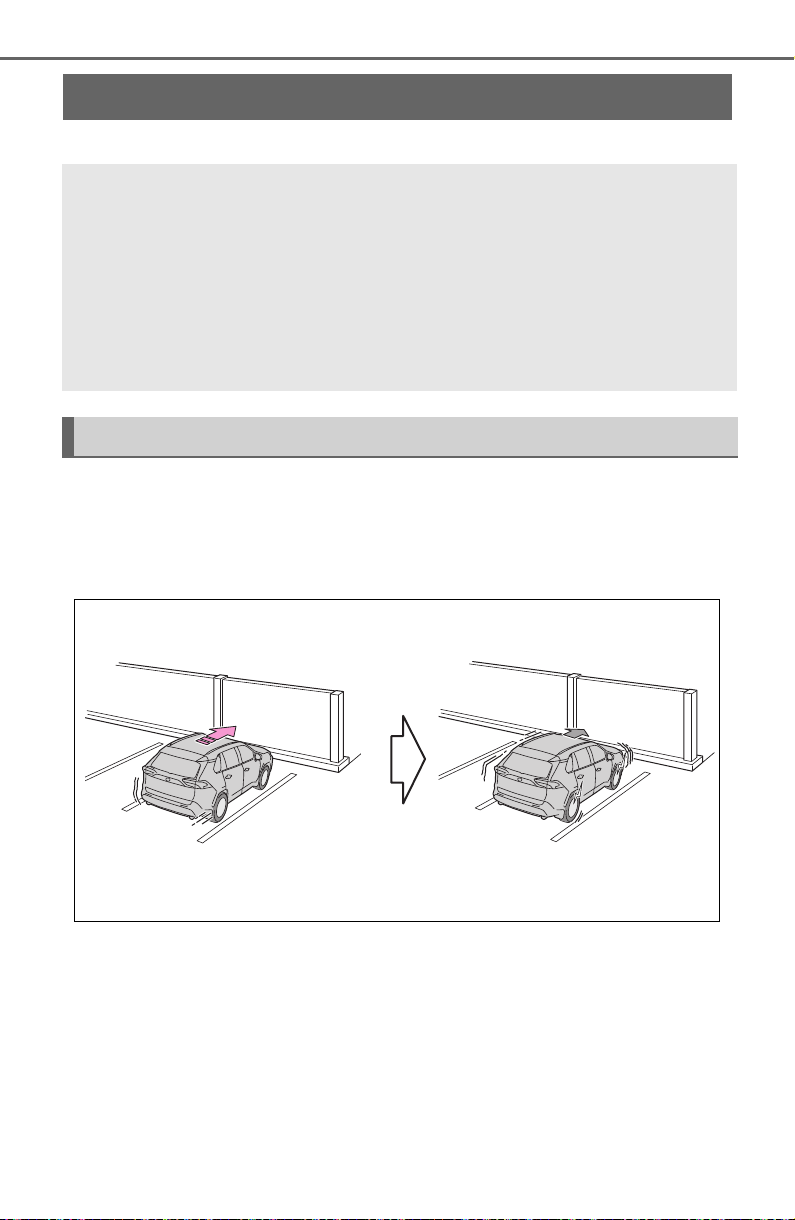
282
4-5. Using the driving support systems
*
: If equipped
This function will operate in situations such as the following if an
object is detected in the traveling direction of the vehicle.
■ When traveling at a low speed and the brake pedal is not
depressed, or is depressed late
Parking Support Brake function (static objects)
*
If the sensors detect a static object, such as a wall, in the trav-
eling direction of the vehicle and the system determines that a
collision may occur due to the vehicle suddenly moving for-
ward due to an accidental accelerator pedal operation, the
vehicle moving the unintended direction due to the wrong
shift position being selected, or while parking or traveling at
low speeds, the system will operate to lessen the impact with
the detected static object and reduce the resulting damage.
Examples of function operation
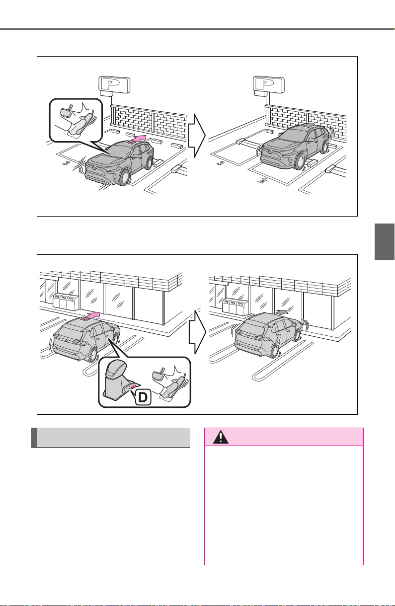
283
4-5. Using the driving support systems
4
Driving
■ When the accelerator pedal is depressed excessively
■ When the vehicle moves in the unintended direction due to
the wrong shift position being selected
P. 2 70
Types of sensors
WARNING
■ To ensure the Parking Sup-
port Brake can operate prop-
erly
Observe the following precautions
regarding the sensors (P.270).
Failure to do so may cause a sen-
sor to not operate properly, and
may cause an accident.
● Do not modify, disassemble or
paint the sensors.

284
4-5. Using the driving support systems
WARNING
● Do not replace a sensor with a
part other than a genuine part.
● Do not subject a sensor or its
surrounding area to a strong
impact.
● Do not damage the sensors,
and always keep them clean.
● If the area around a radar sen-
sor is subjected to an impact,
the system may not operate
properly due to a sensor mal-
function. Have the vehicle
inspected by your Toyota
dealer.
■ Handling the suspension
Do not modify the suspension, as
changes to the height or inclina-
tion of the vehicle may prevent
the sensors from detecting
objects correctly or cause the sys-
tem to not operate or operate
unnecessarily.
■ If the Parking Support Brake
function (static objects) oper-
ates unnecessarily, such as
at a railroad crossing
In the event that the Parking Sup-
port Brake function (static objects)
operates unnecessarily, such as
at a railroad crossing, brake con-
trol will be canceled after approxi-
mately 2 seconds, allowing you to
proceed forward and leave the
area, brake control can also be
canceled by depressing the brake
pedal. Depressing the accelera-
tor pedal after brake control is
canceled will allow you to proceed
forward and leave the area.
■ Notes when washing the vehi-
cle
Do not apply intensive bursts of
water or steam to the sensor
area.
Doing so may result in the sensor
malfunctioning.
● When using a high pressure
washer to wash the vehicle, do
not spray the sensors directly,
as doing so may cause a sensor
to malfunction.
● When using steam to clean the
vehicle, do not direct steam too
close to the sensors as doing so
may cause a sensor to malfunc-
tion.
■ When to disable the Parking
Support Brake
In the following situations, disable
the Parking Support Brake as the
system may operate even though
there is no possibility of a colli-
sion.
● When inspecting the vehicle
using a chassis roller, chassis
dynamo or free roller
● When loading the vehicle onto a
boat, truck or other transport
vessel
● If the suspension has been
modified or tires of a size other
than specified are installed
● If the front of the vehicle is
raised or lowered due to the
carried load
● When equipment that may
obstruct a sensor is installed,
such as a towing eyelet, bumper
protector (an additional trim
strip, etc.), bicycle carrier, or
snow plow
● When using an automatic car
wash

285
4-5. Using the driving support systems
4
Driving
■ The Parking Support Brake
function (static object) will
operate when
The function will operate when the
PKSB OFF indicator is not illumi-
nated or flashing (P.77, 79) and all
of the following conditions are met:
● Engine output restriction control
• The Parking Support Brake is
enabled.
• The vehicle speed is 9 mph (15
km/h) or less.
• There is a static object in the trav-
eling direction of the vehicle and 6
to 13 ft. (2 to 4 m) away.
• The Parking Support Brake deter-
mines that a stronger-than-nor-
mal brake operation is necessary
to avoid a collision.
● Brake control
• Engine output restriction control is
operating
• The Parking Support Brake deter-
mines that an immediate brake
operation is necessary to avoid a
collision.
■ The Parking Support Brake
function (static objects) will
stop operating when
The function will stop operating if
any of the following conditions are
met:
● Engine output restriction control
• The Parking Support Brake is dis-
abled.
• The system determines that the
collision has become avoidable
with normal brake operation.
• The static object is no longer 6 to
13 ft. (2 to 4 m) away from the
vehicle or in the traveling direction
of the vehicle.
● Brake control
• The Parking Support Brake is dis-
abled.
• Approximately 2 seconds have
elapsed since the vehicle was
stopped by brake control.
• The brake pedal is depressed
after the vehicle is stopped by
brake control.
• The static object is no longer 6 to
13 ft. (2 to 4 m) away from the
vehicle or in the traveling direction
of the vehicle.
■ Detection range of the Parking
Support Brake function (static
objects)
The detection range of the Parking
Support Brake function (static
objects) differs from the detection
range of the intuitive parking assist.
(P.274) Therefore, even if the intu-
itive parking assist detects an object
and provides a warning, the Parking
Support Brake function (static
objects) may not start operating.
■ Objects that the Parking Sup-
port Brake function (static
objects) may not detect
The sensors may not be able to
detect certain objects, such as the
following:
● Pedestrian
● Cotton, snow, and other materials
that are poor reflectors of sonic
waves
● Objects which are not perpendicu-
lar to the ground, are not perpen-
dicular to the traveling direction of
the vehicle, are uneven or are
waving
● Low objects
● Thin objects such as wires,
fences, ropes and signposts
● Objects that are extremely close
to the bumper
● Sharply-angled objects
● Tall objects with upper sections
projecting outwards in the direc-
tion of your vehicle
■ Situations in which the Parking
Support Brake function (static
objects) may not operate
When the shift lever is in N
■ Intuitive parking assist buzzer
Regardless of whether the intuitive
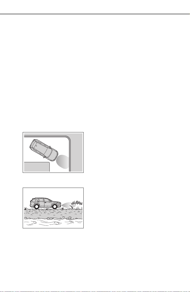
286
4-5. Using the driving support systems
parking assist system is enabled or
not (P.271), if the Parking Support
Brake function (static objects) is
enabled (P.278), the front or rear
sensors detect an object and brake
control and engine output restric-
tion control are performed, the intui-
tive parking assist buzzer will sound
to notify the driver of the approxi-
mate distance to the object.
■ Situations in which the Parking
Support Brake function (static
objects) may operate even if
there is no possibility of a colli-
sion
In some situations, such as the fol-
lowing, the Parking Support Brake
function (static objects) may operate
even though there is no possibility of
a collision.
● Vehicle surroundings
• When driving on a narrow road
• When driving on a gravel road or
in an area with tall grass
• When driving toward a banner,
flag, low-hanging branch or boom
barrier (such as those used at rail-
road crossings, toll gates and
parking lots)
• When there is a structure on the
roadside (such as when driving in
a narrow tunnel, on a narrow
bridge or on a narrow road)
• When parallel parking
• When there is a rut or hole in the
surface of the road
• When driving on a metal cover
(grating), such as those used for
drainage ditches
• When driving up or down a steep
slope
• If a sensor is hit by a large amount
of water, such as when driving on
a flooded road
• When loaded on ships or trucks
• Moving type automatic car wash
• Lift type parking area or multi-
story parking lot
• Underground parking area
• Structures on the ground (speed
bumps, cat’s eyes, etc.)
• Differences in height
• When moving straight ahead or
turning right
• Snow-melting pipes
• Devices for detecting vehicles,
such as traffic lights, devices for
detecting traffic congestion, or
devices for detecting empty
spaces in parking areas
• Railroad tracks
• H-shaped steel
• When there are vehicles on both
sides, or there is a vehicle that
resembles this vehicle
● Weather
• If a sensor is covered with ice,
snow, dirt, etc. (when cleared, the
system will return to normal)
• If heavy rain or water strikes a
sensor
• When driving in inclement weather
such as fog, snow or a sandstorm
• Strong wind is blowing
● Other sonic wave sources
• When vehicle horns, vehicle
detectors, motorcycle engines, air
brakes of large vehicles, the clear-
ance sonar of other vehicles or
other devices which produce ultra-
sonic waves are near the vehicle
• If a sticker or an electronic compo-
nent, such as a backlit license
plate (especially fluorescent type),
fog lights, fender pole or wireless
antenna is installed near a sensor
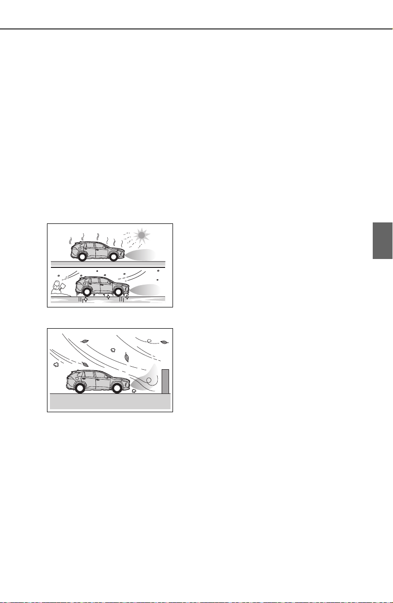
287
4-5. Using the driving support systems
4
Driving
● Changes in the vehicle posture
• If the vehicle is significantly tilted
• If the front of the vehicle is raised
or lowered due to the carried load
• If the orientation of a sensor has
been changed due to a collision or
other impact
■ Situations in which the Parking
Support Brake function (static
objects) may not operate prop-
erly
In some situations, such as the fol-
lowing, this function may not oper-
ate properly.
● Weather
• When a sensor or the area around
a sensor is extremely hot or cold
• When strong winds are blowing
• If a sensor is covered with ice,
snow, dirt, etc. (when cleared, the
system will return to normal)
• If heavy rain or water strikes a
sensor
• When driving in inclement weather
such as fog, snow or a sandstorm
• A sensor is frozen. (Thawing the
area will resolve this problem.)
● Vehicle surroundings
• When an object that cannot be
detected is between the vehicle
and a detected object
• If an object such as a vehicle,
motorcycle, bicycle or pedestrian
cuts in front of the vehicle or runs
out from the side of the vehicle
• The vehicle is approaching a tall
or curved curb.
• On an extremely bumpy road, on
an incline, on gravel, or on grass.
• The objects draw too close to the
sensor.
● Other sonic waves sources
• When vehicle horns, vehicle
detectors, motorcycle engines, air
brakes of large vehicles, the clear-
ance sonar of other vehicles or
other devices which produce ultra-
sonic waves are near the vehicle
• If a sticker or an electronic compo-
nent, such as a backlit license
plate (especially fluorescent type),
fog lights, fender pole or wireless
antenna is installed near a sensor
● Changes in the vehicle
• If the vehicle is significantly tilted
• If the front of the vehicle is raised
or lowered due to the carried load
• If the orientation of a sensor has
been changed due to a collision or
other impact
• When equipment that may
obstruct a sensor is installed, such
as a towing eyelet, bumper pro-
tector (an additional trim strip,
etc.), bicycle carrier, or snow plow
• If the suspension has been modi-
fied or tires of a size other than
specified are installed
• If paint or a sticker is applied to
the sensor

288
4-5. Using the driving support systems
*
: If equipped
This function will operate in situations such as the following if a vehi-
cle is detected in the traveling direction of the vehicle.
■ When reversing, a vehicle is approaching and the brake pedal
is not depressed, or is depressed late
P. 2 63
Parking Support Brake function (rear-crossing
vehicles)
*
If a rear radar sensor detects a vehicle approaching from the
right or left at the rear of the vehicle and the system deter-
mines that the possibility of a collision is high, this function
will perform brake control to reduce the likelihood of an
impact with the approaching vehicle.
Examples of function operation
Types of sensors
WARNING
■ To ensure the Parking Sup-
port Brake (rear-crossing
vehicles) can operate prop-
erly
Observe the following precautions
regarding the rear radar sensors
(P.263). Failure to do so may
cause a sensor to not operate
properly, and may cause an acci-
dent.

289
4-5. Using the driving support systems
4
Driving
■ The Parking Support Brake
function (rear-crossing vehi-
cles) will operate when
The function will operate when the
PKSB OFF indicator is not illumi-
nated or flashing (P.77, 79) and all
of the following conditions are met:
● Engine output restriction control
• The Parking Support Brake is
enabled.
• The vehicle speed is 9 mph (15
km/h) or less.
• Vehicles are approaching from the
right or left at the rear of the vehi-
cle at a traveling speed of less
than approximately 5 mph (8
km/h)
• The shift lever is in R.
• The Parking Support Brake deter-
mines that a stronger than normal
brake operation is necessary to
avoid a collision with an approach-
ing vehicle.
● Brake control
• Engine output restriction control is
operating
• The Parking Support Brake deter-
mines that an emergency brake
operation is necessary to avoid a
collision with an approaching vehi-
cle.
■ The Parking Support Brake
function (rear-crossing vehi-
cles) will stop operating when
The function will stop operating if
any of the following conditions are
met:
● Engine output restriction control
• The Parking Support Brake is dis-
abled.
• The collision becomes avoidable
with normal brake operation.
• A vehicle is no longer approaching
from the right or left at the rear of
the vehicle.
● Brake control
• The Parking Support Brake is dis-
abled.
• Approximately 2 seconds have
elapsed since the vehicle was
stopped by brake control.
• The brake pedal is depressed
after the vehicle is stopped by
brake control.
• A vehicle is no longer approaching
from the right or left at the rear of
the vehicle.
■ Detection area of the Parking
Support Brake function (rear-
crossing vehicles)
The detection area of the Parking
Support Brake function (rear-cross-
ing vehicles) differs from the detec-
tion area of the RCTA function
(P.267). Therefore, even if the
RCTA function detects a vehicle and
provides an alert, the Parking Sup-
port Brake function (rear-crossing
vehicles) may not start operating.
■ Conditions under which the
Parking Support Brake func-
tion (rear-crossing vehicles)
will not detect a vehicle
The Parking Support Brake function
(rear-crossing vehicles) is not
designed to detect the following
WARNING
● Do not modify, disassemble or
paint the sensors.
● Do not replace a rear radar sen-
sor with a part other than a gen-
uine part.
● Do not damage the rear radar
sensors, and always keep the
radar sensors and their sur-
rounding area on the bumper
clean.
● If the area around a rear radar
sensor is subjected to an
impact, the system may not
operate properly due to a sen-
sor malfunction. Have the vehi-
cle inspected by your Toyota
dealer.
● Observe the rear radar sensor
handling precautions. (P.263)
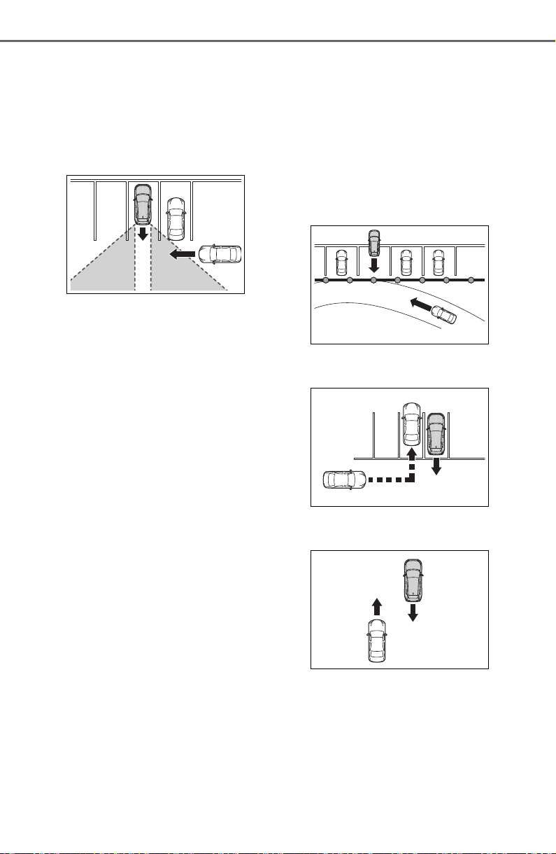
290
4-5. Using the driving support systems
types of vehicles and/or objects:
● Vehicles approaching from directly
behind
● Vehicles backing up in a parking
space next to your vehicle
● Vehicles that the sensors cannot
detect due to obstructions
● Vehicles which suddenly acceler-
ate or decelerate near your vehi-
cle
● Guardrails, walls, signs, parked
vehicles and similar stationary
objects
*
● Small motorcycles, bicycles,
pedestrians, etc.
*
● Vehicles moving away from your
vehicle
● Vehicles approaching from the
parking spaces next to your vehi-
cle
*
● Objects which are extremely close
to a radar sensor
*
● Vehicles which are approaching
from the right or left at the rear of
the vehicle at a traveling speed of
less than approximately 5 mph (8
km/h)
● Vehicles which are approaching
from the right or left at the rear of
the vehicle at a traveling speed of
more than approximately 15 mph
(24 km/h)
*
: Depending on the conditions,
detection of a vehicle and/or
object may occur.
■ Situations in which the system
may operate even though there
is no possibility of a collision
In some situations such as the fol-
lowing, the Parking Support Brake
function (rear-crossing vehicles)
may operate even though there is
no possibility of a collision.
● When the parking space faces a
street and vehicles are being
driven on the street
● When a detected vehicle turns
while approaching the vehicle
● When a vehicle passes by the
side of your vehicle
● When the distance between your
vehicle and metal objects, such as
a guardrail, wall, sign, or parked
vehicle, which may reflect electri-
cal waves toward the rear of the
vehicle, is short
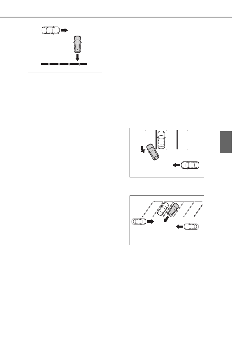
291
4-5. Using the driving support systems
4
Driving
● When there are spinning objects
near your vehicle such as the fan
of an air conditioning unit
● When water is splashed or
sprayed toward the rear bumper,
such as from a sprinkler
■ Situations in which the Parking
Support Brake function (rear-
crossing vehicles) may not
operate properly
In some situations, such as the fol-
lowing, the radar sensors may not
detect an object and this function
may not operate properly
● Stationary objects
● When a sensor or the area around
a sensor is extremely hot or cold
● If the rear bumper is covered with
ice, snow, dirt, etc.
● When it is raining heavily or water
strikes the vehicle
● When the detection area of a
radar sensor is obstructed by an
adjacent vehicle
● If the vehicle is significantly tilted
● When equipment that may
obstruct a sensor is installed, such
as a towing eyelet, bumper pro-
tector (an additional trim strip,
etc.), bicycle carrier, or snow plow
● If the suspension has been modi-
fied or tires of a size other than
specified are installed
● If the front of the vehicle is raised
or lowered due to the carried load
● If a sticker or an electronic compo-
nent, such as a backlit license
plate (especially fluorescent type),
fog lights, fender pole or wireless
antenna is installed near a radar
sensor
● If the orientation of a radar sensor
has been changed
● When multiple vehicles are
approaching with only a small gap
between each vehicle
● If a vehicle is approaching the rear
of your vehicle rapidly
● Situations in which the radar sen-
sor may not detect a vehicle
• When a vehicle approaches from
the right or left at the rear of the
vehicle while you are turning while
backing up
• When turning while backing up
• When backing out of a shallow
angle parking spot
• When backing up on a slope with
a sharp change in grade
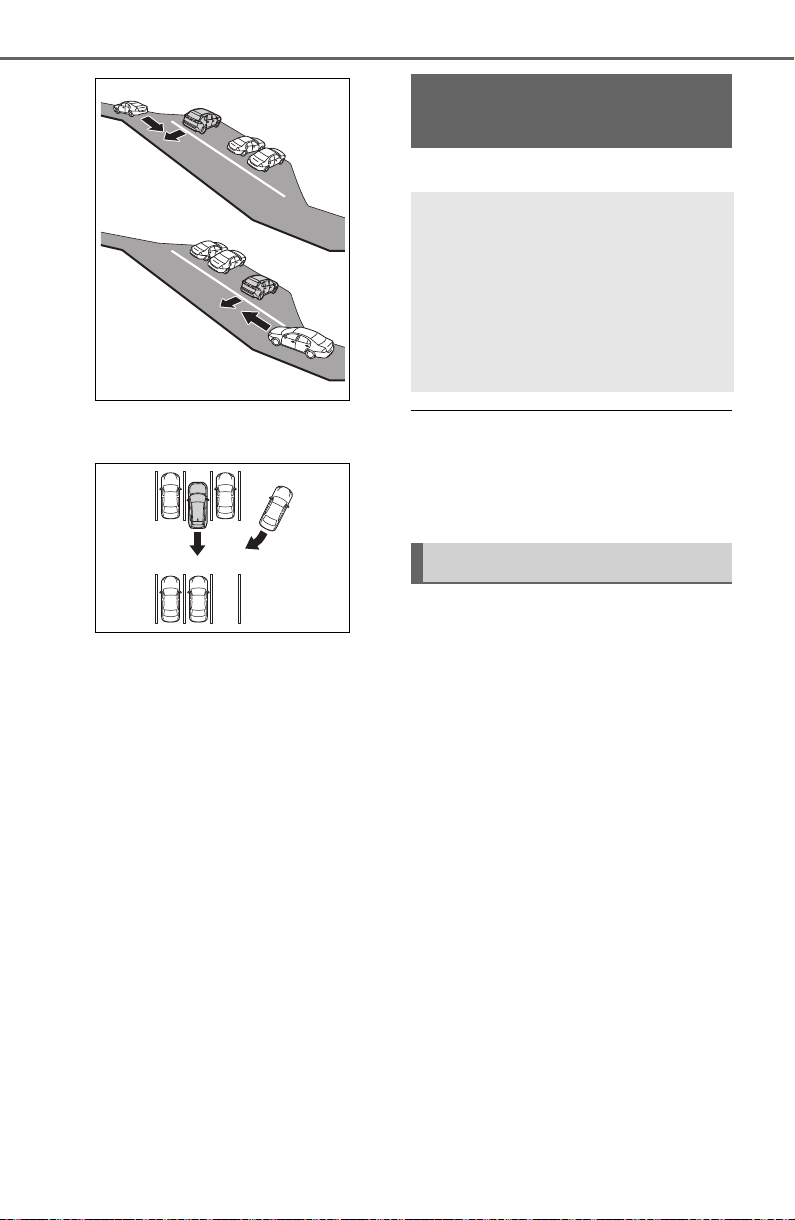
292
4-5. Using the driving support systems
• When a vehicle turns into the
detection area
*
: If equipped
● The screen illustrations used in
this text are intended as exam-
ples, and may differ from the
image that is actually displayed on
the screen.
The rear view monitor system is
a supplemental device intended
to assist the driver when back-
ing up. When backing up, be
sure to visually check all around
the vehicle both directly and
using the mirrors before pro-
ceeding. If you do not, you may
hit another vehicle, and could
possibly cause an accident.
Pay attention to the following
precautions when using the rear
view monitor system.
Rear view monitor sys-
tem
*
The rear view monitor sys-
tem assists the driver by
displaying an image of the
view behind the vehicle with
fixed guide lines on the
screen while backing up, for
example while parking.
Driving precautions
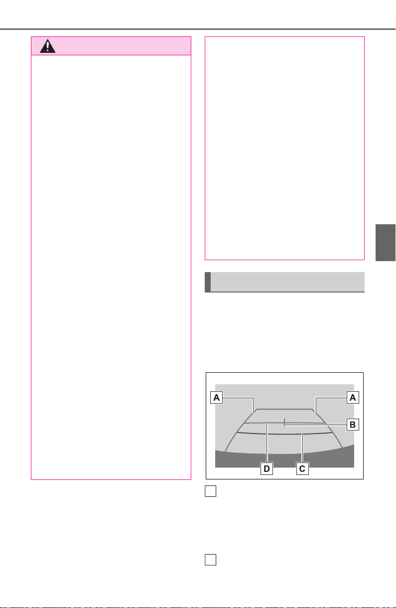
293
4-5. Using the driving support systems
4
Driving
The rear view monitor system
screen will be displayed if the
shift lever is shifted to the “R”
position while the engine switch
is in ON.
Vehicle width guide line
Displays a guide path when the
vehicle is being backed straight up.
• The displayed width is wider than
the actual vehicle width.
Vehicle center guide line
WARNING
● Never depend on the rear view
monitor system entirely when
backing up. The image and the
position of the guide lines dis-
played on the screen may differ
from the actual state.
Use caution, just as you would
when backing up any vehicle.
● Be sure to back up slowly,
depressing the brake pedal to
control vehicle speed.
● The instructions given are only
guide lines. When and how
much to turn the steering wheel
will vary according to traffic con-
ditions, road surface condi-
tions, vehicle condition, etc.
when parking. It is necessary to
be fully aware of this before
using the rear view monitor sys-
tem.
● When parking, be sure to check
that the parking space will
accommodate your vehicle
before maneuvering into it.
● Do not use the rear view moni-
tor system in the following
cases:
• On icy or slick road surfaces, or
in snow
• When using tire chains or emer-
gency tires
• When the back door is not
closed completely
• On roads that are not flat or
straight, such as curves or
slopes
● In low temperatures, the screen
may darken or the image may
become faint. The image could
distort when the vehicle is mov-
ing, or you may become unable
to see the image on the screen.
Be sure to visually check all
around the vehicle both directly
and using the mirrors before
proceeding.
● If the tire sizes are changed, the
position of the fixed guide lines
displayed on the screen may
change.
● The camera uses a special lens.
The distances between objects
and pedestrians that appear in
the image displayed on the
screen will differ from the actual
distances. (P.295)
Screen description
A
B
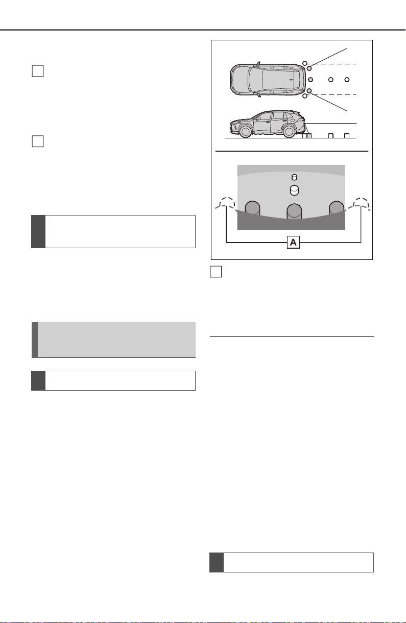
294
4-5. Using the driving support systems
This line indicates the estimated
vehicle center on the ground.
Distance guide line
Shows distance behind the vehicle.
• Displays a point approximately
1.5 ft. (0.5 m) (red) from the edge
of the bumper.
Distance guide line
Shows distance behind the vehicle.
• Displays a point approximately 3
ft. (1 m) (blue) from the edge of
the bumper.
The rear view monitor system is
canceled when the shift lever is
shifted into any position other
than the “R” position.
The rear view monitor system
displays an image of the view
from the bumper of the rear area
of the vehicle.
Corners of bumper
The area around both corners
of the bumper will not be dis-
played.
● The image adjustment procedure
for the rear view monitor system
screen is the same as the proce-
dure for adjusting the screen.
(P.388)
● The area displayed on the screen
may vary according to vehicle ori-
entation conditions.
● Objects which are close to either
corner of the bumper or under the
bumper cannot be displayed.
● The camera uses a special lens.
The distance of the image that
appears on the screen differs from
the actual distance.
● Items which are located higher
than the camera may not be dis-
played on the monitor.
The camera for the rear view
Canceling rear view moni-
tor system
Rear view monitor system
precautions
Area displayed on screen
C
D
The camera
A
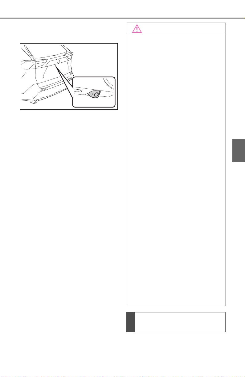
295
4-5. Using the driving support systems
4
Driving
monitor system is located as
shown in the illustration.
■ Using the camera
If dirt or foreign matter (such as
water droplets, snow, mud, etc.)
is adhering to the camera, it
cannot transmit a clear image.
In this case, flush it with a large
quantity of water and wipe the
camera lens clean with a soft
and wet cloth.
The distance guide lines and
the vehicle width guide lines
NOTICE
● The rear view monitor system
may not operate properly in the
following cases.
• If the back of the vehicle is hit,
the position and mounting angle
of the camera may change.
• As the camera has a water
proof construction, do not
detach, disassemble or modify
it. This may cause incorrect
operation.
• When cleaning the camera lens,
flush the camera with a large
quantity of water and wipe it
with a soft and wet cloth.
Strongly rubbing the camera
lens may cause the camera lens
to be scratched and unable to
transmit a clear image.
• Do not allow organic solvent,
car wax, window cleaner or a
glass coating to adhere to the
camera. If this happens, wipe it
off as soon as possible.
• If the temperature changes rap-
idly, such as when hot water is
poured on the vehicle in cold
weather, the system may not
operate normally.
• When washing the vehicle, do
not apply intensive bursts of
water to the camera or camera
area. Doing so may result in the
camera malfunctioning.
● Do not expose the camera to
strong impact as this could
cause a malfunction. If this hap-
pens, have the vehicle
inspected by your Toyota dealer
as soon as possible.
Differences between the
screen and the actual road
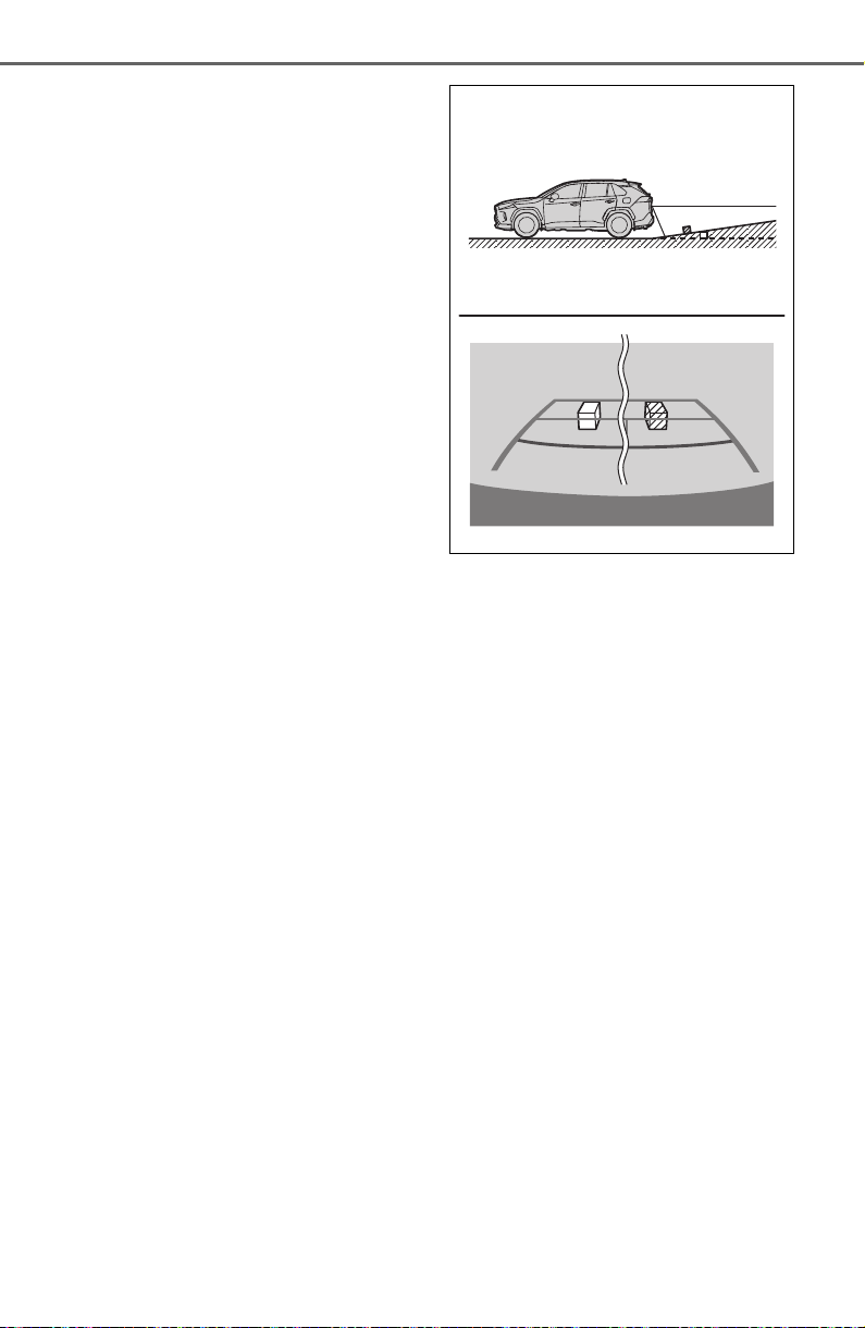
296
4-5. Using the driving support systems
may not actually be parallel
with the dividing lines of the
parking space, even when
they appear to be so. Be sure
to check visually.
The distances between the
vehicle width guide lines and
the left and right dividing lines
of the parking space may not
be equal, even when they
appear to be so. Be sure to
check visually.
The distance guide lines give
a distance guide for flat road
surfaces. In any of the follow-
ing situations, there is a mar-
gin of error between the guide
lines on the screen and the
actual distance/course on the
road.
■ When the ground behind
the vehicle slopes up
sharply
The distance guide lines will
appear to be closer to the vehi-
cle than the actual distance.
Because of this, objects will
appear to be farther away than
they actually are. In the same
way, there will be a margin of
error between the fixed guide
lines and the actual dis-
tance/course on the road.
■ When the ground behind
the vehicle slopes down
sharply
The distance guide lines will
appear to be farther from the
vehicle than the actual distance.
Because of this, objects will
appear to be closer than they
actually are. In the same way,
there will be a margin of error
between the guide lines and the
actual distance/course on the
road.
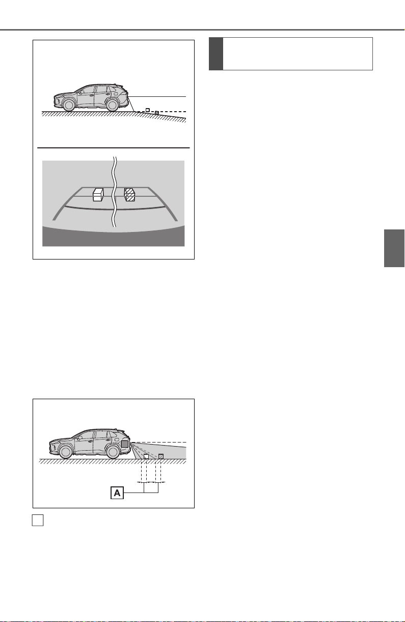
297
4-5. Using the driving support systems
4
Driving
■ When any part of the vehi-
cle sags
When any part of the vehicle
sags due to the number of pas-
sengers or the distribution of the
load, there is a margin of error
between the fixed guide lines on
the screen and the actual dis-
tance/course on the road.
A margin of error
The distance guide lines are dis-
played according to flat surfaced
objects (such as the road). It is
not possible to determine the
position of three-dimensional
objects (such as vehicles) using
the vehicle width guide lines and
distance guide lines. When
approaching a three-dimen-
sional object that extends out-
ward (such as the flatbed of a
truck), be careful of the follow-
ing.
■ Vehicle width guide lines
Visually check the surroundings
and the area behind the vehicle.
In the case shown below, the
truck appears to be outside of
the vehicle width guide lines and
the vehicle does not look as if it
hits the truck. However, the rear
body of the truck may actually
cross over the vehicle width
guide lines. In reality if you back
up as guided by the vehicle
width guide lines, the vehicle
may hit the truck.
A
When approaching three-
dimensional objects

298
4-5. Using the driving support systems
Vehicle width guide lines
■ Distance guide lines
Visually check the surroundings
and the area behind the vehicle.
On the screen, it appears that a
truck is parking at point .
However, in reality if you back
up to point , you will hit the
truck. On the screen, it appears
that is closest and is far-
thest away. However, in reality,
the distance to and is the
same, and is farther than
and .
If you notice any of the following symptoms, refer to the likely cause
and the solution, and re-check.
If the symptom is not resolved by the solution, have the vehicle
inspected by your Toyota dealer.
A
B
A
A
C
A
C
B
A
C
Things you should know
If you notice any symptoms

299
4-5. Using the driving support systems
4
Driving
Symptom Likely cause Solution
The image is difficult to
see
The vehicle is in a dark
area
The temperature
around the lens is
either high or low
The outside tempera-
ture is low
There are water drop-
lets on the camera
It is raining or humid
Foreign matter (mud
etc.) is adhering to the
camera
Sunlight or headlights
are shining directly
into the camera
The vehicle is under
fluorescent lights,
sodium lights, mer-
cury lights etc.
Back up while visually
checking the vehicle’s
surroundings. (Use the
monitor again once con-
ditions have been
improved.)
The procedure for
adjusting the picture
quality of the rear view
monitor system is the
same as the procedure
for adjusting the screen.
(P.388)
The image is blurry
Dirt or foreign matter
(such as water droplets,
snow, mud etc.) is
adhering to the camera.
Flush the camera with a
large quantity of water
and wipe the camera
lens clean with a soft
and wet cloth.
The image is out of
alignment
The camera or sur-
rounding area has
received a strong
impact.
Have the vehicle
inspected by your
Toyota dealer.
The fixed guide lines
are very far out of
alignment
The camera position is
out of alignment.
Have the vehicle
inspected by your
Toyota dealer.
The vehicle is tilted
(there is a heavy load
on the vehicle, tire
pressure is low due to
a tire puncture, etc.)
The vehicle is used on
an incline.
If this happens due to
these causes, it does
not indicate a malfunc-
tion.
Back up while visually
checking the vehicle’s
surroundings.

300
4-5. Using the driving support systems
*
: If equipped
● The screen illustrations used in
this text are intended as exam-
ples, and may differ from the
image that is actually displayed on
the screen.
The parking assist monitor is a
supplemental device intended to
assist the driver when backing
up. When backing up, be sure to
visually check all around the
vehicle both directly and using
the mirrors before proceeding. If
you do not, you may hit another
vehicle, and could possibly
cause an accident.
Pay attention to the following
precautions when using the
parking assist monitor.
Toyota parking assist
monitor
*
The parking assist monitor
assists the driver by dis-
playing an image of the view
behind the vehicle while
backing up, for example
while parking.
When the display is
changed to the wide rear
view mode, a wider lateral
view behind the vehicle will
be displayed.
Driving precautions
WARNING
● Never depend on the parking
assist monitor entirely when
backing up. The image and the
position of the guide lines dis-
played on the screen may differ
from the actual state.
Use caution, just as you would
when backing up any vehicle.
● Be sure to back up slowly,
depressing the brake pedal to
control vehicle speed.
● If you seem likely to hit nearby
vehicles, obstacles, people or
mount the shoulder, depress the
brake pedal to stop the vehicle.
● The instructions given are only
guidelines. When and how
much to turn the steering wheel
will vary according to traffic con-
ditions, road surface condi-
tions, vehicle condition, etc.
when parking. It is necessary to
be fully aware of this before
using the parking assist system.
● When parking, be sure to check
that the parking space will
accommodate your vehicle
before maneuvering into it.
● Do not use the parking assist
monitor in the following cases:
• On icy or slick road surfaces, or
in snow
• When using tire chains or emer-
gency tires
• When the back door is not
closed completely
• On roads that are not flat or
straight, such as curves or
slopes
• If the suspension has been
modified or tires of a size other
than specified are installed
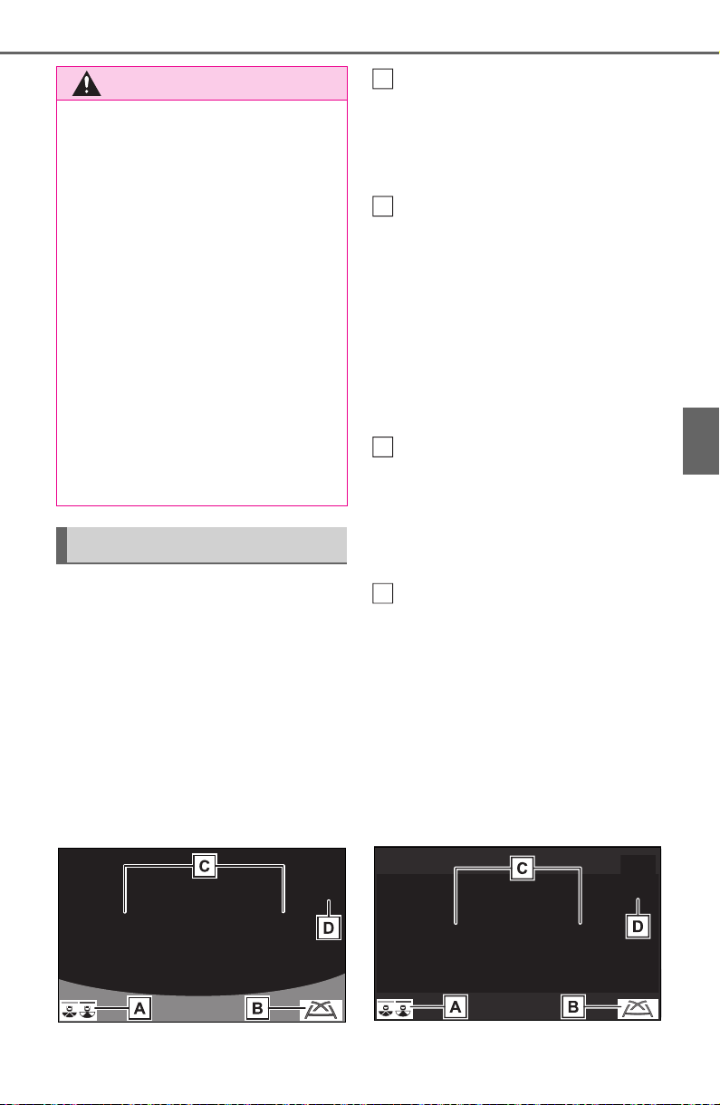
301
4-5. Using the driving support systems
4
Driving
The parking assist monitor
screen will be displayed if the
shift lever is shifted to the “R”
while the engine switch is in ON.
Each time the display mode
switching button is selected, the
mode will change as follows:
Rear view
Displays the rear view of the vehi-
cle.
Display mode switching but-
ton
Each time the button is selected,
the rear view mode and the wide
rear view mode are switched.
Guide line switching button
Select to switch the guide line
mode. (P.302)
• Each time the button is selected,
the display mode changes in the
following order:
Estimated course line display mode
Parking assist guide line display
mode Distance guide line display
mode.
Rear Cross Traffic Alert
*
When a sensor detects a vehicle
approaching from the rear, the
direction of the vehicle approaching
from the rear is displayed and the
buzzer sounds.
Intuitive parking assist
*
When a sensor detects a stationary
object, the direction of and the
approximate distance to the a sta-
tionary object are displayed and the
buzzer sounds.
*
: If equipped
Wide rear view
Displays a near 180° image from
the rear view camera.
WARNING
● In low temperatures, the screen
may darken or the image may
become faint. The image could
distort when the vehicle is mov-
ing, or you may become unable
to see the image on the screen.
Be sure to visually check all
around the vehicle both directly
and using the mirrors before
proceeding.
● If the tire sizes are changed, the
position of the guide lines dis-
played on the screen may
change.
● The camera uses a special lens.
The distances between objects
and pedestrians that appear in
the image displayed on the
screen will differ from the actual
distances. (P.307)
Screen display
A
B
C
D
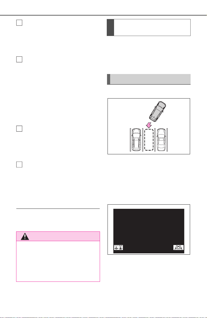
302
4-5. Using the driving support systems
Display mode switching but-
ton
Each time the button is selected,
the rear view mode and the wide
rear view mode are switched.
Guide line switching button
Select to switch the guide line
mode. (P.302)
• Each time the button is selected,
the display mode changes in the
following order:
Estimated course line display mode
Parking assist guide line display
mode Distance guide line display
mode.
Rear Cross Traffic Alert
*
When a sensor detects a stationary
object, the direction of stationary
object is displayed and the buzzer
sounds.
Intuitive parking assist
*
When a sensor detects an obstacle,
the direction of and the approxi-
mate distance to the obstacle are
displayed and the buzzer sounds.
*
: If equipped
● For details about the Rear Cross
Traffic Alert function (P.267) and
intuitive parking assist. (P.270)
The parking assist monitor is
canceled when the shift lever is
shifted into any position other
than the “R”.
Use any of the following modes.
Estimated course line display
mode (P.303)
Estimated course lines are dis-
played which move in accor-
dance with the operation of the
steering wheel.
Parking assist guide line dis-
play mode (P.304)
The steering wheel return points
(parking assist guide lines) are
displayed.
This mode is recommended for
WARNING
● As the Rear Cross Traffic Alert
display is displayed over the
camera view, it may be difficult
to see the Rear Cross Traffic
Alert display depending on the
color and brightness of the sur-
rounding area.
A
B
C
D
Canceling Toyota parking
assist monitor
Using the system
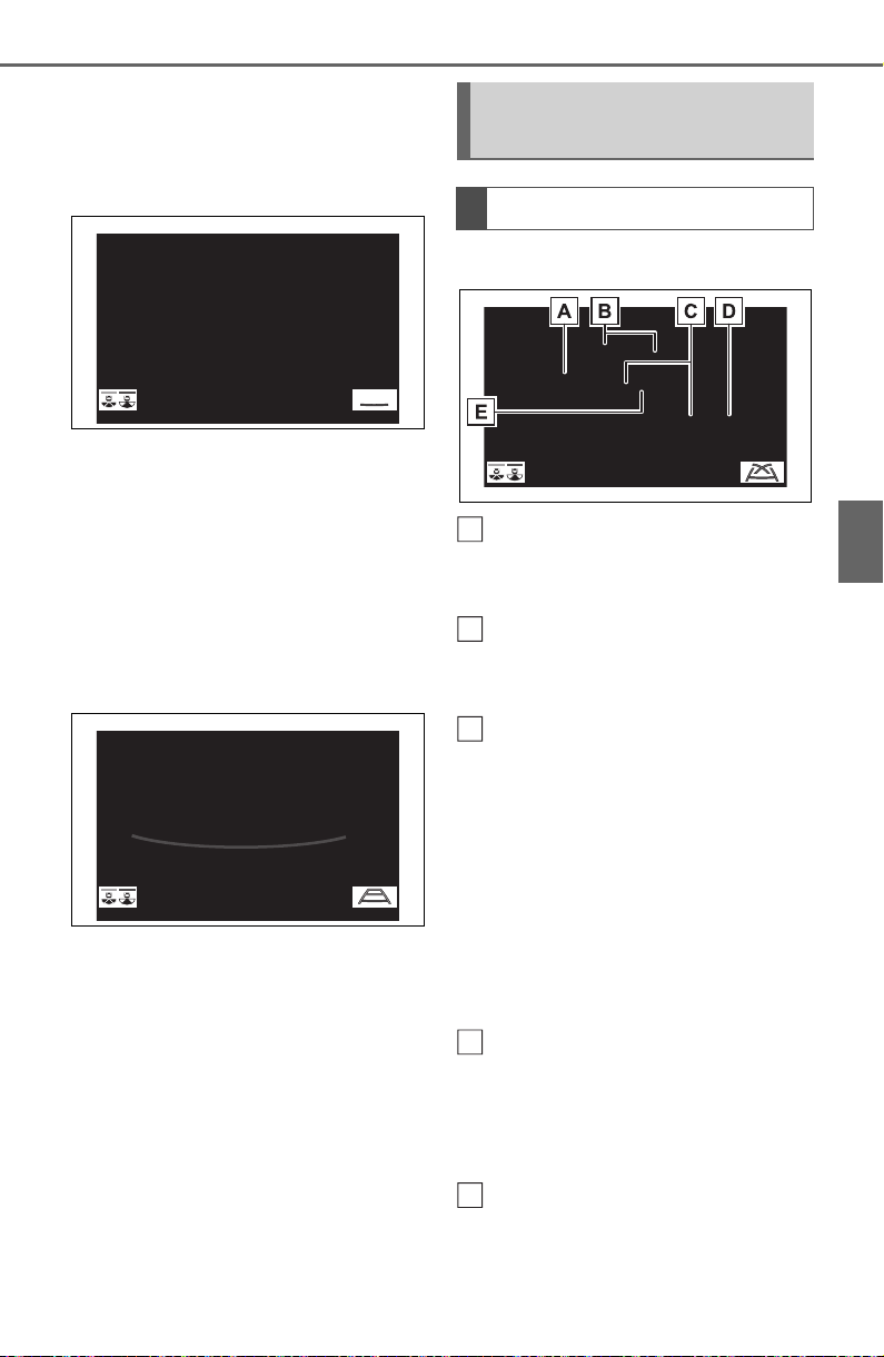
303
4-5. Using the driving support systems
4
Driving
those who are comfortable with
parking the vehicle without the
aid of the estimated course
lines.
Distance guide line display
mode (P.305)
Distance guide lines only are
displayed.
This mode is recommended for
those who are comfortable with
parking the vehicle without the
aid of the guide lines.
Rear view
Vehicle width guide line
Displays a guide path when the
vehicle is being backed straight up.
Estimated course lines
Show an estimated course when
the steering wheel is turned.
Distance guide lines
Show distance behind the vehicle
when the steering wheel is turned.
• The guide lines move in conjunc-
tion with the estimated course
lines.
• The guide lines display points
approximately 1.5 ft. (0.5 m) (red)
and approximately 3 ft. (1 m) (yel-
low) from the center of the edge
of the bumper.
Distance guide line
Shows distance behind the vehicle.
• Displays a point approximately
1.5 ft. (0.5 m) (blue) from the
edge of the bumper.
Vehicle center guide line
Indicates the estimated vehicle
center on the ground.
Estimated course line dis-
play mode
Screen description
A
B
C
D
E
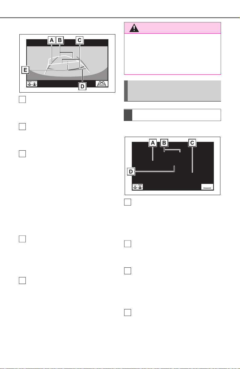
304
4-5. Using the driving support systems
Wide rear view
Vehicle width guide line
Displays a guide path when the
vehicle is being backed straight up.
Estimated course lines
Show an estimated course when
the steering wheel is turned.
Distance guide lines
Show distance behind the vehicle
when the steering wheel is turned.
• The guide lines move in conjunc-
tion with the estimated course
lines.
• The guide lines display points
approximately 1.5 ft. (0.5 m) (red)
and approximately 3 ft. (1 m) (yel-
low) from the center of the edge
of the bumper.
Distance guide line
Shows distance behind the vehicle.
• Displays a point approximately
1.5 ft. (0.5 m) (blue) from the
edge of the bumper.
Vehicle center guide line
Indicates the estimated vehicle
center on the ground.
Rear view
Vehicle width guide line
Displays a guide path when the
vehicle is being backed straight up.
• The displayed width is wider than
the actual vehicle width.
Parking assist guide lines
Show the path of the smallest turn
possible behind the vehicle.
Distance guide line
Shows distance behind the vehicle.
• Displays points approximately 1.5
ft. (0.5 m) (red) from the edge of
the bumper.
Vehicle center guide line
Indicates the estimated vehicle
center on the ground.
A
B
C
D
E
WARNING
● If the steering wheel is straight
and the vehicle width guide
lines and the estimated course
lines are not in alignment, have
the vehicle inspected by your
Toyota dealer.
Parking assist guide line
display mode
Screen description
A
B
C
D
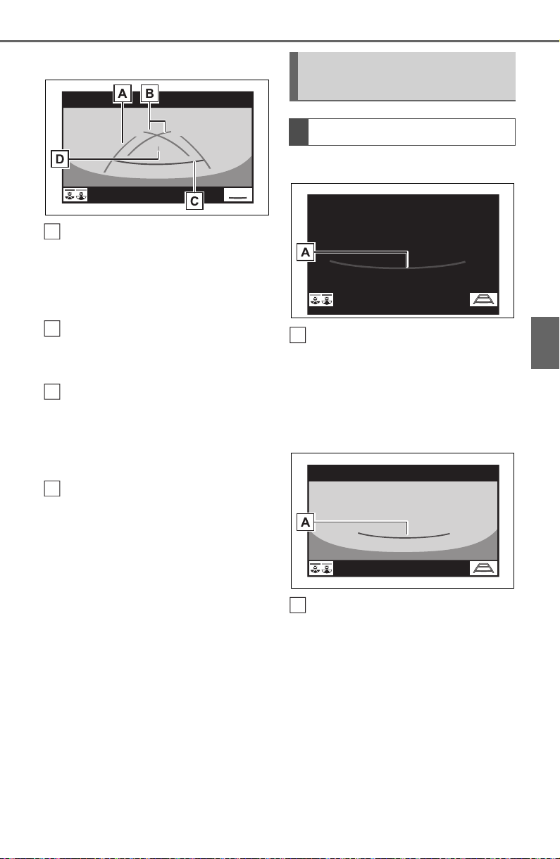
305
4-5. Using the driving support systems
4
Driving
Wide rear view
Vehicle width guide line
Displays a guide path when the
vehicle is being backed straight up.
• The displayed width is wider than
the actual vehicle width.
Parking assist guide lines
Show the path of the smallest turn
possible behind the vehicle.
Distance guide line
Shows distance behind the vehicle.
• Displays points approximately 1.5
ft. (0.5 m) (red) from the edge of
the bumper.
Vehicle center guide line
Indicates the estimated vehicle
center on the ground.
Rear view
Distance guide lines
Shows distance behind the vehicle.
• Displays points approximately 1.5
ft. (0.5 m) (red) from the edge of
the bumper.
Wide rear view
Distance guide lines
Shows distance behind the vehicle.
A
B
C
D
Distance guide line dis-
play mode
Screen description
A
A

306
4-5. Using the driving support systems
• Displays points approximately 1.5
ft. (0.5 m) (red) from the edge of
the bumper.
The parking assist monitor dis-
plays an image of the view from
the bumper of the rear area of
the vehicle.
Rear view
Corners of bumper
• The area around both corners of
the bumper will not be displayed.
Wide rear view
Corners of bumper
• The area around both corners of
the bumper will not be displayed.
● The image adjustment procedure
for the parking assist monitor
screen is the same as the proce-
dure for adjusting the screen dis-
play. (P.388)
● The area displayed on the screen
may vary according to vehicle ori-
entation conditions.
● Objects which are close to either
corner of the bumper or under the
bumper cannot be displayed.
● The camera uses a special lens.
The distance of the image that
appears on the screen differs from
the actual distance.
● Items which are located higher
than the camera may not be dis-
played on the monitor.
Toyota parking assist
monitor precautions
Area displayed on screen
A
A
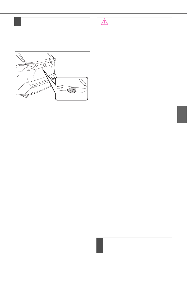
307
4-5. Using the driving support systems
4
Driving
The camera for the parking
assist monitor is located as
shown in the illustration.
■ Using the camera
If dirt or foreign matter (such as
water droplets, snow, mud, etc.)
is adhering to the camera, it
cannot transmit a clear image.
In this case, flush it with a large
quantity of water and wipe the
camera lens clean with a soft
and wet cloth.
The distance guide lines and
the vehicle width guide lines
The camera
NOTICE
● The parking assist monitor may
not operate properly in the fol-
lowing cases.
• If the back of the vehicle is hit,
the position and mounting angle
of the camera may change.
• As the camera has a water
proof construction, do not
detach, disassemble or modify
it. This may cause incorrect
operation.
• When cleaning the camera lens,
flush the camera with a large
quantity of water and wipe it
with a soft and wet cloth.
Strongly rubbing the camera
lens may cause the camera lens
to be scratched and unable to
transmit a clear image.
• Do not allow organic solvent,
car wax, window cleaner or a
glass coating to adhere to the
camera. If this happens, wipe it
off as soon as possible.
• If the temperature changes rap-
idly, such as when hot water is
poured on the vehicle in cold
weather, the system may not
operate normally.
• When washing the vehicle, do
not apply intensive bursts of
water to the camera or camera
area. Doing so may result in the
camera malfunctioning.
● Do not expose the camera to
strong impact as this could
cause a malfunction. If this hap-
pens, have the vehicle
inspected by your Toyota dealer
as soon as possible.
Differences between the
screen and the actual road
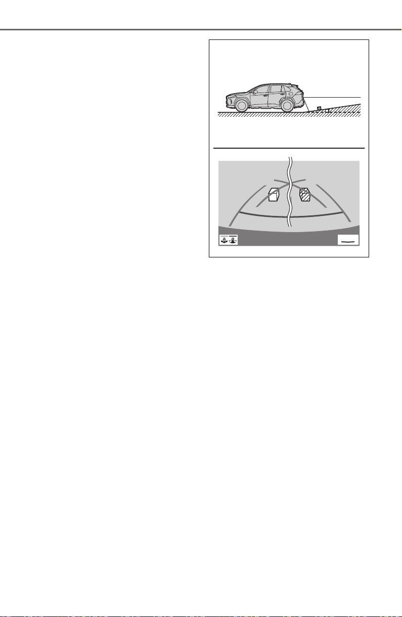
308
4-5. Using the driving support systems
may not actually be parallel
with the dividing lines of the
parking space, even when
they appear to be so. Be sure
to check visually.
The distances between the
vehicle width guide lines and
the left and right dividing lines
of the parking space may not
be equal, even when they
appear to be so. Be sure to
check visually.
The distance guide lines give
a distance guide for flat road
surfaces. In any of the follow-
ing situations, there is a mar-
gin of error between the guide
lines on the screen and the
actual distance/course on the
road.
■ When the ground behind
the vehicle slopes up
sharply
The distance guide lines will
appear to be closer to the vehi-
cle than the actual distance.
Because of this, objects will
appear to be farther away than
they actually are. In the same
way, there will be a margin of
error between the guidelines
and the actual distance/course
on the road.
■ When the ground behind
the vehicle slopes down
sharply
The distance guide lines will
appear to be farther from the
vehicle than the actual distance.
Because of this, objects will
appear to be closer than they
actually are. In the same way,
there will be a margin of error
between the guidelines and the
actual distance/course on the
road.

309
4-5. Using the driving support systems
4
Driving
■ When any part of the vehi-
cle sags
When any part of the vehicle
sags due to the number of pas-
sengers or the distribution of the
load, there is a margin of error
between the guide lines on the
screen and the actual dis-
tance/course on the road.
A margin of error
The estimated course lines tar-
get flat surfaced objects (such
as the road). It is not possible to
determine the position of three-
dimensional objects (such as
vehicles) using the estimated
course lines and distance guide
lines. When approaching a
three-dimensional object that
extends outward (such as the
flatbed of a truck), be careful of
the following.
■ Estimated course lines
Visually check the surroundings
and the area behind the vehicle.
In the case shown below, the
truck appears to be outside of
the estimated course lines and
the vehicle does not look as if it
hits the truck. However, the rear
body of the truck may actually
cross over the estimated course
lines. In reality if you back up as
guided by the estimated course
lines, the vehicle may hit the
truck.
A
When approaching three-
dimensional objects
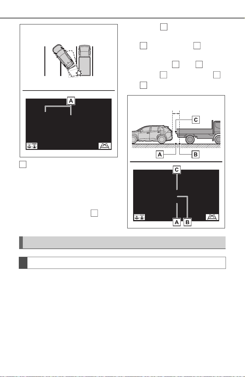
310
4-5. Using the driving support systems
Estimated course lines
■ Distance guide lines
Visually check the surroundings
and the area behind the vehicle.
On the screen, it appears that a
truck is parking at point .
However, in reality if you back
up to point , you will hit the
truck. On the screen, it appears
that is closest and is far-
thest away. However, in reality,
the distance to and is the
same, and is farther than
and .
If you notice any of the following symptoms, refer to the likely cause
and the solution, and re-check.
If the symptom is not resolved by the solution, have the vehicle
inspected by your Toyota dealer.
A
B
A
A
C
A
C
B
A
C
Things you should know
If you notice any symptoms

311
4-5. Using the driving support systems
4
Driving
Symptom Likely cause Solution
The image is difficult to
see
The vehicle is in a dark
area
The temperature
around the lens is
either high or low
The outside tempera-
ture is low
There are water drop-
lets on the camera
It is raining or humid
Foreign matter (mud
etc.) is adhering to the
camera
Sunlight or headlights
are shining directly
into the camera
The vehicle is under
fluorescent lights,
sodium lights, mer-
cury lights etc.
Back up while visually
checking the vehicle’s
surroundings. (Use the
monitor again once con-
ditions have been
improved.)
The procedure for
adjusting the picture
quality of the parking
assist monitor is the
same as the procedure
for adjusting the screen
display. (P.388)
The image is blurry
Dirt or foreign matter
(such as water droplets,
snow, mud etc.) is
adhering to the camera.
Flush the camera with a
large quantity of water
and wipe the camera
lens clean with a soft
and wet cloth.
The image is out of
alignment
The camera or sur-
rounding area has
received a strong
impact.
Have the vehicle
inspected by your
Toyota dealer.
The guide lines are
very far out of align-
ment
The camera position is
out of alignment.
Have the vehicle
inspected by your
Toyota dealer.
The vehicle is tilted
(there is a heavy load
on the vehicle, tire
pressure is low due to
a tire puncture, etc.)
The vehicle is used on
an incline.
If this happens due to
these causes, it does
not indicate a malfunc-
tion.
Back up while visually
checking the vehicle’s
surroundings.

312
4-5. Using the driving support systems
The estimated course
lines move even
though the steering
wheel is straight
There is a malfunction in
the signals being output
by the steering sensor.
Have the vehicle
inspected by your
Toyota dealer.
Guide lines are not dis-
played
The back door is open.
Close the back door.
If this does not resolve
the symptom, have the
vehicle inspected by
your Toyota dealer.
The estimated course
lines are not displayed
Battery has been rein-
stalled.
The steering wheel
has been moved while
the battery was being
reinstalled.
Battery power is low.
The steering sensor
has been reinstalled.
There is a malfunction
in the signals being
output by the steering
sensor.
Stop the vehicle, and
turn the steering wheel
as far as it will go to the
left and right.
If this does not resolve
the symptom, have the
vehicle inspected by
your Toyota dealer.
Symptom Likely cause Solution

313
4-5. Using the driving support systems
4
Driving
*
: If equipped
● The screen illustrations used in
this text are intended as exam-
ples, and may differ from the
image that is actually displayed on
the screen.
The panoramic view monitor is a
supplemental device intended to
assist the driver when checking
around the vehicle. When using,
be sure to visually check all
around the vehicle both directly
and using the mirrors before
proceeding. If you do not, you
may hit another vehicle or possi-
bly cause an accident.
Pay attention to the following
precautions when using the
panoramic view monitor.
Panoramic view moni-
tor
*
Panoramic view monitor
assists the driver in viewing
the surroundings, when
operating at low speeds, by
combining the front, side
and rear cameras and dis-
playing a complete vehicle
overhead image on the
screen.
When you press the camera
switch or shift the shift lever
to the “R” position while the
engine switch is in ON, the
panoramic view monitor
operates.
The monitor displays vari-
ous views of the position
and surroundings of the
vehicle.
Driving precautions
WARNING
● Never depend on the panoramic
view monitor entirely. The
image and the position of the
guide lines displayed on the
screen may differ from the
actual state. Use caution just as
you would when driving any
other vehicle.
● Always make sure to check all
around the vehicle with your
own eyes when driving.
● Never drive while looking only at
the screen as the image on the
screen is different from actual
conditions. If you are driving
while looking only at the screen,
you may hit a person or an
object, resulting in an accident.
When driving, be sure to check
the vehicle’s surroundings with
your own eyes and the vehicle’s
mirrors.
● Depending on the circum-
stances of the vehicle (number
of passengers, amount of lug-
gage, etc.), the position of the
guide lines displayed on the
screen may change. Be sure to
check visually around the vehi-
cle before proceeding.

314
4-5. Using the driving support systems
WARNING
● Do not use the panoramic view
monitor system in the following
cases:
• On icy or slick road surfaces, or
in snow
• When using tire chains or emer-
gency tires
• When the front door or the back
door is not closed completely
• On roads that are not flat or
straight, such as curves or
slopes
• If the suspension has been
modified or tires of a size other
than specified are installed
● In low temperatures, the screen
may darken or the image may
become faint. The image could
distort when the vehicle is mov-
ing, or you may become unable
to see the image on the screen.
Be sure to visually check all
around the vehicle both directly
and using the mirrors before
proceeding.
● If the tire sizes are changed, the
position of the guide lines dis-
played on the screen may
change.
● The camera uses a special lens.
The distances between objects
and pedestrians that appear in
the image displayed on the
screen will differ from the actual
distances. (P.337)
● When an aftermarket part is
installed in the display area of
the screen.
NOTICE
● In panoramic view/moving
view/see-through view, the sys-
tem combines images taken
from the front, back, left and
right side cameras into a single
image. There are limits to the
range and content that can be
displayed. Familiarize yourself
with the characteristics of the
panoramic view monitor system
before using it.
● Image clarity may decline at the
four corners of the panoramic
view/moving view/see-through
view. However, this is not a mal-
function, as these are the
regions along the border of
each camera image where the
images are combined.
● Depending on lighting condi-
tions near each of the cameras,
bright and dark patches may
appear on the panoramic
view/moving view/see-through
view.
● The panoramic view/moving
view/see-through view display
does not extend higher than the
installation position and image
capture range of each camera.
● There are blind spots around
the vehicle. Accordingly, there
are regions not displayed in
panoramic view.
● Three-dimensional objects dis-
played in wide front view, rear
view, wide rear view or side
view may not be displayed in
panoramic view/moving
view/see-through view.
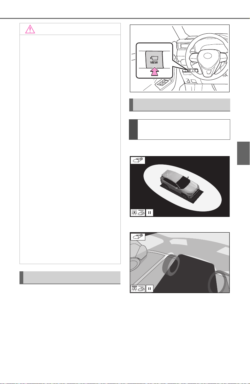
315
4-5. Using the driving support systems
4
Driving
The camera switch is located as
shown in the illustration.
Moving view
See-through view
NOTICE
● People and other three-dimen-
sional obstacles may appear
differently when displayed on
the panoramic view monitor.
(These differences include,
among others, cases in which
displayed objects appear to
have fallen over, disappear near
image processing areas, appear
from image processing areas,
or when the actual distance to
an object differs from the dis-
played position.)
● When the back door, which is
equipped with the back camera,
or front doors, which are
equipped with door mirrors that
have built-in side cameras, are
open, images will not be dis-
played properly on the pan-
oramic view monitor.
● The vehicle icon displayed in
panoramic view/moving
view/see-through view is a com-
puter generated image. Accord-
ingly, properties such as the
color, shape and size will differ
from the actual vehicle. For this
reason, nearby three-dimen-
sional objects may appear to be
touching the vehicle, and actual
distances to three-dimensional
objects may differ from those
displayed.
Camera switch
Display
Checking around the vehi-
cle
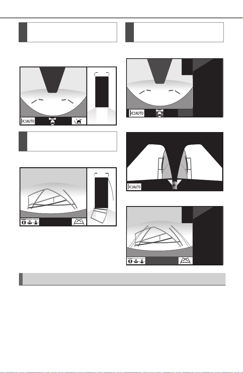
316
4-5. Using the driving support systems
Wide front view & panoramic
view
Rear view & panoramic view
Wide front view & side views
Side views
Rear view & side views
When you press the camera switch or shift the shift lever to the “R”
position while the engine switch is in ON, the panoramic view moni-
tor operates.
The monitor displays various views of the position of the vehicle.
(The following is an example)
Checking the front and
around the vehicle
Checking the rear and
around the vehicle
When folding the outside
rear view mirrors
How to switch the display
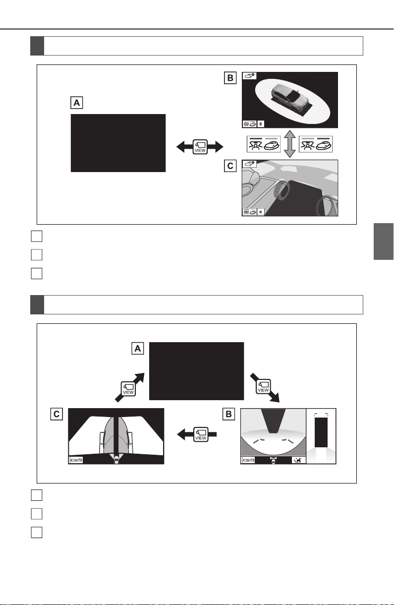
317
4-5. Using the driving support systems
4
Driving
Map screen, audio screen, etc.
Moving view
See-through view
Map screen, audio screen, etc.
Wide front view & panoramic view
Side views
When the shift lever is in the “P” position
When the shift lever is in the “D” or “N” position
A
B
C
A
B
C
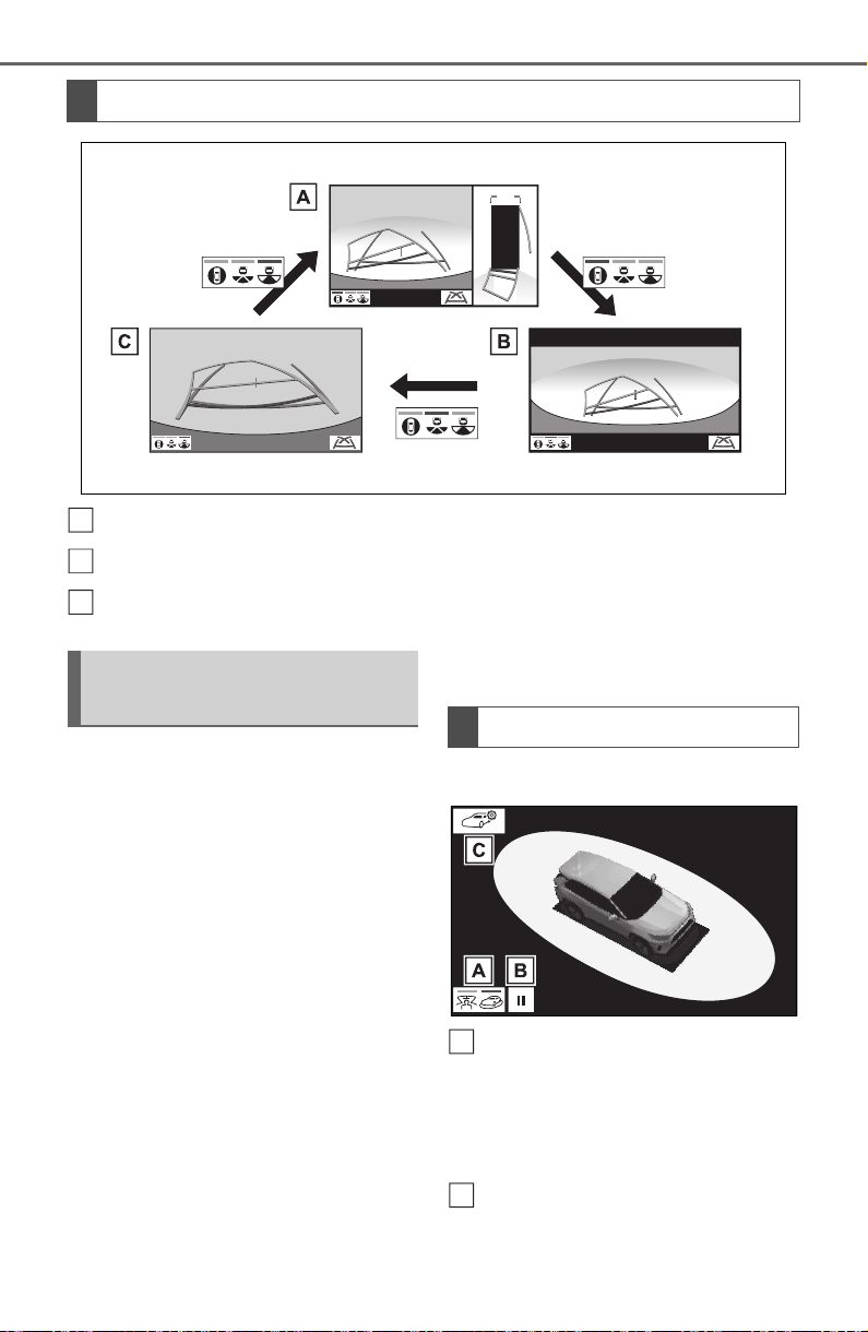
318
4-5. Using the driving support systems
Rear view & panoramic view
Wide rear view
Rear view
The moving view screen and the
see-through view screen pro-
vide support when checking the
areas of around the vehicle
while parking. These screens
display an image of the vicinity
of the vehicle combined from the
4 cameras. The screen will dis-
play a 360° view around the
vehicle from either inside the
vehicle or from a birds-eye view
at an angle.
To display the moving view/see-
through view screen, press the
camera switch when the shift
lever is in the “P” position and
the intuitive parking assist is
enabled.
Moving view
Display mode switching but-
ton
Select to change the display mode
between the moving view and the
see-through view.
Rotation pause switch
Select to pause the rotation of the
When the shift lever is in the “R” position
A
B
C
Checking around the
vehicle
Screen display
A
B
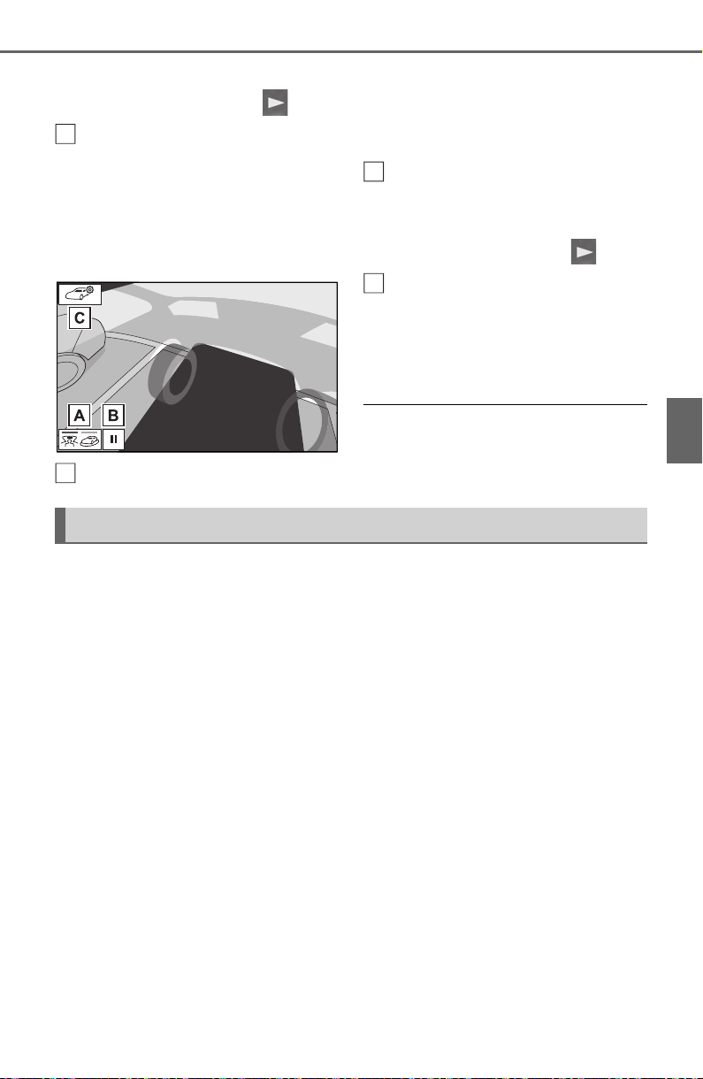
319
4-5. Using the driving support systems
4
Driving
screen.
To resume rotation, select .
Body color setting switch
Select to display the body color set-
ting screen and change the color of
the vehicle displayed on the pan-
oramic view monitor. (P.332)
See-through view
Display mode switching but-
ton
Select to change the display mode
between the moving view and the
see-through view.
Rotation pause switch
Select to pause the rotation of the
screen.
To resume rotation, select .
Body color setting switch
Select to display the body color set-
ting screen and change the color of
the vehicle displayed on the pan-
oramic view monitor. (P.332)
● Pressing the camera switch again
changes the screen back to the
previously displayed screen, such
as the navigation screen.
The wide front view & panoramic view screen provides support when
checking the areas in front of the vehicle and around the vehicle
when taking-off at T-intersections or other intersections during poor
visibility.
To display the screen, press the camera switch when the shift lever
is in the “N” or “D” position with the vehicle moving approximately 7
mph (12 km/h) or less.
This screen will be displayed if the intuitive parking assist detects an
object in front of your vehicle (intuitive parking assist linked display).
C
A
B
C
Checking the front and around the vehicle
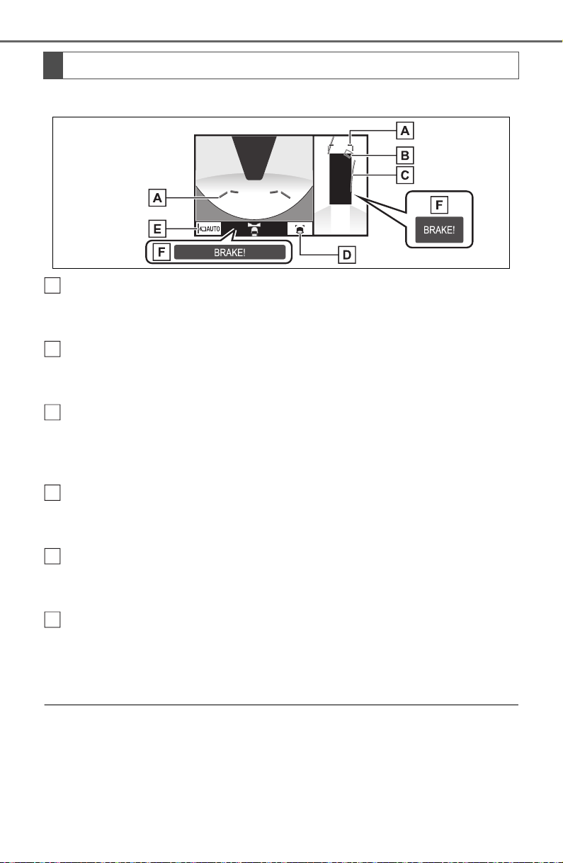
320
4-5. Using the driving support systems
Wide front view & panoramic view
Distance guide lines
Shows distance in front of the vehicle.
• Display points approximately 3 ft. (1 m) from the edge of the bumper.
Intuitive parking assist
When a sensor detects an obstacle, the direction of and the approximate
distance to the obstacle are displayed and the buzzer sounds.
Estimated course lines
Shows an estimated course when the steering wheel is turned.
• This line will be displayed when the steering wheel is turned by 90° or
more from the center (straight-line) position.
Guide line switching button
Select to change the guide line mode between the distance guide line mode
and the estimated course line mode. (P.321)
Automatic display button
Select to turn automatic display mode on/off. The indicator on the button
illuminates during automatic display mode. (P.321)
Parking Support Brake
*
When the system determines that the possibility of a frontal collision with a
detected object is high, a warning message is displayed.
*
: If equipped
● Pressing the camera switch changes the screen to the side views screen
or previously displayed screen, such as the navigation screen.
● For details about the intuitive parking assist (P.270) and Parking Sup-
port Brake
*
function. (P.277)
● The display position of the intuitive parking assist and the position of
obstacles displayed in the camera image do not match.
Screen display
A
B
C
D
E
F
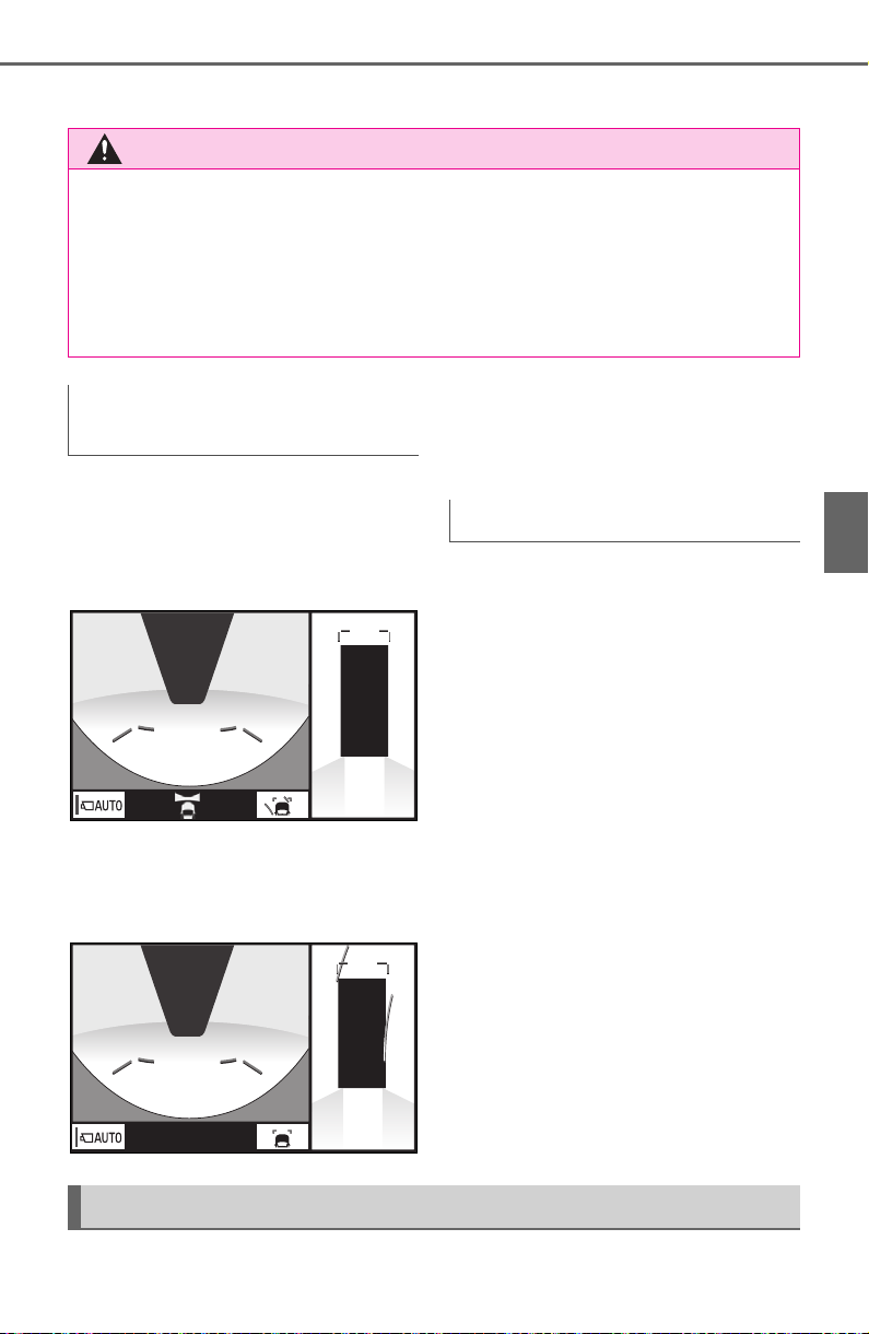
321
4-5. Using the driving support systems
4
Driving
*
: If equipped
Each time the guide line switch-
ing button is selected, the mode
will change as follows:
Distance guide line
Only the distance guide lines
are displayed.
Estimated course line
Estimated course lines will be
added to the distance guide
lines.
In addition to screen switching
by operating the camera switch,
automatic display mode is avail-
able. In this mode, the screen is
switched automatically in
response to vehicle speed.
In automatic display mode, the
monitor will automatically dis-
play images in the following situ-
ations:
When the shift lever is shifted
to “N” or “D” position.
When vehicle speed is
reduced to approximately 6
mph (10 km/h) or less.
The side view screen displays images from the cameras installed on
WARNING
● When a sensor indicator on the intuitive parking assist display illumi-
nates in red or a buzzer sounds continuously, be sure to check the area
around the vehicle immediately and do not proceed any further until
safety has been ensured, otherwise an unexpected accident may occur.
● As the intuitive parking assist display is displayed over the camera view,
it may be difficult to see the intuitive parking assist display depending on
the color and brightness of the surrounding area.
Switching the guide line
mode
Automatic display mode
Checking the sides of the vehicle
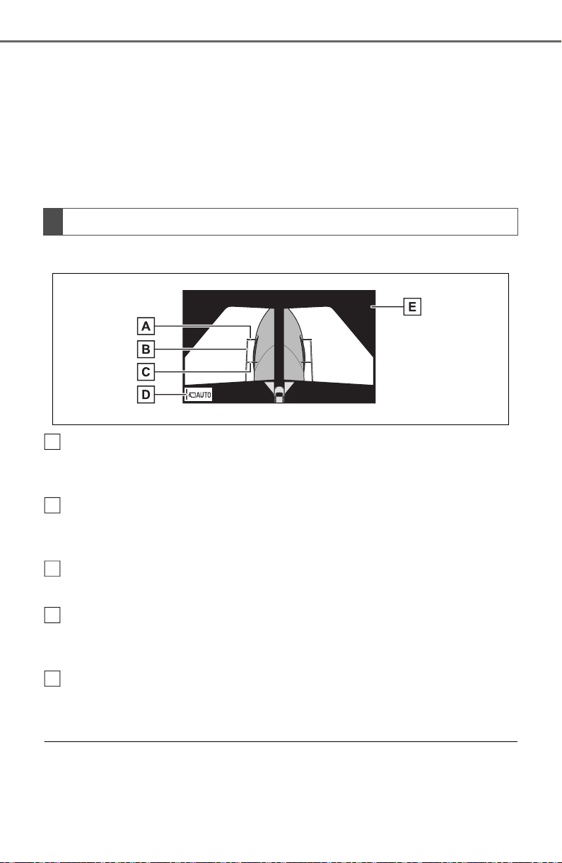
322
4-5. Using the driving support systems
each outside rear view mirror. This screen is designed to support the
driver in safe driving in situations such as when driving on a narrow
road, by allowing them to check the areas around the sides of the
vehicle.
To display the screen, press the camera switch when the shift lever
is in the “D”, or “N” position with the vehicle moving approximately 7
mph (12 km/h) or less.
Side view
Distance guide lines
Show distance in front of the vehicle.
• Display points approximately 3 ft. (1 m) from the edge of the bumper.
Vehicle width guide lines
Shows guide lines of the vehicle’s width including the outside rear view mir-
rors.
Front tire guide lines
Shows guide lines of where the front tire touches the ground.
Automatic display button
Select to turn automatic display mode on/off. The indicator on the button
illuminates during automatic display mode. (P.323)
Intuitive parking assist
When a sensor detects an obstacle, the direction of and the approximate
distance to the obstacle are displayed and the buzzer sounds.
● Pressing the camera switch changes the screen to the wide front view &
panoramic view screen or previously displayed screen, such as the navi-
gation screen.
● For details about the intuitive parking assist. (P.270)
Screen display
A
B
C
D
E
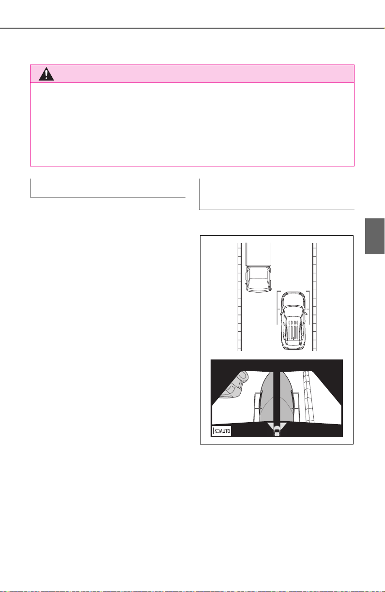
323
4-5. Using the driving support systems
4
Driving
● The side views can be displayed even when the outside rear view mirrors
are retracted.
In addition to screen switching
by operating the camera switch,
automatic display mode is avail-
able. In this mode, the screen is
switched automatically in
response to vehicle speed.
In automatic display mode, the
monitor will automatically dis-
play images in the following situ-
ations:
When the shift lever is shifted
to “N” or “D” position.
When vehicle speed is
reduced to approximately 6
mph (12 km/h) or less.
Side View
Check the positions and dis-
tance between the vehicle
width guide line and a target
object such as the obstacle or
curb of the road.
WARNING
● When a sensor indicator on the intuitive parking assist display illumi-
nates in red or a buzzer sounds continuously, be sure to check the area
around the vehicle immediately and do not proceed any further until
safety has been ensured, otherwise an unexpected accident may occur.
● As the intuitive parking assist display is displayed over the camera view,
it may be difficult to see the intuitive parking assist display depending on
the color and brightness of the surrounding area.
Automatic display mode Using the vehicle width
guide line
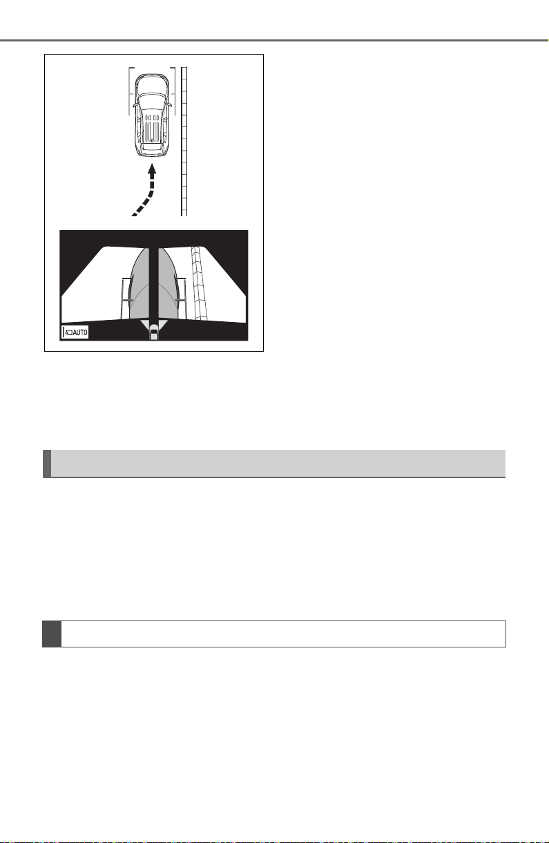
324
4-5. Using the driving support systems
Pull over to the curb as shown
in the illustration above, tak-
ing care not to let the vehicle
width guide line overlap the
target object.
Ensure that the vehicle width
guide line is parallel to the tar-
get object.
The rear view & panoramic view screen, the wide rear view screen
and the rear view screen provide support when checking the areas
of behind the vehicle and around the vehicle while backing up, for
example while parking.
The screens will be displayed when the shift lever is in the “R” posi-
tion.
Each time the display mode switching button is selected, the mode
will change as follows:
Checking the rear and around the vehicle
Screen display
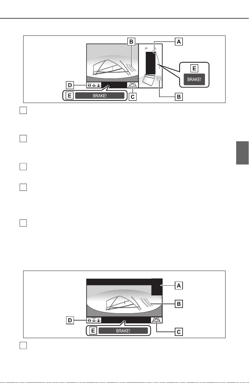
325
4-5. Using the driving support systems
4
Driving
Rear view & panoramic view
Intuitive parking assist
When a sensor detects an obstacle, the direction of and the approximate
distance to the obstacle are displayed and the buzzer sounds.
Rear Cross Traffic Alert
When a sensor detects an obstacle, the direction of obstacle is displayed
and the buzzer sounds.
Guide line switching button
Select to switch the guide line mode. (P.327)
Display mode switching button
Each time the display mode switching button is selected, the mode will
change between the rear view & panoramic view mode and the wide rear
view & panoramic view mode.
Parking Support Brake
*
When the system determines that the possibility of a collision with a
detected object is high, a warning message is displayed.
*
: If equipped
Wide rear view
Intuitive parking assist
When a sensor detects an obstacle, the direction of and the approximate
A
B
C
D
E
A
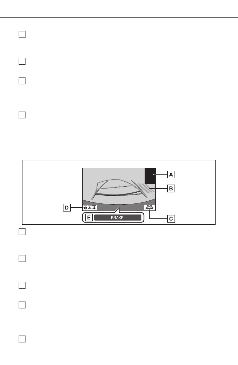
326
4-5. Using the driving support systems
distance to the obstacle are displayed and the buzzer sounds.
Rear Cross Traffic Alert
When a sensor detects an obstacle, the direction of obstacle is displayed
and the buzzer sounds.
Guide line switching button
Select to switch the guide line mode. (P.327)
Display mode switching button
Each time the display mode switching button is selected, the mode will
change between the rear view & panoramic view mode and the wide rear
view & panoramic view mode.
Parking Support Brake
*
When the system determines that the possibility of a collision with a
detected object is high, a warning message is displayed.
*
: If equipped
Rear view
Intuitive parking assist
When a sensor detects an obstacle, the direction of and the approximate
distance to the obstacle are displayed and the buzzer sounds.
Rear Cross Traffic Alert
When a sensor detects an obstacle, the direction of obstacle is displayed
and the buzzer sounds.
Guide line switching button
Select to switch the guide line mode. (P.327)
Display mode switching button
Each time the display mode switching button is selected, the mode will
change between the rear view & panoramic view mode and the wide rear
view & panoramic view mode.
Parking Support Brake
*
B
C
D
E
A
B
C
D
E
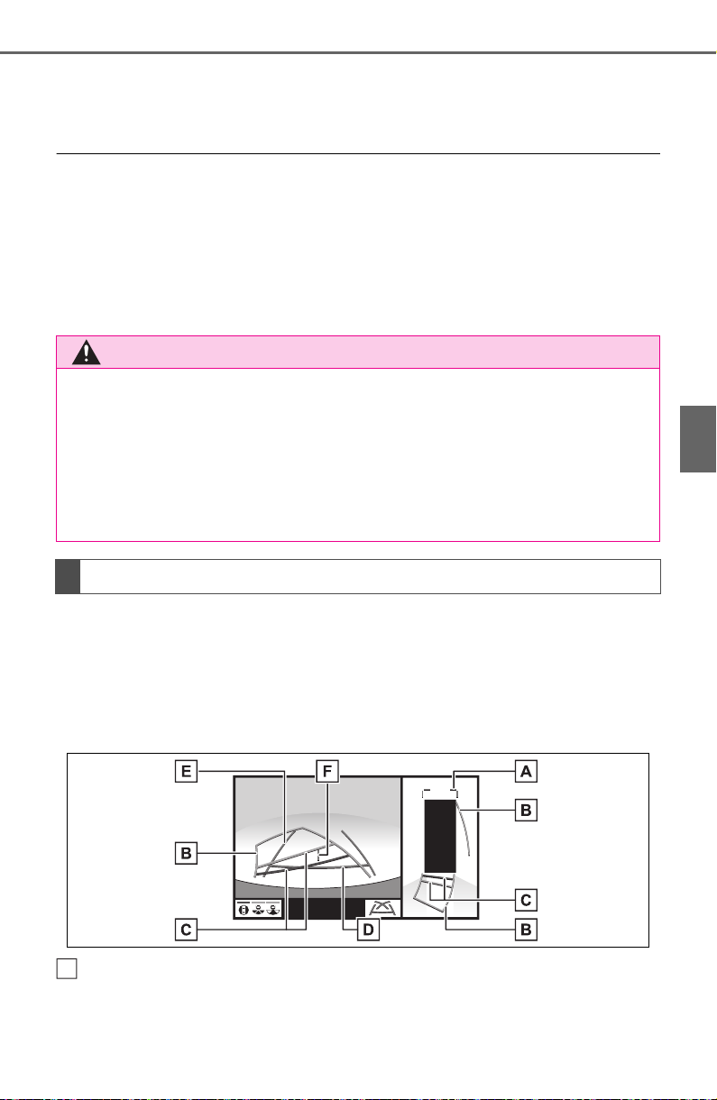
327
4-5. Using the driving support systems
4
Driving
When the system determines that the possibility of a collision with a
detected object is high, a warning message is displayed.
*
: If equipped
● The monitor is cancelled when the shift lever is shifted into any position
other than the “R” position.
● For details about the intuitive parking assist (P.270), Rear Cross Traffic
Alert function (P.267) and Parking Support Brake
*
function. (P.277)
● The display position of the intuitive parking assist and the position of
obstacles displayed in the camera image do not match.
*
: If equipped
Each time the guide line switching button is selected, the mode will
change as follows:
Estimated course line
Estimated course lines are displayed which move in accordance with
the operation of the steering wheel.
Distance guide lines
Shows distance in front of the vehicle.
• Display points approximately 3 ft. (1 m) from the edge of the bumper.
WARNING
● When a sensor indicator on the intuitive parking assist display illumi-
nates in red or a buzzer sounds continuously, be sure to check the area
around the vehicle immediately and do not proceed any further until
safety has been ensured, otherwise an unexpected accident may occur.
● As the intuitive parking assist display and Rear Cross Traffic Alert dis-
play are displayed over the camera view, it may be difficult to see the
intuitive parking assist display and Rear Cross Traffic Alert display
depending on the color and brightness of the surrounding area.
Guide lines displayed on the screen
A
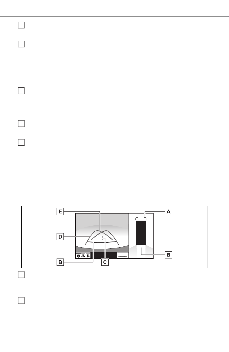
328
4-5. Using the driving support systems
Estimated course lines
Shows an estimated course when the steering wheel is turned.
Distance guide lines
Shows the distance behind the vehicle when the steering wheel is turned.
• The guide lines move in conjunction with the estimated course lines.
• The guide lines display points approximately 1.5 ft. (0.5 m) (red) and
approximately 3 ft. (1 m) (yellow) from the center of the edge of the
bumper.
Distance guide line
Shows the distance behind the vehicle.
• Displays a point approximately 1.5 ft. (0.5 m) (blue) from the edge of the
bumper.
Vehicle width guide lines
Displays a guide path when the vehicle is being backed straight up.
Vehicle center guide line
Indicates the estimated vehicle center on the ground.
Parking assist guide line
The steering wheel return points (parking assist guide lines) are dis-
played.
This mode is recommended for those who are comfortable with park-
ing the vehicle without the aid of the estimated course lines.
Distance guide lines
Shows distance in front of the vehicle.
• Display points approximately 3 ft. (1 m) from the edge of the bumper.
Distance guide line
Shows the distance behind the vehicle.
• Displays a point approximately 1.5 ft. (0.5 m) (red) from the edge of the
bumper.
B
C
D
E
F
A
B
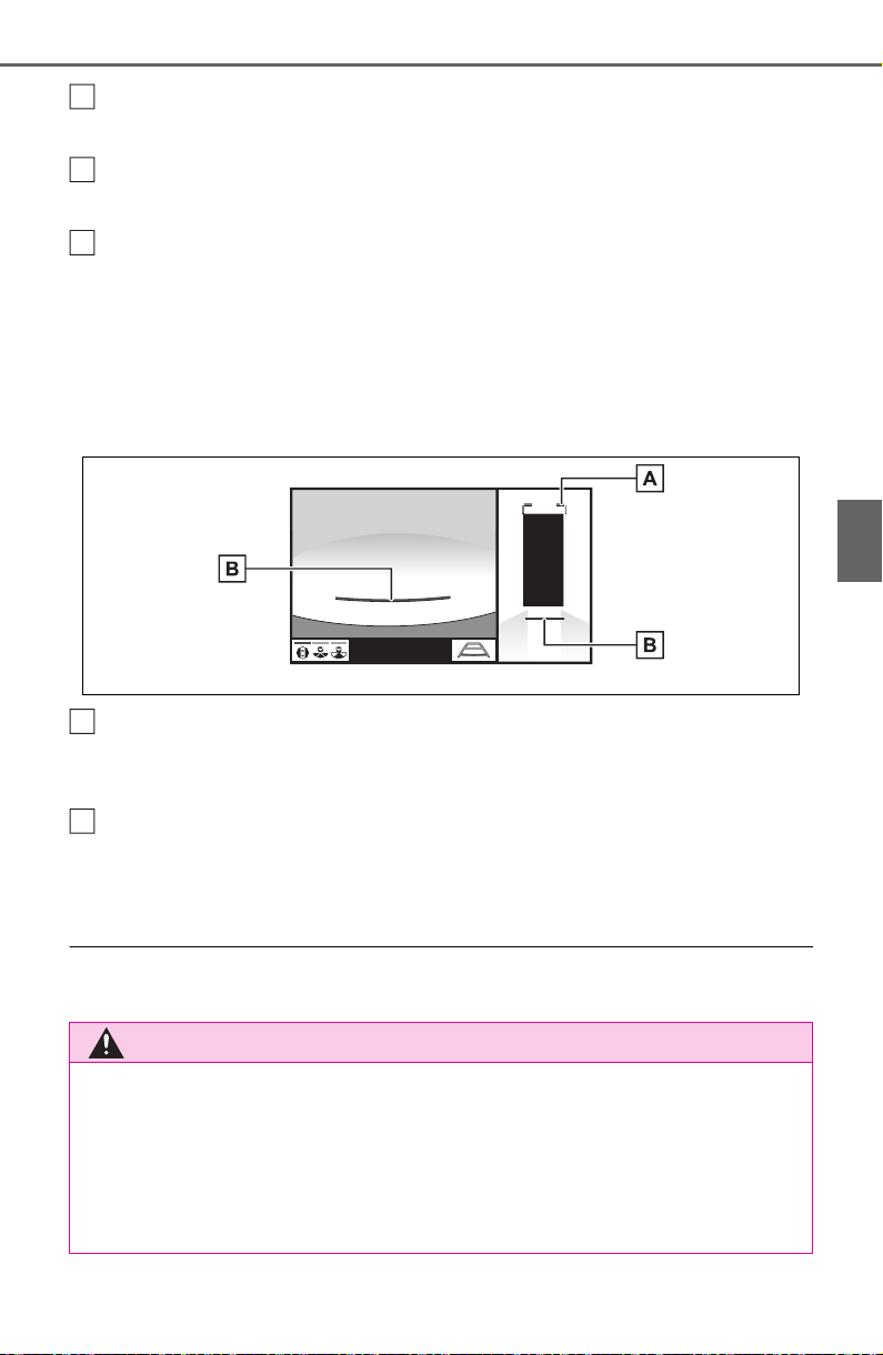
329
4-5. Using the driving support systems
4
Driving
Vehicle center guide line
Indicates the estimated vehicle center on the ground.
Vehicle width guide lines
Displays a guide path when the vehicle is being backed straight up.
Parking assist guide lines
Shows the path of the smallest turn possible behind the vehicle.
Distance guide line
Only distance guide line is displayed.
This mode is recommended for those who are comfortable with park-
ing the vehicle without the aid of the guide lines.
Distance guide lines
Shows distance in front of the vehicle.
• Display points approximately 3 ft. (1 m) from the edge of the bumper.
Distance guide line
Shows the distance behind the vehicle.
• Displays a point approximately 1.5 ft. (0.5 m) (red) from the edge of the
bumper.
● The display position of the intuitive parking assist and the position of
obstacles displayed in the camera image do not match.
WARNING
● Depending on the circumstances of the vehicle (number of passengers,
amount of luggage, etc.), the position of the guide lines displayed on the
screen may change. Be sure to check visually around the vehicle before
proceeding.
● If the steering wheel is straight and the vehicle width guide lines and the
estimated course lines are not in alignment, have the vehicle inspected
by your Toyota dealer.
C
D
E
A
B
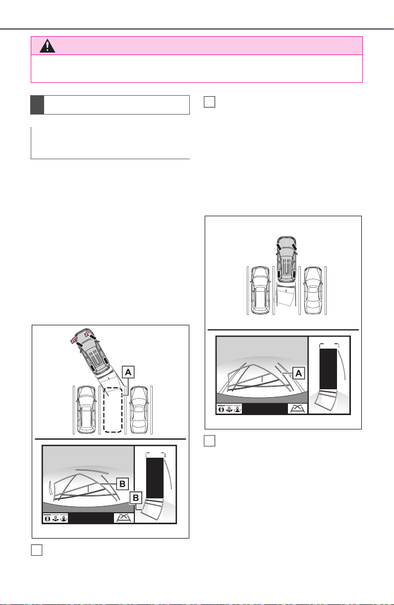
330
4-5. Using the driving support systems
When parking in a space which
is in the reverse direction to the
space described in the proce-
dure below, the steering direc-
tions will be reversed.
1 Shift the shift lever to the “R”
position.
2 Turn the steering wheel so
that the estimated course
lines are within the parking
space, and back up slowly.
Parking space
Estimated course lines
3 When the rear position of the
vehicle has entered the park-
ing space, turn the steering
wheel so that the vehicle
width guide lines are within
the left and right dividing lines
of the parking space.
Vehicle width guide line
4 Once the vehicle width guide
lines and the parking space
lines are parallel, straighten
the steering wheel and back
up slowly until the vehicle
has completely entered the
parking space.
WARNING
● Do not use the system if the display is incorrect due to an uneven (hilly)
road or a non-straight (curvy) road.
Parking
Using the estimated course
line
A
B
A
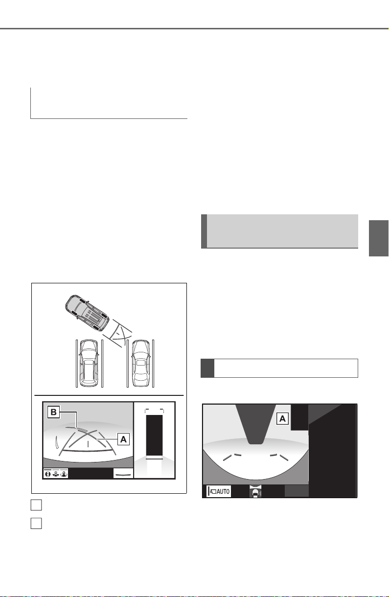
331
4-5. Using the driving support systems
4
Driving
5 Stop the vehicle in an appro-
priate place, and finish park-
ing.
When parking in a space which
is in the reverse direction to the
space described in the proce-
dure below, the steering direc-
tions will be reversed.
1 Shift the shift lever to the “R”
position.
2 Back up until the parking
assist guide line meets the
edge of the dividing line of
the parking space.
Parking assist guide line
Parking space dividing line
3 Turn the steering wheel all
the way to the left, and back
up slowly.
4 Once the vehicle is parallel
with the parking space,
straighten the steering wheel
and back up slowly until the
vehicle has completely
entered the parking space.
5 Stop the vehicle in an appro-
priate place, and finish park-
ing.
Even when outside rear view
mirrors are stored, the monitor
can display various images of
the vicinity of the vehicle and
assist the operation in the con-
firming safe conditions in a nar-
row places, parking, etc.
Wide front view & side views
Using parking assist guide
line
A
B
When folding the outside
rear view mirrors
Screen display
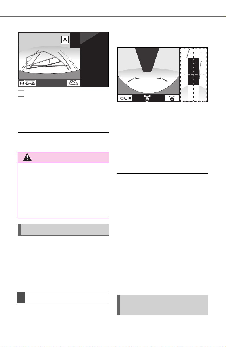
332
4-5. Using the driving support systems
Rear view & side views
Intuitive parking assist
When a sensor detects an obstacle,
the direction of and the approxi-
mate distance to the obstacle are
displayed and the buzzer sounds.
● For details about the front view
and the rear view: P.319, 324
If displayed objects are too
small to see clearly when the
panoramic view is displayed, the
area around any of the 4 cor-
ners of the vehicle can be mag-
nified.
1 Turn the intuitive parking
assist on.
2 Select the area on the pan-
oramic view display you wish
to magnify.
Touching one of the 4 areas
within the dotted lines will
magnify that area. (Dotted
lines are not displayed on the
actual display.)
To return to the normal view,
touch the panoramic view dis-
play again.
● The magnifying function is
enabled when all of the following
conditions are met:
• The wide front view & panoramic
view or the rear view & panoramic
view is displayed.
• The vehicle speed is below
approximately 7 mph (12 km/h).
• The intuitive parking assist is
available.
● In the following situations, the
magnified display will be can-
celed automatically:
• The vehicle speed is approxi-
mately 7 mph (12 km/h) or higher.
• The intuitive parking assist is
unavailable.
● When the display is magnified, the
guide lines will not be displayed.
The color of the vehicle dis-
WARNING
● When a sensor indicator on the
intuitive parking assist display
illuminates in red or a buzzer
sounds continuously, be sure to
check the area around the vehi-
cle immediately and do not pro-
ceed any further until safety has
been ensured, otherwise an
unexpected accident may occur.
Magnifying function
Magnifying the display
A
Customizing the pan-
oramic view monitor
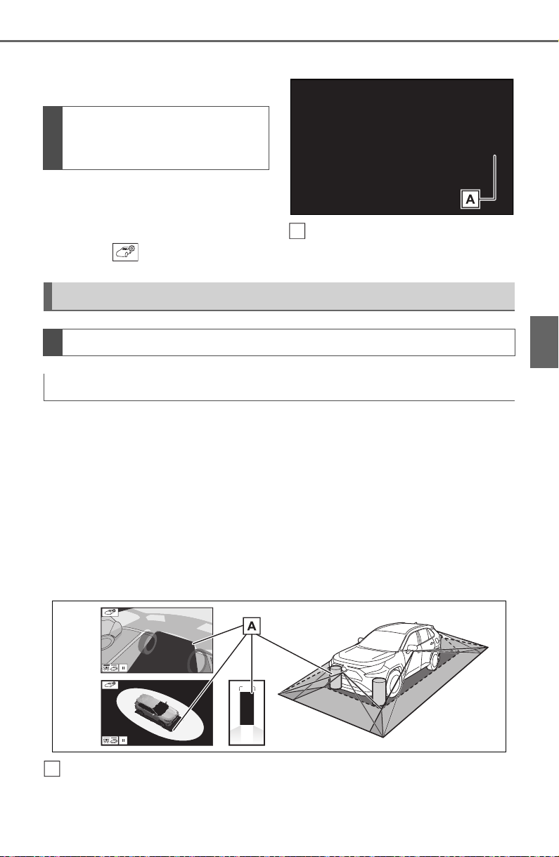
333
4-5. Using the driving support systems
4
Driving
played on the panoramic view
monitor can be changed.
1 Display the moving view/see-
through view screen.
(P.318)
2 Select .
3 Select the desired color.
Displays the next page
The panoramic view monitor displays an image of the surrounding
view of the vehicle.
Since the panoramic view processes and displays images based on
flat road surfaces, it cannot depict the position of three-dimension
objects (such as vehicle bumpers, etc.) that are in positions higher
than the surface of the road. Even if there is room between the bum-
pers of the vehicles and it seems not likely to collide in the image, in
reality, the both vehicles are on a collision course.
Check the safety of the surroundings directly.
Objects located in the shaded areas will not be displayed on the
screen.
Changing the body color
displayed in the pan-
oramic view monitor
A
Panoramic view monitor precautions
Area displayed on screen
Area of image of panoramic view
A

334
4-5. Using the driving support systems
Parts of objects which extend above a certain height cannot be
displayed on the screen.
● As the images obtained from four cameras are processed and displayed
on the standard of a flat road surface; the panoramic view/moving
view/see through view may be displayed as follows.
• Objects may look collapsed; thinner or bigger than usual.
• An object with a higher position than the road surface may look farther
away than it actually is or may not appear at all.
• Tall objects may appear protruding from the non-displayed areas of the
image.
● Variations in the brightness of the image may appear for every camera.
● The displayed image may be shifted by inclination of the vehicle body,
change in vehicle height, etc., depending on the number of passengers,
amount of luggage, fuel quantity, etc.
● If the front doors or back door are not completely closed; neither the
image nor the guide lines are displayed.
● The position relations of the vehicle icon and the road surface or obstacle
may differ from the actual positions.
● The black areas of the vicinity of the vehicle icon are areas that are not
captured by the camera.
● Images like the following are combined, thus some areas may be difficult
to view.
A
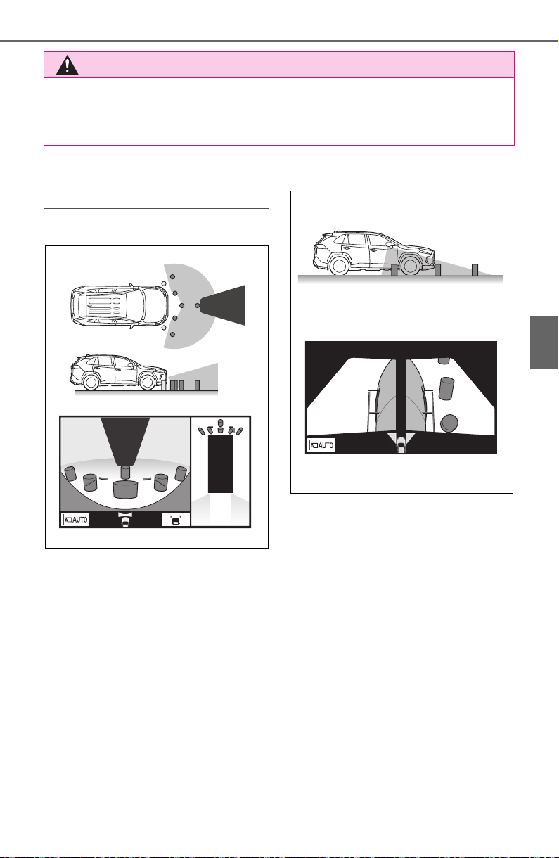
335
4-5. Using the driving support systems
4
Driving
Wide front view
Side view
WARNING
● When a sensor indicator on the intuitive parking assist display illumi-
nates in red or a buzzer sounds continuously, be sure to check the area
around the vehicle immediately and do not proceed any further until
safety has been ensured, otherwise an unexpected accident may occur.
Area of the image captured
by the camera
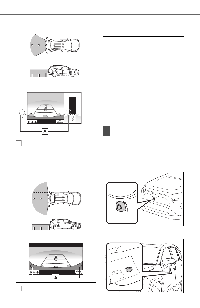
336
4-5. Using the driving support systems
Rear view
The area around both cor-
ners of the bumper will not be
displayed.
Wide rear view
The area around both cor-
ners of the bumper will not be
displayed.
● Black masking is done for dis-
tance detection differences to the
front of the vehicle.
● The area covered by the camera
is limited. Objects which are close
to either corner of the bumper or
under the bumper cannot be seen
on the screen.
● The area displayed on the screen
may vary depending on vehicle
orientation or road conditions.
● The camera uses a special lens.
The distance in the image dis-
played on the screen will differ
from the actual distance.
The cameras for the panoramic
view monitor are located as
shown in the illustrations.
Front camera
Side cameras
A
A
The camera
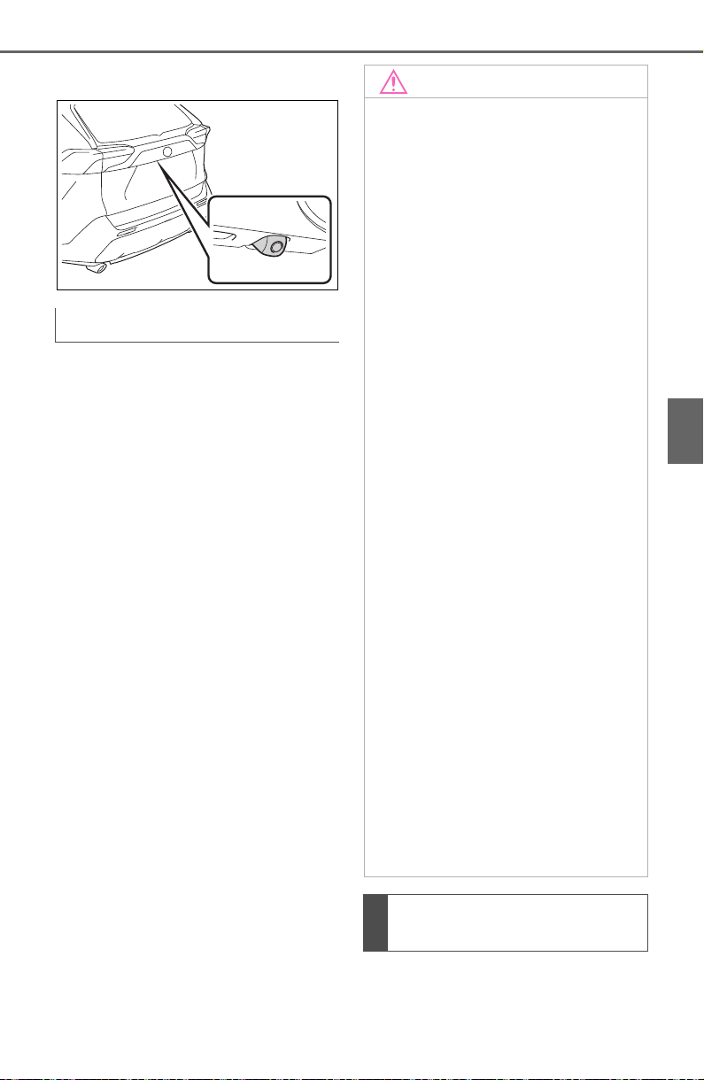
337
4-5. Using the driving support systems
4
Driving
Rear camera
If dirt or foreign matter (such as
water droplets, snow, mud, etc.)
is adhering to the camera, it
cannot transmit a clear image.
In this case, flush it with a large
quantity of water and wipe the
camera lens clean with a soft
and wet cloth.
The distance guide lines and
the vehicle width guide lines
Using the camera
NOTICE
● The panoramic view monitor
may not operate properly in the
following cases.
• If the camera is hit, the position
and mounting angle of the cam-
era may change.
• As the camera has a water
proof construction, do not
detach, disassemble or modify
it. This may cause incorrect
operation.
• When cleaning the camera lens,
flush the camera with a large
quantity of water and wipe it
with a soft and wet cloth.
Strongly rubbing the camera
lens may cause the camera lens
to be scratched and unable to
transmit a clear image.
• Do not allow an organic solvent,
car wax, window cleaner or a
glass coating to adhere to the
camera. If this happens, wipe it
off as soon as possible.
• If the temperature changes rap-
idly, such as when hot water is
poured on the vehicle in cold
weather, the system may not
operate normally.
• When washing the vehicle, do
not apply intensive bursts of
water to the camera or camera
area. Doing so may result in the
camera malfunctioning.
● Do not expose the camera to
strong impacts as this could
cause a malfunction. If this hap-
pens, have the vehicle
inspected by your Toyota dealer
as soon as possible.
Difference between the
screen and the actual road
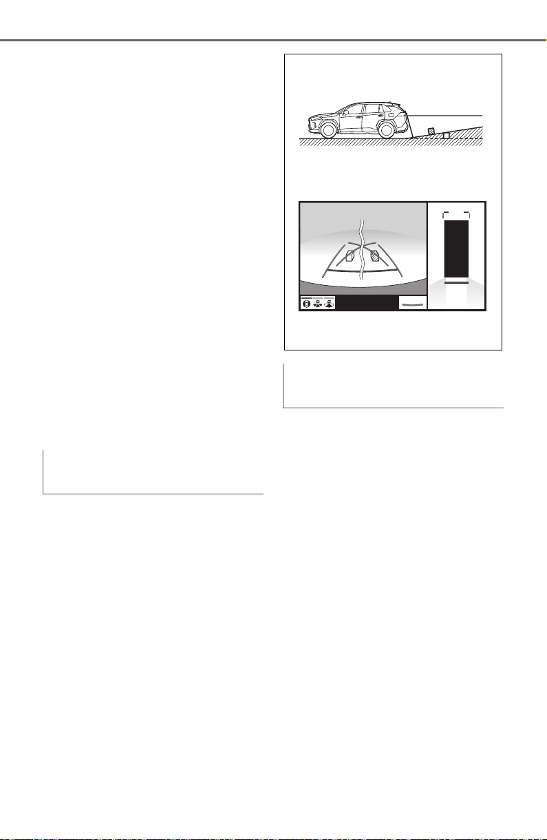
338
4-5. Using the driving support systems
may not actually be parallel
with the dividing lines of the
parking space, even when
they appear to be so. Be sure
to check visually.
The distances between the
vehicle width guide lines and
the left and right dividing lines
of the parking space may not
be equal, even when they
appear to be so. Be sure to
check visually.
The distance guide lines give
a distance guide for flat road
surfaces. In any of the follow-
ing situations, there is a mar-
gin of error between the guide
lines on the screen and the
actual distance/course on the
road.
The distance guide lines will
appear to be closer to the vehi-
cle than the actual distance.
Because of this, objects will
appear to be farther away than
they actually are. In the same
way, there will be a margin of
error between the guidelines
and the actual distance/course
on the road.
The distance guide lines will
appear to be farther from the
vehicle than the actual distance.
Because of this, objects will
appear to be closer than they
actually are. In the same way,
there will be a margin of error
between the guidelines and the
actual distance/course on the
road.
When the ground behind the
vehicle slopes up sharply
When the ground behind the
vehicle slopes down sharply
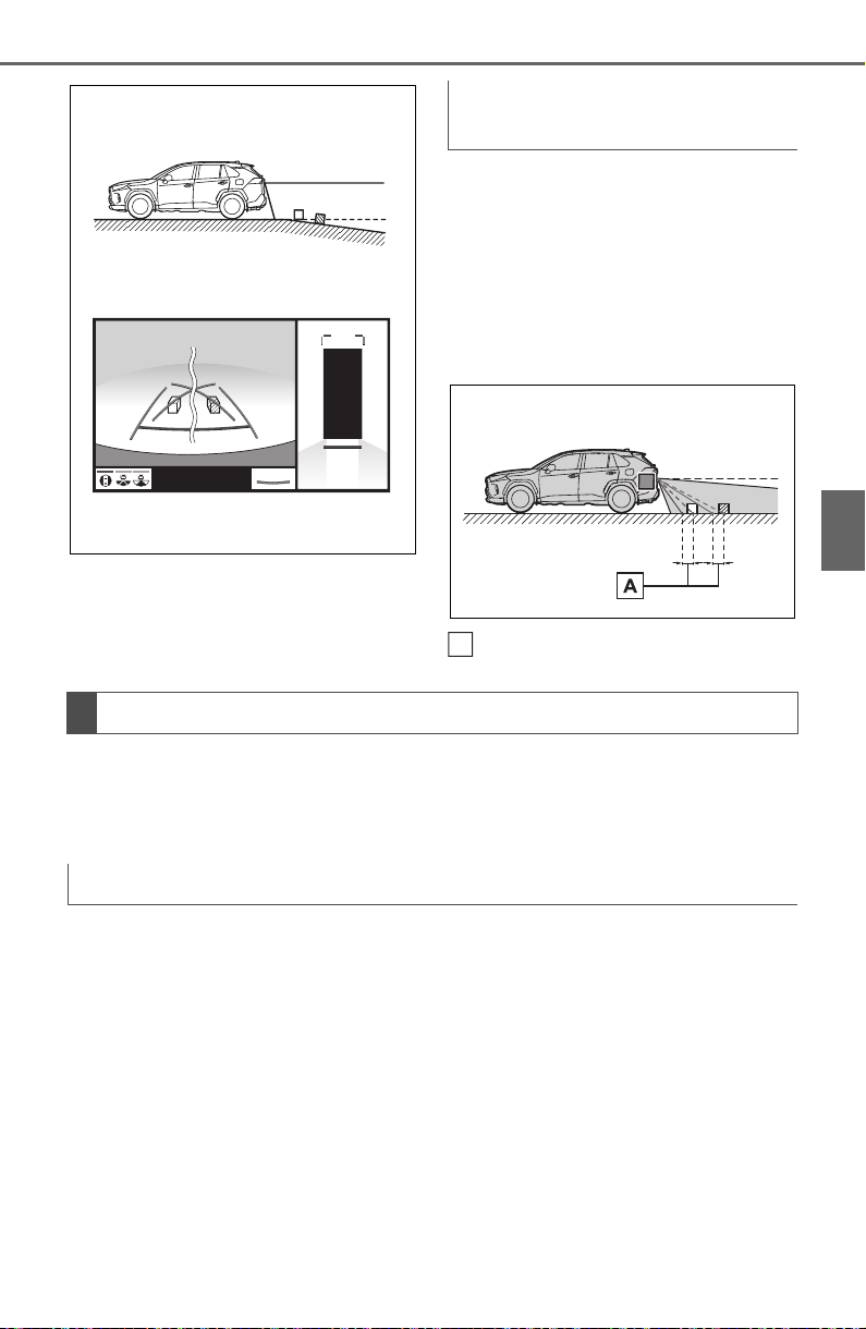
339
4-5. Using the driving support systems
4
Driving
When any part of the vehicle
sags due to the number of pas-
sengers or the distribution of the
load, there is a margin of error
between the guide lines on the
screen and the actual dis-
tance/course on the road.
A margin of error
When there are three-dimensional objects (such as vehicle bum-
pers, etc.) nearby in positions higher than the surface of the road,
take extra care when using the following.
Since the panoramic view processes and displays images based on
flat road surfaces, it cannot depict the position of three-dimension
objects (such as vehicle bumpers, etc.) that are in positions higher
than the surface of the road. For example, even though it appears
that there is space between the bumpers of the two vehicles in the
illustration below and they are not likely to collide, in reality, a colli-
sion is about to occur.
When any part of the vehicle
sags
A
Distortion of three-dimensional objects on the screen
Panoramic view display (including magnified display)
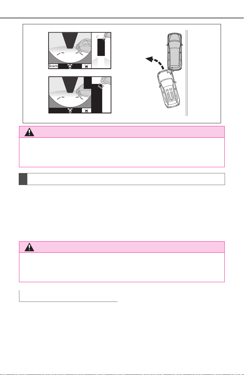
340
4-5. Using the driving support systems
The estimated course lines target flat surfaced objects (such as the
road). It is not possible to determine the position of three-dimen-
sional objects (such as vehicles) using the estimated course lines
and distance guide lines. When approaching a three-dimensional
object that extends outward (such as the flatbed of a truck), be care-
ful of the following.
Since the estimated course line
is displayed for a flat road sur-
face, it cannot depict the posi-
tion of three-dimensional objects
(such as vehicle bumpers, etc.)
that are in positions higher than
the surface of the road. Even if
the bumpers of the vehicle is on
the outside of the estimated
course line in the image, in real-
ity, the vehicles are on a colli-
sion course.
WARNING
● When a sensor indicator on the intuitive parking assist display illumi-
nates in red or a buzzer sounds continuously, be sure to check the area
around the vehicle immediately and do not proceed any further until
safety has been ensured, otherwise an unexpected accident may occur.
When approaching three-dimensional objects
WARNING
● When a sensor indicator on the intuitive parking assist display illumi-
nates in red or a buzzer sounds continuously, be sure to check the area
around the vehicle immediately and do not proceed any further until
safety has been ensured, otherwise an unexpected accident may occur.
Estimated course lines
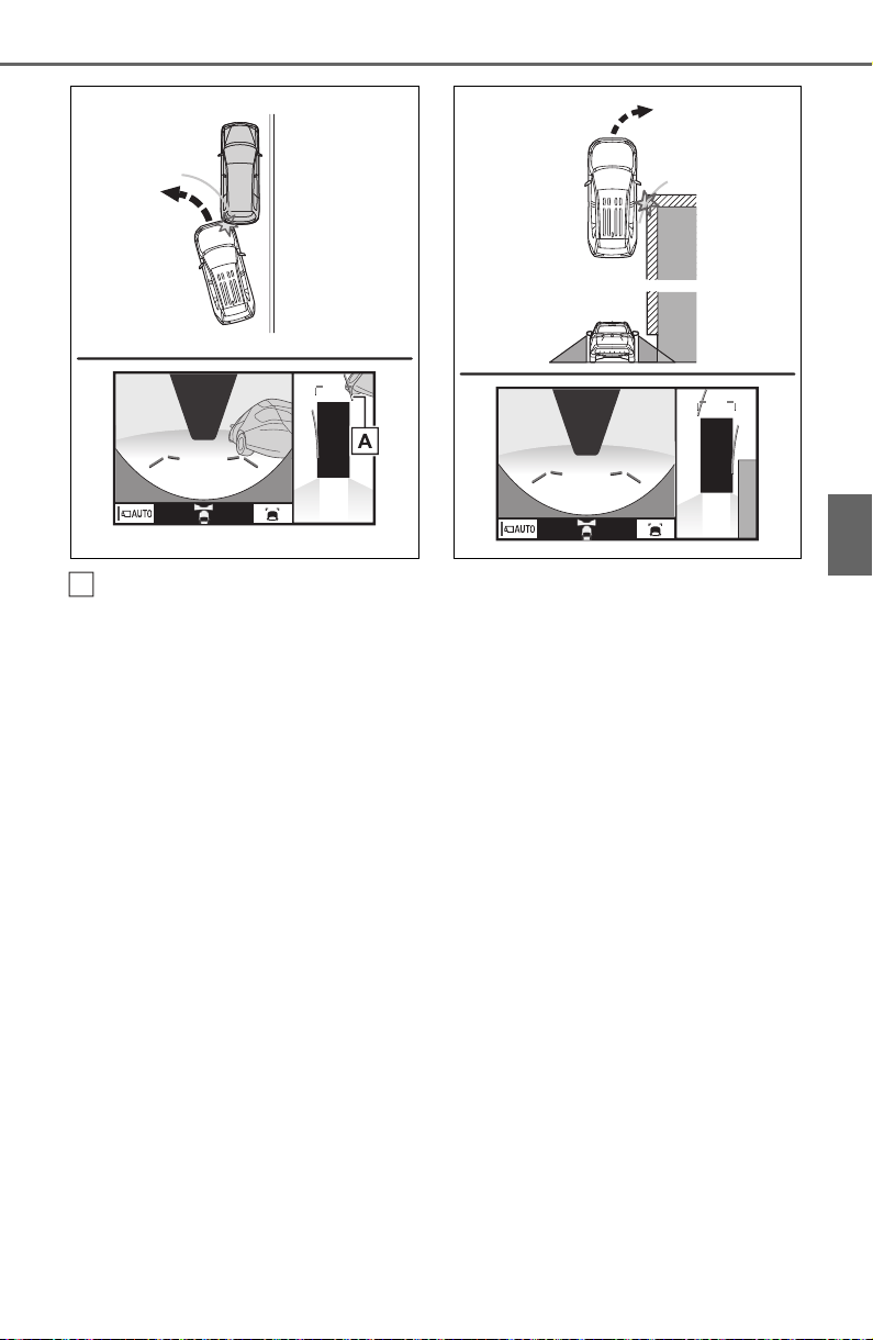
341
4-5. Using the driving support systems
4
Driving
Estimated course line
Three-dimensional objects
(such as the overhang of a wall
or loading platform of a truck) in
high positions may not be pro-
jected on the screen. Check the
safety of the surroundings
directly.
Visually check the surroundings
and the area behind the vehicle.
In the case shown below, the
truck appears to be outside of
the estimated course lines and
the vehicle does not look as if it
hits the truck. However, the rear
body of the truck may actually
cross over the estimated course
lines. In reality if you back up as
guided by the estimated course
lines, the vehicle may hit the
truck.
A
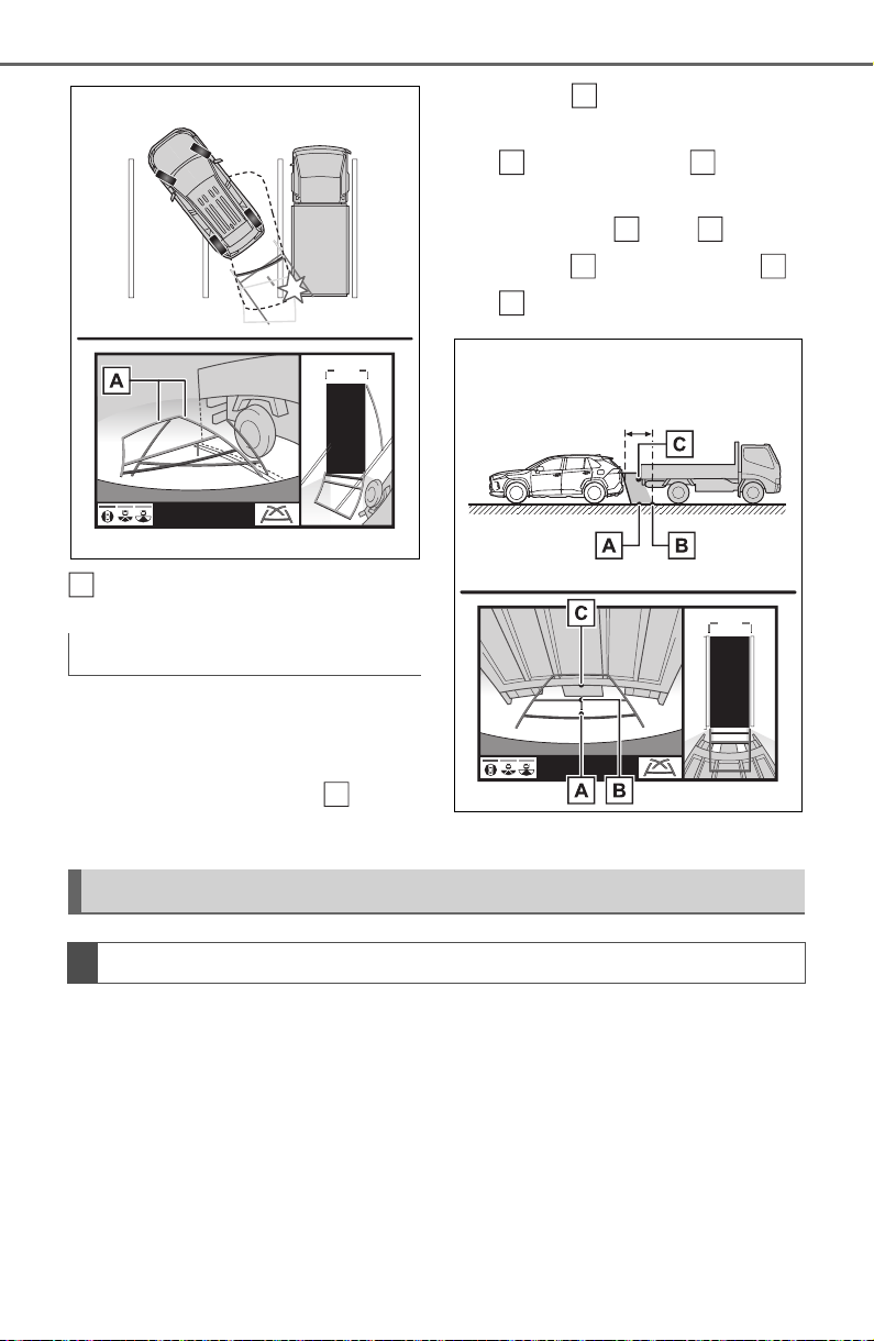
342
4-5. Using the driving support systems
Estimated course lines
Visually check the surroundings
and the area behind the vehicle.
On the screen, it appears that a
truck is parking at point .
However, in reality if you back
up to point , you will hit the
truck. On the screen, it appears
that is closest and is far-
thest away. However, in reality,
the distance to and is the
same, and is farther than
and .
If you notice any of the following symptoms, refer to the likely cause
and the solution, and re-check.
If the symptom is not resolved by the solution, have the vehicle
inspected by your Toyota dealer.
Distance guide lines
A
B
A
A
C
A
C
B
A
C
Things you should know
If you notice any symptoms

343
4-5. Using the driving support systems
4
Driving
Symptom Likely cause Solution
The image is difficult to
see
The vehicle is in a
dark area
The temperature
around the lens is
either high or low
The outside tempera-
ture is low
There are water drop-
lets on the camera
It is raining or humid
Foreign matter (mud,
etc.) is adhering to the
camera
Sunlight or headlights
are shining directly
into the camera
The vehicle is under
fluorescent lights,
sodium lights, mer-
cury lights, etc.
Back up while visually
checking the vehicle’s
surroundings. (Use the
monitor again once con-
ditions have been
improved.)
The procedure for
adjusting the picture
quality of the pan-
oramic view monitor
system is the same as
the procedure for
adjusting the screen dis-
play. (P.388)
The image is blurry
Dirt or foreign matter
(such as water drop-
lets, snow, mud, etc.) is
adhering to the camera.
Flush the camera with a
large quantity of water
and wipe the camera
lens clean with a soft
and wet cloth.
The image is out of
alignment
The camera or sur-
rounding area has
received a strong
impact.
Have the vehicle
inspected by your
Toyota dealer.
The guide lines are very
far out of alignment
The camera position is
out of alignment.
Have the vehicle
inspected by your
Toyota dealer.
The vehicle is tilted.
(There is a heavy load
on the vehicle, tire
pressure is low due to
a tire puncture, etc.)
The vehicle is used on
an incline.
If this happens due to
these causes, it does
not indicate a malfunc-
tion.
Back up while visually
checking the vehicle’s
surroundings.

344
4-5. Using the driving support systems
The estimated course
lines move even though
the steering wheel is
straight
There is a malfunction
in the signals being out-
put by the steering sen-
sor.
Have the vehicle
inspected by your
Toyota dealer.
Guide lines are not dis-
played
The back door is open.
Close the back door.
If this does not resolve
the symptom, have the
vehicle inspected by
your Toyota dealer.
The estimated course
lines are not displayed
Battery has been rein-
stalled.
The steering wheel
has been moved while
the battery was being
reinstalled.
Battery power is low.
The steering sensor
has been reinstalled.
There is a malfunction
in the signals being
output by the steering
sensor.
Have the vehicle
inspected by your
Toyota dealer.
The panoramic view dis-
play cannot be magni-
fied
The intuitive parking
assist may be malfunc-
tioning or dirty.
Follow the correction
procedures for malfunc-
tions of the intuitive
parking assist. (P.270)
The see-through
view/moving view can-
not be displayed
Product license
Symptom Likely cause Solution
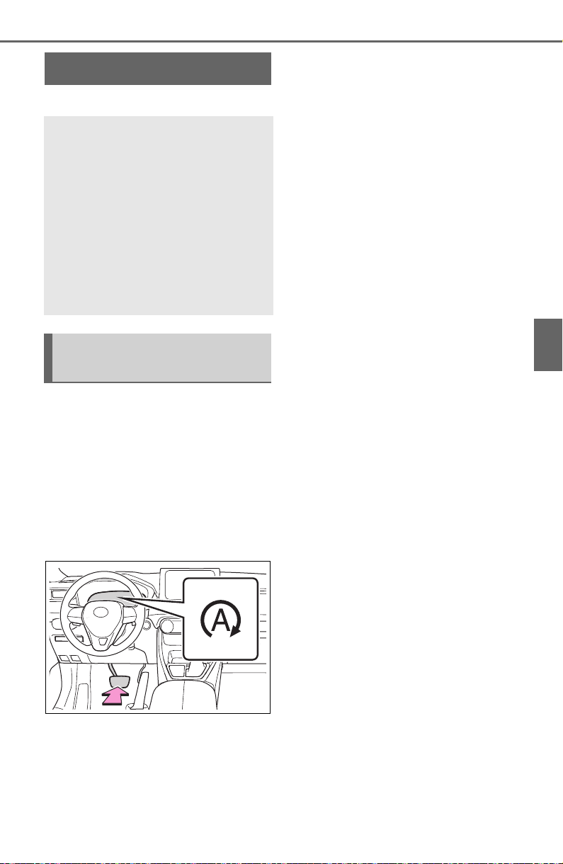
345
4-5. Using the driving support systems
4
Driving
*
: If equipped
■ Stopping the engine
While driving with the D shift
position selected, depress the
brake pedal and stop the vehi-
cle. The engine will stop auto-
matically.
When the engine stops, the Stop &
Start indicator will illuminate.
■ Restarting the engine
Release the brake pedal. The
engine will start automatically.
When the engine starts, the Stop &
Start indicator will turn off.
■ When the brake hold sys-
tem is operating
When the engine is stopped
by the Stop & Start system, if
the brake pedal is released
the engine will remain
stopped.
If the accelerator pedal is
depressed while the engine is
stopped by the Stop & Start
system, the engine will
restart.
While the engine is stopped
by the Stop & Start system, if
the engine is restarted, the
brake hold system will con-
tinue to apply the brakes,
unless the operation condi-
tions of the brake hold system
are no longer met. (P.206)
■ When the dynamic radar
cruise control with full-
speed range is operating
When the vehicle is stopped
by the dynamic radar cruise
control with full-speed range,
the engine will stop automati-
cally even though the brake
pedal is not depressed.
When the preceding vehicle
starts off, the engine will
restart automatically.
If the engine is restarted by
the Stop & Start system while
the vehicle is stopped by the
dynamic radar cruise control
with full-speed range, the
vehicle will remain stopped.
Stop & Start system
*
The Stop & Start system
stops and starts the engine
according to brake pedal or
shift lever operation when
the vehicle is stopped, such
as at a stoplight, intersec-
tion, etc., in order to
improve fuel economy and
reduce noise pollution
caused by the engine idling.
Stop & Start system oper-
ation
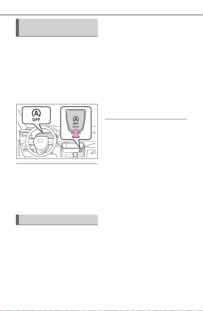
346
4-5. Using the driving support systems
Press the Stop & Start cancel
switch to disable the Stop &
Start system.
The Stop & Start cancel indica-
tor will illuminate.
Pressing the switch again will
enable the Stop & Start system and
the Stop & Start cancel indicator will
turn off.
■ Automatic enabling of the Stop
& Start system
If the Stop & Start system is dis-
abled using the Stop & Start cancel
switch, it will be automatically re-
enabled once the engine switch is
turned off and then the engine is
started.
When the engine is stopped by
the Stop & Start system when
the vehicle is on an incline,
when the brake pedal is
released, brake force is tempo-
rarily maintained to prevent the
vehicle from rolling backwards
before the engine is restarted
and drive force is generated.
When drive force is generated,
the maintained brake force is
automatically canceled.
This function operates on flat
surfaces as well as steep
inclines.
Sound may be generated
from the brake system, but
this does not indicate a mal-
function.
Brake pedal response may
change and vibration may
occur, but this does not indi-
cate a malfunction.
■ Points for use
● If the engine switch is pressed
when the engine is stopped by the
Stop & Start system, the engine
will not be able to be restarted by
the automatic engine start func-
tion. In this case, restart the
engine using the normal engine
starting procedure. (P.193, 194)
● When the engine is being
restarted by the Stop & Start sys-
tem, the power outlets may be
temporarily unusable, but this
does not indicate a malfunction.
● Installation and removal of electri-
cal components and wireless
devices may affect the Stop &
Start system. Contact your Toyota
dealer for details.
● When stopping the vehicle for a
longer period of time, turn the
engine switch off to stop the
engine completely.
● When the engine is restarted by
the Stop & Start system, the steer-
ing wheel may temporarily feel
heavy.
■ Operating conditions
● The Stop & Start system is opera-
tional when all of the following
conditions are met:
Disabling the Stop & Start
system
Hill-start assist control

347
4-5. Using the driving support systems
4
Driving
• The vehicle has been driven a cer-
tain amount of time.
• The brake pedal is being
depressed firmly. (except when
the vehicle is stopped by the
dynamic radar cruise control with
full-speed range when in vehicle-
to-vehicle distance control mode)
• The D shift position is selected.
• The driver’s seat belt is fastened.
• The driver’s door is closed.
• The selected driving mode is nor-
mal or Eco drive mode.
• The selected driving mode is not
snow mode (AWD models).
• Mud & Sand or Rock & Dirt mode
is not selected for Multi-terrain
Select (AWD models).
• The windshield defogger is off.
(vehicles without a manual air
conditioning system)
• The accelerator pedal is not being
depressed.
• The engine is adequately warmed
up.
• The outside temperature is 23°F (-
5°C) or higher.
• The hood is closed. (P.348)
● In the following situations, the
engine may not be stopped by the
Stop & Start system. This is not a
malfunction of the Stop & Start
system.
• When the air conditioning system
is being used.
• When the battery is undergoing a
periodic recharge.
• When the battery is not sufficiently
charged, such as if the vehicle
has been parked for a long time
and the battery charge has
decreased, the electric load is
large, the battery fluid tempera-
ture is excessively low or the bat-
tery has deteriorated.
• When the brake booster vacuum
is low.
• When the elapsed time since the
engine was restarted is short.
• When the vehicle is stopped fre-
quently, such as when in a traffic
jam.
• When the engine coolant tem-
perature or transmission fluid tem-
perature is extremely low or high.
• When the vehicle is stopped on a
steep incline.
• When the steering wheel is being
operated.
• When the vehicle is being driven
in a high altitude area.
• When the battery fluid tempera-
ture is extremely low or high.
• For a while after the battery termi-
nals have been disconnected and
reconnected.
● When the engine is stopped by
the Stop & Start system, the
engine will be restarted automati-
cally if any of the following condi-
tions are met:
(To enable the engine to be
stopped by the Stop & Start sys-
tem again, drive the vehicle.)
• The air conditioning system is
turned on. (vehicles without a
manual air conditioning system)
• The windshield defogger is turned
on. (vehicles without a manual air
conditioning system)
• The shift lever is shifted from D.
• The driver’s seat belt is unfas-
tened.
• The driver’s door is opened.
• The driving mode is changed from
normal or Eco drive mode to
another mode.
• The driving mode is changed to
snow mode (AWD models).
• Mud & Sand or Rock & Dirt mode
is selected for Multi-terrain Select
(AWD models).
• The Stop & Start cancel switch is
pressed.
• The steering wheel is operated.
• The accelerator pedal is
depressed.
• The vehicle starts to roll on an
incline.
● When the engine is stopped by
the Stop & Start system, the
engine may restart automatically
in the following situations: (To
enable the engine to be stopped
by the Stop & Start system again,
drive the vehicle.)
• When the brake pedal is pumped

348
4-5. Using the driving support systems
or strongly depressed.
• When the air conditioning system
is being used.
• When a switch of the air condition-
ing system is operated (windshield
defogger switch, etc.).
• If the battery charge becomes low.
■ When the hood is opened
● If the hood is opened while the
engine is stopped by the Stop &
Start system, the engine will stall
and will not be able to be restarted
by the automatic engine start
function. In this case, restart the
engine using the normal engine
starting procedure. (P.193, 194)
● If the hood is closed after the
engine is started with the hood
open, the Stop & Start system will
not operate. Close the hood, turn
the engine switch off, wait 30 sec-
onds or more, and then start the
engine.
■ Air conditioning system opera-
tion while the engine is stopped
by the Stop & Start system
Vehicles with an automatic air con-
ditioning system: When the air con-
ditioning is in automatic mode and
the engine is stopped by the Stop &
Start system, the fan may operate at
a low speed in order to prevent the
temperature in the cabin from
increasing or decreasing or may be
stopped.
To prioritize air conditioning system
performance when the vehicle is
stopped, disable the Stop & Start
system by pressing the Stop & Start
cancel switch.
● If the windshield is fogged up
Turn the windshield defogger on.
(P.511, 517)
If the windshield fogs up frequently,
press the Stop & Start cancel switch
to disable the Stop & Start system.
● If an odor is emitted from the air
conditioning system
• Vehicles with a manual air condi-
tioning system:
If the idling stop time setting is set
to “Extended”, change it to “Stan-
dard”. If an odor is emitted when
the idling stop time setting is set to
“Standard”, press the Stop & Start
cancel switch to deactivate the
Stop & Start system.
• Vehicles with an automatic air
conditioning system:
Press the Stop & Start cancel
switch to deactivate the Stop &
Start system.
■ Changing the idling stop time
with the air conditioning system
on
The length of time the Stop & Start
system will operate when the air
conditioning system is on can be
changed in of the multi-informa-
tion display (P.94). (The length of
time the Stop & Start system will
operate when the air conditioning
system is off cannot be changed.)
■ Displaying the Stop & Start sys-
tem status
After Start:
Displays the cumulative time that
the engine is stopped by the Stop &
Start system from when the engine
is started until the engine is
stopped.
This item is reset each time the
engine stops.
■ Multi-information display mes-
sages
If the following situations,
and a message may be displayed
on the multi-information display.
● When the engine cannot be
stopped by the Stop & Start sys-
tem
“Press Brake More to Acti-
vate”
349
4-5. Using the driving support systems
4
Driving
• The brake pedal is not sufficiently
depressed.
If the brake pedal is depressed
further, the system will operate.
“Non-Dedicated Battery”
• A battery not designed for use
with a Stop & Start system may
have been installed.
Have the vehicle inspected by
your Toyota dealer.
“Battery Charging”
• The battery charge may be low.
Stopping of the engine is tempo-
rarily prohibited to prioritize charging
of the battery. After the engine runs
for a certain amount of time, the sys-
tem will be enabled.
• A refresh charge may be occur-
ring (Examples: For a while after
the battery terminals have been
disconnected and reconnected.
For a while after the battery has
been replaced. etc.)
After a refresh charge for up to
an hour completes, the system can
be operated.
• If displayed continuously for a
long time (more than an hour)
The battery may be deteriorated.
Contact your Toyota dealer for
details.
“Stop & Start System
Unavailable”
• The Stop & Start system is tempo-
rarily disabled.
Allow the engine to run for some
time.
• The engine may have been
started with the hood open.
Close the hood, turn the engine
switch off, wait for 30 seconds or
more, and then start the engine.
“In Preparation”
• The vehicle is being driven in a
high altitude area.
• The brake booster vacuum is low.
When the brake booster vacuum
reaches a predetermined level, the
system will be enabled.
“For Climate Control”
• The air conditioning system is
being used when the ambient
temperature is high or low.
If the difference between the set
temperature and cabin temperature
becomes small, the system will be
enabled.
• The windshield defogger is on.
● When the engine automatically
restarts while stopped by the Stop
& Start system
“In Preparation”
• The brake pedal has been
depressed further or pumped.
The system will be enabled after
the engine runs and the brake
booster vacuum reaches a predeter-
mined level.
“For Climate Control”
• The air conditioning system has
been turned on or is being used.
• The windshield defogger has
been turned on.
“Battery Charging”
• The battery charge may be low.
The system will be enabled after
the engine runs to sufficiently
350
4-5. Using the driving support systems
charge the battery.
■ When the buzzer sounds
If the driver’s door is opened when
the engine is stopped by the Stop &
Start system and the shift lever is in
D, a buzzer will sound and the Stop
& Start system indicator will flash. To
stop the buzzer, close the driver’s
door.
■ The Stop & Start system protec-
tion function
● When the volume of the audio
system is excessively high, sound
output from the audio system may
suddenly be cut off in order to
reduce battery consumption. To
prevent the audio system from
being cut off, keep the volume of
audio system at a moderate level.
If the audio system has been cut
off, turn the engine switch off, wait
for 3 seconds or more and then
turn it to ACC or ON to re-enable
the audio system.
● The audio system may not be acti-
vated if the battery terminals are
disconnected and then recon-
nected. If this occurs, turn the
engine switch off and then repeat
the following operation twice to
activate the audio system nor-
mally.
• Turn the engine switch to ON and
then to off.
■ Replacing the battery
P.657
■ If the Stop & Start cancel indica-
tor flashes continuously
The system may be malfunctioning.
Have the vehicle inspected by your
Toyota dealer.
■ If “Stop & Start System Mal-
function Visit Your Dealer” is
displayed on the multi-informa-
tion display
The system may be malfunctioning.
Have the vehicle inspected by your
Toyota dealer.
WARNING
■ When the Stop & Start system
is operating
Make sure to disable the Stop &
Start system while the vehicle is in
a poorly ventilated area.
If not disabled, the engine may be
automatically restarted unexpect-
edly, causing exhaust gases to
collect and enter the vehicle, pos-
sibly resulting in death or a seri-
ous health hazard.
● Do not leave the vehicle while
the engine is stopped by the
Stop & Start system (while the
Stop & Start indicator is on). An
accident may occur due to the
automatic engine start function.
● Depress the brake pedal and
apply the parking brake when
necessary while the engine is
stopped by the Stop & Start sys-
tem (while the Stop & Start indi-
cator is on).
NOTICE
■ To ensure the system oper-
ates correctly
If any of the following situations
occur, the Stop & Start system
may not operate correctly. Have
your vehicle inspected by your
Toyota dealer.
● While the driver’s seat belt is
fastened, the driver’s and front
passenger’s seat belt reminder
light flashes.
● Even though the driver’s seat
belt is not fastened, the driver’s
and front passenger’s seat belt
reminder light does not illumi-
nate.
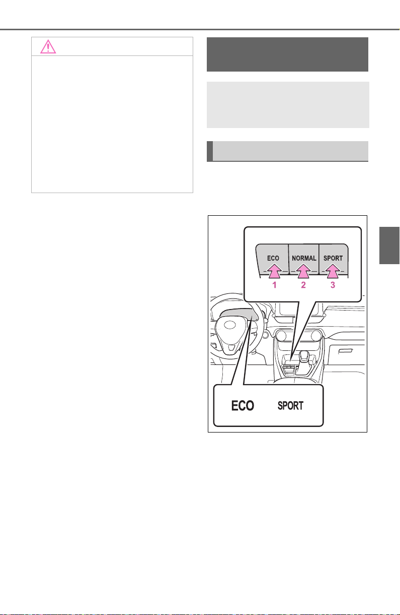
351
4-5. Using the driving support systems
4
Driving
■ FF vehicles/Dynamic
Torque Control AWD vehi-
cles
1 Eco drive mode
Suitable for driving to improve fuel
economy by more smoothly gener-
ating torque in response to acceler-
ator pedal operations compared to
normal mode and restraining air
conditioning system operations
(heating/cooling).
When the switch is pressed while
not in Eco drive mode, the system
switches to Eco drive mode and the
NOTICE
● Even though the driver’s door is
closed, the open door warning
light is illuminated or the interior
light is illuminated when the
interior light switch is in the door
position.
● Even though the driver’s door is
open, the open door warning
light does not illuminate or the
interior light does not illuminate
when the interior light switch is
in the door position.
Driving mode select
switch
The driving modes can be
selected to suit the driving
and usage conditions.
Selecting a driving mode
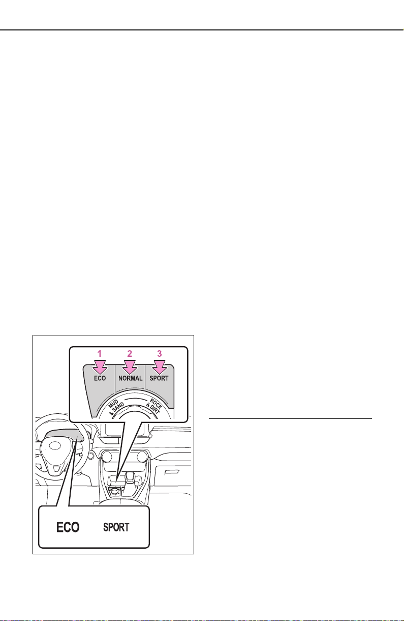
352
4-5. Using the driving support systems
Eco drive mode indicator illumi-
nates on the multi-information dis-
play.
2 Normal mode
Suitable for normal driving.
The driving mode returns to normal
mode if the switch is pressed while
in Eco drive mode or sport mode.
3 Sport mode
Controls the steering feeling and
engine to create an acceleration
response that is suitable for sporty
driving. Suitable for when crisp
handling is desired, such as when
driving on mountainous roads.
When the switch is pressed while
not in sport mode, the system
switches to sport mode and the
sport mode indicator illuminates on
the multi-information display.
■ Dynamic Torque Vectoring
AWD vehicles
1 Eco drive mode
Suitable for driving to improve fuel
economy by more smoothly gener-
ating torque in response to acceler-
ator pedal operations compared to
normal mode and restraining air
conditioning system operations
(heating/cooling).
When the switch is pressed while
not in Eco drive mode, the system
switches to Eco drive mode and the
Eco drive mode indicator illumi-
nates on the multi-information dis-
play.
2 Normal mode
Suitable for normal driving.
The driving mode returns to normal
mode if the switch is pressed while
in Eco drive mode or sport mode.
3 Sport mode
Controls the steering feeling and
engine to create an acceleration
response that is suitable for sporty
driving. Suitable for when crisp
handling is desired, such as when
driving on mountainous roads.
When the switch is pressed while
not in sport mode, the system
switches to sport mode and the
sport mode indicator illuminates on
the multi-information display.
■ When changing to a driving
mode other than normal mode
● The background color of the multi-
information display changes
according to the selected driving
mode.
● When the speedometer is set to
analog display, the speedometer
display color also changes. (For
vehicles with the 7-inch multi-
information display only)
● Switches to AWD control suitable
for the selected mode. (For
Dynamic Torque Vectoring AWD
vehicles only)

353
4-5. Using the driving support systems
4
Driving
■ Air conditioning system opera-
tion in Eco drive mode
In Eco drive mode, heating/cooling
operations and the fan speed is con-
trolled to improve fuel efficiency.
Perform the following procedures to
increase the air conditioning perfor-
mance.
● Vehicles with automatic air condi-
tioning system: Turn eco air condi-
tioning mode off (P.516)
● Adjust the fan speed (P. 51 0,
516)
● Cancel Eco drive mode
■ Canceling a driving mode
● Sport mode is automatically can-
celed and the driving mode
returns to normal mode when the
engine switch is turned off.
● Normal mode and Eco drive mode
are not canceled until another
driving mode is selected. (Even if
the engine switch is turned off,
normal mode and Eco drive mode
will not be automatically can-
celed.)
Multi-terrain Select
(AWD vehicles)
When driving over muddy,
sandy or rough road sur-
faces, Multi-terrain Select
selects a suitable driving
mode to switch AWD, brake
and drive force control to
perform control suitable for
the road condition.
WARNING
■ Before using Multi-terrain
Select
Make sure to observe the follow-
ing precautions. Failure to
observe these precautions may
result in an unexpected accident.
● Check that the Mud & Sand and
Rock & Dirt indicators are illumi-
nated before driving. Multi-ter-
rain Select will not operate
when the indicators are off.
● Do not rely solely upon the
Multi-terrain Select. This func-
tion is not intended to expand
the limits of the vehicle. If the
system is continuously used for
a long period of time, the load
on related parts increases and
the system may be unable to
operate normally, which may
lead to an accident. Thoroughly
check the road conditions and
driving route before driving, and
drive with caution.
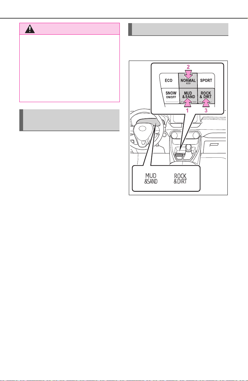
354
4-5. Using the driving support systems
Control that is suitable for the
following road conditions can be
performed by switching to either
of the two modes. Select a
mode that is appropriate for the
road condition.
■ Mud & Sand mode
Suitable for driving on roads
with increased driving resis-
tance such as sandy roads,
muddy roads, etc.
■ Rock & Dirt mode
Suitable for driving in bumpy
road conditions, such as on
unpaved forest roads.
■ Dynamic Torque Control
AWD vehicles
1 Mud & Sand mode
When the switch is pressed while
not in Mud & Sand mode, the sys-
tem switches to Mud & Sand mode
and the Mud & Sand mode indica-
tor, VSC OFF indicator (P.79) and
PCS warning light (P.77) illumi-
nate on the multi-information dis-
play or the instrument cluster.
2 Normal mode
Mode that performs AWD, brake
and drive force control suitable for
driving on general roads. Use nor-
mal mode when not driving off-
road.
The driving mode returns to normal
mode if the switch is pressed while
in Mud & Sand mode or Rock & Dirt
mode.
3 Rock & Dirt mode
WARNING
● The road conditions listed in
“Guidelines for selecting each
mode” are for reference only.
There is a chance that the func-
tion may not be the most appro-
priate in terms of road
conditions such as pitch, slip-
periness, undulation, etc. Thor-
oughly check the road
conditions before driving.
Guidelines for selecting
each mode
Changing the mode

355
4-5. Using the driving support systems
4
Driving
When the switch is pressed while
not in Rock & Dirt mode, the sys-
tem switches to Rock & Dirt mode
and the Rock & Dirt mode indicator
illuminates on the multi-information
display.
■ Dynamic Torque Vectoring
AWD vehicles
1 Mud & Sand mode
When the switch is turned to the left
while not in Mud & Sand mode, the
system switches to Mud & Sand
mode and the Mud & Sand mode
indicator, VSC OFF indicator
(P.79) and PCS warning light
(P.77) illuminate on the multi-
information display or the instru-
ment cluster.
2 Normal mode
Mode that performs AWD, brake
and drive force control suitable for
driving on general roads. Use nor-
mal mode when not driving off-
road.
The driving mode returns to normal
mode if the switch is pressed while
in Mud & Sand mode or Rock & Dirt
mode.
3 Rock & Dirt mode
When the switch is turned to the
right while not in Rock & Dirt mode,
the system switches to Rock & Dirt
mode and the Rock & Dirt mode
indicator illuminates on the multi-
information display.
■ Multi-terrain Select
● Multi-terrain Select is intended for
use when driving on rough roads.
Drive in normal mode during nor-
mal driving.
● The Mud & Sand and Rock & Dirt
modes control the vehicle so that
it can maximize the drive force
and improve drivability on rough
roads. As a result, fuel efficiency
may diminish when compared to
driving in normal mode.
■ If Mud & Sand or Rock & Dirt
mode is selected
● The background of the multi-infor-
mation display will change follow-
ing the Multi-terrain Select mode.
● The AWD operation status display
will automatically switch on the
multi-information display.
● The color of the switch will change
following the Multi-terrain Select
mode. (For Dynamic Torque Vec-
toring AWD vehicles only)
■ AWD control for Mud & Sand
and Rock & Dirt modes
If the vehicle speed exceeds the
speeds listed below, 4WD control is
performed similar to that performed
in Normal mode, even if Mud &
Sand or Rock & Dirt mode is
selected.
● Mud & Sand mode: Vehicle speed
is approximately 40 km/h (25
mph) or more
● Rock & Dirt mode: Vehicle speed

356
4-5. Using the driving support systems
is approximately 25 km/h (16
mph) or more
If the vehicle speed drops below the
above speeds, the system automati-
cally switches to the 4WD control
suitable for each mode.
■ When Multi-terrain Select brake
control temporarily stops oper-
ating
If Mud & Sand or Rock & Dirt mode
is continuously used for a long
period of time, the brakes may over-
heat, and Multi-terrain Select brake
control may temporarily stop operat-
ing.
● At this time, the buzzer sounds
intermittently and “Traction Con-
trol Turned OFF” is displayed on
the multi-information display.
● If Multi-terrain Select brake control
stops operating, stop the vehicle
in a safe location as soon as pos-
sible
*
and wait until the system
temperature decreases. Once the
display message on the multi-
information display turns off, the
brake control returns to normal.
Note that normal driving is still
possible even when Multi-terrain
Select brake control is not operat-
ing.
*
: After stopping the vehicle, do not
stop the engine until the display
message has turned off.
■ When Mud & Sand or Rock &
Dirt mode is canceled
In the following situations, Mud &
Sand mode or Rock & Dirt mode are
automatically canceled even if they
are selected.
● When the driving mode is
changed (P.351)
● When the engine switch is turned
off
■ Driving in Mud & Sand or Rock
& Dirt mode
The following types of situations
may occur, but they are not malfunc-
tions.
● Vibrations may be felt throughout
the vehicle or steering wheel
● Operating noise may be heard
from the engine compartment
■ When an inspection at your
Toyota dealer is necessary
In the following situations, the sys-
tem may be malfunctioning. Have
the vehicle inspected by your Toyota
dealer immediately.
● When the slip indicator light illumi-
nates while Mud & Sand or Rock
& Dirt mode is selected
● When the indicator for each mode
does not illuminate even though
Mud & Sand or Rock & Dirt mode
is selected
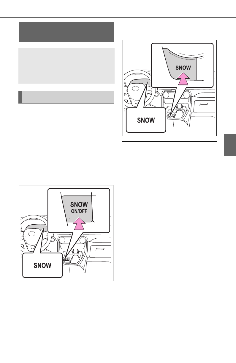
357
4-5. Using the driving support systems
4
Driving
■ Dynamic Torque Control
AWD vehicles
Press the snow mode switch.
When the switch is pressed, the
system switches to snow mode and
the snow mode indicator illuminates
on the multi-information display.
When the switch is pressed again,
the snow mode indicator turns off.
■ Dynamic Torque Vectoring
AWD vehicles
Press the snow mode switch.
When the switch is pressed, the
system switches to snow mode and
the snow mode indicator illuminates
on the multi-information display.
When the switch is pressed again,
the snow mode indicator turns off.
■ When changing to snow mode
The background of the multi-infor-
mation display changes.
■ Canceling the snow mode
Snow mode is automatically can-
celed when the engine switch is
turned off or Mud & Sand or Rock &
Dirt mode is selected for Multi-ter-
rain Select.
Snow mode switch
(AWD vehicles)
Snow mode can be selected
to suit the conditions when
driving on slippery road sur-
faces, such as on snow.
System operation
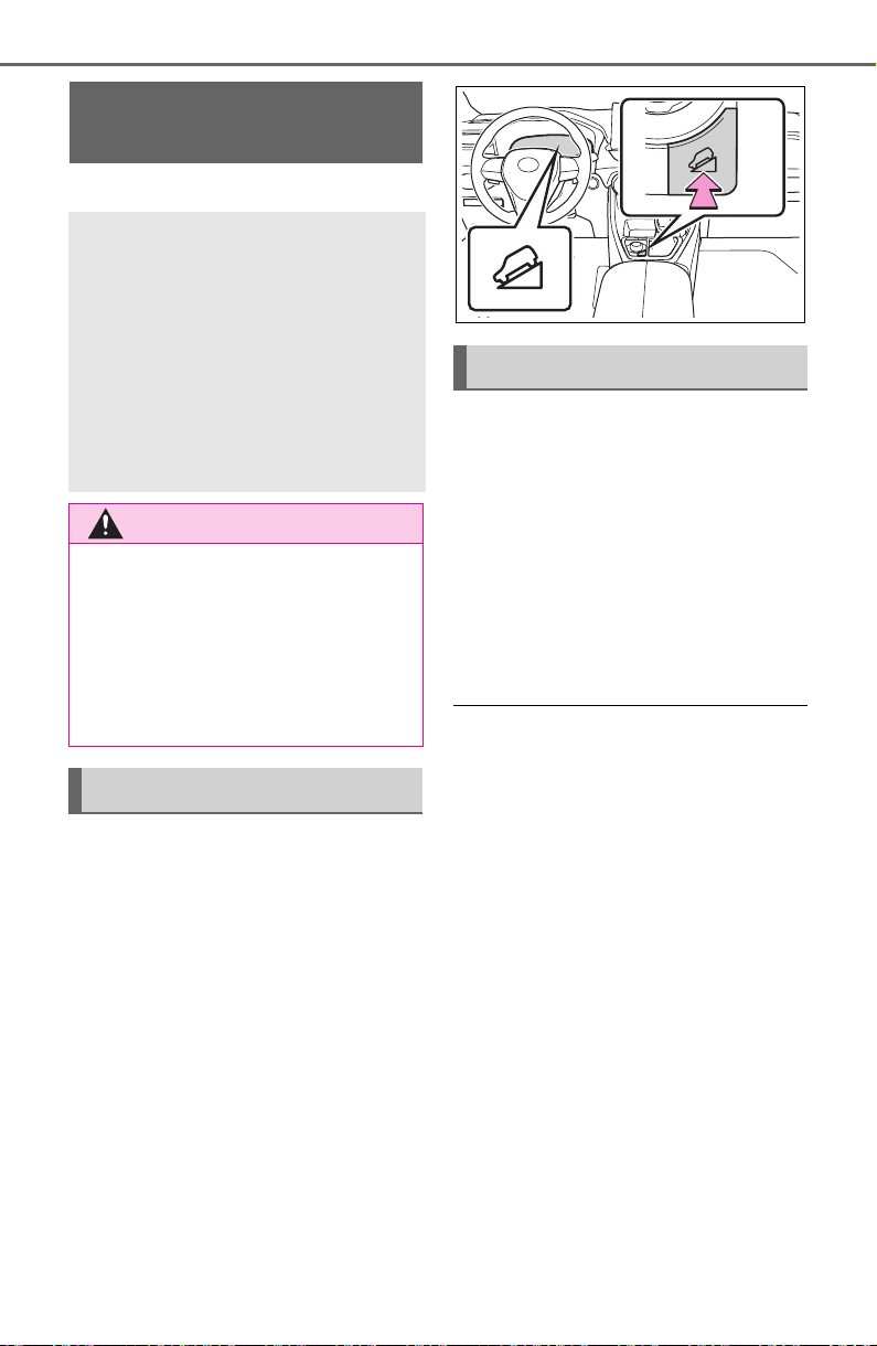
358
4-5. Using the driving support systems
*
: If equipped
Press the “DAC” switch.
The downhill assist control system
indicator will come on and the sys-
tem will operate.
When the system is in operation,
the slip indicator light will flash, and
the stop lights/high mounted stop
lights will be lit. A sound may also
occur during the operation. This
does not indicate a malfunction.
Press the “DAC” switch while
the system is in operation.
The downhill assist control system
indicator will flash as the system
gradually ceases operation, and will
turn off when the system is fully off.
Press the “DAC” switch while the
downhill assist control system indi-
cator is flashing to start the system
again.
■ Operating tips
The system will operate when the
shift lever is in D or 1 range of S
mode or R.
■ If the downhill assist control
system indicator flashes
● In the following situations, the indi-
cator flashes and the system will
not operate:
• The shift lever is in a position
other than D or 1 range of S mode
or R.
• The accelerator or brake pedal is
depressed.
• The vehicle speed exceeds
approximately 15 mph (25 km/h).
• The brake system overheats.
● In the following situation, the indi-
cator flashes to alert the driver,
but the system will operate:
• The “DAC” switch is turned off
while the system is operating.
The system will gradually ceases
Downhill assist con-
trol system
*
The downhill assist control
system helps to prevent
excessive speed on steep
downhill slopes.
The system will operate
when the vehicle is traveling
under 25 km/h (15 mph) with
the accelerator and brake
pedals released.
WARNING
■ When using downhill assist
control system
Do not rely overmuch on the
downhill assist control system.
This function does not extend the
vehicle’s performance limitations.
Always thoroughly check the road
conditions, and drive safely.
System operation
Turning off the system

359
4-5. Using the driving support systems
4
Driving
operation. The indicator will flash
during operation, and then go off
when the system is fully off.
■ When the downhill assist con-
trol system is operated continu-
ously
This may cause the brake actuator
to overheat. In this case, the down-
hill assist control system will stop
operating, a buzzer will sound and
the downhill assist control system
indicator will start flashing. Refrain
from using the system until the
downhill assist control system indi-
cator stays on. (The vehicle can be
driven normally during this time.)
■ Sounds and vibrations caused
by the downhill assist control
system
● A sound may be heard from the
engine compartment when the
engine is started or just after the
vehicle begins to move. This
sound does not indicate that a
malfunction has occurred in down-
hill assist control system.
● Either of the following conditions
may occur when the downhill
assist control system is operating.
None of these are indicators that a
malfunction has occurred.
• Vibrations may be felt through the
vehicle body and steering.
• A motor sound may be heard after
the vehicle comes to a stop.
■ System malfunction
In the following cases, have your
vehicle checked by your Toyota
dealer.
● The downhill assist control system
indicator does not come on when
the engine switch is turned to ON.
● The downhill assist control system
indicator does not come on when
the “DAC” switch is pressed.
● The slip indicator light comes on.
WARNING
■ The system may not operate
on the following surfaces,
which may lead to an acci-
dent causing death or serious
injury
● Slippery surfaces such as wet
or muddy roads
● Icy surface
● Unpaved roads

360
4-5. Using the driving support systems
■ ABS (Anti-lock Brake Sys-
tem)
Helps to prevent wheel lock
when the brakes are applied
suddenly, or if the brakes are
applied while driving on a slip-
pery road surface
■ Brake assist
Generates an increased level of
braking force after the brake
pedal is depressed when the
system detects a panic stop sit-
uation
■ VSC (Vehicle Stability Con-
trol)
Helps the driver to control skid-
ding when swerving suddenly or
turning on slippery road sur-
faces.
■ Enhanced VSC (Enhanced
Vehicle Stability Control)
Provides cooperative control of
the ABS, TRAC, VSC and EPS.
Helps to maintain directional
stability when swerving on slip-
pery road surfaces by con-
trolling steering performance.
■ Trailer Sway Control
Helps the driver to control trailer
sway by selectively applying
brake pressure for individual
wheels and reducing driving
torque when trailer sway is
detected.
■ TRAC (Traction Control)
Helps to maintain drive power
and prevent the drive wheels
from spinning when starting the
vehicle or accelerating on slip-
pery roads
■ Active Cornering Assist
(ACA)
Helps to prevent the vehicle
from drifting to the outer side by
performing inner wheel brake
control when attempting to
accelerate while turning
■ Hill-start assist control
Helps to reduce the backward
movement of the vehicle when
starting on an uphill
■ EPS (Electric Power Steer-
ing)
Employs an electric motor to
reduce the amount of effort
Driving assist systems
To keep driving safety and
performance, the following
systems operate automati-
cally in response to various
driving situations. Be
aware, however, that these
systems are supplementary
and should not be relied
upon too heavily when oper-
ating the vehicle.
Summary of the driving
assist systems
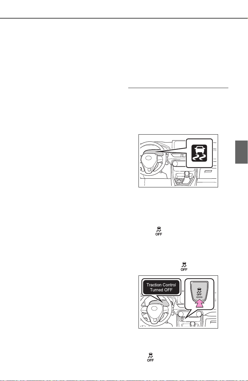
361
4-5. Using the driving support systems
4
Driving
needed to turn the steering
wheel
■ Dynamic Torque Control
AWD system (if equipped)
Automatically switches from
front-wheel drive to all-wheel
drive (AWD) according to the
driving conditions, helping to
ensure reliable handling and
stability. Examples of conditions
where the system will switch to
AWD are when cornering, going
uphill, starting off or accelerat-
ing, and when the road surface
is slippery due to snow, rain, etc.
■ Dynamic Torque Vectoring
AWD system (if equipped)
Automatically switches from
front wheel drive to all-wheel
drive (AWD) according to the
driving conditions, helping to
ensure reliable handling and
stability. Examples of conditions
where the system will switch to
AWD are when cornering, going
uphill, starting off or accelerat-
ing, and when the road surface
is slippery due to snow, rain, etc.
Also, when the vehicle is corner-
ing, the drive torque distribution
between the front and rear
wheels and between the rear left
and right wheels is precisely
controlled to improve drivability
and stability.
■ The Secondary Collision
Brake
When the SRS airbag sensor
detects a collision and the sys-
tem operates, the brakes and
brake lights are automatically
controlled to reduce the vehicle
speed and help reduce the pos-
sibility of further damage due to
a secondary collision.
■ When the TRAC/VSC/Trailer
Sway Control systems are oper-
ating
The slip indicator light will flash
while the TRAC/VSC/Trailer Sway
Control systems are operating.
■ Disabling the TRAC system
If the vehicle gets stuck in mud, dirt
or snow, the TRAC system may
reduce power from the engine to the
wheels.
Pressing to turn the system off
may make it easier for you to rock
the vehicle in order to free it.
To turn the TRAC system off, quickly
press and release .
“Traction Control Turned OFF” will
be shown on the multi-information
display.
Press again to turn the system

362
4-5. Using the driving support systems
back on.
■ Turning off the
TRAC/VSC/Trailer Sway Con-
trol systems
To turn the TRAC/VSC/Trailer Sway
Control systems off, press and hold
for more than 3 seconds while
the vehicle is stopped.
The VSC OFF indicator light will
come on and the “Traction Control
Turned OFF” will be shown on the
multi-information display.
*
Press again to turn the systems
back on.
*
: PCS will also be disabled (only
Pre-Collision warning is avail-
able). The PCS warning light will
come on and a message will be
displayed on the multi-information
display. (P.236)
■ When the message is dis-
played on the multi-information
display showing that TRAC has
been disabled even if has
not been pressed
TRAC is temporary deactivated. If
the information continues to show,
contact your Toyota dealer.
■ Operating conditions of hill-
start assist control
When the following four conditions
are met, the hill-start assist control
will operate:
● The shift lever is in a position
other than P or N (when starting
off forward/backward on an
upward incline).
● The vehicle is stopped.
● The accelerator pedal is not
depressed.
● The parking brake is not engaged.
■ Automatic system cancelation
of hill-start assist control
The hill-start assist control will turn
off in any of the following situations:
● The shift lever is shifted to P or N.
● The accelerator pedal is
depressed.
● The parking brake is engaged.
● No more than 2 seconds have
elapsed after the brake pedal is
released.
■ Sounds and vibrations caused
by the ABS, brake assist, VSC,
Trailer Sway Control, TRAC and
hill-start assist control systems
● A sound may be heard from the
engine compartment when the
brake pedal is depressed repeat-
edly, when the engine is started or
just after the vehicle begins to
move. This sound does not indi-
cate that a malfunction has
occurred in any of these systems.
● Any of the following conditions
may occur when the above sys-
tems are operating. None of these
indicates that a malfunction has
occurred.
• Vibrations may be felt through the
vehicle body and steering.
• A motor sound may be heard also
after the vehicle comes to a stop.
• The brake pedal may pulsate
slightly after the ABS is activated.
• The brake pedal may move down
slightly after the ABS is activated.
■ Active Cornering Assist opera-
tion sounds and vibrations
When the Active Cornering Assist is
operated, operation sounds and
vibrations may be generated from
the brake system, but this is not a
malfunction.
■ AWD system operation sounds
and vibrations when switching
between AWD and front wheel
drive
When the vehicle switches from
AWD to front wheel drive and vice
versa, operation sounds and vibra-
tions may be generated, but this is
not a malfunction.

363
4-5. Using the driving support systems
4
Driving
■ EPS operation sound
When the steering wheel is oper-
ated, a motor sound (whirring
sound) may be heard. This does not
indicate a malfunction.
■ Automatic reactivation of
TRAC, Trailer Sway Control and
VSC systems
After turning the TRAC, Trailer
Sway Control and VSC systems off,
the systems will be automatically re-
enabled in the following situations:
● When the engine switch is turned
off.
● If only the TRAC system is turned
off, the TRAC will turn on when
vehicle speed increases.
If both the TRAC and VSC sys-
tems are turned off, automatic re-
enabling will not occur when vehi-
cle speed increases.
■ Operating conditions of Active
Cornering Assist
The system operates when the fol-
lowing occurs.
● TRAC/VSC can operate
● The driver is attempting to accel-
erate while turning
● The system detects that the vehi-
cle is drifting to the outer side
● The brake pedal is released
■ Reduced effectiveness of the
EPS system
The effectiveness of the EPS sys-
tem is reduced to prevent the sys-
tem from overheating when there is
frequent steering input over an
extended period of time. The steer-
ing wheel may feel heavy as a
result. Should this occur, refrain
from excessive steering input or
stop the vehicle and turn the engine
off. The EPS system should return
to normal within 10 minutes.
■ Secondary Collision Brake
operating conditions
The system operates when the SRS
airbag sensor detects a collision
while the vehicle is in motion. How-
ever, the system does not operate in
any of the following situations.
● The vehicle speed is below 6 mph
(10 km/h)
● Components are damaged
■ Secondary Collision Brake
automatic cancellation
The system is automatically can-
celed in any of the following situa-
tions.
● The vehicle speed drops below
approximately 6 mph (10 km/h)
● A certain amount of time elapses
during operation
● The accelerator pedal is
depressed a large amount

364
4-5. Using the driving support systems
■ If a message about AWD is shown on the multi-information display
(AWD models)
Perform the following actions.
*
: After stopping the vehicle, do not stop the engine until the display mes-
sage has turned off.
Message Details/Actions
“AWD System Over-
heated Switching to
2WD Mode”
AWD system is overheating.
Perform the following actions.
• Reduce the vehicle speed until the message
disappears.
• Stop the vehicle in a safe place and let the
engine idle.
*
Once the display message on the multi-informa-
tion display turns off, there is no problem continu-
ing to drive.
If the message does not disappear, have your
vehicle checked by your Toyota dealer immedi-
ately.
“AWD System Over-
heated 2WD Mode
Engaged”
The vehicle switched from all-wheel drive (AWD)
to front wheel drive due to overheating.
Perform the following actions.
• Reduce the vehicle speed until the message
disappears.
• Stop the vehicle in a safe place and let the
engine idle.
*
Once the display message on the multi-informa-
tion display turns off, the AWD system returns to
normal.
If the message does not disappear, have your
vehicle checked by your Toyota dealer immedi-
ately.
“AWD System Malfunc-
tion 2WD Mode
Engaged Visit Your
Dealer”
A malfunction occurred in the AWD system.
Have your vehicle checked by your Toyota
dealer immediately.

365
4-5. Using the driving support systems
4
Driving
WARNING
■ The ABS does not operate
effectively when
● The limits of tire gripping perfor-
mance have been exceeded
(such as excessively worn tires
on a snow covered road).
● The vehicle hydroplanes while
driving at high speed on wet or
slick roads.
■ Stopping distance when the
ABS is operating may exceed
that of normal conditions
The ABS is not designed to
shorten the vehicle’s stopping dis-
tance. Always maintain a safe dis-
tance from the vehicle in front of
you, especially in the following sit-
uations:
● When driving on dirt, gravel or
snow-covered roads
● When driving with tire chains
● When driving over bumps in the
road
● When driving over roads with
potholes or uneven surfaces
■ TRAC/VSC may not operate
effectively when
Directional control and power may
not be achievable while driving on
slippery road surfaces, even if the
TRAC/VSC system is operating.
Drive the vehicle carefully in con-
ditions where stability and power
may be lost.
■ Active Cornering Assist does
not operate effectively when
● Do not overly rely on Active
Cornering Assist. Active Corner-
ing Assist may not operate
effectively when accelerating
down slopes or driving on slip-
pery road surfaces.
● When Active Cornering Assist
frequently operates, Active Cor-
nering Assist may temporarily
stop operating to ensure proper
operation of the brakes, TRAC
and VSC.
■ Hill-start assist control does
not operate effectively when
● Do not overly rely on hill-start
assist control. Hill-start assist
control may not operate effec-
tively on steep inclines and
roads covered with ice.
● Unlike the parking brake, hill-
start assist control is not
intended to hold the vehicle sta-
tionary for an extended period
of time. Do not attempt to use
hill-start assist control to hold
the vehicle on an incline, as
doing so may lead to an acci-
dent.
■ When the TRAC/VSC/Trailer
Sway Control is activated
The slip indicator light flashes.
Always drive carefully. Reckless
driving may cause an accident.
Exercise particular care when the
indicator light flashes.
■ When the TRAC/VSC/Trailer
Sway Control systems are
turned off
Be especially careful and drive at
a speed appropriate to the road
conditions. As these are the sys-
tems to help ensure vehicle stabil-
ity and driving force, do not turn
the TRAC/VSC/Trailer Sway Con-
trol systems off unless necessary.
Trailer Sway Control is part of the
VSC system and will not operate
if VSC is turned off or experiences
a malfunction.

366
4-5. Using the driving support systems
WARNING
■ Dynamic Torque Vectoring
AWD system (if equipped)
The cornering performance of the
newly developed AWD system
has been improved. However, do
not overly rely on the system and
drive with caution.
■ Replacing tires
Make sure that all tires are of the
specified size, brand, tread pat-
tern and total load capacity. In
addition, make sure that the tires
are inflated to the recommended
tire inflation pressure level.
The ABS, TRAC and VSC/Trailer
Sway Control systems will not
function correctly if different tires
are installed on the vehicle.
Contact your Toyota dealer for fur-
ther information when replacing
tires or wheels.
■ Handling of tires and the sus-
pension
Using tires with any kind of prob-
lem or modifying the suspension
will affect the driving assist sys-
tems, and may cause a system to
malfunction.
■ Trailer Sway Control precau-
tion
The Trailer Sway Control system
is not able to reduce trailer sway
in all situations. Depending on
many factors such as the condi-
tions of the vehicle, trailer, road
surface and driving environment,
the Trailer Sway Control system
may not be effective. Refer to
your trailer owner’s manual for
information on how to tow your
trailer properly.
■ If trailer sway occurs
Observe the following precau-
tions.
Failing to do so may cause death
or serious injury.
● Firmly grip the steering wheel.
Steer straight ahead. Do not try
to control trailer swaying by
turning the steering wheel.
● Begin releasing the accelerator
pedal immediately but very
gradually to reduce speed.
Do not increase speed. Do not
apply vehicle brakes.
If you make no extreme correction
with the steering or brakes, your
vehicle and trailer should stabi-
lize. (P.179)
■ Secondary Collision Brake
Do not rely solely upon the Sec-
ondary Collision Brake. This sys-
tem is designed to help reduce
the possibility of further damage
due to a secondary collision, how-
ever, that effect changes accord-
ing to various conditions. Overly
relying on the system may result
in death or serious injury.

367
4-6. Driving tips
4
Driving
4-6 .Driv ing t ips
Use fluids that are appropriate
to the prevailing outside tem-
peratures.
• Engine oil
• Engine coolant
• Washer fluid
Have a service technician
inspect the condition of the
battery.
Have the vehicle fitted with
four snow tires or purchase a
set of tire chains for the front
tires.
*
Ensure that all tires are the same
size and brand, and that chains
match the size of the tires.
*
: Tire chains cannot be mounted
on vehicles with 235/55R19 tires.
Winter driving tips
Carry out the necessary
preparations and inspec-
tions before driving the
vehicle in winter. Always
drive the vehicle in a man-
ner appropriate to the pre-
vailing weather conditions.
Pre-winter preparations
WARNING
■ Driving with snow tires
Observe the following precautions
to reduce the risk of accidents.
Failure to do so may result in a
loss of vehicle control and cause
death or serious injury.
● Use tires of the specified size.
● Maintain the recommended
level of air pressure.
● Do not drive in excess of 75
mph (120 km/h), regardless of
the type of snow tires being
used.
● Use snow tires on all, not just
some wheels.
■ Driving with tire chains
(except 235/55R19 tires)
Observe the following precautions
to reduce the risk of accidents.
Failure to do so may result in the
vehicle being unable to be driven
safely, and may cause death or
serious injury.
● Do not drive in excess of the
speed limit specified for the tire
chains being used, or 30 mph
(50 km/h), whichever is lower.
● Avoid driving on bumpy road
surfaces or over potholes.
● Avoid sudden acceleration,
abrupt steering, sudden brak-
ing and shifting operations that
cause sudden engine braking.
● Slow down sufficiently before
entering a curve to ensure that
vehicle control is maintained.
● Do not use LTA (Lane Tracing
Assist) system.
NOTICE
■ Repairing or replacing snow
tires (vehicles with tire pres-
sure warning system)
Request repairs or replacement of
snow tires from your Toyota
dealer or legitimate tire retailers.
This is because the removal and
attachment of snow tires affects
the operation of the tire pressure
warning valves and transmitters.

368
4-6. Driving tips
Perform the following according
to the driving conditions:
Do not try to forcibly open a
window or move a wiper that
is frozen. Pour warm water
over the frozen area to melt
the ice. Wipe away the water
immediately to prevent it from
freezing.
To ensure proper operation of
the climate control system
fan, remove any snow that
has accumulated on the air
inlet vents in front of the wind-
shield.
Check for and remove any
excess ice or snow that may
have accumulated on the
exterior lights, vehicle’s roof,
chassis, around the tires or on
the brakes.
Remove any snow or mud
from the bottom of your shoes
before getting in the vehicle.
Accelerate the vehicle slowly,
keep a safe distance between
you and the vehicle ahead, and
drive at a reduced speed suit-
able to road conditions.
Park the vehicle and move
the shift lever to P without set-
ting the parking brake. The
parking brake may freeze up,
preventing it from being
released. If the vehicle is
parked without setting the
parking brake, make sure to
block the wheels.
Failure to do so may be dan-
gerous because it may cause
the vehicle to move unexpect-
edly, possibly leading to an
accident.
When the parking brake is in
automatic mode, release the
parking brake after shifting
the shift lever to P. (P.203)
If the vehicle is left parked
with the brakes damp in cold
temperatures, there is a pos-
sibility of the brakes freezing.
If the vehicle is parked without
setting the parking brake,
confirm that the shift lever
cannot be moved out of P
*
.
*
: The shift lever will be locked if it is
attempted to be shifted from P to
any other position without
depressing the brake pedal. If the
shift lever can be shifted from P,
there may be a problem with the
shift lock system. Have the vehi-
cle inspected by your Toyota
dealer immediately.
Before driving the vehicle
When driving the vehicle
When parking the vehicle
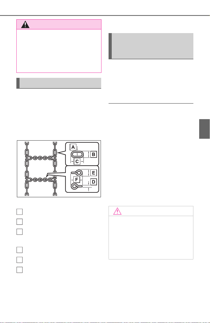
369
4-6. Driving tips
4
Driving
Vehicles without 235/55R19
tires
Use the correct tire chain size
when mounting the tire chains.
Chain size is regulated for each
tire size.
Side chain:
0.12 in. (3 mm) in diameter
0.39 in. (10 mm) in width
1.18 in. (30 mm) in length
Cross chain:
0.16 in. (4 mm) in diameter
0.55 in. (14 mm) in width
0.98 in. (25 mm) in length
Vehicles with 235/55R19 tires
Tire chains cannot be mounted.
Snow tires should be used
instead.
Regulations regarding the use
of tire chains vary depending on
location and type of road.
Always check local regulations
before installing chains.
■ Tire chain installation
Observe the following precautions
when installing and removing
chains:
● Install and remove tire chains in a
safe location.
● Install tire chains on the front tires
only. Do not install tire chains on
the rear tires.
● Install tire chains on front tires as
tightly as possible. Retighten
chains after driving 1/4 - 1/2 mile
(0.5 - 1.0 km).
● Install tire chains following the
instructions provided with the tire
chains.
WARNING
■ When parking the vehicle
When parking the vehicle without
applying the parking brake, make
sure to chock the wheels. If you
do not chock the wheels, the vehi-
cle may move unexpectedly, pos-
sibly resulting in an accident.
Selecting tire chains
A
B
C
D
E
F
Regulations on the use of
tire chains (except
235/55R19 tires)
NOTICE
■ Fitting tire chains (vehicles
with tire pressure warning
system)
The tire pressure warning valves
and transmitters may not function
correctly when tire chains are fit-
ted.

370
4-6. Driving tips
Specific design characteris-
tics give it a higher center of
gravity than ordinary passen-
ger cars. This vehicle design
feature causes this type of
vehicle to be more likely to
rollover. And, utility vehicles
have a significantly higher
rollover rate than other types
of vehicles.
An advantage of the higher
ground clearance is a better
view of the road allowing you
to anticipate problems.
It is not designed for corner-
ing at the same speeds as
ordinary passenger cars any
more than low-slung sports
cars are designed to perform
satisfactorily under off-road
conditions. Therefore, sharp
turns at excessive speeds
may cause the vehicle to roll-
over.
When driving your vehicle off-
Utility vehicle precau-
tions
This vehicle belongs to the
utility vehicle class, which
has higher ground clear-
ance and narrower tread in
relation to the height of its
center of gravity to make it
capable of performing in a
wide variety of off-road
applications.
Utility vehicle feature
WARNING
■ Utility vehicle precautions
Always observe the following pre-
cautions to minimize the risk of
death, serious injury or damage to
your vehicle:
● In a rollover crash, an unbelted
person is significantly more
likely to die than a person wear-
ing a seat belt. Therefore, the
driver and all passengers
should always fasten their seat
belts.
● Avoid sharp turns or abrupt
maneuvers, if at all possible.
Failure to operate this vehicle
correctly may result in loss of
control or vehicle rollover caus-
ing death or serious injury.
● Loading cargo on the roof lug-
gage carrier (if equipped) will
make the center of the vehicle
gravity higher. Avoid high
speeds, sudden starts, sharp
turns, sudden braking or abrupt
maneuvers, otherwise it may
result in loss of control or vehi-
cle rollover due to failure to
operate this vehicle correctly.
● Always slow down in gusty
crosswinds. Because of its pro-
file and higher center of gravity,
your vehicle is more sensitive to
side winds than an ordinary
passenger car. Slowing down
will allow you to have better
control.
● Do not drive horizontally across
steep slopes. Driving straight up
or straight down is preferred.
Your vehicle (or any similar off-
road vehicle) can tip over side-
ways much more easily than
forward or backward.
Off-road driving

371
4-6. Driving tips
4
Driving
road, please observe the follow-
ing precautions to ensure your
driving enjoyment and to help
prevent the closure of areas to
off-road vehicles:
Drive your vehicle only in
areas where off-road vehicles
are permitted to travel.
Respect private property. Get
owner’s permission before
entering private property.
Do not enter areas that are
closed. Honor gates, barriers
and signs that restrict travel.
Stay on established roads.
When conditions are wet,
driving techniques should be
changed or travel delayed to
prevent damage to roads.
■ Additional information for off-
road driving
For owners in U.S. mainland,
Hawaii and Puerto Rico:
To obtain additional information per-
taining to driving your vehicle off-
road, consult the following organiza-
tions:
• State and Local Parks and Recre-
ation Departments
• State Motor Vehicle Bureau
• Recreational Vehicle Clubs
• U.S. Forest Service and Bureau of
Land Management
WARNING
■ Off-road driving precautions
Always observe the following pre-
cautions to minimize the risk of
death, serious injury or damage to
your vehicle:
● Drive carefully when off the
road. Do not take unnecessary
risks by driving in dangerous
places.
● Do not grip the steering wheel
spokes when driving off-road. A
bad bump could jerk the wheel
and injure your hands. Keep
both hands and especially your
thumbs on the outside of the
rim.
● Always check your brakes for
effectiveness immediately after
driving in sand, mud, water or
snow.
● After driving through tall grass,
mud, rock, sand, rivers, etc.,
check that there is no grass,
bush, paper, rags, stone, sand,
etc. adhering or trapped on the
underbody. Clear off any such
matter from the underbody. If
the vehicle is used with these
materials trapped or adhering to
the underbody, a breakdown or
fire could occur.

372
4-6. Driving tips
WARNING
● When driving off-road or in rug-
ged terrain, do not drive at
excessive speeds, jump, make
sharp turns, strike objects, etc.
This may cause loss of control
or vehicle rollover causing
death or serious injury. You are
also risking expensive damage
to your vehicle’s suspension
and chassis.
NOTICE
■ To prevent the water damage
Take all necessary safety mea-
sures to ensure that water dam-
age to the engine or other
components does not occur.
● Water entering the engine air
intake will cause severe engine
damage.
● Water entering the automatic
transmission will cause deterio-
ration in shift quality, locking up
of your transmission accompa-
nied by vibration, and ultimately
damage.
● Water can wash the grease
from wheel bearings, causing
rusting and premature failure,
and may also enter the differen-
tials, transmission and transfer
case (AWD models), reducing
the gear oil’s lubricating quali-
ties.
■ When you drive through
water
If driving through water, such as
when crossing shallow streams,
first check the depth of the water
and the bottom of the riverbed for
firmness. Drive slowly and avoid
deep water.
■ Inspection after off-road driv-
ing
● Sand and mud that has accu-
mulated around brake discs
may affect braking efficiency
and may damage brake system
components.
● Always perform a maintenance
inspection after each day of off-
road driving that has taken you
through rough terrain, sand,
mud, or water. For scheduled
maintenance information, refer
to the “Scheduled Maintenance
Guide” or “Owner’s Manual
Supplement”.

373
5
5
Audio
Audio
5-1. Basic function
Buttons overview......... 375
Menu screen ............... 377
Status icon .................. 378
“Setup” screen ............ 380
5-2. Basic information before
operation
Initial screen................ 381
Touch screen............... 382
Home screen............... 384
Entering letters and num-
bers/list screen operation
.................................. 385
Screen adjustment...... 388
Linking multi-information
display and the system
.................................. 389
5-3. Connectivity settings
Registering/Connecting a
Bluetooth
®
device ..... 390
Setting Bluetooth
®
details
.................................. 394
Wi-Fi
®
Hotspot............ 402
5-4. Apple CarPlay/Android
Auto
Apple CarPlay
®
/Android
Auto........................... 407
5-5. Other settings
General settings.......... 414
Voice settings.............. 418
Vehicle settings........... 419
5-6. Using the audio/visual
system
Quick reference........... 420
Some basics................421
5-7. Radio operation
AM/FM/SiriusXM (SXM)
radio .......................... 425
5-8. Media operation
USB memory...............432
iPod/iPhone (Apple
CarPlay) .................... 434
Android Auto................ 437
Bluetooth
®
audio......... 438
5-9. Audio/visual remote con-
trols
Steering switches........ 442
5-10.Audio settings
Setup...........................444
5-11.Tips for operating the
audio/visual system
Operating information..446
5-12.Voice command system
operation
Voice command system
.................................. 458
Command list.............. 461
5-13.Phone operation (Hands-
free system for cellular
phones)
Quick reference........... 465
Some basics................466

374
Placing a call using the
Bluetooth
®
hands-free sys-
tem............................ 470
Receiving a call using the
Bluetooth
®
hands-free sys-
tem............................ 473
Talking on the Bluetooth
®
hands-free system..... 474
Bluetooth
®
phone message
function...................... 476
5-14.Phone settings
Setup........................... 481
5-15.What to do if...
(Bluetooth
®
)
Troubleshooting .......... 491
5-16.Connected Services over-
view
Connected Services.... 495
Type A: Function achieved
by using a smartphone or
DCM.......................... 496
Type B: Function achieved
by using DCM and the sys-
tem............................ 498
Type C: Function achieved
by using DCM............ 499
Type D: Function achieved
by using DCM and a
smartphone............... 502
5-17.Connected Services oper-
ation
Toyota Apps ................ 504
5-18.Setup
Toyota Apps settings ... 508
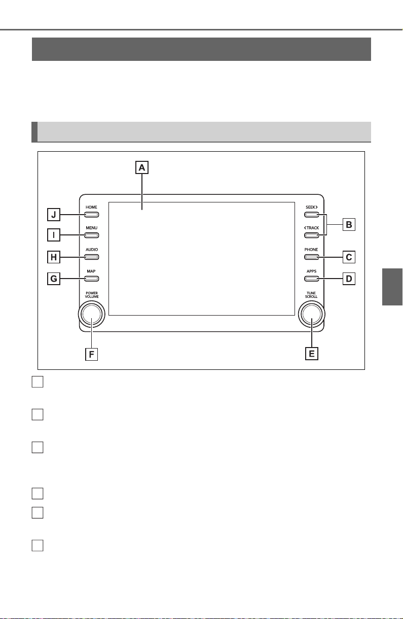
375
5-1. Basic function
5
Audio
5-1.Basic f unction
*
: Vehicles with Audio only
For details about Audio Plus or Premium Audio, refer to “Navigation and
Multimedia System Owner’s Manual”.
By touching the screen with your finger, you can control the
selected functions. (P.382, 383)
Press to seek up or down for a radio station or to access a
desired track/file. (P.425, 432, 434, 438)
Press to access the Bluetooth
®
hands-free system. (P.465)
• When an Apple CarPlay connection is established, press to display the
Phone application screen.
*1
Press to display the Toyota Apps screen.
*1, 2
(P.504)
Turn to change the radio station or skip to the next or previous
track/file. (P.425, 432, 434, 438)
Press to turn the audio/visual system on and off, and turn it to
adjust the volume. Press and hold to restart the system. (P.381,
421)
Buttons overview
*
Operations of each part
A
B
C
D
E
F

376
5-1. Basic function
When an Apple CarPlay/Android Auto connection is established,
press to display the Maps application screen.
*1
Press to display the audio/visual system screen. (420, 421)
Press to display the “Menu” screen. (P.377)
Press to display the home screen. (P.384)
*1
:This function is not made available in some countries or areas.
*2
:When an Apple CarPlay/Android Auto connection is established, this
function will be unavailable.
● The screen shots in this document
and the actual screens of the sys-
tem differ depending on whether
the functions and/or a contract
existed.
G
H
I
J
WARNING
● For safety, the driver should not
operate the system while
he/she is driving. Insufficient
attention to the road and traffic
may cause an accident.
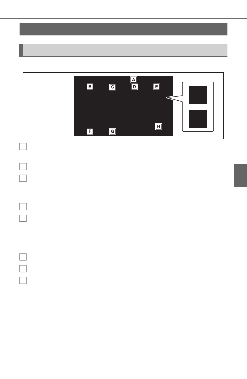
377
5-1. Basic function
5
Audio
Press the “MENU” button to display the “Menu” screen.
Displays the clock. Select to display the clock settings screen.
(P.415)
Select to display the audio control screen. (P.420)
Select to display the hands-free operation screen. (P.465)
• When an Apple CarPlay connection is established, select to display the
Phone application screen.
*1
Select to display the Toyota Apps screen.
*1, 2
(P.504)
When an Apple CarPlay/Android Auto connection is established
and this button displays “Apple CarPlay”/“Android Auto”, select to
display the home screen of Apple CarPlay/Android Auto.
*1
(P.407)
Select to display the fuel consumption screen. (P.9 9 )
Select to display the “Setup” screen. (P.380)
Select to adjust the contrast, brightness, etc. of the display.
(P.388)
*1
:This function is not made available in some countries or areas.
*2
:When an Apple CarPlay/Android Auto connection is established, this
function will be unavailable.
Menu screen
Menu screen operation
A
B
C
D
E
F
G
H
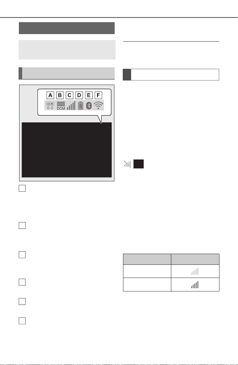
378
5-1. Basic function
Indicate during data commu-
nication performed via Data
Communication Module
(DCM)
*1
The reception level of Data
Communication Module
(DCM) display
*1
(P.378)
The reception level of the
connected phone display
(P.378)
Remaining battery charge
display (P.379)
Bluetooth
®
phone connection
condition display (P. 37 9 )
Wi-Fi
®
connection condition
display
*1, 2
(P.402)
*1
:Vehicles equipped with DCM
*2
:This function is not made avail-
able in some countries or areas.
● The number of status icons that
can be displayed differs depend-
ing on the displayed screen.
The level of reception does not
always correspond with the level
displayed on the cellular phone.
The level of reception may not
be displayed depending on the
phone you have.
When the cellular phone is out
of the service area or in a place
inaccessible by radio waves,
/ is displayed.
“Rm” is displayed when receiv-
ing in a roaming area. While
roaming, display “Rm” top-left
on the icon.
The receiving area may not be
displayed depending on the type
of Bluetooth
®
phone you have.
While connected with cellular
phone
Status icon
Status icons are displayed
at the top of the screen.
Status icon explanation
A
B
C
D
E
F
Reception level display
Reception Level Indicators
Poor
Excellent
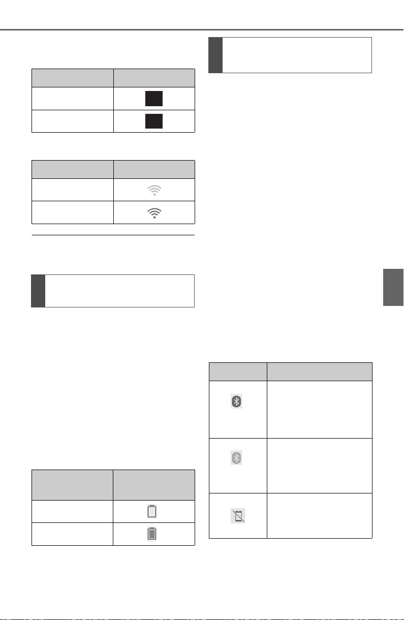
379
5-1. Basic function
5
Audio
While using Data Communi-
cation Module (DCM)
While using Wi-Fi
®
Hotspot
● When Wi-Fi
®
Hotspot is off, no
item is displayed.
The amount displayed does not
always correspond with the
amount displayed on the
Bluetooth
®
device.
The amount of battery charge
left may not be displayed
depending on the type of the
Bluetooth
®
device connected.
This system does not have a
charging function.
An antenna for the Bluetooth
®
connection is built into the
instrument panel.
The condition of the Bluetooth
®
connection may deteriorate and
the system may not function
when a Bluetooth
®
phone is
used in the following conditions
and/or places:
The cellular phone is obstructed
by certain objects (such as
when it is behind the seat or in
the glove box or console box).
The cellular phone is touching or
is covered with metal materials.
Leave the Bluetooth
®
phone in a
place where the condition of the
Bluetooth
®
connection is good.
Reception Level Indicators
Poor
Excellent
Reception Level Indicators
No connection
Connected
Remaining battery charge
display
Remaining
charge
Indicators
Empty
Full
Bluetooth
®
connection
condition display
Indicators Conditions
(Blue)
Indicates that the con-
dition of the
Bluetooth
®
connection
is good.
(Gray)
While in this condition,
sound quality during
phone calls may dete-
riorate.
Indicates that the cel-
lular phone is not con-
nected via Bluetooth
®
.
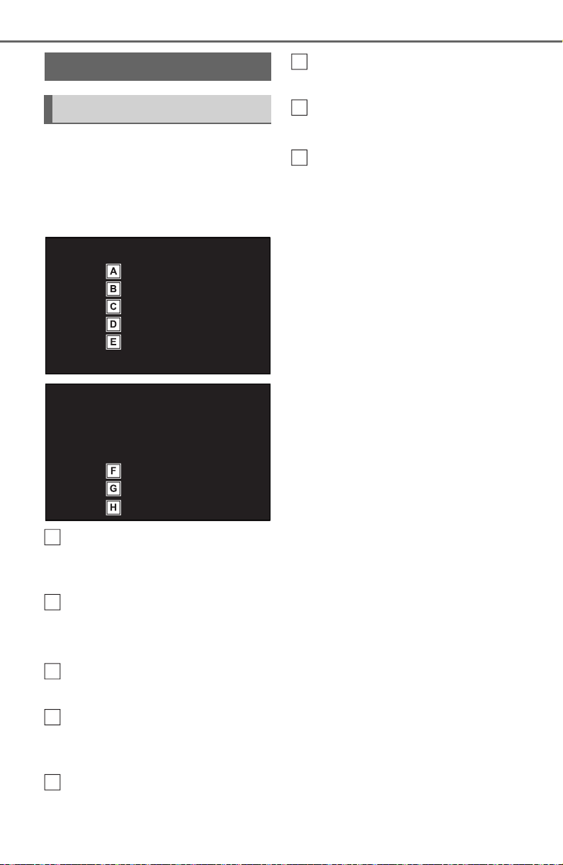
380
5-1. Basic function
Press the “MENU” button, then
select “Setup” to display the
“Setup” screen. The items
shown on the “Setup” screen
can be set.
Select to change the selected
language, operation sound
settings, etc. (P.414)
Select to set Bluetooth
®
device and Bluetooth
®
sys-
tem settings. (P.394)
Select to set audio settings.
(P.444)
Select to set the phone
sound, contacts, message
settings, etc. (P.481)
Select to set the voice set-
tings. (P.41 8 )
Select to set vehicle informa-
tion. (P.419)
Select to set Wi-Fi
®
connec-
tion settings.
*1, 2
(P.403)
Select to set Toyota Apps
settings.
*2
(P.508)
*1
:Vehicles equipped with DCM
*2
:This function is not made avail-
able in some countries or areas.
“Setup” screen
“Setup” screen
A
B
C
D
E
F
G
H
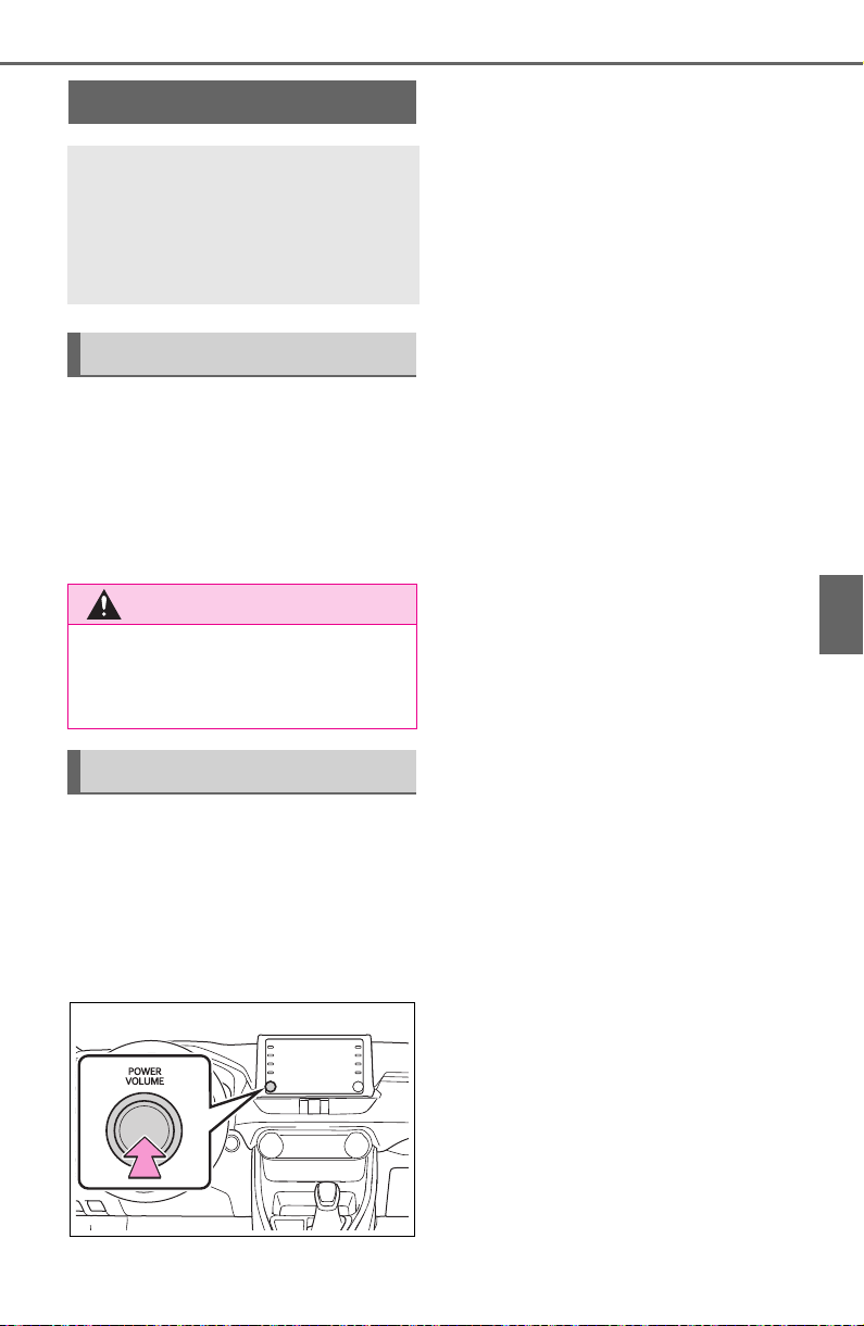
381
5-2. Basic information before operation
5
Audio
5-2.Basic inf ormation before opera tion
After a few seconds, the caution
screen will be displayed.
After about 5 seconds or select-
ing “Continue”, the caution
screen automatically switches to
the next screen.
When system response is
extremely slow, the system can
be restarted.
1 Press and hold the “POWER
VOLUME” knob for 3 sec-
onds or more.
Initial screen
When the engine switch is
turned to ACC or ON, the
initial screen will be dis-
played and the system will
begin operating.
Caution screen
WARNING
● When the vehicle is stopped
with the engine running, always
apply the parking brake for
safety.
Restarting the system
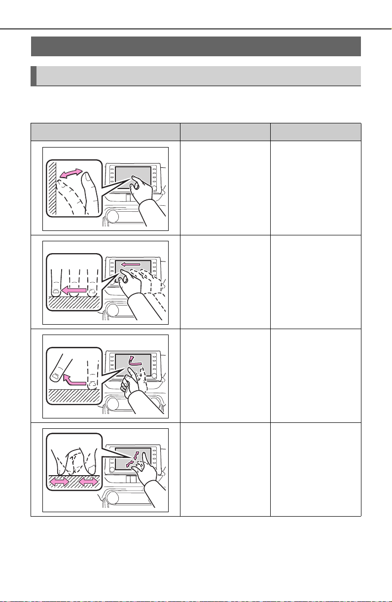
382
5-2. Basic information before operation
Operations are performed by touching the touch screen directly with
your finger.
*1
:The above operations may not be performed on all screens.
*2
:The Apple CarPlay Maps application is not compatible with pinch multi-
touch gestures.
Touch screen
Touch screen gestures
Operation method Outline Main use
Touch
Quickly touch and
release once.
Selecting an item
on the screen
Drag
*1
Touch the screen
with your finger,
and move the
screen to the
desired position.
Scrolling the lists
Flick
*1
Quickly move the
screen by flicking
with your finger.
Scrolling the main
screen page
Pinch in/Pinch
out
Slide fingers toward
each other or apart
on the screen.
Changing the
scale of the
map
*2

383
5-2. Basic information before operation
5
Audio
● Flick operations may not be performed smoothly at high altitudes.
● If the system does not respond to
touching a screen button, move
your finger away from the screen
and then touch it again.
● Dimmed screen buttons cannot be
operated.
● The displayed image may become
darker and moving images may
be slightly distorted when the
screen is cold.
● In extremely cold conditions, the
screen may not be displayed and
the data input by a user may be
deleted. Also, the screen buttons
may be harder than usual to
depress.
● When you look at the screen
through polarized material such as
polarized sunglasses, the screen
may be dark and hard to see. If
so, look at the screen from differ-
ent angles, adjust the screen set-
tings on the display settings
screen or take off your sun-
glasses.
● When is displayed on the
screen, select to return to the
previous screen.
The operable areas of the
capacitive touch screen buttons
use capacitive touch sensors
and may not operate properly in
the following situations:
If the screen is dirty or wet
If a source of strong electro-
magnetic waves is brought
near the screen
If a glove is worn during oper-
ation
If the screen is touched by a
fingernail
If a stylus is used to operate
the buttons
If your palm touches the oper-
able area of another button
during operation
If a button is touched quickly
If the operable part of a
capacitive touch screen but-
ton is touched by or covered
Touch screen operation
This system is operated
mainly by the buttons on
the screen. (Referred to as
screen buttons in this man-
ual.)
When a screen button is
touched, a beep sounds. (To
set the beep sound: P.414)
NOTICE
● To prevent damaging the
screen, lightly touch the screen
buttons with your finger.
● Do not use objects other than
your finger to touch the screen.
● Wipe off fingerprints using a
glass cleaning cloth. Do not use
chemical cleaners to clean the
screen, as they may damage
the touch screen.
Capacitive touch screen
buttons
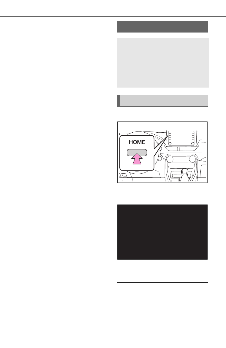
384
5-2. Basic information before operation
with a metal object, such as
the following, it may not oper-
ate properly:
• Magnetic isolation cards
• Metallic foil, such as the inner
packaging of a cigarette box
• Metallic wallets or bags
•Coins
• Discs, such as a CD or DVD
If the operable part of a
capacitive touch screen but-
ton is wiped, it may operate
unintentionally.
If the capacitive touch screen
button is being touched when
the engine switch is changed
to ACC or ON, the button may
not operate properly. In this
case, remove anything touch-
ing the button, turn the engine
switch off and then turn it to
ACC or ON, or restart the sys-
tem by press and hold the
“POWER VOLUME” knob for
3 seconds or more.
● Capacitive touch screen button
sensor sensitivity can be adjusted.
(P.414)
1 Press the “HOME” button.
2 Check that the home screen
is displayed.
Selecting a screen will display
it full screen.
● The display information and area
on the home screen can be cus-
tomized.
● The home screen can be set to
several types of split layouts
Home screen
On the home screen, multi-
ple screens, such as the
audio/visual system screen,
hands-free screen and clock
screen, can be displayed
simultaneously.
Home screen operation
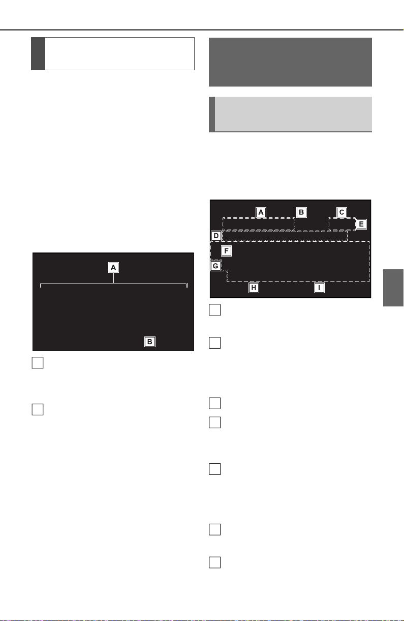
385
5-2. Basic information before operation
5
Audio
The display information/area on
the home screen and the home
screen layout can be changed.
1 Press the “MENU” button.
2 Select “Setup”.
If the general settings screen
is not displayed, select “Gen-
eral”.
3 Select “Customize Home
Screen”.
4 Select the items to be set.
Select to change the display
information and area on the
home screen.
Select to change the home
screen layout.
When searching by a name or
entering data, letters and num-
bers can be entered via the
screen.
Text field. Entered charac-
ter(s) will be displayed.
Select to erase one charac-
ter.
Select and hold to continue
erasing characters.
Select to move the cursor.
Select to choose predictive
text candidate for entered
text. (P.386)
Select to display a list of pre-
dictive text candidates when
there is more than one.
(P.386)
Select to enter desired char-
acters.
Select to enter characters in
lower case or in upper case.
Customizing the home
screen
A
B
Entering letters and
numbers/list screen
operation
Entering letters and num-
bers
A
B
C
D
E
F
G
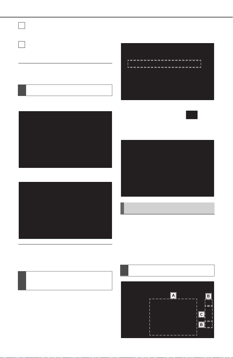
386
5-2. Basic information before operation
Select to change character
types. (P.386)
Select to make a space on
cursor.
● Keyboard layout can be changed.
(P.414)
1 Select “Change Type”.
2 Select the desired character.
● Depending on the screen being
displayed, it may not be possible
to change keyboard characters.
When text is input, the system
predicts the text that may com-
plete the currently unconfirmed
text and displays predictive
replacement candidates that
match the beginning of the text.
1 Input text.
2 Select the desired candidate.
To select a candidate that is
not displayed, select , and
then select the desired predic-
tive replacement candidate.
The list screen may be dis-
played after entering characters.
When a list is displayed, use the
appropriate screen button to
scroll through the list.
Changing character type
Displaying predictive text
candidates
H
I
List screen
Scrolling list screen
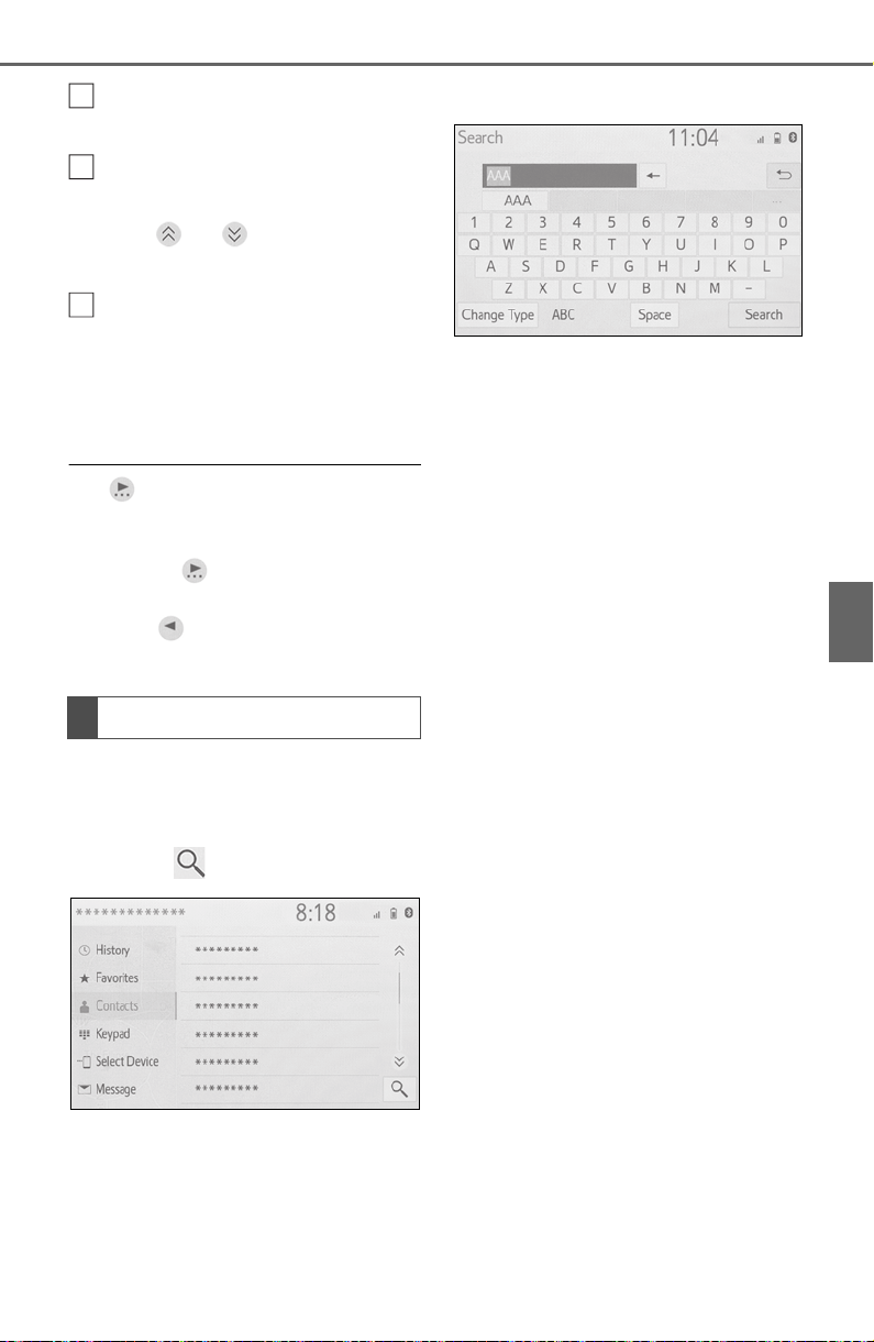
387
5-2. Basic information before operation
5
Audio
To scroll up/down the list,
flick the list up/down.
Select to skip to the next or
previous page. Select and
hold or to scroll
through the displayed list.
Indicates the position of the
displayed entries in the entire
list.
To scroll up/down pages,
drag the bar.
● If appears to the right of an
item name, the complete name is
too long to display.
• Select to scroll to the end of
the name.
• Select to move to the begin-
ning of the name.
Items are displayed in the list
with the most similar results of
the search at the top.
1 Select .
2 Input text.
3 Select “Search”.
4 The list is displayed.
Searching a list
A
B
C
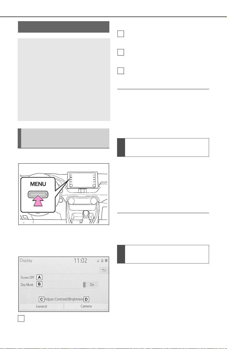
388
5-2. Basic information before operation
1 Press the “MENU” button.
2 Select “Display”.
3 Select the desired items to
be set.
Select to turn the screen off.
To turn it on, press any but-
ton.
Select to turn day mode
on/off. (P.388)
Select to adjust the screen
display. (P.388)
Select to adjust the camera
display.
● When the screen is viewed
through polarized sunglasses, a
rainbow pattern may appear on
the screen due to optical charac-
teristics of the screen. If this is dis-
turbing, please operate the screen
without polarized sunglasses.
Depending on the position of the
headlight switch, the screen
changes to day or night mode.
This feature is available when
the headlight is switched on.
1 Select “Day Mode”.
● If the screen is set to day mode
with the headlight switch turned
on, this condition is memorized
even with the engine turned off.
The contrast and brightness of
the screen can be adjusted
according to the brightness of
your surroundings.
1 Select “General” or “Cam-
era”.
2 Select the desired item.
Screen adjustment
The contrast and brightness
of the screen display and
the image of the camera dis-
play can be adjusted. The
screen can also be turned
off, and/or changed to either
day or night mode.
(For information regarding
audio/visual screen adjust-
ment: P.423)
Displaying the screen
adjustment screen
A
Changing between day
and night mode
Adjusting the con-
trast/brightness
B
C
D

389
5-2. Basic information before operation
5
Audio
“Display (General)” screen
only: Select “<” or “>” to select
the desired display.
•“Contrast”
“+”: Select to strengthen the con-
trast of the screen.
“-”: Select to weaken the contrast of
the screen.
• “Brightness”
“+”: Select to brighten the screen.
“-”: Select to darken the screen.
Linking multi-informa-
tion display and the
system
The following functions of
the system are linked with
the multi-information dis-
play in the instrument clus-
ter:
Audio
Phone
*
etc.
These functions can be
operated using multi-infor-
mation display control
switches on the steering
wheel. (P.89)
*
: When an Apple CarPlay con-
nection is established, this
function will be unavailable.
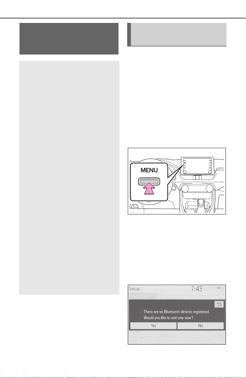
390
5-3. Connectivity settings
5-3.Connectivity settings
■ Registering from the sys-
tem
1 Turn the Bluetooth
®
connec-
tion setting of your cellular
phone on.
This function is not available
when Bluetooth
®
connection
setting of your cellular phone
is set to off.
2 Press the “MENU” button.
3 Select “Phone”.
Operations up to this point
can also be performed by
pressing the “PHONE” button
on the instrument panel.
4 Select “Yes” to register a
phone.
Registering/Connect-
ing a Bluetooth
®
device
To use the hands-free sys-
tem, it is necessary to regis-
ter a Bluetooth
®
phone with
the system.
Once the phone has been
registered, it is possible to
use the hands-free system.
This operation cannot be
performed while driving.
When an Apple CarPlay
connection is established,
Bluetooth
®
functions of the
system will become unavail-
able and any connected
Bluetooth
®
devices will be
disconnected.
When connecting to
Android Auto, a Bluetooth
®
connection will be made
automatically.
When an Android Auto con-
nection is established,
some Bluetooth
®
functions
other than hands-free sys-
tem cannot be used.
Registering a Bluetooth
®
phone for the first time
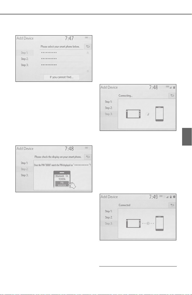
391
5-3. Connectivity settings
5
Audio
5 Select the desired Bluetooth
®
device.
If the desired Bluetooth
®
phone is not on the list, select
“If you cannot find...” and fol-
low the guidance on the
screen. (P.392)
6 Register the Bluetooth
®
device using your Bluetooth
®
device.
For details about operating
the Bluetooth
®
device, see
the manual that comes with it.
A PIN code is not required for
SSP (Secure Simple Pairing)
compatible Bluetooth
®
devices. Depending on the
type of Bluetooth
®
device
being connected, a message
confirming registration may
be displayed on the
Bluetooth
®
device’s screen.
Respond and operate the
Bluetooth
®
device according
to the confirmation message.
7 Check that the following
screen is displayed, indicat-
ing pairing was successful (a
Bluetooth
®
link has been
established but registration is
not yet complete).
The system is connecting to
the registered device.
At this stage, the Bluetooth
®
functions are not yet avail-
able.
8 Check that “Connected” is
displayed and registration is
complete.
If an error message is dis-
played, follow the guidance
on the screen to try again.
● If a cellular phone does not oper-
ate properly after being con-

392
5-3. Connectivity settings
nected, turn the cellular phone off
and on and then connect it again.
■ Registering from phone
1 Select “If you cannot find...”.
2 Select “Register from
Phone”.
3 Check that the following
screen is displayed, and reg-
ister the Bluetooth
®
device
using your Bluetooth
®
device.
For details about operating
the Bluetooth
®
device, see
the manual that comes with it.
A PIN code is not required for
SSP (Secure Simple Pairing)
compatible Bluetooth
®
devices. Depending on the
type of Bluetooth
®
device
being connected, a message
confirming registration may
be displayed on the
Bluetooth
®
device’s screen.
Respond and operate the
Bluetooth
®
device according
to the confirmation message.
4 Follow the steps in “Register-
ing a Bluetooth
®
phone for
the first time” from step 7.
(P.390)
To use the Bluetooth
®
audio, it is
necessary to register an audio
player with the system.
Once the player has been regis-
tered, it is possible to use the
Bluetooth
®
audio.
This operation cannot be per-
formed while driving.
For details about registering a
Bluetooth
®
device: P.397
1 Turn the Bluetooth
®
connec-
tion setting of your audio
player on.
This function is not available
when the Bluetooth
®
connec-
tion setting of your audio
Registering a Bluetooth
®
audio player for the first
time
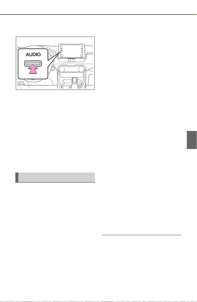
393
5-3. Connectivity settings
5
Audio
player is set to off.
2 Press the “AUDIO” button.
3 Select “Source” on the audio
screen or press “AUDIO” but-
ton again.
4 Select “Bluetooth”.
5 Select “Yes” to register an
audio player.
6 Follow the steps in “Register-
ing a Bluetooth
®
phone for
the first time” from step 5.
(P.390)
This system supports the follow-
ing services.
■ Bluetooth
®
Core Specifica-
tion
Ver. 2.0 (Recommended: Ver.
4.2)
■ Profiles
HFP (Hands Free Profile) Ver.
1.0 (Recommended: Ver. 1.7)
• This is a profile to allow hands-
free phone calls using a cellular
phone. It has outgoing and
incoming call functions.
OPP (Object Push Profile)
Ver. 1.1 (Recommended: Ver.
1.2)
• This is a profile to transfer con-
tacts data.
PBAP (Phone Book Access
Profile) Ver. 1.0 (Recom-
mended: Ver. 1.2)
• This is a profile to transfer phone-
book data.
MAP (Message Access Pro-
file) Ver. 1.0 (Recommended:
Ver. 1.2)
• This is a profile to use phone
message functions.
SPP (Serial Port Profile) Rec-
ommended: Ver. 1.2
• This is a profile to use the Toyota
audio multimedia function.
A2DP (Advanced Audio Dis-
tribution Profile) Ver. 1.0 (Rec-
ommended: Ver. 1.3)
• This is a profile to transmit stereo
audio or high quality sound to the
audio/visual system.
AVRCP (Audio/Video Remote
Control Profile) Ver. 1.0 (Rec-
ommended: Ver. 1.6)
• This is a profile to allow remote
control the A/V equipment.
● This system is not guaranteed to
operate with all Bluetooth
®
devices.
● If your cellular phone does not
support HFP, registering the
Bluetooth
®
phone or using OPP,
PBAP, MAP or SPP profiles indi-
vidually will not be possible.
Profiles
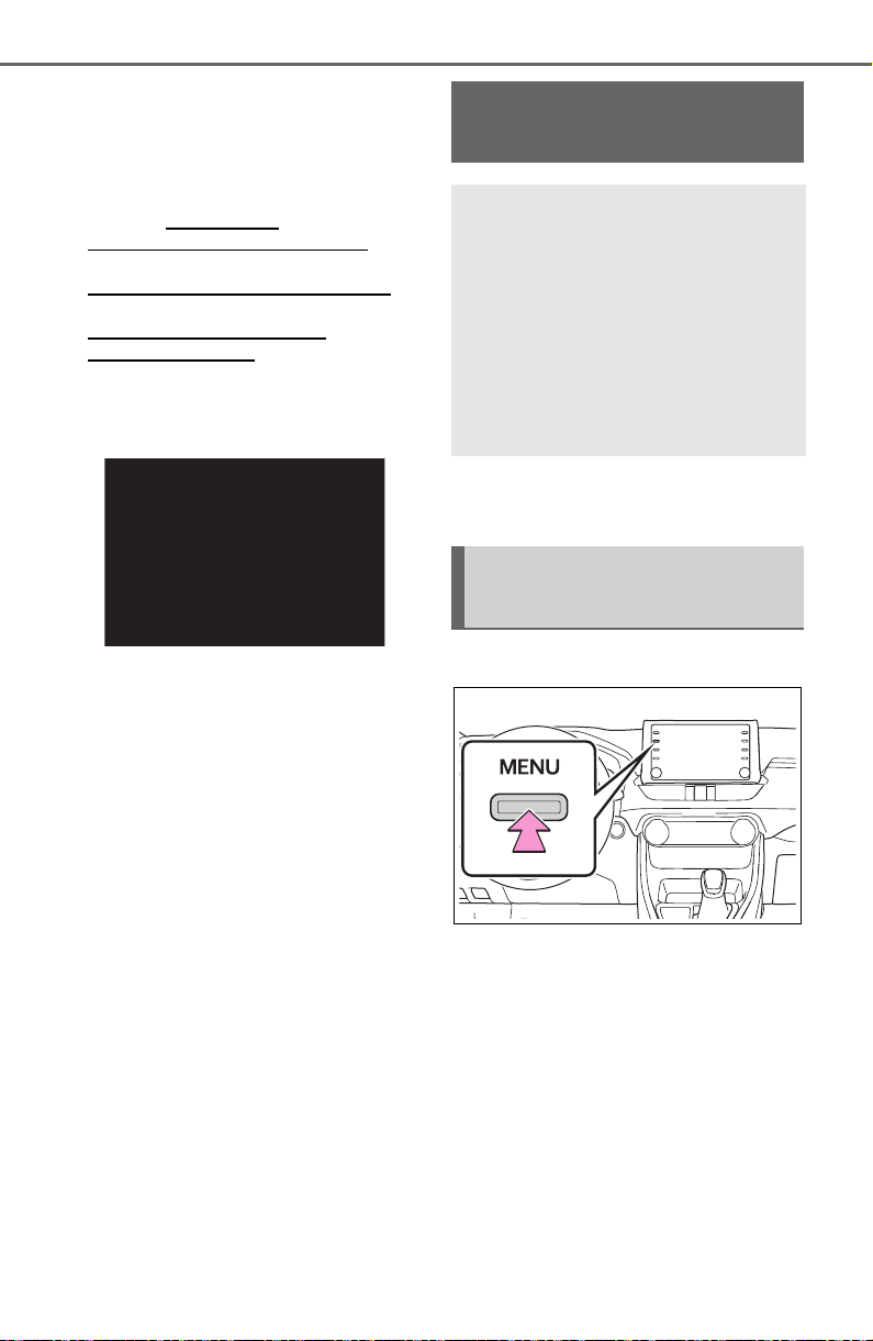
394
5-3. Connectivity settings
● If the connected Bluetooth
®
device version is older than rec-
ommended or incompatible, the
Bluetooth
®
device function may
not work properly.
● Refer to http://www.
toyota.com/audio-multimedia in
the United States,
http://www.toyota.ca/connected
in
Canada, and
http://www.toyotapr.com/
audio-multimedia in Puerto Rico,
to find approved Bluetooth
®
phones for this system.
● Certification
Bluetooth is a registered trademark
of Bluetooth SIG, Inc.
*
: This function is not made avail-
able in some countries or areas.
1 Press the “MENU” button.
2 Select “Setup”.
3 Select “Bluetooth”.
Setting Bluetooth
®
details
When an Apple CarPlay
connection is established,
this function will be unavail-
able.
*
When an Android Auto con-
nection is established,
some functions will be
unavailable.
*
Displaying the Bluetooth
®
setup screen
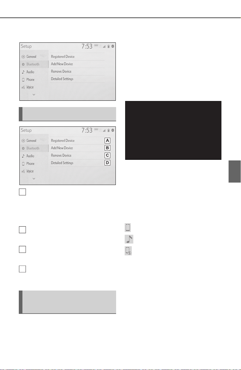
395
5-3. Connectivity settings
5
Audio
4 Select the desired item to be
set.
Connecting a Bluetooth
®
device and editing the
Bluetooth
®
device informa-
tion (P.395, 398)
Registering a Bluetooth
®
device (P.397)
Deleting a Bluetooth
®
device
(P.397)
Setting the Bluetooth
®
sys-
tem (P.399)
Up to 5 Bluetooth
®
devices
(Phones (HFP) and audio play-
ers (AVP)) can be registered.
If more than 1 Bluetooth
®
device
has been registered, select
which device to connect to.
1 Display the Bluetooth
®
set-
tings screen. (P.394)
2 Select “Registered Device”.
3 Select the device to be con-
nected.
“Add”: Registering a Bluetooth
®
device. (P.397)
“Preferred Device Settings”: Select
to change the automatic connection
priority of the registered Bluetooth
®
devices. (P.400)
“Remove”: Deleting a Bluetooth
®
device. (P.397)
: Phone
: Audio player
: Phone/Toyota Apps Services
The profile icon for a currently
connected device will be dis-
played in color.
Selecting a profile icon which
is not currently connected will
switch the connection to the
function.
If the desired Bluetooth
®
device is not on the list, select
“Add New Device” to register
Bluetooth
®
setup screen
Connecting a Bluetooth
®
device
A
B
C
D

396
5-3. Connectivity settings
the device. (P.397)
4 Select the desired connec-
tion.
“Device Info”: Select to con-
firm and change the
Bluetooth
®
device informa-
tion. (P.398)
When another Bluetooth
®
device is connected
To disconnect the Bluetooth
®
device, select “Yes”.
5 Check that a confirmation
screen is displayed when the
connection is complete.
If an error message is dis-
played, follow the guidance
on the screen to try again.
● It may take time if the device con-
nection is carried out during
Bluetooth
®
audio playback.
● Depending on the type of
Bluetooth
®
device being con-
nected, it may be necessary to
perform additional steps on the
device.
● When disconnecting a Bluetooth
®
device, it is recommended to dis-
connect using the system.
■ Connecting a Bluetooth
®
device in a different way
(from phone top screen)
P.467
■ Connecting a Bluetooth
®
device in a different way
(from phone setup screen)
P.481
■ Connecting a Bluetooth
®
device in a different way
(from Bluetooth
®
audio
screen)
P.440
■ Auto connection mode
To turn auto connection mode
on, set “Bluetooth Power” to on.
(P.399) Leave the Bluetooth
®
device in a location where the
connection can be established.
When the engine switch is in
ACC or ON, the system
searches for a nearby regis-
tered device.
The system will connect with
the registered device that was
last connected, if it is nearby.
When automatic connection
priority is set to on and there
is more than one registered
Bluetooth
®
phone available,
the system will automatically
connect to the Bluetooth
®
phone with the highest prior-
ity. (P.399)

397
5-3. Connectivity settings
5
Audio
■ Connecting manually
When the auto connection has
failed or “Bluetooth Power” is
turned off, it is necessary to con-
nect the Bluetooth
®
device man-
ually.
1 Display the Bluetooth
®
set-
tings screen. (P.394)
2 Follow the steps in “Connect-
ing a Bluetooth
®
device” from
step 2. (P.395)
■ Reconnecting the
Bluetooth
®
phone
If a Bluetooth
®
phone is discon-
nected due to poor reception
from the Bluetooth
®
network
when the engine switch is in
ACC or ON, the system auto-
matically reconnects the
Bluetooth
®
phone.
Up to 5 Bluetooth
®
devices can
be registered.
Bluetooth
®
compatible phones
(HFP) and audio players (AVP)
can be registered simultane-
ously.
This operation cannot be per-
formed while driving.
1 Display the Bluetooth
®
set-
tings screen. (P.394)
2 Select “Add New Device”.
When another Bluetooth
®
device is connected
To disconnect the Bluetooth
®
device, select “Yes”.
When 5 Bluetooth
®
devices
have already been registered
A registered device needs to
be replaced. Select “Yes”, and
select the device to be
replaced.
3 Follow the steps in “Register-
ing a Bluetooth
®
phone for
the first time” from step 5.
(P.390)
This operation cannot be per-
formed while driving.
1 Display the Bluetooth
®
set-
tings screen. (P.394)
2 Select “Remove Device”.
3 Select the desired device.
4 Select “Yes” when the confir-
mation screen appears.
5 Check that a confirmation
screen is displayed when the
operation is complete.
Registering a Bluetooth
®
device
Deleting a Bluetooth
®
device
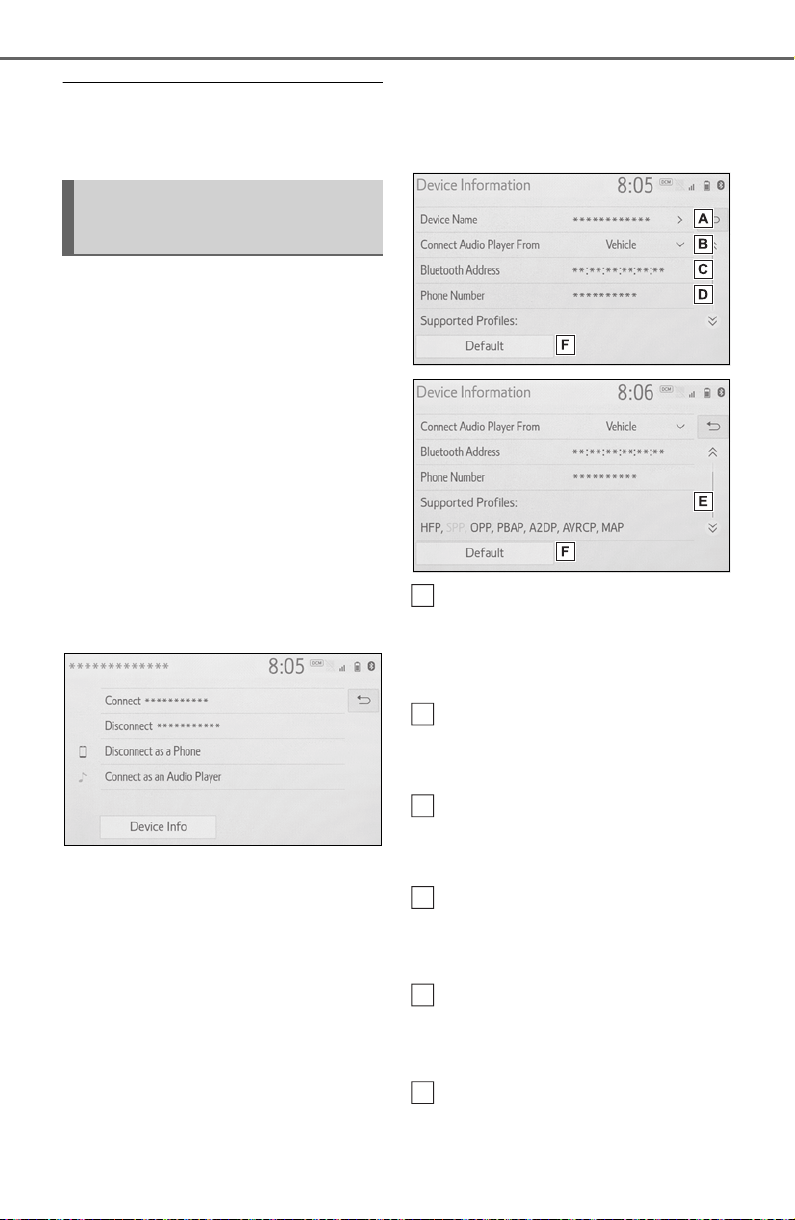
398
5-3. Connectivity settings
● When deleting a Bluetooth
®
phone, the contact data will be
deleted at the same time.
The Bluetooth
®
device’s infor-
mation can be displayed on the
screen. The displayed informa-
tion can be edited.
This operation cannot be per-
formed while driving.
1 Display the Bluetooth
®
set-
tings screen. (P.394)
2 Select “Registered Device”.
3 Select the desired device to
be edited.
4 Select “Device Info”.
5 Confirm and change the
Bluetooth
®
device informa-
tion.
The name of the Bluetooth
®
device is displayed. It can be
changed to a desired name.
(P.399)
Select to set the Bluetooth
®
audio player connection
method. (P.399)
Device address is unique to
the device and cannot be
changed.
Phone number is unique to
the Bluetooth
®
phone and
cannot be changed.
Compatibility profile is unique
to the Bluetooth
®
device and
cannot be changed.
Select to reset all setup
items.
Editing the Bluetooth
®
device information
A
B
C
D
E
F

399
5-3. Connectivity settings
5
Audio
● If 2 Bluetooth
®
devices have been
registered with the same device
name, the devices can be distin-
guished referring to the device’s
address.
● Depending on the type of
Bluetooth
®
phone, some informa-
tion may not be displayed.
1 Select “Device Name”.
2 Enter the name and select
“OK”.
● Even if the device name is
changed, the name registered in
your Bluetooth
®
device does not
change.
1 Select “Connect Audio Player
From”.
2 Select the desired connec-
tion method.
“Vehicle”: Select to connect the
audio player from the vehicle’s
audio/visual system.
“Device”: Select to connect the
vehicle’s audio/visual system from
the audio player.
Depending on the audio
player, the “Vehicle” or
“Device” connection method
may be best. As such, refer to
the manual that comes with
the audio player.
The Bluetooth
®
settings can be
confirmed and changed.
1 Display the Bluetooth
®
set-
tings screen. (P.394)
2 Select “Detailed Settings”.
3 Select the desired item to be
set.
Select to set Bluetooth
®
con-
nection on/off. (P.400)
Select to change the auto-
matic connection priority of
the registered Bluetooth
®
devices. (P.400)
Select to edit the system
information. (P.400)
Select to reset all setup
items.
Changing a device name
Setting audio player con-
nection method
“Detailed Settings”
screen
A
B
C
D
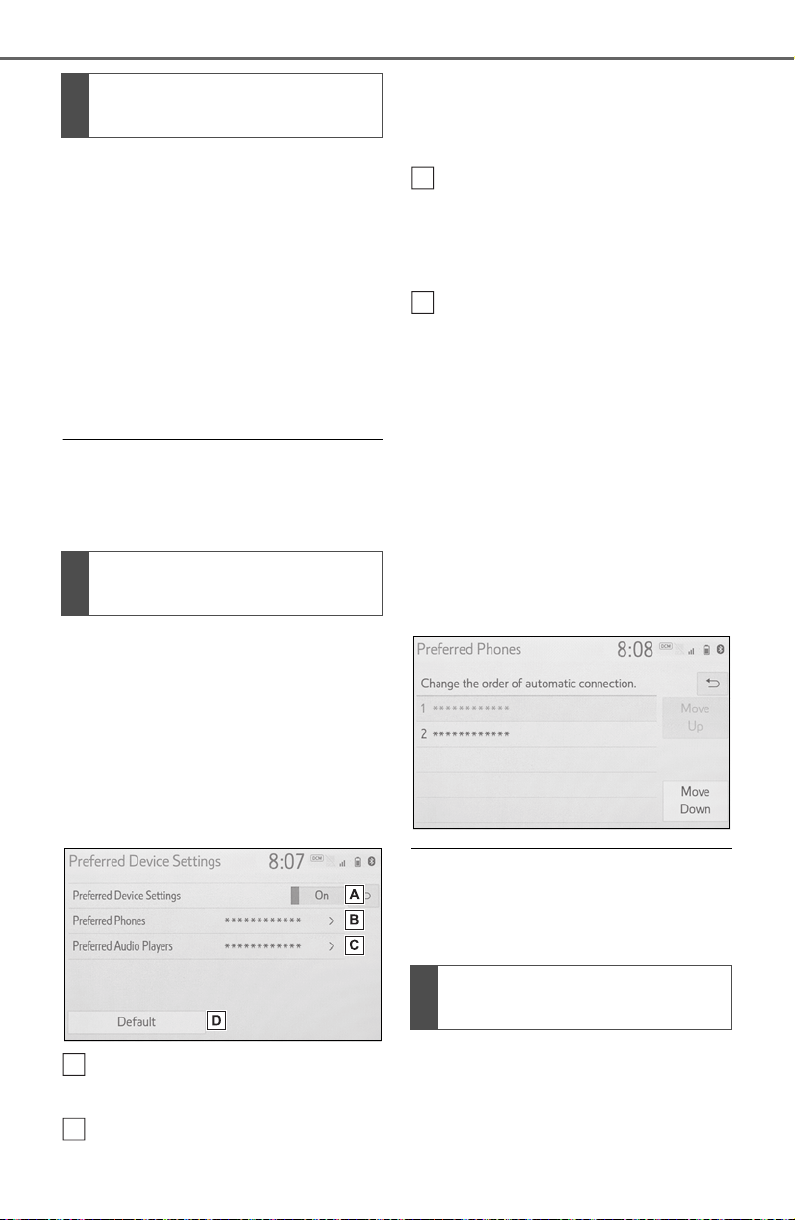
400
5-3. Connectivity settings
1 Select “Bluetooth Power”.
When “Bluetooth Power” is on:
The Bluetooth
®
device is auto-
matically connected when the
engine switch is in ACC or ON.
When “Bluetooth Power” is off:
The Bluetooth
®
device is dis-
connected, and the system will
not connect to it next time.
● While driving, the auto connection
state can be changed from off to
on, but cannot be changed from
on to off.
The automatic connection prior-
ity of the registered Bluetooth
®
devices can be changed.
1 Select “Preferred Device Set-
tings”.
2 Select the desired item to be
set.
Select to set automatic con-
nection priority on/off.
Select to change the auto-
matic connection priority of
the registered Bluetooth
®
phones. (P.400)
Select to change the auto-
matic connection priority of
the registered Bluetooth
®
audio players. (P.400)
Select to reset all setup
items.
■ Changing Bluetooth
®
device automatic connec-
tion priority
1 Select “Preferred Phones” or
“Preferred Audio Players”.
2 Select the desired Bluetooth
®
device and select “Move Up”
or “Move Down” to change
the preferred order.
● A newly registered Bluetooth
®
device will automatically be given
the highest automatic connection
priority.
1 Select “System Information”.
Changing “Bluetooth
Power”
Setting automatic connec-
tion priority
A
B
Editing the system infor-
mation
C
D
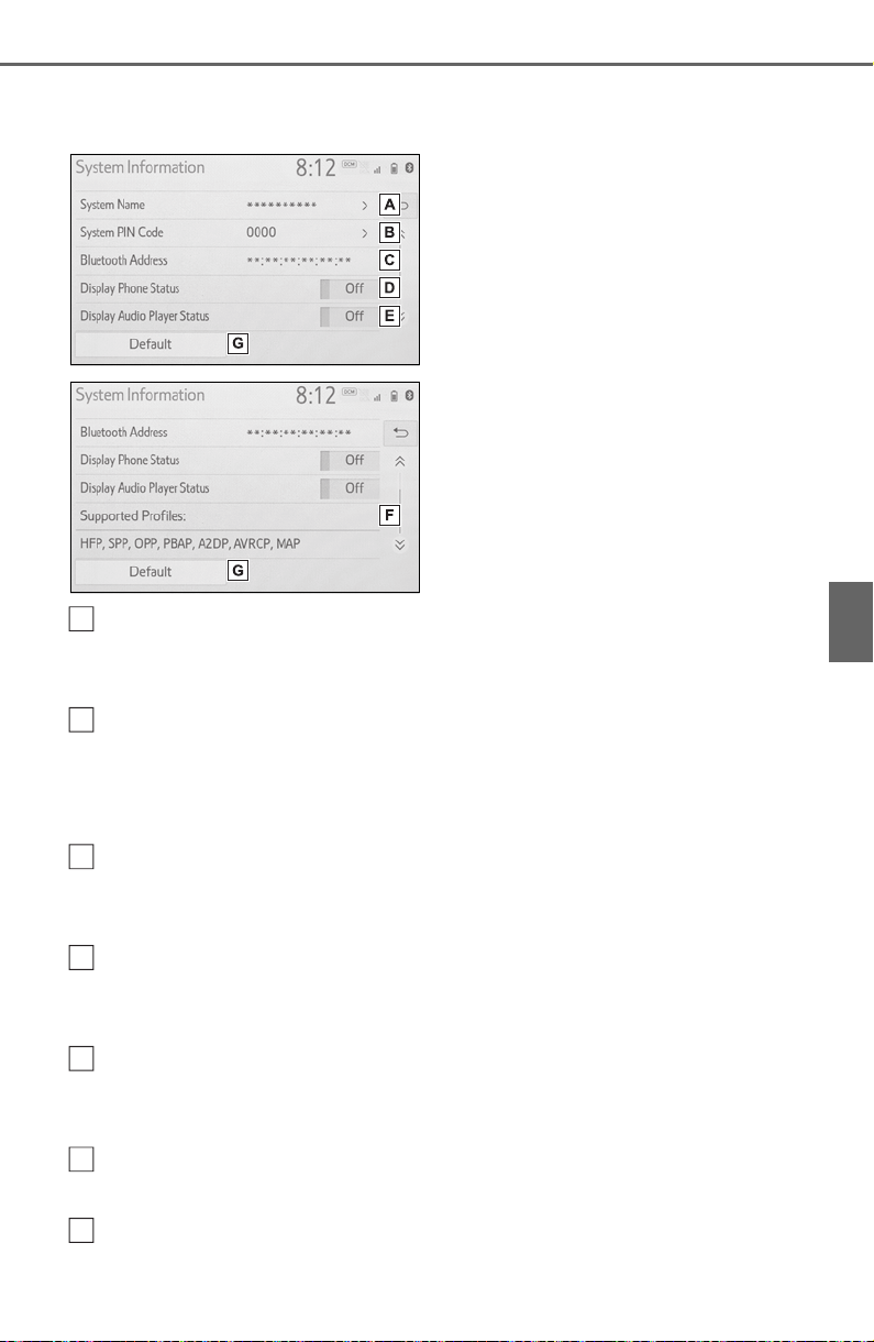
401
5-3. Connectivity settings
5
Audio
2 Select the desired item to be
set.
Displays system name. Can
be changed to a desired
name. (P.401)
PIN code used when the
Bluetooth
®
device was regis-
tered. Can be changed to a
desired code. (P.401)
Device address is unique to
the device and cannot be
changed.
Select to set the connection
status display of the phone
on/off.
Select to set the connection
status display of the audio
player on/off.
Compatibility profile of the
system
Select to reset all setup
items.
■ Editing the system name
1 Select “System Name”.
2 Enter a name and select
“OK”.
■ Editing the PIN code
1 Select “System PIN Code”.
2 Enter a PIN code and select
“OK”.
A
B
C
D
E
F
G

402
5-3. Connectivity settings
*
: Vehicles equipped with DCM
only. This function is not made
available in some countries or
areas.
1 Enable the Wi-Fi
®
Hotspot
function. (P.403)
2 Disable the “Hide Access
Point” function. (P.403)
3 Search for the vehicle access
point using the device you
wish to connect.
For details about operating
the device, refer to the docu-
mentation which came with it.
4 Operate the device to con-
nect it to the vehicle access
point.
To check the vehicle access
point password, check “Pass-
word”. (P.403)
● Hints for connecting to the vehicle
via Wi-Fi
®
can be displayed.
(P.403)
1 Enable the Wi-Fi
®
Hotspot
function. (P.403)
2 Enable the “Hide Access
Point” function. (P.403)
3 Enter the access point name
(SSID) into the device you
wish to connect and connect
it.
To check the vehicle access
point password, check “Pass-
word”. (P.403)
The security settings on the
device must be the same as
that displayed for “Security”.
(P.403)
For details about operating
the device, refer to the docu-
mentation which came with it.
Wi-Fi
®
Hotspot
*
By connecting a device to
the vehicle via Wi-Fi
®
, it can
access the internet through
the DCM.
To use this function, a
W-Fi
®
Hotspot service sub-
scription from AT&T is
required. Connect your
device to the in-vehicle
access point (see instruc-
tions below), or contact your
Toyota dealer for details.
Connecting a device to
the in-vehicle access
point
Searching for and con-
necting a device to the
vehicle access point
Connecting a device to the
in-vehicle access point
using the access point
name (SSID)
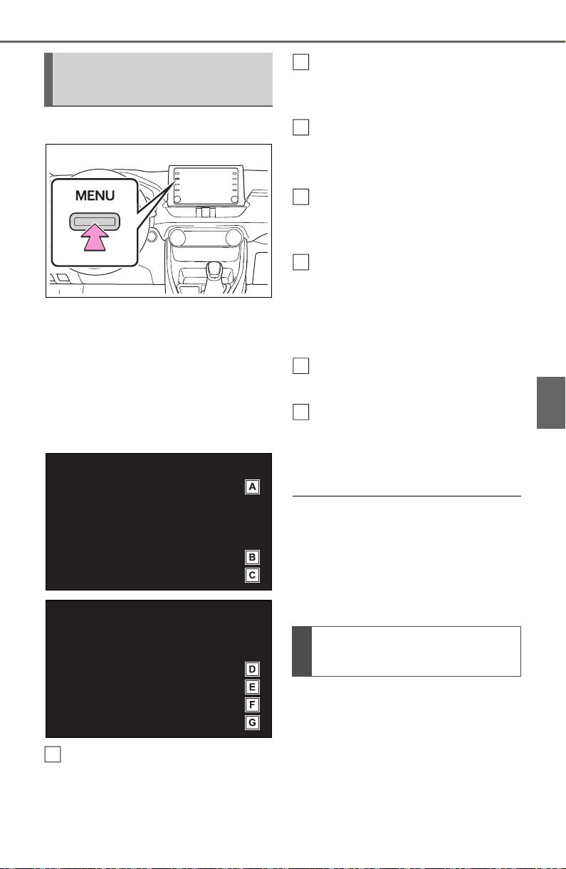
403
5-3. Connectivity settings
5
Audio
1 Press the “MENU” button.
2 Select “Setup”.
3 Select “Wi-Fi
*
”.
*
:Wi-Fi
®
is a registered trademark
of Wi-Fi Alliance
®
.
4 Select the desired item to be
set.
Select to enable/disable the
Wi-Fi
®
Hotspot function.
(P.403)
Select to check/change the
access point password.
(P.404)
Select to display hints for
connecting to the vehicle via
Wi-Fi
®
.
Select to make the access
point searchable/unsearch-
able.
Select to check/change the
security protocol of the
access point (for authentica-
tion and encryption).
(P.404)
Select to change the access
point name (SSID). (P.404)
Select to change the Wi-Fi
®
connection channel (within
the 2.4GHz frequency band).
(P.404)
● If any settings have been
changed, it will be necessary to
reset the Wi-Fi
®
system to com-
plete the changes. To reset the
Wi-Fi
®
system, select “Yes” on the
pop-up displayed after changing
the settings.
When the Wi-Fi
®
Hotspot func-
tion is enabled, the system
checks for a valid Hotspot ser-
vice subscription.
If a Hotspot service subscription
has not been started, connect
your device to the in-vehicle
Changing the Wi-Fi
®
set-
tings
A
Enabling/disabling the
W-Fi
®
Hotspot function
B
C
D
E
F
G
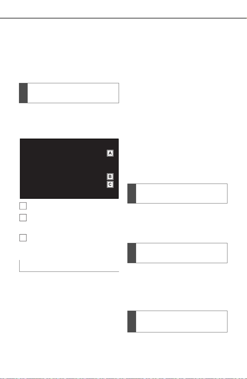
404
5-3. Connectivity settings
access point to start your sub-
scription. A trial subscription
may be available.
Contact your Toyota dealer for
details about the Toyota mobile
application.
1 Select “Password”.
2 Check that the following
screen is displayed.
Displays the password
Select to display/hide the
entered password.
Select to change the pass-
word.
1 Select “Change Password”.
2 Enter the desired password
and select “OK”.
When setting/changing a
password, observe the follow-
ing guidelines to help prevent
the password from being
cracked by a third party:
• Use an 8-character or longer
password consisting of letters
and numbers. (Non-ASCII char-
acters will not be recognized by
the system.)
• Change the password regularly.
• If you write the password down,
do not leave it somewhere where
it would be visible.
• Do not use the same password
for vehicle Wi-Fi
®
Hotspot as
other accounts already protected
by a password.
• Avoid using easy to identify
words, such as your vehicle’s
model name or license plate
number, simple dictionary words,
or words with simple obfuscation,
such as c@t (for cat), as your
password.
1 Select “Security”.
2 Select the desired security
protocol.
1 Select “Access Point Name”.
2 Enter the desired access
point name (SSID) and select
“OK”.
1 Select “Channel”.
Checking/changing the
password
Changing the password
A
B
C
Changing the security pro-
tocol
Changing the access point
name (SSID)
Selecting a Wi-Fi
®
connec-
tion channel

405
5-3. Connectivity settings
5
Audio
2 Check that the following
screen is displayed.
Select to change the chan-
nel selection to auto-
matic/manual.
When “Manual” is selected,
select to change the channel.
1 Set “Select Channel” to
“Manual”.
2 Select “Channel Number”.
3 Enter the desired channel
number and select “OK”.
Channels 1 through 11 can be
selected.
● If a connected device is taken out
of the Wi-Fi
®
connection area, the
connection will be severed.
● If the vehicle is driven out of the
cellular communication coverage
area, connecting to the internet
via the Wi-Fi
®
Hotspot will not be
possible.
● If a Bluetooth
®
device is used
while a device is connected using
the Wi-Fi
®
Hotspot function, the
communication speed may
decrease.
● If the vehicle is near a radio
antenna, radio station or other
source of strong radio waves and
electrical noise, communication
may be slow or impossible.
The condition of Wi-Fi
®
connec-
tion appears on the right upper
side of the screen. (P.3 78 )
Changing the channel
Wi-Fi
®
function operating
hints
A
B
WARNING
● Use Wi-Fi
®
devices only when
safe and legal to do so.
● Your audio unit is fitted with
W-Fi
®
antennas. People with
implantable cardiac pacemak-
ers, cardiac resynchronization
therapy-pacemakers or implan-
table cardioverter defibrillators
should maintain a reasonable
distance between themselves
and the Wi-Fi
®
antennas.
The radio waves may affect the
operation of such devices.
● Before using Wi-Fi
®
devices,
users of any electrical medical
device other than implantable
cardiac pacemakers, cardiac
resynchronization therapy-
pacemakers or implantable car-
dioverter defibrillators should
consult the manufacturer of the
device for information about its
operation under the influence of
radio waves.
Radio waves could have unex-
pected effects on the operation
of such medical devices.
Conditions displayed with
Wi-Fi
®
icon

406
5-3. Connectivity settings
Communication standards
IEEE 802.11b
IEEE 802.11g
IEEE 802.11n (2.4GHz)
Security
WPA™
WPA2™
• WPA™ and WPA2™ are trade-
marks of Wi-Fi Alliance
®
.
Specifications

407
5-4. Apple CarPlay/Android Auto
5
Audio
5-4.Apple C arPlay/Android Auto
*
: This function is not made avail-
able in some countries or areas.
1 Enable Siri on the device to
be connected.
2 Connect the device to the
USB port. (P.422)
3 Select “Always Enable” or
“Enable Once”.
“Do Not Enable”: Select to not
enable Apple CarPlay. Apple
CarPlay will remain off until
“Apple CarPlay” of “Projection
Settings” on the general set-
tings screen is turned on.
Depending on the device con-
nected,it may take approxi-
mately 3 to 6 seconds before
the system returns to previous
screen.
The screen may change to
step 6 depending on the sys-
tem.
4 Press the “MENU” button.
Apple
CarPlay
®
/Android
Auto
*
Apple CarPlay/Android Auto
allows some applications,
such as Map, Phone, and
Music, to be used on the
system.
When an Apple
CarPlay/Android Auto con-
nection is established,
Apple CarPlay/Android Auto
compatible applications will
be displayed on the system
display.
Compatible device
Apple iPhone (iOS Ver. 9.3 or
later) that supports Apple
CarPlay. For details, refer to
https://www.apple.com/ios/car
play/.
Android devices with Android
OS ver 5.0 or higher which
support Android Auto and
have the Android Auto appli-
cation installed. For details,
refer to
https://www.android.com/auto/
.
Establishing an Apple
CarPlay connection
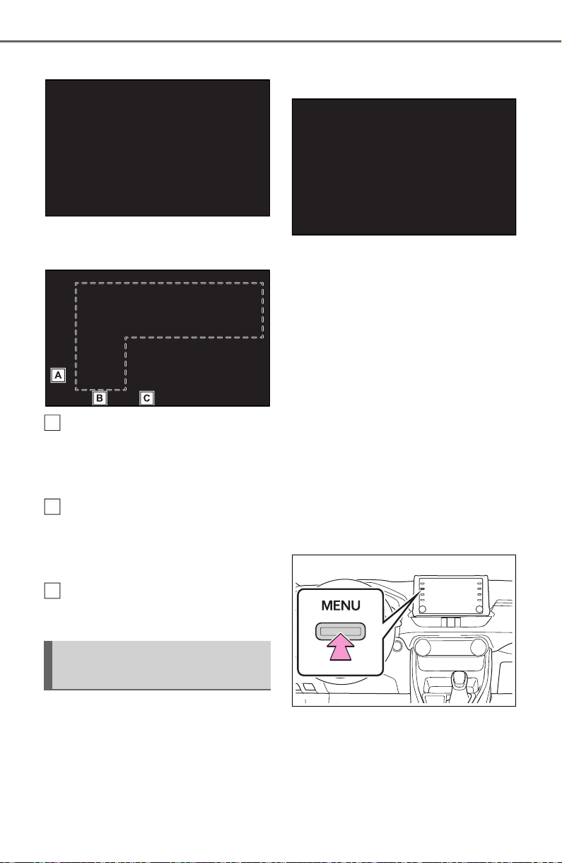
408
5-4. Apple CarPlay/Android Auto
5 Select the “Apple CarPlay”.
6 Check that home screen of
Apple CarPlay is displayed.
Select to display the home
screen of Apple CarPlay.
Select and hold to activate
Siri.
Select to start the application.
User can use any iPhone
application supported by
Apple CarPlay.
Select to display the system
screen.
1 Check that the Android Auto
application is installed to the
device to be connected.
2 Connect the device to the
USB port. (P.422)
3 Select “On” to enable the
function.
“Off”: Select to not enable
Android Auto. Android Auto
will remain off until “Android
Auto” of “Projection Settings”
on the general settings screen
is turned on.
Depending on the device con-
nected,it may take approxi-
mately 3 to 6 seconds before
the system returns to previous
screen.
The screen may change to
step 6 depending on the sys-
tem.
4 Press the “MENU” button.
Establishing an Android
Auto connection
A
B
C
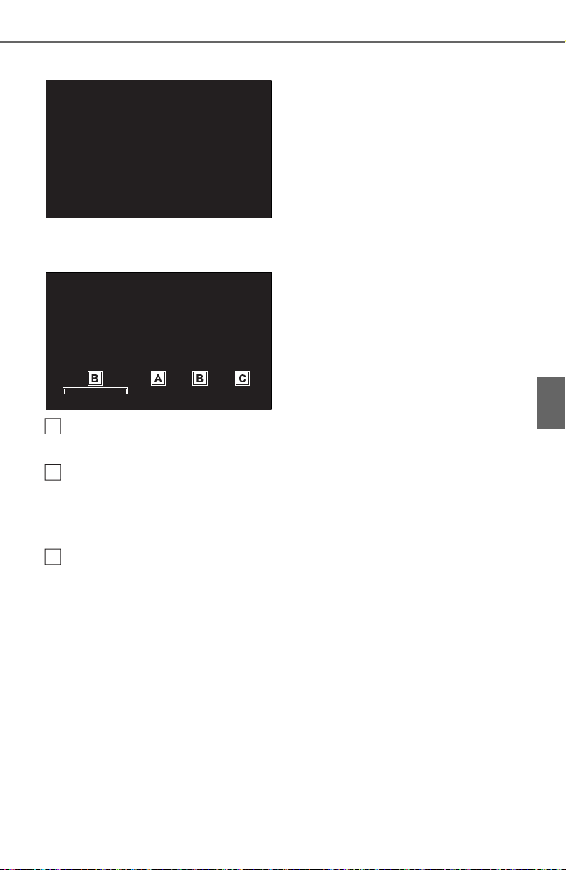
409
5-4. Apple CarPlay/Android Auto
5
Audio
5 Select the “Android Auto”.
6 Check that home screen of
Android Auto is displayed.
Select to display the home
screen of Android Auto.
Select to start the application.
User can use any Android
application supported by
Android Auto.
Select to display the system
screen.
● When an Apple CarPlay/Android
Auto connection is established,
the function of some system but-
tons will change.
● When an Apple CarPlay/Android
Auto connection is established,
some system functions, such as
the following, will be replaced by
similar Apple CarPlay/Android
Auto functions or will become
unavailable:
• iPod (Audio Playback)
• USB audio/USB video
• Bluetooth
®
audio
• Bluetooth
®
phone (Apple CarPlay
only)
• Toyota Apps
● When an Apple CarPlay/Android
Auto connection is established,
voice command system (Siri/Goo-
gle Assistant) and map application
voice guidance volume can be
changed by selecting “Voice Vol-
ume” on the voice settings screen.
It cannot be changed by “POWER
VOLUME” knob on Audio control
panel. (P.418)
● Apple CarPlay/Android Auto is an
application developed by Apple
Inc/Google LLC. Its functions and
services may be terminated or
changed without notice depending
on the connected device’s opera-
tion system, hardware and soft-
ware, or due to changes in Apple
CarPlay/Android Auto specifica-
tions.
● For a list of the apps supported by
Apple CarPlay or Android Auto,
refer to their respective website.
● While using these functions, vehi-
cle and user information, such as
location and vehicle speed, will be
shared with the respective appli-
cation publisher and the cellular
service provider.
● By downloading and using each
application, you agree to their
terms of use.
● Data for these functions is trans-
mitted using the internet and may
incur charges. For information
about data transmission fees, con-
tact your cellular service provider.
● Depending on the application, cer-
tain functions, such as music play-
back, may be restricted.
● As the applications for each func-
tion are provided by a third-party,
they may be subject to change or
discontinuation without notice. For
details, refer to the website of the
function.
● If the vehicle’s navigation system
A
B
C
410
5-4. Apple CarPlay/Android Auto
is being used for route guidance
and a route is set using the Apple
CarPlay/Android Auto Maps app,
route guidance will be performed
through Apple CarPlay/Android
Auto. If the Apple CarPlay/Android
Auto Maps app is being used for
route guidance and a route is set
using the vehicle’s navigation sys-
tem, route guidance will be per-
formed by the vehicle’s navigation
system.
● If the USB cable is disconnected,
operation of Apple
CarPlay/Android Auto will end. At
this time, sound output will stop
and change to the system screen.
■ Certification
● Use of the Apple CarPlay logo
means that a vehicle user inter-
face meets Apple performance
standards. Apple is not responsi-
ble for the operation of this vehicle
or its compliance with safety and
regulatory standards. Please note
that the use of this product with
iPhone or iPod may affect wire-
less performance.
● Apple CarPlay is a trademark of
Apple Inc.
● Android and Android Auto are
trademarks of Google LLC.
If you are experiencing difficulties with Apple CarPlay/Android Auto,
check the following table.
WARNING
● Do not connect iPhone or oper-
ate the controls while driving.
NOTICE
● Do not leave your smartphone
in the vehicle. In particular, high
temperatures inside the vehicle
may damage the smartphone.
● Do not push down on or apply
unnecessary pressure to the
smartphone while it is con-
nected as this may damage the
smartphone or its terminal.
● Do not insert foreign objects into
the port as this may damage the
smartphone or its terminal.
Troubleshooting

411
5-4. Apple CarPlay/Android Auto
5
Audio
Symptom Solution
An Apple CarPlay/Android
Auto connection cannot
be established.
Check if the device supports Apple
CarPlay/Android Auto.
Check if Apple CarPlay/Android Auto is
enabled on the connected device.
Check that the Android Auto application is
installed to the device to be connected.
For details, refer to
https://www.apple.com/ios/carplay/
,
https://www.android.com/auto/
.
Check if “Apple CarPlay”/“Android Auto” of
“Projection Settings” on the general settings
screen is set to on. (P.414)
Check if the USB cable being used is securely
connected to the device and USB port.
Try connecting the smartphone directly to the
USB port in the vehicle, without using the hub.
For Apple CarPlay: Check if the Lightning cable
being used is certified by Apple and check if Siri
is enabled.
After checking all of the above, try to establish
an Apple CarPlay/Android Auto connection.
(P.407)
When an Apple
CarPlay/Android Auto
connection is established
and a video is being
played, the video is not
displayed, but audio is
output through the sys-
tem.
As the system is not designed to play video
through Apple CarPlay/Android Auto, this is not
a malfunction.
Although an Apple
CarPlay/Android Auto
connection is established,
audio is not output
through the system.
The system may muted or the volume may be
low. Increase the system volume.

412
5-4. Apple CarPlay/Android Auto
The Apple
CarPlay/Android Auto
screen has artifacts
and/or audio from Apple
CarPlay/Android Auto has
noise.
Check if the USB cable being used to connect
the device to the system is damaged.
To check if the USB cable is damaged inter-
nally, connect the device to another system,
such as a PC, and check if the device is recog-
nized by the connected system. (The device
should begin charging when connected.)
After checking all of the above, try to establish
an Apple CarPlay/Android Auto connection.
(P.407)
The map display of the
Apple CarPlay Maps app
cannot be enlarged or
contracted with pinch
multi-touch gestures.
As the Apple CarPlay Maps app is not compati-
ble with pinch multi-touch gestures, this is not a
malfunction.
During Apple CarPlay
music application (Apple
Music, Spotify, etc.) play-
back, if the iPhone is
operated to start and play
audio from an application
that is not compatible with
Apple CarPlay
*
and the
onboard device volume is
changed, the audio of the
incompatible application
stops and the system
resumes playback of the
original music application.
This operation is performed according to the
specification of the onboard device, this is not a
malfunction.
After interrupt audio (such
as navigation route guid-
ance) is played from an
application that is not
compatible with Apple
CarPlay while the onboard
device is playing audio
(FM/AM, CD, etc.), the
system does not resume
playback of the original
audio (FM/AM, CD, etc.).
This operation is performed according to the
specification of the onboard device, this is not a
malfunction. Manually change the audio source
by yourself. Or, do not use applications that are
not compatible with Apple CarPlay.
*
Due to
some navigation applications are compatible
from iOS 12, update to the latest iOS and appli-
cation versions.
Symptom Solution

413
5-4. Apple CarPlay/Android Auto
5
Audio
*
: Applications not compatible with Apple CarPlay are applications installed
on the iPhone that are not displayed on the Apple CarPlay screen appli-
cation list. (such as visual voicemail)
When using Apple
CarPlay, route guidance
arrows and turn by turn
navigation are not dis-
played on the multi-infor-
mation display and
system display. When
using Android Auto, turn
by turn navigation is not
displayed on the multiin-
formation display and sys-
tem display.
This is not a malfunction as display of these
items is not possible with this function.
When using Android Auto,
hands-free call audio can-
not be heard from the
vehicle’s speakers.
Disconnect the phone from the USB cable and
check if hands-free call audio can be heard
using the hands-free system.
Connect the phone to the system using Android
Auto, turn up the volume on the system and
check if hands-free call audio can be heard.
Check if other sounds can be heard from the
vehicle’s speakers.
Symptom Solution
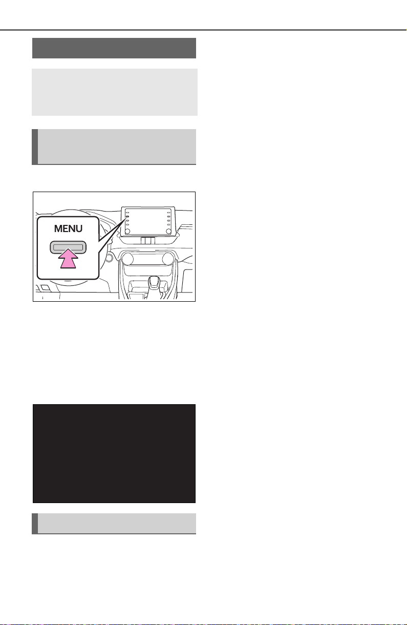
414
5-5. Other settings
5-5.Other s ettings
1 Press the “MENU” button.
2 Select “Setup”.
If the general settings screen
is not displayed, select “Gen-
eral”.
3 Select the desired items to
be set.
“Clock”
Select to change the time zone and
select “On” or “Off” for daylight sav-
ing time, automatic adjustment of
the clock, etc. (P.415)
“Language”
Select to change the language. The
language setting of Apple
CarPlay/Android Auto can only be
changed on the connected device.
“Customize Home Screen”
Select to change the display infor-
mation/area on the home screen
and the home screen layout.
(P.384)
“Projection Settings”
*1
Select to set automatic Apple
CarPlay/Android Auto connection
establishment on/off. (P.416)
“Beep”
Select to turn the beep sound
on/off.
“Theme Setting”
Select to change the screen theme
setting.
“Units of Measurement”
Select to change the unit of mea-
sure for distance/fuel consumption.
“Keyboard Layout”
Select to change the keyboard lay-
out.
“Delete Keyboard History”
Select to delete the keyboard his-
tory.
“Memorize Keyboard History”
Select to set the memorize key-
board history on/off.
“Animation”
Select to turn the animations on/off.
“Driver Setting”
General settings
Settings are available for
clock, operation sounds,
etc.
Displaying the general
settings screen
General settings screen

415
5-5. Other settings
5
Audio
Select to change the driver set-
tings. (P.416)
“Delete Personal Data”
Select to delete personal data.
(P.417)
“Software Update”
Select to update software versions.
For details, contact your Toyota
dealer.
“Software Update Setting”
*2
Select to set software update set-
ting. (P.417)
“Gracenote Database
Update”
Select to update Gracenote
®
data-
base versions. For details, contact
your Toyota dealer.
“Software Information”
Select to display the software infor-
mation. Notices related to third
party software used in this product
are enlisted. (This includes instruc-
tions for obtaining such software,
where applicable.)
“SW Sensitivity Level”
Select to change the capacitive
touch screen button sensitivity to 1
(low), 2 (medium), or 3 (high).
*1
:This function is not made avail-
able in some countries or areas.
*2
:Vehicles equipped with DCM
1 Display the general settings
screen. (P.414)
2 Select “Clock”.
3 Select the desired items to
be set.
Select to change the time
zone. (P.415)
Select to set daylight saving
time on/off.
Select to set automatic
adjustment of the clock by
GPS on/off.
When set to off, the clock can
be manually adjusted.
(P.415)
Select to set the 24 hour time
format on/off.
When set to off, the clock is
displayed in 12 hour time for-
mat.
1 Select “Time Zone”.
2 Select the desired time zone.
When “Auto Adjust by GPS” is
turned off, the clock can be
manually adjusted.
1 Select “Auto Adjust by GPS”
to set to off.
Clock settings
Setting the time zone
Manual clock setting
A
B
C
D
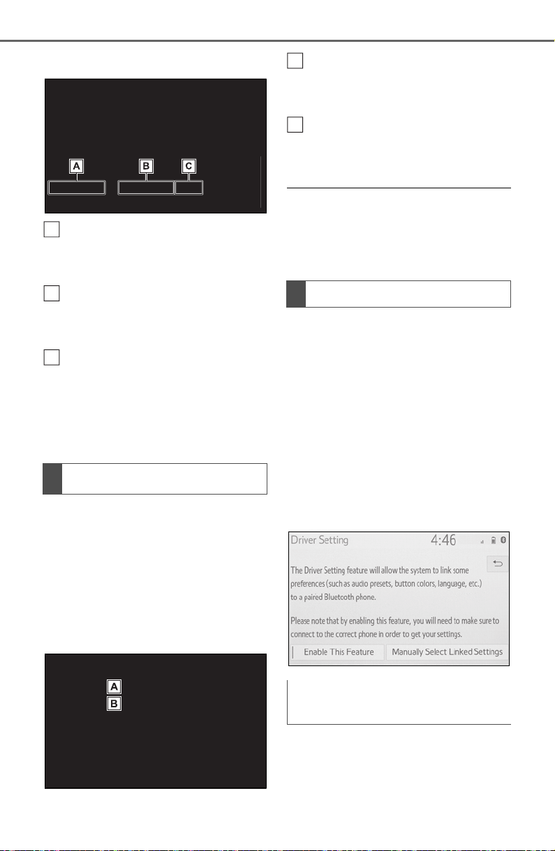
416
5-5. Other settings
2 Adjust the clock manually.
Select “+” to set the time for-
ward one hour and “-” to set
the time back one hour.
Select “+” to set the time for-
ward one minute and “-” to
set the time back one minute.
Select to round to the nearest
hour.
e.g.
1:00 to 1:29 1:00
1:30 to 1:59 2:00
*
: This function is not made avail-
able in some countries or areas.
1 Display the general settings
screen. (P.414)
2 Select “Projection Settings”.
3 Select the desired items to
be set.
Select to turn Apple CarPlay
connection establishment
on/off.
Select to turn Android Auto
connection establishment
on/off.
● When the settings are changed
with a device connected to the
system via USB, disconnect the
device and connect it again to
enable the settings.
The driver settings feature will
allow the system to link some
preferences (such as audio pre-
sets, screen theme, language,
etc.) to a paired Bluetooth
®
phone.
1 Display the general settings
screen. (P.414)
2 Select “Driver Setting”.
3 Select “Enable This Feature”.
1 Select “Manually Select
Linked Settings”.
Projection settings
*
A
B
C
Driver settings
Manually select linked set-
tings
A
B
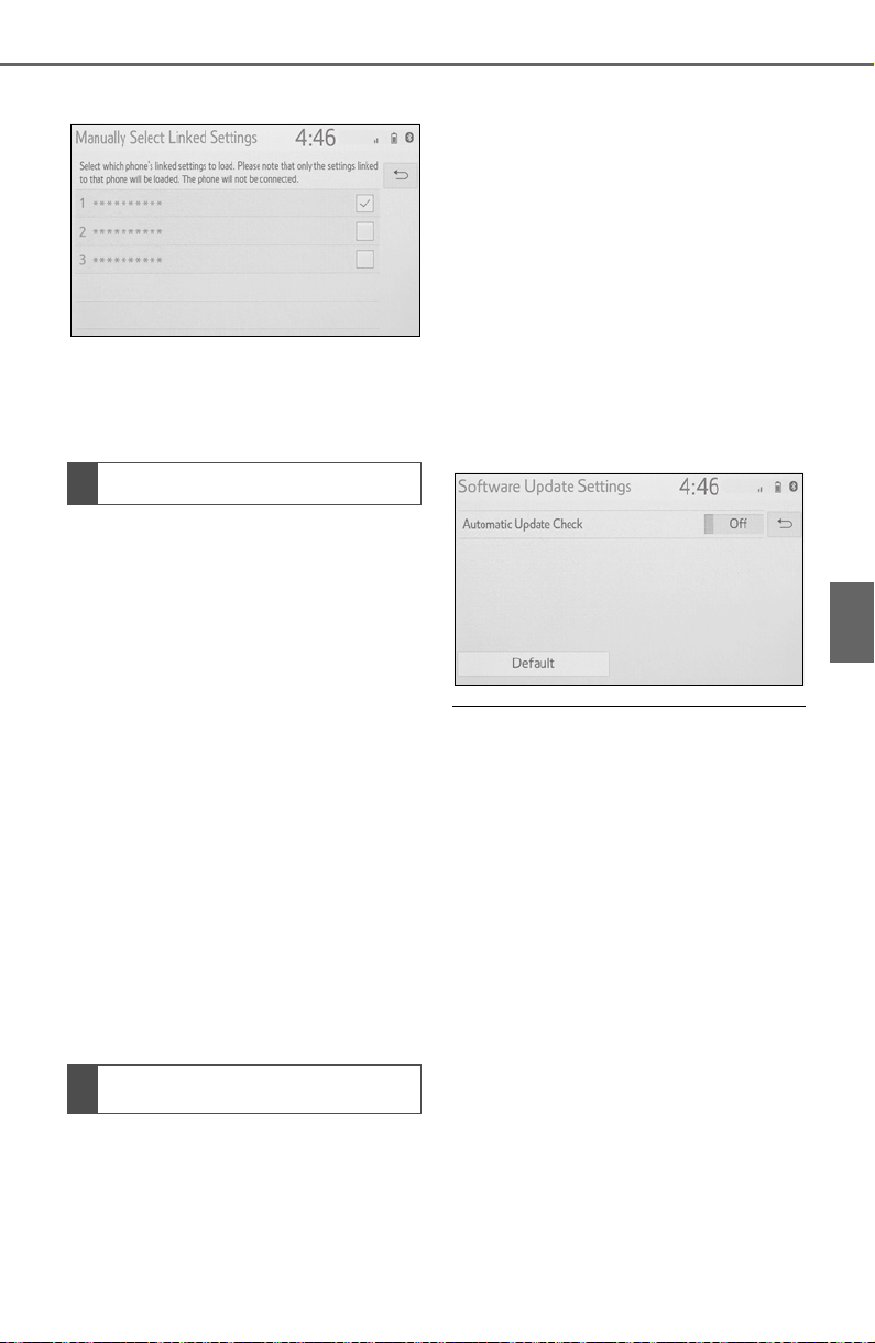
417
5-5. Other settings
5
Audio
1 Select the desired phone.
After a few seconds, loaded
screen automatically switches
to the home screen.
Registered or changed per-
sonal settings will be deleted or
returned to their default condi-
tions.
1 Display the general settings
screen. (P.414)
2 Select “Delete Personal
Data”.
3 Select “Delete”.
4 Select “Yes” when the confir-
mation screen appears.
Examples of settings that can be
returned to their default conditions:
Audio settings
Phone settings
etc.
*
: Vehicles equipped with DCM
only. This function is not made
available in some countries or
areas.
When the automatic update
check function is enabled, if a
software update is available
from the Cloud, a message will
be displayed.
1 Display the general settings
screen. (P.414)
2 Select “Software Update Set-
ting”.
3 Select “Automatic Update
Check” to enable/disable the
automatic update check func-
tion.
● When software update information
is displayed, contact your Toyota
dealer.
Deleting personal data
Software update settings
*
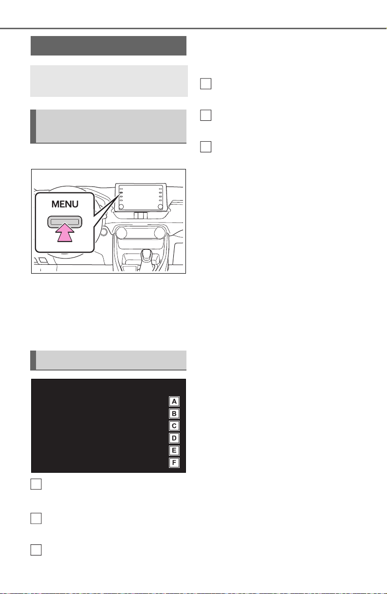
418
5-5. Other settings
1 Press the “MENU” button.
2 Select “Setup”.
3 Select “Voice”.
4 Select the desired items to
be set.
Select to adjust the volume of
voice guidance.
*
Select to set the voice recog-
nition prompts.
Select to train voice recogni-
tion.
The voice command system
adapts the user accent.
Select to start the voice rec-
ognition tutorial.
Select to set the voice
prompt interrupt on/off.
Select to reset all setup
items.
*
: When an Apple CarPlay/Android
Auto connection is established,
voice command system
(Siri/Google Assistant) and map
application voice guidance vol-
ume can be changed.
Voice settings
Voice volume, etc. can be
set.
Displaying the voice set-
tings screen
Voice settings screen
A
B
C
D
E
F
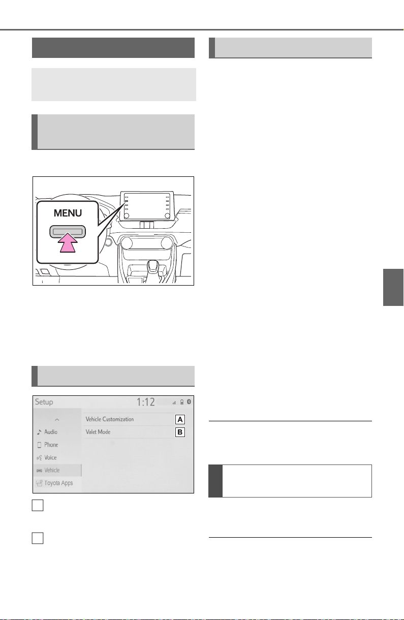
419
5-5. Other settings
5
Audio
1 Press the “MENU” button.
2 Select “Setup”.
3 Select “Vehicle”.
4 Select the desired items to
be set.
Select to set vehicle customi-
zation. (P.688)
Select to set valet mode.
(P.419)
The security system can be set
to on by entering a security code
(4-digit number).
When set to on, the system will
become inoperative once the
electrical power source is dis-
connected until the security
code is entered.
1 Display the vehicle settings
screen. (P.419)
2 Select “Valet Mode”.
3 Enter the 4-digit personal
code and select “OK”.
4 Enter the same 4-digit per-
sonal code again and select
“OK”.
The system will request that
you input the security code
again to confirm that you
remember it correctly.
When valet mode activates,
the system stops and a secu-
rity code (4-digit number)
standby screen is displayed.
● If the 4-digit personal code is for-
gotten, please contact your Toyota
dealer.
1 Enter the 4-digit personal
code and select “OK”.
● If an incorrect security code (4-
digit number) is entered 6 times,
the system will not accept another
security code (4-digit number) for
10 minutes.
Vehicle settings
Settings are available for
vehicle customization, etc.
Displaying the vehicle
settings screen
Vehicle settings screen
A
B
Setting the valet mode
If the valet mode has been
activated
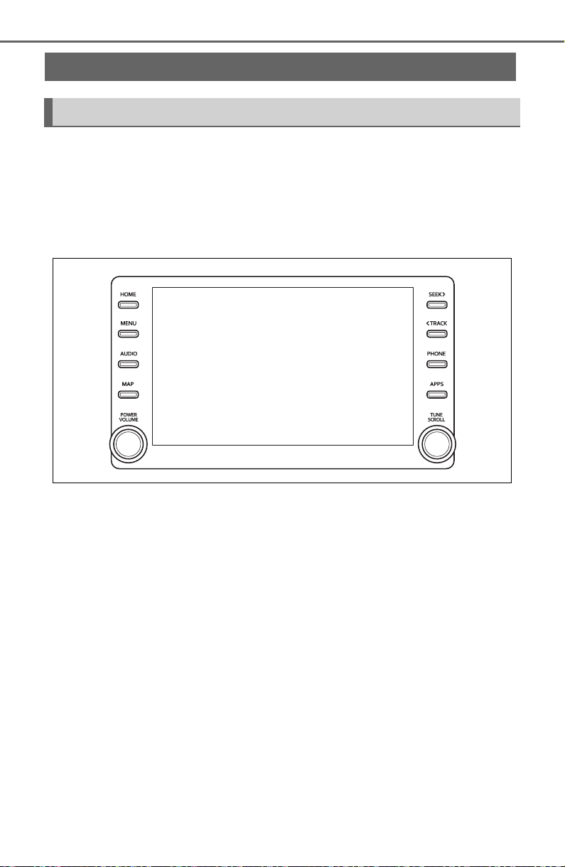
420
5-6. Using the audio/visual system
5-6.Using the audio/visual system
The audio control screen can be reached by the following methods:
From the “AUDIO” button
1 Press the “AUDIO” button.
From the “MENU” button
1 Press the “MENU” button, then select “Audio”.
• Using the radio (P.425)
• Playing a USB memory (P.432)
• Playing an iPod/iPhone (Apple CarPlay
*
) (P.434)
• Using the Android Auto
*
(P.437)
• Playing a Bluetooth
®
device (P.438)
• Using the steering wheel audio switches (P.442)
• Audio system settings (P.444)
*
: This function is not made available in some countries or areas.
Quick reference
Functional overview
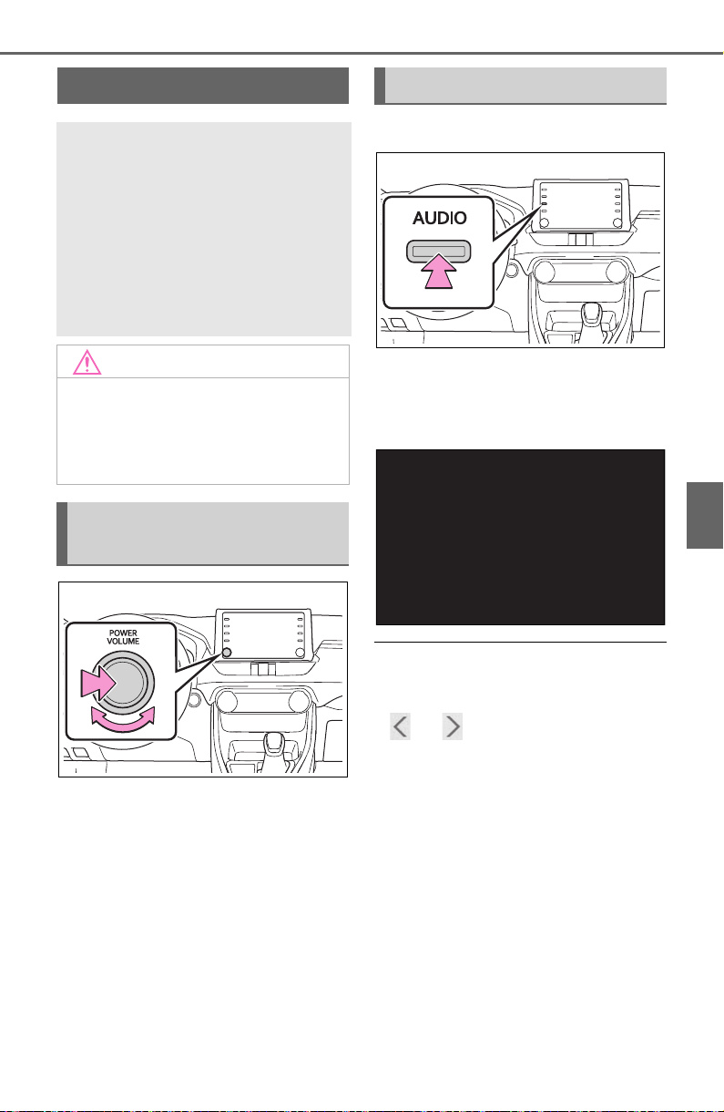
421
5-6. Using the audio/visual system
5
Audio
“POWER VOLUME” knob:
Press to turn the audio/visual
system on and off. The system
turns on in the last mode used.
Turn this knob to adjust the vol-
ume.
1 Press the “AUDIO” button.
2 Select “Source” or press
“AUDIO” button again.
3 Select the desired source.
● Dimmed screen buttons cannot be
operated.
● When there are two pages, select
or to change the page.
● When an Apple CarPlay/Android
Auto connection is established,
some system functions, such as
the following, will be replaced by
similar Apple CarPlay/Android
Auto function or will become
unavailable
*
:
• iPod (Audio Playback)
• USB audio/USB video
• Bluetooth
®
audio
• Toyota Apps
*
: This function is not made avail-
able in some countries or areas.
Some basics
This section describes
some of the basic features
of the audio/visual system.
Some information may not
pertain to your system.
Your audio/visual system
works when the engine
switch is in ACC or ON.
NOTICE
● To prevent the battery from
being discharged, do not leave
the audio/visual system on lon-
ger than necessary when the
engine is not running.
Turning the system on
and off
Selecting an audio source
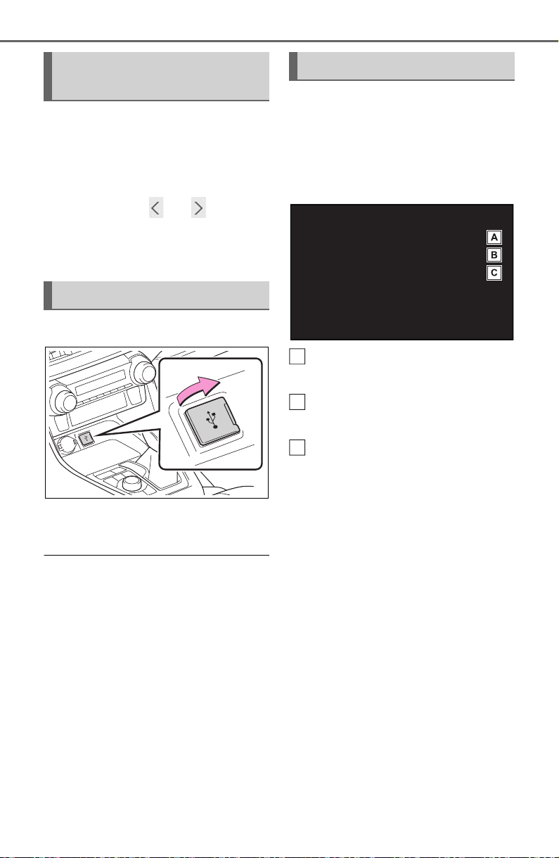
422
5-6. Using the audio/visual system
1 Display the audio source
selection screen. (P.421)
2 Select “Reorder”.
3 Select the desired audio
source then or to reor-
der.
4 Select “OK”.
1 Connect a device.
Turn on the power of the
device if it is not turned on.
● If a USB hub is plugged-in, two
devices can be connected at a
time.
● Even if a USB hub is used to con-
nect more than two USB devices,
only the first two connected
devices will be recognized.
● If a USB hub that has more than
two ports is connected to the USB
port, devices connected to the
USB hub may not charge or be
inoperable, as the supply of cur-
rent may be insufficient.
● When an Apple CarPlay/Android
Auto connection is established,
the other USB port can be used
only for device battery charger.
1 Display the audio control
screen. (P.421)
2 Select “Sound”.
3 Select the desired item to be
set.
Select to set the tre-
ble/mid/bass. (P.422)
Select to set the fader/bal-
ance. (P.423)
Select to set the automatic
sound leveliser. (P. 42 3 )
■ Treble/Mid/Bass
How good an audio program
sounds is largely determined by
the mix of the treble, mid and
bass levels. In fact, different
kinds of music and vocal pro-
grams usually sound better with
different mixes of treble, mid
and bass.
1 Select “Treble/Mid/Bass”.
Reordering the audio
source
USB port
Sound settings
A
B
C
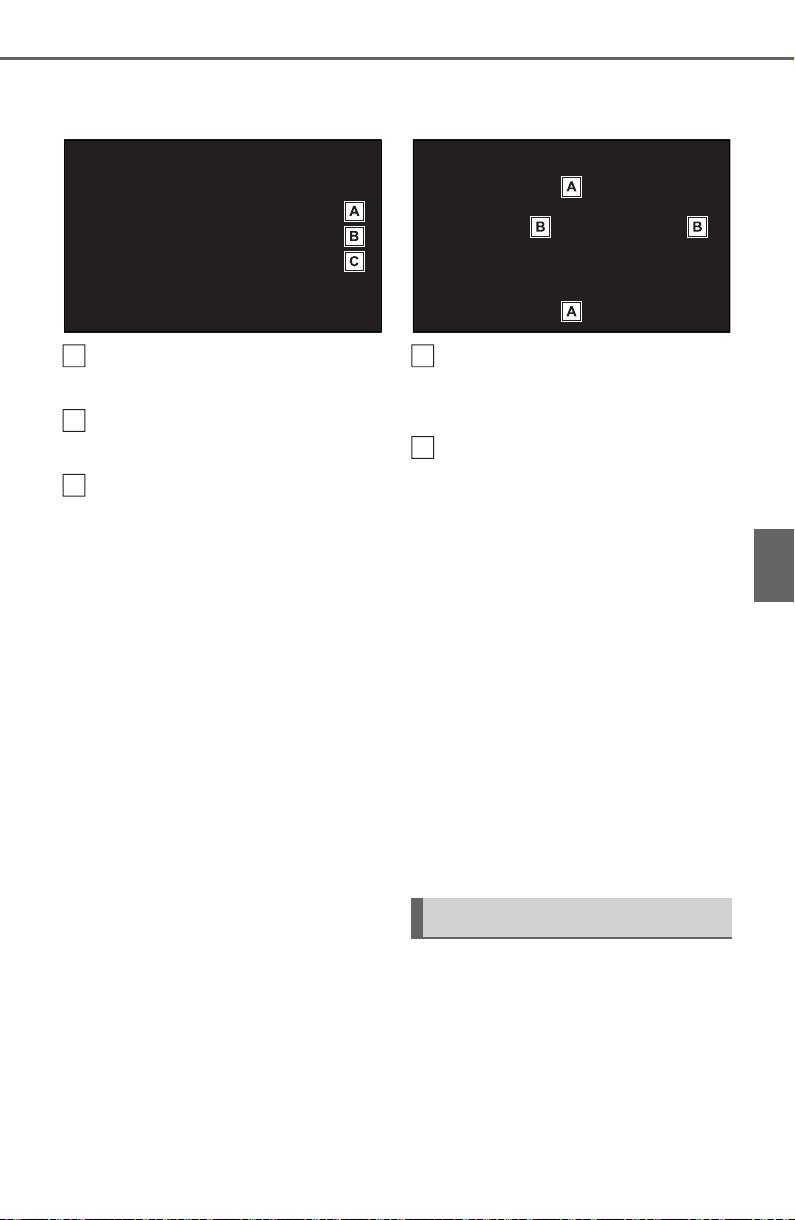
423
5-6. Using the audio/visual system
5
Audio
2 Select the desired screen
button.
Select “+” or “-” to adjust
high-pitched tones.
Select “+” or “-” to adjust mid-
pitched tones.
Select “+” or “-” to adjust low-
pitched tones.
■ Fader/Balance
A good balance of the left and
right stereo channels and of the
front and rear sound levels is
also important.
Keep in mind that when listening
to a stereo recording or broad-
cast, changing the right/left bal-
ance will increase the volume of
1 group of sounds while
decreasing the volume of
another.
1 Select “Fader/Balance”.
2 Select the desired screen
button.
Select to adjust the sound
balance between the front
and rear speakers.
Select to adjust the sound
balance between the left and
right speakers.
■ Automatic sound levelizer
(ASL)
The system adjusts to the opti-
mum volume and tone quality
according to vehicle speed to
compensate for increased road
noise, wind noise, or other
noises while driving.
1 Select “Automatic Sound
Levelizer”.
2 Select “High”, “Mid”, “Low” or
“Off”.
■ Screen format settings
The screen format can be
selected for USB video.
1 Press the “MENU” button.
2 Select “Setup”.
3 Select “Audio”.
A
B
C
Audio screen adjustment
A
B
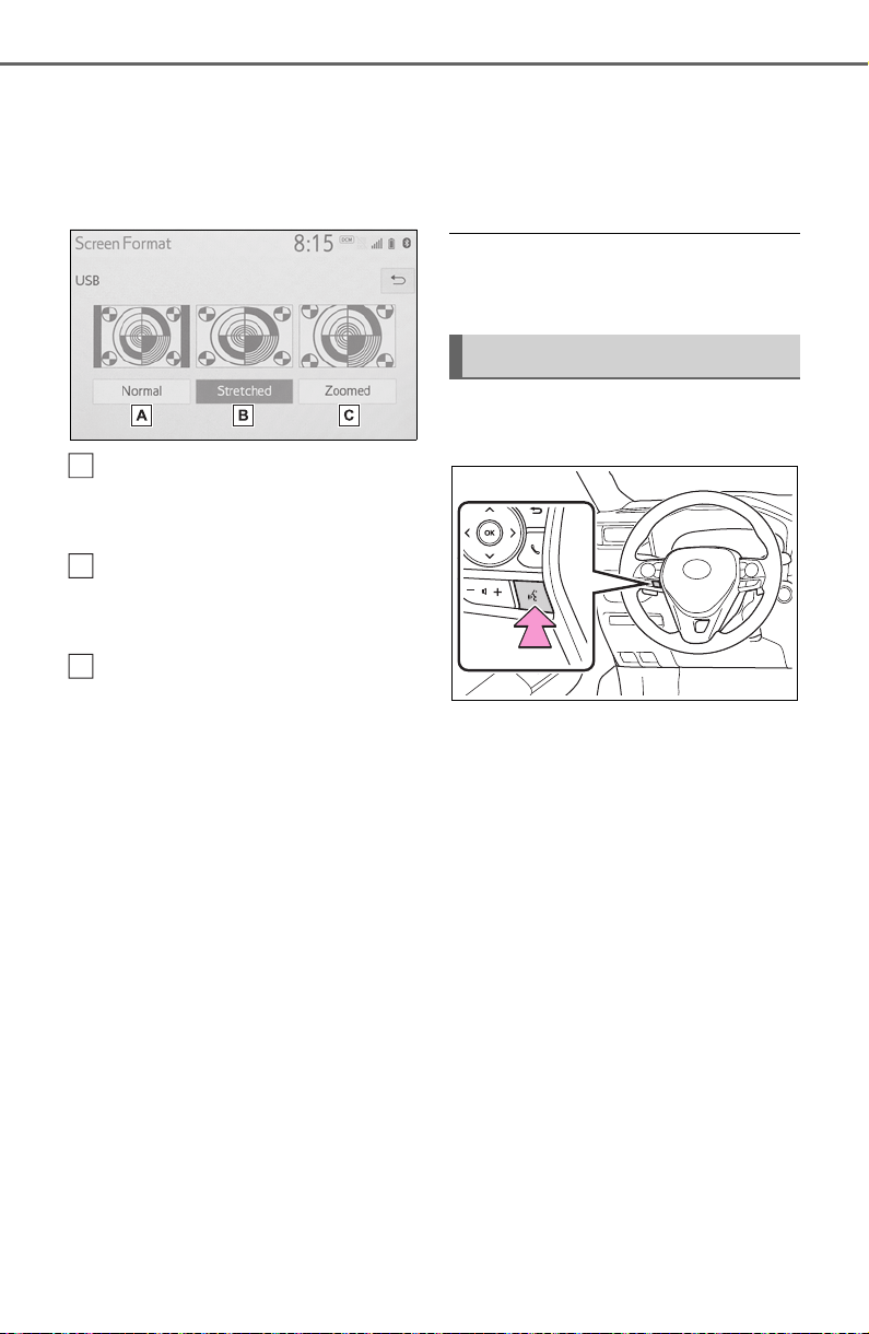
424
5-6. Using the audio/visual system
4 Select “Common”.
5 Select “Screen Format”.
6 Select the desired item to be
adjusted.
Select to display a 4 : 3
screen, with either side in
black.
Select to enlarge the image
horizontally and vertically to
full screen.
Select to enlarge the image
by the same ratio horizontally
and vertically.
■ Contrast and brightness
adjustment
The contrast and brightness of
the screen can be adjusted.
1 Press the “MENU” button.
2 Select “Setup”.
3 Select “Audio”.
4 Select “Common”.
5 Select “Display”.
6 Select the desired item to be
adjusted.
“Contrast”
“+”: Select to strengthen the con-
trast of the screen.
“-”: Select to weaken the contrast of
the screen.
“Brightness”
“+”: Select to brighten the screen.
“-”: Select to darken the screen.
● Depending on the audio source,
some functions may not be avail-
able.
1 Press this switch to operate
the voice command system.
The voice command system
and its list of commands can
be operated. (P.458)
A
B
C
Voice command system
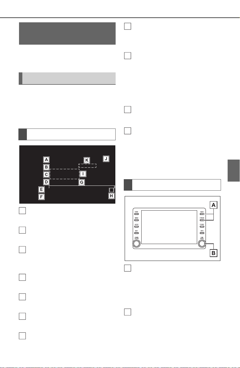
425
5-7. Radio operation
5
Audio
5-7.Radio op eration
*
: This function is not made avail-
able in some countries or areas.
The radio operation screen can
be reached by the following
methods:
P. 4 21
Select to display the audio
source selection screen.
Select to display the preset
stations screen. (P.426)
Select to display the cache
radio operation screen.
(P.426)
Select to display a list of
receivable stations. (P.427)
Select to display the radio
options screen. (P.427)
Select to display the sound
setting screen. (P.422)
Select to tune to preset sta-
tions/channels. (P.426)
Displays items on the chan-
nels registered to smart
favorites
*
(P.430, 445)
Displays the artist info and
song title or album
Select to change the dis-
played information.
Displays messages when
available
*
Displays cover art, station
logo, etc.
*
Displays information about
the song/track currently
being played
*
*
: This function is not made avail-
able in some countries or areas.
Press to seek for stations in
the relevant program
type/channel category.
Press and hold for continu-
ous seek.
Turn to step up/down fre-
quencies/channels.
Turn to move up/down the
station list. Also, the knob
can be used to enter selec-
AM/FM/SiriusXM (SXM)
radio
*
Overview
Control screen
A
B
C
D
E
F
G
Control panel
H
I
J
K
A
B

426
5-7. Radio operation
tions on the list screens by
pressing it.
● The radio automatically changes
to stereo reception when a stereo
broadcast is received.
Radio mode has a mix preset
function, which can store up to
36 stations (6 stations per page
x 6 pages) from any of the AM,
FM or SXM
*
bands.
1 Tune in the desired station.
2 Select and hold “(Hold Edit)”.
When “(Hold Edit)” is
selected, a confirmation mes-
sage appears. Select “Yes”
and select “OK”.
To change the preset station
to a different one, select and
hold the preset station.
*
: This function is not made avail-
able in some countries or areas.
● The number of preset radio sta-
tions displayed on the screen can
be changed. (P.444)
*
: This function is not made avail-
able in some countries or areas.
AM/FM and SXM radio program
can be cached and played back
in a time-shifted manner.
■ Automatic playback of the
cache
If the radio broadcast is inter-
rupted by another audio output,
such as an incoming phone call,
the system will automatically
cache the interrupted portion
and perform time-shift playback
when the interruption ends. This
function is available when “Auto
Pause” is set to on. (P.427)
■ Playing back the cache
manually
The broadcast cached in the
program cache can be played
back manually.
1 Select “SXM Replay”.
2 Select the desired cache
radio operation button.
Returns to the live radio
broadcast
Displays the replay offset
from the current time
Skips backward 2 minutes
(AM/FM)
Presetting a station
Caching a radio program
*
A
B
C
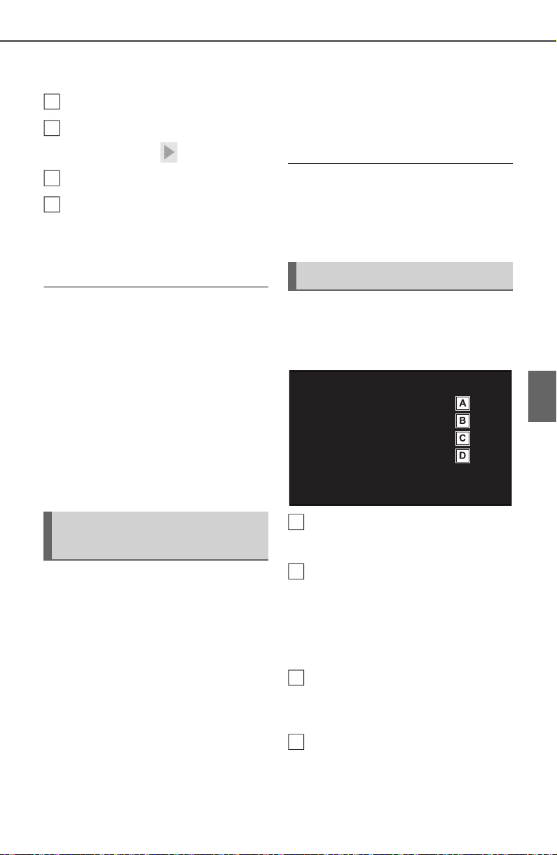
427
5-7. Radio operation
5
Audio
Select to select current/previ-
ous track (SXM)
Fast rewinds continuously
Pauses the playback (To
restart, select )
Fast forwards continuously
Skips forward 2 minutes
(AM/FM)
Select to change the track
(SXM)
● The system can store up to 20
minutes of AM/FM and less than
60 minutes of SXM. Cached data
will be erased when the radio
mode or station is changed or
when the audio system is turned
off.
● AM/FM: If noise or silence occurs
during the caching process, cache
writing will continue, with the noise
or silence recorded as is. In this
case, the cached broadcast will
contain the noise or silence when
played back.
1 Select “Station List”.
2 Select “AM”, “FM” or “SXM
*
”.
Select the desired program
genre when the genre selec-
tion screen is displayed.
3 Select the desired station.
*
: This function is not made avail-
able in some countries or areas.
■ Refreshing the station list
(AM/FM)
1 Select “Station List”.
“Cancel Refresh”: Select to can-
cel the refresh.
“Source”: Select to change to
another audio source while
refreshing.
● The audio/visual system sound is
muted during refresh operation.
● In some situations, it may take
some time to update the station
list.
1 Select “Options”.
2 Select the desired item to be
set.
Select to turn automatic play-
back of the cache on/off.
*
When “SXM Tune Start” is
turned on, the current song is
played from the beginning
when you select the chan-
nel.
*
Analog FM only: Select to
display RBDS text mes-
sages.
Select to scan for receivable
stations. (Type scan in case
SXM
*
is current program
type/channel category.)
Selecting a station from
the list
D
E
F
G
Radio options
A
B
C
D

428
5-7. Radio operation
*
: This function is not made avail-
able in some countries or areas.
This audio/visual system is
equipped with Radio Broadcast
Data Systems (RBDS). RBDS
mode allows text messages to
be received from radio stations
that utilize RBDS transmitters.
When RBDS is on, the radio can
do the following functions.
• Only selecting stations of a
particular program type
• Displaying messages from
radio stations
• Searching for a stronger sig-
nal station
RBDS features are available
only when listening to an FM
station that broadcasts RBDS
information and the “FM Info”
function is on. (P. 42 7 )
*
: This function is not made avail-
able in some countries or areas.
All SiriusXM services, including
satellite radio and data services,
plus streaming services, require
a subscription, sold separately
or as a package by Sirius XM
Radio Inc. (or, in Canada, Sirius
XM Canada Inc.), after any trial
subscription which may be
included with your vehicle pur-
chase or lease. To subscribe
after your trial subscription, call
1-877-447-0011 (U.S.A.) or 1-
877-438-9677 (Canada).
■ Important information
about your subscription
Your SiriusXM services will
automatically stop at the end of
your trial unless you decide to
subscribe. If you decide to con-
tinue service, the paid subscrip-
tion plan you choose will
automatically renew and you will
be charged the rate in effect at
that time and according to your
chosen payment method. Fees
and taxes apply. You may can-
cel at any time by calling 1-866-
635-2349. See SiriusXM Cus-
tomer Agreement for complete
terms at www.siriusxm.com
(U.S.A.) or www.siriusxm.ca
(Canada). All fees and program-
ming subject to change. Traffic
information not available in all
markets.
Radio broadcast data sys-
tem
How to subscribe to
SiriusXM Radio Services
*

429
5-7. Radio operation
5
Audio
● ABOUT SiriusXM Services
• Most in-car trials today include
SiriusXM’s best package All
Access. It includes every channel
available on your radio, plus
streaming.
● SiriusXM All Access Subscription
• Listen everywhere with All
Access. You get every channel
available in your ride, plus you can
listen on the app and online so
you can enjoy the best SiriusXM
has to offer, anywhere life takes
you. It’s the only package that
gives you all of our premium pro-
gramming, including Howard
Stern, every NFL, MLB
®
and NBA
game, every NASCAR
®
race,
NHL
®
games, 24/7 talk channels
dedicated to the biggest leagues,
and more. You get all kinds of
commercial-free music, including
artist-dedicated channels and
more, plus sports, news, talk and
entertainment.
Did you know? SiriusXM also
delivers a wide variety of services
to certain vehicles’ entertainment
and navigation systems such as
Traffic, Weather, Sports Scores,
Movie Listings, Fuel Prices, Stock
Prices and more. For a list of
available features in your vehicle,
visit siriusxm.com/infotainment
and get the most out of your driv-
ing experience.
● RADIO OPERATION
• Look for the Sirius, XM, SiriusXM,
Band, SAT, AUX, Radio or Source
button and you’re in. If you can’t
hear us, it’s easy to get started:
Locate your Radio ID by turning to
Channel 0. If you don’t see your
number there, go to
siriusxm.com/activationhelp
to find
it.
Visit siriusxm.com/refresh
or call
1-855-MYREFRESH (697-3373)
to send a refresh signal to your
radio.
Canadian Customers:
Locate your Radio ID by turning to
Channel 0.
Visit siriusxm.ca/refresh
to send a
refresh signal to your radio or call
1-888-539-7474 for service.
*
: This function is not made avail-
able in some countries or areas.
Each SiriusXM tuner is identified
with a unique radio ID. The radio
ID is required when activating
an SiriusXM Satellite service or
when reporting a problem.
If “Ch 000” is selected using
the “TUNE SCROLL” knob,
the ID code, which is 8 alpha-
numeric characters, will be
displayed. If another channel
is selected, the ID code will no
NOTICE
● It is prohibited to copy, decom-
pile, disassemble, reverse engi-
neer, hack, manipulate, or
otherwise make available any
technology or software incorpo-
rated in receivers compatible
with the SiriusXM Satellite
Radio System or that support
the SiriusXM website, the
streaming service or any of its
content. Furthermore, the
AMBE
®
voice compression soft-
ware included in this product is
protected by intellectual prop-
erty rights including patent
rights, copyrights, and trade
secrets of Digital Voice Sys-
tems, Inc.
● Note: this applies to SiriusXM
Satellite Radio receivers only
and not SiriusXM Ready
devices.
Displaying the radio ID
*

430
5-7. Radio operation
longer be displayed. The
channel (000) alternates
between displaying the radio
ID and the specific radio
code.
*
: This function is not made avail-
able in some countries or areas.
Up to 20 channels can be regis-
tered as presets in the cache.
For channel registration, refer to
(P.444).
1 Select channels registered to
smart favorites.
2 Select “SXM Replay”.
● Caches up to 30 minutes for each
Smart Favorite preset.
● The radio plays the track from
start when that track has not previ-
ously been heard by the user and
the station is registered as a smart
favorite.
● When “SXM Tune Start” is turned
on (P.427), the current song is
played from the beginning when
you select the channel.
● Displays icons on the channels
registered to smart favorites.
(P.425)
When problems occur with the SiriusXM tuner, a message will
appear on the screen. Referring to the table below to identify the
problem, take the suggested corrective action
*
.
*
: This function is not made available in some countries or areas.
Smart favorites
*
Refer to the table below to identify the problem and take
the suggested corrective action
Message Explanation
“Check
Antenna”
The SiriusXM antenna is not connected. Check whether the
SiriusXM antenna cable is attached securely. Contact your
Toyota dealer for assistance.
A short circuit occurs in the antenna or the surrounding
antenna cable. Contact your Toyota dealer for assistance.
“No Signal”
The SiriusXM signal is too weak at the current location. Wait
until your vehicle reaches a location with a stronger signal.
“Chan
Unavailable”
The channel you selected is not broadcasting any program-
ming. Select another channel.

431
5-7. Radio operation
5
Audio
● Contact the SiriusXM Listener Care Center at 1-877-447-0011 (U.S.A.) or
1-877-438-9677 (Canada).
“Ch Unsub-
scribed”
The channel you selected is no longer available. Wait for
about 2 seconds until the radio returns to the previous chan-
nel or “Ch 001”. If it does not change automatically, select
another channel.
“Subscription
Updated”
Subscription is updated. Select “OK” to clear this message.
Message Explanation

432
5-8. Media operation
5-8.Media operation
The USB memory operation
screen can be reached by the
following methods: P.421
Connecting a USB memory
(P.422)
When an Apple
CarPlay/Android Auto con-
nection is established, this
function will be unavailable.
USB audio
Select to display the audio
source selection screen.
Select to return to the top
screen.
Select to display a song list
screen.
Select to display the play
mode selection screen.
Select to display the sound
setting screen. (P.422)
Select to set repeat playback.
(P.433)
Select to change the
file/track.
Select and hold to fast
rewind.
Select to play/pause.
Select to change the
file/track.
Select and hold to fast for-
ward.
Select to set random play-
back. (P.433)
Select to change the
folder/album.
Displays cover art
Select to change the artist.
USB video
1 Select “Browse”.
2 Select “Videos”.
3 Select the desired folder and
file.
Select to display the audio
source selection screen.
Select to return to the top
screen.
Select to display a song list
screen.
Select to display the play
USB memory
Overview
Control screen
A
B
C
D
E
F
G
H
I
J
K
L
M
A
B
C
D
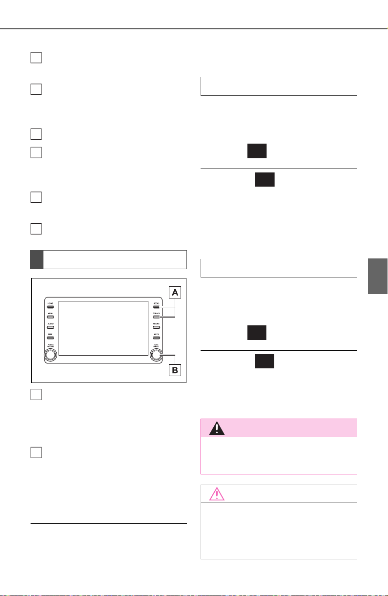
433
5-8. Media operation
5
Audio
mode selection screen.
Select to display the sound
setting screen. (P.422)
Select to change the file.
Select and hold to fast
rewind.
Select to play/pause.
Select to change the file.
Select and hold to fast for-
ward.
Select to display a full screen
image.
Select to change the folder.
Press to change the
file/track.
Press and hold to fast for-
ward/rewind.
Turn to change the file/track.
Turn to move up/down the
list. Also, the knob can be
used to enter selections on
the list screens by pressing it.
● While the vehicle is being driven,
this function can only output
sound.
● If tag information exists, the
file/folder names will be changed
to track/album names.
The file/track or folder/album
currently being listened to can
be repeated.
1 Select .
● Each time is selected, the
mode changes as follows:
When random playback is off
• file/track repeat folder/album
repeat off
When random playback is on
• file/track repeat off
Files/tracks or folders/albums
can be automatically and ran-
domly selected.
1 Select .
● Each time is selected, the
mode changes as follows:
• random (1 folder/album random)
folder/album random (all
folder/album random) off
Control panel
E
F
G
H
I
J
A
B
Repeating
Random order
WARNING
● Do not operate the player’s con-
trols or connect the USB mem-
ory while driving.
NOTICE
● Do not leave your portable
player in the car. In particular,
high temperatures inside the
vehicle may damage the porta-
ble player.
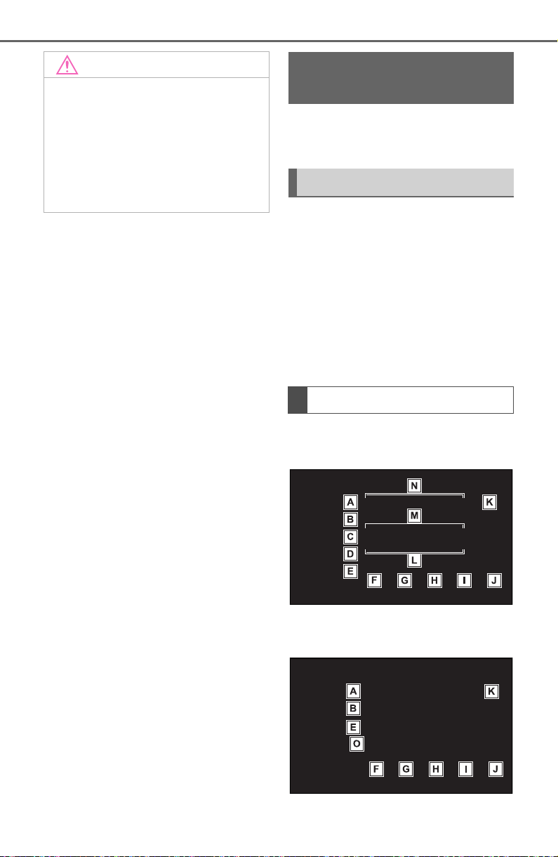
434
5-8. Media operation
*
: This function is not made avail-
able in some countries or areas.
The iPod/iPhone operation
screen can be reached by the
following methods: P.421
Connecting an iPod/iPhone
(P.422)
When an Android Auto con-
nection is established, this
function will be unavailable.
An Apple CarPlay connection
is not established
An Apple CarPlay connection
is established
NOTICE
● Do not push down on or apply
unnecessary pressure to the
portable player while it is con-
nected as this may damage the
portable player or its terminal.
● Do not insert foreign objects into
the port as this may damage the
portable player or its terminal.
iPod/iPhone (Apple
CarPlay
*
)
Overview
Control screen
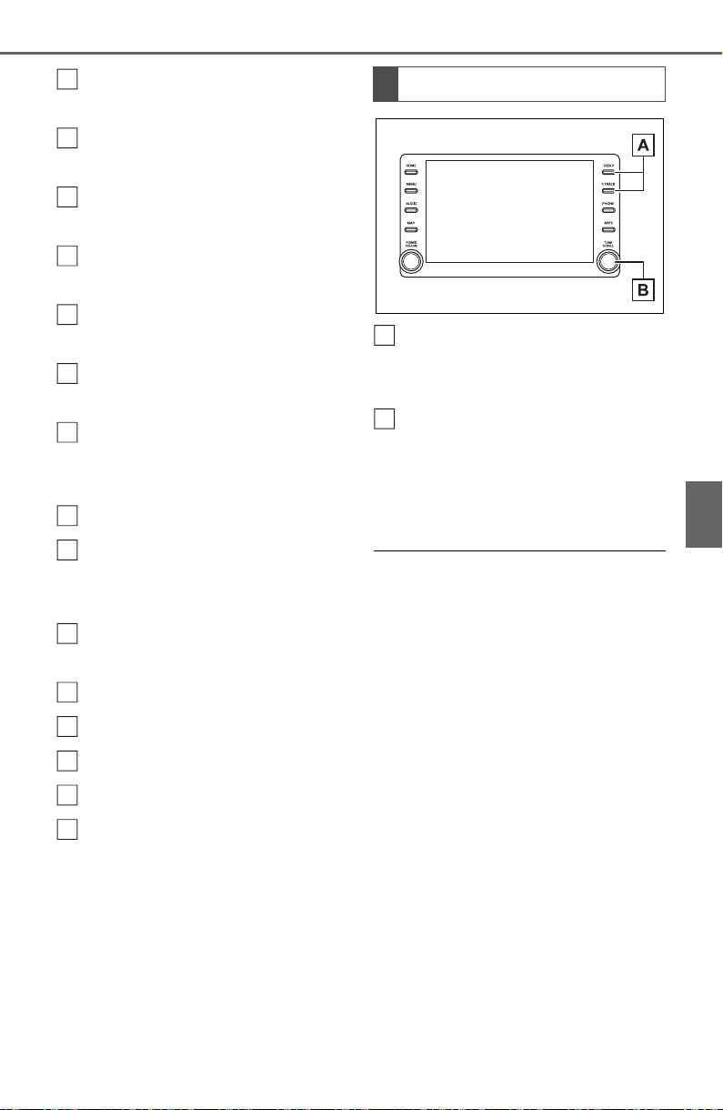
435
5-8. Media operation
5
Audio
Select to display the audio
source selection screen.
Select to return to the top
screen.
Select to display a song list
screen.
Select to display the play
mode selection screen.
Select to display the sound
setting screen. (P.422)
Select to set repeat playback.
(P.436)
Select to change the track.
Select and hold to fast
rewind.
Select to play/pause.
Select to change the track.
Select and hold to fast for-
ward.
Select to set random play-
back. (P. 43 6 )
Displays cover art
Select to change the album.
Select to change the artist.
Select to change the playlist.
Select to display the Apple
CarPlay screen.
Press to change the track.
Press and hold to fast for-
ward/rewind.
Turn to change the track.
Turn to move up/down the
list. Also, the knob can be
used to enter selections on
the list screens by pressing it.
● Some functions may not be avail-
able depending on the type of
model.
● When an iPod/iPhone is con-
nected using a genuine
iPod/iPhone cable, the
iPod/iPhone starts charging its
battery.
● Depending on the iPod/iPhone,
the video sound may not be able
to be heard.
● Depending on the iPod/iPhone
and the songs in the iPod/iPhone,
a cover art may be displayed. This
function can be changed to “On”
or “Off”. (P.444) It may take time
to display the cover art, and the
iPod/iPhone may not be operated
while the cover art display is in
process.
● When an iPod/iPhone is con-
nected and the audio source is
changed to iPod/iPhone mode,
the iPod/iPhone will resume play-
ing from the same point it was last
A
B
C
D
E
F
G
H
I
J
K
L
M
N
O
Control panel
A
B

436
5-8. Media operation
used.
● Depending on the iPod/iPhone
that is connected to the system,
certain functions may not be avail-
able.
● If an iPhone is connected via
Bluetooth
®
and USB at the same
time, system operation may
become unstable. For known
phone compatibility information,
refer to
http://www.toyota.com/
audio-multimedia.
● Tracks selected by operating a
connected iPod/iPhone may not
be recognized or displayed prop-
erly.
● The system may not function
properly if a conversion adapter is
used to connect a device.
The track currently being lis-
tened to can be repeated.
1 Select .
● Each time is selected, the
mode changes as follows:
When shuffle is off (iPhone 5 or
later)
• track repeat album repeat off
When shuffle is off (iPhone 4s or
earlier)
• track repeat off
When shuffle is on
• track repeat off
Tracks or albums can be auto-
matically and randomly
selected.
1 Select .
● Each time is selected, the
mode changes as follows:
• shuffle (1 album shuffle) album
shuffle (all album shuffle) off
Repeating
Random order
WARNING
● Do not operate the player’s con-
trols or connect the iPod/iPhone
while driving.
NOTICE
● Do not leave your portable
player in the car. In particular,
high temperatures inside the
vehicle may damage the porta-
ble player.
● Do not push down on or apply
unnecessary pressure to the
portable player while it is con-
nected as this may damage the
portable player or its terminal.
● Do not insert foreign objects into
the port as this may damage the
portable player or its terminal.
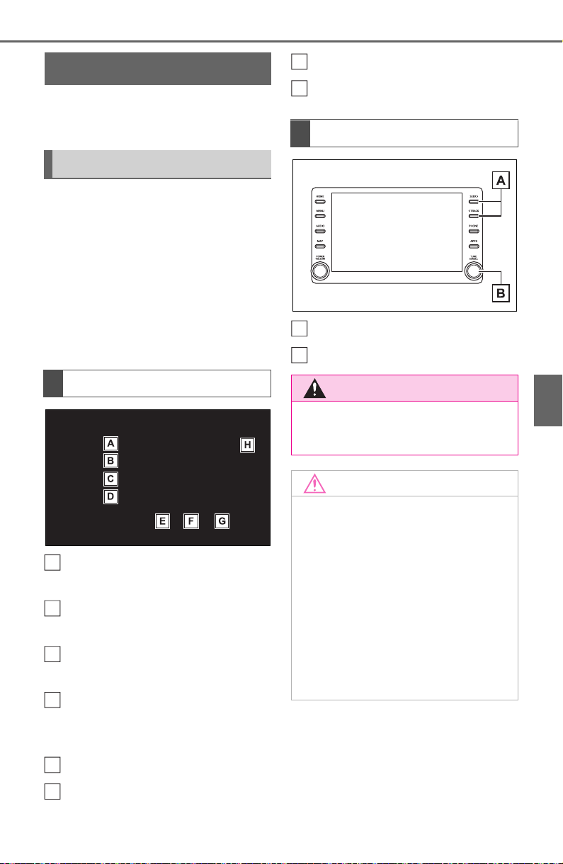
437
5-8. Media operation
5
Audio
*
: This function is not made avail-
able in some countries or areas.
The Android Auto operation
screen can be reached by the
following methods: P.421
Connecting an Android Auto
(P.422)
When an Apple CarPlay con-
nection is established, this
function will be unavailable.
Select to display the audio
source selection screen.
Select to return to the top
screen.
Select to display the sound
setting screen. (P.422)
Select to display the audio
control screen of Android
Auto.
Select to change the track.
Select to play/pause.
Select to change the track.
Displays cover art
Press to change the track.
Turn to change the track.
Android Auto
*
Overview
Control screen
A
B
C
D
E
F
Control panel
WARNING
● Do not connect smartphone or
operate the controls while driv-
ing.
NOTICE
● Do not leave your smartphone
in the vehicle. In particular, high
temperatures inside the vehicle
may damage the smartphone.
● Do not push down on or apply
unnecessary pressure to the
smartphone while it is con-
nected as this may damage the
smartphone or its terminal.
● Do not insert foreign objects into
the port as this may damage the
smartphone or its terminal.
G
H
A
B
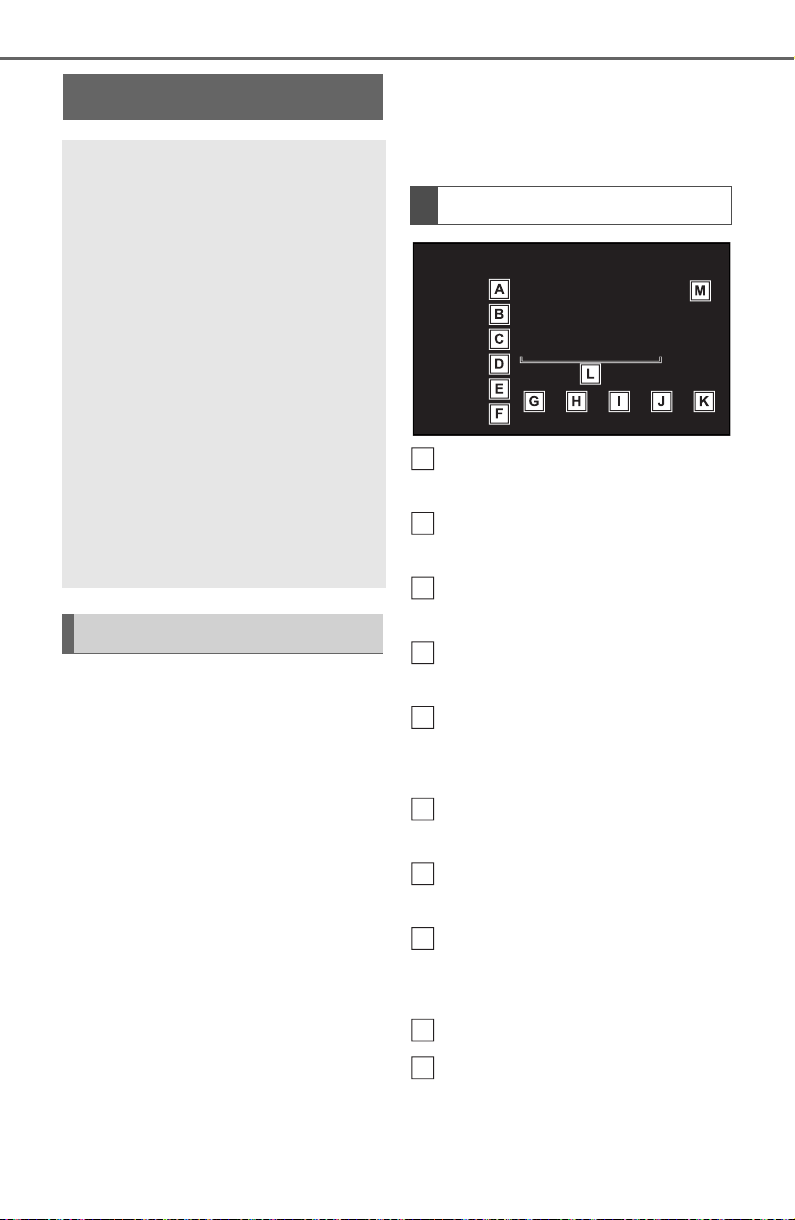
438
5-8. Media operation
The Bluetooth
®
audio operation
screen can be reached by the
following methods: P.421
Connecting a Bluetooth
®
audio device (P.440)
Depending on the type of por-
table player connected, some
functions may not be avail-
able and/or the screen may
look differently than shown in
this manual.
When an Apple
CarPlay/Android Auto con-
nection is established,
Bluetooth
®
audio will be sus-
pended and become unavail-
able.
*
*
: This function is not made avail-
able in some countries or areas.
Select to display the audio
source selection screen.
Select to return to the top
screen.
Select to display a song list
screen.
Select to display the play
mode selection screen.
Select to display the portable
device connection screen.
(P.440)
Select to display the sound
setting screen. (P.422)
Select to set repeat playback.
(P.439)
Select to change the track.
Select and hold to fast
rewind.
Select to play/pause.
Select to change the track.
Select and hold to fast for-
ward.
Bluetooth
®
audio
The Bluetooth
®
audio sys-
tem enables users to enjoy
listening to music that is
played on a portable player
on the vehicle speakers via
wireless communication.
This audio/visual system
supports Bluetooth
®
, a wire-
less data system capable of
playing portable audio
music without cables. If
your device does not sup-
port Bluetooth
®
, the
Bluetooth
®
audio system
will not function.
Overview
Control screen
A
B
C
D
E
F
G
H
I
J
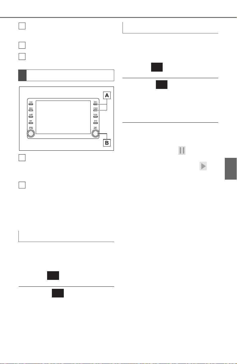
439
5-8. Media operation
5
Audio
Select to set random play-
back. (P. 43 9 )
Select to change the album.
Displays cover art
Press to change the track.
Press and hold to fast for-
ward/rewind.
Turn to change the track.
Turn to move up/down the
list. Also, the knob can be
used to enter selections on
the list screens by pressing it.
The track or album currently
being listened to can be
repeated.
1 Select .
● Each time is selected, the
mode changes as follows:
When random playback is off
• track repeat album repeat off
When random playback is on
• track repeat off
Tracks or albums can be auto-
matically and randomly
selected.
1 Select .
● Each time is selected, the
mode changes as follows:
• random (1 album random)
album random (all album random)
off
● Depending on the Bluetooth
®
device that is connected to the
system, the music may start play-
ing when selecting while it is
paused. Conversely, the music
may pause when selecting
while it is playing.
● In the following conditions, the
system may not function:
• The Bluetooth
®
device is turned
off.
• The Bluetooth
®
device is not con-
nected.
• The Bluetooth
®
device has a low
battery.
● When using the Bluetooth
®
audio
and Wi-Fi
®
Hotspot functions at
the same time, the following prob-
lems may occur:
• It may take longer than normal to
connect to the Bluetooth
®
device.
• The sound may cut out.
● It may take time to connect the
phone when Bluetooth
®
audio is
being played.
● For operating the portable player,
see the instruction manual that
comes with it.
● If the Bluetooth
®
device is discon-
nected due to poor reception from
Control panel
Repeating
K
L
M
A
B
Random order
440
5-8. Media operation
the Bluetooth
®
network when the
engine switch is in ACC or ON,
the system automatically recon-
nects the portable player.
● If the Bluetooth
®
device is discon-
nected on purpose, such as it was
turned off, this does not happen.
Reconnect the portable player
manually.
● Bluetooth
®
device information is
registered when the Bluetooth
®
device is connected to the
Bluetooth
®
audio system. When
selling or disposing of the vehicle,
remove the Bluetooth
®
audio
information from the system.
(P.417)
● In some situations, sound output
via the Bluetooth
®
audio system
may be out of sync with the con-
nected device or output intermit-
tently.
To use the Bluetooth
®
audio
system, it is necessary to regis-
ter a Bluetooth
®
device with the
system.
Registering an additional
device
1 Display the Bluetooth
®
audio
control screen. (P.438)
2 Select “Connect”.
3 Select “Add Device”.
When another Bluetooth
®
device is connected, a confir-
mation screen will be dis-
played. To disconnect the
Bluetooth
®
device, select
“Yes”.
WARNING
● Do not operate the player’s con-
trols or connect to the
Bluetooth
®
audio system while
driving.
● Your audio unit is fitted with
Bluetooth
®
antennas. People
with implantable cardiac pace-
makers, cardiac resynchroniza-
tion therapy-pacemakers or
implantable cardioverter defi-
brillators should maintain a rea-
sonable distance between
themselves and the Bluetooth
®
antennas. The radio waves may
affect the operation of such
devices.
● Before using Bluetooth
®
devices, users of any electrical
medical device other than
implantable cardiac pacemak-
ers, cardiac resynchronization
therapy-pacemakers or implan-
table cardioverter defibrillators
should consult the manufacturer
of the device for information
about its operation under the
influence of radio waves. Radio
waves could have unexpected
effects on the operation of such
medical devices.
NOTICE
● Do not leave your portable
player in the vehicle. In particu-
lar, high temperatures inside the
vehicle may damage the porta-
ble player.
Registering/Connecting a
Bluetooth
®
device

441
5-8. Media operation
5
Audio
4 Follow the steps in “Register-
ing a Bluetooth
®
phone for
the first time” from step 5.
(P.390)
Selecting a registered device
1 Display the Bluetooth
®
audio
control screen. (P.438)
2 Select “Connect”.
3 Select the desired device to
be connected.
4 Check that a confirmation
screen is displayed when the
connection is complete.
If an error message is dis-
played, follow the guidance
on the screen to try again.
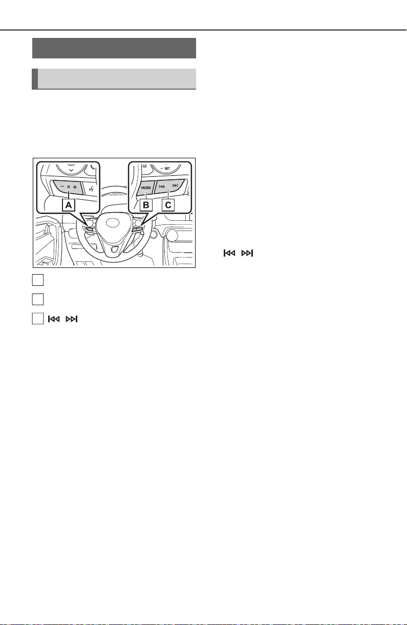
442
5-9. Audio/visual remote controls
5-9.Audio/visual remote controls
Some parts of the audio/visual
system can be adjusted using
the switches on the steering
wheel.
Volume control switch
“MODE” switch
switch
■ Volume control switch
• Press: Volume up/down
• Press and hold (0.8 sec. or
more): Volume up/down con-
tinuously
■ “MODE” switch
AM/FM/SXM
*1
• Press: Change audio modes
• Press and hold (0.8 sec. or
more): Mute/pause
*2
(Press
and hold again to resume)
USB
*3, 4
, iPod/iPhone
*4
,
Bluetooth
®
audio
*3, 4
, Android
Auto
*3
, Toyota Apps
*3, 4
• Press: Change audio modes
• Press and hold (0.8 sec. or
more): Pause (Press and hold
again to resume the play
mode.)
*1
:This function is not made avail-
able in some countries or areas.
*2
:If cached radio is enabled, press-
ing and holding the “MODE”
switch pauses the broadcast.
(Press and hold again to play
back the cached radio program.)
*3
:When an Apple CarPlay connec-
tion is established, this function
will be unavailable.
*4
:When an Android Auto connec-
tion is established, this function
will be unavailable.
■ switch
AM/FM
• Press: Preset channel
up/down
• Press and hold (0.8 sec. or
more): Seek up/down
• Press and hold (1.5 sec. or
more): Seek up/down continu-
ously while the switch is being
pressed
• Press and hold (1.5 sec. or
more): Fast channel up/down
SXM
*1
• Press: Preset channel
up/down
• Press and hold (0.8 sec. or
more): Seek for stations in the
relevant program type/chan-
nel category
• Press and hold (1.5 sec. or
more): Fast channel up/down
Steering switches
Steering switch operation
A
B
C

443
5-9. Audio/visual remote controls
5
Audio
USB
*2, 3
, iPod/iPhone
*3
,
Bluetooth
®
audio
*2, 3
• Press: Track/file up/down
• Press and hold (0.8 sec. or
more): Fast forward/rewind
Android Auto
*2
• Press: Track up/down
*1
:This function is not made avail-
able in some countries or areas.
*2
:When an Apple CarPlay connec-
tion is established, this function
will be unavailable.
*3
:When an Android Auto connec-
tion is established, this function
will be unavailable.
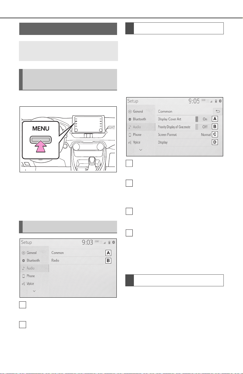
444
5-10. Audio settings
5-10.Audio settings
1 Press the “MENU” button.
2 Select “Setup”.
3 Select “Audio”.
4 Select the desired items to
be set.
Select to set the common
settings. (P.444)
Select to set the radio set-
tings. (P.44 4 )
1 Display the audio settings
screen.
P.444
2 Select “Common”.
3 Select the desired items to
be set.
Select to set the cover art
display on/off.
Select to prioritize the display
of information from the
Gracenote database.
Select to change the screen
size.
*
(P.423)
Select to display the image
quality adjustment screen.
*
(P.424)
*
: Only in USB video mode
1 Display the audio settings
screen
P.444
2 Select “Radio”.
3 Select the desired number of
preset radio stations dis-
played on the screen.
Setup
Detailed audio settings can
be programmed.
Displaying the audio set-
tings screen
Audio settings screen
A
B
Common settings
Radio settings
A
B
C
D

445
5-10. Audio settings
5
Audio
1 Select “Manage Smart
Favorites”.
2 Select the desired channel to
be set.
● Displays the registered preset
channels.
● Up to 20 channels can be regis-
tered.
1 Select “Number of Radio Pre-
sets”.
2 Select the button with the
desired number to be dis-
played.
Manage smart favorites
Setting the number of radio
presets

446
5-11. Tips for operating the audio/visual system
5-11.Tips for operating the audio/visual system
● The use of a cellular phone inside
or near the vehicle may cause a
noise from the speakers of the
audio/visual system which you are
listening to. However, this does
not indicate a malfunction.
Usually, a problem with radio
reception does not mean there
is a problem with the radio it
is just the normal result of condi-
tions outside the vehicle.
For example, nearby buildings
and terrain can interfere with FM
reception. Power lines or phone
wires can interfere with AM sig-
nals. And of course, radio sig-
nals have a limited range. The
farther the vehicle is from a sta-
tion, the weaker its signal will
be. In addition, reception condi-
tions change constantly as the
vehicle moves.
Here are some common recep-
tion problems that may not indi-
cate a problem with the radio as
described.
■ FM
Fading and drifting stations:
Generally, the effective range of
FM is about 25 miles (40 km).
Once outside this range, you
may notice fading and drifting,
which increase with the distance
from the radio transmitter. They
are often accompanied by dis-
tortion.
Multi-path: FM signals are
reflective, making it possible for
2 signals to reach the vehicle’s
antenna at the same time. If this
happens, the signals will cancel
each other out, causing a
momentary flutter or loss of
reception.
Static and fluttering: These
occur when signals are blocked
by buildings, trees or other large
objects. Increasing the bass
level may reduce static and flut-
tering.
Station swapping: If the FM sig-
nal being listened to is inter-
rupted or weakened, and there
is another strong station nearby
on the FM band, the radio may
tune in the second station until
the original signal can be picked
up again.
■ AM
Fading: AM broadcasts are
reflected by the upper atmo-
sphere especially at night.
These reflected signals can
interfere with those received
directly from the radio station,
causing the radio station to
sound alternately strong and
weak.
Operating information
NOTICE
● To avoid damage to the
audio/visual system:
• Be careful not to spill beverages
over the audio/visual system.
Radio
447
5-11. Tips for operating the audio/visual system
5
Audio
Station interference: When a
reflected signal and a signal
received directly from a radio
station are very nearly the same
frequency, they can interfere
with each other, making it diffi-
cult to hear the broadcast.
Static: AM is easily affected by
external sources of electrical
noise, such as high tension
power lines, lightening or electri-
cal motors. This results in static.
■ SiriusXM
*
Cargo loaded on the roof lug-
gage carrier, especially metal
objects, may adversely affect
the reception of SiriusXM Sat-
ellite Radio.
Alternation or modifications
carried out without appropri-
ate authorization may invali-
date the user’s right to
operate the equipment.
*
: This function is not made avail-
able in some countries or areas.
■ Certification
Use of the Made for Apple
badge means that an acces-
sory has been designed to
connect specifically to the
Apple product(s) identified in
the badge, and has been cer-
tified by the developer to meet
Apple performance stan-
dards. Apple is not responsi-
ble for the operation of this
device or its compliance with
safety and regulatory stan-
dards. Please note that the
use of this accessory with an
Apple product may affect
wireless performance.
iPhone, iPod, iPod classic,
iPod nano, iPod touch, and
Lightning are trademarks of
Apple Inc., registered in the
U.S. and other countries.
■ Compatible models
The following iPod touch
®
and
iPhone
®
devices can be used
with this system.
Made for
• iPhone X
• iPhone 8
• iPhone 8 Plus
• iPhone 7
• iPhone 7 Plus
• iPhone SE
iPod/iPhone
448
5-11. Tips for operating the audio/visual system
• iPhone 6s
• iPhone 6s Plus
• iPhone 6
• iPhone 6 Plus
• iPhone 5s
• iPhone 5c
• iPhone 5
• iPod touch (6th generation)
• iPod touch (5th generation)
● This system only supports audio
playback.
● Depending on difference between
models or software versions etc.,
some models might be incompati-
ble with this system.
This device supports high-reso-
lution sound sources.
The definition of high-resolution
is based on the standards of
groups such as the CTA (Con-
sumer Technology Association).
Supported formats and play-
able media are as follows.
■ Supported formats
WAV, FLAC, ALAC, OGG Vorbis
■ Playable media
USB
*
: USB video only
High-resolution sound
source
File information
Compatible USB devices
USB communi-
cation formats
USB 2.0 HS (480
Mbps)
File formats FAT 16/32
Correspon-
dence class
Mass storage
class
Compatible audio format
Compatible compressed files
Item USB
Compatible file
format
MP3/WMA/AAC
WAV(LPCM)/FL
AC/ALAC/OGG
Vorbis
MP4/AVI/WMV
Compatible file
format (video)
*
MP4/AVI/WMV
Folders in the
device
Maximum
3000
Files in the
device
Maximum
9999
Files per folder
Maximum
255

449
5-11. Tips for operating the audio/visual system
5
Audio
*1
:Only compatible with Windows
Media Audio Standard
*2
:Sound source of 48kHz or more
is down-converted to
48kHz/24bit.
*1
:Variable Bit Rate (VBR) compati-
ble
*2
:Only compatible with Windows
Media Audio Standard
Corresponding sampling fre-
quency
File type Frequency (kHz)
MP3 files:
MPEG 1 LAYER
3
32/44.1/48
MP3 files:
MPEG 2 LSF
LAYER 3
16/22.05/24
WMA files:
Ver. 7, 8, 9
*1
(9.1/9.2)
32/44.1/48
AAC files:
MPEG4/AAC-LC
11.025/12/16/
22.05/24/32/
44.1/48
WAV (LPCM)
files
*2
8/11.025/12/16/
22.05/24/32/
44.1/48/88.2/
96/176.4/192
FLAC
*2
8/11.025/12/16/
22.05/24/32/
44.1/48/88.2/
96/176.4/192
ALAC
*2
8/11.025/12/16/
22.05/24/32/
44.1/48/64/
88.2/96
OGG Vorbis
*2
8/11.025/16/
22.05/32/44.1/
48
Corresponding bit rates
*1
File type Bit rate (kbps)
MP3 files:
MPEG 1 LAYER
3
32 - 320
MP3 files:
MPEG 2 LSF
LAYER 3
8 - 160
WMA files: Ver.
7, 8
CBR 48 - 192
WMA files:
Ver. 9
*2
(9.1/9.2)
CBR 48 - 320
AAC files:
MPEG4/AAC-LC
8 - 320
OGG Vorbis 32-500
File type
Quantization bit
rate (bit)
WAV (LPCM)
files
16/24
FLAC
ALAC
Compatible channel modes
File type Channel mode
MP3 files
Stereo, joint ste-
reo, dual chan-
nel and
monaural
WMA files 2ch

450
5-11. Tips for operating the audio/visual system
MP3 (MPEG Audio Layer 3),
WMA (Windows Media Audio)
and AAC (Advanced Audio
Coding) are audio compres-
sion standards.
This system can play
MP3/WMA/AAC files on USB
memory.
MP4, WMV and AVI files can
use the following resolutions:
128x96, 160x120, 176x144
(QCIF), 320x240 (QVGA),
352x240 (SIF), 352x288
(CIF), 640x480 (VGA),
720x480 (NTSC), 720x576
(PAL)
When naming an
MP3/WMA/AAC file, add an
appropriate file extension
(.mp3/.wma/.m4a).
This system plays back files
with .mp3/.wma/.m4a file
extensions as
MP3/WMA/AAC files respec-
tively. To prevent noise and
playback errors, use the
appropriate file extension.
MP3 files are compatible with
the ID3 Tag Ver. 1.0, Ver. 1.1,
Ver. 2.2 and Ver. 2.3 formats.
This system cannot display
disc title, track title and artist
name in other formats.
WMA/AAC files can contain a
WMA/AAC tag that is used in
the same way as an ID3 tag.
WMA/AAC tags carry infor-
mation such as track title and
artist name.
The emphasis function is
available only when playing
MP3 files.
This system can play back
AAC files encoded by iTunes.
The sound quality of
MP3/WMA files generally
improves with higher bit rates.
m3u playlists are not compati-
ble with the audio player.
MP3i (MP3 interactive) and
MP3PRO formats are not
compatible with the audio
player.
The player is compatible with
VBR (Variable Bit Rate).
When playing back files
recorded as VBR (Variable Bit
Rate) files, the play time will
not be correctly displayed if
the fast forward or reverse
operations are used.
It is not possible to check fold-
ers that do not include
MP3/WMA/AAC files.
MP3/WMA/AAC files in fold-
ers up to 8 levels deep can be
played. However, the start of
playback may be delayed
AAC files
1ch, 2ch (Dual
channel is not
supported)
WAV (LPCM)/
FLAC/ALAC/
OGG Vorbis
2ch
File type Channel mode
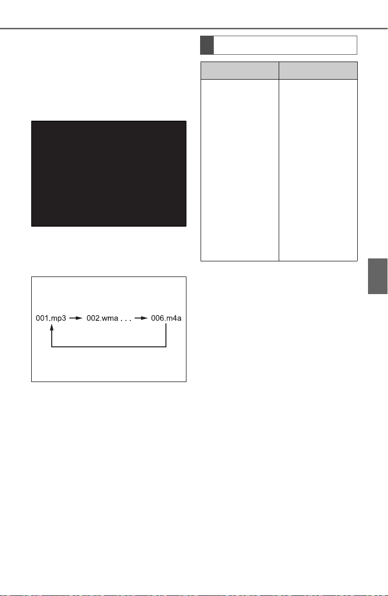
451
5-11. Tips for operating the audio/visual system
5
Audio
when using USB memory
containing numerous levels of
folders. For this reason, we
recommend creating USB
memory with no more than 2
levels of folders.
The play order of the USB
memory with the structure
shown above is as follows:
The order changes depending
on the personal computer and
MP3/WMA/AAC encoding
software you use.
Compatible video format
Format Codec
MPEG-4
Video codec:
H.264/MPEG-
4 AVC
MPEG4
Audio codec:
AAC
MP3
Corresponding
screen size:
MAX 1920
1080
Corresponding
frame rate:
MAX 60i/30p

452
5-11. Tips for operating the audio/visual system
■ ID3 tag
This is a method of embed-
ding track-related information
in an MP3 file. This embed-
ded information can include
the track number, track title,
the artist’s name, the album
title, the music genre, the year
of production, comments,
cover art and other data. The
contents can be freely edited
using software with ID3 tag
editing functions. Although
the tags are restricted to a
number of characters, the
information can be viewed
when the track is played back.
■ WMA tag
WMA files can contain a
WMA tag that is used in the
same way as an ID3 tag.
WMA tags carry information
such as track title and artist
name.
■ MP3
MP3 is an audio compression
standard determined by a
working group (MPEG) of the
ISO (International Standard
Organization). MP3 com-
presses audio data to about
1/10 the size of that on con-
ventional discs.
■ WMA
WMA (Windows Media Audio)
is an audio compression for-
mat developed by Microsoft
®
.
It compresses files into a size
smaller than that of MP3 files.
The decoding formats for
AVI Container
Video codec:
H.264/MPEG-
4 AVC
MPEG4
WMV9
WMV9
Advanced pro-
file
Audio codec:
AAC
MP3
WMA9.2 (7, 8,
9.1, 9.2)
Corresponding
screen size:
MAX 1920
1080
Corresponding
frame rate:
MAX 60i/30p
Windows Media
Video
Video codec:
WMV9
WMV9
Advanced pro-
file
Audio codec:
WMA9.2 (7, 8,
9.1, 9.2)
Corresponding
screen size:
MAX 1920
1080
Corresponding
frame rate:
MAX 60i/30p
Terms
Format Codec

453
5-11. Tips for operating the audio/visual system
5
Audio
WMA files are Ver. 7, 8 and 9.
Windows Media is either a
registered trademark or trade-
mark of Microsoft Corpora-
tion in the United States
and/or other countries.
This product includes technol-
ogy owned by Microsoft Cor-
poration and cannot be used
or distributed without a
license from Microsoft Licens-
ing, Inc.
■ AAC
AAC is short for Advanced
Audio Coding and refers to an
audio compression technol-
ogy standard used with
MPEG2 and MPEG4.
■ USB
■ iPod
■ Bluetooth
®
audio
● If the malfunction is not rectified:
Take your vehicle to your Toyota
dealer.
Error messages
Message Explanation
“USB Error”
This indicates a
problem in the
USB memory or
its connection.
“No music files
found.”
This indicates
that no
MP3/WMA/AAC
files are included
in the USB mem-
ory.
“No video files
found.”
This indicates
that no video
files are included
in the USB mem-
ory.
Message Explanation
“iPod Error”
This indicates a
problem in the
iPod or its con-
nection.
“No music files
found.”
This indicates
that there is no
music data in the
iPod.
“Please check
the iPod firm-
ware version.”
This indicates
that the software
version is not
compatible. Per-
form the iPod
firmware
updates and try
again.
“Unable to
authorize the
iPod.”
This indicates
that it failed to
authorize the
iPod.
Please check
your iPod.
Message Explanation
“Music tracks not
supported.
Please check
your portable
player.”
This indicates a
problem in the
Bluetooth
®
device.

454
5-11. Tips for operating the audio/visual system
For vehicles sold in the U.S.A., Hawaii, Guam, Saipan, American
Samoa and Puerto Rico
Certification

455
5-11. Tips for operating the audio/visual system
5
Audio
For vehicles sold in Canada
456
5-11. Tips for operating the audio/visual system
Gracenote
457
5-11. Tips for operating the audio/visual system
5
Audio
For U.S. owners
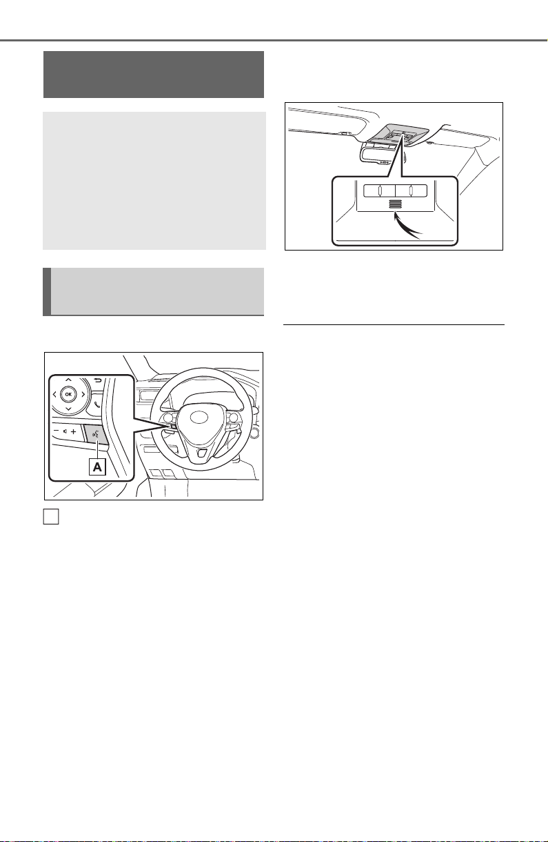
458
5-12. Voice command system operation
5-12.Voice command system operation
■ Steering switch
Talk switch
Voice command system
Press the talk switch to start
the voice command system.
To cancel voice command,
press and hold the talk switch.
When an Apple
CarPlay/Android Auto con-
nection is established
Press and hold the talk switch
to start Siri/Google Assistant.
To cancel Siri/Google Assis-
tant, press the talk switch.
Press the talk switch to start
the voice command system.
■ Microphone
It is unnecessary to speak
directly into the microphone
when giving a command.
● Voice commands may not be rec-
ognized if:
• Spoken too quickly.
• Spoken at a low or high volume.
• The roof or windows are open.
• Passengers are talking while
voice commands are spoken.
• The fan speed of the air condition-
ing system is set at high.
• The air conditioning vents are
turned towards the microphone.
● In the following conditions, the
system may not recognize the
command properly and using
voice commands may not be pos-
sible:
• The command is incorrect or
unclear. Note that certain words,
accents or speech patterns may
be difficult for the system to recog-
nize.
• There is excessive background
noise, such as wind noise.
● Normally, it is necessary to wait
for a beep before saying a com-
mand. To enable the ability to talk
over prompts and say commands
before the beep, enable the voice
prompt interrupt function.
(P.418)
● This system may not operate
immediately after the engine
Voice command sys-
tem
The voice command sys-
tem enables the radio,
phone dialing, etc. to be
operated using voice com-
mands. Refer to the com-
mand list for samples of
voice commands. (P.461)
Using the voice command
system
A
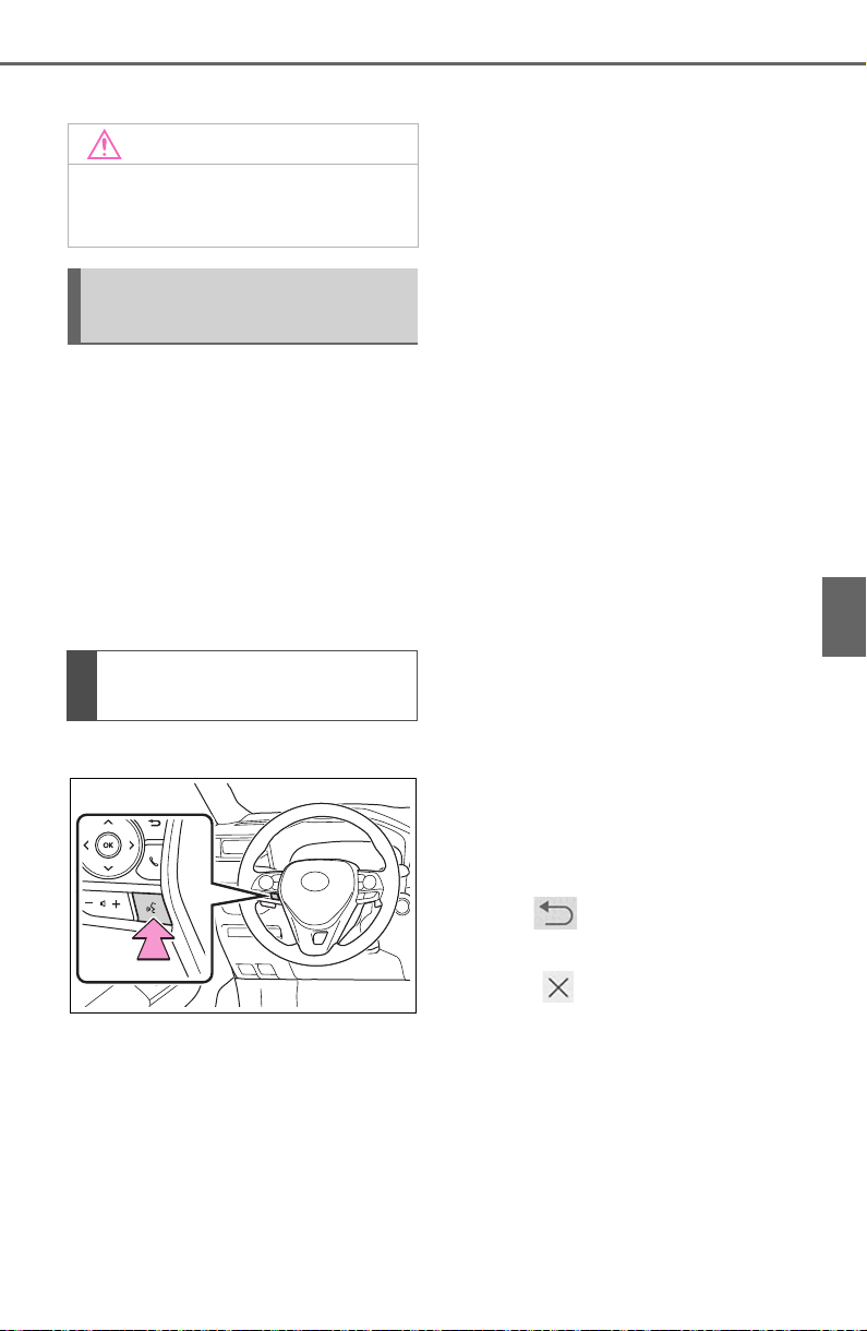
459
5-12. Voice command system operation
5
Audio
switch is in ACC or ON.
The voice command system is
operated by saying commands
which correspond to a sup-
ported function. To display
examples of commands for sup-
ported functions, select a func-
tion button on the screen after
starting the voice command sys-
tem.
1 Press the talk switch.
Voice guidance for the voice
command system can be
skipped by pressing the talk
switch.
2 If “Getting Started with Voice”
screen is displayed, select
“OK” or press the talk switch.
(P.460)
3 After hearing a beep, say a
supported command.
To display sample commands
of the desired function, say
the desired function or select
the desired function button. To
display more commands,
select “More Commands”.
Selecting “Help” or saying
“Help” prompts the voice com-
mand system to offer exam-
ples of commands and
operation methods.
Registered POIs, registered
names in the contacts list etc.,
can be said in the place of the
“<>” next to the commands.
(P.461)
For example: Say “Find a restau-
rant”, “Call John Smith” etc.
If a desired outcome is not
shown, or if no selections are
available, perform one of the
following to return to the pre-
vious screen:
• Say “Go back”.
• Select .
To cancel voice recognition,
select , say “Cancel”, or
press and hold the talk switch.
To perform the voice com-
mand operation again, select
“Start Over” or say “Start
over”.
To suspend voice command
operation, select “Pause” or
say “Pause”. To resume the
NOTICE
● Do not touch and put a sharp
object to the microphone. It may
cause failure.
Voice command system
operation
Operation from the main
menu
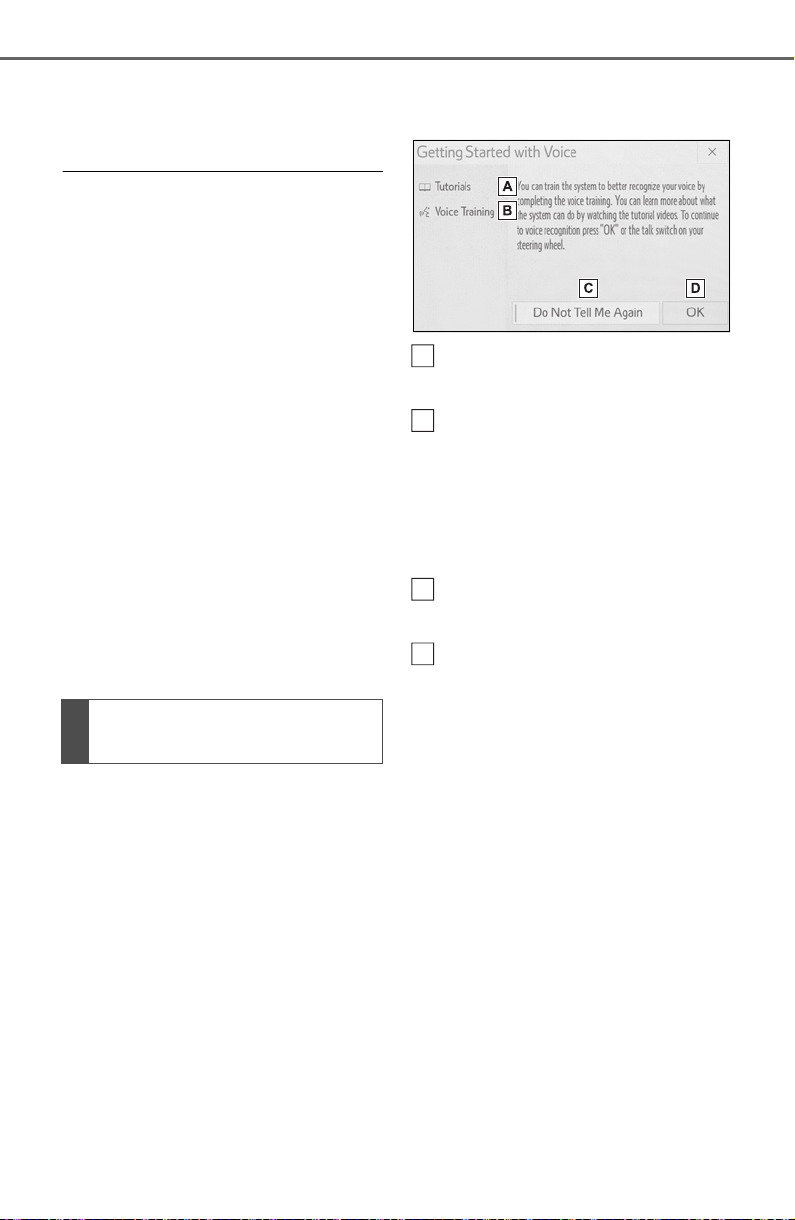
460
5-12. Voice command system operation
voice command operation,
select “Resume” or press the
talk switch.
● If the system does not respond or
the confirmation screen does not
disappear, press the talk switch
and try again.
● If a voice command cannot be rec-
ognized 3 consecutive times,
voice recognition will be canceled.
● Voice recognition prompts can be
changed on the voice settings
screen. (P.418)
This function can be used to cancel
voice guidance by turning the voice
prompts off. When you press the
talk switch while using this setting, a
beep sounds, and then you can
immediately say a command.
● Some voice guidance can be can-
celed by setting voice prompts to
off. Use this setting when it is
desirable to say a command
immediately after pressing the talk
switch and hearing a beep.
To increase voice recognition
performance, use the “Tutori-
als” and “Voice Training” func-
tions on the “Getting Started
with Voice” screen. These func-
tions are only available when
the vehicle is not moving.
The “Tutorials” and “Voice Train-
ing” functions can also be
started on the voice settings
screen. (P.418)
1 Press the talk switch.
2 Select the desired item to be
set.
Select to display the voice
command tutorials.
Select to train the voice com-
mand system.
The user will be asked to say 10
sample phrases. This will help the
voice command system adapt to
the user’s accent.
Select to prevent the screen
from being displayed again.
Select to proceed to the
voice command screen.
Increasing the voice rec-
ognition performance
A
B
C
D

461
5-12. Voice command system operation
5
Audio
Recognizable voice commands
and their actions are shown
below.
Frequently used commands
are listed in the following
tables.
For devices that are not
installed to the vehicle, com-
mands relating to that device
may not be displayed on the
screen. Also, depending on
other conditions, such as
compatibility, some com-
mands may not be displayed
on the screen.
The functions available may
vary according to the system
installed.
Voice recognition language
can be changed. (P.414)
When an Apple
CarPlay/Android Auto con-
nection is established, some
commands will become
unavailable.
■ Common
■ Top menu
*
: Vehicle must be parked
Command list
Command list overview
Command list
Command Action
“Help”
Displays exam-
ples of some of
the available
commands
“Go back”
Returns to the
previous screen
“Cancel”
Cancels the
voice command
system
“Start over”
Returns to top
menu screen
“Pause”
Temporarily
pauses a voice
session until it is
resumed by
pressing the talk
switch again.
Command Action
“Show com-
mand examples
for <menu>”
Displays the
command list of
the selected
menu
“More com-
mands”
Displays more
commonly used
commands
“Voice settings”
Displays Voice
Setting screen
“Train my voice”
Displays Train
Voice Recogni-
tion screen
*

462
5-12. Voice command system operation
■ Phone
*
: If the system does not recognize
the name of a contact, create a
voice tag. (P.483) The name of
a contact can also be recognized
by adding a voice tag.
■ While in a phone call
■ While incoming message
notification is displayed
*
*
: Full screen message notification
must be turned on within the
phone settings (P.481)
Command Action
“Call <contact>”
*
Places a call to
the specified
contact from the
phone book
“Call <contact>
<phone type>”
*
Places a call to
the specified
phone type of
the contact from
the phone book
“Dial <phone
number>”
Places a call to
the specified
phone number
“Redial”
Places a call to
the phone num-
ber of the latest
outgoing call
“Call back”
Places a call to
the phone num-
ber of latest
incoming call
“Show recent
calls”
Displays the call
history screen
“Send a mes-
sage to <con-
tact>”
Sends a text
message to
specified con-
tact from the
phone book
Command Action
“Send <digits>”
Sends DTMF
tones has speci-
fied
“Mute”
Mutes the micro-
phone (far side
cannot hear the
conversation)
“Unmute”
Unmutes the
microphone
Command Action
“Read message”
Reads the
incoming mes-
sage over the
vehicle speakers
“Ignore”
Ignores the
incoming mes-
sage notification
“Reply”
Initiates sending
a reply to the
incoming mes-
sage
“Call”
Places a call to
the phone num-
ber of incoming
message

463
5-12. Voice command system operation
5
Audio
■ Radio
*1
:A station list must be built first
using the radio screen (P.425)
*2
:Requires a satellite radio sub-
scription
■ Audio
*
*
: The audio device must be con-
nected via a USB cable to use the
Command Action
“Tune to <fre-
quency> AM”
Changes the
radio to the
specified AM fre-
quency
“Tune to <fre-
quency> FM”
Changes the
radio to the
specified FM fre-
quency
“Play a <genre>
station”
Changes the
radio to an FM
station of the
specified genre
*1
“Tune to preset
<1-36>”
Changes the
radio to the
specified preset
radio station
“Tune to a
<genre> satel-
lite station”
Changes the
radio to a satel-
lite radio channel
of the specified
genre
*2
“Tune to <satel-
lite channel
name>”
Changes the
radio to the sat-
ellite radio chan-
nel with the
specified name
*2
“Tune to chan-
nel <number> on
XM”
Changes the
radio to a satel-
lite radio channel
of the specified
number
*2
Command Action
“Play Playlist
<name>”
Plays tracks
from the
selected playlist
“Play Artist
<name>”
Plays tracks
from the
selected artist
“Play Song
<name>”
Plays the
selected track
“Play Album
<name>”
Plays tracks
from the
selected album
“Play Genre
<name>”
Plays tracks
from the
selected genre
“Play Composer
<name>”
Plays tracks
from the
selected com-
poser
“Play Podcast
<name>”
Plays tracks
from the
selected podcast
“Play Audiobook
<name>”
Plays tracks
from the
selected audio-
book
“Audio On”
Turns the
audio/visual sys-
tem on
“Audio Off”
Turns the
audio/visual sys-
tem off
“Change the
audio source to
<source name>”
Sets the source
to the specified
audio mode

464
5-12. Voice command system operation
functionality in this section
■ Toyota Apps
*
: When an application is opened
and is in full screen mode, press-
ing the talk switch will start the
voice command system and com-
mands for the currently displayed
application will be available
● Commands relating to operation
of the audio/visual system can
only be performed when the
audio/visual system is turned on.
Command Action
“Launch <appli-
cation name>”
*
Activates the
Toyota Apps
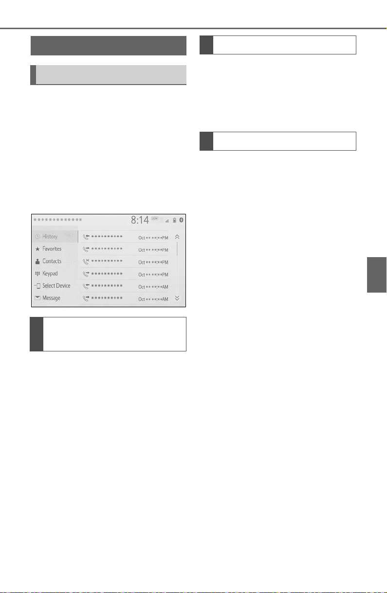
465
5-13. Phone operation (Hands-free system for cellular phones)
5
Audio
5-13.Phone operation (Hands-free system for cellular phones)
The phone screen can be
reached by the following meth-
ods:
From the “PHONE” button
1 Press the “PHONE” button.
From the “MENU” button
1 Press the “MENU” button,
then select “Phone”.
The following functions can be
used on phone operation:
Registering/connecting a
Bluetooth
®
device (P.390)
Placing a call using the
Bluetooth
®
hands-free system
(P.470)
Receiving a call using the
Bluetooth
®
hands-free system
(P.473)
Talking on the Bluetooth
®
hands-free system (P.474)
The following function can be
used on message function:
Using the Bluetooth
®
phone
message function (P.476)
The following functions can be
made in the system:
Phone settings (P. 48 1 )
Bluetooth
®
settings (P.394)
Quick reference
Phone screen operation
Bluetooth
®
hands-free
system operation
Message function
Setting up a phone

466
5-13. Phone operation (Hands-free system for cellular phones)
● This system is not guaranteed to
operate with all Bluetooth
®
devices.
● If your cellular phone does not
support Bluetooth
®
, this system
cannot function.
● In the following conditions, the
system may not function:
• The cellular phone is turned off.
• The current position is outside the
communication area.
• The cellular phone is not con-
nected.
• The cellular phone has a low bat-
tery.
● Depending on the type of
Bluetooth
®
phone, some function
is not available.
● When using the hands-free sys-
tem or Bluetooth
®
audio and
W-Fi
®
Hotspot functions at the
same time, the following problems
may occur:
• The Bluetooth
®
connection may
be cut.
• Noise may be heard on the
Bluetooth
®
audio playback.
• A noise may be heard during
phone calls.
● Bluetooth
®
uses the 2.4 GHz fre-
quency band. If both a Wi-Fi
®
con-
nection and Bluetooth
®
connection are being used simul-
taneously, each connection may
be affected.
● If a Bluetooth
®
device is attempt-
ing to connect to the vehicle while
another device is connected as a
Bluetooth
®
audio device or con-
nected using the hands-free sys-
tem or Wi-Fi
®
Hotspot function,
the communication speed may
decrease or malfunctions may
occur, such as image distortion or
audio skipping. If a Bluetooth
®
device is connected to the system,
the interference it may cause will
be reduced. When carrying a
device with its Bluetooth
®
connec-
tion enabled, make sure to regis-
ter it to the system and connect it
or disable its Bluetooth
®
function.
● When a device is connected via
Bluetooth
®
, the Bluetooth
®
icon
on the status bar will be displayed
in blue. (P.378)
Some basics
The hands-free system
enables calls to be made
and received without having
to take your hands off the
steering wheel.
This system supports
Bluetooth
®
. Bluetooth
®
is a
wireless data system that
enables cellular phones to
be used without being con-
nected by a cable or placed
in a cradle.
The operating procedure of
the phone is explained here.
When an Apple CarPlay
connection is established,
phone functions will be per-
formed by Apple CarPlay
instead of the hands-free
system.
WARNING
● While driving, do not operate a
cellular phone.
467
5-13. Phone operation (Hands-free system for cellular phones)
5
Audio
To use the hands-free system
for cellular phones, it is neces-
sary to register a cellular phone
with the system. (P.390)
■ Connecting a Bluetooth
®
device
Registering an additional
device
1 Display the phone top
screen. (P.465)
2 Select “Select Device”.
3 Select “Add Device”.
When another Bluetooth
®
device is connected, a confir-
mation screen will be dis-
played. To disconnect the
Bluetooth
®
device, select
“Yes”.
4 Follow the steps in “Register-
ing a Bluetooth
®
phone for
the first time” from step 5.
(P.390)
Selecting a registered device
1 Display the phone top
screen. (P.465)
2 Select “Select Device”.
3 Select the desired device to
be connected.
4 Check that a confirmation
screen is displayed when the
connection is complete.
If an error message is dis-
played, follow the guidance
on the screen to try again.
■ Bluetooth
®
phone condition
display
The condition of the Bluetooth
®
phone appears on the upper
right side of the screen.
WARNING
● Your audio unit is fitted with
Bluetooth
®
antennas. People
with implantable cardiac pace-
makers, cardiac resynchroniza-
tion therapy-pacemakers or
implantable cardioverter defi-
brillators should maintain a rea-
sonable distance between
themselves and the Bluetooth
®
antennas. The radio waves may
affect the operation of such
devices.
● Before using Bluetooth
®
devices, users of any electrical
medical device other than
implantable cardiac pacemak-
ers, cardiac resynchronization
therapy-pacemakers or implan-
table cardioverter defibrillators
should consult the manufacturer
of the device for information
about its operation under the
influence of radio waves. Radio
waves could have unexpected
effects on the operation of such
medical devices.
NOTICE
● Do not leave your cellular phone
in the vehicle. The temperature
inside may rise to a level that
could damage the phone.
Registering/Connecting a
Bluetooth
®
phone
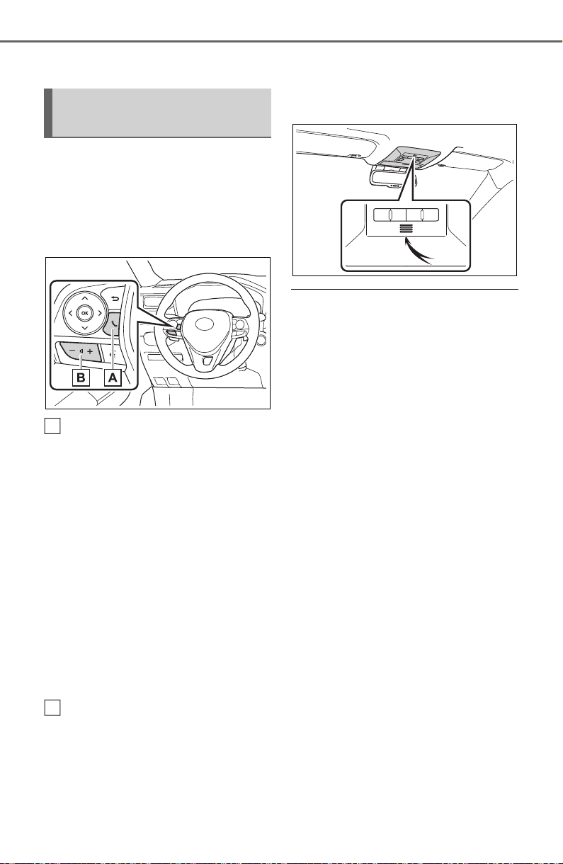
468
5-13. Phone operation (Hands-free system for cellular phones)
(P.378)
■ Steering switch
By pressing the phone switch, a
call can be received or ended
without taking your hands off the
steering wheel.
Phone switch
• If the switch is pressed during a
call, the call will end.
• If the switch is pressed when an
incoming call is received, the call
will be answered.
• If the switch is pressed during a
call when a separate incoming
call is waiting, the waiting call will
be answered.
• If the switch is pressed when an
Apple CarPlay/Android Auto con-
nection is established, the Apple
CarPlay/Android Auto phone
application will be displayed on
the system screen.
Volume control switch
• Press the “+” side to increase the
volume.
• Press the “-” side to decrease the
volume.
■ Microphone
The microphone is used when
talking on the phone.
● The other party’s voice will be
heard from the front speakers.
The audio/visual system will be
muted during phone calls or when
hands-free voice commands are
used.
● Talk alternately with the other
party on the phone. If both parties
speak at the same time, the other
party may not hear what has been
said. (This is not a malfunction.)
● Keep call volume down. Other-
wise, the other party’s voice may
be audible outside the vehicle and
voice echo may increase. When
talking on the phone, speak
clearly towards the microphone.
● The other party may not hear you
clearly when:
• Driving on an unpaved road.
(Making excessive traffic noise.)
• Driving at high speeds.
• The roof or windows are open.
• The air conditioning vents are
pointed towards the microphone.
• The sound of the air conditioning
fan is loud.
• There is a negative effect on
sound quality due to the phone
and/or network being used.
Using the phone
switch/microphone
A
B
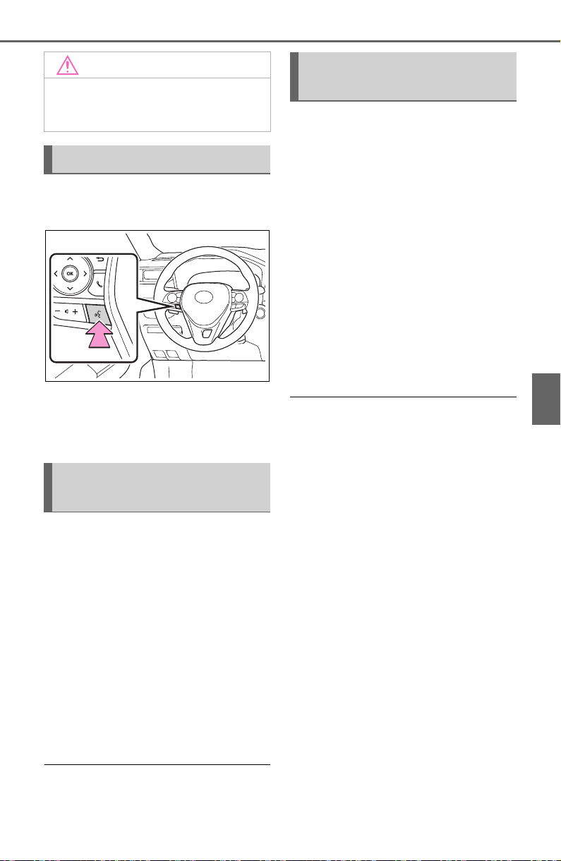
469
5-13. Phone operation (Hands-free system for cellular phones)
5
Audio
Press the talk switch to operate
the voice command system.
The voice command system
and its list of commands can
be operated. (P.458)
The following data is stored
for every registered phone.
When another phone is con-
nected, the following regis-
tered data cannot be read:
• Contact data
• Call history data
• Favorites data
• Image data
• All phone settings
• Message settings
● When a phone’s registration is
deleted, the above-mentioned
data is also deleted.
A lot of personal data is regis-
tered when the hands-free sys-
tem is used. When selling or
disposing of the vehicle, initial-
ize the data. (P.417)
The following data in the sys-
tem can be initialized:
• Contact data
• Call history data
• Favorites data
• Image data
• All phone settings
• Message settings
● Once initialized, the data and set-
tings will be erased. Pay addi-
tional attention when initializing
the data.
NOTICE
● Do not touch and put a sharp
object to the microphone. It may
cause failure.
Voice command system
About the contacts in the
contact list
When selling or disposing
of the vehicle
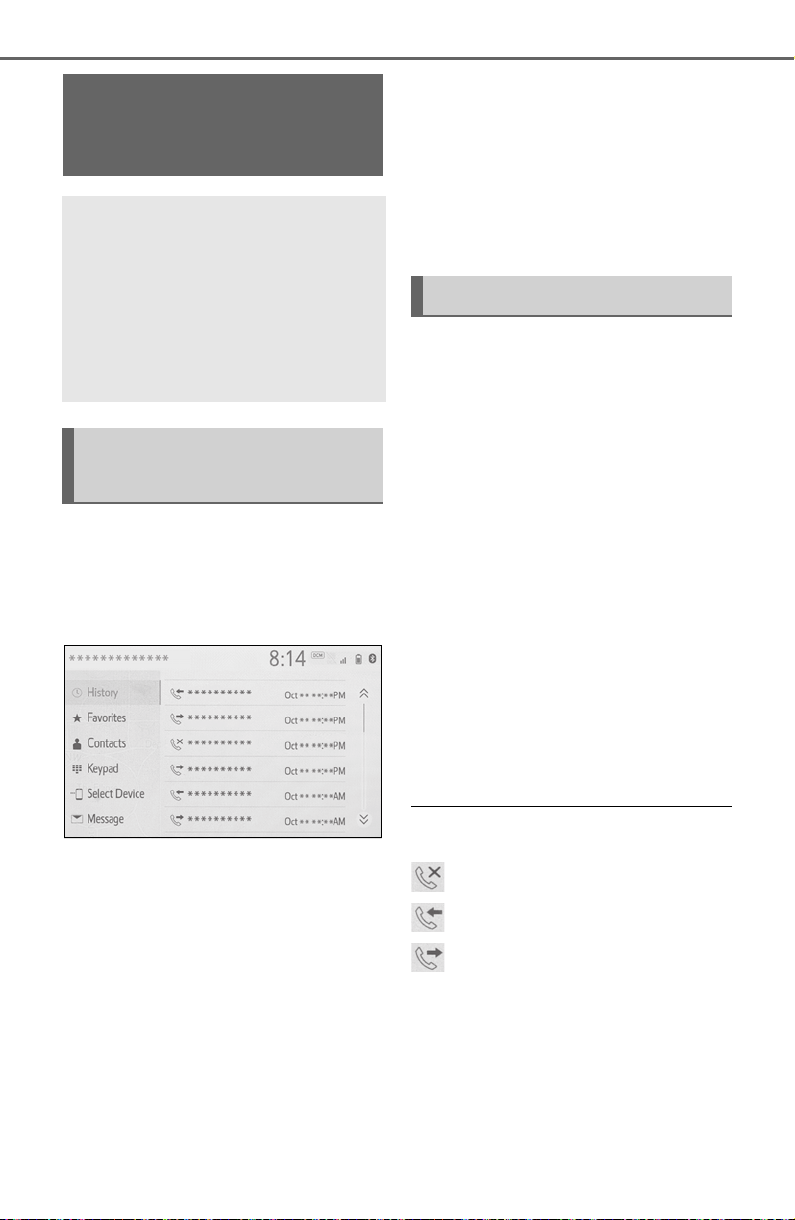
470
5-13. Phone operation (Hands-free system for cellular phones)
1 Display the phone top
screen. (P.465)
2 Select the desired method to
call from.
■ Calling methods from
phone screen
By call history (P.470)
By favorites (P.471)
By contacts (P.471)
By keypad (P.472)
By message (P.479)
■ Also the following lists are
available from each func-
tion’s screen
By voice command system
(P.459)
By home screen (P.473)
Up to 30 of the latest call history
items (missed, incoming and
outgoing) can be selected.
1 Display the phone top
screen. (P.465)
2 Select “History” and select
the desired contact.
If the contact which is not reg-
istered on the contact list is
selected, the name is dis-
played as “Unknown Con-
tact”. In this case, select the
number to make a call prop-
erly.
3 Check that the dialing screen
is displayed.
● The icons of call type are dis-
played.
: Missed call
: Incoming call
: Outgoing call
● When making a call to the same
number continuously, only the
most recent call is listed in call his-
tory.
● When a phone number registered
in the contact list is received, the
name is displayed.
● Number-withheld calls are also
Placing a call using
the Bluetooth
®
hands-
free system
After a Bluetooth
®
phone
has been registered, a call
can be made using the
hands-free system. There
are several methods by
which a call can be made, as
described below.
Calling methods on the
Bluetooth
®
phone
By call history

471
5-13. Phone operation (Hands-free system for cellular phones)
5
Audio
memorized in the system.
● International phone calls may not
be made depending on the type of
Bluetooth
®
phone you have.
● The list should group together
consecutive entries with the same
phone number and same call
type. For example, two calls from
John’s mobile would be displayed
as follows: John (2)
Calls can be made using regis-
tered contacts which can be
selected from a contact list.
(P.471)
1 Display the phone top
screen. (P.465)
2 Select “Favorites” and select
the desired contact.
3 Select the desired number.
4 Check that the dialing screen
is displayed.
Calls can be made by using
contact data which is transferred
from a registered cellular phone.
(P.483)
Up to 5000 contacts (maximum
of 4 phone numbers, e-mail
addresses and addresses per
contact) can be registered in the
contact list.
1 Display the phone top
screen. (P.465)
2 Select “Contacts” and select
the desired contact.
3 Select the desired number.
“Add Favorite”/“Remove Favorite”:
Select to register/remove the con-
tact in the favorites list. (P.488)
“E-mail Addresses”: Select to dis-
play all registered e-mail addresses
for the contact.
“Addresses”: Select to display all
registered addresses for the con-
tact.
4 Check that the dialing screen
is displayed.
■ For PBAP compatible
Bluetooth
®
phones when
“Automatic Transfer” is set
to on (P.483)
Contacts are transferred auto-
matically.
By favorites list
By contacts list
When the contact list is
empty
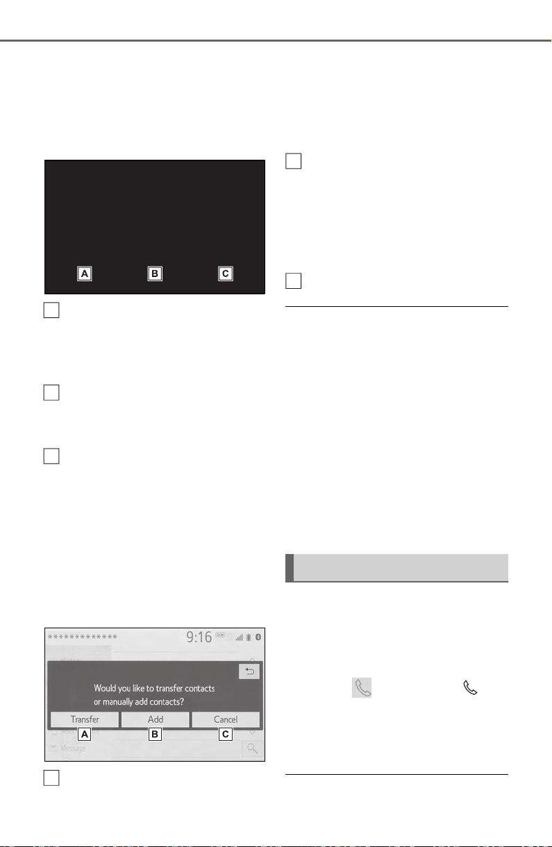
472
5-13. Phone operation (Hands-free system for cellular phones)
■ For PBAP compatible
Bluetooth
®
phones when
“Automatic Transfer” is set
to off (P.483)
1 Select the desired item.
Select to always transfer all
the contacts from a con-
nected cellular phone auto-
matically.
Select to transfer all the con-
tacts from a connected cellu-
lar phone only once.
Select to cancel transferring.
2 Check that a confirmation
screen is displayed when the
operation is complete.
■ For PBAP incompatible but
OPP compatible Bluetooth
®
phones
1 Select the desired item.
Select to transfer the con-
tacts from the connected cel-
lular phone.
Transfer the contact data to
the system using a
Bluetooth
®
phone.
Select to add a new contact
manually.
Follow the steps in “Register-
ing a new contact to the con-
tacts list” from step 2.
(P.486)
Select to cancel transferring.
● If your cellular phone is neither
PBAP nor OPP compatible, the
contacts cannot be transferred
using Bluetooth
®
. But the contacts
can be transferred from USB
device. (P.486)
● Depending on the type of
Bluetooth
®
phone:
• It may be necessary to perform
additional steps on the phone
when transferring contact data.
• The registered image in the con-
tact list may not transfer depend-
ing on the type of Bluetooth
®
phone connected.
1 Display the phone top
screen. (P.465)
2 Select “Keypad” and enter
the phone number.
3 Select or press the
switch on the steering wheel.
4 Check that the dialing screen
is displayed.
● Depending on the type of
A
B
C
A
By keypad
B
C
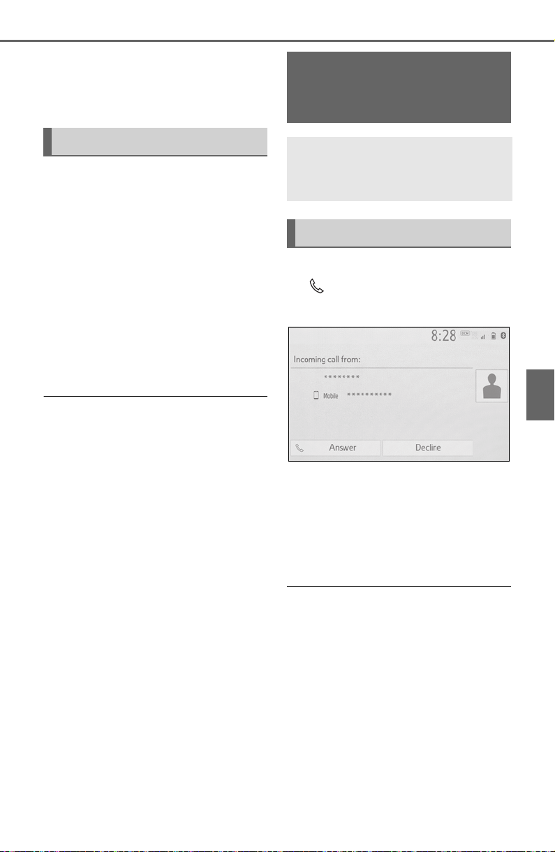
473
5-13. Phone operation (Hands-free system for cellular phones)
5
Audio
Bluetooth
®
phone being con-
nected, it may be necessary to
perform additional steps on the
phone.
1 Display the home screen.
(P.384)
2 Select the desired contact.
3 Check that the dialing screen
is displayed.
■ Registering a new contact
1 Select and hold the screen
button to add a contact.
2 Select the desired contact.
3 Select the desired number.
● If there is no contact in the con-
tacts list, the contacts cannot be
registered at the home screen.
● The contact cannot be registered
at the home screen while driving.
1 Select “Answer” or press the
switch on the steering
wheel to talk on the phone.
“Decline”: Select to refuse to
receive the call.
To adjust the volume of a received
call: Turn the “POWER VOLUME”
knob, or use the volume control
switch on the steering wheel.
● The contact image picture can be
displayed only when the vehicle is
not moving.
● During international phone calls,
the other party’s name or number
may not be displayed correctly
depending on the type of
Bluetooth
®
phone you have.
● The incoming call display mode
can be set. (P.482)
● The ringtone that has been set in
the sound settings screen can be
heard when there is an incoming
call. Depending on the type of
By home screen
Receiving a call using
the Bluetooth
®
hands-
free system
When a call is received, the
following screen is dis-
played with a sound.
Incoming calls
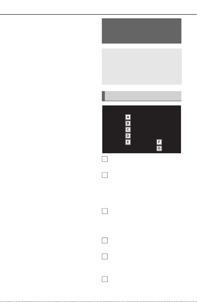
474
5-13. Phone operation (Hands-free system for cellular phones)
Bluetooth
®
phone, both the sys-
tem and Bluetooth
®
phone may
ring simultaneously when there is
an incoming call. (P.481)
Select to display the keypad
to send tones. (P.475)
Select to send tones. This
button only appears when a
number that contains a (w) is
dialed in hands-free mode.
(P.475)
Select to adjust your voice
volume that the other party
hears from their speaker.
(P.475)
Select to mute your voice to
the other party.
Select to change handset
modes between hands-free
and cellular phone.
Select to put a call on hold.
Talking on the
Bluetooth
®
hands-free
system
While talking on the phone,
the following screen is dis-
played. The operations out-
lined below can be
performed on this screen.
Call screen operation
A
B
C
D
E
F

475
5-13. Phone operation (Hands-free system for cellular phones)
5
Audio
To cancel this function, select
“Activate”.
Select to hang up the phone.
● Changing from hands-free call to
cellular phone call is not possible
while driving.
● Only when the vehicle is not mov-
ing, the contact image can be dis-
played.
● When cellular phone call is
changed to hands-free call, the
hands-free screen will be dis-
played and its functions can be
operated on the screen.
● Changing between cellular phone
call and hands-free call can be
performed by operating the cellu-
lar phone directly.
● Transferring methods and opera-
tions will be different depending
on the type of cellular phone you
have.
● For the operation of the cellular
phone, see the manual that
comes with it.
■ By keypad
This operation cannot be per-
formed while driving.
1 Select “0-9”.
2 Enter the desired number.
■ By selecting “Release
Tones”
“Release Tones” appear when a
continuous tone signal(s) con-
taining a (w) is registered in the
contact list.
This operation can be per-
formed while driving.
1 Select “Release Tones”.
● A continuous tone signal is a char-
acter string that consists of num-
bers and the characters “p” or “w”.
(e.g. 056133w0123p#1)
● When the “p” pause tone is used,
the tone data up until the next
pause tone will be automatically
sent after 2 seconds have
elapsed. When the “w” pause tone
is used, the tone data up until the
next pause tone will be automati-
cally sent after a user operation is
performed.
● Release tones can be used when
automated operation of a phone
based service such as an answer-
ing machine or bank phone ser-
vice is desired. A phone number
with continuous tone signals can
be registered in the contact list.
● Tone data after a “w” pause tone
can be operated by voice com-
mand during a call.
1 Select “Transmit Volume”.
2 Select the desired level for
the transmit volume.
3 Select to display previ-
ous screen.
● The sound quality of the voice
heard from the other party’s
speaker may be negatively
impacted.
● “Transmit Volume” is dimmed
when mute is on.
When there are no calls on
hold during a call: “Hold” is
displayed. When selected, the
Sending tones
G
Transmit volume setting
Switching calls while a
call is in progress

476
5-13. Phone operation (Hands-free system for cellular phones)
current call is placed on hold.
When there is no current call,
but there is a call on hold:
“Activate” is displayed. When
selected, the system switches
to the call that was on hold.
When there is another call on
hold during a call: “Swap
Calls” is displayed. When
selected, the current call is
placed on hold, and the sys-
tem switches to the call that
was on hold.
● This function may not be available
depending on the type of cellular
phone.
When a call is interrupted by a
third party while talking, the
incoming screen is displayed.
1 Select “Answer” or press the
switch on the steering
wheel to start talking with the
other party.
To refuse to receive the call:
Select “Decline”.
Each time “Swap Calls” is
selected, the party who is on
hold will be switched.
● This function may not be available
depending on the type of
Bluetooth
®
phone.
1 Display the phone top
screen. (P.465)
2 Select “Message”.
A confirmation message
appears when the “Automatic
Message Transfer” function is
set to off (P.489), select
“Yes”.
3 Check that the message
screen is displayed.
“Phone”: Select to change to phone
mode.
The account name is dis-
played on the left side of
Incoming call waiting
Bluetooth
®
phone
message function
Received messages can be
forwarded from the con-
nected Bluetooth
®
phone,
enabling checking and
replying using the system.
Depending on the type of
Bluetooth
®
phone con-
nected, received messages
may not be transferred to
the system.
If the phone does not sup-
port the message function,
this function cannot be
used. Even when the sup-
ported phone is used, reply
function may not be used.
Displaying the message
screen
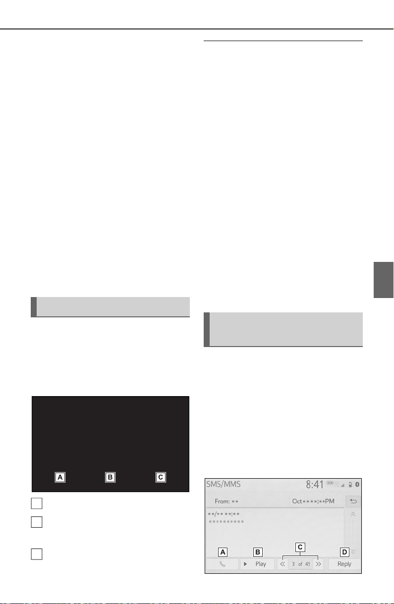
477
5-13. Phone operation (Hands-free system for cellular phones)
5
Audio
screen.
Account names are the
names of the accounts that
exist on the currently con-
nected phone.
The following functions can
be used on message function:
• Receiving a message
(P.477)
• Checking messages
(P.477)
• Replying to a message (dicta-
tion reply) (P.478)
• Replying to a message (quick
reply) (P.479)
• Calling the message sender
(P.479)
• Message settings (P. 48 9 )
When an e-mail/SMS/MMS is
received, the incoming message
screen pops up with sound and
is ready to be operated on the
screen.
Select to check the message.
Select to not open the mes-
sage.
Select to call the message
sender.
● Depending on the type of
Bluetooth
®
phone used for receiv-
ing messages, or its registration
status with the system, some
information may not be displayed.
● The pop-up screen is separately
available for incoming e-mail and
SMS/MMS messages under the
following conditions:
E-mail:
• “Incoming E-mail Display” is set to
“Full Screen”. (P.482)
• “E-mail Notification Pop-up” is set
to on. (P.482)
SMS/MMS:
• “Incoming SMS/MMS Display” is
set to “Full Screen”. (P.482)
• “SMS/MMS Notification Pop-up” is
set to on. (P.482)
● Depending on the type of
Bluetooth
®
phone being con-
nected, E-Mail function cannot be
used via Bluetooth
®
.
1 Display the message screen.
(P.476)
2 Select a desired account
name.
3 Select the desired message
from the list.
4 Check that the message is
displayed.
Receiving a message
A
B
C
Checking received mes-
sages

478
5-13. Phone operation (Hands-free system for cellular phones)
Select to call the message
sender.
Select to have messages
read out.
To cancel this function, select
“Stop”.
When “Automatic Message
Readout” is set to on, mes-
sages will be automatically
read out. (P.489)
Select to display the previous
or next message.
This function can be chosen
the method to reply mes-
sage with “Dictation” or
“Quick Message”.
● Reading a text message is not
available while driving.
● Depending on the type of
Bluetooth
®
phone being con-
nected, this function cannot be
used.
● Depending on the type of
Bluetooth
®
phone being con-
nected, it may be necessary to
perform additional steps on the
phone.
● Messages are displayed in the
appropriate connected Bluetooth
®
phone’s registered mail address
folder. Select the desired folder to
be displayed.
● Only received messages on the
connected Bluetooth
®
phone can
be displayed.
● The text of the message is not dis-
played while driving.
● Turn the “POWER VOLUME”
knob, or use the volume control
switch on the steering wheel to
adjust the message read out vol-
ume.
● “Subject:” field is not shown on
SMS case.
● E-mail only: Select “Mark Unread”
or “Mark Read” to mark mail
unread or read on the message
screen.
This function is available when
“Update Message Read Status on
Phone” is set to on. (P.489)
*
: If equipped
1 Display the message screen.
(P.476)
2 Select the desired message
from the list.
3 Select “Reply”.
4 Select “Dictation”.
5 When the “Say Your Mes-
sage” screen is displayed,
speak message that you
want to send.
6 Select “Send” to send mes-
sage.
“Cancel”: Select to cancel sending
the message.
“Retry”: Select to retry speaking
message that you want to send.
While the message is being
sent, a sending message
screen is displayed.
7 Check that a confirmation
screen is displayed when the
operation is complete.
If an error message is dis-
played, follow the guidance
on the screen to try again.
A
B
C
D
Replying to a message
(dictation reply)
*

479
5-13. Phone operation (Hands-free system for cellular phones)
5
Audio
15 messages have already
been stored.
1 Display the message screen.
(P.476)
2 Select the desired message
from the list.
3 Select “Reply”.
4 Select “Quick Message”.
5 Select the desired message.
: Select to edit the message.
(P.479)
6 Select “Send”.
“Cancel”: Select to cancel sending
the message.
While the message is being
sent, a sending message
screen is displayed.
7 Check that a confirmation
screen is displayed when the
operation is complete.
If an error message is dis-
played, follow the guidance
on the screen to try again.
● Depending on the type of
Bluetooth
®
phone, reply function
is not available.
■ Editing quick reply mes-
sages
This operation cannot be per-
formed while driving.
1 Select corresponding to
the desired message to edit.
2 Select “OK” when editing is
completed.
● To reset the edited quick reply
messages, select “Default”.
Calls can be made to an e-
mail/SMS/MMS message
sender’s phone number.
This operation can be per-
formed while driving.
■ Calling from e-
mail/SMS/MMS message
display
1 Display the message screen.
(P.476)
2 Select the desired message.
3 Select , or press the
switch on the steering wheel.
If there are 2 or more phone
numbers, select the desired
number.
4 Check that the dialing screen
is displayed.
■ Calling from a number
within a message
Calls can be made to a number
identified in a message’s text
area.
This operation cannot be per-
formed while driving.
1 Display the message screen.
(P.476)
2 Select the desired message.
Replying to a message
(quick reply)
Calling the message
sender

480
5-13. Phone operation (Hands-free system for cellular phones)
3 Select the text area.
Identified phone numbers
contained in the message are
displayed in blue text.
4 Select the desired number.
5 Check that the dialing screen
is displayed.
● A series of numbers may be rec-
ognized as a phone number. Addi-
tionally, some phone numbers
may not be recognized, such as
those for other countries.
■ Calling from the incoming
message screen
For detail, refer to “Receiving a
message”. (P.477)
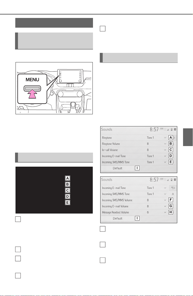
481
5-14. Phone settings
5
Audio
5-14.Phone settings
1 Press the “MENU” button.
2 Select “Setup”.
3 Select “Phone”.
4 Select the desired item to be
set.
Connecting a Bluetooth
®
device and editing the
Bluetooth
®
device informa-
tion (P.395, 398)
Sound settings
*
(P.481)
Notifications/display set-
tings
*
(P.482)
Contact/call history settings
*
(P.483)
Message settings
*
(P.489)
*
: This operation cannot be per-
formed while driving.
The call and ringtone volume
can be adjusted. A ringtone can
be selected.
1 Display the phone settings
screen. (P.481)
2 Select “Sounds”.
3 Select the desired item to be
set.
Select to set the desired
ringtone.
Select “-” or “+” to adjust the
ringtone volume.
Select “-” or “+” to adjust the
default volume of the other
party’s voice.
Setup
Displaying the phone set-
tings screen
Phone settings screen
A
B
C
D
Sounds settings screen
E
A
B
C
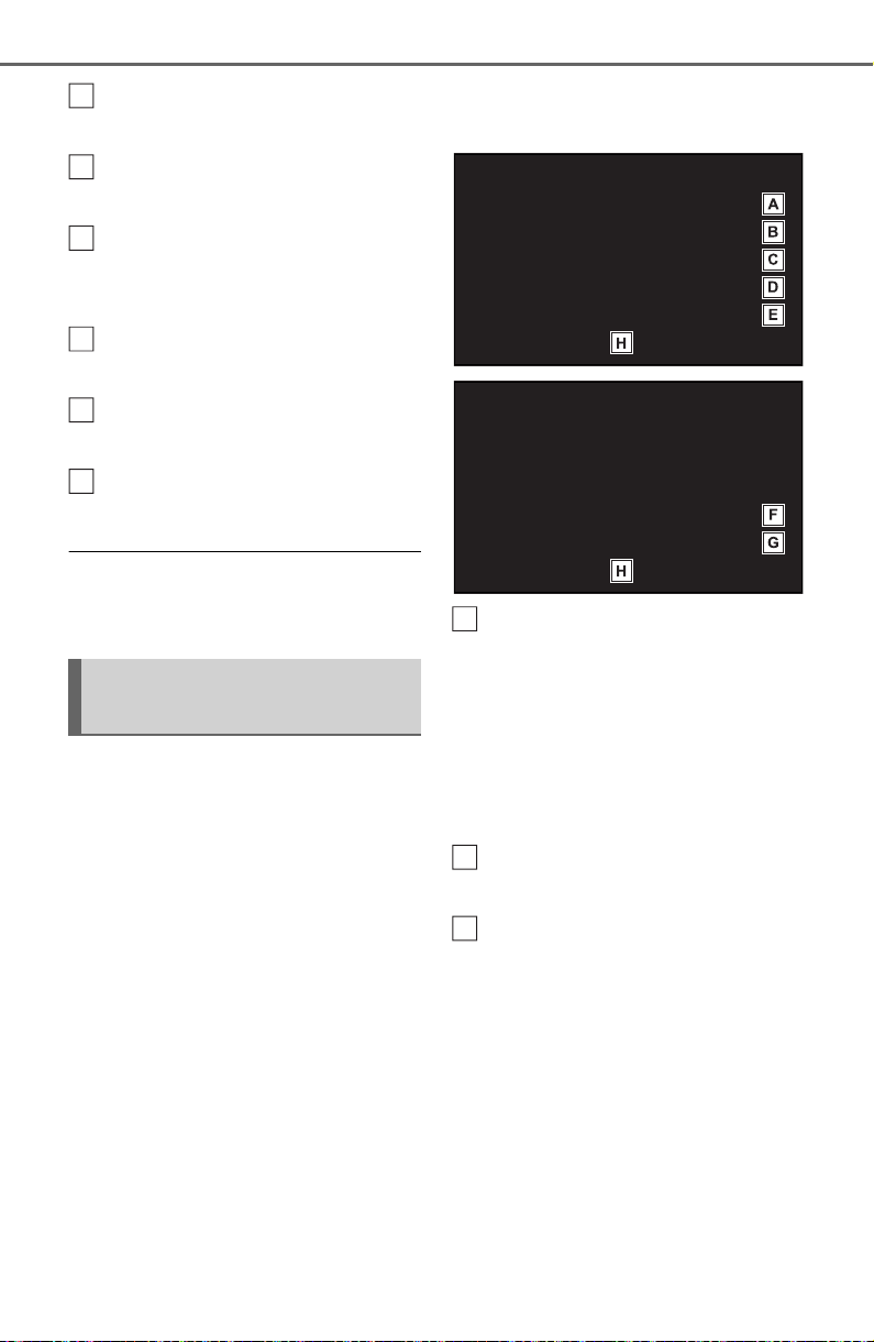
482
5-14. Phone settings
Select to set the desired
incoming e-mail tone.
Select to set the desired
incoming SMS/MMS tone.
Select “-” or “+” to adjust the
incoming SMS/MMS tone
volume.
Select “-” or “+” to adjust the
incoming e-mail tone volume.
Select “-” or “+” to adjust the
message readout volume.
Select to reset all setup
items.
● Depending on the type of
Bluetooth
®
phone, certain func-
tions may not be available.
1 Display the phone settings
screen. (P.481)
2 Select “Notifications/Display”.
3 Select the desired item to be
set.
Select to change the incom-
ing call display.
“Full Screen”: When a call is
received, the incoming call screen
is displayed and can be operated
on the screen.
“Drop-down”: A message is dis-
played at the top of the screen.
Select to set the SMS/MMS
notification pop-up on/off.
Select to change the incom-
ing SMS/MMS display.
“Full Screen”: When an
SMS/MMS message is
received, the incoming
SMS/MMS display screen is
displayed and can be oper-
ated on the screen.
“Drop-down”: When an
SMS/MMS message is
received, a message is dis-
played at the top of the
Notifications/display set-
tings screen
D
E
F
G
H
I
A
B
C
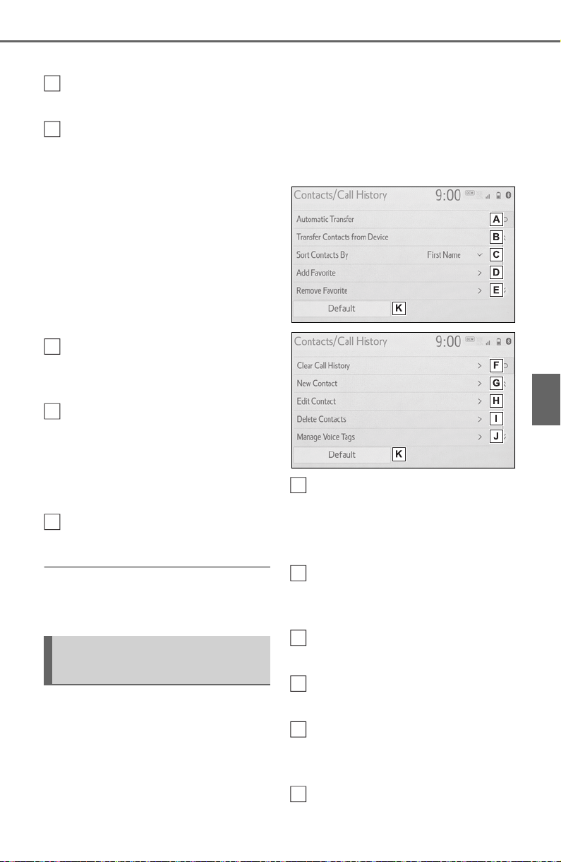
483
5-14. Phone settings
5
Audio
screen.
Select to set the e-mail notifi-
cation pop-up on/off.
Select to change the incom-
ing e-mail display.
“Full Screen”: When an e-
mail is received, the incoming
e-mail display screen is dis-
played and can be operated
on the screen.
“Drop-down”: When an e-
mail is received, a message
is displayed at the top of the
screen.
Select to set display of the
contact/history transfer com-
pletion message on/off.
The phone top screen can be
set to be displayed on the
multi-information display or
system screen.
*
*
: If equipped
Select to reset all setup
items.
● Depending on the type of
Bluetooth
®
phone, these functions
may not be available.
Contacts can be transferred
from a Bluetooth
®
phone to this
system. Contacts and favorites
can be added, edited and
deleted. Also, the call history
can be deleted.
1 Display the phone settings
screen. (P.481)
2 Select “Contacts/Call His-
tory”.
3 Select the desired item to be
set.
For PBAP compatible
Bluetooth
®
phones: Select to
change the contact/history
transfer settings. (P.484)
Select to update contacts
from the connected device.
(P.485)
Select to sort contacts by the
first name or last name field.
Select to add contacts to the
favorites list. (P.487)
Select to delete contacts
from the favorites list.
(P.488)
Select to clear the call his-
Contacts/Call history set-
tings screen
D
E
F
G
H
A
B
C
D
E
F
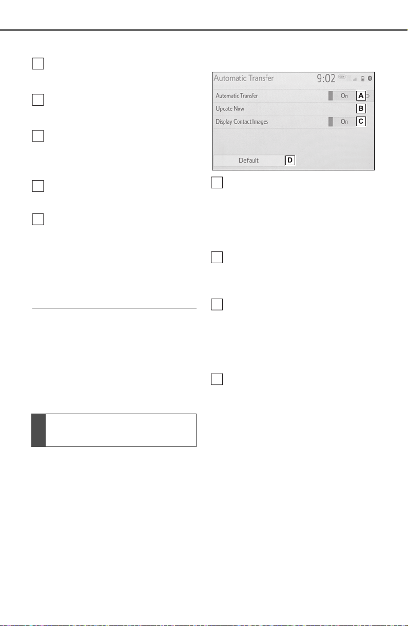
484
5-14. Phone settings
tory.
*
Select to add new contacts to
the contact list.
*
(P.486)
Select to edit contacts in the
contact list.
*
(P.487)
Select to delete contacts
from the contact list.
*
(P.487)
Select to set the voice tags.
(P.488)
Select to reset all setup
items.
*
: For PBAP compatible Bluetooth
®
phones, this function is available
when “Automatic Transfer” is set
to off. (P.484)
● Depending on the type of
Bluetooth
®
phone, certain func-
tions may not be available.
● Contact data is managed inde-
pendently for every registered
phone. When one phone is con-
nected, another phone’s regis-
tered data cannot be read.
The automatic contact/history
function is available for PBAP
compatible Bluetooth
®
phones
only.
1 Select “Automatic Transfer”.
2 Select the desired item to be
set.
Select to set automatic con-
tact/history transfer on/off.
When set to on, the phone’s
contact data and history are
automatically transferred.
Select to update contacts
from the connected phone.
(P.484)
Select to set the transferred
contact image display on/off.
Only when the vehicle is not
moving, the contact image
can be displayed.
Select to reset all setup
items.
■ Updating contacts from
phone
1 Select “Update Now”.
Contacts are transferred auto-
matically.
2 Check that a confirmation
screen is displayed when the
operation is complete.
This operation may be unnec-
essary depending on the type
of Bluetooth
®
phone.
If another Bluetooth
®
device
Setting automatic con-
tact/history transfer
G
H
I
J
K
A
B
C
D

485
5-14. Phone settings
5
Audio
is connected when transfer-
ring contact data, depending
on the phone, the connected
Bluetooth
®
device may need
to be disconnected.
Depending on the type of
Bluetooth
®
phone being con-
nected, it may be necessary
to perform additional steps on
the phone.
■ Updating the contacts in a
different way (from the call
history screen)
*
1 Display the phone top
screen. (P.465)
2 Select “History” and select a
contact not yet registered in
the contact list.
3 Select “Update Contact”.
4 Select the desired contact.
5 Select a phone type for the
phone number.
*
: For PBAP compatible Bluetooth
®
phones, this function is available
when “Automatic Transfer” is set
to off. (P.484)
When an Android Auto connection
is established, this function will be
unavailable.
*
*
: This function is not made avail-
able in some countries or areas.
When the contact is not regis-
tered
1 Select “Transfer Contacts
from Device”.
2 Select “From Phone
(Bluetooth)”.
3 Transfer the contact data to
the system using a
Bluetooth
®
phone.
This operation may be unnec-
essary depending on the type
of Bluetooth
®
phone.
To cancel this function, select
“Cancel”.
4 Check that a confirmation
screen is displayed when the
operation is complete.
When the contact is regis-
tered
1 Select “Transfer Contacts
from Device”.
2 Select “From Phone
(Bluetooth)”.
3 Select “Replace Contacts” or
“Add Contact”.
“Replace Contacts”: Select to trans-
fer the contact from the connected
cellular phone and replace the cur-
rent one.
“Add Contact”: Select to transfer
the desired contact data from the
connected cellular phone to add to
the current one.
Transfer contacts from
device
From phone (OPP compati-
ble Bluetooth
®
phones only)

486
5-14. Phone settings
4 Transfer the contact data to
the system using a
Bluetooth
®
phone.
This operation may be unnec-
essary depending on the type
of Bluetooth
®
phone.
To cancel this function, select
“Cancel”.
5 Check that a confirmation
screen is displayed when the
operation is complete.
Backed-up contact data
(“vCard” formatted) can be
transferred from USB device or
Bluetooth
®
phone to this sys-
tem.
1 Connect a USB device.
(P.422)
2 Select “Transfer Contacts
from Device”.
3 Select “From USB”.
4 Select “USB 1” or “USB 2”
when the multiple USB
devices are connected. If a
USB device is connected,
skip this procedure.
5 Select “Replace Contacts” or
“Add Contact”. If the contact
is already registered, skip
this procedure.
“Replace Contacts”: Select to trans-
fer the contact from the connected
USB device or Bluetooth
®
phone
and replace the current one.
“Add Contact”: Select to transfer
the desired contact data from the
connected USB device or
Bluetooth
®
phone to add to the cur-
rent one.
6 Select a desired file from
vCard file list.
7 Check that a confirmation
screen is displayed when the
operation is complete.
● Depending on the type of
Bluetooth
®
phone used and num-
ber of files, it may take time to dis-
play vCard file lists and download
contacts.
● Downloading may not complete
correctly in the following cases:
• If the engine switch is turned off
during downloading.
• If the USB device or Bluetooth
®
phone is removed before down-
loading is complete.
New contact data can be regis-
tered.
Up to 4 numbers per person can
be registered. For PBAP com-
patible Bluetooth
®
phones, this
function is available when “Auto-
matic Transfer” is set to off.
(P.483)
1 Select “New Contact”.
2 Enter the name and select
“OK”.
3 Enter the phone number and
select “OK”.
4 Select the phone type for the
phone number.
From USB device
Registering a new contact
to the contacts list

487
5-14. Phone settings
5
Audio
5 To add another number to
this contact, select “Yes”.
■ Registering a new contact
in a different way (from the
call history screen)
1 Display the phone top
screen. (P.465)
2 Select “History” and select a
contact not yet registered in
the contact list.
3 Select “Add to Contacts”.
4 Follow the steps in “Register-
ing a new contact to the con-
tacts list” from step 2.
(P.486)
For PBAP compatible
Bluetooth
®
phones, this function
is available when “Automatic
Transfer” is set to off. (P.483)
1 Select “Edit Contact”.
2 Select the desired contact.
3 Select next to the name
or desired number.
4 Enter the name or the phone
number and select “OK”.
For PBAP compatible
Bluetooth
®
phones, this function
is available when “Automatic
Transfer” is set to off. (P.483)
1 Select “Delete Contacts”.
2 Select the desired contact
and select “Delete”.
3 Select “Yes” when the confir-
mation screen appears.
● Multiple data can be selected and
deleted at the same time.
● When a Bluetooth
®
phone is
deleted, the contact data will be
deleted at the same time.
Up to 15 contacts (maximum of
4 numbers per contact) can be
registered in the favorites list.
■ Registering the contacts in
the favorites list
1 Select “Add Favorite”.
2 Select the desired contact to
add to the favorites list.
Dimmed contacts are already
stored as a favorite.
3 Check that a confirmation
screen is displayed when the
operation is complete.
When 15 contacts have
already been registered to the
favorites list
1 When 15 contacts have
already been registered to
the favorites list, a registered
contact needs to be replaced.
Select “Yes” when the confir-
mation screen appears to
replace a contact.
2 Select the contact to be
replaced.
Editing the contact data
Deleting the contact data
Favorites list setting
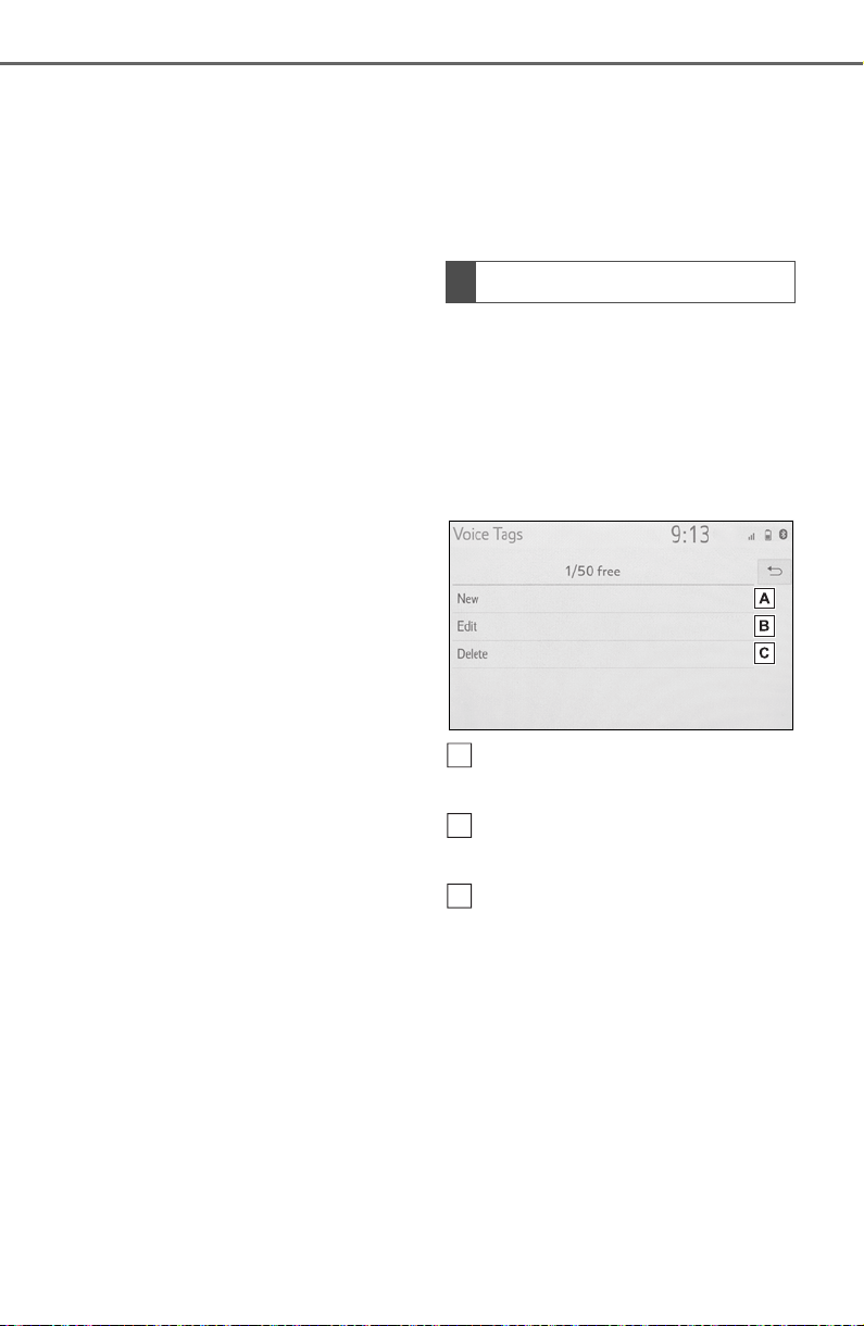
488
5-14. Phone settings
3 Check that a confirmation
screen is displayed when the
operation is complete.
■ Registering contacts in the
favorites list in a different
way (from the contact
details screen)
1 Display the phone top
screen. (P.465)
2 Select “Contacts” and select
the desired contact.
3 Select “Add Favorite”.
4 Check that a confirmation
screen is displayed when the
operation is complete.
■ Deleting the contacts in the
favorites list
1 Select “Remove Favorite”.
2 Select the desired contacts
and select “Remove”.
3 Select “Yes” when the confir-
mation screen appears.
4 Check that a confirmation
screen is displayed when the
operation is complete.
■ Deleting contacts in the
favorites list in a different
way (from the contact
details screen)
1 Display the phone top
screen. (P.465)
2 Select “Favorites” or “Con-
tacts” and select the desired
contact to delete.
3 Select “Remove Favorite”.
4 Select “Yes” when the confir-
mation screen appears.
5 Check that a confirmation
screen is displayed when the
operation is complete.
Calls can be made by saying the
voice tag of a registered contact
in the contact list. (P.458)
1 Select “Manage Voice Tags”.
2 Select the desired item to be
set.
Select to register a new voice
tag. (P.488)
Select to edit a voice tag.
(P.489)
Select to delete a voice tag.
(P.489)
■ Registering a voice tag
Up to 50 voice tags can be reg-
istered.
1 Select “New”.
2 Select the desired contact to
register a voice tag for.
3 Select “REC” and record a
voice tag.
When recording a voice tag,
Setting voice tags
A
B
C
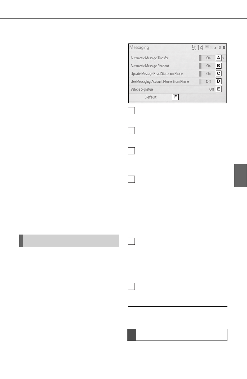
489
5-14. Phone settings
5
Audio
do so in a quiet area.
“Play”: Select to play the voice tag.
4 Select “OK” when voice tag
registration is complete.
■ Editing a voice tag
1 Select “Edit”.
2 Select the desired contact to
edit.
3 Follow the steps in “Register-
ing a voice tag” from step 3.
(P.488)
■ Deleting the voice tag
1 Select “Delete”.
2 Select the desired contact
and select “Delete”.
3 Select “Yes” when the confir-
mation screen appears.
● Multiple data can be selected and
deleted at the same time.
● Voice tags are deleted when the
set language of the system is
changed. (P.414)
1 Display the phone settings
screen. (P.481)
2 Select “Messaging”.
3 Select the desired item to be
set.
Select to set automatic mes-
sage transfer on/off.
Select to set automatic mes-
sage readout on/off.
Select to set updating mes-
sage read status on phone
on/off.
Select to set display of mes-
saging account names on the
message screen on/off.
When set to on, messaging
account names used on the
cellular phone will be dis-
played.
Select to set adding the vehi-
cle signature to outgoing
messages on/off.
The vehicle signature can be
edited. (P.489)
Select to reset all setup
items.
● Depending on the phone, these
functions may not be available.
1 Select “Vehicle Signature”.
Message settings screen
Vehicle signature settings
A
B
C
D
E
F

490
5-14. Phone settings
2 Select the desired item to be
set.
Select to set adding the vehi-
cle signature to outgoing
messages on/off.
Select to edit the vehicle sig-
nature. (P.490)
Select to reset all setup
items.
■ Editing vehicle signature
1 Select “Edit Vehicle Signa-
ture”.
2 Enter desired signature with
using keyboard.
3 Select “OK”.
4 Select “OK” on the confirma-
tion screen, or select “Edit
Again” when it needs to
amend.
A
B
C
491
5-15. What to do if... (Bluetooth
®
)
5
Audio
5-15.What to do if... (Bluetooth
®
)
■ When using the hands-free
system with a Bluetooth
®
device
The hands-free system or
Bluetooth
®
device does not
work.
■ When registering/connect-
ing a cellular phone
A cellular phone cannot be reg-
istered.
Troubleshooting
If there is a problem with the
hands-free system or a
Bluetooth
®
device, first
check the table below.
Troubleshooting
Likely cause Solution
The connected
device may not
be a compatible
Bluetooth
®
cellu-
lar phone.
For a list of spe-
cific devices
which operation
has been con-
firmed on this
system, check
with your Toyota
dealer or the fol-
lowing website:
http://www.
toyota.com/
audio-multimedia
in the United
States,
http://www.
toyota.ca/
connected
in Canada, and
http://www.
toyotapr.com/
audio-multimedia
in Puerto Rico
The Bluetooth
®
version of the
connected cellu-
lar phone may
be older than the
specified ver-
sion.
Use a cellular
phone with
Bluetooth
®
ver-
sion 2.0 or
higher (recom-
mended: Ver. 4.2
or higher).
(P.393)
492
5-15. What to do if... (Bluetooth
®
)
A Bluetooth
®
connection can-
not be made.
■ When making/receiving a
call
A call cannot be made/received.
■ When using the phonebook
Phonebook data cannot be
transferred manually/automati-
cally.
Likely cause Solution
An incorrect
passcode was
entered on the
cellular phone.
Enter the correct
passcode on the
cellular phone.
The registration
operation has
not been com-
pleted on the cel-
lular phone side.
Complete the
registration oper-
ation on the cel-
lular phone
(approve regis-
tration on the
phone).
Old registration
information
remains on
either this sys-
tem or the cellu-
lar phone.
Delete the exist-
ing registration
information from
both this system
and the cellular
phone, then reg-
ister the cellular
phone you wish
to connect to this
system.
(P.397)
Likely cause Solution
Another
Bluetooth
®
device is already
connected.
Manually con-
nect the cellular
phone you wish
to use to this
system.
(P.395)
Bluetooth
®
func-
tion is not
enabled on the
cellular phone.
Enable the
Bluetooth
®
func-
tion on the cellu-
lar phone.
Automatic
Bluetooth
®
con-
nection on this
system is set to
off.
Set automatic
Bluetooth
®
con-
nection on this
system to on
when the engine
switch is in ACC
or ON. (P. 40 0)
Preferred device
settings function
on this system is
set to on.
Set preferred
device settings
function on this
system to off.
(P.400)
Set the desired
cellular phone to
the highest auto-
matic connec-
tion priority.
(P.400)
Likely cause Solution
Your vehicle is in
a area.
Move to where
no longer
appears on the
display.
Likely cause Solution
493
5-15. What to do if... (Bluetooth
®
)
5
Audio
Phonebook data cannot be
edited.
■ When using the Bluetooth
®
message function
Messages cannot be viewed.
New message notifications are
not displayed.
Likely cause Solution
The profile ver-
sion of the con-
nected cellular
phone may not
be compatible
with transferring
phonebook data.
For a list of spe-
cific devices
which operation
has been con-
firmed on this
system, check
with your Toyota
dealer or the fol-
lowing website:
http://www.
toyota.com/
audio-multimedia
in the United
States,
http://www.
toyota.ca/
connected
in Canada, and
http://www.
toyotapr.com/
audio-multimedia
in Puerto Rico
Automatic con-
tact transfer
function on this
system is set to
off.
Set automatic
contact transfer
function on this
system to on.
(P.484)
Passcode has
not been entered
on the cellular
phone.
Enter the pass-
code on the cel-
lular phone if
requested
(default pass-
code: 1234).
Transfer opera-
tion on the cellu-
lar phone has
not completed.
Complete trans-
fer operation on
the cellular
phone (approve
transfer opera-
tion on the
phone).
Likely cause Solution
Automatic con-
tact transfer
function on this
system is set to
on.
Set automatic
contact transfer
function on this
system to off.
(P.484)
Likely cause Solution
Message trans-
fer is not enabled
on the cellular
phone.
Enable mes-
sage transfer on
the cellular
phone (approve
message trans-
fer on the
phone).
Automatic trans-
fer function on
this system is set
to off.
Set automatic
transfer function
on this system to
on. (P.484)
Likely cause Solution
Notification of
SMS/MMS/E-
mail reception on
this system is set
to off.
Set notification
of SMS/MMS/E-
mail reception on
this system to
on. (P.482)
Automatic mes-
sage transfer
function is not
enabled on the
cellular phone.
Enable auto-
matic transfer
function on the
cellular phone.

494
5-15. What to do if... (Bluetooth
®
)
■ In other situations
The Bluetooth
®
connection sta-
tus is displayed at the top of the
screen each time the engine
switch is in ACC or ON.
Even though all conceivable
measures have been taken, the
symptom status does not
change.
● For details, refer to the owner’s
manual that came with the cellular
phone.
Likely cause Solution
Connection con-
firmation display
on this system is
set to on.
To turn off the
display, set con-
nection confir-
mation display
on this system to
off. (P.400)
Likely cause Solution
The cellular
phone is not
close enough to
this system.
Bring the cellu-
lar phone closer
to this system.
Radio interfer-
ence has
occurred.
Turn off Wi-Fi
®
devices or other
devices that may
emit radio
waves.
The cellular
phone is the
most likely cause
of the symptom.
Turn the cellular
phone off,
remove and rein-
stall the battery
pack, and then
restart the cellu-
lar phone.
Enable the cellu-
lar phone’s
Bluetooth
®
con-
nection.
Disable the
W-Fi
®
connec-
tion of the cellu-
lar phone.
Stop the cellular
phone’s security
software and
close all applica-
tions.
Before using an
application
installed on the
cellular phone,
carefully check
its source and
how its opera-
tion might affect
this system.
Likely cause Solution

495
5-16. Connected Services overview
5
Audio
5-16.Connected Se rvices overview
*
: This function is not made avail-
able in some countries or areas.
The functions included are
classified into the following
four types.
• Type A: Function achieved by
using a smartphone or an embed-
ded cellular device in the vehicle
(DCM: Data Communication
Module) and the system
• Type B: Function achieved by
using DCM and the system
• Type C: Function achieved by
using DCM
• Type D: Function achieved by
using DCM and a smartphone
● Connected Services functionality
is dependent upon network recep-
tion level and signal strength.
● Each function is available in the
following areas:
• Toyota Apps is available in the
contiguous United States, Wash-
ington D.C. and Alaska.
•Wi-Fi
®
Hotspot is available in the
contiguous United States, Wash-
ington D.C. and Alaska.
• Safety Connect is available in the
contiguous United States, Wash-
ington D.C. and Alaska.
• Remote Connect is available in
the contiguous United States,
Washington D.C. and Alaska.
• Service Connect is available in the
contiguous United States, Wash-
ington D.C. and Alaska.
Connected Services
*
Connected Services
includes Toyota Apps, Ser-
vice Connect, Wi-Fi
®
Hotspot, Safety Connect
and Remote Connect.
Functional overview
Function Type
Toyota Apps Type A
Wi-Fi
®
Hotspot
Type B
Safety Connect Type C
Remote Connect, Ser-
vice Connect
Type D
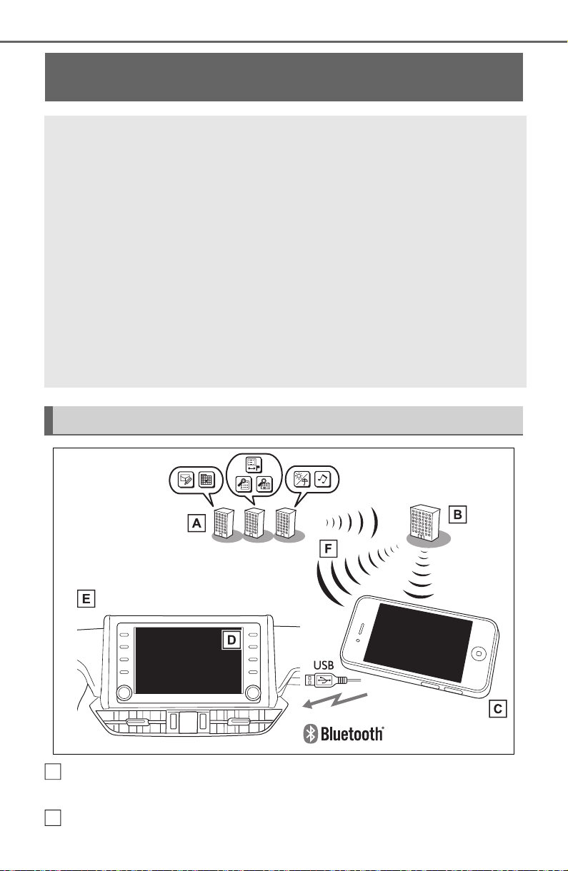
496
5-16. Connected Services overview
Content provider
Provides contents to the application server.
Application server
Type A: Function achieved by using a smartphone
or DCM
Of the functions included with Connected Services, the Toyota
Apps rely on the use of a smartphone or DCM.
Using a smartphone
• Toyota audio multimedia system enables applicable apps
installed on a smartphone to be displayed on and operated from
the screen via a Bluetooth
®
.
Via DCM
• Toyota audio multimedia system enables applicable apps
installed on the system to be displayed on and operated from the
screen.
A few settings must be performed before Toyota Apps can be
used. (P. 49 8 )
By using a smartphone or DCM
A
B

497
5-16. Connected Services overview
5
Audio
Provides applications to the system or a smartphone.
Smartphone
*
Using the Toyota mobile application, communication is relayed
between the system, application server and content provider.
Applications
Display usable content from the content providers on the screen
using the data connection of the connected smartphone or DCM.
System
Content received, via a smartphone or DCM, from content pro-
vider servers is displayed on the screen. The system is equipped
with an application player to run applications.
Via DCM
*
: For known compatible phones, refer to http://www.toyota.com/
connected-services in the United States.
The required operations to acti-
vate applications and connect a
smartphone to the system, and
the registration steps for the
Connected Services are
explained in this section.
■ Subscription
Services requiring a separate
contract can also be used.
*
*
: For details, refer to
http://www.toyota.com/
connected-services
or call 1-800-331-4331 in the
United States.
■ Availability of function
Toyota Apps is available in the
contiguous United States,
Washington D.C. and Alaska.
● Data usage fees may apply while
using Toyota Apps. Confirm data
usage fees before using this func-
tion.
● For details regarding operation of
the Toyota Apps, refer to
http://www.toyota.com/
connected-services
in the United States.
● These functions are not made
available in some countries or
areas. Availability of functions of
the Toyota Apps is dependent on
network reception level.
■ Initializing personal data
The personal data used in appli-
cations can be reset. (P.417)
The following personal data
can be deleted and returned
to their default settings:
• Downloaded contents
• Radio stations that were listened
to
● Once initialized, the data and set-
tings will be erased. Pay much
attention when initializing the data.
C
D
E
F
Before using the function

498
5-16. Connected Services overview
■ Settings required to use
Toyota mobile application
Perform the settings in the fol-
lowing order.
1 Download the Toyota mobile
application to your smart-
phone.
2 Open the Toyota mobile
application on your smart
phone and follow instruc-
tions. Bluetooth
®
Pairing is
required.
In order to use Toyota mobile appli-
cation, the following must first be
performed:
Register a Bluetooth
®
phone
with the hands-free system.
(P.390)
● Applications can only be used
when the Toyota mobile applica-
tion has been downloaded to your
smartphone, and the application is
running.
● Toyota mobile application opera-
tional procedures can also be con-
firmed by visiting
http://www.toyota.com/
connected-services
in the United States.
● If a Toyota mobile application is
used while iPod audio/video is
being played back, system opera-
tion may become unstable.
*
: Vehicles equipped with DCM
■ Subscription
After you have signed the
Telematics Subscription Ser-
vice Agreement and are
enrolled, you can begin
receiving services. A variety
of subscription terms are
available. Contact your Toyota
Preparation before using
Toyota mobile application
Type B: Function
achieved by using
DCM and the system
*
The functionality of Wi-Fi
®
Hotspot is made possible
through the shared work of
the DCM and the system.
These are subscription-
based telematics services
that use Global Positioning
System (GPS) data and
embedded cellular technol-
ogy to provide safety and
security as well as conve-
nience features.
These services are available
by subscription on select,
telematics hardware-
equipped vehicles and sup-
ported by the Toyota
response center, which
operates 24 hours a day, 7
days a week.
For details about Wi-Fi
®
Hotspot:P. 40 2
Before using the function

499
5-16. Connected Services overview
5
Audio
dealer, or call 1-800-331-4331
in the United States, for fur-
ther subscription details.
(P.497)
■ Availability of functions
Wi-Fi
®
Hotspot is available in
the contiguous United States,
Washington D.C. and Alaska.
*
: Vehicles equipped with DCM
● Free/Open Source Software Infor-
mation
This product contains Free/Open
Source Software (FOSS).
The license information and/or the
source code of such FOSS can be
found at the following URL.
http://opensource.lge.com
● Exposure to radio frequency sig-
nals:
The Toyota audio multimedia sys-
tem installed in your vehicle
includes a low power radio trans-
mitter and receiver. The system
receives and also sends out radio
frequency (RF) signals.
● In August 1996, the Federal Com-
munications Commission (FCC)
adopted RF exposure guidelines
with safety levels for mobile wire-
less phones. Those guidelines are
consistent with the safety stan-
dards previously set by both U.S.
and international standards bod-
ies.
• ANSI (American National Stan-
dards Institute) C95.1 [1992]
• NCRP (National Council on Radi-
ation Protection and Measure-
ment) Report 86 [1986]
• ICNIRP (International Commis-
sion on Non-Ionizing Radiation
Protection) [1996]
● These standards are based on
comprehensive and periodic eval-
uations of the relevant scientific lit-
erature. Over 120 scientists,
engineers, and physicians from
Type C: Function
achieved by using
DCM
*
The functionality of Safety
Connect is made possible
by the use of a DCM.
For details, (P. 65 )

500
5-16. Connected Services overview
universities, government health
agencies, and industry reviewed
the available body of research to
develop the ANSI Standard
(C95.1).
● The design of Toyota audio multi-
media system complies with the
FCC guidelines in addition to
those standards.
● Contact with the Toyota response
center is dependent upon the
telematics device being in opera-
tive condition, cellular connection
availability and GPS satellite sig-
nal reception, which can limit the
ability to reach the Toyota
response center or receive sup-
port. Enrollment and Telematics
Subscription Service Agreement
required. A variety of subscription
terms are available; charges vary
by subscription term selected.
● The Toyota response center offers
support in multiple languages.
● Select Safety Connect-sub-
scribed vehicles are capable of
communicating vehicle informa-
tion. Please see the terms and
conditions for additional details.
Owners who do not wish to have
their vehicle transmit this informa-
tion can opt out at the time of
enrollment or by calling 1-800-
331-4331 in the United States,
and following the prompts for
Safety Connect.
● For further details about the ser-
vice, contact your Toyota dealer.
● Toyota audio multimedia are not
subject to section 255 of the Tele-
communications Act and the sys-
tem is not TTY compatible.

501
5-16. Connected Services overview
5
Audio
● Certification
For vehicles sold in the U.S.A.
502
5-16. Connected Services overview
*
: Vehicles equipped with remote
connect only
Remote Connect is a service
that lets you view and remotely
control certain aspects of your
vehicle.
■ Subscription
After you sign the Telematics
Subscription Service Agree-
ment (see the Safety Connect
section P.65), download the
Toyota App from your smart-
phone app store, and register
within the app (or enroll and
complete registration at the
dealer), you can begin using
these services.
A variety of subscription terms
are available. Contact your
Toyota dealer, or call 1-800-
331-4331 for further subscrip-
tion details.
■ Availability of function
Remote Connect is available
in the contiguous United
States, Washington D.C. and
Alaska.
● Availability of functions of the
Remote Connect is dependent on
network reception level.
● Remote Connect should only be
used by authorized users.
● Laws in some communities may
require that the vehicle be within
view of the user when operating
Remote Connect.
In some states, use of Remote
Connect may violate state or local
laws. Before using Remote Con-
nect, check your state and local
laws.
● Any malfunction of the vehicle
should be repaired by your Toyota
dealer.
● Remote Connect is designed to
work at temperatures above
approximately -22 °F (-30 °C).
This specification is related to the
Remote Connect operation, but is
dependent on the vehicle’s oper-
ating temperature range which
may be different.
● Content is subject to change with-
out notice.
● Additional information can be
found at http://www.toyota.com/
connected-services in the United
States.
Type D: Function
achieved by using
DCM and a smart-
phone
The functionality of Remote
Connect and Service Con-
nect are made possible by
the use of a DCM and a
smartphone.
For details about these ser-
vices, refer to
http://www.toyota.com/
connected-services.
Remote Connect
*
WARNING
● Operating Remote Connect
incorrectly may lead to unfore-
seen accidents or malfunctions.
Check the vehicle condition and
assume full responsibility before
using.

503
5-16. Connected Services overview
5
Audio
Service Connect uses DCM to
collect and transmit vehicle data
that allows Toyota to provide:
Vehicle Health Report (VHR)
(Safety Recalls, Service Cam-
paigns, Current Vehicle
Alerts, Required Mainte-
nance, and Vehicle Condition
Status)
Maintenance Notifications
Vehicle Alert Notifications
■ Availability of function
Service Connect is available
in the contiguous United
States, Washington D.C. and
Alaska.
● Availability of functions of the Ser-
vice Connect is dependent on net-
work reception level.
Service Connect
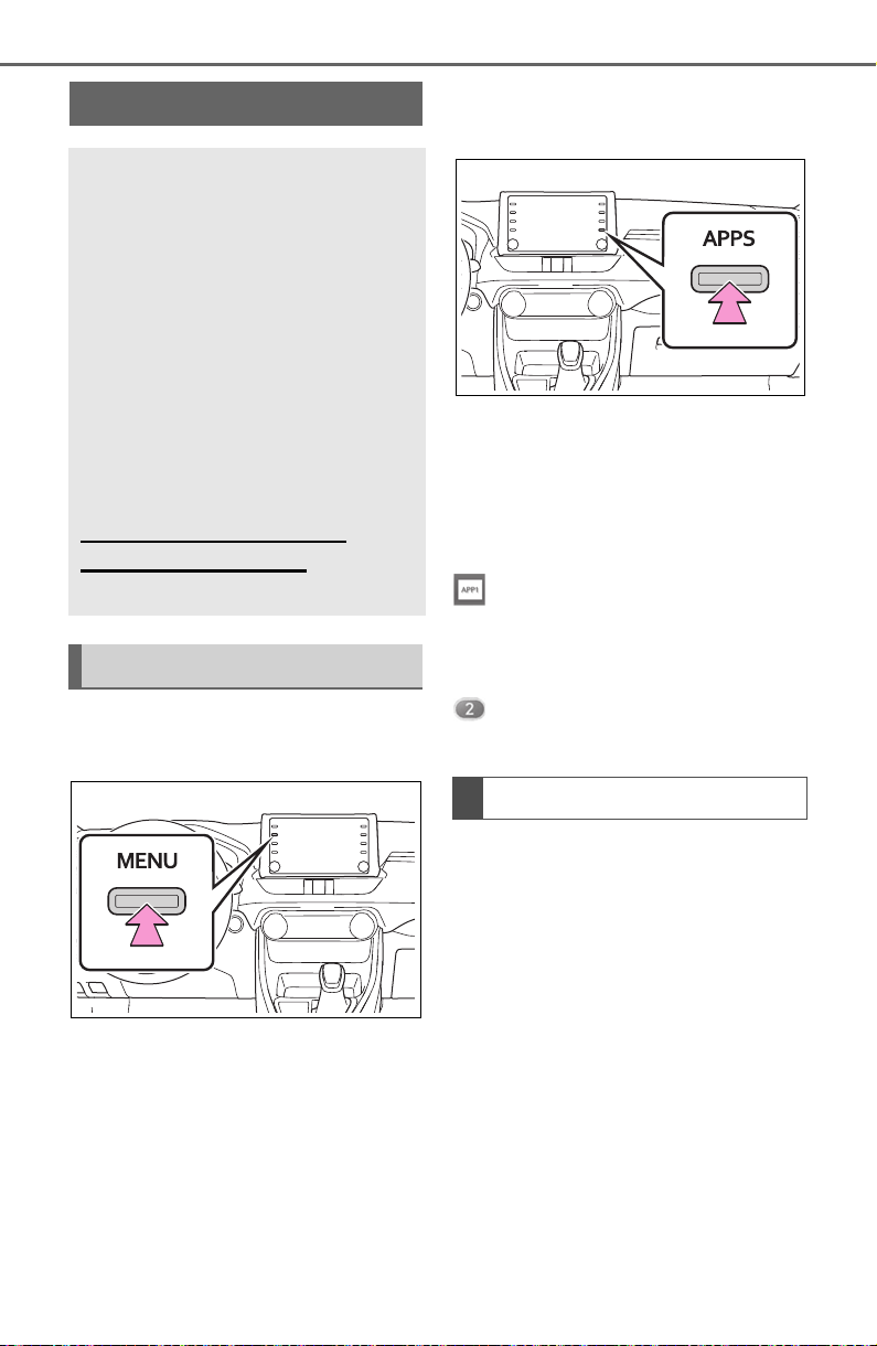
504
5-17. Connected Services operation
5-17.Connected Se rvices operation
From the “MENU” button
1 Press the “MENU” button.
2 Select “Apps”.
3 Follow the steps in “From the
“APPS” button” from step 2.
(P.504)
From the “APPS” button
1 Press the “APPS” button.
If a specific application screen
is displayed, press the
“APPS” button again.
2 Select the desired application
screen button.
: Select to activate an applica-
tion.
“Update”: Select to update the
applications. (P.504)
: Displays the number of new
notifications for the application
When the Toyota Apps is acti-
vated, an application may need
to be updated. To update an
application, it is necessary to
download update data and
install it.
■ Downloading update
If an update is available,
“Update” can be selected.
1 Select “Update” on the appli-
cation screen. (P.504)
2 Check that downloading
starts.
Toyota Apps
Toyota Apps is a function
that enables certain apps
installed on a smartphone
or the system to be dis-
played on and operated
from the system screen.
Before the Toyota Apps can
be used, some setup needs
to be performed. (P.498)
For details about the func-
tions and services provided
by each application, refer to
http://www.toyota.com/
connected-services
in the United States.
Using Toyota Apps
Updating an application

505
5-17. Connected Services operation
5
Audio
“Download in Background”: Select
to operate other functions while
downloading.
“Cancel”: Select to cancel updating.
3 Check that downloading is
complete.
“Later”: Select to install later. When
this screen button is selected, the
screen will return to the last dis-
played screen. To install the update
data: (P.5 05 )
“See Detail”: Select to display
detailed information on the update
data.
“Install”: Select to install the update
data. Follow the steps “Installing
the update data” from step 2.
(P.505)
■ Installing the update data
After the downloading is com-
plete, “Update” will be changed
to “Install”.
1 Select “Install” on the appli-
cation screen. (P.504)
2 Select “Continue”.
“Later”: Select to postpone the
installation of the update data and
go back to the previous screen.
3 Check that installing is
started.
“Install in Background”: Select to
operate other functions while
installing.
4 Select “OK” after the install-
ing is complete.
● The Toyota Apps cannot be oper-
ated while installing.
When problems occur with start-
ing the application player, a
message will appear on the
screen. Referring to the table
below, identify the problem and
take the suggested corrective
action.
“When it is safe and legal to
do so, please ensure your
Toyota mobile application is
running and logged in on your
phone.”
The Toyota mobile application can-
not be connected to Bluetooth
®
SPP.
Refer to
http://www.toyota.com/
connected-services
in the United States, to confirm if
the phone is Bluetooth
®
SPP com-
patible or not, and then activate the
Toyota mobile application.
“Installation failed, please try
again”
Installation can be attempted again
by changing to the application
screen and pressing the “Install”
switch.
“Application download error.
Please try again later.”
Downloading can be attempted
again by checking the communica-
tion status, changing to the applica-
tion screen and pressing the
“Download” switch again.
“Download error, some Toyota
mobile application functions
may not work as expected.
Please reinitiate the download
process.”
If a message appears on
the screen

506
5-17. Connected Services operation
The Toyota mobile application can-
not be connected to Bluetooth
®
SPP.
Refer to
http://www.toyota.com/
connected-services
in the United States, to confirm if
the phone is Bluetooth
®
SPP com-
patible or not, and then activate the
Toyota mobile application.
Please ensure your Toyota mobile
application is running and logged in
on your phone while vehicle is not
moving.
“To use the services, Toyota
mobile application needs to
be running on your phone.
For more information, please
visit toyota.com or call 1-800-
331-4331 in the United
States.”
The Toyota mobile application can-
not be connected to Bluetooth
®
SPP.
Refer to
http://www.toyota.com/
connected-services
in the United States, to confirm if
the phone is Bluetooth
®
SPP com-
patible or not, and then activate the
Toyota mobile application.
“Communication unsuccess-
ful. Please try again.”
Communication was disconnected.
After a few moments, retry the
operation.
A keyword can be entered to an
application by the software key-
board or voice recognition func-
tion. For details about the
functions and services provided
by each application, refer to
http://www.toyota.com/
connected-services
in the United States.
The keyboard layout can be
changed. (P.414)
1 Display the application
screen. (P.504)
2 Select the desired application
screen button.
3 Select the character entering
space.
4 Enter a search term, and
then select “OK”.
5 Entering characters will be
reflected on the character
entering space.
For details on operating the
keyboard: P.385
1 Display the application
screen. (P.504)
Entering keyword opera-
tion
Entering a keyword using
the software keyboard
Entering a keyword using
the voice recognition func-
tion

507
5-17. Connected Services operation
5
Audio
2 Select the desired application
screen button.
3 Press the talk switch.
(P.458)
4 Say the desired keyword.
Completion of the keyword
will be detected automatically.
5 Search results will be dis-
played on the screen.
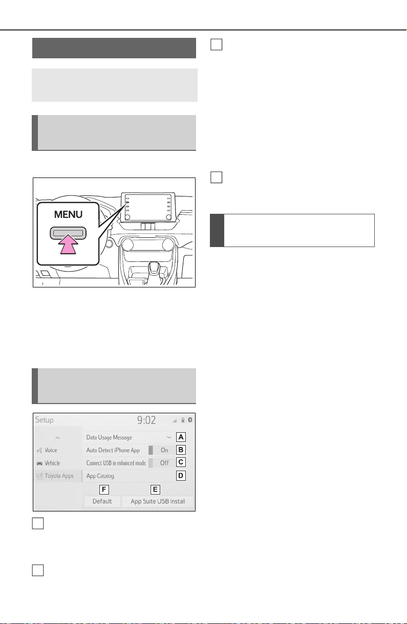
508
5-18. Setup
5-18.Setup
1 Press the “MENU” button.
2 Select “Setup”.
3 Select “Toyota Apps”.
4 Select the desired items to
be set.
Select to set the pop up
reminder for smartphone
data usage. (P.508)
Select to detect iPhone app
automatically on/off.
Select to turn on/off the
enhanced USB connection
mode.
• When an iPhone is connected
while this setting is “On”, commu-
nication with any devices con-
nected to the other USB port is
not possible. Also, depending on
the device, charging may not be
possible.
Select to reset all setup items
to default setting
The data usage notification pop-
up, which indicates that the sys-
tem will use an internet connec-
tion, can be enabled/disabled.
1 Display the Toyota Apps set-
tings screen. (P.508)
2 Select “Data Usage Mes-
sage”.
3 Change the setting as
desired.
Toyota Apps settings
Toyota Apps settings can be
changed.
Displaying the Toyota
Apps settings screen
Toyota Apps settings
screen
A
B
Data usage notification
pop-up settings
C
D

509
6
6
Interior features
Interior features
6-1. Using the air conditioning
system and defogger
Manual air conditioning sys-
tem............................ 510
Automatic air conditioning
system....................... 515
Heated steering wheel/seat
heaters/seat ventilators
.................................. 522
6-2. Using the interior lights
Interior lights list.......... 525
6-3. Using the storage features
List of storage features 528
Luggage compartment fea-
tures.......................... 532
6-4. Using the other interior
features
Other interior features. 537
Garage door opener.... 548
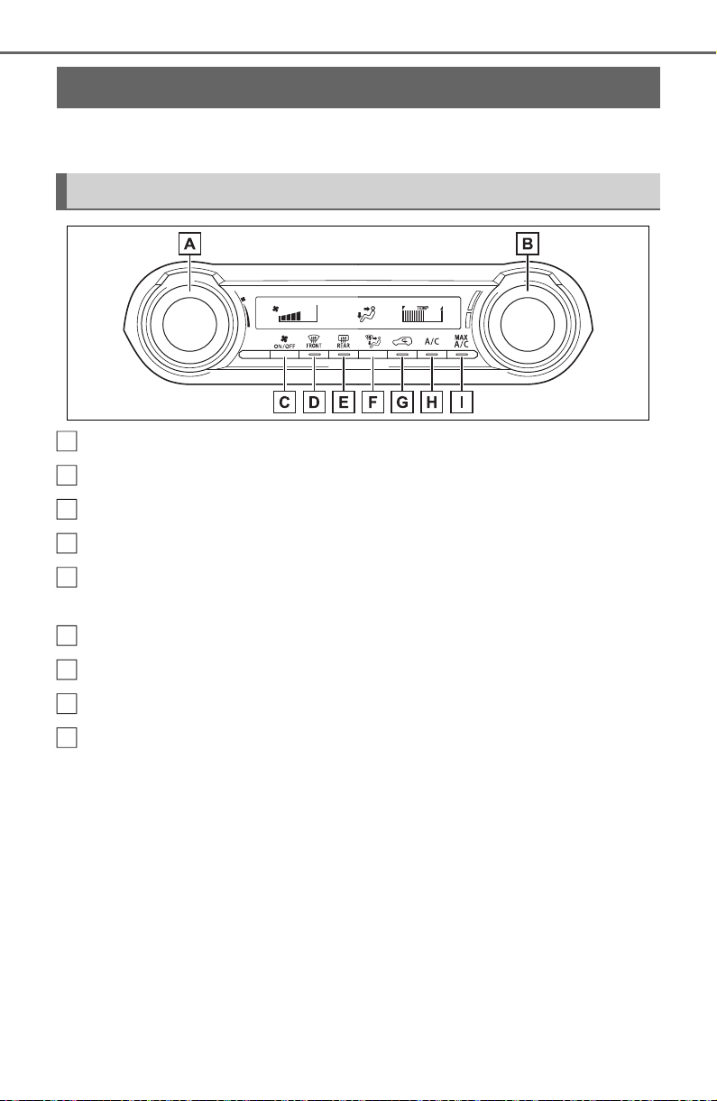
510
6-1. Using the air conditioning system and defogger
6-1.Using t he air conditioning s ystem and defogger
*
: If equipped
Fan speed control switch
Temperature control switch
On/off switch
Windshield defogger switch
Rear window defogger and outside rear view mirror defoggers
*
switch
Airflow mode control switch
Outside/recirculated air mode switch
“A/C” switch
“MAX A/C” switch
*
: If equipped
■ Adjusting the temperature
setting
To adjust the temperature set-
ting, turn the temperature con-
trol switch clockwise (warm) or
counterclockwise (cool).
If “A/C” switch is not pressed, the
system will blow ambient tempera-
ture air or heated air.
■ Fan speed setting
To adjust the fan speed, turn the
fan speed control switch clock-
wise (increase) or counterclock-
wise (decrease).
Pressing the on/off switch turns off
the fan.
When the fan is off, pressing the
on/off switch or turning the fan
speed control switch will turn on the
Manual air conditioning system
*
Air conditioning controls
A
B
C
D
E
F
G
H
I
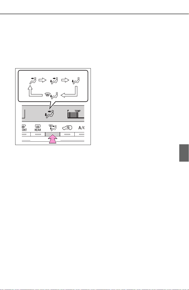
511
6-1. Using the air conditioning system and defogger
6
Interior features
fan.
■ Change the airflow mode
Press the airflow mode control
switch.
The airflow mode changes as fol-
lows each time the switch is
pressed.
1 Upper body
2 Upper body and feet
3 Feet
4 Feet and the windshield
defogger operates
■ Switching between outside
air and recirculated air
modes
Press the outside/recirculated
air mode switch.
The mode switches between
outside air mode and recircu-
lated air mode each time the
switch is operated.
When recirculated air mode is
selected, the indicator illuminates
on the outside/ recirculated air
mode switch.
■ Set cooling and dehumidifi-
cation function
Press the “A/C” switch.
When the function is on, the indica-
tor illuminates on the “A/C” switch.
■ Defogging the windshield
Defoggers are used to defog the
windshield and front side win-
dows.
Press the windshield defogger
switch.
Set the outside/recirculated air
mode switch to outside air mode if
the recirculated air mode is used.
To defog the windshield and the
side windows quickly, turn the air
flow and temperature up.
To return to the previous mode,
press the windshield defogger
switch again when the windshield is
defogged.
When the windshield defogger
switch is on, the indicator illumi-
nates on the windshield defogger
switch.
■ Defogging the rear window
and outside rear view mir-
rors (if equipped)
Defoggers are used to defog the
rear window, and to remove
raindrops, dew and frost from
the outside rear view mirrors (if
equipped).
Press the rear window defogger
and outside rear view mirror
defoggers switch.
When the rear window defogger
and outside rear view mirror defog-
11 22 33
44

512
6-1. Using the air conditioning system and defogger
gers switch is on, the indicator illu-
minates on the rear window
defogger and outside rear view mir-
ror defoggers switch.
The defoggers will automatically
turn off after a while.
■ For quick cooling
Press the “MAX A/C” switch.
The air conditioning will automati-
cally turn on.
At this time, the following will occur:
● The recirculated air mode will be
set
● The windshield defogger will turn
off
● The air flow mode will change to
the upper body mode
■ Operation of the air condition-
ing system in Eco drive mode
In Eco drive mode, the air condition-
ing system is controlled to prioritize
fuel efficiency by regulating the
engine speed and compressor oper-
ation to restrict the heating/cooling
capacity.
To improve air conditioning perfor-
mance, perform the following opera-
tions:
● Adjust the fan speed
● Adjust the temperature setting
● Turn off Eco drive mode (P.351)
■ Fogging up of the windows
● The windows will easily fog up
when the humidity in the vehicle is
high. Turning the “A/C” switch on
will dehumidify the air from the
outlets and defog the windshield
effectively.
● If you turn the “A/C” switch off, the
windows may fog up more easily.
● The windows may fog up if the
recirculated air mode is used.
■ When driving on dusty roads
Close all windows. If dust thrown up
by the vehicle is still drawn into the
vehicle after closing the windows, it
is recommended that the air intake
mode be set to outside air mode and
the fan speed to any setting except
off.
■ Outside/recirculated air mode
Setting to the recirculated air mode
temporarily is recommended in pre-
venting dirty air from entering the
vehicle interior and helping to cool
the vehicle when the outside air
temperature is high.
■ When the outside temperature
falls to nearly 32°F (0°C)
The dehumidification function may
not operate even when the “A/C”
switch is pressed.
■ Ventilation and air conditioning
odors
● To let fresh air in, set the air condi-
tioning system to the outside air
mode.
● During use, various odors from
inside and outside the vehicle may
enter into and accumulate in the
air conditioning system. This may
then cause odor to be emitted
from the vents.
● To reduce potential odors from
occurring:
It is recommended that the air
conditioning system be set to out-
side air mode prior to turning the
vehicle off.
● When parking, the system auto-
matically switches to outside air
mode to encourage better air cir-
culation throughout the vehicle,
helping to reduce odors that occur
when starting the vehicle.
■ Air conditioning system opera-
tions when the engine is
stopped due to the Stop & Start
system (vehicles with Stop &
Start system)
When the engine is stopped due to
the Stop & Start system operations,
the air conditioning cooling, heating
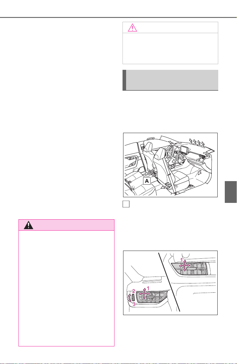
513
6-1. Using the air conditioning system and defogger
6
Interior features
and dehumidification functions turn
off and only ambient temperature air
is blown, and there is a possibility
that the blowing of ambient tem-
perature air will stop. To prevent the
air conditioning system from turning
off, press the Stop & Start cancel
switch to deactivate the system.
■ When the windshield is fogged
up and the engine is stopped
due to the Stop & Start system
(vehicles with Stop & Start sys-
tem)
Press the windshield defogger
switch to restart the engine and
defog the windshield.
If the windshield continuously fogs
up, press the Stop & Start cancel
switch and refrain from using the
Stop & Start system.
■ When an odor comes from the
air conditioning system while
the engine is stopped due to the
Stop & Start system (vehicles
with Stop & Start system)
Press the Stop & Start cancel switch
to restart the engine.
■ Air conditioning filter
P.599
■ Location of air outlets
The air outlets and air volume
change according to the
selected airflow mode.
If equipped
■ Adjusting the air flow direc-
tion and opening/closing
the air outlets
Front
1 Direct air flow to the left or
right, up or down.
2 Open the vent
WARNING
■ To prevent the windshield
from fogging up
Do not use the windshield defog-
ger switch during cool air opera-
tion in extremely humid weather.
The difference between the tem-
perature of the outside air and
that of the windshield can cause
the outer surface of the wind-
shield to fog up, blocking your
vision.
■ When the outside rear view
mirror defoggers are operat-
ing (if equipped)
Do not touch the rear view mirror
surfaces when the outside rear
view mirror defoggers are on.
NOTICE
■ To prevent battery discharge
Do not leave the air conditioning
system on longer than necessary
when the engine is off.
Air outlet layout and oper-
ations
A
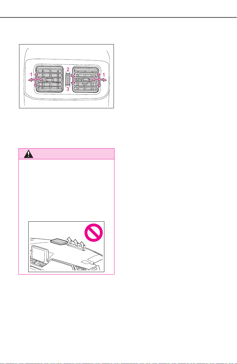
514
6-1. Using the air conditioning system and defogger
3 Close the vent
Rear (if equipped)
1 Direct air flow to the left or
right, up or down
2 Open the vent
3 Close the vent
WARNING
■ To not interrupt the wind-
shield defogger from operat-
ing
Do not place anything on the
instrument panel which may cover
the air outlets. Otherwise, air flow
may be obstructed, preventing the
windshield defoggers from defog-
ging.
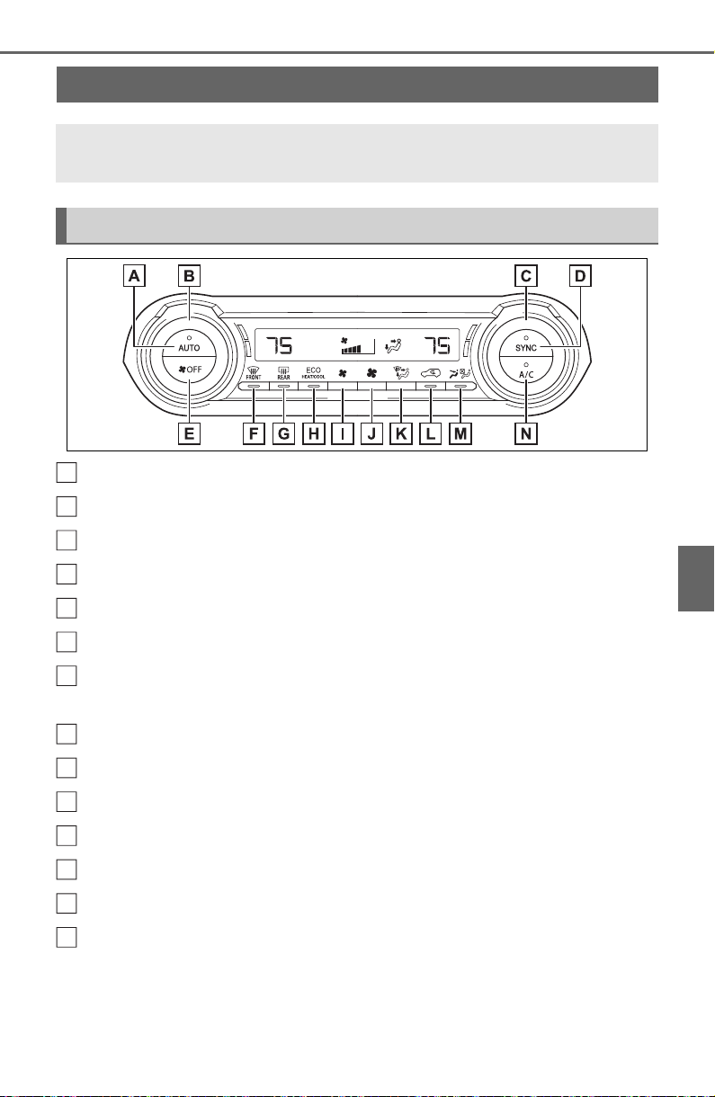
515
6-1. Using the air conditioning system and defogger
6
Interior features
Automatic mode switch
Left-hand side temperature control knob
Right-hand side temperature control knob
“SYNC” switch
“OFF” switch
Windshield defogger switch
Rear window defogger and outside rear view mirror defoggers
switch
Eco air conditioning mode switch
Fan speed decrease switch
Fan speed increase switch
Airflow mode control switch
Outside/recirculated air mode switch
S-FLOW mode switch
“A/C” switch
■ Adjusting the temperature
setting
Turn driver’s side temperature
control dial clockwise to
increases the temperature and
turn the dial counterclockwise to
Automatic air conditioning system
Air outlets and fan speed are automatically adjusted accord-
ing to the temperature setting.
Air conditioning controls
A
B
C
D
E
F
G
H
I
J
K
L
M
N
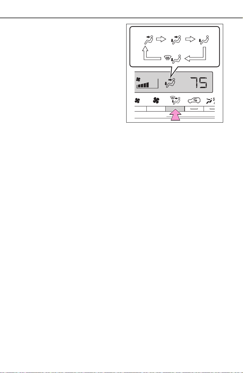
516
6-1. Using the air conditioning system and defogger
decreases the temperature.
The air conditioning system
switches between individual and
simultaneous modes each time the
“SYNC” switch is pressed.
Simultaneous mode (the indicator
on the “SYNC” switch is on):
The driver’s side temperature con-
trol dial can be used to adjust the
temperature for the driver’s and
passenger’s side. At this time,
operate the passenger’s side tem-
perature control dial to enter indi-
vidual mode.
Individual mode (the indicator on
the “SYNC” switch is off):
The temperature for the driver’s
and passenger’s side can be
adjusted separately.
■ Setting the fan speed
Press the fan speed increase
switch to increase the fan speed
and the fan speed decrease
switch to decrease the fan
speed.
Pressing the “OFF” switch to turns
off the fan.
■ Change the airflow mode
Press the airflow mode control
switch.
The airflow mode changes as fol-
lows each time the switch is
pressed.
1 Upper body
2 Upper body and feet
3 Feet
4 Feet and the windshield
defogger operates
■ Switching between outside
air and recirculated air
modes
Press the outside/recirculated
air mode switch.
The mode switches between out-
side air mode and recirculated air
mode each time the switch is oper-
ated.
When recirculated air mode is
selected, the indicator illuminates
on the outside/ recirculated air
mode switch.
■ Set cooling and dehumidifi-
cation function
Press the “A/C” switch.
When the function is on, the indica-
tor illuminates on the “A/C” switch.
■ Eco air conditioning mode
The air conditioning is controlled
with low fuel consumption priori-
1
1
2
2
3
3
4
4

517
6-1. Using the air conditioning system and defogger
6
Interior features
tized such as reducing fan
speed, etc.
Press the eco air conditioning
mode switch.
When the eco air conditioning
mode is on, the indicator illumi-
nates on the eco air conditioning
mode switch.
■ Defogging the windshield
Defoggers are used to defog the
windshield and front side win-
dows.
Press the windshield defogger
switch.
Set the outside/recirculated air
mode switch to outside air mode if
the recirculated air mode is used. (It
may switch automatically.)
To defog the windshield and the
side windows quickly, turn the air
flow and temperature up.
To return to the previous mode,
press the windshield defogger
switch again when the windshield is
defogged.
When the windshield defogger
switch is on, the indicator illumi-
nates on the windshield defogger
switch.
■ Defogging the rear window
and outside rear view mir-
rors (if equipped)
Defoggers are used to defog the
rear window and to remove rain-
drops, dew and frost from the
outside rear view mirrors (if
equipped).
Press the rear window defogger
and outside rear view mirror
defoggers switch.
The defoggers will automatically
turn off after 15 minutes.
When the rear window defogger
and outside rear view mirror defog-
gers switch is on, the indicator illu-
minates on the rear window
defogger and outside rear view mir-
ror defoggers switch.
■ Fogging up of the windows
● The windows will easily fog up
when the humidity in the vehicle is
high. Turning “A/C” switch on will
dehumidify the air from the outlets
and defog the windshield effec-
tively.
● If you turn “A/C” switch off, the
windows may fog up more easily.
● The windows may fog up if the
recirculated air mode is used.
■ When driving on dusty roads
Close all windows. If dust thrown up
by the vehicle is still drawn into the
vehicle after closing the windows, it
is recommended that the air intake
mode be set to outside air mode and
the fan speed to any setting except
off.
■ Outside/recirculated air mode
● Setting to the recirculated air
mode temporarily is recom-
mended in preventing dirty air
from entering the vehicle interior
and helping to cool the vehicle
when the outside air temperature
is high.
● Outside/recirculated air mode may
automatically switch depending on
the temperature setting or the
inside temperature.
■ Operation of the air condition-
ing system in Eco drive mode
● In Eco drive mode, the air condi-
tioning system is controlled as fol-
lows to prioritize fuel efficiency:
• Engine speed and compressor

518
6-1. Using the air conditioning system and defogger
operation controlled to restrict
heating/cooling capacity
• Fan speed restricted when auto-
matic mode is selected
● To improve air conditioning perfor-
mance, perform the following
operations:
• Adjust the fan speed
• Turn off Eco drive mode (P.351)
• Turn off Eco air conditioning mode
● When the driving mode is set to
Eco driving mode, the Eco air con-
ditioning mode will be turned on
automatically. Even in this case,
the Eco air conditioning mode can
be turned off by pressing the Eco
air conditioning mode switch.
■ When the outside temperature
falls to nearly 32°F (0°C)
The dehumidification function may
not operate even when “A/C” switch
is pressed.
■ Ventilation and air conditioning
odors
● To let fresh air in, set the air condi-
tioning system to the outside air
mode.
● During use, various odors from
inside and outside the vehicle may
enter into and accumulate in the
air conditioning system. This may
then cause odor to be emitted
from the vents.
● To reduce potential odors from
occurring:
• It is recommended that the air
conditioning system be set to out-
side air mode prior to turning the
vehicle off.
• The start timing of the blower may
be delayed for a short period of
time immediately after the air con-
ditioning system is started in auto-
matic mode.
● When parking, the system auto-
matically switches to outside air
mode to encourage better air cir-
culation throughout the vehicle,
helping to reduce odors that occur
when starting the vehicle.
■ Air conditioning system opera-
tions when the engine is
stopped due to the Stop & Start
system (vehicles with Stop &
Start system)
When the engine is stopped due to
Stop & Start system operations, the
automatic air conditioning cooling,
heating and dehumidification func-
tions turn off and the fan speed is
decreased according to the outside
temperature etc. or air blowing
stops. To stop the air conditioning
system from turning off, press the
Stop & Start cancel switch and
refrain from using the Stop & Start
system.
■ When the windshield is fogged
up and the engine is stopped
due to the Stop & Start system
(vehicles with Stop & Start sys-
tem)
Press the windshield defogger
switch to restart the engine and
defog the windshield.
If the windshield continuously fogs
up, press the Stop & Start cancel
switch and refrain from using the
Stop & Start system.
■ When an odor comes from the
air conditioning system while
the engine is stopped due to the
Stop & Start system (vehicles
with Stop & Start system)
Press the Stop & Start cancel switch
to restart the engine.
■ Air conditioning filter
P.599
■ Customization
Some functions can be customized.
(Customizable features: P.697)
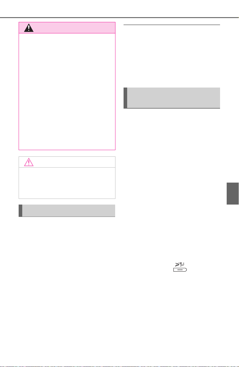
519
6-1. Using the air conditioning system and defogger
6
Interior features
1 Press the “AUTO” switch.
The dehumidification function
begins to operate. Air outlets and
fan speed are automatically
adjusted according to the tempera-
ture setting and humidity.
2 Adjust the temperature set-
ting.
3 To stop the operation, press-
the “OFF” switch.
If the fan speed setting or air
flow modes are operated, the
automatic mode indicator goes
off. However, automatic mode
for functions other than that
operated is maintained.
■ Using automatic mode
Fan speed is adjusted automati-
cally according to the temperature
setting and the ambient conditions.
Therefore, the fan may stop for a
while until warm or cool air is ready
to flow immediately after the auto-
matic mode switch is pressed.
This function automatically con-
trols the air conditioning airflow
so that priority is given to the
front seats. When the front pas-
senger seat is not occupied, air-
flow may switch to only the
driver’s seat. Unnecessary air
conditioning is suppressed, con-
tributing to increased fuel effi-
ciency.
Front seat concentrated airflow
mode operates in the following
situations.
No passengers are detected
in the rear seats
The windshield defogger is
not operating
While operating, illumi-
nates.
■ Manually turning front seat
concentrated airflow mode
on/off
In front seat concentrated air-
flow mode, directing airflow to
the front seats only and to all
seats can be switched via switch
WARNING
■ To prevent the windshield
from fogging up
Do not use the windshield defog-
ger switch during cool air opera-
tion in extremely humid weather.
The difference between the tem-
perature of the outside air and
that of the windshield can cause
the outer surface of the wind-
shield to fog up, blocking your
vision.
■ When the outside rear view
mirror defoggers are operat-
ing (if equipped)
Do not touch the rear view mirror
surfaces when the outside rear
view mirror defoggers are on.
NOTICE
■ To prevent battery discharge
Do not leave the air conditioning
system on longer than necessary
when the engine is off.
Using automatic mode
Front seat concentrated
airflow mode (S-FLOW)
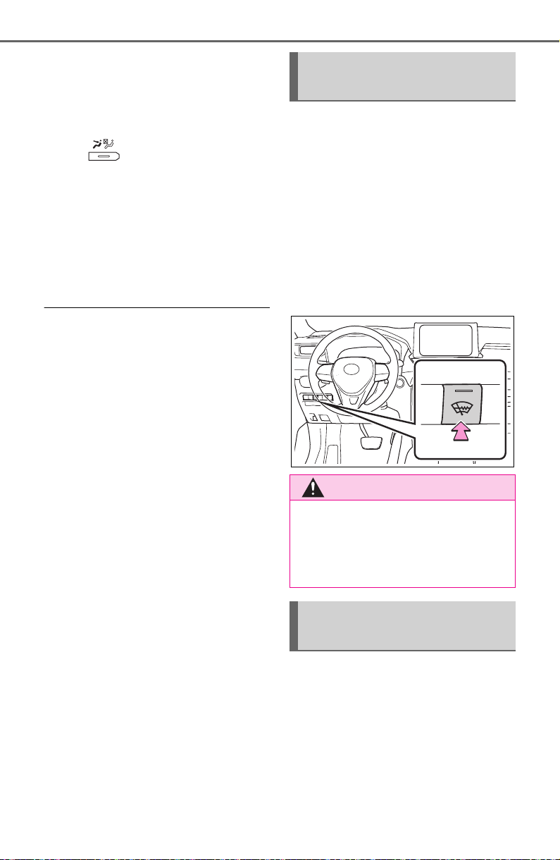
520
6-1. Using the air conditioning system and defogger
operation. When the mode has
been switched manually, auto-
matic airflow control stops oper-
ating.
Press on the air condition-
ing operation panel and switch
the airflow.
Indicator illuminated: Airflow
to the front seats only
Indicator off: Airflow to all the
seats
■ Operation of automatic airflow
control
● In order to maintain a comfortable
interior, airflow may be directed to
seats without passengers immedi-
ately after the engine is started
and at other times depending on
the outside temperature.
● After the engine is started, if pas-
sengers move around inside or
enter/exit the vehicle, the system
cannot accurately detect the pres-
ence of passengers and automatic
airflow control will not operate.
■ Operation of manual airflow
control
Even if the function is manually
switched to directing airflow to only
the front seats, when a rear seat is
occupied, it may automatically direct
airflow to all seats.
■ To return to automatic airflow
control
1 With the indicator off, turn the
engine switch off.
2 After 60 minutes or more elapse,
turn the engine switch to ON.
This feature is used to prevent
ice from building up on the wind-
shield and wiper blades.
Press the switch to turn the sys-
tem on/off.
The indicator comes on when the
system is on.
The windshield wiper de-icer will
automatically turn off after a period
of time.
■ Location of air outlets
The air outlets and air volume
change according to the
selected air flow mode.
Windshield wiper de-icer
(if equipped)
WARNING
■ To prevent burns
Do not touch the glass at lower
part of the windshield or to the
side of the front pillars when the
windshield wiper deicer is on.
Air outlet layout and oper-
ations
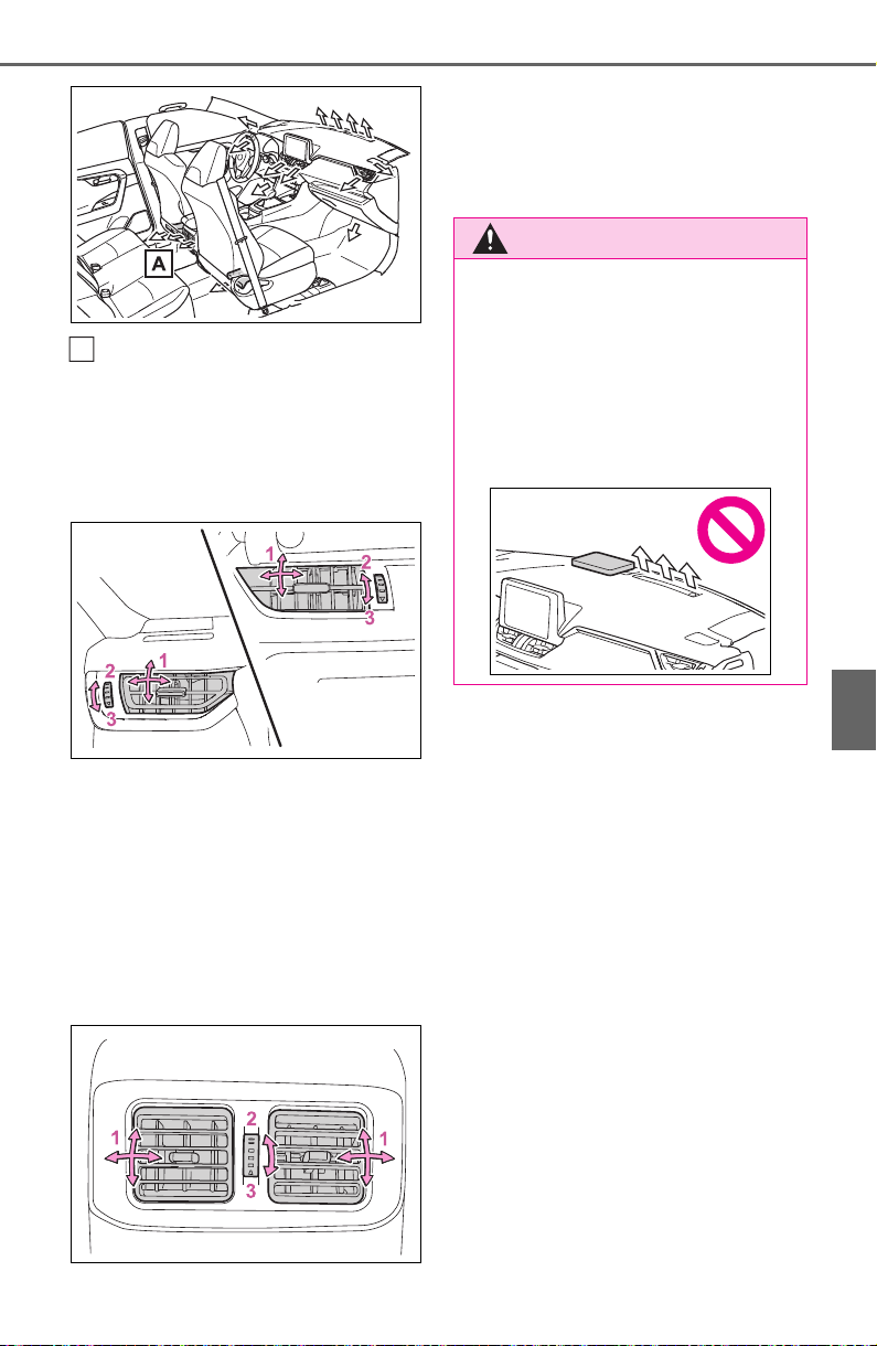
521
6-1. Using the air conditioning system and defogger
6
Interior features
If equipped
■ Adjusting the air flow direc-
tion and opening/closing
the air outlets
Front
1 Direct air flow to the left or
right, up or down
2 Open the vent
*
3 Close the vent
*
*
: If equipped (center air outlets
only)
Rear (if equipped)
1 Direct air flow to the left or
right, up or down
2 Open the vent
3 Close the vent
A
WARNING
■ To not interrupt the wind-
shield defogger from operat-
ing
Do not place anything on the
instrument panel which may cover
the air outlets. Otherwise, air flow
may be obstructed, preventing the
windshield defoggers from defog-
ging.
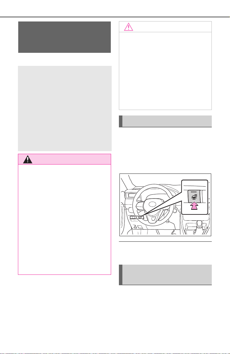
522
6-1. Using the air conditioning system and defogger
*
: If equipped
Turns the heated steering wheel
on/off
The indicator light comes on when
the heated steering wheel is oper-
ating.
■ Operation condition
The engine switch is in ON.
Front
Turns the seat heaters on/off
Heated steering
wheel
*
/seat heat-
ers
*
/seat ventilators
*
Heated steering wheel
Warm up the grip of the steer-
ing wheel
Seat heaters
Warm up the seat upholstery
Seat ventilators
Maintain good ventilation by
pulling air through the seat
upholstery
WARNING
■ To prevent minor burn inju-
ries
Care should be taken if anyone in
the following categories comes in
contact with the steering wheel or
seats when the heater is on:
● Babies, small children, the
elderly, the sick and the physi-
cally challenged
● Persons with sensitive skin
● Persons who are fatigued
● Persons who have taken alco-
hol or drugs that induce sleep
(sleeping drugs, cold remedies,
etc.)
NOTICE
■ To prevent damage to the
seat heaters and seat ventila-
tors
Do not put heavy objects that
have an uneven surface on the
seat and do not stick sharp
objects (needles, nails, etc.) into
the seat.
■ To prevent battery discharge
Do not use the functions when the
engine is not running.
Heated steering wheel
Operating the seat heat-
ers
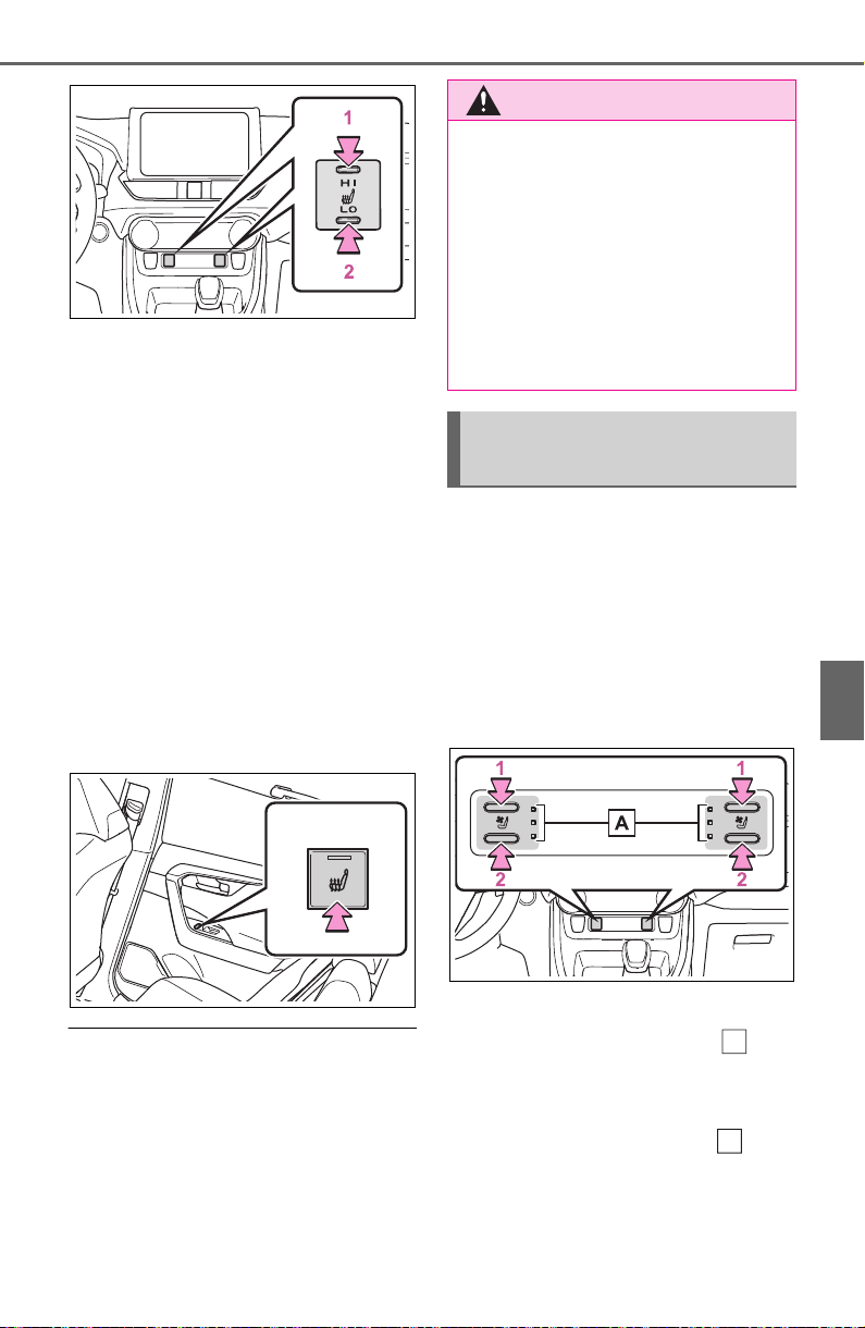
523
6-1. Using the air conditioning system and defogger
6
Interior features
1 High temperature
2 Low temperature
When the seat heater is on, the
indicator illuminates on the seat
heater switch.
When not in use, put the switch
in the neutral position. The indi-
cator will turn off.
Rear
Turns the seat heaters on/off
The indicator light comes on
when the seat heater is operat-
ing.
■ Operation condition
The engine switch is in ON.
Turns the seat heaters and ven-
tilators on/off
Each time the switch is pressed,
the operation condition changes as
follows.
Hi (3 segments lit) Mid (2 seg-
ments lit) Lo (1 segment lit)
Off
1 Turns the seat heater on
The level indicators (yellow)
light up during operation.
2 Turns the seat ventilator on
The level indicators (green)
light up during operation.
WARNING
■ To prevent causes of over-
heating and minor burn inju-
ries
Observe the following precautions
when using a seat heater:
● Do not cover the seat with a
blanket or cushion when using
the seat heater.
● Do not use seat heater more
than necessary.
Seat heaters and ventila-
tors
A
A

524
6-1. Using the air conditioning system and defogger
■ Operation condition
The engine switch is in ON.
■ Air conditioning system-linked
control mode
When a seat ventilator is set to Hi,
the fan speed of the seat ventilator
may increase according to the fan
speed of the air conditioning sys-
tem.
WARNING
■ To prevent causes of over-
heating and minor burn inju-
ries
Observe the following precautions
when using a seat heater:
● Do not cover the seat with a
blanket or cushion when using
the seat heater.
● Do not use seat heater more
than necessary.
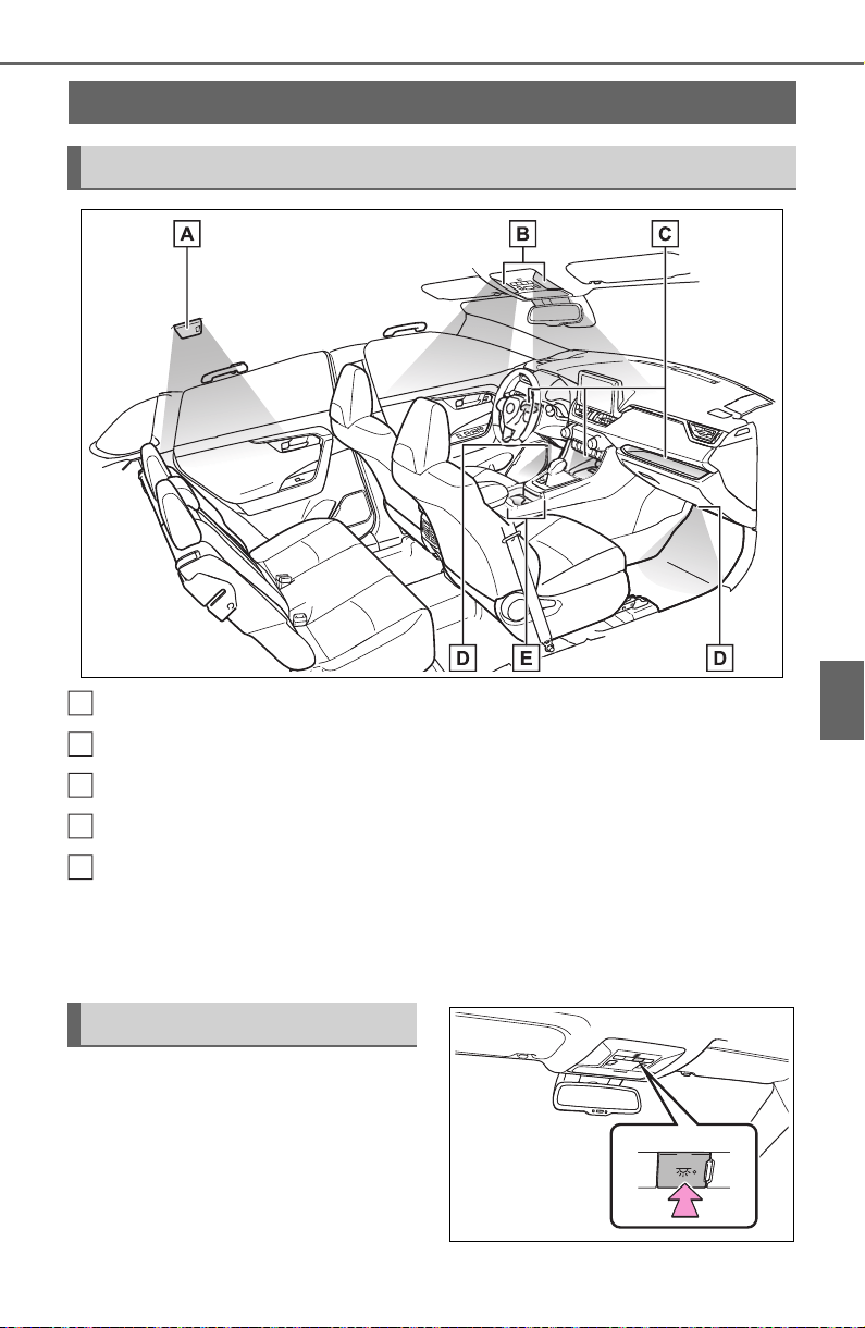
525
6-2. Using the interior lights
6
Interior features
6-2.Us ing the in terior lights
Rear interior light (P.526)
Front interior lights/personal lights (P.525, 526)
Open tray lights (if equipped)
*
Footwell lights (if equipped)
*
Front cup holder lights (if equipped)
*
*
: These lights turn on when a door is unlocked.
When the shift lever is in a position other than P, the brightness of these
lights will reduce intensity.
■ Front interior lights
Turns the lights on/off
Interior lights list
Location of the interior lights
A
B
C
D
E
Operating interior lights
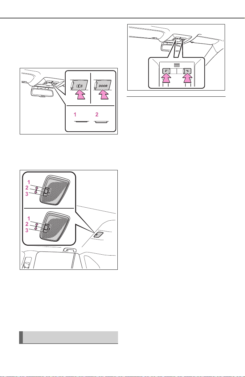
526
6-2. Using the interior lights
Turns the switch to the door
position (door linked)
When a door is opened while the
door position is on, the lights turn
on.
1 Turns the door position on
2 Turns the lights off
■ Rear interior light
1 Turns the light off
2 Turns the door position on
When a door is opened while the
door position is on, the light turns
on.
3 Turns the light on
Turns the lights on/off
■ Illuminated entry system (vehi-
cles with smart key system)
The lights automatically turn on/off
according to the engine switch
mode, the presence of the elec-
tronic key, whether the doors are
locked/unlocked, and whether the
doors are opened/closed.
■ To prevent the battery from
being discharged
If the interior lights remain on when
the engine switch is turned to OFF,
the lights will go off automatically
after 20 minutes.
■ The interior lights will turn on
automatically when
If any of the SRS airbags deploy
(inflate) or in the event of a strong
rear impact, the interior lights will
turn on automatically.
The interior lights will turn off auto-
matically after approximately 20
minutes.
The interior lights can be turned off
manually. However, in order to help
prevent further collisions, it is rec-
ommended that they be left on until
safety can be ensured.
(The interior lights may not turn on
automatically depending on the
force of the impact and conditions of
the collision.)
■ Customization
Setting (e.g. the time elapsed before
the lights turn off) can be changed.
(Customizable features: P.698)
Operating personal lights

527
6-2. Using the interior lights
6
Interior features
NOTICE
■ To prevent battery discharge
Do not leave the lights on longer
than necessary when the engine
is not running.
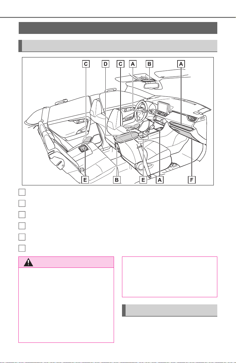
528
6-3. Using the storage features
6-3.Using the storage features
Open tray (P.531)
Auxiliary boxes (P.530)
Bottle holders (P. 53 0 )
Console box (P.529)
Cup holders (P.529)
Glove box (P.528)
Pull up the lever to open the
glove box.
List of storage features
Location of the storage features
A
B
C
D
E
F
WARNING
■ Items that should not be left
in the vehicle
Do not leave glasses, lighters or
spray cans in the storage spaces,
as this may cause the following
when cabin temperature becomes
high:
● Glasses may be deformed by
heat or cracked if they come
into contact with other stored
items.
● Lighters or spray cans may
explode. If they come into con-
tact with other stored items, the
lighter may catch fire or the
spray can may release gas,
causing a fire hazard.
Glove box
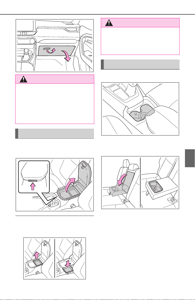
529
6-3. Using the storage features
6
Interior features
Lift the lid while pushing the but-
ton to release the lock.
■ Console box tray (if equipped)
The tray can be removed and stored
in the bottom of the console box.
Front
Rear
Pull the armrest down.
WARNING
■ Caution while driving
Keep the glove box closed. In the
event of sudden braking or sud-
den swerving, an accident may
occur due to an occupant being
struck by the open glove box or
the items stored inside.
Console box
WARNING
■ Caution while driving
Keep the console box closed.
Injuries may result in the event of
an accident or sudden braking.
Cup holders
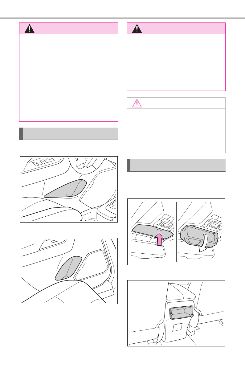
530
6-3. Using the storage features
Front
Rear
■ Bottle holders
● When storing a bottle, close the
cap.
● The bottle may not be stored
depending on its size or shape.
Type A
Push the lid.
Type B (if equipped)
WARNING
■ Items unsuitable for the cup
holders
Do not place anything other than
cups or beverage cans in the cup
holders.
Inappropriate items must not be
stored in the cup holders even if
the lid is closed.
Other items may be thrown out of
the holders in the event of an
accident or sudden braking and
cause injury. If possible, cover hot
drinks to prevent burns.
Bottle holders
WARNING
■ Items unsuitable for the bottle
holders
Do not place anything other than
a bottle in the bottle holders.
Other items may be thrown out of
the holders in the event of an
accident or sudden braking and
cause injury.
NOTICE
■ Items that should be not
stowed in the bottle holders
Do not place open bottles or glass
and paper cups containing liquid
in the bottle holders. The contents
may spill and glasses may break.
Auxiliary boxes
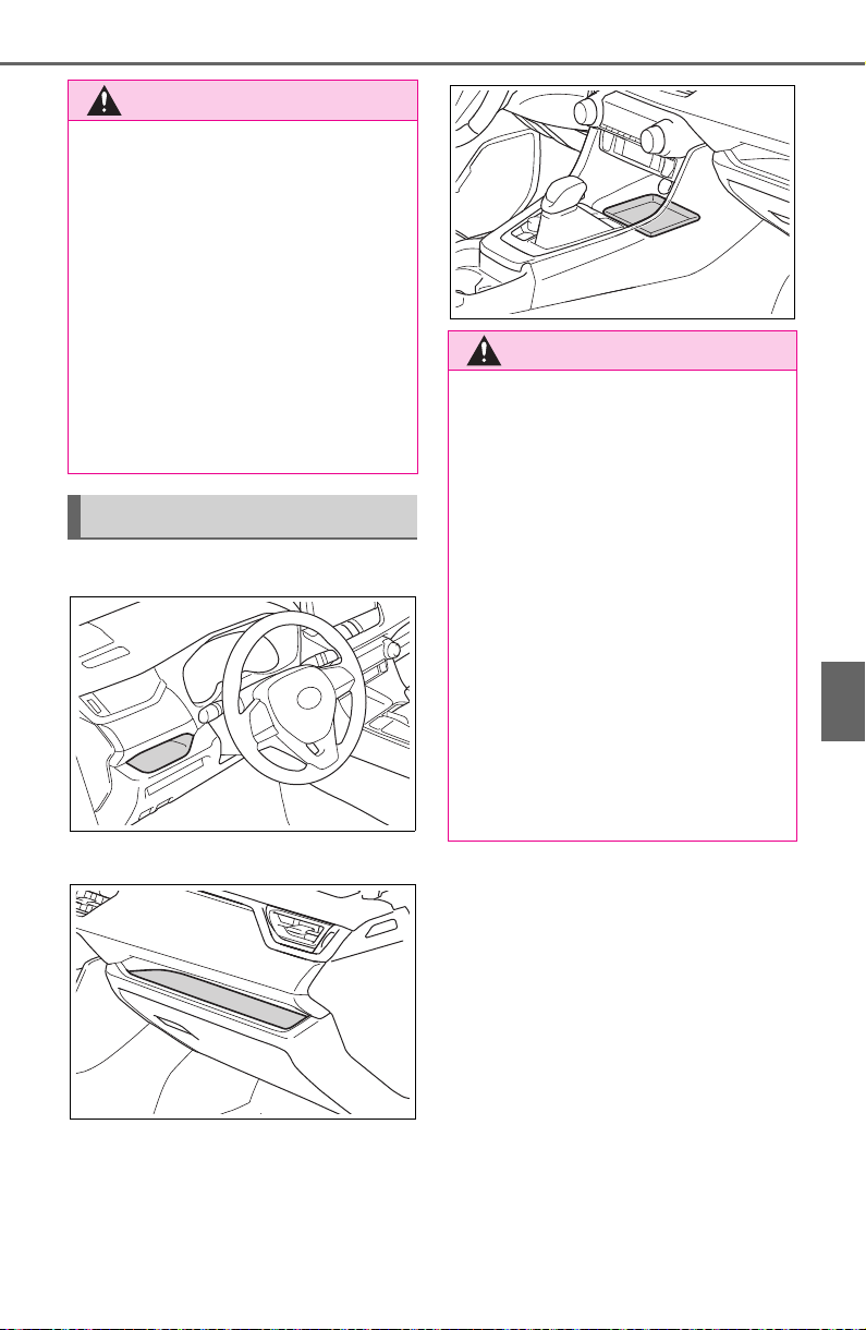
531
6-3. Using the storage features
6
Interior features
Driver’s side
Front passenger’s side
Front of console
Vehicles with wireless charger:
P. 5 40
WARNING
■ Caution while driving
Do not leave the auxiliary box
(type A) open while driving.
Injuries may result in the event of
an accident or sudden braking.
■ Items unsuitable for storing
(type A)
Do not store items heavier than
0.4 lb. (0.2 kg).
Doing so may cause the auxiliary
box to open and the items inside
may fall out, resulting in an acci-
dent.
Open tray
WARNING
■ Items unsuitable for the open
tray
Observe the following precautions
when putting items in the open
tray. Failure to do so may cause
items to be thrown out of the tray
in the event of sudden braking or
steering. In these cases, the items
may interfere with pedal operation
or cause driver distraction, result-
ing in an accident.
● Do not store items in the tray
that can easily shift or roll out.
● Do not stack items in the tray
higher than the tray’s edge.
● Do not put items in the tray that
may protrude over the tray’s
edge.
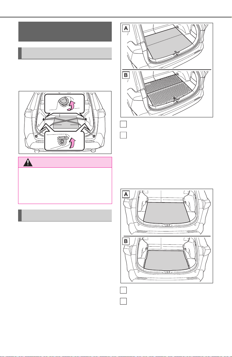
532
6-3. Using the storage features
Raise the hook to use.
The cargo hooks are provided for
securing loose items.
■ Flipping the deck board
upside down
The deck board can be flipped
upside down (resin side up)
depending on the situation.
Original position
Underside (resin side)
■ Changing the deck board
positions
Height of the deck board can be
changed by setting the deck
board under the floor.
Upper
Lower
Luggage compart-
ment features
Cargo hooks
WARNING
■ When cargo hooks are not in
use
To avoid injury, always return the
hooks to their stowed positions
when not in use.
Deck board
A
B
A
B
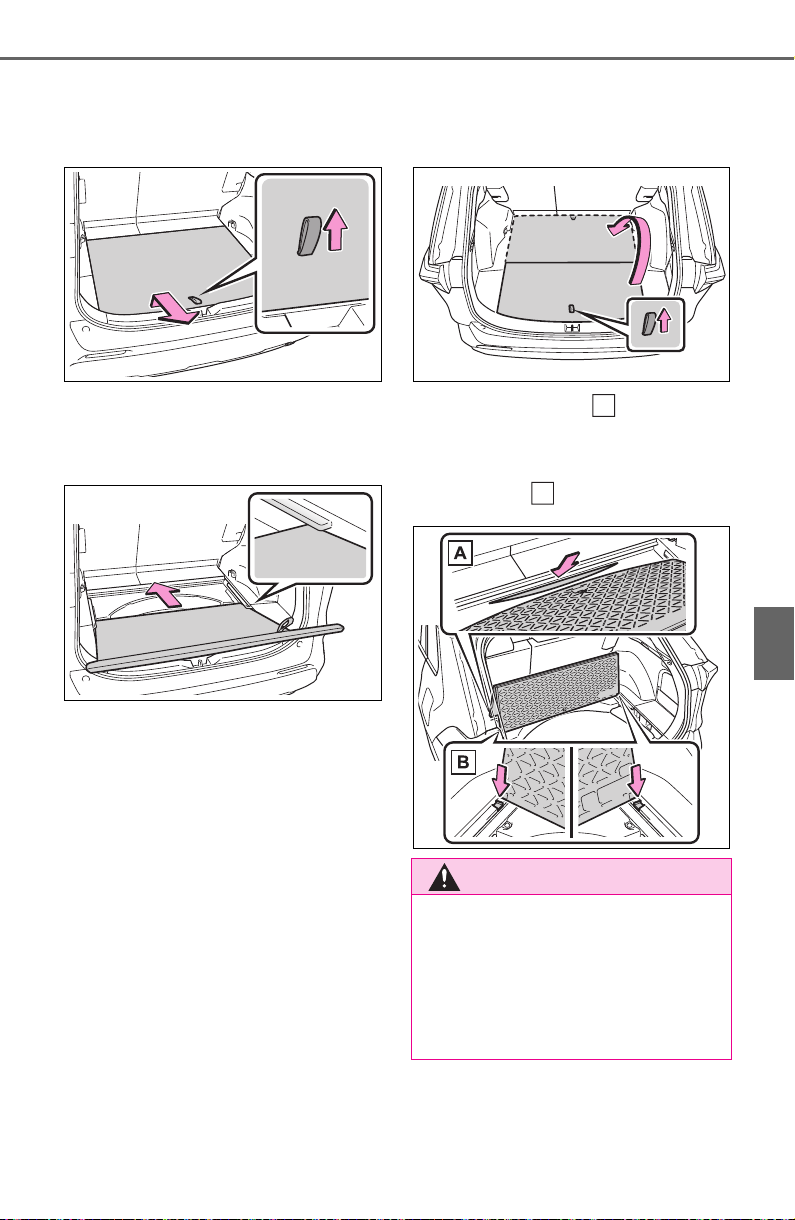
533
6-3. Using the storage features
6
Interior features
1 Pull up the tab to raise the
deck board and move it
toward you to remove.
2 Place the deck board through
the groove and move for-
ward.
■ Setting the deck board
upright
When taking out the tools, the
deck board can be set upright.
When the back surface (resin sur-
face) of the deck board is facing up,
flip it back to the original position.
1 Pull up the tab to raise the
deck board and fold it for-
ward.
2 Place the edge into the
groove, and with the deck
board in a standing state, put
the edge into the holes.
WARNING
■ When operating the deck
board
Do not place anything on the deck
board when operating the board.
Otherwise, your fingers may be
caught or an accident may result
causing injuries.
A
B
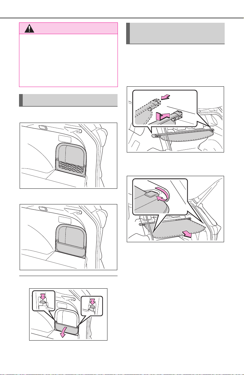
534
6-3. Using the storage features
Type A
Type B
■ Removing the partition plate
Disengage the claws
■ Installing the luggage cover
1 Compress the both ends of
the luggage cover and insert
into the recess to install.
2 Pull out the luggage cover
and hook it onto the anchors.
WARNING
■ Caution while driving
Keep the deck board closed.
In the event of sudden braking, an
accident may occur due to an
occupant being struck by the deck
board or the items stored under
the deck board.
Side auxiliary box
Luggage cover (if
equipped)
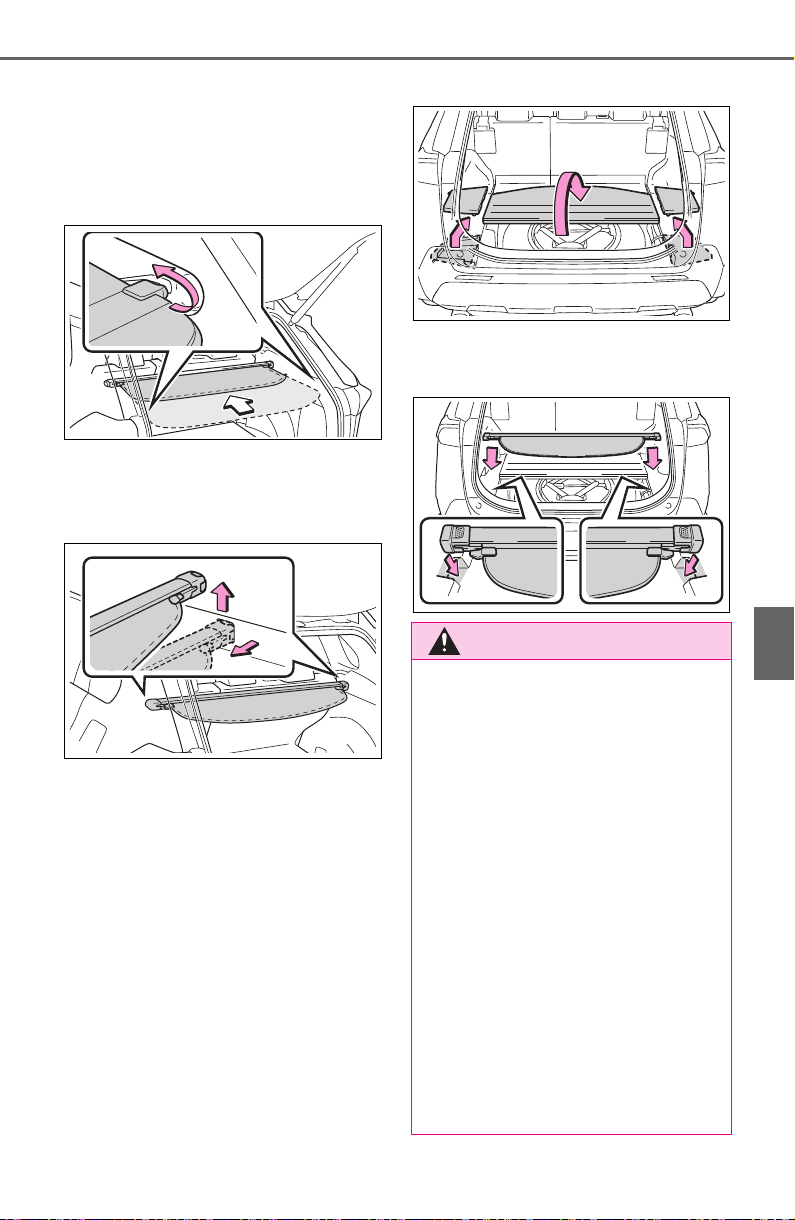
535
6-3. Using the storage features
6
Interior features
■ Removing the luggage
cover
1 Release the cover from the
left and right anchors and
allow it to retract.
2 Compress the end of the lug-
gage cover and lift the lug-
gage cover up.
■ Stowing the luggage cover
1 Open the rear deck board
and remove the side deck
covers.
When the back surface (resin sur-
face) of the deck board is facing up,
remove the deck board.
2 Place the both ends of the
luggage cover into the holder.
WARNING
■ Luggage cover
● When installing/stowing the lug-
gage cover, make sure that the
luggage cover is securely
installed/stowed. Failure to do
so may result in serious injury in
the event of sudden braking or a
collision.
● Do not place anything on the
luggage cover. In the event of
sudden braking or turning, the
item may go flying and strike an
occupant. This could lead to an
unexpected accident, resulting
in death or serious injury.
● Do not allow children to climb
on the luggage cover. Climbing
on the luggage cover could
result in damage to the luggage
cover, possibly causing death or
serious injury to the child.

536
6-3. Using the storage features
NOTICE
■ To prevent damage to the lug-
gage cover
Do not place anything on top of
the luggage cover. When rolling
up the luggage cover, objects may
be caught in the cover, damaging
the cover and generating noise.
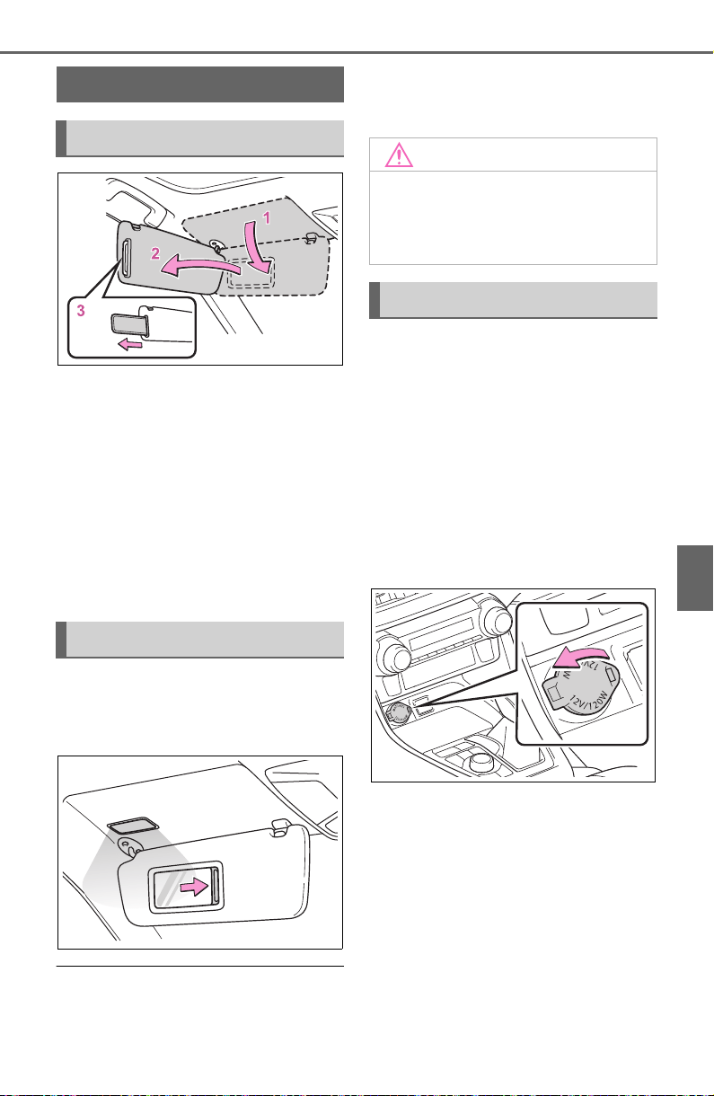
537
6-4. Using the other interior features
6
Interior features
6-4.Using the other interior features
1 To set the visor in the forward
position, flip it down.
2 To set the visor in the side
position, flip down, unhook,
and swing it to the side.
3 To use the side extender (if
equipped), place the visor in
the side position, then slide it
backward.
Slide the cover to open.
The light turns on when the cover is
opened.
■ Automatic light off to prevent
battery discharge
If the vanity lights remain on when
the engine switch is turned to OFF,
the lights will go off automatically
after 20 minutes.
The power outlet can be used
for the following components:
12 V: Accessories that run on
less than 10 A.
120 VAC: Accessories that use
less than 100 W.
■ 12 V
Front
Open the lid.
Console box (if equipped)
Open the console box and open
the lid.
Other interior features
Sun visors
Vanity mirrors
NOTICE
■ To prevent battery discharge
Do not leave the vanity lights on
for extended periods while the
engine is off.
Power outlet
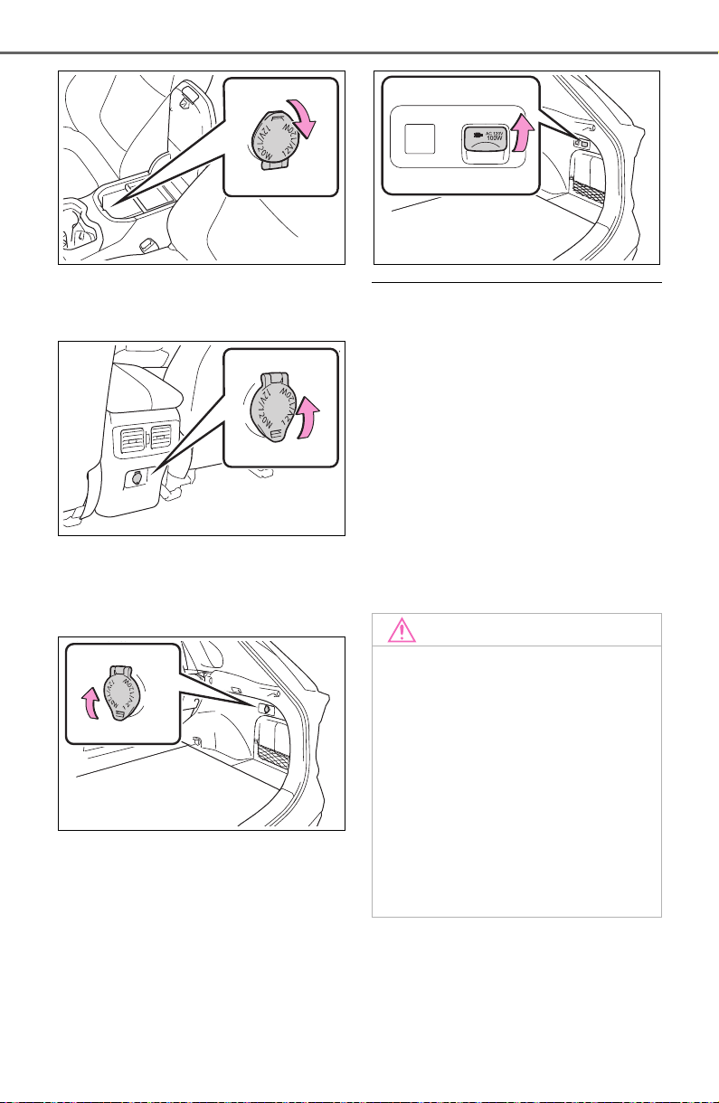
538
6-4. Using the other interior features
Rear (if equipped)
Open the lid.
Luggage compartment (if
equipped)
Open the lid.
■ 120 VAC (if equipped)
Open the lid.
■ The power outlet can be used
when
12 V
The engine switch is in ACC or ON.
120 VAC
The engine switch is in ON.
■ When turning the engine switch
off
Disconnect electrical devices with
charging functions, such as mobile
battery packs.
If such devices are left connected,
the engine switch may not be turned
off normally.
NOTICE
■ To avoid damaging the power
outlet
Close the power outlet lid when
the power outlet is not in use.
Foreign objects or liquids that
enter the power outlet may cause
a short circuit.
■ To prevent the fuse from
being blown
● 12 V
Do not use an accessory that
uses more than 12 V 10 A.
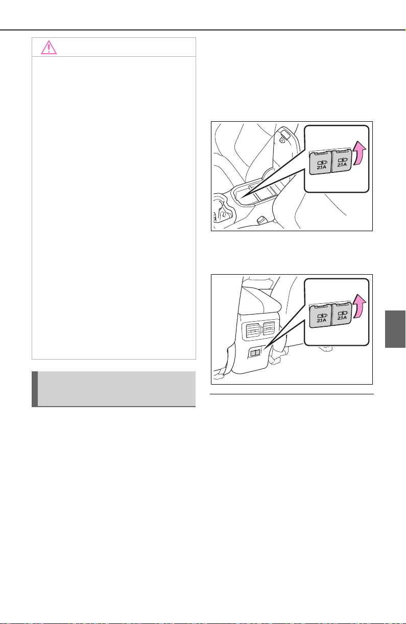
539
6-4. Using the other interior features
6
Interior features
The USB charging ports are
used to supply 2.1 A of electric-
ity at 5 V to external devices.
The USB charging ports are for
charging only. They are not
designed for data transfer or
other purposes.
Depending on the external
device, it may not charge prop-
erly. Refer to the manual
included with the device before
using a USB charging port.
■ Using the USB charging
ports
Console box
Open the console box and open
the lid.
Rear
Open the lid.
■ The USB charging ports can be
used when
The engine switch is in ACC or ON.
■ Situations in which the USB
charging ports may not operate
correctly
● If a device which consumes more
than 2.1 A at 5 V is connected
● If a device designed to communi-
cate with a personal computer,
such as a USB memory device, is
connected
● If the connected external device is
turned off (depending on device)
● If the temperature inside the vehi-
cle is high, such as after the vehi-
NOTICE
● 120 VAC
Do not use a 120 VAC appliance
that requires more than 100 W. If
a 120 VAC appliance that con-
sumes more than 100 W is used,
the protection circuit will cut the
power supply.
■ To prevent battery discharge
Do not use the power outlet lon-
ger than necessary when the
engine is not running.
■ Appliances that may not
operate properly (120 VAC)
The following 120 VAC appliances
may not operate properly even if
their power consumption is under
100 W.
● Appliances with high initial peak
wattage
● Measuring devices that pro-
cess precise data
● Other appliances that require an
extremely stable power supply
USB charging ports (if
equipped)

540
6-4. Using the other interior features
cle has been parked in the sun
■ About connected external
devices
Depending on the connected exter-
nal device, charging may occasion-
ally be suspended and then start
again. This is not a malfunction.
A portable device can be
charged by just placing Qi stan-
dard wireless charge compatible
portable devices according to
the Wireless Power Consortium,
such as smartphones and
mobile batteries, etc., on the
charge area.
This function cannot be used
with portable devices that are
larger than the charging area.
Also, depending on the portable
device, it may not operate as
normal. Please read the opera-
tion manual for portable devices
to be used.
■ The “Qi” symbol
The “Qi” symbol is a trademark
of the Wireless Power Consor-
tium.
NOTICE
■ To prevent damage to the
USB charging ports
● Do not insert foreign objects into
the ports.
● Do not spill water or other liq-
uids into the ports.
● When the USB charging ports
are not in use, close the lids. If a
foreign object or liquid enters a
port may cause a short circuit.
● Do not apply excessive force to
or impact the USB charging
ports.
● Do not disassemble or modify
the USB charging ports.
■ To prevent damage to exter-
nal devices
● Do not leave external devices in
the vehicle. The temperature
inside the vehicle may become
high, resulting in damage to an
external device.
● Do not push down on or apply
unnecessary force to an exter-
nal device or the cable of an
external device while it is con-
nected.
■ To prevent battery discharge
Do not use the USB charging
ports for a long period of time
when the engine is off.
Wireless charger (if
equipped)
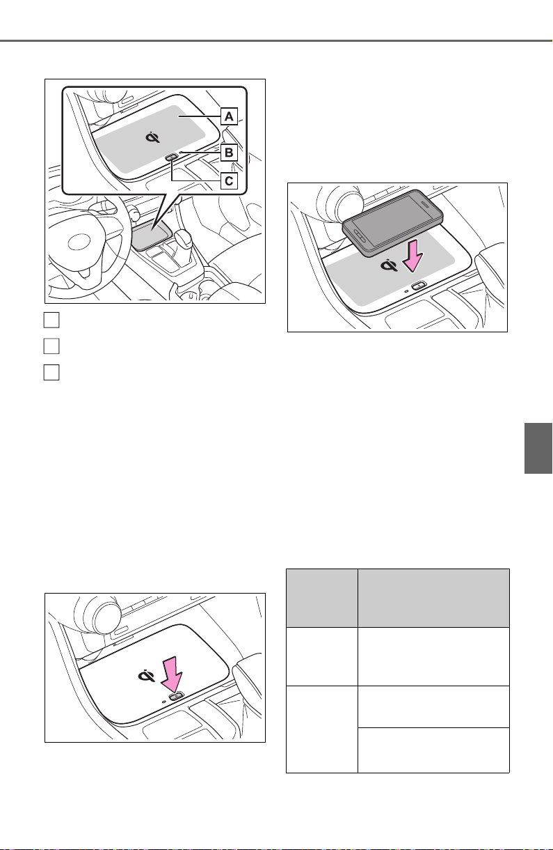
541
6-4. Using the other interior features
6
Interior features
■ Name for all parts
Charge area
Operation indicator light
Power supply switch
■ Using the wireless charger
1 Press the power supply
switch of the wireless char-
ger.
Switches on and off with each
press of the power supply switch.
When turned on, the operation indi-
cator light (green) comes on.
Even with the engine off, the on/off
state of the power supply switch is
memorized.
2 Place the charging side of
the portable device down.
When charging, the operation indi-
cator light (orange) comes on.
If charging is not occurring, try plac-
ing the portable device as close to
the center of the charging area as
possible.
When charging is complete, the
operation indicator light (green)
comes on.
■ Recharging function
When charging is complete
and after a fixed time in the
charge suspension state,
charging restarts.
When the portable device is
moved, charging is stopped
for a moment and then it
restarts.
■ Lighting conditions of oper-
ation indicator light
A
B
C
Operation
indicator
light
Conditions
Turning off
When the Wireless
charger power supply
is off
Green
(comes
on)
On Standby (charging
possible state)
When charging is com-
plete
*

542
6-4. Using the other interior features
*
: Depending on the portable
device, there are cases where the
operation indicator light will con-
tinue being lit up orange even
after the charging is complete.
When the operation indicator
light flashes
When an error occurs, the oper-
ation indicator light flashes an
orange color.
Handle the error based on the
following tables.
• Flashing repeatedly once
every second (Orange)
• Repeatedly flashes 3 times
continuously (Orange)
• Repeatedly flashes 4 times
continuously (Orange)
■ The wireless charger can be
operated when
The engine switch is in ACC or ON.
■ Usable portable devices
Qi standard wireless charge stan-
dard can be used on compatible
devices.
However, not all Qi standard
devices and compatibility are guar-
anteed.
Starting with mobile phones and
smartphones, it is aimed for low
power electrically supplied portable
devices of no more than 5W.
Orange
(comes
on)
When placing the por-
table device on the
charging area (detect-
ing the portable device)
Charging
Suspected
causes
Handling method
Vehicle to char-
ger communica-
tion failure.
Contact your
Toyota dealer.
Operation
indicator
light
Conditions
Suspected
causes
Handling method
A foreign sub-
stance is
between the por-
table device and
charge area.
Remove the for-
eign substance
from between
portable device
and the charge
area.
The portable
device is out of
sync due to the
device being
shifted from the
center of the
charge area.
Place the porta-
ble device near
the center of the
charge area.
Suspected
causes
Handling method
Temperature ris-
ing within the
wireless charger.
Stop charging at
once and start
charging again
after for a while.

543
6-4. Using the other interior features
6
Interior features
■ When covers and accessories
are attached to portable devices
Do not charge in situations where
cover and accessories not able to
handle Qi are attached to the porta-
ble device. Depending on the type
of cover and accessory, it may not
be possible to charge. When
charging is not performed even with
the portable device placed on the
charge area, remove the cover and
accessories.
■ While charging, noise enters
the AM radio
Turn off the wireless charger and
confirm that the noise has
decreased. If the noise decreases,
continuously pushing the power
supply switch of the wireless char-
ger for 2 seconds, the frequency of
the charger can be changed and the
noise can be reduced.Also, on that
occasion, the operation indicator
light will flash orange 2 times.
■ Important points of the wire-
less charger
● If the electronic key cannot be
detected within the vehicle inte-
rior, charging cannot be done.
When the door is opened and
closed, charging may be tempo-
rarily suspended.
● When charging, the wireless
charging device and portable
device will get warmer, however
this is not a malfunction.
When a portable device gets
warm while charging, charging
may stop due to the protection
function on the portable device
side. In this case, when the tem-
perature of the portable device
drops significantly, charge again.
■ Operation sounds
When the power supply is turned
on, while searching for the portable
device a sound will be produced,
however this is not a malfunction.
■ Certification for the wireless charger

544
6-4. Using the other interior features

545
6-4. Using the other interior features
6
Interior features

546
6-4. Using the other interior features
WARNING
■ Caution while driving
When charging a portable device,
for safety reasons, the driver
should not operate the main part
of the portable device while driv-
ing.
■ Caution regarding interfer-
ence with electronic devices
People with implantable cardiac
pacemakers, cardiac resynchroni-
zation therapy-pacemakers or
implantable cardioverter defi-
brillators, as well as any other
electrical medical device, should
consult their physician about the
usage of the wireless charger.
The operations of the wireless
charger may have an affect on
medical devices.
■ To prevent damage or burns
Observe the following precau-
tions.
Failure to do so may result in a
possibility of equipment failure
and damage, catch fire, burns due
to overheat.
● Do not insert any metallic
objects between the charging
area and the portable device
while charging
● Do not attach stickers, metallic
objects, etc., to the charger area
or portable device
● Do not cover with cloth, etc.,
and charge
● Do not charge portable devices
other than designated
● Do not attempt to dismantle for
disassembly or modifications
● Do not hit or apply a strong
force
NOTICE
■ Conditions in which the func-
tion may not operate cor-
rectly
In the following conditions, it may
not operate correctly
● The portable device is fully
charged
● There is foreign matter between
the charge area and portable
device
● The temperature of the portable
device gets higher from
charging
● The charging surface of the por-
table device is facing up
● The placement of the portable
device is out of alignment with
the charge area
● Near a TV tower, electric power
plant, gas station, radio station,
large display, airport or other
facility that generates strong
radio waves or electrical noise
● When the electronic key is in
contact with, or is covered by
the following metallic objects
• Cards to which aluminum foil is
attached
• Cigarette boxes that have alu-
minum foil inside
• Metallic wallets or bags
• Coins
• Hand warmers made of metal
• Media such as CDs and DVDs
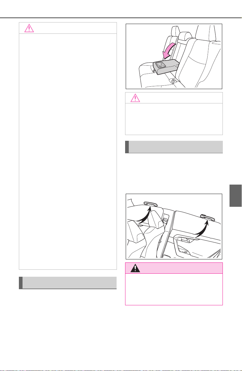
547
6-4. Using the other interior features
6
Interior features
Fold down the armrest for use.
An assist grip installed on the
ceiling can be used to support
your body while sitting on the
seat.
NOTICE
● When other wireless keys (that
emit radio waves) are being
used nearby
In addition, excluding the above-
mentioned, when the charger
does not perform normally or the
operation display lamp is flashing
continuously, it is considered that
the wireless charger is malfunc-
tioning. Contact authorized Toyota
dealer.
■ To prevent failure or damage
to data
● Do not bring magnetic cards,
such as credit cards, or mag-
netic recording media, etc.,
close to the charger while
charging, otherwise, data may
disappear under the influence of
magnetism. Also, do not bring
precision instruments such as
wrist watches, etc., close to the
charger, as such objects may
break.
● Do not leave portable devices in
the cabin. The temperature
inside the cabin may become
high, when under the sun, and
cause damage to the device.
■ To prevent battery discharge
When the engine is stopped, do
not use the wireless charger for a
long time.
Armrest
NOTICE
■ To prevent damage to the
armrest
Do not apply too much load on the
armrest.
Assist grips
WARNING
■ Assist grips
Do not use the assist grip when
getting in or out of the vehicle or
rising from your seat.
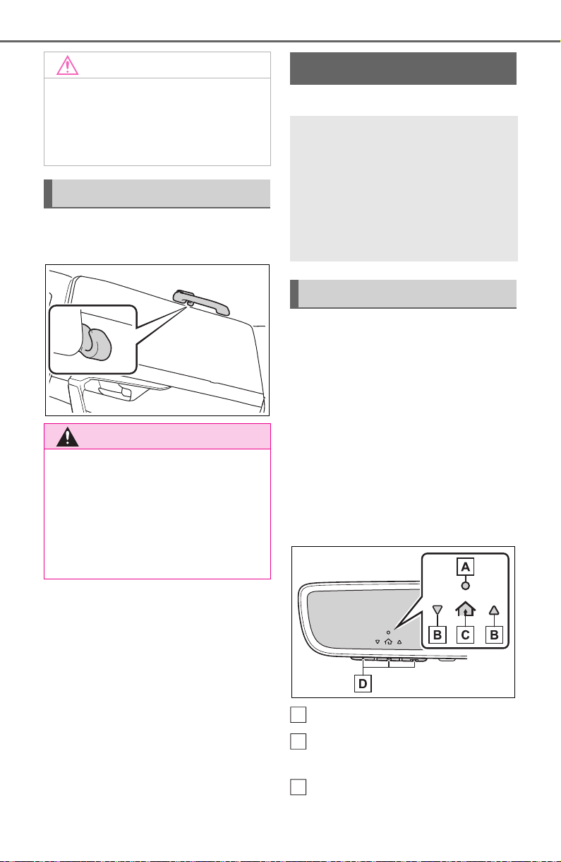
548
6-4. Using the other interior features
The coat hooks are provided
with the rear assist grips.
*
: If equipped
The HomeLink
®
wireless control
system in your vehicle has 3
buttons which can be pro-
grammed to operate 3 different
devices. Refer to the program-
ming methods on the following
pages to determine the method
which is appropriate for the
device.
Vehicles with auto anti-glare
inside rear view mirror
HomeLink
®
indicator light
Garage door operation indi-
cators
HomeLink
®
icon
NOTICE
■ To prevent damage to the
assist grip
Do not hang any heavy object or
put a heavy load on the assist
grip.
Coat hooks
WARNING
■ Items that must not be
hanged on the hook
Do not hang coat hangers or
other hard or sharp objects on the
hook. If the SRS curtain shield air-
bags deploy, these items may
become projectiles, causing death
or serious injury.
Garage door opener
*
The garage door opener can
be programmed using the
HomeLink
®
to operate
garage doors, gates, entry
doors, door locks, home
lighting systems, security
systems, and other devices.
System components
A
B
C
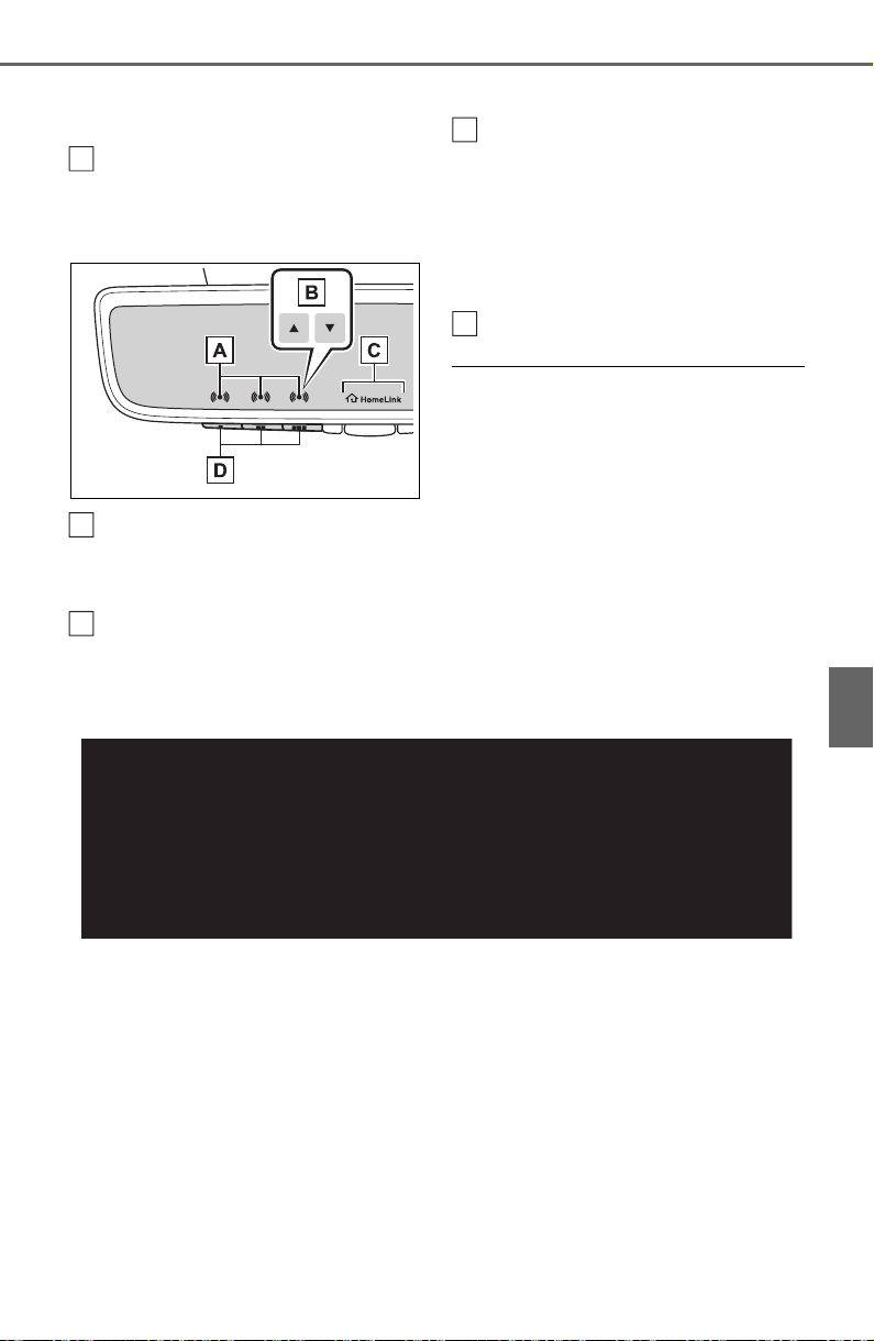
549
6-4. Using the other interior features
6
Interior features
Illuminates while HomeLink
®
is
operating.
Buttons
Vehicles with Digital Rear-
view Mirror
HomeLink
®
indicator light
Illuminates above each button
selected.
Garage door operation indi-
cators
HomeLink
®
logo
Appears while HomeLink
®
is oper-
ating.
When the menu button (P.145) is
pressed, the logo disappears even
while the HomeLink
®
is operating.
Buttons
■ Codes stored in the HomeLink
®
memory
● The registered codes are not
erased even if the battery cable is
disconnected.
● If learning failed when registering
a different code to a HomeLink
®
button that already has a code
registered to it, the already regis-
tered code will not be erased.
■ Certification for the garage door opener
For vehicles sold in the U.S. mainland, Hawaii, Guam, Saipan, American
Samoa and Puerto Rico
D
A
B
C
D

550
6-4. Using the other interior features
For vehicles sold in Canada
■ When support is necessary
Visit on the web at
www.homelink.com/toyota
or call 1-
800-355-3515.
■ Before programming
HomeLink
®
During programming, it is pos-
sible that garage doors,
gates, or other devices may
operate. For this reason,
make sure that people and
objects are clear of the
garage door or other devices
to prevent injury or other
potential harm.
It is recommended that a new
battery be placed in the
remote control transmitter for
successful programming.
WARNING
■ When programming a garage
door or other remote control
device
The garage door or other device
may operate, so ensure people
and objects are out of danger to
prevent potential harm.
■ Conforming to federal safety
standards
Do not use the HomeLink
®
com-
patible transceiver with any
garage door opener or device that
lacks safety stop and reverse fea-
tures as required by federal safety
standards.
This includes any garage door
that cannot detect an interfering
object. A door or device without
these features increases the risk
of death or serious injury.
■ When operating or program-
ming HomeLink
®
Never allow a child to operate or
play with the HomeLink
®
buttons.
Programming HomeLink
®
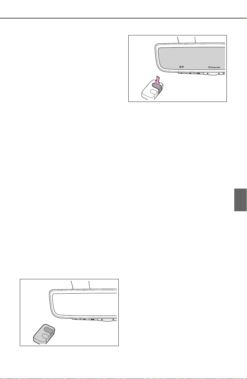
551
6-4. Using the other interior features
6
Interior features
Garage door opener motors
manufactured after 1995 may
be equipped with rolling code
protection. If this is the case,
you may need a stepladder or
other sturdy, safe device to
reach the “Learn” or “Smart”
button on the garage door
opener motor.
■ Programming HomeLink
®
Steps 1 through 3 must be per-
formed within 60 seconds, oth-
erwise the HomeLink
®
indicator
light will stop flashing and pro-
gramming will not be success-
fully completed.
1 Press and release the
HomeLink
®
button you want
to program and check that
the HomeLink
®
indicator light
flashes (orange).
2 Point the remote control
transmitter for the device at
the rear view mirror, 1 to 3 in.
(25 to 75 mm) from the
HomeLink
®
buttons.
Keep the HomeLink
®
indicator light
in view while programming.
3 Program a device.
Programming a device other
than an entry gate (for U.S.A.
owners)
Press and hold the remote con-
trol transmitter button until the
HomeLink
®
indicator light
changes from slowly flashing
orange to rapidly flashing green
(rolling code) or continuously lit
green (fixed code), then release
the button.
Programming an entry gate
(for U.S.A. owners)/Program-
ming a device in the Cana-
dian market
Press and release the remote
control transmitter button at 2
second intervals, repeatedly,
until the HomeLink
®
indicator
light changes from slowly flash-
ing orange to rapidly flashing
(green) (rolling code) or continu-
ously lit (green) (fixed code).
4 Test the HomeLink
®
opera-
tion by pressing the newly
programmed button and
observing the HomeLink
®
indicator light:
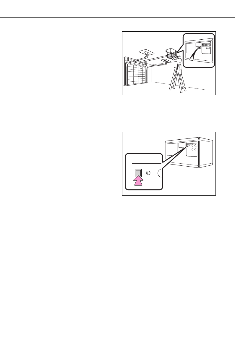
552
6-4. Using the other interior features
HomeLink
®
indicator light illu-
minates: Programming of a
fixed code device has com-
pleted. The garage door or
other device should operate
when a HomeLink
®
button is
pressed and released.
HomeLink
®
indicator light
flashes rapidly: The garage
door opener or other device is
equipped with a rolling code.
To complete programming,
firmly press and hold the
HomeLink
®
button for 2 sec-
onds then release it.
If the garage door or other
device does not operate, pro-
ceed to “Programming a roll-
ing code system”.
5 Repeat the steps above to
program another device for
any of the remaining
HomeLink
®
buttons.
■ Programming a rolling code
system
Two or more people may be
needed to complete rolling code
programming.
1 Locate the “Learn” or “Smart”
button on the garage door
opener motor in the garage.
This button can usually be found
where the hanging antenna wire is
attached to the unit. The name and
color of the button may vary by
manufacturer. Refer to the owner’s
manual supplied with the garage
door opener motor for details.
2 Press and release the
“Learn” or “Smart” button.
Perform 3 within 30 seconds after
performing 2.
3 Press and hold the desired
HomeLink
®
button (inside the
vehicle) for 2 seconds and
release it. Repeat this
sequence
(press/hold/release) up to 3
times to complete program-
ming.
If the garage door opener
motor operates when the
HomeLink
®
button is
pressed, the garage door
opener motor recognizes the
HomeLink
®
signal.
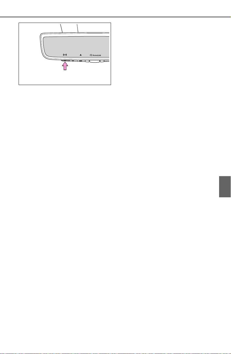
553
6-4. Using the other interior features
6
Interior features
■ Enabling 2-way communi-
cation with a garage door
(only available for compati-
ble devices)
When enabled, 2-way communi-
cation allows you to check the
status of the opening and clos-
ing of a garage door through
indicators in your vehicle.
2-way communication is only
available if the garage door
opener motor used is a compati-
ble device. (To check device
compatibility, refer to
www.homelink.com.)
1 Within 5 seconds after pro-
gramming the garage door
opener has been completed,
if the garage door opener
motor is trained to
HomeLink
®
, both garage
door operation indicators will
flash rapidly (green) and the
light on the garage door
opener motor will blink twice,
indicating that 2-way commu-
nication is enabled.
If the indicators do not flash, per-
form 2 and 3 within the first 10
presses of the HomeLink
®
button
after programming has been com-
pleted.
2 Press a programmed
HomeLink
®
button to oper-
ate a garage door.
3 Within 1 minute of pressing
the HomeLink
®
button, after
the garage door operation
has stopped, press the
“Learn” or “Smart” button on
the garage door opener
motor. Within 5 seconds of
the establishment of 2-way
communication with the
garage door opener, both
garage door operation indica-
tors in the vehicle will flash
rapidly (green) and the light
on the garage door opener
motor will blink twice, indicat-
ing that 2-way communica-
tion is enabled.
■ Reprogramming a single
HomeLink
®
button
When the following procedure is
performed, buttons which
already have devices registered
to them can be overwritten:
1 Press and hold the desired
HomeLink
®
button.
2 When the HomeLink
®
indica-
tor starts flashing orange,
release the HomeLink
®
but-
ton and perform “Program-
ming HomeLink
®
” 1 (it takes
20 seconds for the
HomeLink
®
indicator to start
flashing).
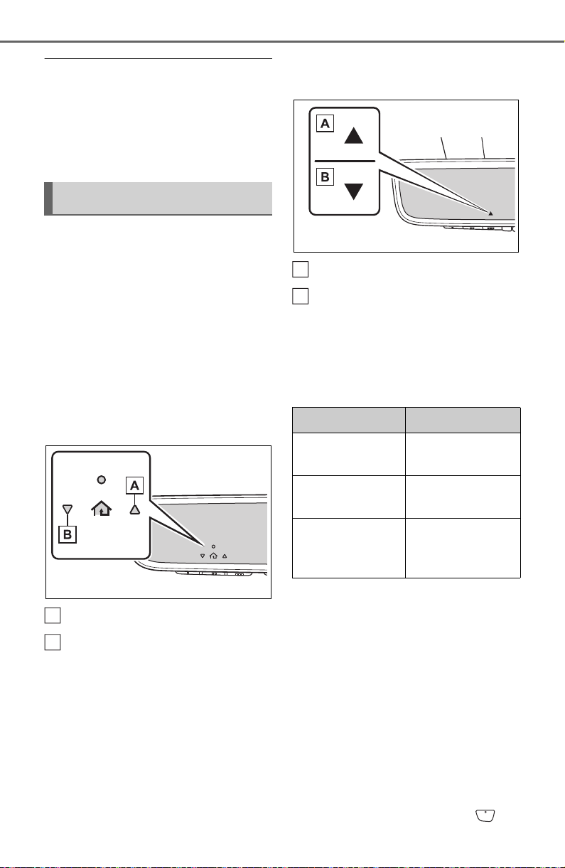
554
6-4. Using the other interior features
■ Before programming
● Install a new battery in the trans-
mitter.
● The battery side of the transmitter
must be pointed away from the
HomeLink
®
buttons.
Press the appropriate
HomeLink
®
button. The
HomeLink
®
indicator light
should turn on.
The status of the opening and
closing of a garage door is
shown by the garage door oper-
ation indicators.
Vehicles with auto anti-glare
inside rear view mirror
Opening
Closing
Vehicles with Digital Rear-
view Mirror
Opening
Closing
This function is only available if the
garage door opener motor used is a
compatible device. (To check
device compatibility, refer to
www.homelink.com.)
The indicators can operate
within approximately 820 ft. (250
m) of the garage door. However,
if there are obstructions
between the garage door and
the vehicle, such as houses and
trees, feedback signals from the
garage door may not be
received.
To recall the previous door oper-
ation status, press and release
either HomeLink
®
buttons
Operating HomeLink
®
A
B
Color Status
Orange (flash-
ing)
Currently open-
ing/closing
Green
Opening/closing
has completed
Red (flashing)
Feedback sig-
nals cannot be
received
A
B
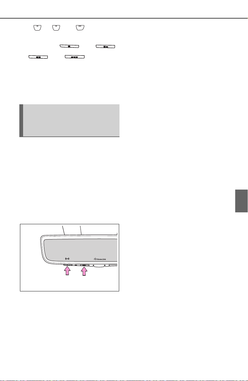
555
6-4. Using the other interior features
6
Interior features
and or and (vehicles
with auto anti-glare inside rear
view mirror), and
or and (vehicles
with Digital Rear-view Mirror)
simultaneously. The last
recorded status will be dis-
played for 3 seconds.
Press and hold the 2 outside
buttons for 10 seconds until the
HomeLink
®
indicator light
changes from continuously lit
(orange) to rapidly flashing
(green).
If you sell your vehicle, be sure to
erase the programs stored in the
HomeLink
®
memory.
Erasing the entire
HomeLink
®
memory (all
three codes)

556
6-4. Using the other interior features

557
7
7
Maintenance and care
Maintenance and care
7-1. Maintenance and care
Cleaning and protecting the
vehicle exterior.......... 558
Cleaning and protecting the
vehicle interior........... 561
7-2. Maintenance
Maintenance requirements
.................................. 564
General maintenance.. 565
Emission inspection and
maintenance (I/M) pro-
grams........................ 568
7-3. Do-it-yourself mainte-
nance
Do-it-yourself service pre-
cautions..................... 569
Hood ........................... 571
Positioning a floor jack 572
Engine compartment... 574
Tires............................ 581
Tire inflation pressure.. 595
Wheels........................ 597
Air conditioning filter.... 599
Wiper insert replacement
.................................. 601
Wireless remote con-
trol/electronic key battery
.................................. 604
Checking and replacing
fuses.......................... 607
Light bulbs................... 609

558
7-1. Maintenance and care
7-1.Maintenance and ca re
Working from top to bottom,
liberally apply water to the
vehicle body, wheel wells and
underside of the vehicle to
remove any dirt and dust.
Wash the vehicle body using
a sponge or soft cloth, such
as a chamois.
For hard-to-remove marks,
use car wash soap and rinse
thoroughly with water.
Wipe away any water.
Wax the vehicle when the
waterproof coating deterio-
rates.
If water does not bead on a clean
surface, apply wax when the vehi-
cle body is cool.
■ Automatic car washes
● Before washing the vehicle:
• Fold the mirrors
• Turn off the power back door (if
equipped)
Start washing from the front of the
vehicle. Make sure to extend the
mirrors before driving.
● Brushes used in automatic car
washes may scratch the vehicle
surface and harm your vehicle’s
paint.
● Rear spoiler may not be washable
in some automatic car washes.
There may also be an increased
risk of damage to vehicle.
■ High pressure car washes
As water may enter the cabin, do
not bring the nozzle tip near the
gaps around the doors or perimeter
of the windows, or spray these
areas continuously.
■ Note for a smart key system (if
equipped)
If the door handle becomes wet
while the electronic key is within the
effective range, the door may lock
and unlock repeatedly. In that case,
follow the following correction pro-
cedures to wash the vehicle:
● Place the key in a position 6 ft. (2
m) or more separate from the
vehicle while the vehicle is being
washed. (Take care to ensure that
the key is not stolen.)
● Set the electronic key to battery-
saving mode to disable the smart
key system. (P.129)
■ Aluminum wheels (if equipped)
● Remove any dirt immediately by
using a neutral detergent.
● Wash detergent off with water
immediately after use.
● To protect the paint from damage,
make sure to observe the follow-
ing precautions.
• Do not use acidic, alkaline or
abrasive detergent.
• Do not use hard brushes.
• Do not use detergent on the
wheels when they are hot, such
as after driving or parking in hot
weather.
● For vehicles with 18-inch matte
painted wheels and 19-inch matte
painted wheels: The wheels are
not maintained in the same way
as normal aluminum wheels. For
Cleaning and protect-
ing the vehicle exte-
rior
Perform the following to
protect the vehicle and
maintain it in prime condi-
tion:
Cleaning instructions
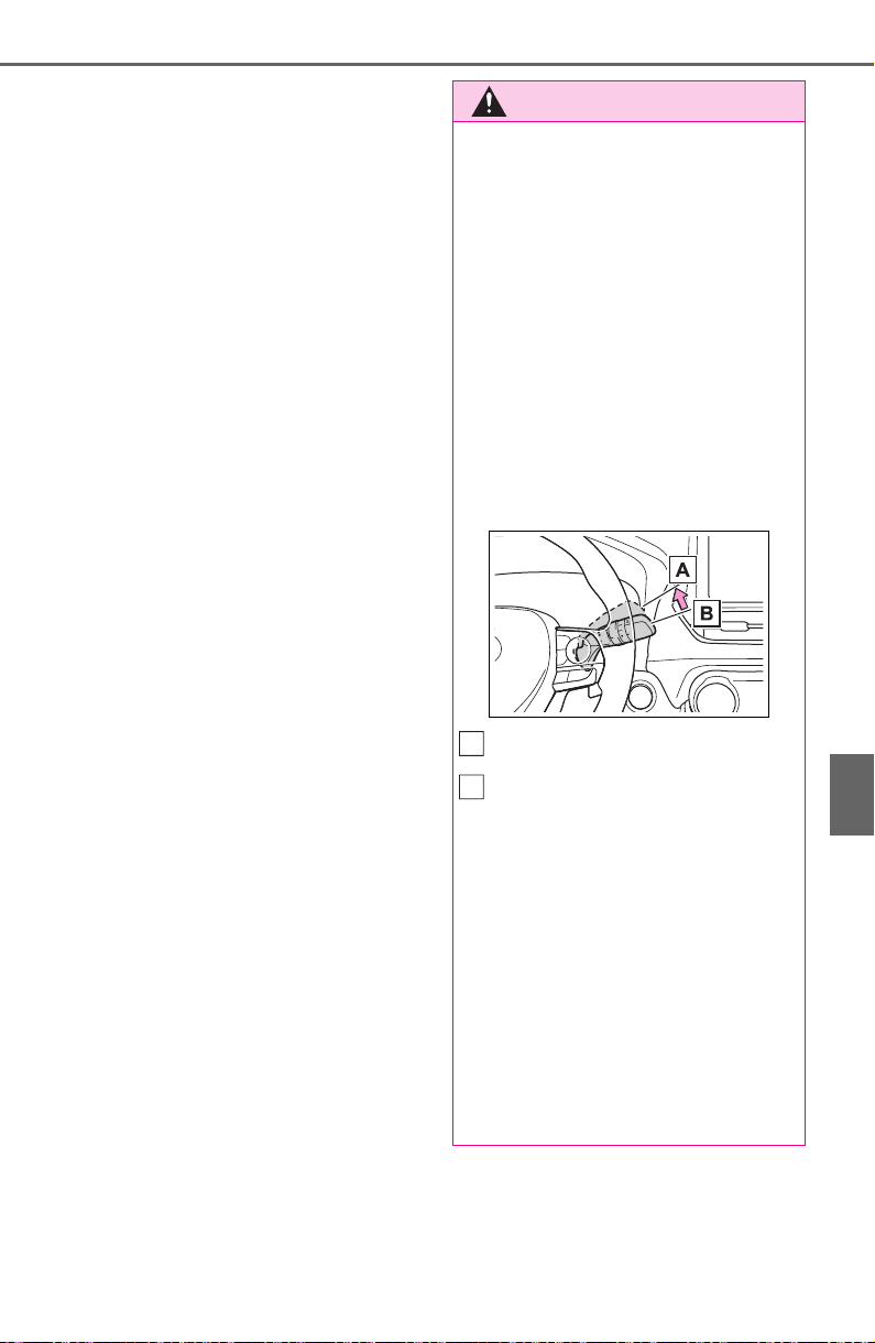
559
7-1. Maintenance and care
7
Maintenance and care
details, contact your Toyota
dealer.
• When washing the vehicle, use
water to wash off dirt. If the vehi-
cle is particularly dirty, use a
diluted neutral detergent and a
sponge or a soft cloth and wash
off the dirt by hand.
• Wash detergent off with water
immediately after use. After using
detergent, wash the detergent off
with water and wipe the vehicle
dry with a soft cloth.
● For vehicles with 18-inch matte
painted wheels and 19-inch matte
painted wheels: Make sure to
observe the following precautions
to prevent damage to the matte
paint.
• Do not polish or scrub with dry
cloths, brushes, etc.
• Do not use detergents containing
coatings or abrasives.
• If using an automatic car wash,
make sure it does not include ded-
icated wheel brushes.
• Do not use high-pressure spray
guns or steam cleaners.
• Do not use detergent on the
wheels when they are hot, such
as after driving or parking in hot
weather.
■ Bumpers
Do not scrub with abrasive cleaners.
■ Plated portions
If dirt cannot be removed, clean the
parts as follows:
● Use a soft cloth dampened with an
approximately 5% solution of neu-
tral detergent and water to clean
the dirt off.
● Wipe the surface with a dry, soft
cloth to remove any remaining
moisture.
● To remove oily deposits, use alco-
hol wet wipes or a similar product.
WARNING
■ When washing the vehicle
Do not apply water to the inside of
the engine compartment. Doing
so may cause the electrical com-
ponents, etc. to catch fire.
■ When cleaning the windshield
(vehicles with rain-sensing
windshield wipers)
Set the wiper switch to off.
If the wiper switch is in “AUTO”,
the wipers may operate unexpect-
edly in the following situations,
and may result in hands being
caught or other serious injuries
and cause damage to the wiper
blades.
Off
AUTO
● When the upper part of the
windshield where the raindrop
sensor is located is touched by
hand
● When a wet rag or similar is
held close to the raindrop sen-
sor
● If something bumps against the
windshield
● If you directly touch the raindrop
sensor body or if something
bumps into the raindrop sensor
A
B
560
7-1. Maintenance and care
WARNING
■ Precautions regarding the
exhaust pipes
Exhaust gasses cause the
exhaust pipes to become quite
hot.
When washing the vehicle, be
careful not to touch the pipes until
they have cooled sufficiently, as
touching hot exhaust pipes can
cause burns.
■ Precaution regarding the rear
bumper with Blind Spot Moni-
tor (if equipped)
If the paint of the rear bumper is
chipped or scratched, the system
may malfunction. If this occurs,
consult your Toyota dealer.
NOTICE
■ To prevent paint deteriora-
tion and corrosion on the
body and components (alumi-
num wheels, etc.)
● Wash the vehicle immediately in
the following cases:
• After driving near the sea coast
• After driving on salted roads
• If coal tar or tree sap is present
on the paint surface
• If dead insects, insect droppings
or bird droppings are present on
the paint surface
• After driving in an area contami-
nated with soot, oily smoke,
mine dust, iron powder or chem-
ical substances
• If the vehicle becomes heavily
soiled with dust or mud
• If liquids such as benzene and
gasoline are spilled on the paint
surface
● If the paint is chipped or
scratched, have it repaired
immediately.
● To prevent the wheels from cor-
roding, remove any dirt and
store in a place with low humid-
ity when storing the wheels.
■ Cleaning the exterior lights
● Wash carefully. Do not use
organic substances or scrub
with a hard brush.
This may damage the surfaces
of the lights.
● Do not apply wax to the sur-
faces of the lights.
Wax may cause damage to the
lenses.
■ When using an automatic car
wash (vehicles with rain-
sensing windshield wipers)
Set the wiper switch to off posi-
tion.
If the wiper switch is in “AUTO”,
the wipers may operate and the
wiper blades may be damaged.
■ When using a high pressure
car wash
● When washing the vehicle, do
not let water from the high-pres-
sure washer directly hit the
camera or the area around the
camera. Due to the shock from
the high pressure water, it is
possible that the device may not
operate normally.
● Do not bring the nozzle tip close
to boots (rubber or resin manu-
factured cover), or connectors
or the following parts.
The parts may be damaged if
they come into contact with
high-pressure water.
• Traction related parts
• Steering parts
• Suspension parts
• Brake parts

561
7-1. Maintenance and care
7
Maintenance and care
Remove dirt and dust using a
vacuum cleaner. Wipe dirty
surfaces with a cloth damp-
ened with lukewarm water.
If dirt cannot be removed,
wipe it off with a soft cloth
dampened with neutral deter-
gent diluted to approximately
1%.
Wring out any excess water
from the cloth and thoroughly
wipe off remaining traces of
detergent and water.
■ Shampooing the carpets
There are several commercial foam-
ing-type cleaners available. Use a
sponge or brush to apply the foam.
Rub in overlapping circles. Do not
use water. Wipe dirty surfaces and
let them dry. Excellent results are
obtained by keeping the carpet as
dry as possible.
■ Handling the seat belts
Clean with mild soap and lukewarm
water using a cloth or sponge. Also
check the belts periodically for
excessive wear, fraying or cuts.
NOTICE
● Keep the cleaning nozzle at
least 11.9 in. (30 cm) away from
the vehicle body. Otherwise
resin section, such as moldings
and bumpers, may be deformed
and damaged. Also, do not con-
tinuously hold the nozzle in the
same place.
● Do not spray the lower part of
the windshield continuously. If
water enters the air conditioning
system intake located near the
lower part of the windshield, the
air conditioning system may not
operate correctly.
Cleaning and protect-
ing the vehicle interior
Perform cleaning in a man-
ner appropriate to each
component and its material.
Protecting the vehicle
interior

562
7-1. Maintenance and care
WARNING
■ Water in the vehicle
● Do not splash or spill liquid in
the vehicle.
Doing so may cause electrical
components, etc., to malfunc-
tion or catch fire.
● Do not get any of the SRS com-
ponents or wiring in the vehicle
interior wet.
(P.34)
An electrical malfunction may
cause the airbags to deploy or
not function properly, resulting
in death or serious injury.
● Vehicles with wireless charger:
Do not let the wireless charger
(P.547) get wet. Failure to do
so may cause the charger to
become hot and cause burns or
could cause electric shock
resulting in death or serious
injury.
■ Cleaning the interior (espe-
cially instrument panel)
Do not use a polish wax or polish
cleaner. The instrument panel
may reflect off the windshield,
obstructing the driver’s view and
leading to an accident, resulting in
death or serious injury.
NOTICE
■ Cleaning detergents
● Do not use the following types
of detergent, as they may dis-
color the vehicle interior or
cause streaks or damage to
painted surfaces:
• Non-seat portions: Organic sub-
stances such as benzene or
gasoline, alkaline or acidic solu-
tions, dye, and bleach
• Seats: Alkaline or acidic solu-
tions, such as thinner, benzene,
and alcohol
● Do not use a polish wax or pol-
ish cleaner. The instrument
panel’s or other interior part’s
painted surface may be dam-
aged.
■ Preventing damage to leather
surfaces
Observe the following precautions
to avoid damage to and deteriora-
tion of leather surfaces:
● Remove any dust or dirt from
leather surfaces immediately.
● Do not expose the vehicle to
direct sunlight for extended peri-
ods of time. Park the vehicle in
the shade, especially during
summer.
● Do not place items made of
vinyl, plastic, or containing wax
on the upholstery, as they may
stick to the leather surface if the
vehicle interior heats up signifi-
cantly.
■ Water on the floor
Do not wash the vehicle floor with
water.
Vehicle systems such as the
audio system may be damaged if
water comes into contact with
electrical components such as the
audio system above or under the
floor of the vehicle. Water may
also cause the body to rust.
■ When cleaning the inside of
the windshield
Do not allow glass cleaner to con-
tact the lens. Also, do not touch
the lens. (P.223)

563
7-1. Maintenance and care
7
Maintenance and care
Remove dirt and dust using a
vacuum cleaner.
Wipe off any excess dirt and
dust with a soft cloth damp-
ened with diluted detergent.
Use a diluted water solution of
approximately 5% neutral wool
detergent.
Wring out any excess water
from the cloth and thoroughly
wipe off all remaining traces
of detergent.
Wipe the surface with a dry,
soft cloth to remove any
remaining moisture. Allow the
leather to dry in a shaded and
ventilated area.
■ Caring for leather areas
Toyota recommends cleaning the
interior of the vehicle at least twice a
year to maintain the quality of the
vehicle’s interior.
Remove dirt and dust using a
vacuum cleaner.
Wipe it off with a soft cloth
dampened with neutral deter-
gent diluted to approximately
1%.
Wring out any excess water
from the cloth and thoroughly
wipe off remaining traces of
detergent and water.
NOTICE
■ Cleaning the inside of the rear
window
● Do not use a glass cleaner to
clean the rear window, as this
may cause damage to the rear
window defogger heater wires.
Use a cloth dampened with
lukewarm water to gently wipe
the window clean. Wipe the win-
dow in strokes running parallel
to the heater wires.
● Be careful not to scratch or
damage the heater wires.
Cleaning the leather areas
Cleaning the synthetic
leather areas

564
7-2. Maintenance
7-2.Maintenance
■ Repair and replacement
It is recommended that genuine
Toyota parts be used for repairs to
ensure performance of each sys-
tem. If non-Toyota parts are used in
replacement or if a repair shop other
than a Toyota dealer performs
repairs, confirm the warranty cover-
age.
■ Allow inspection and repairs to
be performed by a Toyota
dealer
● Toyota technicians are well-
trained specialists and are kept up
to date with the latest service
information. They are well
informed about the operations of
all systems on your vehicle.
● Keep a copy of the repair order. It
proves that the maintenance that
has been performed is under war-
ranty coverage. If any problem
should arise while your vehicle is
under warranty, your Toyota
dealer will promptly take care of it.
General maintenance should be
performed on a daily basis. This
can be done by yourself or by a
Toyota dealer.
Scheduled maintenance should
be performed at specified inter-
vals according to the mainte-
nance schedule.
For details about maintenance
items and schedules, refer to the
“Scheduled Maintenance Guide” or
“Owner’s Manual Supplement”.
Maintenance require-
ments
To ensure safe and econom-
ical driving, day-to-day care
and regular maintenance
are essential. It is the
owner’s responsibility to
perform regular checks.
Toyota recommends the fol-
lowing maintenance:
WARNING
■ If your vehicle is not properly
maintained
Improper maintenance could
result in serious damage to the
vehicle and possible death or seri-
ous injury.
■ Handling of the battery
● Engine exhaust, some of its
constituents, and a wide variety
of automobile components con-
tain or emit chemicals known to
the State of California to cause
cancer and birth defects and
other reproductive harm. Work
in a well ventilated area.
● Oils, fuels and fluids contained
in vehicles as well as waste pro-
duced by component wear con-
tain or emit chemicals known to
the State of California to cause
cancer and birth defects or
other reproductive harm. Avoid
exposure and wash any
affected area immediately.
● Battery posts, terminals and
related accessories contain lead
and lead compounds which are
known to cause brain damage.
Wash your hands after han-
dling. (P.579)
General maintenance
Scheduled maintenance
565
7-2. Maintenance
7
Maintenance and care
■ Resetting the message indicat-
ing maintenance is required
After the required maintenance is
performed according to the mainte-
nance schedule, please reset the
reminder light or message.
To reset the reminder light or mes-
sage, follow the procedure
described below:
1 Press or of the meter
control switches and select
on the multi-information display.
2 Press or of the meter
control switches and select
“Vehicle Settings”. Then press
.
3 Press or of the meter
control switches and select
“Scheduled Maintenance”. Then
press .
4 Select “Yes” and press .
You can perform some mainte-
nance procedures by yourself.
Please be aware that do-it-your-
self maintenance may affect
warranty coverage.
The use of Toyota Repair Manuals
is recommended.
For details about warranty cover-
age, refer to the separate “Owner’s
Warranty Information Booklet” or
“Owner’s Manual Supplement”.
Do-it-yourself mainte-
nance
General maintenance
Listed below are the general
maintenance items that
should be performed at the
intervals specified in the
“Owner’s Warranty Informa-
tion Booklet” or “Owner’s
Manual Supplement/Sched-
uled Maintenance Guide”. It
is recommended that any
problem you notice should
be brought to the attention
of your Toyota dealer or
qualified service shop for
advice.
WARNING
■ If the engine is running
Turn the engine off and ensure
that there is adequate ventilation
before performing maintenance
checks.
Engine compartment
Items Check points
Battery
Check the connec-
tions. (P. 57 9)
Brake fluid
Is the brake fluid at
the correct level?
(P.577)
Engine coolant
Is the engine cool-
ant at the correct
level? (P.576)
Engine oil
Is the engine oil at
the correct level?
(P.574)
566
7-2. Maintenance
Exhaust sys-
tem
There should not
be any fumes or
strange sounds.
Radiator/con-
denser
The radiator and
condenser should
be free from for-
eign objects.
(P.577)
Washer fluid
Is there sufficient
washer fluid?
(P.579)
Vehicle interior
Items Check points
Accelerator
pedal
• The accelerator
pedal should
move smoothly
(without uneven
pedal effort or
catching).
Automatic
transmission
“Park” mecha-
nism
• When parked on
a slope and the
shift position is in
P, is the vehicle
securely
stopped?
Brake pedal
• Does the brake
pedal move
smoothly?
• Does the brake
pedal have
appropriate
clearance from
the floor?
• Does the brake
pedal have the
correct amount
of free play?
Items Check points
Brakes
• The vehicle
should not pull to
one side when
the brakes are
applied.
• The brakes
should work
effectively.
• The brake pedal
should not feel
spongy.
• The brake pedal
should not get
too close to the
floor when the
brakes are
applied.
Head
restraints
• Do the head
restraints move
smoothly and
lock securely?
Indica-
tors/buzzers
• Do the indica-
tors and buzzers
function prop-
erly?
Lights
• Do all the lights
come on?
Parking brake
• Does the park-
ing brake oper-
ate normally?
• When parked on
a slope and the
parking brake is
on, is the vehicle
securely
stopped?
Items Check points
567
7-2. Maintenance
7
Maintenance and care
Seat belts
• Do the seat belts
operate
smoothly?
• The seat belts
should not be
damaged.
Seats
• Do the seat con-
trols operate
properly?
Steering wheel
• Does the steer-
ing wheel rotate
smoothly?
• Does the steer-
ing wheel have
the correct
amount of free
play?
• There should not
be any strange
sounds coming
from the steer-
ing wheel.
Vehicle exterior
Items Check points
Doors
• Do the doors
operate
smoothly?
Engine hood
• Does the engine
hood lock system
work properly?
Fluid leaks
• There should not
be any signs of
fluid leakage
after the vehicle
has been parked.
Items Check points
Tires
• Is the tire infla-
tion pressure
correct?
• The tires should
not be damaged
or excessively
worn.
• Have the tires
been rotated
according to the
maintenance
schedule?
• The wheel nuts
should not be
loose.
Windshield
wipers/rear
window wiper
• The wiper blades
should not show
any signs of
cracking, split-
ting, wear, con-
tamination or
deformation.
• The wiper blades
should clear the
windshield with-
out streaking or
skipping.
Items Check points

568
7-2. Maintenance
The OBD system determines
that a problem exists some-
where in the emission control
system. Your vehicle may not
pass the I/M test and may need
to be repaired. Contact your
Toyota dealer to service the
vehicle.
When the battery is discon-
nected or discharged
Readiness codes that are set
during ordinary driving are
erased.
Also, depending on your driv-
ing habits, the readiness
codes may not be completely
set.
When the fuel tank cap is
loose
The malfunction indicator
lamp comes on indicating a
temporary malfunction and
your vehicle may not pass the
I/M test.
The error code in the OBD sys-
tem will not be cleared unless
the vehicle is driven 40 or more
times.
Contact your Toyota dealer to
prepare the vehicle for re-test-
ing.
Emission inspection
and maintenance (I/M)
programs
Some states have vehicle
emission inspection pro-
grams which include OBD
(On Board Diagnostics)
checks. The OBD system
monitors the operation of
the emission control sys-
tem.
If the malfunction indica-
tor lamp comes on
Your vehicle may not pass
the I/M test in the follow-
ing situations:
When the malfunction
indicator lamp still
remains on after several
driving trips
If your vehicle does not
pass the I/M test

569
7-3. Do-it-yourself maintenance
7
Maintenance and care
7-3.Do -it-yourself maint enance
Do-it-yourself service
precautions
If you perform maintenance
by yourself, be sure to fol-
low the correct procedure as
given in these sections.
Maintenance
Items Parts and tools
Battery con-
dition
(P.579)
•Grease
• Conventional
wrench (for termi-
nal clamp bolts)
Brake fluid
level
(P.577)
• FMVSS No.116
DOT 3 or SAE
J1703 brake fluid
• FMVSS No.116
DOT 4 or SAE
J1704
• Rag or paper
towel
• Funnel (used only
for adding brake
fluid)
Engine cool-
ant level
(P.576)
• “Toyota Super
Long Life Coo-
lant” or a similar
high quality eth-
ylene glycol-based
non-silicate, non-
amine, non-nitrite
and non-borate
coolant with long-
life hybrid organic
acid technology
For the U.S.A.:
“Toyota Super
Long Life Coo-
lant” is pre-mixed
with 50% coolant
and 50% deion-
ized water.
For Canada:
“Toyota Super
Long Life Coo-
lant” is pre-mixed
with 55% coolant
and 45% deion-
ized water.
• Funnel (used only
for adding coolant)
Engine oil
level
(P.574)
• “Toyota Genuine
Motor Oil” or
equivalent
• Rag or paper
towel
• Funnel (used only
for adding engine
oil)
Fuses
(P.607)
• Fuse with same
amperage rating
as original
Items Parts and tools
570
7-3. Do-it-yourself maintenance
Light bulbs
(P.609)
• Bulb with same
number and watt-
age rating as origi-
nal
• Phillips-head
screwdriver
• Flathead screw-
driver
• Wrench
Radiator and
condenser
(P.577)
Tire inflation
pressure
(P.595)
• Tire pressure
gauge
• Compressed air
source
Washer fluid
(P.580)
• Water or washer
fluid containing
antifreeze (for win-
ter use)
• Funnel (used only
for adding water or
washer fluid)
WARNING
The engine compartment contains
many mechanisms and fluids that
may move suddenly, become hot,
or become electrically energized.
To avoid death or serious injury,
observe the following precautions.
■ When working on the engine
compartment
● Keep hands, clothing and tools
away from the moving fan and
engine drive belt.
● Be careful not to touch the
engine, radiator, exhaust mani-
fold, etc., right after driving as
they may be hot. Oil and other
fluids may also be hot.
Items Parts and tools ● Do not leave anything that may
burn easily, such as paper and
rags, in the engine compart-
ment.
● Do not smoke, cause sparks or
expose an open flame to fuel or
the battery. Fuel and battery
fumes are flammable.
● Be extremely cautious when
working on the battery. It con-
tains poisonous and corrosive
sulfuric acid.
■ When working near the elec-
tric cooling fan or radiator
grille
Be sure the engine switch is off.
With the engine switch in ON, the
electric cooling fan may automati-
cally start to run if the air condi-
tioning is on and/or the coolant
temperature is high. (P.577)
■ Safety glasses
Wear safety glasses to prevent
flying or falling material, fluid
spray, etc., from getting in your
eyes.
NOTICE
■ If you remove the air cleaner
filter
Driving with the air cleaner filter
removed may cause excessive
engine wear due to dirt in the air.

571
7-3. Do-it-yourself maintenance
7
Maintenance and care
1 Pull the hood lock release
lever.
The hood will pop up slightly.
2 Push the auxiliary catch lever
to the left and lift the hood.
3 Hold the hood open by insert-
ing the supporting rod into
the slot.
Hood
Release the lock from the
inside of the vehicle to open
the hood.
Opening the hood
WARNING
■ Pre-driving check
Check that the hood is fully closed
and locked.
If the hood is not locked properly,
it may open while the vehicle is in
motion and cause an accident,
which may result in death or seri-
ous injury.
■ After installing the support
rod into the slot
Make sure the rod supports the
hood securely from falling down
on to your head or body.
■ When closing the hood
When closing the hood, take extra
care to prevent your fingers etc.
from being caught.
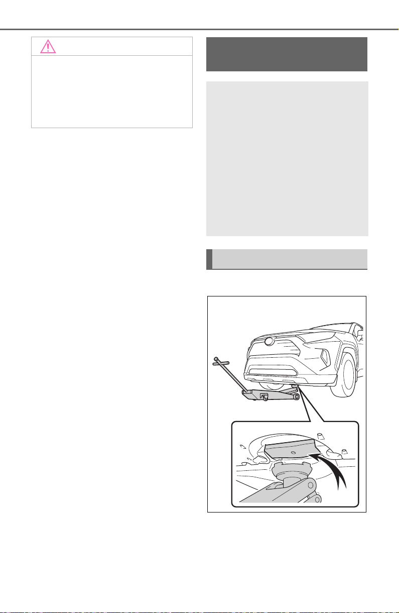
572
7-3. Do-it-yourself maintenance
■ Front
NOTICE
■ When closing the hood
Be sure to return the support rod
to its clip before closing the hood.
Closing the hood without return-
ing the support rod properly could
cause the hood to bend.
Positioning a floor
jack
When using a floor jack, fol-
low the instructions in the
manual provided with the
jack and perform the opera-
tion safely.
When raising your vehicle
with a floor jack, position
the jack correctly.
Improper placement may
damage your vehicle or
cause injury.
Location of the jack point
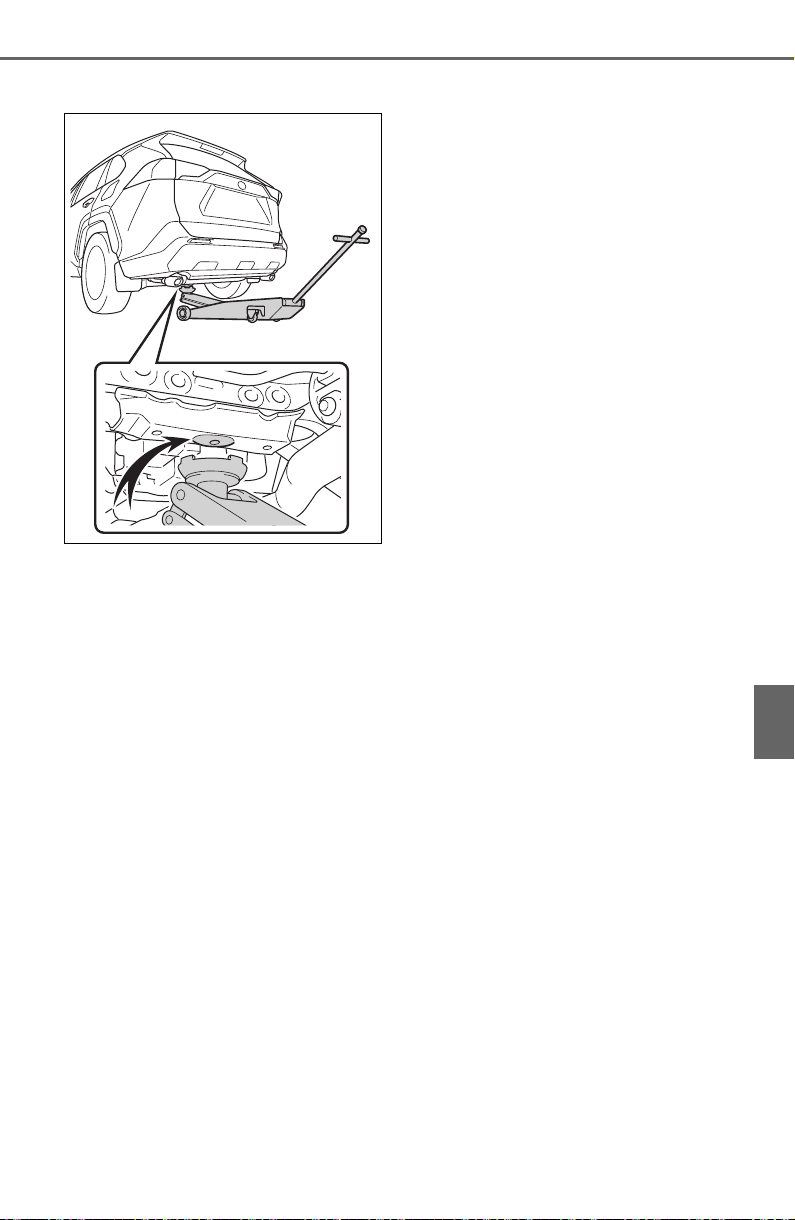
573
7-3. Do-it-yourself maintenance
7
Maintenance and care
■ Rear
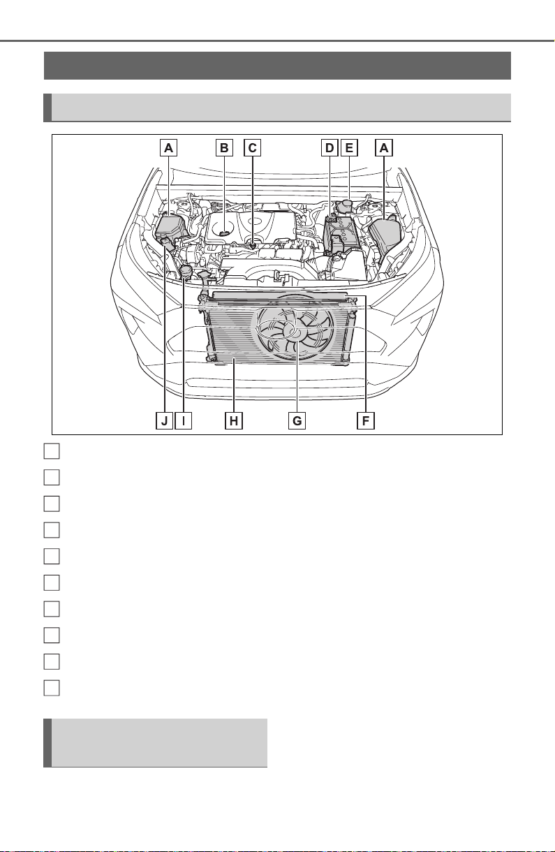
574
7-3. Do-it-yourself maintenance
Fuse boxes (P.607)
Engine oil filler cap (P.575)
Engine oil level dipstick (P.574)
Battery (P.579)
Brake fluid reservoir (P.577)
Radiator (P.577)
Electric cooling fan
Condenser (P. 57 7 )
Washer fluid tank (P.580)
Engine coolant reservoir (P.576)
With the engine at operating
temperature and turned off,
check the oil level on the dip-
stick.
Engine compartment
Components
A
B
C
D
E
F
G
H
I
J
Checking and adding the
engine oil
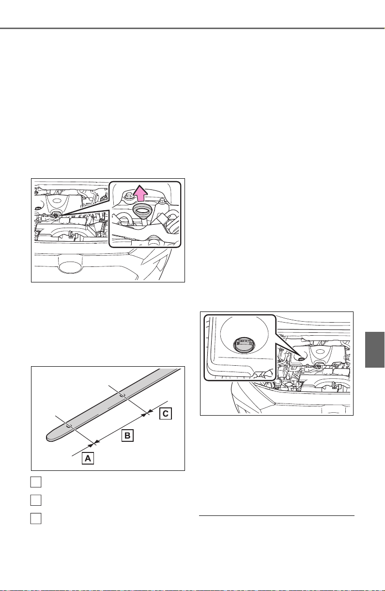
575
7-3. Do-it-yourself maintenance
7
Maintenance and care
■ Checking the engine oil
1 Park the vehicle on level
ground. After warming up the
engine and turning off the
engine, wait more than 5
minutes for the oil to drain
back into the bottom of the
engine.
2 Holding a rag under the end,
pull the dipstick out.
3 Wipe the dipstick clean.
4 Reinsert the dipstick fully.
5 Holding a rag under the end,
pull the dipstick out and
check the oil level.
Low
Normal
Excessive
The shape of the dipstick may differ
depending on the type of vehicle or
engine.
6 Wipe the dipstick and reinsert
it fully.
■ Checking the oil type and
preparing the items needed
Make sure to check the oil type
and prepare the items needed
before adding oil.
Engine oil selection
P.666
Oil quantity (Low Full)
1.6 qt. (1.5 L, 1.3 Imp. qt.)
Item
Clean funnel
■ Adding engine oil
If the oil level is below or near
the low level mark, add engine
oil of the same type as that
already in the engine.
1 Remove the oil filler cap by
turning it counterclockwise.
2 Add engine oil slowly, check-
ing the dipstick.
3 Install the oil filler cap by
turning it clockwise.
■ Engine oil consumption
A certain amount of engine oil will
be consumed while driving. In the
following situations, oil consump-
A
B
C
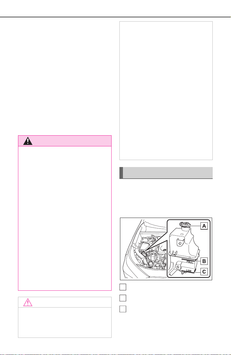
576
7-3. Do-it-yourself maintenance
tion may increase, and engine oil
may need to be refilled in between
oil maintenance intervals.
● When the engine is new, for
example directly after purchasing
the vehicle or after replacing the
engine
● If low quality oil or oil of an inap-
propriate viscosity is used
● When driving at high engine
speeds or with a heavy load,
when towing, or when driving
while accelerating or decelerating
frequently
● When leaving the engine idling for
a long time, or when driving fre-
quently through heavy traffic
The coolant level is satisfactory
if it is between the “FULL” and
“LOW” lines on the reservoir
when the engine is cold.
Reservoir cap
“FULL” line
“LOW” line
If the level is on or below the “LOW”
line, add coolant up to the “FULL”
line. (P.659)
WARNING
■ Used engine oil
● Used engine oil contains poten-
tially harmful contaminants
which may cause skin disorders
such as inflammation and skin
cancer, so care should be taken
to avoid prolonged and
repeated contact. To remove
used engine oil from your skin,
wash thoroughly with soap and
water.
● Dispose of used oil and filters
only in a safe and acceptable
manner. Do not dispose of used
oil and filters in household trash,
in sewers or onto the ground.
Call your Toyota dealer, service
station or auto parts store for
information concerning recy-
cling or disposal.
● Do not leave used engine oil
within the reach of children.
NOTICE
■ To prevent serious engine
damage
Check the oil level on a regular
basis.
■ When replacing the engine oil
● Be careful not to spill engine oil
on the vehicle components.
● Avoid overfilling, or the engine
could be damaged.
● Check the oil level on the dip-
stick every time you refill the
vehicle.
● Be sure the engine oil filler cap
is properly tightened.
■ If oil is spilled on the engine
cover
To prevent the engine cover from
being damaged, remove any
engine oil from the engine cover
as soon as possible using a neu-
tral detergent. Do not use an
organic solvent such as brake
cleaner.
Checking the coolant
A
B
C
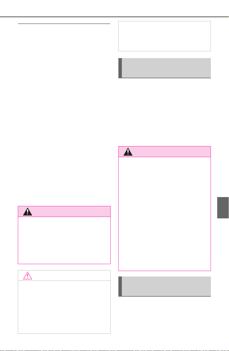
577
7-3. Do-it-yourself maintenance
7
Maintenance and care
■ Coolant selection
Only use “Toyota Super Long Life
Coolant” or a similar high quality
ethylene glycol based non-silicate,
non-amine, non-nitrite, and non-
borate coolant with long-life hybrid
organic acid technology.
U.S.A.:
“Toyota Super Long Life Coolant” is
a mixture of 50% coolant and 50%
deionized water. (Minimum tem-
perature: -31°F [-35°C])
Canada:
“Toyota Super Long Life Coolant” is
a mixture of 55% coolant and 45%
deionized water. (Minimum tem-
perature: -44°F [-42°C])
For more details about coolant, con-
tact your Toyota dealer.
■ If the coolant level drops within
a short time of replenishing
Visually check the radiators, hoses,
engine/power control unit coolant
reservoir caps, drain cock and water
pump.
If you cannot find a leak, have your
Toyota dealer, test the cap and
check for leaks in the cooling sys-
tem.
Check the radiator and con-
denser, and clear away any for-
eign objects.
If either of the above parts is
extremely dirty or you are not
sure of their condition, have
your vehicle inspected by your
Toyota dealer.
■ Checking fluid level
The brake fluid level should be
between the “MAX” and “MIN”
lines on the tank.
WARNING
■ When the engine is hot
Do not remove the engine coolant
reservoir cap.
The cooling system may be under
pressure and may spray hot cool-
ant if the cap is removed, causing
serious injuries, such as burns.
NOTICE
■ When adding coolant
Coolant is neither plain water nor
straight antifreeze. The correct
mixture of water and antifreeze
must be used to provide proper
lubrication, corrosion protection
and cooling. Be sure to read the
antifreeze or coolant label.
■ If you spill coolant
Be sure to wash it off with water to
prevent it from damaging parts or
paint.
Checking the radiator and
condenser
WARNING
■ When the engine is hot
Do not touch the radiator or con-
denser as they may be hot and
cause serious injuries, such as
burns.
■ When the electric cooling fan
is operating
Do not touch the engine compart-
ment.
With the engine switch in ON, the
electric cooling fan may automati-
cally start to run if the air condi-
tioning is on and/or the coolant
temperature is high. Be sure the
engine switch is off when working
near the electric cooling fan or
radiator grille.
Checking and adding the
brake fluid
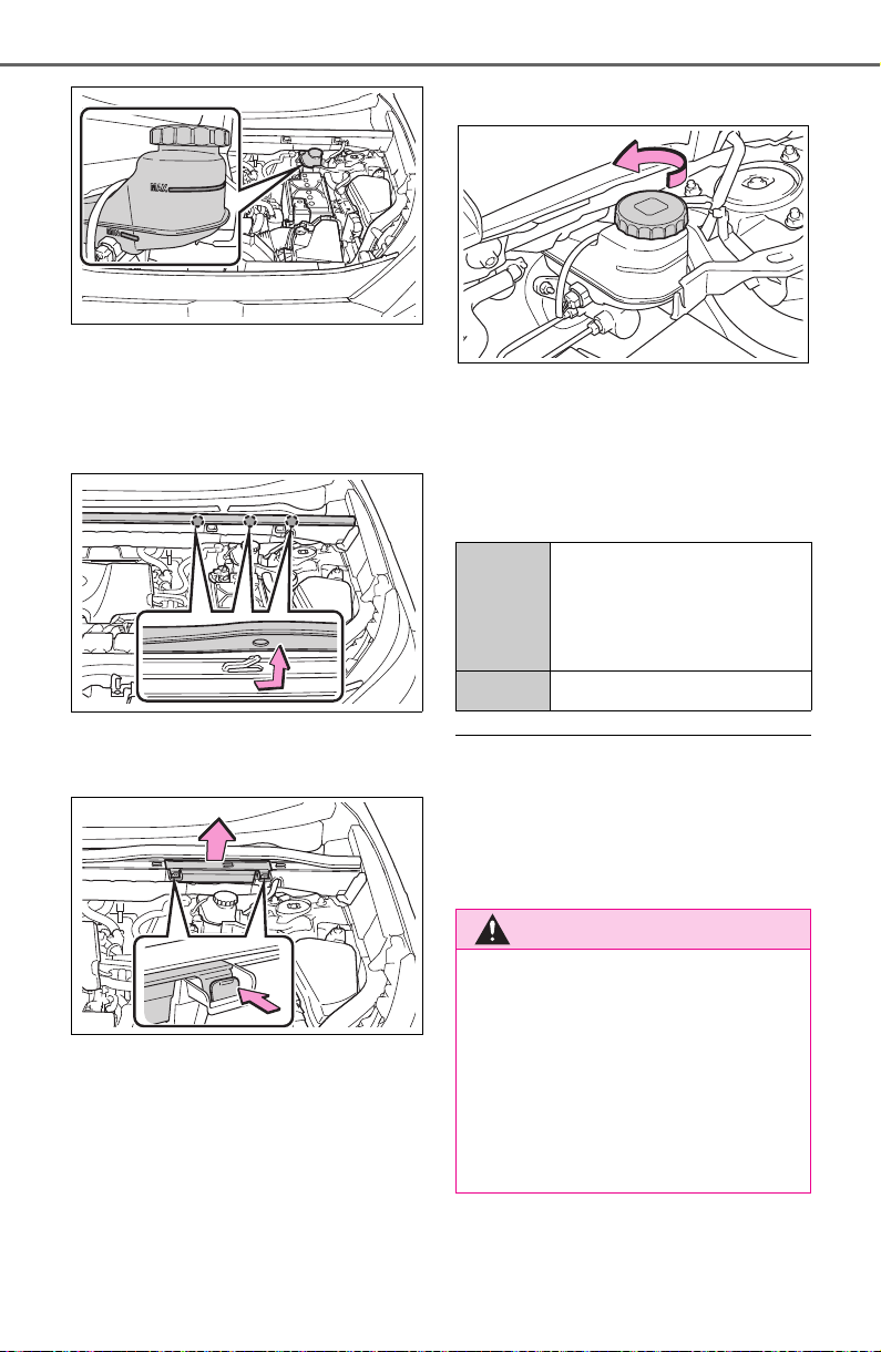
578
7-3. Do-it-yourself maintenance
■ Adding fluid
1 Slide and lift up the rubber
strip to partly remove it as
shown.
2 Disconnect the claws and
remove the service cover.
3 Remove the reservoir cap.
4 Add brake fluid slowly while
checking the fluid level.
Make sure to check the fluid
type and prepare the necessary
item.
■ Brake fluid can absorb moisture
from the air
Excess moisture in the brake fluid
can cause a dangerous loss of brak-
ing efficiency. Use only newly
opened brake fluid.
Fluid
type
FMVSS No.116 DOT 3 or
SAE J1703 brake fluid
FMVSS No.116 DOT 4 or
SAE J1704
Item Clean funnel
WARNING
■ When filling the reservoir
Take care as brake fluid can harm
your hands and eyes and damage
painted surfaces.
If fluid gets on your hands or in
your eyes, flush the affected area
with clean water immediately.
If you still experience discomfort,
see a doctor.
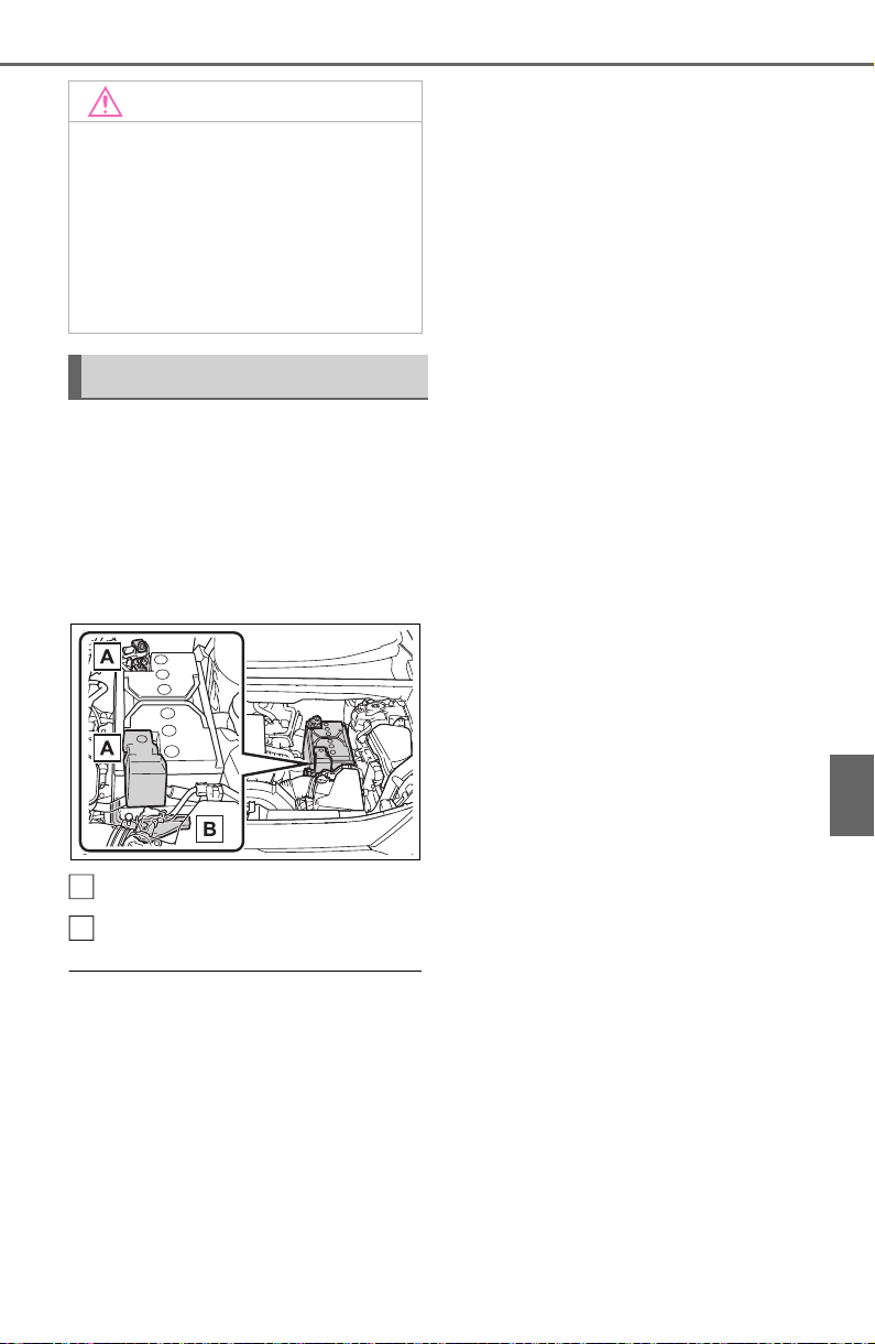
579
7-3. Do-it-yourself maintenance
7
Maintenance and care
Check the battery as follows.
■ Battery exterior
Make sure that the battery termi-
nals are not corroded and that
there are no loose connections,
cracks, or loose clamps.
Terminals
Hold-down clamp
■ Before recharging
When recharging, the battery pro-
duces hydrogen gas which is flam-
mable and explosive. Therefore,
observe the following precautions
before recharging:
● If recharging with the battery
installed on the vehicle, be sure to
disconnect the ground cable.
● Make sure the power switch on
the charger is off when connecting
and disconnecting the charger
cables to the battery.
■ After recharging/reconnecting
the battery (vehicles with smart
key system)
The engine may not start. Follow the
procedure below to initialize the sys-
tem.
1 Shift the shift lever to P.
2 Open and close any of the doors.
3 Restart the engine.
● Unlocking the doors using the
smart key system may not be pos-
sible immediately after reconnect-
ing the battery. If this happens,
use the wireless remote control or
the mechanical key to lock/unlock
the doors.
● Start the engine with the engine
switch in ACC. The engine may
not start with the engine switch
turned off. However, the engine
will operate normally from the sec-
ond attempt.
● The engine switch mode is
recorded by the vehicle. If the bat-
tery is disconnected and recon-
nected, the vehicle will return the
engine switch mode to the status it
was in before the battery was dis-
connected. Make sure to turn off
the engine switch before discon-
necting the battery. Take extra
care when connecting the battery
if the engine switch mode prior to
the battery being disconnected is
unknown.
If the engine will not start even after
multiple attempts, contact your
Toyota dealer.
NOTICE
■ If the fluid level is low or high
It is normal for the brake fluid level
to go down slightly as the brake
pads wear out or when the fluid
level in the accumulator is high.
If the reservoir needs frequent
refilling, there may be a serious
problem.
Checking the battery
A
B
580
7-3. Do-it-yourself maintenance
If any washer does not work or
the warning message appears
on the multi-information display,
the washer tank may be empty.
Add washer fluid.
WARNING
■ Chemicals in the battery
A battery contains poisonous and
corrosive sulfuric acid and may
produce hydrogen gas which is
flammable and explosive. To
reduce the risk of death or serious
injury, take the following precau-
tions while working on or near the
battery:
● Do not cause sparks by touch-
ing the battery terminals with
tools.
● Do not smoke or light a match
near the battery.
● Avoid contact with eyes, skin
and clothes.
● Never inhale or swallow electro-
lyte.
● Wear protective safety glasses
when working near the battery.
● Keep children away from the
battery.
■ Where to safely charge the
battery
Always charge the battery in an
open area. Do not charge the bat-
tery in a garage or closed room
where there is not sufficient venti-
lation.
■ Emergency measures regard-
ing electrolyte
● If electrolyte gets in your eyes
Flush your eyes with clean
water for at least 15 minutes
and get immediate medical
attention. If possible, continue
to apply water with a sponge or
cloth while traveling to the near-
est medical facility.
● If electrolyte gets on your skin
Wash the affected area thor-
oughly. If you feel pain or burn-
ing, get medical attention
immediately.
● If electrolyte gets on your
clothes
It can soak through clothing on
to your skin. Immediately take
off the clothing and follow the
procedure above if necessary.
● If you accidentally swallow elec-
trolyte
Drink a large quantity of water
or milk. Get emergency medical
attention immediately.
■ When there is insufficient bat-
tery fluid
Do not use if there is insufficient
fluid in the battery. There is a pos-
sible danger that the battery may
explode.
NOTICE
■ When recharging the battery
Never recharge the battery while
the engine is running. Also, be
sure all accessories are turned
off.
Adding the washer fluid
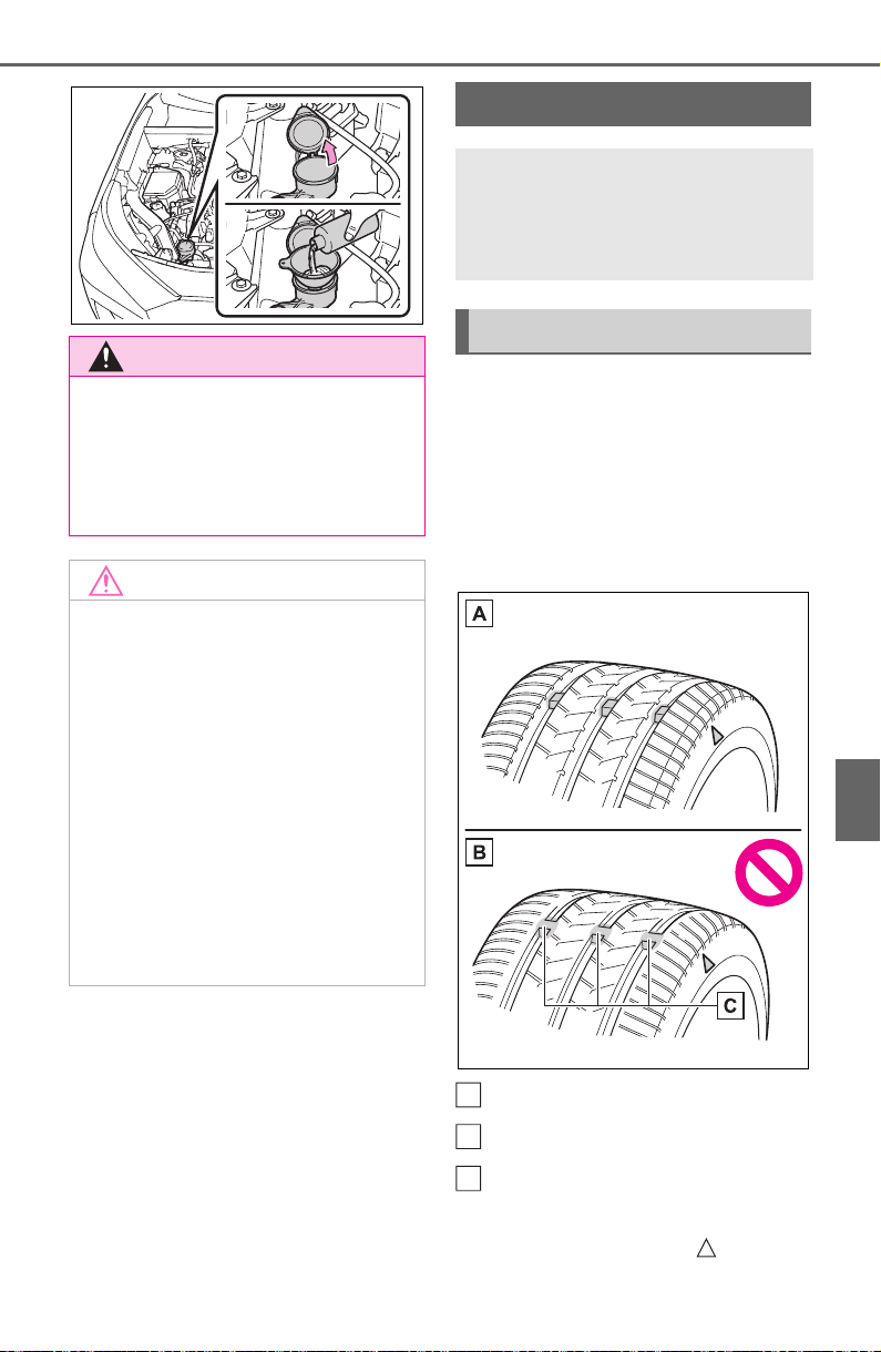
581
7-3. Do-it-yourself maintenance
7
Maintenance and care
Check if the treadwear indica-
tors are showing on the tires.
Also check the tires for uneven
wear, such as excessive wear
on one side of the tread.
Check the spare tire condition
and pressure if not rotated.
New tread
Worn tread
Treadwear indicator
The location of treadwear indicators
is shown by a “TWI” or “ ” mark,
WARNING
■ When adding washer fluid
Do not add washer fluid when the
engine is hot or running as
washer fluid contains alcohol and
may catch fire if spilled on the
engine, etc.
NOTICE
■ Do not use any fluid other
than washer fluid
Do not use soapy water or engine
antifreeze instead of washer fluid.
Doing so may cause streaking on
the vehicle’s painted surfaces, as
well as damaging the pump lead-
ing to problems of the washer
fluid not spraying.
■ Diluting washer fluid
Dilute washer fluid with water as
necessary.
Refer to the freezing tempera-
tures listed on the label of the
washer fluid bottle.
Tires
Replace or rotate tires in
accordance with mainte-
nance schedules and tread-
wear.
Checking tires
A
B
C
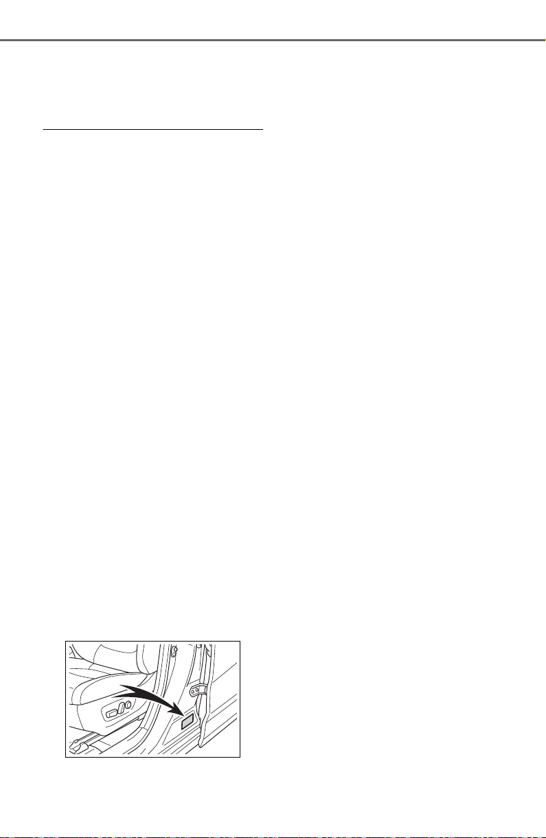
582
7-3. Do-it-yourself maintenance
etc., molded into the sidewall of
each tire.
Replace the tires if the treadwear
indicators are showing on a tire.
■ When to replace your vehicle’s
tires
Tires should be replaced if:
● The treadwear indicators are
showing on a tire.
● You have tire damage such as
cuts, splits, cracks deep enough
to expose the fabric, and bulges
indicating internal damage.
● A tire goes flat repeatedly or can-
not be properly repaired due to the
size or location of a cut or other
damage.
If you are not sure, consult with your
Toyota dealer.
■ Tire life
Any tire over 6 years old must be
checked by a qualified technician
even if it has seldom or never been
used or damage is not obvious.
■ Maximum load of tire
Check that the maximum load of the
replacement tire is greater than 1/2
of the Gross Axle Weight Ratings
(GAWR) of either the front axle or
the rear axle, whichever is greater.
For the GAWR, see the Certification
Regulation Label. For the maximum
load of the tire, see the load limit at
maximum cold tire inflation pressure
mentioned on the sidewall of the
tire. (P.678)
■ Tire types
● Summer tires
Summer tires are high-speed perfor-
mance tires best suited to highway
driving under dry conditions. Since
summer tires do not have the same
traction performance as snow tires,
summer tires are inadequate for
driving on snow-covered or icy
roads. For driving on snow-covered
roads or icy roads, the use of snow
tires is recommended. When install-
ing snow tires, be sure to replace all
four tires.
● All season tires
All season tires are designed to pro-
vide better traction in snow and to
be adequate for driving in most win-
ter conditions as well as for use
year-round. All season tires, how-
ever, do not have adequate traction
performance compared with snow
tires in heavy or loose snow. Also,
all season tires fall short in accelera-
tion and handling performance com-
pared with summer tires in highway
driving.
● Snow tires
For driving on snow-covered roads
or icy roads, we recommend using
snow tires. If you need snow tires,
select tires of the same size, con-
struction and load capacity as the
originally installed tires. Since your
vehicle has radial tires as original
equipment, make sure your snow
tires also have radial construction.
Do not install studded tires without
first checking local regulations for
possible restrictions. Snow tires
should be installed on all wheels.
(P.367)
■ If the tread on snow tires wears
down below 0.16 in. (4 mm)
The effectiveness of the tires as
snow tires is lost.
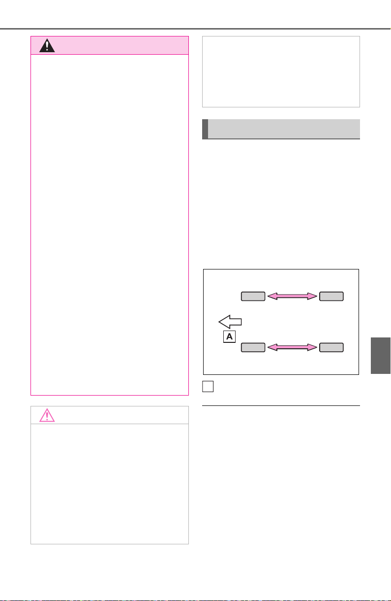
583
7-3. Do-it-yourself maintenance
7
Maintenance and care
Rotate the tires in the order
shown.
To equalize tire wear and extend
tire life, Toyota recommends that
tire rotation is carried out at the
same interval as tire inspection.
Do not fail to initialize the tire pres-
sure warning system after tire rota-
tion. (if equipped)
Front
■ When rotating the tires (vehi-
cles with tire pressure warning
system)
Make sure that the engine switch is
OFF. If the tires are rotated while the
engine switch is in ON, the tire posi-
tion information will not be updated.
If this accidentally occurs, either turn
the engine switch to OFF and then
to ON, or initialize the system after
checking that the tire pressure is
properly adjusted.
WARNING
■ When inspecting or replacing
tires
Observe the following precautions
to prevent accidents.
Failure to do so may cause dam-
age to parts of the drive train as
well as dangerous handling char-
acteristics, which may lead to an
accident resulting in death or seri-
ous injury.
● Do not mix tires of different
makes, models or tread pat-
terns.
Also, do not mix tires of remark-
ably different treadwear.
● Do not use tire sizes other than
those recommended by Toyota.
● Do not mix differently con-
structed tires (radial, bias-belted
or bias-ply tires).
● Do not mix summer, all season
and snow tires.
● Do not use tires that have been
used on another vehicle.
Do not use tires if you do not
know how they were used previ-
ously.
● Do not tow if your vehicle has a
compact spare tire installed.
NOTICE
■ Driving on rough roads
Take particular care when driving
on roads with loose surfaces or
potholes.
These conditions may cause
losses in tire inflation pressure,
reducing the cushioning ability of
the tires. In addition, driving on
rough roads may cause damage
to the tires themselves, as well as
the vehicle’s wheels and body.
■ If tire inflation pressure of
each tire becomes low while
driving
Do not continue driving, or your
tires and/or wheels may be
ruined.
Tire rotation
A

584
7-3. Do-it-yourself maintenance
Your vehicle is equipped with a
tire pressure warning system
that uses tire pressure warning
valves and transmitters to detect
low tire inflation pressure before
serious problems arise.
If the tire pressure drops
below a predetermined level,
the driver is warned a screen
display
*
and by a warning
light. (P.634)
*
: Vehicles with tire inflation pres-
sure display function only
Vehicles with tire inflation
pressure display function
only: The tire pressure
detected by the tire pressure
warning system can be dis-
played on the multi-informa-
tion display. (P. 85 )
The illustration used is intended
as an example, and may differ
from the image that is actually
displayed on the multi-informa-
tion display.
■ Routine tire inflation pressure
checks
The tire pressure warning system
does not replace routine tire inflation
pressure checks. Make sure to
check tire inflation pressure as part
of your routine of daily vehicle
checks.
■ Tire inflation pressure
*
*
: Vehicles with tire inflation pres-
sure display function only
● It may take a few minutes to dis-
play the tire inflation pressure
after the engine switch is turned to
ON. It may also take a few min-
utes to display the tire inflation
pressure after inflation pressure
has been adjusted.
● Tire inflation pressure changes
with temperature. The displayed
values may also be different from
the values measured using a tire
pressure gauge.
■ Situations in which the tire
pressure warning system may
not operate properly (if
equipped)
● In the following cases, the tire
pressure warning system may not
operate properly.
• If non-genuine Toyota wheels are
used.
• A tire has been replaced with a
tire that is not an OE (Original
Equipment) tire.
• A tire has been replaced with a
tire that is not of the specified size.
• Tire chains, etc. are equipped.
• An auxiliary-supported run-flat tire
is equipped.
• If a window tint that affects the
radio wave signals is installed.
• If there is a lot of snow or ice on
the vehicle, particularly around the
wheels or wheel housings.
• If the tire inflation pressure is
extremely higher than the speci-
fied level.
• If wheel without tire pressure
Tire pressure warning
system (if equipped)

585
7-3. Do-it-yourself maintenance
7
Maintenance and care
warning valves and transmitters
are used.
• If the ID code on the tire pressure
warning valves and transmitters is
not registered in the tire pressure
warning computer.
● Performance may be affected in
the following situations.
• Near a TV tower, electric power
plant, gas station, radio station,
large display, airport or other facil-
ity that generates strong radio
waves or electrical noise
• When carrying a portable radio,
cellular phone, cordless phone or
other wireless communication
device
If tire position information is not cor-
rectly displayed due to the radio
wave conditions, the display may be
corrected by driving and changing
the radio wave conditions.
● When the vehicle is parked, the
time taken for the warning to start
or go off could be extended.
● When tire inflation pressure
declines rapidly for example when
a tire has burst, the warning may
not function.
■ Warning performance of the tire
pressure warning system (if
equipped)
The warning of the tire pressure
warning system will change in
accordance with the conditions
under which it was initialized. For
this reason, the system may give a
warning even if the tire pressure
does not reach a low enough level,
or if the pressure is higher than the
pressure that was adjusted to when
the system was initialized.
■ Certification for tire pressure warning system
For vehicles sold in the U.S.A., Hawaii, American Samoa, Guam, Saipan
and Puerto Rico

586
7-3. Do-it-yourself maintenance
For vehicles sold in Canada

587
7-3. Do-it-yourself maintenance
7
Maintenance and care

588
7-3. Do-it-yourself maintenance
For vehicles sold in the U.S.A. and Canada

589
7-3. Do-it-yourself maintenance
7
Maintenance and care
*1
:Vehicles with tire pressure warn-
ing system only
When replacing tires or wheels,
tire pressure warning valves and
transmitters must also be
installed.
Except for models made in
Japan
*2
without tire inflation
pressure display function
When new tire pressure warning
valves and transmitters are
installed, new ID codes must be
registered in the tire pressure
warning computer and the tire
pressure warning system must
be initialized. (P.593)
*2
:The country of production is writ-
ten on the Certification Regula-
tion label. (P.665)
For models made in Japan
*2
without tire inflation pressure
display function
When new tire pressure warning
valves and transmitters are
installed, new ID codes must be
registered in the tire pressure
warning computer and the tire
pressure warning system must
be initialized. Have tire pressure
warning valve and transmitter ID
codes registered by your Toyota
dealer.
*2
:The country of production is writ-
ten on the Certification Regula-
tion label. (P.665)
■ When replacing the tires and
wheels (vehicles with tire pres-
sure warning system)
If the ID code of the tire pressure
warning valve and transmitter is not
registered, the tire pressure warning
system will not work properly. After
driving for about 20 minutes, the tire
pressure warning light blinks for 1
minute and stays on to indicate a
system malfunction.
Installing tire pressure
warning valves and trans-
mitters
*1
NOTICE
■ Repairing or replacing tires,
wheels, tire pressure warn-
ing valves, transmitters and
tire valve caps (vehicles with
tire pressure warning system)
● When removing or fitting the
wheels, tires or the tire pressure
warning valves and transmit-
ters, contact your Toyota dealer
as the tire pressure warning
valves and transmitters may be
damaged if not handled cor-
rectly.
● Make sure to install the tire
valve caps. If the tire valve caps
are not installed, water could
enter the tire pressure warning
valves and the tire pressure
warning valves could be bound.
● When replacing tire valve caps,
do not use tire valve caps other
than those specified.
The cap may become stuck.
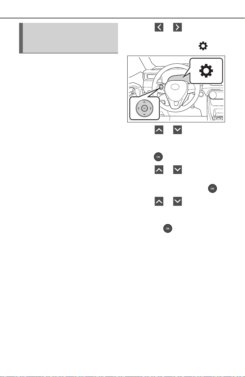
590
7-3. Do-it-yourself maintenance
■ The tire pressure warning
system must be initialized
in the following circum-
stances:
When rotating the tires.
When changing the tire.
After registering the ID codes.
(P.593)
When the tire pressure warning
system is initialized, the current
tire inflation pressure is set as
the benchmark pressure.
■ How to initialize the tire
pressure warning system
Vehicles without tire inflation
pressure display function
1 Park the vehicle in a safe
place and stop the engine.
Initialization cannot be performed
while the vehicle is moving.
2 Adjust the tire inflation pres-
sure to the specified cold tire
inflation pressure level.
(P.671)
Make sure to adjust the tire pres-
sure to the specified cold tire infla-
tion pressure level. The tire
pressure warning system will oper-
ate based on this pressure level.
3 Turn the engine switch to
ON.
4 Press or of the meter
control switches on the steer-
ing wheel and select .
5 Press or of the meter
control switches, select
“Vehicle Settings” and then
press .
6 Press or of the meter
control switches, select
“TPWS” and then press .
7 Press or of the meter
control switches, select the
“Set Pressure”. Then press
and hold .
“Setting Tire Pressure Warning
System” will be displayed on the
multi-information display and the
tire pressure warning light will blink
3 times.
When the message disappears, ini-
tialization is complete.
Vehicles with tire inflation
pressure display function
1 Park the vehicle in a safe
place and stop the engine for
20 minutes or more.
Initialization cannot be performed
while the vehicle is moving.
2 Adjust the tire inflation pres-
sure to the specified cold tire
Initializing the tire pres-
sure warning system (if
equipped)
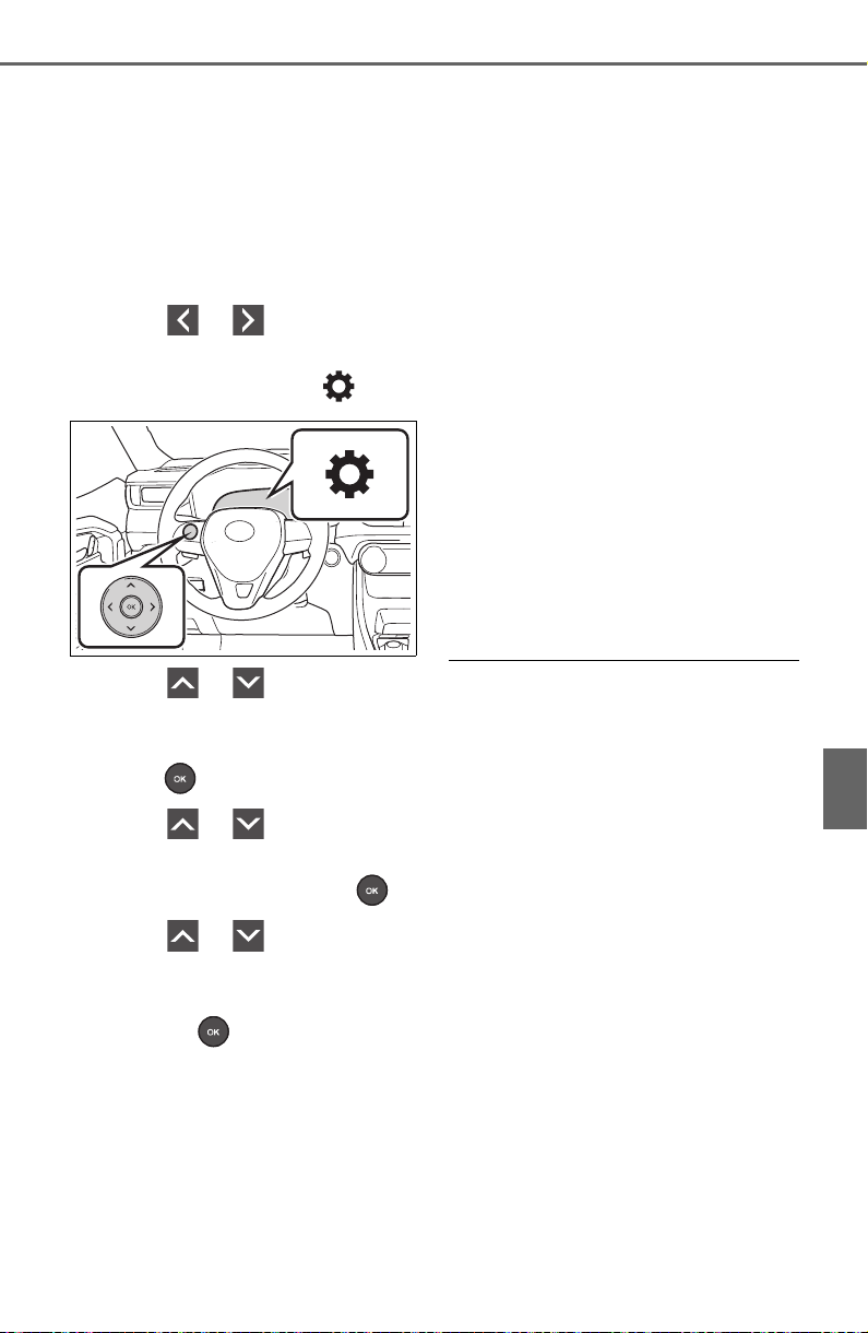
591
7-3. Do-it-yourself maintenance
7
Maintenance and care
inflation pressure level.
(P.671)
Make sure to adjust the tire pres-
sure to the specified cold tire infla-
tion pressure level. The tire
pressure warning system will oper-
ate based on this pressure level.
3 Start the engine.
4 Press or of the meter
control switches on the steer-
ing wheel and select .
5 Press or of the meter
control switches, select
“Vehicle Settings” and then
press .
6 Press or of the meter
control switches, select
“TPWS” and then press .
7 Press or of the meter
control switches, select the
“Set Pressure”. Then press
and hold .
“Setting Tire Pressure Warning
System” will be displayed on the
multi-information display and the
tire pressure warning light will blink
3 times.
When the message disappears, ini-
tialization is complete.
A message is displayed on the
multi-information display. Also, “--”
is displayed for inflation pressure of
each tire on the multi-information
display while the tire pressure
warning system determines the
position.
8 Drive the vehicle at approxi-
mately 25mph (40 km/h) or
more for approximately 10 to
30 minutes.
When initialization is complete, the
inflation pressure of each tire will be
displayed on the multi-information
display.
Even if the vehicle is not driven at
approximately 25 mph (40 km/h) or
more, initialization can be com-
pleted by driving for a long time.
However, if initialization does not
complete after driving for 1 hour or
more, park the vehicle in a safe
place for approximately 20 minutes
and then drive the vehicle again.
■ When initializing
● Vehicles with tire inflation pres-
sure display function only: Initial-
ization is performed while driving
at a vehicle speed of approxi-
mately 25 mph (40 km/h) or more.
● Make sure to carry out initializa-
tion after adjusting the tire inflation
pressure. Also, make sure the
tires are cold before carrying out
initialization or tire inflation pres-
sure adjustment.
● Vehicles with tire inflation pres-
sure display function only: The tire
pressure warning system can be
initialized by yourself, but depend-
ing on the driving conditions and
driving environment, initialization
may take some time to complete.
■ The initialization operation
● If you have accidentally turned the
engine switch to OFF during ini-
tialization, it is not necessary to
restart the initialization again as
initialization will restart automati-

592
7-3. Do-it-yourself maintenance
cally when the engine switch has
been turned to ON for the next
time.
● If you accidentally perform the ini-
tialization when initialization is not
necessary, adjust the tire inflation
pressure to the specified level
when the tires are cold, and con-
duct initialization again.
● Vehicles with tire inflation pres-
sure display function only: While
the position of each tire is being
determined and the inflation pres-
sures are not being displayed on
the multi-information display, if the
inflation pressure of a tire drops,
the tire pressure warning light will
come on.
■ When initialization of the tire
pressure warning system has
failed (vehicles without tire
inflation pressure display func-
tion)
Initialization can be completed in a
few minutes. However, in the follow-
ing cases, the settings have not
been recorded and the system will
not operate properly. If repeated
attempts to record tire inflation pres-
sure settings are unsuccessful,
have the vehicle inspected by your
Toyota dealer.
● When operating the tire pressure
warning reset switch, the tire pres-
sure warning light does not blink 3
times.
● After driving for a certain period of
time since the initialization has
been completed, the warning light
comes on after blinking for 1 min-
ute.
■ If the tire pressure warning sys-
tem is not initialized properly
(vehicles with tire inflation pres-
sure display function)
In the following situations, initializa-
tion may take longer than usual to
be completed or may not be possi-
ble. Normally, initialization com-
pletes within approximately 30
minutes.
• Vehicle is not driven at approxi-
mately 25 mph (40 km/h) or more
• Vehicle is driven on unpaved
roads
• Vehicle is driven near other vehi-
cles and system cannot recog-
nize tire pressure warning valve
and transmitters of your vehicle
over those of other vehicles.
If initialization does not complete
after driving for 1 hour or more, park
the vehicle in a safe place for
approximately 20 minutes and then
drive the vehicle again.
● If the vehicle is reversed during
initialization, the data up to that
point is reset, so perform the ini-
tialization procedure again from
the beginning.
● In the following situations, initial-
ization will not be started or was
not completed properly and the
system will not operate properly.
Perform the initialization proce-
dure again.
• If, when attempting to start initial-
ization, the tire pressure warning
light does not blink 3 times.
• If, when the vehicle has been
driven for about 20 minutes after
performing initialization, the tire
pressure warning light blinks for
approximately 1 minute and then
illuminates.
If the inflation pressure of each tire
is still not displayed, have the vehi-
cle inspected by your Toyota dealer.
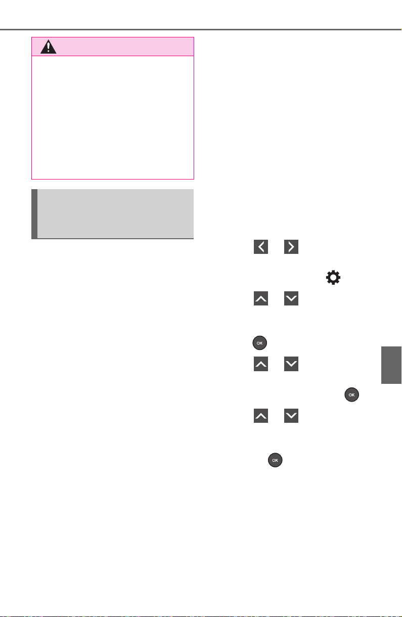
593
7-3. Do-it-yourself maintenance
7
Maintenance and care
For models made in Japan
*1
without tire inflation pressure
display function
Every tire pressure warning
valve and transmitter has a
unique ID code. In addition to
the set of tire pressure warning
system sensor ID codes initially
registered to the vehicle, a sec-
ond set of ID codes can be reg-
istered. A second set of tire
pressure warning system sensor
ID codes can be registered at
your Toyota dealer. When 2 sets
of ID codes have been regis-
tered, either ID code set can be
selected.
*1
:The country of production is writ-
ten on the Certification Regula-
tion label. (P.665)
Except for models made in
Japan
*2
without tire inflation
pressure display function
*2
:The country of production is writ-
ten on the Certification Regula-
tion label. (P.665)
Every tire pressure warning
valve and transmitter has a
unique ID code. When replacing
a tire pressure warning valve
and transmitter, it is necessary
to register the ID code.
When registering the ID codes,
perform the following procedure.
1 Park the vehicle in a safe
place, wait for approximately
20 minutes, and then start
the engine.
2 Press or of the meter
control switches on the steer-
ing wheel and select .
3 Press or of the meter
control switches and select
“Vehicle Settings”, and then
press .
4 Press or of the meter
control switches and select
“TPWS”, and then press .
5 Press or of the meter
control switches and select
“Change Wheel”. Then press
and hold until the tire
pressure warning light starts
slowly blinking 3 times.
The change wheel set mode is acti-
vated and registration is started.
Vehicles with a tire inflation pres-
sure display function only: Then a
message will be displayed on the
multi-information display. When
registration is being performed, the
tire pressure warning light will blink
WARNING
■ When initializing the tire pres-
sure warning system
Do not initializing tire inflation
pressure without first adjusting
the tire inflation pressure to the
specified level. Otherwise, the tire
pressure warning light may not
come on even if the tire inflation
pressure is low, or it may come on
when the tire inflation pressure is
actually normal.
Registering ID codes
(vehicles with tire pres-
sure warning system)
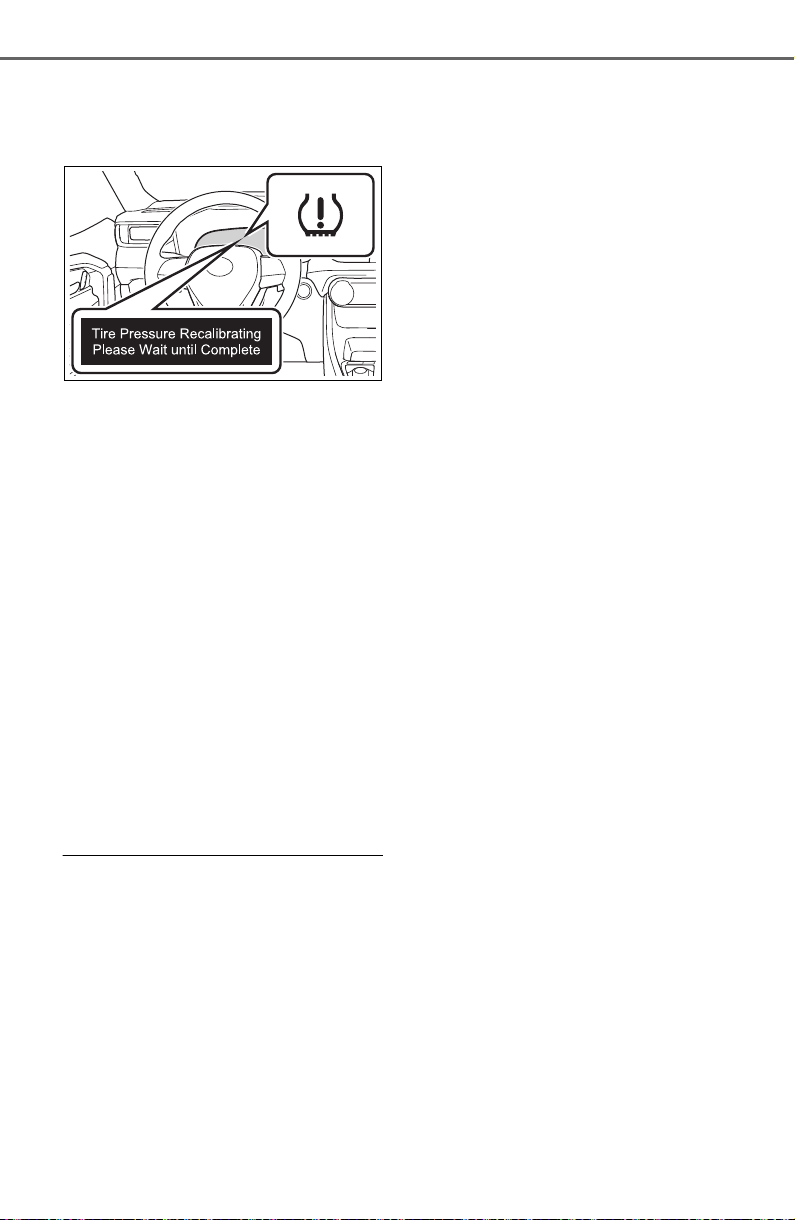
594
7-3. Do-it-yourself maintenance
for approximately 1 minute then illu-
minate and “--” will be displayed for
the inflation pressure of each tire on
the multi-information display.
6 Drive the vehicle at approxi-
mately 25mph (40 km/h) or
more for approximately 10 to
30 minutes.
When registration is completed, the
tire pressure warning light will go off
and the inflation pressure of each
tire will be displayed on the multi-
information display.
Even if the vehicle is not driven at
approximately 25 mph (40 km/h) or
more, registration can be com-
pleted by driving for a long time.
However, if registration does not
complete after driving for 1 hour or
more, perform the procedure again
from the beginning.
7 Initialize the tire pressure
warning system. (P.590)
■ When registering ID codes
● ID code registration is performed
while driving at a vehicle speed of
approximately 25 mph (40 km/h)
or more.
● Before performing ID code regis-
tration, make sure that no wheels
with tire pressure warning valve
and transmitters installed are near
the vehicle.
● Make sure to initialize the tire
pressure warning system after
registering the ID codes. If the
system is initialized before regis-
tering the ID codes, the initialized
values will be invalid.
● ID codes can be registered by
yourself, but depending on the
driving conditions and driving
environment, registration may
take some time to complete.
■ Canceling ID code registration
● To cancel ID code registration
after it has been started, turn the
engine switch off before driving
the vehicle. If the vehicle is driven
after ID code registration is
started, to cancel registration, per-
form the ID code registration start
procedure again and turn the
engine switch off before driving.
● If ID code registration has been
canceled, the tire pressure warn-
ing light will blink for approxi-
mately 1 minute when the engine
switch is turned to ON and then
illuminate. The tire pressure warn-
ing system will be operational
when the tire pressure warning
light turns off.
● If the warning light does not turn
off even after several minutes
have elapsed, ID code registration
may not have been canceled cor-
rectly. To cancel registration, per-
form the ID code registration start
procedure again and then turn the
engine switch off before driving.
■ If ID codes are not registered
properly
In the following situations, ID code
registration may take longer than
usual to be completed or may not be
possible. Normally, registration com-
pletes within approximately 30 min-
utes.
• Vehicle is not parked for approxi-
mately 20 minutes or more before
driving
• Vehicle is not driven at approxi-
mately 25 mph (40 km/h) or more
• Vehicle is driven on unpaved
roads

595
7-3. Do-it-yourself maintenance
7
Maintenance and care
• Vehicle is driven near other vehi-
cles and system cannot recog-
nize tire pressure warning valve
and transmitters of your vehicle
over those of other vehicles
• Wheel with tire pressure warning
valve and transmitter installed is
inside or near the vehicle
If registration does not complete
after driving for 1 hour or more, per-
form the ID code registration proce-
dure again from the beginning.
● If the vehicle is reversed during
registration, the data up to that
point is reset, so perform the reg-
istration procedure again from the
beginning.
● In the following situations, ID code
registration will not be started or
was not completed properly and
the system will not operate prop-
erly. Perform the ID code registra-
tion procedure again.
• If, when attempting to start ID
code registration, the tire pressure
warning light does not blink slowly
3 times.
• If, when the vehicle has been
driven for about 20 minutes after
performing ID code registration,
the tire pressure warning light
blinks for approximately 1 minute
and then illuminates.
If the ID codes cannot be registered
even when performing the above
procedure, contact your Toyota
dealer.
The recommended cold tire
inflation pressure and tire size
are displayed on the tire and
loading information label.
(P.671)
Tire inflation pressure
Make sure to maintain the
proper tire inflation pres-
sure. Tire inflation pressure
should be checked at least
once per month. However,
Toyota recommends that
tire inflation pressure be
checked once every two
weeks. (P. 67 1 )
Checking the specified
tire inflation pressure
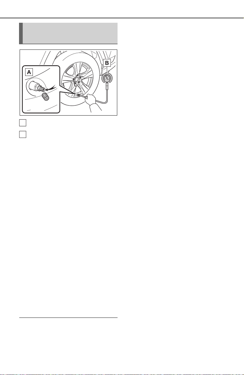
596
7-3. Do-it-yourself maintenance
Tire valve
Tire pressure gauge
1 Remove the tire valve cap.
2 Press the tip of the tire pres-
sure gauge onto the tire
valve.
3 Read the pressure using the
gauge gradations.
4 If the tire inflation pressure is
not at the recommended
level, adjust the pressure. If
you add too much air, press
the center of the valve to
deflate.
5 After completing the tire infla-
tion pressure measurement
and adjustment, apply soapy
water to the valve and check
for leakage.
6 Put the tire valve cap back
on.
■ Tire inflation pressure check
interval
You should check tire inflation pres-
sure every two weeks, or at least
once a month.
Do not forget to check the spare.
■ Effects of incorrect tire inflation
pressure
Driving with incorrect tire inflation
pressure may result in the following:
● Reduced fuel economy
● Reduced driving comfort and poor
handling
● Reduced tire life due to wear
● Reduced safety
● Damage to the drive train
If a tire needs frequent inflating,
have it checked by your Toyota
dealer.
■ Instructions for checking tire
inflation pressure
When checking tire inflation pres-
sure, observe the following:
● Check only when the tires are
cold.
If your vehicle has been parked for
at least 3 hours or has not been
driven for more than 1 mile or 1.5
km, you will get an accurate cold
tire inflation pressure reading.
● Always use a tire pressure gauge.
It is difficult to judge if a tire is
properly inflated based only on its
appearance.
● It is normal for the tire inflation
pressure to be higher after driving
as heat is generated in the tire. Do
not reduce tire inflation pressure
after driving.
● Never exceed the vehicle capacity
weight. Passengers and luggage
weight should be placed so that
the vehicle is balanced.
Inspection and adjust-
ment procedure
A
B
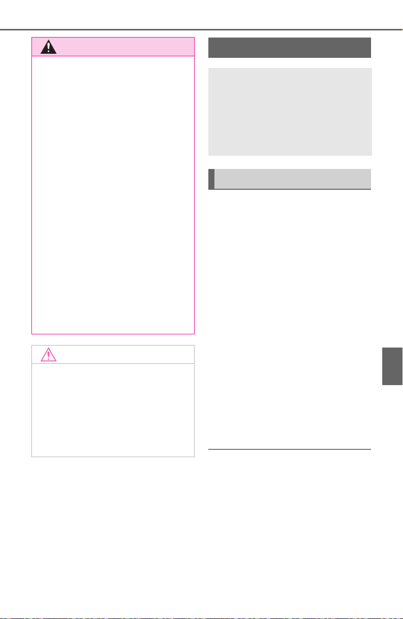
597
7-3. Do-it-yourself maintenance
7
Maintenance and care
When replacing wheels, care
should be taken to ensure that
they are equivalent to those
removed in load capacity, diam-
eter, rim width and inset
*
.
Replacement wheels are avail-
able at your Toyota dealer.
*
: Conventionally referred to as off-
set.
Toyota does not recommend
using the following:
Wheels of different sizes or
types
Used wheels
Bent wheels that have been
straightened
■ When replacing wheels (vehi-
cles with tire pressure warning
system)
The wheels of your vehicle are
equipped with tire pressure warning
valves and transmitters that allow
the tire pressure warning system to
provide advance warning in the
event of a loss in tire inflation pres-
sure. Whenever wheels are
replaced, tire pressure warning
valves and transmitters must be
installed. (P.584, 598)
WARNING
■ Proper inflation is critical to
save tire performance
Keep your tires properly inflated.
If the tires are not properly
inflated, the following conditions
may occur which could lead to an
accident resulting in death or seri-
ous injury:
● Excessive wear
● Uneven wear
● Poor handling
● Possibility of blowouts resulting
from overheated tires
● Air leaking from between tire
and wheel
● Wheel deformation and/or tire
damage
● Greater possibility of tire dam-
age while driving (due to road
hazards, expansion joints,
sharp edges in the road, etc.)
NOTICE
■ When inspecting and adjust-
ing tire inflation pressure
Be sure to put the tire valve caps
back on.
If a valve cap is not installed, dirt
or moisture may get into the valve
and cause an air leak, resulting in
decreased tire inflation pressure.
Wheels
If a wheel is bent, cracked or
heavily corroded, it should
be replaced. Otherwise, the
tire may separate from the
wheel or cause a loss of
handling control.
Wheel selection

598
7-3. Do-it-yourself maintenance
Use only Toyota wheel nuts
and wrenches designed for
use with your aluminum
wheels.
When rotating, repairing or
changing your tires, check
that the wheel nuts are still
tight after driving 1000 miles
(1600 km).
Be careful not to damage the
aluminum wheels when using
tire chains.
Use only Toyota genuine bal-
ance weights or equivalent
and a plastic or rubber ham-
mer when balancing your
wheels.
WARNING
■ When replacing wheels
● Do not use wheels that are a dif-
ferent size from those recom-
mended in the Owner’s Manual,
as this may result in a loss of
handling control.
● Never use an inner tube in a
leaking wheel which is designed
for a tubeless tire. Doing so may
result in an accident, causing
death or serious injury.
■ When installing the wheel
nuts
● Be sure to install the wheel nuts
with the tapered ends facing
inward. (P.647) Installing the
nuts with the tapered ends fac-
ing outward can cause the
wheel to break and eventually
cause the wheel to come off
while driving, which could lead
to an accident resulting in death
or serious injury.
● Never use oil or grease on the
wheel bolts or wheel nuts. Oil
and grease may cause the
wheel nuts to be excessively
tightened, leading to bolt or disc
wheel damage. In addition, the
oil or grease can cause the
wheel nuts to loosen and the
wheel may fall off, causing an
accident and resulting in death
or serious injury. Remove any
oil or grease from the wheel
bolts or wheel nuts.
■ Use of defective wheels pro-
hibited
Do not use cracked or deformed
wheels.
Doing so could cause the tire to
leak air during driving, possibly
causing an accident.
NOTICE
■ Replacing tire pressure warn-
ing valves and transmitters
(vehicles with tire pressure
warning system)
● Because tire repair or replace-
ment may affect the tire pres-
sure warning valves and
transmitters, make sure to have
tires serviced by your Toyota
dealer or other qualified service
shop. In addition, make sure to
purchase your tire pressure
warning valves and transmit-
ters at your Toyota dealer.
● Ensure that only genuine Toyota
wheels are used on your vehi-
cle.
Tire pressure warning valves
and transmitters may not work
properly with non-genuine
wheels.
Aluminum wheel precau-
tions

599
7-3. Do-it-yourself maintenance
7
Maintenance and care
1 Turn the engine switch off.
2 Open the glove box and slide
off the damper.
3 Push in each side of the
glove box to disconnect the
claws, and then slowly and
fully open the glove box while
supporting it.
4 With the glove box fully open,
slightly lift up the glove box
and pull toward the seat to
detach the bottom of the
glove box.
Do not use excessive force if the
glove box does not detach when
lightly pulled. Instead, pull toward
the seat while slightly adjusting the
height of the glove box.
5 Unlock the filter cover ( ),
pull the filter cover out of the
claws ( ), and remove the
filter cover.
Air conditioning filter
The air conditioning filter
must be changed regularly
to maintain air conditioning
efficiency.
Removal method
A
B
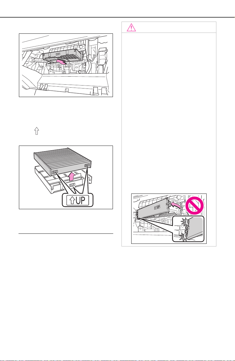
600
7-3. Do-it-yourself maintenance
6 Remove the filter case.
7 Remove the air conditioning
filter from the filter case and
replace it with a new one.
The “ UP” marks shown on the
filter should be pointing up.
8 When installing, reverse the
steps listed.
■ Checking interval
Inspect and replace the air condi-
tioning filter according to the mainte-
nance schedule. In dusty areas or
areas with heavy traffic flow, early
replacement may be required. (For
scheduled maintenance information,
please refer to the “Owner’s Manual
Supplement” or “Scheduled Mainte-
nance”.)
■ If air flow from the vents
decreases dramatically
The filter may be clogged. Check
the filter and replace if necessary.
NOTICE
■ When using the air condition-
ing system
Make sure that a filter is always
installed.
Using the air conditioning system
without a filter may cause damage
to the system.
■ When removing the glove box
Always follow the specified proce-
dure to remove the glove box
(P.599). If the glove box is
removed without following the
specified procedure, the hinge of
the glove box may become dam-
aged.
■ To prevent damage to the fil-
ter cover
When moving the filter cover in
the direction of arrow to release
the fitting, pay attention not to
apply excessive force to the
claws. Otherwise, the claws may
be damaged.
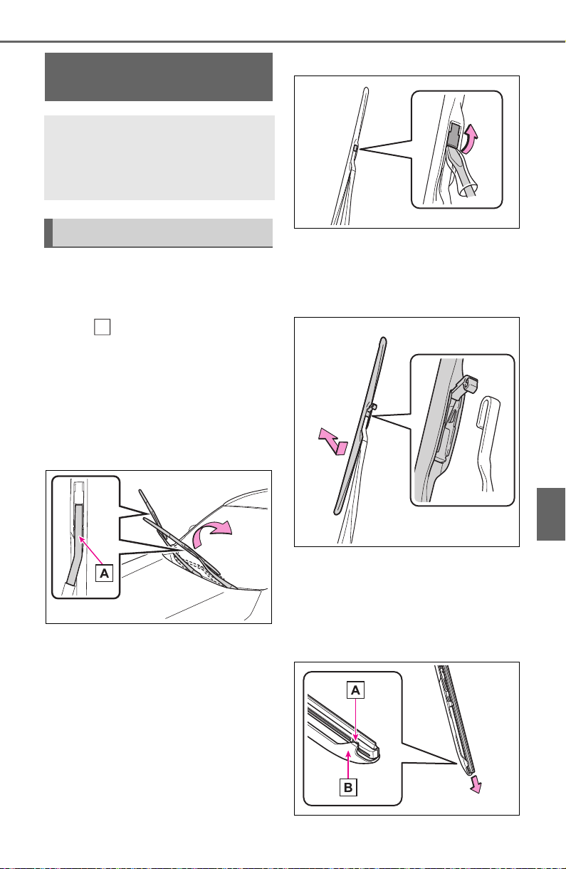
601
7-3. Do-it-yourself maintenance
7
Maintenance and care
■ Windshield wiper blade
removal and installation
1 While holding the hook por-
tion of the wiper arm, first
lift up the driver side, and
then lift up the passenger
side.
When returning the wiper arms to
their original positions, first lower
the passenger side, and then lower
the driver side.
2 Lift the stopper using a flat-
head screwdriver as shown
in the illustration.
To prevent damage to the wiper
arm, protect the tip of the screw-
driver with a rag.
3 Slide the wiper blade to
remove it from the wiper arm.
When installing, reverse the steps
listed.
■ Wiper insert replacement
1 Pull the wiper insert to
remove the claw of the wiper
blade from the stopper, and
pull out the wiper insert.
Wiper insert replace-
ment
When replacing the wiper
insert, perform the following
procedure to operate each
wiper.
Windshield wipers
A
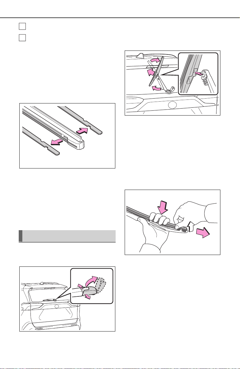
602
7-3. Do-it-yourself maintenance
Stopper
Claw
2 Remove the 2 metal plates
from the wiper insert pulled
out, and install the plates to a
new wiper insert.
Make sure that the cutout location
and warp direction of the metal
blades are same as the original.
3 Install the wiper insert to the
wiper blade from the side
without the stopper.
4 Secure the stopper of the
wiper insert with the claw of
the wiper blade.
1 Lift up the rear window wiper
arm head cap.
2 Move the wiper blade until a
click sound can be heard and
the claw detaches, and then
remove the wiper blade from
the wiper arm.
3 Pull the wiper insert out past
the stopper on the wiper
blade, and then continue to
pull until it is completely
removed.
Lightly grasp between the claws of
the wiper blade to allow the wiper
insert to lift up, making it easier to
remove.
4 Remove the 2 metal plates
from the old wiper insert and
Rear window wiper
A
B
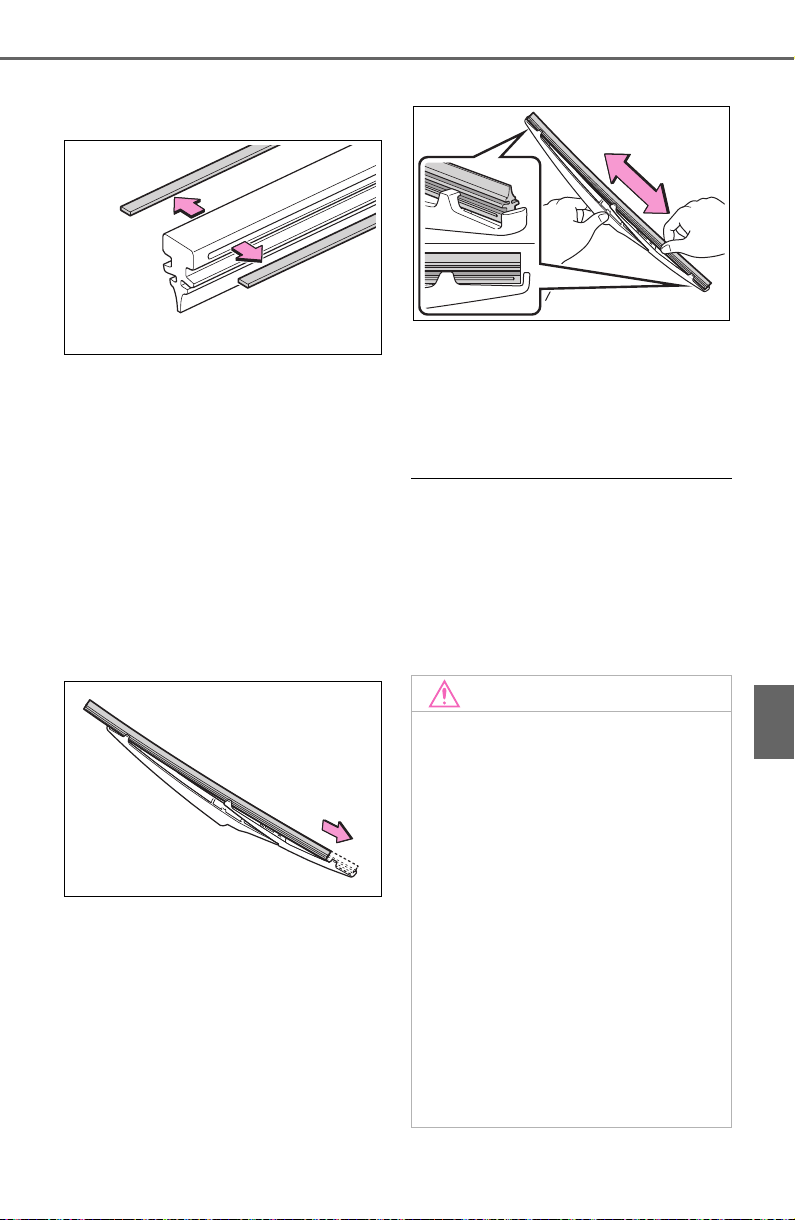
603
7-3. Do-it-yourself maintenance
7
Maintenance and care
install them to the replace-
ment wiper insert.
5 Insert the wiper insert starting
from the claw at the center of
the wiper blade. Pass the
wiper insert through the 3
claws so that it sticks out
from the stopper, and then
pass the wiper insert through
the final remaining claw.
Applying a small amount of washer
fluid to the wiper insert can make it
easier to insert the claws into the
grooves.
6 Check that the wiper blade
claws are fitted in the
grooves of the wiper insert.
If the wiper blade claws are not fit-
ted in the grooves of the wiper
insert, grasp the wiper insert and
slide it back and forth multiple times
to insert the claws into the grooves.
Lightly lift up the center of the wiper
insert to make the rubber easier to
slide.
7 When installing a wiper
blade, reverse the procedure
in step 1.
After installing the wiper blade,
check that the connection is locked.
■ Wiper blade and wiper insert
handling
Improper handling may result in
damage to the wiper blades or wiper
insert. If you have any concerns
about replacing the wiper blades or
wiper insert yourself, contact your
Toyota dealer.
NOTICE
■ When lifting the windshield
wipers
● When raising the wiper arms off
the windshield, lift up the driver
side first, and then lift up pas-
senger side. When returning the
wipers to their original position,
return the passenger side first.
● Do not lift a windshield wiper by
the wiper blade. Otherwise, the
wiper blade may be deformed.
● Do not operate the wiper lever
when the windshield wipers are
lifted. Otherwise, the wind-
shield wipers may contact the
hood, possibly resulting in dam-
age to the windshield wipers
and/or hood.

604
7-3. Do-it-yourself maintenance
■ If the key battery is depleted
The following symptoms may occur:
● The smart key system (if
equipped) and wireless remote
control will not function properly.
● The operational range will be
reduced.
Prepare the following before
replacing the battery:
Flathead screwdriver
Small flathead screwdriver
Lithium battery CR2032
■ Use a CR2032 lithium battery
● Batteries can be purchased at
your Toyota dealer, local electrical
appliance shops or camera stores.
● Replace only with the same or
equivalent type recommended by
the manufacturer.
● Dispose of used batteries accord-
ing to the local laws.
Vehicles without smart key
system
1 Remove the cover.
Use a screwdriver of an appropriate
size. Forcedly prying may cause
the cover damaged.
NOTICE
■ To prevent damage
● Be careful not to damage the
claws when replacing the wiper
insert.
● After the wiper blade is removed
from the wiper arm, place a
cloth, etc., between the rear
window and wiper arm to pre-
vent damage to the rear win-
dow.
● Be sure not to pull excessively
on the wiper insert or deform its
metal plates.
Wireless remote con-
trol/electronic key bat-
tery
Replace the battery with a
new one if it is depleted.
Items to prepare
Replacing the battery
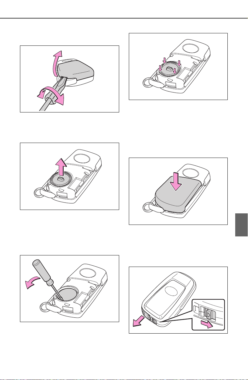
605
7-3. Do-it-yourself maintenance
7
Maintenance and care
To prevent damage to the key,
cover the tip of the screwdriver with
a rag.
2 Remove the battery cover.
If the battery cover is difficult to
remove, lift the edge to remove it.
3 Remove the depleted battery.
When removing the battery, use a
screwdriver of an appropriate size.
Insert a new battery with the “+” ter-
minal facing up.
4 Install the battery cover with
the tab facing up.
Push the entire edge of the battery
cover into the key.
5 Install the key cover.
Align the key cover with the key
and then press it straight into the
key.
Make sure that the key cover is
securely installed without any gaps
between it and the key.
Vehicles with smart key sys-
tem
1 Release the lock and remove
the mechanical key.
2 Remove the key cover.
Use a screwdriver of an appropriate
size. Forcedly prying may cause
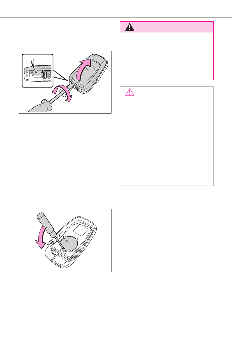
606
7-3. Do-it-yourself maintenance
the cover damaged.
To prevent damage to the key,
cover the tip of the flathead screw-
driver with a rag.
3 Remove the depleted battery
using a small flathead screw-
driver.
When removing the cover, the elec-
tronic key module may stick to the
cover and the battery may not be
visible. In this case, remove the
electronic key module in order to
remove the battery.
When removing the battery, use a
screwdriver of an appropriate size.
Insert a new battery with the “+” ter-
minal facing up.
4 When installing, reverse the
steps listed.
WARNING
■ Removed battery and other
parts
These parts are small and if swal-
lowed by a child, they can cause
choking. Keep away from chil-
dren. Failure to do so could result
in death or serious injury.
NOTICE
■ For normal operation after
replacing the battery
Observe the following precautions
to prevent accidents:
● Always work with dry hands.
Moisture may cause the battery
to rust.
● Do not touch or move any other
component inside the remote
control.
● Do not bend either of the battery
terminals.
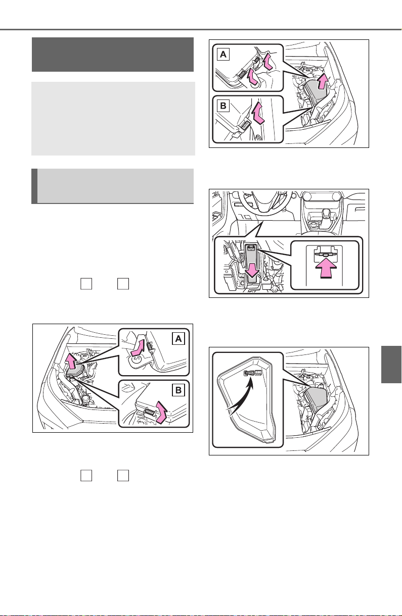
607
7-3. Do-it-yourself maintenance
7
Maintenance and care
1 Turn the engine switch off.
2 Open the fuse box cover.
Engine compartment: Type A
fuse box (if equipped)
Push claw and to com-
pletely release the lock, and then lift
up the cover.
Engine compartment: Type B
fuse box
Push claw and to com-
pletely release the lock, and then lift
up the cover.
Left side instrument panel
Remove the lid.
3 Remove the fuse.
Only type A fuse can be removed
using the pullout tool.
4 Check if the fuse is blown.
Replace the blown fuse with a new
fuse of an appropriate amperage
rating. The amperage rating can be
found on the fuse box lid.
Checking and replac-
ing fuses
If any of the electrical com-
ponents do not operate, a
fuse may have blown. If this
happens, check and replace
the fuses as necessary.
Checking and replacing
fuses
A
B
A
B
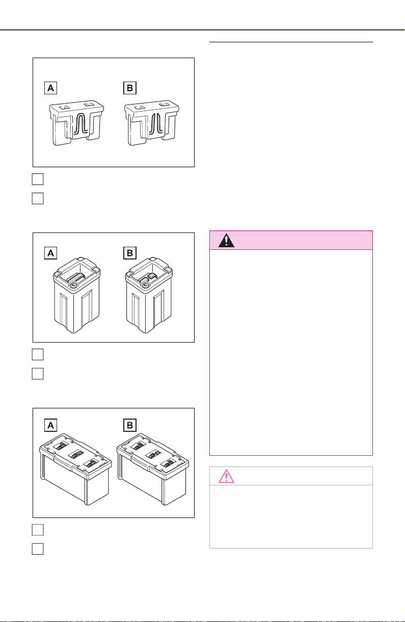
608
7-3. Do-it-yourself maintenance
Type A
Normal fuse
Blown fuse
Type B
Normal fuse
Blown fuse
Type C
Normal fuse
Blown fuse
■ After a fuse is replaced
● When installing the lid, make sure
that the tab is installed securely.
● If the lights do not turn on even
after the fuse has been replaced,
a bulb may need replacement.
(P.609)
● If the replaced fuse blows again,
have the vehicle inspected by
your Toyota dealer.
■ If there is an overload in a cir-
cuit
The fuses are designed to blow, pro-
tecting the wiring harness from
damage.
A
B
A
B
A
B
WARNING
■ To prevent system break-
downs and vehicle fire
Observe the following precau-
tions.
Failure to do so may cause dam-
age to the vehicle, and possibly a
fire or injury.
● Never use a fuse of a higher
amperage rating than that indi-
cated, or use any other object in
place of a fuse.
● Always use a genuine Toyota
fuse or equivalent.
Never replace a fuse with a
wire, even as a temporary fix.
● Do not modify the fuses or fuse
boxes.
NOTICE
■ Before replacing fuses
Have the cause of electrical over-
load determined and repaired by
your Toyota dealer as soon as
possible.
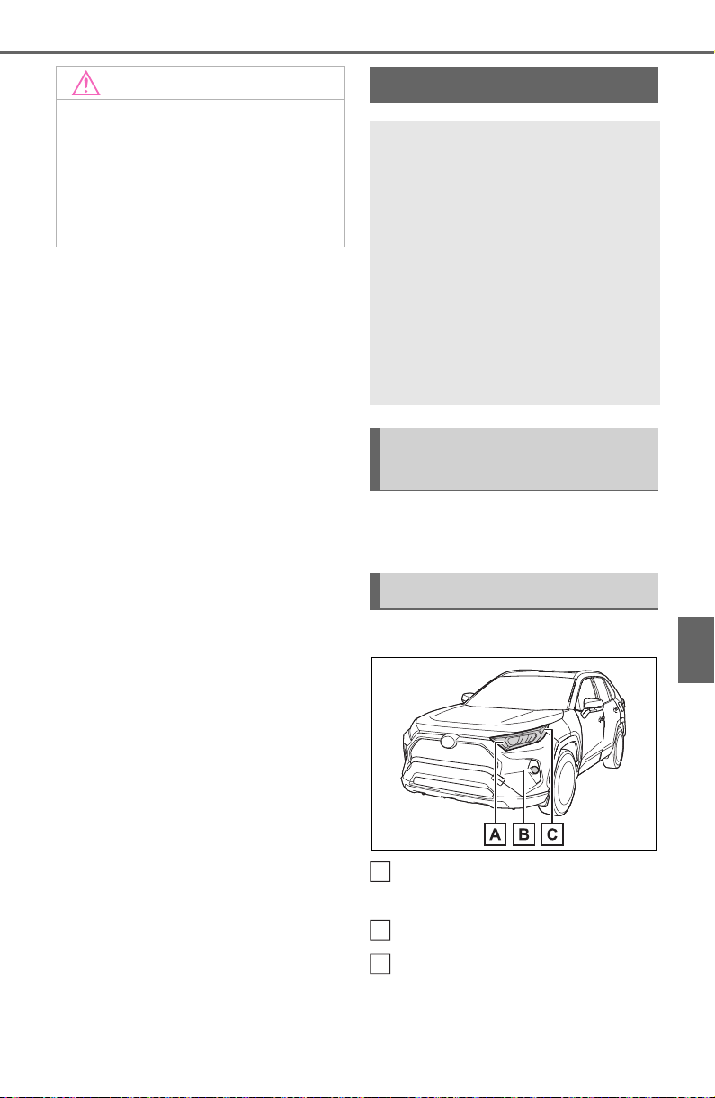
609
7-3. Do-it-yourself maintenance
7
Maintenance and care
Check the wattage of the light
bulb to be replaced. (P.675)
Front (type A)
Front turn signal/parking
lights
Fog lights (if equipped)
Front side marker lights
NOTICE
■ To prevent damage to the
engine compartment fuse box
cover
When opening the fuse box, com-
pletely release the claw locks
before lifting up the cover. Other-
wise, the claws may be damaged.
Light bulbs
You may replace the follow-
ing bulbs by yourself. The
difficulty level of replace-
ment varies depending on
the bulb. If necessary bulb
replacement seems difficult
to perform, contact your
Toyota dealer.
For more information about
replacing other light bulbs,
contact your Toyota dealer.
Preparing for light bulb
replacement
Bulb location
A
B
C
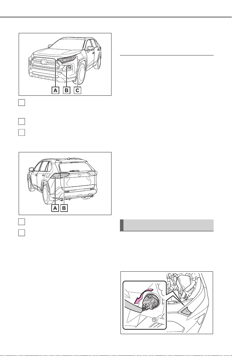
610
7-3. Do-it-yourself maintenance
Front (type B)
Front turn signal/parking
lights
Fog lights
Front side marker lights
Rear
Rear turn signal lights
Back-up lights
■ Lights that need to be
replaced by your Toyota
dealer
Headlights
Daytime running lights
Side turn signal lights (if
equipped)
Tail lights
Stop lights
Rear side marker lights
High mounted stoplight
License plate lights
Outer foot lights (if equipped)
■ LED lights
The lights other than the following
lights each consist of a number of
LEDs. If any of the LEDs burn out,
take your vehicle to your Toyota
dealer to have the light replaced.
● Front turn signal lights
● Parking lights
● Front side marker lights
● Fog lights (if equipped)
● Rear turn signal lights
● Back-up lights
■ Condensation build-up on the
inside of the lens
Temporary condensation build-up
on the inside of the light lens does
not indicate a malfunction. Contact
your Toyota dealer for more informa-
tion in the following situations:
● Large drops of water have built up
on the inside of the lens.
● Water has built up inside the light.
■ Front turn signal
lights/parking lights
1 Turn the bulb base counter-
clockwise.
A
B
C
A
B
Replacing light bulb
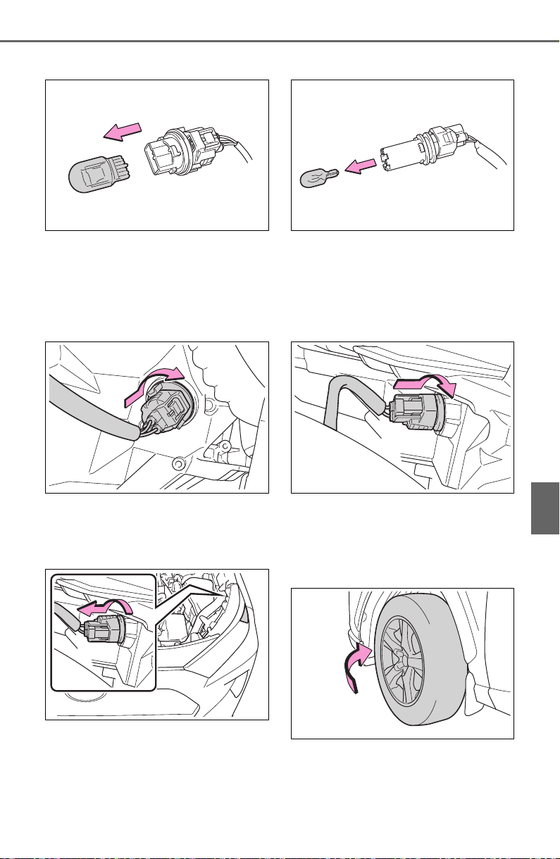
611
7-3. Do-it-yourself maintenance
7
Maintenance and care
2 Remove the light bulb.
3 Install a new light bulb then
install the bulb base to the
light unit by inserting it and
turning the bulb base clock-
wise.
■ Front side marker lights
1 Turn the bulb base counter-
clockwise.
2 Remove the light bulb.
3 Install a new light bulb then
install the bulb base to the
light unit by inserting it and
turning the bulb base clock-
wise.
■ Fog lights (if equipped)
1 To allow enough working
space, turn the steering
wheel.
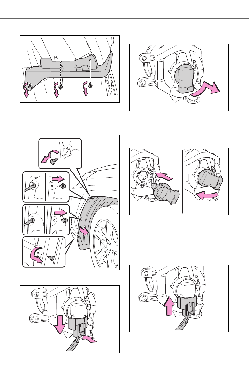
612
7-3. Do-it-yourself maintenance
2 Remove the screws.
3 Remove the screws and
clips, partly remove the
fender liner.
4 Unplug the connector
5 Turn the bulb base counter-
clockwise.
6 Set the new light bulb.
Align the 3 tabs on the light bulb
with the mounting, and insert. Turn
it clockwise to set.
7 Set the connector.
Shake the bulb base gently to
check that it is not loose, turn the
front fog lights on once and visually
confirm that no light is leaking
through the mounting.
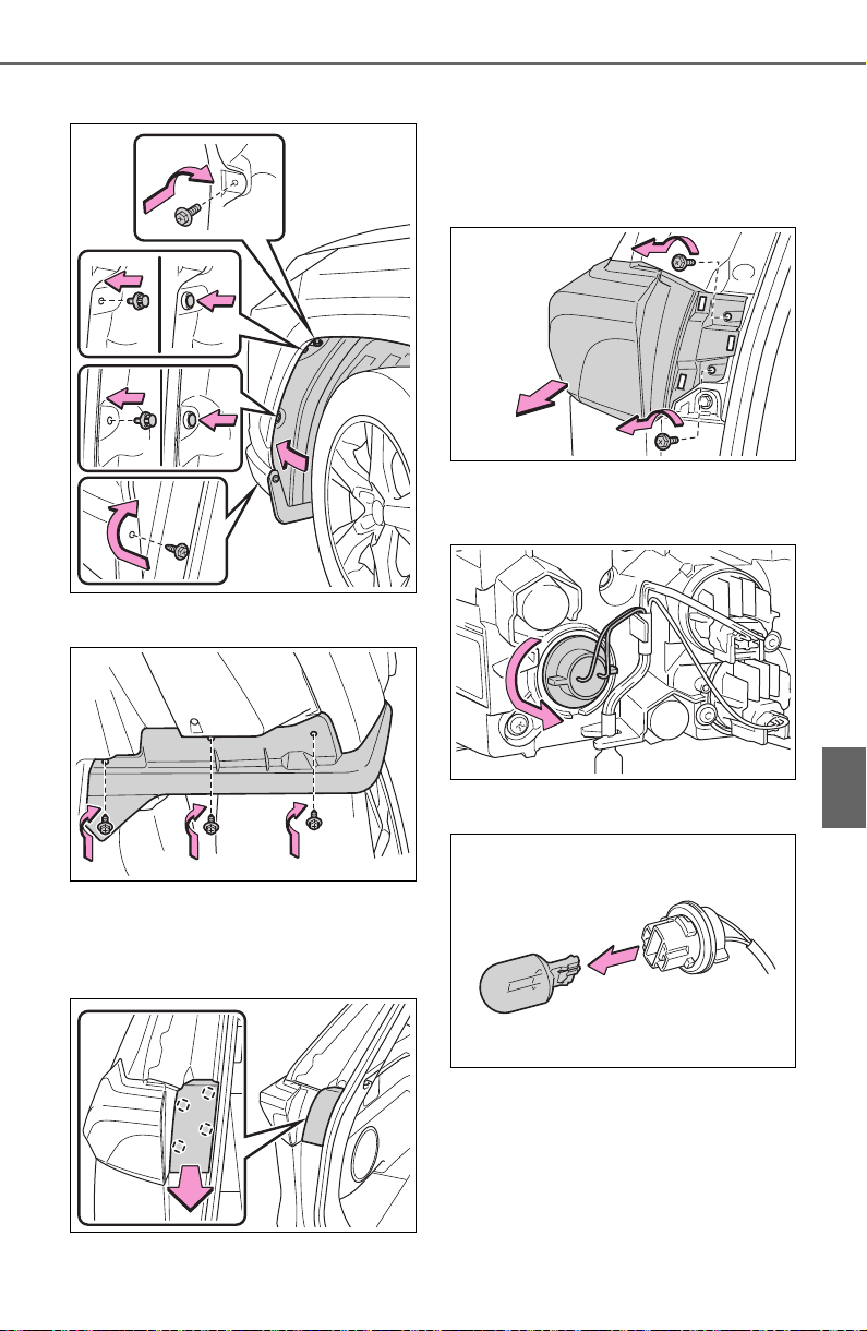
613
7-3. Do-it-yourself maintenance
7
Maintenance and care
8 Reinstall the fender liner.
9 Reinstall the screws.
■ Rear turn signal lights
1 Open the back door and
remove the cover.
2 Remove the securing screws
and remove the unit.
Remove the lamp assembly by pull-
ing it directly backward from the
rear of the vehicle.
3 Turn the bulb base counter-
clockwise.
4 Remove the light bulb.
5 Install a new light bulb then
install the bulb base to the
light unit by inserting it and
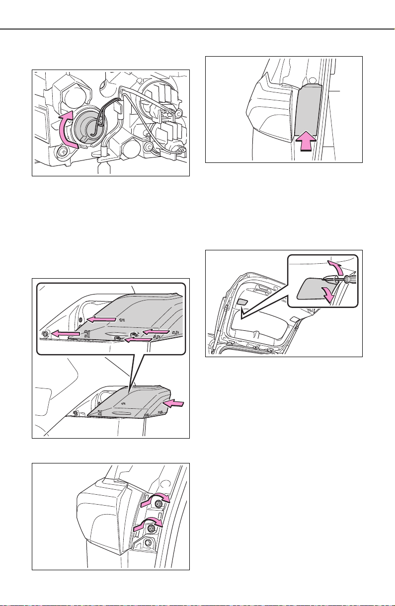
614
7-3. Do-it-yourself maintenance
turning the bulb base clock-
wise.
6 Align the grooves on the light
unit with the claws, and insert
the light unit straight so that
the pin on the light unit fit into
the hole.
Confirm that the light unit is com-
pletely secured.
7 Reinstall the screws.
8 Reinstall the cover.
■ Back-up lights
1 Open the back door and
remove the cover.
To prevent damage to the cover,
protect the tip of the screwdriver
with a rag.
2 Turn the bulb base counter-
clockwise.
Remove the cord from the clip
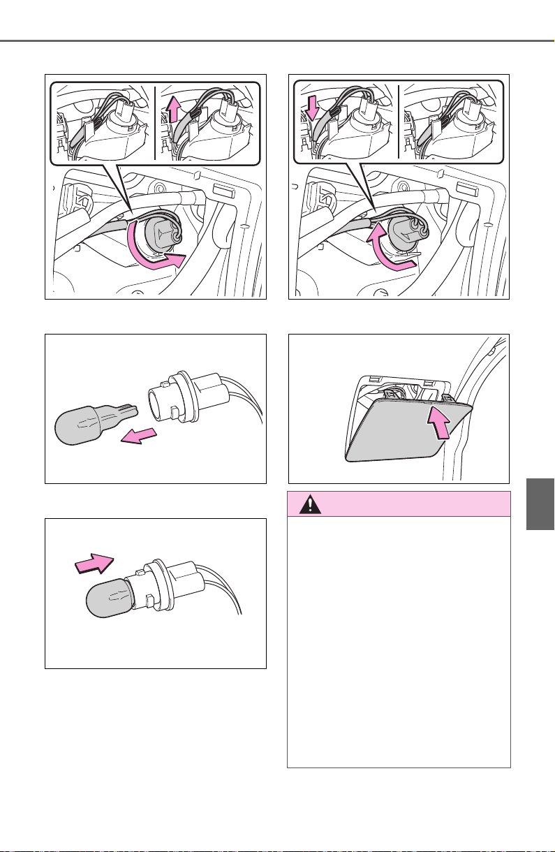
615
7-3. Do-it-yourself maintenance
7
Maintenance and care
before turning the bulb base.
3 Remove the light bulb.
4 Install a new light bulb.
5 Install the bulb base to the
light unit by inserting it and
turning the bulb base clock-
wise.
Secure the cord with the clip back
again after installing the bulb base.
6 Reinstall the cover.
WARNING
■ Replacing light bulb
● Turn off the light. Do not attempt
to replace the bulb immediately
after turning off the light.
The bulb become very hot and
may cause burns.
● Do not touch the glass portion
of the light bulb with bare
hands. When it is unavoidable
to hold the glass portion, use
and hold with a clean dry cloth
to avoid getting moisture and
oils on the bulb.
Also, if the bulb is scratched or
dropped, it may blow out or
crack.

616
7-3. Do-it-yourself maintenance
WARNING
● Fully install light bulb and any
parts used to secure it. Failure
to do so may result in heat dam-
age, fire, or water entering the
light unit. This may damage the
light or cause condensation to
build up on the lens.
● Do not attempt to repair or dis-
assemble light bulbs, connec-
tors, electric circuits or
component parts.
Doing so may result in death or
serious injury due to electric
shock.
■ To prevent damage or fire
● Make sure bulb is fully seated
and locked.
● Check the wattage of the bulb
before installing to prevent heat
damage.

617
8
8
When trouble arises
When trouble arises
8-1. Essential information
Emergency flashers.... 618
If your vehicle has to be
stopped in an emergency
.................................. 618
If the vehicle is trapped in
rising water................ 619
8-2. Steps to take in an emer-
gency
If your vehicle needs to be
towed......................... 621
If you think something is
wrong ........................ 626
Fuel pump shut off system
.................................. 627
If a warning light turns on or
a warning buzzer sounds
.................................. 628
If a warning message is dis-
played........................ 639
If you have a flat tire.... 642
If the engine will not start
.................................. 651
If you lose your keys ... 653
If the electronic key does
not operate properly (vehi-
cles with smart key sys-
tem)........................... 653
If the vehicle battery is dis-
charged..................... 655
If your vehicle overheats
.................................. 659
If the vehicle becomes stuck
.................................. 661
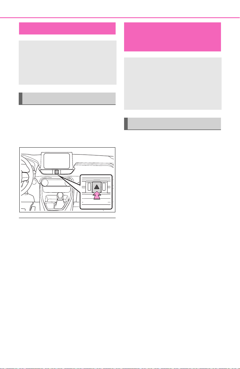
618
8-1. Essential information
8-1.Essential information
Press the switch.
All the turn signal lights will flash.
To turn them off, press the switch
once again.
■ Emergency flashers
● If the emergency flashers are
used for a long time while the
engine is not running, the battery
may discharge.
● If any of the SRS airbags deploy
(inflate) or in the event of a strong
rear impact, the emergency flash-
ers will turn on automatically.
The emergency flashers will turn
off automatically after operating
for approximately 20 minutes. To
manually turn the emergency
flashers off, press the switch
twice. (The emergency flashers
may not turn on automatically
depending on the force of the
impact and conditions of the colli-
sion.)
1 Steadily step on the brake
pedal with both feet and
firmly depress it.
Do not pump the brake pedal
repeatedly as this will increase the
effort required to slow the vehicle.
2 Shift the shift lever to N.
If the shift lever is shifted to N
3 After slowing down, stop the
vehicle in a safe place by the
road.
4 Stop the engine.
If the shift lever cannot be
shifted to N
3 Keep depressing the brake
pedal with both feet to reduce
vehicle speed as much as
possible.
4 Perform the following proce-
dure to stop the engine:
Vehicles without smart key
system
Turn the engine switch to ACC.
Emergency flashers
The emergency flashers are
used to warn other drivers
when the vehicle has to be
stopped in the road due to a
breakdown, etc.
Operating instructions
If your vehicle has to
be stopped in an emer-
gency
Only in an emergency, such
as if it becomes impossible
to stop the vehicle in the
normal way, stop the vehicle
using the following proce-
dure:
Stopping the vehicle
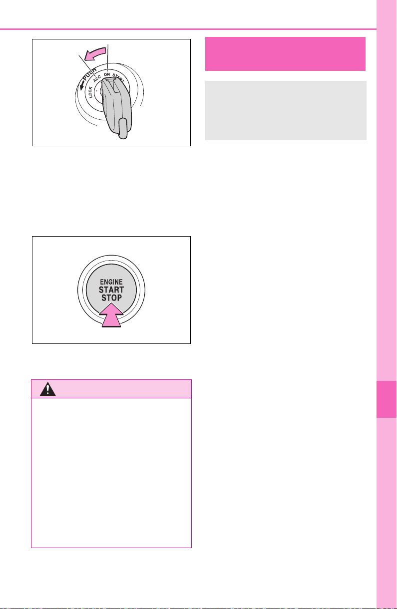
619
8-1. Essential information
8
When trouble arises
Vehicles with smart key sys-
tem
Press and hold the engine switch
for 2 consecutive seconds or more,
or press it briefly 3 times or more in
succession.
5 Stop the vehicle in a safe
place by the road.
Remove the seat belt first.
If the door can be opened,
open the door and exit the
vehicle.
If the door can not be opened,
open the window using the
power window switch and exit
the vehicle through the win-
dow.
If the window can not be
opened using the power win-
dow switch, remain calm, wait
until the water level inside the
vehicle rises to the point that
the water pressure inside of
the vehicle equals the water
pressure outside of the vehi-
cle, and then open the door
and exit the vehicle.
WARNING
■ If the engine has to be turned
off while driving
● Power assist for the brakes and
steering wheel will be lost, mak-
ing the brake pedal harder to
depress and the steering wheel
heavier to turn. Decelerate as
much as possible before turning
off the engine.
● Vehicles without smart key sys-
tem: Never attempt to remove
the key, as doing so will lock the
steering wheel.
If the vehicle is
trapped in rising water
In the event the vehicle is
submerged in water, remain
calm and perform the fol-
lowing.

620
8-1. Essential information
WARNING
■ Using an emergency hammer
*
for emergency escape
The front side windows and rear
side windows, as well as the rear
window can be shattered with an
emergency hammer
*
used for
emergency escape. However, an
emergency hammer can not shat-
ter the windshield as it is lami-
nated glass.
*
: Contact your Toyota dealer, or
aftermarket accessory manu-
facturer for further information
about an emergency hammer.
■ Escaping the vehicle from the
window
There are cases where escaping
the vehicle from the window is not
possible due to seating position,
passenger body type, etc.
When using an emergency ham-
mer, consider your seat location
and the size of the window open-
ing to ensure that the opening is
accessible and large enough to
escape.
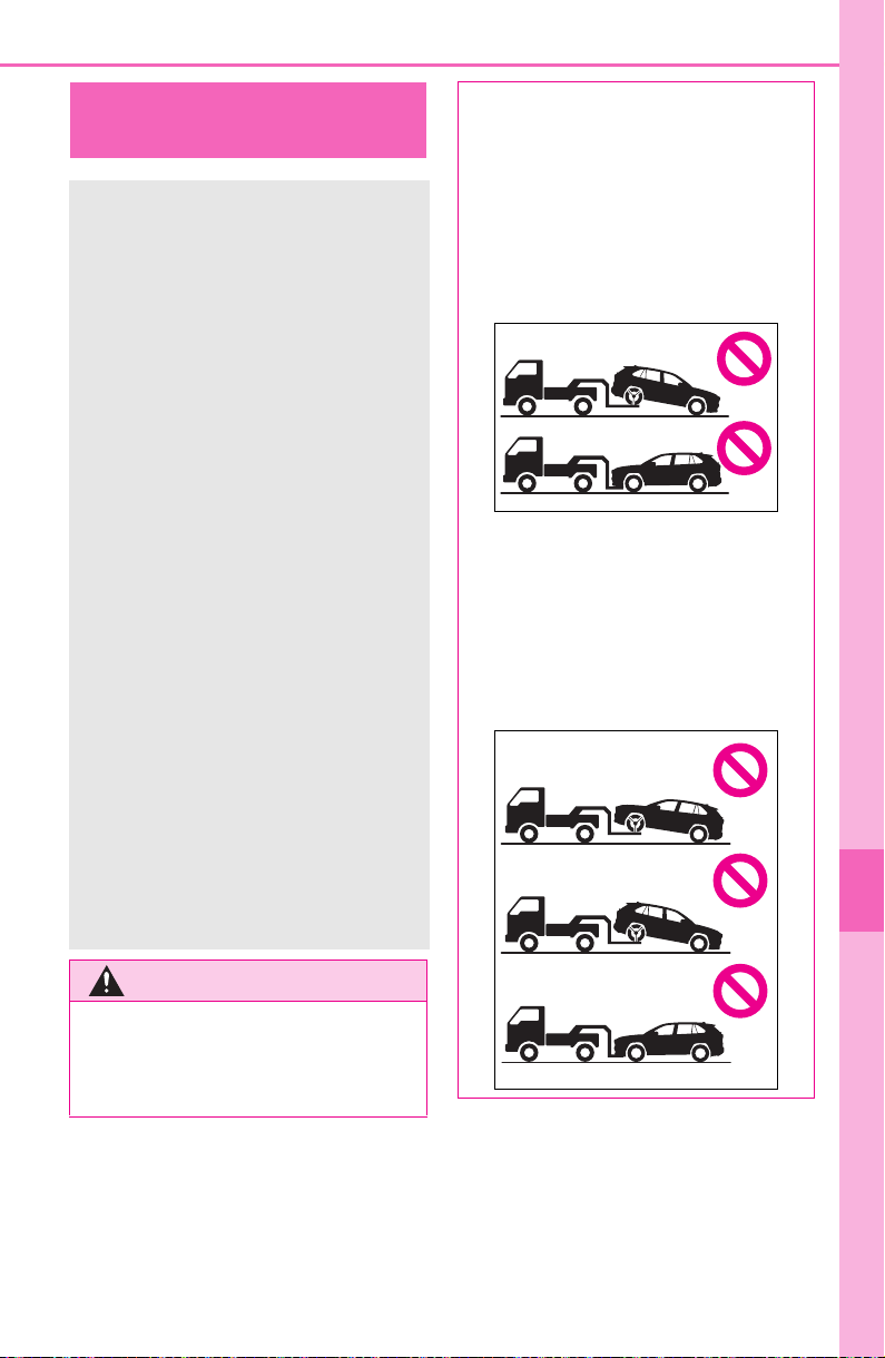
621
8-2. Steps to take in an emergency
8
When trouble arises
8-2.Steps to take in an emergency
If your vehicle needs
to be towed
If towing is necessary, we
recommend having your
vehicle towed by your
Toyota dealer or commercial
towing service, using a
wheel-lift type truck or flat-
bed truck.
Use a safety chain system
for all towing, and abide by
all state/provincial and local
laws.
2WD models: If towing your
vehicle with a wheel-lift type
truck from the front, the
vehicle’s rear wheels and
axles must be in good con-
ditions. (P.623)
If they are damaged, use a
towing dolly or flatbed
truck.
AWD models: If towing your
vehicle with a wheel-lift type
truck, use a towing dolly.
(P.623)
WARNING
Observe the following precau-
tions.
Failure to do so may result in
death or serious injury.
■ When towing the vehicle
2WD models
Be sure to transport the vehicle
with the front wheels raised or
with all four wheels raised off the
ground. If the vehicle is towed
with the front wheels contacting
the ground, the drivetrain and
related parts may be damaged.
AWD models
Be sure to transport the vehicle
with all four wheels raised off the
ground. If the vehicle is towed
with the tires contacting the
ground, the drivetrain or related
parts may be damaged, the vehi-
cle may fly off the truck.
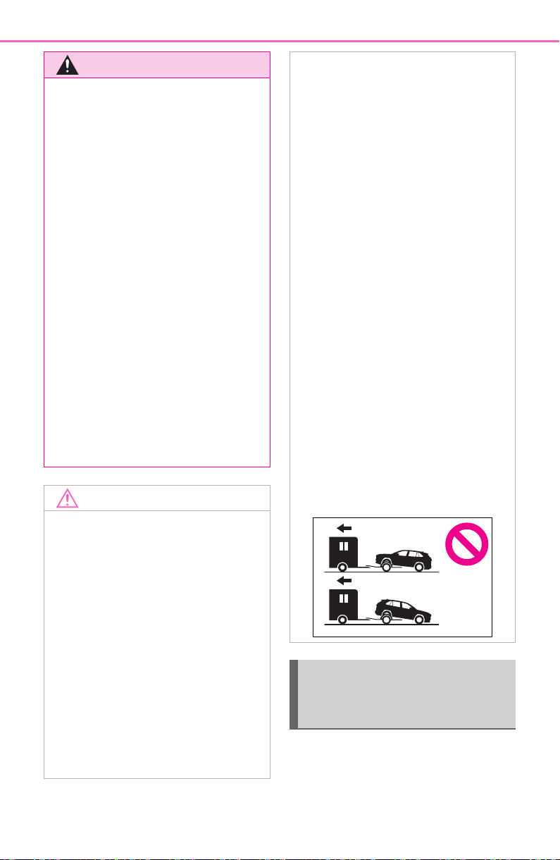
622
8-2. Steps to take in an emergency
The following may indicate a
problem with your transmission.
Contact your Toyota dealer or
commercial towing service
WARNING
■ While towing (vehicles with
towing eyelet)
● When towing using cables or
chains, avoid sudden starts, etc.
which place excessive stress on
the towing eyelets, cables or
chains. The towing eyelets,
cables or chains may become
damaged, broken debris may hit
people, and cause serious dam-
age.
● Do not turn the engine switch to
OFF.
There is a possibility that the
steering wheel is locked and
cannot be operated.
■ Installing towing eyelet to the
vehicle (vehicles with towing
eyelet)
Make sure that towing eyelet is
installed securely.
If not securely installed, towing
eyelet may come loose during
towing.
NOTICE
■ To prevent damage to the
vehicle when towing using a
wheel-lift type truck
● Do not tow the vehicle from the
rear when the engine switch is
in OFF or the key is removed
(vehicles without smart key sys-
tem). The steering lock mecha-
nism is not strong enough to
hold the front wheels straight.
● When raising the vehicle,
ensure adequate ground clear-
ance for towing at the opposite
end of the raised vehicle. With-
out adequate clearance, the
vehicle could be damaged while
being towed.
■ To prevent damage to the
vehicle when towing with a
sling-type truck
Do not tow with a sling-type truck,
either from the front or rear.
■ To prevent damage to the
vehicle during emergency
towing (vehicles with towing
eyelet)
Do not secure cables or chains to
the suspension components.
■ When towing the vehicle
(vehicles with Stop & Start
system)
If it is necessary to tow the vehicle
with all four wheels on the ground,
perform the following procedure
before towing the vehicle, in order
to protect the system.
Turn the engine switch to OFF
and then start the engine or turn
the engine switch to ON.
■ Recreational towing (behind
motor home, etc.)
Never dinghy tow your vehicle to
prevent causing serious damage
to the AWD system (AWD mod-
els) and transmission. (P.191)
Situations when it is nec-
essary to contact dealers
before towing
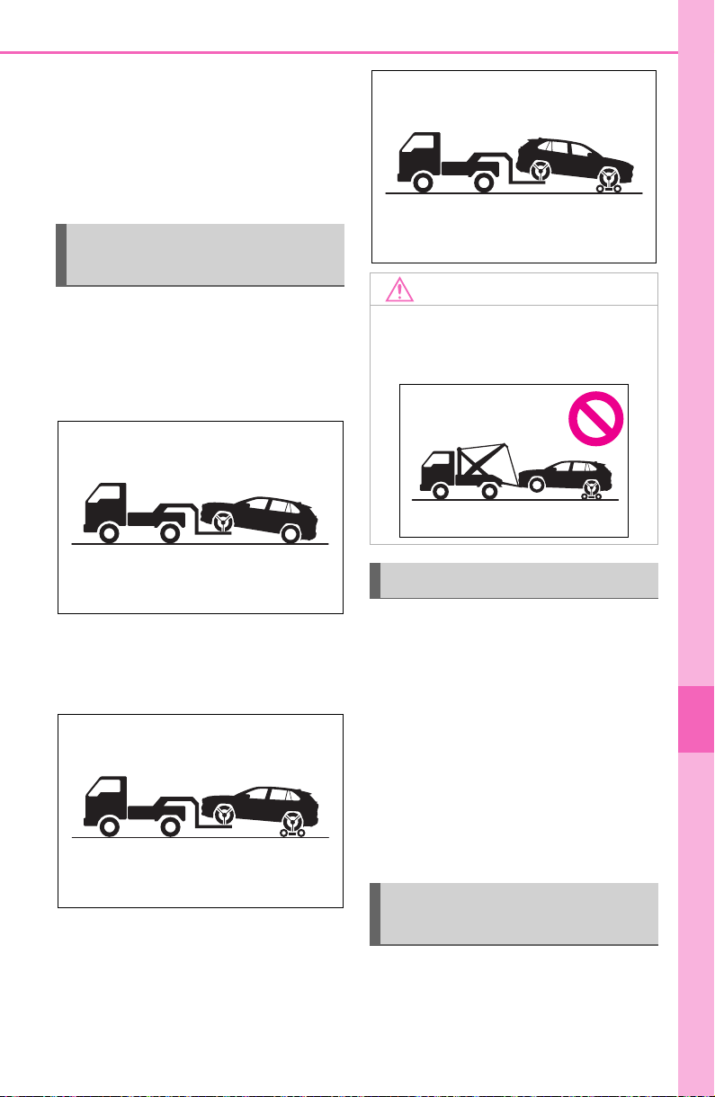
623
8-2. Steps to take in an emergency
8
When trouble arises
before towing.
The engine is running but the
vehicle does not move.
The vehicle makes an abnor-
mal sound.
From the front (2WD models)
Release the parking brake.
Turn automatic mode off.
(P.204)
From the front (AWD models)
Use a towing dolly under the
rear wheels.
From the rear
Use a towing dolly under the
front wheels.
When using a flat-bed truck to
transport the vehicle, use tire
strapping belts. Refer to the
owner’s manual of the flat-bed
truck for the tire strapping
method.
In order to suppress vehicle
movement during transporta-
tion, set the parking brake and
turn the engine switch off.
If a tow truck is not available in
an emergency, your vehicle may
be temporarily towed using
Towing with a wheel-lift
type truck
NOTICE
■ Towing with a sling-type truck
Do not tow with a sling-type truck
to prevent body damage.
Using a flatbed truck
Emergency towing (vehi-
cles with towing eyelet)
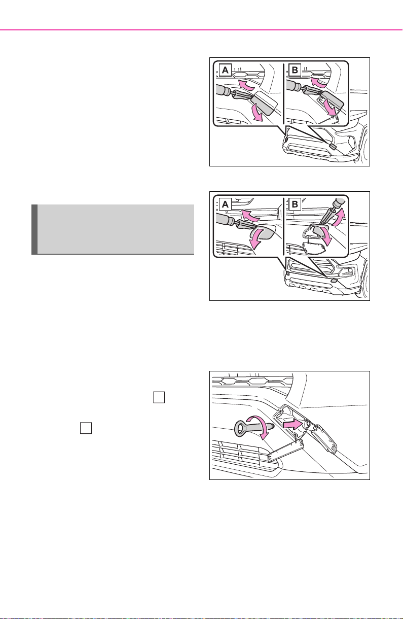
624
8-2. Steps to take in an emergency
cables or chains secured to the
emergency towing eyelets. This
should only be attempted on
hard surfaced roads for at most
50 miles (80 km) at under 18
mph (30 km/h).
A driver must be in the vehicle to
steer and operate the brakes.
The vehicle’s wheels, drive train,
axles, steering and brakes must
be in good condition.
To have your vehicle towed by
another vehicle, the towing eye-
let must be installed to your
vehicle. Install the towing eyelet
by following the specified proce-
dure.
1 Take out the towing eyelet.
(P.643)
2 Using a flathead screwdriver,
remove eyelet cover ( ),
and then remove eyelet
cover ( ).
To protect the bodywork, place a
rag between the screwdriver and
the vehicle body as shown in the
illustration.
Type A
Type B
3 Insert the towing eyelet into
the hole and tighten partially
by hand.
Type A
Emergency towing proce-
dure (vehicles with towing
eyelet)
A
B
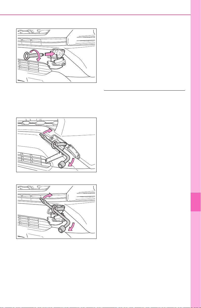
625
8-2. Steps to take in an emergency
8
When trouble arises
Type B
4 Tighten down the towing eye-
let securely using a wheel nut
wrench or hard metal bar.
Type A
Type B
5 Securely attach cables or
chains to the towing eyelet.
Take care not to damage the vehi-
cle body.
6 Enter the vehicle being towed
and start the engine.
Turn off the Parking Support Brake
function. (if equipped): P.282
If the engine does not start, turn the
engine switch to ON.
Vehicles with Stop & Start system:
Before towing the vehicle, turn the
engine switch to OFF once, and
then start the engine.
7 Shift the shift lever to N and
release the parking brake.
When the shift lever cannot be
shifted: P.2 00
■ While towing
If the engine is not running, the
power assist for the brakes and
steering will not function, making
steering and braking more difficult.
■ Wheel nut wrench
Wheel nut wrench is installed in the
tool bag. (P.643)

626
8-2. Steps to take in an emergency
Fluid leaks under the vehicle
(Water dripping from the air
conditioning after use is nor-
mal.)
Flat-looking tires or uneven
tire wear
Engine coolant temperature
gauge needle continually
points higher than normal.
Changes in exhaust sound
Excessive tire squeal when
cornering
Strange noises related to the
suspension system
Pinging or other noises
related to the engine
Engine missing, stumbling or
running roughly
Appreciable loss of power
Vehicle pulls heavily to one
side when braking
Vehicle pulls heavily to one
side when driving on a level
road
Loss of brake effectiveness,
spongy feeling, pedal almost
touches the floor
If you think something
is wrong
If you notice any of the fol-
lowing symptoms, your
vehicle probably needs
adjustment or repair. Con-
tact your Toyota dealer as
soon as possible.
Visible symptoms
Audible symptoms
Operational symptoms

627
8-2. Steps to take in an emergency
8
When trouble arises
Follow the procedure below to
restart the engine after the sys-
tem is activated.
1 Turn the engine switch to
ACC or off.
2 Restart the engine.
Fuel pump shut off
system
To minimize the risk of fuel
leakage when the engine
stalls or when an airbag
inflates upon collision, the
fuel pump shut off system
stops the supply of fuel to
the engine.
Restarting the engine
NOTICE
■ Before starting the engine
Inspect the ground under the
vehicle.
If you find that fuel has leaked
onto the ground, the fuel system
has been damaged and is in need
of repair. Do not restart the
engine.
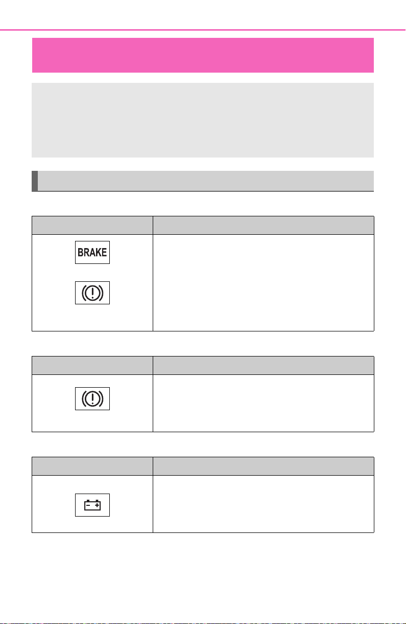
628
8-2. Steps to take in an emergency
■ Brake system warning light (warning buzzer)
■ Brake system warning light
■ Charging system warning light
If a warning light turns on or a warning buzzer
sounds
Calmly perform the following actions if any of the warning
lights comes on or flashes. If a light comes on or flashes, but
then goes off, this does not necessarily indicate a malfunc-
tion in the system. However, if this continues to occur, have
the vehicle inspected by your Toyota dealer.
Actions to the warning lights or warning buzzers
Warning light Details/Actions
(U.S.A.)
(Canada)
(Red)
Indicates that:
The brake fluid level is low; or
The brake system is malfunctioning
Immediately stop the vehicle in a safe
place and contact your Toyota dealer.
Continuing to drive the vehicle may be
dangerous.
Warning light Details/Actions
(Yellow)
Indicates a malfunction in the parking brake sys-
tem
Have the vehicle inspected by your Toyota
dealer immediately.
Warning light Details/Actions
Indicates a malfunction in the vehicle’s charging
system
Immediately stop the vehicle in a safe
place and contact your Toyota dealer.
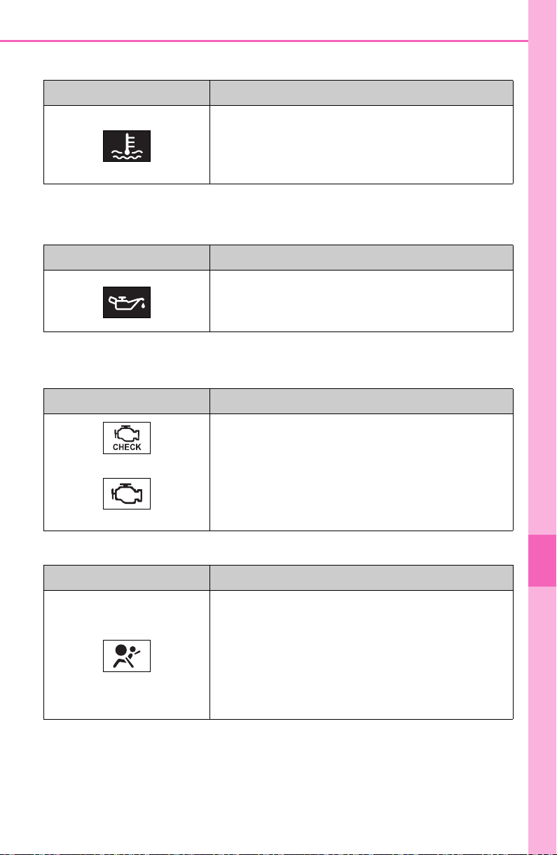
629
8-2. Steps to take in an emergency
8
When trouble arises
■ High coolant temperature warning light
*
(warning buzzer)
*
: This light illuminates on the multi-information display with a message.
■ Low engine oil pressure warning light
*
(warning buzzer)
*
: This light illuminates on the multi-information display with a message.
■ Malfunction indicator lamp
■ SRS warning light
Warning light Details/Actions
Indicates that the engine is overheating
Immediately stop the vehicle in a safe
place.
Handling method (P.659)
Warning light Details/Actions
Indicates that the engine oil pressure is too low
Immediately stop the vehicle in a safe
place and contact your Toyota dealer.
Warning light Details/Actions
(U.S.A.)
(Canada)
Indicates a malfunction in:
The electronic engine control system;
The electronic throttle control system; or
The emission control system (if equipped)
Have the vehicle inspected by your Toyota
dealer immediately.
Warning light Details/Actions
Indicates a malfunction in:
The SRS airbag system;
The front passenger occupant classification
system; or
The seat belt pretensioner system
Have the vehicle inspected by your Toyota
dealer immediately.
630
8-2. Steps to take in an emergency
■ ABS warning light
■ Electric power steering system warning light (warning
buzzer)
■ PCS warning light (warning buzzer)
Warning light Details/Actions
(U.S.A.)
(Canada)
Indicates a malfunction in:
The ABS; or
The brake assist system
Have the vehicle inspected by your Toyota
dealer immediately.
Warning light Details/Actions
(Red/yellow)
Indicates a malfunction in the EPS (Electric
Power Steering) system
Have the vehicle inspected by your Toyota
dealer immediately.
Warning light Details/Actions
(Flashes or illuminates)
When a buzzer sounds simultaneously:
Indicates a malfunction has occurred in the PCS
(Pre-Collision System).
Have the vehicle inspected by your Toyota
dealer immediately.
When a buzzer does not sound:
The PCS (Pre-Collision System) has become
temporarily unavailable, corrective action may
be necessary.
Follow the instructions displayed on the
multi-information display. (P.227, 641)
If the PCS (Pre-Collision System) or VSC (Vehi-
cle Stability Control) system is disabled, the
PCS warning light will illuminate.
P.2 36
631
8-2. Steps to take in an emergency
8
When trouble arises
■ LTA indicator (warning buzzer)
■ Stop & Start cancel indicator
■ Intuitive parking assist OFF indicator (warning buzzer)
Warning light Details/Actions
(Orange)
Indicates a malfunction in the LTA (Lane Tracing
Assist)
Follow the instructions displayed on the
multi-information display. (P.246)
Warning light Details/Actions
(Flashes)
(If equipped)
Indicates a malfunction in the Stop & Start sys-
tem
Have the vehicle inspected by your Toyota
dealer immediately.
Warning light Details/Actions
(Flashes)
(If equipped)
When a buzzer sounds:
Indicates a malfunction in the Intuitive parking
assist function
Have the vehicle inspected by your Toyota
dealer immediately.
When a buzzer does not sound:
Indicates that the system is temporarily unavail-
able, possibly due to a sensor being dirty or cov-
ered with ice, etc.
Follow the instructions displayed on the
multi-information display. (P.273, 639)
632
8-2. Steps to take in an emergency
■ PKSB OFF indicator (warning buzzer)
■ RCTA OFF indicator (warning buzzer)
■ Slip indicator light
Warning light Details/Actions
(Flashes)
(If equipped)
When a buzzer sounds:
Indicates a malfunction in the PKSB (Parking
Support Brake) system
Have the vehicle inspected by your Toyota
dealer immediately.
When a buzzer does not sound:
Indicates that the system is temporarily unavail-
able, possibly due to a sensor being dirty or cov-
ered with ice, etc.
Follow the instructions displayed on the
multi-information display. (P.281, 639)
Warning light Details/Actions
(Flashes)
(If equipped)
When a buzzer sounds:
Indicates a malfunction in the RCTA (Rear
Cross Traffic Alert) function
Have the vehicle inspected by your Toyota
dealer immediately.
When a buzzer does not sound:
Indicates that the rear bumper around the radar
sensor is covered with dirt, etc. (P. 26 3)
Follow the instructions displayed on the
multi-information display. (P.262, 639)
Warning light Details/Actions
Indicates a malfunction in:
Multi-terrain Select brake control (if equipped);
The VSC/Trailer Sway Control system;
The TRAC system;
The hill-start assist control system; or
The downhill assist control system (if
equipped)
Have the vehicle inspected by your Toyota
dealer immediately.
633
8-2. Steps to take in an emergency
8
When trouble arises
■ Brake Override System/Drive-Start Control/PKSB (if
equipped) warning light
*
(warning buzzer)
*
: This light illuminates on the multi-information display with a message.
■ Brake hold operated indicator (warning buzzer)
Warning light Details/Actions
Brake Override System
Indicates that the accelerator and brake pedals
are being depressed simultaneously, and the
Brake Override System is operating.
Release the accelerator pedal and
depress the brake pedal.
Indicates a malfunction in the Brake Override
System (with warning buzzer)
Have the vehicle inspected by your Toyota
dealer immediately.
Drive-Start Control
Indicates that the shift position was changed
and Drive-Start Control was operated while
depressing the accelerator pedal. (with warning
buzzer)
Momentarily release the accelerator pedal.
Indicates a malfunction in the Drive-Start Con-
trol (with warning buzzer)
Have the vehicle inspected by your Toyota
dealer immediately.
PKSB (if equipped)
Parking Support Brake function (for static
objects) is operating. (P.277)
If a warning message is shown on the
multi-information display, read the mes-
sage and follow the instructions.
Warning light Details/Actions
(Flashes)
Indicates a malfunction in the brake hold system
Have the vehicle inspected by your Toyota
dealer immediately.
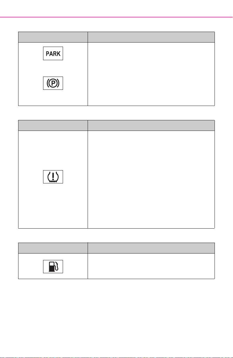
634
8-2. Steps to take in an emergency
■ Parking brake indicator
■ Tire pressure warning light
■ Low fuel level warning light
Warning light Details/Actions
(U.S.A.)
(Flashes)
(Canada)
(Flashes)
It is possible that the parking brake is not fully
engaged or released
Operate the parking brake switch once
again.
This light comes on when the parking brake is
not released. If the light turns off after the park-
ing brake is fully released, the system is operat-
ing normally.
Warning light Details/Actions
(If equipped)
When the light comes on after blinking for 1 min-
ute:
Malfunction in the tire pressure warning system
Have the system checked by your Toyota
dealer.
When the light comes on:
Low tire inflation pressure such as
Natural causes
Flat tire
Immediately stop the vehicle in a safe
place.
Handling method (P.636)
Warning light Details/Actions
Indicates that remaining fuel is approximately
2.2 gal. (8.3 L, 1.8 Imp. gal.) or less
Refuel the vehicle.
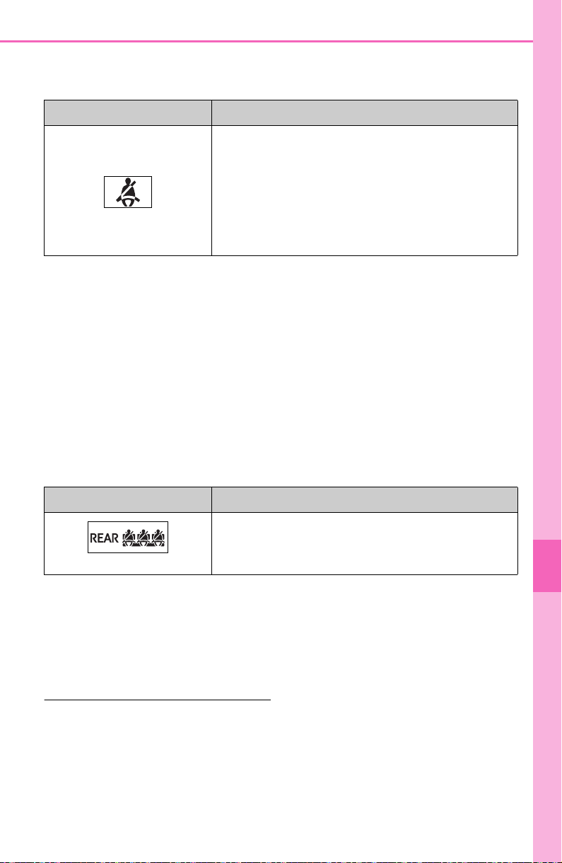
635
8-2. Steps to take in an emergency
8
When trouble arises
■ Driver’s and front passenger’s seat belt reminder light (warn-
ing buzzer
*
)
*
: Driver’s seat belt warning buzzer:
The driver’s seat belt warning buzzer sounds to alert the driver that his or
her seat belt is not fastened. Once the engine switch is turned to ON, the
buzzer sounds. If the seat belt is still unfastened, the buzzer sounds inter-
mittently for a certain period of time after the vehicle reaches a certain
speed.
Front passenger’s seat belt warning buzzer:
The front passenger’s seat belt warning buzzer sounds to alert the front
passenger that his or her seat belt is not fastened. If the seat belt is
unfastened, the buzzer sounds intermittently for a certain period of time
after the vehicle reaches a certain speed.
■ Rear passengers’ seat belt reminder light (warning buzzer
*
)
*
: Rear passengers’ seat belt warning buzzer:
The rear passengers’ seat belt warning buzzer sounds to alert the rear
passenger that his or her seat belt is not fastened. If the seat belt is
unfastened, the buzzer sounds intermittently for a certain period of time,
after the seat belt is fastened and unfastened and the vehicle reaches a
certain speed.
■ Warning buzzer
In some cases, the buzzer may not
be heard because of noisy place or
an audio sound.
■ Front passenger detection sen-
sor, seat belt reminder and
warning buzzer
● If luggage is placed on the front
passenger seat, the front passen-
ger detection sensor may cause
the warning light to flash and the
warning buzzer to sound even if a
Warning light Details/Actions
Warns the driver and/or front passenger to fas-
ten their seat belts
Fasten the seat belt.
If the front passenger’s seat is occupied,
the front passenger’s seat belt also needs
to be fastened to make the warning light
(warning buzzer) turn off.
Warning light Details/Actions
(If equipped)
Warns the rear passengers to fasten their seat
belts
Fasten the seat belt.

636
8-2. Steps to take in an emergency
passenger is not sitting in the
seat.
● If a cushion is placed on the seat,
the sensor may not detect a pas-
senger, and the warning light may
not operate properly.
■ SRS warning light
This warning light system monitors
the airbag sensor assembly, front
impact sensors, side impact sensors
(front door), side impact sensors
(front), side impact sensors (rear),
driver’s seat position sensor,
driver’s seat belt buckle switch, front
passenger occupant classification
system (ECU and sensors), “AIR
BAG ON” indicator light, “AIR BAG
OFF” indicator light, front passen-
ger’s seat belt buckle switch, seat
belt pretensioners and force limiters,
airbags, interconnecting wiring and
power sources. (P. 34 )
■ If the malfunction indicator
lamp comes on while driving
First check the following:
● Is the fuel tank empty?
If it is, fill the fuel tank immediately.
● Is the fuel tank cap loose?
If it is, tighten it securely.
The light will go off after several
driving trips.
If the light does not go off even after
several trips, contact your Toyota
dealer as soon as possible.
■ Electric power steering system
warning light (warning buzzer)
When the battery charge becomes
insufficient or the voltage temporar-
ily drops, the electric power steering
system warning light may come on
and the warning buzzer may sound.
■ When the tire pressure warning
light comes on (vehicles with
tire pressure warning system)
Inspect the tires to check if a tire is
punctured.
If a tire is punctured: P.642
If none of the tires are punctured:
Turn the engine switch to OFF then
turn it to ON. Check if the tire pres-
sure warning light comes on or
blinks.
If the tire pressure warning light
blinks for approximately 1 minute
then stays on
There may be a malfunction in the
tire pressure warning system. Have
the vehicle inspected by your Toyota
dealer immediately.
If the tire pressure warning light
comes on
1 After the temperature of the tires
has lowered sufficiently, check
the inflation pressure of each tire
and adjust them to the specified
level.
2 If the warning light does not turn
off even after several minutes
have elapsed, check that the
inflation pressure of each tire is
at the specified level and perform
initialization. (P.590)
■ The tire pressure warning light
may come on due to natural
causes (vehicles with tire pres-
sure warning system)
The tire pressure warning light may
come on due to natural causes such
as natural air leaks and tire inflation
pressure changes caused by tem-
perature. In this case, adjusting the
tire inflation pressure will turn off the
warning light (after a few minutes).
■ When a tire is replaced with a
compact spare tire (vehicles
with tire pressure warning sys-
tem)
The compact spare tire is not
equipped with a tire pressure warn-
ing valve and transmitter. If a tire
goes flat, the tire pressure warning
light will not turn off even though the
flat tire has been replaced with the
spare tire. Replace the spare tire
with the standard tire and adjust the
tire inflation pressure. The tire pres-

637
8-2. Steps to take in an emergency
8
When trouble arises
sure warning light will go off after a
few minutes.
■ Conditions that the tire pres-
sure warning system may not
function properly
P.584
WARNING
■ If a warning light comes on or
a warning buzzer sounds
when a warning message is
shown on the multi-informa-
tion display
*
Check and follow the message
shown on the multi-information
display.
Failure to do so may result in
death or serious injury.
*
: Warning lights illuminate in red
or yellow and the warning
buzzer beeps once or sounds
continuously.
■ When the electric power
steering system warning light
comes on
When the light comes on yellow,
the assist to the power steering is
restricted. When the light comes
on red, the assist to the power
steering is lost and handling oper-
ations of the steering wheel
become extremely heavy.
If the steering wheel becomes
heavier than usual when operat-
ing, hold firmly and operate using
more force than usual.
■ If the tire pressure warning
light comes on (vehicles with
tire pressure warning system)
Be sure to observe the following
precautions. Failure to do so
could cause a loss of vehicle con-
trol and result in death or serious
injury.
● Stop your vehicle in a safe place
as soon as possible. Adjust the
tire inflation pressure immedi-
ately.
● If the tire pressure warning light
comes on even after tire infla-
tion pressure adjustment, it is
probable that you have a flat
tire. Check the tires. If a tire is
flat, change it with the spare tire
and have the flat tire repaired by
the nearest Toyota dealer.
● Avoid abrupt maneuvering and
braking. If the vehicle tires dete-
riorate, you could lose control of
the steering wheel or the
brakes.
■ If a blowout or sudden air
leakage should occur (vehi-
cles with tire pressure warn-
ing system)
The tire pressure warning system
may not activate immediately.

638
8-2. Steps to take in an emergency
WARNING
■ Maintenance of the tires
(vehicles with tire pressure
warning system)
Each tire, including the spare (if
provided), should be checked
monthly when cold and inflated to
the inflation pressure recom-
mended by the vehicle manufac-
turer on the vehicle placard or tire
inflation pressure label (tire and
load information label). (If your
vehicle has tires of a different size
than the size indicated on the
vehicle placard or tire inflation
pressure label [tire and load infor-
mation label], you should deter-
mine the proper tire inflation
pressure for those tires.)
As an added safety feature, your
vehicle has been equipped with a
tire pressure monitoring system
(TPMS-tire pressure warning sys-
tem) that illuminates a low tire
pressure telltale (tire pressure
warning light) when one or more
of your tires is significantly under-
inflated. Accordingly, when the
low tire pressure telltale (tire pres-
sure warning light) illuminates,
you should stop and check your
tires as soon as possible, and
inflate them to the proper pres-
sure. Driving on a significantly
under-inflated tire causes the tire
to overheat and can lead to tire
failure. Under-inflation also
reduces fuel efficiency and tire
tread life, and may affect the vehi-
cle’s handling and stopping ability.
Please note that the TPMS (tire
pressure warning system) is not a
substitute for proper tire mainte-
nance, and it is the driver’s
responsibility to maintain correct
tire pressure, even if under-infla-
tion has not reached the level to
trigger illumination of the TPMS
low tire pressure telltale (tire pres-
sure warning light).
Your vehicle has also been
equipped with a TPMS (tire pres-
sure warning system) malfunc-
tion indicator to indicate when the
system is not operating properly.
The TPMS (tire pressure warning
system) malfunction indicator is
combined with the low tire pres-
sure telltale (tire pressure warning
light). When the system detects a
malfunction, the telltale will flash
for approximately one minute and
then remain continuously illumi-
nated. This sequence will con-
tinue upon subsequent vehicle
start-ups as long as the malfunc-
tion exists. When the malfunction
indicator is illuminated, the sys-
tem may not be able to detect or
signal low tire pressure as
intended.
TPMS (tire pressure warning sys-
tem) malfunctions may occur for a
variety of reasons, including the
installation of replacement or
alternate tires or wheels on the
vehicle that prevent the TPMS
(tire pressure warning system)
from functioning properly. Always
check the TPMS (tire pressure
warning system) malfunction tell-
tale after replacing one or more
tires or wheels on your vehicle to
ensure that the replacement or
alternate tires and wheels allow
the TPMS (tire pressure warning
system) to continue to function
properly.
NOTICE
■ To ensure the tire pressure
warning system operates
properly (vehicles with tire
pressure warning system)
Do not install tires with different
specifications or manufacturers
as the tire pressure warning sys-
tem may not operate properly.
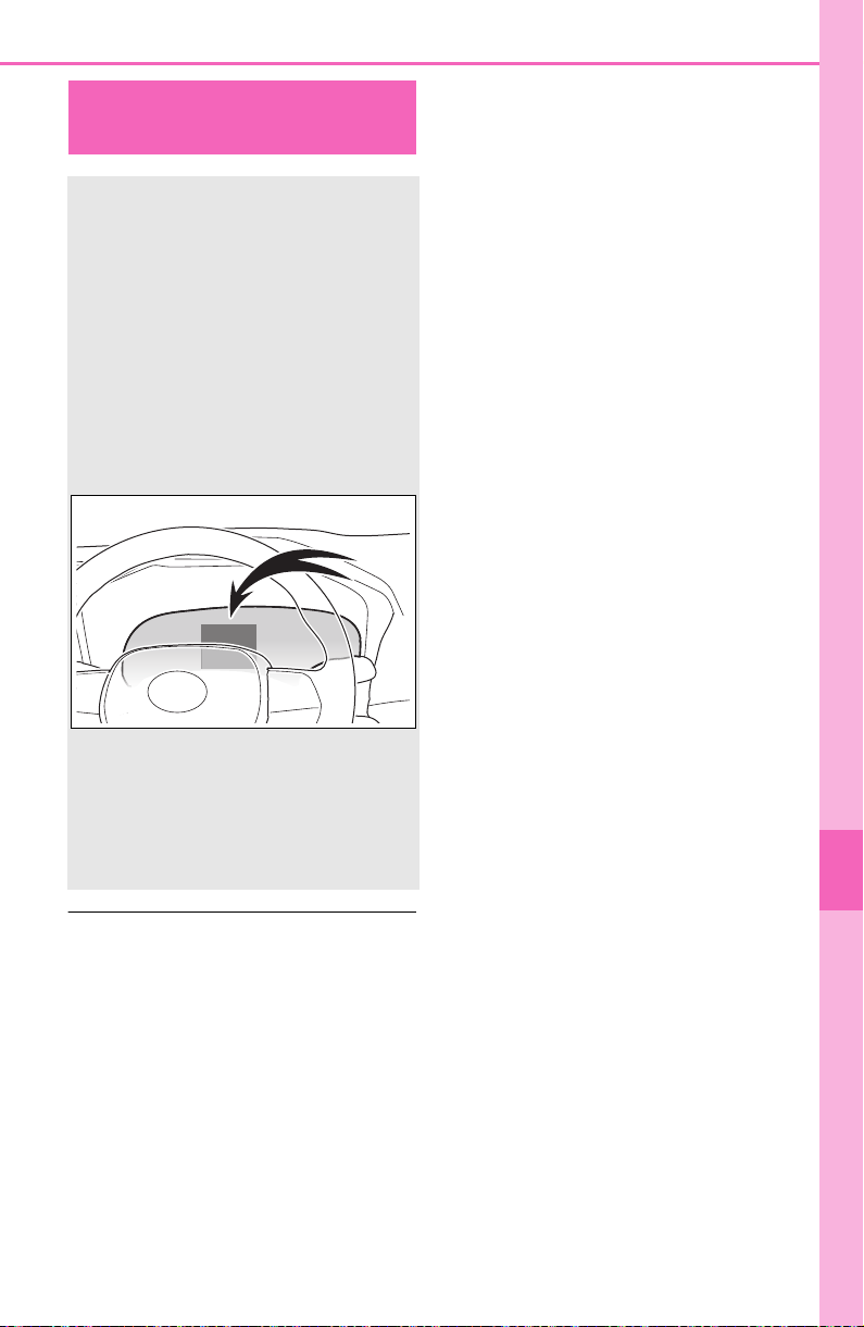
639
8-2. Steps to take in an emergency
8
When trouble arises
■ Warning messages
The warning messages explained
below may differ from the actual
messages according to operation
conditions and vehicle specifica-
tions.
■ If a message about an operation
is shown
● If a message about an operation
of the accelerator pedal or brake
pedal is shown
A warning message about an opera-
tion of the brake pedal may be
shown while the driving assist sys-
tems such as PCS (Pre-Collision
system) or the dynamic radar cruise
control with full-speed range is oper-
ating. If a warning message is
shown, be sure to decelerate the
vehicle or follow an instruction
shown on the multi-information dis-
play.
A warning message is shown when
Brake Override System, Drive-Start
Control or Parking Support Brake (if
equipped) (P.170, 277) operates.
Follow the instructions on the multi-
information display.
● If a message about an operation
of the engine switch is shown
An instruction for operation of the
engine switch is shown when the
incorrect procedure for starting the
engine is performed or the engine
switch is operated incorrectly. Fol-
low the instructions shown on the
multi-information display to operate
the engine switch again.
● If a message about a shift lever
operation is shown
To prevent the shift lever from being
operated incorrectly or the vehicle
from moving unexpectedly, a mes-
sage that requires shifting the shift
lever may be shown on the multi-
information display. In that case, fol-
low the instruction of the message
and shift the shift lever.
● If a message or image about an
open/close state of a part or
replenishment of a consumable is
shown
Confirm the part indicated by the
multi-information display or a warn-
ing light, and then perform the cop-
ing method such as closing the
open door or replenishing a con-
If a warning message
is displayed
The multi-information dis-
play shows warnings of sys-
tem malfunctions,
incorrectly performed oper-
ations, and messages that
indicate a need for mainte-
nance. When a message is
shown, perform the correc-
tion procedure appropriate
to the message.
If a warning message is dis-
played again after the appro-
priate actions have been
performed, contact your
Toyota dealer.

640
8-2. Steps to take in an emergency
sumable.
■ If a message that indicates the
need for visiting your Toyota
dealer is displayed
The system or part shown on the
multi-information display is malfunc-
tioning. Have the vehicle inspected
by your Toyota dealer immediately.
■ If a message that indicates the
need for referring to Owner’s
Manual is displayed
● If “Engine Coolant Temp High” is
shown, follow the instructions
(P.659).
● If the following messages are
shown, there may be a malfunc-
tion.
Immediately stop the vehicle in a
safe place and contact your
Toyota dealer. Continuing to drive
the vehicle may be dangerous.
• “Charging System Malfunction”
• “High Transmission Fluid Temp”
• “Smart Key System Malfunction”
● If the following messages are
shown, there may be a malfunc-
tion.
Immediately have the vehicle
inspected by your Toyota dealer.
• “Oil Pressure Low”
• “Braking Power Low”
■ If “Shift to P when Parked” is
shown
Message is displayed when the
driver’s door is opened without turn-
ing the engine switch to OFF with
the shift lever in any position other
than P.
Shift the shift lever to P.
■ If “Auto Power OFF to Conserve
Battery” is shown
Power was turned off due to the
automatic power off function.
Next time when starting the engine,
increase the engine speed slightly
and maintain that level for approxi-
mately 5 minutes to recharge the
battery.
■ If “Engine Oil Level Low Add or
Replace” is displayed
The engine oil level may be low.
Check the level of the engine oil,
and add engine oil if necessary. This
message may be displayed if the
vehicle is stopped on a slope. Move
the vehicle to a level surface and
check if the message disappears.
■ If “Maintenance Required
Soon” is shown
Indicates that all maintenance
according to the driven distance on
the maintenance schedule
*
should
be performed soon.
Comes on approximately 4500
miles (7200 km) after the message
has been reset.
If necessary, perform maintenance.
Please reset the message after the
maintenance is performed.
(P.565)
*
: Refer to the separate “Scheduled
Maintenance Guide” or “Owner’
Manual Supplement” for the main-
tenance interval applicable to your
vehicle.
■ If “Maintenance Required Visit
Your Dealer” is shown
Indicates that all maintenance is
required to correspond to the driven
distance on the maintenance sched-
ule
*
.
Comes on approximately 5000
miles (8000 km) after the message
has been reset. (The indicator will
not work properly unless the mes-
sage has been reset.)
Perform the necessary mainte-
nance. Please reset the message
after the maintenance is performed.
(P.565)
*
: Refer to the separate “Scheduled
Maintenance Guide” or “Owner’
Manual Supplement” for the main-
tenance interval applicable to your
vehicle.

641
8-2. Steps to take in an emergency
8
When trouble arises
■ If “Front Camera Unavailable”
or “Front Camera Unavailable
See Owner’s Manual” is dis-
played
The following systems may be sus-
pended until the problem shown in
the message is resolved. (P.445,
630)
● PCS (Pre-Collision System)
● LTA (Lane Tracing Assist)
● Automatic High Beam
● RSA (Road Sign Assist)
*
● Dynamic radar cruise control with
full-speed range
*
: If equipped
■ If “Radar Cruise Control
Unavailable See Owner’s Man-
ual” is shown
The dynamic radar cruise control
with full-speed range system is sus-
pended temporarily or until the prob-
lem shown in the message is
resolved. (causes and coping meth-
ods: P.445)
■ If “Radar Cruise Control
Unavailable” is shown
The dynamic radar cruise control
with full-speed range system cannot
be used temporarily. Use the system
when it becomes available again.
■ Warning buzzer
P.635
WARNING
■ If a warning light comes on or
a warning buzzer sounds
when a warning message is
shown on the multi-informa-
tion display
P.6 37
NOTICE
■ “High Power Consumption
Partial Limit On AC/Heater
Operation” is frequently
shown
There is a possible malfunction
relating to the charging system or
the battery may be deteriorating.
Have the vehicle inspected by
your Toyota dealer.

642
8-2. Steps to take in an emergency
Stop the vehicle in a safe place on a hard, flat surface.
Set the parking brake.
Shift the shift lever to P.
Stop the engine.
Turn on the emergency flashers. (P.618)
For vehicles with power back door: Turn off the power back door
system. (P.12 7 )
If you have a flat tire
Your vehicle is equipped with a spare tire. The flat tire can be
replaced with the spare tire.
For details about tires: P.581
WARNING
■ If you have a flat tire
Do not continue driving with a flat tire.
Driving even a short distance with a flat tire can damage the tire and the
wheel beyond repair, which could result in an accident.
Before jacking up the vehicle
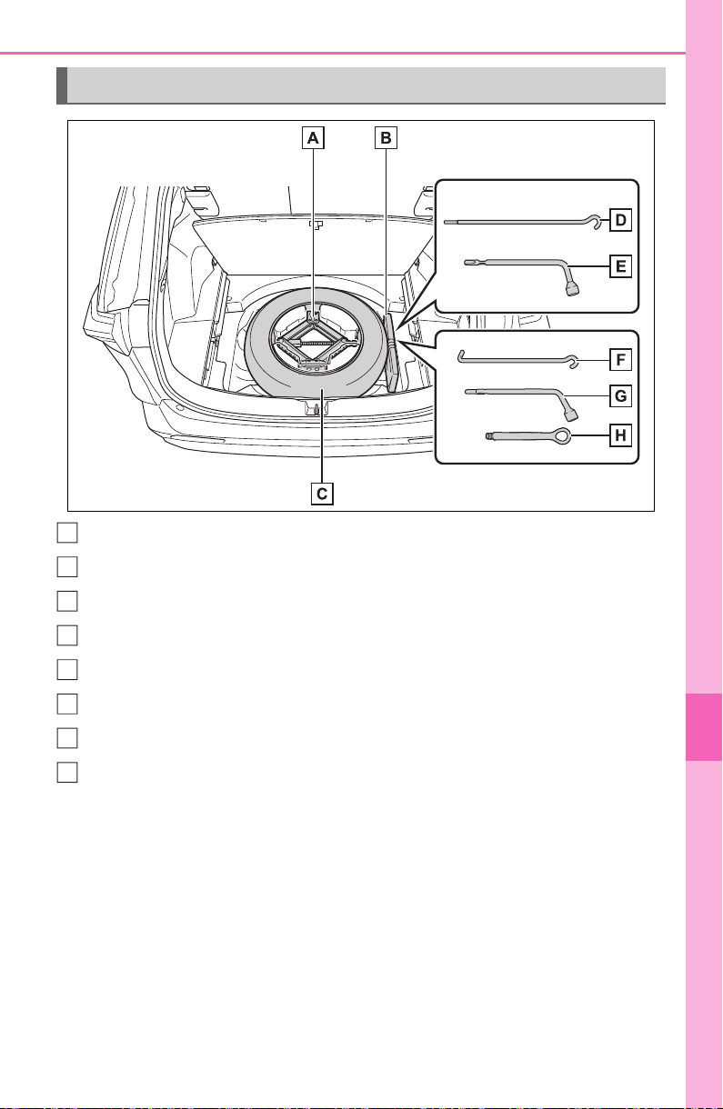
643
8-2. Steps to take in an emergency
8
When trouble arises
Jack
Tool bag
Spare tire
Jack handle
*1
Wheel nut wrench
*1
Jack handle
*2
Wheel nut wrench
*2
Towing eyelet
*2
(if equipped)
*1
:Except for models made in Japan
*3
*2
:For models made in Japan
*3
*3
:The country of production is written on the Certification Regulation label.
(P.665)
Location of the spare tire, jack and tools
A
B
C
D
E
F
G
H
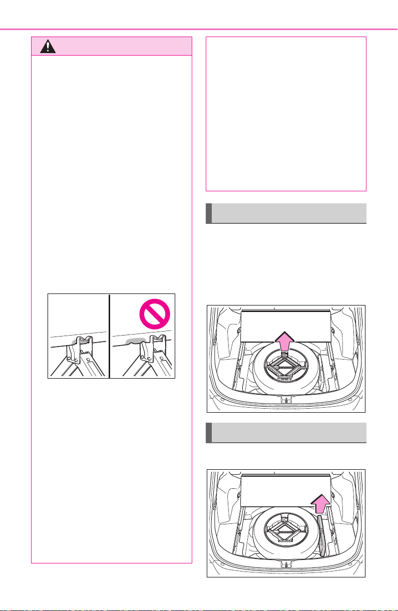
644
8-2. Steps to take in an emergency
1 Open the deck board
(P.532).
2 Take out the jack.
Do not touch the threaded portion
of the jack as it is greased.
Take out the tool bag.
WARNING
■ Using the tire jack
Observe the following precau-
tions.
Improper use of the tire jack may
cause the vehicle to suddenly fall
off the jack, leading to death or
serious injury.
● Do not use the tire jack for any
purpose other than replacing
tires or installing and removing
tire chains.
● Only use the tire jack that
comes with this vehicle for
replacing a flat tire.
Do not use it on other vehicles,
and do not use other tire jacks
for replacing tires on this vehi-
cle.
● Put the jack properly in its jack
point.
● Do not put any part of your body
under the vehicle while it is sup-
ported by the jack.
● Do not start the engine or drive
the vehicle while the vehicle is
supported by the jack.
● Do not raise the vehicle while
someone is inside.
● When raising the vehicle, do not
put an object on or under the
jack.
● Do not raise the vehicle to a
height greater than that required
to replace the tire.
● Use a jack stand if it is neces-
sary to get under the vehicle.
● Stop the vehicle on firm, flat and
level ground, firmly set the park-
ing brake and shift the shift lever
to P. Block the wheel diagonally
opposite to the one being
changed if necessary.
● When lowering the vehicle,
make sure that there is no-one
near the vehicle. If there are
people nearby, warn them
vocally before lowering.
Taking out the jack
Taking out the tool bag
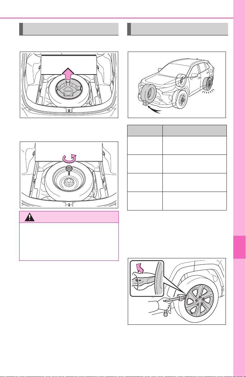
645
8-2. Steps to take in an emergency
8
When trouble arises
1 Take out the jack holder.
2 Loosen the center fastener
that secures the spare tire.
1 Chock the tires.
2 For vehicles with full wheel
ornament: Remove the wheel
ornament using the wrench.
To prevent damage, cover the tip of
the wrench with a rag.
Taking out the spare tire
WARNING
■ When storing the spare tire
Be careful not to catch fingers or
other body parts between the
spare tire and the body of the
vehicle.
Replacing a flat tire
Flat tire Wheel chock positions
Front left-
hand side
Behind the rear right-
hand side tire
Front right-
hand side
Behind the rear left-
hand side tire
Rear left-
hand side
In front of the front
right-hand side tire
Rear right-
hand side
In front of the front
left-hand side tire
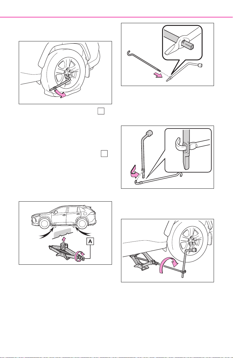
646
8-2. Steps to take in an emergency
3 Slightly loosen the wheel
nuts (one turn).
4 Turn the tire jack portion
by hand until the notch of the
jack is in contact with the jack
point.
After removing the jack from the
jack holder, turn the jack portion
in the opposite direction to lower
the jack, and then adjust the jack
set position.
The jack point guides are located
under the rocker panel. They indi-
cate the jack point positions.
5 Assemble the jack handle
and the wheel nut wrench as
shown in the illustration.
Except for models made in
Japan
*
*
: The country of production is writ-
ten on the Certification Regula-
tion label. (P.665)
For models made in Japan
*
*
: The country of production is writ-
ten on the Certification Regula-
tion label. (P.665)
6 Raise the vehicle until the tire
is slightly raised off the
ground.
7 Remove all the wheel nuts
and the tire.
When resting the tire on the
ground, place the tire so that the
wheel design faces up to avoid
A
A
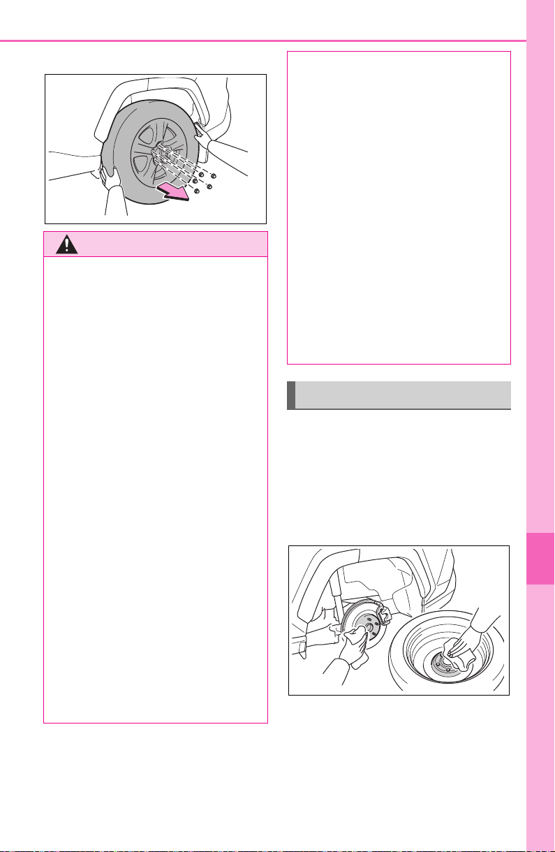
647
8-2. Steps to take in an emergency
8
When trouble arises
scratching the wheel surface.
1 Remove any dirt or foreign
matter from the wheel con-
tact surface.
If foreign matter is on the wheel
contact surface, the wheel nuts
may loosen while the vehicle is in
motion, causing the tire to come off.
2 Install the spare tire and
loosely tighten each wheel
nut by hand by approximately
the same amount.
When replacing a steel wheel with
WARNING
■ Replacing a flat tire
● Do not touch the disc wheels or
the area around the brakes
immediately after the vehicle
has been driven.
After the vehicle has been
driven the disc wheels and the
area around the brakes will be
extremely hot. Touching these
areas with hands, feet or other
body parts while changing a tire,
etc. may result in burns.
● Failure to follow these precau-
tions could cause the wheel
nuts to loosen and the tire to fall
off, resulting in death or serious
injury.
• Have the wheel nuts tightened
with a torque wrench to 76 ft•lbf
(103 N•m, 10.5 kgf•m) as soon
as possible after changing
wheels.
• Do not attach a heavily dam-
aged wheel ornament, as it may
fly off the wheel while the vehi-
cle is moving.
• When installing a tire, only use
wheel nuts that have been spe-
cifically designed for that wheel.
• If there are any cracks or defor-
mations in the bolt screws, nut
threads or bolt holes of the
wheel, have the vehicle
inspected by your Toyota
dealer.
• When installing the wheel nuts,
be sure to install them with the
tapered ends facing inward.
● For vehicles with power back
door: In cases such as when
replacing tires, make sure to
turn off the power back door
system (P.127). Failure to do
so may cause the back door to
operate unintentionally if the
power back door switch is acci-
dentally touched, resulting in
hands and fingers being caught
and injured.
Installing the spare tire
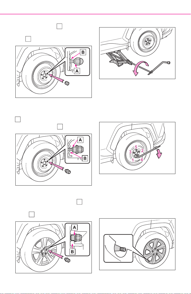
648
8-2. Steps to take in an emergency
a steel wheel, tighten the nuts until
the tapered portion comes into
loose contact with the disc wheel
seat .
When replacing an aluminum wheel
with a steel wheel, tighten the
wheel nuts until the tapered portion
comes into loose contact with
the disc wheel seat .
When replacing an aluminum wheel
with an aluminum wheel, turn the
wheel nuts until the washers
come into contact with the disc
wheel .
3 Lower the vehicle.
4 Firmly tighten each wheel nut
two or three times in the
order shown in the illustra-
tion.
Tightening torque:
76 ft•lbf (103 N•m, 10.5 kgf•m)
5 For vehicles with full wheel
ornament: When reinstalling
an original wheel, reinstall
the wheel ornament
*
.
Align the cutout of the wheel orna-
ment with the valve stem as shown.
*
: The wheel ornament cannot be
A
B
A
B
A
B
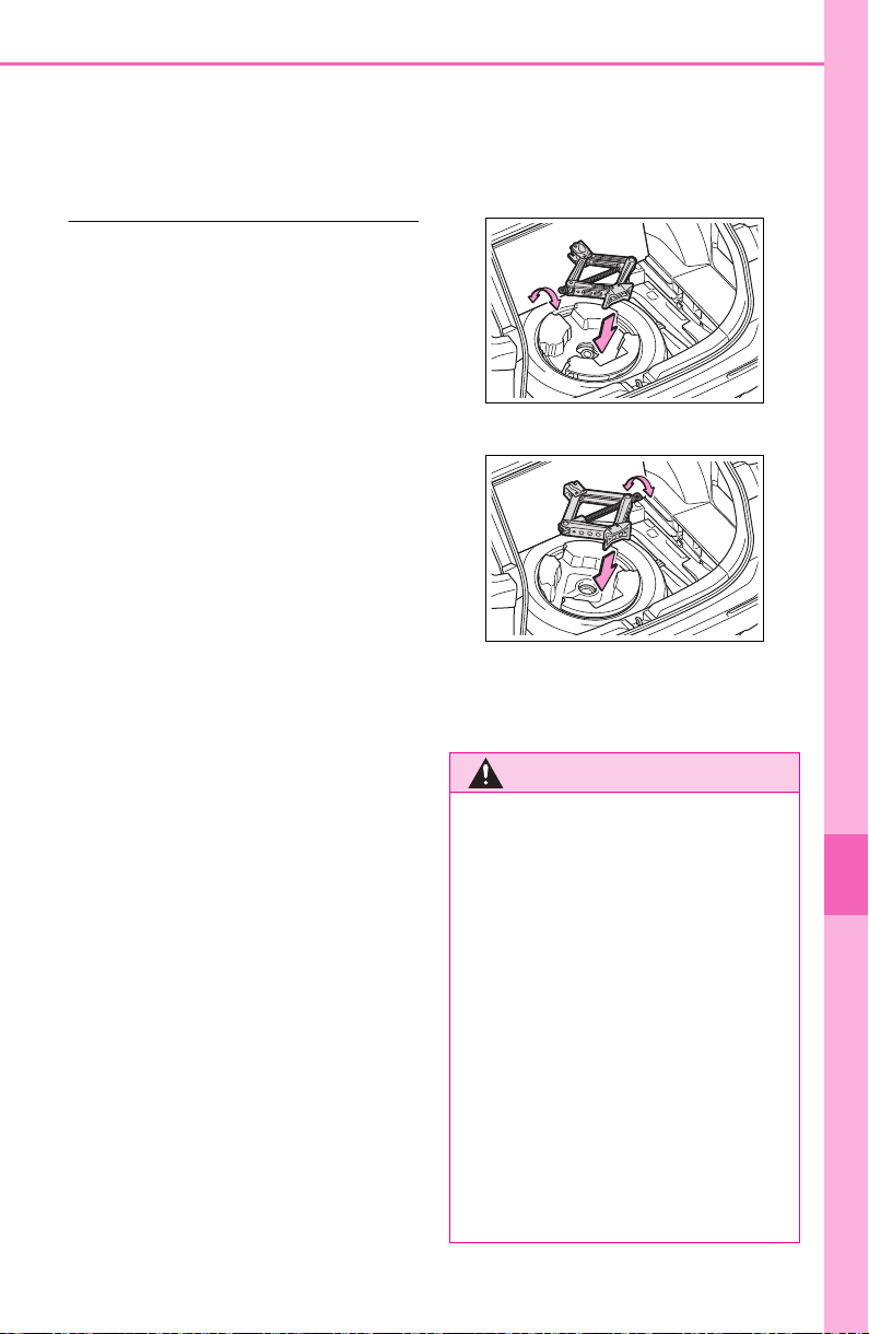
649
8-2. Steps to take in an emergency
8
When trouble arises
installed on the compact spare
tire.
6 Stow the flat tire, tire jack and
all tools.
■ The compact spare tire
● The compact spare tire is identi-
fied by the label “TEMPORARY
USE ONLY” on the tire sidewall.
Use the compact spare tire tempo-
rarily, and only in an emergency.
● Make sure to check the tire infla-
tion pressure of the compact
spare tire. (P.671)
■ When using the compact spare
tire
As the compact spare tire is not
equipped with a tire pressure warn-
ing valve and transmitter, low infla-
tion pressure of the spare tire will
not be indicated by the tire pressure
warning system. Also, if you replace
the compact spare tire after the tire
pressure warning light comes on,
the light remains on.
■ When the compact spare tire is
attached
The vehicle height may become
lower when driving with the compact
spare tire compared to when driving
with standard tires.
■ If you have a flat front tire on a
road covered with snow or ice
Install the compact spare tire on one
of the rear wheels of the vehicle.
Perform the following steps and fit
tire chains to the front tires:
1 Replace a rear tire with the com-
pact spare tire.
2 Replace the flat front tire with the
tire removed from the rear of the
vehicle.
3 Fit tire chains to the front tires.
■ When stowing the jack
Before storing the jack, adjust the
height of the jack to match the
shape of the jack holder.
The storage direction of the jack dif-
fers depending on the type, so make
sure to store the jack in the correct
direction.
Except for models made in Japan
*
:
For models made in Japan
*
:
*
: The country of production is writ-
ten on the Certification Regulation
label. (P.665)
WARNING
■ When using the compact
spare tire
● Remember that the compact
spare tire provided is specifi-
cally designed for use with your
vehicle. Do not use your com-
pact spare tire on another vehi-
cle.
● Do not use more than one com-
pact spare tire simultaneously.
● Replace the compact spare tire
with a standard tire as soon as
possible.
● Avoid sudden acceleration,
abrupt steering, sudden brak-
ing and shifting operations that
cause sudden engine braking.
650
8-2. Steps to take in an emergency
WARNING
■ When the compact spare tire
is attached
The vehicle speed may not be
correctly detected, and the follow-
ing systems may not operate cor-
rectly:
• ABS & Brake assist
• VSC/Trailer Sway Control
•TRAC
• Dynamic radar cruise control
with full-speed range
• Dynamic radar cruise control
• PCS (Pre-Collision System)
•EPS
• LTA (Lane Tracing Assist)
• Tire pressure warning system (if
equipped)
• AHB (Automatic High Beam)
• BSM (Blind Spot Monitor) (if
equipped)
• Downhill assist control system
(if equipped)
• Rear view monitor system (if
equipped)
• Panoramic view monitor (if
equipped)
• Toyota parking assist monitor (if
equipped)
• Intuitive parking assist (if
equipped)
• Navigation system (if equipped)
Also, not only can the following
systems not be utilized fully, but
they may actually negatively
affect the drive-train components:
• Dynamic Torque Control AWD
system (if equipped)
• Dynamic Torque Vectoring AWD
system (if equipped)
■ Speed limit when using the
compact spare tire
Do not drive at speeds in excess
of 50 mph (80 km/h) when a com-
pact spare tire is installed on the
vehicle.
The compact spare tire is not
designed for driving at high
speeds. Failure to observe this
precaution may lead to an acci-
dent causing death or serious
injury.
■ After using the tools and jack
Before driving, make sure all the
tools and jack are securely in
place in their storage location to
reduce the possibility of personal
injury during a collision or sudden
braking.
NOTICE
■ Be careful when driving over
bumps with the compact
spare tire installed on the
vehicle
The vehicle height may become
lower when driving with the com-
pact spare tire compared to when
driving with standard tires. Be
careful when driving over uneven
road surfaces.
■ Driving with tire chains and
the compact spare tire
Do not fit tire chains to the com-
pact spare tire.
Tire chains may damage the vehi-
cle body and adversely affect driv-
ing performance.

651
8-2. Steps to take in an emergency
8
When trouble arises
One of the following may be the
cause of the problem:
There may not be sufficient
fuel in the vehicle’s tank.
Refuel the vehicle.
The engine may be flooded.
Try to restart the engine again
following correct starting pro-
cedures. (P.193, 194)
There may be a malfunction
in the engine immobilizer sys-
tem. (P.70)
One of the following may be the
cause of the problem:
The battery may be dis-
charged. (P.655)
NOTICE
■ When replacing the tires
(vehicles with tire pressure
warning system)
When removing or fitting the
wheels, tires or the tire pressure
warning valve and transmitter,
contact your Toyota dealer as the
tire pressure warning valve and
transmitter may be damaged if not
handled correctly.
If the engine will not
start
If the engine will not start
even though correct starting
procedures are being fol-
lowed (P.193, 194), con-
sider each of the following
points:
The engine will not start
even though the starter
motor operates normally
The starter motor turns
over slowly, the interior
lights and headlights are
dim, or the horn does not
sound or sounds at a low
volume

652
8-2. Steps to take in an emergency
The battery terminal connec-
tions may be loose or cor-
roded.
The engine starting system may
be malfunctioning due to an
electrical problem such as elec-
tronic key battery depletion or a
blown fuse. However, an interim
measure is available to start the
engine. (P.652)
One of the following may be the
cause of the problem:
The battery may be dis-
charged. (P.655)
One or both of the battery ter-
minals may be disconnected.
There may be a malfunction
in the steering lock system
(vehicles with smart key sys-
tem).
Contact your Toyota dealer if the
problem cannot be repaired, or if
repair procedures are unknown.
When the engine does not start,
the following steps can be used
as an interim measure to start
the engine if the engine switch is
functioning normally:
1 Pull the parking brake switch
to check that the parking
brake is set. (P.203)
Parking brake indicator will come
on.
2 Shift the shift lever to P.
3 Turn the engine switch to
ACC.
4 Press and hold the engine
switch for about 15 seconds
while depressing the brake
pedal firmly.
Even if the engine can be
started using the above steps,
the system may be malfunction-
ing. Have the vehicle inspected
by your Toyota dealer.
The starter motor does
not turn over (vehicles
with smart key system)
The starter motor does
not turn over, the interior
lights and headlights do
not turn on, or the horn
does not sound
Emergency start function
(vehicles with smart key
system)

653
8-2. Steps to take in an emergency
8
When trouble arises
■ When the electronic key does
not work properly
● Make sure that the smart key sys-
tem has not been deactivated in
the customization setting. If it is
off, turn the function on.
(Customizable features: P.691)
● Check if battery-saving mode is
set. If it is set, cancel the function.
(P.129)
Use the mechanical key
(P.107) in order to perform the
If you lose your keys
New genuine keys can be
made by your Toyota dealer
using the other key and the
key number stamped on
your key number plate.
Keep the plate in a safe
place such as your wallet,
not in the vehicle.
NOTICE
■ When an electronic key is lost
(if equipped)
If the electronic key remains lost,
the risk of vehicle theft increases
significantly. Visit your Toyota
dealer immediately with all
remaining electronic keys that
were provided with your vehicle.
If the electronic key
does not operate prop-
erly (vehicles with
smart key system)
If communication between
the electronic key and vehi-
cle is interrupted (P.129)
or the electronic key cannot
be used because the battery
is depleted, the smart key
system and wireless remote
control cannot be used. In
such cases, the doors can
be opened and the engine
can be started by following
the procedure below.
NOTICE
■ In case of a smart key system
malfunction, or other key
related problems
Take your vehicle with all the elec-
tronic keys provided with your
vehicle to your Toyota dealer.
Locking and unlocking
the doors
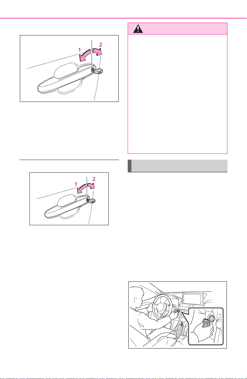
654
8-2. Steps to take in an emergency
following operations.
1 Locks all the doors
2 Unlocks the door
Turning the key rearward unlocks
the driver’s door. Turning the key
once again within 5 seconds
unlocks the other doors.
■ Key linked functions
1 Closes the windows and the
moon roof
*1
or panoramic moon
roof
*1
(turn and hold)
*2
2 Opens the windows and the
moon roof
*1
or panoramic moon
roof
*1
(turn and hold)
*2
*1
:If equipped
*2
:These settings must be custom-
ized at your Toyota dealer.
1 Ensure that the shift lever is
in P and depress the brake
pedal.
2 Touch the Toyota emblem
side of the electronic key to
the engine switch.
When the electronic key is
detected, a buzzer sounds and the
engine switch will turn to ON.
When the smart key system is
deactivated in customization set-
ting, the engine switch will turn to
ACC.
WARNING
■ When using the mechanical
key and operating the power
windows or the moon roof (if
equipped) or panoramic
moon roof (if equipped)
Operate the power window or the
moon roof or panoramic moon
roof after checking to make sure
that there is no possibility of any
passenger having any of their
body parts caught in the window
or the moon roof or panoramic
moon roof. Also, do not allow chil-
dren to operate the mechanical
key. It is possible for children and
other passengers to get caught in
the power window or the moon
roof or panoramic moon roof.
Starting the engine
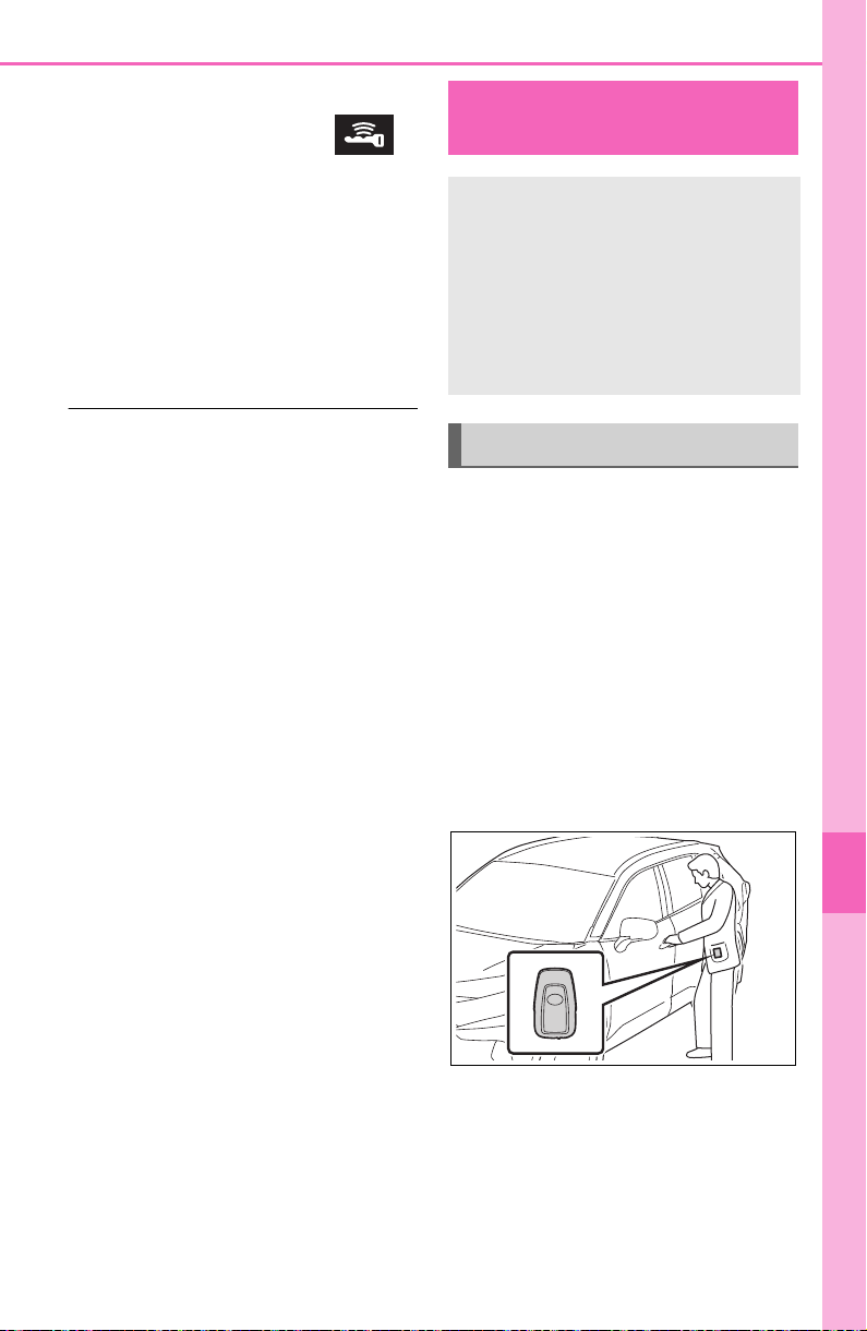
655
8-2. Steps to take in an emergency
8
When trouble arises
3 Firmly depress the brake
pedal and check that
is displayed on the multi-
information display.
4 Press the engine switch
shortly and firmly.
In the event that the engine still
cannot be started, contact your
Toyota dealer.
■ Stopping the engine
Shift the shift lever to P, set the park-
ing brake and press the engine
switch as you normally do when
stopping the engine.
■ Replacing the key battery
As the above procedure is a tempo-
rary measure, it is recommended
that the electronic key battery be
replaced immediately when the bat-
tery is depleted. (P.604)
■ Alarm (if equipped)
Using the mechanical key to lock
the doors will not set the alarm sys-
tem.
If a door is unlocked using the
mechanical key when the alarm sys-
tem is set, the alarm may be trig-
gered. (P. 73 )
■ Changing engine switch modes
Release the brake pedal and press
the engine switch in step 3 above.
The engine does not start and
modes will be changed each time
the switch is pressed. (P.197)
If you have a set of jumper (or
booster) cables and a second
vehicle with a 12-volt battery,
you can jump start your vehicle
by following the steps below.
1 Vehicles with alarm: Confirm
that the electronic key is
being carried.
When connecting the jumper (or
booster) cables, depending on the
situation, the alarm may activate
and the doors locked. (P.7 4 )
2 Open the hood. (P.571)
If the vehicle battery
is discharged
The following procedures
may be used to start the
engine if the vehicle’s bat-
tery is discharged.
You can also call your
Toyota dealer or a qualified
repair shop.
Restarting the engine
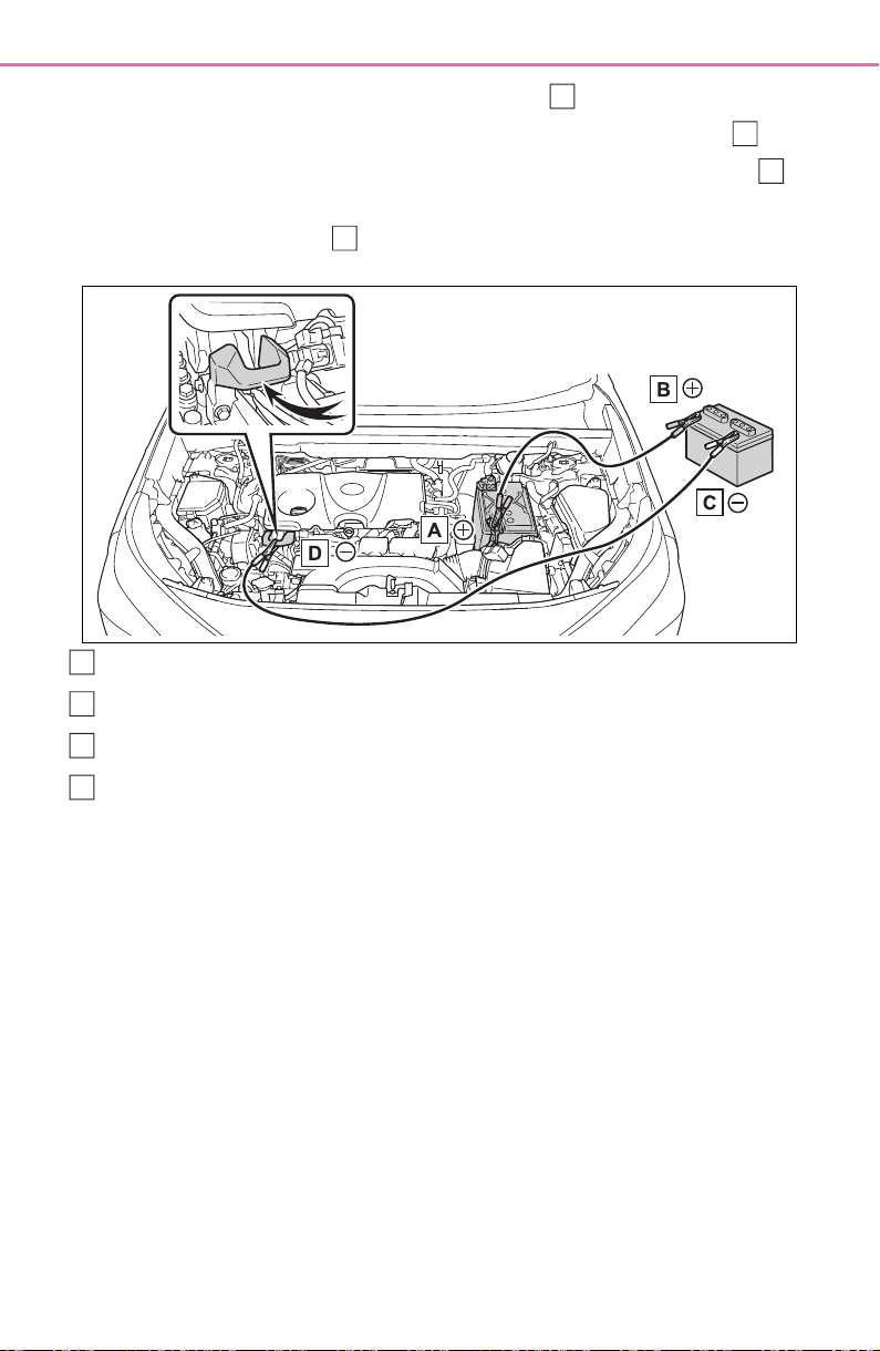
656
8-2. Steps to take in an emergency
3 Connect a positive jumper cable clamp to on your vehicle and
connect the clamp on the other end of the positive cable to on
the second vehicle. Then, connect a negative cable clamp to
on the second vehicle and connect the clamp at the other end of
the negative cable to .
Positive (+) battery terminal (your vehicle)
Positive (+) battery terminal (second vehicle)
Negative (-) battery terminal (second vehicle)
Solid, stationary, unpainted metallic point away from the battery
and any moving parts as shown in the illustration
4 Start the engine of the sec-
ond vehicle. Increase the
engine speed slightly and
maintain at that level for
approximately 5 minutes to
recharge the battery of your
vehicle.
5 Vehicles with smart key sys-
tem only: Open and close
any of the doors of your vehi-
cle with the engine switch
OFF.
6 Vehicles without smart key
system: Maintain the engine
speed of the second vehicle
and start the engine of your
vehicle.
Vehicles with smart key sys-
tem: Maintain the engine
speed of the second vehicle
and start the engine of your
vehicle by turning the engine
switch to ON.
7 Once the vehicle’s engine
has started, remove the
jumper cables in the exact
reverse order from which
they were connected.
A
B
C
D
A
B
C
D

657
8-2. Steps to take in an emergency
8
When trouble arises
Once the engine starts, have the
vehicle inspected at your Toyota
dealer as soon as possible.
■ Starting the engine when the
battery is discharged
The engine cannot be started by
push-starting.
■ To prevent battery discharge
● Turn off the headlights and the
audio system while the engine is
stopped.
(Vehicles with Stop & Start system:
Except when the engine is stopped
due to the Stop & Start system)
● Turn off any unnecessary electri-
cal components when the vehicle
is running at a low speed for an
extended period, such as in heavy
traffic.
■ When the battery is removed or
discharged
● Information stored in the ECU is
cleared. When the battery is
depleted, have the vehicle
inspected at your Toyota dealer.
● Some systems may require initial-
ization. (P.699)
■ When removing the battery ter-
minals
When the battery terminals are
removed, the information stored in
the ECU is cleared. Before remov-
ing the battery terminals, contact
your Toyota dealer.
■ Charging the battery
The electricity stored in the battery
will discharge gradually even when
the vehicle is not in use, due to nat-
ural discharge and the draining
effects of certain electrical appli-
ances. If the vehicle is left for a long
time, the battery may discharge,
and the engine may be unable to
start. (The battery recharges auto-
matically during driving.)
■ When recharging or replacing
the battery (vehicles without
smart key start system)
The engine may not start on the first
attempt after the battery has
recharged but will start normally
after the second attempt. This is not
a malfunction.
■ When recharging or replacing
the battery (vehicles with smart
key system)
● In some cases, it may not be pos-
sible to unlock the doors using the
smart key system when the bat-
tery is discharged. Use the wire-
less remote control or the
mechanical key to lock or unlock
the doors.
● The engine may not start on the
first attempt after the battery has
recharged but will start normally
after the second attempt. This is
not a malfunction.
● The engine switch mode is memo-
rized by the vehicle. When the
battery is reconnected, the system
will return to the mode it was in
before the battery was dis-
charged. Before disconnecting the
battery, turn the engine switch off.
If you are unsure what mode the
engine switch was in before the
battery discharged, be especially
careful when reconnecting the
battery.
■ When the battery is removed or
discharged (vehicles with Stop
& Start system)
The Stop & Start system may not
automatically stop the engine for up
to an hour.
■ When replacing the battery
● Vehicles with Stop & Start system:
Use a genuine battery specifically
designed for use with the Stop &
Start system or a battery with equiv-
alent specifications to a genuine
battery. If an unsupported battery is
used, Stop & Start system functions
may be restricted to protect the bat-

658
8-2. Steps to take in an emergency
tery. Also, battery performance may
decrease and the engine may not
be able to restart. Contact your
Toyota dealer for details.
● Use a battery that conforms to
European regulations.
● Type A:
Use a battery that the case size is
same as the previous one (LN3), 20
hours rate capacity (20HR) is equiv-
alent (65Ah) or greater, and perfor-
mance rating (CCA) is equivalent
(603A) or greater.
Type B:
Use a battery that the case size is
same as the previous one (LN2), 20
hours rate capacity (20HR) is equiv-
alent (60Ah) or greater, and perfor-
mance rating (CCA) is equivalent
(560A) or greater.
Type C:
Use a battery that the case size is
same as the previous one (LN2), 20
hours rate capacity (20HR) is equiv-
alent (60Ah) or greater, and perfor-
mance rating (CCA) is equivalent
(563A) or greater.
• If the sizes differ, the battery can-
not be properly secured.
• If the 20 hour rate capacity is low,
even if the time period where the
vehicle is not used is a short time,
the battery may discharge and
engine may not be able to start.
WARNING
■ When removing the battery
terminals
Always remove the negative (-)
terminal first. If the positive (+) ter-
minal contacts any metal in the
surrounding area when the posi-
tive (+) terminal is removed, a
spark may occur, leading to a fire
in addition to electrical shocks
and death or serious injury.
■ Avoiding battery fires or
explosions
Observe the following precautions
to prevent accidentally igniting the
flammable gas that may be emit-
ted from the battery:
● Make sure each jumper cable is
connected to the correct termi-
nal and that it is not unintention-
ally in contact with any other
than the intended terminal.
● Do not allow the other end of
the jumper cable connected to
the “+” terminal to come into
contact with any other parts or
metal surfaces in the area, such
as brackets or unpainted metal.
● Do not allow the + and - clamps
of the jumper cables to come
into contact with each other.
● Do not smoke, use matches,
cigarette lighters or allow open
flame near the battery.
■ Battery precautions
The battery contains poisonous
and corrosive acidic electrolyte,
while related parts contain lead
and lead compounds. Observe
the following precautions when
handling the battery:
● When working with the battery,
always wear safety glasses and
take care not to allow any bat-
tery fluids (acid) to come into
contact with skin, clothing or the
vehicle body.
● Do not lean over the battery.
● In the event that battery fluid
comes into contact with the skin
or eyes, immediately wash the
affected area with water and
seek medical attention.
Place a wet sponge or cloth
over the affected area until
medical attention can be
received.

659
8-2. Steps to take in an emergency
8
When trouble arises
1 Stop the vehicle in a safe
place and turn off the air con-
ditioning system, and then
stop the engine.
2 If you see steam:
Carefully lift the hood after
the steam subsides.
If you do not see steam:
Carefully lift the hood.
WARNING
● Always wash your hands after
handling the battery support,
terminals, and other battery-
related parts.
● Do not allow children near the
battery.
■ When replacing the battery
For information regarding battery
replacement, contact your Toyota
dealer.
NOTICE
■ When handling jumper cables
When connecting the jumper
cables, ensure that they do not
become entangled in the cooling
fan or engine drive belt.
If your vehicle over-
heats
The following may indicate
that your vehicle is over-
heating.
The needle of the engine
coolant temperature gauge
(P.82, 85) enters the red
zone or a loss of engine
power is experienced. (For
example, the vehicle speed
does not increase.)
“Engine Coolant Temp High
Stop in a Safe Place See
Owner’s Manual” is shown
on the multi-information dis-
play.
Steam comes out from
under the hood.
Correction procedures
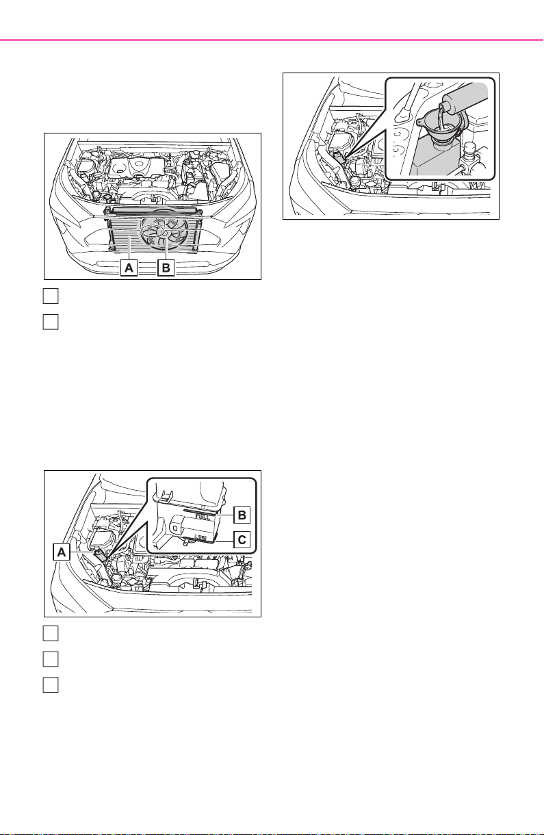
660
8-2. Steps to take in an emergency
3 After the engine has cooled
down sufficiently, inspect the
hoses and radiator core (radi-
ator) for any leaks.
Radiator
Cooling fan
If a large amount of coolant leaks,
immediately contact your Toyota
dealer.
4 The coolant level is satisfac-
tory if it is between the
“FULL” and “LOW” lines on
the reservoir.
Reservoir
“FULL” line
“LOW” line
5 Add coolant if necessary.
Water can be used in an emer-
gency if coolant is unavailable.
6 Start the engine and turn the
air conditioning system on to
check that the radiator cool-
ing fan operates and to check
for coolant leaks from the
radiator or hoses.
The fan operates when the air con-
ditioning system is turned on imme-
diately after a cold start. Confirm
that the fan is operating by check-
ing the fan sound and air flow. If it is
difficult to check these, turn the air
conditioning system on and off
repeatedly. (The fan may not oper-
ate in freezing temperatures.)
7 If the fan is not operating:
Stop the engine immediately
and contact your Toyota
dealer.
If the fan is operating:
Have the vehicle inspected at
the nearest Toyota dealer.
8 Check if “Engine Coolant
Temp High Stop in a Safe
Place See Owner’s Manual”
is shown on the multi-infor-
mation display.
If the message does not disappear:
Stop the engine and contact your
Toyota dealer.
If the message is not displayed:
Have the vehicle inspected at the
nearest Toyota dealer.
A
B
A
B
C
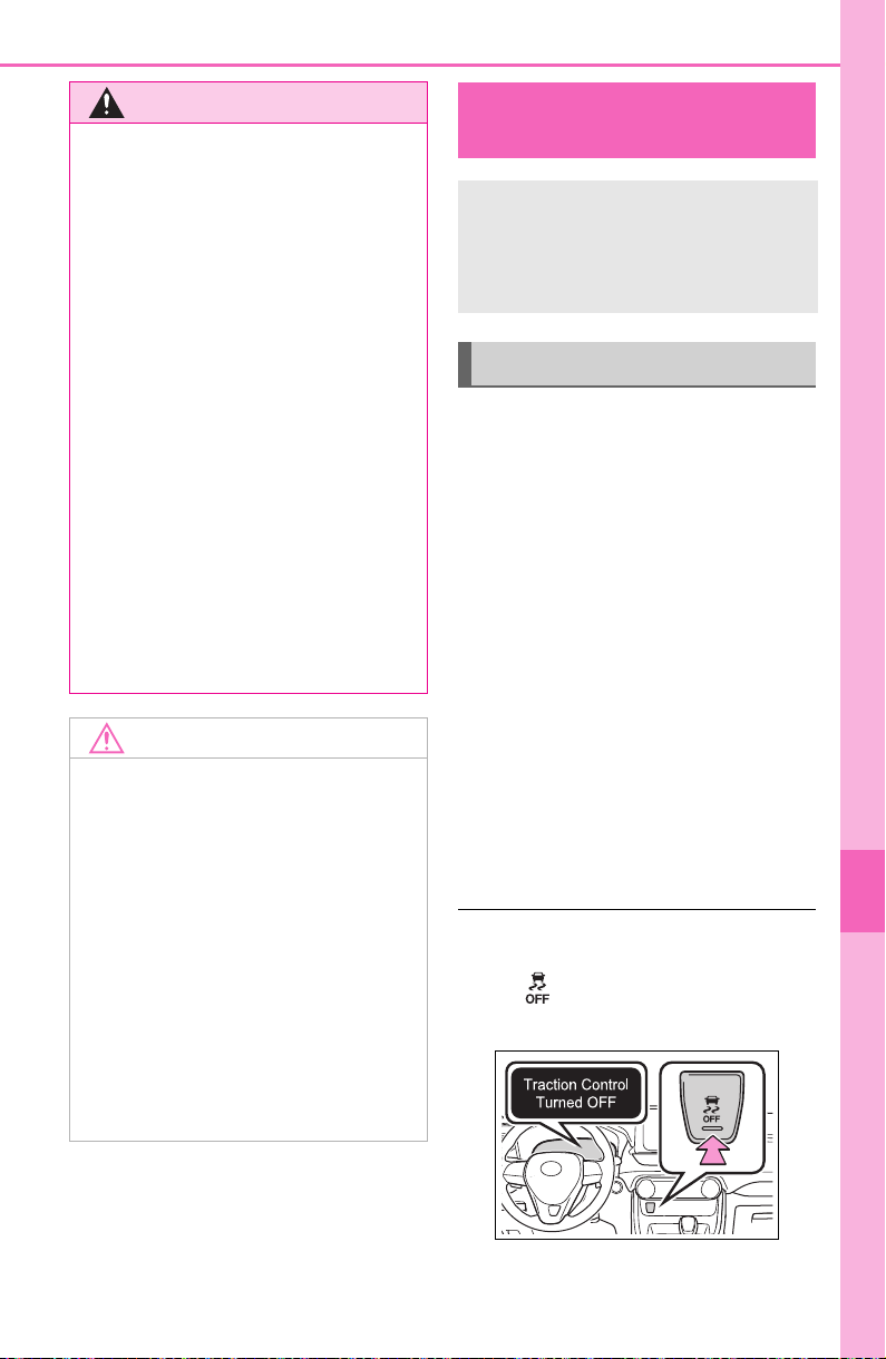
661
8-2. Steps to take in an emergency
8
When trouble arises
1 Stop the engine. Set the
parking brake and shift the
shift lever to P.
2 Remove the mud, snow or
sand from around the stuck
tire.
3 Place wood, stones or some
other material to help provide
traction under the tires.
4 Restart the engine.
5 Shift the shift lever to D or R
and release the parking
brake. Then, while exercising
caution, depress the acceler-
ator pedal.
■ When it is difficult to free the
vehicle
Press to turn off TRAC.
(P.361)
WARNING
■ When inspecting under the
hood of your vehicle
Observe the following precau-
tions.
Failure to do so may result in seri-
ous injury such as burns.
● If steam is seen coming from
under the hood, do not open the
hood until the steam has sub-
sided. The engine compart-
ment may be very hot.
● Keep hands and clothing (espe-
cially a tie, a scarf or a muffler)
away from the fan and belts.
Failure to do so may cause the
hands or clothing to be caught,
resulting in serious injury.
● Do not loosen the coolant reser-
voir cap while the engine and
radiator are hot. High tempera-
ture steam or coolant could
spray out.
NOTICE
■ When adding engine coolant
Add coolant slowly after the
engine has cooled down suffi-
ciently. Adding cool coolant to a
hot engine too quickly can cause
damage to the engine.
■ To prevent damage to the
cooling system
Observe the following precau-
tions:
● Avoid contaminating the coolant
with foreign matter (such as
sand or dust etc.).
● Do not use any coolant additive.
If the vehicle becomes
stuck
Carry out the following pro-
cedures if the tires spin or
the vehicle becomes stuck
in mud, dirt or snow:
Recovering procedure

662
8-2. Steps to take in an emergency
WARNING
■ When attempting to free a
stuck vehicle
If you choose to push the vehicle
back and forth to free it, make
sure the surrounding area is clear
to avoid striking other vehicles,
objects or people. The vehicle
may also lunge forward or lunge
back suddenly as it becomes free.
Use extreme caution.
■ When shifting the shift lever
Be careful not to shift the shift
lever with the accelerator pedal
depressed.
This may lead to unexpected
rapid acceleration of the vehicle
that may cause an accident
resulting in death or serious injury.
NOTICE
■ To avoid damaging the trans-
mission and other compo-
nents
● Avoid spinning the wheels and
depressing the accelerator
pedal more than necessary.
● If the vehicle remains stuck
even after these procedures are
performed, the vehicle may
require towing to be freed.

663
9
9
Vehicle specifications
Vehicle specifications
9-1. Specifications
Maintenance data (fuel, oil
level, etc.).................. 664
Fuel information .......... 676
Tire information ........... 678
9-2. Customization
Customizable features 688
9-3. Initialization
Items to initialize ......... 699

664
9-1. Specifications
9-1.Specifications
Maintenance data (fuel, oil level, etc.)
Dimensions and weights
Overall length
*1
Except ADVEN-
TURE grade (for
the U.S.A.)/Trail
grade (for Can-
ada)
180.9 in. (4595 mm)
ADVENTURE
grade (for the
U.S.A.)/Trail
grade (for Can-
ada)
181.5 in. (4611 mm)
Overall width
*1
Except ADVEN-
TURE grade (for
the U.S.A.)/Trail
grade (for Can-
ada)
73.0 in. (1855 mm)
ADVENTURE
grade (for the
U.S.A.)/Trail
grade (for Can-
ada)
73.4 in. (1865 mm)
Overall height
*1
Without bridge
type roof rail
67.0 in. (1701 mm)
*2
67.2 in. (1706 mm)
*3
With bridge type
roof rail
68.6 in. (1742 mm)
Wheelbase
*1
105.9 in. (2690 mm)
Tread
*1
Front
63.0 in. (1600 mm)
*2
62.6 in. (1590 mm)
*3
Rear
63.7 in. (1619 mm)
*2
63.3 in. (1609 mm)
*3
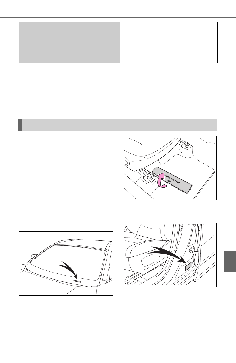
665
9-1. Specifications
9
Vehicle specifications
*1
:Unladen vehicle
*2
:Vehicles without 235/55R19 tires
*3
:Vehicles with 235/55R19 tires
*4
:Vehicles without towing package
*5
:Vehicles with towing package
■ Vehicle identification num-
ber
The vehicle identification num-
ber (VIN) is the legal identifier
for your vehicle. This is the pri-
mary identification number for
your Toyota. It is used in regis-
tering the ownership of your
vehicle.
This number is stamped on the
top left of the instrument panel.
On some models, this number is
also stamped under the right-
hand front seat.
This number is also on the Certi-
fication Regulation Label.
■ Engine number
The engine number is stamped
on the engine block as shown.
Vehicle capacity weight (Occupants +
luggage)
900 lb. (410 kg)
Trailer Weight Rating (Trailer weight
+ cargo weight)
1500 lb. (680 kg)
*4
3500 lb. (1590 kg)
*5
Vehicle identification
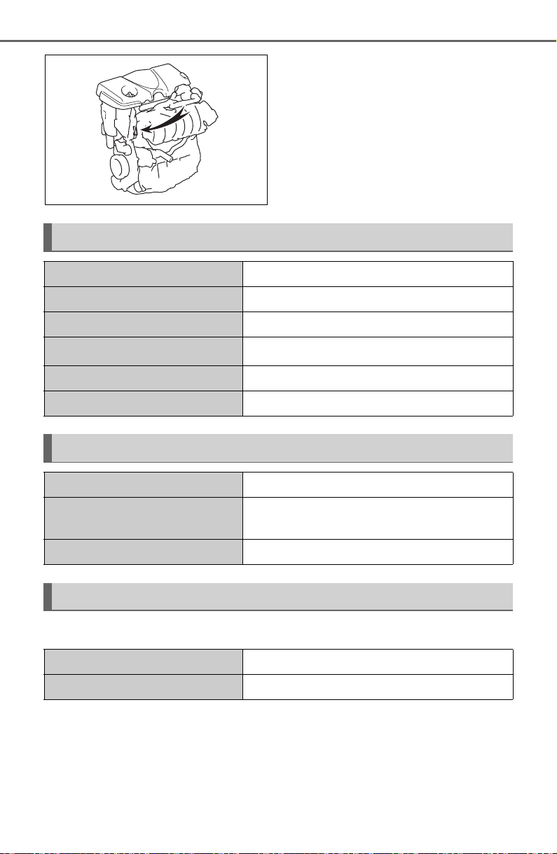
666
9-1. Specifications
■ Oil capacity (Drain and refill reference
*
)
*
: The engine oil capacity is a reference quantity to be used when changing
the engine oil. Warm up and turn off the engine, wait more than 5 min-
utes, and check the oil level on the dipstick.
■ Engine oil selection
“Toyota Genuine Motor Oil” is
used in your Toyota vehicle. Use
Toyota approved “Toyota
Engine
Model A25A-FKS
Type 4-cylinder in line, 4-cycle, gasoline
Bore and stroke 3.44 4.07 in. (87.5 103.4 mm)
Displacement
151.8 cu. in. (2487 cm
3
)
Valve clearance Automatic adjustment
Drive belt tension Automatic adjustment
Fuel
Fuel type Unleaded gasoline only
Octane Rating
87 (Research Octane Number 91) or
higher
Fuel tank capacity (Reference) 14.5 gal. (55 L, 12.1 Imp.gal.)
Lubrication system
With filter 4.8 qt. (4.5 L, 4.0 Imp. qt.)
Without filter 4.4 qt. (4.2 L, 3.7 Imp. qt.)
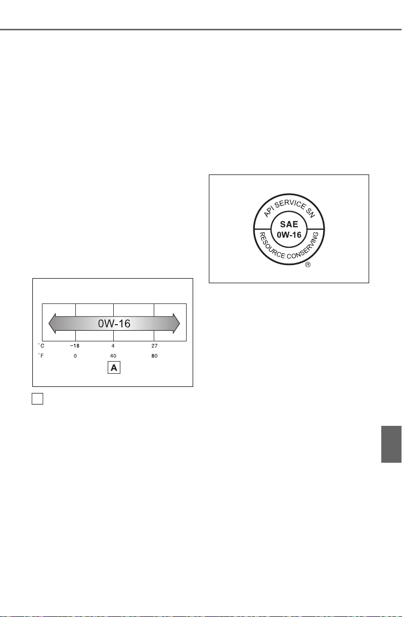
667
9-1. Specifications
9
Vehicle specifications
Genuine Motor Oil” or equiva-
lent to satisfy the following
grade and viscosity.
Oil grade:
API SN/RC multigrade engine
oil
Recommended viscosity:
SAE 0W-16
SAE 0W-16 is the best choice
for good fuel economy and good
starting in cold weather.
If SAE 0W-16 is not available,
SAE 0W-20 oil may be used.
However, it must be replaced
with SAE 0W-16 at the next oil
change.
Outside temperature
Oil viscosity (0W-16 is explained
here as an example):
• The 0W in 0W-16 indicates
the characteristic of the oil
which allows cold startability.
Oils with a lower value before
the W allow for easier starting
of the engine in cold weather.
• The 16 in 0W-16 indicates the
viscosity characteristic of the
oil when the oil is at high tem-
perature. An oil with a higher
viscosity (one with a higher
value) may be better suited if
the vehicle is operated at high
speeds, or under extreme
load conditions.
How to read oil container label:
API registered mark is added to
some oil containers to help you
select the oil you should use.
A
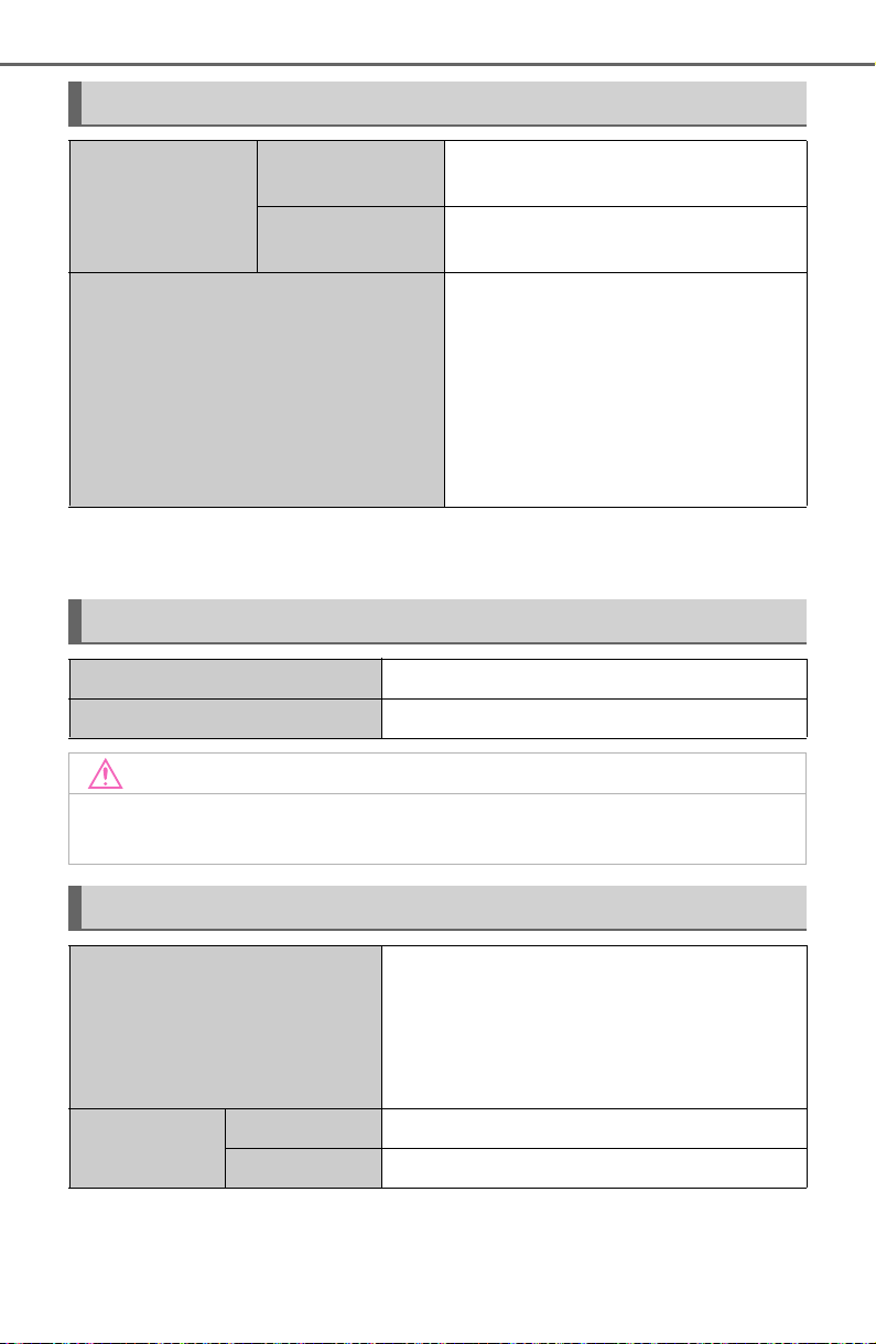
668
9-1. Specifications
*
: The coolant capacity is the quantity of reference.
If replacement is necessary, contact your Toyota dealer.
Cooling system
Capacity
*
Without engine oil
cooler
7.3 qt. (6.9 L, 6.1 Imp. qt.)
With engine oil
cooler
7.4 qt. (7.0 L, 6.2 Imp. qt.)
Coolant type
Use either of the following:
“Toyota Super Long Life Coolant”
Similar high-quality ethylene gly-
colbased non-silicate, non-amine,
non-nitrite, and non-borate cool-
ant with long-life hybrid organic
acid technology
Do not use plain water alone.
Ignition system (spark plug)
Make DENSO FC16HR-Q8
Gap 0.031 in. (0.8 mm)
NOTICE
■ Iridium-tipped spark plugs
Use only iridium-tipped spark plugs. Do not adjust the spark plug gap.
Electrical system (battery)
Specific voltage reading at
68°F (20°C):
12.3 V or higher
(Turn the engine switch to OFF and turn on
the high beam headlights for 30 seconds.)
If the voltage is lower than the standard
value, charge the battery.
Charging rates
Quick charge 15 A max.
Slow charge 5 A max.
669
9-1. Specifications
9
Vehicle specifications
*
: The fluid capacity is the quantity of reference.
If replacement is necessary, contact your Toyota dealer.
Your Toyota vehicle is filled with “Toyota Genuine Differential Gear
Oil” at the factory.
Use Toyota approved “Toyota Genuine Differential Gear Oil” or an
equivalent of matching quality to satisfy the above specification.
Please contact your Toyota dealer for further details.
Automatic transmission
Fluid capacity
*
7.8 qt. (7.4 L, 6.5 Imp.qt.)
Fluid type Toyota Genuine ATF WS
NOTICE
■ Automatic transmission fluid type
Using transmission fluid other than the above type may cause abnormal
noise or vibration, or damage the transmission of your vehicle.
Transfer (Dynamic Torque Control AWD vehicle)
Oil capacity 0.48 qt. (0.45 L, 0.40 Imp.qt.)
Oil type and viscosity
Toyota Genuine Differential gear oil LX
75W-85 GL-5 or equivalent
Transfer (Dynamic Torque Vectoring AWD vehicle)
Oil capacity 0.409 qt. (0.387 L, 0.341 Imp.qt.)
Oil type Toyota Genuine Differential gear oil LX
NOTICE
■ Transfer oil type precaution
Using transfer oil other than the specified oil may cause abnormal noise
or vibration, or damage the transfer of your vehicle.
670
9-1. Specifications
Your Toyota vehicle is filled with “Toyota Genuine Differential Gear
Oil” at the factory.
Use Toyota approved “Toyota Genuine Differential Gear Oil” or an
equivalent of matching quality to satisfy the above specification.
Please contact your Toyota dealer for further details.
*
: Minimum pedal clearance when depressed with a force of 300 N (30.5
kgf, 67.4 lbf) while the engine is running.
Rear differential (Dynamic Torque Control AWD vehicle)
Oil capacity 0.5 qt. (0.5 L, 0.4 Imp.qt.)
Oil type and viscosity
Toyota Genuine Differential gear oil LX
75W-85 GL-5 or equivalent
Rear differential (Dynamic Torque Vectoring AWD vehi-
cle)
Oil capacity 0.553 qt. (0.523 L, 0.460 Imp.qt.)
Oil type Toyota Genuine Differential gear oil LX
NOTICE
■ Differential gear oil type precaution
Using differential gear oil other than the specified oil may cause abnormal
noise or vibration, or damage the differential gear of your vehicle.
Brakes
Pedal clearance
*
5.1 in. (129 mm) Min.
Pedal free play 0.04 0.24 in. (1.0 6.0 mm)
Brake pad wear limit 0.04 in. (1.0 mm)
Fluid type
FMVSS No.116 DOT 3 or SAE J1703
FMVSS No.116 DOT 4 or SAE J1704
Steering
Free play Less than 1.2 in. (30 mm)
671
9-1. Specifications
9
Vehicle specifications
Vehicles with 17-inch wheels (type A)
Vehicles with 17-inch wheels (type B)
Tires and wheels
Tire size
225/65R17 102H, T165/80R17 104M
(spare)
Tire inflation pressure (Recom-
mended cold tire inflation pres-
sure)
Front:
35 psi (240 kPa, 2.4 kgf/cm
2
or bar)
Rear:
35 psi (240 kPa, 2.4 kgf/cm
2
or bar)
Spare:
60 psi (420 kPa, 4.2 kgf/cm
2
or bar)
Wheel size 17 7J, 17 4T (spare)
Wheel nut torque 76 ft•lbf (103 N•m, 10.5 kgf•m)
Tire size
225/65R17 102H, T165/80R17 104M
(spare)
Tire inflation pressure (Recom-
mended cold tire inflation pres-
sure)
Front:
36 psi (250 kPa, 2.5 kgf/cm
2
or bar)
Rear:
36 psi (250 kPa, 2.5 kgf/cm
2
or bar)
Spare:
60 psi (420 kPa, 4.2 kgf/cm
2
or bar)
Wheel size 17 7J, 17 4T (spare)
Wheel nut torque 76 ft•lbf (103 N•m, 10.5 kgf•m)

672
9-1. Specifications
Vehicles with 17-inch wheels (type C)
Vehicles with 17-inch wheels (type D)
Tire size
225/65R17 102H, T165/80D17 104M
(spare)
Tire inflation pressure (Recom-
mended cold tire inflation pres-
sure)
Front:
33 psi (230 kPa, 2.3 kgf/cm
2
or bar)
Rear:
33 psi (230 kPa, 2.3 kgf/cm
2
or bar)
Spare:
60 psi (420 kPa, 4.2 kgf/cm
2
or bar)
Wheel size 17 7J, 17 4T (spare)
Wheel nut torque 76 ft•lbf (103 N•m, 10.5 kgf•m)
Tire size
225/65R17 102H, T165/80D17 104M
(spare)
Tire inflation pressure (Recom-
mended cold tire inflation pres-
sure)
Front:
35 psi (240 kPa, 2.4 kgf/cm
2
or bar)
Rear:
35 psi (240 kPa, 2.4 kgf/cm
2
or bar)
Spare:
60 psi (420 kPa, 4.2 kgf/cm
2
or bar)
Wheel size 17 7J, 17 4T (spare)
Wheel nut torque 76 ft•lbf (103 N•m, 10.5 kgf•m)

673
9-1. Specifications
9
Vehicle specifications
Vehicles with 17-inch wheels (type E)
Vehicles with 18-inch wheels
Tire size
225/65R17 102H, T165/80D17 104M
(spare)
Tire inflation pressure (Recom-
mended cold tire inflation pres-
sure)
Front:
36 psi (250 kPa, 2.5 kgf/cm
2
or bar)
Rear:
36 psi (250 kPa, 2.5 kgf/cm
2
or bar)
Spare:
60 psi (420 kPa, 4.2 kgf/cm
2
or bar)
Wheel size 17 7J, 17 4T (spare)
Wheel nut torque 76 ft•lbf (103 N•m, 10.5 kgf•m)
Tire size
225/60R18 100H, T165/80D17 104M
(spare)
Tire inflation pressure (Recom-
mended cold tire inflation pres-
sure)
Front:
33 psi (230 kPa, 2.3 kgf/cm
2
or bar)
Rear:
33 psi (230 kPa, 2.3 kgf/cm
2
or bar)
Spare:
60 psi (420 kPa, 4.2 kgf/cm
2
or bar)
Wheel size 18 7J, 18 4T (spare)
Wheel nut torque 76 ft•lbf (103 N•m, 10.5 kgf•m)

674
9-1. Specifications
Vehicles with 19-inch wheels (type A)
Vehicles with 19-inch wheels (type B)
Tire size
235/55R19 101V, T165/90D18 107M
(spare)
Tire inflation pressure (Recom-
mended cold tire inflation pres-
sure)
Front:
33 psi (230 kPa, 2.3 kgf/cm
2
or bar)
Rear:
33 psi (230 kPa, 2.3 kgf/cm
2
or bar)
Spare:
60 psi (420 kPa, 4.2 kgf/cm
2
or bar)
Wheel size 19 7 1/2J, 18 4T (spare)
Wheel nut torque 76 ft•lbf (103 N•m, 10.5 kgf•m)
Tire size
235/55R19 101V, T165/90D18 107M
(spare)
Tire inflation pressure (Recom-
mended cold tire inflation pres-
sure)
Front:
35 psi (240 kPa, 2.4 kgf/cm
2
or bar)
Rear:
35 psi (240 kPa, 2.4 kgf/cm
2
or bar)
Spare:
60 psi (420 kPa, 4.2 kgf/cm
2
or bar)
Wheel size 19 7 1/2J, 18 4T (spare)
Wheel nut torque 76 ft•lbf (103 N•m, 10.5 kgf•m)

675
9-1. Specifications
9
Vehicle specifications
A: Wedge base bulbs (clear)
B: H16 halogen bulbs
C: Wedge base bulbs (amber)
D: Double end bulbs (clear)
*
: If equipped
Light bulbs
Light bulbs Bulb No. W Type
Exterior
Front side marker lights W5W 5 A
Fog lights
*
19 B
Front turn signal/parking lights
(bulb type)
7444NA 28/8 C
Rear turn signal lights WY21W 21 C
Back-up lights W16W 16 A
Outer foot lights
*
5 A
Interior
Vanity lights 8 A
Interior lights (front)/personal lights 5 A
Interior light (rear) 8 D
Luggage compartment light 5 A
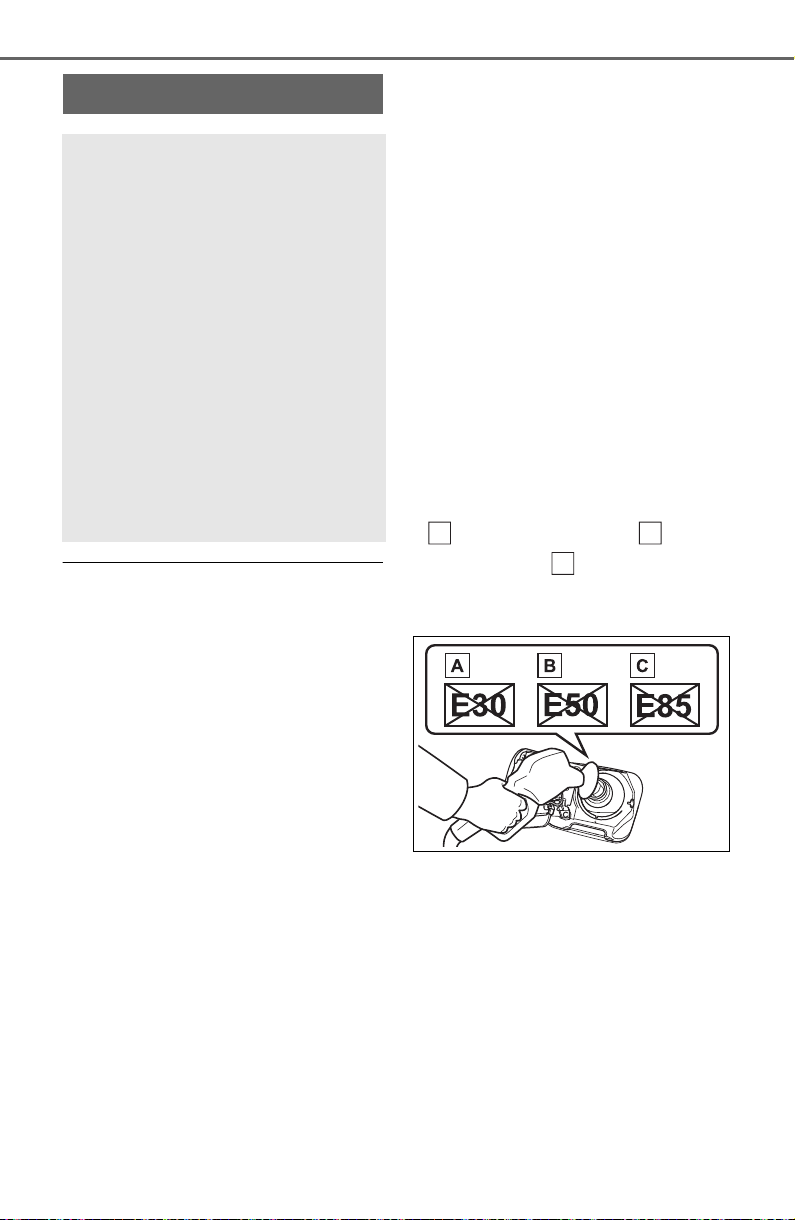
676
9-1. Specifications
■ Gasoline quality
In very few cases, driveability prob-
lems may be caused by the brand of
gasoline you are using. If driveability
problems persist, try changing the
brand of gasoline. If this does not
correct the problem, consult your
Toyota dealer.
■ Recommendation of the use of
gasoline containing detergent
additives
● Toyota recommends the use of
gasoline that contains detergent
additives to avoid the build-up of
engine deposits.
● All gasoline sold in the U.S.A. con-
tains minimum detergent additives
to clean and/or keep clean intake
systems, per EPA’s lowest addi-
tives concentration program.
● Toyota strongly recommends the
use of Top Tier Detergent Gaso-
line. For more information on Top
Tier Detergent Gasoline and a list
of marketers, please go to the offi-
cial website www.toptiergas.com.
■ Recommendation of the use of
low emissions gasoline
Gasolines containing oxygenates
such as ethers and ethanol, as well
as reformulated gasolines, are avail-
able in some cities. These fuels are
typically acceptable for use, provid-
ing they meet other fuel require-
ments.
Toyota recommends these fuels,
since the formulations allow for
reduced vehicle emissions.
■ Non-recommendation of the
use of blended gasoline
● Use only gasoline containing up to
15% ethanol.
DO NOT use any flex-fuel or gas-
oline that could contain more than
15% ethanol, including from any
pump labeled E30 (30% ethanol
), E50 (50% ethanol ), E85
(85% ethanol ) (which are only
some examples of fuel containing
more than 15% ethanol).
● If you use gasohol in your vehicle,
be sure that it has an octane rat-
ing no lower than 87.
● Toyota does not recommend the
use of gasoline containing metha-
nol.
■ Non-recommendation of the
use of gasoline containing MMT
Some gasoline contains an octane
enhancing additive called MMT
(Methylcyclopentadienyl Manga-
nese Tricarbonyl).
Toyota does not recommend the use
Fuel information
You must only use unleaded
gasoline in your vehicle.
Select octane rating 87
(Research Octane Number
91) or higher. Use of
unleaded gasoline with an
octane rating lower than 87
may result in engine knock-
ing. Persistent knocking
can lead to engine damage.
At minimum, the gasoline you
use should meet the specifica-
tions of ASTM D4814 in the
U.S.A..
A
B
C

677
9-1. Specifications
9
Vehicle specifications
of gasoline that contains MMT. If
fuel containing MMT is used, your
emission control system may be
adversely affected.
The malfunction indicator lamp on
the instrument cluster may come on.
If this happens, contact your Toyota
dealer for service.
■ If your engine knocks
● Consult your Toyota dealer.
● You may occasionally notice light
knocking for a short time while
accelerating or driving uphill. This
is normal and there is no need for
concern.
NOTICE
■ Notice on fuel quality
● Do not use improper fuels. If
improper fuels are used, the
engine will be damaged.
● Do not use leaded gasoline.
Leaded gasoline can cause
damage to your vehicle’s three-
way catalytic converters caus-
ing the emission control system
to malfunction.
● Do not use gasohol other than
the type previously stated.
Other gasohol may cause fuel
system damage or vehicle per-
formance problems.
● Using unleaded gasoline with
an octane number or rating
lower than the level previously
stated will cause persistent
heavy knocking.
At worst, this will lead to engine
damage.
■ Fuel-related poor driveability
If poor driveability (poor hot start-
ing, vaporization, engine knock-
ing, etc.) is encountered after
using a different type of fuel, dis-
continue the use of that type of
fuel.
■ When refueling with gasohol
Take care not to spill gasohol. It
can damage your vehicle’s paint.
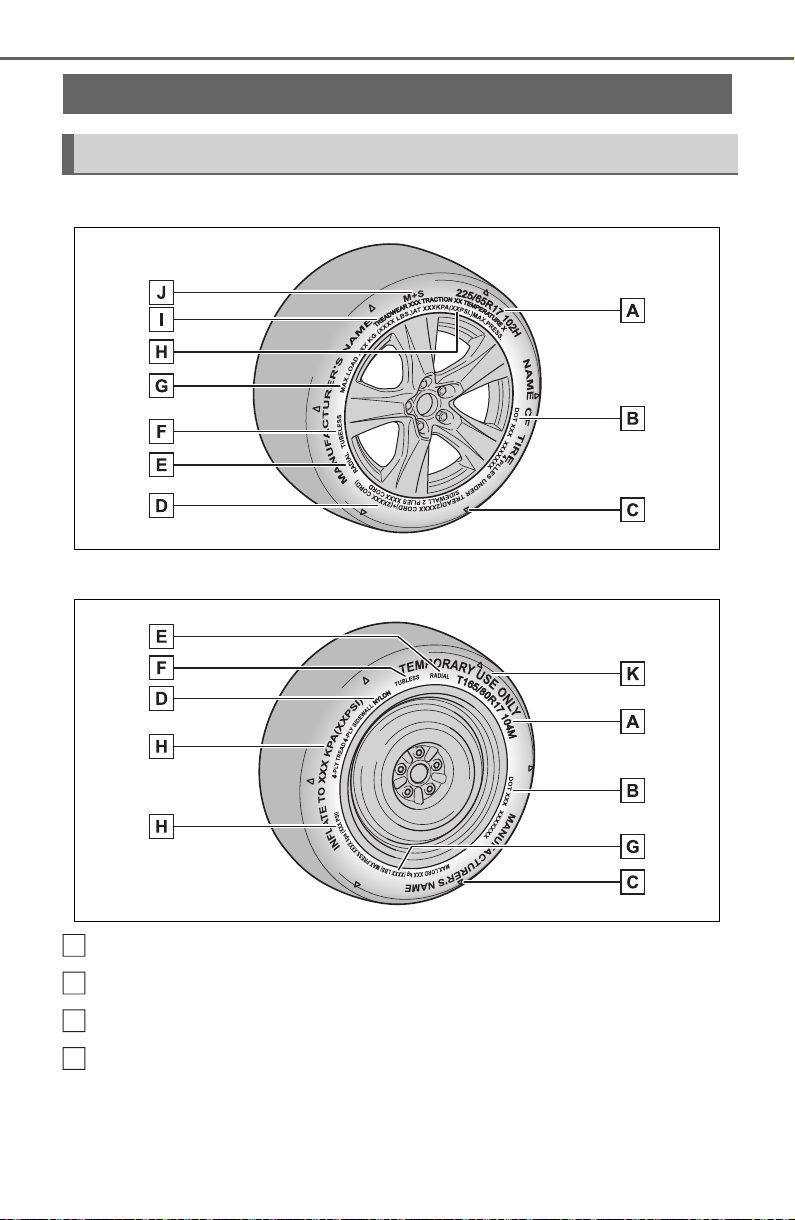
678
9-1. Specifications
Full-size tire
Compact spare tire
Tire size (P.680)
DOT and Tire Identification Number (TIN) (P.679)
Location of treadwear indicators (P.581)
Tire ply composition and materials
Plies are layers of rubber-coated parallel cords. Cords are the strands
which form the plies in a tire.
Tire information
Typical tire symbols
A
B
C
D
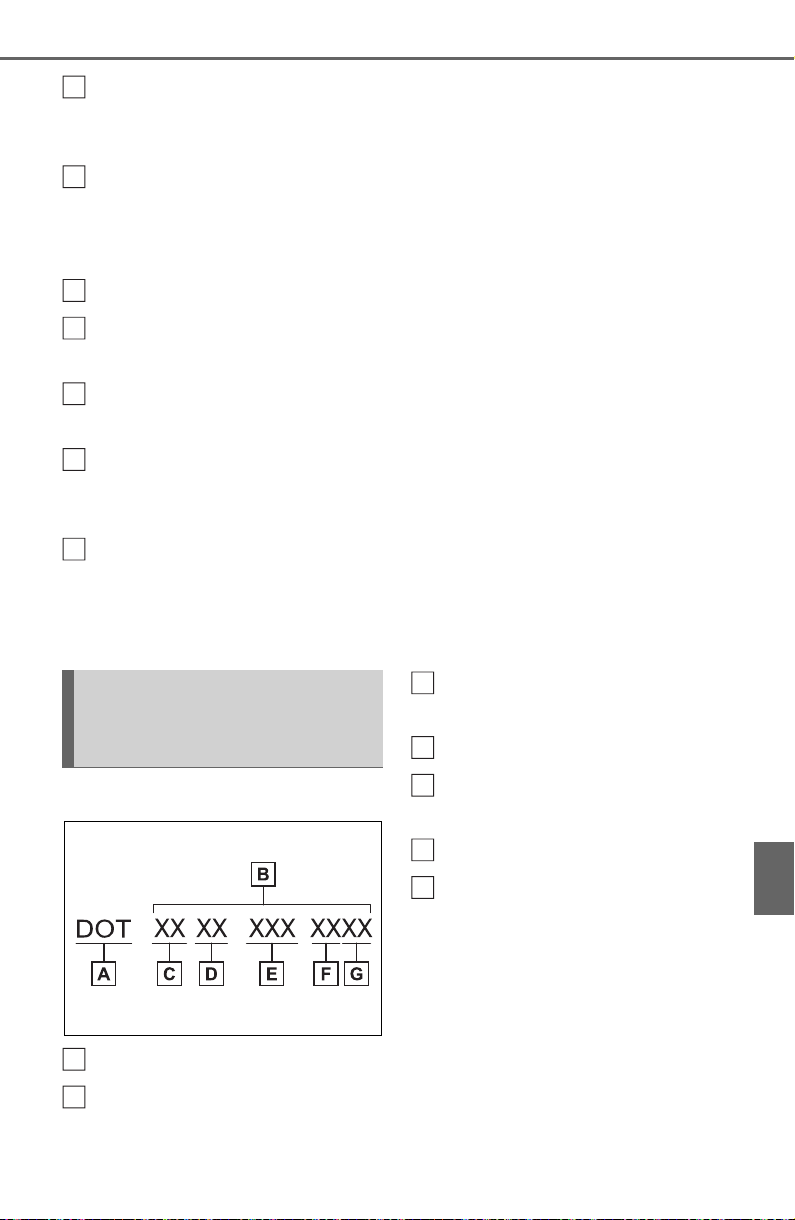
679
9-1. Specifications
9
Vehicle specifications
Radial tires or bias-ply tires
A radial tire has “RADIAL” on the sidewall. A tire not marked “RADIAL” is a
bias-ply tire.
TUBELESS or TUBE TYPE
A tubeless tire does not have a tube and air is directly put into the tire. A
tube type tire has a tube inside the tire and the tube maintains the air pres-
sure.
Load limit at maximum cold tire inflation pressure (P.682)
Maximum cold tire inflation pressure (P.670)
This means the pressure to which a tire may be inflated.
Uniform tire quality grading
For details, see “Uniform Tire Quality Grading” that follows.
Summer tires or all season tires (P.582)
An all season tire has “M+S” on the sidewall. A tire not marked “M+S” is a
summer tire.
“TEMPORARY USE ONLY”
A compact spare tire is identified by the phrase “TEMPORARY USE ONLY”
molded on its sidewall. This tire is designed for temporary emergency use
only.
Type A
DOT symbol
*
Tire Identification Number
(TIN)
Tire manufacturer’s identifi-
cation mark
Tire size code
Manufacturer’s optional tire
type code (3 or 4 letters)
Manufacturing week
Manufacturing year
*
: The DOT symbol certifies that the
tire conforms to applicable Fede-
ral Motor Vehicle Safety Stan-
dards.
E
F
G
H
I
J
K
Typical DOT and Tire
Identification Number
(TIN)
A
B
C
D
E
F
G
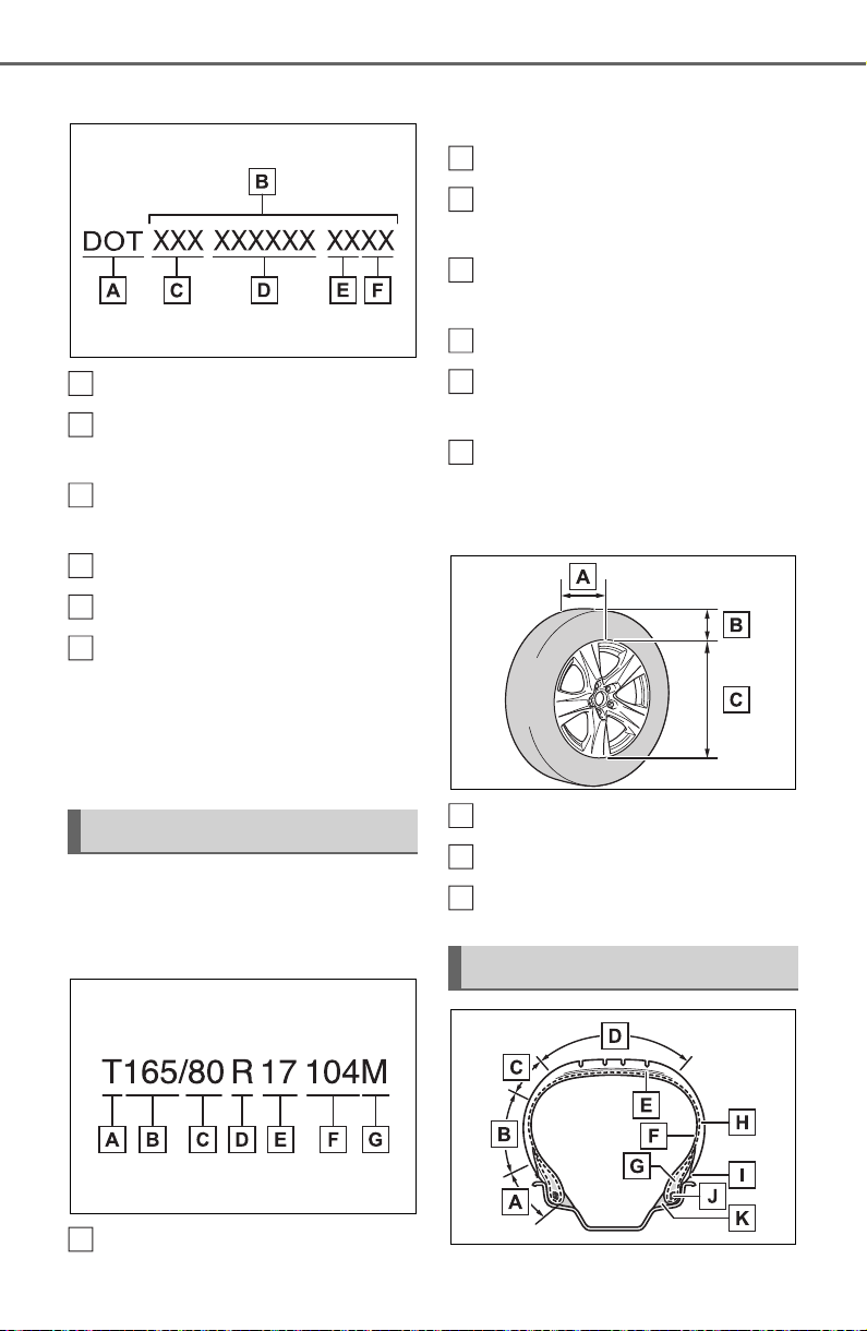
680
9-1. Specifications
Type B
DOT symbol
*
Tire Identification Number
(TIN)
Tire manufacturer’s identifi-
cation mark
Manufacturer’s code
Manufacturing week
Manufacturing year
*
: The DOT symbol certifies that the
tire conforms to applicable Fede-
ral Motor Vehicle Safety Stan-
dards.
■ Typical tire size information
The illustration indicates typical
tire size.
Tire use
(P = Passenger car,
T = Temporary use)
Section width (millimeters)
Aspect ratio
(tire height to section width)
Tire construction code
(R = Radial, D = Diagonal)
Wheel diameter (inches)
Load index (2 digits or 3 dig-
its)
Speed symbol (alphabet with
one letter)
■ Tire dimensions
Section width
Tire height
Wheel diameter
Tire size
A
B
C
D
E
F
A
Tire section names
B
C
D
E
F
G
A
B
C

681
9-1. Specifications
9
Vehicle specifications
Bead
Sidewall
Shoulder
Tread
Belt
Inner liner
Reinforcing rubber
Carcass
Rim lines
Bead wires
Chafer
This information has been pre-
pared in accordance with regu-
lations issued by the National
Highway Traffic Safety Adminis-
tration of the U.S. Department of
Transportation.
It provides the purchasers
and/or prospective purchasers
of Toyota vehicles with informa-
tion on uniform tire quality grad-
ing.
Your Toyota dealer will help answer
any questions you may have as you
read this information.
■ DOT quality grades
All passenger vehicle tires must
conform to Federal Safety
Requirements in addition to
these grades. Quality grades
can be found where applicable
on the tire sidewall between
tread shoulder and maximum
section width.
For example: Treadwear 200 Trac-
tion AA Temperature A
■ Treadwear
The treadwear grade is a com-
parative rating based on the
wear rate of the tire when tested
under controlled conditions on a
specified government test
course.
For example, a tire graded 150
would wear one and a half (1 - 1/2)
times as well on the government
course as a tire graded 100.
The relative performance of tires
depends upon the actual conditions
of their use. Performance may differ
significantly from the norm due to
variations in driving habits, service
practices and differences in road
characteristics and climate.
■ Traction AA, A, B, C
The traction grades, from high-
est to lowest, are AA, A, B and
C, and they represent the tire’s
ability to stop on wet pavement
as measured under controlled
conditions on specified govern-
ment test surfaces of asphalt
and concrete.
A tire marked C may have poor
traction performance.
Warning: The traction grade
assigned to this tire is based on
braking (straight ahead) traction
tests and does not include corner-
ing (turning) traction.
Uniform Tire Quality
Grading
A
B
C
D
E
F
G
H
I
J
K

682
9-1. Specifications
■ Temperature A, B, C
The temperature grades are A
(the highest), B, and C, repre-
senting the tire’s resistance to
the generation of heat and its
ability to dissipate heat when
tested under controlled condi-
tions on a specified indoor labo-
ratory test wheel.
Sustained high temperature can
cause the material of the tire to
degenerate and reduce tire life, and
excessive temperature can lead to
sudden tire failure.
Grade C corresponds to a level of
performance which all passenger
car tires must meet under the Fede-
ral Motor Vehicle Safety Standard
No. 109.
Grades B and A represent higher
levels of performance on the labo-
ratory test wheel than the minimum
required by law.
Warning: The temperature grades
of a tire assume that it is properly
inflated and not overloaded.
Excessive speed, underinflation, or
excessive loading, either sepa-
rately or in combination, can cause
heat buildup and possible tire fail-
ure.
Glossary of tire terminology
Tire related term Meaning
Cold tire inflation pres-
sure
Tire pressure when the vehicle has been parked
for three hours or more, or has not been driven
more than 1 mile or 1.5 km under that condition
Maximum inflation pres-
sure
The maximum cold inflated pressure to which a
tire may be inflated, shown on the sidewall of
the tire
Recommended inflation
pressure
Cold tire inflation pressure recommended by a
manufacturer
Accessory weight
The combined weight (in excess of those stan-
dard items which may be replaced) of transmis-
sion, power steering, power brakes, power
windows, power seats, radio and heater, to the
extent that these items are available as factory-
installed equipment (whether installed or not)
Curb weight
The weight of a motor vehicle with standard
equipment, including the maximum capacity of
fuel, oil and coolant, and if so equipped, air con-
ditioning and additional weight optional engine

683
9-1. Specifications
9
Vehicle specifications
Maximum loaded vehicle
weight
The sum of:
(a) Curb weight
(b) Accessory weight
(c) Vehicle capacity weight
(d) Production options weight
Normal occupant weight
150 lb. (68 kg) times the number of occupants
specified in the second column of Table 1
*
that
follows
Occupant distribution
Distribution of occupants in a vehicle as speci-
fied in the third column of Table 1
*
below
Production options weight
The combined weight of installed regular pro-
duction options weighing over 5 lb. (2.3 kg) in
excess of the standard items which they
replace, not previously considered in curb
weight or accessory weight, including heavy
duty brakes, ride levelers, roof rack, heavy duty
battery, and special trim
Rim
A metal support for a tire or a tire and tube
assembly upon which the tire beads are seated
Rim diameter
(Wheel diameter)
Nominal diameter of the bead seat
Rim size designation Rim diameter and width
Rim type designation
The industry manufacturer’s designation for a
rim by style or code
Rim width Nominal distance between rim flanges
Vehicle capacity weight
(Total load capacity)
The rated cargo and luggage load plus 150 lb.
(68 kg) times the vehicle’s designated seating
capacity
Vehicle maximum load on
the tire
The load on an individual tire that is determined
by distributing to each axle its share of the max-
imum loaded vehicle weight, and dividing by two
Vehicle normal load on
the tire
The load on an individual tire that is determined
by distributing to each axle its share of curb
weight, accessory weight, and normal occupant
weight (distributed in accordance with Table 1
*
below), and dividing by two
Tire related term Meaning

684
9-1. Specifications
Weather side
The surface area of the rim not covered by the
inflated tire
Bead
The part of the tire that is made of steel wires,
wrapped or reinforced by ply cords and that is
shaped to fit the rim
Bead separation
A breakdown of the bond between components
in the bead
Bias ply tire
A pneumatic tire in which the ply cords that
extend to the beads are laid at alternate angles
substantially less than 90 degrees to the center-
line of the tread
Carcass
The tire structure, except tread and sidewall
rubber which, when inflated, bears the load
Chunking
The breaking away of pieces of the tread or
sidewall
Cord The strands forming the plies in the tire
Cord separation
The parting of cords from adjacent rubber com-
pounds
Cracking
Any parting within the tread, sidewall, or inner-
liner of the tire extending to cord material
CT
A pneumatic tire with an inverted flange tire and
rim system in which the rim is designed with rim
flanges pointed radially inward and the tire is
designed to fit on the underside of the rim in a
manner that encloses the rim flanges inside the
air cavity of the tire
Extra load tire
A tire designed to operate at higher loads and at
higher inflation pressures than the correspond-
ing standard tire
Groove The space between two adjacent tread ribs
Innerliner
The layer(s) forming the inside surface of a
tubeless tire that contains the inflating medium
within the tire
Innerliner separation
The parting of the innerliner from cord material
in the carcass
Tire related term Meaning

685
9-1. Specifications
9
Vehicle specifications
Intended outboard side-
wall
(a)The sidewall that contains a whitewall, bears
white lettering, or bears manufacturer, brand,
and/or model name molding that is higher or
deeper than the same molding on the other
sidewall of the tire, or
(b)The outward facing sidewall of an asymmetri-
cal tire that has a particular side that must
always face outward when mounted on a vehi-
cle
Light truck (LT) tire
A tire designated by its manufacturer as primar-
ily intended for use on lightweight trucks or mul-
tipurpose passenger vehicles
Load rating
The maximum load that a tire is rated to carry
for a given inflation pressure
Maximum load rating
The load rating for a tire at the maximum per-
missible inflation pressure for that tire
Maximum permissible
inflation pressure
The maximum cold inflation pressure to which a
tire may be inflated
Measuring rim
The rim on which a tire is fitted for physical
dimension requirements
Open splice
Any parting at any junction of tread, sidewall, or
innerliner that extends to cord material
Outer diameter The overall diameter of an inflated new tire
Overall width
The linear distance between the exteriors of the
sidewalls of an inflated tire, including elevations
due to labeling, decorations, or protective bands
or ribs
Passenger car tire
A tire intended for use on passenger cars, multi-
purpose passenger vehicles, and trucks, that
have a gross vehicle weight rating (GVWR) of
10,000 lb. or less.
Ply A layer of rubber-coated parallel cords
Ply separation
A parting of rubber compound between adjacent
plies
Tire related term Meaning

686
9-1. Specifications
Pneumatic tire
A mechanical device made of rubber, chemi-
cals, fabric and steel or other materials, that,
when mounted on an automotive wheel, pro-
vides the traction and contains the gas or fluid
that sustains the load
Radial ply tire
A pneumatic tire in which the ply cords that
extend to the beads are laid at substantially 90
degrees to the centerline of the tread
Reinforced tire
A tire designed to operate at higher loads and at
higher inflation pressures than the correspond-
ing standard tire
Section width
The linear distance between the exteriors of the
sidewalls of an inflated tire, excluding elevations
due to labeling, decoration, or protective bands
Sidewall
That portion of a tire between the tread and
bead
Sidewall separation
The parting of the rubber compound from the
cord material in the sidewall
Snow tire
A tire that attains a traction index equal to or
greater than 110, compared to the ASTM E-
1136 Standard Reference Test Tire, when using
the snow traction test as described in ASTM F-
1805-00, Standard Test Method for Single
Wheel Driving Traction in a Straight Line on
Snow-and Ice-Covered Surfaces, and which is
marked with an Alpine Symbol ( ) on at least
one sidewall
Test rim
The rim on which a tire is fitted for testing, and
may be any rim listed as appropriate for use
with that tire
Tread
That portion of a tire that comes into contact
with the road
Tread rib
A tread section running circumferentially around
a tire
Tread separation Pulling away of the tread from the tire carcass
Tire related term Meaning

687
9-1. Specifications
9
Vehicle specifications
*
: Table 1 Occupant loading and distribution for vehicle normal load for
various designated seating capacities
Treadwear indicators
(TWI)
The projections within the principal grooves
designed to give a visual indication of the
degrees of wear of the tread
Wheel-holding fixture
The fixture used to hold the wheel and tire
assembly securely during testing
Designated seating
capacity, Number of
occupants
Vehicle normal load,
Number of occupants
Occupant distribution in
a normally loaded vehi-
cle
2 through 4 2 2 in front
5 through 10 3
2 in front, 1 in second
seat
11 through 15 5
2 in front, 1 in second
seat, 1 in third seat, 1 in
fourth seat
16 through 20 7
2 in front, 2 in second
seat, 2 in third seat, 1 in
fourth seat
Tire related term Meaning
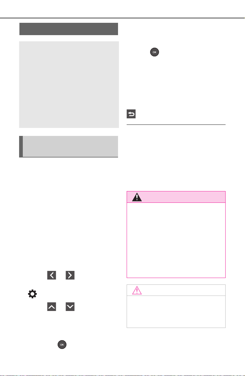
688
9-2. Customization
9-2.Customization
■ Changing using the naviga-
tion/multimedia system
1 Press the “MENU” button.
2 Select “Setup” on the menu
screen and select “Vehicle”.
3 Select “Vehicle Customiza-
tion”.
Various setting can be changed.
Refer to the list of settings that can
be changed for details.
■ Changing using the multi-
information display
1 Press or of the meter
control switches and select
.
2 Press or of the meter
control switches, select the
item.
3 To switch the function on and
off, press to switch to the
desired setting.
4 To perform detailed setting of
functions that support
detailed settings, press and
hold and display the set-
ting screen.
The method of performing detailed
setting differs for each screen.
Please refer to the advice sentence
displayed on the screen.
To go back to the previous screen
or exit the customize mode, press
.
■ When customizing using the
navigation/multimedia system
or multi-information display
Stop the vehicle in a safe place,
apply the parking brake, and shift
the shift lever to P. Also, to prevent
battery discharge, leave the engine
running while customizing the fea-
tures.
Customizable features
Your vehicle includes a vari-
ety of electronic features
that can be personalized to
suit your preferences. The
settings of these features
can be changed using the
multi-information display,
navigation/multimedia sys-
tem, or at your Toyota
dealer.
Customizing vehicle fea-
tures
WARNING
■ During customization
As the engine needs to be operat-
ing during customization, ensure
that the vehicle is parked in a
place with adequate ventilation. In
a closed area such as a garage,
exhaust gases including harmful
carbon monoxide (CO) may col-
lect and enter the vehicle. This
may lead to death or a serious
health hazard.
NOTICE
■ During customization
To prevent battery discharge,
ensure that the engine is running
while customizing features.
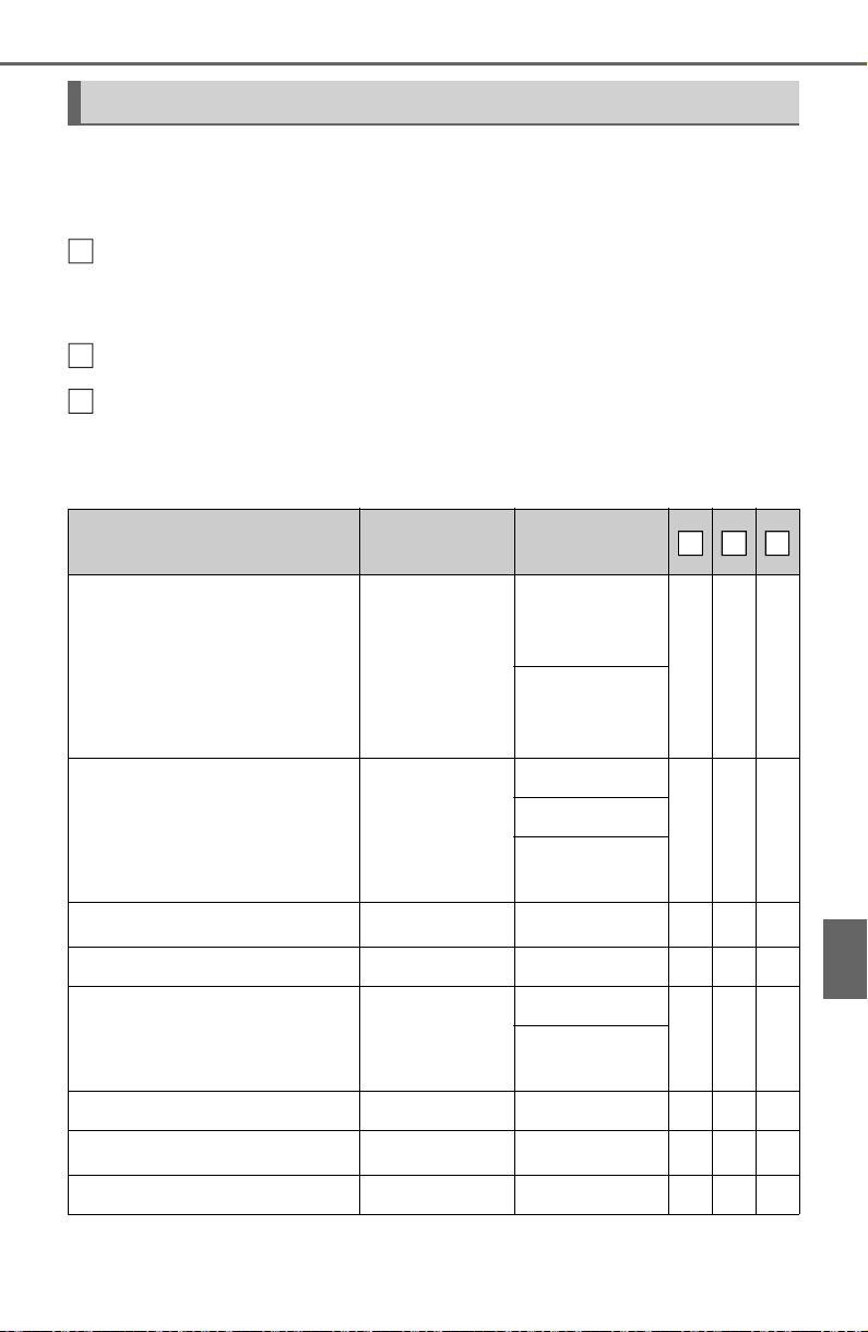
689
9-2. Customization
9
Vehicle specifications
Some function settings are changed simultaneously with other func-
tions being customized. Contact your Toyota dealer for further
details.
Vehicles with navigation system or multimedia system: Settings
that can be changed using the navigation system or multimedia sys-
tem
Settings that can be changed using the multi-information display
Settings that can be changed by your Toyota dealer
Definition of symbols: O = Available, – =Not available
■ Gauges, meters and multi-information display (P.82, 85, 89)
Customizable Features
Function
*1
Default
setting
Customized
setting
Language
*2
“English”
(English)
“Français can-
adien” (Cana-
dian French)
O O –
“Español mexi-
cano” (Mexi-
can Spanish)
Units
*2
miles (MPG
US)
km (km/L)
O O –
km (L/100 km)
miles (MPG
Imperial)
Speedometer display
*3
Analog Digital – O –
Eco Driving Indicator Light On Off – O –
“Fuel Economy”
“Total Aver-
age”
“Trip Average”
– O –
“Tank Aver-
age”
Audio system linked display On Off – O –
AWD system display
*4
On Off – O –
Drive information type Trip Total – O –
A
B
C
A
B
C
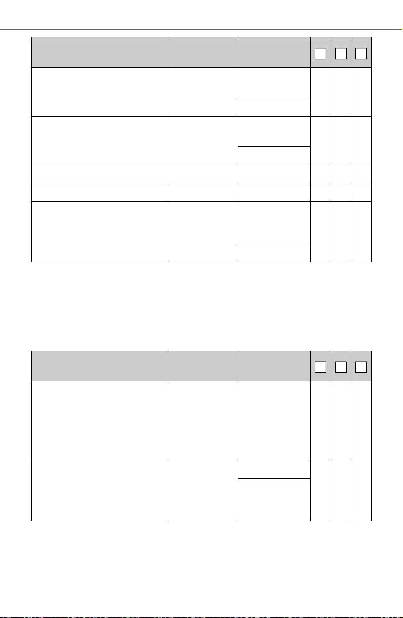
690
9-2. Customization
*1
:For details about each function: P. 9 4
*2
:The default setting varies according to country.
*3
:Vehicles with 7-inch display only
*4
:AWD models
■ Door lock (P.108, 653)
Drive information items (first
item)
Distance
Average
Speed
– O –
Total Time
Drive information items (sec-
ond item)
Total Time
Average
Speed
– O –
Distance
Pop-up display On Off – O –
Multi-Information display off Off On – O –
Suggestion function On
On (when the
vehicle is
stopped)
O – O
Off
Function
Default
setting
Customized
setting
Unlocking using a key
Driver’s door
unlocked in
first step, all
doors
unlocked in
second step
All doors
unlocked in
first step
– – O
Automatic door locking func-
tion
Shift position
linked door
locking opera-
tion
Off
O – O
Speed linked
door locking
operation
Function
*1
Default
setting
Customized
setting
A
B
C
A
B
C
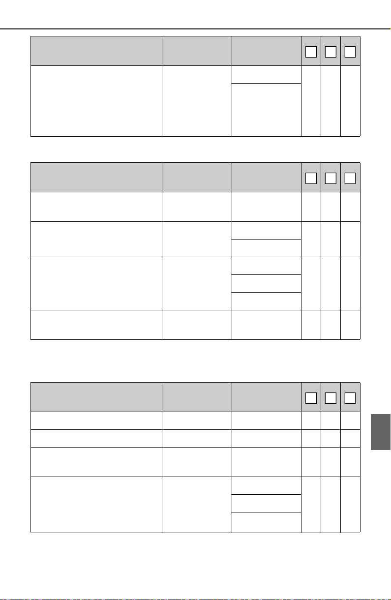
691
9-2. Customization
9
Vehicle specifications
■ Smart key system
*
and wireless remote control (P.104, 128)
*
: If equipped
■ Smart key system
*1
(P.128)
*1
:If equipped
*2
:This setting can be changed when the smart door unlocking setting is set
Automatic door unlocking
function
Shift position
linked door
unlocking
operation
Off
O – O
Driver’s door
linked door
unlocking
operation
Function
Default
setting
Customized
setting
Operation signal (emer-
gency flashers)
On Off O – O
Operation buzzer volume 5
Off
O – O
1 to 7
Time elapsed before the
automatic door lock function
is activated if a door is not
opened after being unlocked
60 seconds
Off
O – O30 seconds
120 seconds
Open door reminder buzzer
(When locking the vehicle)
On Off – – O
Function
Default
setting
Customized
setting
Smart key system On Off – – O
Smart door unlocking Driver’s door All the doors O – O
Number of consecutive door
lock operations
2 times
As many as
desired
– – O
Time elapsed before unlock-
ing all the door when gripping
and holding the driver’s door
handle
*2
2 seconds
Off
– – O
1.5 seconds
2.5 seconds
Function
Default
setting
Customized
setting
A
B
C
A
B
C
A
B
C
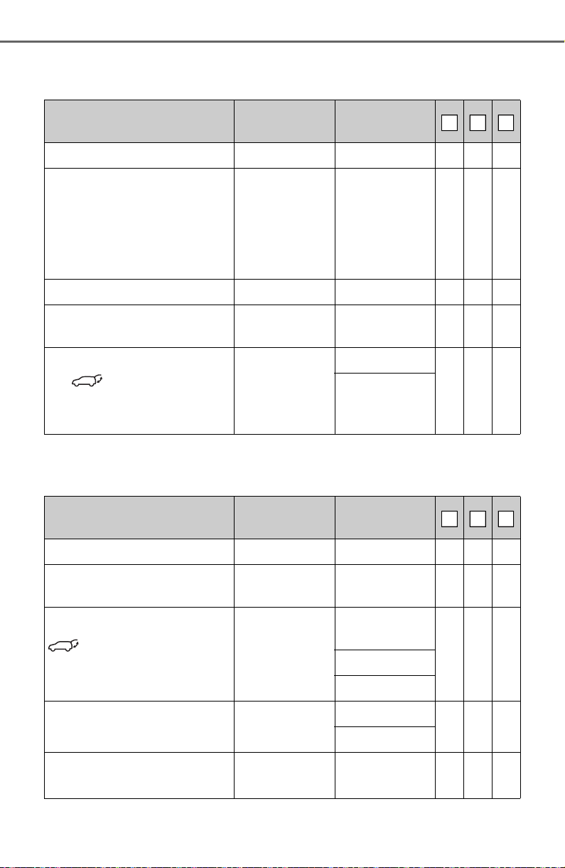
692
9-2. Customization
to “Driver’s door”.
■ Wireless remote control (P.104)
*
: If equipped
■ Power back door
*1
(P.118)
Function
Default
setting
Customized
setting
Wireless remote control On Off – – O
Unlocking operation
Driver’s door
unlocked in
first step, all
doors
unlocked in
second step
All doors
unlocked in
first step
O – O
Theft deterrent panic mode On Off – – O
Locking operation when door
opened
On Off O – O
The function that activates
the switch of the wire-
less remote control when
locking the door
*
(P.118)
On (Unlocking
all the door)
Off
– – O
On (Unlocking
back door
only)
Function
Default
setting
Customized
setting
Power back door operations On Off – O –
Back door opener switch
operations
Press and hold
One short
press
– – O
switch of the wireless
remote control operation
Press and hold
One short
press
– – O
Push twice
Off
Operation buzzer volume 3
1
– O –
2
Operation buzzer while the
back door is operating
*2
Off On – – O
A
B
C
A
B
C
693
9-2. Customization
9
Vehicle specifications
*1
:If equipped
*2
:The operation buzzer that sounds when the back door begins to operate
cannot be turned off.
*3
:The open position is set by the power back door switch. (P.127)
*4
:When the towing hitch is installed, kick sensor does not work.
■ Driving position memory
*
(P.137)
*
: If equipped
■ Power windows, and moon roof
*
or panoramic moon roof
*
(P.156, 159, 162)
Opening angle 5
1 to 4
– O –
User setting
*3
Power back door open oper-
ation when the back door
opener switch is pressed
On Off – – O
Back door closing assist On Off – – O
Kick Sensor
*1, 4
On Off – O O
Function
Default
setting
Customized
setting
Selection the door linking
driving position memory with
door unlock operation
Driver’s door All doors – – O
Function to prevent contact
between the head restraint
and ceiling (while moving to
memory location)
On Off – – O
Function
Default
setting
Customized
setting
Key linked operation (open) Off On – – O
Key linked operation (close) Off On – – O
Wireless remote control
linked operation (open)
Off On – – O
Function
Default
setting
Customized
setting
A
B
C
A
B
C
A
B
C
694
9-2. Customization
*
: If equipped
■ Lights (P.209)
*
: Except for Canada
■ Automatic light control system
*
(P.209)
*
: If equipped
Wireless remote control
linked operation signal
(buzzer)
On Off – – O
Side windows open warning
function
On Off – – O
Sliding roof open warning
function
On Off – – O
Function
Default
setting
Customized
setting
Daytime Running Lights
*
On Off O – O
Light reminder buzzer On Off – – O
Function
Default
setting
Customized
setting
Light sensor sensitivity Standard –2 to 2 O – O
Time elapsed before head-
lights automatically turn off
after doors are closed
30 seconds
Off
O – O60 seconds
90 seconds
Windshield wiper linked
headlight illumination
On Off – – O
Function
Default
setting
Customized
setting
A
B
C
A
B
C
A
B
C
695
9-2. Customization
9
Vehicle specifications
■ Rear window wiper (P.218)
■ PCS (Pre-Collision System) (P.229)
■ LTA (Lane Tracing Assist) (P.237)
■ RSA (Road Sign Assist)
*
(P.247)
Function
Default
setting
Customized
setting
Back door opening linked
rear window wiper stop func-
tion
Off On – – O
Washer linked rear window
wiper operation
On Off – – O
Shift position linked rear win-
dow wiper operation
(P.219)
Only once
Off
– – O
Continuous
Function
Default
setting
Customized
setting
PCS (Pre-Collision System) On Off – O –
Adjust alert timing Middle
Early
– O –
Late
Function
Default
setting
Customized
setting
Lane centering function On Off – O –
Steering assist function On Off – O –
Alert sensitivity High Standard – O –
Vehicle sway warning func-
tion
On Off – O –
Vehicle sway warning sensi-
tivity
Standard
Low
– O –
High
Function
Default
setting
Customized
setting
RSA (Road Sign Assist) On Off – O –
A
B
C
A
B
C
A
B
C
A
B
C
696
9-2. Customization
*
: If equipped
■ BSM (Blind Spot Monitor)
*
(P.260)
*
: If equipped
■ RCTA (Rear cross traffic alert) function
*1
(P.260)
*1
:If equipped
Excess speed notification
method
Display only
No notification
– O –
Display and
buzzer
Excess speed notification
level
1 mph (2 km/h)
3 mph (5 km/h)
– O –
5 mph (10
km/h)
Other notifications method
(No-entry notification)
Display only
No notification
– O –
Display and
buzzer
Function
Default
setting
Customized
setting
BSM (Blind Spot Monitor) On Off – O –
Outside rear view mirror indi-
cator brightness
Bright Dim – O –
Alert timing for presence of
approaching vehicle (sensi-
tivity)
Intermediate
Early
– O –
Late
Only when
vehicle
detected in
blind spot
Function
Default
setting
Customized
setting
RCTA (Rear cross traffic
alert) function
On Off – O –
Buzzer volume
*2
Level 2
Level 1
– O –
Level 3
Function
Default
setting
Customized
setting
A
B
C
A
B
C
A
B
C
697
9-2. Customization
9
Vehicle specifications
*2
:This setting is linked with the buzzer volume of the intuitive parking
assist.
■ Intuitive parking assist
*1
(P. 27 0 )
*1
:If equipped
*2
:This setting is linked with the buzzer volume of the RCTA (Rear cross
traffic alert) function.
■ PKSB (Parking Support Brake)
*
(P.277)
*
: If equipped
■ Stop & Start system
*
(P.345)
*
: If equipped
■ Automatic air conditioning system
*
(P.515)
*
: If equipped
Function
Default
setting
Customized
setting
Intuitive parking assist On Off – O O
Buzzer volume
*2
2
1
– O O
3
Function
Default
setting
Customized
setting
PKSB (Parking Support
Brake) function
On Off – O –
Function
Default
setting
Customized
setting
Change the Stop & Start sys-
tem duration when the A/C is
on
Standard Extended – O –
Function
Default
setting
Customized
setting
A/C Auto switch operation On Off O – O
Switching to the outside air
mode when the vehicle is
parked
On Off – – O
A
B
C
A
B
C
A
B
C
A
B
C

698
9-2. Customization
■ Illumination (P.525)
*1
:Vehicles with smart key system only
*2
:If equipped
■ Vehicle customization
● When the speed linked door locking function and shift position linked door
locking function are both on, the door lock operates as follows.
• If the vehicle is started with all the doors locked, the speed linked door
locking function would not operate.
• If the vehicle is started with any door unlocked, the speed linked door lock-
ing function will operate.
• When shifting the shift lever to any position other than P, all the doors will
be locked.
● When the smart key system is off, the selecting door to unlock cannot be
customized.
● When the doors remain closed after unlocking the doors and the auto-
matic door lock function is activated, the signals will be generated in
accordance with the Operation signal (buzzer) and the Operation signal
(emergency flashers) settings.
Function
Default
setting
Customized
setting
Time elapsed before the inte-
rior lights turn off
15 seconds
Off
O – O7.5 seconds
30 seconds
Operation after the engine
switch is turned off
On Off – – O
Operation when the doors
are unlocked
On Off – – O
Operation when you
approach the vehicle with the
electronic key on your per-
son
*1
On Off – – O
Footwell lighting
*2
On Off – – O
A
B
C
699
9-3. Initialization
9
Vehicle specifications
9-3.Initialization
*1
:If equipped
*2
:Vehicles with Audio Plus or Premium Audio, refer to “NAVIGATION AND
MULTIMEDIA SYSTEM OWNER’S MANUAL”.
Items to initialize
The following items must be initialized for normal system
operation after such cases as the battery being reconnected,
or maintenance being performed on the vehicle:
List of the items to initialize
Item When to initialize Reference
Intuitive parking assist
*1
•After reconnecting or
changing the battery
•After changing a fuse
P.273
Parking Support Brake
*1
P.281
Power back door
*1
P.123
Power windows P.156
Moon roof
*1
P.160
Panoramic moon roof
*1
P.163
Maintenance required
reminder message
• After the maintenance is
performed
P.564
Tire pressure warning sys-
tem
*1
• When rotating the tires
• When changing the tire
• After registering the ID
codes
P.590
Toyota parking assist moni-
tor
*1
• After reconnecting or chang-
ing the battery
• After changing a fuse
P.310
P.342
Panoramic view monitor
*1, 2

700
9-3. Initialization

701
10
10
For owners
For owners
10-1.For owners
Reporting safety defects for
U.S. owners............... 702
Seat belt instructions for
Canadian owners (in
French)...................... 703
SRS airbag instructions for
Canadian owners (in
French)...................... 704

702
10-1. For owners
10-1.For owners
Reporting safety
defects for U.S. own-
ers
If you believe that your vehi-
cle has a defect which could
cause a crash or could
cause injury or death, you
should immediately inform
the National Highway Traffic
Safety Administration
(NHTSA) in addition to noti-
fying Toyota Motor Sales,
U.S.A., Inc. (Toll-free: 1-800-
331-4331).
If NHTSA receives similar
complaints, it may open an
investigation, and if it finds
that a safety defect exists in
a group of vehicles, it may
order a recall and remedy
campaign. However, NHTSA
cannot become involved in
individual problems
between you, your dealer, or
Toyota Motor Sales, U.S.A.,
Inc.
To contact NHTSA, you may
call the Vehicle Safety Hot-
line toll-free at 1-888-327-
4236 (TTY: 1-800-424-9153);
go to
http://www.safercar.gov; or
write to: Administrator,
NHTSA, 1200 New Jersey
Ave., S.E., Washington, DC
20590. You can also obtain
other information about
motor vehicle safety from
http://www.safercar.gov.
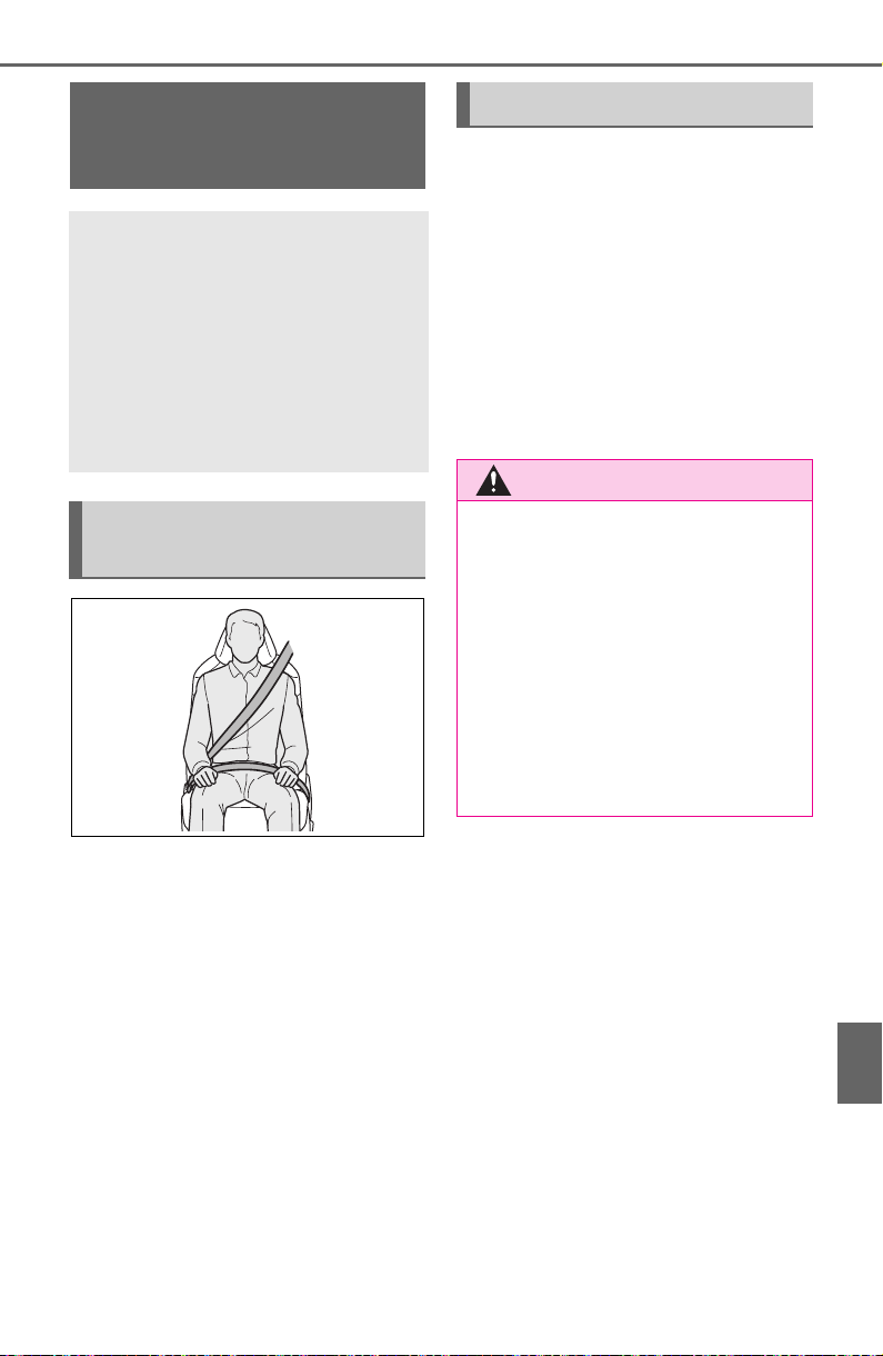
703
10-1. For owners
10
For owners
Tirez sur la ceinture épaulière
jusqu’à ce qu’elle recouvre
entièrement l’épaule; elle ne
doit cependant pas toucher le
cou ni glisser de l’épaule.
Placez la ceinture abdominale
le plus bas possible sur les
hanches.
Réglez la position du dossier.
Tenez-vous assis bien au
fond du siège, le dos droit.
Ne vrillez pas la ceinture de
sécurité.
■ Manipulation des ceintures
de sécurité
Avec un chiffon ou une éponge,
nettoyez à l’aide d’un savon
doux et de l’eau tiède. Vérifiez
aussi les ceintures régulière-
ment pour vous assurer qu’elles
ne présentent pas d’usure
excessive, d’effilochage ou de
coupures.
Seat belt instructions
for Canadian owners
(in French)
The following is a French
explanation of seat belt
instructions extracted from
the seat belt section in this
manual.
See the seat belt section for
more detailed seat belt
instructions in English.
Utilisation adéquate des
ceintures de sécurité
Entretien et soin
AVERTISSEMENT
■ Dommages et usure de la
ceinture de sécurité
Vérifiez périodiquement le sys-
tème de ceintures de sécurité.
Vérifiez qu’il n’y a pas de cou-
pures, d’effilochures ni de pièces
desserrées. N’utilisez pas une
ceinture de sécurité endommagée
avant qu’elle ne soit remplacée.
Les ceintures de sécurité endom-
magées ne peuvent pas protéger
les occupants contre les bless-
ures graves, voire mortelles.
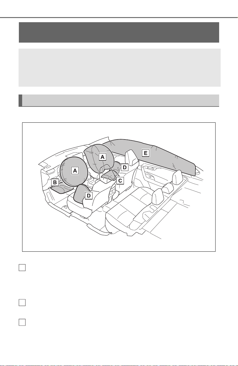
704
10-1. For owners
■ Emplacement des coussins gonflables SRS
Coussins gonflables SRS avant
Coussin gonflable SRS du conducteur/coussin gonflable SRS du
passager avant
Peuvent aider à protéger la tête et la poitrine du conducteur et du passager
avant contre les impacts avec des composants intérieurs
Coussin gonflable SRS de protection des genoux
Peut aider à protéger le conducteur
Coussin gonflable SRS du coussin de siège
Peut aider à retenir le passager avant
SRS airbag instructions for Canadian owners (in
French)
The following is a French explanation of SRS airbag instruc-
tions extracted from the SRS airbag section in this manual.
See the SRS airbag section for more detailed SRS airbag instruc-
tions in English.
Système de coussins gonflables SRS
A
B
C
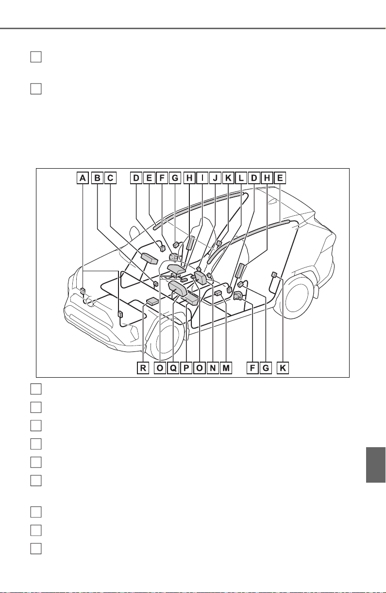
705
10-1. For owners
10
For owners
Coussins gonflables SRS latéraux et en rideau
Coussins gonflables SRS latéraux
Peuvent aider à protéger le torse des occupants des sièges avant
Coussins gonflables SRS en rideau
• Peuvent aider à protéger principalement la tête des occupants des sièges
latéraux
• Peuvent aider à empêcher les occupants d’être éjectés du véhicule en
cas de tonneaux
■ Composants du système de coussins gonflables SRS
Capteurs d’impact avant
Voyants “AIR BAG ON” et “AIR BAG OFF”
Coussin gonflable du passager avant
Capteurs d’impact latéral (portière avant)
Coussins gonflables en rideau
Limiteurs de force et dispositifs de tension des ceintures de sécu-
rité
Capteurs d’impact latéral (avant)
Coussins gonflables latéraux
Coussin gonflable du coussin de siège
D
E
A
B
C
D
E
F
G
H
I

706
10-1. For owners
Contacteur de boucle de ceinture de sécurité du passager avant
Capteurs d’impact latéral (arrière)
Contacteur de boucle de ceinture de sécurité du conducteur
Capteur de position du siège du conducteur
Coussin gonflable du conducteur
Système de classification de l’occupant du siège du passager
avant (ECU et capteurs)
Coussin gonflable de protection des genoux
Lampe témoin SRS
Module de capteur de coussin gonflable
Votre véhicule est doté de COUSSINS GONFLABLES ÉVOLUÉS
dont la conception s’appuie sur les normes de sécurité des véhicules
à moteur américains (FMVSS208). Le module de capteur de coussin
gonflable (ECU) contrôle le déploiement des coussins gonflables en
fonction des informations obtenues des capteurs et d’autres élé-
ments affichés dans le diagramme des composants du système ci-
dessus. Ces informations comprennent des données relatives à la
gravité de l’accident et aux occupants. Au moment du déploiement
des coussins gonflables, une réaction chimique se produit dans les
gonfleurs de coussin gonflable et les coussins gonflables se remplis-
sent rapidement d’un gaz non toxique pour aider à limiter le mouve-
ment des occupants.
J
K
L
M
N
O
P
Q
R

707
10-1. For owners
10
For owners
AVERTISSEMENT
■ Précautions relatives aux
coussins gonflables SRS
Observez les précautions suiva-
ntes en ce qui concerne les cous-
sins gonflables SRS.
Négliger de le faire pourrait occa-
sionner des blessures graves,
voire mortelles.
● Le conducteur et tous les pas-
sagers du véhicule doivent por-
ter leur ceinture de sécurité de
la manière appropriée.
Les coussins gonflables SRS
sont des dispositifs supplémen-
taires qui doivent être utilisés
avec les ceintures de sécurité.
● Le coussin gonflable SRS du
conducteur se déploie avec une
force considérable et peut occa-
sionner des blessures graves,
voire mortelles, notamment lor-
sque le conducteur se trouve
très près du coussin gonflable.
La National Highway Traffic
Safety Administration (NHTSA),
aux États-Unis, fait les recom-
mandations suivantes :
La zone à risque du coussin gon-
flable du conducteur couvre
2 à 3 in. (50 à 75 mm) de la zone
de déploiement du coussin gon-
flable. Pour assurer une marge de
sécurité suffisante, restez à 10 in.
(250 mm) du coussin gonflable.
Cette distance est mesurée
depuis le centre du volant jusqu’à
votre sternum. Si maintenant
vous vous tenez assis à moins de
10 in. (250 mm), vous pouvez
changer votre position de con-
duite de plusieurs manières :
• Reculez votre siège à la posi-
tion maximale vous permettant
d’atteindre encore aisément les
pédales.
• Inclinez légèrement le dossier
du siège.
Bien que les véhicules soient
conçus différemment, la plupart
des conducteurs peuvent main-
tenir une distance de 10 in.
(250 mm), même si leur siège
se trouve complètement vers
l’avant, simplement en inclinant
un peu le dossier du siège vers
l’arrière. Si la visibilité avant est
moindre après avoir incliné le
dossier de votre siège, utilisez
un coussin ferme et non glissant
pour être assis plus haut ou
relevez le siège si cette option
est disponible sur votre
véhicule.
• Si votre volant est réglable en
hauteur, inclinez-le vers le bas.
Cela vous permet d’orienter le
coussin gonflable vers votre
buste plutôt que vers votre tête
et vers votre cou.
Le siège doit être réglé de la
manière recommandée ci-dessus
par la NHTSA, tout en gardant le
contrôle des pédales et du volant,
ainsi que la vue sur les com-
mandes du tableau de bord.
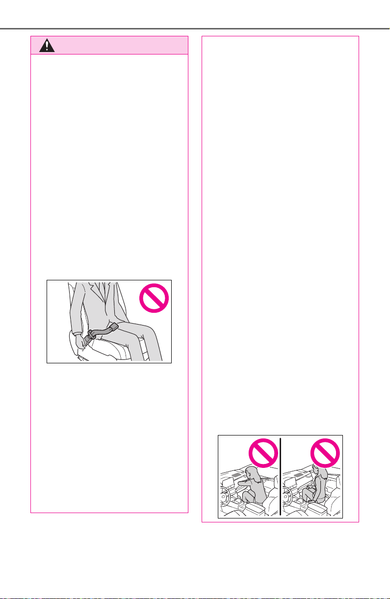
708
10-1. For owners
AVERTISSEMENT
● Si la rallonge de ceinture de
sécurité a été reliée à la boucle
des ceintures de sécurité des
sièges avant sans avoir aussi
été attachée à la plaque de blo-
cage des ceintures de sécurité,
les coussins gonflables SRS
avant considéreront que le con-
ducteur et le passager avant
portent tout de même leur cein-
ture de sécurité même si les
ceintures de sécurité ne sont
pas attachées. Les coussins
gonflables SRS avant peuvent
alors ne pas s’activer correcte-
ment lors d’une collision, ce qui
pourrait occasionner des bless-
ures graves, voire mortelles, en
cas de collision. Assurez-vous
de toujours porter la ceinture de
sécurité avec la rallonge de
ceinture de sécurité.
● Le coussin gonflable SRS du
passager avant se déploie
également avec une force con-
sidérable et peut occasionner
des blessures graves, voire
mortelles, notamment lorsque le
passager avant se trouve très
près du coussin gonflable. Le
siège du passager avant doit se
trouver le plus loin possible du
coussin gonflable et le dossier
doit être réglé de manière à ce
que le passager avant soit assis
bien droit.
● Le déploiement d’un coussin
gonflable risque d’infliger des
blessures graves, voire mor-
telles, aux bébés et aux enfants
mal assis et/ou mal attachés.
Un bébé ou un enfant trop petit
pour utiliser une ceinture de
sécurité doit être correctement
retenu à l’aide d’un dispositif de
retenue pour enfants. Toyota
recommande vivement de
placer et d’attacher correcte-
ment tous les bébés et tous les
enfants sur les sièges arrière du
véhicule à l’aide de dispositifs
de retenue adaptés. Les sièges
arrière sont plus sécuritaires
pour les bébés et les enfants
que le siège du passager avant.
● N’installez jamais un dispositif
de retenue pour enfants de type
dos à la route sur le siège du
passager avant, même si le
voyant “AIR BAG OFF” est
allumé. En cas d’accident, la
force et la vitesse de déploie-
ment du coussin gonflable du
passager avant pourraient
infliger à l’enfant des blessures
graves, voire mortelles, si le dis-
positif de retenue pour enfants
de type dos à la route était
installé sur le siège du passager
avant.
● Ne vous asseyez pas sur le
bord du siège et ne vous
appuyez pas sur la planche de
bord.
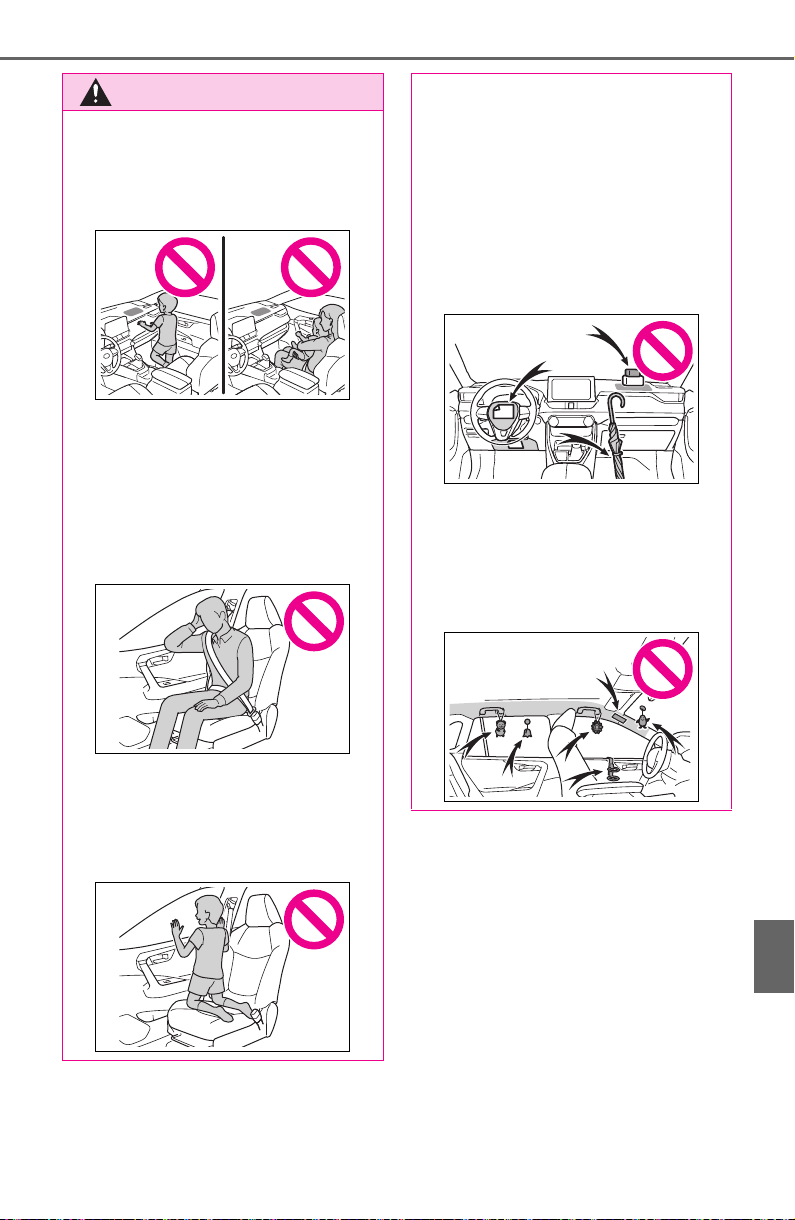
709
10-1. For owners
10
For owners
AVERTISSEMENT
● Ne laissez pas un enfant se
tenir face au coussin gonflable
SRS du passager avant ni
s’asseoir sur les genoux d’un
passager avant.
● Ne laissez pas les occupants
des sièges avant tenir des
objets sur leurs genoux.
● Ne vous appuyez pas sur la
portière ou sur le brancard de
pavillon, ni sur les montants
avant, latéraux ou arrière.
● Ne laissez personne s’age-
nouiller face à la portière sur le
siège du passager ni sortir la
tête ou les mains à l’extérieur
du véhicule.
● Ne fixez et n’appuyez rien sur
des zones telles que la planche
de bord, le tampon de volant ou
encore la partie inférieure du
tableau de bord.
Ces objets peuvent se trans-
former en projectiles lorsque les
coussins gonflables SRS du
conducteur, du passager avant
et de protection des genoux se
déploient.
● Ne fixez rien sur des zones
telles que les portières, le pare-
brise, les glaces latérales, les
montants avant ou arrière, le
brancard de pavillon et la poi-
gnée de maintien.
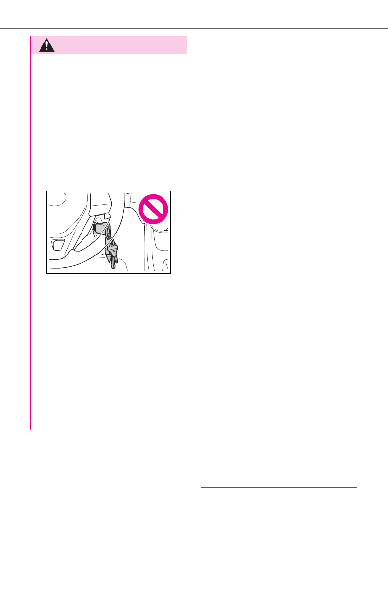
710
10-1. For owners
AVERTISSEMENT
● Véhicules non dotés du sys-
tème Smart key : N’accrochez
pas d’objets lourds, pointus ou
durs, par exemple des clés ou
des accessoires, à la clé. Ces
objets pourraient empêcher le
déploiement du coussin gon-
flable SRS de protection des
genoux ou être projetés violem-
ment dans l’assise du siège du
conducteur par la force du
déploiement, et donc présenter
un danger.
● N’accrochez pas de cintres ni
d’autres objets rigides sur les
crochets porte-vêtements. Tous
ces objets pourraient se trans-
former en projectiles et vous
occasionner des blessures
graves, voire mortelles, en cas
de déploiement des coussins
gonflables SRS en rideau.
● Si un recouvrement de vinyle
est placé sur la zone de
déploiement du coussin gon-
flable SRS de protection des
genoux, veillez à le retirer.
● N’utilisez pas d’accessoires
recouvrant les parties du siège
où les coussins gonflables SRS
latéraux et le coussin gonflable
SRS du coussin de siège se
déploient, car ces accessoires
pourraient entraver le déploie-
ment des coussins SRS. De tels
accessoires peuvent empêcher
les coussins gonflables latéraux
et le coussin gonflable du cous-
sin de siège de se déployer cor-
rectement, rendre le système
inopérant ou provoquer acci-
dentellement le déploiement
des coussins gonflables
latéraux et du coussin gonflable
du coussin de siège, occasion-
nant des blessures graves,
voire mortelles.
● Ne frappez pas et n’appliquez
pas une pression importante à
l’emplacement des portières
avant ou des composants des
coussins gonflables SRS.
Cela peut provoquer un mau-
vais fonctionnement des couss-
ins gonflables SRS.
● Ne touchez à aucun composant
des coussins gonflables SRS
immédiatement après leur
déploiement (gonflage), car ils
pourraient être chauds.
● Si vous avez de la difficulté à
respirer après le déploiement
des coussins gonflables SRS,
ouvrez une portière ou une
glace latérale pour laisser entrer
l’air frais, ou quittez le véhicule
si vous pouvez le faire en toute
sécurité. Dès que possible, net-
toyez tous les résidus afin
d’éviter les irritations cutanées.

711
10-1. For owners
10
For owners
AVERTISSEMENT
● Si les emplacements de stock-
age des coussins gonflables
SRS, tels que le tampon de
volant et les garnitures des
montants avant et arrière, sont
endommagés ou fissurés,
faites-les remplacer par votre
concessionnaire Toyota.
● Ne placez aucun objet, par
exemple un coussin, sur le
siège du passager avant. Cela
disperserait le poids du pas-
sager, ce qui empêcherait le
capteur de le détecter correcte-
ment. Cela pourrait empêcher le
déploiement des coussins gon-
flables SRS du passager avant
en cas de collision.
■ Modification et mise au rebut
des composants du système
de coussins gonflables SRS
Ne mettez pas votre véhicule au
rebut et n’effectuez aucune des
modifications suivantes sans
d’abord consulter votre conces-
sionnaire Toyota. Les coussins
gonflables SRS pourraient
fonctionner de manière incor-
recte ou se déployer (gonfler)
accidentellement, ce qui serait
susceptible d’occasionner des
blessures graves, voire mortelles.
● Installation, retrait, démontage
et réparation des coussins gon-
flables SRS
● Réparations, modifications,
retrait ou remplacement du
volant, du tableau de bord, de la
planche de bord, des sièges ou
du capitonnage des sièges, des
montants avant, latéraux et
arrière, des brancards de pavil-
lon, des panneaux des portières
avant, des garnitures des
portières avant ou des haut-
parleurs des portières avant
● Modifications du panneau de la
portière avant (comme le per-
forer)
● Réparations ou modifications de
l’aile avant, du pare-chocs
avant ou du côté de l’habitacle
● Installation d’une protection de
calandre (barre safari, barre
kangourou, etc.), de lames de
déneigement, de treuils ou d’un
porte-bagages de toit
● Modifications du système de
suspension du véhicule
● Installation d’appareils électro-
niques tels qu’un émetteur-
récepteur radio ou un lecteur de
CD
● Modifications à votre véhicule
pour une personne aux capac-
ités physiques réduites

712
10-1. For owners

713
Index
What to do if... (Trouble-
shooting) .................. 714
Alphabetical Index ...... 717
714
What to do if... (Troubleshooting)
1-1.What to do if... (Troubleshooting)
What to do if... (Troubleshooting)
If you lose your keys or
mechanical keys, new genu-
ine keys or mechanical keys
can be made by your Toyota
dealer. (P.653)
Vehicles with smart key sys-
tem:
If you lose your electronic
keys, the risk of vehicle theft
increases significantly. Con-
tact your Toyota dealer imme-
diately. (P.653)
Is the key battery weak or
depleted? (P.604)
Vehicles with smart key sys-
tem:
Is the engine switch in ON?
When locking the doors, turn
the engine switch off.
(P.197)
Vehicles with smart key sys-
tem:
Is the electronic key left inside
the vehicle?
When locking the doors,
make sure that you have the
electronic key on your person.
The function may not operate
properly due to the condition
of the radio wave. (P.105,
129)
Is the child-protector lock set?
The rear door cannot be
opened from inside the vehi-
cle when the lock is set. Open
the rear door from outside
and then unlock the child-pro-
tector lock. (P. 11 2)
Is the shift lever in P?
(P.193)
Is the battery discharged?
(P.655)
Did you press the engine
If you have a problem,
check the following before
contacting your Toyota
dealer.
The doors cannot be
locked, unlocked, opened
or closed
You lose your keys
The doors cannot be
locked or unlocked
The rear door cannot be
opened
If you think something is
wrong
The engine does not start
(vehicles without smart
key system)
The engine does not start
(vehicles with smart key
system)
715
What to do if... (Troubleshooting)
switch while firmly depress-
ing the brake pedal?
(P.194)
Is the shift lever in P?
(P.194)
Is the electronic key any-
where detectable inside the
vehicle? (P.128)
Is the steering wheel
unlocked? (P.195)
Is the electronic key battery
weak or depleted?
In this case, the engine can
be started in a temporary way.
(P.654)
Is the battery discharged?
(P.655)
Is the engine switch in ON?
If you cannot release the shift
lever by depressing the brake
pedal with the engine switch
in ON (P.200)
Vehicles without smart key
system:
It is locked to prevent theft of
the vehicle if the key is
removed from the engine
switch. (P.193)
Vehicles with smart key sys-
tem:
It is locked automatically to
prevent theft of the vehicle.
(P.195)
Is the window lock switch
pressed?
The power window except for
the one at the driver’s seat
cannot be operated if the win-
dow lock switch is pressed.
(P.158)
The auto power off function
will be operated if the vehicle
is left in ACC or ON (the
engine is not running) for a
period of time. (P.198)
The seat belt reminder light is
flashing
Are the driver and the passengers
wearing the seat belts? (
P. 635)
The parking brake indicator is
on
Is the parking brake released?
(
P.203)
Depending on the situation,
other types of warning buzzer
The shift lever cannot be
shifted from P even if you
depress the brake pedal
The steering wheel can-
not be turned after the
engine is stopped
The windows do not open
or close by operating the
power window switches
The engine switch is
turned off automatically
(vehicles with smart key
system)
A warning buzzer sounds
during driving
716
What to do if... (Troubleshooting)
may also sound. (P.628, 639)
Did anyone inside the vehicle
open a door during setting the
alarm?
The sensor detects it and the
alarm sounds. (P.73)
To stop the alarm, turn the engine
switch to ON or start the engine.
Is the message displayed on
the multi-information display?
Check the message on the
multi-information display.
(P.639)
When a warning light turns on
or a warning message is dis-
played, refer to P.628, 639.
Stop the vehicle in a safe
place and replace the flat tire
with the spare tire. (P.642)
Try the procedure for when
the vehicle becomes stuck in
mud, dirt, or snow. (P.661)
An alarm is activated and
the horn sounds (if
equipped)
A warning buzzer sounds
when leaving the vehicle
A warning light turns on
or a warning message is
displayed
When a problem has
occurred
If you have a flat tire
The vehicle becomes
stuck

717
Alphabetical Index
Alphabetical Index
A
A/C...................................510, 515
Air conditioning filter.............599
Automatic air conditioning sys-
tem.....................................515
Eco air conditioning mode....516
Front seat concentrated airflow
mode (S-FLOW).................519
Manual air conditioning system
...........................................510
ABS (Anti-lock Brake System)
...............................................360
Function ...............................360
Warning light ........................630
ACA (Active Cornering Assist)
...............................................360
Active Cornering Assist (ACA)
...............................................360
Airbags......................................33
Airbag operating conditions....35
Airbag precautions for your child
.............................................38
Airbag warning light..............629
Correct driving posture...........27
Curtain shield airbag operating
conditions.............................36
Curtain shield airbag precautions
.............................................38
Front passenger occupant clas-
sification system...................43
General airbag precautions....38
Locations of airbags...............33
Modification and disposal of air-
bags .....................................41
Seat cushion airbag ...............33
Side airbag operating conditions
.............................................36
Side airbag precautions .........38
Side and curtain shield airbags
operating conditions.............36
Side and curtain shield airbags
precautions...........................38
SRS airbag instructions for
Canadian owners ...............704
SRS airbags ...........................33
SRS warning light.................629
Air conditioning filter .............599
Air conditioning system.510, 515
Air conditioning filter.............599
Automatic air conditioning sys-
tem .....................................515
Eco air conditioning mode....516
Front seat concentrated airflow
mode (S-FLOW).................519
Manual air conditioning system
...........................................510
Alarm .........................................73
Alarm......................................73
Warning buzzer ....................628
AM............................................425
Anchor brackets.......................61
Android Auto...........407, 410, 437
Android Auto button (Menu
screen)...................................377
Antenna (Smart key system).128
Anti-lock brake system (ABS)360
Function................................360
Warning light.........................630
Apple CarPlay.........................434
Apple CarPlay
®
/Android Auto
.......................................407, 410
Apple CarPlay button (Menu
screen)...................................377
Approach warning..................256
Apps button (Menu screen)...377
Armrest....................................547
Assist grips.............................547
Audio .......................................420
Operating information...........446
Some basics.........................421
Turning the system on and off
...........................................421
Audio button (Menu screen)..377

718
Alphabetical Index
Audio button
(Setup screen) ..............380, 444
AUDIO button..........................375
Audio buttons overview.........375
Audio settings ........................444
Automatic air conditioning sys-
tem.........................................515
Air conditioning filter.............599
Eco air conditioning mode....516
Automatic High Beam............212
Automatic light control system
...............................................210
Automatic transmission ........199
S mode.................................201
Auxiliary boxes.......................530
Average fuel consumption ......99
Average fuel economy.............91
Average vehicle speed.......93, 99
B
Back door................................114
Hands Free Power Back Door
...........................................119
Power back door..................118
Wireless remote control .......118
Back-up lights
Replacing light bulbs............609
Wattage................................670
Battery
Checking..............................579
If the vehicle battery is dis-
charged..............................655
Preparing and checking before
winter..................................367
Replacing .............................657
Warning light ........................628
Blind Spot Monitor (BSM)......260
Blind Spot Monitor function..264
Rear Cross Traffic Alert function
...........................................267
Bluetooth
®
button (Setup
screen)...................................380
Bluetooth
®
details settings ...394
Bluetooth
®
setup screen.......395
Connecting a Bluetooth
®
device
...........................................395
Deleting a Bluetooth
®
device397
Detailed settings screen.......399
Displaying the Bluetooth
®
setup
screen.................................394
Editing the Bluetooth
®
device
information..........................398
Registering a Bluetooth
®
device
...........................................397
Bluetooth
®
device information
...............................................398
Bluetooth
®
hands-free system
...............................................465
Bluetooth
®
phone message func-
tion.........................................476
Calling the message sender.479
Checking received messages
...........................................477
Displaying the message screen
...........................................476
Receiving a message...........477
Replying to a message (dicta-
tion reply)............................478
Replying to a message (quick
reply) ..................................479
Bottle holders .........................530
Brake
Brake Hold............................206
Fluid......................................577
Parking brake.......................203
Warning light.........................628
Brake assist ............................360
Brake Hold...............................206
Break-in tips............................170
Brightness control
Instrument panel light

Alphabetical Index
719
control ............................84, 88
BSM (Blind Spot Monitor)......260
Blind Spot Monitor function..264
Rear Cross Traffic Alert function
...........................................267
C
Care
Aluminum wheels.................558
Exterior.................................558
Interior..................................561
Seat belts.............................561
Cargo capacity ...............175, 178
Cargo hooks ...........................532
Chains .....................................369
Child-protectors .....................112
Child restraint system .............50
Fixed with a LATCH system...59
Fixed with a seat belt .............54
Front passenger occupant clas-
sification system...................43
Points to remember................50
Riding with children................49
Types of child restraint system
installation method...............52
Using an anchor bracket........61
Child safety...............................49
Airbag precautions .................38
Back door precautions .........114
Battery precautions ......580, 658
Child restraint system.............52
Heated steering wheel and seat
heater precautions .............522
How your child should wear the
seat belt................................30
Moon roof precautions .........160
Panoramic moon roof precau-
tions....................................164
Power window lock switch....158
Power window precautions ..157
Rear door child-protectors....112
Removed key battery precau-
tions....................................606
Seat belt extender precautions
.............................................30
Seat belt precautions..............29
Seat heater precautions .......522
Cleaning ..........................558, 561
Aluminum wheels .................558
Exterior.................................558
Interior ..................................561
Radar sensor........................224
Seat belts .............................561
Clock....................................84, 88
Coat hooks..............................548
Condenser...............................577
Connected Services...............495
Console box............................529
Consumption screen................99
Coolant
Checking ..............................576
Preparing and checking before
winter..................................367
Warning light.........................629
Cooling system.......................576
Engine overheating ..............659
Cruise control (Dynamic radar
cruise control with full-speed
range).....................................250
Cup holders.............................529
Current fuel consumption........99
Current fuel economy ..............91
Curtain shield airbags..............33
Customizable features...........688
D
Daytime running light system209
Replacing light bulbs ............609
DCM .................496, 498, 499, 502
Deck board..............................532
Defogger
Outside rear view
mirrors ........................511, 517
Rear window.................511, 517

720
Alphabetical Index
Windshield....................511, 517
Differential ..............................669
Digital Rear-view Mirror.........145
Dimensions.............................664
Dinghy towing ........................191
Display
BSM (Blind Spot Monitor).....261
Drive information....................93
Driving information .................91
Dynamic radar cruise control
with full-speed range..........250
Fuel consumption information 99
Intuitive parking assist..........270
LTA (Lane-Tracing Assist) ....242
Multi-information display ........89
RCTA....................................261
Warning messages...............639
Do-it-yourself maintenance.565,
569
Door lock
Back door.............................114
Side doors............................108
Smart key system.................128
Wireless remote control .......104
Doors
Automatic door locking and
unlocking system................113
Back door.............................114
Door glasses ........................156
Door lock..............................108
Open door warning buzzer...112
Outside rear view mirrors.....154
Rear door child-protectors....112
Side doors............................108
Downhill assist control system
...............................................358
Drive information .....................93
Driver’s seat belt reminder light
...............................................635
Driver’s seat position memory
...............................................137
Driving position memory.......137
Memory recall function .........138
Drive-start control ..................170
Driving
Break-in tips .........................170
Correct posture.......................27
Driving mode select switch...351
Procedures...........................169
Winter drive tips....................367
Driving information display.....91
Driving mode select switch ...351
Driving position memory .......137
Memory recall function .........138
Driving support system informa-
tion display..............................93
Dynamic radar cruise control
with full-speed range
Function................................250
Warning message.................639
Dynamic Torque Control AWD
system...................................361
Dynamic Torque Vectoring AWD
system...................................361
E
Eco drive mode.......................351
Eco Driving Indicator ...............92
Eco Driving Indicator Light......92
EDR (Event data recorder).......10
Elapsed time .............................93
Electric Power Steering (EPS)
Function................................360
Warning light.........................630
Electronic key
Battery-saving function.........129
If the electronic key does not
operate properly.................653
Replacing the battery ...........604
Electronic sunshade ..............162
Jam protection function ........163
Operation..............................162
Emergency, in case of
If a warning buzzer sounds ..628

Alphabetical Index
721
If a warning light turns on.....628
If a warning message is dis-
played.................................639
If the electronic key does not
operate properly.................653
If the engine will not start .....651
If the vehicle battery is dis-
charged..............................655
If the vehicle is trapped in rising
water ..................................619
If you have a flat tire.............642
If you lose your keys ............653
If you think something is wrong
...........................................626
If your vehicle becomes stuck
...........................................661
If your vehicle has to be stopped
in an emergency.................618
If your vehicle needs to be towed
...........................................621
If your vehicle overheats......659
Emergency flashers...............618
Engine
ACC..............................193, 197
Compartment .......................574
Engine switch...............193, 194
Fuel pump shut off system...627
Hood.....................................571
How to start the engine 193, 194
Identification number............665
If the engine will not start .....651
If your vehicle has to be stopped
in an emergency.................618
Ignition switch (Engine switch)
...................................193, 194
Overheating..........................659
Tachometer ......................82, 85
Engine coolant
Capacity ...............................668
Checking..............................576
Preparing and checking before
winter..................................367
Warning light.........................629
Engine coolant temperature
gauge.................................82, 85
Engine immobilizer system.....70
Engine oil
Capacity ...............................666
Checking ..............................574
Preparing and checking before
winter..................................367
Warning light.........................629
Engine switch .................193, 194
Auto power off function.........198
Changing the engine switch
modes.................................197
Changing the engine switch
positions .............................193
If your vehicle has to be stopped
in an emergency.................618
Enhanced Vehicle Stability Con-
trol (Enhanced VSC).............360
Enhanced VSC (Enhanced Vehi-
cle Stability Control).............360
Entering letters and numbers/list
screen operation...................385
Entering letters and numbers385
List screen............................386
EPS (Electric Power Steering)
Function................................360
Warning light.........................630
Establishing an Android Auto
connection ............................408
Establishing an Apple CarPlay
connection ............................407
Event data recorder (EDR).......10
F
Flat tire.....................................642
Tire pressure warning system
...........................................584
Floor mats.................................26
Fluid
Automatic transmission ........669

722
Alphabetical Index
Brake............................577, 670
Washer.................................580
FM............................................425
Fog lights
Replacing light bulbs............609
Switch...................................215
Wattage................................670
Footwell lights........................525
Front passenger’s seat belt
reminder light .......................635
Front passenger occupant clas-
sification system....................43
Front seat heaters..................522
Front seats..............................134
Adjustment...........................134
Cleaning...............................561
Correct driving posture...........27
Driving position memory.......137
Head restraints.....................140
Memory recall function.........138
Seat heaters.........................522
Seat position memory ..........137
Seat ventilators ....................522
Front side marker lights ........209
Light switch ..........................209
Replacing light bulbs............609
Wattage................................670
Front turn signal lights
Replacing light bulbs............609
Turn signal lever...................202
Wattage................................670
Fuel
Capacity ...............................666
Fuel gauge .......................82, 85
Fuel pump shut off system...627
Gas station information........736
Information ...........................676
Refueling..............................220
Type .............................666, 676
Warning light ........................634
Fuel consumption information99
Average fuel economy ...........91
Current fuel consumption .......99
Fuel filler door.........................221
Refueling ..............................220
Fuel gauge...........................82, 85
Fuel pump shut off system....627
Fuses.......................................607
G
Garage door opener...............548
Gas station information .........736
Gauges ................................82, 85
General button (Setup screen)
.......................................380, 414
General settings .....................414
Displaying the general settings
screen.................................414
General settings screen .......414
Glove box................................528
H
Hands-free system .................465
Headlights...............................209
Automatic High Beam system
...........................................212
Light switch...........................209
Replacing light bulbs ............609
Wattage................................670
Head restraints .......................140
Heated steering wheel............522
Heaters
Automatic air conditioning sys-
tem .....................................515
Heated steering wheel..........522
Manual air conditioning system
...........................................510
Outside rear view
mirrors ........................511, 517
Seat heaters.........................522
High mounted stoplight
Replacing light bulbs ............609
Hill-start assist control...........360

Alphabetical Index
723
HOME button ..........................384
Home screen...........................384
Hood........................................571
Hooks
Cargo hooks.........................532
Coat hooks...........................548
Retaining hooks (floor mat)....26
Horn.........................................142
I
I/M test.....................................568
Identification
Engine..................................665
Vehicle..................................665
Ignition switch (Engine switch)
.......................................193, 194
Auto power off function ........198
Changing the engine switch
modes ................................197
Changing the engine switch
positions.............................193
If your vehicle has to be stopped
in an emergency.................618
Starting the engine.......193, 194
Immobilizer system..................70
Indicators..................................76
Info button (Menu screen).....377
Initialization
Items to initialize...................699
Maintenance.........................565
Moon roof.............................160
Panoramic moon roof...........163
Parking Support Brake.........281
Power back door..................123
Power windows ....................156
Tire pressure warning system
...........................................590
Initial screen ...........................381
Caution screen.....................381
Restarting the system ..........381
Inside rear view mirror...143, 145
Instrument panel light
control ...............................84, 88
Interior lights...........................525
Switch...................................525
Wattage................................670
Intuitive parking assist
Function................................270
Warning message.................273
iPod/iPhone (Apple CarPlay).434
J
Jack
Positioning a floor jack .........572
Vehicle-equipped jack ..........643
Jack handle.............................643
Jam protection function
Electronic sunshade.............163
Moon roof .............................159
Panoramic moon roof...........163
Power back door ..................121
Power windows ....................156
K
Keyless entry
Smart key system.................128
Wireless remote control........104
Keys.........................................102
Battery-saving function.........129
Electronic key.......................102
Engine switch ...............193, 194
If the electronic key does not
operate properly.................653
If you lose your keys.............653
Key number plate .................102
Keyless entry................104, 128
Mechanical key.....................107
Replacing the battery ...........604
Warning buzzer ....................128
Wireless remote control key.104
Knee airbags.............................33

724
Alphabetical Index
L
Lane Tracing Assist (LTA)......237
Operation .............................237
Warning messages...............246
Language (multi-information dis-
play).................................96, 689
LATCH anchors ........................59
Lever
Auxiliary catch lever .............571
Hood lock release lever........571
Shift lever.............................199
Turn signal lever...................202
Wiper lever...................215, 218
License plate lights
Light switch ..........................209
Replacing light bulbs............609
Light bulbs
Replacing .............................609
Wattage................................670
Lights
Automatic High Beam system
...........................................212
Fog light switch ....................215
Front interior lights ...............525
Headlight switch...................209
Interior lights.........................525
Personal lights......................526
Rear interior light..................526
Replacing light bulbs............609
Turn signal lever...................202
Vanity lights..........................537
Wattage................................670
Linking multi-information display
and the system.....................389
Lock steering column............195
LTA (Lane Tracing Assist)......237
Operation .............................237
Warning messages...............246
Luggage compartment
light................................117, 120
Wattage................................670
Luggage cover........................534
M
Maintenance
Do-it-yourself maintenance ..569
General maintenance...........565
Maintenance data.................664
Maintenance requirements...564
Malfunction indicator lamp....629
Manual air conditioning system
...............................................510
Air conditioning filter.............599
Menu icons................................90
Menu screen............................377
Menu screen operation.........377
Meter
Clock ................................82, 85
Indicators................................76
Instrument panel light
control.............................84, 88
Meter control switches............90
Meters ..............................82, 85
Multi-information display.........89
Settings ..........................94, 689
Units ...............................96, 689
Warning lights.......................628
Warning messages.........98, 639
Meter control switches.............90
Microphone.............................468
Mirrors
Digital Rear-view Mirror........145
Inside rear view mirror..........143
Outside rear view mirror defog-
gers ............................511, 517
Outside rear view mirrors .....154
Vanity mirrors........................537
Moon roof
Door lock linked moon roof oper-
ation....................................159
Jam protection function ........159
Operation..............................159
Warning message.................160

Alphabetical Index
725
Mud & Sand mode..................353
Multi-information display
Audio system-linked display...93
Changing the display..............90
Display contents.....................89
Driving information display.....91
Driving support system informa-
tion display...........................93
Dynamic radar cruise control
with full-speed range..........250
Eco Driving Indicator..............92
Intuitive parking assist-sensor
...........................................270
Language .......................96, 689
LTA (Lane-Tracing Assist) ....242
Menu icons.............................90
Meter control switches ...........90
Navigation system-linked display
.............................................93
PCS (Pre-Collision System).229
Pop-up display .......................96
Settings ..........................94, 689
Suggestion function................98
Tire pressure........................584
Units...............................96, 689
Vehicle information display.....93
Warning message display......98
Warning messages...............639
Multi-terrain Select.................353
N
Navigation system-linked display
.................................................93
Noise from under vehicle ..........8
Normal mode ..................351, 354
O
Odometer ............................82, 85
Odometer and trip meter display
“ODO TRIP” switch ..........84, 88
“ODO TRIP”switch.............84, 88
Oil
Engine oil..............................666
Rear differential oil................669
Transfer oil............................669
Opener
Back door .....................116, 118
Fuel filler door.......................221
Hood.....................................571
Outer foot lights
Replacing light bulbs ............609
Wattage................................670
Outside rear view mirrors......154
Adjusting and folding............154
BSM (Blind Spot Monitor).....261
Outside rear view mirror defog-
gers ............................511, 517
Outside temperature
display...............................83, 87
Overheating.............................659
P
Panic mode .............................105
Panoramic moon roof
Jam protection function ........163
Operation..............................162
Warning message.................164
Panoramic view monitor........313
Camera switch......................315
Checking around the vehicle318
Checking the front and around
the vehicle..........................319
Checking the rear and around
the vehicle..........................324
Checking the sides of the vehicle
...........................................321
Customizing the panoramic view
monitor ...............................332
Display..................................315
Driving precautions...............313
How to switch the display.....316
Magnifying function ..............332
Panoramic view monitor precau-

726
Alphabetical Index
tions....................................333
Things you should know.......342
When folding the outside rear
view mirrors........................331
Parking assist sensors (intuitive
parking assist)......................270
Parking brake
Operation .............................203
Parking brake engaged warning
buzzer ................................205
Warning light ........................634
Warning message ................205
Parking lights
Light switch ..........................209
Replacing light bulbs............609
Wattage................................670
Parking Support Brake (PKSB)
...............................................277
Indicator .................................79
Parking Support Brake function
(rear-crossing vehicles)......288
Parking Support Brake function
(static objects)....................282
Warning light ........................632
Warning message ................281
PCS (Pre-Collision System)
Enabling/disabling the pre-colli-
sion system........................231
Function ...............................229
Warning light ........................630
Warning message ........227, 641
Personal lights .......................526
Switch...................................526
Wattage................................670
Phone ......................................465
About the contacts in the contact
list.......................................469
Phone screen operation.......465
Registering/Connecting a
Bluetooth
®
phone...............467
Some basics.........................466
Troubleshooting....................491
Voice command system .......469
When selling or disposing of the
vehicle ................................469
Phone button (Menu screen).377
Phone button (Setup screen) 380
Phone button ..........................465
Phone settings........................481
Contacts/Call history settings483
Message settings .................489
Notifications/display settings482
Sounds settings....................481
PKSB (Parking Support Brake)
...............................................277
Indicator..................................79
Parking Support Brake function
(rear-crossing vehicles)......288
Parking Support Brake function
(static objects)....................282
Warning light.........................632
Warning message.................281
Placing a call using the
Bluetooth
®
hands-free system
...............................................470
By call history .......................470
By contacts list .....................471
By favorites list .....................471
By home screen ...................473
By keypad.............................472
Power back door switch 118, 119
Power outlets..........................537
Power steering (Electric Power
Steering system)...................360
Warning light.........................630
POWER VOLUME knob..........421
Power windows
Door lock linked window opera-
tion......................................157
Jam protection function ........156
Operation..............................156
Window lock switch ..............158
Pre-Collision System (PCS)
Enabling/disabling the pre-colli-

Alphabetical Index
727
sion system........................231
Function ...............................229
Warning light ........................630
Warning message ........227, 641
Projection button (Menu screen)
...............................................377
R
Radar cruise control
Dynamic radar cruise control
with full-speed range..........250
Radiator...................................577
Radio .......................................425
Rarking lights
Light switch ..........................209
RCTA (Rear Cross Traffic Alert)
RCTA Function.............260, 267
Warning message ................262
Rear Cross Traffic Alert (RCTA)
...............................................260
Rear passengers’ seat belt
reminder light .......................635
Rear seat
Folding down the rear seatbacks
...........................................136
Head restraints.....................140
Seat heaters.........................522
Rear seat heaters ...................522
Rear side marker lights
Light switch ..........................209
Replacing light bulbs............609
Rear turn signal lights
Replacing light bulbs............609
Turn signal lever...................202
Wattage................................670
Rear view mirror
Digital Rear-view Mirror........145
Inside rear view mirror..........143
Outside rear view mirrors.....154
Rear view monitor system.....292
Driving precautions ..............292
Rear view monitor system pre-
cautions..............................294
Screen description................293
Things you should know.......298
Rear window defogger...511, 517
Rear window wiper.................218
Receiving a call using the
Bluetooth
®
hands-free system
...............................................473
Refueling.................................220
Capacity ...............................666
Fuel types.....................666, 676
Opening the fuel tank cap ....221
Registering/Connecting a
Bluetooth
®
device ................390
Profiles .................................393
Registering a Bluetooth
®
audio
player for the first time........392
Registering a Bluetooth
®
phone
for the first time...................390
Remote Connect.....................502
Replacing
Electronic key battery...........604
Fuses....................................607
Light bulbs............................609
Tires......................................642
Wiper insert ..........................601
Wireless remote control battery
...........................................604
Reporting safety defects for U.S.
owners...................................702
Resetting the message indicat-
ing maintenance is required565
Road Sign Assist....................247
Rock & Dirt mode ...................353
RSA (Road Sign Assist).........247
S
Screen adjustment .................388
Seat belt reminder light..........635
Seat belts...................................29
Adjusting the seat belt shoulder

728
Alphabetical Index
anchor height .......................31
Automatic Locking Retractor..31
Child restraint system installation
.............................................54
Cleaning and maintaining the
seat belt..............................561
Emergency Locking Retractor31
How to wear your seat belt.....30
How your child should wear the
seat belt................................30
Pregnant women, proper seat
belt use.................................29
Reminder light and
buzzer ................................635
Seat belt extender..................30
Seat belt instructions for Cana-
dian owners........................703
Seat belt pretensioners..........32
SRS warning light.................629
Seat heaters............................522
Seating capacity.....................178
Seat position memory............137
Seats
Adjustment precautions134, 135
Adjustment...................134, 135
Child restraint system installation
.............................................50
Cleaning...............................561
Driving position memory.......137
Folding down the rear seatbacks
...........................................136
Head restraint.......................140
Properly sitting in the seat......27
Seat heaters.........................522
Seat position memory ..........137
Seat ventilators ....................522
Seat ventilators ......................522
Secondary Collision Brake....361
Sensor
Automatic headlight system .210
Automatic High Beam system
...........................................212
BSM (Blind Spot Monitor).....263
Digital Rear-view Mirror........148
Inside rear view mirror..........144
Intuitive parking assist..........270
LTA (Lane Tracing Assist).....237
Parking Support Brake function
(rear-crossing vehicles)......263
Parking Support Brake function
(static objects)....................270
Rain-sensing windshield wipers
...........................................217
RCTA....................................263
Toyota Safety Sense 2.0 ......223
Service Connect .....................503
Service reminder message....565
Setup button
(Menu screen)...............377, 380
Setup screen...........................380
Shift lever................................199
Automatic transmission ........199
If the shift lever cannot be shifted
from P.................................200
Shift lock system....................200
Side airbags..............................33
Side auxiliary box...................534
Side doors...............................108
Side marker lights
Light switch...........................209
Replacing light bulbs ............609
Wattage................................670
Side mirrors ............................154
Adjustment ...........................154
BSM (Blind Spot Monitor).....261
Folding..................................154
Heaters.........................511, 517
Side turn signal lights
Replacing light bulbs ............609
Turn signal lever...................202
Side windows..........................156
Smart key system...................128
Antenna location...................128
Entry functions..............108, 115

Alphabetical Index
729
Starting the engine...............194
Warning message ................639
Snow mode switch.................357
Snow tires...............................367
Spare tire
Storage location ...................643
Spark plug...............................668
Specifications.........................664
Speedometer ......................82, 85
Sport mode .............................351
Status icon..............................378
Status icon explanation........378
Steering lock
Column lock release.....193, 195
Steering lock system warning
message.............................195
Steering switch...............442, 458
Audio switch.........................442
Steering wheel
Adjustment...........................142
Heated steering wheel .........522
Meter control switches ...........90
Stop lights
Replacing light bulbs............609
Stop & Start system
Function ...............................345
Replacing the battery...........657
Storage feature.......................528
Storage precautions ..............528
Stuck
If the vehicle becomes stuck 661
Suggestion function.................98
Sunglass holder .....................530
Sunshade........................159, 162
Sun visors...............................537
Switches
“ODO TRIP”switch ...........84, 88
“SOS” button..........................65
Automatic High Beam switch212
Brake hold switch.................206
BSM (Blind Spot Monitor).....262
Digital Rear-view Mirror control
switches..............................145
Door lock switch ...................112
Driving mode select switch...351
Driving position memory
switches..............................137
Dynamic radar cruise control
with full-speed range..........250
Electronic sunshade switch..162
Emergency flashers switch...618
Engine switch ...............193, 194
Fog light switch.....................215
Garage door opener switches
...........................................548
Heated steering wheel..........522
Ignition switch (Engine switch)
...................................193, 194
Intuitive parking assist..........271
Light switch...........................209
LTA switch.............................242
Meter control switches............90
Moon roof switches ..............159
Outside rear view mirror
switches..............................154
Panoramic moon roof switches
...........................................162
Parking brake switch ............203
PCS (Pre-Collision System) .231
PKSB (Parking Support Brake)
...........................................278
Power back door switch118, 119
Power door lock switch.........112
Power window switch ...........156
RCTA....................................262
Rear window and outside rear
view mirror defoggers switch
...................................511, 517
Rear window wiper and washer
switch .................................218
Seat heater switches....522, 523
Seat ventilator switches........523
Snow mode switch ...............357
Tire pressure warning reset

730
Alphabetical Index
switch.................................590
Vehicle-to-vehicle distance
switch.................................250
VSC OFF switch...................361
Window lock switch..............158
Windshield defogger
switch.........................511, 517
Windshield wipers and washer
switch.................................215
T
Tachometer .........................82, 85
Tail lights
Light switch ..........................209
Replacing light bulbs............609
Talking on the Bluetooth
®
hands-
free system ...........................474
Call screen operation...........474
Incoming call waiting............476
Sending tones......................475
Transmit volume setting.......475
Theft deterrent system
Alarm......................................73
Engine immobilizer system ....70
Tire inflation pressure
Maintenance data.................670
Tire inflation pressure display
function...............................584
Warning light ........................634
Tire information......................678
Glossary...............................682
Size......................................680
Tire identification number.....679
Tire section names...............680
Tire pressure warning system
Function ...............................584
Initializing .............................590
Installing tire pressure warning
valves and transmitters......589
Registering ID codes............593
Warning light ........................634
Tires.........................................581
Chains ..................................369
Checking ..............................581
Glossary ...............................682
If you have a flat tire.............642
Inflation pressure..................595
Information ...........................678
Replacing .............................642
Rotating tires ........................583
Size ......................................670
Snow tires.............................367
Spare tire..............................642
Tire identification number.....679
Tire inflation pressure display
function...............................584
Tire pressure warning system
...........................................584
Uniform Tire Quality Grading681
Warning light.........................634
Tools ........................................643
Top tether strap ........................61
Total load capacity .........175, 178
Touch screen ..........................382
Touch screen gestures .........382
Touch screen operation........383
Towing
Dinghy towing.......................191
Emergency towing................623
Towing eyelet................624, 643
Trailer sway control ..............360
Trailer towing........................179
Toyota Apps............................504
Entering keyword..................506
Toyota Apps button (Setup
screen)...................................380
Toyota Apps settings .............508
Toyota parking assist monitor
...............................................300
Distance guide line display mode
...........................................305
Driving precautions...............300
Estimated course line display

Alphabetical Index
731
mode..................................303
Parking assist guide line display
mode..................................304
Screen display......................301
Things you should know.......310
Toyota parking assist monitor
precautions.........................306
Using the system..................302
Toyota Safety Sense 2.0 ........223
Automatic High Beam ..........212
Dynamic radar cruise control
with full-speed range..........250
LTA (Lane Tracing Assist).....237
PCS (Pre-Collision System).229
RSA (Road Sign Assist) .......247
TRAC (Traction Control)........360
Traction Control (TRAC)........360
Trailer sway control ...............360
Trailer towing..........................179
Transmission
Automatic transmission........199
Driving mode select switch...351
S mode.................................201
Trip meters..........................82, 85
Troubleshooting
In other situations.................494
When making/receiving a call
...........................................492
When registering/connecting a
cellular phone.....................491
When using the Bluetooth
®
mes-
sage function......................493
When using the hands-free sys-
tem with a Bluetooth
®
device
...........................................491
When using the phonebook .492
Turn signal lights
Replacing light bulbs............609
Turn signal lever...................202
Wattage................................670
U
USB charging ports................539
USB memory...........................432
USB port..................................422
Utility vehicle precautions.....370
V
Vanity lights
Vanity lights ..........................537
Wattage................................670
Vanity mirrors .........................537
Vehicle button (Setup screen)380
Vehicle data recordings.............9
Vehicle identification number665
Vehicle Stability Control (VSC)
...............................................360
Ventilators (seat ventilators) .522
Voice button (Setup screen)..380
Voice command system.........458
Voice command system opera-
tion......................................459
VSC (Vehicle Stability Control)
...............................................360
W
Warning buzzers
Approach warning ................256
Brake hold ............................633
Brake Override System ........633
Brake system........................628
Downshifting.........................202
Drive-Start Control................633
Electric power steering.........630
High coolant temperature.....629
Intuitive parking assist OFF indi-
cator ...................................631
Intuitive parking assist..........270
Low engine oil pressure .......629
LTA (Lane Tracing Assist).....237
LTA indicator.........................631

732
Alphabetical Index
Open door............................112
Open hood ...........................112
Open window .......................157
PKSB OFF indicator.............632
Pre-collision warning............229
RCTA (Rear Cross Traffic Alert)
...........................................261
RCTA OFF indicator.............632
Seat belt reminder................635
Vehicle sway warning...........241
Warning lights
ABS......................................630
Brake hold operated indicator
...........................................633
Brake Override System........633
Brake system .......................628
Charging system..................628
Drive-Start Control ...............633
Electric power steering.........630
Engine..................................629
High coolant temperature.....629
Intuitive parking assist OFF indi-
cator...................................631
Low engine oil pressure .......629
Low fuel level .......................634
LTA indicator.........................631
Malfunction indicator lamp ...629
Parking brake indicator ........634
PCS warning light.................630
PKSB (Parking Support Brake)
...........................................633
PKSB OFF indicator.............632
RCTA OFF indicator.............632
Seat belt reminder light 635, 635
Slip indicator.........................632
SRS......................................629
Stop & Start cancel indicator631
Tire pressure........................634
Warning messages.................639
Washer
Checking..............................580
Low washer fluid warning mes-
sage............................580, 639
Preparing and checking before
winter..................................367
Switch...........................215, 218
Washing and waxing..............558
Weight
Cargo capacity .............175, 178
Load limits............................178
Weight ..................................664
Wheels.....................................597
Replacing wheels .................597
Size ......................................670
Wi-Fi
®
.......................................402
Connecting a device to the in-
vehicle access point...........402
Operating hints.....................405
Wi-Fi
®
button (Setup screen) 380
Wi-Fi
®
Hotspot........................402
Window glasses
Power windows ....................156
Window lock switch ...............158
Windows
Power windows ....................156
Rear window defogger .511, 517
Washer.........................215, 218
Windshield defogger......511, 517
Windshield wipers
Intermittent windshield wipers
...........................................215
Position.........................215, 218
Rain-sensing windshield wipers
...........................................215
Replacing the wiper insert....601
Winter driving tips..................367
Wiper insert.............................601
Wireless charger.....................540
Wireless remote control.........104
Battery-saving function.........129
Locking/Unlocking ................104
Panic mode ..........................105
Replacing the battery ...........604

Alphabetical Index
733
For vehicles with Premium
Audio with Navigation or
Audio Plus, refer to “NAVI-
GATION AND MULTIME-
DIA SYSTEM OWNER’S
MANUAL” for information
regarding the equipment
listed below.
· Navigation system
· Audio system
· Rear view monitor system
· Toyota parking assist monitor
· Panoramic view monitor

734
Alphabetical Index

Alphabetical Index
735
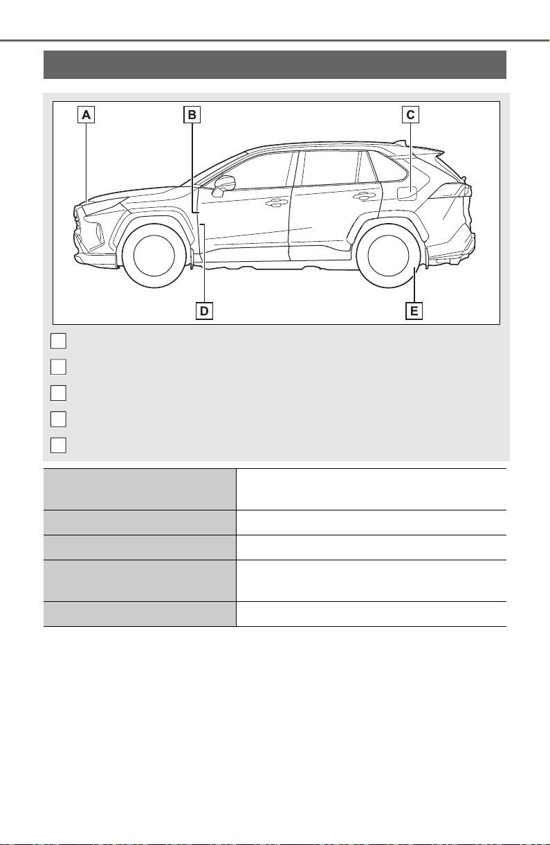
736
GAS STATION INFORMATION
Auxiliary catch lever (P. 57 1 )
Fuel filler door opener lever (P.221)
Fuel filler door (P. 22 1 )
Hood lock release lever (P.571)
Tire inflation pressure (P.671)
Fuel tank capacity
(Reference)
14.5 gal. (55 L, 12.1 Imp.gal.)
Fuel type Unleaded gasoline only P.666
Cold tire inflation pressure P.671
Engine oil capacity
(Drain and refill reference)
P.666
Engine oil type P.666
A
B
C
D
E