The outlet must be properly grounded in accordance with all applicable
For Best Installation
The oven can be difficult for two people to handle during installation. It is recommended that three or more people be available to assist with lifting the unit in to place.
Removal of the lower oven door (to reduce the unit weight and to provide necessary gripping points) can be cumbersome unless the detailed door removal instructions are followed carefully. Do not attempt to remove the speed oven door or steam convection oven door.
Please take time to read and follow the instructions provided for an improved installation experience.codes.
Checklist
Use this checklist to verify that you have completed each step of the installation process. This can help you avoid mistakes.
Before installing the oven, be sure to verify the cabinet dimensions are correct and the required electrical connections are present.
Refer to additional information in this manual regarding Safety, Cabinet Dimensions, Removing Packaging, Electrical Installation, Testing the Installation and Customer Service.
Remove the lower oven door to reduce the unit weight and to provide access to gripping points for lifting. See “Remove Lower Oven Door Prior to Installation” information.
Move the oven units into place in front of the cabinet opening, leaving the bottom packaging on the units to avoid damaging flooring.
Remove the Star-head screws (T-20 size using Starhead screwdriver) holding the speed microwave oven or steam convection oven to the base of its carton.
Assemble the two units of the combination oven. See “Pre-Assembly of the Combination Oven”.
Connect the power cable from the lower oven to the junction box in the cabinet.
Remove the Star-head screws (T-20 size using Starhead screwdriver) holding the lower oven to the base of its carton.
Team-lift the unit directly into the cabinet cutout taking care not to pinch fingers, scratch arms or hands.
Slide the unit all the way in to place.
Fasten the combination unit to the cabinetry opening with the screws supplied (using Philips screwdriver).
Reinstall the oven door removed in Step 3 above.
Consult the complete installation instructions and follow the remainder of the procedures listed, including performing operation test.
INSTALLER- Leave the literature pack and the accessories with the customer.
Removing Packaging
Cut straps on the outside of the boxes.
Remove the upper boxed unit of the combination oven and place on floor so that both shipping cartons can be opened.
Perform the following steps on both units of the combination oven.
Remove the cardboard box by lifting it up and off the unit
Remove all top and side cardboard and foam braces.
Place the unit (leaving it on the shipping base) in front of the cabinet where it is to be installed.
Remove all accessories, racks, packing materials and literature from the oven cavities.
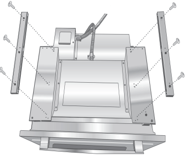
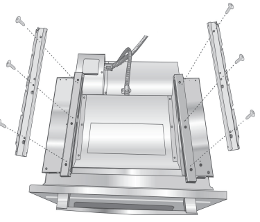
Unscrew unit from packaging brackets as shown in “Packaging Bracket Removal-Left and Right Sides”.
Notes
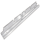
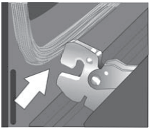
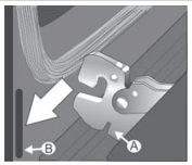
The screws near the base mounting bracket of each unit are all Star-head (T-20 size). Only the one screw that goes through the slotted hole in the mounting bracket on the left and right sides of the unit needs to be removed in order to lift the unit from the mounting base. The screw circled in the image below and marked as (A) is the screw that needs to be removed.
Remove one screw only from each bracket. This will release the oven from the shipping base. Do not remove any additional screws from the oven.
Packaging Bracket Removal-Left and Right Sides
Note: Actual bracket varies in appearance. The bracket remains in the packaging base. The unit should stay on the packaging base until ready to be lifted into cabinet cutout or onto the lower oven.
Preparing Ovens
Place ovens in front of the cabinet where it is to be installed so that they are in line with the cabinet cutout.
Check to be sure all packing materials have been removed from the unit. Also remove the accessories, oven racks, literature pack and any shipping materials from inside the oven cavity. Check both ovens for a double oven or combination oven installation.
Installation
Pre-Assembly of the Combination Oven
Combination ovens require the two components to be assembled prior to installing the combination unit into the wall cabinet.
Note: The installation procedures differ between the microwave, speed oven and steam convection oven combination units. The parts contained in the square tube parts box are common to all three installations.
Parts Provided
Universal connector bracket (2)--in parts box on top of oven
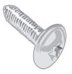
Screws (16)--in red bag inside parts box on top of oven.
Oven Mounting Screws (8)--screws are included to secure the oven trim to the cabinet. The screws are located in a small plastic bag affixed to the literature pack bag.
Trim Piece--in plastic bag on top of oven.
Installation with the Speed Oven or Microwave
Notes:
Do not place the oven into the wall cabinet until after mounting the speed oven on top of the lower oven and securing it with the universal connector brackets.
The universal connector brackets are interchangeable for the left and right sides of the oven. Be sure the taller vertical edge of the bracket is positioned to the outside of the oven.
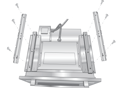
1. Install both universal connector brackets on top of the lower oven using six (6) of the screws provided. Tighten screws securely, but do not overtighten.
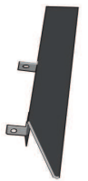
2. Install decorative trim.
Position the decorative trim piece so the flanges with the holes in them face to the rear of the oven.
Align the outer flanges with the outside of the universal brackets. Fasten with one (1) screw each into the end hole of each universal bracket.
Tighten screws securely, but do not overtighten.
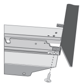
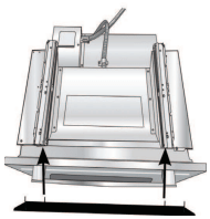
3. Place the speed oven or microwave unit on top of the universal connector brackets and fasten in place using three (3) screws per side. Tighten the screw securely, but do not overtighten.
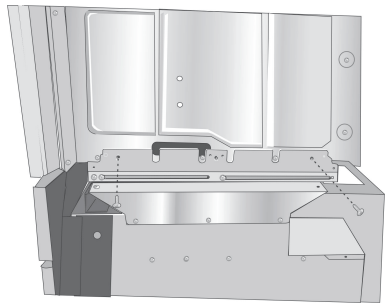
Note: The existing screws in the speed oven base help with alignment. When lowering the speed oven or microwave into place on the universal connector brackets, allow these screw heads to slide into the slots as shown in the illustration below. The screw nearest the front of the speed oven or microwave should slide into the base of the slope at the front of the bracket.
4. Continue to “Connecting the Speed Oven or Steam Convection Oven Electrical Conduit to the Lower Oven”.
Installation with the Steam Convection Oven
Note: Do not place the oven into the wall cabinet until after mounting the steam convection oven on it using the universal connector brackets.
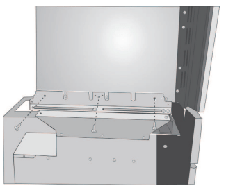
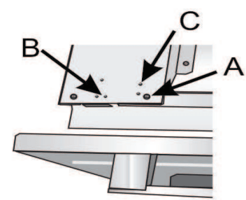
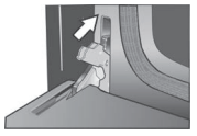
1. Remove the six (6) screws holding the combo service slide assemblies ((A) in illustration below) to the support brackets. Use a magnetic screwdriver bit to reach the screws through the large holes in the tops of the slides.
2. The screw in position (A) in image below (nearest the inside edge, near control panel) must be moved to allow the universal bracket to be positioned there. Remove the inside screw (A) from the left support bracket and reinsert it into the third hole (B) from the outside edge of the support bracket.
Repeat for the right support bracket.
3. Reattach the slide assemblies using the holes near the inside edge of the support bracket. Align the slide assembly parallel to the edge of the bracket and insert the first screw in hole (C).
Insert all three screws for each slide assembly. Tighten the screws but do not overtighten.
Note: When the correct holes are used, the front of the slide assembly will extend just past the front edge of the support bracket 3/16” (5mm). The slide assembly will also be about 1/2” (12mm) from the inside edge of the support bracket.
4. Install the two universal connector brackets to the slide assemblies using the screws provided. Tighten screws securely, but do not overtighten.
Note: The universal connector brackets are interchangeable for the left and right sides of the oven. Be sure the taller vertical edge of the bracket is positioned to the outside of the oven.
5. Install the decorative trim.
Position the decorative trim piece so the flanges with the holes in them face to the rear of the oven.
Align the inner flanges with the inside of the universal brackets. Fasten with one (1) screw each into the end hole of the universal bracket.
Tighten screws securely but do not overtighten.
6. Place the steam convection oven unit on top of the universal connector brackets and fasten in place using two (2) screws per side. Tighten the screws securely, but do not overtighten.
Note: The existing screws in the steam convection oven base help with alignment. When lowering the steam convection oven into place on the universal connector brackets, allow these screw heads to slide into the slots as shown in the illustration below. The screw nearest the front of the steam convection oven should slide into the base of the slope at the front of the bracket.
7. Continue to “Connecting the Speed Oven or Steam Convection Oven Electrical Conduit to the Lower Oven”.
Connecting the Speed Oven or Steam Convection Oven Electrical Conduit to the Lower Oven
Note: When installing the combination unit, the speed oven or steam convection oven, the power cable must be properly attached to the oven-mounted junction box. This must be done prior to supplying electrical power to the oven unit.
WARNING: Check to be sure that no electrical power has yet been supplied to the oven.
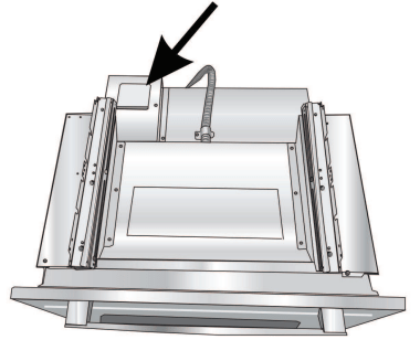
1. Remove the oven-mounted junction box cover located on the top rear of the oven. (See image below).
2. Remove the cap from the conduit access hole in the side of the oven-mounted junction box.
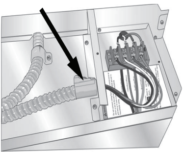
3. Guide the wires from the conduit cable (coming from the speed oven or steam convection oven through the hole in the oven-mounted junction box. (See image below). There are four wires from a speed oven or three wires from a steam convection oven--no white wire from a steam convection oven.
4. Snap the conduit connector into the hole by pressing it in until it clicks into place.
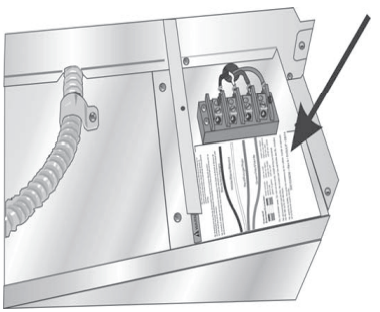
5. Follow the wiring diagram label (see image below) and match and connect each wire by color to the wires attached to the wiring block inside the oven-mounted junction box. Push the bare end of the wire until it is snug in the wiring block then tighten down the retaining screw on each wire.
Tighten securely, but do not overtighten.
See previous illustration in Step 3 for finished appearance.
6. Replace the oven-mounted junction box cover and tighten the two screws holding it in place.
Tighten securely, but do not overtignten
Electrical Installation of Combination Oven-Grounding Instructions
The assembled combination oven should be moved in front of the cabinet opening and the power cable from the lower oven should be connected to the cabinet junction box.
All model ovens on the front cover of this installation instruction manual are dual rated, designed to be connected to either 208 or 240V AC, 60 Hz, 4 wire, single-phase power supply.
Model
Circuit Required
HBL57M52UC
HBL87M52UC
HBL8752UC
HBLP752UC
208V, 60 Hz/ 240V, 60 Hz
40 AMP
The electrical supply should be a 4-wire single phase AC. Install a suitable conduit box (not furnished). An appropriately-sized, UL-listed conduit connector must be used to correctly attach the conduit to the junction box.
Note: Local codes may vary. Installation, electrical connections and grounding must comply with all applicable local codes.
If local codes permit grounding through the electrical supply neutral, connect both the white neutral wire and the green ground wire from the oven to the white neutral eletrical supply wire.
Electrical Connection to Main Power Supply
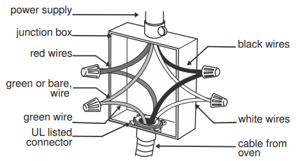
The four-wire connection is preferred, but where local codes permit, the three-wire connection is also acceptable.
Four-wire Connection
Ungrounded Neutral
Connect the red oven wire to the red electrical supply wire (hot wire).
Connect the black oven wire to the black electrical supply wire (hot wire).
Connect the white neutral oven wire to the white neutral (not bare or green ground) electrical supply wire.
Connect the green ground oven wire to the bare or green ground electrical supply wire.
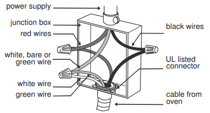
Three-wire Connection
Grounded Neutral
Connect red wire from oven to red wire in junction box.
Connect black wire from oven to black wire in junction box.
Connect both green ground wire and white wire from oven to white, green or bare neutral wire in junction box.
The conduit cable, where connected at the oven, swivels. Rotate conduit cable upward (or downward) and direct through hole prepared in cabinet to attach to junction box.
To maintain serviceability, the flex conduit must not be shortened and should be routed to permit temporary removal of the oven.
Installing Combination Oven into Wall Cabinet
NOTICES:
Before installing the combination oven, be sure to verify the cabinet dimensions and electrical connections.
Check that the cabinet opening is level and plumb for correct installation.
Remove Lower Oven Door Prior to Installation
It is recommended to remove the traditional (lower) oven door to help reduce the unit weight and provide easier access to the latch levers located inside the oven. Do not remove microwave, speed oven or steam convection oven doors.
WARNING
The oven door is heavy and fragile. Use both hands to remove the oven door. The door front is glass. Handle carefully to avoid breaking.
Grasp only the sides of the oven door. Do not grasp the handle as it may swing in your hand and cause damage or injury.
Failure to grasp the oven door firmly and properly could result in personal injury or product damage.
To avoid injury from hinge bracket snapping closed, be sure that both latch levers are securely in place before removing the door. Also, do not force door open or closed--the hinge could be damaged and injury could result.
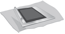
Do not lay removed door on sharp or pointed objects as this could break the glass. Lay door on a protected flat, smooth surface, positioned so that the door cannot fall over.
Be sure to read all warnings and cautions in the installation manual regarding the door removal before attempting to remove the door.
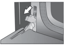
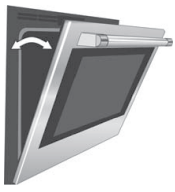
Open the door completely.
Flip latch levers on hinges all the way down toward you.
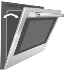
Holding the door firmly on both sides and using both hands, close the door gently until it stops against the latch levers, about 30 degrees from the closed position.
Carefully lift the door up and out of the hinge slots. Hold firmly; the door is heavy
Place the door in a convenient and stable location until you are ready to reinstall it. Lay the door on a towel or section of protective foam padding to avoid damage to the door or the floor.
Correctly Lifting the Combination Oven
CAUTION: It is recommended to wear gloves and long sleeves to protect hands and forearms from abrasion and potential scratches during the lifting process. It is also recommended to take off watches and jewelry and to wear work shoes during installation for foot protection.
CAUTION: Three people or proper equipment are needed to safely lift the combination oven into the cabinet opening.
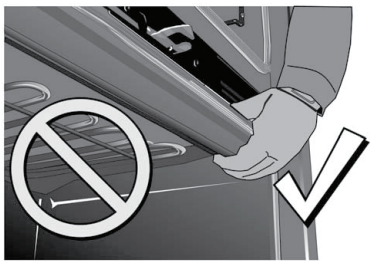
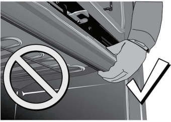
NOTICE: DO NOT attempt to lift the unit by holding the oven’s upper element.
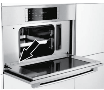
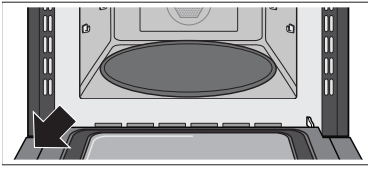
There is a ridge across the top front of the lower oven cavity. Lift by grasping this ridge with one hand while placing the other hand on the back of the unit (for helpers lifting from the sides of the unit). If a third helper is lifting from the front, both hands should lift by holding this ridge area.
Lifting Recommendations
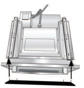
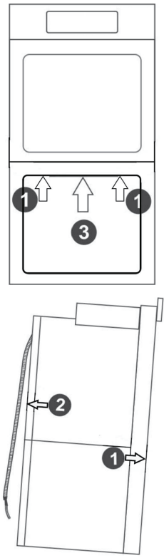
Lift locations or gripping points (with lower oven door removed).
Lift points or gripping points (1) on the front of the unit are for lifting from the sides of the unit. Lift point (3) on the front of the unit is for a third person to help lift the unit.
Lift points or gripping points (2) on the back of the unit shows the location of the opposite hand for the helpers lifting from the sides of the unit. Adjust the location as needed to facilitate the lift.
Wear gloves, a long sleeved shirt, and avoid sharp edges to reduce the risk of cuts or abrasions to the arms or hands.
Placing Combination Oven Into Cabinet Opening
CAUTION: To avoid damage to the door, do not lift, pull or push the unit during installation by using any oven door handle as a gripping point.
When lifting the combined unit into place, avoid grasping the upper element to avoid damaging it. See the illustration below for the correct lifting point. This illustration shows a detailed view of the oven cavity. Note the location of the ridge inside the top of the cavity. This is the area to grip from the front when lifting the combined unit
Installing the Oven into the Cabinet
Lift the combination oven unit into the cabinet cutout without allowing the unit base to contact the flooring.
Guide the unit straight back into the cabinet cutout. Note: Be careful not to crimp the flexible conduit between the oven and the cabinet back wall. If necessary, guide the flexible conduit into the wall of cabinet access hole so it doesn’t prevent the unit from being pushed all the way into the cabinet opening. The oven should be straight and level.
Push the unit straight in until the oven trim is flush with the front of the cabinet trim.
Install four (4) supplied screws through tap holes in the right and left trim pieces to secure oven to cabinetry.
Re-Install the Lower Oven Door
Hold the door firmly in both hands.
Hold the door at an 30° angle from the closed position (approximately 7 inches open at the top).
Insert the hinges into the slots.
You may need to rock the door forward and backward slightly to seat the hinge feet. The door should lower about 3/4” and stop. If not, the hinges have not engaged properly and the door could fall if it is released. The door may need to be removed and re-inserted until the hinges sit correctly in the slots.
Open door all the way to expose hinges, latch levers and slots.
Push latch levers up until they are locked into the slots, flush with front of the oven body.
Close and open door slowly to be sure it is correctly and securely in place. Door must be straight.
Before Calling Service
See the Use and Care Manual for each unit of the combination oven for troubleshooting information. Refer to the Statement of Limited Warranty in the Use and Care Manuals.
To reach a service representative, see the contact information at the front of the Use and Care Manual. Please be prepared with the information printed on your product data plate when calling.
Rating Label
Each component of a combination oven has its own rating label. The rating label shows the model, FD number and serial number. Refer to the rating label when requesting service.
The rating label location varies based on the oven model.
Lower Oven Rating Label
Notes:
The rating labels (A) for the lower oven and steam convection oven are located at the left hand side of the door trim.
The rating label (A) for the speed oven is located at the right hand side of the door trim.
Steam Convection Oven Rating Label
Speed Oven and Microwave Rating Label
The rating label shows the model and serial number. Refer to the rating label on the appliance when requesting service.
The rating label can be found on the inside of the appliance door.