
49-7415-2 JR 06-01
Air Conditioners
Safety Instructions . . . . . . . . . . .2
Operating Instructions
Air Direction . . . . . . . . . . . . . . . .4
Auxiliary Controls . . . . . . . . . .5–9
Controls . . . . . . . . . . . . . . . . . . . .3
Vent Control . . . . . . . . . . . . . . . .4
Care and Cleaning
Air Filters . . . . . . . . . . . . . . . . . .11
Base Pan . . . . . . . . . . . . . . . . . .10
Outdoor Coils . . . . . . . . . . . . . .10
Room Cabinet and Case . . . . . .10
Installation Instructions
Electrical Supply . . . . . . . . .14–16
Installing the Zoneline . . . .17, 18
Optional Drain Kit . . . . . . . . . .19
Preparation . . . . . . . . . . . . . . . .12
Replacing an Existing Unit? . . .13
Troubleshooting Tips . . . . . . .20
Normal Operating Sounds . . . .21
Consumer Support
Consumer Support . . .Back Cover
Product Registration . . . . . .25, 26
Warranty . . . . . . . . . . . . . . . . . .27
Heat/Cool Model 2500
Heat Pump Model 3500
Owner’s Manual and
Installation Instructions
www.GEAppliances.com
Write the model and serial
numbers here:
Model # ____________________
Serial # ____________________
Find these numbers on a label
behind the room cabinet on the
base pan.
Zoneline
®
Customer Service Troubleshooting Tips Care and Cleaning Operating Instructions Safety Instructions
IMPORTANT SAFETY INFORMATION.
READ ALL INSTRUCTIONS BEFORE USING.
WARNING!
For your safety, the information in this manual must be followed to minimize the risk of fire or
explosion, electric shock, or to prevent property damage, personal injury, or loss of life.
■ This Zoneline must be properly
installed in accordance with the
Installation Instructions before it is
used. See the Installation Instructions
in the back of this manual.
■ Immediately repair or replace all
electric service cords that have become
frayed or otherwise damaged.
■ Unplug or disconnect the Zoneline at
the fuse box or circuit breaker before
making any repairs.
NOTE:
We strongly recommend that any
servicing be performed by a qualified
individual.
Replacing an existing unit?
For details, see the Installation
Instructions in this manual.
SAFETY PRECAUTIONS
READ AND FOLLOW THIS SAFETY INFORMATION CAREFULLY.
SAVE THESE INSTRUCTIONS
2
Safety Instructions Operating Instructions Care and Cleaning Troubleshooting Tips Customer Service
3
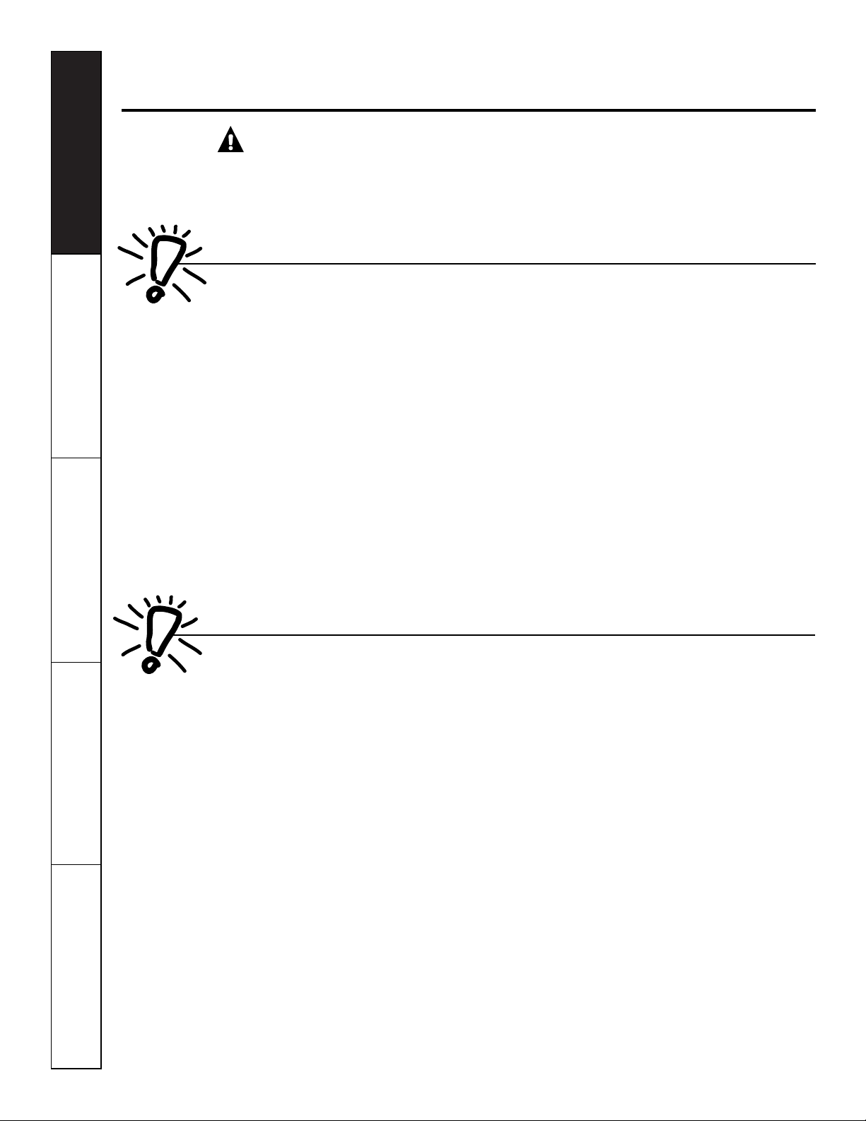
Controls
Mode Control
HIGH COOL
and
AUTO COOL
provide
cooling with different fan speeds.
HIGH HEAT
and
AUTO HEAT
provide
heating with different fan speeds.
LOW FAN
or
HIGH FAN
provides air
circulation and filtering without cooling
or heating.
NOTE: If you move the switch from a cool or heat
setting to STOP or to a fan setting, the unit has an
automatic 3-minute delay before allowing the
compressor to restart in the cool or heat mode.
Temp Control
The temp control is used to maintain the
room temperature. The compressor will
cycle on and off to keep the room at the
same comfort level. When you turn the
knob to
COOLER
(blue) the indoor air
will become cooler. Turn the knob to
WARMER
(red) and the indoor air will
become warmer.
3500 Series only
When the outdoor temperature is lower
than 25°F, heat is provided by the electric
heater in the air conditioner instead of by
the heat pump.
MODE CONTROL TEMP CONTROL
STOP
LOW
FAN
HIGH
FAN
HIGH
HEAT
HIGH
COOL
AUTO
COOL
AUTO
HEAT
W
A
R
M
E
R
C
O
O
L
E
R
About the controls on your Zoneline.
www.GEAppliances.com
About Your Heat Pump (3500 Series only)
Heat pumps can save money by removing heat
from the outside air—even when the outside
temperature is below freezing— and releasing
that heat indoors.
To get the best performance from your heat
pump, don’t change the room thermostat very
often. Raising the heat setting 2–3 degrees will
cause the Zoneline to use its electric heating
elements in order to reach the new temperature
setting quickly.
There is a three minute minimum compressor
run time at any setting to prevent short cycling.
The indoor fan motor starts before the
compressor and stops after the compressor
cycles off.
The electric heating elements use much
more electricity than heat pumps and cost
more to operate.
Customer Service Troubleshooting Tips Care and Cleaning Operating Instructions Safety Instructions
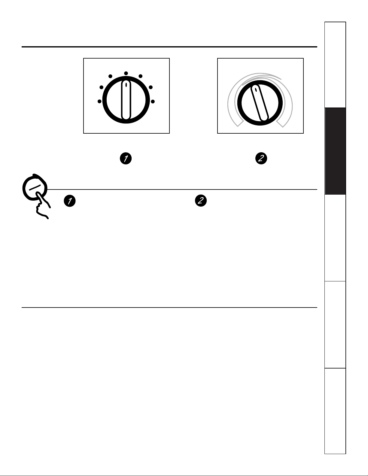
Ventilation Control
The ventilation control lever is located at the
upper left side of the Zoneline unit, behind the
room cabinet.
NOTE: The vent door shipping hardware must be
removed before using the vent control lever.
See the Installation Instructions in this manual.
When set at
CLOSE,
only the air inside the
room is circulated and filtered.
When set at
OPEN,
some outdoor air will be
drawn into the room. This will reduce the
heating or cooling efficiency.
Energy Tip:
Keep the vent control at
CLOSE.
The room air will be filtered and circulated.
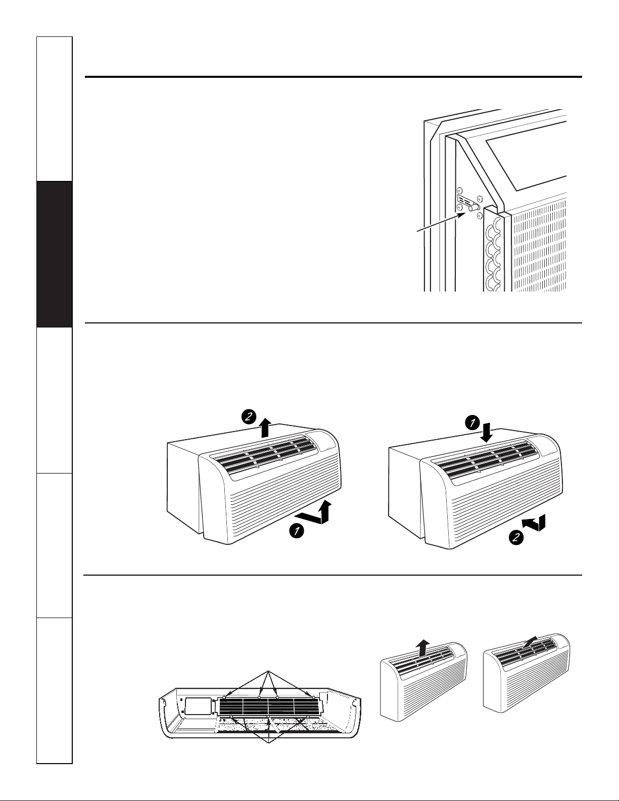
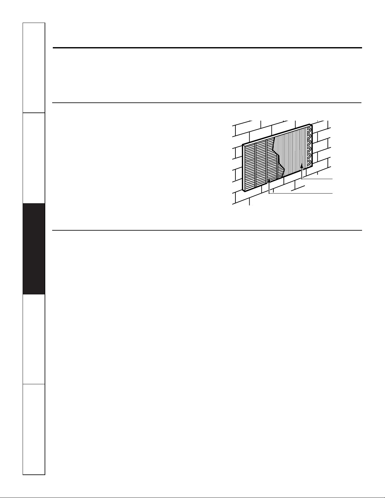
Air Direction
To adjust the air direction, remove the room
cabinet. Remove the 7 louver screws that hold
the louver insert in place. Flip the louver insert
180°, replace the screws and the room cabinet.
Remove the room cabinet and flip the louver
insert to change the air direction.
4
Other features your Zoneline may have.
To Remove the Room Cabinet
Additional controls are located behind the
room cabinet.
To remove:
Pull out at the bottom to release it
from the tabs (1). Then lift up (2).
To replace:
Place the tabs over the top rail (1).
Push inward at the bottom until it snaps into
place (2).
Vent
control
(Pull lever
through
label to
operate)
Open
Close
Louver screws
Louver screws
5
Auxiliary Controls on your Zoneline.
www.GEAppliances.com
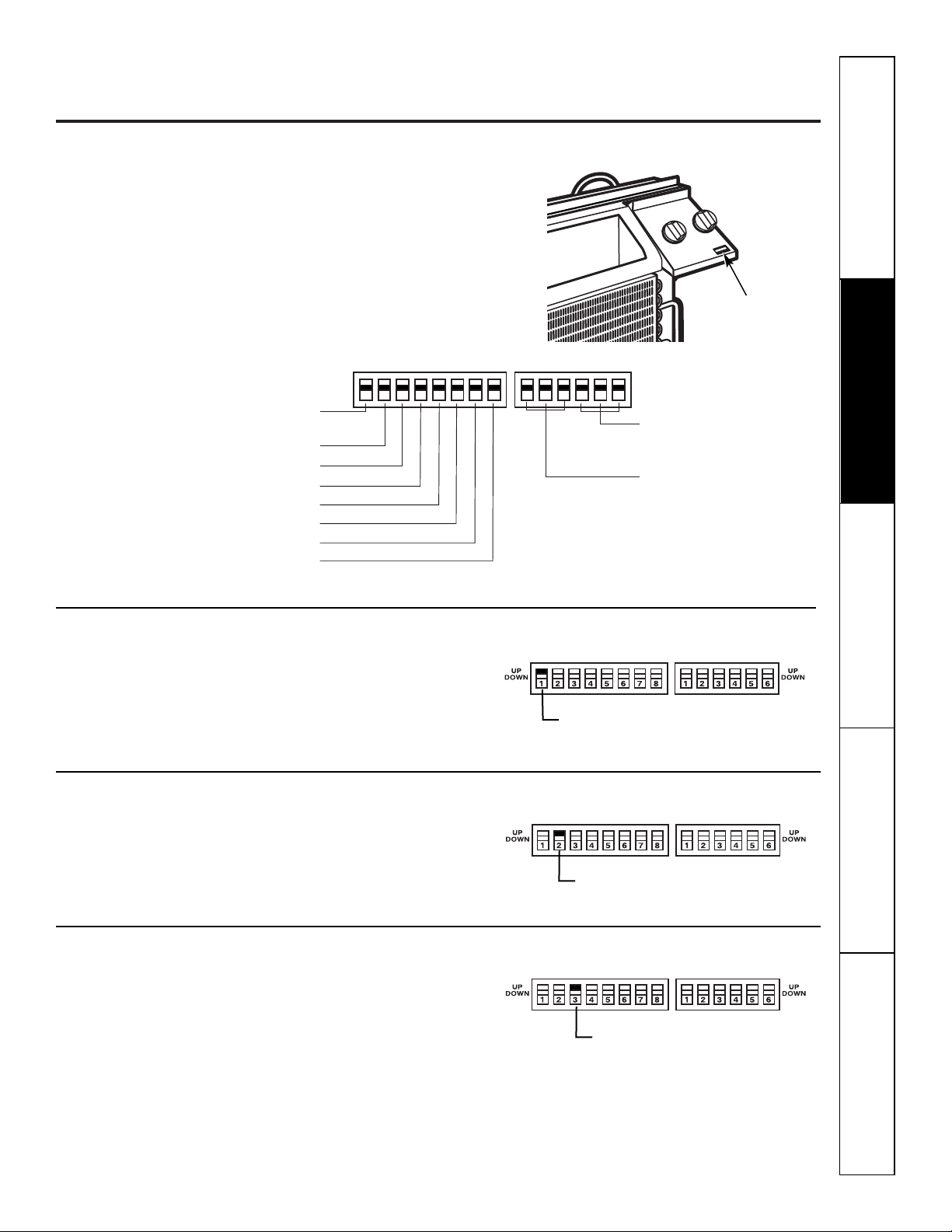
Auxiliary Controls – Dip Switches
The auxiliary dip switch controls are located
behind the room cabinet, through an opening
in the control panel.
Remove the room cabinet. See the
To Remove the
Room Cabinet
section.
The factory settings will be in the
DOWN
position.
The owner is responsible for checking switches
and ensuring they are in the desired position.
HIGH
COOL
1 2 3 4 5 6 1 2 3 4 5 67 8
UP
DOWN
UP
DOWN
ALLI
2
R (All Electric Heat)
(3500 Series models only)
C: FAN CN (Cooling–Smart Fan)
H: FAN CY (Heating–Smart Fan)
CLASS 2 (Remote Thermostat)
LOAD SHEDDING (CDC)
FREEZ Sen (Freeze Sentinel)
CONST FAN (Constant ON Fan)
OCCUPIED (Occupancy Sensor)
TL1 (H) (Temp. Limit 1–Heat)
TL2 (H) (Temp. Limit 2–Heat)
TL3 (H) (Temp. Limit 3–Heat)
TL1 (C) (Temp. Limit 1–Cool)
TL2 (C) (Temp. Limit 2–Cool)
TL3 (C) (Temp. Limit 3–Cool)
Safety Instructions Operating Instructions Care and Cleaning Troubleshooting Tips Customer Service
All Electric Heat
This electric heat option functions only on the
3500 Series models. When this switch is enabled
(UP)
, heat pump operation is locked out, causing
the unit to provide only electric resistance heat.
Cooling–Smart Fan
When this switch is enabled
(UP)
, it allows the
indoor fan to cycle on/off with the compressor.
When this switch is disabled
(DOWN)
, it allows
the indoor fan to run continuously.
Heating–Smart Fan
When this switch is enabled
(UP)
, it allows the
indoor fan to run continuously. When this
switch is disabled
(DOWN)
, it allows the indoor
fan to cycle on/off with the heat pump or
heater operation.
ALLI
2
R (All Electric Heat)
C: FAN CN (Cooling–Smart Fan)
H: FAN CY (Heating–Smart Fan)
Dip Switches
6
Auxiliary controls on your Zoneline.
Remote Thermostat–Class 2
When this switch is enabled
(UP)
, it allows the
unit to operate off of a Class 2 Remote Control
Wall Thermostat. The unit controls are disabled.
Load Shedding (CDC)
This feature is active only if the unit is in
CDC mode. When this switch is enabled
(UP)
,
the indoor fan can be turned ON or OFF with
the unit controls.
Freeze Sentinel
When this switch is enabled
(UP)
, it turns OFF
the freeze sentinel protection feature. With the
switch disabled
(DOWN)
, the freeze sentinel is
activated which automatically provides heat
without user interface. This helps to prevent
plumbing damage by turning the heater and
indoor fan ON at 41° F and OFF at 46°F.
Constant ON Fan
When this switch is enabled
(UP)
, it allows the
indoor fan to run continuously, at high speed,
even if the unit is in the STOP position.
Occupancy Sensor
When this switch is enabled
(UP)
, it allows the
unit to utilize an infrared motion sensor and
a door switch for occupancy detection. This
feature allows an energy management system
to be installed and operated in conjunction
with the unit.
HIGH
COOL
1 2 3 4 5 6 1 2 3 4 5 67 8
UP
DOWN
UP
DOWN
Customer Service Troubleshooting Tips Care and Cleaning Operating Instructions Safety Instructions
CLASS 2 (Remote Thermostat)
LOAD SHEDDING (CDC)
FREEZE Sen (Freeze Sentinel)
CONST FAN (Constant
ON Fan)
OCCUPIED
(Occupancy Sensor)
7
www.GEAppliances.com
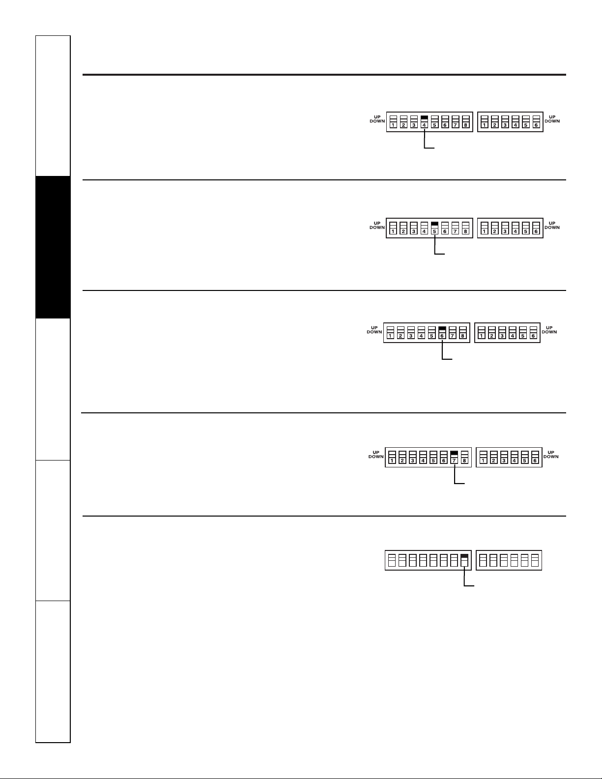
Temperature Limiting
Temperature limiting can reduce energy costs
by limiting the lowest temperature that can be
set for cooling and the highest temperature that
can be set for heating. Temperature limiting is
controlled by the second six auxiliary switches.
The first three switches are used to select the
cooling limits and the remaining three switches
are used to control the heating limits. This
feature is not available with the Remote
Thermostat–Class 2.
HIGH
COOL
1 2 3 4 5 6 1 2 3 4 5 67 8
UP
DOWN
UP
DOWN
TL1 (C) (Temp. Limit 1–Cool)
TL2 (C) (Temp. Limit 2–Cool)
TL3 (C) (Temp. Limit 3–Cool)
HIGH
COOL
1 2 3 4 5 6 1 2 3 4 5 67 8
UP
DOWN
UP
DOWN
TL1 (H) (Temp. Limit 1–Heat)
TL2 (H) (Temp. Limit 2–Heat)
TL3 (H) (Temp. Limit 3–Heat)
Temperature limiting during COOL mode
(all temperatures shown in °F)
UP DOWN Minimum Maximum
NONE 1, 2, 3 60° 85°
1 2, 3 64° 85°
1, 2 3 66° 85°
2 1, 3 68° 85°
2,3 1 70° 85°
1, 2, 3 NONE 72° 85°
1, 3 2 74° 85°
3 1, 2 76° 85°
Temperature limiting during HEAT mode
(all temperatures shown in °F)
UP DOWN Minimum Maximum
NONE 4, 5, 6 60° 85°
4 5, 6 60° 80°
4, 5 6 60° 78°
5 4, 6 60° 76°
5,6 4 60° 74°
4, 5, 6 NONE 60° 72°
4, 6 5 60° 70°
6 4, 5 60° 65°
Safety Instructions Operating Instructions Care and Cleaning Troubleshooting Tips Customer Service
8
Customer Service Troubleshooting Tips Care and Cleaning Operating Instructions Safety Instructions
Auxiliary controls on your Zoneline.
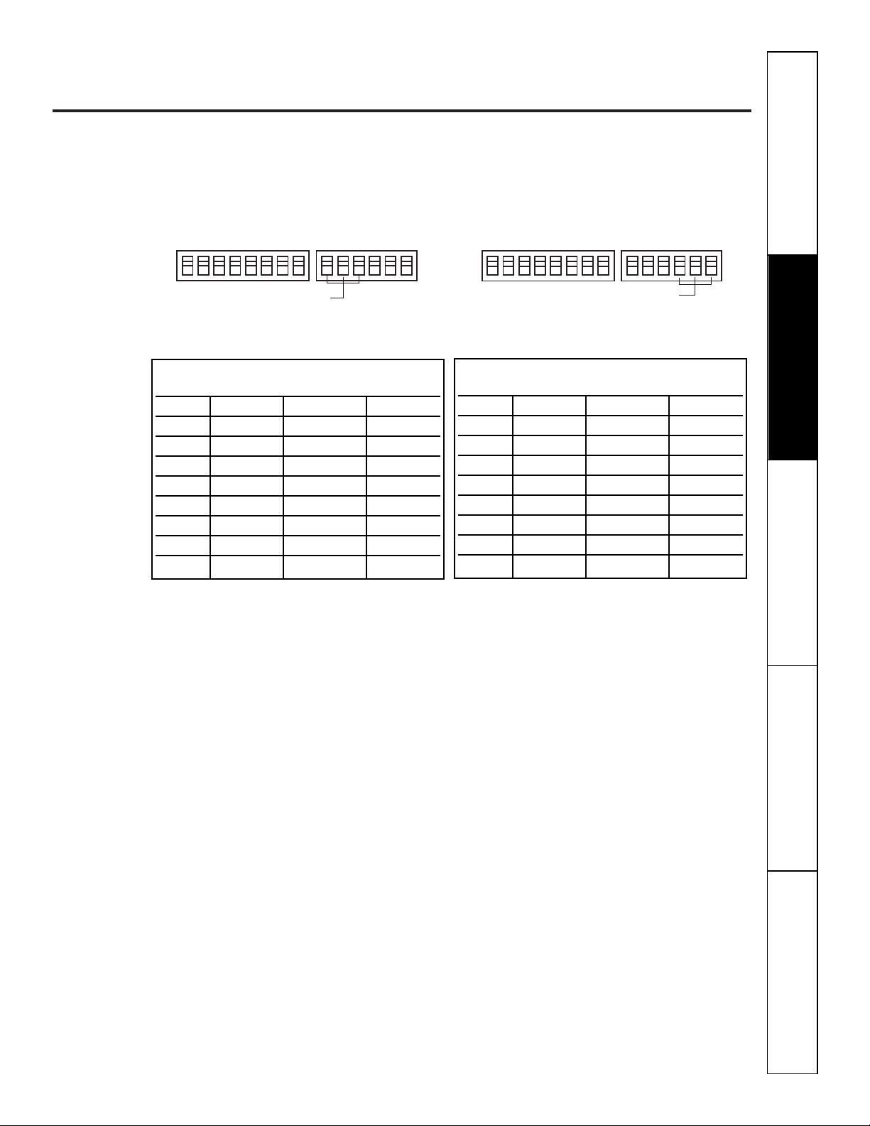
Auxiliary Controls–Terminal Connections
The auxiliary controls are located behind the
room cabinet beneath the control panel.
Remove the room cabinet. See the
To Remove the Room Cabinet
section.
Remove the screw from the control panel
corner.
Remove the control panel and knobs by
grasping the control panel on both sides and
pulling forward. The knobs will pull off with
the control panel.
After all desired settings have been made,
replace the control panel, knobs and room
cabinet by reversing steps 1–3.
NOTE:
The
knob stem is D shaped. Install the flat of the
shaft to the flat of the knob.
The owner is responsible for making all
connections and setting the appropriate
dip switches.
Insert the building hook-up wires into the
bottom of the terminal and tighten screw
securely to make the desired connections.
CAUTION:
Improper wiring may damage the Zoneline
electronics. No common busing is permitted.
Damage or erratic operation may result.
A separate wire pair must be run from each
separate controlling switch to each individual
Zoneline.
4
3
2
1
Motion Sensor
Door Sensor
External Fan
Central Desk Control
Common - Ground
White - Heater
Yellow - Compressor
Black - Solenoid
Green - High Speed Fan
Green - Low Speed Fan
Red - 24 V AC only
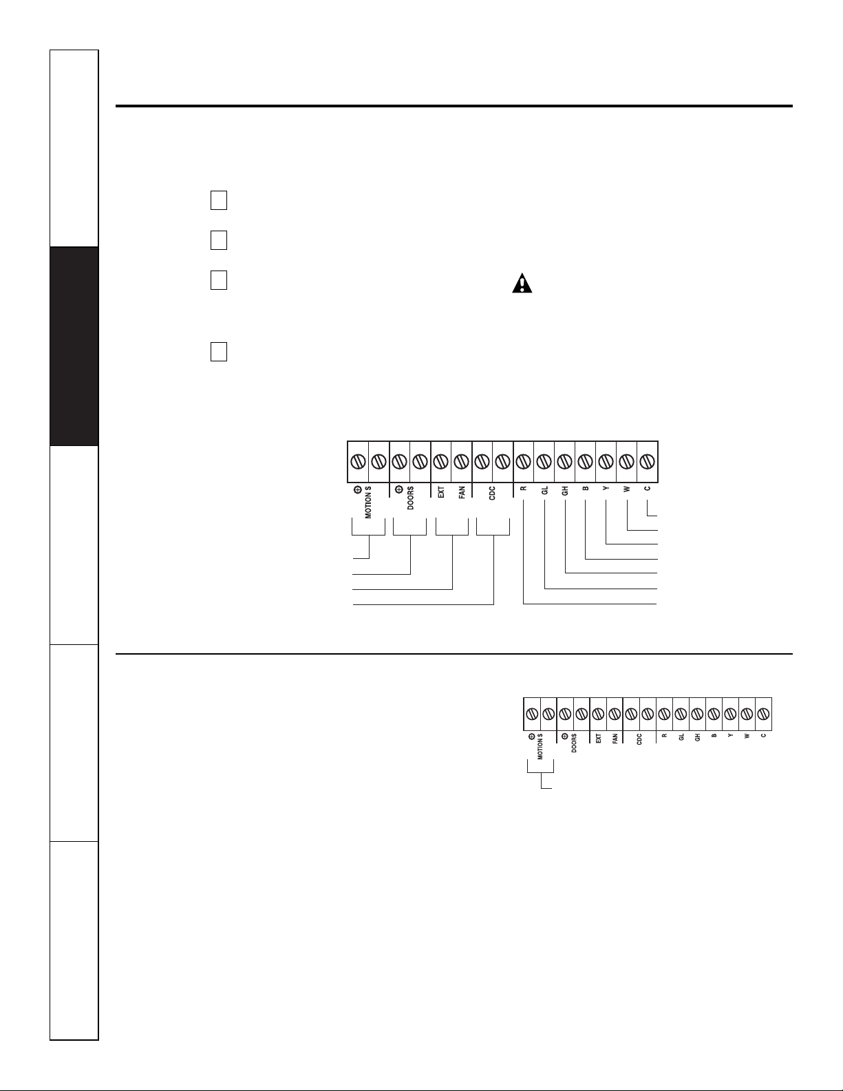
Motion Sensor (Obtained locally)
When connected, the wall mounted motion
sensor will detect motion in the room and
automatically turn the unit ON or OFF.
The door and motion sensors work together
to automatically turn the unit ON or OFF.
Motion Sensor

9
Safety Instructions Operating Instructions Care and Cleaning Troubleshooting Tips Customer Service
www.GEAppliances.com
Door Sensor (Obtained locally)
When connected, the door sensor will detect
when the door in the room was opened or
closed. This feature must be used in conjunction
with the motion sensor.
The door and motion sensors work together
to automatically turn the unit ON or OFF.
Door Sensor
External Fan (Obtained locally)
When connected, an auxiliary or external fan
can be controlled with the indoor fan motor
on the Zoneline. Connections provide 24 V AC
to energize a remote relay, turning on the
external fan.
External Fan
Central Desk Control
When connected, the unit can be turned ON
or OFF with a switch located at the Central
Control Panel. A separate wire pair must be
run from each separate controlling switch to
each individual Zoneline.
Central Desk Control
Remote Thermostat
When connected, the unit will be controlled
by a remote thermostat.
NOTE:
The number 4 dip switch must be in the
enabled
(UP)
position to activate the remote
thermostat. (See the installation instructions
supplied with the remote thermostat).
IMPORTANT:
The Zoneline thermostat connections
provide 24 V AC only.
If using a digital/electronic wall thermostat,
you must set it to the 24 V AC setting.
See the Installation Instructions for the
wall thermostat.
CAUTION:
Damage to a wall thermostat or to the
Zoneline electronics can result from improper
connections. Special care must be used in
connecting blue and black wires. No line voltage
connections should be made to any circuit.
Isolate all wires in building from line voltage.
Common - Ground
White - Heater
Yellow - Compressor
Black - Solenoid
Green - High Speed Fan
Green - Low Speed Fan
Red - 24 V AC only
Customer Service Troubleshooting Tips Care and Cleaning Operating Instructions Safety Instructions
10
Care and cleaning.
Base Pan
In some installations, dirt or other debris may be
blown into the unit from the outside and settle in
the base pan (the bottom of the unit).
In some areas of the United States a “jell-like”
substance may be seen in the base pan.
Check it periodically and clean, if necessary.
Outdoor Coils
The coils on the outdoor side of the Zoneline
should be checked regularly. If they are clogged
with dirt or soot, they may be professionally
steam cleaned, a service available through your
GE service outlet. You will need to remove the
unit to inspect the coils because the dirt
build-up occurs on the inside.
Clean the outside coils regularly.
Room Cabinet and Case
Turn the Zoneline off and disconnect the
power supply.
To clean, use water and a mild detergent.
Do not use bleach or abrasives. Some commercial
cleaners may damage the plastic parts.
Coils
Grille
Safety Instructions Operating Instructions Care and Cleaning Troubleshooting Tips Customer Service
11
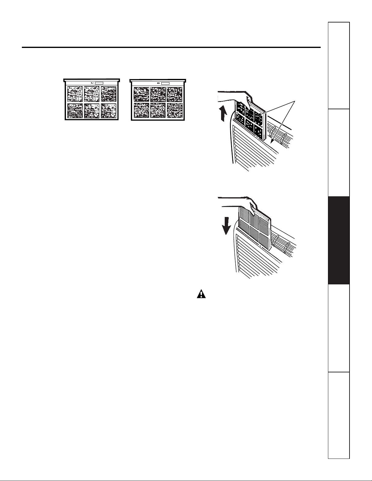
To maintain optimum performance, clean the filters at least every 30 days.
Air Filters
Turn the Zoneline off before cleaning.
The most important thing you can do to
maintain the Zoneline is to clean the filter
at least every 30 days. Clogged filters reduce
cooling, heating and air flow.
Keeping these filters clean will:
■ Decrease cost of operation.
■ Save energy.
■ Prevent clogged heat exchanger coils.
■ Reduce the risk of premature component
failure.
To clean the air filters:
■ Vacuum off the heavy soil.
■ Run water through the filters.
■ Dry thoroughly before replacing.
To remove the air filters:
To replace the air filters:
CAUTION:
Do not operate the
Zoneline without the filters in place. If a filter
becomes torn or damaged it should be replaced
immediately.
Operating without the filters in place or with
damaged filters will allow dirt and dust to reach
the in-door coil and reduce the cooling, heating,
airflow and efficiency of the unit.
Replacement filters are available from your
salesperson, GE dealer, GE Service and Parts
Center or authorized Customer Care
®
servicers.
Dirty filter—Needs cleaning Clogged filter—Greatly
reduces cooling, heating
and airflow.
FRONT
FRONT
Pull up
Push down
2 Air filters
www.GEAppliances.com
BEFORE YOU BEGIN
Installation Zoneline Air
Instructions Conditioners
Read these instructions completely and carefully.
•
IMPORTANT
–
Save these
instructions for local inspector’s use.
•
IMPORTANT
–
Observe all
governing codes and ordinances.
• Note to Installer
–
Be sure to leave these
instructions with the owner.
• Note to Owner
–
Keep these instructions for
future reference.
• Proper installation is the responsibility of the
installer.
• Product failure due to improper installation is not
covered under the Warranty.
Questions? Call 800.GE.CARES (800.432.2737)
or Visit our Website at:
www.GEAppliances.com
IMPORTANT ELECTRICAL
SAFETY–READ CAREFULLY
CAUTION:
• Follow the National Electrical Code (NEC) or local
codes and ordinances.
• For personal safety, this Zoneline must be properly
grounded.
• Protective devices (fuses or circuit breakers)
acceptable for Zoneline installations are specified
on the nameplate of each unit.
• Do not use an extension cord with this unit.
• Aluminum building wiring may present special
problems—consult a qualified electrician.
• When the unit is in the STOP position there is still
voltage to the electrical controls.
• Disconnect the power to the unit before
servicing by:
1 Removing the power cord (if it has one) from
the wall receptacle.
OR
2 Removing the branch circuit fuses or turning
the circuit breakers off at the panel.
Phillips screwdriver
TOOLS YOU WILL NEED
12
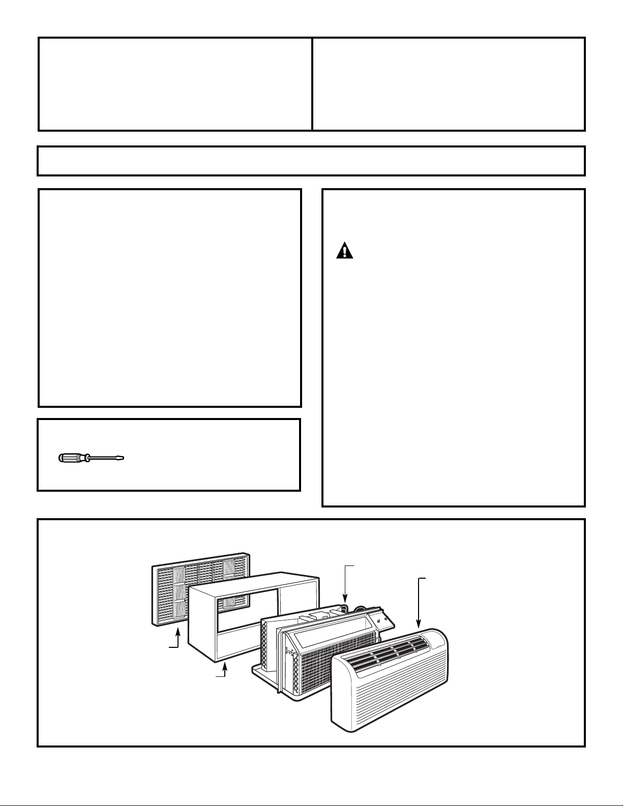
ZONELINE COMPONENTS
Exterior grille/louver**
** Shipped with the Zoneline unit
** Check the “Essential Elements” list on the unit
Wall case**
Zoneline unit
Room cabinet*
13
Installation Instructions
REPLACING AN EXISTING UNIT?
Use the correct wall case
This unit is designed to be installed in a GE plastic or
insulated metal wall case. This minimizes condensation
from forming on the room side of the case.
If the current wall case is not insulated, you can reduce
the possibility of condensation forming by installing
insulation kit RAK901L, available where you purchased
the unit.
Use the correct outdoor grille
You should use the outdoor grilles shown on the
“Essential Elements” label on the top of the unit.
• If an existing grille is not replaced, capacity and
efficiency will be reduced and the unit may fail to
operate properly or fail prematurely. A deflector kit,
RAK40, may be used with grilles that were not
designed for your new GE Zonelines. The RAK40
contains air deflectors and gaskets that mount to the
unit to direct the hot exhaust air away from the air
intake to allow the unit to function properly. The
grille must have a 65% minimum free area.
• Any vertical deflectors in the existing rear grille should
be removed to decrease condenser air recirculation
which can cause the unit to “short-cycle” and lead
to premature component failure.
Check the “Essential
Elements” label for
important information.
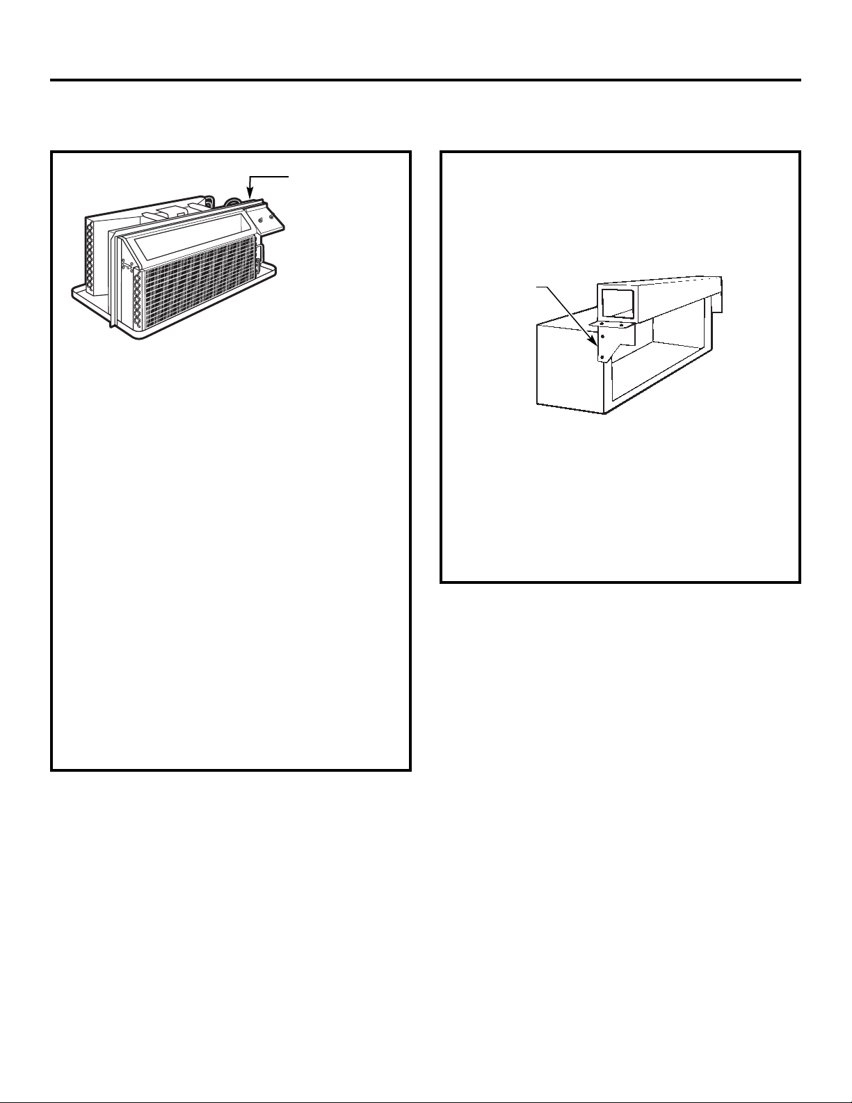
Replacing a ducted unit
New ducted installation:
If this unit is to be installed in a new ducted application
using a duct adapter kit, the kit must be installed before
the unit is placed in the wall case. The installation
instructions are packed with the kit.
Existing ducted installation:
Replacement of an existing ducted unit may require
different components. Request this information from
your sales representative.
• Replacing 230/208 volt units:
See page 14.
• Replacing 265 volt units:
See pages 15 and 16.
Mounting
plate
Duct
Case
Installation Instructions
14
HOW TO CONNECT
1 Remove the room cabinet.
2 Connect to electrical power.
3 See the special instructions below for applicable
supply voltages.
4 Reinstall the room cabinet.
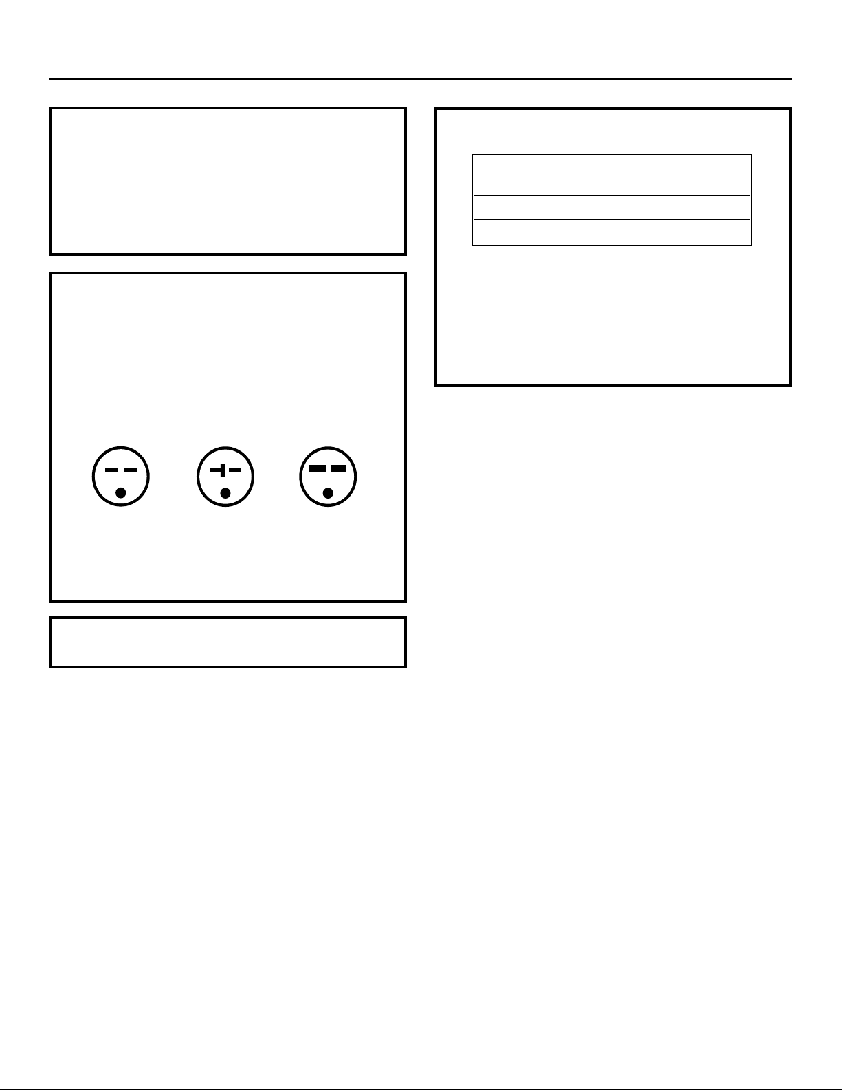
230/208 VOLT
ELECTRICAL SUPPLY
All wiring, including installation of the receptacle,
must be in accordance with the NEC and local codes,
ordinances and regulations.
This unit is equipped with a line cord for appropriate
amperage wall receptacle. See below.
Tandem
15 Amp.
230/208 volt receptacle configuration.
Perpendicular
20 Amp.
Large Tandem
30 Amp.
Order Kit RAK4002A for 230/208 volt
direct connection.
230/208 volt models may be installed using one of
the following electrical subbases:
Electrical subbases provide a flexible enclosure for
direct connection or enclosed receptacles.
The instructions provided with the selected subbase
kit must be carefully followed. It is the responsibility
of the installer to ensure the connection of
components is done in accordance with these
instructions and all electrical codes.
Branch Circuit and Proper GE
Unit Amperage Rating Subbase Kit
15/20 RAK204D20
30 RAK204D30
15
Installation Instructions
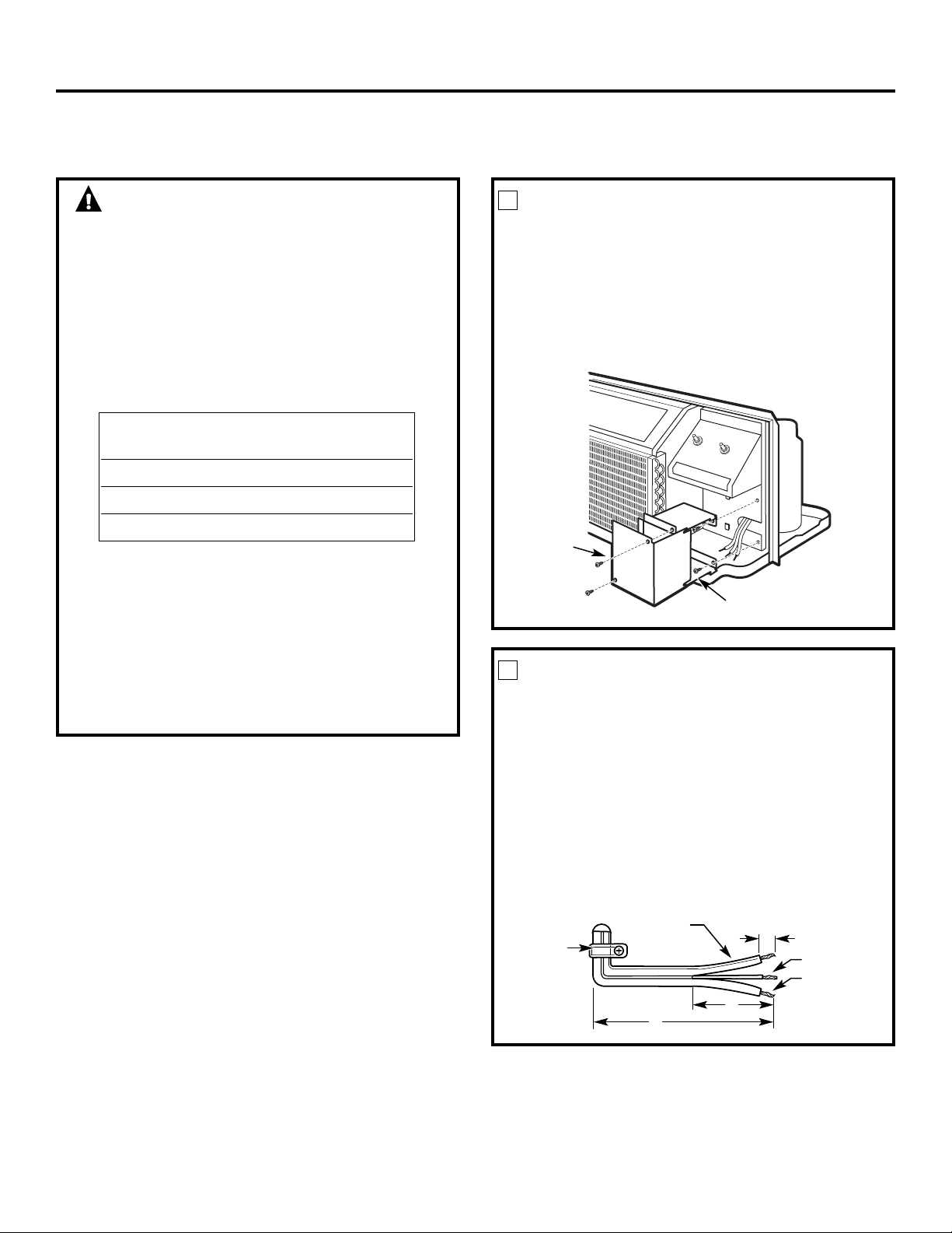
265 VOLT ELECTRICAL SUPPLY
WARNING:
Connection of this 265 V AC product to a branch
circuit MUST be done by direct connection in
accordance with the National Electric Code.
Plugging this unit into a building mounted
exposed receptacle is not permitted by code.
These models must be installed using one of the
following methods:
A Electrical subbase kits are available to provide a
flexible enclosure for direct connection.
The instructions provided with the selected subbase
kit must be carefully followed. It is the responsibility
of the installer to ensure the connection of
components is done in accordance with these
instructions and all electrical codes.
B For direct connection to branch circuit wiring inside
the provided junction box without using a subbase
kit, cut the cord, strip the wire ends and connect
as follows.
Branch Circuit and Proper GE
Unit Amperage Rating Subbase Kit
15 RAK204E15
20 RAK204E20
30 RAK204E30
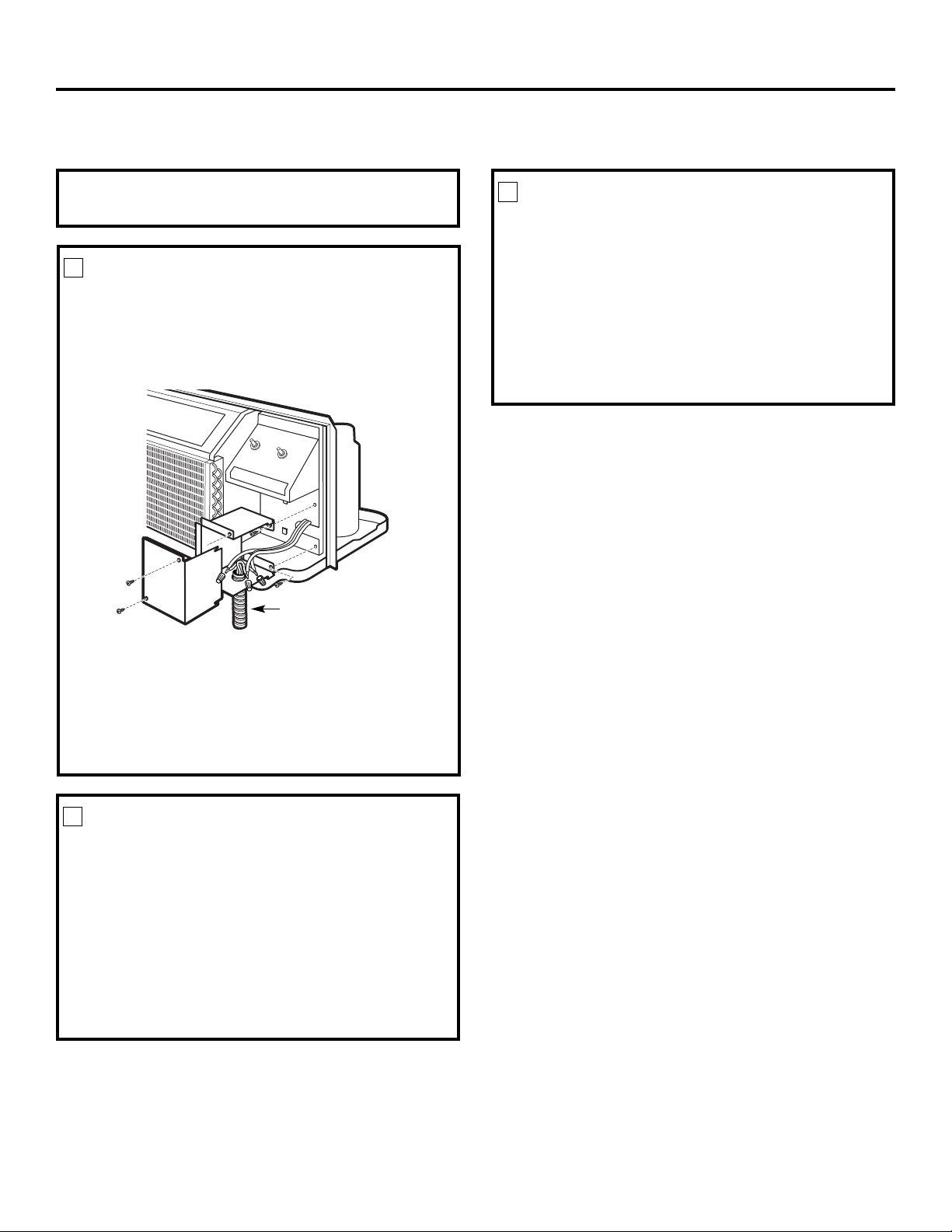
REMOVE JUNCTION BOX
1 Remove the junction box cover by taking out the
front two screws.
2 Remove the junction box by taking out the top
and bottom rear screws. Note how the tabs on
the lower left side of the junction box serve to
hold the side in place. This will help when the
box is being reinstalled. The cord will be coiled
up inside the junction box.
1
Junction
box cover
Junction box
CUT AND STRIP THE CORDSET
1 Measure 6″ down the cord from the strain relief
securing the cord to the unit and cut the cord
through at this point.
2 Carefully split the cord insulation at the center
for 2″ so as to separate into three insulated wires.
Be careful not to cut through the center green
ground wire insulation.
3 Strip 3/4″ of the insulation away at the end
of each of the three wires (L1, Neutral and
Ground). The Neutral wire is identified by
molded rib along its entire length. The L1
(Hot) wire insulation is smooth.
2
Strain
relief
6″
2″
3/4″
Neutral wire
(molded rib)
Ground wire
L1 wire
(smooth)
Installation Instructions
16
ATTACH CONDUIT
1 Use the round knockout at the bottom of the
junction box to attach conduit coming from the
branch circuit. Remove the knockout, attach the
conduit and bring wires into the junction box.
Leave 6″ of wire free at the end of the conduit
to allow connections to be made.
2 If a fuse and fuseholder are to be used, the knockout
at the top of the box is for mounting a Buss
Fuseholder. Be sure the fuse and fuseholder are of the
same rating as the branch circuit. Leadwires at the
fuse can be either soldered in place or attached using
UL-listed 1/4″ female (receptacle) crimp connectors.
3
Conduit
REINSTALL JUNCTION BOX
• Reinstall the junction box by engaging the left tabs
on the lower right face of the unit, aligning the
screw holes at the top and bottom and driving the
two screws until secure. Be sure that all wire leads
are inside the box and not pinched between the box
and the unit.
The identified (ribbed) Neutral wire of the cordset
MUST be connected to the white Neutral wire of
the branch circuit. The green insulated ground wire
from the unit MUST be connected to the branch
circuit ground wire.
4
265 VOLT ELECTRICAL SUPPLY
MAKE WIRING CONNECTIONS
1 Make all wire connections by using appropriate
UL-listed electrical connectors and techniques
(black to black, white to white and green to green).
2 Carefully tuck all wires and connections back inside
the junction box. Be sure there are no loose
connections or stray uninsulated wires exposed.
3 Place the junction box cover in place. Replace the
two screws removed earlier and tighten securely.
4 Discard the unused portion of the plug and
the cordset.
5
NOTE: Order Kit RAK4002CW to enable a quick
disconnect inside the junction box.
Installation Instructions
17
INSTALL THE WALL CASE AND
EXTERIOR GRILLE
The RAB71 series or RAB77 wall case must be
properly installed per instructions packed with
the case.
• Remove the corrugated stiffener and the outdoor
protective panel. Use the slit in the outdoor panel
as a handhold and push out.
• Install the exterior grille from the room side
following instructions packed with the grill.
Insulated Wall Case
This unit is designed to be installed in a GE plastic
or an insulated steel wall case. This minimizes
condensation from forming on the room side of
the case.
The RAB71 series wall cases are insulated. Insulation
kit RAK901L is available for use with RAB77 or
existing uninsulated wall cases when needed.
NOTE: For installation with a subbase or duct adapter,
see the instructions packed with those kits.
1
Stiffener
Protective
panel
Slit
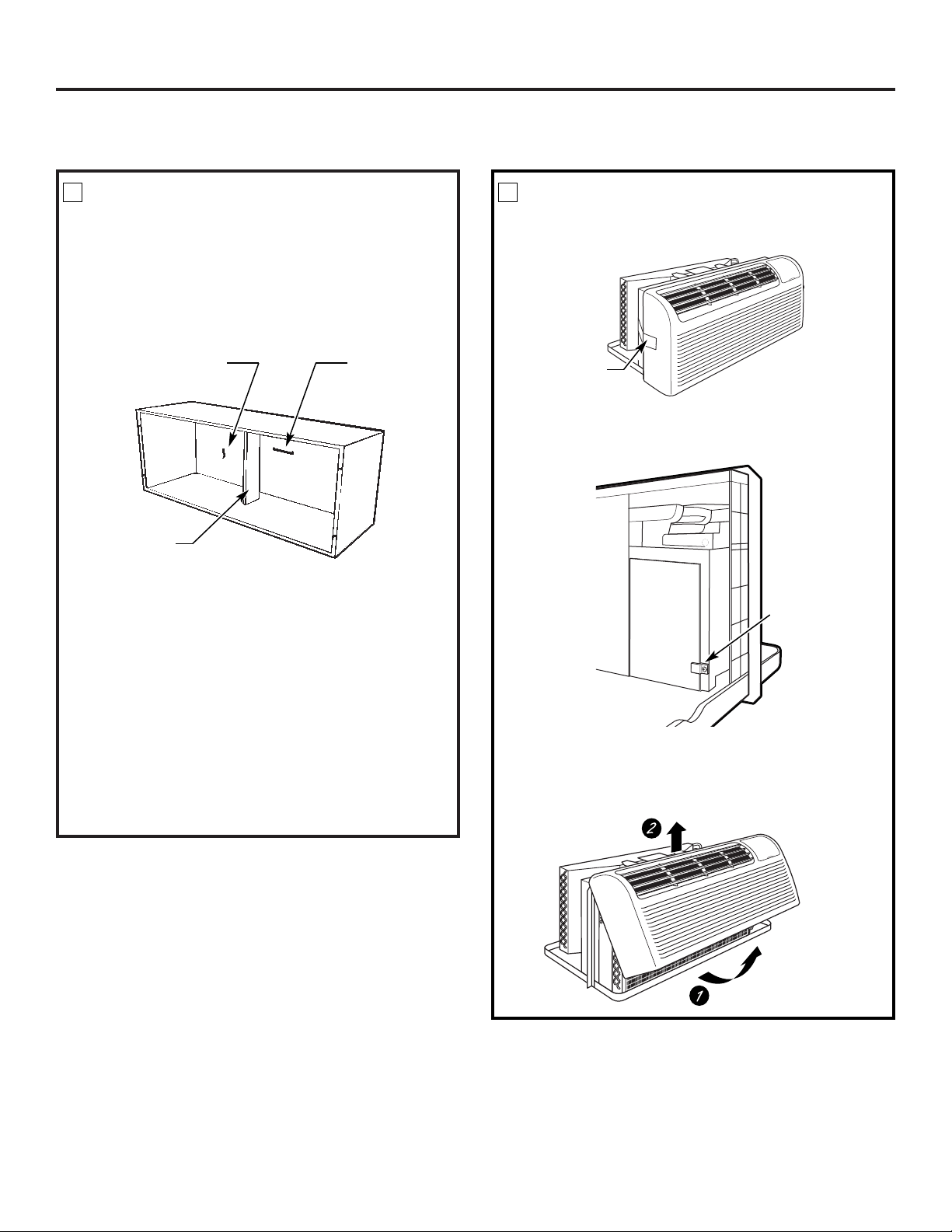
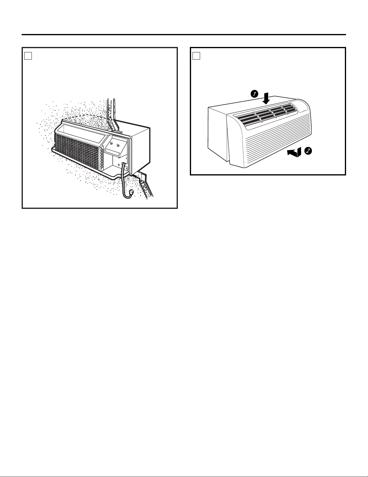
PREPARE THE ROOM CABINET
• Carefully remove shipping tape, if there is any, from
the room cabinet and vent door.
• Remove the shipping screw/clamp from the top of
the vent door, if present.
• Remove the room cabinet by pulling it out at the
bottom to release it (1), then lift it up to clear the
rail along the unit top (2).
2
Shipping
tape
Remove shipping
screw and clamp
if present
INSTALLING THE ZONELINE
INSTALL THE UNIT INTO THE
WALL CASE
Slide the unit into the wall case and secure with four
screws through the unit flange holes.
3
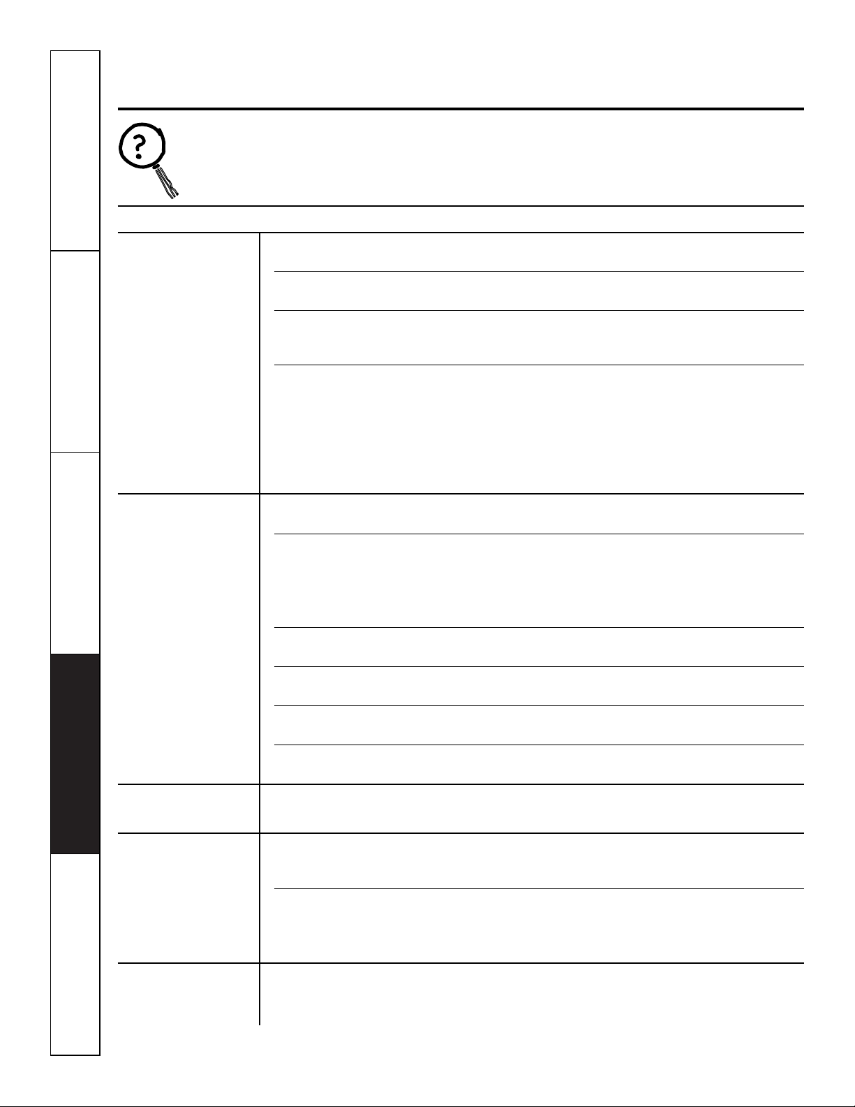
REPLACE THE ROOM CABINET
Reinstall the room cabinet by hooking the top over
the rail along the unit top (1), then pushing it in at
the bottom (2).
4
Installation Instructions
18

Installation Instructions
19
OPTIONAL – DRAIN KIT INSTALLATION
Dry Air 2500 Series models are designed to improve dehumidification by 25%. Since more moisture will be removed from
the air, there is a greater possibility that water will drip from the wall case than with a standard unit. To prevent this water
from dripping onto external building walls, we recommend the use of RAD10 Drain Kit.
External Drain
See the Installation Instructions
in the RAD10 kit.
Internal Drain
See the Installation Instructions
in the RAD10 kit
Type “A” screw for metal case or
Type “B” screw for molded case
Square drain holes
Square drain holes
Neoprene sponge gasket
Steel mounting plate
1/2″O.D. drain tube
Neoprene sponge gasket
Steel mounting plate
Type “A” screw for metal case or
Type “B” screw for molded case
Alternate:
6″long, 1/2″O.D. straight
copper tube
Customer Service Troubleshooting Tips Care and Cleaning Operating Instructions Safety Instructions
Before You Call For Service…
Troubleshooting Tips
Save time and money! Review the charts on the following
pages first and you may not need to call for service.
Problem Possible Causes What To Do
Zoneline does
The unit is • Make sure the Zoneline plug is pushed completely
not start
unplugged. into the outlet.
The fuse is blown/circuit • Check the house fuse/circuit breaker box and replace
breaker is tripped. the fuse or reset the breaker.
The unit is waiting for • This is normal. The Zoneline will start again after
the compressor overload it resets.
protector to reset.
Power failure. • If power failure occurs, set the mode control to
STOP.
When power is restored, set the mode control to the
desired setting.
• There is a protective time delay (up to 3 minutes) to
prevent tripping of the compressor overload. For this
reason, the unit may not start normal heating or cooling
for 3 minutes after it is turned back on.
Zoneline does not cool
Indoor airflow • Make sure there are no curtains, blinds or furniture
or heat as it should
is restricted. blocking the front of the Zoneline.
Outdoor airflow is • Make sure the rear grille is not restricted. This can cause
restricted or recirculated. the unit to cycle off due to the compressor overload.
• Outdoor grille must have a minimum of 65% free area.
Non-GE grilles may be too restrictive for proper
performance. Consult your salesperson for assistance.
The temp control may • Turn the control to a lower or higher setting.
not be set high enough.
NOTE: The temperature limiter may be limiting the temperature range.
The air filter is dirty. • Clean the filter at least every 30 days.
See the
Operating Instructions
section.
The room may have • When the Zoneline is first turned on you need to
been hot or cold. allow time for the room to cool down or warm up.
Outdoor air is • Set the vent control to the
CLOSE
position.
entering the room.
Burning odor at the start
Dust is on the surface • This can cause a “burning” odor at the beginning of
of heating operation
of the heating element. the heating operation. This odor should quickly fade.
The air is not always
The heat pump is not • This is normal. The heat pump will produce warm air
cool or hot during
producing hot air. but not as hot as air produced when the higher-cost
operation
electric heat is used.
The fan switch may be • This causes the fan to blow room temperature air
set at continuous fan even when the compressor or heater cycles off.
The continuous air movement provides better
overall temperature control.
The air does not feel
The heat pump alone • Use the Electric Heat Option. This turns off the
warm enough during
produces air that feels heat pump and warms with electric heat only.
heating operation
cooler than desired.
NOTE: Use of this option will result in increased energy
consumption.
20
Safety Instructions Operating Instructions Care and Cleaning Troubleshooting Tips Customer Service
21
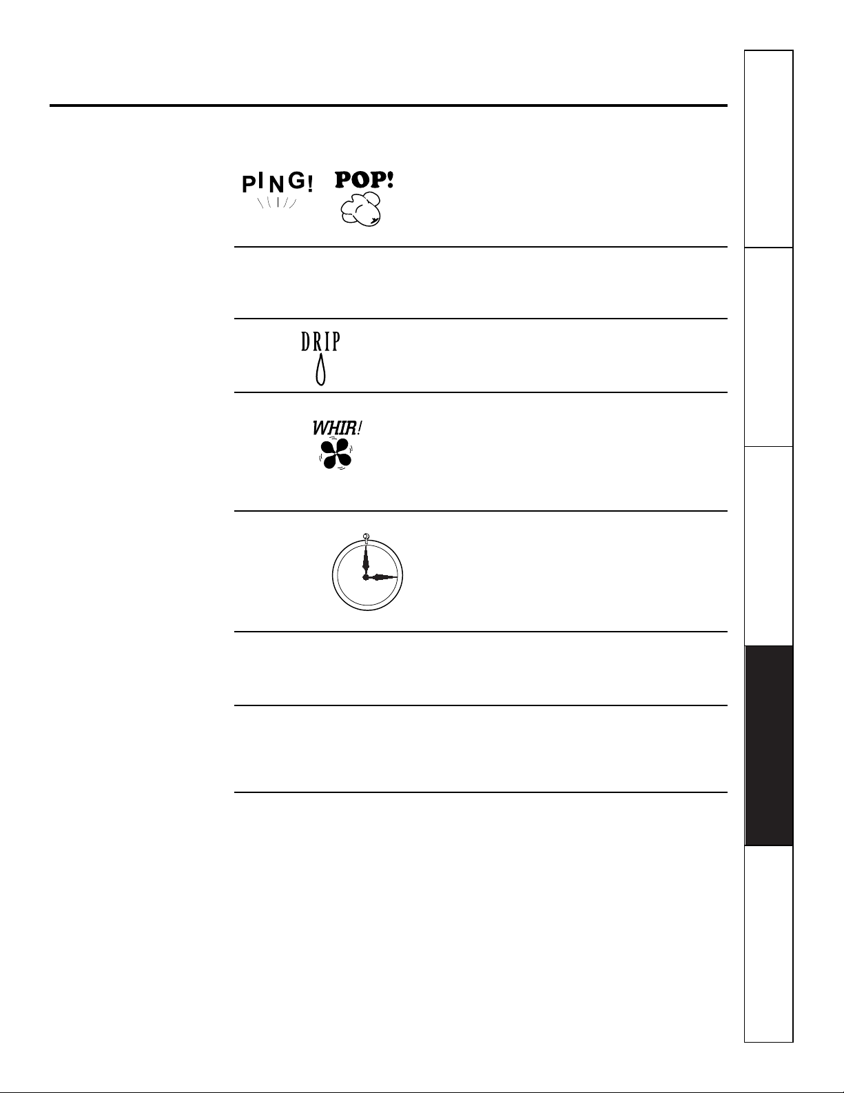
Normal Operating Sounds
You may hear a pinging noise caused by water being
picked up and thrown against the condenser on
rainy days or when the humidity is high. This design
feature helps remove moisture and improve
efficiency.
You may hear relays click when the controls cycle
on and off or are adjusted to change the room
temperature.
Water will collect in the base pan during high
humidity or on rainy days. The water may overflow
and drip from the outdoor side of the unit.
The indoor fan runs continuously when the unit is
operating in the cooling mode, unless the fan switch
behind the room cabinet is set at fan cycle (up).
This will cause the fan to cycle on and off with the
compressor. You may also hear a fan noise stop
and start.
You may notice a few minutes delay in starting if you
try to restart the Zoneline too soon after turning it
off or if you adjust the thermostat right after the
compressor has shut off. This is due to a built-in
restart protector for the compressor that causes
a 3-minute delay.
The compressor shuts off during the defrost cycle.
Full resistance heat comes on during the defrost
cycle to maintain room comfort.
To protect the compressor and prevent short
cycling, the unit is designed to run for a minimum
of 3 minutes, after the compressor starts at any
thermostat setting.
Things that are normal.
www.GEAppliances.com
3-Minute
Delay
“CLICK”
SILENCE
COMPRESSOR
PROTECTION

22
Notes.
Customer Service Troubleshooting Tips Care and Cleaning Operating Instructions Safety Instructions

Safety Instructions Operating Instructions Care and Cleaning Troubleshooting Tips Customer Service
23
Notes.
24
Notes.
Customer Service Troubleshooting Tips Care and Cleaning Operating Instructions Safety Instructions

25
General Electric Company
Warranty Registration Department
P.O. Box 32150
Louisville, KY 40232-2150
Please place in envelope and mail to:
✁
Cut here
Consumer Product Ownership Registration
Important
Mail
Today!
General Electric Company
Louisville, Kentucky
www.GEAppliances.com
First
Name
Mr. ■■ Ms. ■■ Mrs. ■■ Miss ■■
Street
Address
City
State
Date Placed
In Use
Month
Day
Year
Zip
Code
Apt. #
Last
Name
Phone
Number
_
_
Consumer Product Ownership Registration
Dear Customer:
Thank you for purchasing our product and thank you for placing your confidence in us.
We are proud to have you as a customer!
Follow these three steps to protect your new appliance investment:
Important: If you did not get a registration card with your
product, detach and return the form below to
ensure that your product is registered, or register
online at www.GEAppliances.com.
1
23
Model Number Serial Number
✁
Cut here
Complete and mail
your Consumer
Product Ownership
Registration today.
Have the peace of
mind of knowing we
can contact you in
the unlikely event of
a safety modification.
After mailing the
registration below,
store this document
in a safe place. It
contains information
you will need should
you require service.
Our service number is
800.GE.CARES
(800.432.2737).
Read your Owner’s
Manual carefully.
It will help you
operate your new
appliance properly.
Model Number Serial Number
E-mail Address*
* Please provide your e-mail address to receive, via e-mail, discounts, special offers and other important
communications from GE Appliances (GEA).
■■ Check here if you do not want to receive communications from GEA’s carefully selected partners.
26
Safety Instructions Operating Instructions Care and Cleaning Troubleshooting Tips Customer Service
27
Zoneline Warranty.
For The Period Of: GE Will Replace:
One Year Any part
of the Zoneline which fails due to a defect in materials or workmanship. During this
From the date of the full one-year warranty,
GE will also provide,
free of charge,
all labor and on-site service to
original purchase
replace the defective part.
Five Years Any part of the sealed refrigerating system
(the compressor, condenser, evaporator and all
From the date of the
connecting tubing) which fails due to a defect in materials or workmanship. During this
original purchase full five-year sealed refrigerating system warranty,
GE will also provide,
free of charge,
all labor
and on-site service to replace the defective part.
Five Years
For the
second through the fifth year
from the date of original purchase, GE will replace
From the date of the certain parts
that fail due to a defect in materials or workmanship. Parts covered are fan
original purchase
motors, switches, thermostats, heater, heater protectors, compressor overload, solenoids,
circuit boards, auxiliary controls, thermistors, frost controls, ICR pump, capacitors,
varistors and indoor blower bearing. During this
limited four-year parts warranty,
you will be
responsible for any labor or on-site service costs.
■ Service trips to your site to teach you how to use the
product.
■ Improper installation.
■ If you have an installation problem, or if the air
conditioner is of improper cooling capacity for the
intended use, contact your dealer or installer. You are
responsible for providing adequate electrical
connecting facilities.
■ In commercial locations, labor necessary to move the
unit to a location where it is accessible for service by an
individual technician.
■ Failure or damage resulting from corrosion due to
installation in an environment containing corrosive
chemicals.
■ Replacement of fuses or resetting of circuit breakers.
■ Failure of the product resulting from modifications to
the product or due to unreasonable use including
failure to provide reasonable and necessary
maintenance.
■ Failure or damage resulting from corrosion due to
installation in a coastal environment, except for models
treated with special factory-applied anti-corrosion
protection as designated in the model number.
■ Damage to product caused by improper power supply
voltage, accident, fire, floods or acts of God.
■ Incidental or consequential damage to personal
property caused by possible defects with this air
conditioner.
What GE Will Not Cover:
This warranty is extended to the original purchaser and any succeeding owner for products purchased for use
within the USA and Canada. In Alaska, the warranty excludes the cost of shipping or service calls to your site.
Some states or provinces do not allow the exclusion or limitation of incidental or consequential damages. This
warranty gives you specific legal rights, and you may also have other rights which vary from state to state or
province to province. To know what your legal rights are, consult your local, state or provincial consumer
affairs office or your state’s Attorney General.
Warrantor: General Electric Company. Louisville, KY 40225
All warranty service provided by our Factory Service Centers,
or an authorized Customer Care
®
technician. To schedule service,
on-line, 24 hours a day, visit us at www.GEAppliances.com,
or call 800.GE.CARES (800.432.2737). For service in Canada,
call 1.800.361.3400.
Staple your receipt here.
Proof of the original purchase
date is needed to obtain service
under the warranty.
Printed in China
Consumer Support.
GE Appliances Website
www.GEAppliances.com
Have a question or need assistance with your appliance? Try the GE Appliances Website 24 hours a day,
any day of the year! For greater convenience and faster service, you can now download Owner’s Manuals,
order parts, catalogs, or even schedule service on-line. You can also “Ask Our Team of Experts
™
”
your questions, and so much more...
Schedule Service
www.GEAppliances.com
Expert GE repair service is only one step away from your door. Get on-line and schedule your service at
your convenience 24 hours any day of the year! Or call 800.GE.CARES (800.432.2737) during normal
business hours.
Real Life Design Studio
www.GEAppliances.com
GE supports the Universal Design concept—products, services and environments that can be used by
people of all ages, sizes and capabilities. We recognize the need to design for a wide range of physical and
mental abilities and impairments. For details of GE’s Universal Design applications, including kitchen
design ideas for people with disabilities, check out our Website today. For the hearing impaired, please call
800.TDD.GEAC (800.833.4322).
Parts and Accessories
www.GEAppliances.com
Individuals qualified to service their own appliances can have parts or accessories sent directly to their
homes (VISA, MasterCard and Discover cards are accepted). Order on-line today, 24 hours every day or
by phone at 800.626.2002 during normal business hours.
Instructions contained in this manual cover procedures to be performed by any user. Other servicing generally
should be referred to qualified service personnel. Caution must be exercised, since improper servicing may cause
unsafe operation.
Contact Us
www.GEAppliances.com
If you are not satisfied with the service you receive from GE, contact us on our Website with all the details
including your phone number, or write to: General Manager, Customer Relations
GE Appliances, Appliance Park
Louisville, KY 40225
Register Your Appliance
www.GEAppliances.com
Register your new appliance on-line—at your convenience! Timely product registration will allow for
enhanced communication and prompt service under the terms of your warranty, should the need arise.
You may also mail in the pre-printed registration card included in the packing material, or detach and
use the form in this Owner’s Manual.


