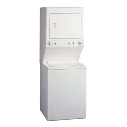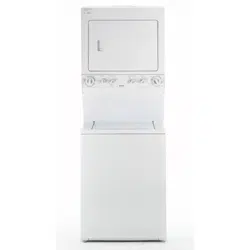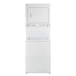
27" (69 cm) Wide
LAUNDRY CENTER
Washer- Dryer
Installation Instructions
CENTRO DE LAVANDERiA
de 27" (69 cm) de ancho
Lavadora - Secadora
Instrucciones para la instalaci6n
J
I
i
\
Table Of Contents
S UBJECT PAGE
Pre-lnstallation Requirements ............................... 2
Electrical Requirements .......................................... 3
Water Supply Requirements .................................... 3
Drain Requirements ................................................. 3
Exhaust System Requirements ................................. 4-5
Gas Supply Requirements ........................................... 5
Location ................................................................... 5
Rough-In Dimensions ............................................. 6
Mobile Home Installation ........................................... 7
Unpacking .............................................................. 7
Electrical Installation ................................................. 8
Grounding Requirements ......................................... 8
3 & 4-Wire Connections ............................................ 9
Installation ....................................................... 10-11
Replacement Parts ................................................. 11
PIN 134809300C (0904)
Indice
MA TERIA PA GINA
Requerimientos de instalacion preliminares .................... 12
Requerimientos electricos ........................................... 13
Requerimientos del sumin istro de agua .......................... 13
Requenmlentos de desagOe .......................................... 13
Requerimientos del sistema de escape ..................... 14-15
Requerimientos del suministro de gas............................. 15
Ubicacidn ....................................................................... 15
Dimensiones para la instalaci6n ..................................... 16
Instalaci6n en casas m6viles ........................................ 17
Desembalaje ........................................................................ 17
Instalaci6n electrica ..................................................... 18
Requerimientos para la puesta a tierra ........................... 18
Conexi6nes electricas - trifilares y tetrafilares .......... 18-19
Instalaci6n .............................................................. 19-20
Repuestos ................................................................... 20
Sears, Roebuck and Co., Hoffman Estates, IL 60179 U.S.A. www.sears.com
_This isthe safety alert symbol. This symbol alerts you to hazards that can kill or hurt you or others. All safety messages will
be preceded by the safety alert symbol and the word "DANGER" or "WARNING ". Thesewords mean:
You can be killed or seriously injured if you don't immediately follow instructions.
You can be killed or seriously injured if you don't follow instructions.
All safety messages will identify the hazard, tell you how to reduce the chance of injury, and tell you what can happen if the
instructions are not followed.
Foryour safety the information in this manual must be followed to minimize the risk of fire or
explosion or to prevent property damage, personal injury or loss of life. Do not store or use gasoline or other flammable vapors
and liquid in the vicinity of this or any other appliance.
Readall of the following instructions before installing and using this appliance.
• Destroy the carton and plastic bags after the Laundry Center is unpacked. Children might use them for play. Cartons
covered with rugs, bedspreads, or plasic sheets can become airtight chambers causing suffocation. Placeall materials in a
garbage container or make materials inaccessible to children.
Installations must be performed by a qualified or licensed contractor, plumber, or gasfitter qualified or license by the state,
province, or region where this appliance is being installed.
Before beginning installation, carefully read these instructions. Thiswill simplify the installation and ensure the Laundry Center
is installed correctly and safely. Leavethese instructions near the Laundry Center after installation for future reference.
The electrical serviceto the Laundry Center must conform with local codes and ordinances and the latest edition of the National
Electrical Code, ANSI/NFPA70, or in Canada, the Canadian electrical code C22.1 part 1.
The gasserviceto the Laundry Center must conform with local codes and ordinances and the latest edition of the National Fuel
GasCode ANSI Z223.1, or in Canada, CAN/ACG B149.1-2000.
The Laundry Center isdesigned under ANSI Z 21.5.1 or ANZl/UL 2158 - CAN/CSA C22.2 No. 112 (latest editions) for HOME
USEonly. This Laundry Center is not recommended for commercial applications such as restaurants or beauty salons, etc.
Do not install a Laundry Center with flexible plastic venting materials. Flexible venting materials are known to collapse, be
easily crushed and trap lint. These conditions will obstruct clothes dryer airflow and increase the risk of fire.
Your safety and the safety of others isvery important. We have provided many important safety messages in the
Installation Instructions / Use & Care Guide and on your appliance. Always read and obey all safety messages.
The instructions in this manual and other literature included with this dryer are not meant to cover every possible condition and
situation that may occur. Good safe practice and caution MUST be applied when installing, operating and maintaing any
appliance.
WHAT TO DO IF YOU SMELL GAS
Do not try to light any appliance.
Do not touch any electrical switch; do not use any phone in your building.
Clear the room, building or area of all occupants.
Immediately call your gas supplier from a neighbor's phone. Follow the gassupplier's instructions.
If you cannot reach your gas supplier, call the fire department.
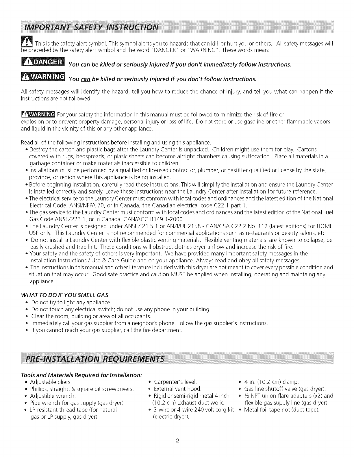
Tools and Materials Required for Installation:
Adjustable pliers.
Phillips, straight, & square bit screwdrivers.
Adjustible wrench.
Pipe wrench for gas supply (gas dryer).
LP-resistant thread tape (for natural
gas or LPsupply, gas dryer)
Carpenter's level.
External vent hood.
Rigid or semi-rigid metal 4 inch
(10.2 cm) exhaust duct work.
3-wire or 4-wire 240 volt corg kit
(electric dryer).
4 in. (10.2 cm) clamp.
Gas line shutoff valve (gas dryer).
1/2NPTunion flare adapters (x2) and
flexible gas supply line (gas dryer).
Metal foil tape not (duct tape).
[
ELECTRICLaundry Center
CIRCUIT- Individual 30 amp. branch circuit fused with 30
amp. time delay fuses or circuit breakers.
Use separately fused circuits for washers and dryers, and DO
NOToperate a washer and a dryer on the same circuit.
POWER SUPPLY- 3 wire or 4-wire, 240 volt, single phase, 60
Hz, Alternating Current.
]
POWER SUPPLYCORD KIT- 3 wire - the dryer MUSTemploy
a 3-conductor power supply cord NEMA 10-30 type SRDTrated
at 240 volt AC minimum, 30 amp., with 3 open end spade lug
connectors with upturned ends or closed loop connectors and
marked for use with clothes dryers. See ELECTRICAL
CONNECTIONSFORA 3-WIRE SYSTEM.
4 wire - The dryer MUSTemploy a 4-conductor power supply
cord NEMA 14-30 type SRDTor ST(as required) rated at 240
volt AC minimum, 30 amp., with 4 open end spade lug
connectors with upturned ends or closed loop connectors and
marked for use with clothes dryers. See ELECTRICAL
CONNECTIONSFORA 4-WIRE SYSTEM.
(Canada - 4-wire power supply cord is installed on dryer.)
WARNING- Risk of Shock. Appliance grounded to neutral
conductor through a link. Grounding through the neutral link is
prohibited for (1) New branch circuit installations (2) mobile
homes; (3) recreational vehicles; and (4) areaswhere local codes
do not permit grounding through the neutral, (1) disconnect the
link from the neutral, (2) use grounding terminal or lead to
ground appliance in accordancewith localcodes and (3) connect
neutral terminal or lead to branch circuit neutral in usual manner
(if the appliance isto be connected by means of a cord kit, use
4-conductor cord for this purpose). USECOPPERCONDUCTOR
ONLY.
OUTLET RECEPTACLE- NEMA 10-30R receptacle to be located
so the power supply cord is accessible when the dryer is in the
installed position. (Canada - NEMA 14-30R receptacle.)
NEMA 10-30R NEMA 14-30R
[ GASLaundryCenter ]
CIRCUIT- Individual 15 amp minimum branch circuit fused with
a time delay fuse or circuit breaker.
POWER SUPPLY-3 wire, 120 volt single phase, 60 Hz,
Alternating Current.
POWER SUPPLY CORD -The gas laundry center is equipped
with a 120 volt 3-wire power cord.
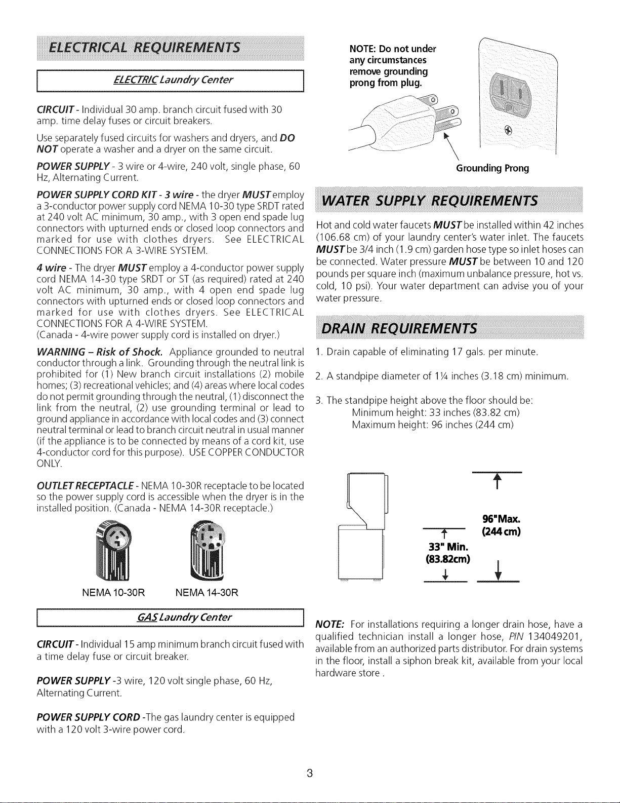
NOTE:Do not under
any circumstances
remove grounding
prong from plug.
\
Grounding Prong
Hot and cold water faucets MUSTbe installed within 42 inches
(106.68 cm) of your laundry center's water inlet. The faucets
MUSTbe 3/4 inch (1.9 cm) garden hose type soinlet hoses can
be connected. Water pressure MUST be between 10 and 120
pounds per square inch (maximum unbalance pressure, hot vs.
cold, 10 psi). Your water department can advise you of your
water pressure.
1. Drain capable of eliminating 17 gals. per minute.
2. A standpipe diameter of 11/4inches (3.18 cm) minimum.
3. The standpipe height above the floor should be:
Minimum height: 33 inches (83.82 cm)
Maximum height: 96 inches (244 cm)
m
f
96"Max.
? (244cm)
33" Min.
(83.82cm)
NOTE: For installations requiring a longer drain hose, have a
qualified technician install a longer hose, PIN 134049201,
available from an authorized parts distributor. Fordrain systems
in the floor, install a siphon break kit, available from your local
hardware store.
3
Use only 4 inch (10.2 cm) diameter (minimum) rigid or flexible
metal duct and approved vent hood which has a swing-out
damper(s) that open when the dryer is in operation. When the
dryer stops, the dampers automatically close to prevent drafts
and the entrance of insects and rodents. Toavoid restricting the
outlet, maintain a minimum of 12 inches (30.5 cm) clearance
between the vent hood and the ground or any other obstruction.
The following are specific requirements for
proper and safe operation of your dryer. Failure to follow
these instructions can create excessive drying times and
fire hazards.
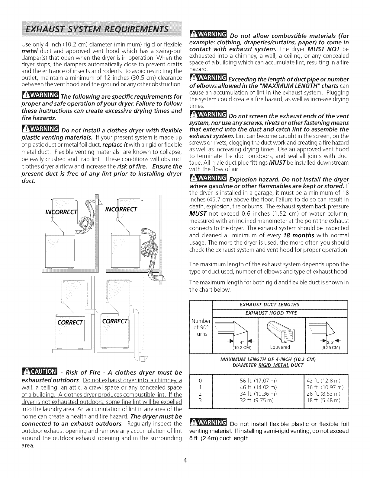
Do not install a dothes dryer with flexible
plastic venting materials. If your present system is made up
of plasticduct or metal foil duct, replace itwith a rigid or flexible
metal duct. Flexible venting materials are known to collapse,
be easily crushed and trap lint. These conditions will obstruct
clothes dryer airflow and increase the risk of fire. Ensure the
present duct is free of any lint prior to installing dryer
duct.
L
7
- Risk of Fire - A clothes dryer must be
exhausted outdoors. Do not exhaust dryer into a chimney, a
wall, a ceiling, an attic, a crawl space or any concealed space
of a building A clothes dryer produces combustible lint. If the
dryer is not exhausted outdoors some fine lint will be expelled
into the laundry area. An accumulation of lint in any area of the
home can create a health and fire hazard. The dryer must be
connected to an exhaust outdoors. Regularly inspect the
outdoor exhaust opening and remove any accumulation of lint
around the outdoor exhaust opening and in the surrounding
area.
Do not allow combustible materials (for
example: dothing, draperies/curtains, paper) to come in
contact with exhaust system. The dryer MUST NOT be
exhausted into a chimney, a wall, a ceiling, or any concealed
space of a building which can accumulate lint, resulting in a fire
hazard.
Exceeding the length of duct pipe or number
of elbows allowed in the "MAXIMUM LENGTH" charts can
cause an accumulation of lint in the exhaust system. Plugging
the system could create a fire hazard, aswell as increase drying
times.
Do not screen the exhaust ends of the vent
system, nor use any screws, rivets or other fastening means
that extend into the duct and catch lint to assemble the
exhaust system. Lint can become caught in the screen, on the
screwsor rivets,clogging the duct work and creating a fire hazard
aswell as increasing drying times. Use an approved vent hood
to terminate the duct outdoors, and seal all joints with duct
tape. All male duct pipe fittings MUSTbe installed downstream
with the flow of air.
Explosion hazard. Do not install the dryer
where gasoline or other flammables are kept or stored. If
the dryer is installed in a garage, it must be a minimum of 18
inches (45.7 cm) above the floor. Failure to do so can result in
death, explosion, fire or burns. The exhaust systemback pressure
MUST not exceed 0.6 inches (1.52 cm) of water column,
measured with an inclined manometer at the point the exhaust
connects to the dryer. The exhaust system should be inspected
and cleaned a minimum of every 18 months with normal
usage. The more the dryer is used, the more often you should
check the exhaust system and vent hood for proper operation.
The maximum length of the exhaust system depends upon the
type of duct used, number of elbows and type of exhaust hood.
The maximum length for both rigid and flexible duct isshown in
the chart below.
Number
of 90°
Turns
EXHAUST DUCT LENGTHS
EXHAUST HOOD TYPE
(10.2 CM) Louvered
MAXIMUM LENGTH OF 4-INCH (10.2 CM)
DIAMETER RIGID METAL DUCT
_ 2.5"
(6_
0
1
2
3
56 ft. (17.07 m)
46 ft. (14.02 m)
34ft. (10.36 m)
32 ft. (9.75 m)
42 ft. (12.8 m)
36 ft. (10.97 m)
28 ft. (8.53 m)
18 ft. (5.48 m)
Do not install flexible plastic or flexible foil
venting material. Ifinstalling semi-rigid venting, do not exceed
8 ft. (2.4m) duct length.
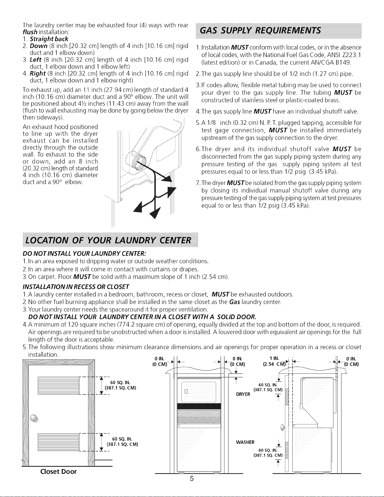
Thelaundrycentermaybeexhaustedfour(4)wayswithrear
flushinstallation:
1.Straight back
2. Down (8 inch [20.32 cm] length of 4 inch [10.16 cm] rigid
duct and 1 elbow down)
3. Left (8 inch [20.32 cm] length of 4 inch [10.16 cm] rigid
duct, 1 elbow down and 1 elbow left)
4. Right (8 inch [20.32 cm] length of 4 inch [10.16 cm] rigid
duct, 1 elbow down and 1 elbow right)
To exhaust up, add an 11 inch (27.94 cm) length of standard 4
inch (10.16 cm) diameter duct and a 90° elbow. The unit will
be positioned about 41/2inches (11.43 cm) away from the wall
(flush to wall exhausting may be done by going below the dryer
then sideways).
An exhaust hood positioned
to line up with the dryer
exhaust can be installed
directly through the outside
wall. To exhaust to the side
or down, add an 8 inch
(20.32 cm) length of standard
4 inch (10.16 cm) diameter
duct and a 90° elbow.
DO NOT INSTALL YOUR LAUNDRY CENTER:
......
1.Installation MUST conform with local codes, or in the absence
of local codes, with the National FuelGasCode, ANSI Z223.1
(latest edition) or in Canada, the current AN/CGA B149.
2.The gas supply line should be of 1/2 inch (1.27 cm) pipe.
3.If codes allow, flexible metal tubing may be used to connect
your dryer to the gas supply line. The tubing MUST be
constructed of stainless steel or plastic-coated brass.
4.The gas supply line MUSThave an individual shutoff valve.
5.A 1/8 inch (0.32 cm) N. F T. plugged tapping, accessible for
test gage connection, MUST be installed immediately
upstream of the gas supply connection to the dryer.
6.The dryer and its individual shutoff valve MUST be
disconnected from the gas supply piping system during any
pressure testing of the gas supply piping system at test
pressures equal to or less than 1/2 psig (3.45 kPa).
7.The dryer MUSTbe isolated from the gassupply piping system
by closing its individual manual shutoff valve during any
pressuretesting of the gassupply piping systemattest pressures
equal to or less than 1/2 psig (3.45 kPa).
1.In an area exposed to dripping water or outside weather conditions.
2.In an area where it will come in contact with curtains or drapes.
3.On carpet. Floor MUSTbe solid with a maximum slope of 1 inch (2.54 cm).
INSTALLATION IN RECESSOR CLOSET
1.A laundry center installed in a bedroom, bathroom, recessor closet, MUSTbe exhausted outdoors.
2.No other fuel burning appliance shall be installed in the same closet asthe Gas laundry center.
3.Your laundry center needs the spacearound it for proper ventilation.
DO NOT INSTALL YOUR LAUNDRY CENTER IN A CLOSET WITH A SOLID DOOR.
4.A minimum of 120 square inches (774.2 square cm) of opening, equally divided at the top and bottom of the door, is required.
Air openings are required to be unobstructed when a door isinstalled. A Iouvered door with equivalent air openings for the full
length of the door isacceptable.
5.The following illustrations show minimum clearance dimensions and air openings for proper operation in a recess or closet
installation.
0 IN.
0 IN. 1 IN. ; ; ',', 0 IN.
(0 _(0 c
M) (2.54CM)'I,,_ _(0 CM)
60 SQ.iN. 60SQ._N.
(387.1 SQ. CM) (387.1 SQ. CM) I_ II III
(387.1 SQ. CM)
60 SQ. IN. _ I
Closet Door
5
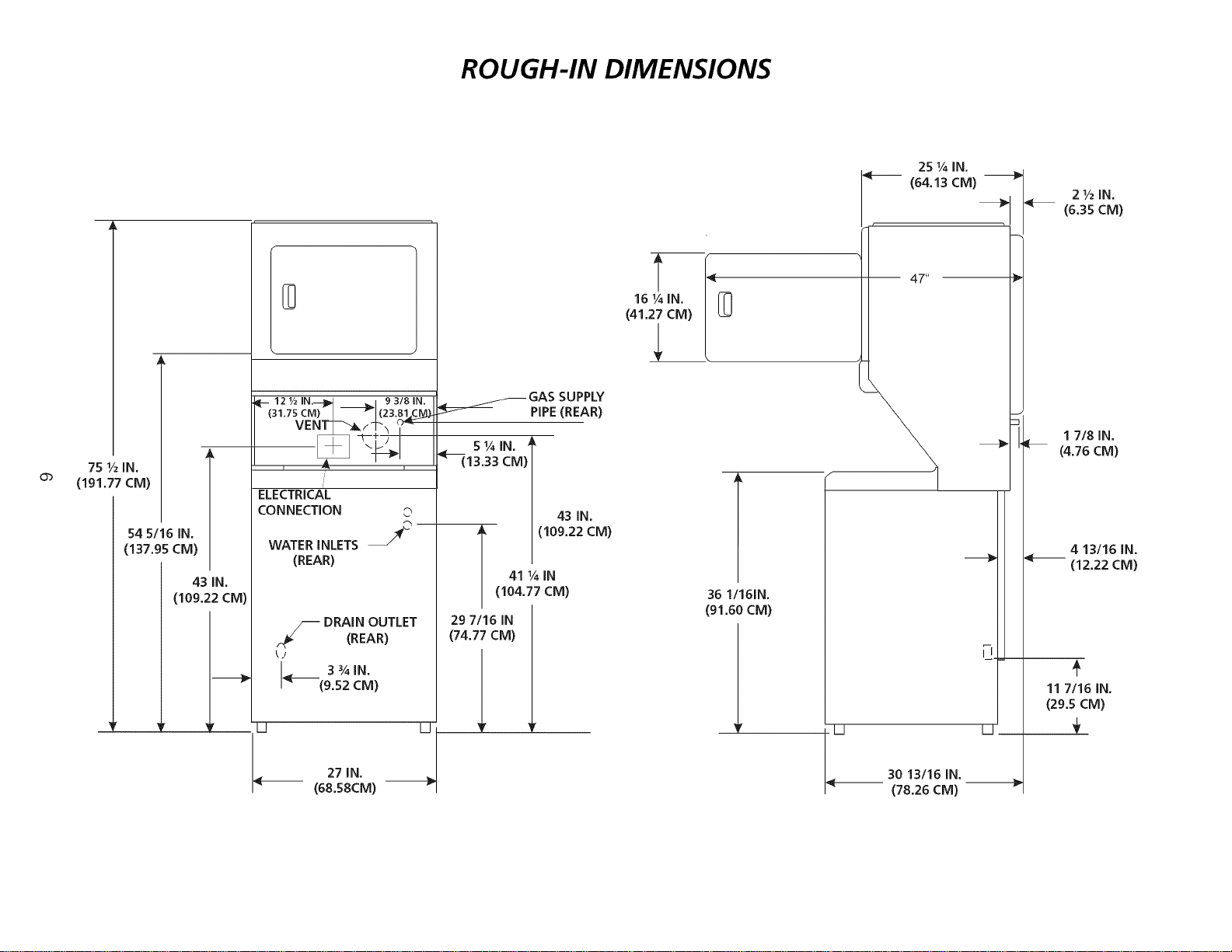
ROUGH-IN DIMENSIONS
75 1/2IN,
(191,77 CM)
54 5/16 IN,
(137.95 CM)
43 IN.
(109.22 CM)
D
II-- 121/2 IN.--]II_I _ , 93181N.
(31.75 CM) _ _1(23"81_C_
VENT_I_ _,_'_
ELECTRICAL
CONNECTION ©
WATER INLETS J_
(REAR)
_._/_ DRAIN OUTLET
(REAR)
<__ 3%1N,
(9,52 CM)
II D
27 IN.
(68,58CM)
_.____._ GAS SUPPLY
PIPE(REAR)
13.33 CM)
43 IN.
A (109.22 CM)
41 ¼ IN
(104.77 CM)
29 7/16 IN
(74.77 CM)
16 ¼ IN,
(41,27 CM)
U
l
36 1/161N.
(91.60CM)
30 13116 IN.
(78.26 CM)
II
1.Dryer MUST be exhausted outside (outdoors, not beneath the mobile
home) using metal ducting that will not support combustion. Metal II
ducting must be 4 inches (10.16 cm)in diameter with no obstructions.
Rigid metal duct is preferred.
2.If dryer is exhausted through the floor and area beneath the mobile
home is enclosed, the exhaust system MUST terminate outside the
enclosure with the termination securely fastened to the mobile home ___
structure.
3.Refer to page 4 for other important venting requirements.
4.When installing a gas dryer into a mobile home, a provision must be
made for outside make up air. This provision isto be not lessthan twice
the area of the dryer exhaust outlet.
5.Installation MUSTconform to current Manufactured Home Construction
& Safety Standard (which is a Federal Regulation Title 24 CFR-Part 32-
80) or when such standard is not applicable, with American National
Standard for Mobile Homes. In Canada, the CSA Z240 is applicable.
_The laundry center isdesigned under ANSI Z 21.5.1for HOME USEonly.
iiii
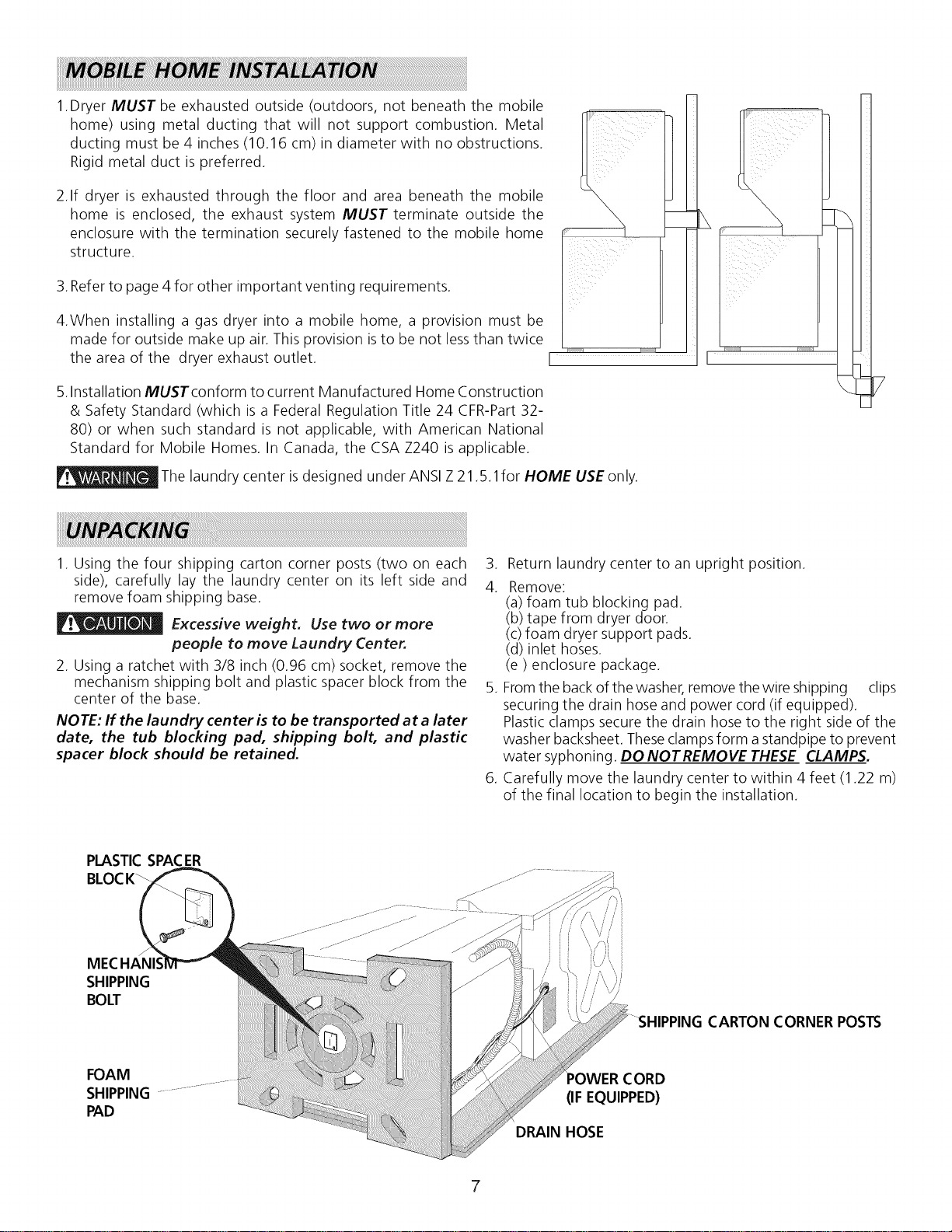
1. Using the four shipping carton corner posts (two on each 3.
side), carefully lay the laundry center on its left side and 4.
remove foam shipping base.
_v_ Excessive weight. Use two or more
people to move Laundry Center.
2. Using a ratchet with 3/8 inch (0.96 cm) socket, remove the
mechanism shipping bolt and plastic spacer block from the 5.
center of the base.
NOTE: If the laundry center is to be transported at a later
date, the tub blocking pad, shipping bolt, and plastic
spacer block should be retained.
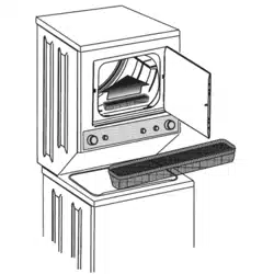
.
Return laundry center to an upright position.
Remove:
(a) foam tub blocking pad.
(b) tape from dryer door.
(c)foam dryer support pads.
(d) inlet hoses.
(e) enclosure package.
Fromthe back of the washer, remove the wire shipping clips
securing the drain hose and power cord (if equipped).
Plastic clamps secure the drain hose to the right side of the
washer backsheet. Theseclamps form a standpipe to prevent
water syphoning. DO NOTREMOVE THESE CLAMPS.
Carefully move the laundry center to within 4 feet (1.22 m)
of the final location to begin the installation.
PLASTICSPACER
BLOCK_
MECHANIS
SHIPPING
BOLT
CARTON CORNER POSTS
FOAM
SHIPPING ......
PAD
CORD
(IF EQUIPPED)
DRAIN HOSE
7
i ALL ELECTRICLaundry Centers 1
_The following are specific requirements for
proper and safe electrical installation of your laundry center.
Failure to follow these instructions can create electrical shock
and/or a fire hazard.
_This appliance MUST be properly grounded.
Electrical shock can result if the laundry center isnot properly
grounded. Follow the instructions in this manual for proper
grounding.
Do not use an extension cord with this
laundry center. Some extension cords are not designed to
withstand the amounts of electrical current this laundry center
utilizes and can melt, creating electrical shock and/or fire hazard.
Locate the laundry center within reach of the receptacle for the
length power cord to be purchased, allowing some slack in the
cord. Refer to the pre-installation requirements in this manual
for the proper power cord to be purchased.
A U.L approved strain relief must be
installed onto power cord. If the strain relief isnot attached, the
cord can be pulled out of the laundry center and can be cut by
any movement of the cord, resulting in electrical shock.
Ir : 1,1,_I_!,1_1._ Do not use an aluminum wired receptacle
with a copper Wired power cord and plug (or vice versa). A
chemical reaction occurs between copper and aluminum and
can cause electrical shorts.
The proper wiring and receptacle is a copper wired power
cord with a copper wired receptacle OR aluminum wired
power cord with an aluminum wired receptacle.
NOTE: Laundry centers operating on a 208 volt power supply
will have longer drying times than laundry centers operating on
a 240 volt power supply.
GROUNDING REQUIREMENTS
I Non-Canadian ELECTRICLaundry Center I
_ Improper connection of the equipment
grounding conductor can result in a risk of electrical shock.
Check with a licensed electrician if you are in doubt asto whether
the appliance isproperly grounded.
For a grounded cord-connected laundry center:
1. The laundry center MUST be grounded. In the event of
malfunction or breakdown, grounding will reduce the risk of
electrical shock by a path of least resistance for electrical
current.
.
If your laundry center isequipped with a power supply cord
having an equipment-grounding conductor and a grounding
plug, the plug MUSTbe plugged into an appropriate, copper
wired receptacle that is properly installed and grounded in
accordance with all local codes and ordinances. If in doubt,
call a licensed electrician. Do not modify plug provided
with the appliance.
For a permanently connected laundry center:
The laundry center MUST be connected to a grounded metal,
permanent wiring system; or an equipment grounding conductor
MUST be run with the circuit conductors and connected to the
equipment-grounding terminal or lead on the appliance.
{
Canadian ELECTRICLaundry Center
1
_lmproper connection of the equipment
grounding conductor can result in a risk of electrical shock.
Check with a licensed electrician if you are in doubt as to
whether the appliance is properly grounded.
For a grounded cord connected laundry center:
1. The laundry center MUST be grounded. In the event of
malfunction or breakdown, grounding will reduce the risk of
electrical shock by providing a path of least resistance for
the electrical current.
.
Since your laundry center is equipped with a power supply
cord having an equipment-grounding conductor and a
grounding plug, the plug MUST be plugged into an
appropriate outlet that isproperly installed and grounded in
accordance with all codes and ordinances. If in doubt, call a
licensed electrician.
I
ALL GASLaundry Centers
I
1. Thelaundry center isequipped with a three-prong (grounding)
plug for your protection against shock hazard and should
be plugged directly into a properly grounded three-prong
receptacle. Do not cut or remove the grounding prong from
the plug.
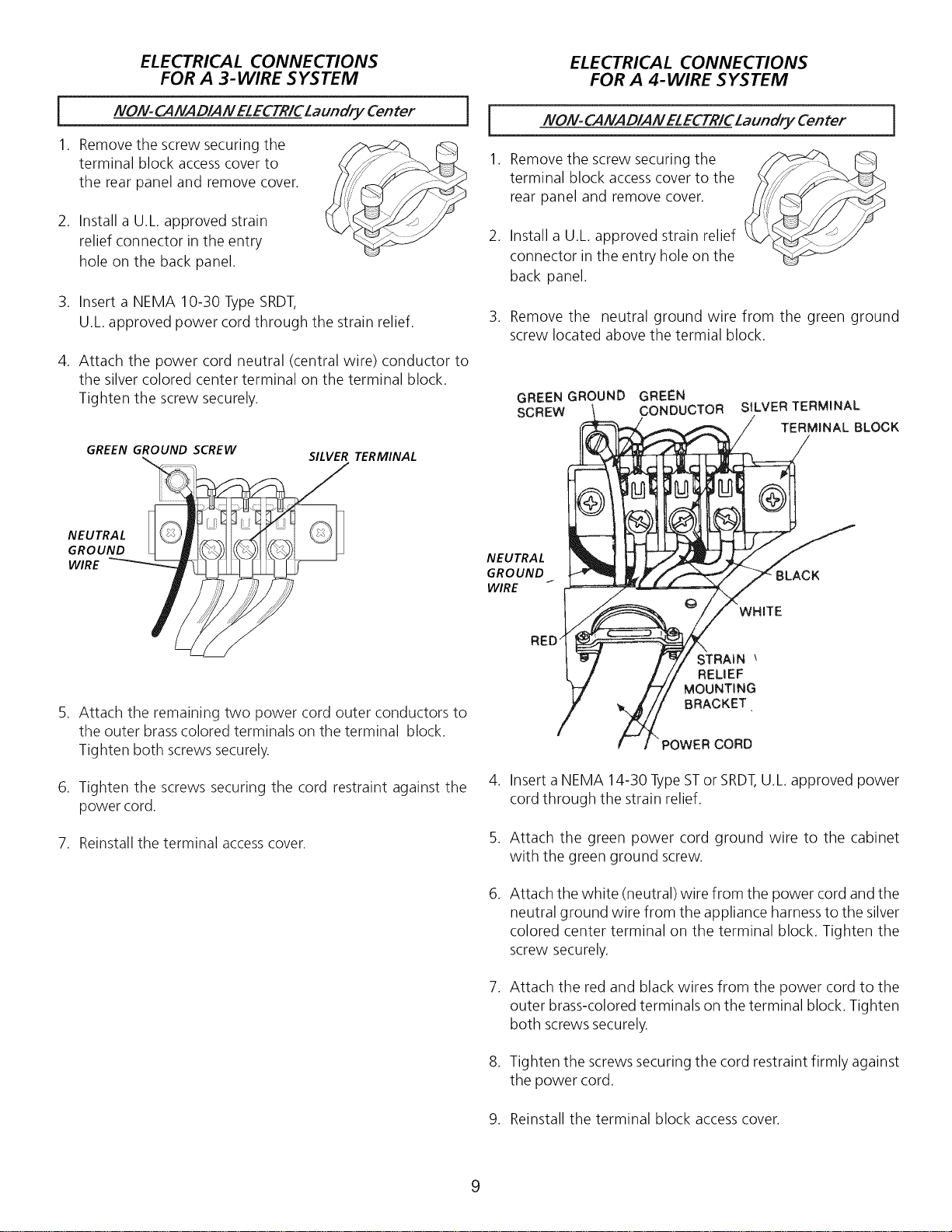
ELECTRICAL CONNECTIONS
FOR A 3- WIRE SYSTEM
NO!V-CANAD/AN ELECTR/CLaundry Center
1. Remove the screw securing the
terminal block access cover to
the rear panel and remove cover.
2. Install a U.L approved strain
relief connector in the entry
hole on the back panel.
3. Insert a NEMA 10-30 Type SRDT,
U.L approved power cord through the strain relief.
4. Attach the power cord neutral (central wire) conductor to
the silver colored center terminal on the terminal block.
Tighten the screw securely.
GREEN GROUND SCREW
SILVER TERMINAL
ELECTRICAL CONNECTIONS
FOR A 4- WIRE SYSTEM
!VON-CANAD/AN ELECTR/CLaundry Center
1. Remove the screw securing the
terminal block access cover to the
rear panel and remove cover.
.
.
Install a U.L approved strain relief
connector in the entry hole on the
back panel.
Remove the neutral ground wire from the green ground
screw located above the termial block.
GREEN GROUND GREEN
SCREW CONDUCTOR SILVER TERMINAL
TERMINAL BLOCK
NEUTRAL
GROUND
WIRE
NEUTRAL
GROUND
WIRE
BLACK
WHITE
,
,
Attach the remaining two power cord outer conductors to
the outer brass colored terminals on the terminal block.
Tighten both screws securely.
Tighten the screws securing the cord restraint against the
power cord.
7. Reinstall the terminal accesscover.
STRAIN "
RELIEF
MOUNTING
BRACKET,
.
POWER CORD
Insert a NEMA 14-30 Type STor SRDT,U.L approved power
cord through the strain relief.
.
.
.
.
Attach the green power cord ground wire to the cabinet
with the green ground screw.
Attach the white (neutral) wire from the power cord and the
neutral ground wire from the appliance harness to the silver
colored center terminal on the terminal block. Tighten the
screw securely.
Attach the red and black wires from the power cord to the
outer brass-colored terminals on the terminal block. Tighten
both screws securely.
Tighten the screws securing the cord restraint firmly against
the power cord.
9. Reinstall the terminal block access cover.
9
1. Runsome water from the hot and cold faucets to flush the
water lines and remove particles that might clog up the
water valve screens.
.
.
Check inlet hosesto ensurethe rubber washers are installed
in each end.
Carefully connect the inlet hoses to the water valve (on the
left sideof the washer cabinet),tighten by hand, then tighten
another 2/3 turn with pliers.
C.
d.
.
Open the shutoff valve in the gassupply line.
Testall connections by brushing on a soapy water solution.
NEVER TEST FOR GAS LEAKS WITH AN OPEN FLAME.
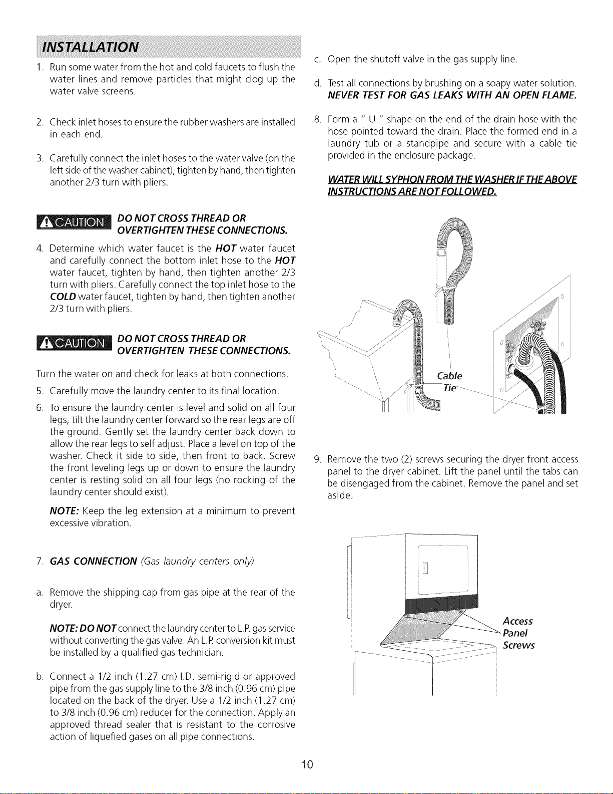
Form a " U " shape on the end of the drain hose with the
hose pointed toward the drain. Placethe formed end in a
laundry tub or a standpipe and secure with a cable tie
provided in the enclosure package.
WATERWILLSYPHON FROM THEWASHERIF THEABOVE
INSTRUCTIONS ARE NOTFOLLOWED.
DO NOT CROSS THREAD OR
-- OVERTIGHTEN THESECONNECTIONS.
. Determine which water faucet is the HOT water faucet
and carefully connect the bottom inlet hose to the HOT
water faucet, tighten by hand, then tighten another 2/3
turn with pliers. Carefully connect the top inlet hose to the
COLD water faucet, tighten by hand, then tighten another
2/3 turn with pliers.
DO NOT CROSS THREAD OR
-- OVERTIGHTEN THESECONNECTIONS.
Turn the water on and check for leaks at both connections.
5. Carefully move the laundry center to its final location.
6. To ensure the laundry center is level and solid on all four
legs, tilt the laundry center forward sothe rear legs are off
the ground. Gently set the laundry center back down to
allow the rear legs to self adjust. Placea level on top of the
washer. Check it side to side, then front to back. Screw
the front leveling legs up or down to ensure the laundry
center is resting solid on all four legs (no rocking of the
laundry center should exist).
NOTE: Keep the leg extension at a minimum to prevent
excessivevibration.
7. GAS CONNECTION (Gas/aundry centers on/y)
a.
b.
Remove the shipping cap from gas pipe at the rear of the
dryer.
NOTE: DO NOTconnect the laundry center to L Rgasservice
without converting the gasvalve.An LR conversion kit must
be installed by a qualified gas technician.
Connect a 1/2 inch (1.27 cm) I.D. semi-rigid or approved
pipe from the gassupply line to the 3/8 inch (0.96 cm) pipe
located on the back of the dryer. Use a 1/2 inch (1.27 cm)
to 3/8 inch (0.96 cm) reducer for the connection. Apply an
approved thread sealer that is resistant to the corrosive
action of liquefied gaseson all pipe connections.
Cable
Tie -
.
Remove the two (2) screws securing the dryer front access
panel to the dryer cabinet. Lift the panel until the tabs can
be disengaged from the cabinet. Remove the panel and set
aside.
10
10. Connect the exhaust duct to outside duct work. Use duct
tape to seal all joints.
11. Plugthe power cord into a grounded outlet.
12. Reinstall the dryer front accesspanel.
NOTE: Check to ensure the power isoff at a circuit breaker/
fuse box before plugging the power cord into an
outlet.
13. Turn on the power at a circuit breaker/fuse box.
If replacement parts are needed for your Laundry Center, call
SearsParts and Service TollFreeNumber 1-800-4-MY-HOMF M
(1-800-469-4663).
_ Destroy the carton, plastic bags, and metal
band after the laundry center isunpacked. Children might use
them for play. Cartons covered with rugs, bedspreads, or plastic
sheets can become airtight chambers causing suffocation. Place
all materials in a garbage container or make materials inaccessible
to children.
Label all wires prior to disconnection when
servicing controls. Wiring errors can cause improper and
dangerous operation. Verify proper operation after servicing.
Before operating the dryer, make
sure the dryer area is c/ear and free from
combustible materials, gasoline, and other
flammable vapors. Also see that nothing (such as
boxes, c/othing, etc.) obstructs the f/ow of
combustion and ventilation air.
14. Runthe washer and dryer though a cycle. Check for proper
operation.
The instructions in this manual and all other
literature included with this laundry center are not meant to
cover everypossible condition and situation that may occur.Good
safe practice and caution MUST be applied when installing,
operating and maintaining any appliance.
Maximum benefits and enjoyment are achieved when
all the Safetyand Operating instructions are understood
and practiced asa routine with your laundry tasks.
NOTE: On gas dryers, before the burner will light, it is
necessary for the gas line to be bled of air. If the burner
does not light within 45 seconds the first time the
dryer is turned on, the safety switch will shut the
burner off. If this happens, turn the timer to "OFF"
and wait 5 minutes before making another attempt to
light.
15. If your laundry center does not operate, please review the
"Avoid Service Checklist" located in your Owner's Guide
before calling for service.
16. Place these instructions in a location near the laundry
center for future reference.
NOTE: A wiring diagram is located behind the dryer front
access panel.
11
_Este simbolo significa alerta. Este simbolo Io alerta acerca de peligros que pueden matar o lesionar, tanto a usted como a
otras personas. Todoslos mensajesde seguridad set,in precedidos pot el simbolo de alerta para su seguridad y la palabra "PELIGRO
o ADVERTENCIA" (DANGER" o WARNING). Estaspalabras significan:
PELIGRO(DANGER) Usted morir_ o resultar_ seriamente lesionado si no sigue /asinstrucdones siguientes.
ADVERTENCIA (WARNING) Usted puede morir o resultar seriamente lesionado si no sigue /as
instrucciones siguientes.
Todos los mensajes de seguridad identificar_n el peligro, le dir_n a usted come reducir la posibilidad de lesion y
tambi_n qu_ puede suceder si no se siguen /as instrucdones.
R/ESGO DE/NCEND/O. Parasu seguridad, siga lasinstrucciones contenidas en este manual a fin de reducir
a un minimo los riesgos de incendio o explosi6n o para evitar dahos materiales, lesiones personales o la muerte. GUARDEESTAS
/NSTRUCC/ONES.
• Hemos proporcionado muchos mensajes importantes para la seguridad en las Instrucciones de Operaci6n del Manual de Uso y
Mantenimiento, las Instrucciones de Instalaci6n y en el mismo aparato. Siempre lea y obedezca todos los mensajes para
seguridad.La instalaci6n y el servicio de la centro de lavadaria de ropa sedeben realizar pot un instalador calificado, la agencia
de servicio o el surtidor de gas.
Instale la centro de lavadaria de ropa seg0n las instrucciones del fabricante y los cOdigos locales. Antes de comenzar la
instalaci6n, lea cuidadosamente estas instrucciones. Esto simplificar_i la instalaci6n y asegurar_i que la secadora se instale
correctamente y de manera segura. Despu_s de completar la instalaci6n, coloque estas instrucciones cerca de la secadora para
referencia futura.
Laalimentaci6n el_ctrica para lacentro de lavadaria deber_icumplir con losc6digos yreglamentos localesycon la 01timaedici6n del
C6digo El@ctricoNacional, ANSI/NFPA70 o en Canada1CSAC22.1 C6digo El@ctricoCanadiense, Parte 1.
Laalimentaci6n de gas para la centro de lavadaria deber_icumplir con losc6digos y reglamentos localesy con la 01timaedici6n del
C6digo Nacional para GasesCombustibles, ANSIZ223.1 o enCanada1CAN/CGA B149.12.
Lasecadora est_qclasificada para USODOMESTICOsolamente, de acuerdo con la norma ANSIZ21.5.1 oANSI/UL 21B8- CAN/CSA
C22.2 No. 112 (las01timasedici6nes). Estasecadora no serecomienda para uso commercial tal como en restaurantes, salones de
belleza, etc.
Losmateriales de ventilaci6n flexibles sepueden colapsar o apachurrar f_icilmente y atrapar pelusa. Estascondiciones obstru irwinla
circulaci6n de aire de la centro de lavadaria de ropa y aumentar_in el riesgo de incendio.
Noalmacene ni utilice gasolina uotrosvapores yliquidos inflamables en laproximidad de @steo decualquier otto artefacto el@ctrico.
Lainstalaci6n yel servicio de mantenimiento debe de realizarlos un instalador calificado, laagencia de servicios o el proveedor de
gas.
QUE DEBEHA CERS/PERC/BEOLORA GAS
Notrate de encender ning0n artefacto el@ctrico.
Notoque ning0n interruptor el@ctrico;no usening0n tel@fonoen suedificio.
Haga salir a todos los ocupantes de la habitaci6n, del edificio y del lugar.
Llame a suproveedor de gasdesde el tel@fono de un vecino. Siga lasinstrucciones del proveedor de gas.
Si no Iogra comunicarse con su proveedor de gas, Ilame al departamento de bomberos.
Herramientas y materiales necesarios para la instalacion:
Pinzas ajustables
Destornilladores Philipscon punta
derecha y cuadrada
Llave ajustable
Llave para tubos de suministro de gas
Cinta aislante resistente al gas LP
(para suministro de gas natural o LP)
Nivel de carpintero
Capucha de ventilaci6n externa
Conducto de escape de metal rigido
o semirigido de 4 pulgadas (10 cm)
Kit de cables de alimentaci6n trifilar
o tetrafilar de 240 voltios (secadora
el_ctrica)
Abrazadera de 4" (10,2 cm)
V_qlvulade cierre de linea de gas
(secadora a gas)
Adaptadores NPIde unibn acampanada
(x2) y linea flexible de suministro de
gas (secadora a gas) de 1/2'(15,2 cm)
Cinta de papel aluminio (no cinta
adhesiva aislante)
12
Centro de/avanderia EL_'CTRICAS
CIRCUITO: circuito independiente individual de 30 A con fusibles
de acci6n retardada o disyuntores.
Use circuitos con fusibles separados para las lavadoras y
secadoras y NO haga funcionar una lavadora y una secadora
en el mismo circuito.
SUMINISTRO ELECTRICO: trifilar o tetrafilar, 240 V, 1fase, 60
Hz, corriente alterna.
CABLE DEALIMENTA CION ELi_CTRICA:Trifflar: la lavadoras
y secadora DEBE emplear un cable de alimentaci0n el_ctrica
de 3 conductores tipo NEMA 10-30, SRDTcalificado para CA
minima de 240 voltios, 30 A., con 3 conectores de terminal
horquilla con extremos doblados hacia arriba o de bucle cerrado
ycalificados para uso en secadoras de ropa. Vea CONEXIONES
ELECTRICASPARA UN SISTEMATRIFILAR.
Tetrafilar: la secadora DEBE emplear un cable de alimentaciOn
el_ctrica de 4 conductores tipo NEMA 14-30, SRDTo ST(segOn
se especifique) calificado para CA minima de 240 voltios, 30
amp., con 4 conectores de terminal horquilla con extremos
doblados hacia arriba o de bucle cerrado y calificados para uso
en secadoras de ropa. Vea CONEXIONES ELECTRICASPARA
UN SISTEMA TETRAFILAR.
(Canada1- cable de alimentaciOn el_ctrica de 4 cables instalado
en la lavadoras y secadora.)
ADVERTENCIA: riesgo de choque el_ctrico Electrodom_stico
puesto a tierra a trav_s de un enlace al conductor neutro. La
puesta a tierra a trav_s del neutro est,1 prohibida para (1)
instalaciones de circuitos de bifurcaci0n nuevos (2) casas
rodantes; (3) vehiculos recreativos; y (4) _ireascuyasleyeslocales
no permiten lapuesta a tierra a trav_s del neutro; (1)desconecte
el enlace al neutro; (2) use un terminal o cable de puesta a
tierra para realizar la conexi0n segOn las leyes locales; y (3)
conecte el terminal o cable del neutro al neutro del circuito de
bifurcaciOn como se hace normalmente (siel electrodom_stico
seva a conectar a trav_s de un kit de cordon el_ctrico, use un
cable tetrafilar). SOLOUSECABLESDECOBRE.
RECEPTACULO DEL TOMACORRIENTE: Recept_iculo NEMA
10-30R(trifilar) o recept_iculoNEMA 14-30R(tetrafilar) que debe
estar ubicado en un lugar al que el cable de alimentaciOn
el_ctrica pueda acceder cuando la secadora est_ instalada.
i Centro de/avanderia a GAS ]
CIRCUITO - Circuito individual derivado de 15 amp m[nimo, con
fusibles de retardo m_iximo o disyuntor.
ALIMENTACION ELECTRICA - Corriente alterna, monof_%ica,
60 Hz, 120 voltios, trifilar.
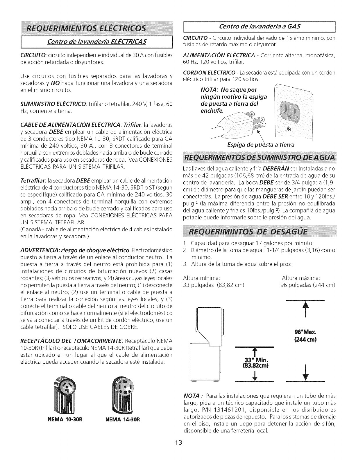
CORDON ELECTRICO - La secadora est,1equipada con un cordon
electrico trifilar para 120 voltios.
NOTA: No saque per
ningun motivo la espiga
de puesta a tierra del
enchufe.
Espiga de pu a tierra
LasIlavesdel agua caliente yfria DEBERAN set instaladas a no
m_isde 42 pulgadas (106,68 cm) de la entrada de agua de su
centro de lavanderia. La boca DEBE set de 3/4 pulgada (1,9
cm) de di_imetro para que las mangueras de jardin puedan set
conectadas. La presiOnde agua DEBESER entre 10 y 1201bs./
pulg.2 (la maxima diferencia entre la presiOn no equilibrada
del agua caliente y fria es 101bs./pulg3) Lacompahib de agua
potable puede informarle sobre le presi0n del agua.
1. Capacidad para desaguar 17 galones pot minuto.
2. Dibmetro de la toma de agua: 1-1/4 pulgadas (3,16) como
minimo.
3. Altura de la toma de agua sobre el piso:
Altura minima:
33 pulgadas (83,82 cm)
Altura maxima:
96 pulgadas (244 cm)
1'
33" Min.
(83.82cm)
f
NEMA 10-30R NEMA 14-30R
13
NOTA : Para las instalaciones que requieran un tubo de mas
largo, pida a un t_cnico capacitado que instale un tubo mas
largo, P/N 131461201, disponsible en los disribuidores
autorizados de piezasde repuesto. Paralossistemasde drenaje
en el piso, instale un uego para detener la acciOn de sifOn,
disponsible de una ferreteria local.
Utilicesolamenteductosmet_ilicos rigidos o flexibles de 4"
(10,2 cm) de di_imetro (minimo) y una caperuza de salida de uso
aprobado, con registrosque giren haciaafueraque seabren cuando
lasecadora seencuentra en funcionamiento. Cuando lasecadora
sedetiene, los registros secierran autom_iticamente para evitar
lascorrientes de airey laentrada de insectosy roedores. Paraevitar
obstruir la salida, mantenga una altura libre minima de 12"(30,5
cm) entre la caperuza de salida y el piso o entre cualquier otra
obstrucci6n.
Los siguientes requerimientos son
especificos para el fundonamiento correcto y seguro de su
secadora. El incumplimiento de estas instrucdones puede
causar prolongacibn excesiva de! tiempo de secado y riesgos
de incendio.
No instale la centro de lavadaria con materiales deventilaci6n
pl_isticosflexibles. Losmaterialesdeventilaci6n flexiblesse pueden
colapsaro apachurrarf_icilmenteyatrapar pelusa.Estascondiciones
obstruir_inlacirculaci6nde airede laSecadorade ropayaumentar_in
el riesgo de incendio.
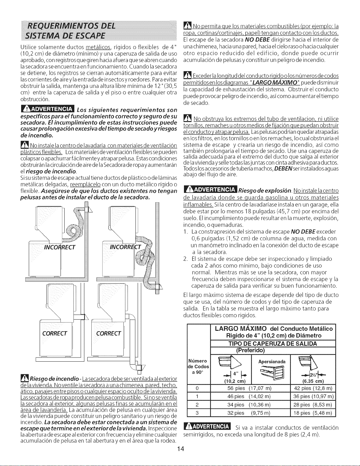
Sisusistemade escapeactual tiene ductos de pl_isticoode I_iminas
met_ilicasdelgadas, reempl_icelo con un ducto met_ilico rigido o
flexible. AsegOrese de que los ductos existentes no tengan
pelusas antes de instalar el ducto de la secadora.
ECT
_iii_iiii_iiiiiiiiiiiiiiiiiiiiiiiiiiiiiiiiiiiiiiiiiii_iii_iiiiiiiiiiiiiiiiiiiiiiiiiiiiiiiiiiiiiiiiiiiiiiiiiiiiiii_
l
No permita que losmateriales combustibles (por ejemplo: la
ropa cortinas/cortinajes, papel) tengan contacto con losductos.
Elescape de la secadora NO DEBE dirigirse hacia el interior de
unachimenea, haciauna pared, haciaelcielorasoohaciacualquier
otro espacio reducido del edificio, donde puede ocurrir
acumulaci6n de pelusas yconstituir un peligro de incendio.
ExcederlaIongitud del conducto rigidoo losnOmerosde codos
permitidosen Iosdiaqramas "LARGOMAXIMO" puededisminuir
la capacidad de exhaustaci6n del sistema. Obstruir el conducto
puede provocar peligro de incendio, asicomo aumentar eltiempo
de secado.
No obstruya los extremos del tubo de ventilation ni utilice
tornillos remachesuotros medios de fijaci6n que puedan obstruir
elconductoyatrapar pelusa. Laspelusaspodrian quedar atrapadas
en losfiltros, en lostornillos o en losremaches, Iocualobstruiria el
sistema de escape y crearia un riesgo de incendio, asi como
tambi@nprolongaria el tiempo de secado. Useuna caperuza de
salida adecuada para el extremo del ducto que salga al exterior
delavivienda yselletodaslasjuntas concinta adhesivaparaductos.
Todoslosaccesoriosdetuberia machos,DEBENserinstaladosaguas
abajo del flujo de aire.
Riesgo de explosi6n. No instale lacentro
de lavadaria donde se guarda gasolina u otros materiales
inflamables. Sila centro de lavadariase instala en un garage, ella
debe estar por Io menos 18 pulgadas (45,7 cm) por encima del
suelo. Elincumplimiento puede resultar en la muerte, explosi6n,
incendio, o quemaduras.
1. LaconstrapresiOn del sistema de escape NO DEBE exceder
0,6 pulgadas (1,52 cm) de columna de agua, medida con
un man6metro inclinado en la conexi6n del ducto de escape
a la secadora.
2. El sistema de escape debe ser inspeccionado y limpiado
cada 2 ahos como minimo, bajo condiciones de uso
normal. Mientras m_s se use la secadora, con mayor
frecuencia deben inspeccionarse el sistema de escape y la
caperuza de salida para verificar su buen funcionamiento.
El largo m_ximo sistema de escape depende del tipo de ducto
que se usa, del nOmero de codos y del tipo de caperuza de
salida. En la tabla se muestra el largo maximo tanto para
ductos flexibles como rigidos.
Riesgo de incendio- Lasecadoradebe serventilada al exterior
delavivienda. Noventile lasecadoraauna chimenea pared, techo,
_itico,pasajesentre pisoso cualquier espacio oculto de lavivienda.
Lassecadorasde ropa producen pelusacombustible. Sinoseventila
la secadora al exterior algunas pelusasfinas seacumular_in en el
_ireade lavanderia. La acumulaci6n de pelusa en cualquier _irea
de la vivienda puede constituir un peligro sanitario yun riesgo de
incendio. La secadora debe estar conectada a un sistema de
escape que termine en el exterior de la vivienda. Inspeccione
laabertura de escapealexterior con frecuencia yelimine cualquier
acumulaci6n de pelusa en tal abertura yen el _ireaque la rodea.
LARGO M/_XIIVIO del Conducto IVlet_lico
Rigido de 4" (10,2 cm) de Di_rnetro
TIPO DE CAPERUZA DE SALIDA
(Preferido)
deNUmer°codos_ Apersianada_
"90° ._ 4" _. ,,_=
(10,2 ere) (6.35 ere)
0 56 pies (17,07 m) 42 pies (12,8 m)
1 46 pies (14,02m) 36 pies (10,97m)
2 34 pies (10,36m) 28 pies (8,53m)
3 32 pies (9,75m) 18 pies (5,48m)
Si va a instalar conductos de ventilaciOn
semirrigidos, no exceda una Iongitud de 8 pies (2,4 m).
14
Se puede colocar el ducto de escape de cuatro (4) maneras
distintas cuando el artefacto est_instalado conel fondo paralelo
con la pared.
1. Derecho hacia arras.
2. Hacia abajo - ducto rigido, 8 pulgadas(20.32 cm) de Iongitud
y 4 pulgadas (10,16 cm) de all,metro & 1 ducto acodado
hacia abajo.
3. Hacia la izquierda - ducto rigido, 8 pilgadas (20,32 cm) de
Iongitud y 4 pulgadas (10,16 cm) de all,metro, 1 ducto
acodado hacia abajo y un ducto acodado hacia la derecha.
4. Hacia la derecha - ducto rigido, 8 pulgadas (20,32 cm) de
Iongitud y 4 pulgadas (10,16 cm) de all,metro, 1 ducto
acodado hacia abajo y un ducto acodado hacia la derecha.
Aungue un sistema vertical seaaceptable, algunas circunstancias
atenuantes pueden afectar el funcionamiento de la secadora:
• Sedebe utilizar solamente conductos -_
metalicos rigidos. _,/z':J"......
• Una salida del sistema vertical en el /,,_¢
techo, puede exponerle a un corriente ,.
'f_%/,J
de aire descendente ydisminuir asisu _
capacidad de exhaustaci6n. "_j-_"_
• Elaislante que debe atravesarel sistema
puede causar condensaci6nydisminuir "
asi la capacidad de exhaustaci6n del
sistema.
• Lacapacidad de exhaustaci6n de un sistema de exhaustaci6n
comprimido o ondulado puede disminuirse.
Para colocar el ducto de escape hacia arriba, ahada un ducto
de 11 pulgadas (27,94 cm) de Iongitud y de 4 pulgadas (10,16
cm) de di_metro y un ducto acodado de 90°. El artefacto
debe estar a aproximadamente 4 1/2 pulgadas (11,43 cm) de
la pared (Se puede colocar el ducto de escape paralelo con la
pared pot colocarlo debajo de la secadora y dirigirlo hacia un
lado). Una caperuza de escape colocada en forma tal que se
alinie con el escape de la secadora,
puede set instalada directamente a trav_s de la pared exterior.
Para colocar el ducto de escape hacia arriba, ahada un ducto 11
pulgadas (27,94 cm) de Iongitud y 4 pulgadas (10,16 cm) de
all,metro y un ducto acodado de 90°. El artefacto debe estar a
aproximadamente 4 1/2 pulgadas (11,43 cm) de la pared (sepuede
colocar el ducto de escapeparalelo con la pared coloc_ndolo debajo
de la secadora y dirigido hacia un lado). Para permitir el escape
lateral o inferior, agregue un ducto de 8 pulgadas (20,32 cm) de
largo y 4 pulgadas (10,16 cm) de all,metro est_ndar y un codo de
90°
1. Lainstalaci6n DEBEhacerse cumplir con los c6digos locales o en
ausenciadelosmismos,deacuerdo conlosestandaresdelNational
FuelGasCode (C6digo Nacional para GasesCombustibles), ANSI
Z223.1 (la Oltima editi6n). ParaCanada1,el Estandar CAN/CGA
5149 que est@en vigor.
2. La tuberia de alimentaci6n de gas debe set de 1/2 pulgada
(1,27 cm) de di_imetro.
3. Siest_qpermitido pot losc6digos locales,sepuede usartuberia de
metal para conectar susecadora a la linea de suministro de gas.
La tuberia DEBE set fabricada de acero inoxidable o cobre
recubierto de pl_istico.
4. Latuberia de alimentaci6n de gasDEBEtener una Ilavede cierre
individual.
5. Una toma de 1/8 de pulgada (0,32 cm) N.RT. accesible para
conexi6n del man6metro de prueba, DEBE set instalada
inmediatamente aguas arriba de la conexi6n de la tuberia de
alimentaci6n de gasa la secadora.
6. La secadora DEBE set desconectada del sistema de tuberias de
alimentaci6n de gas durante cualquier ensayo de presi6n del
sistema de tuberias de alimentaci6n de gas realizado a presiones
de prueba de m_isde 1/2 Ibs/pulg. 2(3,45 kPa).
7. LasecadoraDEBEaislarsedel sistemade tuberias de alimentaci6n
de gasdurante cualquier ensayode presi6ndel sistemadetuberias
de alimentaci6n de gasrealizado en ensayosde presi6n iguales o
inferiores a 1/2 Ibs/pulg.2(3,45 kPa).
NO INSTALESULAVA NDERL"
1. En un lugar donde puede haber goteos de agua o quede expuesta alas inclemencias del tiempo.
2. En un _ireadonde pueda entrar en contacto con cortinas, cortinajes o cualquier otra cosa que obstruya el flujo de combusti6n y
ventilaci6n de aire.
3. Sobre alfombras. ElpisoDEBEset firme con un desnivel m_qximode 1 pulgada (2,54 cm).
INSTALACIONDENTRO DE UN NICHO OARMARIO
1. Silasecadora esinstalada en un dormitorio, cuarto de baho, nicho oarmario, eltubo delescapeDEBEser instalado haciaelexterior.
2. No sedebe instalar ningOn otto artefacto que queme combustible en el mismo armario en que est_qinstalada lasecadora a Gas.
3. Lasecadora necesita espacio a sualrededor para una ventilaci6n adecuada.
NO INSTALELA SECADORA ENUN ARMA RiO CON PUERTAMA CIZA.
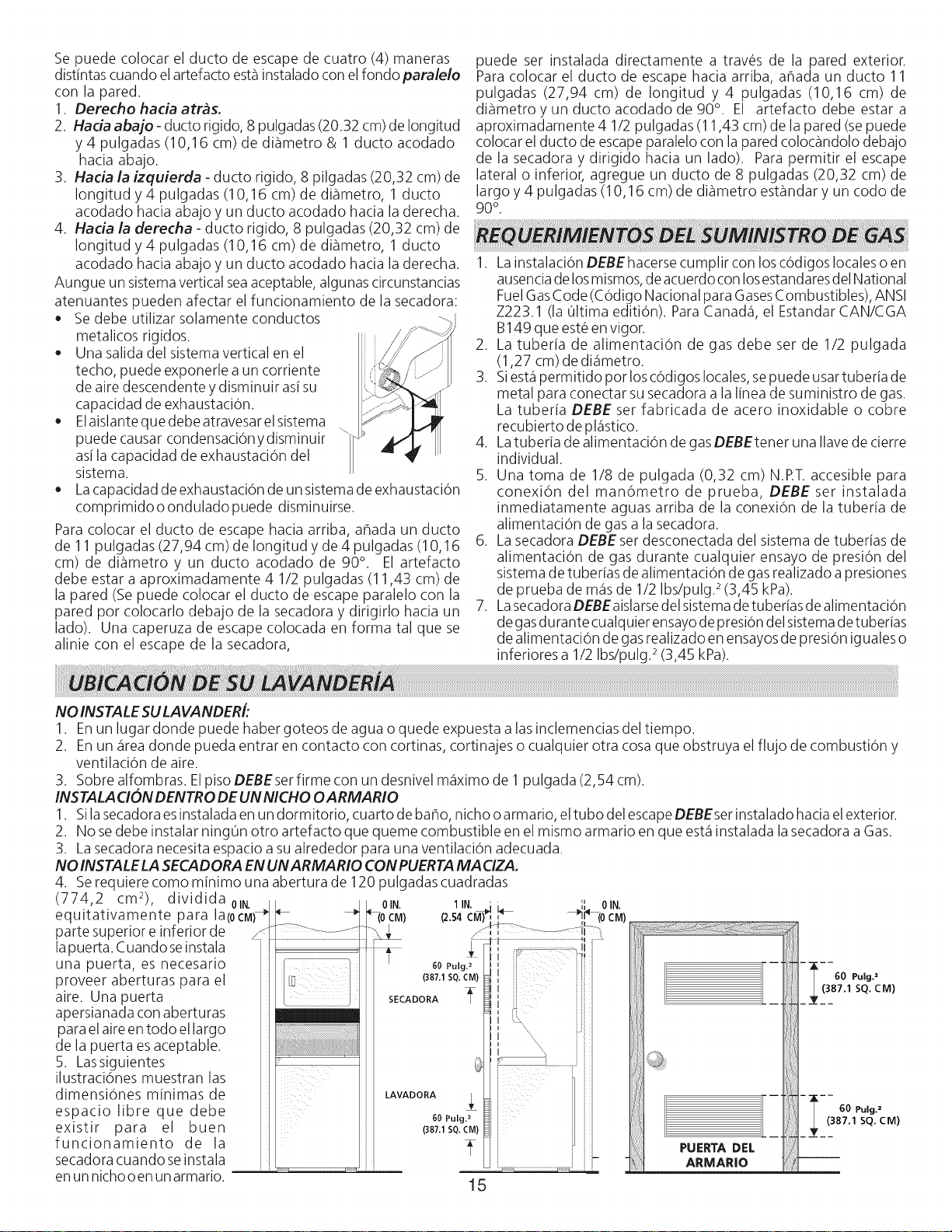
4. Serequiere como minimo una abertura de 120 pulgadas cuadradas
(774,2 cm2), dividida01N
equitativamente para la(0CM)
parte superior e inferior de
lapuerta. Cuando seinstala
una puerta, es necesario
proveer aberturas para el
aire. Una puerta
apersianada con aberturas
para elaire en todo el largo
de la puerta esaceptable.
5. Lassiguientes
ilustraci6nes muestran las
dimensi6nes minimas de
espacio libre que debe
existir para el buen
funcionamiento de la
secadora cuando seinstala
en un nichooen unarmario.
15
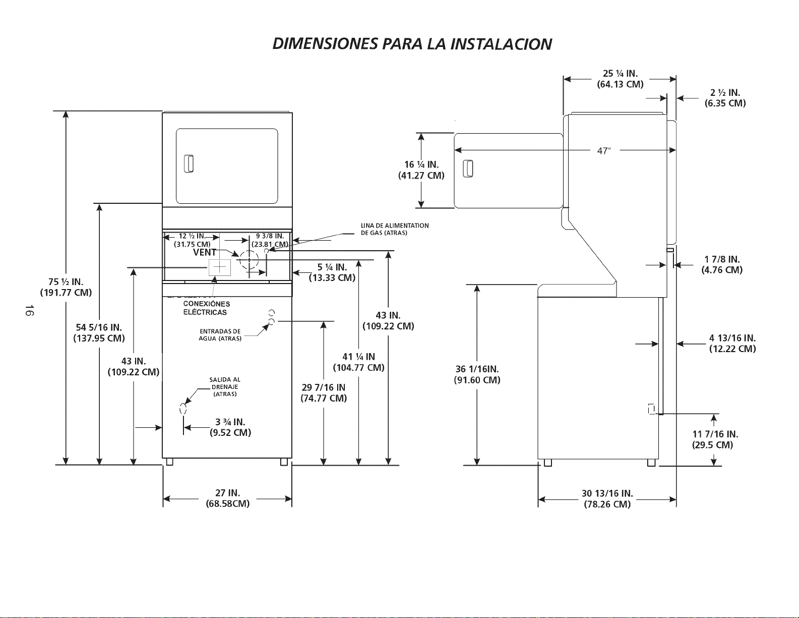
DIMENSiONES PARA LA INSTALACiON
75 1/2IN.
(191.77 CM)
Ob
54 5/16 IN.
(137.95 CM)
43 IN.
(109.22 CM)
D
I_-- 121/21N._D,_ _ m 93/81N.
(31.75 CM)" _I(23.81,CIM)
VEm'_--_t-_ _
CONEXIONES
ELC:CTRICAS
ENTRADAS DE /_"
AGUA (ATRA S)
SALIDA AL
DRENAJE
r._ (ATRAS)
k/
3¾IN.
(9.52 CM)
C_ [3-
27 IN.
(6&S8CM)
16 I,_ IN.
(41.27 CM)
LINA DE ALIMENTATION
DEGAS (ATRAS)
5 IA IN" _ T
_--_13.33cM)
43 IN.
i (109.22 CM)
41 1_ IN
(104.77 CM)
29 7/16 IN
(74.77 CM)
f
36 1/161N.
(91.60 CM)
25 I/_ IN.
I (64.13 CM)
30 13116 IN.
(78.26 CM)
i-J
U
2 I/2 IN.
4-- (6.35 CM)
I 718 IN.
(4.76 CM)
4 13116 IN.
4-- (12.22 CM)
11 7/16 IN.
(29.5 CM)
--9
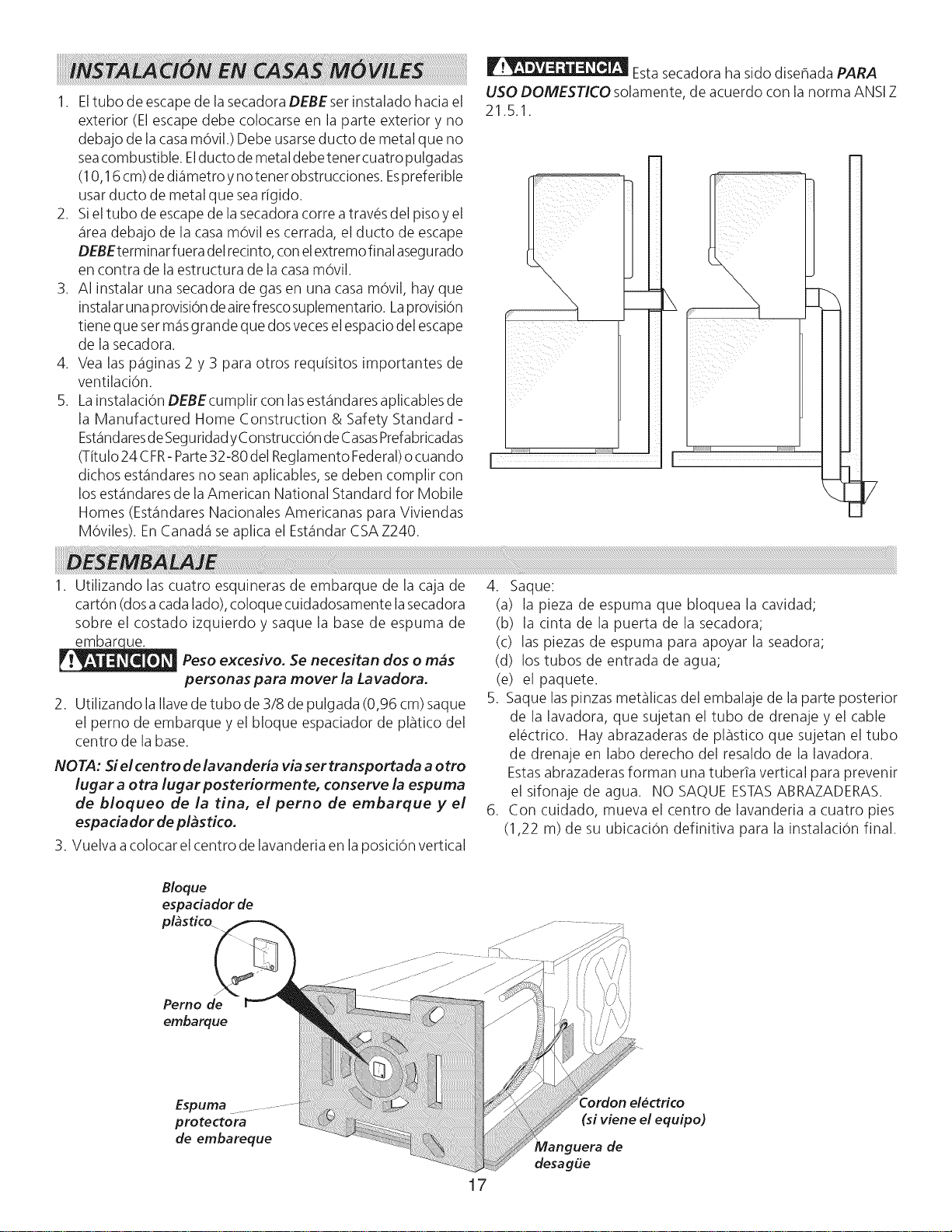
1. Eltubo de escape de la secadora DEBEser instalado hacia el
exterior (El escape debe colocarse en la parte exterior y no
debajo de la casam6vil.) Debe usarseducto de metal que no
seacombustible. Elducto de metal debe tenor cuatropulgadas
(10,16 cm)de di_imetro ynotenor obstrucciones. Espreferible
usar ducto de metal que searigido.
2. Siel tubo de escape de la secadora corre a trav_s del piso yel
_ireadebajo de la casa m6vil escerrada, el ducto de escape
DEBEterminar fuera delrecinto, conelextremofinal asegurado
en contra de la estructura de la casa m6vil.
3. AI instalar una secadora de gasen una casa mOvil, hay que
instalar unaprovisi6n deairefrescosuplementario. Laprovisi6n
tiene que set m_qsgrande que dosveceselespacio del escape
de la secadora.
4. Vea las p_iginas 2 y 3 para otros requisitos importantes de
ventilaciOn.
5. Lainstalaci6n DEBEcumplir con lasest_indaresaplicables de
la Manufactured Home Construction & Safety Standard -
Est_qndaresdeSeguridadyConstrucci6n deCasasPrefabricadas
(Titulo 24 CFR-Parte32-80 del Reglamento Federal)ocuando
dichos est_qndaresno seanaplicables, sedeben complir con
los est_qndaresde la American National Standard for Mobile
Homes (Est_qndaresNacionales Americanas para Viviendas
M6viles). EnCanada1se aplica el Est_indarCSAZ240.
Estasecadora ha sido disehada PARA
USO DOMESTICO solamente, de acuerdo con la norma ANSIZ
21.5.1.
P'
; iii i
I ii , _ i i i i i i i i i i
1. Utilizando las cuatro esquineras de embarque de la caja de
cart6n (dosa cadalado), coloque cuidadosamente la secadora
sobre el costado izquierdo y saque la base de espuma de
embarc ue.
Peso excesivo. Se necesitan dos o m_s
personas para mover la Lavadora.
2. Utilizando la Ilavede tubo de 3/8 de pulgada (0,96 cm) saque
el perno de embarque y el bloque espaciador de pl_tico del
centro de la base.
NOTA: Si el centro de lavanderia via sertransportada a otto
lugar a otra lugar posteriormente, conserve la espuma
de bloqueo de la tina, el perno de embarque y el
espa ciador de plbs rico.
3. Vuelva acolocar el centro de lavanderia en la posiciOn vertical
4. Saque:
(a) la pieza de espuma que bloquea la cavidad;
(b) la cinta de la puerta de la secadora;
(c) las piezas de espuma para apoyar la seadora;
(d) los tubos de entrada de agua;
(e) el paquete.
5. Saque laspinzas metalicas del embalaje de la parte posterior
de la lavadora, que sujetan el tubo de drenaje y el cable
el_ctrico. Hay abrazaderas de pl_stico que sujetan el tubo
de drenaje en labo derecho del resaldo de la lavadora.
Estasabrazaderas forman una tuberTa vertical para prevenlr
el sifonaje de agua. NO SAQUE ESTASABRAZADERAS.
6. Con cuidado, mueva el centro de lavanderia a cuatro pies
(1,22 m) de su ubicaci6n definitiva para la instalaci6n final.
Bloque
espaciador de
plbstico_
Perno de
embarque
Espuma
protectora
de embareque
17
Cordon el6ctrico
(si viene el equipo)
Manguera de
desag_e
I
TODAS /os centro /a vandoria ELECTRICAS
i
Los siguientes requerimientos son
especificos para el funcionamiento correcto y seguro de su
secadora. El incumplimiento de estas instrucciones puede
causar prolongacion excesiva de#tiempo de secado y riesgos
de incendio.
Este artefacto DEBE ser puesto a tierra de
manera correcta. Si la lavanderia no est,1debidamente puesta a
tierra sepuede producir un choque el_ctrico. Sigalasinstrucciones
indicadas en este manual para la puesta atierra enforma correcta.
No use un cord6n de extensi6n con esta
lavanderia. Algunos cordones de extensi6n no pueden soportar la
cantidad de corriente el_ctrica que utiliza esta secadora ypueden
fundirse, creando un peligro de choque el_ctrico y/o incendio.
Ubique la lavanderia de manera que el cord6n el_ctrico Ilegue
hastaeltomacorriente que sevaausar,dejando un poco de holgura
paraelcord6n. Consultelosrequerimientosdeinstalaci6n
preliminares indicados en estemanual para elcord6n el_ctrico que
debe seradquirido.
Se debe instalar un anclaje aprobado por el
U.L.parael cord6n el_ctrico. Sino seutiliza unanclaje parasujetar
el cord6n el_ctrico, _ste puede salirse de la lavanderia y cortarse
con cualquier movimiento, resultando en un choque el_ctrico.
No utilice un tomacorriente con cables de
aluminio con un cord6n y un enchufe de cobre (o viceversa). Se
produce una reacci6n qufmica entre el cobre y el aluminio que
puede causar cortacircuitos. El cableado y tomacorriente
apropiado esun cord6n el_ctrico equipado con conductores
de cobre con un tomacorriente con conductores de cobre.
NOTA: Laslavanderia que operan con un suministro de energfa
de 208 voltios usar_in m_istiempo de secado que aquellas que
operan con un suministro de energfa de 240 voltios.
REQUERIMIENTOS PARA LA PUESTA A TIERRA
Centro de/avanderia ELECTRICASNo canadienses
I
_La conexi6n indebida del conductor de puesta
atierra del equipo puede ocasionar un riesgode choque el_ctrico.
Consulteconun electricistaprofesionalsitienealguna duda respecto
a la puesta a tierra correcta del artefacto.
Parauna secadora puesta atierra, con cord6n el_ctrico:
1. La lavanderia DEBE ser puesta a tierra. En caso de
malfuncionamiento ofalla, la puesta atierra reducir_iel riesgo
de choque el_ctrico proporcionando un trayecto de menor
resistencia a la corriente el_ctrica.
2. Sisulavanderiaest,1equipada conun cord6n el_ctricoque posee
un conductor de puesta a tierra del equipo y un enchufe de
puesta a tierra, dicho enchufe DEBE ser conectado a un
tomacorriente adecuado, debidamente instalado y puesto a
tierra de acuerdo con todos losc6digos yreglamentos locales.
Sitiene alguna duda consulte a un electricista profesional. No
modifique el enchufe proporcionado /a aplicacion.
18
Para una lavanderia conectada permanentemente:
1. La lavanderia DEBEser conectada a un sistema de cableado
met_ilico permanente, puesto a tierra; o sedebe instalar un
conductor de puesta a tierra de equipo junto con los
conductores del circuitoy conectarse alborne de puesta atierra
del equipo o al cable del artefacto.
Centro de/avanderia ELECTRICAScanadienses
_La conexi6n indebida del conductor de puesta
atierra del equipo puede ocasionar un riesgodechoque el@ctrico.
Consulte con un electricista profesional si tiene alguna duda
respecto a la puesta a tierra correcta del artefacto.
Parauna lavanderia puesta a tierra con cord6n el@ctrico:
1. La lavanderia DEBE ser puesta a tierra.En caso de
malfuncionamiento ofalla, la puesta atierra reducir_iel riesgo
de choque el@ctricoproporcionando un trayecto de menor
resistencia a la corriente el_ctrica.
1
,
Si su lavanderia est,1equipada con un cord6n el_ctrico que
poseeun conductor de puesta atierra del equipoy un enchufe
de puesta a tierra, dicho enchufe DEBE ser conectado a un
tomacorriente adecuado, debidamente instalado y puesto a
tierra de acuerdo contodos losc6digos yreglamentos locales.
Sitiene alguna duda consulte a un electricista profesional. No
modifique el enchufe proporcionado /a aplicacion.
TODOS /os centros /avanderia a GAS
Estalavenderia est,1equipada con un enchufe detres espigas (de
puesta atierra) para protecci6n en contra de choques el_ctricos
y debe serconectada directamenta en un recept_iculo para tres
espigas el cual debe estar puesto atierra. No corte ni elimine la
espiga de puesta a tierra de este enchufe.
1
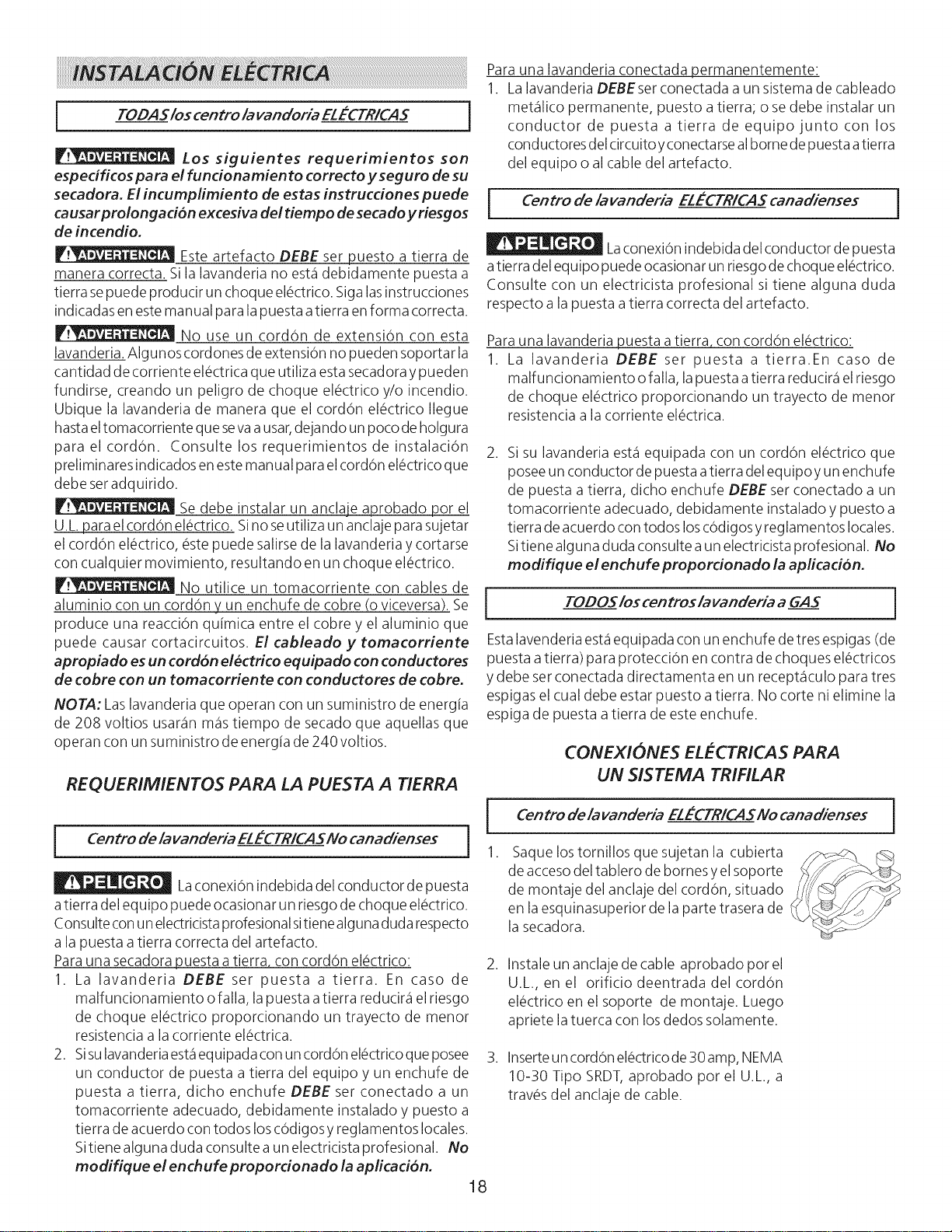
1.
,
,
CONEX#ONES ELECTR#CAS PARA
UN S#STEMA TR#F#LAR
Centro de /avanderia ELECTRICASNo canadienses
Saque lostornillos que sujetan la cubierta
de accesodel tablero de bornes yel soporte
de montaje del anclaje del cord6n, situado
en la esquinasuperior de la parte trasera de
la secadora.
I
Instale un anclaje de cable aprobado por el
U.L., en el orificio deentrada del cord6n
el@ctricoen el soporte de montaje. Luego
apriete latuerca con losdedos solamente.
Inserteun cord6n el@ctricode30 amp, NEMA
10-30 Tipo SRDT,aprobado por el U.L., a
trav@sdel anclaje de cable.
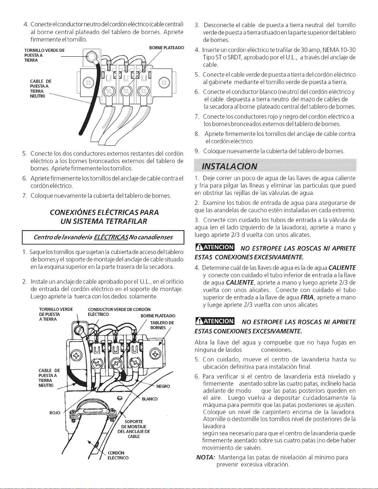
4.Conecteelconductorneutrodelcordonel_ctrico(cablecentral)
albornecentralplateadodeltablerodebornes.Apriete
firmementeeltornillo.
TORNILLO VERDE DE
PUESTAA
TERRA
BORNE PLATEADO
CABLE DE
PUESTAA
TERRA
NEUTR0
5. Conecte losdos conductores externos restantes del cordon
el_ctrico a los bornes bronceados extemos del tablero de
bornes. Apriete firmemente Iostornillos.
6. Apriete firmemente lostornillos del anclaje de cablecontra el
cordon el_ctrico.
7. Coloque nuevamente la cubierta del tablero de bornes.
CONEXIONES ELECTRICAS PARA
UN SISTEMA TETRAFILAR
Centro de/avanderia ELECTRICASNo canadienses
]
1. SaqueIostornillos que sujetan la cubierta deaccesodeltablero
de bornesy el soporte de montaje del anclajede cablesituado
en la esquina superior en la parte trasera de la secadora.
,
Instale un anclaje de cable aprobado porel U.L.,en el orificio
de entrada del cord6n el@ctricoen el soporte de montaje.
Luego apriete la tuerca con los declos solamente.
TORNILLO VERDE CONDUCTORVERDE DECORDON
DE PUESTA ELECTRICO BORNE PLATEADO
ATIERRA
TABLERO DE
BORNES
CABLE DE
PUESTAA
TERRA
NEUTR0
ROJO
NEGRO
BLANCO
SOPORTE
DE MONTAJE
DEL ANCLAJE DE
CABLE
CORDON
ELI_CTRICO
,
,
Desconecte el cable de puesta a tierra neutral del tornillo
verde de puesta atierra situado en laparte superior deltablero
de bornes.
Inserteun cord6n el@ctricotetrafilar de 30 amp, NEMA 10-30
Tipo STo SRDT,aprobado por el U.L., atrav@sdel anclaje de
cable.
5. Conecte el cableverde de puesta a tierra del cordon el#ctrico
al gabinete mediante el tornillo verde de puesta atierra.
6. Conecte el conductor blanco (neutro) del cordon el#ctrico y
el cable depuesta atierra neutro del mazo de cables de
la secadora al borne plateado central del tablero de bornes.
7. Conecte losconductores rojo y negro del cordon el#ctrico a
losbornes bronceados externos del tablero de bornes.
,
9.
Apriete firmemente lostornillos del anclaje de cable contra
el cord6n el_ctrico.
Coloque nuevamente la cubierta del tablero de homes.
1. Deje correr un poco de agua de las Ilavesde agua caliente
y fria para pilgar las Itneas y eliminar las particulas que pued
en obstriur las rejillas de lasvSIvulas de agua.
2. Examine los tubos de entrada de agua para asegurarse de
que lasarandelas de caucho est_n instaladas en cada extremo.
3. Conecte con cuidado los tubos de entrada a la vSIvula de
agua (en el lado izquierdo de la lavadora), apriete a mano y
luego apriete 2/3 d vuelta con unos alicates.
NO ESTROPEE LAS ROSCAS N/ APR/ETE
ESTAS CONEXIONES EXCES/VAMENTE.
4. Determine cual de lasIlavesde agua esla de agua CALIENTE
y conecte con cuiclado el tubo inferior de entrada a la Ilave
de agua CALIENTE, apriete a mano y luego apriete 2/3 de
vuelta con unos alicates. Conecte con cuidado el tubo
superior de entrada a la Ilavede agua FRIA, apriete a mano
y luege apriete 2/3 vuelta con unos alicates
NO ESTROPEE LAS ROSCAS NI APR/ETE
ESTASCONEXIONES EXCES/VAMENTE.
Abra la Ilave del agua y compuebe que no haya fugas en
ninguna de lasdos conexiones.
5. Con cuidado, mueve el centro de lavanderia hasta su
ubicaciOn definitiva para instalaciOn final.
6. Para verificar si el centro de lavanderia est,1 nivelado y
firmemente asentado sobre lascuatro patas, inclinelo hacia
adelante de modo que las patas posteriors queden en
el aire. Luego vuelva a depositar cuidadosamente la
maquina para permitir que laspatas posteriores seajusten.
Coloque un nivel de carpintero encima de la lavadora.
Atornille o destornille lostornillos nivel de posteriores de la
lavadora
seg0n seanecesario para que el centro de lavanderia quede
firmemente asentado sobre suscuatro patas (no debe haber
movimiento de vaiv_n.
NOTA: Mantenga las patas de nivelaci0n al minimo para
prevenir excesiva vibraci0n.
7. CONEXIONDELGAS(Secadoras a gas solamente)
a. Saque la tapa de embarque de la tuberia de gas de la
secadora situada en la parte trasera.
NOTA: NO conecte la lavanderia al suministro de propano, sin
)rimero instalar el juego de conversion a propano. Eljuego de
conversion a propano clebe set instalado pot un t_cnico de gas
calificado.
b.Conecte una tuberia semirigida de 1/2" (1,27 cm)D.I. o
una tuberia aprobada, desde la linea de suministro de
gas a la tuberia de 3/8" (0,96 cm) ubicada en la parte
trasera de la secadora. Utilice un reductor de 1/2" (1,27
cm)a 3/8" (0,96 cm)para laconexi6n. Aplique unsellador
de roscas de uso aprobado, resistente a la corrosi6n de
los gaseslicuados, en todas lasuniones de la tuberia.
c. Abra la wilvula decierre en la tuberia de suministro de
gas.
d. Pruebetodas lasconexiones aplicando con una
escobilla una soluci6njabonosa.
NUNCA UTILICEUNA LLAMA ABIERTA PARADETECTAR
FUGAS DE GAS.
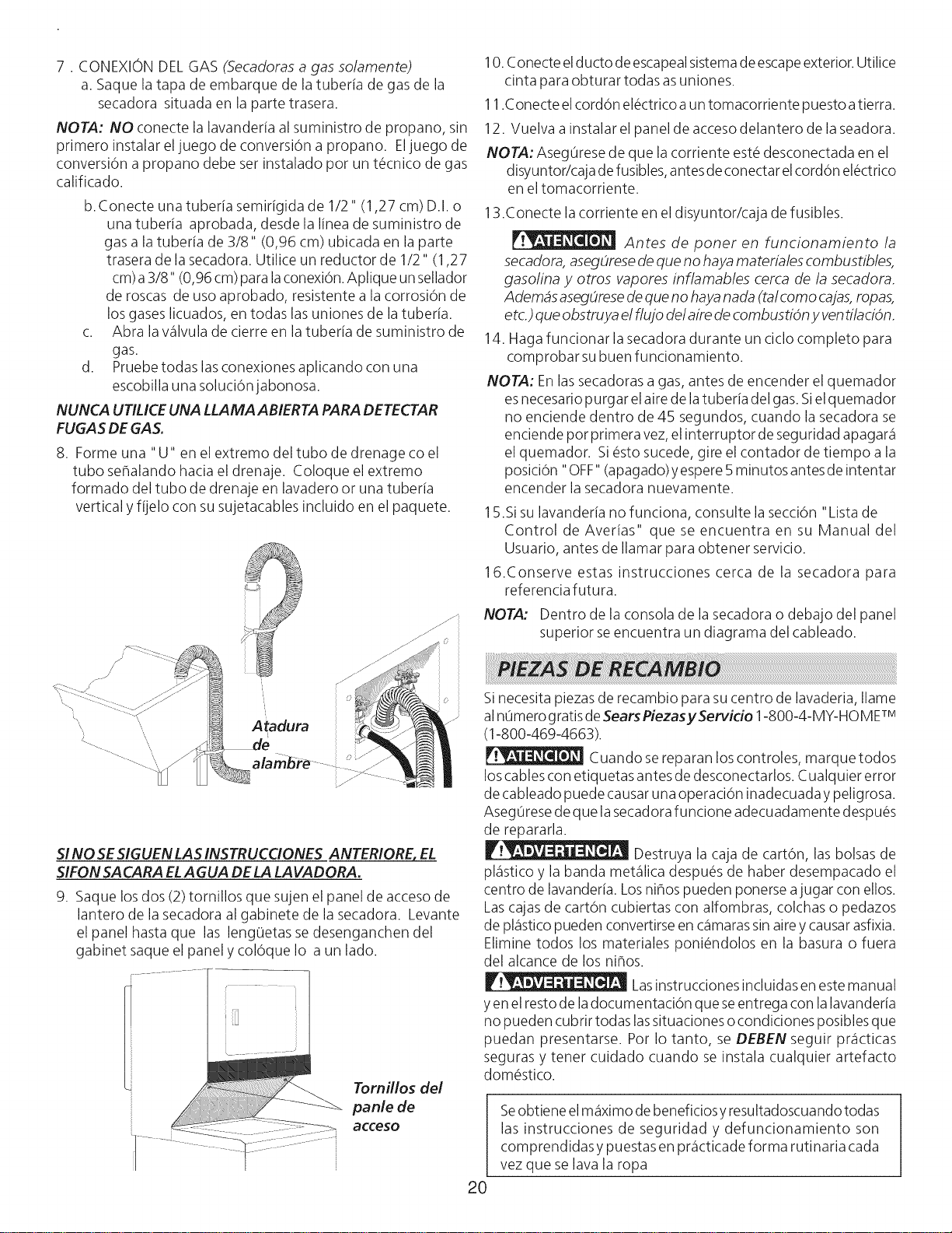
8. Forme una "U" en el extremo del tubo de drenage co el
tubo sehalando hacia el drenaje. Coloque el extremo
formado del tubo de drenaje en lavadero or una tuberia
vertical yfijelo con su sujetacables incluido en el paquete.
Atadura
alambre _ _ _ J_
jJ
j"
i©
S!NO SESIGUEN LAS INSTRUCCIONES ANTERIORE, EL
SIFON SACARA ELA GUA DELA LAVADORA.
9. Saque los dos (2) tomillos que sujen el panel de acceso de
lantero de la secadora al gabinete de la secadora. Levante
el panel hasta que las leng0etas sedesenganchen del
gabinet saque el panel y colOque Io a un lado.
[ ..............
I Tornillos del
panle de
10.Conecte elducto de escapealsistemade escapeexterior. Utilice
cinta para obturar todas asuniones.
11.Conecte elcordon el_ctrico a un tomacorriente puesto atierra.
12. Vuelva a instalar el panel de accesodelantero de la seadora.
NOTA: Aseg0rese de que la corriente est_ desconectada en el
disyuntor/caja de fusibles,antes deconectar elcordon el_ctrico
en el tomacorriente.
13.Conecte la corriente en el disyuntor/caja de fusibles.
Antes de poner en funcionamiento la
secadora, asegOresede que no haya materiales combustibles,
gasolina y otros vapores inflamables cerca de la secadora.
Ademas asegOresede que no hayanada (talcomo cajas,ropas,
etc.) que obstruya el flujo del aire de combustion y ventilacion.
14. Haga funcionar la secadora durante un ciclo completo para
comprobar subuen funcionamiento.
NOTA: Enlas secadoras a gas, antes de encender el quemador
esnecesario purgar el aire de latuberia del gas.Sielquemador
no enciende dentro de 45 segundos, cuando la secadora se
enciende pot primera vez,el interruptor de seguridad apagar_i
el quemador. Si _sto sucede, gire el contador de tiempo a la
posiciOn "OFF" (apagado) yespere5 minutos antesde intentar
encender la secadora nuevamente.
15.Sisu lavanderia no funciona, consulte la secciOn"Lista de
Control de Averias" que se encuentra en su Manual del
Usuario, antes de Ilamar para obtener servicio.
16.Conserve estas instrucciones cerca de la secadora para
referencia futura.
NOTA: Dentro de la consola de la secadora o debajo del panel
superior seencuentra un diagrama del cableado.
20
Sinecesita piezas de recambio para sucentro de lavaderia, Ilame
alnOmerogratisdeSearsPiezasyServido 1-800-4-MY-HOME TM
(1-800-469-4663).
Cuando sereparan loscontroles, marque todos
loscables con etiquetas antes de desconectarlos. Cualquier error
de cableado puede causar una operaciOn inadecuada ypeligrosa.
Aseg0rese de que lasecadora funcione adecuadamente despu_s
de repararla.
Destruya la caja de carton, las bolsas de
pl_isticoy la banda met_qlicadespu_s de haber desempacado el
centro de lavanderia. Losnihos pueden ponerse ajugar con ellos.
Lascajas de carton cubiertas con alfombras, colchas o pedazos
de pl_isticopueden convertirse en c_qmarassinairey causarasfixia.
Elimine todos los materiales poni_ndolos en la basura o fuera
del alcance de los nihos.
Lasinstrucciones incluidas en este manual
yen el resto de ladocumentaci6n que seentrega con lalavanderia
no pueden cubrir todas lassituaciones o condiciones posibles que
puedan presentarse. Pot Io tanto, se DEBEN seguir pr_icticas
seguras y tenet cuidado cuando se instala cualquier artefacto
dom_stico.
Seobtiene el m_iximode beneficiosyresultadoscuando todas
las instrucciones de seguridad y defuncionamiento son
comprendidas y puestasen pr_icticadeforma rutinaria cada
vez que se lava la ropa