• Install the remote controller holder in a place where the signal can be received by the indoor unit.
• When the remote controller is not used, place it in this holder.
Only use the remote controller provided with the unit.
Do not use other remote controllers. If two or more indoor units are installed in proximity to one another, an indoor unit that is not intended to be operated may respond to the remote controller
PREPARATION BEFORE OPERATION
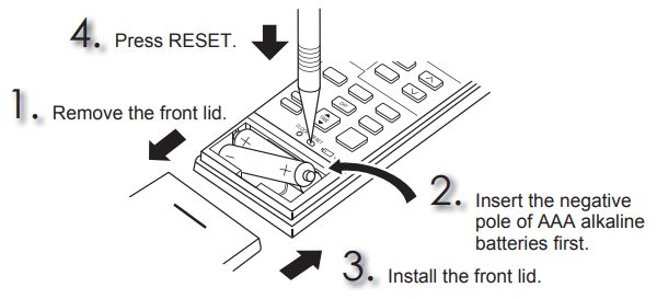
Installing the remote controller batteries
• Make sure the polarity of the batteries is correct.
• Do not use manganese batteries and leaking batteries. The remote controller could malfunction.
• Do not use rechargeable batteries.
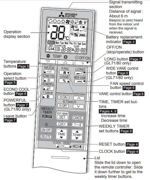
• The battery replacement indicator lights up when the battery is running low. In 7 days after the indicator starts light up, the remote control stops working.
• Replace all batteries with new ones of the sae type.
• Batteries can be used for approximately 1 year. However, batteries with expired shelf lives last shorter.
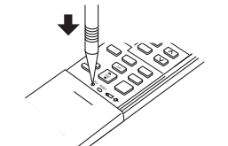
• Press RESET gently using a thin instrument. If the RESET button is not pressed, the remote controller may not operate correctly.
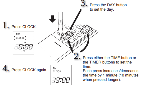
Setting current time
• Press CLOCK gently using a thin instrument.
SELECTING OPERATION MODES
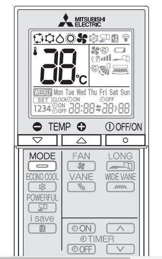
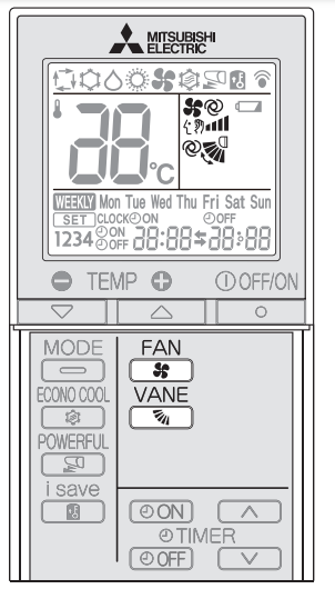
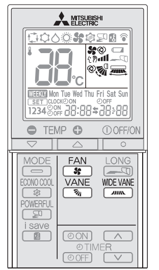
1. Press to start the operation.
2. Press to select the operation mode. Each press changes mode in the following order:
3. Press or to set the temperature. Each press raises or lowers the temperature by 1°C.
Press to stop the operation.
• The same setting is selected the next time by simply pressing .
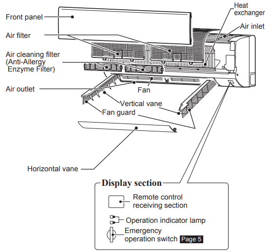
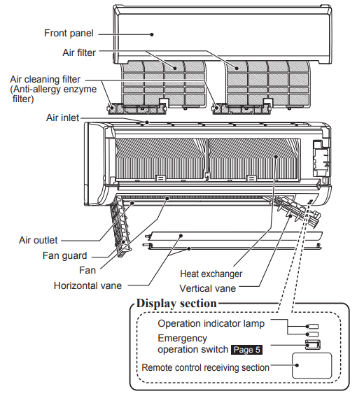
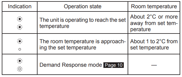
Operation indicator lamp
The operation indicator lamp shows the operation state of the unit.
Lighted
Blinking
Not lighted
AUTO mode (Auto change over)
The unit selects the operation mode according to the difference between the room temperature and the set temperature. During AUTO mode, the unit changes mode (COOL↔HEAT) when the room temperature is 2°C away from the set temperature for more than 15 minutes.
COOL mode
Enjoy cool air at your desired temperature.
DRY mode
Dehumidify your room. The room may be cooled slightly. Temperature cannot be set during DRY mode.
HEAT mode
Enjoy warm air at your desired temperature.
FAN mode
Circulate the air in your room.
Emergency operation
When the remote controller cannot be used...
The emergency operation can be activated by pressing the emergency operation switch (E.O.SW) on the indoor unit.
Each time the E.O.SW is pressed, the operation changes in the following order:
Operation indicator lamp
Auto restart function
If a power failure occurs or the main power is turned off during operation, the “Auto restart function” automatically starts operation in the same mode as the one set with the remote controller just before the shutoff of the main power. When the timer is set, the timer setting is canceled and the unit starts operation when power is resumed.
If you do not want to use this function, please consult the service representative because the setting of the unit needs to be changed.
FAN SPEED AND AIRFLOW DIRECTION ADJUSTMENT
<GF25/35/42/50/60>
Press to select fan speed. Each press changes fan speed in the following order:
• Two short beeps are heard from the indoor unit when set to AUTO.
• Use a higher fan speed to cool/heat the room more powerfully. It is recommended to lower the fan speed once the room is cool/warm.
• Use a lower fan speed for quiet operation.
Press to select airflow direction. Each press changes airfl ow direction in the following order:
• Two short beeps are heard from the indoor unit when set to AUTO.
Airflow direction
(AUTO) .........The vane is set to the most efficient airflow direction. COOL/ DRY/FAN: a horizontal position. HEAT: position (4).
(Manual) .......For efficient air conditioning, select the upper position for COOL/DRY, and the lower position for HEAT. If the lower position is selected during COOL/DRY, the vane automatically moves to the horizontal position after 0.5 to 1 hour to prevent any condensation from dripping.
(Swing) .........The vane moves up and down intermittently.
■ To change the horizontal airflow direction.
Move the vertical vane manually before starting the operation.
<GL71/80>
Press to select fan speed. Each press changes fan speed in the following order:
• Two short beeps are heard from the indoor unit when set to AUTO.
• Use a higher fan speed to cool/heat the room quicker. It is recommended to lower the fan speed once the room is cool/warm.
• Use a lower fan speed for quiet operation.
Press to select airflow direction. Each press changes airflow direction in the following order:
• Two short beeps are heard from the indoor unit when set to AUTO.
Press to select horizontal airflow direction. Each press changes airflow direction in the following order:
Airflow direction
(AUTO) .........The vane is set to the most efficient airflow direction. COOL/ DRY/FAN: a horizontal position. HEAT: position (5).
(Manual) .......For efficient air conditioning, select the upper position for COOL/DRY, and the lower position for HEAT. If the lower position is selected during COOL/DRY, the vane automatically moves to the horizontal position after 0.5 to 1 hour to prevent any condensation from dripping.
(Swing) .........The vane moves up and down intermittently
LONG OPERATION
<GL71/80 Only>
Press to start a LONG operation.
• Fan speed increases and the horizontal vane moves to the position for LONG mode.
• Air reaches to longer distance.
Press again to cancel the LONG operation.
• LONG operation is canceled when the OFF/ON, VANE, or ECONO COOL button is pressed.
POWERFUL OPERATION
<GL71/80 Only>
Press during COOL or HEAT mode Page 5 to start POWERFUL operation.
Fan speed : Exclusive speed for POWERFUL mode Horizontal vane : Set position, or downward airflow position during AUTO setting
• Temperature cannot be set during POWERFUL operation.
Press again to cancel the POWERFUL operation.
• POWERFUL operation also is canceled automatically in 15 minutes, or when the OFF/ON, FAN, ECONO COOL, or i-save button is pressed.
I-SAVE OPERATION
Press during COOL, ECONO COOL, or HEAT mode to select i-save mode
Set the temperature, fan speed, and airflow direction.
• The same setting is selected the next time by simply pressing .
• Two settings can be saved. (One for COOL/ECONO COOL, one for HEAT)
• Select the appropriate temperature, fan speed, and airflow direction according to your room.
• Normally, the minimum temperature setting in HEAT mode is 16°C. However, during i-save operation only, the minimum temperature setting is 10°C.
Press again to cancel i-save operation.
• i-save operation also is canceled when the MODE or POWERFUL button is pressed.
i-save operation
• A simplified setback function enables to recall of the preferred (preset) setting with a single push of the button. Press the button again and you can go back to the previous setting in an instance.
• i-save operation cannot be set on the weekly timer.
Example of use:
1. Low energy mode Set the temperature 2°C to 3°C warmer in COOL and cooler in HEAT mode. This setting is suitable for unoccupied rooms, and while you are sleeping.
2. Saving frequently used settings Save your preferred setting for COOL/ECONO COOL and HEAT. This enables you to select your preferred setting with a single push of the button.
ECONO COOL OPERATION
Press during COOL mode on page 5 to start the ECONO COOL operation.
The unit performs swing operations vertically in various cycles according to the temperature of the airflow.
Press again to cancel the ECONO COOL operation.
• ECONO COOL operation is canceled when the VANE, LONG, or POWERFUL button is pressed.
What is “ECONO COOL”?
Swing airflow (change of airflow) makes you feel cooler than stationary airflow. The set temperature and the airflow direction is automatically changed by the microprocessor. It is possible to perform cooling operations with keeping comfort. As a result, energy can be saved.
TIMER OPERATION (ON/OFF TIMER)
1. Press or during operation to set the timer.
(ON timer) : The unit turns ON at the set time.
(OFF timer) : The unit turns OFF at the set time.
* or blinks.
* Make sure that the current time and day are set correctly. Page 4
2. Press (Increase) and (Decrease) to set the time of timer.
Each press increases or decreases the set time by 10 minutes.
• Set the timer while or is blinking.
3. Press or again to cancel timer
WEEKLY TIMER OPERATION
DEMAND RESPONSE AND INDOOR UNIT OPERATION
• A maximum of 4 ON or OFF timers can be set for individual days of the week.
• A maximum of 28 ON or OFF timers can be set for a week.
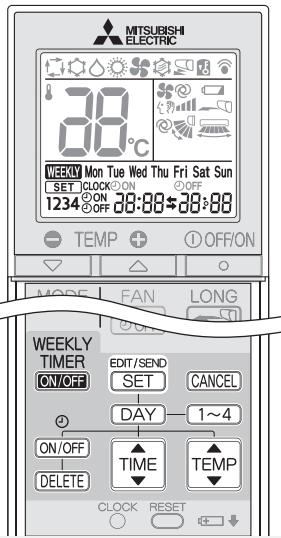
Setting the weekly timer
Make sure that the current time and day are set correctly.
1. Press to enter the weekly timer setting mode.
2. Press and to select setting day and number
3. Press , , and to set ON/OFF, time, and temperature.
* Hold down the button to change the time quickly.
* The temperature can be set between 16°C and 31°C at weekly timer.
Press and to continue setting the timer for other days and/or numbers.
4. Press to complete and transmit the weekly timer setting.
5. Press to turn the weekly timer ON. ( lights.)
* When the weekly timer is ON, the day of the week whose timer setting is complete, will light.
Press again to turn the weekly timer OFF. ( goes out.)
Checking the weekly timer setting
Press to enter the weekly timer setting mode. * blinks.
Press or to view the setting of a particular day or number.
Press to exit the weekly timer setting.
DEMAND RESPONSE AND INDOOR UNIT OPERATION
Demand response
This unit has demand response capability which is compliant with AS/NZS 4755.3.1. To activate this function, you need to make a contract with remote agents such as the electric supply company, then this unit should be connected to the Demand response enabling device (DRED). For further information, consult your dealer.
Demand response represents the automated alteration of an electrical product’s normal mode of operation in response to an initiating signal originating from or defined by a remote agent.
This unit supports 3 Demand Response Modes (DRMs).
CLEANING
Instructions:
• Switch off the power supply or turn off the breaker before cleaning.
• Be careful not to touch the metal parts with your hands.
• Do not use benzine, thinner, polishing powder, or insecticide.
• Use only diluted mild detergents.
• Do not expose parts to direct sunlight, heat, or fire to dry.
• Do not use water hotter than 50°C.
Front panel
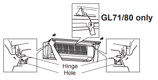
1. Lift the front panel until a “click” is heard.
2. Hold the hinges and pull to remove as shown in the above illustration.
• Wipe with a soft dry cloth or rinse it with water.
• Do not soak it in water for more than two hours.
• Dry it well in the shade.
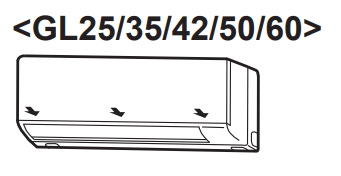
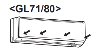
3. Install the front panel by following the removal procedure in reverse. Close the front panel securely and press the positions indicated by the arrows.
Air outlet and Fan (before cleaning, make sure that the fan is stopped)
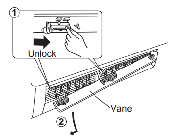
<GL25/35/42/50/60>Turn the horizontal vane downward. Then, remove the vane as shown in ➀ and ➁. <GL71/80>Turn the horizontal vanes downward. Then, remove the upper vane as shown in ➀ and ➁. • Repeat ➀ and ➁ for the lower vane.
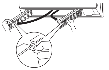
Swing out the two vertical vanes one by one.
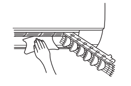
Clean the air outlet and fan. • Wipe with a soft dry cloth.
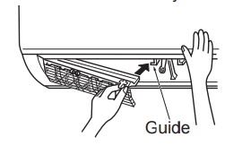
Put the vertical vanes back to their original positions correctly one by one, into their respective guide. • Push the vanes until they click into place.
Install the horizontal vanes by following the removal procedure in reverse.
• If the horizontal vanes are not installed correctly, all LED lamps blink when power is turned on.
WHEN YOU THINK THAT TROUBLE HAS OCCURRED
Symptom
Explanation & Checkpoints
Indoor Unit
The unit cannot be operated.
• Is the breaker turned on?
• Is the power supply plug connected?
• Is the ON timer set?
All LED lamps on the indoor unit are blinking.
• Are the horizontal vanes installed correctly?
The horizontal vane does not move.
• Are the horizontal vane and the vertical vane installed correctly? | Page 11
• Is the fan guard deformed?
The unit cannot be operated for about 3 minutes when restarted.
• This protects the unit according to instructions from the microprocessor. Please wait.
Mist is discharged from the air outlet of the indoor unit.
• The cool air from the unit rapidly cools moisture in the air inside the room, and it turns into mist.
The swing operation of the HORIZONTAL VANE is suspended for a while, then restarted.
• This is for the swing operation of the HORIZONTAL VANE to be performed normally.
The airflow direction changes during operation.
The direction of the horizontal vane cannot be adjusted with the remote controller.
• When the unit is operated in COOL or DRY mode, if the operation continues with air blowing down for 0.5 to 1 hour, the direction of the airflow is automatically set to horizontal position to prevent water from condensing and dripping.
• In the heating operation, if the airflow temperature is too low or when defrosting is being done, the horizontal vane is automatically set to horizontal position.
The operation stops for about 10 minutes in the heating operation.
• Outdoor unit is in defrost.
Since this is completed in max. 10 minutes, please wait. (When the outside temperature is too low and humidity is too high, frost is formed.)
The unit starts operation by itself when the main power is turned on, but isn’t received sign from the remote controller.
• These models are equipped with an auto restart function. When the main power is turned off without stopping the unit with the remote controller and is turned on again, the unit starts operation automatically in the same mode as the one set with the remote controller just before the shutoff of the main power. Refer to “Auto restart function” Page 5 .
In COOL/DRY mode, when the room temperature reaches near the set temperature, the outdoor unit stops, then the indoor unit operates at low speed.
• When the room temperature rises and the outdoor unit turns on, the indoor fan starts running according to the settings on the remote controller.
The indoor unit discolors over time.
• Although plastic turns yellow due to the influence of some factors such as ultraviolet light and temperature, this has no effect on the product functions.
Outdoor Unit
The fan of the outdoor unit does not rotate even though the compressor is running. Even if the fan starts to rotate, it stops soon.
• When the outside temperature is low during cooling operation, the fan operates intermittently to maintain sufficient cooling capacity.
Water leaks from the outdoor unit.
• During COOL and DRY operations, pipe or pipe connecting sections are cooled and this causes water to condense.
• In the heating operation, water condensed on the heat exchanger drips down.
• In the heating operation, the defrosting operation makes ice forming on the outdoor unit melt and drip down.
White smoke is discharged from the outdoor unit.
• In the heating operation, vapor generated by the defrosting operation looks like white smoke.
Remote controller
The display on the remote controller does not appear or it is dim. The indoor unit does not respond to the remote control signal.
• Are the batteries exhausted? Page 4
• Is the polarity (+, -) of the batteries correct? Page 4
• Are any buttons on the remote controller of other electric appliances being pressed?
Does not cool or heat
The room cannot be cooled or heated suffi ciently
• Is the temperature setting appropriate? Page 5
• Is the fan setting appropriate? Please change fan speed to High or Super High. Page 6
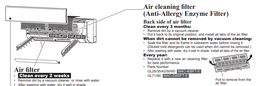
• Are the fi lters clean? Page 11
• Is the fan or heat exchanger of the indoor unit clean? Page 11
• Are there any obstacles blocking the air inlet or outlet of the indoor or outdoor unit?
• Is a window or door open?
• It may take a certain time to reach the setting temperature or may not reach that depending on the size of the room, the ambient temperature, and the like.
The room cannot be cooled suffi ciently
• When a ventilation fan or a gas cooker is used in a room, the cooling load increases, resulting in an insuffi cient cooling effect.
• When the outside temperature is high, the cooling effect may not be suffi cient.
The room cannot be heated suffi ciently.
• When the outside temperature is low, the heating effect may not be suffi cient.
Air does not blow out soon in the heating operation.
• Please wait as the unit is preparing to blow out warm air.
Poor cooling or heating performance.
• Do you have an arrangement with your electric company for Demand Response?
Airflow
The air from the indoor unit smells strange.
• Are the fi lters clean? Page 11
• Is the fan or heat exchanger of the indoor unit clean? Page 11
• The unit may suck in an odor adhering to the wall, carpet, furniture, cloth, etc. and blow it out with the air.
Sound
Cracking sound is heard.
• This sound is generated by the expansion/ contraction of the front panel, etc. due to change in temperature.
Burbling” sound is heard.
• This sound is heard when the outside air is absorbed from the drain hose by turning on the range hood or the ventilation fan, making water fl owing in the drain hose to spout out. This sound is also heard when the outside air blows into the drain hose in case the outside wind is strong.
Mechanical sound is heard from the indoor unit.
• This is the switching sound in turning off/on the fan or the compressor.
The sound of water flowing is heard.
• This is the sound of refrigerant or condensed water fl owing in the unit.
Hissing sound is sometimes heard.
• This is the sound when the fl ow of refrigerant inside the unit is changed.
Timer
Weekly timer does not operate according to settings.
• Is the ON/OFF timer set? Page 8, 9
• Transmit the setting information of the weekly timer to the indoor unit again. When the information is successfully received, a long beep will sound from the indoor unit. If information fails to be received, 3 short beeps will be heard. Ensure information is successfully received. Page 9
• When a power failure occurs and the main power turns off, the indoor unit built-in clock will be incorrect. As a result, the weekly timer may not work normally. Be sure to place the remote controller where the signal can be received by the indoor unit. Page 3
The unit starts/stops the operation by itself.
• Is the weekly timer set? Page 9
In the following cases, stop using the air conditioner and consult your dealer.
• When water leaks or drips from the indoor unit.
• When the upper operation indicator lamp blinks.
• When the breaker trips frequently.
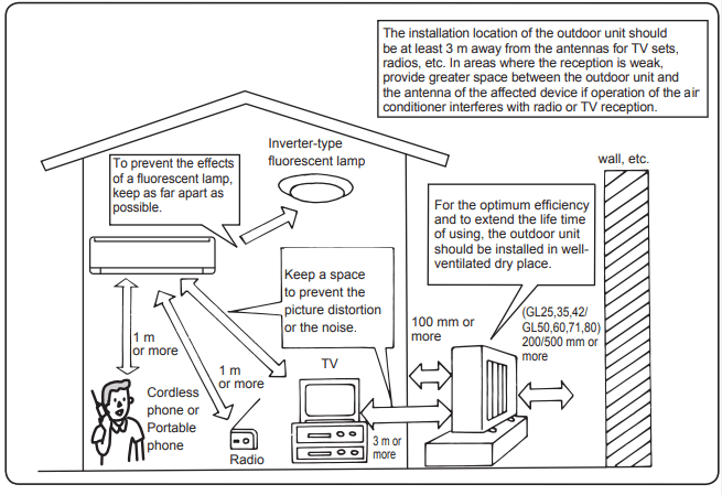
• The remote control signal is not received in a room where an electronic ON/ OFF type fluorescent lamp (inverter-type fluorescent lamp, etc.) is used.
• Operation of the air conditioner interferes with radio or TV reception. An amplifier may be required for the affected device.
• When an abnormal sound is heard.
• When any refrigerant leakage is found.
WHEN THE AIR CONDITIONER IS NOT GOING TO BE USED FOR A LONG TIME
Set to the highest temperature in manual COOL mode, and operate for 3 to 4 hours. Page 5 • This dries the inside of the unit. • Moisture in the air conditioner contributes to the growth of fungi, such as mold.
Press to stop the operation.
Turn off the breaker and/or disconnect the power supply plug.
Remove all batteries from the remote controller.
When using the air conditioner again:
Clean the air fi lter. Page 11
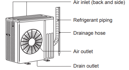
Check that the air inlet and outlet of the indoor and outdoor units are not blocked.
Check that the earth is connected correctly.
Refer to the “PREPARATION BEFORE OPERATION”, and follow the instructions. Page 4
INSTALLATION PLACE AND ELECTRICAL WORK
Installation place
Avoid installing the air conditioner in the following places.
• Where there is much machine oil.
• Salty places such as the seaside.
• Where sulfide gas is generated such as hot springs, sewage, and wastewater.
• Where oil is splashed or where the area is filled with oily smoke (such as cooking areas and factories, in which the properties of plastic could be changed and damaged).
• Where there is high-frequency or wireless equipment.
• Where the air from the outdoor unit air outlet is blocked.
• Where the operation sound or air from the outdoor unit bothers the house next door.
• The mounting height of the indoor unit 1.8m to 2.3m is recommended. If it is impossible, please consult your dealer.
Electrical work
• Provide an exclusive circuit for the power supply of the air conditioner.
 to start the operation.
 to select the operation mode. Each press changes mode in the following order:
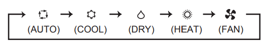
 or
or to set the temperature. Each press raises or lowers the temperature by 1°C.
 to stop the operation.
 .
.
 Lighted
 Blinking
 Not lighted
 AUTO mode (Auto change over)
 COOL mode
 DRY mode
 HEAT mode
 FAN mode
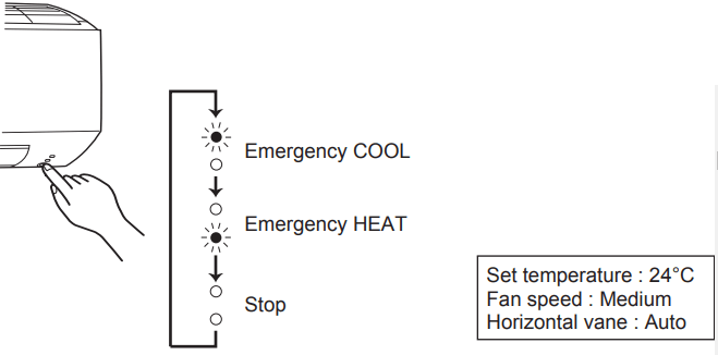
 to select fan speed. Each press changes fan speed in the following order:
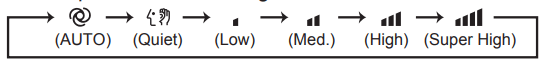
 to select airflow direction. Each press changes airfl ow direction in the following order:
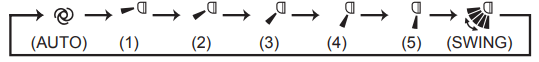
 (AUTO) .........The vane is set to the most efficient airflow direction. COOL/ DRY/FAN: a horizontal position. HEAT: position (4).
 (Manual) .......For efficient air conditioning, select the upper position for COOL/DRY, and the lower position for HEAT. If the lower position is selected during COOL/DRY, the vane automatically moves to the horizontal position after 0.5 to 1 hour to prevent any condensation from dripping.
 (Swing) .........The vane moves up and down intermittently.
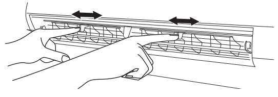
 to select fan speed. Each press changes fan speed in the following order:
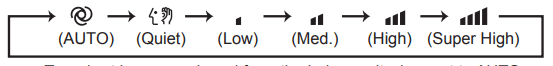
 to select airflow direction. Each press changes airflow direction in the following order:
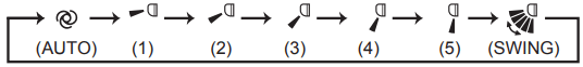
 to select horizontal airflow direction. Each press changes airflow direction in the following order:
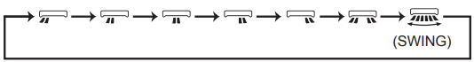
 (AUTO) .........The vane is set to the most efficient airflow direction. COOL/ DRY/FAN: a horizontal position. HEAT: position (5).
 (Manual) .......For efficient air conditioning, select the upper position for COOL/DRY, and the lower position for HEAT. If the lower position is selected during COOL/DRY, the vane automatically moves to the horizontal position after 0.5 to 1 hour to prevent any condensation from dripping.
 (Swing) .........The vane moves up and down intermittently
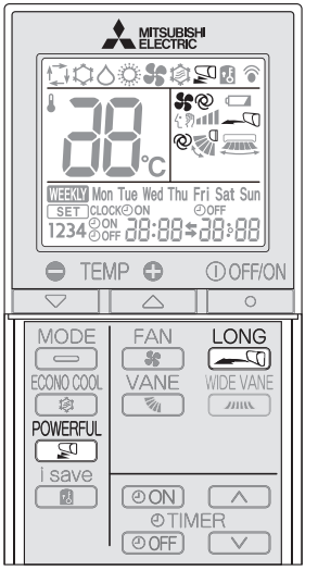
 to start a LONG operation.
 during COOL or HEAT mode Page 5 to start POWERFUL operation.
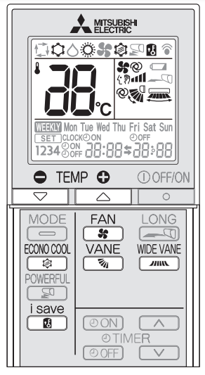
 during COOL, ECONO COOL, or HEAT mode to select i-save mode
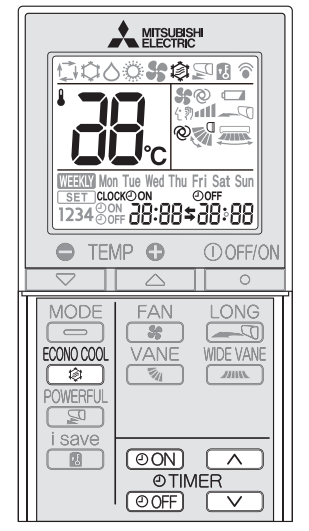
 during COOL mode on page 5 to start the ECONO COOL operation.
 or
or  during operation to set the timer.
 (Increase) and
  (Decrease) to set the time of timer.
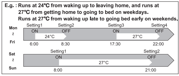
 to enter the weekly timer setting mode.
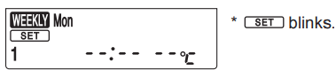
 and
and  to select setting day and number
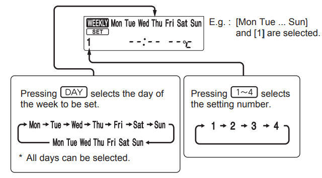
 ,
, , and
, and  to set ON/OFF, time, and temperature.
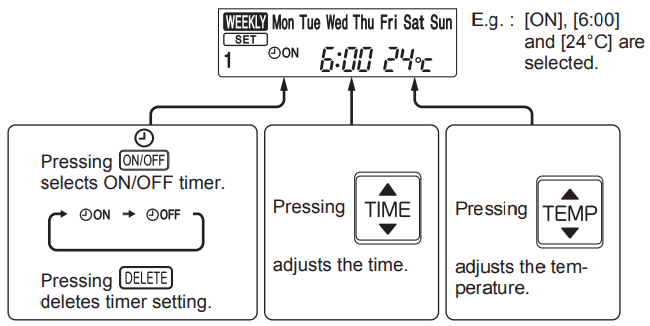
 and
and  to continue setting the timer for other days and/or numbers.
 to complete and transmit the weekly timer setting.
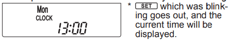
 to turn the weekly timer ON. (
 lights.)
 to enter the weekly timer setting mode.
  blinks.
 or
or to view the setting of a particular day or number.
 to exit the weekly timer setting.
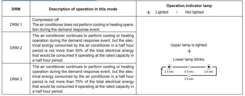
 <GL71/80>Turn the horizontal vanes downward. Then, remove the upper vane as shown in ➀ and ➁.
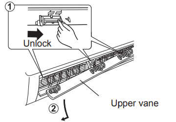
 to stop the operation.