Loading ...
Loading ...
Loading ...
4
NS-PCW4508/NS-PCW4508-C/NS-PCW5508/NS-PCW5508-C
www.insigniaproducts.com
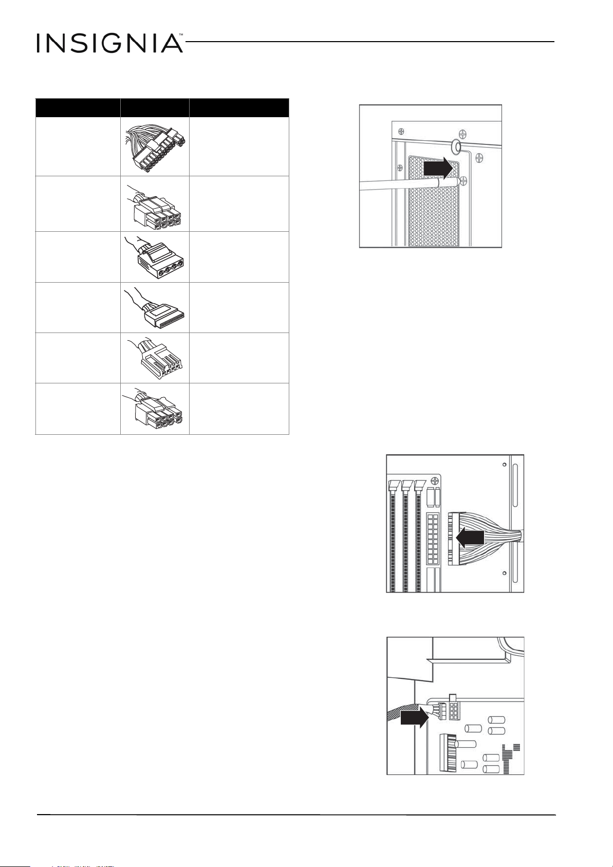
Connector types
Installing the power supply
Preparing your power supply:
1 Make sure that your motherboard, graphics
card, and other components are compatible
with this power supply. Refer to the
documentation that came with each
component.
2 Check your local AC voltage (115VAC for USA,
Canada, Japan, and others, and 230VAC for
Europe, Southeast Asia, and others). The
NS-PCW4508/NS-PCW5508 is compatible
with 100-240VAC.
Caution: Using the incorrect voltage can damage the power supply
and connected equipment and may void your warranty.
Are you replacing a power supply?
• If yes, start at “Removing your old power supply”
below.
• If no, go to “Installing the power supply” on pg 4.
Removing your old power supply:
1 Turn off your computer.
2 Unplug the power cord from your computer.
3 Open your computer case. (See the instructions
that came with your computer.)
4 Disconnect your old power supply from all
computer components.
Tip: Make sure to note each component and the connector type for
when you need to connect them to your new power supply.
5 Remove the screws that secure your old power
supply to your computer case, then remove it
from the case.
Installing your power supply:
1 Position your power supply in the computer
case, making sure that the AC power jack and
cooling fan are facing out, then secure your
power supply using the screws included with
your computer case.
2 Connect the power supply cables to the
motherboard and compatible computer
components (see below). Make sure that each
connection is secure.
Tip: If you are replacing an old power supply, reference your notes
from when you removed the old power supply to make sure that
you are connecting all of your components correctly.
a Connect the 20+4-pin main power
connector to your motherboard (either 20 or
24 pins).
b Connect the 8-pin (4+4) or 4-pin +12V
power connector to your motherboard.
Connector Illustration Connect to
20+4-PIN Main Power
The motherboard (can
be used with
motherboards with
either 20 or 24 pin ports)
8-PIN (4+4) + 12V -
The motherboard (for
CPU power) (can be used
with motherboards with
either 4 or 8 pin ports)
4-PIN peripheral -
Total 2 connectors
Internal IDE drives
Serial ATA (SATA) -
Total 4 connectors
Internal SATA drives
Floppy drive
3.25” floppy drives
8-PIN (6+2) PCI-E
Total 2 connectors
PCI Express cards (such
as a graphics card) that
requires power (can be
used with cards with
either 6 or 8 pin ports)
NS-PCW4508-NS-PCW5508_17-0459_MAN_V1_ENG.book Page 4 Monday, July 24, 2017 11:53 AM
Loading ...
Loading ...
Loading ...