Loading ...
Loading ...
Loading ...
WARNING – SERVICING TO BE CARRIED OUT ONLY BY AN AUTHORISED PERSON
Disconnect from electricity before servicing. Check appliance is safe when you have nished.
32
3 Controls
3.1. To Replace the Ignition or Light Switch
DISCONNECT FROM THE ELECTRICITY SUPPLY.
Remove the control panel (see 1.1).
Note: The old switch may be destroyed during removal.
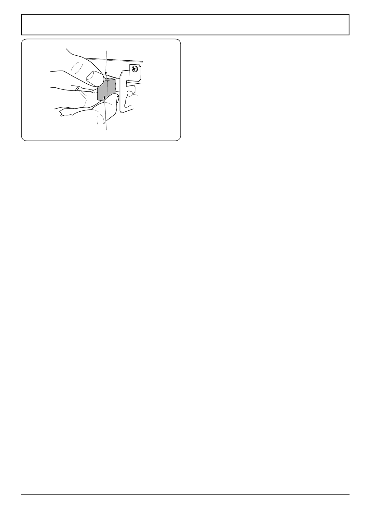
Remove the old switch from its bezel by gripping the
switch body behind the control panel and twisting
sharply. Remove the switch bezel by folding back the
locking wings and pushing forward.
To t the new bezel to the control panel: rst line up the
raised key on its body with the cut-out in the control
panel and push it in from the front.
Assemble the new switch to the bezel by lining up the
key sections and pushing home. Fit the new button by
pushing in from the front.
Replace the control panel in the reverse order and test
for correct operation.
3.2 To Replace the Clock
DISCONNECT FROM THE ELECTRICITY SUPPLY.
Remove the control panel (see 1.1). Pull o the timer
control buttons.
Undo the timer xing screws and remove the timer/
mounting bracket assembly from the control panel.
Remove the timer from its mounting bracket by
depressing the plastic lugs on the timer case, and at the
same time pulling the unit forward.
Reassemble in the reverse order. When replacing the
leads, refer to the wiring diagram. Check the operation
of the timer.
3.3 To Change the Ignition Generator
DISCONNECT FROM THE ELECTRICITY SUPPLY.
Pull the cooker forwards to gain access to the cover box
at the rear of the cooker. Remove the screws securing
the cover and lift clear. Noting the position of the leads,
pull o all the leads to the generator. Slacken the 2
screws holding generator to cooker and remove the
generator.
Fit the new generator to the cooker and replace the
leads. Refer to the wiring diagram and reassemble in the
reverse order. Check the ignition performance.
Spring clip
Grill injector holder
Fig.9-4
Loading ...
Loading ...
Loading ...