WARNING
The engine exhaust from this
product contains chemicals known
to cause cancer, birth defects or
other reproductive harm.
A card containing important ATV safety information should be
attached to the owner’s manual on the next page. If you cannot
locate this card, or if it has been removed, please call
1-800-342-3764 for assistance.

FOREWORD
Congratulations and thank you from Polaris Industries Inc. for purchasing one of
our all-terrain vehicles (ATV’s). Built with American engineering and manufactur-
ing know-how, it is designed to provide superior riding comfort, enjoyment and
safety.
This manual is furnished to ensure that the operator is aware of safe operating pro-
cedures. It also includes information about the general care and maintenance of
your ATV.
Carefully read the following pages. If you have any questions regarding this ATV
contact a Polaris dealer for assistance. Remember, Polaris dealers have the
knowledge and facilities to provide you with the best service possible.
PROTECT YOUR SPORT
Know all local, state/province riding laws;
Respect your vehicle;
Respect the environment; and
You will gain the respect of others.
We also advise you to strictly follow the recommended maintenance program as
outlined. This preventive maintenance program is designed to ensure that all criti-
cal components on this ATV are thoroughly inspected at various intervals.
All information in this manual is based upon the latest product data and specifica-
tions available at the time of printing. Polaris Industries Inc. reserves the right to
make product changes and improvements which may affect illustrations or ex-
planations.
No part of this manual shall be reproduced or used without the written permission
of Polaris Industries Inc.
Illustrations included in this manual are general representations of parts having a
similar function. Your model may differ.

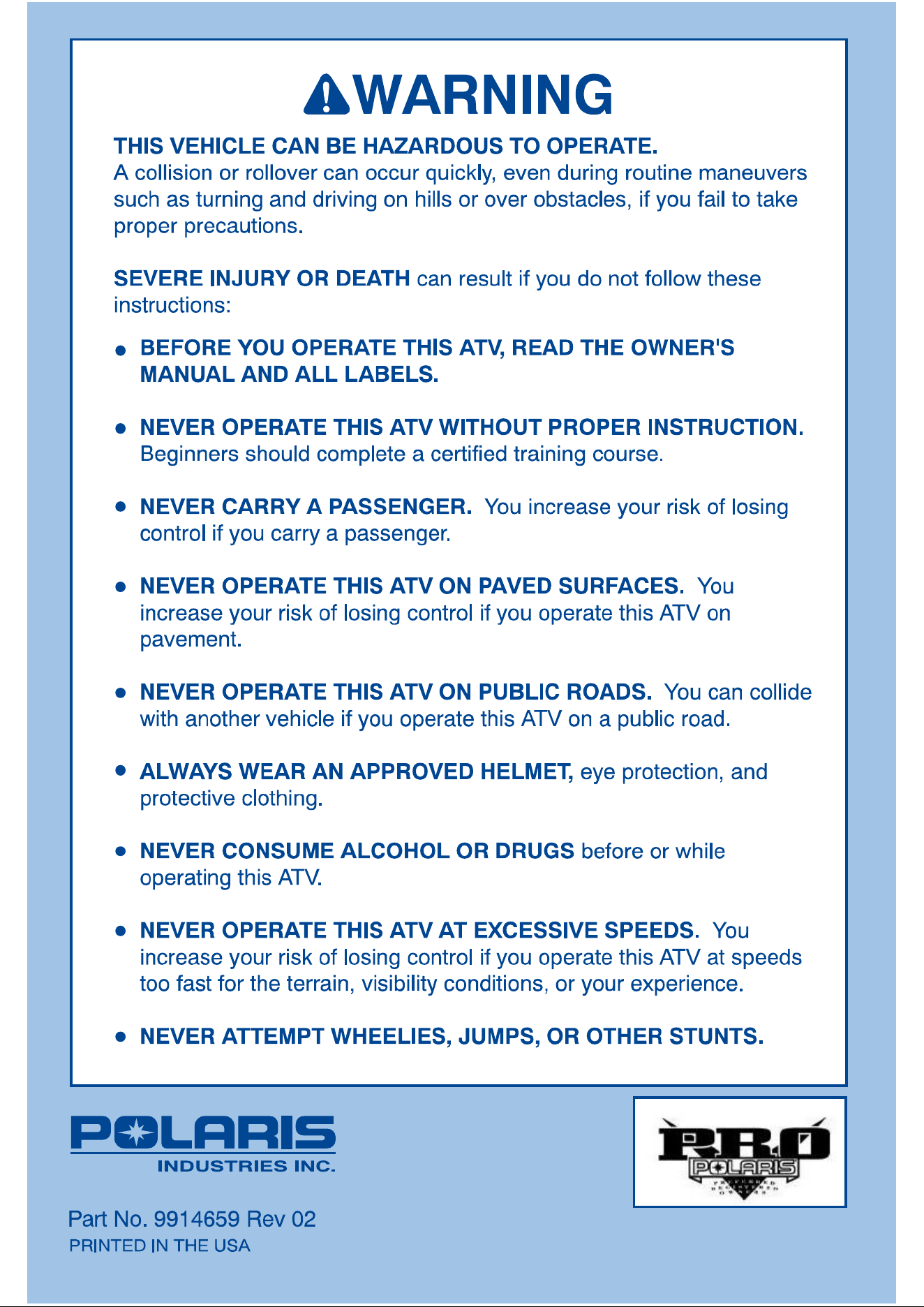
AN ATV IS NOT A TOY AND CAN BE HAZARDOUS TO OPERATE. An
ATV handles differently from other vehicles including motorcycles and
cars. A collision or rollover can occur quickly, even during routine maneu-
vers such as turning and driving on hills or over obstacles, if you fail to take
proper precautions.
SEVERE INJURY OR DEATH can result if you do not follow these instructions:
• Read this manual and all labels carefully and follow the operating procedures
described.
• Never operate an ATV without proper instruction. Take a training course. Be-
ginners should receive training from a certified instructor. Contact an authorized
Polaris ATV dealer or call Polaris at 1-800-342-3764 to find out about the training
courses nearest you.
• Never allow anyone under 18 years of age to operate this ATV.
• Never permit a guest to operate this ATV unless the guest has read this manual
and all product labels, and has completed a certified training course.
• Never operate an ATV on any paved surfaces, including sidewalks, driveways,
parking lots and streets.
• Never operate an ATV without wearing an approved helmet that fits properly. You
should also wear eye protection (goggles or face shield), gloves, boots, long-
sleeved shirt or jacket, and long pants.
• Never consume alcohol or drugs before or while operating this ATV.
• Never operate at excessive speeds. Always travel at a speed which is proper
for the terrain, visibility and operating conditions, and your experience.
• Never attempt wheelies, jumps or other stunts.
• Always inspect your ATV each time you use it to make sure it is in safe operating
condition. Always follow the inspection and maintenance procedures and
schedules described in this manual.
• Always keep both hands on the handlebars and both feet on the footrests of the
ATV during operation.
• Always go slowly and be extra careful when operating on unfamiliar terrain. Al-
ways be alert to changing terrain conditions when operating the ATV.
• Never operate on excessively rough, slippery or loose terrain.
• Always follow proper procedures for turning as described in this manual. Prac-
tice turning at low speeds before attempting to turn at faster speeds. Do not turn
at excessive speed.
• Always have the ATV checked by an authorized Polaris dealer if it has been in-
volved in an accident.
• Never operate the ATV on hills too steep for the ATV or for your abilities. Practice
on smaller hills before attempting larger hills.

• Always follow proper procedures for climbing hills as described in this manual.
Check the terrain carefully before you start up any hill. Never climb hills with ex-
cessively slippery or loose surfaces. Shift your weight forward. Never open the
throttle suddenly or make sudden gear changes. Never go over the top of any
hill at high speed.
• Always follow proper procedures for going down hills and for braking on hills as
described in this manual. Check the terrain carefully before you start down any
hill. Shift your weight backward. Never go down a hill at high speed. Avoid going
down a hill at an angle which would cause the vehicle to lean sharply to one side.
Go straight down the hill where possible.
• Always follow proper procedures for crossing the side of a hill as described in this
manual. Avoid hills with excessively slippery or loose surfaces. Shift your
weight to the uphill side of the ATV. Never attempt to turn the ATV around on
any hill until you have mastered the turning technique described in this manual
on level ground. Avoid crossing the side of a steep hill if possible.
• Always use proper procedures if you stall or roll backwards when climbing a hill.
To avoid stalling, maintain a steady speed when climbing a hill. If you stall or roll
backwards, follow the special procedure for braking described in this manual.
Dismount on the uphill side or to either side if pointed straight uphill. Turn the
ATV around and remount, following the procedure described in this manual.
• Always check for obstacles before operating in a new area. Never attempt to
operate over large obstacles, such as large rocks or fallen trees. Always follow
proper procedures when operating over obstacles as described in this manual.
• Always be careful of skidding or sliding. On slippery surfaces, such as ice, go
slowly and be very cautious in order to reduce the chance of skidding or sliding
out of control.
• Never operate an ATV in fast flowing water or in water deeper than that specified
in this manual. Remember that wet brakes may have reduced stopping ability.
Test your brakes after leaving water. If necessary, apply them lightly several
times to let friction dry out the pads.
• Always be sure there are no obstacles or people behind you when you operate
in reverse. When it is safe to proceed in reverse, go slowly. Avoid turning at
sharp angles in reverse.
• Always use the size and type tires specified in this manual. Always maintain
proper tire pressure as described in this manual.
• Never modify an ATV through improper installation or use of accessories.
• Never exceed the stated load capacity for an ATV. Cargo should be properly dis-
tributed and securely attached. Reduce speed and follow instructions in this
manual for carrying cargo or pulling a trailer. Allow greater distance for braking.
FOR MORE INFORMATION ABOUT ATV SAFETY, call the Consumer Product
Safety Commission at 1-800-638-2772, or Polaris at 1-800-342-3764.

indicates a potential hazard which
could result in serious injury or death.
WARNING
Additional Important Information...
Due to our concern for the safety of our customers and the general public, Polaris
hereby strongly recommends and requests that consumers not have installed on
a Polaris ATV any equipment which is intended to increase the speed or power of
the vehicle; or make any other modifications to the vehicle for these purposes. Any
modifications to the original equipment of the ATV substantially increase the risk
of bodily injury. Please be aware that these modifications may create a substantial
safety hazard.
Polaris hereby informs you that the warranty on your ATV is terminated if any such
equipment has been added to the ATV or any modifications have been made to
the ATV which increase its speed or power.
We also advise you to strictly follow the recommended maintenance program out-
lined in this manual. This preventive maintenance program is designed to ensure
that all critical components on the ATV are thoroughly inspected by your dealer at
various mileage intervals.
NOTE:
The addition of certain accessories including (but not limited to) mowers, blades,
tires, sprayers, or large racks may change the handling characteristics of the ATV.
Be certain any accessories added to this ATV have been approved by Polaris.
Familiarize yourself with their function and affect on the ATV.

The Polaris Preferred
Registered Owners
(PRO) Family
Your Owners Program
As the owner of a new Polaris vehicle, you are entitled to a FREE two- year mem-
bership in the Polaris PRO Family---the Preferred Registered Owners Family. It’s
an owners program for Polaris owners like you, people who have chosen the finest
recreational vehicle available, people who share an interest in Polaris and its prod-
ucts.
Once your new vehicle’s warranty is registered, you will receive a PRO Family
membership packet that will include:
A letter of welcome to the PRO Family
A PRO Family card with your name and membership number
A colorful sticker of the PRO logo
A PRO merchandise brochure and order form.
As a PRO Family member, you’re entitled to opportunities such as:
A free subscription to PRO Spirit, the official magazine of the PRO Family
The chance to buy insurance for you Polaris vehicle. The toll-free insurance
telephone number is: 1-800-473-0111
The chance to arrange travel through the Polaris Travel Center. The toll-free
travel telephone number is: 1-800-267-1915
The chance to apply to serve on PRO Consumer Councils that provide input
into the Polaris vehicles of the future
The chance to serve as a PRO Field Evaluator and provide feedback on your
new vehicle
The chance to take part in national PRO snowmobile, ATV or personal water-
craft rides
The chance to purchase exclusive PRO Family merchandise
And more!
To order PRO merchandise, you’ll complete the order form you receive with your
membership packet, take the form to your Polaris dealer and pay for the merchan-
dise. The merchandise will be shipped directly to your home from the PRO mer-
chandise fulfillment center.
Watch for your PRO membership packet and the next issue of PRO Spirit maga-
zine. This quarterly magazine will keep you informed about Polaris news and
events, and special PRO merchandise, travel, and ride opportunities.
Enjoy your new Polaris vehicle, and welcome to the family--The Polaris PRO Fami-
ly.

CONTENTS
UNDERSTANDING WARNINGS 1-2. . . . . . . . . . . . . . . . . . . . . . . . . .
SAFETY WARNING AND OPERATION DECALS 3-13. . . . . . . . . . .
DAILY PRE-RIDE INSPECTION 14. . . . . . . . . . . . . . . . . . . . . . . . . . .
OPERATION WARNINGS 15-33. . . . . . . . . . . . . . . . . . . . . . . . . . . . . .
VEHICLE IDENTIFICATION NUMBERS 34. . . . . . . . . . . . . . . . . . . . .
CONTROL AND PARTS FUNCTIONS 35-54. . . . . . . . . . . . . . . . . . .
STARTING THE ENGINE 55. . . . . . . . . . . . . . . . . . . . . . . . . . . . . . . . .
VEHICLE BREAK IN PERIOD 56-57. . . . . . . . . . . . . . . . . . . . . . . . . .
RIDING GEAR 58. . . . . . . . . . . . . . . . . . . . . . . . . . . . . . . . . . . . . . . . . . .
CARRYING LOADS 59. . . . . . . . . . . . . . . . . . . . . . . . . . . . . . . . . . . . . .
CARGO WEIGHT DISTRIBUTION 60. . . . . . . . . . . . . . . . . . . . . . . . .
DAILY PRE-RIDE INSPECTION 61. . . . . . . . . . . . . . . . . . . . . . . . . . .
RIDING 62-72. . . . . . . . . . . . . . . . . . . . . . . . . . . . . . . . . . . . . . . . . . . . . .
BATTERY 73-74. . . . . . . . . . . . . . . . . . . . . . . . . . . . . . . . . . . . . . . . . . . .
NOISE EMISSION CONTROL SYSTEM REGULATION 75. . . . . . .
MAINTENANCE 76-131. . . . . . . . . . . . . . . . . . . . . . . . . . . . . . . . . . . . .
TROUBLE SHOOTING 132. . . . . . . . . . . . . . . . . . . . . . . . . . . . . . . . .
PAINT CODES 133-134. . . . . . . . . . . . . . . . . . . . . . . . . . . . . . . . . . . . .
ACCESSORIES 135-143. . . . . . . . . . . . . . . . . . . . . . . . . . . . . . . . . . . .
WARRANTY 144-145. . . . . . . . . . . . . . . . . . . . . . . . . . . . . . . . . . . . . . .
INDEX 146-147. . . . . . . . . . . . . . . . . . . . . . . . . . . . . . . . . . . . . . . . . . . .

1
UNDERSTANDING WARNINGS
ATTENTION:
This is an ADULT VEHICLE ONLY; not a toy. Operation is prohibited for any-
one under 18 years of age. READ AND UNDERSTAND WARNINGS AND
OWNER’S MANUAL BEFORE OPERATION.
KNOW YOUR VEHICLE BEFORE YOU BEGIN RIDING!
Read this manual thoroughly referring to the various areas which are being dis-
cussed on your machine. Operating this vehicle carries with it responsibilities for
your personal safety, the safety of others, and the protection of our environment.
SAFETY TRAINING
When you purchased this vehicle your dealer presented a hands-on safety training
course covering all aspects of ATV safety. In addition, you were provided with cer-
tain printed material which instructs you on safe operating procedures.
You should review this information on a regular basis. In the event you purchased
a used Polaris ATV from a party other than a Polaris dealer, you can obtain this
safety training at no charge from any authorized Polaris dealer.
Failure to follow the warnings contained in this manual can result in SERIOUS IN-
JURY OR DEATH.
NOTE: Illustrations used in this manual are for general representation only.
Your model may differ.
2
UNDERSTANDING WARNINGS
SAFETY ALERT
The following precautionary signal words are used throughout this manual to con-
vey the following messages:
This is the safety alert symbol. When you see this symbol
on your machine or in this manual, be alert to the potential
for personal injury. Your safety is involved!
WARNING
Indicates a potential hazard
which could result in serious
injury or death.
CAUTION
Indicates a potential hazard which
may result in minor personal inju-
ry or damage to the ATV.
NOTE
The word “NOTE:” in this manual will alert
you to key information or instructions.
WARNING
HAZARD
Failure to heed WARNINGS.
WHAT CAN HAPPEN
WARNINGS identify special instructions or procedures which, if not cor-
rectly followed, could result in personal injury, or loss of life.
HOW TO AVOID THE HAZARD
Read all WARNINGS in this manual carefully and for your safety be
sure to follow their instructions.
3
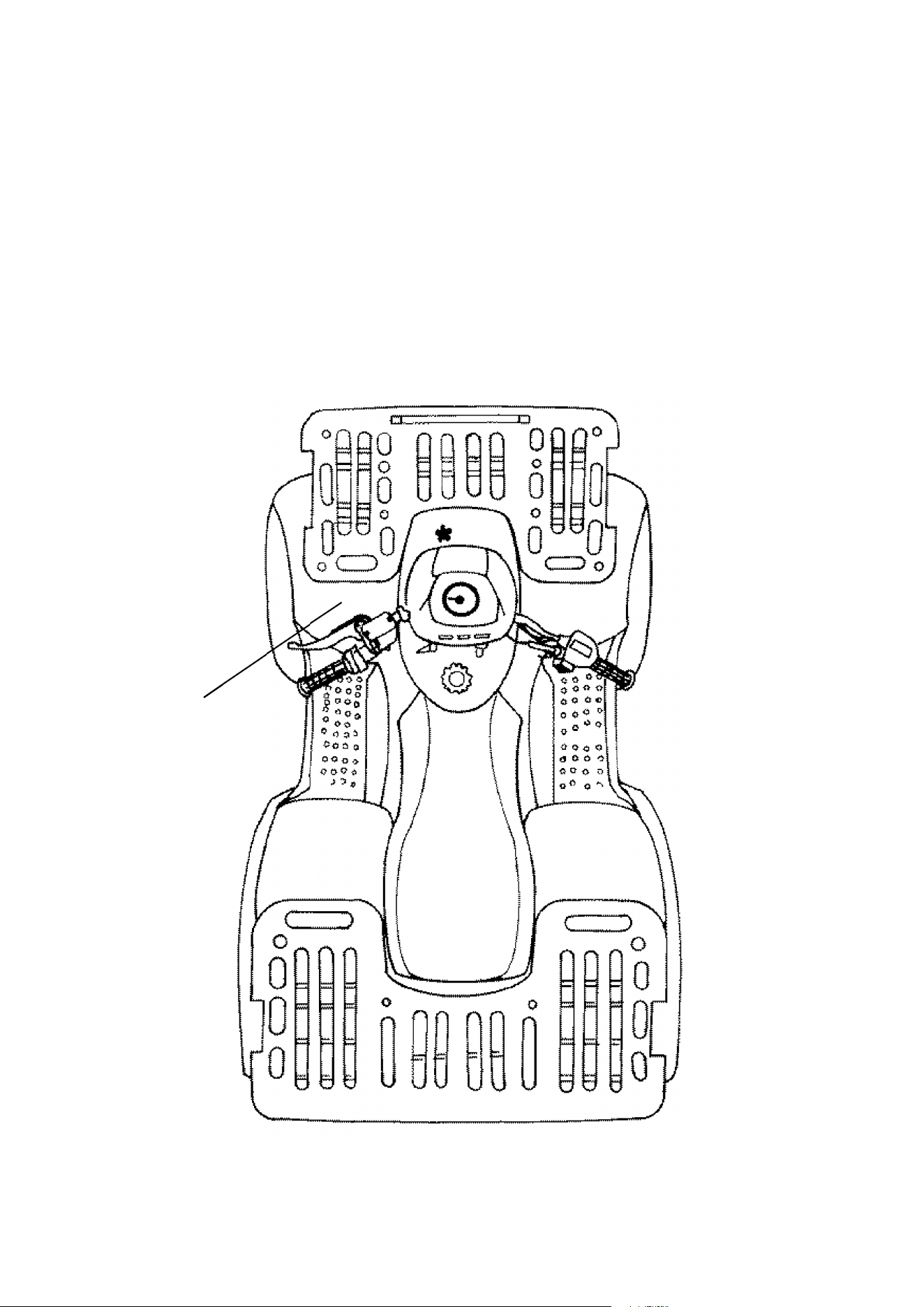
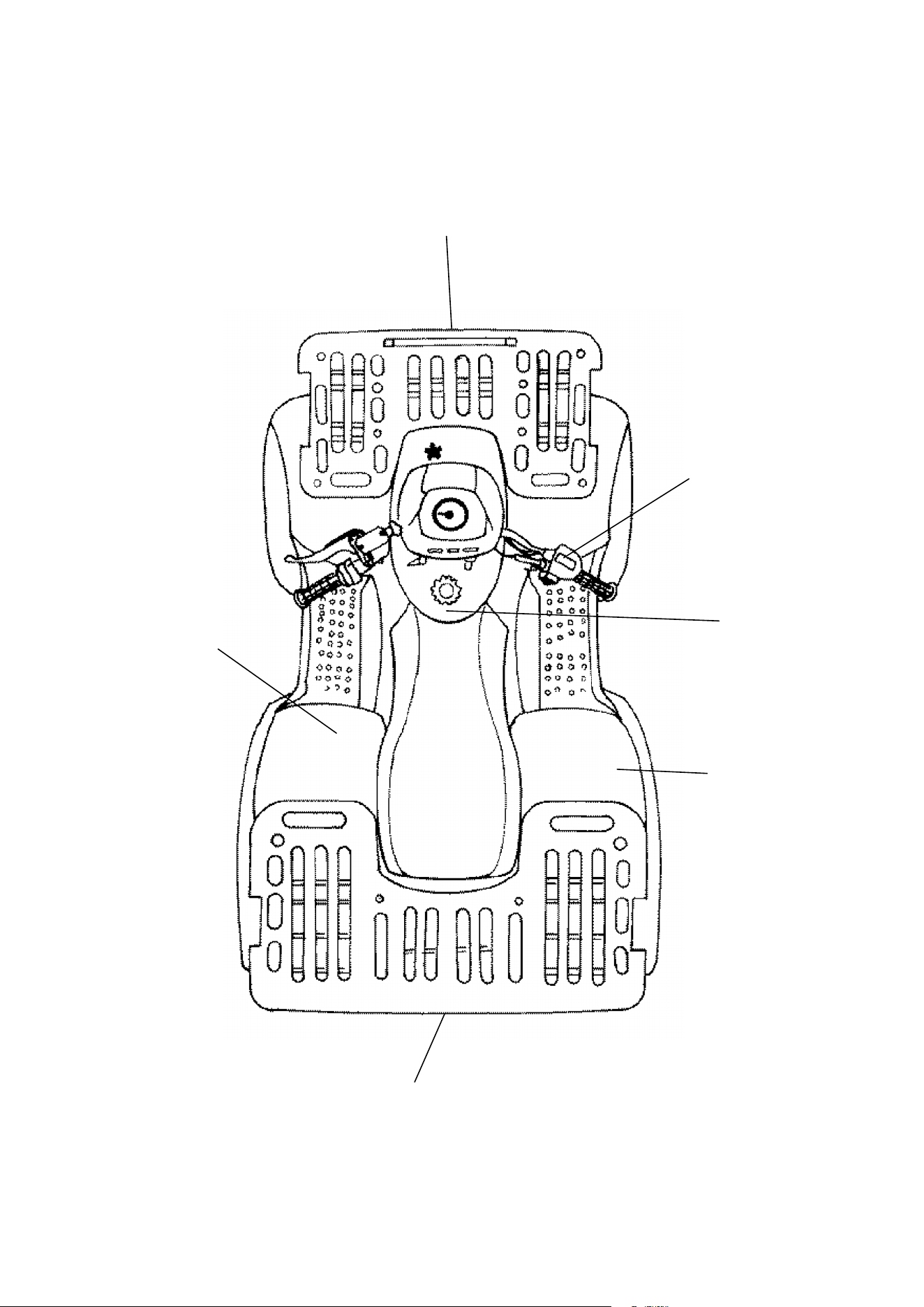
SAFETY WARNING AND OPERATION DECALS
NOTE:
Warning decals have been placed on the vehicle for your protection. Read and
follow the instructions on each decal carefully. In the event any decal becomes il-
legible or comes off, contact your Polaris dealer for a replacement. Any safety de-
cal needing replacement will be provided by Polaris at no charge. The part number
is printed on the decal.
1
4
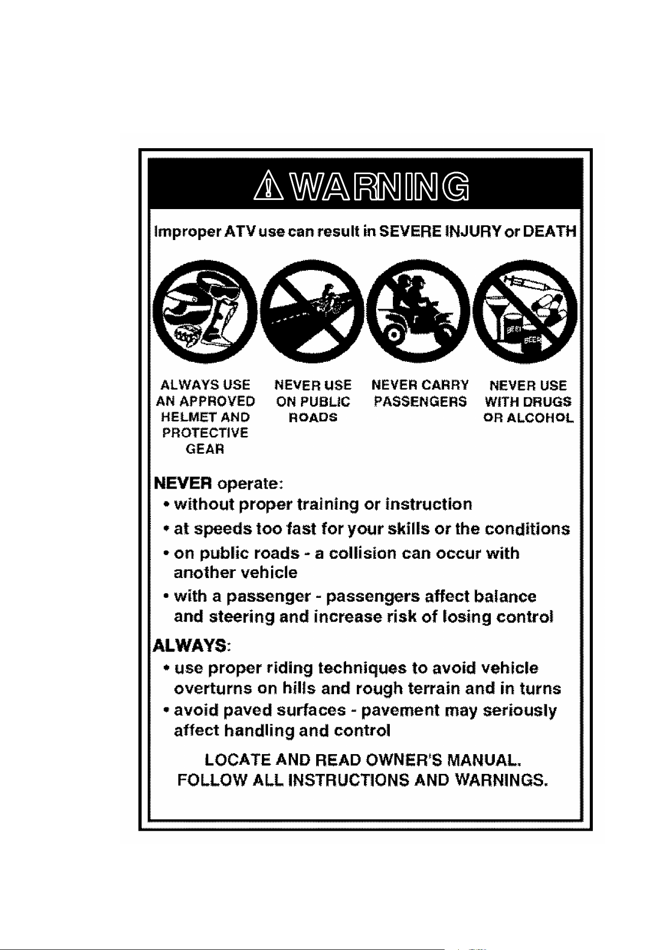
SAFETY WARNING AND OPERATION DECALS
1
5
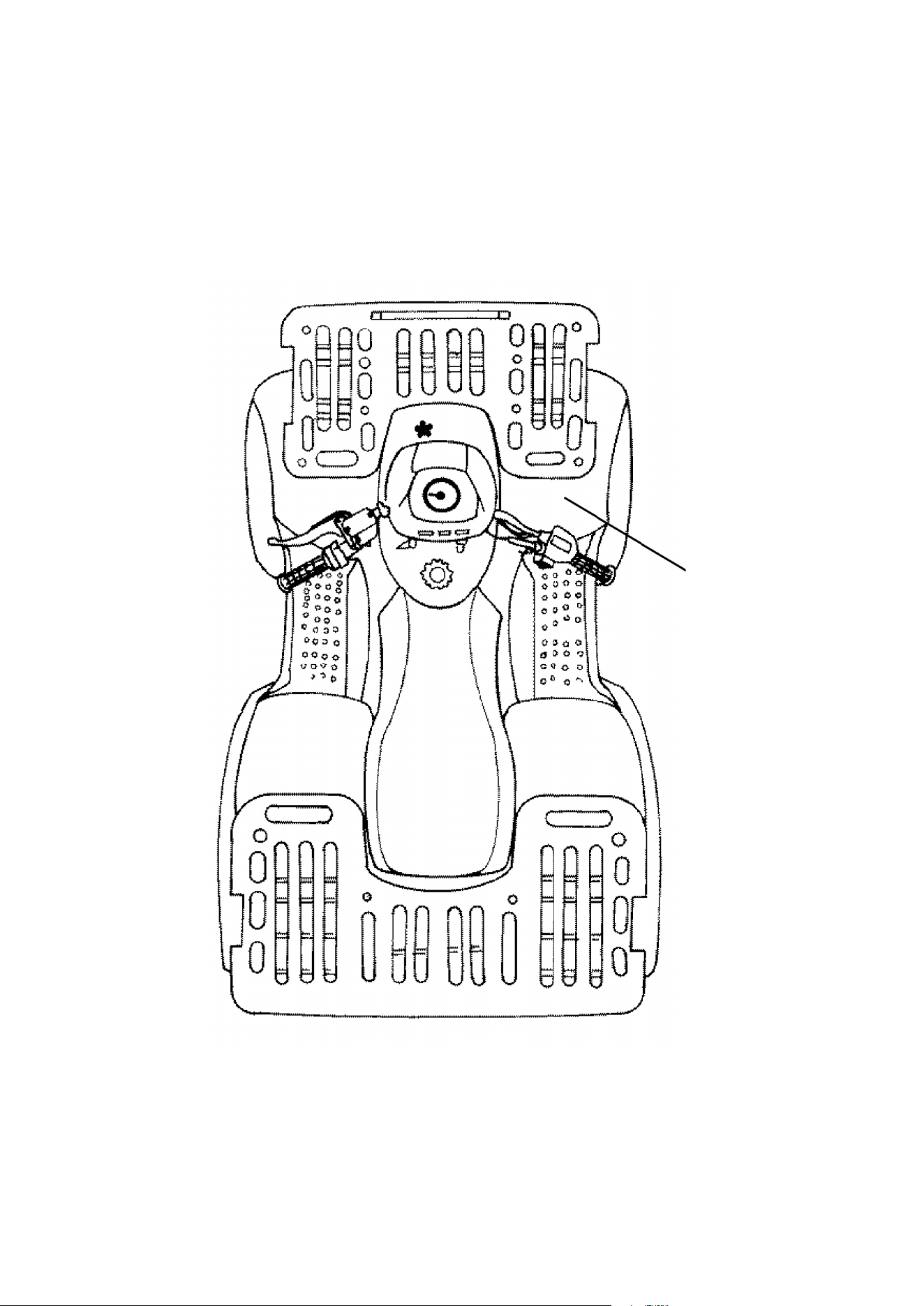
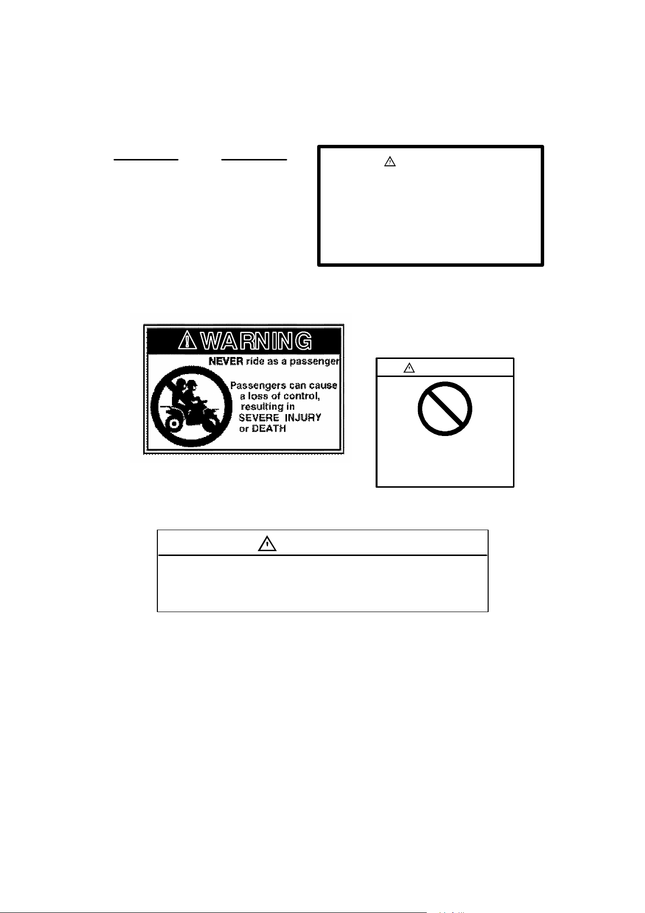
SAFETY WARNING AND OPERATION DECALS
2

6
SAFETY WARNING AND OPERATION DECALS
2
25_
WARNING
READ AND UNDERSTAND WARNINGS AND OWNER’S MANUAL BEFORE
OPERATION. SEVERE INJURY OR DEATH CAN RESULT FROM IGNORING
WARNINGS OR IMPROPER USE.
TO REDUCE TIPOVER RISK, BE ESPECIALLY CAREFUL WHEN
ENCOUNTERING OBSTACLES AND SLOPES, WHEN BRAKING ON HILLS
OR DURING TURNS.
KEEP FEET ON FOOTRESTS AT ALL TIMES.
HILL CLIMBING IS DANGEROUS, and should be attempted only by
experienced operators. Start on shallow slopes and practice procedures
described in Owner’s Manual before trying steeper terrain. Some hills are too
steep to safely stop or recover from an unsuccessful climbing attempt.
Effectiveness of brakes is significantly reduced on hills.
Never operate this ATV on grades steeper than 25 degrees . If vehicle
slides backwards down hill, apply hand brakes with gradual, even pressure to
avoid flipover. Never open throttle suddenly as flipover may result.
REDUCE SPEED when operating this vehicle on rough or hilly terrain, or when
carrying cargo on the racks.
REVERSE OPERATION CAN BE DANGEROUS evenat low speeds. Steering
control becomes difficult. When backing up, proceed slowly and apply hand
brakes carefully; aggressive braking may result in flipover. Avoid backing
downhill. Avoid turning at sharp angles in reverse.
USE OVERRIDE FOR REVERSE SPEED LIMITER WITH CAUTION; it allows
full engine power and can result in excessive speeds. Never activate override
button while throttle is open, as loss of control may result.
STOPPING DISTANCE MAY INCREASE with wet brakes or on wet surfaces.
AUXILIARY FOOT BRAKE: The right foot auxiliary brake pedal operates the
rear brake only. When backing up or when operating on hills, avoid sudden use
of the auxiliary brake; aggressive braking may result in flipover.
PARK BRAKE MAY RELAX WHEN USED FOR LONG PERIODS. When
parking on grades, leave the gear shift in forward and don’t leave brake
engaged for more than 5 minutes.
VEHICLE DESIGNED MAINLY FOR WARM WEATHER USE. Throttle linkage
and brakes may stick if operated in freezing weather, causing loss of control.
Dirt, mud, water, or other contaminants can also affect operation of controls.
Check both frequently.
ENGINE SHUT OFF SWITCH is available for use in event of throttle failure or
other emergency when engine shut off is desired.
NEVER PERMIT A GUEST TO OPERATE THIS ATV unless the guest has
read the Owner’s Manual and all labels, and has completed a certified training
course.
7075413
CAUTION: Do not shift transmission while vehicle is moving.
7
SAFETY WARNING AND OPERATION DECALS
4
5
6
7
6
3
8
SAFETY WARNING AND OPERATION DECALS
ETC
This vehicle is equipped with a
Polaris Electronic Throttle Control
(ETC) to reduce the risk of a stuck
or “frozen” throttle. Please refer to
your Owner’s Manual for details.
7072724
5
WARNING
OVER-LOADING CAN CAUSE STEER ING,
TIPPING A ND BRAKING PROBLEMS RE-
SULTING IN LOSS OF CONTROL.
LOSS OF CONTROL CAN CAUSE SEVERE
INJURY OR DEATH.
DO NOT OVERLOAD THE ATV.
SEE YOUR OWNER’S MANUAL.
7072786
7
WARNING
Operating this ATV if you are under
the age of 18 increases your chance
of severe injury or death.
NEVER operate this ATV if you are
under age 18.
7074827
UNDER
81
3
WARNING
DO NOT TOW FROM RACK OR BUMPER.
Vehicle damage or tipover may result causing severe injury
or death. Tow only from tow hooks or hitch.
7074954
6
(Found on models with no racks)
(Found on models with racks)
4

9
SAFETY WARNING AND OPERATION DECALS
WARNING
LOAD DISTRIBUTION WARNINGS
Correct loading of this vehicle is necessary to maintain proper stability and operating char-
acteristics. Overloading or incorrect positioning of the load effects the vehicles turning,
stopping distance and stability. Failure to follow loading requirements could cause severe
injury or death. REDUCE SPEED AND ALLOW GREATER DISTANCE FOR BRAKING
WHEN CARRYING CARGO.
CARGO WEIGHT DISTRIBUTION should be 1/3 on the front rack and 2/3 on the rear rack.
When operating over rough or hilly terrain, reduce speed and cargo to maintain stable driv-
ing conditions. Maximum cargo capacity is 270 lbs. on level terrain. When operating at
maximum cargo capacity, the cargo weight distribution must be 90 lbs. on the front rack and
180 lbs. on the rear rack.
ALL LOADS MUST BE SECURED BEFORE MOVING VEHICLE. Unsecured loads can
create unstable operating conditions which could result in loss of control of the vehicle.
LOADS MUST BE CARRIED AS LOW ON THE RACKS AS POSSIBLE. Carrying loads
high on the racks raises the center of gravity of the vehicle and creates a less stable operat-
ing condition. When cargo loads are carried high on the racks, the weight of the loads must
be reduced to maintain stable operating conditions.
OPERATE ONLY WITH STABLE AND SAFELY ARRANGED LOADS. When handling off-
centered loads which cannot be centered, securely fasten load and operate with extra cau-
tion.
EXTREME CAUTION MUST BE USED when operating with loads extending over the rack
sides. Stability and maneuverability may be adversely affected, causing the machine to
overturn.
DO NOT BLOCK THE FRONT HEADLIGHT BEAM when carrying loads on the front rack.
SEE YOUR OWNER’S MANUAL.
7074110
7
This decal is found only on models with dual racks.

10
SAFETY WARNING AND OPERATION DECALS
WARNING
RACK LOAD WARNINGS
Correct loading of this vehicle is necessary to maintain proper stability and operating
characteristics. Overloading or incorrect positioning of the load effects the vehicles
turning, stopping distance and stability. Failure to follow loading requirements could
cause severe injury or death. REDUCE SPEED AND ALLOW GREATER
DISTANCE FOR BRAKING WHEN CARRYING CARGO.
MAXIMUM CARGO CAPACITY is 125 lbs. on level terrain. When operating over
rough or hilly terrain, reduce speed and cargo to maintain stable driving conditions.
ALL LOADS MUST BE SECURED BEFORE MOVING VEHICLE. Unsecured loads
can create unstable operating conditions which could result in loss of control of the
vehicle.
LOADS MUST BE CARRIED AS LOW ON THE RACK AS POSSIBLE. Carrying
loads high on the rack raises the center of gravity of the vehicle and creates a less
stable operating condition. When cargo load is carried high on the rack, the weight
of the load must be reduced to maintain stable operating conditions.
OPERATE ONLY WITH STABLE AND SAFELY ARRANGED LOADS. When
handling off-centered loads which cannot be centered, securely fasten load and
operate with extra caution.
EXTREME CAUTION MUST BE USED when operating with loads extending over
the rack sides. Stability and maneuverability may be adversely affected, causing the
machine to overturn.
SEE YOUR OWNER’S MANUAL. 7074173
7
This decal is found on models with only rear racks.
11
SAFETY WARNING AND OPERATION DECALS
8
ATTENTION
DOPERATION OF THIS VEHICLE WITHOUT
THE FILTER ELEMENT WILL SEVERELY
DAMAGE THE ENGINE.
DCLEAN AIR FILTER OFTEN, MORE FRE-
QUENT CLEANING REQUIRED IN
DUSTY CONDITIONS.
DLiutilisation de ce véhicule sous liélément
filtre endommage sévèrement le moteur.
DNettoyer souvent le filtre à air, surtout dans
des situations poussiereuses.
7072791
BRAKE SHIELD COVERS MOVING PARTS.
CONTACT WITH MOVING PARTS MAY RESULT
IN SEVERE INJURY.
DO NOT REMOV E BRAKE SHIELD.
7075339
WARNING
(On right side)
(Under Seat)
8
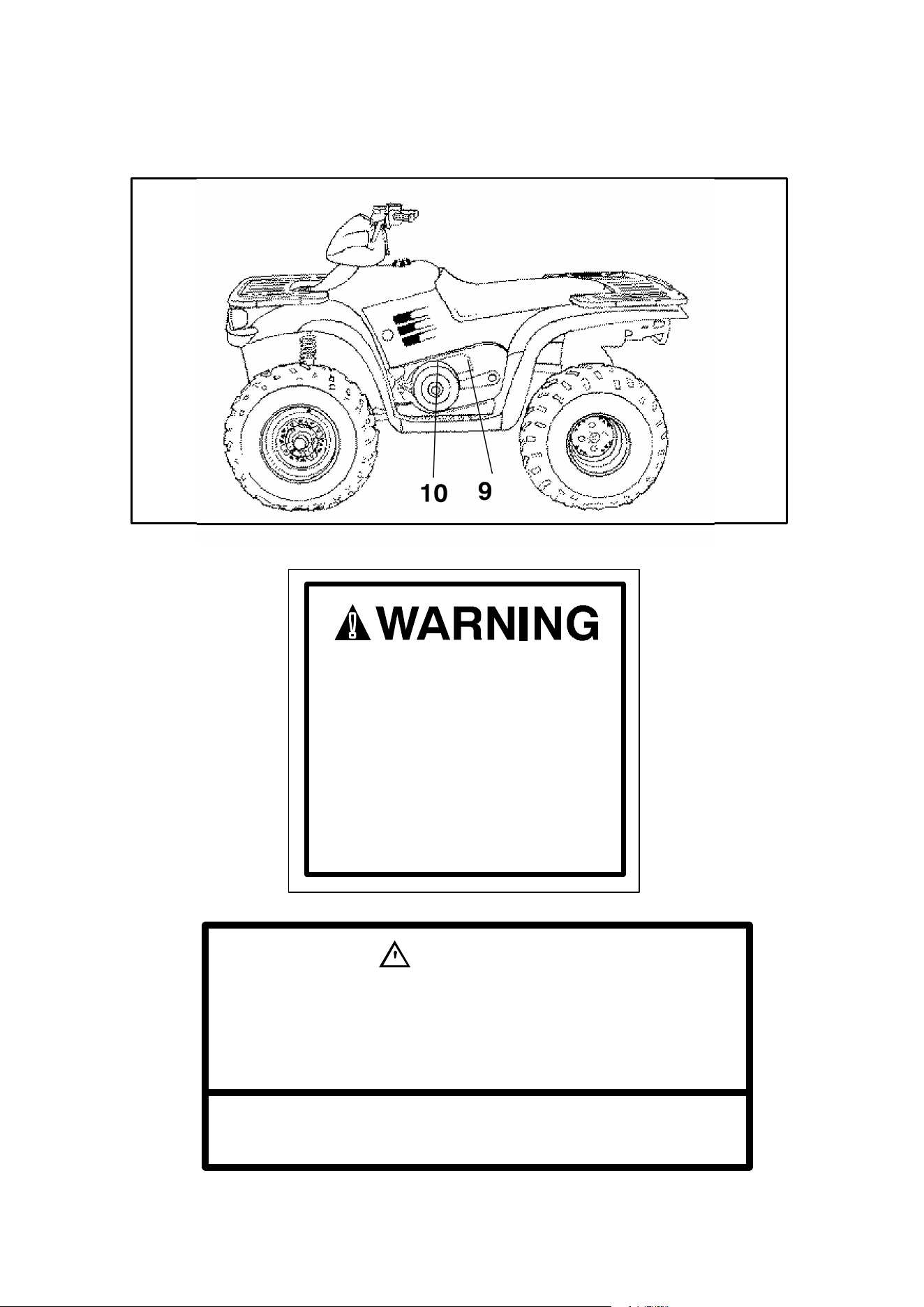
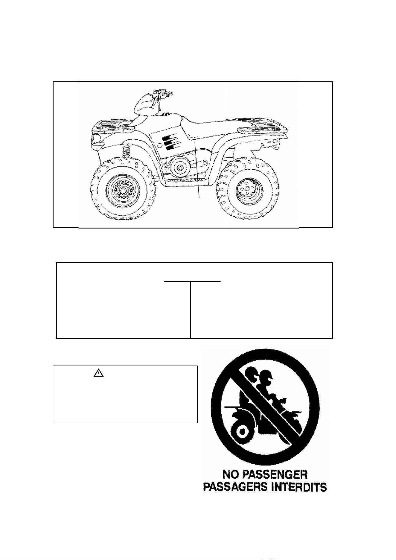
12
SAFETY WARNING AND OPERATION DECALS
9
10
DO NOT ATTEMPT ENGINE OR
CLUTCH MODIFICATION. DOING SO
CAN CAUSE IMBALANCE AND/OR
EXCESSIVE ENGINE RPM.
EXCESSIVE ENGINE RPM CAN CAUSE
PART FAILURE RESULTING IN
POSSIBLE SEVERE INJURY OR
DEATH.
DO NOT MODIFY ENGINE OR CLUTCH.
9
10
BELT -- CLUTCH GUARD COVERS MOVING PARTS.
CONTACT WITH MOVING PARTS MAY RESULT IN SEVERE
INJURY OR DEATH.
DO NOT OPERATE VEHICLE WITH GUARD REMOVED.
WARNING
NO STEP
7074946
7077377
13
SAFETY WARNING AND OPERATION DECALS
VEHICLE LIGHTS WILL
BURN OUT IF BATTERY
IS DISCONNECTED
DURING VEHICLE
OPERATION.
Les phares et les
ampoules du véhicule
sautent si la batterie est
désaccouplée durant le
fonctionnement du
véhicule.
7072606
CAUTION
PRECAUTION
ALL WHEEL
DRIVE
SWITCH
Do not push switch to
engage AWD if the rear
wheels are spinning.
This may cause severe
drive shaft and clutch
damage.
See your Owner’s
Manual.
7074935
MANUFACTURED BY: PO-
LARIS IND
DATE:
VIN:
THIS VEHICLE IS AN ALL TERRAIN VEHICLE AND
IS NOT INTENDED FOR USE ON PUBLIC ROADS.
THIS VEHICLE CONFORMS TO ALL APPLICABLE
FEDERAL MOTOR VEHICLE SAFETY STAN-
DARDS IN EFFECT ON THE DATE OF ITS
MANUFACTURE AS SHOWN ABOVE.
PRINTED IN U.S.A.
7073464
CE VÉHICULE EST UN VÉHICULE TOUT TERRAIN
QUI NiEST PAS DESTINÉ À ÊTRE UTILISÉ SUR
LES CHEMINS PUBLICS. CE VÉHICULE EST CON-
FORME À TOUTES LES NORMES DE SÉCURITÉ
FÉDÉRALES PRESCRITES QUI SONT EN VI-
GUEUR À LA DATE DE SA FABRICATION INDI-
QUÉE CI-HAUT.
Chain Freeplay Is
Important. Collapse
Suspension To Adjust.
DO NOT Overtension.
See Owner’s Manual.
Torque Eccentric Bolts
To 60 Ft. Lbs.
Le jeu libre de la chaine est
important. Écrasez la suspension
pour L’adjuster. Prenez soin de ne
pas trop serrer la chaine. Voir le
manuel d’opérateur.
Serrez les boulons de l’eccentrique
à 60 livres/pieds de pression.
7074752
ATTENTION
Specific carburetor jetting and adjustments are required depending on
temperature and altitude. See your Owner’s Manual.
Factory setting:
40° to 80° F. at 0-3000 feet. (+5° to 26° C. at 0-900 meters). 7073761
TRAILER MAX.
WEIGHT 850 LBS.
HITCH MAX. VERTICAL
WEIGHT 30 LBS.
POIDS MAX. DE
REMORQUE 386 KG.
POIDS MAX.
VERTICAL D’ATTACHE
14 KG.
OVERRIDE
SWITCH
Reverse override
and all wheel drive
activation in reverse
is controlled by the
override switch.
See your Owner’s
Manual.
7076273
LUBRICATE SWING ARM AND OUTPUT SHAFT
BEARINGS MONTHLY; MORE OFTEN IN WET
OR VERY DUSTY CONDITIONS.
SEE YOUR OWNER’S MANUAL. 7074214
ATTENTION
Reverse Speed is
limited.
Reverse override is
controlled by the
override switch.
See your Owner’s
Manual.
OVERRIDE
SWITCH
7076274
AWD Models 2WD Models
7077542
TRAILER MAX WEIGHT:
1250 LBS. (568 KG) ON LEVEL GROUND
850 LBS. (368 KG) UP TO 15° GRADE
HITCH MAX. VERTICAL WEIGHT: 30 LBS. (14KG)
7072533
(Found on Sportsman 500)
(Found on all models except Sportsman 500)

14
DAILY PRE-RIDE INSPECTION
Inspect your ATV each time before riding to ensure it is in proper working or-
der. If proper inspection is not done, severe injury or death could result.
WARNING
If a proper inspection is not performed serious injury or death can result.
Always inspect your ATV before riding following the checklist carefully.
Before riding your vehicle, inspect all operating controls and parts.
Item/Inspection Procedure
1. Tires - check condition and pressures
2. Fuel and oil tanks - fill both tanks to their proper levels
3. All brakes - check operation, adjustment and fluid level (includes
auxiliary brake)
4. Throttle - check for free operation and closing
5. Headlight/Taillight/Brakelight - check operation of all indicator lights
and switches
6. Engine stop switch - check for proper function
7. Wheels - check for tightness of wheel nuts and axle nuts; check that
axle nuts are secured by cotter pins
8. Drive chain - condition and slack; refer to drive chain adjustment
9. Air cleaner element - check for dirt; clean or replace
10. Steering - check for free operation noting any unusual looseness in
any area
11. Loose parts - visually inspect vehicle for any damaged or loose nuts/
bolts or fasteners
12. Operators helmet, goggles and clothing
13. Engine coolant - (Liquid Cooled Models Only) check for proper level
at the recovery bottle
15
OPERATION WARNINGS
WARNING
WARNING
POTENTIAL HAZARD
Operating this ATV without proper instruction.
WHAT CAN HAPPEN
The risk of an accident is greatly increased if the operator does not
know how to operate the ATV properly in different situations and on dif-
ferent types of terrain.
HOW TO AVOID THE HAZARD
Beginning and inexperienced operators should complete the certified
training course offered by Polaris Industries Inc. They should then reg-
ularly practice the skills learned in the course and the operating tech-
niques described in the Owner’s Manual.
For more information about the training course, contact an authorized
ATV dealer or call Polaris at 1-800-342-3764.
POTENTIAL HAZARD
Failure to follow the age recommendations for this ATV.
WHAT CAN HAPPEN
Use by children of ATVs that are not recommended for their age can
lead to severe injury or death of the child.
Even though a child may be within the age group for which some ATVs
are recommended, he or she may not have the skills, abilities, or judg-
ment needed to operate the ATV safely and may be involved in a seri-
ous accident.
HOW TO AVOID THE HAZARD
No one under 18 should operate a Polaris ATV.
16
OPERATION WARNINGS
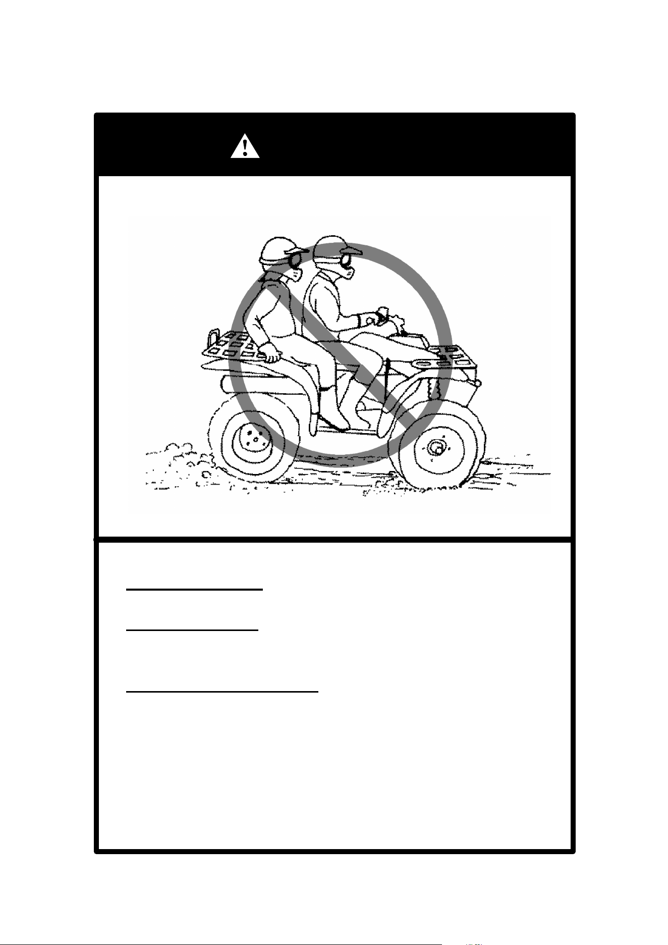
WARNING
POTENTIAL HAZARD
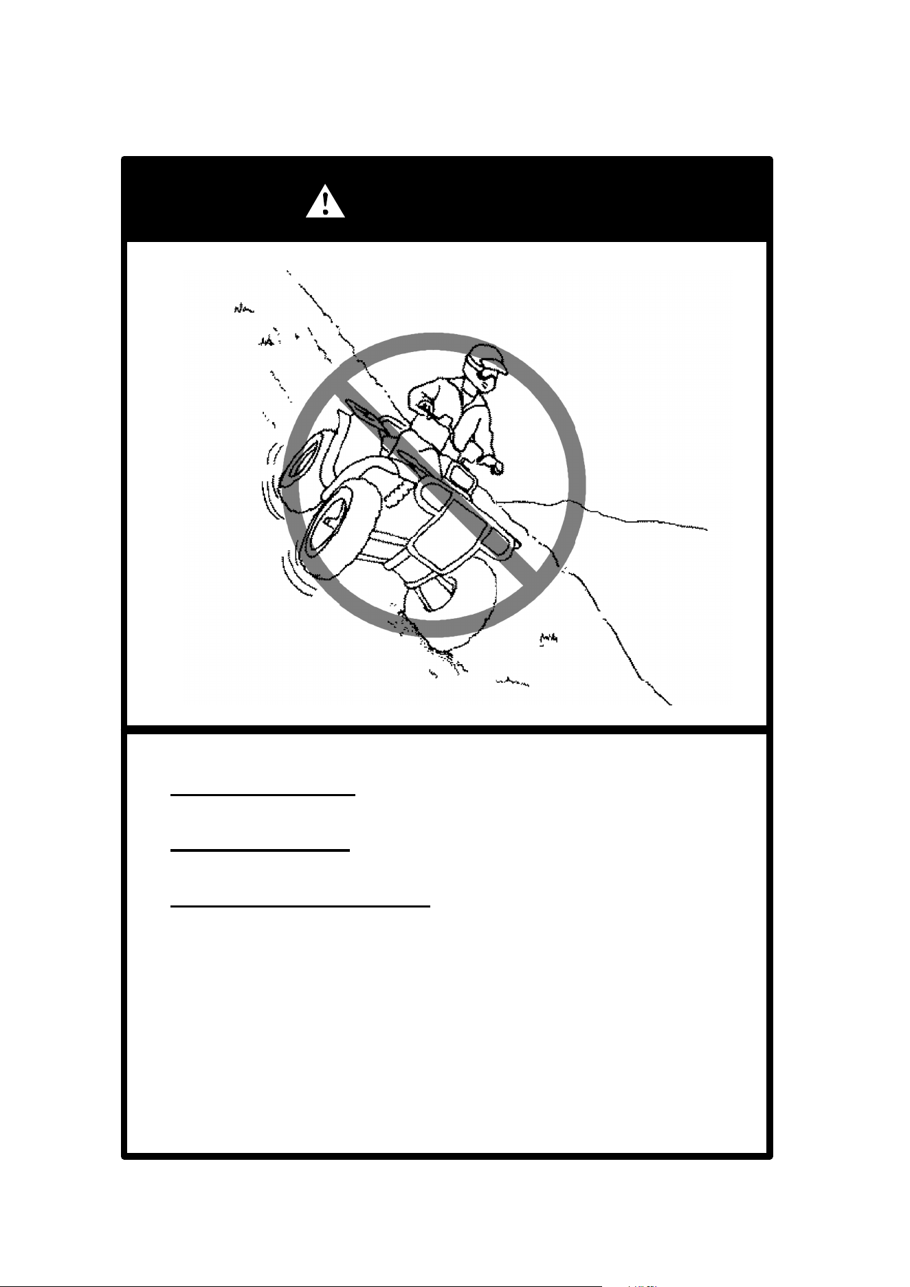
Carrying a passenger on this ATV.
WHAT CAN HAPPEN
Greatly reduces your ability to balance and control this ATV.
Could cause an accident, resulting in harm to you and/or yourpassenger.
HOW TO AVOID THE HAZARD
Never carry a passenger. The long seat is to allow the operator to shift
position as needed during operation. It is not for carrying passengers.
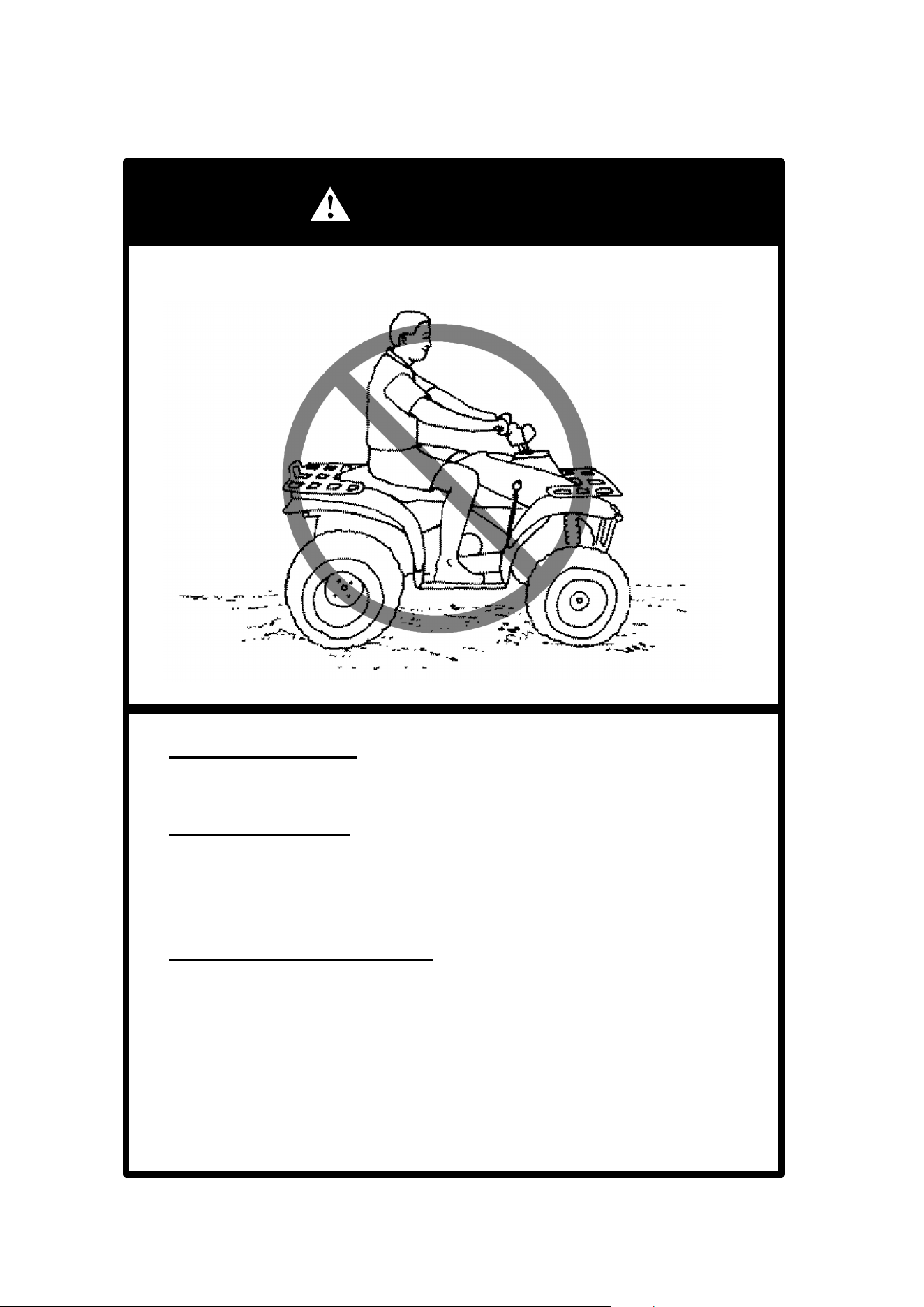
17
OPERATION WARNINGS
WARNING
POTENTIAL HAZARD
Operating this ATV on paved surfaces.
WHAT CAN HAPPEN
The ATV’s tires are designed for off-road use only; not for use on
pavement. Paved surfaces may seriously affect handling and control
of the ATV, and may cause the vehicle to go out of control.
HOW TO AVOID THE HAZARD
Never operate the ATV on any paved surfaces, including sidewalks,
driveways, parking lots and streets.
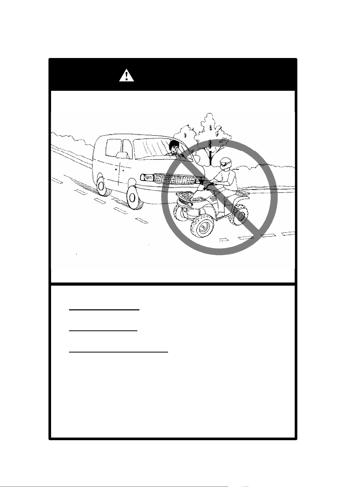
18
OPERATION WARNINGS
WARNING
POTENTIAL HAZARD
Operating this ATV on public streets, roads or highways.
WHAT CAN HAPPEN
You can collide with another vehicle.
HOW TO AVOID THE HAZARD
Never operate this ATV on any public street, road or highway, even
a dirt or gravel one.
In many states it is illegal to operate ATVs on public streets, roads
and highways.
19
OPERATION WARNINGS
WARNING
POTENTIAL HAZARD
Operating this ATV without wearing an approved helmet, eye protection
and protective clothing.
WHAT CAN HAPPEN
Operating without an approved helmet increases your chances of a se-
vere head injury or death in the event of an accident.
Operating without eye protection can result in an accident and in-
creases your chances of a severe injury in the event of an accident.
HOW TO AVOID THE HAZARD
Always wear an approved helmet which fits properly.
You should also wear:
Deye protection (goggles or face shield);
Dgloves;
Dboots;
Dlong-sleeved shirt or jacket; and
Dlong pants.
20
OPERATION WARNINGS
WARNING
WARNING
POTENTIAL HAZARD
Operating this ATV after consuming alcohol or drugs.
WHAT CAN HAPPEN
Could seriously affect your judgment.
Could cause you to react more slowly.
Could affect your balance and perception.
Could result in an accident.
HOW TO AVOID THE HAZARD
Never consume alcohol or drugs before or while driving this ATV.
POTENTIAL HAZARD
Operating this ATV at excessive speeds.
WHAT CAN HAPPEN
Increases your chances of losing control of the ATV, which can result
in an accident.
HOW TO AVOID THE HAZARD
Always travel at a speed which is proper for the terrain, visibility and
operating conditions; and your experience.
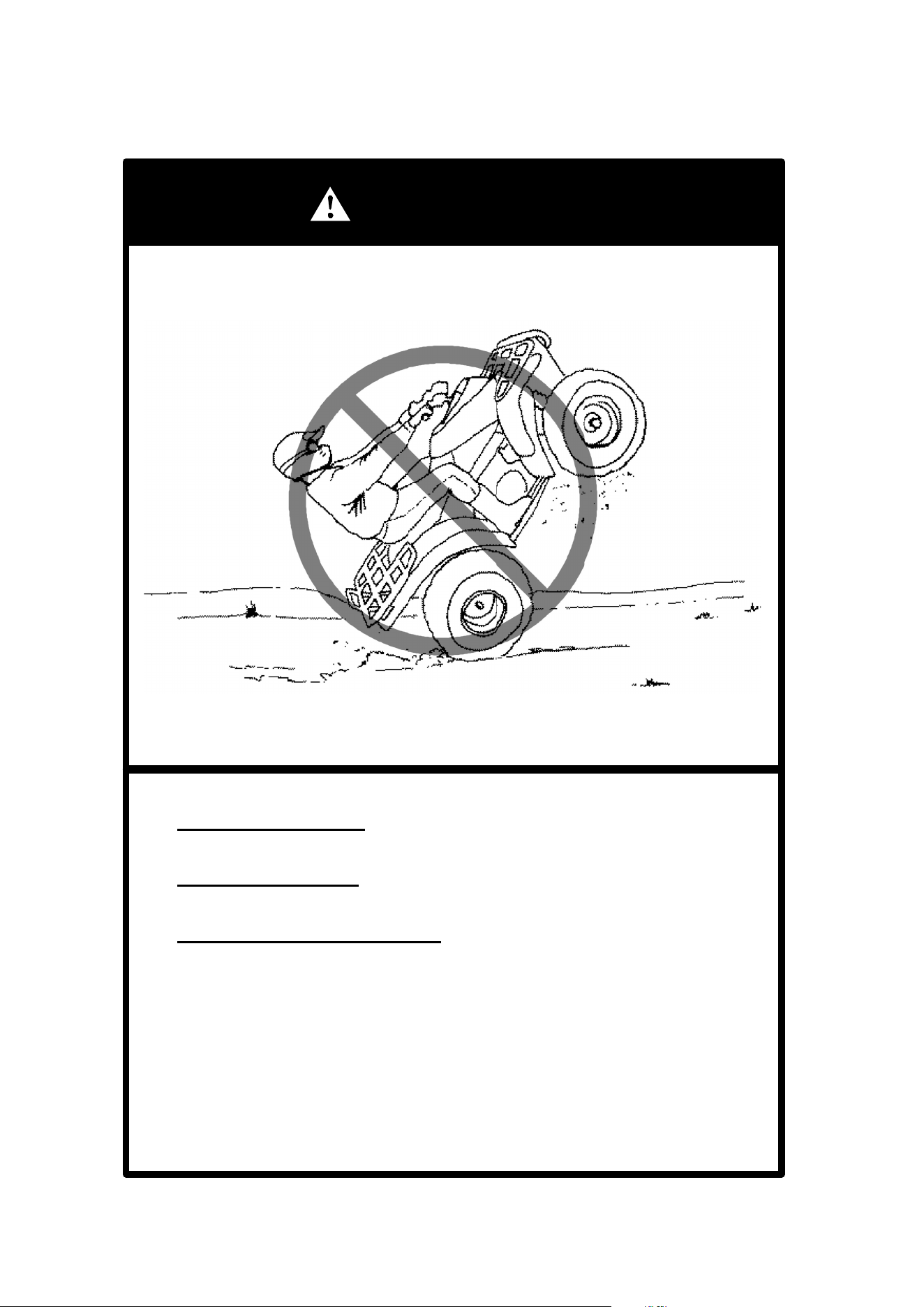
21
OPERATION WARNINGS
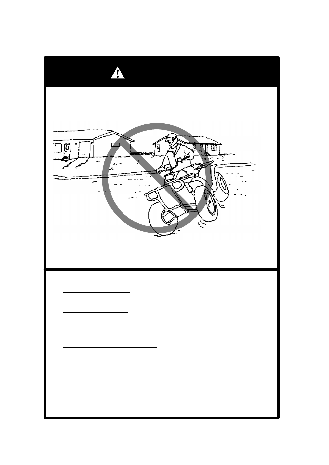
WARNING
POTENTIAL HAZARD
Attempting wheelies, jumps and other stunts.
WHAT CAN HAPPEN
Increases the chance of an accident, including an overturn.
HOW TO AVOID THE HAZARD
Never attempt stunts, such as wheelies or jumps. Don’t try to show off.
22
OPERATION WARNINGS
WARNING
WARNING
POTENTIAL HAZARD
Failure to inspect the ATV before operating.
Failure to properly maintain the ATV.
WHAT CAN HAPPEN
Increases the possibility of an accident or equipment damage.
HOW TO AVOID THE HAZARD
Always inspect your ATV each time you use it to make sure the ATV
is in safe operating condition.
Always follow the inspection and maintenance procedures and
schedules described in the Owner’s Manual.
POTENTIAL HAZARD
Removing hands from handlebars or feet from footrests during op-
eration.
WHAT CAN HAPPEN
Removing even one hand or foot can reduce your ability to control
the ATV or could cause you to lose your balance and fall off the ATV.
If you remove a foot from the footrest, your foot or leg may come into
contact with the rear wheels, which could injure you or cause an acci-
dent.
HOW TO AVOID THE HAZARD
Always keep both hands on the handlebars and both feet on the foot-
rests of your ATV during operation.
23
OPERATION WARNINGS
WARNING
POTENTIAL HAZARD
Failure to use extra care when operating this ATV on unfamiliarterrain.
WHAT CAN HAPPEN
You can come upon hidden rocks, bumps, or holes, without enough
time to react.
Could result in the ATV overturning or going out of control.
HOW TO AVOID THE HAZARD
Go slowly and be extra careful when operating on unfamiliar terrain.
Always be alert to changing terrain conditions when operating the
ATV.
24
OPERATION WARNINGS
WARNING
POTENTIAL HAZARD
Failure to use extra care when operating on excessively rough, slip-
pery or loose terrain.
WHAT CAN HAPPEN
Could cause loss of traction or vehicle control, which could result in
an accident, including an overturn.
HOW TO AVOID THE HAZARD
Do not operate on excessively rough, slippery or loose terrain until
you have learned and practiced the skills necessary to control the
ATV on such terrain.
Always be especially cautious on these kinds of terrain.

25
OPERATION WARNINGS
WARNING
WARNING
POTENTIAL HAZARD
Turning improperly.
WHAT CAN HAPPEN
ATV could go out of control, causing a collision or overturn.
HOW TO AVOID THE HAZARD
Always follow proper procedures for turning as described in the Own-
er’s Manual. See page 63 .
Practice turning at low speeds before attempting to turn at faster
speeds.
Do not turn at excessive speed.
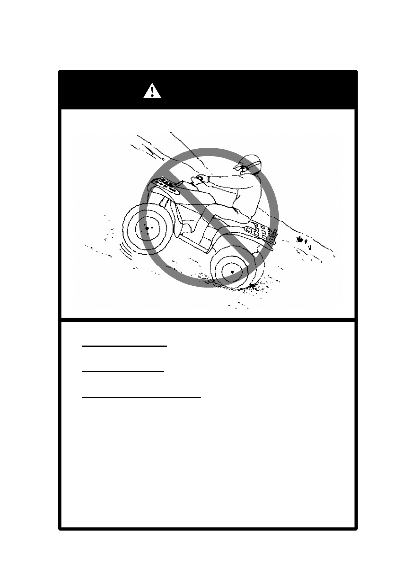
POTENTIAL HAZARD
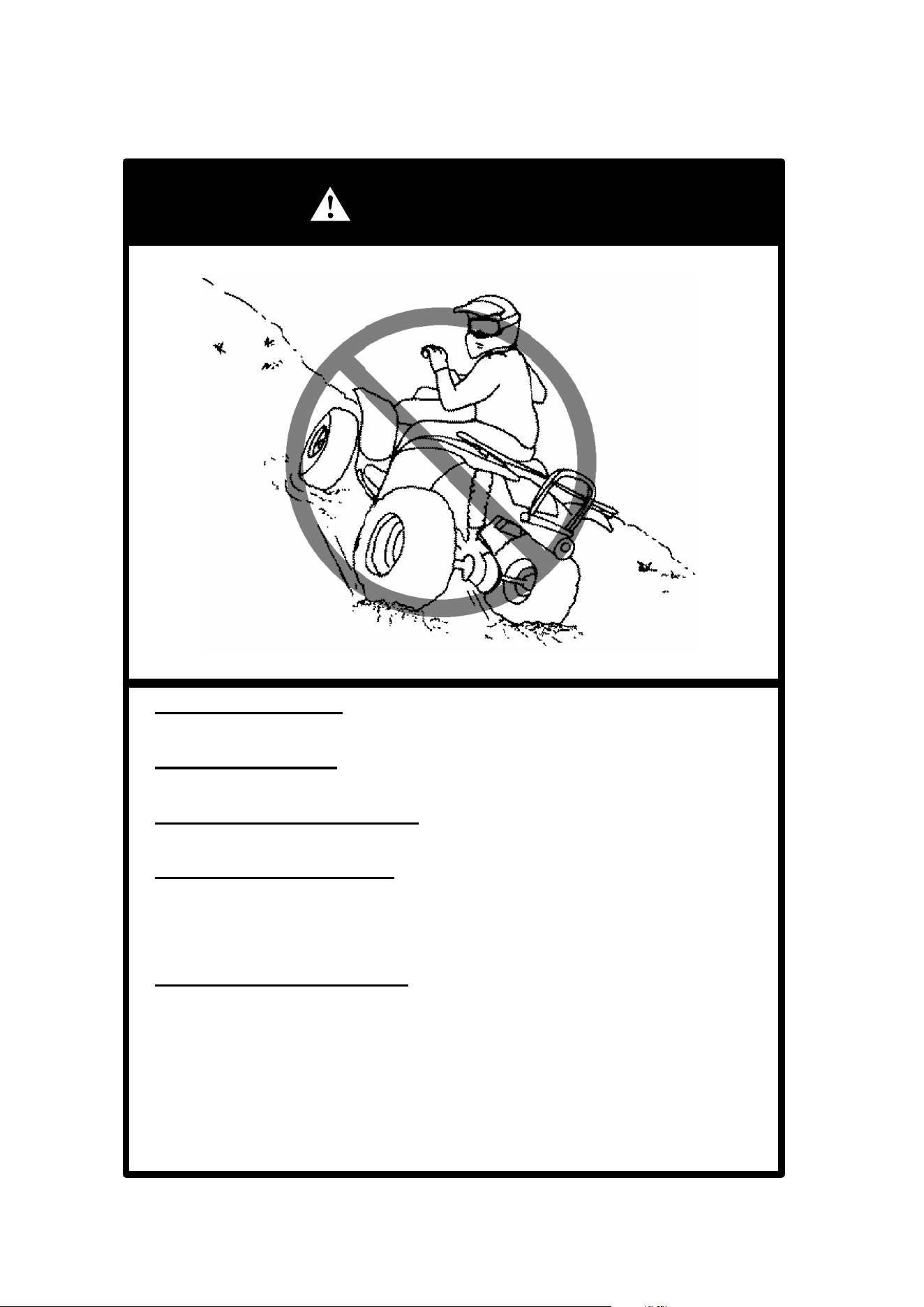
Operating on excessively steep hills.
WHAT CAN HAPPEN
The vehicle can overturn more easily on extremely steep hills than on
level surfaces or small hills.
HOW TO AVOID THE HAZARD
Never operate the ATV on hills too steep for the ATV or for your abilities.
Practice on smaller hills before attempting large hills.
Never operate ATV on hills steeper than 25_.
26
OPERATION WARNINGS
WARNING
POTENTIAL HAZARD
Climbing hills improperly.
WHAT CAN HAPPEN
Could cause loss of control or cause ATV to overturn.
HOW TO AVOID THE HAZARD
Always follow proper procedures for climbing hills as described in the
Owner’s Manual. See pages 65 through 68.
Always check the terrain carefully before you start up any hill.
Never climb hills with excessively slippery or loose surfaces.
Shift your weight forward.
Never open the throttle suddenly. The ATV could flip over backwards.
Never go over the top of any hill at high speed. An obstacle, a sharp
drop, or another vehicle or person could be on the other side of the
hill.
27
OPERATION WARNINGS
WARNING
POTENTIAL HAZARD
Going down a hill improperly.
WHAT CAN HAPPEN
Could cause loss of control or cause ATV to overturn.
HOW TO AVOID THE HAZARD
Always follow proper procedures for going down hills as described in
the Owner’s Manual. See page 67. NOTE: A special technique is
required when braking as you go downhill.
Always check the terrain carefully before you start down any hill.
Shift your weight backward.
Never go down a hill at high speed.
Avoid going down a hill at an angle which would cause the vehicle to
lean sharply to one side. Go straight down the hill where possible.
28
OPERATION WARNINGS
WARNING
POTENTIAL HAZARD
Improperly crossing hills or turning on hills.
WHAT CAN HAPPEN
Could cause loss of control or cause ATV to overturn.
HOW TO AVOID THE HAZARD
Never attempt to turn the ATV around on any hill until you have mas-
tered the turning technique as described in the Owner’s Manual on
level ground. See page 68. Be very careful when turning on any hill.
Avoid crossing the side of a steep hill if possible.
When crossing the side of a hill:
Always follow proper procedures as described in the Owner’s Manual.
Avoid hills with excessively slippery or loose surfaces.
Shift your weight to the uphill side of the ATV.
29
OPERATION WARNINGS
WARNING
POTENTIAL HAZARD
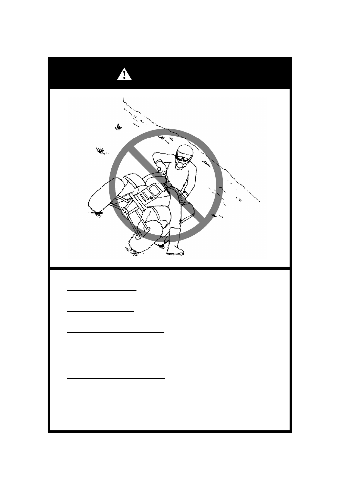
Stalling, rolling backwards or improperly dismounting while climbing a hill.
WHAT CAN HAPPEN
Could result in ATV overturning.
HOW TO AVOID THE HAZARD
Maintain steady speed when climbing a hill.
If you lose all forward speed:
Keep weight uphill.
Apply the brakes.
Lock parking brake after you are stopped.
If you begin rolling backwards:
Keep weight uphill; never apply engine power.
Never apply the rear brake while rolling backwards.
Apply the single-lever brake gradually.
When fully stopped, apply rear brake as well, and then lock parking brake.
Dismount on uphill side, or to either side if pointed straight uphill.
Turn the ATV around and remount, following the procedure described in
the Owner’s Manual. See page 68.
30
OPERATION WARNINGS
WARNING
WARNING
WARNING
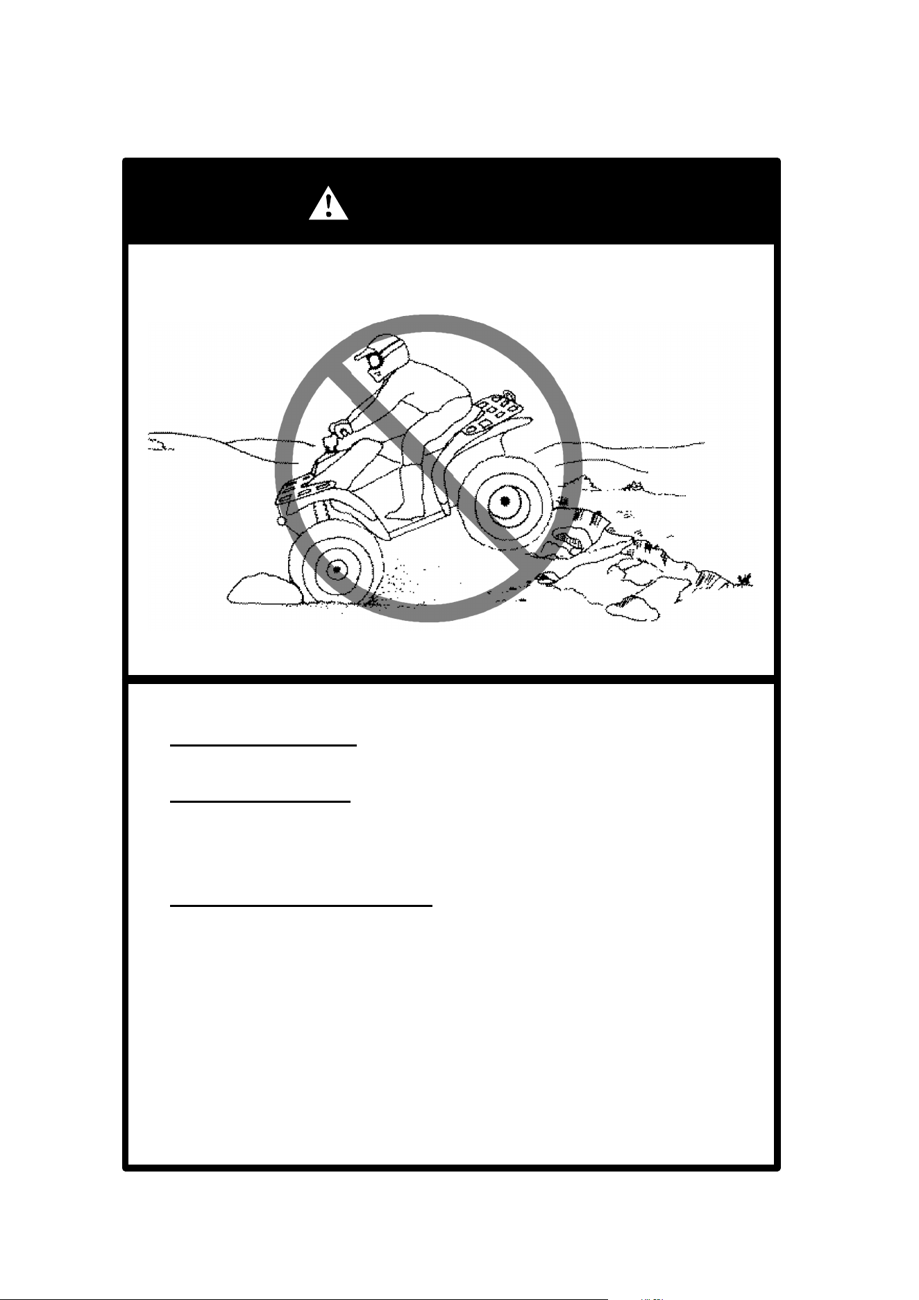
POTENTIAL HAZARD
Improperly operating over obstacles.
WHAT CAN HAPPEN
Could cause loss of control or a collision. Could cause the ATV to overturn.
HOW TO AVOID THE HAZARD
Before operating in a new area, check for obstacles.
Use extreme caution when riding over large obstacles, such as large rocks
or fallen trees.
If you cannot avoid obstacles, always follow proper procedures as de-
scribed in the Owner’s Manual.
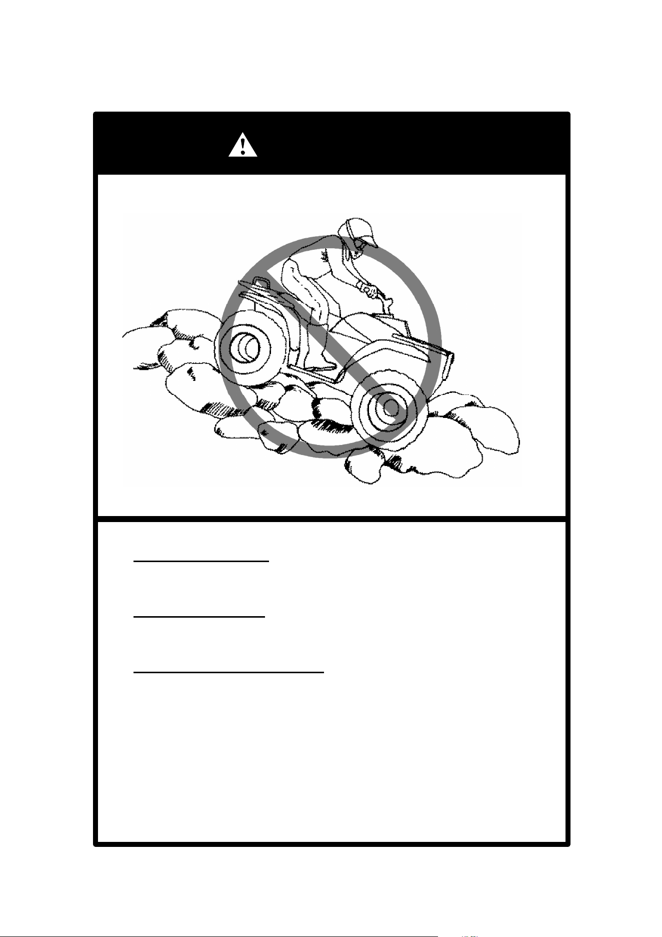
POTENTIAL HAZARD
Skidding or sliding.
WHAT CAN HAPPEN
You may lose control of the ATV.
You may also regain traction unexpectedly, which may cause the ATV to
overturn.
HOW TO AVOID THE HAZARD
On slippery surfaces, such as ice, go slowly and be very cautious in order
to reduce the chance of skidding or sliding out of control.
POTENTIAL HAZARD
Riding on frozen lakes and rivers.
WHAT CAN HAPPEN
Severe injury or death can result if the ATV and/or the operator break
through the ice.
HOW TO AVOID THE HAZARD
Never ride your ATV on a frozen body of water before you are sure the ice
is thick enough and sound enough to support the machine and its operator,
as well as the force that is created by a moving vehicle.

31
OPERATION WARNINGS
WARNING
WARNING
POTENTIAL HAZARD
Operating this ATV through deep or fast flowing water.
WHAT CAN HAPPEN
Tires may float, causing loss of traction and loss of control, which
could lead to an accident.
HOW TO AVOID THE HAZARD
Never operate this ATV in fast flowing water or in water deeper than
that specified in your Owner’s Manual. See page 69.
Remember that wet brakes may have reduced stopping ability. Test
your brakes after leaving water. If necessary, apply them several
times to let friction dry out the pads.
POTENTIAL HAZARD
Improperly operating in reverse.
WHAT CAN HAPPEN
You could hit an obstacle or person behind you, resulting in serious
injury.
HOW TO AVOID THE HAZARD
When you select reverse gear, make sure there are no obstacles or
people behind you. When it is safe to proceed, go slowly.
32
OPERATION WARNINGS
WARNING
WARNING
POTENTIAL HAZARD
Operating this ATV with improper tires, or with improper or uneven tire
pressure.
WHAT CAN HAPPEN
Use of impropertires on this ATV, or operation of this ATV with improp-
er or uneven tire pressure, may cause loss of control, and increases
the risk of an accident.
HOW TO AVOID THE HAZARD
Always use the size and type tires specified in the Owner’s Manual
Supplement for this vehicle.
Always maintain proper tire pressure as described in the Owner’s
Manual Supplement.
POTENTIAL HAZARD
Operating this ATV with improper modifications.
WHAT CAN HAPPEN
Improper installation of accessories or modification of this vehicle may
cause changes in handling which in some situations could lead to an
accident.
HOW TO AVOID THE HAZARD
Never modify this ATV through improper installation or use of acces-
sories. All parts and accessories added to this vehicle should be gen-
uine Polaris Industries Inc. or equivalent components designed for
use on this ATV; and should be installed and used according to
instructions. If you have questions, consult an authorized Polaris ATV
dealer.
33
OPERATION WARNINGS
WARNING
WARNING
POTENTIAL HAZARD
Overloading this ATV or carrying or towing cargo improperly.
WHAT CAN HAPPEN
Could cause changes in vehicle handling which could lead to an ac-
cident.
HOW TO AVOID THE HAZARD
Never exceed the stated load capacity for this ATV.
Cargo should be properly distributed and securely attached.
Reduce speed when carrying cargo or pulling a trailer. Allow greater
distance for braking.
Always follow the instructions in the Owner’s Manual for carrying car-
go or pulling a trailer. See pages 59 and 60.
After a rollover or an accident, have a qualified service dealer check
the complete machine including, but not limited to, brakes, throttle and
steering for possible damage.
WARNING
Safe operation of this rider active vehicle requires good judgement
and physical skills. Persons with cognitive or physical disabilities
who operate this vehicle have an increased risk of overturns and
loss of control which could result in serious injury or death.
CAUTION: Keep combustible materials away from exhaust system. Fire may re-
sult.
34
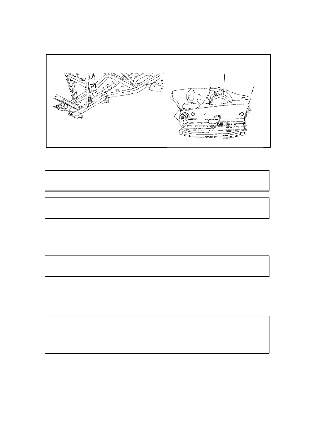
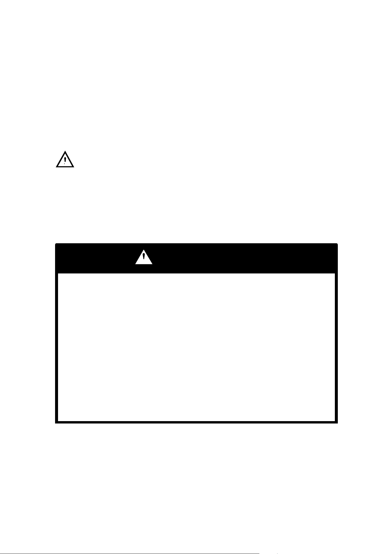
VEHICLE IDENTIFICATION NUMBERS
2 On recoil
housing
1 VIN on the lower left
side of the frame tube
Important: Record these numbers from your ATV in the spaces provided.
1. Frame VIN
2. Engine Serial Number (Right front side of engine crankcase)
Remove the spare key and store in a safe place. Record your ignition key num-
ber here. It is a four digit number found stamped on the key. In the event the
key is lost, replacement can be made by supplying your dealer with this number.
Ignition Key Number
The vehicle frame and engine serial numbers are important for model identifica-
tion when registering your vehicle, obtaining insurance or whenever replace-
ment parts are required. In the event your vehicle were stolen these numbers
are essential to the recovery and identification of your ATV.
Dealer Imprint
35
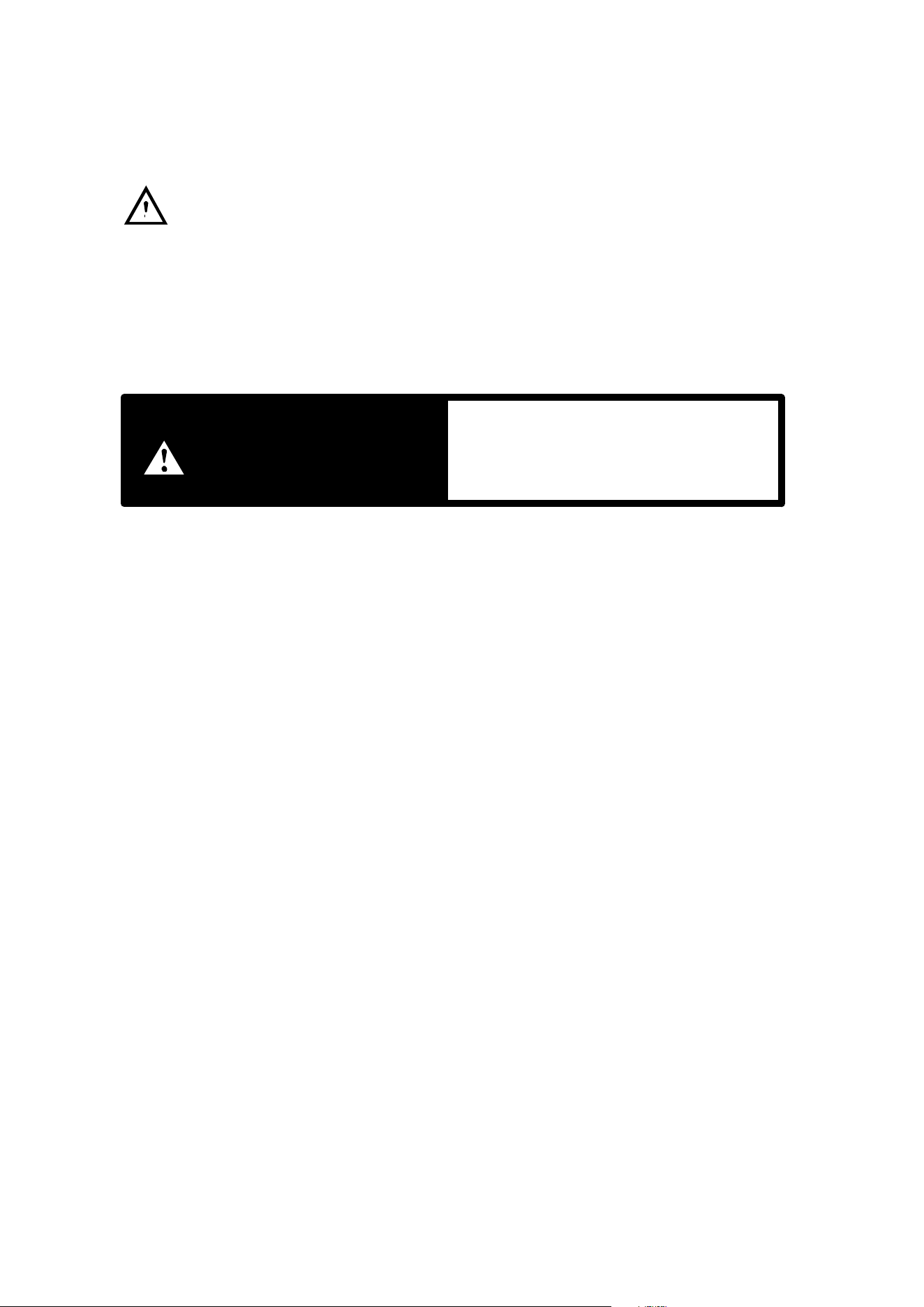
CONTROL AND PARTS FUNCTIONS
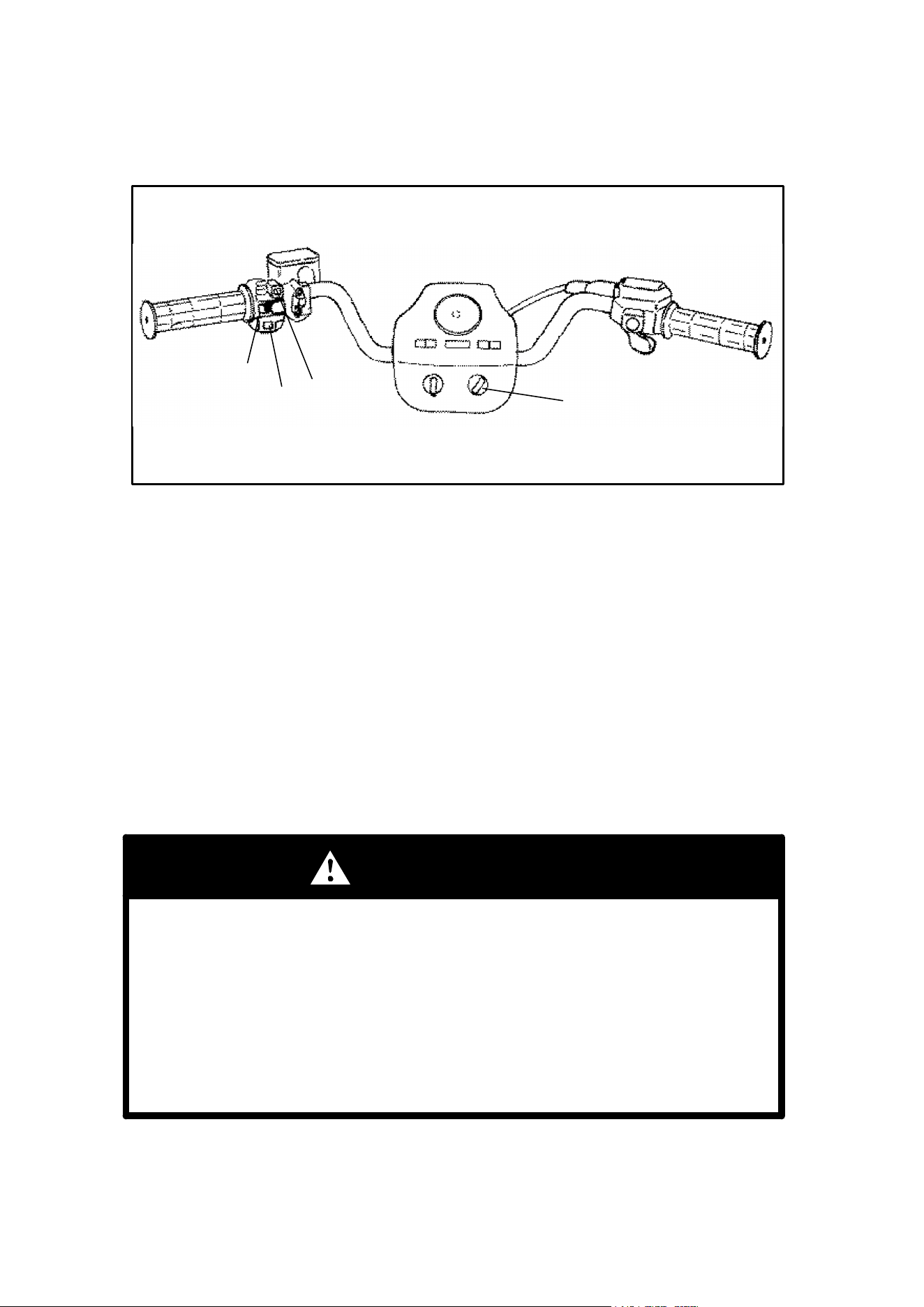
Engine Electrical Switches
1. Override Switch (Reverse Speed Limiter) - This vehicle is equipped with a re-
verse speed limiter system. To obtain additional power while backing up, depress
the override button. WARNING: Never activate the override button while throttle
is open as loss of control may result, causing severe personal injury or death.
NOTE: The override switch also allows activation of Demand 4 Drive (All Wheel
Drive) in reverse, if Demand 4 Drive switch is on.
2. Main Switch - This switch must be turned clockwise to the “on” position to start
the engine.
3. Emergency Engine Stop Switch - The engine will not start or run when the
switch is in its “off” position. Its purpose is to provide the operator with a quick
means of engine shutdown in case of stuck throttle or other emergency.
NOTE: Both the main switch and the emergency engine stop switch shut off all
electrical power to the entire vehicle including lights.
4. Engine Start Button - Press to start the engine.
WARNING
Backing your ATV can be dangerous!
You could hit an obstacle or person behind you; or the vehicle could tip
over rearward on a steep incline causing severe injury or death.
Always back slowly avoiding excessive speed and do not use the reverse
speed override switch system unless additional power is required for ve-
hicle movement.
Avoid backing on steep inclines.
Avoid turning at sharp angles in reverse.
1
2
3
4
36
CONTROL AND PARTS FUNCTIONS
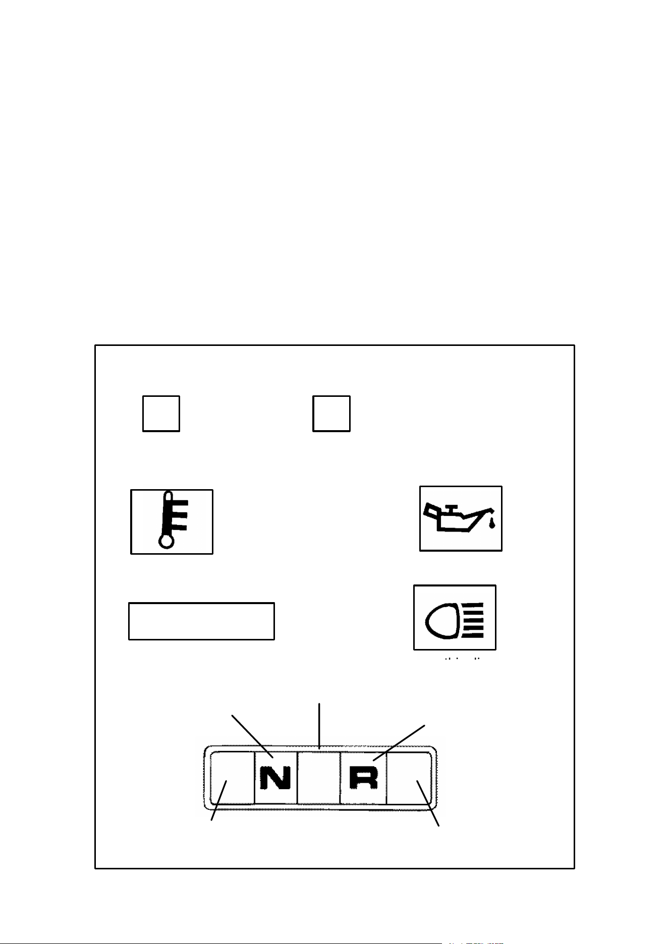
Light Switches and Indicator Lights
Switches
Each Polaris ATV has a main switch. It is located on the right hand side of the ma-
chine and operated with a key.
The light switch is located on the left hand handlebar. In addition to turning the
lights on and off, it also switches the lights from Hi to Lo on models equipped with
Hi-Lo beams. NOTE: Will not light unless the main switch is on.
Indicator Lights
Each Polaris ATV has indicator lights. The configuration of these lights differs with
individual models and not every model is equipped with all the lights. The informa-
tion in your Owner’s Manual Supplement and in the following box will help you iden-
tify the lights on your machine and their function.
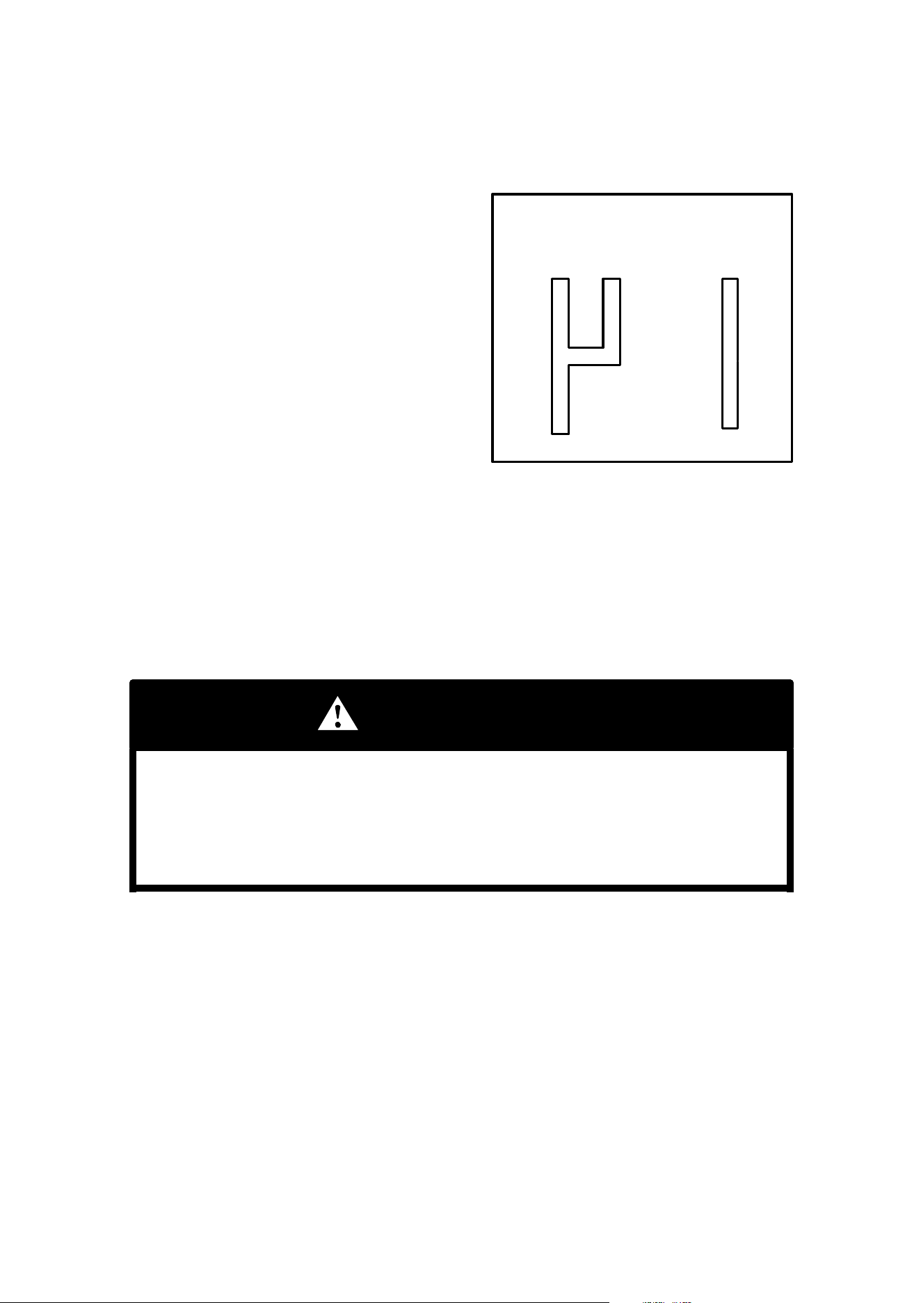
High Beam Indicator (Blue)
HI BEAM
OR
Transmission Neutral
indicator - Green
Transmission Reverse
indicator - Yellow
R
All Wheel Drive
Indicator - Red
(Refer to page
43 for location)
Low Oil Warning
Light (Red)
Engine Hi Temp
Warning Indicator
If your machine has the following light configuration, use this diagram to de-
termine indicator light location and function.
Hi Temp Warning - Red (will
light only if engine overheats)
Neutral - Green
Hi Beam - Blue
Reverse - Yellow
Low Oil Warning Light - Red
N
37
CONTROL AND PARTS FUNCTIONS
With engine running, verify function of indicator lights each time ATV is used.
WARNING
This ATV is not equipped with highway approved lighting. This ATV is designed
for off-road use only and must not be ridden on streets or highways. Use caution
and drive at reduced speeds in conditions of reduced visibility such as fog, rain and
darkness.
NOTE: The taillight is on whenever the main switch (key) is in the on position. Turn
the key off to prevent battery drain.
indicates a potential hazard which
could result in serious injury or death.
WARNING
38
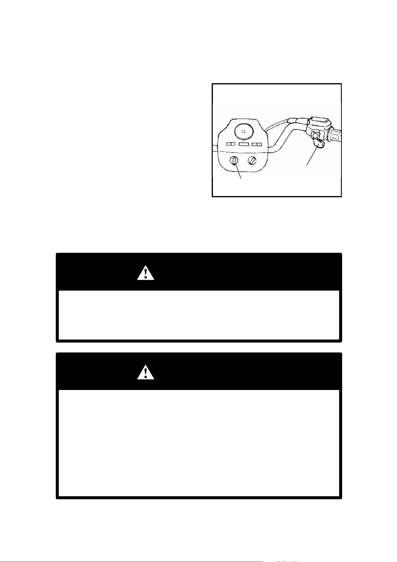
CONTROL AND PARTS FUNCTIONS
Engine Throttle and Choke
Throttle Lever
Engine speed and vehicle movement
are controlled by pressing the throttle le-
ver. The throttle lever is spring loaded
and engine speed returns to idle when
the lever is released. This vehicle is
equipped with a Polaris Electronic
Throttle Control (ETC) which is designed
to reduce the risk of a frozen or stuck
throttle. In the event the throttle should
stick in an open position, engine RPM
will diminish and power to the rear
wheels will cease when the operator re-
leases the throttle lever.
Choke Lever
Refer to the engine starting procedure on page 55 for correct choke and throttle
settings during starting.
WARNING
The Electronic Throttle Control (ETC) limits engine power in the event
of a throttle system malfunction and is provided for your safety. Do not
attempt to modify the ETC system or replace it with any after market
throttle mechanisms.
WARNING
Do not start or operate an ATV with sticking or improperly operating
throttle controls. A stuck or improperly operating throttle could cause an
accident resulting in severe injury or death.
Always contact your dealer for service repairs whenever throttle prob-
lems arise.
Failure to check or maintain proper operation of the throttle system can
result in the throttle lever sticking during riding and cause an accident.
Always check the lever for free movement and return before starting the
engine and occasionally during riding.
Throttle
Choke
39
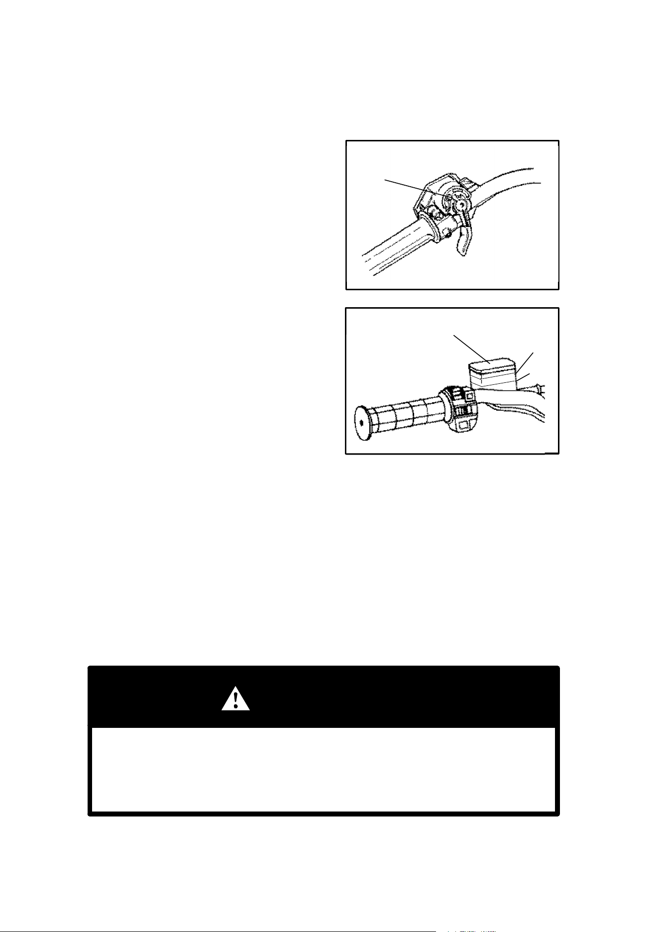
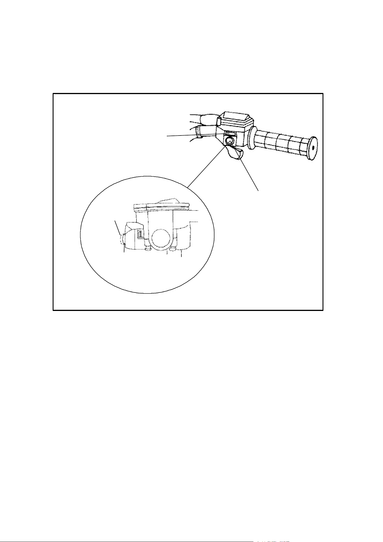
CONTROL AND PARTS FUNCTIONS
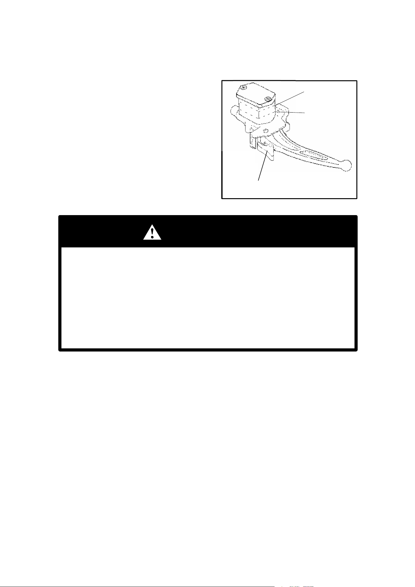
Throttle Control/Brakes
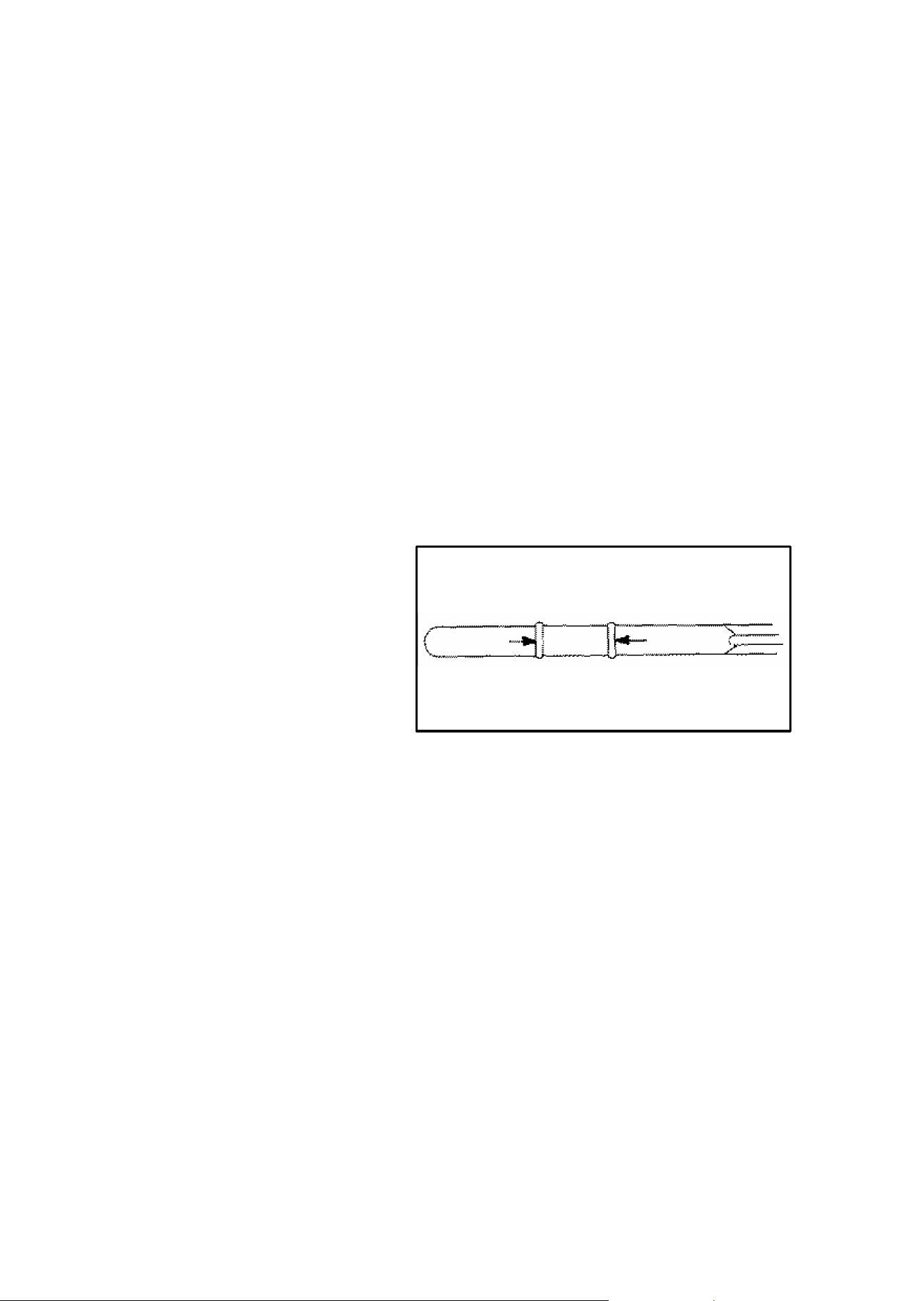
Throttle Control Lever Stop
The throttle control lever incorporates
an adjustable stop. This can be ad-
justed to limit the amount of throttle
opening by loosening the screw (A) and
sliding the stop to a desired setting.
Then tighten screw.
Front and Rear Brakes
The brake fluid in the master cylinder,
which is located on the left handlebar,
should be checked before each ride.
The fluid level can be seen through the
plastic reservoir, and should be main-
tained between the indicated max and
min marks on the reservoir. NOTE:
When checking the fluid level, the ATV
must be on level ground the the handle-
bars straight. If the fluid level is low add
DOT 3 (PN 2870990) only.
WARNING: Once a bottle of brake fluid is opened, use what is necessary and dis-
card the rest. Do not store or use a partial bottle of brake fluid. Brake fluid is hygro-
scopic, meaning it rapidly absorbs moisture from the air. This causes the boiling
temperature of the brake fluid to drop, which can lead to early brake fade and the
possibility of serious injury.
The front and rear brakes are applied by squeezing the left side brake lever toward
the handlebar. The front and rear brakes are hydraulically activated disc type
brakes which are activated by one lever only.
Always test brake lever travel and reservoir fluid level before riding. When
squeezed, the lever should feel firm. Any sponginess would indicate a possible
fluid leak or low master cylinder fluid level which must be corrected before riding.
Contact your dealer for proper diagnosis and repairs.
WARNING
Improperly operating the ATV with a spongy brake lever can result in loss
of braking. Loss of braking could cause an accident.
Never operate the ATV with a spongy feeling brake lever.
A
Bottom View
Master Cylinder
Reservoir
Max
Min
40
CONTROL AND PARTS FUNCTIONS
Parking Brake
Setting the Parking Brake
1. Squeeze the left hand brake lever
two or three times and hold it.
2. Rotate the park brake lock into the
notches on the master cylinder body.
Release the brake lever.
3. To release the parking brake lock,
squeeze the brake lever. It will return
to its released position.
WARNING
Always check to be sure that the parking brake has been disengaged
before operating the ATV. An accident could result if the parking
brake is left on while the ATV is operated.
The parking brake may relax when left on for a long period of time.
This could cause an accident.
Do not leave the vehicle on a hill depending on the parking brake
for more than five minutes.
Always block the downhill side of the wheels if leaving the ATV on a
hill or park the ATV in a side hill position.
Auxiliary Power Outlet
Auxiliary power outlets provide 12V power for operating accessories such as hand
held spot lights.
Outlets are located on the front headlight pod and/or rear taillight bracket.
Do not use front and rear outlets simultaneously as increased battery drain will re-
sult.
To determine if your vehicle is equipped with auxiliary power outlets, please check
your Owner’s Manual Supplement.
Parking Brake Lock
Minimum
Maximum
41
CONTROL AND PARTS FUNCTIONS
Auxiliary Mechanical Brake
Your Polaris ATV has an auxiliary mechanical brake provided as a safety feature.
It is located on the inside of the right floor board and is operated by the right foot.
It is intended as a backup to the hydraulic brake system, especially if the hydraulic
system becomes inoperative.
WARNING: Use caution when applying the auxiliary mechanical brake. Do
not aggressively apply the auxiliary brake when going forward or the rear wheels
may skid and slide sideways causing loss of control. If the rear wheels slide, re-
duce brake pedal pressure to brake the rear wheels without skidding. Aggressive-
ly applying the rear brake when backing down a hill may cause rear tip over.
The auxiliary brake system is mechanical and requires periodic adjustment. If ad-
justment is necessary, please refer to page 106.
Auxiliary Brake
Pedal
42
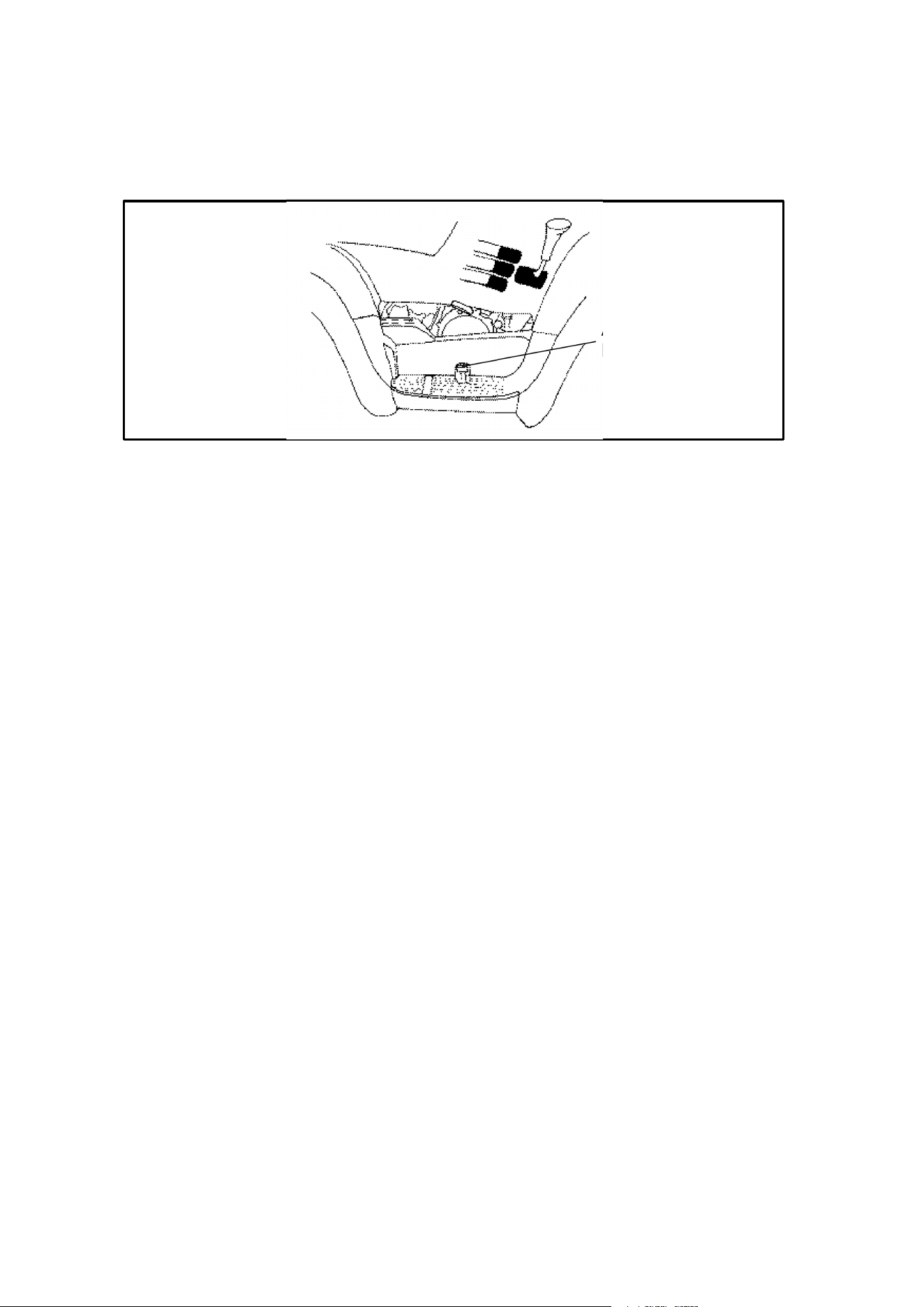
CONTROL AND PARTS FUNCTIONS
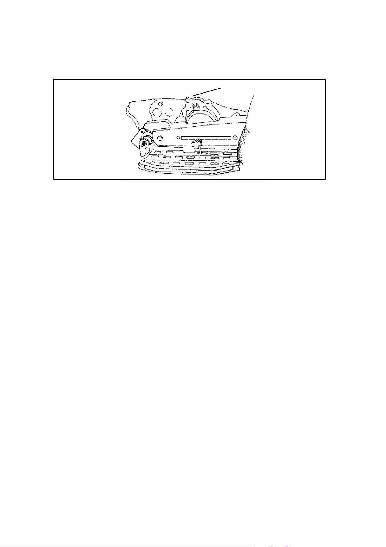
Transmission Gear Selector Operation
Shift patterns depend on the type of vehicle
you own. Please check your Owner’s
Manual Supplement to define your ma-
chine’s shift pattern.
The transmission gear selector is located
on the right side of the vehicle directly
above and forward of the engine recoil
starter. The transmission selector lever
has three or four positions: high forward; re-
verse; neutral; and low forward or forward;
reverse; and neutral. Check your Owner’s
Manual Supplement for specification.
Use of low forward gear is recommended in
heavy pulling situations to extend belt life.
To change gears, stop the vehicle and with the engine idling, move the lever to the
desired gear. Do not attempt to shift gears with engine speed above idle or while
the vehicle is moving.
Always place the transmission in gear with the parking brake locked whenever the
vehicle is left unattended.
Maintaining shift linkage adjustment is important to assure proper transmission
function. Should you experience any shifting problem see your dealer.
WARNING
1. Do not attempt to shift the transmission while the vehicle
is moving or while operating on hilly terrain.
2. Always place the transmission in gear with the parking
brake applied and turn the vehicle off whenever the ve-
hicle is left unattended.
H
N
R
H
L
N
R
Shift Patterns
43
CONTROL AND PARTS FUNCTIONS
Demand 4 Drive
(Found on models with All Wheel Drive)
AWD Button
AWD
Button
Out “Off”
AWD
Button in
“On”
AWD Indicator
Light
Exclusive Demand 4 Drive System (All Wheel Drive)
This Polaris AWD is equipped with a unique, Polaris exclusive, Demand 4 Drive
(AWD) system which is activated by a switch on the right handlebar. When the
switch is “off” the 4x4 is in 2 wheel drive at all times. When the switch is “on” the
4x4 is in Demand 4 Drive and the front wheels will automatically engage anytime
the rear wheels lose traction. When the rear wheels regain traction, the front
wheels will automatically disengage. NOTE: The override switch also allows ac-
tivation of Demand 4 Drive (AWD) in reverse, if Demand 4 Drive switch is on.
The AWD button position and a red AWD light indicates when the vehicle is in De-
mand 4 Drive. There is no limit to the length of time the vehicle may remain in De-
mand 4 Drive.
The Demand 4 Drive switch may be turned on or off while the vehicle is moving.
If the switch is turned off when the front hubs are driving they will not release until
the rear wheels regain traction.
CAUTION: Do not switch on Demand 4 Drive if the rear wheels are spinning. This
may cause severe drive shaft and clutch damage. Engage the Demand 4 Drive
switch before getting into conditions where front wheel drive may be needed. If the
rear wheels are spinning, release the throttle before turning the Demand 4 Drive
switch on.
44
CONTROL AND PARTS FUNCTIONS
Disengaging Wheel Hubs
When backing uphill while in Demand 4 Drive and then going forward downhill, one
or both hubs may remain engaged. If one or both hubs remain engaged they can
be disengaged by stopping, shifting to and moving in reverse. Then proceed in
forward again.
You can tell if only one front hub is engaged if the handlebars pull to one side. If
both front wheel hubs are engaged, steering effort increases but remains balanced
from left to right, and vehicle speed is somewhat restricted.
WARNING: If both hubs were engaged and only one released during opera-
tion, loss of control could result. If you experience hub engaging symptoms, use
the above disengaging technique before proceeding. Failure to disengage front
hubs as directed above could result in severe injury or death.
Ifthe hubs remain engaged after following these instructions return the ATV to your
dealer for service.
PVT System
WARNING
The PVT system rotates at high speeds, creating large amounts of force
on clutch components. Extensive engineering and testing has been con-
ducted to insure the safety of this product. However, as the owner you
have the following responsibilities to make sure this system remains safe:
DDo not modify any component of the PVT system. Doing so may re-
duce its strength so that a failure may occur at high speeds. This
system has been precision balanced. Any modification will cause the
system to be out of balance, creating vibration and additional loads
on components.
DRoutine maintenance is the responsibility of the owner. Always follow
recommended maintenance procedures. See your dealer!
DThis PVT system is intended for use on Polaris products only.
DThe PVT housing must be securely in place during operation.
Failure to comply with this warning can result in severe injury or death.
45
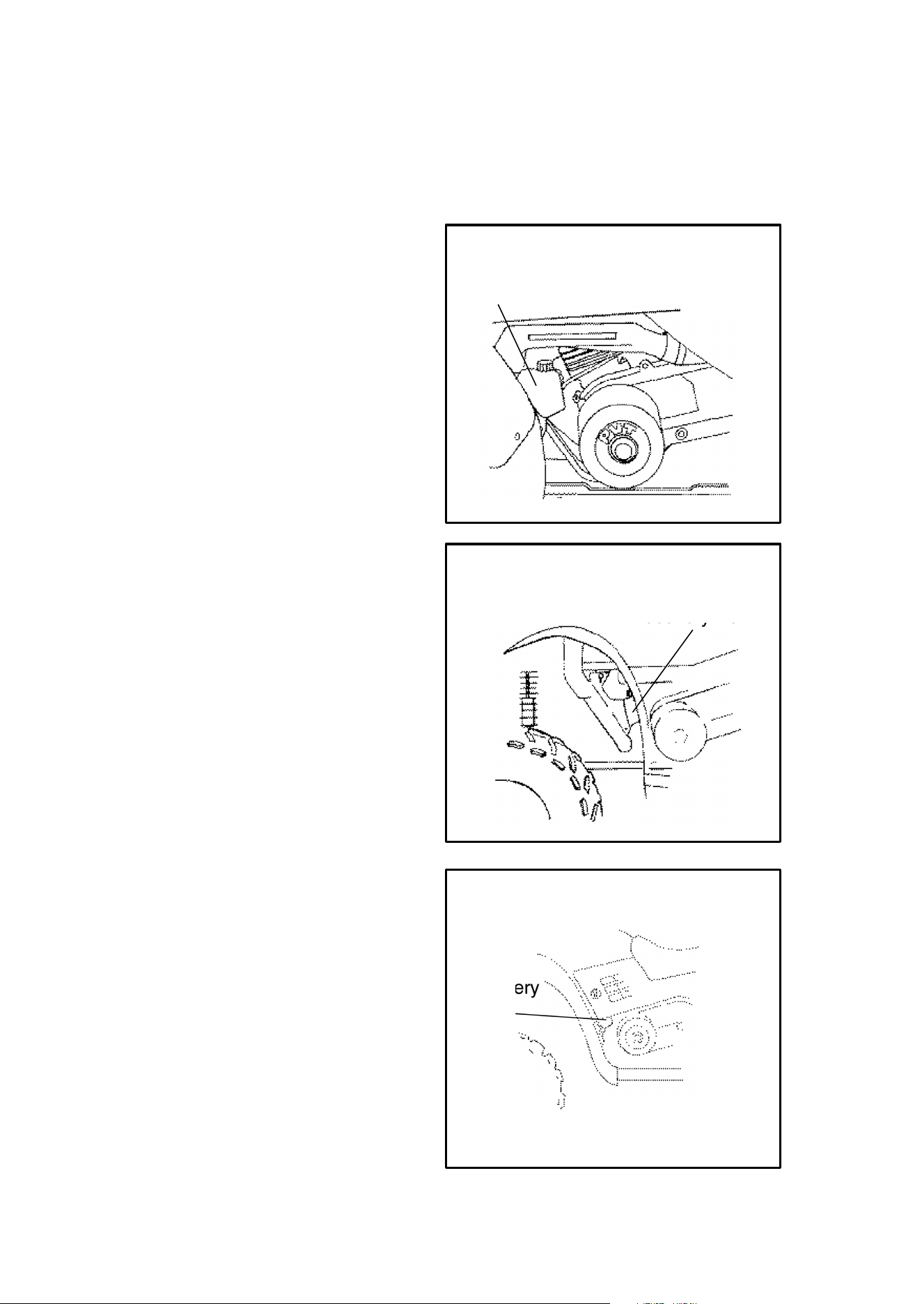
CONTROL AND PARTS FUNCTIONS
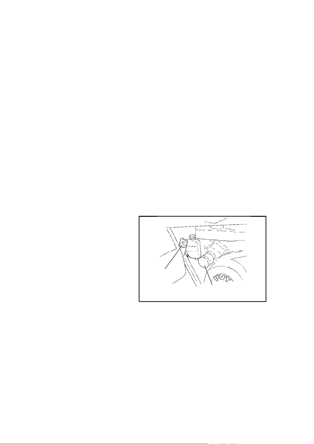
Engine Cooling System
Coolant Level
The recovery bottle, located on the
left side of the machine, must be
maintained between the minimum
and maximum levels indicated on the
recovery bottle.
The engine coolant level is controlled
or maintained by the recovery sys-
tem. The recovery system compo-
nents are the recovery bottle, radia-
tor filler neck, radiator pressure cap
and connecting hose.
As coolant operating temperature in-
creases, the expanding (heated) ex-
cess coolant is forced out of the ra-
diator past the pressure cap and into
the recovery bottle. As engine cool-
ant temperature decreases the con-
tracting (cooled) coolant is drawn
back up from the tank past the pres-
sure cap and into the radiator.
NOTE: Some coolant level drop on
new machines is normal as the sys-
tem is purging itself of trapped air.
Observe coolant levels and maintain
as recommended by adding coolant
to the recovery bottle. Polaris recom-
mends the use of Polaris Premium
60/40 anti-freeze/coolant or a 50/50
mixture of high quality aluminum
compatible anti-freeze/coolant and
distilled water. NOTE: Polaris Pre-
mium 60/40 is already premixed and
ready to use. Do not dilute with water.
NOTE: Always follow the manufac-
turer’s mixing recommendations for
the freeze protection required in your
area.
To access the recovery bottle on Gen
IV machines it is necessary to re-
move the left side panel as described
on page 94.
Recovery Bottle
Gen III
Recovery Bottle
Gen II
Recovery
Bottle
Gen IV
46
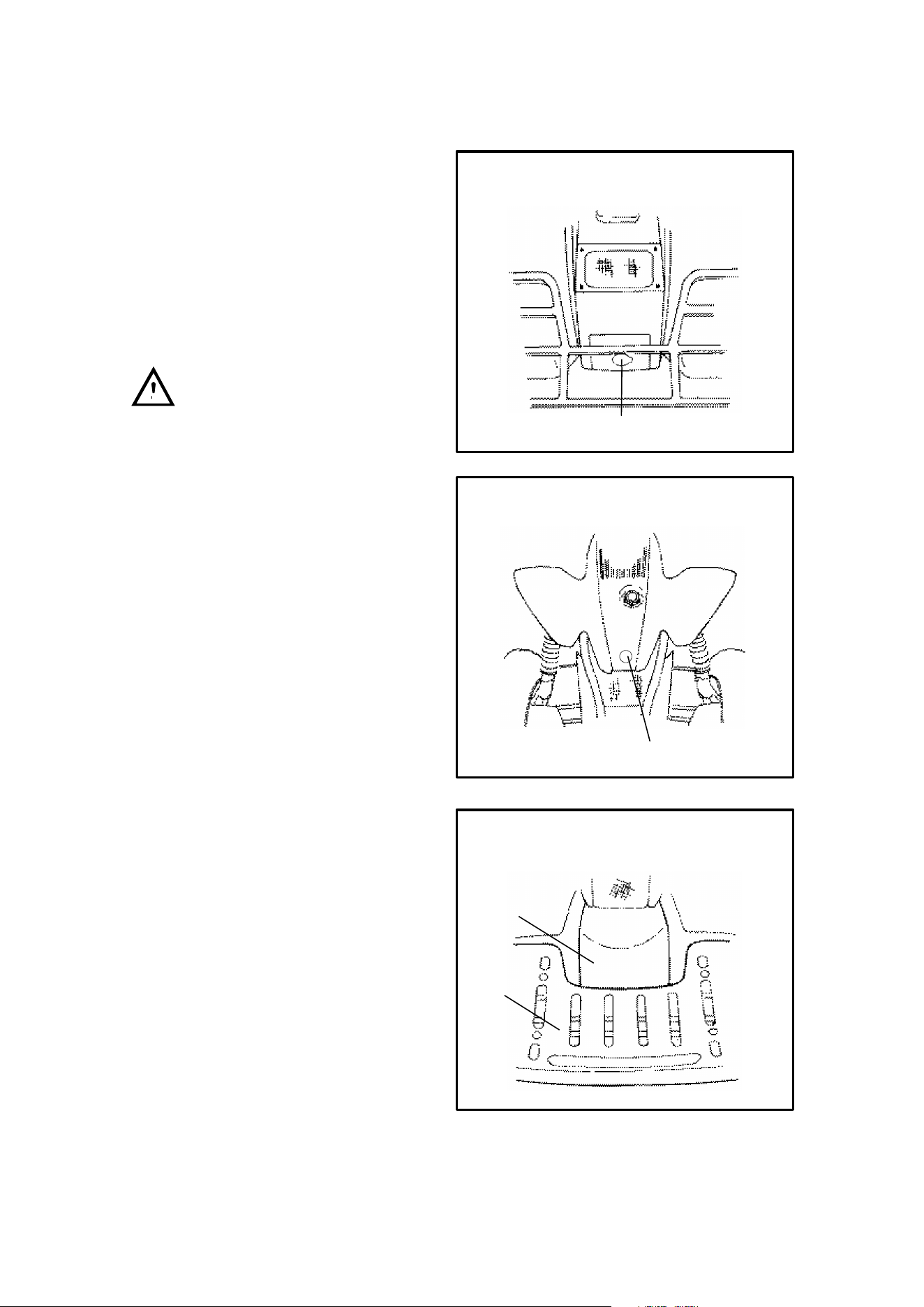
CONTROL AND PARTS FUNCTIONS
Engine Cooling System
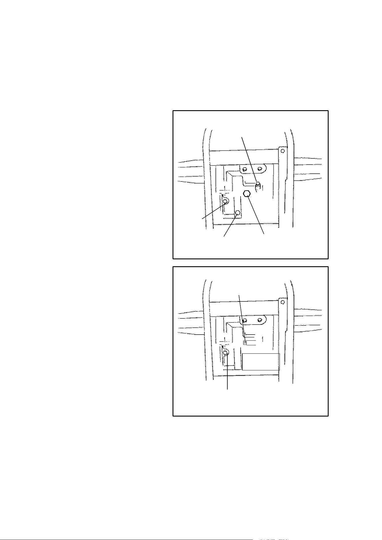
Radiator Coolant Level Inspection
NOTE: This procedure is only re-
quired if the cooling system has been
drained for maintenance and/or re-
pair. However, if the recovery bottle
has run dry, the level in the radiator
should be inspected and coolant
added if necessary.
WARNING Never remove the
pressure cap when the engine is
warm or hot. Escaping steam can
cause severe burns. The engine
must be cool before removing the
pressure cap.
To access the radiator pressure cap:
Gen II - To access the pressure cap,
remove the access cover on the front
of the ATV just below the oil cap. Us-
ing a flat, stubby screwdriver loosen
the screw 1/4 turn and pull the cover
forward and up to remove.
Gen III - To access the pressure cap,
clean the area around the oil cap and
remove the oil cap (2 cycle models).
Remove front cover by placing your
fingers under the front of the cover
and pulling upward. Reinstall oil cap.
Gen IV - Remove the four screw se-
curing front rack. Remove front cov-
er by placing your fingers under the
front of the cover and pulling upward.
NOTE: Use of a non-standard pres-
sure cap will not allow the recovery
system to function properly. If the
cap should need replacement con-
tact your dealer for the correct re-
placement part.
Pressure Cap
Gen II
Pressure Cap
Gen III
Rack
Front
Cover
Gen IV

47
CONTROL AND PARTS FUNCTIONS
Engine Cooling System
To insure that the coolant maintains its ability to protect the engine, it is recom-
mended that the system be completely drained every two years and a fresh mixture
of antifreeze and water be added. Polaris recommends the use of Polaris Pre-
mium 60/40 anti-freeze/coolant or a 50/50 mixture of high quality aluminum com-
patible anti-freeze/coolant and distilled water. NOTE: Polaris Premium 60/40 is
already premixed and ready to use. Do not dilute with water. IMPORTANT: Al-
ways follow the manufacturer’s mixing recommendations for the freeze protection
required in your area.
Using a funnel, slowly add coolant as necessary through the radiator filler neck.
48
CONTROL AND PARTS FUNCTIONS
Engine Fuel and Oil System
1
2
The fuel tank filler cap (1) is located directly behind the handlebar. Refer to your
owner’s Manual Supplement for tank capacity. Use either leaded or unleaded gas-
oline with a minimum pump octane number of 87 R+ M/2 octane.
On models with a two cycle engine, the engine oil injection tank filler cap (2) is lo-
cated on the front of the machine. Refer to you Owner’s Manual Supplement to
determine the type of engine your vehicle has. The tank capacity is 2 quarts (1.9
l). CAUTION: To avoid serious engine damage always top off the oil level when
refueling.
CAUTION: On models with a two cycle engine, use only Polaris injectionoil. Never
substitute or mix oil brands. Serious engine damage and voiding of warranty can
result.
The fuel tank supply decal located on the left side of the fuel tank cover displays
the three fuel valve positions:
OFF: For vehicle storage and whenev-
er transporting.
ON: For normal operation.
RES: For reserve supply in the event of
main supply exhaustion.
NOTE: There is about a 7 to 10 mile
(11.2 to 16 km) range on reserve gas.
Always refill the gas tank as soon as
possible after having used the reserve
supply.
Always return valve to “on” position after
refueling machine.
ON
OFF
RES
49
CONTROL AND PARTS FUNCTIONS
Engine Fuel Safety/Fuel/Filter
The Polaris ATV is equipped with a unique in-line fuel filter.
This filter should be replaced by your dealer after every 100 hours of operation or
annually. Do not attempt to clean the fuel filter.
WARNING
Gasoline is highly flammable and explosive under certain conditions.
DAlways exercise extreme caution whenever handling gasoline.
DAlways refuel with the engine stopped and outdoors or in a well venti-
lated area.
DDo not smoke or allow open flames or sparks in or near the area
where refueling is performed or where gasoline is stored.
DDo not over fill the tank. Do not fill the tank neck.
DIf you get gasoline on your skin or clothing, immediately wash it off
with soap and water and change clothing.
DNever start the engine or let it run in an enclosed area. Gasoline
powered engine exhaust fumes are poisonous and can cause loss
of consciousness and death in a short time.
DShut off fuel valve whenever the ATV is stored or parked.
WARNING
The engine exhaust from this
product contains chemicals
known to cause cancer, birth de-
fects or other reproductive harm.
50
CONTROL AND PARTS FUNCTIONS
4 Cycle Premium 4 Synthetic Lubricant
Polaris Premium 4 All Season Synthetic engine oil has been specially formulated
for use in Polaris 4 cycle engines. It is a fully synthetic, high performance, multi-vis-
cosity oil designed to provide the ultimate in lubrication performance and protec-
tion.
Premium 4 possesses unsurpassed film strength over the widest possible temper-
ature range. It resists viscosity and frictional breakdown in ambient temperatures
from -40° F to 120° F. Its exceptional frictional properties result in more efficient
operation, more power output and lower fuel consumption.
Although Polaris Premium 4 is the only oil recommended for use in this engine, use
of any API certified “SH” oil is allowable. Oil may need to be changed more fre-
quently if Polaris Premium 4 is not used. You will also need to follow the manufac-
turers recommendations for ambient temperature operation.
Oil System
The oil tank is located on the left side of the vehicle. To check the oil:
1. Set machine on a level surface.
2. Start the engine and let it
idle for 20-30 seconds.
3. Stop the engine, remove
dipstick and wipe dry with a
clean cloth.
4. Screw in the dipstick
completely, remove it and
read the oil level. NOTE:
The dipstick must be
screwed in to keep the
angle and depth of stick
consistent.
5. Remove dipstick and check to see that the oil level is between the full and add
marks. Add oil as indicated by the level on the dipstick. Do not overfill.
CAUTION: Use only Polaris Premium 4 All Season synthetic oil (PN 2871271), or
API certified “SH” oil. Never substitute or mix oil brands. Serious engine damage
and voiding of warranty can result.
Oil and Filter Change
The recommended oil change interval is 100 hours, 1000 miles, or every six
months, whichever comes first. Suggested break in oil change is at 20 hours, 500
miles, or one month, whichever comes first. Severe use operation requires more
frequent service. Severe use includes continuous duty in dusty or wet conditions,
and cold weather riding. NOTE: Severe use cold weather riding is all riding below
10° F, and riding between 10° F and 30°F when most trips are slow speed and less
than 5 miles. Be sure to change the oil filter whenever changing oil (Polaris PN
3084963)
1. Place vehicle on a level surface.
2. Clean area around drain plug at the bottom of the oil tank.
3. Run engine for two to three minutes until warm. Shut engine off.
ADD 8 OZ. NORMAL FULL
Maintain Oil Level In Normal Range
51
CONTROL AND PARTS FUNCTIONS
Oil and Filter Change (Cont.)
4. Place a drain pan beneath the oil tank and remove the drain plug. CAUTION:
Oil may be hot. Do not allow hot oil to come into contact with skin as serious
burns may result.
5. Allow oil to drain completely.
6. Install a new sealing washer (PN 5850135) on oil drain plug. NOTE: The
sealing surfaces on the drain plug and the oil tank should be clean and free of
burrs, nicks or scratches.
7. Reinstall drain plug and torque to 14-17 ft. lbs. (1.93-2.35 kg/m)
8. Place shop towels beneath oil filter. Using an oil filter wrench, turn filter
counterclockwise to remove.
9. Using a clean dry cloth, clean filter sealing surface on crankcase.
10. Lubricate O-Ring on new filter with a film of new engine oil. Check to make
sure the O-Ring is in good condition. Also make sure the O-ring from the old
filter is not still on the engine.
11. Install new filter and tighten by hand 1/2 to 3/4 turn after gasket contact.
12. Approximately 1 cup of engine oil will remain in the crankcase. To drain,
remove drain plug found on lower right side of crankcase. NOTE: The sealing
surfaces on the drain plug and crankcase should be clean and free of burrs,
nicks or scratches.
13. Reinstall drain plug.
14. Remove dipstick and add 2
quarts (1.9 l) of Polaris
Premium 4 synthetic oil.
Reinstall dipstick. NOTE: If
sump is not drained, add
about 1 3/4 quarts initially.
15. Place gear selector in
neutral and set parking
brake.
16. Start engine and let it idle for
one to two minutes. Stop
engine and inspect for
leaks.
17. Re-check oil level on the dipstick and add oil as necessary to bring the level to
the upper mark on the dipstick.
18. Dispose of used filter and oil properly.
Fuel Filter and Oil Filter
Polaris 2 cycle ATVs are equipped with a unique in-line oil filter.
All Polaris ATVs are equipped with a unique in-line fuel filter.
These filters should be replaced by your dealer after every 100 hours of operation
or annually. Do not attempt to clean these filters.
Dipstick
Filter
4 Cycle

52
CONTROL AND PARTS FUNCTIONS
Polaris 2-Cycle Lubricants
Polaris has a family of premium oils available for use in all our products and highly
recommends their use. The only oils recommended for Polaris 2-cycle ATVs are
Polaris Premium 2-cycle oil or Premium Gold Synthetic 2-cycle oil.
CAUTION: Engine warranty coverage may become void if other
brands are substituted.
Polaris Premium 2-cycle lubricants are the most advanced formulation of oils spe-
cifically designed for today’s 2-cycle engines. Months of lab and field tests have
resulted in anew generation of 2-cycle lubricants. Polaris Premium 2-cycle lubri-
cants provide additives for 2-cycle engines lacking in today’s fuel that keep ring
grooves cleaner for less ring sticking and provide improved overall engine cleanli-
ness. With new generation lubricity technology, they excel in meeting the lubrica-
tion demands of today’s high performance 2-cycle engines. These are optimum
oils recommended for liquid cooled and air cooled 2-cycle engines. We believe
these oils are the best available in the market today.
Premium Gold Synthetic 2-Cycle Oil
Your vehicle has been primed with Premium Gold Synthetic oil. This lubricant has
been specially formulated for low smoke, low odor and high lubricity. We recom-
mend continued use of this oil or Premium 2-cycle oil.
Premium 2-Cycle Oil
Polaris also has a TC-W3 premium oil available for use in all of our products. We
highly recommend its use. The only oil recommended for this ATV is Polaris brand
oil.
Polaris Premium 2-cycle oils will readily mix with each other, however do not mix
Polaris Premium 2-cycle oils with any other oils as they may not be compatible and
engine damage may occur.
53
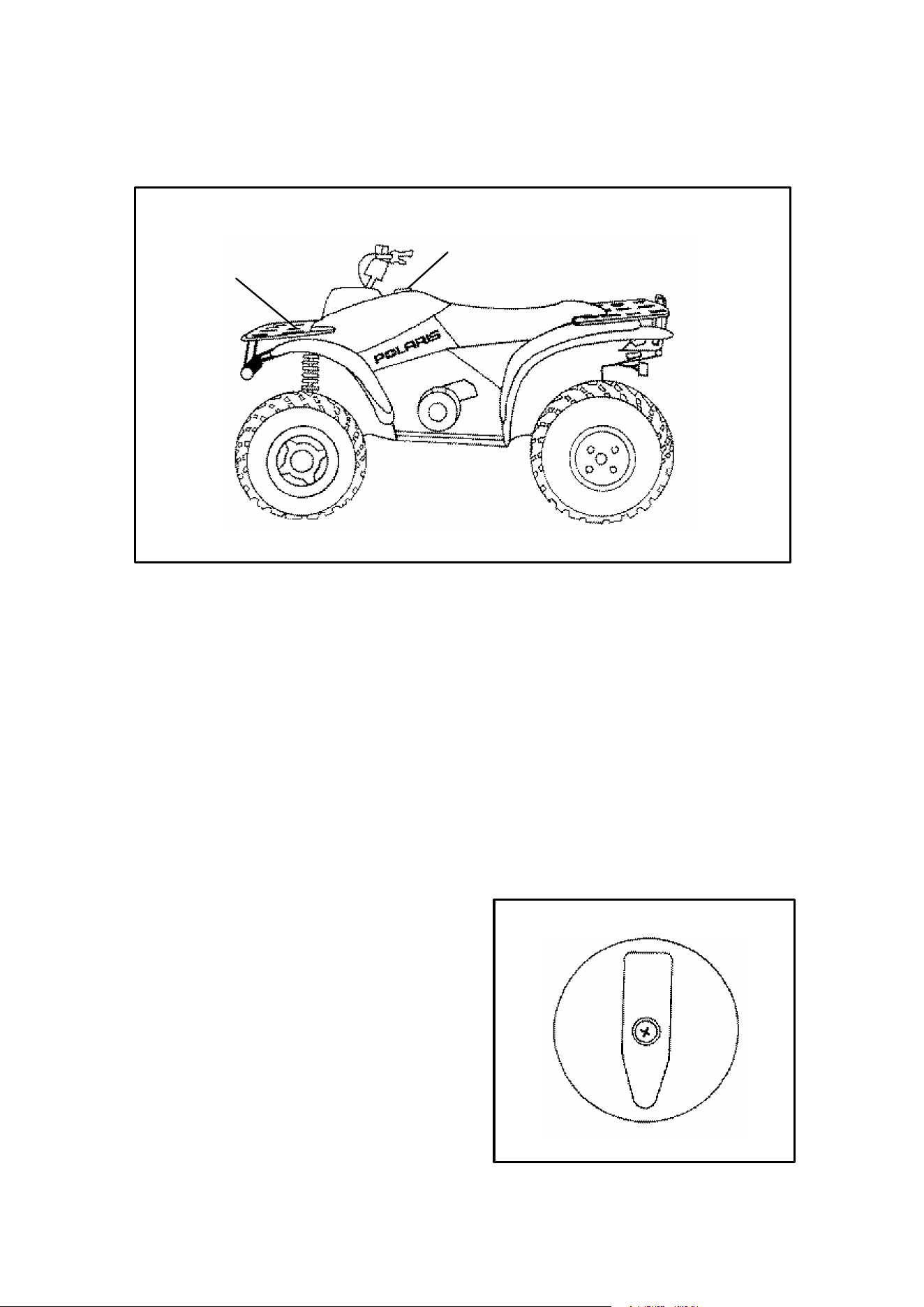
CONTROL AND PARTS FUNCTIONS
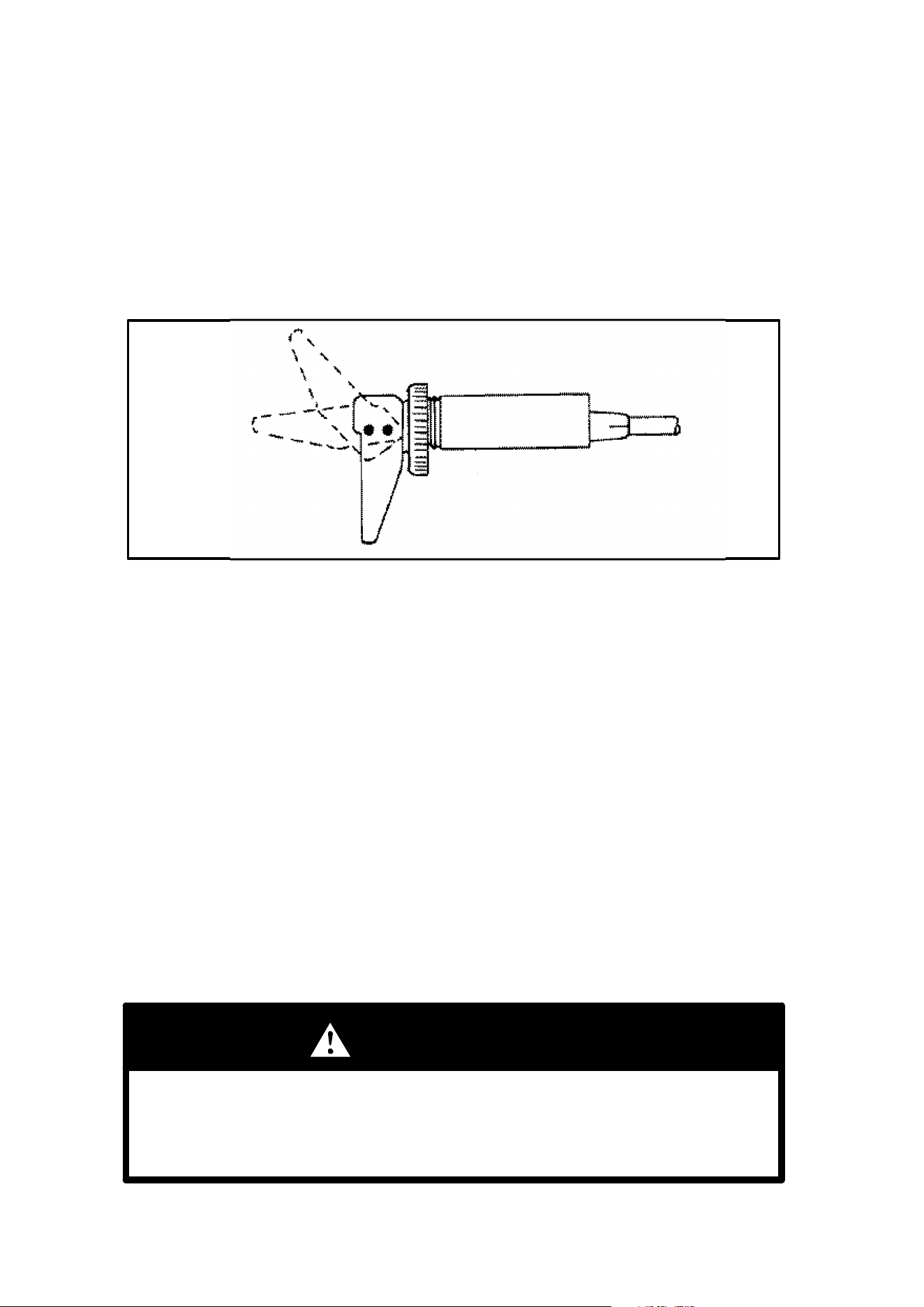
Recoil Starter
Recoil Starter
If the battery is weak and cannot start the engine, use of the recoil starter located
on the right side of the machine will allow vehicle operation until repairs can be
made.
Polaris engines are equipped with automatic decompressors. This makes recoil
starting possible by allowing compression to “leak” at cranking speeds. The de-
compressor senses when the engine is spinning fast enough to start and restores
compression for starting.
1. Be certain your vehicle is on a level surface and the parking brake is set . See
page 40.
2. Take the machine out of gear.
3. Grasp the recoil starter tightly and pull slightly until the starter mechanism en-
gages.
4. Pull the rope abruptly to start the engine. CAUTION: Take care not to extend
the starter rope so far that it stops, causing damage to the recoil assembly.
CAUTION: Never start the engine with the battery disconnected. Damage to the
electrical system and lamps will result.
54
CONTROL AND PARTS FUNCTIONS
Drain the recoil housing after operating the ATV in very wet conditions. This should
also be done before storing the ATV. The drain screw is located at the bottom of
the recoil housing. Remove the screw with a 10mm wrench. Reinstall screw once
housing has been drained.
CAUTION: Make sure the
manual start handle is fully
seated on the recoil housing,
especially when travelling in
wet areas. If it is not sealed
properly, water may enter the
recoil housing and damage
components.
Water will enter the recoil
housing if the starter handle is
disengaged from the rope
guide when under water.
After travelling in wet areas
the recoil housing and starter
should always be drained
completely by removing the
recoil.
Do not open the crankcase
drain unless the engine has
ingested water. On 4-cycle
engines, some engine oil will
be lost if crankcase drain is
opened.
On the Trail Blazer, the recoil
handle must be behind the heat
shield for it to seal properly. If it is
not sealed properly, water may
enter the recoil housing and dam-
age components.
Recoil
Drain
Crankcase Drain
Starter Pinion
Drain
300 and 400 Engines
Counter Balance
Drain (400s Only)
Recoil Drain (above front
propshaft on shaft drive models)
Crankcase Drain
4 Cycle Engines
55
STARTING THE ENGINE
Procedure for Starting a Cold Engine
1. Place the transmission in neutral and push the vehicle to a level surface.
2. Lock the parking brake.
3. Turn the fuel tank valve to ON.
4. Sit on the vehicle.
“HALF”
“FULL”
“OFF”
Choke Lever Side View
5. Move the choke lever to the FULL position.
6. Turn the ignition key to ON and the engine stop switch to RUN.
7. Press the starter button.
8. Do not press the throttle while starting the engine.
9. Press starter button for five seconds. If engine does not start, release starter
button and wait five seconds; then press starter button for another five se-
conds. Repeat this procedure until engine starts.
NOTE: Do not press the throttle while starting the engine.
After the Engine Starts
1. If the engine slows or stops, use of the choke lever at its HALF position willallow
proper engine warm up.
2. Vary the engine RPM slightly with the throttle to aid in warm up until the engine
idles smoothly. Then move the choke to OFF.
CAUTION: Proper engine warm up is essential each time before driving to avoid
engine damage.
WARNING
Carbon monoxide exhaust gas is poisonous!
Always start the ATV outdoors.
Never run the engine in an enclosed area.

56
VEHICLE BREAK-IN PERIOD
2 Cycle Engines
The break in period for your new Polaris ATV is defined as the time it takes to use
the first tank of gasoline. No single action on your part is as important as a proper
break in period. Careful treatment of a new engine will result in more efficient per-
formance and longer life for the engine. Perform the following procedures carefully.
CAUTION: Use only Polaris injection oil. Never substitute or mix oil brands. Seri-
ous engine damage and voiding of warranty can result.
1. Mix 12.8 ounces of injection oil to four gallons of gasoline in a suitable gas can.
Fill the fuel tank as outlined on pages 48 through 49.
2. Fill the oil tank with Polaris injection oil.
3. Drive slowly at first. Select an area which is open and will give you room to fa-
miliarize yourself with vehicle operation and handling.
4. Vary the throttle positions. CAUTION: Do not operate at full throttle or high
speeds for extended periods during the first three hours of use. Excessive heat
can build up and cause damage to close fitted engine parts.
5. Perform regular checks on fluid levels, controls and all important areas on the
vehicle as outlined earlier on the daily pre-ride inspection checklist found on
page 14.
After the break in period the oil injection system provides the necessary engine lu-
brication without the need for pre-mixed fuel. CAUTION: To avoid serious engine
damage always fill the oil tank when refueling the ATV.
After the first tank of pre-mixed fuel has been used please verify that the oil
level in the oil tank has dropped, indicating that the oil pump is functioning
properly. If the level has not dropped, see your dealer for oil pump bleeding
and repeat the pre-mix procedure.
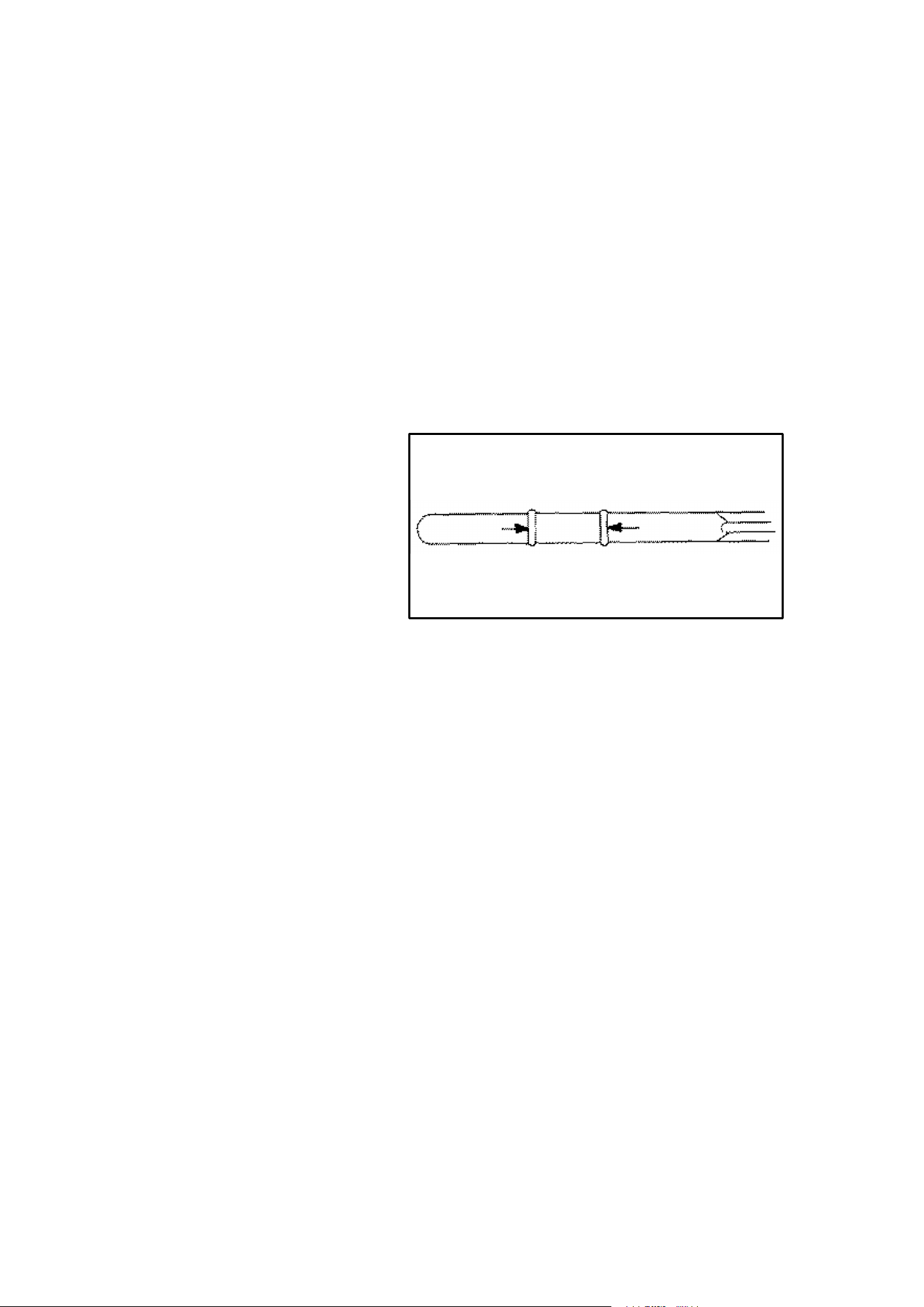
57
VEHICLE BREAK-IN PERIOD
4 Cycle Engines
The break in period for your new Polaris ATV is defined as the first ten hours of op-
eration, or the time it takes to use the first two tanks full of gasoline. No single action
on your part is as important as a proper break in period. Careful treatment of a new
engine will result in more efficient performance and longer life for the engine. Per-
form the following procedures carefully.
CAUTION: Use only Polaris Premium 4 All Season synthetic oil, or API certified
“SH” oil. Never substitute or mix oil brands. Serious engine damage and voiding
of warranty can result.
1. Fill fuel tank with either unleaded or leaded fuel which has a minimum pump
octane number of 87= (R+ M)/2.
2. Check oil reservoir level in-
dicated on dipstick. Add oil
if necessary.
3. Drive slowly at first. Select
an area which is open and
will give you room to famil-
iarize yourself with vehicle
operation and handling.
4. Vary the throttle positions. Do not operate at sustained idle. CAUTION: Do
not operate at full throttle or high speeds for extended periods during the first
three hours of use. Excessive heat can build up and cause damage to close
fitted engine parts.
5. Perform regular checks on fluid levels, controls and all important areas on the
vehicle as outlined earlier on the daily pre-ride inspection checklist found on
page 14.
6. Pull only light loads.
7. Break in oil and filter. Change at 20 hours or 500 miles.
ADD 8 OZ. NORMAL FULL
Maintain Oil Level In Normal Range
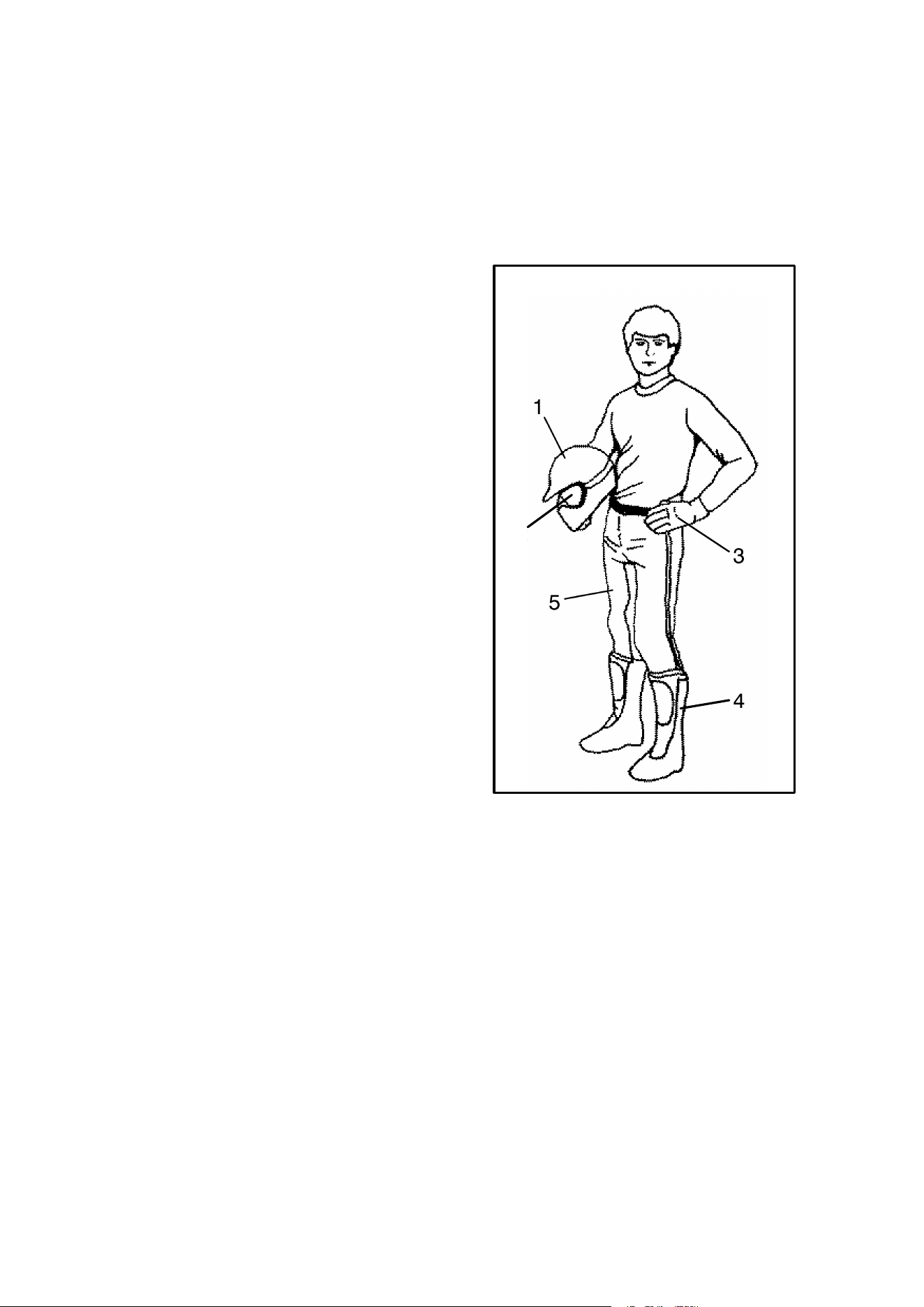
58
RIDING GEAR
Safe Riding Gear
Always wear clothing suited to the type of riding you are doing. ATV riding requires
special protective clothing which will make you feel more comfortable and reduce
chances of injury.
1. Helmet
Your helmet is the most important piece
of protective gear for safe riding. A hel-
met can prevent a serious head injury.
Select an approved helmet which meets
or exceeds your state’s safety standards
and bears either the Department of
Transportation (DOT) label, the Ameri-
can National Standards Institute label
(ANSI z90.1), or the Snell Memorial
Foundation label.
2. Eye Protection
Do not depend on sunglasses for proper
eye protection. A pair of goggles or hel-
met face shield offer the best protection
for your eyes. They should be kept clean
and be of shatterproof design (bearing
the markings z2.1 or VESC 8).
3. Gloves
Off-road style gloves with knuckle pads
are the best for comfort and protection.
4. Boots
The best footwear is a pair of strong over the calf type boots with heels, such as
moto-cross boots.
5. Clothing
To protect your body, long sleeves and pants should always be worn. Riding pants
with kneepads, a jersey and shoulder pads provide the best protection.
1
2
3
4
5

59
CARRYING LOADS
Your ATV has been designed to carry a certain amount of load. CARGO WEIGHT
should be evenly distributed (1/3 on the front and 2/3 on the rear) and mounted as
low as possible. When operating over rough or hilly terrain, reduce speed and car-
go to maintain stable driving conditions. Never exceed the following weights.
Model Total Load Capac-
ity
(includes driver &
cargo)
Front Rack
Cargo Maximum
Rear Rack
Cargo Maximum
Sportsman 500 470 lbs. (213 kg) 90 lbs. (41 kg) 180 lbs. (82 kg)
Xplorer 300 470 lbs. (213 kg) 90 lbs. (41 kg) 180 lbs. (82 kg)
Xplorer 400 470 lbs. (213 kg) 90 lbs. (41 kg) 180 lbs. (82 kg)
Xplorer 500 470 lbs. (213 kg) 90 lbs. (41 kg) 180 lbs. (82 kg)
Magnum 2x4 470 lbs. (213 kg) 90 lbs. (41 kg) 180 lbs. (82 kg)
Magnum 4X4 470 lbs. (213 kg) 90 lbs. (41 kg) 180 lbs. (82 kg)
Trail Boss 325 (148 kg) No Front Rack 125 (57 kg)
Sport 400 L 200 (91 kg) No Front Rack No Rear Rack
Trail Blazer 200 (91 kg) No Front Rack No Rear Rack
Scrambler 400 200 (91 kg) No Front Rack No Rear Rack
Scrambler 500 200 (91 kg) No Front Rack No Rear Rack
Maximum trailer weight - 850 lbs.(386 kg); maximum vertical hitch weight - 30
lbs.(14 kg). Sportsman 500 may tow up to 1250 (568 kg) on level ground only.
Maximum grade while trailer towing - 15°. Do not tow any trailer on a grade steeper
than 15°.
If your machine is equipped with a front rack, take care when loading. Improper
loading of the front rack can obstruct the headlight beam, reducing night visibility.
Do not obstruct the headlight beam with cargo.
Use of low forward gear is recommended in heavy pulling situations to extend belt
life.

60
CARGO WEIGHT DISTRIBUTION
2/3 of Load on
Rear Rack
1/3 of Load on
Front Rack
WARNING
Correct loading of this vehicle is necessary to maintain proper stability and
operating characteristics. Overloading or incorrect positioning of the load af-
fects the vehicle’s turning, stopping distance and stability. Failure to follow
loading requirements could cause severe injury or death. REDUCE SPEED
AND ALLOW GREATER DISTANCE FOR BRAKING WHEN CARRYING
CARGO.
CARGO WEIGHT DISTRIBUTION should be 1/3 on the front rack and 2/3 on
the rear rack. When operating over rough or hilly terrain, reduce speed and
cargo to maintain stable driving conditions. Carrying loads on one rack only
increases the possibility of vehicle tip over.
HEAVY LOADS CAN CAUSE BRAKING AND CONTROL PROBLEMS. Use
extreme caution when applying brakes with a loaded vehicle. Avoid terrain
or situations which may require backing downhill.
ALL LOADS MUST BE SECURED BEFORE MOVING VEHICLE. Unse-
cured loads can create unstable operating conditions, which could result in
loss of control of the vehicle.
LOADS MUST BE CARRIED AS LOW ON THE RACKS AS POSSIBLE. Car-
rying loads high on the racks raises the center of gravity of the vehicle and
creates a less stable operating condition. When cargo loads are carried high
on the racks, the weight of the loads must be reduced to maintain stable oper-
ating conditions.
OPERATE ONLY WITH STABLE AND SAFELY ARRANGED LOADS. When
handling off-centered loads which cannot be centered, securely fasten load
and operate with extra caution. Always attach the tow load to the hitch point
designated for your ATV.
EXTREME CAUTION MUST BE USED when operating with loads extending
over the rack sides. Stability and maneuverability may be adversely affected,
causing the machine to overturn.
DO NOT BLOCK THE FRONT HEADLIGHT BEAM when carrying loads on
the front rack.
DO NOT TRAVEL FASTER THAN THE RECOMMENDED SPEEDS. Vehicle
should never exceed 10 mph (16 kph) while towing a load on a level grass
surface. Vehicle speed should never exceed 5 mph (8 kph) when towing
loads in rough terrain, while cornering, or while ascending or descending a
hill.

61
DAILY PRE-RIDE INSPECTION
Inspect your ATV each time before riding to ensure it is in proper working or-
der. If proper inspection is not done, severe injury or death could result.
WARNING
If a proper inspection is not performed serious injury or death can result.
Always inspect your ATV before riding following the checklist carefully.
Before riding your vehicle, inspect all operating controls and parts.
Item/Inspection Procedure
1. Tires - check condition and pressures
2. Fuel and oil tanks - fill both tanks to their proper levels
3. All brakes - check operation, adjustment and fluid level (includes
auxiliary brake)
4. Throttle - check for free operation and closing
5. Headlight/Taillight/Brakelight - check operation of all indicator lights
and switches
6. Engine stop switch - check for proper function
7. Wheels - check for tightness of wheel nuts and axle nuts; check that
axle nuts are secured by cotter pins
8. Drive chain - condition and slack; refer to drive chain adjustment
9. Air cleaner element - check for dirt; clean or replace
10. Steering - check for free operation noting any unusual looseness in
any area
11. Loose parts - visually inspect vehicle for any damaged or loose nuts/
bolts or fasteners
12. Operators helmet, goggles and clothing
13. Engine coolant - (Liquid Cooled Models Only) check for proper level
at the recovery bottle
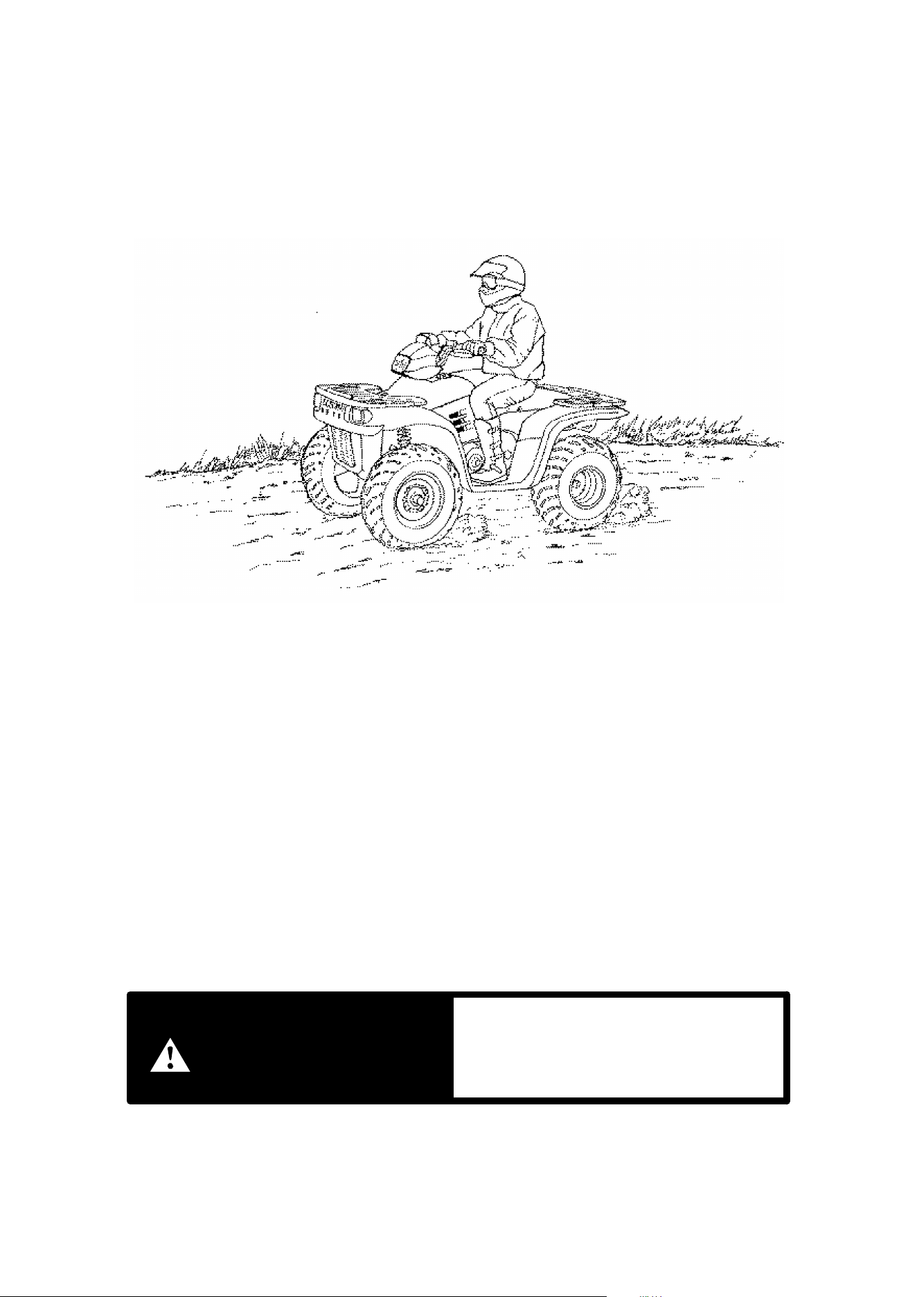
62
RIDING
1. Sit upright with both feet on the footrests and both hands on the handlebars.
2. After starting the engine and allowing it to warm up, shift the transmission into
gear.
3. Check your surroundings and determine your path of travel.
4. Release the parking brake.
5. Slowly depress the throttle with your right thumb and begin driving. Vehicle
speed is controlled by the amount of throttle opening and all transmission shift-
ing is done automatically.
6. Drive slowly, practice maneuvering and using the throttle and brakes on level
surfaces.
indicates a potential hazard which
could result in serious injury or death.
WARNING
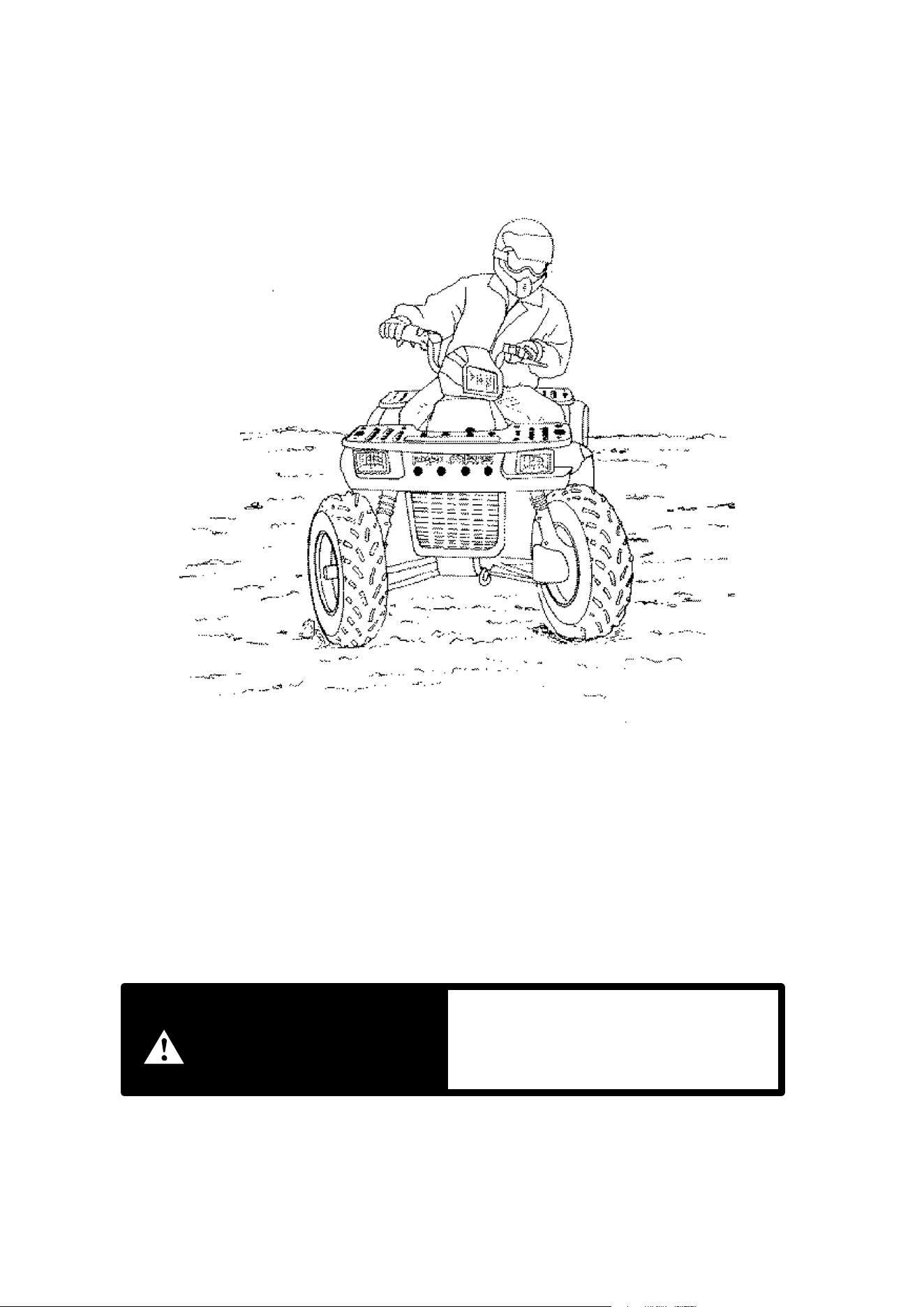
63
RIDING
Making Turns
Practice making turns at slow speeds.
Polaris ATVs are equipped with a solid rear axle which drives both rear wheels
equally at all times. This means that the wheel on the outside of the turn must travel
a greater distance than the inside wheel when turning and the inside tire must slip
traction slightly. To turn, steer in the direction of the turn leaning your upper body
to the inside of the turn while supporting your weight on the outer footrest. This
technique alters the balance of traction between the rear wheels allowing the turn
to be made smoothly. The same leaning technique should be used for turning in
reverse. WARNING: Avoid turning at sharp angles in reverse as tipover and seri-
ous injury may result.
indicates a potential hazard which
could result in serious injury or death.
WARNING
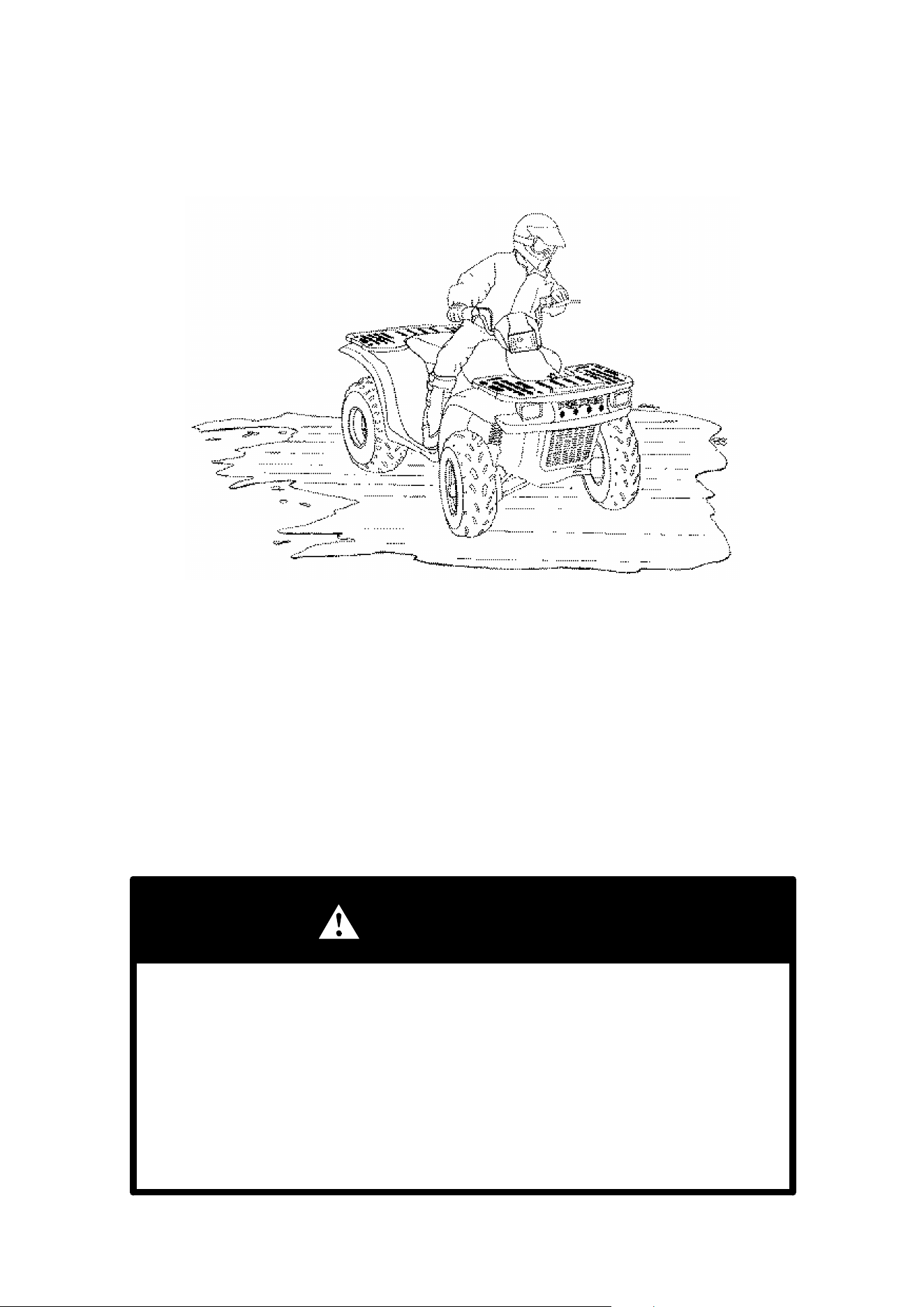
64
RIDING
Riding On Slippery Surfaces
Whenever riding on slippery surfaces such as wet trails or loose
gravel, or during cold freezing weather, special attention must be
paid to prevent vehicle turnover. Always:
1. Slow down when entering slippery areas.
2. Maintain a high level of alertness, reading the trail and avoiding quick, sharp
turns which can cause skids.
3. Correct a skid by turning the handlebars in the direction of the skid and shifting
your body weight forward.
4. Driving with Demand 4 Drive (All Wheel Drive) engaged can assist in control-
ling the vehicle in slippery areas. CAUTION: Never engage Demand Drive
while wheels are spinning as severe damage to drive train may occur.
WARNING
Failure to exercise care when operating the ATV on slippery surfaces can
be dangerous.
Loss of tire traction and vehicle control can result in an accident, including
an overturn.
DNever apply brakes during a skid. Complete loss of ATV control can
result.
DDo not operate on excessively slippery surfaces if possible to avoid.
DAlways reduce speed and use additional caution.
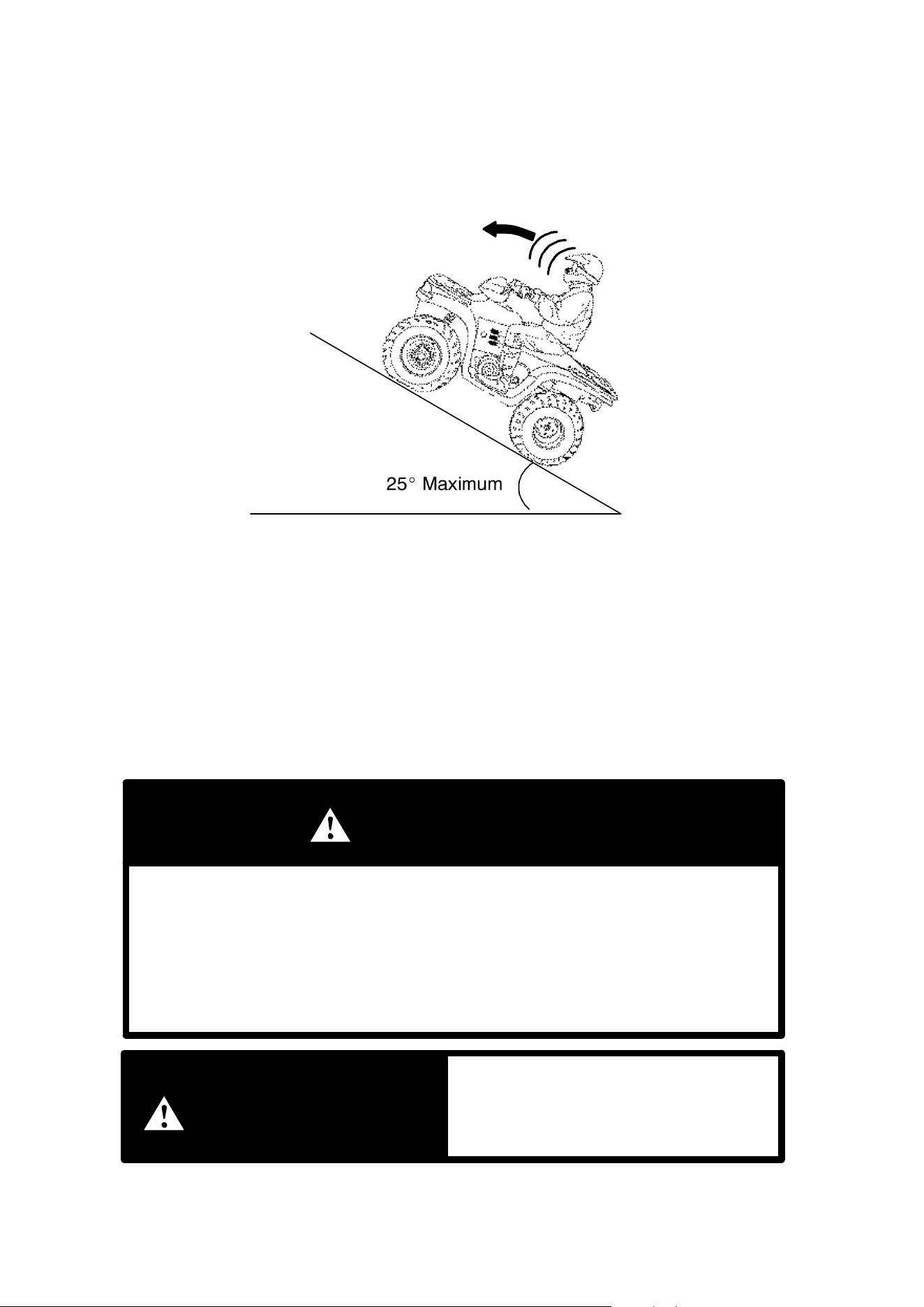
65
RIDING
Traveling Uphill
25_ Maximum
Whenever traveling uphill always travel straight uphill and:
1. Avoid steep hills.
2. Keep both feet on the footrests.
3. Transfer your weight forward.
4. Proceed at a steady rate of speed and throttle opening.
5. Remain alert and be prepared to take emergency action. This may include
quick dismounting of the ATV.
WARNING
Braking and handling are greatly affected whenever operating in hilly ter-
rain.
Loss of vehicle control or overturning of the ATV could occur.
DAvoid operating on steep hills (25_ maximum).
DUse extreme care when operating your ATV in hilly terrain.
indicates a potential hazard which
could result in serious injury or death.
WARNING
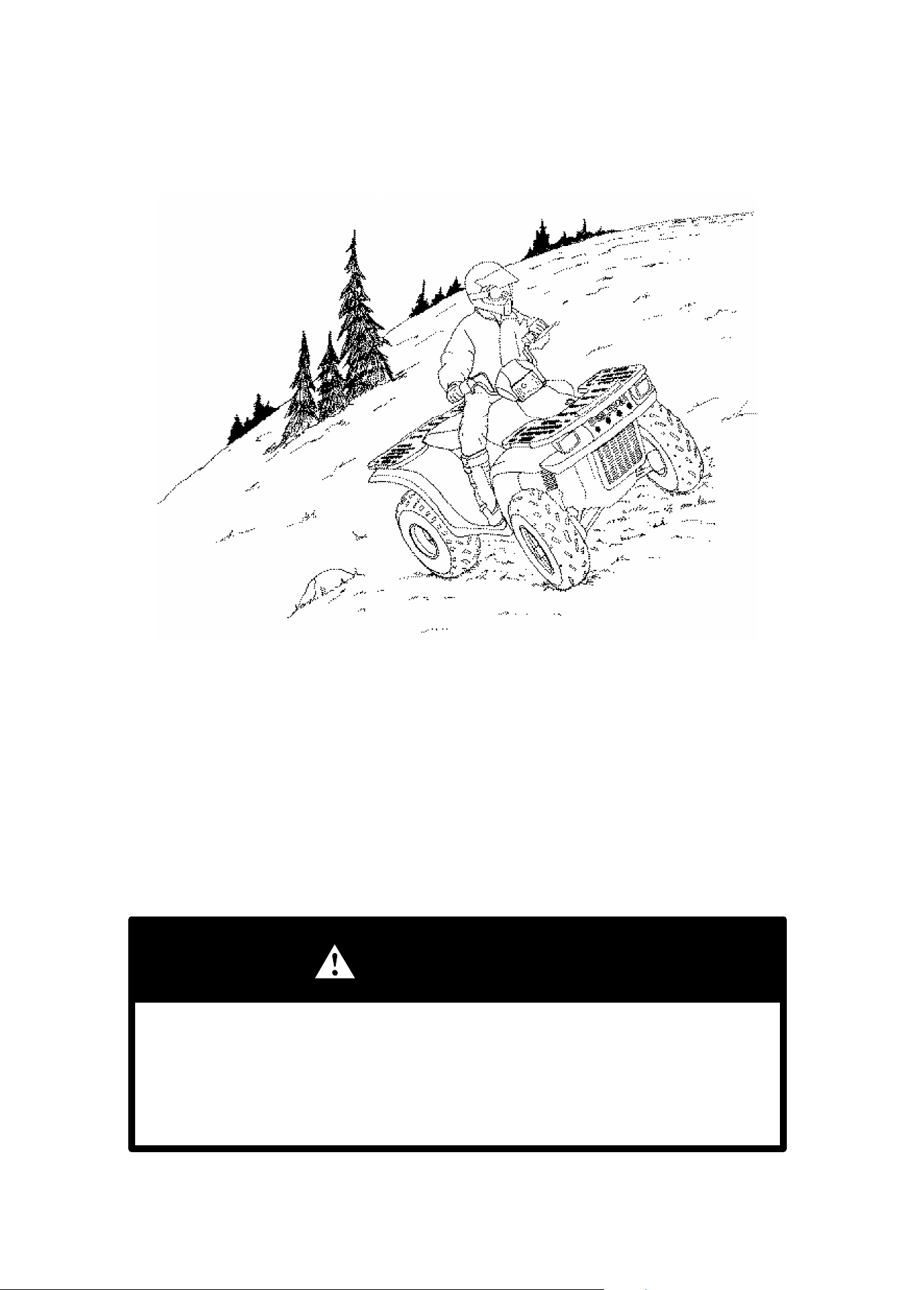
66
RIDING
Sidehilling
Sidehilling your ATV is one of the most dangerous types of riding
and should be avoided if possible. In the event you do enter into a
situation where sidehilling is necessary, always:
1. Slow down.
2. Lean into the hill transferring your upper body weight toward the hill while keep-
ing your feet on the footrests.
3. Steer slightly into the hill to maintain vehicle directions.
If vehicle begins to tip, quickly turn the front wheel downhill, if possible, or dismount
on the uphill side immediately!
WARNING
Improperly crossing hills or turning on hills can be dangerous!
Loss of vehicle control or overturning of the ATV could occur.
DAvoid crossing the side of a steep hill if possible.
DUse extreme care when operating your ATV in hilly terrain.

67
RIDING
Traveling Downhill
Whenever descending a hill, always:
1. Drive directly downhill.
2. Transfer your weight to the rear of the vehicle.
3. Slow down.
4. Apply the brakes slightly to aid in slowing.
Familiarize yourself with the auxiliary rear brake pedal and its use in the event loss
of normal service brakes occurs.
WARNING
Loss of vehicle control due to excessive speed can occur. Loss of control
may result in serious injury or death.
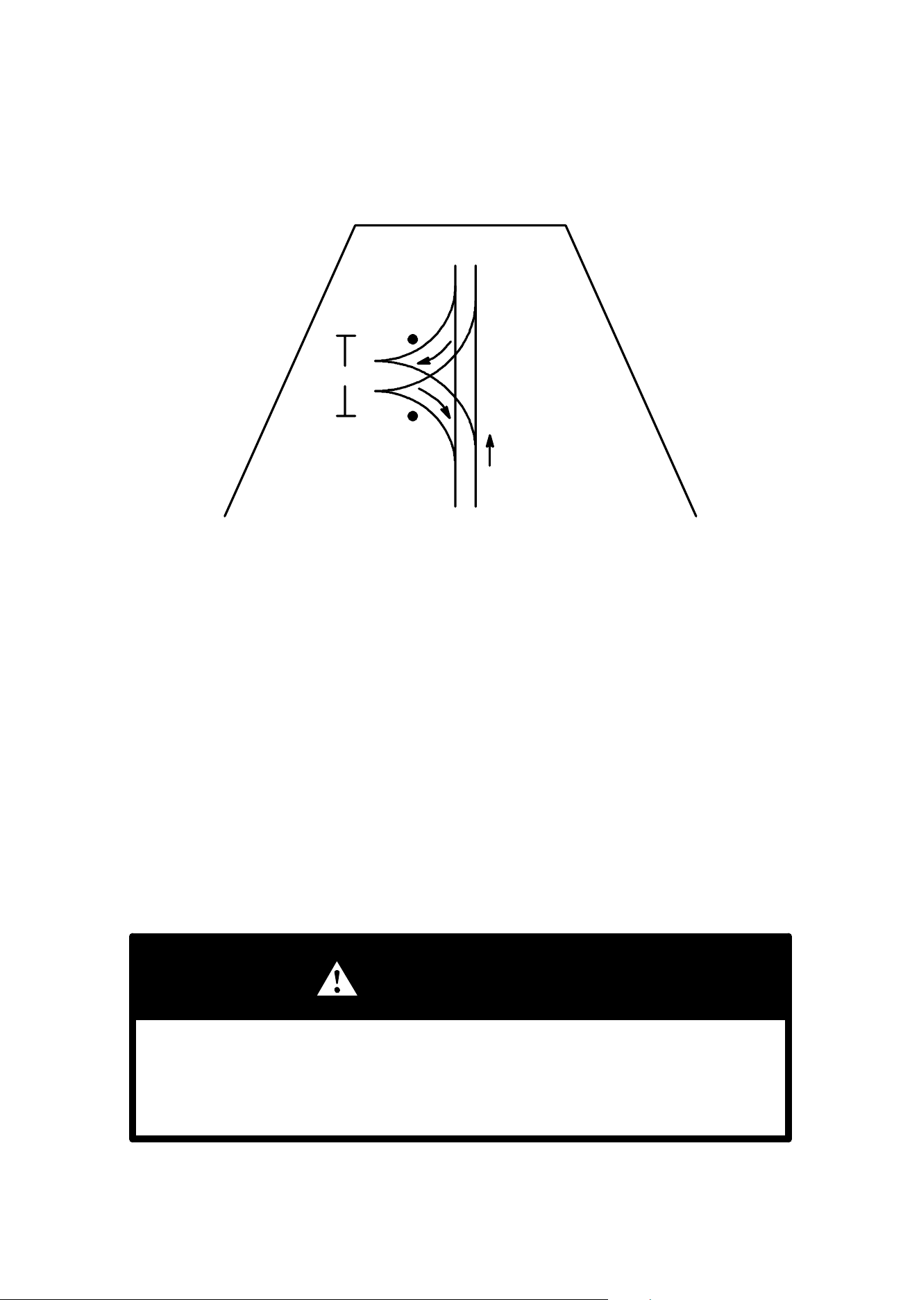
68
RIDING
Turning Around On A Hill
8’
Uphill
If the ATV stalls while climbing a hill, never back it down the hill! One
maneuver which can be used when it is necessary to turn around
while climbing a hill is the K-turn.
1. Stop and lock the parking brake while maintaining body weight uphill.
2. Leave transmission in forward and shut off engine.
3. Dismount on left or uphill side of ATV.
4. Staying uphill of ATV, turn handlebars full left (while facing front of ATV).
5. While holding service brake, release parking brake lock and slowly allow ATV
to roll around to your right until ATV is pointing across the hill or slightly down-
ward.
6. Lock the parking brake and remount ATV from the uphill side, maintaining body
weight uphill.
7. Restart engine with transmission still in forward, release parking brake, and
proceed slowly, controlling speed with the service brake, until ATV is on rea-
sonably level ground.
WARNING
Avoid climbing steep hills.
Loss of vehicle control or overturning of the ATV could occur.
DUse extreme care when operating your ATV in hilly terrain.
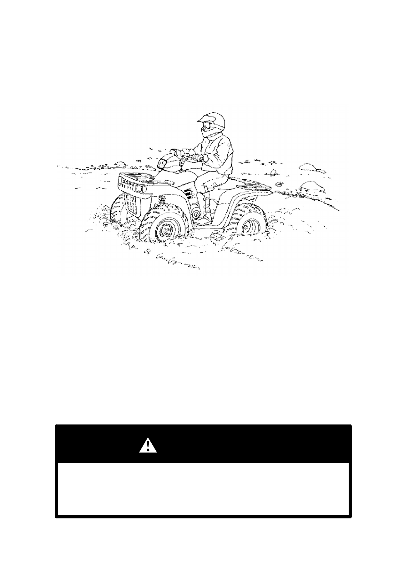
69
RIDING
Crossing Streams
Your Polaris ATV can operate through water up to depths reaching
the footrests. Before fording streams always:
1. Determine water depths and current.
2. Choose a crossing where both banks have gradual inclines.
3. Proceed slowly, avoiding rocks and obstacles if possible.
4. After crossing, dry the brakes by applying light pressure to the lever until brak-
ing action is normal.
CAUTION: Should your ATV become immersed, it will be necessary to take it to
your dealer as soon as possible. Do not start the engine! Immersion of the ATV
can cause major damage if not correctly repaired.
WARNING
Never try to cross any deep or fast flowing streams.
The large tires can cause the ATV to float resulting in loss of control.
DDetermine stream depth and speed before crossing.
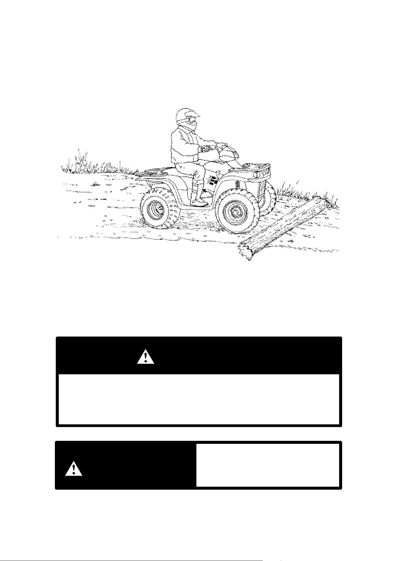
70
RIDING
Trail Obstacles
Keep Alert!
Look ahead and learn to read the trail as you ride. Stay on the right side of the trail,
if possible, and be constantly alert for hazards such as logs, rocks and low hanging
branches.
WARNING
Hidden or unseen hazards on the trail can be dangerous.
Personal injury or the vehicle overturning can occur from unseen obstacles.
DKeep alert and constantly look for obstacles on the trail.
indicates a potential hazard which
could result in serious injury or death.
WARNING
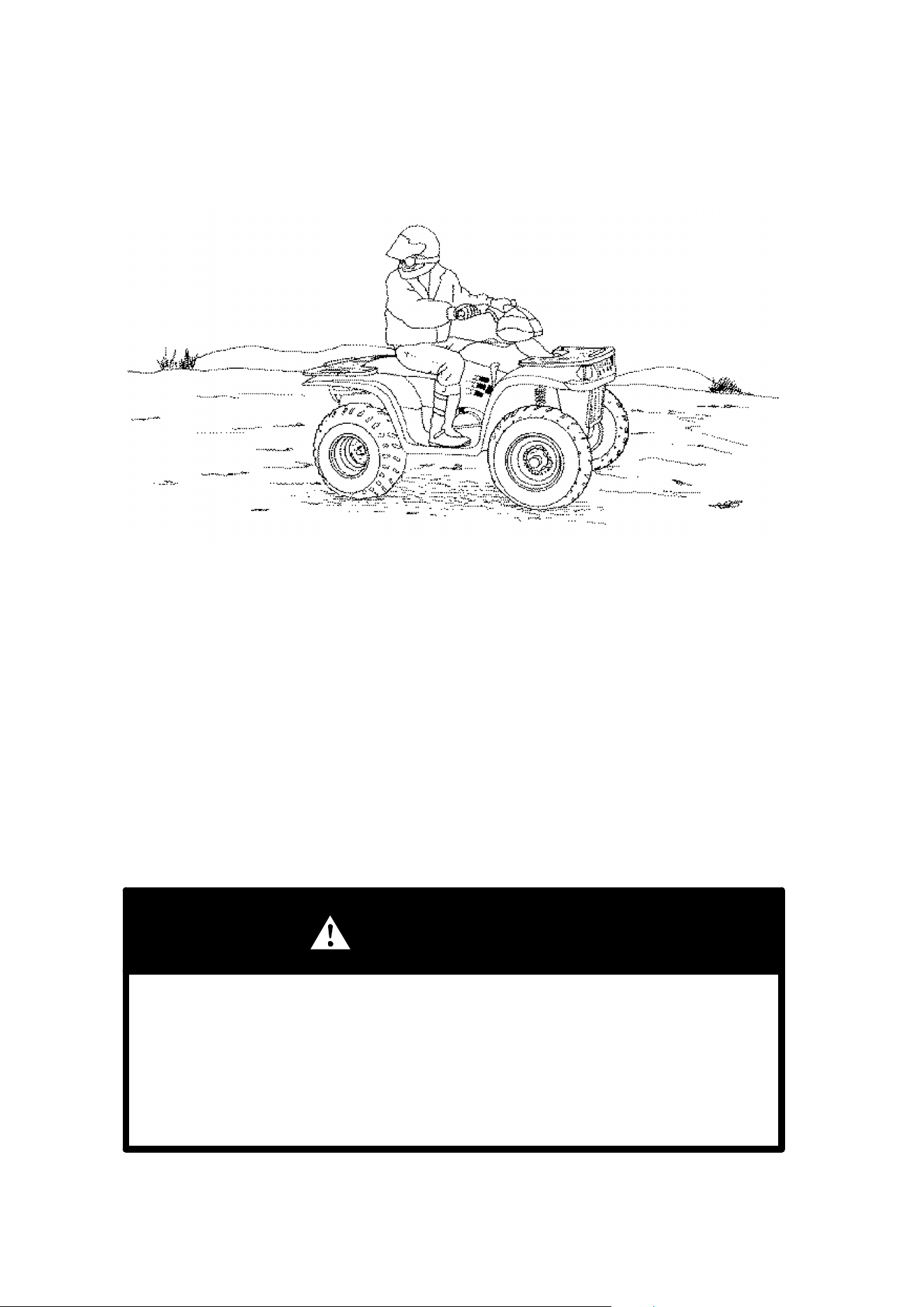
71
RIDING
Backing Up
Backing Up
1. Whenever backing up, always avoid backing downhill.
2. Back slowly.
3. When in reverse, apply the brakes lightly for stopping.
4. Avoid turning at sharp angles in reverse.
5. Never open the throttle suddenly while backing.
6. Never activate override button while throttle is open. Loss of control may result.
NOTE: This vehicle is equipped with a reverse speed limiter. The override button
should be used with caution as rearward vehicle speed is greatly increased. Do
not operate at wide open throttle. Only open the throttle enough to maintain a de-
sired speed. Opening the throttle more than required may cause excessive fuel
to build in the exhaust, resulting in engine popping and/or engine damage.
WARNING
Backing your ATV can be dangerous! You could hit an obstacle or person
behind you; or the ATV could tip over rearward on a steep incline.
DAlways back slowly, avoiding excessive speed; and do not use the
reverse speed override switch system unless additional power is
required for vehicle movement.
DAvoid backing on steep inclines.
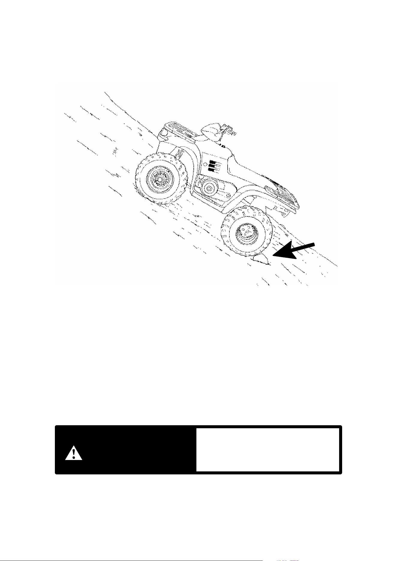
72
RIDING
Parking on an Incline
Whenever the Vehicle is Parked
1. Turn the engine off.
2. Place the transmission in gear.
3. Set the parking brake.
4. Avoid parking on an incline. If it is necessary to park on an incline, always block
the rear wheels on the down hill side as shown above.
5. Shut off fuel supply.
indicates a potential hazard which
could result in serious injury or death.
WARNING
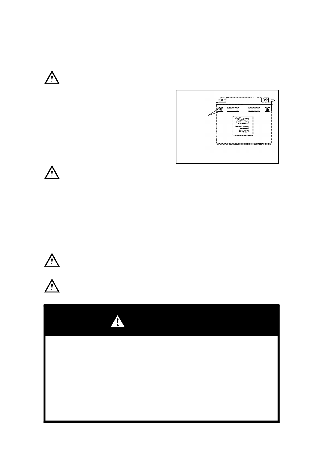
73
BATTERY
Battery
CAUTION
Whenever removing the battery, discon-
nect the negative (black) cable first. When
reinstalling the battery, connect the nega-
tive (black) cable last.
Replenishing the Battery Fluid
A poorly maintained battery will deteriorate
rapidly. Check the battery fluid level often.
The fluid level should be kept between the
upper and lower level marks.
To refill use only distilled water. Tap
water contains minerals which are harmful
to a battery.
Battery Connections
Battery terminals and connections should be kept free of corrosion.
If cleaning is necessary, remove the corrosion with a stiff wire brush. Wash with
a solution of one tablespoon baking soda and one cup water. Rinse well with tap
water and dry off with clean rags. Coat the terminals with dielectric grease or petro-
leum jelly.
Do not allow cleaning solution or tap water to enter the battery. It will shorten
the life of the battery.
Vehicle lamps will burn out if battery is disconnected during vehicle opera-
tion. Also, the reverse speed limiter can be damaged.
WARNING
Battery electrolyte is poisonous. It contains sulfuric acid. Serious burns can
result from contact with skin, eyes or clothing. Antidote:
External: Flush with water.
Internal: Drink large quantities of water or milk. Follow with milk of magnesia,
beaten egg, or vegetable oil. Call physician immediately.
Eyes: Flush with water for 15 minutes and get prompt medical attention.
Batteries produce explosive gases. Keep sparks, flame, cigarettes, etc. away.
Ventilate when charging or using in an enclosed space. Always shield eyes
when working near batteries. KEEP OUT OF REACH OF CHILDREN.
Maintain
between
upper and
lower level
marks

74
BATTERY
Battery Removal
1. Disconnect hold down straps holding the electrical box and battery in position
and remove battery cover.
2. Remove the battery vent tube from the battery.
3. Disconnect the black (negative) battery cable first.
4. Disconnect the red (positive) battery cable next.
5. Lift the battery out of the ATV, being careful not to tip it sideways and spill any
electrolyte.
CAUTION: If electrolyte spills, immediately wash it off with a solution of one table-
spoon baking soda and one cup water to prevent damage to the ATV.
Battery Installation
WARNING: To avoid the possibility of explosion, always connect battery cables
in the order specified. Red (positive) cable first; black (negative) cable last.
1. Set the battery in its holder.
2. Install the battery vent tube. It must be free from obstructions and securely
installed. If not, battery gases could accumulate and cause an explosion. The
tube should be routed away from the frame and body to prevent corrosion.
Avoid skin contact with electrolyte, severe burns could result.
3. First connect and tighten the red (positive) cable.
4. Second connect and tighten the black (negative) cable.
5. Reinstall battery cover and attach the hold down strap.
6. Verify that cables are properly routed.
NOTE:
DWhen your ATV is placed in storage for three months or more, the battery
should be removed, charged to proper level, and stored in a cool dry place.
DBefore reusing, take the battery to your dealer for testing and recharging.
DPower plug leads may need to be bent down so that the battery cover may be
installed.

75
NOISE EMISSION CONTROL SYSTEM REGULATION
TAMPERING WITH NOISE CONTROL SYSTEM PROHIBITED!
U.S. Federal law prohibits the following acts or the causing thereof:
(1) The removal or rendering inoperative by any person other than for purposes of
maintenance, repair, or replacement of any device or element of design incorpo-
rated into any new vehicle for the purpose of noise control prior to its sale ordelivery
to the ultimate purchaser or while it is in use or
(2) the use of the vehicle after such device or element of design has been removed
or rendered inoperative by any person.
“AMONG THOSE ACTS PRESUMED TO CONSTITUTE TAMPERING ARE THE
ACTS LISTED BELOW.”
1. Removal or alteration or the puncturing of the muffler or any engine component
which conducts removal of engine exhaust gases.
2. Removal or alteration or the puncturing of any part of the engine air induction
system.
3. Replacement of any vehicle parts with parts not in compliance with federal reg-
ulations.
4. Lack of proper maintenance.
CAUTION: Remember, exhaust system components are very hot during and after
use of ATV.
DDo not touch exhaust system components. Serious burns can result.
DBe especially careful when traveling through tall grass. The potential for fire
exists.
USFS Approved Spark Arrestor
Polaris ATVs have mufflers that were tested and approved in accordance with the
USFS Forest Service Standard 5100-1A. For specific information on your model,
see the Owner’s Manual Specification Supplement that came with your machine.
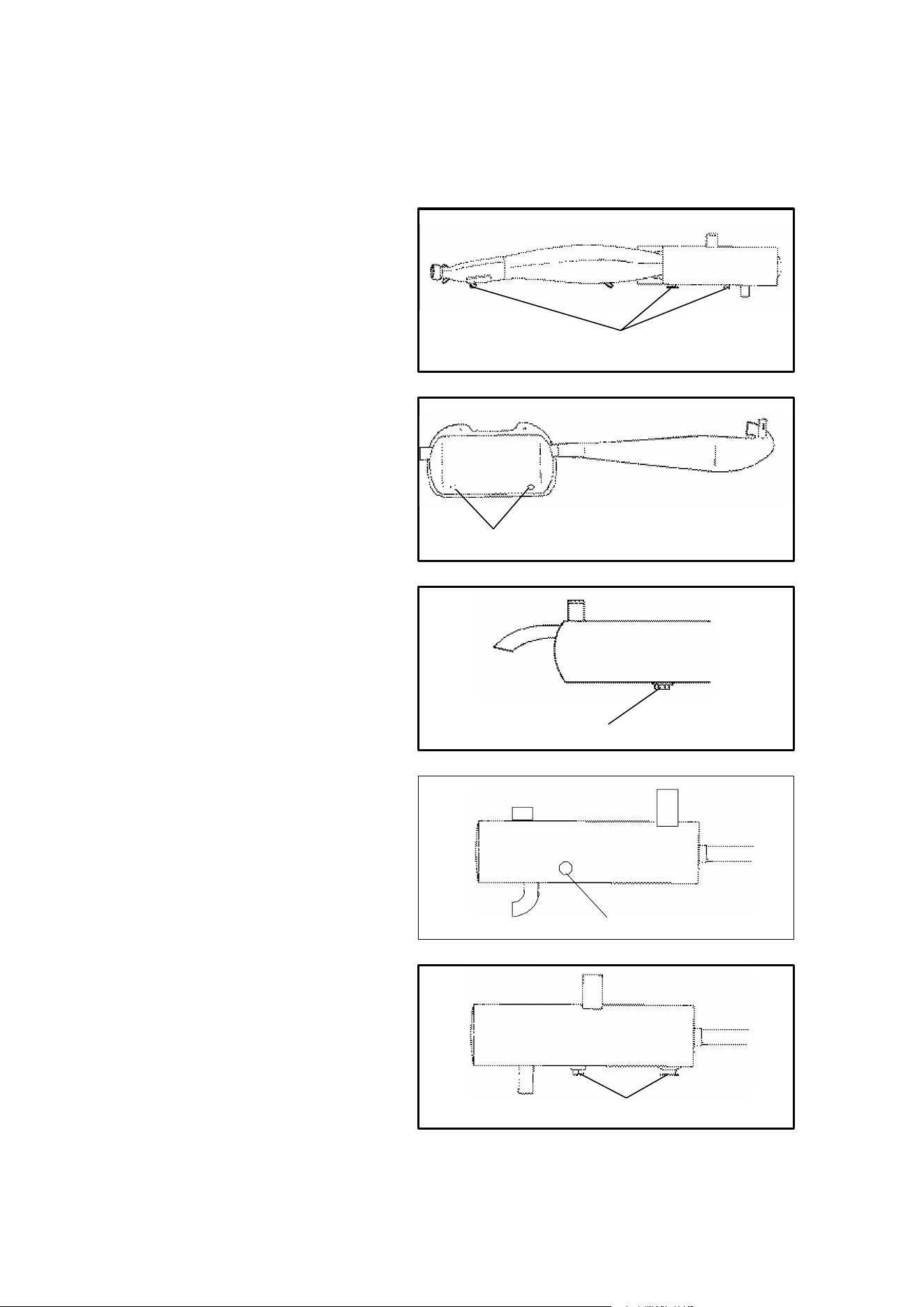
76
MAINTENANCE
Spark Arrestor
The exhaust pipe must be periodically purged of accumulated carbon as follows:
1. Remove the clean out
plugs located on the bottom
of the muffler as shown
above.
2. Place the transmission in
neutral and start the en-
gine. Purge accumulated
carbon from the system by
momentarily revving the
engine several times.
3. If some carbon is expelled,
cover the exhaust outlet
and rap on the pipe around
the clean out plugs while
revving the engine several
more times.
4. If particles are still sus-
pected to be in the muffler,
back the machine onto an
incline so the rear of the ma-
chine is one foot higher
than the front. Set the park-
ing brake and block the
wheels. Make sure the ma-
chine is in neutral and re-
peat steps 2 and 3. WARN-
ING: SEE BELOW.
5. If particles are still sus-
pected to be in the muffler,
drive the machine onto the
incline so the front of the
machine is one foot higher
than the rear. Set the park-
ing brake and block the
wheels. Make sure the ma-
chine is in neutral and re-
peat steps 2 and 3. WARN-
ING: SEE BELOW.
6. Repeat steps 2 through 5
until no more particles are
expelled when the engine is
revved.
7. Stop the engine and allow
the arrestor to cool.
8. Reinstall the arrestor plugs.
Clean Out Plugs
Clean Out Plug
Clean Out Plugs
Clean Out Plug
Clean Out Plugs

77
MAINTENANCE
Spark Arrestor (Cont.)
WARNING
DDo not perform this operation immediately after the engine has been run
because the exhaust system becomes very hot.
DBecause of the increased fire hazard, make sure that there are no com-
bustible materials in the area when purging the spark arrestor.
DWear eye protection.
DDo not stand behind or in front of the vehicle while purging the carbon
from the spark arrestor.
DNever run the engine in an enclosed area. The exhaust contains poi-
sonous carbon monoxide gas.
DDo not go under the machine while it is inclined.
Failure to heed these warnings could result in serious personal injury or death.
CAUTION: Keep combustible materials away from exhaust system. Fire may re-
sult.
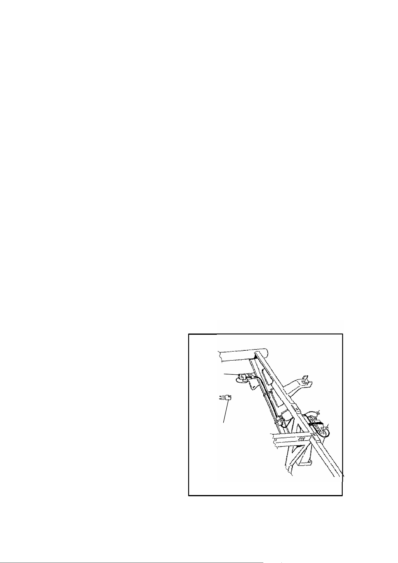
78
MAINTENANCE
Tool Kits
To help you perform routine maintenance, a tool kit is provided in the storage
compartment under the seat. Items included in the kits are:
2 cycle engines
Dflat screwdriver
Dspark plug wrench with Phillips head screwdriver
Dwrench
Dtire pressure gauge
Dspanner wrench for adjusting rear shock spring preload (selected models)
4 cycle engines
Dscrewdriver
Dopen end wrench (8-10 mm)
Dopen end wrench (12-14 mm)
Dbox end wrench
Dtire pressure gauge
Dspark plug wrench and handle
Dspanner wrench for adjusting rear shock spring preload (selected models)
NOTE: Other tools are also necessary to perform maintenance work. They are
called out later in this manual.
Power Pig Tail
Some models are equipped
with an auxiliary power outlet.
Refer to your Owner’s Manual
Supplement to determine if your
machine has one.
A power pig tail is included in the
tool kit . This pig tail will allow
you to plug power accessories
into the vehicle. Attach the pig
tail to the power accessory and
then plug into the rear power
outlet of the vehicle.
CAUTION: Be sure to wrap
bare wires with electrical tape
and follow correct wire splicing
procedures to avoid shorts in
the wiring system.
Additional pig tails may be pur-
chased under Polaris PN
2460442.
Power
Outlet
Pigtail

79
MAINTENANCE
Periodic Maintenance Schedule
Careful periodic maintenance will help keep your vehicle in the safest, most reliable
condition. Inspection, adjustment and lubrication intervals of important compo-
nents are explained in the following chart
Maintenance intervals are based upon average riding conditions and a vehicle
speed of approximately 10 miles per hour. Vehicles subjected to severe use, such
as operation in wet or dusty areas, should be inspected and serviced more fre-
quently. If you are not familiar with safe service and adjustment procedures, have
a qualified dealer perform these operations.
Inspect, clean, lubricate, adjust or replace parts as necessary. NOTE: Inspection
may reveal the need for replacement parts. Always use genuine Polaris parts
available from your Polaris dealer.
Service and adjustments are critical. If you are not familiar with safe service and
adjustment procedures, have a qualified dealer perform these operations.
J CAUTION: Due to the nature of these adjustments, it is recommended that
service be performed by an authorized Polaris dealer. Do not attempt to perform
this work unless you are familiar with mechanical repair.
" More often under severe use, such as dirty or wet conditions
L Emission Control System Service (California - 4-Cycle)
Item Hours or
Odometer
Frequency Remarks
"
L
Engine Oil - Level/Change
(4-Cycle)
100 hrs/1000
miles
6 months Check Level Daily; Break in Service at
1 month. Change oil more often in cold
weather use.
"
L
Oil Filter(4-Cycle) 100 hrs/1000
miles
6 months Replace with oil change
Injector Oil Level (2-Cycle) Daily Daily Check when refueling
J Injector Oil Filter (2-Cycle) 100 hrs Annually Replace
Engine Counterbalance
(400 Engines)
20 hrs Monthly Check oil level; change annually
Oil Pump Cable (2-Cycle) 50 hrs 6 months Inspect, adjust, lubricate, replace if re-
quired
"
L
Engine breather filter
(4 cycle)
20 hrs Monthly Inspect--replace annually and as need-
ed
L
Engine breather hose
(4 cycle)
100 hrs 6 months Inspect
Engine Mounts 100 hrs 12 months Inspect
Engine Cylinder Head and
Cylinder Base Fasteners
25 hrs 3 months Inspect (re-torque required at first ser-
vice only)
"
L
Air Filter - Pre-Cleaner Daily Daily Inspect-Clean
"
L
Air Filter - Main Element Weekly Weekly Inspect-Replace if necessary
" Air Box Sediment Tube Daily Daily Drain deposits whenever visible
J
L
Valve Clearance (4-Cycle) 100 hrs 12 months Inspect/Adjust
L
Spark Plug 100 hrs 12 months Inspect--replace if necessary
J
L
Ignition Timing 100 hrs 12 months Inspect and adjust as needed

80
MAINTENANCE
Periodic Maintenance Schedule (Cont.)
Item Hours or
Odometer
Frequency Remarks
J
L
Fuel System 100 hours 12 months Check for leaks at tank cap, lines, fuel
valve, filter, pump and carburetor. Re-
place lines every two years.
J Fuel Filter 100 hrs 12 months Replace annually
Carburetor Float Bowl 50 hrs 6 months Drain bowl periodically and prior to stor-
age
L
Idle Speed As Required As Required Adjust
J Throttle Cable/ETC Switch 50 hrs 6 months Inspect--adjust, lubricate, replace if nec-
essary; pre-ride inspection item
L
Choke (Enricher) Cable 50 hrs 6 months Inspect--adjust, lubricate, replace if nec-
essary
Coolant/Level Inspection Daily Daily Replace engine coolant every two
years
Coolant strength/pressure test
system
100 hrs 6 months Inspect strength seasonally; pressure
test system annually
Radiator 100 hrs 12 months Inspect/clean external surface
Cooling System hoses 100 hrs 12 months Inspect
Spark arrestor 100 hrs 12 months Clean out
Recoil housing As required As required Drain moisture out after riding in water
" General Lubrication 50 hrs 3 months Lubricate all fittings, pivots, cables, etc.
" Front hubs/fluid check (AWD) 50 hrs 6 months Check monthly
" Front hubs/fluid change (AWD) 100 hrs 12 months
" Front Gearcase OIl (shaft drive) 100 hrs 12 months Check monthly and change annually
" Transmission Oil Level 25 hrs Monthly Inspect monthly; change annually
Shift linkage 50 hrs 6 months Inspect, lubricate, adjust
J Shift selector box 200 hrs 24 months Change lubricant every two years
J Drive belt 50 hrs 6 months Inspect--adjust, replace if necessary
J Clutches (drive and driven) 100 hrs 12 months Inspect, clean
J Steering 50 hrs 6 months Inspect daily, lubricate
J Toe adjustment As required As required Periodic inspection, adjust when parts
are replaced
" Rear Axle 50 hrs 6 months Inspect bearings
" Front Suspension 50 hrs 6 months Inspect--lubricate, tighten fasteners
" Rear Suspension 50 hrs 6 months Inspect, tighten fasteners
J Front wheel bearings 300 hrs 36 months Replace
" Drive Chain(s) 50 hrs 6 months Inspect daily, adjust and lubricate if
needed
Battery 20 hrs monthly Check Terminals/clean/check fluid level
Headlight Aim As required As required Adjust if necessary

81
MAINTENANCE
Periodic Maintenance Schedule (Cont.)
Item Hours or
Odometer
Frequency Remarks
Headlamp Inspection Daily Daily Check operation daily; apply Polaris di-
electric grease to connector when re-
placed
Tail lamp inspection Daily Daily Check operation daily; apply Polaris di-
electric grease to socket when replaced
Brake System Pre-ride Pre-ride Pre-ride inspection item
J Brake fluid 200 hrs 24 months Change every two years
J Brake pad wear 10 hrs/100
miles
Monthly Inspect periodically
Auxiliary As required As required Inspect deflection daily; adjust
Tires Pre-ride Pre-ride Inspect daily, pre-ride inspection item
Wheels Pre-ride Pre-ride Pre-ride inspection item
Frame nuts, bolts, fasteners Pre-ride Pre-ride Pre-ride inspection item
J CAUTION: Due to the nature of these adjustments, it is recommended that
service be performed by an authorized Polaris dealer. Do not attempt to perform
this work unless you are familiar with mechanical repair.
" More often under severe use, such as dirty or wet conditions
L Emission Control System Service (California - 4-Cycle)

82
MAINTENANCE
Lubrication Recommendations
Item Lube Rec. Method Frequency*
1. Engine Oil
(2-Cycle)
Polaris
Injection Oil
Fill oil tank. See page 48. As needed,
when refueling
2.Engine OIl
(4-Cycle)
Polaris Pre-
mium 4 Syn-
thetic 0W40
Add to proper level on dipstick.
See page 50.
Check level dai-
ly.
3. Brake Fluid DOT 3 Only Maintain level between fill lines.
See page 39.
As required;
change every
two years or 200
hours
4. Transmission
Oil
Polaris Pre-
mium Syn-
thetic chain
case lube
Add to FULL level on dipstick.
See page 115.
Change annually
or at 100 hours
5. Front Gear-
case Oil
GL5 80-90
Weight Gear
Lube
Fill to bottom thread of filler hole.
Make certain machine is on level
surface.
Change annually
6. Rear Half-
shafts
Grease+ Locate Fittings and Grease Every 3 months
or 50 hours
7. Front Prop
Shaft U-joints
Grease+ Locate Fittings and Grease Every 3 months
or 50 hours
8. Front Prop-
shaft Yoke
Grease+ Locate fittings and grease -- 3
pumps maximum
Every 3 months
or 50 hours
9. Speedometer
Cable
Polaris
Cable Lube
Disconnect cable on back of
speedometer and lubricate inner
cable.
3 months or 50
hours
10. Drive
Chain(s)
O-Ring chain
lube or
SAE 80/90
Lubricate as often as required.
Before each ride in wet conditions
As required
11.Demand 4
Hubs - All
Wheel Drive
ATVs
Premium
Hub Lube
Remove set screw in hubs. Ro-
tate wheels to 4 O’clock position.
If lubricant is not visible add more.
Reinstall set screw.
Annually or at
100 hrs
12. Front Drive
Axle (U Joint)
(AWD Mod
els)
Grease+ Locate grease fitting and grease
with grease gun.
Every 3 months
or 50 hours
13. Ball Joint Grease** Locate fitting on back side of
struts and grease with grease
gun.
Every 3 months
or 50 hours

83
MAINTENANCE
Lubrication Recommendations
14. Front A Arm
Pivot Shaft
Grease**∆ Locate fitting on pivot shaft and
grease with grease gun.
Every 3
months or 50
hours
15. Counter Bal-
ance Housing
(400)
SAE 10/30 Check level on dipstick and add oil as
necessary. Change annually. To
change oil see page 117.
Check month-
ly and change
annually
16. Output Shaft
Support Bearing
Grease ** Locate fitting on bearing and grease
with a grease gun.
Monthly or at
20 hours
17. Steering Post
Bushings
Grease** Locate fittings on steering post and
grease with grease gun.
Every 3
months or 50
hours
18. Rear Axle
Bearing
Grease** Locate fittings and grease Every 3
months or 50
hours
19. Swing Arm
Bushings
Grease** Locate fittings on swing arm and
grease with grease gun.
Monthly or at
20 hours
20. Chain Ad-
justers (Center
and Front Eccen-
trics)
Grease** Locate fitting on center eccentric and
grease. Locate fitting on front eccen-
tric (side opposite chain) and grease.
Every 3
months or 50
hours
21. Upper Control
Arms
Grease**∆ Locate fittings and grease Semi-annually
22. Lower Control
Arms
Grease**∆ Locate fittings and grease Semi-annually
23. Rear Wheel
Hub Bearing Car-
rier
Grease**∆ Locate fitting and grease Semi-annually
24. Rear Anti-Roll
Bar
Grease Semi-annually
25. Tie Rod Ends Grease** Remove bolt above inner tie rod boot.
Lift boot. Clean away dirt and grease.
Apply fresh grease by hand and reas-
semble. On models equipped with
grease fitting, locate outer tie rod fit-
ting and grease with grease gun.
Every 3
months or 50
hours
* More often under severe use, such as wet or dusty conditions.
**Polaris Premium all Season Grease or grease conforming to NLGI No. 2, such as
Conoco Superlube M or Mobilegrease Special.
+ Grease every 500 miles, or after submerging in water or before long periods of storage or
after pressure washing. Always use Polaris Premium U-Joint Lube for maximum service of
these driveline components (PN 2871515 3 oz.)(PN 2871551 14 oz.).
∆ When suspension action becomes stiff or after washing.
NOTE: Hours are based on 10 mph average.
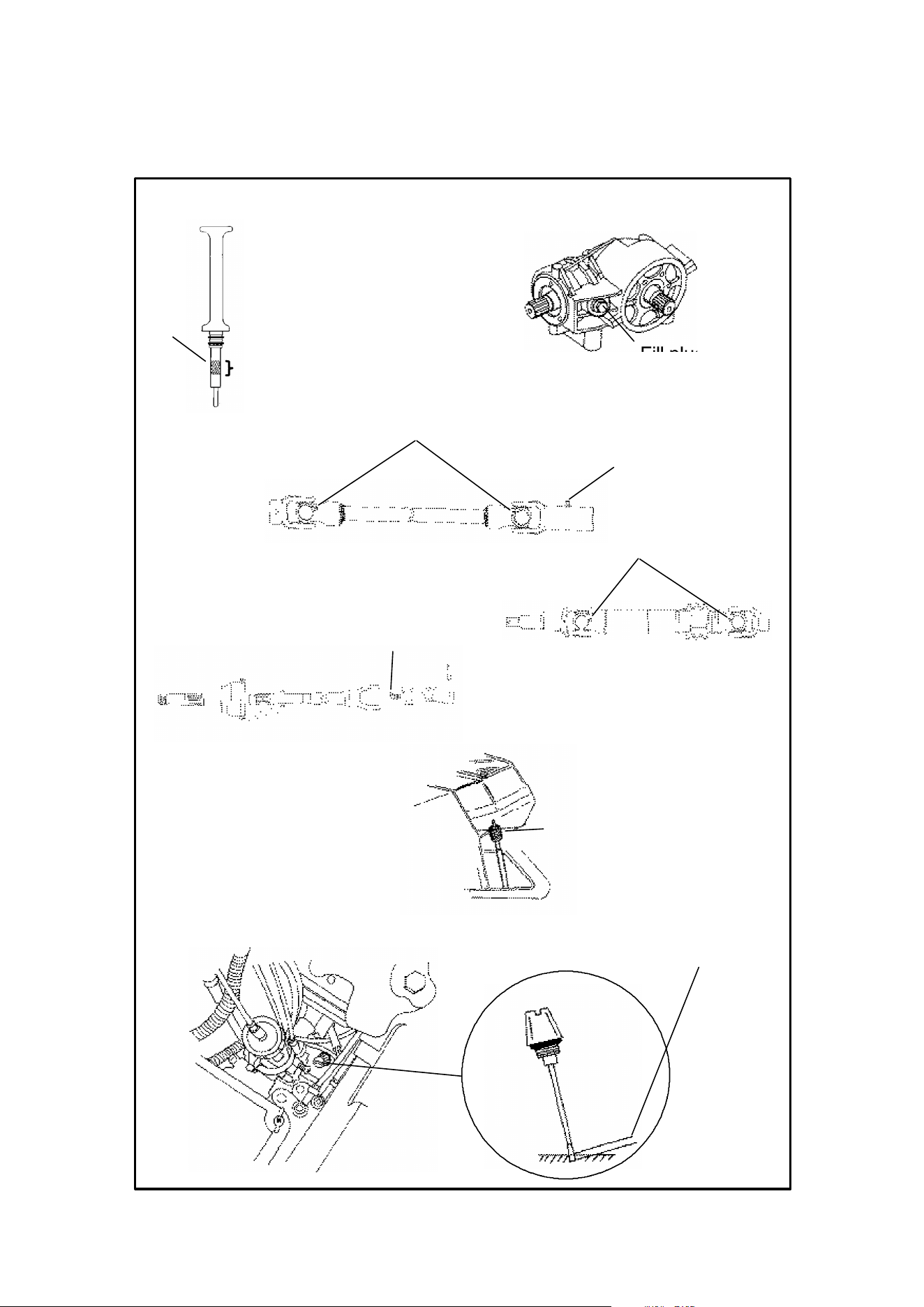
84
MAINTENANCE
Lubrication Recommendations
Operating
Range
Full
4. Transmission
7. Front Prop Shaft
(U-Joint)
12. Axle Cardan
Front Drive
(AWD Models)
6. Rear Halfshaft
(U Joint)
8. Propshaft Yoke
9. Speedo
meter Cable
Fill plug
5. Front Gear Case
15. Counterbalance
Dipstick
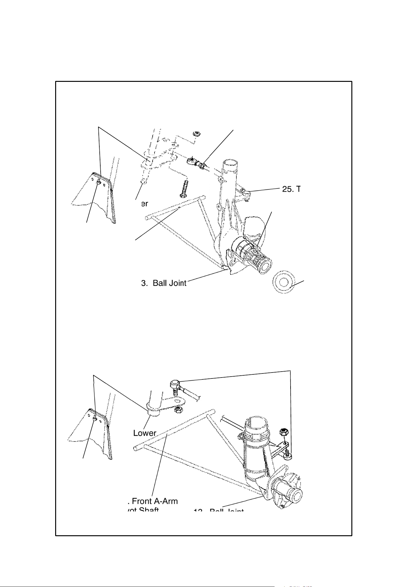
85
MAINTENANCE
Lubrication Recommendations
4WD
17. Steering Post Bushings
25. Tie Rod End
25. Tie Rod End
13. Ball Joint
14. Front A-Arm
Pivot Shaft
Lower
Upper
11. 4
O’clock
position
11. Demand 4 Hubs
17. Steering Post Bushings
25. Tie Rod Ends
13. Ball Joint
14. Front A-Arm
Pivot Shaft
Lower
Upper
Trail Boss
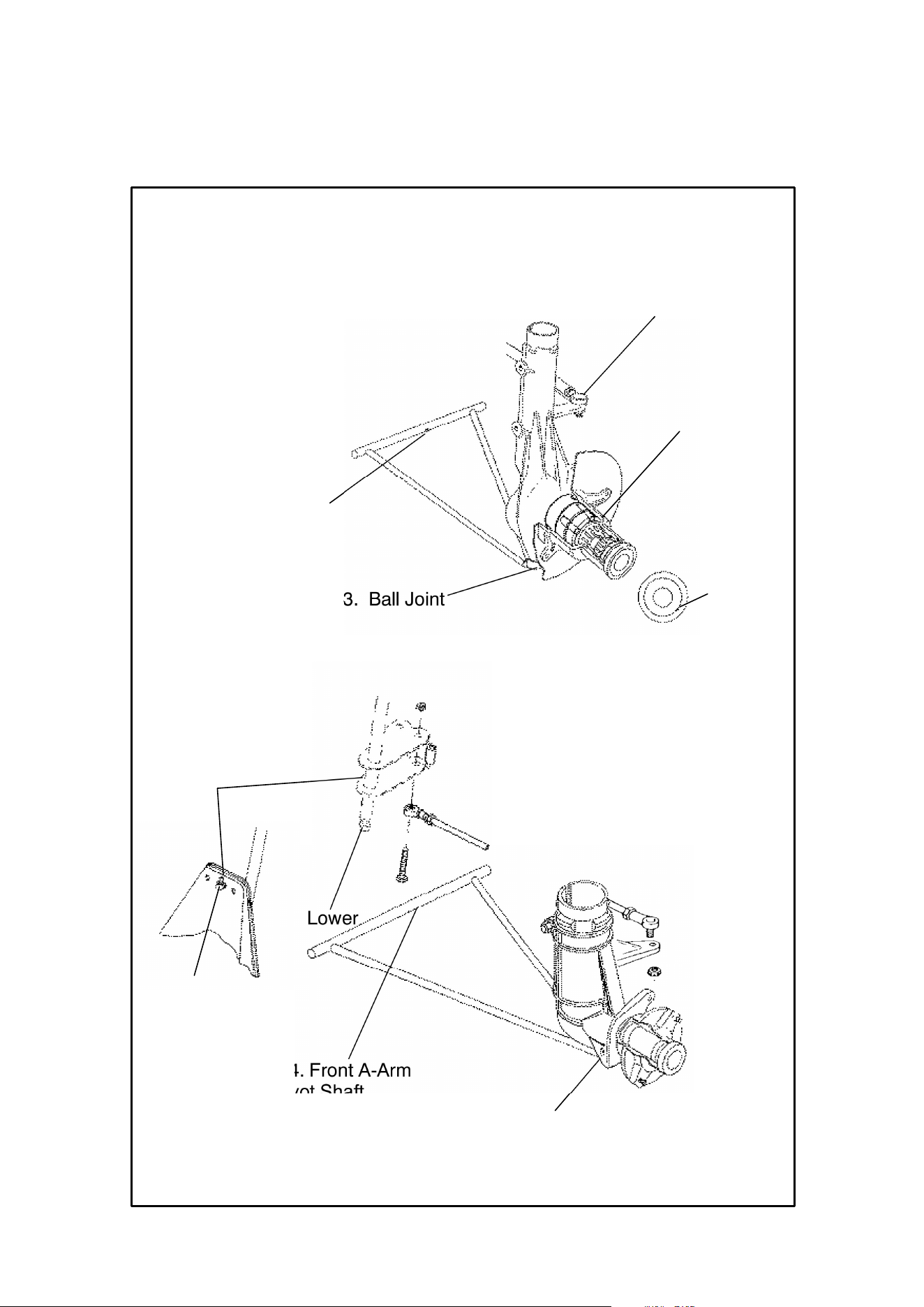
86
MAINTENANCE
Lubrication Recommendations
17. Steering Post
Bushings
13. Ball Joint
14. Front A-Arm
Pivot Shaft
Lower
Upper
25. Tie Rod End
13. Ball Joint
14. Front A-Arm
Pivot Shaft
11. 4
O’clock
position
11. Demand 4 Hubs
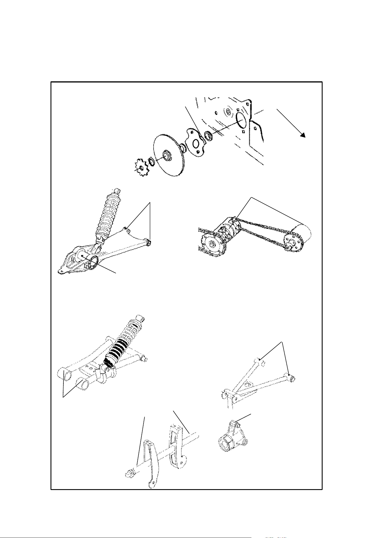
87
MAINTENANCE
Lubrication Recommendations
19. Swing Arm Bushings
18. Rear Axle Bearing
Forward
16. Output shaft sup-
port bearing grease fit-
ting
20. Center and Front Eccentrics
21. Upper Control
Arm
23. Rear Wheel
Hub Bearing Carri-
er
24. Rear Anti-
Roll Bar
22. Lower Control
Arm
INDEPENDENT REAR SUSPENSION

88
MAINTENANCE
Periodic Maintenance Record
Use the following chart to record periodic maintenance work:
Maintenance
Interval
Performed
Servicing
Date
Servicing
Dealer
or Person
Remarks
First 5 Hrs.
25 Hrs.
50 Hrs.
75 Hrs.
100 Hrs.
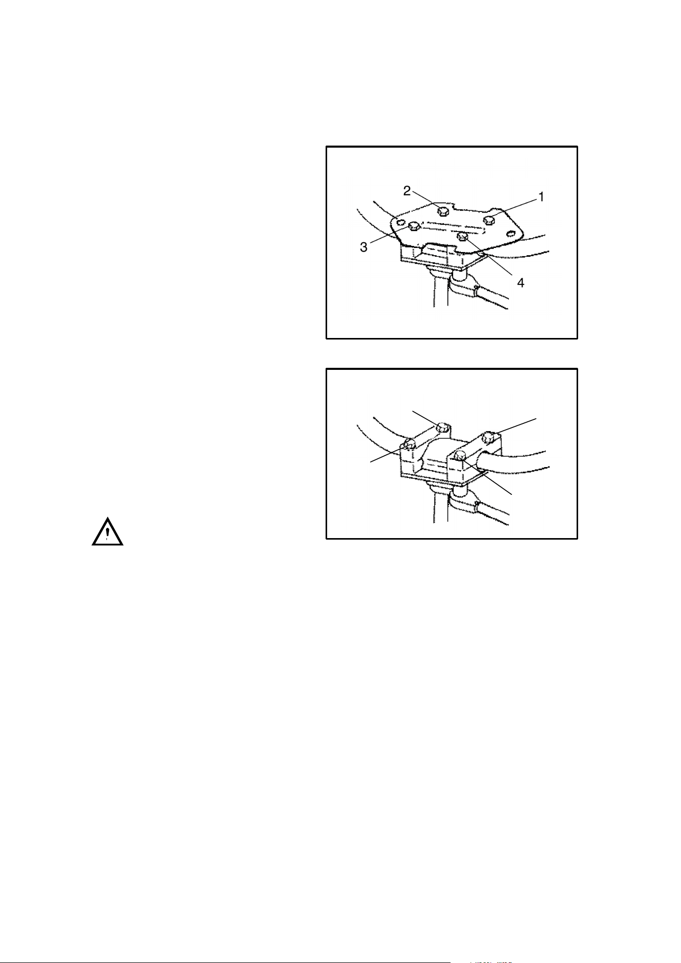
89
MAINTENANCE
Steering
Handlebar Adjustment
Your ATV has handlebars which can
be adjusted for your personal fit.
1. Locate handlebar bolts. On mod-
els with a headlight pod, it will be
necessary to remove the upper
headlight pod. On other models
remove the handlebar cover.
2. Loosen the four bolts.
3. Adjust handlebar to desired
height. Be sure handlebars do
not hit gas tank or any other part
of machine when turned fully to
left or right.
4. Torque handlebar adjuster block
bolts to 10 to 12 ft. lbs.
NOTE: Tighten bolts so there is an
equal gap at the front and rear of the
handlebar block. Improper gap will
result in improper fit of upper pod.
WARNING
Improper adjustment of the handlebars or incorrect torquing of the adjuster block
tightening bolts can cause limited steering or loosening of the handlebars, resulting
in loss of control and possible serious personal injury or death.
1
2
3
4
1
2
3
4

90
MAINTENANCE
The following items should be checked occasionally for tightness; or if they have
been loosened for maintenance service.
Axle and Wheel Nut Torque Specifications
Model Item Specification
Front Spindle Nut(s) 40 Ft. Lbs.
2
X
4
Front Wheel Nuts 15 Ft. Lbs.
2
X
4
Rear Axle Nut(s) 80 Ft. Lbs.
Rear Wheel Nuts 50 Ft. Lbs.
Front Spindle Nut(s) Dealer Performed Service
4
x
4
Front Wheel Nuts 15 Ft. Lbs.
4
x
4
Chain Drive
Rear Axle Nut(s) 80 Ft. Lbs.
Rear Wheel Nuts 50 Ft. Lbs.
Front Spindle Nut(s) Dealer Performed Service
4
x
4
Front Wheel Nuts 15 Ft. Lbs.
4
x
4
Shaft Drive
Rear Hub Retaining Nut(s) 100 Ft. Lbs.
Rear Wheel Nuts 15 Ft. Lbs.
Front Wheel Hub Tightening
Front wheel bearing tightness and spindle nut retention are critical component op-
erations. Service work must be performed by your authorized Polaris dealer.
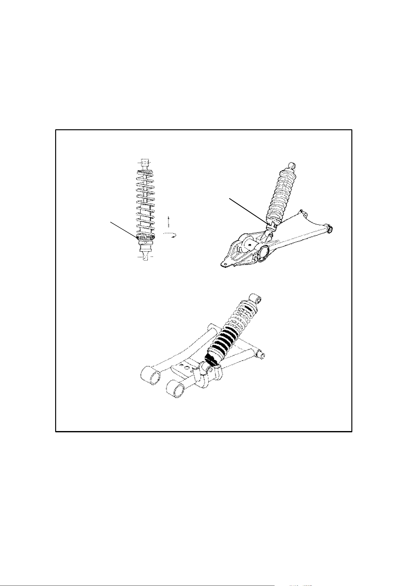
91
MAINTENANCE
Rear Spring Adjustment
The rear shock absorber spring is adjusted by rotating the adjuster in the direction
required to increase or decrease spring tension.
Rear Spring
Adjustment
Rear Spring
Adjustment
Cam

92
MAINTENANCE
Optional Suspension Springs
Although your Polaris ATV suspension has the capability of providing you with the
best ride possible, the following accessory springs are available to better suit your
individual riding preference.
NOTE: Optional springs may be a different color than standard springs. Owner
may paint springs to desired color using Polaris touch up paint, available through
your dealer.
SOFT FIRM
Trail Boss Rear
Compression
Spring
7041518-067
OPTION 175 LB/IN
7041204-179
STANDARD 190 lb/in
7041303-067
OPTION 250 lb/in
Trail Boss - Front
Strut Spring
7041471-067
OPTION 41 LB/IN
7041238-179
STANDARD 61 lb/in
7041375-067
OPTION 64/113 lb/in
Sportsman 500
4x4 - Rear
Compression
Spring
7041517-067
OPTION
80 lb/in
7041546-067
STANDARD
100 lb/in
7041519-067
OPTION
140 lb/in
Sportsman 500
4x4 - Front Strut
Spring
7041238-067
OPTION
61 lb/in
7041375-067
STANDARD
64/113 lb/in
7041450-067
OPTION
101 lb/in
Xplorer 300-
Rear
Compression
Spring
7041518-067
OPTION 175 lb/in
7041204-195
STANDARD 190 lb/in
7041303-067
OPTION 250 lb/in
Xplorer 300 -
Front Strut Spring
7041238-067
OPTION 61 lb/in
7041375-195
STANDARD 64/113
lb/in
7041450-067
OPTION 101 lb/in
Xplorer 400L -
Rear
Compression
Spring
7041518-067
OPTION 175 lb/in
7041204-195
STANDARD 190 lb/in
7041303-067
OPTION 250 lb/in
Xplorer 400L -
Front Strut Spring
7041238-067
OPTION 61 lb/in
7041375-195
STANDARD 64/113
lb/in
7041450-067
OPTION 101 lb/in
Magnum 2x4 -
Front Strut Spring
7041238-067
OPTION 61 lb/in
7041375-093
STANDARD 64/113
lb/in
7041450-067
OPTION 101 lb/in
Magnum 2x4 --
Rear
Compression
spring
7041518-067
OPTION 175 lb/in
7041204-093
STANDARD 190 lb/in
7041303-067
OPTION 250 lb/in

93
MAINTENANCE
SOFT FIRM
Xpress 300-
Rear
Compression
Spring
7041518-067
OPTION 175 lb/in
7041204-157
STANDARD 190 lb/in
7041303-067
OPTION 250 lb/in
Xpress 300 -
Front Strut Spring
7041238-067
OPTION 61 lb/in
7041375-157
STANDARD 64/113
lb/in
7041450-067
OPTION 101 lb/in
Magnum 4x4 --
Front Strut Spring
7041238-067
OPTION 61 lb/in
7041375-195
STANDARD 64/113
lb/in
7041415-067
OPTION 101 lb/in
Magnum 4x4 -
Rear
Compression
Spring
7041518-067
OPTION 175 lb/in
7041204-195
STANDARD 190 lb/in
7041303-067
OPTION 250 lb/in
Sport 400L- Rear
Compression
Spring
7041470-067
OPTION 150 lb/in
7041389-194
STANDARD 175 lb/in
7041204-067
OPTION 190 lb/in
Sport 400L -
Front Strut Spring
7041471-067
OPTION 41 lb/in
7041238-194
STANDARD 61 lb/in
7041375-067
OPTION 64/113 lb/in
Trail Blazer- Rear
Compression
Spring
N/A 7041470-093
STANDARD 150 lb/in
7041389-067
OPTION 175 lb/in
Trail Blazer -
Front Strut Spring
N/A 7041471-093
STANDARD 41 lb/in
7041238-067
OPTION 61 lb/in
Scrambler 400L-
Rear Comp.
Spring
7041470-067
OPTION 175 lb/in
7041389-171
STANDARD 175 lb/in
7041303-067
OPTION 250 lb/in
Scrambler 400L -
Front Strut Spring
7041648-067
OPTION 75/100 lb/in
7041603-171
STANDARD 75/110
lb/in
7041647-067
OPTION 80/120 lb/in
Scrambler 500-
Rear Comp.
Spring
7041518-067
OPTION 175 lb/in
7041389-216
STANDARD 175 lb/in
7041303-067
OPTION 250 lb/in
Scrambler 500 -
Front Strut Spring
7041648-067
OPTION 75/100 lb/in
7041603-216
STANDARD 75/110
lb/in
7041647-067
OPTION 80/120 lb/in
Xplorer 500 4x4 -
Rear
Compression
Spring
7041238-067
OPTION 61 lb/in
7041375-067
STANDARD 64/113
lb/in
7041450-067
OPTION 101 lb/in
Xplorer 500 4x4 -
Front Strut Spring
N/A 7041546-067
STANDARD 100 lb/in
7041519-067
OPTION 140 lb/in
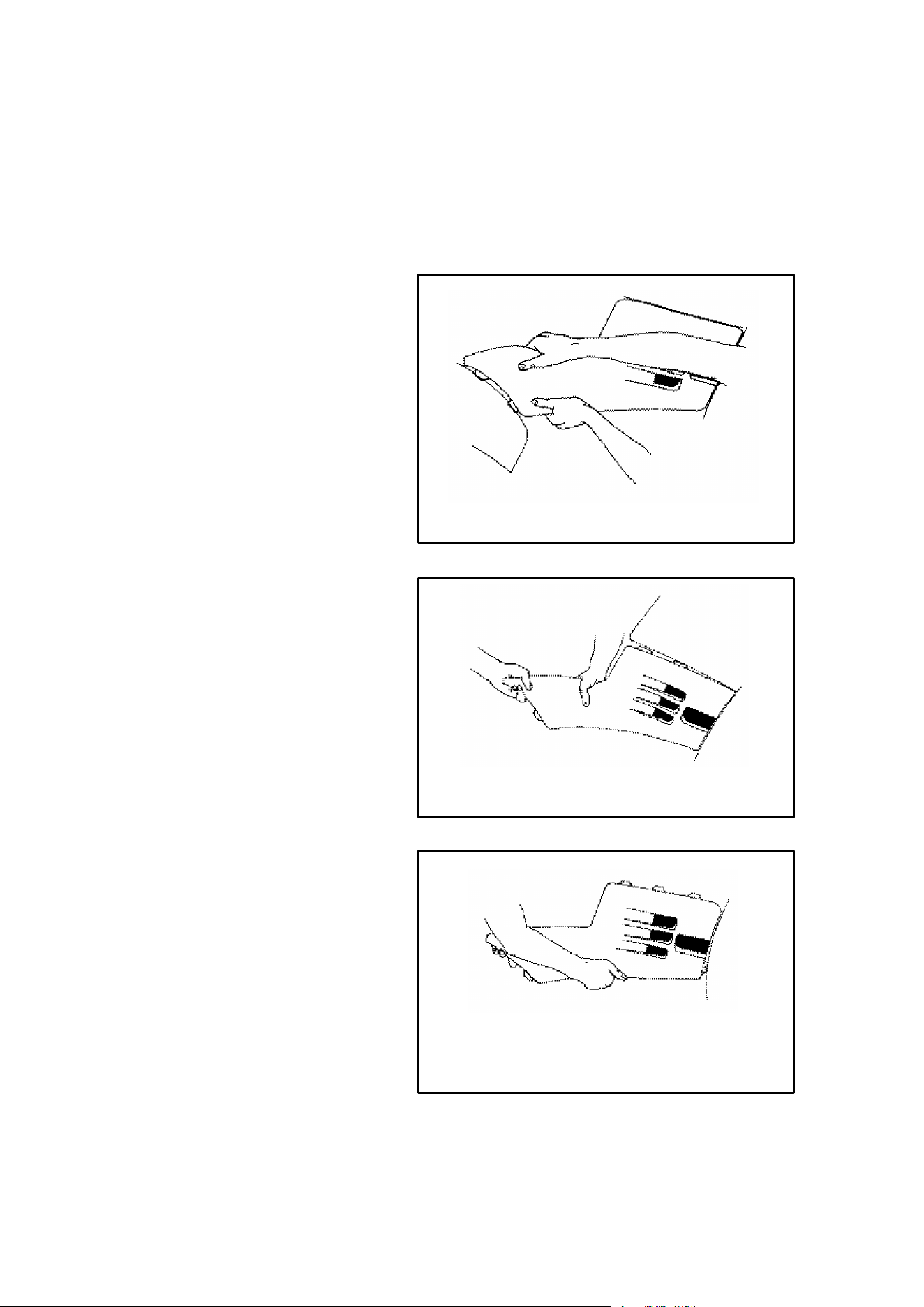
94
MAINTENANCE
Side Panel Removal (Gen IV Models)
Side panel removal may be difficult until the locking tabs and receivers have been
snapped and unsnapped a few times.
1. Remove seat. Grasp rear
of side panel near rearcab.
With a quick and firm
motion, pull the panel
forward and outward to
disengage the two rear
tabs.
2. Place hand on top of side
panel behind the fuel tank.
With a quick and firm
motion, push down on the
side panel to disengage
the top rear two tabs. Then
pull up on side panel to
disengage front upper and
lower tab.
3. To reinstall side panel,
align panel tabs with slots
on front cab. Push panel
upward and forward until
tabs lock. Bend rear of
side panel and insert the
two tabs into the rear cab.
Pull forward and out to disengage
two rear tabs.
Step 1.
Push down to disengage top rear
two tabs.
Step 2.
To reinstall, align panel tabs with
slots. Push upward and forward un-
til tabs lock.
Step 3.
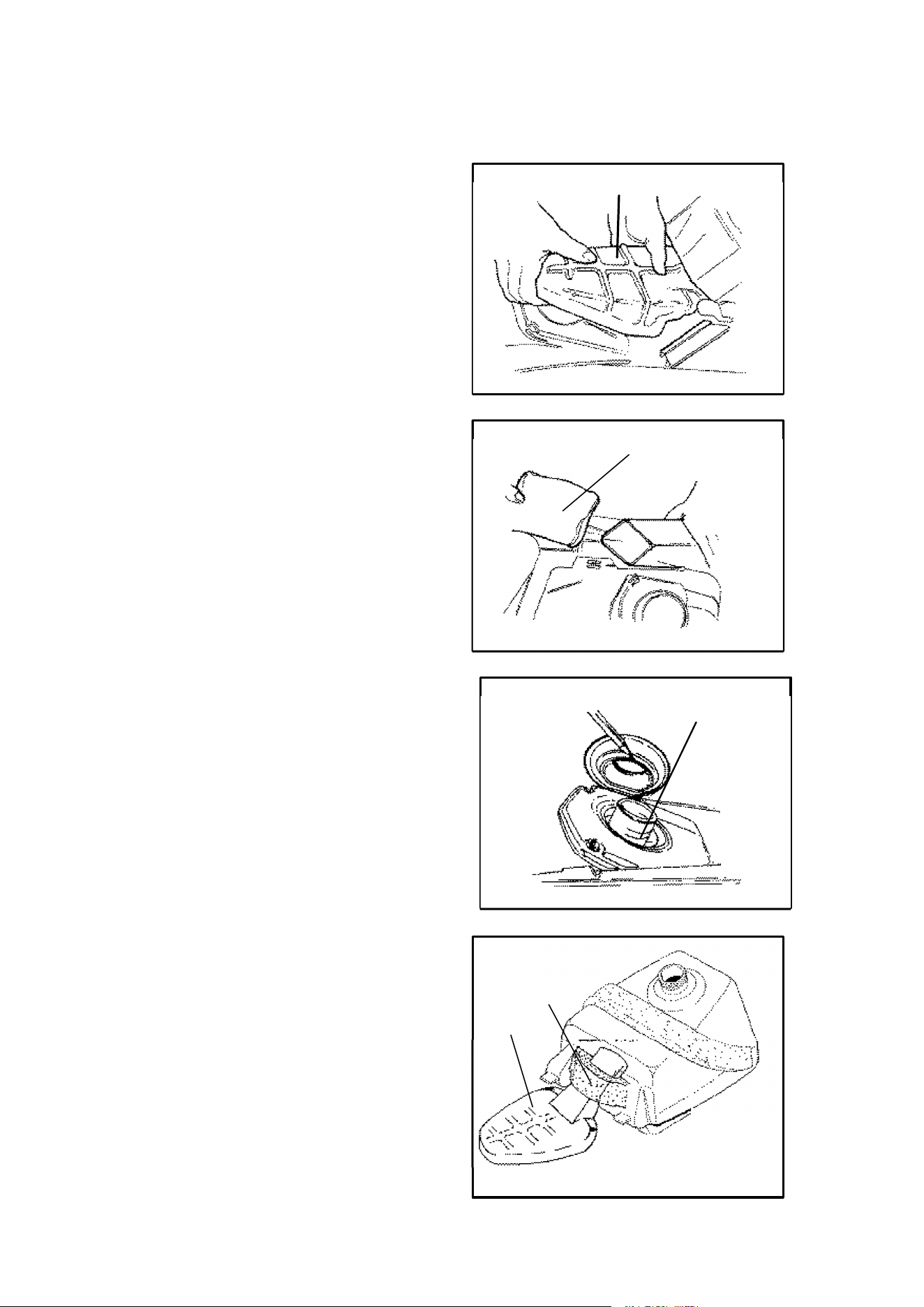
95
MAINTENANCE
Air Cleaner
Trail Boss, Xpress 300,
Xplorer 300, Xplorer 400
Dual Stage Air Cleaner
The Polaris ATV is equipped with a
dual stage engine air filtration system.
The primary pre-cleaner foam boot is
designed to remove the majority of
dust particles before they reach the
secondary dry filter element.
Primary Pre-cleaner Foam Boot
Inspect the primary air cleaner boot
daily or on a regular basis depending
on running conditions and dust.
1. Remove the ATV seat.
2. Remove the primary air filter box.
3. Remove the yellow pre-cleaner
foam boot, held in place by a gray
collar, from the air box. Do not re-
move the collar.
4. Carefully wash the yellow foam
boot in soapy water and dry it.
5. Oil the foam boot with engine injec-
tion oil (1 to 2 teaspoons).
Squeeze out the excess into an ab-
sorbant cloth.
6. Reinstall the yellow foam boot onto
the air filter box.
7. Reinstall the primary air filter box
removed in step 2. NOTE: There
will be some resistance. Be sure
the black rubber sealing ring is se-
curely positioned over the main fil-
ter neck.
CAUTION: When installing the prima-
ry air filter box be sure the gray foam
collar (B) is below the intake opening of
the air box intake (A). Improper instal-
lation will restrict airflow to the engine
possibly resulting in engine damage.
Primary Air Filter Box
Pre-cleaner Boot
Main Filter Neck
B
A
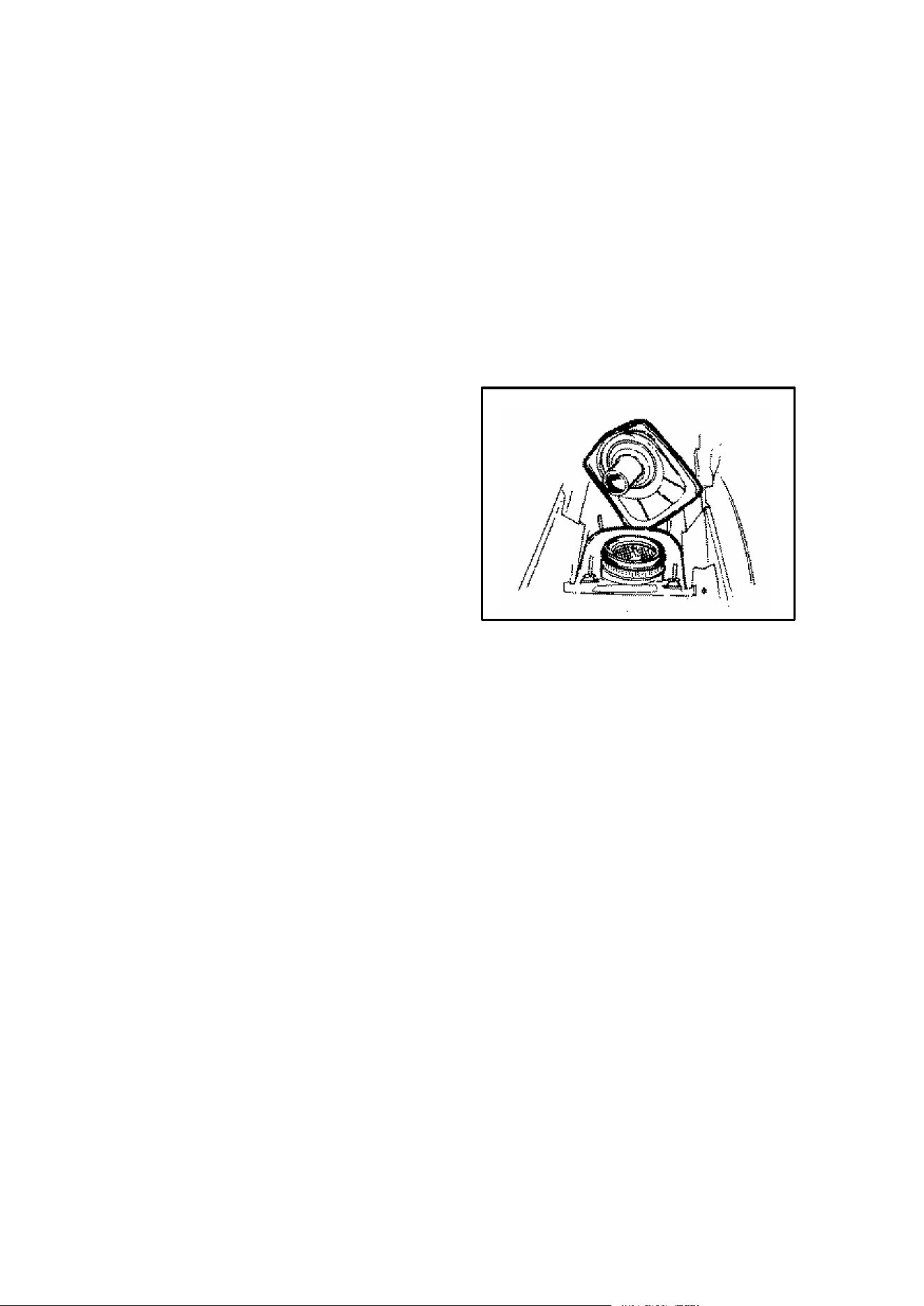
96
MAINTENANCE
Air Cleaner
Trail Blazer, Trail Boss, Xpress 300,
Xplorer 300, Xplorer 400
Secondary (Main) Filter
Inspect the secondary filter weekly or after every 50 hours of operation.
CAUTION: Never operate the ATV with the filter element removed. Dirt will enter
the engine causing serious rapid wear and damage to the engine.
Secondary filter removal and installation procedure:
1. Remove ATV seat.
2. Remove primary air filter box.
3. Remove four wing nuts holding
cover assembly to secondary air fil-
ter housing.
4. Remove filter element.
5. Inspect gaskets on both sides of fil-
ter. Replace if required.
6. Coat top and bottom gaskets of filter
with a generous amount of grease.
7. Check condition of air box and replace if necessary. Install filter into airbox.
Be sure filter element seats securely.
8. Check cover gasket and replace if required. Be sure cover is seated properly
and wing nuts are finger tightened securely.
9. Reinstall primary air filter box as per instructions found on page 95.
10. Reinstall ATV seat.
Cleaning the Main Filter
Important:
It is advisable to replace the filter when it is dirty. However, in an emergency it is
permissible to clean the main filter if you observe the following practices.
1. Never immerse the filter in water since dirt can be transferred to the clean air
side of the filter.
2. If compressed air is used never exceed a pressure of 40 PSI. Always use a
dispersion type nozzle to prevent filter damage and clean from the outside to
the inside.
NOTE: Replace the air filter every 50 hours, and possibly more often in very dirty
conditions.
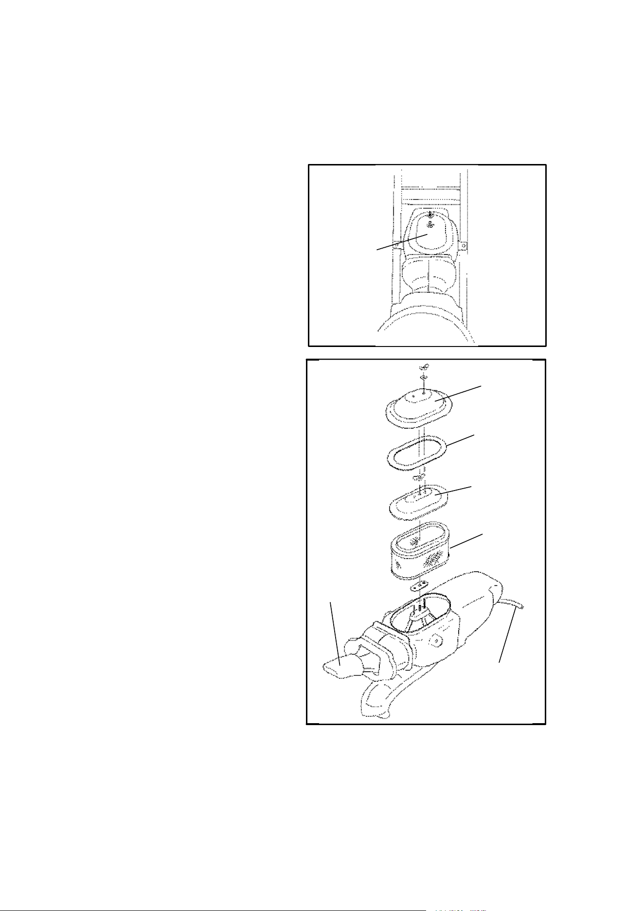
97
MAINTENANCE
Air Filter Service
Magnum 2 x 4, Magnum 4 x 4
It is recommended that the air filter
be inspected weekly and replaced if
dirty. When riding in extremely
dusty conditions replacement will
be required more often.
1. Lift up on the rear of the seat.
2. Pull the seat back and free of the
tabs. NOTE: When reinstalling
seat, make sure the slots in the
seat engage the tabs in the fuel
tank.
3. Remove the two wing nuts and
washers securing the air filter
access cover.
4. Remove the cover. Inspect the
gasket. It should adhere tightly
to the cover and seal all the way
around.
5. Remove the wing nut and wash-
er securing the second cover.
The cover should be straight
and not distorted.
6. Remove the air filter. Do not at-
tempt to clean the main ele-
ment.
7. Install new air filter. NOTE: Ap-
ply a small amount of general
purpose grease to the sealing
edges of the filter before instal-
ling.
8. Check air box drain tube. If oil or
water deposits are found, drain
them into a suitable container.
NOTE: Service more frequently
if vehicle is operated in wet
conditions or at high throttle
openings for extended periods.
Access
Cover
Access
Cover
Second
Cover
Cover
Gasket
Filter
Air Box
Drain
Pre-Filter
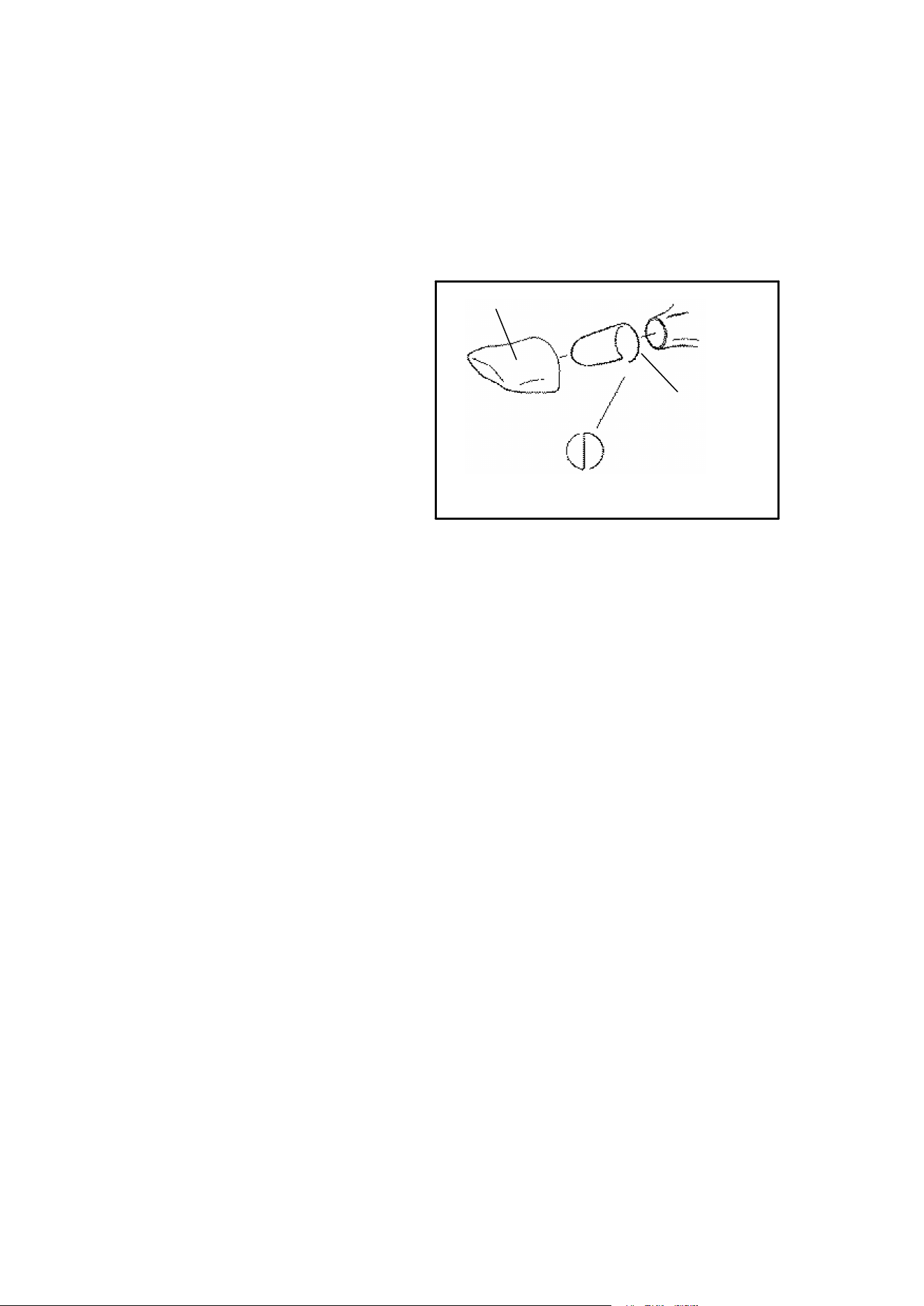
98
MAINTENANCE
Primary Pre-Filter Service
Magnum 2x4 and 4x4
The pre filter should be cleaned before each ride, using the following procedure.
1. Remove pre-filter element.
Note position of duct support
wire. It must be properly posi-
tioned before reinstalling pre-
filter.
2. Clean the element with high
flash point solvent, followed by
hot soapy water.
3. Rinse and dry thoroughly.
4. Inspect element for tears or
damage.
5. Apply foam filter oil or clean engine oil and squeeze until excess oil is removed.
6. Reinstall pre-filter element making sure duct support wire is in proper position.
Secure using a cable tie. Do not tuck the element under the noise baffle foam.
Air Box Drain
Periodically check the air box drain tube located on the bottom rear of the air box
and empty if necessary.
Duct Support
Wire Must Be
Positioned
Properly
Element
Magnum 2x4 and 4x4
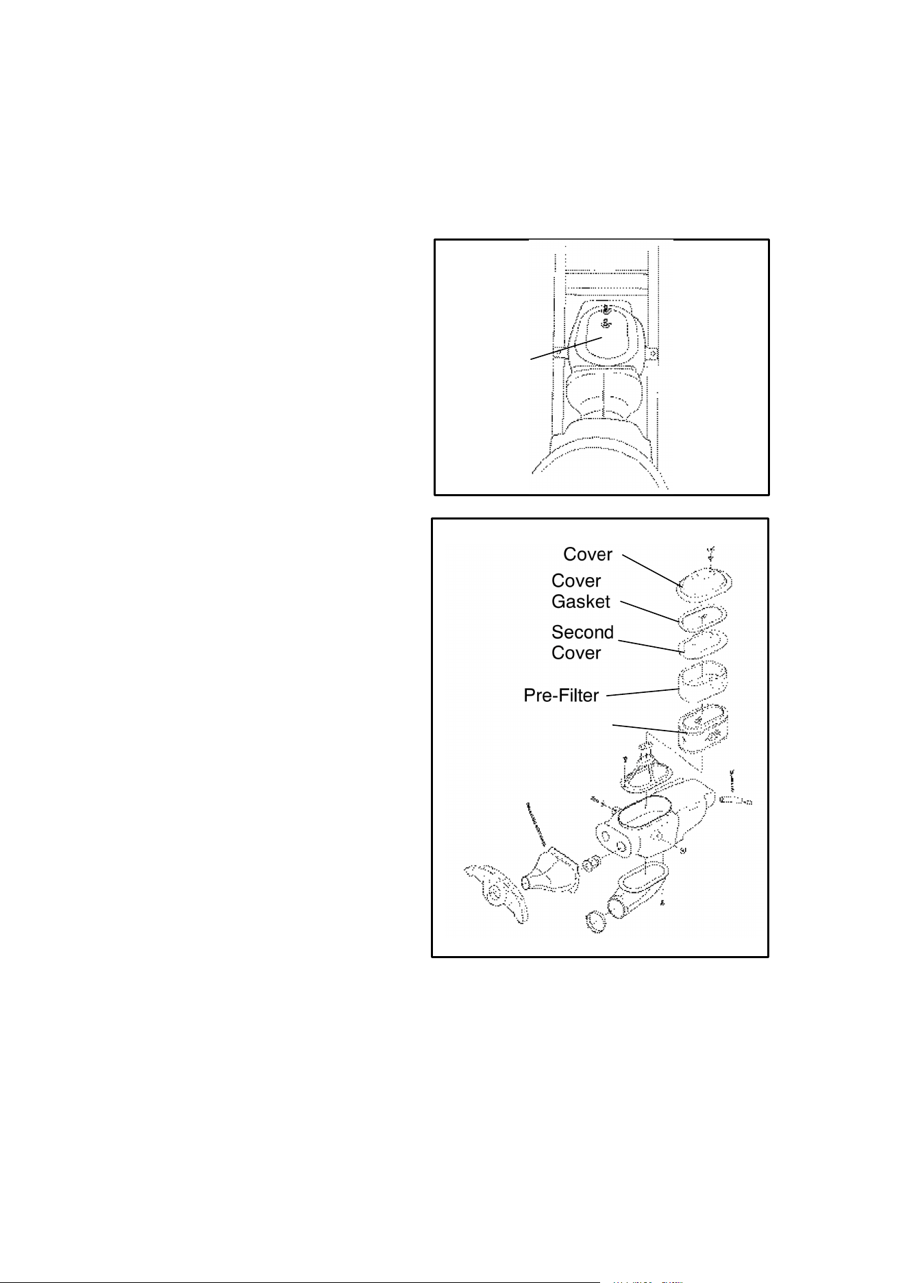
99
MAINTENANCE
Air Filter Service
Sport, Scrambler 400
1. Release seat latch and lift up on
the rear of the seat.
2. Pull the seat back and free the
tab from front cab.
3. Remove the two wing nuts and
washers securing the air filter
access cover.
4. Remove the cover. Inspect the
gasket. It should adhere tightly
to the cover and seal all the way
around.
5. Remove the wing nut and
washer securing the second
cover. The cover should be
straight and not distorted.
6. Remove pre filter from main fil-
ter and discard the main air filter.
7. Carefully wash the pre-filter in
soapy water and dry it.
8. Install dry pre-filter over new
main filter and install. NOTE:
Apply a small amount ofgeneral
purpose grease to the sealing
edges of the filter before instal-
ling.
Access
Cover
Access
Cover
Second
Cover
Cover
Gasket
Pre-Filter
Filter
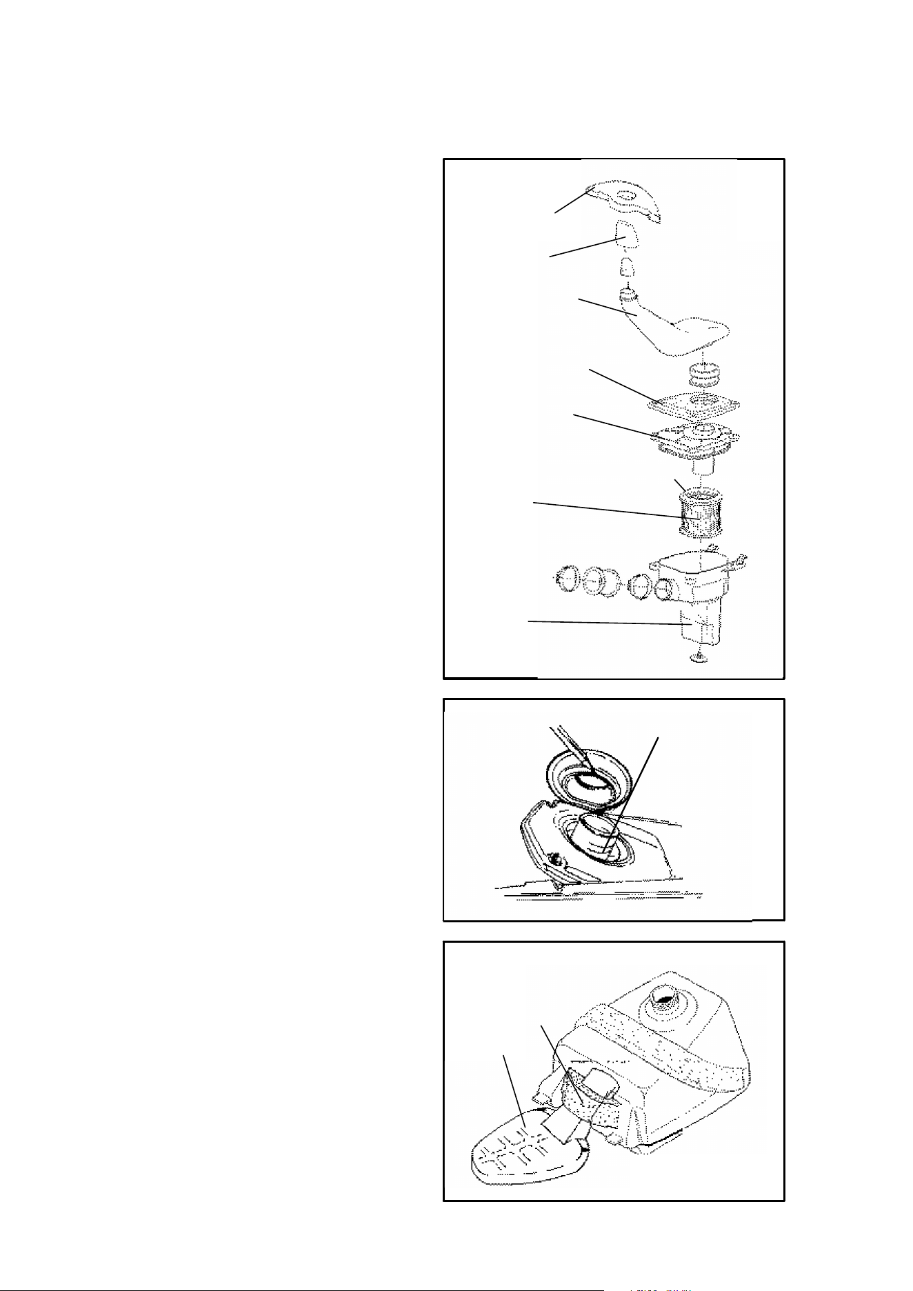
100
MAINTENANCE
Air Filter Service
Trail Blazer
1. Release seat latch and lift up on
the rear of the seat.
2. Pull the seat back and free of
the tabs.
3. Remove the primary air filter
box.
4. Remove the yellow pre-cleaner
foam boot, held in place by a
gray collar, from the air box. Do
not remove the collar.
5. Carefully wash the yellow foam
boot in soapy water and dry it.
6. Oil the foam boot with engine in-
jection oil (1 to 2 teaspoons).
Squeeze out the excess into an
absorbant cloth.
7. Reinstall the yellow foam boot
onto the air filter box.
8. Reinstall the primary air filter
box removed in step 2. NOTE:
There will be some resistance.
Be sure the black rubber seal-
ing ring is securely positioned
over the main filter neck.
CAUTION: When installing the pri-
mary air filter box be sure the gray
foam collar (B) is below the intake
opening of the air box intake (A).
Improper installation will restrict air-
flow to the engine possibly resulting
in engine damage.
Gray Collar
Yellow Boot
Intake Silencer
Airbox
Air Filter
Airbox Retainer
Airbox Cover
Main Filter Neck
B
A
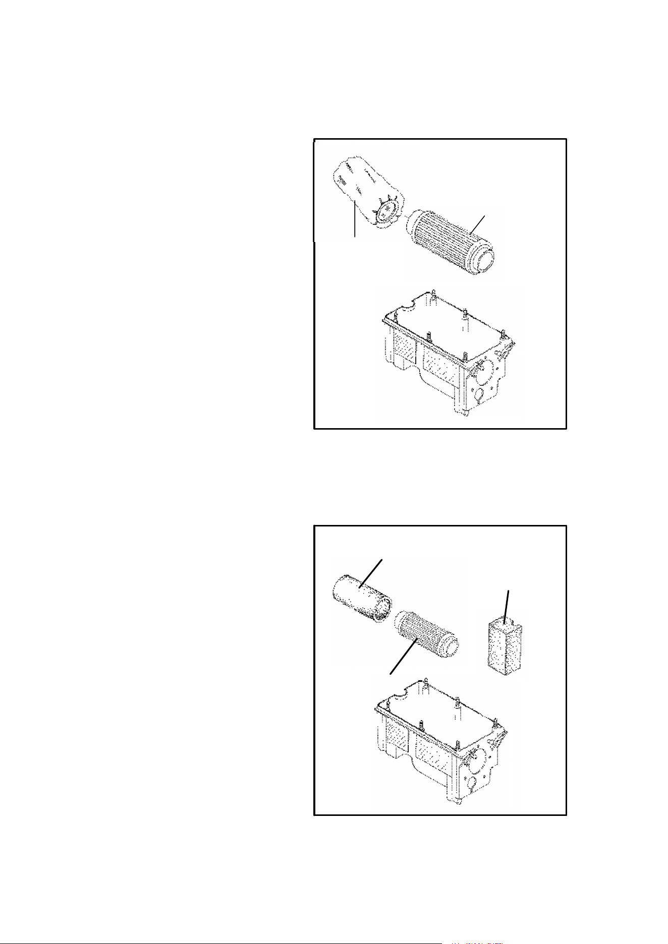
101
MAINTENANCE
Air Filter Service
Scrambler 500
1. Remove seat.
2. Release clips and remove cov-
er.
3. Loosen clamp and remove filter
4. Remove fabric type pre-filter
from main filter. Wash pre-filter
in soapy water and dry it.
5. Reinstall pre-filter in main filter.
Replace main filter as required.
Air Filter Service
Sportsman 500, Xplorer 500
1. Remove seat.
2. Remove wingnuts securing the
airbox lid and remove lid.
3. Pull foam breather filter out.
4. Loosen clamp and remove filter.
5. Remove foam pre-cleaner from
main filter.
6. Wash the pre-filter in soapy wa-
ter and dry it.
7. Install dry pre-filter over new
main filter and reinstall.
8. Push foam breather filter
straight down into airbox until
flush with upper edge of box.
Make certain foam is flush with
front edge of airbox so air can-
not enter engine breather fitting
hole without first passing
through the foam.
Main Filter
Pre-Filter
Breather Filter
Main Filter
Foam
Pre--cleaner
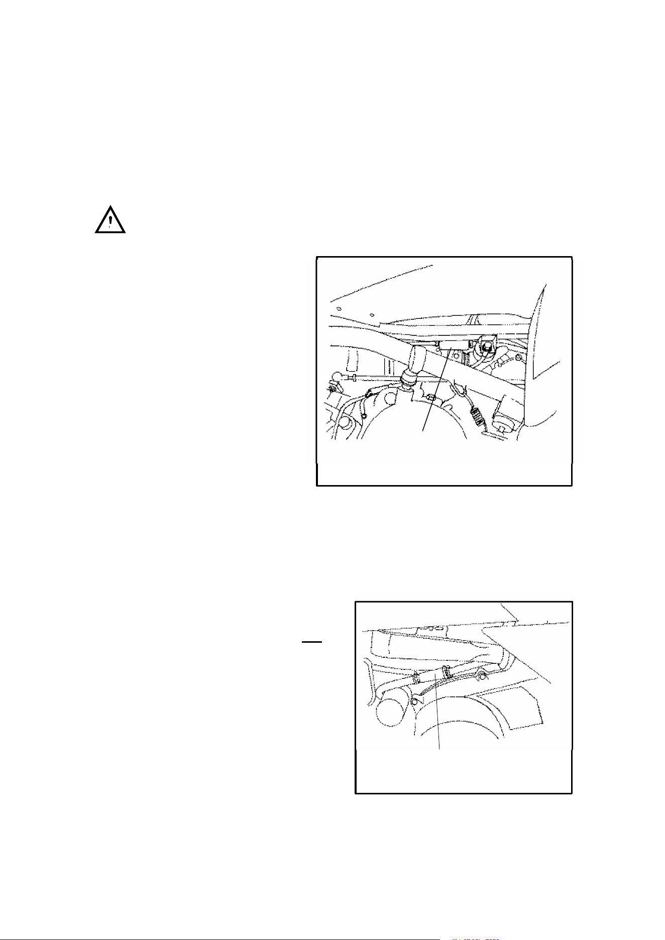
102
MAINTENANCE
CAUTION: Operation of your ATV without a breather filter can cause engine dam-
age.
Breather Filter and Hoses
Scrambler 500
WARNING: Do not perform this operation immediately after the engine has
been run. The exhaust system becomes very hot and can cause severe burns.
1. Remove heat shield screws
and front fender to floorboard
screws. Pull fender up and
slide heat shield out the front.
2. Reach up under frame rail
and remove clamps and
filter.
3. Inspect filter for debris. Blow
through gently in direction of
arrow on filter to check for
clogging. Replace as
needed.
4. Check hoses for cracks,
deterioration, abrasion, or
leaks. Replace as needed.
5. Reinstall filter and clamps with arrow pointing toward engine. Reinstall heat
shield. NOTE: Breather filter life is longer when airbox pre-filter is in place.
Never operate ATV without pre-filter.
Breather Filter and Hoses
425 Engines
1. Remove the clamps and pull the filter
out of the hoses. NOTE: It will not be
necessary to remove the lower hose
from the engine.
2. Inspect filter for debris. Blow through
gently in direction of arrow on filter to
check for clogging. Replace as
needed.
3. Check hoses for cracks,
deterioration, abrasion, or leaks.
Replace as needed.
4. Reinstall filter and clamps with arrow pointing toward engine. NOTE:
Breather filter life is longer when airbox pre-filter is in place. Never operate the
ATV without the pre-filter.
Breather
Filter
Breather
Filter
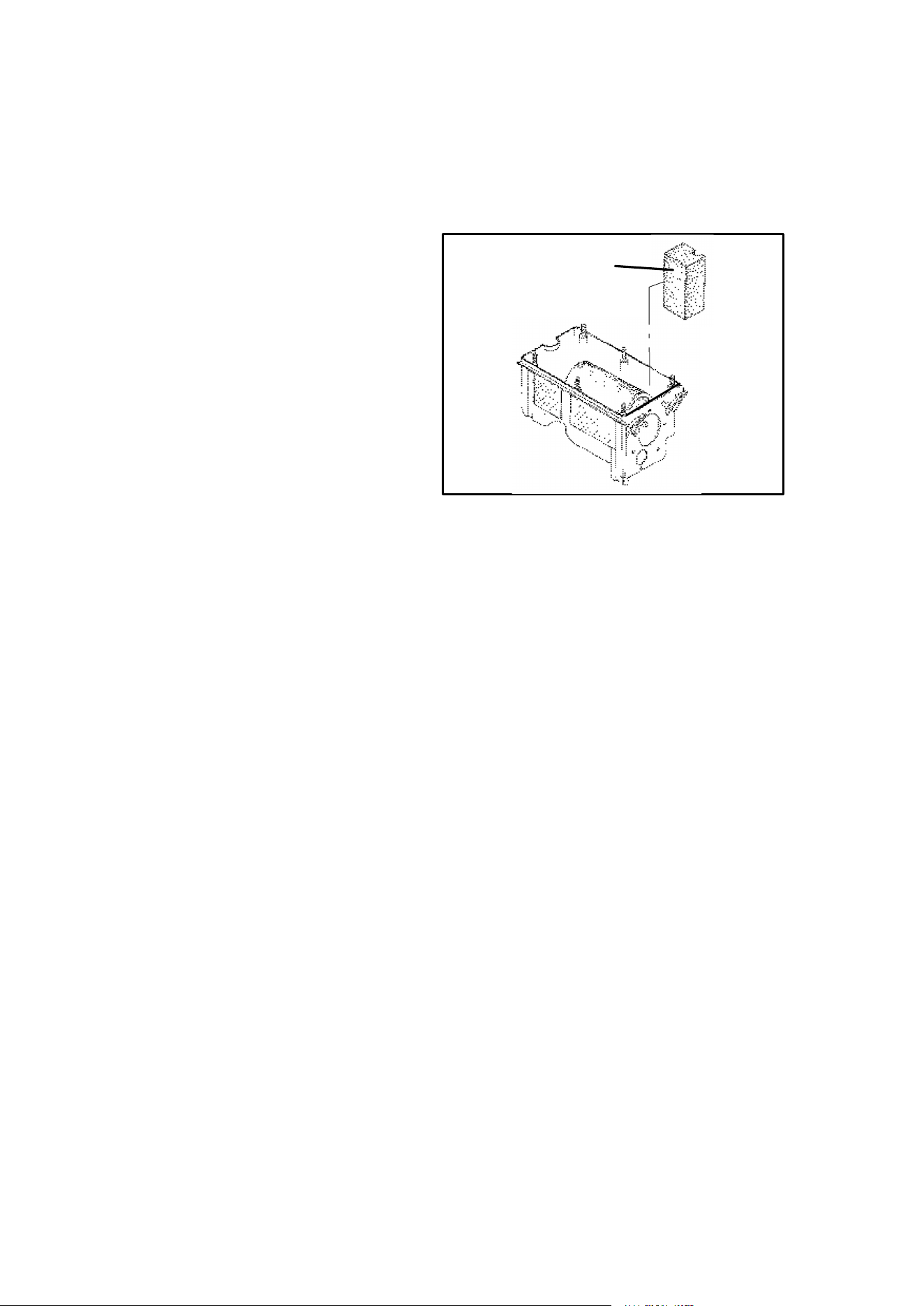
103
MAINTENANCE
Breather Filter and Hose
Sportsman 500, Xplorer 500
1. Remove seat and airbox lid.
2. Locate foam breather filter
which is in the front left corner of
airbox covering the engine
breather hose fitting hole on the
front inside of the airbox.
3. Pull filter out and blow off with
compressed air. If filter still has
debris lodged in the foam, wash
in high flash point solvent.
Gently squeeze out excess
solvent and dry. Do not oil.
4. Push foam filter straight down into airbox until flush with upper edge of box.
Make sure foam is flush with front edge of airbox so air cannot enter engine
breather fitting hole without passing through foam.
5. Check hose for cracks, deterioration, abrasion, or leaks. Replace as needed.
NOTE: Filter is not needed for oil tank vent hose outlet on right side of airbox.
Always install foam filter on left side of airbox.
Breather Filter
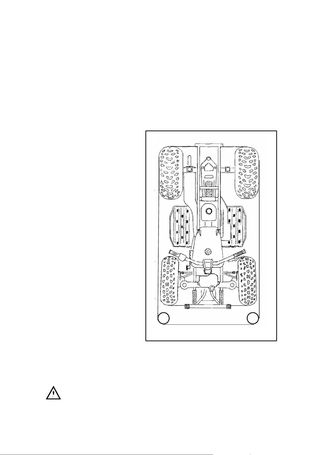
104
MAINTENANCE
Steering Inspection
The steering assembly of the machine should be checked periodically for loose
nuts and bolts. If loose nuts and bolts are found, have your dealer tighten them
before riding your vehicle.
Camber and Caster
The camber and caster are non-adjustable.
Toe Alignment
You can check the toe align-
ment of the vehicle using the fol-
lowing method. The recom-
mended toe alignment is 1/8″ to
1/4″ (.3 to .6 cm) toe out. If you
discover improper adjustment
have your dealer correct it.
1. Set the handlebars in a
straight ahead position and
hold them in this position.
NOTE: The steering frog
can be used as an indicator
of whether the handlebars
are straight. The frog should
always point straight back
from the steering post.
2. Place stands in front of the
machine, perpendicular to
the rear tires.
3. Tie an elastic string around
the machine, making sure
string just touches side sur-
face of the rear tires on each
side of machine and goes
around the stands in front of
the machine.
4. Measure from string to rim at
front and rear of front rim.
Rear rim measurement
should be 1/16″ - 1/8″ (.2 to
.3 cm) more than front rim
measurement.
5. If this measurement needs to be adjusted, contact your dealer for service.
WARNING: Do not attempt to adjust the tie rod for toe alignment. Severe
injury or death can result from improper adjustment. Contact your Polaris dealer.
He/she has the training and tools to make these adjustments.
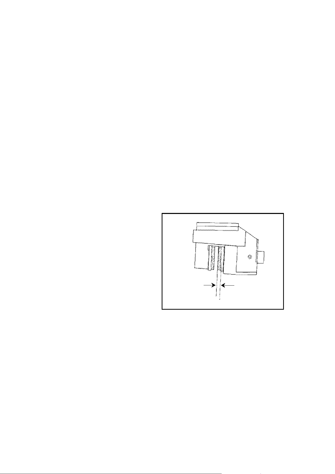
105
MAINTENANCE
Front Brake
The front brakes are hydraulic disc type brakes which are activated by the brake
lever being moved toward the handlebar. These brakes are self-adjusting and re-
quire no adjustment.
The following checks are recommended to keep the brake system in good operat-
ing condition. How often they need checking depends upon the type of driving that
has been done.
DKeep fluid level in the master cylinder reservoir between the max and min level
marks at all times. Normal functioning of the diaphragm is to extend into the
reservoir as fluid level drops. If the fluid level is low and the diaphragm is not
extended, a leak is indicated and the diaphragm should be replaced. Always
fill the reservoir as indicated whenever the cover is loosened or removed to
insure proper diaphragm operation. Use Polaris DOT 3 brake fluid (PN
2870990).
WARNING: Once a bottle of brake fluid is opened, use what is necessary and dis-
card the rest. Do not store or use a partial bottle of brake fluid. Brake fluid is hygro-
scopic, meaning it rapidly absorbs moisture from the air. This causes the boiling
temperature of the brake fluid to drop, which can lead to early brake fade and the
possibility of serious injury.
DCheck brake system for fluid
leaks.
DCheck brake system for fluid
leaks.
DCheck brake for excessive travel
or spongy feel.
DCheck friction pads for wear, dam-
age and looseness.
DCheck security and surface condi-
tion of the disc.
DPads should be changed when
worn to 3/64″ (.1 cm), or about
the thickness of a dime.
3/64″ (.1 cm)
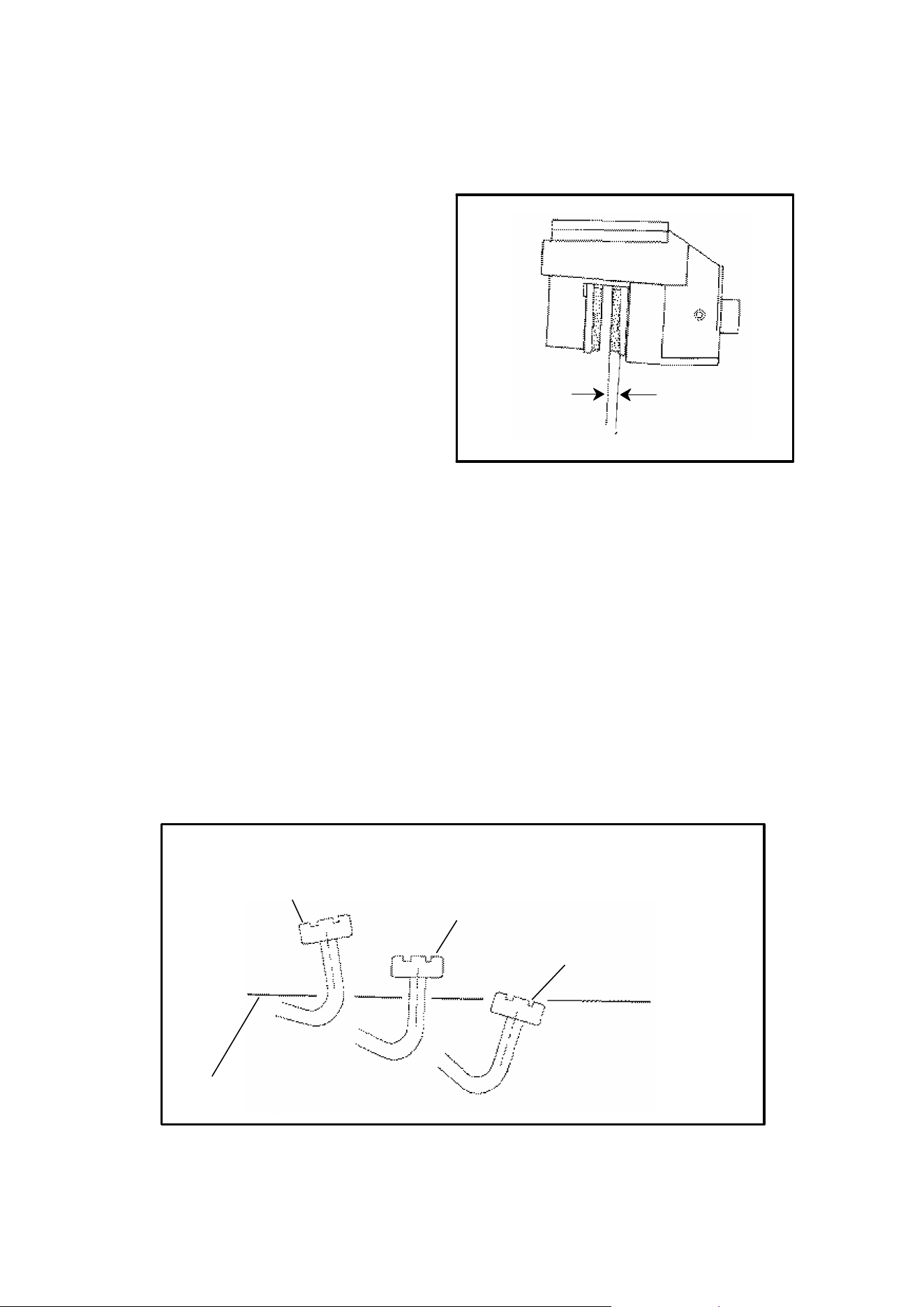
106
MAINTENANCE
Rear and Auxiliary Mechanical Brake
Rear Brake
The rear brake is a hydraulic disc
type brake which is activated by the
same lever which activates the front
brake system. The rear brake sys-
tem is self adjusting and requires no
maintenance other than periodic
checks of the pads for wear.
Wear Line
DPads should be changed when
worn to 3/64″ (.1 cm) which is
about the thickness of a dime.
DInspect the brake disc spline and pad wear surface for excessive wear.
Auxiliary Mechanical Brake System
The auxiliary brake system is intended to be used as a backup for the hydraulic
service brake system. Should the hydraulic system fail, the rear brake can be acti-
vated by depressing the foot pedal on the inside of the right floorboard.
NOTE: Since this is a rear brake only, it will not be as effective as the all wheel sys-
tem.
Auxiliary Brake Adjustment (Mechanical)
The auxiliary brake should be checked for proper adjustment.
1. Support the rear wheels off the ground.
2. While turning the rear wheels by hand, apply the auxiliary foot brake. This
brake should not stop the wheels from turning until the lever is half way be-
tween its rest position and bottoming on the footrest.
Auxiliary Foot Brake Pedal
Floorboard Surface
Full Height
Engagement
(1/2 Height)
Full Engagement
(Flush)
3/64″ (.1 cm)
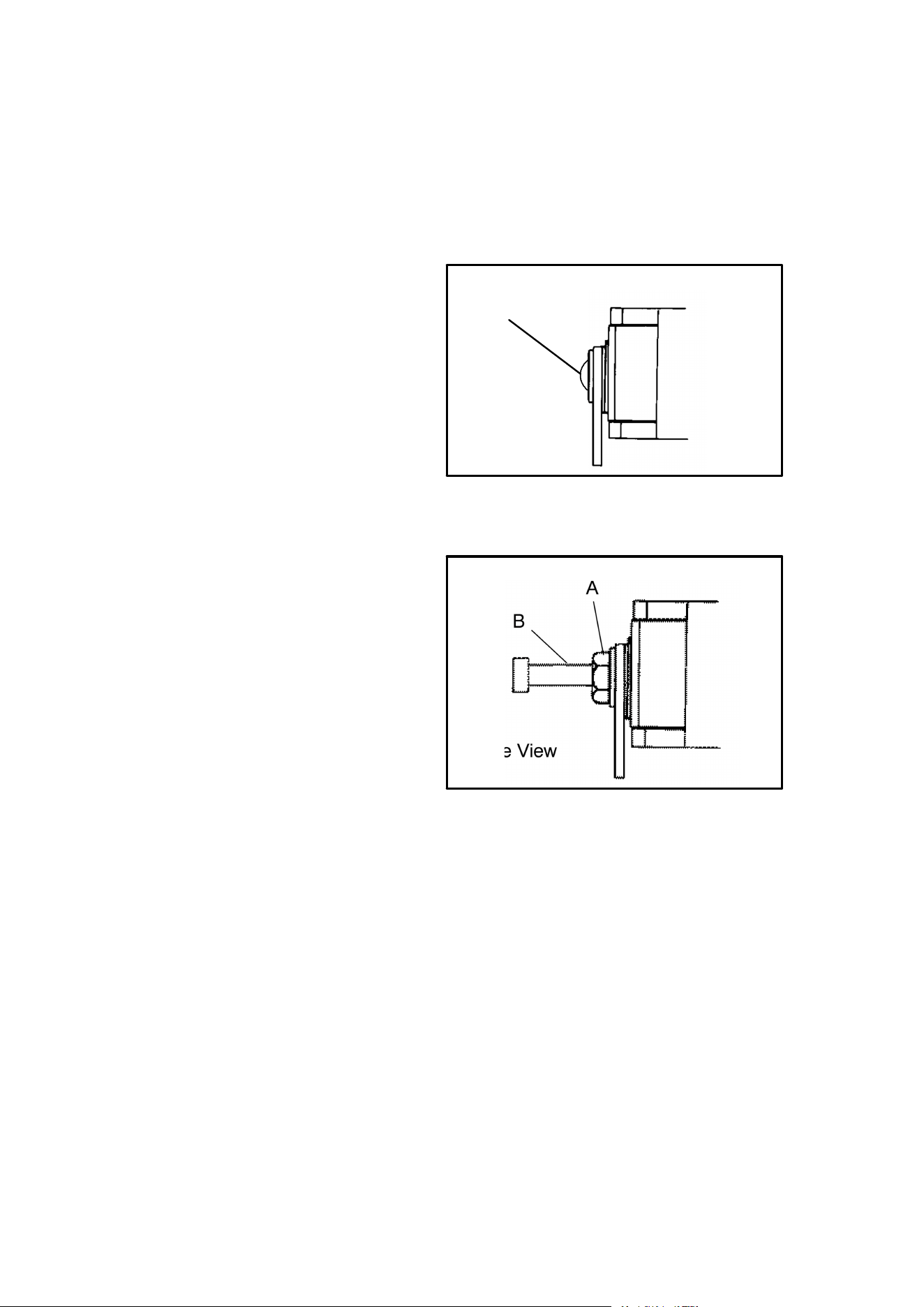
107
MAINTENANCE
Auxiliary Brake Adjustment (Cont.)
Polaris ATVs have two different types of auxiliary brake adjustment. Consult your
owner’s manual supplement to determine what type your machine has and adjust
accordingly.
1. Type I: If adjustment is neces-
sary turn adjuster bolt (A) clock-
wise until disc rotation becomes
difficult. Turn adjuster bolt coun-
terclockwise until brake engage-
ment starts at approximately 1/2
of the total pedal travel (See Il-
lustration).
2. Type II:If adjustment is neces-
sary, loosen jam nut (A) and turn
adjuster bolt (B) clockwise until
disc rotation becomes difficult.
Turn adjuster bolt counterclock-
wise until brake engagement
starts at approximately 1/2 of the
total pedal travel (See Illustra-
tion). Lock the locknut.
3. Check the auxiliary brake deflec-
tion daily.
Side View
Auxiliary Brake Adjustment - Type I
A
A
B
Side View
Auxiliary Brake Adjustment - Type II
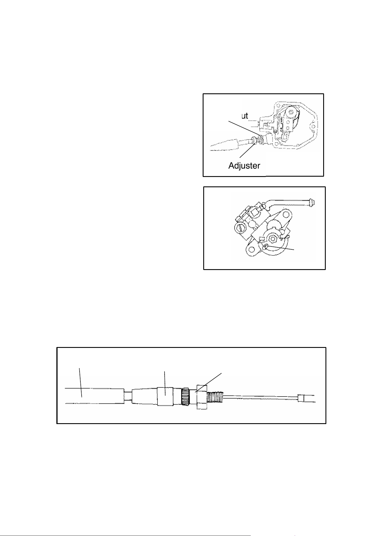
108
MAINTENANCE
Oil Pump Adjustment Procedure
400 Engines
1. Before adjusting the oil pump, check
engine idle RPM and carburetor ad-
justments which are found in the own-
er’s manual supplement.
2. Remove electronic throttle control
(ETC) cover.
3. Loosen throttle cable jam nut and turn
adjuster in or out until there is 1/16″
(.16 cm) of throttle lever travel before
throttle slide starts to open.
4. Place very slight pressure on the
throttle lever until all freeplay is re-
moved from throttle cable (to the point
where the carb slide is just starting to
rise).
5. Lift boot up off adjuster sleeve. Re-
move the oil pump cover. Loosen the
cable adjuster locknut. Adjust oil
pump cable until marks align (D) when
the throttle slide just begins to raise.
6. Tighten the locknut.
7. Recheck adjustment. If correct, slide boot all the way down over the upper por-
tion of the bottom nut to ensure good sealing against water entry. Reinstall oil
pump cover gasket.
8. Reinstall the ETC cover removed in step 2, making sure cover gasket is proper-
ly seated. If not, moisture will enter the ETC and damage the switch.
Jam Nut
Adjuster
Oil Pump Adjustment 400
D
Boot
Adjuster
Sleeve
Upper Portion
of Bottom Nut
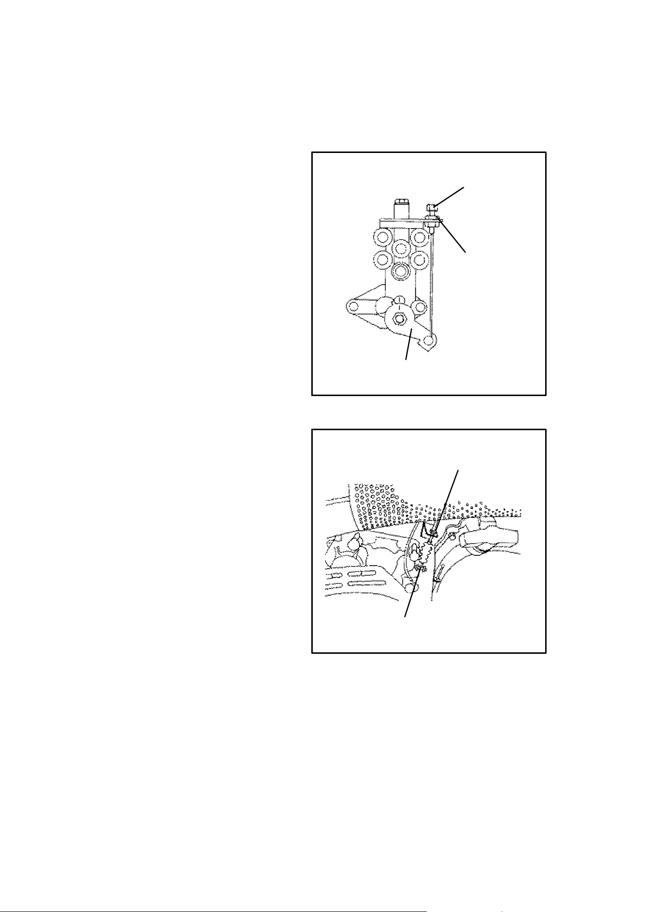
109
MAINTENANCE
Oil Pump Adjustment Procedure
250 and 300 Engines
1. Before adjusting the oil pump,
check engine idle RPM and car-
buretor adjustments which are
found in the owner’s manual sup-
plement.
2. Remove electronic throttle con-
trol (ETC) cover.
3. Loosen throttle cable jam nut and
turn adjuster in or out until there is
1/16″ (.16 cm) of throttle lever
travel before throttle slide starts to
open.
4. Place very slight pressure on the
throttle lever until all freeplay is re-
moved from throttle cable (to the
point where the carb slide is just
starting to rise).
5. Loosen locknut. Turn adjuster in
or out until all freeplay is removed
from oil pump cable (the point
where the oil pump arm is just
starting to move off of its stop).
The pump stop keeps the pump
arm from rotating any farther
down than the idle position so no
visual alignment of marks is nec-
essary. Tighten the locknut
Lever
Locknut
Cable Adjuster
Locknut
Lever Arm
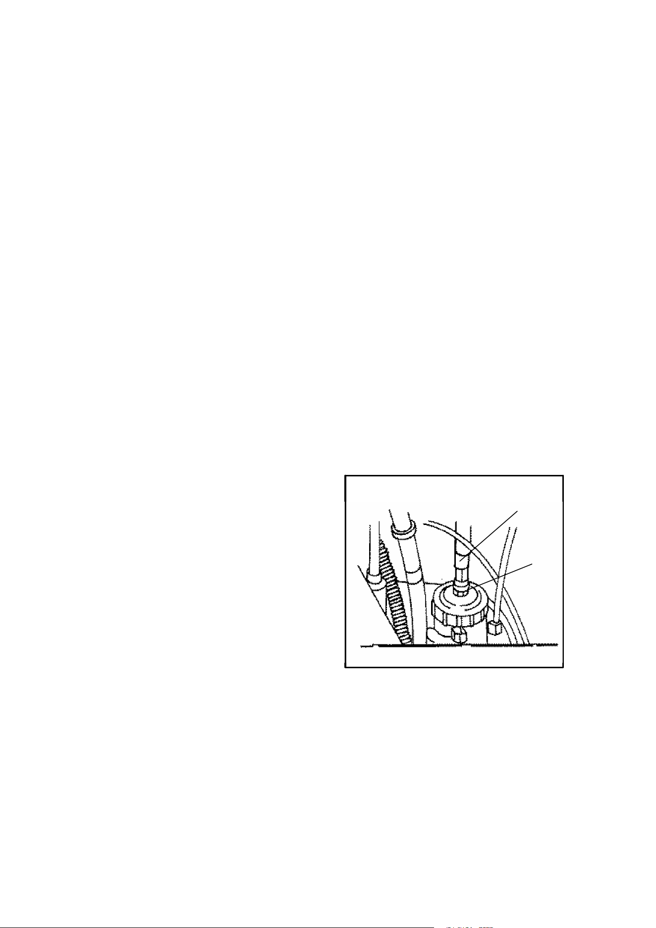
110
MAINTENANCE
Oil Pump Bleeding Procedure
1. Fill the oil reservoir with Polaris injector oil.
2. Loosening the bleeder screw is only necessary when the oil supply line has
been disconnected from the pump or the oil reservoir and supply line have
been completely run out of oil. In these cases, loosen the pump bleed screw
one full turn. Allow oil to flow from the bleed screw for five to tenseconds. Tight-
en bleed screw. CAUTION: Never run the engine with the bleed screw loose.
Loss of oil will cause serious engine damage.
3. Start the engine and rotate the oil pump lever to its full open position. With the
engine at idle, hold the lever up for thirty seconds to make sure all air is out of
the system.
Throttle Cable Adjustment
400 Engines
Vehicles with 400 engines do not utilize a cable sleeve jam nut. You will need to
bottom the cable to the carburetor slidevalve cap. Adjust at throttle cable adjuster
on throttle block.
Throttle Cable
250 and 300 Engines
Ifthe proper throttle freeplay cannot be obtained with the throttle block adjuster, ad-
just cable at carburetor using the following procedure.
Loosen throttle cable sleeve jam nut (A)
located on the carburetor slidevalve cap.
Rotate cable sleeve (B) counterclock-
wise until carb slide and oil pump lever
rise together when throttle lever is being
depressed slightly. This can be checked
by placing the transmission in neutral, id-
ling the engine, and observing the oil
pump lever while depressing the throttle
lever slightly. The lever should begin
moving when the engine RPM begins to
increase.
A
B
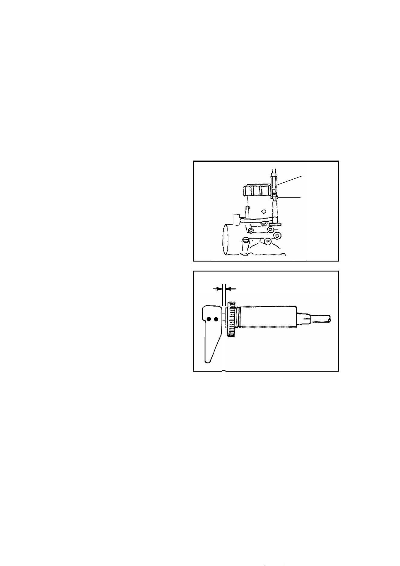
111
MAINTENANCE
Engine Choke Adjustment
2 Cycle Engines
With the dash mounted choke control toggle flipped to full off position, the choke
plunger must be seated on the fuel passageway in the carburetor. If the plunger
is not seated on the passageway, the engine will flood or run too rich, causing spark
plug fouling and very poor engine performance.
If there is too much choke cable slack resulting in excessive toggle free play, the
engine will be hard starting when cold and the half-on choke position used for inter-
mittent applications will not function.
Choke Adjustment Procedure
1. Flip choke toggle to the full off
position.
2. Loosen adjustment locknut (A) on
carburetor.
3. Turn cable sleeve adjusting nut
(B) clockwise on carburetor until
1/8″ (.3 cm) or more choke toggle
free play is evident.
4. Turn the cable sleeve adjusting
nut counterclockwise on the car-
buretor until the toggle has zero
free play. Then rotate it clockwise
until 1/8″ to 1/4″ (.3 to .6 cm) toggle
free play is evident.
5. Tighten adjustment locknut.
B
A
1/8I-1/4I Freeplay
(.3-.6 cm)
Choke Side View
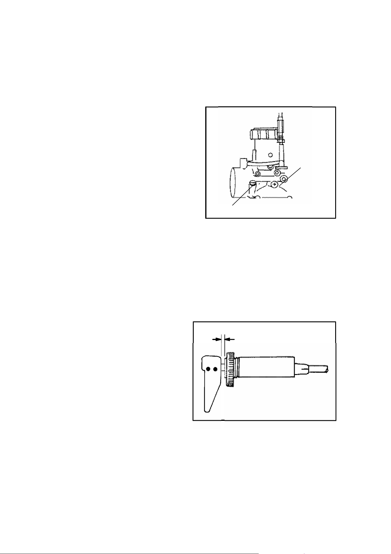
112
MAINTENANCE
Carburetor/Engine Idle RPM Adjustment
2 Cycle Engines
If the engine idle speed is not satisfactory, and all other conditions are favorable,
the carburetor can be adjusted as follows:
1. Warm up the engine by running
the vehicle approximately five
minutes.
2. Place the transmission in gear
with the parking brake applied.
3. Adjust the carburetor idle screw
in or out until the desired idle
RPM is reached . Turning the
screw in (clockwise) will raise
RPM. Turning the screw out
(counterclockwise) will lower
RPM.
The following variations to air screw adjustment should be noted:
DFor improving cold weather start and reducing audible detonation noise, the
air screw can be closed from 1/2 to 1 turn by turning the screw clockwise.
DDuring hot weather and/or high altitude operation the air screw can be ad-
justed for smooth operation by approximately 2 turns counterclockwise.
Choke Adjustment Procedure
4-cycle Engines
1. Flip choke toggle to the full off
position.
2. Slide boot off in-line cable adjust-
er sleeve. Loosen adjustment
locknut on in-line cable adjuster.
3. Turn cable sleeve adjusting nut
clockwise on in-line adjuster until
1/8″ (.3 cm) or more choke toggle
free play is evident.
4. Turn the cable sleeve adjusting
nut counterclockwise on the in-
line cable adjuster until the toggle
has zero free play. Then rotate it clockwise until 1/8″ to 1/4″ (.3 to .6 cm) toggle
free play is evident.
5. Tighten adjustment locknut.
6. Slide boots back over cable adjuster sleeve until they touch at the middle
point of the sleeve.
Idle
Screw
Air Screw
1/8I-1/4I Freeplay
(.3-.6 cm)
Choke Side View
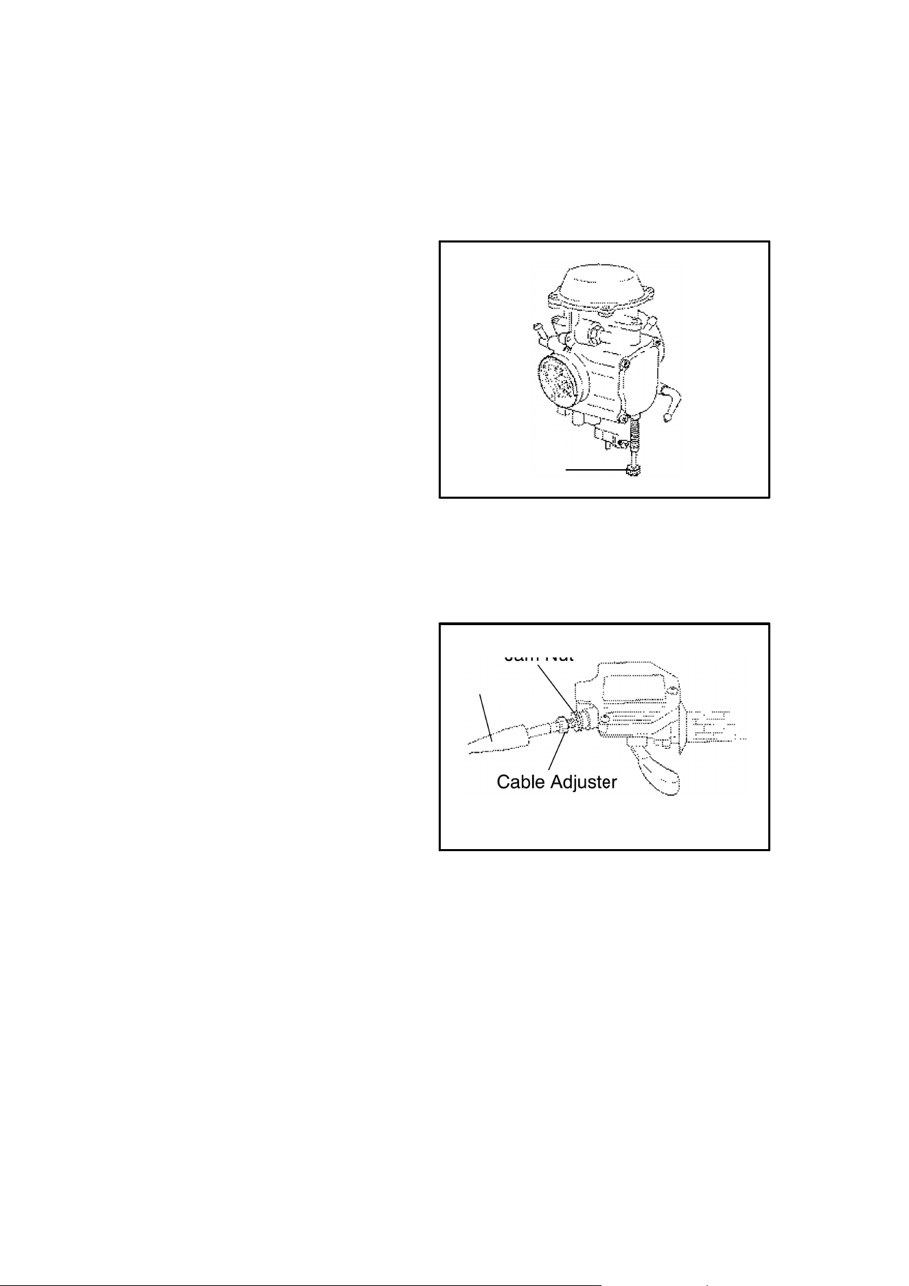
113
MAINTENANCE
Carburetor/Engine Idle RPM Adjustment
4-cycle Engines
If the engine idle speed is not satis-
factory, and all other conditions are
favorable, the carburetor can be ad-
justed as follows:
1. Warm up the engine by running
the vehicle approximately five
minutes.
2. Place the transmission in gear
with the parking brake applied.
3. Adjust the carburetor idle screw in
or out until the desired idle RPM is
reached. Turning the screw in
(clockwise) will raise RPM. Turn-
ing the screw out (counterclock-
wise) will lower RPM.
Throttle Cable Free Play
Adjustment
Throttle cable free play is adjusted at
the handlebar.
1. Slide the protective cover back.
2. Loosen jam nut.
3. Turn adjuster until 1/16″ free play
is achieved.
4. Tighten jam nut and replace pro-
tective cover.
Idle Screw
Cable Adjuster
Jam Nut
Cover

114
MAINTENANCE
Spark Plugs
Check your owner’s manual supplement for recommended spark plug and gap.
The spark plug and its condition is indicative of engine operation. The spark plug
firing end condition should be read after the engine is warmed up and the vehicle
is driven at higher speeds. Immediately check the spark plug for correct color.
1. Normal
The insulator tip is gray, tan or light brown. There will be few combustion deposits.
The electrodes are not burned or eroded. This indicates the proper type and heat
range for the engine and the service.
NOTE: The tip should not be white. A white insulator tip indicates overheating,
caused by use of an improper spark plug or incorrect carburetion adjustments.
2. Wet Fouled
The insulator tip is black. A damp oil film covers the firing end. There may be a
carbon layer over the entire nose. Generally, the electrodes are not worn. General
causes are excessive oil, use of non-recommended injection oil, improper use of
the choke, or incorrect carburetion adjustments.
Spark Plug Removal and Replacement
WARNING: Never attempt to remove a spark plug while the engine is warm.
The exhaust system or engine could burn you causing severe injury.
The spark plug is removed by using the special wrench provided in the tool pouch
under the seat. Reach under the right hand fender and then back for access. Re-
move the spark plug cap and then the spark plug by rotating counterclockwise.
Reverse the procedure for spark plug installation. Torque to 17 ft. lbs.
Never deviate from the recommended spark plug as engine damage can occur.
Cylinder Head/Cylinder Base Fastener Torque
(2 Stroke Models)
Have your dealer check the ATV cylinder head and cylinder base fasteners for
proper torque at the first service or after 25 hours.
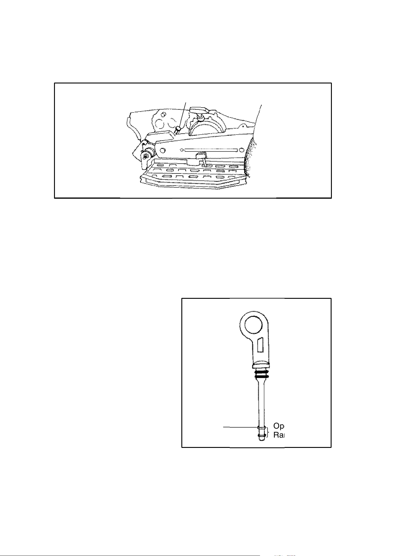
115
MAINTENANCE
Transmission Lubrication
Transmission Dipstick
The transmission dipstick is located on the right side of the machine.
The transmission lubricant level should be checked monthly or 1000 miles (1600
km), whichever comes first. Transmission oil should be changed annually. With
the ATV on a level surface, remove fill plug dipstick and check the lubricant level.
Lubricant should be kept at the full mark on the dipstick. The correct transmission
lubricant to use is Polaris Premium Synthetic Gearcase Lubricant (PN 2871478).
Transmission Oil Changing
Procedure
1. Remove skid plate.
2. Remove fill plug/dipstick.
3. Remove transmission drain
plug located on the bottom
right hand side and drain the
oil. Catch and discard used oil
properly.
4. Clean and reinstall the drain
plug.
5. Add Polaris Premium Syn-
thetic Gearcase Lubricant
(PN 2871478 - 12 oz. bottle) to
full mark on the fill plug/dip-
stick.
6. Check for leaks.
7. Reinstall skid plate removed
in step 1.
Full
Operating
Range
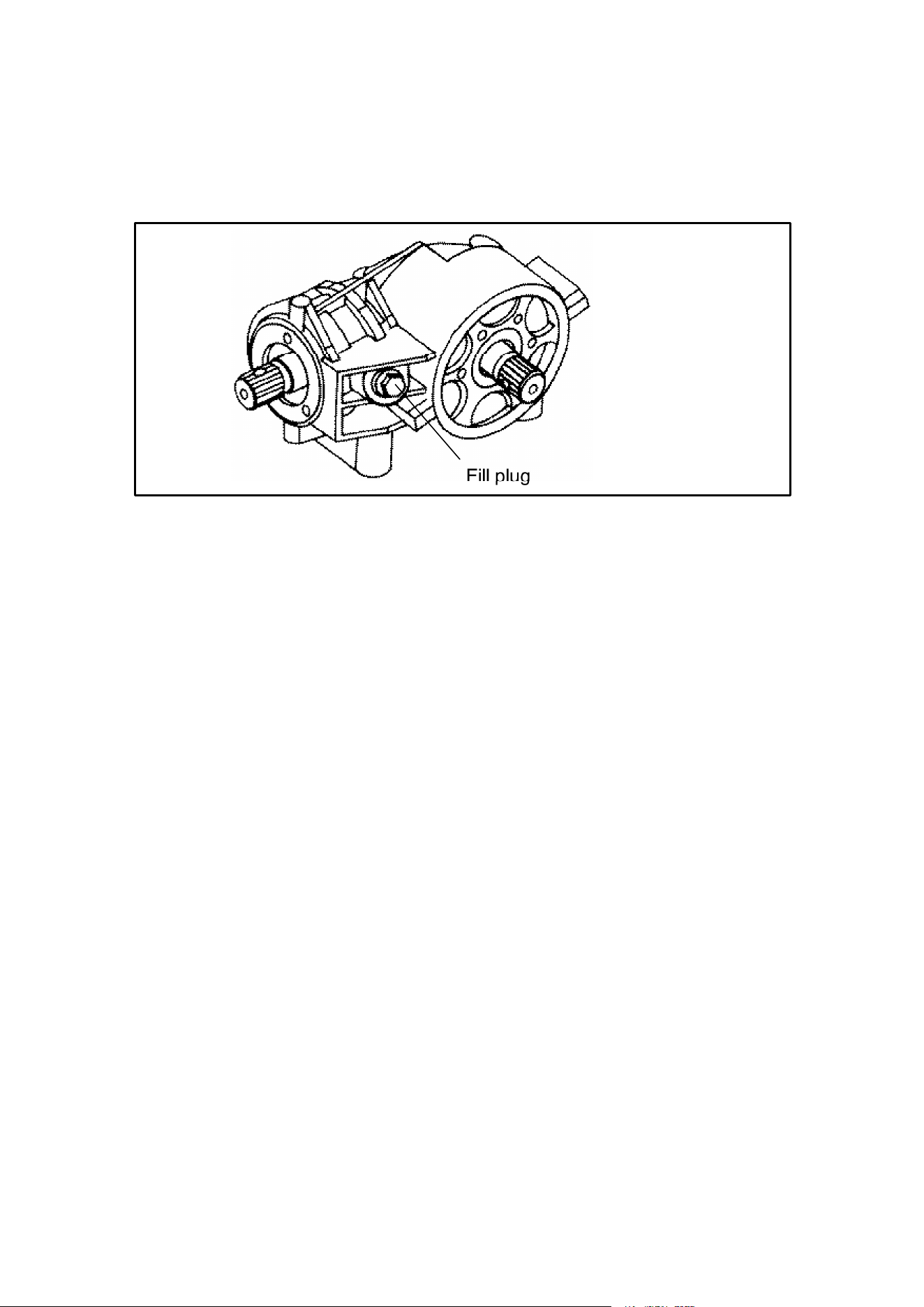
116
MAINTENANCE
Front Gearcase Lubrication
Sport 500, Xplorer 500, Scrambler 400
Fill plug
Front Gearcase Lubrication
The front gearcase fill plug is located on the right side of the machine.
The front gearcase lubricant level should be checked every six months or 1000
miles (1600 km), whichever comes first. Front gearcase oil should be changed
annually. With the ATV on a level surface, remove fill plug and check the lubricant
level. Lubricant should be kept at the full mark on the bottom of fill plug threads.
The correct gearcase lubricant to use is GL5 80-90 Weight Gear Lube.
Gearcase Oil Changing
Procedure
1. Remove fill plug.
2. Remove gearcase drain plug located on the bottom right hand side and drain
the oil. Catch and discard used oil properly.
3. Clean and reinstall the drain plug and tighten securely (14 ft. lbs/1.93 kgm).
4. Add GL5 80-90 Weight Gear Lube to the top thread on the fill hole.
5. Reinstall filler plug.
6. Check for leaks.
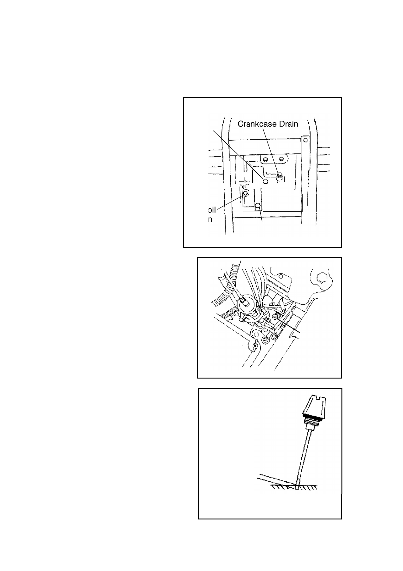
117
MAINTENANCE
Counter Balance Lubrication
400 Engines
The counter balance oil should be
checked semi-annually and oil
should be added or changed as
necessary. The oil should be
changed annually, especially be-
fore off season storage. If the ma-
chine is used in wet conditions the
oil should be checked more fre-
quently. If the oil has a milky ap-
pearance it should be changed as
soon as possible. Failure to prop-
erly maintain this important area
can result in premature wear or
possible failure of the counter bal-
ance components. Always use
SAE 10W30 oil.
Procedure for Adding Oil
1. Remove seat and locate dipstick.
2. Remove dipstick. Oil level is
shown on dipstick.
3. Add SAE 10W30 oil with a trans-
mission fluid funnel until oil is at
the proper level on the dipstick
(See Ill.). If overfilled, excess oil
will be expelled through the vent
hose.
4. Reinstall dipstick.
Counter Balance Oil Changing
Procedure
1. Remove skid plate.
2. Remove counter balance drain
plug. Catch used oil and discard
of properly.
3. Clean and reinstall drain plug.
4. Add 10W30 oil to full mark on dip-
stick. Capacity after draining is
approximately 70-75 cc (2.3 - 2.5
oz).
5. Reinstall dipstick and check
for leaks.
Recoil
Drain
Crankcase Drain
Starter
Pinion Drain
Counter
Balance
Drain
Dipstick
Recommended oil level
Capacity after draining is
approximately 70 - 75cc
Screw dipstick in completely then
remove to check level.
Level
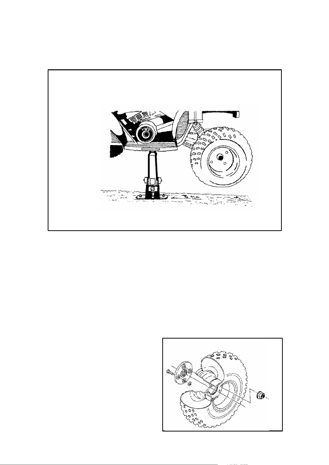
118
MAINTENANCE
Wheel Removal Front or Rear
Wheel Removal Procedure
1. Stop the engine, place the transmission in gear and lock the parking brake.
2. Loosen the wheel nuts slightly.
3. Elevate the side of the vehicle by placing a suitable stand under the footrest
frame as shown.
4. Remove the wheel nuts and remove the wheel.
Wheel Installation
1. With the transmission in gear and the parking brake locked, place the wheel
in the correct position on the wheel hub. Be sure the valve stem is toward the
outside and rotation arrows on the tire point toward forward rotation.
2. Attach the wheel nuts and finger
tighten them.
3. Lower the vehicle to the ground.
4. Securely tighten the wheel nuts
according to the chart found on
page 90:
CAUTION: If wheels are improperly
installed it could affect vehicle han-
dling and tire wear.
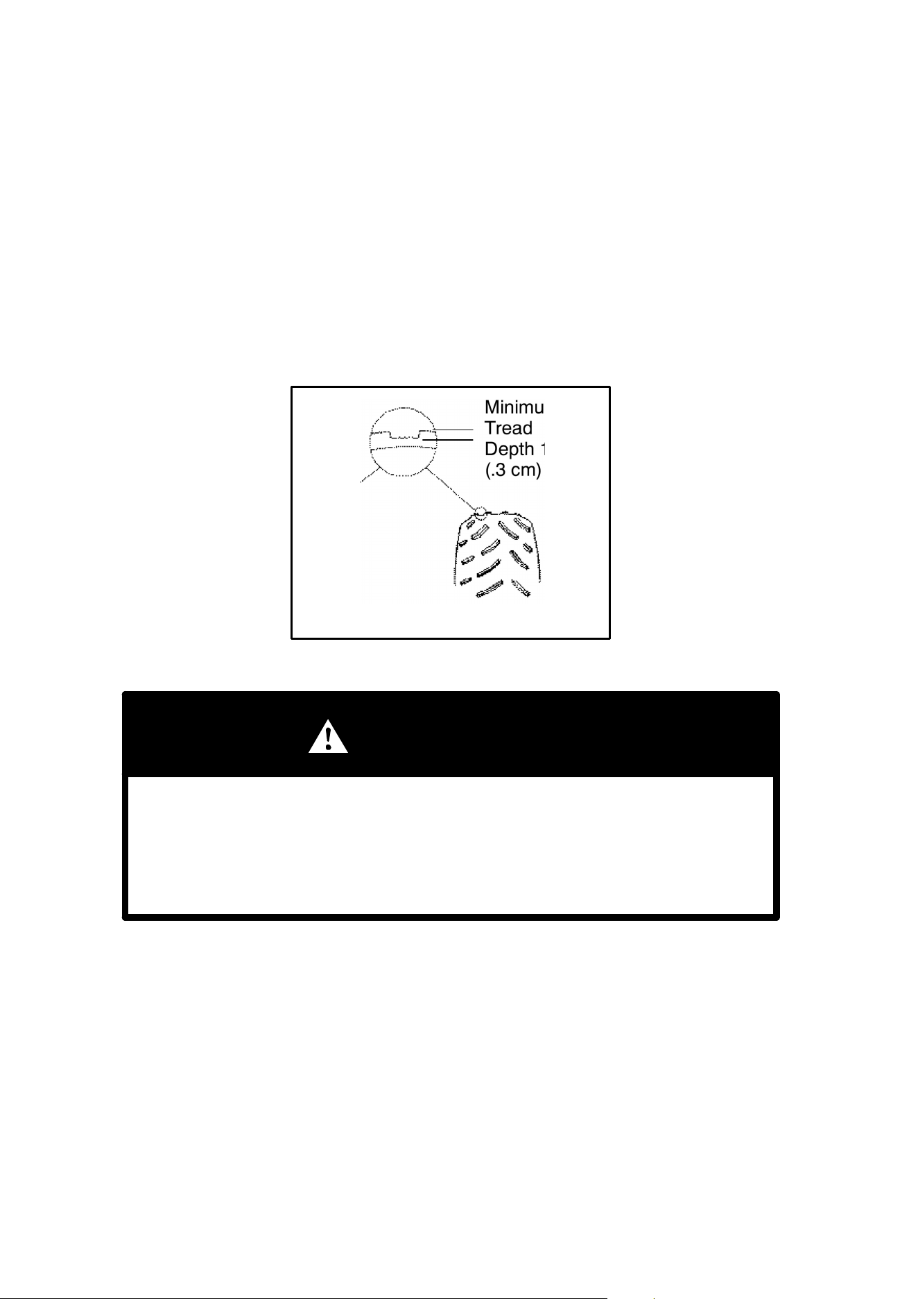
119
MAINTENANCE
Tire Inspection
CAUTION: Maintain proper tire pressure according to charts below. Improper tire
inflation may affect ATV maneuverability.
When replacing a tire always use original equipment size and type.
CAUTION: The use of non-standard size or type tires may affect ATV handling.
Tire Tread Depth
Always replace tires when tread depth is worn to 1/8″ (.3 cm) or less. Please refer
to your Owner’s Manual Supplement for tire specifications.
WARNING
Operating your ATV with worn tires will increase the possibility of the ve-
hicle skidding easily with possible loss of control.
Worn tires can cause an accident.
Always replace tires when the tread depth measures 1/8″ (.3 cm) or less.
Minimum
Tread
Depth 1/8I
(.3 cm)
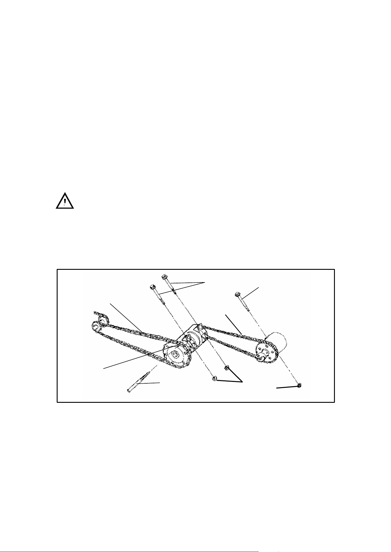
120
MAINTENANCE
Drive Chain Inspection and Adjustment
Polaris ATV drive chains are equipped with O-ring sealed permanently greased
pins and rollers. However, it is still necessary to lubricate the outer surfaces of the
roller.
CAUTION: Never wash the chain with a high pressure washer or gasoline. Dam-
age to the O-rings will result, causing premature wear and drive chain failure.
Always inspect the drive chain prior to operating the vehicle, checking for dam-
aged or missing O-rings, rollers and correct slack adjustment. Maintain the stone
guard to rear sprocket clearance at 1/8″ (.3 cm).
Regularly lubricate the drive chain with SAE 80-90 lube or an approved O-ring
chain spray lube.
Center/Front Drive Chain Slack Adjustment
CAUTION: Never adjust or operate the vehicle with the front or center drive
chain too loose or too tight as severe damage to the transmission and drive compo-
nents can result.
Periodically remove the chain guards to check chain quality and adjustment.
The center chain should be adjusted first since this adjustment affects the
front chain slack. After the recommended center chain adjustment is made, pro-
ceed to the front chain.
Front
Center
Pin Punch
1/4I-1/2″
(.6-1.3 cm)
with 18 lb. load
A
B
1/4I-1/2″
(.6-1.3 cm)
with 18 lb. load
Sprocket
Holes
Torque
to 45 ft. lbs.
Center/Front Drive Chain Inspection/Adjustment
Gen IV Models
1. Remove mudguard and footwell hardware.
2. Remove footwell. Loosen center chain eccentric clamp bolts (A).
3. Rotate vehicle forward or rearward until a sprocket hole aligns with hole pro-
vided in eccentric.
4. Insert a large punch or screwdriver through sprocket and into eccentric hole.
Rotate vehicle rearward to tighten chain. Chain deflection should be 1/4″-1/2″
(.6-1.3 cm) with 18 lbs. (8.2 kg) of force at center of chain.

121
MAINTENANCE
Adjustment Procedure (cont.)
5. Tighten eccentric clamp bolts to 45 ft. lbs. (6.21 kg/m). Check chain tension.
Gen II and III Models
1. Remove cotter pin and washer connecting brake pedal linkage to caliper actu-
ating arm. Remove linkage from arm.
2. Remove right front fender mud flap foot board attaching hardware.
3. Remove center chain guard attaching hardware. Press brake pedal downward
and remove guard.
4. Remove forward chain guard attaching bolts and guard.
5. Loosen center chain eccentric clamp bolts (A)
6. Rotate vehicle forward or rearward until a sprocket hole aligns with hole pro-
vided in eccentric.
7. Insert a large punch or screwdriver through gear and into eccentric hole. Ro-
tate vehicle rearward to tighten chain. Chain deflection should be 1/4″-1/2″
(.6-1.3 cm) with 18 lbs. (8.3 kg) of force at center of chain.
8. Tighten eccentric clamp bolts to 45 ft. lbs. (6.21 kg/m). Check chain tension.
9. Loosen forward chain eccentric clamp bolt (B). Install punch in front sprocket
as described previously and adjust chain to 1/4″-1/2″ (.6-1.3 cm) deflection with
18 lbs. (8 kg) of force at center of chain.
10. Tighten forward eccentric clamp bolt to 45 ft. lbs. (6.21 kg/m). When this bolt
is tightened the chain deflection may change slightly. Check deflection and ad-
just again if needed.
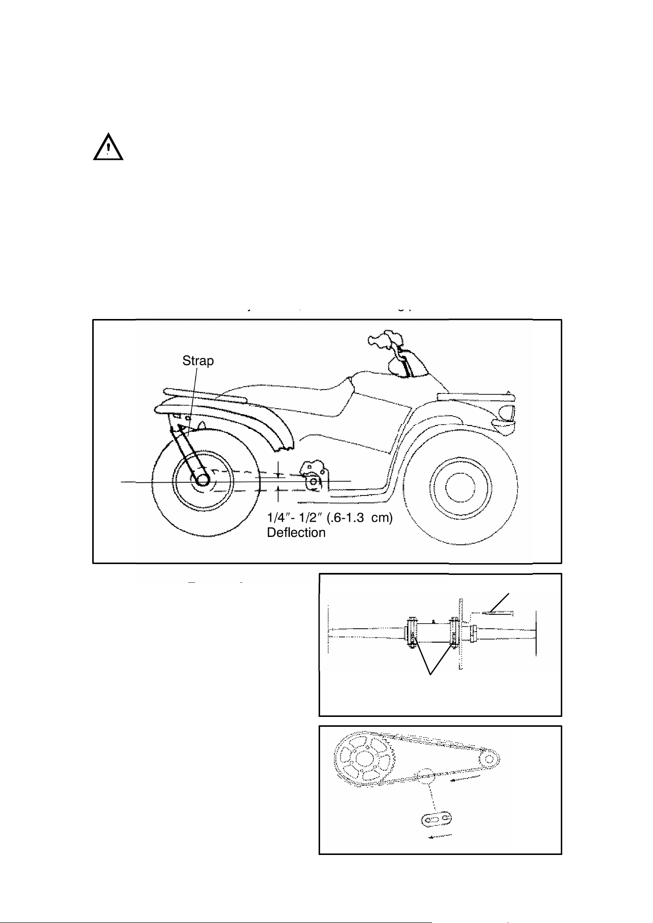
122
MAINTENANCE
Rear Drive Chain Slack Adjustment
CAUTION: Never adjust or operate the vehicle with the rear drive chain too
loose or too tight as severe damage to the transmission and drive components can
result. Chain tension must be inspected with the swing arm in the position shown
in illustration.
Check the amount of chain slack by moving the vehicle slightly forward to gain
slack at the top side of the rear chain. Collapse the suspension by using an adjust-
able (buckle type) trailer tie down. Fasten the strap around the axle and rear bum-
per tube. Tighten until a straight line (A) can be drawn from the axle to the transmis-
sion output shaft intersecting the swing arm pivot. This establishes the tightest
chain position. At this point the chain should have 1/4″-1/2″(.6cm-1.3cm) deflec-
tion. If the chain needs adjustment, use the following procedure.
Adjustment Procedure
1. Loosen chain guard.
2. Loosen two eccentric locking
bolts.
3. Insert a pin punch through the
sprocket hub and into the eccen-
tric axle housing.
4. Roll the vehicle ahead or back to
adjust chain slack to the proper
dimension.
5. Tighten the eccentric locking
bolts to 60 ft. lbs. (8.3 kg/m).
6. Reinstall chain guard.
NOTE: Reposition chain guide to al-
low 1/8″ (.3 cm) clearance between
sprocket and guide.
Rear Drive Chain Adjustment
3
2
Proper Splice-
link Clip Open-
ing Position
Strap
1/4″- 1/2″ (.6-1.3 cm)
Deflection
A
(Freeplay of chain - no force applied to chain)

123
MAINTENANCE
Headlight Lamp Replacement
WARNING: Due to the nature of ATVs and where they are ridden, headlight
and taillight lenses become dirty. Frequent washing is necessary to maintain light-
ing quality. Poor lighting while riding can result in severe injury or death.
CAUTION: Do not service while headlight is hot. Serious burns may result.
NOTE: Do not touch a halogen lamp with bare fingers. Oil from your skin leaves
a residue, causing a hot spot which will shorten the life of the lamp.
Headlight Lamp Installation - Scrambler
1. Remove wire harness connector from the back of headlight.
2. Grasp bulb housing, turn counterclockwise and remove bulb.
3. Install bulb into headlight housing and rotate clockwise firmly. NOTE: bulb is
to be positioned so the harness installs into the lamp at the bottom.
4. Reinstall connector.
High Beam Headlight Adjustment
The headlight beam can be adjusted up and down.
1. Place the vehicle on a level surface with the headlight approximately 25’ (7.6
m) from a wall.
2. Measure the distance from the floor to the center of the headlight and make a
mark on the wall at the same height.
3. Start the engine and turn the headlight switch to high beam.
4. Observe headlight aim. The most intense part of the headlight beam should
be aimed 2″ (5.1 cm) below the mark placed on the wall in step 2. NOTE: Rider
weight must be included on the seat.
5. Loosen pivot bolt and adjust beam to desired position.
6. Tighten nut and bolt. Torque to 60 in. lbs.
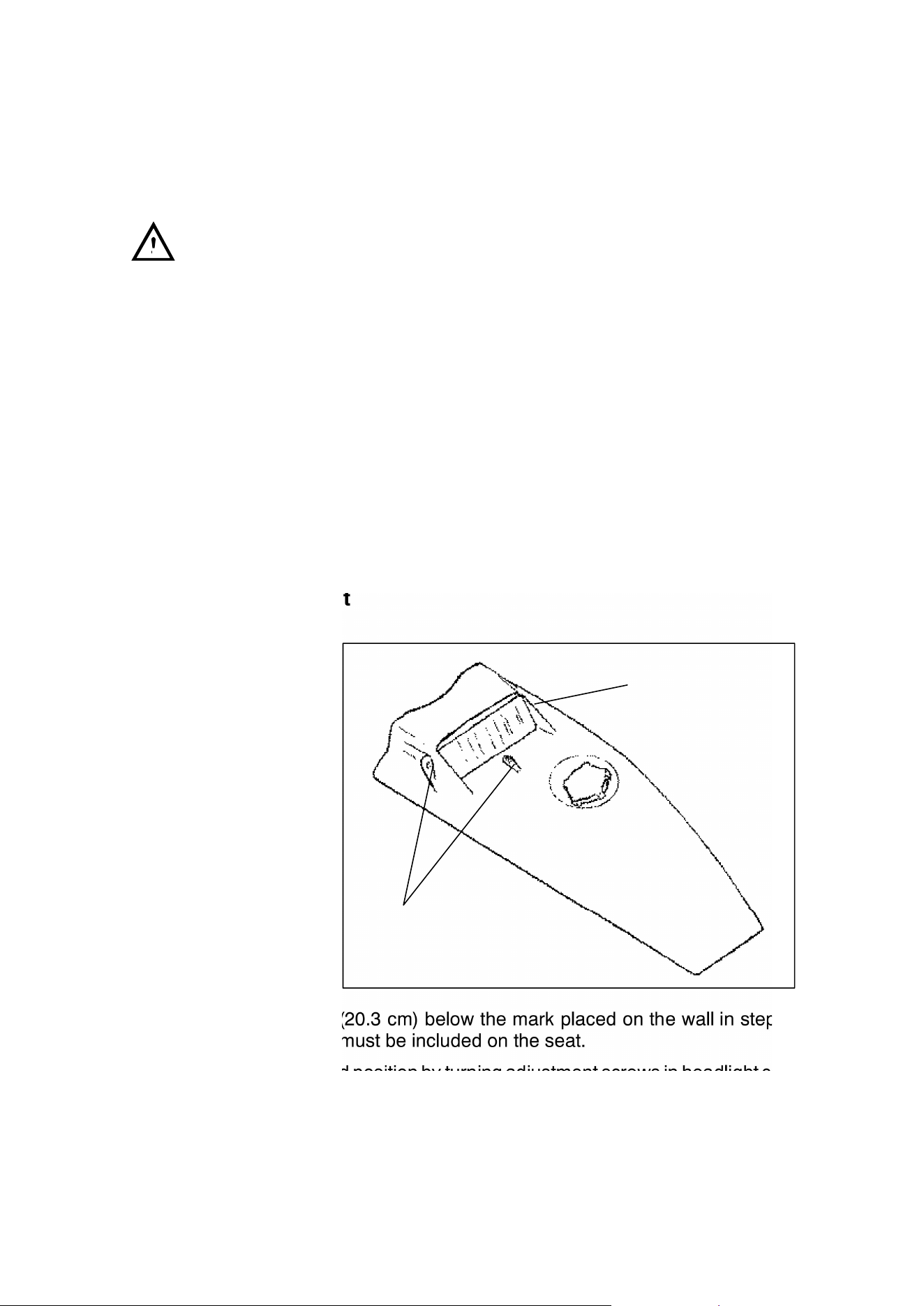
124
MAINTENANCE
Headlight Lamp Replacement
Trail Blazer, Sport
WARNING: Due to the nature of ATVs and where they are ridden, headlight
and taillight lenses become dirty. Frequent washing is necessary to maintain light-
ing quality. Poor lighting while riding can result in severe injury or death.
CAUTION: Do not service while headlight is hot. Serious burns may result.
1. Remove rubber cap from back of headlight to reveal retention screw.
2. Remove small phillips head screw, and carefully remove bulb from housing.
3. Gently unplug headlight lead wire from yellow jumper, and ground wire from ter-
minal board.
4. Insert new bulb into housing and tighten retention screw.
5. Plug lead and ground wire back into terminal board and jumper.
6. Mount cover to machine.
7. Properly adjust headlight aim.
Headlight Adjustment
1. Place the vehicle on
a level surface with
the headlight
approximately 25’
(7.6 m) from a wall.
2. Measure the dis-
tance from the floor
to the center of the
headlight and make
a mark on the wall at
the same height.
3. Start the engine and
turn on headlight.
4. Observe headlight
aim. The most in-
tense part of the
headlight beam
should be aimed 8″ (20.3 cm) below the mark placed on the wall in step 2.
NOTE: Rider weight must be included on the seat.
5. Adjust beam to desired position by turning adjustment screws in headlight cov-
er. Turning right screw clockwise moves the intense spot of light up to the left.
Turning the left screw clockwise moves intense spot of light up to the right.
Turning the bottom screw clockwise adjusts the light upwards.
Headlight
adjustment
Screws
Headlight
adjustment
Screw
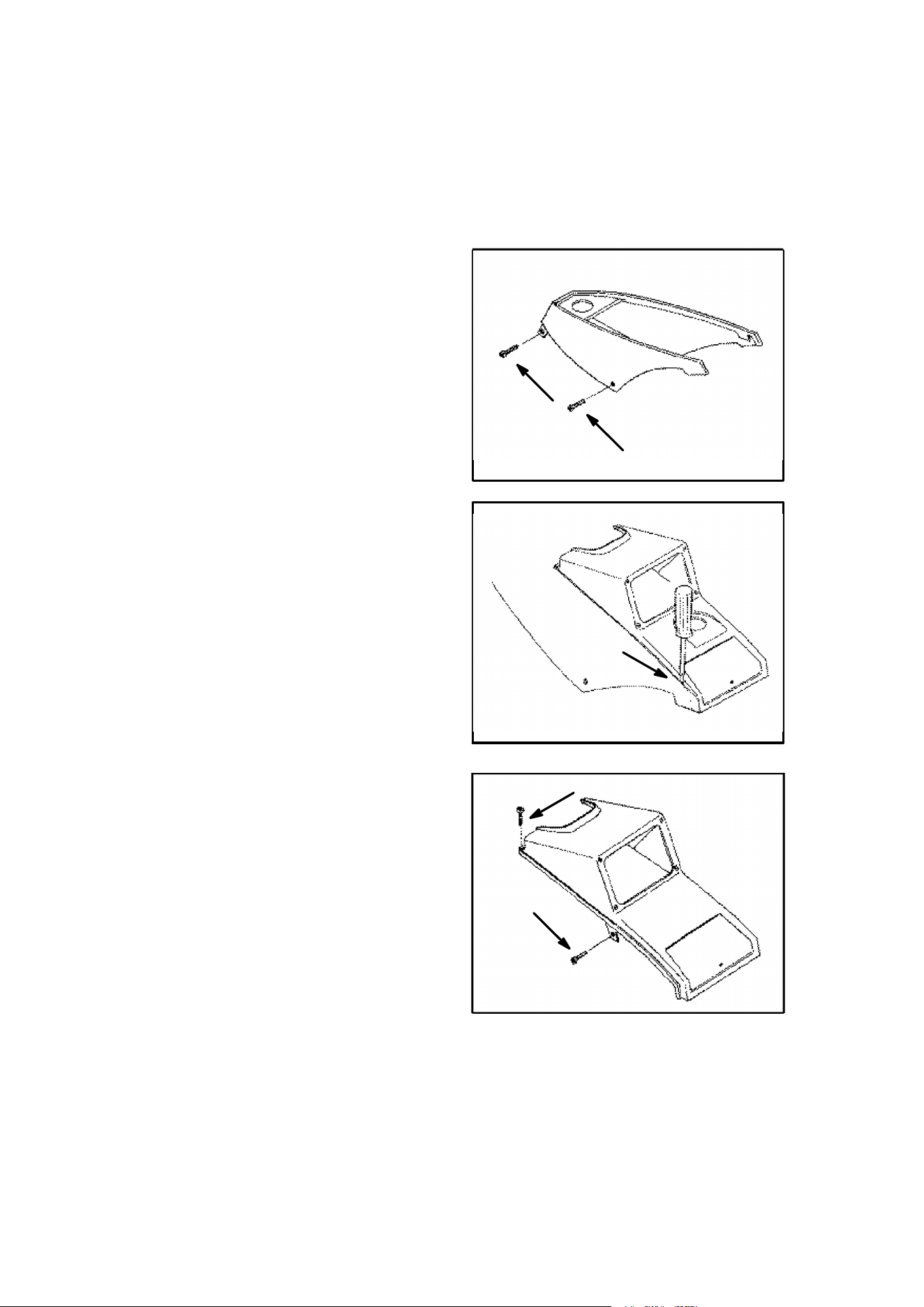
125
MAINTENANCE
Headlight Lamp Replacement
Magnum 2x4, Magnum 4x4, Trail Boss
1. Remove the seat.
2. Remove the plastic panel surround-
ing the upper portion of the gas tank
by first removing the gas tank cap.
3. Remove the Phillips head screws on
either side of the panel at the junc-
tion of this panel, the lower panels,
and the rear of the front fenders.
4. Remove the Phillips head screws on
either side of the rear of the upper
panel which were revealed by the re-
moval of the seat., and starter pinion
5. Remove the door on the front of the
ATV covering the radiator cap by us-
ing a stubby, flat screwdriver to dis-
engage the screw. Remove the door
and set it aside.
6. Disengage the tabs at the front of the
upper panel where they snap into
the lower panel surrounding the
headlight assembly. Also disengage
the tabs on the upper panel which
engage with the lower triangular
panels on either side of the machine.
Lift off the upper panel and set it
aside.
7. Reinstall the gas tank cap.
8. Remove the panel surrounding the
headlight by removing the Phillips
head machine screws from either
side of this panel. Also remove the
two Torx screws at the rear of this
panel.
9. Ease the panel forward and up to al-
low you to reach the socket con-
nected to the headlight lamp.
3. & 4.
6.

126
MAINTENANCE
Headlight Adjustment
10. Carefully unplug the socket from the lamp. Remove the panel and set it aside.
11. Replace the oil reservoir cap.
12. Stand the panel containing the headlight assembly on end to allow access to
the back of the headlight assembly.
13. Disengage the wire bail holding the headlight lamp in place and move it out of
the way.
14. Grasp the base of the lamp and lift it out.
15. Reverse the previous steps to replace the lamp and reassemble the panels.
High Beam Headlight Adjustment
The headlight beam can be adjusted to any position desired by turning the four
screws at the outer corners of the lamp housing.
1. Place the vehicle on a level surface with the headlight approximately 25’ (7.6
m) from a wall.
2. Measure the distance from the floor to the center of the headlight and make a
mark on the wall at the same height.
3. Start the engine and turn the headlight switch to high beam.
4. Observe headlight aim. The most intense part of the headlight beam should
be aimed 2″ (5.1 cm) below the mark placed on the wall in step 2. NOTE: Rider
weight must be included on the seat. For machines with separate low beam
lights, the drop on low beam should be 8″ (20.3 cm) in 25’.
5. Adjust beam to desired position by turning screws on the housing.
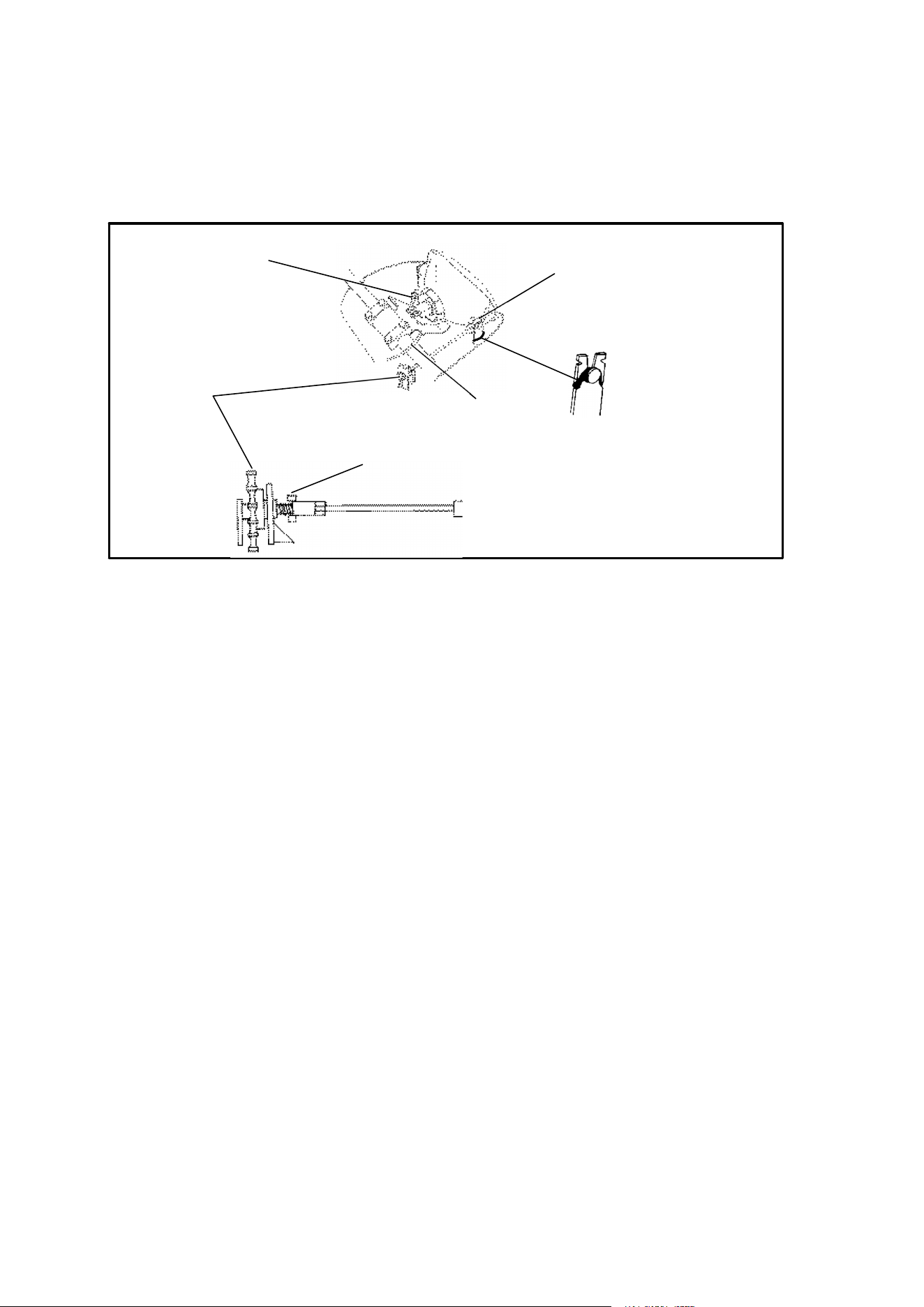
127
MAINTENANCE
Headlight Lamp Replacement
Xplorer 400, Xplorer 500, Sportsman 500
1. Remove Phillips screws from bottom of headlight pod at each front corner.
NOTE: To aid in accessing these screws, it may be helpful to turn handlebars
to left or right and use a short, stubby screwdriver. Removal of the front rack
and cover may also allow easier access.
2. Remove three Phillips screws at back of headlight pod.
3. Lift pod cover up. Using a pliers, disconnect speedometer cable. Unplug indi-
cator lights from harness and remove pod cover.
4. Unplug headlamp from wiring harness.
5. Remove boot and locking collar from back of lamp housing.
6. Grasp base of lamp and lift it out.
7. Reverse previous steps to replace lamp and reassemble pod. Make sure tab
on lamp locks into place in housing.
High Beam Headlight Adjustment
The headlight beam can be adjusted to any position desired by turning the adjust-
ing knob located on the bottom right side of the headlight pod.
Snap pins
into tabs
Position
knob in
slot and
secure in
locking
tabs
Slip O-Ring
over pin
Adjustment
Knob Stop
Speedometer
Cable
Route plug
over
handlebar
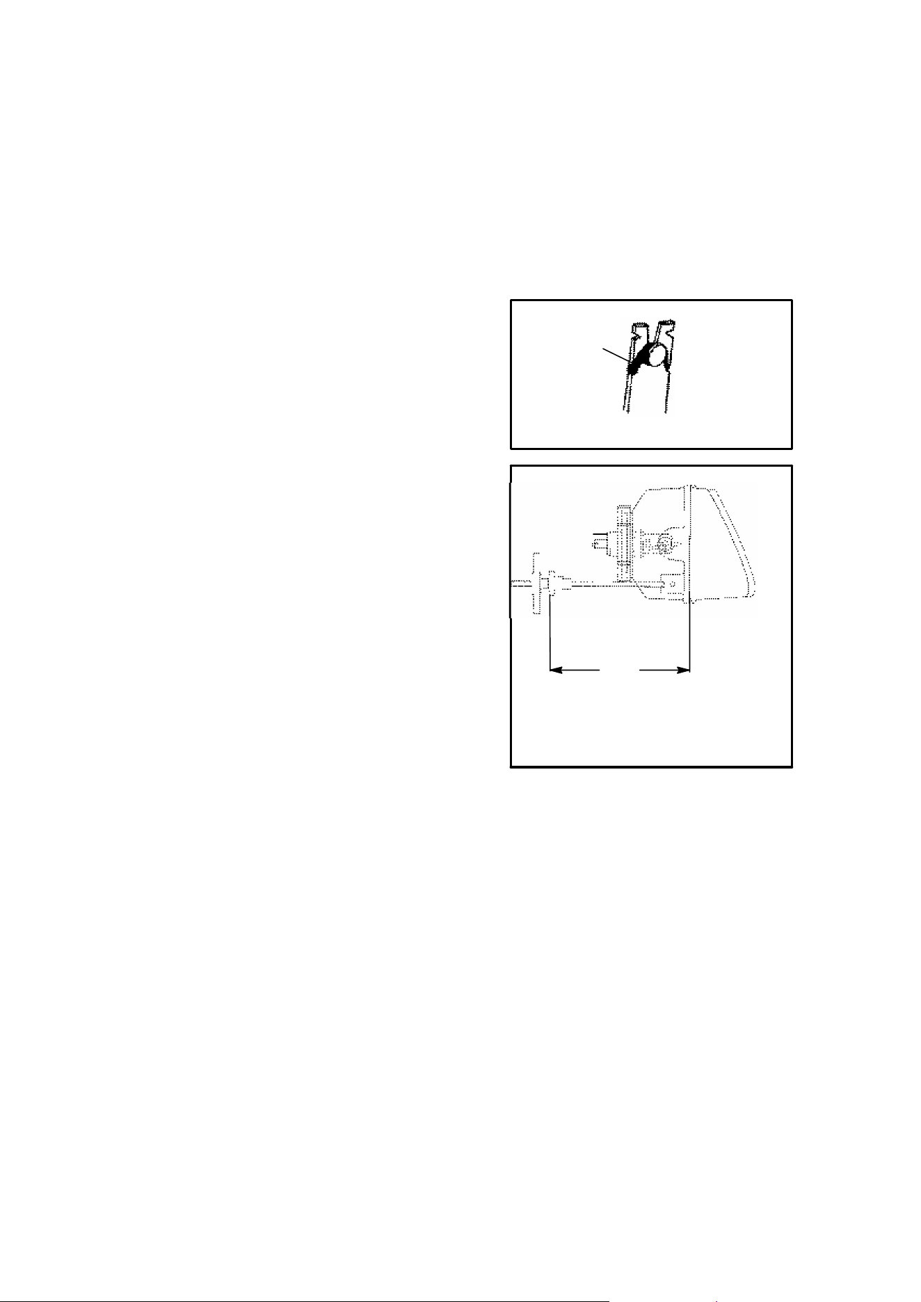
128
MAINTENANCE
Headlight Housing Replacement
1. Remove Phillips screws from bottom of headlight pod at each front corner.
NOTE: To aid in accessing these screws, it may be helpful to turn handlebars
to left or right and use a short, stubby screwdriver. Removal of the front rack
and cover may also allow easier access.
2. Remove three Phillips screws at back of
headlight pod.
3. Lift pod cover up. Using a pliers, discon-
nect speedometer cable. Unplug indica-
tor lights from harness and remove pod
cover.
4. Unplug headlamp from wiring harness.
5. Remove O-Ring from headlight pivot
pins.
6. Pull headlight housing up to release
from locking tabs.
7. Lift adjusting knob up to remove from
locking tabs.
8. Carefully pull assembly up and out of
pod.
9. Reverse steps to install new housing
and reassemble pod.
10. Adjust headlight aim by turning adjust-
ing knob.
O-Ring
5 1/8″
(13 cm)
Distance from headlamp parting
line to end of adjustment knob stop
is 5 1/8″ (13 cm).
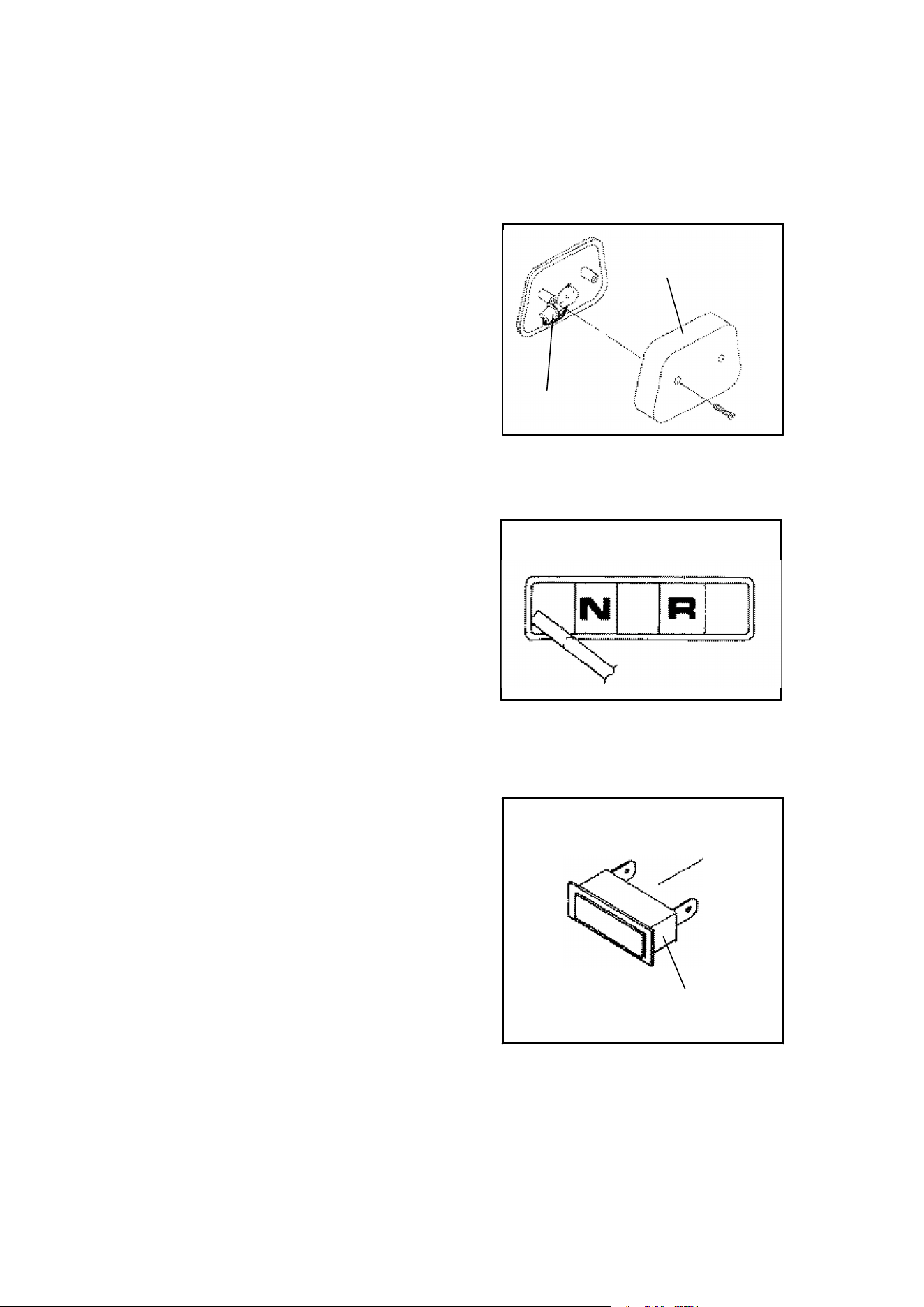
129
MAINTENANCE
Taillight/Brakelight Lamp
Replacement
If the taillight/brakelight does not work the
lamp may need to be replaced.
1. From the rear of the taillight remove two
screws holding lens cover in place and
remove lens cover.
2. Remove lamp and replace it with recom-
mended lamp.
3. Test the taillight/brakelight to see that it’s
working.
4. Reinstall the lens cover removed in step 1.
Indicator Lamp Replacement - Style I
1. With a small, flat screwdriver gently pry
loose the indicator light cover.
2. Using a small flexible tube (such as an
oil delivery hose) grasp the burned out
lamp and remove it.
3. Replace the removed lamp with a Polar-
is PN 4030042 (Sylvania PN 12POL).
4. Replace the indicator light cover.
Indicator Lamp Replacement - Style II
1. Follow steps 1 - 3 of Headlight Housing
Replacement on previous page.
2. Unplug light from harness, depress lock-
ing tabs and remove from pod.
3. Install new light and reassemble pod.
Lens Cover
Bulb
Style I
Depress locking
tabs to remove.
Style II
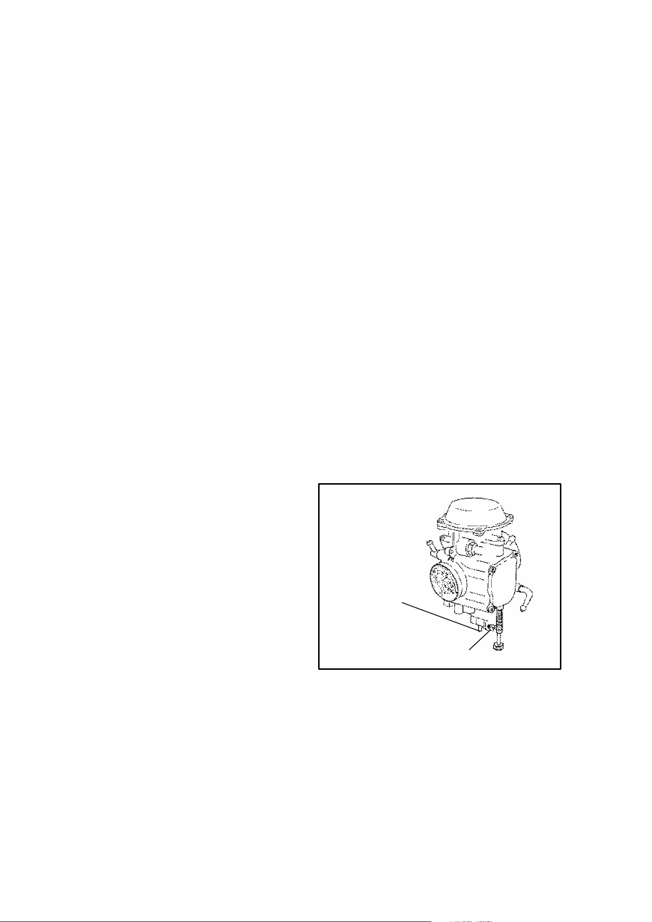
130
MAINTENANCE
Cleaning Your ATV
Keeping your ATV clean will not only improve its appearance but it can also extend
the life of various components. With a few precautions, your ATV can be cleaned
much like an automobile.
Washing
If a high pressure type car wash system is used, extreme care must be taken to
avoid water damage to the wheel bearings, transmission seals, body panels,
brakes and warning labels. Many expensive repair bills can result from using high
pressure detergent systems.
NOTE: If a high pressure car wash is used, grease all zerk fittings immediately af-
ter washing. Also run the vehicle to evaporate any water that might have entered
the engine or exhaust system.
The best and safest way to clean your ATV is with a garden hose and a pail of mild
soap and water. Use a professional type washing mitten, cleaning the upper body
first and the lower parts last. Rinse with water frequently and dry with a chamois
to prevent water spots. NOTE: If warning labels are damaged, contact your a Po-
laris dealer for free replacement.
Waxing
Your ATV can be waxed with any quality brand automotive paste wax. Avoid the
use of harsh cleaners since they can scratch the body finish.
Storage
If your ATV is to be placed in ex-
tended or off season storage, the fol-
lowing steps should be taken to pre-
serve its condition.
1. Perform all necessary repairs
and thoroughly clean the ATV.
2. Turn the fuel valve to “off” and
drain the carburetor.
3. On 2-cycle engines, remove the
spark plug and pour approxi-
mately one ounce of injection oil
into the cylinder. Operate the
starter for a few seconds and re-
install the spark plug.
4. On 4-cycle engines, remove the spark plug and pour approximately one ounce
of Premium 4 oil into the cylinder. Operate the starter for a few seconds and
reinstall the spark plug.
5. Remove the battery. Store it in a cool, dry place out of the sun.
6. Lubricate suspension pivot points, lower steering post, all U-joints (if any) and
rear axle fittings (if any).
Drain tube
attached
here
Drain Screw
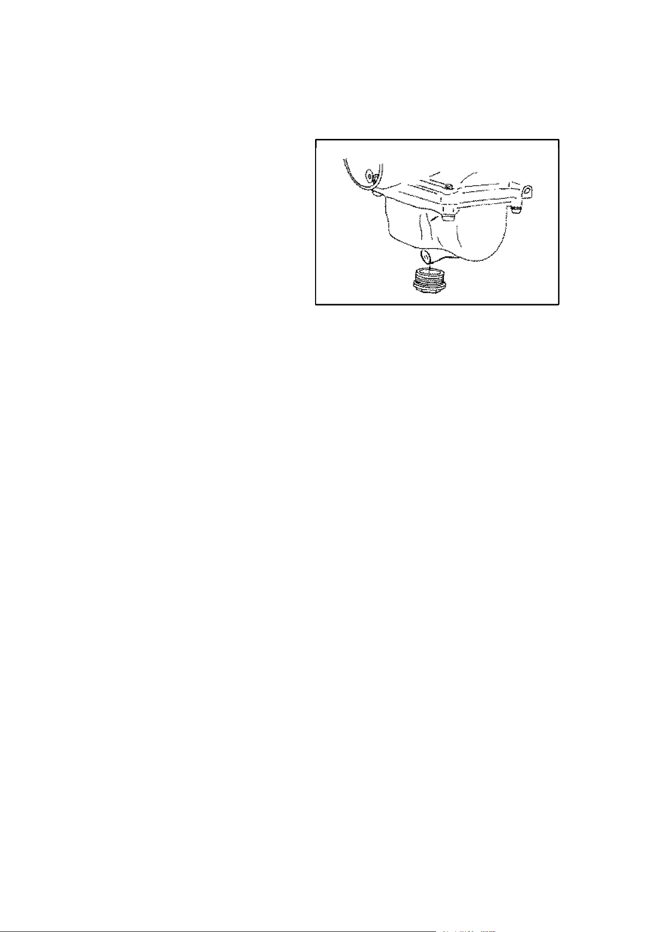
131
MAINTENANCE
Storage (Cont.)
7. Drain the recoil housing.
8. Block the ATV so all tires are sus-
pended off the ground.
9. Add Polaris Premium Storage
Stabilizer to the fuel tank.
10. Cover the ATV with a canvas
cover. Do not use plastic or
coated materials since they do
not allow ventilation of the ve-
hicle.
Transporting
Whenever the ATV is to be transported the following measures should be taken.
1. Turn the fuel valve to off.
2. Be certain the fuel cap and oil cap are installed correctly.
3. Always tie the frame of the ATV to the transporting unit securely using suitable
straps or rope.
4. Always place the transmission in gear and lock the parking brake.
Carburetor Adjustments
If the vehicle is to be operated at various altitudes and temperatures, certainadjust-
ments can be made to improve its operation and driveability. Above 6000 feet
(1800 m) the engine air/fuel mixture becomes overly rich. An engine loses approxi-
mately 3% of its power for each 1000 foot (304.8 m) increase in elevation. Although
this power cannot be regained, changes to the carburetor and drive system can
be made to allow efficient operation. These changes include:
1. Carburetor re-jetting to compensate for altitude and/or temperature changes.
2. Transmission convertor modification to adjust for engine horsepower loss dur-
ing high altitude operation. Contact your dealer.
3. On 2 cycle models, air screw adjustments can be made to compensate for tem-
perature changes and/or changes in altitude.
4. On 4 cycle models, pilot screw adjustments can be made to compensate for
temperature changes and/or changes in altitude.
NOTE: Contact your dealer for altitude adjustments. They have the training and
special tools required to perform all necessary modifications for you.
Remove plug and drain the carburetor
400 Engines

132
TROUBLESHOOTING
Procedures
The following information is provided to help you identify probable causes for ques-
tions you may have about the operation of your ATV. See your Polaris dealer with
any additional questions you may have.
ENGINE CRANKS BUT FAILS TO START
Stop Switch Off No Fuel Water in Fuel Spark Plug
Fuel Valve Off Drain System
No Spark to
Spark Plug
Contact Your
Dealer
Clogged Fuel
Valve
ENGINE STOPS OR LOSES POWER
No Fuel
Contact Your
Dealer
Contact Your
Dealer
Overuse of
Choke
Spark Plug
Fouled
Engine
Overheated
Clean Engine
Exterior
Turn Fuel Valve
to “Res”
Water in Fuel
Air Filter
Clogged
Reverse Speed
Limiter
Malfunction
Electronic
Throttle Control
Malfunction
Fuel Vent Line
Kinked or
Plugged
Clean Radiator
screen and
Radiator Core
(liquid cooled
models)

133
PAINT CODES
Model Item Color Raw Material
No.
PPG Ditzler
No.
Springs Fire Red 8520149 7060
1998
T
r
a
i
l
B
o
s
s
Rims Bright White 8520153 2185
T
r
a
i
l
B
o
s
s
Rack Fire Red 8520149 72060
Springs Black 8520147 9440
1998
Magnum 2x4
Rims Brushed Alu-
minum
N/A N/A
Rack Black 8520147 9440
1
9
9
8
Springs Fire Red 8520149 72060
1
9
9
8
Trail Blazer
Rims Bright White 85200153 2185
1998
Springs Fire Red 8520149 72060
1
9
9
8
Scrambler
400
Rims Bright White 8520153 2185
1
9
9
8
Springs Black 8520147 9440
1
9
9
8
Scrambler
500
Rims Brushed
Aluminum
N/A N/A
Springs Fire Red 8520149 72060
1998
Magnum 4x4
Rims Brushed
Aluminum
N/A N/A
Rack E.B. Green 8520150 44931
1
9
9
8
Springs Fire Red 8520149 72060
1998
Sport
Rims Bright White 8520153 2185
Springs Bonnie Blue 8520148 12908
1998
Xplorer 500
Rims Brushed
Aluminum
N/A N/A

134
PAINT CODES
Model Item Color Raw Material
No.
PPG Ditzler
No.
Springs Fire Red 8520149 72060
1998
Xplorer 300
Rims Brushed
Aluminum
N/A N/A
1998
Springs Burnished
Brown
8520264 N/A
1
9
9
8
Xplorer 400
Rims Brushed
Aluminum
N/A N/A
1998
Springs Black 8520147 9440
1
9
9
8
Sportsman
500
Rims Black 8520147 9440
Springs Bonnie Blue 8520148 12908
1998
Xpress 300
Rims Brushed
Aluminum
N/A N/A
Order direct from Midwest Industrial Coatings (612) 934-2852. Mix as directed.

135
ACCESSORIES
Trail
Blazer
Trail Boss Sport Xpress
300
14 Gallon Sprayer N/A 2871087 N/A 2871087
Boom Mounting Kit N/A 2871340 N/A 2871340
42″ Spray Boom N/A 2871088 N/A 2871088
123″ Spray Boom N/A 2871089 N/A 2871089
Seeder/Spreader, Elec. N/A 2871219 N/A 2871219
Speedometer 2871275 2871275 2871341 2761539
20mph Speedometer N/A N/A N/A N/A
Speedometer Protector N/A N/A N/A N/A
Elect. Accessory Brd. N/A N/A N/A N/A
Gas Gauge Cap 2871442 2871442 2871442 2871442
Chains, pair (Rear) 2870684 2870684 2870684 2870790
Ramps, for Pick-up
Tailgate
2871495 2871495 2871495 2871495
Utilitiy Trailer N/A 2871498 N/A 2871498
Utility Trailer
(Rubbermaid)
N/A 2871338 N/A 2871338
Windshield Kit, Clear 2870864 2870864 2870864 2870864
Fairing Kit, Black N/A 2871817 N/A 2871817
Fox Shock, Rear 2871513 2871513 STD 2871513
1 3/8″ CAM Adjust
Rear Shock
2761514 2761514 2761514 2761514
Shock Covers, Front 2871790 2871790 2871790 2871791
Shock Covers, Rear 2871793 2871793 2871793 2871793
Throttle/Thumb Warmer 2871314 2871314 2871314 2871314
Handwarmer, Dual Heat 2760586 2760586 2760586 2760586
Engine Heater N/A N/A N/A N/A
Mud Skirt, Front & Rear N/A 2871106 N/A N/A
Mud Skirt, Front 2871777 N/A 2871777 N/A
Mud Skirt, Rear 2761505 N/A 2761505 N/A
Hand Guards 2871778 2871778 2871778 2871778

136
ACCESSORIES
Magnum
2x4
Scrambler
400
Scrambler
500
Xplorer
300
Xplorer
400
Xplorer
500
2871087 N/A N/A 2871087 2871087 2871087
2871340 N/A N/A 2871340 2871340 2871340
2871088 N/A N/A 2871088 2871088 2871088
2871089 N/A N/A 2871089 2871089 2871089
2871219 N/A N/A 2871219 2871219 2871219
STD TBA TBA 2871539 STD 2871789
2871085 N/A N/A N/A 2871353 N/A
2871316 N/A N/A N/A N/A N/A
2871802 2871802 2871802 N/A N/A N/A
2871441 2871442 2871441 2871442 2871442 N/A
2870684 2870684 2870684 2870790 2870948 2870948
2871495 2871495 2871495 2871495 2871495 2871495
2871498 N/A N/A 2871498 2871498 2871498
2871338 N/A N/A 2871338 2871338 2871338
2870864 2871324 2871324 2870864 2871324 2870864
2871817 N/A N/A 2871817 2871816 2871817
2871513 STD STD 2871513 2871513 N/A
STD 2871514 2871514 2871514 STD N/A
2871791 2871792 2871792 2871791 2871791 2871791
2871793 2871793 2871793 2871793 2871793 2871794
2871314 2871314 2871314 2871314 2871314 2871314
2870586 2870586 2870586 2870586 2870586 2870586
2871507 N/A 2871507 N/A N/A 2871507
2871106 N/A N/A N/A N/A N/A
N/A 2871777 2871777 N/A N/A N/A
N/A 2871505 2871505 N/A N/A N/A
2871778 TBA TBA 2871778 2871778 2871778

137
ACCESSORIES
Trail
Blazer
Trail Boss Sport Xpress
300
Gun Scabbard N/A 2870854 N/A 2870854
CV Protector N/A N/A N/A N/A
Rack Bag, Large, Black N/A N/A N/A 2871787
Rack Bag, Gray/Black N/A N/A N/A 2871216
Rack Bag, Camo N/A N/A N/A 2871506
Dual Headlights 2871490 N/A 2871490 STD
K&N Air Filter 2871509 2871509 2871508 2871509
Cover, Red/Blue 2870796 2870796 2870796 2870796
Cover for ATV w/wind-
shield Red/Blue
N/A 2871313 N/A 2871313
Cover, Camo 2871084 2871084 2871084 2871084
Safety Whip Flag 2870799 2870799 2870799 2870799
Reverse Warning Kit
(Sound)
2870991 2870991 2870991 2870991
Hour Meter 2871011 2871011 2871011 2871011
8 hp 40″ Rear Mower N/A 2871457 N/A 2871457
10.5 hp 40″ Rear Mower N/A 2871491 N/A 2871491
12 hp 60″ Rear Mower
(E/S)
N/A 2871493 N/A 2871493
12 hp 60″ Rear Mower
(Recoil)
N/A 2871492 N/A N/A
V-Plow N/A 2871795 N/A 2871795
48″ Snow/Dirt Blade N/A 2871730 N/A 2871730
60″ Blade N/A 2871731 N/A 2871731
Blade Attachment Kit N/A 2871799 N/A 2871738
Plow Frame Kit N/A 2871732 N/A 2871732
3-pt Hitch Kit N/A N/A N/A N/A
Rear Blade for 3-Pt N/A N/A N/A N/A
Cultivator for 3 pt Hitch N/A N/A N/A N/A
2000 lb Warn Winch Kit N/A N/A N/A N/A
Accessory Winch Kit N/A N/A N/A N/A
Front Rack Kit N/A 2870775 N/A STD

138
ACCESSORIES
Magnum
2x4
Scrambler
400
Scrambler
500
Xplorer
300
Xplorer
400
Xplorer
500
2870854 N/A N/A 2870854 2870854 N/A
N/A 2871234 2871234 2871234 2871234 STD
2871787 N/A N/A 2871787 2871787 2871787
2871216 N/A N/A 2871216 2871216 2871216
2871506 N/A N/A 2871506 2871506 2871506
2870936 STD STD STD STD STD
2871508 2871508 2871786 2871509 2871509 1871786
2870796 2870796 2870796 2870796 2870796 2870796
2871313 N/A N/A 2871313 2871313 2871313
2871084 2871084 2871084 2871084 2871084 2871084
2980799 2980799 2980799 2980799 2980799 2980799
2870991 2870991 2870991 2870991 2870991 2870991
2871011 2871011 2871011 2871011 2871011 2871011
2871457 N/A N/A 2871457 2871457 2871457
2871491 N/A N/A 2871491 2871491 2871491
2871493 N/A N/A 2871493 2871493 2871493
2871492 N/A N/A 2871492 2871492 2871492
2871795 N/A N/A 2871795 2871795 2871795
2871730 N/A N/A 2871730 2871730 2871730
2871731 N/A N/A 2871731 2871731 2871731
2871734 N/A N/A 2871736 2871736 2871740
2871732 N/A N/A 2871732 2871732 2871732
N/A N/A N/A 2871511 2871511 TBA
N/A N/A N/A 2870866 2870866 TBA
N/A N/A N/A 2871317 2871317 TBA
2871776 N/A N/A 2871775 2871775 2871775
2871461 N/A N/A 2871461 2871461 2871461
STD N/A N/A STD STD STD

139
ACCESSORIES
Trail
Blazer
Trail Boss Sport Xpress
300
Rear Rack Kit 2871357 STD 2871357 STD
Front Rack Extender 3.5″ N/A 2871502 N/A 2871499
Front Rack Extender 8″ N/A N/A N/A 2871318
Rear Rack Extender 3.5″ N/A 2871504 N/A 2871501
Rear Rack Extender 8″ N/A 2870918 N/A 2871319
Gun Shovel Holder 2871315 2871315 2871315 2761427

140
ACCESSORIES
Magnum
2x4
Scrambler
400
Scrambler
500
Xplorer
300
Xplorer
400
Xplorer
500
STD 2871357 2871357 STD STD STD
2871502 N/A N/A 2871499 2871499 2871499
2870931 N/A N/A 2871318 2871318 2871318
2871503 N/A N/A 2871501 2871501 2871501
2870942 N/A N/A 2871319 2871319 2871319
2871315 2871315 2871315 2871427 2871427 2871427

141
ACCESSORIES
Magnum
4x4
Sportsman
500
14 Gallon Sprayer 2871087 2871087
Boom Mounting Kit 2871340 2871340
42″ Spray Boom 2871088 2871088
123″ Spray Boom 2871089 2871089
Seeder/Spreader, Elec. 2871219 2871219
Speedometer STD STD
20mph Speedometer 2871085 2871353
Speedometer Protector 2871316 N/A
Elect. Accessory Brd. 2871802 N/A
Gas Gauge Cap 2871441 N/A
Chains, pair (Rear) 2870948 2870948
Ramps, for Pick-up Tail-
gate
2871495 2871495
Utilitiy Trailer 2871498 2871498
Utility Trailer (Rubber-
maid)
2871338 2871338
Windshield Kit, Clear 2870864 2871324
Fairing Kit, Black 2871817 2871816
Fox Shock, Rear 2871513 N/A
1 3/8″ CAM Adjust Rear
Shock
STD N/A
Shock Covers, Front 2871791 2871791
Shock Covers, Rear 2871793 2871794
Throttle/Thumb Warmer 2871314 2871314
Handwarmer, Dual Heat 2870586 2870586
Engine Heater 2871507 2871507
Mud Skirt, Front & Rear STD N/A
Mud Skirt, Front N/A N/A
Mud Skirt, Rear N/A N/A
Hand Guards 2871778 2871778

142
ACCESSORIES
Magnum
4x4
Sportsman
500
Rear Rack Kit STD STD
Front Rack Extender
(3.5″)
2871502 2871499
Gun Scabbard 2870854 2870854
CV Protector 2871234 STD
Rack Bag, Large, Black 2871787 2871787
Rack Bag, Gray/Black 2871216 2871216
Rack Bag, Camo 2871506 2871506
Dual Headlights STD STD
K&N Air Filter 2871508 2871786
Cover, Red/Blue 2870796 2870796
Cover for ATV w/wind-
shield Red/Blue
2871313 2871313
Cover, Camo 2871084 2871084
Safety Whip Flag 2870799 2870799
Reverse Warning Kit
(Sound)
2870991 2870991
Hour Meter 2871011 2871011
8 hp 40″ Rear Mower 2871457 2871457
10.5 hp 40″ Rear Mower 2871491 2871491
12 hp 60″ Rear Mower 2871493 2871493
12 hp 60″ Rear Mower
(Recoil)
2871492 2871492
V-Plow 2761795 2761795
48″ Snow/Dirt Blade 2761730 2761730
60″ Blade 2871731 2871731
Blade Attachment Kit 2871734 2871740
Plow Frame Kit 2871732 2871732
3-pt Hitch Kit 2871512 N/A
Rear Blade for 3-Pt 2870886 N/A
Cultivator for 3 pt Hitch 2871317 N/A
2000 lb Warn Winch Kit 2871776 2871775

143
ACCESSORIES
Magnum
4x4
Sportsman
500
Accessory Winch Kit 2871461 2871461
Front Rack Kit STD STD
Front Rack Extender 8″ 2870931 2871318
Rear Rack Extender 3.5″ 2871503 STD
Rear Rack Extender 8″ 2870942 2871319
Gun Shovel Holder 2871315 2871427

144
WARRANTY
LIMITED WARRANTY
Polaris Industries Inc., 1225 Highway 169 North, Minneapolis, Minnesota
55441--5078, gives a SIX MONTH LIMITED WARRANTY on all components of the
Polaris All Terrain Vehicle (ATV) againstdefects in material or workmanship. Polar-
is also gives a one year limited warranty on the final drive chain for failure due to
defects. This warranty covers the parts and labor charges for repair or replace-
ment of defective parts which are covered by this warranty. This warranty begins
on the date of purchase. This warranty is transferrable to another consumer during
the warranty period through a Polaris dealer. There is a charge of $35.00 payable
to Polaris Industries Inc.
REGISTRATION
At the time of sale, the Warranty Registration Form must be completed by your
dealer and submitted to Polaris within ten days. Upon receipt of this registration,
Polaris will record the registration for warranty. THE PURCHASER MUST COM-
PLETE AN ATV SAFETY TRAINING COURSE PROVIDED BY THE DEALER IN
ORDER TO HAVE VALID WARRANTY ON THE ATV. No verification of registra-
tion will be sent to the purchaser as the copy of the Warranty Registration Form will
be the warranty entitlement. If you have not signed the original registration and re-
ceived the “customer copy”, please contact your dealer immediately. NO WAR-
RANTY COVERAGE WILL BE ALLOWED UNLESS YOUR ATV IS REG-
ISTERED WITH POLARIS.
Initial dealer preparation and set--up of your ATV is very important in ensuring
trouble--free operation. Purchasing a machine in the crate or without proper dealer
set--up will void your warranty coverage.
WARRANTY COVERAGE AND EXCLUSIONS:
LIMITATIONS OF WARRANTIES AND REMEDIES
The Polaris limited warranty excludes any failures that are not caused by a defect
in material or workmanship. This warranty does not cover accidental damage, nor-
mal wear and tear, abuse or improper handling. This warranty also does not cover
any ATV that has been altered structurally, modified, neglected, improperly main-
tained, used for racing, or used for purposes other than for which it was manufac-
tured, or for any damages which occur during trailer transit or as a result of unau-
thorized service or the use of unauthorized parts. In addition, this warranty does
not cover physical damage to paint or finish, stress cracks, tearing or puncturing of
upholstery material, corrosion, or defects in parts, components or the ATV due to
fire, explosions or any other cause beyond Polaris’ control.

145
WARRANTY
This warranty does not cover the use of unauthorized lubricants, chemicals, or
fuels that are not compatible with the ATV. The exclusive remedy for breach of this
warranty shall be, at Polaris’ exclusive option, repair or replacement of any defec-
tive materials, or components or products. THE REMEDIES SET FORTH IN THIS
WARRANTY ARE THE ONLY REMEDIES AVAILABLE TO ANY PERSON FOR
BREACH OF THIS WARRANTY. POLARIS SHALL HAVE NO LIABILITY TO ANY
PERSON FOR INCIDENTAL, CONSEQUENTIAL OR SPECIAL DAMAGES OF
ANY DESCRIPTION, WHETHER ARISING OUT OF EXPRESS OR IMPLIED
WARRANTY OR ANY OTHER CONTRACT, NEGLIGENCE, OR OTHER TORT
OR OTHERWISE. Some states do not permit the exclusion or limitation of inciden-
tal or consequential damages or implied warranties, so the above limitations or ex-
clusions may not apply to you if inconsistent with controlling state law.
ALL IMPLIED WARRANTIES (INCLUDING BUT NOT LIMITED TO THE IMPLIED
WARRANTIES OF MERCHANTABILITY AND FITNESS FOR A PARTICULAR
PURPOSE) ARE LIMITED IN DURATION TO THE ABOVE SIX MONTH WAR-
RANTY PERIOD. POLARIS FURTHER DISCLAIMS ALL EXPRESS WARRAN-
TIES NOT STATED IN THIS WARRANTY. Some states do not allow limitations on
how long an implied warranty lasts, so the above limitation may not apply to you if
inconsistent with controlling state law.
HOW TO OBTAIN WARRANTY SERVICE
If your ATV requires warranty service, you must take it to a Polaris dealer autho-
rized to repair Polaris ATVs. When requesting warranty service you must present
your copy of the Warranty Registration form to the dealer. (THE COST OF TRANS-
PORTATION TO AND FROM THE DEALER IS YOUR RESPONSIBILITY). Polaris
suggests that you use your original selling dealer; however, you may use any Po-
laris Servicing Dealer to perform warranty service.
Please work with your dealer to resolve any warranty issues. Should your dealer
require any additional assistance they will contact the appropriate person at Polar-
is.
This warranty gives you specific legal rights, and you may also have other rights
which vary from state to state.
If any of the above terms are void because of state or federal law, all other warranty
terms will remain in effect.
Engine Oil
1. Always use Polaris engine oil.
2. Never substitute or mix oil brands as serious engine damage and voiding of war-
ranty can result.

INDEX
146
Engine Cooling System 45-47. . . . . . . . . .
Accessories 135-143. . . . . . . . . . . . . . . . .
Air Box Drain 98. . . . . . . . . . . . . . . . . . . . .
Air Cleaner 95-101. . . . . . . . . . . . . . . . . .
Air Filter Service, Magnum 97. . . . . . . . .
Air Filter Service,
Sport, Scrambler 400 99. . . . . . . . . .
Air Filter, Trail Blazer 100. . . . . . . . . . . . .
Air Filter, Scramblert 500 101. . . . . . . . . .
Air Filter, Sportsman 500,
Xplorer 500 101. . . . . . . . . . . . . . . . .
All Wheel Drive 43. . . . . . . . . . . . . . . . . . .
Auxiliary Brake Adjustment 106-107. . . .
Backing Up 71. . . . . . . . . . . . . . . . . . . . . .
Battery Installation 74. . . . . . . . . . . . . . . .
Battery Maintenance 73. . . . . . . . . . . . . .
Battery Removal 74. . . . . . . . . . . . . . . . . .
Brake, Auxiliary Mechanical 41 and 106.
Brake, Front 105. . . . . . . . . . . . . . . . . . . .
Brake, Parking 40. . . . . . . . . . . . . . . . . . .
Brake, Rear 106. . . . . . . . . . . . . . . . . . . . .
Brakes, Front 39. . . . . . . . . . . . . . . . . . . .
Brakes, Rear 39. . . . . . . . . . . . . . . . . . . . .
Break In Period 57. . . . . . . . . . . . . . . . . . .
Break In Period (4 Cycle) 57. . . . . . . . . . .
Break In Period -- 4 Cycle 56. . . . . . . . . .
Breather Filter, Scrambler 500 102. . . . . .
Breather Filter, 425 Engines 102. . . . . . .
Breather Filter, Sportsman 500,
Xplorer 500 103. . . . . . . . . . . . . . . . .
Camber And Caster 104. . . . . . . . . . . . . .
Carburetor Adjustment (4 Cycle) 113. . .
Carburetor Adjustment (2 Cycle) 112. . .
Carburetor Adjustments 131. . . . . . . . . . .
Cargo Weight Distribution 60. . . . . . . . . .
Carrying Loads 59. . . . . . . . . . . . . . . . . . .
Center Drive Chain
Inspection/Adjustment 120. . . . . . . .
Chain Adjustment 122. . . . . . . . . . . . . . . .
Choke Adjustment (4 Cycle) 112. . . . . . .
Choke Adjustment Procedure 111. . . . . .
Choke Lever 38. . . . . . . . . . . . . . . . . . . . .
Cleaning Your ATV 130. . . . . . . . . . . . . . .
Control And Parts Functions 35-54. . . . . .
Coolant Level 45. . . . . . . . . . . . . . . . . . . .
Coolant Level Inspection 46. . . . . . . . . . .
Counter Balance Lubrication 117. . . . . . .
Counter Balance Oil Changing
Procedure 117. . . . . . . . . . . . . . . . . .
Crossing Streams 69. . . . . . . . . . . . . . . . .
Cylinder Head Torque 114. . . . . . . . . . . . .
Daily Pre-ride Inspection 14 and 61. . . . .
Demand 4 Drive 43. . . . . . . . . . . . . . . . . .
Disengaging Wheel Hubs 44. . . . . . . . . .
Draining Recoil Housing 54. . . . . . . . . . .
Drive Chain Adjustment 120. . . . . . . . . . .
Engine Choke Adjustment 113. . . . . . . . .
Engine Choke Adjustment (400) 111. . . .
Engine Electrical Switches 35. . . . . . . . .
Engine Idle Rpm Adjustment 113. . . . . . .
Engine Idle Rpm Adjustment (500) 112. .
Filter Change 50-51. . . . . . . . . . . . . . . . . . .
Front Drive Chain
Inspection/Adjustment 120. . . . . . . .
Front Gearcase Lubrication 116. . . . . . . .
Front Wheel Hub Tightening 90. . . . . . . .
Fuel Filter 51. . . . . . . . . . . . . . . . . . . . . . . .
Fuel Safety 49. . . . . . . . . . . . . . . . . . . . . .
Fuel System 48. . . . . . . . . . . . . . . . . . . . .
Gearcase Oil Changing Procedure 116. .
Handlebar Adjustment 89. . . . . . . . . . . . .
Headlight Adjustment 123-127. . . . . . . . .
Headlight Lamp Replacement 123-127. .
Indicator Lamp Replacement 129. . . . . . .
Indicator Lights 36. . . . . . . . . . . . . . . . . . .
Light Switches 36. . . . . . . . . . . . . . . . . . . .
Load Capacity 59. . . . . . . . . . . . . . . . . . . .
Lubricant, 2cycle 52. . . . . . . . . . . . . . . . .
Lubrication Recommendations 82-87. . . .
Main Switch 35. . . . . . . . . . . . . . . . . . . . . .
Battery 73-74. . . . . . . . . . . . . . . . . . . . . . . .
Maintenance 76-131. . . . . . . . . . . . . . . . .
Maintenance Record 88. . . . . . . . . . . . . .
Maintenance Schedule 79-81. . . . . . . . . . .
Making Turns 63. . . . . . . . . . . . . . . . . . . .
Noise Control System 75. . . . . . . . . . . . .
Oil Change 50-51. . . . . . . . . . . . . . . . . . . .
Oil Filter 51. . . . . . . . . . . . . . . . . . . . . . . . .
Oil Pump Adjustment 108-109. . . . . . . . .
Oil Pump Bleeding 110. . . . . . . . . . . . . . .
Oil System 48-50. . . . . . . . . . . . . . . . . . . . .
Operation Warnings 15-33. . . . . . . . . . . . .
Paint Codes 133-134. . . . . . . . . . . . . . . . .
Parking On An Incline 72. . . . . . . . . . . . .
Power Pig Tail 78. . . . . . . . . . . . . . . . . . . .
Pre--filter, Magnum 98. . . . . . . . . . . . . . . .
Premium 4 Synthetic Lubricant 50. . . . . .
PVT System 44. . . . . . . . . . . . . . . . . . . . .
Rear Spring Adjustment 91. . . . . . . . . . . .
Recoil Starter 53. . . . . . . . . . . . . . . . . . . .
Riding 62-72. . . . . . . . . . . . . . . . . . . . . . . . .
Riding Gear 58. . . . . . . . . . . . . . . . . . . . . .
Riding On Slippery Surfaces 64. . . . . . . .
Safety Warning And
Operation Decals 3-13. . . . . . . . . . . .
Side Panel Removal 94. . . . . . . . . . . . . . .
Sidehilling 66. . . . . . . . . . . . . . . . . . . . . . .
Spark Arrestor 76-77. . . . . . . . . . . . . . . . . .
Spark Plugs 114. . . . . . . . . . . . . . . . . . . . .
Starting A Cold Engine 55. . . . . . . . . . . . .
Starting The Engine 55. . . . . . . . . . . . . . .
Steering Inspection 104. . . . . . . . . . . . . . .
Storage 130-131. . . . . . . . . . . . . . . . . . . .
Suspension Springs, Optional 92. . . . . . .
Taillight/Brakelight
Lamp Replacement 129. . . . . . . . . .
Throttle Cable Adjustment 110. . . . . . . . .
Throttle Control Lever Stop 39. . . . . . . . .

INDEX
147
Throttle Lever 38. . . . . . . . . . . . . . . . . . . .
Tire Inspection 119. . . . . . . . . . . . . . . . . . .
Toe Alignment 104. . . . . . . . . . . . . . . . . . .
Tool Kit 78. . . . . . . . . . . . . . . . . . . . . . . . . .
Torque Specifications 90. . . . . . . . . . . . . .
Trail Obstacles 70. . . . . . . . . . . . . . . . . . .
Transmission Gear Selector
Operation 42. . . . . . . . . . . . . . . . . . .
Transmission Lubrication 115. . . . . . . . . .
Transmission Oil Changing
Procedure 115. . . . . . . . . . . . . . . . . .
Transporting 131. . . . . . . . . . . . . . . . . . . .
Traveling Downhill 67. . . . . . . . . . . . . . . .
Traveling Uphill 65. . . . . . . . . . . . . . . . . . .
Troubleshooting 132. . . . . . . . . . . . . . . . .
Turning Around On A Hill 68. . . . . . . . . . .
Understanding Warnings 1-2. . . . . . . . . . .
Vehicle Identification Numbers 34. . . . . .
Warranty 145. . . . . . . . . . . . . . . . . . . . . . .
Warranty 144. . . . . . . . . . . . . . . . . . . . . . .
Wheel Installation 118. . . . . . . . . . . . . . . .
Wheel Removal 118. . . . . . . . . . . . . . . . . .