Loading ...
Loading ...
Loading ...
10
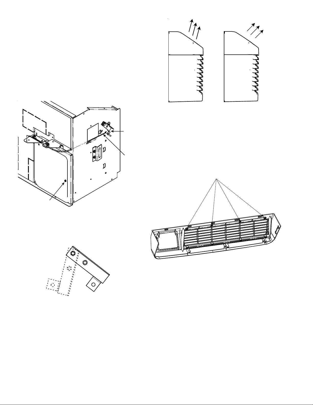
VENT CONTROL - FOR STANDARD PTAC MODELS ONLY
The vent control allows outside air to be drawn into the
conditioned area. This outside air can provide ventilation when
the blower is operating, but it will increase the heating or
cooling load and operating costs.
To obtain access to the vent control:
1. Remove the cabinet front (see Front Removal).
2. Remove the shipping screw (if installed) from the vent door.
3. Remove the label (if present) from over the vent control
lever on the left side of the chassis. Remove the vent door
shipping screw.
Vent
Control
Lever
Vent
Control
Vent Door
Shipping Screw
Vent Control Lever
For DigiAIR (Fresh Air Solution) kit models, refer to IO-900*.
4. Rotate the vent control lever to either open or close the
damper.
Vent
Closed
Vent
Open
Vent Door Lever Positions
Hydronic Heat Installations
To avoid the risk of freezing the steam or water coil during
prolonged shut down periods, the vent door must be left closed
when the outdoor temperature might fall below freezing.
AIR DISCHARGE GRILLE
The discharge grille can be adjusted to expel air at either a 16°
or 56° angle.
16°
Discharge
Air
56°
Discharge
Air
Discharge Grille Orientation Options
Use the following procedure to change the angle of the discharge
air flow:
1. Remove the front cabinet (see Front Removal).
2. Position the front so that the backside is accessible.
Discharge Air Flow
3. Remove the four (4) screws which secure the discharge air
grille to the cabinet front.
Location of 4 Screws
Discharge Air Flow Grille Removal
4. Rotate the grille 180° clockwise.
5. Reinstall the screws securing the discharge air grille to the
cabinet front. Reinstall the cabinet front on the unit.
REMOTE THERMOSTAT
To operate this unit with a “manufacturer-approved” remote
thermostat, configure the control to be operated by the remote
thermostat. Enter configuration mode C1 and then select option
Code L5 (see Configuration Settings in back of manual). When
in the remote mode, the unit will only respond to the thermostat
inputs (terminal strip positions GL (or GH), W2, Y/W1, and B*
shown in “Control Board User Inputs” illustration). NOTE: Once
configuration C1 with option code L5 has been selected, the
control touchpad will no longer accept inputs other than configu-
ration and diagnostics modes. The room occupant must operate
the unit at the remote mounted thermostat.
Loading ...
Loading ...
Loading ...