OWNER’S
MANUAL
Alhambra
7N5012720BE
Inglés
7N5012720BE (11.15)
Alhambra Inglés (11.15)
SEAT recommends
SEAT GENUINE OIL
SEAT recommends
Castrol EDGE Professional

SEAT S.A. is permanently concerned about continuous development of its types and models. For this reason we ask you to under-
stand, that at any given time, changes regarding shape, equipment and technique may take place on the car delivered. For this reason
no right at all may derive based on the data, drawings and descriptions in this current handbook.
All texts, illustrations and standards in this handbook are based on the status of information at the time of printing. Except for error
or omission, the information included in the current handbook is valid as of the date of closing print.
Re-printing, copying or translating, whether total or partial is not allowed unless SEAT allows it in written form.
SEAT reserves all rights in accordance with the “Copyright” Act.
All rights on changes are reserved.
❀
This paper has been manufactured using bleached non-chlorine cellulose.
© SEAT S.A. - Reprint: 15.11.15
About this manual
This manual contains a description of the
equipment supplied with the vehicle at the
time this manual was published. Some of the
units described herein will not be available
until a later date or are only available in cer-
tain markets.
Because this is a general manual for the
ALHAMBRA, some of the equipment and func-
tions that are described in this manual are not
included in all types or variants of the model;
they may vary or be modified depending on
the technical requirements and on the mar-
ket; this is in no way deceptive advertising.
The illustrations are intended as a general
guide and may vary from the equipment fitted
in your vehicle in some details.
The steering indications (left, right, forward,
reverse) appearing in this manual refer to the
normal driving movements of the vehicle ex-
cept when otherwise indicated.
The equipment marked with an aster-
isk* is fitted as standard only in certain
versions, and is only supplied as op-
tional extras for some versions, or are
only offered in certain countries.
® All registered marks are indicated with
®. Although the copyright symbol does
not appear, it is a copyrighted mark.
>> The section is continued on the follow-
ing page.
Important warnings on a given page
Detailed contents on a given page
General information on a given page
Emergency information on a given page
WARNING
Texts preceded by this symbol contain infor-
mation on safety. They warn you about possi-
ble dangers of accident or injury.
CAUTION
Texts with this symbol draw your attention to
potential sources of damage to your vehicle.
For the sake of the environment
Texts preceded by this symbol contain rele-
vant information concerning environmental
protection.
Note
Texts preceded by this symbol contain additio-
nal information.
This manual is divided into six large parts,
which are:
1. The essentials
2. Safety
3. Emergencies
4. Operation
5. Tips
6. Technical data
At the end of this manual, there is a detailed
alphabetical index that will help you quickly
find the information you require.

Foreword
Thi
s
In
struction Manual and its correspond-
ing supplements should be read carefully to
familiarise yourself with your vehicle.
Besides the regular care and maintenance of
the vehicle, its correct handling will help pre-
serve its value.
For safety reasons, always note the informa-
tion concerning accessories, modifications
and part replacements.
If selling the vehicle, give all of the on-board
documentation to the new owner, as it
should be kept with the vehicle.
You can access the information in this man-
ual using:
●
Thematic table of contents that follows the
manual’s general chapter structure.
●
Alphabetical index with many terms and
synonyms to help you find information.
WARNING
Read and always observe safety informa-
tion concernin
g the passenger's front air-
bag ››› page 75, Important information
regarding the front passenger's airbag.


Table of Contents
Table of Contents
The e
s
senti
als . . . . . . . . . . . . . . . . . . . . . . . . 5
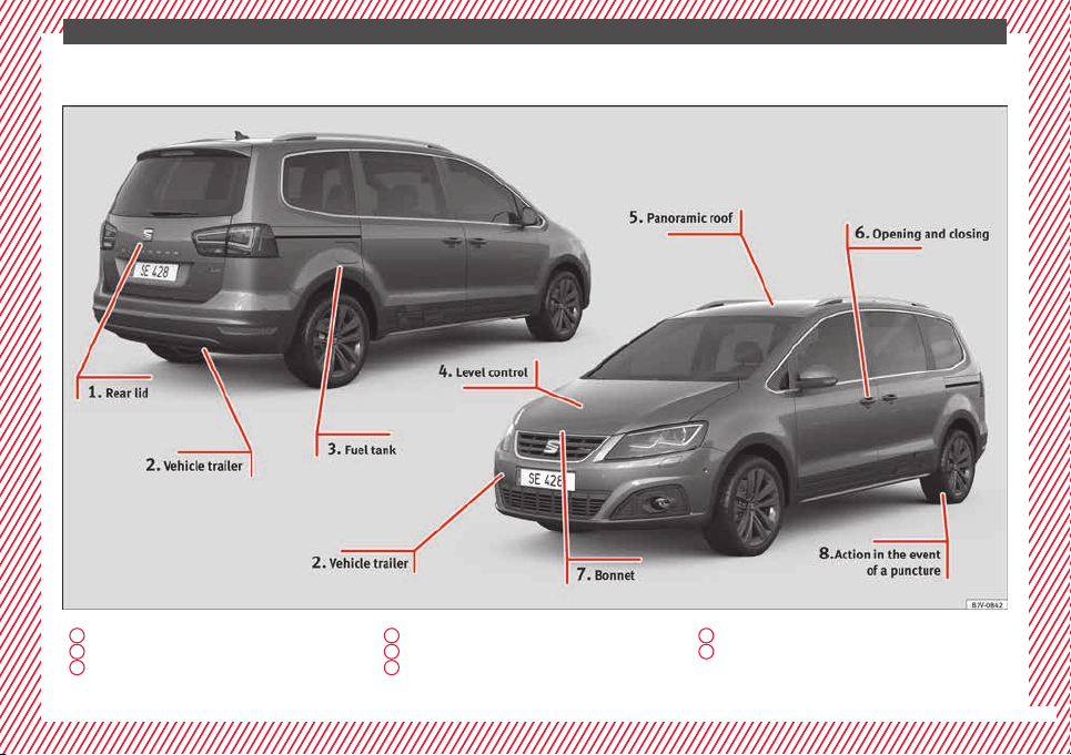
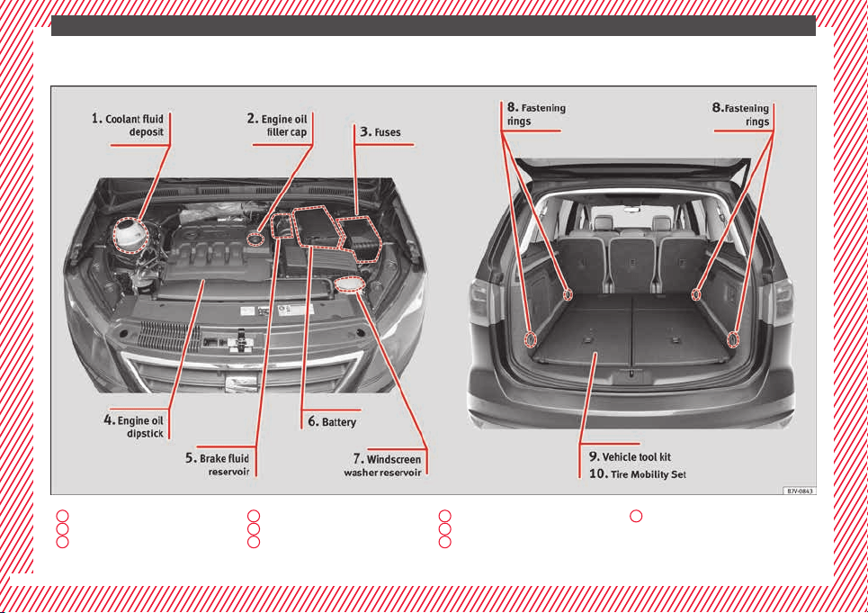
Exterior view . . . . . . . . . . . . . . . . . . . . . . . . . . . . 5
Exterior view . . . . . . . . . . . . . . . . . . . . . . . . . . . . 6
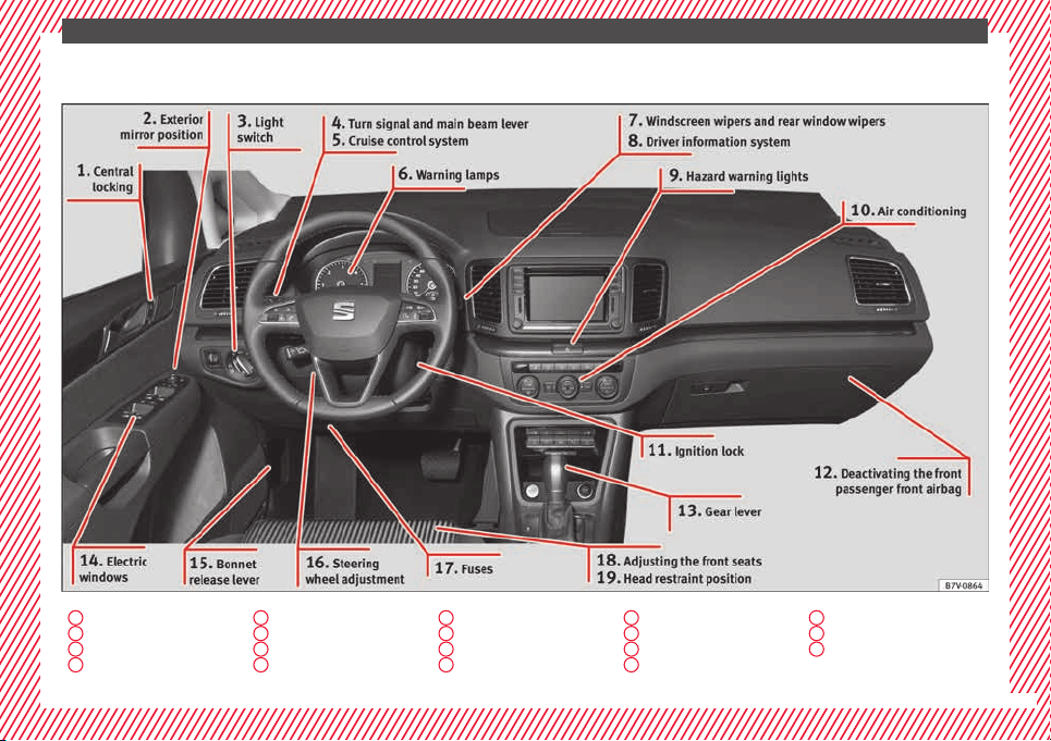
Interior view (left guide) . . . . . . . . . . . . . . . . . . 7
How it works . . . . . . . . . . . . . . . . . . . . . . . . . . . . 8
Unlocking and locking . . . . . . . . . . . . . . . . . . . . 8
Before driving . . . . . . . . . . . . . . . . . . . . . . . . . . . 13
Airbags . . . . . . . . . . . . . . . . . . . . . . . . . . . . . . . . 17
Child seats . . . . . . . . . . . . . . . . . . . . . . . . . . . . . 20
Starting the vehicle . . . . . . . . . . . . . . . . . . . . . . 23
Lights and visibility . . . . . . . . . . . . . . . . . . . . . . 24
SEAT information system . . . . . . . . . . . . . . . . . . 26
Cruise control . . . . . . . . . . . . . . . . . . . . . . . . . . . 32
Warning lamps . . . . . . . . . . . . . . . . . . . . . . . . . . 32
Gearbox lever . . . . . . . . . . . . . . . . . . . . . . . . . . . 34
Air conditioning . . . . . . . . . . . . . . . . . . . . . . . . . 36
Level control . . . . . . . . . . . . . . . . . . . . . . . . . . . . 39
Emergencies . . . . . . . . . . . . . . . . . . . . . . . . . . . . 42
Fuses . . . . . . . . . . . . . . . . . . . . . . . . . . . . . . . . . . 42
Bulbs . . . . . . . . . . . . . . . . . . . . . . . . . . . . . . . . . . 43
Action in the event of a puncture . . . . . . . . . . . 44
Changing a wheel . . . . . . . . . . . . . . . . . . . . . . . 45
Snow chains . . . . . . . . . . . . . . . . . . . . . . . . . . . . 49
Emergency towing of the vehicle . . . . . . . . . . . 50
How to jump start . . . . . . . . . . . . . . . . . . . . . . . . 51
Changing windscreen wipers . . . . . . . . . . . . . . 54
Safety . . . . . . . . . . . . . . . . . . . . . . . . . . . . . . . . 56
Safe driving . . . . . . . . . . . . . . . . . . . . . . . . . . . . 56
Safety first! . . . . . . . . . . . . . . . . . . . . . . . . . . . . . 56
Advice about driving . . . . . . . . . . . . . . . . . . . . . 56
Correct position of the vehicle occupants . . . . 57
Pedal area . . . . . . . . . . . . . . . . . . . . . . . . . . . . . . 60
Seat belts . . . . . . . . . . . . . . . . . . . . . . . . . . . . . . 61
Why wear a seat belt? . . . . . . . . . . . . . . . . . . . . 61
How to properly adjust your seatbelt . . . . . . . . 64
Seat belt tensioners . . . . . . . . . . . . . . . . . . . . . . 67
Airbag system . . . . . . . . . . . . . . . . . . . . . . . . . . 68
Brief introduction . . . . . . . . . . . . . . . . . . . . . . . . 68
Airbag safety instructions . . . . . . . . . . . . . . . . . 71
Deactivating airbags . . . . . . . . . . . . . . . . . . . . . 72
Transporting children safely . . . . . . . . . . . . . . . 74
Safety for children . . . . . . . . . . . . . . . . . . . . . . . 74
Child seats . . . . . . . . . . . . . . . . . . . . . . . . . . . . . 75
Integrated child seat . . . . . . . . . . . . . . . . . . . . . 78
Emergencies . . . . . . . . . . . . . . . . . . . . . . . . . . 82
Self-help . . . . . . . . . . . . . . . . . . . . . . . . . . . . . . . 82
In case of emergency . . . . . . . . . . . . . . . . . . . . . 82
Vehicle tool kit* . . . . . . . . . . . . . . . . . . . . . . . . . 82
Changing a wheel* . . . . . . . . . . . . . . . . . . . . . . . 84
Tyre repair . . . . . . . . . . . . . . . . . . . . . . . . . . . . . . 85
Changing the windscreen wiper blades . . . . . . 87
Tow-starting and towing . . . . . . . . . . . . . . . . . . 87
Emergency locking and unlocking . . . . . . . . . . 89
Fuses and bulbs . . . . . . . . . . . . . . . . . . . . . . . . . 90
Fuses . . . . . . . . . . . . . . . . . . . . . . . . . . . . . . . . . . 90
Changing bulbs . . . . . . . . . . . . . . . . . . . . . . . . . 91
Operation . . . . . . . . . . . . . . . . . . . . . . . . . . . . . 99
General instrument panel . . . . . . . . . . . . . . . . . 99
Instrument panel . . . . . . . . . . . . . . . . . . . . . . . . 98
Instruments . . . . . . . . . . . . . . . . . . . . . . . . . . . . 100
Control lamps . . . . . . . . . . . . . . . . . . . . . . . . . . . 105
Communications and multimedia . . . . . . . . . . . 106
Steering wheel controls* . . . . . . . . . . . . . . . . . . 106
Multimedia . . . . . . . . . . . . . . . . . . . . . . . . . . . . . 110
Three button unit in headliner . . . . . . . . . . . . . . 110
Opening and closing . . . . . . . . . . . . . . . . . . . . . 112
Vehicle key set . . . . . . . . . . . . . . . . . . . . . . . . . . 112
Central locking and locking system . . . . . . . . . 114
Doors . . . . . . . . . . . . . . . . . . . . . . . . . . . . . . . . . . 121
Sliding doors . . . . . . . . . . . . . . . . . . . . . . . . . . . 121
Rear lid . . . . . . . . . . . . . . . . . . . . . . . . . . . . . . . . 124
Electric windows . . . . . . . . . . . . . . . . . . . . . . . . . 127
Panoramic sliding sunroof* . . . . . . . . . . . . . . . . 128
Lights and visibility . . . . . . . . . . . . . . . . . . . . . . 130
Lights . . . . . . . . . . . . . . . . . . . . . . . . . . . . . . . . . 130
Visibility . . . . . . . . . . . . . . . . . . . . . . . . . . . . . . . 136
Windscreen wiper and window wiper sys-
tems . . . . . . . . . . . . . . . . . . . . . . . . . . . . . . . . . . 137
Rear vision mirror . . . . . . . . . . . . . . . . . . . . . . . . 139
Seats and head restraints . . . . . . . . . . . . . . . . . 142
Adjusting the seats and head restraints . . . . . . 142
Seat functions . . . . . . . . . . . . . . . . . . . . . . . . . . 146
Transport and practical equipment . . . . . . . . . 152
Transporting objects . . . . . . . . . . . . . . . . . . . . . 152
Luggage compartment . . . . . . . . . . . . . . . . . . . . 154
Roof carrier* . . . . . . . . . . . . . . . . . . . . . . . . . . . . 164
Storage compartments . . . . . . . . . . . . . . . . . . . 166
Drink holders . . . . . . . . . . . . . . . . . . . . . . . . . . . 171
Ashtray and cigarette lighter* . . . . . . . . . . . . . . 172
Power sockets . . . . . . . . . . . . . . . . . . . . . . . . . . . 173
Air conditioning . . . . . . . . . . . . . . . . . . . . . . . . . 176
Air conditioning . . . . . . . . . . . . . . . . . . . . . . . . . 176
Auxiliary heater* (additional heater) . . . . . . . . 180
Driving . . . . . . . . . . . . . . . . . . . . . . . . . . . . . . . . 183
Address . . . . . . . . . . . . . . . . . . . . . . . . . . . . . . . . 183
Stopping and starting the engine . . . . . . . . . . . 185
Braking and parking . . . . . . . . . . . . . . . . . . . . . 189
Gearbox . . . . . . . . . . . . . . . . . . . . . . . . . . . . . . . . 194
Run-in and economical driving . . . . . . . . . . . . . 199
Engine management and exhaust gas purifica-
tion system . . . . . . . . . . . . . . . . . . . . . . . . . . . . . 202
Driving abroad . . . . . . . . . . . . . . . . . . . . . . . . . . 204
Driving along flooded roadways . . . . . . . . . . . . 204
Driver assistance systems . . . . . . . . . . . . . . . . . 205
Braking and stability systems . . . . . . . . . . . . . . 205
Start assist systems . . . . . . . . . . . . . . . . . . . . . . 208
3

Table of Contents
Parking distance warning system* . . . . . . . . . . 211
Park Assist system* (Park Assist) . . . . . . . . . . . 214
Rear assist* (Rear View Camera) . . . . . . . . . . . . 217
Cruise control* (Cruise control system -
C
C
S)
. . . . . . . . . . . . . . . . . . . . . . . . . . . . . . . . . . . 221
Lane Assist system* . . . . . . . . . . . . . . . . . . . . . . 222
Blind spot detector (BSD) with parking assis-
tant (RTA) . . . . . . . . . . . . . . . . . . . . . . . . . . . . . . 225
Traffic signal detection (Sign Assist)* . . . . . . . . 230
Tiredness detection (recommendation to take
a break) . . . . . . . . . . . . . . . . . . . . . . . . . . . . . . . . 232
Dynamic Chassis control (DCC)* . . . . . . . . . . . . 233
Tyre monitoring systems . . . . . . . . . . . . . . . . . . 234
Towing bracket device . . . . . . . . . . . . . . . . . . . . 237
Driving with a trailer . . . . . . . . . . . . . . . . . . . . . . 237
Advice . . . . . . . . . . . . . . . . . . . . . . . . . . . . . . . . 247
Care and maintenance . . . . . . . . . . . . . . . . . . . . 247
Accessories, replacement of parts and modifi-
cations . . . . . . . . . . . . . . . . . . . . . . . . . . . . . . . . 247
Caring for and cleaning the vehicle interior . . . 253
Caring for and cleaning the vehicle interior . . . 258
Notes for the user . . . . . . . . . . . . . . . . . . . . . . . . 263
Checking and refilling levels . . . . . . . . . . . . . . . 264
Filling the tank . . . . . . . . . . . . . . . . . . . . . . . . . . 264
Fuel . . . . . . . . . . . . . . . . . . . . . . . . . . . . . . . . . . . 267
Selective catalytic reduction* (AdBlue) . . . . . . 270
Working in the engine compartment . . . . . . . . 272
Engine oil . . . . . . . . . . . . . . . . . . . . . . . . . . . . . . 276
Engine coolant . . . . . . . . . . . . . . . . . . . . . . . . . . 279
Brake fluid . . . . . . . . . . . . . . . . . . . . . . . . . . . . . 282
Windscreen washer reservoir . . . . . . . . . . . . . . 284
Vehicle battery . . . . . . . . . . . . . . . . . . . . . . . . . . 284
Wheels and tyres . . . . . . . . . . . . . . . . . . . . . . . . 288
Tyres . . . . . . . . . . . . . . . . . . . . . . . . . . . . . . . . . . 288
Winter service . . . . . . . . . . . . . . . . . . . . . . . . . . . 296
Technical data . . . . . . . . . . . . . . . . . . . . . . . . 298
Technical features . . . . . . . . . . . . . . . . . . . . . . . 298
Important information . . . . . . . . . . . . . . . . . . . . 298
Towing a trailer . . . . . . . . . . . . . . . . . . . . . . . . . . 300
Wheels . . . . . . . . . . . . . . . . . . . . . . . . . . . . . . . . 300
Engine data . . . . . . . . . . . . . . . . . . . . . . . . . . . . . 301
Dimensions . . . . . . . . . . . . . . . . . . . . . . . . . . . . . 306
Index . . . . . . . . . . . . . . . . . . . . . . . . . . . . . . . . . 307
4
The essentials
How it works
Un
loc
k
ing and locking
Doors
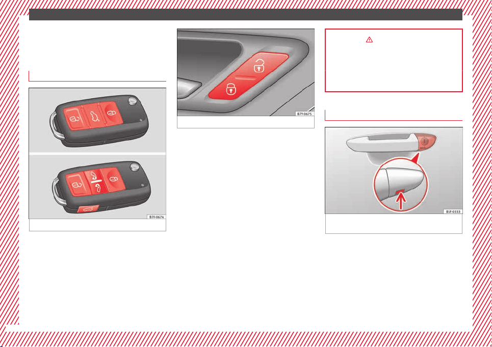
Fig. 1 Remote control key: buttons.
Fig. 2 See position on page 7
Locking and unlocking the vehicle using the
k
ey
●
L
oc
king: press the ››› Fig. 1 button.
●
Locking the vehicle without activating the
anti-theft system: Press the ››› Fig. 1 button
for a second time for the next 2 seconds.
●
Unlocking: press the ››› Fig. 1 button.
●
Unlocking the rear lid: Hold down the
››› Fig. 1 button for at least 1 second.
Locking and unlocking with the central lock-
ing switch
●
Locking: press the ››› Fig. 2 button. None
of the doors can be opened from the outside.
The doors can be opened from the inside by
pulling the inside door handle.
●
Unlocking: press the ››› Fig. 2 button.
››› in Introduction on page 114
››› page 112
››› page 8, ››› page 9
Locking or unlocking of driver door
Fig. 3 Driver door handle: Hidden lock cylin-
der
As a general rule, when the driver door is
loc
k
ed al
l other doors are locked. Unlocking
manually only opens the driver door. Please
note the instructions for the anti-theft alarm
›››
page 114.
●
Unfold the key shaft
›››
page 112.
●
Insert the key shaft into the lower opening
in the cover on the driver door handle from
8

The essentials
below ›
›› Fig. 3
(arr
ow) then remove the cover
upwards.
●
Insert the key shaft into the lock cylinder to
unlock or lock the vehicle.
Special Characteristics
●
The anti-theft alarm will remain active when
vehicles are unlocked. However, it is not trig-
gered ›››
page 114.
●
If the driver door is opened, the alarm will
be triggered.
●
Switch the ignition on. The electronic im-
mobilizer recognises a valid vehicle key and
deactivates the anti-theft alarm system.
››› in Introduction on page 90
Note
The anti-theft alarm is not activated when the
vehicl
e is locked manually using the key
shaft ›››
page 114.
Locking the passenger side door and
s
lidin
g door
s manually
Fig. 4 At the front of the passenger sliding
door: Emer
g
ency
lock, hidden by a rubber
cap.
Fig. 5 Emergency locking of the vehicle using
the
v
ehic
le key
The passenger side door and the sliding
door
s
c
an be locked manually. The anti-theft
alarm is not activated in this case.
●
Open the door.
●
Remove the rubber cap to the front of the
door. The rubber cap is marked with a lock
symbol ››› Fig. 4.
●
Unfold the vehicle key shaft
›››
page 112.
●
Insert the key shaft horizontally into the
opening and moved the coloured lever for-
ward ››› Fig. 5.
●
Replace the rubber cap and close the door.
●
Check if the door is locked.
●
Carry out the same operation on the other
doors if necessary.
●
Have the vehicle checked by a specialised
workshop.
››› in Introduction on page 90
Note
The doors can be opened and unlocked indi-
vidual
ly from the inside by pulling the inside
door handle. To open, pull the inner door re-
lease lever twice ›››
page 114.
9
The essentials
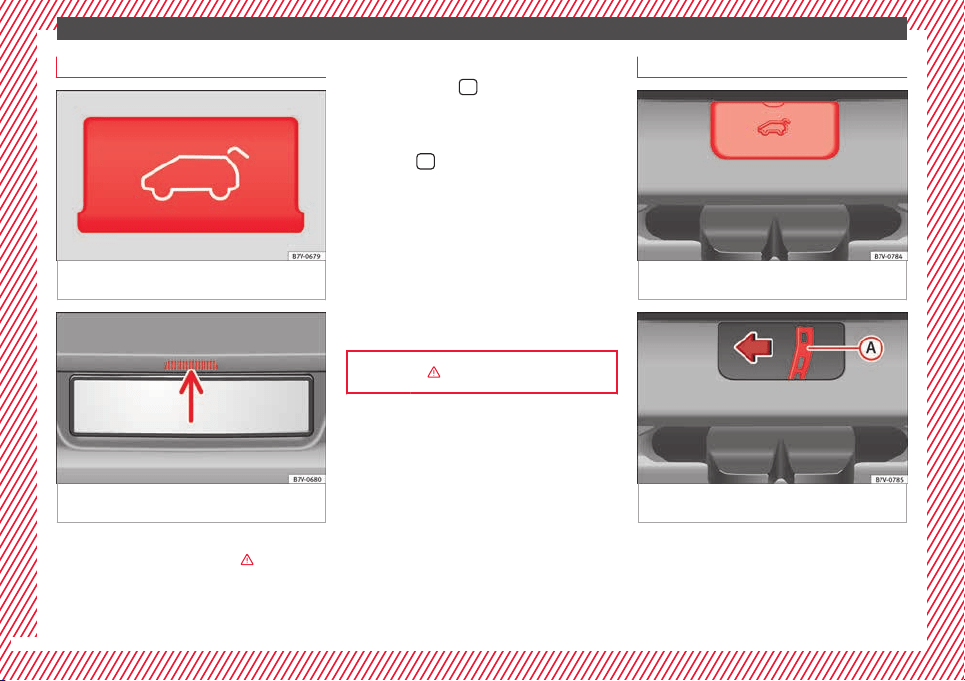
Opening the rear door
Fig. 6 Detailed view of the centre console:
b
utt
on f
or unlocking the rear lid
Fig. 7 Opening the boot hatch from the out-
s
ide
Before opening the rear lid, always remove
an
y
lo
ad on its luggage rack ›››
in Introduc-
tion on p
ag
e 124
.
Opening with the ignition key
●
Press the button
on the vehicle key un-
ti
l
the r
ear lid opens automatically.
To open using the centre console control
●
Press the
button on the centre console
›
›
›
Fig. 6. The rear lid will be automatically
opened.
●
The button is still operative when the igni-
tion is switched off.
Opening the rear lid with the button
●
Unlock the vehicle or open a door.
●
Raise the rear lid using the button ››› Fig. 7
(arrow).
››› in Introduction on page 124
Emergency unlocking the boot hatch
Fig. 8 From the luggage compartment: re-
mo
v
e the boot
hatch cover.
Fig. 9 From the luggage compartment: Emer-
g
ency
u
nlocking of the booth hatch.
●
Remove equipment to access the inside of
the r
e
ar lid.
●
R
emove the square cover in the inner trim
of the rear lid ››› Fig. 8.
10
The essentials
●
P
u
sh the r
elease lever ››› Fig. 9
A
in the di-
r
ection of
the arr
ow to unlock the boot.
●
Manually open the rear lid.
››› in Introduction on page 90
Bonnet
Fig. 10 See position on page 7
Fig. 11 Cam under the bonnet
●
Openin
g the bonnet: P
u
ll the lever under
the dashboard ››› Fig. 10
1
.
●
Lift up the bonnet. Press the release catch
u
nder the bonnet
up
wards ››› Fig. 11. The ar-
rester hook under the bonnet is released.
●
The bonnet can be opened. Release the
bonnet stay and secure it in the fixture de-
signed for this in the bonnet.
››› in Opening and closing the bonnet
on page 275
››› page 272
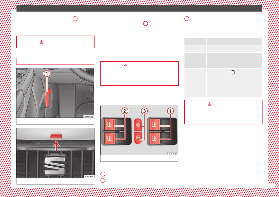
Electric windows*
Fig. 12 See position on page 7
Buttons on the driver door
F
or the fr
ont
electric windows.
For the sliding door electric windows.
1
2
To lock the sliding doors and their win-
do
w
s.
Openin
g and closing the windows
Opening: Push the button
.
Closing: Pull the
button.
To stop the
one touch
function:
Press or pull on the corresponding win-
dow button.
Press the button
for the electronic
child safety lock to deactivate the con-
trols for the electric windows on the
sliding doors and to lock these doors
››› page 121. The indicator on the but-
ton will light up.
››› in Electric windows: functions on
page 127
››› page 127
3
11
The essentials
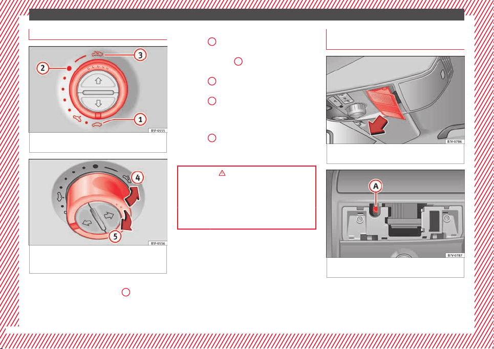
Panoramic sunroof*
Fig. 13 On the interior roof lining: use the ro-
t
ar
y
button for opening and closing
Fig. 14 On the interior roof lining: press the
b
utt
on and p
ull on it to raise and lower the
sunroof.
To open the panoramic sliding sunroof, the
sw
it
c
h must be in the position
1
.
●
Openin
g:
T
urn the switch to position
››› Fig. 13
3
.
●
Convenience position: Turn the switch to
po
s
ition ›
›› Fig. 13
2
.
●
Closing: Turn the switch to position
›
›
›
Fig. 13
1
.
●
To tilt open: Push the switch to position
›
›
›
Fig. 14
4
. For an intermediate position,
ho
l
d do
wn the switch until you reach the de-
sired position.
●
Lowering: Pull the switch to position
››› Fig. 14
5
. For an intermediate position,
ho
l
d do
wn the switch until you reach the de-
sired position.
››› in Panoramic sliding sunroof: oper-
ating on page 128
››› page 128
››› page 12
Manually closing the panoramic sun-
r
oof
Fig. 15 On the interior roof lining: remove
c
o
v
er.
Fig. 16 Allen bolt to close the panoramic slid-
in
g s
u
nroof
●
Push open the cover in the direction indica-
t
ed (arr
o
w) ››› Fig. 15.
12
The essentials
●
In
ser
t
a standard 4 mm Allen key
1)
into the
Allen bolt ››› Fig. 16
A
.
●
Rotate the Allen bolt to close the panoram-
ic
s
lidin
g sunroof.
●
Re-install the lining.
●
Bring the vehicle to a specialised workshop
to check the panoramic sliding sunroof given
that the emergency closing operation could
damage general operation or the anti-trap
function of the panoramic sliding sunroof.
››› in Introduction on page 90
Before driving
M
anua
l
ly adjusting the front seat
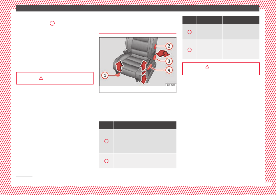
Fig. 17 Front left seat controls
The controls are mirrored for the front right-
h
and se
at
.
Mechanically and electrically adjusted con-
trols can be combined on the seat.
Fig. 17 Function Necessary operations
1
Moving the
head restraint
backwards or
forwards.
Pull the lever and move
the seat forwards. The
front seat must be engag-
ed when the lever is re-
leased!
2
Adjusting the
lumbar sup-
port*.
Turn the lever.
Fig. 17 Function Necessary operations
3
Adjusting the
seat backrest
angle.
Turn the wheel.
4
Adjusting the
seat height.
Pull the lever up or push
down (several times if
necessary) from its home
position.
››› in Manual adjustment of seats on
page 142
1)
Not included with the vehicle tool kit.
13
The essentials
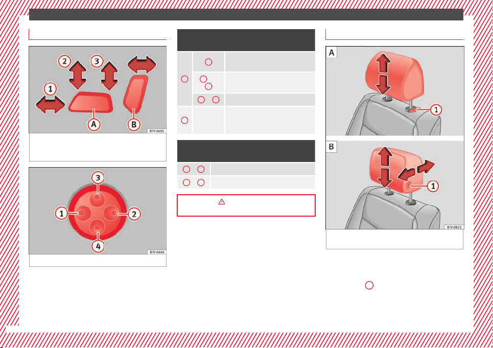
Electrical controls on the front seat*
Fig. 18 Adjusting the front left seat forwards
or b
ac
k
wards, the height, the seat angle and
the front seat backrest
Fig. 19 Adjusting the lumbar support
The controls are mirrored for the front right-
h
and se
at
.
Mechanically and electrically adjusted con-
trols can be combined on the seat.
Fig. 18 Press the control in the direction of the
arrow:
A
1
Move the seat backwards or for-
wards.
2
and
3
Raise or lower the seat.
2
or
3
Adjust the seat angle.
B
Forwards
or back-
wards.
Adjust the seat backrest angle.
Fig. 19 Press the corresponding area of the
switch:
1
or
2
Adjust the curve of the lumbar support.
3
or
4
Adjust the height of the lumbar support.
››› in Electric driver seat adjustment*
on page 143
Adjustment of the head restraint
Fig. 20 Front seat: adjustment of the head re-
s
tr
aint
.
Grab the sides of the head restraints with
both h
and
s
and push upwards to the desired
position. To lower it, repeat the same action,
pressing the
1
button on the side.
14
The essentials
››› in Removing and installing the head
restraints on page 146
››› page 57, ››› page 144
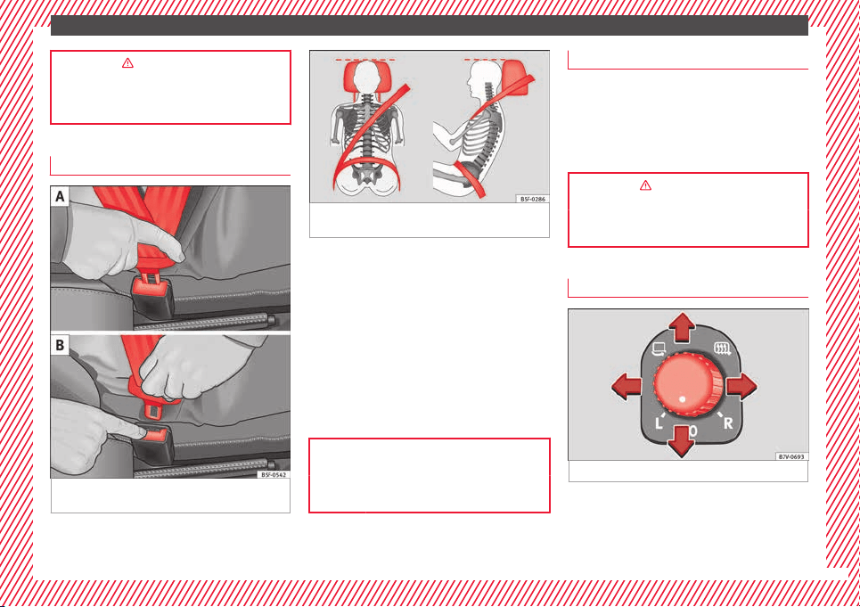
Adjustment of the seat belt
Fig. 21 Positioning and removing the seat
belt
b
uc
kle.
Fig. 22 Correct seat belt and head restraint
position
s, viewed from front and the side.
To adjust the seat belt around your should-
er
s, a
dju
st the height of the seats or the
height of the belt.
The shoulder part of the seat belt should be
well centred over it, never over the neck. The
seat belt lies flat and fits comfortably on the
upper part of the body.
The lap part of the seat belt lies across the
pelvis, never across the stomach. The seat
belt lies flat and fits comfortably on the pel-
vis.
››› page 61
››› page 64
Seat belt tensioners
In the event of a head-on, lateral or rear colli-
sion, the seat
belts on the front seats and the
outer seats of the second row will tighten au-
tomatically.
The tensioner can be triggered only once.
››› in Service and disposal of belt ten-
sion devices on page 68
››› page 67
Adjusting the exterior mirrors
Fig. 23 See position on page 7
Adjusting the exterior mirrors: Turn the knob
t
o the c
orr
esponding position:
Turning the knob to the desired posi-
tion, adjust the mirrors on the driver
»
L/R
15
The essentials
side (L, left) and the passenger side (R,
right) t
o the dir
ection de
sired.
Depending on the equipment fitted on
the vehicle, the mirrors may be heated
according to the outside temperature.
Folding in mirrors.
››› in Exterior mirrors on page 141
››› page 141
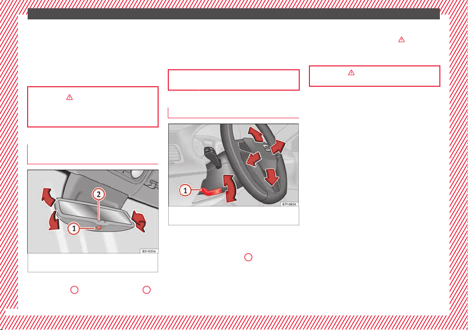
Adjusting the rear view mirror (auto-
m
atic
anti-d
azzle function)*
Fig. 24 Automatic anti-dazzle interior rear vi-
s
ion mirr
or
.
Switching on the automatic anti-dazzle func-
tion: pr
e
s
s the
1
›
›
› Fig. 24
button. The
2
warning lamp lights up and, in bright light,
the r
e
ar
view mirror darkens.
To adjust the mirror, turn it in the direction of
the arrows.
››› page 140
Adjusting the steering wheel
Fig. 25 Mechanical steering wheel adjust-
ment
Adjust the steering wheel before your trip
and on
ly
when the
vehicle is stationary.
●
Push the lever
›››
Fig. 25
1
downwards.
●
Adjust the steering wheel so that you can
ho
l
d ont
o the steering wheel with both hands
on the outside of the ring at the 9 o'clock and
3 o'clock positions and your arms slightly
bent.
●
Push the lever firmly upwards until it is
flush to the steering column ›››
in Adjust-
in
g the s
t
eering wheel position on
page 58.
››› in Adjusting the steering wheel po-
sition on page 58
16
The essentials
Airbags
Fr
ont
Airb
ags
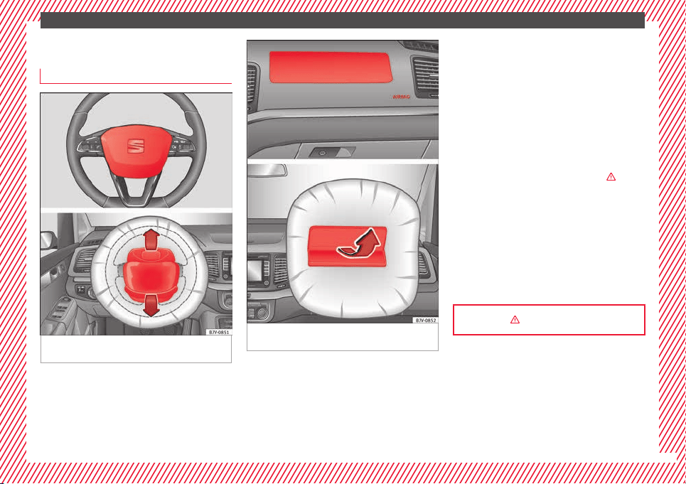
Fig. 26 Location and deployment area of the
fr
ont
airb
ag for the driver
Fig. 27 Location and deployment area of the
fr
ont
airb
ag for the front passenger
In conjunction with the seat belts, the front
airb
ag sy
s
tem gives the driver and the front
passenger additional protection for the head
and chest in the event of a severe frontal col-
lision. Always remains as far away as possi-
ble from the front airbag. This way, in the
event of an accident, the front airbags can
deploy fully when triggered, providing maxi-
mum protection.
The front airbag for the driver is located in
the steering wheel ››› Fig. 26 and the airbag
for the front passenger is located in the dash
panel ››› Fig. 27. Airbags are identified by the
word “AIRBAG”.
When the front airbags are triggered they fill
the zones marked in red (deployment area)
››› Fig. 26. Therefore, objects should never be
placed or mounted in these areas ›››
in
Fr
ont
airb
ags on page 71, Factory-fitted ac-
cessories are outside the range of the front
airbag for the driver and the front passenger,
e.g. the baseplate for the mobile phone sup-
port.
The airbag covers open out of the steering
wheel or dash panel and remain attached to
them when the driver and front passenger
front airbags are triggered ››› Fig. 27.
››› in Front airbags on page 71
17
The essentials
Disconnecting the passenger front air-
b
ag
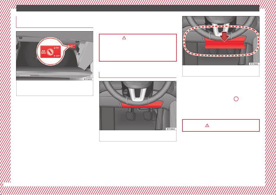
Fig. 28 In the glove compartment on the front
p
a
s
senger side: Key switch for enabling and
disabling the front passenger front airbag.
Disabling the front passenger front airbag
●
Switch the ignition off.
●
Open the glove compartment on the front
p
a
s
senger side.
●
Unfold the vehicle key shaft
›››
page 112.
●
Insert the key into the slot of the switch for
deactivating the front passenger airbag
››› Fig. 28. About 3/4 of the key should enter,
as far as it will go.
●
Then turn the key gently to the OFF posi-
tion. Do not force it if you feel resistance, and
make sure you have inserted the key fully.
●
Close the glove compartment on the front
passenger side.
●
The control lamp on
the dash panel will remain lit while the igni-
tion is switched on ›››
page 72.
››› in Manual disabling and enabling of
the front passenger front airbag with the
key switch on page 73
››› page 73
Knee airbag
Fig. 29 On the driver side: location of the
knee airb
ag
Fig. 30 On the driver side: radius of action of
the knee airbag.
The knee airbag is located on the driver side
belo
w the d
a
sh panel ››› Fig. 29. Airbags are
identified by the word “AIRBAG”.
The area framed red ››› Fig. 30
A
is covered
b
y
the knee airb
ag when it is triggered (de-
ployment area). Therefore, objects should
never be placed or mounted in these areas.
››› in Knee airbag* on page 71
18
The essentials
Side airbags
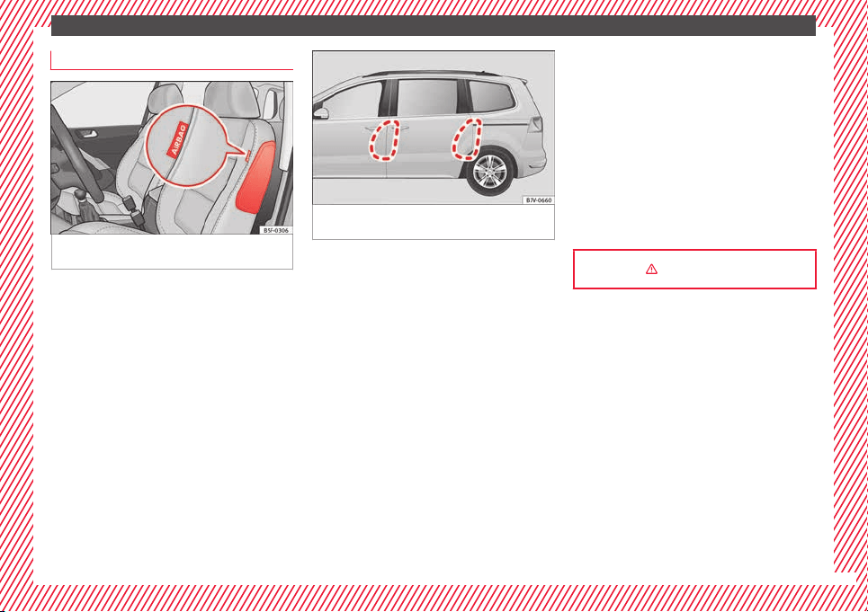
Fig. 31 On the side of the front seat: location
of
the s
ide airb
ag
Fig. 32 Range of action of the front and rear
side airbag
s. With 5 and 7 seats.
The side airbags are located in the outer
c
u
shion of
the driver and front passenger
seat backrests ››› Fig. 31. Depending on the
equipment of the model, the outer seats of
the second row of seats may also be fitted
with side airbags, located between the seat
backrests and the access area. Their position
is indicated by the word “AIRBAG”. The red
area (dotted line) ››› Fig. 32 shows the field of
action of the side airbags.
In a side collision, the side airbags are trig-
gered on the affected side of the vehicle,
thus reducing the risk of injury to passengers
on that side.
››› in Side airbags* on page 71
19
The essentials
Head-protection airbags
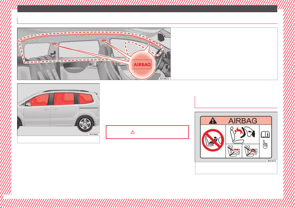
Fig. 33 On the left side of the vehicle: location and deploy-
ment are
a of the curtain airbag
Fig. 34 Deployed head-protection airbags.
The curtain airbags are located on the driver
and fr
ont
p
assenger side above the doors
››› Fig. 33. Airbags are identified by the word
“AIRBAG”.
The area framed red ››› Fig. 33 is covered by
the curtain airbag when it is deployed (de-
ployment area). Therefore, objects should
never be placed or mounted in these areas.
In a side collision, the curtain airbag on the
side affected will be deployed. The airbag
covers the windows and pillars.
In a side collision, the head-protection air-
bags for the front and outer rear seats reduce
the risk of injury to the areas of the body fac-
ing the impact.
››› in Curtain airbags* on page 72
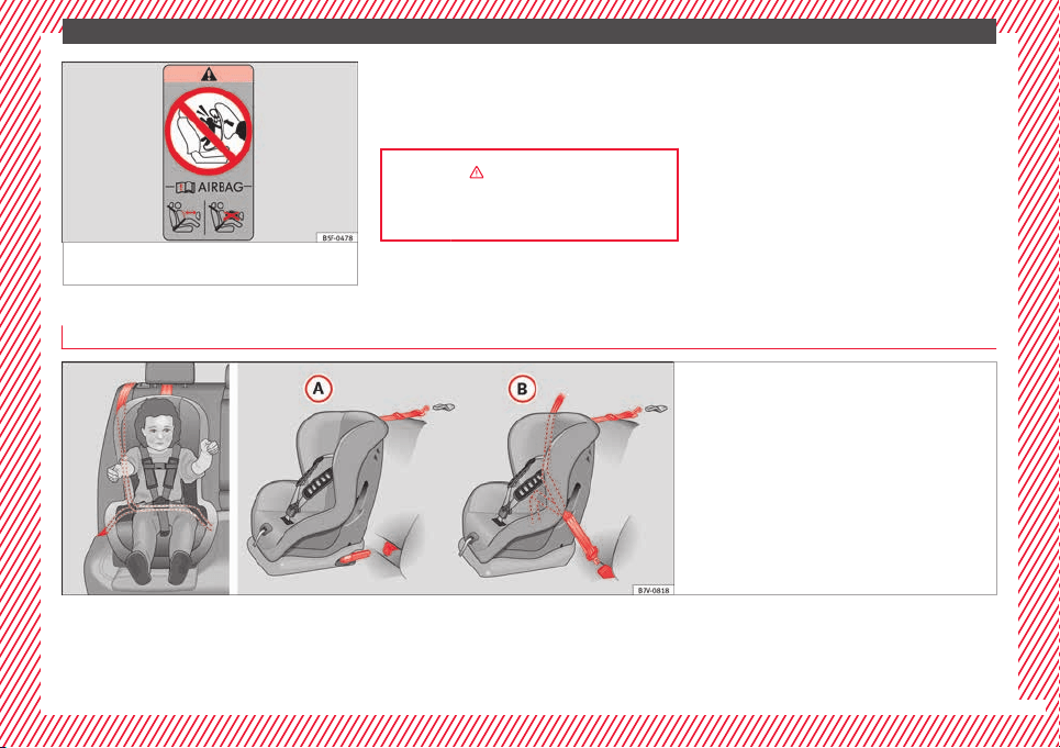
Child seats
Impor
t
ant
information regarding the
front passenger's airbag
Fig. 35 Passenger's side sun visor: airbag
s
tic
k
er.
20
The essentials
Fig. 36 On the rear frame of the passenger
side door: airbag s
ticker.
A sticker with important information about
the p
a
s
senger airbag is located on the pas-
senger's sun visor and/or on the passenger
side door frame.
››› in Introduction on page 74
››› page 75
Different mounting systems
Fig. 37 On the rear seats: Possible installations
for the chi
ld seat.
Always secure child seats properly and safely
in the
v
ehic
le according to the child seat
manufacturer's installation instructions.
Mounted child seats must rest correctly on
the vehicle's seat and must not move or rock
more than 2.5 cm (1 inch).
Child seats equipped for a Top Tether strap
must also be secured using the Top Tether re-
taining strap in the vehicle ››› page 23. Only
secure the retaining belt to the rings fitted for
this purpose and identified as Top Tether.
»
21
The essentials
Not all rings can be used with the Top Tether
sy
s
t
em. Always tighten the Top Tether retain-
ing strap so that the child seat fits snugly
against the corresponding seat in the vehi-
cle.
Specific mounting systems for each country
Europe: ISOFIX retaining rings and upper
retaining strap ››› page 22 and
››› page 23.
Three-point seat belt and upper retaining
strap ››› page 22.
The systems include the child restraint sys-
tem mounting with an upper retaining strap
(Top Tether) and lower anchoring points on
the seat.
Securing child seats with the seat belt
Securing the child seat using the seat belt
●
Please read and observe the child seat
m
anuf
act
urer's handling instructions.
●
Positioning the child seat on the seat ac-
cording to the manufacturer's instructions.
●
The seat belt height adjustment must be as
high as possible.
●
Fasten the seat belt or pass it around the
child seat structure in the manner described
in the manufacturer's instructions.
●
Make sure the seat belt is not twisted.
A
B
●
In
ser
t
the latch plate into the buckle for the
appropriate seat and push it down until it is
securely locked with an audible click.
●
Ensure that the upper belt web lies tightly
on the child seat.
●
Pull the belt (it must be no longer possible
to pull the lower belt webbing out).
Removing the child seat
The seat belt must not be unfastened until
the vehicle has come to a standstill.
●
Press the red button on the buckle. The
latch plate is released from the buckle.
●
Guide the belt back by hand so that it rolls
up easily and the trim will not be damaged.
●
Remove the child seat from the vehicle.
››› in Safety instructions on page 75
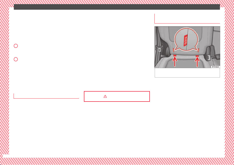
Fix the child seat with the lower an-
c
hor point
s
(ISOFIX)ISOFIX system
Fig. 38 Version 2: identification of the anchor
points
f
or the c
hild seat on the vehicle seat
There are tw
o
r
etaining rings, the so-called
lower anchor points, on each rear seat or,
where applicable, on the front passenger
seat. The retaining rings are attached to the
seat frames.
Child seats with rigid mounting
●
Observe the manufacturer's instructions
when installing and removing the child seat.
●
Press the child seat onto the retaining rings
››› Fig. 38 in the direction of the arrow. The
child seat must be safely engaged and click
audibly into place.
●
Pull on both sides of the child seat to en-
sure that it is secure.
22
The essentials
Child seat with adjustable retaining straps
●
Observe the manufacturer's instructions
when in
s
t
alling and removing the child seat.
●
Place the child seat on the seat cushion
and attach the retaining strap hooks to the
retaining rings ››› Fig. 38.
●
Tighten the straps evenly using the corre-
sponding adjustment device. The child seat
must sit flush against the vehicle seat.
●
Pull on both sides of the child seat to en-
sure that it is secure.
››› in Safety instructions on page 75
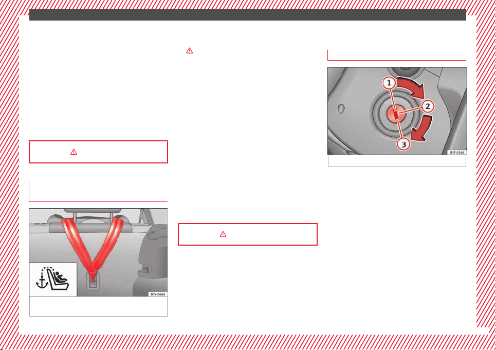
Securing a child seat using a Top Teth-
er r
et
ainin
g strap
Fig. 39 Upper retaining strap hooked in the
lug
g
ag
e compartment
●
O
b
ser
ve the manufacturer's instructions
when installing and removing the child seat
›››
in Safety instructions on page 75.
●
Raise the head restraint behind the child
se
at
u
ntil it engages.
●
Secure the child seat to the lower anchor
points ››› page 22.
●
Pull the upper child seat retaining strap
back to the seat backrest of the rear seat, be-
low or on both sides of the head restraint
(depending on the child seat model).
●
Hook the upper retaining strap to the corre-
sponding retaining ring (for Top Tether) on
the back of the seat backrest on the rear seat
››› Fig. 39.
●
Push the head restraint down as far as it
will go. Ensure that it does not interfere with
the seatbelt from the upper attachment.
●
Tighten the strap so that the top of the
child seat rests on the seat backrest.
››› in Safety instructions on page 75
Starting the vehicle
Ignition loc
k
Fig. 40 See position on page 7
Switch ignition on: Place the key in the igni-
tion and s
t
ar
t the engine.
Locking and unlocking the steering wheel
●
Engaging the steering wheel lock: Remove
the key from the ignition and turn the wheel
until it locks. In vehicles with an automatic
gearbox, the gear lever must be in the P posi-
tion in order to remove the key. If necessary,
press the locking key on the selector lever
and release it again.
●
Unlocking the steering wheel: Put the key
into the ignition and turn it at the same time
as the steering wheel in the direction indica-
ted by the arrow. If it is not possible to turn
the steering wheel, it may be because it is
locked.
»
23
The essentials
Turning on/switching off the ignition, glow
p
lug
s
reheating
●
Switch ignition on: Turn the key to the
2
position.
●
Switch ignition off. Turn the key to the
1
position.
●
Diesel vehicles :
The glo
w p
lugs reheat
when the ignition is switched on
Starting the engine
●
Manual gearbox: press the clutch pedal all
the way down and move the gearbox lever in-
to neutral.
●
Automatic gearbox: Press the brake pedal
and move the selector lever to the P position
or into N.
●
Turn the key to the
3
position. The key au-
t
om
atic
ally returns to the
2
position. Do not
pr
e
s
s the accelerator.
Start-Stop System*
When you stop and release the clutch pedal,
the Start-Stop system* turns off the engine.
The ignition remains switched on.
››› in Ignition lock on page 186
››› page 185
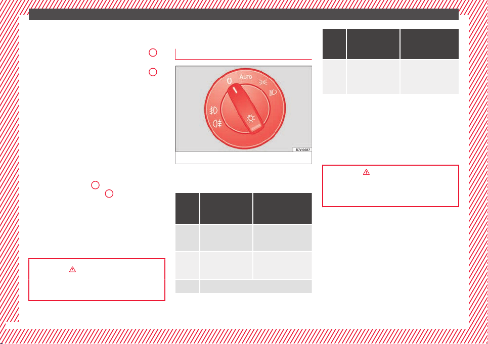
Lights and visibility
Light
sw
it
ch
Fig. 41 See position on page 7
Turn the switch to the required position
›
›
›
Fig. 41.
When the igni-
tion is switched
off
When the ignition
is on
Fog lights, dipped
beam and side
lights off.
Lights off or daytime
driving light on.
The guidance lights
may be switched
on.
Automatic dipped
beam control or day-
time driving light on.
Side light on.
When the igni-
tion is switched
off
When the ignition
is on
Dipped beam off; if
necessary, the side
light comes on for a
time.
Dipped beam switch-
ed on.
Front fog lights: mov
e the switch to the
first position, from positions , or .
Rear fog light: move the switch completely
from positions , or .
Switching off fog lights: Push the switch or
turn it to the position.
››› in Switching lights on and off on
page 131
››› page 130
24
The essentials
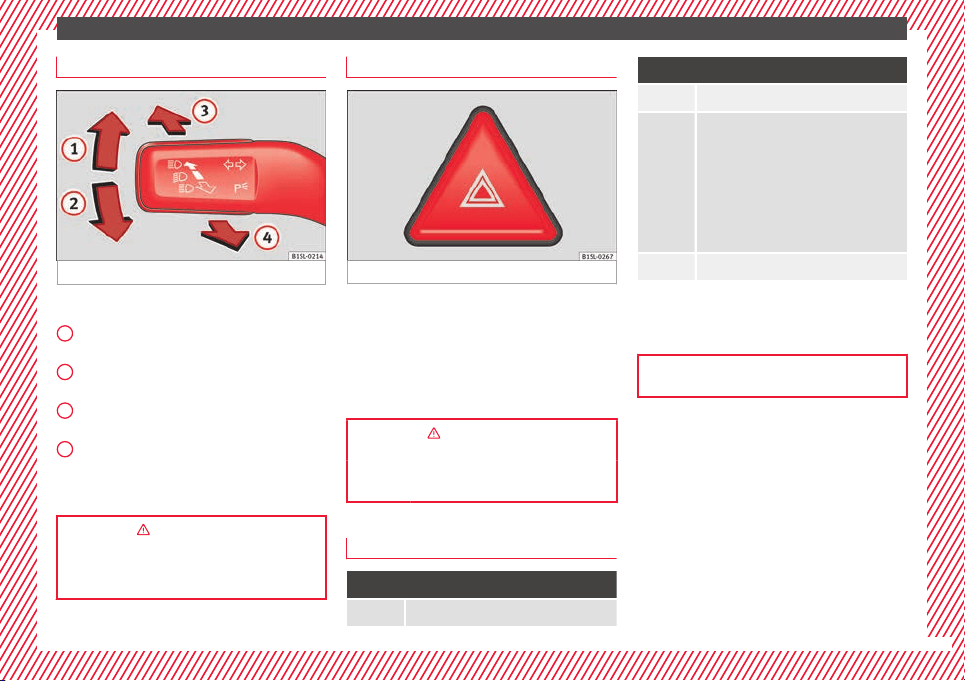
Turn signal and main beam lever
Fig. 42 See position on page 7
More the lever to the required position:
Right
t
urn s
ignal: Right-hand parking
light (ignition switched off).
Left turn signal: Left-hand parking light
(ignition switched off).
Main beam switched on: Control lamp
lit up on the instrument panel.
Headlight flasher: lit up when the lever is
pushed. Control lamp lit up.
Lever all the way down to switch it off.
››› in Switching lights on and off on
page 131
››› page 131
1
2
3
4
Hazard warning lights
Fig. 43 See position on page 7
Switched on, for example:
●
When approaching a traffic jam
●
In an emergency
●
The vehicle has broken down
●
When towing or being towed
››› in Hazard warning lights on
page 134
››› page 134
Interior lights
Button/Position: Function
Switches interior lights off.
Button/Position: Function
Switches interior lights on.
Switches door contact control on (central
position).
The interior lights come on automatically
when the vehicle is unlocked, a door is
opened or the key is removed from the igni-
tion.
The lights go off a few seconds after all the
doors are closed, the vehicle is locked or
the ignition is switched on.
Turning the reading light on and off
Ambient light: in the door panel, it changes
c
o
lour (whit
e or red) depending on the driv-
ing mode.
››› page 136
25
The essentials
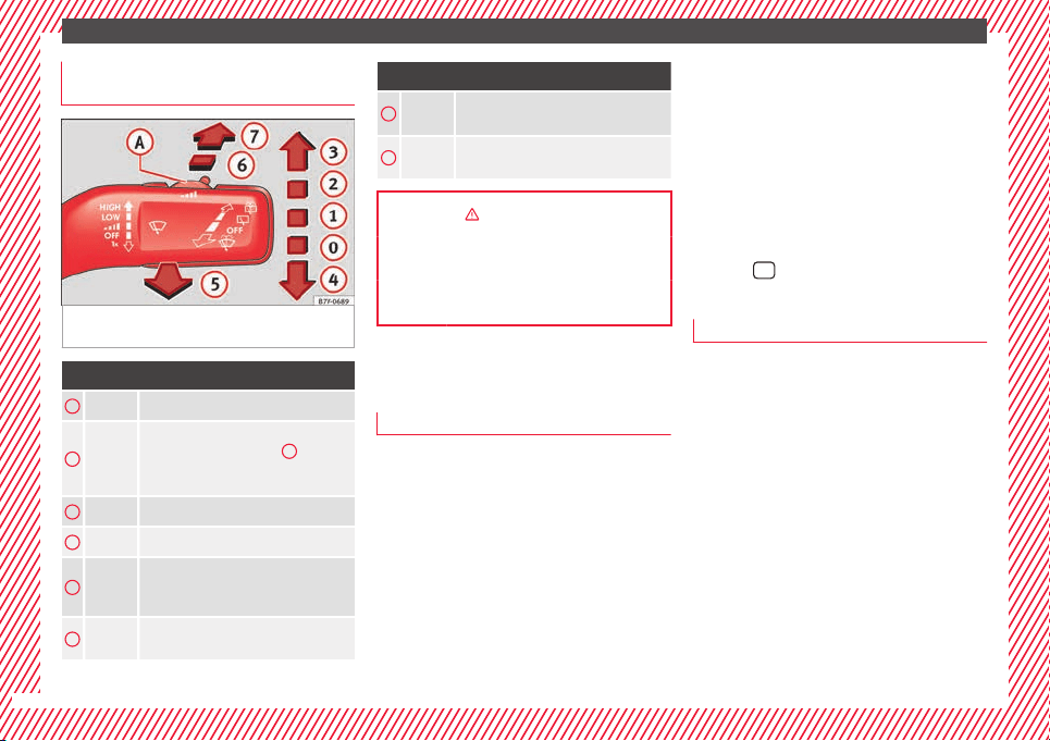
Windscreen wipers and window wiper
b
l
a
de
Fig. 44 Operating the windscreen wiper and
r
e
ar w
iper
Move the lever to the required position
0
Windscreen wiper off.
1
Windscreen wipers interval wipe.
Using the control ››› Fig. 44
A
adjust
the interval (vehicles without rain sen-
sor), or the sensitivity of the rain sensor.
2
Slow wipe.
3
Continuous wipe.
4
Brief wipe - short wipe. Hold the lever
down for more time to increase the wipe
frequency.
5
Automatic wipe for cleaning wind-
screens with the lever up.
Move the lever to the required position
6
Interval wipe for rear window. The wiper
wipes the window at 6-second intervals.
7
Automatic wipe for cleaning rear win-
dows with the lever pressed.
››› in Window wiper lever on page 137
››› page 137
››› page 54
SEAT information system
Intr
oduction
With the ignition switched on, it is possible
t
o r
e
ad the different functions of the display
by scrolling through the menus.
In vehicles with a multifunction steering
wheel, there are no buttons on the wind-
screen wiper lever. The multifunction display
can only be controlled from the buttons on
the steering wheel.
The number of menus displayed on the in-
strument panel will vary according to the ve-
hicle electronics and equipment.
A specialised workshop will be able to pro-
gramme or modify additional functions, ac-
cording to the vehicle equipment. SEAT rec-
ommends taking your car in for technical
service.
Some menu options can only be read when
the vehicle is at a standstill.
As long as a priority 1 warning is displayed, it
will not be possible to read the menus. To
display the menus, confirm the warning by
pressing
OK
.
Summary of the menu structure
■
Multif
unction display (MFI) ››› page 29
■
Journey duration
■
Current fuel consumption
■
Average fuel consumption
■
Operating range
■
Distance covered
■
Average speed
■
Digital display of speed
■
Oil temperature digital display
■
Speed warning
■
Audio
›››
Booklet Radio or
›››
Booklet Navi-
gation system
■
Navigation
›››
Booklet Navigation system
■
Telephone
›››
Booklet Radio or
›››
Book-
let Navigation system
■
Auxiliary heating ›››
page 180
26

The essentials
■
A
ctiv
ation
■
Pr
ogramme On / Off
■
Disconnection
■
Timer 1-3
■
Day
■
Time
■
Minute
■
Activate
■
Duration
■
Operating mode
■
Heat
■
Ventilation
■
Day
■
Default setting
■
Vehicle condition ››› page 28
■
Configuration ››› page 30
■
Multifunction display data
■
Journey duration
■
Current fuel consumption
■
Average fuel consumption
■
Distance covered
■
Operating range
■
Average speed
■
Digital display of speed
■
Speed warning
■
Compass
■
Convenience ››› page 30
■
Central locking system (Central locking)
■
Automatic lock (Auto. lock) On / Off
■
Automatic unlocking (Auto. unlock.)
On / Off
■
Unlocking doors (Door unlock.: All,
One door, Vehicle side, Individual)
■
Back
■
Electric windows
■
Off
■
All
■
Driver
■
Back
■
Mirror angle (Mirror angle) On / Off
■
Adjusting mirrors (Adjust. mirrors)
■
Individual
■
Synchronised
■
Back
■
Factory settings (Factory settings)
■
Back
■
Lights & visibility ››› page 31
■
Coming Home
■
Leaving Home
■
Footwell light
■
Convenience turn signals On / Off
■
Default setting
■
Tourist light On / Off
■
Time
■
Winter tyres
■
Language
■
Units
■
Second speed display On / Off
■
Autohold
■
Service
■
Info
■
Reset
■
Default setting
27
The essentials
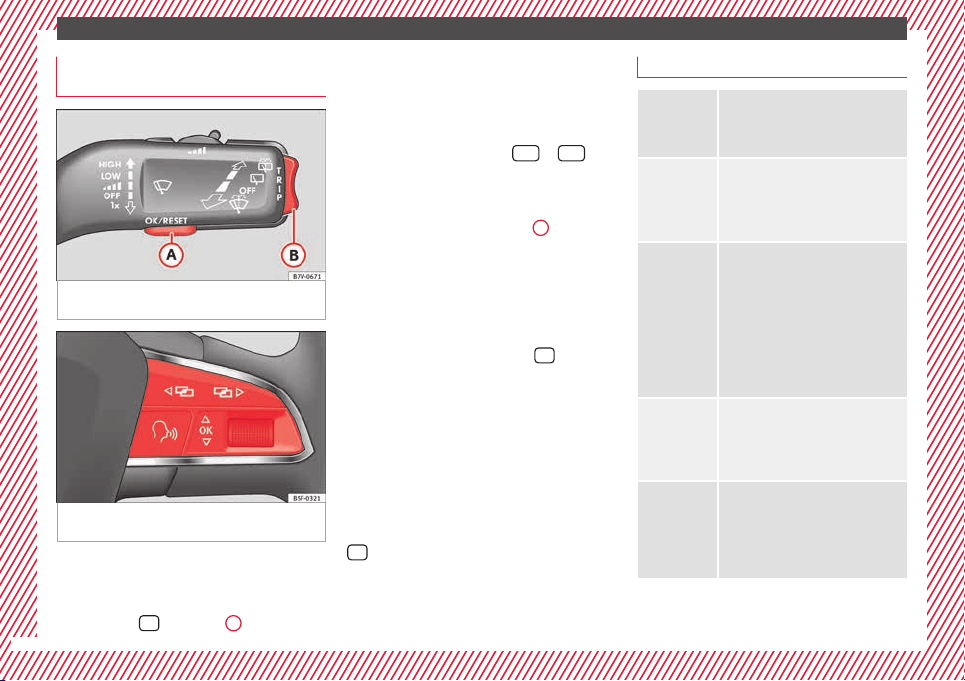
Using the menus on the instrument
p
anel
Fig. 45 Windscreen wiper lever: buttons to
ac
c
e
ss the instrument panel menus
Fig. 46 Multifunction steering wheel: buttons
t
o ac
c
ess the instrument panel menus
Enabling the main menu
●
Switch the ignition on.
●
If a message or vehicle symbol is dis-
p
l
a
yed, press
OK
(›
›
› Fig. 45
A
or ›
›
› Fig. 46
).
●
If managed from the windscreen wiper lev-
er: the main menu list is displayed.
●
If managed from the multifunction steering
wheel: the main menu list is not displayed.
To scroll through the options of the main
menu, press the arrow keys
or
re-
pe
at
edly
››› page 28.
Select a submenu
●
Press rocker switch ››› Fig. 45
B
upwards
or do
wn
w
ards, or, on the multifunction steer-
ing wheel, turn the thumbwheel until you
reach the required menu option.
●
The selected option is displayed between
two horizontal lines. In addition, a triangle is
displayed on the right .
●
To select the submenu, press
OK
.
M
ak
in
g changes according to the menu
●
Use the rocker switch on the windscreen
wiper lever or the thumbwheel on the multi-
function steering wheel to make the required
modifications. To scroll through numbers
more quickly, hold the rocker switch down or
turn the thumbwheel more quickly (fast for-
ward or reverse).
●
Mark or confirm the selected option with
OK
.
Main menu
MFI
Information and possible configura-
tions of the multifunction display
(MFD).
››› page 29
Audio
If the radio is on, the station is dis-
played.
In CD mode, the current CD is played.
››› Booklet Radio or ››› Booklet naviga-
tion system
Navigation
When the navigation to destination is
on, change of direction arrows and a
proximity bar are displayed. These
symbols are similar to those used in
the navigation system.
If navigation to destination is not on,
the direction of travel (compass) and
the name of the street on which you
are driving are displayed.
››› Booklet Navigation system
Telephone
Information and possible configura-
tions of the mobile phone preinstalla-
tion.
››› Booklet Radio or ››› Booklet Naviga-
tion system
Parking heat-
ing
Information and configurations of the
parking heating:
switching the parking heating on or
off. Select the operating mode and du-
ration.
››› page 180
28
The essentials
Vehicle condi-
tion
Current warning or information texts.
This option only appears when one of
the following texts is available. The
number of available messages is dis-
played. Example 1/1 or 2/2.
››› page 100
Configuration
Different setting options, for example,
the Convenience, Lighting & Visibility
menus, and the time, speed warning
with winter tyres, language, units of
measurement, or “Display off”.
››› page 30
MFI menu (mu
ltif
u
nction display)
The multifunction display (MFI) has two auto-
m
atic
memorie
s: 1 - Partial memory and 2 -
Total memory. The selected memory will be
shown in the upper right-hand corner of the
display.
With the ignition switched on, and memory 1
or 2 displayed, briefly press
OK
to change
fr
om one memor
y
to another
1
Trip memo-
ry (for a sin-
gle jour-
ney).
The memory stores the values for the
journey and the consumption from the
moment the ignition is switched on until
it is switched off again.
If the journey is broken for more than 2
hours, the memory is automatically
erased. If the journey is continued in less
than 2 hours after the ignition is switch-
ed off, the new data is added to the data
already stored in the memory.
2
Total mem-
ory (for all
journeys).
The memory records the values for a spe-
cific number of partial trips, up to a total
of 19 hours and 59 minutes or 99 hours
and 59 minutes, or 1999.9 km (or miles)
for 9999 km (or miles), depending on the
model of instrument panel. On reaching
either of these limits, the memory is au-
tomatically erased and starts to count
from 0 again.
Possible displays
Journey dura-
tion
This indicates the hours (h) and mi-
nutes (min) since the ignition was
switched on.
Current fuel
consumption
The current fuel consumption while
driving is displayed in l/100 km (or
miles per gallon, mpg); when the en-
gine is running but the vehicle is not
moving, in l/h (or gallons per hour).
Average fuel
consumption
When the ignition is switched on, the
average consumption (in l/100 km or
in mpg) is displayed after the vehicle
has moved approximately 100 metres
(328 feet). Otherwise horizontal lines
are displayed. The value shown is up-
dated approximately every 5 seconds.
Operating
range
Approximate distance in km (or miles)
that can still be travelled with the fuel
remaining in the tank, assuming the
same style of driving is maintained.
This is calculated using the current
fuel consumption.
Distance cov-
ered
Distance travelled, after ignition is
switched on, in km (or miles).
Average speed
After the ignition is switched on, the
average speed will be shown after a
distance of approximately 100 metres
(328 feet) has been travelled. Other-
wise horizontal lines are displayed.
The value shown is updated approxi-
mately every 5 seconds.
Digital display
of speed
Current speed displayed digitally.
Oil tempera-
ture digital
display
Updated engine oil temperature digi-
tal display
Speed warn-
ing at --- km/h
If the stored speed is exceeded (be-
tween 30 - 250 km/h, or 18 -
155 mph), an audible warning is given
together with a visual warning.
Changing between display modes
●
In vehicles without multifunction steering
whe
e
l:
press the lever.
●
Vehicles with a multifunction steering
wheel: press
or
.
St
orin
g a s
peed for the speed warning
●
Select the display Speed warning at
--- km/h.
●
Press
OK
to store the current speed and
sw
it
c
h off the warning.
●
In addition, set the required speed by
pressing the rocker switch on the windscreen
wiper lever
or
buttons on the multifunc-
tion s
t
eerin
g wheel for 5 seconds. Next,
»
29
The essentials
press
OK
again or wait a few seconds. The
s
peed i
s
stored and the warning activated.
●
To switch off, press
OK
. The stored speed is
del
et
ed.
M
anually erasing memory 1 or 2
●
Select the memory that you wish to erase.
●
Hold down
OK
for approximately 2 sec-
ond
s.
P
er
sonalising the displays
It is possible to select which of the displays
in the multifunction display you wish to see
on the instrument panel in the settings
menu. The units of measurement can also be
modified ››› page 30.
Configuration Menu
Multifunc-
tion display
data
Configuration of the multifunction dis-
play data that you wish to see on the in-
strument panel display ››› page 29.
Compass
Changing the magnetic region and cali-
bration of the compass. To calibrate the
compass, please follow the instructions
given on the instrument panel display.
Convenience
Changing vehicle convenience functions
››› page 30.
Lights & vis-
ibility
Configuration of vehicle lighting
››› page 31.
Time
Changing the hours and minutes of the
instrument panel clock and the naviga-
tion system. The time can be set here
and the choice can be made between
the 24-hour and 12-hour display. The S
in the upper part of the display indicates
that the clock is set to summer time.
Winter tyres
Changing the visual and audible speed
warnings. This function should only be
used when the vehicle is fitted with win-
ter tyres, which are not designed for
travel at high speeds.
Language
Changing the language of the display
texts and the navigation system.
Units
Changing the units of measurement for
the temperature, consumption and dis-
tance.
Second
speed
Switching second speed display on and
off.
Service
Check the service notifications or reset
the service intervals to zero.
Factory set-
tings
Some functions of the Configuration
menu will be reset to the factory value.
Back The main menu is displayed again.
Submenu Convenience
Central lock-
ing
›››
page 114
Auto. lock (Auto Lock): automatic
locking of all doors and boot when
reaching a speed of approximately
15 km/h (10 mph). In order to unlock
the vehicle when it is stopped, push the
central locking button, pull the door
handle or remove the key from the igni-
tion lock if the Auto unlock function
is enabled.
Auto unlock (Auto Lock): Unlocking
all doors and the boot by removing the
ignition lock key.
Door unlock: when unlocking the ve-
hicle with the key, the following doors
will unlock based on the setting:
– All: all of the doors are unlocked.
– One door: when unlocking the vehi-
cle with the key, only the driver's door
unlocks. Pressing the button
again
unlocks all doors and the boot.
– Vehicle side: the doors on the
driver's side unlock.
On vehicles fitted with the Keyless
Access ››› page 114 system, when using
the corresponding handle, all doors un-
lock on the side of the vehicle where the
key is.
Handling
windows
Adjusting the electric windows: this en-
ables the windows to be opened or
closed when the vehicle is unlocked or
locked respectively. The open function
can only be activated from the driver
door ››› page 127.
30
The essentials
Rear vision
mirror ad-
justment
Tilts passenger mirror downwards when
reverse gear is engaged. This enables
the driver to see the edge of the pave-
ment, for example ››› page 139.
Exterior mir-
ror adjust.
If synchronised adjustment is selec-
ted, when the driver side exterior mirror
is adjusted, the passenger exterior mir-
ror is also moved.
Factory set-
tings
Some functions of the Convenience
submenu will be reset to the factory val-
ue.
Back
The Configuration menu is dis-
played again.
Lights & visibility submenu
Coming
Home
This permits the adjustment of the time
the headlamps stay on after locking or
unlocking the vehicle, the function can
also be connected or disconnected here
››› page 133.
Leaving
Home
Footwell
light
This permits the adjustment of the
brightness of the footwell lighting when
the doors are open, the function can al-
so be connected or disconnected here
Convenience
turn signals
Switching convenience turn signals on
and off When the convenience turn sig-
nals are connected,, these flash at least
three times when the turn signal is
switched on ››› page 130.
Factory set-
tings
All the configurations in the submenu
Lights & visibility are reset to
the predefined factory values.
Tourist light
Headlamp adjustment for countries in
which vehicles are driven on the other
side of the road. When the mark is acti-
vated, the headlamps of a left-hand
drive vehicle are adjusted for driving on
the left. This function must only be used
for a short period.
Back
The Configuration menu is dis-
played again.
Personal convenience settings
When two people use a vehicle, SEAT recom-
mend
s
th
at each person always uses “their”
own remote control key. When the ignition is
switched off, or the vehicle is locked, the per-
sonal convenience settings are stored and
automatically allocated to the vehicle key
›››
page 26.
The values of the personalised convenience
settings of the following menu options are al-
located to the vehicle key:
■
Parking heating menu
■
Configuration Menu
■
Time
■
Language
■
Units
■
Convenience settings menu
■
Door unlock (individual opening, Auto
Lock)
■
Convenience handling of windows
■
Rear vision mirror adjustment
■
Lights & visibility settings
menu
■
Coming home and leaving home
■
Footwell light
■
Convenience turn signals
The stored settings are automatically activa-
ted, at the latest when the ignition is switch-
ed on. Please refer to the information and
tips relating to the seat memory
›››
page 146.
31
The essentials
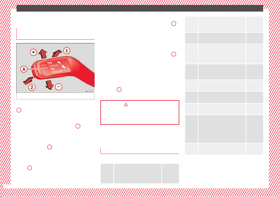
Cruise control
Oper
atin
g the c
ruise control system
(CCS)*
Fig. 47 See position on page 7
●
Switching on the CCS: move the lever to
1
›
›
› Fig. 47
. The system switches on but it
does not control the speed as no speed has
been programmed.
●
Activating the CCS: press the
A
››› Fig. 47 button. It
memorises and main-
tains the current speed.
●
Temporarily switching off the CCS: move
the lever t
o
2
›
›
› Fig. 47
and release it
or press the brake or clutch pedal. The cruise
control system is switched off temporarily.
●
Reactivating the CCS: move the lever to
1
›
›
› Fig. 47
and release it. The memo-
rised speed is saved and controlled again.
●
Increasing stored speed during CCS regula-
tion: briefly move the lever toward
+
to increase the speed by 10 km/h intervals.
B
y
ho
lding it down, the vehicle will accelerate
to the desired speed. Release the button to
store the current speed.
●
Reducing stored speed during CCS regula-
tion: briefly move the lever toward
–
to decrease the speed by 10 km/h intervals.
B
y
ho
lding it down the vehicle will slow
down, ceasing to accelerate but not applying
the brakes. Release the button to store the
current speed.
●
Switching off the CCS: move the lever to po-
sition
2
›
›
› Fig. 47
. The system is discon-
nected and the memorised speed is deleted.
››› in Cruise control system operation
on page 222
››› page 221
Warning lamps
W
arnin
g and indic
ation lamps
Red warning lamps
Do not continue driving!
The electronic parking brake is
on, the brake fluid level is too
low or the brake system is faulty.
››› page
189
Do not continue driving!
Fault in the engine cooling sys-
tem.
››› page
279
Do not continue driving!
Engine oil pressure too low.
››› page
276
Do not continue driving!
At least one of the vehicles doors
is open, or is not correctly
closed.
››› page
121
Do not continue driving!
The rear lid is open or is incor-
rectly closed.
››› page
124
Do not continue driving!
Fault in the steering.
››› page
183
Engine cannot be started again!
"AdBlue" level too low.
››› page
270
Driver or passenger has not fas-
tened seat belt.
››› page
64
Use the foot brake!
Change
››› page
194
Brake
››› page
189
Faulty generator.
››› page
284
32
The essentials
Yellow warning lamps
Front brake pads worn.
››› page
189
it lights up: ESC malfunction or
off.
flashes: ESC working.
ASR manually deactivated.
ABS faulty or does not work.
Electronic parking brake faulty.
››› page
189
Rear fog light switched on.
››› page
130
it lights up: Driving light totally
or partially faulty.
››› page
91
flashes: Fault in the adaptive
light system.
››› page
130
Fault in catalytic converter.
››› page
202
it lights up: pre-ignition of diesel
engine.
flashes: Fault in engine manage-
ment.
Fault in engine management.
Diesel particulate filter blocked
Fault in the steering system.
››› page
183
Tyre pressure too low.
››› page
288
Fault in the tyre pressure gauge.
››› page
234
Level of windscreen washer fluid
too low.
››› page
137
Fuel tank almost empty.
››› page
264
flashes: engine oil sensor faulty.
››› page
276
it lights up: insufficient engine
oil.
Fault in airbag system and seat
belt tensioners.
››› page
72
Front passenger front airbag is
disabled (
).
››› page
72
Top up "AdBlue", or there is a
fault in the "AdBlue" system.
››› page
270
Fuel tank not closed correctly.
››› page
264
Lane Assist is switched on, but
not active.
››› page
223
Other warning lamps
Left or right turn signal.
››› page
130
Hazard warning lights on.
››› page
82
Use the foot brake!
Change
››› page
194
Brake
››› page
189
Cruise control operating.
››› page
221
Lane Assist is switched on and
active.
››› page
223
Main beam on or flasher on.
››› page
130
Headlight adjustment (Light As-
sist) on.
Electronic immobiliser active.
››› page
185
Service interval display
››› page
103
Mobile telephone is connected
via Bluetooth to the original tel-
ephone device.
››› Book-
let Radio
or
››› Book-
let Navi-
gation
system
Mobile telephone battery charge
meter. Available only for pre-in-
stalled factory-fitted devices.
Freezing warning. The outside
temperature is lower than +4°C
(+39°F).
››› page
102
»
33
The essentials
››› in Warning and indication lamps on
page 105
››› page 105
Gearbox lever
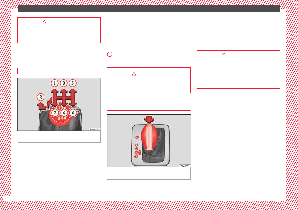
M
anua
l
gearbox
Fig. 48 Gear shift pattern of a 6-speed man-
ual
g
e
arbox
The position of the gears is indicated on the
g
e
arbo
x lever ››› Fig. 48.
●
Press the clutch pedal and keep your foot
right down.
●
Move the gearbox lever to the required po-
sition.
●
Release the clutch.
Selecting reverse gear
●
Press the clutch pedal and keep your foot
right down.
●
With the gearbox lever in neutral, push it
upwards, move it to the left as far as it will go
and then forwards to select reverse ››› Fig. 48
R
.
●
Release the clutch.
››› in Manual gear change on page 195
››› page 195
Automatic gear box*
Fig. 49 Automatic gearbox: selector lever po-
s
ition
s.
Parking lock
R
ev
er
se gear
P
R
Neutral (idling)
Drive (forward)
Tiptronic mode: pull the lever forwards
(+) to go up a gear or backwards (–) to
go down a gear.
››› in Automatic gear change* on
page 197
››› page 196
››› page 35
N
D/S
+/–
34
The essentials
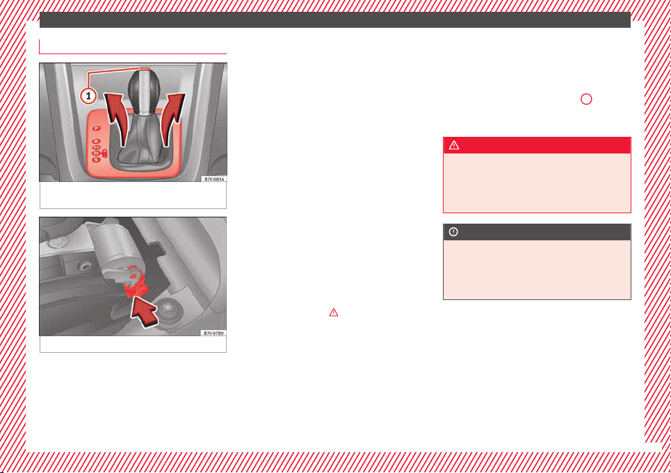
Manual release of the selector lever
Fig. 50 Remove the lining from the area of
the g
e
ar indic
ation
Fig. 51 Manual release of gear selector lever
If the vehicle power supply should ever fail
(e.
g. di
s
charged battery) and the vehicle has
to be pushed or towed, the selector lever
must first be moved to position N using the
manual release mechanism.
The emergency release mechanism is located
underneath the gearbox cover panel to the
right-hand side. To release the gear selector
lever mechanism, a suitable tool is required,
(e.g. a screwdriver).
Preparations
●
Apply the parking brake. If the brake can-
not be activated, the vehicle must be alterna-
tively secured so that it cannot move.
●
Switch the ignition off.
To remove the gearbox cover panel
●
Pull the cover up around the dust guard on
the gear selector lever ››› Fig. 50.
●
Take the cover off by passing it over the
gear selector lever ›››
.
Manual release of the selector lever
●
Press the release lever ›
›
›
Fig. 51 in the di-
rection of the arrow and hold it in this posi-
tion.
●
Press the lock button ››› Fig. 50
1
on the
g
e
ar sel
ector lever knob and place the gear
selector lever in the N position.
WARNING
Never move the gear selector lever from the
position P whi
le the electronic parking brake
is deactivated. Otherwise, the vehicle may
accidentally move off on hills or steep slopes
causing serious accidents.
CAUTION
If the vehicle is moved on its wheels with the
engine st
opped and the selector lever in posi-
tion N for a prolonged period of time and at
high speed, for example for towing, then the
automatic gearbox will be damaged.
35
The essentials
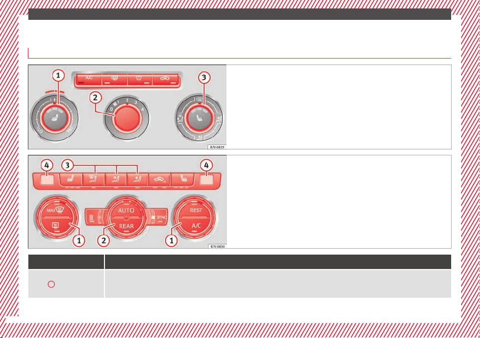
Air conditioning
Ho
w doe
s
the air conditioning work?
Fig. 52 Detailed view of the centre console: Electronic manual air conditioning
contro
ls
Fig. 53 Detailed view of the centre console: Climatronic controls
Control button
Additional information. Electronic manual air conditioning ››› Fig. 52; Climatronic ››› Fig. 53.
1
Temperature
Electronic manual air conditioning: rotate the control to adjust the temperature accordingly. In the
MAX
position, the cooling output will be set to
maximum. The air recirculation mode and the cooling system are automatically switched on.
Climatronic: the left and right sides can be adjusted separately. Rotate the control to adjust the temperature accordingly.
36
The essentials
Control button
Additional information. Electronic manual air conditioning ››› Fig. 52; Climatronic ››› Fig. 53.
2
Fan
Electronic manual air conditioning: Setting 0: air fan and air conditioning system (manual) switched off, setting 4: maximum setting of fan.
Climatronic: the power of the fan is automatically adjusted. Rotate the control to manually adjust the fan.
3
Air distribution
Electronic manual air conditioning: rotate the continuous control to direct the airflow to the desired area.
Climatronic: the airflow will be automatically adjusted to a comfortable flow. It can also be switched on manually with the buttons
3
.
4
Climatronic: display of the selected interior temperature for the left and right sides.
Electronic manual air conditioning: defrost function. The airflow is directed at the windscreen. In this position, air recirculation is automatically switch-
ed off or is not switched on. Increase the fan power to clear the windscreen of condensation as soon as possible. to dry the air, the cooling system will
automatically switch on.
Climatronic: defrost function. The air drawn in from outside the vehicle is directed at the windscreen and air recirculation is automatically switched off.
To defrost the windscreen more quickly, the air is dehumidified at temperatures over approximately +3°C (+38°F) and the fan runs at maximum output.
The air is directed at the chest of driver and passengers by the dash panel air vents.
Air distribution towards the footwell.
Electronic manual air conditioning: air distribution towards the windscreen and the footwell.
Climatronic: upward air distribution.
Heated rear window: only works when the engine is running and switches off automatically after a 10 minutes.
Electronic manual air conditioning: air recirculation ››› page 179.
Climatronic: manual and automatic air recirculation ››› page 179.
Instant auxiliary heating on/off button ››› page 180.
Buttons for the seat heating ››› page 146.
Climatronic: depending on the vehicle equipment there may be a button for the windscreen heating on the air conditioner control panel. The wind-
screen heating only works when the engine is running and switches off automatically after a few minutes.
»
37
The essentials
Control button
Additional information. Electronic manual air conditioning ››› Fig. 52; Climatronic ››› Fig. 53.
Press the button to switch on or off the cooling system.
Climatronic: accept the temperature selection for the driver and front passenger sides. When the
SYNC
button light is lit, the temperature settings on
the driver side also apply to the passenger side. Press the button or adjust the temperature control for the passenger side in order to set a different
temperature. No lamp lights up on the button.
Climatronic: automatic temperature, fan, and air distribution control. Press the button to switch on the function. The control lamp lights up on the
AUTO
button.
Climatronic: press the
REAR
button to adjust the air conditioner for the rear seats from the front seats. A lamp is lit on the
REAR
button if the feature is
activated. The settings for the rear seats will be displayed. Press the button again to switch the function off or do not touch any other button for
around 10 seconds.
Climatronic: Press the
REST
button to use the heat that the engine produces. When the engine is still warm but the ignition switched off, the heat
given off by the engine can be used to keep the vehicle interior warm. The
REST
button will light up when the function is switched on. The function will
switch off after around 30 minutes and if the battery level is low.
a)
Switch off.
Electronic manual air conditioning: turn the fan switch to setting 0.
Climatronic: press the
OFF
button or manually set the fan to 0. When the device is switched off the
OFF
button will light up.
a)
Depending on the version of the model.
››› in Introduction on page 176
››› page 176
38
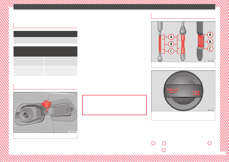
The essentials
Level control
Fi
l
lin
g capacities
Tank level
70 litres. 8 litre reserve
Capacity of the windscreen washer fluid con-
tainer
Versions without head-
light washer system
3.5 litres
Versions with headlight
washer system
6 litres
Fuel
Fig. 54 Fuel tank flap with tank cap attached.
Before r
efuelling, always turn off the engine,
the ignition, mo
b
ile telephones, auxiliary
heating and keep them off during refuelling.
Opening the fuel tank cap
●
The tank flap is at the rear of the vehicle on
the right.
●
Press the rear of the tank flap to open it.
●
Unscrew the tank cap anticlockwise and in-
sert it in the hole in the tank flap hinge
›››
Fig. 236.
Closing the fuel tank cap
●
Screw on the tank cap clockwise until it you
hear it click into position.
●
Press the tank flap until you hear it click in-
to place. The tank flap must be flush with the
body contour.
››› page 264
››› page 266
Oil
Fig. 55 Engine oil dipstick.
Fig. 56 In the engine compartment: Engine
oi
l
fi
ller cap
The level is measured using the dipstick loca-
t
ed in the en
gine c
ompartment
›››
page 275.
The oil should leave a mark between zones
A
and
C
. It should never exceed zone
A
.
●
Zone
A
: Do not add oil.
»
39
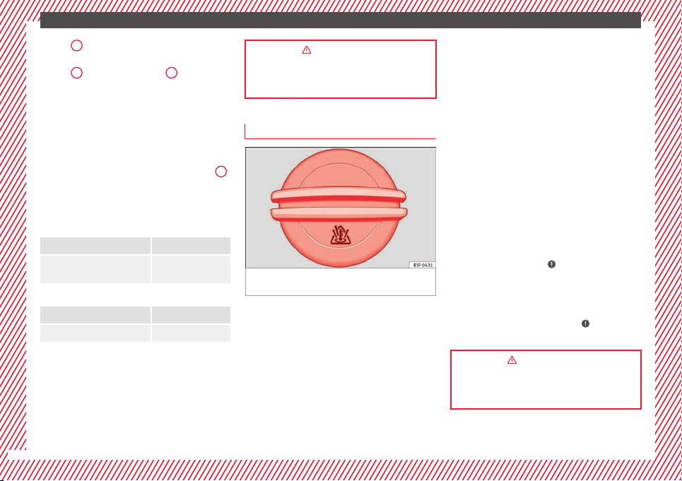
The essentials
●
Z
one
B
: You can add oil but keep the level
in th
at
zone.
●
Zone
C
: Add oil up to zone
B
.
T
op
pin
g up engine oil
●
Unscrew cap from oil filler opening.
●
Add oil slowly.
●
At the same time, check the level to ensure
you do not add too much.
●
When the oil level reaches at least zone
B
,
u
n
s
crew the engine oil filler cap carefully.
Motor oil specifications
Petrol engines
With LongLife service VW 504 00
Without LongLife service
VW 504 00,
VW 502 00
Diesel engines
With LongLife service VW 507 00
Without LongLife service VW 507 00
Engine oil additives
No type of
a
d
ditive should be mixed with the
engine oil. The deterioration caused by these
additives is not covered by the warranty.
››› in Topping up engine oil on
page 278
››› page 276
Coolant
Fig. 57 Engine compartment: coolant expan-
s
ion t
ank
cap.
The coolant tank is located in the engine
c
omp
ar
tment ›››
page 275.
When the engine is cold, replace the coolant
when the level is below .
Coolant specifications
The engine cooling system is supplied from
the factory with a specially treated mixture of
water and at least 40 % of the additive G 13
(TL-VW 774 J), purple. This mixture gives the
necessary frost protection down to -25°C
(-13°F) and protects the light alloy parts of
the engine cooling system against corrosion.
It also prevents scaling and considerably rai-
ses the boiling point of the coolant.
To protect the cooling system, the percentage
of additive must always be at least 40 %,
even in warm climates where anti-freeze pro-
tection is not required.
If for weather reasons further protection is
necessary, the proportion of additive may be
increased, but only up to 60 %; otherwise an-
tifreeze protection will diminish and this will
worsen cooling.
When the coolant is topped up, use a mixture
of distilled water and at least 40 % of the G
13 or G 12 plus-plus (TL-VW 774 G) additive
(both are purple) to obtain an optimum anti-
corrosion protection ›››
in Coolant specifi-
c
ation
s on p
age 280. The mixture of G 13
with G 12 plus (TL-VW 774 F), G 12 (red) or G
11 (green-blue) engine coolants will signifi-
cantly reduce anti-corrosion protection and
should therefore be avoided ›››
in Coolant
s
pec
ific
ations on page 280.
››› in Coolant specifications on
page 280
››› page 279
40
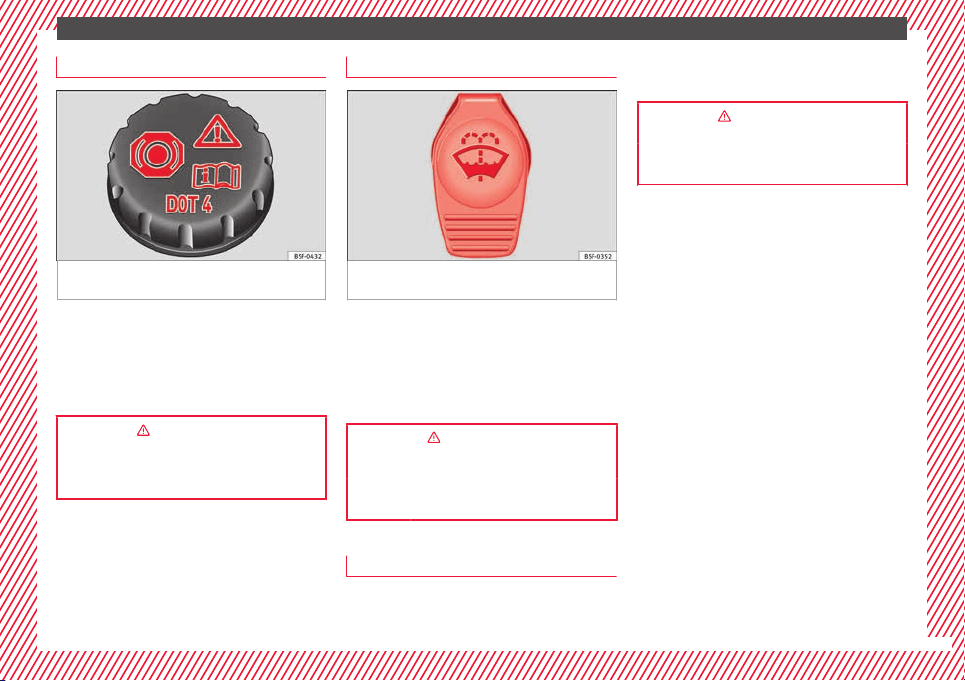
The essentials
Brake fluid
Fig. 58 Engine compartment: brake fluid res-
er
v
oir c
ap
The brake fluid reservoir is located in the en-
gine c
omp
ar
tment ›››
page 275.
The level should be between the and
marks. If it is below , please visit a Techni-
cal Service.
››› in Checking the brake fluid level on
page 283
››› page 282
Windscreen washer
Fig. 59 In the engine compartment: wind-
s
c
r
een washer reservoir top.
The windscreen washer reservoir is located in
the en
gine c
omp
artment ›››
page 275.
To top up, mix water with a product recom-
mended by SEAT.
In cold temperatures, add anti-freeze.
››› in Checking and topping up the
windscreen washer reservoir on
page 284
››› page 284
Battery
The battery is located in the engine compart-
ment
›
›
›
page 275. It does not require
maintenance. It is checked as part of the In-
spection Service.
››› in Checking the electrolyte level of
the vehicle battery on page 286
››› page 284
41
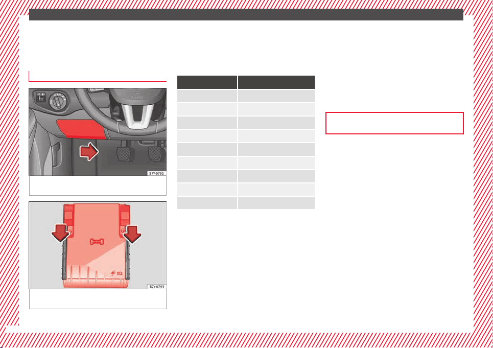
The essentials
Emergencies
F
u
se
s
Fuse location
Fig. 60 On the driver-side dash panel: fuse
bo
x
c
over
Fig. 61 In the engine compartment: fuse box
c
o
v
er
Only replace fuses with a fuse of the same
amper
ag
e (s
ame colour and markings) and
size.
Identifying fuses by colours
Colour Amp rating
Purple 3
Light brown 5
Brown 7.5
Red 10
Blue 15
Yellow 20
White or transparent 25
Green 30
Orange 40
To open the dash panel fuse box
●
To remove the cover, move the activation
l
ev
er in the lo
wer part to the right ››› Fig. 60.
●
For right-hand drive vehicles, move the lev-
er to the left.
To open the engine compartment fuse box
●
Open the bonnet ›››
page 272.
●
Move the attachment tabs forwards, in the
direction indicated by the arrow to release
the fuse box cover ››› Fig. 61.
●
Then lift the cover out.
●
To fit the cover, place it on the fuse box.
Push the attachment tabs back, in the oppo-
site direction indicated by the arrow until
they click audibly into place.
In is possible that there are more fuses be-
hind a cover in the lower left-hand side of the
luggage compartment.
››› page 90
42
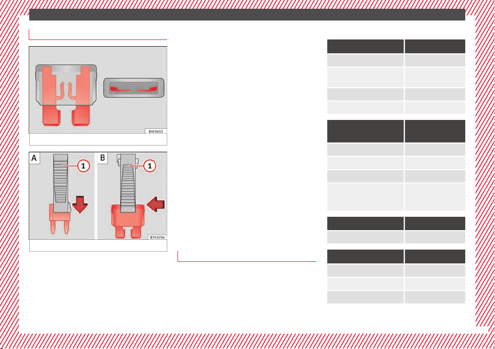
The essentials
Replacing a blown fuse
Fig. 62 Image of a blown fuse
Fig. 63 Removing or fitting a fuse
Preparation
●
Switch off the ignition, lights and all elec-
tric
al
equipment
.
●
Open the corresponding fuse box
››› page 42
Identifying a blown fuse
A fuse is blown if its metal strip is ruptured
››› Fig. 62.
●
Point a lamp at the fuse to see if it has
blown.
To replace a fuse
●
If necessary, remove the plastic pincers
from the fuse box cover.
●
Small fuses: lock the pincer in from above
››› Fig. 63 A.
●
Larger fuses: move the pincer sideways
over the fuse ››› Fig. 63 B.
●
Remove the relevant fuse.
●
Replace the blown fuse by one with an
identical amperage rating (same colour and
markings) and identical size.
●
Replace the cover.
Bulbs
Bulbs (12 V)
Full-LED headlights are designed to last the
lif
etime of
the c
ar and light bulbs cannot be
replaced. In case of headlight failure, go to
an authorised workshop to have it replaced.
Light source used for each function
Halogen headlights Type
Dipped beam headlights H7 LL
Main beam headlights/day-
time running lights (DRL)
H15 (double element)
Side lights W5W
Turn signal PY21W NA LL
AFS bi-xenon main head-
light
Type
Daytime running lights (DRL) P21W SLL
Side lights W5W
Turn signal PY21W NA LL
Dipped beam / Main beam
Xenon bulb. Visit an
authorised workshop
for replacement.
Front fog light Type
Fog lights HB4
LED rear lights Type
Side/brake light LED
Turn signal WY21W
Reverse lights W16W
43
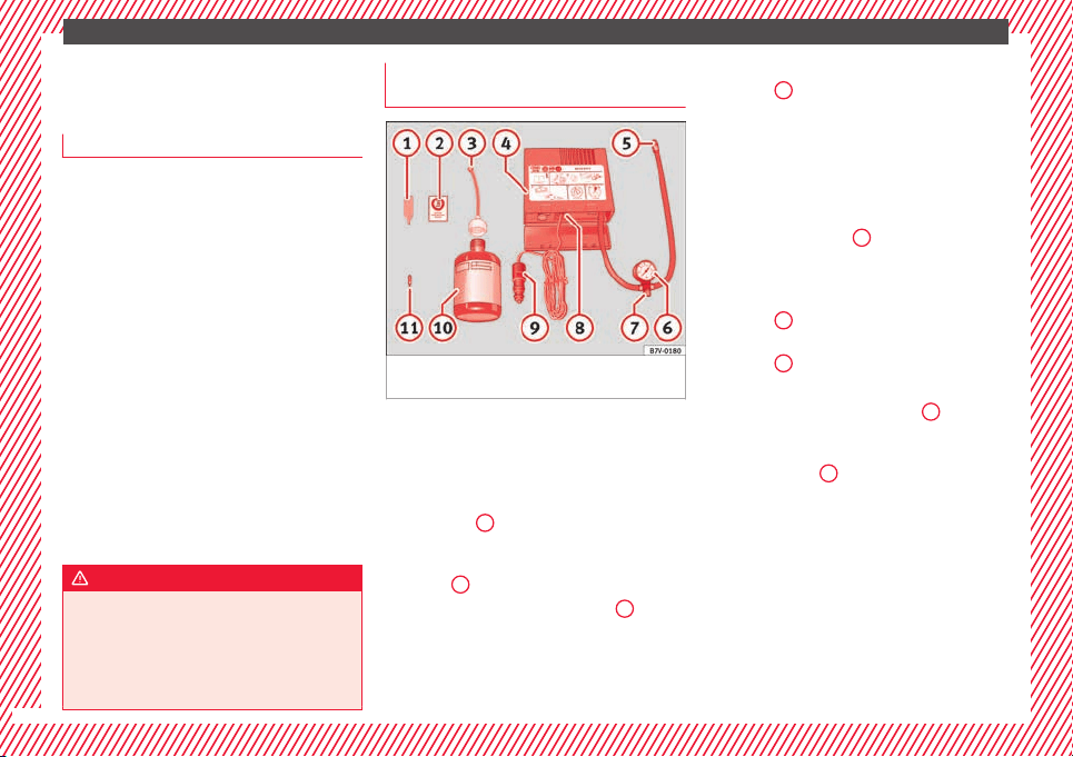
The essentials
Action in the event of a punc-
t
ur
e
Wh
at to do first
●
Park the vehicle on a horizontal surface
and in a safe p
lace as far away from traffic as
possible.
●
Apply the handbrake.
●
Switch on the hazard warning lights.
●
Manual gearbox: select the 1st gear.
●
Automatic gearbox: Move the sel
ector lever
to position P.
●
If you are towing a trailer, unhitch it from
your vehicle.
●
Keep the vehicle tool kit ready*
›››
page 82.
●
Observe the applicable legislation for each
country (reflective vest, warning triangles,
etc.).
●
All occupants should leave the vehicle and
wait in a safe place (for instance behind the
roadside crash barrier).
WARNING
●
Alwa
ys observe the above steps and pro-
tect yourself and other road users.
●
If you change the wheel on a slope, block
the wheel on the opposite side of the car with
a stone or similar to prevent the vehicle from
moving.
Repairing a tyre with the anti-punc-
t
ur
e k
it
Fig. 64 Standard representation: Contents of
the ty
r
e mo
bility system.
The anti-puncture kit is located under the
floor p
anel
in the lug
gage compartment.
Sealing the tyre
●
Unscrew the tyre valve cap and insert. Use
the ››› Fig. 64
1
tool to remove the insert.
Pl
ac
e it
on a clean surface.
●
Shake the tyre sealant bottle vigorously
››› Fig. 64
10
.
●
Screw the inflator tube ›
›
›
Fig. 64
3
into
the se
al
ant
bottle. The bottle's seal will break
automatically.
●
Remove the lid from the filling tube
››› Fig. 64
3
and screw the open end of the
t
ube int
o the ty
re valve.
●
With the tyre sealant bottle upside down,
fill the tyre with the contents of the sealant
bottle.
●
Remove the bottle from the valve.
●
Place the insert back into the tyre valve us-
ing the tool ››› Fig. 64
1
.
Infl
atin
g the ty
re
●
Screw the compressor tyre inflator tube
››› Fig. 64
5
into the tyre valve.
●
Check that the air bleed screw is closed
›
›
›
Fig. 64
7
.
●
Start the engine and leave it running.
●
Insert the connector ›
›
›
Fig. 64
9
into the
v
ehic
l
e's 12-volt socket ›››
page 174.
●
Turn the air compressor on with the ON/OFF
switch ››› Fig. 64
8
.
●
Keep the air compressor running until it
r
e
ac
hes 2.0 to 2.5 bar
(29-36 psi/200-250 kPa). a maximum of 8
minutes.
●
Disconnect the air compressor.
●
If it does not reach the pressure indicated,
unscrew the tyre inflator tube from the valve.
●
Move the vehicle 10m so that the sealant is
distrib
uted throughout the tyre.
44
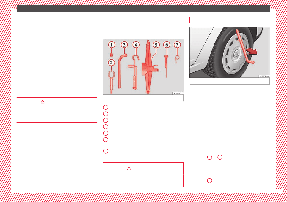
The essentials
●
Sc
r
ew the c
ompressor tyre inflator into the
valve.
●
Repeat the inflation process.
●
If the indicated pressure still cannot be
reached, the tyre is too badly damaged. Stop
and request assistance from an authorised
technician.
●
Disconnect the air compressor. Unscrew
the tyre inflator tube from the tyre valve.
●
When the tyre pressure is between 2.5 and
2.0 bars, continue driving without exceeding
80 km/h (50 mph).
●
Check the pressure again after 10 minutes
›››
page 86.
››› in TMS (Tyre Mobility System)* on
page 85
››› page 85
Changing a wheel
V
ehic
l
e tool kit
Fig. 65 See Fig. for positioning 2
Adapter for anti-theft bolt
T
o
w
ing eye, removable
Box spanner for wheel bolts
Crank handle for jack
Jack
Screwdriver with hexagon socket in the
handle
Hook for pulling off wheel trims or wheel
bolt caps.
››› in Location on page 82
››› page 82
1
2
3
4
5
6
7
Full hubcaps*
Fig. 66 Removing the full hubcap
Removing the full hubcap
●
Take the wheel brace and the wire hook
fr
om the
v
ehicle tool kit ›››
page 82.
●
Hook the wire through one of the grooves
on the hubcap.
●
Insert the wheel brace onto the wire hook
››› Fig. 66 and pull the hub cap in the direc-
tion shown by the arrow.
Fitting hubcaps
Before mounting the full trim, the anti-theft
wheel lock must be threaded into position
›››
Fig. 69
2
or
3
. Otherwise it will not be
po
s
s
ible to mount the full hubcap.
●
Press the trim against the wheel so that the
space for the valve fits over the tyre valve
››› Fig. 69
1
. Make sure that the hubcap is
c
orr
ectly
fitted all the way around the wheel.
45
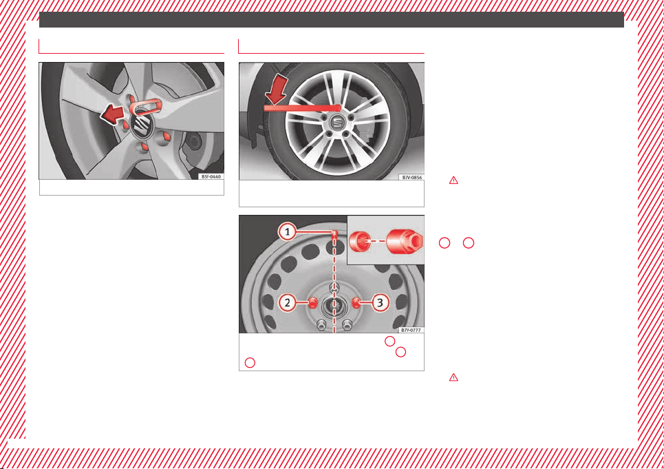
The essentials
Wheel bolt caps
Fig. 67 Clip for removing the wheel bolt caps
Removal
●
Fit the plastic clip (vehicle tools) over the
c
ap u
nti
l it clicks into place ››› Fig. 67.
●
Remove the cap with the plastic clip.
The caps protect the wheel bolts and should
be remounted after changing the tyre.
The anti-theft wheel locking bolt has a spe-
cial cap. This only fits on anti-theft locking
bolts and is not for use with standard wheel
bolts.
Loosen the wheel bolts
Fig. 68 Changing a wheel: Slacken the wheel
bo
lts.
Fig. 69 Changing a wheel: tyre valve
1
and
po
s
ition of
anti-theft wheel locking bolt
2
or
3
.
Only use the tool supplied with the vehicle to
loo
sen the wheel
bo
lts.
Loosen the wheel bolts only about one turn
before raising the vehicle with the jack.
If the wheel bolt is very tight, you may be
able to loosen it by pushing down on the end
of the wheel brace carefully with your foot.
Hold on to the vehicle for support and take
care not to slip.
Loosening wheel bolts
●
Fit the wheel brace as far as it will go over
the wheel bolt ››› Fig. 68.
●
Hold the wheel brace at the end and rotate
the bolt approximately one turn anticlockwise
›››
.
L
oo
senin
g anti-theft wheel bolts
For wheels with full trim, the anti-theft wheel
lock must be threaded into position ››› Fig. 69
2
or
3
. Otherwise it will not be possible to
mou
nt
the entir
e hubcap.
●
Take the adapter for anti-theft wheel bolts
out of the vehicle tool kit.
●
Insert the adapter onto the anti-theft wheel
bolt.
●
Fit the wheel brace onto the adapter as far
as possible.
●
Hold the wheel brace at the end and rotate
the bolt approximately one turn anticlockwise
›››
.
46
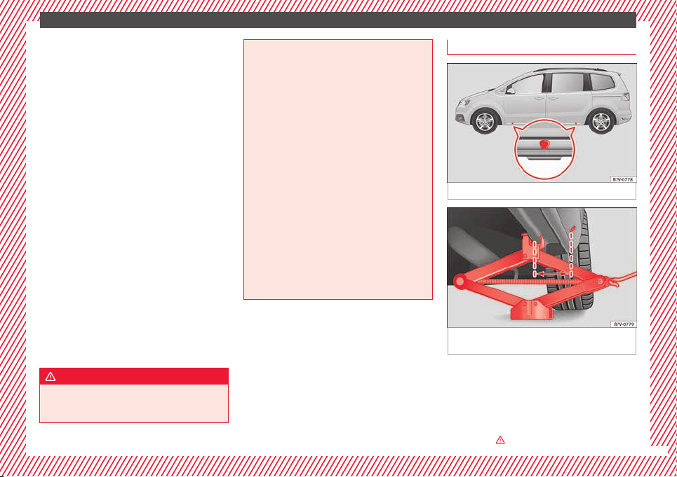
The essentials
Important information about wheel bolts
The wheel
rims
and bo
lts have been de-
signed to be fitted to factory options. If differ-
ent rims are fitted, the correct wheel bolts
with the right length and correctly shaped
bolt heads must be used. This ensures that
wheels are fitted securely and that the brake
system functions correctly.
In some circumstances, wheel bolts from the
same model vehicle should not be used.
Wheel bolt tightening torque
The prescribed tightening torque for wheel
bolts for steel and alloy wheels is 140 Nm.
Have the tightening torque of the wheel bolts
checked as soon as possible with a reliable
torque wrench.
If wheel bolts are rusty and it is difficult to
tighten them, the threads should be replaced
and cleaned before checking the tightening
torque.
Never grease or lubricate wheel bolts or the
wheel hub threads. Although they have been
tightened to the prescribed torque, they
could come loose while driving.
WARNING
If the wheel bolts are not fitted correctly they
coul
d be released while driving leading to
loss of vehicle control and serious damage.
●
Only u
se wheel bolts which correspond to
the wheel rims in question.
●
Never use different wheel bolts.
●
The bolts and threads should be clean, free
of oil and grease and easy to thread.
●
To loosen and tighten the wheel bolts, al-
ways use the wheel brace supplied with the
vehicle.
●
Loosen the wheel bolts only about one turn
before raising the vehicle with the jack.
●
Never grease or lubricate wheel bolts or the
wheel hub threads. Although they have been
tightened to the prescribed torque, they
could come loose while driving.
●
Never loosen the bolted joints of wheel
rims with bolted ring trims.
●
If the wheel bolts are not tightened to the
correct torque, they may come loose while
driving, and the bolts and rims may come
out. If the tightening torque is too high, the
wheel bolts and threads can be damaged.
Raising the vehicle with the jack
Fig. 70 Jack position points
Fig. 71 Jack mounted on the left rear part of
the
v
ehic
le
The jack may be applied only at the jacking
points
sho
wn (m
arks on chassis) ››› Fig. 70.
The mark indicates the jacking points below
the vehicle. The jacking points are on the ribs
behind the front edges ››› Fig. 71. Always the
relevant jacking point for the wheel to be
changed
›››
.
»
47
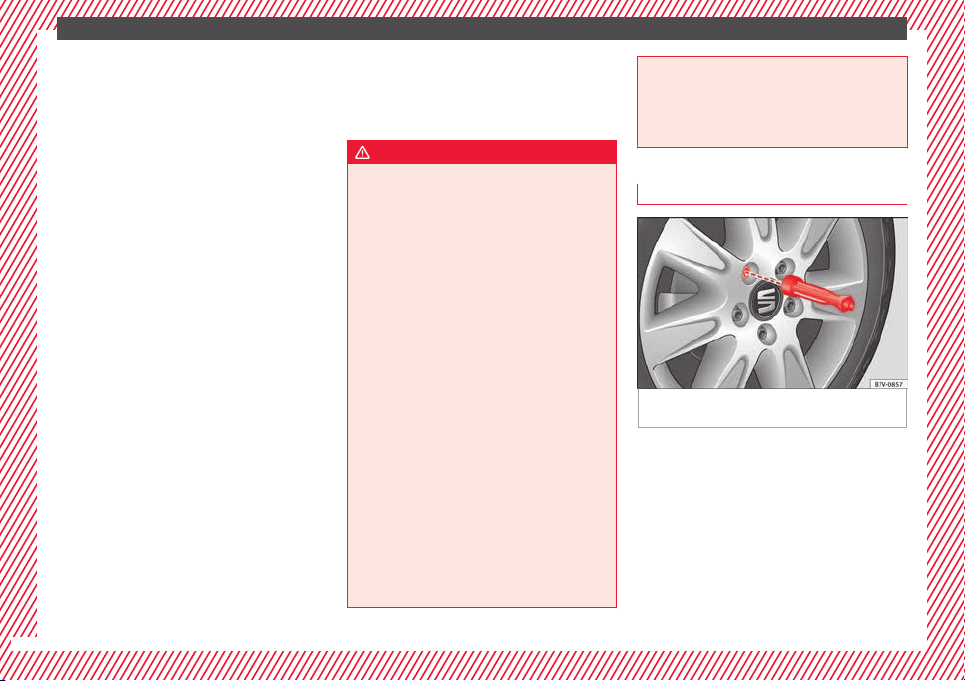
The essentials
Raise the vehicle using only the designated
j
ac
k
ing points.
For your own safety and that of other passen-
gers, the following points should be ob-
served in the order given:
Select a suitable flat and firm surface for
raising the vehicle.
Switch off the engine, engage a gear
(manual gearbox) or place the selector
lever in position P ›››
page 194 and
turn on the electronic parking brake
›››
page 189.
Block the wheel diagonally opposite the
wheel being changed with folding wheel
chocks* or other suitable objects.
When towing a trailer: unhook the trailer
from the towing vehicle and park it cor-
rectly.
Loosen the wheel bolts on the wheel to
be changed ››› page 46.
Look below the vehicle for the jacking
point ››› Fig. 70 closest to the tyre which
has to be changed.
Raise the jack with the handle until it
can be inserted below the jacking point.
Ensure that the foot of the jack is firmly
on the ground and that it is placed im-
mediately below the lifting point on the
vehicle ››› Fig. 71.
Straighten the jack and continue raising
it using the handle until the claw holds
1.
2.
3.
4.
5.
6.
7.
8.
9.
the vertical reinforcement beneath the
vehicle ››› Fig. 71.
Raise the vehicle until the wheel is clear
of the ground.
WARNING
If the vehicle is not correctly raised, it could
fal
l off the jack causing serious injury. Please
observe the following rules to minimise the
risk of injury:
●
You should only use a jack approved by
SEAT for your vehicle. Other jacks, even those
approved for other SEAT models, might slip
out of place.
●
The ground should be firm and flat. If the
ground is sloped or soft then the vehicle
could slip and fall off the jack. If necessary,
support the jack on a wide solid base.
●
If the ground is slippery, such as tiles,
place a non-slip surface (a floor mat, for in-
stance) beneath the jack to avoid slipping.
●
Only fit the jack at the prescribed jacking
points. The claw of the jack should grip the
reinforcement nerve on the underbody
››› Fig. 71.
●
You should never place a body limb such as
an arm or leg under a raised vehicle that is
solely supported by the jack.
●
If you have to work underneath the vehicle,
you must use suitable stands additionally to
support the vehicle, there is a risk of acci-
dent!.
10.
●
Never rai
se the vehicle if it is tilting to one
side or the engine is running.
●
Never start the engine when the vehicle is
raised. The vehicle may come loose from the
jack due to the engine vibrations.
Removing and fitting the wheel
Fig. 72 Changing a wheel: loosen wheel bolts
w
ith the soc
k
et at the end of the wheel brace
Removing the wheel
●
Slacken the wheel bolts ›
›
›
page 46.
●
Raise the vehicle ››› page 47.
●
Using the hexagonal socket in the wheel
brace ››› Fig. 72, unscrew the slackened
wheel bolts and place them on a clean sur-
face.
●
Take off the wheel.
48
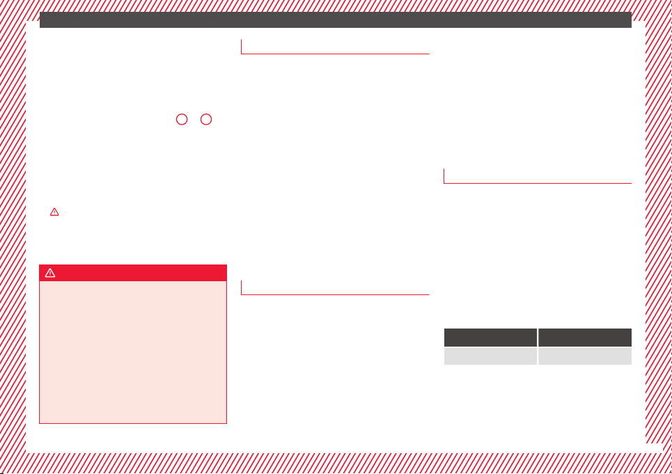
The essentials
Putting on the spare wheel
Chec
k
the dir
ection of rotation of the tyre
››› page 49.
●
Fit the wheel.
●
Screw on the anti-theft locking bolt with
the adapter in position ››› Fig. 69
2
or
3
clockwise and tighten gently.
●
Replace the other wheel bolts and tighten
s
ligh
tl
y using the hexagonal socket on the
end of the wheel brace.
●
Lower the car with the jack.
●
Tighten all of the wheel bolts clockwise
›››
. Tighten the bolts in diagonal pairs (not
in a c
ir
c
le).
●
Put the caps, trim or full hubcap back on
››› page 45.
WARNING
If the wheel bolts are not treated suitably or
not tightened t
o the correct torque then this
could lead to loss of vehicle control and to a
serious accident.
●
All the wheel bolts and hub threads should
be clean and free of oil and grease. The wheel
bolts should be easily tightened to the cor-
rect torque.
●
The hexagonal socket in the wheel brace
should be used for turning wheel bolts only.
Do not use it to loosen or tighten the wheel
bolts.
Tyres with directional tread pattern
Tyres with directional tread pattern have
been designed t
o operate best when rotating
in only one direction. An arrow on the tyre
sidewall indicates the direction of rotation on
tyres with directional tread ›››
page 295.
Always observe the indicated direction of ro-
tation in order to guarantee optimum grip
and help avoid aquaplaning, excessive noise
and wear.
If the tyre is mounted in the opposite direc-
tion of rotation, drive with extreme caution,
as the tyre is no longer being used correctly.
This is of particular importance when the
road surface is wet. Change the tyre as soon
as possible or remount it with the correct di-
rection of rotation.
Subsequent work
●
On alloy wheels: r
ep
l
ace the wheel bolt
caps.
●
On plate wheels: replace the wheel hubcap.
●
Return all tools to their proper storing loca-
tion
›››
page 82.
●
Check the tyre pressure of the newly moun-
ted tyre as soon as possible.
●
If the vehicle is fitted with a tyre monitoring
system, this should be “reprogrammed” if
necessary whenever a tyre is changed
›››
page 234.
●
Have the tightening torque of the wheel
bolts checked as soon as possible with a tor-
que wrench ››› page 47. Meanwhile, drive
carefully.
Snow chains
Action
When using snow chains, applicable local
l
e
gi
slation and maximum permitted speed
limits must be observed.
In winter weather, snow chains not only help
to improve grip but also improve the braking
capacity.
Snow chains must only be mounted on the
front wheels, even on all-wheel drive vehi-
cles, and only with the tyre and rim combina-
tions listed below:
Tyre size Wheel rim
205/60 R16 6 1/2 J x 16 ET 33
SEAT recommends you ask a technical serv-
ic
e f
or f
urther information on wheel, tyre and
chain sizes.
»
49
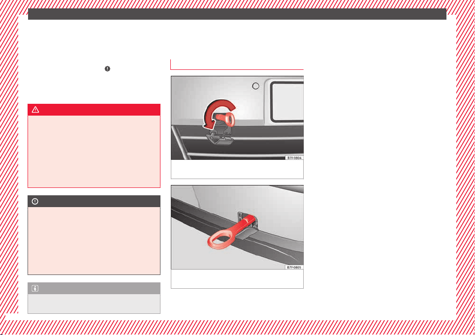
The essentials
Wherever possible use fine-link chains meas-
urin
g l
e
ss than 15 mm (37/64 inch) includ-
ing the lock.
Remove wheel hub covers and trim rings be-
fore fitting snow chains ›››
. The wheel bolts
shou
l
d be c
overed with caps for safety rea-
sons. These are available from technical serv-
ices.
WARNING
The use of unsuitable or incorrectly fitted
chain
s could lead to serious accidents and
damage.
●
Always the appropriate snow chains.
●
Observe the fitting instructions provided by
the snow chain manufacturer.
●
Never exceed the maximum permitted
speeds when driving with snow chains.
CAUTION
●
Remov
e the snow chains to drive on roads
without snow. Otherwise they will impair
handling, damage the tyres and wear out very
quickly.
●
Wheel rims may be damaged or scratched if
the chains come into direct contact with
them. SEAT recommends the use of covered
snow chains.
Note
Snow chains are available in different sizes
accor
ding to the vehicle type.
Emergency towing of the vehi-
c
l
e
T
owing
Fig. 73 On the right-hand side of the front
b
umper:
Sc
rew in the towline anchorage.
Fig. 74 On the rear bumper, to the right hand
s
ide:
T
owline anchorage in position
Towline anchorages
Att
ac
h the b
ar or rope to the towline ancho-
rages.
They are located with the vehicle's tools
›››
page 82.
Screw the towline anchorage into the screw
connection ››› Fig. 73 o ››› Fig. 74 and tighten
it with the wheel brace.
Tow rope or tow bar
When towing, the tow bar is the safest and
vehicle friendly way. You should only use a
tow rope if you do not have a tow bar.
A tow rope should be slightly elastic to avoid
damage to both vehicles. It is advisable to
use a tow rope made of synthetic fibre or sim-
ilarly elastic material.
Only secure the tow rope or tow bar to the
towline anchorage or specially designed fit-
ting.
Vehicles with a factory fitted towing device,
can only be used for towing with a tow bar,
specially designed to fit on a tow hitch ball
›››
page 237.
Towing vehicles with an automatic gearbox
Note the following for a towed vehicle:
●
Make sure the gear selector lever is in the N
position.
●
Do not drive faster than 50 km/h (30 mph).
50
The essentials
●
Do not
t
o
w further than 50 km (30 miles).
●
If a breakdown truck is used, the vehicle
must be towed with the front wheels raised.
Note the following instructions for towing
four all-wheel drive vehicles.
Instructions for towing all-wheel drive vehi-
cles
All-wheel drive vehicles can be towed using a
toolbar or tow rope. If the vehicle is towed
with the front or rear axle raised, the engine
must be turned off to avoid transmission
damage.
For vehicles with a double clutched DSG
®
(di-
rect shift gearbox) the instructions for towing
vehicles with an automatic gearbox apply
››› page 50.
Situations in which a vehicle should not be
towed
In the following cases, the vehicle should not
be towed but transported on a trailer or spe-
cial vehicle:
●
If the vehicle gearbox does not contain lu-
bricant due to a fault.
●
If the vehicle battery is flat and, as a result,
the electronic steering lock and electronic
parking brake cannot be disengaged if ap-
plied.
●
If the vehicle to be towed has an automatic
gearbox and the distance to be covered is
greater than 50 km (30 miles).
››› in Introduction on page 87
››› page 87
Tow-starting
In general, the vehicle should not be started
b
y
t
owing. Jump-starting is much more pref-
erable ››› page 51.
For technical reasons, the following vehicles
can not be tow started:
●
Vehicles with an automatic gearbox.
●
Vehicles with the Keyless Access locking
and ignition system, since the electronic
steering lock may not unlock.
●
Vehicles with an electronic parking brake,
given that it is possible that the brake will
not be disengaged.
●
If the vehicle battery is flat, it is possible
that the engine control units do not operate
correctly.
However, if your vehicle must absolutely be
tow-started (manual gearbox):
●
Put it into second or third gear.
●
Keep the clutch pressed down.
●
Switch on the ignition and the hazard warn-
ing lights.
●
Release the clutch when both vehicles are
moving.
●
As soon as the engine starts, press the
clutch and move the gear lever into neutral.
This helps to prevent a collision with the tow-
ing vehicle.
How to jump start
Jump leads
If the engine fails to start because of a dis-
c
h
ar
ged battery, the battery of another vehi-
cle can be used to start the engine. Before
starting, check the magic eye on the battery
›››
page 284.
For starting assistance, jump lead cables con-
forming to the standard DIN 72553 are re-
quired (see the cable manufacturer instruc-
tions). The jump lead cable must be at least
25 mm
2
in section (0.038 inches
2
) for petrol
engines, and 35 mm
2
(0.054 inches
2
) for die-
sel engines.
For vehicles whose battery is not in the en-
gine compartment, the jump leads should
only be connected to the starting assistance
connection points in the engine compart-
ment.
»
51
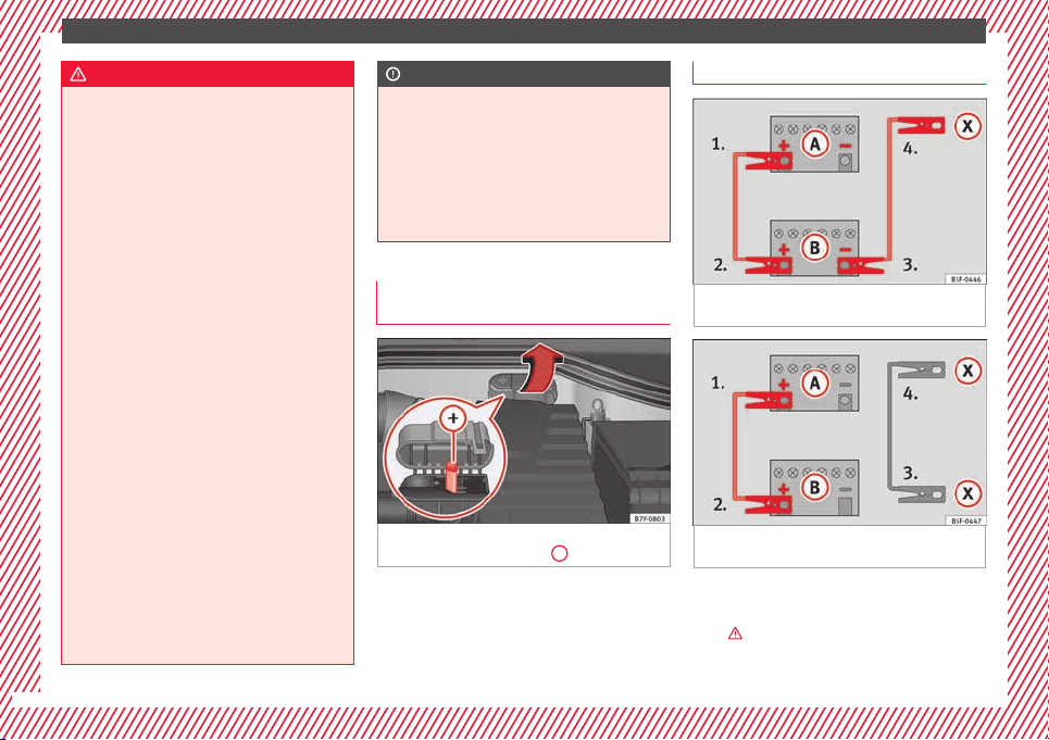
The essentials
WARNING
Incorrect use of jump leads and incorrectly
jump star
ting could cause the battery to ex-
plode resulting in serious injury. Please ob-
serve the following rules to minimise the risk
of a battery explosion:
●
The battery providing current must have
the same voltage (12V) and approximately
the same capacity (see markings on battery)
as the flat battery.
●
Never charge a frozen or recently thawed
battery. A flat battery can also freeze at tem-
peratures close to 0°C (+32°F).
●
If a battery is frozen and/or has been frozen
then it must be replaced.
●
A highly explosive mixture of gases is re-
leased when the battery is being charged. Al-
ways keep lit cigarettes, flames, sparks and
fire far from the battery. Never use a mobile
telephone when connecting and removing the
jump leads.
●
Charge the battery only in well ventilated
areas given that when the battery is charged
by outside assistance, it creates a mix of
highly explosive gases.
●
Jump leads should never enter into contact
with moving parts in the engine compart-
ment.
●
Never switch the positive and negative
poles or connect the jump leads incorrectly.
●
Note the instruction manual provided by
the manufacturer of the jump leads.
CAUTION
To avoid considerable damage to the vehicle
electrica
l system, note the following careful-
ly:
●
If the jump leads are incorrectly connected,
this could result in a short circuit.
●
The vehicles must not touch each other,
otherwise electricity could flow as soon as
the positive terminals are connected.
Positive pole on the jump lead con-
nection point
s
Fig. 75 In the engine compartment: positive
po
l
e f
or starting assistance
+
.
On some vehicles, there is a starting assis-
t
anc
e t
erminal in the engine compartment,
under a labelled cover.
How to jump start: description
Fig. 76 Diagram of connections for vehicles
w
ithout
Start-Stop system.
Fig. 77 Diagram of connections for vehicles
w
ith
St
art-Stop system.
Jump lead terminal connections
1. Switch off the ignition of both vehicles
›
›
›
.
52
The essentials
2. Connect one end of the r
e
d
jump lead to
the positive
+
terminal of the vehicle
w
ith the fl
at
battery
A
›
›› Fig. 76
.
3.
Connect the other end of the red jump
lead to the positive terminal
+
in the ve-
hic
l
e pr
oviding assistance
B
.
4. For vehicles without Start-Stop system:
c
onnect
one end of
the black jump lead to
the negative terminal
–
of the vehicle
pr
o
v
iding the current
B
›
›› Fig. 76
.
–
F
or vehicles with Start-Stop system: con-
nect one end of the black jump lead
X
to a
s
uit
ab
le ground terminal, to a solid piece of
metal in the engine block, or to the engine
block itself ››› Fig. 77.
5. Connect the other end of the black jump
lead
X
to a solid metal component bolted
t
o the en
gine b
lock or to the engine block
itself of the vehicle with the flat battery.
Do not connect it to a point near the bat-
tery
A
.
6. Position the leads in such a way that they
c
annot
c
ome into contact with any moving
parts in the engine compartment.
Starting
7. Start the engine of the vehicle with the
boosting battery and let it run at idling
speed.
8. Start the engine of the vehicle with the flat
battery and wait for 2 or 3 minutes until
the engine is running.
Removing the jump leads
9. Before you remove the jump leads, switch
off the dipped beam headlights if they are
switched on.
10.Turn on the heater blower and heated rear
window in the vehicle with the flat battery.
This helps minimise voltage peaks which
are generated when the leads are discon-
nected.
11.When the engine is running, disconnect
the leads in reverse order to the details
given above.
Make sure the battery clamps have sufficient
metal-to-metal contact with the battery termi-
nals.
If the engine fails to start, switch off the start-
er after about 10 seconds and try again after
about 1 minute.
WARNING
●
Plea
se note the safety warnings referring to
working in the engine compartment
›››
page 272.
●
The battery providing assistance must have
the same voltage as the flat battery (12V) and
approximately the same capacity (see imprint
on battery). Failure to comply could result in
an explo
sion.
●
Never use jump leads when one of the bat-
teries is frozen. Danger of explosion! Even af-
ter the battery has thawed, battery acid could
leak and cause chemical burns. If a battery
freezes, it should be replaced.
●
Keep sparks, flames and lighted cigarettes
away from batteries, danger of explosion.
Failure to comply could result in an explo-
sion.
●
Observe the instructions provided by the
manufacturer of the jump leads.
●
Do not connect the negative cable from the
other vehicle directly to the negative terminal
of the flat battery. The gas emitted from the
battery could be ignited by sparks. Danger of
explosion.
●
Do not attach the negative cable from the
other vehicle to parts of the fuel system or to
the brake line.
●
The non-insulated parts of the battery
clamps must not be allowed to touch. The
jump lead attached to the positive battery
terminal must not touch metal parts of the ve-
hicle, this can cause a short circuit.
●
Position the leads in such a way that they
cannot come into contact with any moving
parts in the engine compartment.
●
Do not lean on the batteries. This could re-
sult in chemical burns.
»
53
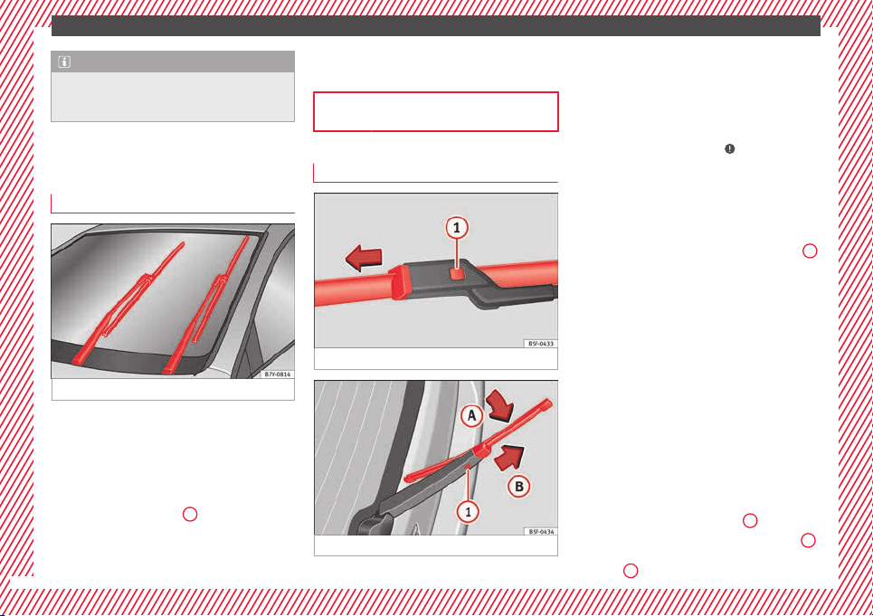
The essentials
Note
The vehicles must not touch each other, oth-
erwi
se electricity could flow as soon as the
positive terminals are connected.
Changing windscreen wipers
Winds
creen wipers service position
Fig. 78 Wipers in service position
The wiper arms can be raised when the wip-
er
s
ar
e in service position ››› Fig. 78.
●
Close the bonnet ›››
page 272.
●
Switch the ignition on and off.
●
Press the windscreen wiper lever down-
wards briefly ››› page 26
4
.
B
ef
or
e driving, always lower the wiper arms.
Using the windscreen wiper lever, the wind-
screen wiper arms return to their initial posi-
tion.
››› page 87
Changing the front wiper blades
Fig. 79 Changing the front wiper blades
Fig. 80 Changing the rear wiper blade
Cleaning windscreen wiper blades
●
Lifting and unfolding the wiper arms.
●
Use a soft cloth to remove dust and dirt
fr
om the w
iper b
lades.
●
If the blades are very dirty, a sponge or
damp cloth may be used ›››
in Changing
the w
ind
s
creen and rear window wiper
blades on page 87.
Change the windscreen wiper blades
●
Lifting and unfolding the wiper arms.
●
Press and hold release button ››› Fig. 79
1
and pull gently on the wiper blade in the di-
r
ection of
the arr
ow.
●
Fit a new wiper blade of the same length
and design on to the wiper arm and hook it
into place.
●
Rest the wiper arms back onto the wind-
screen.
Lifting and unfolding the wiper arms
The wiper arm may only be lifted at the point
where it is fastened to the blade.
Changing the rear wiper blade
●
Lift and unfold the wiper arm.
●
Pull the wiper blade out of its mounting on
the wiper arm ››› Fig. 80 (arrow
A
).
●
Hold down the release button ›
›
›
Fig. 80
1
while gently pulling the blade in the direction
of
arr
o
w
B
. This may require some strength.
54
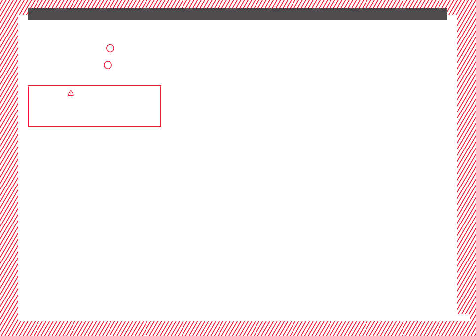
The essentials
●
In
ser
t
a new blade of the same length and
type in the wiper arm in the opposite direc-
tion to the arrow ››› Fig. 80
B
and hook into
p
l
ac
e. This feature is operational when the
knob is in position (arrow
A
).
●
Replace the wiper arm on the rear window.
››› in Changing the windscreen and
rear window wiper blades on page 87
››› page 87
55
Safety
Safety
Saf
e driv
in
g
Safety first!
This chapter contains important information,
tips, sug
gestions and warnings that you
should read and consider for both your own
safety and for your passengers' safety.
WARNING
●
This m
anual contains important informa-
tion about the operation of the vehicle, both
for the driver and the passengers. The other
sections of the on-board documentation also
contain further information that you should
be aware of for your own safety and for the
safety of your passengers.
●
Ensure that the on-board documentation is
kept in the vehicle at all times. This is espe-
cially important when lending or selling the
vehicle to another person.
Advice about driving
Intr
oduction
Depending upon how you expect to use your
v
ehic
l
e, it may a good idea to protect the en-
gine from below. An undercarriage may help
to reduce the risk of damage to the lower part
of the vehicle and the oil sump when driving
over kerbs, or along dirt tracks or unsurfaced
roads, etc. SEAT recommends you have the
guard fitted by a technical service centre.
WARNING
Driving under the influence of alcohol, drugs,
medication or nar
cotics may result in severe
accidents and even loss of life.
●
Alcohol, drugs, medication and narcotics
may significantly alter perception, affect re-
action times and safety while driving, which
could result in the loss of control of the vehi-
cle.
Before setting off
For your own safety and the safety of your
p
a
s
sengers, always note the following points
before every trip:
–
Make sure that the vehicle's lights and turn
signals are working properly.
–
Check tyre pressure.
–
Ensure that all windows provide a clear and
good view of the surroundings.
–
Make sure all luggage is secured
›››
page 152.
–
Make sure that no objects can interfere
with the pedals.
–
Adjust front seat, head restraint and rear vi-
sion mirrors properly according to your
size.
–
Ensure that the passengers in the rear
seats always have the head restraints in
the in-use position ››› page 144.
–
Instruct passengers to adjust the head re-
straints according to their height.
–
Protect children with appropriate child
seats and properly applied seat belts
››› page 74.
–
Assume the correct sitting position. Instruct
your passengers also to assume a proper
sitting position. ››› page 57.
–
Fasten your seat belt securely. Instruct your
passengers also to fasten their seat belts
properly. ››› page 64.
What affects driving safety?
As a driver, you are responsible for yourself
and
y
our p
assengers. When your concentra-
tion or driving safety is affected by any cir-
cumstance, you endanger yourself as well as
others on the road
›››
, for this reason:
–
Always pay attention to traffic and do not
g
et
di
stracted by passengers or telephone
calls.
–
Never drive when your driving ability is im-
paired (e.g. by medication, alcohol, drugs).
56

Safe driving
–
O
b
ser
ve traffic laws and speed limits.
–
Always reduce your speed as appropriate
for road, traffic and weather conditions.
–
When travelling long distances, take
breaks regularly - at least every two hours.
–
If possible, avoid driving when you are tired
or stressed.
WARNING
When driving safety is impaired during a trip,
the risk of
injury and accidents increases.
Safety equipment
Never put your safety or the safety of your
p
a
s
sengers in danger. In the event of an acci-
dent, the safety equipment may reduce the
risk of injury. The following list includes most
of the safety equipment in your SEAT:
●
Three-point seat belts
●
belt tension limiters for the front and rear
side seats,
●
Belt tensioners for the front seats
●
Front airbags
●
knee airbags,
●
Side airbags in the front seat backrests
●
Side airbags in the rear seat backrests*
●
Head-protection airbags
●
“ISOFIX” anchor points for child seats in
the rear side seats with the “ISOFIX” system,
●
Height-adjustable front head restraints
●
Rear head restraints with in-use position
and non-use position
●
Adjustable steering column
The safety equipment mentioned above
works together to provide you and your pas-
sengers with the best possible protection in
the event of an accident. However, these
safety systems can only be effective if you
and your passengers are sitting in a correct
position and use this equipment properly.
Safety is everyone's business!
Correct position of the vehicle
occupants
Correct sitting position
Fig. 81 The correct distance between the driv-
er and the s
t
eerin
g wheel must be at least 25
cm (10 inches).
Fig. 82 Correct belt web and head restraint
po
s
ition
s
»
57
Technical dataAdviceOperationEmergenciesSafety
Safety
The correct sitting positions for the driver and
p
a
s
sengers are shown below.
If your physical constitution prevents you
from maintaining the correct sitting position,
contact a specialised workshop for help with
any special devices. The seat belt and airbag
can only provide optimum protection if a cor-
rect sitting position is adopted. SEAT recom-
mends taking your car in for technical serv-
ice.
For your own safety and to reduce the risk of
injury in the event of an accident or sudden
braking or manoeuvre, SEAT recommend the
following positions:
Valid for all vehicle occupants:
●
Adjust the head restraint so that its upper
edge is at the same level as the top of your
head, or as close as possible to the same lev-
el as the top of your head and under no cir-
cumstances below eye level. Keep the back
of your neck as close as possible to the head
restraint ››› Fig. 81 and ››› Fig. 82.
●
Short people must lower the head restraint
completely, even if your head is below its up-
per edge.
●
Tall people must raise the head restraint
completely.
●
Adjust the seat backrest to an upright posi-
tion so that your back rests completely
against it.
●
Always keep your feet in the footwell while
the vehicle is in motion.
●
Adjust and fasten your seat belt correctly
››› page 64.
Also valid for the driver:
●
Adjust the steering wheel so that there is a
distance of at least 25 cm (10 inches) be-
tween it and your chest ››› Fig. 81 and so that
you can hold the steering wheel with both
hands on the outside of the ring at the 9
o'clock and 3 o'clock positions with your
arms slightly bent.
●
The adjusted steering wheel must face your
chest and not your face.
●
Adjust the driver seat forwards or back-
wards so that you are able to press the accel-
erator, brake and clutch pedals to the floor
with your knees slightly angled and the dis-
tance between your knees and the dash pan-
el is at least 10 cm (4 inches) ››› Fig. 81.
●
Adjust the height of the driver seat so that
you can easily reach the top of the steering
wheel.
●
Keep both feet in the footwell so that you
have the vehicle under control at all times.
Also valid for the front passenger:
●
Move the front passenger seat back as far
as possible for optimum protection should
the airbag deploy.
Adjusting the steering wheel position
Read the additional information carefully
›››
page 16.
WARNING
Incorrect use of the steering wheel adjust-
ment fu
nction and an incorrect adjustment of
the steering wheel can result in severe or fa-
tal injury.
●
After adjusting the steering column, push
the lever ›››
Fig. 25
1
firmly upwards to
ensur
e the steering wheel does not acciden-
tally change position while driving.
●
Never adjust the steering wheel while the
vehicle is in motion. If you need to adjust the
steering wheel while the vehicle is in motion,
stop safely and make the proper adjustment.
●
The adjusted steering wheel should be fac-
ing your chest and not your face so as not to
hinder the driver's front airbag protection in
the event of an accident.
●
When driving, always hold the steering
wheel with both hands on the outside of the
ring at the 9 o'clock and 3 o'clock positions
to reduce injuries when the driver's front air-
bag deploys.
●
Never hold the steering wheel at the 12
o'clock position or in any other manner (e.g.
in the centre of the steering wheel). In such
cases, if the driver's airbag deploys, you may
sustain injuries to your arms, hands and
head.
58
Safe driving
Danger of injuries due to an incorrect
s
ittin
g po
sition
Number of seats
Depending on the equipment,
your vehicle
has a total of five or seven seats. Each seat is
equipped with a seat belt.
5 seats
Seats in the
front
Seats in the
second row
Seats in the
third row
2 3 –
7 seats
Seats in the
front
Seats in the
second row
Seats in the
third row
2 3 2
If the seat belts are worn incorrectly or not at
al
l, the ri
sk
of severe injuries increases. Seat
belts can provide optimal protection only if
the belt web is properly worn. Being seated
in an incorrect position means the seat belt
cannot offer its full protection. This could re-
sult in severe and even fatal injuries. The risk
of severe or fatal injuries is especially height-
ened when a deploying airbag strikes a vehi-
cle occupant who has assumed an incorrect
sitting position. The driver is responsible for
all passengers in the vehicle, particularly
children.
The following list shows just some examples
of incorrect sitting positions which can be
dangerous to all vehicle occupants.
Whenever the vehicle is in motion:
●
Never stand in the vehicle.
●
Never stand on the seats.
●
Never kneel on the seats.
●
Never tilt your seat backrest too far to the
rear.
●
Never lean against the dash panel.
●
Never lie on the rear bench.
●
Never sit on the front edge of a seat.
●
Never sit sideways.
●
Never lean out of a window.
●
Never put your feet out of a window.
●
Never put your feet on the dash panel.
●
Never put your feet on the surface of a seat
or seat backrest.
●
Never travel in a footwell.
●
Never sit on the armrests.
●
Never travel on a seat without wearing the
seat belt.
●
Never carry any person in the luggage com-
partment.
WARNING
An incorrect sitting position in the vehicle
can le
ad to severe injuries or death in the
event of sudden braking or manoeuvres, colli-
sion or acc
idents or if the airbag deploys.
●
Before the vehicle moves, assume the prop-
er sitting position and maintain it throughout
the trip. This also includes fastening the seat
belt.
●
Never transport more people than there are
seats with a seat belt available in the vehicle.
●
Children must always be protected with an
approved child restraint system suited to
their height and weight ››› page 74.
●
Always keep your feet in the footwell while
the vehicle is in motion. Never, for example,
put your feet on the surface of a seat or on
the dash panel and never put them out of a
window. Otherwise the airbag and seat belt
offer insufficient protection and the risk of in-
jury in the event of an accident is increased.
WARNING
Before every trip, adjust the seat, the seat
belt and the hea
d restraints and instruct your
passengers to fasten their seat belts proper-
ly.
●
Move the front passenger seat back as far
as possible.
●
Adjust the driver seat so that there is a dis-
tance of at least 25 cm (10 inches) between
the centre of your chest and the hub of the
steering wheel. Adjust the driver seat so that
you are able to press the accelerator, brake
and clutch pedals to the floor with your knees
slightly angled and that the distance
»
59
Technical dataAdviceOperationEmergenciesSafety
Safety
between your knees and the dash panel is at
lea
st 10 cm (4 inches). If your physical consti-
tution prevents you from meeting these re-
quirements, contact a specialised workshop
to make any modifications required.
●
Never drive with the seat backrest tilted far
back. The further the seat backrests are tilted
to the rear, the greater the risk of injury due
to incorrect positioning of the belt web or to
the incorrect sitting position!
●
Never drive with the seat backrest tilted
forwards. Should a front airbag deploy, it
could throw the seat backrest backwards and
injure the passengers of the rear seats.
●
Sit as far away as possible from the steer-
ing wheel and the dash panel.
●
Keep your back straight and resting com-
pletely against the seat backrest and the
front seats correctly adjusted. Never place
any part of your body in the area of the airbag
or very close to it.
●
If passengers on the rear seats are not sit-
ting in an upright position, the risk of severe
injury due to incorrect positioning of the belt
web increases.
WARNING
Incorrect seat adjustment may lead to acci-
dents and sev
ere injuries.
●
Only adjust the seats when the vehicle is
stationary, as the seats could move unex-
pectedly while the vehicle is in motion and
you could lose control of the vehicle. Further-
more, an incorrect position is adopted when
adjus
ting the seat.
●
Only adjust the height, seat backrest and
forwards or backwards position of the seat
when there is nobody in the seat adjustment
area.
●
There must be no objects blocking the seat
adjustment area.
●
Only adjust the height, angle and longitu-
dinal position of the rear seats when nobody
is in the way.
●
The seat adjustment and lock areas must
be kept clean.
Pedal area
P
ed
a
ls
Do not allow floor mats or other objects to
o
b
s
truct the free passage of the pedals.
Floor mats should leave the pedal area free
and unobstructed and be correctly secured in
the footwell zone.
In the event of failure of a brake circuit, the
brake pedal must be pressed harder than
normal to brake the vehicle.
WARNING
Objects falling into the driver's footwell could
prevent
use of the pedals. This could lead the
driver to lose control of the vehicle, increas-
ing the risk
of a serious accident.
●
Make sure the pedals can be used at all
times, with no objects rolling underneath
them.
●
Always secure the mat in the footwell.
●
Never place other mats or rugs on top of
the original mat supplied by the factory.
●
Ensure that no objects can fall into the driv-
er's footwell while the vehicle is in motion.
CAUTION
The pedals must always have free and unob-
structed p
assage to the floor. For example, in
case of a fault in the brake circuit, the brake
pedal will need to be pressed further to stop
the vehicle. To press the brake pedal down
further will require more force than usual.
60

Seat belts
Seat belts
Wh
y
w
ear a seat belt?
Introduction
Check the condition of all the seat belts at
regu
lar intervals. If you notice that the belt
webbing, fittings, retractor mechanism or
buckle of any of the belts is damaged, the
belt must be replaced immediately by a spe-
cialised workshop ›››
. The specialised
w
ork
shop mu
st use the appropriate spare
parts corresponding to the vehicle, the
equipment and the model year. SEAT recom-
mends taking your car in for technical serv-
ice.
WARNING
Unbuckled or badly buckled seat belts in-
cre
ase the risk of severe or even fatal inju-
ries. The seat belt cannot offer its full protec-
tion if it is not fastened and used correctly.
●
Seat belts are the most effective way of re-
ducing the risk of sustaining severe or fatal
injuries in the event of an accident. Seat belts
must be correctly fastened when the vehicle
is in motion to protect the driver and all vehi-
cle occupants.
●
Before each trip, every occupant in the ve-
hicle occupants must sit properly, correctly
fasten the seat belt belonging to his or her
seat and keep it fastened throughout the trip.
This also applies to other vehicle occupants
when driving in t
own.
●
When travelling, children must be secured
in the vehicle with a child restraint system
suitable for their weight and height and with
the seat belts correctly fastened
››› page 74.
●
Instruct your passengers to fasten their
seat belts properly before driving off.
●
Insert the latch plate into the buckle for the
appropriate seat and ensure it is engaged.
Using the latch plate in the buckle of another
seat will not protect you properly and may
cause severe injuries.
●
Do not allow liquids or foreign bodies to en-
ter the buckle fastenings. This could damage
the buckles and seat belts.
●
Never unbuckle your seat belt when the ve-
hicle is moving.
●
Never allow more than one passenger to
share the same seat belt.
●
Never hold children or babies on your lap
sharing the same seat belt.
●
Loose, bulky clothing (such as a jacket) im-
pairs the proper fit and function of the seat
belt.
WARNING
It is extremely dangerous to drive using dam-
aged seat
belts and could result in serious in-
jury or loss of life.
●
Avoid d
amaging the seat belt by jamming it
in the door or the seat mechanism.
●
If the fabric or other parts of the seat belt
are damaged, the seat belts could break in
the event of an accident or sudden braking.
●
Always have damaged seatbelts replaced
immediately by seat belts approved for the
vehicle in question by SEAT. Seat belts which
have been worn in an accident and stretched
must be replaced by a specialised workshop.
Renewal may be necessary even if there is no
apparent damage. The belt anchorage should
also be checked.
●
Never attempt to repair, modify or remove a
seat belt yourself. All repairs to seat belts, re-
tractors and buckles must be carried out by a
specialised workshop.
61
Technical dataAdviceOperationEmergenciesSafety

Safety
Warning lamp
Fig. 83 Warning lamp on the instrument pan-
el
.
Fig. 84 Example of seat belt status display for
the r
e
ar se
ats (here, a 7-seat vehicle) on the
instrument panel above, the second row and,
below, the third row of seats.
Lights up or flashes
Driver's seat belt not
fastened or front pas-
senger seat belt not
fastened if the front
passenger seat is occu-
pied.
Fasten seat belts!
Objects on the front
passenger seat.
Remove any objects from the
front passenger seat and
store them safely.
Some control and warning lamps on the in-
strument p
anel will come on to check certain
functions when the ignition is switched on.
They will switch off after a few seconds.
An audible warning will be heard for a maxi-
mum of 90 seconds if the seat belts are not
fastened as the car drives off and reaches a
speed of more than 25 km/h (15 mph) or if
the seat belts are unfastened while the vehi-
cle is in motion. The seat belt warning lamp
will also flash.
The warning lamp does not switch off until
the driver and front passenger fasten their
seat belts while the ignition is switched on.
Seat belt status display for rear seats
The seat belt status display on the instru-
ment panel informs the driver, when the igni-
tion is switched on, whether any passengers
in the rear seats have fastened their seat
belts. The symbol indicates that the pas-
senger in this seat has fastened “his or her”
seat belt
››› Fig. 84.
The seat belt status is displayed for around
30 seconds when a seat belt in the rear seats
is fastened or unfastened. You can switch off
this display by pressing the
0.0 / SET
button.
The se
at
belt
status flashes for a maximum of
30 seconds when a seat belt in the rear seats
is unfastened while the vehicle is in motion.
An audible warning will also be heard if the
vehicle is travelling at over 25 km/h
(15 mph).
The rear seat display can be enabled or disa-
bled by a technical service centre.
The protective function of seat belts
Fig. 85 Drivers with properly worn seat belts
w
i
l
l not be thrown forward in the event of sud-
den braking
62
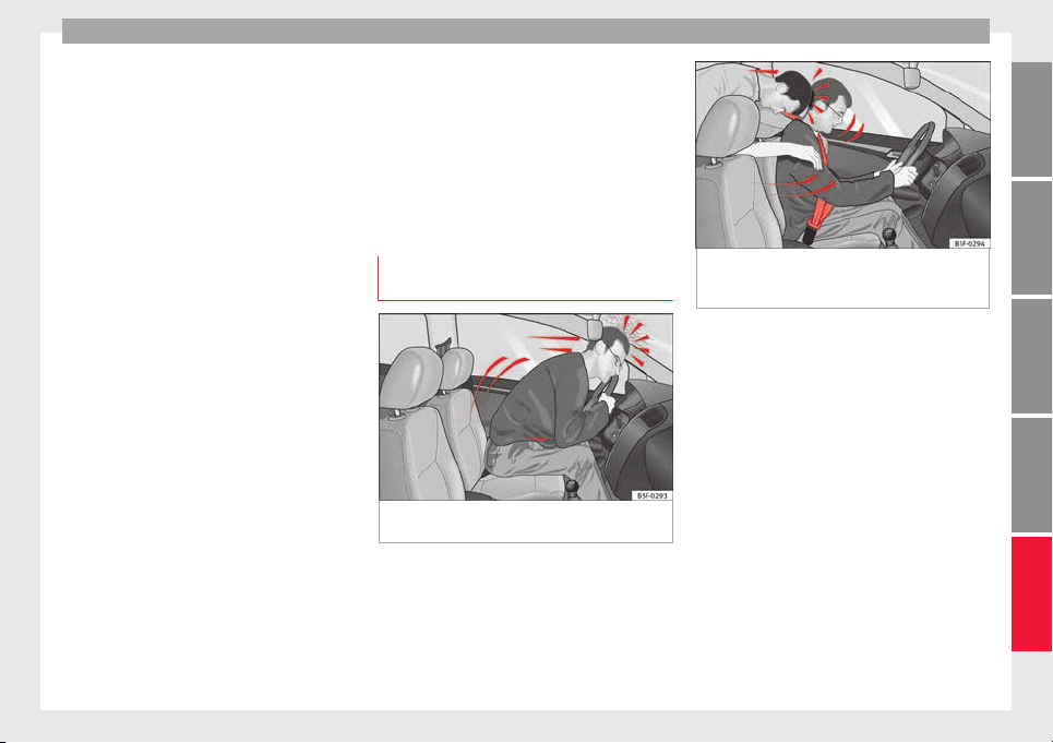
Seat belts
Properly worn seat belts hold the occupants
in the pr
oper po
s
ition. They also help prevent
uncontrolled movements that may result in
serious injury and reduce the risk of being
thrown out of the vehicle in case of an acci-
dent.
Vehicle occupants wearing their seat belts
correctly benefit greatly from the ability of the
belts to absorb kinetic energy. In addition,
the front part of your vehicle and other pas-
sive safety features (such as the airbag sys-
tem) are designed to absorb the kinetic ener-
gy released in a collision. Taken together, all
these features reduce the releasing kinetic
energy and consequently, the risk of injury.
This is why it is so important to fasten seat
belts before every trip, even when "just driv-
ing around the corner".
Ensure that your passengers wear their seat
belts as well. Accident statistics have shown
that wearing seat belts is an effective means
of substantially reducing the risk of injury
and improving the chances of survival when
involved in a serious accident. Furthermore,
properly worn seat belts improve the protec-
tion provided by airbags in the event of an
accident. For this reason, wearing a seat belt
is required by law in most countries.
Although your vehicle is equipped with air-
bags, the seat belts must be fastened and
worn. The front airbags, for example, are only
triggered in some cases of head-on collision.
The front airbags will not be triggered during
minor frontal or side collisions, rear-end colli-
sions, rollovers or accidents in which the air-
bag trigger threshold value in the control unit
is not exceeded.
Therefore, you should always wear your seat
belt and ensure that all vehicle occupants
have fastened their seat belts properly before
you drive off!
Head-on collisions and the laws of
physics
Fig. 86 A driver not wearing a seat belt is
thr
o
wn f
orward violently
Fig. 87 The unbelted rear passenger is
thrown f
orward violently, hitting the driver
wearing a seat belt
It is easy to explain how the laws of physics
w
ork
in the c
ase of a head-on collision: when
a vehicle starts moving, a type of energy
called “kinetic energy” is created both in the
passengers and inside the vehicle.
The amount of “kinetic energy” depends on
the speed of the vehicle and the weight of
the vehicle and its passengers. The higher
the speed and the greater the weight, the
more energy there is to be “absorbed” in an
accident.
The most significant factor, however, is the
speed of the vehicle. If the speed doubles
from 25 km/h (15 mph) to 50 km/h
(30 mph), for example, the corresponding ki-
netic energy is multiplied by four.
Because the vehicle occupants in our exam-
ple are not restrained by seat belts, in the
»
63
Technical dataAdviceOperationEmergenciesSafety
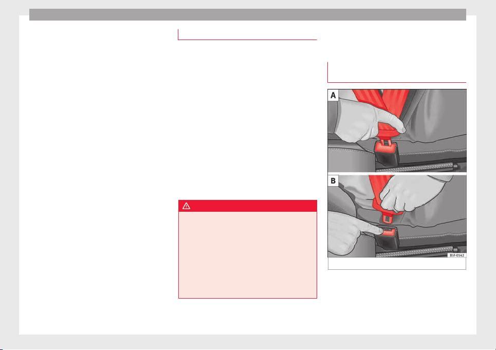
Safety
event of crashing against a wall, all of the oc-
c
up
ants' k
inetic energy will be absorbed
solely by said impact.
Even at speeds of 30 km/h (19 mph) to
50 km/h (30 mph), the forces acting on bod-
ies in a collision can easily exceed one tonne
(1000 kg). At greater speed these forces are
even higher.
Vehicle occupants not wearing seat belts are
not “attached” to the vehicle. In a head-on
collision, they will move forward at the same
speed their vehicle was travelling just before
the impact. This example applies not only to
head-on collisions, but to all accidents and
collisions.
Even at low speeds the forces acting on the
body in a collision are so great that it is not
possible to brace oneself with one's hands.
In a frontal collision, unbelted passengers
are thrown forward and will make violent con-
tact with the steering wheel, dash panel,
windscreen or whatever else is in the way
››› Fig. 86.
It is also important for rear passengers to
wear seat belts properly, as they could other-
wise be thrown forward violently through the
vehicle interior in an accident. Passengers in
the rear seats who do not use seat belts en-
danger not only themselves but also the front
occupants ››› Fig. 87.
Using seat belts
Twisted seat belt
If it i
s difficult to remove the seat belt from
the guide, the seat belt may have become
twisted inside the side trim after being
wound too quickly on unfastening:
●
Pull out the seat belt completely, carefully
pulling on the latch plate.
●
Untwist the belt and guide it back, assist-
ing it by hand.
The seat belt must be fastened even if it is
impossible to untwist it. In this case, the
twisted area must not be in an area in direct
contact with your body. Have the seat belt
untwisted urgently by a specialised work-
shop.
WARNING
An improperly handled seat belt increases
the risk of
sustaining severe or fatal injuries.
●
Regularly check that the seat belts and
their components are in perfect condition.
●
Always keep your seat belt clean.
●
Do not jam or damage the seat belt or rub it
with sharp edges.
●
Make sure there are no liquids or foreign
bodies on the latch plate and in the buckle.
How to properly adjust your
se
at
belt
F
astening and unfastening your seat
belt
Fig. 88 Insert the latch plate into the buckle
64
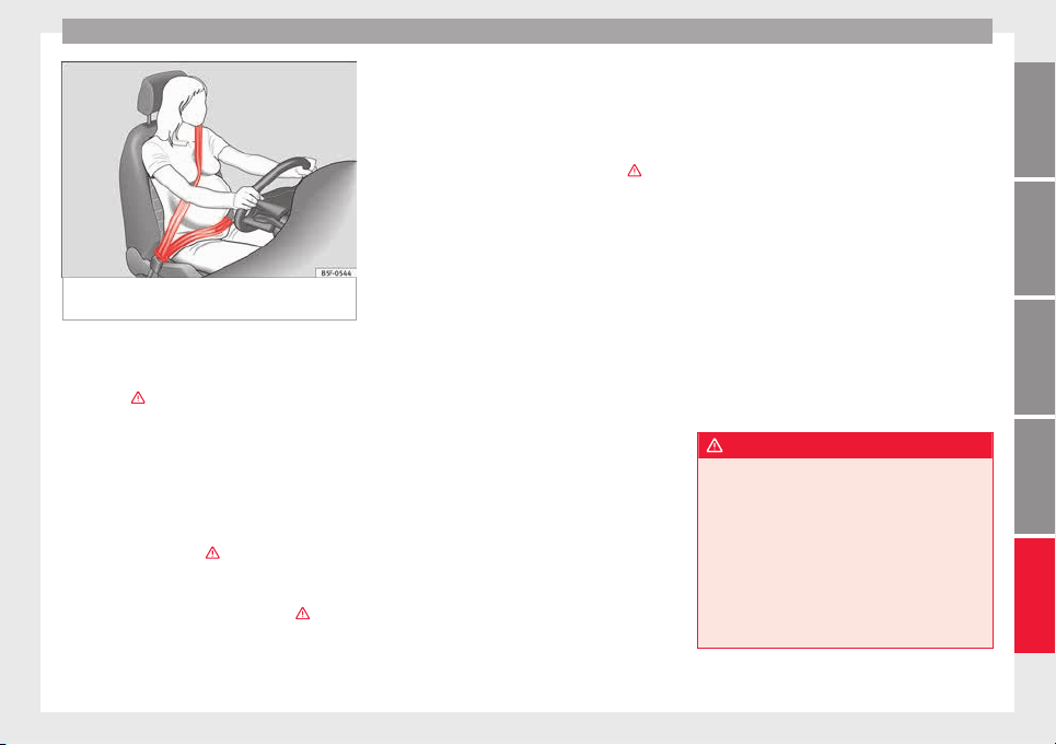
Seat belts
Fig. 89 Position of seat belt during pregnan-
cy
.
Properly worn seat belts hold the vehicle oc-
c
up
ants
in the position that most protects
them in the event of an accident or sudden
braking
›››
.
F
a
s
tening the seat belt
Fasten your seat belt before each trip.
●
Adjust the front seat and head restraint cor-
rectly
›››
page 57.
●
Engage the seat backrest of the rear seat in
an upright position
›››
.
●
Pull the latch plate and place the belt web-
b
in
g ev
enly across your chest and lap. Do not
twist the seat belt when doing so
›››
.
●
Engage the latch plate in the buckle of the
c
orr
e
sponding seat
›››
Fig. 88 A.
●
Pull the belt to ensure that the latch plate is
securely engaged in the buckle.
Unfastening the seat belt
The seat belt must not be unfastened until
the vehicle has come to a standstill ›››
.
●
Press the red button on the buckle
›
›
›
Fig. 88 B. The latch plate is released from
the buckle.
●
Guide the belt back by hand so that it rolls
up easily and the trim will not be damaged.
Correct belt position
Seat belts offer their maximum protection in
the event of an accident and reduce the risk
of sustaining severe or fatal injuries only
when they are properly positioned. Further-
more, if the webbing is correctly positioned,
the seat belt will hold the vehicle occupants
in the optimum position to ensure the airbag
provides the maximum protection. The seat
belt must therefore always be worn and the
webbing correctly positioned.
Incorrectly worn seat belts can cause severe
or even fatal injuries ››› page 57, Correct po-
sition of the vehicle occupants.
●
The shoulder part of the seat belt must lie
on the centre of the shoulder, never across
the neck or the arm, under the arm or behind
the shoulder.
●
The lap part of the seat belt must lie across
the pelvis, never across the stomach.
●
The seat belt must lie flat and fit comforta-
bly. Pull the belt tight if necessary to take up
any slack.
In the case of pregnant women, the seat belt
must lie evenly across the chest and as low
as possible over the pelvis, never across the
stomach and must be worn properly at all
times during the pregnancy ››› Fig. 89.
Adapting the position of the belt webbing to
your size
The seat belt can be adapted using the fol-
lowing equipment:
●
Belt height adjustment for the front seats.
●
Front seat height adjustment.
WARNING
An incorrectly worn seat belt web can cause
severe or f
atal injuries in the event of an acci-
dent.
●
The seat belt cannot offer its full protection
unless the seat backrest is in an upright posi-
tion and the seat belt is worn correctly, ac-
cording to your size.
●
Unbuckling your seat belt while the vehicle
is in motion can cause severe or fatal injuries
in the event of an accident or sudden braking.
»
65
Technical dataAdviceOperationEmergenciesSafety
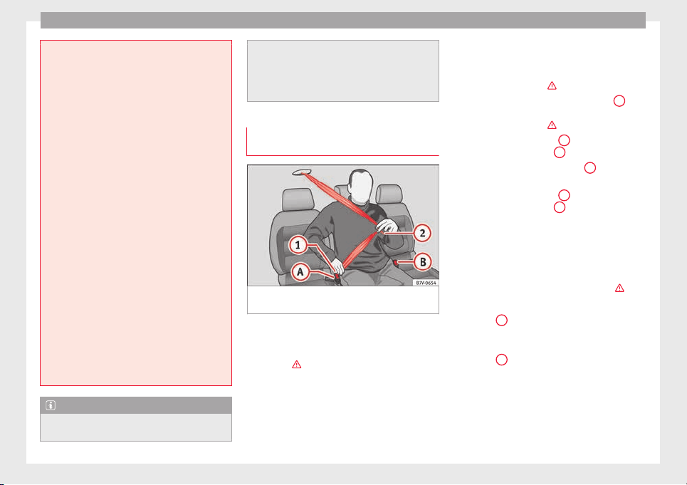
Safety
●
The seat belt
itself, or a loose seat belt, can
cause severe injuries if the belt moves from
hard areas of the body to soft areas (e.g. the
stomach).
●
The shoulder part of the seat belt must lie
on the centre of the shoulder, never across
the neck or the arm.
●
The seat belt must lie flat and fit comforta-
bly on the torso
●
The lap part of the seat belt must lie across
the pelvis, never across the stomach. The
seat belt must lie flat and fit comfortably on
the pelvis Pull the belt tight if necessary to
take up any slack.
●
For pregnant women, the lap part of the
seat belt must lie as low as possible over the
pelvis and always lie flat, “surrounding” the
stomach ››› Fig. 89.
●
Do not twist the seat belt while it is fas-
tened.
●
Once the seat belt is positioned correctly,
don't pull it away from your body with your
hand.
●
Do not lie the seat belt across rigid or frag-
ile objects, e.g. glasses, pens or keys.
●
Never use seat belt clips, retaining rings or
similar instruments to alter the position of
the belt webbing.
Note
If your physical constitution prevents you
from maint
aining the correct position of the
belt webbing, contact a specialised workshop
for help with an
y special devices to ensure
the optimum protection of the seat belt and
airbag. SEAT recommends taking your car in
for technical service.
Fastening or unfastening the seat belt
with two b
uckles
Fig. 90 Fasten the seat belt on the centre seat
in the sec
ond r
o
w of seats
Properly worn seat belts hold the vehicle oc-
c
up
ants
in the position that most protects
them in the event of an accident or sudden
braking ›››
.
The se
at
belts
for the centre seat in the sec-
ond row of seats and for the seats in the third
row of seats are fastened using two buckles.
Fastening the seat belt
Fasten your seat belt before each trip.
●
Adjust the rear seat and head restraint cor-
rectly ››› page 57.
●
Engage the seat backrest of the rear seat in
an upright position ›››
.
●
Use latch plate of the belt ›
›
›
Fig. 90
1
to
p
u
l
l the seat belt down. Do not twist the seat
belt when doing so ›››
.
●
Engage the latch plate
1
in the buckle of
the c
orr
e
sponding seat
A
.
●
Use the latch plate ›
›
›
Fig. 90
2
to pull the
se
at
belt
across your lap.
●
Engage the latch plate
2
in the buckle of
the c
orr
e
sponding seat
B
.
●
Pull the belt to ensure that both l
at
c
h
plates are securely engaged in the buckles.
Unfastening the seat belt
The seat belt must not be unfastened until
the vehicle has come to a standstill ›››
.
●
Press the red button on the buckle
›
›
›
Fig. 90
A
. The latch plate is released from
the b
uc
k
le.
●
Press the red button on the buckle
››› Fig. 90
B
. The latch plate is released from
the b
uc
k
le.
●
Guide the belt back by hand so that it rolls
up easily and the trim will not be damaged.
66
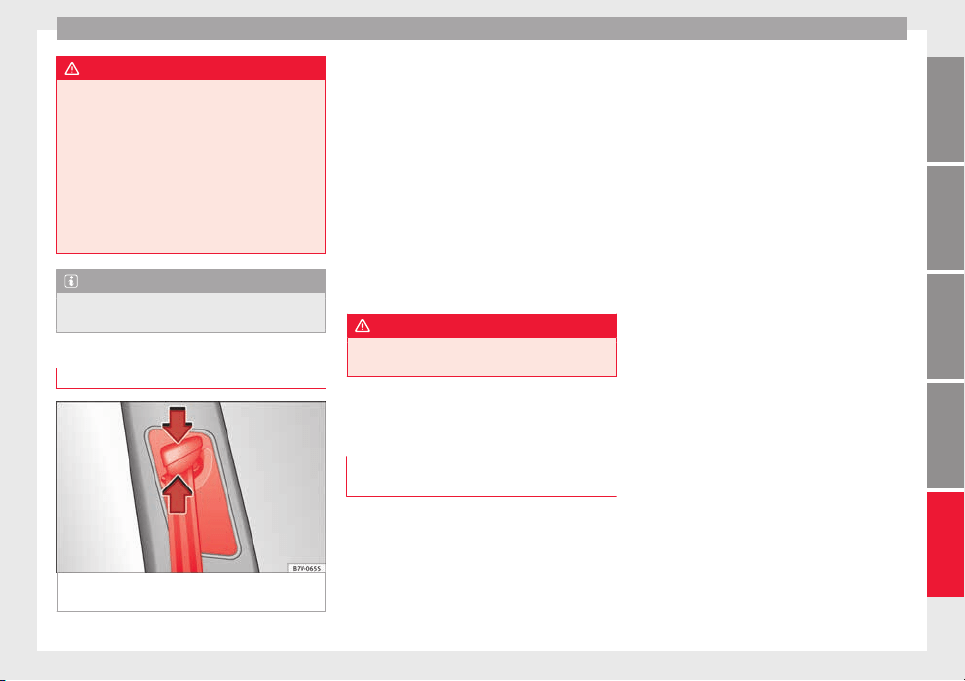
Seat belts
WARNING
An incorrectly worn seat belt web can cause
severe or f
atal injuries in the event of an acci-
dent.
●
The seat belt cannot offer its full protection
unless the seat backrests are in an upright
position and the seat belt is worn correctly,
according to your size.
●
Unbuckling your seat belt while the vehicle
is in motion can cause severe or fatal injuries
in the event of an accident or sudden braking.
Note
Seat belts with two buckles include a dia-
gram to sho
w how to fasten the seat belt.
Belt height adjustment
Fig. 91 Next to the front seats: belt height ad-
ju
s
t
er
Using the height adjusters for the front seats
and the out
er se
ats
of the second row, the
position of the seat belts can be adjusted in
the shoulder area according to the height of
the occupant:
●
Keep the guide device pressed down in the
direction of the arrow ››› Fig. 91.
●
Move the guide device up or down until the
seat belt lies over the centre of your shoulder
››› page 64.
●
Release the guide device.
●
Pull the belt sharply to check that the de-
vice is engaged securely.
WARNING
Never adjust the belt height while the vehicle
is in motion.
Seat belt tensioners
Aut
om
atic
belt retractor, belt tension-
er, belt tension limiter
Seat belts are part of the vehicle’s safety fea-
t
ur
e
s and consist of the following important
functions:
Automatic belt retainer
Every seat belt is equipped with an automatic
belt retainer on the shoulder belt. If the belt
is pulled slowly or during normal driving, the
system allows for total freedom of movement
on the shoulder belt. However, during sud-
den braking, during travel in mountains or
bends and during acceleration, the automat-
ic belt retainer on the seat belt is locked is
pulled quickly.
Belt tensioners
The seat belts on the front seats and the out-
er seats of the second row are equipped with
belt tensioners.
Sensors trigger the belt tensioners during se-
vere head-on, lateral and rear collisions and
retract and tighten the seat belts. If the seat
belt is loose, it is retracted to reduce the for-
wards movement of vehicle occupants or
movement in the direction of the collision.
The belt tensioner works in combination with
the airbag system. The belt tensioner will not
be triggered in the event of the vehicle over-
turning if the side airbags are not deployed.
If the belt tensioner is triggered, a fine dust is
produced. This is normal and it is not an indi-
cation of fire in the vehicle.
Belt tension limiter
The belt tension limiter reduces the force of
the seat belt on the body in the event of an
accident.
»
67
Technical dataAdviceOperationEmergenciesSafety
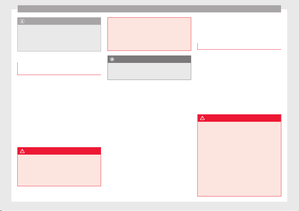
Safety
Note
The relevant safety requirements must be ob-
served when the
vehicle is dismantled or sys-
tem components are removed. These require-
ments are known to specialised workshops
››› page 68.
Service and disposal of belt tension
device
s
If you work on the belt tensioners or remove
and inst
all other parts of the vehicle when
performing other repair work, the seat belt
may be damaged. The consequence may be
that, in the event of an accident, the belt ten-
sioners function incorrectly or not at all.
So that the effectiveness of the belt tensioner
is not reduced and that removed parts do not
cause any injuries or environmental pollu-
tion, regulations must be observed. These re-
quirements are known to specialised work-
shops.
WARNING
Improper handling and homemade repairs of
seat belt
s, automatic belt retainers and ten-
sion devices increase the risk of sustaining
severe or fatal injuries. The belt tensioner
may fail to trigger or may trigger in the wrong
circumstances.
●
Never attempt
to repair, adjust or remove or
install parts of the belt tensioners or seat
belts. Any work must be performed by a spe-
cialised workshop only ››› page 247.
●
Belt tensioners and automatic belt retain-
ers cannot be repaired and must be replaced.
For the sake of the environment
Airbag modules and belt tensioners may con-
t
ain perc
hlorate. Observe the legal require-
ments for their disposal.
Airbag system
Brief
intr
oduction
Intr
oduction
Front airbags have been installed for both
driver and pa
ssenger. The front airbags can
also protect the chest and head of driver and
passenger if the seats, seat belts head re-
straints and, for the driver, the steering
wheel are correctly adjusted and used. Air-
bags are considered as additional safety
equipment. An airbag cannot replace the
seat belt, which must be worn at all times,
even in front seats where front airbags have
been installed.
WARNING
Never exclusively trust the airbag system as a
means
of protection.
●
Even when triggered, airbag protection is
only auxiliary.
●
The airbags provide the best protection
when the seat belts are properly fastened,
thus reducing the risk of sustaining injuries
››› page 64, How to properly adjust your seat-
belt.
●
Before each trip, every occupant must sit
properly, correctly fasten the seat belt be-
longing to his or her seat and keeping it fas-
tened throughout the trip. This rule is valid
for all vehicle occupants.
68

Airbag system
WARNING
Vehicle occupants sitting in the front of the
vehicl
e must never carry any objects in the
deployment space between them and the air-
bags, as this increases the risk of sustaining
injuries if the airbag is triggered. This modi-
fies the airbag deployment space or the ob-
jects may fly uncontrollably and hit your
body.
●
Never carry objects in your hand or on your
lap while the vehicle is in motion.
●
Never transport objects on the front pas-
senger seat. In the event of sudden braking
and manoeuvres, the objects may end up in
the airbag deployment space and fly uncon-
trollably around the vehicle interior if the air-
bag is activated.
●
Vehicle occupants of the front and outer
rear seats must never carry any other people,
pets or objects in the deployment space be-
tween them and the airbags. Make sure chil-
dren and other passengers also respect this
recommendation.
WARNING
The airbag system provides protection for
one accident
only. If they have been de-
ployed, they must be replaced.
●
Ensure deployed airbags and the system
components involved are immediately re-
placed with new, SEAT-approved components
for the vehicle.
●
Have any
repairs or modifications carried
out at a specialised workshop. Specialised
workshops have the necessary tools, diag-
nostics equipment, repair information and
qualified personnel.
●
Never fit recycled or reused airbag compo-
nents in your vehicle.
●
Never modify the airbag system compo-
nents.
WARNING
If the airbags are triggered, a fine dust is pro-
duc
ed. Thi
s is normal and it is not an indica-
tion of fire in the vehicle.
●
This fine dust may irritate the skin and eyes
and cause breathing difficulties, particularly
in people suffering from or who have suffered
from asthma or other illnesses of the respira-
tory tract. To reduce breathing difficulties,
get out of the vehicle and open and doors and
windows to breath in fresh air.
●
Should you touch the dust, wash your
hands and face using a mild soap and water
before you eat.
●
Prevent the dust from affecting the eyes or
open wounds.
●
Rinse your eyes with water if you have dust
in them.
WARNING
Solvents cause the surfaces of the airbag
module
s to become porous. If an airbag is ac-
cidentally triggered, the detachment of plas-
tic par
ts could cause serious injury.
●
Never clean the dash panel and the surfa-
ces of the airbag modules with cleaners con-
taining solvents.
Description of the airbag system
The airbag system is not a substitute for the
seat belts.
The airbag system offers addition-
al protection for the driver and passenger in
combination with the seat belts.
The airbag system comprises the following
modules (as per vehicle equipment):
●
Electronic control unit.
●
Front airbags for driver and passenger
●
Knee airbag for the driver
●
Side airbags
●
Head airbag
●
Airbag control lamp on the instrument
p
anel
●
Key-operated switch for front passenger air-
bag
●
Control lamp to disconnect/connect the
front airbag.
»
69
Technical dataAdviceOperationEmergenciesSafety
Safety
The airbag system operation is monitored
el
ectr
onic
ally. The airbag control lamp will il-
luminate for a few seconds every time the ig-
nition is switched on (self-diagnosis).
There is a fault in the system if the control
lamp :
●
does not light up when the ignition is
switched on,
●
turns off after 4 seconds after the ignition
is switched on
●
turns off and then lights up again after the
ignition is switched on
●
illuminates or flashes while the vehicle is
moving.
The airbag system is not triggered if:
●
the ignition is switched off
●
there is a minor frontal collision
●
there is a minor side collision
●
there is a rear-end collision
●
the vehicle turns over.
WARNING
●
The seat belt
s and airbags can only provide
maximum protection if the occupants are
seated correctly ››› page 57.
●
If a fault has occurred in the airbag system,
have the system checked immediately by a
specialised workshop. Otherwise there is a
danger that during a collision, the system
may
fail to trigger, or not trigger correctly.
Airbag activation
The airbags deploy extremely rapidly, within
thousandths
of a second, to provide addi-
tional protection in the event of an accident.
The airbag system is only ready to function
when the ignition is on.
In special accidents instances, several air-
bags may activate at the same time.
In the event of minor head-on and side colli-
sions, rear-end collisions, overturning or roll-
over of the vehicle, airbags do not activate.
Activation factors
The conditions that lead to the airbag system
activating in each situation cannot be gener-
alised. Some factors play an important role,
such as the properties of the object the vehi-
cle hits (hard/soft), angle of impact, vehicle
speed, etc.
Deceleration trajectory is key for airbag acti-
vation.
The control unit analyses the collision trajec-
tory and activates the respective restraint
system.
If the deceleration rate is below the prede-
fined reference value in the control unit the
airbags will not be triggered, even though
the accident
may cause extensive damage to
the car.
The following airbags are triggered in seri-
ous head-on collisions
●
Driver airbag.
●
Front passenger front airbag
●
Knee airbag for the driver.
The following airbags are triggered in seri-
ous side-on collisions
●
Front side airbag on the side of the acci-
dent.
●
Rear side airbag on the side of the acci-
dent.
●
Curtain (head) airbag on the side of the ac-
cident.
In an accident with airbag activation:
●
the interior lights switch on (if the interior
light switch is in the courtesy light position);
●
the hazard warning lights switch on;
●
all doors are unlocked;
●
the fuel supply to the engine is cut.
70

Airbag system
Airbag safety instructions
Fr
ont
airb
ags
Read the additional information carefully
›››
page 17.
WARNING
The airbag is deployed at high speed in frac-
tions of
a second.
●
Always keep the deployment areas of the
front airbags free.
●
Never secure objects to the covers or in the
deployment area of the airbag modules, e.g.
drink holders or phone supports.
●
The deployment space between the front
passengers and the airbags must not in any
case be occupied by other passenger, pets
and objects.
●
Never fix any object to the windscreen
above the front airbag on the front passenger
side.
●
Do not alter, cover or stick anything to the
steering wheel hub or the surface of the air-
bag module on the passenger side of the
dash panel.
WARNING
Front airbags are deployed in front of the
steerin
g wheel ›››
Fig. 26 and the dash
panel ›››
Fig. 27.
●
When driving, a
lways hold the steering
wheel on the outer edge of the ring with both
hands: 9 o'clock and 3 o'clock position.
●
Adjust the driver seat so that there is at
least 25 cm distance between your chest and
the hub of the steering wheel. If your physi-
cal constitution prevents you from meeting
these requirements, make sure you contact a
specialised workshop.
●
Adjust the front passenger seat so there is
as much distance as possible between the
front passenger and the dash panel.
Knee airbag*
Read the additional information carefully
›
›
›
page 18.
WARNING
The airbag is deployed at high speed in frac-
tions of
a second.
●
The knee airbag is deployed in front of the
driver's knees. Always keep the deployment
areas of the knee airbags free.
●
Never not fix objects to the cover or in the
deployment area of the knee airbag.
●
Adjust the driver seat so that there is a dis-
tance of at least 10 cm (4 inches) between
your knees and the location of the knee air-
bag. If your physical constitution prevents
you from meeting these requirements, make
sure you contact a specialised workshop.
Side airbags*
Read the additional information carefully
›››
page 19.
WARNING
The airbag is deployed at high speed in frac-
tions of
a second.
●
Always keep the deployment areas of the
side airbags free.
●
Vehicle occupants of the front and outer
rear seats must never carry any other people,
pets or objects in the deployment space be-
tween them and the airbags.
●
The built-in coat hooks should be used only
for lightweight clothing. Do not leave any
heavy or sharp-edged objects in the pockets.
●
Do not mount accessories on the doors.
●
Only used protective covers for the seats
that are approved for the vehicle. Otherwise,
the side airbag would be obstructed when de-
ployed.
WARNING
Incorrect handling of the driver's and front
pas
senger seat could prevent the side airbag
from deploying properly and cause severe in-
juries.
●
Never remove the front seats of the vehicle
or modify any of their components.
»
71
Technical dataAdviceOperationEmergenciesSafety
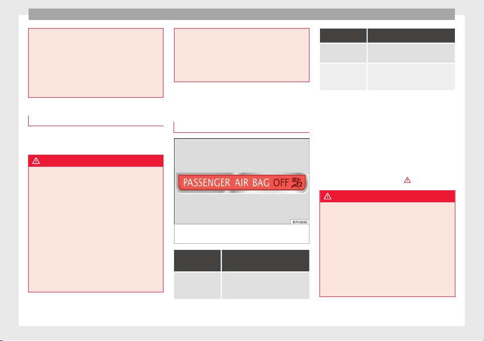
Safety
●
Great
forces must not be exerted on the
seat backrest bolsters because the side air-
bags might not deploy correctly, might not
deploy at all or might deploy unexpectedly.
●
Any damage to the original seat upholstery
or around the seams of the side airbag units
must be repaired immediately by a special-
ised workshop.
Curtain airbags*
Read the additional information carefully
›
›
›
page 20.
WARNING
The airbag is deployed at high speed in frac-
tions of
a second.
●
Always keep the deployment areas of the
head-protection airbags free.
●
Do not fix objects to the cover or in the de-
ployment area of the curtain airbag.
●
Vehicle occupants of the front and outer
rear seats must never carry any other people,
pets or objects in the deployment space be-
tween them and the airbags.
●
The built-in coat hooks should be used only
for lightweight clothing. Do not leave any
heavy or sharp-edged objects in the pockets.
●
Do not mount accessories on the doors.
●
Do not fit c
urtains to the windows other
than those expressly approved for use in the
vehicle.
●
Only turn the sun blinds towards the win-
dows if there is no object, e.g. pens or garage
remote controls, secured to the sun blind.
Deactivating airbags
Contro
l lamp
Fig. 92 Control lamp for disabling the front
p
a
s
senger front airbag on the dash panel
It lights up on the combi-in-
strument
Fault in airbag
system and seat
belt tensioners.
Have the system checked immedi-
ately by a specialised workshop.
It lights up on the dash panel
Fault in the air-
bag system.
Have the system checked immedi-
ately by a specialised workshop.
Front passenger
front airbag disa-
bled.
Check whether the airbag should
remain disabled
Several warning and indication lamps light
up for a few sec
onds when the ignition is
switched on, signalling that the function is
being verified. They will switch off after a few
seconds.
If the front passenger airbag is deactivated,
the lamp does not re-
main lit, or if it is lit together with the control
lamp on the dash panel, there may be a
fault in the airbag system
›››
.
WARNING
In the event of a fault in the airbag system,
the airbag ma
y not trigger correctly, may fail
to trigger or may even trigger unexpectedly,
leading to severe or fatal injuries.
●
Have the airbag system checked immedi-
ately by a specialised workshop.
●
Never mount a child seat in the front pas-
senger seat ››› page 78 or remove the
mounted child seat! The front passenger front
airbag may deploy during an accident in spite
of the fault.
72
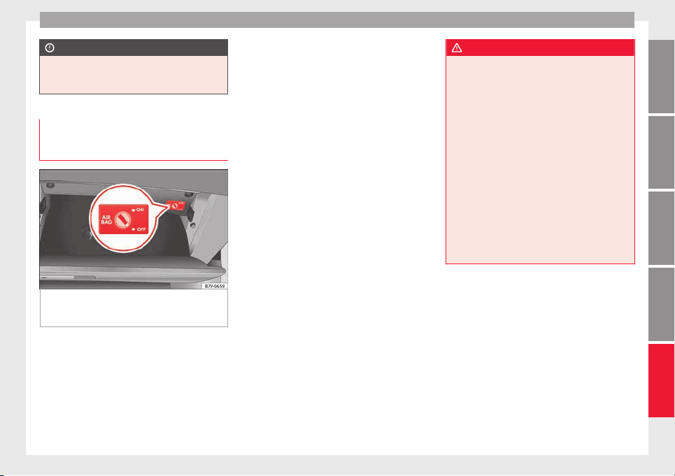
Airbag system
CAUTION
Always pay attention to any lit control lamps
and to the corr
esponding descriptions and in-
structions to avoid damage to the vehicle.
Manual disabling and enabling of the
front p
assenger front airbag with the
key switch
Fig. 93 In the glove compartment on the front
p
a
s
senger side: Key switch for enabling and
disabling the front passenger front airbag.
Read the additional information carefully
›
›
›
page 18.
The front passenger front airbag must be dis-
abled when a rear-facing child seat is moun-
ted.
Activating the front passenger front airbag
●
Switch the ignition off.
●
Open the glove compartment on the front
passenger side.
●
Insert the key into the slot of the switch for
deactivating the front passenger airbag
››› Fig. 93. About 3/4 of the key should enter,
as far as it will go.
●
Then turn the key gently to the ON position.
Do not force it if you feel resistance, and
make sure you have inserted the key fully.
●
Close the glove compartment on the front
passenger side.
●
Check that, with the ignition switched on,
the control lamp on the
dash panel is not lit ››› page 72.
How to know whether the front passenger
front airbag is disabled
The only indication of the front passenger air-
bag being disabled is that the
control lamp on the dash panel re-
mains lit ( stays yellow) ››› page 72,
Control lamp.
If the control lamp on
the centre console does not remain lit or is lit
in combination with the control lamp on
the dash panel, a child restraint system can-
not be mounted on the front passenger seat
for safety reasons. The front passenger front
airbag may deploy during an accident.
WARNING
The front passenger front airbag must only be
disab
led in special cases.
●
Disable and activate the front passenger
front airbag when the ignition is switched off
to avoid damage to the airbag system.
●
It is the driver's responsibility to ensure
that the key operated switch is set to the cor-
rect position.
●
Only disable the front passenger front air-
bag when a child seat is to be mounted under
exceptional circumstances.
●
As soon as the child seat is no longer nee-
ded on the front passenger seat, reconnect
the front passenger front airbag.
●
Never leave the key in the airbag deactiva-
tion switch as it could get damaged or acti-
vate or deactivate the airbag during driving.
73
Technical dataAdviceOperationEmergenciesSafety
Safety
Transporting children safely
Saf
ety
f
or children
Introduction
Read the additional information carefully
›››
page 20.
Please read the information regarding the air-
bag system fully before transporting babies
and children in a child seat or other child re-
straint system installed on the front passen-
ger seat.
This information is extremely important for
driver and passenger safety, particularly that
of babies and children.
SEAT recommends the use of child seats from
the SEAT accessory programme. These child
seats have been designed and tested for use
in SEAT vehicles. You can purchase child
seats with different mountings from a techni-
cal service centre.
Using child restraint systems with a base or
foot
Some child retention systems are secured to
the seat using a base or support leg. For cer-
tain kinds of equipment the use of an addi-
tional accessory will be necessary (e.g. an ac-
cessory for the footwell) to fit the child reten-
tion system correctly and securely.
WARNING
Make sure children are properly belted in and
correctly
secured to avoid severe or fatal inju-
ries while the vehicle is in motion.
●
If a child seat is secured to the front pas-
senger seat, the risk to the child of sustain-
ing critical or fatal injuries in the event of an
accident increases.
●
An inflating front passenger airbag can
strike the rear-facing child seat and project it
with great force against the door, the roof or
the backrest.
●
Never install a child seat facing backwards
on the front passenger seat unless the front
passenger front airbag has been disabled.
Risk of potentially fatal injuries to the child!
However, if it is necessary, in exceptional ca-
ses, to transport a child in the front passen-
ger seat, the front passenger front airbag
must always be disabled ››› page 72. If the
passenger seat has a height adjustment op-
tion, move it to the highest, most upright po-
sition. If you have a fixed seat, do not install
any child restraint system in this location.
●
For those vehicles that do not include a key
lock switch to deactivate the airbag, the vehi-
cle must be taken to a technical service.
●
Children up to 12 years old should always
travel on the rear seat.
●
Children must always be protected with an
approved child restraint system suited to
their height and weight.
●
Childr
en must assume the proper sitting
position and be properly belted in while trav-
elling.
●
Ensure the seat backrest is upright when a
child seat is being used on it.
●
Do not allow the child's head or other part
of his or her body to fall into the deployment
area of the side airbags.
●
Make sure the belt webbing is correctly
positioned.
●
Never hold children or babies on your lap or
in your arms.
●
Only one child may occupy a child seat.
●
If you are using a child seat with a base or
foot, always install this base or foot correctly
and safely.
●
If the vehicle has a storage compartment in
the footwell in front of the last row of seats,
this compartment cannot be used as de-
signed; on the contrary: It must be filled us-
ing the specially designed accessory so that
the base or foot is correctly supported by the
closed compartment and the child seat is se-
cured properly. If this compartment is not
suitably secured when using a child seat with
a base or foot then the compartment cover
could rupture in an accident and the child will
be ejected and suffer serious injury.
●
Please read and observe the child seat
manufacturer's handling instructions.
74
Transporting children safely
WARNING
An empty or loose child seat could fly uncon-
trol
lably around the vehicle interior and
cause injuries in the event of an accident or
sudden braking.
●
When not in use while the vehicle is in mo-
tion, always safely secure the child seat or
store it in the luggage compartment.
Note
Replace the child seat after an accident, as it
may
have invisible damage.
Important information regarding the
fr
ont
p
assenger's airbag
Read the additional information carefully
›
›
›
page 20.
Read and always observe the safety informa-
tion included in the following chapters:
●
Child seats and passenger side airbag
›››
page 76, Use of the child seat on the
front passenger seat.
●
Safety distance with respect to the passen-
ger airbag
›››
in Introduction on page 68.
●
Objects between the passenger and the
p
a
s
senger side airbag
›››
in Front airbags
on p
ag
e 71
.
Child seats
Safety instructions
Read the additional information carefully
›››
page 20.
WARNING
The lower anchor points for child seats are
not anchor
s meant to support cargo. Only se-
cure booster seats to lower anchor points.
WARNING
Child seats with lower anchor points and with
an upper ret
aining strap must be installed in
line with the manufacturer's instructions.
Failure to comply could result in severe inju-
ries.
●
Always secure just one retaining strap from
a child seat to a retaining ring (for Top Tether)
on the seat backrest on the rear seat in the
boot.
●
Never fix child seats to the cargo anchors in
the luggage compartment.
●
Never secure a child seat to the movable at-
tachment elements for vehicles with an at-
tachment element and rail system.
WARNING
In general, the rear seat is always the safest
plac
e for correctly belted in children in the
event of an accident.
●
A suitab
le child seat that is correctly instal-
led and used on one of the rear seats offer
the most protection possible for babies and
small children in most accidents.
WARNING
Unbuckling the seat belt while the vehicle is
in motion c
an cau
se severe or fatal injuries in
the event of an accident or sudden braking.
●
The seat belt must not be unfastened until
the vehicle has come to a standstill.
Note
Other accessories may be required to fit the
chil
d retention system with a base or foot se-
curity and safely. Contact a technical service
centre or specialised workshop.
General information on transporting
c
hi
l
dren in the vehicle
Read the additional information carefully
›
›
›
page 21.
Legal regulations and provisions will always
take priority over the descriptions of this in-
struction manual. There are different regula-
tions and provisions for the use of child seats
and their mountings (
›››
table on page 76).
In some countries, for example, the use of
child seats on certain seats in the vehicle
may be forbidden.
»
75
Technical dataAdviceOperationEmergenciesSafety
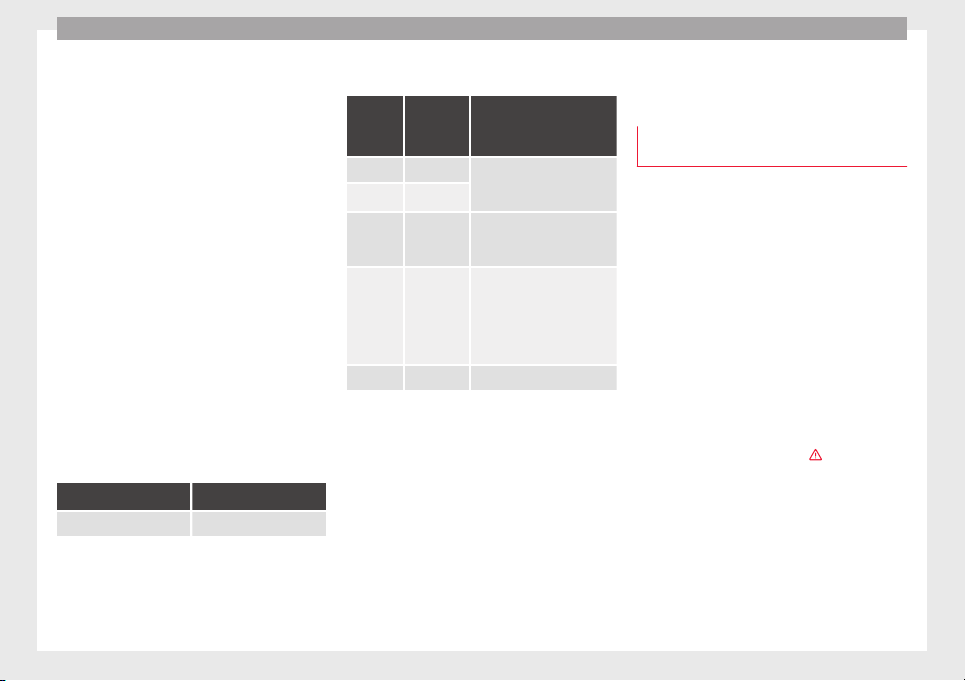
Safety
The physical principles and the forces acting
on the
v
ehic
le in the event of a collision or
other type of accidents also apply to children
››› page 64. However, unlike adults and
youngsters, children do not have fully devel-
oped muscle and bone structures. In the
event of an accident, children are subject to a
greater risk than adults of sustaining severe
injuries.
Given that children's bodies are not yet fully
developed, child restraint systems must be
used that are especially adapted to their
height, weight and constitution. There are
laws in force in many countries that indicate
the use of approved seat systems for trans-
porting babies and children.
Only used authorised, approved child seats
that are suitable for the vehicle. Always con-
sult with a technical service centre or a speci-
alised workshop should you have any
doubts.
Specific child seat regulations for each coun-
try (selection)
Regulation Further information
ECE-R 44
a)
technical service centre
a)
ECE-R: Economic Comission for Europe Regulation.
Categorisation of child seats according to
ECE-R44
Weight
catego-
ry
Weight of
the child
Installation of the child
seat
Group 0 up to 10 kg Rear-facing. On rear seats,
optionally using the ISOFIX
system.
Group 0+ up to 13 kg
Group 1 9 to 18 kg
Forward-facing. On rear
seats, optionally using the
ISOFIX system.
Group 2 15 to 25 kg
Forward-facing. On the outer
rear seats or in the centre
seat of the second row of
seats and on all seats in the
third row. Optionally with
ISOFIX system.
Group 3 22 to 36 kg Forward-facing.
Not all children fit in the seat of their weight
gr
oup
. Nor do al
l seats adapt to the vehicle.
Therefore, always check whether the child fits
properly in the child seat and whether the
seat can be installed safely in the vehicle.
The rear seats are suitable for child seats
with the ISOFIX system specially designed
for this type of vehicle in accordance with
regulation ECE-R 44.
Child seats approved under the ECE-R 44 reg-
ulation are fitted with the corresponding ap-
proval symbol. The sign is an upper-case E in
a circle with the identification number below
it.
Use of the child seat on the front pas-
senger seat
Transporting children on the front passenger
seat i
s not permitted in all countries. Further-
more, not all child seats are approved for use
on the front passenger seat. Your technical
service centre has an updated list of all ap-
proved child seats. Only used child seats that
are approved for each vehicle.
The front airbag on the front passenger side
is highly dangerous for a child. The front pas-
senger seat is life-threatening to a child if he
or she is transported in a rear-facing child
seat.
If a rear-facing child seat is secured to the
front passenger seat, an inflating front airbag
can strike it with such great force that severe
or fatal injuries may result
›››
. Therefore,
r
e
ar
-facing child seats must never be placed
on the front passenger seat when the front
passenger front airbag is enabled.
Only use a rear-facing child seat on the front
passenger seat if the front passenger front
airbag is disabled. When it is disabled, the
yellow PASSENGER AIR BAG control
lamp on the dash panel will be lit
›››
page 72.
If you cannot disable the front passenger
front airbag and it remains activated, it is
76
Transporting children safely
forbidden to transport children on the front
p
a
s
senger seat ›››
.
Thin
g
s
to note if using a child seat on the
front passenger seat:
●
The front passenger front airbag must be
disabled when using a rear-facing child
seat ››› page 73.
●
The seat backrest of the front passenger
seat must be upright.
●
The front passenger seat must be moved as
far back as possible.
●
The seat backrest of the front passenger
seat must be upright.
●
The seat belt height adjustment must be as
high as possible.
Suitable child seats
The child seat must be authorised by the
manufacturer especially for use on a front
passenger seat with a front or side airbag.
If the front passenger seat is equipped with
retaining rings, the child seat can be secured
using an approved retaining system provided
it is approved for this type of vehicle in ac-
cordance with current regulations of the
country in question.
Universal seats for children of groups 0, 0+,
1, 2 or 3 according to the standard ECE-R 44
can be mounted on the front passenger seat
and the rear seats.
WARNING
If a child seat is mounted on the front passen-
ger seat, the ri
sk of the child sustaining se-
vere or fatal injuries in the event of an acci-
dent increases. Rear-facing child seats must
never be mounted on the front passenger
seat when the front passenger front airbag is
enabled. This is life-threatening to the child
should the front airbag deploy, as the child
seat would be struck by the inflated airbag
and thrown against the seat backrest.
WARNING
If, in exceptional circumstances, a child must
be trans
ported in a rear-facing child seat on
the front passenger seat, strictly observe the
following:
●
Always disable the front passenger front
airbag and leave it disabled.
●
The child seat must be approved by the
manufacturer for use on a front passenger
seat with front and side airbag.
●
Follow the installation instructions of the
child seat manufacturer and observe the
warnings.
●
Move the front passenger seat as far back
as possible and adjust it to its highest posi-
tion to keep as far away as possible from the
front airbag.
●
Move the seat backrest to the upright posi-
tion.
●
The seat belt height adjustment must be as
high as possible.
●
Childr
en must always be protected with an
approved child restraint system suited to
their height and weight.
Use of the child seat on the rear seat
If a child seat is mounted on the rear seat,
adapt
the position of the front passenger
seat so that the child has enough space.
Therefore, adapt the front passenger seat to
the size of the child seat and the height of
the child. Ensure the passenger is in the cor-
rect position ››› page 57.
Move the second and third rows of seats fully
back and lock them. Place the seat backs in a
vertical position and fold the head restraints
down.
ISOFIX child seats approved for rear seats
The rear seats are suitable for child seats
with the ISOFIX system specially designed
for this type of vehicle in accordance with
regulation ECE-R 44.
ISOFIX child seats are divided into “specific
categories for the vehicle”, “limited” or
“semi-universal”.
Child seat manufacturers supply a list of ve-
hicles with each ISOFIX seat, which includes
the models for which the ISOFIX child seat in
question is approved. If the vehicle is inclu-
ded in the manufacturer's list and the ISOFIX
»
77
Technical dataAdviceOperationEmergenciesSafety
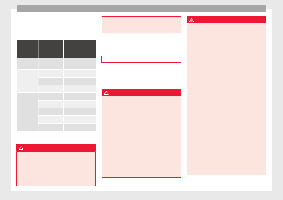
Safety
child seat belongs to a seat category inclu-
ded in the li
s
t, then it
can be used in your ve-
hicle. If necessary, contact the child seat
manufacturer for an updated list of vehicles.
Group
(weight
category)
ISOFIX child
seat category
Seat position in
the rear seats
Group 0:
to 10 kg
E IUF
a)
Group 0+:
to 13 kg
E IUF
a)
D IUF
a)
C IUF
a)
Group 1:
9 to 18 kg
D IUF
a)
C IUF
a)
B IUF
a)
B1 IUF
a)
A IUF
a)
a)
IUF: suitable for “universal” ISOFIX child seats authorised for
use in this group.
WARNING
If child seats are fitted to all the seats in the
second ro
w then it is possible that the seats
of this row cannot be folded down from the
third row of seats in case of an accident. In
the event of an emergency, passengers in the
third row of seats will not be able to leave the
vehicle or to help themselves.
●
Child se
ats should never occupy all the
seats of the second row if other passengers
are to occupy the third row of seats.
Integrated child seat
Introduction
The integrated child seat is only suitable for
chil
dren in Group 2 (15-25 kg) and Group 3
(22-36 kg), according to the ECE-R44 regula-
tion.
WARNING
Child travelling without their seat belt fas-
tened or not sec
ured using a suitable re-
straint system may sustain fatal injuries if
the airbag is deployed.
●
Children up to 12 years old should always
travel on the rear seat.
●
Always disable the front passenger front
airbag if, in exceptional cases, you have no
alternative but to transport a child in a rear-
facing child safety seat on the front passen-
ger seat.
●
Children must always be protected with a
child restraint system suited to their height
and weight.
●
Always fasten children's seat belts correct-
ly.
WARNING
Children must travel in a child seat appropri-
ate to their w
eight and height while the vehi-
cle is in motion.
●
Children must always be protected with a
child restraint system suited to their height
and weight.
●
Children must assume the proper sitting
position and be properly belted in while trav-
elling.
●
The shoulder part of the seat belt must lie
approximately on the centre of the shoulder,
never across the neck or the arm.
●
The seat belt must lie close to the upper
part of the body.
●
The lap belt part must lie across the pelvis,
not across the stomach, and always fit close-
ly.
●
Allow the belt to retract until it fits tightly
over the child's seat.
●
Never hold children or babies on your lap.
●
Always use a child seat and the seat belt
for children who are under 1.5 m tall. The nor-
mal seat belt could cause injuries to the ab-
dominal and neck areas.
●
Only one child may occupy a child seat.
●
Read and follow the information and warn-
ings provided by the child seat manufacturer.
●
Never leave an unsupervised child alone on
a child seat or in the vehicle.
78
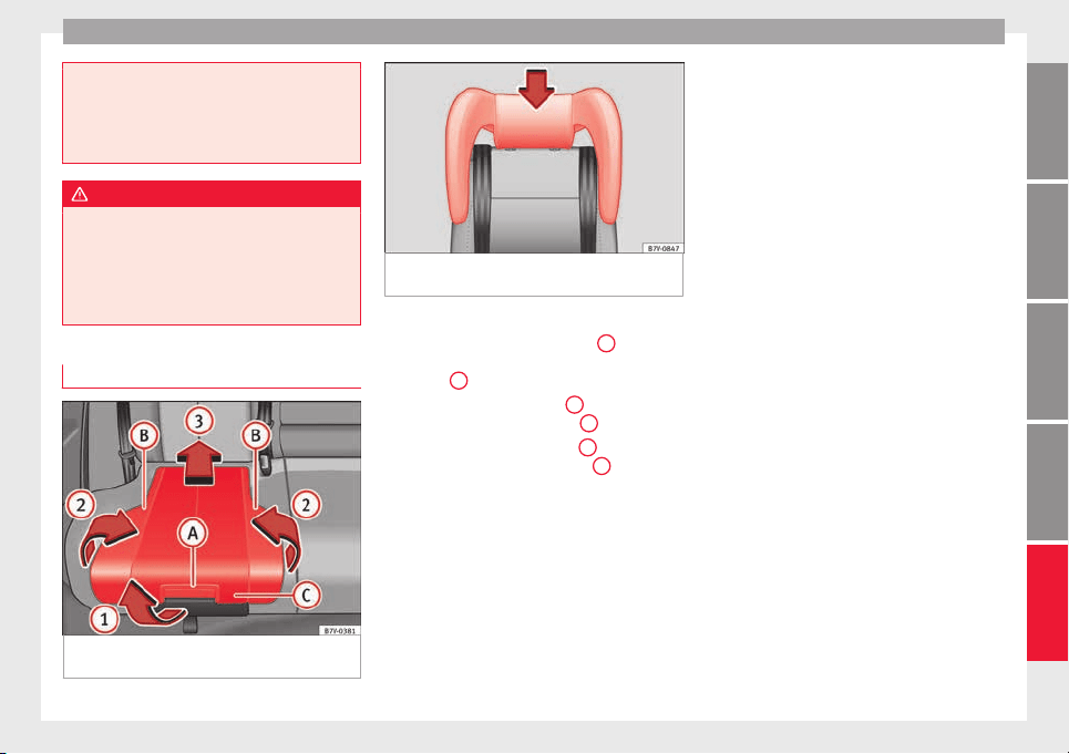
Transporting children safely
●
All
modifications to the integrated child
seat must be carried out by a specialised
workshop.
●
Replace the child seat or any seat compo-
nents damaged or involved in an accident.
WARNING
Loose objects could fly uncontrollably around
the
vehic
le interior and cause injuries in the
event of an accident or sudden braking.
●
Do not leave toys or other hard, loose ob-
jects on the child seat or on the seat while
the vehicle is in motion.
Unfolding the integrated child seat
Fig. 94 Integrated child seats. lift up the
c
u
shion
Fig. 95 Integrated child seats. install its head
suppor
t.
Lifting the cushion
●
Pull the unlock lever ›
›
›
Fig. 94
A
on the
c
u
shion in the dir
ection of the arrow
››› Fig. 94
1
.
●
Fold both sides ›
›
›
Fig. 94
B
up in the di-
r
ection of
the arr
ow ››› Fig. 94
2
.
●
Push the cushion ›
›
›
Fig. 94
C
back in the
dir
ection of
the arr
ow ››› Fig. 94
3
until it en-
g
ag
e
s.
Install the head restraint on the child safety
seat
●
Remove the head support and store it safe-
ly in the vehicle ››› page 142.
●
Make sure that the seat belt guide is instal-
led in the head support of the seat for chil-
dren on the window side ››› page 80.
●
Enter the child seat head support in the
corresponding backrest until it fits correctly
into place ››› Fig. 95.
●
Make sure that the rear seats and backrests
are correctly locked into place, pulling on
both of them.
79
Technical dataAdviceOperationEmergenciesSafety
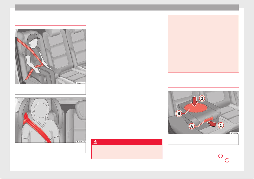
Safety
Seat belt routing on the integrated
c
hi
l
d seat
Fig. 96 Integrated child seats. adjusting the
se
at
belt
.
Fig. 97 Integrated child seats. seat belt rout-
in
g w
ith guide h
andle
Using the guide handle ›
›
›
Fig. 97, position
the seat belt so that the shoulder part of the
belt lies on the centre of the child's shoulder.
Seat belt guide handle
●
Secure the seat belt guide handle to the
side head restraint on the window side. The
guide handle is secured by a button.
●
Open the upper button on the seat belt
guide handle and pass the belt webbing be-
low the side head restraint and through the
guide handle.
●
Close the button again.
Adjusting the seat belt
●
Guide the automatic three-point seat belt
below the side head restraint.
●
Pull the latch plate and slowly place the
belt webbing across the child's chest and
lap.
●
Insert the latch plate into the buckle for the
appropriate seat and push it down until it is
securely locked with an audible click.
●
Pull the belt to ensure that the latch plate is
securely engaged in the buckle.
WARNING
The seat belt only offers maximum protection
from sever
e or fatal injuries when it is cor-
rectly positioned.
●
Childr
en must assume the proper sitting
position and be properly belted in while trav-
elling.
●
The shoulder belt must be positioned
against the middle of the shoulder.
●
The seat belt must lie flat and fit comforta-
bly.
●
Allow the belt to retract until it fits tightly
over the child's seat.
●
The lap part of the seat belt must lie across
the pelvis, never across the stomach.
●
Only one child may occupy a child seat.
Removing the child seat
Fig. 98 Integrated child seats. lowering the
c
u
shion
Lowering the cushion
●
Pull the unlock lever ›
›
›
Fig. 98
A
on the
c
u
shion in the dir
ection of the arrow
1
.
80
Transporting children safely
●
P
u
sh the c
ushion down through the central
area
B
in the direction of the arrow
2
until
it
s
af
ely engages ›››
. The side supports fold
a
w
a
y automatically.
Remove the head restraint on the child safe-
ty seat
●
Open the guide lever on the seat belt and
guide it by hand to pull the belt back in more
easily and without damaging the trim.
●
Lift the child seat head restraint to the top.
●
Fold the backrest of the rear seat forwards
››› page 146.
●
Remove the head restraint on the child
safety seat.
●
Fitting the head restraint.
CAUTION
When lowering the integrated child seat, only
pres
s on the centre of the cushion ››› Fig. 98
2
. Otherwise the cushion could bend and
not eng
age properly.
81
Technical dataAdviceOperationEmergenciesSafety
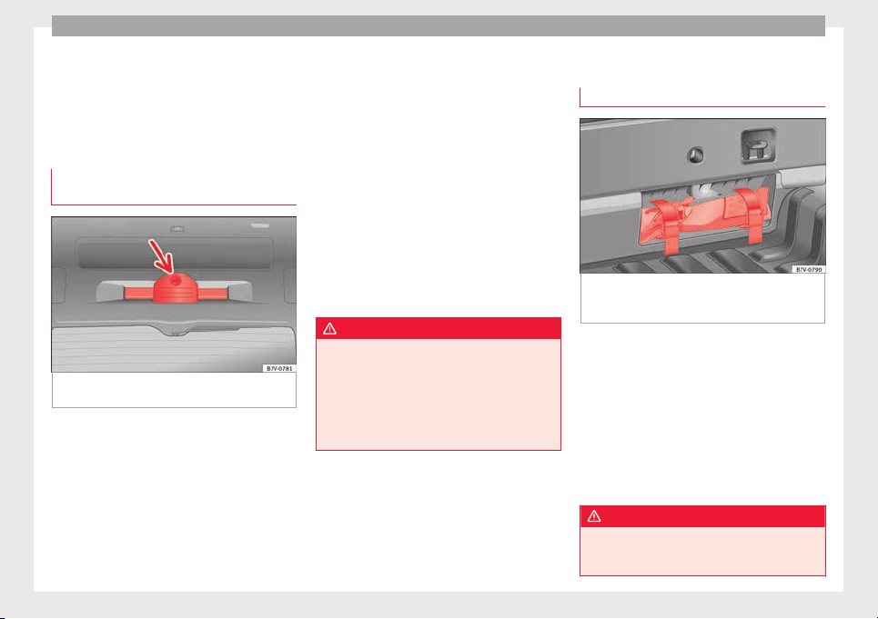
Emergencies
Emergencies
Self
-help
In c
a
se of emergency
First aid kit, warning triangle, reflec-
tive vests and fire extinguishers*
Fig. 99 On the rear lid: Warning triangle
br
ac
k
et
Reflective vests
Some
v
ehic
les will have a driver door com-
partment to store a reflective vest
››› page 98.
Warning triangle
With the boot hatch open, rotate the lock 90°
››› Fig. 99. Lower the bracket and remove the
warning triangle.
First-aid kit
There is a first aid kit ››› page 166 in the rear
left-hand side storage compartment of the
luggage compartment.
The first aid kit must comply with legal re-
quirements. Check the expiry date of the con-
tents of the first aid kit.
Fire extinguisher
There is a Fire extinguisher underneath the
front passenger seat.
The fire extinguisher must conform to legal
requirements, be ready for use and be
checked regularly. Check the certification
seal on the extinguisher.
WARNING
Loose objects in the vehicle interior can be vi-
olently
thrown in case of a sudden manoeu-
vre or braking and especially in accidents
causing serious injury.
●
Secure fire extinguishers, first aid kit, re-
flective vests and warning triangle securely
to their respective supports.
Vehicle tool kit*
L
oc
ation
Fig. 100 In the luggage compartment, viewed
fr
om in
s
ide the vehicle: the vehicle tool kit lo-
cated in a cavity close to the lock carrier.
When securing the vehicle in case of a break-
do
wn, p
l
ease note the legal requirements for
each country.
Depending on the model, the vehicle tools
may be kept in the luggage compartment, in
a cavity close to the lock carrier ››› Fig. 100.
Loosen the safety straps and remove the ve-
hicle tool kit. For vehicles factory-fitted with
winter tyres, you will find additional tools in a
toolbox located in the luggage compartment.
WARNING
Loose objects in the vehicle interior can be vi-
olently
fired through the compartment in
case of a sudden manoeuvre or braking and
82
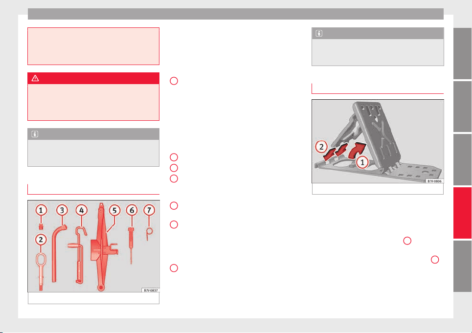
Self-help
especially in accidents causing serious in-
jury.
●
M
ake sure that the vehicle tools are stored
safely in the luggage compartment.
WARNING
Unsuitable or damaged vehicle tools can
c
ause injur
y or accidents.
●
Never work with inappropriate or damaged
tools.
Note
After use, return the jack to its initial position
usin
g the handle in order to securely store it
in the vehicle.
Components
Fig. 101 Components of the vehicle tool kit
The vehicle tool kit depends on the vehicle
equipment
.
The f
ollowing is a description for
a vehicle with all options.
The individual elements of the vehicle tool
kit ››› Fig. 101
Adapter for anti-theft bolt. SEAT recom-
mend you carry the wheel bolt adapter in
the vehicle tool kit at all times. The code
number of the anti-theft wheel bolt is
stamped on the front of the adapter. In
case it is lost, another adapter can be or-
dered using this number. Note the anti-
theft bolt code for the wheels and keep it
in a place other than the vehicle.
Towline anchorage, removable.
Wheel spanner.
Jack crank handle. The crank handle
needs to be folded away before returning
it to the tool kit.
Jack. Before storing the jack in the tool
kit, fold its hook.
Screwdriver with hexagon socket in the
handle for screwing and unscrewing the
wheel bolts. The screwdriver bit is inter-
changeable. The screwdriver may be
found underneath the wheel spanner.
Wire hook for pulling off the wheel cover,
integral hubcaps and the wheel bolt
caps.
1
2
3
4
5
6
7
Note
The jack does not generally require any main-
tenanc
e. If required, it should be greased us-
ing universal type grease.
Folding wheel chocks*
Fig. 102 To unfold the foldable wedges.
The folding chocks are in the tool kit
›
›
›
Fig. 101.
Assemble the folding chocks
●
Lift the base plate ››› Fig. 102
1
.
●
Insert the two “tabs” of the mounting plate
int
o the lon
g openin
gs on the base plate
2
.
C
orr
ect
use
The folding chocks may be used to block the
wheel diagonally opposite to the wheel being
changed.
»
83
Technical dataAdviceOperationEmergenciesSafety
Emergencies
The chocks should be placed directly in front
and behind the wheel
and on
ly
be used on
firm ground.
WARNING
If the folding chocks are assembled or used
incorrectly
, an accident may occur and seri-
ous injury caused.
●
Never use damaged chocks.
●
Never use chocks to immobilize the vehicle
on a slope.
Changing a wheel*
Intr
oduction
Read the additional information carefully
›
›
›
page 45
All Alhambra models have TMS (Tyre Mobility
System).
If a tyre needs to be changed the tools neces-
sary are available at spare parts dealers:
●
Jack,
●
box spanner for wheel bolts,
●
tool to remove wheel bolt caps
The tyres mounted on the vehicle are anti-
puncture. The wheels should only be
changed when switching from summer to
winter tyres or vice-versa. See
›››
page 294
The vehicle only comes with the necessary
tools for changing wheels if factory supplied
with winter tyres. If this is not the case, you
need to go to a specialised workshop to get
the wheels changed.
You should only change the wheels yourself if
the vehicle is parked in a safe place, you are
familiar with the procedure and safety stand-
ards and you have all the necessary tools!
Otherwise, you should seek professional as-
sistance.
WARNING
Changing a wheel can be dangerous, espe-
cia
lly on the hard shoulder. Please observe
the following rules to minimise the risk of in-
jury:
●
Stop the vehicle safely as soon as possible.
Park at a safe distance from surrounding traf-
fic to change a wheel.
●
When changing a wheel, keep all passen-
gers, and particularly children, a safe dis-
tance away from the work area.
●
Turn on the hazard warning lights to warn
other road users.
●
Ensure the ground on which you park is flat
and solid. If necessary, support the jack on a
wide solid base.
●
If you are changing a wheel yourself, you
should be familiar with the required proce-
dure. Otherwise, you should seek professio-
nal assistance.
●
Only u
se suitable tools that are not dam-
aged when changing a wheel.
●
Always stop the engine, turn on the elec-
tronic parking brake and place the gear selec-
tor lever in position P, for an automatic gear-
box, or engage a gear for a manual gearbox to
reduce the risk of the vehicle moving acciden-
tally.
●
Have the tightening torque of the wheel
bolts checked as soon as possible with a reli-
able torque wrench.
WARNING
If the wheel trims are not appropriate or not
fitted corr
ectly, they could cause major acci-
dents or damage.
●
Incorrectly mounted wheel trims may come
off while driving and endanger other road
users.
●
Damaged trims must never be mounted on
the wheels.
●
Always ensure that the brake ventilation
and cooling is not cut off or blocked. This is
also valid if hubcaps are fitted later. If there
is not enough air, you may require signifi-
cantly longer braking distances.
CAUTION
Remove and remount wheel trims taking care
to avoid d
amage to the vehicle.
84
Self-help
Tyre repair
TM
S
(T
yre Mobility System)*
Read the additional information carefully
›››
page 44
The Anti-puncture kit* (Tyre Mobility System)
will reliably seal punctures caused by the
penetration of a foreign body of up to about
4 mm in diameter. Do not remove foreign ob-
jects, e.g. screws or nails, from the tyre.
Once the sealant is in the tyre, make sure to
check the pressure after 10 minutes driving.
If the vehicle has more than one damaged
tyre, seek professional assistance. The tyre
mobility system is designed for filling one
tyre.
Only use the tyre mobility system if the vehi-
cle is properly parked, you know how to do it
and the necessary safety measures, and if
you have the right kit! Otherwise, you should
seek professional assistance.
The tyre sealant should not be used in the
following cases:
●
If the wheel is damaged.
●
The outside temperature is lower than
-20°C (-4°F).
●
If the t
ear or puncture on the tyre is over 4
mm wide.
●
If you have driven with very low pressure or
a flat tyre.
●
If the expiry date on the bottle of tyre seal-
ant has passed.
WARNING
Using the tyre mobility system can be dan-
gerou
s, especially when filling the tyre at the
roadside. Please observe the following rules
to minimise the risk of injury:
●
Stop the vehicle safely as soon as possible.
Park it at a safe distance from surrounding
traffic to fill the tyre.
●
Ensure the ground is flat and firm.
●
All occupants, and especially children,
should always be at a safe distance outside
the work area.
●
Turn on the hazard warning lights to warn
other road users.
●
Use the tyre mobility system only if you are
familiar with the necessary procedures. Oth-
erwise, you should seek professional assis-
tance.
●
Only use the tyre mobility system in the
event of an emergency to get to the nearest
workshop.
●
Replace the repaired tyre with the tyre mo-
bility set as soon as possible.
●
The sealant is hazardous for your health
and if it touches your skin, it must be imme-
diately washed off.
●
Keep chi
ldren away from the tyre mobility
system.
●
Never use a jack even if it is approved for
the vehicle.
●
To reduce the risk of the vehicle possibly
moving on its own, always turn off the en-
gine, set the electronic parking brake and put
the selector lever in position P or put into
gear if the gearbox is a manual.
WARNING
A tyre filled with sealant does not have the
s
ame perf
ormance properties as a conven-
tional tyre.
●
Never drive faster than 80 km/h (50 mph).
●
Avoid heavy acceleration, hard braking and
fast cornering.
●
Drive for only 10 minutes at a maximum
speed of 80 km/h (50 mph) and then check
the tyre.
For the sake of the environment
Once used or expired, dispose of the sealant
accor
ding to legal provisions.
Note
●
Seal
ant bottles can be purchased from
SEAT dealers.
●
Observe the usage instructions provided by
the snow chain manufacturer.
85
Technical dataAdviceOperationEmergenciesSafety
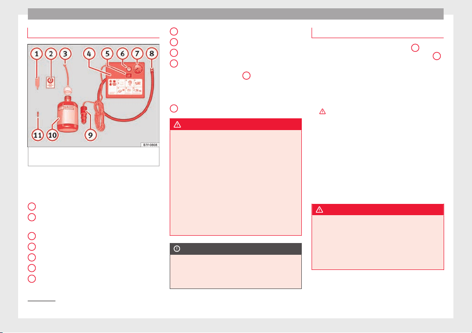
Emergencies
Contents of the tyre mobility system*
Fig. 103 Standard representation: Contents
of
the ty
r
e mobility system.
The tyre mobility system is located under-
ne
ath the floor c
o
vering in the boot. It in-
cludes the following components ››› Fig. 103:
Tyre valve remover
Sticker indicating maximum speed “max.
80 km/h” or “max. 50 mph”
Filler tube with cap
Air compressor
ON/OFF switch
Air bleed screw
1)
Tyre pressure monitoring
1)
1
2
3
4
5
6
7
Tube for inflating tyres
12
v
o
lt connector
Bottle of sealant
Spare insert for valve
The valve insert remover
1
has a gap at the
lo
w
er end f
or a valve insert. The valve insert
can only be screwed or unscrewed in this
way. This also applies to its replacement part
11
.
WARNING
When inflating the tyre, the air compressor
and the inflator t
ube may become hot.
●
Protect hands and skin from hot parts.
●
Do not place the air compressor or inflator
tube onto flammable materials while they are
hot.
●
Before storing the equipment, let it cool.
●
If a minimum pressure of 2.0 bar
(29 psi / 200 kPa) cannot be reached, the tyre
is badly damaged. In this instance, the seal-
ant will not be able to seal the tyre. Do not
continue driving. Seek specialist assistance.
CAUTION
The air compressor should be turned off after
a maximum of
8 minutes since otherwise it
will overheat. Before switching it on again, let
it cool for a few minutes.
8
9
10
11
Check after 10 minutes of driving
Screw the inflator tube ›››
Fig. 103
8
again
and check
the tyre pressure on the gauge
7
.
Equal
to or below 1.3 bar (19 psi/130 kPa):
●
Stop driving! The tyre could not be suffi-
ciently sealed with the tyre mobility system.
●
You should obtain professional assistance
›››
.
Equal
to or above 1.4 bar (20 psi/140 kPa):
●
Correct the tyre pressure until the correct
level
is reached ››› page 288.
●
Carefully head to the nearest specialised
workshop at a maximum speed of 80 km/h
(50 mph).
●
Ask the workshop to change the damaged
tyre.
WARNING
Driving with a tyre that cannot be sealed is
dang
erous and may lead to accidents and se-
rious injury.
●
Do not continue driving if the tyre pressure
is 1.3 bar (19 psi / 130 kPa) or lower.
●
Seek specialist assistance.
1)
An inflator tube may also be included.
86
Self-help
Changing the windscreen wiper
b
l
a
des
Changing the windscreen and rear
window wiper blades
Read the additional information carefully
›››
page 54.
The windscreen wiper blades are supplied as
standard with a layer of graphite. This layer is
responsible for ensuring that the wipe is si-
lent. If the graphite layer is damaged, the
noise of the water as it is wiped across the
windscreen will be louder.
Check the condition of the wiper blades regu-
larly. If the wipers scrape across the glass
they should be changed if they are damaged,
or cleaned if they are dirty
›››
.
Dam
ag
ed w
iper blades should be replaced
immediately. These are available from quali-
fied workshops.
WARNING
Worn or dirty wiper blades reduce visibility
and incre
ase the risk of accident and serious
injury.
●
Always replace damaged or worn blades or
blades which do not clean the windscreen
correctly.
CAUTION
●
Damaged or dir
ty windscreen wipers could
scratch the glass.
●
If products containing solvents, rough
sponges or sharp objects are used to clean
the blades, the graphite layer will be dam-
aged.
●
Never use fuel, nail varnish remover, paint
thinner or similar products to clean the win-
dows.
●
In icy conditions, always check that the
wiper blades are not frozen to the glass be-
fore using the wipers. In cold weather, it may
help to leave the vehicle parked with the wip-
ers in service position ›››
page 54.
●
To prevent damage to the bonnet and the
wiper arms, only leave them in the service
position.
●
Before driving, always lower the wiper
arms.
Tow-starting and towing
Intr
oduction
Read the additional information carefully
›
›
›
page 50
When towing, always respect legal require-
ments.
For technical reasons, it is not possible to
tow a vehicle if the battery is flat.
If the vehicle comes with the Keyless Access
system, towing is only allowed with the igni-
tion on!
The vehicle battery drains if the vehicle is
towed with the engine switched off and the
ignition connected. Depending on the battery
charge status, the drop in voltage may be so
large, even after just a few minutes, that no
electrical device in the vehicle may work e.g.
the hazard warning lights. In vehicles with
the Keyless Access system, the steering
wheel could lock ›››
.
WARNING
A vehicle with a flat battery should never be
tow
ed.
●
Never remove the key from the ignition
lock. Otherwise, the steering wheel lock
could suddenly lock. The vehicle would not
be controlled and a serious accident could
ensue.
WARNING
When towing the vehicle, the handling and
brakin
g efficiency change considerably.
Please observe the following instructions to
minimise the risk of serious accidents and in-
jury:
●
As the driver of the vehicle being towed:
–
The brake must be depressed must hard-
er as the brake servo does not operate.
»
87
Technical dataAdviceOperationEmergenciesSafety
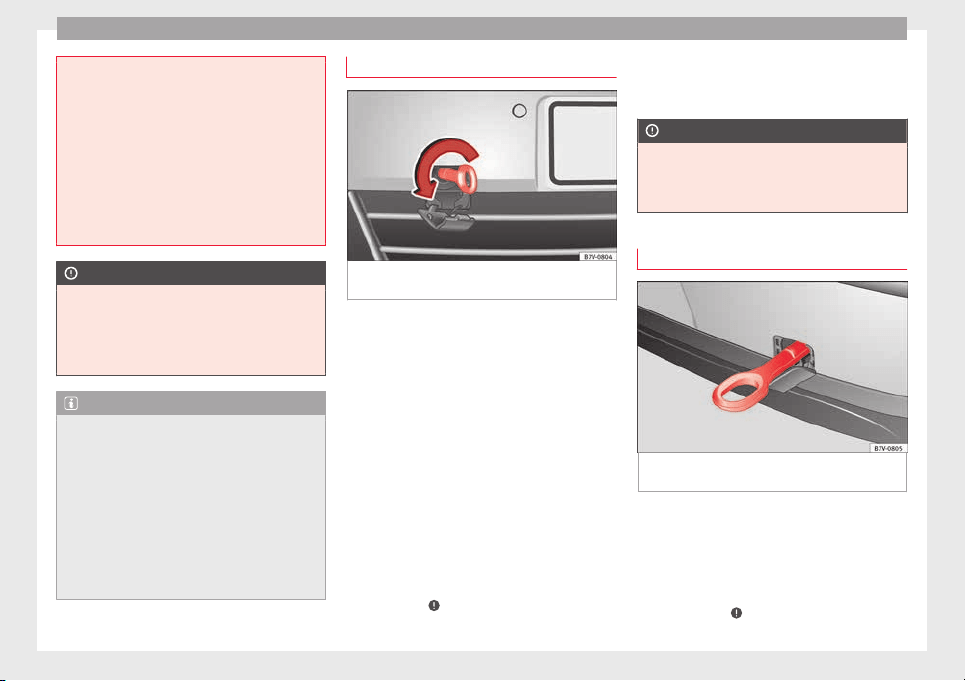
Emergencies
Always remain aware to avoid collision
with the to
wing vehicle.
–
More strength is required at the steering
wheel as the power steering does not op-
erate when the engine is switched off.
●
As the driver of the towing vehicle:
–
Accelerate gently and carefully.
–
Avoid sudden braking and manoeuvres.
–
Brake well in advance than usual and
brake gently.
CAUTION
●
Caref
ully fit and remove the towline anchor-
age and its cover to avoid damage to the ve-
hicle (e.g. paintwork).
●
When towing, fuel could enter the catalytic
converter and cause damage!
Note
●
The vehic
le can only be towed if the elec-
tronic parking brake and steering lock are de-
activated. If the vehicle has no power supply
or there is an electric system fault, the en-
gine must be started using jump leads to de-
activate the electronic parking brake and
electronic steering lock.
●
Vehicles with the Keyless Access locking
and ignition system should only be towed
with the ignition connected since, otherwise,
the electronic steering lock will not unlock.
Fitting the front towline anchorage
Fig. 104 On the right-hand side of the front
b
umper:
Sc
rew in the towline anchorage.
The location for the removable towline an-
c
hor
ag
e is on the right-hand side of the front
bumper ››› Fig. 104.
The towline anchorage should always be kept
in the vehicle.
Note the instructions for towing
›››
page 50.
To fit the towline anchorage
●
Take the towline anchorage from the vehi-
cle tool kit ››› page 82.
●
Press on the upper cover and carefully re-
move it forwards. Allow the cover to hang.
●
Screw in the towline anchorage into its po-
sition anticlockwise as far as it will go
››› Fig. 104 ›››
. Use a suitable tool to firmly
tight
en the t
o
wline anchorage in its location.
●
After towing, remove the towline anchorage
by turning it clockwise and put the cover
back in place.
CAUTION
The towline anchorage must always be com-
plet
ely and firmly tightened. Otherwise, it
could be released while towing and tow-start-
ing.
Fitting the rear towline anchorage
Fig. 105 On the rear bumper, to the right
h
and s
ide:
Towline anchorage in position
The location for the removable towline an-
c
hor
ag
e is on the right-hand side of the rear
bumper ››› Fig. 105. For vehicles with a facto-
ry fitted towing bracket, there is no fitting be-
hind the cover to insert the towline anchor-
age. For towing, fit and use the tow hitch
››› page 237, ›››
.
88
Self-help
Note the instructions for towing
›
›
›
page 50.
Fitting the towline anchorage to the rear for
vehicles without factory fitted tow hitch
●
Take the towline anchorage from the vehi-
cle tool kit in the luggage compartment
››› page 82.
●
Press on the upper cover and carefully re-
move it back. This may require some
strength. Allow the cover to hang.
●
Screw in the towline anchorage into its po-
sition anticlockwise as far as it will go ›››
.
U
se a s
uit
able tool to firmly tighten the tow-
line anchorage in its location.
●
After towing, remove the towline anchorage
by turning it clockwise and put the cover
back in place.
CAUTION
●
The towline anc
horage must always be
completely and firmly tightened. Otherwise,
it could be released while towing and tow-
starting.
●
Vehicles with a factory fitted towing brack-
et, can only be used for towing with a tow
bar, specially designed to fit on a tow hitch
ball. Otherwise, the tow hitch ball and the ve-
hicle may be damaged. Otherwise, a tow rope
should be used.
Towing advice
Towing requires some expertise and experi-
ence, es
pecially when using a tow rope. Both
drivers should be familiar with the technique
required for towing. For this reason, inexper-
ienced drivers should abstain.
While driving, avoid excessive traction forces
and jerking. When towing on an unpaved
road, there is always a risk of overloading
and damaging the anchorage points.
If the vehicle is towed, with the hazard warn-
ing lights on and the ignition switched on,
the turn signal may be used to indicate
changes of direction. Simply operate the turn
signal lever as usual. Meanwhile, the hazard
warning lights will go off. When the turn sig-
nal lever is returned to the rest position, the
hazard warning lights will be turned on auto-
matically.
Notes for the driver of the towed vehicle
●
Leave the ignition on to avoid locking the
steerin
g wheel, to release the electronic
parking brake and to activate the turn sig-
nals, the horn as well as the window wipers
and window washers.
●
As the power assisted steering does not
work if the engine is not running, you will
need more strength to steer than normally.
●
The brake must be depressed must harder
as the brake servo does not operate. Avoid
hitting the towing vehicle.
●
Note the instructions and information con-
tained in the Instruction Manual for the vehi-
cle to be towed.
Notes for the driver of the towing vehicle
●
Accelerate gently and carefully. Avoid sud-
den manoeuvres.
●
Brake well in advance than usual and brake
gently.
●
Note the instructions and information con-
tained in the Instruction Manual for the vehi-
cle to be towed.
Emergency locking and unlock-
ing
Introduction
Read the additional information carefully
›
›
›
page 8,
›››
page 10,
›››
page 12
The doors, rear lid and panoramic sliding
sunroof can be locked manually and partially
opened, for example if the key or the central
locking is damaged.
»
89
Technical dataAdviceOperationEmergenciesSafety
Emergencies
WARNING
Opening and closing doors carelessly can
cause seriou
s injury.
●
If the vehicle is locked from outside, the
doors and windows cannot be opened from
the inside.
●
Never leave children or disabled people
alone in the car. They could be trapped in the
car in an emergency and will not be able to
get themselves to safety.
●
Depending on the time of the year, temper-
atures inside a locked and closed vehicle can
be extremely high or extremely low resulting
in serious injuries and illness or even death,
particularly for young children.
WARNING
Getting in the way of the doors and the pan-
oramic s
liding sunroof is dangerous and can
lead to serious injury.
●
Open and close the doors and the panor-
amic sliding sunroof only when nobody is in
the way.
CAUTION
When opening and closing in an emergency,
caref
ully disassemble components and then
reassemble them carefully to avoid damage
to the vehicle.
Fuses and bulbs
F
u
se
s
Vehicle fuses
Read the additional information carefully
›››
page 42
Due to the constant updating of vehicles,
fuse assignments based on equipment and
the use of the same fuse for various electrical
components, it is not possible to provide an
up-to-date summary of the fuse positions for
the electrical components at the time of
printing this manual. For detailed information
about the fuse positions, please consult a
technical service.
In general, a fuse can be assigned to various
electrical components. Likewise, an electrical
component can be protected by several
fuses.
Only replace fuses when the cause of the
problem has been solved. If a newly inserted
fuse blows after a short time, you must have
the electrical system checked by a special-
ised workshop as soon as possible.
WARNING
The high voltages in the electrical system can
give serious
electrical shocks, causing burns
and even death!
●
Never touc
h the electrical wiring of the igni-
tion system.
●
Take care not to cause short circuits in the
electrical system.
WARNING
Using unsuitable fuses, repairing fuses or
bridgin
g a curr
ent circuit without fuses can
cause a fire and serious injury.
●
Never use a fuse with a higher value. Only
replace fuses with a fuse of the same amper-
age (same colour and markings) and size.
●
Never repair a fuse.
●
Never replace a fuse by a metal strip, staple
or similar.
CAUTION
●
To prev
ent damage to the vehicle's electric
system, before replacing a fuse always turn
off the ignition, the lights and all electrical
elements and remove the key from the igni-
tion.
●
If you replace a fuse with higher-rating
fuse, you could cause damage to another part
of the electrical system.
●
Protect the fuse boxes when open to pre-
vent the entry of dust or humidity as they can
damage the electrical system.
●
Always carefully remove the fuse box cov-
ers and refit them correctly to avoid problems
with your vehicle.
90
Fuses and bulbs
●
Protect
the fuse boxes when open to avoid
the entry of dust or humidity. Dirt and humid-
ity inside fuse boxes can cause damage to
the electrical system.
Note
●
In the
vehic
le, there are more fuses than
those indicated in this chapter. These should
only be changed by a specialised workshop.
●
One component may have more than one
fuse.
●
Several components may run on a single
fuse.
Changing bulbs
Intr
oduction
Changing bulbs requires a certain amount of
m
anual
sk
ill. If you are unsure, SEAT recom-
mends that you consult a technical service or
request assistance from a specialist. In gen-
eral, a specialist is required if other vehicle
components must be removed or if the dis-
charge bulbs must be replaced.
You should store spare light bulbs in the ve-
hicle for safety-relevant lights. Spare bulbs
may be obtained from the technical services.
In some countries, it is a legal requirement to
carry spare bulbs in the vehicle.
Driving with faults and blown bulbs on the
vehicle exterior lighting is against the law.
Additional bulb specifications
The specifications of some headlamp bulbs
and bulbs for the rear lamps fitted at the fac-
tory may be different to those of conventional
bulbs. Bulb information is displayed on the
bulb socket or on the bulb itself.
WARNING
If the road is not well-lit and the vehicle is
not cl
early visible to other drivers, there is a
risk of accident.
WARNING
Failure to replace bulbs correctly may cause
serious ac
cidents.
●
Before carrying out any work in the engine
compartment please read and observe the
warnings ››› page 272. In any vehicle, the en-
gine compartment is a hazardous area and
could cause severe injury.
●
Discharge lamps work with high-voltage
and can cause serious or fatal injury if han-
dled incorrectly.
●
H7 and discharge bulbs are highly pressur-
ised and could explode when being changed.
●
Only replace the bulbs concerned when
they have cooled.
●
Never replace bulbs alone if you are not fa-
miliar with the operations necessary. If you
are not sure about procedures then visit a
speci
alised workshop to carry out the neces-
sary work.
●
Never touch the bulb glass directly. Finger-
prints will be evaporated by the heat of the
operating bulb thus “fogging” up the reflec-
tor.
●
The headlamp frameworks in the engine
compartment and the rear lamps contain
sharp elements. Always protect your hands
when changing bulbs.
CAUTION
●
After c
hanging a bulb, if the rubber covers
are not replaced correctly on the headlamp
framework, the electrical installation may be
damaged, especially if water is allowed to en-
ter.
●
Remove the ignition key before working on
the electric system. Otherwise, a short circuit
could occur.
●
Switch off the lights and the parking light
before changing a bulb.
●
Take good care to avoid damaging any com-
ponents.
91
Technical dataAdviceOperationEmergenciesSafety
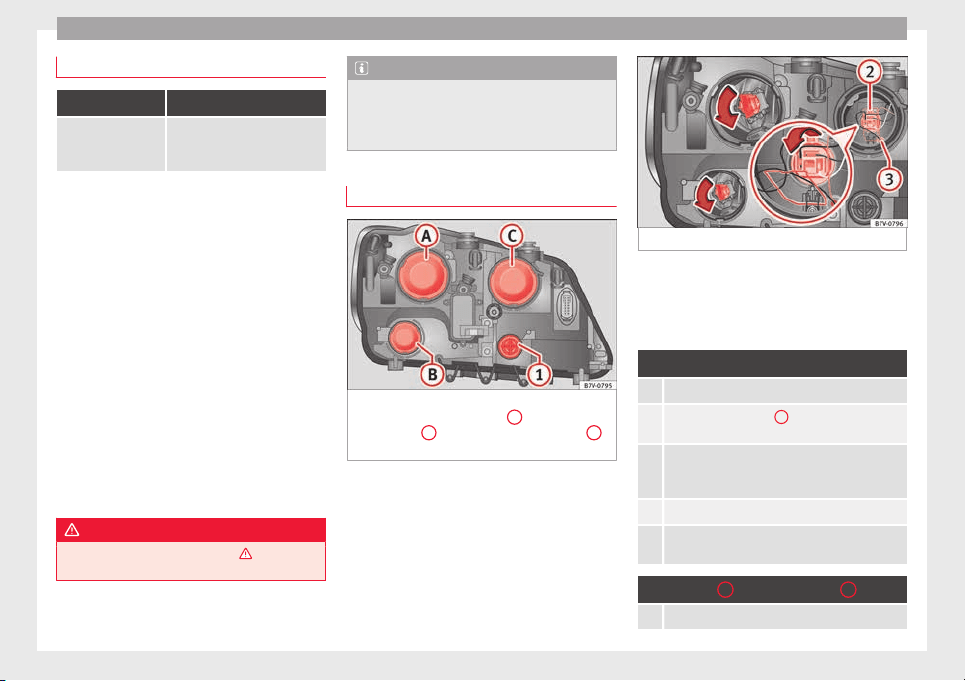
Emergencies
Control lamp
It lights up
A vehicle exterior
lighting bulb is not
working.
Replace the faulty bulb.
Several warning and indication lamps light
up for a few sec
onds when the ignition is
switched on, signalling that the function is
being verified. They will switch off after a few
seconds.
Checking the bulbs of a trailer
For vehicles with the factory fitted towing
bracket, certain trailer lights are also control-
led if the power socket is correctly connected.
A fault on a trailer turn signal is indicated on
the instrument panel by the turn signal blink-
ing twice as fast ( or )
›››
page 130.
●
General fault of all turn signals on one side.
●
Fault in one rear light (on some models, al-
so the regi
stration light).
●
Fault in two brake lights.
WARNING
Observe the safety warnings ›››
in Warning
and indication lamp
s on page 105.
Note
A fault in the LED on the rear lights will not be
indicated. Ho
wever, if the fault affects all the
LEDs then this will be indicated by the control
lamp .
To replace halogen headlight bulbs
Fig. 106 In the engine compartment: left-
h
and s
ide he
adlight lining.
A
dipped beam
he
a
dlights,
B
daytime driving lights and
C
main beam headlights and side lights
Fig. 107 Left headlight.
There is no need to remove the headlight to
r
ep
l
ace bulbs.
Complete operations only in the sequence
given:
Turn signals (small bulb holder)
1. Open the bonnet
››› page 272.
2. Rotate the bulb holder
1
to the left all the way
and pull it out backwards together with the bulb.
3. Depending on the model, the bulb is removed di-
rectly from the bulb holder or it may need to be ro-
tated and then removed.
4. Replace the faulty bulb with a new identical bulb.
5. Place the bulb holder in the headlight and rotate
to the right all the way.
Dipped beam
A
and daytime lights
B
1. Open the bonnet
››› page 272.
92
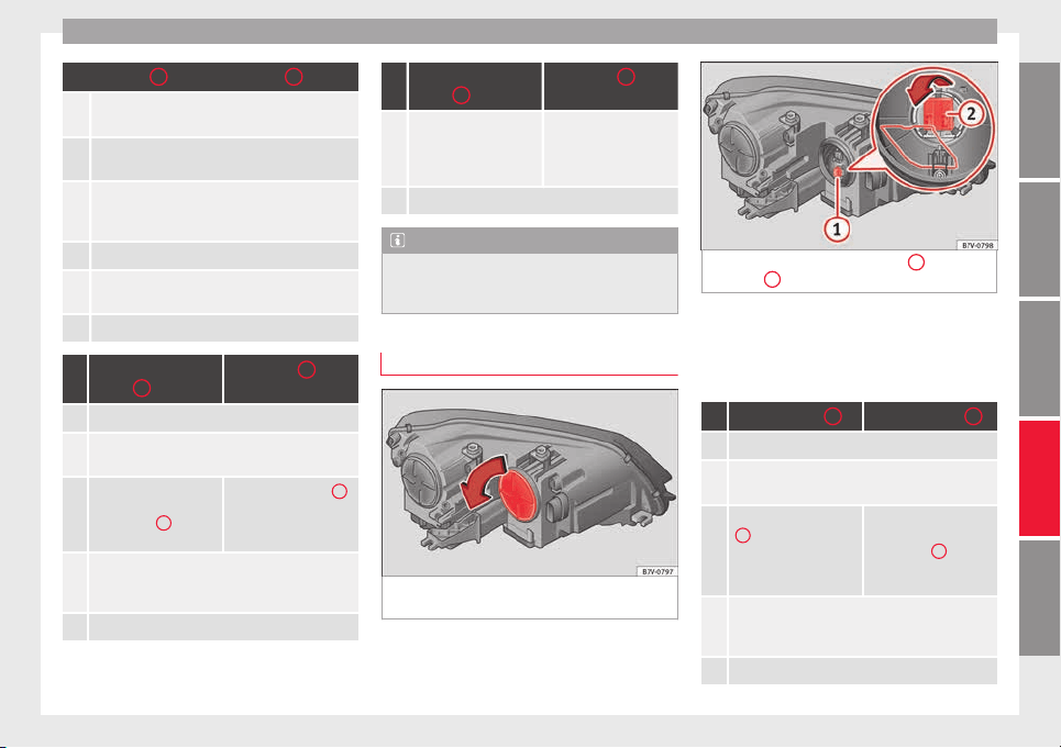
Fuses and bulbs
Dipped beam
A
and daytime lights
B
2. Remove the rubber cover on the rear of the head-
light.
3. Rotate the bulb holder to the left all the way and
pull it out backwards together with the bulb.
4. Depending on the model, the bulb is removed di-
rectly from the bulb holder or it may need to be ro-
tated and then removed.
5. Replace the faulty bulb with a new identical bulb.
6. Place the bulb holder in the headlight and rotate
to the right all the way.
7. Insert the rubber cover.
Main beam head-
lights
C
Side lights
C
1. Open the bonnet
››› page 272.
2. Remove the rubber cover on the rear of the head-
light.
3. Press the wire clip
downwards and pull the
bulb holder
2
out to-
gether with the bulb.
Pull the bulb holder
3
out backwards together
with the bulb.
4. Depending on the model, the bulb is removed di-
rectly from the bulb holder or it may need to be ro-
tated and then removed.
5. Replace the faulty bulb with a new identical bulb.
Main beam head-
lights
C
Side lights
C
6. Place the bulb holder in
the headlight and pull
the wire clip upwards
until it clicks into place.
Place the bulb holder in
the headlight and insert
completely.
7. Insert the rubber cover.
Note
The images show the left hand headlight
from behind. The s
tructure of the right hand
side headlight is symmetric.
To replace the xenon headlight bulb
Fig. 108 In the engine compartment: turn sig-
n
al
indic
ator cover.
Fig. 109 Turn signal bulb holder
1
and turn-
ing light
2
.
There is no need to remove the headlight to
r
ep
l
ace bulbs.
Complete operations only in the sequence
given:
Turn signals
1
Turning lights
2
1. Open the bonnet
››› page 272.
2.
Rotate the cover ››› Fig. 108 in the direction of the
arrow and remove it.
3.
Rotate the bulb holder
1
››› Fig. 109 to the
left all the way and pull
it out backwards to-
gether with the bulb.
Press the wire clip
downwards and pull the
bulb holder
2
››› Fig. 109 out together
with the bulb.
4.
Depending on the model, the bulb is removed di-
rectly from the bulb holder or it may need to be ro-
tated and then removed.
5. Replace the faulty bulb with a new identical bulb.
»
93
Technical dataAdviceOperationEmergenciesSafety
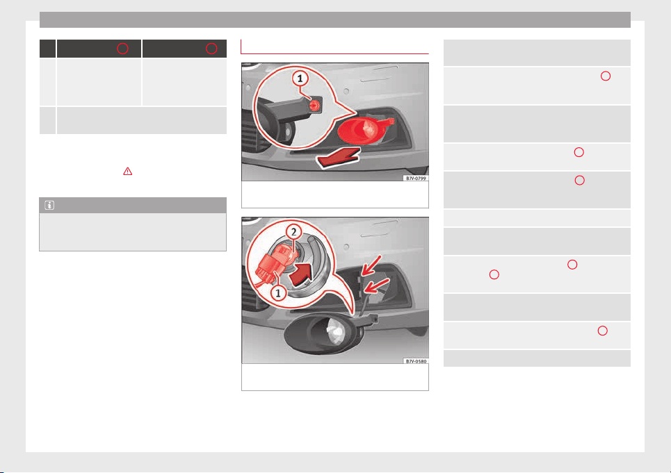
Emergencies
Turn signals
1
Turning lights
2
6.
Place the bulb holder in
the headlight and ro-
tate to the right all the
way.
Place the bulb holder in
the headlight and pull
the wire clip upwards
until it clicks into place.
7.
Rotate the cover ››› Fig. 108 in the opposite direc-
tion to the arrow as far as it will go.
Always seek the help of a specialist when
chan
ging the Xenon dipped beam and main
beam headlamps ›››
in Introduction on
page 91
.
Note
The illustrations show the left hand head-
light. The s
tructure of the right hand side
headlight is symmetric.
Replacing the front bumper bulbs
Fig. 110 On the right-hand side of the front
b
umper: r
emo
ving the headlights.
Fig. 111 Changing the bulbs in the head-
lights
Complete operations only in the sequence
giv
en:
1.
Pull the cover forwards, in the direction of the ar-
row ››› Fig. 110.
2.
Unscrew the attachment screw ››› Fig. 110
1
us-
ing the screwdriver from the vehicle tool kit
››› page 82.
3.
Tilt the headlight slightly forward and extract it
from its lateral attachments ››› Fig. 111 (small ar-
rows).
4.
Release the connector ››› Fig. 111
1
and remove
it.
5.
Rotate the bulb holder ››› Fig. 111
2
to the left all
the way, in the direction of the arrow, and pull it
out backwards together with the bulb.
6. Replace the faulty bulb with a new identical bulb.
7.
Place the bulb holder in the headlight and rotate
to the right all the way.
8.
Insert the connector ››› Fig. 111
1
on the bulb
holder
2
. The connector must audibly click into
place.
9.
Place the headlight into its position ››› Fig. 111
(small arrows) and tilt it backwards.
10.
Tighten the attachment screw ››› Fig. 110
1
us-
ing the screwdriver.
11. Replace the cover on the bumper ››› Fig. 110.
94
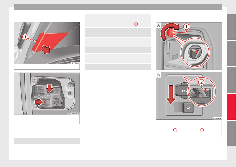
Fuses and bulbs
Replacing the rear lid bulbs
Fig. 112 On the rear lid: Remove the cover.
Fig. 113 On the rear lid: remove the bulb-
ho
l
der
.
Complete operations only in the sequence
giv
en:
1. Open the rear lid ››› page 124.
2.
Extract the cover carefully using the flat part of the
screwdriver from the vehicle tool kit as a lever
(››› Fig. 101) on the indent ››› Fig. 112
1
.
3.
Release the bulb holder connector by pulling on
the red connector block.
4.
Press on the attachment tabs in the direction of
the arrow ››› Fig. 113 and pull out the bulb holder.
5. Replace the faulty bulb with a new identical bulb.
6.
Install the bulb holder. The attachment tabs should
audibly click into place.
7. Insert the cover. The cover should lock into place.
Replacing the rear bulbs in the body
Fig. 114 On the side of the luggage compart-
ment: r
emo
v
ing the left and right hand side
rear lights.
1
remove the cap;
2
attach-
ment
s
c
rew
»
95
Technical dataAdviceOperationEmergenciesSafety
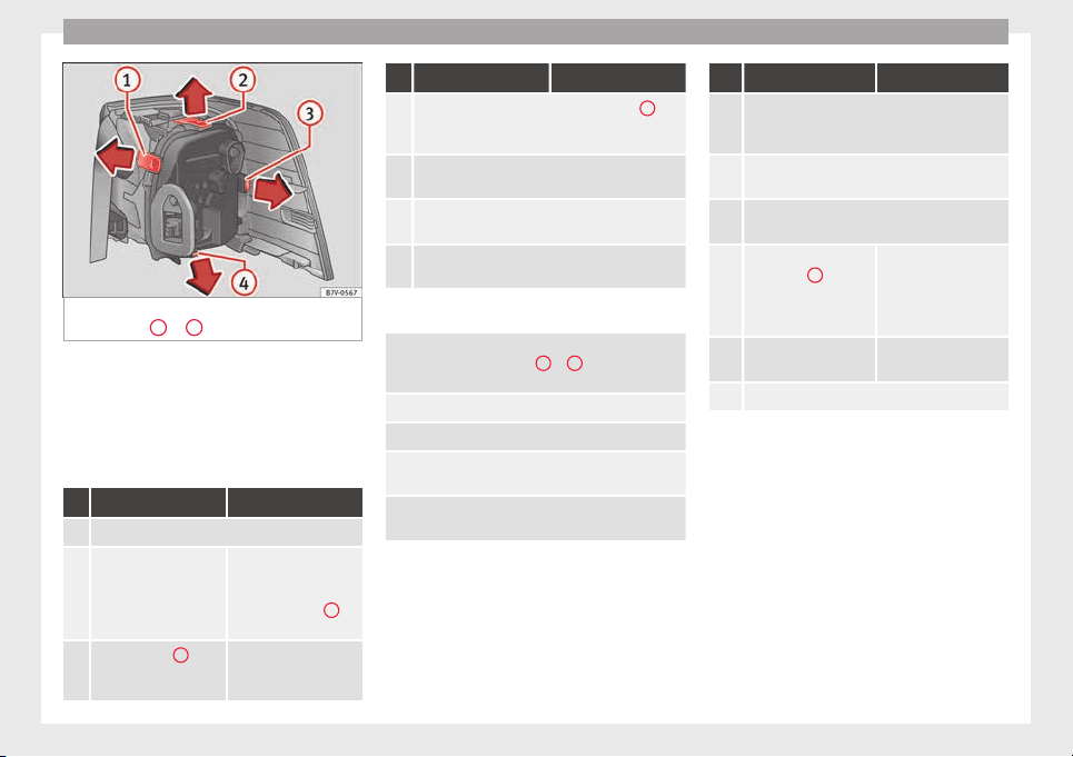
Emergencies
Fig. 115 Rear lights in the body: Remove the
b
u
l
b holder.
1
to
4
: Attachment tab
Complete operations only in the sequence
giv
en.
R
emo
ving the rear light units
Complete operations only in the sequence
given:
Rear light, left Rear light, right
1. Open the rear lid ››› page 124.
2.
Open the storage com-
partments on the left-
hand side of the lug-
gage compartment
››› page 166.
Move the 12 V power
socket support by
pressing gently down-
wards ››› Fig. 114
B
(arrow).
3.
Rotate the cap
1
90°
in the direction of the
arrow and remove it.
Rear light, left Rear light, right
4.
Unscrew the attachment screw ››› Fig. 114
2
us-
ing the screwdriver from the vehicle tool kit
››› page 82. The bolt is secured in its position.
5.
Extract the rear light from the bodywork by careful-
ly pulling backwards.
6.
Pull the red strip on the connector and extract the
connector.
7.
Disassemble the tail light unit and place it on a
flat, clean surface.
To change the bulb
8.
To release the bulb holder, press on the attach-
ment tabs ››› Fig. 115
1
to
4
in the direction of
the arrow.
9. Remove the bulb holder from the rear light unit.
10. Replace the faulty bulb with a new identical bulb.
11.
Place the bulb holder in the tail light unit. The at-
tachment tabs should audibly click into place.
12.
Insert the connector and press the red attachment
strip in so that the connector is locked into place.
Assembling the rear light units
C
omp
l
ete operations only in the sequence
given:
Rear light, left Rear light, right
13.
Carefully insert the tail light unit into the opening
in the bodywork. To do this, insert the upper rear
light unit guide into the attachment ring.
14.
Tighten the white attachment screw using the
screwdriver from the vehicle tool kit.
15.
Ensure that the tail light unit has been correctly
fitted and is firmly secured.
16.
Replace the cap
››› Fig. 114
1
and ro-
tate it 90° in the oppo-
site direction of the ar-
row.
Move the 12 V power
socket support up-
wards gently until it is
correctly closed.
17.
Close the storage com-
partment.
18. Close the rear lid ››› page 124.
96
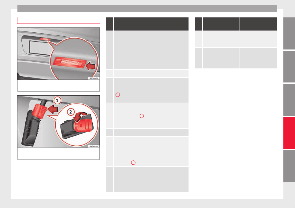
Fuses and bulbs
Changing the number plate light
Fig. 116 On the rear bumper: number plate
lights
Fig. 117 Number plate light: Remove the bulb
ho
l
der
.
Complete operations only in the sequence
giv
en:
Fixed number plate
light
Bolted number plate
light
1.
Press the flat part of the
screwdriver included in
the vehicle on-board
tools (››› Fig. 101) in the
direction of the arrow,
in the groove of the
number plate light
››› Fig. 116.
Unscrew the number
plate light screws using
the screwdriver from
the vehicle tool kit
(››› Fig. 101).
2. Detach the number plate light.
3.
Press on the connector
lock in the direction of
the arrow ››› Fig. 117
1
and pull out the
connector.
Separate the attach-
ment tabs from the rear
panel of the number
plate light by pressing.
4.
Rotate the bulb holder
in the direction of the
arrow ››› Fig. 117
2
and extract it together
with the bulb.
Take the bulb holder
out of the number plate
light.
5. Replace the faulty bulb with a new identical bulb.
6.
Insert the bulb holder
into the number plate
light and rotate all the
way in the opposite di-
rection to the arrow
››› Fig. 117
2
.
Insert the bulb holder
into the number plate
light.
7.
Plug the connector into
the bulb holder.
Press on the attach-
ment tabs. The bulb
holder must be firmly
attached to the number
plate light.
Fixed number plate
light
Bolted number plate
light
8.
Insert the number plate light carefully into the
opening on the bumper. Ensure that the number
plate light is in the correct position.
9.
Insert the number plate
light into the bumper
until it audibly clicks in-
to place.
Tighten the attachment
screws for the number
plate light using the
screwdriver.
97
Technical dataAdviceOperationEmergenciesSafety
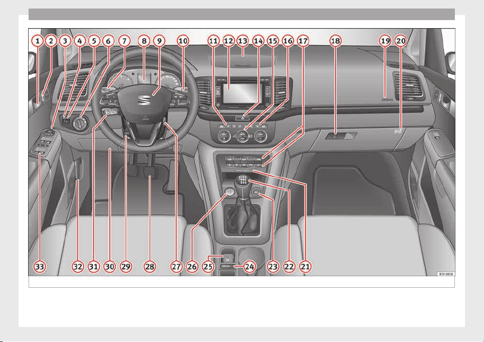
Operation
Fig. 118 Dash panel.
98
General instrument panel
Operation
Gener
a
l
instrument panel
Instrument panel
Interior door release lever . . . . . . . . . 121
Central lock button . . . . . . . . . . 114
Switch for adjusting the exterior
mirrors . . . . . . . . . . . . . . . . . . . . . . . . . . . 139
–
Exterior mirror a
djustment
–
Heated exterior mirrors
–
Folding exterior mirrors
Instrument panel controls and light-
ing control . . . . . . . . . . . . . . . . . . . . . 130
Headlamp range adjustment . . . 130
Light switch . . . . . . . . . . . . . . . . . . . 130
–
Light off --
–
Automatic dipped beam head-
light control --
–
Side/dipped lights
–
Fog lights
Lever for . . . . . . . . . . . . . . . . . . . . . . . . . 130
–
Main beam headlights
–
Headlight flasher
–
Turn signals
–
Parking lights
Instrument panel:
1
2
3
4
5
6
7
8
–
In
s
truments . . . . . . . . . . . . . . . . . . . . 100
–
Digit
al display . . . . . . . . . . . . . . . . . . 100
–
Control and warning lamps . . . . . . 105
Steering wheel with horn and
–
Driver airbag . . . . . . . . . . . . . . . . . . . 17
–
On-board computer controls . . . . 26
–
Controls for radio, telephone,
navigation and speech dialogue
system ››› Booklet Radio
–
Paddle levers for tiptronic gear-
shift (automatic gearbox) . . . . . . . 197
Windscreen wiper/ windscreen
wash lever . . . . . . . . . . . . . . . . . . . . . . . 137
–
Winds
creen wipers –
–
Intermittent wipe
–
“Brief wipe” x
–
Windscreen wipers
–
Automatic windscreen wash/wipe
–
Rear window wiper
–
Automatic rear window
wash/wipe
–
Lever with buttons for controlling
the SEAT information system - ,
/ . . . . . . . . . . . . . . . . . . . . . . . . . 26
Left seat heating controls . . . . . . . 146
Radio or navigation system (fitted
at
f
act
ory) ››› Booklet Radio or
››› Booklet Navigation system
9
10
11
12
Storage compartment . . . . . . . . . . . . . 166
Hazard warning lights switch . . . 82
Switches for:
–
El
ectr
onic
manual air condition-
ing . . . . . . . . . . . . . . . . . . . . . . . . . . . . . 176
–
Climatronic . . . . . . . . . . . . . . . . . . . . . 176
Right seat heating controls . . . . . 146
Button for:
–
Anti-slip regulation (ASR) . . 189
–
Start-Stop operation . . . . . . . . . . 208
–
Parkin
g distance warning system
(Park Pilot) . . . . . . . . . . . . . . . . . . 211
–
Park Assist system . . . . . . . . . . . 214
–
Tyre pressure monitor . . . . . 234
–
Dynamic chassis control (DCC)
–
Opening the rear lid . . . . . . . . . 124
–
Opening and closing of electric
sliding doors . . . . . . . . . . . . . . . . 121
Locking lever to open glove com-
partment . . . . . . . . . . . . . . . . . . . . . . . . . 166
P
osition of passenger front airbag
on the dash panel . . . . . . . . . . . . . . . . 17
Key-operated switch in glove com-
partment for deactivating front pas-
senger front airbag . . . . . . . . . . . . . . . 18
Passenger front airbag off warning
lamp . . . . . . . . . . . . . . . . . . . . . . . . . . . . . 72
Lev
er for:
»
13
14
15
16
17
18
19
20
21
22
99
Technical dataAdviceOperationEmergenciesSafety
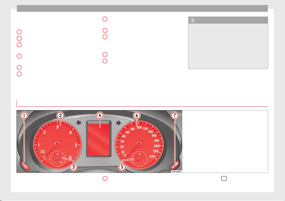
Operation
–
M
anual
g
earbox . . . . . . . . . . . . . . . . 194
–
Automatic gearbox . . . . . . . . . . . . . 194
12 volt power socket . . . . . . . . . . . . . . 173
Auto Hold Switch - . . . . . . . . 208
Electronic parking brake switch
. . . . . . . . . . . . . . . . . . . . . . . . . . . . . . . 189
Start-up push button (Keyless Ac-
cess closing and start-up system)
Ignition lock . . . . . . . . . . . . . . . . . . . . . . 185
Pedals . . . . . . . . . . . . . . . . . . . . . . . . . . . 194
23
24
25
26
27
28
Steering column adjustment lev-
er . . . . . . . . . . . . . . . . . . . . . . . . . . . . . . . . 57
Fuse box cover . . . . . . . . . . . . . . . . . . . 90
Lever for:
–
C
rui
se C
ontrol System (CCS) –
– – – – . . 221
Open bonnet lever . . . . . . . . . . . . . . . . 272
Controls for:
–
Electric windows . . . . . . . . . . . . . 127
–
Childproof locks . . . . . . . . . . . . . 121
29
30
31
32
33
Note
●
Some of the items
of equipment listed here
are fitted only on certain model versions or
are optional extras.
●
In versions with the steering wheel on the
right, the layout of the control elements is
somewhat different. But the symbols as-
signed to the controls correspond to the sym-
bols used in the versions with the steering
wheel on the left
Instruments
V
iew of
in
strument panel
Fig. 119 Instrument panel, on dash panel
Details of the instruments ›
›
›
Fig. 119: Clock set button
1)
.
1
–
Pr
e
s
s button
to select the hour or
minut
e di
s
play.
100
General instrument panel
–
T
o c
ontinue settin
g, press
0.0 / SET
››› Fig. 119
7
. Hold button down to
s
c
r
oll through the numbers quickly.
–
Press button
again to end the clock
settin
g.
R
ev
counter (with the engine running, in
thousands of revolutions per minute).
Together with the gear-change indicator,
the rev counter offers you the possibility
of using the engine of your vehicle at a
suitable speed. The start of the red area
››› Fig. 119 indicates the maximum en-
gine speed working at operating temper-
ature. However, it is advisable to change
up a gear or move the selector lever to D
(or lift your foot off the accelerator) before
the needle reaches the red zone ›››
. We
r
ec
ommend th
at you avoid high revs and
that you follow the recommendations on
the gear-change indicator. Consult the
additional information in ››› page 199.
Engine coolant temperature display
››› page 279.
Displays on the screen ››› page 101.
Fuel reserve display ››› page 264.
Speedometer.
Reset knob for trip recorder (trip).
2
3
4
5
6
7
–
Pr
e
s
s button
0.0 / SET
to reset to zero.
WARNING
Any distraction may lead to an accident, with
the risk of
injury.
●
Do not operate the instrument panel con-
trols when driving.
CAUTION
To prevent damage to the engine, the rev
count
er needle should only remain in the red
zone for a short period of time.
For the sake of the environment
Changing up a gear in time reduces fuel con-
sumption and noise.
Indications on the display
A variety of information can be viewed on the
in
s
trument
panel display
›››
Fig. 119
4
, de-
pendin
g on the
v
ehicle equipment:
●
Warning and information text.
●
Mileage.
●
Time.
●
Outside temperature.
●
Compass.
●
Selector lever positions ››› page 194.
●
Recommended gear (manual gearbox)
››› page 194.
●
Multifunction display (MFI) and menus for
different setting options ›››
page 26.
●
Service interval display ››› page 103.
●
Second speed display (menu Configura-
tion) ›››
page 26.
●
Start-Stop operation indicator ››› page 102.
Warning and information texts
The system runs a check on certain compo-
nents and functions when the ignition is
switched on and while the vehicle is moving.
Faults in the operation are displayed on the
screen using red and yellow symbols and
messages on the instrument panel display
(››› page 105) and, in some cases, with audi-
ble warnings. The display may vary according
to the type of instrument panel fitted.
»
1)
Depending on the vehicle equipment, it is also
poss
ible to set the time using the settings menu
on the instrument panel display ›››
page 30.
101
Technical dataAdviceOperationEmergenciesSafety
Operation
Priority 1 warning (red symbols)
Symbol flashing or lit; partly combined with audible
warnings.
Stop the vehicle! It is dangerous ››› in Warning
and indication lamps on page 105 !
Check the function that is faulty and repair it. If necessa-
ry, request assistance from specialised personnel.
Priority 2 warning (yellow symbols)
Symbol flashing or lit; partly combined with audible
warnings.
A function fault, or fluids which are below the correct
levels may cause damage to the vehicle ›››
in Warning
and indication lamps on page 105 !
Check the faulty operation as soon as possible. If neces-
sary, request assistance from specialised personnel.
Informative text
Information relating to different vehicle processes.
Mileage
The odomet
er
r
egisters the total distance
travelled by the car.
The odometer (trip) shows the distance
travelled since the last odometer reset. The
last digit of the trip recorder indicates distan-
ces of 100 metres or one tenths of a mile.
Outside temperature display
When the outside temperature is below +4°C
(+39°F), the symbol “ice crystal” (warning of
risk of freezing) is also displayed next to the
temperature. At first this symbol flashes and
then it remains lit until the outside tempera-
ture rises above +6°C (+43°F) ›››
.
When the
v
ehic
le is at a standstill, with the
auxiliary heating on (››› page 180), or when
travelling at very low speeds, the tempera-
ture displayed may be higher than the true
outside temperature, as a result of the heat
produced by the engine.
The temperatures measured range from
-40°C to +50°C (-40°F to +122°F).
Compass
With the ignition on and the navigation sys-
tem on, the cardinal point corresponding to
the vehicle's direction of travel is displayed
on the instrument panel ››› page 103.
Selector lever positions
The range of engaged gears of the selector
lever is shown on the side of the lever, and
on the instrument panel display. In positions
D and S, and with the Tiptronic, the corre-
sponding gear is also displayed.
Recommended gear (manual gearbox)
The recommended gear in order to save fuel
is displayed on the instrument panel while
you are driving
›››
page 194.
Second speed display (mph or km/h)
In addition to the speedometer, the speed
can also be displayed in a different unit of
measurement (in miles or in km per hour). To
change the units, in the Settings menu, se-
lect the option Second speed
›››
page 26.
Vehicles without menu display on the instru-
ment panel
●
Switch on the engine.
●
Press button
three times. The odometer
di
s
p
lay flashes on the instrument panel dis-
play.
●
Press button
0.0 / SET
once. “mph”
or “km/h” i
s
di
splayed briefly instead of the
odometer.
●
This activates the second speed display. To
switch it off, repeat the procedure.
This option cannot be deactivated in models
destined for countries in which the second
speed must always be visible.
Start-Stop operating display.
Updated information relating to the status is
displayed on the instrument panel
››› page 208.
WARNING
Observe the safety warnings ›››
in Warning
and indication lamp
s on page 105.
102
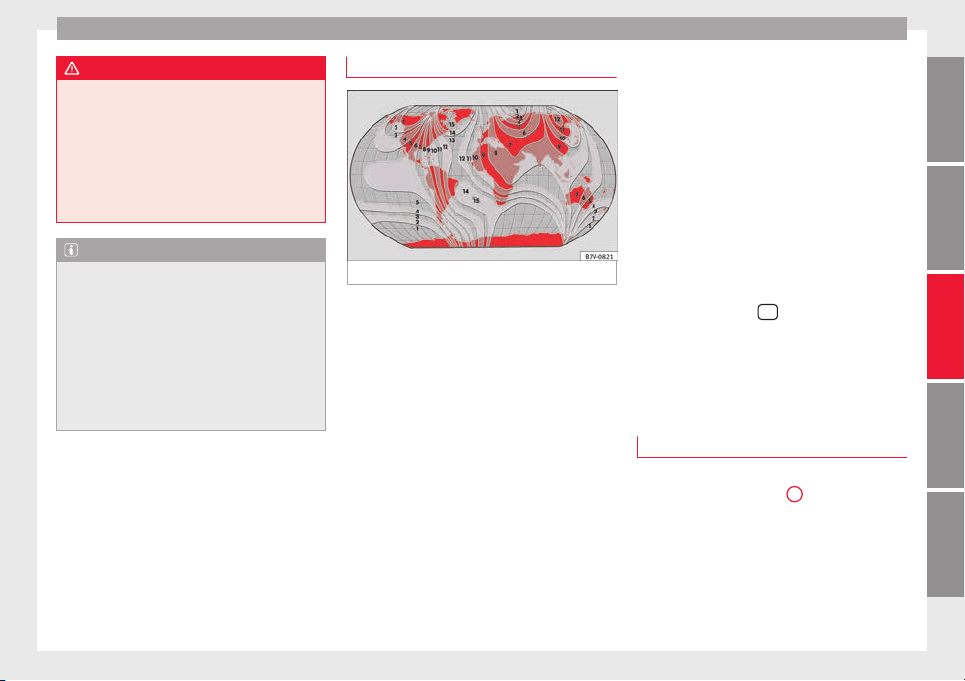
General instrument panel
WARNING
Even though outside temperatures are above
freezin
g, some roads and bridges may be icy.
●
At outside temperatures above +4°C
(+39°F), even when the “ice crystal symbol”
is not visible, there may still be patches of ice
on the road.
●
Never rely on the outside temperature indi-
cator!
Note
●
Different
versions of the instrument panel
are available and therefore the versions and
instructions on the display may vary. In the
case of displays without warning or informa-
tion texts, faults are indicated exclusively by
the warning lamps.
●
When several warnings are active at the
same time, the symbols are shown succes-
sively for a few seconds and will stay on until
the fault is rectified.
Compass*
Fig. 120 Magnetic zones
The compass does not require calibration in
v
ehic
l
es for which the navigation system was
mounted at the factory. The option compass
disappears.
The compass in vehicles in which the naviga-
tion system was not mounted at the factory,
is permanently and automatically calibrated.
If electronic or metal accessories (mobile
phone, television) are subsequently mounted
in the vehicle, the compass should be recali-
brated manually.
Adjusting the magnetic zone
●
Switch the ignition on.
●
Select the Settings menu followed by the
option Compass and Zone.
●
Select the magnetic zone corresponding to
the position of the vehicle ››› Fig. 120.
●
Adjust and confirm the magnetic zone
(1-15).
Calibrating compass
To calibrate the compass you must be in one
of the valid magnetic zones with sufficient
space to be able to trace a circumference
with the vehicle.
●
Switch the ignition on.
●
Select the Settings menu followed by the
option Compass and Calibrate.
●
Confirm the message Describe a com-
plete circumference to calibrate
the compass with
OK
and then trace a
c
omp
l
ete circumference driving at approxi-
mately 10 km/h (6 mph).
When the corresponding cardinal point is dis-
played, the calibration is complete.
Service interval display
The service indication is shown on the dash
p
anel
di
splay
›››
Fig. 119
4
.
S
EA
T di
stinguishes between services with en-
gine oil change (Interval Service) and serv-
ices without engine oil change (Inspection
Service). The service interval display only
gives information for service dates which in-
volve an engine oil change. The dates for the
»
103
Technical dataAdviceOperationEmergenciesSafety
Operation
other services (e.g. the next Inspection Serv-
ic
e or c
h
ange of brake fluid) are listed on the
label attached to the door strut, or in the
Maintenance Programme.
In vehicles with Services established by time
or mileage, the service intervals are already
pre-defined.
In vehicles with LongLife Service, the inter-
vals are determined individually. Technical
progress has made it possible to considera-
bly reduce servicing requirements. The tech-
nology used by SEAT ensures that your vehi-
cle only has an Interval Service when it is
necessary. To establish when the Interval
Service is due (max. 2 years), the vehicle's
conditions of use and individual driving
styles are considered. The service pre-warn-
ing first appears 20 days before the date es-
tablished for the corresponding service. The
kilometres (miles) remaining until the next
service are always rounded up to the nearest
100 km (miles) and the time is given in com-
plete days. The current service message can-
not be viewed until 500 km after the last
service. Prior to this only lines are visible on
the display.
Inspection reminder
When the Service date is approaching, when
the ignition is switched on a Service remind-
er is displayed.
In vehicles without text messages, a spanner
is displayed on the instrument panel with
a figure given in km. The number of kilome-
tres shown is the maximum number that may
be driven until the next service. After a few
seconds, the display mode changes. A clock
symbol appears and the number of days until
the next service appointment is due.
In vehicles with text messages, Service in
--- km (miles) or --- days is dis-
played on the instrument panel.
Service due
After the service date, an audible warning is
given when the ignition is switched on and
the spanner displayed on the screen flashes
for a few seconds . In vehicles with text
messages, Service in --- km or ---
days is displayed on the instrument panel.
Reading a service notification
With the ignition switched on, the engine off
and the vehicle at a standstill, the current
service notification can be read:
●
Press the button
on the instrument pan-
el
sev
er
al times until the spanner symbol is
displayed .
●
OR: select the Settings menu.
●
From the Service submenu, select
the op-
tion Info.
When the servic
e date has past, a minus sign
is displayed in front of the number of kilome-
tres or days. In vehicles with text messages
the following is displayed: Service ---
km (miles) or --- days ago.
Resetting service interval display
If the service was not carried out by a techni-
cal service centre, the display can be reset as
follows:
In vehicles with text messages:
Select the Settings menu.
In the submenu Service, select the option Reset.
Confirm with
OK
when requested to do so by the sys-
tem.
In vehicles without text messages:
Switch the ignition off.
Press and hold the
0.0 / SET
button.
Switch the ignition back on.
Release the
0.0 / SET
button and, press
for the next
20 seconds.
Do not r
eset the indicator to zero between
tw
o int
ervals, otherwise the display will be
incorrect.
If you reset the display manually, the next
service interval will be indicated as in vehi-
cles with fixed service intervals. For this
104
General instrument panel
reason we recommend that the service inter-
v
al
di
splay be reset by a SEAT authorised
service ››› Booklet Maintenance schedule.
Note
●
The servic
e message disappears after a few
seconds, when the engine is started or when
OK
is pressed.
●
In vehicles with the LongLife system in
which the batt
ery has been disconnected for
a long period of time, it is not possible to cal-
culate the date of the next service. Therefore
the service interval display may not be cor-
rect. In this case, bear in mind the maximum
service intervals permitted in the ››› Book-
let Maintenance Programme.
Control lamps
W
arnin
g and indic
ation lamps
Read the additional information carefully
›
›
›
page 32
The control and warning lamps are indicators
of warnings,
›››
, faults
›
›
›
or certain func-
tion
s.
Some c
ontrol and warning lamps come
on when the ignition is switched on, and
switch off when the engine starts running, or
while driving.
Depending on the model, additional text
messages may be viewed on the instrument
panel display. These may be purely informa-
tive or they may be advising of the need for
action ››› page 100, Instruments.
Depending upon the equipment fitted in the
vehicle, instead of a warning lamp, some-
times a symbol may be displayed on the in-
strument panel.
When certain control and warning lamps are
lit, an audible warning is also heard.
WARNING
If the warning lamps and messages are ignor-
ed, the vehic
le may stall in traffic, or may
cause accidents and severe injuries.
●
Never ignore the warning lamps or text
messages.
●
Stop the vehicle safely as soon as possible.
●
Park the vehicle away from traffic and en-
sure that there are no highly flammable ma-
terials under the vehicle that could come into
contact with the exhaust system (e.g. dry
grass, fuel).
●
A faulty vehicle represents a risk of acci-
dent for the driver and for other road users. If
necessary, switch on the hazard warning
lamps and put out the warning triangle to ad-
vise other drivers.
●
Before opening the bonnet, switch off the
engine and allow it to cool.
●
In any vehicle, the engine compartment is a
hazardous area and could cause severe inju-
ries ››› page 272.
CAUTION
Failure to heed the control lamps and text
mess
ages when they appear may result in
faults in the vehicle.
105
Technical dataAdviceOperationEmergenciesSafety

Operation
Communications and multi-
medi
a
St
eerin
g wheel controls*
General information
The vehicle includes a multifunction module
from where it
is possible to control the audio,
telephone and radio/navigation functions
without needing to distract the driver.
There are two versions of the multifunction
module:
●
Audio version, to control the available au-
dio function
s from the steering wheel (Radio,
audio CD, MP3 CD, iPod
®1)
, USB
1)
).
●
Audio + telephone versions o control the
available audio functions from the steering
wheel (Radio, audio CD, MP3 CD, iPod
®1)
,
USB
1)
, SD
1)
) and the Bluetooth system.
1)
Depending on the vehicle equipment.
106
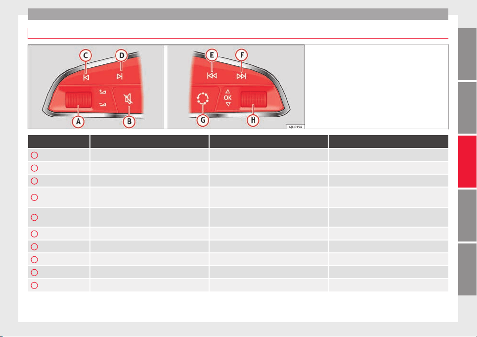
Communications and multimedia
Operating the audio system
Fig. 121 Controls on the steering wheel.
Button Radio Media (except AUX) AUX
A
Turn Up/down volume Up/down volume Up/down volume
A
Press No function No function No function
B
Mute Pause Mute
C
Search for last station
Short press: switch to the previous song
Hold down: quick rewind
No function
D
Search for the next station
Short press: switch to the next song
Hold down: fast forward
No function
E
Previous preset Previous folder No function
F
Next preset station Next folder No function
G
Change source Change source Change source
H
Turn Switch MFA function Switch MFA function Switch MFA function
H
Press Acts on the MFA Acts on the MFA Acts on the MFA
107
Technical dataAdviceOperationEmergenciesSafety
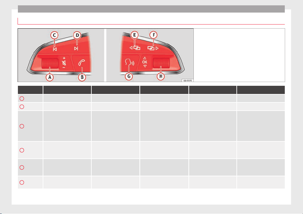
Operation
Operating the audio system + telephone
Fig. 122 Controls on the steering wheel.
Button Radio Media (except AUX) AUX Telephone
a)
Navigation
a)
A
Turn Up/down volume Up/down volume Up/down volume Up/down volume Up/down volume
A
Press Mute Pause Mute Mute Mute
B
Short press: access to the tele-
phone menu on the dash pan-
el
a)
.
Hold down: redial
a)
Short press: access to the tele-
phone menu on the dash pan-
el
a)
.
Hold down: redial
a)
Short press: access to the tele-
phone menu on the dash pan-
el
a)
.
Hold down: redial
a)
Short press: answer/hang up
calls, enable/open the tele-
phone menu.
Hold down: reject an incoming
call/switch to private/redial
mode
Short press: access to the tele-
phone menu on the dash pan-
el
a)
.
Hold down: redial
a)
C
Search for last station
Short press: switch to the pre-
vious song
Hold down: quick rewind
No function No function
b)
Radio/media functionality (ex-
cept AUX )
D
Search for the next station
Short press: switch to the next
song
Hold down: fast forward
No function No function
b)
Radio/media functionality (ex-
cept AUX )
E
Change menu on instrument
panel
Change menu on instrument
panel
Change menu on instrument
panel
Change menu on instrument
panel
Change menu on instrument
panel
108

Communications and multimedia
Button Radio Media (except AUX) AUX Telephone
a)
Navigation
a)
F
Change menu on instrument
panel
Change menu on instrument
panel
Change menu on instrument
panel
Change menu on instrument
panel
Change menu on instrument
panel
G
Enable/disable voice control
a)
Enable/disable voice control
a)
Enable/disable voice control
a)
No function
b)
Enable/disable voice control
H
Turn Next/previous preset station
c)
Next/previous song
c)
Acts upon the dash panel
menu depending on where it is
located
Acts upon the dash panel
menu depending on where it
is located
Acts upon the dash panel
menu depending on where it
is located
H
Press
Acts on the MFA or confirms
the menu option of the dash
panel depending on the menu
option
Acts on the MFA or confirms
the menu option of the dash
panel depending on the menu
option
Acts on the MFA or confirms
the menu option of the dash
panel depending on the menu
option
Acts on the MFA or confirms
the menu option of the dash
panel depending on the menu
option
Acts on the MFA or confirms
the menu option of the dash
panel depending on the menu
option
a)
According to the vehicle's equipment package.
b)
When a call is being made, radio/media functionality (except AUX).
c)
Only if the dash panel is in audio menu.
109
Technical dataAdviceOperationEmergenciesSafety
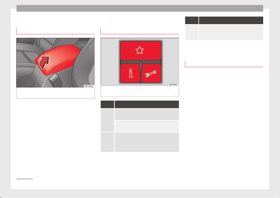
Operation
Multimedia
USB/A
UX
-IN inp
ut
Fig. 123 Front centre armrest: USB/AUX-IN in-
p
ut
.
Depending on the features and the country,
the
v
ehic
le may have a USB/AUX-IN connec-
tion.
The USB/AUX-IN input is in the front centre
armrest ››› Fig. 123.
The operating description is located in the re-
spective Instruction Manuals of the audio
system or the navigation system.
Three button unit in headliner
Three button unit*
Fig. 124 Three button unit in headliner: con-
tr
o
l
s for the telephone management system.
Function
Press it briefly: to accept or end a call.
Press the button: to reject a call.
Press it briefly: to start or stop the voice con-
trol function, for example, to make a call.
a)
Press the button for more than 2 seconds: to
obtain information about the SEAT brand and
selected additional services related to traffic
and travel.
Function
Press the button for more than 2 seconds: to
obtain help from the network of SEAT dealers
in the event of a breakdown.
a)
Not operational if a SEAT Media system 2.2 navigation system
with voice control is fitted.
Information and assistance calls
Communication with the SEAT Customer Care
Servic
e is established using the and but-
tons of the three button unit
1)
. The system
will automatically connect you with the Assis-
tance Centre of the relevant country. You will
only be able to make calls if your mobile is
turned on and connected to the pre-installed
Bluetooth.
Information call
The Information call button offers in-
formation on the SEAT brand and selected
additional services related to traffic and your
travel.
To establish communication, press the but-
ton for more than 2 seconds.
In countries where there is no information tel-
ephone number, an information call is made
after pressing the button.
1)
Depending upon country.
110
Communications and multimedia
Assistance call
The assistance call b
utt
on giv
es im-
mediate help in case of a breakdown. To this
end, the SEAT dealer network, with its mobile
assistance vehicles, is at your disposal.
To establish communication, press the
button for more than 2 seconds.
Note
Calls made with the and button
s take pri-
ority over normal calls. If the or button is
pressed during a normal telephone call, this
call will be cut off and a connection will be
made to the information or assistance centre.
Note
Any call made to the information service will
be interrupted if
the assistance button is
pressed. The connection to the assistance
service will then be made (and vice versa).
Note
Mobile phone coverage must be available to
plac
e a call to the information and assistance
services. This service might not be available
in some countries.
Activating and deactivating
Switching on the speech control system
●
Press the button on the mu
lti-function
steering wheel.
●
OR: press the button in the three button
unit in the headliner .
●
Wait for the acoustic signal.
●
Give the command.
●
Follow the dialogue instructions (extended
dialogue).
Ending voice control
●
Press the button on the mu
lti-function
steering wheel.
●
OR: press the button in the three button
unit in the headliner .
Interrupting the instructions
●
During the instructions, press the button
on the multi-function steering wheel.
●
OR: press the button in the three button
unit in the headliner .
●
You will be able to give a command imme-
diately afterwards.
111
Technical dataAdviceOperationEmergenciesSafety
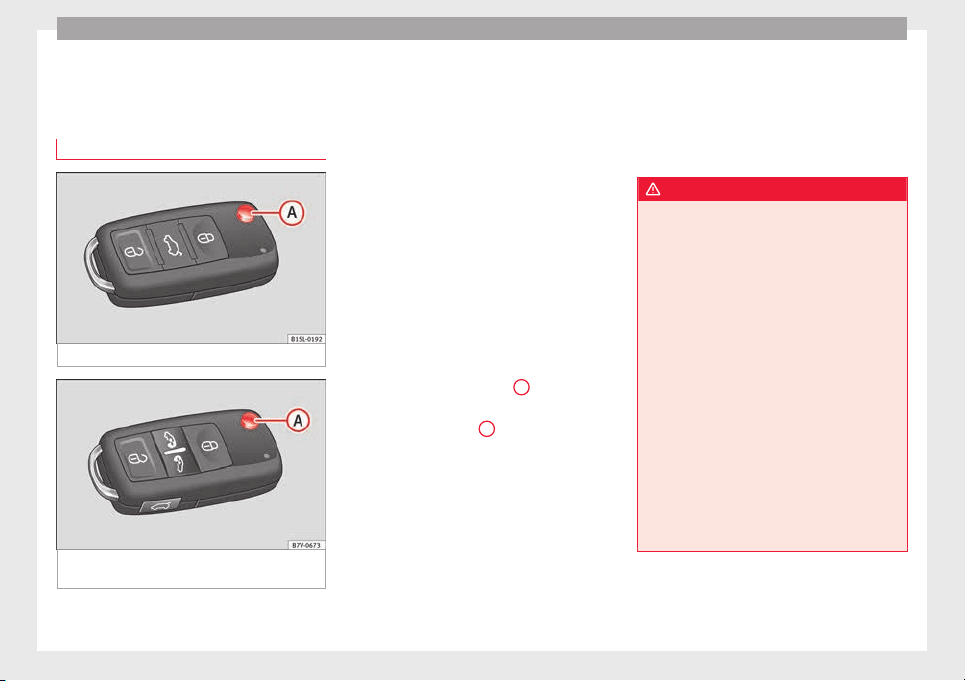
Operation
Opening and closing
V
ehic
l
e key set
Vehicle key
Fig. 125 Vehicle keys
Fig. 126 Vehicle key for vehicles with electric
s
lidin
g door
s
Vehicle keys
W
ith the
v
ehicle key ››› Fig. 125 or ››› Fig. 126
the vehicle may be locked or unlocked re-
motely.
The vehicle key includes an emitter and bat-
teries. The receiver is in the interior of the ve-
hicle. The range of the vehicle key with re-
mote control and new batteries is several me-
tres around the vehicle.
If it is not possible to open or close the vehi-
cle using the remote control key, this should
be re-synchronised ››› page 114 or the bat-
tery changed ››› page 113.
Different keys belonging to the vehicle may
be used.
Folding the key shaft in and out
When the button is pressed
A
, the key shaft
i
s
r
eleased and unfolds.
To fold it press button
A
and fold the key
sh
af
t
in until it locks in place.
Spare key
To obtain a spare key and other vehicle keys,
the vehicle chassis number is required.
Each new key must contain a microchip and
be coded with the data from the vehicle elec-
tronic immobiliser. A vehicle key will not work
if it does not contain a microchip or the mi-
crochip has not been encoded. This is also
true for keys cut for the vehicle.
The vehicle keys or new spare keys can be
obtained from a technical service centre, a
specialised workshop or approved key serv-
ice qualified to provide this kind of key.
New keys or spare keys must be synchron-
ised before use ››› page 114.
WARNING
Careless or incorrect use of vehicle keys may
res
ult in severe injury and accident.
●
Always take all the keys with you whenever
you leave the vehicle. Children and unauthor-
ised individuals could lock the doors or the
boot hatch, start the engine or turn on the ig-
nition, activating electrical systems, the elec-
tric windows, for example.
●
Never leave children or disabled people
alone in the car. They could be trapped in the
car in an emergency and will not be able to
get themselves to safety. For example, de-
pending on the time of the year, tempera-
tures inside a locked and closed vehicle can
be extremely high or extremely low resulting
in serious injuries and illness or even death,
particularly for young children.
●
Never remove the key from the ignition if
the vehicle is in motion. The steering may
lock and it will not be possible to turn the
steering wheel.
112
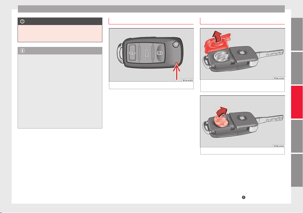
Opening and closing
CAUTION
All of the vehicle keys contain electronic com-
ponents. Prot
ect them from damage, impacts
and humidity.
Note
●
Only u
se the key button when you require
the corresponding function. Pushing the but-
ton unnecessarily could accidentally unlock
the vehicle or trigger the alarm. It is also pos-
sible even when you are outside the radius of
action.
●
Key operation can be greatly influenced by
overlapping radio signals around the vehicle
working in the same range of frequencies
(e.g. radio transmitters, mobile telephones).
●
Obstacles between the remote control and
the vehicle, bad weather conditions and
draining batteries can considerably reduce
the range of the remote control.
Control lamp on the vehicle key
Fig. 127 Control lamp on the vehicle key
When a button on the vehicle key is pressed,
the c
ontr
o
l lamp flashes ››› Fig. 127 (arrow)
once briefly. If the button is pressed and
held, the indicator blinks several times (e.g.
for the convenience opening function).
When the control lamp does not light upon
pushing a button, the batteries of the key
must be changed ››› page 113.
Replacing the battery
Fig. 128 Vehicle key: battery compartment
c
o
v
er
Fig. 129 Vehicle key: removing the battery
SEAT recommend having the batteries
c
h
an
ged in a specialised workshop.
The battery is located to the rear of the vehi-
cle key, under a cover ››› Fig. 128.
When changing the battery, use another bat-
tery of the same model and observe the po-
larity when fitting it ›››
.
»
113
Technical dataAdviceOperationEmergenciesSafety
Operation
To change the battery
●
Unfold the vehicle key shaft ›
›
›
page 112.
●
Remove the cover from the back of the ve-
hicle key ››› Fig. 128 in the direction of the ar-
row ›››
.
●
Extract the battery from the compartment
u
s
in
g a suitable thin object ››› Fig. 129.
●
Place the new battery in the compartment,
pressing in the direction of the arrow as
shown ››› Fig. 129 ›››
.
●
Fit the battery compartment cover, pressing
in the dir
ection of
the arr
ow as shown
››› Fig. 128 until it clicks into place.
CAUTION
●
If the batt
ery is not changed correctly, the
vehicle key may be damaged.
●
Use of unsuitable batteries may damage
the vehicle key. For this reason, always re-
place the dead battery with another of the
same voltage, size and specifications.
For the sake of the environment
●
Plea
se dispose of your used batteries cor-
rectly and with respect for the environment.
●
The vehicle key battery may contain per-
chlorate. Observe the legal requirements for
their disposal.
Synchronising the vehicle key
If the button
is pressed frequently outside
of the v
ehicle range, it is possible that the ve-
hicle can no longer be locked or unlocked us-
ing the key. In this case, the vehicle key must
be synchronised once more as follows:
●
Unfold the vehicle key shaft ››› page 112.
●
Remove the cover from the driver door han-
dle ››› page 89.
●
Press the button
on the vehicle key. For
this, it mu
st remain with the vehicle.
●
Open the vehicle within one minute using
the key sh
aft.
●
Turn on the ignition using the vehicle key.
The key has been synchronised.
●
Replace the driver door handle cover.
Central locking and locking
system
Introduction
Read the additional information carefully
›
›
›
page 8
Central locking functions correctly when all
the doors and the rear lid are correctly shut.
If the driver door is open, the vehicle cannot
be locked with the key.
If the vehicle has the Keyless Access closing
and ignition system, it may only be locked
with the ignition off and the driver's door
closed.
The battery of an unlocked vehicle parked for
a long period (e.g. in a private garage) may
run down and fail to start the motor.
WARNING
The incorrect use of the central locking sys-
tem ma
y cause serious injuries.
●
The central locking system will lock all
doors. A vehicle locked from the inside can
prevent any non-authorised individual from
opening the doors and accessing the vehicle.
Nevertheless, in case of emergency or acci-
dent, locked doors will complicate access to
the vehicle interior to help the passengers.
●
Never leave children or disabled people
alone in the vehicle. The central locking but-
ton can be used to lock all the doors from
within. Therefore, passengers will be locked
inside the vehicle. Individuals locked in the
vehicle can be exposed to very high or very
low temperatures.
●
Depending on the time of the year, temper-
atures inside a locked and closed vehicle can
be extremely high or extremely low resulting
in serious injuries and illness or even death,
particularly for young children.
●
Never leave individuals locked in a closed
and locked vehicle. In case of emergency,
they may not be able to exit the vehicle by
themselves or get help.
114
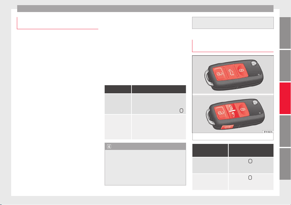
Opening and closing
Description of the central locking sys-
t
em
The central locking system allows all doors
and the rear lid t
o be locked and unlocked
centrally.
●
From outside, using the vehicle key.
●
From outside with the Keyless Access sys-
tem ››› page 117,
●
From inside, by pushing the central locking
button ››› page 116.
In the submenu Convenience in the Con-
figuration menu, or by visiting a special-
ised workshop, special functions of the cen-
tral locking system can be switched on or off
›››
page 26.
In case of a vehicle key fault or central lock-
ing system fault, all doors can be locked or
unlocked manually.
Automatic locking (Auto Lock)
In this instance, the vehicle locks automati-
cally when moving at speeds above approx.
15 km/h (10 mph)
›››
page 26. When the
vehicle is locked, the control lamp of the
central locking button
›››
Fig. 131 lights up in
yellow.
Automatic unlocking (Auto Unlock)
When the key i
s removed from the ignition
slot, here the vehicle unlocks all doors and
the boot automatically ›››
page 26.
Locking the vehicle after the airbags have
been deployed
If the airbags are deployed due to an acci-
dent, the vehicle will be automatically and
completely unlocked. Depending on the
amount of damage, it can be locked follow-
ing an accident in the following ways:
Function Action
Lock the vehicle
by pushing the
central locking
button:
– Switch off the ignition.
– Open a door of the vehicle and
close it again.
– Push the central locking button
.
Lock the vehicle
with the vehicle
key:
– Disconnect the ignition button.
OR: remove the key from the igni-
tion.
– Open a door once.
– Lock the vehicle with the key.
Note
If the vehicle key buttons are pressed
›››
Fig. 130 or one of the central locking but-
tons is pressed ››› Fig. 131 several times in
quick succession, the central locking feature
is disabled briefly to protect from overload-
ing. The vehicle will then remain unlocked for
around 30 seconds. If no door nor the boot is
opened during this time, the vehicle will then
automatic
ally unlock.
Unlocking and locking the vehicle
from outs
ide
Fig. 130 Buttons on the vehicle key
Function Handling the buttons on
the vehicle
Unlocking the vehicle. Press button
. Keep it
pushed for the convenience
opening.
Lock the vehicle. Press button
. Keep it push-
ed for the convenience lock-
ing function.
»
115
Technical dataAdviceOperationEmergenciesSafety
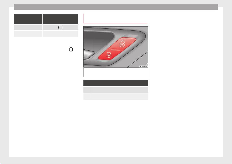
Operation
Function Handling the buttons on
the vehicle
Unlocking the rear lid. Press button
.
Open the sliding door. ››› page 121.
Please note: depending on the select
ed func-
tion in the central locking submenu Conven-
ience, you may push the button twice
›››
page 26 to unlock all doors and the
boot h
atch.
The vehicle key only locks and unlocks the
vehicle if it is within range of the vehicle and
if the batteries have enough power. When
locking, the vehicle's turn signals will blink.
If the driver door is open, the vehicle cannot
be locked with the key. If you unlock the vehi-
cle without opening any doors or the rear lid,
it will lock again automatically after a few
seconds. This function prevents the vehicle
from remaining unlocked if the unlocking
button is pressed by mistake.
Convenience open/close function
●
See "Electric windows: functions"
›››
page 127.
●
See "Panoramic sliding sunroof: operation"
›››
page 128.
Unlocking and locking the vehicle
from inside
Fig. 131 In the driver door: central locking
b
utt
on
Push the button ››› Fig. 131:
Unlocking the vehicle.
Locking the vehicle.
The central locking button is still operative
when the ignition i
s
sw
itched off.
The central locking button is only deactivated
if the deadlock is activated ››› page 119.
Please note the following when you use the
central locking button to lock your vehicle:
●
Do not turn on the deadlock ››› page 119.
●
Do not turn on the anti-theft alarm.
●
It w
ill not be possible to open the doors or
the rear lid fr
om the outside. This may offer
extra safety, for example when stopped at
traffic lights.
●
The doors can be opened and unlocked in-
dividually from the inside by pulling the in-
side door handle. If necessary, pull the door
release lever twice.
●
The driver door cannot be locked when
open. This avoids locking the vehicle key in-
side the vehicle when there is nobody inside.
116
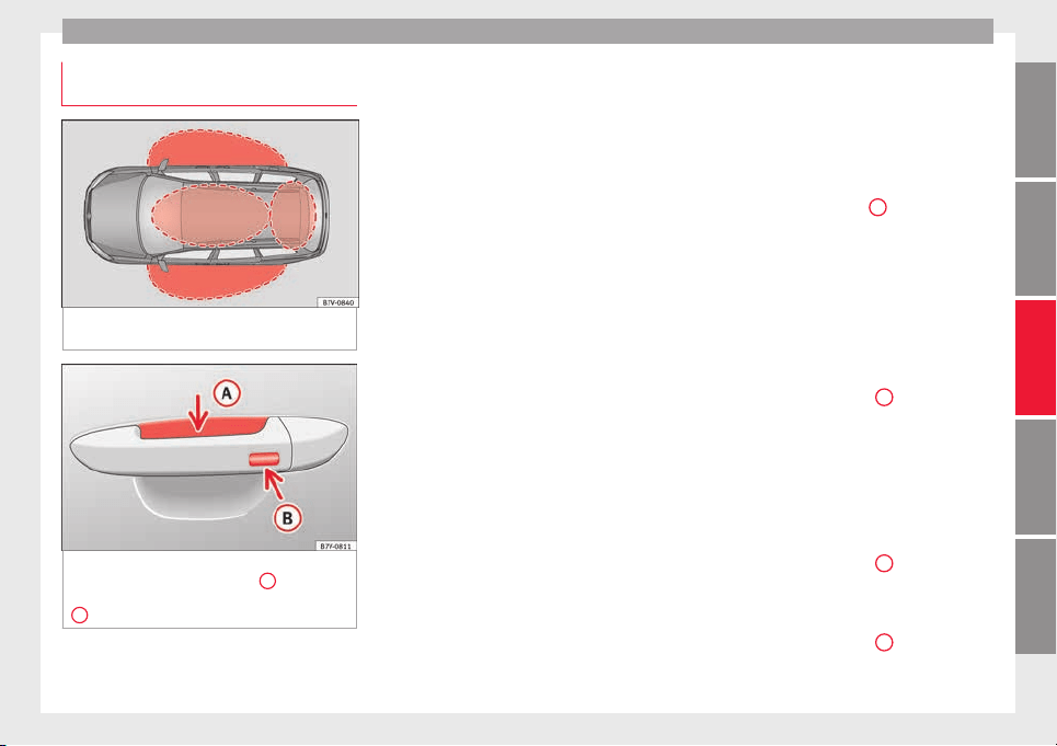
Opening and closing
Locking and unlocking the vehicle
w
ith K
eyl
ess Access
Fig. 132 Lock and ignition system without
K
eyl
e
ss Access: in the proximity of the car.
Fig. 133 Lock and ignition system without
K
eyl
e
ss Access: sensor surface
A
for unlock-
in
g in
s
ide the door handle and sensor surface
B
for locking on the exterior of the handle.
Keyless Access is a key-free lock and ignition
sy
s
t
em to unlock and lock the vehicle without
actively using its key. For this, only a valid ve-
hicle key is required to be in an area near
››› Fig. 132 the vehicle and one of the sensor
surfaces to be touched on the door handles
››› Fig. 133.
General information
If a valid key is located in the proximity of the
car ››› Fig. 132, the Keyless Access lock and
ignition system gives the key entry as soon
as one of the sensor surfaces on the door
handles is touched or the push button on the
boot hatch is operated. The following fea-
tures are then available without having to
use the vehicle key actively:
●
Keyless-Entry: unlocking of the vehicle with
the handles on the four doors or the button
located on the boot hatch.
●
Keyless-Go: engine ignition and driving. For
this to occur, there has to be a valid key in-
side the vehicle and the ignition push button
needs to be pressed ››› page 185.
●
Keyless-Exit: unlocking of the vehicle with
one of the four door handle.
The central locking and locking systems oper-
ate in the same way as a normal locking and
unlocking system. Only the controls change.
Unlocking the vehicle is confirmed with a
double flash of the indicator lights; locking
by a single flash.
The vehicle will lock again after a few sec-
onds if you unlock the vehicle but fail to open
any door or boot hatch.
Unlocking and opening the doors (Keyless-
Entry)
●
Grip the door handle. In doing this, the
sensor surface ››› Fig. 133
A
(arrow) is
t
ouc
hed on the h
andle and the vehicle un-
locks.
●
Open the door.
On vehicles without a "safe" system: locking
and unlocking doors (Keyless-Exit)
●
Switch the ignition off.
●
Close the driver's door.
●
Touch the surface sensor
B
onc
e (arrow)
on the door h
andl
e. The door being operated
must be closed.
On vehicles with a "safe" security system:
locking and unlocking doors (Keyless-Exit)
●
Switch the ignition off.
●
Close the driver's door.
●
Touch the surface sensor
B
onc
e (arrow)
on the door h
andl
e. The vehicle locks with
the "safe" security system ››› page 119. The
door being operated must be closed.
●
Touch the sensor surface
B
twic
e (arrow)
on the door h
andl
e to lock the vehicle with-
out the "safe" security system ››› page 119.
»
117
Technical dataAdviceOperationEmergenciesSafety
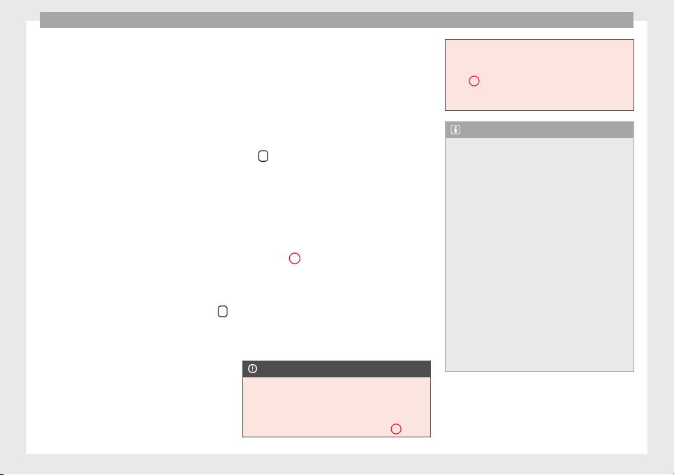
Operation
Unlocking and locking the boot hatch
When the
v
ehic
le is locked, the hatch auto-
matically unlocks on opening if ››› Fig. 132
there is a valid vehicle key in the proximity.
Open or close the hatch normally
››› page 124.
After closing, the hatch locks automatically.
In the following instances, the rear lid does
not lock automatically after closing:
●
If the entire vehicle is unlocked.
●
If the key used last is inside the vehicle. All
vehicle indicator lights flash four times. The
vehicle will lock again after a few seconds if
no door or boot hatch are opened.
Locking the vehicle with a second key
If there is a vehicle key inside the vehicle and
it is locked from the outside with a second
vehicle key, the key inside the vehicle is
blocked for engine ignition ››› page 185. In
order to enable engine ignition, the button
on the key inside the vehicle needs to be
pr
e
s
sed ››› Fig. 130.
Automatically disabling sensors
If the vehicle is not locked or unlocked for a
long period of time, the proximity sensor on
the passenger door is automatically disa-
bled.
If the exterior sensor on the door handle is
often activated unusually with the vehicle
locked (e.g. by the branches of a bush rub-
bing against it), all proximity sensors are dis-
abled for a time. If this only happens with the
exterior sensor on the driver's door, only this
sensor is disabled.
Sensors will again be enabled:
●
After a time.
●
OR: if the vehicle is unlocked with the but-
ton
on the key.
●
OR: if
the boot is opened.
C
on
venience functions
To close all electric windows, the sun roof
and electric tilting panoramic roof with the
convenience feature, keep your finger for a
few seconds on the lock sensor surface
››› Fig. 133
B
located on the exterior part of
the driv
er or p
a
ssenger door handle until the
windows and roof close.
Opening the doors by touching the sensor
surface on the handle takes places in accord-
ance with the settings activated on the menu
Configuration - Convenience
›››
page 26.
CAUTION
The sensor surfaces on the door handles
coul
d engage if hit with a water jet or high
pressure steam if there is a valid vehicle key
in the nearby area. If at least one of the win-
dows is open and the sensor surface
B
on
one of the handle permanently activates, all
window
s will close. If the water jet or steam
is briefly moved away from the sensor sur-
face
A
on one of the handles and then poin-
ted at it
again, all the windows will probably
open ››› page 118, Convenience functions.
Note
●
If
the v
ehicle battery has little or no charge,
or the vehicle key battery is almost or entire-
ly out of charge, it is likely that the vehicle
will not be able to be lock or unlocked with
the Keyless Access system. The vehicle can
be unlocked or locked manually ››› page 89.
●
If there is no valid key inside the vehicle or
the system fails to detect one, a warning will
display on the dash panel screen. This could
happen if any other radio frequency signal in-
terferes with the key signal (e.g. from a mo-
bile device accessory) or if the key is covered
by another object (e.g. an aluminium case).
●
If the sensors are very dirty, e.g. have a lay-
er of salt, how the sensors on the door han-
dles operate may be affected. If this is the
case, wash the vehicle ››› page 253.
●
If the vehicle is equipped with an automatic
gearbox, it may only be locked in the gear
stick is in position P.
118
Opening and closing
"Safe" security system
Function Necessary operations
Locks the vehicle with
the "Safe" security sys-
tem.
Press the
button once on
the vehicle key.
Locks the vehicle with-
out the "Safe" security
system.
Press the
button twice on
the vehicle key.
Touch the Keyless Access
close and ignition lock sensor
surface located on the exteri-
or part of the door handle
twice ››› page 117.
Press the central locking but-
ton
on the driver door
once.
Depending on the vehicle, when disabling
the ignition, a w
arnin
g on the d
ash panel
screen may display stating that the "safe" se-
curity system is activated (
Lock SAFE
or
SAFELOCK
).
Disabling the "safe" security system
The "safe" security system may be disable in
one of the following ways:
●
Press the button
on the vehicle key
twic
e
.
●
T
ouch the Keyless Access close and igni-
tion lock sensor surface located on the exteri-
or part of the door handle twice ››› page 117.
●
Switch the ignition on.
●
Press the ignition push button of the
Keyless Access lock and ignition system.
When the “safe” security system is disabled,
the following needs to be taken into account:
●
The vehicle can be opened and unlocked
from the inside using an inside door handle.
●
The anti-theft alarm is activated.
●
The vehicle interior monitoring system and
the anti-tow system are disabled.
WARNING
Careless use of the “Safe” security system
can cau
se serious injury.
●
Never leave anybody inside the vehicle if it
has been locked using the key. When the
"Safe" security system is activated, doors
cannot be opened from the inside!
●
When the doors are locked, it is difficult to
get to passengers in the vehicle interior in
case of an emergency. Passengers could re-
main trapped inside and unable to unlock the
doors in case of an emergency.
Anti-theft alarm
The anti-theft alarm makes it more difficult to
br
e
ak
into the vehicle or steal it.
The anti-theft alarm is automatically turned
on when the vehicle is locked with the key.
When does the system trigger an alarm?
The anti-theft alarm siren will be triggered for
about 30 seconds accompanied by optical
warning signals for about five minutes when
the vehicle is locked and the following unau-
thorised actions are taken:
●
When the door is mechanically unlocked
using the vehicle key without turning the ig-
nition within the following 15 seconds.
●
A door is opened.
●
The bonnet is opened.
●
The rear lid is opened.
●
When the ignition is switched on with a
non-authorised key.
●
When the vehicle battery is disconnected.
●
When there is movement inside the vehicle
(vehicles with interior monitoring).
●
When the vehicle is towed (vehicles with
anti-tow system)
●
When the vehicle is lifted (vehicles with an-
ti-tow system).
●
Transporting the vehicle on a ferry or by
railroad (vehicles with an anti-tow system or
interior monitoring).
●
Unhitch a trailer connected to the anti-theft
alarm ››› page 237.
How to turn OFF the alarm
Unlock the vehicle with the unlocking button
on the key or turn on the ignition with a valid
»
119
Technical dataAdviceOperationEmergenciesSafety
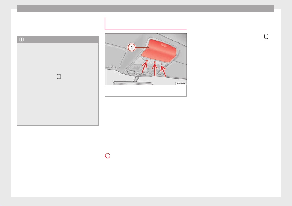
Operation
key. On vehicles with the Keyless Access sys-
t
em, the al
arm c
an also be disabled by grasp-
ing the door handle ››› page 117.
Note
●
The alarm w
ill be triggered once more when
anybody enters the same zone of surveillance
or any other zone. If, for example, after open-
ing a door, the rear lid is also opened.
●
The anti-theft alarm is not activated when
the vehicle is locked from within using the
central locking button
.
●
If the driver door is unlocked mechanically
with the key
, only the driver door is unlocked,
the rest of the doors remain locked. Only
when the ignition has been turned on will the
other doors be available - but not unlocked -
and the central lock button will be activated.
●
If the vehicle battery is run down or flat
then the anti-theft alarm will not operate cor-
rectly.
Interior monitoring system and anti-
t
o
w sy
stem*
Fig. 134 On the roof console: interior moni-
t
orin
g sen
sors
The interior monitoring system triggers the
al
arm if
the
vehicle is locked and movement
is detected inside the vehicle. The anti-tow
system triggers the alarm if the vehicle is
locked when the system detects the vehicle
is being raised.
Switching on the interior monitoring and the
anti-tow systems
Close the storage compartment ››› Fig. 134
1
on the roof console, otherwise the interior
monit
orin
g f
unction (arrow) is not guaran-
teed to work freely.
Use the key to lock the vehicle. If the anti-
theft alarm is turned on, the interior monitor-
ing and the anti-tow systems are also activa-
ted.
Switching off the interior monitoring and the
anti-tow systems
The interior monitoring is switched off by
pressing the remote control lock button
twice.
●
Lock all doors and rear lid.
●
Use the key to lock the vehicle. The interior
monit
orin
g and / or anti-t
owing alarm are
switched off until the next time the vehicle is
locked.
To turn off the interior monitoring and anti-
tow systems before unlocking the vehicle, for
example in the following situations:
●
When leaving animals inside the vehicle
››› page 114.
●
When the vehicle must be loaded.
●
When the vehicle is being transported, for
example, by ferry.
●
When the vehicle must be towed with the
axle raised.
Risk of false alarms
The interior monitoring system will only oper-
ate correctly if the vehicle is completely
closed. Observe legal requirements. The
alarm may be accidentally triggered in the
following cases:
●
When a window is completely or partially
open.
120
Opening and closing
●
If
the s
u
nglasses storage compartment in
the roof console is open.
●
When the panoramic sliding sunroof is
completely or partially open.
●
When suspended objects are hung from
the interior mirror (air freshener) or there are
loose papers in the vehicle.
●
If the separation net is fitted and moves
(due to heating).
●
Due to a vibrating mobile telephone inside
the vehicle.
Note
Upon activating the alarm, if any door or the
rear lid i
s open, only the anti-theft alarm will
be activated. The interior monitoring and an-
ti-tow systems will only be activated when
the doors and rear lid are fully closed.
Doors
Intr
oduction
WARNING
If a door is not correctly closed, it could open
unexpect
edly when driving and cause serious
injuries.
●
Always stop immediately and close the
door.
●
When clos
ing, ensure that the door has
closed correctly. A closed door should be
flush with the corresponding parts of the
bodywork.
●
Open and close doors only when nobody is
in the way of the door.
WARNING
A door held open by its retainer could be
b
lown c
losed by the wind or close if the vehi-
cle is on a hill, causing injury.
●
When opening and closing doors, always
use the door handle.
Warning lamp
It lights up
At least one vehi-
cle door is open or
not correctly shut.
Stop driving immediately!
Open the corresponding door and
close it immediately.
Several warning and indication lamps light
up f
or a f
ew sec
onds when the ignition is
switched on, signalling that the function is
being verified. They will switch off after a few
seconds.
If a door is open or incorrectly closed, the
warning lamp or on the instrument pan-
el will light up.
Depending on the vehicle equipment, a sym-
bol may be displayed on the dash panel
screen instead of the warning lamp. The indi-
cation is also visible when the ignition is
switched off. The indication disappears
around 15 seconds after the vehicle has
been locked.
Sliding doors
Introduction
WARNING
If a sliding door is not correctly closed, it
coul
d open unexpectedly when driving and
cause serious injuries.
●
Stop immediately and close it.
●
When closing, ensure that the sliding door
has closed correctly. A closed sliding door
should be flush with the corresponding parts
of the bodywork.
●
Only open and close sliding doors when no
body is in the way of the door.
WARNING
If a sliding door is not fully open, it could
close u
nexpectedly and cause serious inju-
ries.
●
Always open the sliding door fully.
»
121
Technical dataAdviceOperationEmergenciesSafety
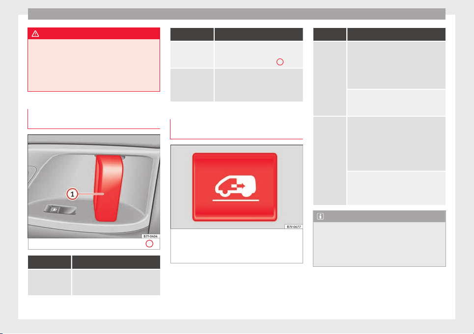
Operation
WARNING
Opening sliding doors while driving is dan-
gerou
s. These doors may be pushed open or
closed when the vehicle accelerates or brakes
and cause serious injuries.
●
Never open the sliding doors when the ve-
hicle is in movement.
Manually opening and closing the
sliding door
Fig. 135 On the sliding door. door handle
1
Function Necessary operations
Open the sliding
door from the in-
side.
When the sliding door is released,
open the door fully by pulling on the
outside handle.
Function Necessary operations
Opening the
sliding door
from the inside.
When the sliding door is released,
open the door fully by pulling on its
interior handle ››› Fig. 135
1
.
Closing the slid-
ing door.
Pull on the inside or outside door
handle and close the sliding door by
pushing gently. Make sure that it is
completely closed.
Electric opening and closing of the
sliding door*
Fig. 136 On the dash panel, on the remote
c
ontr
o
l key and on the interior lining of the
sliding door: button for opening and closing
the electric sliding door.
All of the electric sliding doors can be
opened and c
lo
sed m
anually using more
force.
Function Necessary operations
Opens the
sliding door
electrically.
Press the ››› Fig. 136 button on the dash
panel, on the remote control key and on
the interior lining of the sliding door. The
sliding door opens with the rollback anti-
trap function as long as the button is not
pressed again.
Pull briefly on the interior or exterior han-
dle the door. The sliding door opens au-
tomatically.
Closing the
sliding door
electrically.
Press the ››› Fig. 136 button on the dash
panel, on the remote control key and on
the interior lining of the sliding door. The
sliding door closes with the rollback anti-
trap function as long as the button is not
pressed again. As it closes, a warning
sound is given.
Pull briefly on the interior or exterior door
handle. The sliding door closes with the
roll-back function. As it closes, a warning
sound is given.
Note
●
When the fuel t
ank flap is open, the right-
hand side electric sliding door is locked and
can only be opened manually.
●
If the window of a sliding door is lowered
them this door cannot open fully.
122
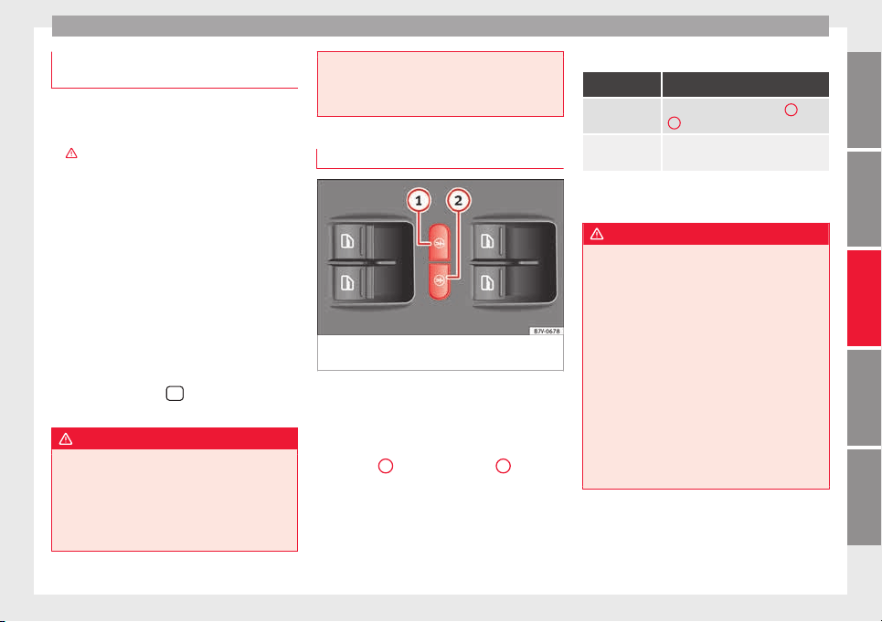
Opening and closing
Rollback anti-trap function of the elec-
tric
s
lidin
g doors
The rollback anti-trap function of the electric
sliding door
s can reduce the risk of injury
when opening and closing the sliding doors
›››
.
If an ob
ject gets in the way of the sliding
door while it is closing, it will open again.
If an object gets in the way of the sliding
door while it is opening, the door will be im-
mobilised at this point.
●
Check the reason for which the sliding door
does not
open or close.
●
Try to open or close the sliding door again.
To close the sliding door without the rollback
anti-trap function
●
Turn off the ignition and turn it on again.
●
Press and hold the
›
›
›
Fig. 136 button.
The sliding door closes with full force.
WARNING
Closing the electric windows without the an-
ti-trap fu
nction can cause serious injury.
●
Always close the sliding doors carefully.
●
Nobody should ever get in the way of the
electric sliding doors, especially when clos-
ing without the anti-trap function.
●
The anti-trap fu
nction does not prevent fin-
gers or other parts of the body getting
pinched against the window frame and caus-
ing injury.
Electric child safety lock
Fig. 137 In the driver door: electric child safe-
ty
loc
k
s buttons
The electric child safety lock avoids opening
and loc
k
in
g of the sliding door and its elec-
tric windows from the inside so that children
cannot accidentally open the door while the
vehicle is being driven. Using the left-hand
››› Fig. 137
1
or right-hand side
2
button,
the c
hi
l
dproof lock is activated on the left- or
right-hand side respectively.
Turning on and off the electric child safety
Function Necessary operations
To switch sys-
tem on:
Press the button ››› Fig. 137
1
or
2
.
To switch sys-
tem off:
Press the button again.
The yellow control lamp indicate
s that the
feature is on for the corresponding button.
WARNING
When the electric child safety function is acti-
vated, the s
liding door can be opened from
the outside only.
●
Never leave children or disabled people
alone in the vehicle if the doors are to be
locked. Therefore, passengers will be locked
inside the vehicle. They could be trapped in
the car in an emergency and will not be able
to get themselves to safety. Individuals
locked in the vehicle can be exposed to very
high or very low temperatures.
●
Depending on the time of the year, temper-
atures inside a locked and closed vehicle can
be extremely high or extremely low resulting
in serious injuries and illness or even death,
particularly for young children.
123
Technical dataAdviceOperationEmergenciesSafety
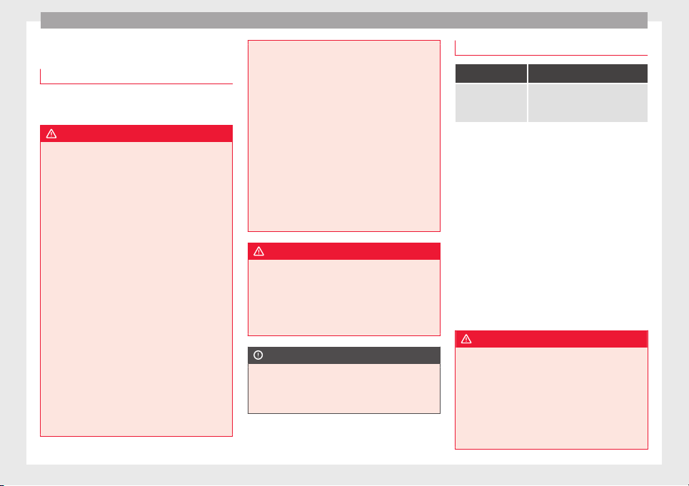
Operation
Rear lid
Intr
oduction
Read the additional information carefully
›››
page 10
WARNING
Careless and unsuitable locking, opening and
clos
ing of the rear lid can cause accidents
and serious injury.
●
Open and close the rear lid only when no-
body is in the way.
●
Do not close the rear lid by pushing it down
with your hand on the rear window. This
could break and cause injury.
●
Ensure the rear lid is locked after closing,
otherwise, it may open unexpectedly while
driving. A closed rear lid should be flush with
the corresponding parts of the bodywork.
●
Always keep the rear lid closed while driv-
ing to avoid toxic gases entering the vehicle
interior.
●
Do not open the rear lid when there is a
load carrier installed. Likewise, the boot
hatch cannot be opened when a load is at-
tached to it, for example bicycles. An open
rear lid could close itself if there is an addi-
tional weight on it. If necessary, press down
on the rear lid and remove the load.
●
Close and lock both the rear lid and all the
other doors when you are not using the vehi-
cle. Ensure that nobody remains inside the
vehicl
e.
●
Never allow children to play inside or
around the vehicle without supervision, espe-
cially if the rear lid is open. Children could
enter the luggage compartment, close the
rear lid and become trapped. Depending on
the time of the year, temperatures inside a
locked and closed vehicle can be extremely
high or extremely low resulting in serious in-
juries and illness or even death, particularly
for young children.
●
Never leave children or disabled people
alone in the vehicle. If the vehicle key or the
central locking button is used, they may be
locked in the vehicle.
WARNING
Unsuitable or careless unlocking and opening
of the re
ar lid could cause serious injuries.
●
If there is a loaded luggage carrier on the
rear lid, it could be unlocked or open but not
recognised as such. An unlocked or open rear
lid could open unexpectedly while driving.
CAUTION
Before opening the rear lid, ensure that there
is s
ufficient free space to open and close it,
for example if you are towing a trailer or in a
garage.
Warning lamp
It lights up
The rear lid is open
or not correctly
shut.
Stop driving immediately!
Open the rear lid and close it
again.
Several warning and indication lamps light
up for a few sec
onds when the ignition is
switched on, signalling that the function is
being verified. They will switch off after a few
seconds.
A warning lamp appears on the dash panel
if the boot hatch is open or not properly
closed.
Depending on the vehicle equipment, a sym-
bol may be displayed on the dash panel
screen instead of the warning lamp. The indi-
cation is also visible when the ignition is
switched off. The indication disappears
around 15 seconds after the vehicle has
been locked.
WARNING
If the rear lid is not correctly closed, it could
open unexpect
edly when driving and cause
serious injuries.
●
Always stop immediately and close the rear
lid.
●
Ensure that the rear lid has been locked in-
to place by the element on the lock carrier
when you close it.
124
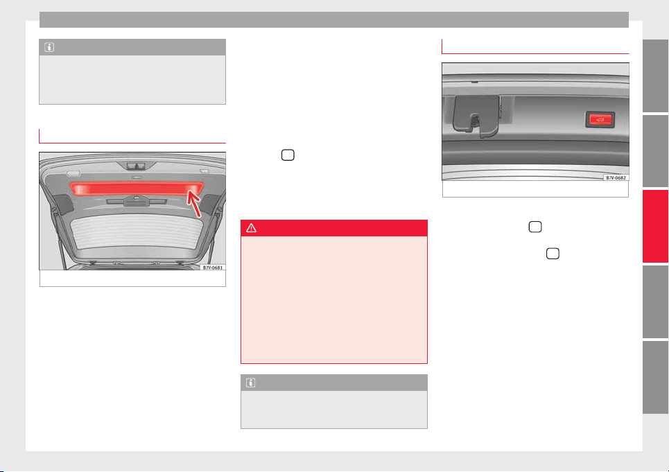
Opening and closing
Note
At outside temperatures of less than 0°C
(+32°F), the pres
surised gas struts cannot al-
ways automatically lift the rear lid. In this
case, open the rear lid manually.
Closing the rear lid
Fig. 138 Rear lid open: hand grip
Closing the rear lid
●
Grab the handgrip inside the rear lid
›
›
›
Fig. 138 (arrow).
●
Push the rear lid downwards until it locks
into place in the lock.
●
Ensure that it is correctly closed by pulling
on it firmly.
Locking the rear lid
If you unlock the vehicle without opening any
doors or the rear lid, it will lock again auto-
matically after 30 seconds. This function pre-
vents the vehicle from remaining unlocked if
the unlocking button is pressed by mistake.
Locking is only possible when the rear lid is
correctly and fully closed.
●
The rear lid is also locked by a central lock-
ing.
●
If the vehicle rear lid is locked or unlocked
using the
button, when it is closed once
mor
e it
w
ill lock automatically.
●
A closed but not locked rear lid will lock au-
tomatically at a speed above about 9 km/h
(7 mph).
WARNING
Unsuitable or careless closing and locking of
the rear lid c
ould cause serious injuries.
●
Never leave the vehicle unattended, or al-
low children to play inside or around the vehi-
cle without supervision, especially if the rear
lid is open. Children could enter the luggage
compartment, close the rear lid and become
trapped. A locked vehicle can be subjected to
extremely high and low temperatures, de-
pending on the time of year, thus causing se-
rious injuries/illness and even death.
Note
Before closing the rear lid, make sure that the
key h
as not been left inside the luggage com-
partment.
Opening the rear lid electronically
Fig. 139 Button with rear lid open
Opening the rear lid
●
Press and hold the
button on the vehi-
c
l
e k
ey until the rear lid opens automatically.
●
OR: press and hold the
button on the
c
entr
e c
onsole for approximately 1 second
›››
Fig. 6.
●
OR: press the ›››
Fig. 7 boot hatch but-
ton (arrow).
In case of difficulty or obstruction, automatic
opening of the rear lid is interrupted.
Electronically opening the rear lid does not
work when a trailer is electrically connected
and hitched to a factory fitted tow hitch
››› page 237.
The rear lid can be opened manually by ap-
plying more force.
»
125
Technical dataAdviceOperationEmergenciesSafety
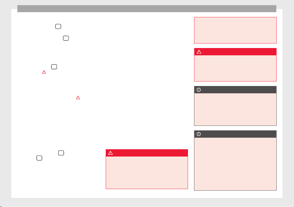
Operation
Closing the rear lid
●
Press and hold the
button on the vehi-
c
l
e k
ey for approximately 1 second.
●
OR: press and hold the
button on the
c
entr
e c
onsole for approximately 1 second
›››
Fig. 6.
●
OR: press the ›››
Fig. 7 boot hatch but-
ton (arrow).
●
Press the button
on the open rear lid
›
›
›
Fig. 139 ›››
.
●
Manually push the rear lid down to close it.
The r
e
ar lid w
ill move down to the closed po-
sition to close and lock itself automatically
using the power-close feature ›››
.
In c
a
se of
difficulty or obstruction, automatic
closing of the rear lid is interrupted and it will
open slightly.
Check why the rear lid could not close.
Attempt to close it once more.
Interrupting the opening and closing process
Rear lid opening and closing can be stopped
by pressing one of the
buttons. Each time
one of
the
buttons is pressed, the rear lid
mo
v
e
s to its initial position.
Then, it can be opened or closed by hand. To
do this, apply a little more force.
Memorising the opening angle
The rear lid must be at least half open to
memorise an opening angle.
●
Stop automatic opening in the opening po-
sition required ››› page 126.
●
Hold down the button ››› Fig. 139 with the
rear lid open for at least three seconds. The
opening angle is memorised.
Memorisation is confirmed by blinking of the
hazard warning lights and an audible warn-
ing.
To fully open the boot hatch again, the open-
ing angle must be memorised once more.
●
Release the rear lid and open it to the
memorised height.
●
Push the rear lid all the way up. To do this,
apply a little more force.
●
Hold down the button ››› Fig. 139 with the
rear lid open for at least three seconds.
●
The opening angle is reset to the original
factory setting.
WARNING
Unsuitable or careless closing and locking of
the rear lid c
ould cause serious injuries.
●
Never leave the vehicle unattended, or al-
low children to play inside or around the vehi-
cle without supervision, especially if the rear
lid is open. Children could enter the luggage
compartment, close the rear lid and become
trapped. A loc
ked vehicle can be subjected to
extremely high and low temperatures, de-
pending on the time of year, resulting in seri-
ous injuries/illness or even death.
WARNING
It is possible that the rear lid does not open
c
ompl
etely or, if it is open, closes alone if a
large amount of snow has built up on it or if a
luggage rack is fitted. In this case, the rear lid
must be supported.
CAUTION
●
When usin
g a trailer, ensure that there is
sufficient space to open and close the rear
lid.
●
Before opening the rear lid, any kind of
equipment carrier should be removed, for ex-
ample a bicycle carrier.
CAUTION
In case of repeated short-term use, the sys-
tem is
turned off to avoid overheating.
●
When it has cooled, it may be used once
again. During this time, the rear lid may be
manually opened or closed applying a little
more effort.
●
If the vehicle battery is disconnected or the
fuse blows when the rear lid is open, the rear
lid system must be re-initialised. To do this,
close the rear lid.
126
Opening and closing
Note
Before closing the rear lid, make sure that the
key h
as not been left inside the luggage com-
partment.
Electric windows
Electric w
indows: functions
Read the additional information carefully
›››
page 11
After turning off the ignition, the windows
can be opened and closed for a short time
using the buttons on the door as long as the
driver door or passenger side door is not
open. When the key is removed from the igni-
tion and the driver door is open, all of the
electric windows can be opened or closed at
the same time keeping the button on the
driver’s door pressed down. After a few sec-
onds, the convenience opening or closing
function will begin
›››
page 127.
One-touch opening and closing
The one-touch automatic opening and clos-
ing is used to open or close the windows
completely. It will not be necessary to hold
the button of the corresponding electric win-
dow.
For the one-touch closing function: p
ul
l the
button for the corresponding window up-
wards until it reaches the second position.
For the one-touch opening function: push the
button for the corresponding window down-
wards until it reaches the second position.
To stop the one touch function: push or pull
on the button of the corresponding window.
Restoring one-touch opening and closing
The one-touch opening and closing function
is not active after the vehicle battery has
been disconnected or is flat and will have to
be reset.
●
Close all windows and doors.
●
Pull the button of the corresponding win-
dow and hold it for one second in this posi-
tion.
●
Release the button and pull upwards and
hold again. The one-touch function is now
ready for operation.
The automatic one-touch electric windows
can be reinitialised individually or several at
a time.
Convenience opening/closing
The electric windows can be opened or
closed from outside using the vehicle key:
●
Keep the vehicle unlocking or locking but-
ton pressed. All windows which function elec-
trically will be either opened or closed.
●
To interrupt the function, release the lock-
ing or unlocking button.
During convenience closing, first the win-
dows and then the sliding sunroof will be
closed.
In the Configuration - convenience
menu, there are different settings for operat-
ing the windows ›››
page 26.
WARNING
Careless use of the electric windows can
cause seriou
s injury.
●
Only operate the electric windows when
nobody is in the way.
●
Never leave children or disabled people
alone in the vehicle if the doors are to be
locked. The windows cannot be opened in
case of an emergency.
●
Always take all the keys with you whenever
you leave the vehicle. After turning off the ig-
nition, the windows can be opened and
closed for a short time using the buttons on
the door as long as the driver door or passen-
ger side door is not open.
●
When transporting children in the rear
seats, always deactivate the rear electric win-
dows with the child safety lock so that they
cannot be opened and closed.
»
127
Technical dataAdviceOperationEmergenciesSafety
Operation
Note
The one-touch function and roll-back function
wil
l not work if there is a malfunction in the
electric windows. Visit an authorised work-
shop.
Roll-back function on electric win-
dows
The anti-trap function of the electric windows
can reduc
e the risk of injury when opening
and closing the electric windows
›››
. If a
w
indo
w i
s not able to close because it is stiff
or because of an obstruction, it will automati-
cally open again.
●
Check why the window does not close.
●
Attempt to close the window again.
●
If you try within the following 10 seconds
and the window closes with difficulty or there
is an obstruction once again, the one-touch
closing will stop working for 10 seconds.
●
If the window is still obstructed, it will stop
at the corresponding position. When the but-
ton is operated within 10 seconds, the win-
dow will close without the anti-trap function
›››
.
To close windows without the anti-trap func-
tion
●
Attempt to close the corresponding electric
w
indo
w w
ithin 10 seconds after by holding
the button. The window is closed without the
anti-trap function, deactivated for a short
time.
●
After more than 10 seconds, the anti-trap
function is reactivated. The window will stop
once again if there is another difficulty or ob-
stacle.
●
If the window will still not close, visit a spe-
cialised workshop.
WARNING
Closing the electric windows without the an-
ti-trap fu
nction can cause serious injury.
●
Always close the electric windows careful-
ly.
●
Nobody should be in the way of the electric
windows, especially when the anti-trap func-
tion is deactivated.
●
The anti-trap function does not prevent fin-
gers or other parts of the body getting
pinched against the window frame and caus-
ing injury.
Note
The anti-trap function also operates if the
window
s are closed from the outside of the
vehicle using the ignition key for convenience
closing ››› page 127.
Panoramic sliding sunroof*
P
anor
amic
sliding sunroof: operating
Read the additional information carefully
›››
page 12
The panoramic sliding sunroof will only work
with the ignition on. It can be opened or
closed for a few minutes after the ignition
has been switched off, provided the driver
door and the front passenger door are not
opened.
Convenience open/close function
The panoramic sliding sunroof can be
opened or closed from outside the vehicle
using the vehicle key:
●
Keep the vehicle unlocking or locking but-
ton pre
ssed. The panoramic sliding sunroof
is adjusted or closes.
●
Release the unlock or lock button to stop
the function.
During convenience closing, first the win-
dows and then the panoramic sliding sunroof
will be closed.
WARNING
Careless or uncontrolled use of the panoram-
ic slidin
g sunroof can cause serious injuries.
128
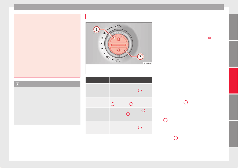
Opening and closing
●
Only c
lose the panoramic sliding sunroof
and the sun blind when nobody is in the way.
●
Always take all the keys with you whenever
you leave the vehicle.
●
Never leave children or disabled persons in
the vehicle, particularly if they have access to
the keys. Uncontrolled use of the key could
lock the vehicle, start the engine, turn on the
ignition and operate the panoramic sliding
sunroof.
●
The panoramic sliding sunroof can be oper-
ated for up to about ten minutes after the ig-
nition has been switched off, provided the
driver door and the front passenger door are
not opened.
Note
●
In case of
a fault in the operation of the
panoramic sliding sunroof, the anti-trap func-
tion will not operate correctly. Visit a special-
ised workshop.
●
The rotary button of the panoramic sliding
sunroof remains in the last position selected
if the roof is closed using convenience clos-
ing from outside the vehicle, and will have to
be re-positioned the next time you drive.
Opening or closing the sun blind
Fig. 140 On the interior roof lining: switches
f
or the s
u
n blind
Function Necessary operations
To open com-
pletely (automat-
ic):
Press button ››› Fig. 140
1
briefly.
To stop automatic
operation:
Briefly press the button ››› Fig. 140
1
o ››› Fig. 140
2
.
To set the inter-
mediate position:
Hold the button ››› Fig. 140
1
or ››› Fig. 140
2
until the required
position is reached.
To close com-
pletely (automat-
ic):
Press button ››› Fig. 140
2
briefly.
The panoramic sliding sunroof can be operat-
ed f
or up t
o about
ten minutes after the igni-
tion has been switched off, provided the driv-
er door and the front passenger door are not
opened.
Anti-trap function of the panoramic
sliding sunroof and the sun blind
The anti-trap function reduces the risk of in-
jury when openin
g and closing the panoram-
ic sliding sunroof and sun blind ›››
. When
they encou
nter an obstacle while closing,
they reopen.
●
Check why the panoramic sliding sunroof
or the sun blind did not close.
●
Attempt to close the panoramic sliding
sunroof or sun blind once again.
●
If the panoramic sliding sunroof or sun
blind is
still obstructed, it will stop at the cor-
responding position. Close it without the an-
ti-trap function.
Closing without the roll-back function
●
The switch
›››
Fig. 13 should be in the
“closed” position
1
.
●
Panoramic sliding sunroof: w
ithin fiv
e sec
-
onds of triggering the anti-trap function, pull
the control all the way back
›››
Fig. 13 (ar-
row
5
) until the panoramic sliding sunroof
c
lo
se
s fully.
●
Sun blind: Within 5 seconds of triggering
the anti-trap function, push button
›››
Fig. 140
2
until the sun blind closes com-
p
l
et
ely.
●
The panoramic sliding sunroof or sun blind
closes without the anti-trap function.
»
129
Technical dataAdviceOperationEmergenciesSafety
Operation
●
If
the p
anor
amic sliding sunroof still cannot
be closed, visit a specialised workshop.
WARNING
Closing the panoramic sliding sunroof or sun
blind without
the anti-trap function can cause
serious injuries.
●
Always close the panoramic sliding sunroof
carefully.
●
Nobody should be in the way of the panor-
amic sliding sunroof or sun blind, especially
when they are closed without the anti-trap
function.
●
The anti-trap function does not prevent fin-
gers or other parts of the body getting
pinched against the window frame and caus-
ing injury.
Note
The anti-trap function is activated if the win-
dows
and the panoramic sliding sunroof are
closed from the outside of the vehicle using
the ignition key for convenience closing
››› page 127.
Lights and visibility
Light
s
C
ontr
ol lamps
It lights up
Driving light totally or
partially faulty.
Replace the corresponding bulb
››› page 91.
If all the bulbs are OK, the vehi-
cle should be taken to a speci-
alised workshop if necessary.
Fault in adaptive
light.
››› page 132.
Flashes
Fault in the adaptive
light system.
Contact a specialised workshop
››› page 131.
It lights up
Rear fog light switch-
ed on.
››› page 24.
It lights up
Front fog lights
switched on
››› page 24.
It lights up
Left or right turn sig-
nal.
The control lamp
flashes twice as fast
when a vehicle or
trailer turn signal is
faulty.
If necessary, check the vehicle
and trailer lighting.
It lights up
Main beam on or
flasher on.
››› page 131.
It lights up
Headlight adjustment
(Light Assist) on.
››› page 131.
Several warning and indication lamps light
up f
or a f
ew sec
onds when the ignition is
switched on, signalling that the function is
being verified. They will switch off after a few
seconds.
WARNING
Observe the safety warnings ›››
in Warning
and indication lamp
s on page 105.
Switching lights on and off
Read the additional information carefully
›
›
›
page 24
130
Lights and visibility
The legal requirements regarding the use of
v
ehic
l
e lights in each country must be ob-
served.
The driver is personally responsible for the
correct use and adjustment of the lights in all
situations.
In vehicles with tow hitch fitted as standard:
if the trailer is connected electrically and is
fitted with a rear fog light, the vehicle’s fog
light is automatically switched off.
Audible warnings to advise the driver that
the lights have not been switched off
If the key is not in the ignition and the driver
door is open, an audible warning signal is
heard in the following cases: this is a remind-
er to turn off the lights.
●
When the parking light is on ››› page 131.
●
When the light switch is in position .
WARNING
The side lights or daytime driving lights are
not bright enough t
o illuminate the road
ahead and to ensure that other road users are
able to see you.
●
Always use your dipped beam head lights if
it is raining or if visibility is poor.
WARNING
If the headlights are set too high and the
main beam i
s not used correctly, there is a
risk of dazzling or distracting other road
users. This could result in a serious accident.
●
Always make sure that the headlights are
correctly adjusted.
●
Never use the main beam or headlight
flasher when it can dazzle others on the road.
Turn signal and main beam lever
Read the additional information carefully
›
›
›
page 25
Convenience turn signals
For the convenience turn signals, move the
lever as far as possible upwards or down-
wards and release the lever. The turn signal
will flash three times.
The control turn signals are switched on and
off from the menu Lights & Visibility
on the instrument panel display
›››
page 26. This function can be discon-
nected at a specialised workshop for those
vehicles which do not have the menu
Lights & Visibility.
Note
●
If the con
venience turn signals are operat-
ing (three flashes) and the other convenience
turn signals are switched on, the active part
stop
s flashing and only flashes once in the
new part selected.
●
The turn signal only works when the igni-
tion is switched on. The hazard warning
lights also work when the ignition is switch-
ed off ››› page 82.
●
If a turn signal on the vehicle or trailer is
faulty, the warning lamp flashes twice as fast
as usual.
●
The main beam headlights can only be
switched on if the dipped beam headlights
are already on.
Lights and visibility: functions
Parking light
When the p
ark
in
g light is switched on, (right
or left turn signal), the front side light and
the rear light on the corresponding side of
the vehicle stay lit. The parking lights will on-
ly work with the ignition off.
Daytime running lights
The daytime running lights reduce the risk of
accidents by increasing the visibility of the
vehicle. These are independent lights that
are built into the headlights and come on
each time the ignition is turned on if the light
switch is in position or 0.
»
131
Technical dataAdviceOperationEmergenciesSafety

Operation
When the light switch is in position
, a
phot
o sen
sor automatically turns the instru-
ment and switch lighting on and off.
Automatic dipped beam control
The automatic dipped beam control is merely
intended as an aid and is not able to recog-
nise all driving situations.
When the light switch is in position , the
vehicle lights and the instrument panel and
switch lighting switch on and off automatical-
ly in the following situations ›››
:
Automatic switching
on
Automatic switching
off or switch to day-
time running lighting
The photo sensor detects
darkness, for example,
when driving through a
tunnel.
When adequate lighting is
detected.
The rain sensor detects
rain and activates the
windscreen wipers.
When the windscreen wip-
er has been inactive for a
few minutes.
Adaptive headlights (AFS)
The a
d
aptiv
e headlights only operate when
the dipped beam is on and at speeds of over
10 km/h (6 mph). On bends, the adaptive
headlights automatically improve lighting on
the road ahead.
The adaptive headlights can be switched on
and off from the infotainment system.
Static cornering lights
When turning slowly to change direction or
going round a tight bend, the static cornering
lights automatically come on. The static cor-
nering lights only work at speeds of less than
40 km/h (25 mph).
The static cornering lights may be incorpora-
ted into the fog lights or the front headlights,
depending upon the equipment.
WARNING
If the road is not well lit and other road users
cannot see the
vehicle well enough or at all,
accidents may occur.
●
The automatic dipped beam control ()
only switches on the dipped beam when
there are no changes in brightness, and not,
for example when it is foggy.
●
Never drive with daytime lights if the road
is not well lit due to weather or lighting con-
ditions. Daytime lights do not provide
enough light to illuminate the road properly
or be seen by other road users.
●
The rear lights do not come on with the
daytime driving light. A vehicle which does
not have the rear lights on may not be visible
to other drivers in the darkness, if it is rain-
ing or in conditions of poor visibility.
Headlight adjustment
Headlight adjustment (Light Assist)
The headlight
adjustment automatically con-
nects and disconnects these lights depend-
ing on the environmental and traffic condi-
tions and on the speed, within the limitations
of the system ›››
. This is monitored by a
sensor locat
ed on the inside of the wind-
screen, above the interior rear vision mirror.
The automatic headlight adjustment auto-
matically switches on the lights depending
on the vehicles travelling in front and in the
opposite direction, and on other environmen-
tal and traffic conditions from an approxi-
mate speed of 60 km/h (37 mph) and turns
them off again at speeds below approximate-
ly 30 km/h (18 mph).
Switching on and off
Action
Switch-
ing on:
– With the ignition on, turn the lights control
to the position
and put the turn signal
and main beam lever in the main beam posi-
tion ››› page 131. When the headlight adjust-
ment (automatic lights also) is activated, the
warning lamp lights up in the dash panel
display
.
132
Lights and visibility
Switch-
ing off:
– Disconnect the on button.
– OR: turn the lights control to a different po-
sition to
››› page 130.
– OR: place the turn signal and main beam
lever in the headlight flasher or main beam
position ››› page 131.
The following conditions can cause the head-
light adju
stment to fail to turn off the main
beam or fail to do so in time:
●
On roads with insufficient lighting with very
reflective signs
●
If road users are insufficiently lit up, e.g.
pedestri
ans or cyclists.
●
On closed curves, when the traffic in the
opposite direction is partially hidden, on pro-
nounced slopes
●
On roads with traffic in the opposite direc-
tion and with a central reservation barrier
where the driver can see through gaps or
over it e.g. lorry drivers.
●
If the camera is damaged or if the power
supply has been cut off
●
In the event of fog, snow or heavy rain
●
In the event of dust or sand storms
●
If the windscreen is damaged by the impact
from a stone in the camera's field of vision
●
If the camera's field of vision is misted up,
dirty or covered by a sticker, snow or ice.
WARNING
The greater comfort that the headlight ad-
justment
provides (automatic also) must not
cause you to take risks. The system is not a
replacement for driver awareness.
●
Always monitor the lights yourself and ad-
just them depending on the light, visibility
and traffic conditions.
●
The headlight adjustment (automatic also)
may not correctly detect all situations and in
certain situations may only provide limited
function.
●
If the windscreen is damaged or modifica-
tions are made to the vehicle lighting, this
may harm the functioning of the headlight
adjustment (automatic lights also), for exam-
ple, if additional headlight are fitted.
Note
Main beam and flashed headlights can be
turned on and off m
anually at any time with
the turn signal and main beam lever
››› page 131.
“Coming home” and “Leaving home”
f
u
nction (guid
ance lights)
The “Coming home” function should be
sw
it
c
hed on manually. However the “Leav-
ing home” function is automatically control-
led by a photo sensor.
“Coming home”: necessary operations
To switch
system on:
– Switch off the ignition.
– Briefly flash the headlights for approxi-
mately one second ››› page 131.
The “Coming home” lighting comes on
when the driver door is opened. The delay
in switching off the headlights is counted
from when the last door or boot hatch is
closed.
To switch
system off:
– Automatically at the end of the delay pe-
riod.
– Automatically, if 30 seconds after com-
ing on, a vehicle door or the boot hatch re-
mains open.
– When the light switch is turned to posi-
tion
.
– When the ignition is switched on.
“Leaving home”: necessary operations
To switch
system on:
– Unlock the vehicle when the light switch
is in position
and the photo sensor
detects darkness.
To switch
system off:
– Automatically, at the end of the delay
period.
– When the vehicle is locked.
– When the light switch is turned to posi-
tion
.
– When the ignition is switched on.
Lighting around the exterior mirrors
The lightin
g ar
ou
nd the exterior mirrors illu-
minates the door area on entering and leav-
ing the vehicles. It comes on when the vehi-
cle is unlocked, when the vehicle door is
»
133
Technical dataAdviceOperationEmergenciesSafety
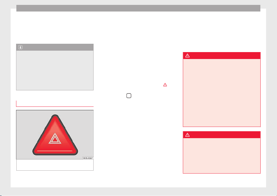
Operation
opened and when the “Coming home” or
“L
e
av
ing home” function is switched on. If
the equipment includes the light sensor, the
lighting around the exterior mirrors only
comes when it is dark.
Note
●
The time taken f
or the headlights to go off
can be changed in the Lights & Visibil-
ity menu and the function can be switched
on or off ›››
page 26.
●
When the “Coming home” function is on, if
the vehicle door is opened there is no audible
warning signal to advise that the light is still
on.
Hazard warning lights
Fig. 141 In the centre of the dash panel: push
b
utt
on f
or hazard warning lights.
Read the additional information carefully
›
›
›
page 25
Always fulfil legal requirements for securing a
broken down vehicle. In a number of coun-
tries it is now obligatory, for example, to turn
on the hazard warning lights and use a re-
flective safety vest ››› page 82.
When being towed with the hazard warning
lights on, a change in direction or traffic lane
can be indicated as usual using the turn sig-
nal lever. The hazard lights will be interrup-
ted temporarily.
If your vehicle breaks down:
Park the vehicle a safe distance from
traffic and on suitable ground ›››
.
T
urn on the h
az
ard warning lights with
the button
›
›
› Fig. 141
.
Connect the electronic parking brake
››› page 189.
Move the selector lever to its intermedi-
ate position or to P ››› page 194.
Stop the engine and remove the key
from the ignition ››› page 185.
Have all occupants leave the vehicle and
move to safety, for example behind a
guard rail.
When leaving the vehicle, take all keys
with you.
Place an emergency warning triangle to
indicate the position of your vehicle to
other road users.
1.
2.
3.
4.
5.
6.
7.
8.
Allow the engine to cool and check if a
specialist is required.
If the hazard warning lights are not working,
you must use an alternative method of draw-
ing attention to your vehicle. This method
must comply with traffic legislation.
WARNING
A faulty vehicle in traffic represents a risk of
accident
for the driver and for other road
users.
●
Stop the vehicle safely as soon as possible.
Park the vehicle a safe distance from sur-
rounding traffic to lock all the doors in case of
an emergency. Turn on the hazard warning
lights to warn other road users.
●
Never leave children or disabled people
alone in the vehicle if the doors are to be
locked. In case of an emergency, passengers
will be trapped inside the vehicle. Individuals
locked in the vehicle can be exposed to very
high or very low temperatures.
WARNING
The components of the exhaust system reach
very
high temperatures. This could cause a
fire and considerable damage.
●
Always park your vehicle so that no part of
the exhaust system can come in contact with
flammable materials (such as dried grass or
fuel).
9.
134
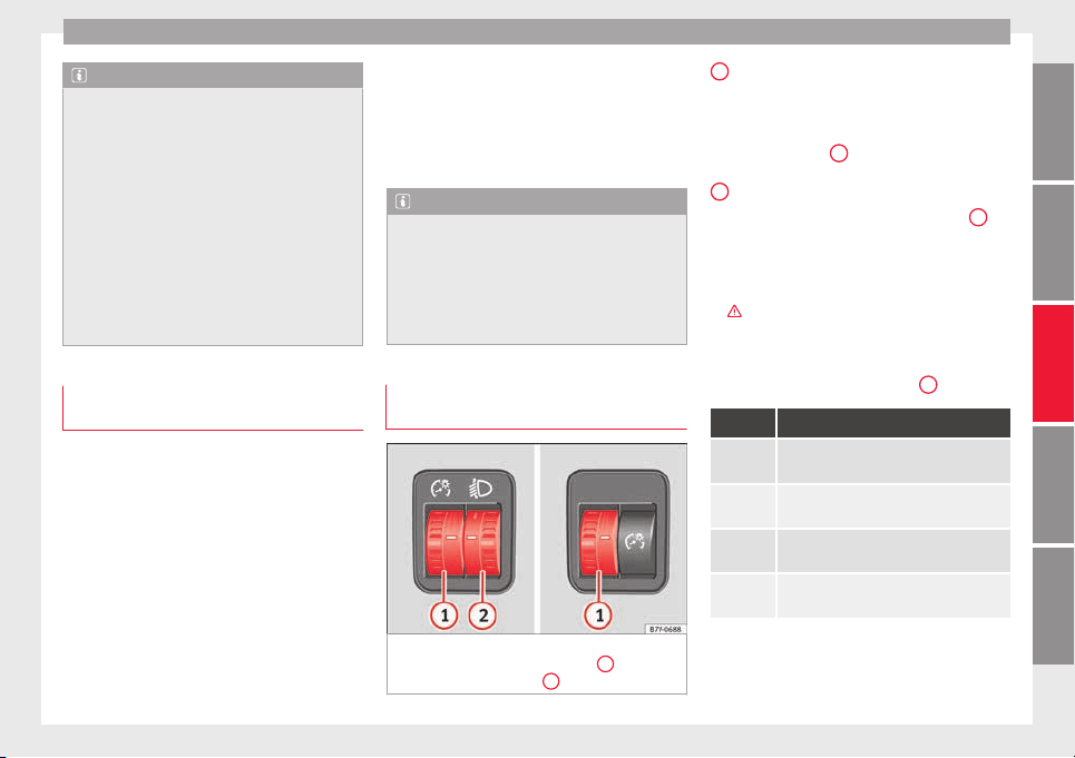
Lights and visibility
Note
●
The vehic
le battery will discharge and run
down if the hazard warning lights remain on
for too long (even with the ignition turned
off).
●
In some vehicles, the brake lights will flash
when braking abruptly at speeds of approxi-
mately 80 km/h (50 mph) to warn vehicles
travelling behind. If braking continues, the
hazard warning lights system will automati-
cally be turned on at a speed of less than ap-
proximately 10 km/h (6 mph). The brake
lights remain lit. Upon accelerating, the haz-
ard warning lights will be automatically
turned off.
Adhesive strips for headlights or ad-
ju
s
tin
g headlights
In those countries where vehicles drive on
the other s
ide of
the r
oad to the home coun-
try, the asymmetric dipped beam may dazzle
drivers of oncoming vehicles. Therefore,
when driving abroad, adhesive strips should
be attached to the headlights or the head-
lights should be adjusted accordingly.
The direction of the headlights can be adjus-
ted from the instrument panel, in the Tou-
rist light submenu of the Configura-
tion menu
›››
page 30.
For those vehicles in which it is not possible
to adjust the headlights from the menu, ad-
hesive strips are used to cover certain parts
of the headlamp cover or the headlights may
be adjusted at a specialised workshop. For
further information, please refer to a special-
ised workshop. SEAT recommends visiting a
technical service.
Note
Use of the Tourist light option and the
adhes
ives on the headlights is only allowed if
they are to be used for a short period of time.
To modify the direction of the headlights per-
manently, please take the vehicle to a speci-
alised workshop. SEAT recommends visiting a
technical service centre.
Headlight range control, lighting of
the in
s
trument
panel and controls
Fig. 142 Next to the steering wheel: instru-
ment
and sw
it
ch lighting control
1
and
he
a
dlight
range control
2
1
Instrument and switch lighting
When the he
a
dlights
are switched on, the
brightness of the instruments and switch
lighting can be regulated by turning the
switch ››› Fig. 142
1
.
2
Headlight range control
The he
a
dlight
range control ››› Fig. 142
2
is
modified ac
c
or
ding to the value of the head-
light beam and the vehicle load status. This
offers the driver optimum visibility and the
headlights do not dazzle oncoming drivers
›››
.
The he
a
dlights
can only be adjusted when
the dipped beam is switched on.
To reset, turn switch ››› Fig. 142
2
:
Value Vehicle load status
a)
–
Two front occupants, luggage compart-
ment empty
1
All seats occupied, luggage compartment
empty
2
All seats occupied, luggage compartment
full With trailer and minimum drawbar load
3
Driver only, luggage compartment full With
trailer and maximum drawbar load
a)
If the vehicle load does not correspond to those shown in the
table, it is possible to select intermediary positions.
»
135
Technical dataAdviceOperationEmergenciesSafety
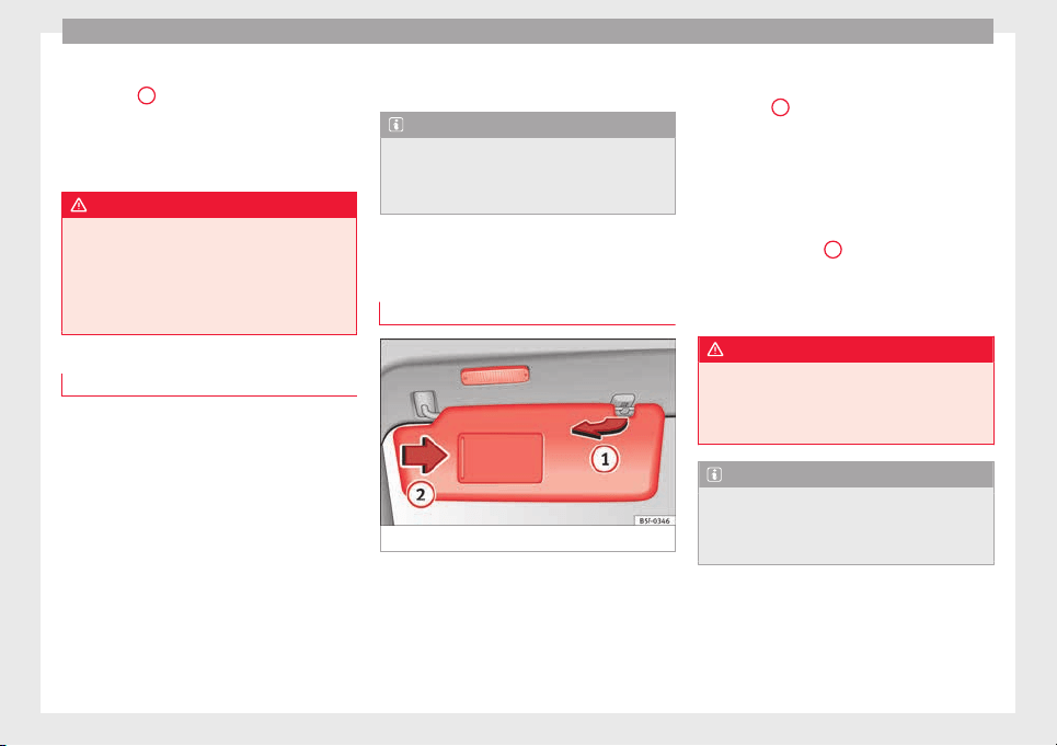
Operation
Dynamic headlight range control
The c
ontr
o
l
2
is not mounted in vehicles
w
ith dy
n
amic headlight range control. The
headlight range is automatically adjusted ac-
cording to the vehicle load status when they
are switched on.
WARNING
Heavy objects in the back of vehicle may
cause he
adlight dazzle and distract other
drivers. This could result in a serious acci-
dent.
●
Adjust the light beam to the vehicle load
status so that it does not blind other drivers.
Interior and reading lights
Read the additional information carefully
›
›
›
page 25
Storage and luggage compartment lighting
When the glove compartment and the rear lid
are opened and closed, a light automatically
switches on or off.
Ambient lighting
The ambient lighting in the front covering of
the ceiling lights up the controls on the cen-
tre console from above when the side light or
dipped beam lights are on.
In addition, the lever on the door moulding
can also be illuminated.
Note
The reading lights go out when the vehicle is
locked, or a f
ew minutes after the key is re-
moved from the ignition. This prevents the
vehicle's battery from discharging.
Visibility
Sun
visors
Fig. 143 Sun visor
Options for adjusting driver and front pas-
sen
g
er s
un visors:
●
Lower the sun visor towards the wind-
screen.
●
The sun visor can be pulled out of its
mounting and turned towards the door
››› Fig. 143
1
.
●
Swing the sun visor towards the door, lon-
git
udin
al
ly backwards.
Vanity mirror light
There may be a vanity mirror, with a cover, on
the rear of the sun visor. When the cover is
opened ››› Fig. 143
2
a light comes on.
The l
amp g
oe
s out when the vanity mirror
cover is closed or the sun visor is pushed
back up.
WARNING
Sun visors and sun blinds may reduce visibili-
ty when open.
●
Alw
ays roll or fold sun blinds and visors
away when not in use.
Note
The light above the sun visor automatically
switc
hes off after a few minutes in certain
conditions. This prevents the battery from
discharging.
136
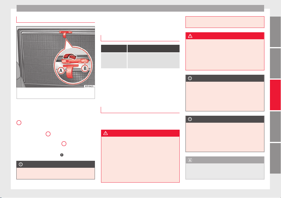
Lights and visibility
Rear side window sun blinds
Fig. 144 On the rear right-hand window: sun
b
lind
The sun blinds for the vehicle interior are fit-
t
ed in the s
ide p
anels of the windows.
●
Pull the sun blind by the handle
›››
Fig. 144
A
up to the top.
●
Hook both rings of the fastening rod in the
s
p
ac
es provided
B
. Check that the sun blind
i
s
sec
urely hooked into the spaces provided
when it has been lowered
B
.
●
To put the sun blind away, unhook it at the
t
op and lo
w
er by hand
›››
.
CAUTION
To prevent damage to the blind or the interior
trim, do not low
er the sun blind “quickly”.
Windscreen wiper and window
w
iper sy
s
tems
Control lamp
It lights up
Windscreen wip-
er fluid level too
low
Top up the windscreen wiper reser-
voir as soon as possible
››› page 284.
Several warning and indication lamps light
up for a few sec
onds when the ignition is
switched on, signalling that the function is
being verified. They will switch off after a few
seconds.
Window wiper lever
Read the additional information carefully
›
›
›
page 26
WARNING
Water from the windscreen washer water bot-
tle ma
y freeze on the windscreen if it does
not contain enough anti-freeze, reducing for-
ward visibility.
●
In winter, ensure the windscreen washer
contains enough anti-freeze.
●
In cold conditions, you should not use the
wash/wipe system unless you have warmed
the windscreen with the ventilation system.
The antifreeze could freeze on the windscreen
and reduce
visibility.
WARNING
Worn or dirty wiper blades reduce visibility
and inc
re
ase the risk of accident and serious
injury.
●
Always replace damaged or worn blades or
blades which do not clean the windscreen
correctly.
CAUTION
In icy conditions, always check that the wiper
bla
des are not frozen to the glass before us-
ing the wipers for the first time. In cold
weather, it may help to leave the vehicle
parked with the wipers in service position
›››
page 54.
CAUTION
If the ignition is switched off while the wind-
scr
een wipers are on, the windscreen wipers
carry on wiping at the same level when the
ignition is switched back on. Ice, snow and
other obstacles may damage the windscreen
wiper and the respective motor.
Note
●
The winds
creen wipers will only function
when the ignition is switched on and the re-
spective bonnet or rear lid are closed.
»
137
Technical dataAdviceOperationEmergenciesSafety
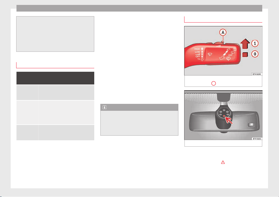
Operation
●
The interv
al wipe speed varies according to
the vehicle speed. The faster the vehicle is
moving, the more often the windscreen is
cleaned.
●
The rear wiper is automatically switched on
when the windscreen wiper is on and the car
is in reverse gear.
Windscreen wiper functions
Windscreen wiper performance in different sit-
uations
If the vehicle
is at a stand-
still
The activated position provisionally
changes to the previous position.
During auto-
matic wipe
The air conditioner comes on for ap-
proximately 30 seconds in air recircula-
tion mode to prevent the smell of the
windscreen washer fluid entering the
inside the vehicle.
For the inter-
val wipe
Intervals between wipes depend on the
vehicle's speed. The higher the vehicle
speed the shorter the intervals.
Heated windscreen washer jets
The he
atin
g on
ly thaws the frozen jets, it
does not thaw the water in the washer hoses.
The heated windscreen washer jets automati-
cally adjust the heat depending on the ambi-
ent temperature when the ignition is switch-
ed on.
Headlight wash/wipe system
The headlight washers/wipers clean the
headlight lenses.
After the ignition is switched on, the first and
every fifth time the windscreen washer is
switched on, the headlights are also washed.
Therefore, the windscreen wiper lever should
be pulled towards the steering wheel when
the dipped beam or main beam are on. Any
incrusted dirt (such as insects) should be
cleaned regularly (e.g. when refuelling).
To ensure the headlight washers work cor-
rectly in winter, any snow which has got into
the bumper jet supports should be cleaned
away. If necessary, remove snow with an anti-
icing spray.
Note
The wiper will try to wipe away any obstacles
that ar
e on the windscreen. The wiper will
stop moving if the obstacle blocks its path.
Remove the obstacle and switch the wiper
back on again.
Rain sensor*
Fig. 145 Windscreen wiper lever: adjusting
the r
ain sen
sor
A
Fig. 146 Rain sensor sensitive surface
The rain sensor controls the frequency of the
w
ind
s
creen wiper intervals, depending on
the amount of rain ›››
. The sensitivity of the
r
ain sen
sor c
an be adjusted manually. Man-
ual wipe ››› page 137.
138
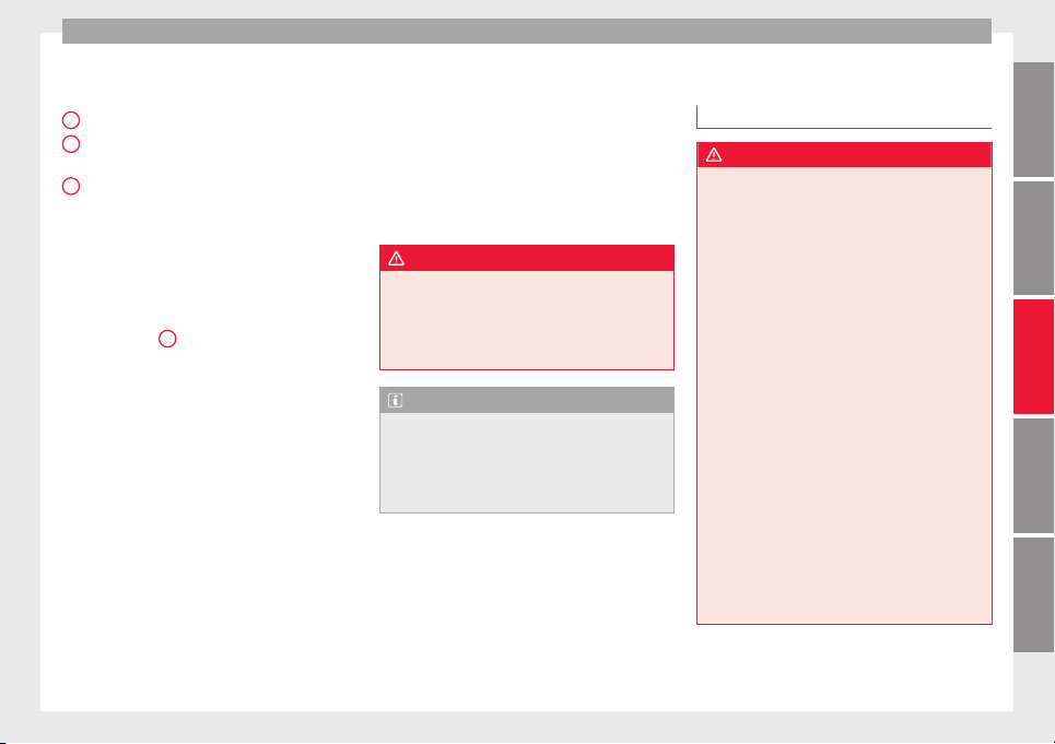
Lights and visibility
Move the lever to the required position
›
›
›
Fig. 145:
Rain sensor off.
Rain sensor on; automatic wipe if neces-
sary.
Setting sensitivity level of rain sensor
–
Set control to the right: highly sensi-
tive.
–
Set control to the left: less sensitive.
When the ignition is switched off and then
back on, the rain sensor stays on and starts
operating again when the windscreen wipers
are in position
1
and the vehicle is travel-
lin
g at
mor
e than 4 km/h (2 mph).
Rain sensor modified behaviour
Possible causes of faults and mistaken read-
ings on the sensitive surface ››› Fig. 146 of
the rain sensor include:
●
Damaged blades: a film of water on the
damaged blades may lengthen the activation
time, reduce the washing intervals or result
in a fast and continuous wipe.
●
Insects: insects on the sensor may trigger
the windscreen wiper.
●
Salt on roads: in winter, salt spread in the
roads may cause an extra long wipe when the
windscreen is almost dry.
●
Dirt: dry dust, wax, coating on glass (Lotus
effect) or traces of detergent (car wash) may
0
1
A
reduce the effectiveness of the rain sensor or
m
ak
e it
react more slowly, later or not at all.
●
Cracked windscreen: the impact of a stone
will trigger a single wipe cycle with the rain
sensor on. Next the rain sensor detects the
reduction in the sensitive surface area and
adapts accordingly. The behaviour of the sen-
sor will vary with the size of the damage
caused by the stone.
WARNING
The rain sensor may not detect enough rain
to swit
ch on the wipers.
●
If necessary, switch on the wipers manually
when water on the windscreen obstructs visi-
bility.
Note
●
Cle
an the sensitive surface of the rain sen-
sor regularly and check the blades for dam-
age ››› Fig. 146 (arrow).
●
To remove wax and coatings, we recom-
mend a window cleaner containing alcohol.
Rear vision mirror
Intr
oduction
WARNING
The automatic anti-dazzle rear vision mirror
contain
s an electrolytic fluid which may leak
if the mirror is broken. This could cause irrita-
tion to the skin, eyes and respiratory organs.
●
The electrolytic fluid may cause irritation to
the skin, eyes and respiratory organs, partic-
ularly in individuals suffering from asthma or
other illnesses. Make sure that adequate
quantities of fresh air enter and leave the ve-
hicle if it is not possible to open all the doors
and windows.
●
If the electrolytic fluid comes into contact
with eyes or skin, wash the area for at least
15 minutes with plenty of water, and seek
medical advice.
●
If the electrolytic fluid comes into contact
with shoes or clothing, wash the area for at
least 15 minutes with plenty of water. Wash
shoes and clothing before wearing them
again.
●
If the electrolytic fluid is swallowed, wash
your mouth with plenty of water for at least
15 minutes. Do not try to provoke vomiting
unless recommended by a Doctor. Seek medi-
cal advice immediately.
»
139
Technical dataAdviceOperationEmergenciesSafety
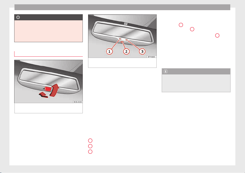
Operation
CAUTION
In the event that an automatic anti-dazzle
rear
vision mirror breaks, an electrolyte fluid
may leak. This liquid attacks plastic surfaces.
Therefore, it should be cleaned as fast as
possible with a damp sponge or similar.
Interior rear vision mirror
Fig. 147 Manual anti-dazzle function for rear
v
i
s
ion mirror
Fig. 148 Automatic anti-dazzle function for
rear
vision mirror
The driver should always adjust the rear vi-
s
ion mirr
or t
o permit adequate visibility
through the rear window.
Manual anti-dazzle function for interior rear
vision mirror
●
Basic position: point the lever at the bot-
tom of the mirror forwards.
●
Pull the lever to the back to select the anti-
dazzle function ››› Fig. 147.
Automatic anti-dazzle function for interior
mirror
Key to Fig. 148:
Control lamp
Control
Light incidence sensor
1
2
3
This function can be activated and deactiva-
t
ed b
y
pressing the rear-view mirror switch
››› Fig. 148
2
. When it is activated, the warn-
in
g l
amp lights
up
1
.
When the ignition i
s
on, the sen
sor
3
auto-
matic
a
l
ly moves the rear vision mirror to the
anti-dazzle position depending upon the in-
cidence of the light from behind.
The automatic anti-dazzle function is deacti-
vated when reverse gear is engaged or the in-
terior or reading lights are on.
Note
If the light is obstructed or prevented from
reac
hing the sensor, e.g. by the sun blinds,
the rear vision mirror with automatic anti-
dazzle function will not operate correctly.
140

Lights and visibility
Exterior mirrors
Fig. 149 In the driver door: exterior mirror
c
ontr
o
ls
Read the additional information carefully
›
›
›
page 15
Turn the knob to the required position:
Electric folding exterior mirrors ››› .
Switch on the exterior mirror heating This only
heats up if the ambient temperature is less
than +20°C (+68°F).
Adjust the left-hand exterior mirror by turning
the knob forward, backward, to the right or to
the left.
Adjust the right-hand exterior mirror by turning
the knob forward, backward, to the right or to
the left .
Zero position. Exterior mirror unfolded, exterior
mirror heating off, adjustment of exterior mir-
ror not possible.
Synchronised mirror adjustment
●
In the Settings - Convenience menu,
sel
ect
whether or not
the mirrors should
move in synchronisation ›››
page 26.
●
Turn the knob to position L.
●
Adjust the left-hand exterior mirror. The
right exterior mirror will be adjusted at the
same time (synchronised).
●
If necessary the right exterior mirror adjust-
ment may need correcting. turn the control to
position R.
Automatic anti-dazzle exterior mirror, driver
side
The automatic anti-dazzle exterior mirror is
controlled in the same way as the automatic
anti-dazzle rear vision mirror ››› page 140.
Store the reverse settings for the passenger
exterior mirror
●
Select the vehicle key in which the setting
is to be stored.
●
Use this key to unlock the vehicle.
●
Connect the automatic parking brake.
●
Switch the ignition on.
●
Move the gear lever to neutral.
●
In the menu Settings - Convenience
activate the function Mirror adjustment.
●
Select reverse gear.
●
Adjust the front passenger side exterior
mirror so that you can see, for example, the
kerb area.
●
The new position of the mirror will be stor-
ed automatically and allocated to the vehicle
key that was used to unlock the vehicle. For
vehicles with seat memory, please see
››› page 146.
Activating the passenger exterior mirror set-
tings
●
Turn the exterior mirror knob to position R.
●
With the ignition switched on, select re-
verse gear.
●
The stored position of the passenger exteri-
or mirror for reverse gear is deleted when
driving forwards at 15 km/h (9 mph), or if the
knob is turned from position R to another po-
sition.
WARNING
Fold and unfold the exterior mirror, taking
care t
o avoid injuries.
●
Only fold or unfold the exterior mirror when
there is no-one in the way of the mirror.
●
When moving the mirror, take care not to
trap fingers between the mirror and the mir-
ror bracket.
»
141
Technical dataAdviceOperationEmergenciesSafety
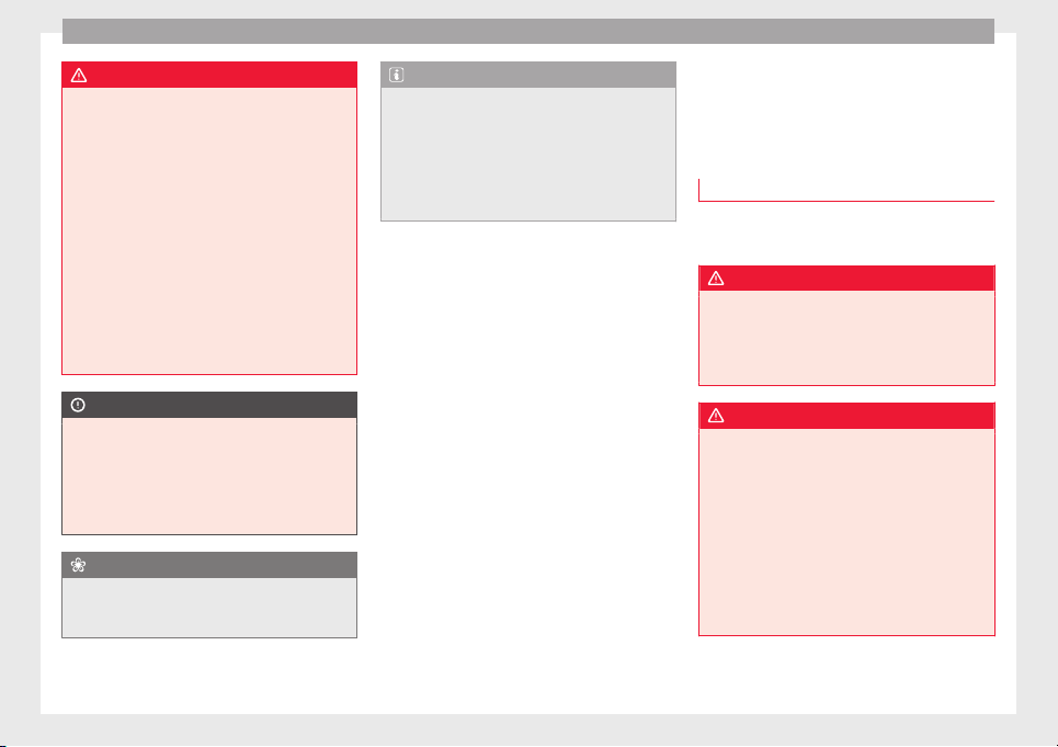
Operation
WARNING
Failure to correctly estimate the distance of
the vehic
le behind could lead to serious acci-
dent.
●
Rear-view convex or aspheric mirrors in-
crease the field of vision, however objects ap-
pear smaller and further away in the mirrors.
●
The use of these mirrors to estimate the
distance to the next vehicle when changing
lane is imprecise and could result in serious
accident.
●
If possible, use the rear vision mirror to es-
timate distances to vehicles behind you or in
other circumstances.
●
Make sure that the rear visibility is ade-
quate.
CAUTION
●
Befor
e entering a car wash, always ensure
that the exterior mirrors are correctly folded
in.
●
Electrically-folding exterior mirrors should
not be folded and unfolded mechanically as
this may damage the electrical operation.
For the sake of the environment
The exterior mirror heating should be switch-
ed off when it i
s no longer needed. Other-
wise, it is an unnecessary fuel waste.
Note
●
The exterior mirr
or heating initially heats
up with a high power, after two minutes the
heat will depend upon the ambient tempera-
ture.
●
In the event of a fault, the electric exterior
mirrors can be adjusted manually by pressing
the edge of the mirror surface.
Seats and head restraints
Adju
s
tin
g the seats and head
restraints
Manual adjustment of seats
Read the additional information carefully
›››
page 13
WARNING
The safe driving chapter contains important
information, tip
s, suggestions and warnings
that you should read and observe for your
own safety and the safety of your passengers
››› page 56.
WARNING
●
Adjust
the front seats only when the vehi-
cle is stationary. Failure to follow this instruc-
tion could result in an accident.
●
Be careful when adjusting the seat height.
Careless or uncontrolled adjustment can
cause injuries.
●
The front seat backrests must not be re-
clined for driving. Otherwise, seat belts and
the airbag system might not protect as they
should in the case of an accident, increasing
risk of injury.
142
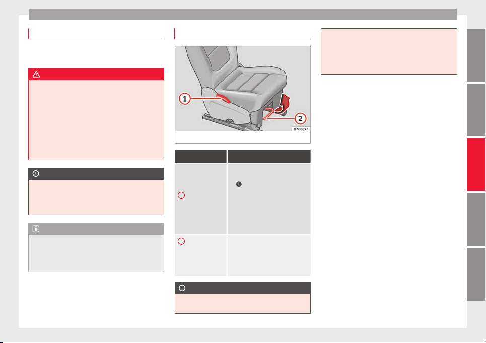
Seats and head restraints
Electric driver seat adjustment*
Read the additional information carefully
›››
page 14
WARNING
Using the front electric seats in a careless or
uncontr
olled manner may lead to severe inju-
ries.
●
The front seats can also be electrically ad-
justed when the ignition is switched off. Nev-
er leave children or disabled people alone in
the vehicle.
●
In the event of an emergency, stop electri-
cal adjustment by pressing any button.
CAUTION
So as not the damage the electrical compo-
nents of
the front seats, do not kneel on the
seats or apply specific pressure to one point
of the seat or seat backrest.
Note
●
It ma
y not be possible to electrically adjust
the seat if the vehicle battery is very low.
●
Seat adjustment is stopped when the en-
gine is started.
Adjusting the rear seats
Fig. 150 Adjusting rear seats
Function Necessary operations
1
Adjusting the
seat backrest.
Pull the lever and adjust the seat
backrest to the required position
›››
. The seat backrest must be
engaged when the lever is re-
leased! There is a handle instead
of the lever on the third row of
seats and on the central seat of
the second row. It is used in the
same manner as the lever.
2
On the second
row of seats only:
moving the seat
backwards or for-
wards.
Pull the lever and move the seat
forwards or backwards. The seat
must be engaged when the lever
is released!
CAUTION
●
Tilting the se
at backrest of the second row
of seats fully back could damage the luggage
compartment tray. Remove the tray before
adjus
ting the seat backrest.
●
Objects in the luggage compartment could
cause damage when moving the rear seats
forwards or backwards.
143
Technical dataAdviceOperationEmergenciesSafety

Operation
Adjustment of the head restraints
Fig. 151 A: Adjust the head restraints with no
po
s
s
ibility of lengthways direction adjust-
ment; B: Adjust the head restraints with
lengthways direction adjustment
Fig. 152 Adjust the head restraints in the sec-
ond or third ro
w of seats
Read the additional information carefully
›
›
›
page 14
All seats are equipped with a head restraint.
Adjusting height
●
Raise the head restraint in the direction of
the arrow or lower it ››› Fig. 151 or ››› Fig. 152
1
with the button pressed ›
›
›
in Removing
and in
s
t
alling the head restraints on
page 146.
●
The head restraint must engage securely in
position. There are three possible positions
on the second row of seats and two possible
positions on the third row of seats.
Adjusting the front head restraints
●
Push the head restraint forward in the di-
rection of the arrow or backward ››› Fig. 151
1
B w
ith the button pressed.
●
The hea
d r
estraint must engage securely in
position.
Correct adjustment of head restraints
Adjust the head restraint so that its upper
edge is at the same level as the top of your
head, or as close as possible to the same lev-
el as the top of your head and under no cir-
cumstances below eye level. Keep the back
of your neck as close as possible to the head
restraint.
Adjusting the head restraint for short people
Lower the head restraint completely, even if
your head is below its upper edge. When the
head restraint is at its lowest, it is possible
that a small gap remains between it and the
seat backrest.
Adjusting the head restraint for tall people
Raise the head restraint completely.
144
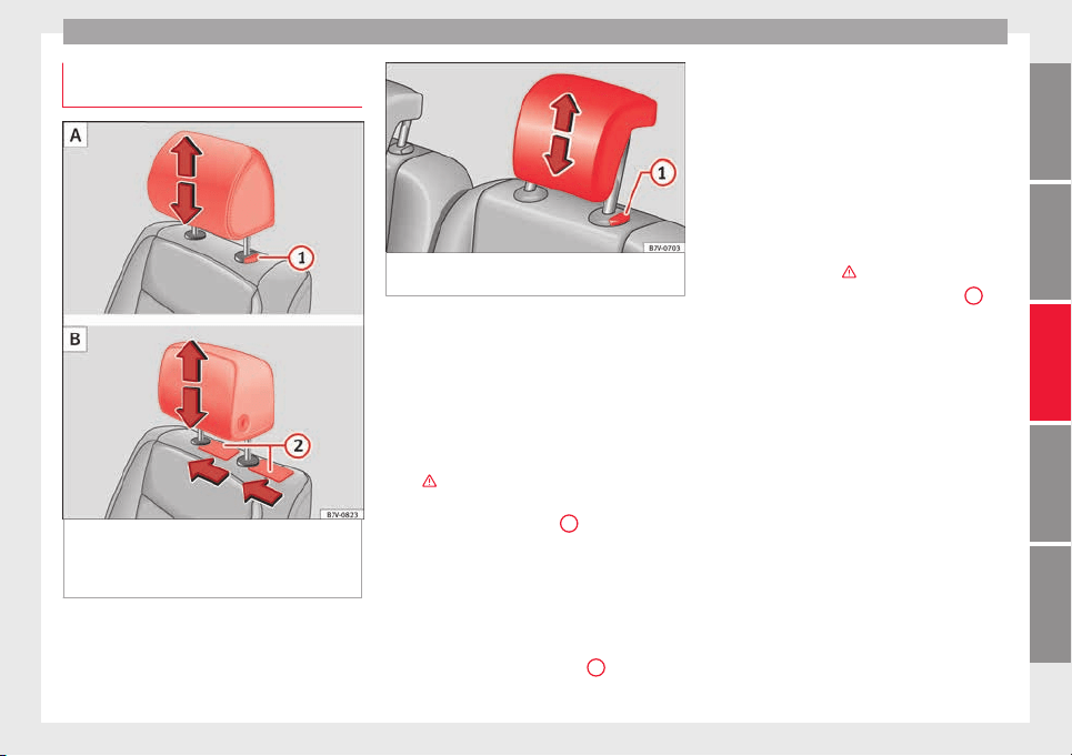
Seats and head restraints
Removing and installing the head re-
s
tr
aint
s
Fig. 153 A: Fitting the head restraints with no
po
s
s
ibility of lengthways direction adjust-
ment; B: Fitting the head restraints with
lengthways direction adjustment
Fig. 154 Fitting the head restraints in the sec-
ond or third ro
w of seats
All seats are equipped with a head restraint.
R
emo
v
ing the front head restraints in vehi-
cles without the lengthways direction ad-
justment of the head restraints
●
If necessary, adjust the seat backrest so
that the head restraint can be fitted.
●
Push the head restraint up as far as it will
go ›››
.
●
Pull out the head restraint pressing the but-
t
on c
omp
letely ››› Fig. 153
1
A.
Fittin
g the fr
ont
head restraints in vehicles
without the lengthways direction adjustment
of the head restraints
●
Correctly place the head restraint into the
guides on the seat backrest and insert it.
●
Completely press the button
1
A and p
ush
the he
a
d restraint downwards.
●
Adjust the head restraint according to the
correct seat position and secure it
››› page 144.
Removing the front head restraints in vehi-
cles with the lengthways direction adjust-
ment of the head restraints
●
If necessary, adjust the seat backrest so
that the head restraint can be fitted.
●
Push the head restraint up and backward
as far as it will go ›››
.
●
Place a flat object, e.g. a plastic card
2
B,
on both s
ide
s
between the seat backrest cov-
er and the end protector of the seat backrest
retaining bar and unlock the retaining bars
with a little pressure.
●
Completely pull out the head restraint.
Fitting the front head restraints in vehicles
with the lengthways direction adjustment of
the head restraints
●
Pull out the two retaining bars from the
head restraint as far as possible.
●
Correctly place the head restraint into the
guides on the seat backrest and insert it.
●
Push the head restraint down as far as pos-
sible until the two retaining bars are secured.
●
Adjust the head restraint according to the
correct seat position and secure it
››› page 144.
»
145
Technical dataAdviceOperationEmergenciesSafety
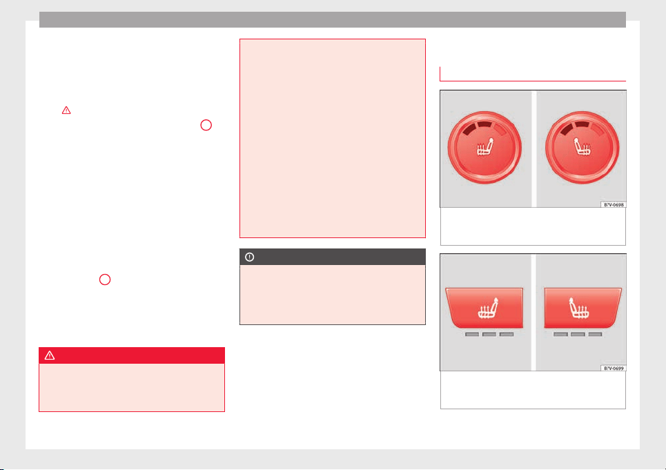
Operation
Removing the head restraints from the sec-
ond and thir
d r
o
w of seats
●
Fold the backrest of the rear seat forwards
››› page 154.
●
Push the head restraint up as far as it will
go ›››
.
●
Pull out the head restraint ›
›
›
Fig. 154
1
with the button pressed.
●
Fold the backrest of the rear seat back-
w
ar
d
s until it is engaged.
Fitting the head restraints in the second and
third row of seats
●
Fold the backrest of the rear seat forwards
››› page 154.
●
Insert the head restraint into the guides on
the seat backrest.
●
Push the head restraint down while press-
ing the button
1
.
●
Fold the backrest of the rear seat backward
ag
ain u
nti
l it is engaged.
●
Adjust the head restraint to the correct po-
sition ››› page 144.
WARNING
Travelling with the head restraints removed
or improperly a
djusted increases the risk of
severe or fatal injuries in the event of acci-
dents and sudden braking or manoeuvres.
●
Alwa
ys fit and adjust the head restraint
properly whenever a person is occupying a
seat.
●
Refit any removed head restraints immedi-
ately so that passengers are properly protec-
ted.
●
All vehicle occupants must correctly adjust
the head restraint according to their height to
reduce the risk of back injuries in the event of
an accident. The upper edge of the head re-
straint must be as close as possible to the
same level as the top of your head and under
no circumstances below eye level. Keep the
back of your neck as close as possible to the
head restraint.
●
Never adjust the head restraint while the
vehicle is in motion.
CAUTION
When removing and fitting the head restraint,
make s
ure it does not hit the headliner of the
vehicle or the front seat backrest. Otherwise,
the interior roof and other parts of the vehicle
could be damaged.
Seat functions
Se
at
he
ating*
Fig. 155 Detailed view of the centre console:
fr
ont
se
at heating controls, here with the sec-
ond temperature level set
Fig. 156 Detailed view of the centre console:
c
ontr
o
ls for the front seat heating in vehicles
equipped with Climatronic
146
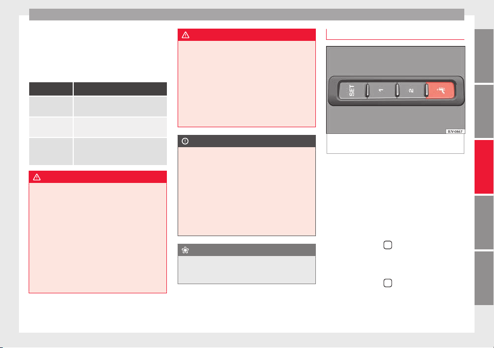
Seats and head restraints
The seat cushions can be heated electrically
when the ignition i
s
sw
itched on. The back-
rest is also heated in some versions.
Switch off seat heating if there is nobody in
the seat.
Function Action ››› Fig. 155, ››› Fig. 156
Activate Press button
. Seat heating is
switched on fully.
Adjusting the
heating output
Keep pressing button
until the re-
quired intensity is set.
Deactivating Keep pressing button
until all of
the lights are switched off
››› Fig. 155, ››› Fig. 156.
WARNING
Inappropriate use of the seat functions can
cause sev
ere injuries.
●
Assume the proper sitting position before
your trip and remain in it throughout. This al-
so applies to the other occupants.
●
Only adjust the seat position memory when
the vehicle is stationary.
●
Only switch the lumbar massage function
on and off when the vehicle is stationary.
●
Keep hands, fingers, feet and other limbs
away from the seat operating and adjustment
radius.
WARNING
People whose pain and temperature thresh-
old h
as been affected by some kind of medi-
cine, paraplegia or chronic illness (e.g. diabe-
tes) may sustain burns to the back, buttocks
and legs from using the seat heaters that
may lead to a long healing process or that
may never completely heal. Seek medical ad-
vice if you have doubts regarding your health.
●
People with limited pain and temperature
thresholds must never use seat heating.
CAUTION
●
To avoid d
amaging the heating elements of
the seat heaters, please do not kneel on the
seat or apply sharp pressure to a single point
on the seat cushion or backrest.
●
Liquids, sharp objects and insulating mate-
rials on the seat could damage the seat heat-
ing.
●
In the event of smells, switch off the seat
heating immediately and have the unit in-
spected by a specialised workshop.
For the sake of the environment
The seat heating should remain on only when
needed. Otherwi
se, it is an unnecessary fuel
waste.
Lumbar massage function*
Fig. 157 On the side of the front seat: lumbar
m
a
s
sage function switch.
During the massage operation, the lumbar
s
up
por
t will move in a way that massages the
lumbar area of the back. While it is operat-
ing, the arch of the lumbar support can be
adjusted using the corresponding control
based on your personal preferences
››› page 57.
Connection
●
Press the button
in the control panel of
the se
at
.
Di
sconnection
●
Press the button
again in the control
p
anel
of
the seat.
»
147
Technical dataAdviceOperationEmergenciesSafety
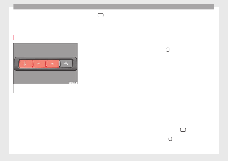
Operation
Automatic off
●
The lumbar massage will disconnect auto-
m
atic
al
ly after approx. 10 minutes.
Seat with position memory*
Fig. 158 Memory buttons on the outside of
the driv
er se
at
Memory buttons
Indiv
idual
settin
gs for the driver seat and the
exterior mirror can be assigned to each mem-
ory button.
Storing exterior mirror settings for driving
forwards
●
Connect the automatic parking brake.
●
Move the gear lever to neutral.
●
Switch the ignition on.
●
Adjust the front seat and the exterior mir-
rors.
●
Keep the
SET
button held down for more
th
an one sec
ond ›
›› Fig. 158.
●
Press the required memory button for the
following 10 seconds. An audible warning
confirms the settings have been stored.
Storing front passenger exterior mirror set-
tings for driving in reverse gear
●
Connect the automatic parking brake.
●
Move the gear lever to neutral.
●
Switch the ignition on.
●
Press the required memory button.
●
Select reverse gear.
●
Adjust the front passenger side exterior
mirror so that you can see, for example, the
kerb area.
●
The new position of the mirror will be stor-
ed automatically and allocated to the vehicle
key that was used to unlock the vehicle.
Activating exterior mirror settings
●
With the driver door open and the ignition
turned off, push the memory button of the
corresponding door briefly.
●
OR: with the ignition switched on, hold in
the corresponding memory button until the
memorised position is reached.
To activate the memory function of the vehi-
cle key
Important: a position must be memorised in
the memory.
●
Open the driver-side door.
●
Press and hold any memory button.
●
Within the following three seconds, push
the button
to open the vehicle on the vehi-
c
l
e k
ey. An audible warning confirms the set-
tings have been activated.
Adjusting the wing mirrors for driving and
assigning driver seat settings to a vehicle
key
●
Activate the memory function of the vehicle
key
●
Adjust the front seat and the exterior mir-
rors.
●
Lock the vehicle. The settings are assigned
to the vehicle key.
To deactivate the memory function of the ve-
hicle key
Important: a position must be memorised in
the memory.
●
Press and hold the
SET
button.
●
Within the following 10 seconds, push the
open b
utt
on
on the vehicle key. An audi-
b
l
e w
arning confirms the settings have been
deactivated.
148
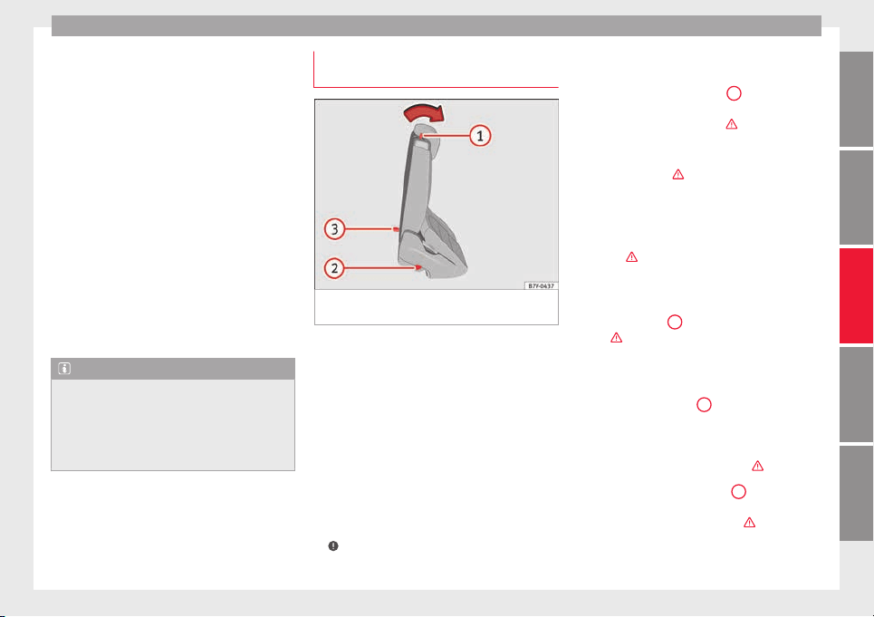
Seats and head restraints
Initialising the seat position memory
The po
s
ition memor
y system must be restar-
ted if, for example, the driver seat has been
changed.
Restarting deletes all memories and assign-
ments for the seat with position memory. The
memory buttons can then be reprogrammed
and the vehicle keys re-assigned.
●
Open the driver door and do not get into
the vehicle.
●
Operating the seat settings from outside
the vehicle.
●
Move the angle of the seat backrest com-
pletely forwards.
●
Release the control to set the angle and
then press again until an audible warning is
heard.
Note
The front passenger side exterior mirror auto-
matica
lly changes from the position stored
for reversing as soon as the vehicle moves
forward at a speed of at least 15 km/h
(9 mph) or when the gear selection lever is
changed to a position other than R.
Convenient entry function for the third
r
o
w of
seats
Fig. 159 Second row of seats: convenient en-
tr
y
f
unction controls
The outer seats of the second row can be fol-
ded t
o m
ak
e it easier to get in and out of the
third row of seats.
Folding down the second row seats
●
If necessary, open the belt loop and wind
up the seat belt by hand.
●
If necessary, remove the side head restraint
of the integrated child seat
›››
page 78.
●
If necessary, raise the armrests.
●
Remove any objects located in the footwell
of the second row of seats, where applicable
›››
.
●
P
u
sh the he
ad restraint down as far as it
will go ››› page 57.
●
Push the lever ››› Fig. 159
1
forwards and
f
o
l
d the backrest of the rear seat. This seat
folds forward completely ›››
and can still
be mo
v
ed f
urther forward.
●
Always take care when entering and leav-
ing the vehicle ›››
.
R
epo
s
itioning the seat in the second row
●
Lift the backrest of the rear seat in an up-
right position. The entire seat folds back-
wards ›››
.
●
Make sure that the rear seat is securely en-
g
ag
ed so th
at the seat belts can provide
proper protection in the rear seats. The red
mark ››› Fig. 159
2
should no longer be visi-
b
l
e ›
››
in Folding down rear seats to create
lo
a
d s
pace on page 156.
Emergency exit function
If the lever ››› Fig. 159
1
does not work, e.g.
af
t
er an ac
cident, the seats on the second
row can be folded forwards from the third row
to allow vehicle occupants of the third row of
seats to get out of the vehicle ›››
.
●
Pull the handle ›
›
›
Fig. 159
3
back and
f
o
l
d the backrest of the rear seat. The com-
plete rear seat folds forward ›››
.
»
149
Technical dataAdviceOperationEmergenciesSafety
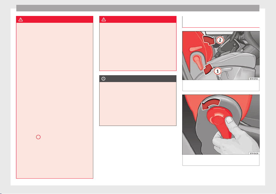
Operation
WARNING
Careless or uncontrolled use of the conven-
ient entry
assistant may result in severe in-
jury and accident.
●
Never use the convenient entry function
when the vehicle is in motion.
●
Avoid trapping or damaging the seat belt
when folding the rear seats back.
●
Keep your hands, fingers, feet and other
body parts out of the hinges and the seat
locking mechanism when folding and unfold-
ing.
●
Mats or other objects can be caught in the
hinges of the seat backrests or rear seat. This
could prevent the seat backrest from locking
safely when positioned upright.
●
All seat backrests must engage correctly for
the seat belts on the rear seats to work prop-
erly. When the seat backrest of an occupied
seat is not correctly locked in place, the pas-
senger can be thrust forward with the seat
backrest in case of sudden braking, sudden
manoeuvres or an accident.
●
A red mark on the side of the seat
››› Fig. 159
2
indicates that the seat back-
res
t is not engaged. The mark is no longer
visible when it is correctly engaged.
●
If the seat backrest or seat are folded down
and are not correctly locked in place, no pas-
senger should use them.
●
When getting in or out, never lean or hold
onto the folded seat on the second row of
seats.
WARNING
If child seats are fitted to all the seats in the
second ro
w then it is possible that the seats
of this row cannot be folded down from the
third row of seats in the event of an accident.
In the event of an emergency, passengers in
the third row of seats will not be able to leave
the vehicle or to help themselves.
●
Child seats should not occupy all the seats
of the second row if other passengers are to
occupy the third row.
CAUTION
●
Befor
e folding down the rear seat backrest
for returning it to its position, adjust the front
seats so that the head restraints and seat
backrests do not hit each other when folding
and unfolding.
●
Any objects located in the footwell of the
second row of seats may be damaged on fold-
ing the rear seat forwards. Remove any ob-
jects before folding the seat down.
Folding the backrest of the front pas-
sen
g
er se
at*
Fig. 160 Folding the backrest of the front pas-
sen
g
er se
at
Fig. 161 Unlocking the folding backrest of the
fr
ont
p
assenger seat
The backrest of the front passenger seat can
be f
o
l
ded and locked horizontally.
150
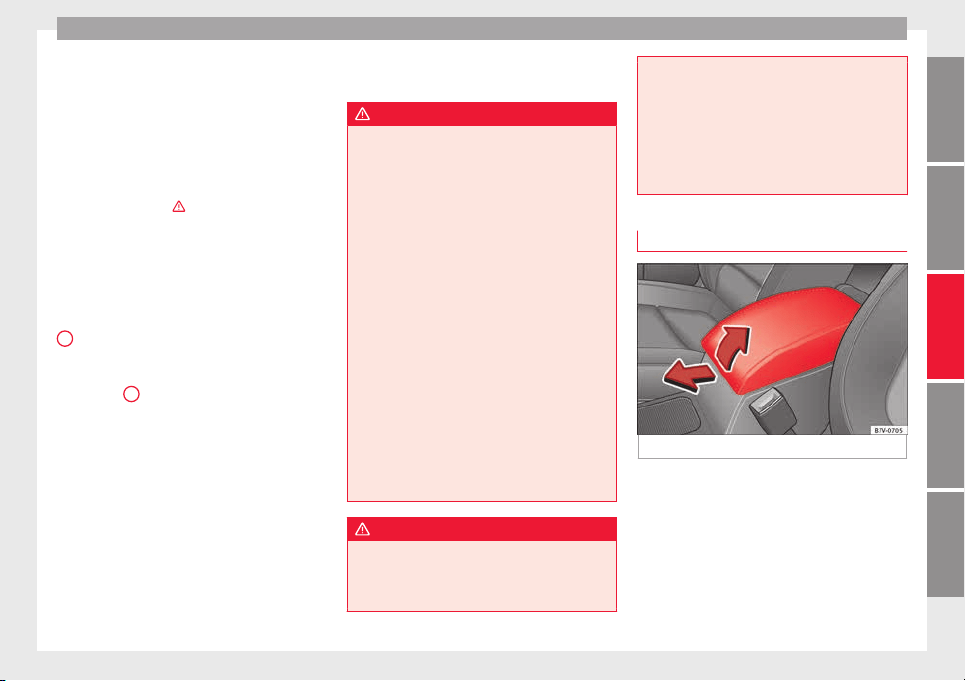
Seats and head restraints
The front passenger front airbag must be dis-
ab
l
ed ›
››
page 18 if objects are being
transported on the folded front passenger
seat.
Folding the backrest of the front passenger
seat
●
Remove any objects from the front passen-
ger seat cushion ›››
.
●
Adjust the front passenger seat to its low-
e
s
t
position ››› page 57.
●
Push the head restraint down as far as it
will go ››› page 57.
●
Unlock the backrest of the front passenger
seat in the direction of the arrow ››› Fig. 160
1
.
●
Fold the backrest of the front passenger
se
at
f
orwards in the direction of the arrow
››› Fig. 160
2
until it is horizontal.
●
The backrest of the front passenger seat
mu
s
t
engage safely in its folded position.
Lifting the backrest of the front passenger
seat
●
Check that there are no objects or parts of
the body in the hinge area.
●
Lift the backrest of the front passenger seat
by first unlocking it again ››› Fig. 161.
●
Lift the backrest of the front passenger seat
until
it is upright. The seat backrest must be
engaged.
●
The upright bac
krest of the front passenger
seat must safely engage.
WARNING
Folding and lifting the backrest of the front
pas
senger seat uncontrollably or without
paying attention may lead to severe injuries.
●
Only fold and lift the backrest of the front
passenger seat when the vehicle is station-
ary.
●
While the backrest of the front passenger
seat is folded, the front airbag must remain
disabled and the PASSENGER AIRBAG
OFF light on.
●
Keep your hands, fingers, feet and other
body parts out of the hinges and the seat
locking mechanism when folding and unfold-
ing.
●
Mats or other objects can be caught in the
hinges of the backrest of the front passenger
seat. This could prevent the seat backrest
from locking safely when positioned upright.
●
The upright backrest of the front passenger
seat must engage. If the backrest of the front
passenger seat is not locked, it may suddenly
move and cause severe injuries.
WARNING
Seat anchors and hinges exposed when the
back
rest of the front passenger seat is folded
may lead to severe injuries in the event of an
accident or sudden braking.
●
Never carr
y people or children on the front
passenger seat when the seat backrest is fol-
ded.
●
When the backrest of the front passenger
seat is folded, only the outer seat behind the
driver on the second row of seats may be oc-
cupied. This also applies to children sitting in
a child seat.
Centre armrest
Fig. 162 Front centre armrest
To lif
t the central armrest, lift it upwards in
the dir
ection of
the arrow ››› Fig. 162, setting
by setting.
To lower the centre armrest, pull it down-
wards. Then lower the centre armrest.
»
151
Technical dataAdviceOperationEmergenciesSafety
Operation
WARNING
The centre armrest may limit the freedom of
movement
of the driver's arm and cause a se-
rious accident.
●
Keep the centre armrest compartments
closed while the vehicle is in motion.
●
The centre armrest is not designed for chil-
dren to sit on! Sitting in this incorrect posi-
tion can cause severe injuries.
Transport and practical
equipment
T
r
an
sporting objects
Introduction
Always transport heavy loads in the luggage
compar
tment and place the seat backs in a
vertical position. Always use the anchors pro-
vided with suitable rope to secure heavy ob-
jects. Never overload the vehicle. Both the
carrying capacity as well as the distribution
of the load in the vehicle affect driving be-
haviour and braking ability
›››
.
WARNING
Unsecured or incorrectly secured objects can
cause seriou
s injury in case of a sudden ma-
noeuvring or breaking or in case of an acci-
dent. This is especially true when objects are
struck by a detonating airbag and fired
through the vehicle interior. To reduce the
risks, please note the following:
●
Secure all objects in the vehicle. Always
keep equipment and heavy objects in the lug-
gage compartment.
●
Always secure objects with suitable rope or
slings so that they cannot enter the areas
around the front or side airbags in case of
sudden braking or an accident.
●
Alwa
ys ensure that objects inside the vehi-
cle cannot move into the area of the airbags
while driving.
●
While driving, always keep object compart-
ments closed.
●
Remove all objects from the front passen-
ger seat when it is folded down. When the
seat backrest is folded down, it presses on
small and light objects and these are detec-
ted by the weight sensor on the seat; this
sends false information to the airbag control
unit.
●
While the backrest of the front passenger
seat is folded, the front airbag must remain
disabled and the PASSENGER AIRBAG
OFF light on.
●
Objects secured in the vehicle should never
be placed in such a way as to make passen-
gers sit in an incorrect position.
●
If secured objects occupy a seat, this seat
should not be occupied or used by anyone.
WARNING
The driving behaviour and braking ability
chan
ge when transporting heavy and large
objects.
●
Adjust your speed and driving style to visi-
bility, road, traffic and weather conditions.
●
Accelerate gently and carefully.
●
Avoid sudden braking and manoeuvres.
●
Brake early.
152
Transport and practical equipment
Transporting a load
Secure all objects in the vehicle
●
Distribute the load throughout the vehicle,
on the roof and in a tr
ailer as uniformly as
possible.
●
Transport heavy objects as far forward as
possible in the luggage compartment and
lock the seat backs in the vertical position.
●
Secure luggage in the luggage compart-
ment with suitable straps on the fastening
rings ››› page 154.
●
Check the headlight adjustment
›››
page 130.
●
Use the suitable tyre pressure according to
the load being transported. Read the tyre in-
flation information label
›››
page 288.
●
For vehicles with a tyre pressure indicator,
change the vehicle load status
›››
page 234.
CAUTION
Objects on the shelf could chafe against the
wire
s of the heating element in the heated
rear window and cause damage.
Note
Please note the information about loading a
trail
er ››› page 237 and the roof carrier sys-
tem ››› page 164.
Driving with the rear lid open
Driving with the rear lid open creates an addi-
tional ri
sk. Secure all objects and secure the
rear lid correctly and take all measures possi-
ble to reduce toxic gases from entering the
vehicle.
WARNING
Driving with the rear lid unlocked or open
coul
d cause serious injuries.
●
Always drive with the rear lid closed.
●
Secure all objects in the vehicle. Loose
items could fall out of the vehicle and injure
other road users or damage other vehicles.
●
Drive particularly carefully and think
ahead.
●
Avoid sudden manoeuvres and braking giv-
en that this could cause an uncontrolled
movement of the open rear lid.
●
When transporting objects that protrude
out of the luggage compartment, indicate
them suitably. Observe legal requirements.
●
If objects must project out of the luggage
compartment, the rear lid must never be used
to “secure” or “attach” objects.
●
If a baggage rack is fitted on the rear lid, it
should be removed before travelling with the
rear lid open.
WARNING
Toxic gases may enter the vehicle interior
when the rear lid i
s open. This could cause
loss of consciousness, carbon monoxide poi-
soning, serious injury and accidents.
●
To avoid toxic gases entering the vehicle al-
ways drive with the rear lid closed.
●
In exceptional circumstances, if you must
drive with the rear lid open, observe the fol-
lowing to reduce the entry of toxic gases in-
side the vehicle:
–
Close all windows and the sliding sun-
roof.
–
Turn off the air recirculation for the heat-
ing and air conditioner.
–
Open all of the air outlets in the dash
panel.
–
Turn the heating fan and heater to the
highest level.
CAUTION
An open boot hatch changes the length and
height of the
vehicle.
Driving with the vehicle loaded
For the best handling when driving a loaded
v
ehic
l
e, note the following:
●
Secure all objects
›››
page 153.
●
Accelerate gently and carefully.
»
153
Technical dataAdviceOperationEmergenciesSafety
Operation
●
A
v
oid s
udden braking and manoeuvres.
●
Brake early.
●
If necessary, read the instructions for driv-
ing with a trailer ››› page 237.
●
If necessary, read the instructions for driv-
ing with a roof carrier system ››› page 164.
WARNING
A sliding load could considerably affect the
stab
ility and safety of the vehicle resulting in
an accident with serious consequences.
●
Secure loads correctly so they do not move.
●
When transporting heavy objects, use suit-
able ropes or straps.
●
Lock the seat backs in vertical position.
Luggage compartment
Intr
oduction
Always transport heavy loads in the luggage
c
omp
ar
tment and place the seat backs in a
vertical position. Always use the fastening
rings with suitable rope or straps. Never over-
load the vehicle. Both the carrying capacity
as well as the distribution of the load in the
vehicle have effects on the driving behaviour
and braking ability
›››
.
WARNING
When the vehicle is not in use or being
watc
hed, always lock the doors and the rear
lid to reduce the risk of serious injury or
death.
●
Do not leave children unwatched, especial-
ly when the boot is open. Children could
climb into the luggage compartment, close
the rear lid from inside and be unable to es-
cape themselves. This could lead to serious
injury or death.
●
Never allow children to play in or around
the vehicle.
●
Never transport people in the luggage com-
partment.
WARNING
Unsecured or incorrectly secured objects can
cause seriou
s injury in case of a sudden ma-
noeuvring or breaking or in case of an acci-
dent. This is especially true when objects are
struck by a detonating airbag and fired
through the vehicle interior. To reduce the
risks, please note the following:
●
Secure all objects in the vehicle. Always
place equipment and heavy objects in the
boot.
●
Always secure objects with suitable ropes
or straps so that they cannot be pushed in-
side the cabin and move around the areas
around the front or side airbags in the event
of sudden braking or an accident.
●
While driv
ing, always keep object compart-
ments closed.
●
Do not place hard, heavy or sharp objects
inside the vehicle interior, in open storage
compartments, the rear shelf or on the dash
panel.
●
Remove hard, heavy and sharp objects from
clothes and pockets inside the vehicle and
store securely.
WARNING
The transport of heavy object changes vehi-
c
le h
andling and increases braking distance.
Heavy loads that have not been stored or se-
cured correctly could cause loss of control
and result in serious injury.
●
Vehicle handling changes when transport-
ing heavy objects due to a change in the cen-
tre of gravity.
●
Distribute the load as uniformly and as low
down on the vehicle as possible.
●
Store heavy objects in the luggage com-
partment as far from the rear axle as possi-
ble.
CAUTION
●
Hard ob
jects on the rear shelf could chafe
the wires of the heating element and antenna
of the rear window and cause damage.
●
The side window antenna could be dam-
aged due to chafing from objects.
154
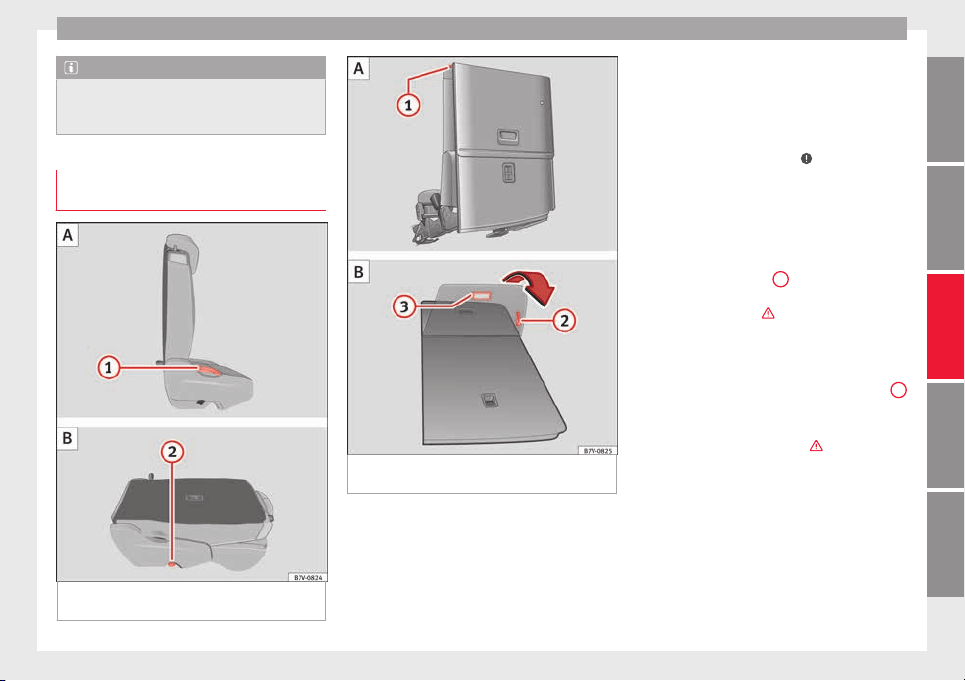
Transport and practical equipment
Note
The ventilating slits between the heated rear
window and the shelf
must not be covered so
that used air can escape from the vehicle.
Folding down rear seats to create load
spac
e
Fig. 163 Second row of seats: folding the rear
se
at
A
, rear seat as load space B.
Fig. 164 Third row of seats: fold down the
r
e
ar se
at to load A then return to position B
Each rear seat can fold down individually to
e
xt
end the lug
gage compartment.
Folding the seats in the second row of seats
for loading
●
If necessary, open the belt loop and wind
up the seat belt by hand.
●
If required, remove the head restraints from
the integrated seats for children and refit
them ››› page 78.
●
If necessary, raise the armrests.
●
Remove objects from the footwell in front of
and behind the rear seat ›››
.
●
Move the rear seat all the way back.
●
Push the head restraint down as far as it
w
i
l
l go ››› page 57.
●
In the middle seat, close the drinks carrier
in the rear of the centre console, if necessary.
●
Pull lever ››› Fig. 163
1
back and fold the
se
at
b
ackrest forwards. The complete rear
seat folds forward ›››
.
●
Fold the seat backrest forwards until it
loc
k
s
into the load surface position
››› Fig. 163 B.
●
If necessary, pull on the lever ››› Fig. 164
2
to move the seat to the required position.
●
When the seat is folded down, no adults or
c
hi
l
dren should travel in it ›››
.
F
o
l
ding the seats in the third row of seats for
loading
●
If necessary, open the belt loop and wind
up the seat belt by hand.
●
Open the rear lid.
●
Push the head restraint down as far as it
wil
l go ››› page 57.
»
155
Technical dataAdviceOperationEmergenciesSafety
Operation
●
R
emo
v
e objects from the footwell in front of
and behind the rear seat ›››
.
●
Remove objects from the space below the
r
e
ar se
at.
●
Remove the attachment elements and sup-
ports for the net from the rail system.
●
Pull lever ››› Fig. 164
1
back and fold the
se
at
b
ackrest forwards. The rear seat folds
forward ›››
and the cushion also moves for-
w
ar
d.
●
F
old the seat tray forward on top of the fol-
ded seat.
●
When the seat is folded down, no adults or
children should travel in it ›››
.
P
uttin
g the se
ats in the second row back in
place
●
Pull lever ››› Fig. 163
1
upwards and place
the se
at
b
ackrests in vertical position. The
entire seat folds backwards.
●
Pull on the rear seats and the seat backrest
to ensure that they are correctly locked in
place and that the seat belt protection is
guaranteed for rear seat passengers.
Putting the seats in the third row back in
place
●
Open the rear lid.
●
Pull on the handle ›››
Fig. 164
2
to put the
se
at
tr
ay back in position.
●
Pull on the handle ››› Fig. 164
3
. The en-
tir
e se
at
folds backwards.
●
Press on the seat tray in the seat backrest
until it is held in position by its magnets.
●
Open the sliding door.
●
Put the seat backrest into position and
press firmly until it clicks into place.
●
Pull on the rear seats and the seat backrest
to ensure that they are correctly locked in
place and that the seat belt protection is
guaranteed for rear seat passengers.
WARNING
Folding and lifting the rear seats carelessly
without p
aying attention could cause serious
injury.
●
Never fold or lift the seats while driving.
●
Do no trap or damage seat belts when rais-
ing the seat backrest.
●
Keep your hands, fingers, feet and other
body parts out of the hinges and the seat
locking mechanism when folding and unfold-
ing.
●
Mats or other objects can be caught in the
hinges of the seat backrests or rear seat. This
could prevent the seat or seat backrest from
locking securely in the vertical position.
●
All seat backrests must engage correctly for
the seat belts on the rear seats to work prop-
erly. When the seat backrest of an occupied
seat is not correctly locked in place, the pas-
senger can be thrust forward with the seat
backrest in case of sudden braking, sudden
manoeuvr
es or an accident.
●
No seat must be occupied if the seat back-
rest or seat is folded or not correctly engag-
ed.
CAUTION
●
B
efor
e folding the rear seat backrest, ad-
just the front seats so that neither the head
restraint or backrest hit them when folded.
●
Objects placed in the footrest area in front
of and behind the rear seats can be damaged
when seats are folded down or put back into
position. Remove any objects in the way be-
fore folding seats down or repositioning
them.
●
Objects placed in the moulding on the back
of the third row of seats can be damaged
when folding down the seats or putting them
back into position. Remove any objects in the
way before folding seats down or reposition-
ing them.
●
The attachment elements and supports for
the net partition placed on the rail system
can be damaged when folding down seats
from the third row or putting them back into
position and these can also damage the seats
themselves. Before folding down or reposi-
tioning the seats, remove the attachment ele-
ments and supports for the net from the rail
system.
156
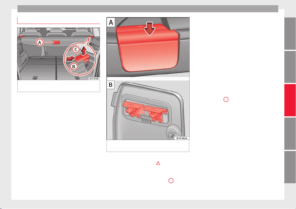
Transport and practical equipment
Shelf*
Fig. 165 In the luggage compartment: rear
shelf
Fig. 166 Remove the shelf supports A then
p
ut
them a
way safely B.
The rear shelf can be fitted behind the sec-
ond or thir
d r
o
w of seats
›››
.
Openin
g the shelf
●
P
u
ll the shelf handle
›››
Fig. 165
A
back-
w
ar
d
s.
●
Release the shelf upwards by the side sup-
ports and guide it forward.
Closing the shelf
●
Pull the unfolded shelf evenly on the guide
backwards.
●
Secure the shelf using the left and right
side supports.
Installing the shelf behind the second row of
seats
●
Place the shelf in its position in the side
lining, left-hand side first.
●
Release the shelf in the direction of the ar-
row ››› Fig. 165
B
.
●
Insert the shelf into the right-hand support,
pr
e
s
sing down.
Installing the shelf behind the third row of
seats
●
Remove the shelf from the support in the
side lining ››› Fig. 166 A. To do this, press the
shelf upwards (arrow) and remove it.
●
Open the compartment in the left-hand
side boot lining ››› page 166 and hook the
shelf to the rear of the compartment lid
››› Fig. 166 B.
●
Close the rear left-hand side lining com-
partment.
●
Place the shelf in its position in the side
lining, left-hand side first.
»
157
Technical dataAdviceOperationEmergenciesSafety
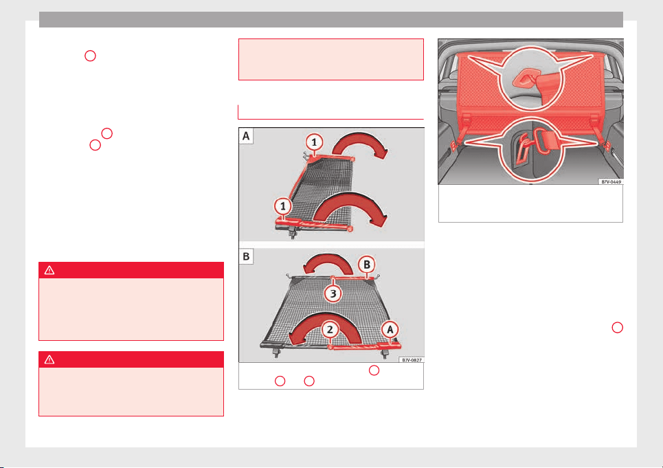
Operation
●
Lif
t
the shelf
off in direction of the arrow
››› Fig. 165
B
.
●
Insert the shelf into the right-hand support,
pr
e
s
sing down.
Removing the shelf
●
Release the shelf in the direction of the ar-
row ››› Fig. 165
B
and lift it in the direction
of
the arr
o
w
C
.
●
Remove the shelf from the right-hand side
s
up
por
t.
●
In addition, when removing the shelf be-
hind the third row of seats: cover the side lin-
ing supports with their covers.
●
Only with 5 places: support the released
shelf by placing it on the front section of the
boot floor ››› page 166.
WARNING
If the shelf is placed on one of the rear seats,
this c
ould cause serious injury in case of sud-
den braking or an accident.
●
Whenever it the third row seats are occu-
pied, the shelf should be put behind this row.
WARNING
Unsecured or incorrectly secured objects or
animal
s on the rear shelf could cause serious
injuries in case of a sudden manoeuvre or
braking or even an accident.
●
Do not le
ave hard, heavy or sharp objects
(loose or in bags) on the rear shelf.
●
Never transport animals on the rear shelf.
Net partition*
Fig. 167 Unfold the net partition
1
then fold
it
ag
ain
2
and
3
Fig. 168 In the luggage compartment: install
the net
p
ar
tition behind the second row of
seats.
The net partition can prevent objects in the
lug
g
ag
e compartment entering the vehicle
interior / the driver area.
First remove the net from its bag and unfold
it.
Fold out the net partition
Fold out the cross support rods ››› Fig. 167
1
for the net partition fully in the direction of
the arr
o
w u
ntil you hear a “click”.
Installing the net partition behind the sec-
ond row of seats
●
Hook in the net partition on the left-hand
side roof support ››› Fig. 168. To do this,
guide the rod from up to down.
158
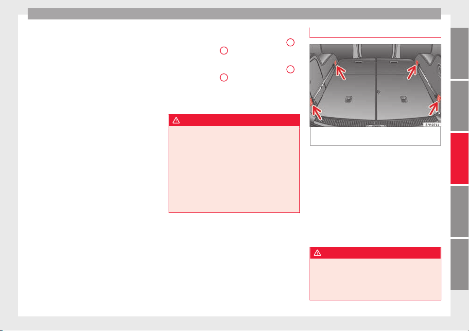
Transport and practical equipment
●
Hook
in the net
p
artition on the rear right-
hand side roof support by pressing on the
rod.
●
Secure the net partition hooks into the
straps in the front of the boot ››› Fig. 168 then
tighten the belts.
Installing the net partition behind the front
seats
●
Hook in the net partition on the front left-
hand side roof support ››› Fig. 168. To do this,
guide the rod from up to down.
●
Hook in the net partition on the rear right-
hand side roof support by pressing on the
rod.
●
Secure the hooks of the net partition to the
attachment rings in the left and right hand
side footwells on the second row of seats
then tighten the straps.
Removing the net partition
●
Loosen the net partition straps.
●
Release the net partition hooks from the
rings ››› Fig. 168.
●
Unhook the net partition on the right-hand
side roof support ››› Fig. 168 by pressing on
the rod.
●
Unhook the net partition from the left-hand
side roof support.
Folding in the net partition
●
Press on the release button ››› Fig. 167
2
and bend the rod
A
in the direction of the
arr
o
w w
ith the release button pressed.
●
Press on the release button ››› Fig. 167
3
and bend the rod
B
in the direction of the
arr
o
w w
ith the release button pressed.
●
Store the net partition securely in the vehi-
cle.
WARNING
Loose objects in the vehicle interior can be vi-
olently
thrown in case of a sudden manoeu-
vre or braking and especially in accidents
causing serious injury.
●
Ensure that the rods are correctly locked in
place.
●
Even when the net partition is correctly fit-
ted, objects must be secured.
●
When driving with the net partition, no pas-
sengers should be behind it.
Fastening rings*
Fig. 169 In the luggage compartment: fasten-
in
g rin
g
s
To the front and rear of the luggage compart-
ment, ther
e ar
e f
astening rings for securing
objects ››› Fig. 169 (arrows). On some mod-
els, the fastening rings are located right at
the back, in the area of the lock carrier plate.
There are other fastening rings located to the
left and right hand side of the second row
footrests.
Some models of fastening rings must be lif-
ted to use them.
WARNING
Unsuitable or damaged ropes or straps may
be rele
ased in case of sudden braking or an
accident. As a result, objects may be fired
through the vehicle interior causing serious
injury or death.
»
159
Technical dataAdviceOperationEmergenciesSafety

Operation
●
Alwa
ys use suitable ropes and straps in
good condition.
●
Secure the ropes and straps to the fasten-
ing rings.
●
Loose objects in the luggage compartment
can suddenly slide and change the way the
vehicle handles.
●
Secure all objects, little and large.
●
Never secure a load that is too heavy for
the fastening rings.
●
Never secure a child seat to the fastening
rings.
Note
●
The maximum lo
ad of the fastening rings is
approximately 3.5 kN (3.57 kp).
●
You can find suitable transport straps and
load securing systems at a specialised work-
shop. SEAT recommends taking your car in for
technical service.
Rails and attachment system*
Fig. 170 In the luggage compartment: system
inc
ludin
g r
ails, adjustable attachment ele-
ments
1
and adjustable tightening straps
2
.
The rails and attachment system consists of
f
our r
ai
ls, movable attachment elements,
straps to be secured to the rails and a net
with supports to cover baggage ››› page 162.
The rail and attachment system is designed
to secure light objects. If the seats in the
third row are to be occupied by passengers
then attachment elements should never be
placed in the section of the rails close to the
seats ›››
.
In
s
t
alling the attachment elements
●
Fit the attachment element with the ruts
facing upwards ››› Fig. 170
1
to the upper
p
ar
t
of the guide and press downwards.
●
Move the attachment element to the de-
sired position.
●
Always ensure that the attachment inserts
into the guide system ›››
.
R
emo
v
ing the attachment elements
●
Remove the attachment element from the
guide and pull downwards.
Securing a load
●
Pull the strap through the attachment ele-
ment and secure the load ›››
.
WARNING
In case of an accident or sudden braking, the
attachment
elements in the parts of the rails
close to the seats of the third row could in-
jure seat occupants.
●
Whenever the seats on the third row are to
be occupied, remove the attachment ele-
ments from the rails or move them all the way
back.
WARNING
Movable attachment elements that are not
secured c
orrectly can be released from the
guide in case of sudden braking or accident.
As a result, objects may be fired through the
vehicle interior causing serious injury or
death.
160
Transport and practical equipment
●
Alwa
ys ensure that the movable attach-
ment elements are correctly inserted into the
guides.
WARNING
Unsuitable or damaged ropes or straps may
be r
ele
ased in case of sudden braking or an
accident. As a result, objects may be fired
through the vehicle interior causing serious
injury or death.
●
Always use the attachment straps of the
rail and attachment system.
●
Secure the attachment straps firmly to the
attachment elements.
●
Loose objects in the luggage compartment
can suddenly slide and change the way the
vehicle handles.
●
Secure all objects, little and large.
●
Never secure a child seat to the attachment
elements.
CAUTION
●
The attachment
elements placed on the rail
system can be damaged when folding down
seats from the third row or putting them back
into position and these can also damage the
seats themselves. Before folding down or re-
positioning the seats, remove the attachment
elements and supports for the net from the
rail system.
161
Technical dataAdviceOperationEmergenciesSafety

Operation
Baggage net*
Fig. 171 Hook the baggage net A and use it
a
s
a b
ag B.
Fig. 172 Release the baggage net
If the seats in the third row are to be occu-
pied b
y
p
assengers then attachment ele-
ments should never be placed in the section
of the rails close to the seats ›››
.
In
s
t
alling the baggage net supports
●
Fit the baggage net support into the guide
from the back and press downwards.
●
Move the baggage net support to the re-
quired position.
●
Always ensure that the net support inserts
into the rail system ›››
.
Hook
in
g the b
aggage net into the support
Place the attachment rod on the baggage net
support ››› Fig. 171
1
and rotate 90° to the
l
ef
t
2
. The red mark on the attachment rod
shou
l
d not
be visible ›››
.
Using the net for bag type baggage
●
Fit the baggage net supports to each one of
the up
per r
ai
ls.
●
Fit a movable baggage net attachment ele-
ment to each one of the lower guides
››› page 160.
●
Hook the baggage net into the supports.
●
Hook the baggage net attachment strap un-
derneath into one of the movable attachment
elements ››› Fig. 171 B.
●
Join the baggage net supports to the upper
rails as much as possible by pushing them.
●
Press the sides of the baggage net together
so that they are held by the Velcro.
Using the baggage net to separate the lug-
gage compartment
●
Fit the baggage net supports to each one of
the upper rails.
●
Fit the baggage net supports to each one of
the lower rails.
●
Hook the baggage net into the supports.
To release the baggage net
●
Rotate the attachment rod 90° to the right
››› Fig. 172
1
until you can see the red mark
on the r
od. P
u
ll the attachment rod upwards
2
.
●
Only with 5 places: af
ter r
emoving, place
the baggage net safely in the front compart-
ment on the floor of the boot ››› page 166.
162
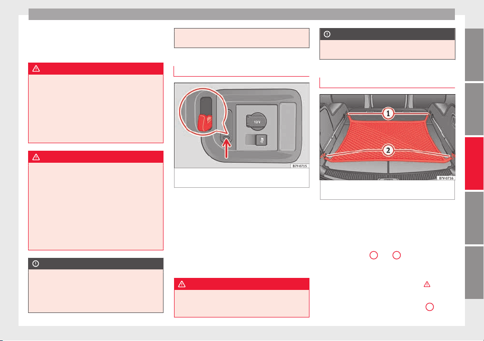
Transport and practical equipment
Removing the baggage net supports
●
Remove the net attachment element from
the r
ai
l
and pull it out downwards.
WARNING
In case of an accident or sudden braking, the
net attac
hment elements in the parts of the
rails close to the seats of the third row could
injure seat occupants.
●
Whenever the seats on the third row are to
be occupied, remove the attachment ele-
ments from the rails or move them all the way
back.
WARNING
Baggage net supports that are not secured
correctly
can be released from the guide in
case of the sudden braking or accident. As a
result, objects may be fired through the vehi-
cle interior causing serious injury or death.
●
Always ensure that the baggage net sup-
ports are correctly inserted into the rails; the
red mark should not be visible.
●
Never secure a child seat to the baggage
net supports.
CAUTION
●
The bagg
age net supports placed on the
rail system can be damaged when folding
down seats from the third row or putting
them back into position and these can also
damage the seats themselves. Before folding
down or repositioning the seats, remove the
bagg
age net supports from the rail system.
Retaining hooks
Fig. 173 In the luggage compartment: retain-
in
g hook
s
On the right-hand side of the luggage com-
p
ar
tment, ther
e are folding retaining hooks
››› Fig. 173 that can be used to secure light
shopping bags.
●
Press the retaining hooks down ››› Fig. 173
(arrow) and fold them.
●
Hook the bags in place.
●
After use, raise the hooks again.
WARNING
Never use these hooks to secure objects. In
the event of
sudden braking or an accident,
they could be pulled out.
CAUTION
The hooks can support a maximum of 2.5 kg
(about 5 l
bs).
Luggage net*
Fig. 174 In the luggage compartment: net
u
sed on sec
ur
ed baggage
The baggage net can be used to secure light-
er it
ems.
Hook
in
g the baggage net into the boot floor
●
Hook the baggage net into the fastening
rings ››› Fig. 174
1
and
2
.
R
el
e
asing the baggage net
The secured baggage net is taut ›››
.
●
Carefully unhook the baggage net hooks
fr
om the f
a
stening rings ››› Fig. 174
1
.
»
163
Technical dataAdviceOperationEmergenciesSafety

Operation
●
C
ar
ef
ully unhook the baggage net hooks
from the fastening rings ››› Fig. 174
2
.
WARNING
The elastic baggage net stretches when it is
secured t
o the luggage compartment fasten-
ing rings. The secured baggage net is taut.
The hooks on the net can cause injury if the
net is incorrectly hooked or unhooked.
●
Always ensure that the hooks do not sud-
denly release from the fastening rings when
hooking or un-hooking.
●
Always keep your face and eyes protected
at a safe distance to avoid injury should a
hook slip while hooking or unhooking.
●
Always engage the hooks in the order giv-
en. If a baggage net hook springs back this
can cause injury.
Roof carrier*
Intr
oduction
The vehicle roof has been designed to opti-
mi
se aer
ody
namics. For this reason, conven-
tional roof carrier systems cannot be secured
to the roof water drain channel.
Given that the water drains have been incor-
porated into the roof for aerodynamic rea-
sons, only the SEAT approved basic supports
and roof carrier systems can be used.
When should the roof carrier system be re-
moved?
●
When it is not being used.
●
When the vehicle is being washed in a car
wash.
●
When the vehicle height exceeds the maxi-
mum height (e.g. in a garage).
WARNING
The risk of an accident is increased by trans-
porting he
avy or bulky loads on the roof,
which affects the car's handling by shifting
the centre of gravity and increasing suscepti-
bility to cross winds.
●
Always secure loads correctly with suitable
and undamaged attachment rope or straps.
●
Large, heavy, wide and flat loads negatively
affect the vehicle aerodynamics, centre of
gravity and handling.
●
Avoid brusque manoeuvres and sudden
braking.
●
Adjust your speed and driving style to visi-
bility, road, traffic and weather conditions.
CAUTION
●
Alwa
ys remove the roof carrier system from
the roof before entering a car wash.
●
The height of your vehicle is changed by
the installation of the roof carrier and the
load secured on it. Compare the vehicle
height with the passage height, for example
in underground car parks or for garage doors.
●
The roof ant
enna, the range of the panor-
amic sliding sunroof and the boot hatch
should not be affected by the roof carrier sys-
tem and the load being transported.
●
Take extra care not to let the hatch strike
the roof load when opening.
For the sake of the environment
The vehicle uses more fuel when the roof car-
rier sy
st
em is fitted.
Fastening the base supports and the
r
oof
c
arrier system
Fig. 175 Attachment points for the basic sup-
por
t
and the r
oof carrier system
The mounts are the basis of a complete roof
c
arrier sy
s
tem. Special fixtures must then be
added in order to safely transport luggage,
bicycles, skis, surf boards, boats, etc. on the
164
Transport and practical equipment
roof. All these system components are
av
ai
l
able from a technical service centre.
Securing the base supports and roof carrier
system
Always secure the base supports and roof
carrier system correctly.
The roof carrier system must always be instal-
led exactly according to the instructions pro-
vided.
The position openings are located on the in-
ner side of the side roof rods ››› Fig. 175.
WARNING
If the base supports and the roof carrier sys-
tem are inc
orrectly fitted or used in an unsuit-
able manner, the entire system could break
free causing accident and injury.
●
Always take the manufacturer assembly in-
structions into account.
●
Only use base supports and roof carrier
systems that are not damaged and are cor-
rectly fitted.
●
The base support should only be fitted to
the points indicated in the diagram
››› Fig. 175.
●
Secure the base supports and roof carrier
system correctly.
●
Check the screws and attachments before
driving and after a short distance. During
each long journey, check the attachments
during every break.
●
Alwa
ys fit the roof carrier system correctly
for wheels, skis, surfboards, etc.
●
Never modify or repair the basic supports
or roof carrier system.
Note
Read and take into account the instructions
inc
luded with the r
oof carrier system fitted
and keep them in the vehicle.
Loading the roof carrier
Loads can only be correctly secured when the
r
oof
c
arrier system is correctly fitted ›››
.
M
ax
imum authori
sed roof load
The maximum authorised roof load is 100 kg
(220 lbs). The roof load includes the roof car-
rier system and the load being transported
›››
.
A
lw
a
ys check the roof carrier system weight
and the weight of the load to be transported
and, if necessary, weigh them. Never exceed
the maximum authorised roof load.
If you are using a roof carrier with a lower
weight rating, you cannot transport the maxi-
mum roof load. Do not exceed the maximum
weight limit for the roof carrier given in the
fitting instructions.
Distributing a load
Uniformly distribute loads and secure them
correctly ›››
.
Chec
k
att
achments
After fitting the base supports and the roof
carrier system, always check the attachments
after a short trip and at regular intervals.
WARNING
Exceeding the maximum authorised roof load
can re
sult in accidents and/or vehicle dam-
age.
●
Never surpass the maximum authorised
weight for the roof, the maximum authorised
weight on the axles and the total maximum
authorised weight of the vehicle.
●
Never exceed the capacity of the roof carri-
er system even if this is less than the maxi-
mum authorised roof load.
●
Secure heavy items as far forward as possi-
ble and, in general, distribute the vehicle
load uniformly.
WARNING
Loose and incorrectly secured loads can fall
from the roof
carrier system causing acci-
dents and injury.
●
Always use suitable ropes and straps in
good condition.
●
Always secure loads correctly.
165
Technical dataAdviceOperationEmergenciesSafety
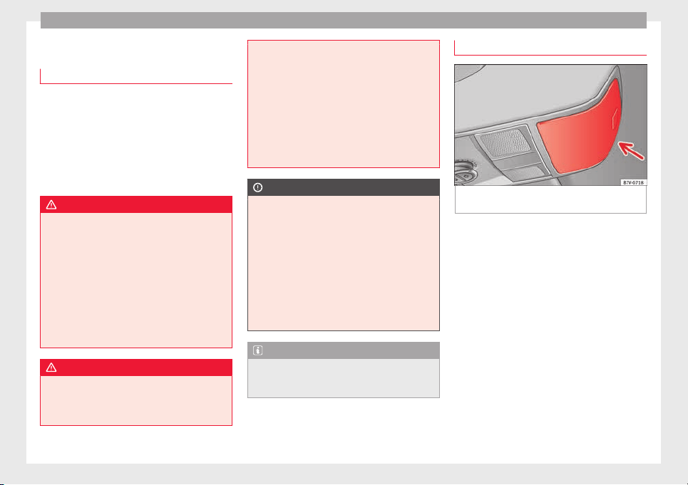
Operation
Storage compartments
Intr
oduction
Storage compartments must only be used to
stor
e light or small objects.
In the front centre armrest compartment the
following factory-fitted connections are avail-
able: USB/AUX-IN.
The factory-fitted CD changer is located in the
left-hand storage compartment of the boot.
WARNING
In the event of sudden braking movements or
turns, loo
se objects may be thrown around
the vehicle interior. This could cause serious
injuries to passengers and cause the driver to
lose control of the vehicle.
●
Do not transport animals or place hard,
heavy or sharp objects inside the vehicle in:
open storage compartments, dash panel, rear
shelf, items of clothing or bags.
●
While driving, always keep object compart-
ments closed.
WARNING
Objects falling into the driver's footwell could
prevent
use of the pedals. This could lead the
driver to lose control of the vehicle, increas-
ing the risk of a serious accident.
●
Make s
ure the pedals can be used at all
times, with no objects rolling underneath
them.
●
The floor mat should always be secured to
the floor.
●
Never place other mats or rugs on top of
the original mat supplied by the factory.
●
Make sure that no objects can fall into the
driver's footwell while the vehicle is in mo-
tion.
CAUTION
●
O
bj
ects on the shelf could chafe against
the wires of the heating element in the heat-
ed rear window and cause damage.
●
Do not keep heat-sensitive objects, food or
medicines inside the vehicle. Heat and cold
could damage them or render them useless.
●
Light-transparent objects placed inside the
vehicle, such as lenses, magnifying glasses
or transparent suction caps on the windows,
may concentrate the sun's rays and cause
damage to the vehicle.
Note
The ventilating slits between the heated rear
window and the shelf
must not be covered so
that used air can escape from the vehicle.
Spectacle case in the roof console
Fig. 176 On the roof console: sunglasses
s
t
or
age compartment.
To open, pr
ess and release the button
›
›
› Fig. 176 (arrow).
To close, press the cover upwards until it
clicks into place.
To ensure the interior monitoring works cor-
rectly, the spectacle case must be closed
when the vehicle is locked ››› page 120.
166
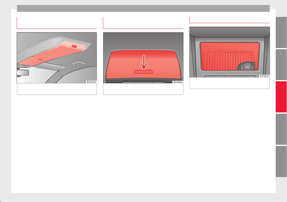
Transport and practical equipment
Storage compartment in the roof con-
so
l
e
Fig. 177 On the roof console: storage com-
p
ar
tment
To open pr
ess the button and release it
›
›
› Fig. 177.
To close, press the storage compartment up-
wards until it clicks into place.
To ensure interior monitoring works properly,
the storage compartments must be closed
when the vehicle is locked ››› page 120.
Compartment on the instrument pan-
el*
Fig. 178 Storage compartment on the dash
p
anel
The storage compartment on the instrument
p
anel
m
ay have a cover.
To open, press the button on the cover
››› Fig. 178 (arrow).
To close, press the cover down until it clicks
into place.
Compartment on the centre console
Fig. 179 Compartment in the front centre con-
so
l
e.
There is an open compartment on the centre
c
on
so
le ››› Fig. 179 in which there may be a
12 volt power socket ››› page 173.
167
Technical dataAdviceOperationEmergenciesSafety
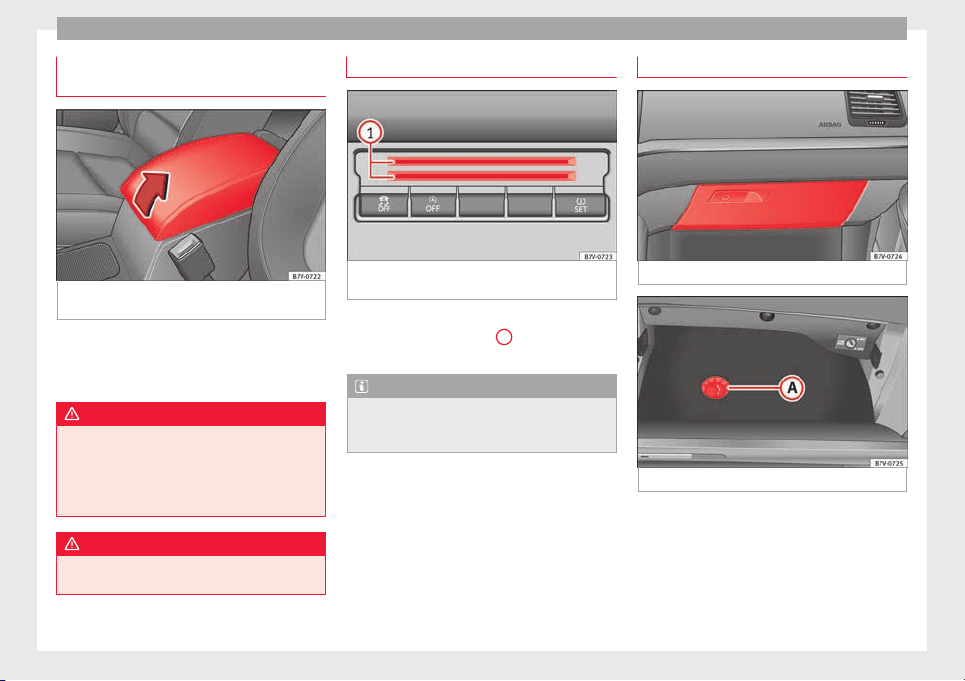
Operation
Compartment in the front central arm-
r
e
s
t
Fig. 180 Storage compartment in the front
c
entr
al
armrest.
To open, f
ully lift the central armrest in the di-
r
ection of
the arrow ››› Fig. 180.
To close, lower the central armrest.
WARNING
The centre armrest may limit the freedom of
movement
of the driver's arm and cause a se-
rious accident.
●
Keep the centre armrest compartments
closed while the vehicle is in motion.
WARNING
The centre armrest is not designed for chil-
dren to s
it on!
Card compartment*
Fig. 181 Centre console, lower section: card
c
omp
ar
tment
To the bottom of the centre console there is a
c
omp
ar
tment ››› Fig. 181
1
for coins, cards,
c
ar p
ark
tickets and similar items.
Note
To avoid theft or use by others, do not use the
compar
tment to store credit or ATM cards or
similar.
Glove compartment
Fig. 182 Glove compartment
Fig. 183 Glove compartment open
Opening and closing the glove compartment
Un
loc
k
the glove compartment where neces-
sary. The glove compartment is locked when
the key slot is vertical.
Pull the lever to open ››› Fig. 182.
Press the cover upwards to close.
168
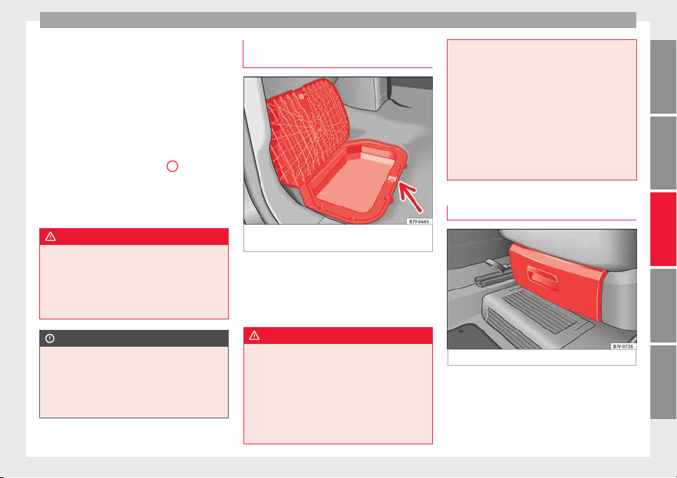
Transport and practical equipment
Vehicle wallet compartment
The glo
v
e c
ompartment is designed to store
the vehicle documentation.
The vehicle on-board documentation wallet
should always be kept in the glove compart-
ment. Insert it crosswise in the glove com-
partment.
Glove compartment cooling
There is an air vent ››› Fig. 183
A
on the rear
p
anel
so th
at cooled air from the air condi-
tioner (this must be connected) is fed into
the glove compartment. Turn the air vent to
open and close it.
WARNING
The risk of serious injuries in the event of an
accident
during a sudden braking manoeuvre
or turn is increased if the glove compartment
is left open.
●
Keep the glove compartment closed while
the vehicle is in motion.
CAUTION
For structural reasons, some model versions
wil
l have gaps behind the glove compartment
into which small objects may fall. This could
lead to strange noises and damage to the ve-
hicle. You should therefore not keep very
small objects in the glove compartment.
Storage compartments in the rear
f
ootw
el
l*
Fig. 184 Storage compartments in the foot-
w
el
l
of the second row of seats.
Move the mat to one side (where applicable).
T
o
open
, pull on the rear centre part of the
cover
›››
Fig. 184 (arrow).
To close, press the cover down.
WARNING
Make sure children are properly belted in and
correctly
secured to avoid severe or fatal inju-
ries while the vehicle is in motion.
●
If you are using a child seat with a base or
foot, always install this base or foot correctly
and safely.
●
If the vehicle has a storage compartment in
the footwell in front of the last row of seats,
this compartment cannot be used as de-
signed; on the contr
ary, it must be filled us-
ing the specially designed accessory so that
the base or foot is correctly supported by the
closed compartment and the child seat is se-
cured properly. If this compartment is not
suitably secured when using a child seat with
a base or foot then the compartment cover
could rupture in an accident and the child will
be ejected and suffer serious injury.
●
Please read and observe the child seat
manufacturer's handling instructions.
Drawers*
Fig. 185 Drawer under the front seat
There may be a drawer below the front seats.
Openin
g and c
lo
sing the drawer
To open, press the button on the drawer han-
dle and pull the drawer out.
»
169
Technical dataAdviceOperationEmergenciesSafety
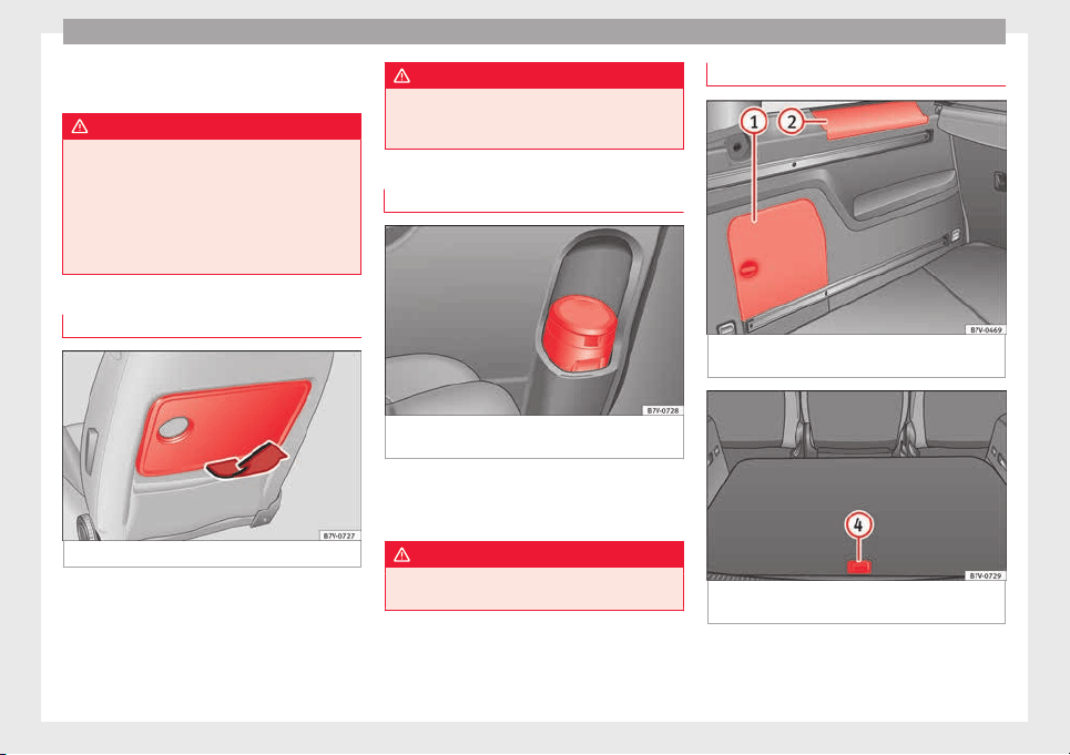
Operation
To clo
se, push the drawer under the seat until
it
c
licks into place.
WARNING
If the drawer is open it could obstruct use of
the pedal
s. This could result in serious acci-
dent.
●
The drawers must remain closed while the
vehicle is in motion. Otherwise, the drawer
and any objects in it could fall into the driv-
er's footwell and obstruct the pedals.
Folding table*
Fig. 186 Folding table on the front seat
Fold out the t
ab
l
e by pulling on it ››› Fig. 186
(arrow).
A drink holder is built into the folding table
››› page 171.
To fold it back, push the folding table down
as far as possible ››› Fig. 186.
WARNING
The folding table must not be folded down
while the
vehicle is in motion to avoid the
risk of injuries.
Portable waste bin*
Fig. 187 Left sliding door trim: portable waste
b
in.
The portable waste bin fits onto the bottle
ho
l
der on the trim of
the left-hand sliding
door.
WARNING
Do not use the portable waste bin as an ash-
tray
to avoid the risk of fire.
Other storage compartments
Fig. 188 In the luggage compartment: Side
s
t
or
age compartment
Fig. 189 Other compartments in the boot
floor
.
170
Transport and practical equipment
Side compartments in the luggage compart-
ment
Ther
e ar
e other c
ompartments ››› Fig. 188
1
and
2
in the side of the boot. To open the
c
omp
ar
tment
1
, turn the catch clockwise. To
open the c
omp
ar
tment
2
, lift the cover.
C
omp
ar
tment
1
houses the factory fitted CD
c
h
an
ger. The compartment lid
1
can safely
s
t
or
e the tray support covers.
Compartments in the boot floor
More storage compartments can be found in
the boot floor.
Function Necessary operations
Open the rear com-
partment ››› Fig. 189
4
:
Lift the rear of the boot floor
using the handle.
Keeping the rear com-
partment open:
Move the hook at the rear
right of the boot and hook the
boot floor onto it ››› page 154.
Closing the compart-
ment:
Push back the hook and
push the rear of the boot floor
4
down.
Other storage compartments:
●
in the centre console, front and rear.
●
in the door trims, front and rear.
●
Coat hooks on the c
entr
al
door pillars and
on the rear roof handles.
●
Bag hook in the luggage compartment
››› page 154.
WARNING
Clothing hung on the coat hooks could re-
strict the driv
er's view and lead to serious ac-
cidents.
●
Hang the clothes from the hooks so that
driver's view is not restricted.
●
The coat hook is suitable for light items of
clothing. Never place heavy, hard or sharp
objects in the bags.
CAUTION
Keep the CD changer compartment closed
while the
vehicle is in motion to reduce vibra-
tions that could damage the changer.
Note
The first aid kit is located in the rear left com-
partment
of the luggage compartment.
Drink holders
Intr
oduction
Bottle holders
Ther
e i
s
a bottle holder in the open compart-
ments in the driver and front passenger
doors and in that of the sliding door.
WARNING
Improper use of the drink holders can cause
injury.
●
Nev
er place hot drinks in the drink holders.
During sudden braking or driving manoeu-
vres, the hot drink could be spilled and lead
to scalding.
●
Ensure that no bottles or other object are
dropped in the driver footwell, as they could
get under the pedals and obstruct their work-
ing.
●
Never place heavy containers, food or other
heavy objects in the drink holder. In the
event of an accident, these heavy objects
could be “thrown around” the vehicle interior
and cause serious injuries.
WARNING
Closed bottles inside the vehicle could ex-
plode or cr
ack due to the heat or the cold.
●
Never leave a closed bottle in the vehicle if
the inside temperature is too high or too low.
CAUTION
Do not leave open cans in the drink holders
when the vehic
le is in motion. They could
spill during braking, for example, and cause
damage to the vehicle and the electrical sys-
tem.
»
171
Technical dataAdviceOperationEmergenciesSafety
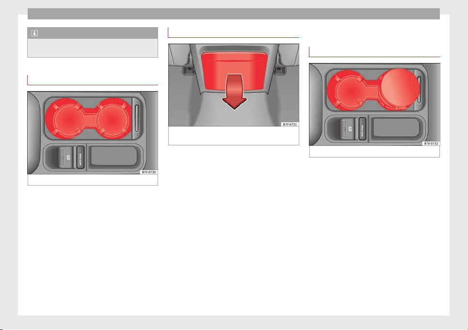
Operation
Note
The drink holders can be removed for clean-
ing.
Drink holders in front centre console
Fig. 190 Front centre console: drink holder
●
To open, mo
v
e the c
over backwards
››› Fig. 190.
●
To close, move the cover forwards.
Drink holders, rear*
Fig. 191 Centre console, rear section: folding
out
the drink
ho
lder
Opening and closing the drink holder in the
r
e
ar c
entre console
●
To open, move the drink holder downwards
in the direction of the arrow ››› Fig. 191.
●
To close, lift the drink holder.
The third row of seats has a drink holder in
the side trim compartment on the rear left.
Ashtray and cigarette lighter*
Ashtray
Fig. 192 Front centre console: ashtray closed
There are ashtrays located on the front of the
c
entr
e c
onsole ››› Fig. 192 and on the rear lin-
ing of the rear door.
Opening and closing the ashtray
●
To open, lift the ashtray cover.
●
To close, push the ashtray cover down.
Emptying the ashtray
●
Remove the ashtray from the drink holder
or lining of the door by pulling it upwards.
●
After emptying the ashtray, insert it from
above into the drink holder or door lining.
172
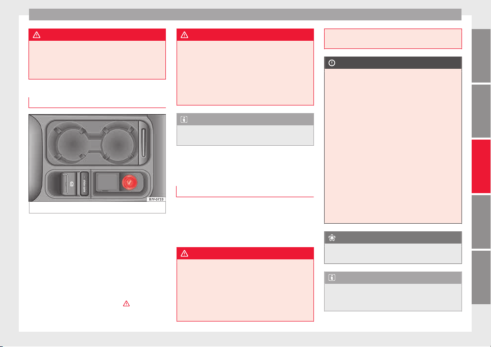
Transport and practical equipment
WARNING
Incorrect use of the ashtray may cause a fire
or burns
and other serious injuries.
●
Never put paper or other flammable objects
in the ashtray.
Cigarette lighter
Fig. 193 Front centre console: lighter
Depending on the vehicle equipment, there
m
a
y
be a lighter to the front of the centre
console ››› Fig. 193 or in the compartment to
the front of the centre console.
●
Push the button on the cigarette lighter in-
wards with the ignition on ››› Fig. 193.
●
Wait for the lighter to pop out slightly.
●
Pull out the cigarette lighter and light the
cigarette on the glowing coil ›››
.
●
Replace the cigarette lighter in its insert.
WARNING
Undue use of the cigarette lighter may cause
a fire or burn
s and other serious injuries.
●
The cigarette lighter must only be used to
light cigarettes or similar.
●
Never leave children unsupervised in the
vehicle. The cigarette lighter can be used
when the ignition is switched on.
Note
The cigarette lighter can also be used with
the 12 vo
lt power socket ››› page 173.
Power sockets
Intr
oduction
Electrical equipment can be connected to the
po
w
er soc
kets in the vehicle.
All connected appliances should be in per-
fect working order without any faults.
WARNING
Improper use of the power sockets or electri-
cal
devices could lead to a fire and cause seri-
ous injuries.
●
Never leave children unsupervised in the
vehicle. The power sockets and equipment
connected to them can be used when the ig-
nition is switched on.
●
Should a c
onnected electrical device over-
heat, switch it off and unplug it immediately.
CAUTION
●
T
o avoid d
amage to the vehicle's electrical
system, never connect equipment that gener-
ates electrical current, such as solar panels
or battery chargers, to the 12 volt power
sockets in order to charge the vehicle's bat-
tery.
●
Only use accessories with approved elec-
tromagnetic compatibility according to cur-
rent regulations.
●
To avoid damage due to voltage variations,
switch off all devices connected to the 12 V
power sockets before switching the ignition
on or off and before starting the engine.
●
Never connect an appliance to the 12 volt
power socket that consumes more than the
power indicated in watts. Exceeding the max-
imum power absorption could damage the ve-
hicle's electrical system.
For the sake of the environment
Do not leave the engine running when the ve-
hicle i
s at a standstill.
Note
●
Usin
g devices with the engine stopped and
the ignition switched on will drain the bat-
tery.
»
173
Technical dataAdviceOperationEmergenciesSafety
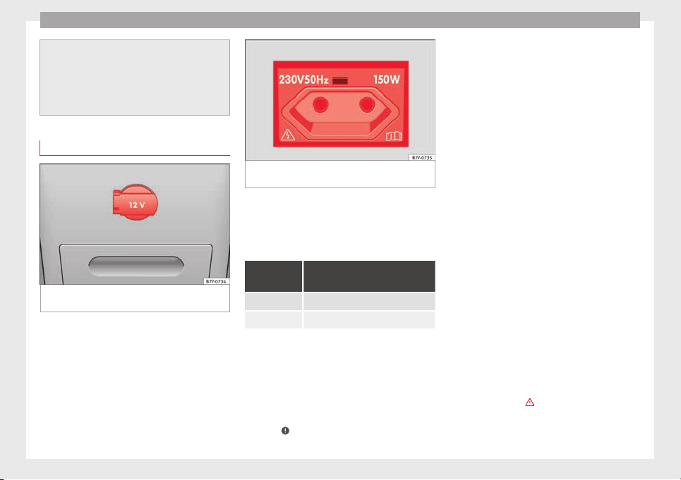
Operation
●
Unshielded equipment
can cause interfer-
ence on the radio equipment and the vehi-
cle's electrical system.
●
Interference can occur on the radio's AM
waveband if electrical appliances are used
near the rear window aerial.
Vehicle power sockets
Fig. 194 Centre console, rear section: 12 volt
soc
k
et
Fig. 195 Rear centre console: 230 Volt Euro
power soc
ket
Depending on your vehicle version, you may
h
av
e a 12-
volt power socket and/or a 230
volt power socket.
Maximum power consumption
Power sock-
et
Maximum power consumption
12 Volts 120 Watts
230 Volts 150 Watts (300 Watt peak)
The maximum capacity of each power socket
mu
s
t
not be exceeded. The power consump-
tion is indicated on the rating plate of each
appliance.
Where two or more appliances are connected
at the same time, the total rating of all the
connected devices must never exceed 190
Watts ›››
.
12 volt power socket
The 12
v
o
lt power socket will only work with
the ignition on.
Using electrical appliances with the engine
stopped and the ignition switched on will
drain the battery. Therefore, electrical devi-
ces connected to the power socket can only
be used when the engine is running.
To prevent voltage variations from causing
damage, switch off the electrical consumer
connected to the 12 volt power socket before
switching the ignition on or off and before
starting the engine.
12 volt power sockets can be found in the fol-
lowing locations in the vehicle:
●
Compartment in the centre of the centre
console.
●
Compartment in the front centre console.
●
Storage compartment in the front central
armrest.
●
Rear centre console ››› Fig. 194.
●
At the rear right of the luggage compart-
ment.
230 Volt Euro power socket*
The power socket only works when the en-
gine is running
›››
.
C
onn
e
cting an electrical appliance: plug the
device into the power socket as far as possi-
ble to unlock the built-in childproof lock. The
174
Transport and practical equipment
current only flows when the childproof lock is
u
n
loc
ked.
LED on the power socket ››› Fig. 195
Steady green light: The childproof lock is un-
locked. The power socket can
now be used.
Flashing red light: There is some kind of fault
(e.g. disconnection due to ex-
cess current or temperature).
Heat protection
The 230
V
o
lt Euro power connector converter
switches off automatically when a certain
temperature is exceeded. This disconnect
prevents overheating in the event of an in-
crease in power consumption of the connec-
ted appliance and where the atmospheric
temperature is too high. The inverter will
switch on again automatically after it has
cooled down. Appliances that are switched
on and connected to the power socket will
start up again. Therefore, switch off all elec-
trical appliances connected to the power
socket when the current converter switches
off due to overheating.
WARNING
High voltage in the electrical installation!
●
Liquids must not be spilt over the power
socket
.
●
Do not plug a
dapters or extension cords in-
to the 230 Volt Euro power connector. Other-
wise, the built-in child safety device will
switch off and the connector will become live.
●
Do not plug current conductors such as a
knitting needle into the 230 Volt Euro power
connector.
CAUTION
●
A
lwa
ys follow the operating instructions for
the appliances to be connected!
●
Never exceed the maximum power rating as
this could damage the vehicle's general elec-
trical system.
●
12 volt power socket:
–
Only use accessories with approved elec-
tromagnetic compatibility according to
current regulations.
–
Never power the socket.
●
230 Volt Euro power socket:
–
Do not plug in devices or connectors that
are too heavy (e.g. a transformer) into the
power socket.
–
Do not connect lamps which contain a ne-
on tube.
–
Only plug appliances with a voltage that
matches the power socket voltage into
the power socket.
–
Where devices have with a high start-up
current, surge protection prevents them
from switching on. In this case, unplug
the device and try plugging it back in af-
ter arou
nd 10 seconds.
Note
●
Some ap
pli
ances may not work properly in
the 230 Volt Euro power connector due to a
lack of power (Watts).
●
The 230 Watt Euro power connector can be
modified for 115 Watt appliances and vice
versa. Consult a specialist shop for advice on
accessories to adapt the connector. SEAT rec-
ommends taking your car in for technical
service.
175
Technical dataAdviceOperationEmergenciesSafety
Operation
Air conditioning
Air c
onditionin
g
Intr
oduction
Viewing Climatronic information
The factor
y-fitted radio or navigation system
screen briefly displays information relating to
Climatronic.
The units of temperature measurement is dis-
played on the factory-installed radio or navi-
gation system and, depending on the vehicle
equipment, can be set using the Configu-
ration menu on the instrument panel.
WARNING
Reduced visibility through the windows in-
cre
ases the risk of serious accidents.
●
Ensure that all windows are free of ice and
snow and that they are not fogged up pre-
venting a clear view of everything outside.
●
The maximum heat output required to de-
frost windows quickly is only available when
the engine has reached its normal running
temperature. Only drive when you have good
visibility.
●
Always ensure that you use the air condi-
tioner and heated rear window to maintain
good visibility.
●
Never leave the air recirculation on for a
long period of time. If the cooling system is
switched off and air recirculation mode
switc
hed on, the windows can mist over very
quickly, considerably limiting visibility.
●
Switch air recirculation mode off when it is
not required.
WARNING
Stuffy or used air will increase fatigue and re-
duc
e driver c
oncentration possibly resulting
in a serious accident.
●
Never leave the fresh air fan turned off or
use the air recirculation for long periods of
time; the air in the vehicle interior will not be
refreshed.
CAUTION
●
Switc
h the air conditioner off if you think it
may be broken. This will avoid additional
damage. Have the air conditioner checked by
a specialised workshop.
●
Repairs to the air conditioner require spe-
cialist knowledge and special tools. SEAT rec-
ommends taking your car in for technical
service.
●
Do not smoke when air recirculation is
switched on in vehicles with an air condition-
er. The smoke taken in could lie on the cool-
ing system vaporiser and on the activated
charcoal cartridge of the dust and pollen fil-
ter, leading to a permanently unpleasant
smell.
Note
●
When the coolin
g system is turned off, air
coming from the outside will not be dried. To
avoid fogging up the windows, SEAT recom-
mends leaving the cooler (compressor) on. To
do this, press the
A/C
button. The button
lamp shoul
d light up.
●
If the humidity and temperature outside the
vehicle are high, condensation can drip off
the evaporator in the cooling system and
form a pool underneath the vehicle, this is
completely normal and there is no need to
suspect a leak.
●
Keep the air intake slots in front of the
windscreen free of snow, ice and leaves to en-
sure heating and cooling are not impaired,
and to prevent the windows from misting
over.
Controls
Read the additional information carefully
›
›
›
page 36
To switch a function on or off, press the ap-
propriate button. Press the button again to
switch off the function.
The LED on each control lights up to indicate
that the respective function of a control has
been switched on.
Some Climatronic controls may also be on
the air conditioner control panel located in
176
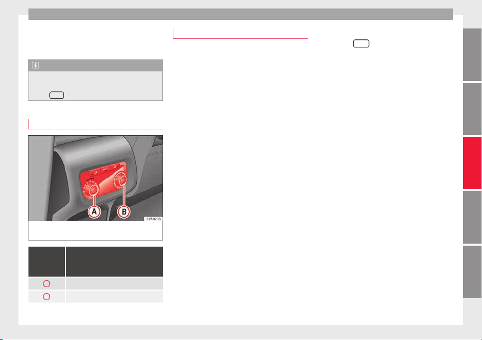
Air conditioning
the rear centre console. These controls are
u
sed t
o m
ake the appropriate settings for the
rear seats.
Note
●
Not al
l Climatronic buttons are operational
in REAR mode.
●
The
REAR
button is locked in defrost mode.
Controls in the rear seats
Fig. 196 Centre console: details of the con-
tr
o
l
s in the rear seats
Rotary con-
trol
››› Fig. 196
Description
A
Temperature selector
B
Air flow regulator
Air conditioning user instructions
The interior cooling system only works when
the engine is
running and fan is switched on.
The air conditioner operates most effectively
with the windows and the electric sliding
panoramic roof closed. However, if the vehi-
cle has heated up after standing in the sun
for some time, the air inside can be cooled
more quickly by opening the windows and
the sliding electric panoramic sunroof briefly.
Setting for conditions of optimal visibility
When the air conditioning is switched on, the
temperature and the air humidity in the vehi-
cle interior drop. In this way, when the out-
side air humidity is high, the windows do not
mist over and comfort for the vehicle occu-
pants is improved.
Electronic manual air conditioning
●
Switch off the air recirculation
›››
page 179.
●
Set the fan to the required setting.
●
Turn the temperature control to the centre
position.
●
Open and direct all the air outlets in the
dash panel
›››
page 178.
●
Turn the air distribution control to the re-
quired position.
With Climatronic
●
Press the
AUTO
button.
●
Set the temperature to +22°C (+72°F).
●
Open and direct all the air outlets in the
d
a
sh p
anel ››› page 178.
Climatronic: Switching the measuring units
for temperature on the radio display or the
navigation system installed with the default
settings
Switching the temperature indication from
Celsius to Fahrenheit on the radio display or
the navigation system is carried out in the
menu on the instrument panel
›››
page 30.
The cooling system does not switch on
If the air conditioning system cannot be
switched on, this may be caused by the fol-
lowing:
●
The engine is not running.
●
The fan is switched off.
●
The air conditioning fuse is blown.
●
The outside temperature is lower than ap-
proximately +3°C (+38°F).
●
The air conditioner compressor has been
temporarily switched off because the engine
coolant temperature is too high.
»
177
Technical dataAdviceOperationEmergenciesSafety
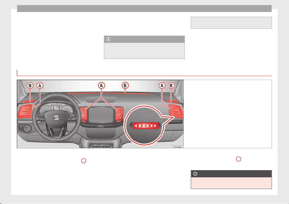
Operation
●
Another f
au
lt
in the vehicle. Have the air
conditioner checked by a specialised work-
shop.
Special features
If the humidity and temperature outside the
vehicle are high, condensation can drip off
the vaporiser in the cooling system and form
a pool underneath the vehicle. This is normal
and does not indicate a leak!
Note
After starting the engine, any residual humid-
ity in the air conditioner c
ould mist over the
windscreen. Switch on the defrost function as
soon as possible to clear the windscreen of
condens
ation.
Air vents
Fig. 197 Air vents in the dash panel
Air vents
Nev
er c
lo
se the air vents ››› Fig. 197
A
com-
p
l
et
ely to ensure heating, cooling and venti-
lation inside the vehicle.
●
Turn the thumbwheel in the required direc-
tion to open and close the air vents. When
the thumbwheel is in the position, the cor-
responding air vent is closed.
●
Change the air direction using the ventila-
tion grille lever.
There are other air vents that cannot be ad-
justed on the dash panel
B
, in the footwell
and in the r
e
ar ar
ea of the interior.
CAUTION
Never place food, medicines or other heat-
sensitiv
e objects close to the air vents. Being
178
Air conditioning
heat-sensitive, they may be damaged or
made u
nsuitable for use by the air coming
from the air vents.
Note
The air from the vents flows through the vehi-
c
le int
erior and out through the outlets below
the rear window. The slots must not be cov-
ered with items of clothing or other objects.
Air recirculation
Air recirculation mode prevents the ambient
air fr
om ent
erin
g the interior.
When the outside temperature is very high,
selecting manual air recirculation mode for a
short period refreshes the vehicle interior
more quickly.
For safety reasons, air recirculation mode is
switched off when the button is press-
ed or the air distributor turned to ›››
.
Sw
it
c
hing the recirculation mode on and off
manually on the air conditioning (Electronic
manual air conditioning)
Switching on: press the button until the
lamp on the button lights up.
Switching off: press the button until the
lamp on the button switches off.
Switching the recirculation mode on and off
manually on the Climatronic
Switching on: press the button until the
lamp on the button lights up.
Switching off: press the button until the
lamp on the button switches off.
Automatic air recirculation mode
Fresh air enters the vehicle interior in posi-
tion . If the system detects a high con-
centration of hazardous substances in the
ambient air, air recirculation mode is switch-
ed on automatically. When the level of impur-
ities drops to within a normal range, recircu-
lation mode is switched off.
The system is unable to detect unpleasant
smells.
With the following outside temperatures and
conditions the air recirculation does not
switch on automatically:
●
The cooling system is switched on (the
AC
button is lit up) and the outside temperature
i
s
belo
w +3°C (+38°F).
●
The cooling system and the windscreen
wipers are switched off and the outside tem-
perature is below +10°C (+50°F).
●
The cooling system is switched off and the
outside temperature is below +15°C (+59°F).
The windscreen wiper is switched on.
Switching the automatic air recirculation
mode on and off
Switching on: press the button until the
right lamp on the button lights up.
Switching off: press the button until all
the lamps on the button are switched off.
Switching the automatic air recirculation
mode off temporarily
●
Press the button once to temporarily
switch to manual air recirculation mode in
the event of unpleasant smells from outside.
The left indicator lamp turns on.
●
After more than two seconds, press the
button again to restart automatic air recircu-
lation. The right indicator lamp turns on.
WARNING
Observe the safety warnings ›››
in Intro-
duction on page 176
.
●
If the cooling system is switched off and air
recirculation mode switched on, the windows
can mist over very quickly, considerably limit-
ing visibility.
●
Switch air recirculation mode off when it is
not required.
»
179
Technical dataAdviceOperationEmergenciesSafety
Operation
CAUTION
Do not smoke when air recirculation is
switc
hed on in vehicles with an air condition-
er. The smoke taken in could lie on the cool-
ing system vaporiser and on the activated
charcoal cartridge of the dust and pollen fil-
ter, leading to a permanently unpleasant
smell.
Note
Climatronic: air recirculation mode switches
on to prev
ent exhaust gas from entering the
vehicle interior when it is in reverse and
while the automatic windscreen wipers are
working.
Auxiliary heater* (additional
he
at
er)
Intr
oduction
The auxiliary heater is powered by fuel from
the
v
ehic
le's fuel tank and can be used while
the vehicle is in motion and at a standstill.
Select the mode required (heat or fan)
›››
page 182 on the dash panel.
In winter, the auxiliary heater can be used in
heat mode before switching on the ignition
to remove any ice, mist or snow from the
windscreen (thin layers only).
WARNING
The auxiliary heater fumes contain carbon di-
oxide, an odourl
ess and colourless toxic gas.
Carbon monoxide can cause people to lose
consciousness. It can also cause death.
●
Never switch on the auxiliary heater or
leave it running in places that are enclosed or
unventilated.
●
Never program the independent heating
system to be activated and operated in
closed, unventilated areas.
WARNING
The components of the auxiliary heater ex-
haus
t system heat up a great deal. This could
cause a fire.
●
Always park your vehicle so that no part of
the exhaust system can come in contact with
flammable materials (such as dried grass).
CAUTION
Never place food, medicines or other heat-
sensitiv
e objects close to the air vents. Food,
medicines and other heat-sensitive objects
may be damaged or made unsuitable for use
by the air coming from the air vents.
Switching the auxiliary heater on and
off
Switching the auxiliary heater on:
Manually using the instant on/off
button.
››› page
176
ON
Manually using the remote control.
››› page
181
Automatically at the programmed
and enabled on time.
››› page
182
Switching the auxiliary heater off:
Manually using the instant on/off
button for the air conditioner.
››› page
176
OFF
Manually using the remote control.
››› page
181
Automatically after the programmed
time.
››› page
182
Automatically when the light comes
on
(fuel reserve).
››› page
264
Automatically when the battery pow-
er drops to a very low level.
››› page
284
Special feature
Af
t
er sw
itching the auxiliary heater off, it con-
tinues to run for a short period to completely
180
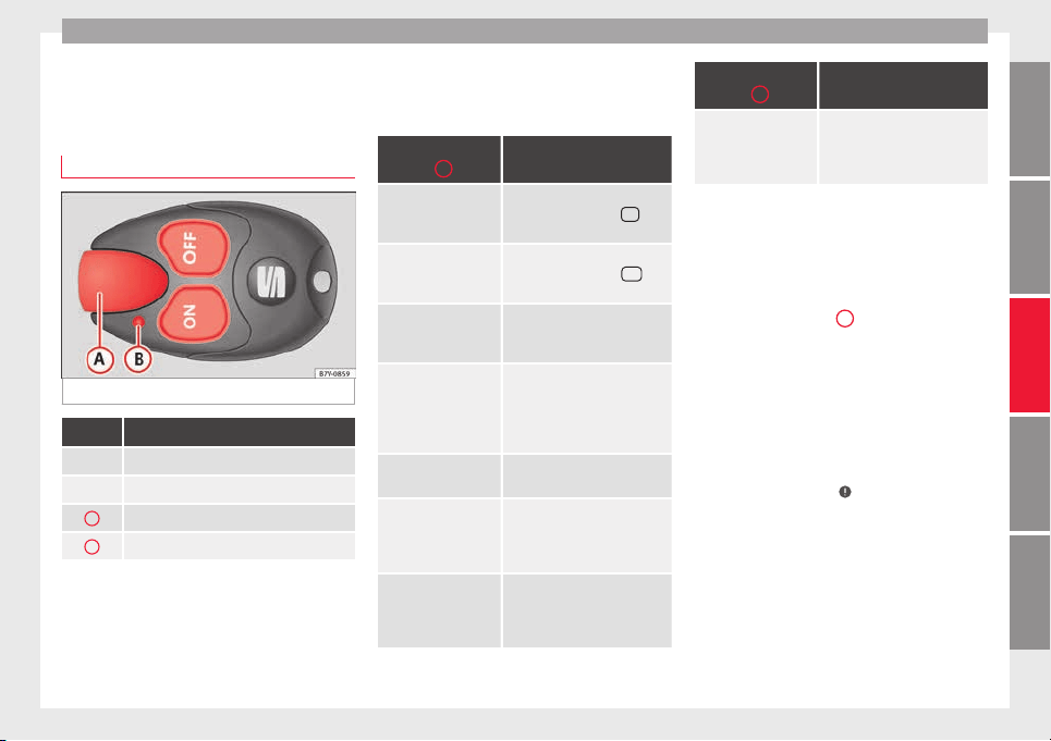
Air conditioning
burn any fuel remaining in the auxiliary heat-
er
.
The e
xhaust gases are also extracted from
the system.
Remote control
Fig. 198 Auxiliary heater: remote control
Fig. 198 Meaning
ON Switch the auxiliary heater on.
OFF Switch the auxiliary heater off:
A
Aerial.
B
Light.
The auxiliary heater may accidentally switch
on if
a b
utt
on is pressed on the remote con-
trol by mistake. This may also occur outside
the range of the remote control or if the light
flashes.
Remote control light
The remote control light provides users with
different information at the push of a button:
Battery light
Fig. 198
B
Meaning
Lights up green for
around two seconds.
The auxiliary heater has been
switched on using the
ON
but-
ton.
Lights up red for
around two seconds.
The auxiliary heater has been
switched off using the
OFF
but-
ton.
Slowly flashes green
for around two sec-
onds.
No on
a)
signal has been re-
ceived.
Quickly flashes green
for around two sec-
onds.
The auxiliary heater is locked.
Possible causes: the fuel tank
is almost empty, the battery
charge is very low or there is a
fault.
Flashes red for
around two seconds.
No off
a)
signal has been re-
ceived.
Lights up orange for
around two seconds,
then green or red.
The remote control battery is
almost flat. However, the on or
off signal has been received,
respectively.
Lights up orange for
around two seconds,
then flashes green or
red.
The remote control battery is
almost flat. The on or off signal
has not been received, respec-
tively.
Battery light
Fig. 198
B
Meaning
Flashes orange for
around five seconds.
The remote control battery is
flat. The on or off signal has
not been received, respective-
ly.
a)
Within its range, the remote control might not receive the sig-
nal sent by the vehicle receiver. In this case, the remote control
will send an error message whether the auxiliary heater is on or
off. Come closer to the vehicle and press the corresponding but-
ton on the remote control once again.
Replacing the remote control battery
If the light
›››
Fig. 198
B
on the remote con-
tr
o
l
does not come on when the button is
pressed, the remote control battery should
soon be replaced.
The battery is located beneath a cover on the
back of the remote control. Turn the slot to
the left using a flat, blunt object (e.g. a coin).
When changing the battery, use another bat-
tery of the same model and observe the po-
larity when fitting it
›››
.
R
an
g
e
The receiver is in the interior of the vehicle.
The remote control, when fitted with new bat-
teries, has a range of several hundred me-
tres. Obstacles between the remote control
and the vehicle, bad weather conditions and
discharged batteries can considerably reduce
the range of the remote control.
»
181
Technical dataAdviceOperationEmergenciesSafety
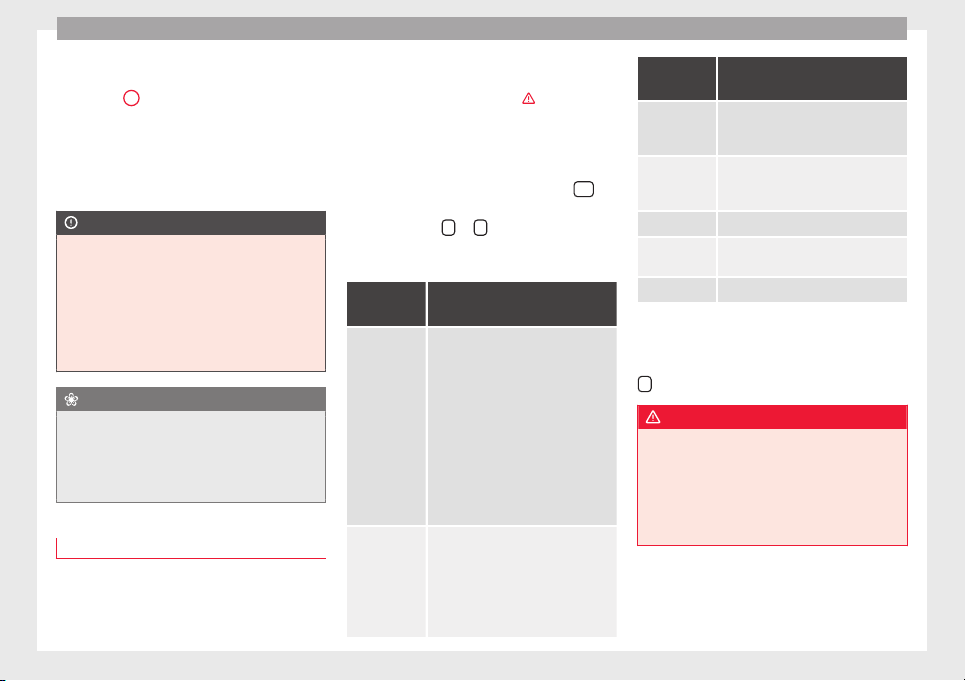
Operation
An optimum range is obtained by keeping
the r
emot
e c
ontrol vertical, with the aerial
››› Fig. 198
A
pointing upwards. When doing
so
, do not
c
over the aerial with your fingers
or with the palm of your hand.
There must be a minimum distance of 2 me-
tres between the remote control and the vehi-
cle.
CAUTION
●
The radio fr
equency remote control con-
tains electronic components. Therefore, avoid
getting it wet and being knocked and protect
it from direct sunlight.
●
Use of inappropriate batteries may damage
the remote control. For this reason, always re-
place the used battery with another of the
same voltage, size and specifications.
For the sake of the environment
●
Plea
se dispose of old batteries so that they
do not harm the environment.
●
The remote control battery may contain
perchlorate. Observe the legal requirements
for their disposal.
Programming the auxiliary heater
The heater or ventilation inside the vehicle
c
an be pr
ogr
ammed for a certain period.
Before programming, check that the day is
correctly set in the Auxiliary heater -
day of the week menu ›››
.
En
ab
lin
g the Auxiliary heater menu on
the instrument panel
●
From the main menu, select the Auxili-
ary heater submenu and press the
OK
button on the windscreen wiper lever.
●
OR: pr
ess the
or
arrow buttons on the
mu
lti-f
u
nction steering wheel until the Aux-
iliary heater menu is displayed.
Menu op-
tions
Description
Switching
on
Switching
off
The auxiliary heater can be set to come
on automatically if required. To do so,
select a timer:
– The timer is displayed marked with a
.
– Only one timer can be selected. If a
timer has been selected, Prog. ON
will be displayed on the screen. If no
timer has been selected, the dash
panel display will show Prog. OFF.
– To modify the programmed timer, se-
lect another timer or select the Off
option.
Timer 1
Timer 2
Timer 3
Three different timers (hh.mm) can lat-
er be selected using the On option. If
the auxiliary heater is to be switched
on for just a certain day of the week,
select the day of the week and the
time for the auxiliary heater to come
on.
Menu op-
tions
Description
Duration
The operating time may vary between
10 and 60 minutes and can be set to
5-minute intervals.
Operating
mode
Set to heat or ventilate the vehicle in-
terior when the auxiliary heater is
switched on.
Day Set the current day of the week.
Factory
settings
The predefined factory values for the
functions of this menu are restored.
Back This returns to the main menu.
Checking programming
If
the timer h
a
s been switched on after
switching the ignition off, the light on button
will remain lit for around 10 seconds.
WARNING
Never program the independent heating sys-
tem to be activ
ated and operated in closed,
unventilated areas. The auxiliary heater
fumes contain carbon dioxide, an odourless
and colourless toxic gas. Carbon monoxide
can cause people to lose consciousness. It
can also cause death.
182
Driving
Operating instructions
The auxiliary heater exhaust system located
below the v
ehicle must be kept clear of snow,
mud and other objects. The exhaust gases
must not be obstructed in any way. The ex-
haust gases generated by the auxiliary heater
are removed via an exhaust pipe fitted under-
neath the vehicle.
On heating the vehicle interior, depending on
the outside temperature the warm air is first
directed at the windscreen and then to the
rest of the vehicle interior through the air
vents. If the air vents are turned towards the
windows, for example, the form of air distri-
bution may be affected.
Depending on the outside temperature, the
temperature at which the auxiliary heater
warms the vehicle interior may be somewhat
higher if the heating or air conditioner tem-
perature control is set to maximum before
switching the heating on.
Depending on the engine, vehicles with aux-
iliary heater may be fitted with a second bat-
tery in the luggage compartment that is re-
sponsible for powering the auxiliary heater.
When will the auxiliary heater will not switch
on?
●
The auxiliary heater requires about as
much pow
er as the dipped beam headlights.
If the battery charge is low, the auxiliary heat-
er will switch off automatically or will not
even switch on. This avoids problems when
starting the engine.
●
The heater will switch on just once each
time. The timer will also have to be switched
back on every time it is required.
Note
●
Noise wi
ll be heard while the auxiliary
heater is running.
●
When the air humidity is high and the out-
side temperature low, the heating system
may evaporate condensation from the auxili-
ary heater. In this case, steam may be re-
leased from underneath the vehicle. This is
completely normal and there is no need to
suspect a fault!
●
If the auxiliary heater runs several times
over a prolonged period, the vehicle battery
may run flat. To re-charge the battery, drive
the vehicle for a long distance. As a general
rule, drive for as much time as the auxiliary
heating was working.
Driving
Ad
dr
e
ss
Introduction
The power steering is not hydraulic but elec-
tromech
anical. The advantage of this steer-
ing system is that it disposes of hydraulic
tubes, hydraulic oil, the pump, filter and oth-
er components. The electromechanical sys-
tem saves fuel. While a hydraulic system re-
quires oil pressure to be maintained, electro-
mechanical steering only requires energy
when the steering wheel is turned.
With the power steering system, the assisted
steering function automatically adjusts ac-
cording to the vehicle speed, the steering tor-
que and the wheel turning angle. The power
steering only works when the engine is run-
ning.
WARNING
If the power steering is not working then the
steerin
g wheel is much more difficult to turn
and the vehicle more difficult to control.
●
The power steering only works when the
engine is running.
●
Never allow the vehicle to move when the
engine is switched off.
●
Never remove the key from the ignition if
the vehicle is in motion. The steering may
»
183
Technical dataAdviceOperationEmergenciesSafety
Operation
lock and it will not be possible to turn the
steerin
g wheel.
Warning and indication lamps
It lights up red
Power steering faul-
ty.
The steering system should be
checked by a specialised work-
shop as soon as possible.
It lights up yellow
Power steering op-
eration reduced.
The steering system should be
checked by a specialised work-
shop as soon as possible.
If, after restarting the engine and
driving for a short distance, the
yellow warning lamp no longer
comes on, it will not be necessa-
ry to take the vehicle to a speci-
alised workshop.
The vehicle battery
was disconnected
and has been recon-
nected.
Drive for a short distance at
15-20 km/h (9-12 mph).
Flashes red
Fault in the steering
column electronic
lock.
Do not drive on!
Seek professional advice.
It flashes yellow
Steering column de-
viation.
Gently turn the steering wheel to
and fro.
Steering wheel not
unlocked or locked.
Remove the key from the ignition
and then switch the ignition
back on. Check the messages
displayed on the instrument
panel at the same time.
Do not drive on, if the steering
column remains locked after the
ignition has been switched on.
Seek specialist assistance.
Several warning and indication lamps light
up f
or a f
ew sec
onds when the ignition is
switched on, signalling that the function is
being verified. They will switch off after a few
seconds.
WARNING
Observe the safety warnings ›››
in Warning
and indication lamp
s on page 105.
Information on the steering
Electronic steering column lock
V
ehic
l
es with Keyless Access: the steering
column locks when the driver's door is
opened and the ignition is switched off.
Therefore, the vehicle should be at a stand-
still and, where applicable, the selector lever
in position P.
If the driver door is opened before the igni-
tion is switched off, the steering column elec-
tronic lock is activated via the ignition key or
the sensor built into the door handle.
Steering column mechanical lock
To prevent theft, we recommend you lock the
steering before leaving the vehicle.
Please engage steer-
ing lock
Unlocking the steering
Parking the vehicle
››› page 189.
Turn the steering wheel
slightly to release the
steering lock.
Remove the key from the
ignition.
Insert the key in the igni-
tion lock.
Turn the steering wheel
slightly until you hear the
steering lock.
Hold the steering wheel in
this position and switch
on the ignition.
Electromechanical power steering
W
ith the po
w
er steering system, the assisted
steering function automatically adjusts ac-
cording to the vehicle speed, the steering tor-
que and the wheel turning angle. The power
steering only works when the engine is run-
ning.
You should remember that you will need con-
siderably more power than normal to steer
the vehicle if the power steering is not work-
ing correctly or not at all.
184
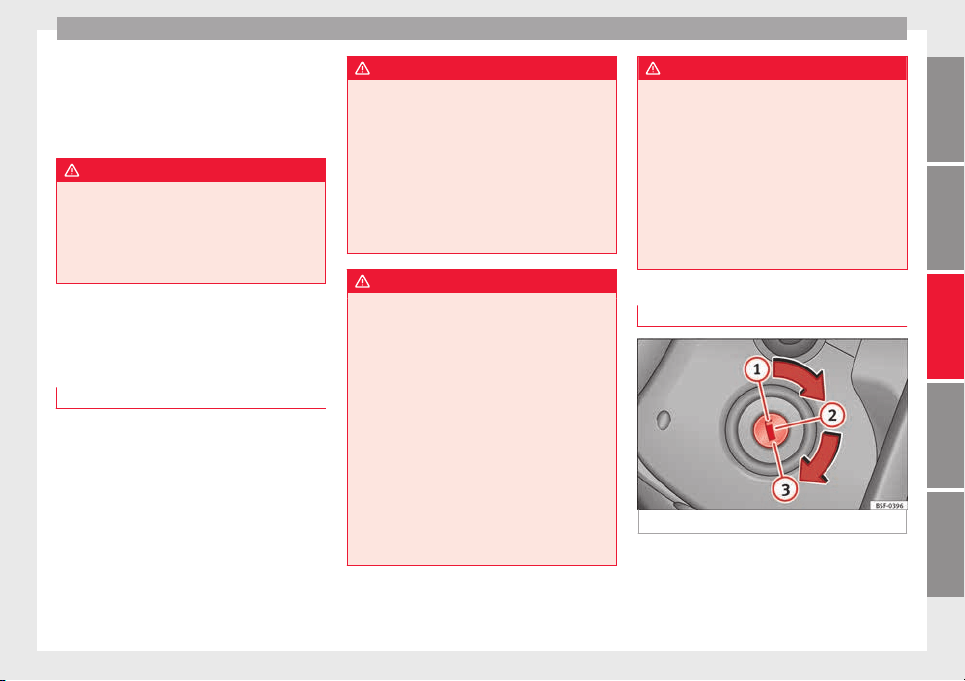
Driving
Counter steering assistance system
The c
ou
nt
er steering assistance system helps
the driver in critical situations. Additional
steering power helps the driver when counter
steering.
WARNING
The counter steering assistance system com-
bined with E
SC helps the driver to steer the
vehicle in critical driving conditions. At all
times, it is the driver who steers the vehicle.
The counter steering system does not steer
the vehicle.
Stopping and starting the en-
gine
Intr
oduction
Immobiliser display
When an in
v
alid k
ey is used or in the event of
a system fault, or Immobiliser on is
displayed on the instrument panel. The en-
gine cannot be started.
Pushing or towing
For technical reasons, the vehicle must not
be push- or tow-started. Jump starting is pref-
erable.
WARNING
Turning off the engine while driving will make
stop
ping the vehicle difficult; this could even
result in the loss of control causing an acci-
dent with serious consequences.
●
The assisted braking and steering systems,
the airbag system, seat belts and certain
safety equipment are only active while the
engine is running.
●
The engine should only be switched off
when the vehicle is at a standstill.
WARNING
While the engine is running or starting it
coul
d help reduce the risk of serious injury.
●
Never start or leave the engine running in
poorly ventilated or closed spaces. Exhaust
gas contains carbon monoxide, a toxic, col-
ourless and odourless gas. Carbon monoxide
can cause people to lose consciousness. It
can also cause death.
●
Never leave the vehicle unattended if the
engine is running. The vehicle could move off
suddenly or something unexpected could
happen resulting in damage and serious in-
jury.
●
Never use start boosters. Cold start sprays
could explode or increase the engine speed
unexpectedly.
WARNING
The components of the exhaust system reach
very
high temperatures. This could cause a
fire and considerable damage.
●
Always park your vehicle so that no part of
the exhaust system can come in contact with
flammable materials (such as wood, leaves,
dried grass, spilled fuel, etc.).
●
Do not apply additional underseal or anti-
corrosion coatings to the exhaust pipes, cata-
lytic converter, heat shields or the diesel par-
ticulate filter.
Ignition lock
Fig. 199 Vehicle key positions
Read the additional information carefully
›
›
›
page 23
»
185
Technical dataAdviceOperationEmergenciesSafety
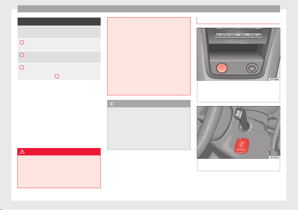
Operation
Vehicle keys ››› Fig. 199
No key in the ignition lock: The steering lock may
be activated.
1
Ignition off, all electrical devices disconnected.
Key can be removed from the vehicle.
2
Ignition is switched on. Pre-heating of diesel en-
gine. The steering lock can be unlocked.
3
Switch on the engine. Release the key when the
engine has started. When it is released, the key
returns to position
2
.
Key not authorised for the vehicle
If
a k
ey
which is not authorised for this vehi-
cle is inserted in the ignition lock, it can be
removed as follows:
●
Automatic gearbox: the key cannot be re-
moved from the ignition lock. Press and re-
lease the selector lever locking button. Key
can be removed from the vehicle.
●
Manual gearbox: remove the key from the
ignition.
WARNING
Unsuitable or careless use of the vehicle key
coul
d result in serious injury.
●
Always take all the keys with you whenever
you leave the vehicle. If not, the engine could
accidentally be started and electrical equip-
ment such as the windows could accidentally
be operated which may result in serious in-
jury.
●
Nev
er leave children or disabled people
alone in the car. Passengers could be trapped
in the car in an emergency and not be able to
get themselves to safety. For example, de-
pending on the time of the year, tempera-
tures inside a locked and closed vehicle can
be extremely high or extremely low resulting
in serious injuries and illness or even death,
particularly for young children.
●
Never remove the key from the ignition if
the vehicle is in motion. The steering may
lock and it will not be possible to turn the
steering wheel.
Note
●
If the key
is left in the ignition lock with the
engine off for long periods, the vehicle bat-
tery will run flat.
●
For automatic gearbox vehicles, the key can
only be removed from the ignition lock if the
gear selector lever is in position P. In this
case, press and release the selector lever
locking button.
Starter button
Fig. 200 In the centre console: start-up push
b
utt
on f
or the Keyless Access lock and start-
up system. The layout in right-hand drive ve-
hicles is symmetrical.
Fig. 201 Emergency ignition in vehicles with
KE
S
S
Y.
The start-up button may only be used if there
i
s
a
valid key in the vehicle.
186
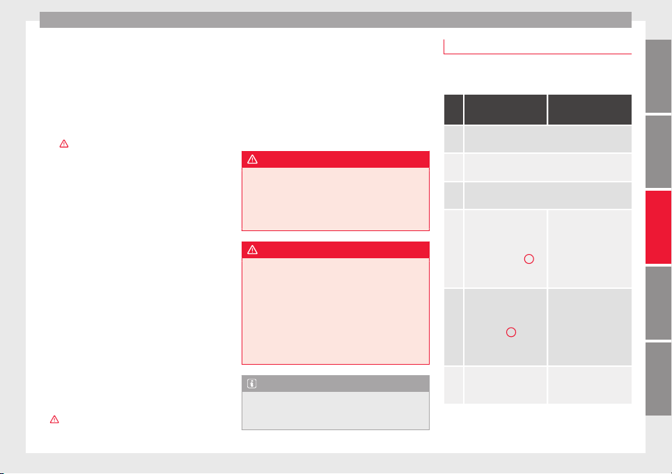
Driving
Opening the driver's door when e
x
itin
g the
vehicle activates the electronic lock on the
steering column if the ignition is disabled
››› page 183.
Switching the ignition on/off
●
Briefly push the start-up button ››› Fig. 200
without touching the brake or clutch ped-
al ›››
.
Emer
g
ency
starting function
If no valid key is detected inside the vehicle,
an emergency start-up will be required. The
relevant message will appear in the dash
panel display. This may happen when, for ex-
ample, the vehicle key battery is very low or
flat:
●
Immediately after pushing the start-up but-
ton, keep the vehicle key next to the steering
column ››› Fig. 201.
●
The ignition connects and the engine starts
automatically.
Emergency disconnection
If the engine does not stop after briefly press-
ing the start-up button, an emergency dis-
connect will be required:
●
Press the starter button twice within 1 sec-
ond or press it once for more than 2 seconds
›››
.
●
The engine turns off automatically.
Engine restart feature
If
no
v
alid key is detected inside the vehicle
after the engine stops, you will only have 5
seconds to restart it. A warning will display
on the dash panel screen.
After this interval, it will not be possible to
start the engine without a valid key inside
the vehicle.
WARNING
Any accidental movement of the vehicle could
res
ult in serious injury.
●
When pressing the start-up button, do not
press the brake or clutch pedal, this way the
engine will start immediately.
WARNING
If vehicle keys are used negligently or with-
out due car
e, this may cause accidents and
serious injury.
●
Never leave any key inside the vehicle
when exiting. Otherwise, a child or unauthor-
ised person could lock the vehicle, start the
engine or connect the ignition and, in this
way, operate electronic equipment (e.g. the
windows).
Note
In diesel vehicles with the Keyless Access
syst
em, there may be a delay in the engine
starting if it requires preheating.
Starting the engine
Complete operations only in the sequence
given:
Vehicles without
Keyless Access
Vehicles with
Keyless Access
1.
Press and hold the brake pedal until step 5 is per-
formed.
1a.
In vehicles with a manual gearbox: press and
hold the clutch down until the engine starts.
2.
Put the gearbox lever in neutral or the selector
lever in position P or N.
3.
Only in vehicles with
diesel engines: for pre-
heating, turn the key in
the ignition lock to po-
sition ››› Fig. 199
2
. A
control lamp lights up
on the dash panel
.
4.
Turn the key in the igni-
tion lock to position
››› Fig. 199
3
; do not
press the accelerator.
Press the starter button
››› Fig. 200; do not
press the accelerator.
There needs to be a
valid key inside the ve-
hicle for the engine to
start.
5.
Once the engine starts,
release the key in the
ignition lock.
Once the engine starts,
release the start-up
button.
»
187
Technical dataAdviceOperationEmergenciesSafety
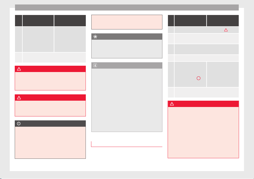
Operation
Vehicles without
Keyless Access
Vehicles with
Keyless Access
6.
If the engine does not
start, stop and wait for
around 1 minute to try
again.
If the engine does not
start, stop and wait for
around 1 minute to try
again. If necessary,
perform an emergency
start ››› page 187.
7.
Disconnect the electronic parking brake when you
are about to start driving ››› page 189.
WARNING
Never leave the vehicle unattended if the en-
gine is ru
nning. The vehicle could move off
suddenly, especially if it is in gear, resulting
in an accident and serious injury.
WARNING
Cold start sprays could explode or cause a
sudden inc
rease in the engine speed.
●
Never use start boosters.
CAUTION
●
An attempt t
o start the engine while driving
or starting the engine immediately after turn-
ing it off can cause damage to the engine or
starter motor.
●
When the engine is cold, avoid high revs
and heavy acceleration and do not make the
engine work hard.
●
Do not pu
sh or tow start the engine. Un-
burnt fuel could damage the catalytic con-
verter.
For the sake of the environment
Do not warm the engine at idle speed; start
driv
ing immedi
ately if the visibility is OK.
This helps the engine reach operating tem-
perature faster and reduces emissions.
Note
●
For ex
ample, if the key battery is very worn
or flat, the engine cannot be started with the
starter button. In this case, remove the igni-
tion button from the lock and insert the key.
●
Electrical devices with a high power con-
sumption are switched off temporarily when
the engine starts.
●
When the engine is started cold, there may
be strong vibrations for a few moments for
technical reasons. This is quite normal, and
no cause for concern.
●
At temperatures below +5°C (+41°F),
smoke may be given off below the vehicle
when the additional heater is connected.
Stopping the engine
Complete operations only in the sequence
giv
en:
Vehicles without
Keyless Access
Vehicles with
Keyless Access
1. Bring the vehicle to a full stop ››› .
2.
Press and hold the brake pedal until the step 4 is
performed.
3.
If the vehicle has an automatic gearbox, place the
selector lever in position P.
4. Connect the electronic parking brake ››› page 189.
5.
Turn the vehicle key in
the ignition lock to po-
sition ››› Fig. 199
1
.
Briefly press the start-
up button ››› Fig. 200. If
the engine fails to
switch off, perform an
emergency disconnect
››› page 187.
6.
If the vehicle is equipped with a manual gearbox,
put it into 1st or reverse.
WARNING
Never switch off the engine while the vehicle
is mo
ving. You may lose control of the vehicle
and there is a risk of serious accident.
●
The airbags and belt tensioners do not
work when the ignition is switched off.
●
The brake servo does not work with the en-
gine off. To stop, the brake pedal must be
pressed with more force.
●
As the power steering does not work if the
engine is not running, you will need more
strength to steer than normally.
188
Driving
●
If the key
is removed from the ignition, the
steering may lock and it will not be possible
to steer the vehicle.
CAUTION
If the engine has been driven at high speed
f
or a pro
longed period of time, it may over-
heat when turned off. To avoid engine dam-
age, allow the engine to run for approximate-
ly two minutes in neutral before switching it
off.
Note
●
In vehic
les with automatic gearbox, the key
can only be removed when the selector lever
is in position P.
●
After stopping the engine, the engine com-
partment fan may continue running for a few
minutes, even when the ignition has been
switched off or the key removed. The radiator
fan is automatically switched off.
Electronic immobiliser
The gear lock prevents the engine from being
s
t
ar
ted with an unauthorised key and the ve-
hicle being moved.
The vehicle key has a chip that automatically
disables the immobilizer when the key is
placed in the ignition lock.
The electronic immobiliser will be activated
again automatically as soon as you pull the
key out of the ignition lock. For vehicles with
the Keyless Access system, the key has to be
outside the vehicle ››› page 117.
For this reason, the vehicle can only be used
with a genuine SEAT key with the correct
code. Coded keys can be purchased from
your technical service centre ››› page 112.
If an unauthorised key is used, the message
SAFE or Immobiliser active is displayed
on the instrument panel. The vehicle cannot
be started in this case
Note
The correct operation of the vehicle is only
guaranteed when origin
al SEAT keys are
used.
Braking and parking
Intr
oduction
The a
ssisted braking systems include the an-
ti-loc
k
braking system (ABS), the brake assist
system (BAS), the electronic differential lock
(EDL), the traction control system (ASR) and
the electronic stability control (ESC).
WARNING
Driving with worn brake pads or a faulty
brake sy
stem may lead to serious accident.
●
If lights, alone or accompanied by a
warning message on the instrument panel
display, please go immediately to a special-
ised workshop to check the brake pads and to
replace them if they are worn.
WARNING
Careless parking can cause serious injury.
●
Never remove the key from the ignition if
the vehic
le is in motion. The steering lock
may engage and lock the steering wheel mak-
ing the vehicle impossible to control.
●
Always park your vehicle so that no part of
the exhaust system can come in contact with
flammable materials (such as wood, leaves,
dried grass, spilled fuel, etc.).
●
Always apply the electronic parking brake
when you leave your vehicle and when you
park.
●
Never leave children or disabled people
alone in the vehicle. They could release the
electronic parking brake, activate the selec-
tor lever or gear stick and start the vehicle
moving. This could result in a serious acci-
dent.
●
Always take all the keys with you whenever
you leave the vehicle. The engine could acci-
dentally be started and electrical equipment
such as the windows could accidentally be
operated resulting in serious injury.
»
189
Technical dataAdviceOperationEmergenciesSafety
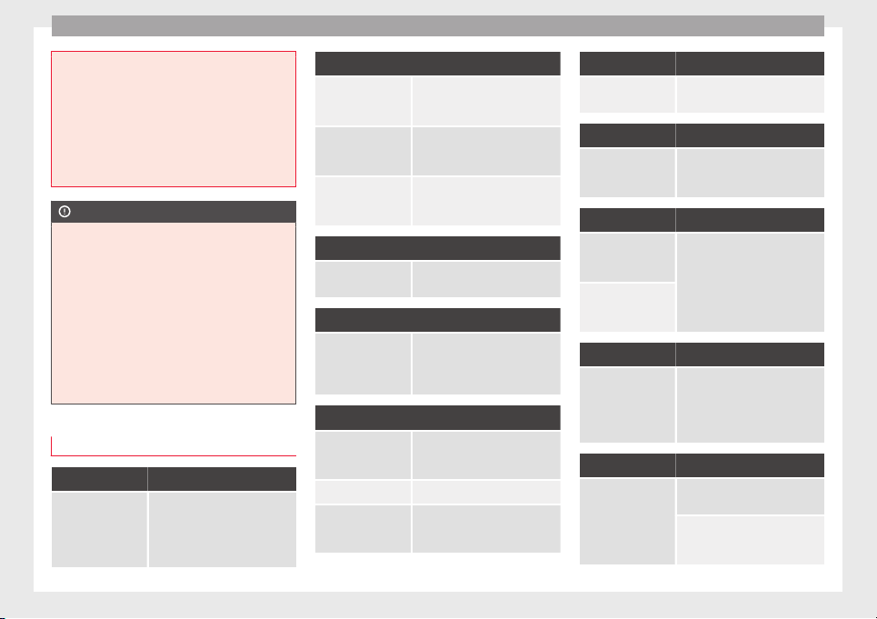
Operation
●
Never le
ave children or disabled people
alone in the car. They could be trapped in the
car in an emergency and will not be able to
get themselves to safety. For example, de-
pending on the time of the year, tempera-
tures inside a locked and closed vehicle can
be extremely high or extremely low resulting
in serious injuries and illness or even death,
particularly for young children.
CAUTION
●
S
peci
al care should be taken when parking
in areas with high kerbs or fixed barriers. Ob-
jects protruding from the ground may dam-
age the bumper or other parts of the vehicle
during manoeuvres. To avoid damage, stop
before the wheels touch the barrier or kerb.
●
Special attention is required when driving
through entrances, over ramps, kerbs or oth-
er objects. The vehicle underbody, bumpers,
mudguards and running gear, and the engine
and exhaust system could be damaged as
you drive over these objects.
Warning and indication lamps
It lights up red
Together with the
control lamp
on
the button: Elec-
tronic parking brake
on.
››› page 191
It lights up red
Fault in the brake
system
Stop the vehicle!
Seek professional assistance!
››› page 193.
Brake fluid level in-
adequate.
Do not drive on!
Check brake fluid level
››› page 283.
Together with the
ABS control lamp
: ABS fault.
Contact a specialised workshop.
The vehicle can be braked with-
out ABS.
It lights up red
Brake pedal not
pressed!
Press brake pedal to the floor.
It lights up yellow
Front brake pads
worn.
Contact a specialised workshop
immediately. Inspect all the
brake pads and replace as nec-
essary.
It lights up yellow
ESC disconnected
by the system.
Switching the ignition on and off
If necessary, drive for a short dis-
tance.
Fault in the ESC. Contact a specialised workshop.
Together with the
ABS control lamp
: Fault in the ABS.
Contact a specialised workshop.
The vehicle can be braked with-
out ABS.
It lights up yellow
The battery has
been reconnected.
››› page 284
It lights up yellow
ASR manually deac-
tivated.
Switch on ASR ››› page 207. ASR
is automatically activated when
the ignition is switched on or off.
It lights up yellow
Together with the
ESC control lamp
:
Fault in the ABS.
Contact a specialised workshop.
The vehicle can be braked with-
out ABS.
Together with the
warning lamp
or
: ABS fault.
It lights up yellow
Together with the
warning lamp
flashing: electronic
parking brake faul-
ty.
Contact a specialised workshop.
It lights up green
Brake pedal not
pressed.
Press the brake pedal to select a
gear range.
Press the brake pedal to discon-
nect the electronic parking brake
››› page 191.
190
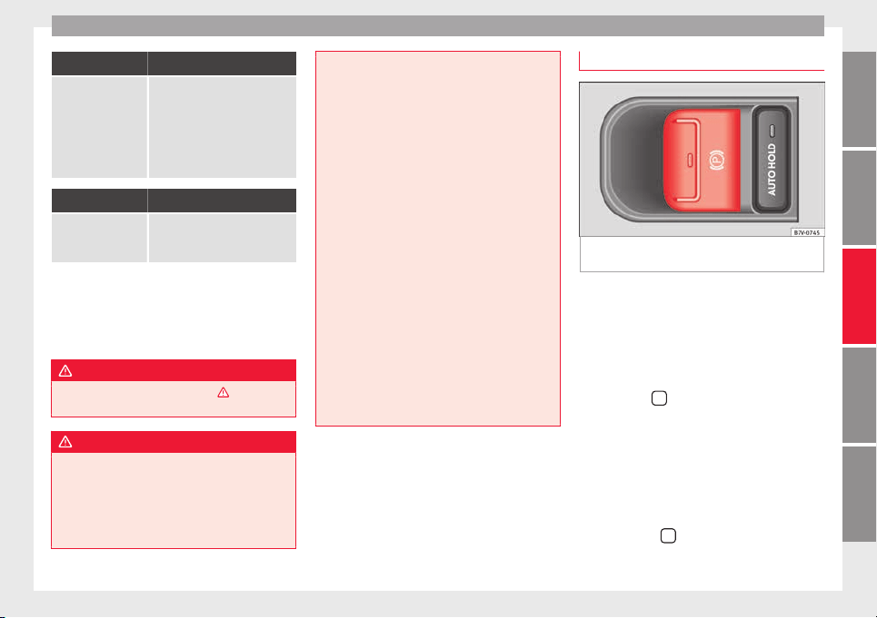
Driving
Flashes red
Electronic parking
brake faulty. The
control lamp
may
light up at the same
time or the control
lamp
may flash
on the button.
Contact a specialised workshop,
as it may not be possible to park
the vehicle in safety.
It flashes yellow
ESC or ASR regulat-
ing.
Take your foot off the accelera-
tor. Adjust your driving style to
the road conditions.
Several warning and indication lamps light
up f
or a f
ew sec
onds when the ignition is
switched on, signalling that the function is
being verified. They will switch off after a few
seconds.
WARNING
Observe the safety warnings ›››
in Warning
and indication lamp
s on page 105.
WARNING
Driving with brakes in bad condition could re-
sult
in a serious accident.
●
If the brake warning lamp does not go
out, or if it lights up when driving, the brake
fluid level in the reservoir is too low or there
is a fault in the brake system. Obtain profes-
sional assistance immediately ›››
page 282,
Checking the brake fluid level.
●
If the brake warning lamp lights up to-
gether with the ABS warning lamp , the
regulation function of the ABS could be mal-
functioning. As a result, the rear wheels can
lock relatively easily when braking. If the rear
wheels lock this could result in loss of vehicle
control! If possible, reduce your speed and
drive carefully to a specialised workshop
close by to check the brake system. During
the following journey, avoid sudden braking
and manoeuvres.
●
If the ABS warning lamp does not go out
or if it lights while driving, the ABS is mal-
functioning. The vehicle can only be stopped
using normal braking without ABS. The pro-
tection provided by the ABS is not available.
Visit a specialised workshop as soon as pos-
sible.
●
If lights, alone or accompanied by a
warning message on the instrument panel
display, please go immediately to a special-
ised workshop to check the brake pads and to
replace them if they are worn.
Electronic parking brake
Fig. 202 Detailed view of the centre console:
el
ectr
onic
parking brake switch
Applying the electronic parking brake
The p
ark
in
g brake can be applied whenever
the vehicle is at a standstill, even when the
ignition is switched off. Always apply the
parking brake when you leave your vehicle
and when you park.
●
Pull button
until the control lamp on
the b
utt
on lights
up.
●
The parking brake is applied when the con-
trol lamp lights up on the instrument pan-
el ››› page 190.
Disengaging the electronic parking brake
●
Switch the ignition on.
●
Press button
. At the same time, press
the br
ak
e ped
al hard or gently press the ac-
celerator pedal with the engine switched on.
»
191
Technical dataAdviceOperationEmergenciesSafety
Operation
●
The c
ontr
o
l lamps on the button and
on the instrument panel go out.
Automatic release of the electronic parking
brake on starting the engine
The electronic parking brake is automatically
released when the vehicle starts moving, if
the driver door is closed and the driver is
wearing his/her seat belt. In addition, in ve-
hicles with a manual gearbox the clutch ped-
al should also be pressed to the floor before
starting the engine so that the system recog-
nises that the parking brake should be re-
leased.
Emergency braking function
Only use the emergency braking function if
the vehicle cannot be stopped with the brake
pedal ›››
!
●
Pull button
h
ard to stop the vehicle. The
w
arnin
g display will be accompanied by the
corresponding audible warning.
●
To stop the braking process, release the
button or press the accelerator.
WARNING
The incorrect use of the electronic parking
brake m
ay result in serious accident.
●
Never use the electronic parking brake to
brake the vehicle except in an emergency.
The braking distance is considerably longer,
because braking is only applied to the rear
wheels. Alw
ays use the foot brake.
●
Never accelerate from the engine compart-
ment with the engine running and a gear or a
gear range engaged. The vehicle could move,
even if the parking brake is applied.
Note
●
In
vehic
les with a manual gearbox: when
the clutch pedal is released and the accelera-
tor pressed at the same time, the electronic
parking brake is automatically released.
●
If the vehicle battery is flat, it will not be
possible to disconnect the electronic parking
brake. Use the jump-start ›››
page 51.
●
When the electronic parking brake is ap-
plied or released, noises may be heard.
●
If the electronic parking brake has not been
used for a long while, the system sometimes
performs automatic and audible checks while
the vehicle is at a standstill.
Parking
When parking your vehicle, all legal require-
ments
shou
l
d be observed.
To park the vehicle
Complete operations only in the sequence
given.
●
Park the vehicle on a suitable surface ›››
.
●
Pr
e
s
s and hold the brake pedal until the ve-
hicle comes to a standstill.
●
Connect the electronic parking brake
››› page 191.
●
For an automatic gearbox, move the selec-
tor lever to position P.
●
Switch off the engine and release the brake
pedal.
●
Remove the key from the ignition.
●
If necessary, turn the steering wheel slight-
ly to lock the steering.
●
With a manual gearbox, engage 1st gear on
flat ground and slopes, or even reverse gear
on hills, and release the clutch pedal.
●
Ensure that all passengers leave the vehi-
cle, especially children.
●
When leaving the vehicle, take all keys with
you.
●
Lock the vehicle.
Additional information for steep slopes and
hills
Before switching off the engine, rotate the
steering wheel so that if the vehicle should
move, it will be held by the kerb.
●
On slopes, turn the front wheels so that
they are against the edge of the kerb.
●
Uphill, turn the wheels towards the centre
of the ro
ad.
192
Driving
WARNING
The components of the exhaust system reach
very
high temperatures. This could cause a
fire and considerable damage.
●
Always park your vehicle so that no part of
the exhaust system can come in contact with
flammable materials (such as wood,
leaves,dried grass, or spilled fuel).
CAUTION
●
Speci
al care should be taken when parking
in areas with high kerbs or fixed barriers. Ob-
jects protruding from the ground may dam-
age the bumper or other parts of the vehicle
during manoeuvres. To avoid damage, stop
before the wheels touch the barrier or kerb.
●
Special attention is required when driving
through entrances, over ramps, kerbs or oth-
er objects. The vehicle underbody, bumpers,
mudguards and running gear, and the engine
and exhaust system could be damaged as
you drive over these objects.
Information on the brakes
For the first 200 to 300 km (100 to 200
mi
l
e
s), new brake pads have not yet reached
their maximum braking capacity, and need to
be “run in” first
›››
. The slightly reduced
br
ak
in
g effect can be compensated for by in-
creasing pressure on the brake pedal. While
running in, the full braking distance or emer-
gency braking distance is larger then when
the brake pads have been run in. While run-
ning in, avoid full power braking or situations
requiring braking performance. For example,
in heavy traffic.
The rate of wear of the brake pads depends
to a great extent on the conditions in which
the vehicle is used and the way the vehicle is
driven. If the vehicle is used frequently in city
traffic or for short trips or driven sport style,
visit a specialised workshop regularly, more
frequently than advised in the Maintenance
Programme, to have the brake pads checked.
If you drive with wet brakes, for example, af-
ter crossing areas of water, in heavy rainfall
or even after washing the car, the effect of
the brakes is lessened as the brake discs are
wet or even frozen (in winter). At higher
speed, “dry” the brakes as quickly as possi-
ble by braking gently several times. Only do
this without endangering vehicles behind
you or any other road users ›››
.
A l
a
y
er of salt on the discs and brake pads
will reduce the effectiveness of the brakes
and increase braking distance. If you drive for
a prolonged period on salted roads without
braking then brake carefully several times to
eliminate the layer of salt on the brakes
›››
.
If
the
v
ehicle remains parked for considera-
ble lengths of time, is used little, or if the
brakes are not used, there may be corrosion
on the brake discs and a build up of dirt on
the brake pads. If the brakes are not used fre-
quently, or if rust has formed on the discs,
SEAT recommends cleaning the pads and
discs by braking firmly a few times at a mod-
erately high speed. Only do this without en-
dangering vehicles behind you or any other
road users ›››
.
F
au
lt
s in the brake system
During braking, if you notice that the vehicle
does not react as usual (that the braking dis-
tance has increased suddenly) it may be pos-
sible that there is a fault in the braking sys-
tem. The warning lamp lights up and a
text message displayed. Take the vehicle to a
specialised workshop immediately and have
the fault repaired. Drive at a moderate speed
and be prepared to use more pressure on the
brake pedal, and allow for longer stopping
distances.
Brake servo
The brake servo only operates when the en-
gine is running and the pressure applied by
the driver on the brake pedal increases.
If the brake servo does not operate or the ve-
hicle must be towed, then the brake pedal
will have to be pressed with more force given
that the braking distance will be increased
when the brake servo does not operate
›››
.
»
193
Technical dataAdviceOperationEmergenciesSafety
Operation
WARNING
New brake pads do not brake to full efficien-
cy.
●
For the fir
st 320 km (200 miles), new brake
pads have not yet reached their maximum
braking capacity, and need to be “run in”
first. For this, to compensate for reduced
braking efficiency the brake pedal will have
to be pressed with more force.
●
To avoid losing control of the vehicle and
causing serious accidents, always take great
care when driving with new brake pads.
●
When running in new brake pads, always
respect the safety distances between you and
other vehicles and do not cause situations re-
quiring extreme braking performance.
WARNING
When brakes overheat, braking is less effi-
cient and br
aking distances increase.
●
When driving on slopes, brakes can be
overloaded and overheat quickly.
●
Reduce speed or change down a gear when
faced with steep and long slopes. This allows
you to use the engine braking effect and to
reduce the strain on the brake system.
●
Non-standard or damaged front spoilers
could restrict the airflow to the brakes and
cause them to overheat.
WARNING
Wet, frozen or salt-covered brakes take lon-
ger to en
gage and this increases braking dis-
tances.
●
Test the brakes carefully.
●
Dry the brakes, free them of ice and salt by
braking gently several times, when weather,
road and traffic conditions permit.
WARNING
Driving without the brake servo may signifi-
cantly inc
rease the braking distance and re-
sult in a severe accident.
●
Never allow the vehicle to move forwards
when the engine is switched off.
●
If the brake servo does not operate or the
vehicle must be towed, then the brake pedal
will have to be pressed with more force given
that the braking distance will be increased
when the brake servo does not operate.
CAUTION
●
Never mak
e the brakes “slip” by pressing
the pedal gently, if it is not really necessary
to brake. Continuously pressing on the brake
pedal will heat the brakes. This could signifi-
cantly reduce braking power, increase brak-
ing distance or even result in the total failure
of the brake system.
●
Reduce speed or change down a gear when
faced with steep and long slopes. This allows
you to use the engine braking effect and to
reduce the strain on the brake system. Other-
wise, the br
akes may overheat and fail. Only
use the brakes to reduce speed or to stop.
Note
When checking the front brake pads, take the
time t
o al
so check the rear brake pads. The
thickness of the brake pads should be
checked visually and regularly, by looking
through the openings in the wheel rims or
from underneath the vehicle. If necessary, re-
move the wheels to check them thoroughly.
SEAT recommends taking your car in for tech-
nical service.
Gearbox
Intr
oduction
When reverse gear is engaged and the igni-
tion i
s
sw
itched on the following takes place:
●
Reverse lights light up.
●
When reversing, the air conditioner auto-
matically changes to air recirculation mode.
●
The rear window heater switches on when
the windscreen wiper is activated.
●
Also, the parking sensor system, the opti-
cal parking sensor and the camera for the re-
verse assist system are connected.
194
Driving
WARNING
Rapid acceleration can cause loss of traction
and skiddin
g, especially on slippery ground.
This could cause loss of control of the vehicle
resulting in an accident and considerable
damage.
●
Only use the kick-down function or rapid
acceleration if visibility, weather, road and
traffic conditions so permit.
WARNING
Do not allow the brakes to “rub” for a pro-
longed period of
time, or brake frequently or
for long periods of time. Continuous braking
heats up the brakes. This could significantly
reduce braking power, increase braking dis-
tance or even result in the total failure of the
brake system.
Control and warning lamps
It lights up red
Brake pedal not
pressed!
Press brake pedal to the floor.
It lights up green
Brake pedal not
pressed.
To select a range of gears, press
the brake pedal.
Please also see "Electronic park-
ing brake" ››› page 189.
Flashes green
The selector lever
locking button has
not engaged. The
vehicle does not
start to move.
Engage the selector lever lock
››› page 196.
Several warning and indication lamps light
up for a few sec
onds when the ignition is
switched on, signalling that the function is
being verified. They will switch off after a few
seconds.
WARNING
Observe the safety warnings ›››
in Warning
and indication lamp
s on page 105.
Manual gear change
Read the additional information carefully
›
›
›
page 34
In some countries, it is necessary to press the
clutch pedal to the floor to start the engine.
Selecting reverse gear
Engage reverse gear only when the vehicle is
stopped.
WARNING
When the engine is running, the vehicle will
star
t to move as soon as a gear is engaged
and the clutch released. This is also the case
with the electr
onic parking brake on.
●
Never engage the reverse gear when a vehi-
cle is moving forward.
CAUTION
To prevent damage and avoid premature
w
ear
, please observe the following:
●
While driving, do not leave your hand rest-
ing on the gear stick. The pressure applied by
your hand is transmitted to the gearbox se-
lector forks.
●
Always ensure that the vehicle is complete-
ly stopped before engaging the reverse gear.
●
When changing gear, always make sure the
clutch pedal is pushed right to the floor.
●
Never hold the vehicle “on the clutch” on
hills with the engine on.
195
Technical dataAdviceOperationEmergenciesSafety
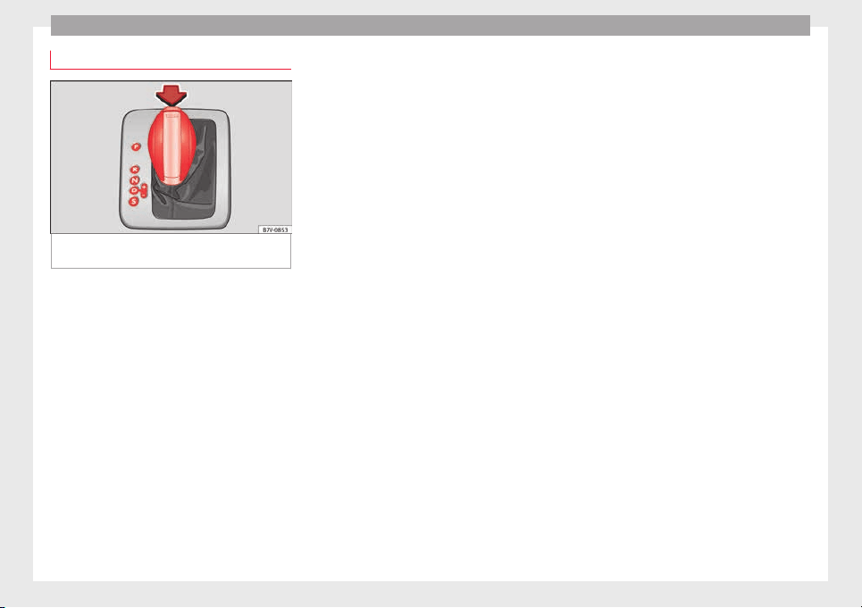
Operation
Automatic gear change*
Fig. 203 Automatic gearbox selector lever
w
ith loc
k
ing button (arrow)
Read the additional information carefully
›
›
›
page 34
The selector lever has a lock. When changing
the selector lever from position P to a range
of gears, press the brake pedal and press the
lock on the selector lever, located on the
front part of the knob, in the direction of the
arrow ››› Fig. 203. To move the gear selector
lever from the position N to D or to R, first
press and hold the brake pedal.
When the ignition is on, the current position
of the selector lever is shown on the instru-
ment panel.
- Parking lock
The driven wheels are mechanically locked.
Only change gears when the vehicle is at a
standstill. To change the position of the se-
lector lever, press the brake pedal and switch
on the ignition.
- Reverse gear
Reverse gear is engaged.
Only put in reverse when the vehicle is at a
standstill. If not it could result in serious
damage.
- Neutral
The gear box is in neutral. No movement is
transmitted to the wheels and the engine
does not act as a brake.
- Standard forwards driving position (nor-
mal programme)
The gears are changed (up and down) auto-
matically. The gear shifts are determined by
the engine load, your individual driving style
and the speed of the vehicle.
- Standard forwards driving position
(sports programme)
The shift up to a higher gear is automatically
delayed and the shift down is faster with re-
spect to the D range of gears, to take full ad-
vantage of the engine power. The gear shifts
are determined by the engine load, your indi-
vidual driving style and the speed of the ve-
hicle.
Selector lever locking
The gear selector lever lock prevents, in P or
N, a gear selection from being inadvertently
engaged and the vehicle moving off acciden-
tally.
To release the gear selector lever lock, press
and hold the brake pedal with the ignition
on. Press simultaneously on the selector lev-
er lock.
The selector lever lock is not engaged if it is
moved quickly through position N (e.g. when
shifting from R to D). This makes it possible,
for instance, to “rock the vehicle backwards
and forwards” if it is stuck in snow or mud.
The selector lever lock engages automatically
if the brake pedal is not pressed and the lev-
er is in position N for more than about one
second at a speed of less than 5 km/h
(3 mph).
In vehicles with a DSG
®
automatic gearbox,
on rare occasions the selector lever lock may
not engage. In this case, the transmission is
locked to prevent the vehicle from moving ac-
cidentally. The green control light flashes
and an information text is displayed. Proceed
as follows to engage the selector lever lock:
●
Press the brake pedal and then release.
196
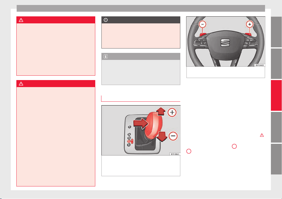
Driving
WARNING
Placing the selector lever in an incorrect posi-
tion may
cause loss of control of the vehicle
and a serious accident.
●
Do not press the accelerator when engag-
ing a range of gears.
●
With the engine running and a range of
gears selected, the vehicle will move off
when the brake pedal is released.
●
Never select reverse gear or the parking
lock while driving.
WARNING
Unintentional movements of the vehicle
coul
d cause serious injury.
●
As a driver, you should never leave your ve-
hicle if the engine is running and a gear range
is engaged. If you have to leave your vehicle
while the engine is running, you must apply
the electronic parking brake and engage
parking lock P with the selector lever.
●
While the engine is running and with the D,
S or R range of gears selected, keep the brake
pressed to keep the vehicle at a standstill.
Transmission is not totally interrupted either
when the vehicle is idling or when the vehicle
“continues moving forwards”.
●
Never engage the R or P gear ranges when
the vehicle is moving.
●
Never leave the vehicle with the gear selec-
tor in N. The vehicle may move downhill re-
gardless of whether the engine is switched
on or not.
CAUTION
If, when the vehicle is at a standstill, the
electronic
parking brake is not applied and
the brake pedal is released while in position
P, the vehicle may move a few centimetres
forwards or backwards.
Note
If, while driving, the selector lever is acciden-
tal
ly placed in position N, lift your foot off the
accelerator. Wait until the engine is running
at idle speed before selecting a new gear
range.
Gear change with Tiptronic*
Fig. 204 Selector lever in Tiptronic position
(l
ef
t
-hand drive vehicles). The lay-out in right-
hand drive vehicles is symmetrically op-
posed.
Fig. 205 Steering wheel with two paddle
shifts f
or Tiptronic
The Tiptronic system allows you to manually
c
h
an
ge gears in vehicles with an automatic
gearbox. When you change to the Tiptronic
programme, the vehicle remains in the cur-
rently selected gear. This is possible as long
as the system is not changing gear automati-
cally due to a traffic situation.
Using Tiptronic with the selector lever
●
Press the selector lever from position D to
the right into the Tiptronic selector gate ›››
in Automatic gear change* on page 197.
●
Press the lever forwards
+
or backwards
–
to move up or down a gear ›
›
›
Fig. 204.
Using the Tiptronic with the steering wheel
paddle shifts
●
In D or S, move the steering wheel paddle
shifts ››› Fig. 205.
»
197
Technical dataAdviceOperationEmergenciesSafety
Operation
●
P
u
l
l the right-hand side paddle
+
››› Fig. 205 t
o
w
ards the steering wheel to
step up a gear.
●
Pull the left-hand side paddle
–
›
›› Fig. 205
t
o
wards the steering wheel step down a gear.
If the paddles are not used for a period of
time, the vehicle leaves Tiptronic mode.
CAUTION
●
When accel
erating, the gearbox automati-
cally shifts up into the next gear shortly be-
fore the maximum engine speed is reached.
●
When reducing speed manually, the gear
box only shifts gear when the engine can no
longer exceed the maximum engine speed.
Driving with automatic gearbox
The gearbox changes gear ratios automatical-
ly
a
s
the vehicle moves.
Driving down hills
The steeper the gradient, the lower the gear
you will need. The lowest gears increase the
engine braking work. Never go down hills
with the selector lever in neutral N.
●
You should reduce speed accordingly.
●
Press the selector lever from position D to
the right int
o the Tiptronic selector gate
›››
page 197.
●
Gently pu
ll the selector lever back to
change down a gear.
●
OR: reduce using the steering wheel pad-
dles ››› Fig. 205 ››› page 197.
Back-up mode
If all the selector lever positions on the in-
strument panel display are shown with a
light-coloured background, this means there
is a fault in the system. The automatic gear-
box will operate in back-up mode. When the
backup programme is activated, it is possible
to drive the vehicle, however, at low speeds
and within a selected range of gears.
For the DSG
®
dual clutch gearbox, in some
cases, this may mean that the reverse gear
does not engage. The gearbox should be
checked by a specialised workshop as soon
as possible.
Protection against overloading the DSG
®
6-
gear automatic gearbox
When the clutch is overloaded, the vehicle
begins to jerk and the selector lever position
indicator begins to flash. To prevent damage
to the clutch, this interrupts the power trans-
mission between the engine and the gear-
box. There is no more traction and it is not
possible to accelerate. If the clutch is opened
automatically due to overloading, press the
brake pedal. Wait a few seconds before start-
ing to move again.
Kick-down
The kick-down system provides maximum ac-
celeration when the gear selector lever is in
the positions D, S or in the Tiptronic position.
When the accelerator pedal is pressed right
down, the automatic gearbox will shift down
to a lower gear, depending on road speed
and engine speed. This takes advantage of
the maximum acceleration of the vehicle
›››
.
When the ac
c
el
erator is pressed to the floor,
the automatic gearbox shifts to the next gear
only after the engine reaches the specified
maximum engine speed.
Launch-Control Programme
The Launch-Control programme enables max-
imum acceleration while at a standstill.
●
Switch off the ASR ››› page 189.
●
Press and hold the brake pedal with your
left foot.
●
Place the selector lever in position S or Tip-
tronic.
●
Press the accelerator with the right foot un-
til the vehicle reaches an engine speed of ap-
proximately 3200 rpm.
●
Lift the left foot off the brake ›››
. The ve-
hic
l
e s
tarts with maximum acceleration.
●
Turn on the ASR after accelerating!
198
Driving
WARNING
Rapid acceleration can cause loss of traction
and skiddin
g, especially on slippery ground.
This could cause loss of control of the vehicle
resulting in an accident and considerable
damage.
●
Only use kick-down and rapid acceleration
when weather conditions, surface conditions
and traffic conditions permit; accelerate and
drive in a manner that does not endanger
other road users.
●
Please remember that the driven wheels
can slip and the vehicle can skid if the ASR is
turned off, especially on slippery ground.
●
Turn on the ASR after accelerating!
CAUTION
●
If y
ou stop on a hill with a gear range en-
gaged, do not try to prevent the vehicle from
rolling back by pressing on the accelerator.
This could cause overheating and damage the
automatic gearbox.
●
Never allow the vehicle to move with the
gear selector lever in N, especially with the
engine turned off. The automatic gearbox will
not be lubricated and could be damaged.
Recommended gear display
In some vehicles, the recommended gear for
r
educ
in
g fuel consumption is displayed on
the instrument panel:
Display Meaning
Optimum gear.
Recommendation to change up a gear.
Recommendation to change down a
gear.
Information for “cleaning” the diesel partic-
ulat
e filter
The exhaust gas system control recognises
when the diesel particulate filter is blocked,
and helps to clean it by recommending a spe-
cific gear for driving. It may therefore be nec-
essary to drive with the engine at an excep-
tionally high speed
›››
page 202.
WARNING
The recommended gear display is intended as
a guideline only; it shou
ld never replace the
driver's attention to driving carefully.
●
Responsibility for selecting the correct gear
for each situation continues to lie with the
driver, for example when overtaking, climb-
ing a hill or towing a trailer.
For the sake of the environment
Selecting the most appropriate gear for the
situation w
ill help you to save fuel.
Note
The recommended gear display is switched
off when the clut
ch pedal is pressed.
Run-in and economical driving
Runnin
g in
Please observe the instructions for running-in
new components.
Ru
nning-in the engine
The engine needs to be run-in over the first
1500 km (1000 miles). During its first few
hours of running, the internal friction in the
engine is greater than later on when all the
moving parts have bedded down.
How the vehicle is driven for the first
1500 km (1000 miles) influences the future
engine performance. Throughout the life of
the vehicle, it should be driven at a moderate
speed – especially when the engine is cold –
this will reduce engine wear and increase its
useful life. Never drive at extremely low en-
gine speeds. Always engage a lower gear
when the engine works “irregularly”. For the
first 1000 km or 600 miles, please note:
●
Do not use full throttle.
●
Do not force the engine above two thirds of
its max
imum speed.
»
199
Technical dataAdviceOperationEmergenciesSafety

Operation
●
Do not
t
o
w a trailer.
Between 1000 and 1500 kilometres (600 to
1000 miles), gradually increase power until
reaching the maximum speed and high en-
gine speeds.
Running in new tyres and brake pads
●
Replacement of wheel rims and new tyres
››› page 288
●
Notes on the brakes ››› page 193
For the sake of the environment
If the engine is run in gently, the life of the
engine wi
ll be increased and the engine oil
consumption reduced.
Environmental compatibility
Environmental protection is a top priority in
the de
s
ign, c
hoice of materials and manufac-
ture of your new SEAT.
Constructive measures to encourage recy-
cling
●
Joints and connections designed for easy
dismantling
●
Modular construction to facilitate disman-
tling
●
Increased use of single-grade materials.
●
Plastic parts and elastomers are marked in
accordance with ISO 1043, ISO 11469 and
ISO 1629.
Choice of materials
●
Use of recycled materials.
●
Use of compatible plastics in the same part
if its components are not easily separated.
●
Use of recycled materials and/or materials
originating from renewable sources.
●
Reduction of volatile components, includ-
ing odour, in plastic materials.
●
Use of CFC-free coolants.
Ban on heavy metals, with the exceptions
dictated by law (Annex II of ELV Directive
2000/53/EC): cadmium, lead, mercury, hexa-
valent chromium.
Manufacturing methods
●
Reduction of the quantity of thinner in the
protective wax for cavities.
●
Use of plastic film as protection during ve-
hicle transport.
●
Use of solvent-free adhesives.
●
Use of CFC-free coolants in cooling sys-
tems.
●
Recycling and energy recovery from resi-
dues (RDF).
●
Improvement in the quality of waste water.
●
Use of systems for the recovery of residual
heat (thermal recovery, enthalpy wheels,
etc.).
●
The use of water-soluble paints.
Economical and environmentally
friendly driving
Fuel consumption, environmental impact and
engine, brak
e and tyre wear depend largely
on three factors:
●
Personal driving style.
●
Conditions of use (weather, road surface).
●
Technical requirements.
Saving
s of up to 25% in fuel consumption
are possible with an appropriate driving style
and the adoption of certain simple tips.
Changing gear early
General instructions: The highest gear is al-
ways the most economical. As a guideline,
for the majority of vehicles: at a speed of
30 km/h (19 mph), drive in third gear, at
40 km/h (25 mph) in fourth gear and at
50 km/h (31 mph) in fifth gear.
In addition, “skipping” gears when shifting
up helps to save fuel, weather and traffic
conditions permitting.
200

Driving
Do not wait until the last moment before
c
h
an
ging gear. Only use first gear when you
move off and change to second gear quickly.
Avoid the kick-down function in vehicles with
automatic gearbox.
Vehicles with a gear display help to achieve
an economical driving style as the display in-
dicates the best moment to change gear.
Let the vehicle roll
If you take your foot off the accelerator, the
fuel supply is stopped and consumption is
reduced.
Allow the vehicle to roll without accelerating,
for example when approaching a red traffic
light. However, if the vehicle is rolling too
slowly or the distance is too long, the clutch
pedal should be pressed to declutch. The en-
gine will then operate at idle speed.
If the vehicle is going to be at a standstill for
a period of time, switch off the engine; for ex-
ample, while waiting at a level crossing. In
vehicles which have the Start-Stop function
on, the engine switches off automatically
when the vehicle is not moving.
Think ahead and “flow” with the traffic
Frequent acceleration and braking considera-
bly increase fuel consumption. If you think
ahead as you drive and keep a safe distance
from the vehicle in front, it is possible to slow
down by simply lifting your foot off the accel-
erator. This eliminates the need for constant
braking and acceleration.
Calm and steady driving
Constancy is more important than speed: The
more you drive at a constant speed, the lower
the fuel consumption.
When driving on the motorway, it is more effi-
cient to drive at a constant and more moder-
ate speed than to be continuously accelerat-
ing and braking. As a general rule, you will
reach your destination just as quickly when
you drive at a constant speed.
The cruise control function helps you to ach-
ieve a constant style of driving.
Moderate use of additional devices
It is important to travel in comfort, but con-
venience systems should be used ecological-
ly.
Some equipment, when connected, increase
fuel consumption considerably, for example:
●
Air conditioning cooling system: If the air
conditioning system is required to cool to
significantly lower temperatures than the true
outside temperature, it will require a large
amount of energy from the engine. Therefore,
we recommend that the selected temperature
for the vehicle is not too different to the out-
side temperature. It is a good idea to air the
vehicle before starting your journey and to
drive a short distance with all the windows
open. Only then should you close all the win-
dows and switch on the air conditioning.
Keep windows closed when travelling at high
speeds. Driving with the windows open in-
creases fuel consumption.
●
Switch off the seat heating when the seats
have warmed up.
●
Switch off the heated rear window and the
windscreen heating when the windows have
demisted and are free of ice.
●
Do not leave the auxiliary heater switched
on when the vehicle is moving ››› page 180.
Avoid short journeys
Fuel consumption is much higher when the
engine is cold, immediately after it has been
started. It takes a few kilometres of driving
for the engine to warm up and to normalise
consumption.
The engine and catalytic converter need to
reach their proper working temperature in or-
der to minimise fuel consumption and emis-
sions. The ambient temperature has a deci-
sive influence.
Therefore, unnecessary short journeys
should be avoided. Try to combine trips.
The vehicle uses more fuel in winter than in
summer, even when other conditions are the
same.
»
201
Technical dataAdviceOperationEmergenciesSafety
Operation
The engine takes a long time to warm up
when it
i
s
idling. Mechanical wear and pollu-
tant emissions are also especially high dur-
ing this initial warm-up phase. It is therefore
best to drive off immediately after starting
the engine. Avoid running the engine at high
speed.
Adjusting type pressures.
Having the correct pressure in your tyres
helps to reduce rolling resistance and, as a
result reduces fuel consumption. Increasing
the tyre pressure slightly (+0.2 bar
[2.9 psi/20 kPa]) can help to save fuel.
If you are prepared to accept a slight reduc-
tion in comfort, the tyres may be filled to the
pressures recommended for a fully-loaded
vehicle. This is also valid when driving alone
without luggage.
When you buy new tyres, make sure they are
optimised for minimum rolling resistance.
Avoid carrying unnecessary loads
The lighter the vehicle, the more economical
and ecological the driving style. For example,
an additional weight of 100 kg will increase
fuel consumption up to 0.3 l/100 km.
Remove any unnecessary objects or loads
from the vehicle.
Remove optional equipment and unnecessa-
ry accessories
The more aerodynamic the vehicle, the lower
the fuel consumption. Optional equipment
and accessories (such as roof racks or bike
carriers) reduce the aerodynamic benefits of
the vehicle.
Therefore, we recommend you remove all op-
tional and unnecessary equipment and racks,
especially if you intend to drive at high
speeds.
Other factors which increase fuel consump-
tion (examples):
●
Fault in engine management.
●
Driving on hills.
●
Trailer towing.
WARNING
Always adapt your speed and the distance to
the vehic
les ahead in line with visibility,
weather conditions, the condition of the road
and the traffic situation.
Engine management and ex-
h
au
s
t gas purification system
Introduction
WARNING
The components of the exhaust system reach
very
high temperatures. This could cause a
fire.
●
Always park your vehicle so that no part of
the exhaust system can come in contact with
flammable materials (such as dried grass).
●
Do not apply additional underseal or anti-
corrosion coatings to the exhaust pipes, cata-
lytic converter, heat shields or the diesel par-
ticulate filter.
Control lamps
It lights up
Fault in engine
management (Elec-
tronic Power Con-
trol).
Take the vehicle to a specialised
workshop as soon as possible
and have the engine checked.
It lights up
Pre-heating a diesel
engine before start-
ing the engine.
››› page 185
202
Driving
Flashes
Fault in the engine
management (die-
sel engines).
Take the vehicle to a specialised
workshop as soon as possible
and have the engine checked.
It lights up
Fault in catalytic
converter.
You should reduce speed accord-
ingly. Drive carefully until you
reach the next specialised work-
shop. Have the engine checked
there.
Flashes
Combustion fault
which could dam-
age the catalytic
converter.
You should reduce speed accord-
ingly. Drive carefully until you
reach the next specialised work-
shop. Have the engine checked
there.
It lights up
Diesel particulate
filter blocked
››› page 204
Several warning and indication lamps light
up f
or a f
ew sec
onds when the ignition is
switched on, signalling that the function is
being verified. They will switch off after a few
seconds.
WARNING
Observe traffic regulations when cleaning the
diesel p
articulate filter while driving.
●
Only c
arry on driving if visibility, weather,
road and traffic conditions so permit.
●
Never endanger your safety or that of other
road users.
CAUTION
Always pay attention to any lit control lamps
and t
o the corr
esponding descriptions and in-
structions to avoid damage to the vehicle.
Note
While the indicators , or remain lit,
ther
e may be engine problems, fuel consump-
tion may be greater and the engine may lose
power.
Catalytic converter
The catalytic converter permits the subse-
quent
tr
e
atment of the exhaust gases thus
reducing contaminating gas emissions. To
ensure a longer working life for the exhaust
system and catalytic converter in a petrol en-
gine:
●
Always use unleaded petrol.
●
Never run the fuel tank completely dry.
●
Do not top up with too much engine oil
›››
page 276.
●
Do not tow-start the vehicle; use the starter
cables
›››
page 51.
If you should notice misfiring, uneven run-
ning or loss of power when the car is moving,
reduce speed immediately. Have the car in-
spected by a specialised workshop. If this
happens, unburnt fuel can enter the exhaust
system and escape into the atmosphere. The
catalytic converter can also be damaged by
overheating.
For the sake of the environment
Even when the emission control system is
workin
g perfectly, there may be a smell of
sulphur under certain conditions. This de-
pends on the sulphur content of the fuel be-
ing used.
Diesel particulate filter
The diesel particulate filter removes soot par-
tic
u
l
ates from the exhaust gas, retains and
burns them. To assist the combustion proc-
ess, SEAT recommends you avoid frequent
short trips.
●
Always use diesel with a low sulphur con-
tent
›››
page 267.
●
Never use petrol or fuel oil.
●
Never use biodiesel. However, a blend pre-
pared by the diesel manufacturer containing
biodiesel within the limits established by the
EN 590 standard may be used
›››
page 267.
●
Never run the fuel tank completely dry.
»
203
Technical dataAdviceOperationEmergenciesSafety
Operation
●
Do not
t
op up w
ith too much engine oil
››› page 276.
●
Do not tow-start the vehicle; use the starter
cables ›››
page 51.
In order to reduce blocking of the diesel par-
ticulate filter, some vehicles with an automat-
ic gearbox may increase the engine speed
slightly to start cleaning the filter automati-
cally. The control lamp will not light up in this
case .
Control lamp
If the control lamp lights up you should
help the filter clean itself by driving in the ap-
propriate manner.
To do this, drive about 15 minutes in fourth
or fifth gear (automatic gearbox: S gear
range) at a minimum speed of 60 km/h
(37 mph), with the engine running at approxi-
mately 2,000 rpm. In this way, the soot build
up in the filter is burned. When cleaning is
successful, the control lamp turns off.
If the lamp does not turn off, or the three
lamps turn on (particulate filter , fault in
the emission control system and glow
plugs ), drive the vehicle to a specialised
workshop and have the fault repaired at the
earliest opportunity.
WARNING
●
Alwa
ys drive according to the road weather
conditions, the terrain and traffic. Driving rec-
ommendations should never lead to illegal
manoeuvres in surrounding traffic.
For the sake of the environment
Even when the emission control system is
workin
g perfectly, there may be a smell of
sulphur under certain conditions. This de-
pends on the sulphur content of the fuel be-
ing used.
Driving abroad
In some countries, certain safety regulations
and r
equir
ements
are in force relating to ex-
haust gas emissions, which differ from the
technical characteristics of the vehicle. Be-
fore travelling abroad, SEAT recommends you
consult a technical service about the legal re-
quirements and the following points:
●
Does the vehicle need technical modifica-
tions for driving abroad, for example, adjust-
ment of the headlamps?
●
Does the vehicle have all the tools, diag-
nostics equipment and spare parts required
for inspections and repairs?
●
Are there any SEAT dealers in the destina-
tion countr
y?
●
For petro
l vehicles: Is unleaded petrol avail-
able at the right octane rating?
●
For diesel engines: Is diesel fuel available
with a low sulphur content?
●
Are a suitable engine oil (››› page 276) and
other engine fluids complying with SEAT
specifications available in the destination
country?
●
Will the navigation system fitted at the fac-
tory operate correctly in the destination coun-
try with the available navigation data?
●
Are special tyres required in the destination
country?
CAUTION
SEAT does not accept liability for any damage
to the v
ehicle due to the use of a lower quali-
ty fuel, an inadequate service or the non-
availability of genuine spare parts.
Driving along flooded roadways
To prevent damage to the vehicle when driv-
in
g thr
ough w
ater, for example, along a floo-
ded road, please observe the following:
●
Check the depth of the water before enter-
ing the flooded zone. The water should never
come above the lower edge of the bodywork
›››
.
●
Do not drive faster than a pedestrian.
204
Driver assistance systems
●
Do not
s
t
op in the water, use reverse gear
or switch off the engine.
●
Oncoming traffic will cause waves which
raise the level of the water, making it difficult
to cross the water.
The Start/Stop system must be deactivated
when driving through flooded areas
WARNING
When driving through water, mud, melted
snow
, etc., please remember that due to
damp or frozen brake discs and shoes in win-
ter, the braking effect may be delayed, there-
fore the required braking distance is greater.
●
“Dry the brakes and remove ice” by braking
carefully. Ensure that you are not endanger-
ing other road-users or breaking traffic regu-
lations in the process.
●
After driving through water, avoid sudden
sharp manoeuvres.
CAUTION
●
Driving thr
ough flooded areas may severely
damage vehicle components such as the en-
gine, transmission, drive train or electrical
system.
●
Never drive through salt water as salt cau-
ses corrosion. Always rinse any parts of the
vehicle which have been in contact with salt
water.
Driver assistance systems
Br
ak
in
g and stability systems
Brake assist systems
The brake assist systems ESC, ABS, BAS, ASR
and EDL only
operate when the ignition is
switched on. They contribute significantly to
increasing active safety.
Electronic Stability Control (ESC)
ESC reduces the risk of skidding and increa-
ses the vehicle stability by braking individual
wheels under specific driving conditions. ESC
detects critical handling situations, such as
understeer, oversteer and wheelspin on the
driven wheels. The system stabilises the ve-
hicle by braking individual wheels or by re-
ducing the engine torque.
The ESC has limits. It is important to realise
that the ESC is also subject to the laws of
physics. ESC will not be able to deal with all
situations with which drivers may be faced.
For example, if the road surface changes sud-
denly then ESC will not be useful in all cases.
If the vehicle suddenly enters a section cov-
ered by water, mud or snow then ESC will not
provide assistance in the same way as on dry
ground. If the vehicle loses its grip on the
ground and moves on a film of water (“aqua-
planing”), the ESC will not be able to assist
the driver to control the vehicle as the loss of
adherenc
e with the road surface will prevent-
ing braking and steering. If the vehicle is
driven through series of bends at high
speed, the ESC will not always be as effec-
tive: the vehicle reaction to aggressive driv-
ing is not the same as at reduced speeds.
When driving with a trailer, ESC does not pro-
vide the same amount of vehicle control as
without a trailer.
Adjust your speed and driving style to road,
traffic and weather conditions. ESC cannot
push the limits of the laws of physics; im-
prove the transmission available or maintain
the vehicle on the road if a lack of driver at-
tention creates an inevitable situation. Other-
wise, ESC assists in maintaining vehicle con-
trol in extreme situations and uses the move-
ments of the steering made by the driver to
maintain the vehicle moving in the desired
direction. If the vehicle is driven at such a
speed that it will leave the road before ESC
can intervene then the system cannot pro-
vide assistance.
The ABS, BAS, ASR and EDL systems are in-
corporated into the ESC. The ESC is always
on. The ESC should only be turned off using
the ASR button
›››
Fig. 206 when traction is
insufficient. Always remember to turn on the
ASR once more when the vehicle has traction
again.
»
205
Technical dataAdviceOperationEmergenciesSafety

Operation
Anti-lock system (ABS)
ABS
c
an pr
event the wheels from locking dur-
ing braking until just before the vehicle stops
thus helping the driver to steer the vehicle
and maintain control. This means that, even
during full braking, the risk of skidding is re-
duced:
●
Press and hold the brake pedal fully. Do not
remove your foot from the brake pedal or re-
duce braking force!
●
Do not “pump” the brake pedal, or reduce
braking force!
●
Maintain vehicle direction when braking
fully.
●
When the brake pedal is released or when
the brake force is reduced, ABS is turned off.
ABS control can be observed by vibration of
the brake pedal and noise. You should never
expect the ABS to reduce the braking dis-
tance under any circumstances. This distance
will increase when driving on gravel, recent
snow or on icy and slippery ground.
When driving on loose ground, the all-terrain
configuration of the ABS is automatically
turned on. When ABS is activated, the front
wheels may lock briefly. This shortens the
braking distance in off-road situations as the
wheels are prevented from digging into loose
surfaces. All-terrain ABS only intervenes
when driving in a straight line. When the
front wheels are turned, the normal ABS is
activated.
Brake assist system (BAS)
The brake assist system may reduce the re-
quired braking distance. The brake assist
system boosts the braking force if you press
the brake pedal quickly in an emergency. As
a result, the braking pressure increases rap-
idly, the braking force is multiplied and the
braking distance is reduced. This enables the
ABS to be activated more quickly and effec-
tively.
Do not lift your foot off the brake pedal!
When the brake pedal is released or when
the brake force is reduced, braking assist au-
tomatically turns off the brake servo.
Traction control when accelerating (ASR)
In the event of wheelspin, the traction control
system reduces the engine torque to match
the amount of grip available. The ASR makes
some situations easier, for example, when
starting, accelerating or going uphill, even in
unfavourable road conditions.
The ASR can be switched on or off manually
››› page 207.
Electronic differential lock system (EDS)
EDL is available when driving in straight lines
under normal conditions. When the EDL de-
tects wheelspin, it brakes the spinning wheel
and directs the power to the other drive
wheels. To prevent the disc brake of the
braked wheel from overheating, the EDL cuts
out automatically if subjected to excessive
loads. The EDL will switch on again automati-
cally when the brake has cooled down.
Electronic drive torque management (XDS)
When taking a curve, the driveshaft differen-
tial mechanism allows the outer wheel to turn
at a higher speed than the inner wheel. In
this way, the wheel that is turning faster (out-
er wheel) receives less drive torque than the
inner wheel. This may mean that in certain
situations the torque delivered to the inner
wheel is too high, causing the wheels to
spin. On the other hand, the outer wheel is
receiving a lower drive torque than it could
transmit. This causes an overall loss of lateral
grip on the front axle, resulting in understeer
or “lengthening” of the trajectory.
The XDS system can detect and correct this
effect via the sensors and signals of the ESC.
Via the ESC, the XDS will brake the inside
wheel and counter the excess driving torque
of that wheel. This means that the driver's
desired trajectory is much more precise.
The XDS system works in combination with
the ESC and is always active, even when ASR
traction control is disconnected.
206
Driver assistance systems
WARNING
Driving at high speed on icy, slippery wet
ground c
an result in loss of vehicle control
and serious injury to the driver and passen-
gers.
●
Adjust your speed and driving style to visi-
bility, road, traffic and weather conditions.
Even though the brake assist systems, ABS,
BAS, EDL, ASR and ESC, provide more securi-
ty, do not take unnecessary risks while driv-
ing.
●
Brake assist systems can not overcome the
laws of physics. Even with ESC and other sys-
tems, slippery and wet roads will always be
dangerous.
●
Driving to quickly on wet ground can result
in the wheels losing contact with the ground
in an effect known as “aquaplaning”. Without
adherence, it is impossible to brake, steer or
control the vehicle.
●
Brake assist systems cannot avoid acci-
dents if, for example, the driver does not re-
spect safety distances or drives to quickly in
difficult conditions.
●
Even though brake assist systems are ex-
tremely effective and help control the vehicle
in difficult situations, remember that the ve-
hicle stability depends on tyre grip.
●
When accelerating on a slippery surface,
for example on ice or snow, press the acceler-
ator carefully. The wheels can still slip even
with brake assist systems resulting in loss of
vehicle control.
WARNING
The effectiveness of the ESC can be consider-
ably r
educed if other components and sys-
tems affecting driving dynamics are not main-
tained or are not functioning correctly. This
includes, among others, brakes, tyres and
other systems already mentioned.
●
Remember that changing and fitting other
components to the vehicle can affect opera-
tion of the ABS, BAS, ASL EDL and ESC.
●
Changes to the vehicle suspension or using
unapproved wheel/tyre combinations can af-
fect operation of the ABS, BAS, ASL EDL and
ESC, as well as their effectiveness.
●
Likewise, the effectiveness of ESC depends
on the use of suitable tyres ››› page 288.
Note
●
To ens
ure that the ESC and ASR work prop-
erly, all four wheels must be fitted with iden-
tical tyres. Any differences in the rolling radi-
us of the tyres can cause the system to re-
duce engine power when this is not desired.
●
If a malfunction should occur in the ABS,
the ESC, EDL and ASR will also be out of ac-
tion.
●
Noises may be heard while any of the
above systems are operating.
Switching ASR on and off
Fig. 206 Detailed view of the centre console:
b
utt
on u
sed to switch ASR on and off (vehi-
cles with ESC)
The electronic stability control ESC consists
of
ABS, EDL
and ASR and on
ly works when
the engine is running.
The ASR can be switched off while the engine
is running by pressing the
OFF
›
›
› Fig. 206
b
utton. The ASR (and similar) is only switch-
ed off when the required traction is not ob-
tained:
●
When driving through deep snow or on
loose ground (gravel, etc.).
●
When “freeing” a trapped vehicle.
Turn the ASR back on by pressing the but-
ton
OFF
›
›
› Fig. 206
.
207
Technical dataAdviceOperationEmergenciesSafety
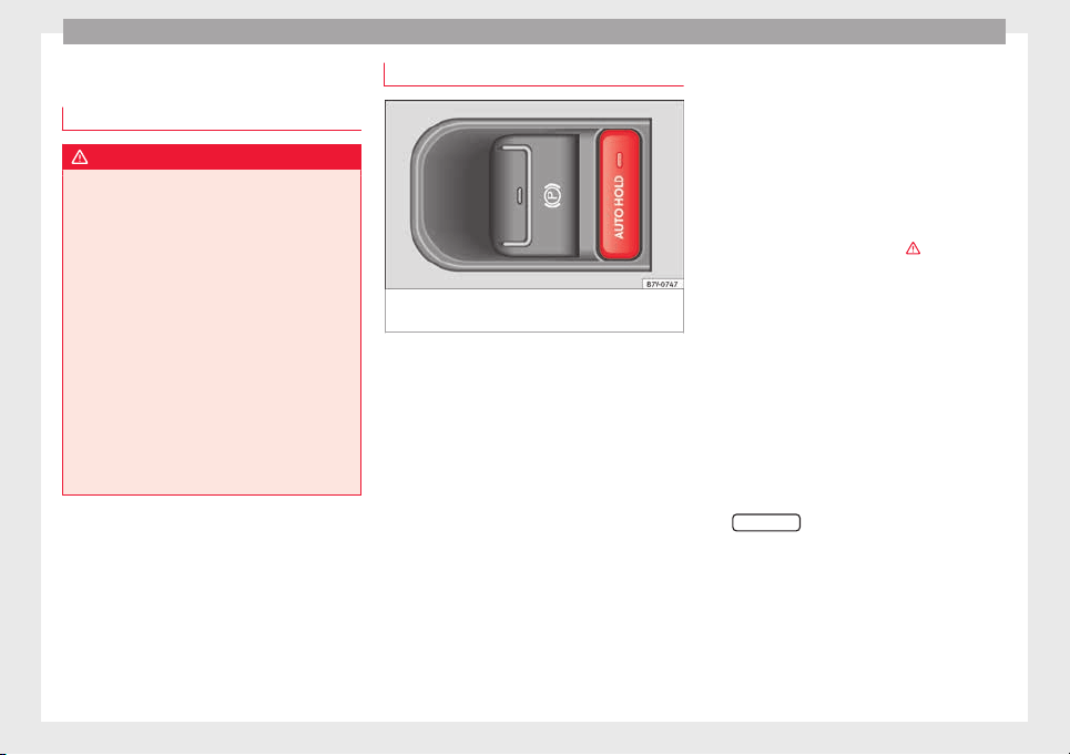
Operation
Start assist systems
Intr
oduction
WARNING
The intelligent technology in the start assist
syst
ems cannot change the laws of physics.
The improved comfort provided by start as-
sist systems should not prompt you to take
risks.
●
Unintentional movements of the vehicle
could cause serious injury.
●
The start assist systems are not a replace-
ment for driver awareness.
●
Always try to adapt the speed of the vehi-
cle and your style of driving to the condition
of the ground or the road and to weather and
traffic conditions.
●
The start assist system cannot keep the ve-
hicle stationary in all conditions on a gradi-
ent or cause it to brake on steep downhill
gradients, e.g. if the road is slippery or icy.
Auto Hold function*
Fig. 207 Detailed view of the centre console:
Aut
o Ho
l
d button
The control lamp on the button switches on
when the Aut
o Ho
l
d function is on.
When the Auto Hold function is on, this helps
the driver if they must regularly stop the vehi-
cle or if they must stop with the engine run-
ning for prolonged periods, for example, on
hills, before a traffic light or in traffic jams
with continuous stopping and starting.
The Auto Hold function automatically pre-
vents the vehicle from rolling away acciden-
tally when at a standstill, without the driver
having to keep his/her foot on the brake ped-
al.
When the system that detects that the vehi-
cle has stopped, the Auto Hold keeps the ve-
hicle at a standstill. The brake pedal can be
released.
If the driver presses the brake pedal briefly or
the accelerator to start off, the Auto Hold
function releases the brake once more. The
vehicle moves according to the gradient.
If any of the conditions necessary for the Au-
to Hold function change while the vehicle
stopped, the system is turned off as is the in-
dicator on the button ››› Fig. 207. The elec-
tronic parking brake engages where necessa-
ry to park the vehicle safely ›››
.
C
ondition
s
for keeping the vehicle at a
standstill with Auto Hold:
●
The driver door must be closed.
●
The driver seat belt must be buckled.
●
The engine must be running.
●
The ASR system is switched on
››› page 189.
Automatically engaging and disengaging the
Auto Hold function
If the Auto Hold function was engaged with
the
AUTO HOLD
button before disengaging the
ignition, the f
u
nction w
ill automatically re-
main engaged after the ignition is re-engag-
ed.
If the Auto Hold function was not disengag-
ed, it will automatically remain disengaged
after the ignition is engaged.
208
Driver assistance systems
Permanent Auto Hold connection
The Aut
o Ho
l
d function must be switched on
every time the engine is started. However, to
switch the Auto Hold function on permanent-
ly, the mark must be switched on in the Set-
tings menu, “Autohold” submenu
›››
page 26.
Auto Hold works automatically under the fol-
lowing conditions:
All points must be fulfilled simultaneously
›››
:
Manual gearbox Automatic gearbox
1. If the vehicle is stopped using the brake pedal on a
flat or slope.
2. The engine must be “running smoothly”.
3. On a slope, the 1st gear
is engaged uphill or the
reverse gear is engaged
for a downhill. The
clutch must be held
down.
A gear for driving is se-
lected from R, D or S.
Upon accelerating and
pressing in the clutch
simultaneously, the
brake releases gradual-
ly.
Upon accelerating, the
brake releases gradual-
ly.
Auto Hold turns off automatically under the
f
o
l
lowing conditions:
Manual gearbox Automatic gearbox
1. If one of the conditions mentioned in table on
page 209 changes.
2. If the engine is “not running regularly” or if there is
a malfunction.
3. When changing to idle
speed.
If the selector lever is
placed in neutral (N).
4. If the engine is turned
off or stalls.
If the engine is switch-
ed off.
5. If the driver accelerates
while pressing the
clutch in.
If the vehicle is acceler-
ated.
6. When one of the wheels
has minimal contact
with the ground (e.g. on
uneven ground).
WARNING
The Auto Hold technology is limited by the
law
s of physics. The improved comfort provi-
ded by Auto Hold should never prompt you to
take risks.
●
Never leave the vehicle running and with
the Auto Hold function switched on.
●
Auto Hold cannot always stop the vehicle
uphill and downhill (e.g. if the ground is slip-
pery or frozen).
CAUTION
Before entering an automatic car wash, al-
way
s switch the Auto Hold function off, as it
could be damaged when the electronic park-
ing brake automatically engages.
Start-Stop Function*
Fig. 208 Detailed view of the centre console:
St
ar
t
-Stop function button
With the Start-Stop system enabled, the en-
gine i
s
aut
omatically stopped when the vehi-
cle is at a standstill. The engine restarts auto-
matically when required.
The function is enabled automatically when-
ever the ignition is switched on. The instru-
ment panel displays information on the cur-
rent status.
»
209
Technical dataAdviceOperationEmergenciesSafety
Operation
Vehicles with a manual gearbox
●
When the vehicle is at a standstill, leave it
in neutr
al
and t
ake your foot off the clutch.
The engine switches off.
●
Simply depress the clutch pedal to move
off again.
Vehicles with an automatic gearbox
●
When the vehicle is at a standstill, depress
the brake or keep it pressed down. The en-
gine switches off.
●
The engine will start again as soon as you
release the brake pedal.
●
With the selector lever set to position P, the
engine will not start until a range of gears is
selected or the accelerator pedal is de-
pressed.
Important conditions for the engine to auto-
matically switch off
●
The driver seat belt must be buckled.
●
The driver door must be closed.
●
The bonnet must be closed.
●
The factory-fitted towing bracket must not
be electrically connected to a trailer.
●
A minimum engine temperature has been
reached.
●
The steering wheel must not be turned
more than 270 degrees.
●
The vehicle has moved since the last stop.
●
In vehicles with Climatronic: the tempera-
ture inside the vehicle is within the pre-set
temperature range.
●
The temperature set is neither very high nor
very low.
●
The air conditioning defrost function is not
switched on.
●
In vehicles with Climatronic: the blower has
not been manually set to a high speed.
●
The power level of the vehicle's battery is
sufficient.
●
The vehicle's battery temperature is neither
too high nor too low.
●
The vehicle is not on a steep gradient or
slope.
●
The front wheels are not overly turned.
●
The heated windscreen is not switched on.
●
Reverse gear is not engaged.
●
The park assist system is not switched on.
Conditions for automatically restarting the
engine
The engine may automatically restart under
the following conditions:
●
If the vehicle interior is too hot or too cold.
●
If the vehicle moves.
●
If the vehicle's battery voltage drops.
Conditions requiring the key to restart the
engine
The engine must be started manually under
the following conditions:
●
If the driver unbuckles his/her seat belt.
●
If the driver door is opened.
●
If the bonnet is opened.
●
In vehicles with a manual gearbox: if a gear
has been selected.
Switching Start-Stop mode on and off man-
ually
●
Press the
button on the centre console
›
›
›
Fig. 208.
●
The button will light up when the Start-Stop
function is switched off.
The engine will start immediately if the vehi-
cle is in Stop mode when it is switched off
manually.
WARNING
The brake servo and the power steering do
not work
when the engine is switched off.
●
Never allow the vehicle to move when the
engine is switched off.
CAUTION
Using the Start-Stop function for a long peri-
od at v
ery high outside temperatures could
damage the vehicle's battery.
210
Driver assistance systems
Note
●
In some case
s, you may have to restart the
vehicle using the key. Observe the corre-
sponding message on the instrument panel
display.
●
If the steering wheel is turned more than
270°, Stop will not function; however, the an-
gle of steering wheel turn does not affect
starting the vehicle.
Parking distance warning sys-
t
em*
Intr
oduction
The parking distance warning system assists
the driv
er when p
ark
ing. When the vehicle
approaches an obstacle, forwards or back-
wards, an intermittent audible warning will
be heard, higher or lower depending on the
distance. The shorter the distance, the short-
er the intervals between tones. If the vehicle
is too close to the obstacle, the audible warn-
ing becomes constant.
If you continue to approach an obstacle when
the sound is continuous, this means the sys-
tem can no longer measure the distance.
The sensor system on the bumpers transmit
and receive ultrasound. Using the ultrasound
signal (transmission, reflection from the ob-
stacle and reception), this system continu-
ously calculates the distance between the
bumper and the obstacle.
WARNING
The parking distance warning system and the
optical
parking system cannot replace driver
awareness.
●
The sensors have blind spots in which ob-
stacles and people are not registered.
●
Always observe the area around the vehi-
cle, as the sensors do not always detect
small children, animals or objects.
●
The surface of certain objects and some
clothing do not reflect the ultrasound signals
from the parking distance system. The sys-
tem cannot detect or incorrectly detects
these objects and people wearing these
types of clothes.
●
External sound sources can affect the park-
ing distance aid signals. In this case, under
certain circumstances, people and objects
will not be detected.
CAUTION
●
The sensors
may not always be able to de-
tect objects such as trailer draw bars, thin
rails, fences, posts, trees and open boots,
etc. This could result in damage to your car.
●
Although the parking distance warning sys-
tem detects and warns of the presence of an
obstacle, the obstacle could disappear from
the angle of measurement of the sensors if it
is too high or low and the system would no
longer show it. Therefore, it will not warn you
of these o
bjects. Ignoring the warnings of the
parking sensor system could cause consider-
able damage to the vehicle.
●
The bumper sensors may become damaged
or misaligned, for example, when parking.
●
To ensure that the system works properly,
the bumper sensors must be kept clean, free
of ice and snow and uncovered.
●
When cleaning the sensors with high-pres-
sure or steam cleaning equipment, spray the
sensors briefly at a distance of no less than
10 cm (4 inches).
Note
Acoustic sources may lead to erroneous warn-
ings
on the parking sensor system, e.g.
rough tarmac, cobbles or the noise of other
vehicles.
211
Technical dataAdviceOperationEmergenciesSafety

Operation
Parking distance warning system*
Fig. 209 Detailed view of the centre console:
b
utt
on f
or switching the parking distance
warning system on and off
Fig. 210 Parking sensor system sensors on
the fr
ont
b
umper
The parking distance warning system assists
the driv
er when p
ark
ing. If the vehicle is ap-
proaching an obstacle, an intermittent audi-
ble warning is emitted. The shorter the dis-
tance, the shorter the intervals between
tones. If the vehicle is too close to the obsta-
cle, the audible warning becomes constant.
Switching the parking distance warning sys-
tem on and off
●
Press the
button ›
›› Fig. 209
when the
ignition i
s switched on.
●
Automatic on: select reverse gear.
●
Automatic off: drive faster than 15 km/h
(9 mph).
The button lights up when the function is
switched on.
Things to note on the parking distance warn-
ing system
●
The parking distance warning system
sometimes registers water on the sensors as
an obstacle.
●
If the distance does not change, the warn-
ing signal will sound less loudly after a few
seconds. If the continuous signal sounds, the
volume will remain constant.
●
When the vehicle moves away from the ob-
stacle, the beeping sound automatically
switches off. On approaching the obstacle
again, the beeping sound will automatically
switch back on.
●
If the electronic parking brake is engaged
or the selector lever is set to P, no audible
warning will be emitted.
●
Your technical service centre can adjust the
volume of the warning signals.
Note
If the parking distance warning system is
faulty
, a constant audible warning will be
emitted the first time it is switched on and
the button will flash. Switch the parking dis-
tance warning system off using the button
and take the vehicle to a specialised work-
shop to have the system checked as soon as
possible.
212
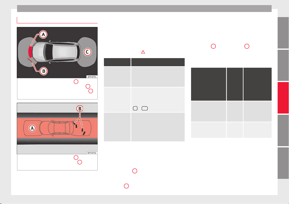
Driver assistance systems
Optical parking system* (OPS)
Fig. 211 On-screen OPS display:
A
has de-
t
ect
ed an o
bstacle in the collision zone;
B
has detected an obstacle in the segment;
C
zone recorded behind the vehicle.
Fig. 212 On-screen OPS display:
A
has de-
t
ect
ed an o
bstacle in the segment;
B
restric-
t
ed ar
e
a in front of the vehicle.
The optical parking system is an accessory to
the P
ark
in
g distance warning system
››› page 212 and the park assist system
››› page 214.
The zone recorded by the sensors in front of
and behind the vehicle is displayed on the
factory-fitted radio or navigation system
screen. Any obstacles are displayed in rela-
tion to the vehicle ›››
.
Function Necessary operations
Switching the
display on:
Switch on the parking distance
warning system ››› page 212 or the
park assist system ››› page 214. The
OPS switches on automatically.
Switching the
display off man-
ually:
Press a zone selection button on the
factory-fitted radio or navigation
system
OR: briefly press the function button
or
RVC
on the screen.
Switching the
display off man-
ually:
Drive forwards at more than about
10-15 km/h (6-9 mph).
Select the reverse gear on vehicles
with rear assist ››› page 217. The
display changes to the image of the
camera.
Zones explored
The
z
one in whic
h obstacles are recognised
runs to a distance of around 120 cm from the
front of the vehicle and up to 60 cm to the
side
›››
Fig. 212
B
. Behind the vehicle, the
z
one an
aly
sed reaches a distance of up to
160 cm and around 60 cm to the sides
›››
Fig. 211
C
.
Screen display
The im
ag
e di
splayed represents the super-
vised zones in several segments. As the vehi-
cle moves closer to an obstacle, the segment
moves closer to the vehicle displayed
››› Fig. 211
B
and ›
›› Fig. 212
A
. When the
penu
ltim
at
e segment is displayed, this
means that the vehicle has reached the colli-
sion zone. Stop the vehicle!
Distance from the
vehicle to the ob-
stacle
Audible
warn-
ing
Displayed in
colour on the
screen: colour
of the segment
if an obstacle
is recognised
Front: approx. 31 -
120 cm
Behind: approx. 31 -
160 cm
Beeping
sound
Yellow
Approximately 0 –
30 cm in front or be-
hind
a)
Perma-
nent
sound
Red
a)
The permanent sound starts at a somewhat greater distance
on vehicles with a factory-fitted towing bracket.
With towing bracket
A specific image is displayed on the screen of
vehicles with a factory-fitted towing bracket
and an electrically connected trailer. In this
case, the distances behind the vehicle are
not indicated.
»
213
Technical dataAdviceOperationEmergenciesSafety
Operation
Switching the parking sensor system sound
on and off
If
the
button on the radio or navigation
sy
s
t
em screen may mute the sound of OPS
warnings. To switch the warnings back on,
press the button again briefly.
When the OPS is switched off and back on
again, muting is cancelled. Error messages
cannot be switched off.
WARNING
Do not be distracted from the traffic when
looking at
the screen.
Park Assist system* (Park As-
s
i
s
t)
Introduction
The Park Assist system helps the driver to
find a s
uit
ab
le place to park, to insert the ve-
hicle into parallel and perpendicular parking
places and to leave parallel parking places.
The Park Assist system is limited to the sys-
tem abilities and requires that the driver is
especially attentive
›››
.
The p
ark
in
g sensor system is a component of
the Park Assist system that helps to park the
vehicle.
For vehicles with the optical parking system
(OPS), the radio navigation systems screen
displays the detected zones in front of and
behind the vehicle, indicating - within the
limits of the system - the position of obsta-
cles in relation to the vehicle.
The park assist system cannot be switched
on if the factory-fitted towing bracket is elec-
trically connected to a trailer.
WARNING
Despite the assistance provided by the park
ass
ist system, do not run any risks when
parking. The system is not a replacement for
driver awareness.
●
Unintentional movements of the vehicle
could cause serious injury.
●
Adjust your speed and driving style to visi-
bility, road, traffic and weather conditions.
●
The surface of certain objects and items of
clothing and external sound sources may
have a negative affect on the park assist sig-
nals or on the system sensors or may not re-
flect its signals.
●
The sensors have blind spots in which ob-
stacles and people are not registered.
●
Always observe the area around the vehi-
cle, as the sensors do not always detect
small children, animals or objects.
CAUTION
●
The park a
ssist system aims exclusively at
other parked vehicles, without taking curbs
or other circumstances into account. Make
sure you do not damage the tyres and wheel
rims when parking. Where necessary, stop
manoeuvring to avoid damaging the vehicle.
●
The sensors may not always be able to de-
tect objects such as trailer draw bars, thin
rails, fences, posts and trees, etc. This could
result in damage to your car.
●
Although the parking distance warning sys-
tem detects and warns of the presence of an
obstacle, the obstacle could disappear from
the angle of measurement of the sensors if it
is too high or low and the system would no
longer show it. Therefore, it will not warn you
of these objects. Ignoring the warnings of the
parking sensor system could cause consider-
able damage to the vehicle. This is also valid
when using the park assist (e.g. to park be-
hind a truck or motorcycle). Therefore, always
keep a close watch on the area in front of and
behind the vehicle while parking, and inter-
vene promptly if necessary.
●
To ensure that the system works properly,
the bumper sensors must be kept clean, free
of ice and snow and uncovered.
●
The bumper sensors may become damaged
or misaligned, for example, when parking.
●
When cleaning the sensors with high-pres-
sure or steam cleaning equipment, spray the
sensors briefly at a distance of no less than
10 cm.
214
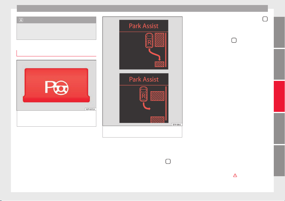
Driver assistance systems
Note
Contact a specialised workshop with any sys-
tem fau
lts. SEAT recommends taking your car
in for technical service.
Parking using the park assist system
Fig. 213 Detailed view of the centre console:
b
utt
on t
o switch the park assist system on
manually
Fig. 214 Gap detected: engage the reverse
g
e
ar t
o park (parallel or nose/tail to the kerb)
Preparing to park
●
The Traction control system ASR must be
t
urned on
›
›
›
page 189.
●
Parallel parking: press the button
at
s
peed
s
up to 50 km/h (31 mph) once. When
the function is enabled, the button
›››
Fig. 213 will light up.
●
Perpendicular parking: press the button
at speeds up to 50 km/h (31 mph) tw
ic
e
.
When the function is enabled, the button
››› Fig. 213 will light up.
●
If necessary, press the
button once
mor
e t
o c
hange parking mode.
●
Apply the turn signal for the side on which
a gap is to be detected for parking. The in-
strument panel displays the side correspond-
ing to the road.
Parking
●
Parking parallel to the road: drive next to
the gap at a speed of no more than 40 km/h
(25 mph) and at a distance of between 0.5 m
and 2 m.
●
Parking perpendicular to the road: drive
next to the gap at a speed of no more than
20 km/h (12 mph) and at a distance of be-
tween 0.5 m and 2 m.
●
The best parking results will be achieved if
you position the vehicle as parallel as possi-
ble to the line of parked cars or the kerb.
●
When a suitable parking place is displayed
on the instrument panel, stop and select re-
verse gear.
●
Follow the instructions given on the instru-
ment panel display
●
Then, release the steering wheel when the
warning signal sounds ›››
: The system
will move the steering wheel! Ob-
serve the surrounding area.
»
215
Technical dataAdviceOperationEmergenciesSafety
Operation
●
O
b
ser
ve the surrounding area and acceler-
ate carefully at a maximum of 7 km/h
(4 mph).
●
The park assist system is only responsible
for moving the steering wheel during the ma-
noeuvre. The driver applies the accelerator,
the clutch, the gears and the brake.
●
Follow the instructions given by the park
assist system until the manoeuvre is comple-
ted.
●
The park assist system steers the vehicle
forwards and backwards until it is in a
straight position in the parking space.
●
The manoeuvre is complete when the corre-
sponding indication is given on the instru-
ment panel display.
Stopping the parking manoeuvre
The park assist system stops the manoeuvre
in advance in the event of one of the follow-
ing:
●
Press button
.
●
Driving faster than 7 km/h (4 mph).
●
The driver moves the steering wheel.
●
The parking manoeuvre has not been com-
p
l
et
ed after 6 minutes since the park assist
system was activated.
●
A sliding door is opened. To restart the ma-
noeuvre, c
lose the sliding door and press the
button
again.
●
Ther
e i
s
a system malfunction (system tem-
porarily unavailable).
●
The ASR system is switched off or the ASR
or ESC is working.
WARNING
The steering wheel turns quickly by itself
when parkin
g using the park assist system.
Placing your hand between the steering
wheel spokes could lead to injuries.
Note
●
The park a
ssist system has its limitations.
For example, it is not possible to park on
tight bends using the park assist system.
●
Even if the park assist system recognises
that there is not enough space for parking
the vehicle, the instrument panel display will
still show this place. In this case, the parking
manoeuvre should not be requested.
●
Changing gears between forward and re-
verse gears before indicated (that is, before
the signal from the parking sensor system)
the parking results may not be ideal.
●
For parallel parking (parallel to the road), a
sound will tell the driver when they must
change from forward gears to reverse; the
signal from the parking sensor system does
not indicate changes of direction.
●
The park assist can also be activated after-
wards, if you pass close to a parallel parking
space at a maximum of 40 km an hour
(25 mph) or close to be perpendicular parking
space at about 20 km an hour (12 mph) then
pres
s the button
.
●
The progress bar on the screen of the in-
strument p
anel shows a display of the rela-
tive distance to be covered.
●
When the Park Assist system is turning the
steering wheel of the stopped vehicle the
symbol is also displayed. Press on the
brake pedal so that the steering can turn with
the vehicle at a standstill and thus reduce the
number of manoeuvres.
●
A “suitable” parking space length is at
least 1.1 m greater than the length of the ve-
hicle.
●
If the results of the park assist system are
not as good after changing the wheels, the
system must memorise the perimeter of the
new wheels. This process is performed auto-
matically while the vehicle is in motion. To
help this process, turn slowly (at less than
20 km/h [12 mph]), e.g. in an empty car park.
Leaving a parking space using the
P
ark
As
sist system
Driving off
●
Switch on the engine.
●
Press button
. When the function is ena-
b
l
ed, the b
utton ››› Fig. 213 will light up.
●
Apply the turn signal for the side on which
you want
to leave the parking space.
●
Select reverse gear.
216
Driver assistance systems
●
F
o
l
low the instructions given by the park
assist system.
●
When the next indication appears, release
the steering wheel ›››
in Parking using the
p
ark
a
ssist system on page 216: The sys-
tem will move the steering wheel!
Observe the surrounding area.
●
Observe the surrounding area and acceler-
ate carefully at a maximum of 7 km/h
(4 mph).
●
The park assist system is only responsible
for moving the steering wheel during the ma-
noeuvre. The driver applies the accelerator,
the clutch, the gears and the brake.
●
When it is possible to leave the parking
space, the Park Assist system will stop. Take
control of the steering and when traffic condi-
tions permit, leave the parking space.
Automatic stoppage of the manoeuvre
The park assist system stops the manoeuvre
in the event of one of the following:
●
Driving faster than 7 km/h (4 mph).
●
The driver moves the steering wheel.
●
A sliding door is opened. To restart the ma-
noeuvre, close the sliding door and press the
button
again.
●
There is a system malfunction (system tem-
por
ari
ly
unavailable).
●
The ASR system is switched off or the ASR
or ESC is working.
WARNING
The steering wheel turns quickly automatical-
ly when le
aving a parking space using the
park assist system. Placing your hand be-
tween the steering wheel spokes could lead
to injuries.
Park Assist brake operation
The Park Assist system helps the driver by
brakin
g automatically. Automatic braking
does not relieve the driver of responsibility
for controlling the accelerator, brake and
clutch
›››
.
Br
ak
in
g to avoid damage at excess speed
It is possible that the system operates the
brakes to reduce excess speed. The parking
manoeuvre can then continue. The brakes
will intervene during each parking process.
Braking to minimise damage
When approaching an obstacle, the vehicle
may brake automatically. In certain circum-
stances (e.g. storm, detection of ultrasounds,
vehicle status, load, inclination), the Park As-
sist system may stop the vehicle completely
before an object.
●
Press the foot brake
›››
!
Following the intervention of the brakes, the
P
ark
As
sist will stop.
WARNING
Despite the assistance provided by the park
ass
ist system, do not run any risks when
parking. The system is not a replacement for
driver awareness.
●
Always be ready to brake.
●
Automatic brake intervention will end after
1.5 seconds approximately. Following auto-
matic intervention of the brakes, stop the ve-
hicle yourself.
Rear assist* (Rear View Cam-
er
a)
Intr
oduction
The camera fitted to the rear lid helps drivers
durin
g p
ark
ing or reversing manoeuvres. The
camera image and certain orientation points
generated by the system are indicated on the
factory-fitted radio or navigation system
screen.
Two types of location point (modes) can be
selected:
●
Mode 1: reverse parking perpendicular to
the road (e.g. in a car park).
»
217
Technical dataAdviceOperationEmergenciesSafety
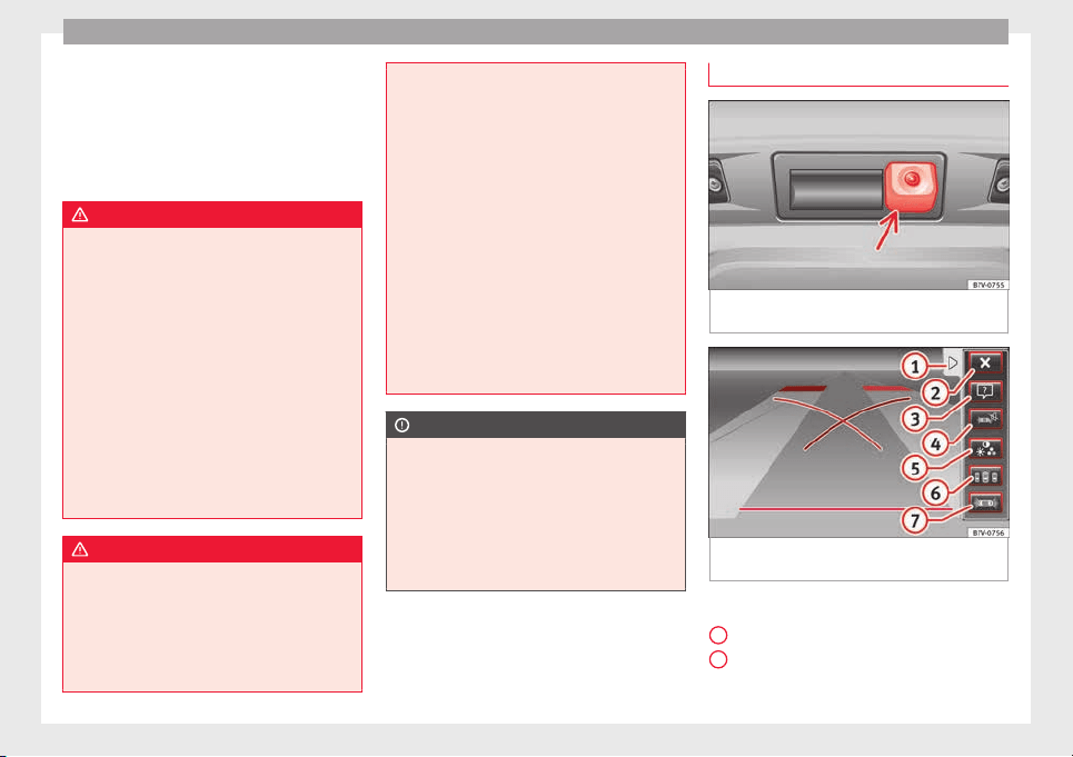
Operation
●
Mode 2: r
ev
er
se parking parallel to the
curb.
The mode can be changed by pressing the
button on the radio or navigation system
screen. Only the mode to which the points
can be changed will be displayed.
WARNING
Use of the camera to calculate the distance
from ob
stacles (people, vehicles, etc.) is inac-
curate and may cause accidents and severe
injuries.
●
The camera lens expands and distorts the
field of vision and displays the objects on the
screen in a different, vague manner.
●
Some objects may not be displayed or may
not be very clear (e.g. very thin posts or fen-
ces), due to the resolution of the monitor or if
the light is dim.
●
The camera has blind spots in which obsta-
cles and people are not detected.
●
Keep the camera lens clean and clear of
snow and ice. Do not cover it.
WARNING
The intelligent technology in the rear assist
syst
em cannot change the limits imposed by
the laws of physics and by the system itself.
Careless or uncontrolled use of the rear assist
system may result in severe injuries and acci-
dents. The system is not a replacement for
driver awareness.
●
Adjust
your speed and driving style to visi-
bility, road, traffic and weather conditions.
●
Always keep a close eye on the area around
the vehicle and always look towards where
you are parking. The display shows the path
of the rear end of the vehicle using the cur-
rent steering angle. The front of the vehicle
turns more in comparison with the rear.
●
Do not be distracted from the traffic when
looking at the screen.
●
Always observe the area around the vehi-
cle, as the cameras do not always detect chil-
dren, animals or objects.
●
The system might not show all areas clear-
ly.
●
Only use the rear assist system when the
boot hatch is completely closed.
CAUTION
●
The camera on
ly displays 2D images on the
screen. Due to the lack of depth, it might be
difficult or impossible to recognise protrud-
ing objects or cracks in the road.
●
The cameras may not always be able to de-
tect objects such as thin rails, fences, posts
and trees, etc. This could result in damage to
your car.
Instructions for use
Fig. 215 On the rear lid: location of the rear
a
s
s
ist camera
Fig. 216 Rear assist display: mode 2 connec-
t
ed
Function buttons on the screen:
di
s
p
lay the menu;
hide the menu.
Turning off the reversing camera im-
ages
1
2
218
Driver assistance systems
Display help. The help list explains the
s
ur
f
aces and lines on the camera image.
Press to exit help.
Mute the sound.
Adjust the display: brightness, contrast,
colour.
Switching on the orientation points for
rear parking perpendicular to the road
(mode 1).
Displaying the optical parking system.
Operations in vehicles with no optical parking
system (OPS)
Switching the dis-
play on automati-
cally:
Select reverse gear with the igni-
tion switched on or the engine run-
ning. Mode 1 will be displayed.
Switching the dis-
play off manually:
Press a button to select the area on
the radio or the navigation system
››› Booklet Radio or ››› Booklet Navi-
gation system.
OR: press the button
on the
screen.
OR: after switching off the ignition,
the rear assist image remains on
the screen for a short period.
Switching off the
display by disen-
gaging reverse
gear:
The image will switch off after
around 10 seconds.
Switching off the
display by driving
forwards:
Drive forwards at more than ap-
prox. 15 km/h (9 mph).
3
4
5
6
7
Operations in vehicles with the optical parking
system (OPS)
Switching the dis-
play on automati-
cally:
Select reverse gear with the igni-
tion switched on or the engine run-
ning. Mode 1 will be displayed.
Switching the dis-
play off manually:
Press a button to select the area on
the radio or the navigation system
››› Booklet Radio or ››› Booklet Navi-
gation system.
OR: press the button
on the
screen.
OR: after switching off the ignition,
the rear assist image remains on
the screen for a short period.
Press button
.
Switching off the
display by disen-
gaging reverse
gear:
The OPS display will immediately
be shown.
Switching off the
display by driving
forwards:
Drive forwards at more than ap-
prox. 10 km/h (6 mph).
Things to note
1) Do not use the rear assist system in the fol-
lowing cases:
– If there is a fault in the dynamic chassis control (DCC).
– If the image displayed is not very clear or reliable (low
visibility or dirty lens).
– If the space behind the vehicle cannot be clearly or
completely recognised.
1) Do not use the rear assist system in the fol-
lowing cases:
– If the vehicle has been overloaded at the rear.
– If the driver is not familiar with the system.
– If the rear lid is open.
– If the position and installation angle of the camera
have been changed, e.g. in a rear-end collision. Have a
specialised workshop check the system.
2) Optical illusions of the camera (examples)
The rear assist camera produces two-dimensional im-
ages. Any cracks in or objects protruding from the
ground or from other vehicles are more difficult to spot
or cannot be seen due to a lack of depth in the image
displayed.
Objects or other vehicles may seem to be closer or fur-
ther away than what they really are:
– On changing from a flat surface to a slope or gradient.
– On changing from a slope or gradient to a flat surface.
– If the vehicle has been overloaded at the rear.
– On approaching protruding objects. These objects
may be outside the angle of vision of the camera when
reversing.
Cleaning the camera lens
K
eep the c
amer
a lens clean and clear of snow
and ice:
●
Moisten the lens using a commercially
available, alcohol-based glass cleaning
»
219
Technical dataAdviceOperationEmergenciesSafety
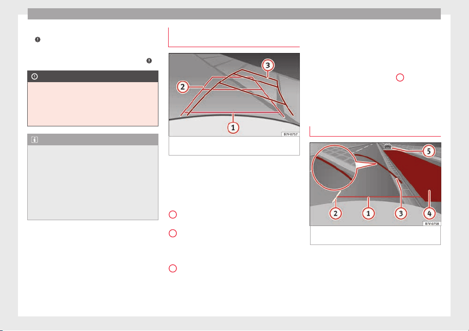
Operation
agent and clean the lens with a dry cloth
›
›
›
.
●
Remove snow using a small brush.
●
Use de-icing spray to remove any ice ›
›
›
.
CAUTION
●
Never use abr
asive cleaners to clean the
camera lens.
●
Never remove snow or ice from the camera
lens using warm or hot water. This could
damage the lens.
Note
●
SEAT r
ecommends that you practise park-
ing with the rear assist system in a quiet lo-
cation or in a car park to become familiar with
the system, including the orientation lines
and their function.
●
The orientation lines will not be displayed
on the screen if the rear lid is open or the fac-
tory-fitted towing bracket is electrically con-
nected to a trailer.
Parking perpendicular to the road
(mode 1)
Fig. 217 Display: orientation lines for the
p
ark
in
g space behind the vehicle
Summary of the orientation points
M
e
anin
g of orientation lines displayed on the
screen ››› Fig. 217. All of the lengths of the
orientation lines use a vehicle located on a
horizontal surface as reference.
Red: safety distance, i.e. road area loca-
ted up to 40 cm behind the vehicle.
Green: prolongation of the rear of the ve-
hicle (somewhat enlarged). The area dis-
played green ends around 2 metres be-
hind the vehicle, on the road.
Yellow: prolongation of the rear of the ve-
hicle as the steering wheel turns. The
area displayed yellow ends around 3 me-
tres behind the vehicle, on the road.
1
2
3
Parking
●
Stop the vehicle in front of a space and se-
l
ect
r
everse gear.
●
Reverse slowly and turn the steering wheel
so that the yellow orientation lines guide you
towards the space ››› Fig. 217
3
.
●
Align the vehicle straight in the parking
p
l
ac
e using the help of the green orientation
lines.
Parking parallel to the road (mode 2)
Fig. 218 Display: orientation lines and surfa-
c
e
s
for the space behind the vehicle
After applying the turn signal, the lines and
s
ur
f
aces not required are deleted.
Summary of the orientation points
Meaning of orientation lines and surfaces
displayed on the screen ››› Fig. 218. All of the
220
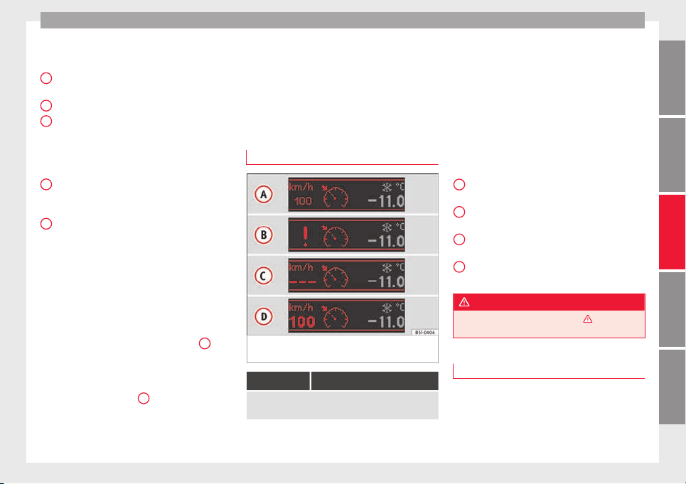
Driver assistance systems
lengths of the orientation lines use a vehicle
loc
at
ed on a horiz
ontal surface as reference.
Safety distance: road area located up to
around 40 cm behind the vehicle.
Vehicle side limit.
Turning point when parking. When the
yellow line touches the curb or another
limit of the parking space, the point for
changing direction (magnifying glass)
will have been reached.
Free space required to parallel park the
vehicle. The surface displayed must com-
pletely fit in the space.
Possible vehicle parked next to the curb.
Parking
●
Stop the vehicle 1 m away parallel to the
parking space and select reverse gear.
●
Switch on mode 2 on the navigation system
screen for parallel parking.
●
Slowly reverse and turn the steering wheel
so that the surface displayed yellow on the
screen stops in front of any obstacles
5
(e.g. another vehicle).
●
Turn the steering wheel fully towards the
s
p
ac
e and reverse slowly.
●
When the yellow line
3
touches the side
limit
of
the s
pace, e.g. the border or curb
(magnifying glass), turn the steering wheel
fully in the opposite direction.
1
2
3
4
5
●
C
ontinue r
ev
ersing until the vehicle is in-
side the space, parallel to the road. Correct
the position if necessary.
Cruise control* (Cruise control
system - CCS)
Warning and control lamp
Fig. 219 Instrument panel display: CCS status
indic
ation
s
It lights up
This cruise control system maintains the set speed of
the vehicle.
Several warning and indication lamps light
up f
or a f
ew sec
onds when the ignition is
switched on, signalling that the function is
being verified. They will switch off after a few
seconds.
Indication on display
There are different versions of the cruise con-
trol system. In vehicles with the multifunction
display (MFI), the set speed is displayed on
the instrument panel screen.
Status Fig. 219:
CCS temporarily switched off. The set
speed is displayed in small figures.
System error. Contact a specialised work-
shop.
CCS switched on. The speed memory is
empty.
The CCS is switched on. The set speed is
displayed in large figures.
WARNING
Observe the safety warnings ›››
in Warning
and indication lamp
s on page 105.
Cruise control system operation
Read the additional information carefully
›
›
›
page 32
The cruise control system (CCS) is able to
maintain the set speed when driving for-
wards from approx. 20 km/h (12 mph).
»
A
B
C
D
221
Technical dataAdviceOperationEmergenciesSafety
Operation
The CCS only slows down by reducing the ac-
c
el
er
ator but not by braking ›››
.
T
r
av
elling down hills with the CCS
When travelling down hills the CCS cannot
maintain a constant speed. Slow the vehicle
down using the brake pedal and reduce
gears if required.
Automatic off
The cruise control system (CCS) is switched
off automatically or temporarily:
●
If the system detects a fault that could af-
fect the working order of the CCS.
●
If you increase the stored speed by using
the accelerator for a certain time.
●
if the brake or clutch pedal is depressed.
●
If you change gears.
●
If the airbag is triggered.
WARNING
Use of the cruise control could cause acci-
dents and sev
ere injuries if it is not possible
to drive at a constant speed maintaining the
safety distance.
●
Do not use the cruise control in heavy traf-
fic, if the distance from the vehicle in front is
insufficient, on steep roads, with several
bends or in slippery circumstances (snow,
ice, rain or loose gravel), or on flooded roads.
●
Never use the C
CS when driving off-road or
on unpaved roads.
●
Always adapt your speed and the distance
to the vehicles ahead in line with visibility,
weather conditions, the condition of the road
and the traffic situation.
●
To avoid unexpected operation of the cruise
control system, turn it off every time you fin-
ish using it.
●
It is dangerous to use a set speed which is
too high for the prevailing road, traffic or
weather conditions.
●
When travelling down hills, the CCS cannot
maintain a constant speed. The vehicle tends
to accelerate under its own weight. Select a
lower gear or use the foot brake to slow the
vehicle.
Lane Assist system*
Intr
oduction
WARNING
The intelligent technology in the lane assist
syst
em cannot change the limits imposed by
the laws of physics and by the system itself.
Careless or uncontrolled use of the Lane As-
sist system may cause accidents and injury.
The system is not a replacement for driver
awareness.
●
Alwa
ys adapt your speed and the distance
to the vehicles ahead in line with visibility,
weather conditions, the condition of the road
and the traffic situation.
●
Always keep your hands on the steering
wheel so you can turn it at any time.
●
The lane assist system does not detect all
road markings. In some circumstances, the
poor state of the road, structures located on
it or certain objects may be mistakenly recog-
nised as road markings by the lane assist
system. In such situations, switch the lane
assist system off immediately.
●
Pay attention to the instructions on the in-
strument panel display and act accordingly to
its requests.
●
Always pay attention to the vehicle's sur-
roundings.
Note
The lane assist system has been exclusively
developed for driv
ing on asphalted roads.
Note
If the lane assist system does not work as de-
scribed in thi
s chapter, do not use it and con-
tact a specialised workshop.
Note
If you observe any system malfunction, have
the syst
em checked by a specialised work-
shop.
222
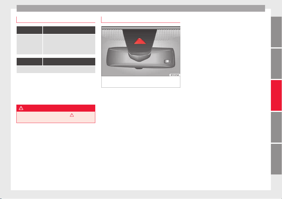
Driver assistance systems
Control lamps
Blinks or lights up yellow:
Lane assist sys-
tem connected
but inactive.
The system cannot clearly detect the
lane. See page 223, The lane assist
system is inactive (control lamp lit
in yellow).
Blinks or lights up green:
Lane assist system connected and active.
Several warning and indication lamps light
up f
or a f
ew sec
onds when the ignition is
switched on, signalling that the function is
being verified. They will switch off after a few
seconds.
WARNING
Observe the safety warnings ›››
in Warning
and indication lamp
s on page 105.
Operation mode
Fig. 220 In the windscreen: field of vision of
the l
ane a
s
sist system camera.
Using the camera located in the sun visor,
the l
ane a
s
sist system detects the possible
lines dividing it. When the vehicle involuntar-
ily approaches a dividing line it has detected,
the system will notify the driver with a correc-
tive intervention. It is possible to over-regu-
late the corrective intervention at any time.
If the turn signal is connected, there will be
no warning as the lane assist system under-
stands that you wish to change lanes volun-
tarily.
Steering wheel vibration
The following situations cause the steering
wheel to vibrate and require the driver to take
active control of the steering:
●
If the limits inherent to the system are
reached.
●
If the maximum rotational torque during
the corrective intervention is not enough to
keep the vehicle inside the lane.
●
If during the corrective intervention by the
system the lane is no longer detected.
Switching the lane assist system on or off
●
Select the corresponding menu option us-
ing the button for the driver assist systems
›››
page 26.
●
OR: activate or deactivate the system in the
menu Settings, sub-menu Assist sys-
tems, menu Lane Assist ›››
page 26.
The “confirmation sign” indicates that the
driver assist system is switched on.
Automatic deactivation: the lane assist sys-
tem can be deactivated automatically if there
is a system malfunction. Control lamp
switches off.
The lane assist system is inactive (control
lamp lit in yellow)
●
When driving speed drops to approx.
65 km/h (40 mph).
●
When the Lane Assist system does not de-
tect the dividing lines of the road. For exam-
ple, in the event of road works, and snow,
dirt, moisture or reflections.
●
When the radius of a curve is too small.
»
223
Technical dataAdviceOperationEmergenciesSafety

Operation
●
When ther
e i
s
no dividing line.
●
When the distance to the next dividing line
is excessive.
●
When there are more than two lane mark-
ings per lane.
●
When the ASR is switched off.
●
When the system does not detect any ac-
tive rotation of the steering wheel by the driv-
er during a prolonged period.
●
Temporarily, in the event of very dynamic
driving.
●
When the turn signal is connected.
Note
●
Befor
e starting travel, verify that the cam-
era's field of vision is not covered ››› Fig. 220.
●
Keep the camera window clean.
Disconnect the lane assist system in
the f
o
l
lowing situations
Due to the limits of the Lane Assist system,
sw
it
c
h it off in the following situations:
●
When more attention is required of the
driver
●
For very sporty driving
●
In very unfavourable weather conditions
●
In very unfavourable road conditions
●
In areas of road works
224
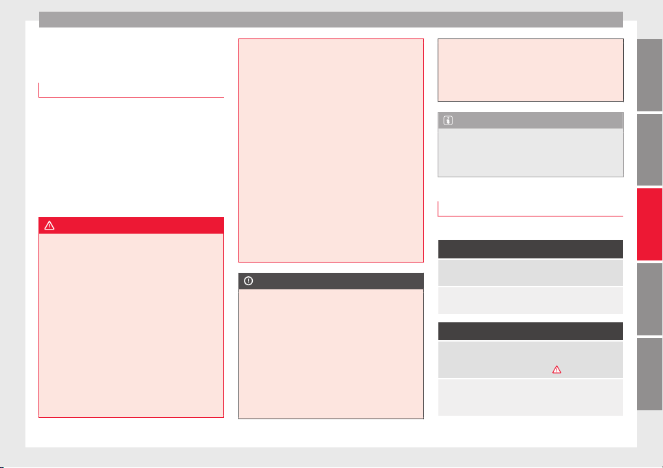
Driver assistance systems
Blind spot detector (BSD) with
p
ark
in
g assistant (RTA)
Introduction
The blind spot detector (BSD) helps detect
the traffic s
ituation to the sides and behind
the vehicle.
The integrated parking assistant (RTA) helps
the driver when backing out of a parallel
parking spot and in manoeuvring.
The blind spot detector has been developed
for driving on paved roads.
WARNING
The smart technology incorporated into the
blind spot
detector (BSD) with parking assis-
tance (RTA) included cannot overcome the
limits imposed by the laws of physics; it only
works within the limits of the system. Acci-
dents and severe injury may occur if the blind
spot detection system or the parking assis-
tant are used negligently or involuntarily. The
system is not a replacement for driver aware-
ness.
●
Adapt your speed and safe distance to the
vehicle in front of you at all times to suit visi-
bility, weather, road and traffic conditions.
●
Keep your hands on the wheel at all times,
and be ready to intervene in the steering at
any time.
●
Pay
attention to the control lamps that may
come on in the external rear view mirrors and
on the instrument panel, and follow any in-
structions they may give.
●
The blind spot assistant may react in the
face of any special constructions that may be
present on the sides of the vehicle: e.g., high
or irregular protective fences. This may cause
erroneous warnings.
●
Never use the blind spot detector with
parking assistance on unpaved roads. The
blind spot detector with parking assistance
has been designed for use on paved roads.
●
Always pay attention to the vehicle's sur-
roundings.
●
Never use the blind spot detector with
parking assistance if the radar sensors are
dirty, covered or damaged. The system may
work incorrectly in these cases.
CAUTION
●
The rad
ar sensors on the rear bumper may
be damaged or shifted in the event of a colli-
sion, for example, when entering or exiting a
parking space. This may result in the system
disconnecting itself, or at least having its
functionality diminished.
●
In order to ensure that the radar sensors
work properly, keep the rear bumper free of
snow and ice and do not cover it.
●
The rear bumper should only be painted
with paint authorised by SEAT. The blind spot
detector's functions may be limited or work
incorrectly
if other paints are used.
●
The external rear view mirror control lamps
may have their functionality limited in the
event of solar radiation.
Note
If the blind spot detector with the parking as-
s
is
tant does not work as described in this
chapter, do not use it and have it checked by
a specialised workshop.
Control lamps
Control lamp in external rear view mirrors:
Lights up
Lights up once briefly: the blind spot detector is activa-
ted and ready to operate.
Lights up: blind spot detector has detected a vehicle in
the blind spot.
Flashes
The blind spot detector has detected a vehicle in the
blind spot and the turn signal has been turned on in the
direction of the detected vehicle ›››
.
For vehicles that are also equipped with Lane Assist
››› page 222, a warning to switch lanes will also appear
even though the turn signal has not been engaged.
»
225
Technical dataAdviceOperationEmergenciesSafety
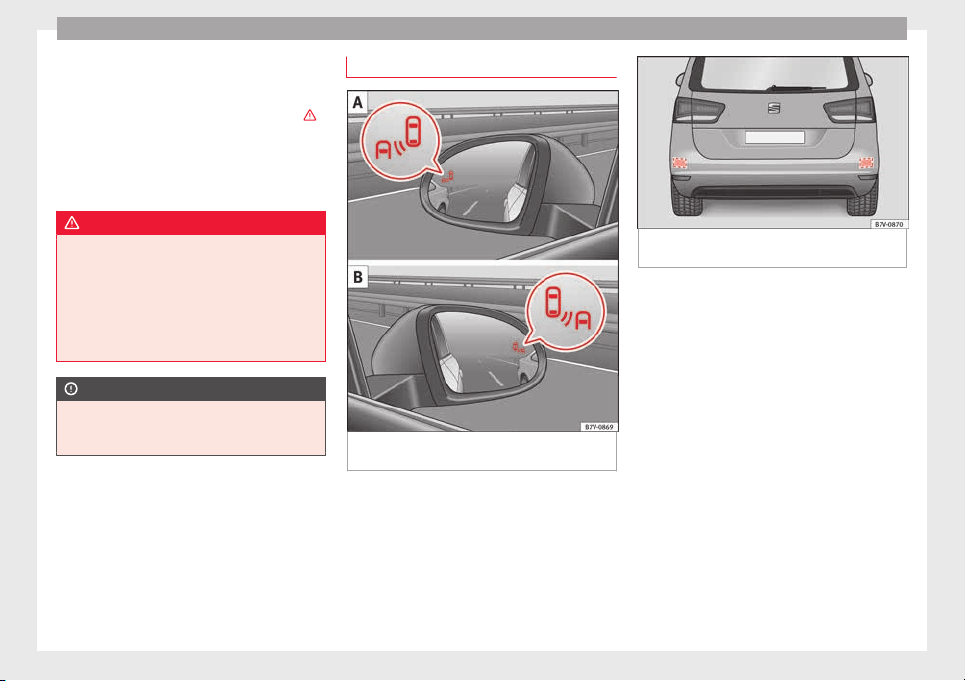
Operation
If there are no indications from the control
l
amp in the e
xt
ernal rear view mirror, this
means that the blind spot detector has not
detected any other vehicles in the area ›››
in Introduction on page 225.
If
the dip
ped be
am is on, then the control
lamps in the external rear view mirrors will be
dimmed (night mode).
WARNING
If the warning lamps and the corresponding
mess
ages are ignored when they light up, the
vehicle may stall in traffic and cause acci-
dents and severe injuries.
●
Never ignore the warning lamps or messag-
es.
●
Carry out the necessary operations.
CAUTION
Failure to heed the control lamps and corre-
sponding t
ext messages when they light up
may result in damage to the vehicle.
Blind spot detector (BSD)
Fig. 221 In the exterior mirrors: indication of
the b
lind s
pot
detector.
Fig. 222 Rear view of the vehicle: radar sen-
sor zone
s.
The Blind spot detector uses radar sensors to
monit
or the ar
e
as to the side and behind the
vehicle. The system does this by measuring
the vehicle's distance from other vehicles
and its speed differential. The blind spot de-
tector will not work at speeds of less than ap-
prox. 15 km/h (9 mph). The system uses opti-
cal signals in the external rear view mirrors to
notify the driver.
Indication in the external rear view mirrors
The control lamp (expanded view) provides
an indication in the corresponding external
mirror ››› Fig. 221 regarding the traffic situa-
tion behind the vehicle, if it is deemed to be
critical. The control lamp of the left-hand ex-
ternal mirror A indicates the traffic situation
to the left of the vehicle, and the control lamp
of the right-hand external mirror B, indicates
the traffic situation to the right of the vehicle.
226

Driver assistance systems
In the case of tinted windows or windows
w
ith tint
ed fi
lm, the indications of the exter-
nal mirrors may not be seen clearly or correct-
ly.
Keep the external mirrors clean and free of
snow and ice, and do not cover them with ad-
hesives or other similar materials.
Radar sensors
The radar sensor are located on the left and
right of the bumper, and are not visible from
the outside ››› Fig. 222. The sensors have a
range of approx. 20 metres behind the vehi-
cle, including the blind spots to the left and
right of the vehicle. The range to the sides of
the vehicle is roughly larger than the width of
a lane.
The lane width is not detected individually,
but is rather pre-configured in the system.
Thus if you are driving in wide lanes or in be-
tween two lanes, the indications may be in-
correct. Furthermore, the system can detect
vehicles driving in the lane next to you (if
there are any), and can also detect stationary
objects such as dividers, and thus give an in-
correct indication.
227
Technical dataAdviceOperationEmergenciesSafety

Operation
Driving conditions
Fig. 223 Schematic diagram: Pas
sing sit-
uation with traffic behind the vehicle. Indi-
cation from the blind spot detector in the left-
hand external mirror.
Fig. 224 Schematic diagram: Situation of
pa
ssing and then moving into the right-hand
lane. Indication from the blind spot detec-
tor in the right-hand external mirror.
In the following situations, an indication will
be di
s
p
layed in the external mirror ››› Fig. 223
B (arrow) or ››› Fig. 224 B (arrow):
●
When being passed by another vehicle
››› Fig. 223 A.
●
When passing another vehicle ››› Fig. 224 A
with a speed differential of approx. 10 km/h
(6 mph). If the vehicle is passing at a consid-
erably higher speed, no indication will be
displayed.
The faster the vehicle approaches, the sooner
an indication will be displayed in the external
mirror, because the blind spot detector takes
into account the speed differential with other
vehicles. Thus even though the distance from
the other vehicle is identical, the indication
will appear sooner in some cases and later in
others.
Physical limitations inherent to the system
In some situations the blind spot detector
may not interpret the traffic situation correct-
ly. E.g. in the following situations:
●
on tight bends
●
in the case of lanes with different widths
●
at the top of slopes
●
in adverse weather conditions
228
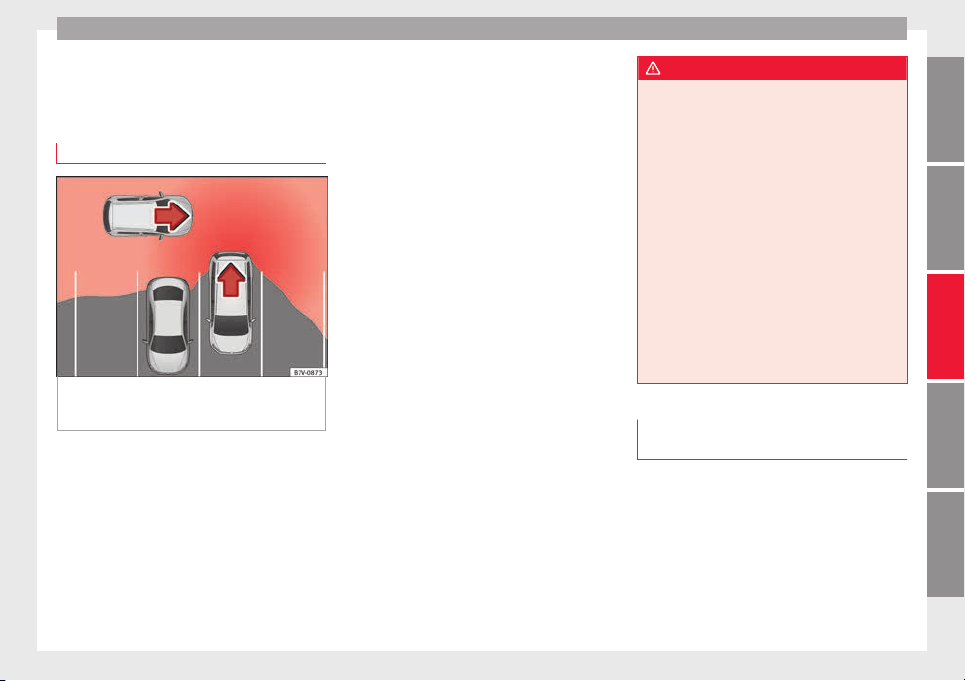
Driver assistance systems
●
in the c
a
se of
special constructions to the
side of the vehicle, e.g., high or irregular di-
viders
Parking assistant (RTA)
Fig. 225 Schematic representation of the
p
ark
in
g assistant: monitored zone around the
vehicle being parked.
The parking assistant uses the radar sensors
on the r
e
ar b
umper ››› Fig. 222 to monitor the
traffic crossing behind the vehicle as it backs
out of a parallel parking space or as it is be-
ing manoeuvred, for example in very low visi-
bility conditions.
If the system detects that someone else on
the road is approaching the rear of the vehi-
cle ››› Fig. 225, an acoustic alarm will sound.
●
In vehicles without ParkPilot a “gong” will
sound and a message will be displayed on
the instrument panel.
●
If the vehicle is equipped ParkPilot, the
ParkPilot acoustic alarm will sound continu-
ously.
Automatic braking to reduce damages
If the system detects that someone else on
the road is approaching the rear of the vehi-
cle and the driver does not step on the brake,
the system will engage the brakes automati-
cally.
The parking system helps the driver by auto-
matically engaging the brakes to reduce any
damage. The system will brake automatically
if the vehicle is backing up at a speed of ap-
proximately 1-12 km (1-7 mph). Once it has
detected that the vehicle has stopped, the
system will keep the vehicle stopped for ap-
prox. 2 seconds.
After automatically braking to reduce dam-
age, the system will not be able to automati-
cally brake again for approximately 10 sec-
onds.
You can interrupt the automatic braking by
stepping forcefully on the accelerator pedal
or the brake pedal in order to regain control
of the vehicle.
WARNING
The smart technology incorporated into the
blind spot
detector cannot overcome the lim-
its imposed by the laws of physics; it only
works within the limits of the system. Do not
let the extra convenience afforded by the
parking assistant tempt you into taking any
risks. The system is not a replacement for
driver awareness.
●
The system should never be used in limited
visibility conditions or complicated traffic,
e.g., in high-traffic areas or when crossing
multiple lanes.
●
Be sure to always be aware of the vehicle's
surroundings, since the system is not guaran-
teed to detect things such as bicycles or pe-
destrians in all situations.
●
The parking assistant itself will not brake
the vehicle to a complete stop.
Using the blind spot detector (BSD)
w
ith p
ark
ing assistance (RTA)
Activating and deactivating the blind spot
det
ect
or (BSD) w
ith parking assistance (RTA)
The blind spot detector with parking assis-
tant can be activated or deactivated in the
“Assistants” menu of the SEAT information
system, or depending on the vehicle's equip-
ment, by using the driver assistance key loca-
ted on the headlight lever.
Open the Assistants menu.
»
229
Technical dataAdviceOperationEmergenciesSafety
Operation
●
BSD
●
P
arking Assist.
If
the
verification box on the control panel is
checked , the functionality will be automat-
ically activated at ignition.
When the blind spot detector is ready to op-
erate, the indications in the external mirrors
will turn on briefly as confirmation.
The control lamp of the instrument panel in-
dicates the system's status.
When the vehicle is restarted, the last adjust-
ment in the system will remain active.
If the blind spot detector was automatically
deactivated, it will only be possible to restart
the system after turning the vehicle off and
restarting it.
Automatic deactivation of the blind spot de-
tector (BSD)
The radar sensors of the blind spot detector
with parking assistant will be automatically
deactivated when, among other reasons, one
of the sensors is detected to be permanently
covered. This may be the case if, for example,
there is a layer of snow or ice in front of one
of the sensors.
The relevant text message will appear in the
dash panel display
Towing a trailer
The Blind spot detector and the parking as-
sistant will be automatically deactivated and
it will be impossible to activate them if the
tow hitch is electrically connected to a trailer
or other similar object.
As soon as the driver starts to drive with a
trailer connected electrically to the vehicle, a
message will appear on the instrument panel
display indicating that the blind spot detec-
tor and parking assistant are deactivated.
Once the trailer has been unhitched from the
vehicle, if you want to us the blind spot de-
tector and parking assistant, you will have to
reactivate them in the corresponding menu.
If the towing hitch is not factory equipped,
then the blind spot detector and parking as-
sistant will have to be deactivated manually
when driving with a trailer.
Traffic signal detection
(Sign Assist)*
Introduction
Sign Assist can help the driver with informa-
tion on s
peed limits
or if
overtaking is pro-
hibited at that moment. The traffic signs and
additional information detected by the sys-
tem is represented in the dash panel display
and in the visual presentation of the naviga-
tion system map.
Applicable countries:
Sign Assist is accepted in the following coun-
tries:
Andorra, Belgium, Denmark, Germany, Fin-
land, France, Ireland, Italy, Liechtenstein,
Luxembourg, Monaco, Netherlands, Norway,
Austria, Poland, Portugal, San Marino, Swe-
den, Switzerland, Spain, Czech Republic, Uni-
ted Kingdom, Vatican City.
WARNING
The traffic signs and instructions shown by
Sign Assi
st may differ from the current traffic
situation.
●
The signs and highway code rules always
take precedence over the instructions and
display of Sign Assist.
●
Adjust your speed and driving style to visi-
bility, road, traffic and weather conditions.
●
The system cannot always detect or cor-
rectly show all the traffic signs.
WARNING
The traffic sign detection is not a replacement
for driver a
wareness.
●
Adverse conditions of visibility, darkness,
snow, rain and fog can cause the system not
to show the traffic signs or to show them er-
roneously.
230
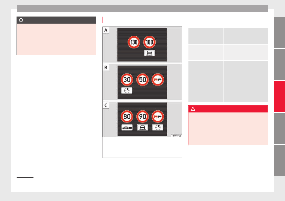
Driver assistance systems
CAUTION
●
If ol
d mapping data is used in the naviga-
tion system, this may cause the traffic signs
to be shown incorrectly.
●
In the route points mode (navigation by
route points) of the navigation system, Sign
Assist is only partly available.
Indication on display
1)
Fig. 226 Instrument panel display: Examples
of
s
peed limits
or overtaking prohibitions de-
tected together with the corresponding addi-
tional signs
Display text of Sign Assist on the instrument
p
anel
Error: Sign As-
sist
System fault.
Have the system checked by a
specialised workshop.
Sign Assist:
Clean the wind-
screen!
The windscreen is dirty in the
area of the camera.
Clean the windscreen.
Sign Assist: only
partly available
at the moment.
No data is being transmitted
from the navigator.
Connect the navigator and in-
sert the navigation data me-
dium.
ALTERNATIVELY: Sign Assist is
not supported in the country
in which you are driving at
this time.
WARNING
If the warning lamps and messages are ignor-
ed, the vehic
le may stall in traffic, or may
cause accidents and severe injuries.
●
Never ignore the warning lamps or text
messages.
●
Stop the vehicle safely as soon as possible.
»
1)
Depending on the version, the display may be in
colour or b
lack and white.
231
Technical dataAdviceOperationEmergenciesSafety
Operation
CAUTION
Failure to heed the control lamps and text
mess
ages when they appear may result in ve-
hicle faults.
Operation mode
Sign Assist does not work in all countries.
This mu
st be taken into account when travel-
ling abroad.
Display of traffic signs
Speed limits or overtaking prohibitions to-
gether with the corresponding additional
signs are shown on the instrument panel dis-
play
›››
Fig. 226. Depending on the naviga-
tion system installed in the vehicle, traffic
signs will be shown as above and also in the
navigation system's map display.
When Sign Assist is connected, the vehicle
records the traffic signs with a camera in the
base of the interior rear vision mirror. After
checking and evaluating the information
from the camera, the navigation system and
the current vehicle data, up to three valid
traffic signs are displayed in conjunction with
the corresponding additional signs. The traf-
fic sign that is currently valid for the driver is
shown first, in the left side of the screen. A
traffic sign of only limited validity,
e.g. 90 km/h (56 mph) is shown second, to-
gether with the additional sign “if the road is
wet”. If the vehicle's rain sensor detects rain
during trav
el, the traffic sign valid at this mo-
ment will move to the first position along the
additional sign “if the road is wet”.
The permanent display on the instrument
panel screen is shown as you pass the real
traffic signs. The signs for entering and leav-
ing towns activate the display of the usual
speed limits for that country on roads in
populated areas and national highways, even
if the speed is not limited by an actual traffic
sign.
The end of a prohibition or limitation is not
displayed. If you exceed the speed limits
shown, a warning will not appear. The system
does not detect areas with little traffic. The
current legal provisions apply.
Connection and disconnection
●
Connect or disconnect the assist system in
the Settings menu in the SEAT information
system ›››
page 26.
●
OR: press the button for the driver assist
systems on the main beam lever.
Trailer
Connect or disconnect the secondary display
for speed limits and overtaking bans that ap-
ply to trailers (trailer mode) in the Settings
menu in the SEAT information system
›››
page 26.
Tiredness detection (recom-
mendation to take a break)
Introduction
WARNING
Do not let the extra convenience afforded by
the tirednes
s detection function tempt you
into taking any risks when driving. When
making long trips, conveniently long breaks
must be taken.
●
The driver is responsible for determining
their capacity to drive.
●
Never drive when tired.
●
The system does not always detect the
tiredness of the driver. Please read the infor-
mation provided in the section ››› page 233,
Limited operation.
●
In some situations the system may incor-
rectly interpret an intended manoeuvre as a
sign of tiredness of the driver.
●
In the event of the an episode called “mi-
crosleep” at the wheel, a strong warning is
not in place!
●
Observe the indications on the display of
the instrument panel and act in accordance
with them.
232
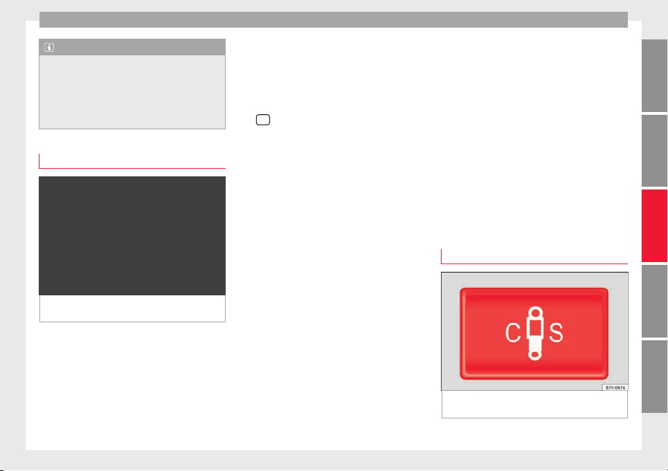
Driver assistance systems
Note
●
The tirednes
s detection function has only
been designed for driving on motorways and
wide roads.
●
If there is a fault in the system, refer to a
Specialised workshop to have the system in-
spected.
Function and operation
Fig. 227 On the instrument panel display:
tir
edne
s
s detection symbol
The tiredness detection function registers the
beh
av
iour of
the driver at the wheel at the
beginning of a journey and, using this, evalu-
ates the tiredness. This is continually com-
pared with the current behaviour at the
wheel. If the system detects that the driver is
tired, an audible warning using a “gong” is
given and a symbol and complementary mes-
sage on the instrument panel display are
shown ››› Fig. 227. The on-screen message
on the dash panel is displayed for 5 seconds
and, where required, repeated again. The
system stores the last message displayed.
The message that appears on the instrument
panel display can be switched off by pressing
the
OK
button on the multifunction steering
wheel
or on the w
indo
w wiper lever
›››
page 28. Using the multifunction dis-
play ›››
page 28 the message on the in-
strument panel display can be shown.
Conditions of operation
Behaviour at the wheel is only evaluated at
speeds of above 65 km/h (40 mph).
Switching on and off
The system can be switched on or off in the
Assistants menu. If an assistance system
is switched on, this is indicated with a
“mark”.
Limited operation
The tiredness detection function is subject to
certain limitations. Therefore it is possible
that in some driving situations behaviour at
the wheel cannot be correctly interpreted.
E.g. in the following situations:
●
at speeds lower than 65 km/h (40 mph),
●
in sections with corners,
●
on roads in poor condition,
●
in the event of adverse weather conditions,
●
when a sporty driving style is employed,
●
in the event of a major distraction for the
driver,
The tiredness detection function switches off
when the ignition is switched off or when the
driver unbuckles their seat belt and opens
the door. If driving for a long time under 65
km/h (40 mph), the system ceases to assess
tiredness automatically. If driving speed is
then increased, the behaviour at the wheel
will again be evaluated.
Dynamic Chassis control (DCC)*
Operation and control
Fig. 228 In the centre console: button for set-
tin
g the dy
n
amic chassis control.
»
233
Technical dataAdviceOperationEmergenciesSafety
Operation
DCC continuously adapts the suspension to
the c
ondition of
the r
oad and current driving
conditions, according to the pre-set pro-
gramme.
Steering is also adapted in the “Sport” pro-
gramme.
Programme Driving recommendations
“COMFORT” C
Adjust it to the most comfortable set-
ting, for example, driving on surfaces
in poor condition, or making long
trips.
“NORMAL”
Balanced setting, suitable, for exam-
ple, for day-to-day use.
“SPORT” S Sport setting for sporty style driving
Select a program
●
Switch the ignition on.
●
Press the C S b
utt
on r
epeatedly until the
desired programme is displayed.
The “NORMAL” programme is active when
neither the C nor S buttons are lit up.
WARNING
Switching the dynamic chassis control sys-
tem on whil
e the vehicle is in motion could
divert your attention from the traffic and
cause accidents.
WARNING
Adjusting the suspension can change driving
propertie
s. Dynamic chassis control must
never lead to any kinds of risk.
●
Adapt your speed and driving style at all
times to suit visibility, weather, road and traf-
fic conditions.
Note
If the dynamic chassis control does not oper-
ate as
described in this chapter, go to an au-
thorised workshop and request it be checked.
Note
In case of a fault in the dynamic chassis con-
trol, the b
uttons C and S will so indicate. A
fault could the affect driving comfort. Have
the system checked by a specialised work-
shop.
Tyre monitoring systems
Intr
oduction
The tyre monitor indicator monitors the tyre
pr
e
s
sure of each wheel during driving using
the ABS sensors. The ABS sensors monitor
the tyre tread perimeter and vibrations of
each tyre. The tyre monitor indicator warns
the driver if it detects a considerable drop in
tyre pressure of one or several tyres while
driving. Loss of tyre pressure will be indica-
ted by the indicator as well as an audible
warning and sometimes a text message on
the dash panel display. When you open the
driver door, you will find a label indicating
the tyre pressure recommended by the manu-
facturer for the maximum vehicle load for
each tyre approved for the vehicle in ques-
tion. By pressing the adjustment button on
the tyre monitoring indicator, you may
change the reference pressure for the tyres
so that the tyre pressure coincides with ac-
tual pressure ››› page 236.
Suitable use of the adjustment button
››› page 236.
WARNING
Unsuitable handling of the wheels and tyres
may
lead to sudden tyre pressure losses, to
tread separation or even to a blow-out.
●
Check tyre pressures regularly and ensure
they are maintained at the pressures indica-
ted. If the tyre pressure is too low, the tyres
could overheat, resulting in tread detachment
or even burst tyres.
●
Tyre pressure should be that indicated on
the label when the tyres are cold at all times
››› page 292.
●
Regularly check the cold inflation pressure
of the tyres. If necessary, change the tyre
pressure of the vehicle tyres while they are
cold.
234
Driver assistance systems
●
Regu
larly check your tyres for damage and
wear.
●
Never exceed the maximum permitted
speed or loads specified for the type of tyre
fitted on your vehicle.
WARNING
Incorrect use of the tyre monitoring indicator
b
utton c
ould result in the indicator giving er-
roneous messages or prevented from indicat-
ing the danger caused by a defective tyre
››› page 236.
CAUTION
●
The tyre
valves may be damaged if the cap
is not in place. Check that the caps are identi-
cal to the standard caps and have been cor-
rectly tightened. Do not use metal caps
››› page 236.
●
Do not damage the valves when changing
the tyres ››› page 236.
For the sake of the environment
Under-inflated tyres lead to increased fuel
cons
umption and tyre wear.
Note
●
Do not only
rely on the tyre monitoring sys-
tem. Regularly check your tyres to ensure
that the tyre pressure is correct and that the
tyres are not damaged due to puncture, cuts,
tears and impacts/dents. Remove objects
from the tyr
es only when the tyres have not
been pierced by these.
●
The tyre monitoring system is set to the
tyre pressure recommended by the manufac-
turer and indicated on the label ››› Fig. 252.
Elements of the tyre monitoring indi-
cator
Tyre monitoring indicator with button.
See ››› page 236.
Control lamp
on the instrument panel.
SET
button on the centre console.
Monitoring the tread of all tyres using ABS sensors
(indirect measurement).
Adjustable medium and full-load tyre pressures.
Button to update the system when the tyre pressure is
changed.
Control lamp
Blinks or lights up
The tyre pres-
sure of a wheel
has dropped
considerably in
relation to the
pressure set by
the driver
››› page 236.
Stop the vehicle! Reduce your
speed immediately! Stop the vehicle
safely as soon as possible. Avoid
sudden manoeuvres and braking!
Check all tyres and pressures. Re-
place any damaged tyres.
System malfunc-
tion.
Consult a specialised workshop if
the tyre pressure is correct and the
lamp remains lit after switching the
ignition off and back on again. Have
the system checked there.
Several warning and indication lamps light
up f
or a f
ew sec
onds when the ignition is
switched on, signalling that the function is
being verified. They will switch off after a few
seconds.
WARNING
Observe the safety warnings ›››
in Warning
and indication lamp
s on page 105.
WARNING
When the tyres are inflated at different pres-
sure
s or at a pressure that is too low then a
tyre may be damaged resulting in a loss of
control of the vehicle and a serious or fatal
accident.
»
235
Technical dataAdviceOperationEmergenciesSafety
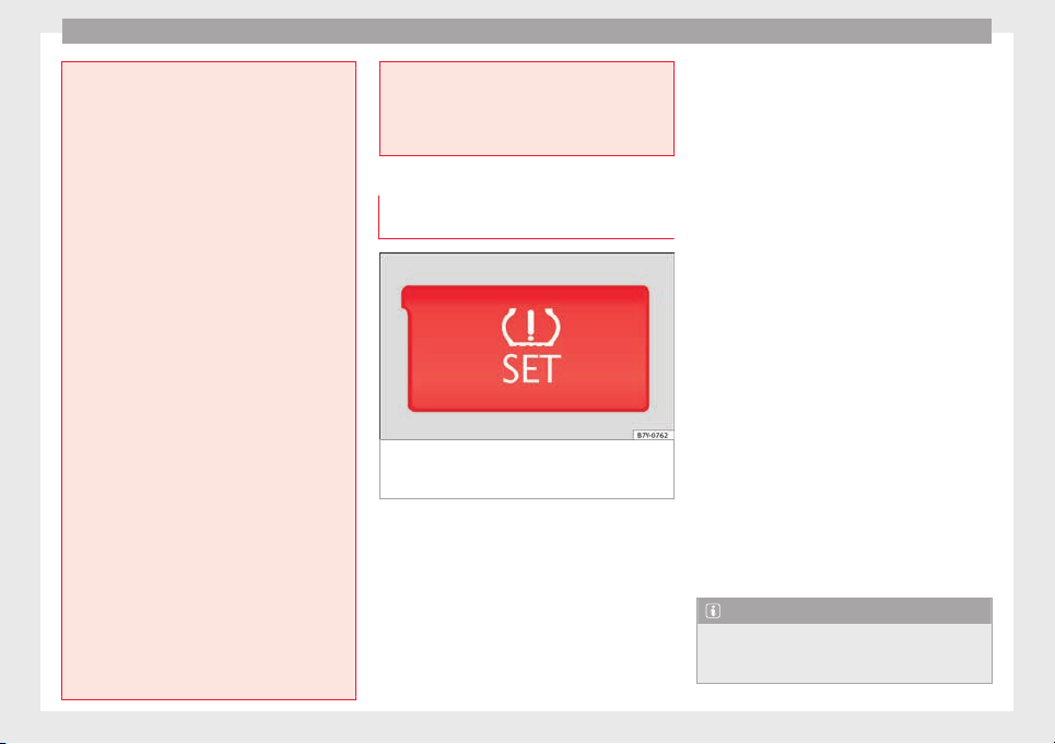
Operation
●
If the warnin
g lamp lights up, stop im-
mediately and check the tyres.
●
If the tyres are inflated at different pres-
sures or if a tyre pressure is too low, this will
increase tyre wear, negatively affecting vehi-
cle stability and increasing braking distan-
ces.
●
If tyres are inflated at different pressures or
a tyre pressure is too low, a tyre may be dam-
aged and burst resulting in a loss of control
of the vehicle.
●
The driver is responsible for ensuring that
all of the vehicle tyres are correctly inflated
to the right pressure. The recommended tyre
pressure is indicated on the label ››› Fig. 252.
●
The tyre monitoring system can only oper-
ate correctly if all of the tyres are inflated to
the correct pressure when cold.
●
Driving with tyres at the wrong pressure
can damage them and result in an accident.
Ensure that the tyre pressures of all the tyres
correspond to the vehicle load.
●
Before starting a journey, always inflate
tyres to the correct pressure.
●
If tyre pressure is too low then the tyre is
subject to greater forces and it may be heated
to such an extent that the tread can rupture
and the tyre will burst.
●
With an overloaded vehicle at high speed,
the tyres can overheat and burst resulting in
a loss of vehicle control.
●
Tyre pressures which are too high or too
low reduce the useful life of the tyre, affect-
ing vehicle performance.
●
If a tyr
e has not been “punctured” and does
not have to be changed immediately, drive to
the nearest specialised workshop at a moder-
ate speed and have the tyre checked and in-
flated to the correct pressure.
Tyre monitoring indicatortyre monitor-
ing indicat
or
Fig. 229 Detailed view of the centre console:
b
utt
on f
or the tyre pressure monitoring indi-
cator
The tyre monitor indicator compares wheel
r
ev
o
lutions and, with this information, the
tread of each wheel using the ABS sensors. If
the tread of a wheel is changed, the tyre
monitoring indicator will indicate as such on
the instrument panel. The wheel tread
changes when:
●
Tyre pressure is insufficient
●
Tyre structure is damaged
●
The vehicle is unbalanced because of a
load
●
If the wheels on an axle are subject to a
heavier load (e.g. when towing a trailer).
●
The vehicle is fitted with snow chains
●
The wheel on one axle is changed
There may be a delay in the reaction of the
tyre monitoring indicator or it may not in-
dicate anything under certain circumstances
(e.g. sports driving, snow-covered or un-
paved roads).
Adaptation of the tyre monitoring indicator
On adjusting tyre pressure or changing one
or more wheels, the ››› Fig. 229 button on the
tyre monitoring indicator must be kept press-
ed down, with the ignition on, until an audi-
ble warning is heard. Do the same, for exam-
ple, when the front and rear wheels are swap-
ped ››› Fig. 251.
If the wheels are subjected to an excessive
load (towing a trailer, heavy load), the tyre
pressure must be increased to the maximum
recommended pressure ››› page 288. Press
the tyre monitoring indicator button to con-
firm the new pressure value.
Note
An incorrect warning may be given when
snow c
hains are in use because the chains in-
crease the tread of the wheel.
236
Towing bracket device
Towing bracket device
Driv
in
g w
ith a trailer
Introduction
Always be aware of the legal requirements for
each c
ountry to drive with a trailer and to use
a tow hitch.
Your car is intended mainly for transporting
passengers however, it can also be used to
tow a trailer provided that it is fitted with the
necessary equipment. The additional load
has an effect on the useful life, fuel con-
sumption and the vehicle performance and,
in some cases, reduce the service intervals.
Driving with a trailer requires more force from
the vehicle and, thus, more concentration
from the driver.
For wintertime temperatures, fit winter tyres
to the vehicle and the trailer.
Drawbar load
The maximum permitted Drawbar load exer-
ted by the trailer drawbar on the ball joint of
the tow hitch must not exceed 100 kg (ap-
proximately 220 lbs).
Vehicles with the Start-Stop function
With a SEAT factory fitted or retrofitted tow
hitch, the Start-Stop function is automatically
deactivated when a trailer is connected. For
tow hit
ches not installed by SEAT, the Start-
Stop function must be deactivated manually
using a button located on the dash panel be-
fore driving with a trailer and it must remain
off for the entire journey ›››
.
WARNING
Never transport people in a trailer: this will
endang
er in their life and is against the law.
WARNING
The incorrect use of the tow hitch can cause
accident
s and injury.
●
Only use a tow hitch in perfect condition
and correctly installed.
●
Never change or repair a tow hitch.
●
To reduce the risk of injury in case of a re-
versing collision, injury to pedestrians and
cyclists when parking, always keep the ball
joint in when a trailer is not being used.
●
Never fit a trailer tow hitch “that distrib-
utes the load” or “balances the load”. Your
vehicle has not been designed for this type of
tow hitch. The tow hitch may fail and the
trailer will separate from the vehicle.
WARNING
Driving with a trailer and transporting heavy
or larg
e objects can affect vehicle handling
and even cause an accident.
●
Alwa
ys secure loads correctly with suitable
and undamaged attachment rope or straps.
●
Adjust your speed and driving style to visi-
bility, road, traffic and weather conditions.
●
Trailers with a high centre of gravity can
overturn more easily than those with a low
centre of gravity.
●
Avoid brusque manoeuvres and sudden
braking.
●
Always take the following precautions seri-
ously.
●
Reduce your speed immediately if you ob-
serve the trailer rocking from side to side.
●
Never drive at more than 80 km/h (50 mph)
when towing a trailer (or 100 km/h [62 mph]
in exceptional circumstances). This also ap-
plies in countries where higher speeds are
permitted. Always take the speed limits for
vehicles with and without trailers in each
country into account.
●
Never try to stop the “snaking” by increas-
ing speed.
WARNING
When driving with a trailer and using a tow
hitch th
at was not installed by SEAT, the
Start-Stop function must be manually deacti-
vated. Otherwise, this could cause a braking
anomaly that could result in an accident with
serious consequences.
●
Always manually deactivate the Start-Stop
function when a trailer is being used on a tow
hitch that has not been installed by SEAT.
»
237
Technical dataAdviceOperationEmergenciesSafety
Operation
Note
●
Alwa
ys turn off the anti-theft alarm system
before connecting or disconnecting a trailer
››› page 119. Otherwise, the tilt sensor may
erroneously activate the alarm.
●
Never use a trailer with a new engine (for
the first 1,000 km or 600 miles) ››› page 247.
●
At SEAT, we recommend folding in the tow
hitch ball when a trailer is not being used. In
case of a rear collision, the damage caused to
the vehicle with the extended tow hitch ball
could be more extensive.
●
In some models, a tow hitch is necessary
for towing vehicles. For this reason, you
should store the tow hitch in the vehicle at all
times.
Technical requirements
If the car is supplied with a f
act
or
y-fitted tow-
ing bracket it will already have the necessary
technical modifications and meet the statuto-
ry requirements for towing a trailer.
Only use an approved tow hitch for the gross
trailer weight rating. The tow hitch must be
suitable for both the vehicle and trailer and
must be securely fitted to the vehicle chassis.
Only use a tow hitch with a removable ball
joint. Always check and take into account the
tow hitch manufacturer's instructions. Never
fit a trailer tow hitch “that distributes the
load” or “balances the load”.
Bumper mounted tow hitch
Never fit a tow hitch or its attachments to the
bumper. A tow hitch should never interfere
with the bumper performance. Do not modify
the exhaust system and brake system. Regu-
larly check the tow hitch to ensure it is firmly
fitted.
Engine cooling system
Driving with a trailer increases the load on
the engine and cooling system. The cooling
system should always have sufficient coolant
and to be able to cope with the vehicle and
trailer.
Electric trailer brake
If the trailer has its own braking system,
please note the relevant legal requirements.
The trailer braking system should never be
connected to the vehicle braking system.
Trailer cable
Always use a cable between the vehicle and
the trailer ››› page 240.
Trailer rear lights
The rear lights of a trailer must fulfil the cor-
responding standards ››› page 240.
Never connect the trailer's rear lights directly
to the vehicle electric system. In case of any
doubt about the electrical connection of the
trailer, ask a specialised workshop. SEAT rec-
ommends visiting a technical service.
Wing mirrors
When the field of vision behind the trailer
cannot be seen using the standard wing mir-
rors of the towing vehicle, additional wing
mirrors are required according to the legal re-
quirements of each country. The wing mirrors
must be fitted before driving and must pro-
vide a sufficient field of vision behind.
Trailer electricity consumption
Never exceed the specifications:
Devices Maximum power
Side lights and rear lights 50 Watts
Turn signal (each side) 54 Watts
Brake lights (total) 84 Watts
Reversing lights (total) 42 Watts
Rear fog light 42 Watts
WARNING
If the tow hitch is badly fitted or unsuitable,
the trail
er may separate from the vehicle
causing an accident with serious consequen-
ces.
238
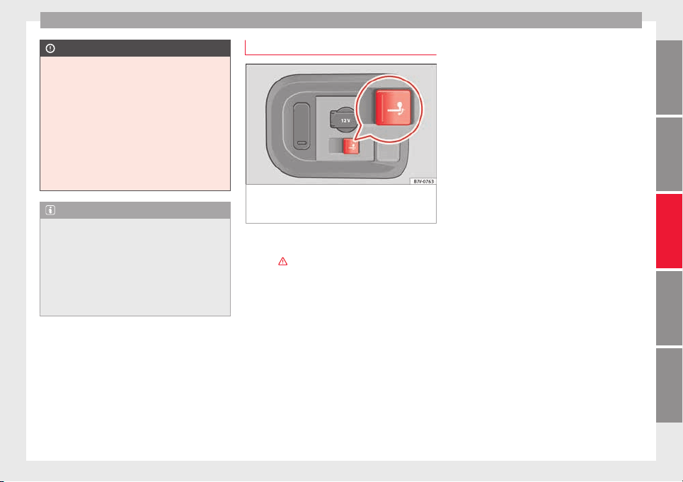
Towing bracket device
CAUTION
●
If the re
ar lights of the trailer are not cor-
rectly connected, the vehicle electronics may
be damaged.
●
If the trailer absorbs excessive electric cur-
rent, the vehicle electronics may be dam-
aged.
●
Never connect the trailer's electric system
to the electrical connections of the rear lights
or any other power sources. Only use suitable
connections for providing electric current to
the trailer.
Note
●
Tow
ing a trailer places additional demands
on the vehicle. At SEAT, we recommend addi-
tional services between the normal inspec-
tion intervals if the vehicle is used frequently
for towing a trailer.
●
In some countries, an additional fire extin-
guisher is required if the trailer weight is
more than 2500 kg
Electric tow hitch ball*
Fig. 230 Right-hand side of the luggage com-
p
ar
tment: b
utton to electrically release the
tow hitch ball
The rotation radius of the tow hitch ball
shou
l
d be fr
ee of people, animals and ob-
jects ›››
.
The t
o
w
ing bracket is located in the bumper.
The electric tow ball is fixed and cannot be
removed.
Releasing and unfolding the tow ball
●
Stop the vehicle and apply the electric
parking brake.
●
Switch the ignition off.
●
Open the rear lid.
●
Press the knob briefly ››› Fig. 230. The tow
ball is released electronically and folds out
automatically; the button indicator will blink.
●
Move the ball joint until it inserts and the
button control lamp lights.
●
Close the rear lid.
●
Before hitching the trailer, remove the dust
guard from the ball.
●
The indicator only lights when the boot
hatch is open and when a trailer is not hitch-
ed.
Restoring the tow ball to its originally posi-
tion
●
Stop the vehicle and apply the electric
parking brake.
●
Switch the ignition off.
●
Remove the trailer and disconnect the ca-
ble between the vehicle and trailer. If neces-
sary, remove the power socket adapter.
●
Place the dust guard over the ball.
●
Open the rear lid.
●
Press the knob briefly ››› Fig. 230. The tow
ball is electronically released; the indicator
blinks.
●
Push the tow ball into the bumper until it
locks in position and the button indicator
lights.
●
Close the rear lid.
»
239
Technical dataAdviceOperationEmergenciesSafety
Operation
The control lamp
●
When the control lamp flashe
s
, the t
ow ball
is not in its final position, has not engaged or
is damaged ›››
.
●
When the control lamp r
emain
s
lit and the
rear lid is open, the tow ball has inserted cor-
rectly into the folded or deployed position.
●
When the rear lid is closed, the indicator is
turned off.
WARNING
The incorrect use of the tow hitch can cause
accident
s and injury.
●
Ensure that no person, animal or object
gets in the way of the tow ball.
●
Never push the button when there is a tow
hitched or when any kind of carrier or acces-
sory is fitted to the tow hitch ball.
●
While the ball is moving, do not interfere
with any tool.
●
Do not drive with a trailer if the control
lamp does not light.
●
If there is a fault in the electric system or
the trailer tow hitch, visit a specialised work-
shop to have it checked.
●
If the diameter of the tow hitch is less than
49 mm, never use this for a trailer.
CAUTION
●
If anythin
g is attached to the tow hitch ball,
do not, under any circumstances press the
button.
●
Never direct a high-pressure or steam
cleaning system directly at the tow hitch ball
or trailer power socket. This could cause
damage to seals or remove lubricating
grease.
Note
In extremely low temperatures, it is possible
that the t
ow hitch is not released. In this
case, place the vehicle in a warmer location
(e.g. a garage).
Installing a bicycle carrier to the tow
hit
c
h
The maximum load permitted for a bicycle
c
arrier on the t
o
w hitch ball is 75 kg, with a
maximum distance of 30 cm from the sup-
port. The distance between supports is the
distance between the bicycle carrier centre of
gravity (with the bicycles) and the centre of
point of the tow hitch ball.
WARNING
The incorrect use of the tow hitch with a bicy-
cle c
arrier installed can cause accidents and
injury.
●
Never ex
ceed the load and distances be-
tween supports indicated.
●
Never fit the bicycle carrier to the tow hitch
ball neck, underneath the tow hitch given
that the bicycle carrier may be incorrectly fit-
ted due to the shape of the tow hitch and the
model of bicycle carrier.
●
Always read and take the manufacturer as-
sembly instructions into account.
CAUTION
Exceeding the maximum load and distance
betw
een sup
ports indicated can cause con-
siderable damage to the vehicle.
●
Never exceed the specifications.
Hitching and connecting the trailer
Fig. 231 Schematic diagram: assignment of
the pin
s
of
the trailer's electrical socket.
240
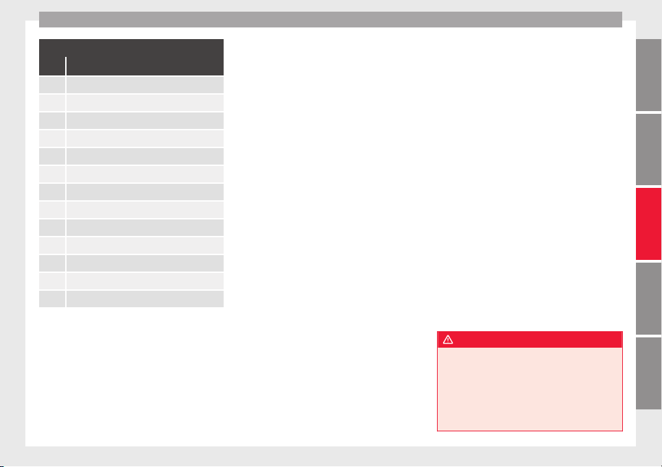
Towing bracket device
Key of the Schematic diagram ››› Fig. 231:
Pin Meaning
1 Left turn signal
2 Rear fog light
3 Earth, pins 1 to 8
4 Right turn signal
5 Rear light, right
6 Brake lights
7 Rear light, left
8 Reverse lights
9 Permanent live
10 Live charge cable
11 Unassigned
12 Unassigned
13 Earth, pins 9 to 13
Electrical socket for trailer
The
v
ehic
le is fitted with a 13-pole power
socket for the electrical connection between
the trailer and the vehicle. With the engine
running, electrical devices on the trailer re-
ceive power from the electrical connection
(pin 9 and pin 10 on the trailer power plug).
If the system detects that a trailer has been
connected electrically, the electrical equip-
ment on the trailer will receive voltage
through this connection (pins 9 and 10). Pin
9 has a permanent live. This powers, for ex-
ample, the trailer's interior lighting. Electrical
devices such as a fridge in a caravan only re-
ceive electrical power if the engine is running
(through pin 10).
The earth wires, pin 3 and pin 13, should not
be connected to each other to avoid over-
loading the electrical system.
If the trailer has a 7-contact connector, you
will need to use an adapter cable. In this case
the function corresponding to pin 10 will not
be available.
Trailer cable
Always secure the trailer cable to the towing
vehicle correctly. Leave a little bit of slack in
the cable for turning. However, ensure that
the cable does not rub off the ground while
driving.
Trailer rear lights
Check the trailer rear lights to ensure they
work correctly and remain legal. Ensure that
the trailer does not use more than the maxi-
mum power ››› page 238.
Trailer connected to the anti-theft alarm:
●
When a vehicle comes from the factory fit-
ted with an anti-thef
t alarm and tow hitch.
●
When the trail
er is connected to the vehicle
using the socket.
●
When the vehicle and trailer electrical sys-
tems work correctly and are not damaged.
●
When the vehicle is locked using the vehi-
cle key and the anti-theft alarm is turned on.
When the vehicle is locked, the alarm is trig-
gered when the electrical connection be-
tween the vehicle and the trailer is removed.
Always turn off the anti-theft alarm system
before connecting or disconnecting a trailer.
Otherwise, the tilt sensor may erroneously
activate the alarm.
Trailer with rear LED lights
For technical reasons, trailers fitted with rear
LED lights cannot be connected to the anti-
theft alarm system.
When the vehicle is locked, the alarm does
not trigger if the electrical connection with
the trailer is cut if it has rear light with light-
emitting diodes.
WARNING
Erroneous or unsuitable connection of elec-
tric cab
les may supply energy to the trailer
causing an anomaly in the vehicle electronics
that could result in an accident with serious
consequences.
●
All work on the electrical system must be
carried out only by a specialised workshop.
»
241
Technical dataAdviceOperationEmergenciesSafety
Operation
●
Never connect
the trailer's electric system
to the electrical connections of the rear lights
or any other power sources.
CAUTION
Do not leave the trailer connected to the vehi-
c
le when p
arked; places on its support wheel
or its supports. For example, when changing
the load or a puncture, the vehicle will be
pushed up or down. The force acting on the
tow hitch and the trailer could damage the
vehicle or the trailer.
Note
●
In the event of
a fault in the vehicle or trail-
er electrical system or in the event of prob-
lems with the anti-theft alarm system, have
the system checked by a specialised work-
shop.
●
If the trailer accessories use energy from
the power socket when the engine is stop-
ped, the battery will be discharged.
●
For technical reasons, trailers fitted with
rear LED lights cannot be connected to the
anti-theft alarm system.
●
If the vehicle battery is running low, the
electrical connection with the trailer is auto-
matically cut.
●
With the engine running, the electrical
equipment on the trailer will be supplied with
power.
Loading the trailer
Trailer weight / drawbar load
The trail
er weight is the load that the vehicle
can pull ›››
. The drawbar load is the vertical
weight of
the tow hitch on the tow hitch ball
››› page 245.
The figures for trailer weights and drawbar
load weights given on the data plate of the
tow hitch are for values of this model only.
The correct figures for your specific vehicle,
which may be lower than these figures for the
tow hitch, are given in the vehicle documen-
tation. The instructions in the official vehicle
documents take precedence.
For the sake of road safety, SEAT recom-
mends using the maximum allowed drawbar
load. The handling of the combined vehicle
and trailer will be poor if the drawbar load is
too low.
The drawbar load increases the weight on the
rear axle, reducing the vehicle carrying ca-
pacity.
Gross combination weight
This figure refers to the combined weight of
the loaded vehicle and loaded trailer.
Loading the trailer
The combined vehicle and trailer must be
balanced. Use the maximum drawbar load
authorised and do not overload the front or
the rear of
the trailer:
●
Distribute loads in the trailer so that heavy
objects are as near to the axle as possible or
above it.
●
Correctly secure the trailer load.
Tyre pressure
Inflate the trailer tyres according to the man-
ufacturer's instructions.
Inflate the towing vehicles tyres to the maxi-
mum ››› page 288.
WARNING
Exceeding the maximum authorised axle
load, dr
awbar load or the gross combination
weight of the towing vehicle and trailer could
cause a serious accident with severe conse-
quences.
●
Never exceed the specifications.
●
With the actual load on the front and rear
axles, the maximum axle load should never
be exceeded. The weight on the front and rear
should never exceed the gross vehicle
weight.
WARNING
If the load moves, the stability and safety of
the vehic
le and trailer combination will be se-
riously affected and this could result in a seri-
ous accident.
242
Towing bracket device
●
Alwa
ys correctly load the trailer.
●
Always secure loads correctly with suitable
and undamaged attachment rope or straps.
Driving with a trailer
Adjusting the headlights
When tow
ing a trailer, the front of the vehicle
may rise and so the dipped beam headlights
may blind other drivers. Use the headlight
range control to lower the cone of light. If you
do not have headlight range control, have
the headlights adjusted by a specialised
workshop. Vehicles with high-intensity dis-
charge lamps adapt automatically and do not
require adjustment.
Things to note when towing a trailer or cara-
van
●
If the trailer has an overru
n brake, apply
the brakes gently at first and then, firmly.
This will prevent the jerking that can be
caused by the trailer wheels locking.
●
As of the combined vehicle and trailer
mass, braking distances will be greater.
●
Select a low gear before driving down a
steep hill to use the engine braking effect to
slow down the vehicle. Otherwise, the brak-
ing system could overheat and fail.
●
The vehicle centre of gravity and handling
change because of the trailer load and be-
cause of the increased combined mass of the
vehicle and trailer.
●
If the towing vehicle is empty and the trail-
er loaded then the load distribution is incor-
rect. If you must travel in these conditions,
drive carefully and reduce your speed accord-
ingly.
Hill starts with a trailer
Depending on the hill and the gross com-
bined weight, it is possible that the com-
bined vehicle and trailer move backwards
slightly when starting.
For a hill start with a trailer, proceed as fol-
lows:
●
Press and hold the brake pedal.
●
Press the button
once to turn off the
el
ectric
p
arking brake ››› page 189.
●
Press and hold the button
to hold the
v
ehic
l
e and trailer combination using the
parking brake.
●
With a manual gearbox: press the clutch
pedal to the floor.
●
Engage first gear or the gear range D
››› page 194, Gearbox.
●
Release the brake pedal.
●
Move off slowly. To do this, gently release
the clutch pedal (for manual gearbox).
●
Release the button
only when the en-
gine pr
o
v
ides sufficient power to move the
vehicle and trailer combination.
WARNING
Jerking the trailer in an unsuitable manner
coul
d cause loss of vehicle control with the
subsequent serious consequences.
●
Driving with a trailer and transporting
heavy or a large objects will change the vehi-
cle handling and braking distances.
●
Anticipate traffic and be extremely cau-
tious. Brake early.
●
Adjust your speed and driving style to visi-
bility, road, traffic and weather conditions.
Reduce your speed, especially on steep hills.
●
Accelerate gently and carefully. Avoid brus-
que manoeuvres and sudden braking.
●
Always take the following precautions seri-
ously. Reduce your speed immediately if you
observe the trailer rocking from side to side.
●
Never try to stop the “snaking” by increas-
ing speed.
●
Always take the speed limits for vehicles
with and without trailers into account.
243
Technical dataAdviceOperationEmergenciesSafety
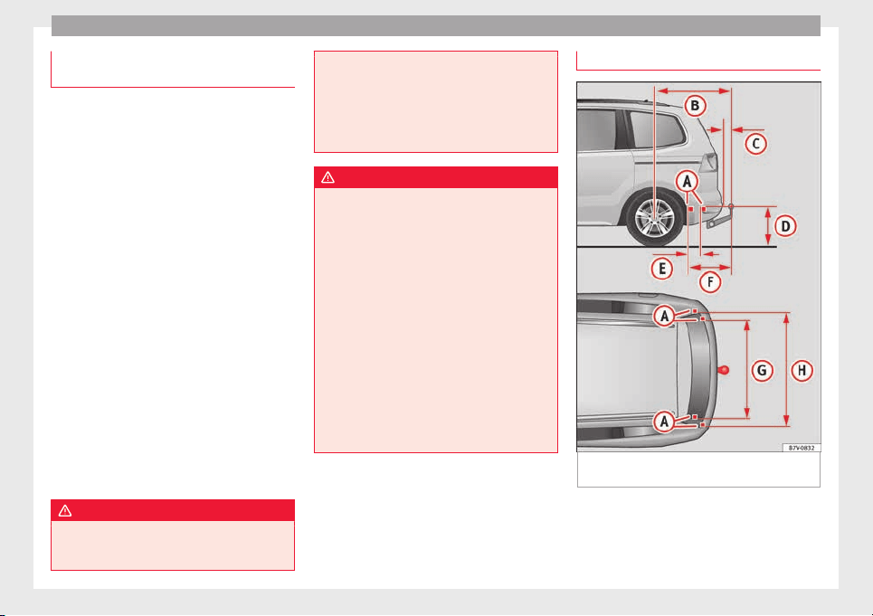
Operation
Stabilising the vehicle and trailer
c
omb
in
ation
Stabilisation of the vehicle and trailer combi-
nation is
an extension of the electronic sta-
bility control (ESC) and helps, with the assis-
tance of the trajectory control, to reduce trail-
er “snaking”.
Stabilisation of the vehicle and trailer combi-
nation is active when the ESC indicator on
the dash panel remains lit for about two sec-
onds more than the ABS indicator.
Requirements for stabilising the vehi-
cle/trailer combination
●
An original tow hitch is fitted by the manu-
factur
er or a compatible model is retrofitted.
●
The ECS is switched on. The warning lamp
on the dash panel is not lit.
●
The trailer is connected to the vehicle using
the power socket.
●
It travels faster than 60 km/h (37 mph).
●
The maximum drawbar load is used.
●
The trailer must have a fixed drawbar.
●
Trailers with brakes must be equipped with
a mechanical inertia brake.
WARNING
Do not let the extra safety afforded by the
stab
ilisation system tempt you into taking
any risks when driving.
●
Adjust
your speed and driving style to visi-
bility, road, traffic and weather conditions.
●
If the road surface is slippery, take care
when accelerating.
●
When a system is operating, lift your foot
off the accelerator.
WARNING
It is possible that the combination stabilisa-
tion sy
st
em does not correctly recognised all
driving situations.
●
It is possible that the stabilisation system
does not detect snaking of a light trailer and
thus does not intervene.
●
When driving on slippery ground, the trail-
er could jack-knife despite the stabilisation
system.
●
Trailers with a high centre of gravity may
even tip over before they start to rock side-
ways.
●
If a trailer is not used and the trailer power
socket is connected (e.g. installation of a bi-
cycle carrier with lights), repeated automatic
braking may occur in extreme driving condi-
tions.
Retrofitting a tow hitch
Fig. 232 Measurements and attachments to
r
etr
ofit
a tow hitch
SEAT recommends visiting a specialised
w
ork
shop t
o retrofit a tow hitch. For example,
244
Towing bracket device
it may be necessary to adjust the cooling sys-
t
em or t
o inc
lude thermal plates. SEAT recom-
mends taking your car in for technical serv-
ice.
In any case, the separation distances must
be observed when fitting a tow hitch. The dis-
tance between the centre of the tow hitch ball
and the road surface ››› Fig. 232
D
must nev-
er be lo
w
er th
an that indicated. This also ap-
plies when the vehicle is fully laden, includ-
ing maximum drawbar load.
Separation distances ››› Fig. 232:
Attachment points.
1,040 mm (41 inches)
74 mm (3 inches)
364 mm (14 inches)
247 mm (10 inches)
596 mm (23 inches)
1,097 mm (43 inches)
1,102 mm (43 inches)
WARNING
Erroneous or unsuitable connection of elec-
tric cab
les may cause anomalies in the vehi-
cle electronics that could result in an acci-
dent with serious consequences.
●
Never connect the trailer's electric system
to the electrical connections of the rear lights
or any other unsuitable power sources. Only
use suitable connectors to connect a trailer.
A
B
C
D
E
F
G
H
●
Vis
it a specialised workshop if you wish to
retrofit a tow hitch to the vehicle.
WARNING
If the tow hitch is badly fitted or unsuitable,
the tr
ail
er may separate from the vehicle
while driving. This could result in a serious
accident.
Note
Use only tow hitches approved by SEAT for
the vehic
le.
Maximum gross trailer weight
The instructions in the official vehicle docu-
ments
t
ak
e precedence. All the technical data
provided in this documentation is applicable
to the basic model. The vehicle data label in
the Maintenance Programme or the vehicle
documentation shows which engine is instal-
led in your vehicle.
The figures may be different depending
whether additional equipment is fitted, for
different models and for special vehicles.
WARNING
Exceeding the maximum trailer weight indica-
ted cou
ld cause a serious accident.
●
Never exceed the indicated trailer weight.
CAUTION
Exceeding the maximum trailer weight indica-
ted cou
ld cause damage to the vehicle.
●
Never exceed the indicated trailer weight.
Gross combined vehicle weight rating
The instructions in the official vehicle docu-
ments tak
e precedence. All the technical data
provided in this documentation is applicable
to the basic model. The vehicle data label in
the Maintenance Programme or the vehicle
documentation shows which engine is instal-
led in your vehicle.
The figures may be different depending
whether additional equipment is fitted, for
different models and for special vehicles.
The maximum combined weights listed are
only applicable for altitudes up to 1000 m
above sea level. The weight of the car and
trailer must be reduced by about 10% for ev-
ery further 1000 m (or part thereof).
WARNING
Exceeding the maximum weight indicated
coul
d cause a serious accident.
●
Never exceed the gross combined weight
rating.
»
245
Technical dataAdviceOperationEmergenciesSafety

Operation
CAUTION
Exceeding the maximum gross combined
weight r
ating indicated could cause damage
to the vehicle.
●
Never exceed the gross combined weight
rating.
246
Care and maintenance
Advice
C
ar
e and m
aintenance
Accessories, replacement of
parts and modifications
Introduction
WARNING
The use of spare parts and accessories, or in-
correctly
performed modifications or repairs
may result in damage to the vehicle, acci-
dents and serious injury.
●
SEAT strongly recommends you to only use
SEAT approved accessories and SEAT
®
origi-
nal spare parts. These parts and accessories
have been specially tested by SEAT for suita-
bility, reliability and safety.
●
Have any repairs or modifications carried
out at a specialised workshop. These work-
shops have the necessary tools, diagnostics
equipment, repair information and qualified
personnel.
●
Only mount parts with the same specifica-
tions as the parts fitted at factory.
●
Never mount, fasten or fit objects such as
drink holders or telephone cradles over the
covers of the airbag modules or within their
radius of action.
●
Only u
se wheels and tyre combinations
which have been approved by SEAT for your
vehicle type.
Accessories and spare parts
SEAT recommends you consult an Official
Servic
e before purchasing accessories and
spare parts or consumables. For example,
when fitting accessories at a later date, or
when replacing a component. A technical
service centre will advise you as to the legal
requirements and manufacturer's recommen-
dations regarding accessories, spare parts
and other components.
SEAT recommend you use only approved
SEAT accessories and genuine SEAT spare
parts
®
. These parts and accessories have
been specially tested by SEAT for suitability,
reliability and safety. In addition the techni-
cal service centre will guarantee that the as-
sembly is carried out professionally.
Although we continually monitor the market,
SEAT cannot guarantee that products not ap-
proved by SEAT are reliable, safe and suita-
ble for the vehicle. Therefore, SEAT cannot ac-
cept liability, even in those cases authorised
by an officially recognised technical inspec-
tion office or other official body.
Any retro-fitted equipment which has a direct
effect on the vehicle and/or the way it is driv-
en must be approved by SEAT for use in your
vehicl
e and bear the e mark (the European
Union's authorisation symbol). This includes
cruise control systems or electronically con-
trolled suspension.
If any additional electrical devices are fitted
which do not serve to control the vehicle it-
self, these must bear the mark (European
Union manufacturer conformity declaration).
This includes refrigerator boxes, laptops or
ventilator fans.
WARNING
Unprofessional repairs or modifications to
the vehic
le may affect the performance of the
airbags, and may cause operating faults or fa-
tal accidents.
●
Never mount, fasten or fit objects such as
drink holders or telephone cradles over the
covers of the airbag modules or within their
radius of action.
●
Objects placed over the airbag covers, or
within their radius of action, could lead to se-
rious injury or loss of life if the airbags are
triggered.
Service fluids and components
All vehicle fluids and consumables, s
uc
h a
s
notched belts, tyres, coolant fluids, engine
oils, spark plugs and batteries are continual-
ly being developed. Therefore all fluids and
»
247
Technical dataAdviceOperationEmergenciesSafety
Advice
consumables should be changed at a speci-
ali
sed w
ork
shop. Technical services are per-
manently informed of any modifications.
WARNING
The incorrect use or handling of fluids or con-
sumab
les may result in accident, serious in-
jury, burns or intoxication.
●
Therefore, fluids must always be stored
closed in their original container.
●
Never store fluids in empty food containers
or bottles as other people may accidentally
drink the fluid.
●
Keep all fluids and consumables out of
reach of children.
●
Read and observe the information and
warnings given on the fluid containers.
●
Only work in the open air or in well-ventila-
ted zones, when using products which give
off harmful vapours.
●
Never use fuel, turpentine, engine oil, ace-
tone or any other volatile liquid in the main-
tenance of the vehicle. These are toxic and
highly flammable. They could lead to fire or
explosions!
CAUTION
●
Only u
se appropriate fluids. Do not confuse
fluids as this can cause serious malfunctions
or engine damage.
●
Accessories and other components moun-
ted in front of the air inlet reduce the cooling
effect of the coolant. If the engine is running
under gre
at strain in high outside tempera-
tures, it could overheat.
For the sake of the environment
Leaking fluids could pollute the environment.
C
ol
lect any spilt fluids in suitable containers
and dispose of them in accordance with legis-
lation and with respect for the environment.
Technical repairs and replacements
When performing repairs and technical mod-
ific
ation
s,
SEAT's directives must be ob-
served! ›››
Unauthorised modifications to the electronic
c
omponents
or sof
tware in the vehicle may
cause malfunctions. Due to the way the elec-
tronic components are linked together in net-
works, other indirect systems may be affec-
ted by the faults. This may significantly affect
the vehicle's performance, increase compo-
nent wear and could mean that the vehicle
registration documents are no longer valid.
Your technical service centre cannot be held
liable for any damage caused by technical
modifications or repairs performed incorrect-
ly.
The technical service centre does not accept
liability for damage resulting from technical
modifications or repairs performed incorrect-
ly; neither is the SEAT warranty valid in these
cases.
SEAT recommends you have any technical
modifications or repairs performed at a tech-
nical service centre and that you use genuine
SEAT spare parts
®
.
Vehicles with special accessories and equip-
ment
The manufacturers of additional equipment
guarantee that the equipment complies with
applicable laws and regulations with respect
to the environment, in particular Directives
2000/53/CE and 2003/11/CE. The first direc-
tive governs the disposal of end-of-life vehi-
cles while the second refers to the restric-
tions on the marketing and use of certain
dangerous substances and preparations.
The vehicle owner should keep the documen-
tation for the additional equipment safely
and hand it over to the scrap yard at the end
of the vehicle's service life. This ensures that
any additional equipment mounted in end-of-
life vehicles is correctly disposed of with re-
spect for the environment.
WARNING
Repairs or modifications which are not per-
formed corr
ectly may result in damage or er-
rors in the vehicle operation, affecting the ef-
fectiveness of the driver assist systems. This
could result in serious accident.
248
Care and maintenance
●
All
repairs and modifications to the vehicle
should only be performed by a specialised
workshop.
Repairs and malfunctions in the air-
bag sys
tem
When performing repairs and technical mod-
ifications,
SEAT's directives must be ob-
served! ›››
Modifications and repairs to the front bump-
er
, door
s, fr
ont seats, and repairs to the roof
or chassis should only be carried out in a
specialised workshop. These components
may contain parts or sensors belonging to
the airbag system.
If work is carried out on the airbag system or
parts have to be removed and fitted on the
system when performing other repair work,
parts of the airbag system may be damaged.
The consequence may be that, in the event of
an accident, the airbag inflates incorrectly or
does not inflate at all.
So that the effectiveness of the airbag is not
reduced and that removed parts do not cause
any injuries or environmental pollution, regu-
lations must be observed. These require-
ments are known to specialised workshops.
Modifications to the vehicle suspension may
affect the operation of the airbag system in
the event of collision. For example, if wheel
and tyre combinations not approved by SEAT
are used, or if the vehicle height is lowered,
the suspension is stiffened or the suspension
springs, telescopic arms, dampers, etc., are
modified, the results received by the airbag
sensors and sent to the control unit may not
be accurate. For example, some modifica-
tions to the suspension could increase the
force measured by the sensors and result in
the triggering of the airbag systems in colli-
sions. Under normal conditions, the meas-
ured values would be lower and the airbag
would not have been triggered. Other modifi-
cations may reduce the forces measured by
the sensors and prevent the airbags from be-
ing triggered when they should.
WARNING
Repairs or modifications which are not per-
formed corr
ectly may result in damage or er-
rors in the vehicle operation, affecting the ef-
fectiveness of the airbag systems. This could
result in serious or fatal accidents.
●
All repairs and modifications to the vehicle
should only be performed by a specialised
workshop.
●
Airbag modules must never be repaired: if
damaged, they must be replaced.
●
Never fit recycled or reused airbag compo-
nents in your vehicle.
WARNING
Modifications to the vehicle suspension, in-
cluding the u
se of unauthorised wheel and
tyre combinations, may affect the perform-
ance of the airbags and increase the risk of
serious or fatal injury in the event of acci-
dent.
●
Never fit suspension components which are
not identical to the original parts in the vehi-
cle.
●
Never use wheel and tyre combinations not
approved by SEAT.
Retrofitting of mobile phones
An exterior aerial is required for the use of
tw
o-w
a
y radios in the vehicle.
The retro-fitting of electrical or electronic ap-
pliances in the vehicle is subject to their ap-
proval for use in your vehicle. Under certain
circumstances, this could mean that your ve-
hicle registration documents are no longer
valid.
SEAT has approved your vehicle for use with
two-way radios providing the following condi-
tions are observed:
●
The exterior aerial must be mounted pro-
fessionally.
●
The maximum transmitting power is 10
watts.
»
249
Technical dataAdviceOperationEmergenciesSafety
Advice
The optimal reach of the equipment is only
ac
hiev
ed w
ith an external aerial.
Check first with a specialised workshop that
understands the technical possibilities of in-
stallation if you wish to use a two-way radio
with a transmitting power of over 10 watts.
SEAT recommends taking your car in for tech-
nical service.
All legal requirements, together with the in-
structions for the use of two-way radios must
be observed.
WARNING
If the two-way radio is not securely fastened
in position, it
could be sent flying around the
vehicle in the event of sharp braking, sudden
manoeuvres or accident, causing injury.
●
While driving, two-way radios must be se-
curely fastened in position, outside the radi-
us of action of the airbags, or safely stowed
away.
WARNING
When using a two-way radio without a con-
nection to an ext
erior aerial, the maximum
permitted levels of electromagnetic radiation
may be exceeded. This is also the case if the
aerial has not been correctly installed.
●
You should only use a two-way radio inside
the vehicle if it has first been correctly con-
nected to an exterior aerial.
Information stored by the control
u
nit
s
Your vehicle is fitted at the factory with a ser-
ies of
electronic control units responsible for
the engine and gearbox management. In ad-
dition, the control units supervise the per-
formance of the exhaust gas system and the
airbag systems.
Therefore, while the vehicle is being driven,
these electronic control units are continuous-
ly analysing the vehicle data. In the event of
faults or deviations from the theoretical val-
ues, only this data is stored. Normally, the
warning lamps on the instrument panel light
up in the event of faults.
This data can only be read and analysed us-
ing special equipment.
The storing of the data allows specialised
workshops to detect and repair faults. Stored
data may include:
●
Data relating to the engine or the gearbox
●
Speed
●
Direction of travel
●
Braking force
●
Detection of seat belt
The vehic
le control units never record conver-
sations held by passengers in the vehicle.
In vehicles equipped with an emergency call
function via the mobile phone or other appli-
ances connected in the vehicle, it is possible
to send the vehicle position. If the control
unit records an accident with airbag activa-
tion, the system may automatically send a
signal. This will depend on the network oper-
ator. Normally, transmission is only possible
in areas with good coverage.
Event Data Recorder
The vehicle is not fitted with an event data re-
corder.
An event data recorder temporarily stores the
vehicle information. Therefore, in the event of
an accident, it is possible to obtain detailed
information about how the accident occur-
red. For example, in vehicles with airbag sys-
tems, data relating to speed of impact, seat
belt status, seat positions and airbag activa-
tion times may be stored. The volume of data
depends on the manufacturer.
Event data recorders can only be mounted
with authorisation from the vehicle owner
and, in some countries, they are governed by
local legislation.
Reprogramming control units
On the whole, all the data required for the
component management is stored in the con-
trol units. The programming of certain con-
venience functions, such as the turn signals,
individual door opening and instructions on
the display can be modified using special
250
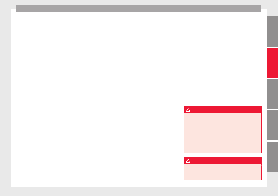
Care and maintenance
equipment at the workshop. If this is the
c
a
se, the inf
ormation and descriptions given
in the Instruction Manual will not match the
original functions. Therefore, SEAT recom-
mends that any modifications be recorded in
the section “Other workshop notes” in the
Maintenance Programme.
The technical service centre must have a re-
cord of any modification to the programming.
Reading the vehicle fault memory
There is a diagnostics connector in the vehi-
cle interior for reading the vehicle fault mem-
ory. The fault memory documents errors and
deviations from the theoretical values of the
electronic control units.
The diagnostics connector is in the driver
side footwell area, next to the lever for open-
ing the bonnet, below a cover.
The fault memory should only be read and re-
set by a specialised workshop.
Using a mobile telephone in a vehicle
without connection to an exterior aer-
ial
Mobile telephones transmit and receive radio
w
av
e
s, both when in use and when on stand-
by. Scientific studies state that radio waves
exceeding certain values may be harmful to
the human body. International committees
and authorities have established limits and
directives in order to ensure electromagnetic
radiation from mobile phones remains within
certain limits that do not endanger health.
Nevertheless, there is no conclusive scientif-
ic evidence that wireless telephones are to-
tally safe.
Therefore, some experts recommend that use
of mobile phone be kept to a minimum until
the results of current research are published.
When a mobile phone not connected to an
exterior aerial is used inside the vehicle, the
electromagnetic radiation may be greater
than if the mobile phone were connected to a
built-in aerial or to another exterior aerial.
If the vehicle is fitted with a suitable hands-
free device, it will comply with the legislation
in many countries which only permits the use
of mobile phones inside vehicles using a
hands-free device.
The hands-free system mounted at the facto-
ry has been designed for use with conven-
tional mobile phones and phones with Blue-
tooth technology. Mobile phones should be
placed on a suitable phone cradle. In addi-
tion, the cradle should always be correctly fit-
ted into the base plate. This ensures that the
mobile phone is securely attached to the
dash panel, it is always within reach of the
driver and is connected to the vehicle exterior
aerial.
If the mobile phone is connected to an aerial
incorporated into the vehicle or an exterior
aerial connected to the vehicle, it will help re-
duce the electromagnetic radiation transmit-
ted and the risk to human health. It will also
improve the quality of the connection.
If the phone is used inside the vehicle with-
out the hands-free system, it will not be se-
curely fastened and will not be connected to
the exterior aerial of the vehicle telephone.
Nor will the telephone charge if it is not on
the support. In addition, some calls may
break off and the quality of the connection
will be affected.
Mobile phones should only be used inside
the vehicle if they are connected to a hands-
free system with an exterior aerial.
WARNING
If the mobile phone is not securely fastened
in position, it
could be sent flying around the
vehicle in the event of sharp braking, sudden
manoeuvres or accident, causing injury.
●
While driving, mobile phones must be se-
curely fastened in position, outside the radi-
us of action of the airbags, or safely stowed
away.
WARNING
When using a mobile phone without a con-
nection to an ext
erior aerial, the maximum
permitted levels of electromagnetic radiation
»
251
Technical dataAdviceOperationEmergenciesSafety
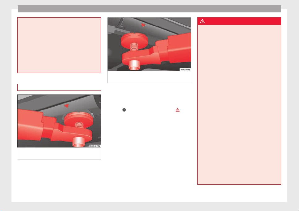
Advice
may be exceeded. This is also the case if the
aerial
has not been correctly installed.
●
A minimum of 20 centimetres should be
kept between mobile phone aerials and artifi-
cial pacemakers, as mobile telephones may
affect the working of pacemakers.
●
Do not keep mobile phones in breast pock-
ets directly above pacemakers.
●
Switch off the mobile phone immediately if
you suspect there may be interference.
Support points for raising the vehicle
Fig. 233 Front jacking points for raising vehi-
c
l
e w
ith lifting platform or jack
Fig. 234 Rear jacking points for raising vehi-
cle w
ith lifting platform or jack
Always use the jacking points indicated in
the figur
e
s
››› Fig. 233 and ››› Fig. 234 when
raising the vehicle. If the vehicle is not lifted
at these points, it could be seriously dam-
aged ›››
or lead to serious injury ›
›
›
.
The
v
ehic
le should not be lifted using lifting
platforms with lift pads containing fluid.
When raising a vehicle using a platform or
jack, a series of precautionary measures are
required. Do not raise the vehicle with a lift-
ing platform or jack unless you have received
training in how to do so and know how to do
so safely.
Notes on raising the vehicle with a jack
›››
page 47.
WARNING
The improper use of the lifting platform or
the jack
when raising the vehicle may result
in accidents or serious injury.
●
Before raising the vehicle, please observe
the manufacturer's instructions for the plat-
form or jack, and the legal requirements,
where applicable.
●
There should not be anyone inside the ve-
hicle when it is being raised or once it is in
the air.
●
Only use the jacking points indicated in the
figures ››› Fig. 233 and ››› Fig. 234 when rais-
ing the vehicle. If the vehicle is not lifted at
the indicated points, it may fall from the plat-
form while the engine or gearbox is being
dismounted, for example.
●
The jacking points should be centrally
aligned and firmly positioned on the platform
support plates.
●
Never start the engine when the vehicle is
raised! The vehicle may fall from the platform
due to the engine vibrations.
●
If it is necessary to work underneath the ve-
hicle while it is raised, you should check that
the supporting stands have an adequate load
capacity.
●
Never climb onto the lifting platform.
●
Always make sure that the weight of the ve-
hicle does not exceed the lifting platform
load capacity.
252
Care and maintenance
CAUTION
●
Never rai
se the vehicle at the engine oil
sump, the gearbox or the rear or front axles.
●
Always use an intermediate rubber support
to prevent damage to the vehicle underbody.
Check that the arms of the lifting platform are
able to move with obstruction.
●
The arms should not come into contact with
the side running boards or other parts of the
vehicle.
Caring for and cleaning the ve-
hic
l
e int
erior
Introduction
Regular maintenance and washing help to
m
aint
ain the
value of the vehicle. This may
also be one of the requirements for acknowl-
edging warranty claims in the event of body-
work corrosion or paint defects.
Products suitable for the care of your vehicle
are available at any technical service.
WARNING
Car-care products may be toxic and hazard-
ous. If c
ar care products are not suitable or
are used inappropriately, this could result in
accident, serious injury, burns or intoxica-
tion.
●
Car car
e products must always be stored in
the original container which should be kept
closed.
●
Observe information provided by the manu-
facturer.
●
To prevent confusion, never store car care
products in empty food cans, bottles or other
containers.
●
Keep all care products out of reach of chil-
dren.
●
Harmful vapours may be produced when us-
ing car care products. Therefore, care prod-
ucts should only be used in well-ventilated
spaces or in the open air.
●
Never use fuel, turpentine, engine oil, ace-
tone or any other volatile liquid to wash,
clean or care for the vehicle. These are toxic
and highly flammable.
WARNING
Inappropriate care and cleaning of vehicle
components
may effect the vehicle safety
equipment, increasing the risk of severe in-
jury.
●
Vehicle components should only be
cleaned and maintained in accordance with
the manufacturer's instructions.
●
Only use approved or recommended care
products.
CAUTION
Cleaning products which contain solvents will
damag
e the material.
For the sake of the environment
●
Only w
ash the vehicle in areas allocated for
this purpose, to prevent dirty water which
may be contaminated by oil, grease or fuel,
from entering the drains. In some places,
washing it outside the planned areas is even
banned.
●
Where possible, always use products which
respect the environment.
●
The remains of car care products should not
be disposed of with ordinary household
waste. Observe information provided by the
manufacturer.
Washing the vehicle
The longer substances such as insects, bird
dr
op
pin
gs, resinous tree sap, road dirt, in-
dustrial deposits, tar, soot or road salt and
other aggressive materials remain on the ve-
hicle, the more damage they do to the paint-
work. High temperatures (for instance due to
strong sunlight) further intensify the corro-
sive effect. The vehicle undercarriage should
also be thoroughly washed at regular inter-
vals.
»
253
Technical dataAdviceOperationEmergenciesSafety
Advice
Automatic car washes
A
lw
a
ys observe the instructions provided at
the automatic car wash. The standard pre-
cautionary measures prior to entering the car
wash should be taken to avoid damage to
the vehicle (close all windows, fold in exterior
mirrors). If the vehicle is fitted with additional
components (spoiler, roof-rack, aerial, etc.),
check with the car wash supervisor whether
these can enter the car wash ›››
.
The
v
ehic
le paintwork is so durable that the
vehicle can normally be washed without
problems in an automatic car wash tunnel.
However, wear and damage to the paintwork
will depend on the type of car wash used.
SEAT recommends the use of car washes
without brushes.
To remove traces of wax on windows and to
prevent wiper blades from scratching, please
observe the following ››› page 255, Cleaning
windows and exterior mirrors.
Washing the car by hand
When washing the car by hand, use plenty of
water to soften the dirt first, and rinse off as
well as possible.
Then clean the vehicle with a soft sponge,
glove or brush using only slight pressure.
Start at the roof and work downwards. Spe-
cial car shampoo should only be used for
very persistent dirt.
Rinse the sponge or glove thoroughly and of-
ten.
Wheels, sills and similar should be cleaned
last. Use a second sponge for this.
WARNING
Sharp components on the vehicle may cause
injury.
●
Pr
otect arms and hands from sharp edges
when cleaning the vehicle undercarriage or
the interior of the wheel hubs.
WARNING
After the vehicle has been washed, the brak-
ing effect
will be reduced (and the braking
distance increased) due to moisture (and ice
in winter) on the brakes.
●
“Dry the brakes and remove ice” by braking
carefully. Ensure that you are not endanger-
ing other road-users or breaking traffic regu-
lations in the process.
CAUTION
●
The temperat
ure of the water must not ex-
ceed +60°C (+140°F).
●
To avoid damage to the paintwork, do not
wash the vehicle in full sun.
●
Do not use rough sponges or similar which
could damage the surface to clean away the
traces of insects.
●
Never wipe the he
adlights with a dry cloth
or sponge, always moisten first. It is best to
use soapy water.
●
Washing the vehicle in low temperatures:
When washing the vehicle with a hose, do
not direct water into the lock cylinders or the
gaps around the doors or roof. Locks and
seals could freeze!
CAUTION
To avoid any risk of damage to the vehicle,
p
le
ase check the following points before us-
ing an automatic car wash:
●
Compare the distance between the vehicle
wheels and the distance between the guide-
rails of the car wash to prevent damage to the
wheels and tyres!
●
Switch off the rain sensor and the Au-
to Hold function before entering a car wash.
●
Compare the height and width of your vehi-
cle with the available height and width when
entering and driving through the car wash.
●
Fold in exterior mirrors Electrically retracta-
ble exterior mirrors must not be folded in or
out by hand. Always use the electrical power
control.
●
To avoid damaging the bonnet paintwork,
rest the wipers on the windscreen after dry-
ing them. Do not let them fall!
●
Lock the rear lid to prevent it from opening
unexpectedly while inside the car wash.
254
Care and maintenance
Washing the vehicle with a high pres-
s
ur
e c
leaner
When cleaning the vehicle with a high-pres-
sure c
leaner, always follow the operating in-
structions for the equipment. Pay special at-
tention to the required pressure of the jet
and the distance between the jet and the ve-
hicle ›››
.
Keep a suit
able distance from soft materials,
such as rubber hoses or insulating material,
and from the parking distance warning sys-
tem sensors. The parking distance sensors
are fitted in the rear bumpers and, where ap-
plicable, in the front bumpers ›››
.
Do not
u
se a no
zzle that sprays the water out
in a direct stream or one that has a rotating
jet for forcing off dirt
›››
.
WARNING
The incorrect use of high pressure cleaning
equipment cou
ld result in permanent dam-
age, visible or invisible, to the tyres or other
materials. This could result in a serious acci-
dent.
●
Ensure there is a suitable distance between
the nozzle and the tyres.
●
Never wash tyres with a concentrated jet or
so-called “dirt blasters”. Even at large spray-
ing distances and short cleaning times, you
may damage the tyres.
WARNING
After the vehicle has been washed, the brak-
ing effect
will be reduced (and the braking
distance increased) due to moisture (and ice
in winter) on the brakes.
●
“Dry the brakes and remove ice” by braking
carefully. Ensure that you are not endanger-
ing other road-users or breaking traffic regu-
lations in the process.
CAUTION
●
The water t
emperature should not exceed
+60°C (+140°F).
●
To avoid damage to the paintwork, do not
wash the vehicle in full sun.
●
The sensors on the bumpers should be kept
clean and free of ice at all times to ensure the
parking distance warning system and the
park assist system operate correctly. When
cleaning with pressure hoses and steam
cleaners, the sensors should be sprayed only
briefly. A distance of 10 cm between the sen-
sors and the steam / hose nozzle must be ob-
served.
●
Do not use a high pressure cleaner to re-
move ice or snow from windows
●
Washing the vehicle in low temperatures:
When washing the vehicle with a hose, do
not direct water into the lock cylinders or the
gaps around the doors or roof. Locks and
seals could freeze!
Cleaning windows and exterior mir-
r
or
s
Cleaning windows and exterior mirrors
Spra
y windows and exterior windows with a
standard window cleaner containing alcohol.
Dry the windows with a clean chamois leath-
er or a lint-free cloth. The chamois leathers
used on painted surfaces are not suitable for
cleaning windows because they are soiled
with wax deposits which could smear the
windows.
Use window cleaner or a silicone remover to
clean rubber, oil, grease and silicone depos-
its off ›››
.
R
emo
v
ing wax residue
Automatic car washes and certain car care
products may leave wax deposits on the win-
dows. These deposits can only be removed
with a special product or cleaning cloths.
Wax deposits on the windscreen could cause
the wiper blades to judder. SEAT recom-
mends you wipe the wax deposits off the
windscreen with a soft cloth each time after
you have washed the vehicle.
A window cleaning detergent which helps to
dissolve the wax may be added to the wind-
screen washer fluid to prevent the wiper
blades from scratching the windscreen.
Please ensure you add the cleaning product
in the correct proportions. Products for
»
255
Technical dataAdviceOperationEmergenciesSafety
Advice
removing grease do not eliminate the wax
depo
s
its
›››
.
S
pec
i
al cleaning products or window cloths
are available at any technical service. To re-
move wax deposits, SEAT recommends the
following products:
●
For the hottest time of the year: the
G 052 184 A1 window cleaner for summer
use. Proportion 1:100 (1 part detergent,
100 parts water) in the windscreen washer
reservoir.
●
All year round: window cleaning product
G 052 164 A2; proportion 1:2 in windscreen
washer container (1 part concentrate, 2 parts
water) in winter, up to -18 ℃ (-0.4 ºF), or 1:4,
during the rest of the year.
●
Window cloths G 052 522 A1 for all win-
dows and exterior mirrors.
Removing snow
Use a small brush to remove snow from the
windows and exterior mirrors.
Removing ice
If possible, use a de-icing spray to remove
ice. If you use an ice scraper, push it in one
direction only without swinging it. If you pull
the scraper backwards, the dirt may scratch
the window.
WARNING
Dirty or misted windows reduce visibility in
all
directions and increase the risk of acci-
dent and serious injury.
●
Do not drive unless you have good visibility
through all windows!
●
Remove ice and snow from the windows
and demist inside and out.
CAUTION
●
Never mix
our cleaning products with other
products not recommended by SEAT in the
windscreen washer reservoir. This could lead
to flocculation and may block the windscreen
washer jets.
●
Do not use hot or warm water to remove ice
or snow from the windows and exterior mir-
rors. The glass could crack!
●
The heating element for the rear window is
located on the inner side of the window. Do
not stick adhesive labels over the heating el-
ements and never clean the inside of the rear
window with corrosive or acid products or
other similar chemical cleaning products.
●
Aerials on the inside of windows may be
damaged if knocked or if cleaned with corro-
sive or acid cleaning products. Do not stick
adhesive labels over the heating elements
and never clean the inside of the rear window
with corrosive or acid products or other simi-
lar chemical cleaning products.
Caring for and polishing the vehicle
p
aintw
ork
Waxing
Regu
lar waxing protects the paintwork. It is
time to apply a good coat of wax when water
no longer forms droplets and rolls off the
clean paintwork.
Even if a wax solution is used regularly in the
automatic car wash, SEAT recommends pro-
tecting the paint with a hard wax coating at
least twice a year.
Polishing
Polishing is only necessary if the paint has
lost its shine, and the gloss cannot be
brought back by applying wax.
If the polish does not contain wax, a wax
product should be applied after polishing.
CAUTION
●
To prev
ent damage, car polish or hard wax
should not be used on components painted in
matt paint, plastic components and the glass
headlamp and tail light covers.
●
Do not polish the paintwork if it is dirty, ap-
ply polish in dusty or sandy zones.
256

Care and maintenance
Cleaning chrome parts
Clean chrome parts with a damp cloth. SEAT
recommend
s the use of a chrome care prod-
uct to clean stains and dirt from chrome sur-
faces. Use a soft dry cloth to polish chrome
parts.
CAUTION
To prevent scratching chrome surfaces:
●
Do not use abrasive products.
●
Do not clean or polish chrome parts in a
sandy or du
sty environment.
●
Do not polish dirty surfaces.
Caring for and cleaning anodized sur-
f
ac
e
s
It is not easy to detect the difference between
aluminium and an anodiz
ed s
ur
face, for ex-
ample, a radiator grille. However, anodized
surfaces must not be treated in the same way
as aluminium surfaces. Never use rough
sponges or cloths to wipe away insect re-
mains.
●
Use a clean, damp, lint-free cloth to clean
anodized surfaces.
●
If there is a lot of dirt, use a special clean-
ing product which does not contain solvents.
CAUTION
To prevent damage to the anodized surfaces:
●
Do not use products containing solvents.
●
Do not use polish or hard wax.
●
Do not use abrasive products.
●
Do not polish anodized surfaces in sandy or
dusty
environments.
●
Do not polish dirty surfaces.
Cleaning wheels
Cleaning steel wheels
U
se an indu
s
trial cleaner to remove brake
dust. Therefore, clean wheels regularly with a
separate sponge.
Any damage to the paint on steel wheels
should be touched up before the metal starts
to rust.
Caring for and cleaning alloy wheels
Remove road salt and brake dust by washing
the wheels approximately once a fortnight.
Use an acid free detergent to clean the wheel
rims. SEAT recommends treating the wheels
thoroughly with a wax compound about once
every three months.
It is important to remove road salt and brake
dust by washing the wheels at regular inter-
vals, otherwise the finish will be impaired.
Always use an acid-free detergent for alloy
wheel rims. Car polish or other abrasive
agents should not be used for maintaining
the rims.
If the protective coating on the paint has
been damaged (e.g. hit by a stone), it should
be repaired immediately.
Caring for rubber seals
The rubber seals on doors, windows, etc., re-
main fle
xible, provide a better seal and last
longer if they are regularly treated with a
product specifically designed for use on rub-
ber.
Before applying the product, use a soft cloth
to remove dust and dirt from the rubber
seals.
De-icing the door lock cylinder
To de-ice the lock cylinders, SEAT recommend
the u
se of
g
enuine SEAT spray with lubricat-
ing and anti-corrosive properties.
CAUTION
The use of products containing degreasing
agents
to de-ice the locks may rust the lock
cylinder.
257
Technical dataAdviceOperationEmergenciesSafety
Advice
Protection of vehicle undercarriage
The vehicle underbody is coated to protect it
from chemic
al and mechanical damage. The
protective coat on the undercarriage may
wear from use while driving. Therefore, SEAT
recommends that the protective coating on
the undercarriage and on the running gear
should be regularly checked, and repaired if
necessary.
WARNING
Additional underseal or anti-corrosion prod-
ucts c
ould catch fire due to the high tempera-
tures reached by the exhaust gas system and
other engine components.
●
Do not apply additional underseal or anti-
corrosion products to the exhaust pipes, cat-
alytic converters, heat shields or other parts
of the vehicle which reach high temperatures.
Cleaning the engine compartment
The engine compartment of any motor vehi-
c
l
e i
s a potentially hazardous area
›››
page 272.
The engine compartment should only be
cleaned by qualified personnel. If it is not
correctly cleaned, the anti-corrosion coating
and consequently electrical components may
be damaged. Moreover, water may filter di-
rectly into the vehicle interior through the wa-
ter chamber ›››
.
If
the en
gine c
ompartment is very dirty, al-
ways take the vehicle to a specialised work-
shop for professional cleaning. SEAT recom-
mends taking your car in for technical serv-
ice.
Water box
The water box is in the engine compartment,
between the windscreen and the engine, and
beneath a perforated cover. Air is taken in
through the water box from outside to the ve-
hicle interior via the heating and air condi-
tioner.
Leaves and other loose objects should be
regularly cleaned away from the water box ei-
ther by hand or with a vacuum.
WARNING
When working on the engine or in the engine
compar
tment, there is a risk of injury, burns,
accident or fire.
●
Before starting work, please ensure you are
familiar with the required procedure and the
safety precautions ››› page 272.
●
SEAT recommends getting a specialised
workshop to do these jobs.
CAUTION
If water is manually poured into the water box
(e.g. us
ing a high pressure cleaning appli-
ance), this could cause significant damage to
the vehicle.
For the sake of the environment
Only wash the engine compartment in areas
alloc
ated for this purpose, to prevent dirty
water which may be contaminated by oil,
grease or fuel, from entering the drains. In
some places, washing this compartment out-
side the planned areas is even banned.
Caring for and cleaning the ve-
hic
l
e int
erior
Introduction
The dye used in many modern garments, for
e
x
amp
le dark jeans, is not always sufficiently
colour-fast. Seat upholstery (material and
leather), especially when light-coloured, may
visibly discolour if the dye comes out of
clothing (even when used correctly). This is
not an upholstery defect but indicates that
the dye in the item of clothing is not suffi-
ciently colour-fast.
The longer stains or dirt remain on the vehi-
cle surfaces, especially the fabrics covering
the padded upholstery, the more difficult it
258
Care and maintenance
becomes to clean and maintain them. If
s
t
ain
s and dirt are left for a long time, it may
be that they are impossible to remove.
WARNING
Car-care products may be toxic and hazard-
ous. Us
ing unsuitable car-care products or,
using them in the wrong way, may cause acci-
dents, serious injury, burns or intoxication.
●
Keep your car-care products in their origi-
nal containers.
●
Read the instructions.
●
Never keep car-care products in empty food
containers, bottles or other similar contain-
ers. Other people may confuse them.
●
Keep all car-care products out of the reach
of children.
●
Some products may give off harmful va-
pours during use. Therefore, they should be
used outdoors in well-ventilated places.
●
Never use fuel, turpentine, engine oil, nail-
varnish remover or any other volatile product
for washing, maintenance or cleaning. These
are toxic and highly flammable.
WARNING
Unsuitable maintenance and cleaning of vehi-
cle c
omponents may impair proper operation
of safety equipment and cause serious injury.
●
Maintain and clean vehicle components ac-
cording to the manufacturer's instructions.
●
Only u
se approved or recommended clean-
ing products.
CAUTION
●
C
le
aning products which contain solvents
have a corrosive effect and may damage the
material irreparably.
●
Stains and dirt containing aggressive sub-
stances or solvents attack the material and
may damage it irreparably, even when they
are cleaned quickly.
●
Dirt and stains should not be allowed to dry
and should be cleaned as quickly as possible.
●
In the case of stubborn stains, take the ve-
hicle to a specialised workshop to avoid dam-
age.
How to care for the upholstery
To treat and maintain your seat upholstery,
k
eep the f
o
llowing in mind ›››
:
●
Before entering the vehicle, close any Vel-
c
r
o f
asteners that might snag on the uphols-
tery or trim fabric. Any open Velcro fasteners
may damage the trim or upholstery fabrics.
●
To prevent damage, avoid direct contact
between sharp decorative objects and the
upholstery and trim fabrics. Decorative ob-
jects include zips, rivets and rhinestones on
clothing and belts.
●
From time to time, clean the dust that gath-
ers in the perforations, folds and seams so
that the surfaces of the seats are not dam-
aged by its abrasive effect.
●
Make sure clothes are colour-fast to avoid
them running and staining the upholstery.
This is especially important if the upholstery
is light in colour.
CAUTION
If you ignore this advice, which is important
for maint
aining your seat upholstery, the fab-
ric may be damaged or stained.
Note
SEAT recommends you take the vehicle to a
speci
alised workshop to treat any stains on
the upholstery caused by the discolouration
of clothing.
Cleaning the trim and seat fabrics, the
A
lc
ant
ara
®
Cleaning the upholstery on heated seats and
el
ectric
a
lly operated seats or seats with air-
bag components
It is possible that there are important airbag
components and electrical connections in-
side the driver seat, passenger seat and pos-
sibly the outer rear seats. If these seats and
seat backrests are damaged, or are cleaned
»
259
Technical dataAdviceOperationEmergenciesSafety
Advice
and are treated incorrectly, or if they get wet,
the
v
ehic
le electric system may be destroyed
and the airbag system damaged ›››
.
El
ectric
and he
ated seats contain compo-
nents and electrical connections that may be
damaged if the seats are cleaned or incor-
rectly treated ›››
. Similarly, damage might
be c
au
sed at
other points in the vehicle's
electric system.
For this reason, bear the following indica-
tions in mind for cleaning:
●
Do not use high-pressure or steam cleaning
equipment or cold aerosols.
●
Do not use cream detergents or detergent-
based solutions for delicate garments.
●
Prevent the fabric from getting wet at all
times.
●
Only use cleaning products approved by
SEAT.
●
If in doubt, take the vehicle to a professio-
nal cleaning company.
Cleaning the upholstery on non-heated seats
and non-electrically operated seats or seats
without airbag components
●
Before using any cleaning products, con-
sult and keep in mind the instructions of use,
indications and warnings on the container.
●
Use a vacuum cleaner (with the brush at-
tachment) on the trim and seat fabrics, the
Alcantara
®
upholstery of the seats and the
carpet.
●
Do not use high-pressure or steam cleaning
equipment or cold aerosols.
●
For general cleaning, use a soft sponge or
an ordinary lint-free microfibre cloth ›››
.
●
Clean Alcantara
®
s
ur
f
aces with a slightly
damp cotton or woollen cloth, or a standard
lint-free microfibre cloth ›››
.
If
the dir
t
on the trim and upholstery fabrics
is only superficial, you can use a standard
foam cleaner.
If the upholstery and trim are very dirty, be-
fore cleaning them we recommend you find
out about the most suitable cleaning options
from a professional cleaning company. If nec-
essary, the cleaning should be carried out by
a specialised company.
Stain removal
When removing stains, it may be necessary
to clean the whole surface and not just the
stain itself. Especially if the surface has been
dirtied through normal use. If you only clean
the stained area, that part may then look
lighter than the rest. If in doubt, take the ve-
hicle to a professional cleaning company.
WARNING
If there is a fault in the airbag system, it is
likely th
at the airbag will not deploy correct-
ly, not deploy at all, or do so unexpectedly,
which cou
ld cause serious or fatal injuries.
●
Have the system checked immediately by a
specialised workshop.
CAUTION
If the upholstery on electrically operated
se
ats
or seats with airbag components gets
soaked, the vehicle's electric system and cer-
tain other components may be damaged.
●
If the seat gets soaked, take the vehicle im-
mediately to a specialised workshop to be
dried and for the system components to be
inspected.
●
Do not use steam cleaning equipment as
the dirt becomes more encrusted and fixed in
the material.
●
High-pressure cleaning equipment and cold
aerosols may damage the upholstery.
CAUTION
●
Brushes
should only be used to clean the
carpet and floor mats! Other fabrics may be
damaged if cleaned with a brush.
●
If cream detergents or detergents for deli-
cate garments are applied with a damp cloth
or sponge, they may, for example, leave rings
when dry because of the surfactant compo-
nents they contain. Generally, such rings are
very difficult or almost impossible to remove.
260
Care and maintenance
CAUTION
●
Do not let
water soak into Alcantara
®
under
any circumstances.
●
Do not use leather cleaning products, sol-
vents, wax polish, shoe cream, stain remov-
ers or similar products on Alcantara
®
.
●
Never use brushes for cleaning damp mate-
rial as they could damage the surface.
Cleaning and maintenance of natural
leather upho
lstery
Consult a professional cleaning workshop if
y
ou h
av
e any doubts on cleaning and main-
taining the leather equipment in your vehicle.
Maintenance and treatment
Nappa natural leather is delicate because it
has no additional protective layer.
●
After cleaning, regularly apply a condition-
er with sun-screen and impregnating action.
These products nourish the leather, soften it
and make it more breathable, as well as re-
hydrating it. They also provide it with a pro-
tective film.
●
Clean the leather every 2 or 3 months and
remove stains as they appear.
●
Treat the leather every 6 months with a
suitab
le maintenance product.
●
Apply
as few cleaning and maintenance
products as possible, always using a dry, lint-
free cotton or woollen cloth. Do not apply
cleaning and maintenance products directly
to the leather.
●
Remove recent ball-point pen and ink
stains, lipstick, shoe cream and similar
stains as soon as possible.
●
Maintain the colour of the leather. To do
this, use a special cream especially coloured
for leather to achieve the same overall colour,
if necessary.
●
Afterwards, go over it with a soft cloth.
Cleaning the vehicle
SEAT recommends using a slightly damp cot-
ton or woollen cloth for general cleaning pur-
poses.
Generally, the leather should never be
soaked at any point, nor should water pene-
trate the seams.
Before cleaning the leather upholstery, bear
in mind the following recommendations
››› page 259, Cleaning the upholstery on
heated seats and electrically operated seats
or seats with airbag components.
CAUTION
●
On no accou
nt use solvents, wax polish,
shoe cream, stain removers or similar materi-
als on leather.
●
If the st
ain remains on the leather for long,
it will soak in and be impossible to remove.
●
In the event of spilt liquids, dry immediate-
ly with an absorbent cloth to prevent the liq-
uid penetrating through the leather or seams.
●
If the vehicle is left standing in the sun for
long periods, the leather should be protected
against direct sunlight to prevent it from fad-
ing.
Note
The leather will usually change colour slight-
ly
with u
se.
Cleaning synthetic leather upholstery
Before cleaning synthetic leather upholstery,
be
ar in mind the f
o
llowing recommendations
››› page 259, Cleaning the upholstery on
heated seats and electrically operated seats
or seats with airbag components
Only use water and neutral cleaning products
to clean synthetic leather upholstery.
CAUTION
Do not use solvents, floor wax, shoe cream,
stain r
emovers or similar products on syn-
thetic leather. These will stiffen the material,
causing it to crack prematurely.
261
Technical dataAdviceOperationEmergenciesSafety
Advice
Cleaning storage compartments,
drink
s
ho
lders and ashtrays
Cleaning storage compartments and drinks
holder
s
Some storage compartments and drinks
holders have a removable rubber mat.
●
Use a clean, damp, lint-free cloth to clean
parts.
●
If this does not provide satisfactory results,
we recommend using a special solvent-free
plastic cleaning product.
Cleaning the ashtray
●
Extract the ashtray and empty it.
●
Clean the ashtray with a dishcloth.
Use a toothpic
k or similar to remove ash from
the area where cigarettes are stubbed out.
Care and cleaning of plastic parts,
wooden trim and the instrument pan-
el
●
Use a clean, damp, lint-free cloth to clean
p
ar
ts.
●
C
lean plastic parts (inside and outside the
vehicle) and the dash panel with a special
solvent-free product for the care and clean-
ing of plastic, approved by SEAT
›››
.
●
W
a
sh
wooden trims with a mild soap and
water solution.
WARNING
Solvents cause the surfaces of the airbag
module
s to become porous. If an airbag is ac-
cidentally triggered, the detachment of plas-
tic parts could cause serious injury.
●
Never clean the dash panel and the surfa-
ces of the airbag modules with cleaners con-
taining solvents.
Cleaning seatbelts
If the seat belt is very dirty, the belt retractor
m
a
y
not work correctly thus preventing the
seat belt from operating correctly.
The seat belts should never be removed from
the vehicle for cleaning.
●
Use a soft brush to remove the worst dirt
›››
.
●
Pull the seat belt right out and leave it out.
●
Clean dirty seat belts with a gen
tle
so
ap
and water solution.
●
Wait until they are completely dry.
●
Only allow the seat belt to retract when it is
completely dry.
WARNING
Check the condition of all the seat belts at
regu
lar intervals. If the webbing or other
parts of the belt are damaged, the vehicle
should be taken to a specialised workshop
immediately and the belts should be re-
placed. It is extremely dangerous to drive us-
ing damaged seat belts and could result in
serious injury or loss of life.
●
Seat belts and their components must nev-
er be cleaned with chemical products, nor
should they be allowed to come into contact
with corrosive liquids, solvents or sharp ob-
jects. This could affect the strength of the
seat belt webbing.
●
Seat belts should be completely dry before
retracting. Damp could damage the belt re-
tractor so that it is does not operate correct-
ly.
●
Do not allow liquids or foreign bodies to en-
ter the buckle fastenings. This could damage
the buckles and seat belts.
●
Never attempt to repair, modify or remove a
seat belt yourself.
●
Always have damaged seatbelts replaced
immediately by seat belts approved for the
vehicle in question by SEAT. Seat belts which
have been worn in an accident and stretched
must be replaced by a specialised workshop.
Renewal may be necessary even if there is no
apparent damage. The belt anchorage should
also be checked.
262
Care and maintenance
Notes for the user
Label
s
and p
lates
Some parts in the engine compartment come
from the fact
ory with certificates of safety, la-
bels or plates containing important informa-
tion regarding the operation of the vehicle,
for example, on the fuel tank flap, on the pas-
senger's sun visor, on the driver door strut, or
on the floor of the boot.
●
Never remove these certificates of safety,
labels
or plates, and ensure they are kept in
good condition and are legible.
●
If a vehicle part, bearing a certificate of
safety, label or plate, is replaced, the special-
ised workshop should attach the information
back in the same place.
Certificate of safety
A certificate of safety on the door strut states
that all the safety standards and regulations
established by the national traffic authorities
responsible for road safety were met at the
time of manufacture. It may also give the
month and year of manufacture, together
with the chassis number.
Warning of high voltage label*
There is a label close to the bonnet lock
which warns of high voltage in the vehicle's
electrical system. The vehicle ignition system
complies with several standards, including
the Canadian standard, ICES-002.
Using your vehicle in other countries
and continents
The vehicle is manufactured at the factory for
use in a par
ticular country in accordance with
the national legislation in force at the time of
manufacture.
If the vehicle is sold in another country or
used in another country for an extended peri-
od of time, the applicable legislation of that
country should be observed.
It may be necessary to fit or remove certain
pieces of equipment or to deactivate certain
functions. Service work may also be affected.
This is particularly true if the vehicle is used
in a different climate for an extended period
of time.
As there are different types of frequency
bands around the world, you may find that
the radio or navigation system supplied at
the factory does not work in another country.
CAUTION
●
SEAT doe
s not accept liability for any dam-
age to the vehicle due to the use of a lower
quality fuel, an inadequate service or the
non-availability of genuine spare parts.
●
SEAT doe
s not accept liability if the vehicle
does not comply in part or in full with the le-
gal requirements of other countries or conti-
nents.
Radio and antenna reception
The aerial of radio and navigation systems
fitted at the f
actory may be mounted in differ-
ent parts of the vehicle:
●
On the inside of the rear window, next to
the rear w
indow heating,
●
on the inside of the rear side windows,
●
on the inside of the windscreen,
●
on the roof of the vehicle.
Aerials mounted on the inside of a window
can be recognised by the fine wires.
CAUTION
Aerials on the inside of windows may be dam-
aged if knoc
ked or if cleaned with corrosive or
acid cleaning products. Do not stick adhesive
labels over the heating elements and never
clean the inside of the rear window with cor-
rosive or acid products or other similar chem-
ical products.
»
263
Technical dataAdviceOperationEmergenciesSafety
Advice
Note
If electrical equipment is used near an aerial
built
-into the window, you may observe inter-
ference in the reception of AM stations.
Notes on SEAT repairs
WARNING
Repairs or modifications which are not per-
formed corr
ectly may result in damage or er-
rors in the vehicle operation, affecting the ef-
fectiveness of the driver assist and airbag
systems. This could result in serious acci-
dent.
●
Have any repairs or modifications carried
out at a specialised workshop.
Collection and scrapping of end-of-life
v
ehic
l
es
Collection of end-of-life vehicles
An e
xt
en
sive network of used car reception
centres already exists in much of Europe. Af-
ter the vehicle has been delivered, you will
receive a certificate of destruction describing
the environmentally friendly scrapping of the
vehicle in accordance with applicable legisla-
tion.
We will collect the used vehicle free of
charge, provided it complies with all national
legislation.
Please see your technical service for further
information about the collection and scrap-
ping of end-of-life vehicles.
Scrapping
The relevant safety requirements must be ob-
served when the vehicle or components of
the airbag or belt tensioner systems are
scrapped. These requirements are known to
specialised workshops.
Checking and refilling levels
Fi
l
lin
g the tank
Introduction
The fuel tank flap is on the rear right of the
vehicl
e.
WARNING
Refuelling or handling fuel carelessly can
cause an e
xplosion or fire resulting in serious
burns and injuries.
●
Always make sure that you correctly close
the fuel cap to avoid evaporation and fuel
spillage.
●
Fuels are highly explosive and inflammable
substances that can cause serious burns and
injuries.
●
Fuel could leak out or be spilt if the engine
is not switched off or if the filler fuel nozzle is
not fully inserted into the tank filler neck
when refuelling. This could lead to a fire, ex-
plosion and severe injuries.
●
When refuelling, turn off the engine, the
auxiliary heating (››› page 180) and turn off
the ignition for safety reasons.
●
Always turn off mobile telephones, radio
apparatus and other radio wave emitting
equipment before refuelling. Electromagnetic
waves could cause sparks and lead to a fire.
264
Checking and refilling levels
●
Never enter the
vehicle while refuelling. If it
is absolutely necessary to enter, close the
door and touch a metal surface before touch-
ing the filler nozzle again. This will prevent
the generation of static electricity. Sparks
could cause a fire when refuelling.
●
Never handle fuel close to flames, sparks or
objects with slow combustion (e.g. ciga-
rettes).
●
Avoid static electricity and electro-magnet-
ic radiation when refuelling.
●
Observe the safety regulations of the serv-
ice station.
●
Never spill fuel on the vehicle or in the lug-
gage compartment.
WARNING
For safety reasons, SEAT does not recommend
carry
ing a spare fuel canister in the vehicle.
Fuel could be spilled and catch fire, above all
in case of an accident and this applies to a
full container as well as empty containers.
This could lead to explosions, fires and inju-
ries.
●
Observe the following if you exceptionally
have to carry fuel in a canister:
–
Never place a fuel container to fill it in-
side the vehicle or on the vehicle, for ex-
ample, in the boot or on the hatch. Filling
in these circumstances could create an
electrostatic charge and spark that could
ignite fuel fumes.
–
Alwa
ys place the canister on the ground
to fill it.
–
Insert the fuel nozzle into the neck of the
canister as far as possible.
–
If you are using a metal fuel canister, the
nozzle must always touch the canister
while it is being filled to avoid static elec-
tricity.
–
Follow the legal requirements for the use,
storage and transport of spare fuel canis-
ters.
–
Insure that the fuel container complies
with manufacturing standards, for exam-
ple, ANSI or ASTM F852-86.
CAUTION
●
Alwa
ys remove any fuel spilled on the vehi-
cle paintwork immediately to avoid damage
to the wheel housing, the tyre and vehicle
paintwork.
●
Refuelling a petrol engine with diesel or a
diesel engine with petrol can cause serious
engine and fuel system damage; the resulting
malfunctions are not covered by the SEAT
warranty. If you refuel with the wrong type of
fuel, never start the engine. This applies to
even the smallest amount of the wrong fuel.
Seek specialist assistance. With the engine
running, the composition of the wrong fuel
could significantly damage the fuel system
and the engine itself.
●
In vehicles with a diesel engine, under no
circumstances should you refuel or drive with
petrol, kerosene, heating oil or any other
type of diff
erent fuel. Other types of fuels
could cause serious damage to the engine
and to the fuel supply system and the result-
ing problems are not covered by the SEAT
warranty.
For the sake of the environment
Fuels can contaminate the environment. Col-
l
ect an
y spilt service fluids and allow a pro-
fessional to dispose of them.
Note
There is no emergency mechanism for the
manual
release of the fuel tank flap. If neces-
sary, request assistance from specialised per-
sonnel.
265
Technical dataAdviceOperationEmergenciesSafety
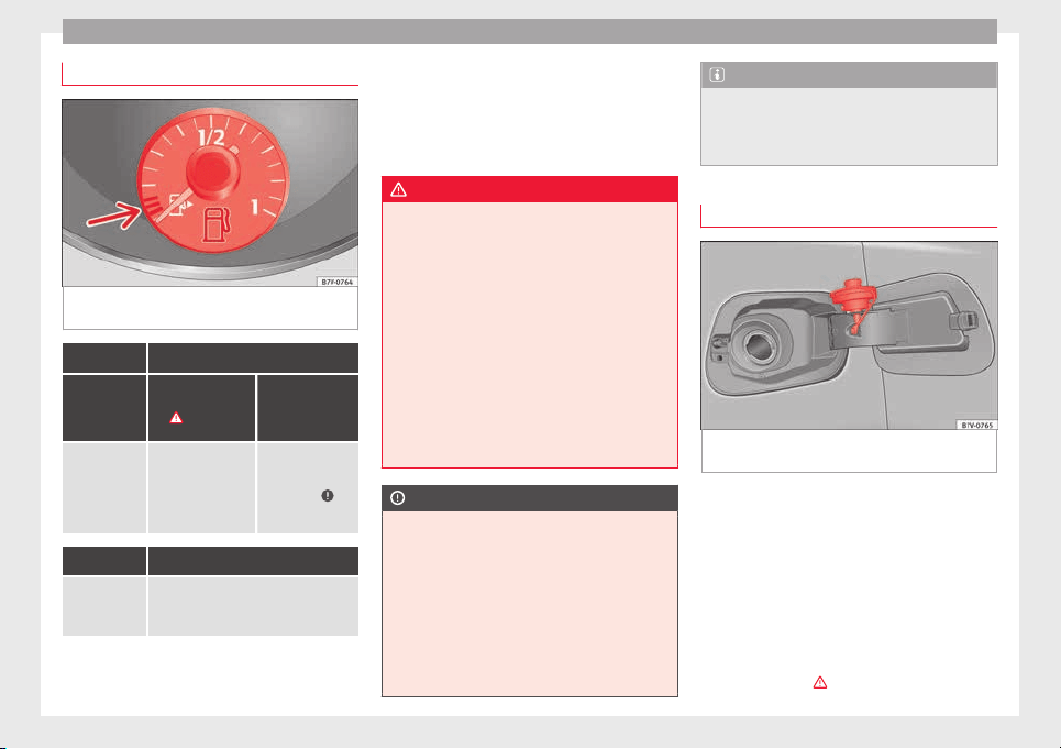
Advice
Control lamps and fuel gauge
Fig. 235 On the instrument panel: Fuel gauge
f
or petr
o
l and diesel
It lights up
Gauge posi-
tion
››› Fig. 235
Possible cause
›››
Solution
Red mark (ar-
row)
The fuel tank is al-
most empty.
The reserve tank is
being used
››› page 39.
Refuel as soon as
possible ››› .
It lights up
Fuel tank not
closed cor-
rectly.
Stop the vehicle and close the tank
flap properly.
Several warning and indication lamps light
up f
or a f
ew sec
onds when the ignition is
switched on, signalling that the function is
being verified. They will switch off after a few
seconds.
When the control lamp lights up or the
auxiliary heating and heater running off pet-
rol automatically switch off.
WARNING
Driving with insufficient fuel reserve could re-
sult
in the vehicle breaking down in traffic
and a serious accident.
●
If the fuel level is too low then the fuel sup-
ply to the engine can become irregular espe-
cially on slopes.
●
If the engine “is choked” or stalls due to
lack of or irregularity of the fuel supply, the
power steering as well as all of the driver as-
sistance systems including braking assis-
tance will stop working.
●
Always refuel when there is only one quar-
ter of the fuel tank left to avoid running out of
fuel.
CAUTION
●
Alwa
ys pay attention to any lit control
lamps and to the corresponding descriptions
and instructions to avoid damage to the vehi-
cle.
●
Never run the fuel tank completely dry. An
irregular fuel supply may lead to ignition
faults and unburnt fuel could enter the ex-
haust system. This could damage the catalyt-
ic converter filter or the diesel particulate fil-
ter!
Note
The arrow next to the fuel pump symbol on
the instrument
panel ››› Fig. 235 indicates the
side of the vehicle on which the fuel tank flap
is located.
Refuelling
Fig. 236 Open fuel tank flap with tank cap in
the ho
l
der
Read the additional information carefully
›
›
›
page 39
Refuelling
The correct petrol type for the vehicle is loca-
ted on a sticker inside the fuel tank flap
››› page 267.
●
If the automatic filler nozzle is operated
correctly, it will switch itself off as soon as
the tank is full ›››
.
266
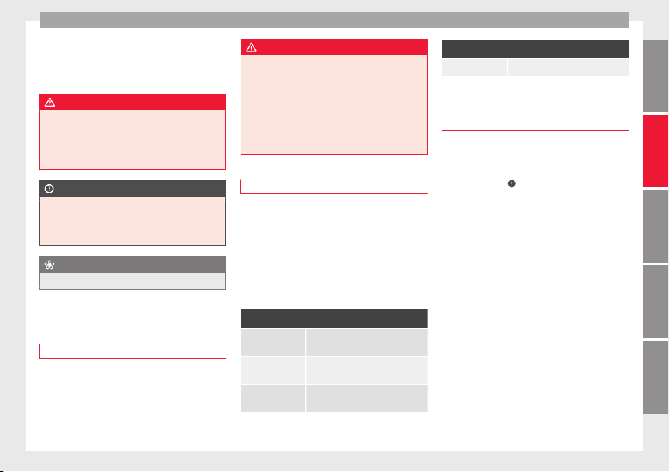
Checking and refilling levels
●
Do not
c
ontinue t
o refuel if it is turned off!
Otherwise, this will fill the expansion cham-
ber and fuel may leak out if the ambient con-
ditions are warm.
WARNING
Do not continue refilling once the fuel nozzle
has
switched itself off. The fuel tank may be
filled too much. As a result, fuel may spurt
out and spill. This could lead to a fire, explo-
sion and severe injuries.
CAUTION
●
Alwa
ys remove any fuel spilled on the vehi-
cle paintwork immediately to avoid damage
to the wheel housing, the tyre and vehicle
paintwork.
For the sake of the environment
Spilt fuel can contaminate the environment.
Fuel
Intr
oduction
You will find a factory-fitted sticker containing
inf
orm
ation on the type of
fuel for your vehi-
cle on the inside of the fuel tank flap.
WARNING
Refuelling or handling fuel carelessly can
cause an e
xplosion or fire resulting in serious
burns and injuries.
●
Fuel is a highly explosive, easily flammable
substance.
●
Observe current safety instructions and lo-
cal regulations concerning the handling of
fuel.
Types of fuel
The type of fuel to use when refilling will de-
pend on the
v
ehic
le's engine. You will find a
factory-fitted sticker containing information
on the type of fuel for your vehicle on the in-
side of the fuel tank flap.
SEAT recommends the use of sulphur-free or
low sulphur fuel to reduce consumption and
prevent engine damage.
Possible types of fuel
91
a)
RON Normal petrol, normal unleaded
petrol ››› page 267
95
a)
RON Premium unleaded petrol (95 RON)
››› page 267
98
a)
RON Premium unleaded petrol 98
››› page 267
Possible types of fuel
Diesel ››› page 268
a)
RON = Regulation Octane Number
Petrol
Petrol types
Vehicl
es with petrol engines must refuel us-
ing unleaded petrol according to European
norm EN 228 ›››
.
P
etr
o
l types are categorised according to
their octane number (e.g. 91, 95, 98 or 99
RON (RON = “Research Octane Number”).
You may use petrol with a high octane num-
ber than the one recommended for your en-
gine. However, this has no advantage in
terms of fuel consumption and engine power.
SEAT recommends refuelling with a low sul-
phur content or sulphur-free petrol to reduce
fuel consumption for petrol engines.
Petrol additives
The quality of the fuel influences the behav-
iour, power and service life of the engine.
This is why the petrol you use should carry
suitable additives already included by the
petrol industry, free of metals. These addi-
tives will help to prevent corrosion, keep the
fuel system clean and prevent deposits from
building up in the engine.
»
267
Technical dataAdviceOperationEmergenciesSafety
Advice
If good-quality petrol with metal-free addi-
tiv
e
s
is not available or engine problems
arise, the necessary additives must be added
when refuelling ›››
.
Not
al
l
petrol additives have been shown to
be effective. The use of unsuitable petrol ad-
ditives may cause significant damage to the
engine and the catalytic converter. Metal ad-
ditives should never be used. Metal additives
may also be contained in petrol additives for
improving anti-detonation ratings or octane
ratings ›››
.
S
EA
T r
ecommends “genuine Volkswagen
Group Fuel Additives for petrol engines”.
These additives can be bought at SEAT deal-
ers, where information on how to use them
can also be obtained.
CAUTION
●
Do not ref
uel if the filler indicates that the
fuel contains metal. LRP (lead replacement
petrol) fuels contain high concentrations of
metal additives. Using them may damage the
engine!
●
Only use fuel with an octane rating that is
in line with the norm EN 228, otherwise sig-
nificant damage could be caused to the en-
gine and fuel system. Furthermore, it could
lead to a loss of performance with the conse-
quent engine fault.
●
The use of unsuitable petrol additives could
damage the engine.
●
If, in ex
ceptional circumstances, petrol with
a lower octane rating to that recommended is
used, only use moderate engine speeds and a
light throttle. Avoid using full throttle and
overloading the engine. Otherwise you may
damage the engine. Fill up with fuel of a suit-
able octane rating as soon as possible.
●
Just one full tank of leaded fuel would seri-
ously impair the efficiency of the catalytic
converter and could damage it.
Diesel
Diesel fuel
Die
sel
f
uel must correspond to European
standard EN 590 (In Germany, EN 590 or
DIN 51628).
The use of diesel fuel with a high sulphur
percentage requires shorter service intervals
››› Booklet Maintenance Programme ›››
.
Y
our t
ec
hnical service centre will be able to
tell you which countries have diesel with a
high sulphur content.
Do not mix fuel additives (thinners, or similar
additives) with diesel fuel.
Winter-grade diesel
When using “summer-grade diesel fuel”, dif-
ficulties may be experienced at temperatures
below 0°C (+32°F) because the fuel thickens
due to wax separation. For this reason, “win-
ter-grade diesel fuel” is available in Germany,
for example, during the cold months. It can
be used at temperatures as low as -20°C
(-4°F).
In countries with different climatic condi-
tions, other types of diesel fuel are available
that are suitable to local temperatures. Tech-
nical service centres and filling stations in
the country concerned will inform you on the
types of diesel fuels available.
A cold diesel engine makes more noise dur-
ing winter temperatures than summer tem-
peratures. Furthermore, the exhaust gases
may turn slightly bluish while the engine is
heating. The quantity of exhaust gases will
depend on the outside temperature.
Filter pre-heater
Vehicles with a diesel engine are fitted with a
fuel filter pre-heating system. This ensures
that the fuel system remains operational to
approx. -24°C (-11.2 ºF), provided you use
winter-grade diesel which is safe to -15°C
(+5.0°F).
However, if the fuel has waxed to such an ex-
tent that the engine will not start at tempera-
tures of under -24°C (-11.2°F), simply place
the vehicle in a warm garage or workshop for
a while to heat up.
268
Checking and refilling levels
Auxiliary heater
V
ehic
l
es with a diesel engine may be fitted
with an auxiliary heater. The heater runs off
the fuel from the fuel tank. On doing so,
smells and steam may be noticed outside the
vehicle for a short period. This is normal and
it is not an indication of a fault in the vehicle.
Whenever there is little fuel in the tank (re-
serve), the auxiliary heater automatically
switches off.
WARNING
Never use start boosters. An aerosol start
boost
er could explode or cause a sudden rise
in engine speed leading to engine damage
and serious injury.
CAUTION
●
The vehic
le is not prepared for the use of
biodiesel. Never, under any circumstances re-
fuel with biodiesel. It could damage the fuel
system and subsequently lead to engine
faults!
●
The addition of biodiesel to diesel by the
diesel producer according to Standard EN 590
or other equivalent (DIN 51628 in Germany,
for example) is authorised and causes no
type of damage to the engine or the fuel sys-
tem.
●
The diesel engine has been designed for to
use diesel fuel exclusively. Therefore, never
use petrol, fuel oil or other unsuitable fuels.
The composition of these fuels may signifi-
cantly d
amage the fuel system and the en-
gine.
●
The use of diesel fuels with a high sulphur
percentage could considerably reduce the
service life of the diesel particulate filter.
Your technical service centre will be able to
tell you which countries have diesel with a
high sulphur content.
Information on fuel consumption
The consumption and emission values indi-
c
at
ed do not
refer to one specific vehicle.
They are only to be used to compare the val-
ues of the different vehicle versions. The fuel
consumption and CO
2
emissions of a vehicle
not only depend on the effective use of fuel.
They also depend on your driving style and
other non-technical factors.
Calculation of fuel consumption
Fuel consumption and emission values are
determined according to the current version
of the 715/2007/EC or 80/1268/EEC regula-
tion and are valid for the vehicle kerb weight.
The specifications do not refer to an individu-
al vehicle. Two measuring cycles are carried
out on a rolling road test bed to calculate fuel
consumption. The test criteria are as follows:
Urban cycle
Measurement of the urban cycle
starts with an engine cold start. City
driving is simulated below at be-
tween 0 and 50 km/h (31 mph).
Road cycle
In the road cycle simulation, the car
undergoes frequent acceleration and
braking in all gears, as in normal ev-
eryday driving. The road speed rang-
es from 0 to 120 km/h (0 to 75 mph).
Combined
The average combined consumption
is calculated with a weighting of
around 37 % for the urban cycle and
63 % for the road cycle.
CO
2
emissions
of the combina-
tion
The exhaust gases are collected dur-
ing both driving cycles to calculate
carbon dioxide emissions (urban and
road). The gas composition is then
analysed to evaluate the CO
2
content
and other emissions.
Note
●
The kerb weight
may vary according to the
vehicle equipment. This could raise consump-
tion and the CO
2
emissions slightly.
●
In practice, consumption values could be
different to the values calculated based on
the 715/2007/EC or 80/1268/EEC regula-
tions.
269
Technical dataAdviceOperationEmergenciesSafety
Advice
Selective catalytic reduction*
(AdBlue)
Intr
oduction
In vehicles with “Selective Catalytic Reduc-
tion”, a speci
al urea solution (AdBlue) is in-
jected into the exhaust gas system in front of
the catalytic converter to reduce nitrogen ox-
ide emissions.
The consumption of AdBlue depends on indi-
vidual driving style, the temperature at which
the system operates and the outside temper-
ature where the vehicle is driven.
AdBlue is kept in an independent tank in the
vehicle and should be refilled at an official
supplier. The AdBlue tank holds about 17 li-
tres.
The AdBlue fill level must be checked when
the vehicle is being serviced.
WARNING
If the AdBlue fill level is too low, the vehicle
may
not restart after switching the ignition
off. The emergency start or jump start will not
be possible either!
●
Top up with AdBlue at the latest 1,000 km
or 600 miles before it runs out.
●
Do not allow the AdBlue to run too low.
WARNING
AdBlue is an irritant, corrosive liquid that can
cause injurie
s if it touches the skin, eyes or
respiratory organs.
●
If AdBlue get in contact with eyes and skin,
rinse for at least 15 minutes with plenty of
water and seek medical help.
●
If the AdBlue is swallowed, wash your
mouth with plenty of water for at least 15 mi-
nutes. Do not try to provoke vomiting unless
recommended by a Doctor. Seek medical ad-
vice immediately.
CAUTION
AdBlue damages surfaces such as painted ve-
hicle p
arts, plastic, items of clothing and car-
pets. Spilt AdBlue should be removed as
quickly as possible using a damp cloth and
plenty of cold water.
●
If the AdBlue has crystallised, remove with
warm water and a sponge.
Warning and indication lamps
It lights up red
The engine can-
not be restarted!
The level of
AdBlue is too
low.
Stop the vehicle in a suitable, safe
and flat area then top up with the
minimum quantity of AdBlue re-
quired ››› page 271.
It lights up red
together with
The engine can-
not be restarted!
AdBlue system
malfunction.
Contact a specialised workshop.
Have the system checked there.
It lights up yellow
The AdBlue re-
serve is low.
Refill AdBlue over the next kilome-
tres or miles as indicated
››› page 271. SEAT recommends
contacting a specialised workshop.
It lights up yellow
together with
There is a fault
in the AdBlue
system or un-
suitable AdBlue
fluid has been
used.
Contact a specialised workshop.
Have the system checked there.
Several warning and indication lamps should
light
up f
or a f
ew seconds when the ignition
is switched on, signalling that the function is
being verified. They will switch off after a few
seconds.
270
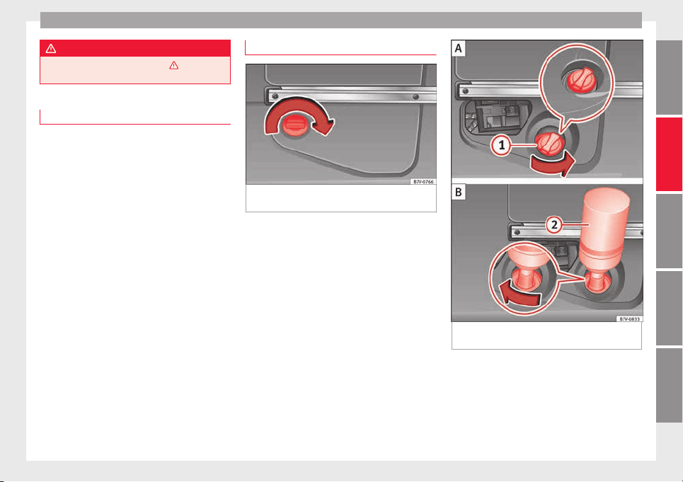
Checking and refilling levels
WARNING
Observe the safety warnings ›››
in Warning
and indication lamp
s on page 105.
Information on AdBlue
A message will be displayed on the dash
panel ar
ound 2,400 km before the next serv-
ice to indicate that AdBlue must be refilled
››› page 271. If you ignore this message and
do not refill, you will be unable to start the
engine afterwards
›››
page 270.
SEAT recommends contacting a specialised
workshop. If not possible, it should be parti-
ally filled with a minimum 5.0 litres of
AdBlue. Only refill using AdBlue expressly
approved by SEAT.
When the indicators and light simulta-
neously, there is a fault. SEAT recommends
visiting the closest specialised workshop.
AdBlue
®
is a registered trademark in the US,
Germany, the European Union and other
countries belonging to the German automo-
bile industry association (“"Verband der Au-
tomobilindustrie e. V."”, VDA).
Refilling AdBlue
Fig. 237 At the rear left of the luggage com-
p
ar
tment: AdBlue t
ank, behind a cover panel
Fig. 238 AdBlue tank with filler neck cap and
r
efi
l
ling bottle
To refill AdBlue, the vehicle must be on flat
gr
ou
nd and not, f
or example, parked on a
kerb or slope. If the vehicle is not on flat
ground then the filling indicator cannot
measure the filling quantity.
»
271
Technical dataAdviceOperationEmergenciesSafety
Advice
Opening the tank filling neck
●
Open the rear lid.
●
Rotate the shut off on the cover clockwise
›
›
›
Fig. 237 and open the cover forwards.
●
Unscrew the tank filler neck cap ››› Fig. 238
1
anticlockwise.
R
efi
l
ling AdBlue
Only use AdBlue that is approved by SEAT
and that complies with ISO 22241-1 Stand-
ard. Only use genuine bottles.
●
Observe the instructions and information
provided by the refill bottle manufacturer.
●
Observe the expiry date.
●
Unscrew the cap on the refill bottle.
●
Place the refill bottle
2
upside down in-
s
ide the t
ank
filler neck.
●
Press the refill bottle against the filler neck
and keep in this position.
●
Add at least 5.0 litres of AdBlue (6 bottles).
A lower quantity would be insufficient.
●
Wait until the contents of the refill bottle
have been poured into the AdBlue tank. Do
not crush or damage the bottle!
●
Unscrew the liquid bottle anticlockwise and
remove it carefully ›››
.
●
You can tell when the AdBlue tank is full
bec
au
se the bottl
e will be empty.
Closing the tank filling neck
●
Screw on the tank filler neck cap ››› Fig. 238
1
clockwise until it is fully inserted.
●
Place the cover and turn the shut off anti-
c
loc
k
wise to close it.
Operations before driving
●
Only switch the ignition on after refilling.
●
Keep the ignition switch on for at least 30
seconds so that the system detects tank re-
filling.
●
Wait 30 seconds before starting the en-
gine!
WARNING
Only keep AdBlue in its original container,
tightly shut and in a s
afe place.
●
Never keep AdBlue in empty food cans, bot-
tles or other containers to avoid other people
mistaking it for something else.
●
Keep the AdBlue out of the reach of small
children.
CAUTION
●
Only r
efill using AdBlue expressly approved
by SEAT. The use of any other type of AdBlue
could cause engine damage!
●
AdBlue should never be mixed with water
or any other additives. Any type of damage
caused by a mixture will not be covered by
the warranty.
●
Do not ad
d AdBlue to the diesel fuel tank!
Otherwise you may damage the engine.
●
Never leave the refill bottle in the vehicle. It
could become permeable due to temperature
changes and bottle damage and the AdBlue
could damage the vehicle interior.
For the sake of the environment
Dispose of the refill bottle in an environment-
friendly
manner
.
Note
Suitable AdBlue refill bottles can be pur-
cha
sed from a technical service centre.
Working in the engine compart-
ment
Intr
oduction
Before working in the engine compartment,
m
ak
e s
ure that the vehicle is parked on hori-
zontal and firm ground.
The engine compartment of the vehicle is a
hazardous area. Never work on the engine or
in the engine compartment if you are not fa-
miliar with the operations to be carried out,
the applicable safety standards and especial-
ly if you do not have the necessary instru-
ments, liquids and tools ›››
! Have the work
272

Checking and refilling levels
carried out by a specialised workshop if you
ar
e u
nc
ertain. Negligent work can cause seri-
ous injury.
WARNING
If the vehicle moves unexpectedly, this could
cause seriou
s injury.
●
Never work under the vehicle if it has not
been immobilized. If you must work under-
neath the vehicle with the wheels in contact
with the ground then it should be parked on
flat ground, the wheels should be prevented
from moving and the key should be removed
from the ignition.
●
If you have to work underneath the vehicle,
you must use suitable stands additionally to
support the vehicle, there is a risk of acci-
dent!. The jack is not intended for this kind of
work and its failure could lead to severe inju-
ries.
WARNING
The engine compartment is a dangerous area
capab
le of causing serious injury.
●
For all type of work, always take the utmost
precautions, work carefully and note the gen-
eral safety standards in force. Never take per-
sonal risks.
●
Never work on the engine or in the engine
compartment if you are not familiar with the
necessary operations. If you are not sure
about procedures then visit a specialised
workshop to carry out the necessary work.
Working incorrectly can cause serious inju-
ries.
●
Never open the bonnet
if you see steam or
coolant escaping from the engine compart-
ment. This may cause serious burns. Always
wait until you cannot see or hear the sound of
steam or coolant coming from the engine
compartment.
●
Always allow the engine to cool down be-
fore opening the bonnet.
●
Contact with hot elements of the engine
and the exhaust system can cause burns.
●
Once the engine has cooled, follow the in-
structions below before opening the bonnet:
–
Turn on the electronic parking brake and
place the gear selector lever in P or the
gearbox lever in neutral.
–
Remove the key from the ignition.
–
Keep children away from the engine com-
partment and never leave them unsuper-
vised.
●
When the engine is warm or hot, the cool-
ing system is pressurised. Do not unscrew
the cap on the expansion tank when the en-
gine is hot. Otherwise, coolant may spray out
under pressure causing burns and serious in-
jury.
–
Carefully and slowly unscrew the cap an-
ticlockwise, gently pressing down on it.
–
Always protect your face, hands and arms
from hot coolant and steam using a large,
thick cloth.
●
When refil
ling liquids, avoid spilling them
on parts of the engine and the exhaust sys-
tem. Spilled liquids could cause a fire.
WARNING
The high voltages of the electrical system can
giv
e electric
shocks as well as causing burns
and serious injury and possibly even death!
●
Never cause short circuits in the electrical
system. The battery could explode.
●
To minimise the risk of electric shock and
serious consequences while the engine is
running or starting the engine, note the fol-
lowing:
–
Never touch the electrical wiring of the
ignition system.
–
Never touch electric cables or the gas dis-
charge lamps.
WARNING
In the engine compartment, there are rotat-
ing par
ts that could cause serious injury.
●
Never place your hands on or near the radi-
ator fan. Touching the rotor blades could seri-
ously harm you. The ventilator works accord-
ing to the engine temperature and could start
suddenly even when the ignition is turned off
and the key is removed.
●
If any work has to be performed when the
engine is started or with the engine running,
there is an additional, potentially fatal, safety
»
273
Technical dataAdviceOperationEmergenciesSafety
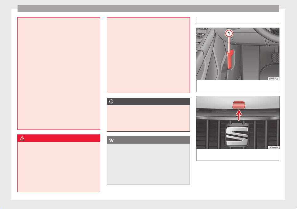
Advice
risk from rotating parts, such as the drive
belts, alt
ernator, radiator fan, etc., as well as
from the high-voltage ignition system. Al-
ways work with the utmost caution.
–
Always make sure that no parts of your
body, jewellery, ties, loose clothing and
long hair can be trapped by the rotating
parts of the engine. Before any work, re-
move ties and jewellery (necklaces, etc),
tie long hair back and tie all items of
loose clothing to your body to make sure
that they cannot be trapped by engine
components.
–
Take extreme caution when operating the
accelerator and remain attentive. The ve-
hicle could move, even with the electron-
ic parking brake activated.
●
Always make sure you have not left any ob-
jects, such as cleaning cloths and tools, in
the engine compartment. If any object is left
in the engine compartment, this could cause
malfunctions, engine faults and even a fire.
WARNING
Refill liquids and certain materials can catch
fire ea
sily in the engine compartment, caus-
ing a fire and serious injury!
●
Never smoke.
●
Never work close to places exposed to
flames or sparks.
●
Never pour service fluids over the engine.
These fluid may ignite hot engine parts and
cause injuries.
●
If it i
s necessary to work on the fuel system
or the electrical system, please follow the in-
structions below:
–
Always disconnect the vehicle battery.
When disconnecting the battery, ensure
that the vehicle is unlocked otherwise
the anti-theft alarm will be triggered.
–
Never work close to heaters, heat sources
or places exposed to flames or sparks.
●
Always keep a recently serviced and per-
fectly working fire extinguisher close by.
●
Never cover the engine with additional in-
sulating materials such as a blanket. Risk of
fire!
CAUTION
When refilling or changing service liquids,
ensur
e that you put the liquids into the right
tank. Making a mistake when refilling could
cause serious malfunctions and damage the
engine!
For the sake of the environment
Service fluids leaks are harmful to the envi-
ronment. F
or this reason you should make
regular checks on the ground underneath
your vehicle. Take the vehicle to a specialised
workshop to be checked if you see stains, oil
or other fluids on the ground. Collect any
spilt service fluids and allow a professional to
dispose of them.
Opening and closing the bonnet
Fig. 239 In the footwell on the driver side:
L
ev
er f
or unlocking the bonnet
Fig. 240 Release lever to open the bonnet in
the r
a
di
ator grille
Opening the bonnet
The l
ev
er t
o open the bonnet can only be
used if the driver door is open.
274
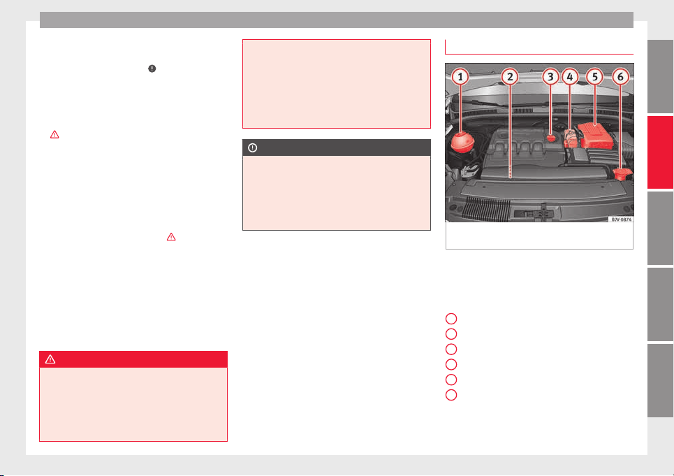
Checking and refilling levels
●
B
ef
or
e opening the bonnet, make sure that
the windscreen wiper arms are in place
against the windscreen ›››
.
●
Open the driver door.
●
Pull the release lever ›
›
›
Fig. 239 in the di-
rection of the arrow. The bonnet is released
from the lock carrier by a spring mechanism
›››
.
●
Lift the bonnet using the release lever
›
›
›
Fig. 240 (arrow) and open the bonnet fully.
The bonnet is held open thanks to the gas
strut.
Closing the bonnet
●
To close the bonnet, pull it down to over-
come the gas strut pressure ›››
.
●
Allow the bonnet to fall into the lock carrier.
Do not
pr
e
ss down.
If the bonnet is not correctly closed, open it
once again and close it correctly.
The bonnet is correctly closed when it is flush
with the corresponding parts on the body-
work.
WARNING
If the bonnet is not correctly closed, it could
sudden
ly open while driving leaving the driv-
er without visibility. This could result in a se-
rious accident.
●
After closing the bonnet, always check that
it is properly secured by the locking mecha-
nism in the lock carrier. The bonnet must be
flush with the s
urrounding body panels.
●
While driving, if you notice that the bonnet
is not correctly closed then stop immediately
and close it correctly.
●
Only open and close the bonnet when there
is nobody within its range.
CAUTION
●
T
o avoid d
amage to the bonnet and to the
windscreen wiper arms, only open it when
the windscreen wipers are in place against
the windscreen.
●
Before driving, always lower the wiper
arms.
Checking fluid levels
Fig. 241 Diagram for the location of the vari-
ou
s
el
ements.
From time to time, the levels of the different
fluid
s
in the
vehicle must be checked. Never
fill with incorrect fluids, otherwise serious
damage to the engine may be caused.
Coolant fluid deposit
Engine oil dipstick
Oil filler neck
Brake fluid reservoir
Vehicle battery (underneath a cover)
Windscreen washer fluid reservoir
»
1
2
3
4
5
6
275
Technical dataAdviceOperationEmergenciesSafety
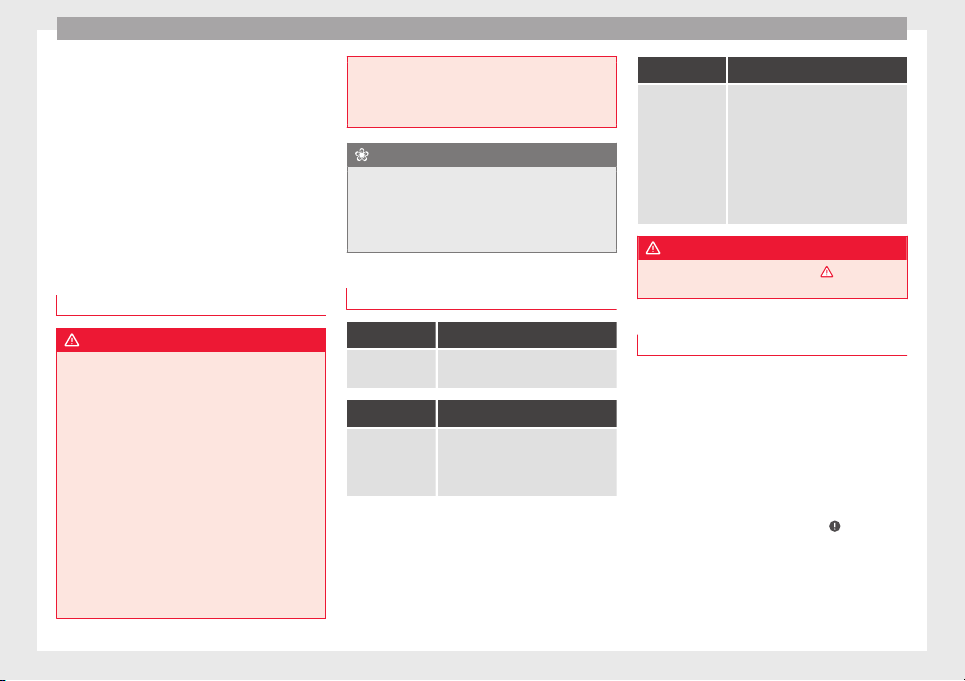
Advice
The checking and refilling of service fluids
ar
e c
arried out
on the components men-
tioned above. These operations are descri-
bed in ››› page 272.
Overview
Further explanations, instructions and restric-
tions on the technical data are contained as
of ››› page 298
Engine oil
Introduction
WARNING
Incorrectly handling engine oil can cause in-
jury and seriou
s burns.
●
Always protect your eyes when handling
engine oil.
●
Oil is toxic and must be kept out of the
reach of children.
●
Engine oil should only be kept in its origi-
nal packaging; the same goes for used oil un-
til it is disposed of.
●
Never store engine oil in empty food con-
tainers or bottles as other people may acci-
dentally drink it.
●
Regular contact with engine oil can be bad
for the skin. If you come into contact with en-
gine oil, wash your skin with soap and water.
●
With the engine ru
nning, the engine oil
gets extremely hot and can cause severe skin
burns. Always wait until the engine has fully
cooled.
For the sake of the environment
Similar to the other service liquids, spilled
en
gine oil
can be bad for the environment.
Collect these liquids in suitable containers
and dispose of them while respecting the en-
vironment.
Warning and indication lamps
It lights up
Insufficient en-
gine oil.
Switch the ignition off. Check the en-
gine oil level ››› page 277.
Flashes
Engine oil sen-
sor faulty.
Contact a specialised workshop.
Have the engine oil sensor checked.
Meanwhile, check the oil level man-
ually.
Flashes
Engine oil pres-
sure too low.
Stop the vehicle!
Switch off the engine. Check the en-
gine oil level.
- If the warning lamp flashes al-
though the oil level is correct, do not
continue driving or leave the engine
running. Otherwise, the engine
could be damaged. Seek specialist
assistance.
WARNING
Observe the safety warnings ›››
in Warning
and indication lamp
s on page 105.
Engine oil specifications
Replacement engine oil must strictly comply
w
ith the s
pec
ifications.
The correct oil must be used to ensure the
correct operation and long service life of the
engine. The engine comes with a high-quality
multigrade oil that can generally be used all
year round.
Only use an engine oil that complies to SEAT
standards whenever possible
›››
. If you
w
i
sh t
o maintain the long-life service dura-
tion, only engine oils approved for this serv-
ice according to the corresponding VW stand-
ard (
›››
table on page 40) may be used.
All oils indicated are synthetic multigrade
oils.
276
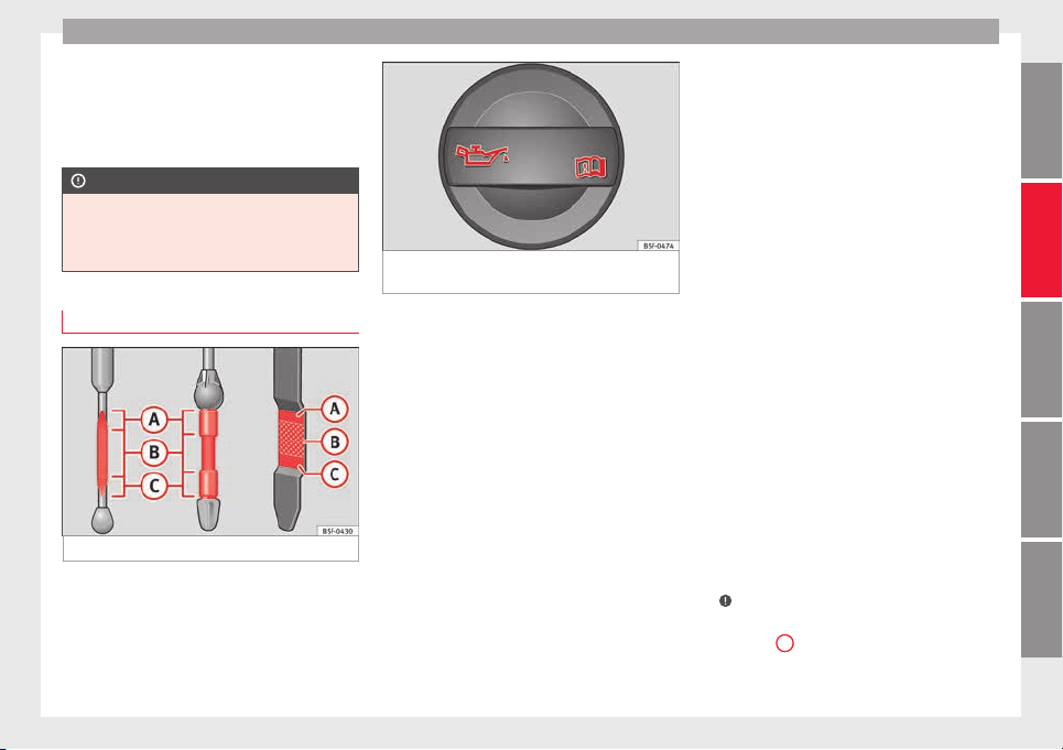
Checking and refilling levels
Engine oils are being continuously further
dev
eloped.
T
echnical services are constantly
updated with any modifications. SEAT there-
fore recommends that you have the engine
oil changed by a technical service.
CAUTION
●
Only u
se engine oils whose specifications
are expressly approved by SEAT. The use of
any other type of oil could cause engine dam-
age!
Checking engine oil level
Fig. 242 Marked engine oil dipstick
Fig. 243 In the engine compartment: Engine
oil fi
ller cap.
Read the additional information carefully
›
›
›
page 39
Preparations
●
Park the vehicle on flat ground so that the
engine oil reading is correct.
●
Stop the engine and wait a few minutes for
the oil to drain back into the sump. When the
engine has cooled down, immediately check
the oil level and top up if necessary.
●
Open the bonnet ››› page 272.
●
The engine oil filler neck can be recognised
by the symbol on the cap ››› Fig. 243 and
the dipstick by its coloured handle.
Checking the engine oil level
●
Pull out the dipstick and wipe it on a clean
cloth.
●
Replace the dipstick, pushing it in as far as
it will go. If the dipstick has a mark, when you
reintroduce it this mark should slot into the
corresponding groove located on the upper
end of the tube.
●
Remove the oil dipstick again and check
the engine oil level.
●
After reading the oil level, replace the dip-
stick in the tube completely.
Adding oil after checking the level
Only add engine oil in small quantities and in
steps:
●
Unscrew the cap from engine oil filler neck
on the cylinder head ››› Fig. 243. If you are
not sure where the cap is, request help from
a specialist.
●
Only refill using approved SEAT engine oil
in small quantities (no more than 0.5 l)
››› page 276.
●
To avoid adding too much oil, each time
you add a quantity, wait until the oil has flow-
ed into the crankcase so that it can be meas-
ured with the dipstick.
●
Check the oil level before adding any more
oil. Do not top up with too much engine oil
›››
.
●
When the oil level is at least in the
›
›
›
Fig. 242
B
zone, insert the dipstick into
the t
ube f
u
lly to avoid engine oil escaping
when the engine is running.
»
277
Technical dataAdviceOperationEmergenciesSafety
Advice
●
Af
t
er t
opping up the oil, ensure that the
cap is screwed on to the filler neck correctly.
WARNING
Oil could catch fire if it comes into contact
with hot en
gine components. This could lead
to a fire, explosion and severe injuries.
●
Always ensure that after topping of oil, the
engine oil filler cap is correctly tightened.
This will avoid engine oil spilling onto hot en-
gine parts when the engine is running.
CAUTION
●
If the engine oi
l level is above the area
››› Fig. 242
A
do not start the engine. Seek
speci
alist assistance. Otherwise catalytic
converter and engine damage may occur.
●
When refilling or changing service liquids,
ensure that you put the liquids into the right
tank. Making a mistake when refilling could
cause serious malfunctions and damage the
engine!
For the sake of the environment
The oil level must never be above area
›››
Fig. 242
A
. Otherwise oil can be drawn in
through the cr
ankcase breather and escape
into the atmosphere via the exhaust system.
Engine oil consumption
The consumption of engine oil can be differ-
ent from one en
gine to another and can vary
during the useful life of the engine.
Depending on driving style and the condi-
tions of use, the consumption of engine oil
can reach 1 litre every 2,000 km (one quarter
of a gallon every 1,200 miles); for new vehi-
cles, this could be higher for the first
5,000 km (3,000 miles). For this reason the
engine oil level must be checked at regular
intervals, preferably when filling the tank and
before a journey.
Topping up engine oil
Read the additional information carefully
›
›
›
page 39
The engine oil must be changed regularly ac-
cording to the specifications of the Mainte-
nance Programme.
Due to the problems linked with disposing of
used oil and the need for suitable tools and
special knowledge, always visit a specialised
workshop to have the engine oil and filter
changed. SEAT recommends taking your car
in for technical service.
Detailed information on the service intervals
is shown in the Maintenance Programme.
WARNING
If, in exceptional circumstances, you must
chan
ge the engine oil yourself, please note
the following:
●
Wear eye protection.
●
Always wait until the engine has complete-
ly cooled to avoid being burned.
●
Always keep your arms horizontal when un-
screwing the oil drainage bolt so that it does
not run down your arms.
●
Use a suitable container large enough to
collect all of the used oil in the engine.
●
Never collect engine oil in empty food con-
tainers, cans, bottles or other containers as
not all people are able to identify engine oil.
●
Oil is toxic and must be kept out of the
reach of children.
CAUTION
No additives should be used with engine oil.
This c
ould result in engine damage. Any dam-
age caused by the use of such additives
would not be covered by the factory warranty.
For the sake of the environment
●
Befor
e changing the engine oil, find a suita-
ble location or service for proper disposal.
●
Always dispose of engine oil with the ut-
most respect for the environment. Never dis-
pose of used engine oil in places such as a
garden, woods, drains, roads, paths, rivers
and drainage systems.
278
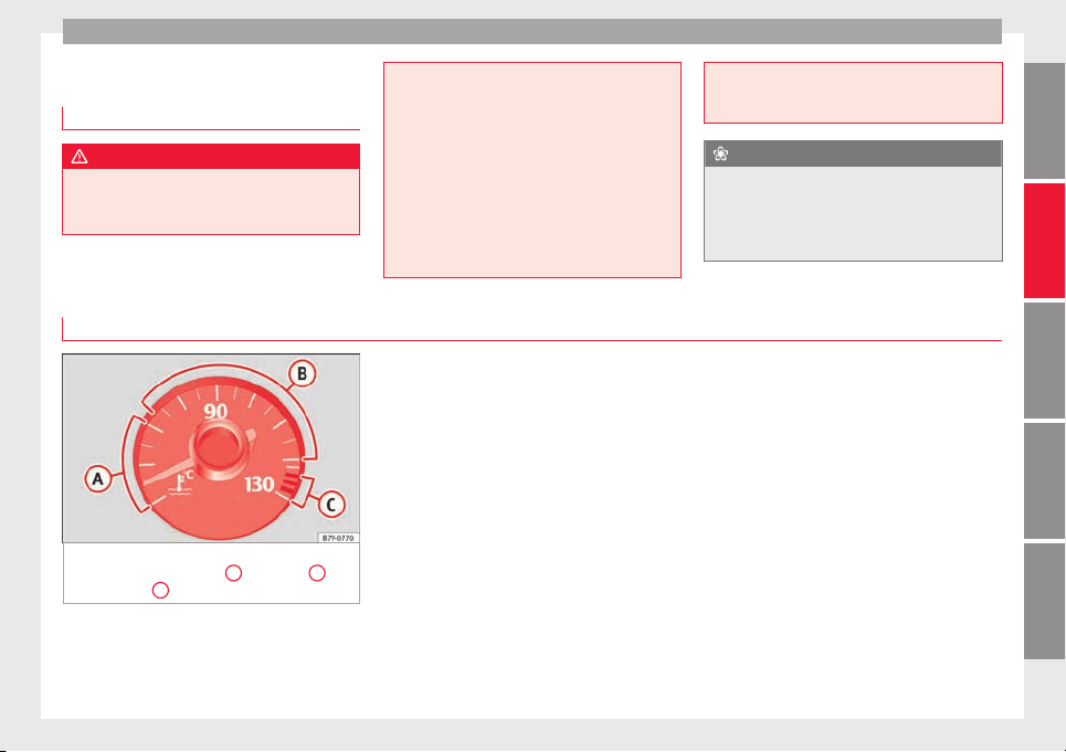
Checking and refilling levels
Engine coolant
Intr
oduction
WARNING
Engine coolant is toxic!
●
Only keep engine coolant in its original
container
, tightly shut and in a safe place.
●
Never st
ore engine coolant in empty food
containers or bottles as other people may ac-
cidentally drink it.
●
Always keep engine coolant out of reach of
children.
●
Ensure that the proportion of engine cool-
ant additive corresponds to the lowest out-
side temperature to which the vehicle will be
exposed.
●
If the outside temperature is extremely low,
the engine coolant could freeze causing the
vehicle to stop. As this would also cause the
heating t
o stop working, passengers without
warm clothing could freeze.
For the sake of the environment
Coolants and additives can contaminate the
en
vir
onment. Collect any spilt fluids in suita-
ble containers and dispose of them in accord-
ance with legislation and with the utmost re-
spect for the environment.
Warning lamp and coolant temperature indicator
Fig. 244 Engine coolant temperature gauge
on the instrument
panel:
A
cold area;
B
normal area;
C
warning area
When driving normally, the needle will re-
m
ain in the mid
dl
e area. The temperature
may also rise when the engine is working
hard, especially at high outside temperatures
and so the indicator will move quite far to the
right-hand side.
Several warning and indication lamps light
up for a few seconds when the ignition is
switched on, signalling that the function is
being verified. They will switch off after a few
seconds.
»
279
Technical dataAdviceOperationEmergenciesSafety
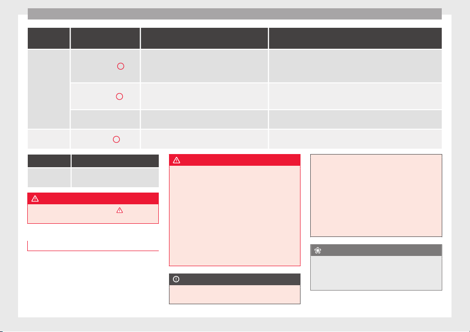
Advice
It lights up
Gauge position
››› Fig. 244
Possible cause Solution
Warning area
C
Excessive engine coolant temperature.
Stop the vehicle!
Stop the vehicle safely as soon as possible. Switch off the engine and wait
for it to cool down and for the needle to return to the normal area. Check
the engine coolant level ››› page 281.
Normal area
B
Insufficient engine coolant level.
Check the engine coolant when the engine has cooled and, if it is low, refill
with engine coolant ››› page 281.
Although the coolant level is correct, there is a fault.
-- Engine coolant system faulty.
Do not drive any further.
Obtain professional assistance.
-- Cold area
A
--
Avoid revving the engine too much or making it work hard while it has not
reached normal service temperature.
Flashes
Engine coolant
system faulty.
Seek specialist assistance.
WARNING
Observe the safety warnings ›››
in Warning
and indication lamp
s on page 105.
Coolant specifications
Read the additional information carefully
›
›
›
page 40
WARNING
If there is not enough anti-freeze in the cool-
ant sys
tem, the engine may fail leading to se-
rious damage.
●
Please make sure that the percentage of
additive is correct with respect to the lowest
expected ambient temperature in the zone in
which the vehicle is to be used.
●
When the outside temperature is very low,
the coolant could freeze and the vehicle
would be immobilised. In this case, the heat-
ing would not work either and inadequately
dressed passengers could die of cold.
CAUTION
The original additives should never be mixed
with coo
lants which are not approved by
SEAT. Otherwise, you run the risk of causing
severe d
amage to the engine and the engine
cooling system.
●
If the fluid in the expansion tank is not pur-
ple but is, for example, brown, this indicates
that the G 13 additive has been mixed with
an inadequate coolant. The coolant must be
changed as soon as possible if this is the
case! This could result in serious faults and
engine damage.
For the sake of the environment
Coolants and additives can contaminate the
en
vir
onment. If any fluids are spilled, they
should be collected and correctly disposed
of, with respect to the environment.
280
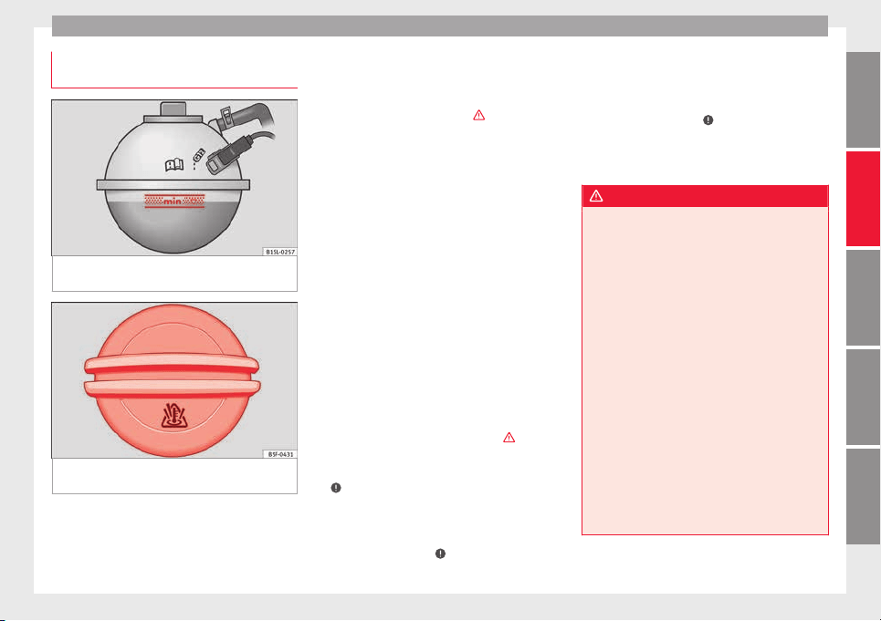
Checking and refilling levels
Checking the coolant level and top-
pin
g up
Fig. 245 In the engine compartment: Marking
on c
oo
l
ant expansion tank
Fig. 246 In the engine compartment: Coolant
e
xp
an
sion tank cap
If the coolant level is low, the coolant warn-
in
g indic
at
or will light.
Preparations
●
Park the vehicle on even, flat and firm
ground.
●
Allow the engine to cool ›››
.
●
Open the bonnet ›
›
›
page 272.
●
The coolant expansion tank is easily recog-
nisable because of the symbol on the cap
››› Fig. 246.
Checking the engine coolant level
●
When the engine is cold, check the coolant
level using the side marking on the expan-
sion tank ››› Fig. 245.
●
If the level is below the “MIN” mark, top up
with coolant. When the engine is hot it may
be slightly above the marked area.
Topping up the engine coolant level
●
Always protect your face, hands and arms
from hot coolant and steam using a large,
thick cloth over the coolant expansion tank
cap.
●
Remove the cap very carefully ›››
.
●
Only refill using new en
gine c
oo
lant ac-
cording to SEAT specifications (››› page 280)
›››
.
●
The engine coolant level should be be-
tw
een the m
ark
s on the coolant expansion
tank ››› Fig. 245. Do not exceed the top level
of the marked area ›››
.
●
Screw on the cap tightly.
●
If
, in the ev
ent
of an emergency, you have
no coolant that is compliant to the required
specifications (››› page 280), do not use an-
other type of additive. Instead, top up with
distilled water only ›››
. Then re-establish
the c
orr
ect
proportion of the mixture with the
correct additive as soon as possible
››› page 280.
WARNING
Hot vapours and coolant can cause serious
burns.
●
Nev
er open the coolant expansion tank if
steam or coolant is coming from the engine
compartment. Wait until you cannot see or
hear any steam or coolant escaping.
●
Always wait until the engine has complete-
ly cooled before very carefully opening the
expansion tank cap. Contact with hot ele-
ments of the engine can cause skin burns.
●
When the engine is warm or hot, the cool-
ing system is pressurised. Do not unscrew
the cap on the expansion tank when the en-
gine is hot. Otherwise, coolant may spray out
under pressure causing burns and serious in-
jury.
–
Carefully and slowly unscrew the cap an-
ti-clockwise, gently pressing down on it.
–
Always protect your face, hands and arms
from hot coolant and steam using a large,
thick cloth.
»
281
Technical dataAdviceOperationEmergenciesSafety
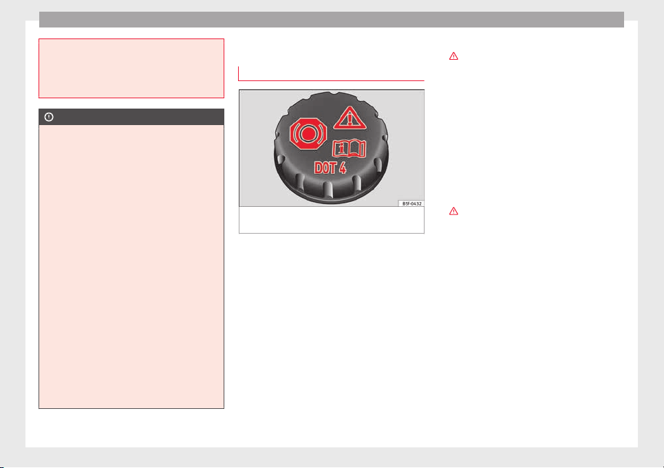
Advice
●
When refil
ling liquids, avoid spilling them
on parts of the engine and the exhaust sys-
tem. Spilled liquids could cause a fire. Under
specific circumstances, the ethylene glycol
can catch fire.
CAUTION
●
On
ly fi
ll with distilled water. Any other type
of water may lead to considerable rusting in
the engine due to its chemical components.
This could consequently damage the engine.
If you have not used distilled water but an-
other type of water to top up the coolant, a
specialised workshop must immediately re-
place all of the fluid in the engine cooling
system.
●
Only top up coolant to the top level of the
marked area ››› Fig. 245. Otherwise the ex-
cess coolant will be forced out of the cooling
system when the engine is hot, causing dam-
age.
●
If a lot of liquid coolant has been lost, wait
for the engine to cool down completely before
adding coolant. Extensive coolant loss is an
indication of leaks in the engine cooling sys-
tem. Have the engine cooling system inspec-
ted immediately by a specialised workshop.
Otherwise engine damage may occur.
●
When refilling service liquids, ensure that
you put the liquids into the right tank. Mak-
ing a mistake when refilling could cause seri-
ous malfunctions and damage the engine!
Brake fluid
Chec
k
in
g the brake fluid level
Fig. 247 In the engine compartment: brake
fluid r
e
ser
voir cap
Read the additional information carefully
›
›
›
page 41
In the course of time, the brake fluid absorbs
water from the ambient air. If there is too
much water in the brake fluid, the brake sys-
tem could be damaged. In addition, the boil-
ing point of the brake fluid is significantly
lowered. When the brake fluid contains too
much water and the brakes are subject to
considerable forces, bubbles of water vapour
can form in the system. These bubbles can
significantly reduce braking power, notably
increasing braking distance, and could even
result in the total failure of the brake system.
Ensuring that the brake system is always
functioning correctly is essential for your own
safety and the safety of other road users
›››
.
Br
ak
e fluid s
pecifications
SEAT have developed a special brake fluid
optimised for the brake systems of their vehi-
cles. To ensure the optimum working of the
brake system, SEAT recommends the use of
brake fluid in accordance with the VW 501 14
standard. If this brake fluid is not available or
another brake fluid is used for different rea-
sons, use a brake fluid that complies with the
United States standard FMVSS 116 DOT 4 or
the German standard DIN ISO 4925 CLASS 4
›››
.
Br
ak
e fluid
s conforming to the standard
VW 501 14, fulfil the American requirements
of the FMVSS 116 DOT 4 standard and the
German DIN ISO 4925 CLASS 4 standard.
However, fluids that comply with the US
FMVSS 116 DOT 4 standard or the German
DIN ISO 4925 CLASS 4 standard do not nec-
essarily comply with the VW 501 14 stand-
ard. Always check the information on the
brake fluid container and ensure that you are
using suitable brake fluid.
A suitable brake fluid can be obtained from
technical service centres.
282
Checking and refilling levels
Brake fluid level
The l
ev
el
of the brake fluid should always be
between the MIN and MAX marks, or above
the MIN mark ›››
.
It
i
s
not always possible to check the level of
the brake fluid, as in some models the en-
gine components make it difficult to see the
brake fluid reservoir. If you cannot read the
exact brake fluid level, consult a specialist.
The brake fluid level drops slightly when the
vehicle is being used due to wear of the
brake pads and the automatic readjustment
of the brake.
Changing the brake fluid
The brake fluid should be changed in accord-
ance with the instructions given in the Main-
tenance Programme. Have the brake fluid
changed by a specialised workshop. SEAT
recommends taking your car in for technical
service. This means that only brake fluid
complying with the required specifications
will be used.
WARNING
If the brake fluid level is low or unsuita-
ble/o
ld brake fluid is used, the brake system
may fail or braking power may be reduced.
●
Check the brake system and the brake fluid
level regularly!
●
The brake fluid shou
ld be changed regular-
ly in accordance with the instructions given
in the Maintenance Programme.
●
When the brake fluid is used and brakes
are subjected to extreme braking forces, bub-
bles of vapour form in the brake system.
These bubbles can significantly reduce brak-
ing power, notably increasing braking dis-
tance, and could result in the total failure of
the brake system.
●
Only used brake fluid that conforms to the
VW 501 14 standard, FMVSS 116 DOT 4
standard or even the DIN ISO 4925 CLASS 4
standard. Other types of brake fluid could af-
fect brake operation and reduce braking pow-
er. Do not use a brake fluid if the container
does not specify compliance with the
VW 501 14, FMVSS 116 DOT 4 or
DIN ISO 4925 CLASS 4 standards.
●
The replacement brake fluid must be new.
●
Always ensure that you use suitable brake
fluid. Do not use a brake fluid if the container
does not specify compliance with the
VW 501 14, FMVSS 116 DOT 4 or
DIN ISO 4925 CLASS 4 standards.
WARNING
Brake fluid is poisonous.
●
To reduce the risk of poisoning, do not keep
brake fluid in drink
s bottles/containers or
similar. Other people could drink from these
recipients even if the contents are clearly
marked.
●
Alwa
ys keep brake fluid in the original con-
tainer; keep it correctly sealed and out of
reach of children.
CAUTION
Brake fluid damages the vehicle paintwork.
W
ipe off an
y brake fluid from the paintwork
immediately.
For the sake of the environment
Brake fluid is an environmental pollutant.
Col
lect any spilt service fluids and allow a
professional to dispose of them.
283
Technical dataAdviceOperationEmergenciesSafety
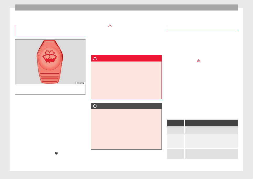
Advice
Windscreen washer reservoir
Chec
k
in
g and topping up the wind-
screen washer reservoir
Fig. 248 In the engine compartment: wind-
s
c
r
een washer reservoir top
Read the additional information carefully
›
›
›
page 41
Check the level in the windscreen washer
tank regularly and top up as required.
●
Open the bonnet ››› page 272.
●
The washer reservoir is marked with the
symbol on the lid ››› Fig. 248.
●
Check there is enough water in the reser-
voir.
●
To top up, mix water with a window cleaner
recommended by SEAT ›››
. Please follow
the in
s
truction
s for use found on the packag-
ing.
●
In cold weather, a special antifreeze should
also be added to prevent the water from
freezing ›››
.
Fi
l
lin
g amounts
The capacity of the tank is approximately 3 li-
tres; in vehicles with a headlight washer sys-
tem, it is approximately 7 litres.
WARNING
Never mix an unsuitable antifreeze or other
simil
ar additives with the windscreen washer
water. A greasy layer may be formed on the
windscreen which will impair visibility.
●
Use clean water with a window cleaner rec-
ommended by SEAT.
●
If necessary, add a suitable antifreeze to
the water in the reservoir.
CAUTION
●
Do not mix
cleaning products recommen-
ded by SEAT with other products. This could
lead to flocculation and may block the wind-
screen washer jets.
●
When topping up service fluids, make abso-
lutely certain that you fill the fluids into the
correct reservoirs. Using the wrong fluids
could cause serious malfunctions and engine
damage!
Vehicle battery
Intr
oduction
The battery is a component of the vehicle's
electrical
system.
Never work on the electrical system without
fully understanding the operations required,
the applicable safety standards and without
the correct tools ›››
! If required, have any
work c
arried out by a specialised workshop.
SEAT recommends taking your car in for tech-
nical service. Negligent work can cause seri-
ous injury.
Location and number of batteries in the vehi-
cle
The battery is located in the engine compart-
ment.
Explanation of the warning indications on
the vehicle's battery
Symbol Meaning
Wear eye protection!
Battery acid is extremely corrosive. Al-
ways wear protective gloves and eye pro-
tection!
Fires, sparks, open flames and smoking
are prohibited.
284
Checking and refilling levels
Symbol Meaning
A highly explosive mixture of gases is re-
leased when the battery is under charge.
Keep children away from acid and batter-
ies!
WARNING
Working on the vehicle battery and the elec-
trical
system can cause corrosion, fire and
electric shocks. Always read and take into ac-
count the following warnings and safety
standards before carrying out any work:
●
Before working on the battery, switch off
the engine, the ignition and all electrical de-
vices then disconnect the negative connec-
tion on the battery.
●
Keep children away from acid and the bat-
tery itself!
●
Wear eye protection.
●
Battery acid is very corrosive and caustic. It
can burn skin and cause blindness. When
handling the battery, protect yourself from
splashes of acids, above all your hands, arms
and face.
●
Do not smoke and never work close to pla-
ces exposed to flames or sparks.
●
Avoid sparks and electrostatic discharges
when working with cables and electrical devi-
ces.
●
Never short the battery terminals.
●
Never use a d
amaged battery. It can ex-
plode. Replace a damaged battery immedi-
ately.
●
Replaced damaged or frozen batteries as
soon as possible. A flat battery can also
freeze at temperatures close to 0°C (+32°F).
●
For vehicles with the battery in the luggage
compartment: Check that the battery gas
ventilation hose is securely attached.
CAUTION
●
Nev
er dis
connect the battery if the ignition
is switched on or if the engine is running.
This could damage the electrical system or
electronic components.
●
Do not expose the battery to direct sunlight
over a long period of time, as the intense ul-
traviolet radiation can damage the battery
housing.
●
If the car is left standing for long periods,
protect the battery from extreme cold temper-
ature so that it does not “freeze up” and be-
come damaged.
Warning lamp
It lights up
Faulty generator.
Contact a specialised workshop.
Have the electrical system checked.
Disconnect any unnecessary electri-
cal devices. The generator does not
charge the battery while the vehicle
is in motion.
Several warning and indication lamps light
up for a few sec
onds when the ignition is
switched on, signalling that the function is
being verified. They will switch off after a few
seconds.
WARNING
If the warning lamps and messages are ignor-
ed, the vehic
le may stall in traffic, or may
cause accidents and severe injuries.
●
Never ignore the warning lamps or text
messages.
●
Stop the vehicle safely as soon as possible.
CAUTION
Failure to heed the control lamps and text
mess
ages when they appear may result in
faults in the vehicle.
285
Technical dataAdviceOperationEmergenciesSafety
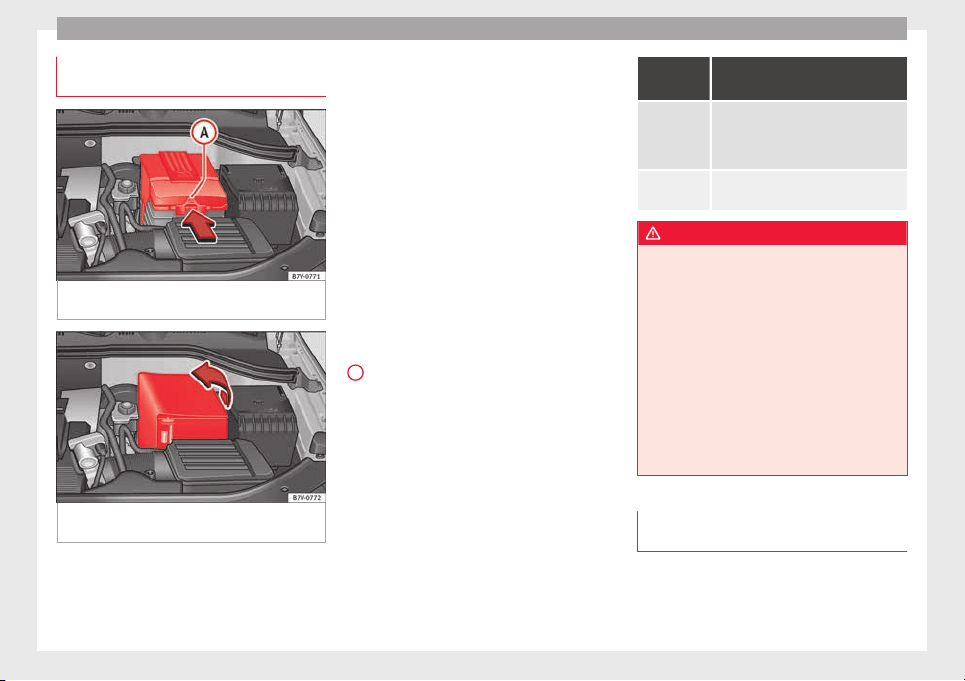
Advice
Checking the electrolyte level of the
v
ehic
l
e battery
Fig. 249 In the engine compartment: remove
the lid fr
om the
v
ehicle's battery.
Fig. 250 In the engine compartment: lift off
the c
o
v
er from the vehicle's battery.
Read the additional information carefully
›
›
›
page 41
The battery's electrolyte level should be
checked regularly in high-mileage vehicles,
in hot countries and in older batteries. Other
batteries do not require maintenance.
Start-Stop systems (››› page 209) are equip-
ped with a special battery labelled “AGM”.
For technical reasons, it is not possible to
check the electrolyte level of these batteries
Preparations
●
Prepare the vehicle for work in the engine
compartment ››› page 272
●
Open the bonnet ››› page 272.
Opening the battery cover
The battery covers are different depending on
the engine size of the vehicle:
●
In the case of a lid: press the tab ››› Fig. 249
A
in the direction of the arrow and pull the
c
o
v
er upwards.
●
In the case of a cover: fold the cover to one
side to remove ››› Fig. 250.
Checking the battery electrolyte level
●
Make sure there is sufficient lighting to
clearly recognise the colours. Never use
flames or flashing objects as a light source.
●
Depending on the level of acid, the Magic
eye on the top of the battery will change col-
our.
Colour in-
dicator
Necessary operations
Light yellow
or Colourless
The electrolyte level of the vehicle's bat-
tery is too low. Have the battery checked
and, where applicable, replaced by a
specialised workshop.
Black
The electrolyte level of the vehicle's bat-
tery is correct.
WARNING
Working with the vehicle battery involves a
risk of
corrosion, explosions or electric
shock.
●
Never tilt the vehicle battery. Battery acid
could spill out of the openings for the release
of gases and cause corrosion damage.
●
Never open the vehicle battery.
●
If battery acid splashes on you, immediate-
ly rinse your eyes and skin abundantly with
water for several minutes. Then seek medical
care immediately.
●
If acid is swallowed by mistake, consult a
doctor immediately.
Charging, replacing and connecting or
di
s
c
onnecting the battery
Charging the battery
The
v
ehic
le battery should be charged by a
specialised workshop only, as batteries us-
ing special technology have been installed
286

Checking and refilling levels
and they must be charged in a controlled en-
v
ir
onment
›››
. SEAT recommends taking
y
our c
ar in f
or technical service.
Replacing a vehicle battery
The battery has been developed to suit the
conditions of its location and has special
safety features. If the battery must be re-
placed, consult a technical service for infor-
mation on electromagnetic compatibility, the
size and maintenance, performance and
safety requirements of the new battery in
your vehicle before you purchase one. SEAT
recommends you have the battery replaced
by a technical service.
Use only maintenance-free genuine batteries
conforming to TL 825 06 and VW 7 50 73
Standards. These standards must be dated
April 2008 or later.
Start-Stop systems (››› page 209) are equip-
ped with a special battery. Therefore, it must
only be replaced with a battery of the same
specifications.
Disconnecting the vehicle's battery
If you must disconnect the battery from the
electrical system, please note the following:
●
Switch off the ignition and all electrical
equipment.
●
The vehicle must be unlocked before dis-
connecting the battery, otherwise the alarm
will be triggered.
●
First disconnect the negative cable and
then the positive ›››
.
C
onnectin
g the
vehicle's battery
●
Before reconnecting the battery, switch off
the engine and all electrical devices.
●
First reconnect the positive cable and then
the negative ›››
.
Diff
er
ent
control lamps may light up after
connecting the battery and switching the ig-
nition on. They will be turned off after a short
trip at a speed of between 15-20 km/h
(10-12 mph). If the warning indicators remain
lit, please visit a specialised workshop to
have the vehicle checked.
If the battery has been disconnected for a
long time, it is possible that the next service
date is not displayed or calculated correctly
››› page 100. Respect the maximum service
intervals permitted ››› Booklet Maintenance
Programme.
Vehicles with Keyless Access (››› page 117):
if, after connecting the battery, the ignition
cannot be switched on, lock and unlock the
vehicle from outside. Then try to switch on
the ignition again. If the ignition does not
work, seek professional assistance.
Automatically disconnecting devices
The intelligent vehicle electrical system auto-
matically implements a range of measures to
prevent the battery from discharging when
high demands are made on it:
●
the idling speed is increased so that the al-
ternator provides more electricity.
●
where necessary, the power of the most
powerful devices is reduced or even com-
pletely disconnected.
●
On starting the engine, the power supply
from the 12-volt power sockets and the ciga-
rette lighter may be interrupted for a short
time.
The on-board management program cannot
always prevent the battery from running flat.
For example, if the ignition is left on for a
long period with the engine off or if the side
lights or parking lights are left on while the
vehicle is stationary.
Why does the battery run flat?
●
When stationary for a long time without
starting the engine, particularly if the ignition
is switched on.
●
Use of electrical devices with the engine
switched off.
●
If the auxiliary heater is running
››› page 180.
»
287
Technical dataAdviceOperationEmergenciesSafety
Advice
WARNING
Incorrectly securing the battery or using the
wrong b
attery can cause short-circuits, fire
and serious injuries.
●
Always use only maintenance free batteries
that do not run flat alone and whose proper-
ties, specifications and size correspond to
the standard battery. The specifications are
indicated on the battery case.
WARNING
A highly explosive mixture of gases is re-
lea
sed when the battery is under charge.
●
The batteries should be charged in a well-
ventilated room only.
●
Never charge a frozen or recently thawed
battery. A flat battery can also freeze at tem-
peratures close to 0°C (+32°F).
●
Always replace a battery which has frozen.
●
Battery cables not correctly connected may
cause a short circuit. Reconnect first the posi-
tive cable and then the negative cable.
CAUTION
●
Never dis
connect the battery if the ignition
is switched on or if the engine is running.
This could damage the electrical system or
electronic components.
●
Never plug accessories that supply current,
such as solar panels or a battery charger, to
the 12-volt power sockets or the cigarette
lighter. This could damage the vehicle's elec-
trical
system.
For the sake of the environment
●
Di
spo
se of the battery in an environment-
friendly manner. Batteries contain toxic sub-
stances such as sulphuric acid and lead.
●
Battery acid can contaminate the environ-
ment. If it has leaked use adequate care col-
lecting it (gloves and protective glasses), and
dispose of it correctly.
Wheels and tyres
T
y
r
es
Introduction
The SEAT Alhambra is equipped as standard
with anti-pu
ncture technology tyres (Conti-
Seal). In the event of a puncture or air leak of
up to 5 mm, the tyre seals the hole with a
protective layer inside the tread.
The inclusion of this technology means that
there is no type of spare wheel included in
the vehicle's equipment.
SEAT recommend that all work on tyres and
wheels is carried out by a specialised work-
shop. These workshops have the necessary
special tools and replacement parts, trained
personnel and facilities for disposing of the
old tyres while respecting the environment.
SEAT recommends taking your car in for tech-
nical service.
WARNING
The vehicle cannot be totally controlled or
braked if
the tyres (new or used) are worn or
damaged.
●
Incorrect use of wheels and tyres could
make driving more dangerous and result in
serious accidents and damage.
288
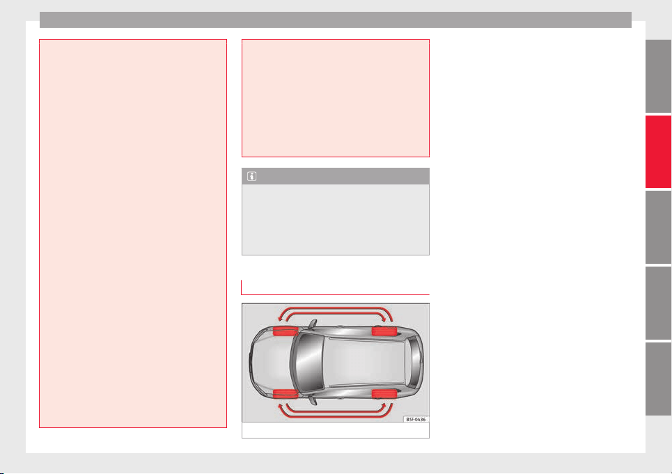
Wheels and tyres
●
All
four wheels must be fitted with radial
tyres of the same type, size (rolling
circumference) and the same tread pattern.
●
New tyres do not give maximum grip and
will not have reached their maximum braking
capacity to start with, and therefore need
running in. To prevent accidents and major
damage, extreme caution should be taken for
the first 500 km (310 miles).
●
Check tyre pressures regularly and ensure
they are maintained at the pressures indica-
ted. If the tyre pressure is too low, they could
overheat, resulting in tread detachment or
even burst tyres.
●
Never drive on damaged (punctured, cut,
cracked or dented) or worn tyres. Driving on
damaged or worn tyres could result in burst
tyres, serious accidents or damage. Worn or
damaged tyres must be replaced immediate-
ly.
●
Never exceed the maximum permitted
speed or loads specified for the type of tyre
fitted on your vehicle.
●
The effectiveness of driver and brake assist
systems also depends on the grip of the
tyres.
●
If you notice unusual vibration or if the ve-
hicle pulls to one side when driving, stop the
car immediately and check the tyres and
wheels for damage.
●
To minimise the risk of losing control of the
vehicle or causing a serious accident, never
undo the bolted joints of beadlock wheels.
●
Never mount
used tyres or wheels if you are
not sure of their previous history. They may
be damaged, although the damage is not im-
mediately visible.
●
Old tyres, even if they have never been
used, may lose air or burst unexpectedly
while driving, resulting in serious accident or
damage. If tyres are over six years old, they
should only be used in an emergency and
with extreme caution.
Note
●
F
or tec
hnical reasons, it is not generally
possible to use the wheels from other vehi-
cles. In some cases, this may also be true for
the same model of wheel. Please refer to the
vehicle documentation or ask at a technical
service.
Handling tyres and wheels
Fig. 251 Diagram for changing wheels
The tyres of a vehicle are the components
whic
h ar
e s
ubjected to most stress and are
the most underestimated. Tyres are very im-
portant, as the support offered by their nar-
row surface is the only point of contact be-
tween the vehicle and the road.
The service life of tyres is dependent on tyre
pressure, driving style, the care they receive
and the correct fitting.
The tyres and wheel rims are an essential
part of the vehicle's design. The tyres and
rims approved by SEAT are specially matched
to the characteristics of the vehicle and our
critical to good road holding and safe han-
dling.
Avoiding damage to tyres and wheels
●
If you have to drive over a kerb or similar
obstacle, drive very slowly and as near as
possible at a right angle to the kerb.
●
Inspect the tyres regularly for damage
(punctures, cuts, cracks, dents).
●
Remove any foreign bodies found on the
outside of the tyre tread and ensure that they
have not passed through the wall of the tyre
››› page 294.
●
In addition, the instructions for tyre control
systems should always be observed.
●
Replace damaged or worn tyres as soon as
possible ››› page 294.
»
289
Technical dataAdviceOperationEmergenciesSafety
Advice
●
R
e
gu
larly check tyres for non-visible dam-
age ››› page 294.
●
Never exceed the maximum permitted
speed or loads specified for the type of tyre
fitted on your vehicle ››› page 295.
●
Do not allow tyres to come into contact with
aggressive substances, grease, oil, fuel or
brake fluid ›››
.
●
Lost valve caps should be replaced imme-
di
at
ely
.
Changing wheels
To ensure that the wear is equal on all tyres
the wheels should be changed round from
time to time according to the system
››› Fig. 251. The useful life of all the tyres will
then be about the same time.
SEAT recommends you take the vehicle to a
specialised workshop to have the tyres
changed.
Tyres over 6 years old
Tyres are subject to an ageing process as a
result of physical and chemical processes.
This may affect their performance. Tyres
which are stored for long periods of time
without being used, harden and become
more fragile than tyres which are in constant
use.
SEAT recommends that tyres over six years
old are replaced with new tyres. This also ap-
plies to tyres which appear to be in perfect
condition on the outside and which have a
tread depth within the values stipulated by
the Law ›››
.
The d
at
e of
manufacture, part of the tyre
identification number (TIN), indicates the age
of the tyre ››› page 295.
Storing tyres
Mark tyres when you remove them to indicate
the direction of rotation (left, right, forwards,
backwards). This ensures you will be able to
mount them correctly when you replace
them. When removed, the wheels and/or
tyres should be stored in a cool, dry and pref-
erably dark location. Do not place tyres
mounted on the wheel in a vertical position.
Protect tyres not mounted on wheels from
dirt by storing them in suitable bags and
standing them on the ground on their tread.
WARNING
Aggressive fluids or substances could result
in vi
sible or invisible damage with the conse-
quent risks.
●
Always ensure that tyres do not come into
contact with chemical products, oil, grease,
fuel, brake fluid or other aggressive substan-
ces.
WARNING
Old tyres, even if they have never been used,
may
lose air or burst unexpectedly while driv-
ing, resulting in serious accident or damage.
●
If tyres are over six years old, they should
only be used in an emergency and with ex-
treme caution.
For the sake of the environment
Old tyres must be disposed of by qualified
personnel ac
cording to the laws in the coun-
try concerned.
Wheels
The design of wheel bolts is matched to the
rims. If
diff
er
ent rims are fitted, the correct
wheel bolts with the right length and correct-
ly shaped bolt heads must be used. This en-
sures that wheels are fitted securely and that
the brake system functions correctly
›››
page 84.
For technical reasons, it is not generally pos-
sible to use the wheels from other vehicles.
In some cases, this may also be true for the
same model of wheel.
The tyres and rims approved by SEAT are spe-
cially matched to the characteristics of the
vehicle and are critical to good road holding
and safe handling.
290
Wheels and tyres
Note for Italy: A
S
EA
T Service Centre should
be consulted whether different sized wheels
or tyres to those originally fitted by SEAT may
be fitted, as well as the combinations al-
lowed between the front axle (axle 1) and
back axle (axle 2).
Wheel bolts
Wheel bolts must be tightened to the correct
torque ››› page 84.
Beadlock wheel rims
Beadlock wheel rims have various compo-
nents. These are joined together by special
bolts using a special procedure. This ensures
good performance, a better seal, improved
safety and wheel run out. Therefore, worn
rims should always be replaced and must on-
ly be repaired in a specialised workshop.
SEAT recommends visiting a technical service
›››
.
Wheel
rims
w
ith bolted trims
Wheel rims may be fitted with interchangea-
ble trim parts which are attached to the rim
using self-locking bolts. Worn trims should
only be replaced at a specialised workshop.
SEAT recommends visiting a technical service
›››
.
WARNING
The use of worn or damaged wheel rims could
make driv
ing more dangerous and result in
serious accidents and damage.
●
Only wheel rims which have been approved
for use with your vehicle should be used.
●
Inspect wheel rims regularly for damage
and replace as required.
WARNING
If the bolted joints of wheel rims with bolted
ring trims ar
e not correctly tightened or loos-
ened, this could result in serious accident.
●
Never loosen the bolted joints of wheel
rims with bolted ring trims.
●
Any work relating to wheel rims with bolted
rims should be carried out at specialised
workshop. SEAT recommends taking your car
in for technical service.
Replacement of wheel rims and new
ty
r
e
s
New tyres
●
When tyres are new, drive with extreme
c
aution f
or the fir
st 500 km (310 miles), as
all tyres need to be run in. Tyres which have
not been run in do not have such good grip
or
›››
braking capacity
›
›
›
.
●
A
l
l
four wheels must be fitted with radial
tyres of the same type, size (rolling circumfer-
ence) and the same tread pattern.
●
The tread depth of new tyres may vary, ac-
cording to the type and make of tyre and the
tread pattern.
Replacing tyres
●
Where possible, always replace both
wheels on an axle (both wheels on the front
axle or both wheels on the rear axle) ›››
.
●
Old tyres should only be replaced by SEAT
ap
pr
o
ved tyres for the vehicle in question,
and in accordance with the maximum permit-
ted size, diameter, load and speed capacity.
●
If replacing tyres, make sure the new ones
have an emergency ride system (Conti-
Seal/Run flat). Otherwise, we recommend
carrying a tyre mobility system.
●
Never use tyres which are larger than SEAT
approved tyres. If the tyres are too big, they
may knock or rub against the chassis or other
components, resulting in damage.
WARNING
New tyres do not give maximum grip and will
not hav
e reached their maximum braking ca-
pacity to start with, and therefore need run-
ning in.
●
To prevent accidents and major damage,
extreme caution should be taken for the first
500 km (310 miles).
»
291
Technical dataAdviceOperationEmergenciesSafety
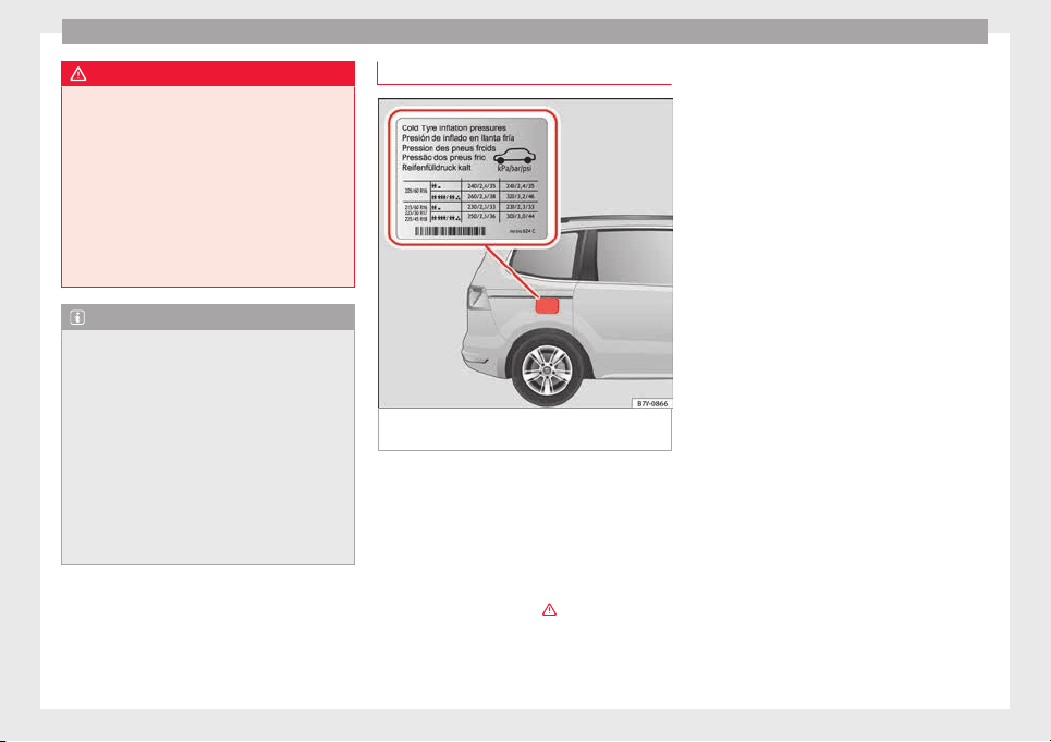
Advice
WARNING
There should be adequate space between the
tyre
s and the vehicle in accordance with the
vehicle design. If this is not the case, the
tyres may rub against parts of the running
gear, chassis or brake lines, leading to faults
in the brake system or to tread detachment,
and the risk of burst tyres.
●
The true tyre dimension should not be
greater than the dimensions of tyres manu-
factured and approved by SEAT and should
not rub against parts of the vehicle.
Note
●
Although tyr
es may be shown as being the
same size, the true dimensions of different
types of tyre may vary with respect to the
nominal size, or tread patterns may be differ-
ent.
●
If you use tyres that are approved by SEAT,
you can be sure that the true tyre dimensions
will be correct for your vehicle. For other tyre
models, the tyre vendor should provide the
manufacturer's certificate with the tyre, indi-
cating that this type of tyre is suitable for
your vehicle. This certificate should always
be carried with the vehicle.
Tyre pressure
Fig. 252 Position of tyre pressure specifica-
tion p
l
at
e
The correct tyre pressures for tyres fitted at
the f
act
or
y is shown on a label and is valid
for summer and winter tyres. This label
››› Fig. 252 is either on the driver door strut or
inside the fuel tank flap.
Under-inflation or over-inflation will reduce
the life of the tyres considerably and also im-
pair the car's handling ›››
. It is essential to
m
aint
ain the c
orrect tyre pressures, especial-
ly if driving at high speeds. Incorrect tyre
pressure causes premature wear and could
cause tyre blow-out.
The pressure should therefore be checked at
least once a month and before starting a
journey.
As a general rule, the pressures given are for
cold tyres. When the tyres are hot, the pres-
sures are greater.
Never deflate a hot tyre in order to obtain the
required pressure. This could result in very
low tyre pressures which may lead to sudden
blow-outs.
Checking tyre pressures
Tyre pressures should only be checked when
the vehicle has not been driven for more than
a few kilometres (miles) at low speeds in the
past three hours.
●
The tyre pressures should be checked regu-
larly, and only when the tyres are cold. Al-
ways check all the tyres. Tyre pressures
should be checked more often in colder re-
gions, and only when the vehicle has not
been driven recently. Always use a correctly-
operating tyre gauge.
●
Adjust tyre pressures to the loads carried in
the vehicle.
●
After checking the pressure, always replace
the valve caps, and where applicable, ob-
serve the instructions given for adjusting the
tyre control system ››› page 234.
292
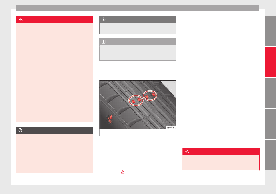
Wheels and tyres
WARNING
If tyre pressures are too high or too low, the
tyre m
ay deflate or burst suddenly while driv-
ing. This could result in a serious accident.
●
If the tyre pressure is too low, they could
overheat, resulting in tread detachment or
even burst tyres.
●
When driving at high speeds and/or fully
loaded, the tyre could suddenly overheat,
burst or be subject to tread detachment, with
the resultant loss of control of the vehicle.
●
Tyre pressures which are too high or too
low reduce the service life of the tyre, affect-
ing the vehicle's performance.
●
Tyre pressures should be checked regularly,
at least once a month and before long jour-
neys.
●
Adjust the pressures of all the tyres to the
vehicle load.
●
Never deflate excess pressure from hot
tyres.
CAUTION
●
Take c
are not to tilt the manometer when
placing it on the valve. Otherwise, the valve
may be damaged.
●
If tyre valves are not protected by caps, or if
the caps are not screwed on correctly, they
may become damaged. Check that the caps
are identical to the standard caps and have
been correctly tightened.
For the sake of the environment
Under-inflated tyres will increase fuel con-
sumption.
Note
When checking tyre pressures, please ob-
serve the in
structions for the tyre control sys-
tem ››› page 234.
Wear indicator depth profile
Fig. 253 Tyre tread: tread wear indicators
Tread depth
C
er
t
ain driving conditions require a deeper
tread, as well as needing the tread to be ap-
proximately the same on the front and rear
tyres. This is particularly important when
driving in winter, in cold temperatures and on
wet roads ›››
.
The minimum tread depth required by law in
the m
aj
ority
of cases is 1.6 mm (1/16 of an
inch), measured in the tread grooves next to
the tread wear indicators. Observe legal re-
quirements in each country.
Winter tyres lose much of their performance
when their tread has worn to 4 mm
(5/32 inch).
The tread depth of new tyres may vary, ac-
cording to the type and make of tyre and the
tread pattern.
Wear indicators on the tyre
The original tyres on your vehicle have
1.6 mm (1/16 inch) high ››› Fig. 253 tread
wear indicators running across the tread. A
number of these indicators are equally
spaced around the tyre tread. Certain marks
on the tyre walls (e.g. the letters “TWI” or
other symbols) indicate the position of the
wear indicators.
Tread wear indicators indicate if a tyre is
worn. They must always be replaced before
the tyre tread has worn to the level of the in-
dicator.
WARNING
Driving with worn tyres is dangerous, and
may
lead to loss of control of the vehicle with
serious consequences.
»
293
Technical dataAdviceOperationEmergenciesSafety
Advice
●
Tyr
es must be replaced before the wear in-
dicators are at the same level as the tread
pattern.
●
Worn tyres have significantly reduced grip,
especially on wet surfaces, increasing the
risk of “aquaplaning”.
●
Worn tyres make control of the vehicle
more difficult in normal or difficult driving
conditions, increasing the braking distance
and the risk of skidding.
Tyre damage
Damage to wheels and tyres is often invisible
t
o the n
ak
ed eye. If you notice unusual vibra-
tion or the car pulling to one side, this may
indicate that one of the tyres is damaged
›››
.
●
Slow down immediately if you think you
h
av
e a d
amaged wheel.
●
Check the wheels and tyres for damage.
●
If tyres are worn, stop driving and seek
qualified assistance.
●
If there is no visible exterior damage, drive
slowly and carefully to the nearest special-
ised workshop and have the vehicle checked.
Foreign bodies in the tyre
●
Do not remove foreign bodies if they have
penetrated through the tyre wall!
●
If the vehicle comes with a tyre mobility
system, where necessary seal the damaged
tyre as shown in section ››› page 85. Use a
specialised workshop for repair or replace-
ment. SEAT recommends visiting a SEAT deal-
ership for this.
The sealant at the lower part of the tyre tread
wraps around the foreign body and provision-
ally seals the tyre.
Tyre wear
The wear of tyres depends on a number of
factors, for example:
●
Driving style.
●
Unbalanced wheels.
●
Running gear settings.
Driving style: Driving round bends quickly or
sudden acceleration or braking speed accel-
erates tyre wear. When the driving style is
normal, if the tyres wear too quickly, have the
running gear settings checked at a special-
ised workshop.
Wheel run-out: The wheels on new vehicles
are balanced. However, certain circumstan-
ces may lead to imbalance (run-out), which is
detected as vibrations in the steering wheel.
Run-out leads to wear of the steering and
suspension. In the event of run out, the
wheels should be balanced again. When a
new wheel is fitted, it should be balanced
again.
Running gear settings: an incorrectly posi-
tioned running gear increases the wear of
tyres and affects your safety while driving. If
tyres wear too quickly, have the wheel align-
ment checked at a specialised workshop.
WARNING
If you notice unusual vibration or the car pulls
to one side whi
le driving, this may indicate
that one of the tyres is damaged.
●
Reduce speed immediately and stop, while
observing the highway code.
●
Check the wheels and tyres for damage.
●
Never carry on driving on worn tyres or
wheels. Request qualified assistance immedi-
ately.
●
If there is no visible exterior damage, drive
slowly and carefully to the nearest special-
ised workshop and have the vehicle checked.
294
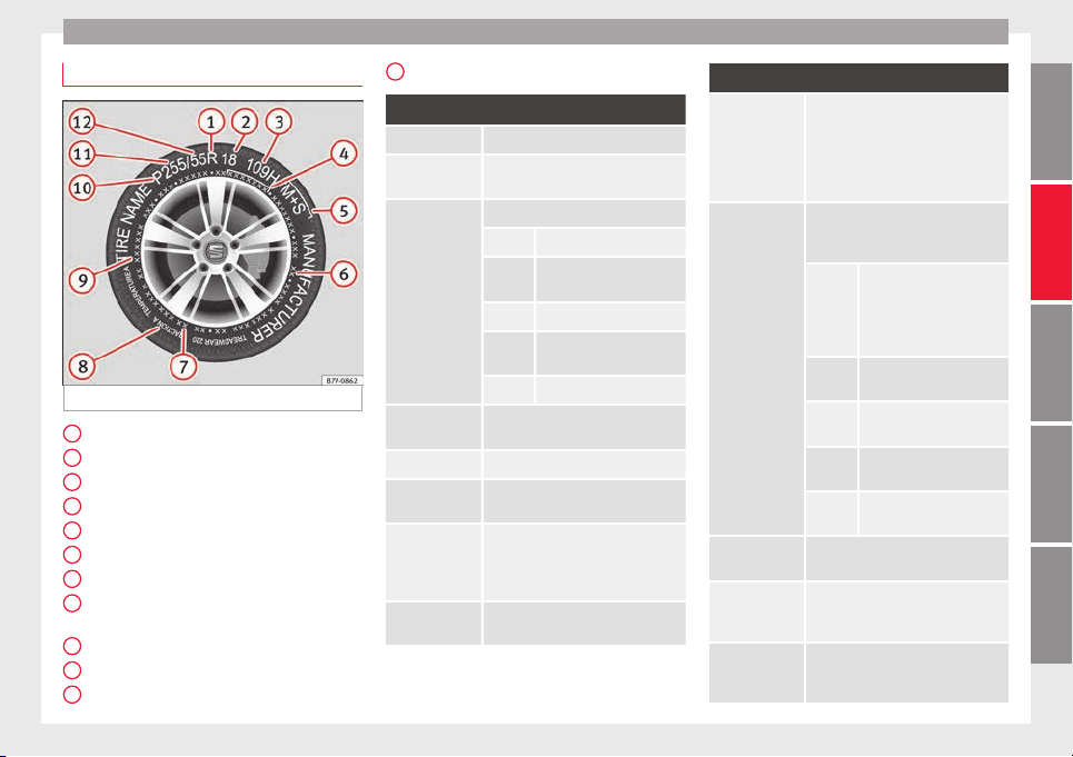
Wheels and tyres
Tyre code
Fig. 254 Universal code on tyres
Radial
Rim di
amet
er c
ode
Load index & speed rating
DOT tyre identification number
Severe snow conditions
Tyre ply composition and materials used
Max. load rating
Treadwear, traction and temperature
grades
Max. permissible inflation pressure
Passenger car tyre
Nominal width of tyre in millimetres
1
2
3
4
5
6
7
8
9
10
11
Ratio of height to width (aspect ratio)
Tyre code (example): Meaning
Make, logotype Manufacturer
Product name Name of tyre assigned by manufac-
turer.
P215 /
55 R 16
Size:
P Passenger vehicle code.
215
Nominal width between
walls, in mm.
55 Height/width ratio in %
R
Tyre type (R indicates "ra-
dial").
16 Rim diameter in inches
91 V Load index ››› page 296 and speed
rating ››› page 296.
XL Reinforced tyres (“Reinforced”).
M+S or M/S Winter tyres (mud and snow tyres)
››› page 296.
SSR or DSST,
Eufonia, RFT,
ROF, RSC, ZP,
Conti-Seal
Specific manufacturer codes for run-
flat tyres.
RADIAL
TUBELESS
Radial tyre without inner tube.
12
Tyre code (example): Meaning
E4 ... E-mark certifying tyre complies with
international legislation followed by
a number denoting the country
granting the authorisation. The au-
thorisation number ( several digits)
is shown below.
DOT BT RA TY5
1709
Tyre identification number (TIN
a)
,
may be only on interior wall of wheel)
and date of manufacture:
DOT The tyre complies with the
legal requirements of the
US Department of Trans-
port, responsible for tyre
safety regulations.
BT Place of manufacture
code.
RA Information about manu-
facturer and tyre size.
TY5 Manufacturer's tyre speci-
fications.
1709 Date of manufacture:
Week 17 of 2009.
TWI This identifies the position of the
Tread Wear Indicator ››› page 293.
MAX LOAD
615 KG
(1356 LBS)
US load rating, indicating maximum
permitted load per tyre.
MAX INFLATION
350 KPA
(51 PSI)
US limit, indicating maximum permit-
ted tyre pressure.
»
295
Technical dataAdviceOperationEmergenciesSafety

Advice
Tyre code (example): Meaning
SIDEWALL 1 PLY
RAYON
Information about tyre wall compo-
nents:
1 layer of rayon (artificial silk).
TREAD 4 PLIES
1 RAYON +
2 STEEL +
1 NYLON
Information about tread compo-
nents:
In the example, there are 4 layers be-
low the tread: 1 layer of rayon (artifi-
cial silk), 2 layers of steel reinforce-
ment and 1 layer of nylon.
Information for the end consumer concerning the com-
parative values of the established base tyres (standar-
dised test procedures):
TREADWEAR
280
Relative service life of the tyre, with
respect to specific US standard test.
TRACTION AA Braking capacity of tyre on wet sur-
face (AA, A, B or C).
TEMPERATURE A Tyre temperature resistance at higher
test speeds (A, B or C).
If there are different letters, they are specific codes of
the tyre manufacturer or specific national codes.
a)
The letters TIN refer to the tyre serial number.
Tyres with directional tread patterns
Tyres with directional tread pattern have
been designed to operate best when rotating
in only one direction. An arrow on the tyre
sidewall indicates the direction of rotation on
tyres with directional tread. Always observe
the direction of rotation indicated when
mounting the wheel. This guarantees opti-
mum grip and helps to avoid aquaplaning,
grip, noise and wear.
Tyre load rating
The load rating code indicates the maximum
load in kilogrammes each wheel can carry
(load capacity).
615 kg (1,356 pounds)
650 kg (1,433 pounds)
690 kg (1,521 pounds)
730 kg (1,609 pounds)
775 kg (1,709 pounds)
Speed rating
The speed rating indicates the maximum
speed permitted for the tyres.
max. 150 km/h (93 mph)
max. 160 km/h (99 mph)
max. 170 km/h (106 mph)
max. 180 km/h (112 mph)
max. 190 km/h (118 mph)
max. 200 km/h (124 mph)
max. 210 km/h (130 mph)
max. 240 km/h (149 mph)
max. 240 km/h (149 mph)
max. 270 km/h (168 mph)
max. 300 km/h (186 mph)
91
93
95
97
99
P
Q
R
S
T
U
H
V
Z
W
Y
Some manufacturers use the letters “ZR” for
tyres with a maximum authorised speed
above 240 km/h (149 mph).
Winter service
Winter tyres*
In winter conditions winter tyres will consid-
erably
improve the vehicle's handling. The
design of summer tyres (width, rubber com-
pound, tread pattern) gives less grip on ice
and snow. Winter tyres also improve the vehi-
cle braking performance, reducing the brak-
ing distance in winter weather. SEAT recom-
mend that winter tyres be fitted to the vehicle
at temperatures below +7°C (+45°F).
The performance of winter tyres is much re-
duced if the tyre tread is worn below 4 mm
(1/16 inch). The age of the tyre is another
factor affecting performance, regardless of
the depth of the tyre tread.
Please observe the following when using
winter tyres:
●
Observe legal requirements in each coun-
try.
●
W
inter tyres must be fitted on all four
wheels.
●
Only use winter tyres in wintery weather
conditions.
296
Wheels and tyres
●
On
ly
u
se winter tyres of the size authorised
for the vehicle.
●
Only use radial winter tyres of the same
type, size (rolling circumference) and tread
pattern.
●
Adjust speeds to within the limits indicated
(code letter on tyre) ›››
.
S
peed limit
A c
ode l
etter indicating the speed limit is
stamped on all winter tyres ››› page 296.
In some vehicles, it is possible to set a speed
warning in the MFA (multifunction
display) menu on the instrument panel
›››
page 26.
If you use V-rated tyres the speed limits and
tyre pressure will be determined by engine
size. Please ask your technical service centre
for further information on the maximum per-
mitted speed and the required pressures for
the tyres.
All-wheel drive*
Thanks to its all-wheel drive, your car will
have plenty of traction in winter conditions,
even with the standard tyres. Nevertheless,
SEAT still recommend that winter tyres or all-
season tyres should be fitted on all four
wheels when winter road conditions are ex-
pected, mainly because this will give a better
braking response.
Please observe all instructions and warnings
when using snow chains ›››
page 49.
WARNING
Although winter tyres help to make driving
safer in the w
inter, you should not take un-
necessary risks.
●
Adjust your speed and driving style to visi-
bility, road, traffic and weather conditions.
●
Never exceed the maximum permitted
speed or loads specified for the type of winter
tyre fitted on your vehicle.
For the sake of the environment
When winter is over, change back to summer
tyre
s when you have the time. In tempera-
tures above +7°C (+45°F), performance will
be improved if summer tyres are used. Fuel
consumption, wear and noises while driving
will all be reduced.
Note
●
If the v
ehicle is fitted with a tyre control
system, this should be “reprogrammed”
whenever a tyre is changed ››› page 236.
●
Please ask at a technical service centre for
information about the permitted sizes for
winter tyres.
297
Technical dataAdviceOperationEmergenciesSafety
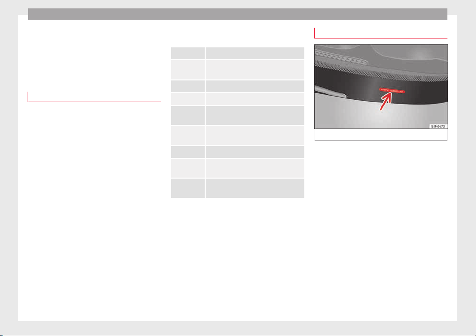
Technical data
Technical data
T
ec
hnic
al features
Important information
Important
The information in the vehicle documentation
alway
s takes precedence over the informa-
tion in this Instruction Manual.
All technical specifications provided in this
documentation are valid for the standard
model in Spain. The vehicle data card inclu-
ded in the Maintenance Programme or the
vehicle registration documents shows which
engine is installed in the vehicle.
The figures may be different depending
whether additional equipment is fitted, for
different models, for special vehicles and for
other countries.
Abbreviations used in the Technical Specifi-
cations
section
kW Kilowatt, engine power measurement.
PS
Pferdestärke (horsepower), formerly
used to denote engine power.
rpm Revolutions per minute - engine speed.
Nm Newton metres, unit of engine torque.
litres per
100 km
Fuel consumption in litres per 100 km
(70 miles).
g/km
Carbon dioxide emissions in grams per
km (mile) travelled.
CO
2
Carbon dioxide
CN
Cetane number, indication of the diesel
combustion power.
RON
Research octane number, indication of
the knock resistance of petrol.
Vehicle identification data
Fig. 255 Vehicle identification number.
Vehicle identification number
The
v
ehic
le identification number (chassis
number) can be read from outside the vehicle
through a viewer in the windscreen
››› Fig. 255. This viewer is located in the lower
part of the windscreen. The vehicle identifica-
tion number (chassis number) is also stam-
ped on the right water drain channel. The wa-
ter drain channel is located between the sus-
pension tower and the wing. Open the bon-
net to read the vehicle identification number
››› page 272.
Vehicle data plate
The vehicle data plate is attached to the lug-
gage compartment, and contains the follow-
ing information:
298

Technical features
●
V
ehic
l
e identification number (chassis
number).
●
Vehicle type, engine power, gearbox type.
●
Engine and gearbox code, paint number,
interior equipment.
●
Optional extras, PR numbers.
These data are also provided in the Mainte-
nance Programme.
Type plate
The type plate is visible when the driver door
is opened, on the lower part of the strut. Ve-
hicles for certain export countries do not
have a type plate.
The manufacturer's type plate contains the
following data:
●
Gross vehicle weight
●
Maximum authorised weight of vehicle and
trailer
●
Maximum gross front axle weight
●
Maximum rear axle weight
Information on fuel consumption
The consumption and emission details
sho
wn on the
v
ehicle data sticker differ from
one vehicle to another.
The fuel consumption, CO
2
emissions and ac-
tual kerb weight of the vehicle are noted on
the vehicle data sticker.
The fuel consumption and emissions figures
given are based on the vehicle weight cate-
gory, which is determined according to the
engine/gearbox combination and the equip-
ment fitted.
The consumption and emission figures are
calculated in accordance with the EC test re-
quirements 1999/100/EC. These test re-
quirements specify a realistic test method
based on normal everyday driving.
The following test conditions are applied:
Urban cycle
The urban cycle starts with an engine
cold start. City driving is then simulated.
Extra urban
cycle
In the extra urban cycle simulation the
vehicle frequently accelerates and
brakes in all gears, as in normal every-
day driving. The road speed ranges from
0 to 120 km/h (0 to 75 mph).
Total con-
sumption
The average total consumption is calcu-
lated with a weighting of around 37% for
the urban cycle and 63% for the extra ur-
ban cycle.
CO
2
emis-
sions
The exhaust gases are collected during
both driving cycles to calculate carbon
dioxide emissions. The gas composition
is then analysed to evaluate the CO
2
content and other emissions.
Note
●
Actua
l consumption may vary from quoted
test values, depending on personal driving
style, road and traffic conditions, the weather
and the vehicle condition.
●
Fuel consumption and CO
2
values can vary
depending on the vehicle's tyres.
Weights
Kerb weight refers to the basic model with a
f
uel
t
ank filled to 90% capacity and without
optional extras. The figure quoted includes
75 kg to allow for the weight of the driver.
Special versions, optional equipment fittings
or retro-fitting accessories will increase the
weight of the vehicle
›››
.
WARNING
●
Plea
se note that the centre of gravity may
shift when transporting heavy objects; this
may affect vehicle handling and lead to an ac-
cident. Always adjust your speed and driving
style to suit road conditions and require-
ments.
●
Never exceed the gross axle weight rating
or the gross vehicle weight rating. If the per-
missible axle load or the permissible total
weight is exceeded, the driving characteris-
tics of the vehicle may change, leading to ac-
cidents, injuries and damage to the vehicle.
299
Technical dataAdviceOperationEmergenciesSafety
Technical data
Towing a trailer
T
r
ai
ler weights
Trailer weight
The trail
er weights and drawbar loads ap-
proved are selected in intensive trials accord-
ing to precisely defined criteria. The ap-
proved trailer weights are valid for vehicles in
the EU for maximum speeds of 80 km/h (50
mph) (in certain circumstances up to 100
km/h (62 mph)). The figures may be different
in other countries. All data in the official vehi-
cle documentation takes precedence over
these data at all times
›››
.
Dr
a
wb
ar loads
The maximum permitted drawbar load on the
ball joint of the towing bracket must not ex-
ceed 100 kg.
In the interest of road safety, we recommend
that you always tow approaching the maxi-
mum drawbar load. The response of the trail-
er on the road will be poor, if the drawbar
load is too small.
If the maximum permissible drawbar load
cannot be met (e.g. with small, empty and
light-weight single axle trailers or tandem
axle trailers with a wheelbase of less than 1
metre), a minimum of 4% of the actual trailer
weight is legally required for the drawbar
load.
WARNING
●
For saf
ety reasons, do not exceed the 80
km/h (50 mph) limit. This is also valid in
countries where higher speeds are permitted.
●
Never exceed the maximum trailer weights
or the drawbar load. If the permissible axle
load or the permissible total weight is excee-
ded, the driving characteristics of the vehicle
may change, leading to accidents, injuries
and damage to the vehicle.
Wheels
T
y
r
e pressure, snow chains, wheel
bolts
Tyre pressures
The s
tic
k
er with the tyre pressure values can
be found on the inside of the fuel tank flap.
The tyre pressure values given there are for
cold tyres. The slightly raised pressures of
warm tyres must not be reduced.
›››
The pressure for winter tyres is 0.2 bar
(2.9 p
s
i / 20 kP
a) higher than that of summer
tyres.
Snow chains
Snow chains may be fitted only to the front
wheels.
Consult the section “wheels” of this manual.
Wheel bolts
After the wheels have been changed, the
tightening torque of the wheel bolts should
be checked as soon as possible with a torque
wrench ›››
. The tightening torque for steel
and al
lo
y
wheels is 140 Nm.
WARNING
●
Check the ty
re pressure at least once per
month. Checking the tyre pressure is very im-
portant. If the tyre pressure is too high or too
low, there is an increased danger of accidents
- particularly at high speeds.
●
If the tightening torque of the wheel bolts
is too low, they could loosen while the vehi-
cle is in motion. Risk of accident! If the tight-
ening torque is too high, the wheel bolts and
threads can be damaged.
Note
We recommend that you ask your Technical
Servic
e for information about appropriate
wheel, tyre and snow chain size.
300
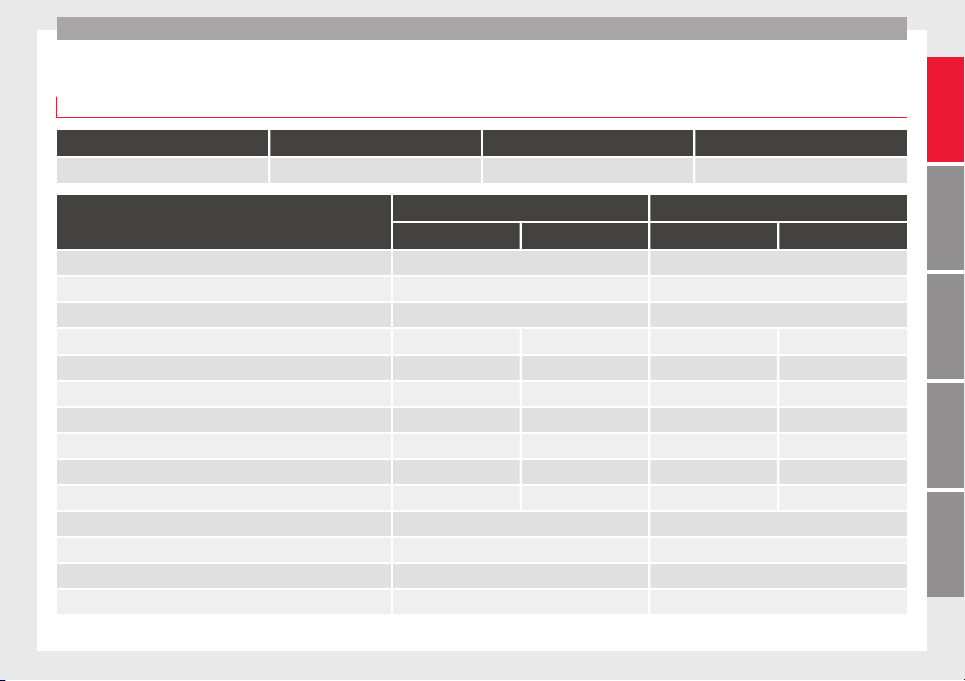
Technical features
Engine data
P
etr
o
l engine 1.4 110 kW (150 PS)
Power output in kW (PS) at rpm Maximum torque (Nm at rpm) No. of cylinders/displacement (cm
3
) Fuel
110 (150)/5,000-6,000 250/1,500-3,500 4/1,395 Super 95 RON
Manual Automatic
5 seats 7 seats 5 seats 7 seats
Top speed (km/h) 200 (VI) 198 (VI)
Acceleration from 0-80 km/h (seconds) 6.7 6.7
Acceleration from 0-100 km/h (seconds) 9.9 9.9
Consumption (litres/100 km) / CO
2
emissions (g/km) urban 7.9/182-183 8.0/184-185 8.0/186-187 8.1/188-189
Consumption (litres/100 km) / CO
2
emissions (g/km) intercity 5.5/129-130 5.6/131-132 5.8/135-136 5.8/135-136
Consumption (litres/100 km) / CO
2
emissions (g/km) mixed 6.4/148-149 6.5/150-151 6.6/154-155 6.7/156-157
Maximum authorised weight (in kg) 2,300 2,420 2,340 2,430
Weight in running order (with driver) (in kg) 1,703 1,755 1,717 1,768
Maximum authorised weight on front axle (en kg) 1,190 1,190 1,200 1,200
Maximum authorised weight on rear axle (en kg) 1,160 1,280 1,160 1,280
Permitted roof load (in kg) 100 100
Maximum weight trailer without brakes (in kg) 750 750
Weight of trailer with brakes, gradients up to 8% (in kg) 2,000 2,000
Weight of trailer with brakes, gradients up to 12% (in kg) 1,800 1,800
301
Technical dataAdviceOperationEmergenciesSafety

Technical data
Petrol engine 2.0 162 kW (220 PS)
Power output in kW (PS) at rpm Maximum torque (Nm at rpm) No. of cylinders/displacement (cm
3
) Fuel
162 (220)/4,500-6,200 350/1,500-4,400 4/1,984 Super 95 RON
Automatic
5 seats 7 seats
Top speed (km/h) 226 (V)
Acceleration from 0-80 km/h (seconds) 5.4
Acceleration from 0-100 km/h (seconds) 7.8
Consumption (litres/100 km) / CO
2
emissions (g/km) urban 9.2-9.3/214-215
Consumption (litres/100 km) / CO
2
emissions (g/km) intercity 6.0-6.1/140-141
Consumption (litres/100 km) / CO
2
emissions (g/km) mixed 7.2-7.3/167-168
Maximum authorised weight (in kg) 2,360 2,490
Weight in running order (with driver) (in kg) 1,790 1,838
Maximum authorised weight on front axle (en kg) 1,250 1,250
Maximum authorised weight on rear axle (en kg) 1,160 1,290
Permitted roof load (in kg) 100
Maximum weight trailer without brakes (in kg) 750
Weight of trailer with brakes, gradients up to 8% (in kg) 2,300 2,400
Weight of trailer with brakes, gradients up to 12% (in kg) 2,200
302

Technical features
Diesel engine 2.0 85 kW (115 PS)
Power output in kW (PS) at rpm Maximum torque (Nm at rpm) No. of cylinders/displacement (cm
3
) Fuel
85 (115)/3,500 280/1,750-3,000 4/1,968
Diesel according to standard EN 590, min.
51 CZ
5 seats 7 seats
Top speed (km/h) 184 (VI)
Acceleration from 0-80 km/h (seconds) 8.4
Acceleration from 0-100 km/h (seconds) 12.6
Consumption (litres/100 km) / CO
2
emissions (g/km) urban 6.0-6.1/130-132
Consumption (litres/100 km) / CO
2
emissions (g/km) intercity 4.5-4.6/117-119
Consumption (litres/100 km) / CO
2
emissions (g/km) mixed 5.0-5.1/130-132
Maximum authorised weight (in kg) 2,390 2,520
Weight in running order (with driver) (in kg) 1,772 1,822
Maximum authorised weight on front axle (en kg) 1,260 1,260
Maximum authorised weight on rear axle (en kg) 1,180 1,310
Permitted roof load (in kg) 100
Maximum weight trailer without brakes (in kg) 750
Weight of trailer with brakes, gradients up to 8% (in kg) 2,200
Weight of trailer with brakes, gradients up to 12% (in kg) 2,000
303
Technical dataAdviceOperationEmergenciesSafety

Technical data
Diesel engine 2.0 110 kW (150 PS)
Power output in kW (PS) at rpm Maximum torque (Nm at rpm) No. of cylinders/displacement (cm
3
) Fuel
110 (150)/3,500 340/1,750-3,000 4/1,968
Diesel according to standard EN 590, min.
51 CZ
Manual Automatic All-wheel drive
5 seats 7 seats 5 seats 7 seats 5 seats 7 seats
Top speed (km/h) 200 (VI) 198 (VI) 198 (VI)
Acceleration from 0-80 km/h (seconds) 7.3 7.3 7.1
Acceleration from 0-100 km/h (seconds) 10.3 10.3 10.6
Consumption (litres/100 km) / CO
2
emissions (g/km) urban 6.0-6.1/154-156 5.9/155-156 6.7/176-177
Consumption (litres/100 km) / CO
2
emissions (g/km) intercity 4.5-4.6/117-119 4.7/124-125 5.0/130-131
Consumption (litres/100 km) / CO
2
emissions (g/km) mixed 5.0-5.1/130-132 5.2/136-137 5.6/146-147
Maximum authorised weight (in kg) 2,390 2,520 2,410 2,540 2,560 2,590
Weight in running order (with driver) (in kg) 1,772 1,882 1,793 1,843 1,821 1,952
Maximum authorised weight on front axle (en kg) 1,260 1,260 1,280 1,280 1,320 1,320
Maximum authorised weight on rear axle (en kg) 1,180 1,310 1,180 1,310 1,290 1,320
Permitted roof load (in kg) 100 100 100
Maximum weight trailer without brakes (in kg) 750 750 750
Weight of trailer with brakes, gradients up to 8% (in kg) 2,300 2,400 2,300 2,400 2,400
Weight of trailer with brakes, gradients up to 12% (in kg) 2,200 2,200 2,400
304

Technical features
Diesel engine 2.0 135 kW (184 PS)
Power output in kW (PS) at rpm Maximum torque (Nm at rpm) No. of cylinders/displacement (cm
3
) Fuel
135 (184)/3,500-4,000 380/1,750-3,000 4/1,968
Diesel according to standard EN 590, min.
51 CZ
Manual Automatic
5 seats 7 seats 5 seats 7 seats
Top speed (km/h) 215 (VI) 213 (VI)
Acceleration from 0-80 km/h (seconds) 6.4 6.4
Acceleration from 0-100 km/h (seconds) 8.9 8.9
Consumption (litres/100 km) / CO
2
emissions (g/km) urban 6.7/176-177 6.1/160-161
Consumption (litres/100 km) / CO
2
emissions (g/km) intercity 4.5/117-118 4.8/126-127
Consumption (litres/100 km) / CO
2
emissions (g/km) mixed 5.3/138-139 5.3/138-139
Maximum authorised weight (in kg) 2,400 2,550 2,400 2,550
Weight in running order (with driver) (in kg) 1,800 1,841 1,804 1,845
Maximum authorised weight on front axle (en kg) 1,290 1,290 1,290 1,290
Maximum authorised weight on rear axle (en kg) 1,160 1,310 1,160 1,310
Permitted roof load (in kg) 100 100
Maximum weight trailer without brakes (in kg) 750 750
Weight of trailer with brakes, gradients up to 8% (in kg) 2,400 2,400
Weight of trailer with brakes, gradients up to 12% (in kg) 2,200 2,200
305
Technical dataAdviceOperationEmergenciesSafety
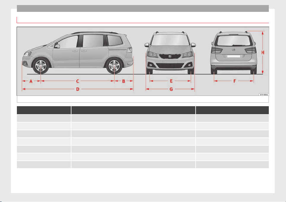
Technical data
Dimensions
Fig. 256 Dimensions
ALHAMBRA
A/B Front and rear projection (mm) 968/966
C Wheelbase (mm) 2,919
D Length (mm) 4,854
E/F Front/rear
a)
track width (mm) 1,569/1,617
G Width (mm) 1,904
H Height at kerb weight (mm) 1,720
Turning radius (m) 11.9
a)
This data will change depending on the type of wheel rim.
306

Index
Index
A
Abr
o
a
d
extended stay abroad with your vehicle . . . . . 263
sale of vehicle . . . . . . . . . . . . . . . . . . . . . . . . . . 263
ABS
see Anti-lock brake system . . . . . . . . . . . . . . . 205
Accessories . . . . . . . . . . . . . . . . . . . . . . . . . . . . . . 247
Acoustic alarms
seatbelt unfastened . . . . . . . . . . . . . . . . . . . . . . 62
warning and indication lamps . . . . . . . . . . . . . . 32
Adaptive headlights
dynamic . . . . . . . . . . . . . . . . . . . . . . . . . . . . . . . 132
AdBlue
information . . . . . . . . . . . . . . . . . . . . . . . . . . . . 271
minimum quantity for a refill . . . . . . . . . . . . . . 271
refilling . . . . . . . . . . . . . . . . . . . . . . . . . . . . . . . 271
specifications . . . . . . . . . . . . . . . . . . . . . . . . . . 272
tank filling capacity . . . . . . . . . . . . . . . . . . . . . 270
warning and indication lamps . . . . . . . . . . . . . 270
Additional heater
see "Auxiliary heater" . . . . . . . . . . . . . . . . . . . . 180
Adjusting
folding the backrest of the front passenger
seat . . . . . . . . . . . . . . . . . . . . . . . . . . . . . . . . 150
front seats . . . . . . . . . . . . . . . . . . . . . . . . . . . . . 142
lights . . . . . . . . . . . . . . . . . . . . . . . . . . . . . . . . . 135
seats . . . . . . . . . . . . . . . . . . . . . . . . . . . . . . . . . . 57
seat with position memory . . . . . . . . . . . . . . . 148
Adjusting the head restraint
rear head restraints . . . . . . . . . . . . . . . . . 14, 144
Adjusting the seats
front seats . . . . . . . . . . . . . . . . . . . . . . . . . . . . . 142
rear seats . . . . . . . . . . . . . . . . . . . . . . . . . . . . . 143
AFS . . . . . . . . . . . . . . . . . . . . . . . . . . . . . . . . . . . . 132
Air-conditioning
malfunctions . . . . . . . . . . . . . . . . . . . . . . . . . . . 177
Airbag covers . . . . . . . . . . . . . . . . . . . . . . . . . . . . . 17
Airbags
see Airbag system . . . . . . . . . . . . . . . . . . . . . . . 18
Airbag system . . . . . . . . . . . . . . . . . . . . . . . . . . 17, 68
activation . . . . . . . . . . . . . . . . . . . . . . . . . . . . . . 70
cleaning dash panel . . . . . . . . . . . . . . . . . . . . . 262
control lamp . . . . . . . . . . . . . . . . . . . . . . . . . . . . 72
description . . . . . . . . . . . . . . . . . . . . . . . . . . . . . 69
front airbags . . . . . . . . . . . . . . . . . . . . . . . . . 17, 71
functioning . . . . . . . . . . . . . . . . . . . . . . . . . . . . . 70
head-protection airbag . . . . . . . . . . . . . . . . . . . 20
knee airbag . . . . . . . . . . . . . . . . . . . . . . . . . . . . . 18
locking the vehicle after deployment . . . . . . . 115
repairs . . . . . . . . . . . . . . . . . . . . . . . . . . . . . . . . 249
side airbags . . . . . . . . . . . . . . . . . . . . . . . . . . . . 19
use of child seats . . . . . . . . . . . . . . . . . . . . . 18, 73
vehicle care . . . . . . . . . . . . . . . . . . . . . . . . . . . . 262
Air conditioning . . . . . . . . . . . . . . . . . . . . . . . . . . 176
air recirculation . . . . . . . . . . . . . . . . . . . . . . . . . 179
air vents . . . . . . . . . . . . . . . . . . . . . . . . . . . . . . 178
climatronic . . . . . . . . . . . . . . . . . . . . . . . . 36, 176
controls . . . . . . . . . . . . . . . . . . . . . . . . . . . 36, 176
electronic manual air conditioning . . . . . . . . . 176
indirect ventilation . . . . . . . . . . . . . . . . . . . . . . 178
rear seats . . . . . . . . . . . . . . . . . . . . . . . . . . . . . 177
special features . . . . . . . . . . . . . . . . . . . . . . . . 178
user instructions . . . . . . . . . . . . . . . . . . . . . . . . 177
Air recirculation . . . . . . . . . . . . . . . . . . . . . . . . . . 179
Air vents . . . . . . . . . . . . . . . . . . . . . . . . . . . . . . . . 178
Alcantara . . . . . . . . . . . . . . . . . . . . . . . . . . . . . . . . 259
All-wheel drive
snow chains . . . . . . . . . . . . . . . . . . . . . . . . . . . . 49
winter tyres . . . . . . . . . . . . . . . . . . . . . . . . . . . . 297
Ambient lighting . . . . . . . . . . . . . . . . . . . . . . . . . 136
Anodized surfaces . . . . . . . . . . . . . . . . . . . . . . . . 257
Antenna . . . . . . . . . . . . . . . . . . . . . . . . . . . 249, 263
Anti-freeze . . . . . . . . . . . . . . . . . . . . . . . . . . . . . . . 40
Anti-lock brake system . . . . . . . . . . . . . . . . . . . . . 205
Anti-lock system . . . . . . . . . . . . . . . . . . . . . . . . . . 206
Anti-puncture kit . . . . . . . . . . . . . . . . . . . . . . . . 44, 85
Anti-theft alarm . . . . . . . . . . . . . . . . . . . . . . . . . . 119
Anti-tow system . . . . . . . . . . . . . . . . . . . . . . . . 120
false alarms . . . . . . . . . . . . . . . . . . . . . . . . . . . 120
Interior monitoring . . . . . . . . . . . . . . . . . . . . . . 120
trailer . . . . . . . . . . . . . . . . . . . . . . . . . . . . . . . . . 241
Anti-theft security system . . . . . . . . . . . . . . . . . . 119
Anti-tow system . . . . . . . . . . . . . . . . . . . . . . . . . . 120
Anti-trap function
panoramic sunroof . . . . . . . . . . . . . . . . . . . . . . 129
sun blind . . . . . . . . . . . . . . . . . . . . . . . . . . . . . . 129
Antifreeze . . . . . . . . . . . . . . . . . . . . . . . . . . . 40, 280
Armrests . . . . . . . . . . . . . . . . . . . . . . . . . . . . . . . . 151
Ashtray . . . . . . . . . . . . . . . . . . . . . . . . . . . . . . . . . 172
ASR
see Braking assist systems . . . . . . . . . . 206, 207
switching on and off . . . . . . . . . . . . . . . . . . . . . 207
see also Traction control system . . . . . . . . . . . 205
Assistance call . . . . . . . . . . . . . . . . . . . . . . . . . . . 110
Assistance systems
Electronic differential lock system (EDS) . . . . 206
Electronic drive torque management (XDS) . . 206
Launch-Control programme . . . . . . . . . . . . . . . 198
tiredness detection . . . . . . . . . . . . . . . . . . . . . 232
tyre monitoring systems . . . . . . . . . . . . . . . . . 236
Assisted starting . . . . . . . . . . . . . . . . . . . . . . . . . . 51
Assist systems
adaptive headlights . . . . . . . . . . . . . . . . . . . . . 132
auto Hold . . . . . . . . . . . . . . . . . . . . . . . . . . . . . 208
blind spot detector (BSD) with parking assis-
tant (RTA) . . . . . . . . . . . . . . . . . . . . . . . . . . . . 225
brake assist system (BAS) . . . . . . . . . . . . . . . . 206
cruise control system . . . . . . . . . . . . . . . . . . . . 221
dynamic chassis control (DCC) . . . . . . . . . . . . 233
307

Index
lane assist system . . . . . . . . . . . . . . . . . . . . . . 222
optic
al
p
arking system . . . . . . . . . . . . . . . . . . . 213
Park Assist . . . . . . . . . . . . . . . . . . . . . . . . . . . . 214
parking assistance . . . . . . . . . . . . . . . . . . . . . . 212
parking assistant (RTA) . . . . . . . . . . . . . . . . . . 225
Parking distance warning system . . . . . . . . . . 212
rear assist . . . . . . . . . . . . . . . . . . . . . . . . . . . . . 217
rear View Camera . . . . . . . . . . . . . . . . . . . . . . . 217
sign Assist . . . . . . . . . . . . . . . . . . . . . . . . . . . . . 230
Start-Stop . . . . . . . . . . . . . . . . . . . . . . . . . . . . . 209
start assistance . . . . . . . . . . . . . . . . . . . . . . . . 208
traction control when accelerating (ASR) . . .206, 207
traffic signal detection . . . . . . . . . . . . . . . . . . . 230
Auto Hold . . . . . . . . . . . . . . . . . . . . . . . . . . . . . . . 208
Automatic belt retractor . . . . . . . . . . . . . . . . . . . . . 67
Automatic car wash
Switching Auto Hold off . . . . . . . . . . . . . . . . . . 209
switching the start assist off . . . . . . . . . . . . . . 209
Automatic dipped beam control . . . . . . . . . . . . . 132
Automatic gearbox
driving tips . . . . . . . . . . . . . . . . . . . . . . . . . . . . 198
emergency release . . . . . . . . . . . . . . . . . . . . . . . 35
ignition key removal lock . . . . . . . . . . . . . . . . . 186
kick-down . . . . . . . . . . . . . . . . . . . . . . . . . . . . . 198
malfunction . . . . . . . . . . . . . . . . . . . . . . . . . . . . 198
AUX-IN . . . . . . . . . . . . . . . . . . . . . . . . . . . . . . . . . . 110
Auxiliary heater . . . . . . . . . . . . . . . . . . . . . 180, 269
automatic off . . . . . . . . . . . . . . . . . . . . . . . . . . . 266
operating instructions . . . . . . . . . . . . . . . . . . . 183
Programming . . . . . . . . . . . . . . . . . . . . . . . . . . 182
remote control . . . . . . . . . . . . . . . . . . . . . . . . . 181
remote control range . . . . . . . . . . . . . . . . . . . . 181
remote control: replacing the battery . . . . . . . 181
special features . . . . . . . . . . . . . . . . . . . . . . . . 180
switching off . . . . . . . . . . . . . . . . . . . . . . . . . . . 180
Switching on . . . . . . . . . . . . . . . . . . . . . . . . . . . 180
things to note . . . . . . . . . . . . . . . . . . . . . . . . . . 183
Auxiliary heater remote control
auxiliary heater . . . . . . . . . . . . . . . . . . . . . . . . . 181
replacing the battery . . . . . . . . . . . . . . . . . . . . 181
B
BAS
see Brake assist systems . . . . . . . . . . . . . . . . . 206
Battery
changing in the vehicle key . . . . . . . . . . . . . . . 113
Before setting off . . . . . . . . . . . . . . . . . . . . . . . . . . 56
Belt height adjustment . . . . . . . . . . . . . . . . . . . . . 67
Belt tension device
service and disposal . . . . . . . . . . . . . . . . . . . . . 68
Belt tensioner . . . . . . . . . . . . . . . . . . . . . . . . . . . . . 67
Belt tension limiter . . . . . . . . . . . . . . . . . . . . . . . . . 67
Belt tightening . . . . . . . . . . . . . . . . . . . . . . . . . . . . 67
Bicycle carrier
Installing on tow hitch . . . . . . . . . . . . . . . . . . . 240
Maximum load . . . . . . . . . . . . . . . . . . . . . . . . . 240
Biodiesel . . . . . . . . . . . . . . . . . . . . . . . . . . . . . . . . 269
Blind spot detector (BSD) . . . . . . . . . . . . . . . . . . 225
control lamps . . . . . . . . . . . . . . . . . . . . . . . . . . 225
driving conditions . . . . . . . . . . . . . . . . . . . . . . 228
indication in the external rear view mirror . . . 226
malfunction . . . . . . . . . . . . . . . . . . . . . . . . . . . . 225
operating . . . . . . . . . . . . . . . . . . . . . . . . . . . . . . 226
towing . . . . . . . . . . . . . . . . . . . . . . . . . . . . . . . . 230
Bonnet . . . . . . . . . . . . . . . . . . . . . . . . . . . . . . . . . . 11
opening and closing . . . . . . . . . . . . . . . . . . . . 274
Boot hatch
emergency locking and unlocking . . . . . . . . . . . 10
Bottle holders . . . . . . . . . . . . . . . . . . . . . . . . . . . . 171
Brake assist systems . . . . . . . . . . . . . . . . . . . . . . 205
Brake fluid . . . . . . . . . . . . . . . . . . . . . . . . . . . . . . . 41
specification . . . . . . . . . . . . . . . . . . . . . . . . . . . 282
Brakes . . . . . . . . . . . . . . . . . . . . . . . . . . . . . . . . . . 189
brake assist systems . . . . . . . . . . . . . . . . . . . . 205
brake fluid . . . . . . . . . . . . . . . . . . . . . . . . . . . . . 282
brake fluid level . . . . . . . . . . . . . . . . . . . . . . . . 283
brake pads . . . . . . . . . . . . . . . . . . . . . . . . . . . . 193
brake servo . . . . . . . . . . . . . . . . . . . . . . . . . . . . 193
changing the brake fluid . . . . . . . . . . . . . . . . . 283
electronic parking brake . . . . . . . . . . . . . . . . . 191
emergency braking function . . . . . . . . . . . . . . 192
running in new brake pads . . . . . . . . . . . . . . . 193
warning and indication lamps . . . . . . . . . . . . . 190
Brake servo . . . . . . . . . . . . . . . . . . . . . . . . . 193, 205
Brake system . . . . . . . . . . . . . . . . . . . . . . . . . . . . 205
fault . . . . . . . . . . . . . . . . . . . . . . . . . . . . . . . . . . 193
Braking
brake assist system . . . . . . . . . . . . . . . . . . . . . 205
BSD
see Blind spot detector . . . . . . . . . . . . . . . . . . 225
Bulb malfunction
see Changing bulbs . . . . . . . . . . . . . . . . . . . . . . 91
C
Capacities . . . . . . . . . . . . . . . . . . . . . . . . . . . . . . . . 39
windshield wiper fluid tank . . . . . . . . . . . . . . . 284
Card compartment . . . . . . . . . . . . . . . . . . . . . . . . 168
Caring for paintwork . . . . . . . . . . . . . . . . . . . . . . . 256
Caring for the vehicle
exterior . . . . . . . . . . . . . . . . . . . . . . . . . . . . . . . 253
interior . . . . . . . . . . . . . . . . . . . . . . . . . . . . . . . . 253
Catalytic converter . . . . . . . . . . . . . . . . . . . . . . . . 203
Malfunction . . . . . . . . . . . . . . . . . . . . . . . . . . . . 203
warning and indication lamps . . . . . . . . . . . . . 202
CCS . . . . . . . . . . . . . . . . . . . . . . . . . . . . . . . . . . . . 221
see cruise control . . . . . . . . . . . . . . . . . . . . . . . . 32
CD changer . . . . . . . . . . . . . . . . . . . . . . . . . 166, 171
308

Index
Central locking system . . . . . . . . . . . . . . . . . . . . . 114
af
t
er airb
ag deployment . . . . . . . . . . . . . . . . . 115
Anti-theft alarm . . . . . . . . . . . . . . . . . . . . . . . . . 119
description . . . . . . . . . . . . . . . . . . . . . . . . . . . . 115
Emergency locking and unlocking . . . . . . . . . . . . 9
keyless Access . . . . . . . . . . . . . . . . . . . . . . . . . 117
opening doors individually . . . . . . . . . . . . . . . 115
remote control key . . . . . . . . . . . . . . . . . . . . . . 115
Centre armrest . . . . . . . . . . . . . . . . . . . . . . . . . . . 151
Changing a wheel . . . . . . . . . . . . . . . . . . . . . . 45, 84
subsequent work . . . . . . . . . . . . . . . . . . . . . . . . 49
wheel bolts . . . . . . . . . . . . . . . . . . . . . . . . . . . . . 46
Changing bulbs . . . . . . . . . . . . . . . . . . . . . . . . . . . 91
body . . . . . . . . . . . . . . . . . . . . . . . . . . . . . . . . . . 95
control lamp . . . . . . . . . . . . . . . . . . . . . . . . . . . . 92
front bumper . . . . . . . . . . . . . . . . . . . . . . . . . . . . 94
halogen headlights . . . . . . . . . . . . . . . . . . . . . . 92
number plate light . . . . . . . . . . . . . . . . . . . . . . . 97
rear lid . . . . . . . . . . . . . . . . . . . . . . . . . . . . . . . . . 95
rear lights . . . . . . . . . . . . . . . . . . . . . . . . . . . . . . 95
xenon headlights . . . . . . . . . . . . . . . . . . . . . . . . 93
Changing gear
Control and warning lamps . . . . . . . . . . . . . . . 195
Changing gears automatically . . . . . . . . . . . . . . . 196
Changing the blades . . . . . . . . . . . . . . . . . . . . . . . 87
Changing windscreen wipers . . . . . . . . . . . . . . . . 54
Charging the battery . . . . . . . . . . . . . . . . . . . . . . . 51
Checking
tyre pressures . . . . . . . . . . . . . . . . . . . . . . . . . . 292
Checking fluid levels . . . . . . . . . . . . . . . . . . . . . . 275
Child safety . . . . . . . . . . . . . . . . . . . . . . . . . . . . . . . 74
Child seat . . . . . . . . . . . . . . . . . . . . . . . . . . . . . . . . 20
deactivating the passenger front airbag . . . . . . 18
disabling the front passenger front airbag . . . . 73
integrated child seat . . . . . . . . . . . . . . . . . . . . . 78
in the passenger seat . . . . . . . . . . . . . . . . . . . . . 76
ISOFIX system . . . . . . . . . . . . . . . . . . . . . . . . . . . 77
mounting systems . . . . . . . . . . . . . . . . . . . . . . . 22
on rear seats . . . . . . . . . . . . . . . . . . . . . . . . . . . . 77
regulations . . . . . . . . . . . . . . . . . . . . . . . . . . . . . 76
safety instructions . . . . . . . . . . . . . . . . . . . . 20, 75
securing with seat belt . . . . . . . . . . . . . . . . . . . . 22
Top Tether system . . . . . . . . . . . . . . . . . . . . . . . . 23
transporting children in the vehicle . . . . . . . . . 75
weight categories . . . . . . . . . . . . . . . . . . . . . . . . 76
Child seats . . . . . . . . . . . . . . . . . . . . . . . . . . . . . . . 75
Chrome parts . . . . . . . . . . . . . . . . . . . . . . . . . . . . 257
Cigarette lighter . . . . . . . . . . . . . . . . . . . . . 172, 173
Cleaning . . . . . . . . . . . . . . . . . . . . . . . . . . . . . . . . 253
compartments . . . . . . . . . . . . . . . . . . . . . . . . . 262
dash panel . . . . . . . . . . . . . . . . . . . . . . . . . . . . 262
engine compartment . . . . . . . . . . . . . . . . . . . . 258
fabrics . . . . . . . . . . . . . . . . . . . . . . . . . . . . . . . . 259
folding the rear view mirrors . . . . . . . . . . . . . . 142
natural leather . . . . . . . . . . . . . . . . . . . . . . . . . 261
seatbelts . . . . . . . . . . . . . . . . . . . . . . . . . . . . . . 262
synthetic leather . . . . . . . . . . . . . . . . . . . . . . . . 261
textile covers . . . . . . . . . . . . . . . . . . . . . . . . . . . 259
trims . . . . . . . . . . . . . . . . . . . . . . . . . . . . . . . . . 259
washing the vehicle . . . . . . . . . . . . . . . . . . . . . 253
Washing the vehicle with high pressure clean-
ers . . . . . . . . . . . . . . . . . . . . . . . . . . . . . . . . . 255
wheels . . . . . . . . . . . . . . . . . . . . . . . . . . . . . . . . 257
windows . . . . . . . . . . . . . . . . . . . . . . . . . . . . . . 255
Cleaning the vehicle
high pressure cleaners . . . . . . . . . . . . . . . . . . . 255
Climatronic . . . . . . . . . . . . . . . . . . . . . . . . . . 36, 176
Closing . . . . . . . . . . . . . . . . . . . . . . . . . . . . . . . . . 112
bonnet . . . . . . . . . . . . . . . . . . . . . . . . . . . . . . . . . 11
electric windows . . . . . . . . . . . . . . . . . . . . . . . . . 11
luggage compartment . . . . . . . . . . . . . . . 10, 125
panoramic sunroof . . . . . . . . . . . . . . . . . . . . . . . 12
Clothes hook . . . . . . . . . . . . . . . . . . . . . . . . . . . . 170
Code number . . . . . . . . . . . . . . . . . . . . . . . . . . 45, 83
Combined weight rating . . . . . . . . . . . . . . . . . . . 245
Coming Home . . . . . . . . . . . . . . . . . . . . . . . . . . . . 133
Compartments
centre console . . . . . . . . . . . . . . . . . . . . . . . . . 167
Front central armrest . . . . . . . . . . . . . . . . . . . . 168
Compass . . . . . . . . . . . . . . . . . . . . . . . . . . . . . . . . 103
Connectors
faults . . . . . . . . . . . . . . . . . . . . . . . . . . . . . . . . . 175
Consumption
how it is determined . . . . . . . . . . . . . . . . . . . . 269
information . . . . . . . . . . . . . . . . . . . . . . . . . . . . 269
Control and warning lamps
Changing gear . . . . . . . . . . . . . . . . . . . . . . . . . 195
for the seat belt . . . . . . . . . . . . . . . . . . . . . . . . . 62
fuel level . . . . . . . . . . . . . . . . . . . . . . . . . . . . . . 266
key . . . . . . . . . . . . . . . . . . . . . . . . . . . . . . . . . . . 113
Lane Assist system . . . . . . . . . . . . . . . . . . . . . . 223
lights . . . . . . . . . . . . . . . . . . . . . . . . . . . . . . . . . 130
refuelling . . . . . . . . . . . . . . . . . . . . . . . . . . . . . . 266
Control of function
rain sensor . . . . . . . . . . . . . . . . . . . . . . . . . . . . 139
Controls on the steering wheel
operating the audio system . . . . . . . . . . . . . . . 107
operating the audio system and telephone . . 108
Control units . . . . . . . . . . . . . . . . . . . . . . . . . . . . . 250
reprogramming . . . . . . . . . . . . . . . . . . . . . . . . . 250
Convenience closing
windows . . . . . . . . . . . . . . . . . . . . . . . . . . . . . . 127
Convenience functions
Reprogramming . . . . . . . . . . . . . . . . . . . . . . . . 250
Convenience opening
windows . . . . . . . . . . . . . . . . . . . . . . . . . . . . . . 127
Convenient entry function for the third row of
seats . . . . . . . . . . . . . . . . . . . . . . . . . . . . . . . . . 149
Cooling system
checking the coolant . . . . . . . . . . . . . . . . . . . . 279
topping up with coolant . . . . . . . . . . . . . . . . . . 279
309

Index
Cornering lights
see "St
atic
c
ornering lights" . . . . . . . . . . . . . . 132
static . . . . . . . . . . . . . . . . . . . . . . . . . . . . . . . . . 132
Correct position . . . . . . . . . . . . . . . . . . . . . . . . . . . 57
driver . . . . . . . . . . . . . . . . . . . . . . . . . . . . . . . . . . 57
Counter steering assistance system . . . . . . . . . . 185
Crossing through water
salt water . . . . . . . . . . . . . . . . . . . . . . . . . . . . . 205
Cruise Control System (CCS) . . . . . . . . . . . . 32, 221
Control lamp . . . . . . . . . . . . . . . . . . . . . . . . . . . 221
Operations . . . . . . . . . . . . . . . . . . . . . . . . . . . . 221
Warning lamp . . . . . . . . . . . . . . . . . . . . . . . . . . 221
D
Dangers of not using a seat belt . . . . . . . . . . . . . . 63
Dash panel . . . . . . . . . . . . . . . . . . . . . . . . . . . . . . . 99
airbag system . . . . . . . . . . . . . . . . . . . . . . . . . . 262
Data registry . . . . . . . . . . . . . . . . . . . . . . . . . . . . . 250
Data storage during the journey . . . . . . . . . . . . . 250
Daytime running lights . . . . . . . . . . . . . . . . . . . . 131
DCC
see Dynamic chassis control . . . . . . . . . . . . . . 233
De-icing the locks . . . . . . . . . . . . . . . . . . . . . . . . . 257
Diagnostics connector . . . . . . . . . . . . . . . . . . . . . 251
Diesel . . . . . . . . . . . . . . . . . . . . . . . . . . . . . . . . . . 268
auxiliary heater . . . . . . . . . . . . . . . . . . . . . . . . . 269
biodiesel . . . . . . . . . . . . . . . . . . . . . . . . . . . . . . 269
filter pre-heater . . . . . . . . . . . . . . . . . . . . . . . . . 268
winter-grade diesel . . . . . . . . . . . . . . . . . . . . . 268
Diesel particulate filter . . . . . . . . . . . . . . . . . . . . 203
Malfunction . . . . . . . . . . . . . . . . . . . . . . . . . . . . 203
recommended gear . . . . . . . . . . . . . . . . . . . . . 199
things to note . . . . . . . . . . . . . . . . . . . . . . . . . . 269
Differential lock
See Braking assist systems . . . . . . . . . . . . . . . 206
Digital clock . . . . . . . . . . . . . . . . . . . . . . . . . . . . . 100
Dimensions . . . . . . . . . . . . . . . . . . . . . . . . . . . . . . 306
Directional tread pattern
tyres . . . . . . . . . . . . . . . . . . . . . . . . . . . . . . . . . . . 49
Disconnecting devices . . . . . . . . . . . . . . . . . . . . . 287
Disconnecting the passenger front airbag . . . . . . 18
Display . . . . . . . . . . . . . . . . . . . . . . . . . . . . 100, 101
Disposal
belt tension device . . . . . . . . . . . . . . . . . . . . . . . 68
Door
childproof lock . . . . . . . . . . . . . . . . . . . . . . . . . 123
emergency locking and unlocking . . . . . . . . . . . . 8
opening and closing . . . . . . . . . . . . . . . . . . . . . . 8
warning lamp . . . . . . . . . . . . . . . . . . . . . . . . . . 121
Door handle . . . . . . . . . . . . . . . . . . . . . . . . . . . . . . . 8
Door lock . . . . . . . . . . . . . . . . . . . . . . . . . . . . . . . . . . 8
Door lock cylinder . . . . . . . . . . . . . . . . . . . . . . . . . . 8
Doors . . . . . . . . . . . . . . . . . . . . . . . . . . . . . . . . . . . 121
Drawbar load . . . . . . . . . . . . . . . . . . . . . . . . . . . . 237
loading the trailer . . . . . . . . . . . . . . . . . . . . . . . 242
Drawers . . . . . . . . . . . . . . . . . . . . . . . . . . . . . . . . . 169
Drink holders . . . . . . . . . . . . . . . . . . . . . . . . . . . . 171
central console . . . . . . . . . . . . . . . . . . . . . . . . . 172
rear . . . . . . . . . . . . . . . . . . . . . . . . . . . . . . . . . . 172
Driving
automatic gearbox . . . . . . . . . . . . . . . . . . . . . . 198
cross country . . . . . . . . . . . . . . . . . . . . . . . . . . . 56
data storage . . . . . . . . . . . . . . . . . . . . . . . . . . . 250
driving abroad . . . . . . . . . . . . . . . . . . . . . . . . . 204
driving through water . . . . . . . . . . . . . . . . . . . . 204
economical . . . . . . . . . . . . . . . . . . . . . . . . . . . . 200
fuel gauge . . . . . . . . . . . . . . . . . . . . . . . . . . . . . 266
fuel level too low . . . . . . . . . . . . . . . . . . . . . . . 266
Parking downhill . . . . . . . . . . . . . . . . . . . . . . . . 192
Parking uphill . . . . . . . . . . . . . . . . . . . . . . . . . . 192
towing . . . . . . . . . . . . . . . . . . . . . . . . . . . . . . . . . 89
trailer . . . . . . . . . . . . . . . . . . . . . . . . . . . . . . . . . 243
undercarriage guard . . . . . . . . . . . . . . . . . . . . . . 56
with a trailer . . . . . . . . . . . . . . . . . . . . . . . . . . . 237
Driving abroad
headlights . . . . . . . . . . . . . . . . . . . . . . . . . . . . . 135
Driving in winter
fuel consumption . . . . . . . . . . . . . . . . . . . . . . . 201
snow chains . . . . . . . . . . . . . . . . . . . . . . . . . . . . 49
Tread depth . . . . . . . . . . . . . . . . . . . . . . . . . . . . 293
tyre pressures . . . . . . . . . . . . . . . . . . . . . . . . . . 292
Windscreen washer container . . . . . . . . . . . . . 256
Driving safety . . . . . . . . . . . . . . . . . . . . . . . . . . . . . 56
Driving through water . . . . . . . . . . . . . . . . . . . . . 204
Driving tips
For a loaded vehicle . . . . . . . . . . . . . . . . . . . . . 152
Driving with a trailer
extinguisher . . . . . . . . . . . . . . . . . . . . . . . . . . . 239
technical requirements . . . . . . . . . . . . . . . . . . 238
Duplicate keys . . . . . . . . . . . . . . . . . . . . . . . . . . . 112
Dynamic Chassis Control (DCC) . . . . . . . . . . . . . . 233
Control . . . . . . . . . . . . . . . . . . . . . . . . . . . . . . . . 233
fault . . . . . . . . . . . . . . . . . . . . . . . . . . . . . . . . . . 234
Operation . . . . . . . . . . . . . . . . . . . . . . . . . . . . . 233
Dynamic headlight range control . . . . . . . . . . . . 135
E
EDS
See Braking assist systems . . . . . . . . . . . . . . . 206
Electric
windows . . . . . . . . . . . . . . . . . . . . . . . . . . . . . . . 11
Electrical devices . . . . . . . . . . . . 173, 174, 183, 242
Electrical socket
trailer . . . . . . . . . . . . . . . . . . . . . . . . . . . . . . . . . 241
Electric child safety lock . . . . . . . . . . . . . . . . . . . 123
Electric sliding doors
opening and closing . . . . . . . . . . . . . . . . . . . . 122
rollback anti-trap function . . . . . . . . . . . . . . . . 123
Electric windows . . . . . . . . . . . . . . . . . . . . . . . . . . . 11
see Windows . . . . . . . . . . . . . . . . . . . . . . . . . . . 127
Electronic differential lock system (EDS) . 205, 206
310

Index
Electronic drive torque management (XDS) . . . . 206
El
ectr
onic
immobiliser . . . . . . . . . . . . . . . . . . . . . 189
operating fault . . . . . . . . . . . . . . . . . . . . . . . . . 185
Electronic Stability Control (ESC) . . . . . . . . . . . . 205
Emergencies . . . . . . . . . . . . . . . . . . . . . . . . . . . . . . 82
bulbs . . . . . . . . . . . . . . . . . . . . . . . . . . . . . . . . . . 43
changing a wheel . . . . . . . . . . . . . . . . . . . . . . . . 45
emergency towing of the vehicle . . . . . . . . . . . . 50
extinguishers . . . . . . . . . . . . . . . . . . . . . . . . . . . 82
first aid kit . . . . . . . . . . . . . . . . . . . . . . . . . . . . . . 82
fuses . . . . . . . . . . . . . . . . . . . . . . . . . . . . . . . . . . 42
Hazard warning lights . . . . . . . . . . . . . . . . . . . 134
jump leads . . . . . . . . . . . . . . . . . . . . . . . . . . . . . 51
puncture . . . . . . . . . . . . . . . . . . . . . . . . . . . . . . . 44
replacing a blown fuse . . . . . . . . . . . . . . . . . . . . 43
vehicle tool kit . . . . . . . . . . . . . . . . . . . . . . . . . . 82
warning triangle . . . . . . . . . . . . . . . . . . . . . . . . . 82
Emergency braking function . . . . . . . . . . . . . . . . 192
Emergency locking and unlocking . . . . . . . . . . . . 89
driver door . . . . . . . . . . . . . . . . . . . . . . . . . . . . . . 8
panoramic sliding sunroof . . . . . . . . . . . . . . . . . 12
Passenger side door . . . . . . . . . . . . . . . . . . . . . . . 9
Emergency locking of the doors . . . . . . . . . . . . . . . 9
Emergency unlocking
boot hatch . . . . . . . . . . . . . . . . . . . . . . . . . . . . . . 10
doors . . . . . . . . . . . . . . . . . . . . . . . . . . . . . . . . . . . 8
Emergency unlocking the boot hatch
boot hatch . . . . . . . . . . . . . . . . . . . . . . . . . . . . . . 10
Emergency warning triangle . . . . . . . . . . . . . . . . 134
Emission control system
warning and indication lamps . . . . . . . . . . . . . 202
Emissions data . . . . . . . . . . . . . . . . . . . . . . . . . . . 298
Engine
assisted starting . . . . . . . . . . . . . . . . . . . . . . . . . 51
noises . . . . . . . . . . . . . . . . . . . . . . . . . . . . . . . . 188
Running in . . . . . . . . . . . . . . . . . . . . . . . . . . . . . 199
Engine and ignition . . . . . . . . . . . . . . . . . . . . . . . 185
12 volt power sockets . . . . . . . . . . . . . . . . . . . 173
ignition lock . . . . . . . . . . . . . . . . . . . . . . . . . . . 185
immobiliser . . . . . . . . . . . . . . . . . . . . . . . . . . . . 189
pre-heating . . . . . . . . . . . . . . . . . . . . . . . . . . . . 187
starting the engine . . . . . . . . . . . . . . . . . 185, 187
starting the engine with Keyless Access . . . . . 186
stopping the engine . . . . . . . . . . . . . . . . . . . . . 188
unauthorised vehicle key . . . . . . . . . . . . . . . . . 185
Engine bonnet . . . . . . . . . . . . . . . . . . . . . . . . . . . 272
Engine compartment . . . . . . . . . . . . . . . . . . 11, 272
battery . . . . . . . . . . . . . . . . . . . . . . . . . . . . 41, 284
brake fluid . . . . . . . . . . . . . . . . . . . . . . . . . 41, 282
coolant . . . . . . . . . . . . . . . . . . . . . . . . . . . 40, 279
engine oil . . . . . . . . . . . . . . . . . . . . . 39, 276, 278
opening and closing . . . . . . . . . . . . . . . . . . . . 274
windscreen washer reservoir . . . . . . . . . . 41, 284
Engine coolant . . . . . . . . . . . . . . . . . . . . . . . . . . . . 40
checking the level . . . . . . . . . . . . . . . . . . 279, 281
G 12 plus-plus . . . . . . . . . . . . . . . . . . . . . 40, 280
G 12 plus-plus . . . . . . . . . . . . . . . . . . . . . . . . . . 40
G 13 . . . . . . . . . . . . . . . . . . . . . . . . . . . . . . 40, 280
specifications . . . . . . . . . . . . . . . . . . . . . . 40, 280
tank filler neck . . . . . . . . . . . . . . . . . . . . . . . . . 281
temperature indicator . . . . . . . . . . . . . . . . . . . 279
topping-up . . . . . . . . . . . . . . . . . . . . . . . . . . . . 281
warning and indication lamps . . . . . . . . . . . . . 279
Engine data . . . . . . . . . . . . . . . . . . . . . . . . . . . . . . 301
Engine management . . . . . . . . . . . . . . . . . . . . . . 202
control lamp . . . . . . . . . . . . . . . . . . . . . . . . . . . 202
Engine oil . . . . . . . . . . . . . . . . . . . . . . . . . . . 39, 276
checking oil level . . . . . . . . . . . . . . . . . . . . . . . 277
consumption . . . . . . . . . . . . . . . . . . . . . . 277, 278
dipstick . . . . . . . . . . . . . . . . . . . . . . . . . . . . . . . 277
specifications . . . . . . . . . . . . . . . . . . . . . . . . . . 276
topping up . . . . . . . . . . . . . . . . . . . . . . . . . . . . 278
warning and indication lamps . . . . . . . . . . . . . 276
Environment
ecological driving . . . . . . . . . . . . . . . . . . . . . . . 200
Environmental compatibility . . . . . . . . . . . . . . 200
Environmental tip
refuelling . . . . . . . . . . . . . . . . . . . . . . . . . . . . . . 266
Equipment . . . . . . . . . . . . . . . . . . . . . . . . . . . . . . 247
ESC
electronic stability control . . . . . . . . . . . . . . . . 205
Event Data Recorder . . . . . . . . . . . . . . . . . . . . . . . 250
Exhaust gas purification system . . . . . . . . . . . . . 202
Exterior mirrors
adjusting . . . . . . . . . . . . . . . . . . . . . . . . . . . . . . . 15
vehicle care . . . . . . . . . . . . . . . . . . . . . . . . . . . . 255
Exterior rear view mirrors
control of the function . . . . . . . . . . . . . . . . . . . 142
electric exterior mirrors . . . . . . . . . . . . . . . . . . 142
exterior . . . . . . . . . . . . . . . . . . . . . . . . . . . . . . . 141
folding the rear view mirrors . . . . . . . . . . . . . . 142
Exterior view . . . . . . . . . . . . . . . . . . . . . . . . . . . . . 5, 6
Extinguisher
driving with a trailer . . . . . . . . . . . . . . . . . . . . . 239
F
Fabrics: cleaning . . . . . . . . . . . . . . . . . . . . . . . . . 259
Fastening rings . . . . . . . . . . . . . . . . . . . . . . . . . . . 159
Fault
dynamic chassis control (DCC) . . . . . . . . . . . . 234
panoramic sunroof . . . . . . . . . . . . . . . . . . . . . . 129
Park assist system . . . . . . . . . . . . . . . . . . . . . . 215
Parking distance warning system . . . . . . . . . . 212
rear assist . . . . . . . . . . . . . . . . . . . . . . . . . . . . . 220
Fault memory
connector . . . . . . . . . . . . . . . . . . . . . . . . . . . . . 251
reading . . . . . . . . . . . . . . . . . . . . . . . . . . . . . . . 251
Filling capacities
AdBlue tank . . . . . . . . . . . . . . . . . . . . . . . . . . . 270
Filling the tank . . . . . . . . . . . . . . . . . . . . . . 264, 266
311

Index
Filter pre-heater . . . . . . . . . . . . . . . . . . . . . . . . . . 268
Fir
e e
xtin
guisher . . . . . . . . . . . . . . . . . . . . . . . . . . . 82
First-aid kit
storage . . . . . . . . . . . . . . . . . . . . . . . . . . . . . . . . 82
Fitting
Tow hitch . . . . . . . . . . . . . . . . . . . . . . . . . . . . . . 244
Floor mats . . . . . . . . . . . . . . . . . . . . . . . . . . . . . . . . 60
Fog light . . . . . . . . . . . . . . . . . . . . . . . . . . . . . . . . . 24
Folding down rear seats
load space . . . . . . . . . . . . . . . . . . . . . . . . . . . . . 155
Folding table . . . . . . . . . . . . . . . . . . . . . . . . . . . . . 170
Folding the backrest of the front passenger seat 150
Folding wheel chocks . . . . . . . . . . . . . . . . . . . . . . . 83
Front airbags . . . . . . . . . . . . . . . . . . . . . . . . . . . . . 71
Front passenger front airbag
control lamp . . . . . . . . . . . . . . . . . . . . . . . . . . . . 73
disconnection . . . . . . . . . . . . . . . . . . . . . . . . . . . 73
Front seat
manual adjustment . . . . . . . . . . . . . . . . . . . . . . 13
Front wiper blades
change . . . . . . . . . . . . . . . . . . . . . . . . . . . . . . . . 54
cleaning . . . . . . . . . . . . . . . . . . . . . . . . . . . . . . . 54
Fuel . . . . . . . . . . . . . . . . . . . . . . . . . . . . . . . . 39, 267
depending on the engine . . . . . . . . . . . . . . . . 267
diesel . . . . . . . . . . . . . . . . . . . . . . . . . . . . . . . . . 268
information on consumption . . . . . . . . . . . . . . 269
petrol . . . . . . . . . . . . . . . . . . . . . . . . . . . . . . . . . 267
savings . . . . . . . . . . . . . . . . . . . . . . . . . . . . . . . 200
type of fuel . . . . . . . . . . . . . . . . . . . . . . . . . . . . 267
Fuel consumption
Why does fuel consumption increase? . . . . . . 203
Fuel gauge
control lamp . . . . . . . . . . . . . . . . . . . . . . . . . . . 266
petrol . . . . . . . . . . . . . . . . . . . . . . . . . . . . . . . . . 266
Fuel tank flap
opening and closing . . . . . . . . . . . . . . . . . . . . . 39
Function control
tow hitch . . . . . . . . . . . . . . . . . . . . . . . . . . . . . . 242
Fuses . . . . . . . . . . . . . . . . . . . . . . . . . . . . . . . . . 42, 90
fuse box . . . . . . . . . . . . . . . . . . . . . . . . . . . . . . . . 90
identification using colours . . . . . . . . . . . . . . . . 42
identifying blown fuses . . . . . . . . . . . . . . . . . . . 43
Preparation before replacing . . . . . . . . . . . . . . . 43
replacing . . . . . . . . . . . . . . . . . . . . . . . . . . . . . . . 43
G
Gearbox . . . . . . . . . . . . . . . . . . . . . . . . . . . . . . . . . 194
emergency release . . . . . . . . . . . . . . . . . . . . . . . 35
Gearbox lever . . . . . . . . . . . . . . . . . . . . . . . . . . . . . 34
Gear change . . . . . . . . . . . . . . . . . . . . . . . . . . . . . . 34
automatic gearbox . . . . . . . . . . . . . . . . . . . . . . . 34
changing gears automatically . . . . . . . . . . . . . 196
changing gears manually . . . . . . . . . . . . . . . . . 195
gear recommendation . . . . . . . . . . . . . . . . . . . 199
Manual gear change . . . . . . . . . . . . . . . . . . . . . . 34
putting the vehicle in gear (automatic gear-
box) . . . . . . . . . . . . . . . . . . . . . . . . . . . . . . . . 196
putting the vehicle in gear (manual gearbox) 195
Tiptronic . . . . . . . . . . . . . . . . . . . . . . . . . . . . . . 197
Gear engaged . . . . . . . . . . . . . . . . . . . . . . . . . . . . . 34
General instrument panel
Instrument panel . . . . . . . . . . . . . . . . . . . . . . . . 99
General overview of the engine compartment . . 276
Generator . . . . . . . . . . . . . . . . . . . . . . . . . . . . . . . 285
Glove compartment . . . . . . . . . . . . . . . . . . . . . . . 168
Glove compartment lighting . . . . . . . . . . . . . . . . 136
H
Hand brake
see Parking brake . . . . . . . . . . . . . . . . . . . . . . . 191
Hazard warning lights . . . . . . . . . . . . . . . . . 25, 134
Head-on collisions and the laws of physics . . . . . 63
Headlamp range adjustment . . . . . . . . . . . . . . . . . 99
Headlight range control . . . . . . . . . . . . . . . . . . . . 135
Headlights
adaptive headlights . . . . . . . . . . . . . . . . . . . . . 132
driving abroad . . . . . . . . . . . . . . . . . . . . . . . . . 135
headlight adjustment . . . . . . . . . . . . . . . . . . . . 132
Headlight washers . . . . . . . . . . . . . . . . . . . . . . 138
Head restraints . . . . . . . . . . . . . . . . . . . . . . . . . . . 145
adjustment . . . . . . . . . . . . . . . . . . . . . . . . 14, 144
assembly and removal . . . . . . . . . . . . . . . . . . . 145
Headrests
adjustment . . . . . . . . . . . . . . . . . . . . . . . . 14, 144
assembly and removal . . . . . . . . . . . . . . . . . . . 145
Heat and air conditioning . . . . . . . . . . . . . . . . . . 176
Heated rear window . . . . . . . . . . . . . . . . . . . . . . . . 37
Heated windscreen . . . . . . . . . . . . . . . . . . . . . . . . 37
Heating and air conditioning
controls . . . . . . . . . . . . . . . . . . . . . . . . . . . . . . . . 36
Hitch ball
electric release . . . . . . . . . . . . . . . . . . . . . . . . . 239
Horn . . . . . . . . . . . . . . . . . . . . . . . . . . . . . . . . . . . . 99
How to jump start . . . . . . . . . . . . . . . . . . . . . . . . . . 51
Hubcaps . . . . . . . . . . . . . . . . . . . . . . . . . . . . . . . . . 45
I
Identifying letters on engine . . . . . . . . . . . . . . . . 298
Ignition . . . . . . . . . . . . . . . . . . . . . . . . . . . . . . . . . . 23
see Engine and ignition . . . . . . . . . . . . . . . . . . 185
Ignition lock . . . . . . . . . . . . . . . . . . . . . . . . . . . . . . 23
removal lock . . . . . . . . . . . . . . . . . . . . . . . . . . . 186
unauthorised vehicle key . . . . . . . . . . . . . . . . . 185
Immobiliser . . . . . . . . . . . . . . . . . . . . . . . . . . . . . . 189
In case of emergency . . . . . . . . . . . . . . . . . . . . . . . 82
Indications on the display . . . . . . . . . . . . . . . . . . 101
outside temperature . . . . . . . . . . . . . . . . . . . . . 102
Sign Assist . . . . . . . . . . . . . . . . . . . . . . . . . . . . 231
Information call . . . . . . . . . . . . . . . . . . . . . . . . . . 110
Information on consumption . . . . . . . . . . . . . . . . 269
312

Index
Instrument panel . . . . . . . . . . . . . . . . . . . . . 26, 100
di
s
p
lay . . . . . . . . . . . . . . . . . . . . . . . . 26, 100, 101
general instrument panel . . . . . . . . . . . . . . . . . . 99
instruments . . . . . . . . . . . . . . . . . . . . . . . . . . . . 100
menus . . . . . . . . . . . . . . . . . . . . . . . . . . . . . . . . . 28
service intervals . . . . . . . . . . . . . . . . . . . . . . . . 103
symbols . . . . . . . . . . . . . . . . . . . . . . . . . . . 32, 105
warning and control lamps . . . . . . . . . . . . . . . 105
warning and indication lamps . . . . . . . . . . . . . . 32
Integrated child seat . . . . . . . . . . . . . . . . . . . . . . . 78
removing . . . . . . . . . . . . . . . . . . . . . . . . . . . . . . . 80
seat belt routing . . . . . . . . . . . . . . . . . . . . . . . . . 80
setting up . . . . . . . . . . . . . . . . . . . . . . . . . . . . . . 79
Interior door release lever . . . . . . . . . . . . . . . . . . . 99
Interior lights . . . . . . . . . . . . . . . . . . . . . . . . . . . . . 25
Interior monitoring . . . . . . . . . . . . . . . . . . . . . . . . 120
Interior rear vision mirror . . . . . . . . . . . . . . . . . . . 139
anti-dazzle . . . . . . . . . . . . . . . . . . . . . . . . . . . . 140
Interior view
left guide . . . . . . . . . . . . . . . . . . . . . . . . . . . . . . . . 7
ISOFIX system . . . . . . . . . . . . . . . . . . . . . . . . . . . . . 22
J
Jack . . . . . . . . . . . . . . . . . . . . . . . . . . . . . . 45, 82, 84
mounting points . . . . . . . . . . . . . . . . . . . . . . . . . 47
Jump leads . . . . . . . . . . . . . . . . . . . . . . . . . . . . . . . 51
K
Keyless Access
keyless-Entry . . . . . . . . . . . . . . . . . . . . . . . . . . . 117
keyless-Exit . . . . . . . . . . . . . . . . . . . . . . . . . . . . 117
locking and unlocking the vehicle . . . . . . . . . . 117
starter button . . . . . . . . . . . . . . . . . . . . . . . . . . 186
things to note . . . . . . . . . . . . . . . . . . . . . . . . . . 118
Keyless Access locking and ignition system
see Keyless Access . . . . . . . . . . . . . . . . . . . . . . 117
Keys
control lamp . . . . . . . . . . . . . . . . . . . . . . . . . . . 113
locking and unlocking . . . . . . . . . . . . . . . . . . . . . 8
remote control . . . . . . . . . . . . . . . . . . . . . . . . . 112
replacing the battery . . . . . . . . . . . . . . . . . . . . 113
spare key . . . . . . . . . . . . . . . . . . . . . . . . . . . . . . 112
Synchronising . . . . . . . . . . . . . . . . . . . . . . . . . . 114
unlocking and locking . . . . . . . . . . . . . . 115, 116
vehicle key . . . . . . . . . . . . . . . . . . . . . . . . . . . . 112
L
Labels and plates . . . . . . . . . . . . . . . . . . . . . . . . . 263
Lane Assist system . . . . . . . . . . . . . . . . . . . 222, 223
control lamp . . . . . . . . . . . . . . . . . . . . . . . . . . . 223
malfunction . . . . . . . . . . . . . . . . . . . . . . . . . . . . 222
operation mode . . . . . . . . . . . . . . . . . . . . . . . . 223
when is it necessary to disconnect it? . . . . . . . 224
Leaving Home . . . . . . . . . . . . . . . . . . . . . . . . . . . . 133
Level control . . . . . . . . . . . . . . . . . . . . . . . . . . . . . . 39
Lift platform . . . . . . . . . . . . . . . . . . . . . . . . . . . . . 252
Lighting of the instrument panel . . . . . . . . . . . . . 135
Lights . . . . . . . . . . . . . . . . . . . . . . . . . . . . . . 24, 130
AUTO . . . . . . . . . . . . . . . . . . . . . . . . . . . . . . . . . 132
automatic dipped beam control . . . . . . . . . . . 132
Coming home . . . . . . . . . . . . . . . . . . . . . . . . . . 133
control and warning lamps . . . . . . . . . . . . . . . 130
Cornering lights . . . . . . . . . . . . . . . . . . . . . . . . 132
daytime running lights . . . . . . . . . . . . . . . . . . . 131
dipped beam headlights . . . . . . . . . . . . . . . . . 130
driving abroad . . . . . . . . . . . . . . . . . . . . . . . . . 135
fog lights . . . . . . . . . . . . . . . . . . . . . . . . . . . . . . . 24
functions . . . . . . . . . . . . . . . . . . . . . . . . . . . . . . 131
Hazard warning lights . . . . . . . . . . . . . . . . . . . . 25
Headlight range control . . . . . . . . . . . . . . . . . . 135
Interior lights . . . . . . . . . . . . . . . . . . . . . . . . . . 136
Leaving home . . . . . . . . . . . . . . . . . . . . . . . . . . 133
light controls . . . . . . . . . . . . . . . . . . . . . . . . . . . 130
lighting of the instruments . . . . . . . . . . . . . . . 135
lighting of the switches . . . . . . . . . . . . . . . . . . 135
main beam headlights . . . . . . . . . . . . . . . . . . . 130
main beam lever . . . . . . . . . . . . . . . . . . . . . . . . 131
main beams . . . . . . . . . . . . . . . . . . . . . . . . . . . . 25
parking light . . . . . . . . . . . . . . . . . . . . . . . . . . . 131
Reading lights . . . . . . . . . . . . . . . . . . . . . . . . . . 136
side lights . . . . . . . . . . . . . . . . . . . . . . . . . . . . . 130
switch . . . . . . . . . . . . . . . . . . . . . . . . . . . . . . . . . 24
turn signal lever . . . . . . . . . . . . . . . . . . . . . . . . 131
Load compartment in the luggage compartment
see Loading the luggage compartment . . . . . 154
Loading
general advice . . . . . . . . . . . . . . . . . . . . . . . . . 152
Loading the luggage compartment . . . . . . . . . . . 154
Driving with the rear lid open . . . . . . . . . . . . . 153
Loading the vehicle
fastening rings . . . . . . . . . . . . . . . . . . . . . . . . . 159
luggage compartment . . . . . . . . . . . . . . . . . . . . 10
net partition . . . . . . . . . . . . . . . . . . . . . . . . . . . 158
rails and attachment system . . . . . . . . . . . . . . 160
roof carrier system . . . . . . . . . . . . . . . . . . . . . . 165
trailer . . . . . . . . . . . . . . . . . . . . . . . . . . . . . . . . . 242
transporting a load . . . . . . . . . . . . . . . . . . . . . . 153
vehicle loaded . . . . . . . . . . . . . . . . . . . . . . . . . 153
Loads on the axles . . . . . . . . . . . . . . . . . . . . . . . . 299
Locking . . . . . . . . . . . . . . . . . . . . . . . . . . . . . . . . . 112
bonnet . . . . . . . . . . . . . . . . . . . . . . . . . . . . . . . . . 11
electric windows . . . . . . . . . . . . . . . . . . . . . . . . . 11
panoramic sunroof . . . . . . . . . . . . . . . . . . . . . . . 12
sun blind . . . . . . . . . . . . . . . . . . . . . . . . . . . . . . 129
Locking and unlocking
electric panoramic sunroof . . . . . . . . . . . . . . . 128
electric sliding door . . . . . . . . . . . . . . . . . . . . . 122
in the lock cylinder . . . . . . . . . . . . . . . . . . . . . . . . 8
luggage compartment . . . . . . . . . . . . . . . . . . . 125
sliding door . . . . . . . . . . . . . . . . . . . . . . . . . . . . 121
313

Index
sun blind . . . . . . . . . . . . . . . . . . . . . . . . . . . . . . 129
w
ith K
eyl
ess Access . . . . . . . . . . . . . . . . . . . . . 117
Locking button . . . . . . . . . . . . . . . . . . . . . . . . . . . 196
Luggage compartment . . . . . . . . . . . . . 10, 124, 154
closing . . . . . . . . . . . . . . . . . . . . . . . . . . . . . . . . 125
driving with the rear lid open . . . . . . . . . . . . . . 153
electronic locking . . . . . . . . . . . . . . . . . . . . . . . 125
electronic opening . . . . . . . . . . . . . . . . . . . . . . 125
emergency unlocking . . . . . . . . . . . . . . . . . . . . . 10
extension . . . . . . . . . . . . . . . . . . . . . . . . . . . . . 155
folding down rear seats to create load space . 155
Luggage compartment lighting . . . . . . . . . . . . 136
net . . . . . . . . . . . . . . . . . . . . . . . . . . . . . . . . . . . 163
net partition . . . . . . . . . . . . . . . . . . . . . . . . . . . 158
rails and attachment system . . . . . . . . . . . . . . 160
shelf . . . . . . . . . . . . . . . . . . . . . . . . . . . . . . . . . 157
see also Loading the luggage compartment . 154
Luggage compartment baggage net . . . . . . . . . . 163
Luggage compartment hatch . . . . . . . . . . . . . . . . 10
Lumbar massage . . . . . . . . . . . . . . . . . . . . . . . . . 147
Lumbar support . . . . . . . . . . . . . . . . . . . . . . . . . . 142
M
Main beam lever . . . . . . . . . . . . . . . . . . . . . . . . . . 131
Main panel
turn signal and main beam lever . . . . . . . . . . . 131
Malfunction
air conditioner . . . . . . . . . . . . . . . . . . . . . . . . . 177
automatic gearbox . . . . . . . . . . . . . . . . . . . . . . 198
blind spot detector (BSD) . . . . . . . . . . . . . . . . 225
Catalytic converter . . . . . . . . . . . . . . . . . . . . . . 203
diesel particulate filter . . . . . . . . . . . . . . . . . . . 203
lane assist system . . . . . . . . . . . . . . . . . . . . . . 222
windows . . . . . . . . . . . . . . . . . . . . . . . . . . . . . . 128
Mobile phone . . . . . . . . . . . . . . . . . . . . . . . 110, 249
use without an exterior aerial . . . . . . . . . . . . . 251
Mobile tow hitch
Installing a bicycle carrier . . . . . . . . . . . . . . . . 240
Model plate . . . . . . . . . . . . . . . . . . . . . . . . . . . . . . 298
Motor oil
oil properties . . . . . . . . . . . . . . . . . . . . . . . . . . . 40
Multifunction display . . . . . . . . . . . . . . . . . . . . . . . 29
N
Net
Luggage compartment . . . . . . . . . . . . . . . . . . . 163
Net partition . . . . . . . . . . . . . . . . . . . . . . . . . . . . . 158
Noises
auxiliary heater . . . . . . . . . . . . . . . . . . . . . . . . . 183
brake assist systems . . . . . . . . . . . . . . . . . . . . 207
engine . . . . . . . . . . . . . . . . . . . . . . . . . . . 188, 268
parking brake . . . . . . . . . . . . . . . . . . . . . . . . . . 192
tyres . . . . . . . . . . . . . . . . . . . . . . . . . . . . . . . . . . 297
Notes for the user . . . . . . . . . . . . . . . . . . . . . . . . . 263
Number of seats . . . . . . . . . . . . . . . . . . . . . . . . . . . 59
O
Octane rating . . . . . . . . . . . . . . . . . . . . . . . . . . . . 267
Odometer
partial . . . . . . . . . . . . . . . . . . . . . . . . . . . . . . . . 100
total . . . . . . . . . . . . . . . . . . . . . . . . . . . . . . . . . . 100
Oil properties . . . . . . . . . . . . . . . . . . . . . . . . . . . . . 40
Opening . . . . . . . . . . . . . . . . . . . . . . . . . . . . . . . . 112
bonnet . . . . . . . . . . . . . . . . . . . . . . . . . . . . . . . . . 11
electric windows . . . . . . . . . . . . . . . . . . . . . . . . . 11
fuel tank flap . . . . . . . . . . . . . . . . . . . . . . . . . . . 266
panoramic sunroof . . . . . . . . . . . . . . . . . . . . . . . 12
Opening and closing . . . . . . . . . . . . . . . . . . . . 8, 112
bonnet . . . . . . . . . . . . . . . . . . . . . . . . . . . . . . . . . 11
by remote control . . . . . . . . . . . . . . . . . . . . . . . 115
doors . . . . . . . . . . . . . . . . . . . . . . . . . . . . . . . . . 121
electric panoramic sunroof . . . . . . . . . . . . . . . 128
electric sliding door . . . . . . . . . . . . . . . . . . . . . 122
electric windows . . . . . . . . . . . . . . . . . . . . . . . . . 11
fuel tank flap . . . . . . . . . . . . . . . . . . . . . . . . . . . 266
in the lock cylinder . . . . . . . . . . . . . . . . . . . . . . . . 8
luggage compartment . . . . . . . . . . . . . . . . . . . . 10
panoramic sunroof . . . . . . . . . . . . . . . . . . . . . . . 12
sliding door . . . . . . . . . . . . . . . . . . . . . . . . . . . . 121
sun blind . . . . . . . . . . . . . . . . . . . . . . . . . . . . . . 129
with Keyless Access . . . . . . . . . . . . . . . . . . . . . 117
Opening doors individually . . . . . . . . . . . . . . . . . 115
Operating fault
immobiliser . . . . . . . . . . . . . . . . . . . . . . . . . . . . 185
Optical parking system . . . . . . . . . . . . . . . . . . . . 213
Outside temperature . . . . . . . . . . . . . . . . . . . . . . 102
Overview
warning and indication lamps . . . . . . . . . . . . . . 32
P
Paintwork
code . . . . . . . . . . . . . . . . . . . . . . . . . . . . . . . . . . 298
Panoramic sunroof . . . . . . . . . . . . . . . . . . . . 12, 128
anti-trap function . . . . . . . . . . . . . . . . . . . . . . . 129
Emergency locking . . . . . . . . . . . . . . . . . . . . . . . 12
fault . . . . . . . . . . . . . . . . . . . . . . . . . . . . . . . . . . 129
sun blind . . . . . . . . . . . . . . . . . . . . . . . . . . . . . . 129
Park Assist system . . . . . . . . . . . . . . . . . . . . . . . . 214
automatic stoppage . . . . . . . . . . . . . . . . . . . . . 217
Brake operation . . . . . . . . . . . . . . . . . . . . . . . . 217
fault . . . . . . . . . . . . . . . . . . . . . . . . . . . . . . . . . . 215
leaving the parking space . . . . . . . . . . . . . . . . 216
parking . . . . . . . . . . . . . . . . . . . . . . . . . . . . . . . 215
Preparing to park . . . . . . . . . . . . . . . . . . . . . . . 215
stopping . . . . . . . . . . . . . . . . . . . . . . . . . . . . . . 216
switching on or off (leaving the parking
space) . . . . . . . . . . . . . . . . . . . . . . . . . . . . . . 216
Switching on or off (parking) . . . . . . . . . . . . . . 215
Parking . . . . . . . . . . . . . . . . . . . . . . . . . . . . 189, 192
Parking assistance . . . . . . . . . . . . . . . . . . . 212, 214
314

Index
Parking assistant (RTA) . . . . . . . . . . . . . . . 225, 229
c
ontr
o
l lamp . . . . . . . . . . . . . . . . . . . . . . . . . . . 225
Parking brake
Automatic release . . . . . . . . . . . . . . . . . . . . . . . 192
connection . . . . . . . . . . . . . . . . . . . . . . . . . . . . 191
disengaging . . . . . . . . . . . . . . . . . . . . . . . . . . . 191
electronic . . . . . . . . . . . . . . . . . . . . . . . . . . . . . 191
emergency braking function . . . . . . . . . . . . . . 192
Parking distance warning system . . . . . . . . . . . . 211
fault . . . . . . . . . . . . . . . . . . . . . . . . . . . . . . . . . . 212
optical parking system . . . . . . . . . . . . . . . . . . . 213
with towing . . . . . . . . . . . . . . . . . . . . . . . . . . . . 212
Parking light . . . . . . . . . . . . . . . . . . . . . . . . 131, 212
Passenger front airbag
disconnecting . . . . . . . . . . . . . . . . . . . . . . . . . . . 18
Pedals . . . . . . . . . . . . . . . . . . . . . . . . . . . . . . . . 58, 60
Petrol
additives . . . . . . . . . . . . . . . . . . . . . . . . . . . . . . 267
fuel . . . . . . . . . . . . . . . . . . . . . . . . . . . . . . . . . . 267
fuel gauge . . . . . . . . . . . . . . . . . . . . . . . . . . . . . 266
types . . . . . . . . . . . . . . . . . . . . . . . . . . . . . . . . . 267
Polishing . . . . . . . . . . . . . . . . . . . . . . . . . . . . . . . . 256
Portable waste bin . . . . . . . . . . . . . . . . . . . . . . . . 170
Power brake system
Anti-lock system . . . . . . . . . . . . . . . . . . . . . . . . 206
Power socket . . . . . . . . . . . . . . . . . . . . . . . . . . . . 173
12 volts . . . . . . . . . . . . . . . . . . . . . . . . . . . . . . . 174
faults . . . . . . . . . . . . . . . . . . . . . . . . . . . . . . . . . 175
Pre-heating . . . . . . . . . . . . . . . . . . . . . . . . . . . . . . 187
Protection of vehicle undercarriage . . . . . . . . . . 258
Puncture
action . . . . . . . . . . . . . . . . . . . . . . . . . . . . . . . . . 44
Pushing the vehicle . . . . . . . . . . . . . . . . . . . . . . . 185
R
Radio-operated remote control
see Keys . . . . . . . . . . . . . . . . . . . . . . . . . . . . . . 112
Radio reception
antenna . . . . . . . . . . . . . . . . . . . . . . . . . . . . . . . 263
operating faults . . . . . . . . . . . . . . . . . . . . . . . . 264
Rails and attachment element system
baggage net . . . . . . . . . . . . . . . . . . . . . . . . . . . 162
Rails and attachment system . . . . . . . . . . . . . . . 160
Rain sensor . . . . . . . . . . . . . . . . . . . . . . . . . . . . . . 138
Control of function . . . . . . . . . . . . . . . . . . . . . . 139
Raising the vehicle . . . . . . . . . . . . . . . . . . . . . . . . . 47
lift platform . . . . . . . . . . . . . . . . . . . . . . . . . . . . 252
Rear assist . . . . . . . . . . . . . . . . . . . . . . . . . . . . . . 217
fault . . . . . . . . . . . . . . . . . . . . . . . . . . . . . . . . . . 220
instructions for use . . . . . . . . . . . . . . . . . . . . . 218
mode 1 . . . . . . . . . . . . . . . . . . . . . . . . . . . . . . . 220
mode 2 . . . . . . . . . . . . . . . . . . . . . . . . . . . . . . . 220
screen . . . . . . . . . . . . . . . . . . . . . . . . . . . . . . . . 218
things to note . . . . . . . . . . . . . . . . . . . . . . . . . . 219
Rear door . . . . . . . . . . . . . . . . . . . . . . . . . . . . . . . . 10
Rear lid
warning lamp . . . . . . . . . . . . . . . . . . . . . . . . . . 124
see also Luggage compartment . . . . . . . . . . . 124
Rear Traffic Alert . . . . . . . . . . . . . . . . . . . . . . . . . . 229
Rear view camera . . . . . . . . . . . . . . . . . . . . . . . . . 217
Rear view mirrors
adjusting the exterior mirrors . . . . . . . . . . . . . 141
adjusting the interior mirror . . . . . . . . . . . . . . . 16
Recommended gear . . . . . . . . . . . . . . . . . . . . . . . 199
Recycled . . . . . . . . . . . . . . . . . . . . . . . . . . . . . . . . 264
Reflective vest . . . . . . . . . . . . . . . . . . . . . . . . . . . . 82
Refuelling
control and warning lamps . . . . . . . . . . . . . . . 266
fuel gauge . . . . . . . . . . . . . . . . . . . . . . . . . . . . . 266
mistakes . . . . . . . . . . . . . . . . . . . . . . . . . . . . . . 265
opening fuel tank flap . . . . . . . . . . . . . . . . . . . 266
Remote control key
unlocking and locking . . . . . . . . . . . . . . . . . . . 115
Repairs . . . . . . . . . . . . . . . . . . . . . . . . . . . . 248, 264
airbag system . . . . . . . . . . . . . . . . . . . . . . . . . . 249
Repair work . . . . . . . . . . . . . . . . . . . . . . . . . . . . . . 247
Replacement parts . . . . . . . . . . . . . . . . . . . . . . . . 247
Replacing bulbs
see Changing bulbs . . . . . . . . . . . . . . . . . . . . . . 91
Reprogramming control units . . . . . . . . . . . . . . . 250
Retaining hooks . . . . . . . . . . . . . . . . . . . . . . . . . . 163
Rev counter . . . . . . . . . . . . . . . . . . . . . . . . . . . . . . 100
Rims
changing a wheel . . . . . . . . . . . . . . . . . . . . . . . . 45
Roll-back function
windows . . . . . . . . . . . . . . . . . . . . . . . . . . . . . . 128
Rollback anti-trap function
electric sliding doors . . . . . . . . . . . . . . . . . . . . 123
Roof carrier system . . . . . . . . . . . . . . . . . . . . . . . . 164
fastening the supports . . . . . . . . . . . . . . . . . . . 164
Roof rack . . . . . . . . . . . . . . . . . . . . . . . . . . . . . . . . 164
RTA . . . . . . . . . . . . . . . . . . . . . . . . . . . . . . . . . . . . 229
see Parking assistant . . . . . . . . . . . . . . . . . . . . 225
Rubber seals . . . . . . . . . . . . . . . . . . . . . . . . . . . . . 257
Run-flat tyres
codes . . . . . . . . . . . . . . . . . . . . . . . . . . . . . . . . . 295
Run-in
tyres . . . . . . . . . . . . . . . . . . . . . . . . . . . . . . . . . . 291
Running in
brake pads . . . . . . . . . . . . . . . . . . . . . . . . . . . . 193
new engine . . . . . . . . . . . . . . . . . . . . . . . . . . . . 199
S
Safe
driving safe . . . . . . . . . . . . . . . . . . . . . . . . . . . . . 56
SAFE . . . . . . . . . . . . . . . . . . . . . . . . . . . . . . 119, 189
Safety . . . . . . . . . . . . . . . . . . . . . . . . . . . . . . . . . . . 56
child safety . . . . . . . . . . . . . . . . . . . . . . . . . . . . . 74
child seats . . . . . . . . . . . . . . . . . . . . . . . . . . . . . . 74
315

Index
disconnecting the passenger front airbag . . . . 18
Saf
e driv
in
g . . . . . . . . . . . . . . . . . . . . . . . . . . . . . 56
Safety equipment . . . . . . . . . . . . . . . . . . . . . . . . . . 57
Safety instructions
using child seats . . . . . . . . . . . . . . . . . . . . . 20, 75
Sale of vehicle
in other countries / continents . . . . . . . . . . . . 263
Salt water . . . . . . . . . . . . . . . . . . . . . . . . . . . . . . . 205
Scrapping . . . . . . . . . . . . . . . . . . . . . . . . . . . . . . . 264
airbag system . . . . . . . . . . . . . . . . . . . . . . . . . . 264
vend-of-life vehicles . . . . . . . . . . . . . . . . . . . . . 264
Seat . . . . . . . . . . . . . . . . . . . . . . . . . . . . . . . . . . . . . 59
adjustment . . . . . . . . . . . . . . . . . . . . . . . . . . . . 142
convenient entry function for the third row of
seats . . . . . . . . . . . . . . . . . . . . . . . . . . . . . . . 149
electric front seat . . . . . . . . . . . . . . . . . . . . . . . . 14
folding down rear seats . . . . . . . . . . . . . . . . . . 155
folding the backrest of the front passenger
seat . . . . . . . . . . . . . . . . . . . . . . . . . . . . . . . . 150
heating . . . . . . . . . . . . . . . . . . . . . . . . . . . . . . . 146
incorrect position . . . . . . . . . . . . . . . . . . . . . . . . 59
number of seats . . . . . . . . . . . . . . . . . . . . . . . . . 59
rear seats . . . . . . . . . . . . . . . . . . . . . . . . . . . . . 143
seat with position memory . . . . . . . . . . . . . . . 148
Seat belt position . . . . . . . . . . . . . . . . . . . . . . . . . . 65
for pregnant women . . . . . . . . . . . . . . . . . . . . . . 15
seat belts . . . . . . . . . . . . . . . . . . . . . . . . . . . . . . 15
Seat belts . . . . . . . . . . . . . . . . . . . . . . . . . . . . . . . . 61
adjustment . . . . . . . . . . . . . . . . . . . . . . . . . . 15, 64
automatic belt retractor . . . . . . . . . . . . . . . . . . . 67
belt height adjustments . . . . . . . . . . . . . . . . . . . 67
belt tensioner . . . . . . . . . . . . . . . . . . . . . . . . . . . 67
belt tension limiter . . . . . . . . . . . . . . . . . . . . . . . 67
cleaning . . . . . . . . . . . . . . . . . . . . . . . . . . . . . . 262
protective function . . . . . . . . . . . . . . . . . . . . . . . 62
purpose . . . . . . . . . . . . . . . . . . . . . . . . . . . . . . . . 61
seat belt position . . . . . . . . . . . . . . . . . . . . . . . . 65
twisted belt . . . . . . . . . . . . . . . . . . . . . . . . . . . . . 64
unfastened . . . . . . . . . . . . . . . . . . . . . . . . . . . . . 63
use . . . . . . . . . . . . . . . . . . . . . . . . . . . . . . . . . . . . 64
warning lamp . . . . . . . . . . . . . . . . . . . . . . . . . . . 62
with two buckles . . . . . . . . . . . . . . . . . . . . . . . . . 66
Seat belt tensioner . . . . . . . . . . . . . . . . . . . . . . 15, 67
Seat belt with two buckles
fastening . . . . . . . . . . . . . . . . . . . . . . . . . . . . . . . 66
twisting . . . . . . . . . . . . . . . . . . . . . . . . . . . . . . . . 66
unfastening . . . . . . . . . . . . . . . . . . . . . . . . . . . . . 66
Seat functions . . . . . . . . . . . . . . . . . . . . . . . . . . . 146
convenient entry function for the third row of
seats . . . . . . . . . . . . . . . . . . . . . . . . . . . . . . . 149
folding the backrest of the front passenger
seat . . . . . . . . . . . . . . . . . . . . . . . . . . . . . . . . 150
lumbar massage . . . . . . . . . . . . . . . . . . . . . . . . 147
Seat heating . . . . . . . . . . . . . . . . . . . . . . . . . . . . . 146
SEAT information system . . . . . . . . . . . . . . . . . . . . 26
structure . . . . . . . . . . . . . . . . . . . . . . . . . . . . . . . 26
Seat upholstery
cleaning and maintenance of natural leather . 261
synthetic leather . . . . . . . . . . . . . . . . . . . . . . . . 261
Selective Catalytic Reduction . . . . . . . . . . . . . . . 270
Selector lever locking . . . . . . . . . . . . . . . . . . . . . . 196
Service fluids . . . . . . . . . . . . . . . . . . . . . . . . . . . . 247
Service interval display . . . . . . . . . . . . . . . . . . . . 103
Service notification: read . . . . . . . . . . . . . . . . . . . 104
Signal lever . . . . . . . . . . . . . . . . . . . . . . . . . . . . . . . 25
Sign Assist . . . . . . . . . . . . . . . . . . . . . . . . . 230, 231
Connection . . . . . . . . . . . . . . . . . . . . . . . . . . . . 232
Disconnection . . . . . . . . . . . . . . . . . . . . . . . . . . 232
indication on display . . . . . . . . . . . . . . . . . . . . 231
Operation mode . . . . . . . . . . . . . . . . . . . . . . . . 232
trailer . . . . . . . . . . . . . . . . . . . . . . . . . . . . . . . . . 232
Sliding door . . . . . . . . . . . . . . . . . . . . . . . . . . . . . 121
childproof lock . . . . . . . . . . . . . . . . . . . . . . . . . 123
manually opening and closing . . . . . . . . . . . . 122
opening and closing electrically . . . . . . . . . . . 122
Snow chains . . . . . . . . . . . . . . . . . . . . . . . . . 49, 300
all-wheel drive . . . . . . . . . . . . . . . . . . . . . . . . . . 49
Spanner symbol . . . . . . . . . . . . . . . . . . . . . . . . . . 104
Spare fuel canister . . . . . . . . . . . . . . . . . . . . . . . . 265
Spare parts . . . . . . . . . . . . . . . . . . . . . . . . . . . . . . 247
Specifications
combined weight . . . . . . . . . . . . . . . . . . . . . . . 245
drawbar load . . . . . . . . . . . . . . . . . . . . . . . . . . . 237
Trailer weight . . . . . . . . . . . . . . . . . . . . . . . . . . 245
Spectacle case . . . . . . . . . . . . . . . . . . . . . . . . . . . 166
Speed rating . . . . . . . . . . . . . . . . . . . . . . . . . . . . . 296
Stabilising the vehicle and trailer combination . 244
Start-Stop function . . . . . . . . . . . . . . . . . . . . . . . . 209
Driving with a trailer . . . . . . . . . . . . . . . . . . . . . 237
Start assist
See Assist systems . . . . . . . . . . . . . . . . . . . . . . 208
Starter button . . . . . . . . . . . . . . . . . . . . . . . . . . . . 186
Starting assistance
description . . . . . . . . . . . . . . . . . . . . . . . . . . . . . 52
jump leads . . . . . . . . . . . . . . . . . . . . . . . . . . . . . 52
positive pole . . . . . . . . . . . . . . . . . . . . . . . . . . . . 52
Starting the vehicle . . . . . . . . . . . . . . . . . . . . . . . . 23
Steering
counter steering assistance system . . . . . . . . 185
electromechanical . . . . . . . . . . . . . . . . . . . . . . 184
power steering . . . . . . . . . . . . . . . . . . . . . . . . . 184
steering column lock . . . . . . . . . . . . . . . . . . . . 184
tendency to pull to one side . . . . . . . . . . . . . . 294
warning and indication lamps . . . . . . . . . . . . . 184
Steering wheel
adjustment . . . . . . . . . . . . . . . . . . . . . . . . . . . . . 16
Setting . . . . . . . . . . . . . . . . . . . . . . . . . . . . . . . . . 58
Steering wheel controls . . . . . . . . . . . . . . . . . . . . 106
Storage compartment in the roof console . . . . . 167
Storage compartments . . . . . . . . . . . . . . . . . . . . 166
cards . . . . . . . . . . . . . . . . . . . . . . . . . . . . . . . . . 168
drawers . . . . . . . . . . . . . . . . . . . . . . . . . . . . . . . 169
316

Index
folding table . . . . . . . . . . . . . . . . . . . . . . . . . . . 170
glo
v
e c
ompartment . . . . . . . . . . . . . . . . . . . . . 168
Glove compartment lighting . . . . . . . . . . . . . . 136
instrument panel . . . . . . . . . . . . . . . . . . . . . . . 167
other storage compartments . . . . . . . . . . . . . . 170
portable waste bin . . . . . . . . . . . . . . . . . . . . . . 170
rear footwell . . . . . . . . . . . . . . . . . . . . . . . . . . . 169
roof console . . . . . . . . . . . . . . . . . . . . . . . . . . . 167
spectacle . . . . . . . . . . . . . . . . . . . . . . . . . . . . . . 166
Sun blind
anti-trap function . . . . . . . . . . . . . . . . . . . . . . . 129
opening and closing . . . . . . . . . . . . . . . . . . . . 129
rear side windows . . . . . . . . . . . . . . . . . . . . . . 137
Sun protection . . . . . . . . . . . . . . . . . . . . . . . . . . . 136
Sun visors . . . . . . . . . . . . . . . . . . . . . . . . . . . . . . . 136
Switch
Hazard warning lights . . . . . . . . . . . . . . . . . . . 134
Switching lights off . . . . . . . . . . . . . . . . . . . . . . . 130
Switching lights on . . . . . . . . . . . . . . . . . . . . . . . 130
Switching the ignition on and off . . . . . . . . . . . . . 23
Symbols
see Warning and control lamp . . . . . . . . . 32, 105
Systems
Tyre monitoring systems . . . . . . . . . . . . . . . . . 234
T
Technical data
engine oil specifications . . . . . . . . . . . . . . . . . 276
Roof load . . . . . . . . . . . . . . . . . . . . . . . . . . . . . . 165
Technical details
capacities . . . . . . . . . . . . . . . . . . . . . . . . . . . . . 284
loads on the axles . . . . . . . . . . . . . . . . . . . . . . 299
type of fuel . . . . . . . . . . . . . . . . . . . . . . . . . . . . 267
tyre pressure . . . . . . . . . . . . . . . . . . . . . . . . . . . 292
weights . . . . . . . . . . . . . . . . . . . . . . . . . . . . . . . 299
Technical features . . . . . . . . . . . . . . . . . . . . . . . . 298
Technical modifications . . . . . . . . . . . . . . . . . . . . 248
Technical specifications
dimensions . . . . . . . . . . . . . . . . . . . . . . . . . . . . 306
Telephone management
three button unit . . . . . . . . . . . . . . . . . . . . . . . . 110
Tightening torque . . . . . . . . . . . . . . . . . . . . . . . . . 300
wheel bolts . . . . . . . . . . . . . . . . . . . . . . . . . . . . . 47
TIN . . . . . . . . . . . . . . . . . . . . . . . . . . . . . . . . . . . . . 295
Tiptronic . . . . . . . . . . . . . . . . . . . . . . . . . . . . . . . . 197
Tiredness detection . . . . . . . . . . . . . . . . . . . . . . . 232
Top Tether system . . . . . . . . . . . . . . . . . . . . . . . . . 23
Tow-starting . . . . . . . . . . . . . . . . . . . . . . . . . . . 51, 87
Tow hitch
function control . . . . . . . . . . . . . . . . . . . . . . . . 242
installing a bicycle carrier . . . . . . . . . . . . . . . . 240
Towing
Blind spot detector (BSD) . . . . . . . . . . . . . . . . 230
parking distance warning system . . . . . . . . . . 212
things to note . . . . . . . . . . . . . . . . . . . . . . 51, 230
Towing a trailer . . . . . . . . . . . . . . . . . . . . . . . . . . . 300
Towing bracket . . . . . . . . . . . . . . . . . . . . . . . . . . . 237
optical parking system . . . . . . . . . . . . . . . . . . . 213
Towing the vehicle . . . . . . . . . . . . . . . . . 50, 87, 185
driving tips . . . . . . . . . . . . . . . . . . . . . . . . . . . . . 89
front towline anchorage . . . . . . . . . . . . . . . . . . . 88
rear towline anchorage . . . . . . . . . . . . . . . . . . . 88
Towline anchorages . . . . . . . . . . . . . . . . . . . . . . . . 50
Traction . . . . . . . . . . . . . . . . . . . . . . . . . . . . . . . . . 296
Traction control system . . . . . . . . . . . . . . . . . . . . 205
Traction control (ASR) . . . . . . . . . . . . . . . . . 206, 207
Traffic signal detection . . . . . . . . . . . . . . . . . . . . 230
Trailer . . . . . . . . . . . . . . . . . . . . . . . . . . . . . . . . . . 237
adjusting the headlights . . . . . . . . . . . . . . . . . 243
anti-theft alarm . . . . . . . . . . . . . . . . . . . . . . . . . 241
connecting . . . . . . . . . . . . . . . . . . . . . . . . . . . . 240
Drawbar load . . . . . . . . . . . . . . . . . . . . . . . . . . 237
driving with a trailer . . . . . . . . . . . . . . . . . . . . . 243
electrically releasing the hitch ball . . . . . . . . . 239
electrical socket . . . . . . . . . . . . . . . . . . . . . . . . 241
fitting a trailer tow hitch . . . . . . . . . . . . . . . . . . 244
function control . . . . . . . . . . . . . . . . . . . . . . . . 242
hitch ball . . . . . . . . . . . . . . . . . . . . . . . . . . . . . . 239
hitching . . . . . . . . . . . . . . . . . . . . . . . . . . . . . . . 240
loading . . . . . . . . . . . . . . . . . . . . . . . . . . . . . . . 242
rear LED lights . . . . . . . . . . . . . . . . . . . . . 238, 241
rear lights . . . . . . . . . . . . . . . . . . . . . . . . . . . . . 238
Rear lights . . . . . . . . . . . . . . . . . . . . . . . . . . . . . 241
stabilising the vehicle and trailer combina-
tion . . . . . . . . . . . . . . . . . . . . . . . . . . . . . . . . 244
trailer cable . . . . . . . . . . . . . . . . . . . . . . . 238, 241
trailer weight . . . . . . . . . . . . . . . . . . . . . . . . . . . 245
wing mirrors . . . . . . . . . . . . . . . . . . . . . . . . . . . 238
Trailer cable . . . . . . . . . . . . . . . . . . . . . . . . 238, 241
Trailer tow hitch
Electric release . . . . . . . . . . . . . . . . . . . . . . . . . 239
Trailer weights . . . . . . . . . . . . . . . . . . . . . . . . . . . 300
permitted maximum . . . . . . . . . . . . . . . . . . . . . 245
Transport
folding the backrest of the front passenger
seat . . . . . . . . . . . . . . . . . . . . . . . . . . . . . . . . 150
Transporting
baggage net . . . . . . . . . . . . . . . . . . . . . . . . . . . 163
driving with a trailer . . . . . . . . . . . . . . . . . . . . . 243
driving with the rear lid open . . . . . . . . . . . . . . 153
load . . . . . . . . . . . . . . . . . . . . . . . . . . . . . . . . . . 153
loading the trailer . . . . . . . . . . . . . . . . . . . . . . . 242
net partition . . . . . . . . . . . . . . . . . . . . . . . . . . . 158
rails and attachment system . . . . . . . . . . . . . . 160
retaining hooks . . . . . . . . . . . . . . . . . . . . . . . . 163
vehicle loaded . . . . . . . . . . . . . . . . . . . . . . . . . 153
Transporting children . . . . . . . . . . . . . . . . . . . . . . . 74
Transporting items
fastening rings . . . . . . . . . . . . . . . . . . . . . . . . . 159
roof carrier . . . . . . . . . . . . . . . . . . . . . . . . . . . . . 164
roof carrier system . . . . . . . . . . . . . . . . . 164, 165
Trailer weight . . . . . . . . . . . . . . . . . . . . . . . . . . 245
317

Index
Treadwear . . . . . . . . . . . . . . . . . . . . . . . . . . . . . . . 296
T
urn s
ign
al convenience function . . . . . . . . . . . . 131
Turn signal lever . . . . . . . . . . . . . . . . . . . . . . . . . . 131
Type of fuel . . . . . . . . . . . . . . . . . . . . . . . . . . . . . . 267
Tyre control systems
tyre pressures . . . . . . . . . . . . . . . . . . . . . . . . . . 292
Tyre load rating . . . . . . . . . . . . . . . . . . . . . . . . . . . 296
Tyre mobility set . . . . . . . . . . . . . . . . . . . . . . . . . . . 44
components . . . . . . . . . . . . . . . . . . . . . . . . . . . . 86
more than one damaged tyre . . . . . . . . . . . . . . 85
Tyre mobility system
cases where it should not be used . . . . . . . . . . 85
check after 10 minutes . . . . . . . . . . . . . . . . . . . . 86
inflating a tyre . . . . . . . . . . . . . . . . . . . . . . . . . . . 86
sealing a tyre . . . . . . . . . . . . . . . . . . . . . . . . . . . 86
Tyre Mobility System
see Anti-puncture kit . . . . . . . . . . . . . . . . . . . . . 85
Tyre monitoring systems . . . . . . . . . . . . . . 234, 236
control lamp . . . . . . . . . . . . . . . . . . . . . . . . . . . 235
Tyre pressure . . . . . . . . . . . . . . . . . . . . . . . 292, 300
Tyre profile . . . . . . . . . . . . . . . . . . . . . . . . . . . . . . 293
Tyre repair kit . . . . . . . . . . . . . . . . . . . . . . . . . . . . . 85
see also Anti-puncture kit . . . . . . . . . . . . . . . . . 85
Tyres
avoiding damage . . . . . . . . . . . . . . . . . . . . . . . 289
changing . . . . . . . . . . . . . . . . . . . . . . . . . . 45, 290
code . . . . . . . . . . . . . . . . . . . . . . . . . . . . . . . . . . 295
deterioration . . . . . . . . . . . . . . . . . . . . . . . . . . . 294
errors in wheel alignment . . . . . . . . . . . . . . . . 294
foreign bodies in the tyres . . . . . . . . . . . . . . . . 294
handling . . . . . . . . . . . . . . . . . . . . . . . . . . . . . . 289
new . . . . . . . . . . . . . . . . . . . . . . . . . . . . . . . . . . 291
old . . . . . . . . . . . . . . . . . . . . . . . . . . . . . . . . . . . 290
pressure . . . . . . . . . . . . . . . . . . . . . . . . . . . . . . 292
replacing . . . . . . . . . . . . . . . . . . . . . . . . . . . . . . 291
run-flat tyre codes . . . . . . . . . . . . . . . . . . . . . . . 295
run-out . . . . . . . . . . . . . . . . . . . . . . . . . . . . . . . . 294
serial number . . . . . . . . . . . . . . . . . . . . . . . . . . 295
snow chains . . . . . . . . . . . . . . . . . . . . . . . . . . . . 49
speed rating . . . . . . . . . . . . . . . . . . . . . . . . . . . 296
storing . . . . . . . . . . . . . . . . . . . . . . . . . . . . . . . . 290
technical details . . . . . . . . . . . . . . . . . . . . . . . . 295
tyre code . . . . . . . . . . . . . . . . . . . . . . . . . . . . . . 295
tyre identification number (TIN) . . . . . . . . . . . . 295
tyre load rating . . . . . . . . . . . . . . . . . . . . . . . . . 296
tyre pressure sensor . . . . . . . . . . . . . . . . . . . . . 293
tyres with directional tread pattern . . . . . . . . . 296
tyre wear . . . . . . . . . . . . . . . . . . . . . . . . . . . . . . 294
valve caps . . . . . . . . . . . . . . . . . . . . . . . . . . . . . 293
wear indicators . . . . . . . . . . . . . . . . . . . . . . . . . 293
wheel balancing . . . . . . . . . . . . . . . . . . . . . . . . 294
wheels . . . . . . . . . . . . . . . . . . . . . . . . . . . . . . . . 290
winter tyres . . . . . . . . . . . . . . . . . . . . . . . . . . . . 296
with directional tread pattern . . . . . . . . . . . . . . 49
Tyres with directional tread pattern . . . . . . . . . . 296
Tyre tread depth . . . . . . . . . . . . . . . . . . . . . . . . . . 293
Tyre wear . . . . . . . . . . . . . . . . . . . . . . . . . . . 293, 294
U
Unfastening the seat belt . . . . . . . . . . . . . . . . 15, 64
Unlocking and locking . . . . . . . . . . . . . . . . . . . . . . . 8
by remote control . . . . . . . . . . . . . . . . . . . . . . . 115
doors . . . . . . . . . . . . . . . . . . . . . . . . . . . . . . . . . 121
from inside . . . . . . . . . . . . . . . . . . . . . . . . . . . . 116
Upholstery cleaning
textile covers . . . . . . . . . . . . . . . . . . . . . . . . . . . 259
upholstery . . . . . . . . . . . . . . . . . . . . . . . . . . . . . 259
USB/AUX-IN input . . . . . . . . . . . . . . . . . . . 110, 166
V
Valve caps . . . . . . . . . . . . . . . . . . . . . . . . . . . . . . . 293
Vanity mirror . . . . . . . . . . . . . . . . . . . . . . . . . . . . . 136
Vehicle
chassis number . . . . . . . . . . . . . . . . . . . . . . . . 298
data label . . . . . . . . . . . . . . . . . . . . . . . . . . . . . 298
identification data . . . . . . . . . . . . . . . . . . . . . . 298
identification number . . . . . . . . . . . . . . . . . . . . 298
loading . . . . . . . . . . . . . . . . . . . . . . . . . . . . . . . 152
Parking downhill . . . . . . . . . . . . . . . . . . . . . . . . 192
parking uphill . . . . . . . . . . . . . . . . . . . . . . . . . . 192
raising . . . . . . . . . . . . . . . . . . . . . . . . . . . . . . . . . 47
recycling . . . . . . . . . . . . . . . . . . . . . . . . . . . . . . 264
Vehicle battery . . . . . . . . . . . . . . . . . . . . . . . 41, 284
acid . . . . . . . . . . . . . . . . . . . . . . . . . . . . . . . . . . 286
assisted starting . . . . . . . . . . . . . . . . . . . . . . . . . 51
automatically disconnecting devices . . . . . . . 287
charging . . . . . . . . . . . . . . . . . . . . . . . . . . . . . . 286
checking the battery electrolyte level . . . . . . . 286
connecting . . . . . . . . . . . . . . . . . . . . . . . . . . . . 286
discharging . . . . . . . . . . . . . . . . . . . . . . . 183, 186
disconnecting . . . . . . . . . . . . . . . . . . . . . 105, 286
Positive terminal for starting assistance . . . . . . 52
preparations . . . . . . . . . . . . . . . . . . . . . . . . . . . 286
replacing . . . . . . . . . . . . . . . . . . . . . . . . . . . . . . 286
running flat . . . . . . . . . . . . . . . . . . . . . . . . . . . . 287
starting assistance . . . . . . . . . . . . . . . . . . . . . . . 52
warning and indication lamps . . . . . . . . . . . . . 285
Vehicle care
Airbag modules (dash panel) . . . . . . . . . . . . . 262
anodized surfaces . . . . . . . . . . . . . . . . . . . . . . 257
antenna incorporated in window . . . . . . . . . . . 263
chrome parts . . . . . . . . . . . . . . . . . . . . . . . . . . . 257
cleaning wheels . . . . . . . . . . . . . . . . . . . . . . . . 257
Dash panel . . . . . . . . . . . . . . . . . . . . . . . . . . . . 262
De-icing the door lock cylinder . . . . . . . . . . . . 257
engine compartment . . . . . . . . . . . . . . . . . . . . 258
exterior mirrors . . . . . . . . . . . . . . . . . . . . . . . . . 255
interior . . . . . . . . . . . . . . . . . . . . . . . . . . . . . . . . 258
Plastic parts . . . . . . . . . . . . . . . . . . . . . . . . . . . 262
318

Index
protection of vehicle undercarriage . . . . . . . . 258
rubber se
al
s
. . . . . . . . . . . . . . . . . . . . . . . . . . . 257
Special features . . . . . . . . . . . . . . . . . . . . . . . . 254
vehicle paintwork . . . . . . . . . . . . . . . . . . . . . . . 256
windows . . . . . . . . . . . . . . . . . . . . . . . . . . . . . . 255
Wooden trim . . . . . . . . . . . . . . . . . . . . . . . . . . . 262
Vehicle care products . . . . . . . . . . . . . . . . . . . . . . 253
Vehicle code
Vehicle data label . . . . . . . . . . . . . . . . . . . . . . . 298
Vehicle data label . . . . . . . . . . . . . . . . . . . . . . . . . 298
Vehicle key set . . . . . . . . . . . . . . . . . . . . . . . . . . . 112
Vehicle tool kit . . . . . . . . . . . . . . . . . . . . . . . . . 45, 82
components . . . . . . . . . . . . . . . . . . . . . . . . . . . . 83
location . . . . . . . . . . . . . . . . . . . . . . . . . . . . . . . . 82
Vehicle undercarriage guard . . . . . . . . . . . . . . . . . 56
Vibrations
steering . . . . . . . . . . . . . . . . . . . . . . . . . . . . . . . 294
Voice control . . . . . . . . . . . . . . . . . . . . . . . . . . . . . 111
W
Warning and control lamp
ABS . . . . . . . . . . . . . . . . . . . . . . . . . . . . . . . . . . 190
adBlue . . . . . . . . . . . . . . . . . . . . . . . . . . . . . . . . 270
airbag system . . . . . . . . . . . . . . . . . . . . . . . . . . . 72
blind spot detector (BSD) . . . . . . . . . . . . . . . . 225
brake system . . . . . . . . . . . . . . . . . . . . . . . . . . . 190
catalytic converter . . . . . . . . . . . . . . . . . . . . . . 202
changing bulbs . . . . . . . . . . . . . . . . . . . . . . . . . . 92
coolant . . . . . . . . . . . . . . . . . . . . . . . . . . . . . . . 279
Cruise Control System (CCS) . . . . . . . . . . . . . . 221
door . . . . . . . . . . . . . . . . . . . . . . . . . . . . . . . . . . 121
emission control system . . . . . . . . . . . . . . . . . 202
engine management . . . . . . . . . . . . . . . . . . . . 202
engine oil sensor . . . . . . . . . . . . . . . . . . . . . . . 276
ESC . . . . . . . . . . . . . . . . . . . . . . . . . . . . . . . . . . 190
generator . . . . . . . . . . . . . . . . . . . . . . . . . . . . . . 285
indication of break pad wear . . . . . . . . . . . . . . 190
lights . . . . . . . . . . . . . . . . . . . . . . . . . . . . . . . . . 130
locking the steering column . . . . . . . . . . . . . . 184
overview . . . . . . . . . . . . . . . . . . . . . . . . . . 32, 105
parking assistance (RTA) . . . . . . . . . . . . . . . . . 225
rear lid . . . . . . . . . . . . . . . . . . . . . . . . . . . . . . . . 124
refuelling . . . . . . . . . . . . . . . . . . . . . . . . . . . . . . 266
remote control . . . . . . . . . . . . . . . . . . . . . . . . . 181
tyre monitoring indicator . . . . . . . . . . . . . . . . . 235
vehicle battery . . . . . . . . . . . . . . . . . . . . . . . . . 285
windscreen washer fluid level . . . . . . . . . . . . . 137
Warning lamps . . . . . . . . . . . . . . . . . . . . . . . . . . . . 32
Warning triangle . . . . . . . . . . . . . . . . . . . . . . . . . . . 82
Washing the vehicle . . . . . . . . . . . . . . . . . . . . . . . 253
sensors . . . . . . . . . . . . . . . . . . . . . . . . . . 211, 214
special features . . . . . . . . . . . . . . . . . . . . . . . . 254
things to note . . . . . . . . . . . . . . . . . . . . . . . . . . 118
Wax . . . . . . . . . . . . . . . . . . . . . . . . . . . . . . . . . . . . 255
Wear indicators . . . . . . . . . . . . . . . . . . . . . . . . . . 293
Weights . . . . . . . . . . . . . . . . . . . . . . . . . . . . . . . . . 299
Wheel bolts . . . . . . . . . . . . . . . . . . . . . . . . . . 84, 300
anti-theft . . . . . . . . . . . . . . . . . . . . . . . . 45, 83, 84
caps . . . . . . . . . . . . . . . . . . . . . . . . . . . . . . . . . . . 46
loosen . . . . . . . . . . . . . . . . . . . . . . . . . . . . . . . . . 46
tightening torque . . . . . . . . . . . . . . . . . . . . . . . . 47
Wheel load capacity . . . . . . . . . . . . . . . . . . . . . . . 295
Wheel rims
beadlock . . . . . . . . . . . . . . . . . . . . . . . . . . . . . . 291
bolted trims . . . . . . . . . . . . . . . . . . . . . . . . . . . 291
Wheels . . . . . . . . . . . . . . . . . . . . . . . . 288, 290, 300
changing a wheel . . . . . . . . . . . . . . . . . 45, 48, 84
hubcaps . . . . . . . . . . . . . . . . . . . . . . . . . . . . . . . 45
Wheels and tyres
speed rating . . . . . . . . . . . . . . . . . . . . . . . . . . . 295
Wheel trim
hubcaps . . . . . . . . . . . . . . . . . . . . . . . . . . . . . . . 45
remove . . . . . . . . . . . . . . . . . . . . . . . . . . . . . . . . 46
Windows
automatic operation . . . . . . . . . . . . . . . . . . . . . 127
automatic raising/lowering . . . . . . . . . . . . . . . 127
convenience closing . . . . . . . . . . . . . . . . . . . . . 127
convenience opening . . . . . . . . . . . . . . . . . . . . 127
malfunction . . . . . . . . . . . . . . . . . . . . . . . . . . . . 128
removing ice . . . . . . . . . . . . . . . . . . . . . . . . . . . 255
roll-back function . . . . . . . . . . . . . . . . . . . . . . . 128
Window wiper . . . . . . . . . . . . . . . . . . . . . . . . . . . . 137
Window wiper blade . . . . . . . . . . . . . . . . . . . . . . . . 26
Windscreen and rear window wiper blades . . . . . 87
Windscreen washer . . . . . . . . . . . . . . . . . . . 41, 137
Windscreen washer fluid
checking . . . . . . . . . . . . . . . . . . . . . . . . . . . . . . 284
control lamp . . . . . . . . . . . . . . . . . . . . . . . . . . . 137
Topping up . . . . . . . . . . . . . . . . . . . . . . . . . . . . 284
Windscreen wipers . . . . . . . . . . . . . . . . . . . . 26, 137
functions . . . . . . . . . . . . . . . . . . . . . . . . . . . . . . 138
headlight washer system . . . . . . . . . . . . . . . . . 138
heated windscreen washer jets . . . . . . . . . . . . 138
lifting the wiper blade . . . . . . . . . . . . . . . . . . . . 54
rain sensor . . . . . . . . . . . . . . . . . . . . . . . . . . . . 138
replacing the wiper blade . . . . . . . . . . . . . . . . . 54
service position . . . . . . . . . . . . . . . . . . . . . . . . . 54
special features . . . . . . . . . . . . . . . . . . . . . . . . 138
window wiper lever . . . . . . . . . . . . . . . . . . . . . . 137
Windscreen wipers service position . . . . . . . . . . . 54
Wing mirrors
driving with a trailer . . . . . . . . . . . . . . . . . . . . . 238
Winter
additional heater . . . . . . . . . . . . . . . . . . . . . . . 180
menu configuration . . . . . . . . . . . . . . . . . . . . . . 30
Winter driving
Driving with a trailer . . . . . . . . . . . . . . . . . . . . . 237
filter pre-heater . . . . . . . . . . . . . . . . . . . . . . . . . 268
winter-grade diesel . . . . . . . . . . . . . . . . . . . . . 268
winter tyres . . . . . . . . . . . . . . . . . . . . . . . . . . . . 296
319

Index
Winter operation
he
a
dlight
washers . . . . . . . . . . . . . . . . . . . . . . 138
heated windscreen washer jets . . . . . . . . . . . . 138
Salt on the roads . . . . . . . . . . . . . . . . . . . . . . . 139
Winter tyres
all-wheel drive . . . . . . . . . . . . . . . . . . . . . . . . . 297
speed limit . . . . . . . . . . . . . . . . . . . . . . . . . . . . 297
X
XDS
See Breaking Assistance Systems . . . . . . . . . . 206
320

SEAT S.A. is permanently concerned about continuous development of its types and models. For this reason we ask you to under-
stand, that at any given time, changes regarding shape, equipment and technique may take place on the car delivered. For this reason
no right at all may derive based on the data, drawings and descriptions in this current handbook.
All texts, illustrations and standards in this handbook are based on the status of information at the time of printing. Except for error
or omission, the information included in the current handbook is valid as of the date of closing print.
Re-printing, copying or translating, whether total or partial is not allowed unless SEAT allows it in written form.
SEAT reserves all rights in accordance with the “Copyright” Act.
All rights on changes are reserved.
❀
This paper has been manufactured using bleached non-chlorine cellulose.
© SEAT S.A. - Reprint: 15.11.15
About this manual
This manual contains a description of the
equipment supplied with the vehicle at the
time this manual was published. Some of the
units described herein will not be available
until a later date or are only available in cer-
tain markets.
Because this is a general manual for the
ALHAMBRA, some of the equipment and func-
tions that are described in this manual are not
included in all types or variants of the model;
they may vary or be modified depending on
the technical requirements and on the mar-
ket; this is in no way deceptive advertising.
The illustrations are intended as a general
guide and may vary from the equipment fitted
in your vehicle in some details.
The steering indications (left, right, forward,
reverse) appearing in this manual refer to the
normal driving movements of the vehicle ex-
cept when otherwise indicated.
The equipment marked with an aster-
isk* is fitted as standard only in certain
versions, and is only supplied as op-
tional extras for some versions, or are
only offered in certain countries.
® All registered marks are indicated with
®. Although the copyright symbol does
not appear, it is a copyrighted mark.
>> The section is continued on the follow-
ing page.
Important warnings on a given page
Detailed contents on a given page
General information on a given page
Emergency information on a given page
WARNING
Texts preceded by this symbol contain infor-
mation on safety. They warn you about possi-
ble dangers of accident or injury.
CAUTION
Texts with this symbol draw your attention to
potential sources of damage to your vehicle.
For the sake of the environment
Texts preceded by this symbol contain rele-
vant information concerning environmental
protection.
Note
Texts preceded by this symbol contain additio-
nal information.
This manual is divided into six large parts,
which are:
1. The essentials
2. Safety
3. Emergencies
4. Operation
5. Tips
6. Technical data
At the end of this manual, there is a detailed
alphabetical index that will help you quickly
find the information you require.
OWNER’S
MANUAL
Alhambra
7N5012720BE
Inglés
7N5012720BE (11.15)
Alhambra Inglés (11.15)
SEAT recommends
SEAT GENUINE OIL
SEAT recommends
Castrol EDGE Professional