Loading ...
Loading ...
Loading ...
INSTALLATION
7
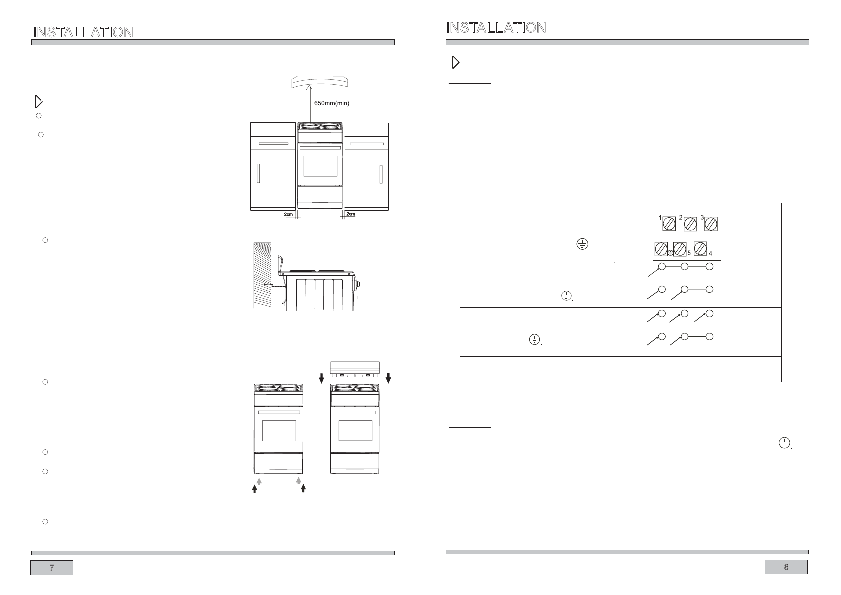
Installing the cooker
The kitchen where the appliance is to
The room should be equipped with a
ventilation system that pipes away
exhaust fumes created during
combustion. This system should
consist of a ventilation grid or hood.
Hoods should be installed according
to the manufacturer’s instructions.
The cooker should be placed so as
to ensure free access to all control
elements.
Coating or veneer used on fitted
furniture must be applied with a heat
resistant adhesive (100).This
prevents surface deformation or
detachment of the coating. If you
are unsure of your furniture’s heat
leave resistance, you should
the cooker should be resistant to
high temperatures. During operation,
its back side can warm up to around
INSTALLATION
8
The following instructions are addressed to
the qualified specialist installing the cooker.
These instructions aim to ensure that installstion
is performed as professionally as possible.
be installed must be dry and well ventilated.
approximately 2 cm of free a space
around the cooker. The wall behind
Fix the cooker to the back wall with 2 chains
Anti tilt chains are located at the rear of the
appliance and must be secured to the wall
behind the appliance to prevent accidental
tipping/tilting.The chain length must be as
short as practicable to avoid appliance tilting
forward and also diagonal to avoid appliance
moving sideways.
The cooker should stand on a hard,
even floor(do not put it on a base.)
Before you start using the cooker it should
be leveled,which is particularly important for
fat distribution in a frying pan. To this
purpose, adjustable feet are accessible after
removal of the drawer. The adjustment range is +/-5mm.
To fi t the rear pane l /spl a shba c k,sl i de t h e lu g s on the b otto m of t he p a nel
into the matching slots on rear of stove and fix with screws provided.
Electrical connection
Caution !
All electrical work should be carried out by a suitably qualified and authorized electrician.
No alterations or willful changes in the electricity supply should be carried out.
Fitting guidelines
The cooker is manufactured to work with three phase alternating current(380-415v 3N~50Hz).
The voltage rating of the cooker heating elements is 220-240V. Adapting the cooker to operate
with one-phase current is possible by appropriate bridging in the connection box according
to the connection diagram below. The connection diagram is also found on the cover of the
connection box. Remember that the connection wir
e should match the connection type and
the power rating of the cooker.
CONNECTION DIAGRAM
Caution! Voltage of heating elements 220-240V
Caution! In the event of any connection the safety
Wire must be connected to the E terminal.
Recommended
type of
connection
lead
1
2
For 220-240V earthed one-phase connection,
bridges connect 1-2-3 terminals and 4-5
terminals, safety wire to
H05VV-F3G4
H05VV-F5G1,5
For 380-415V/220-240V earthed three-phase
connection,bridges connect 4-5 terminals,
phases in succession 1,2 and 3,earth to 4-5,
safety wire to
L1=R, L2=S, L3=T, N=null terminal,E=safety wire terminal
L1
E
N
L3
E
LI
L2
N
Caution !
The connection cable must be secured in a strain-relief clamp.
Remember to connect the safety circuit to the connection box terminal marked with The
electricity supply for the cooker must have a safety switch which enables the power to be
cut off in case of emergency.The distance between the working contacts of the safety
switch must be at least 3 mm.
Before connecting the cooker to the power supply it is important to read the information on
the data plate and the connection diagram.
Loading ...
Loading ...
Loading ...