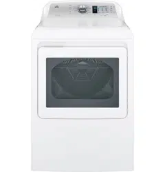
User manual Electric Dryer
Operating instructions
Throughout this manual, features and appearance may vary from your model.
IMPORTANT: Clean the lint filter each time you use the dryer.
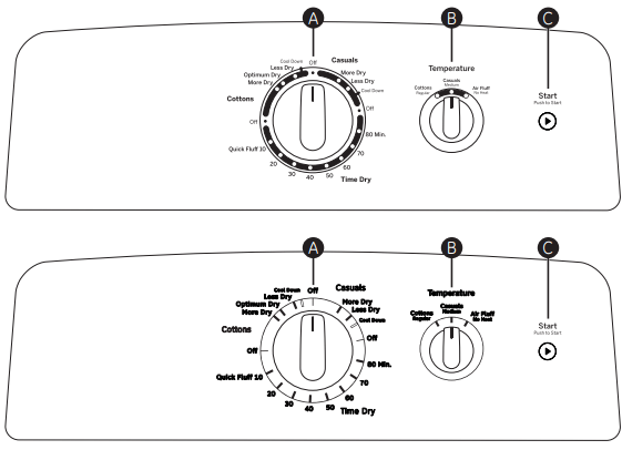
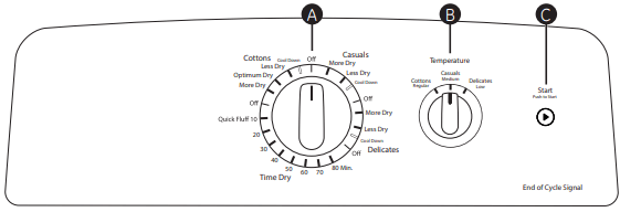
A Drying Cycles (Not all features are on all models)
Cottons For cottons and most linens. For most loads, select Optimum Dry (on some models).
Casuals For wrinkle-free, permanent press and delicate items, and knits.
Delicates On some models. For delicate items, special-care fabrics and knits.
Time Dry Set the Cycle Selector at the desired drying time.
Quick Fluff For freshening or fluffing up already dry clothing, fabrics, linens and pillows. Use with Air Fluff No Heat. Provides 10 minutes of no heat tumbling.
Sensor cycles automatically determine fabric dryness. Select Less Dry if you want your clothes slightly damp at the end of the drying cycle. Select More Dry if you want them to feel drier.
Timed cycles run for a selected time.
B Temperature (Not all features are on all models)
Cottons Regular For regular to heavy cottons.
Casuals Medium For synthetics, blends, delicates and items labeled permanent press.
Delicates Low On some models. For delicates, synthetics and items labeled tumble dry low.
Air Fluff No Heat On some models. For fluffing items without heat. Use the Time Dry cycle.
C Start - Close the dryer. Select Start. Opening the door during operation will stop the dryer. To restart the dryer, close the door and select Start to complete the cycle.
NOTE: Drying times will vary according to the type of heat used (Electric, Natural or LP gas), size of load, types of fabrics, wetness of clothes and condition of exhaust ducts.
About loading and using the dryer.
Always follow the fabric manufacturer’s care label when laundering.
Sorting and Loading Hints
As a general rule, if clothes are sorted properly for the washer, they are sorted properly for the dryer.
Do not add fabric softener sheets once the load has become warm. They may cause fabric softener stains. Bounce® Fabric Conditioner Dryer Sheets have been approved for use in all GE Dryers when used in accordance with the manufacturer’s instructions.
Do not overload. This wastes energy and causes wrinkling.
Do not dry the following items: fiberglass items, woolens, rubber-coated items, plastics, items with plastic trim and foam-filled items.
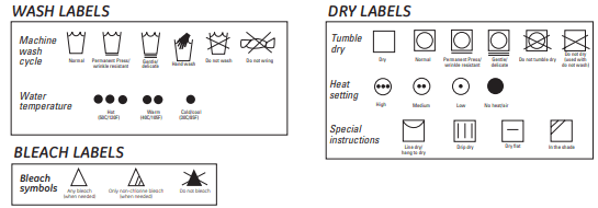
Fabric Care Labels
Below are fabric care label “symbols” that affect the clothing you will be laundering.
About the dryer features.

Drum Lamp (on some models)
Before replacing the light bulb, be sure to unplug the dryer power cord or disconnect the dryer at the household distribution panel by removing the fuse or switching off the circuit breaker.
Reach above dryer opening from inside the drum. Remove the bulb and replace with the same size bulb.
Drying Rack (on some models)

A handy drying rack may be used for drying delicate items such as washable sweaters.
Hook the rack over the lint filter so the rack extends into the dryer drum.
NOTE:
- The drying rack must be used with the Time Dry cycle.
- Do not use this drying rack when there are other clothes in the dryer.
Alloy Steel Drum (on some models)
The alloy steel used to make the dryer drum provides the highest reliability available in a GE dryer.
If the dryer drum should be scratched or dented during normal use, the drum will not rust or corrode. These surface blemishes will not affect the function or durability of the drum.
Care and Cleaning of the Dryer. GEAppliances.com
The Exterior: Wipe or dust any spills or washing compounds with a damp cloth. Dryer control panel and finishes may be damaged by some laundry pretreatment soil and stain remover products. Apply these products away from the dryer. The fabric may then be washed and dried normally. Damage to your dryer caused by these products is not covered by your warranty.
The Lint Filter: Clean the lint filter before each use. Remove by pulling straight up. Run your fingers across the filter. A waxy buildup may form on the lint filter from using dryer added fabric softener sheets.
To remove this buildup, wash the lint screen in warm, soapy water. Dry thoroughly and replace. Do not operate the dryer without the lint filter in place.
Vacuum the lint from the dryer lint filter area if you notice a change in dryer performance.
Stainless Steel: To clean stainless steel surfaces, use a damp cloth with a mild, non-abrasive cleaner suitable for stainless steel surfaces. Remove the cleaner residue, and then dry with a clean cloth.
Dryer Interior and Duct: The interior of the appliance and exhaust duct should be cleaned once a year by qualified service personnel.
The Exhaust Duct: Inspect and clean the exhaust ducting at least once a year to prevent clogging. A partially clogged exhaust can lengthen the drying time.
Follow these steps:
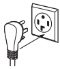
1 Turn off electrical supply by disconnecting the plug from the wall socket.
2 Disconnect the duct from the dryer.
3 Vacuum the duct with the hose attachment and reconnect the duct.
The Exhaust Hood: Check from the outside that the flaps of the hood move freely when operating. Make sure that there is not wildlife (birds, insects, etc.) nesting inside the duct or hood.
About venting the dryer.
For the best drying performance, the dryer needs to be properly vented. The dryer will use more energy and run longer if it is not vented to the below specifications. Carefully follow the details on Exhausting in the Installation Instructions.
- Use only rigid metal 4” diameter ductwork inside the dryer cabinet. Use only rigid metal or UL listed flexible metal 4” diameter ductwork for exhausting to the outside.
- Do not use plastic or other combustible ductwork.
- Use the shortest length possible.
- Do not crush or collapse.
- Avoid resting the duct on sharp objects.
- Venting must conform to local building codes.
Before you call for service…
Dryer doesn’t start
Make sure the dryer plug is pushed completely into the outlet.
- Fuse is blown/circuit breaker is tripped
Check the house fuse/circuit breaker box and replace fuse or reset breaker. NOTE: Most electric dryers use 2 fuses/breakers.
Dryer doesn’t heat
- Fuse is blown/circuit breaker is tripped; the dryer may tumble but not heat
Check the house fuse/circuit breaker box and replace both fuses or reset both breakers. Your dryer may tumble if only one fuse is blown or one breaker tripped.
Make sure gas shutoff at dryer and main shutoff are fully open.
Dryer shakes or makes noise
- Some shaking/noise is normal. Dryer may be sitting unevenly
Move dryer to an even floor space, or adjust leveling legs as necessary until even.
Greasy spots on clothes
- Improper use of fabric softener
Follow directions on fabric softener package.
- Drying dirty items with clean ones
Use your dryer to dry only clean items. Dirty items can stain clean items and the dryer.
- Clothes were not completely clean
Sometimes stains which cannot be seen when the clothes are wet appear after drying. Use proper washing procedures before drying.
Lint on clothes
Clean lint screen before each load.
Sort lint producers (like chenille) from lint collectors (like corduroy).
- Static electricity can attract lint
See suggestions in this section under Static occurs.
Separate large loads into smaller ones.
- Paper, tissue, etc. left in pockets
Empty all pockets before laundering clothes.
Static occurs
- No fabric softener was used
Try a fabric softener.
Bounce® Fabric Conditioner Dryer Sheets have been approved for use in all GE Dryers when used in accordance with the manufacturer’s instructions.
Try a fabric softener.
Adjust setting to Less Dry.
- Synthetics, permanent press and blends can cause static
Try a fabric softener.
Inconsistent drying times
Automatic drying times will vary according to the type of heat used (electric, natural or LP gas), size of load, types of fabrics, wetness of clothes and condition of exhaust ducts.
Clothes take too long to dry
Separate heavy items from lightweight items (generally, a well-sorted washer load is a well-sorted dryer load).
- Large loads of heavy fabrics (like beach towels)
Large, heavy fabrics contain more moisture and take longer to dry. Separate large, heavy fabrics into smaller loads to speed drying time
Match control settings to the load you are drying.
Clean lint filter before every load.
- Improper or obstructed ducting
Check installation instructions for proper ducting/venting.
Make sure ducting is clean, free of kinks and unobstructed.
Check to see if outside wall damper operates easily.
Check the Installation Instructions to make sure the dryer venting is correct.
- Blown fuses or tripped circuit breaker
Replace fuses or reset circuit breakers. Since most dryers use 2 fuses/breakers, make sure both are operating.
- Overloading/combining loads
Do not put more than one washer load in the dryer at a time.
If you are drying only one or two items, add a few items to ensure proper tumbling.
Clothes are wrinkled
Select a shorter drying time.
Remove items while they still hold a slight amount of moisture. Select a Less Dry setting.
- Letting items sit in dryer after cycle ends
Remove items when cycle ends and fold or hang mmediately.
Separate large loads into smaller ones.
Clothes shrink
- Some fabrics will naturally shrink when washed. Others can be safely washed, but will shrink in the dryer
To avoid shrinkage, follow garment care labels exactly.
Some items may be pressed back into shape after drying.
If you are concerned about shrinkage in a particular item, do not machine wash or tumble dry it.
Installation Instructions
CONNECTING INLET HOSES (for steam dryer models only)
CONNECTING INLET HOSES
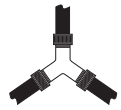
To produce steam, the dryer must connect to the cold water supply. Since the washer must also connect to the cold water, a “Y” connector is inserted to allow both inlet hoses to make that connection at the same time.
NOTE: Use new inlet hoses; never use old hoses.
1. Turn the cold water faucet off. Remove the washer inlet hose from the washer fill valve connector (cold).
2. Ensure the rubber flat washer is in place and attach one female coupling of the short hose provided onto the washer fill valve connector. Tighten by hand until firmly seated.
3. Attach one male end of the “Y” connector to the other female coupling of the short hose. Ensure the rubber flat washer is in place. Tighten by hand until firmly seated.
4. Insert the filter screen in the coupling of the washer’s inlet hose. If a rubber flat washer is already in place remove it before installing the filter screen. Attach this coupling to one male end of the ‘’Y’’ connector. Tighten by hand until firmly seated.
5. Ensure the rubber flat washer is in place and attach a 4 ft. to 6 ft. long water inlet hose (may need to be purchased separately) to one male end of the ‘’Y’’ connector. Tighten by hand until firmly seated.
6. Ensure the rubber flat washer is in place and attach the other end of the dryer’s long inlet hose to the fill valve connector at the bottom of the dryer back panel. Tighten by hand until firmly seated.
7. Using pliers, tighten all the couplings with an additional two–thirds turn. NOTE: Do not overtighten. Damage to the couplings may result.
8. Turn the water faucet on.
9. Check for leaks around the ‘’Y’’ connector, faucet and hose couplings.
WATER SUPPLY REQUIREMENTS
Hot and cold water faucets MUST be installed within 42 in. (107 cm) of your washer’s water inlet. The faucets MUST be 3/4 in. (1.9 cm) garden hose-type so inlet hoses can be connected. Water pressure MUST be between 10 and 120 pounds per square inch. Your water department can advise you of your water pressure.
NOTE: A water softener is recommended to reduce buildup of scale inside the steam generator if the home water supply is very hard.
CONNECTING A GAS DRYER (skip for electric dryers)
DRYER GAS SUPPLY CONNECTION
You must use with this dryer a flexible metal connector (listed connector ANSI Z21.24 / CSA 6.10). The length of the connect shall not exceed 4 feet.
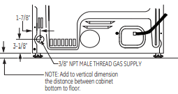
GAS SUPPLY
- A 1/8” National Pipe Taper thread plugged tapping, accessible for test gauge connection, must be installed immediately upstream of the gas supply connection to the dryer. Contact your local gas utility should you have questions on the installation of the plugged tapping.
- Supply line is to be 1/2” rigid pipe and equipped with an accessible shutoff within 6 feet of, and in the same room with, the dryer.
- Use pipe thread compound appropriate for natural or LP gas or use PTFE tape.
- Connect flexible metal connector to dryer and gas supply.
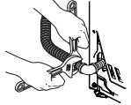
CONNECTING THE DRYER TO THE GAS SUPPLY
A Install a female 3/8” NPT elbow at the end of the dryer gas inlet. Install a 3/8” flare union adapter to the female elbow.
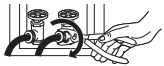
IMPORTANT: Use a pipe wrench to securely hold on to the end of the dryer gas inlet to prevent twisting the inlet.
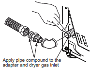
NOTE: Apply pipe compound or PTFE tape to the threads of the adapter and dryer gas inlet.
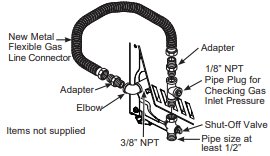
B Attach the flexible metal gas line connector to the adapter.
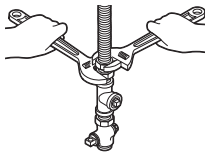
C Tighten the flexible gas line connection, using two adjustable wrenches.
D Install a 1/8” NPT plugged tapping to the dryer gas line shut-off valve for checking gas inlet pressure.
Install a flare union adapter to the plugged tapping.
NOTE: Apply pipe compound or PTFE tape to the threads of the adapter and plugged tapping.
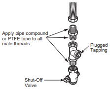
E Tighten all connections, using two adjustable wrenches. Do not overtighten.
F Open the gas shut-off valve.
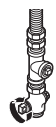
TEST FOR LEAKS
Never use an open flame to test for gas leaks.
Check all connections for leaks with soapy solution or equivalent.
Apply a soap solution. The leak test solution must not contain ammonia, which could cause damage to the brass fittings.
If leaks are found, close the valve, retighten the joint and repeat the soap test.

EXHAUSTING THE DRYER
EXHAUST LENGTH
Using exhaust longer than specified length will:
- Increase the drying times and the energy cost.
- Reduce the dryer life.
- Accumulate lint, creating a potential fire hazard.
The correct exhaust installation is YOUR RESPONSIBILITY.
Problems due to incorrect installation are not covered by the warranty.
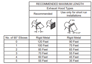
The MAXIMUM ALLOWABLE length of the exhaust system depends upon the type of duct, number of turns, the type of exhaust hood (wall cap) and all conditions noted on the chart.
- Internal elbows added for side or bottom vent conversions must be included in the total elbow count.
- Any elbow greater than 45° should be treated as a 90° elbow; one elbow of 45° or less may be ignored.
- Two 45° elbows will be treated like one 90° elbow.
- For the side exhaust installations, add one 90° elbow to the chart.
- For every additional 90° elbow, reduce the allowable vent system length by 10 feet.
- When calculating the total vent system length, you must add all the straight portions and elbows of the system (including the transition duct).
EXHAUST SYSTEM CHECKLIST
HOOD OR WALL CAP
- Terminate in a manner to prevent back drafts or entry of birds or other wildlife.
- Termination should present minimal resistance to the exhaust airflow and should require little or no maintenance to prevent clogging.
- Wall caps must be installed at least 12” above ground level or any other obstruction with the opening pointed down.
SEPARATION OF TURNS
- For best performance, separate all turns by at least 4 ft. of straight duct, including distance between last turn and dampened exhaust hood (wall cap).
SEALING OF JOINTS
- All joints should be tight to avoid leaks. The male end of each section of duct must point away from the dryer.
- Duct joints should be made air- and moisture-tight by wrapping the overlapped joints with duct tape or aluminum tape.
- Do not assemble ductwork with any fasteners that extend into the duct. These fasteners can accumulate lint, creating a potential fire hazard.
- Horizontal runs should slope down towards the outdoors 1/4” per foot.
- Provide an access for inspection and cleaning of the exhaust system, especially at turns and joints. Exhaust system shall be inspected and cleaned at least once a year.
INSULATION
- Ductwork that runs through an unheated area or is near air conditioning should be insulated to reduce condensation and lint build-up.
STANDARD REAR EXHAUST
We recommend that you install your dryer before installing your washer. This will permit direct access for easier exhaust connection.
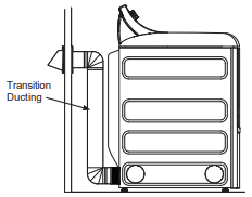
Slide the end of the exhaust duct on the back of the dryer and secure with duct tape or a hose clamp.
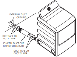
NOTE: We strongly recommend using rigid metal exhaust duct. However, if flexible ducting is used it must be UL-Listed metal, not plastic.
- For straight line installation, connect the dryer exhaust to the external exhaust hood using duct tape or clamp.
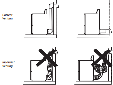
RECOMMENDED CONFIGURATION TO MINIMIZE EXHAUST BLOCKAGE
Using duct elbows will prevent duct kinking and collapsing.
SIDE OR BOTTOM VENTING
Dryer Exhaust to right of the cabinet for Electric models only.
Dryer Exhaust to left of the cabinet for Gas and Electric models.
Dryer Exhaust to the bottom of cabinet for Gas and Electric models.
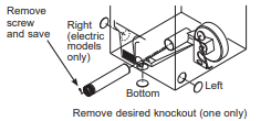
Detach and remove the right (electric models only), left or bottom knockout as desired. Remove the screw inside the dryer exhaust duct and save.
Pull the duct out of the dryer.
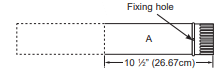
Cut the duct as shown and keep portion A.
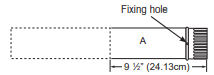
For models GTD60, GTD65 and GTD68 only, use the dimension below:
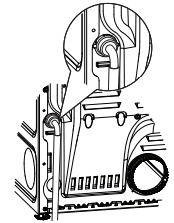
TAB LOCATION
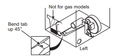
Through the rear opening, locate the tab in the middle of the appliance base. Lift the tab to about 45°, using a flat-blade screwdriver.
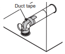
ADDING A NEW DUCT
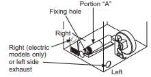
Reconnect the cut portion (A) of the duct to the blower housing. Make sure that the shortened duct is aligned with the tab in the base. Use the screw saved previously to secure the duct in place through the tab on the appliance base.
ADDING ELBOW AND DUCT FOR EXHAUST TO RIGHT (ELECTRIC MODELS ONLY) OR LEFT SIDE OF CABINET
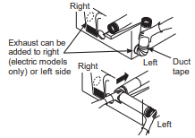
- Preassemble 4” elbow with 4” duct. Wrap duct tape around joint.
- Insert duct assembly, elbow first, through the side opening and connect the elbow to the dryer internal duct.
Be sure not to pull or damage the electrical wires inside the dryer when inserting the duct.
- Apply duct tape as shown on the joint between the dryer internal duct and the elbow, and also the joint between the elbow and the side duct.
Use 4” rigid metal ducting only inside the dryer. Internal duct joints must be secured with tape, otherwise they may separate and cause a safety hazard.
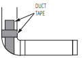
ADDING ELBOW FOR EXHAUST THROUGH BOTTOM OF CABINET
- Insert the elbow through the rear opening and connect it to the dryer internal duct.
- Apply duct tape as shown on the joint between the dryer internal duct and the elbow, and also the joint between the elbow and the bottom duct.
Internal duct joints must be secured with tape; otherwise, they may separate and cause a safety hazard.
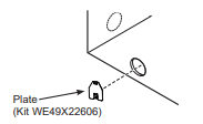
ADDING COVER PLATE TO REAR OF CABINET
FINAL SETUP
1 LEVEL THE DRYER
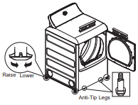
Stand the dryer upright near the final location and adjust the leveling legs at the corners to ensure the dryer is level side-to-side and front-to-back. Then, adjust the two anti-tip legs at the front inner corners, taking care that they are touching the floor to avoid unit tip over. The installation is not complete until this process is finished.
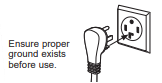
2 PLUG DRYER IN
3 DRYER START-UP

Press the Start button.
NOTE: If the dryer has been exposed to temperatures below freezing for an extended period of time, allow it to warm up before pressing Start. Otherwise, the display will not come on. The dryer is now ready for use.
REVERSING THE DOOR
A REVERSING THE DOOR - SOLID DOOR MODELS
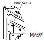
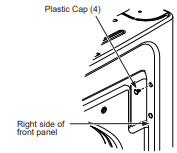
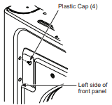
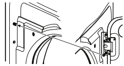
1 Open the door approximately 130 degrees. With a putty knife, remove the 4 plastic caps located along the left side of the front panel and set them aside.
2 Remove the bottom screw from each hinge (right side) and partially insert them into each top hinge hole on the left side. NOTE: All 4 front panel hinge screws will now be in the top hinge holes - 2 on the left and 2 on the right.
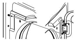
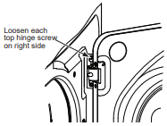
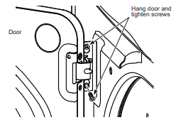
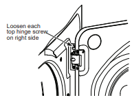
3 Loosen each top hinge screw on right side. Remove the door and place it on a protective flat surface to avoid any damage.
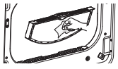
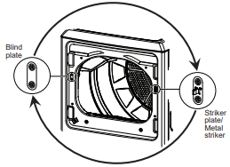
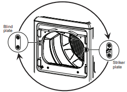
4 Remove both the blind plate and the striker plate/ metal striker and install them in opposite positions.
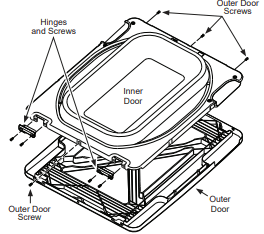
5 GTX52 model only: Remove 2 hinges and 8 screws (4 for the hinges and 4 for the outer door). Remove the inner door by lifting it up, using a flat blade screwdriver, and out.
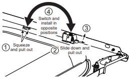
6 GTX52 model only: Flip the inner door over. Remove the dock by squeezing its tabs and pulling it out. Remove the latch catch by sliding down and pulling it out. Switch and install in the opposite positions.
7 GTX52 model only: Flip the inner door back over and rotate it 180°. Replace it back into the outer door. Replace the 2 hinges and 8 screws (4 for the hinges and 4 for the outer door).
8 Mount the door on the 2 upper left side hinge screws installed in step 2. Move the hinge screws loosened in step 3 into the lower left side screw holes and firmly tighten all 4 screws.
9 Install the 4 plastic caps removed in step 1 into the 4 right side front panel holes.
NOTE: To return the door to the original setup, follow these instructions, swapping “left” and “right”.
When you finish
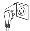
Plug the dryer back into its electrical outlet.
B REVERSING THE DOOR - GLASS PANEL DOOR MODELS
1 Open the door approximately 130 degrees. With a putty knife, remove the 4 plastic caps located along the left side of the front panel and set them aside.
2 Remove the bottom screw from each hinge (right side) and partially insert them into each top hinge hole on the left side.
NOTE: All 4 front panel hinge screws will now be in the top hinge holes - 2 on the left and 2 on the right.
3 Loosen each top hinge screw on right side. Remove the door and place it on a protective flat surface to avoid any damage.
4 Remove both the blind plate and the striker plate and install them in the opposite positions.
5 Remove the 4 door hinge screws, 6 inside screws and 2 pocket screws. Lift the inner door upwards using a flat blade screwdriver.
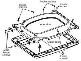
6 Remove and swap the 2 plastic caps and the 2 hinges.
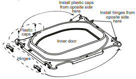
7 Rotate the outer door 180 degrees, mount the inner door back into the outer door frame and secure with the screws removed in step 5. Make sure you mount the hinges on the side opposite the pocket.
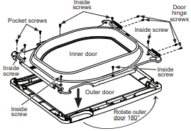
8 Mount the assembled door on the 2 upper left side hinge screws installed in step 2. Move the hinge screws loosened in step 2 into the lower left side screw holes and firmly tighten all 4 screws.
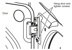
9 Install the 4 plastic caps removed in step 1 into the 4 right side front panel holes.
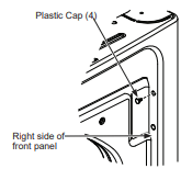
NOTE: To return the door to the original setup, follow these instructions, swapping “left” and “right”.
When you finish
Plug the dryer back into its electrical outlet.