User Gudie Whirlpool WMH53521HZ Microwave
MICROWAVE HOOD COMBINATION SAFETY
Location Requirements
- Check the opening where the microwave oven will be installed.
- The location must provide:
- Minimum installation dimensions. See “Installation
- Dimensions” illustration.
- Minimum one 2" x 4" (50.8 mm x 101.6 mm) wood wall stud and minimum 3/8" (10 mm) thickness drywall or plaster/lath within cabinet opening.
- Support for weight of 150 lbs (68 kg), which includes microwave oven and items placed inside the microwave oven and upper cabinet.
- Grounded electrical outlet inside upper cabinet. See the
- Electrical Requirements” section.
NOTES:
- If installing the microwave oven near a left sidewall, make sure there is at least 6" (15.2 cm) of clearance between the wall and the microwave oven, so that the door can open fully.
- If installing the microwave oven near a right sidewall, make sure there is at least 3" (7.6 cm) of clearance between the wall and the microwave oven, so that you can grab the handle integrated inside the door.
- Some cabinet and building materials are not designed to withstand the heat produced by the microwave oven for cooking. Check with your builder or cabinet supplier to make sure that the materials used will not discolor, delaminate, or sustain other damages.
Special Requirements
For Wall Venting Installation Only:
- Cutout must be free of any obstructions so that the vent fits properly and the damper blade opens freely and fully.
For Roof Venting Installation Only:
- If you are using a rectangular to round transition piece, the 3" (7.6 cm) clearance needs to exist above the microwave oven so that the damper blade can open freely and fully.
- See “Rectangular to Round Transition” illustration in the “Venting Design Specifications” section.
INSTALLATION INSTRUCTIONS
Remove Mounting Plate
- Depending on your model, the mounting plate may be in the foam packaging or it may be attached to the back of the microwave oven.
NOTE:
- To avoid possible damage to the work surface, cover the work surface.
- Remove any remaining contents from the microwave oven cavity.
- If the mounting plate is attached to the back of the microwave oven, remove it and set it aside.
- Tape the microwave oven door closed so that door does not swing open while the microwave oven is being handled.
NOTE:
- To avoid damage to the microwave oven, do not grip or use the door or door handle while the microwave oven is being handled.
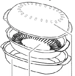
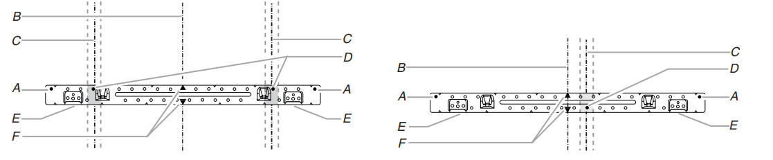
Rotate Blower Motor
- The microwave oven is set for recirculation installation. For wall or roof venting, changes must be made to the venting system.
NOTE:
- Skip this section if you are using recirculation installation. Keep the damper assembly in case the venting method is changed or the microwave oven is reinstalled in another location where wall or roof venting may be used.
Wall Venting Installation Only
- Remove screws attaching damper plate to top of microwave oven exterior. Slide damper plate toward the front of the microwave oven and lift up.
- Keep damper plate and screws together and set aside.
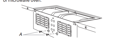
- Remove 2 screws attaching blower motor to back of microwave oven.
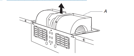
- Lift blower motor out of microwave oven.
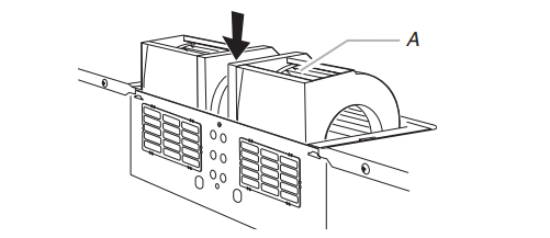
- Rotate blower motor 180° so that exhaust ports face the back of microwave oven, and lower blower motor back into the microwave oven.
Roof Venting Installation Only
- Repeat steps 1 to 4 from the “Wall Venting Installation Only” section.
- Rotate blower motor so that exhaust ports face the top of microwave oven and flat sides of blower motor face back of microwave oven. Lower blower motor back into microwave oven.
IMPORTANT:
- If blower motor is not positioned with flat sides facing the back of the microwave oven (as shown), performance will be poor.
- Reattach blower motor to back of microwave oven with screws removed in Step 3 of the “Wall Venting Installation
- Only” section. Securely tighten screws.
NOTE:
- If blower motor is not correctly oriented, the 2 screws removed in Step 3 cannot be reattached to the microwave oven.
- Using diagonal wire cutting pliers, gently snip out the rectangular vent covers on the damper plate removed in Step 1 at the perforations.
- Reattach damper plate. Make sure damper plate tabs are inserted into the slots in the top of the microwave oven.
- Secure damper plate with 2 screws removed in Step 1 of the
- Wall Venting Installation Only” section.
Possible Wall Stud Configurations
Mark Rear Wall
- The microwave oven must be installed on a minimum of 1 wall stud, preferably 2, using a minimum of 1 lag screw, preferably 2.
- Using measuring tape, find and clearly mark the vertical centerline of the opening.
- Align the center markers on the wall template to the centerline on the wall, making sure it is level and that the top of the wall template is butted up against the bottom edge of the upper cabinet.
NOTES:
- If the front edge of the upper cabinet is lower than the back edge, lower the wall template so that its top is level with the front edge of the cabinet.
- If the wall template is damaged or unusable, measure and mark the wall with the dimensions described in Step 4.
- Tape the wall template in place. Mark both holes in the lower corners, and draw a horizontal line across the bottom edge of the wall template. These represent the mounting plate’s end holes and bottom edge.
- Remove the wall template and check the markings:
Wall Venting Installation Only
- Mark the centerline 3/8" (1 cm) down from the bottom edge of the upper cabinet.
- Using measuring tape, measure out 6" (15.2 cm) on both sides of the centerline, and mark.
- Measure down 4" (10.2 cm) from the mark made in Step 8, and mark.
- Using a straightedge, draw the 2 horizontal, level lines through the marks made in steps 8 and 10.
- Draw the 2 vertical, plumb lines down from the marks made in Step 9 to complete the 12" x 4" (30.5 cm x 10.2 cm) rectangle. This is the venting cutout area.
- Cut a 3/4" (19 mm) hole in one corner of the cutout area.
- Using a keyhole saw, cut out the venting cutout area.
Drill Holes in Rear Wall
- In addition to being installed on at least 1 wall stud, the mounting plate must attach to the wall at both end holes.
- If the end holes are not over wall studs, use two 3/16-24 x 3" cm) round-head bolts with toggle nuts; if 1 end hole is over a wall stud, use 1 lag screw and one 3/16-24 x 3" (7.6 cm) round-head bolt with toggle nut; or if both end holes are over wall studs, use 2 lag screws. Following are 3 installation configurations.
Installation for No Wall Studs at End Holes
- Drill 5/8" (16 mm) holes through the wall at both end holes marked in Step 3 of the “Mark Rear Wall” section.
- Drill 3/16" (5 mm) hole(s) into the wall stud(s) at the hole(s) marked in Step 6 of the “Mark Rear Wall” section Refer to figures 1 and 2 in “Possible Wall Stud
- Configurations” in the “Locate Wall Stud(s)” section.
Installation for Wall Stud at One End Hole (Figure 3)
- Drill a 3/16" (5 mm) hole into the wall stud at the end hole marked in Step 3 of the “Mark Rear Wall” section.
- If installing on a second wall stud, drill a 3/16" (5 mm) hole into the wall stud at the other hole marked in Step of the “Mark Rear Wall” section. Refer to Figure 3 in
- Possible Wall Stud Configurations” in the “Locate Wall
- Stud(s)” section.
- Drill a 5/8" (16 mm) hole through the wall at the other end hole.
Wall Stud at One End Hole (Figure 3)
- With the support tabs of the mounting plate facing forward, insert a 3/16-24 x 3" (7.6 cm) round-head bolt through the end hole that fits over the 5/8" (16 mm) hole drilled in Step 3 of “Installation for Wall Stud at One End Hole” in the “Drill
Holes in Rear Wall” section.
- Start a toggle nut on the bolt from the back of the mounting plate. Leave enough space for the toggle nut to go through the wall and to open.
- Position mounting plate on the wall.
- Push the bolt with toggle nut through the drywall, and finger tighten the bolt to make sure toggle nut has opened against drywall.
- Insert a lag screw into the remaining end hole.
- If installing on a second wall stud, insert a lag screw into the other hole drilled in Step 2 of “Installation for Wall Stud at One End Hole” in the “Drill Holes in Rear Wall” section.
- Check alignment of mounting plate, making sure it is level.
- Securely tighten the lag screw(s) and bolt.
- Wall Studs at Both End Holes (Figure 4)
- Position mounting plate on the wall.
- Insert lag screws into both end holes.
- Check alignment of mounting plate, making sure it is level.
- Securely tighten the lag screws.
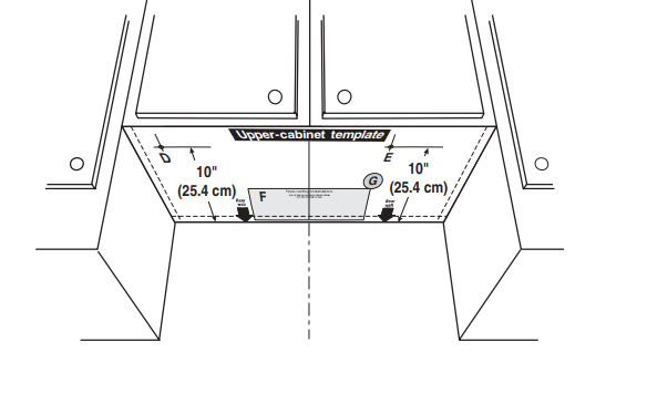
Prepare Upper Cabinet
- Disconnect power to outlet.
- Remove all contents from upper cabinet.
- Place Upper Cabinet Template against the bottom of the upper cabinet, and attach with tape or thumbtacks.
- Make sure the template centerline aligns with the vertical centerline on the rear wall.
- The “rear wall” arrows must be against the rear wall so that the holes cut into the upper cabinet align with the holes in the top of the microwave oven.
NOTES:
- If the upper cabinet has a frame around it, trim the template edges so that it fits inside the frame, against the upper cabinet bottom. The template has trim lines to use as guides.
- If the wall behind the microwave oven (as installed) has a partial wall covering (for example, tile backsplash), be sure the “Rear Wall” arrows align to the thickest part of the rear wall (for example, the thickness of the tiles rather than the drywall).
- Make sure the 10" (25.4 cm) dimension from the rear wall to points “D” and “E” on the template is maintained.
Install the Microwave Oven
- Place a washer on each 1/4-20 x 3" (7.6 cm) flat-head bolt and place inside upper cabinet near the 3/8" (10 mm) holes.
- Make sure the microwave oven door is closed and taped shut.
- Using 2 or more people, lift microwave oven and hang it on support tabs at the bottom of mounting plate.
- NOTE: To avoid damage to the microwave oven, do not grip or use the door or door handle while the microwave oven is being handled.
- With front of microwave oven still tilted, thread power supply cord through the power supply cord hole in the bottom of the upper cabinet.
- Rotate microwave oven up toward upper cabinet.
NOTE:
- If venting through the wall, make sure the damper assembly fits easily into the vent in the wall cutout.
A. Metal cabinet
B. Power supply cord bushing
C. Damper blade
D. Sheet metal screws
WARNING
- Excessive Weight Hazard
- Use two or more people to move and install microwave oven.
- Failure to do so can result in back or other injury.
A. Mounting plate
B. Support tabs
- Push microwave oven against mounting plate and hold in place.
NOTE:
- If microwave oven does not need to be adjusted, skip steps 7-9.
- If adjustment is required, rotate microwave oven downward.
- Using 2 or more people, lift microwave oven off of mounting plate, and set aside on a covered surface.
- Loosen mounting plate screws. Adjust mounting plate and retighten screws.
- Repeat steps 3-6.
- With the microwave oven centered, and with at least one person holding it in place, insert bolts through upper cabinet into microwave oven. Tighten bolts until there is no gap between upper cabinet and microwave oven.
NOTES:
- Some upper cabinets may require bolts longer or shorter than 3" (7.6 cm). Longer or shorter bolts are available at most hardware stores.
- Overtightening bolts may warp the top of the microwave oven. To avoid warping, wood filler blocks (installer to provide) may be added. The blocks must be the same thickness as the space between the upper cabinet bottom and the microwave oven.
For Roof Venting Installation Only
- Insert damper assembly through the cabinet cutout so that the long tab of the damper assembly slides under the raised tabs of the damper plate. Then secure with sheet metal screw.
NOTE:
- The screw cannot be installed if the damper assembly is not positioned as shown.
- Connect vent to damper assembly.
VENTING DESIGN SPECIFICATIONS
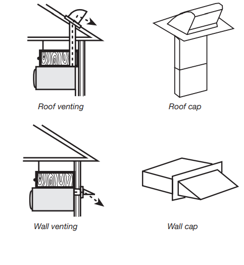
- For optimal venting installation, we recommend:
- Using roof or wall caps that have back draft dampers.
- Using a rigid metal vent.
- Using the most direct route by minimizing the length of the vent and number of elbows to provide efficient performance.
- Using uniformly sized vents.
- Using duct tape to seal all joints in the vent system.
- Using caulking compound to seal exterior wall or roof opening around cap.
- Not installing 2 elbows together for optimal hood performance.
- If venting through the wall, be sure that there is proper clearance within the wall for the damper to open fully.
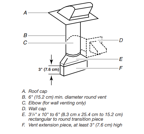
- If venting through the roof, and rectangular to round transition is used, be sure there is at least 3" (7.6 cm) of clearance between the top of the microwave oven and the transition piece. See the “Rectangular to Round
- Transition” illustration.
Rectangular to Round Transition:
NOTE:
- The minimum 3" (7.6 cm) clearance must exist between the top of the microwave oven and the rectangular to round transition piece so that the damper can open freely and fully
Recommended
- Vent Length A 31 /4" x 10" (8.3 cm x 25.4 cm) rectangular or 6" (15.2 cm) round vent should be used. The total length of the vent system including straight vent, elbow(s), transitions and wall or roof caps must not exceed the equivalent of 140 ft (42.7 m) for either type of vent.
- See the “Recommended Standard Fittings” section for equivalent lengths
- For best performance, use no more than three 90° elbows. To calculate the length of the system you need, add the equivalent lengths of each vent piece used in the system. See the following examples
ASSISTANCE
Replacement Parts
- If any of the installation hardware needs to be replaced, call us at our toll free number listed in the User Guide.
- Following is a list of available replacement parts. You will need your model number located on the front facing of the microwave oven opening behind the door.
- Damper Assembly
- Mounting Plate
- Upper Cabinet Template
- Mounting Screw Kit (includes parts A-G in “Parts Supplied” in the “Tools and Parts” section)
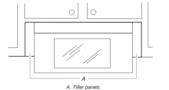
- Accessories Filler Panel Kits are available from your dealer to use when installing this microwave oven in a 36" (91.4 cm) or 42" (106.7 cm) wide opening. The filler panels come in pairs. Each panel is 3" (7.6 cm) wide.