Loading ...
Loading ...
Loading ...
6
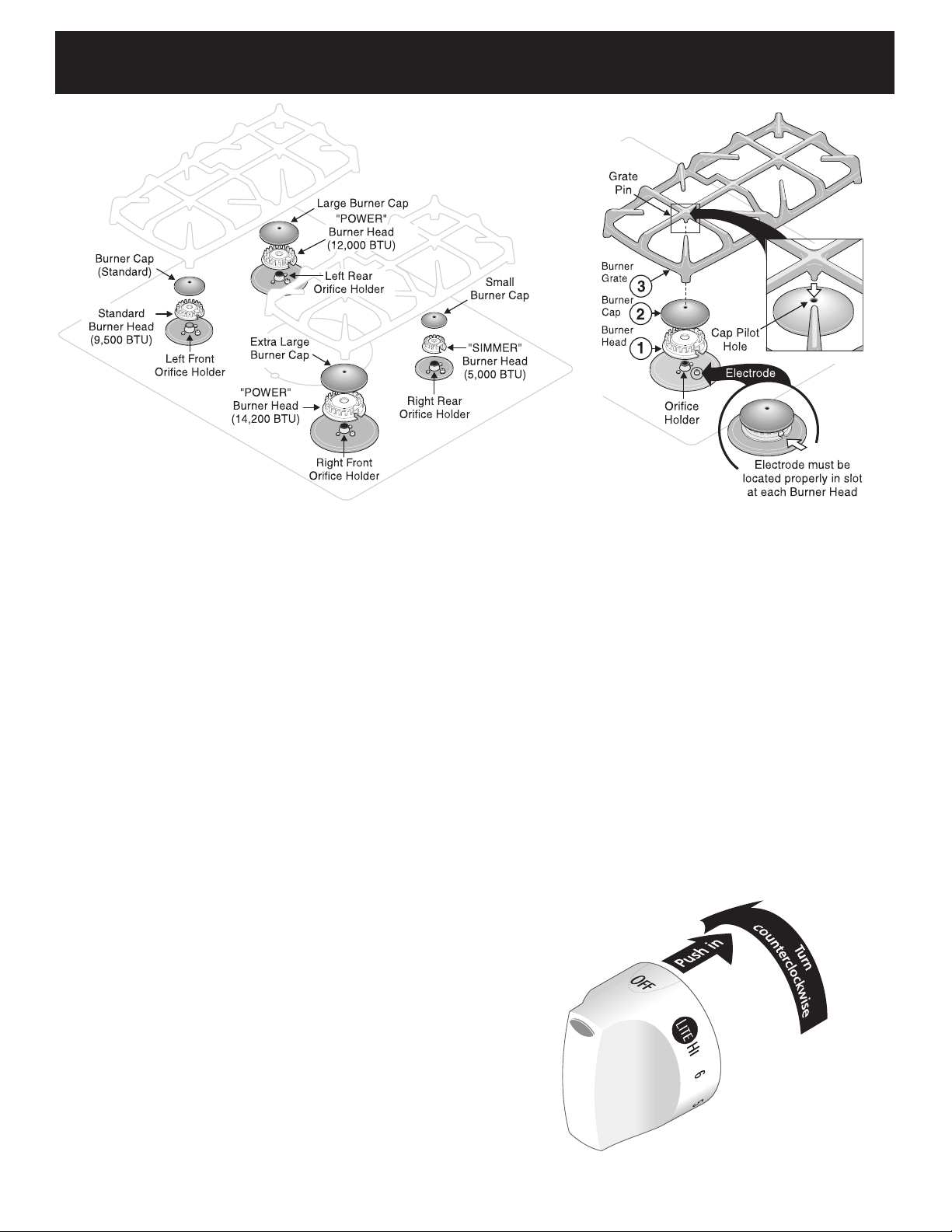
7. Electric Ignition Surface Burners
Operation of electric igniters should be checked after range
and supply line connectors have been carefully checked for
leaks and range has been connected to electric power.
a. To check for proper lighting, push in and turn a surface
burner knob counterclockwise to the LITE position. You
will hear the igniter sparking (See Fig. 3).
b. The surface burner should light when gas is available to
the top burner. Purge air from supply lines by leaving knob
in the LITE position until burner ignites. Each burner
should light within four (4) seconds in normal operation
after air has been purged from supply lines.
c. Visually check that burner has lit. Once the burner lights,
the control knob should be turned out of the LITE position.
d. There are separate electrodes (igniters) for each burner.
Try each knob separately until all burner valves have been
checked.
30" GAS RANGE INSTALLATION INSTRUCTIONS
(For Models with Sealed Top Burners)
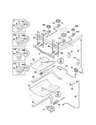
6. Assembly of the Surface Burner Heads, Burner
Caps and Burner Grates:
It is very important to makes sure that all of the Surface Burner
Heads, Surface Burner Caps and Surface Burner Grates are
installed correctly and in the correct locations.
a. Place all 4 (four) Burner Heads in the correct locations
(See Fig. 1). Make sure that the correct Burner Head is
placed with the corresponding Orifice Holder and that the
Electrode is located properly in the slot provided with each
Burner Head (See Fig. 2). Proper Burner Head placement
insures that each Burner will have the correct spark
required for gas ignition.
b. Place the correct Burner Caps at each of the burner
locations (Burner Cap Pilot Hole must face up). Each of
the 4 (four) Burner Heads MUST have a Burner Cap
installed to insure proper ignition and gas flame size and
must be in place with the Pilot Hole facing up BEFORE
placing the Burner Grates (See Fig. 2).
c. Place the 2 (two) cast iron Burner Grates supplied with the
range. Carefully line-up the 2 Grate Pins on each Grate
with the Cap Pilot Holes in the 2 Burner Caps on each side
of the range. DO NOT force the Burner Grates onto the
Burner Caps. Forcing the grates down onto improperly
installed Burner Heads and Burner Caps may damage the
gas burners. Each Burner Cap is designed with a Cap Pilot
Hole in the top center of the Cap. Visually check that ALL
the Grate Pins line up into the Burner Cap Pilot Holes (See
Figure 2). Properly installed Burner Grates will rest with all
four Grate legs on the glass cooktop.
REMEMBER — DO NOT ALLOW SPILLS, FOOD, CLEANING
AGENTS OR ANY OTHER MATERIAL TO ENTER THE GAS
ORIFICE HOLDER OPENING. Always keep the Burner Caps
and Burner Heads in place whenever the surface burners are
in use.
Figure 1
Figure 2
Figure 3
Loading ...
Loading ...