Owner’s manual
SEAT Ateca
575012720BH
Inglés
575012720BH (11.18)
SEAT Ateca Inglés (11.18)

SEAT S.A. is permanently concerned about continuous development of its types and models. For this reason we ask you to understand,
that at any given time, changes regarding shape, equipment and technique may take place on the car delivered. For this reason no
right at all may derive based on the data, drawings and descriptions in this current handbook.
All texts, illustrations and standards in this handbook are based on the status of information at the time of printing. Except for error or
omission, the information included in the current handbook is valid as of the date of closing print.
Re-printing, copying or translating, whether total or partial is not allowed unless SEAT allows it in written form.
SEAT reserves all rights in accordance with the “Copyright” Act.
All rights on changes are reserved.
❀
This paper has been manufactured using bleached non-chlorine cellulose.
© SEAT S.A. - Reprint: 15.11.18
Vehicle identification data
Model:
Vehicle Registration:
Vehicle identification
number:
Date of vehicle registration
or vehicle delivery:
SEAT Official Service:
Service advisor:
Telephone:
Confirmation of receipt of documentation
and vehicle keys
The following items were delivered
with the vehicle:
YES NO
On-board documentation
First key
Second key
Correct working order of all keys was
checked
Location:
Date:
Signature of owner:

Introduction
Thank you f
or your trust choosing a SEAT v
e-
hicl
e.
With your new SEAT, you will be able to enjoy
a vehicle with state-of-the-art technology
and top quality features.
We recommend reading this Instruction Man-
ual carefully to learn more about your vehicle
so you can enjoy all its benefits in your daily
driving.
Information about handling is complemented
with instructions regarding the operation and
maintenance of the vehicle in order to ensure
its safety and maintain its value. Moreover, we
want to give you valuable advice and tips to
drive your vehicle efficiently and respecting
the environment.
We wish you safe and enjoyable motoring.
SEAT, S.A.
WARNING
Read and always observe safety infor-
mation concerning the passenger's
front airbag
›
››
page 81, Important in-
formation regarding the front passeng-
er's airbag.
About this manual
This manual describes the f
eat
ur
es of the ve-
hicle at the time of drafting this text. Some of
the features described below will be intro-
duced in the future or will only be available in
certain markets.
Some of the features described here are
not included in all the types or variations
of the model and they can be varied or
modified based on technical or marketing
requirements without it being considered
misleading advertising.
Some details on the drawings may vary from
its vehicle and must be interpreted as a
standard representation.
The direction indicators (left, right, forwards,
backwards) in this manual refer to the travel
direction of the vehicle unless otherwise sta-
ted.
The audiovisual material is only meant to
help the users better understand some fea-
tures of the car. It is not a replacement for the
instruction manual. Access the instruction
manual to see the complete information and
warnings.
The features marked with an asterisk
are included by default only in certain
versions of the model, supplied as op-
tional only for certain versions or only of-
fered in certain countries.
Trademarks are marked with ®. The ab-
sence of this symbol does not guarantee
that the term is not a trademark.
It indicates that the section continues on
the next page.
Important warnings on the page.
More in-depth content on the page.
General information on page indicated.
Emergency information on the page.
You can access the information in this manual
using:
●
Thematic table of contents that follows the
manual’s general chapter structure.
●
Visual table of contents that uses graphics
to indicate the pages containing “essential”
information, which is detailed in the corre-
sponding chapters.
●
Alphabetical index with many terms and
synonyms to help you find information.
WARNING
Texts after this symbol contain informa-
tion about safety and w
arn you about
possible accident or injury risks.
®
CAUTION
Texts after this symbol indicate possible
damage to the vehicl
e.
For the sake of the environment
Texts after this symbol contain informa-
tion about the protection of the envir
on-
ment.
Note
Texts after this symbol contain addition-
al information.
Printed Instruction Manual
The print
ed instruction manual cont
ains r
ele-
vant information about the use of the vehicle
and the Infotainment System.
The digital version of the manuals contains
more in-depth information.
Digital Version of the Infotainment
Syst
em Manual
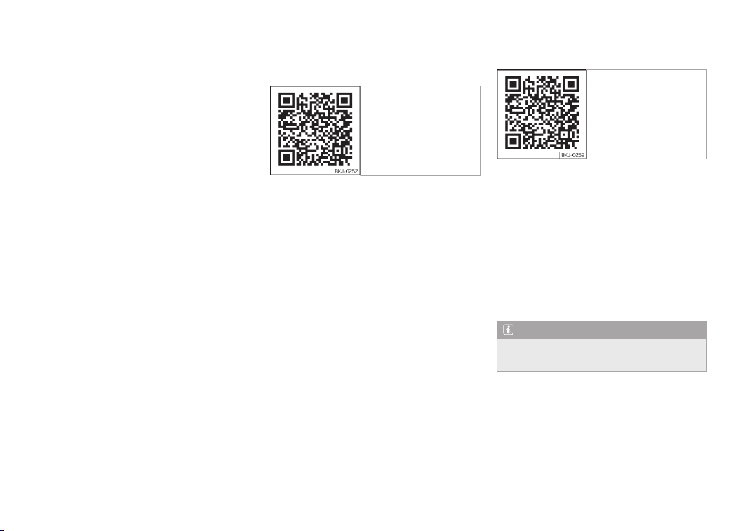
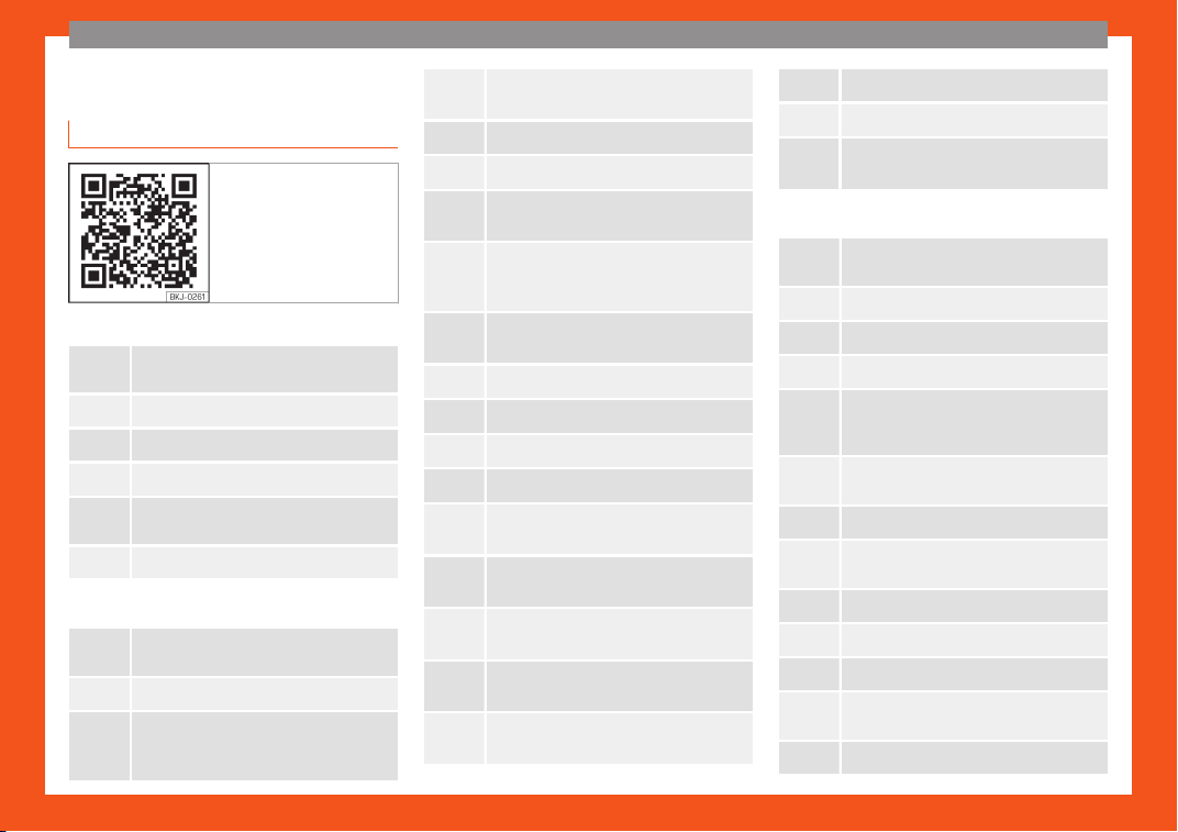
Fig. 1 SEAT website
The digital version is available on SEAT's offi-
cial website
.
To view the digital version of the manual:
●
scan the QR code
›››
Fig. 1
●
OR enter the following address in the navi-
gator website:
http://www.seat.com/owners/your-
seat/manuals-offline.html
choose your v
ehicle and then “Infotainment”.
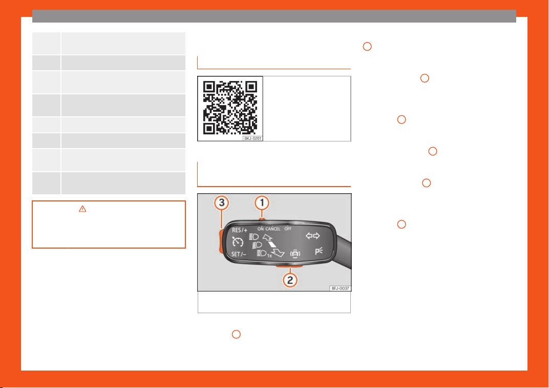
Related videos
Fig. 2 SEAT website
The operation of some of the vehicle's fea-
tures can be sho
wn as an instruction video:
●
scan the QR code
›››
Fig. 2
●
OR enter the following address in the navi-
gator website:
http://www.seat.com/owners/your-
seat/manuals-offline.html
choose your v
ehicle and then “Multimedia”.
Note
Video instructions are only available in
certain l
anguages.

Frequently Asked Ques-
tions
Before driving
How do you adjust the seat?
›››
page 19
How do you adjust the steering wheel?
›››
page 21
How do you adjust the exterior mirrors?
›››
page 21
How do you turn on the exterior lights?
›››
page 32
How does the automatic gearbox selector lever
work?
››
›
page 41
How do you refuel?
›
›
›
page 47
How do you activate the windscreen wipers and
windscreen washer system?
›››
page 34
Emergency situations
A warning lamp lights up or flashes. What does
this mean?
›››
page 39
How do you open the bonnet?
›››
page 18
How do you perform a jump start?
›››
page 59
Where is the vehicle tool kit located?
›››
page 54
How do you repair a tyre with the anti-puncture
kit?
›››
page 53
How do you change a wheel?
›››
page 54
How do you change a fuse?
›››
page 51
How do you change a light?
›››
page 52
How do you tow a vehicle?
›››
page 58
Useful tips
How do you set the time?
›››
page 116
When should the vehicle inspection should be
performed?
››
›
page 119
What functions do the buttons/thumbwheels on
the steering wheel perform?
›
››
page 123
How do you remove the luggage compartment
cover?
›
››
page 172
How do you drive in an economical and environ-
mentally-friendly way?
›
››
page 262
How do you check and top up the engine oil?
›
›
›
page 47
How do you check and top up the engine cool-
ant?
›››
page 49
How do you top up the windscreen washer fluid?
›››
page 50
How do you check and top up the brake fluid?
›››
page 49
How do you check and adjust tyre pressure val-
ues?
›››
page 358
Vehicle washing tips
›››
page 370
Functions of interest
Easy Connect, Car menu
›››
page 35
How does the START-STOP system work?
›››
page 269
What parking assistants are available?
›››
page 313
How does the rear assist work?
›››
page 326
How does the adaptive cruise control work?
›››
page 283
How can the SEAT driving mode be adjusted?
›
›
›
page 303
How does the lane departure warning system
work?
›››
page 292
How does tyre pressure monitoring work?
›››
page 361
How do you open the vehicle without a key
(Keyless Access)?
›››
page 131
Interior lighting and ambient light
›››
page 155

Table of Contents
Table of Contents
The essential
s
. . . . . . . . . . . . . . . . . . . . . . . . . .
7
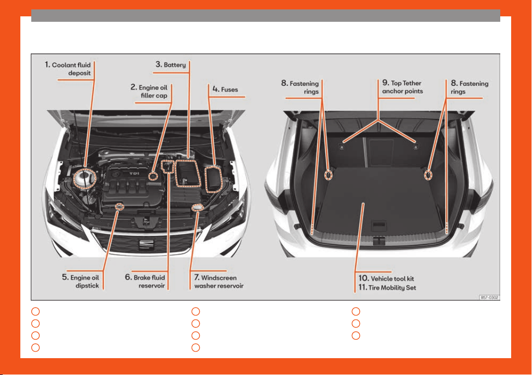
Exterior view . . . . . . . . . . . . . . . . . . . . . . . . . . . . . . . 7
Exterior view . . . . . . . . . . . . . . . . . . . . . . . . . . . . . . . 8
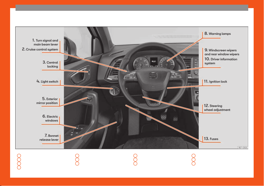
Driver-side general instrument panel
(left-hand drive) . . . . . . . . . . . . . . . . . . . . . . . . . . 9
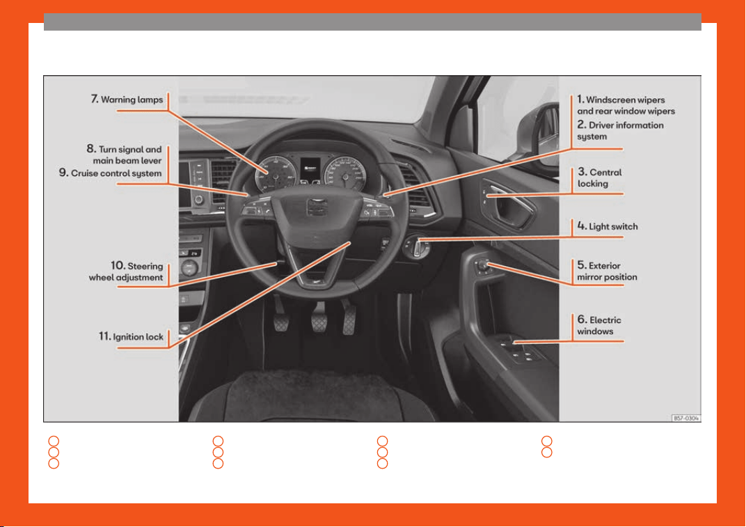
Driver-side general instrument panel
(right-hand drive) . . . . . . . . . . . . . . . . . . . . . . . . . 10
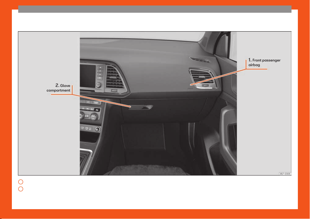
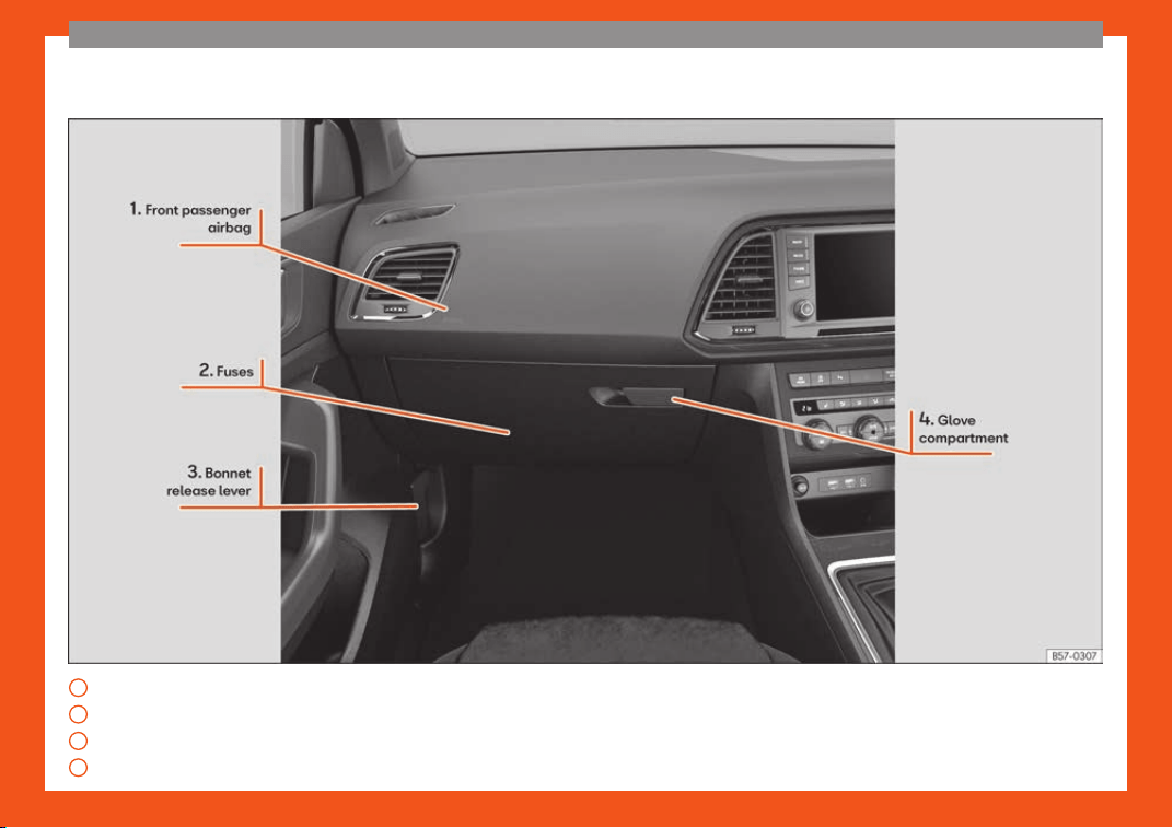
Passenger-side general instrument pan-
el (left-hand drive) . . . . . . . . . . . . . . . . . . . . . . . . 11
Passenger-side general instrument pan-
el (right-hand drive) . . . . . . . . . . . . . . . . . . . . . . 12
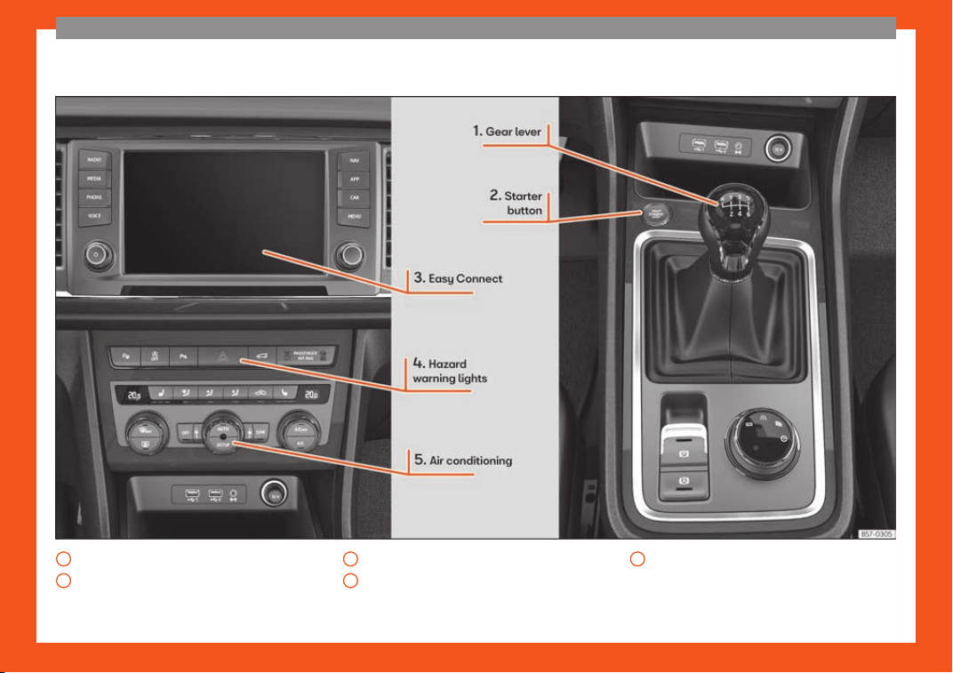
Centre console . . . . . . . . . . . . . . . . . . . . . . . . . . . . 13
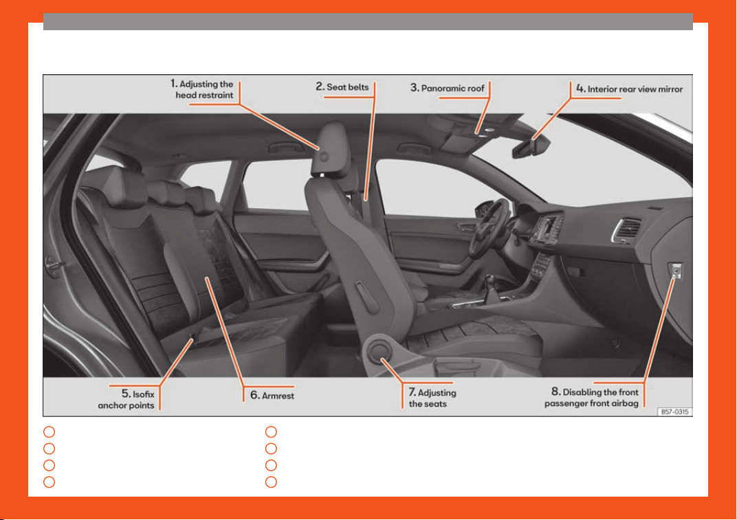
Interior view . . . . . . . . . . . . . . . . . . . . . . . . . . . . . . . 14
How it works . . . . . . . . . . . . . . . . . . . . . . . . . . . . . . . 15
Unlocking and locking . . . . . . . . . . . . . . . . . . . . . . 15
Before driving . . . . . . . . . . . . . . . . . . . . . . . . . . . . . . 19
Airbags . . . . . . . . . . . . . . . . . . . . . . . . . . . . . . . . . . . . . 21
Child seats . . . . . . . . . . . . . . . . . . . . . . . . . . . . . . . . . 25
Starting the vehicle . . . . . . . . . . . . . . . . . . . . . . . . . 32
Lights and visibility . . . . . . . . . . . . . . . . . . . . . . . . . 32
Easy Connect . . . . . . . . . . . . . . . . . . . . . . . . . . . . . . 35
Warning lamps . . . . . . . . . . . . . . . . . . . . . . . . . . . . . 39
Cruise control . . . . . . . . . . . . . . . . . . . . . . . . . . . . . . 40
Gearbox lever . . . . . . . . . . . . . . . . . . . . . . . . . . . . . . 41
Air conditioning . . . . . . . . . . . . . . . . . . . . . . . . . . . . . 42
Fluid level control . . . . . . . . . . . . . . . . . . . . . . . . . . . 47
Emergencies . . . . . . . . . . . . . . . . . . . . . . . . . . . . . . 51
Fuses . . . . . . . . . . . . . . . . . . . . . . . . . . . . . . . . . . . . . . . 51
Bulbs . . . . . . . . . . . . . . . . . . . . . . . . . . . . . . . . . . . . . . . 52
Action in the event of a puncture . . . . . . . . . . . 53
Changing a wheel . . . . . . . . . . . . . . . . . . . . . . . . . . 54
Snow chains . . . . . . . . . . . . . . . . . . . . . . . . . . . . . . . . 58
Emergency towing of the vehicle . . . . . . . . . . . 58
How to jump start . . . . . . . . . . . . . . . . . . . . . . . . . . . 59
Changing the wiper blades . . . . . . . . . . . . . . . . 61
Safety . . . . . . . . . . . . . . . . . . . . . . . . . . . . . . . . . . . . 63
Safe driving . . . . . . . . . . . . . . . . . . . . . . . . . . . . . . . 63
Advice about driving . . . . . . . . . . . . . . . . . . . . . . . . 63
Correct position of the vehicle occu-
pants . . . . . . . . . . . . . . . . . . . . . . . . . . . . . . . . . . . . . . . 64
Pedal area . . . . . . . . . . . . . . . . . . . . . . . . . . . . . . . . . 68
Seat belts . . . . . . . . . . . . . . . . . . . . . . . . . . . . . . . . . 69
Why wear a seat belt . . . . . . . . . . . . . . . . . . . . . . . 69
How to properly adjust your seat belt . . . . . . 72
Seat belt tensioners . . . . . . . . . . . . . . . . . . . . . . . . 73
Airbag system . . . . . . . . . . . . . . . . . . . . . . . . . . . . . 74
Brief introduction . . . . . . . . . . . . . . . . . . . . . . . . . . . 74
Airbag safety instructions . . . . . . . . . . . . . . . . . . . 76
Deactivating airbags . . . . . . . . . . . . . . . . . . . . . . . 78
Transporting children safely . . . . . . . . . . . . . . 80
Safety for children . . . . . . . . . . . . . . . . . . . . . . . . . . 80
Child seats . . . . . . . . . . . . . . . . . . . . . . . . . . . . . . . . . 82
Emergencies . . . . . . . . . . . . . . . . . . . . . . . . . . . . 85
Self-help . . . . . . . . . . . . . . . . . . . . . . . . . . . . . . . . . . 85
Emergency equipment . . . . . . . . . . . . . . . . . . . . . 85
Tyre repair . . . . . . . . . . . . . . . . . . . . . . . . . . . . . . . . . . 85
Manual unlocking/locking . . . . . . . . . . . . . . . . . . 87
Changing the windscreen wiper blades . . . . 88
Tow-starting and towing . . . . . . . . . . . . . . . . . . . . 88
Fuses and bulbs . . . . . . . . . . . . . . . . . . . . . . . . . . . 92
Fuses . . . . . . . . . . . . . . . . . . . . . . . . . . . . . . . . . . . . . . . 92
Changing a bulb . . . . . . . . . . . . . . . . . . . . . . . . . . . 96
Change the front bulbs . . . . . . . . . . . . . . . . . . . . . 97
Change the rear bulbs . . . . . . . . . . . . . . . . . . . . . 99
Operation . . . . . . . . . . . . . . . . . . . . . . . . . . . . . . . 103
Controls and displays . . . . . . . . . . . . . . . . . . . . 103
General instrument panel . . . . . . . . . . . . . . . . . . 102
Instruments and warning/control
lamps . . . . . . . . . . . . . . . . . . . . . . . . . . . . . . . . . . . . . . 104
Dashboard . . . . . . . . . . . . . . . . . . . . . . . . . . . . . . . . . 104
Using the instrument panel . . . . . . . . . . . . . . . . . 120
Control lamps . . . . . . . . . . . . . . . . . . . . . . . . . . . . . . 122
Multifunction steering wheel* . . . . . . . . . . . . . . 123
Opening and closing . . . . . . . . . . . . . . . . . . . . . . 127
Central locking . . . . . . . . . . . . . . . . . . . . . . . . . . . . . 127
Anti-theft alarm system* . . . . . . . . . . . . . . . . . . . 137
Rear lid (luggage compartment) . . . . . . . . . . . 139
Controls for the windows . . . . . . . . . . . . . . . . . . . 142
Sunroof* . . . . . . . . . . . . . . . . . . . . . . . . . . . . . . . . . . . 144
Lights and visibility . . . . . . . . . . . . . . . . . . . . . . . . 147
Lights . . . . . . . . . . . . . . . . . . . . . . . . . . . . . . . . . . . . . . . 147
Visibility . . . . . . . . . . . . . . . . . . . . . . . . . . . . . . . . . . . . 156
Windscreen wiper and window wiper sys-
tems . . . . . . . . . . . . . . . . . . . . . . . . . . . . . . . . . . . . . . . . 156
Mirror . . . . . . . . . . . . . . . . . . . . . . . . . . . . . . . . . . . . . . . 158
Seats and head restraints . . . . . . . . . . . . . . . . 160
Adjusting the seats and headrests . . . . . . . . . . 160
Seat functions . . . . . . . . . . . . . . . . . . . . . . . . . . . . . . 161
Transport and practical equipment . . . . . . 164
Storage compartments . . . . . . . . . . . . . . . . . . . . 164
Storing objects . . . . . . . . . . . . . . . . . . . . . . . . . . . . . 168
Roof carrier* . . . . . . . . . . . . . . . . . . . . . . . . . . . . . . . 173
Air conditioning . . . . . . . . . . . . . . . . . . . . . . . . . . . 176
Heating, ventilation and cooling . . . . . . . . . . . . 176
Auxiliary heater (additional heater)* . . . . . . . . 182
5

Table of Contents
Infotainment System . . . . . . . . . . . . . . . . . . 186
Introduction . . . . . . . . . . . . . . . . . . . . . . . . . . . . . . . 186
Safety warnings . . . . . . . . . . . . . . . . . . . . . . . . . . . . 186
Overview of the unit . . . . . . . . . . . . . . . . . . . . . . . . 188
General instructions for use . . . . . . . . . . . . . . . . 189
Connectivity . . . . . . . . . . . . . . . . . . . . . . . . . . . . . . 195
Data transfer . . . . . . . . . . . . . . . . . . . . . . . . . . . . . . . 195
Full Link* . . . . . . . . . . . . . . . . . . . . . . . . . . . . . . . . . . . 195
SEAT Media Control* . . . . . . . . . . . . . . . . . . . . . . . 202
WLAN access point* . . . . . . . . . . . . . . . . . . . . . . . . 203
Operating modes . . . . . . . . . . . . . . . . . . . . . . . . . 205
Radio . . . . . . . . . . . . . . . . . . . . . . . . . . . . . . . . . . . . . . . 205
Media . . . . . . . . . . . . . . . . . . . . . . . . . . . . . . . . . . . . . . 207
Navigation . . . . . . . . . . . . . . . . . . . . . . . . . . . . . . . . . 216
Navigation in Offroad mode* . . . . . . . . . . . . . . . 227
Vehicle Menu . . . . . . . . . . . . . . . . . . . . . . . . . . . . . . . 229
Telephone . . . . . . . . . . . . . . . . . . . . . . . . . . . . . . . . . . 230
Multimedia . . . . . . . . . . . . . . . . . . . . . . . . . . . . . . . . . 237
Driving . . . . . . . . . . . . . . . . . . . . . . . . . . . . . . . . . . . 239
Start and driving . . . . . . . . . . . . . . . . . . . . . . . . . . 239
Starting and stopping the engine . . . . . . . . . . . 239
Braking and parking . . . . . . . . . . . . . . . . . . . . . . . . 244
Braking and stability systems . . . . . . . . . . . . . . . 248
Manual gearbox . . . . . . . . . . . . . . . . . . . . . . . . . . . . 251
Automatic gearbox/DSG automatic gear-
bo
x* . . . . . . . . . . . . . . . . . . . . . . . . . . . . . . . . . . . . . . . .
252
Gear
-change recommendation . . . . . . . . . . . . 260
Steering . . . . . . . . . . . . . . . . . . . . . . . . . . . . . . . . . . . . 260
Run-in and economical driving . . . . . . . . . . . . . 261
Power management . . . . . . . . . . . . . . . . . . . . . . . 264
Engine management and emission control
system . . . . . . . . . . . . . . . . . . . . . . . . . . . . . . . . . . . . . 265
Driving tips . . . . . . . . . . . . . . . . . . . . . . . . . . . . . . . . . 267
Driver assistance systems . . . . . . . . . . . . . . . . 269
Start-Stop system* . . . . . . . . . . . . . . . . . . . . . . . . . 269
Hill Descent Control (HDC) . . . . . . . . . . . . . . . . . 271
Auto Hold Function . . . . . . . . . . . . . . . . . . . . . . . . . 272
Cruise control system (CCS)* . . . . . . . . . . . . . . 274
Speed limiter . . . . . . . . . . . . . . . . . . . . . . . . . . . . . . . 275
Emergency braking assistance system
(Front Assist)* . . . . . . . . . . . . . . . . . . . . . . . . . . . . . . 279
Adaptive cruise control (ACC)* . . . . . . . . . . . . . 283
Lane Assist system* . . . . . . . . . . . . . . . . . . . . . . . . 292
Traffic Jam Assist . . . . . . . . . . . . . . . . . . . . . . . . . . . 295
Emergency Assist . . . . . . . . . . . . . . . . . . . . . . . . . . . 296
Blind spot detector (BSD) with parking as-
sistance (RCTA)* . . . . . . . . . . . . . . . . . . . . . . . . . . . 298
SEAT Drive Profile* . . . . . . . . . . . . . . . . . . . . . . . . . 303
Park Assist* . . . . . . . . . . . . . . . . . . . . . . . . . . . . . . . . 305
Parking aid parking and manoeuvring
(ParkPilot) . . . . . . . . . . . . . . . . . . . . . . . . . . . . . . . . . . 313
Parking System Plus* . . . . . . . . . . . . . . . . . . . . . . . 315
Rear parking aid* . . . . . . . . . . . . . . . . . . . . . . . . . . 319
Top View Camera* . . . . . . . . . . . . . . . . . . . . . . . . . 321
Rear Assist (Rear View Camera)* . . . . . . . . . . . 326
Towing bracket device* . . . . . . . . . . . . . . . . . . . 329
Trailer mode . . . . . . . . . . . . . . . . . . . . . . . . . . . . . . . . 329
Practical tips . . . . . . . . . . . . . . . . . . . . . . . . . . . 340
Care and maintenance . . . . . . . . . . . . . . . . . . . 340
Accessories and modifications to the vehi-
cle . . . . . . . . . . . . . . . . . . . . . . . . . . . . . . . . . . . . . . . . . 340
Checking and refilling levels . . . . . . . . . . . . . 341
Filling the tank . . . . . . . . . . . . . . . . . . . . . . . . . . . . . . 341
Fuel . . . . . . . . . . . . . . . . . . . . . . . . . . . . . . . . . . . . . . . . 343
AdBlue
®
. . . . . . . . . . . . . . . . . . . . . . . . . . . . . . . . . . . . 345
Engine compartment . . . . . . . . . . . . . . . . . . . . . . . 347
Engine oil . . . . . . . . . . . . . . . . . . . . . . . . . . . . . . . . . . . 349
Cooling system . . . . . . . . . . . . . . . . . . . . . . . . . . . . 352
Brake fluid . . . . . . . . . . . . . . . . . . . . . . . . . . . . . . . . . . 353
Windscreen washer reservoir . . . . . . . . . . . . . . . 354
Battery . . . . . . . . . . . . . . . . . . . . . . . . . . . . . . . . . . . . . 354
Wheels . . . . . . . . . . . . . . . . . . . . . . . . . . . . . . . . . . . . 357
Wheels and tyres . . . . . . . . . . . . . . . . . . . . . . . . . . . 357
Tyre monitoring system . . . . . . . . . . . . . . . . . . . . . 361
Temporary spare wheel . . . . . . . . . . . . . . . . . . . . 364
Winter service . . . . . . . . . . . . . . . . . . . . . . . . . . . . . . 365
Maintenance . . . . . . . . . . . . . . . . . . . . . . . . . . . . 367
Service . . . . . . . . . . . . . . . . . . . . . . . . . . . . . . . . . . . . 367
Service intervals . . . . . . . . . . . . . . . . . . . . . . . . . . . . 367
Additional service offers . . . . . . . . . . . . . . . . . . . . 369
Warranty . . . . . . . . . . . . . . . . . . . . . . . . . . . . . . . . . . . 370
Vehicle maintenance . . . . . . . . . . . . . . . . . . . . . 370
Maintenance and cleaning . . . . . . . . . . . . . . . . . 370
Information for the user . . . . . . . . . . . . . . 376
Information for the user . . . . . . . . . . . . . . . . . . . 376
Event Data Recorder . . . . . . . . . . . . . . . . . . . . . . . 376
Other important information . . . . . . . . . . . . . . . . 376
Information about the EU Directive
2014/53/EU . . . . . . . . . . . . . . . . . . . . . . . . . . . . . . . . 377
Technical data . . . . . . . . . . . . . . . . . . . . . . . . . 380
Technical specifications . . . . . . . . . . . . . . . . . . 380
Important information . . . . . . . . . . . . . . . . . . . . . . 380
Information on fuel consumption . . . . . . . . . . . 380
Trailer mode . . . . . . . . . . . . . . . . . . . . . . . . . . . . . . . . 381
Wheels . . . . . . . . . . . . . . . . . . . . . . . . . . . . . . . . . . . . . 382
Engine data . . . . . . . . . . . . . . . . . . . . . . . . . . . . . . . . 383
Vehicle data . . . . . . . . . . . . . . . . . . . . . . . . . . . . . . . . 387
Index . . . . . . . . . . . . . . . . . . . . . . . . . . . . . . . . . . . . . . 389
6
The essentials
How it works
Unl
ocking and l
ocking
R
elated video
Fig. 3 Opening and clos-
ing
Doors
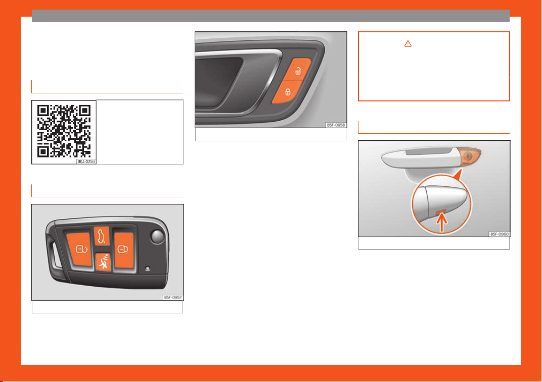
Fig. 4
Remote control key: keys.
Fig. 5 Driver door: central locking switch.
Locking and unlocking the vehicle using
the k
ey
●
L
ocking: pr
ess the button
›››
Fig. 4.
●
Locking the vehicle without activating the
anti-theft system: Press the button for a sec-
ond time
›››
Fig. 4 within 2 seconds.
●
Unlocking: press the button
›››
Fig. 4.
●
Unlock the trunk lid: hold down the
›››
Fig. 4 button for at least 1 second.
Locking and unlocking with the central
locking switch
●
Locking: press the button
›››
Fig. 5. None
of the doors can be opened from the outside.
The doors can be opened from the inside by
pulling the inside door handle.
●
Unlocking: press the button
›››
Fig. 5.
›››
in Description on page 127
›››
page 127
›››
page 15,
›
››
page 16
Unlocking or locking of driver door
Fig. 6
Driver door lever: hidden lock cylinder.
If the central locking system should fail to op-
er
at
e
, the driver door can still be locked and
unlocked by turning the key in the lock.
As a general rule, when the driver door is
locked manually all other doors are locked.
When it is unlocked manually, only the driver
door opens. Please observe the instructions
relating to the anti-theft alarm system
›››
page 127.
»
15
The essentials
●
Unf
ol
d the v
ehicle key blade
›››
page 128.
●
Insert the key shaft into the lower opening in
the cover on the driver door handle
›››
Fig. 6
(arrow) then remove the cover upwards.
●
Insert the key blade into the lock cylinder to
unlock or lock the vehicle.
Special characteristics
●
The anti-theft alarm will remain active
when vehicles are unlocked. However, the
alarm will not be triggered
›››
page 127.
●
After the driver door is opened, you have 15
seconds to switch on the ignition. Once this
time has elapsed, the alarm is triggered.
●
Switch the ignition on. The electronic immo-
bilizer recognises a valid vehicle key and de-
activates the anti-theft alarm system.
Note
The anti-theft alarm is not activated when
the vehicle is l
ocked manually using the
key shaft
›››
page 127.
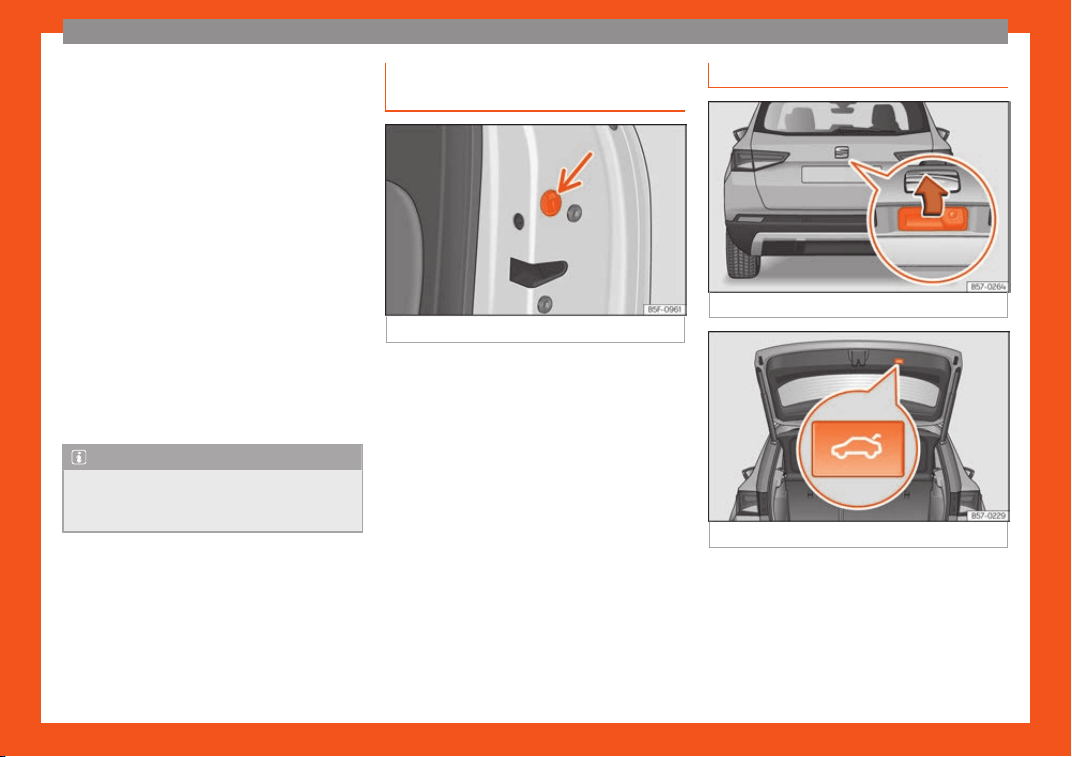
Emergency locking of doors with-
out door cylinder
Fig. 7
Locking the door manually.
If the central locking system should fail to
w
ork at any time
, doors with no l
ock cylinder
will have to be locked separately.
A mechanical locking device (only visible
when the door is open) is provided on the
front passenger door.
●
Pull the cap out of the opening.
●
Insert the key in the inside slot and turn it to
the right as far as it will go (if the door is on
the right side) or to the left (if the door is on
the left side).
Once the door has been closed it can no lon-
ger be opened from the outside. Pull the inte-
rior door handle once to unlock and open the
door.
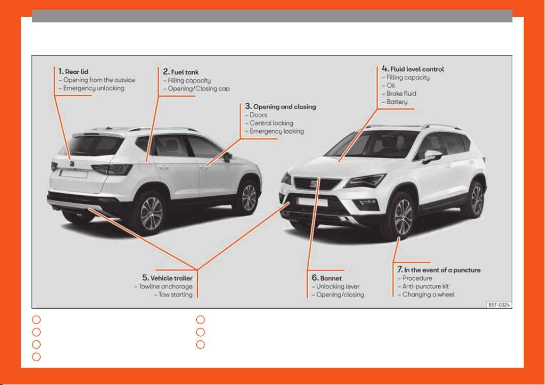
Rear lid
Fig. 8
Rear lid: handle
Fig. 9
Rear lid: button to close rear lid.
The rear lid opening system operates electri-
cally*. It is activ
at
ed by e
xerting slight pres-
sure on the handle
›››
Fig. 8.
To lock/unlock, press the button or button
›››
Fig. 4 on the remote control key.
A warning appears on the instrument panel
display if the rear lid is open or not properly
16
The essentials
closed.* An audible warning is also given if it
is opened whil
e the v
ehicl
e is moving faster
than 6 km/h (4 mph)*.
Opening and closing
●
Open the rear lid: exert slight pressure on
the handle. The rear lid opens automatically.
●
Closing the rear lid: hold one of the handles
on the inner trim and close it by sliding down,
or press the button on the rear lid*
›››
Fig. 9.
›››
in Rear lid automatic locking on
page 141
›››
page 139
›››
page 1
7
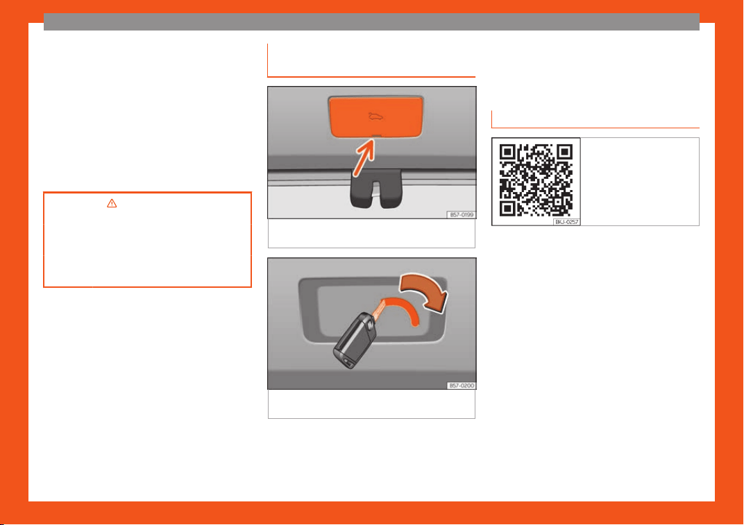
Manual release mechanism for the
r
ear lid
Fig. 10
Luggage compartment: access to
manual r
el
ease
.
Fig. 11
Luggage compartment: manual re-
l
ease
.
The rear lid can be unlocked manually from
inside in the e
v
ent of an emer
gency.
●
Remove the cover using the key blade as a
lever
›››
Fig. 10.
●
To unlock the rear lid, push the lever in the
direction of the arrow using the key blade
›››
Fig. 11.
Related video
Fig. 12 Bonnet
17
The essentials
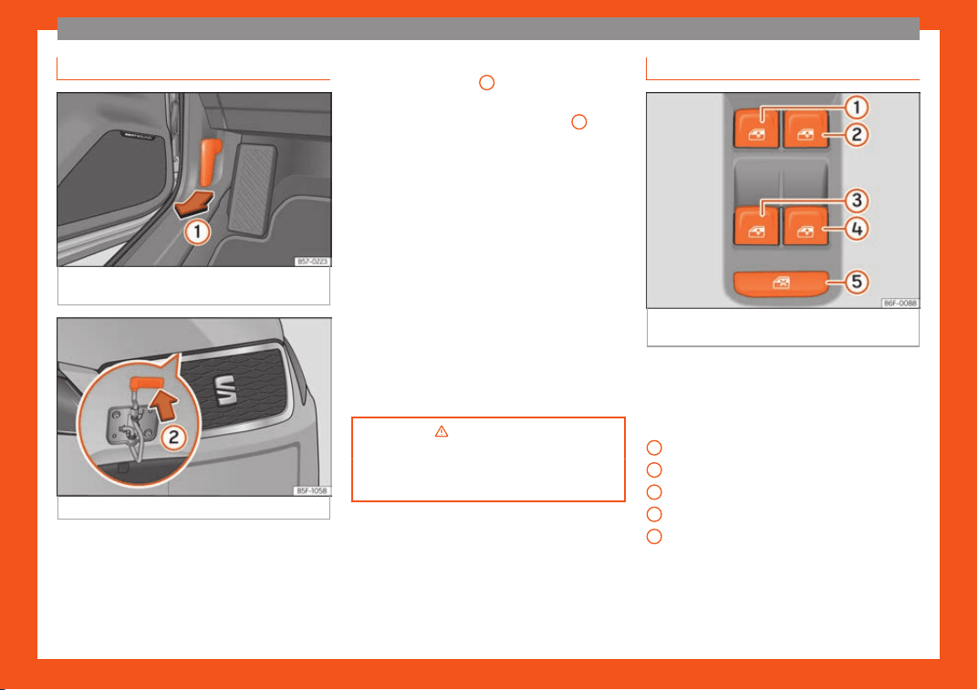
Bonnet
Fig. 13
Release lever in the driver's footwell
ar
ea.
Fig. 14 Cam under the bonnet
Opening the bonnet
The bonnet is r
el
eased fr
om inside the vehi-
cle.
Before opening the bonnet, make sure that
the windscreen wiper arms are in place
against the windscreen.
●
Open the door and pull the lever under the
dashboard
›››
Fig. 13
1
.
●
To lift the bonnet: press the release catch
under the bonnet up
w
ar
ds
›››
Fig. 14
2
. The
arr
est
er hook under the bonnet is r
eleased.
●
The bonnet can be opened. Release the
bonnet stay and secure it in the fixture de-
signed for this in the bonnet.
Closing the bonnet
●
Slightly lift the bonnet.
●
Release the bonnet stay and replace it in its
support.
●
At a height of approximately 30 cm let it fall
so it locks.
If the bonnet does not close, do not press
downwards. Open it again and let it fall as
mentioned above.
›››
in Opening and closing the
bonnet on page 347
›››
page 34
7
Controls for the windows*
Fig. 15 Detail of the driver door: controls for
the windo
ws.
●
Opening the window: press the button .
●
Closing the window: pull the button .
Butt
ons on the driv
er door
Windo
w on the front left door
Window on the front right door
Window on the rear left door
Window on the rear right door
Safety switch for deactivating the electric
window buttons in the rear doors.
1
2
3
4
5
18
The essentials
›››
in Opening and closing the
electric windows on page 142
›››
page 14
2
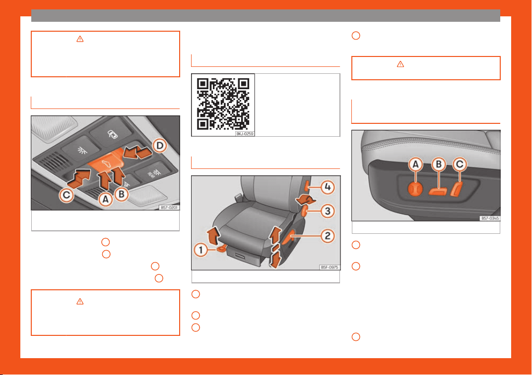
Panoramic roof*
Fig. 16 On the interior roof lining: sunroof but-
t
on.
●
Open: press button
C
backwards.
●
Close: press button
D
forwards.
●
Raise: press the rear part of button
B
.
●
Lower: press the front part of button
A
.
›››
in Introduction on page 144
›››
page 144
Before driving
R
el
at
ed video
Fig. 17 Vehicle interior
Manually adjusting the front seats
Fig. 18
Front seats: manual seat adjustment.
Forwards/backwards: pull the lever and
mo
v
e the seat.
R
aising/lowering: pull/push the lever.
Tilting the backrest: turn the hand wheel.
1
2
3
Lumbar support: move the lever until the
r
equir
ed position is achie
ved.
›››
in Manual adjustment of the
seats on page 160
Electric adjustment of the driver's
seat*
Fig. 19
Driver's seat: electric seat adjustment.
Adjust the lumbar support: press the but-
t
on accor
ding t
o the desired position.
Seat up/down: Press the button up/down.
To adjust the front of the seat cushion,
press the front of the button up/down. To
adjust the rear of the seat cushion, press
the rear of the button up/down.
Seat forwards/backwards: press the but-
ton forwards/backwards.
Backrest further upright/further reclined:
press the button forwards/backwards.
»
4
A
B
C
19
The essentials
›››
in Electric driver's seat adjust-
ment* on page 160
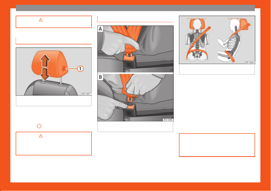
Adjusting the head restraints
Fig. 20
Front seat: adjusting the head re-
str
aint.
●
Grab the sides of the head restraints with
both hands and push up
w
ar
ds to the desired
position. To lower it, repeat the same action,
pressing the
1
button on the side.
›››
in Correct adjustment of front
head restraints on page 67
›››
page 6
7
,
›
››
page 160
Adjustment of the seat belt
Fig. 21
Positioning and removing the seat belt
buckl
e
.
Fig. 22 Correct seat belt and head restraint
positions, viewed fr
om front and the side.
To adjust the seat belt around your shoulders,
adjust the height of the seats.
The shoul
der part of the seat belt shoul
d be
w
ell centred over it, never over the neck. The
seat belt lies flat and fits comfortably on the
upper part of the body.
The lap part of the seat belt lies across the
pelvis, never across the stomach. The seat
belt lies flat and fits comfortably on the pel-
vis.
›››
page 70
›››
page 7
2
20
The essentials
Seat belt tensioners
During a collision, the seat belts on the front
seats and side rear seats
1)
tighten aut
omati-
cally.
The tensioner can be triggered only once.
›››
in Maintenance and disposal of
belt tensioners on page 74
›
››
page 7
3
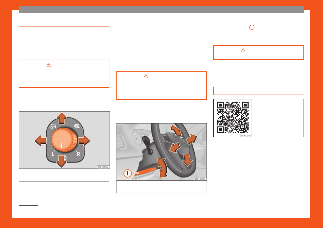
Adjusting the exterior mirrors
Fig. 23
Detail of the driver door: control for the
e
xt
erior mirr
or.
Adjusting the exterior mirrors: Turn the knob to
the corr
esponding position:
T
urning the knob t
o the desired position,
adjust the mirrors on the driver side (L,
left) and the passenger side (R, right) to
the direction desired.
Depending on the equipment fitted on
the vehicle, the mirrors may be heated
according to the outside temperature.
Folding in mirrors.
›››
in Adjusting the exterior rear-
view mirrors on page 159
›››
page 159
Adjusting the steering wheel
Fig. 24
Lever in the lower left side of the steer-
ing column.
L/R
●
Adjusting the position of the st
eering wheel:
pull the
›
›
›
Fig. 24
1
lever down, move the
st
eering wheel t
o the desir
ed position and lift
the lever back up until it locks.
›››
in Adjusting the steering wheel
position on page 65
Airbags
Related video
Fig. 25 Vehicle interior
1)
Depending on version/market.
21
The essentials
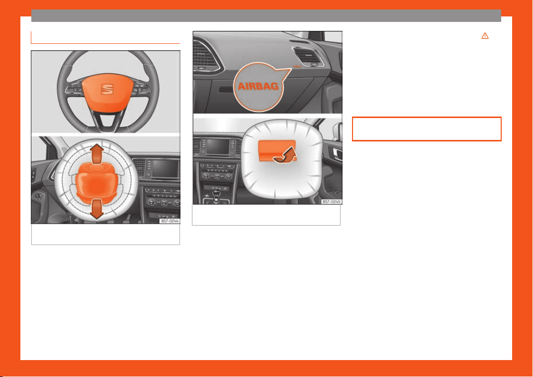
Front airbags
Fig. 26
Driver airbag located in steering
wheel
.
Fig. 27 Front passenger airbag located in
dash panel
.
The front airbag for the driver is located in the
st
eering wheel
›
›
›
Fig. 26 and the airbag for
the front passenger is located in the dash
panel
›››
Fig. 27. Airbags are identified by the
word “AIRBAG”.
When the driver and front passenger airbags
are deployed, the covers remain attached to
the steering wheel and dashboard, respec-
tively
›››
Fig. 26
›››
Fig. 27.
In conjunction with the seat belts, the front
airbag system gives the front occupants ad-
ditional protection for the head and chest in
the event of a severe frontal collision
›››
in
Fr
ont airbags on page 76
.
Their special design all
ows the controlled es-
cape of the propellant gas when an occu-
pant puts pressure on the bag. Thus, the
head and chest are protected by the airbag.
After the collision, the airbag deflates suffi-
ciently to allow visibility.
›››
page 76
22
The essentials
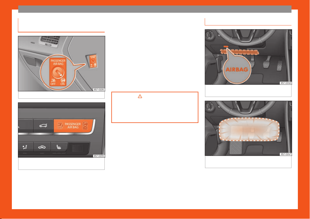
Deactivating the front passenger
fr
ont airbag
Fig. 28
Front passenger front airbag switch.
Fig. 29 Dashboard: control lamp for deactiva-
t
ed fr
ont passenger airbag in centr
e console.
To deactivate the front passenger front
airbag:
●
Switch the ignition off.
●
Open the door on the front passenger side.
●
Insert the k
ey int
o the sl
ot of the switch for
deactivating the front passenger airbag
›››
Fig. 28. About 3/4 of the key should enter;
this is as far as it will go.
●
Turn the key gently to the position. If you
have difficulty, ensure that you have inserted
the key as far as it will go.
●
Close the front passenger door.
●
Check, with the ignition switched on, that
the control lamp remains lit where it
says in the centre of the
dash panel
›››
Fig. 29.
›››
in Activation and deactivation
of front passenger airbag* on
page 79
›
››
page 78
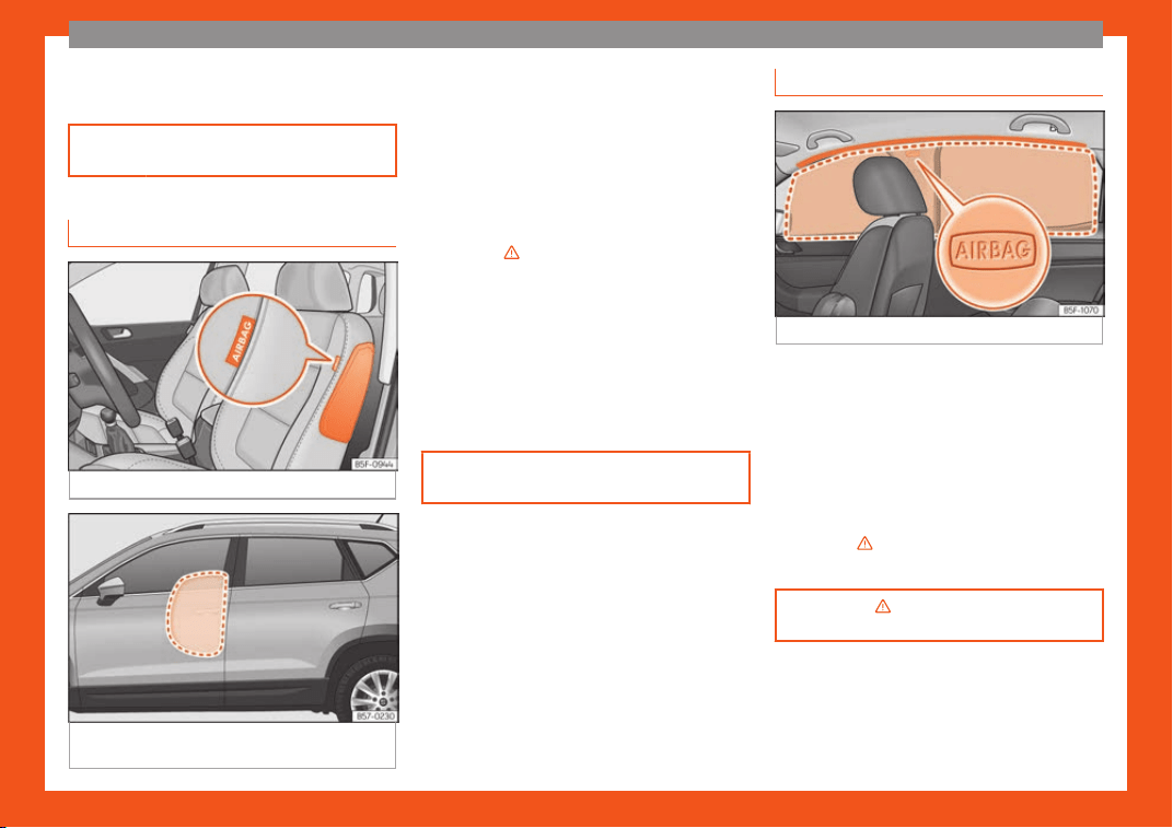
Knee airbag*
Fig. 30
On the driver side: location of airbag
f
or knees.
Fig. 31 On the driver side: action radius of air-
bag f
or knees.
The knee airbag is located on the driver side
bel
o
w the dash panel
›
››
Fig. 30. Airbags are
identified by the word “AIRBAG”.
The area framed in red (deployment area)
›››
Fig. 31 is covered by the knee airbag when
»
23
The essentials
it is deployed. Objects should never be
pl
aced or mount
ed in this ar
ea.
›››
page 7
7
Side airbags*
Fig. 32
Side airbag in driver's seat.
Fig. 33
Illustration of completely inflated side
airbags on the l
eft side of the v
ehicl
e.
The side airbags are located in the driver's
seat and fr
ont passenger seat backr
ests
›
››
Fig. 32. The locations are identified by the
text “AIRBAG” in the upper region of the
backrests.
In conjunction with the seat belts, the side air-
bag system provides additional protection for
the upper body in the event of a severe side
collision
›››
in Side airbags* on
page 7
7
.
In a side collision, the side airbags r
educe the
risk of injury to passengers to the areas of the
body facing the impact. In addition to their
normal protection, the seat belts also hold
the passengers in the event of a side collision;
this is how these airbags provide maximum
protection.
›››
page 7
7
Head-protection airbags*
Fig. 34
Location of head-protection airbags.
The head-protection airbags are located on
both sides in the int
erior abo
v
e the doors
›››
Fig. 34 and are identified with the text
“AIRBAG”.
In conjunction with the seat belts, the head-
protection airbag system gives the vehicle
occupants additional protection for the head
and upper body in the event of a severe side
collision
›››
in Curtain airbags* on
page 7
8
.
›
››
in Curtain airbags* on
page 78
24
The essentials
Child seats
R
el
at
ed video
Fig. 35 Vehicle interior
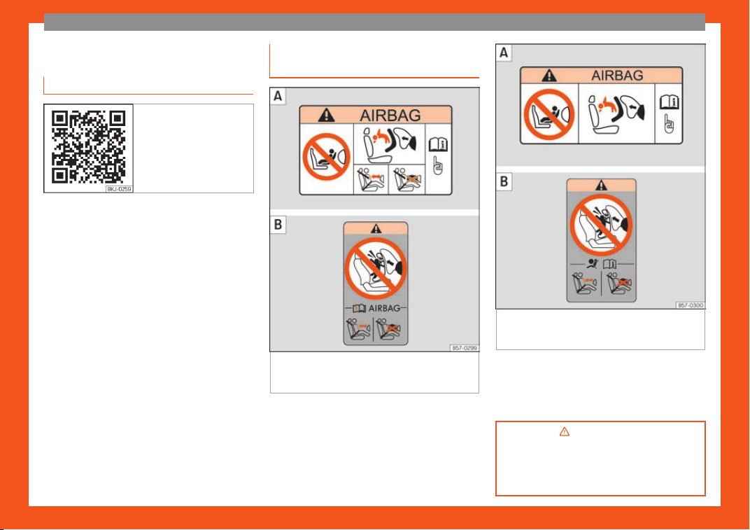
Important information regarding
the fr
ont passenger
's airbag
Fig. 36 Airbag adhesives - version 1: on the
passenger
-side sun blind and on the r
ear
fr
ame of the front passenger's door .
Fig. 37
Airbag adhesives - version 2: on the
passenger
-side sun blind and on the r
ear
fr
ame of the front passenger's door .
A sticker with important information about the
passenger airbag is l
ocat
ed on the passeng-
er
's sun visor and/or on the passenger side
door frame.
›››
in Important information re-
garding the front passenger
's airbag
on page 81
›››
page 80
25
The essentials
Securing a child seat with the seat belt
Fig. 38 On rear seats: possible assemblies of chil-
dren seats.
Figure
›
›
›
Fig. 38
A
shows the basic child re-
str
aint syst
em mounting using l
ower retaining
rings and the upper retaining strap. Figure
›››
Fig. 38
B
shows the child restraint system
mounting using the v
ehicl
e seat belt.
The seat belt may be used t
o secure univer-
sal type child seats to the vehicle seats
marked with a U in the table below.
●
In the passenger seat without height regu-
lation: the passenger seat must be in its rear-
most position
1)
.
●
In the passenger seat with height regula-
tion: the passenger seat must be in its rear-
most and highest position
1)
.
To correctly use a child seat in the back, the
front backrest must be adjusted so that there
is no contact with the child seat in the back in
the case that it goes opposite to the direction
of the car. In the case of front facing restraint
systems, the front backrest must be adjusted
so that there is no contact with the child's
feet.
To adjust the passenger seat to accommo-
date a child's seat and get the seat belt in a
perfect position, adjust the passenger back-
rest as far forward as possible
1)
.
If a semi-universal type chair is to be instal-
led, in which the method of attachment to the
car is through the seat belt and support
bracket, it should never be installed in the
central rear seat as the ground clearance is
lower than in other places and the support
bracket will not allow the seat to remain suffi-
ciently stable.
The systems include the child restraint
system mounting with an upper retaining
1)
Compliance with current national legislation
and the manufactur
er's instructions is required
when using or installing child seats.
26
The essentials
strap (Top Tether) and lower anchoring
points on the seat.
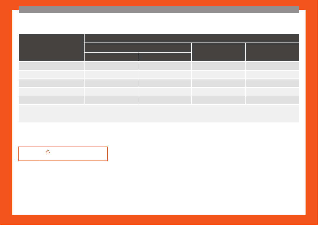
Weight group
Seating position
Front passenger seat
a)
Rear side seat Rear central seat
b)
airbag on airbag off
Group 0 to 10 kg X U
c)
U U
Group 0+ to 13 kg X U
c)
U U
Group I 9 to 18 kg X U
c)
U U
Group II 15 to 25 kg X UF
c)
UF UF
Group III 22 to 36 kg X UF
c)
UF UF
X: It is not compatible to install chairs in this configuration.
U: Suit
able f
or universal restraint systems for use in this weight group.
UF: Acceptable for front-facing universal-category child restraint systems approved for this mass group.
a)
Compliance with current national legislation and the manufacturer's instructions is required when using or installing child seats.
b)
For semi-universal chairs where the securing system is the car safety belt and the support bracket, do not use them in the centre rear seat.
c)
Seats without height adjustment shoul
d be pl
aced in their r
earmost position. Seats with height adjustment should be placed in their rearmost and highest position.
›››
in Safety instructions on
page 82
27
The essentials
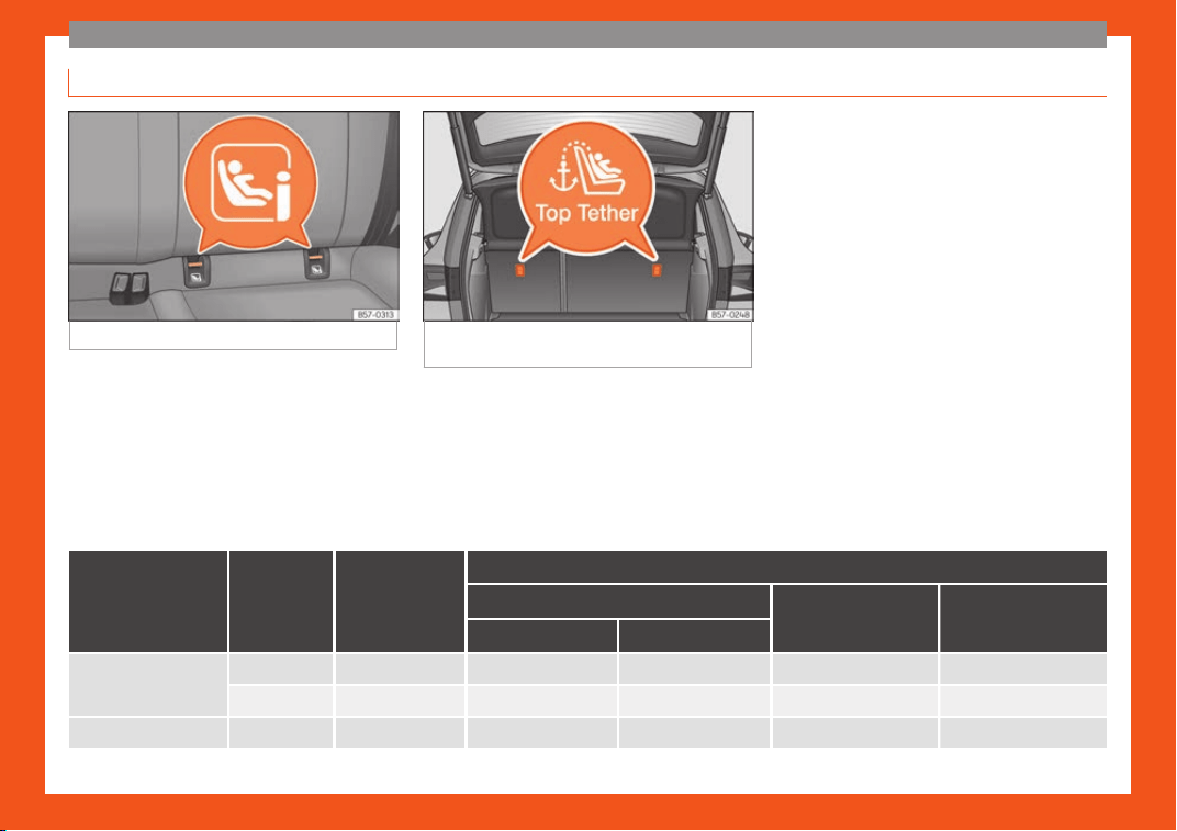
Securing a child seat with the ISOFIX/i-Size and Top Tether system*
Fig. 39 ISOFIX/i-Size securing rings.
Fig. 40 Position of the Top Tether rings on the
back of the rear seat.
Child seats can be secured quickly, easily
and saf
ely on the r
ear out
er seats with the
“ISOFIX” and Top Tether* system.
Two “ISOFIX” retaining rings are fitted on each
rear side seat. In some vehicles, the rings are
secured to the seat frame and, in others, they
are secured to the rear floor. The “ISOFIX”
rings are located between the rear seat
backrest and the seat cushioning
›››
Fig. 39.
The Top Tether* rings are located on the rear
part of the backrests of the rear side seats
(behind the seat backrest or in the boot)
›››
Fig. 40.
To understand the compatibility of the “ISO-
FIX” systems in the vehicle, check the table
below.
The body weight permitted and information
regarding sizes A to F is indicated on the label
on child seats with “universal” or “semi-uni-
versal” certification.
Weight group Size class
Electrical
equipment
Vehicle Isofix positions
Front passenger seat
Rear side seat Rear central seat
airbag on airbag off
Baby carrier
F ISO/L1 X X X X
G ISO/L2 X X X X
Group 0 to 10 kg E ISO/R1 X X IL X
28

The essentials
Weight group Size class
Electrical
equipment
Vehicle Isofix positions
Front passenger seat
Rear side seat Rear central seat
airbag on airbag off
Group 0+ to 13 kg
E ISO/R1 X X IL X
D ISO/R2 X X IL X
C ISO/R3 X X IL X
Group I 9 to 18 kg
D ISO/R2 X X IL X
C ISO/R3 X X IL X
B ISO/F2 X X IUF/IL X
B1 ISO/F2X X X IUF/IL X
A ISO/F3 X X IUF/IL X
Group II 15 to 25 kg --- --- --- ---
Group III 22 to 36 kg --- --- --- ---
IUF: Suitable for forward-facing ISOFIX universal child restraint systems approved for use in this mass group.
IL: Suitabl
e for certain ISOFIX child restraint systems (CRSs) listed in the attached list. This relates to ISOFIX CRSs that can be for the specific vehicle, restricted or semi-
universal categories.
X: ISOFIX position not suitable for ISOFIX child restraint systems for this weight group or size class.
»
29
The essentials
Securing the child seat with the “ISOFIX/i-
Siz
e syst
em”
Y
ou are obliged to follow the seat manufac-
turer's instructions.
●
Press the child seat onto the “ISOFIX” re-
taining rings
›››
Fig. 39 until the child seat is
heard to engage securely. If the child seat is
equipped with Top Tether* anchor points, se-
cure it to the corresponding ring
›››
page 31. Observe the manufacturer's in-
structions.
●
Pull on both sides of the child seat to ensure
that it is properly anchored.
Child seats with the “ISOFIX” and Top Tether*
attachment system are available from Tech-
nical Services.
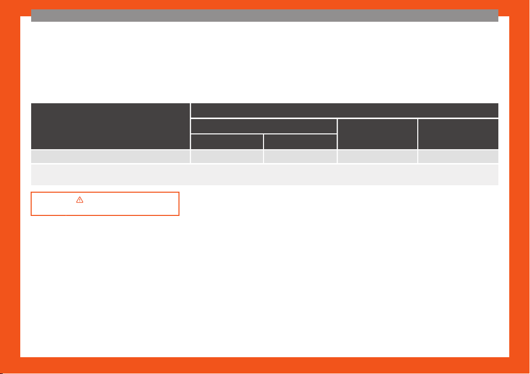
Vehicle i-Size positions
Front passenger seat
Rear side seat Rear central seat
airbag on airbag off
Child restraint system approved under ECE R129 X X i-U X
i-U: Valid position for front-facing and rear-facing child restraint systems approved under ECE R129.
X
: Invalid position f
or child restraint systems approved under ECE R129.
›››
in Safety instructions on
page 82
30
The essentials
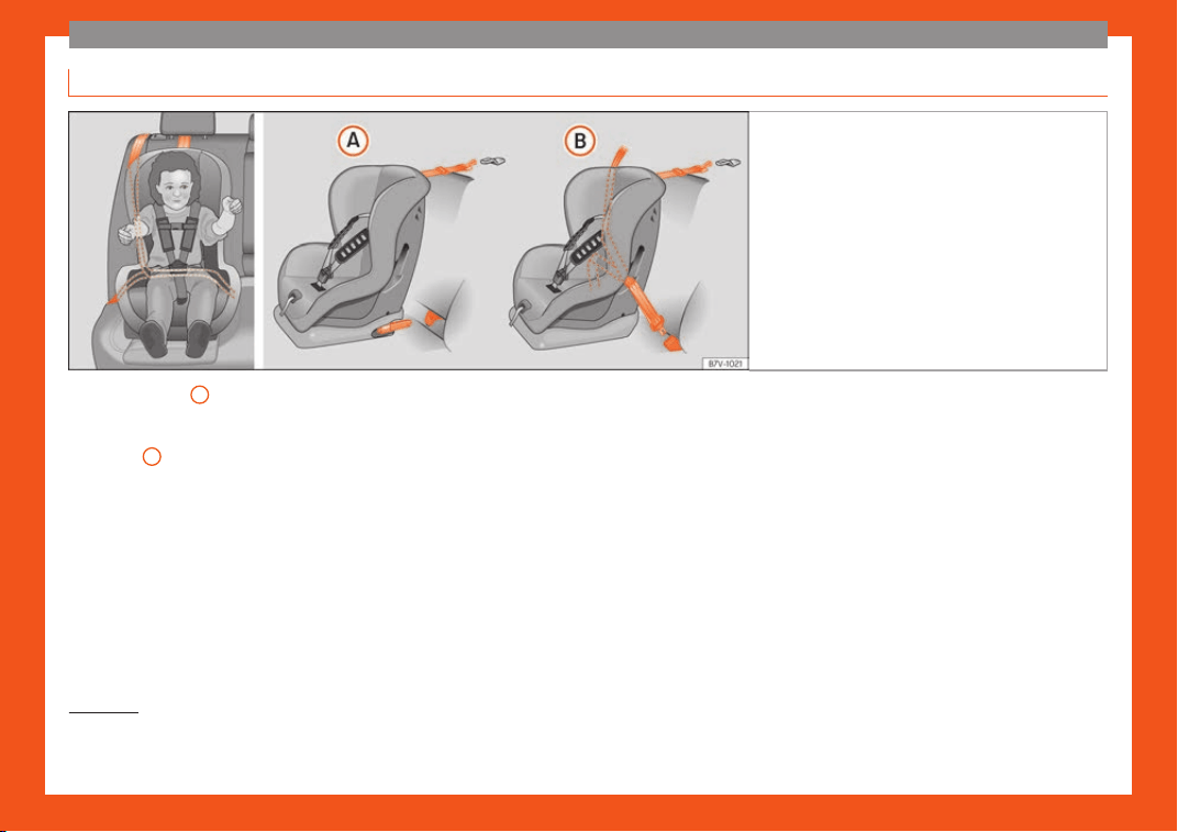
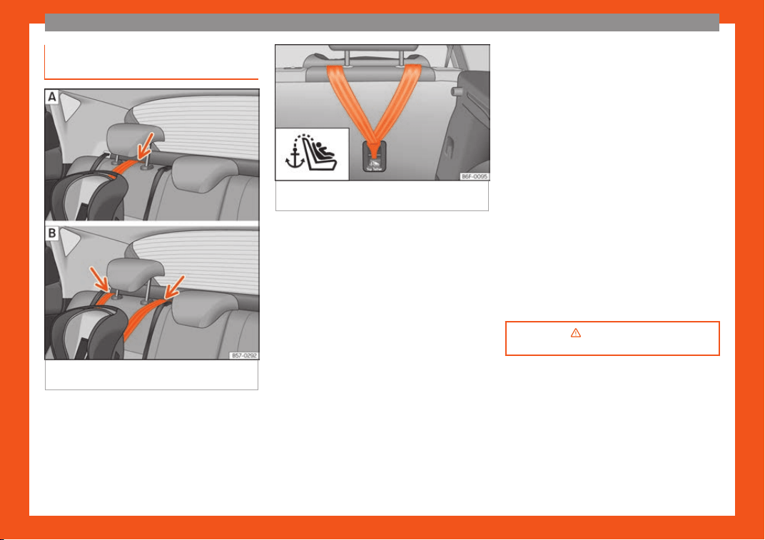
Securing a child seat with the Top
T
ether* r
et
aining straps
Fig. 41 Retainer strap: adjustment and assem-
bly accor
ding t
o the T
op Tether belt.
Fig. 42 Rear part of the rear seats: securing
rings for the Top T
ether strap.
Child seats with the Top Tether system come
with a str
ap f
or securing the seat t
o the vehi-
cle anchor point, located at the back of the
rear seat backrest and provide greater re-
straint.
The objective of this strap is to reduce for-
ward movements of the child seat in a crash,
to reduce the risk of injuries to the head from
hitting the inside of the vehicle.
Using the Top Tether in rear-facing moun-
ted seats
Currently, there are very few rear-facing child
safety seats that have Top Tether. Please
carefully read and follow the seat manufac-
turer instructions to learn the proper way to
install the Top Tether strap.
Securing the retaining strap
●
Follow the manufacturer's instructions to
deploy the child seat Top Tether retaining
strap.
●
Place the belt under the head restraint of
the back seat
›››
Fig. 41 (depending on the in-
structions of the chair itself, lift or remove the
head restraint if necessary).
●
Slide the strap and secure it properly with
the anchorage of the backrest
›››
Fig. 42.
●
Firmly tighten the strap following the manu-
facturer's instructions.
Releasing the retaining strap
●
Loosen the strap following the manufactur-
er's instructions.
●
Push the lock and release it from the an-
choring support.
›››
in Safety instructions on
page 82
31
The essentials
Starting the vehicle
Ignition l
ock
Fig. 43
Ignition key positions.
Turn on the ignition: place the key in the igni-
tion and st
art the engine
.
L
ocking and unlocking the steering wheel
●
Lock the steering wheel: remove the key
from the ignition and turn the wheel until it
locks. Depending on the country, in vehicles
with automatic transmission, in order to re-
move the key, move the gear shift to the P po-
sition. If necessary, press the gear shift block-
ing key and release it.
●
Unlock the steering wheel: put the key into
the ignition and turn it at the same time as the
steering wheel in the direction indicated by
the arrow. If it is not possible to turn the steer-
ing wheel, it may be because it is locked.
Turning on/switching off the ignition, glow
plugs reheating
●
Turn on the ignition: turn the key to the
2
position.
●
Turn off the ignition: turn the key to the
1
position.
●
Diesel vehicles : the gl
o
w plugs r
eheat
when the ignition is switched on.
Starting the engine
●
Manual transmission: press the clutch ped-
al all the way down and move the gearbox
lever into neutral.
●
Automatic transmission: press the brake
pedal and move the selector lever to the P
position or into N.
●
Turn the key to the
3
position. The key au-
t
omatically r
et
urns to the
2
position. Do not
pr
ess the accel
er
ator.
Start-Stop system*
When you stop and release the clutch pedal,
the Start-Stop system* turns off the engine.
The ignition remains switched on.
›››
in Switching the ignition on and
starting the engine with the k
ey on
page 240
›››
page 239
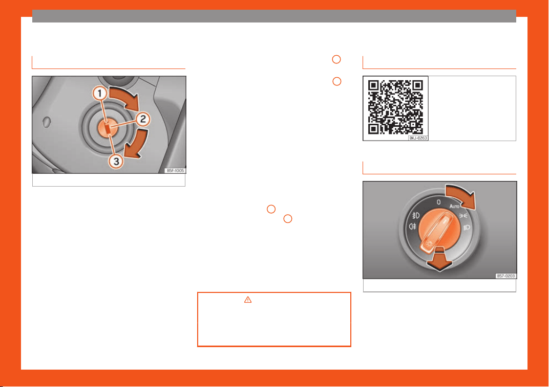
Lights and visibility
R
el
at
ed video
Fig. 44 Lights and visibil-
it
y
Light switch
Fig. 45
Instrument console: light panel.
●
Turn the switch to the required position
›
›
›
Fig. 45.
32
The essentials
Sym-
bol
Ignition switch-
ed off
Ignition is
switched on
F
og lights, dipped
beam and side
lights off.
Daylight running
lights switched on.
The “Coming
home”, “Leaving
home” and Wel
-
come lights may be
switched on.
Automatic control
of dipped beam
and daytime run-
ning light.
Side light on.
Daylight running
lights switched on.
Dipped beam head-
light off
Dipped beam
switched on.
Fog lights: mo
ve the switch to the first po-
sition, from positions , or .
Rear fog light: move the switch complete-
ly from positions , or .
●
Turn on fog lights: push the switch or turn it
to the position.
››
›
in Side light and dipped beam
headlight on page 148
›››
page 14
7
Turn signal and main beam lever
Fig. 46
Turn signal and main beam lever.
More the lever to the required position:
Right t
urn light: right
-hand parking light
(ignition s
witched off).
Left turn light: left-hand parking light (ig-
nition switched off).
Main beam on: control lamp lit up on
the instrument panel.
Light flash: on with the lever pushed. Con-
trol lamp lit up.
Lever all the way down to switch it off.
›››
in Turn signal and main beam
lever on page 149
›››
page 14
8
1
2
3
4
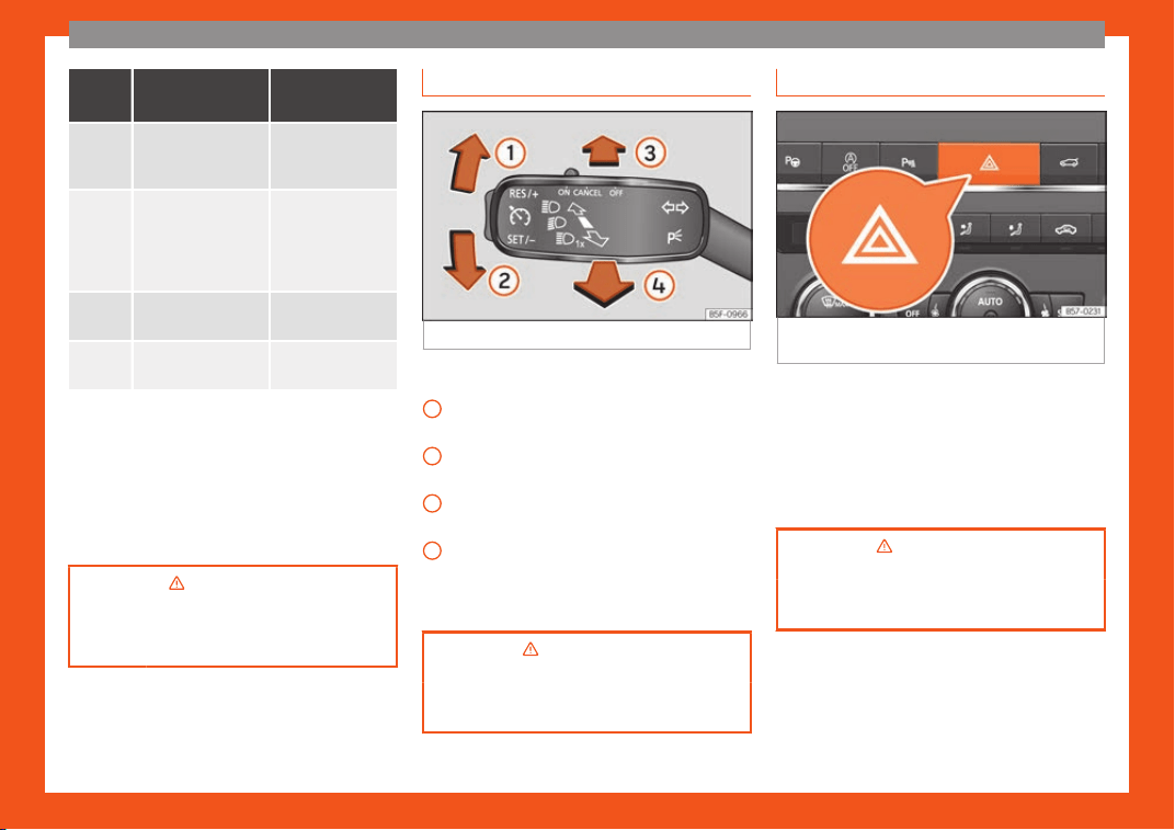
Hazard warning lights
Fig. 47
Dashboard: switch for hazard warning
lights.
Switched on, for example:
●
When approaching a traffic jam
●
In an emergency
●
The vehicle has broken down
●
When towing or being towed
›››
in Hazard warning lights on
page 153
›››
page 152
33
The essentials
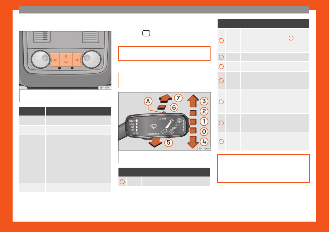
Interior lights
Fig. 48
Detail of headliner: front interior light-
ing.
Knob Function
Switches interior lights off.
Switches interior lights on.
Central po-
sition
or
a)
Door contact switch-on.
The int
erior lights come on automati-
cally when the v
ehicle is unlocked, a
door is opened or the key is removed
from the ignition.
The light goes off a few seconds af-
ter all the doors are closed, the vehi-
cle is locked or the ignition is switch-
ed on.
Turning the reading light on and off
a)
Depending on version.
Ambient light*: light guide on door panel.
Lighting can be sel
ect
ed fr
om 8 possible col-
ours via the
menu and the SETTINGS
function butt
on.
›
›
›
page 155
Windscreen wipers and window
wiper blade
Fig. 49
Operating the windscreen wiper and
r
ear wiper
.
More the lever to the required position:
0
Windscreen wipers off.
More the lever to the required position:
1
Windscreen wipers interval wipe.
Using the control
››
›
Fig. 49
A
adjust
the interval (vehicles without rain sen-
sor), or the sensitivity of the rain sensor.
2
Slow wipe.
3
Continuous wipe.
4
Short wipe. Brief press, short clean.
Hold the lever down for more time to in-
crease the wipe frequency.
5
Automatic wipe. The windscreen wash-
er function is activated by pushing the
l
ever forwards, and simultaneously the
windscreen wipers start.
6
Interval wipe for rear window. The wip-
er will wipe the window appro
ximately
every six seconds.
7
The rear window wash function is acti-
vated by pr
essing the lever, and the
rear wiper starts simultaneously.
›››
page 156
›››
page 61
34
The essentials
Easy Connect
Vehicle menu settings
Fig. 50 Easy Connect: Main menu. Fig. 51 Easy Connect: Vehicle Menu.
The actual number of menus available and
the name of the v
arious options will depend
on the v
ehicl
e’s electronics and equipment.
●
Switch the ignition on.
●
If the Infotainment System is off, switch it on.
●
Press the Infotainment button
and
then the Vehicle function butt
on
›
›
›
Fig. 50.
●
OR: Press the infotainment button
to
open the Vehicle menu
›
›
›
Fig. 51.
●
Press the SETTINGS function button to open
the Vehicle settings menu.
●
To select a function in the menu, press the
desired button.
When the function button check box is activa-
ted , the function is active.
Pressing the menu button will always take
you to the last menu used.
Any changes made using the settings menus
are automatically saved on closing those
menus.
Menu Submenu Possible setting Description
ESC system –
Activation and deactivation of the traction control system (ASR) and the elec-
tronic stabilit
y control (ESC) system, selecting the Sport / Off-road* mode of the
electronic stability control (ESC Sport)
›››
page 248
»
35

The essentials
Menu Submenu Possible setting Description
Tyres
Tyre pressure monitoring Tyre pressure storing (Calibration)
›››
page 361
Winter tyres
Activation and deactivation of the speed warning, adjusting the speed warning
value
›››
page 365
Lights
Light assist
Dynamic Light Assist, Light Assist, motorway function, turning-on time, headlamp
range adjustment, automatic lights when r
aining, one-touch signalling, travel
mode.
›››
page 147
Vehicle interior lighting Brightness of instrument panel and control
s
›››
page 155
Coming Home/Leaving Home
function
Switch-on time of the “Coming home” and “Leaving home” functions
›››
page 151
›››
page 152
Driver assis-
tance
ACC (adaptive cruise control) Activation and deactivation: default distance level, driving profiles.
›››
page 283
Front Assist (emergency brak-
ing assistance system)
Activation and deactivation: Front Assist, advance warning, distance warning dis-
pl
ay
›
›
›
page 279
Lane Assist (system warning
you if you leave the lane)
Activation and deactivation of lane departure warning, adaptive lane guidance
›››
page 292
Detection of traffic signs
Display on the instrument panel, activation and deactivation of the speed warn-
ing
›››
page 114
Trailer
Trailer recognition (display of traffic signs for vehicles with trailer), use to calcu-
late the route, maximum speed for trailer
›››
page 329
Fatigue detection Activation and deactivation
›››
page 112
36

The essentials
Menu Submenu Possible setting Description
Parking and ma-
noeuvring
ParkPilot
Automatic activation, front volume, front sound treble, rear volume, rear sound
treble
, adjust Infotainment volume
›››
page 315,
›››
page 319
Auto Hold Switching on and off when starting off
›››
page 272
Electric parking brake Swit
ching on and off automatically
›››
page 246
Braking while manoeuvring
function
Swit
ching on and off
›››
page 319
Displaying the parking space Switching on and off
Ambient lighting – Switching on and off, selecting brightness, colour, area or total
›››
page 155
Mirrors and
windscreen wip-
ers
Mirrors
Synchronised regulation, fold in after parking, rear-view mirror heating, dim in the
dark
›››
page 2
1,
›
››
page 159
Windscreen wipers
Activate and deactivate automatic windscreen wipers in case of rain, wipe when
reversing
›››
page 34
Opening and
closing
Electric windows control
Convenience opening, automatic closure in case of rain, automatic closure with
central locking
›››
page 143
Central locking
Unlocking doors, automatic lock/unlock when driving, “Easy Open” audible con-
firmation, “Easy Entry” convenient entry function, automatic opening of the rear
lid, interior monitoring
›››
page 127
Instrument panel –
Current consumption, average consumption, convenience consumers, ECO Ad-
vice, travelling time, distance travelled, average speed, digital speed display,
speed warning, oil temperature, coolant temperature, reset data “when setting
off”, reset data for “total calculation”, traffic signal detection
›››
page 110
Date and time – Time sour
ce, time, select time zone, time format, date, date format –
Units –
Distance, speed, temperature, volume, fuel consumption, GNC consumption,
electric consumption, pressur
e
–
Service –
Chassis number, date of next SEAT service inspection, date of next oil change
service
›››
page 119
»
37

The essentials
Menu Submenu Possible setting Description
Factory settings
All Restore all settings –
Individual
Lights, driver assistance, parking and manoeuvring, background lighting, rear
view mirrors and windscreen wipers, opening and closing, instrument panel
–
WARNING
Any distraction may lead to an accident,
with the risk of injury. Operating the Easy
Connect system whil
e driving could dis-
tract you from traffic.
38
The essentials
Warning lamps
Contr
ol and w
arning l
amps
Fig. 52 Related video
Red warning lamps
Notification central lamp: additional infor-
mation on the instrument panel display
Parking br
ake on
›››
page 245.
Fault in the brake system
›
›
›
page 245.
Fault in the steering system
›
›
›
page 261.
Driver or passenger has not fastened seat
belt
›››
page 69.
Press the foot brake
›››
page 284.
Yellow warning lamps
Notification central lamp: additional infor-
mation on the instrument panel display
Front br
ake pads worn
›››
page 245.
Fault in ESC or disconnection caused by
the system; OR
ESC or ASR in operation
›››
page 248.
ASR manually deactivated; OR ESC in
Sport mode
›››
page 248.
Fault in the ABS
›››
page 248.
Rear fog light switched on
›››
page 147.
Fault in the emission control system
›››
page 265.
Pre-heating of the diesel engine; OR fault
in the management of the diesel engine
››
›
page 265.
Fault in the petrol engine management
›››
page 265.
Particulate filter blocked
›
›
›
page 265.
Fault in the steering system
›››
page 261.
Tyre monitor system
›››
page 362.
Fuel tank almost empty
›››
page 117.
Fault in airbag system and seat belt ten-
sioners
›››
page 79.
Front passenger front airbag is disa-
bled
›››
page 79.
The front passenger front airbag is activa-
ted
›››
page 79.
Lane assist warning (Lane Assist)
›››
page 292.
Fault in the lighting of the vehicle
›››
page 147.
Low engine oil level
›››
page 350.
Fault in the gearbox
›››
page 259.
Windscreen cleaning fluid too low
›››
page 156.
Other warning lamps
Turn lights or emergency lights on
›››
page 147.
Trailer turn signals
›››
page 147.
Auto Hold activated
›
›
›
page 272.
Press the foot brake
›
›
›
page 252.
Speed regulator
›››
page 274; OR speed
limiter
›››
page 275; OR Adaptive Cruise
Control (ACC)
›››
page 284.
Lane assist warning (Lane Assist)
›››
page 292.
Main beam on or flasher on
›
›
›
page 147.
Door(s), rear lid or bonnet open or not
properly closed
›
››
page 108.
Engine cooling fluid
›››
page 118.
Engine oil pressure
›››
page 350.
Fault in the battery
›››
page 355.
Main beam assist (Light Assist)
›››
page 147.
Hill descent control (HDC)
›››
page 271.
»
39
The essentials
Electronic immobiliser active
›››
page 135.
Service interval display
›››
page 119.
Mobile telephone is connected via Blue-
tooth
®
››
›
page 230.
Mobile telephone battery charge status
›››
page 230.
Risk of freezing
›››
page 108.
Start-Stop system activated
›
›
›
page 269.
Start-Stop system unavailable
›
›
›
page 269.
Low consumption driving status
›››
page 109.
›››
in Control and warning lamps
on page 123
›››
page 122
Cruise control
R
el
at
ed video
Fig. 53 Dash panel
Operating the cruise control sys-
t
em (CCS)*
Fig. 54
Left of the steering column: CCS
s
wit
ch and contr
ols.
●
Switching on the CCS: Move switch
›
›
›
Fig. 54
1
to
. The syst
em is on. If no
speed has been pr
ogrammed, the system will
not control it.
●
Activate the CCS: Press button
›››
Fig. 54
2
in the ar
ea. The curr
ent speed is
memorised and contr
olled.
●
Temporarily switching off the CCS: Move
switch
›››
Fig. 54
1
to
or push the
br
ak
e. The cruise control system is switched
off temporarily.
●
Reactivating the CCS: Press button
›››
Fig. 54
2
in . The memorised speed is
sav
ed and contr
oll
ed again.
●
Increasing stored speed during CCS regu-
lation: press button
2
in
. The vehicle
accel
erates until the new stored speed.
●
Reducing stored speed during CCS regula-
tion: press button
2
in t
o lower the
speed by 1 km/h (
1 mph). Speed is r
educed
until reaching the new stored speed.
●
Switching off the CCS: Move switch
›››
Fig. 54
1
to
. The system is disconnec-
t
ed and the memorised speed is deleted.
40
The essentials
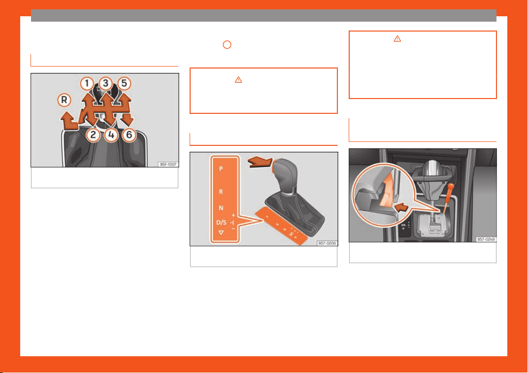
Gearbox lever
Manual gearbo
x
Fig. 55
Gear shift pattern of a 5 or 6-speed
manual gearbo
x.
The position of the gears is indicated on the
gearbo
x l
e
ver
›››
Fig. 55.
●
Press the clutch pedal and keep your foot
right down.
●
Move the gearbox lever to the required po-
sition.
●
Release the clutch.
Selecting reverse gear
●
Press the clutch pedal and keep your foot
right down.
●
With the gearbox lever in neutral, push it
downwards, move it to the left as far as it will
go and then forwards to select reverse
›››
Fig. 55
R
.
●
Release the clutch.
›››
in Changing gear on page 251
›››
page 251
Automatic gearbox*
Fig. 56
Automatic transmission: selector lever
positions.
Parking lock
R
e
v
erse gear
Neutral (idling)
Drive (forward)
Tiptronic mode: pull the lever forwards
(+) to go up a gear or backwards (–) to
go down a gear.
P
R
N
D/S
+/–
›››
in Selector lever positions on
page 253
›››
page 252
›››
page 41
Manual release of the selector lev-
er
Fig. 57
Selector lever: manual release from
position P
.
Should the power supply be interrupted,
ther
e is a manual unl
ocking de
vice located
under the console of the selector lever, on the
right. Releasing the selector lever requires a
certain degree of practical skill.
●
Unlock: use the flat part of a screwdriver
blade.
»
41
The essentials
Removing the cover from the selector lev-
er
●
Apply the electronic parking brake
›
›
›
to ensure that the car does not move.
●
Carefully pull the corners of the selector
l
e
v
er boot and twist it upwards above the lev-
er handle.
Releasing the selector lever
●
Using a screwdriver, press and hold the yel-
low unlocking tab sideways
›››
Fig. 57.
●
Press the interlock button on the selector
lever and move the selector lever to posi-
tion N.
●
After carrying out the manual release, at-
tach the selector lever boot on the gearbox
console again.
If the power supply should ever fail (e.g. dis-
charged battery) and the vehicle has to be
pushed or towed, the selector lever must first
be moved to position N, after operating the
manual release mechanism.
WARNING
The selector lever must only be moved out
of position P when the electronic parking
br
ake is applied. If this does not work, se-
cure the vehicle with the brake pedal. On a
slope the vehicle could otherwise start to
move inadvertently after shifting the selec-
tor lever out of position P - accident risk!
Air conditioning
R
el
at
ed video
Fig. 58 Air conditioning
42
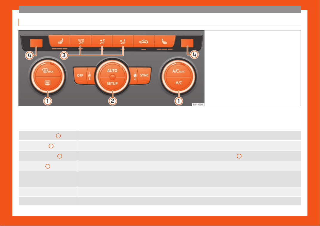
The essentials
How does Climatronic* work?
Fig. 59 In the centre console: Climatronic control
panel.
To switch a specific function on, press the ap-
pr
opriat
e butt
on. Press the button again to
switch off the function.
The LED on each control lights up to indicate
that the respective function of a control has
been switched on.
Temperature
1 The left and right sides can be adjusted separately: turn the control to adjust the temperature
Fan
2 The power of the fan is automatically adjusted. The fan is also adjusted manually by turning the control.
Air distribution
3
The airflow adjusts automatically for comfort. You can also switch it on manually using the buttons
3
.
4 Indications on the temperature display screen selected for the right and left sides.
Defrost function
The air dr
awn in from outside the vehicle is directed at the windscreen and air recirculation is automatically switched off. To defrost the
windscreen more quickly, the air is dehumidified at t
emperatures over approximately +3°C (+38°F) and the fan runs at maximum output.
The air is directed at the chest of driver and passengers by the dash panel air vents.
Air distribution towards the footwell.
»
43

The essentials
Upward air distribution.
Heated rear window: this only works when the engine is running and switches off automatically after a maximum of 10 minutes.
Air recirculation
Seat heating buttons
Press the button to switch on or off the cooling system.
Press the butt
on to make maximum cooling capacity available. The recirculation of air and the cooling system turn on automatically and
air distribution adjusts automatically to the position
.
When the warning light for button lights up
, the settings on the driver side also apply to the passenger side, press the button or the
temperature control on the passenger side
Automatic adjustment of temperature, fan, and air distribution. Press key: the lamp in button will lit up
.
Press the key: the air conditioning operation menu will be displayed on the Easy Connect system screen.
Switching off
Turn the blower control to the position or press the button.
›››
in Introduction on page 176
›››
page 1
76
44
The essentials
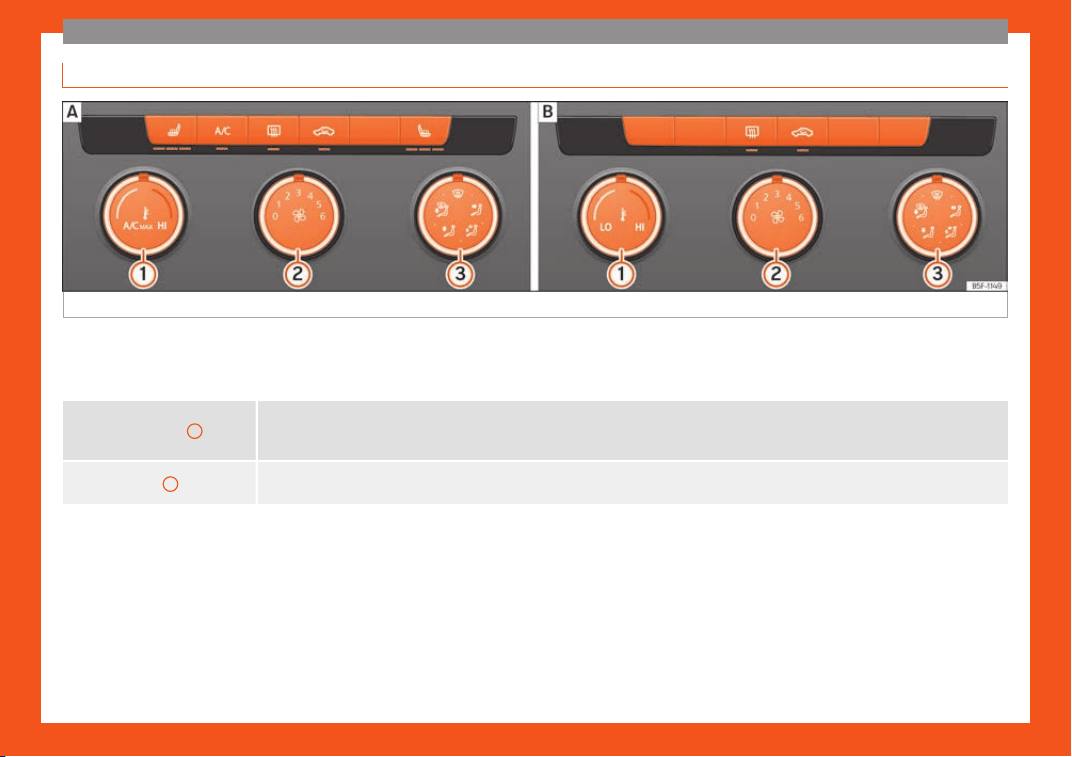
How does the manual air conditioning* and the heating and fresh air system work?
Fig. 60
In the centre console: contr
ol
s f
or the manual air conditioning; heating and fresh air system controls.
To switch a specific function on, press the ap-
pr
opriat
e butt
on. Press the button again to
switch off the function.
The LED on each control lights up to indicate
that the respective function of a control has
been switched on.
Temperature
1
Turn the control to adjust the temperature
Heating and ventilation syst
em: The temperature cannot be lower than that of the exterior air temperature, as this system cannot cool
or dehumidify the air
Fan
2
Level 0: blower and manual air conditioning/heating and fresh air system off
Lev
el 6: maximum fan level.
»
45
The essentials
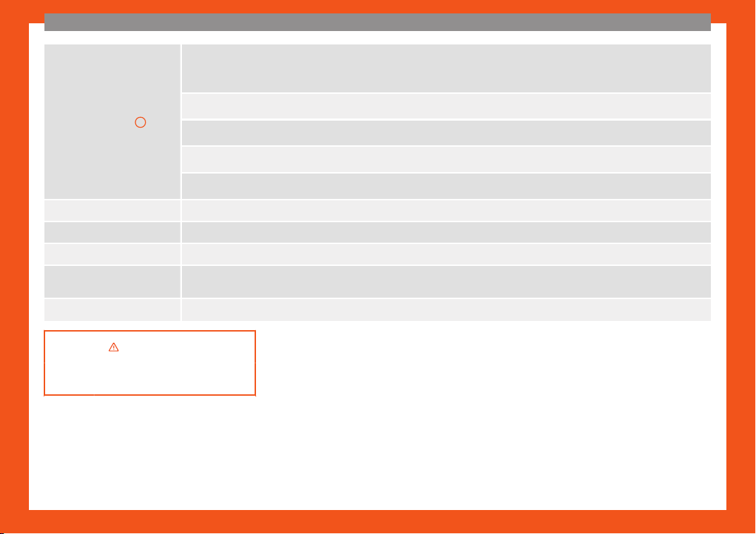
Air distribution
3
: Defr
ost function. The airfl
o
w is directed at the windscreen.
Manual air conditioning: Air recirculation is automatically switched off or is not switched on. Increase the fan power to clear the wind-
screen of condensation as soon as possible. To dehumidify the air, the cooling system will automatically switch on.
: The air is directed at the chest of driv
er and passengers by the dash panel air vents.
: Distribution of air tow
ards the chest and the footwell area.
: Air distribution towards the footwell.
: Air distribution tow
ards the windscreen and the footwell.
Heated rear window: this only works when the engine is running and switches off automatically after a maximum of 10 minutes.
Air recirculation
Manual air conditioning: Pr
ess the button t
o switch on or off the cooling system.
Manual air conditioning: Maximum cooling power
. The recirculation of air and the cooling system turn on automatically and air distribu-
tion adjusts automatically to the position .
Manual air conditioning: Seat heating butt
ons
›››
in Introduction on page 176
›››
page 1
76
46
The essentials
Fluid level control
Filling capacities
Tank level
Petrol and die-
sel engines
Front-wheel drive vehicles:
50 l
, of which appro
x.7 l reserve
Four-wheel drive vehicles:
55 l, of which appro
x. 8.5 l re-
serve
Capacity of the windscreen washer fluid con-
t
ainer
Versions with-
out headlight
washer system
appr
ox. 3 litres
Versions with
headlight
washer system
appr
ox. 5 litres
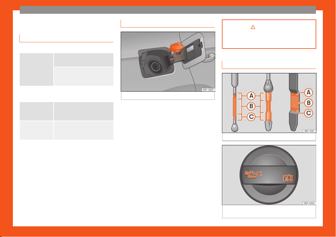
Fuel
Fig. 61
Fuel tank flap with tank cap attached.
The flap that covers the tank cap is unlocked
and l
ock
ed aut
omatically using the central
locking.
Opening the fuel tank cap
●
Open the fuel tank flap by pressing on the
left side.
●
Unscrew the cap by turning it to the left.
●
Place it in the space on the hinge of the
open flap
›››
Fig. 61.
Closing the fuel tank cap
●
Unscrew the cap by turning it to the right as
far as it will go.
●
Close the lid.
›››
in Refuelling on page 341
›››
page 341
Oil
Fig. 62
Engine oil dipstick.
Fig. 63
In the engine compartment: Engine oil
fill
er cap
.
»
47
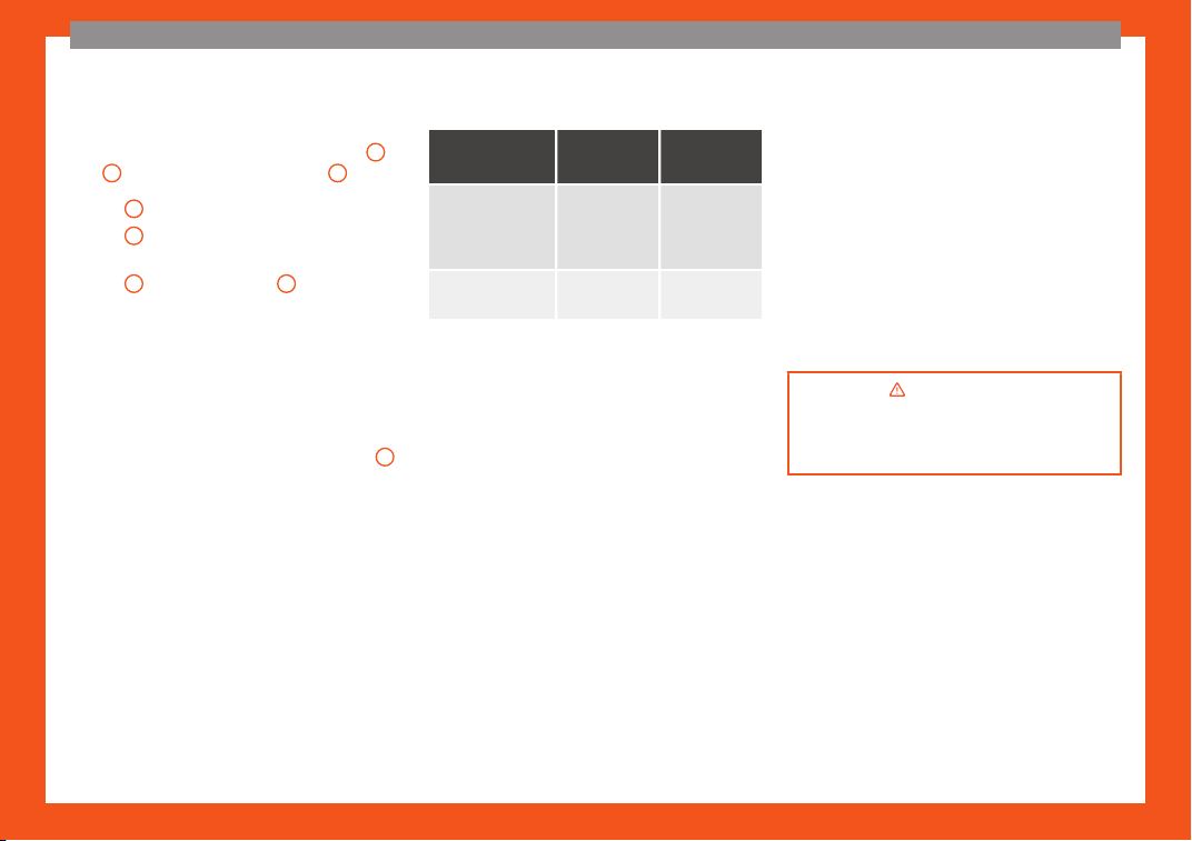
The essentials
The level is measured using the dipstick loca-
t
ed in the engine compartment
›
›
›
page 349.
The oil indicator must be between zones
A
and
C
. It can never go above zone
A
.
●
Zone
A
: do not add oil.
●
Zone
B
: you can add oil but keep the level
in that z
one
.
●
Z
one
C
: add oil until zone
B
.
T
opping up engine oil
●
Unscr
e
w cap from oil filler opening.
●
Add oil slowly.
●
At the same time, check the level to ensure
you do not add too much.
●
When the oil level reaches at least zone
B
,
unscr
e
w the engine oil fill
er cap carefully.
Engine oil additives
No type of additive should be mixed with the
engine oil. The deterioration caused by these
additives is not covered by the warranty.
Engine oil specifications
Diesel engines
Engine type
Type of
Service
Specifica-
tion
With particulate
filter (DPF)
a)
Set Service
and Flexibl
e
Service Inter-
vals
VW 507 00
Without particu-
late filt
er (DPF)
Set Service
Intervals
VW 505 01
b)
VW 506 01
b)
a)
Only use recommended oils, otherwise you may
damage the engine
.
b)
If the qualit
y of the fuel av
ailable in the country
does not fulfil the EN 590 (for diesel) standard.
If the engine oil level is too low
You can get information about the correct en-
gine oil for your vehicle in your specialised
shop. If you have to change your engine oil,
use this oil.
If the recommended engine oil is not availa-
ble, in the event of an emergency you can
change the oil once with a maximum of 0.5 L
of the next oil until the next oil change:
Petrol engines: standard VW 504 00,
VW 502 00, VW 508 00, ACEA C3 or
API SN.
Diesel engines: standard VW 507 00,
VW 505 01, ACEA C3 or API CK-4.
–
–
Have the oil changed by a specialised work-
shop.
Using engine oil that is compliant with the VW
504 00 standard instead of VW 508 00
could increase consumption and the vehicle’s
CO
2
emissions.
Recommended by SEAT
SEAT recommends using original SEAT oil to
guarantee high SEAT engine performance.
›››
in Changing engine oil on
page 352
›››
page 349
48
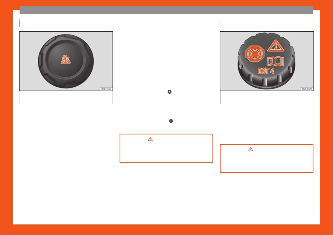
The essentials
Coolant
Fig. 64
Engine compartment: coolant expan-
sion t
ank cap
.
The coolant tank is located in the engine
compartment
›
›
›
page 349.
When the engine is cold, replace the coolant
when the level is below .
Coolant specifications
The engine cooling system is supplied from
the factory with a specially treated mixture of
water and at least 40 % of the additive G13
(TL-VW 774 J), purple. This mixture gives the
necessary frost protection down to -25°C
(-13°F) and protects the light alloy parts of
the engine cooling system against corrosion.
It also prevents scaling and considerably rai-
ses the boiling point of the coolant.
To protect the cooling system, the percent-
age of additive must always be at least 40 %,
even in warm climates where anti-freeze pro-
tection is not required.
If for weather reasons further protection is
necessary, the proportion of additive may be
increased, but only up to 60 %; otherwise an-
tifreeze protection will diminish and this will
worsen cooling.
When the coolant is topped up, use a mixture
of distilled water and at least 40 % of the
G13 or G12 plus-plus (TL-VW 774 G) additive
(both are purple) to obtain an optimum anti-
corrosion protection
›››
in Topping up
cool
ant on page 353
. The mixt
ure of G13
with G12 plus (TL-VW 774 F), G12 (red) or G11
(green-blue) engine coolants will significantly
reduce anti-corrosion protection and should
therefore be avoided
›››
in Topping up
cool
ant on page 353
.
›
››
in Topping up coolant on
page 353
›››
page 352
Brake fluid
Fig. 65
Engine compartment: brake fluid res-
erv
oir cap
.
The brake fluid reservoir is located in the en-
gine compartment
›
›
›
page 349.
The level should be between the and
marks. If it is below , please visit a Technical
Service.
›››
in Top up brake fluid on
page 353
›››
page 353
49
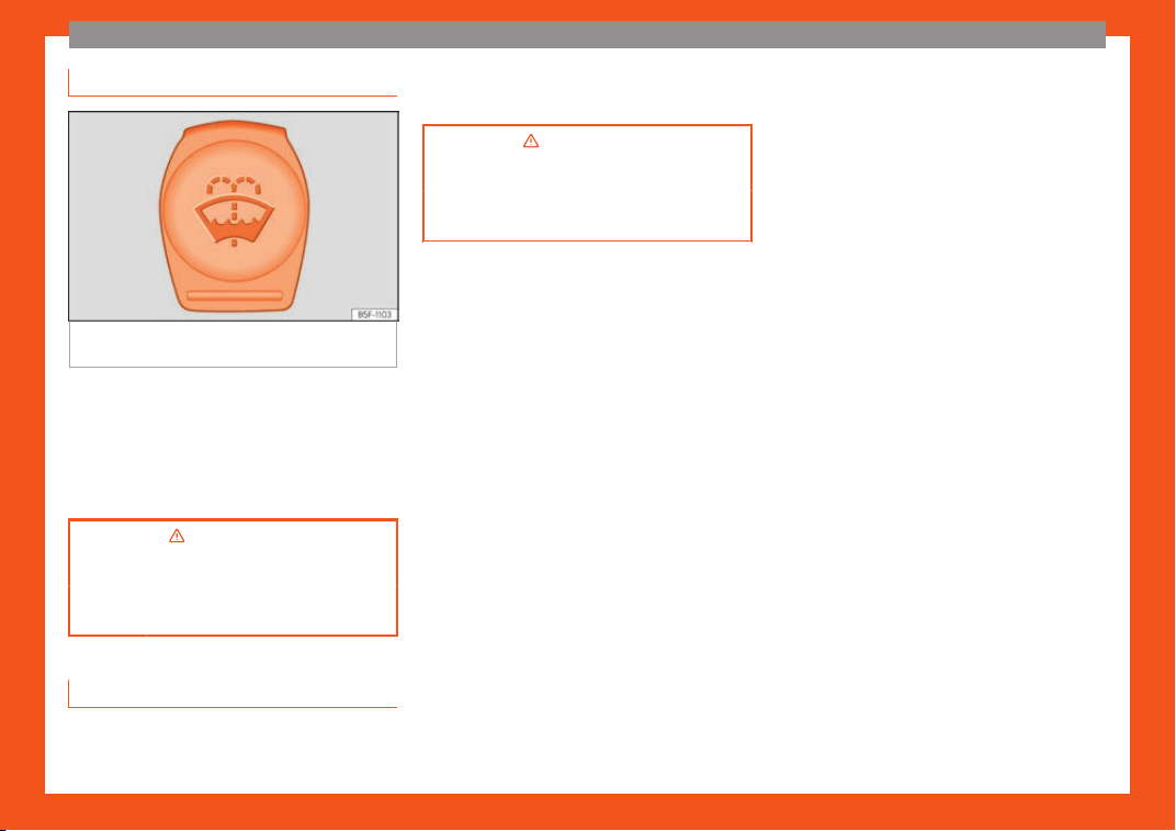
The essentials
Windscreen washer
Fig. 66
In the engine compartment: cap of the
windscr
een w
asher t
ank.
The windscreen washer reservoir is located in
the engine compartment
›
›
›
page 349.
To top up, mix water with a product recom-
mended by SEAT.
In cold temperatures, add anti-freeze.
›››
in Checking and topping up the
windscreen washer r
eservoir on
page 354
›››
page 354
Battery
The battery is located in the engine compart-
ment
›
›
›
page 349. It does not require
maintenance. It is checked as part of the In-
spection Service.
›››
in Important safety warnings
for handling a vehicl
e battery on
page 355
›››
page 354
50
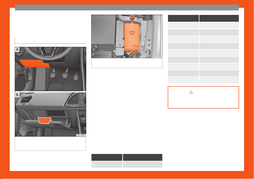
The essentials
Emergencies
Fuses
Fuse l
ocation
Fig. 67 Left guide: fuse box co
ver on the
driver-side dash panel. Right guide: fuse box
behind the glove compartment.
Fig. 68 In the engine compartment: lid of the
fuse box.
Underneath the instrument panel (left-
hand driv
e)
The fuse bo
x is l
ocated behind the storage
compartment
›››
Fig. 67 .
Behind the glove compartment (right-
hand drive)
The fuse box is located behind the glove
compartment
›››
Fig. 67 . To be able to ac-
cess the fuse box
›››
page 93.
In the engine compartment
Press the locking tabs to release the fuse box
cover
›››
Fig. 68.
Identifying fuses situated below the dash
panel by colours
Colour Amp rating
Black 1
Colour Amp rating
Purple 3
Light brown 5
Brown 7.5
Red 10
Blue 15
Yellow 20
White or transparent 25
Green 30
Orange 40
›››
in Introduction on page 92
›››
page 92
51
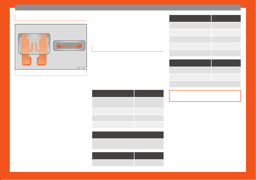
The essentials
Replacing a blown fuse
Fig. 69
Image of a blown fuse.
Preparation
●
Switch off the ignition, lights and all electri-
cal equipment.
●
Open the corresponding fuse box
›
›
›
page 93.
Identifying a blown fuse
A fuse is blown if its metal strip is ruptured
›››
Fig. 69.
●
Point a lamp at the fuse to see if it has
blown.
To replace a fuse
●
Remove the fuse.
●
Replace the blown fuse by one with an
identical amperage rating (same colour and
markings) and identical size.
●
Replace the cover again or close the fuse
box lid.
Bulbs
Bulbs (12 V)
Note: Depending on the lev
el of equipment
fitted in the vehicle, LEDs may be used for
part or all of the interior and/or exterior light-
ing. LEDs have an estimated life that exceeds
that of the vehicle. If an LED light fails, go to
an authorised workshop for its replacement.
Light source used for each function
Halogen headlights. Type
Daytime running light/side
light
LED (it cannot be
replaced)
Dipped beam headlights
H7 LL
Main beam headlights H7 LL
Turn signal PY21W
Full-LED main headlights
No bulbs may be replaced. All functions are with
LEDs
Front fog light Type
Fog/cornering lights* H8
Rear lights Type
Brake light/tail light P21W LL
Side lights P21W LL
Turn signal PY21W LL
Retro fog light P21W LL
Reverse lights W16W
LED rear lights Type
Turn signal PY21W LL
Reverse lights W16W
The remaining functions work with LEDs
›››
page 96
52
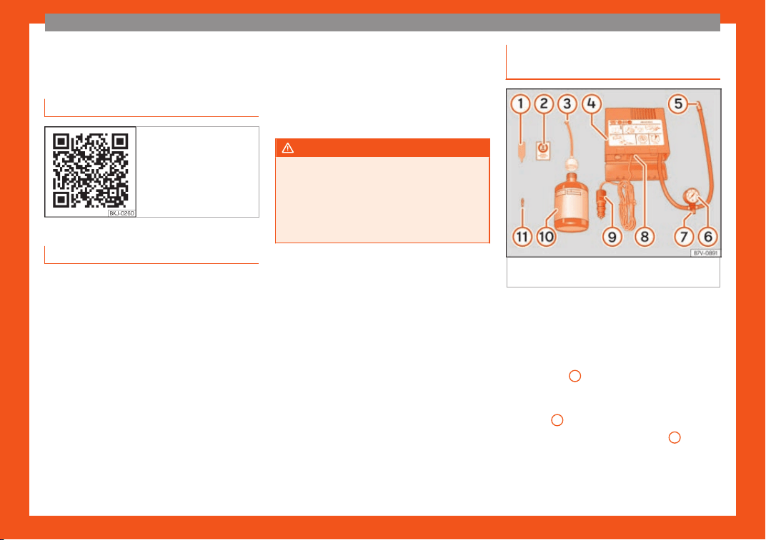
The essentials
Action in the event of a punc-
t
ur
e
R
elated video
Fig. 70 Wheels
What to do first
●
Park the vehicle on a horizontal surface and
in a saf
e pl
ace as f
ar away from traffic as
possible.
●
Apply the electronic parking brake.
●
Switch on the hazard warning lights.
●
Manual transmission: select the 1st gear.
●
Automatic transmission: Move the selector
lever to position P.
●
If you are towing a trailer, unhitch it from
your vehicle.
●
Have the vehicle tool kit
›››
page 85
and the spare wheel* ready
›››
page 364.
●
Observe the applicable legislation for each
country (reflective vest, warning triangles,
etc.).
●
All occupants should leave the vehicle and
wait in a safe place (for instance behind the
roadside crash barrier).
WARNING
●
Always observ
e the above steps and pro-
tect yourself and other road users.
●
If you change the wheel on a slope, block
the wheel on the opposite side of the car
with a stone or similar to prevent the vehi-
cle from moving.
Repairing a tyre with the anti-punc-
t
ur
e kit
Fig. 71
Standard display: contents of the anti-
punct
ur
e kit.
The anti-puncture kit is located under the
fl
oor panel in the luggage compartment.
Sealing the t
yr
e
●
Unscrew the tyre valve cap and insert. Use
the
›››
Fig. 71
1
tool to remove the insert.
Pl
ace it on a cl
ean surf
ace.
●
Shake the tyre sealant bottle vigorously
›››
Fig. 71
10
.
●
Screw the inflator tube
›
›
›
Fig. 71
3
into the
seal
ant bottl
e
. The bottle's seal will break au-
tomatically.
»
53
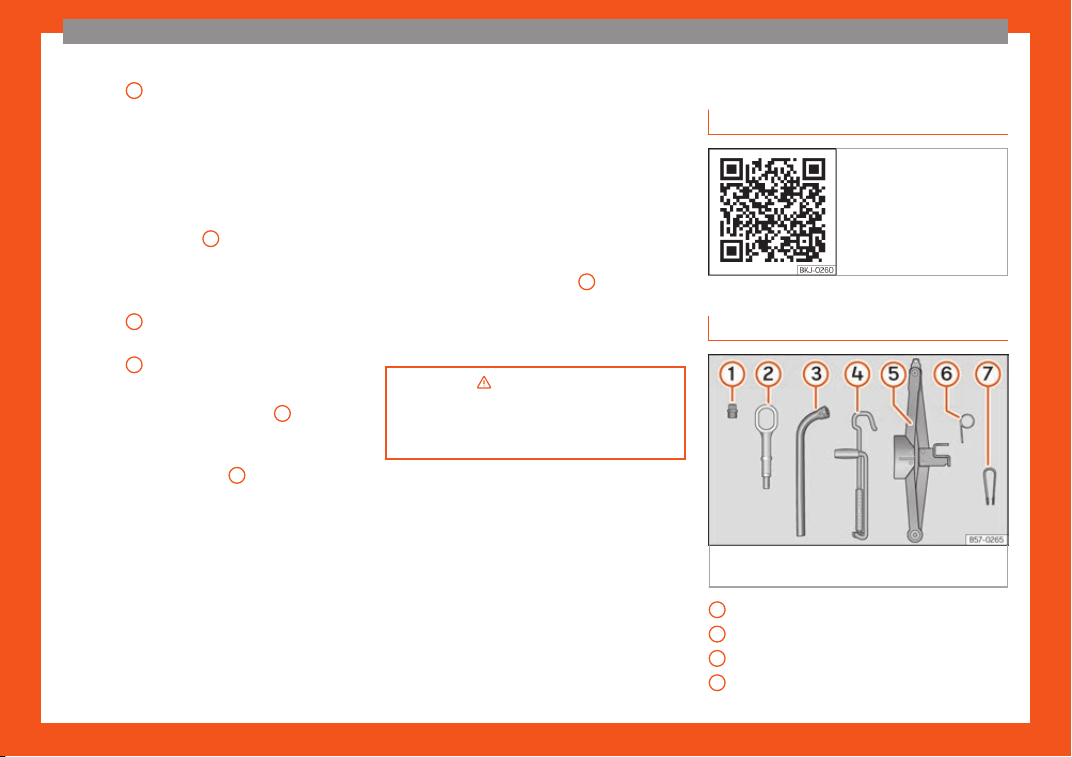
The essentials
●
R
emo
v
e the lid from the filling tube
›››
Fig. 71
3
and screw the open end of the
t
ube int
o the t
yre valve.
●
With the tyre sealant bottle upside down, fill
the tyre with the contents of the sealant bot-
tle.
●
Remove the bottle from the valve.
●
Place the insert back into the tyre valve us-
ing the tool
›››
Fig. 71
1
.
Infl
ating the t
yr
e
●
Screw the compressor tyre inflator tube
›››
Fig. 71
5
into the tyre valve.
●
Check that the air bleed screw is closed
›
›
›
Fig. 71
7
.
●
Start the engine and leave it running.
●
Insert the connector
›
›
›
Fig. 71
9
into the
v
ehicl
e's 12-v
olt socket
›››
page 167.
●
Turn the air compressor on with the
ON/OFF switch
›››
Fig. 71
8
.
●
Keep the air compressor running until it rea-
ches 2.
0 t
o 2.5 bar (29-36 psi/200-250 kP
a).
A maximum of 8 minutes.
●
Disconnect the air compressor.
●
If it does not reach the pressure indicated,
unscrew the tyre inflator tube from the valve.
●
Move the vehicle 10m so that the sealant is
distributed throughout the tyre.
●
Screw the compressor tyre inflator into the
valve.
●
Repeat the inflation process.
●
If the indicated pressure still cannot be
reached, the tyre is too badly damaged. Stop
and request assistance from an authorised
technician.
●
Disconnect the air compressor. Unscrew
the tyre inflator tube from the tyre valve.
●
When the tyre pressure is between 2.5 and
2.0 bars, continue driving without exceeding
80 km/h (50 mph).
●
Attach the sticker
›››
Fig. 71
2
to the instru-
ment clust
er
, within the driv
er's visual field.
●
Check the pressure again after 10 minutes
›››
page 87.
›››
in TMS (Tyre Mobility System)*
on page 85
›››
page 85
Changing a wheel
R
el
at
ed video
Fig. 72 Wheels
Vehicle tool kit
Fig. 73
Underneath the floor panel of the lug-
gage compartment: on-boar
d t
ool
s.
Adapter for the anti-theft wheel bolts*
T
o
wline anchor
age
Box spanner for wheel bolts*
Crank handle for jack
1
2
3
4
54
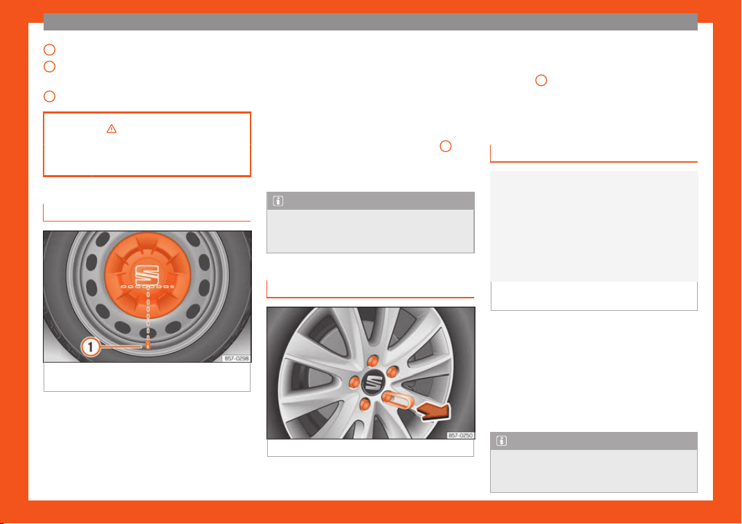
The essentials
Jack*
Hook f
or e
xtr
acting the central wheel
trims*
Clip for removing the wheel bolt caps.
›››
in What to do first on page 53
›››
page 85
Central wheel trim*
Fig. 74 Correct positioning of the central
wheel trim f
or st
eel rims.
The central trims must be removed for access
t
o the wheel bolts.
R
emo
ving
●
Attach the wire hook (vehicle tools) to one
of the chambers of the central wheel trim.
5
6
7
●
Insert the bo
x spanner thr
ough the hook
,
supporting it on the tyre and remove the
wheel trim.
Fitting
●
Fit the central wheel trim onto the rim. The
bottom of the “S” of the SEAT badge should
align with the inflation valve
›››
Fig. 74
1
.
●
Press the central trim firmly until it locks in
with an audibl
e click
.
Note
There is also a valve mark on the back of
the central wheel trim that indicates the
corr
ect alignment.
Wheel bolt caps*
Fig. 75
Wheel: wheel bolts with caps.
Removal
●
Fit the plastic clip (vehicle tools
›
›
›
Fig. 73
7
) over the cap until it clicks into
pl
ace
›
›
›
Fig. 75.
●
Remove the cap with the plastic clip.
Anti-theft wheel bolts
Fig. 76
Anti-theft wheel bolt with cap and
adapt
er
.
●
Remove the wheel cover* or the cap*.
●
Insert the special adapter (vehicle tools)
ont
o the anti-theft wheel bolt and push it on
as f
ar as it will go
.
●
Insert the wheel brace (vehicle tools) onto
the adapter as far as it will go.
●
Remove the wheel bolt
›››
page 56.
Note
Make a note of the code number of the an-
ti-theft wheel bolt and keep it in a safe
pl
ace, but not in your vehicle. If you need a
»
55
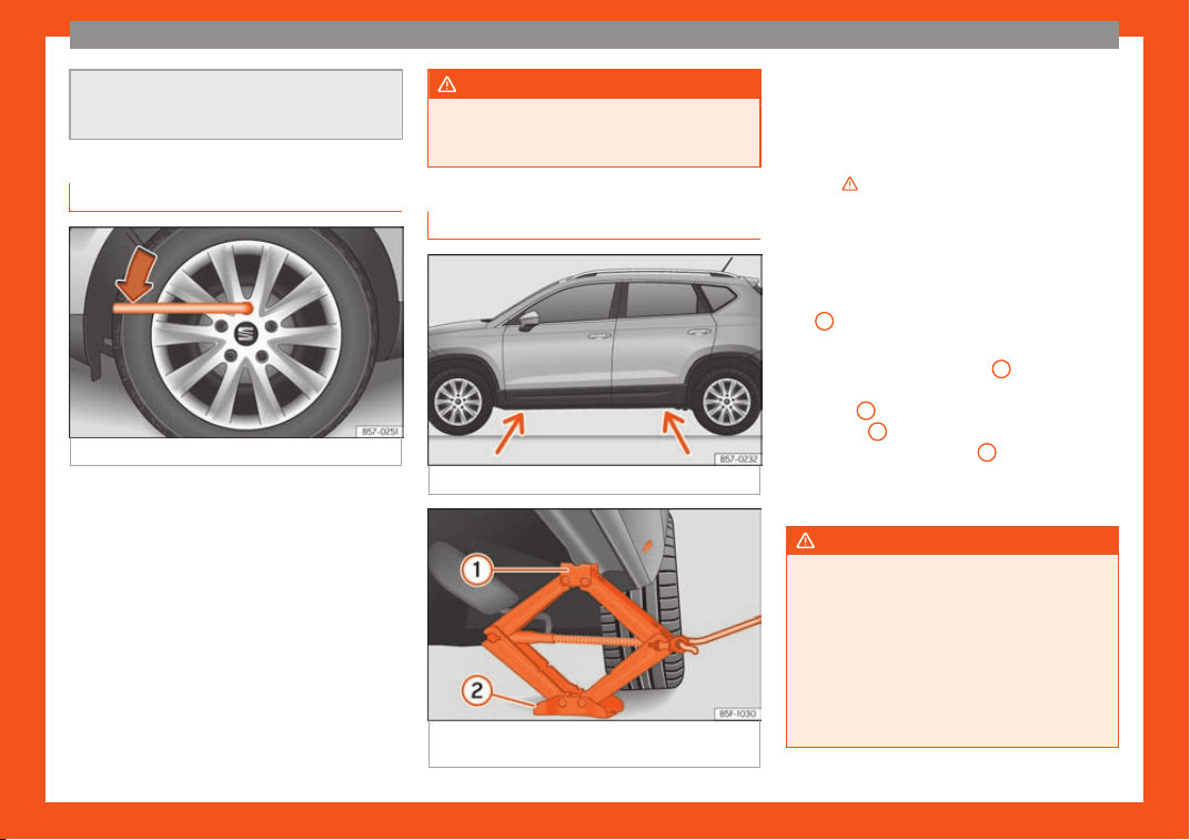
The essentials
new adapter, you can obtain it from the
SEAT Official Service, indicating the code
number.
Loosening the wheel bolts
Fig. 77 Wheel: loosen the wheel bolts.
●
Insert the box spanner (vehicle tools) onto
the wheel bolt as f
ar as it will go
. An adapt
er
is required to unscrew or tighten the anti-theft
wheel bolts
›››
page 55.
●
Turn the wheel bolt approximately one turn
to the left
›››
Fig. 77 (arrow). To apply the re-
quired torque, hold the wheel brace at the
end. If it is not possible to loosen a wheel bolt,
carefully apply pressure with one foot on the
end of the box spanner. Hold on to the vehicle
for support and take care not to slip.
WARNING
Slightly loosen the wheel bolts (one turn)
before r
aising the vehicle with the jack*. If
not, an accident may occur.
Raising the vehicle
Fig. 78
Crossbar: brands.
Fig. 79
Crossbar: mounting the jack on the ve-
hicl
e
.
●
Pl
ace the jack* (v
ehicl
e tools) on firm
ground. If necessary use a large, strong
board or similar support. If the surface is slip-
pery (for example tiles) place the jack on a
rubber mat or similar to prevent it from slip-
ping
›››
.
●
Find the support point on the strut (sunken
ar
ea) cl
osest t
o the wheel to be changed
›››
Fig. 78.
●
Turn the jack* crank handle, located below
the strut support point, to raise it until the
tab
1
›
›
›
Fig. 79 is below the housing provi-
ded.
●
Align the jack* so that tab
1
“grips” onto
the housing pr
o
vided on the strut and the mo-
bil
e base
2
is resting on the ground. The
base pl
at
e
2
should fall vertically with re-
spect t
o the support point
1
.
●
Continue turning the jack* until the wheel is
slightly lift
ed off the gr
ound.
WARNING
●
Make sure that the jack* r
emains stable.
If the surface is slippery or soft, the jack*
could slip or sink, respectively, with the re-
sultant risk of injury.
●
Only raise the vehicle with the jack* sup-
plied by the manufacturer. Other jacks,
even those approved for other SEAT mod-
els could slip, with the consequent risk of
injury.
56

The essentials
●
Only mount the jack* on the support
points designed for this purpose on the
strut, and al
ways align the jack correctly. If
you do not, the jack* could slip as it does
not have an adequate grip on the vehicle:
risk of injury!
●
The height of the parked vehicle can
change as a result of variations in tempera-
ture and loading.
CAUTION
The vehicle must not be raised on the
cr
ossbar. Only pl
ace the jack* on the
points designed for this purpose on the
strut. Otherwise, the vehicle may be dam-
aged.
Removing and fitting a wheel
Change the wheel after loosening the wheel
bolts and r
aising the v
ehicl
e with the jack.
Taking off the wheel
●
Unscrew the wheel bolts using the box
spanner and place them on a clean surface.
●
Take off the wheel.
Putting on the spare wheel
When fitting tyres with a compulsory rotation
direction, observe the instructions in
›››
page 57.
●
Mount the wheel.
●
Screw on the wheel bolts in position and
tighten them loosely with a box spanner.
●
Carefully lower the vehicle using the jack*.
●
Tighten the wheel bolts in diagonal pairs
using the wheel brace.
The wheel bolts should be clean and turn
easily. Before fitting the spare wheel, inspect
the wheel condition and hub mounting surfa-
ces. These surfaces must be clean before fit-
ting the wheel.
Tyres with compulsory direction of
rotation
A directional tread pattern can be identified
by the arr
o
ws on the side
wall that point in the
direction of rotation. Always observe the di-
rection of rotation indicated when fitting the
wheel to guarantee optimum properties of
this type of tyres with regard to grip, noises,
wear and aquaplaning.
If it is absolutely necessary to fit the spare
tyre* against the direction of rotation, drive
with care as this means the tyre does not of-
fer optimum driving properties. This is of par-
ticular importance when the road surface is
wet.
To return to directional tread tires, replace the
punctured tyre as soon as possible and re-
store the obligatory direction of rotation of all
tyres.
Subsequent work
●
Alloy wheels: replace the wheel bolt caps.
●
Pl
ate wheels: replace the wheel hubcap
›››
page 55.
●
Return all tools to their proper storing loca-
tion.
●
If the replaced wheel does not fit in the
spare wheel housing, stor
e it safely in the lug-
gage compartment
›››
page 168.
●
Check the tyre pressure of the newly moun-
ted tyre as soon as possible.
●
In vehicles fitted with a tyre pressure indica-
tor, adjust the pressure and store the reading
in the radio/Easy Connect system*
›››
page 361.
●
Have the tightening torque of the wheel
bolts checked as soon as possible with a tor-
que wrench (it should be 140 Nm). Meanwhile,
drive carefully.
●
Have the flat tyre replaced as quickly as
possible.
57
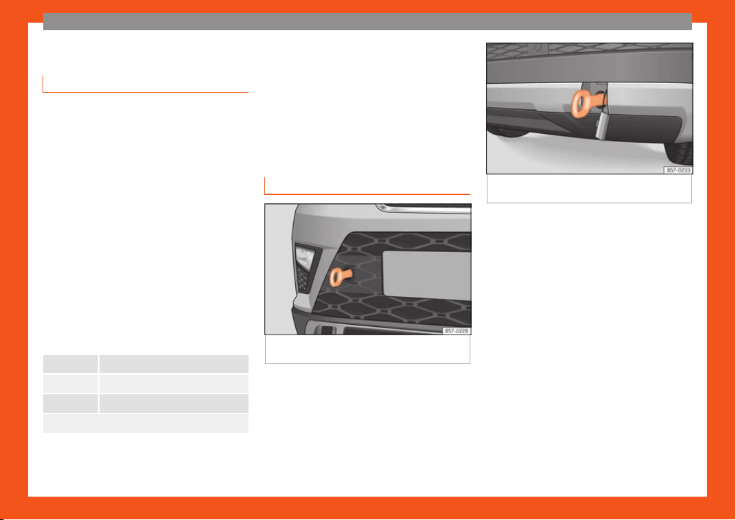
The essentials
Snow chains
Use
Snow chains should only be used on the front
wheels.
Check that they are corr
ectly seated after
driving for a few yards; correct the position if
necessary, in accordance with the manufac-
turer's fitting instructions. Keep your speed
below 50 km/h (30 mph).
If there is a danger of being trapped despite
having mounted the chains, it is best to disa-
ble the driving wheels (ASR) in the ESC
›››
page 250, Switching on/off the ESC
and ASR.
Snow chains will improve braking ability as
well as traction in winter conditions.
For technical reasons snow chains may only
be used with the following wheel rim/tyre
combination.
215/60 R16 Chains with links of maximum 15 mm
215/55 R17 Chains with links of maximum 15 mm
215/50 R18 Chains with links of maximum 15 mm
Other dimensions do not allow chains
Remove any central wheel trims and the rim
ring bef
or
e fitting sno
w chains.
Remove the chains when roads are free of
snow. Driving characteristics worsen, and the
wheels become damaged quickly and may
even be rendered unusable.
Emergency towing of the ve-
hicle
Towing
Fig. 80 Right side of the front bumper: towline
anchor
age scr
e
wed in.
Fig. 81 Right side of the rear bumper: towline
anchorage scre
wed in.
Towline anchorages
Att
ach the bar or r
ope t
o the towline ancho-
rages.
The towline anchorages are located under
the floor panel in the luggage compartment,
next to the vehicle tools
›››
page 85.
Screw the towline anchorage into the screw
connection
›››
Fig. 80 or
›››
Fig. 81 and tight-
en it with the wheel brace.
Tow rope or tow bar
The tow bar offers increased safety and a
lower risk of damage.
The tow rope is recommended when there is
no tow bar. It must be elastic so that it does
not damage the vehicle.
58
The essentials
Notes for the driver of the towing vehicle
●
The tow rope must be taut before you drive
off
.
●
R
el
ease the clutch very carefully when
starting the vehicle (manual gearbox), or ac-
celerate gently (automatic gearbox).
Driving style
Towing requires some experience, especially
when using a tow rope. Both drivers should
realise how difficult it is to tow a vehicle. Inex-
perienced drivers should not attempt to tow.
Do not pull too hard with the towing vehicle
and take care to avoid jerking the tow rope.
When towing on an unpaved road, there is al-
ways a risk of overloading and damaging the
anchorage points.
Switch on the ignition so that the turn signals,
windscreen wipers and windscreen washer
can work. Ensure that the steering wheel is
unlocked and moves freely.
Place the gear lever in neutral on vehicles
with a manual gearbox. With an automatic
gearbox, place the lever in N.
To brake, press the brake pedal firmly. The
brake servo does not work when the engine is
switched off.
The power steering only works when the igni-
tion is switched on and the vehicle is moving,
provided that the battery is sufficiently
charged. Otherwise, it will need more force.
Ensure that the tow rope remains taut at all
times.
›››
in Introduction on page 88
›››
page 88
Tow-starting
If the engine will not start, first try starting it
using the batt
ery of another v
ehicl
e
›››
page 59. You should only attempt to
tow-start a vehicle if charging the battery
does not work. This is done by leveraging
wheel movement.
When tow-starting a vehicle with a petrol en-
gine, do not tow it more than a short dis-
tance, otherwise unburned fuel can enter the
catalytic converter.
●
Engage 2nd or 3rd gear before moving off.
●
Press the clutch and hold the pedal down.
●
Switch the ignition on.
●
Once both vehicles are moving, release the
clutch.
●
As soon as the engine has started, press the
clutch and move the gear lever to neutral.
How to jump start
Jump leads
The jump lead must have a sufficient wire
cross section.
If the engine fail
s to start because of a dis-
charged battery, the battery can be connec-
ted to the battery of another vehicle to start
the engine.
Jump leads must comply with standard DIN
72553 (see cable manufacturer's instruc-
tions). The wire cross section must be at least
25 mm
2
for petrol engines and at least
35 mm
2
for diesel engines.
Note
●
The vehicles must not t
ouch each other,
otherwise electricity could flow as soon as
the positive terminals are connected.
●
The discharged battery must be properly
connected to the on-board network.
59
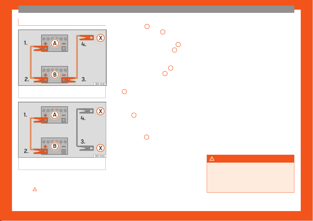
The essentials
How to jump start: description
Fig. 82
Diagram of connections for vehicles
without St
art St
op syst
em
Fig. 83
Diagram of connections for vehicles
with St
art St
op syst
em
Jump lead terminal connections
S
wit
ch off the ignition of both v
ehicles
›››
.
1.
Connect one end of the r
ed
jump l
ead to
the positive
+
terminal of the vehicle
with the fl
at batt
ery
A
›
›
›
Fig. 82.
Connect the other end of the red jump
lead to the positive terminal
+
in the ve-
hicl
e pr
o
viding assistance
B
.
In v
ehicl
es without a St
art-Stop system:
connect one end of the black jump lead
to the negative terminal
–
of the vehicle
pr
o
viding the curr
ent
B
›
›
›
Fig. 82.
In vehicles with a Start-stop system:
connect one end of the black jump lead
X
to a suitable ground terminal, to a sol-
id piece of met
al in the engine bl
ock
, or
to the engine block itself
›››
Fig. 83.
Connect the other end of the black jump
lead
X
to a solid metal component bol-
t
ed t
o the engine bl
ock or to the engine
block itself of the vehicle with the flat
battery. Do not connect it to a point near
the battery
A
.
P
osition the l
eads in such a w
ay that
they cannot come into contact with any
moving parts in the engine compart-
ment.
Starting
Start the engine of the vehicle with the
boosting battery and let it run at idling
speed.
2.
3.
4a.
4b.
5.
6.
7.
Start the engine of the vehicle with the
flat battery and wait for 2 or 3 minutes
until the engine is running.
Removing the jump leads
Before you remove the jump leads,
switch off the dipped beam headlights if
they are switched on.
Turn on the heater blower and heated
rear window in the vehicle with the flat
battery. This helps minimise voltage
peaks which are generated when the
leads are disconnected.
When the engine is running, disconnect
the leads in reverse order to the details
given above.
Make sure the battery clamps have sufficient
metal-to-metal contact with the battery ter-
minals.
If the engine fails to start after about 10 sec-
onds, switch off the starter and try again after
about 1 minute.
WARNING
●
Please note the saf
ety warnings referring
to working in the engine compartment
›››
page 347.
●
The battery providing assistance must
have the same voltage as the flat battery
8.
9.
10.
11.
60
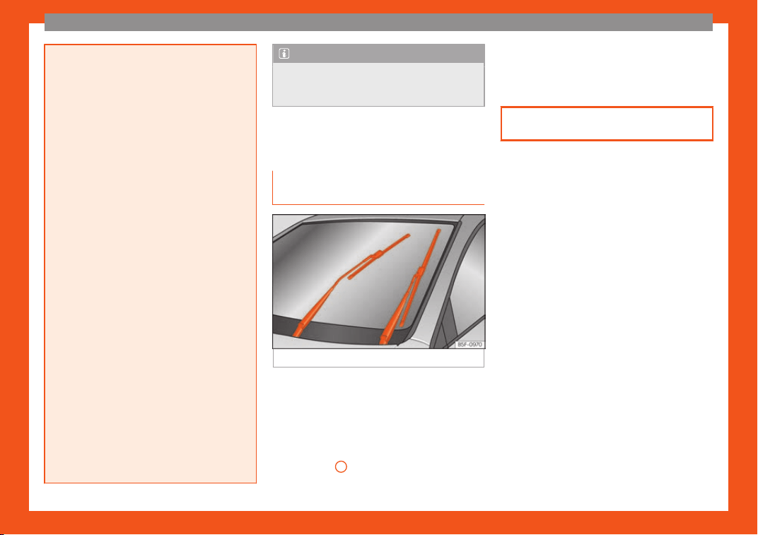
The essentials
(12V) and approximately the same capaci-
ty (see imprint on battery). F
ailure to com-
ply could result in an explosion.
●
Never use jump leads when one of the
batteries is frozen. Danger of explosion!
Even after the battery has thawed, battery
acid could leak and cause chemical burns.
If a battery freezes, it should be replaced.
●
Keep sparks, flames and lighted ciga-
rettes away from batteries, danger of ex-
plosion. Failure to comply could result in an
explosion.
●
Observe the instructions provided by the
manufacturer of the jump leads.
●
Do not connect the negative cable from
the other vehicle directly to the negative
terminal of the flat battery. The gas emit-
ted from the battery could be ignited by
sparks. Danger of explosion.
●
Never attach the negative cable to fuel
system components or the brake lines in
the other vehicle.
●
The non-insulated parts of the battery
clamps must not be allowed to touch. The
jump lead attached to the positive battery
terminal must not touch metal parts of the
vehicle, this can cause a short circuit.
●
Position the leads in such a way that they
cannot come into contact with any moving
parts in the engine compartment.
●
Do not lean on the batteries. This could
result in chemical burns.
Note
The vehicles must not touch each other,
otherwise electricity coul
d flow as soon as
the positive terminals are connected.
Changing the wiper blades
Windscreen wipers service posi-
tion
Fig. 84
Wipers in service position.
The wiper arms can be raised when the wip-
ers ar
e in service position
›
›
›
Fig. 84.
●
Close the bonnet
›››
page 347.
●
Switch the ignition on and off.
●
Press the windscreen wiper lever down-
wards briefly
4
›
›
›
page 34.
Before driving, always lower the wiper arms.
Using the windscreen wiper lever, the wind-
screen wiper arms return to their initial posi-
tion.
›››
page 88
61
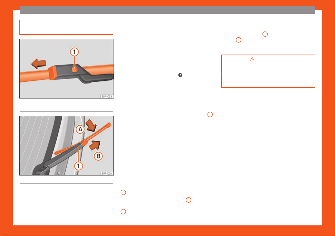
The essentials
Changing the windscreen and rear
windo
w wiper bl
ades
Fig. 85
Changing the windscreen wiper
bl
ades
Fig. 86
Changing the rear wiper blade
Raising and lowering windscreen wiper
arms
●
Place the windscreen wipers in the service
position
›
›
›
page 61.
●
Grip the wiper arms only by the blade's
fastening point.
Cleaning windscreen wiper blades
●
Raise the wiper arms.
●
Use a soft cloth to remove dust and dirt
from the windscreen wiper blades.
●
If the blades are very dirty, a sponge or
damp cloth may be used
›››
in Changing
the windscr
een and r
ear windo
w wiper
blades on page 88.
Changing the windscreen wiper blades
●
Lift and unfold the wiper arms.
●
Press and hold release button
›››
Fig. 85
1
and pull gently on the wiper blade in the di-
r
ection of the arr
o
w.
●
Fit a new wiper blade of the same length
and design on to the wiper arm and hook it
into place.
●
Rest the wiper arms back onto the wind-
screen.
Changing the rear wiper blade
●
Lift and fold the wiper arm.
●
Turn the blade slightly
›››
Fig. 86 (arrow
A
).
●
Hold down the release button
1
while gen-
tly pulling the bl
ade in the dir
ection of arr
ow
B
.
●
Insert a ne
w bl
ade of the
same length and
type in the rear wiper arm in the opposite di-
rection to the arrow
B
and hook into place
butt
on
1
.
●
Replace the wiper arm on the rear window.
›››
in Changing the windscreen
and rear window wiper bl
ades on
page 88
›››
page 88
62
Safe driving
Safety
Saf
e driving
Advice about driving
Saf
et
y first!
WARNING
●
This manual contains import
ant informa-
tion about the operation of the vehicle,
both for the driver and the passengers. The
other sections of the on-board documenta-
tion also contain further information that
you should be aware of for your own safety
and for the safety of your passengers.
●
Ensure that the on-board documentation
is kept in the vehicle at all times. This is es-
pecially important when lending or selling
the vehicle to another person.
Before setting off
For your own safety and the safety of your
passengers, al
w
ays not
e the following points
before every trip:
–
Make sure that the vehicle's lights and turn
signals are working properly.
–
Check tyre pressure.
–
Ensure that all windows provide a clear and
good view of the surroundings.
–
Make sure all luggage is secured
›››
page 168.
–
Make sure that no objects can interfere with
the pedals.
–
Adjust front seat, head restraint and mirrors
properly according to your size.
–
Ensure that the passengers in the rear seats
always have the head restraints in the in-
use position
›››
page 68.
–
Instruct passengers to adjust the head re-
straints according to their height.
–
Protect children with appropriate child
seats and properly applied seat belts
›››
page 80.
–
Assume the correct sitting position. Instruct
your passengers also to assume a proper
sitting position
›››
page 64.
–
Fasten your seat belt securely. Instruct your
passengers also to fasten their seat belts
properly
›››
page 69.
What affects driving safety?
As a driver, you are responsible for yourself
and your passengers. When your concentr
a-
tion or driving saf
et
y is affected by any cir-
cumstance, you endanger yourself as well as
others on the road
›››
, for this reason:
–
Always pay attention to traffic and do not
get distr
act
ed by passengers or t
elephone
calls.
–
Never drive when your driving ability is im-
paired (e.g. by medication, alcohol, drugs).
–
Observe traffic laws and speed limits.
–
Always reduce your speed as appropriate
for road, traffic and weather conditions.
–
When travelling long distances, take breaks
regularly - at least every two hours.
–
If possible, avoid driving when you are tired
or stressed.
WARNING
When driving safety is impaired during a
trip, the risk of injury and accidents increa-
ses.
Safety equipment
Never put your safety or the safety of your
passengers in danger
. In the e
v
ent of an acci-
dent, the safety equipment may reduce the
»
63
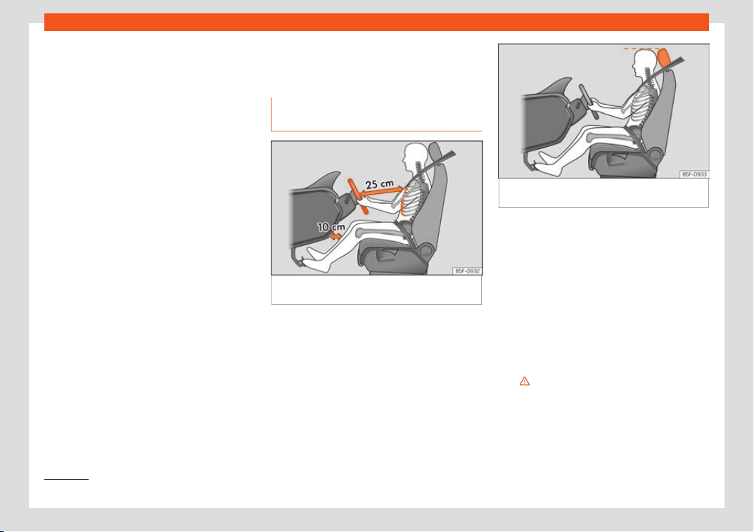
Safety
risk of injury. The following points cover part
of the saf
et
y equipment in your SEAT
1)
:
●
thr
ee-point seat belts,
●
belt tension limiters for the front and rear
side seats,
●
belt tensioners for the front and rear side
seats,
●
front airbags,
●
knee airbags,
●
side airbags in the front seat backrests,
●
head-protection airbags,
●
“ISOFIX” anchor points for child seats in the
rear side seats with the “ISOFIX” system,
●
height-adjustable front head restraints,
●
rear head restraints with in-use position and
non-use position,
●
adjustable steering column.
The safety equipment mentioned above
works together to provide you and your pas-
sengers with the best possible protection in
the event of an accident. However, these
safety systems can only be effective if you
and your passengers are sitting in a correct
position and use this equipment properly.
Safety is everyone's business!
Correct position of the vehi-
cle occupants
Correct sitting position for the driv-
er
Fig. 87
The proper distance between driver
and st
eering wheel
.
Fig. 88 Correct head restraint position for the
driver.
For your own safety and to reduce the risk of
injury in the e
v
ent of an accident, w
e recom-
mend the following adjustments for the driver:
–
Adjust the steering wheel so that there is a
distance of at least 25 cm between the
steering wheel and the centre of your chest
›››
Fig. 87.
–
Move the driver's seat forwards or back-
wards so that you are able to press the ac-
celerator, brake and clutch pedals to the
floor with your knees still slightly angled
›››
.
–
Ensure that you can reach the highest point
of the st
eering wheel.
–
Adjust the head r
estr
aint so that its upper
edge is at the same level as the top of your
1)
Depending on the version/market.
64

Safe driving
head, or as close as possible to the same
l
e
v
el as the top of your head
›››
Fig. 88.
–
Move the seat backrest to an upright posi-
tion so that your back rests completely
against it.
–
Fasten your seat belt securely
›››
page 69.
–
Keep both feet in the footwell so that you
have the vehicle under control at all times.
Adjustment of the driver's seat
›››
page 160.
WARNING
●
An incorrect sitting position of the driver
can l
ead to severe injuries.
●
Adjust the driver's seat so that there is at
least 25 cm distance between the centre of
the chest and the centre of the steering
wheel
›››
Fig. 87. If you are sitting closer
than 25 cm, the airbag system cannot pro-
tect you properly.
●
If your physical constitution prevents you
from maintaining the minimum distance of
25 cm, contact a specialised workshop.
The workshop will help you decide if spe-
cial specific modifications are necessary.
●
When driving, always hold the steering
wheel with both hands on the outside of the
ring at the 9 o'clock and 3 o'clock posi-
tions. This reduces the risk of injury when
the driver airbag is triggered.
●
Never hol
d the steering wheel at the 12
o'clock position, or in any other manner
(e.g. in the centre of the steering wheel). In
such cases, if the airbag is triggered, you
may sustain injuries to the arms, hands and
head.
●
To reduce the risk of injury to the driver
during sudden braking manoeuvres or an
accident, never drive with the backrest til-
ted far back! The airbag system and seat
belts can only provide optimal protection
when the backrest is in an upright position
and the driver is wearing his or her seat belt
correctly.
●
Adjust the head restraint properly to ach-
ieve optimal protection.
Adjusting the steering wheel posi-
tion
Read the additional information carefully
›
›
›
page 21.
WARNING
●
Never adjust the position of the st
eering
wheel when the vehicle is moving, as this
could cause an accident.
●
Move the lever up firmly so the steering
wheel position does not accidentally
change during driving. risk of accident!
●
Make sure you ar
e capable of reaching
and firmly holding the upper part of the
steering wheel: risk of accident!
●
If you adjust the steering wheel so that it
points towards your face, the driver airbag
will not protect you properly in the event of
an accident. Make sure that the steering
wheel points towards your chest.
Correct position for the front pas-
senger
For your own safety and to reduce the risk of
injury in the e
v
ent of an accident, w
e recom-
mend the following adjustments for the front
passenger:
–
Move the front passenger seat back as far
as possible
›››
.
–
Move the seat backrest to an upright posi-
tion so that your back r
ests compl
et
ely
against it.
–
Adjust the head restraint so that its upper
edge is at the same level as the top of your
head, or as close as possible to the same
level as the top of your head
›››
page 67.
–
Always keep both feet in the footwell in
front of the front passenger seat.
–
Fasten your seat belt securely
›››
page 69.
»
65
Safety
It is possible to deactivate the front passen-
ger airbag in e
x
ceptional cir
cumstances
›››
page 78.
Adjusting the front passenger seat
›››
page 160.
WARNING
●
An incorrect sitting position of the front
passenger can l
ead to severe injuries.
●
Adjust the front passenger seat so that
there is at least 25 cm between your chest
and the dash panel. If you are sitting closer
than 25 cm, the airbag system cannot pro-
tect you properly.
●
If your physical constitution prevents you
from maintaining the minimum distance of
25 cm, contact a specialised workshop.
The workshop will help you decide if spe-
cial specific modifications are necessary.
●
Always keep your feet in the footwell
when the vehicle is moving; never rest them
on the dash panel, out the window or on the
seat. An incorrect sitting position exposes
you to an increased risk of injury in case of
a sudden braking or an accident. If the air-
bag is triggered, you could sustain severe
injuries due to an incorrect sitting position.
●
To reduce the risk of injury to the front
passenger in events such as sudden brak-
ing manoeuvres or an accident, never trav-
el with the backrest tilted far back! The air-
bag system and seat belts can only pro-
vide optimal protection when the backrest
is in an upright position and the front pas-
senger is wearing his or her seat belt prop-
erly. The fur
ther the seat backrests are til-
ted to the rear, the greater the risk of injury
due to incorrect positioning of the belt web
or to the incorrect sitting position!
●
Adjust the head restraint correctly in or-
der to achieve maximum protection.
Correct sitting position for rear
seat passengers
To reduce the risk of injury in the event of a
sudden br
aking manoeuvr
e or an accident,
passengers on the r
ear seat bench must con-
sider the following:
–
Sit up straight.
–
Adjust the head restraint to the correct po-
sition
›››
page 68.
–
Always keep both feet in the footwell in
front of the rear seat.
–
Fasten your seat belt securely
›››
page 69.
–
Use an appropriate child restraint system
when you take children in the vehicle
›››
page 80.
WARNING
●
If the passengers in the rear seats are not
sitting pr
operly, they could sustain severe
injuries.
●
Adjust the head restraint correctly in or-
der to achieve maximum protection.
●
Seat belts can only provide optimal pro-
tection when seat backrests are in an up-
right position and the vehicle occupants
are wearing their seat belts correctly. If
passengers In the rear seats are not sitting
in an upright position, the risk of injury due
to incorrect positioning of the seat belt in-
creases.
Examples of incorrect sitting posi-
tions
Seat belts can provide optimal protection on-
ly when the belt w
ebs ar
e pr
operly posi-
tioned. Incorrect sitting positions substantially
reduce the protective function of seat belts
and increase the risk of injury due to incorrect
seat belt position. As the driver, you are re-
sponsible for all passengers, especially chil-
dren.
–
Never allow anyone to assume an incorrect
sitting position in the vehicle while travelling
›››
.
The f
oll
o
wing list contains examples of sitting
positions that could be dangerous for all
66
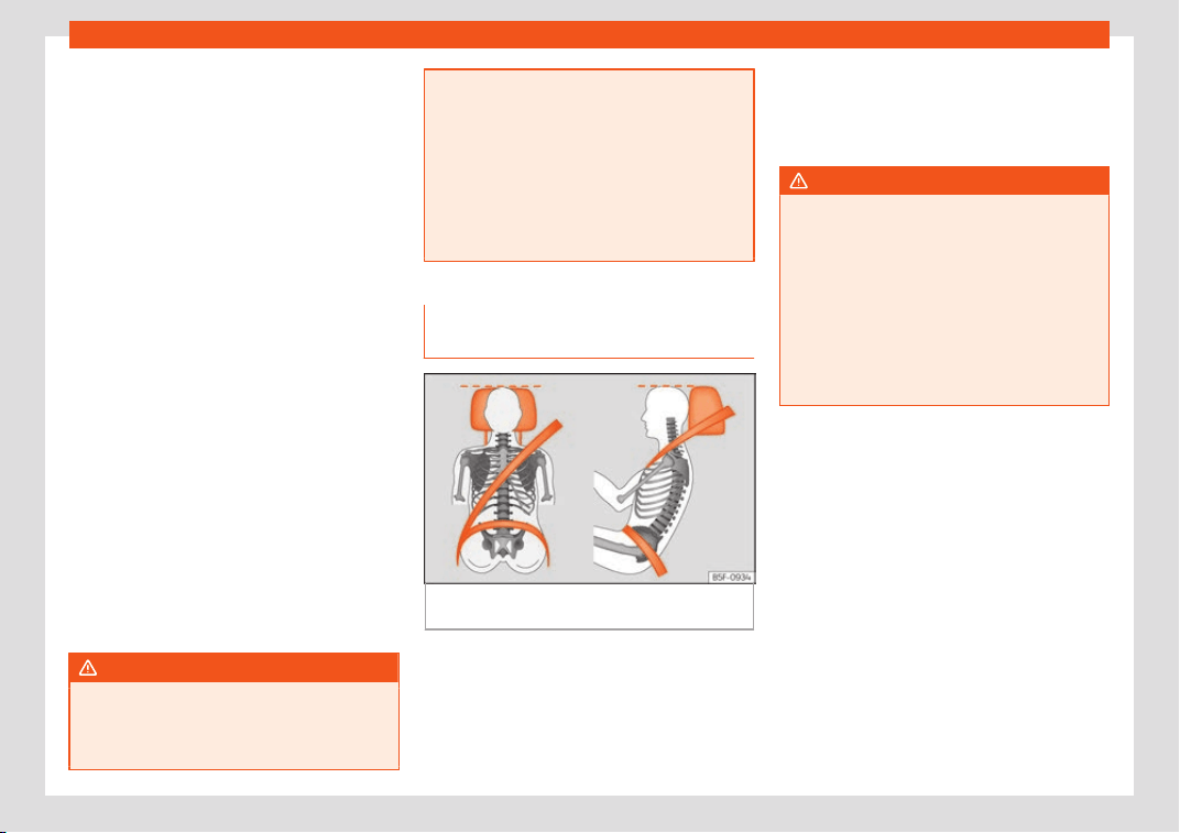
Safe driving
vehicle occupants. The list is not complete,
but w
e w
oul
d like to make you aware of this
issue.
Therefore, whenever the vehicle is in mo-
tion:
●
Never stand in the vehicle.
●
Never stand on the seats.
●
Never kneel on the seats.
●
Never tilt your seat backrest far to the rear.
●
Never lean against the dash panel.
●
Never lie on the rear bench.
●
Never sit on the front edge of a seat.
●
Never sit sideways.
●
Never lean out of a window.
●
Never put your feet out of a window.
●
Never put your feet on the dash panel.
●
Never put your feet on the surface of a seat.
●
Do not allow anyone to travel in the foot-
well.
●
Never travel without wearing the seat belt.
●
Do not allow anyone to travel in the lug-
gage compartment.
WARNING
●
Any incorrect sitting position increases
the risk of se
vere injuries. Sitting in an in-
correct position exposes the vehicle occu-
pants to severe injuries if airbags are trig-
gered, by striking a vehicle occupant who
has assumed an incorrect sitting position.
●
Befor
e the vehicle moves, assume the
proper sitting position and maintain it
throughout the trip. Before every trip, in-
struct your passengers to sit properly and
to stay in this position during the trip
›››
page 64, Correct position of the vehicle
occupants.
Correct adjustment of front head
restraints
Fig. 89
Correctly adjusted head restraint as
vie
w
ed fr
om the front and the side.
Read the additional information carefully
›
›
›
page 20.
Properly adjusted head restraints are an im-
portant part of passenger protection and can
reduce the risk of injuries in most accident sit-
uations.
●
Adjust the head restraint so that its upper
edge is, as far as possible, at the same level
as the top of your head, or at the very least,
at eye level
›››
Fig. 89.
WARNING
●
Trav
elling with the head restraints re-
moved or improperly adjusted increases
the risk of severe injuries. An improper ad-
justment of the head restraints may cause
death in an accident and increase the risk
of suffering injuries during abrupt braking
actions or unexpected manoeuvres.
●
The head restraints must always be ad-
justed according to the height of the pas-
senger.
67
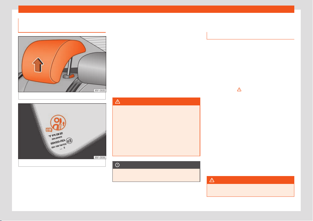
Safety
Correct adjustment of rear head
r
estr
aints
Fig. 90
Head restraints in the correct position.
Fig. 91 Head restraint position warning label.
Properly adjusted head restraints are an im-
port
ant part of the passenger pr
ot
ection and
can reduce the risk of injuries in most acci-
dent situations
Rear head restraints
–
The rear head restraints have 2 positions:
use and non-use.
–
One position for use (head restraint raised)
›››
Fig. 90. In this position, the head re-
straints are used normally, protecting pas-
sengers along with the rear seat belts.
–
And one position for non-use (head re-
straint lowered).
–
To fit the head restraints in position for use,
pull on the edges with both hands in the di-
rection of the arrow.
WARNING
●
Under no circumstances shoul
d the rear
passengers travel while the head restraints
are in the non-use position. See the warn-
ing label located on the rear side fixed win-
dow
›››
Fig. 91.
●
Do not swap the centre rear head re-
straint with either of the outer seat rear
head restraints. Risk of injury in case of an
accident!
CAUTION
Note the instructions on the adjustment of
the head restraints
›
››
page 160.
Pedal area
P
edal
s
–
Ensure that you can always press the ac-
celerat
or, brake and clutch pedals unim-
paired to the floor.
–
Ensure that the pedals can return unim-
paired to their initial positions.
–
Ensure that the floor mats are securely fas-
tened during the trip and do not obstruct
the pedals
›››
.
Only use fl
oor mats which l
eav
e the pedals
clear and which are secured to prevent them
from slipping. You can obtain suitable floor
mats from a specialised dealership. Fasten-
ers* for floor mats are fitted in the footwells.
If a brake circuit fails, the brake pedal must be
pressed down thoroughly in order to stop the
vehicle.
Wear suitable footwear
Always wear shoes which support your feet
properly and give you a good feeling for the
pedals.
WARNING
●
Restricting pedal operation can l
ead to
critical situations while driving.
68
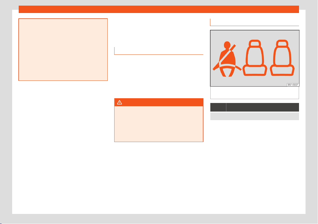
Seat belts
●
Never l
ay or fit floor mats or other floor
coverings over the original floor mats. This
would reduce the pedal area and could ob-
struct the pedals. Risk of accident.
●
Never place objects in the driver footwell.
An object could move into the pedal area
and impair pedal operation. In the event of
a sudden driving or braking manoeuvre,
you will not be able to operate the brake,
clutch or accelerator pedal. Risk of acci-
dent!
Seat belts
Why w
ear a seat belt
Number of seats
Your vehicle has five seats, tw
o in the front
and three in the rear. Each seat is equipped
with a three-point seat belt.
In some versions, your vehicle is approved
only for four seats. Two front seats and two
rear seats.
WARNING
●
Never tr
ansport more than the permitted
amount of people in your vehicle.
●
Every vehicle occupant must properly
fasten and wear the seat belt belonging to
his or her seat. Children must be protected
with an appropriate child restraint system.
Seat belt control lamp*
Fig. 92
Dashboard: right rear seat occupied
and corr
esponding seat belt f
ast
ened display.
It lights up red
Driver or passenger has not fastened seat belt.
The control lamp illuminates to remind the
driv
er t
o f
asten his seat belt.
Before starting the vehicle:
●
Fasten your seat belt securely.
●
Instruct your passengers to fasten their
seat belts properly before driving off.
●
Protect children by using a child seat ac-
cording to the child's height and weight.
When starting to drive, if the vehicle's speed
surpasses approx. 25 km/h (15 mph) and the
seat belts are not fastened or are unfastened
during the drive, a warning sound will be
»
69
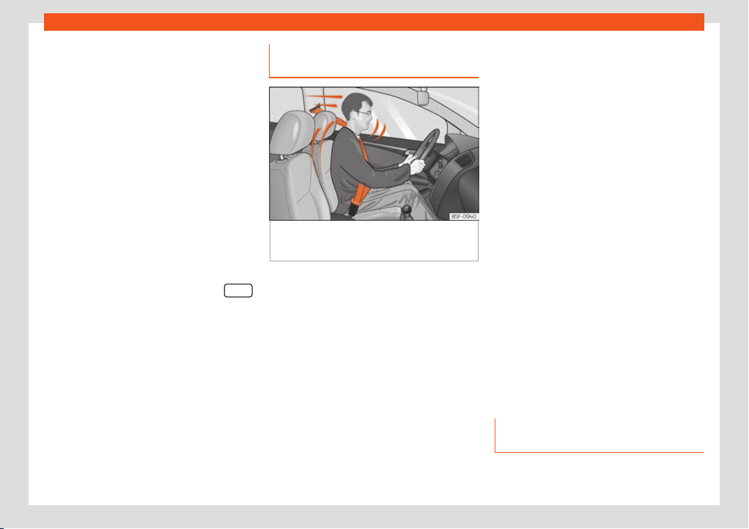
Safety
heard for a few seconds. The warning light
will al
so fl
ash
.
The lamp goes out when the driver and
passenger seat belts are fastened with the
ignition switched on.
Rear seat belts fastened display*
Depending on the model version, when the
ignition is switched on, the seat belt status
display
›››
Fig. 92 on the instrument panel in-
forms the driver whether the passengers in
the rear seats have fastened their seat belts.
The symbol indicates that the passenger in
this seat has fastened “his or her” seat belt.
When a seat belt in the rear seats is fastened
or unfastened, the seat belt status is dis-
played for approximately 30 seconds. The in-
dication can be hidden by pressing the
button on the dash panel.
The seat belt st
at
us fl
ashes for a maximum of
30 seconds when a seat belt in the rear seats
is unfastened while the vehicle is in motion. An
audible warning will also be heard if the vehi-
cle is travelling at over 25 km/h (15 mph).
The protective function of seat
belts
Fig. 93
Drivers with properly worn seat belts
will not be thr
o
wn f
orward in the event of sud-
den braking.
Properly worn seat belts hold the occupants
in the pr
oper position. They al
so help pr
event
uncontrolled movements that may result in
serious injury and reduce the risk of being
thrown out of the vehicle in case of an acci-
dent.
Vehicle occupants wearing their seat belts
correctly benefit greatly from the ability of
the belts to absorb kinetic energy. In addition,
the front part of your vehicle and other pas-
sive safety features (such as the airbag sys-
tem) are designed to absorb the kinetic ener-
gy released in a collision. Taken together, all
these features reduce the releasing kinetic
energy and consequently, the risk of injury.
This is why it is so important to fasten seat
belts before every trip, even when "just driving
around the corner".
Ensure that your passengers wear their seat
belts as well. Accident statistics have shown
that wearing seat belts is an effective means
of substantially reducing the risk of injury and
improving the chances of survival when in-
volved in a serious accident. Furthermore,
properly worn seat belts improve the protec-
tion provided by airbags in the event of an
accident. For this reason, wearing a seat belt
is required by law in most countries.
Although your vehicle is equipped with air-
bags, the seat belts must be fastened and
worn. The front airbags, for example, are only
triggered in some cases of head-on collision.
The front airbags will not be triggered during
minor frontal or side collisions, rear-end colli-
sions, overturns or accidents in which the air-
bag trigger threshold value in the control unit
is not exceeded.
Therefore, you should always wear your seat
belt and ensure that all vehicle occupants
have fastened their seat belts properly before
you drive off!
Important safety instructions for
the use of seat belts
–
Always wear the seat belt as described in
this section.
70
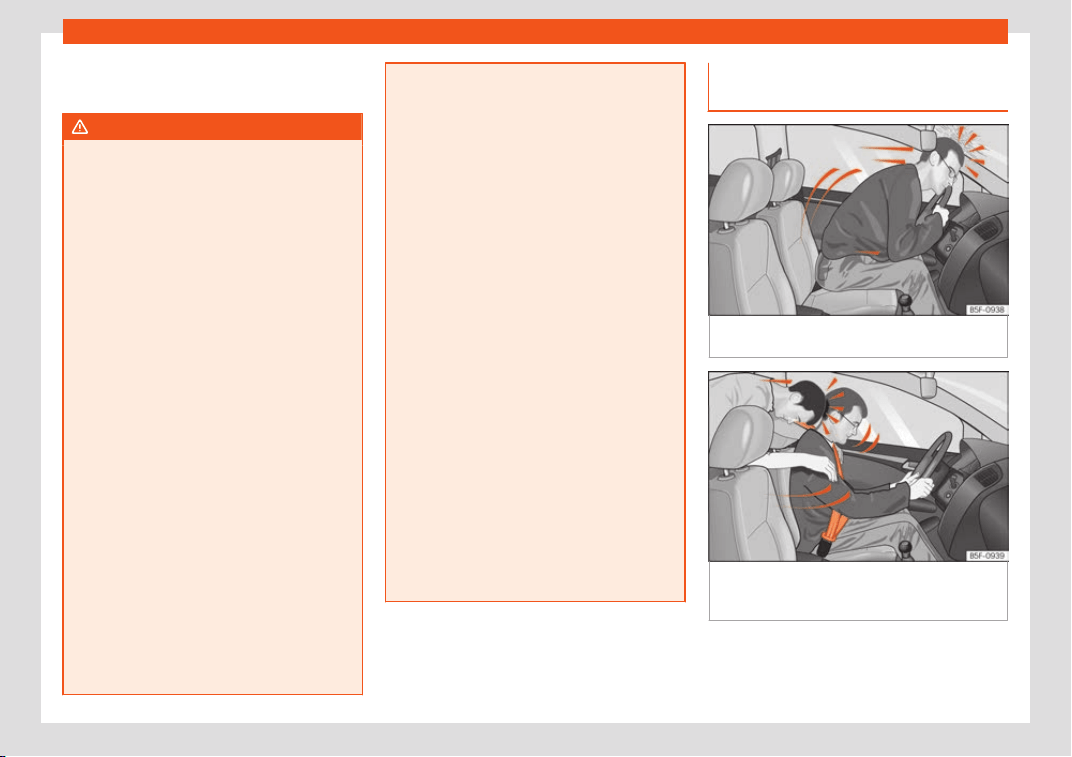
Seat belts
–
Ensur
e that the seat belts can be f
ast
ened
at all times and are not damaged.
WARNING
●
If seat belts are worn incorr
ectly or not at
all, the risk of severe injuries increases. The
optimal protection from seat belts can be
achieved only if you use them properly.
●
Fasten your seat belt before every trip -
even when driving in town. Other vehicle
occupants must also wear the seat belts at
all times, otherwise they run the risk of be-
ing injured.
●
The seat belt cannot offer its full protec-
tion if the seat belt is not positioned cor-
rectly.
●
Never allow two passengers (even chil-
dren) to share the same seat belt.
●
Always keep both feet in the footwell in
front of your seat as long as the vehicle is in
motion.
●
Never unbuckle a seat belt while the ve-
hicle is in motion. Risk of fatal injury.
●
The seat belt must never be twisted while
it is being worn.
●
The seat belt should never lie on hard or
fragile objects (such as glasses or pens,
etc.) because this can cause injuries.
●
Do not allow the seat belt to be damaged
or jammed, or to rub on any sharp edges.
●
Never wear the seat belt under the arm or
in any other incorrect position.
●
Bulky and unfast
ened clothing (such as
an overcoat over a sweater) impairs the
proper fit and function of the seat belts, re-
ducing their capacity to protect.
●
The slot in the seat belt buckle must not
be blocked with paper or other objects, as
this can prevent the latch plate from en-
gaging securely.
●
Never use seat belt clips, fastening rings
or similar items to alter the position of the
belt webbing.
●
Frayed or torn seat belts or damage to
the connections, belt retractors or parts of
the buckle could cause severe injuries in
the event of an accident. Therefore, you
must check the condition of all seat belts
at regular intervals.
●
Seat belts which have been worn in an
accident and have been stretched must be
replaced by a specialised workshop. Re-
newal may be necessary even if there is no
apparent damage. The belt anchorage
should also be checked.
●
Do not attempt to repair a damaged seat
belt yourself. The seat belts must not be re-
moved or modified in any way.
●
The belts must be kept clean, otherwise
the retractors may not work properly.
Head-on collisions and the laws of
physics
Fig. 94
A driver not wearing a seat belt is
thr
o
wn f
orward violently.
Fig. 95
The unbelted passenger in the rear
seat is thr
o
wn f
orward violently, hitting the driv-
er who is wearing a seat belt.
The effects of the laws of physics in the case
of a head-on collision ar
e easy t
o e
xplain: the
»
71
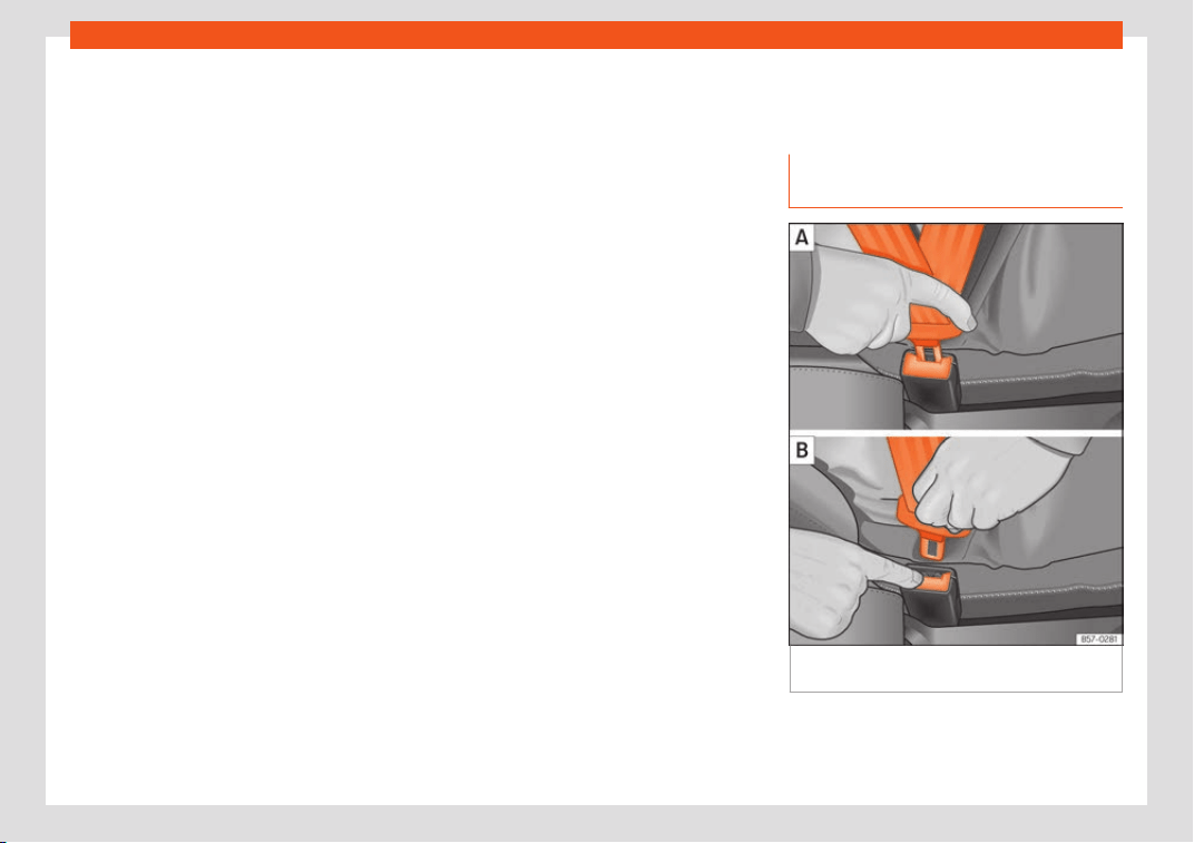
Safety
moment a vehicle starts moving, a type of en-
er
gy call
ed “kinetic ener
gy” starts acting on
both the vehicle and its passengers.
The amount of “kinetic energy” depends on
the speed of the vehicle and on the weight of
the vehicle and of its passengers. The higher
they are, the more energy there is to be “ab-
sorbed” in the event of an accident.
The most significant factor, however, is the
speed of the vehicle. If the speed doubles
from 25 km/h (15 mph) to 50 km/h (30 mph),
for example, the corresponding kinetic ener-
gy is multiplied by four.
Given that the passengers of the vehicle in
our example do not have their seat belts fas-
tened, in the event of a collision the entire
amount of the passengers' kinetic energy will
be only absorbed by the mentioned impact.
Even at speeds of 30 km/h (19 mph) to
50 km/h (30 mph), the forces acting on bod-
ies in a collision can easily exceed one tonne
(1000 kg). At greater speed these forces are
even higher.
Vehicle occupants not wearing seat belts are
not “attached” to the vehicle. In a head-on
collision, they will move forward at the same
speed their vehicle was travelling just before
the impact. This example applies not only to
head-on collisions, but to all accidents and
collisions.
Even at low speeds the forces acting on the
body in a collision are so great that it is not
possible to brace oneself with one's hands. In
a frontal collision, unbelted passengers are
thrown forward and will make violent contact
with the steering wheel, dash panel, wind-
screen or whatever else is in the way
›››
Fig. 94.
It is also important for rear passengers to
wear seat belts properly, as they could other-
wise be thrown forward violently through the
vehicle interior in an accident. Passengers in
the rear seats who do not use seat belts en-
danger not only themselves but also the front
occupants
›››
Fig. 95.
How to properly adjust your
seat belt
Fastening and unfastening your
seat belt
Fig. 96 Positioning and removing the seat belt
buckl
e
.
72
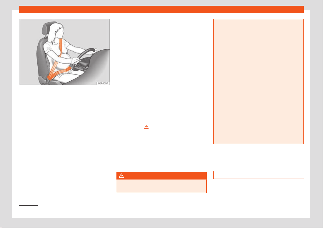
Seat belts
Fig. 97
Position of seat belt during pregnancy.
Read the additional information carefully
›
›
›
page 20.
Fasten your seat belt
The seat belt cannot offer its full protection if
the seat belt is not positioned correctly.
●
Adjust the seat and head restraint correct-
ly.
●
To fasten the belt, take hold of the latch
plate and pull it slowly across your chest and
lap.
●
Insert the latch plate into the buckle for the
appropriate seat and push it down until it is
securely locked with an audible click
›››
Fig. 96 A.
●
Pull the belt to ensure that the latch plate is
securely engaged in the buckle.
The seat belts are equipped with an auto-
matic retractor on the shoulder strap. Full
freedom of movement is permitted when the
shoulder belt is pulled slowly. However, dur-
ing sudden braking, during travel in steep
areas or bends and during acceleration, the
automatic retractor on the shoulder belt is
locked.
The automatic belt retractors on the front
seats and side rear seats
1)
are fitted with seat
belt tensioners
›››
page 73.
Releasing the seat belt
●
Press the red button on the belt buckle
›››
Fig. 96 B. The latch plate is released and
springs out
›››
.
●
Guide the belt back by hand so that it rolls
up easily and the trim is not damaged.
P
ositioning seat belts
Seat belts off
er their maximum pr
otection on-
ly when they are properly positioned.
WARNING
●
The seat belts offer best prot
ection only
when the backrests are in an upright posi-
tion and the seat belts have been fastened
properly.
●
Nev
er put the latch plate in the buckle of
another seat. If you do this, the seat belt
will not protect you properly and the risk of
injury is increased.
●
Never unbuckle a seat belt while the ve-
hicle is in motion. If you do, you increase
the risk of sustaining severe or fatal injuries.
●
An incorrectly worn seat belt can cause
severe injuries in the event of an accident.
●
For pregnant women, the lap part of the
seat belt must lie as low as possible over
the pelvis, never across the stomach, and
always lie flat so that no pressure is exer-
ted on the abdomen
›››
Fig. 97.
●
Always engage the retractor lock when
you are securing a child seat in group 0, 0+
or 1
›››
page 80.
●
Read and observe the warnings
›››
page 70.
Seat belt tensioners
Ho
w the seat belt t
ensioner w
orks
Read the additional information carefully
›
›
›
page 21.
»
1)
Depending on version/market.
73
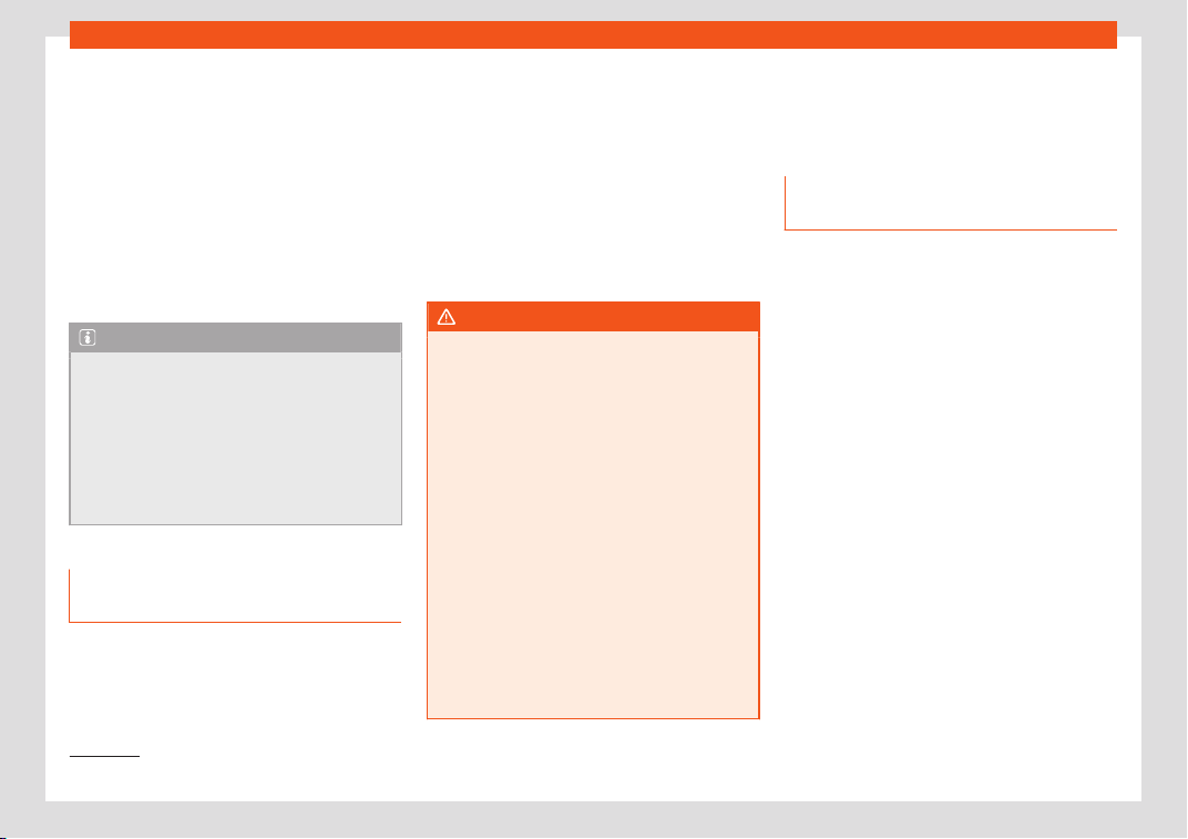
Safety
The seat belts for the front seats and the side
r
ear seats
1)
ar
e equipped with belt t
ension-
ers. The belt tensioners are activated by sen-
sors, although only in severe head-on, lateral
and rear-end collisions. This retracts and
tightens the seat belts, reducing the forward
motion of the occupants.
The belt tensioners will not be triggered in the
event of minor collisions, if the vehicle over-
turns, or in accidents where no major forces
act on the vehicle.
Note
●
If the seat belt tensioners are trigger
ed, a
fine dust is produced. This is normal and it
is not an indication of fire in the vehicle.
●
The relevant safety requirements must be
observed when the vehicle or components
of the system are scrapped. Specialised
workshops are familiar with these regula-
tions, which are also available to you.
Maintenance and disposal of belt
t
ensioners
The belt tensioners are components of the
seat belts that ar
e inst
all
ed in the seats of
your vehicle. If you work on the belt tension-
ers or remove and install parts of the system
when performing other repair work, the seat
belt may be damaged. The consequence
may be that, in the event of an accident, the
belt tensioners function incorrectly or may
not function at all.
So that the effectiveness of the seat belt ten-
sioner is not reduced and that removed parts
do not cause any injuries or environmental
pollution, regulations, which are known to the
specialised workshops, must be observed.
WARNING
●
Improper use or repairs not carried out by
qualified mechanics incr
ease the risk of se-
vere or fatal injuries. The belt tensioners
may fail to trigger or may trigger in the
wrong circumstances.
●
Never attempt to repair, adjust, remove or
install parts of the belt tensioners or seat
belts.
●
The seat belt tensioner, seat belt and au-
tomatic retractor cannot be repaired.
●
Any work on the belt tensioners and seat
belts, including the removal and refitting of
system parts in conjunction with other re-
pair work, must be performed by a special-
ised workshop only.
●
The belt tensioners will only provide pro-
tection for one accident and must be
changed if they have been activated.
Airbag system
Brief intr
oduction
Why is it so impor
t
ant to wear a
seat belt and to sit correctly?
For the inflating airbags to achieve the best
protection, the seat belt must al
ways be worn
properly and the correct sitting position must
be assumed.
The airbag system is not a substitute for seat
belts, but it is an integral part of the vehicle's
overall passive safety system. Please bear in
mind that the airbag system can only work
effectively when the vehicle occupants are
wearing their seat belts correctly and have
adjusted the head restraints properly. There-
fore, it is most important to properly wear the
seat belts at all times, not only because this is
required by law in most countries, but also for
your safety
›››
page 69, Why wear a seat
belt.
The airbag inflates in a matter of seconds, so
if you are not properly seated when the air-
bag is triggered, you may sustain fatal inju-
ries. Therefore, it is essential that all vehicle
occupants assume a correct sitting position
while travelling.
1)
Depending on version/market.
74

Airbag system
Sharp braking before an accident may cause
a passenger not w
earing a seat belt t
o be
thr
own forward into the area of the deploying
airbag. In this case, the inflating airbag may
inflict critical or fatal injuries on the occupant.
This also applies to children.
Always maintain the greatest possible dis-
tance between yourself and the front airbag.
This way, the front airbags can completely
deploy when triggered, providing their maxi-
mum protection.
The most important factors for triggering the
airbag are the type of accident, the angle of
impact and the vehicle speed.
Whether or not the airbags are triggered de-
pends primarily on the vehicle deceleration
rate resulting from the collision and detected
by the control unit. If the vehicle deceleration
occurring during the collision and measured
by the control unit remains below the speci-
fied reference values, the front, side and/or
curtain airbags will not be triggered. Take into
account that the visible damage in a vehicle
involved in an accident, no matter how seri-
ous, is not a determining factor for the air-
bags to have been triggered.
WARNING
●
Wearing the seat belt incorrectly or as-
suming an incorr
ect sitting position can
lead to critical or fatal injuries.
●
All vehicle occupants, including chil
dren,
who are not properly belted can sustain
critical or fatal injuries if the airbag is trig-
gered. Children up to 12 years old should
always travel on the rear seat. Never trans-
port children in the vehicle if they are not
restrained or the restraint system is not ap-
propriate for their age, size or weight.
●
If you are not wearing a seat belt, or if
you lean forward or to the side while travel-
ling or assume an incorrect sitting position,
there is a substantially increased risk of in-
jury. This increased risk of injury will be fur-
ther increased if you are struck by an inflat-
ing airbag.
●
To reduce the risk of injury from an inflat-
ing airbag, always wear the seat belt prop-
erly
›››
page 69.
●
Always adjust the front seats properly.
Description of airbag system
Read the additional information carefully
›
›
›
page 21.
The airbag system is not a substitute for the
seat belts. The airbag system offers addition-
al protection for the driver and passenger in
combination with the seat belts.
The airbag system comprises the follow-
ing modules (as per vehicle equipment):
●
Electronic control unit
●
Front airbags for driver and passenger
●
Knee airbag for the driver
●
Side airbags
●
Head airbag
●
Airbag control lamp on the instrument
panel
›››
page 79
●
Key-operated switch for front passenger
airbag
●
Control lamp for disabled/enabled status
of the front passenger airbag.
The airbag system operation is monitored
electronically. The airbag control lamp will il-
luminate for a few seconds every time the ig-
nition is switched on (self-diagnosis).
There is a fault in the system if the control
lamp :
●
does not light up when the ignition is
switched on
›››
page 79,
●
turns off after 4 seconds after the ignition is
switched on,
●
turns off and then lights up again after the
ignition is switched on,
●
illuminates or flashes while the vehicle is
moving.
The airbag system is not triggered if:
●
the ignition is switched off
●
there is a minor frontal collision
»
75
Safety
●
ther
e is a minor side collision
●
ther
e is a r
ear-end collision
●
the vehicle turns over.
WARNING
●
The seat belts and airbags can only pro-
vide maximum prot
ection if the occupants
are seated correctly
›››
page 64, Correct
position of the vehicle occupants.
●
If a fault has occurred in the airbag sys-
tem, have the system checked immediately
by a specialised workshop. Otherwise
there is a danger that during a collision, the
system may fail to trigger, or not trigger
correctly.
Airbag activation
The airbags deploy extremely rapidly, within
thousandths of a second, t
o pr
o
vide addition-
al protection in the event of an accident. A
fine dust may develop when the airbag de-
ploys. This is normal and it is not an indication
of fire in the vehicle.
The airbag system is only ready to function
when the ignition is on.
In special accidents instances, several air-
bags may activate at the same time.
In the event of minor head-on and side colli-
sions, rear-end collisions, overturning or roll-
over of the vehicle, airbags do not activate.
Activation factors
The conditions that lead to the airbag system
activating in each situation cannot be gener-
alised. Some factors play an important role,
such as the properties of the object the vehi-
cle hits (hard/soft), angle of impact, vehicle
speed, etc.
Deceleration trajectory is key for airbag acti-
vation.
The control unit analyses the collision trajec-
tory and activates the respective restraint
system.
If the deceleration rate is below the prede-
fined reference value in the control unit the
airbags will not be triggered, even though the
accident may cause extensive damage to the
car.
The following airbags are triggered in seri-
ous head-on collisions:
●
Driver airbag.
●
Front passenger front airbag
●
Knee airbag for the driver.
The following airbags are triggered in seri-
ous side-on collisions:
●
Front side airbag on the side of the acci-
dent.
●
Curtain (head) airbag on the side of the ac-
cident.
In an accident with airbag activation:
●
the interior lights switch on (if the interior
light switch is in the courtesy light position);
●
the hazard warning lights switch on;
●
all doors are unlocked;
●
the fuel supply to the engine is cut.
Airbag safety instructions
Front airbags
Read the additional information carefully
›
›
›
page 22.
WARNING
●
The deployment space between the fr
ont
passengers and the airbags must not in
any case be occupied by other passenger,
pets and objects.
●
The airbags provide protection for just
one accident; replace them once they have
deployed.
●
It is also important not to attach any ob-
jects such as cup holders or telephone
mountings to the surfaces covering the air-
bag units.
●
Do not attempt to modify components of
the airbag system in any way.
76
Airbag system
Knee airbag*
Read the additional information carefully
›››
page 23.
WARNING
●
The knee airbag is deployed in front of
the driv
er's knees. Always keep the deploy-
ment areas of the knee airbags free.
●
Never not fix objects to the cover or in the
deployment area of the knee airbag.
●
Adjust the driver's seat so that there is a
distance of at least 10 cm (4 inches) be-
tween your knees and the location of the
this airbag. If your physical constitution
prevents you from meeting these require-
ments, make sure you contact a special-
ised workshop.
Side airbags*
Read the additional information carefully
›
›
›
page 24.
WARNING
●
If you do not wear a seat belt, if you lean
f
orward, or are not seated correctly while
the vehicle is in motion, you are at a greater
risk of injury if the side airbag system is
triggered in an accident.
●
In order for the side airbags to provide
their maximum protection, the prescribed
sitting position must always be maintained
with seat belts fastened whil
e travelling.
●
In a side-on collision the side airbags will
not work if the sensors do not correctly
measure the pressure increase on the inte-
rior of the doors, due to air escaping
through the areas with holes or openings in
the door panel.
●
Never drive if the interior door panels
have been removed or if the panels have
not been correctly fitted.
●
Never drive the vehicle if the loudspeak-
ers in the door panels have been removed,
unless the holes left by the loudspeakers
have been closed properly.
●
Always check that the openings are
closed or covered if loudspeakers or other
equipment are fitted inside the door pan-
els.
●
Occupants of the outer seats must never
carry any objects or pets in the deploy-
ment space between them and the airbags,
or allow children or other passengers to
travel in this position. It is also important
not to attach any accessories (such as cup
holders) to the doors. This would impair the
protection offered by the side airbags.
●
The built-in coat hooks should be used
only for lightweight clothing. Do not leave
any heavy or sharp-edged objects in the
pockets.
●
Great forces, such as hard blows or kicks,
must not be exerted upon the backrest bol-
ster because the system may be damaged.
In this case, the side airbags woul
d not be
triggered.
●
Under no circumstances should protec-
tive covers be fitted over seats with side
airbags unless the covers have been ap-
proved for use in your vehicle. Because the
airbag deploys from the side of the back-
rest, the use of conventional seat covers
would obstruct the side airbag, seriously
reducing the airbag's effectiveness.
●
Any damage to the original seat uphols-
tery or around the seams of the side airbag
units must be repaired immediately by a
specialised workshop.
●
The airbags provide protection for just
one accident; replace them once they have
deployed.
●
Any work on the side airbag system or re-
moval and installation of the airbag com-
ponents for other repairs (such as removal
of the front seat) should only be performed
by a specialised workshop. Otherwise,
faults may occur during the airbag system
operation.
●
Do not attempt to modify components of
the airbag system in any way.
Curtain airbags*
Read the additional information carefully
›
›
›
page 24.
»
77
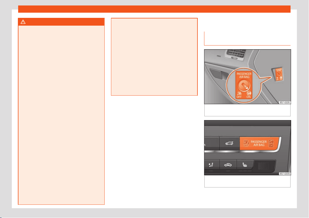
Safety
WARNING
●
In order for the head-pr
otection airbags
to provide their maximum protection, the
prescribed sitting position must always be
maintained with seat belts fastened while
travelling.
●
For safety reasons, the curtain airbag
must be disabled in those vehicles fitted
with a screen dividing the interior of the ve-
hicle. See your technical service to make
this adjustment.
●
There must be no other persons, animals
or objects between the occupants of the
outer seats and the deployment space of
the head-protection airbags so that the
head-protection airbag can deploy com-
pletely without restriction and provide the
greatest possible protection. Therefore,
sun blinds which have not been expressly
approved for use in your vehicle may not be
attached to the side windows
●
The built-in coat hooks should be used
only for lightweight clothing. Do not leave
any heavy or sharp-edged objects in the
pockets. Please, do not hang the clothes on
coat hangers.
●
The airbags provide protection for just
one accident; replace them once they have
deployed.
●
Any work on the head-protection airbag
system or removal and installation of the
airbag components for other repairs (such
as removal of the roof lining) should only
be performed by a specialised workshop.
Otherwise, faults may occur during the air-
bag system operation.
●
Do not att
empt to modify components of
the airbag system in any way.
●
The side and head airbags are managed
through sensors located in the interior of
the front doors. To ensure the correct oper-
ation of the side and curtain airbags nei-
ther the doors nor the door panels should
be modified in any way (e.g. fitting loud-
speakers). If the front door is damaged, the
airbag system may not work correctly. All
work carried out on the front door must be
done in a specialised workshop.
Deactivating airbags
Activ
ation and deactiv
ation of fr
ont
passenger airbag*
Fig. 98 Switch for activating and deactivating
the fr
ont passenger airbag.
Fig. 99
Dashboard: control lamp for deactiva-
t
ed fr
ont passenger airbag in centr
e console.
78
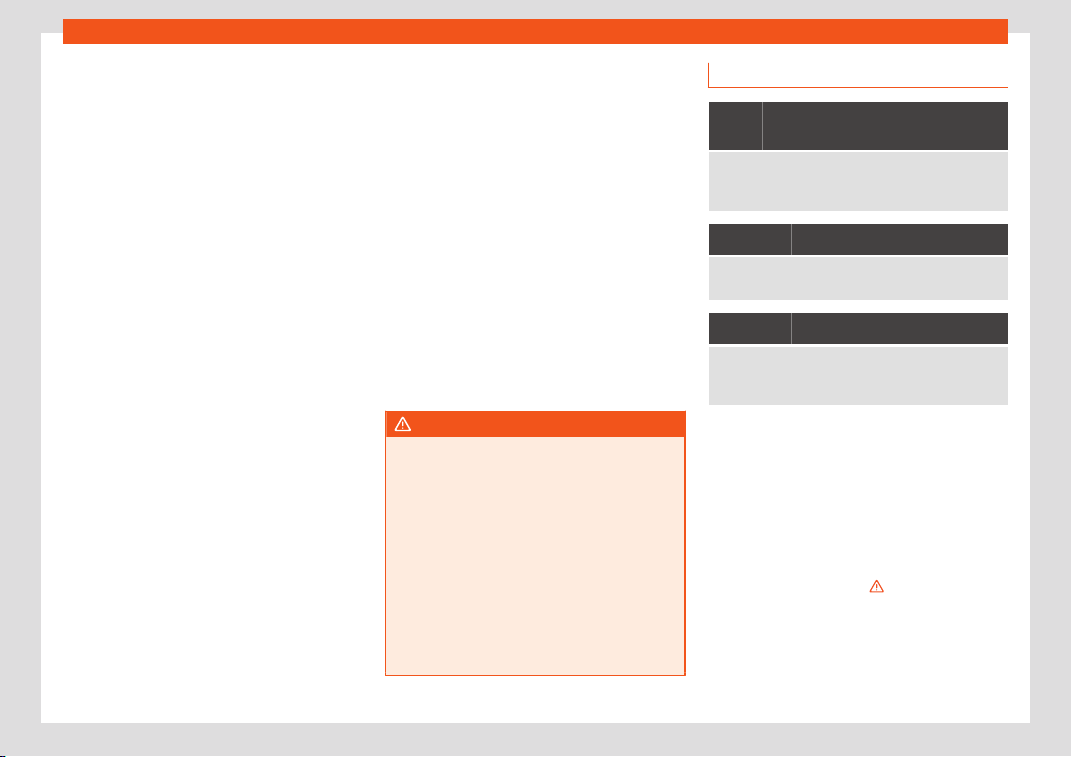
Airbag system
Deactivate the front passenger front airbag
only if you hav
e t
o use a r
ear-facing child
seat in the front passenger seat.
SEAT recommends fitting the child seat in the
rear seat to avoid having to deactivate the
front passenger airbag.
Front passenger front airbag switch
When the front passenger airbag is deacti-
vated, this means that only the front passen-
ger front airbag is deactivated. All the other
airbags in the vehicle remain activated.
Disconnect the front passenger front air-
bag
●
Switch the ignition off.
●
Open the door on the front passenger side.
●
Insert the key into the slot of the switch for
deactivating the front passenger airbag
›››
Fig. 98. About 3/4 of the key should enter;
this is as far as it will go.
●
Turn the key gently to the position. If you
have difficulty, ensure that you have inserted
the key as far as it will go.
●
Close the front passenger door.
●
Check, with the ignition switched on, that
the control lamp remains lit where it
says in the centre of the
dash panel
›››
Fig. 99.
Connect the front passenger front airbag
●
Switch the ignition off.
●
Open the front passenger door.
●
Insert the key into the slot of the switch for
deactivating the front passenger airbag
›››
Fig. 98. About 3/4 of the key should enter,
as far as it will go.
●
Turn the key gently to the position. If you
have difficulty, ensure that you have inserted
the key as far as it will go.
●
Close the front passenger door.
●
Check, with the ignition switched on, that
the control lamp is not lit where it says
in the centre of the dash
panel
›››
Fig. 99. The control lamp lights
up for 60 seconds and then goes off.
WARNING
●
The driver of the vehicl
e is responsible for
disabling or switching on the airbag.
●
Always switch off the ignition before dis-
abling the front passenger airbag! Failure
to do so could result in a fault in the airbag
deactivation system.
●
Never leave the key in the airbag disa-
bling switch as it could get damaged or en-
able or disable the airbag during driving.
●
If for any reason an airbag is deactivated,
reactivate it as soon as possible so that it
can fulfil its protective function.
Airbag system control lamps
It lights up on the combi-instru-
ment
Fault in airbag system and seat belt tensioners.
Have the system checked immediately by a special-
ised workshop.
It lights up on the dash panel
Front passenger front airbag disabled.
Check whether the airbag should remain disabl
ed
It lights up on the dash panel
Front passenger airbag enabled.
The control lamp switches off automatically 60 sec-
onds after the ignition is switched on
Several warning and control lamps light up
f
or a f
e
w seconds when the ignition is switch-
ed on, signalling that the function is being
verified. They will switch off after a few sec-
onds.
If the airbag and seat belt tensioner system
control lamp remains on or flashes, it indi-
cates a malfunction in the airbag and seat
belt tensioner system
›››
. Have the system
check
ed immediat
ely by a specialised w
ork-
shop.
If the front passenger airbag is deactivated,
the warning lamp re-
mains lit on the dash panel to remind you that
»
79
Safety
the airbag is deactivated. If, with the front
passenger airbag deactiv
at
ed, this l
amp
does not remain lit or if it is lit together with
the control lamp on the dash panel, there
is a fault in the airbag system
›››
. If the con-
tr
ol l
amp is fl
ashing, there is a fault in the dis-
abling of the airbag system
›››
. Have the
syst
em check
ed immediat
ely by a special-
ised workshop.
WARNING
In the event of a fault in the airbag and seat
belt tensioner system, the airbags and seat
belts may not trigger corr
ectly, may fail to
trigger or may even trigger unexpectedly.
●
The vehicle occupants run the risk of sus-
taining severe or fatal injuries. Have the
system checked immediately by a special-
ised workshop.
●
Do not mount a child seat in the front
passenger seat or remove the mounted
child seat! The front passenger front airbag
may deploy during an accident in spite of
the fault.
CAUTION
Always pay attention to any lit control
lamps and to the corr
esponding descrip-
tions and instructions to avoid damage to
the vehicle or harm to the occupants.
Transporting children
saf
ely
Saf
et
y for children
Introduction
For safety reasons, as we have learned from
accident statistics, we r
ecommend that chil-
dren under 12 years of age travel in the rear
seats. Depending on their age, height and
weight, children travelling in rear seats must
use a child seat or a seat belt. For safety rea-
sons, the child seat should be installed in the
rear seat, behind the front passenger seat or
in the centre back seat.
The physical laws involved and the forces
acting in a collision apply also to children
›››
page 71. But unlike adults, children do not
have fully developed muscle and bone struc-
tures. This means that children are subject to
a greater risk of injury.
To reduce the risk of injuries, children must al-
ways use special child restraint systems
when travelling in the vehicle.
We recommend the use of child safety prod-
ucts from the SEAT Original Accessories Pro-
gramme, which includes systems for all ages
made by “Peke” (not for all countries) (see
www.seat.com).
These systems have been especially de-
signed and approv
ed, complying with the
ECE-R44. regulation.
SEAT recommends securing the child seats
shown on the website as described below:
●
Child seats in the opposite direction of trav-
el (group 0+): ISOFIX and support bracket
(Peke G0 Plus + ISOFIX Base (RWF)).
●
Child seats in the direction of travel (group
1): ISOFIX and Top Tether (Peke G1 ISOFIX
DUO Plus).
80
Transporting children safely
●
Chil
d seats dir
ect
ed towards the front of
the vehicle for group 2: safety belt and ISOFIX
(Peke G3 KIDFIX)
1)
.
●
Child seats directed towards the front of
the vehicle for group 3: safety belt and ISOFIX
(Peke G3 KIDFIX)
1)
.
Follow the manufacturer's instructions and
observe any statutory requirements when in-
stalling and using child seats. Always read
and note
›››
page 81.
We recommend you always carry the manu-
facturer's Child Seat Instruction Manual to-
gether with the on-board documentation.
Important information regarding
the front passenger's airbag
Read the additional information carefully
›
›
›
page 25.
Read and always observe the safety informa-
tion included in the following chapters:
●
Safety distance with respect to the passen-
ger airbag
›››
page 74.
●
Objects between the passenger and the
passenger side airbag
›››
in Front airbags
on page 76.
The passenger side fr
ont airbag, when ena-
bl
ed, is a serious risk f
or a child that is facing
backward since the airbag can strike the seat
with such force that it can cause serious or
fatal injuries. Children up to 12 years old
should always travel on the rear seat.
Therefore we strongly recommend you to
transport children on the rear seats. This is
the safest location in the vehicle. Alternative-
ly, the front passenger airbag can be disa-
bled with a key-operated switch
›››
page 78.
When transporting children, use a child seat
suitable for the age and size of each child
›››
page 82.
WARNING
●
If a child seat is secured t
o the front pas-
senger seat, the risk to the child of sustain-
ing critical or fatal injuries in the event of an
accident increases.
●
An inflating front passenger airbag can
strike the rear-facing child seat and project
it with great force against the door, the roof
or the backrest.
●
Never inst
all a child seat facing back-
wards on the front passenger seat unless
the front passenger front airbag has been
disabled. Risk of potentially fatal injuries to
the child! However, if it is necessary, in ex-
ceptional cases, to transport a child in the
front passenger seat, the front passenger
front airbag must always be disabled
›››
page 78. If the passenger seat has a
height adjustment option, move it to the
highest, most upright position. If you have a
fixed seat, do not install any child restraint
system in this location.
●
For those vehicles that do not include a
key lock switch to deactivate the airbag,
the vehicle must be taken to a technical
service. Do not forget to reconnect the air-
bag when an adult wants to sit in the front
passenger seat.
●
All vehicle occupants, especially chil-
dren, must assume the proper sitting posi-
tion and be properly belted in while travel-
ling.
●
Never hold children or babies on your lap,
this can result in potentially fatal injuries to
the child!
●
Never allow a child to be transported in a
vehicle without being properly secured, or
»
1)
Temporarily, the child seat recommended by
the Accessories Programme f
or groups 2 and 3
will be ROMER KIDFIX XP
©
instead of Peke G3
KIDFIX. It is available on the SEAT website.
81
Safety
to stand up or kneel on a seat while travel-
ling. In an accident, the child could be flung
thr
ough the vehicle, causing possibly fatal
injuries to themselves and to the other vehi-
cle occupants.
●
If children assume an improper sitting po-
sition when the vehicle is moving, they ex-
pose themselves to greater risk of injury in
the event of a sudden braking manoeuvre
or in an accident. This is particularly impor-
tant if the child is travelling on the front
passenger seat and the airbag system is
triggered in an accident; as this could
cause serious injury or even death.
●
A suitable child seat can protect your
child!
●
Never leave a child alone in the child seat
or inside the vehicle because depending on
the season, very high temperatures may be
reached inside a parked vehicle, which
could be fatal.
●
Children who are less than 1.5 metres tall
must not wear a normal seat belt without a
child seat, as this could cause injuries to
the abdominal and neck areas during a
sudden braking manoeuvre or in an acci-
dent.
●
Do not allow the seat belt to become
twisted and the seat belt should be proper-
ly in place
›››
page 69.
●
Only one child may occupy a child seat
›››
page 82, Child seats.
●
When a child seat is mounted in the r
ear
seats, the door child-proof lock should be
activated
›››
page 136.
Child seats
Safety instructions
Read the additional information carefully
›››
page 25.
WARNING
When travelling, children must be secured
in the vehicle with a r
estraint system suita-
ble for age, weight and size.
●
Read and always observe information
and warnings concerning the use of child
seats
›››
page 81.
WARNING
The retaining rings are designed only for
use with “ISOFIX” and Top Tether* syst
em
child seats.
●
Never secure other child seats that do
not have the “ISOFIX” or Top Tether* sys-
tem, or retaining belts or objects to the fas-
tening rings - this can result in potentially
fatal injuries to the child.
●
Ensure that the child seat is secured cor-
rectly using the “ISOFIX” and Top Tether*
securing rings.
WARNING
An undue installation of the safety seat will
increase the risk of injury in the ev
ent of a
crash.
●
Never tie the retainer strap to a hook in
the luggage compartment.
●
Never secure or tie luggage or other
items to the lower anchorages (ISOFIX) or
the upper ones (Top Tether).
Categorisation of child seats into
gr
oups
Use only child seats that are officially ap-
pr
o
v
ed and suitable for the child.
Child seats are subject to the regulation ECE-
R 44 or ECE-R 129. ECE-R stands for: Eco-
nomic Commission for Europe Regulation.
The child seats are grouped into 5 catego-
ries:
Group 0 Up to 10 kg (up to around 9
months)
Group 0+ Up to 13 kg (up to around 18
months)
Group 1 from 9 to 18 kg (up to approx. 4
years old)
Group 2 from 15 to 25 kg (up to approx. 7
years old)
82

Transporting children safely
Group 3 fr
om 22 to 36 kg (up to approx. 7
years ol
d)
Chil
d seats that have been tested and ap-
proved under the ECE-R 44 or ECE-R 129
standard bear the test mark ECE-R 44 or
ECE-R 129 on the seat (the letter E in a circle
with the test number below it).
Follow the manufacturer's instructions and
observe any statutory requirements when in-
stalling and using child seats.
We recommend you to always include the
manufacturer's Child Seat Instruction Manual
together with the on-board documentation.
SEAT recommends you use child seats from
the Original Accessories Catalogue. These
child seats have been designed and tested
for use in SEAT vehicles. You can find the right
child seat for your model and age group at
SEAT dealers.
Child seats by approval category
Child seats may have the approval category
of universal, semi-universal, vehicle specific
(all according to the ECE-R 44 standard) or i-
Size (according to the ECE-R 129 standard).
●
Universal: child seats with universal appro-
val can be installed in all vehicles. There is no
need to consult any list of models. In the case
of universal approval for ISOFIX, the child
seat is additionally provided with a Top Tether
belt.
●
Semi-universal: semi-universal approval,
in addition to the standard requirements of
universal approval, requires safety devices to
lock the child seat, which require additional
testing. Child seats with semi-universal ap-
proval include a list of vehicle models for
which they can be installed.
●
Vehicle-specific: vehicle-specific approval
requires a dynamic test of the child seat for
each vehicle model separately. Child seats
with vehicle-specific approval also include a
list of vehicle models for which they can be
installed.
●
i-Size: child seats with i-Size approval must
meet the requirements prescribed in the ECE-
R 129 standard in relation to installation and
safety. Child seat manufacturers can tell you
which seats have i-Size approval for this vehi-
cle.
Attachment systems
Depending on the country, different attach-
ment syst
ems ar
e used f
or safely installing
child seats.
Attachment systems overview
●
ISOFIX: ISOFIX is a standardised attach-
ment system allowing quick and safe attach-
ment of child seats in the vehicle. ISOFIX at-
tachment establishes a rigid connection be-
tween the child seat and the car body.
The child seat has two rigid attachment clips,
called connectors. These connectors are fit-
ted into the ISOFIX attachment rings found
between the seat cushion and the backrest
of the vehicle's back seat (on the sides). ISO-
FIX attachment systems are used mainly in
Europe
›››
page 28. If necessary, ISOFIX
attachment may have to be supplemented
with a Top Tether belt or a support bracket.
●
Automatic three-point seat belt. When-
ever possible, it is preferable to attach the
child seats with the ISOFIX system rather than
attaching them with an automatic three-point
seat belt
›››
page 26.
Additional attachment:
●
Top Tether: the Top Tether belt is guided
over the back of the rear seat and attached
to an anchor point with a hook. Anchor points
are located at the back of the rear seat back-
rest on the boot side
›››
page 31. The
rings for retaining the Top Tether belt are
marked with an anchor symbol.
●
Support bracket: some child seats rest on
the floor of the vehicle with a support bracket.
The support bracket prevents the child seat
from tipping forward in the event of impact.
Child seats fitted with a support bracket
should only be used in the passenger seat
and side rear seats
›››
. For the assembly of
this t
ype of seat you shoul
d al
so consult the
list of approved vehicles for this assembly,
»
83

Safety
available in the instructions for child restraint
syst
ems.
R
ecommended syst
ems for attaching
child seats
SEAT recommends attaching child seats as
follows:
●
Baby carriers or child seats in the oppo-
site direction of travel: ISOFIX and support
bracket or i-Size.
●
Child seats in the direction of travel: ISO-
FIX and Top Tether.
WARNING
Incorrect use of the support bracket can
cause serious or fatal injury.
●
Mak
e sure the support bracket is correct-
ly and safely installed.
84
Self-help
Emergencies
Self
-help
Emer
gency equipment
V
ehicle tool kit, anti-puncture kit*
The tools and anti-puncture kit* are stored
under the floor panel in the luggage com-
partment.
To access the v
ehicle tools:
–
Lift up the floor surface by the plastic han-
dle until it is fast
ened to the tabs on both
sides.
Depending on the vehicle equipment, the an-
ti-puncture kit* is located under the floor
panel in the luggage compartment.
The tool kit includes:
●
Jack*
●
Wire hook for pulling off the wheel cov-
er*/wheel bolt cap clip.
●
Box spanner for wheel bolts*
●
Towline anchorage
●
Adapter for the anti-theft wheel bolts*
●
Towing bracket device
Some of the items listed are only provided in
certain model versions, or are optional extras.
Note
The jack does not generally require any
maintenance. If r
equired, it should be
greased using universal type grease.
Tyre repair
TMS (Tyr
e Mobility System)*
Read the additional information carefully
›
›
›
page 53
The Anti-puncture kit* (Tyre Mobility System)
will reliably seal punctures caused by the
penetration of a foreign body of up to about
4 mm in diameter. Do not remove foreign
objects, e.g. screws or nails, from the tyre.
After inserting the sealant residue in the tyre,
you must again check the tyre pressure
about 10 minutes after starting the engine.
You should only use the tyre mobility set if the
vehicle is parked in a safe place, you are fa-
miliar with the procedure and you have the
necessary tyre mobility set! Otherwise, you
should seek professional assistance.
Do not use the tyre sealant in the following
cases:
●
If the wheel rim has been damaged.
●
In outside temperatures below -20°C
(-4°F).
●
In the event of cuts or perforations in the
tyre greater than 4 mm.
●
If you have been driving with very low pres-
sure or a completely flat tyre.
●
If the sealant bottle has passed its use by
date.
WARNING
Using the tyre mobility system can be dan-
gerous, especially when filling the tyr
e at
the roadside. Please observe the following
rules to minimise the risk of injury:
●
Stop the vehicle safely as soon as possi-
ble. Park it at a safe distance from sur-
rounding traffic to fill the tyre.
●
Ensure the ground on which you park is
flat and solid.
●
All passengers and particularly children
must keep a safe distance from the work
area.
●
Turn on the hazard warning lights to warn
other road users.
●
Use the tyre mobility system only if you
are familiar with the necessary procedures.
Otherwise, you should seek professional
assistance.
»
85
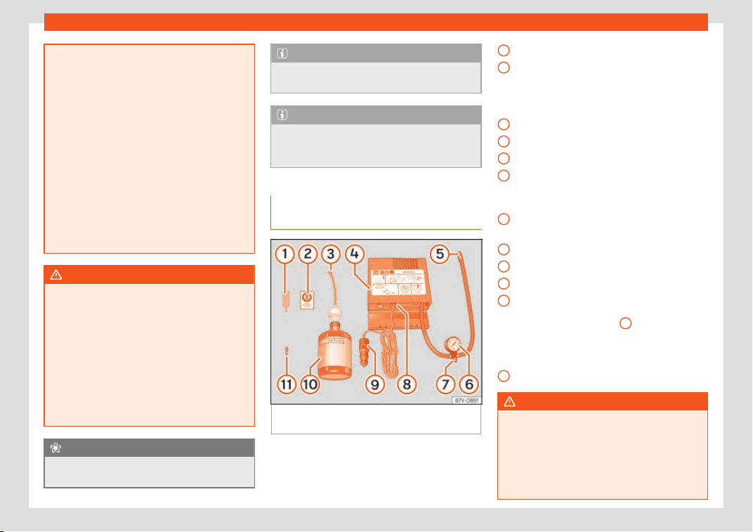
Emergencies
●
The tyre mobilit
y set is intended for tem-
porary emergency use only until you can
reach the nearest specialised workshop.
●
Replace the repaired tyre with the tyre
mobility set as soon as possible.
●
The sealant is a health hazard and must
be cleaned immediately if it comes into
contact with the skin.
●
Always keep the tyre mobility set out of
the reach of small children.
●
Always stop the engine, apply the elec-
tronic parking brake and put it in gear when
using a manual gearbox, in order to reduce
the risk of involuntary movement of the ve-
hicle.
WARNING
A tyre filled with sealant does not have the
same performance proper
ties as a conven-
tional tyre.
●
Never drive faster than 80 km/h
(50 mph).
●
Avoid heavy acceleration, hard braking
and fast cornering.
●
Drive for only 10 minutes at a maximum
speed of 80 km/h (50 mph) and then check
the tyre.
For the sake of the environment
Dispose of used or expired sealant observ-
ing any legal requir
ements.
Note
A new bottle of sealant can be purchased
at SEAT dealerships.
Note
Take into account the separate instruction
manual of the tyre mobilit
y set* manufac-
turer.
Contents of the tyre mobility sys-
tem*
Fig. 100
Standard display: contents of the an-
ti-punct
ur
e kit.
The anti-puncture kit is located underneath
the fl
oor co
v
ering in the luggage compart-
ment. It includes the following components
›››
Fig. 100:
Tyre valve remover
A sticker to be adhered to the instrument
cluster, within the driver's visual field, to
remind that the maximum advisable
speed “max. 80 km/h” or “max. 50 mph”
Filler tube with cap
Air compressor
Tube for inflating tyres
Warning provided by tyre pressure moni-
toring system (it can also be integrated in
the compressor).
Air bleed screw (in its place, the compres-
sor may have a button).
ON/OFF switch
12 volt connector
Bottle of sealant
Spare tyre valve
The valve insert remover
1
has a gap at
the l
o
w
er end for a valve insert. The valve in-
sert can only be screwed or unscrewed in this
way. This also applies to its replacement part
11
.
WARNING
When inflating the wheel, the air compres-
sor and the inflator t
ube may become hot.
●
Protect hands and skin from hot parts.
●
Do not place the hot flexible inflator tube
or hot air compressor on flammable mate-
rial.
1
2
3
4
5
6
7
8
9
10
11
86
Self-help
●
Allow them t
o cool before storing the de-
vice.
●
If it is not possible to inflate the tyre to at
least 2.0 bars (29 psi / 200 kPa), the tyre is
too badly damaged. The sealant is not in a
good condition to seal the tyre. Do not con-
tinue driving. Seek specialist assistance.
CAUTION
Switch off the air compressor after a maxi-
mum of 8 oper
ational minutes t
o avoid
overheating! Before switching on the air
compressor again, let it cool for several mi-
nutes.
Check after 10 minutes of driving
Screw the inflator tube
›
›
›
Fig. 100
5
again
and check the pr
essur
e on the gauge
6
.
1.3 bar (19 psi / 130 kP
a) and l
o
wer:
●
Stop the vehicle! The tyre cannot be
sealed sufficiently with the tyre mobility set.
●
You should obtain professional assistance
›››
.
1.4 bar (20 psi / 140 kP
a) and higher:
●
Set the t
yr
e pressure to the correct value
again.
●
Carefully resume your journey until you
reach the nearest specialised workshop with-
out exceeding 80 km/h (50 mph).
●
Have the damaged tyre replaced.
WARNING
Driving with an unsealed tyre is dangerous
and can cause accidents and serious in-
jury.
●
Do not continue driving if the tyre pres-
sure is 1.3 bar (19 psi / 130 kPa) and l
ower.
●
Seek specialist assistance.
Manual unlocking/locking
Intr
oduction
Read the additional information carefully
›
›
›
page 16,
›››
page 17.
The doors, rear lid and panoramic tilting sun-
roof can be locked manually and partially
opened, for example if the key or the central
locking is damaged.
WARNING
Opening and closing doors carelessly can
cause serious injury.
●
If the vehicle is locked from outside, the
doors and windows cannot be opened from
the inside
.
●
Never l
eave children or disabled people
alone in the car. They could be trapped in
the car in an emergency and will not be
able to get themselves to safety.
●
Depending on the time of the year, tem-
peratures inside a locked and closed vehi-
cle can be extremely high or extremely low
resulting in serious injuries and illness or
even death, particularly for young children.
WARNING
Getting in the way of the doors and the rear
lid is danger
ous and can lead t
o serious in-
jury.
●
Open and close the doors and the rear lid
only when there is nobody in the way.
CAUTION
When opening and closing in an emergen-
cy, carefully disassemble components and
then r
eassemble them carefully to avoid
damage to the vehicle.
87
Emergencies
Changing the windscreen
wiper bl
ades
Changing the windscr
een and r
ear
window wiper blades
Read the additional information carefully
›››
page 62.
The windscreen wiper blades are supplied as
standard with a layer of graphite. This layer is
responsible for ensuring that the wipe is silent.
If the graphite layer is damaged, the noise of
the water as it is wiped across the windscreen
will be louder.
Check the condition of the wiper blades reg-
ularly. If the wipers scrape across the
glass, they should be changed if they are
damaged, or cleaned if they are dirty
›››
.
Damaged windscr
een wiper bl
ades shoul
d
be replaced immediately. These are availa-
ble from qualified workshops.
WARNING
Worn or dirty windscreen wiper blades re-
duce visibility and increase the risk of acci-
dent and serious injury.
●
Al
ways replace damaged or worn wind-
screen wiper blades or blades that no lon-
ger clean the windscreen properly.
CAUTION
●
Damaged or dirty windscr
een wipers
could scratch the glass.
●
If products containing solvents, rough
sponges or sharp objects are used to clean
the blades, the graphite layer will be dam-
aged.
●
Never use fuel, nail varnish remover, paint
thinner or similar products to clean the win-
dows.
●
In icy conditions, always check that the
wiper blades are not frozen to the glass be-
fore using the wipers. In cold weather, it
may help to leave the vehicle parked with
the wipers in service position
›››
page 61.
CAUTION
●
To pre
vent damage to the bonnet and the
wiper arms, only leave them in the service
position.
●
Before driving, always lower the wiper
arms.
Tow-starting and towing
Intr
oduction
Tow-starting means st
arting the engine of
the v
ehicl
e while another pulls it.
Towing means one vehicle pulling another
that is not roadworthy.
Always consider the legal provisions relating
to tow-starting and towing.
For technical reasons, towing a vehicle
with a discharged battery is not allowed.
The jump start should be used instead
›››
page 59.
If the vehicle comes with the Keyless Access
system, towing is only allowed with the igni-
tion on!
The vehicle battery drains if the vehicle is
towed with the engine switched off and the
ignition connected. Depending on the battery
charge status, the drop in voltage may be so
large, even after just a few minutes, that no
electrical device in the vehicle may work e.g.
the hazard warning lights. In vehicles with the
Keyless Access system, the steering wheel
could lock
›››
.
WARNING
A vehicle with no power should never be
tow
ed.
●
During towing, never switch off the igni-
tion with the starter button. Otherwise, the
electronic lock of the steering column
could suddenly get blocked and it would be
impossible to steer the vehicle. This could
cause an accident, serious injury and loss
of control of the vehicle.
88
Self-help
●
If during towing the v
ehicle runs out of
power, stop towing immediately and re-
quest the assistance of specialist person-
nel.
WARNING
Vehicle handling and braking capacity
change consider
ably during to
wing. Please
observe the following instructions to mini-
mise the risk of serious accidents and in-
jury:
●
As the driver of the vehicle being towed:
–
You should depress the brake much
harder as the brake servo does not op-
erate. Pay the utmost attention to avoid
crashing into the towing vehicle.
–
More strength is required at the steer-
ing wheel as the power steering does
not operate when the engine is switch-
ed off.
●
As the driver of the towing vehicle:
–
Accelerate with particular care and
caution.
–
Avoid sudden braking and manoeuvres.
–
Brake earlier than usual and more
smoothly.
CAUTION
●
To avoid damaging the v
ehicle, for exam-
ple the paint, remove and replace the lid
and towing eye carefully.
●
Unburnt fuel could enter the cat
alytic
converter and damage it during towing.
Indications for tow-starting
Vehicle's should not generally be tow-
start
ed. The jump start should be used in-
stead
›››
page 59.
For technical reasons, towing the following
vehicles is not allowed:
●
Vehicles with an automatic gearbox.
●
If the vehicle battery is discharged, be-
cause in vehicles with the K
eyless Access
locking and ignition system the steering re-
mains locked and the electronic parking
brake cannot be deactivated nor can the
electronic lock of the steering column be re-
leased if they are activated.
●
If the battery is flat, it is possible that the
engine control units may not operate correct-
ly.
However, if the vehicle must absolutely be
tow-started (in the case of manual gear-
boxes):
●
Engage the 2nd or 3rd gear.
●
Keep the clutch pressed down.
●
Switch on the ignition and the hazard warn-
ing lights.
●
Once both vehicles are moving, release the
clutch.
●
Once the engine starts, press the clutch
and disengage the gear to avoid colliding
with the towing vehicle.
CAUTION
When tow-starting, unburnt fuel could en-
ter the catalytic conv
erter and damage it.
Note
The vehicle can only be tow-started if the
electronic parking br
ake and, if appropri-
ate, the electronic lock of the steering col-
umn are deactivated. If the vehicle has no
power supply or there is an electric system
fault, the engine must be tow-started to de-
activate the electronic parking brake and
the electronic lock of the steering column.
Indications for towing
Tow rope or tow bar
It is saf
er f
or the v
ehicle to be towed using a
tow bar, avoiding damage to the vehicle. A
tow rope should only be used if a tow bar is
not available.
A tow rope should be slightly elastic to avoid
damage to both vehicles. It is advisable to
use a tow rope made of synthetic fibre or sim-
ilarly elastic material.
»
89
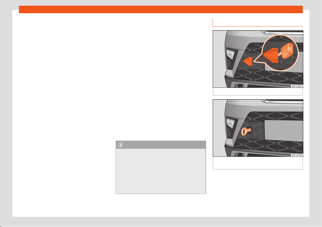
Emergencies
Only attach the tow rope or the tow bar to
the t
o
wing eyes pr
ovided or a towing bracket.
If the vehicle is factory-equipped with a
towing bracket, it is only allowed to tow with
a tow bar if this has been specially designed
to be installed with a tow hitch
›››
page 332.
When the vehicle needs to be towed:
Check whether the vehicle may be towed
›››
page 90, Cases where towing a vehi-
cle is not allowed.
●
Switch the ignition on.
●
Put the gearbox lever in neutral or the se-
lector lever in the N
›››
page 251 position.
●
Do not allow the vehicle to be towed at
speeds of over 50 km/h (30 mph).
●
The vehicle must not be towed further than
50 km (30 miles).
●
If a breakdown lorry is used, vehicles with
automatic transmission are only allowed to
be towed with the front wheels suspended.
Towing vehicles with four-wheel drive
(4Drive)
Four-wheel drive vehicles (4Drive) can be
towed using a tow bar or tow rope. If the vehi-
cle is towed with the front or rear axle sus-
pended, the engine must be switched off,
otherwise the transmission may be damaged.
Cases where towing a vehicle is not al-
lowed
●
If, due to a fault, the gearbox is out of lubri-
cant.
●
If the vehicle battery is discharged, be-
cause the steering remains locked and, if ap-
propriate, the electronic parking brake can-
not be deactivated or the electronic lock of
the steering column released.
●
If a distance above 50 km needs to be trav-
elled.
●
When, for example, after an accident, the
smooth rotation of the wheels or the steering
operation cannot be guaranteed.
When the vehicle is to tow another vehicle:
●
Observe legal requirements.
●
Keep in mind the instructions in the manual
on towing vehicles.
Note
The vehicle can only be towed if the elec-
tronic parking brak
e and the electronic
lock of the steering column are deactiva-
ted. If the vehicle has no power supply or
there is an electric system fault, the engine
must be tow-started
›››
page 59 to de-
activate the electronic parking brake and
the electronic lock of the steering column.
Fitting the front towing eye
Fig. 101
Front bumper on right: remove the lid.
Fig. 102
Right side of the front bumper: towline
anchor
age scr
e
wed in.
The housing of the screw towing eye is on the
right side of the fr
ont bumper behind a lid
›
›
›
Fig. 101.
The towing eye should always be kept in the
vehicle.
90
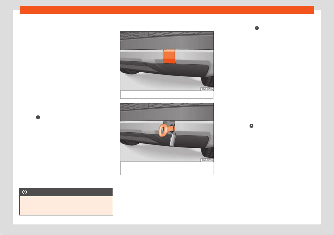
Self-help
Bear in mind the instructions for towing
›
›
›
page 89.
Fitting the towline anchorage
●
Remove the towing eye from the vehicle
tool kit in the luggage compartment
›››
page 85.
●
Extract the lid for the towing eye using the
vehicle key blade (if you do not have the spe-
cific tool), pressing on the side and levering
gently from left to right.
●
Remove the lid and let it hang from the ve-
hicle.
●
Screw the towing eye in the housing by
turning it to the maximum anticlock-
wise
›››
. Use a suitable object that can
compl
et
ely and secur
ely tighten the towing
eye in its housing.
●
After towing, unscrew the towing eye
clockwise with a suitable object.
●
Insert the side tab of the lid into the opening
of the bumper and press until the tab is prop-
erly clipped into the bumper.
●
Clean the towing eye if necessary and then
store it in the luggage compartment along
with the other vehicle tools.
CAUTION
The towing eye must always be completely
and firmly tightened. Otherwise, it coul
d be
released while towing and tow-starting.
Fitting the rear towing eye
Fig. 103
Rear bumper on right: remove the lid.
Fig. 104
Right side of the rear bumper: towline
anchor
age scr
e
wed in.
The housing of the screw towing eye is on the
right side of the r
ear bumper behind a lid
›
›
›
Fig. 103. Vehicles equipped as standard
with a towing bracket do not have any hous-
ing for the screw towing eye behind the lid. In
this case, the tow hitch needs to be extracted
or installed and used for towing
›››
page 329,
›››
.
Bear in mind the instructions f
or t
o
wing
›››
page 89.
Assemble the rear towing eye (cars with-
out a factory-equipped towing bracket)
●
Remove the towing eye from the vehicle
tool kit in the luggage compartment
›››
page 85.
●
Press the upper side of the lid
›››
Fig. 103 to
unclip it.
●
Remove the lid and let it hang from the ve-
hicle.
●
Screw the towing eye in the housing by
turning it to the maximum anticlockwise
›››
Fig. 104
›››
. Use a suitable object that
can compl
et
ely and secur
ely tighten the tow-
ing eye in its housing.
●
After towing, unscrew the towing eye
clockwise with a suitable object.
●
Insert the upper flange of the lid into the
opening of the bumper and press the lower
side of the lid until the upper flange is inserted
into the bumper.
●
Clean the towing eye if necessary and then
store it in the luggage compartment along
with the other vehicle tools.
»
91
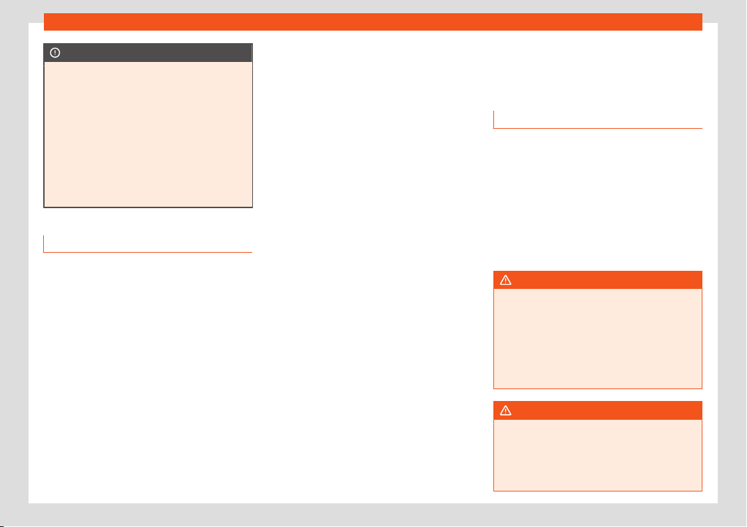
Emergencies
CAUTION
●
The towing eye must al
ways be com-
pletely and firmly tightened. Otherwise, it
could be released while towing and tow-
starting.
●
If the vehicle is factory-equipped with a
towing bracket, it is only allowed to tow
with a tow bar if this has been specially de-
signed to be installed with a tow hitch. If an
unsuitable tow bar is used, both the tow
hitch and the vehicle may be damaged. In-
stead, a tow rope should be used.
Driving tips for towing
Towing requires some expertise and experi-
ence
, especially when using a t
o
w rope. Both
drivers should be familiar with the difficulties
involved in towing. For this reason, inexper-
ienced drivers should abstain from towing.
During towing, it should be ensured that no
impermissible tractive forces or shocks are
generated. When towing on an unpaved
road, there is always a risk of overloading and
damaging the anchorage points.
During towing, the towing vehicle can signal
the change of direction even with the hazard
warning lights turned on. To do so, at the
same time, the turn signal lever must be oper-
ated with ignition switched on. Meanwhile, the
hazard warning lights will go off. When the
turn signal lever is returned to the rest posi-
tion, the hazard warning lights will be auto-
matically reactivated.
Notes for the driver of the towed vehicle
●
Leave the ignition on, so that the steering is
not blocked, and the electronic parking brake
may be deactivated and the turn signals and
wash/wipe operated.
●
More strength is required at the steering
wheel as the power steering does not oper-
ate when the engine is switched off.
●
You should depress the brake much harder
as the brake servo does not operate. Avoid
hitting the towing vehicle.
●
Bear in mind the information and instruc-
tions in the manual of the vehicle to be towed.
Notes for the driver of the towing vehicle
●
Accelerate with particular care and cau-
tion. Avoid sharp manoeuvres.
●
Brake earlier than usual and smoothly.
●
Bear in mind the information and instruc-
tions in the manual of the towed vehicle.
Fuses and bulbs
Fuses
Intr
oduction
In general, a fuse can be assigned to various
electrical components. Like
wise, an electrical
component can be protected by several
fuses.
Only replace fuses when the cause of the
problem has been solved. If a newly inserted
fuse blows after a short time, you must have
the electrical system checked by a special-
ised workshop as soon as possible.
WARNING
The high voltages in the electrical system
can give serious electrical shocks, causing
burns and e
ven death!
●
Never touch the electrical wiring of the
ignition system.
●
Take care not to cause short circuits in
the electrical system.
WARNING
Using unsuitable fuses, repairing fuses or
bridging a current circuit without fuses can
cause a fir
e and serious injury.
●
Never use a fuse with a higher value. Only
replace fuses with a fuse of the same
92
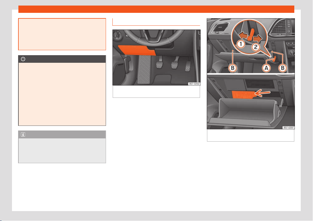
Fuses and bulbs
amperage (same colour and markings) and
size.
●
Ne
ver repair a fuse.
●
Never replace a fuse by a metal strip, sta-
ple or similar.
CAUTION
●
T
o pre
vent damage to the vehicle's elec-
tric system, before replacing a fuse always
turn off the ignition, the lights and all elec-
trical elements and remove the key from
the ignition.
●
If you replace a fuse with higher-rating
fuse, you could cause damage to another
part of the electrical system.
●
Protect the fuse boxes when open to pre-
vent the entry of dust or humidity as they
can damage the electrical system.
Note
●
One component may have more than one
fuse
.
●
Several components may run on a single
fuse.
Vehicle interior fuses
Fig. 105
On the dashboard on the driver side
(l
eft guide): lid of the fuse bo
x.
Fig. 106
Glove compartment (left guide): Ac-
cess t
o the fuse bo
x.
Opening and closing the fuse box situated
bel
o
w the dash panel (l
eft-hand drive)
●
Open: fold the cover down
›››
Fig. 105.
●
Close: push back the cover it in until it clicks
into place.
Fuses behind the glove compartment
(right-hand drive)
To be able to access the fuse box:
»
93
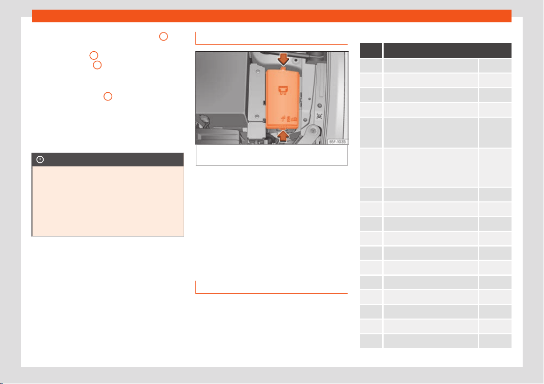
Emergencies
●
Undo the opening limit
er
›
›
›
Fig. 106
A
in
tw
o st
eps: first, unl
ock the limiter by pulling
back on it (arrow
1
) and then move it gently
t
o the right (arr
o
w
2
). Remove the guide
when the co
v
er is in the normal opening posi-
tion (30°).
●
Fr
ee the side pivots
B
to release the cover
t
o its second opening position (60°).
F
oll
ow the same procedure in reverse order
to return the glove compartment to its normal
position.
CAUTION
●
Always car
efully remove the fuse box
covers and refit them correctly to avoid
problems with your vehicle.
●
Protect the fuse boxes when open to
avoid the entry of dust or humidity. Dirt and
humidity inside fuse boxes can cause dam-
age to the electrical system.
Engine compartment fuses
Fig. 107
In the engine compartment: lid of the
fuse bo
x.
To open the engine compartment fuse box
●
Open the bonnet
›
›
›
page 347.
●
Press the locking tabs to release the fuse
box cover
›››
Fig. 107.
●
Then lift the cover out.
●
To fit the cover, place it on the fuse box.
Push the locking tabs down until they click
audibly into place.
Fuse placement
Read the additional information carefully
›
›
›
page 51
Only replace fuses with a fuse of the same
amperage (same colour and markings) and
size.
Fuses in the vehicle interior
No. Consumers/Amps
1 Adblue (SCR) 20
4 Alarm horn 7.5
5 Gateway 7.5
6 Automatic gearbox lever 7.5
7
Air conditioning and heating
control panel, back windo
w
heating, auxiliary heating.
10
8
Diagnosis, electronic parking
brake s
witch, light switch, re-
verse light, interior lighting, driv-
ing mode, lit-up door sill
7.5
9 Steering column 7.5
10 Radio display 7.5
11 Left lights 40
12 Radio 20
14 Air conditioner fan 40
15 Steering column release 10
16 Connectivity Box 7.5
17 Instrument panel, OCU 7.5
18 Rear camera 7.5
19 Kessy 7.5
20 SCR, engine relay, 1.5 10/15
94
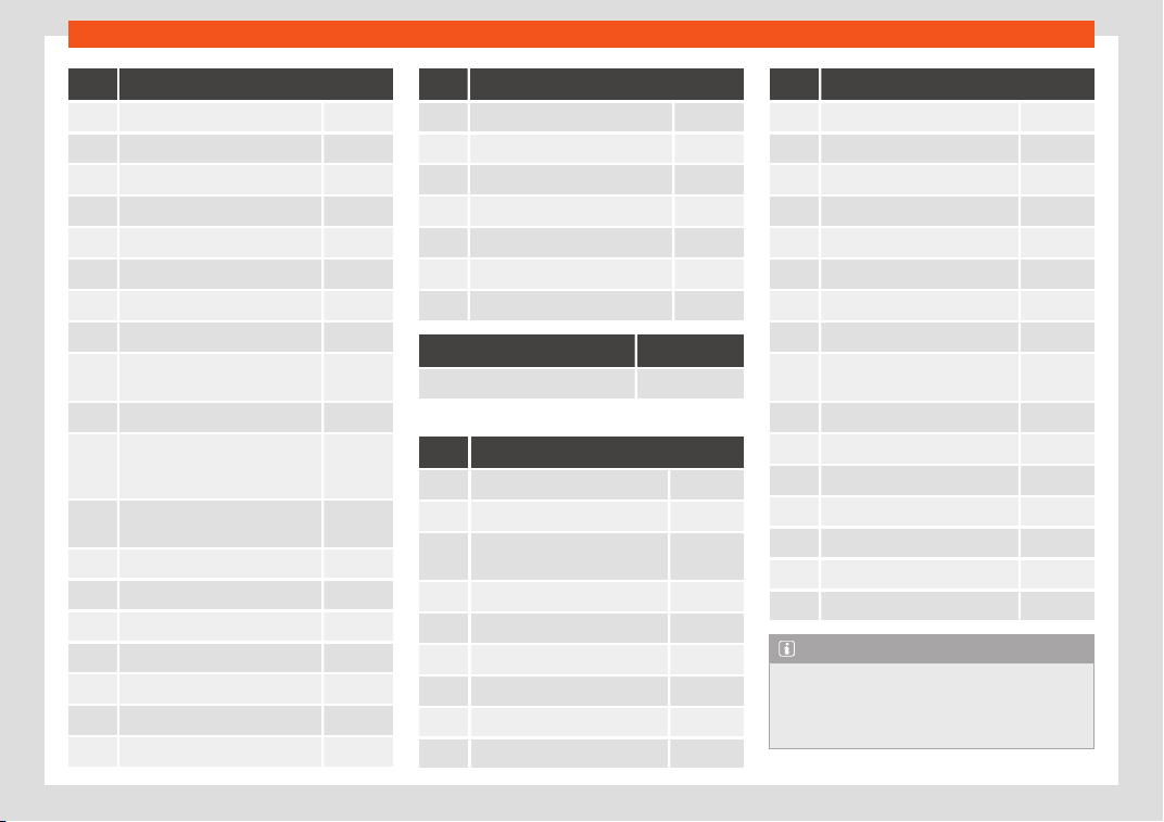
Fuses and bulbs
No. Consumers/Amps
21 4x4 Haldex Control Unit 15
22 Trailer 15
23 Electric sunroof 20
24 Right lights 40
25 Left door 30
26 Heated seats 30
27 Interior light 30
28 Trailer 25
32
Control unit for parking aid,
fr
ont camera and r
adar
7.5/10
33 Airbag 7.5
34
Reverse switch, climate sensor,
electrochromic mirror, rear
power sockets (USB)
7.5
35
Diagnosis, headlight control
unit, headlight adjuster
7.5
36 Right LED headlight 7.5
37 Left LED headlight 7.5
38 Trailer 25
39 Right door 30
40 12V socket 20
42 Central locking 40
43 Beats Audio CAN and MOST. 30
No. Consumers/Amps
44 Trailer 15
45 Electric driver's seat 15
47 Rear window wiper 15
49 Starter motor; clutch sensor 7.5
50 Electric rear lid 40
52 Driving mode. 15
53 Heated rear window 30
In-line fuse Amperes
Rear power sockets 7.5
Fuse arrangement in engine compartment
No. Consumers/Amps
1 ESP control unit 25
2 ESP control unit 40
3
Engine control unit (diesel/pet-
rol)
30/15
4 Engine sensors 7.5
5
Engine sensors 7.5
6 Brake light sensor 7.5
7 Engine power supply 7.5/10
8 Lambda probe 10/15
9 Engine 5/10/20
No. Consumers/Amps
10 Fuel pump control unit 15/20
11 PTC 40
12 PTC 40
13 Gearbox pump 30
14 Heated windscreen 40
15 Horn 15
16 Petrol pump 7.5/15/20
17 Engine control unit 7.5
18
Terminal 30 (positive refer-
ence)
7.5
19 Front windscreen washer 30
21 Automatic gearbox control unit 15/30
22 Engine control unit 7.5
23 Starter motor 30
24 PTC 40
31 Pressure pump 15
37 Parking heating 20
Note
●
In the vehicle
, there are more fuses than
those indicated in this chapter. These
should only be changed by a specialised
workshop.
»
95
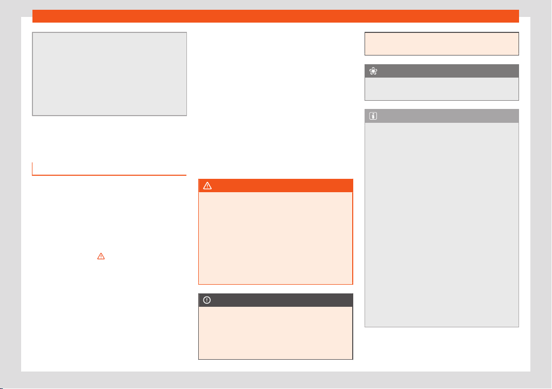
Emergencies
●
Positions not containing a fuse do not ap-
pear in the f
ollowing tables.
●
Some of the equipment listed in the ta-
bles below pertain only to certain versions
of the model or are optional extras.
●
Please note that the above lists, while
correct at the time of printing, are subject
to change.
Changing a bulb
Topic introduction
Read the additional information carefully
›
›
›
page 52.
Changing bulbs requires a certain degree of
practical skill.
If you choose to change the engine compart-
ment lamps yourself, remember that it is a
dangerous area
›››
in Working in the en-
gine compar
tment on page 347
.
Al
ways use identical bulbs with the same
designation. The name can be found on the
base of the bulb holder.
Depending on how equipped the vehicle is,
there are different sets of headlights and tail
lights:
●
Halogen headlights.
●
Full-LED main headlights*
●
Rear bulb light
●
LED rear light*
Full-LED headlight system*
Full-LED headlights handle all light functions
(daylight, side light, turn signal, dipped beam
and route light) with light emitting diodes
(LEDs) as a light source.
Full-LED headlights are designed to last the
lifetime of the car and light bulbs cannot be
replaced. In case of headlight failure, go to an
authorised workshop to have it replaced.
WARNING
●
Take par
ticular care when working on
components in the engine compartment if
the engine is warm. Risk of burns.
●
Bulbs are highly sensitive to pressure. The
glass can break when you touch the bulb,
causing injury.
●
When changing bulbs, please take care
not to injure yourself on sharp edges, in
particular on the headlight housing.
CAUTION
●
Remov
e the ignition key before working
on the electric system. Otherwise, a short
circuit could occur.
●
Switch off the lights and the parking light
before changing a bulb.
●
Take good car
e to avoid damaging any
components.
For the sake of the environment
Please ask your specialist retailer how to
dispose of used bulbs in the pr
oper manner.
Note
●
Please check at regul
ar intervals that all
lighting (especially the exterior lighting) on
your vehicle is functioning properly. This is
not only in the interest of your own safety,
but also that of all other road users.
●
Before changing a bulb, make sure you
have the correct new bulb.
●
Do not touch the glass part of the bulb
with your bare hands, use a cloth or paper
towel instead, since the fingerprints left on
the glass will vaporise as a result of the
heat generated by the bulb, they will be
deposited on the reflector and will impair
its surface.
●
Depending on the level of equipment fit-
ted in the vehicle, LEDs may be used for
part or all of the interior and/or exterior
lighting. LEDs have an estimated life that
exceeds than that of the car. If an LED light
fails, go to an authorised workshop for its
replacement.
96
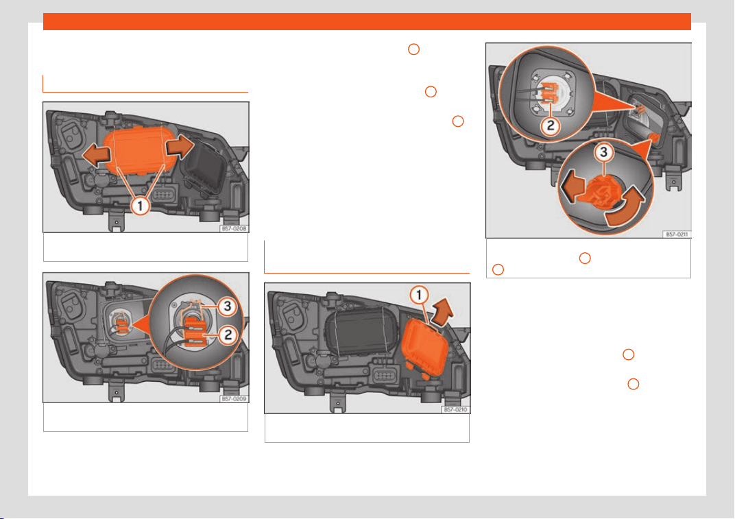
Fuses and bulbs
Change the front bulbs
Dipped beam headlight
Fig. 108
In the engine compartment: remove
the lid.
Fig. 109
In the engine compartment: dipped
beam l
amp
.
Follow the steps indicated:
R
aise the bonnet.1.
Mo
v
e the loops
›››
Fig. 108
1
in the di-
r
ection of the arr
o
w and remove the cov-
er.
Remove connector
›››
Fig. 109
2
from
the bulb
.
Unclip the r
et
ainer spring
›››
Fig. 109
3
pressing clockwise and inwards.
Extr
act the bulb and fit the r
epl
acement
so that the lug on the base fits into the
recess on the reflector.
Installation involves all of the above
steps in reverse sequence.
Main beam headlight bulb and turn
signal bulb
Fig. 110
In the engine compartment: remove
the lid.
2.
3.
4.
5.
6.
Fig. 111
In the engine compartment: main
beam headlight bulb
2
and turn signal bulb
3
.
Follow the steps indicated:
Main beam headlight bulb
R
aise the bonnet.
Mo
v
e the loop
›››
Fig. 110
1
in the direc-
tion of the arr
o
w and r
emove the cover.
Slide connector
›››
Fig. 111
2
to the left
or right and pull.
R
emo
v
e the bulb by disconnecting the
connector.
Installation involves all of the above
steps in reverse sequence.
»
1.
2.
3.
4.
5.
97
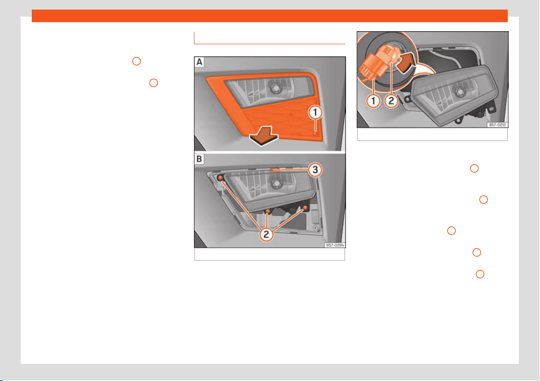
Emergencies
Turn signal bulb
R
aise the bonnet.
Mo
v
e the loop
›››
Fig. 110
1
in the direc-
tion of the arr
o
w and r
emove the cover.
Turn the bulb holder
›››
Fig. 111
3
anti-
cl
ockwise and pull.
R
emo
ve the bulb by pressing on the bulb
holder and turning it anticlockwise at the
same time.
Installation involves all of the above
steps in reverse sequence.
1.
2.
3.
4.
5.
Front fog light bulb*
Fig. 112
Fog light: remove the grille
Fig. 113 Fog light: detach the bulb holder
Follow the steps indicated:
R
emo
v
e the screw
›››
Fig. 112
1
fr
om
the f
og light grill
e using a screwdriver
and extract the grille.
Remove the 3 screws
›››
Fig. 112
2
.
R
emo
v
e the metal clip situated on the
upper part of the fog light by pulling
away from the vehicle
3
and e
xtract
the f
og light.
R
emove connector
›››
Fig. 113
1
from
the bulb
.
T
urn the bulb hol
der
›››
Fig. 113
2
anti-
cl
ockwise and pull.
R
emo
ve the bulb by pressing on the bulb
holder and turning it anticlockwise at the
same time.
Installation involves all of the above
steps in reverse sequence.
Check that the bulb works properly.
1.
2.
3.
4.
5.
6.
7.
8.
98
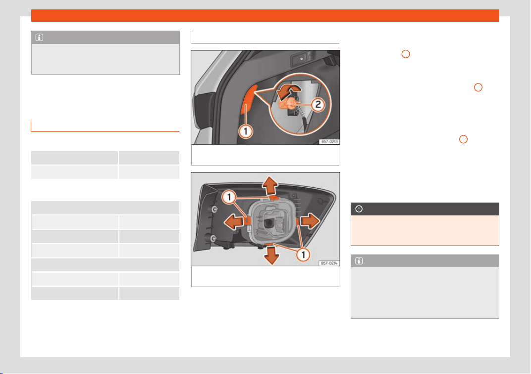
Fuses and bulbs
Note
Due to the difficulty of accessing fog light
bulbs, have them repl
aced at a Technical
Service or specialised workshop.
Change the rear bulbs
Overview of t
ail lights
Tail lights on side panel
Turn signal PY21W NA LL
Side light and brake light P21W LL
Tail lights on the rear lid
Left side
Side lights P21W LL
Fog light/side light P21W LL
Reverse light W16W
Right side
Side lights 2x P21W LL
Reverse light W16W
The table corresponds to a right-hand traffic
v
ehicl
e
. The position of lights may vary ac-
cording to the country.
Rear bulbs (in the side panel)
Fig. 114
Boot: access to the bolt securing the
t
ail light unit.
Fig. 115 Retaining tabs on reverse side of tail
light.
Follow the steps indicated:
Check which of the bulbs is def
ectiv
e
.
Open the rear lid.
1.
2.
Remove the lid, levering it with the flat
side of a screwdriver into the recess
›››
Fig. 114
1
.
R
emo
v
e the bulb connector.
Unscrew the light securing bolt by hand
or using a screwdriver
›››
Fig. 114
2
.
R
emo
v
e the light from the body, gently
pulling it toward you, and place on a
clean, smooth surface.
Disassemble the bulb holder unlocking
the securing tabs
›››
Fig. 115
1
.
Change the damaged bulb
.
T
o r
efit follow the steps in reverse order,
taking special care when fitting the bulb
holder. The securing tabs must click into
place.
CAUTION
Take care when removing the rear light unit
to make sur
e there is no damage to the
paintwork or any of its components.
Note
●
Make sure you hav
e a soft cloth ready to
place under the glass on the rear light unit,
to avoid any scratches.
●
In the case of LED lights, change only the
turn signal bulb.
3.
4.
5.
6.
7.
8.
9.
99
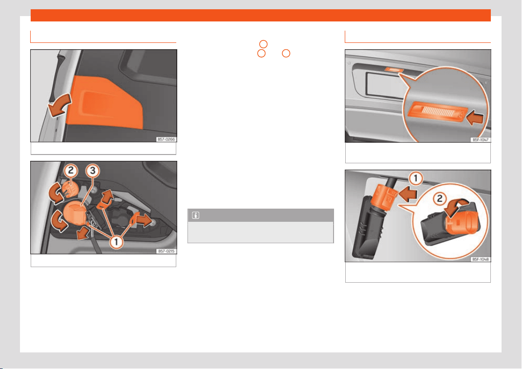
Emergencies
Rear lights (in the rear lid)
Fig. 116
Rear lid open: remove the lid.
Fig. 117
Remove the bulb holder.
The rear lid must be open to change the
bulbs.
F
oll
o
w the steps indicated:
Remove the rear lid cover in the direction
indicated
›››
Fig. 116.
1.
Unlock the securing tabs from the bulb
holder
›››
Fig. 117
1
or turn the bulb
hol
der t
o the l
eft
2
and
3
.
R
emo
v
e the bulb holder from its location.
Lightly press the defective bulb into the
bulb holder, then turn it to the left and re-
move it.
Fit the new bulb, pressing it into the bulb
holder and turn it to the right as far as it
will go.
Use a cloth to remove any fingerprints
from the glass part of the bulb.
Check that the new bulb works properly.
Carry out the same actions in reverse or-
der for assembly and pay special atten-
tion to placing the bulb holder, ensuring
that the tabs are properly secured.
Note
For LED pilots, you can only change the re-
verse bulb.
2.
3.
4.
5.
6.
7.
8.
Changing number plate light bulbs
Fig. 118
In the rear bumper: number plate
light.
Fig. 119 Number plate light: detach the bulb
hol
der
.
Follow the steps indicated:
Pr
ess the number pl
at
e light in the direc-
tion of the arrow
›››
Fig. 118.
Remove the number plate light.
1.
2.
100
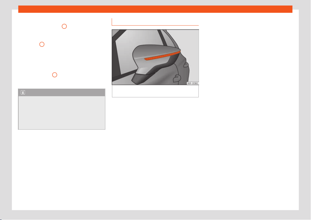
Fuses and bulbs
Turn the connector lock
›
›
›
Fig. 119 in the
direction of arrow
1
and pull on the
connect
or
.
R
otate the bulb holder in the direction of
arrow
2
and extract it with the bulb.
R
epl
ace the def
ective bulb with a new
bulb with the same features.
Insert the bulb holder in the number
plate light and turn in the opposite direc-
tion of arrow
2
until it stops.
Plug the connect
or int
o the bulb hol
der.
Note
Depending on how equipped the vehicle is,
the number plate lights may be LEDs. LEDs
hav
e an estimated life that exceeds than
that of the car. If a light with LEDs fails, go
to an authorised workshop for replace-
ment.
3.
4.
5.
6.
7.
Side turn signals
Fig. 120
Turn signal integrated in the rear view
mirr
or
The side turn signals are LEDS and are inte-
gr
at
ed in the e
xterior mirrors.
In case of failure, go to an authorised work-
shop to have them replaced.
101
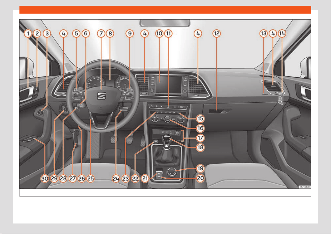
Operation
Fig. 121
Instruments and controls.
102
Controls and displays
Operation
Contr
ol
s and displ
ays
General instrument panel
Door release lever
Central locking s
witch . . . . . . . . . . . . . . . 130
Control for the electric adjustment
of the exterior mirrors . . . . . . . . . . . . . . . . 159
Air vents . . . . . . . . . . . . . . . . . . . . . . . . . . . . . . 179
Control lever for:
–
Turn signals and main beam
headlights
. . . . . . . . . . . . . . . . . . . . . . . . . . 148
–
Lane Assist . . . . . . . . . . . . . . . . . . . . . . . . . 292
–
Main beam assist . . . . . . . . . . . . . . . . . . 149
–
Cruise control system (CCS) . . . . . 274
Depending on equipment fitted:
–
Lever for cruise control . . . . . . . . . . . . 274
Steering wheel with horn and
–
Driver airbag . . . . . . . . . . . . . . . . . . . . . . . 21
–
On-board computer controls . . . . . 120
–
Controls for radio, telephone,
navigation and speech dialogue
system . . . . . . . . . . . . . . . . . . . . . . . . . . . . . . 186
–
Paddle levers for tiptronic gear-
shift (automatic gearbox) . . . . . . . . . 255
Instrument panel . . . . . . . . . . . . . . . . . . . . . 105
1
2
3
4
5
6
7
8
Control lever for:
–
Windscr
een wipers and w
asher
. . . 156
–
Wipe and wash system . . . . . . . . . . . . 156
–
On-board computer . . . . . . . . . . . . . . . 110
According to features: radio or dis-
play for Easy Connect (navigation,
radio, TV/video) . . . . . . . . . . . . . . . . . . . . . . 186
Depending on the equipment, but-
tons for:
–
Start-Stop system . . . . . . . . . . . . . . . . . 269
–
Park assist system . . . . . . . . . . . . . . . . . 313
–
Hazard warning lights . . . . . . . . . . . . . 152
–
Tyre pressure switch . . . . . . . . . . . . . . . 363
–
Airbag off display . . . . . . . . . . . . . . . . . . 78
Depending on the equipment, glove
compartment with: . . . . . . . . . . . . . . . . . . . 166
–
CD player* and/or SD card* . . . . . 209
Front passenger airbag . . . . . . . . . . . . . . 21
Front passenger airbag switch . . . . . . 78
Front passenger seat heating con-
trol . . . . . . . . . . . . . . . . . . . . . . . . . . . . . . . . . . . . 161
Depending on the equipment, con-
trols for:
–
Heating and ventilation system or
manual air conditioner . . . . . . . . . . . . 45
–
Automatic air conditioner . . . . . . . . . 42
Depending on the equipment:
–
USB/AUX-IN input. . . . . . . . . . . . . . . . . . . 237
9
10
11
12
13
14
15
16
17
–
Light
er/po
w
er socket . . . . . . . . . . . . . . 167
–
Connectivity Box/Wireless Charg-
er* . . . . . . . . . . . . . . . . . . . . . . . . . . . . . . . . . . 237
–
Storage compartment . . . . . . . . . . . . . 164
Gear lever for:
–
Manual gearbox . . . . . . . . . . . . . . . . . . . 251
–
Automatic gearbox . . . . . . . . . . . . . . . . 252
Rotating control(Driving Experience
button) for driving modes . . . . . . . . . . . . 303
Auto Hold switch . . . . . . . . . . . . . . . . . . . . . 272
Electronic parking brake switch . . . . . 244
Start-up push button (Keyless Ac-
cess closing and start-up sys-
tem) . . . . . . . . . . . . . . . . . . . . . . . . . . . . . . . . . . . 241
Driver's seat heating control . . . . . . . . 161
Ignition lock (vehicles without Key-
less Access) . . . . . . . . . . . . . . . . . . . . . . . . . . 239
Steering column adjustment lev-
er . . . . . . . . . . . . . . . . . . . . . . . . . . . . . . . . . . . . . 21
Knee airbag . . . . . . . . . . . . . . . . . . . . . . . . . . 23
Bonnet lock release . . . . . . . . . . . . . . . . . . 347
Headlight range control . . . . . . . . . . . . . 154
Headlight switch . . . . . . . . . . . . . . . . . . . . . 147
Electric windows . . . . . . . . . . . . . . . . . . . . . 142
Note
●
Some of the equipment listed in this sec-
tion is only fitted on cer
tain models or are
optional extras.
»
18
19
20
21
22
23
24
25
26
27
28
29
30
103
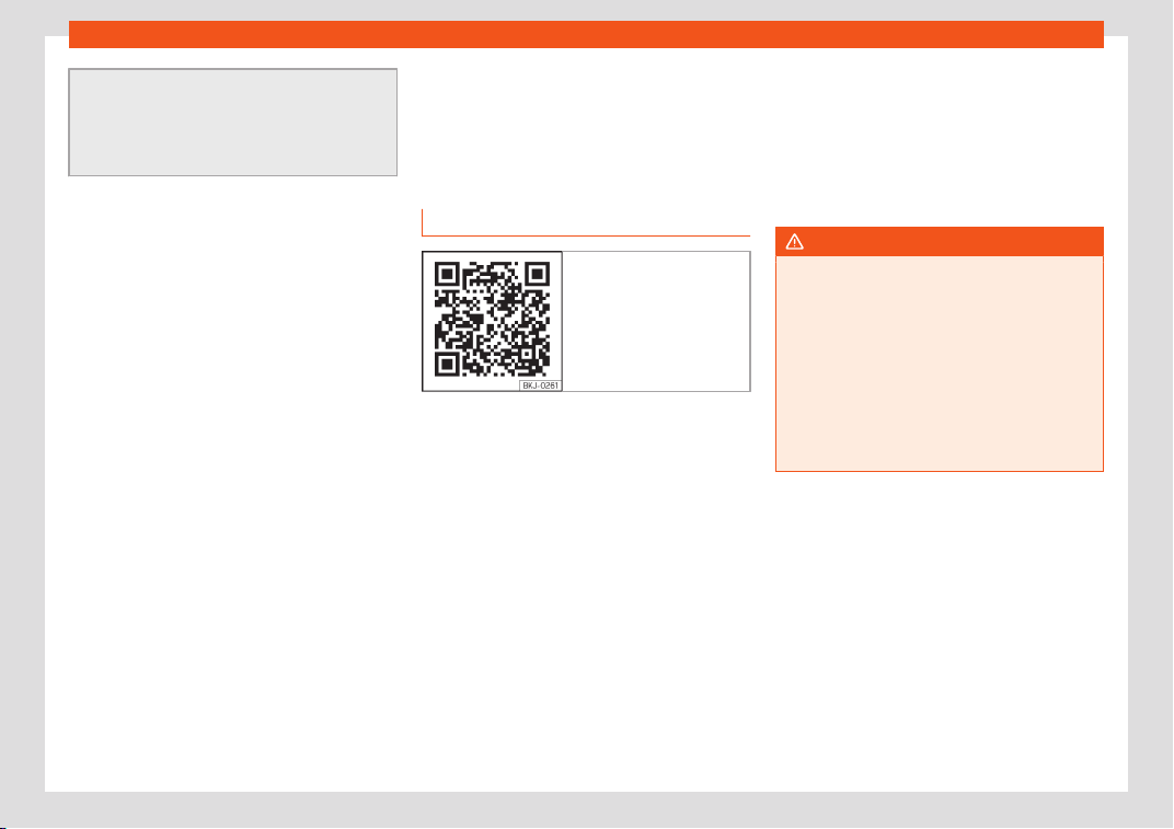
Operation
●
The arrangement of swit
ches and con-
trols on right-hand drive models* may be
slightly different from the layout shown in
›››
page 102. However, the symbols used to
identify the controls are the same.
Instruments and warn-
ing/contr
ol l
amps
Dashboar
d
Introduction
Fig. 122 Related video:
Dash panel
The vehicle can be fitted with a instrument
panel digit
al l
ap timer or one Digit
al (SEAT
Cockpit).
After switching the engine on with a 12-volt
battery that is heavily discharged or newly
changed some system settings (such as the
time, the date, the personalised comfort set-
tings and the programming) might be altered
or deleted. Check and correct these settings
once the battery is sufficiently charged.
WARNING
Any distraction may lead to an accident,
with the risk of injury.
●
Do not operate the instrument panel con-
trols when driving.
●
T
o reduce the risk of accident and injury,
only make adjustments to the instructions
on the screen of the instrument panel and
to the instructions on the screen of the Info-
tainment system when the vehicle is sta-
tionary.
104
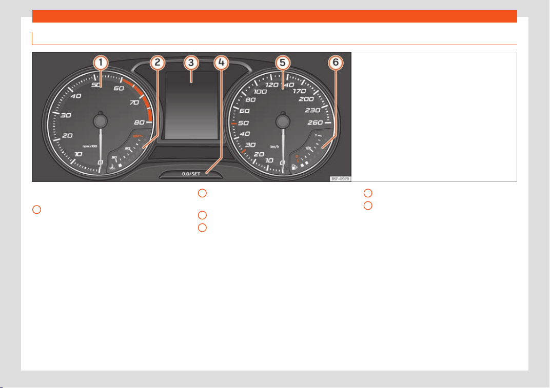
Instruments and warning/control lamps
Analogue instrument panel
Fig. 123
Instrument panel, on dash panel.
Details of the instruments
›
›
›
Fig. 123:
Revolution counter (with the engine run-
ning, in hundreds of revolutions per mi-
nute)
›››
page 117.
1
Engine coolant temperature display
›
›
›
page 118
Displays on the screen
›››
page 108.
Adjuster button and display.
2
3
4
Speedometer.
Fuel gauge
›
›
›
page 117.
5
6
105
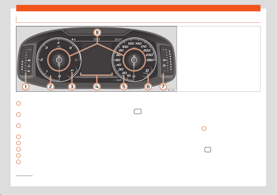
Operation
Digital instrument panel (SEAT Digital Cockpit)
Fig. 124 SEAT Digital Cockpit on the instrument
panel (classic view).
Details of the instruments:
Engine cool
ant t
emper
ature display
›››
page 118
Revolution counter. Revolutions per mi-
nute the engine is running
›››
page 117.
Gear engaged or position of the selec-
tor lever currently selected
Screen display
›››
page 108
Speedometer
Digital speed display
Fuel gauge
›››
page 117.
Information Profile
›››
page 106.
1
2
3
4
5
6
7
8
The Digital SEAT Cockpit is an instrument
panel digit
al with monochr
ome scr
een in col-
our high resolution. It has a 3 views accessi-
ble using the button
of the multifunction
st
eering wheel. By sel
ecting diff
erent infor-
mation profiles, indications other than the
classic circular instruments can be displayed,
such as navigation data, multimedia informa-
tion or travel data.
The 3 views are:
Classic View
Digital maps (no information profiles)
Semicircular watches
–
–
–
All views will display information on the
screen about audio, phone, travel data, vehi-
cle status, navigation
1)
and driving aids
1)
.
In Classic View and Semicircular watches it is
possible to customise the information dis-
played under Information Profiles
›››
Fig. 124
8
.
Inf
ormation pr
ofil
es
With the option INSTRUMENT PANEL (Infotain-
ment button
> Vehicle function but-
ton > View > Instrument cluster) you
1)
Depending on the version.
106
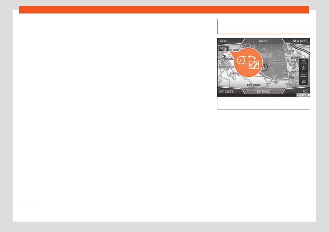
Instruments and warning/control lamps
can choose between the different display op-
tions of the inf
ormation that appears in the
Digit
al SEAT Cockpit.
Cl
assic View
The revolutions per minute and speedometer
needles appear along the entire length
›››
Fig. 124.
View 1, 2, 3 or AUTOMATIC*
1)
Personalisation of the information that ap-
pears in the Digital SEAT Cockpit. Only 2 of
these items of information can be displayed
at the same time, but the user chooses which
to display, and in what order, by moving the
finger vertically over the dials.
Depending on the version, the Views can be
memorised by exiting the menu or keeping
the View button pressed.
●
Consumption. Graphic representation of
the current consumption and digital display
of the average consumption.
●
Audio. Digital display of the current audio
playback.
●
Altitude. Digital display of the current alti-
tude above sea level.
●
Compass. Digital display of the compass.
●
Information about the final destination.
Digital display of the remaining travelling
time, distance to the destination and the esti-
mated time of arrival.
●
Operating range. Digital display of the re-
maining range.
●
Travel time.
●
Route guidance.
●
Journey. Digital display of the distance
travelled.
●
Assistance systems. Graphic representa-
tion of different assistance systems.
●
Traffic signs. Display of traffic signs detec-
ted.
●
Navigation. Graphical representation of
the navigation with arrows.
It may vary based on the features, the num-
ber and the contents of the selectable infor-
mation profiles..
Navigation system in the SEAT
Digital Cockpit*
Fig. 125
Infotainment system: map transfer
butt
on
Depending on the features, the SEAT Digital
Cockpit can displ
ay a det
ail
ed map. To do
this, select the Navigation option in the
menu menu on the instrument panel
›››
page 110.
Depending on the features or the navigation
map, it can be shown in the Digital SEAT
Cockpit or on the Infotainment system or on
both at the same time. If it is displayed only in
the Infotainment system, the SEAT Digital
Cockpit will only display the arrows for ma-
noeuvres.
»
1)
Pre-set information depending on the “Driving
mode” selected.
107

Operation
Transfer of navigation map
Using the map tr
ansf
er k
ey
›››
Fig. 125, the
map is transferred from the Infotainment sys-
tem to the Digital SEAT Cockpit and vice ver-
sa.
Using the right thumbwheel of the multifunc-
tion steering wheel, in the Navigation menu,
you can transfer the map back to the Info-
tainment System.
Display indications
Possible indications on the instrument
panel displ
ay
Diff
er
ent pieces of information can be dis-
played on the screen of the instrument panel,
depending on the features of the vehicle.
●
Doors, bonnet and rear lid open
●
Warning and information messages
●
Odometer
●
Time
›››
page 116
●
Indications of the radio and navigation sys-
tem
●
Indications of the phone
●
Outside temperature
●
Indications of the compass
●
Selector lever positions
●
Gear-change recommendation
›››
page 260
●
Display of travel data (multifunction dis-
play) and menus for different settings
›››
page 110
●
Service interval display
›››
page 119
●
Speed warning
›››
page 110
●
Speed warning for winter tyres
●
Start-Stop system status display
›››
page 269
●
Signs detected by the traffic signal detec-
tion system
›››
page 114
●
Indication of the status of active cylinder
management (ACT
®
)
›››
page 262
●
Low consumption driving
●
Identifying letters on engine (LDM)
●
Driver assistance system display
›››
page 269
●
Copyright
Doors, bonnet and rear lid open
When the vehicle is unlocked and while driv-
ing, the instrument panel display shows if any
of the doors, the bonnet or rear lid are
opened and, in some cases, it is also indica-
ted by an audible warning. The display may
vary according to the type of instrument pan-
el fitted.
Selector lever positions (dual-clutch
DSG
®
)
The current position of the selector lever is
shown on the side of the lever and on the in-
strument panel display. When the lever is in
the D/S position or in the Tiptronic position, in
some cases, the gear engaged in each case
is shown on the instrument panel display.
Outside temperature display
If the outside temperature is lower than ap-
proximately +4°C (+39°F), the “ice crystal
symbol” on the outside temperature dis-
play also lights up. This symbol remains lit un-
til the outside temperature exceeds +6°C
(+43°F)
›››
.
When the v
ehicl
e is st
ationary, when the aux-
iliary heater is switched on or when driving at
very low speeds, the outside temperature in-
dicated may be higher than the actual tem-
perature due to the heat produced by the en-
gine.
The margin of measurement ranges from
-45°C (-49°F) to +76°C (+169°F).
Driving recommendation
While driving, the instrument panel of certain
vehicles may indicate a gear recommenda-
tion for saving fuel
›››
page 260.
108
Instruments and warning/control lamps
Odometer
The od
omet
er
registers the total distance
travelled by the car.
The partial odometer (trip) shows the dis-
tance travelled since the last time it was reset
to zero.
Vehicles with analogue instrument panel:
●
Briefly press the button
›
›
›
Fig. 123
4
to reset the trip recorder to 0.
●
Keep the button
4
pressed for
about 3 seconds and the pr
e
vious v
alue will
be displayed.
Vehicles with digital instrument panel:
●
Set the odometer to zero via the Infotain-
ment system or the multifunction steering
wheel
›››
page 110.
Speed warning for winter tyres
If the maximum speed set is exceeded, this is
displayed on the instrument panel
›››
page 110.
The speed warning can be adjusted on the
Infotainment system: using button
> SET-
TINGS > Driver Assistance
›
›
›
page 35 button.
Compass indication
Depending on the equipment, when the igni-
tion is on, the instrument panel display indi-
cates the direction in which you are driving
with a symbol, e.g. NW for Northwest.
When the Infotainment system is on and there
is no route guidance active, the graphic rep-
resentation of a compass is also shown.
Low consumption driving*
Depending on the equipment, when driving,
the display appears on the instrument
panel when the vehicle is in low consumption
status due to active cylinder management
(ACT
®
)*
›››
page 262.
Identifying letters on engine (LDM)
Vehicles with analogue instrument panel:
●
Switch the ignition on, but do not start the
engine.
●
Hold the button
›
›
›
Fig. 123
4
down
f
or mor
e than 15 seconds t
o display the iden-
tifying letters of the vehicle engine (MKB).
Copyright
Legal text about the property rights and
copyrights of the instrument cluster.
WARNING
Even when the outside temperature is high-
er than freezing t
emperature, some roads
and bridges could be frozen.
●
The “ice crystal symbol” indicates that
there may be a risk of freezing.
●
At outside temperat
ures above +4°C
(+39°F), there may be ice even when the
“ice crystal symbol” is not on.
●
The outside temperature sensor takes a
guideline measurement.
Note
●
Ther
e are diff
erent instrument panels and
therefore the versions and instructions on
the display may vary. In the case of dis-
plays without warning or information texts,
faults are indicated exclusively by the con-
trol warning lamps.
●
Some indications on the instrument panel
screen may be concealed by a sudden
event, e.g. an incoming call.
●
Depending on the equipment, some set-
tings and instructions can be carried out or
displayed on the infotainment system as
well.
●
If there are several warnings at the same
time, the symbols will be displayed one af-
ter the other for a few seconds. The sym-
bols will stay on until you remove the
cause.
●
If when switching on the ignition warnings
are shown about existing faults, it might not
be possible to change the settings or show
the information as described. In this case,
go to a specialised workshop and request a
repair.
109

Operation
Instrument panel menus
The number of menus and information items
availabl
e will depend on the vehicle’s elec-
tronics and features.
A specialised workshop can programme or
modify additional functions, according to the
vehicle equipment. SEAT recommends visiting
a SEAT dealership for this.
Some menu options can only be read when
the vehicle is stationary.
■
Driving data
›››
page 110
■
Assistance systems.
■
Lane Assist On/Off
›››
page 292
■
Front Assist On/Off
›››
page 279
■
Blind spot detector On/Off
›››
page 298
■
ACC (only display)
›››
page 283
■
Navigation.
■
Audio.
■
Telephone.
■
Vehicle status
›››
page 112
Service Menu
3 Applies to vehicl
es with Active Info Display
(Digital SEAT Cockpit)
In the Service menu various settings can be
adjusted depending on the features.
Open the Service menu
To open up the Service menu, sel
ect the
Driving range information profile while in
the Travel data menu, and keep the
key
pr
essed on the multifunction st
eering wheel
f
or approximately 4 seconds. When it is re-
leased, the Service menu will be displayed.
Now you can browse through the menu using
the keys on the multifunction steering wheel
as usual.
Restart the service interval display
Select the Service menu and follow the in-
structions on the screen of the instrument
panel.
Restart the oil service
Select the Restore Oil service menu and
follow the instructions on the instrument pan-
el display.
Restart journey data
Select the Reset trip menu and follow the
instructions on the instrument panel display
to reset the value.
Identifying letters on engine (LDM)
Select the menu Engine code. The identify-
ing letters of the engine will be shown on the
instrument cluster display at the bottom left.
Setting the clock
Select the Time menu and set the correct
time by turning the right thumbwheel of the
multifunction steering wheel.
Journey data display (multifunc-
tion display)
The display of the travel data (multifunction
display) shows diff
erent values about the
journey and the consumption.
Change from one display to another
Vehicles without multifunction steering wheel:
●
press the rocker switch
on the wind-
scr
een wiper l
e
ver
›››
page 121.
Vehicles with multifunction steering wheel:
●
Turn the right thumbwheel of the multifunc-
tion steering wheel
›››
page 121.
Changing memory (vehicles with ana-
logue instrument cluster)
Press the
button on the windscreen
wiper l
e
v
er or the
button of the multifunc-
tion st
eering wheel.
Changing memory (v
ehicl
es with digital
instrument cluster)
While in Travel data > General infor-
mation press
on the multi-function
110

Instruments and warning/control lamps
steering wheel to switch between the 3 mem-
ories
1)
:
The memory is del
et
ed if the
journey is int
errupted for more than 2
hours.
Display and storage of
the journey data and the consumption
values collected. When refuelling, the
memory is deleted.
This memory contains travel data
up to a maximum of 19 hours and 59 mi-
nutes or 99 hours and 59 minutes, or up
to a maximum of 1999.9 km or
9999.9 km. When one of these values is
exceeded (varies depending on the ver-
sion of the instrument panel), the memo-
ry is deleted.
Delete journey data presets
●
Select the memory that you wish to erase.
●
Hold the
button of the multifunction
st
eering wheel or the button of the multi-
function wheel pr
essed do
wn f
or about 2
seconds.
Since start
Since refuelling
Long-term
Select the instructions
In the Infotainment system, in the menu Vehi-
cle settings, you can display different travel
data
›››
page 35.
The current
fuel consumption display operates
throughout the journey, in litres/100 km;
and with the engine running and the ve-
hicle stopped, in litres/hour.
The average
fuel consumption is displayed after driv-
ing for approximately 300 metres.
This indicates the hours
(h) and minutes (min) since the ignition
was switched on.
Approximate distance in
km that can still be travelled if the same
driving style is maintained.
Approxi-
mate distance in km that can still be
travelled with the current level of the
AdBlue
®
tank with the same driving style.
The indication appears from a range of
less than 2,400 km and cannot be de-
activated.
2)
Current fuel consumption
Average fuel consumption
Travelling time
Operating range
Adblue Autonomy or Autonomy
Distance covered in
km (m) after switching on the ignition.
The average speed will be
shown after driving for approximately
100 metres.
Current speed displayed in
digital format.
Displays a list of
the connected comfort systems that in-
crease energy consumption, e.g. air
conditioning.
Set a speed warning
●
Select the display Speed warning at
--- km/h or Speed warning at --- mph.
●
Press the button
on the windscreen
wiper l
e
v
er or the button
on the multifunc-
tion st
eering wheel t
o st
ore the current speed
and activate the warning.
●
Activate: adjust to the desired speed within
5 seconds using the rocker switch
on the
windscr
een wiper l
e
ver or by turning the
thumbwheel on the multifunction steering
wheel. Next, press the button
or
again or wait several seconds. The speed is
st
or
ed and the w
arning activated.
»
Distance travelled
Average speed
Digital speed
Convenience consumers
1)
This will show all data on the display at the
same time: distance trav
elled, average con-
sumption, average speed and autonomy.
2)
Not available in all countries.
111
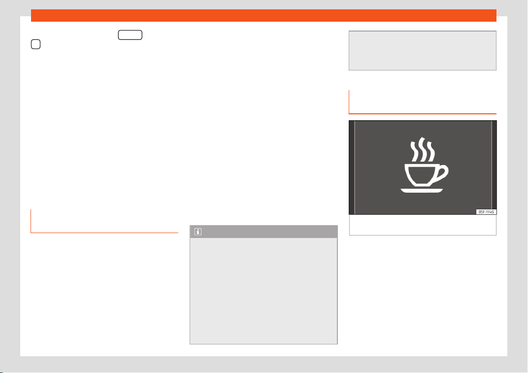
Operation
●
Deactiv
at
e:
press button
or button
. The stored speed is deleted.
The w
arning can be adjust
ed f
or speeds be-
tween 30 km/h (18 mph) and 250 km/h
(155 mph).
Display Oil temperature
The engine reaches its operating tempera-
ture when, under normal driving conditions,
the oil temperature is between 80°C and
120°C. If the engine is under a lot of stress
and the outside temperature is high, the en-
gine oil temperature can increase. This does
not present any problem as long as the warn-
ing lamps or
›››
page 350 do not ap-
pear on the display.
Warning and information messages
(Vehicle status)
The system runs a check on certain compo-
nents and functions when the ignition is
s
wit
ched on and whil
e the vehicle is moving.
Faults displayed on the instrument panel as
red and yellow warning symbols accompa-
nied with messages and
›››
page 39, de-
pending on the case, even an audible warn-
ing. The representation of the messages and
symbols may vary depending on the version
of the instrument panel.
Existing faults can also be checked manually.
To do so, open the menu Vehicle status or
Vehicle
›››
page 110.
The symbol lights
up or flashes (in part accompanied by
audible warnings). Stop driving! Dan-
ger! Check the fault and eliminate the
cause. If necessary, seek professional
assistance.
The symbol
lights up or flashes (in part accompa-
nied by audible warnings). Operating
faults or the lack of operating fluids can
cause damage to the vehicle or a fault.
Check the faulty function as soon as
possible. If necessary, seek professional
assistance.
It provides informa-
tion about processes in the vehicle.
Note
●
Depending on the equipment, some set-
tings and instructions can be carried out or
displayed on the inf
otainment system as
well.
●
If there are several warnings at the same
time, the symbols will be displayed one af-
ter the other for a few seconds. The sym-
bols will stay on until you remove the
cause.
●
If when switching on the ignition warnings
are shown about existing faults, it might not
Priority 1 warning (red).
Priority 2 warning (yellow).
Information message.
be possible to change the settings or show
the information as described. In this case,
go t
o a specialised workshop and request a
repair.
Fatigue detection (break recom-
mendation)*
Fig. 126
On the screen of the instrument pan-
el
: f
atigue det
ection.
The Fatigue detection informs the driver when
their driving behaviour sho
ws signs of f
atigue
.
Function and operation
Fatigue detection determines the driving be-
haviour of the driver when starting a journey,
making a calculation of tiredness. This is con-
stantly compared with the current driving be-
haviour. If the system detects that the driver is
tired, an audible warning is given with a
sound and an optic warning is shown with a
112
Instruments and warning/control lamps
symbol and complementary message on the
instrument panel displ
ay
›
›
›
Fig. 126. The
message on the instrument panel display is
shown for approximately 5 seconds, and de-
pending on the case, is repeated. The system
stores the last message displayed.
The message on the instrument panel display
can be switched off by pressing the
button on the windscreen wiper lever or the
butt
on
on the multi function steering
wheel
›
›
›
page 120.
The message can be recalled to the instru-
ment panel display using the multifunction
display
›››
page 110.
Conditions of operation
Driving behaviour is only calculated on
speeds above about 65 km/h (40 mph) up to
around 200 km/h (125 mph).
Switching on and off
Fatigue detection can be activated or deacti-
vated in the Easy Connect system with the
/ button and the SETTINGS function but-
t
on
›
›
›
page 35. A mark indicates that the
adjustment has been activated.
System limitations
The Fatigue detection has certain limitations
inherent to the system. The following condi-
tions can limit the Fatigue detection or pre-
vent it from functioning.
●
At speeds below 65 km/h (40 mph)
●
At speeds above 200 km/h (125 mph)
●
When cornering
●
On roads in poor condition
●
In unfavourable weather conditions
●
When a sporty driving style is employed
●
In the event of a serious distraction to the
driver
Fatigue detection will be restored when the
vehicle is stopped for more than 15 minutes,
when the ignition is switched off or when the
driver has unbuckled their seat belt and
opened the door.
In the event of slow driving during a long peri-
od of time (below 65 km/h, 40 mph) the sys-
tem automatically re-establishes the tired-
ness calculation. When driving at a faster
speed the driving behaviour will be recalcula-
ted.
WARNING
Do not let the comfort afforded by the Fati-
gue detection system t
empt you into taking
any risks when driving. Take regular breaks,
sufficient in length when making long jour-
neys.
●
The driver always assumes the responsi-
bility of driving to their full capacity.
●
Never drive if you are tired.
●
The system does not detect the tiredness
of the driver in all circumstances. Consult
the information in the section
›››
page 113,
System limitations.
●
In some situations, the system may incor-
rectly interpret an intended driving ma-
noeuvre as driver tiredness.
●
No warning is given in the event of the ef-
fect called microsleep!
●
Please observe the indications on the in-
strument panel and act as is necessary.
Note
●
Fatigue detection has been de
veloped
for driving on motorways and well paved
roads only.
●
If there is a fault in the system, have it
checked by a specialised workshop.
113
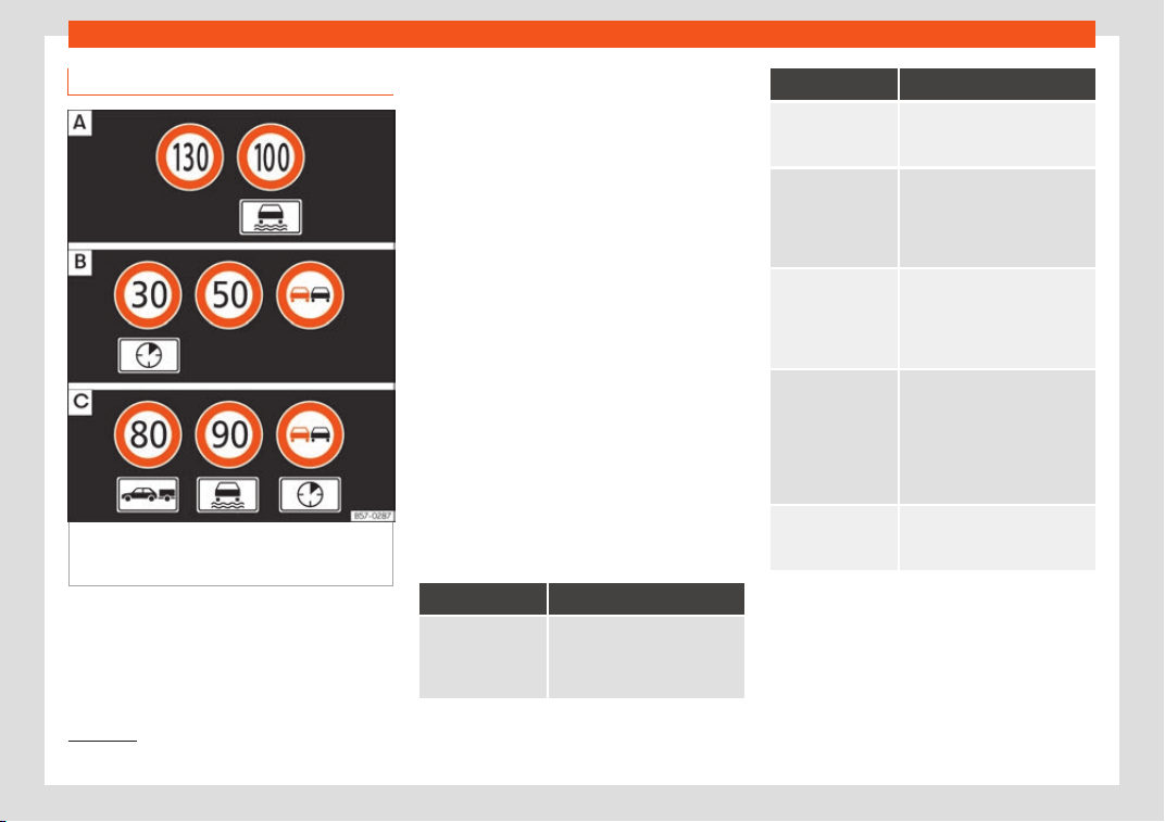
Operation
Traffic sign detection system*
1)
Fig. 127
On the instrument panel display: ex-
ampl
es of speed limits or o
v
ertaking prohibi-
tions with their respective additional signs.
The traffic sign detection system records the
st
andar
d tr
affic signs in front of the vehicle
with a camera located on the base of the in-
terior mirror and provides information about
speed limits and overtaking prohibitions.
Within its limitations, the system also displays
additional signals, such as time-specific pro-
hibitions, signs for vehicles towing trailers
›››
page 329 or limitations that only apply in
the event of rain. Even on journeys without
signs, the system may display any applicable
speed limits.
The traffic sign detection system does not
work in all countries. Keep this in mind when
travelling abroad.
Indication on the display
In Germany, on motorways and vehicle
roads, besides speed limits and overtaking
provisions the system also displays the end of
prohibition signs. The valid speed limit at the
time in other countries is always shown.
The traffic signs detected by the system are
displayed on the dash panel display
›››
Fig. 127 and, depending on the navigation
system fitted in the vehicle, on the infotain-
ment system as well
›››
page 35.
Traffic sign detection system messages
Message Cause and solution
There are no
traffic signs
available
The system is starting up.
OR: the camera has not rec-
ognised any obligation or pr
o-
hibition signs.
Message Cause and solution
Error: Detec-
tion of traf-
fic signs
There is a fault in the system.
Have the system check
ed by a
specialised workshop.
Speed warning
currently un-
available.
The speed warning function of
the traffic sign detection sys-
t
em is faulty.
Have the system checked by a
specialised workshop.
Detection of
traffic
signs: Clean
the wind-
screen!
The windscreen is dirty in the
camera area.
Cl
ean the windscreen.
Detection of
traffic
signs: Limi-
ted at the
moment
No data transfer by the navi-
gation system.
Check whether the navigation
system has curr
ent maps.
OR: the vehicle is currently in a
region that is not included in
the navigation system's map.
No data
available
The traffic sign detection sys-
tem does not work in the cur-
rent country.
Activating and deactivating traffic sign
displ
ay on the instrument panel
The permanent displ
ay of tr
affic signs on the
instrument panel can be activated or deacti-
vated in the infotainment system using the
1)
System available depending on the country.
114

Instruments and warning/control lamps
> SETTINGS > Driver Assistance
function butt
ons.
Displ
ay of tr
affic signs
When the traffic sign detection system is con-
nected, a camera located on the base of the
interior rear-view mirror records the traffic
signs in front of the vehicle. After checking
and evaluating the information from the cam-
era, the navigation system and the current
vehicle data, up to three valid traffic signs are
displayed
›››
Fig. 127 B in conjunction with
their corresponding additional signs.
The sign that is currently valid for the
driver is shown in the left side of the
screen For example, a maximum speed
limit of 130 km/h (100 mph)
›››
Fig. 127 A.
A sign valid only in certain circum-
stances, e.g. 100 km/h (60 mph) is shown
second, together with the additional rain
sign.
If the windscreen wiper is
working while you are driving, the signal
with the additional rain sign will be
shown first, on the left, as it is the one
that is applicable at the time.
A sign valid only with restrictions, e.g.
No overtaking at certain times, will be
displayed third
›››
Fig. 127 C.
First:
Second:
Additional sign:
Third:
Speed warning
If the system detects that the permitted
speed is exceeded, it may warn the driver
with a “gong” and visually with a message on
the dash panel display.
The speed warning can be adjusted or deac-
tivated completely in the infotainment system
using the
> SETTINGS > Driver As-
sistance function butt
ons
›
›
›
page 35.
The speed is adjusted in steps of 5 km/h
(3 mph) within a range of between 0 km/h
(mph) and 20 km/h (12 mph) above the maxi-
mum speed permitted.
Trailer mode
In vehicles equipped with a towing bracket
device from the factory and a trailer that is
electrically connected to the vehicle, it is
possible to activate or deactivate the display
of specific traffic signs for vehicles with trailer,
such as speed limits or overtaking prohibi-
tions. Activation or deactivation is performed
on the infotainment system using the
>
SETTINGS > Driver Assistance function
butt
ons
›
›
›
page 35.
For trailer mode, the display of speed limits
applicable to the type of trailer or to the legal
provisions can be adjusted. The speed is ad-
justed in steps of 10 km/h (5 mph) within a
range of between 60 km/h (40 mph) and
130 km/h (80 mph). If it is adjusted to a speed
greater than that which is permitted in the
country in question for driving with a trailer,
the system automatically displays the usual
speed limits, e.g. in Germany 80 km/h
(50 mph).
If the speed warning for the trailer is deacti-
vated, the system displays the speed limits as
if there were no trailer hitched.
Limited operation
The traffic sign detection system has certain
limitations. The following cases may lead the
system to operate with limitations or not at
all:
●
In the case of poor visibility, e.g. in snow,
rain, fog or intense mist.
●
In cases of dazzling, e.g. caused by head-
on traffic or by the sun.
●
When driving at high speeds.
●
If the camera is covered or dirty.
●
If the traffic signs are out of the camera's
field of vision.
●
If the traffic signs are partially or totally
covered, e.g. by trees, snow, dirt or other vehi-
cles.
●
In the case of traffic signs that do not fulfil
the regulations.
●
In the case of damaged or bent traffic
signs.
»
115
Operation
●
In the case of v
ariabl
e messages on o
ver-
head or gantry signs (LED-based variable
traffic signs or other lighting units).
●
If the maps on the navigation system are
not up-to-date.
●
In the case of adhesives affixed to vehicles
that depict traffic signs, e.g. speed limits on
lorries.
WARNING
The technology in the traffic sign detection
system cannot change the limits imposed
by the laws of physics and only w
orks with-
in the system's limits. Do not let the extra
convenience afforded by the traffic sign
detection system tempt you into taking any
risks when driving. The system is not a re-
placement for driver awareness.
●
Adapt your speed and driving style to suit
visibility, weather, road and traffic condi-
tions.
●
Poor visibility, darkness, snow, rain and
fog may lead to the system failing to dis-
play traffic signs or not displaying them
correctly.
●
If the camera's field of vision is dirty, cov-
ered or damaged, system operation may
be impaired.
WARNING
The driving recommendations and traffic
indications shown on the traffic sign det
ec-
tion system may differ from the actual cur-
rent traffic sit
uation.
●
The system may not detect or correctly
show all the traffic signs.
●
Traffic signs and traffic regulations have
priority over the recommendations and dis-
plays provided by the system.
WARNING
If messages are ignored, the vehicle may
st
all in traffic and cause accidents and se-
v
ere injuries.
●
Never ignore the messages displayed.
●
Stop the vehicle at the next opportunity
and in a safe place.
Note
In order not to compromise the system's
operation, please t
ake the following points
into account:
●
Regularly clean the area of vision of the
camera and keep it in a clean state, without
snow or ice.
●
Do not cover the field of vision of the
camera.
●
Always replace damaged or worn blades
when required to avoid lines on the cam-
era's field of vision.
●
Check that the windscreen is not dam-
aged in the area of the camera's field of vi-
sion.
●
The use of outdated maps on the naviga-
tion syst
em may cause the system to show
traffic signs incorrectly.
●
In the waypoints mode of the navigation
system, the traffic sign detection system is
only partly available.
●
Failure to heed the control lamps and
corresponding text messages when they
light up may result in damage to the vehi-
cle.
Time
Setting the time on the infotainment sys-
t
em
●
Pr
ess the inf
otainment
button.
●
Press the SETTINGS function butt
on.
●
Sel
ect the menu option
Date and time to
set the time
›››
page 35.
Setting the time on analogue the instru-
ment panel
●
To set the time (for all vehicle clocks), press
and hold the button
on the instrument
panel until the Time is displ
ayed.
●
R
el
ease the button
. The time is dis-
pl
ayed on the instrument panel displ
ay and
the hours fiel
d is highlighted.
●
Afterwards, press the button
until the
desir
ed time is displ
ayed. T
o scroll quickly,
hold the button
.
116
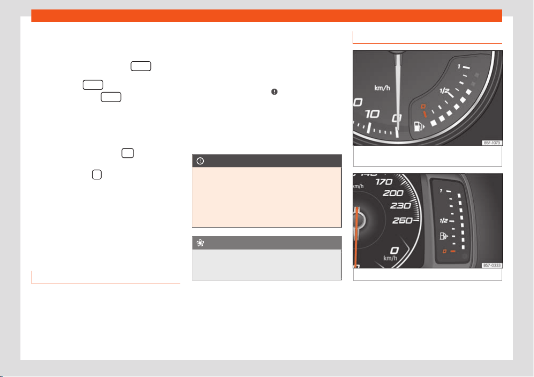
Instruments and warning/control lamps
●
When they hav
e finished setting the hour
,
w
ait until the minute field is marked on the in-
strument panel display.
●
Afterwards, press the button
until the
desir
ed time is displ
ayed. T
o scroll quickly,
hold the button
.
●
Release the button in order to finish
setting the time
.
Adjusting the time in the SEAT Digit
al
Cockpit
●
Whil
e on the Driving data menu select
Range (Infotainment button
> View >
Driving data > Range).
●
Press the button on the multifunction
st
eering wheel until the Service menu is dis-
pl
ayed on the instrument panel displ
ay
›››
page 110.
●
Select the menu Time.
●
Adjust the correct time by turning the right
thumbwheel of the multifunction steering
wheel.
Revolution counter
The rev counter indicates the number of en-
gine r
e
v
olutions per minute.
Together with the gear-change indicator, the
rev counter offers you the possibility of using
the engine of your vehicle at a suitable
speed.
The beginning of the red zone of the rev
counter indicates the maximum speed in any
gear after running-in and with the engine hot.
However, it is advisable to change up a gear
or move the selector lever to D (or lift your
foot off the accelerator) before the needle
reaches the red zone
›››
.
W
e r
ecommend that you av
oid high revs and
that you follow the recommendations on the
gear-change indicator. Consult the addition-
al information in
›››
page 260, Choosing the
ideal gear.
CAUTION
●
To pre
vent damage to the engine, the rev
counter needle should only remain in the
red zone for a short period of time.
●
When the engine is cold, avoid high revs
and heavy acceleration and do not make
the engine work hard.
For the sake of the environment
Changing up a gear early will help you to
save fuel and minimise emissions and en-
gine noise.
Fuel level indicator
Fig. 128
Analogue instrument panel: fuel
gauge
Fig. 129 Digital instrument panel: fuel gauge.
»
117
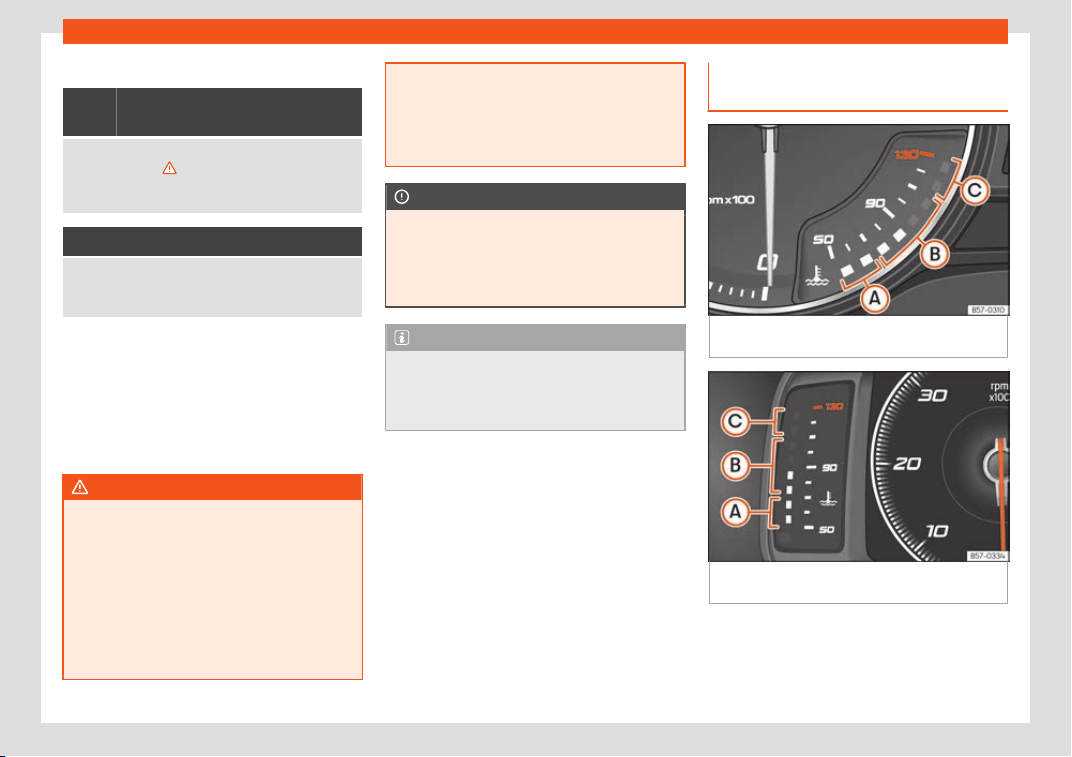
Operation
Control lamps
It lights up, and in addition, the
low
er diode lights up in red
Fuel tank almost empty. The fuel reserve level has
been reached
››
›
. Refuel as soon as possible.
When the fuel level is very low, the lower diode flash-
es in red.
It lights up yellow
Presence of water in the diesel.
Switch off the engine and r
equest the assistance of
specialised personnel.
The display only works when the ignition is
s
wit
ched on.
The fuel r
ange is displayed on the instrument
panel.
You can consult the tank capacity of your ve-
hicle in the
›››
page 47 section.
WARNING
When driving with low fuel, the vehicle may
stall in traffic and cause accidents and se-
v
ere injuries.
●
If the fuel tank level is too low, fuel could
reach the engine irregularly, particularly
when driving up or down slopes.
●
The steering system and the driver assis-
tance systems and brakes do not work
when the engine is running irregularly or
switches off due to lack of fuel or an irregu-
lar supply thereof
.
●
Always refuel when there is only one
quarter of fuel in tank to prevent the vehicle
to stop due to lack of fuel.
CAUTION
Never run the fuel tank completely dry. An
irr
egular fuel supply can cause misfiring
and unburnt fuel coul
d enter the exhaust
system. The catalytic converter or the par-
ticulate filter may get damaged!
Note
The small arrow on the fuel gauge next to
the fuel pump symbol points out tow
ards
the side of the vehicle with the fuel tank
flap.
Engine coolant temperature dis-
pl
ay
Fig. 130
Analogue instrument panel: engine
cool
ant t
emper
ature display.
Fig. 131
Digital instrument panel: engine cool-
ant t
emper
at
ure display.
›››
Fig. 130,
›
››
Fig. 131
:
1
18
Instruments and warning/control lamps
Cool zone. The engine has not r
eached
oper
ating t
emperature yet. Avoid high en-
gine speeds and stressing the engine if it
has not reached operating temperature.
Normal zone. At high outside tempera-
tures and when making the engine work
hard, the diodes may continue lighting up
and reach the upper zone. This is no
cause for concern, provided the control
lamp does not light up
Warning area. When the engine is work-
ing hard, especially at high outside tem-
peratures, the diodes may light up in the
warning area.
The coolant temperature gauge only works
when the ignition is switched on.
Control and warning lamp
It lights up red
Do not keep driving!
Engine coolant l
evel too low, coolant temperature too
high
Flashes red
Fault in the engine coolant system.
●
Stop the vehicle, switch off the engine and
l
et it cool do
wn.
●
Check the engine cool
ant level
›››
page 352.
A
B
C
●
If the w
arning l
amp does not s
witch off even
if the coolant level is correct, request assis-
tance from specialised personnel.
CAUTION
●
To ensure a l
ong useful life for the engine,
avoid high revs, driving at high speed and
making the engine work hard for approxi-
mately the first 15 minutes when the engine
is cold. The phase until the engine is warm
also depends on the outside temperature. If
necessary, use the engine oil temperature*
›››
page 112 as a guide.
●
Additional lights and other accessories in
front of the air inlet reduce the cooling ef-
fect of the coolant. At high outside temper-
atures and high engine loads, there is a risk
of the engine overheating.
●
The front spoiler also ensures proper dis-
tribution of the cooling air when the vehicle
is moving. If the spoiler is damaged this can
reduce the cooling effect, which could
cause the engine to overheat. Seek spe-
cialist assistance.
Service intervals
The service interval indication appears on the
instrument panel displ
ay and the Inf
ot
ain-
ment system.
There are different versions of instrument
panels and infotainment systems, so the ver-
sions and instructions on the screens may
vary.
SEAT distinguishes between services with en-
gine oil change (e.g. Oil change service) and
services without engine oil change (e.g. In-
spection).
In vehicles with Services established by
time or mileage, the service intervals are al-
ready pre-defined.
In vehicles with LongLife Service, the inter-
vals are determined individually. Thanks to
technological progress, maintenance work
has been greatly reduced. Because of the
technology used by SEAT, with this service
you only need to change the oil when the ve-
hicle so requires. To calculate this variation
(max. 2 years), the vehicle's conditions of use
and individual driving styles are considered.
The advance warning first appears 20 days
before the date established for the corre-
sponding service. The kilometres (miles) re-
maining until the next service are always
rounded up to the nearest 100 km (miles) and
the time is given in complete days. The cur-
rent service message cannot be viewed until
500 km after the last service. Prior to this, on-
ly lines are visible on the display.
Inspection reminder
If a service or an inspection has to be carried
out soon, a service reminder will be dis-
played when the ignition is switched on.
»
119
Operation
The figure displayed are the kilometres that
can still be tr
av
ell
ed or the time until the next
service.
Service due
When the time for a service or an inspec-
tion comes, an audible warning will be emit-
ted when the ignition is switched on and the
fixed key symbol may appear on the in-
strument panel for a few seconds, along with
one of the following messages:
●
Service now!
●
Request an inspection.
●
Oil service required!
●
Oil service and inspection re-
quired!
Check a service warning
With the ignition switched on, the engine off
and the vehicle at a standstill, the current
service notification can be read:
Check the date of the current service on the
infotainment system
●
Press the infotainment
button.
●
Press the SETTINGS function butt
on
›
›
›
page 35.
●
Select the Service menu option to display
information about the services.
Vehicles with analogue instrument panel
●
Press and hold the button
›››
Fig. 123
4
for more than 5 seconds to
consult the service message
V
ehicl
es with digit
al instrument panel
●
The date of the service can only be read
through the Service menu
›››
page 110.
Resetting service interval display
If the service was not carried out by a SEAT
dealership, the display can be reset as fol-
lows:
Vehicles with analogue instrument panel
●
Switch off the ignition, press and hold but-
ton
›
›
›
Fig. 123
4
.
●
Switch ignition back on.
●
Release the button and press it
again f
or the ne
xt 20 seconds.
V
ehicles with digital instrument panel
●
The service interval display can only be re-
set through the Service menu
›››
page 110.
Do not restart the indicator between the
service intervals, otherwise the information
displayed will be incorrect.
If the oil change service is reset manually, the
service interval display changes to a fixed
service interval, also in vehicles with Flexible
oil change service.
Note
●
The service message disappears after a
fe
w seconds, when the engine is started or
when OK/RESET
is pressed on the wind-
screen wiper le
ver, or OK
on the multifunc-
tion steering wheel.
●
In vehicl
es with the LongLife system in
which the battery has been disconnected
for a long period of time, it is not possible to
calculate the date of the next service.
Therefore the service interval display may
not be correct. In this case, bear in mind the
maximum service intervals permitted
›››
page 367.
●
If you reset the display manually, the next
service interval will be indicated as in vehi-
cles with fixed service intervals. For this
reason we recommend that the service in-
terval display be reset by a SEAT author-
ised Dealer.
Using the instrument panel
Intr
oduction
With the ignition switched on, it is possible to
r
ead the diff
er
ent functions of the display by
scrolling through the menus.
In vehicles with multifunction steering wheel,
the multifunction display can only be operat-
ed with the steering wheel buttons.
120
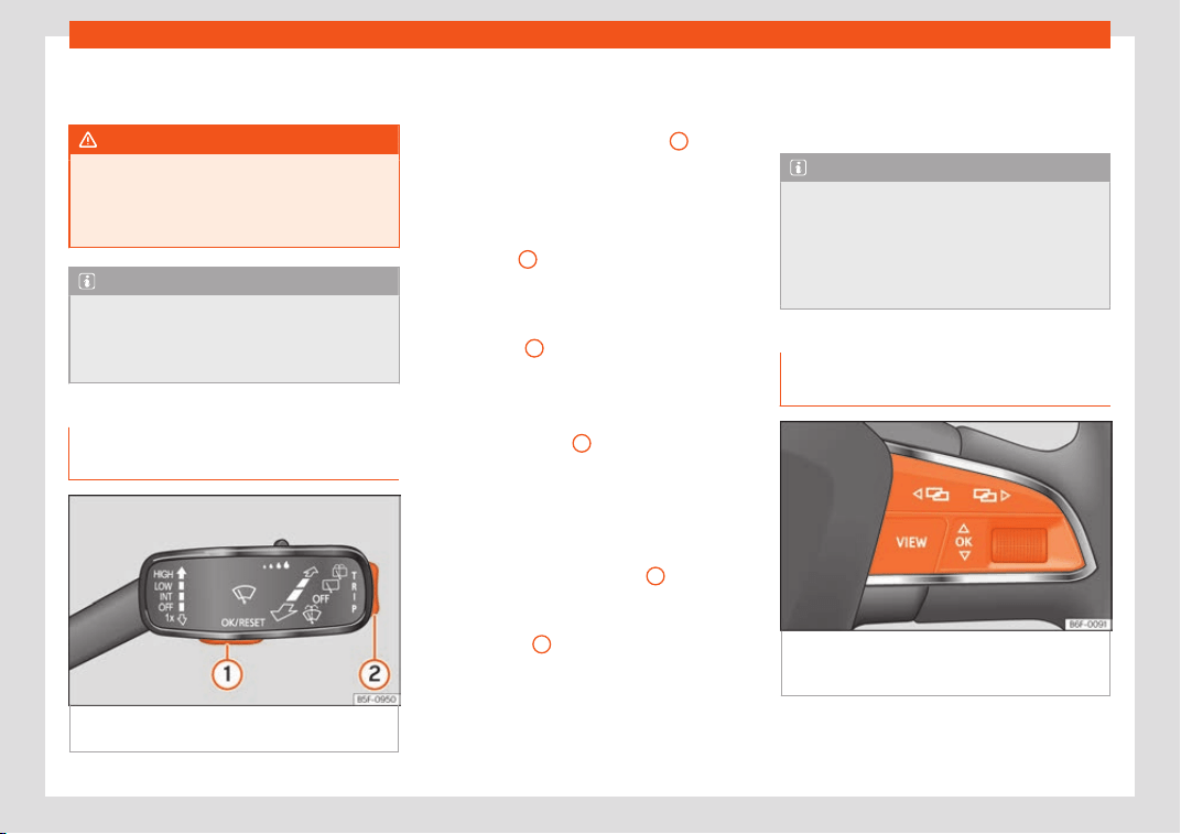
Instruments and warning/control lamps
Some menu options can only be read when
the v
ehicl
e is at a st
andstill.
WARNING
Distracting the driver in any way can lead
to an accident and cause injuries.
●
Nev
er use the menus on the instrument
panel display while the vehicle is in motion.
Note
After loading or changing the 12-volt bat-
tery, check the system settings. If the po
w-
er supply is interrupted, the system settings
might be incorrect or deleted.
Operation with the windscreen wip-
er l
e
v
er
Fig. 132
Windscreen wipers lever: control but-
t
ons.
As long as a priority 1
›
›
›
page 112 warning is
active, it will not be possible to access any
menu. Some warnings can be confirmed and
hidden with the button
›››
Fig. 132
1
.
Sel
ect a menu or an inf
ormativ
e display
●
Switch the ignition on.
●
If a message or vehicle symbol is displayed,
press button
1
; if necessary, several times.
●
To display the menus
›
›
›
page 110 or to re-
turn to the selection of menus from a menu or
from an informative display, hold down the
rocker button
2
.
●
To change from one menu to another, press
the upper or l
o
w
er part of the rocker switch.
●
To open the menu or the informative display
shown, press button
1
or wait a few seconds
until the menu or the inf
ormativ
e displ
ay
opens automatically.
Changing menu settings
●
In the menu displayed, press the upper or
lower part of the rocker switch
2
until the re-
quir
ed menu option is check
ed. The option
appears fr
amed.
●
Press button
1
to make the required modi-
fications. A mark indicat
es that the syst
em or
function is activ
ated.
Back to menu selection
Select Back on the corresponding menu to
exit.
Note
If when switching on the ignition warnings
are shown about e
xisting faults, it might not
be possible to change the settings or show
the information as described. In this case,
go to a specialised workshop and request a
repair.
Using the multifunction steering
wheel
Fig. 133
Right side of multifunction steering
wheel
: butt
ons t
o the menus and informative in-
dications on the instrument panel.
As long as a priority 1
›
›
›
page 112 warning is
active, it will not be possible to access any
menu. Some warnings can be confirmed and
»
121
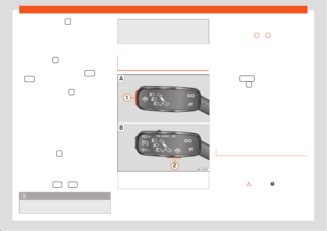
Operation
hidden with the button of the multifunction
st
eering wheel
›
›
›
Fig. 133.
Select a menu or an informative display
●
Switch the ignition on.
●
If a message or vehicle symbol is displayed,
press the button
›
›
›
Fig. 133; if necessary,
several times.
●
To change menus, use buttons
or
›
›
›
Fig. 133.
●
To open the menu or the information dis-
played, press the button
›
›
›
Fig. 133 or
wait a few seconds until the menu or the in-
formative display opens automatically.
Changing menu settings
●
In the menu displayed, turn the right thumb-
wheel of the multifunction steering wheel
›››
Fig. 133 until the desired option of the
menu is highlighted. The option appears
framed.
●
Press the button
›
›
›
Fig. 133 to make the
required modifications. A mark indicates that
the system or function is activated.
Back to menu selection
Press the button
or
›
›
›
Fig. 133.
Note
If when switching on the ignition warnings
are shown about e
xisting faults, it might not
be possible to change the settings or show
the information as described. In this case,
go t
o a specialised workshop and request a
repair.
Key for the driving assistance sys-
tems*
Fig. 134
On the turn light and main beam lev-
er: k
ey f
or driv
er assistance systems (depend-
ing on the version).
With the turn signal and main beam headlight
l
e
v
er button, you can activate or deactivate
the driver assistance systems displayed in the
Assistance systems menu.
Activate or deactivate a driver assistance
system
●
Press
›››
Fig. 134
1
or
2
briefly to open
the Driving aids menu.
●
Select the driver assistance system and ac-
tiv
at
e or deactiv
ate it
›››
page 120. A mark in-
dicates that driver assistance system is
switched on.
●
Afterwards, mark or confirm the selection
with button
on the windscreen wiper
l
e
v
er or button
on the multifunction steer-
ing wheel.
The driv
er assist
ance syst
ems can also be
switched on and off in the infotainment sys-
tem, in the menu Vehicle settings
›››
page 35.
Control lamps
Control and warning lamps
Read the additional information carefully
›
›
›
page 39.
The control and warning lamps are indicators
of warnings,
›››
, faults
›
›
›
or certain func-
tions. Some contr
ol and w
arning l
amps come
on when the ignition is switched on, and
switch off when the engine starts running, or
while driving.
122
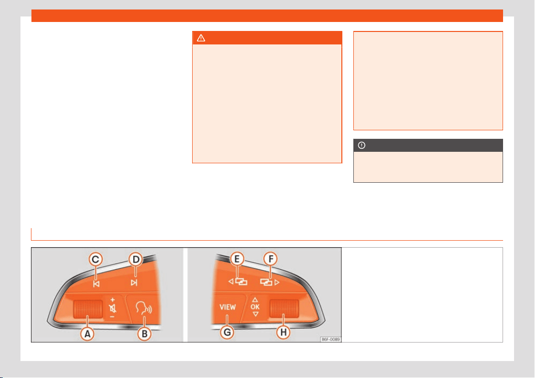
Instruments and warning/control lamps
Depending on the model, additional text
messages may be vie
w
ed on the instrument
panel displ
ay. These may be purely informa-
tive or they may be advising of the need for
action
›››
page 104, Dashboard.
Depending upon the equipment fitted in the
vehicle, instead of a warning lamp, some-
times a symbol may be displayed on the in-
strument panel.
When certain control and warning lamps are
lit, an audible warning is also heard.
WARNING
If the warning lamps and messages are ig-
nored, the vehicl
e may stall in traffic, or
may cause accidents and severe injuries.
●
Never ignore the warning lamps or text
messages.
●
Stop the vehicle safely as soon as possi-
ble.
●
Park the vehicle away from traffic and
ensure that there are no highly flammable
materials under the vehicle that could
come into contact with the exhaust system
(e.g. dry grass, fuel).
●
A faulty v
ehicle represents a risk of acci-
dent for the driver and for other road users.
If necessary, switch on the hazard warning
lamps and put out the warning triangle to
advise other drivers.
●
Before opening the bonnet, switch off the
engine and allow it to cool.
●
In any vehicle, the engine compartment is
a hazardous area and could cause severe
injuries
›››
page 347.
CAUTION
Failure to heed the control lamps and text
messages when they appear may r
esult in
faults in the v
ehicle.
Multifunction steering wheel*
Oper
ating the audio
, t
elephone and navigation system with voice control
Fig. 135 Controls on the steering wheel.
»
123

Operation
The steering wheel includes a multifunction
modul
e fr
om wher
e it is possible to control
the audio, telephone and radio/navigation
functions without needing to distract the driv-
er.
Applies to vehicles with analogue instrument panel
Button Radio Media (except AUX) AUX Telephone* Navigation*
A
Turn
Turn volume up/down. You
do not need to be in audio
mode (radio).
Turn volume up/down. You
do not need to be in audio
mode (media).
Turn volume up/down. You
do not need to be in audio
mode (media).
Turn volume up/down. You
do not need to be in tele-
phone mode.
Turn announcement volume
up/down. You do not need t
o be in
navigation mode but there has to
be an announcement active when
you adjust the volume.
A
Press
Mute volume. Mute volume. Mute volume. Mute incoming call.
Mute the current navigation an-
nouncement.
B
a)
Enable/disable voice control.
b)
This function can be used from any mode, in the case of an activ
e call.
C
/
D
Search for the previous/next
station
c)
.
Short press:
Switch t
o the
previous/next song.
Hold down: Fast rewind/for-
ward
d)
.
No function
– No active call: Radio/Me-
dia functions (except AUX)
– Active call: no function
No function for the other modes
(navigation, assistants, vehicle
status, travel data).
E
/
F
a)
Change instrument panel menu.
This function can be used from any mode (audio, media, navigation, assist
ants, vehicle status, travel data).
G
Coloured instrument panel: change to the pre
vious menu.
Monochrome Instrument panel: switch to the previous function.
H
Turn
Coloured instrument panel:
List of stations avail
able
(only if the instrument panel
is in audio menu).
Coloured instrument panel:
next track (only if the instru-
ment panel is in audio
menu).
No function
– There is no active call: Re-
cent calls list.
– Activ
e call: go to the call
options list (call in standby,
hang up, mute microphone,
private number, etc.).
– Active route: access the view to
halt guidance t
o destination.
– No active route: list of most re-
cent destinations.
124

Instruments and warning/control lamps
Button Radio Media (except AUX) AUX Telephone* Navigation*
H
Press
Acts on the instrument panel or confirms the instrument panel menu option depending on the menu option.
a)
According to the vehicle's equipment package.
b)
This function can be used from any mode (audio, media, navigation, vehicle status, travel data).
c)
This action can be performed when you are listening to the radio; there is no need to be in audio-radio mode.
d)
These actions can be performed when you are listening to media; there is no need to be in audio-radio mode.
Applies to vehicl
es with Active Info Display (Digital SEAT Cockpit)
Button Radio Media (except AUX) AUX Telephone* Navigation*
A
Turn
Turn volume up/down. You
do not need to be in audio
mode (radio).
T
urn volume up/down. You
do not need to be in audio
mode (media).
Turn volume up/down. You
do not need to be in audio
mode (media).
Turn volume up/down. You
do not need to be in tele-
phone mode.
Turn announcement volume
up/down. You do not need t
o be in
navigation mode but there has to
be an announcement active
when you adjust the volume.
A
Press
Mute volume. Mute volume. Mute volume. Mute incoming call.
Mute the current navigation an-
nouncement.
B
a)
Enable/disable voice control
b)
.
This function can be used from any mode, e
xcept with an active call.
C
/
D
Search for the previous/next
st
ation
c)
.
Short pr
ess:
Switch t
o the
previous/next song.
Hold down: Fast rewind/for-
ward
d)
.
No function
– No active call: Radio/Me-
dia functions (except AUX)
– Active call: no function
No function for the other modes
(navigation, assistants, vehicle
status, travel data).
E
/
F
a)
Change menu on instrument panel.
b)
G
Short press
b)
: change views Classic Info / Digital Maps / Semi-circular clocks
Long press
b)
: access settings of “Individual Profiles”.
»
125

Operation
Button Radio Media (except AUX) AUX Telephone* Navigation*
H
Turn
List of sources available
(audio/media).
List of sources available
(audio/media).
No function
– There is no active call: Re-
cent calls list.
– Active call: go to the call
options list (call in standby,
hang up, mute microphone,
private number, etc.).
– Navi System Plus: Zoom in/out
(with and without active r
oute).
– Navi System: If there is a map on
the Digital Scorecard: Zoom in-
out (with and without active
route). If there is no map on the
Digital Scorecard: the map is
transferred from the Infotainment
System display to the Digital
Scorecard (with and without ac-
tive route).
H
Press
No function No function No function No function
Auto/Manual Zoom Zoom if the
map on the DigitScorecard.
a)
According to the vehicle's equipment package.
b)
This function can be used from any mode (audio, media, navigation, vehicle status, travel data).
c)
This action can be performed when you are listening to the radio; there is no need to be in audio-radio mode.
d)
These actions can be performed when you are listening to media; there is no need to be in audio-radio mode.
126

Opening and closing
Opening and closing
Centr
al l
ocking
Description
Read the additional information carefully
›››
page 15
The vehicle can be locked and unlocked via
the central locking system. There are several
methods, depending on the vehicle equip-
ment:
●
key with remote control
›››
page 129,
●
lock on driver door (emergency opening
›››
page 15) or
●
interior central locking switch
›››
page 130.
Unlocking one side of the vehicle only
When you lock the vehicle with the key, the
doors and the rear lid are locked. When you
open the door, you can either unlock only the
driver door, or all the vehicle doors. To select
the required option, use Easy Connect*
›››
page 130.
Auto Lock*
The Auto Lock function locks the doors and
the rear lid when the vehicle exceeds a speed
of about 15 km/h (9 mph).
The vehicle is unlocked again when the igni-
tion key is removed. Alternatively, the vehicle
can also be unlocked via the central locking
switch or by pulling one of the inside door
handles. The Auto Lock function can be
switched on and off on the sound system or
on the Easy Connect* system
›››
page 130.
In the event of an accident in which the air-
bags inflate, the doors will be automatically
unlocked to facilitate access and assistance.
Anti-theft alarm system*
If the anti-theft alarm system senses interfer-
ence with the vehicle it triggers an audible
and visible alarm.
The anti-theft alarm system is automatically
switched on when locking the vehicle. It
switches off when the vehicle is unlocked
from a distance.
When the driver door is unlocked with the key,
you should switch on the ignition within 15
seconds. Otherwise the alarm will be trig-
gered. On some export versions, the alarm is
triggered immediately when you open a door.
To deactivate the alarm, press the button
on the remote control key, or switch on the ig-
nition. After a certain time, the alarm will au-
tomatically switch off.
Switch off the vehicle interior monitoring and
tow-away protection if you wish to prevent
the alarm from being triggered accidentally
›››
page 139.
Turn signals
The turn signals will flash twice when the ve-
hicle is unlocked and once when the vehicle
is locked.
If it does not flash, this indicates that one of
the doors, the rear lid or the bonnet is not
closed correctly.
Accidental lock-out
The central locking system prevents you from
being locked out of the vehicle in the follow-
ing situations:
●
If the driver door is open, the vehicle cannot
be locked with the central locking switch
›››
page 130.
Lock the vehicle with the remote control key,
when all the doors and the rear lid have been
closed. This prevents the accidental locking
of the vehicle.
WARNING
Do not leave anyone (especially children)
in the vehicle if it is l
ocked from the outside
and the anti-theft security system* is ena-
bled, as the doors and windows cannot
then be opened from the inside. Locked
doors could delay assistance in an emer-
gency, potentially putting lives at risk.
»
127
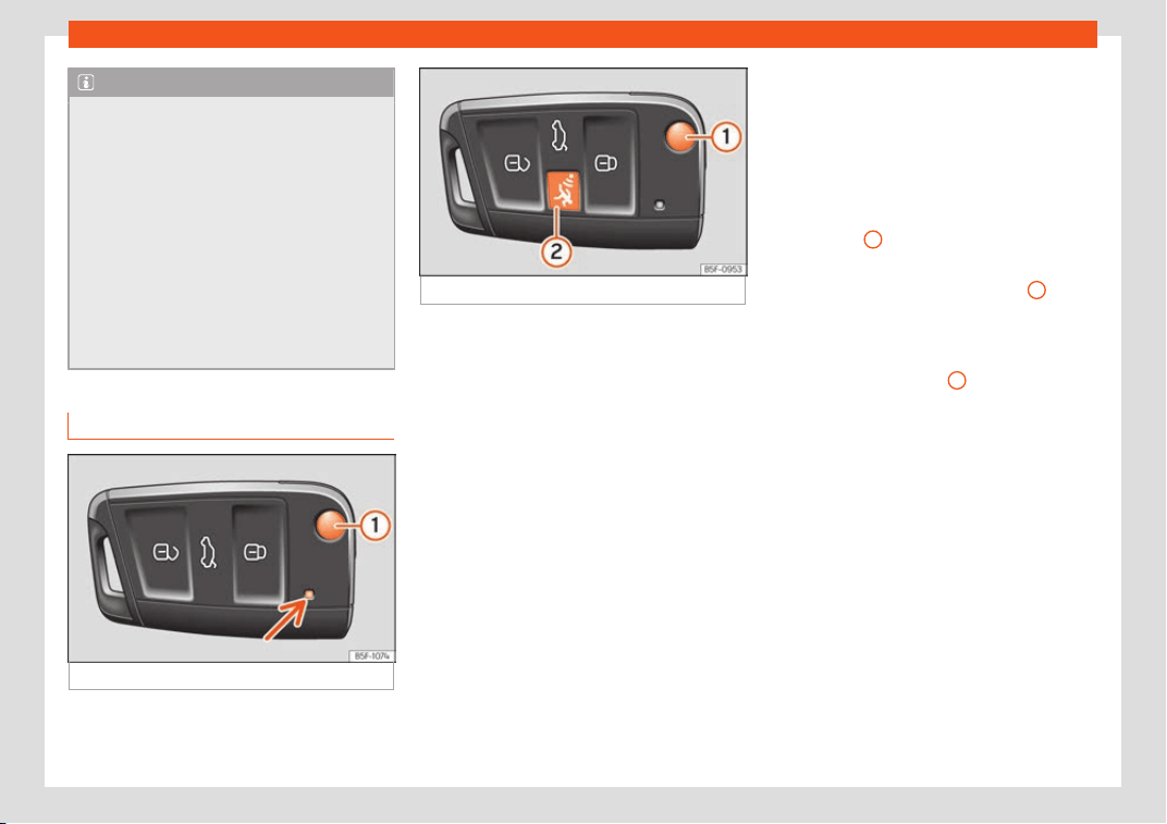
Operation
Note
●
Never l
eave any valuable items in the ve-
hicle unattended. Even a locked vehicle is
not a safe.
●
If the diode on the driver door sill lights
up for about 30 seconds when the vehicle
is locked, the central locking system or an-
ti-theft alarm* is not working properly. You
should have the fault repaired at a SEAT
Official Service or specialised workshop.
●
The vehicle interior monitoring of the an-
ti-theft alarm* system will only function as
intended if the windows and the sunroof*
are closed.
Car key
Fig. 136 Vehicle key
Fig. 137 Vehicle key with alarm button.
Vehicle key
With the v
ehicl
e k
ey the vehicle may be
locked or unlocked remotely
›››
page 127.
The vehicle key includes an emitter and bat-
tery. The receiver is in the interior of the vehi-
cle. The range of the vehicle key with remote
control and new battery is several metres
around the vehicle.
If it is not possible to open or close the vehicle
using the remote control key, this should be
re-synchronised
›››
page 136 or the battery
changed
›››
page 135.
Different keys belonging to the vehicle may
be used.
Control lamp on the vehicle key
When a button on the vehicle key is pressed,
the control lamp flashes
›››
Fig. 136 (arrow)
once briefly, but if the button is held down for
a longer period the control lamp flashes sev-
eral times, such as in convenience opening.
If the vehicle key control lamp does not light
up when the button is pressed, replace the
key's battery
›››
page 135.
Unfolding and folding the key shaft
Press button
1
›
›
›
Fig. 136 or
›››
Fig. 137 to
unlock and unfold the key shaft.
To fold the shaft away, press button
1
and
f
ol
d the k
ey shaft in until it locks in place.
Alarm button*
Only press alarm button
2
in the event of an
emer
gency! When the al
arm butt
on is press-
ed, the vehicle horn is heard and the turn sig-
nals are switched on for a short time. When
the alarm button is pressed again, the alarm
is switched off.
Spare key
To obtain a spare key and other vehicle keys,
the vehicle chassis number is required.
Each new key contains a microchip which
must be coded with the data from the vehicle
electronic immobiliser. A vehicle key will not
work if it does not contain a microchip or the
microchip has not been encoded. This is also
true for keys which are specially cut for the
vehicle.
128
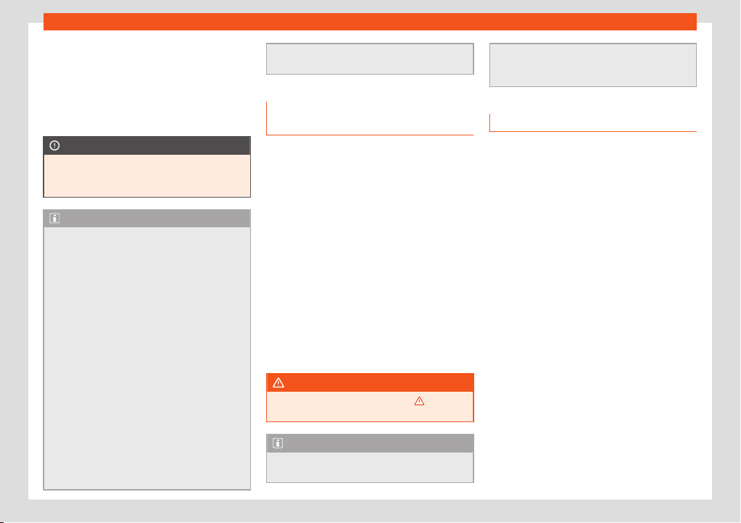
Opening and closing
The vehicle keys or new spare keys can be
obt
ained fr
om a SEAT Official Service
, a spe-
cialised workshop or an approved key service
qualified to create this kind of key.
New keys or spare keys must be synchronised
before use
›››
page 136.
CAUTION
All of the vehicle keys contain electronic
components. Protect them fr
om damage,
impacts and humidity.
Note
●
Only use the key button when you r
equire
the corresponding function. Pushing the
button unnecessarily could accidentally
unlock the vehicle or trigger the alarm. It is
also possible even when you are outside
the radius of action.
●
Key operation can be greatly influenced
by overlapping radio signals close to the
vehicle working in the same range of fre-
quencies, for example, radio transmitters or
mobile telephones.
●
Obstacles between the remote control
and the vehicle, bad weather conditions
and discharged batteries can considerably
reduce the range of the remote control.
●
If the buttons of the vehicle key are
pressed
›››
Fig. 136 or
›››
Fig. 137 or one of
the central locking buttons
›››
page 130 is
pressed repeatedly in short succession, the
central locking briefly disconnects as pro-
tection against overloading. The vehicle is
then unlocked. L
ock it if necessary.
Unlocking/Locking by remote con-
trol
Read the additional information carefully
›››
page 15
The vehicle will be locked again automatical-
ly if you do not open one of the doors or the
rear lid within 30 seconds after unlocking the
car. This function prevents the vehicle from
remaining unlocked if the unlocking button is
pressed by mistake. This does not apply if you
press the button for at least one second.
In vehicles with a security central locking
feature (selective unlocking of side doors)
›››
page 129, when the button is pressed
once, only the driver door and the fuel tank
flap are unlocked. When the button is pressed
a second time, all the vehicle doors are un-
locked.
WARNING
Observe the safety warnings
›››
in De-
scription on page 127.
Note
●
Do not use the remote contr
ol key until
the vehicle is visible.
●
Other functions of the remote contr
ol key
›››
page 143, Convenience opening and
closing.
Selective unlocking system
The selective unlocking system allows you to
only unlock the driver door and the fuel t
ank
flap. All other doors and the rear lid remain
locked.
Unlocking the driver door and tank flap
–
Press (once) the button on the remot
e
control key or turn the key once in the
opening direction.
Unlocking all the doors, the rear lid and
the tank flap simultaneously.
–
Within 5 seconds, press (twice) the but-
ton on the remote control key, or turn the
key twice within 5 seconds in the opening
direction.
The anti-theft security system* and the anti-
theft alarm* are immediately disabled if you
unlock only the driver door, without unlocking
the other doors.
In vehicles with Easy Connect*, you can pro-
gramme the security central locking system
directly
›››
page 130.
129
Operation
Adjusting the central locking
You can use Easy Connect* to select which
doors are unlock
ed with the central locking
system. Using the radio or the Easy Connect*
system, you can select whether the vehicle
automatically closes with the “Auto Lock”
programme at speeds of more than 15 km/h
(9 mph).
Programming the unlocking of the doors
(vehicles with Easy Connect)
–
Select the
button > SETTINGS function
butt
on >
Opening and closing >
Central
locking > Unlocking doors.
Programming the Auto Lock (vehicles with
radio)
–
Select: SETUP
button > control button
Central locking > Locking while
driving.
Pr
ogr
amming the Aut
o Lock (vehicles with
Easy Connect)
–
Select:
button > SETTINGS function
butt
on >
Opening and closing >
Central
locking > Locking while driving.
Unlocking doors
You can choose to unlock all the doors or
only the driver door when you unlock the
vehicle. In all the options, the fuel tank flap is
also unlocked.
With the Driver setting, when you press the
button on the remote control key once, only
the driver door is unlocked. If that button is
pressed twice, the rest of the doors and the
rear lid will be unlocked.
In vehicles with a conventional key, turn the
key in the door lock, in the direction of open-
ing, twice within 2 seconds.
If the button is pressed, all the vehicle
doors are locked. At the same time, a confir-
mation signal* is heard.
Auto Lock while driving
If you select on, all the vehicle doors are
locked at speeds above 15 km/h (9 mph).
Central locking switch
Read the additional information carefully
›
›
›
page 15
Please note the following when using the
central locking switch to lock your vehicle:
●
It is not possible to open the doors or the
rear lid from the outside (for safety reasons,
e.g. when stopped at traffic lights).
●
The LED in the central locking switch lights
up when all the doors are closed and locked.
●
You can open the doors individually from
the inside by pulling the inside door handle.
●
In the event of an accident in which the air-
bags inflate, doors locked from the inside will
be automatically unlocked to facilitate ac-
cess and assistance.
WARNING
●
The central locking s
witch also operates
when the ignition is switched off and auto-
matically locks all the vehicle doors when
the button is pressed.
●
The central locking switch does not oper-
ate if the vehicle is locked from the outside
and the anti-theft security system is
switched on.
●
Locked doors could delay assistance in
an emergency, potentially putting lives at
risk. Do not leave anyone, especially chil-
dren, in the vehicle.
Note
Your vehicle will lock automatically when it
reaches a speed of about 15 km/h (9 mph)
(Auto L
ock)
›››
page 127. You can unlock the
vehicle again using the button on the
central locking switch.
130
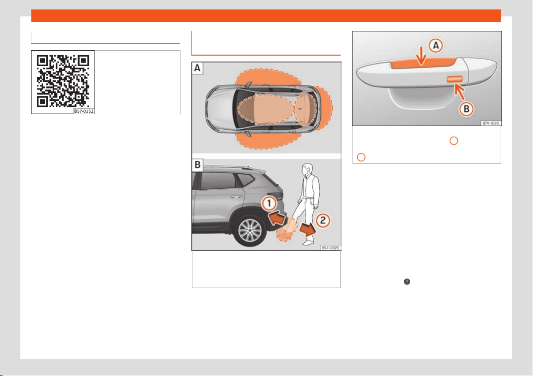
Opening and closing
Related video Keyless Access
Fig. 138 Handsfree
Unlocking and locking the vehicle
with K
eyl
ess Access*
Fig. 139 Keyless Access locking and ignition
syst
em:
In the pr
o
ximity of the car.
Open-
ing the rear lid with sensor-controlled opening
(Easy Open)
Fig. 140 Locking and ignition system without
Keyless Access: sensor surf
ace
A
for unlock-
ing inside the door handle and sensor surface
B
for locking on the exterior of the handle.
Depending on the equipment, the vehicle
may hav
e the K
eyl
ess Access system.
Keyless Access is a key-free locking and igni-
tion system to unlock and lock the vehicle
without actively using its key. To do this, all
that is required is to have a valid vehicle key in
the detection area where you are attempting
to access the vehicle
›››
Fig. 139 and to
touch one of the sensor surfaces on the door
handles
›››
Fig. 140 or operate the soft-
touch/handle on the rear lid
›››
page 139
›››
.
The v
ehicl
e can be unl
ocked and locked via
the front doors only. When doing so, the re-
mote control key must be no further than ap-
prox. 1.5 m away from the door handle.
»
131

Operation
It does not matter where you carry the key,
f
or inst
ance whether it is in your jack
et pocket
or in a briefcase.
Once the doors have been locked, they can-
not be opened again immediately. This will
enable you to check that the doors are prop-
erly closed.
If you wish, when unlocking, you can unlock
only the corresponding door or the entire ve-
hicle. The necessary adjustments can be per-
formed in vehicles with a driver information
system
›››
page 35.
General information
If a valid key is in the proximity of the car,
›››
Fig. 139 the Keyless Access locking and
starting system gives the key entry as soon as
one of the sensor surfaces on the door han-
dles is touched or the softtouch/handle on
the rear lid is operated. The following features
are then available without having to use the
vehicle key actively:
●
Keyless Entry: unlocking the vehicle using
the handles of the front doors or the soft-
touch/handle on the rear lid.
●
Keyless Exit: locking the vehicle using the
sensor of the driver or passenger door han-
dle.
●
Easy Open: opening the rear lid moving one
foot below the rear bumper.
●
Press & Drive: keyless starting of the engine
with the starter button
›››
page 239.
The central locking and locking systems op-
erate in the same way as a normal locking
and unlocking system. Only the controls
change.
Unlocking the vehicle is confirmed with a
double flash of the indicator lights; locking by
a single flash.
If the vehicle is locked and then all doors and
the rear lid are closed leaving the last key
used inside the vehicle and none outside, the
vehicle will not lock immediately. All the ve-
hicle's indicator lights will flash four times.
The vehicle will lock after a few seconds if
you do not open any door or the rear lid.
The vehicle will lock again after a few sec-
onds if you unlock the vehicle but fail to open
any door or boot hatch.
Unlocking and opening the doors (Key-
less-Entry)
●
Grip one of the front door handles. In doing
this, the sensor surface
›››
Fig. 140
A
(arrow)
on the handl
e is t
ouched and the v
ehicle un-
locks.
●
Open the door.
On vehicles with selective opening or info-
tainment system configuration, pulling the
door handle twice will unlock all doors.
In vehicles without safety system
“Safelock”: closing and locking the doors
(Keyless-Exit)
●
Switch the ignition off.
●
Close the driver's door.
●
Touch (once) the locking sensor surface
B
(arrow) on one of the front door handles. The
door that is used must be cl
osed.
In v
ehicl
es with a safety system
“Safelock”: closing and locking the doors
(Keyless-Exit)
●
Switch the ignition off.
●
Close the driver's door.
●
Touch (once) the sensor surface
B
(arrow)
on one of the fr
ont door handl
es. The v
ehicle
locks with the “Safelock” security system
›››
page 135. The door that is used must be
closed.
●
Touch (twice) the sensor surface
B
(arrow)
of one of the fr
ont door handl
es t
o lock the
vehicle without activating the “Safelock” se-
curity system
›››
page 135.
Unlocking and locking the boot hatch
When the vehicle is locked, the rear lid auto-
matically unlocks on opening if there is a val-
id vehicle key in the proximity
›››
Fig. 139 .
Open or close the rear lid normally.
132

Opening and closing
After closing, the hatch locks automatically. If
the compl
et
e v
ehicle is unlocked, the rear lid
will not lock automatically after closing it.
Rear lid with sensor-controlled open-
ing/closing (Easy Open)
If there is a valid vehicle key in the proximity
›››
Fig. 139 of the rear lid, it is possible to
unlock and open or close it moving one foot
in the area of the sensors
›››
Fig. 139 loca-
ted under the rear bumper.
●
Switch the ignition off.
●
Stand in front of the rear bumper, in the
middle.
●
With a brisk movement, bring your foot and
lower leg as close as you can to the bumper.
The lower part of the leg needs to be close to
the upper sensor area and your foot to the
lower sensor area
›››
Fig. 139
1
.
●
Quickly remove your foot and lower leg
fr
om the sensor ar
eas
›
››
Fig. 139
2
. The
r
ear lid will be aut
omatically opened.
●
If the r
ear lid fails to open, repeat the pro-
cedure after a few seconds.
The third brake light flashes once to show the
boot has opened with the Easy Open func-
tion.
The rear lid can be closed with another foot
movement similar to the opening one (provi-
ded a valid vehicle key is in the proximity of
the rear lid).
When closed, the rear lid automatically locks
if the vehicle has been locked beforehand
and there is no valid key inside.
While the rear lid is in motion (either opening
or closing), it can be stopped with another
foot movement similar to the opening one
(provided a valid vehicle key is in the proximi-
ty of the rear lid).
The Easy Open feature is not available or on-
ly has limited availability in the following sit-
uations (examples):
●
If the rear bumper is very dirty.
●
If the rear bumper is wet with salt water, e.g.
after having driven on gritted roads.
●
If the electrical unlocking tow hitch is not
covered.
●
If the vehicle has been equipped at a later
time with a tow bracket.
In the event of heavy rain, the Easy Open fea-
ture may take a little longer to open the boot
or may deactivate automatically, to avoid the
boot opening by accident, e.g. because of
the running water.
The Easy Open function can be connected
and disconnected permanently in the info-
tainment system by pressing the
button
and the SETTINGS > Opening and clos-
ing function butt
ons
›
›
›
page 35.
What happens when locking the vehicle
with a second key
If there is a vehicle key inside the vehicle and
it is locked from the outside with a second ve-
hicle key, the key inside the vehicle is blocked
for engine ignition
›››
page 239. In order to
enable engine ignition, press the button on
the key inside the vehicle.
Automatically disabling sensors
If the vehicle is not locked or unlocked for a
long period of time, the proximity sensors on
the passenger doors are automatically disa-
bled.
If one of the sensor surfaces on the door han-
dles is often activated in an unusual manner
with the vehicle locked (e.g. by the branches
of a bush rubbing against it), all proximity
sensors are disabled for a certain period of
time.
Sensors will again be enabled:
●
After a time.
●
OR: if the vehicle is unlocked with the but-
ton on the key.
●
OR: if the boot is opened.
●
OR: if the vehicle is unlocked manually with
the key.
»
133
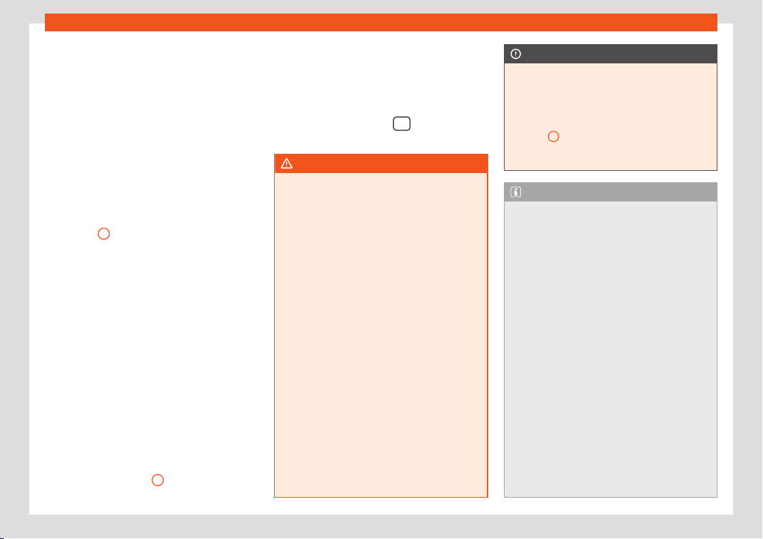
Operation
Keyless Access temporary disconnection
function*
Y
ou can deactiv
at
e the vehicle's Keyless Ac-
cess unlocking for a locking and unlocking
cycle.
●
Move the gear lever to position P (if the ve-
hicle has automatic gearbox), since other-
wise the vehicle cannot be locked.
●
Close the door.
●
Push the central locking button on the re-
mote control and touch the locking sensor
surface of the driver door handle
›››
Fig. 140
B
within the following 5 seconds.
Do not gr
asp the door handl
e; otherwise the
v
ehicle will not unlock. Deactivation is also
possible if the vehicle is locked through the
driver’s door lock.
●
To check that the function has been deacti-
vated, wait at least 10 seconds, grip and pull
on the door handle. The door should not
open.
The next time the door can only be unlocked
via the remote control or the lock cylinder.
The next time the door is locked/unlocked,
Keyless Access will be active again.
Convenience functions
To close all the electric windows using the
convenience function, keep a finger on the
locking sensor surface
B
(arrow) of the door
handle for a few seconds until the windows
hav
e cl
osed.
The
doors opened by touching the sensor
surface of the door handle depend on the
settings that have been activated in the info-
tainment system with the
> SETTINGS >
Opening and closing function butt
ons.
WARNING
If there is a valid key in the proximity of the
rear lid, in some cases the Easy Open func-
tion may be accidentally activ
ated and the
rear lid will open, for example, when
sweeping under the rear bumper, when di-
recting a water jet or high pressure steam
to the area or when carrying out mainte-
nance work or repairs in that area. If acci-
dentally opened, the rear lid could injure
somebody situated in its area of operation
or cause material damage.
●
Therefore, always make sure that there is
no unsupervised valid key in the area near
the rear lid.
●
Before carrying out any maintenance or
repair work on the vehicle, always disable
the Easy Open feature via the infotainment
system.
●
Before washing the vehicle, always disa-
ble the Easy Open feature via the infotain-
ment system.
●
Before attaching a bicycle rack or a trail-
er,
›››
page 329, always disable the Easy
Open feature via the infotainment system.
CAUTION
The sensor surfaces on the door handles
could engage if hit with a wat
er jet or high
pressure steam if there is a valid vehicle
key in the proximity. If at least one of the
electric windows is open and the sensor
surface
B
(arrow) on one of the handles is
activated continuously, all windo
ws will
close.
Note
●
If the vehicle batt
ery has little or no
charge, or the vehicle key battery is almost
or entirely out of charge, you will probably
not be able to lock or unlock the vehicle
with the Keyless Access system. The vehi-
cle can be unlocked or locked manually
›››
page 87.
●
To control the proper locking of the vehi-
cle, the release function is disabled for ap-
prox. 2 seconds.
●
If the message Keyless access system
faulty is displayed on the screen of the
dash panel, abnormalities may occur in the
operation of the Keyless Access system.
Contact a specialised workshop. SEAT rec-
ommends visiting a SEAT dealership for
this.
●
Depending on the function set on the in-
fotainment system for the mirrors, the exte-
rior mirrors will unfold and the surround
lighting will come on when unlocking the
vehicle using the sensor surface on the
134
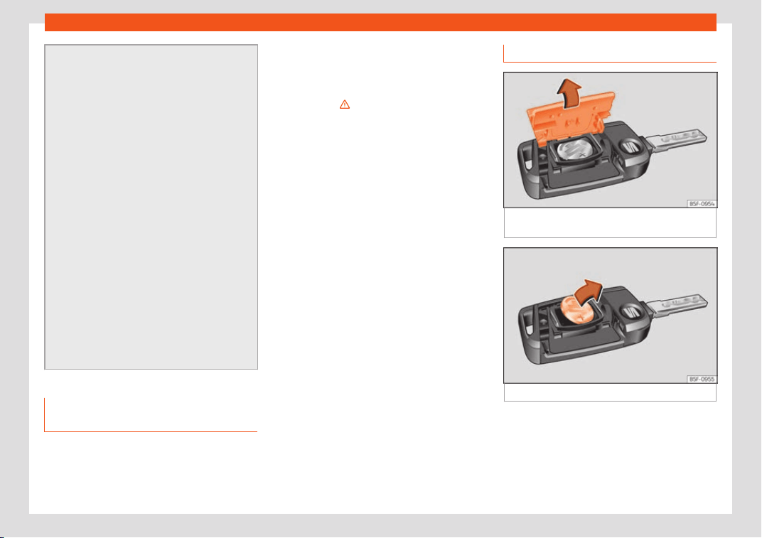
Opening and closing
driver and passenger door handles
›››
page 158.
●
If there is no valid key inside the vehicle
or the system fails to detect one, a warning
will display on the dash panel screen. This
could happen if any other radio frequency
signal interferes with the key signal (e.g.
from a mobile device accessory) or if the
key is covered by another object (e.g. an
aluminium case).
●
If the sensors are very dirty, e.g. have a
layer of salt, the correct functioning of the
sensors on the door handles may be affec-
ted. In this case, clean the vehicle.
●
If the vehicle is equipped with an auto-
matic gearbox, it may only be locked in the
gear stick is in position P.
●
To improve the safety of your vehicle, the
remote control of the system is equipped
with a position sensor. If this remote control
does not detect movement for a certain
length of time, the system will conclude
that the vehicle cannot be opened (e.g. on
a night table) so it will be disabled.
Anti-theft security system (Safe-
l
ock)*
The following message is displayed on the in-
strument panel t
o r
emind the driv
er that when
the vehicle is closed from the outside, the an-
ti-theft security system is switched on. Do
not forget the Safelock. Please see
Instruction Manual. The vehicle cannot
be opened from inside. This makes it more dif-
ficult for unauthorised persons to break into
the vehicle
›››
in Description on page 127.
The anti-theft securit
y syst
em can be s
witch-
ed off each time the vehicle is locked:
●
Turn the key a second time to the lock posi-
tion, in the door lock, within two seconds. If
necessary, remove the protective cover on
the driver door handle
›››
page 15 or
●
Press the button on the remote control
key for a second time within 2 seconds.
The flashing frequency of the diode in the
door sill immediately confirms the process.
Initially, the diode flashes in a fast sequence
for a brief period, then it stops for approxi-
mately 30 seconds and, lastly continues
flashing slowly.
Replacing the battery
Fig. 141
Vehicle key: opening the battery com-
partment.
Fig. 142 Vehicle key: removing the battery.
SEAT recommends you ask a specialised
w
orkshop t
o r
eplace the battery.
The battery is located to the rear of the vehi-
cle key, under a cover.
»
135
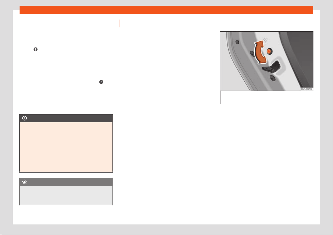
Operation
Changing the battery
●
Unfold the vehicle key blade
›
›
›
page 128.
●
Remove the cover from the back of the ve-
hicle key
›››
Fig. 141 in the direction of the ar-
row
›››
.
●
Extract the battery from the compartment
using a suit
abl
e thin ob
ject
›››
Fig. 142.
●
Place the new battery in the compartment
as shown
›››
Fig. 142, pressing in the opposite
direction to that shown by the arrow
›››
.
●
Fit the cover as shown
›
›
›
Fig. 141, pressing
it onto the vehicle key casing in the opposite
direction to that shown by the arrow until it
clicks into place.
CAUTION
●
If the battery is not changed correctly,
the v
ehicle key may be damaged.
●
Use of unsuitable batteries may damage
the vehicle key. For this reason, always re-
place the dead battery with another of the
same voltage, size and specifications.
●
When fitting the battery, check that the
polarity is correct.
For the sake of the environment
Please dispose of your used batteries cor-
rectly and with respect f
or the environ-
ment.
Synchronising the vehicle key
If the button is pressed fr
equently outside
of the vehicle range, it is possible that the ve-
hicle can no longer be locked or unlocked us-
ing the key. In this case, the key must be re-
synchronised as described below:
●
Unfold the vehicle key blade
›››
page 128.
●
If necessary, remove the cover from the
driver door lever
›››
page 15.
●
Press the button on the vehicle key. For
this, it must remain with the vehicle.
●
Open the vehicle within one minute using
the key blade
. The key has been synchron-
ised.
●
If necessary, fit the cap.
Childproof lock
Fig. 143
Childproof lock on the left hand side
door
.
The childproof lock prevents the rear doors
fr
om being opened fr
om the inside
. This sys-
tem prevents minors from opening a door ac-
cidentally while the vehicle is running.
This function is independent of the vehicle
electronic opening and locking systems. It
only affects rear doors. It can only be activa-
ted and deactivated manually, as described
below:
Activating the childproof lock
–
Unlock the vehicle and open the door in
which you wish to activate the childproof
lock.
–
With the door open, rotate the groove in the
door using the ignition key, clockwise for
the left hand side doors
›››
Fig. 143 and an-
ti-clockwise for the right hand side doors.
136

Opening and closing
Deactivating the childproof lock
–
Unlock the vehicle and open the door
whose chil
dpr
oof l
ock you want to deacti-
vate.
–
With the door open, rotate the groove in the
door using the ignition key, anti-clockwise
for the left hand side doors
›››
Fig. 143 and
clockwise for the right hand side doors.
Once the childproof lock is activated, the
door can only be opened from the outside.
The childproof lock can be activated or de-
activated by inserting the key in the groove
when the door is open, as described above.
Anti-theft alarm system*
Description
The anti-theft alarm makes it more difficult to
br
eak int
o the v
ehicle or steal it.
The anti-theft alarm is automatically turned
on when the vehicle is locked with the key.
●
The turn signal light will flash twice on
opening and deactivating the alarm.
●
The turn signal light will flash once on clos-
ing and activating the alarm.
When does the system trigger an alarm?
The anti-theft alarm siren will be triggered for
about 30 seconds accompanied by sound
and optical (flashing) warning signals and
will be repeated about ten times when the
vehicle is locked and the following unauthor-
ised actions are attempted:
●
Opening a door that is mechanically un-
locked using the vehicle key without switching
on the ignition in the next 15 seconds (in cer-
tain markets, such as the Netherlands, there is
no 15 second waiting time and the alarm is
activated immediately on opening the door).
●
A door is opened.
●
The bonnet is opened.
●
The rear lid is opened.
●
When the ignition is switched on with a non-
authorised key.
●
When the vehicle battery is disconnected.
●
Movement inside the vehicle (in vehicles
with interior monitoring
›››
page 139).
●
When the vehicle is towed (in vehicles with
anti-tow system
›››
page 139).
●
When the vehicle is raised (in vehicles with
anti-tow system
›››
page 139).
●
When the vehicle is transported on a ferry
or by rail (vehicles with an anti-tow system or
vehicle interior monitoring
›››
page 139).
●
When a trailer connected to the anti-theft
alarm system is disconnected.
How to turn OFF the alarm
Unlock the vehicle with the unlocking button
on the key or turn on the ignition with a valid
key.
Note
●
After 28 days, the indicator light will be
s
witched off to prevent the battery from ex-
hausting if the vehicle has been left parked
for a long period of time. The alarm system
remains activated.
●
If, after the audible warning goes off, an-
other monitored area is accessed (e.g. the
rear lid is opened after a door has been
opened), the alarm is triggered again.
●
The anti-theft alarm is not activated
when the vehicle is locked from within using
the central locking button .
●
If the driver door is unlocked mechanical-
ly with the key, only the driver door is un-
locked, the rest of the doors remain locked.
Only when the ignition has been turned on
will the other doors be available - but not
unlocked - and the central locking button
will be activated.
●
If the vehicle battery is run down or flat
then the anti-theft alarm will not operate
correctly.
●
Vehicle monitoring remains active even if
the battery is disconnected or not working
for any reason.
»
137
Operation
●
The alarm is triggered immediat
ely if one
of the battery cables is disconnected while
the alarm system is active.
Vehicle interior monitoring and an-
ti-tow syst
em*
It is a monitoring or control function incorpo-
rated in the anti-theft al
arm* which detects
unauthorised vehicle entry by means of ultra-
sound.
Activation
–
It is automatically switched on when the
anti-theft alarm is activat
ed.
Deactivation
–
Open the vehicle with the key, either me-
chanically or by pressing the button on
the remote control. The time period from
when the door is opened until the key is in-
serted in the contact should not exceed 15
seconds, otherwise the alarm will be trig-
gered.
–
Press the button on the remote control
twice. The volumetric sensor and tilt sen-
sors will be deactivated. The alarm system
remains activated.
The vehicle interior monitoring and the anti-
tow system are automatically switched on
again next time the vehicle is locked.
The vehicle interior monitoring and anti-tow
sensor (tilt sensor) are automatically switch-
ed on when the anti-theft alarm is switched
on. In order to activate it, all the doors and
the rear lid must be closed.
If you wish to switch off the vehicle interior
monitoring and the anti-tow system, it must
be done each time that the vehicle is locked;
if not, they will be automatically switched on.
The vehicle interior monitoring and the anti-
tow system should be switched off if animals
are left inside the locked vehicle (otherwise,
their movements will trigger the alarm) or
when, for example, the vehicle is transported
or has to be towed with only one axle on the
ground.
False alarms
Interior monitoring will only operate correctly
if the vehicle is completely closed. Please ob-
serve related legal requirements.
The following cases may cause a false
alarm:
●
Open windows (partially or fully).
●
Panoramic/tilting sunroof open (partially or
completely).
●
Movement of objects inside the vehicle,
such as loose papers, items hanging from the
rear vision mirror (air fresheners), etc.
Note
●
If the vehicle is r
elocked and the alarm is
activated without the volumetric sensor
function, relocking will activate the alarm
with all its functions, except the volumetric
sensor. This function is reactivated when
the alarm is switched on again, unless it is
deliberately switched off.
●
If the alarm has been triggered by the
volumetric sensor, this will be indicated by
a flashing of the warning lamp on the driver
door when the vehicle is opened. The flash
is different to the flash indicating the alarm
is activated.
●
The vibration of a mobile phone left in-
side the vehicle may cause the vehicle in-
terior monitoring alarm to trigger, as both
sensors react to movements and shakes in-
side the vehicle.
●
If on activating the alarm, any door or the
rear lid is open, only the alarm will be acti-
vated. The vehicle interior monitoring and
the anti-tow system will only be activated
once all the doors are closed (including the
rear lid).
138
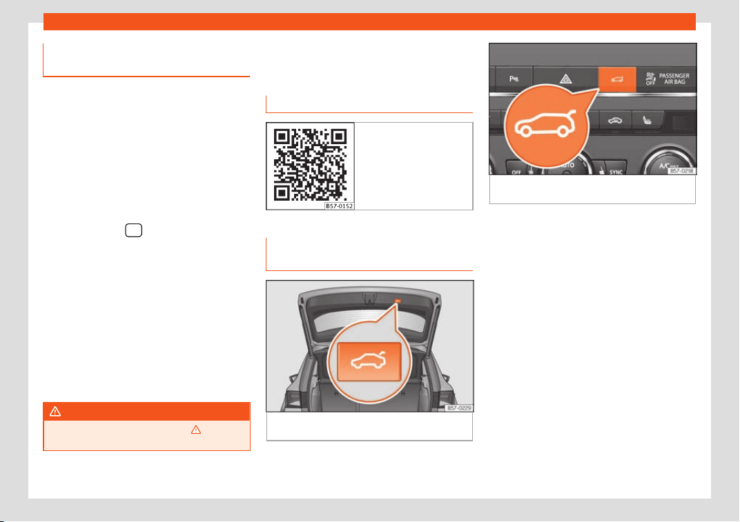
Opening and closing
Deactivating the vehicle interior
monit
oring and anti-t
o
w system*
When the vehicle is locked, the alarm will be
triggered if mov
ements are detected in the in-
terior (e.g. by animals) or if the vehicle's incli-
nation is changed (e.g. during transport). You
can prevent the alarm from being triggered
accidentally by switching off the vehicle inte-
rior monitoring and/or tow-away protection.
●
To disconnect vehicle interior monitoring
and anti-tow protection, switch off the igni-
tion and use the infotainment system to se-
lect the following:
button > function but-
t
on
SETTINGS > Open and close > Cen-
tral locking > Vehicle interior mon-
itoring.
●
When the v
ehicle is locked now, the vehicle
interior monitoring and the tow-away protec-
tion are switched off until the next time the
door is opened.
If the anti-theft security system (Safelock)*
›››
page 135 is switched off, the vehicle interi-
or monitoring and the tow-away protection
are automatically switched off.
WARNING
Observe the safety warnings
›››
in De-
scription on page 127.
Rear lid (luggage compart-
ment)
R
el
at
ed video
Fig. 144 Handsfree
Rear lid with electric opening and
cl
osing*
Fig. 145 Rear lid open: button to close rear lid
immediat
ely.
Fig. 146 Centre console: button to open and
close rear lid.
Opening the rear lid
●
Unlock the vehicle
›
›
›
page 127 and briefly
press the handle of the rear lid. On vehicles
with Keyless Access you can directly press
the handle of the rear lid. The rear lid is un-
locked if an authorised key is recognised in
the proximity of the vehicle.
●
OR: press the button on the centre console
for at least one second
›››
Fig. 146. The but-
ton also works when the ignition is switched
off.
●
OR: press and hold the button of the ve-
hicle key for approx. 1 second. If the vehicle is
locked, only the rear lid is unlocked (the doors
remain locked).
●
OR: on vehicles with Keyless Access and
sensor-controlled opening you can open the
rear lid by moving one foot in the area of the
sensors located below the rear bumper (Easy
»
139

Operation
Open). The rear lid will be automatically
opened.
Cl
osing the r
ear lid
●
Briefly pr
ess the button on the rear lid
›››
Fig. 145
›››
.
●
OR: pr
ess the button located on the
centr
e consol
e until the rear lid is closed
›››
Fig. 146.
●
OR: on vehicles with Keyless Access, press
and hold the vehicle key button until the
rear lid is closed or move one foot in the area
of the sensors located below the rear bumper
(Easy Open)
›››
page 131. The key of the vehi-
cle must not be further away than 1.5 m from
the boot or inside the vehicle.
●
OR: manually move the rear lid in the direc-
tion of closing until it closes automatically.
●
The rear lid goes down automatically to the
final position and also closes automatically
›››
.
Int
errupting opening or cl
osing
Aft
er beginning to open or close the rear lid,
the action can be halted by pressing one of
the buttons.
Continue opening or closing the rear lid by
hand. To do this, some force will have to be
used.
If you press one of the buttons again, the
rear lid will move again in the original direc-
tion.
If the rear lid is met with resistance or an ob-
stacle during the automatic opening or clos-
ing, opening or closing will be interrupted im-
mediately. For the closing process, the rear
lid opens again slightly.
●
Check why it has not been possible to open
or close the rear lid.
●
Try to open or close the rear lid again.
●
If necessary, the rear lid can be opened or
closed by hand using reasonable force.
Special feature for pulling a trailer
If the factory-fitted towing bracket is electri-
cally connected to a trailer
›››
page 329, the
electric rear lid can only be opened or closed
with the buttons on the rear lid itself.
Acoustic warnings
Throughout the process of opening or closing
the rear lid, acoustic warnings can be heard.
Exception: when the rear lid is opened man-
ually using the handle or the Easy Open func-
tion with the movement of the foot or closed
using the button on the rear lid itself
›››
Fig. 145.
Modifying and memorising the opening
angle
If the space behind or above the vehicle is
less than the travel area of the rear lid, you
can change the opening angle of the rear lid.
To memorise a new opening angle, the rear
lid must be open at least halfway.
●
Interrupt the opening process in the desired
position.
●
Press the button
›››
Fig. 145 on the rear
lid for at least 3 seconds.
The opening angle is memorised. Memorisa-
tion is indicated by blinking of the hazard
warning lights and an audible warning.
Resetting and memorising the opening an-
gle
For the rear lid to reopen completely, the
opening angle must be reset and memorised
again.
●
Release the rear lid and open it to the
memorised height.
●
Lift the rear lid by hand as far as it goes. To
do this, some force will have to be used.
●
Press the button
›››
Fig. 145 on the rear
lid for at least 3 seconds.
●
This resets and memorises the factory-set
opening angle. Memorisation is indicated by
140
Opening and closing
blinking of the hazard warning lights and an
audibl
e w
arning.
Aut
omatic protection against overheating
If the system is operated repeatedly in a short
space of time, it automatically switches off to
prevent overheating.
Once the system is cool again, the function
can be reused. Until then, the rear lid can only
be opened and closed by hand using reason-
able force.
If with the rear lid open the vehicle battery is
disconnected
›››
page 354 or the corre-
sponding fuse burns out
›››
page 92, the sys-
tem will have to be reset. This requires closing
the rear lid completely once.
Emergency unlocking
›››
page 17
WARNING
If a lot of snow builds up on the rear lid or it
is heavily loaded, the rear lid may not open
or
, after opening, it may lower by itself due
to the extra weight and cause serious in-
jury.
●
Do not open the rear lid when there is a
lot of snow on it or when carrying a load
(e.g. on a rack).
●
Before opening the rear lid, remove the
snow or the load.
WARNING
If the rear lid is closed incorrectly or with-
out due care, it coul
d result in serious in-
jury.
●
Never leave the vehicle unattended or al-
low children to play inside or next to it, es-
pecially if the rear lid is open. Children
could enter the luggage compartment,
close the rear lid and become trapped. A
locked vehicle can reach extremely high
and low temperatures, depending on the
time of year, thus causing serious injuries,
illness or even death.
CAUTION
Before opening or closing the rear lid, make
sure that there is enough space t
o open or
close it, e.g. when pulling a trailer or in a
garage.
Rear lid automatic locking
Where the vehicle has been locked by press-
ing the butt
on on the r
emot
e control with
the rear lid open, the rear lid will lock auto-
matically when closed.
The automatic rear lid locking time extension
function can be activated. Where this func-
tion is activated and once the rear lid has
been unlocked by pressing the button on
the remote control key
›››
page 129, the rear
lid can be re-opened for a certain length of
time.
Where required, the automatic tailgate lock-
ing time extension function can be activated
or deactivated at an Authorised SEAT Serv-
ice, which will provide all the necessary infor-
mation.
Before the vehicle locks automatically, there
is a risk of intruders getting into the vehicle.
Therefore, we recommend you always lock
the vehicle by pressing the button on the
remote control or by using the central locking
button.
WARNING
Observe the safety warnings
›››
in Intro-
duction on page 87.
●
Always close the rear lid properly. Risk of
accident or injury.
●
The rear lid must not be opened when the
rev
erse or rear fog lights are lit. This may
damage the tail lights.
●
Do not close the rear lid by pushing it
down with your hand on the rear window.
The glass could smash. Risk of injury!
●
Ensure the rear lid is locked after closing
it. If not, it may open unexpectedly while
driving.
●
Closing the rear lid without observing
and ensuring it is clear could cause serious
injury to you and to third parties. Make sure
that no one is in the path of the rear lid.
»
141
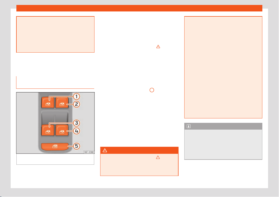
Operation
●
Never driv
e with the rear lid open or half-
closed, exhaust gases may penetrate into
the interior of the vehicle. Danger of poi-
soning!
●
If you only open the rear lid, do not leave
the key inside. The vehicle cannot be
opened if the key is left inside.
Controls for the windows
Opening and closing the electric
windo
ws
Fig. 147 Detail of the driver door: controls for
the windo
ws.
Read the additional information carefully
›
›
›
page 18
The front and rear electric windows can be
operated by using the controls on the driver
door. The other doors each have a switch for
their own window.
Always close the windows fully if you park the
vehicle or leave it unattended
›››
.
Y
ou can use the el
ectric windo
ws for approx.
10 minutes after switching off the ignition if
neither the driver door nor the front passen-
ger door has been opened and the key has
not been removed from the ignition.
Safety switch *
The safety switch
›››
Fig. 147
5
on the driver
door can be used t
o disabl
e the el
ectric win-
dow buttons on the rear doors.
Safety switch not pressed: buttons on rear
doors are activated.
Safety switch pressed: buttons on rear doors
are deactivated.
The safety control symbol lights up in yel-
low if the buttons on the rear doors are
switched off.
WARNING
Observe the safety warnings
›››
in Intro-
duction on page 87.
●
Incorrect use of the electric windows can
result in injury.
●
Never cl
ose the rear lid without observing
and ensuring it is clear, to do otherwise
could cause serious injury to you and third
parties. Make sure that no one is in the path
of a window.
●
If the ignition is switched on, the electric
equipment could be activated with risk of
injury, for example, in the electric windows.
●
The doors can be locked using the re-
mote control key. This could become an
obstacle for assistance in an emergency
situation.
●
Therefore always take the key with you
when you leave the vehicle.
●
The electric windows will work until the
ignition has been switched off and one of
the front doors has been opened.
●
If necessary, use the safety switch to dis-
able the rear electric windows. Make sure
that they have been disabled.
Note
If the window is not able to close because it
is stiff or because of an obstruction, the
window will automatically open again
›
››
page 143. If this happens, check why the
window could not be closed before at-
tempting to close it again.
142
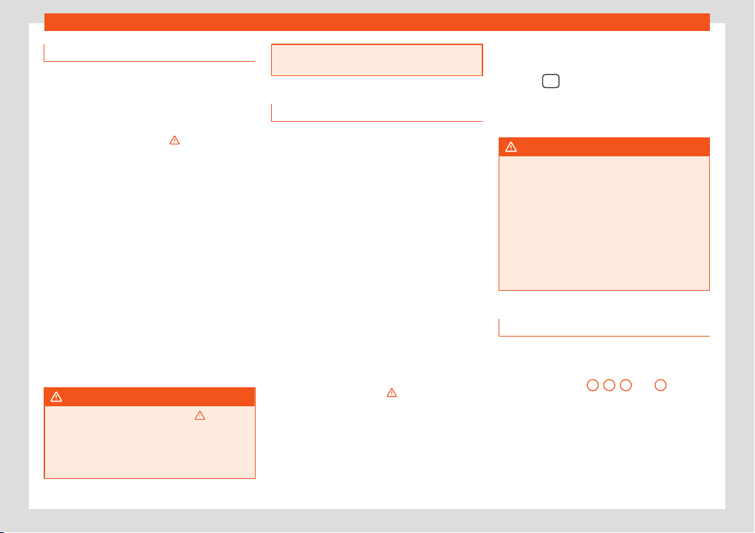
Opening and closing
Roll-back function
The roll-back function reduces the risk of in-
jury when the electric windows cl
ose.
●
If a window is obstructed when closing au-
tomatically, the window stops at this point
and lowers immediately
›››
.
●
Next, check why the window does not close
before att
empting it again.
●
If you try within the following 10 seconds
and the window closes again with difficulty or
there is an obstruction, the automatic closing
will stop working for 10 seconds.
●
If the window is still obstructed, the window
will stop at this point.
●
If there is no ob
vious reason why the win-
dow cannot be closed, try to close it again by
pulling the tab within ten seconds. The win-
dow closes with maximum force. The roll-
back function is now deactivated.
●
If more than 10 seconds pass, the window
will open fully when you operate one of the
buttons. One-touch closing is reactivated.
WARNING
Observe the safety warnings
›››
in Open-
ing and closing the electric windo
ws on
page 142.
●
The roll-back function does not prevent
fingers or other parts of the body getting
pinched against the window frame. Risk of
accident.
Convenience opening and closing
Use the convenience opening/closing func-
tion to easily open/close all the windo
ws
from the outside.
Convenience open function
–
Press and hold the button on the remot
e
control key until all the windows and the
sunroof* have reached the desired position,
or
–
First unlock the vehicle using the button
on the remote control key and then keep
the key in the driver door lock until all the
windows and the sunroof* have reached
the required position.
Convenience close function
–
Press and hold button on the remote
control key until all the windows and the
sunroof* are closed
›››
, or
–
Keep the key in the driver door in the "lock"
position until all the windo
ws and the sun-
r
oof* ar
e closed.
Programming convenience opening in the
Easy Connect*
–
Select:
button > SETTINGS function
button > Opening and closing >
Opening the window by holding down
button or > Front window on/off.
WARNING
●
Never cl
ose the windows without due
care or proper control. There is a risk of suf-
fering injury.
●
For safety reasons, you should only use
the remote control open and close func-
tions within about 2 metres of the vehicle.
To avoid injuries, always keep an eye on the
windows when pressing the button to close
them. The windows stop moving as soon as
the button is released.
One-touch opening and closing
One-touch opening and closing means you
do not hav
e t
o hol
d down the button.
Buttons
›››
Fig. 147
1
,
2
,
3
and
4
have
tw
o positions f
or opening windo
ws and two
for closing them. This makes it easier to open
and close windows to the desired position.
One-touch closing
–
Pull up the window button briefly up to the
second position. The window closes fully.
»
143
Operation
One-touch opening
–
Push down the window button briefly up to
the second position. The windo
w opens
fully.
R
esetting one-t
ouch opening and closing
The automatic open and close function will
not work if the battery has been temporarily
disconnected. The function can be restored
as follows:
–
Close the window as far as it will go by lift-
ing and holding the electric window switch.
–
Release the switch and then lift it again for 1
second. This will re-enable the automatic
function.
If you push (or pull) a button to the first stage,
the window will open (or close) until you re-
lease the button. If you push or lift the button
briefly to the second stage, the window will
open (one-touch opening) or close (one-
touch closing) automatically. If you operate
the button while the window is opening or
closing, it stops at this position.
Sunroof*
Introduction
The sunroof consists of two glass parts. The
rear part is fixed and cannot be opened. It al
-
so has a sun blind.
WARNING
If the sunroof is used negligently or without
paying due attention, it can cause serious
injury.
●
Open or close the sunr
oof and the sun
blind only when no one is in their path of
movement.
●
Never leave any key inside the vehicle
when exiting.
●
Never leave a child or any other person
who may need help in the vehicle, espe-
cially if they have access to the vehicle
key. If using they key unattended, they
could lock the vehicle, start the engine,
switch on the ignition and activate the sun-
roof.
●
After switching off, it is still possible to
open or close the sunroof during a short
space of time provided that neither the
driver nor passenger door is opened.
CAUTION
●
To pre
vent damage, during winter tem-
peratures remove any ice or snow that
might be on the car roof before opening the
sunroof or adjusting the tilt position.
●
Befor
e leaving the vehicle or in case of
rainfall, always close the sunroof. With the
sunroof open or in a tilted position, water
can enter the interior and can cause con-
siderable damage to the electrical system.
As a result, other damage can occur in the
vehicle.
Note
●
L
eaves and other l
oose objects that ac-
cumulate on the sunroof rails should be
regularly cleaned away either by hand or
with a vacuum.
●
If the sunroof does not work correctly, the
anti-trap function will not work either. Con-
tact a specialised workshop.
144
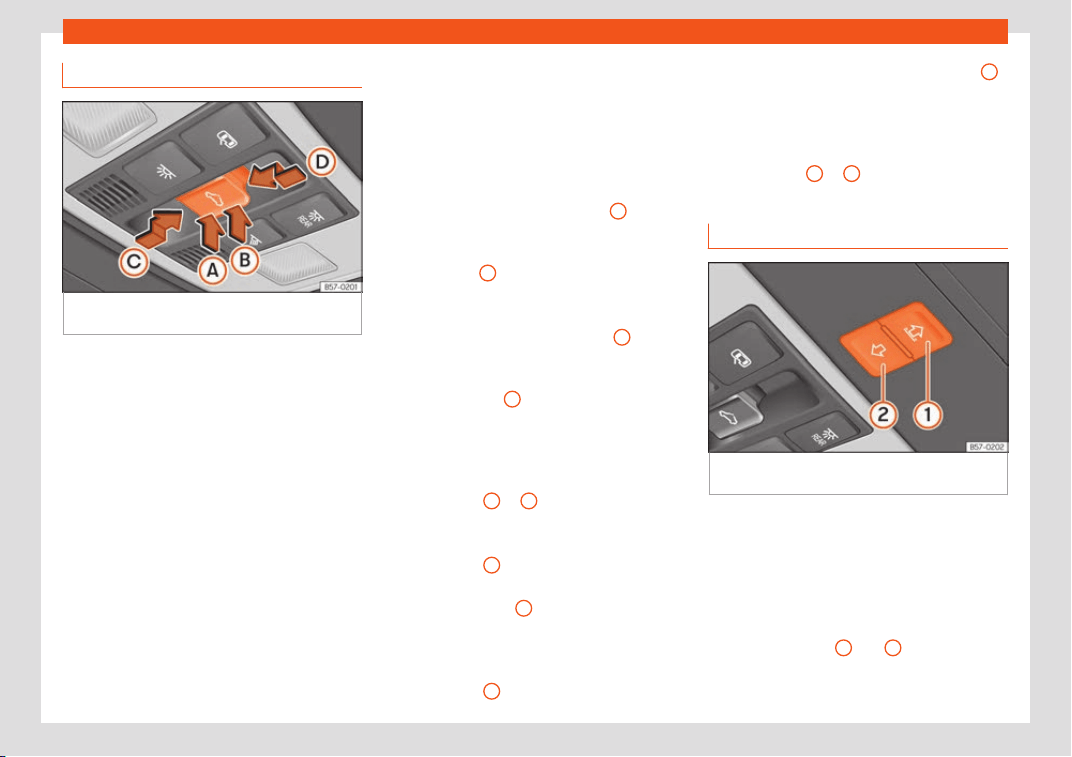
Opening and closing
Opening and closing the sunroof
Fig. 148
On the interior roof lining: sunroof
butt
on.
The sunroof only works when the ignition is
s
wit
ched on. Once the ignition has been
s
witched off, you can still open or close the
sunroof for a few minutes provided the driver
door and the front passenger door are not
opened.
The sun blind automatically opens along with
the sunroof if completely closed or if in front
of the sunroof. The sun blind remains in the
previous position and does not automatically
close with the sunroof. The sun blind can only
be closed completely once the sunroof has
been closed.
The button
›››
Fig. 148 has two levels. The
first level switches the sunroof to the tilted po-
sition, opening or closing it fully or partially.
On the second level, the sunroof automati-
cally moves to the corresponding final posi-
tion after briefly pressing the button. Activat-
ing the button again stops the automatic
function.
Adjusting the tilt position of the sunroof
●
Press the rear part of the button
B
to the
first l
e
v
el.
●
Automatic function: briefly press the rear
part of button
B
to the second level.
Cl
osing the sunr
oof fr
om a tilted position
●
Press the front part of the button
A
to the
first l
e
v
el.
●
Automatic function: briefly press the front
part of the button
A
to the second level.
St
opping the aut
omatic oper
ation by ad-
justing the tilted position of the sunroof or
by closing the sunroof
●
Press button
A
or
B
again.
Opening the sunr
oof
●
Pr
ess butt
on
C
backwards to the first level.
●
Automatic function to the comfort position:
briefly pr
ess butt
on
C
backwards to the sec-
ond l
e
v
el.
Closing the sunroof
●
Press button
D
forwards to the first level.
●
Aut
omatic function: briefly pr
ess butt
on
D
forwards to the second level.
St
opping the aut
omatic oper
ation during
the opening or closing
●
Press button
C
or
D
again.
Opening and closing the sun blind
Fig. 149
On the interior roof lining: switches for
the sun blind.
The electrical sun blind works when the igni-
tion is s
wit
ched on.
When the sunr
oof is in its most tilted position,
the sun blind automatically goes into a venti-
lation position. The sun blind remains in this
position also with the sunroof closed.
Buttons
›››
Fig. 149
1
and
2
have two lev-
el
s. The first l
e
vel opens or closes the sun
blind fully or partially.
»
145
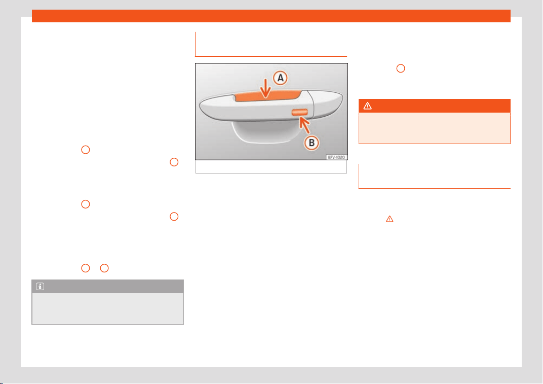
Operation
By briefly pressing the button to the second
l
e
v
el, the sun blind automatically moves to
the corresponding final position. Activating
the button again stops the automatic func-
tion.
Once the ignition has been switched off, you
can still open or close the sun blind for a few
minutes provided the driver door and the
front passenger door are not opened.
Opening the sun blind
●
Press button
1
to the first level.
●
Automatic function: briefly press button
1
to the second level.
Cl
osing the sun blind
●
Pr
ess butt
on
2
to the first level.
●
Automatic function: briefly press button
2
to the second level.
St
opping the aut
omatic oper
ation during
the opening or closing
●
Press button
1
or
2
again.
Note
When the sunroof is open, the electric sun
blind can only be closed to the fr
ont edge
of the sunroof.
Convenience function to open or
cl
ose the sunr
oof*
Fig. 150
Driver door lever: sensor surfaces.
The sunroof can be opened and closed with
the conv
enience function, just lik
e the win-
do
ws.
Using the door lock*
●
Hold the key in the door lock of the driver
door in either the unlocking or locking posi-
tion to open or close the roof in the tilted po-
sition. Release the key to interrupt this func-
tion.
Using the remote control
●
Keep the locking/unlocking button pressed
to open/close the roof. If you release the but-
ton is the opening/closing will stop.
Using the Keyless Access* system (only
closing)
●
Press and hold the locking sensor surface
›››
Fig. 150
B
on the door handle to close the
sunr
oof
. If you r
elease the sensor surface, the
closing movement stops.
WARNING
If the sunroof is used negligently or without
paying due attention, it can cause serious
injury.
Anti-trap function of the panoramic
sliding sunr
oof and the sun blind
The anti-trap function can reduce the risk of
injury when cl
osing the sunr
oof and the sun
blind
›
››
. If the sunroof or sun blind encoun-
t
er r
esist
ance or an obstacle when closing,
they reopen immediately.
●
Check why the sunroof or sun blind do not
close.
●
Try to close the sunroof or sun blind again.
●
If the sunroof or sun blind cannot be closed
due to an obstacle or some resistance, it
stops at the corresponding position and then
opens. For automatic closing, a new closing
attempt might take place.
●
If the sunroof or sun blind is still unable to
close, close it without the anti-trap function.
146
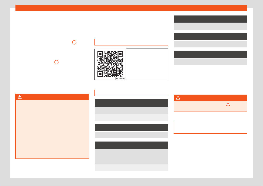
Lights and visibility
Closing the sunroof or sun blind without
the anti-tr
ap function
●
Sunr
oof:
within approximately 5 seconds of
having activated the roll-back function, press
the button
›››
Fig. 148 to the second level
in the direction of arrow
›››
Fig. 148
D
until
the sunr
oof cl
oses compl
etely.
●
Sun blind: within approximately 5 seconds
of having activated the anti-trap function,
press button
›››
Fig. 149
2
until the sun blind
cl
oses compl
et
ely.
●
The sunroof or sun blind close without
the anti-trap function intervening!
●
If the sunroof or sun blind will still not close,
visit a specialised workshop.
WARNING
Closing the sunroof or sun blind without the
anti-trap function can cause serious inju-
ries.
●
Alw
ays be careful when closing the sun-
roof and sun blind.
●
No person should ever remain in the way
of the sunroof or sun blind, especially when
closing without the anti-trap function.
●
The anti-trap function does not prevent
fingers or other parts of the body from be-
coming trapped against the roof frame and
injuries occurring.
Lights and visibility
Lights
R
el
at
ed video
Fig. 151 Vehicle lights
Control lamps
It lights up
Driving light totally or partially faulty.
Fault in the cornering light system.
It lights up
Rear fog light switched on
›››
page 151.
It lights up
Left or right turn signal.
The control lamp fl
ashes twice as fast when a turn
signal is faulty.
Hazard warning lights on
›››
page 152.
It lights up
Trailer turn signals
It lights up
Main beam on or flasher on
›››
page 148.
It lights up
The Light Assist system is on
›››
page 150.
Several warning and control lamps light up
for a fe
w seconds when the ignition is switch-
ed on, signalling that the function is being
verified. They will switch off after a few sec-
onds.
WARNING
Observe the safety warnings
›››
in Con-
trol and warning l
amps on page 123.
Side light and dipped beam head-
light
Read the additional information carefully
›
›
›
page 32
The driver is personally responsible for the
correct use and adjustment of the lights in all
situations.
»
147
Operation
Audible warnings to advise the driver that
the lights hav
e not been s
wit
ched off
If the key is not in the ignition and the driver
door is open, an audible warning signal is
heard in the following cases: this will remind
you to turn the light off.
●
When the parking light is on
›››
page 148.
●
When the light switch is in position or .
WARNING
The side lights or daytime running lights
are not bright enough to illuminat
e the road
ahead and to ensure that other road users
are able to see you.
●
Always use your dipped beam head
lights if it is raining or if visibility is poor.
WARNING
If the headlights are set too high and not
used correctly, there is a risk of dazzling or
distr
acting other road users. This could re-
sult in a serious accident.
●
Always make sure that the headlights are
correctly adjusted.
Note
The legal requirements regarding the use
of vehicle lights in each country must be
observ
ed.
Daytime running lights
The daytime running lights consist of individu-
al lights, integrat
ed in the front headlights. By
connecting the daytime running lights, these
lights are switched on
1)
›››
.
The daytime running lights s
wit
ch on e
very
time the ignition is switched on, if the switch is
in positions or , according to the level of
exterior lighting.
When the light switch is in position , a light
sensor automatically switches dipped beam
on and off (including the control and instru-
ment lighting) or the daytime running lights
depending on the level of exterior lighting.
WARNING
●
Never driv
e with daytime lights if the road
is not well lit due to weather or lighting
conditions. Daytime lights do not provide
enough light to illuminate the road properly
or be seen by other road users.
●
On vehicles with r
ear lights with bulbs,
when activating the daytime running light
the rear lights are not switched on. A vehi-
cle which does not have the rear lights on
may not be visible to other drivers in the
darkness, in the case of heavy rain or in
conditions of poor visibility.
Turn signal and main beam lever
Read the additional information carefully
›››
page 33
Push the lever all the way down to turn off the
corresponding function.
Convenience turn signals
For the one-touch signalling, when the igni-
tion is switched on, move the lever as far as
possible upwards or downwards and release
the lever. The turn signal will flash three times.
One-touch signalling is activated and deacti-
vated in the Easy Connect system via the
button and the function button SETTINGS >
Lights > One-touch signalling
›
›
›
page 35.
1)
On vehicles equipped with rear LED lights, the
rear side light is swit
ched on as well.
148
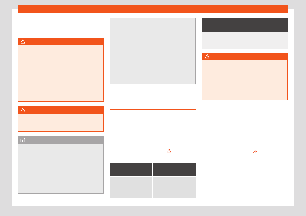
Lights and visibility
In vehicles that do not have the correspond-
ing menu, this function can be deactiv
at
ed in
a specialised w
orkshop.
WARNING
Improper or lack of use of the turn signals,
or forgetting t
o deactivate them can con-
fuse other road users. This could result in a
serious accident.
●
Always give warning when you are going
to change lane, overtake or when turning,
activating the turn signal in good time.
●
As soon as you have finished changing
lane, overtaking or turning, switch the turn
signal off.
WARNING
Incorrect use of the headlights may cause
accidents and serious injury, as the main
beam may distract or dazzle other driv
ers.
Note
●
If the convenience turn signal
s are oper-
ating (three flashes) and the other conven-
ience turn signals are switched on, the ac-
tive part stops flashing and only flashes
once in the new part selected.
●
The turn signal only works when the igni-
tion is switched on. The hazard warning
lights also work when the ignition is switch-
ed off.
●
If a trailer t
urn signal malfunctions, the
control lamp will stop flashing (trailer turn
signals) and the vehicle turn signal will
flash at double speed.
●
The main beam headlights can only be
switched on if the dipped beam headlights
are already on.
●
In cold or damp weather conditions, the
headlights, tail lights and turn signals may
mist up inside temporarily. This is normal
and in no way effects the useful life of the
vehicle lighting system.
Automatic dipped beam control
*
The automatic dipped beam control is merely
int
ended as an aid and is not abl
e t
o recog-
nise all driving situations.
When the light switch is in position , the
vehicle lights and the instrument panel and
switch lighting switch on and off automatical-
ly in the following situations
›››
in Daytime
running lights on page 14
8
:
Automatic switch-
ing on
Automatic switch-
ing off
The photo sensor de-
tects darkness
, for exam-
ple, when driving through
a tunnel.
When adequate lighting
is detected.
Automatic switch-
ing on
Automatic switch-
ing off
The rain sensor detects
rain and activat
es the
windscreen wipers.
When the windscreen
wipers have been inac-
tive for a few minutes.
WARNING
If the road is not well lit and other road
users cannot see the vehicle w
ell enough
or at all, accidents may occur.
●
The automatic dipped beam control
() only switches on the dipped beam
when there are no changes in brightness,
and not, for example when it is foggy.
Main beam assist (Light Assist)*
The main beam assist acts within the limits of
the syst
em and depending on envir
onment
al
and traffic conditions. Once switched on, the
system is activated as of a speed of about 60
km/h (37 mph) and is deactivated below
about 30 km/h (18 mph)
›››
.
When the syst
em is activ
at
ed and the cam-
era detects other vehicles that may be daz-
zled, the main beam is automatically switch-
ed off. Otherwise, the main beam is automati-
cally switched on.
The main beam assist generally detects illu-
minated areas and deactivates the main
»
149
Operation
beam when passing through a town, for ex-
ampl
e
.
S
witching the main beam assist on and off
Func-
tion
Use
Activate:
– Switch the ignition on and turn the light
switch t
o position .
– From the base position, move the main
beam and turn signal lever forwards
›››
page 148. When the warning lamp
is displayed on the instrument panel dis-
play, the main beam assist is switched
on.
Deacti-
vate:
– T
urn the light switch to a different posi-
tion to
››
›
page 147.
– OR: with main beam on, move the turn
signal and main beam lever backwards.
– OR: move the turn signal and main
beam lever forward to manually enable
the main beam. The main beam assist
will then be deactivated.
Malfunctions
The f
oll
o
wing conditions may prevent the
main beam headlight control from turning off
the headlights in time or from turning off alto-
gether:
●
In poorly lit towns with highly reflective
signs.
●
Other insufficiently lit road users (such as
pedestrians or cyclists).
●
On tight bends and steep slopes (bumps)
and when oncoming vehicles are partially
obscured.
●
When the drivers of other oncoming vehi-
cles (such as a truck) can see over a guard
rail in the centre of the road.
●
If the camera is damaged or the power
supply is cut off.
●
In fog, snow and heavy rain.
●
With dust and sand turbulence.
●
With loose gravel in the field of vision of the
camera.
●
When the field of vision of the camera is
misted up, dirty or covered by stickers, snow,
ice, etc.
WARNING
The convenience features of the main
beam assist should not encourage the t
ak-
ing of risks. The system is not a replace-
ment for driver concentration.
●
You are always in control of the main
beam and adapting it to the light, visibility
and traffic conditions.
●
It is possible that the main beam head-
light control does not recognise all driving
situations and is limited under certain cir-
cumstances.
●
When the field of vision of the camera is
dirty, covered or damaged, operation of
the main beam control may be affected.
This also applies when changes are made
to the vehicle lighting system, for example,
if additional headlights are install
ed.
CAUTION
To avoid affecting the operation of the sys-
t
em, tak
e the following points into consid-
eration:
●
Clean the field of vision of the camera
regularly and make sure it is free of snow
and ice.
●
Do not cover the field of vision of the
camera.
●
Check that the windscreen is not dam-
aged in the area of the field of vision of the
camera.
Note
Main beam and headlight flasher can be
turned on and off manually at any time with
the turn signal and main beam l
ever
›››
page 148.
150
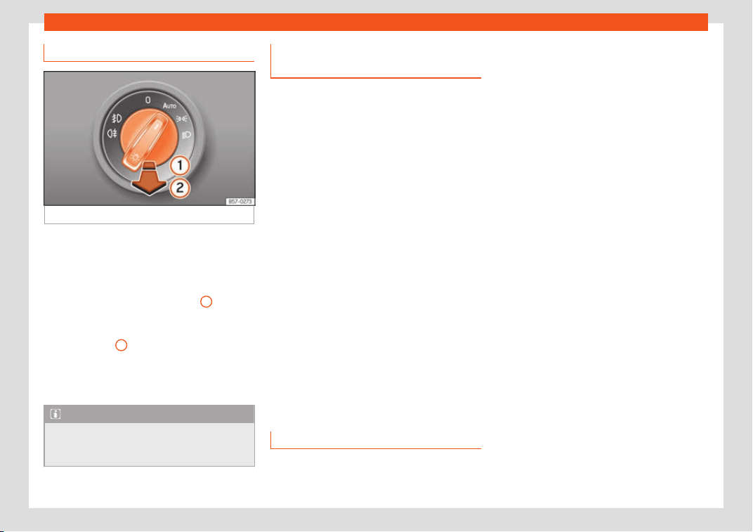
Lights and visibility
Fog lights
Fig. 152
Instrument console: light panel.
The warning lamps or al
so sho
w
, on the
light switch or instrument panel, when the fog
lights are on.
●
Turn on the fog lights* ; pull the light
switch to the first point
›››
Fig. 152
1
, from
positions , or
.
●
T
urn on the r
ear fog light : completely pull
the light switch
2
from position , or
.
●
T
o s
witch off the fog lights, press the light
switch or turn it to position .
Note
The rear fog light can dazzle drivers behind
you. You should use the r
ear fog light only
when visibility is very poor.
Fog lights with cornering light func-
tion*
The cornering light function is an additional
function to the dipped beam headlights to
impr
ove lighting of the side of the road when
taking a sharp turn at low speed.
The cornering light function works when the
dipped beam headlights are already on and
it is enabled when driving at speeds below
approximately 40 km/h (25 mph).
Forward gear
●
If the steering wheel is turned to the right or
the right-hand turn signal s
witched on, the
right-hand fog lamp is gradually switched on.
●
If the steering wheel is turned to the left or
the left-hand turn signal switched on, the left-
hand fog lamp is gradually switched on.
●
After the turn, the cornering light function is
gradually switched off.
Reverse gear
●
When engaging the reverse gear, both fog
lights turn on.
“Coming home” function
This function may be connected/disconnec-
t
ed thr
ough the r
adio menu. The “Coming
Home” and/or “Leaving Home” delay time
may also be set (default: 30 sec).
Vehicle with halogen headlights
In the “Coming Home” function, the daytime
running lights (DRL), the rear side lights and
the licence plate lights are turned on.
Vehicle with full-LED headlights
In the “Coming Home” function, the dipped
beams, the daytime running lights (DRL), the
rear side lights, the number plate lights and
the courtesy lights in the rear view mirror
(Welcome Light) switch on.
Automatic* activation of “Coming Home”
For vehicles with a light and rain sensor (rota-
ry light switch in position ).
●
Switch off the engine and remove the key
from the ignition with the rotary light switch in
position
›››
page 32.
●
The automatic “Coming Home” function is
only active when the light sensor detects
darkness.
●
When the car door is opened, the “Coming
Home” lighting comes on.
Manual “Coming Home” activation
For vehicles with a light and rain sensor (rota-
ry light switch without position ).
»
151
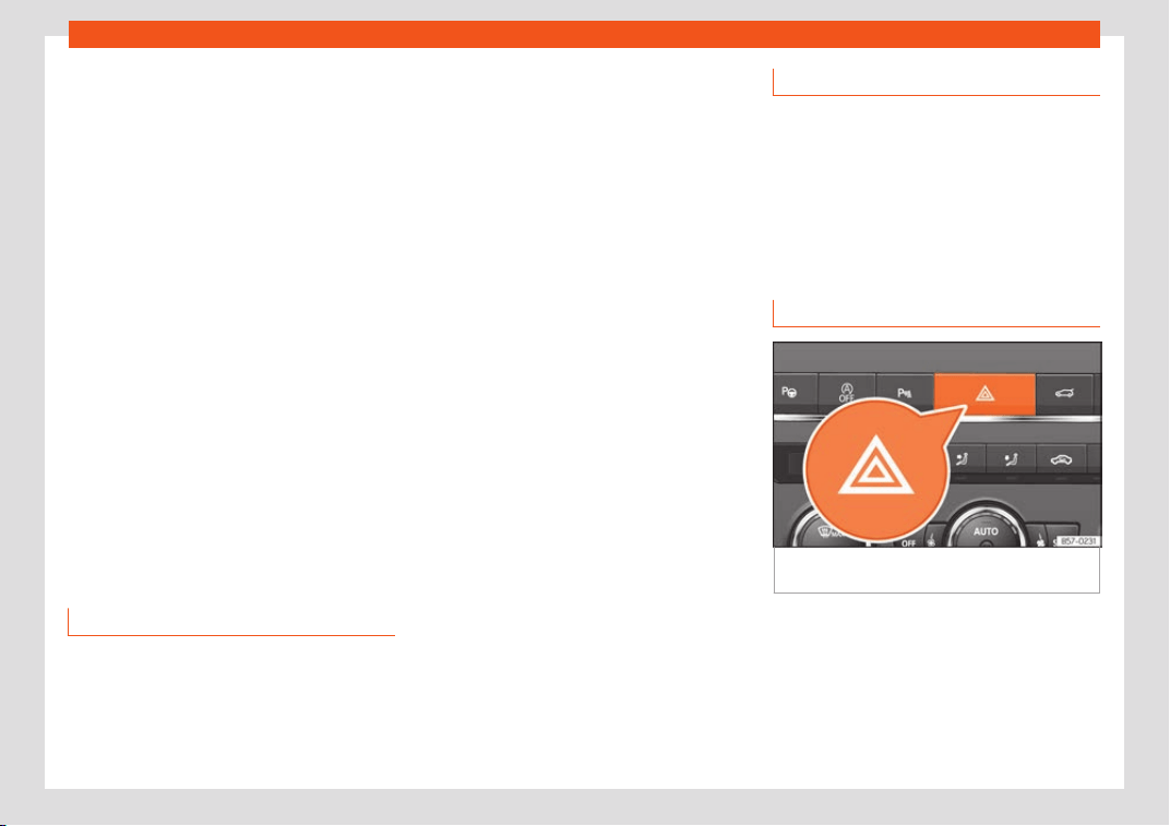
Operation
●
S
wit
ch off the engine and r
emove the key
from the ignition.
●
Activate the headlight flashers for approxi-
mately 1 second.
●
Activated for any position of the rotary light
switch.
●
When the car door is opened, the “Coming
Home” lighting comes on. The headlights are
turned off 60 seconds after the vehicle door
is opened.
Deactivation
●
If no door has been closed, they go out au-
tomatically after 60 seconds.
●
After the last door has been closed, the
headlights will be switched off after the
“Coming Home” delay (as established in the
radio menu) has elapsed.
●
On turning the light switch to position
›››
page 32.
●
When the ignition is switched on (when
starting the engine).
Function “Leaving Home”
The “Leaving Home” function is only available
f
or v
ehicl
es with a light and rain sensor (rota-
ry light switch in position ).
This function may be connected/disconnec-
ted through the radio menu. The “Leaving
Home” function switch-off delay may also be
set (default: 30 sec).
Vehicle with halogen headlights
In the “Leaving Home” function, the daytime
running lights (DRL), the rear side lights and
the licence plate lights are switched on.
Vehicle with full-LED headlights
In the “Leaving Home” function, the dipped
beams, the daytime running lights (DRL), the
rear side lights, the number plate lights and
the courtesy lights in the rear view mirror
(“Welcome Light”) switch on.
Activation
●
When the vehicle is unlocked using the re-
mote control.
●
The “Leaving Home” function is only activa-
ted when the rotary light switch is in position
and the light sensor detects darkness.
Deactivation
●
When the “Leaving Home” delay period
ends (default: 30 sec).
●
When the vehicle is locked using the remote
control.
●
When the light control is switched into a po-
sition other than .
●
With the ignition is switched on.
Welcome light*
3 Valid for vehicles with a light and rain sensor
and Full LED headlights.
The Wel
come light is a light located on the
exterior mirrors facing the ground which is
switched on or off if the lights control is in the
position and the “Coming Home” /
“Leaving Home” function is switched on or off.
Hazard warning lights
Fig. 153
Dashboard: switch for hazard warning
lights.
Read the additional information carefully
›
›
›
page 33
The hazard warning lights are used to draw
the attention of other road users to your vehi-
cle in emergencies.
If your vehicle breaks down:
152
Lights and visibility
1. Park your vehicle at a safe distance from
mo
ving tr
affic.
2.
Press the button to switch on the hazard
warning lights
›››
.
3. Switch the ignition off.
4. Apply the electronic parking brake.
5. For a manual gearbox, engage 1st gear;
f
or an aut
omatic gearbo
x, move the gear
lever to P.
6. Use the warning triangle to draw the at-
tention of other road users to your vehicle.
7. Always take the vehicle key with you when
you leave the vehicle.
All turn signals flash simultaneously when the
hazard warning lights are switched on. The
two turn signal turn signal lamps and the
turn signal lamp in the switch will flash at
the same time. The simultaneous hazard
warning lights also work when the ignition is
switched off.
Emergency braking warning
If the vehicle brakes suddenly and continu-
ously at a speed of more than 80 km/h (50
mph), the brake light flashes several times per
second to warn the vehicles driving behind. If
you continue braking, the hazard warning
lights will come on automatically when the
vehicle comes to a standstill. They switch off
automatically when the vehicle starts to
move again.
WARNING
●
The risk of an accident increases if your
vehicl
e breaks down. Always use the haz-
ard warning lights and a warning triangle to
draw the attention of other road users to
your stationary vehicle.
●
Due to the high temperatures that the
catalytic converter can reach, never park
in an area where the catalytic converter
could come into contact with highly inflam-
mable materials, for example dry grass or
spilt petrol. This could start a fire.
Note
●
The battery will run down if the haz
ard
warning lights are left on for a long time,
even if the ignition is switched off.
●
The use of the hazard warning lights de-
scribed here is subject to the relevant stat-
utory requirements.
Parking lights
When the parking light is switched on, (right
or l
eft t
urn signal), the fr
ont side light and the
rear light on the corresponding side of the ve-
hicle stay lit. The parking lights can only be
activated with the ignition switched off and
the turn signal and main beam lever in the
central position, before being triggered.
Parking light on both sides
With the ignition switched off and the light
switch in position
, when locking the vehicle
from the outside, the parking lights on both
sides of the vehicle light up. In doing so, only
the side lights of both headlights light up, and
additionally the tail lights will do so partially.
Motorway light*
The motorway light is available on vehicles
equipped with full
-LED lights.
The function is connect
ed/disconnect
ed via
the corresponding Easy Connect system
menu.
●
Activation: when going above 110 km/h
(68 mph) for more than 30 seconds, the dip-
ped beam raises slightly to increase the driv-
er's visibility distance.
●
Deactivation: when reducing the speed of
the car below 100 km/h (62 mph), the dipped
beam returns to its normal position.
153
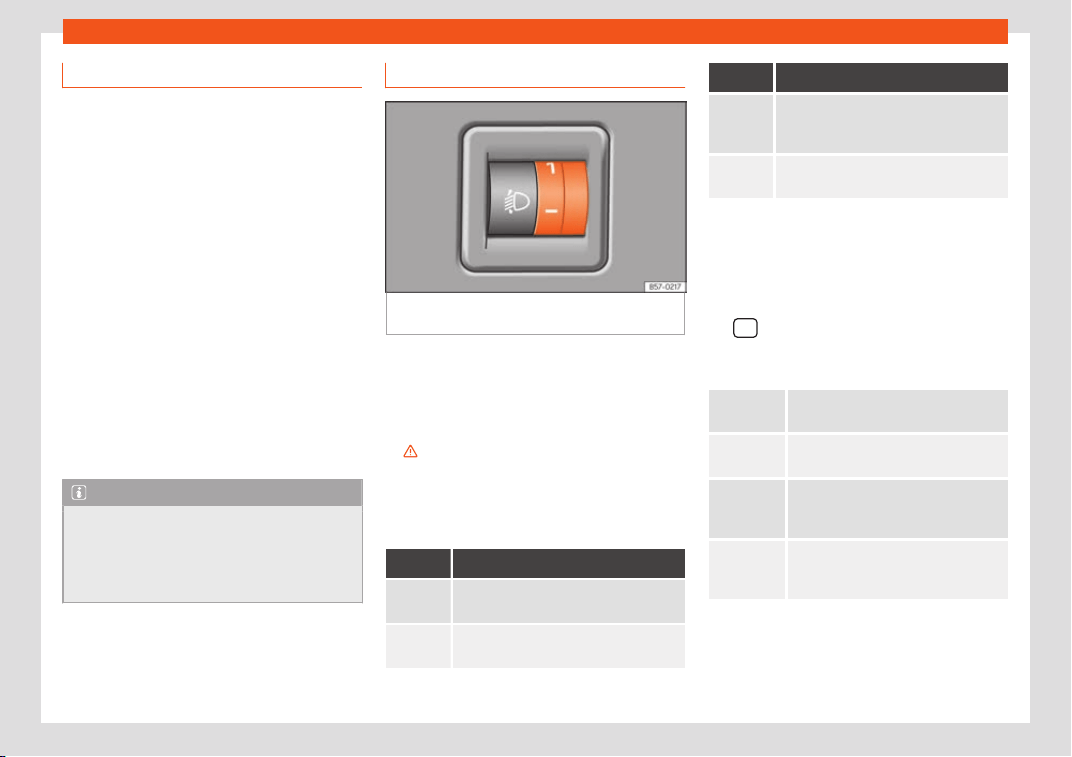
Operation
Driving abroad
The light beam of the dipped beam lights is
asymmetric: the side of the road on which
you are driving is lit mor
e intensely.
When a car that is manufactured in a country
that drives on the right travels to a country
that drives on the left (or vice versa), it is nor-
mally necessary to cover part of the head-
light bulbs with stickers or to change the ad-
justment of the headlights to avoid dazzling
other drivers.
In such cases, the regulations specify certain
light values that must be complied with for
designated points of the light distribution. This
is known as “Tourist light”.
The light distribution of the halogen and full-
LED headlights allows the specific “tourist
light” values to be met without the need for
stickers or changes in the settings.
Note
“Tourist light” is only allowed temporarily. If
you are planning a l
ong stay in a country
that drives on the other side, you should
take the vehicle to an Authorised Technical
Service to change the headlights.
Headlight range control
Fig. 154
Next to the steering wheel: regulator
headlight r
ange contr
ol
.
The headlight range control
›
›
›
Fig. 154 is
modified according to the value of the head-
light beam and the vehicle load status. This
offers the driver optimum visibility and the
headlights do not dazzle oncoming drivers
›››
.
The headlights can only be adjust
ed when
the dipped beam is s
wit
ched on.
To reset, turn switch
›››
Fig. 154:
Value Vehicle load status
a)
Two front occupants, luggage compart-
ment empty
All seats occupied, luggage compart-
ment empty
Value Vehicle load status
a)
All seats occupied, luggage compart-
ment full. With trail
er and minimum
drawbar load.
Driver only, luggage compartment full
With trailer and maximum dr
awbar load.
a)
If the vehicle load does not correspond to those
shown in the tabl
e, it is possible to select intermediary
positions.
OR:
Using the Easy Connect system, by means of
the
button and the function button SET-
TINGS > Lights > Headlight height
adjustment
›
›
›
page 35).
Setting 0
Two front occupants, luggage com-
partment empty
Setting 1
All seats occupied, luggage compart-
ment empty
Setting 2
All seats occupied, luggage compart-
ment full. With trailer and minimum
drawbar load.
Setting 3
Driver only, luggage compartment full
Driving with trailer and minimum
dr
awbar load.
154
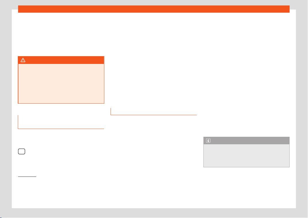
Lights and visibility
Dynamic headlight range control
The contr
ol is not mount
ed in v
ehicles with
dynamic headlight range control. The head-
light range is automatically adjusted accord-
ing to the vehicle load status when they are
switched on.
WARNING
Heavy objects in the vehicle may mean
that the headlights dazzle and distract oth-
er driv
ers. This could result in a serious ac-
cident.
●
Adjust the light beam to the vehicle load
status so that it does not blind other driv-
ers.
Lighting of the instrument panel,
scr
eens and contr
ol
s
Depending on the model, the lighting of the
instrument panel and contr
ol
s can be adjus-
t
ed in the Easy Connect system, using the
button and the SETTINGS function butt
on
›
›
›
page 35.
With the ignition on and without light activa-
tion, the analogue instrument panel lighting
remains activated in daytime light conditions.
The lighting is reduced as the exterior light di-
minishes. In some cases, e.g. when driving
through a tunnel without the function ac-
tive, the instrument panel lighting may even
switch off. The objective of this function is to
provide the driver with a visual indication that
he or she should activate the dipped beam.
If your vehicle is equipped with a digital in-
strument panel (Digital SEAT Cockpit), the
following message will appear Turn on the
lights on the instrument panel.
Interior and reading lights
1)
Read the additional information carefully
›
›
›
page 34
Glove compartment and luggage com-
partment lighting*
When opening and closing the glove com-
partment on the front passenger side and the
rear lid, the respective light will automatically
switch on and off.
Footwell lighting*
The lights in the footwell area below the dash
(driver and front passenger sides) will switch
on when the doors are opened and will de-
crease in intensity while driving. The intensity
of these lights can be adjusted using the ra-
dio menu (see Easy Connect > Light
Settings > Interior lighting
›››
page 35).
Ambient light*
The ambient light lights up the area of the
centre console, the footwell area and, de-
pending on the version, the front door panels.
The ambient lighting in the door panels may
change colour. The brightness and colour of
these lights can be adjusted using the radio
menu (see Easy Connect > Light Set-
tings > Interior lighting
›››
page 35).
Note
The reading lights switch off when the vehi-
cle is lock
ed using a key or after several mi-
nutes if the key is removed from the ignition.
This prevents the battery from discharging.
1)
Depending on the features fitted in the vehicle,
LEDs can be used for the foll
owing interior lights:
front vanity mirror light, rear vanity mirror light,
footwell light, sun blind and glove compartment
light.
155
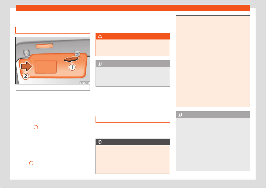
Operation
Visibility
Sun visors
Fig. 155
Sun visor
Options for adjusting driver and front pas-
senger sun visors:
●
Lower the sun visor towards the wind-
scr
een.
●
The sun visor can be pull
ed out of its
mounting and t
urned towards the door
›››
Fig. 155
1
.
●
Swing the sun visor towards the door, longi-
t
udinally backw
ar
ds.
Vanity mirror light
There may be a vanity mirror, with a cover, on
the rear of the sun visor. When the cover is
opened
2
a light comes on.
The lamp goes out when the vanity mirror
co
v
er is cl
osed or the sun visor is pushed
back up.
WARNING
Folded sun blinds can reduce visibility.
●
Always store sun blinds and visors in their
housing when not in use.
Note
The light above the sun visor automatically
switches off aft
er a few minutes in certain
conditions. This prevents the battery from
discharging.
Windscreen wiper and win-
do
w wiper syst
ems
Windo
w wiper lever
Read the additional information carefully
›
›
›
page 34
CAUTION
If the ignition is switched off with the wind-
screen wipers active
, they complete their
wipe before returning to the rest position.
When switching the ignition back on, the
windscreen wiper will continue to operate
at the same wiping level. Ice, snow and oth-
er obstacles on the windscreen may dam-
age the wiper and the windscreen wiper
motor
.
●
If necessary, remove snow and ice from
the windscreen wipers before starting your
journey.
●
Carefully lift the frozen windscreen wip-
ers from the glass. SEAT recommends a de-
icer spray for this operation.
●
Do not switch on the windscreen wipers if
the windscreen is dry. Cleaning with the
windscreen wipers while dry can cause
damage.
●
In icy conditions, always check that the
wiper blades are not frozen to the glass be-
fore using the wipers. In cold weather, it
may help to leave the vehicle parked with
the wipers in service position
›››
page 61.
Note
●
The windscreen and window wipers only
function when the ignition is s
witched on
and the bonnet or rear lid, respectively, are
closed.
●
The interval wipe speed varies according
to the vehicle speed. The faster the vehicle
is moving, the more often the windscreen is
cleaned.
●
The rear wiper is automatically switched
on when the windscreen wiper is on and the
car is in reverse gear.
156
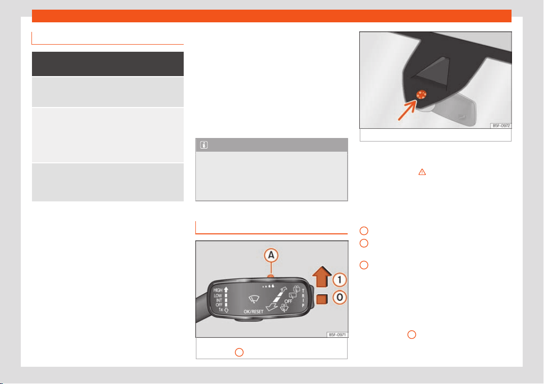
Lights and visibility
Windscreen wiper functions
Windscreen wipers performance in differ-
ent situations
If the vehicl
e is at a
standstill
The activat
ed position provi-
sionally changes to the previ-
ous position.
During automatic
wipe
The air conditioner comes on
for appro
ximately 30 seconds
in air recirculation mode to pre-
vent the smell of the wind-
screen washer fluid entering
the inside the vehicle.
For the interval
wipe
Intervals between wipes de-
pend on the vehicle
's speed.
The higher the vehicle speed
the shorter the intervals.
Heated windscreen washer jets*
The heating only thaws the fr
o
z
en jets, it does
not thaw the water in the washer hoses.
When the ignition is switched on the heated
windscreen washer jets automatically adjust
the heat depending on the ambient tempera-
ture.
Headlight wash/wipe system*
The headlight washers/wipers clean the
headlight lenses.
After the ignition is switched on, the first and
every fifth time the windscreen washer is
switched on, the headlights are also washed.
Therefore, the windscreen wiper lever should
be pulled towards the steering wheel when
the dipped beam or main beam are on. Any
encrusted dirt (such as insects) should be
cleaned regularly (e.g. when refuelling).
To ensure the headlight washers work cor-
rectly in winter, any snow which has got into
the bumper jet supports should be cleaned
away. If necessary, remove snow with an an-
ti-icing spray.
Note
The wiper will try to wipe away any obsta-
cles that are on the windscr
een. The wiper
will stop moving if the obstacle blocks its
path. Remove the obstacle and switch the
wiper back on again.
Rain sensor*
Fig. 156
Windscreen wipers lever: adjust the
r
ain sensor
A
.
Fig. 157 Rain sensor sensitive surface
The rain sensor controls the frequency of the
windscr
een wiper int
erv
als, depending on the
amount of rain
›››
. The sensitivity of the rain
sensor can be adjust
ed manually. Manual
wipe
›
›
›
page 156.
Move the lever to the required position
›››
Fig. 156:
Rain sensor off.
Rain sensor on; automatic wipe if neces-
sary.
Setting sensitivity level of rain sensor
–
Set control to the right: high sensitivity.
–
Set control to the left: low sensitivity.
When the ignition is switched off and then
back on, the rain sensor stays on and starts
operating again when the windscreen wipers
are in position
1
and the vehicle is travelling
at mor
e than 16 km/h (
10 mph).
»
0
1
A
157

Operation
Rain sensor modified behaviour
P
ossibl
e causes of f
aults and mistaken read-
ings on the sensitive surface
›››
Fig. 157 of the
rain sensor include:
●
Damaged wipers: a film of water on the
damaged blades may lengthen the activa-
tion time, reduce the washing intervals or re-
sult in a fast and continuous wipe.
●
Insects: insects on the sensor may trigger
the windscreen wiper.
●
Salt on the road: in winter, salt spread on
the roads may cause an extra long wipe
when the windscreen is almost dry.
●
Dirt: dry dust, wax, coating on glass (Lotus
effect) or traces of detergent (car wash) may
reduce the effectiveness of the rain sensor or
make it react more slowly, later or not at all.
●
Windscreen crack: the impact of a stone
will trigger a single wipe cycle with the rain
sensor on. Next the rain sensor detects the re-
duction in the sensitive surface area and
adapts accordingly. The behaviour of the
sensor will vary with the size of the damage
caused by the stone.
WARNING
The rain sensor may not detect enough rain
to swit
ch on the wipers.
●
If necessary, switch on the wipers man-
ually when water on the windscreen ob-
structs visibility.
Note
●
Clean the sensitive surf
ace of the rain
sensor regularly and check the blades for
damage
›››
Fig. 157 (arrow).
●
To remove wax and coatings, we recom-
mend a window cleaner containing alco-
hol.
Mirror
Anti-dazzle rear vie
w mirror
It is dangerous to drive if you cannot see
cl
early thr
ough the r
ear window.
Rear view mirror with automatic anti-daz-
zle function*
The anti-dazzle function is activated every
time the ignition is switched on.
When the anti-dazzle function is enabled, the
interior rear vision mirror will darken auto-
matically according to the amount of light it
receives. The anti-dazzle function is cancel-
led if reverse gear is engaged.
WARNING
In the event that an automatic anti-dazzle
rear vision mirror br
eaks, an electrolyte flu-
id may leak. This could cause irritation to
the skin, eyes and respiratory organs. If you
come into contact with this liquid, it must
be rinsed with large quantities of w
ater. If
necessary, get medial help.
CAUTION
In the event that an automatic anti-dazzle
r
ear vision mirror br
eaks, an electrolyte flu-
id may leak. This liquid attacks plastic sur-
faces. Clean it with a wet sponge as soon
as possible.
Note
●
If the light incident in the interior rear vi-
sion mirr
or is obstructed (e.g. with the sun
blind*), the anti-dazzle rear vision mirror
with automatic setting will not operate per-
fectly.
●
When the interior lights are on or reverse
gear engaged, the mirrors do not darken
with automatic adjustment for anti-dazzle
position.
158
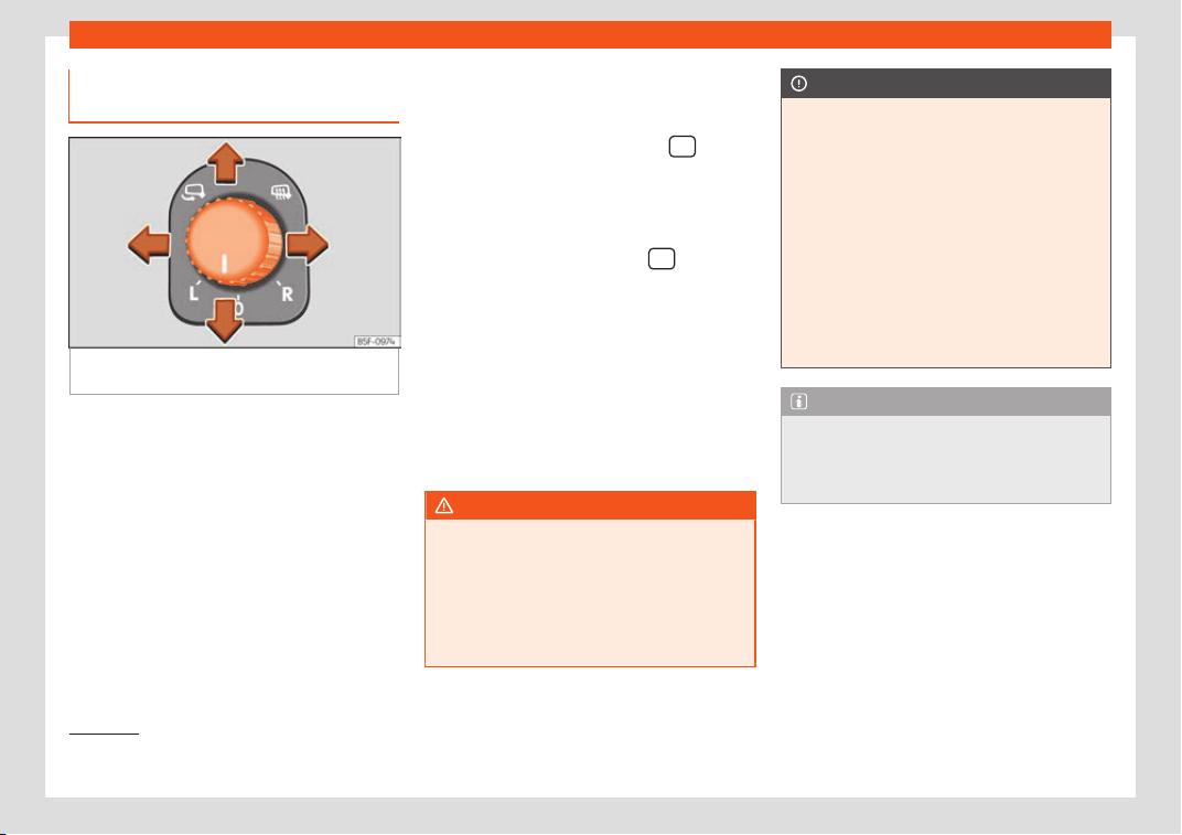
Lights and visibility
Adjusting the exterior rear-view
mirr
ors
Fig. 158
Driver door: control for the exterior
mirr
or
.
Read the additional information carefully
›
›
›
page 21
Synchronized regulation of the exterior
mirrors
●
In the Settings - Convenience menu,
select whether or not the exterior mirrors
should move in synchronisation.
●
Turn the knob to position L
1)
.
●
Adjust the left-hand exterior mirror. The
right exterior mirror will be adjusted at the
same time (synchronised).
●
If necessary, correct the right-hand rear-
view mirror: rotate the control to position R
1)
.
●
In the Easy Connect system the exterior
mirrors can be adjusted using the
button
and the SETTINGS function butt
on.
F
ol
d the rearview mirrors when locking the
vehicle*
The Easy Connect system, the
> SET-
TINGS > Mirrors and windscreen wip-
ers can be used t
o hav
e the e
xterior mirrors
fold in when the vehicle is parked and locked
›››
page 35.
When the vehicle is locked with the remote
control, the exterior mirrors are retracted au-
tomatically. When the vehicle is opened with
the remote control, the exterior mirrors are
deployed automatically.
WARNING
Convex or wide-angle* exterior mirrors
give a lar
ger field of vision. However, they
make objects look smaller and further
away than they really are. If you use these
mirrors to estimate the distance to vehicles
behind you when changing lane, you could
misjudge the distance. Risk of accident!
CAUTION
●
If one of the mirror housings is knocked
out of position (e
.g. when parking), the mir-
rors must first be fully retracted with the
electric control. Do not readjust the mirror
housing by hand, as this will interfere with
the mirror adjuster function.
●
Before washing the vehicle in an auto-
matic car wash, please make sure to re-
tract the exterior mirrors to prevent them
from being damaged. Electrically retracta-
ble exterior mirrors must not be folded in or
out by hand. Always use the electrical
power control.
Note
If the electrical adjustment should fail to
operate
, both of the mirrors can be adjus-
ted by hand by lightly pressing the edge of
the mirror glass.
1)
Regulation in right-hand drive vehicles is sym-
metrical.
159
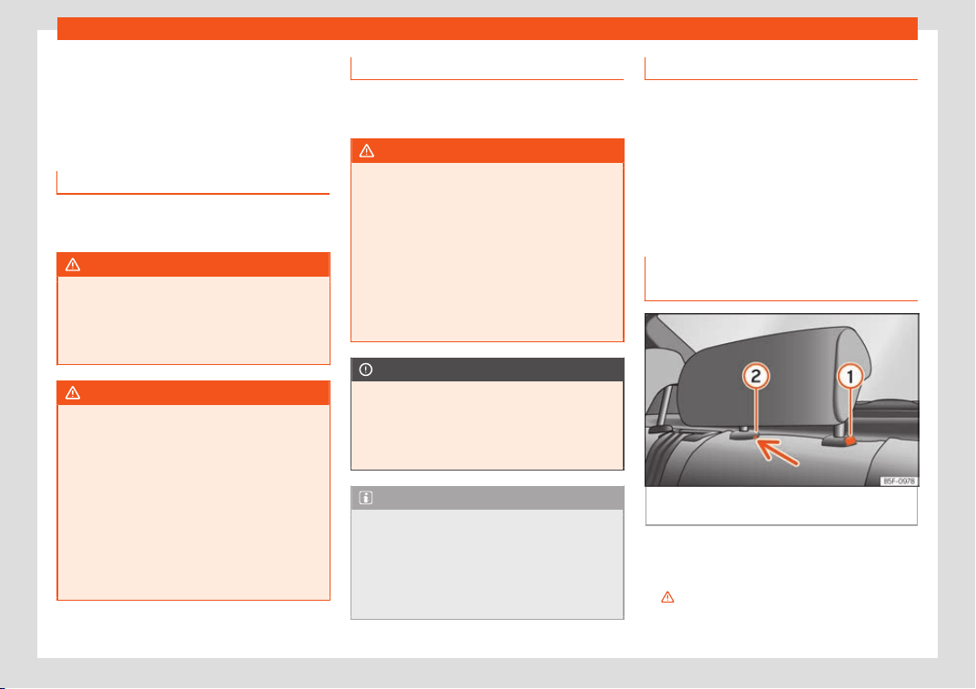
Operation
Seats and head restraints
Adjusting the seats and
headr
ests
Manual adjustment of the seats
Read the additional information carefully
›››
page 19
WARNING
The safe driving chapter contains impor-
tant information, tips, suggestions and
w
arnings that you should read and observe
for your own safety and the safety of your
passengers
›››
page 63.
WARNING
●
Adjust the front seats only when the vehi-
cl
e is stationary. Failure to follow this in-
struction could result in an accident.
●
Be careful when adjusting the seat
height. Careless or uncontrolled adjust-
ment can cause injuries.
●
The front seat backrests must not be re-
clined for driving. Otherwise, seat belts and
the airbag system might not protect as
they should, with the subsequent danger of
injury.
Electric driver's seat adjustment*
Read the additional information carefully
›››
page 19
WARNING
●
If the electric front seats ar
e used negli-
gently or without paying due attention, it
can cause serious injury.
●
The front seats can also be electrically
adjusted when the ignition is switched off.
Never leave a child or any other person
who may need help in the vehicle.
●
In the event of an emergency, electrical
adjustment can be stopped by pressing
any control.
CAUTION
To avoid damaging the electrical compo-
nents of the front seats, please r
efrain from
kneeling on the seat or applying sharp
pressure at a single point to the seat cush-
ion and backrest.
Note
●
It may not be possible to el
ectrically ad-
just the seat if the vehicle battery is very
low.
●
If the engine is started while the seats are
being electrically adjusted, the adjustment
will stop.
Adjusting the front head restraints
Read the additional information carefully
›››
page 20
Adjust the head restraint
›››
page 20 so
that as far as possible the top of the head re-
straint is level with the top of your head. When
this is not possible, try to get as close as pos-
sible to this position.
Adjustment of the rear head re-
straints
Fig. 159
Rear centre head restraint: release
point.
When transporting people in the back seat,
pl
ace the head r
estr
aints of the occupied
seats at a minimum of the next socket up
›››
.
160
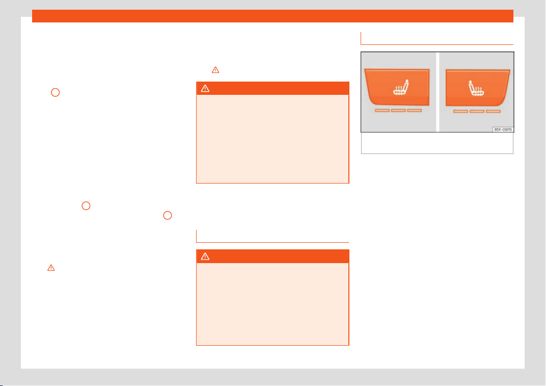
Seats and head restraints
Adjusting the head restraints
–
To set the head restraint higher, grasp the
sides with both hands and mo
v
e it up
wards,
until you see it engage.
–
To set the head restraint lower down, press
the
1
›
›
›
Fig. 159 button and move it
downwards.
Removing the head restraint
To remove the head restraint, the corre-
sponding backrest must be partially folded
forward.
–
Unlock the backrest
›››
page 163.
–
Move the head restraint upwards until it ar-
rives to the top.
–
Press button
1
›
›
›
Fig. 159, while simulta-
neously pressing on the security hole
2
›››
Fig. 159 with a fl
at scr
e
wdriver a maxi-
mum of 5 mm wide, and remove the head
restraint.
–
Move the backrest until it engages properly
›››
.
Fitting the head r
estr
aint
T
o mount the external head restraints, the
corresponding backrest must be partially fol-
ded forward.
–
Unlock the backrest
›››
page 163.
–
Insert the head restraint bars into the
guides until they perceptibly engage. It
should not be possible to remove the head
restraint from the backrest.
–
Move the backrest until it engages properly
›››
.
WARNING
●
Please observe the gener
al notes
›››
page 68.
●
Remove the rear head restraints only
when it is necessary for the placement of a
child seat
›››
page 80. After removing a
child seat, remount the head restraint im-
mediately. Travelling with the head re-
straints removed or improperly adjusted in-
creases the risk of severe injuries.
Seat functions
Intr
oduction
WARNING
Inappropriate use of the seat functions can
cause sever
e injuries.
●
Assume the proper sitting position before
your trip and remain in it throughout. This
also applies to the other occupants.
●
Always keep hands, fingers, feet and oth-
er parts of the body away from the operat-
ing radius and the adjustment of seats.
Seat heating
Fig. 160 On the centre console: front seats
heating switch
The seat cushions can be heated electrically
when the ignition is s
wit
ched on. The backr
est
is also heated in some versions.
The seat heating should not be engaged in
any of the following conditions:
●
The seat is unoccupied.
●
The seat has a covering.
●
There is a child seat installed in the seat.
●
The seat cushion is wet or damp.
●
The indoor or outdoor temperature is great-
er than 25°C (77°F).
Activate
Press the button
or
. Seat heating is
switched on fully.
»
161
Operation
Adjusting the heating output
Pr
ess the butt
on
or repeatedly until the
desired temperature is reached.
Deactivating
Press the button or until all the warning
lamps switch off.
WARNING
Children and people who cannot perceive
pain or temperat
ure because of medica-
tions, paralysis or chronic diseases (e.g.
diabetes) or have a limited perception of
these, may suffer burns to the back, but-
tocks or legs when using seat heating, an
occurrence that may entail a very lengthy
recovery period or from which it may not be
possible to recover fully. Seek medical ad-
vice if you have doubts regarding your
health.
●
People with limited pain and temperature
thresholds must never use seat heating.
●
If an abnormality in the device's temper-
ature control is detected, have it checked
by a specialist workshop.
WARNING
If the fabric of the cushion is wet, this can
adversely affect the oper
ation of the seat
heating, increasing the risk of burns.
●
Make sure the seat cushion is dry prior to
using the seat heater.
●
Do not sit on the seat with clothing that is
wet or damp
.
●
Do not leave clothing that is wet or damp
on the seat.
●
Do not spill liquid on the seat.
CAUTION
●
T
o avoid damaging the heating el
ements
of the seat heaters, please do not kneel on
the seat or apply sharp pressure to a single
point on the seat cushion or backrest.
●
Liquids, sharps objects and insulating
materials (e.g. covers or child seats) can
damage the seat heating.
●
In the event of smells, switch off the seat
heating immediately and have it inspected
by a specialised workshop.
For the sake of the environment
The seat heating should remain on only
when needed. Otherwise, it is an unneces-
sary fuel wast
e.
Front centre armrest
The centre armrest can be adjusted to vari-
ous l
e
v
els.
Adjusting the centre armrest
–
To adjust the tilt, lift the armrest from the
starting position so that it is engaged.
–
To return the armrest to the starting posi-
tion, remove the armrest from the upper
fixed position and lower it.
The armrest can be moved backwards and
forwards.
162
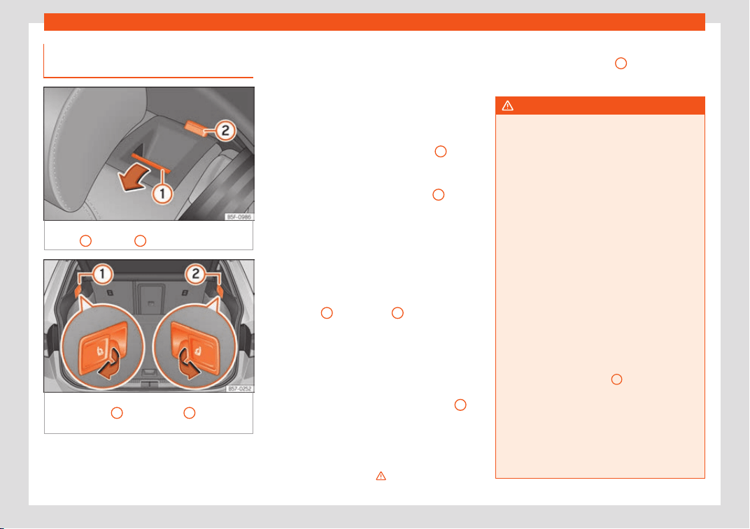
Seats and head restraints
Folding down and lifting the rear
seat backr
est
Fig. 161
On the rear seat backrest: release
butt
on
1
; red mark
2
.
Fig. 162
In the trunk: levers for remote release
of the l
eft part
1
and right part
2
of the rear
seat backr
est.
The rear seat backrest is split and each part
be l
o
w
ered separately to extend the luggage
compartment.
When the rear seat backrest is lowered no-
body else can travel in the corresponding
seats (not even a child).
Lowering the rear seat backrest with the
unlock button
●
Lower the head restraint properly.
●
Push the unlock button
›››
Fig. 161
1
for-
w
ar
ds and at the same time lift the backr
est.
●
The rear seat backrest is not engaged
when the red marking of the button
2
is visi-
bl
e
.
L
owering the rear seat backrest with the
remote release lever
●
Lower the head restraint properly.
●
Open the rear lid.
●
Pull the remote release lever of the left part
›››
Fig. 162
1
or right part
2
of the backrest
in the dir
ection of the arr
o
w. The released
part of the rear seat backrest is folded auto-
matically down and forwards.
●
If this occurs, close the rear lid.
The rear seat backrest is not engaged when
the red marking of the button
›››
Fig. 161
2
is
visibl
e
.
F
olding up the rear seat backrest
●
Lift the backrest and press it firmly into the
lock until it engages
›››
.
●
It shoul
d not be possibl
e t
o see the red
mark of the unlock button
2
.
●
The backrest must be properly engaged.
WARNING
Serious injuries can be caused if the rear
seat backrest is lo
wered or lifted without
due care and attention.
●
Never lower or lift the rear seat backrest
while driving.
●
Do no trap or damage the seat belt when
raising the rear seat backrest.
●
When lowering or lifting the rear seat
backrest, keep your hands, fingers, feet
and other body parts out of its path.
●
For the rear seat belts to offer the neces-
sary protection all the parts of the rear
backrest must be properly engaged. This is
particularly important in the case of the
centre rear seat. If someone is seated in a
seat whose backrest is not properly engag-
ed they will fly forward, along with the
backrest, during an accident or a sudden
driving or braking manoeuvre.
●
A red signal on button
2
warns that the
backrest is not engaged. Alw
ays check
that the red marking is not visible when the
backrest is in the upright position.
●
When the rear seat backrest is lowered or
is not properly engaged nobody else can
travel in the corresponding seats (not even
a child).
»
163
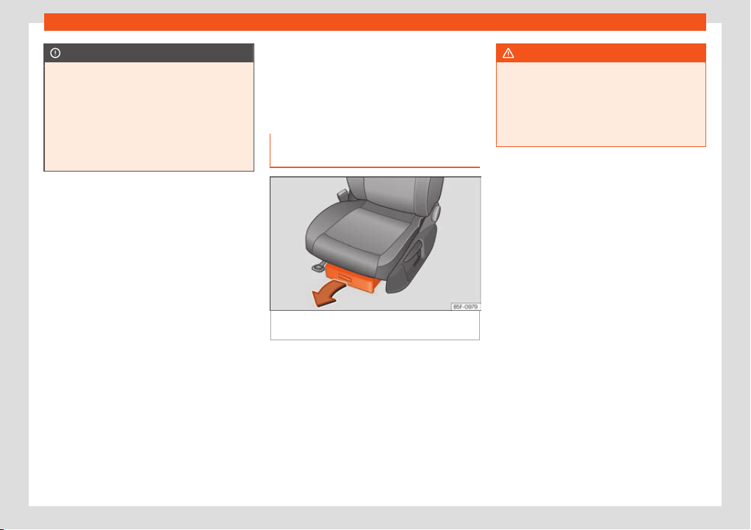
Operation
CAUTION
Serious damage can be caused to the vehi-
cle and other objects if the r
ear seat back-
rest is lowered or lifted without due care
and attention.
●
Before lowering the rear seat backrest,
always adjust the front seats so that nei-
ther the head restraints nor the cushions of
the rear backrest can hit them.
Transport and practical
equipment
St
or
age compar
tments
Storage areas under the front
seats*
Fig. 163
Storage compartment under the front
seats.
There is a storage compartment with a cover
under each fr
ont seat.
The dr
aw
er* is opened by pulling on the han-
dle of the cover
›››
Fig. 163.
To close the drawer, press the cover until it
locks into position.
WARNING
●
The drawers will hol
d a maximum weight
of 1.5 kg.
●
Do not drive with the drawer cover open.
There is an injury risk for passengers if the
cargo is released in case of sudden braking
or an accident.
164
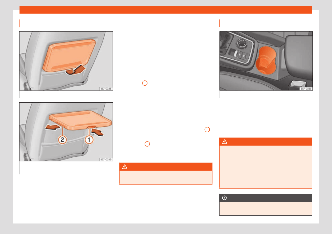
Transport and practical equipment
Folding table*
Fig. 164
Left-hand front seat: folding table.
Fig. 165
Left-hand front seat: folding table
with drinks hol
der
.
Depending on the model version, at the rear
of the fr
ont seats, ther
e may be “pl
ane-style”
folding tables for passengers in the rear
seats.
Folding the table
●
Push the table downwards, as much as you
can.
Folding the table or adjusting its inclina-
tion
The foldable table can be used at different
inclinations.
●
Press the unlocking lever under the table
›››
Fig. 165
1
and keep it that way.
●
Adjust: Adjust the inclination of the t
abl
e by
pr
essing the lever.
●
Fold: Push the table downwards while
pressing the lever.
Drink holder
A drink holder is built into the folding table
2
.
With the f
ol
dabl
e table extended, remove the
drink holder
2
following the direction of the
arr
o
w
. To store the drink holder, insert it into
the table against the direction of the arrow.
WARNING
The table must always be closed while
driving to decrease the risk of injuries.
Drink holders
Fig. 166
Centre console: drinks holder.
Front drink holders
–
Place drinks in the holder
›
›
›
Fig. 166.
Placement of two drinks is possible. There is
also the possibility of placing larger plastic
bottles in the trims of the doors.
WARNING
●
Do not place any hot drinks in the drink
holder whil
e the vehicle is moving. Hot
drinks could spill and cause burns, which
may cause an accident.
●
Do not use hard china cups or glasses.
These could cause injury in the event of an
accident.
CAUTION
You should avoid putting open drinks con-
tainers in the drink holders. The drinks
»
165
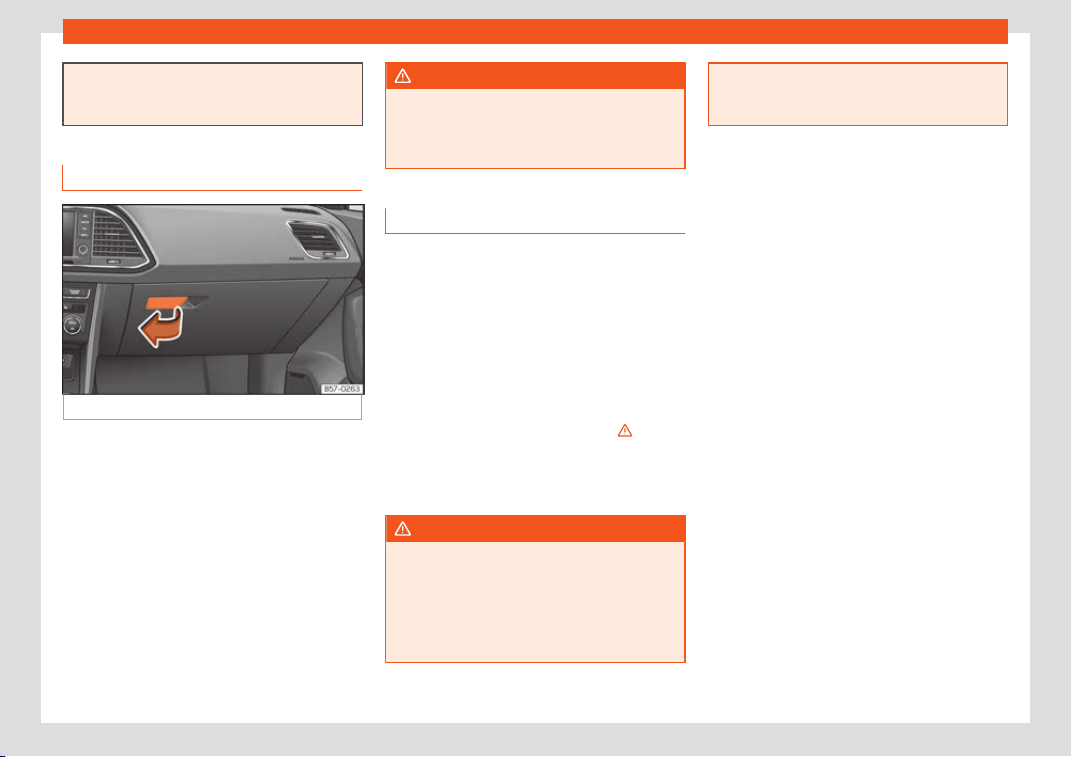
Operation
could otherwise spill over and cause dam-
age to e.g. the el
ectrical equipment or the
seat covers.
Glove compartment
Fig. 167 Glove compartment
Opening/closing
–
To open the glove compartment, pull the
handl
e in the dir
ection of the arr
ow.
–
To close the glove compartment, move the
cover upwards until it engages.
Depending on the vehicle equipment, the CD
player is located in the glove compartment.
Separate operating instructions are enclosed
for this equipment in the corresponding In-
struction Manual.
WARNING
The cover of the glove compartment should
always be cl
osed while driving. Failure to
follow this instruction could result in an ac-
cident.
Other storage compartments
You will find more object holders, compart-
ments and supports in other parts of the vehi-
cle:
●
In the t
op of the glove compartment in vehi-
cles that do not have a CD r
eader. The load
of the compartment should not exceed 1.2 kg.
●
In the centre console under the centre arm-
rest*.
●
Coat hooks in the door frames
›››
.
●
Other storage compartments are found in
the r
ear seat, t
o the l
eft and the right of the
seats.
WARNING
●
Please make sur
e that any items of cloth-
ing hanging from the coat hooks do not ob-
struct your view to the rear.
●
The coat hooks should only be used for
lightweight clothing. Do not leave any
heavy or sharp objects in the pockets.
●
Do not use clothes hangers to hang up
the cl
othing, as this could interfere with the
function of the head-protection airbags.
166
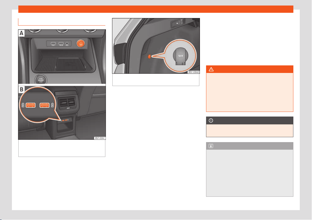
Transport and practical equipment
Power sockets
Fig. 168
Centre console: fr
ont 12 volt power
socket.
Rear of the centre console: USB
sockets.
Fig. 169 Detailed view of the side trim in the
boot: 12-volt pow
er socket.
In the centre console
–
Remove the cap located on the centre con-
sol
e of the sock
et
›
››
Fig. 168. .
–
Insert the plug of the electrical appliance
into the power socket.
In the luggage compartment*
–
Lift the power socket cover
›››
Fig. 169.
–
Insert the plug of the electrical appliance
into the power socket.
Electrical equipment can be connected to
the 12 volt power socket. The appliances con-
nected to each power socket must not ex-
ceed a power rating of 120 Watt.
USB power sockets
Depending on the equipment and the coun-
try, the vehicle may also have USB connec-
tions exclusively for charging or as a power
socket.
These USB ports are located at the rear of
the console, between the front seats
›››
Fig. 168 . These connectors can work at
a maximum power of up to 10.5 W per port.
They are not intended for file playback.
WARNING
The power socket works only when the igni-
tion is on. Improper use may cause serious
injury or ev
en fire. Children should there-
fore not be left in the vehicle unattended if
the button is also left behind. Otherwise
there is a possibility that they may be in-
jured.
CAUTION
Always use the correct type of plugs to
avoid damaging the sockets.
Note
●
The use of electrical appliances with the
engine swit
ched off will cause a battery
discharge.
●
Should the connected appliance over-
heat, immediately switch it off and discon-
nect it from the socket.
●
Before switching the ignition on or off, un-
plug the appliances from the USB ports to
»
167
Operation
protect them from any damage caused by
fluctuations in volt
age.
Storing objects
Loading the luggage compartment
All luggage and other loose objects must be
safely secured in the luggage compartment.
Unsecur
ed objects which shift back and forth
could impair the driving safety or driving
characteristics of the vehicle by shifting the
centre of gravity.
–
Distribute the load evenly in the luggage
compartment.
–
Place heavy objects as far forward as pos-
sible in the luggage compartment.
–
Place the heavy ob
jects first.
–
Secure heavy objects to the fitted fastening
rings
›››
page 170.
WARNING
●
Loose luggage and other objects in the
luggage compar
tment could cause serious
injuries.
●
Always stow objects in the luggage com-
partment and secure them on the fastening
rings.
●
Use suitable str
aps to secure heavy ob-
jects.
●
During sudden manoeuvres or accidents,
loose objects can be thrown forward, injur-
ing vehicle occupants or passers-by. This
increased risk of injury will be further in-
creased if a loose object is struck by an in-
flating airbag. If this happens, objects may
shoot outward like a missile. Risk of fatal in-
jury.
●
Please note that the centre of gravity
may shift when transporting heavy objects;
this may affect vehicle handling and lead
to an accident. Therefore, it is essential to
adjust your speed and driving style ac-
cordingly, to avoid accidents.
●
Never exceed the allowed axle weights or
allowed maximum weight. If said weights
are exceeded, the driving characteristics of
the vehicle may change, leading to acci-
dents, injuries and damage to the vehicle.
●
Never leave your vehicle unattended, es-
pecially when the rear lid is open. Children
could climb into the luggage compartment,
closing the door behind them; they will be
trapped and run the risk of death.
●
Never allow children to play in or around
the vehicle. Close and lock all the doors
and the rear lid when you leave the vehicle.
Before you lock the vehicle, make sure that
there are no adults or children in the vehi-
cle.
Note
●
Air circulation in the v
ehicle helps reduce
fogging of the windows. Used air escapes
through ventilation slits in the side trim of
the luggage compartment. Ensure that the
ventilation slots are never covered.
●
Straps for securing the load to the fas-
tening rings are commercially available
from accessory shops.
168
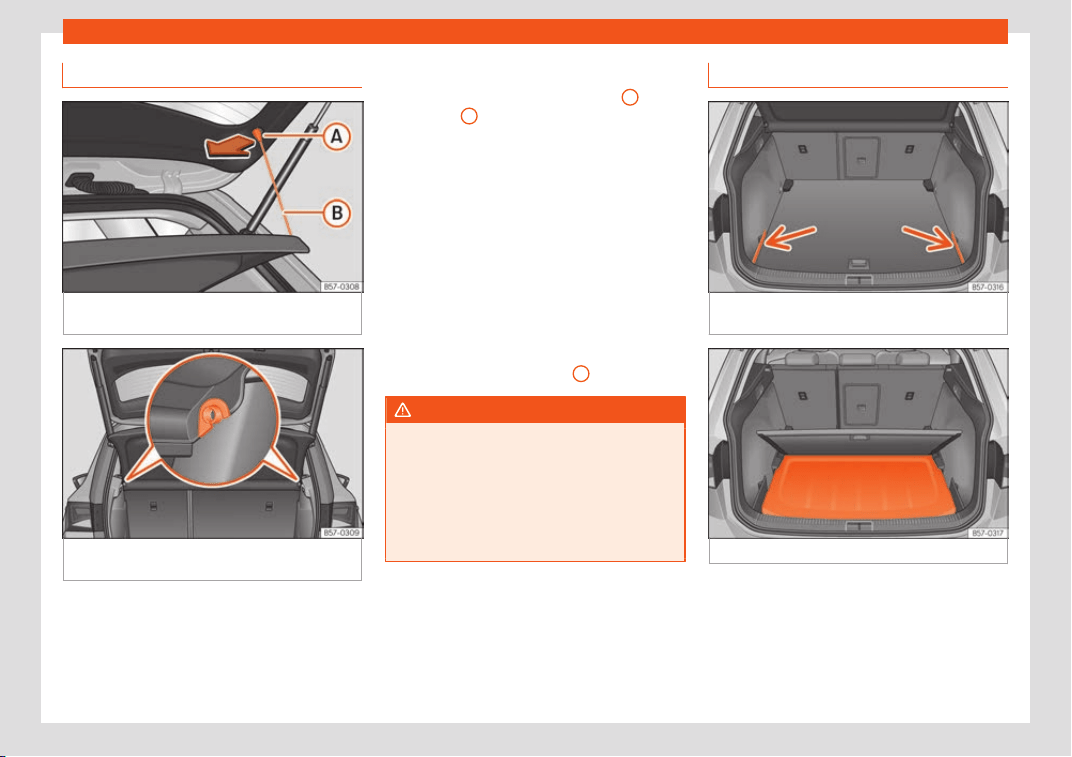
Transport and practical equipment
Luggage compartment shelf
Fig. 170
In the boot: removing and installing
the shelf
.
Fig. 171 In the boot: removing and installing
the shelf
.
The luggage compartment cover blocks the
vie
w int
o the luggage compartment.
R
emoving
●
Detach the cord loops
›››
Fig. 170
B
from
their hooks
A
.
●
Remove the rear shelf from the side sup-
ports
›
›
›
Fig. 171 by pulling it upwards and
then take it out.
If necessary, the rear shelf can be stored un-
der the luggage compartment double floor
›››
page 169.
Fitting
●
Insert the cover horizontally so that the “re-
cess” fits onto the axis of the supports
›››
Fig. 171 and press down until it engages.
●
Hook the loops
›››
Fig. 170
B
to the rear lid.
WARNING
●
The luggage compartment cov
er must
always be fixed properly (risk of accident).
●
The luggage compartment cover should
not be used as a storage shelf. Articles
placed on this cover could cause injury to
vehicle occupants in an accident or if the
brakes are applied suddenly.
Storing the rear shelf
Fig. 172
In the boot: covers for storing the rear
shelf
.
Fig. 173 In the boot: fitting the rear shelf.
The rear shelf can be stored under the lug-
gage compartment v
ariabl
e fl
oor.
●
Remove the left and right covers
›››
Fig. 172.
●
Press the rear shelf until it engages in its
housing
›››
Fig. 173.
»
169
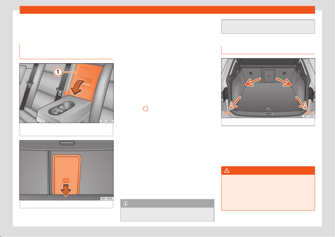
Operation
●
Put the l
eft and right co
v
ers in their original
position.
Tailboard for transporting long
items*
Fig. 174
On the rear seat backrest: opening
the t
ailboar
d.
Fig. 175
In the boot: opening the tailboard.
On the rear seat, behind the central armrest,
ther
e is a t
ailboar
d for transporting long items
in the interior, such as skis.
To avoid soiling the interior, dirty objects
should be wrapped (e.g. in a blanket) before
they are inserted through the tailboard.
When the armrest is down, nobody may trav-
el in the centre rear seat.
Opening the tailboard
●
Lower the centre armrest.
●
Pull the release lever in the direction of the
arrow and push the tailboard cover
›››
Fig. 174
1
down and forwards.
●
Open the rear lid.
●
Insert the long objects through the gap
fr
om the luggage compartment.
●
Secur
e the ob
jects with the seat belt.
●
Close the rear lid.
Closing the tailboard
●
Lift the tailboard cover until it engages. The
red mark on the luggage compartment side
should never be visible.
●
Close the rear lid.
●
Lift the centre armrest if necessary.
Note
The tailboard can also be opened from the
luggage compartment. To do so
, press the
release lever down, in the direction of the
arrow
, and the cover upwards
›››
Fig. 175.
Fastening rings*
Fig. 176
In the boot: fastening rings.
In the front and rear part of the luggage com-
partment ther
e ar
e f
astening rings to secure
the luggage
›››
Fig. 176.
In order to use the fastening rings, they must
be lifted beforehand.
WARNING
If unsuitable or damaged belts or retaining
straps are used, they coul
d break in the
event of braking or an accident. Objects
could then be launched across the passen-
ger compartment and cause serious or fa-
tal injuries.
170
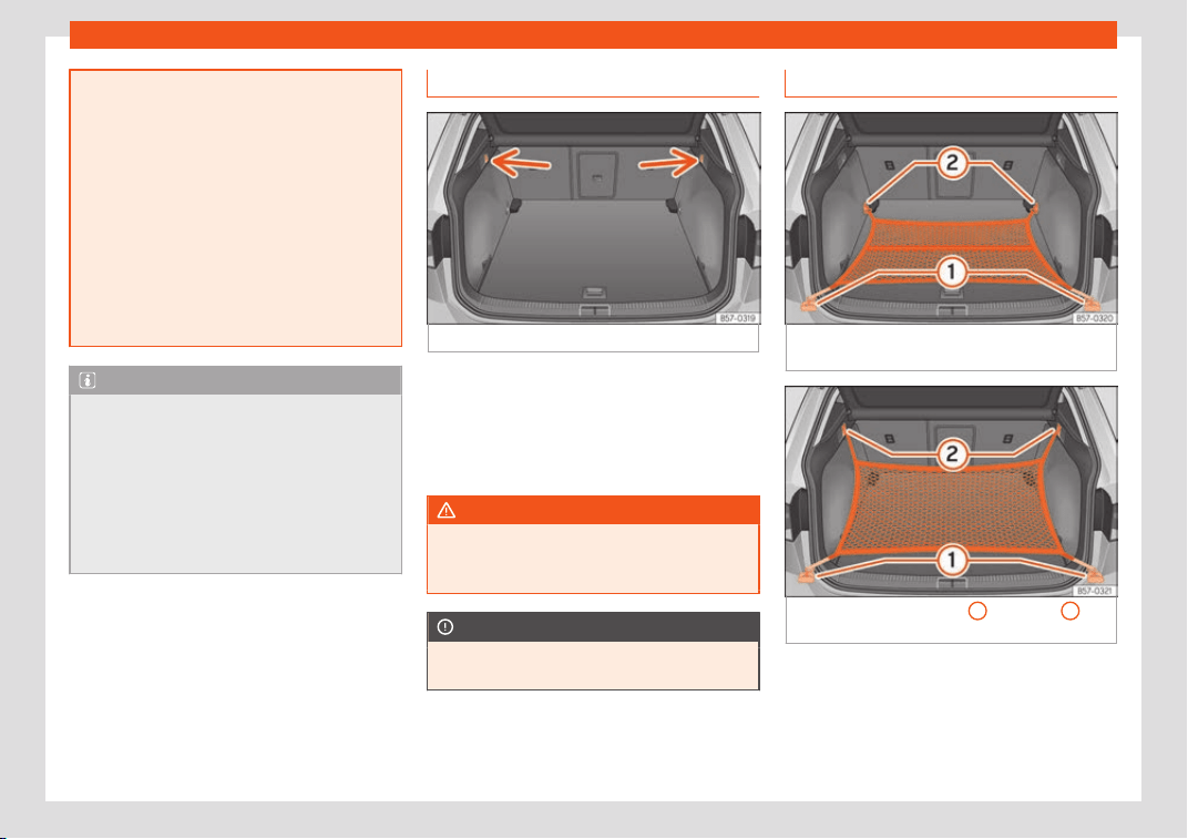
Transport and practical equipment
●
Always use belts or r
etaining straps that
are suitable and in a good condition.
●
Belts and retaining straps should be se-
curely fastened to the fastening rings.
●
Objects in the luggage compartment
that are unsecured could move suddenly
and modify the handling of the vehicle.
●
Secure all objects, little and large.
●
Never exceed the maximum tensile load
of the fastening ring when securing objects.
●
Never secure a child seat to the fastening
rings.
Note
●
The maximum tensile l
oad that the fas-
tening rings can support is 3.5 kN.
●
Belts and securing systems for the ap-
propriate load can be obtained from speci-
alised dealerships. SEAT recommends visit-
ing a SEAT dealership for this.
●
The fastening rings are rendered unusa-
ble for versions with a spare wheel.
Retaining hooks
Fig. 177
In the boot: retaining hooks.
At the rear of the luggage compartment, on
the l
eft and right, ther
e ar
e fixed retaining
hooks
›››
Fig. 177.
The retaining hooks have been designed to
secure light shopping bags.
WARNING
Never use the retaining hooks as fastening
rings. In case of sudden braking or an acci-
dent, the hooks could br
eak.
CAUTION
Each hook is designed for a maximum load
of 2.5 kg.
Net bag*
Fig. 178
In the boot: net bag hooked up at floor
l
e
v
el.
Fig. 179 In the boot: rings
1
and hooks
2
for
att
aching the net bag.
The luggage compartment prevents light
luggage fr
om mo
ving. The net bag has a zip
and can be used t
o store small objects.
The net bag can be hooked up to the lug-
gage compartment in different ways.
»
171
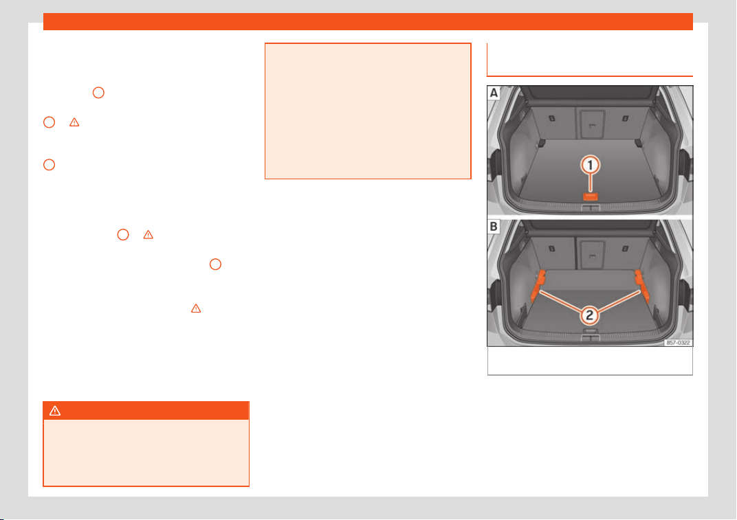
Operation
Hooking the net bag into the luggage
compar
tment fl
oor
●
As applicabl
e, lift the front fastening rings
›››
Fig. 178
2
.
●
Secure the net hooks to the fastening rings
2
›
›
›
. The bag zip should be facing up-
w
ar
ds.
●
Secur
e the net hooks to the fastening rings
1
.
Hook the net bag ne
xt t
o the l
oad thresh-
old
●
Secure the short net hooks to the fastening
rings
›››
Fig. 179
1
›
›
›
. The bag zip should
be f
acing up
w
ards.
●
Secure the straps in the bag hooks
2
.
R
emo
ving the net bag
The hook
ed up net bag is taut
›››
.
●
Remove the hooks and the net bag straps
fr
om the f
ast
ening rings and from the bag
hooks.
●
Store the net bag in the luggage compart-
ment.
WARNING
To secure the elastic net bag on the fasten-
ing rings it must be stretched out. Once
hook
ed up it is taut. If the net bag is hooked
up or unhooked incorrectly the hooks could
cause injuries.
●
Always secur
e the net hooks properly so
that they do not suddenly release from the
fastening rings when hooking or unhooking
them.
●
On hooking or unhooking them, protect
your eyes and face in case the hooks are
released suddenly.
●
Always hook up the net bag hooks in the
described order. If a hook is unexpectedly
released the risk of injury is increased.
Luggage compartment variable
fl
oor
Fig. 180 Variable boot floor:
r
aised position;
l
o
wered position.
172
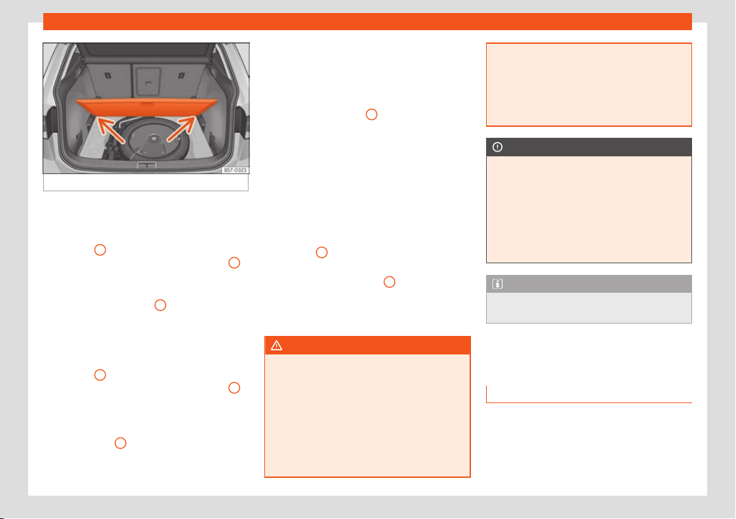
Transport and practical equipment
Fig. 181 Variable boot floor: tilted position.
Variable floor in high position
●
To move from the low position to the high
position, lift the fl
oor using the handl
e
›
››
Fig. 180
1
, and pull it back until the front
of the fl
oor has fully passed the supports
2
.
●
Move the floor forward over the supports as
f
ar as the r
ear seat backr
est and then lower
the floor with the handle
1
.
V
ariabl
e fl
oor in low position
●
To move from the high position to the low
position, lift the floor using the handle
›››
Fig. 180
1
, and pull it back until the front
of the fl
oor has fully passed the supports
2
.
●
Now let the front part fall to the floor and
slide the fl
oor f
orw
ards as far as the rear seat
backrest; lower the floor at the same time
with the handle
1
.
Variable floor in the tilted position
When the v
ariabl
e fl
oor is tilted you can ac-
cess the spare wheel/anti-puncture kit area.
●
Lift the variable floor in the high position us-
ing handle
›››
Fig. 180
1
, pull it up and push
it t
o
w
ards the backrest of the rear seats until
the floor folds along the hinge line and the
movable part of the floor is resting on itself.
●
Rest the floor on its housings
›››
Fig. 181 (ar-
rows).
Variable floor with folded seats
●
To move from the high position to the low
position, lift the floor using the handle
›››
Fig. 180
1
and pull it back a little.
●
Push the variable floor towards the folded
r
ear seats with the handl
e
1
using some
do
wnw
ar
d pressure so that the moving part
of the floor is flush with the backs of the rear
seats.
WARNING
During a sudden driving or braking ma-
noeuvre, or in the e
vent of an accident, ob-
jects could be flung though the interior and
cause serious or fatal injuries.
●
Always secure objects, even when the
luggage compartment floor is properly lif-
ted.
●
Only objects that do not protrude more
than 2/3 the height of the floor may be car-
ried between the rear seat and the raised
luggage compartment floor
.
●
Only objects that do not weigh than ap-
proximately 7.5 kg may be carried between
the rear seat and the raised luggage com-
partment floor.
CAUTION
●
The maximum w
eight that can be loaded
on the luggage compar
tment variable floor
in the top position is 150 kg.
●
Do not let the luggage compartment
floor fall when closing it. Always carefully
guide it downwards in a controlled manner.
Otherwise, the lining and the floor of the
luggage compartment could be damaged.
Note
SEAT recommends the use of straps to se-
cure objects t
o retaining rings.
Roof carrier*
Intr
oduction
The vehicle roof has been designed to opti-
mise aer
odynamics. F
or this r
eason, cross
bars or conventional roof carrier systems
cannot be secured to the roof water drains.
»
173
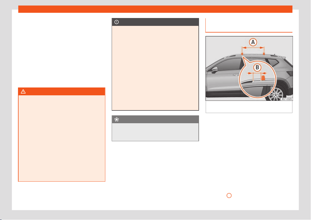
Operation
As the roof water drains are integrated in the
r
oof t
o r
educe air resistance, only SEAT-ap-
proved cross bars and roof carrier systems
can be used.
Cases in which cross bars and the roof
carrier system should be disassembled.
●
When they are not used.
●
When the vehicle is washed in a car wash.
●
When the vehicle height exceeds the maxi-
mum height, for example, in some garages.
WARNING
When heavy or bulky loads are transported
on the roof carrier system, car driving per
-
formance is affected, as the centre of grav-
ity shifts and there is greater wind resist-
ance.
●
Always secure the load properly using
belts or retaining straps that are suitable
and in a good condition.
●
Bulky, heavy, long or flat loads have a
negative effect on aerodynamics, the cen-
tre of gravity and driving performance.
●
Avoid sudden braking and manoeuvres.
●
Adapt your speed and driving style at all
times to suit visibility, weather, road and
traffic conditions.
CAUTION
●
Remov
e the cross bars and the roof carri-
er system before entering a car wash.
●
Vehicle height is increased by the instal-
lation of cross bars or a roof carrier system
and the load secured on them. For this pur-
pose, check that your vehicle's height does
not surpass the headspace limit, for exam-
ple, for underpasses or for entering garage
doors.
●
Cross bars, the roof carrier system and
the load secured on them should not inter-
fere with the roof aerial or hamper the path
of the panoramic sun roof and the rear lid.
●
On opening the rear lid make sure that it
does not knock into the roof load.
For the sake of the environment
When cross bars and a roof carrier system
are install
ed, the increased air resistance
means that the vehicle uses more fuel.
Attach the cross bars and the roof
carrier syst
em
Fig. 182
Attachment points for the roof railings
f
or the r
oof carrier syst
em.
The crossbars are the basis of a series of
special r
oof carrier syst
ems. F
or safety rea-
sons, special fixtures must be used to safely
transport luggage, bicycles, skis, surf boards
or boats on the roof. Suitable accessories
can be acquired at SEAT dealerships.
Always secure the crossbars and the roof
carrier system properly. Always take the as-
sembly instructions that come with the cross-
bars and the roof carrier system in question
into account.
The crossbars are assembled on the roof rail-
ings. The distance between crossbars
›››
Fig. 182
A
should be between 70 and 90
cm and the dist
ance betw
een the cr
ossbars
174
Transport and practical equipment
and the brackets of the roof railings
B
must
be 15 cm.
WARNING
Incorrect attachment and use of the cross-
bars and the roof carrier system may cause
the whol
e system to detach from the roof
and cause an accident and injuries.
●
Always take the manufacturer assembly
instructions into account.
●
Use only crossbars and the roof carrier
system when they are in perfect condition
and are properly secured.
●
Secure the crossbars and the roof carrier
system properly.
●
Check threaded joints and attachments
travelling and if necessary tighten them af-
ter you have travelled a short distance.
When making long trips, check the threa-
ded joints whenever you stop for a rest.
●
Always fit the special roof carrier sys-
tems correctly for wheels, skis and surf-
boards, etc.
●
Do not modify or repair the crossbars or
roof carrier system.
Note
Always read the assembly instructions that
come with the crossbars and the roof carri-
er syst
em carefully and keep them in the
vehicle.
Loading the roof carrier system
The load can only be secured if the crossbars
and the roof carrier system ar
e properly in-
stalled
›››
.
Maximum authorised roof load
The maximum permissibl
e roof load is 75 kg.
This figure comes from the combined weight
of the roof carrier, the cross bars and the load
itself on the roof
›››
.
Always check the w
eight of the roof carrier
system, the cross bars and the weight of the
load to be transported and weigh them if
necessary. Never exceed the maximum au-
thorised roof load.
If you are using cross bars and a roof carrier
with a lower weight rating, you will not be
able to carry the maximum authorised roof
load. In this case, do not exceed the maxi-
mum weight limit for the roof carrier which is
listed in the fitting instructions.
Distributing a load
Distribute loads uniformly and secure them
correctly
›››
.
Check att
achments
Once the cr
oss bars and r
oof carrier system
have been installed, check the bolted con-
nections and attachments after a short jour-
ney and subsequently with a certain frequen-
cy.
WARNING
Exceeding the maximum authorised roof
load can result in accidents and consider
a-
ble vehicle damage.
●
Never exceed the maximum authorised
load on the roof and on the axles or the ve-
hicle's maximum authorised weight.
●
Never exceed the load capacity of the
cross bars and the roof carrier system,
even if the maximum authorised roof load
has not been reached.
●
Secure heavy items as far forward as
possible and distribute the vehicle load
uniformly.
WARNING
If the load is loose or not secured, it could
fall from the r
oof carrier system or cause
accidents and injuries.
●
Always use belts or retaining straps that
are suitable and in a good condition.
●
Secure the load properly.
175
Operation
Air conditioning
Heating, v
entil
ation and
cooling
Intr
oduction
Read the additional information carefully
›››
page 42
Viewing Climatronic information
On the screen of Climatronic control unit and
on the screen of the factory-fitted Easy Con-
nect system, the theoretical values of the
temperature zones are shown.
The unit of temperature measurement can be
changed in the Easy Connect system.
Dust and pollen filter
The dust and pollen filter with its activated
charcoal cartridge serves as a barrier
against impurities in the air taken into the ve-
hicle interior.
The dust and pollen filter must be changed
regularly so that air conditioner performance
is not adversely affected.
If the filter loses efficiency prematurely due to
use in areas with very high levels of air pollu-
tion, the filter must be changed more fre-
quently than stated in the Service Schedule.
WARNING
Reduced visibility through the windows in-
creases the risk of serious accidents.
●
Alw
ays ensure that all windows are free
of ice and snow, and that they are not fog-
ged, so as to maintain good visibility of ev-
erything outside.
●
The maximum heat output required to de-
frost windows as quickly as possible is only
available when the engine has reached its
normal running temperature. Only drive
when you have good visibility.
●
Always ensure that you use the heating
system, fresh air system, air conditioner
and the heated rear window to maintain
good visibility to the outside.
●
Never leave the air recirculation on for a
long period of time. If the cooling system is
switched off and air recirculation mode
switched on, the windows can mist over
very quickly, considerably limiting visibility.
●
Switch air recirculation mode off when it
is not required.
WARNING
Stuffy or used air will increase fatigue and
reduce driver concentr
ation possibly re-
sulting in a serious accident.
●
Never leave the fresh air fan turned off or
use the air recirculation for long periods of
time; the air in the vehicle interior will not
be refreshed.
CAUTION
●
To repl
ace the pollen filter, always visit a
service centre.
●
Switch the air conditioner off if you think
it may be broken. This will avoid additional
damage. Have the air conditioner checked
by a specialised workshop.
●
Repairs to the air conditioner require spe-
cialist knowledge and special tools. SEAT
recommends visiting a SEAT Official Serv-
ice.
Note
●
When the cooling system is turned off
, air
coming from the outside will not be dried.
To prevent fogging of the windows, SEAT
recommends leaving the cooling system
(compressor) turned on. To do this, press
the
button. The button lamp should
light up.
●
The maximum heat output requir
ed to de-
frost windows as quickly as possible is only
available when the engine has reached its
normal running temperature.
●
Keep the air intake slots in front of the
windscreen free of snow, ice and leaves to
ensure heating and cooling are not im-
paired, and to prevent the windows from
misting over.
176
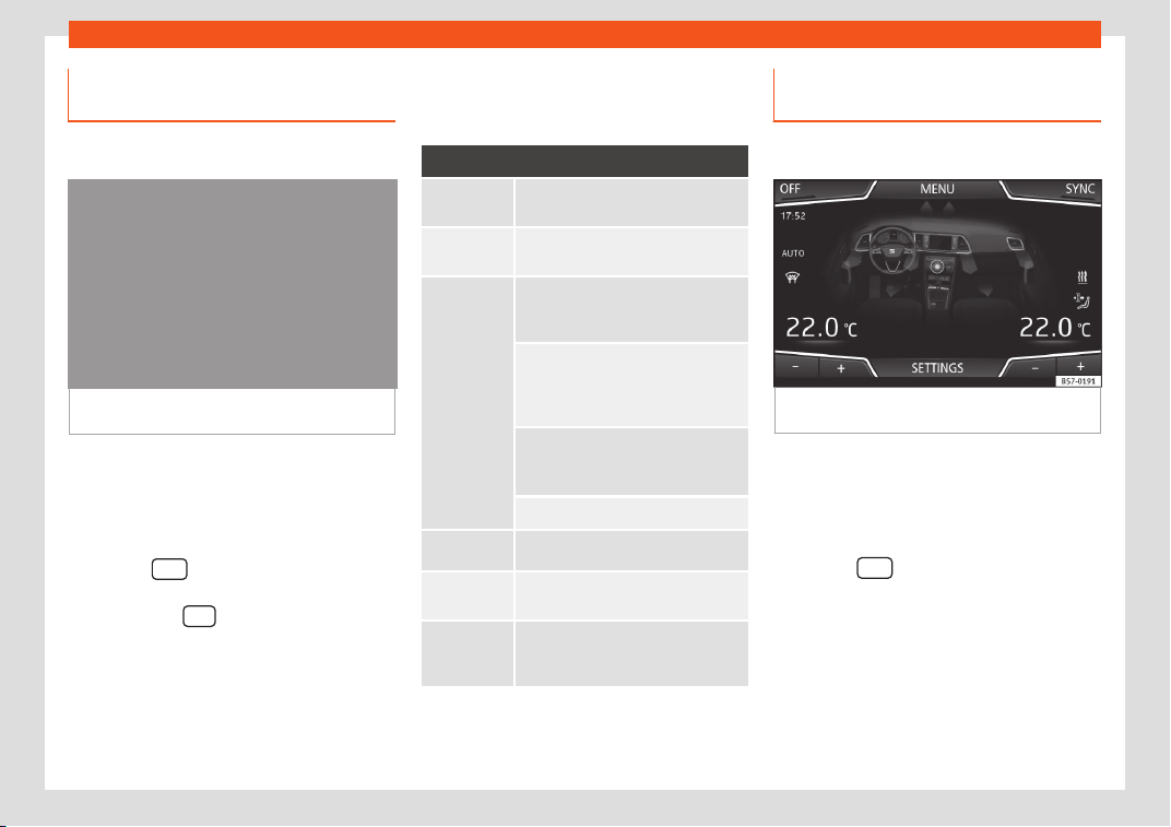
Air conditioning
Operating the Climatronic through
the Easy Connect syst
em*
3 Applies to vehicles with a Media System
Touch/Col
our.
Fig. 183
Easy Connect screen: air conditioner
menu.
In the Easy Connect system it is also possible
t
o perf
orm v
arious adjustments to the Clima-
tronic.
Open the air conditioner menu
●
Press the
button on the Climatronic
contr
ol panel.
●
OR:
pr
ess the
button in Easy Connect.
With the r
ot
ating s
witch select the air con-
ditioner menu and open it.
On the touch screen you can see and
change the current settings, for example, the
temperature set for the driver and passenger
sides, the air distribution and the fan speed.
To switch a function on or off, or to select a
submenu, you must press the corresponding
function button.
Function button: Function
OFF
Switch off and switch on the Clima-
tr
onic.
SYNC
Synchronise driv
er and front passen-
ger t
emperat
ures.
SETTINGS
The air conditioning settings subme-
nu is opened. The follo
wing settings
can also be adjusted:
Air conditioning profile.:
Adjust the power of the f
an in AUTO
mode. You can choose between low,
medium and high.
Automatic air recircula-
tion: Switching aut
omatic air recir-
culation on and off
›››
page 179.
BACK : Cl
ose the submenu.
*
The auxiliary heat
er submenu opens.
*
It enabl
es manual switching on or off
of the windscr
een heat
er
.
It enables activation and deactiva-
tion of the PureAir and opens the
submenu.
Operating the Climatronic through
the Easy Connect syst
em*
3 Applies to vehicles with Media System Plus /
Navi System / Navi Syst
em Plus.
Fig. 184
Easy Connect screen: air conditioner
menu.
In the Easy Connect system it is also possible
t
o perf
orm v
arious adjustments to the Clima-
tronic.
Open the air conditioner menu
●
Press the
button of the Climatronic
contr
ol panel.
On the t
op of the scr
een you can see and
change the current settings, such as, for ex-
ample, the temperature set for the driver side
and for that of passenger. Temperatures up to
+22°C (+72°F) are shown with blue arrows,
and temperatures over +22°C (+72°F) with red
arrows.
»
177
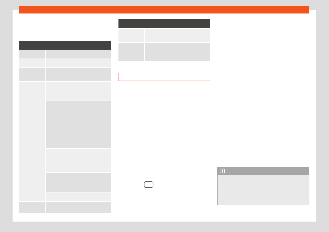
Operation
To switch a function on or off, or to select a
submenu, you must pr
ess the corr
esponding
function butt
on.
Function button: Function
OFF Climatronic is switched off.
ON Climatronic is switched on.
SYNC
Synchronise driver and front passen-
ger t
emperat
ures.
SETTINGS
The air conditioning settings subme-
nu is opened. The follo
wing settings
can also be adjusted:
Automatic supplementary
heater: to activat
e/deactivate the
automatic activation of the auxiliary
heating for colder countries (only for
engines with auxiliary heating). With
the option deactivated, depending
on the outside temperature the heat-
ing may need more time than normal
to reach a comfortable temperature.
Automatic front window
heating:* to swit
ch the automatic
windscreen heating on and off
›››
page 180.
Automatic air recircula-
tion: to switch automatic air recir-
culation on and off
›››
page 179.
BACK: t
o close the submenu.
*
The auxiliary heat
er submenu opens.
Function button: Function
*
It enables manual switching on or off
of the windscreen heater
.
It enables activation and deactiva-
tion of the PureAir and opens the
submenu.
Air conditioning user instructions
The interior cooling system only works when
the engine is running and fan is swit
ched on.
The air conditioner operates most effectively
with the windows and the panoramic sliding
sunroof closed. However, if the vehicle has
heated up after standing in the sun for some
time, the air inside can be cooled more quick-
ly by opening the windows and the panoram-
ic sliding sunroof briefly.
Climatronic: change the temperature unit
on the screen of the factory-fitted info-
tainment system
The temperature display can be changed
from Celsius to Fahrenheit on the screen of
the Infotainment system using the Infotain-
ment button
> Settings > Units but
-
t
on.
The cooling syst
em cannot be activated
If the air conditioning system cannot be
switched on, this may be caused by the fol-
lowing:
●
The engine is not running.
●
The fan is switched off.
●
The air conditioner fuse has blown.
●
The outside temperature is lower than ap-
proximately +3°C (+38°F).
●
The air conditioner compressor has been
temporarily switched off because the engine
coolant temperature is too high.
●
Another fault in the vehicle. Have the air
conditioner checked by a specialised work-
shop.
Special characteristics
If the humidity and temperature outside the
vehicle are high, condensation can drip off
the evaporator in the cooling system and
form a pool underneath the vehicle. This is
normal and does not indicate a leak!
Note
After starting the engine, any residual hu-
midity in the air conditioner could mist o
ver
the windscreen. Switch on the defrost func-
tion as soon as possible to clear the wind-
screen of condensation.
178
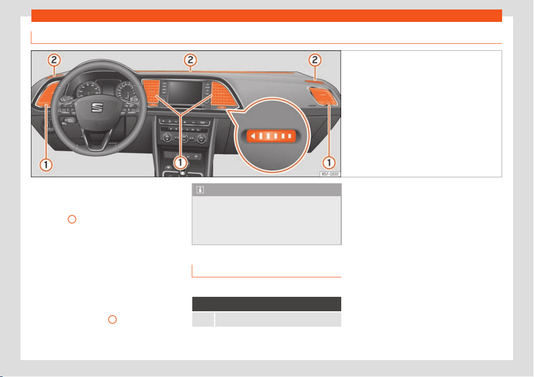
Air conditioning
Air outlets
Fig. 185
On the dash panel air vents.
Air vents
T
o ensur
e pr
oper heating, cooling and venti-
lation in the vehicle interior, air vents
›››
Fig. 185
1
should remain open.
●
Turn the corresponding thumbwheel (de-
t
ail) in the r
equir
ed direction to open and
close the air vents. When the thumbwheel is
in the position, the corresponding air vent is
closed.
●
Change the air direction using the ventila-
tion grille lever.
There are other additional, non-adjustable air
vents in the dash panel
2
, in the footwell and
in the r
ear ar
ea of the int
erior.
Note
Food, medicine and other heat or cold sen-
sitive objects shoul
d never be placed in
front of the air outlets as they may be dam-
aged or made unsuitable for use by the air
coming from the air vents.
Air recirculation mode
Basic points
Air recirculation:
Manual recirculation
Air recirculation mode prevents the ambient
air fr
om ent
ering the int
erior.
When the outside temperature is very high,
selecting manual air recirculation mode for a
short period refreshes the vehicle interior
more quickly.
For safety reasons, air recirculation mode is
switched off when the button is pressed
or the air distributor turned to .
Switching the manual air recirculation
mode on and off
Activate: press the button until the warn-
ing lamp lights up.
Deactivate: press the button until the
warning lamp goes off.
»
179
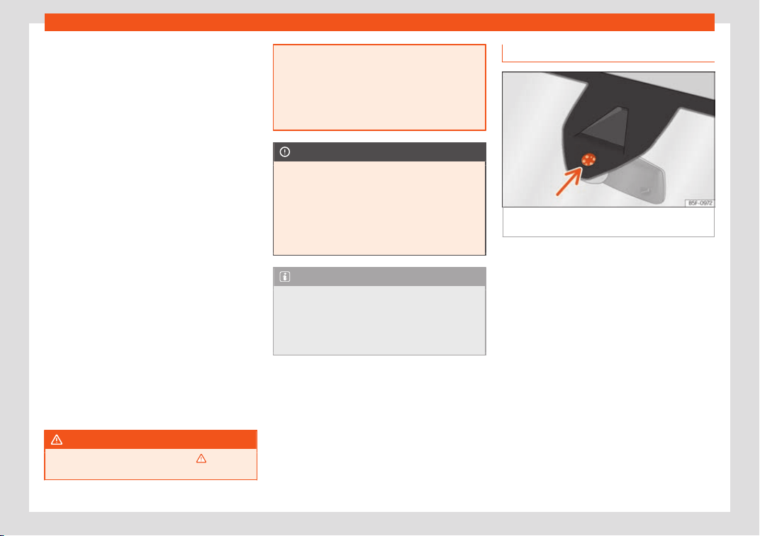
Operation
Functioning mode of automatic air recircu-
l
ation (air conditioning menu)
With the aut
omatic air r
ecirculation mode ac-
tivated, the entry of fresh air into the cabin in-
terior is enabled. If the system detects a high
concentration of hazardous substances in the
ambient air, air recirculation mode is switched
on automatically. When the level of impurities
drops to within a normal range, recirculation
mode is switched off.
The system is unable to detect unpleasant
smells.
The air recirculation will not connect auto-
matically in versions without humidity sensor
and in the following external conditions:
●
The outside temperature is lower than +3°C
(+38°F).
●
The cooling system is switched off and the
outside temperature is below +10°C (+50°F).
●
The cooling system is switched off, the out-
side temperature is below +15°C (+59°F) and
the windscreen wipers are switched on.
Activation/deactivation of automatic air recir-
culation is done in the air conditioner menu,
under Configuration.
WARNING
Observe the safety warnings
›››
in Intro-
duction on page 176.
●
If the cooling system is swit
ched off and
air recirculation mode switched on, the
windows can mist over very quickly, con-
siderably limiting visibility.
●
Switch air recirculation mode off when it
is not required.
CAUTION
Do not smoke when air recirculation is
s
witched on in v
ehicles with an air condi-
tioner. The smoke taken in could lie on the
cooling system vaporiser and on the acti-
vated charcoal cartridge of the dust and
pollen filter, leading to a permanently un-
pleasant smell.
Note
Climatronic: air recirculation mode is acti-
vated t
o prevent exhaust gas or unpleasant
odours from entering the vehicle interior
when it is in reverse and while the automat-
ic windscreen wiper is working.
Heated windscreen*
Fig. 186
Windscreen humidity and tempera-
t
ur
e sensor
.
The heated windscreen is comprised of a set
of heat
ed wir
es pl
aced between the layers of
the windscreen which, when electric current
is supplied to them, heat up and cause the
temperature of the glass to rise.
Its function is to assist the air-conditioning
system to prevent the windscreen from mist-
ing up or to demist it faster if it does mist up.
The system can be switched on manually or
automatically.
Manual activation
●
Press the button of the Climatronic
control panel.
●
Press the function button to switch the
windscreen heating on or off.
180

Air conditioning
Automatic activation
T
o f
acilit
ate use of the heated windscreen it
can turn on automatically.
The Climatronic control panel can detect the
danger of the windscreen misting thanks to its
temperature and humidity sensors, switching
the system on or off accordingly
›››
Fig. 186.
Moreover, it will also be activated automati-
cally when the button is pressed on the
Climatronic control panel.
Adjust it as follows for it to switch on automat-
ically:
●
Press the button of the Climatronic
control panel.
●
Press the SETTINGS function button on the
infotainment system.
●
Switch the function on or off by pressing the
Automatic windscreen heating
function button.
181
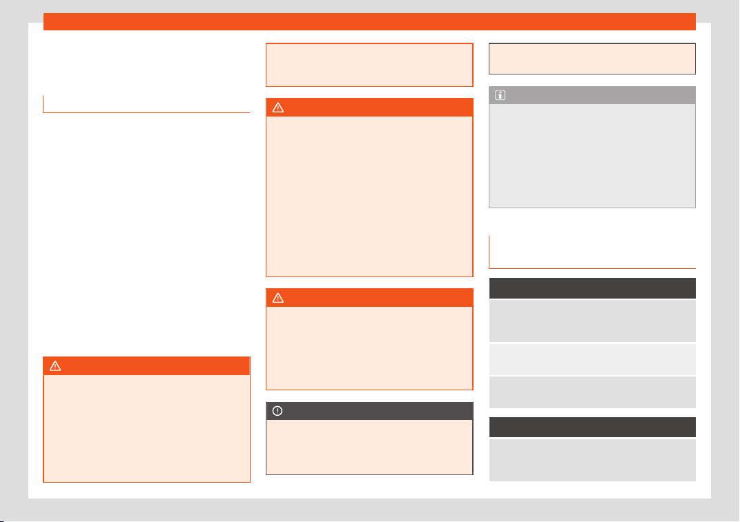
Operation
Auxiliary heater (additional
heat
er)*
Intr
oduction
The auxiliary heater runs on fuel from the ve-
hicle's tank and can be used whil
e you are
driving and when the vehicle is stationary.
The auxiliary heater can be switched on using
the fast heating button of the air conditioning
controls, with the remote control or by previ-
ously programming a departure time in the
auxiliary heater menu of the infotainment sys-
tem.
In winter, with the auxiliary heater switched
on, you can defog the windscreen and leave
it free of ice and snow (if it is a thin layer) be-
fore you start driving.
If the outside temperature is very high, the ve-
hicle interior can be ventilated with the en-
gine off using the auxiliary heater.
WARNING
Swallowing a battery with a 20 mm diame-
ter or any other button batt
ery can cause
serious and even fatal injuries within a very
short time.
●
Always keep the remote control, keyrings
with batteries, the spare batteries, button
batteries and all other batteries over 20
mm out of reach of children.
●
If you suspect that someone may have
sw
allowed a battery, seek immediate med-
ical attention.
WARNING
The auxiliary heater exhaust fumes contain
carbon mono
xide, an odourl
ess and colour-
less toxic gas. Carbon monoxide can cause
people to lose consciousness. It can also
cause death.
●
Never switch on the auxiliary heater or
leave it running in enclosed spaces or
areas with no ventilation.
●
Never programme the auxiliary heater so
that it switches itself on and is running in an
enclosed space or an area with no ventila-
tion.
WARNING
The components of the auxiliary heater are
extremely hot and coul
d cause a fire.
●
Always park your vehicle so that no part
of the exhaust system can come in contact
with easily flammable materials that might
be below the vehicle, such as dried grass.
CAUTION
Never place food, medicines or other tem-
peratur
e-sensitive objects close to the air
vents. Food, medicines and other objects
sensitive to heat or cold may be damaged
or made unsuitable for use by the air com-
ing from the vents.
Note
After switching the engine on with a 12-volt
batt
ery that is heavily discharged or ne
wly
changed or after a jump start some system
settings (such as the time, the date, the
personalised comfort settings and the pro-
gramming) might be altered or deleted.
Check and correct these settings once the
battery is sufficiently charged.
Switching on and off the auxiliary
heat
er
Switching the auxiliary heater on:
Manually with the fast heating button of the
air conditioner controls. The contr
ol lamp of
the button will light up
›››
page 176.
Manually with the remote control
›››
page 183.
Automatically by programming and activat-
ing a departure time
›
››
page 184.
Switching the auxiliary heater off:
Manually with the fast heating button of the
air conditioner controls. The contr
ol lamp of
the button goes off
›››
page 176.
182
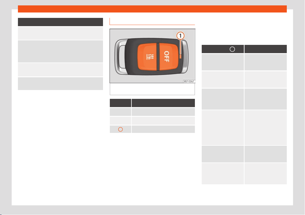
Air conditioning
Switching the auxiliary heater off:
Manually with the remote control
›››
page 183.
Automatically once the programmed depar-
ture time has arriv
ed or after the program-
med operating time has elapsed
›››
page 184.
Automatically when the control lamp (fuel
l
ev
el indicator)
›››
page 341 lights up.
Automatically when the 12-volt battery
charge is too l
ow
›››
page 354.
Special feature
Once s
wit
ched off
, the auxiliary heater will
continue to operate for a short period of time
in order to burn the fuel remaining in the sys-
tem and also to expel the exhaust fumes.
Remote control
Fig. 187
Independent heating: radiofrequency
r
emot
e contr
ol key
Fig. 187 Meaning
Switch the auxiliary heater on
Switch the auxiliary heater off
1
Control lamp
If the buttons of the remote control are press-
ed unnecessarily, it coul
d s
wit
ch on the auxili-
ary heater involuntarily, even when it is out of
range or when the control lamp is flashing.
To switch on and off the independent heating,
the button must be pressed and held for ap-
proximately 1 second.
Control lamp on the remote control
When the buttons are pressed, the control
lamp on the remote control provides the user
with different information:
Control lamp
1
Meaning
It lights up for approx. 2
seconds in green.
The auxiliary heater has
been s
witched on using
the button.
It lights up for approx. 2
seconds in red.
The auxiliary heater has
been s
witched off using
the button.
It flashes for approx. 2
seconds in green (ap-
pro
x. 4 times per sec-
ond).
No on
a)
signal has been
received.
It fl
ashes quickly for ap-
prox. 2 seconds in gr
een
(approx. 10 times per
second).
The independent heat-
ing is blocked.
P
ossible causes: the fuel
tank is almost empty, the
12-volt battery charge is
very low or there is a
fault.
It flashes for approx. 2
seconds in red (approx. 4
times per second).
No off
a)
signal has been
received.
It lights up for approx.
2 seconds in orange,
then green or red.
The remote control bat-
tery is almost flat. How-
ever, the on or off signal
has been received.
»
183
Operation
Control lamp
1
Meaning
It lights up for approx.
2 seconds in orange,
then fl
ashes in green or
red.
The remote control bat-
tery is almost flat. No on
or off signal has been re-
ceived.
Flashes orange for
around 5 seconds.
The remot
e control bat-
tery is flat. No on or off
signal has been r
e-
ceived.
a)
The remote control is out of range. In this case it will
be necessary to get closer t
o the vehicle and press
the corresponding button again.
Replacing the remote control battery
When pressing the buttons, if the control
lamp of the remote
1
flashes for approx. 5
or
ange or does not light up
, the batt
eries
must be replaced.
The battery is located beneath a cover on
the back of the remote control.
●
To open the cover, lift it slightly at the bot-
tom and slide it down.
●
Remove the old battery.
●
Insert the new battery. When doing so, take
into account the polarity and use batteries of
the same type
›››
.
●
Replace the battery cover by inserting the
t
abs at the t
op and pr
essing the bottom.
Range
The receiver is inside the vehicle. The remote
control, when fitted with new batteries, has a
range of several hundred metres. Obstacles
between the remote control and the vehicle,
bad weather conditions and discharged bat-
teries can considerably reduce the range of
the remote control.
CAUTION
●
The radio frequency r
emote control con-
tains electronic components. Therefore,
avoid getting it wet and exposing it to
knocks or direct sunlight.
●
The use of inappropriate batteries may
damage the radio frequency remote con-
trol. For this reason, always replace the
used battery with another of the same volt-
age, size and specifications.
For the sake of the environment
●
Please dispose of your used batteries
corr
ectly and with respect for the environ-
ment.
●
The remote control battery may contain
perchlorate. Observe the legal provisions
regarding disposal.
●
Care should be taken so as not to oper-
ate the remote control unintentionally so
as to prevent the auxiliary heater being
switched on accidentally.
Programming the auxiliary heater
Before programming it, check that the vehi-
cle's dat
e and time are set correctly
›››
.
The auxiliary heater is progr
ammed in the
Auxiliary heater menu of the infotainment
system.
Open the Auxiliary heater menu.
●
Press the button of the Climatronic
control panel.
●
Press the function button.
Function button: function
Switch off: The auxiliary heater is immediately
s
witched off.
Heat, Ventilate: Set to heat or ventil
ate the vehi-
cle interior when the auxiliary heater is switched on.
By pressing the function button , you can select
the desired mode.
Set: Opens the
Auxiliary heater menu.
184
Air conditioning
Function button: function
Departure time 1, Departure time
2, Departure time 3: Three differ
ent de-
parture times (hh.mm) may be programmed. If
the auxiliary heater should only be switched
on a certain day of the week, this can also be
selected.
Duration: The duration determines the oper
-
ating time of the auxiliary heater when switch-
ed on using the fast heating button on the
air conditioning controls. The duration is also
used to calculate the departure time for the
manual air conditioner. It can be set between
10 and 60 minutes at 10-minute intervals.
This returns to the main menu.
The programmed departure time determines
the appr
o
ximat
e time it should take to reach
the temperature set in the vehicle. The start of
the heating operation is determined automat-
ically depending on the outside temperature.
Checking the programming
When a departure time is activated and the
ignition is switched off the control lamp of the
fast heating button lights up for approxi-
mately 10 seconds.
WARNING
Never programme the auxiliary heater so
that it switches itself on and is running in an
encl
osed space or an area with no ventila-
tion. The auxiliary heater exhaust fumes
contain carbon monoxide, an odourless
and colourless t
oxic gas. Carbon monoxide
can cause people to lose consciousness. It
can also cause death.
Operating instructions
The auxiliary heater exhaust system located
below the v
ehicle must be kept clear of snow,
mud and other objects. The exhaust fumes
must be able to exit freely. The emissions
generated by the auxiliary heater are re-
moved via an exhaust pipe fitted underneath
the vehicle.
On heating the vehicle interior, depending on
the outside temperature, the warm air is first
directed at the windscreen and then to the
rest of the vehicle interior through the air
vents. Directing the diffusers – towards the
windows for example – can affect air distribu-
tion.
When will the auxiliary heater not be acti-
vated?
●
The auxiliary heater requires about as
much power as the dipped beam headlights.
If the 12-v
olt battery charge is too low, the
auxiliary heater switches off automatically
and cannot be switched on. This avoids prob-
lems when starting the engine.
●
The heating must be activated every time
you want to set off. Similarly, the departure
time must reactivate each time.
●
The control lamp (fuel level indicator)
lights up.
Note
●
Noises will be heard while the auxiliary
heat
er is running.
●
When the air humidity is high and the in-
side temperature low, condensation from
the heating and ventilating system may
evaporate when the auxiliary heater is
switched on. In this case, steam may be re-
leased from underneath the vehicle. This
does not mean that there is a vehicle mal-
function.
●
If the vehicle is tilted, e.g. if parked on a
slope, the operation of the auxiliary heater
may be restricted if the fuel tank level is
low (just above the reserve level).
●
If the auxiliary heater is used a number of
times for a long period of time, the 12-volt
battery will lose its charge. To recharge the
battery, the vehicle must be driven for a
number of kilometres from time to time. As
a guideline: the journey should last approx-
imately as long as the heater was connec-
ted.
●
At temperatures below +5°C (+41°F), the
auxiliary heater may switch itself on auto-
matically when the engine is switched on.
The auxiliary heater is switched off again
after a certain time.
185
Infotainment System
Infotainment System
Intr
oduction
Saf
et
y warnings
Safety instructions related to the
Infotainment system
Travelling on today's roads requires the driv-
er's full attention at all times.
Only oper
ate the infotainment system and its
various functions when the traffic situation
really permits this.
WARNING
●
Before st
arting the trip, you should famili-
arise yourself with the different infotain-
ment system functions.
●
High audio volume may represent a dan-
ger to you and to others.
●
Adjust the volume in a way that you can
distinguish surrounding noise, for example,
horns and sirens, etc.
●
Changes to the Infotainment system set-
tings should be made when the car is stop-
ped, or by a passenger.
WARNING
Distracting the driver in any way can lead
to an accident and cause injuries. Operat
-
ing the Infotainment system can distract
your attention from the traffic.
●
Always drive carefully and responsibly.
●
Select volume settings that allow you to
easily hear signals from outside the vehicle
at all times (e.g. emergency services sirens
and horns).
●
Hearing may be impaired if using too high
a volume setting, even if only for short peri-
ods of time.
WARNING
The volume level may suddenly change
when you switch audio sour
ce or connect a
new audio source.
●
Lower the base volume before connect-
ing or switching audio sources.
WARNING
The driving recommendations and traffic
indications shown on the navigation system
may diff
er from the current traffic situation.
●
Traffic signs and traffic regulations have
priority over the recommendations and dis-
plays provided by the navigation system.
●
Adjust your vehicle speed and driving
style to suit visibility, weather, road and
traffic conditions.
WARNING
Connecting, inserting or removing a data
medium while driving can distract your at
-
tention from the traffic and cause an acci-
dent.
WARNING
Connecting leads for external devices may
obstruct the driver.
●
Arr
ange the connecting leads so that
they do not obstruct the driver.
WARNING
External devices that are loose or not prop-
erly secured could mo
ve around the pas-
senger compartment during a sudden driv-
ing or braking manoeuvre or an accident
and cause damage or injury.
●
Never place or fit external devices to the
doors, windscreen, steering wheel, dash
panel, the backs of the seats, on top of or
near the area marked “AIRBAG” or between
these areas and the occupants. External
devices can cause serious injury in an acci-
dent, especially when the airbags inflate.
WARNING
The armrest may obstruct the driver's arm
movements, which coul
d cause an acci-
dent and severe injuries.
186
Introduction
●
Always k
eep the armrest closed while the
vehicle is in motion.
WARNING
Opening a CD or DVD player's housing can
l
ead to injuries fr
om invisible laser radia-
tion.
●
Have CD or DVD players repaired only by
a qualified workshop.
CAUTION
The Infotainment system can be damaged
by the incorr
ect inser
tion of a dat
a storage
device or the insertion of an incompatible
data storage device.
●
When inserting a data storage device,
make sure it is correctly positioned.
●
Applying force may irreparably damage
the memory card slot locking mechanism.
●
Only use compatible memory cards.
●
When inserting and removing CDs and
DVDs, always hold them at right angles to
the front of the CD/DVD drive without tilt-
ing so as not to scratch them.
●
If a CD or DVD is inserted while another is
already in the unit or being ejected, the
DVD drive may be irreparably damaged.
Always wait until the data medium is com-
pletely ejected.
CAUTION
Any foreign objects stuck to a data storage
device and non-round media may damage
the CD or D
VD player.
●
Only clean, standard 12 cm CDs or DVDs
should be used.
–
Do not affix stickers or other items to
the data medium. Stickers may peel off
and damage the drive.
–
Do not use printable data media. Prin-
ted labels and coverings may peel off
and damage the CD/DVD drive.
–
Do not insert 8 cm single CDs or irregu-
larly shaped CDs or DVDs.
–
Do not insert DVD-Plus discs, Dual
Discs or Flip Discs, as these are thicker
than normal CDs.
CAUTION
The vehicle loudspeakers may be dam-
aged if the volume is too high or the sound
is dist
orted.
Note
For the proper functioning of the Infotain-
ment system it is import
ant that the date
and time set in the vehicle are correct.
187
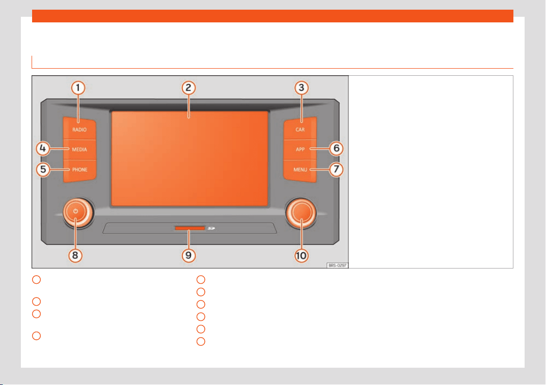
Infotainment System
Overview of the unit
Media Syst
em T
ouch / Media Syst
em Colour
Fig. 188
Overview of the controls (this configura-
tion depends on the v
ersion).
Radio Mode (change of band frequency
›
›
›
page 205
Touchscreen
›››
page 191
Vehicle settings
›››
page 35,
›››
page 229
Media mode (audio sources)
›››
page 207
1
2
3
4
Phone Mode
›
›
›
page 230
Full Link
›››
page 195
Selecting the main menu
›››
page 190
Volume. Off/on
›››
page 190
Slot for memory cards
›››
page 210
Settings button (search and selection)
›››
page 190
5
6
7
8
9
10
188
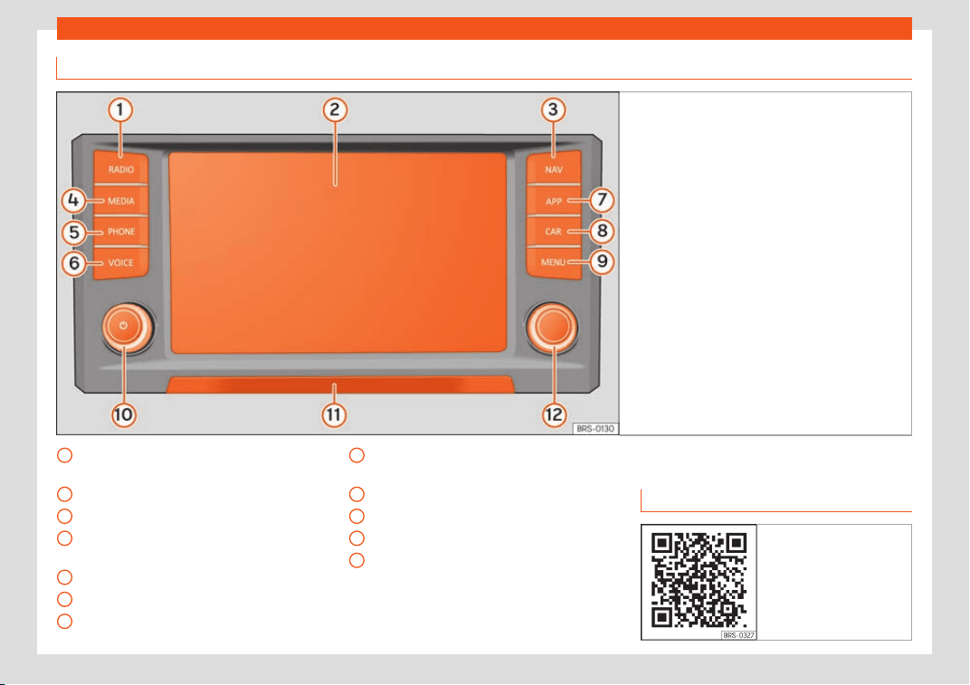
Introduction
Media System Plus / Navi System / Navi System Plus
Fig. 189 Overview of the controls
Radio Mode (change of band frequency
›
›
›
page 205
Touchscreen
›››
page 191
Navigation Mode
›››
page 216
Media mode (audio sources)
›››
page 207
Phone Mode
›››
page 230
Voice control
Full Link
›››
page 195
1
2
3
4
5
6
7
Vehicle settings
›
›
›
page 35,
›››
page 229
Selecting the main menu
›››
page 190
Volume. Off/on
›››
page 190
Proximity sensor
›››
page 193
Settings button (search and selection)
›››
page 190
8
9
10
11
12
General instructions for use
Intr
oduction
Fig. 190 Related video
»
189
Infotainment System
If the setup is changed, this may change the
displ
ay on the scr
een and in some cases, the
Inf
otainment system may behave in a manner
different to that described in this manual.
Note
●
Lightly pressing the buttons or briefly
pr
essing the touchscreen is sufficient to
operate the Infotainment system.
●
Not all listed function buttons and func-
tions described may be available due to
the device software used in your market.
The equipment is not faulty if a function
button is missing from the screen.
●
Due to country-specific legislation, cer-
tain functions may not be available on the
screen when the vehicle is travelling above
a certain speed.
●
Using a mobile telephone in the vehicle
may cause noise from the vehicle loud-
speakers.
●
Restrictions on the use of devices using
Bluetooth
®
technology may apply in some
countries. For further information, contact
the local authorities.
●
On some vehicles with ParkPilot, the vol-
ume of the audio source is automatically
lowered when reverse gear is selected. The
volume can be lowered in the menu Sound
> Volume.
Diagram of the menus
The Infotainment system touchscreen can be
used to select the diff
erent main menus.
Press the Infotainment button
to open
the menus summary.
The display of the touchscr
een's main menu
can be switched between “grid” and “carou-
sel” via the Settings/System > Display
menu.
Infotainment rotary/push knobs
Rotary/push knobs
The l
eft
-hand r
otary knob is the volume
control or the on/off button.
The right-hand rotary knob is the setup but-
ton.
Infotainment buttons
The buttons on the unit are shown in this
manual with the word “infotainment button”
and their function within a rectangle, for ex-
ample, the infotainment button
.
The Inf
ot
ainment butt
ons are used by press-
ing them or pressing and holding.
Switching on and off
To manually switch the Infotainment system
on and off, briefly pr
ess the left rotary knob .
When switching on, the system starts-up with
the last set volume, provided that this does
not exceed the preset maximum start-up vol-
ume. Select Sound > Volume.
The unit will switch off automatically when
the key is removed from the ignition or when
the on/off button is pressed (depending on
the equipment fitted or the vehicle). If the In-
fotainment system is switched on again, it will
switch off automatically after approximately
30 minutes (switch-off delay).
Note
●
The Infotainment syst
em is a part of the
vehicle. It cannot be used in any other vehi-
cle.
●
If the battery has been disconnected, the
ignition must be activated before switching
on the Infotainment system.
Changing the basic volume
Increasing or decreasing the volume or
muting the sound
R
aise the v
olume
: turn the volume control
clockwise or move the left thumbwheel on
the multifunction steering wheel upward .
190
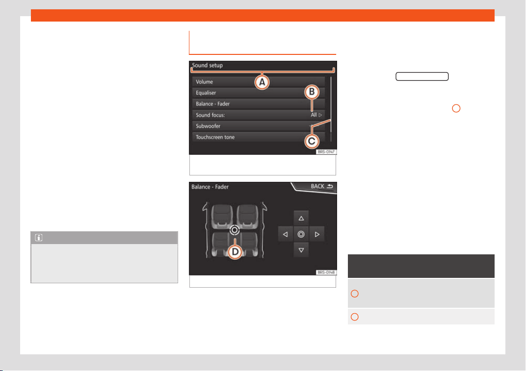
Introduction
Lower the volume: t
urn the v
olume contr
ol
clockwise or move the left thumbwheel on
the multifunction steering wheel downward
.
Changes in volume are indicated by a vol-
ume bar on the screen. The volume can be
controlled using the steering wheel controls.
In this case, the changes in volume are dis-
played on the instrument panel by a volume
bar.
It is possible to preset certain volume settings
and adjustments. Select Sound > Volume
Muting the Infotainment system sound
●
Turn the volume control anti-clockwise
until it displays .
Muting the Infotainment system sound stops
the media source that is playing The screen
displays .
Note
If the base volume has been considerably
increased to pl
ay a certain audio source,
lower the volume again before switching to
another audio source.
Handling the function buttons and
displ
ay instructions
Fig. 191
View of some of the function buttons
on the scr
een.
Fig. 192
Sound setup menu
The Infotainment system comes equipped
with a t
ouchscr
een.
Activ
e areas of the screen that call up a cer-
tain function are called “function buttons”.
These buttons are operated by briefly press-
ing the screen or by pressing and holding.
The function buttons appear in the instruc-
tions with the label “function button” and a
button symbol inside a rectangle
.
Function butt
ons st
art functions or open sub-
menus. The curr
ently selected menu is dis-
played in the title bar
›››
Fig. 191
A
of the
submenus.
Inactiv
e (gr
ey) function butt
ons cannot be se-
lected.
Increase or decrease the size of the im-
ages displayed on the screen
The size of the navigation map image
›››
page 216 and, for example, photos when
viewing images
›››
page 207 can be en-
larged or reduced. To do so, enlarge or re-
duce the image displayed by moving two fin-
gers.
Overview of screen and function buttons
Display and function buttons: operation
and effect
A
The title bar shows the selected menu
and, where applicable
, other function
buttons.
B
Press it to open another menu.
»
191
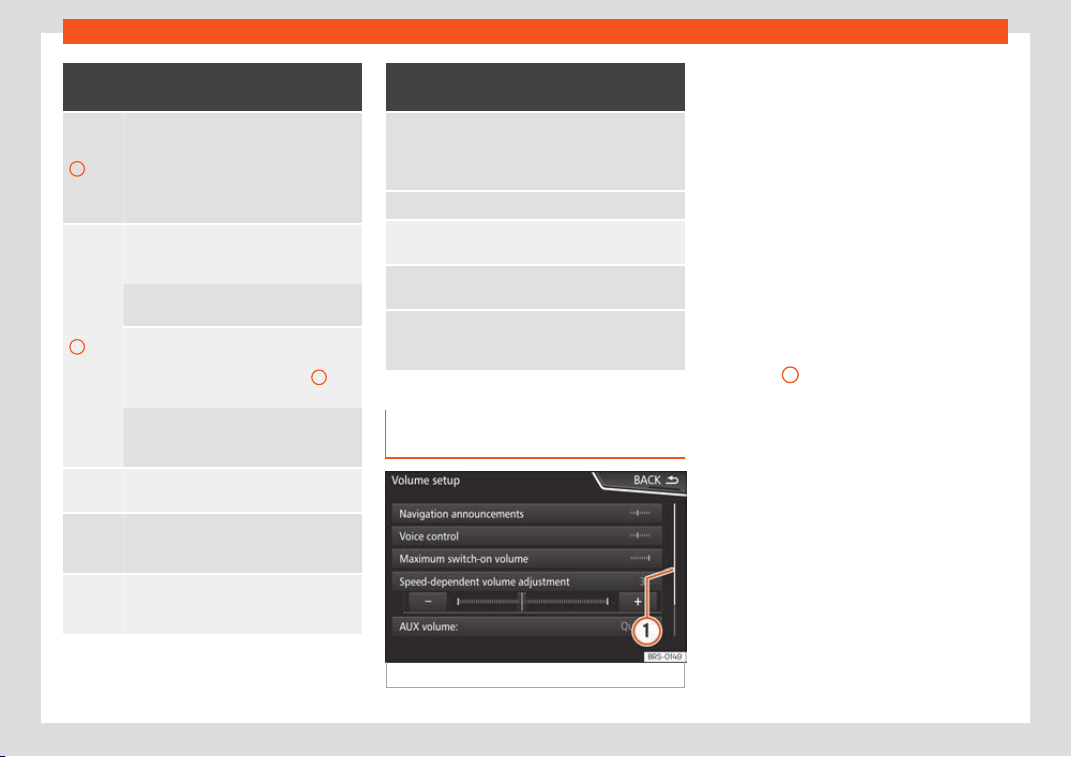
Infotainment System
Display and function buttons: operation
and effect
C
The scroll bar is shown on the right and its
size depends on the entries in the list.
Mov
e the bar on the screen by pressing
lightly and without lifting the finger, see
›››
page 192, Opening list entries and
searching in lists.
D
Movable cursor: Move the cursor around
the screen by pressing lightly and without
lifting the finger.
OR: To move the cursor to a particular po-
sition, press that spot on the scr
een.
Fixed crosshair: Press the up, do
wn, left
and right arrows to move the sound ac-
cording to preference. The cursor
D
will
move
.
OR: Press the central button to centre the
ster
eo sound in the centre of the passen-
ger compartment
Press it on some lists to move up a level,
one by one.
BACK
Press to return from the submenus one at
a time t
o the main menu or to undo the
entries made.
When pressed, a pop-up window opens
(options window) which displays other
setup options.
Display and function buttons: operation
and effect
/
Some functions or messages are accom-
panied by a check box and are activ
ated
or deactivated by pressing said
check box.
OK Press to confirm an entry or a selection.
×
Press to close a pop-up window or an in-
put windo
w.
/
Pr
ess them to change the setup adjust-
ments one at a time.
Mov
e the slider around the screen by
pr
essing it lightly and without lifting your
finger
.
Opening list entries and searching
in lists
Fig. 193 Entries on a setup menu list.
The entries on a list can be activated by
pr
essing them on the scr
een dir
ectly or by us-
ing the adjustment button.
Mark list entries using the setup button
and open them
●
Turn the setup button to mark the entries on
the list with a rectangle one by one and con-
tinue searching the list in this manner.
●
Press the setup button to activate the
marked entry on the list.
Search lists (scrolling the screen)
The scroll bar is shown on the right and its
size depends on the entries in the list
›››
Fig. 193
1
.
●
Briefly press the scr
een abo
v
e or below the
scroll marker.
●
OR: Place a finger over the scroll marker
and without lifting it, move it around the
screen. Lift your finger off the screen when
you reach the desired position.
●
OR: Place your finger in the centre of the
screen and without lifting it, move it around
the screen. Lift your finger off the screen
when you reach the desired position.
192
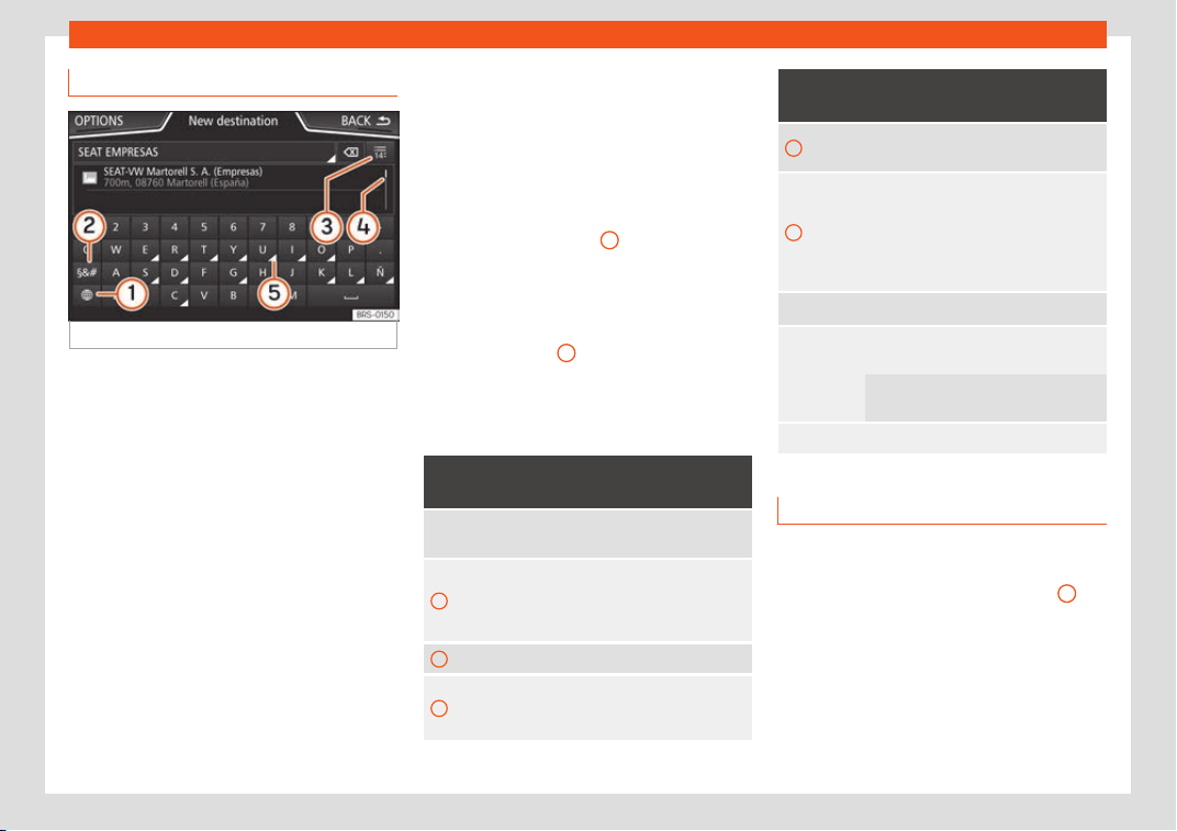
Introduction
Input masks with on-screen keypad
Fig. 194
Input window with on-screen keypad.
Input windows with on-screen keypad are
used f
or functions such as ent
ering an entry
name
, selecting a destination address or en-
tering a search term for searching long lists.
The function buttons listed below are not
available in all countries or for all topics.
Subsequent chapters only explain those
functions that differ from those in the screen
shown in the figure.
The input line with cursor is located in the top
bar of the screen. All inputs are displayed
here.
Input windows for “free text input”
In the input masks for open text, you may en-
ter letters, numbers and special characters in
any combination.
Input windows for selecting a saved entry
(e.g. selection of a destination address)
It is only possible to select a sequence of let-
ters, numbers and special characters that
matches a stored entry.
Suggestions for matching destinations ap-
pear depending on the characters entered in
the input line
›››
Fig. 194
4
. In the case of
compound names, it is necessary t
o ent
er a
space
.
If there are fewer than 99 selectable entries,
the number of remaining entries is displayed
after the input line
3
. Pressing this function
butt
on displ
ays these r
emaining entries in a
list.
Overview of the function buttons
Function icon and text: operation and ef-
fect
Lett
ers and
digits
Press them to copy them into the input
line.
1
Press to change the keypad to anoth-
er language. Keypad languages can
be selected from the menu System
settings > Language.
2
Press to show symbols on the keypad.
3
Displays the number and opens the
list of remaining select
able entries
that match the entered text.
Function icon and text: operation and ef-
fect
4
Scroll bar, the size of which depends
on the number of matching entries.
5
Hold and press to display a pop-up
window with the special characters
based on said letter. Press the desired
character to enter it. Some special
characters can be written out instead
(e.g. “AE” for “Ä”).
Press to enter a space.
Press to delete characters in the input
line from right to l
eft.
Press and hold to delete several char-
acters.
BACK Press to close the input window.
Proximity sensors
3 Valid for: Navi System and Navi System Plus.
The Inf
otainment system is equipped with an
integrated proximity sensor
›››
Fig. 189
11
.
The image on the scr
een changes fr
om dis-
pl
ay mode to automatic operation when your
hand moves toward it. In operation mode, the
function buttons are automatically highligh-
ted to facilitate their use.
193
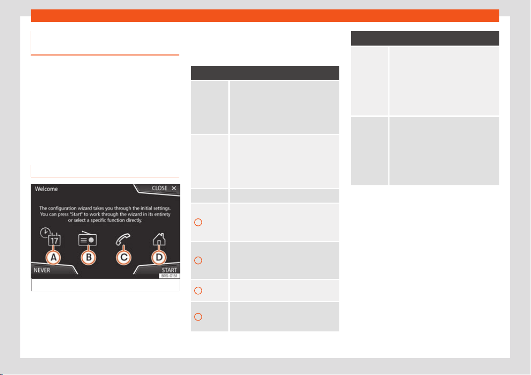
Infotainment System
Additional information and display
options
The displays appearing on the screen may
vary depending on the settings, and may dif-
f
er from those described here.
The status bar on the screen can display, for
example, the current time and outside tem-
perature.
All displays can be viewed only after com-
pletely restarting the Infotainment system.
Initial configuration wizard
Fig. 195
Initial configuration wizard
The initial configuration wizard will help you
t
o set up your Inf
ot
ainment system the first
time you switch it on.
Every time you switch on the Infotainment
system, the initial setup screen will appear
›››
Fig. 195 if any parameters have not been
set or if the NEVER function button has not
been pressed.
Function button: function
CLOSE
Closes the Configuration Wizard, and
the main menu or last mode in which
you used the Infot
ainment system will
appear. The next time you switch on
the system, the Configuration Wizard
will start up again.
NEVER
Disables the possibility of changing
the settings of the Infotainment sys-
t
em. If you want to perform the initial
system setup, you must enter via Sys-
tem setup and select Configura-
tion Wizard.
START Starts up the Configuration Wizard.
A
Press to configure the time and date (if
it has a navigation system it will be
configured aut
omatically with the
GPS).
B
Press to search and store to memory
the radio stations that hav
e the best
reception at that moment on all avail-
able bands (AM, FM and DAB).
C
Press to link your mobile telephone to
the Infotainment syst
em.
D
a)
Press to select your home address us-
ing your current position or by man-
ually entering an addr
ess.
Function button: function
PREVIOUS
NEXT
To go to the previous or next parameter
to set.
When a paramet
er has been set, the
only way to reset it is from the main
menu, clicking on it, and not using the
Previous/Next buttons.
When setting any parameter, a confir-
mation mark will appear on it .
FINISH
Once one or more settings have been
applied, click on this in the main menu
of the wizard t
o confirm and finalize
the settings.
If there are any parameters you have
not set, the next time you connect the
Infotainment system, the Initial Config-
uration Wizard will start up.
a)
Only valid for Navi System and Navi System Plus.
194
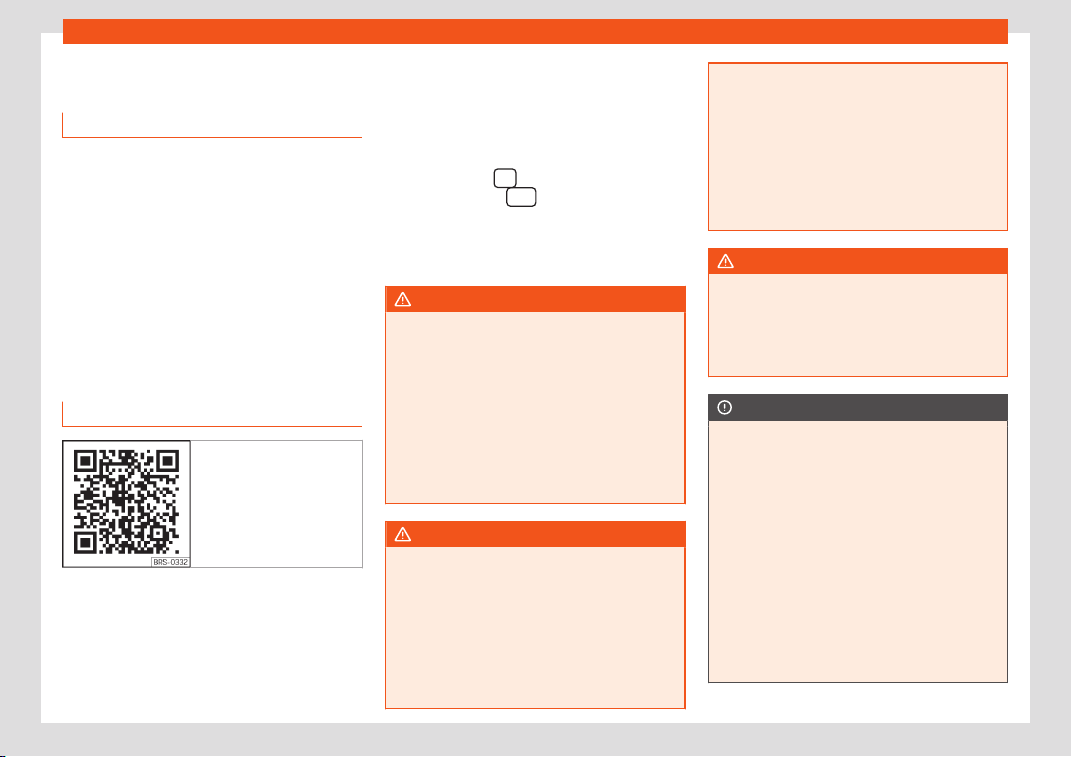
Connectivity
Connectivity
Dat
a tr
ansf
er
This communication can allow data to be
read and/or written.
Fr
om the SETTINGS menu > Data transfer for
SEAT apps, there is a checkbox to acti-
vate/deactivate the function and a dropdown
menu called Operation via apps which con-
trols the level of interaction between the apps
and the system.
Full Link*
Full Link technology description
Fig. 196 Related video
The Full Link system provides a way of bring-
ing t
ogether t
echnol
ogies that allow commu-
nication between the Infotainment System
and mobile devices:
●
MirrorLink
®
●
Android Auto™
●
Apple CarPlay™
Interfaces
To access the Full Link system, press the Info-
tainment button
(Full Link) or press the in-
f
ot
ainment butt
on
and then select the
Full Link cont
e
xt.
The connection t
o Full Link is made through a
USB interface.
WARNING
If a mobile terminal is not secured or is in-
correctly secured in the v
ehicle, it could
move around the passenger compartment
in the event of a sudden driving manoeuvre,
emergency stop or accident, resulting in in-
jury.
●
While driving, mobile terminals must be
securely fastened in position, outside the
airbag deployment zones, or safely stowed
away.
WARNING
Any applications that are not suitable or
execut
e incorrectly may cause damage to
the vehicle, accidents and serious injuries.
●
SEAT recommends the use of the Apps
that SEAT provides for this vehicle.
●
To make full use of SEAT Apps, you must
activate the option , Settings/System >
Data transfer for SEAT apps.
●
The interaction l
evel of the Apps on the
system must be: ALLOW.
●
Protect the mobile terminal with its appli-
cations from improper use.
●
Never make modifications to the applica-
tions.
●
Consult the instruction manual for the
mobile terminal.
WARNING
The use of applications while driving can
distr
act your attention fr
om the traffic. Dis-
tracting the driver in any way can lead to
an accident and cause injuries.
●
Always drive carefully and responsibly.
CAUTION
●
In areas where special r
egulations apply
or the use of mobile terminals is forbidden,
the mobile terminal must be switched off at
all times. The radiation produced by the
mobile terminal when switched on may in-
terfere with sensitive technical and medi-
cal equipment, possibly resulting in mal-
function or damage to the equipment.
●
SEAT cannot be held liable for any dam-
age caused to the vehicle as a result of the
use of applications that are of poor quality
or are defective, the inadequate program-
ming of the applications, the insufficient
coverage of the network, the loss of data
»
195
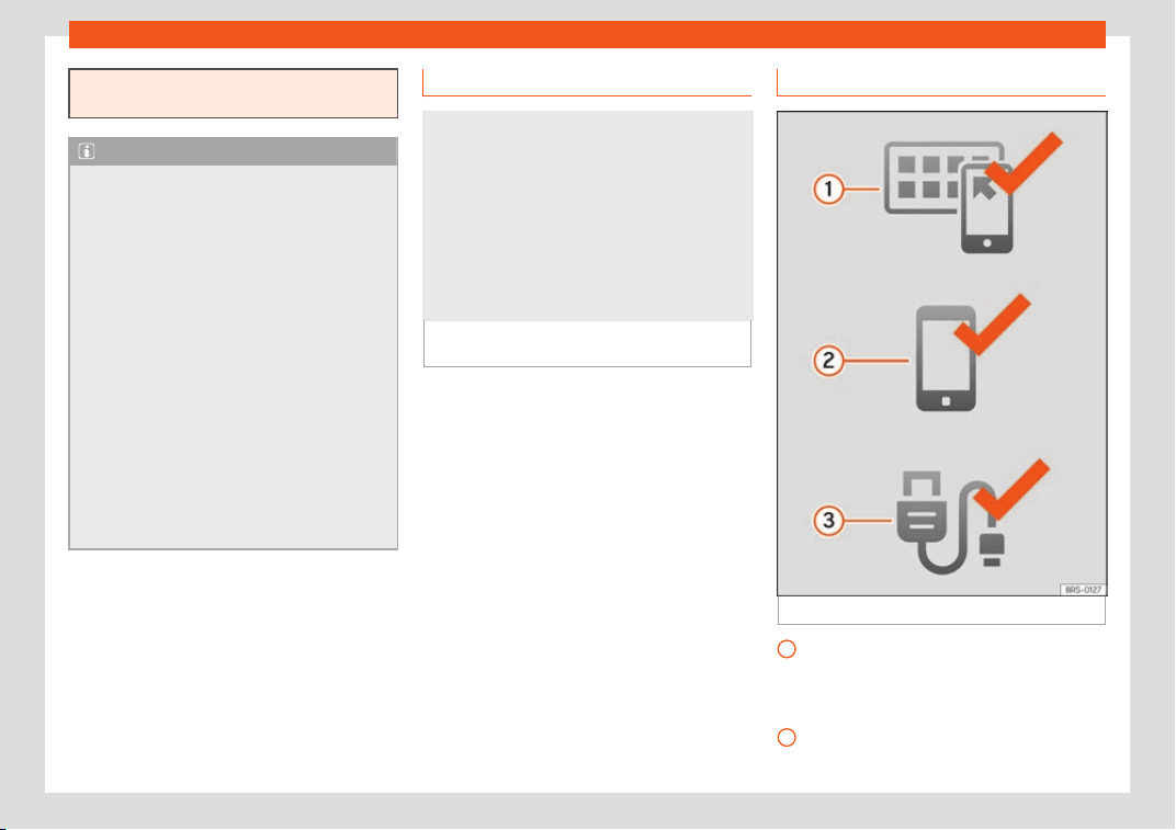
Infotainment System
during transmission or the improper use of
mobile terminal
s.
Note
●
Use of Full Link t
echnology may r
esult in
high consumption of your 3G/4G data plan.
●
SEAT recommends having a high battery
charge on the device when connected to
Full Link.
●
SEAT recommends that to use Full Link,
the “Date and time” should be correctly
configured. Select Settings/System >
Date and Time.
●
SEAT applications are designed to com-
municate with the vehicle and interact with
it via the Full Link connection, therefore its
functionality is linked to the mobile device
being connected via USB.
●
You can find further information on the
technical requirements, compatible devi-
ces, suitable applications and availability
at www.seat.com or at SEAT dealers.
Is Full Link blocked?
Fig. 197
Message on Infotainment system
scr
een.
To unblock this feature, you must obtain the
accessory fr
om your SEAT deal
er
. Otherwise,
a message like this will appear on the screen
whenever you select the feature
›››
Fig. 197.
Requirements for Full Link
Fig. 198 Full Link Requirements
Full Link Activated: If you do not hav
e
Full Link in your v
ehicl
e you can acquire it
as an accessory at your Authorised Serv-
ice.
Compatible Phones. Go to the Mirror-
Link
®
, Android Auto™ or Apple CarPlay™
1
2
196
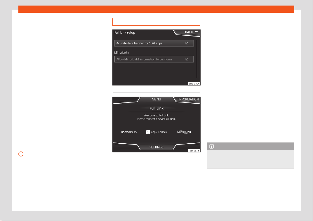
Connectivity
websites to confirm whether your phone
is compatibl
e with the syst
em.
Mirr
or Link
–
Check smartphone compatibility:
www.mirrorlink.com/phones
–
MirrorLink
®
1.1 or higher
–
Some of the Apps certified by SEAT or
the CCC must be installed in the de-
vice.
Android Auto
–
Check smartphone compatibility. An-
droid Auto™: www.android.com/auto/
–
Android 5.0 (Lollipop) or higher
–
Install Android Auto™ app
Apple CarPlay
–
Check smartphone compatibility. Apple
CarPlay™:www.apple.com/ios/carplay
–
iPhone 5 or higher and iOS 7.1 or higher
–
Turn on the SIRI personal assistant (see
phone settings)
USB cable connecting car to phone:
use the USB cable approved and sup-
plied by the phone's official distributor.
3
Activation of Full Link
Fig. 199
Full Link Setup
Fig. 200
Full Link menu
Data connection via Wi-Fi or SIM is not
necessary t
o est
ablish the connection be-
tw
een the smartphone and Full Link.
Data connection via Wi-Fi or SIM is neces-
sary to enable all of the app features
1)
.
Proceed as follows to use Full Link:
●
Switch on the Infotainment system
●
Connect the smartphone to the vehicle's
USB port using a USB cable
›››
page 237.
●
In the main menu for the Full Link setup, se-
lect Activate data transfer for SEAT
apps
›››
Fig. 199:
Finally, a message will appear stating that
data transfer will commence when the device
is connected. Please note that data is trans-
ferred over connections between your vehi-
cle and mobile device. Press OK. Once selec-
ted, the technology compatible with your de-
vice can be used.
Note
Depending on your smartphone, it may
have to be unl
ocked for the connection to
occur.
1)
Using the data connection to transfer the
smartphone apps to Full Link may invol
ve addi-
tional charges. Please check the charges with
your operator.
197
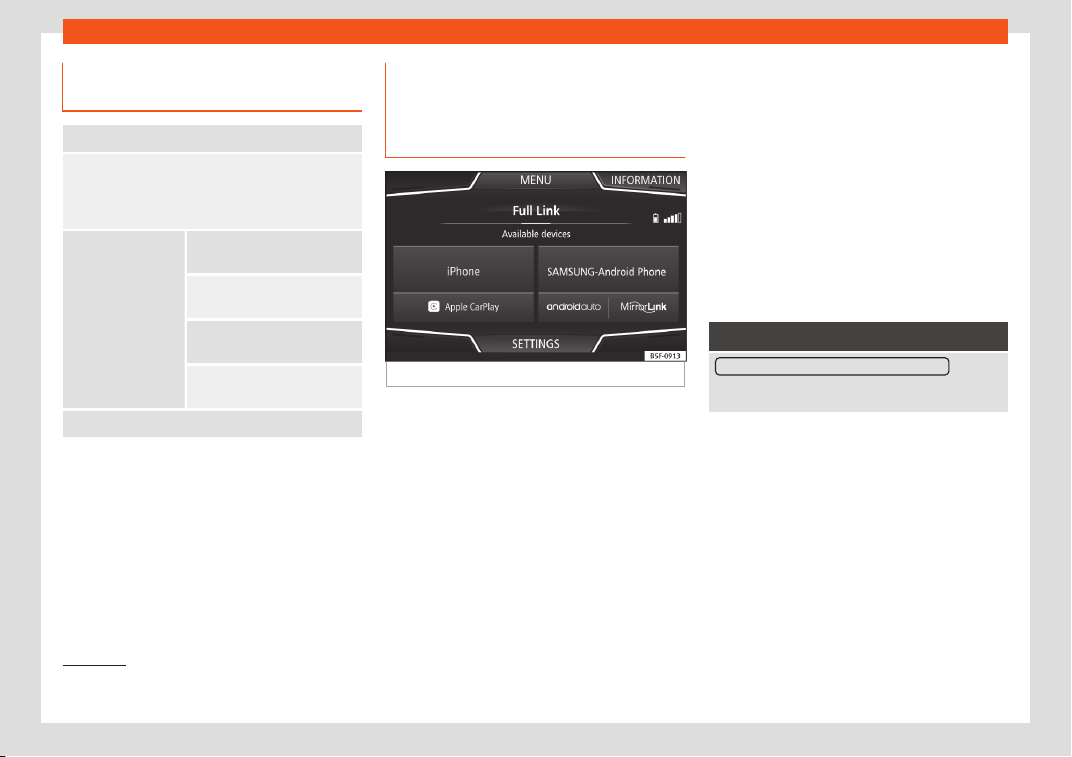
Infotainment System
What should I do if it does not con-
nect?
Restart the mobile device
Check the USB cable visually.
Make sure that the USB cable is not damaged. Check
that both connections (USB/micro USB) are not dam-
aged or worn.
Visually check
that the USB ports
are pr
operly con-
nected.
Check that the ve-
hicle and device
USB connections
are not damaged
and/or worn.
Clean the USB ports (device
and vehicle).
T
ry another compatible mo-
bile device
.
Have the USB port replaced at
a SEAT Authorised Service.
Have the mobil
e device re-
paired or repl
ace it.
Try another compatible mobile device.
Pairing of portable devices sup-
por
ting the Mirr
orLink
®
, Andr
oid
Auto™ and/or Apple CarPlay™
technologies
Fig. 201
Full Link menu
Carousel
When you ent
er the Full Link cont
e
xt for the
first time, the technologies available for pair-
ing the portable device are displayed.
Once the device connects via USB, the sys-
tem will offer you the technologies available
for establishing a connection with your mo-
bile phone.
In the event of simultaneous connections be-
tween two devices with different operating
systems, a choice will be presented for which
one to make the connection with
›››
Fig. 201.
View of the device list
iPhone™ devices only support Apple Car-
Play™.
There are some Android devices that support
MirrorLink
®
and Android Auto™.
Bear in mind that once the device is connec-
ted it will not be available as an audio source.
Full Link setup
Function button: function
Activating data transfers for SEAT applications : allows
the exchange of inf
ormation between the vehicle and
applications authorised by SEAT.
Last Mode
If a session using one t
echnol
ogy ends with-
out the disconnection being made fr
om the
Infotainment system (simply by disconnect-
ing the cable) then when the device is next
connected to it, the session will start without
the user being required to take any action
1)
.
Information
Consult the mobile device manual.
1)
Unless the device requires the screen to be un-
locked in or
der to establish the connection.
198
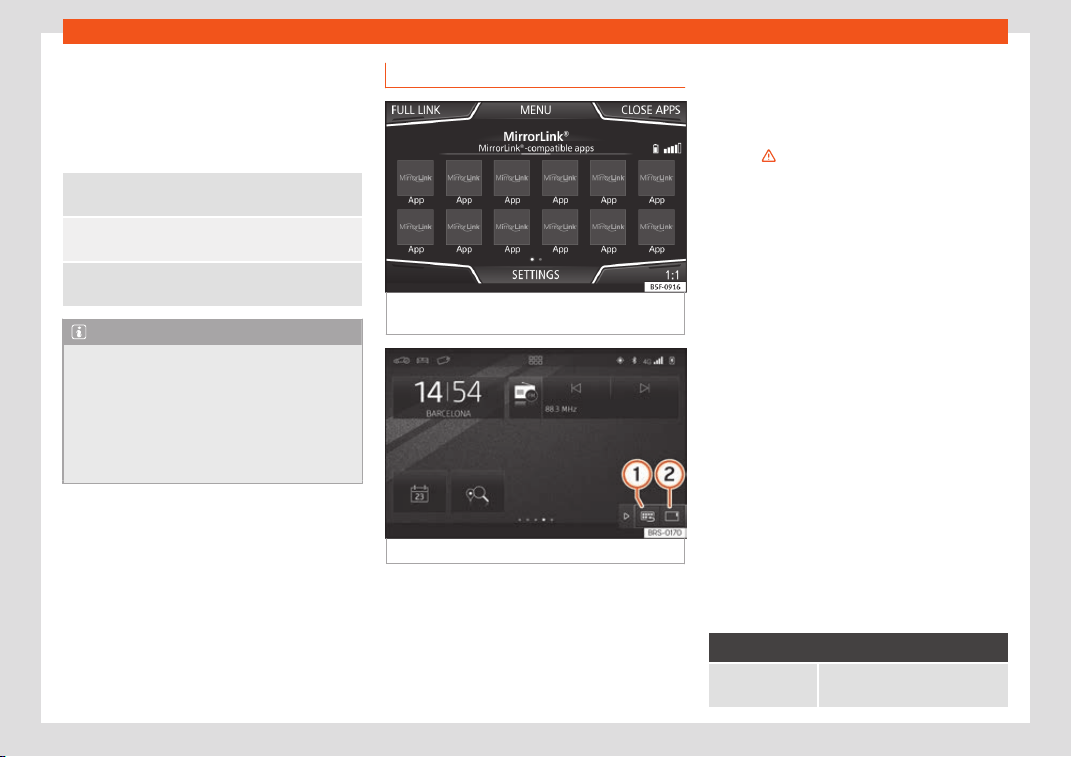
Connectivity
Depends on each technology:
Av
ail
abilit
y in a country
Third party applications
For further information:
MirrorLink
®
:
www.mirrorlink
.com
Apple CarPlay™:
www.apple
.com/ios/carplay
Android Auto™:
www.android.com/aut
o
Note
●
In order to use Andr
oid Auto™ technology
it is necessary to download the Android
Auto™ application, located on Google
Play™.
●
Only compatible applications can be
used, in accordance with the technology
connected.
1.
2.
MirrorLink
®
Fig. 202
Function buttons in the general view
of compatibl
e applications.
Fig. 203 Other MirrorLink function buttons.
MirrorLink
®
is a pr
ot
ocol which enabl
es com-
munication between a portable device and
the Infotainment system via USB.
Using it makes it possible to display and man-
age the content and functions displayed on
the portable device on the Infotainment sys-
tem screen.
To avoid distracting the driver while driving,
only specially adapted applications can be
used
›››
in Full Link technology descrip-
tion on page 195.
R
equir
ements
In or
der to use MirrorLink
®
, the following re-
quirements must be met:
●
The mobile device must be compatible with
MirrorLink
®
.
●
The mobile device must be connected to
the Infotainment system via USB.
●
Depending on the mobile device used, a
suitable application must be installed for the
use of MirrorLink
®
on the device.
Initiating the connection
●
In order to initiate the connection with the
mobile device, it is simply necessary to con-
nect it to the Infotainment system via the USB
connection.
●
A pop-up screen will appear, which will re-
quest that you accept the device.
Function buttons and possible messages
Function button: function
Full Link
To return to the Full Link main
menu.
»
199
Infotainment System
Function button: function
CLOSE APPS
Press to close the open apps.
Then press the apps to be
cl
osed or the Close all
function
button to close all the open ap-
plications.
1 : 1
Press to change to the mobile
device screen.
SETTINGS To open the Full Link setup
›››
Fig. 203
1
Press to return to the MirrorLink
®
main menu.
›››
Fig. 203
2
Press to display all the function
buttons in the lo
wer or upper
right-hand margin of the screen.
›››
Fig. 203 /
Allows buttons
1
and
2
to be
hidden or shown.
››
›
Fig. 189
12
MirrorLink
®
set
up
Function button: function
Activate MirrorLink pop-up windows: Allows Mirror-
Link
®
pop-up windows in applications that support it.
Apple CarPlay™*
3 Valid for compatible iPhone™ mobile tele-
phones. Also
, iPhone™ mobile telephones only
support Apple CarPlay™
Apple CarPlay™ is a protocol which enables
communication between a mobile telephone
and the Infotainment system via USB.
This makes it possible to display and operate
the mobile telephone on the Infotainment
system screen.
Requirements
In order to use Apple CarPlay™, the following
requirements must be met:
●
Make sure that you do not have Apple
CarPlay™ restrict
ed on your device, at: Set-
tings > General > Restrictions >
CarPlay > ON.
●
The mobile device must be compatible with
Apple CarPlay™.
●
The mobile device must be connected to
the Infotainment system via USB.
Initiating the connection
In order to initiate the connection with the
mobile device, it is simply necessary to con-
nect it to the Infotainment system via the USB
connection.
●
A pop-up screen will appear, which will re-
quest that you accept the device.
●
If you start the session using Apple
CarPlay™ technology, it will not be possible
to pair another device via Bluetooth
®
. The fol-
lowing message will appear in the main
Phone menu:
Please disconnect Apple CarPlay
first, before you can connect an-
other mobile telephone.
Holding down the steering wheel multifunc-
tion button or the
button of the Info-
t
ainment syst
em will st
art the Apple™ “voice
engine”.
To return to the basic contents of the Infotain-
ment system, press the SEAT icon.
Android Auto™*
3 Valid for compatible Android mobile phones.
Andr
oid Auto™ is a protocol which enables
communication between a portable device
and the Infotainment system via USB.
This makes it possible to display and operate
the mobile telephone on the Infotainment
system screen.
Requirements
In order to use Android Auto™, the following
requirements must be met:
200
Connectivity
●
The mobil
e de
vice must be compatibl
e with
Android Auto™.
●
The mobile device must be connected to
the Infotainment system via USB.
●
The Android Auto™ application should al-
ready be downloaded and installed on the
mobile device.
Initiating the connection
In order to initiate the connection with the
mobile device, it is simply necessary to con-
nect it to the Infotainment system via the USB
connection, and to be sure to follow the in-
structions of the device being paired.
●
The first connection to Android Auto™ must
be done while the vehicle is stationary.
●
Once the first pop-up window about ac-
cepting data transfer between the car and
the device has been accepted, a message
will appear requesting that you check your
mobile device for the confirmations needed
to pair it with the Infotainment system.
●
If you are initiating the session using
Android Auto™ technology via USB, the mo-
bile telephone connects automatically via
Bluetooth
®
to the Infotainment system tele-
phone and it will not be possible to pair an-
other mobile telephone via Bluetooth
®
.
Holding down the steering wheel multifunc-
tion button or the
button of the Info-
tainment system will start the Android™
“v
oice engine”.
T
o r
eturn to the basic contents of the Infotain-
ment system, press the Return to SEAT
button.
Note
Some mobile devices require a change in
the USB connection mode in order to use
Andr
oid Auto™.
●
Make sure that your mobile is in “Media
Transfer Protocol (MTP)” mode before it is
connected by USB to the Infotainment sys-
tem.
Note
Android Auto™ requires the use of Google™
services, as well as cert
ain basic applica-
tions of the Android system.
●
Make sure that you always have Google™
services updated in order to use this tech-
nology.
Frequently asked questions about
Full Link
What is the connection method?
USB Cable.
Will the USB cable be supplied with the vehicle?
No. The USB cable supplied with the de
vice should
be used.
Is there a navigation option?
Navigation is possible in each one of the Full Link
technol
ogies if the technology is available in your
country and if you have the Navigation app.
What is the difference between using the Full Link
system navigator (via t
elephone) instead of an-
other navigator?
Benefits: Daily updates.
Issues: data consumption, reception problems.
Can I send voice messages?
With certified apps, you can answer but not send
v
oice messages.
What apps are visible while driving?
Depending on the technology:
– for MirrorLink
®
: SEAT-certified apps and CCC,
– for Android Auto™: Apps selected by Google™,
– for Apple CarPlay™: Apps selected by Apple™.
Where can I find compatible apps?
Compatible apps can be found on the following links:
www.mirrorlink.com/
www.android.com/auto/
www.apple.com/ios/carplay/
»
201
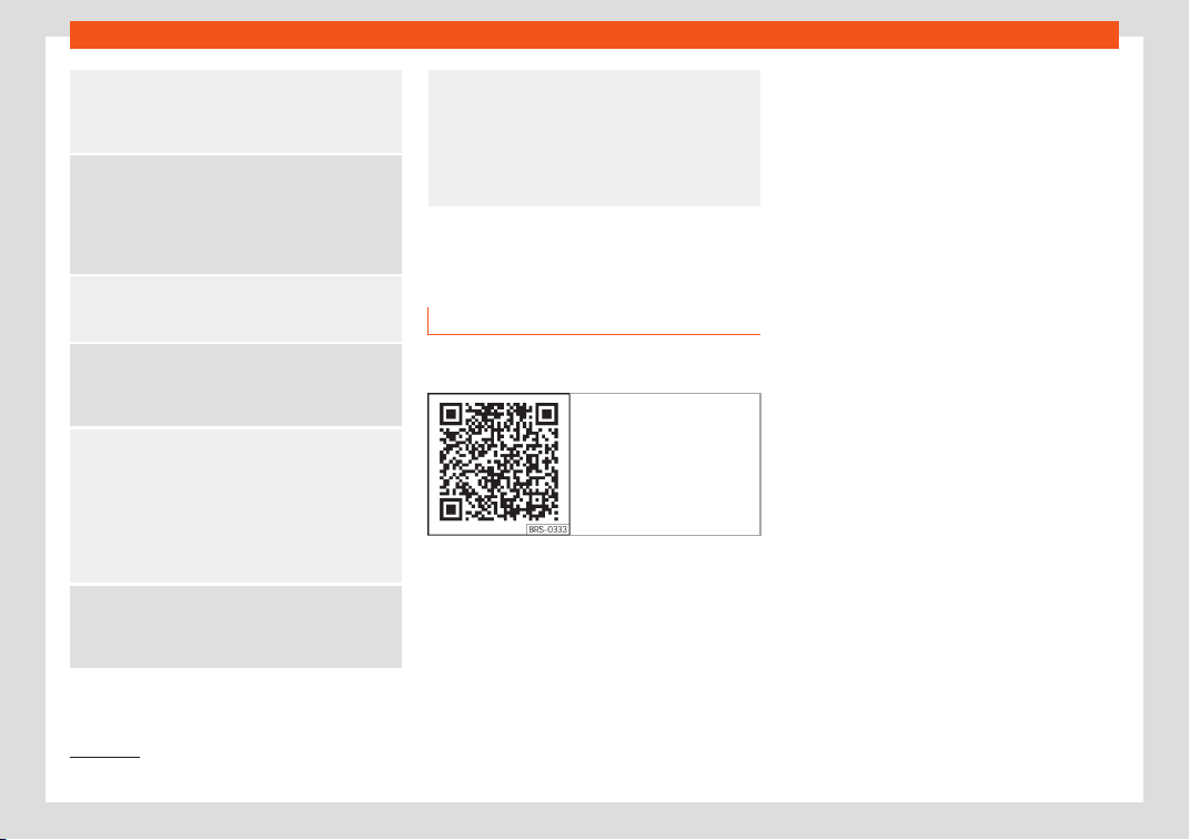
Infotainment System
Where can I download apps?
On Google Play™ f
or Android Auto™/MirrorLink
®
and
on Apple Store™ for Apple CarPlay™.
If Full Link stops working, where can I have it re-
paired?
If the probl
em is in the car, you should go to the deal-
er. If the problem is in the mobile device, you should
see your mobile telephone vendor.
Will WhatsApp be certified?
This depends on the technology.
Is Mirr
orLink
®
availabl
e in my country?
Yes, MirrorLink
®
is available in all the countries and
regions where SEAT operates.
What are the differences between MirrorLink
®
,
Android Auto™ and Apple CarPlay™?
MirrorLink
®
is not compatible with Android Auto™ and
Apple CarPlay™, as they are different technologies.
They all coexist in Full Link, although Android Auto™ is
designed for mobile devices with the Android™ oper-
ating system, and Apple CarPlay™ for iPhone.
Can MirrorLink
®
be installed in a pr
evious SEAT
model?
No, this is not possible.
Where can I find more information about Full
Link?
If you have any questions, please see our
Innova-
tion/Connectivity sections on our website:
www.seat.es or www.seat.com or e-mail seat-re-
SEAT Media Control*
Introduction
3 Not availabl
e for model: Media System Touch /
Colour
Fig. 204 Related video
The SEAT Media Contr
ol
1)
app can be used
t
o r
emotely operate some partial functions in
Radio mode, Media mode and Navigation
mode. Information can be exchanged be-
tween a device and the Infotainment System.
Each one of the functions is operated by
means of a Tablet or partially by means of a
mobile phone.
Operating requirements:
●
A tablet or mobile phone.
●
The app must be available on the corre-
sponding device.
●
There must be a WLAN connection between
the Infotainment System and the device. Se-
lect Menu > Media > Settings > WLAN >
Share connection via WLAN > Configu-
ration.
Make sure that data transfer for apps is acti-
vated:
●
From the SETTINGS menu > Data trans-
fer for SEAT apps, there is a checkbox to
activate/deactivate the function and a drop-
down menu called Operation via apps
which controls the level of interaction be-
tween the apps and the system. Select Menu
> Settings/System > Transfer data
from mobile devices.
You can obtain information about technical
requirements on the SEAT website or at SEAT
dealerships.
Telephone functions are not part of the func-
tions of this app.
1)
Availability depends on the country.
202
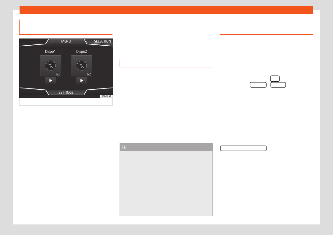
Connectivity
Data transmission and control
functions
Fig. 205
SEAT Media Control Main menu
The Infotainment System can be operated
fr
om other seats in the v
ehicl
e as follows, with
the help of SEAT Media Control:
●
Radio remote control.
●
Multimedia playback remote control.
The following information can be exchanged
between a device and the Infotainment Sys-
tem, depending on the country and the
equipment:
●
Navigation destinations.
●
Traffic information.
●
Social media contents.
●
Audio transmission.
●
Vehicle data.
●
Location-specific information, for example,
POIs.
WLAN access point*
Introduction
3 Not available for model: Media System Touch /
Colour
The Inf
otainment System can be used to
share a WLAN connection with up to 8 devi-
ces
›››
page 203, Setting up WLAN connec-
tion sharing.
The Infotainment System can also use the
WLAN hotspot of an external wireless device
to provide Internet to the devices connected
to the hotspot (WLAN client)
›››
page 204,
Setting up Internet access.
Note
●
Data transmission may incur char
ges.
Due to the high volume of data exchanged,
SEAT recommends the use of a flat rate
mobile phone deal for data transmission.
Mobile phone operators can provide the
relevant information.
●
The exchange of data packages over the
internet may generate additional costs, de-
pending on your mobile phone rate, partic-
ularly if you are abroad (for example,
roaming rates).
Setting up WLAN connection shar-
ing
The Infotainment System can be used to
share a WLAN connection with 8 wirel
ess de-
vices.
Establishing the connection with the wire-
less network (WLAN)
●
Press the Infotainment
button and
then press the Settings / System menu.
●
Activate the wireless network (WLAN) on the
Inf
ot
ainment Syst
em. To do so, press the
WLAN function button.
●
Activate the wireless network (WLAN) on the
wireless device that is to be connected. If
necessary, refer to the manufacturer’s in-
struction manual.
●
Activate the mobile device assignment on
the Infotainment System. To do so, press the
Enable WLAN connection
button and activate
the checkbo
x.
●
Ent
er and confirm the netw
ork key dis-
played on the wireless device.
The following settings can also be made on
the menu Share connection:
WPA2 encryption automatical-
ly generates a network key.
Network key automatically gen-
erated. Press the function button to
»
Security level:
Network key:
203

Infotainment System
manually change the network key. The
netw
ork k
ey must hav
e a minimum of 8
characters and a maximum of 63.
WLAN Network name (maximum of 32
characters).
Activate
the checkbox to deactivate the visibility
of the wireless (WLAN) network.
The wireless (WLAN) connection is establish-
ed. To complete the connection, it may be
necessary to enter other data into the wire-
less device.
Repeat this process to connect other wireless
devices.
Wi-Fi Protected Setup (WPS)
1)
Wi-Fi Protected Setup can be used t
o cr
eat
e
a ciphered local wireless network quickly and
simply.
●
Establish the connection with the wireless
network (WLAN)
›››
page 214.
SSID:
Do not send network name (SSID):
●
Press the WPS button on the WLAN router
2)
until the warning light on the router starts
flashing.
●
OR: Press and hold the WLAN button on the
WLAN router until the WLAN light on the router
starts flashing.
●
Press the WPS button on the WLAN device.
The wireless (WLAN) connection is establish-
ed.
Repeat this process to connect other wireless
devices.
Setting up Internet access
The Infotainment System can use the WLAN
hotspot of an e
xt
ernal wir
eless device to es-
tablish an internet connection.
Establishing the connection with the wire-
less network (WLAN)
●
Activate and check the wireless hotspot on
the external device. If necessary, refer to the
manufacturer’s instruction manual.
●
Press the Infotainment
button and
then pr
ess the Settings
/ Syst
em
menu; OR
access the Media or SEAT Media Contr
ol
mode and press the SETTINGS menu.
●
Press the WLAN menu and then ent
er
Int
er-
net access settings on your phone and acti-
vate the checkbox.
●
Press the Find function button and select
the wireless device you want from the list.
●
If necessary, enter the network key of the
wireless device in the Infotainment System
and confirm with OK.
To manually enter the net-
work settings of an external wireless
(WLAN) device.
The wireless (WLAN) connection is establish-
ed. To complete the connection, it may be
necessary to enter other data into the wire-
less device.
Note
Due to the large number of different wire-
less devices in e
xistence, it is not possible
to guarantee fault-free operation of all
functions.
Manual settings:
1)
This function depends on the equipment and
the country in question.
2)
If the WLAN router does not support WPS the
network must be configured manually.
204
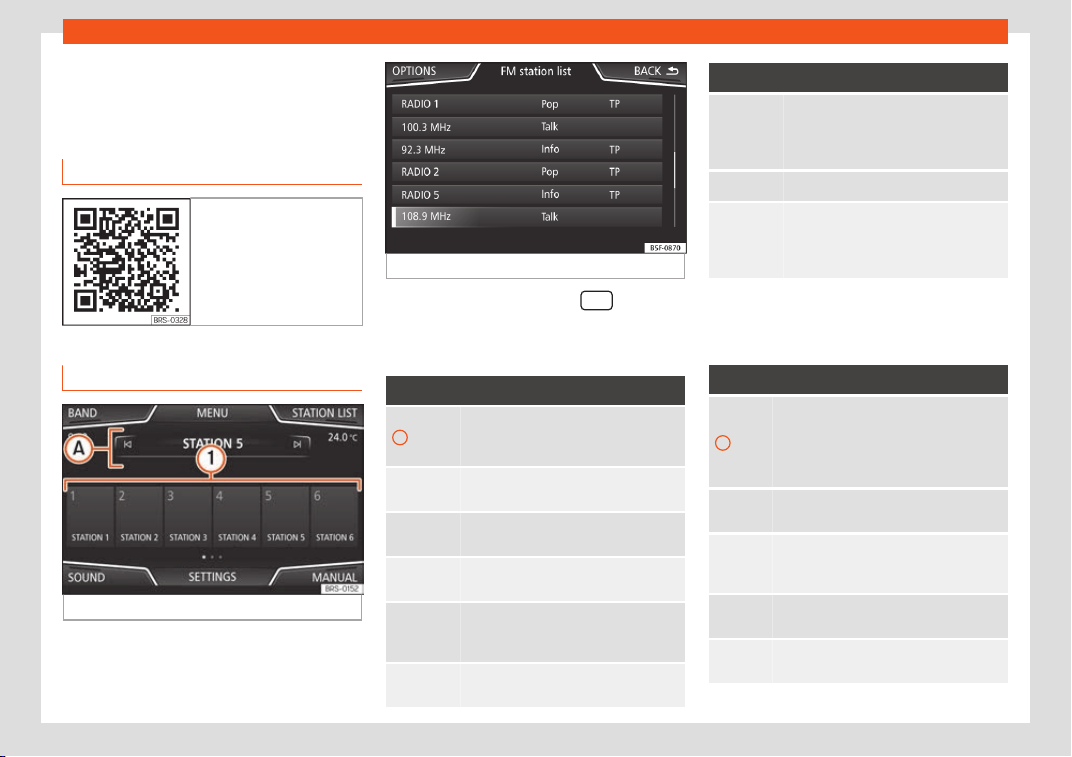
Operating modes
Operating modes
R
adio
R
el
ated video
Fig. 206 Radio mode
RADIO main menu
Fig. 207 RADIO main menu.
Fig. 208 Radio mode: station list (FM).
Press the infotainment button
to open
the R
adio
main menu
›
››
Fig. 207.
RADIO main menu function buttons
Function button: function
1
To change the group of memory but-
tons slide a finger ov
er the memory
buttons from left to right or vice-versa
BAND
Allows you to select the frequency
band.
STATION
LIST
Opens the list of currently r
eceivable
radio from the active frequency band.
MANUAL
Allows you to select the frequency
manually.
VIEW
Allows you to select the information
shown on the screen. Only av
ailable in
DAB mode.
SETTINGS
Opens the setup menu of the active
frequency band (FM, AM or DAB).
Function button: function
/
Selects the previous or next stored sta-
tion or of the station list. This setting
can be changed in the Radio settings
menu (FM, AM, D
AB).
1 to 18
a)
Memory buttons
›
››
page 206.
SCAN
Stops the scan function (only visible
when the function is under way). It can
be activat
ed in the settings menu (FM,
AM and DAB).
a)
The Media System / Touch Colour model has 15
memories.
Inf
ormation and possibl
e icons
Display: Meaning
A
View the frequency or the name of the
station and, where applicabl
e, the radio
text. The name of the radio station and
the radio text will only be displayed if
equipped with RDS and if it is active.
RDS
Off
The RDS radio data service is deactiva-
ted.
TP
Tr
affic information can be retrieved: se-
lect Radio > Settings > Traffic
station.
No st
ations with traffic news are availa-
bl
e.
The r
adio station is stored on a memory
button.
»
205
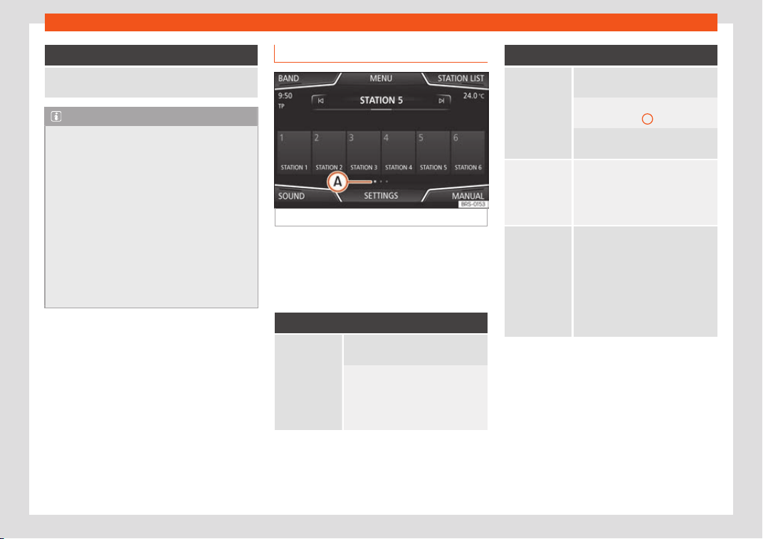
Infotainment System
Display: Meaning
AF off
The tracking of alternative frequencies is
disabl
ed.
Note
●
The availabilit
y of AM and DAB bands de-
pends on the country and/or equipment. In
the event that the AM and DAB bands are
not available, the BAND function button
text will not be shown.
●
Bear in mind that being underground, in
tunnels, in areas with tall buildings or
mountains can interfere with radio signals.
●
Foil or metal-coated stickers attached to
the windows may affect reception on vehi-
cles with a window aerial.
●
Radio stations are responsible for the
content of the information they transmit.
Memory buttons
Fig. 209
RADIO main menu.
In the R
adio main menu, you can store sta-
tions fr
om all av
ailable frequency wave-
lengths on the numbered function buttons.
These function buttons are called “memory
buttons”.
Functions of the memory buttons
Selecting the
st
ation fr
om
the memory
butt
ons
Press the memory button corre-
sponding t
o the desir
ed st
ation.
The stored stations can only be
played by pressing the corre-
sponding memory button provided
it can be received at your current
location.
Functions of the memory buttons
Change mem-
ory bank
Move your finger over the screen
from left t
o right or vice-versa.
OR: Press one of the function but-
tons
›
››
Fig. 209
A
The memory buttons are displayed
in three memory banks.
Storing the
station on the
memory but-
t
ons
Keep and hold the desired memory
button until an audible signal is
heard, the station will be stored on
this memory button. You can also
store a station from a station list.
Storing the
station logo on
the memory
butt
ons
A station logo can be assigned to
the stations stor
ed on the memory
buttons.
A logo is automatically assigned
from the database if the Advanced
radio settings option is enabled
a)
.
A logo can also be assigned man-
ually from an external data source
(USB/SD card).
a)
Not available for the Media System Touch/Colour
model.
206
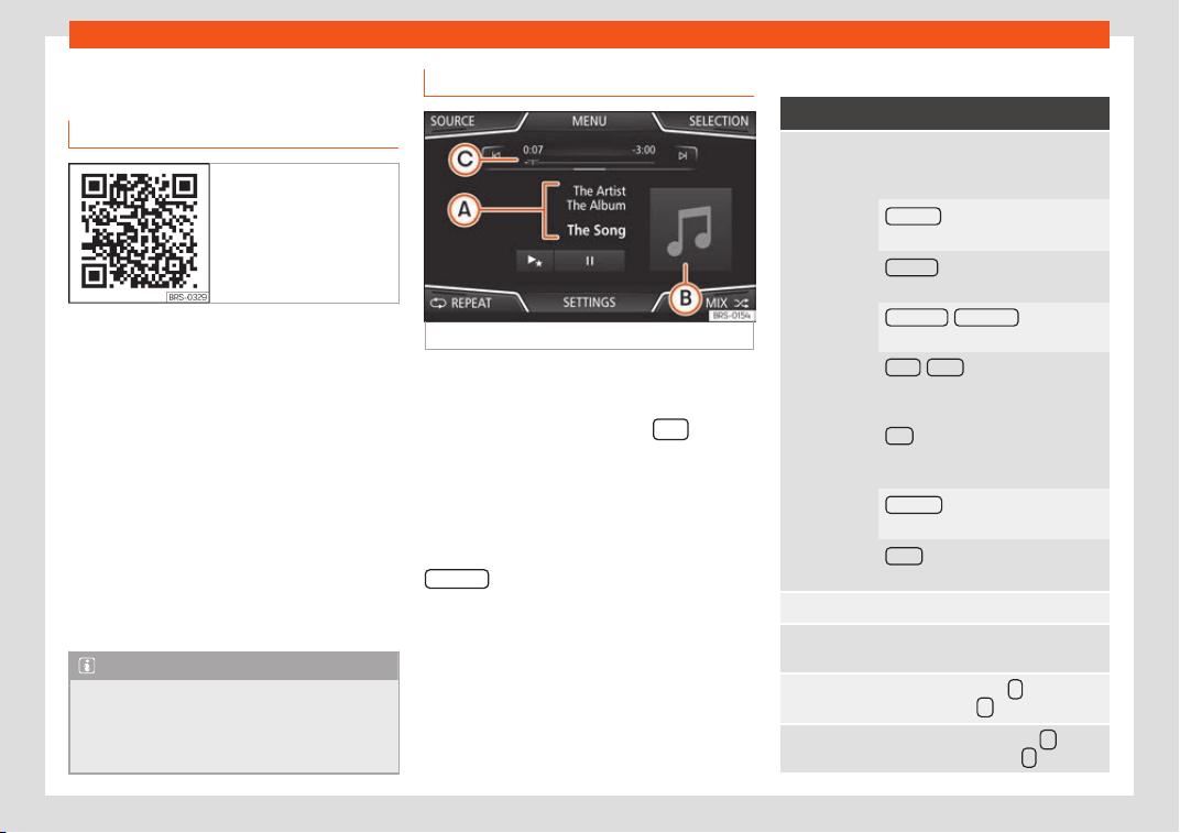
Operating modes
Media
Intr
oduction
Fig. 210 Related video
“Media sour
ces
” ar
e audio sources contain-
ing audio files on various different data stor-
age devices (e.g. CD, memory card, external
MP3 player). These audio files can be played
by the Infotainment system via their corre-
sponding drives or audio input sockets (inter-
nal CD drive, memory card slot, AUX-IN multi-
media socket etc.).
Copyright
Audio and video files on data storage devices
are usually protected by intellectual property
rights, as per the corresponding national and
international laws. Be aware of the current le-
gal provisions!
Note
●
Do not use memory card adapters.
●
SEAT assumes no liabilit
y for any deterio-
ration or loss of files on data storage devi-
ces.
MEDIA main menu
Fig. 211
MEDIA main menu.
Using the Media main menu, diff
er
ent media
sour
ces can be selected and played.
●
Press the infotainment button
to open
the R
adio
main menu
›
››
Fig. 211.
It will continue playing the last media source
selected from the same point.
The media source being played is indicated
on the dropdown list when pressing the
SOURCE
function button
›
›
›
Fig. 211.
If there is no available media source, the Me-
dia main menu is displayed.
Function buttons of the main Media menu
Function button: function
SOURCE
Indicates the media source being
played. Press t
o select another me-
dia source
›››
page 209.
JUKEBOX
a)
: Internal hard drive
(SSD)
›››
page 212.
CD/DVD
a)
: Internal CD and DVD
driv
e
›››
page 209.
SD CARD 1
, SD CARD 2 *: SD memory
card
››
›
page 210.
USB 1
, USB 2 *: External data stor-
age device connected t
o the USB
port
›››
page 210.
AUX
: External audio source connec-
ted to the AUX-IN multimedia sock
et
›››
page 211.
BT AUDIO
: Bluetooth
®
audio
›››
page 211.
WLAN
*
b)
: External audio source
connected by WLAN
›
››
page 214
SELECTION Opens the track list.
/
Changes track in Media mode or
fast forward/rewind.
Playback stops. The
function but-
ton changes to .
Playback is resumed. The func-
tion button changes to .
»
207
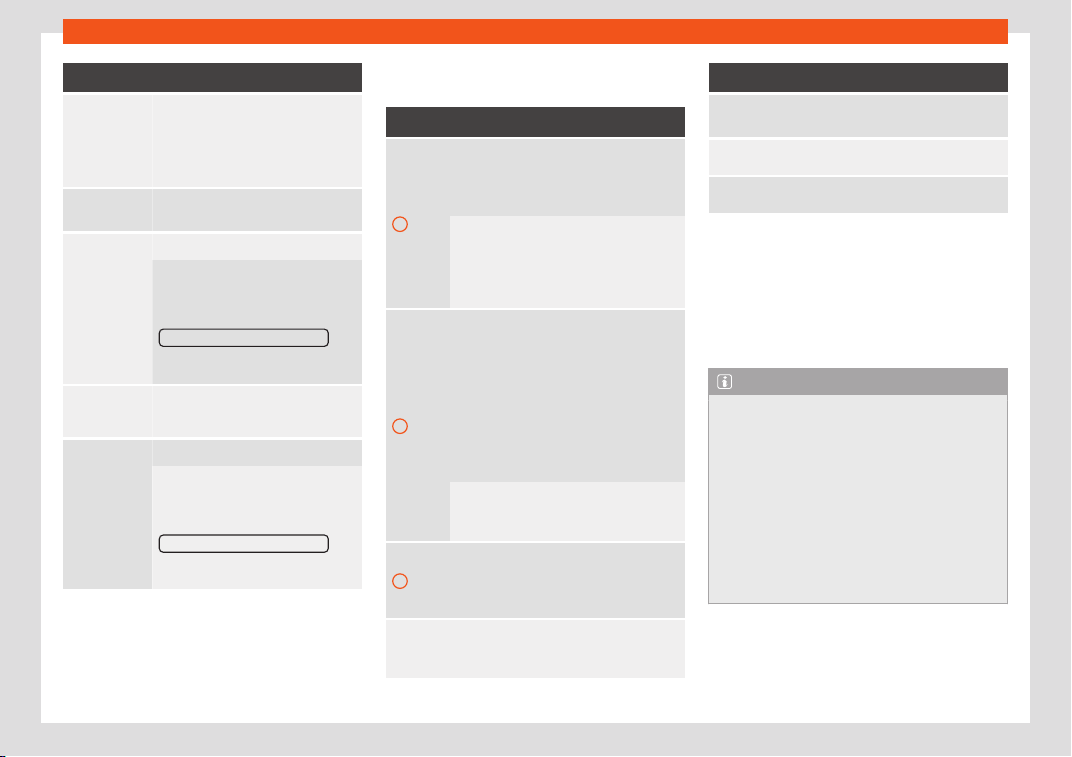
Infotainment System
Function button: function
a)
Play more like this.
Creates a virt
ual playlist that in-
cludes tracks with a similar rhythm
to the one being played if available
using Gracenote
®
.
SETTINGS
Opens the Media Settings
menu.
REPEAT
Repeat all tracks.
Repeats all the tracks that are on
the same memory l
ev
el as the track
being played at that moment. If in
the Media Settings menu the
Mix/Repeat including subfolders
op-
tion is enabled, it also includes the
subf
olders.
REPEAT
The current track will be repeated.
MIX
Random play.
Includes all the tracks that are on
the same memory lev
el as the track
being played at that moment. If in
the Media Settings menu the
Mix/Repeat including subfolders
op-
tion is enabled, it also includes the
subf
olders.
a)
The DVD drive and the Jukebox (SSD) are only
av
ail
abl
e for the “Navi System Plus” model.
b)
Not available for the Media System Touch/Colour
model.
Messages and symbols on the MEDIA main
menu
Display: Meaning
A
Displays information about the artist
name, album name and song title (CD
t
ext , ID3 tag on compressed audio
files).
Audio CD: displays track information if
available via Gracenote
®a)
. If no data is
available, it only displays Track and the
number corresponding to the position it
occupies on the data storage device.
B
View of album cover: If there are various
covers within the same f
older/album, the
system only displays one of them.
It prioritizes displaying the covers in the
following manner:
1. Cover embedded in the file(s).
2. Image in file folder.
3. Image provided by the Gracenote
®a)
database.
4. Default icon for the connected device.
If playing a video file, by pressing the
icon (cover) it can be pl
ayed on full
screen.
C
The playing time so far and time remain-
ing in minutes and seconds. In the case
of audio files with v
ariable bit rates (VBR)
the remaining time may vary.
RDS
Off
b)
The RDS radio data service is deactiva-
ted. The RDS can be activated in the FM
setup menu.
Display: Meaning
TP
b)
The TP function is active and can be
t
uned in.
b)
There is no tr
affic news station available.
b)
DAB not available.
a)
Gracenote
®
is a database avail
able on the Infotain-
ment system hard drive that contains information on
the tracks of different artists and albums. In order for
the user to benefit from the functions offered by
Gracenote
®
, the tracks must contain the artist and/or
album data (only available for the model: “Navi Sys-
tem Plus”.
b)
Depends on the market and unit in question.
Note
●
When the media source is insert
ed, play-
ing will not start automatically; it is neces-
sary for the user to select the source. Nor
will the media source change when it is
ejected.
●
In order to see the different covers inside
of the same album/folder, make sure that
the tracks contain different information
about the Artist or Album in its metadata. If
not, you will see the same cover for all of
tracks contained in the same album/folder.
208
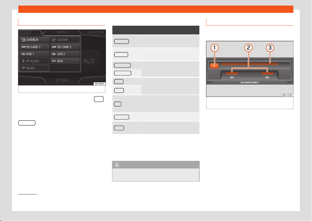
Operating modes
Changing the Media source
Fig. 212
MEDIA mode: change media source.
●
From the Media main menu, pr
ess the
Infotainment button repeatedly to cycle
thr
ough the av
ail
able media sources.
●
OR: From the Media main menu, press the
SOURCE
function button
›
›
›
Fig. 212 and se-
lect the desired media source.
In the pop-up window, the Media sources not
selected are shown as deactivated (in grey).
When a Media source that has already been
played is selected again, playback is re-
sumed from the point at which it was stop-
ped.
Optional Media playback sources
Function button: media source
JUKEBOX
a)
Internal hard drive (SSD)
›››
page 212.
CD/DVD
a)
Internal CD/DVD drive
›››
page 209.
SD CARD 1
SD memory card
›››
page 210.
SD CARD 2
*
USB 1 External data storage device con-
nected to the USB port
›››
page 210.
USB 2
*
AUX
External audio source connected
to the AUX-IN multimedia socket
›
››
page 211.
BT AUDIO
Bluetooth
®
audio
›››
page 211.
WLAN
*
b)
External audio source connected
by WLAN
›››
page 214
a)
The DVD drive and the Jukebox (SSD) are only
av
ail
abl
e for the “Navi System Plus” model.
b)
Not available for the Media System Touch/Colour
model.
Note
The Media source can be changed in the
Track list
view: select Media > View.
Insert or eject a CD or DVD
1)
3 Not available for model: Media System
Touch/Col
our
Fig. 213
Slots for data storage devices in the
gl
o
v
e compartment.
The driver should refrain from operating the
unit whil
e the v
ehicl
e is in motion. Insert or
change the data storage device before mov-
ing off!
The CD and DVD drive can play audio CDs
and DVDs and audio data CDs and DVDs.
Insert a CD or DVD
●
Hold the CD or DVD with the printed side
facing up.
»
1)
The DVD drive is only available for the model:
“Navi System Plus”.
209
Infotainment System
●
Push the CD or D
VD int
o the D
VD slot
›››
Fig. 213
3
to the point where it is drawn in
aut
omatically.
Eject a CD or D
VD
●
Pr
ess button
1
.
●
The CD or DVD in the drive will be ejected
and must be r
emo
v
ed within approximately
10 seconds.
Insert or eject a memory card
Depending on the features and the country,
the v
ehicl
e may hav
e one or two slots for SD
cards.
Inserting a memory card
Insert the compatible memory card, bevelled
edge first and with the label face up (con-
tacts face down), into slot
›››
Fig. 213
2
or
›
›
›
Fig. 188
9
, until properly inserted.
If a memory car
d cannot be insert
ed, mak
e
sure it is positioned correctly and is compati-
ble with the unit.
Removing a memory card
The inserted memory cards must be pre-
pared for removal.
●
From the main Media menu, press the
SETTINGS
button to open the Media Set-
tings menu or pr
ess the inf
ot
ainment button
and then press Settings / Syst
em
, to
open menu System settings.
●
Press the R
emo
v
e safely
function button. A
dr
opdo
wn menu appears with the f
ollowing
options: SD1 Card, SD2 Card*, USB1 and
USB2*. After correctly ejecting the memory
card from the system, the function button be-
comes inactive (grey colour).
●
Press the inserted memory card. The mem-
ory card “jumps” to the eject position.
●
Remove the memory card.
Unreadable memory card
If a memory card is inserted and the data
cannot be read, the relevant warning ap-
pears.
External data storage device con-
nected to the USB port
Depending on the features and the country,
the v
ehicl
e may hav
e one or two USB con-
nections
›››
page 237.
Audio files on an external data storage device
connected to the USB port can be played
and controlled via the Infotainment system.
Where this manual refers to external data
storage devices, this means USB mass stor-
age devices containing supported audio files,
such as MP3 players, iPods™ and USB sticks.
Only supported audio files are displayed and
played. Other files are ignored.
Further operation of the external data medi-
um (changing track, selecting tracks and
playback modes) is described in the appro-
priate chapters of this manual
›››
page 207.
Instructions and restrictions
Compatibility with Apple™ devices and other
media players depends on the unit.
The USB port supplies the usual USB volt-
age of 5 volts for a USB connection.
External hard disks with a capacity greater
than 32 GB must be reformatted for the FAT32
file system in some circumstances. You will
find the necessary software and information
on the Internet.
Take into account all other instructions and
limitations regarding requirements for media
sources.
Disconnecting
Any connected data storage devices must
be prepared before their disconnection in or-
der to remove them.
●
From the main Media menu, press the
SETTINGS
button to open the Media Set-
tings menu or pr
ess the inf
ot
ainment button
210
Operating modes
and then press Settings / Syst
em
, to
open menu System settings.
●
Press the R
emo
v
e safely
function button. A
dr
opdo
wn menu appears with the f
ollowing
options: SD1 Card, SD2 Card*, USB1 and
USB2*. After correctly ejecting the data stor-
age device from the system, the function but-
ton becomes inactive (grey colour).
●
Now the data storage device can be dis-
connected.
Note
●
Do not connect an external media pl
ayer
at the same time to play music via Blue-
tooth
®
and via the USB port with the In-
fotainment system, as this could cause
playback limitations.
●
If the external player is an Apple™ device,
it cannot be simultaneously connected by
USB and by Bluetooth
®
.
●
If a connected device is not recognised,
disconnect all the connected devices and
try connecting the device again.
●
Do not use memory card adaptors, USB
extension cords or USB hubs!
External audio source connected to
the AUX-IN multimedia sock
et
Depending on the equipment and country
ther
e may be an AUX-IN multimedia sock
et.
The connect
ed external audio source is
played over the vehicle speakers and cannot
be controlled via the Infotainment system
controls.
The connection of an external audio source is
indicated by AUX on the screen.
Connecting an external audio
source via Bluetooth
®
Bluetooth
®
Audio mode all
o
ws you t
o listen to
audio files being played on a Bluetooth
®
au-
dio source (e.g., a mobile telephone) connec-
ted via Bluetooth
®
(audio playback by Blue-
tooth
®
) over the vehicle speakers.
Conditions
●
The Bluetooth
®
audio source must support
the A2DP Bluetooth
®
profile.
●
In the Bluetooth Settings menu the
Bluetooth Audio (A2DP/AVRCP) function
must
be on. Sel
ect
Phone > Settings > Blue-
tooth
St
arting Bluetooth
®
audio transfer
●
Activate Bluetooth
®
visibility on the external
Bluetooth
®
audio source (e.g., mobile tele-
phone).
●
Lower the base volume on the Infotainment
system.
●
In the MEDIA main menu, press the SOURCE
function button and select B
T audio
.
●
Press Sear
ch f
or ne
w device
in order to con-
nect an e
xt
ernal Bluet
ooth
®
audio source for
the first time
›››
page 232.
●
OR: Select a Bluetooth
®
external audio
source from the list.
●
Please refer to the instructions on the
screen of the Infotainment system and on the
Bluetooth
®
audio source regarding the rest of
the procedure.
You may still need to manually start playback
on the Bluetooth
®
source.
When playback on the Bluetooth
®
audio
source is stopped, the Infotainment system
remains in Bluetooth
®
Audio mode.
Controlling playback
The extent to which the Bluetooth
®
audio
source can be controlled via the Infotainment
system depends on the connected Blue-
tooth
®
audio source.
The available functions will depend on the
Bluetooth
®
Audio profile that the connected
external player supports.
With media players that support the AVRCP
Bluetooth
®
profile, playback on the Blue-
tooth
®
audio source can be automatically
started or stopped when the unit is switched
»
211
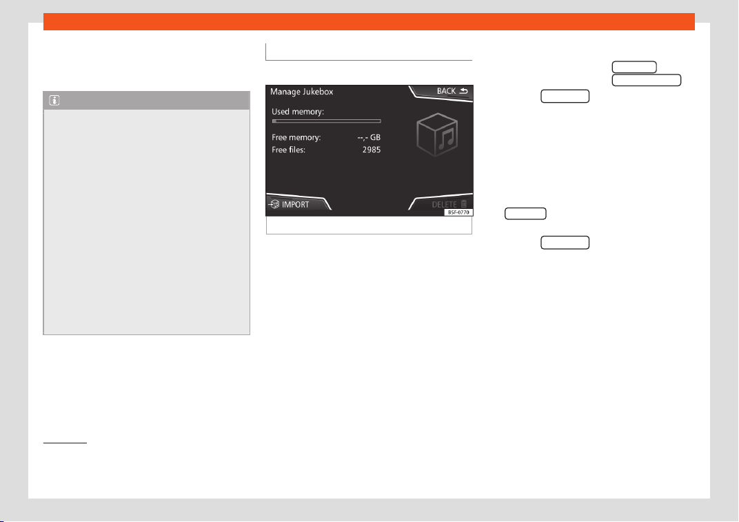
Infotainment System
to Bluetooth
®
Audio mode or t
o a diff
er
ent au-
dio source. In addition, it is possible to view or
change the track via the Infotainment system.
Note
●
Due to the lar
ge number of possible Blue-
tooth
®
audio sources, it is not possible to
guarantee fault-free operation of all de-
scribed functions.
●
To play music, do not link the external
media player simultaneously to Bluetooth
®
and the USB interface of the infotainment
system, as this can cause limitations during
playback.
●
Do not connect an external media player
to play music via Bluetooth
®
and via the
USB port
›››
page 210 at the same time
with the Infotainment system, as this could
cause playback limitations.
●
If the external player is an Apple™ device,
it cannot be simultaneously connected by
USB and by Bluetooth
®
.
Jukebox (SSD)
3 Only available for the model: Navi System Plus
Fig. 214
Manage Jukebox
The “jukebox” is located on the hard drive of
the Inf
ot
ainment syst
em (SSD
1)
).
Compressed audio files (MP3 and WMA) and
some video files (Podcasts, AVIs, etc.) can be
imported from different data storage devices
to the jukebox and this used to play them.
The files will only be copied when the engine
is running. Copying copy-protected CDs and
DVDs is prohibited
Importing files
●
In Media mode, press the SETTINGS
func-
tion butt
on and then sel
ect Manage juk
ebox
.
●
Press the IMPOR
T
function button.
●
Select the desired source from the Select
source menu.
The dat
a st
or
age device is prepared. This op-
eration may take a few seconds.
●
Activate the checkboxes to the right of the
files or folders to be imported.
●
If Select all
is activated, all files and folders
on the dat
a st
or
age device will be imported.
●
Press the IMPORT
function button.
Depending on the sel
ection, all fil
es and f
old-
ers will be imported with the indicated name
to the Jukebox.
If no track information is available, the audio
files will be placed in the following folders:
Audio data CD
■
Album
■
Unknown albums
■
Track.mp3
2)
■
Artists
1)
Solid-State-Drive (SSD).
2)
The name and extension of the file are exam-
ples.
212
Operating modes
■
Unknown artists
■
Unknown albums
■
Track.mp3
1)
Functions and pr
ogr
ess displ
ay during the
copying operation
While copying, an animation is displayed
along with the progress percentage on the
import screen.
Audio data CD: It is not possible to copy and
play files at the same time.
●
Press the Cancel
function button to end the
import of the whol
e tr
ack that is curr
ently be-
ing imported.
●
To obtain information on the status of the
import, press the Information
function button.
●
Press the BACK function button to close
the import scr
een with the pr
ogr
ess informa-
tion.
●
When the file import ends, a message will
appear.
Deleting files
●
In Media mode, press the SETTINGS
func-
tion butt
on and then sel
ect Manage juk
ebox
.
●
Press the DELETE
function button.
●
Activ
at
e the checkbo
xes to the right of the
files or folders to be deleted.
●
If Select all
is activated, all the files and
f
ol
ders on the dat
a storage device will be de-
leted.
●
Press the DELETE
function button. The
fil
es and f
ol
ders will be deleted according to
the selection made.
●
When the files have been deleted, a mes-
sage will appear.
●
Press the BACK
function button to close
the menu.
Opening st
or
ed audio and video fil
es
●
Change to Jukebox (SSD) content.
When storing the tracks, they are stored un-
der different categories and lists according to
the information available.
The tracks saved can be checked and
opened from these lists according to different
categories.
Jukebox
●
Playlist
●
Artist
●
Album
●
Music genre
●
Title
●
Video
●
Non-playable files (an unsupported file has
been imported).
Note
●
If the Infotainment syst
em cancels a
copying operation, check the storage
space on the internal hard drive and check
the data storage device.
●
Due to copyright laws, before any
change in ownership of the Infotainment
system, all files stored on the jukebox must
be deleted.
●
There are several possible reasons why
files may be shown as inactive (grey): files
that cannot be imported (e.g. images), files
that are already stored in the Jukebox or
files that take up more space than availa-
ble in the internal memory.
1)
The name and extension of the file are exam-
ples.
213
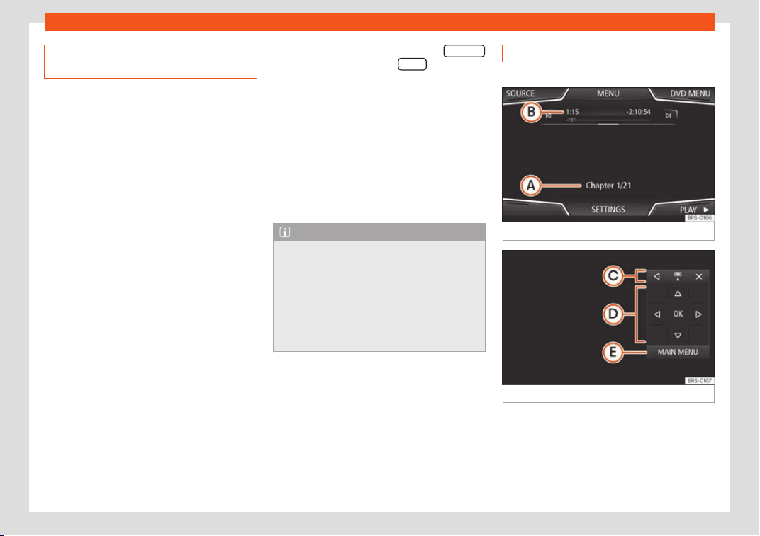
Infotainment System
Connecting an external audio
sour
ce thr
ough WLAN*
3 Not available for model: Media System
Touch/Col
our
WLAN allows wireless connection between an
external audio source (for example a smart
phone) and the Infotainment system.
To use this connection, the device being con-
nected must have an app compatible with
the UPnP (Universal Plug and Play) communi-
cation protocol, allowing the app to provide
the system with the available media content.
Conditions
●
Having a compatible (UPnP) app installed
on the mobile device
.
●
Having the Enable WLAN connection op-
tion active, which can be found in the wireless
connection configuration.
●
Pairing the mobile device to the Infotain-
ment system using a password generated by
the system. The pairing must be done from
the mobile device that you wish to connect to
the Infotainment system.
Starting the WLAN audio transfer
●
Lower the base volume on the Infotainment
system.
●
Start the UPnP app or the app for the play-
back of the WLAN audio source.
●
In the MEDIA main menu, press the SOURCE
function button and select WLAN .
●
Please refer to the instructions on the
scr
een of the Inf
ot
ainment system and on the
WLAN audio source regarding the rest of the
procedure.
Controlling playback
The extent to which the WLAN audio source
can be controlled via the Infotainment system
depends on the connected WLAN audio
source and the application used.
Note
●
The Infotainment syst
em does not pro-
vide an internet connection, it only estab-
lishes a wireless connection between the
mobile device and said system.
●
Via the WLAN, only the connection be-
tween the device and the Infotainment sys-
tem can be guaranteed, its operation de-
pends on the application itself.
DVD video mode
3 Only available for the model: Navi System Plus
Fig. 215
DVD main menu.
Fig. 216
DVD mode control menu.
Regional code of video DVD
Quit
e oft
en, the pl
ayback of DVD video is
limited to certain regions (for example, to the
US and Canada) by so-called region “co-
des”. These DVDs can only be played on
units that are coded for the same region.
214
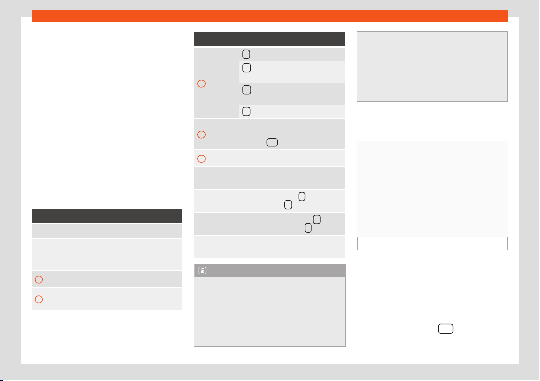
Operating modes
The unit's DVD drive is configured to read the
r
egional code f
or the r
egion in which the vehi-
cle was originally sold.
Starting the DVD mode
●
Insert a compatible DVD in the DVD drive.
The reading of DVD data may take a few sec-
onds.
The DVD's “intro” (short initial sequence) is
played. Next, the different DVD menus are
displayed.
Controlling a DVD menu
●
Briefly touch the screen to activate the
function buttons in the DVD mode main menu
›››
Fig. 215.
Function button: function
SOURCE Display and selection of the source.
DVD MENU
To display the control menu and re-
turn to the main D
VD screen
›››
Fig. 216.
A
Chapter display.
B
Displays play time duration and re-
maining play time.
Function button: function
C
: Move the control menu window.
: Minimise the control menu win-
dow.
: Maximise the control menu win-
dow.
: Close the control menu.
D
Use the arrow buttons to browse the
D
VD menu. Confirm the sel
ection by
pr
essing OK
.
E Press to open the DVD main menu.
/
To move to the next or previous
chapter.
Pl
ayback stops. The
function but-
ton changes to .
Playback is resumed. The func-
tion button changes to .
SETTINGS
This menu contains the Video (DVD)
settings.
Note
●
The visual appearance of the DVD film
menus and the menu options which it off
ers
are the responsibility of the DVD manufac-
turer.
●
The difference in behaviour of some films
when using the same mode is the responsi-
bility of the DVD manufacturer.
●
You may not be able t
o play video DVDs
which you have burned yourself.
●
The Infotainment system screen only dis-
plays the image when the vehicle is stop-
ped. Whilst in motion, the screen discon-
nects (the image), but the audio remains
active.
Images
Fig. 217
Images main menu.
Using the Images menu, image fil
es can be
vie
w
ed (e.g. photos) individually or as a slide-
show.
The image files must be stored on a compati-
ble data storage device (e.g., a CD or an SD
card).
●
Press the Infotainment
button and
then sel
ect the
Images cont
ext.
»
215
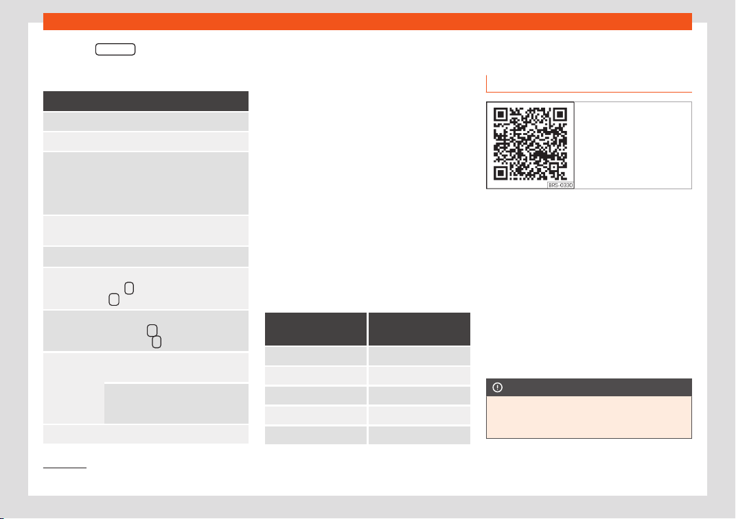
Infotainment System
●
Pr
ess the SOURCE
function button to select
the sour
ce wher
e the pict
ures in question are
located.
Function button: function
SOURCE Viewing and selecting the source.
SELECTION Opens a list of image files.
The image viewed was obtained via
GPS l
ocalisation and upon pressing
this function butt
on, the navigator
menu opens to start a route to this
destination.
/
Rotate the view of the image to the
left or the right.
Reset the vie
w of the image.
To stop the playback of a slideshow.
The
function button changes to
.
To continue the playback of a slide-
show. The function button
changes to .
/
To change to the PREVIOUS or
NEXT image.
The same function can be per-
f
ormed by sliding your finger hori-
zontally across the screen.
SETTINGS Open the Image settings menu.
Enlarging or reducing the view
T
o enl
ar
ge or reduce the view of the image
displayed:
●
Stretch or reduce the image on the screen
using 2 fingers.
Rotating the view/image
To rotate an image, in addition to the buttons
provided for this ( / ), you can also press
on the screen (e.g. with your thumb) and,
while continuing to press with your thumb,
slide another finger (e.g. your index finger)
around it like a compass either clockwise (to
rotate the image to the right) or anti-clock-
wise (to turn the image to the left). This will ro-
tate the image 90° with respect to its current
position.
Requirements for viewing images
Image files Maximum resolu-
tion
BMP 4MP
JPEG 4MP (Progressive Mode)
JPG 64MP
GIF 4MP
PNG 4MP
Navigation
1)
Intr
oduction
Fig. 218 Related video
General information
Using all the dat
a av
ail
able, the Infotainment
system calculates the optimum route to the
destination.
The destination is defined by entering an ad-
dress or a point of interest, e.g. a petrol sta-
tion or hotel. Traffic reports, if any, will also be
taken into account in the route calculation
(dynamic route guidance
›››
page 225).
Spoken instructions and visual guidance on
the navigation unit and on the instrument
panel will direct you to your destination.
CAUTION
The navigation announcements played
may be inaccurate (e
.g. due to out-of-date
navigation data).
1)
Valid for: Navi System and Navi System Plus.
216
Operating modes
Instructions for navigation
When the Infotainment system is unable to re-
ceive any data fr
om GPS satellites (due to a
dense tree canopy, underground car park),
navigation can still continue using the vehicle
sensors.
Possible limitations in navigation
In areas that are not or are only partially digi-
tised on the data storage device (e.g. insuffi-
cient definition of one-way streets and road
categories), the Infotainment system will still
attempt to provide route guidance.
Navigation area and updating navigation
data
Roads and streets are subject to constant
change (e.g. new roads, changes to street
names and building numbers). Therefore, if
the navigation data is not updated, then er-
rors or inaccuracies may occur during guid-
ance.
SEAT recommends updating navigation data
on a regular basis. Up to date navigation data
can be downloaded from www.seat.com or
acquired at a SEAT dealer.
Updating and using navigation da-
ta from an SD car
d
3 Only available for the model: Navi System
The Infot
ainment system always requires the
navigation data that is currently valid for this
unit in order to allow all functions to be used
in full. Using an old version may lead to errors
during navigation.
Updating navigation data
The current navigation data can be downloa-
ded in the internet at www.seat.com and stor-
ed in a SD card compatible with the unit.
Suitable SD Cards can be acquired at SEAT
dealerships.
The procedure is described on the internet at
www.seat.com.
Using navigation data
●
Insert the memory card
›››
page 210.
●
Do not remove the memory card while test-
ing. Wait for the testing icon to disappear.
If the inserted memory card contains valid
navigation data, the following message ap-
pears: “The source contains a valid
navigation database”. It is now possible to
navigate with the memory card data. When
the memory card is no longer needed by the
hardware, it will be prepared for removal
›››
page 210.
Note
●
The inserted memory car
d must be pre-
pared before it is ejected
›››
page 210.
●
Press the Infotainment button
and
then Settings/System to open the System
settings menu.
●
Navigation is not possibl
e without the SD
card.
●
Do not remove the memory card while
the navigation data is in use. This could
damage the memory card!
●
The navigation memory card may not be
used as memory for other files. The info-
tainment system will not recognise the files
saved.
●
SEAT recommends only using original
SEAT memory cards to use navigation data.
The use of other memory cards could limit
its operation.
Updating and installing navigation
dat
a
3 Only availabl
e for the model: Navi System Plus
The Infotainment system is equipped with an
internal navigation data memory. The re-
quired navigation data are already installed
on the system.
The Infotainment system always requires the
navigation data that is currently valid for this
unit in order to allow all functions to be used
»
217
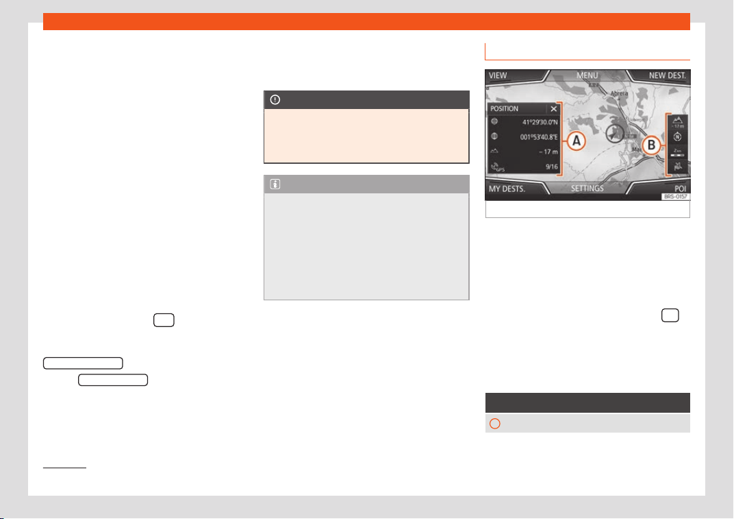
Infotainment System
in full. Using an old version may lead to errors
during navigation.
Updating navigation dat
a
T
o updat
e navigation data visit our website:
www.seat.com.
The navigation data must be installed after
downloading. Navigation is not possible from
the memory card.
Installing navigation data
The installation process takes about 2 hours.
If the Infotainment system is switched off, the
installation process is paused and will auto-
matically resume when switched back on.
●
Switch the ignition on.
●
Insert the memory card containing the nav-
igation data
›››
page 210.
●
Press the Infotainment
button and
then sel
ect the
System cont
ext.
●
In the System settings menu, press the
System information
function button.
●
Press Updat
e softw
ar
e
to import the stored
navigation dat
a.
●
F
oll
ow the instructions displayed on the
screen.
Once installed, the memory card can be re-
moved. The memory card must be prepared
for removal
›››
page 210.
CAUTION
Do not remove the memory card while the
navigation data is being install
ed. The
memory card may be irreparably dam-
aged!
Note
●
The navigation memory card may not be
used as memory stor
age for other files. The
Infotainment system will not recognise the
files saved on it.
●
SEAT recommends a CLASS 10
1)
memory
card for the use of navigation data. The use
of other memory cards could limit its oper-
ation.
Navigation main menu
Fig. 219
Navigation main menu
The Navigation main menu all
o
ws you t
o se-
lect a new destination, call up a previously
used or stored destination and search for
points of interest.
Opening the main Navigation menu
●
Press the Infotainment system button
to open the last menu that was open in navi-
gation.
Function butt
ons and messages on the
main Navigation menu
Function button: function
A
The split screen is displayed
›››
page 223.
1)
The speed class of an SD card.
218
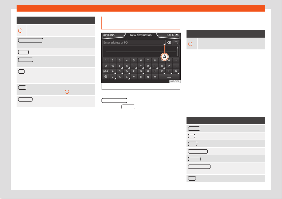
Operating modes
Function button: function
B
Messages and function buttons on the map
display
››
›
page 224.
NEW DESTINATION
: To enter a new destination
›››
page 219.
ROUTE : During route guidance
›››
page 221.
MY DESTS.
: To activate or manage stored destina-
tions
›››
page 221.
POI
: Search for points of interest (car parks, fuel sta-
tions and restaur
ants) within a particular search area
›››
page 222.
VIEW
To modify or activate or deactivate the split
screen and show POI
›
››
Fig. 219
A
›››
page 223.
SETTINGS
Open the Navigation Settings
menu.
New destination (enter destina-
tion)
Fig. 220
Search screen.
●
In the Navigation main menu, pr
ess the
Ne
w destination function button.
●
Press the Options function button and se-
l
ect the r
equir
ed type of destination (Search,
Address, POI on the route or On map).
●
Using voice control*, if you say Town, street
and number, without pauses, and then the in-
struction “Start Route Guidance” a route to
the given destination will start.
Search
Search for addresses and Points of Interest
using the keypad to enter them
›››
Fig. 220.
For cities, post codes and points of interest,
the full details must be entered. You can also
search for points of interest by names or cat-
egories. When necessary, enter the name of
the city to refine the search.
›››
Fig. 220
A
Press to open the cursor buttons (, ),
which allow you t
o move within the text.
Address
After entering a country and a t
own, you can
start navigating towards the centre of the se-
lected town.
When narrowing down the destination ad-
dress, please note that every entry restricts
the available range of subsequent selections.
For instance, if the street you are looking for is
not in the postcode area you have selected
in a previous window, you will not be able to
find the street at the street selection stage.
Function button: function
Country : To select the desired country.
City : To enter the desired city or postcode.
Street : To enter the desired street name.
House number : To enter the desired house number.
Junction : To select the desired intersection.
Last destinations : Open the My destinations
menu
›››
page 221.
Start
: Start route guidance to the selected address.
»
219
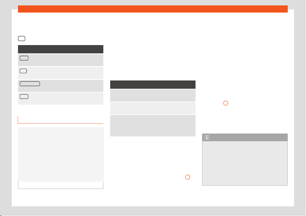
Infotainment System
Using the map
●
Select the destination on the map or enter
it using GPS coor
dinat
es and confirm with
OK .
Function button: function
Save : To save the selected point of interest in the
destination memory
›››
page 221.
Edit
: To edit a destination or to enter another desti-
nation.
Route options : To adjust route options, see Naviga-
tion Settings > Route options.
Start : Starts guided navigation to the selected point
of interest.
After starting route guidance
Fig. 221
Route calculation.
After starting route guidance, the route to the
first destination will be cal
cul
at
ed.
The calculation will be performed in accord-
ance with the data selected in the Route
options menu.
After starting route guidance, three alterna-
tive routes will be suggested depending on
the selected setup
›››
Fig. 221. These 3 routes
correspond to the selectable route options:
Economical, Fast and Short.
Route criteria: Meaning
Blue route: Economical route
, the route is calculated
by taking into consideration economic factors.
Red route: Fastest r
oute to the destination, even if it
is necessary to make a deviation.
Orange route: Shortest rout
e to the destination,
even if it results in longer travelling time. The route
may have unconventional sections such as secon-
dary roads.
●
Select the desired route by pressing it.
Once the r
out
e has been cal
culated, the sys-
tem gives the first navigation announcement.
Up to 3 navigation announcements are given
before a turn.
●
Press the adjustment knob
›››
Fig. 189
12
to
list
en t
o the l
ast audible navigation instruc-
tion.
A navigation announcement informs you
when you have reached your “destination”.
A navigation announcement informing you
that you have reached the “destination area”
is given if the exact destination cannot be
reached because it is located in a non-digi-
tised area.
During dynamic route guidance, you re-
ceive information about reported traffic con-
gestion on the route. An additional navigation
announcement is given if the route is recalcu-
lated due to traffic congestion.
During a navigation announcement, you can
change its volume using the button
›››
Fig. 189
10
.
F
or other adjustments t
o the navigation r
ec-
ommendations, select Navigation > Set-
tings > Navigation announcements
settings.
Note
●
If you miss a turning during rout
e guid-
ance and are currently unable to turn back,
keep on driving until the navigation system
offers a new route.
●
The quality of the navigation recommen-
dations given by the Infotainment system
depends on the navigation data available
and any reported traffic problems.
220
Operating modes
Route
In the Navigation main menu, press the Rout
e
function button.
The Route function button is only displayed
with route guidance activ
ated.
Function button: function
Stop route guidance : Aborts current route guidance.
Enter destination : To enter a new destination or a new
stopov
er
›››
page 219.
Congestion ahead
: To exclude a section (of 0.2 to 10
km in length) from the curr
ent route, e.g. to avoid
congestion. To cancel the exclusion, press the Route
function button and then Cancel congestion .
Change route
a)
: The map of the calculat
ed route ap-
pears and by holding a finger on the route and drag-
ging the finger across said map, the route is changed
to the road(s) that you want and the new route is then
recalculated.
Route details
: View route information for current route.
a)
Only available for the model: Navi System Plus
My destinations (destination mem-
ory)
The stored destinations can be selected from
the My destinations menu.
●
Pr
ess the My destinations.
function button in
the main Navigation menu.
●
Select the desired function button.
St
or
e position , R
outes
, Destinations ,
L
ast destinations
or Home addr
ess
.
St
or
e position
●
By pr
essing the Store position
function but-
t
on, the v
ehicl
e's current position is stored as
a Flagged destination in the destination
memory.
●
Mark the Flagged destination in the
destination memory.
●
Press the Store
function button.
The name can be changed in the f
oll
o
wing
input window. Press the
function button to
st
or
e the destination.
R
outes
In the Route mode, you can define various
destinations (final destination and stopovers).
The starting point of a route is always the
current vehicle position determined by the In-
fotainment system. The destination is the
end point of a route. Stopover destinations
are driven to before the destination.
●
In the Navigation main menu, press the
My Destinations.
function button.
●
Press the R
out
es function button. The
r
out
es st
ored previously will appear.
If you have not stored any routes or want to
create a new route, press the New route
func-
tion butt
on and then f
oll
ow the instructions as
for a new destination, before pressing Store
.
Pr
essing on a st
or
ed route brings up the fol-
lowing function buttons:
Function button: function
Delete : To delete a stored route.
Edit : To edit and store a route.
Start : To start route guidance.
Function buttons and indications in the New
route or Edit route menu
Function button or message: function or meaning
Stopover.
Destination.
...
Estimated time of arrival at destina-
tion.
...
Calculated distance to destination.
...
Travelling time.
...
Distance to the next stopover.
Press on the destination to display the function
buttons.
Delet
e destination.
»
221
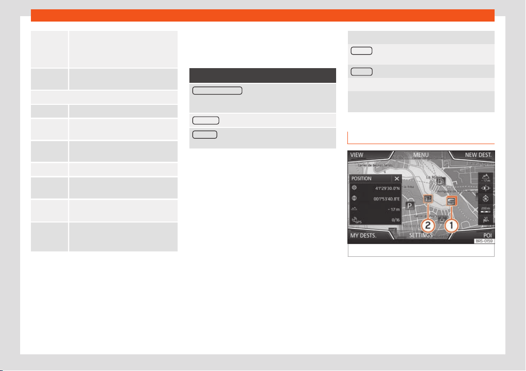
Infotainment System
To start guidance direct to the selec-
ted destination. Destinations that
come befor
e the selected destination
are ignored.
To open the detailed view of the desti-
nation in question.
Available function buttons.
New dest. To add a new destination to the tour.
Destina-
tions
To add a new destination from My
destinations to the tour
.
Storing To store the created tour in the tour
memory.
Start To start route guidance.
Calculate To update calculated distance and es-
timated arrival time
.
a)
Stop To stop route guidance to the active
destination.
b)
To move a stopover or a destination to
another position on the list. Press and
drag to move the destination.
a)
This function button is only displayed with route
guidance activ
at
ed and when a destination has been
added t
o the tour.
b)
This function button is only displayed with route
guidance activated.
Last destinations
View of destinations for which a route has al-
ready been started.
My destinations
●
Press the Options function button and se-
lect the desired function button.
Function button: function
Destination memory : View of destinations stored man-
ually and from imported vCar
ds
›››
page 226, Im-
porting vCards (electronic business cards).
Favourites
: View of destinations stored as favourites.
Contacts : View of entries in the phonebook that have
a stored addr
ess (postal address).
Home address
Only one addr
ess or position can be st
or
ed
as the home address at any one time. The
stored home address can be edited or over-
written.
If a home address has already been stored,
route guidance will be started to the stored
home address.
If a home address has not yet been stored, an
address can be assigned as the home ad-
dress.
Assigning the home address for the first time:
Position : Press to store the vehicle's current position
as the home address.
Address : Press to enter the home address manually.
Editing the home address:
The home address can be edited in the Naviga-
tion settings > Manage memory menu.
Points of interest (POI)
Fig. 222
Points of interest on the map.
The points of interest saved in the navigation
dat
a memory ar
e divided int
o different point
of interest categories. Each point of interest
category is assigned a symbol for display on
the map.
If a database of points of interest has been
imported into the Infotainment system,
222
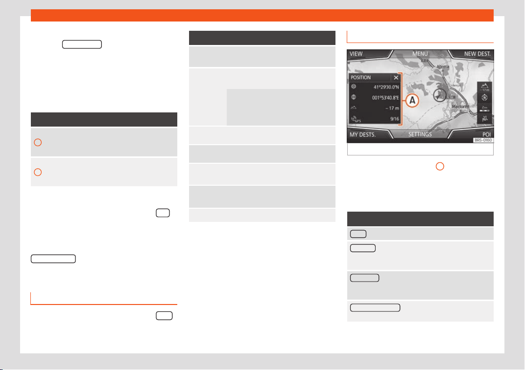
Operating modes
›››
page 226, Impor
ting P
ersonal POI
the
category Personal POI
is also shown.
In the Map settings menu, the cat
egories of
points of int
er
est to display on the map can
be configured. Up to 10 categories of points
of interest can be selected.
Selecting a point of interest on the map
Function button: function
1
There are several points of interest in the area.
Press this symbol to open a list of points of in-
t
erest.
2
The only point of interest in this zone. Press the
symbol to open the detailed view of the point of
interest.
Quick POI search
In the Navigation main menu, pr
ess the POI
function button and the three main catego-
ries will appear
. Alt
ernativ
ely, enter the name
of the point of interest to be searched using
the new destination keypad, or press
Search nearby
on the map
›
›
›
table on
page 224.
View
In the Navigation main menu, pr
ess the Vie
w
function button.
Function button: function
2D
Map display in two dimensions (con-
ventional).
3D
Map display in thr
ee dimensions (bird's
eye view).
Buildings ar
e also displayed in three
dimensions. The places of inter
est and
well-known buildings are shown in de-
tail and in colour.
a)
To display the destination on the map.
a)
To display the route on the map.
Auto /
Day / Night
To change between day and night for-
mat.
Split screen
Press to display the split screen
›
››
page 223.
POI Display points of interest on the map.
a)
This function button is only displayed with route
guidance activ
at
ed.
Split scr
een
Fig. 223
Split screen displayed.
The split screen
›
›
›
Fig. 223
A
may display
any of the inf
ormation described bel
o
w:
●
Press on the name of the split screen to se-
lect a display option.
Function button: function
Audio : Indicates the selected audio source.
Compass : Displays a compass with the current trav-
elling direction and indicates the current position of
the vehicle (street name).
Manoeuvre : Displays a list of the next manoeuvres,
POIs or TMCs on the rout
e and pressing them brings
up additional information
Most frequent routes
a)
: Information on the user's most
fr
equent routes.
»
223
Infotainment System
Function button: function
Position : current vehicle position in coordinates and
GPS status (sat
ellite reception).
a)
This function button is only shown when route guid-
ance is not active or when predictiv
e route guidance
is active.
Press the
function button to close the split
screen.
At any moment during navigation, pressing
inside the map will mak
e a pop-up menu ap-
pear with the following functions:
Function button: function
Street name or coordinates : shows the details of the
point selected on the map
.
Only when you press on an icon on the map:
POI
: name of the point of interest (when only one
appears on the map).
Group of POIs : more points of interest (when you
press on the map on various POIs gr
ouped to-
gether).
Favourite
: name of the favourite.
Home
: Home address.
Start route guidance : starts guidance directly.
Add stopover destination : only when you have an ac-
tive rout
e.
Search nearby
: enters in the search menu, but only
for the area ar
ound the point selected on the map.
Function button: function
Demo mode start (only when demo mode is active)
Map display
Fig. 224
Messages and function buttons on
the map displ
ay.
Function buttons and messages on the
map displ
ay.
T
o activ
ate function buttons and , press
function button .
Function button: function
Current altitude indicator.
To centre the vehicle position on the map.
Function button: function
To centre the destination on the map. This
function button is only displayed if either
Displ
ay destination on map or Display
route on the map is selected
›››
page 223.
To change the orientation of the map
(north-facing or direction of tr
avel). This
function is only available in 2D mode.
View map scale. Turn the setup button or
move your fingers t
ogether/apart on the
touchscreen to change the scale of the
map.
To select automatic scaling. If the func-
tion is active, the symbol is displ
ayed in
blue.
Briefly zooms in on the map. After a few
seconds, it automatically returns to the
last selected scale.
It can mute or repeat the last announce-
ment, or can change the announcement
volume.
Road signs: Depending on the vehicle's equip-
ment, the road signs stored in the navigation data are
displayed. Select Navigation > Settings >
Map > Show road signs.
224
Operating modes
Traffic reports and dynamic route
guidance t
o the destination (TRAF-
FIC)
Fig. 225
Traffic reports
The Infotainment system constantly receives
tr
affic r
eports (T
MC/TMCpro) in the back-
ground, provided a TMC traffic news station
can be received at the current location. The
station being listened to does not have to be
the traffic news station.
List of available traffic reports
●
Press the Infotainment
›
›
›
Fig. 189
9
button and then select the Traffic cont
e
xt.
Dynamic r
oute guidance
In order for dynamic route guidance to func-
tion, Dynamic route must be activated in the
route options.
If during route guidance a traffic report is re-
ceived that affects the route being travelled,
an alternative route will be searched for if the
Infotainment system calculates that time can
be saved.
Traffic reports on map (selection)
Symbol: Meaning
: Slow tr
affic
: Traffic jam
: Accident
: Slippery road surface (ice or sno
w)
: Slippery road surface
: Danger
: R
oad works
: Str
ong wind
: Road closed to traffic
During route guidance, traffic congestion that
does not aff
ect the r
out
e calculated is dis-
played in grey.
Predictive navigation
Fig. 226
Predictive navigation
When you activate Predictive navigation, the
syst
em det
ects and st
ores in the background
routes that are frequently followed, without
them being active destination routes. This
function has no navigation announcements
unless the user requires them, getting them
by pressing the adjustment knob
›››
Fig. 189
12
.
●
On the main screen of the Navigation menu,
in the pop-up windo
w
, pr
ess the
Frequent routes
button. To display frequently
f
oll
o
wed routes press the Show on map
button
›
›
›
Fig. 226.
225
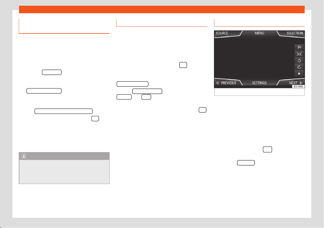
Infotainment System
Importing vCards (electronic busi-
ness car
ds)
Importing vCards to the destination mem-
ory
●
Insert the data storage device with the stor-
ed vCards or connect it to the Inf
otainment
system
›››
page 207.
●
Press the SETTINGS
function button in the
main Navigation menu.
●
In the Navigation settings menu, press
the Import destinations
function button.
●
Select the data carrier with the vCards
sav
ed in the list.
●
Pr
ess Import all vCar
ds from this folder
.
●
Confirm the import notice with the OK
function button.
The sav
ed vCar
ds will no
w be in the destina-
tion memory
›››
page 221 and may be used
for navigation.
Note
Only one address per vCard can be impor-
ted. In the ev
ent any vCards have multiple
addresses, only the main address will be
imported.
Importing Personal POI
Importing the Personal POI to a points of
interest destination memory
●
Insert the dat
a storage device with the stor-
ed Personal POI or connect it to the Infotain-
ment system
›››
page 207.
●
Press the Infotainment button
and then
select Settings.
●
In the
Settings menu, press the
Manage memory
function button.
●
Press Updat
e my POIs and then press
Updat
e
and Ne
xt
to import the Personal
POIs.
●
Confirm the import notification with the OK
function button.
The st
or
ed P
ersonal POI are now in the points
of interest destination memory
›››
page 222
and can be used for navigation purposes.
The stored Personal POI can be deleted in
the Navigation Settings menu.
Navigation with images
Fig. 227
Images main menu.
Selecting an image and starting route
guidance
Bear in mind the r
equir
ements and f
ormats of
the compatible images.
●
Insert the data storage device with the stor-
ed images or connect it to the Infotainment
system.
●
Press the Infotainment
button and
then sel
ect the
Images cont
ext.
●
Press the SOURCE
›
›
›
Fig. 227 function but-
ton and select the data storage device where
the images are stored.
●
Select the desired image.
●
If the image displayed was taken using GPS
localisation, the function button will appear.
Press to start guidance to a destination.
226
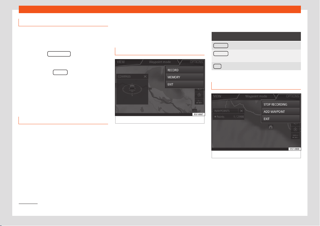
Operating modes
Route guidance in Demo mode
If demo mode is activated in the Navigation
Settings menu, an additional pop-up win-
dow opens when you start r
oute guidance.
●
Pressing the Demo mode
function button
starts a “virtual r
oute guidance” to the desti-
nation you have entered.
●
If you press the Normal
function button, a
“real rout
e guidance” starts.
Navigation in Offroad
mode*
1)
Introduction
Offroad* navigation is a function for offroad
driving that pr
o
vides dir
ections in “non-digi-
tised areas” at low speeds.
Non-digitised areas are areas about which
the system does not have information for the
streets or terrain. It does not detect streets,
buildings or natural limits such as mountains
or rivers, although they may be shown on the
map.
Offroad* navigation is not suitable for driving
on conventional roads as it does not detect
one-way streets, motorway entries or similar.
Offroad Navigation Menu
Fig. 228 Offroad Navigation Menu start
Press the SETTINGS function butt
on in the
main Navigation menu.
●
In the menu, pr
ess the
Waypoint mode
function button.
●
The Offroad Navigation menu opens
›››
Fig. 228.
Function buttons in the Offroad Navigation
menu
Function button: function
RECORD : Initiates the plotting of an Offroad tour.
MEMORY : Opens a list allowing the selection of a
stored Offroad tour.
EXIT : Ends Offroad navigation.
Recording an Offroad tour
Fig. 229
Recording an Offroad tour
An Offroad tour is formed by a series of stor-
ed w
aypoints
.
»
1)
Only available for the model: Navi System Plus
227
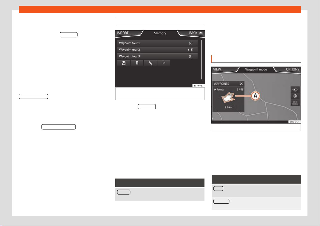
Infotainment System
Starting recording
●
In the Offroad Navigation menu, in the pop-
up windo
w pr
ess the RECORD pop-up button.
●
In the pop-up window, the user is able to
pl
ot the t
our with a giv
en destination or start
plotting the route without giving a final desti-
nation.
●
Starts plotting the route.
The offroad markers can be recorded by in-
dicating a manual waypoint.
●
In the Offroad Navigation menu, press the
ADD WAYPOINT
function button. The tour way-
points defined manually ar
e sho
wn on the
map by a mark
er.
Ending recording
●
Press the STOP RECORDING
function button
in the main Offr
oad Navigation menu.
Managing st
or
ed Offroad tours
Fig. 230
Offroad Navigation menu, stored
t
ours
●
Press the MEMORY function button in the
Offr
oad Navigation menu.
●
A list of st
or
ed Offroad tours opens, if there
are any.
When a tour is selected, the following icons
will appear
›››
Fig. 230:
Export the tour to an SD card.
Edit the name of the tour.
Delete the tour.
Load tour
Function button: function
IMPORT : allows the import of an Offroad route in
“.GPX” format.
Loading an Offroad tour
When the Offr
oad t
our is sel
ected, press Play
and the selected tour will be loaded onto
the Navigation system.
Creating an Offroad tour
Fig. 231
Offroad route guidance mode
Start route guidance
●
Loads the stored Offroad tour.
●
Starting off in a stored route is not detected
by the syst
em aut
omatically.
Set
up
Function button: function
Invert : Reverses the direction of the stored Offroad
tour.
Ne
xt point
: Starts the Offroad tour from the nearest
point.
228
Operating modes
Function button: function
Start : Starts the complete Offroad tour.
When route guidance starts, the system
switches t
o the map view.
Stopping route guidance
●
Press the Options
button on the screen and
then press Stop .
End waypoint navigation
●
Press the EXIT
function button in the Off-
r
oad Navigation menu.
WARNING
Terrain features are disregarded during
route guidance Driv
e slowly and following
the instructions in order to perform the ma-
noeuvre as far as possible!
●
The general direction of travel is indica-
ted straight ahead by direction arrows in
the Infotainment System pop-up window
›››
Fig. 231
A
.
Note
If an Offroad tour is being recorded, this is
automatically stor
ed if Offroad navigation
is discontinued.
Vehicle Menu
Intr
oduction t
o using the V
ehicle
menu
By pressing button of the infotainment
system you will access its main menu with the
foll
owing options:
●
VIEW
●
MINIPLAYER, in the top right corner (Radio
or Media function if the HDC descent con-
trol* is not active).
●
PREVIOUS-NEXT (to change screen)
●
SETTINGS
›››
page 35
With the function button VIEW
you can ac-
cess the f
oll
o
wing information:
Instrument panel
Press the Instrument Panel
button to choose
fr
om the v
arious displ
ay options and custom-
ise the information that appears in the Digital
Cockpit
›››
page 106:
Automatic Display: default information
depending on the selected Driving
Mode.
–
Classic Display: the entire lengths of
the revolutions per minute and speed-
ometer needles are shown.
Views 1, 2, 3: customise the information
that appears in the digital cockpit. Only
2 of these items of information can be
displayed at the same time, but the user
chooses which to display, and in what
order, by moving the finger vertically
over the dials. Depending on the version,
the Views can be memorised by existing
the menu or keeping the View
button
pr
essed.
Spor
t*
If the corr
esponding equipment is available,
the information that appears in the Sport op-
tion is the following:
Instantaneous power expressed in kW
G forces
Turbo pressure, expressed in bar (“bar”),
kilopascals (“kPa”) or in pounds per
square inch (“psi”). Press the Setup but-
ton to change the units of pressure.
Coolant temperature
Oil temperature
»
–
–
1.
2.
3.
4.
5.
229
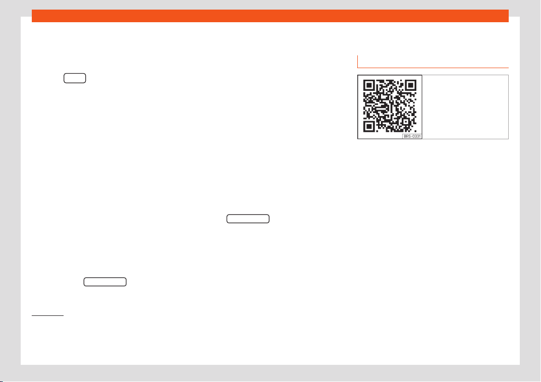
Infotainment System
Only 3 of these items of information can be
displ
ayed at the same time
, but the user
chooses which t
o display, and in what order,
by moving the finger vertically over the dials.
Press the Next
button to display the L
ap
timer
menu
1)
.
Offr
oad*
If the corresponding equipment is available,
the information that appears is the following:
Compass.
Altimeter: altitude above sea level.
Turning angle of steered wheels.
Coolant temperature.
Lubricating oil temperature
Only the altimeter and 2 more of these items
of information can be displayed at the same
time, but the user chooses which to display,
and in what order, by moving their finger ver-
tically over the dials.
Consumers
By pressing the CONSUMERS
button, informa-
tion on the st
at
us of the v
ehicle's main con-
1.
2.
3.
4.
5.
sumption devices is obtained. It is shown via a
consumption indicator bar in l/h (gal/h)
2)
.
Driving data
The onboard computer is equipped with 3
memories that work automatically. In these
memories you can see the distance travelled,
average speed, time passed, average con-
sumption and autonomy of the vehicle.
Ecotrainer*
If the corresponding equipment is available,
the ECOTRAINER will provide information on
driving style. The information on driving style
is only evaluated and displayed when moving
forward.
Vehicle status
Press the Vehicle status
button to access infor-
mation on the Vehicle status messages
and Start-Stop system. The V
ehicl
e st
atus
messages are displayed, in addition to being
specified on the corresponding button.
Telephone
General information
Fig. 232 Related video
The Telephone functions described below
can be used thr
ough the Inf
ot
ainment system
if there is a mobile telephone connected to it
via Bluetooth
®
›››
page 232.
In order for the mobile telephone to be able
to connect to the Infotainment system the tel-
ephone must be equipped with Bluetooth
®
.
If there is no mobile telephone connected to
the Infotainment system, the telephone man-
agement system will not be available.
The instructions shown on the screen for the
telephone menus will depend on the mobile
telephone used. There may be variations.
1)
This lap timer is independent of the one that
appears on the instrument panel.
2)
In the case of Gas (CNG) vehicles, the units are
in kg/h.
230
Operating modes
Only use compatible Bluetooth
®
de
vices. F
or
further inf
ormation on compatible Bluetooth
®
products, ask your nearest SEAT dealer or
check on the internet.
Use the instruction manual of the mobile tele-
phone and of any accessories.
If you detect any operating issues between
your mobile telephone and the Infotainment
system, restart your mobile by switching it off
and on again.
Some functions and setup can only be per-
formed when the vehicle is stopped and are
not available on all mobile telephones.
WARNING
General, mandatory, legal and country-
specific instructions and laws for the use of
mobil
e phones inside the vehicle must al-
ways be considered.
WARNING
Speaking by telephone and using the mo-
bile tel
ephone management system whilst
driving can distract you from the road and
cause an accident.
●
Always drive carefully and responsibly.
●
Select volume settings that allow you to
easily hear signals from outside the vehicle
at all times (e.g. emergency services sirens
and horns).
●
In areas of little or no co
verage or, in
some cases, in a tunnel, garage or under-
pass, your call may be cut off and you may
not be able to make even emergency calls.
WARNING
If a mobile telephone is not secured or is in-
corr
ectly secured in the v
ehicle, it could
move around the passenger compartment
in the event of a sudden driving manoeuvre
or emergency stop, resulting in injury.
●
While the vehicle is in motion, always se-
cure the mobile telephone properly outside
the airbag deployment zone.
WARNING
Mobile telephones may interfere with and
alter the correct oper
ation of pacemakers
if they are carried directly over them.
●
Maintain a minimum distance of at least
20 centimetres between the aerials of the
mobile telephone and the pacemaker.
●
Do not carry your switched-on mobile
telephone in your breast pocket directly
over the pacemaker.
●
If you suspect interference, switch off the
mobile telephone immediately.
CAUTION
High speeds, poor weather or road condi-
tions and the quality of reception can all
affect the audio quality of a telephone con-
versation in the vehicl
e.
Note
●
R
estrictions on the use of devices using
Bluet
ooth
®
technology may apply in some
countries. For further information, contact
the local authorities.
●
If you wish to connect a device to the tel-
ephone management system via Blue-
tooth
®
technology, consult the safety
warnings in its instruction manual. Only use
compatible Bluetooth
®
devices.
Places with special regulations
Switch off the mobile telephone and the mo-
bil
e
’
s Bluetooth
®
function in places with a risk
of explosion. In the majority of cases, these
places are signposted, but not always clearly
›››
in General information on page 231.
They include
, f
or e
xample:
●
the vicinity of chemical pipelines and tanks
●
The lower decks of boats and ferries.
●
In the proximity of vehicles that run on liquid
gas (such as propane or butane).
●
places where the air is laden with chemi-
cals or particles such as flour, dust or metal
powder.
»
231
Infotainment System
●
all other pl
aces wher
e the v
ehicle engine
must be switched off.
WARNING
Switch off the mobile phone in areas with a
risk of explosion! The mobil
e telephone can
automatically connect to the mobile tele-
phone network again if it loses the Blue-
tooth
®
connection to the telephone man-
agement system.
CAUTION
In areas where special regulations apply or
the use of mobile tel
ephones is prohibited,
both the telephone and the telephone
management system must be switched off.
The radiation produced by the mobile tele-
phone when switched on may interfere with
sensitive technical and medical equipment,
possibly resulting in a malfunction or dam-
age to the equipment.
Bluetooth
®
Bluetooth
®
t
echnol
ogy all
ows a mobile tele-
phone to be connected to your vehicle's tele-
phone management system. In order to use
the telephone management system with a
mobile telephone with Bluetooth
®
technolo-
gy, it is first necessary to pair them.
Some Bluetooth
®
mobile telephones detect
and automatically connect when turning on
the ignition if a connection has been previ-
ously established. For this to take place the
telephone must be switched on and its Blue-
tooth
®
function activated, and there must be
no active Bluetooth
®
connection with other
devices.
Bluetooth
®
connections are free.
Bluetooth
®
is a registered trademark of Blue-
tooth
®
SIG, Inc.
Bluetooth profiles
®
When a mobile phone is connected to the tel-
ephone management system, a data ex-
change takes place via one of the Bluetooth
®
profiles.
●
Hands-Free Profile (HFP): When connect-
ing a mobile telephone to the phone manag-
er through the HFP the calls can be managed
via the Infotainment system.
●
Audio profile (A2DP): This profile makes it
easier to transmit audio to the infotainment
system with stereo quality. This function may
require connecting additional profiles for
managing and controlling audio playback.
●
Phone book access profile (PBAP):
Serves to download phone book contacts
from the mobile telephone to the Infotainment
system.
●
Message profile (MAP):
1)
Serves the
download and synchronise short messages
(SMS) of the mobile telephone to the Infotain-
ment system.
Note
To prevent them from being heard through
the speakers, the button and mobil
e tele-
phone alert tones must be disconnected.
Where necessary, disconnect the headset
from the mobile telephone you wish to con-
nect to the system.
Pairing and connecting a mobile
t
el
ephone t
o the Infotainment sys-
tem
In order to manage a mobile telephone via
the Inf
ot
ainment syst
em, it is necessary to
pair both devices once.
For your safety, we recommend you make the
link when the vehicle is stationary. In some
countries it is not possible to perform the pair-
ing with the vehicle running.
1)
Not available for the Media System Touch/Col-
our model.
232
Operating modes
Conditions
Y
ou must guar
ant
ee the following setup in the
mobile phone and the Infotainment system:
●
The ignition must be switched on.
●
The Bluetooth
®
function of the mobile tel-
ephone and the Infotainment system must be
active as well as visibility.
●
The keypad lock on the mobile telephone
must be deactivated.
Follow instructions in the manual for the mo-
bile telephone.
During the pairing process, it is necessary to
enter data via the mobile telephone's keypad.
Pairing a mobile telephone
●
Make sure the mobile device's Bluetooth
®
function is activated and visible.
●
Press the infotainment
button.
●
Press the Find t
el
ephone > R
esults
function
butt
on.
OR:
●
Pr
ess the inf
otainment
button.
●
Press the function button Set
up
>
Sel
ect mobil
e phone > R
esults
.
OR:
●
Press the infotainment
button.
●
Pr
ess the Settings
> Bluet
ooth
> Find de
vices
> R
esults
button.
The name of the Bluet
ooth
®
function of your
Inf
ot
ainment system will be displayed on the
main Telephone screen and you can edit this
name via the Bluetooth settings
menu
The sear
ch pr
ocess can t
ake up to 1 minute.
On the screen, the system will dynamically
update the names of the Bluetooth
®
devices
found.
As soon as the search is completed, the
names of the Bluetooth
®
devices found are
displayed on-screen.
●
Select the Bluetooth
®
device you want to
connect on the infotainment system. In cer-
tain circumstances, it is possible that to finish
the connection between the two devices, you
must enter additional data in the mobile tele-
phone and Infotainment system.
●
Use your mobile telephone to enter and
confirm your PIN code, as indicated in the dis-
play of the infotainment system.
●
If more Bluetooth
®
profile pairing requests
are received on the mobile telephone, make
sure to reply to them.
OR:
●
Compare the PIN code shown on the dis-
play of the Infotainment system with that
shown on the mobile telephone. If they
match, confirm on both devices.
When the pairing has been finalized correct-
ly, the Telephone main menu will appear. The
phone book, call list and SMS messages stor-
ed in the mobile phone will be loaded once
the requests have been accepted in the mo-
bile phone. After downloading, the data will
be available on the Infotainment system.
Pairing and connection of mobile tele-
phones
You can pair up to 20 mobile telephones to
the Infotainment system, but the number of si-
multaneous connections varies:
●
Media System Touch / Colour: a phone
connected to the hands-free profile and the
same or a different device connected to the
Bluetooth
®
audio profile.
●
Media System Plus / Navi System: two mo-
bile phones simultaneously connected to the
hands-free profile and one of them is also
connected Bluetooth
®
audio profile.
●
Navi System Plus: two mobile phones simul-
taneously connected to the hands-free pro-
file and one of them or a third one connected
to the Bluetooth
®
audio profile.
When the Infotainment system is switched on,
it automatically connects to the last connec-
ted mobile telephone. If it is not possible to
connect to this mobile telephone, the tele-
phone management system will try to auto-
matically connect to the next mobile tele-
phone on the list of paired devices.
»
233
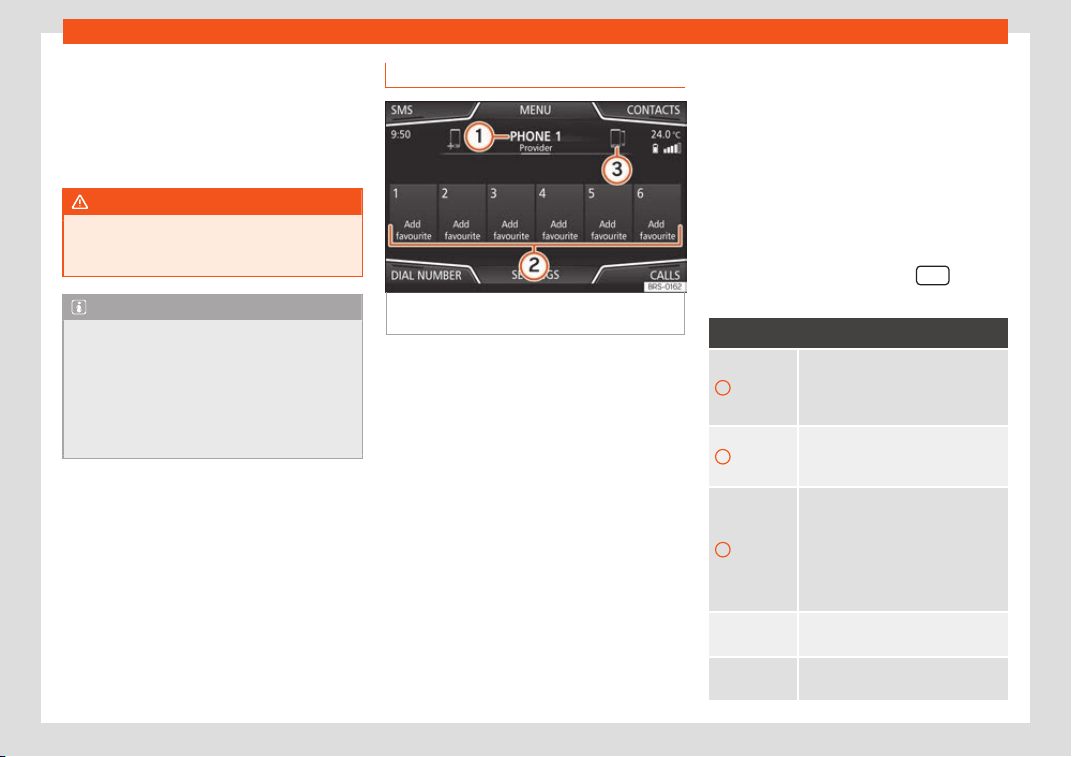
Infotainment System
The maximum r
ange of the Bluet
ooth
®
con-
nection is appr
ox. 10 meters. The active
Bluetooth
®
connection disconnects if this dis-
tance is exceeded. The connection is auto-
matically re-established as soon as the de-
vice is once again within Bluetooth
®
range.
WARNING
Do not perform the pairing and connection
process while driving. This may cause an
accident
!
Note
●
It may be necessary to confirm the phone
book data and SMS tr
ansfer request on the
mobile telephone.
●
Check that there are no requests pend-
ing acceptance in your mobile phone. If
there are, this could block some of the
functions in the Telephone menu.
Telephone main menu
Fig. 233
Telephone main menu (view of the 8"
scr
een).
Assign a user profile
The dat
a fr
om the phonebook
, the call lists
and the stored speed dial buttons are as-
signed to a user profile and remain stored on
the telephone management system. This in-
formation will be available every time the mo-
bile telephone is connected to the telephone
management system.
After the first connection, it will take a few mi-
nutes for the data from the phonebook of the
linked mobile phone to be available in the In-
fotainment system. The next time that the
mobile telephone is connected (e.g. on the
next journey) the phonebook is updated au-
tomatically.
If any entries in the mobile phonebook have
been modified while connected, a manual
update of the phonebook data can be initi-
ated from the User profile settings
menu.
Telephone management can store a maxi-
mum of 4 user profiles for mobile telephones.
If you wish to link/connect another mobile
phone, the oldest user profile will automati-
cally be replaced.
Telephone management system function
buttons
●
Press the infotainment button
to open
the Phone main menu.
Function button: function
1
Name of connected mobile tele-
phone. Press the icon t
o the left to
connect or pair with another mobile
telephone.
2
Speed dial buttons, to which tele-
phone numbers from the phone-
book may be assigned respectively.
3
To change to another telephone
connected to the hands-fr
ee profile.
This button will only be visible when
there are two telephones connected
as hands-free. The active user pro-
file corresponds to the telephone
appearing on the screen.
DIAL NUM-
BER
To open the number pad and enter a
telephone number
›
››
page 235.
CONTACTS
To open the phonebook of the con-
nected mobile telephone.
234
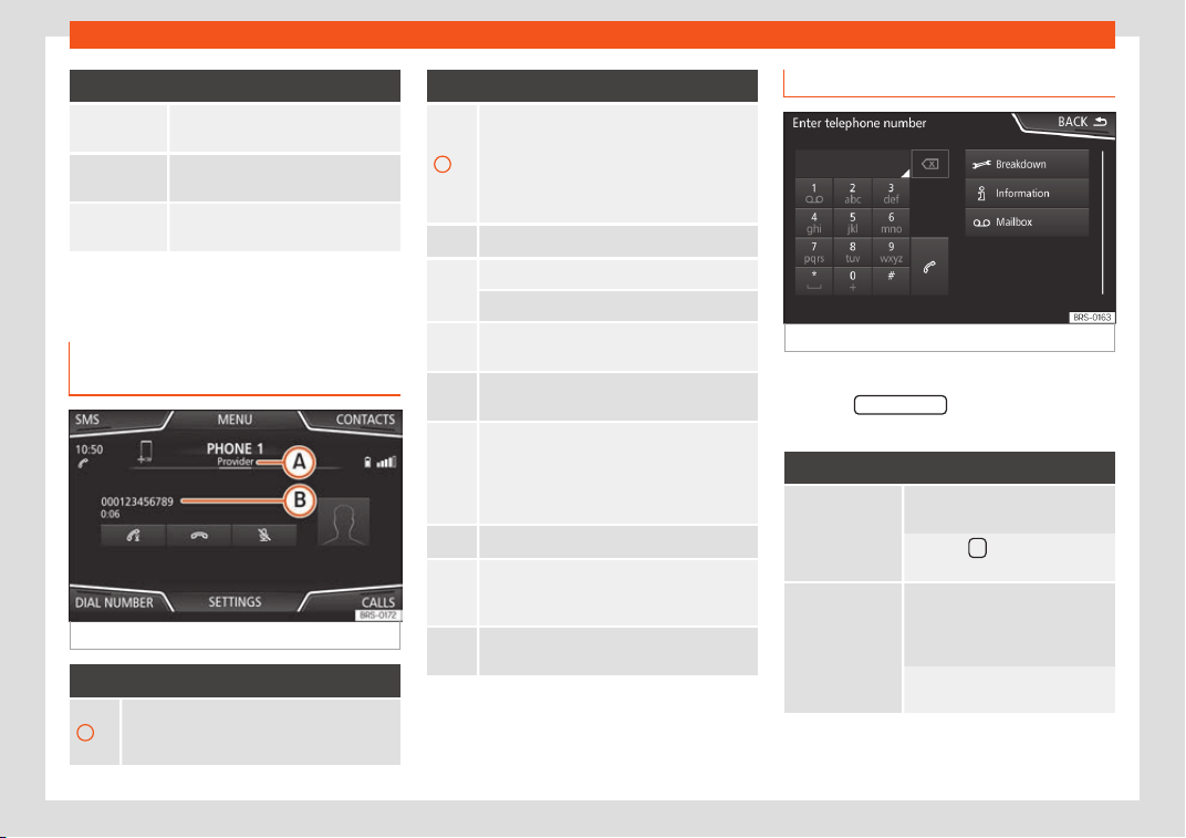
Operating modes
Function button: function
SMS
a)
To open the menu for SMS messag-
es.
CALLS
To open call lists of the connected
mobile telephone
›››
page 236.
SETTINGS
To open the Telephone set-
tings menu.
a)
Not available for the Media System Touch/Colour
model.
Display and symbols of the tele-
phone management syst
em
Fig. 234
Active call.
Display: Meaning
›››
Fig. 234
A
Name of the mobile network operator (pro-
vider) to which the mobile t
elephone is con-
nected.
Display: Meaning
›››
Fig. 234
B
View of stored telephone number or name. If
the name stored in the phonebook has an
assigned phot
o, it can be displayed: select
Telephone > Settings > User
profile > Show pictures for
contacts*.
Press to accept a call.
Press t
o end a call
.
OR: Press t
o reject an incoming call.
Press t
o mute or to reactivate the ring tone
during an incoming call.
Press t
o mute the microphone during an ac-
tive call and to reactivate it.
This button keeps the call active. While the
call is on hold the listener will not hear the
conversation. To reactivate it, press the call
accept button . To reject it, press the reject
button .
Press to add a participant to the active call.
Charge status of a mobile telephone con-
nected via “Hands-free pr
ofile” (HFP) Blue-
tooth
®
.
Strength of coverage signal received by the
mobile tel
ephone.
Enter telephone number menu
Fig. 235
Enter telephone number menu.
Open the Enter telephone number menu
Pr
ess the DIAL NUMBER
function button from
the PHONE main menu.
Possible functions
Enter telephone
number
Entering a phone number with
the keypad.
Press the function button to
make a call.
Select a con-
tact from the
list
Ent
er the first letters of the con-
tact to find using the k
eypad.
The available entries appear in
the phonebook.
Select the desired contact from
the phonebook to make the call
.
»
235
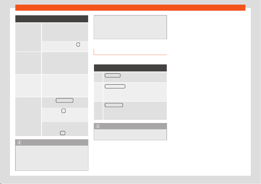
Infotainment System
Possible functions
Enter the coun-
try code
To enter a country code, instead
of the first two digits (interna-
tional access code e
.g. “00”)
you can enter the character “+”.
Press the function button 0
for
approx. 2 seconds to add the +.
Breakdown
service call
Press the function button to ob-
tain help in the ev
ent of break-
down. For this the network of
SEAT dealerships is available to
you with their Mobility Service.
Information call
Press the function button to ob-
tain information on the SEAT
br
and and the additional serv-
ices contracted related to traffic
and travel.
Call mailbox
Press the Voice mail
function
button to mak
e the call.
OR: Press the
function button
for about 2 seconds to mak
e a
call.
If the number for the mailbox has
not yet been stored, enter it and
confirm with OK
.
Note
●
Breakdo
wn service and information calls
can incur an additional cost on your tele-
phone bill.
●
The Roadside Assistance and Information
services might not work properly, for exam-
ple, if the vehicle and the operator of the
connected mobile t
elephone are in differ-
ent countries. If you are not able to use
these services contact an authorised SEAT
workshop.
Call Menu (call lists)
Possible displays in the Calls menu
Display: Meaning
Missed calls : Displays the numbers of missed
and unanswer
ed calls.
Dialled numbers
: Indicates the numbers dial-
led on the mobile t
elephone and on the Info-
tainment system telephone management
system.
Received calls
: Indicates the numbers of the
calls received on the mobile telephone and
on the Infotainment system telephone man-
agement system.
Note
The availability of the call lists will depend
on the mobile phone used.
236
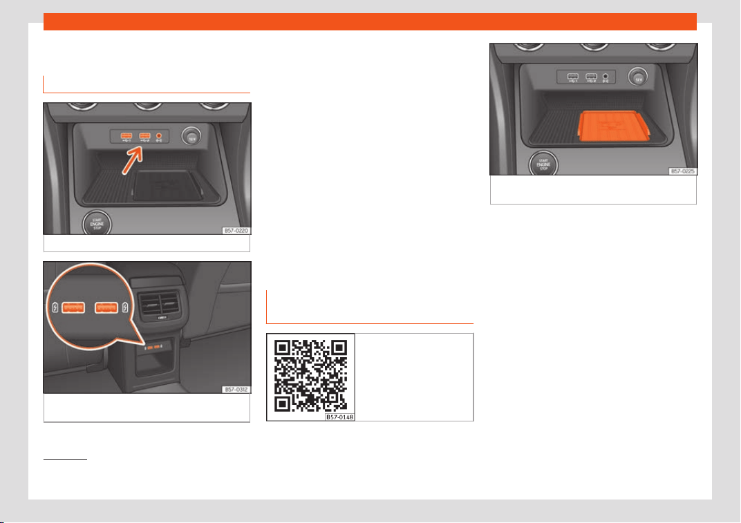
Operating modes
Multimedia
USB/AUX-INP
or
t
Fig. 236
Centre console: USB/AUX-IN input.
Fig. 237
Centre console, rear section: USB
connect
ors.
Depending on the special characteristics and
the country, the v
ehicl
e may hav
e a
USB/AUX-IN port.
The USB/AUX-IN port can be found in the
storage compartment area of the centre
console
›››
Fig. 236.
The operating description is located in
›››
page 207.
Depending on the equipment and the coun-
try, the vehicle may also have USB connec-
tions exclusively for charging or as a power
socket.
These USB ports are located at the rear of
the console, between the front seats
›››
Fig. 237.
Connectivity Box* / Wireless
Charger*
Fig. 238 Related video
Fig. 239 Centre console: slot for mobile phone
connection.
The Connectivity Box includes different func-
tions that will help t
o use your mobil
e de
vice.
They are the “Wireless Charger” and the
“Mobile Signal Amplifier”.
The Wireless Charger only features the
“Wireless Charger” function.
“Wireless Charger”
The “Wireless Charger” allows mobile devi-
ces with Qi
1)
technology to be charged with-
out a cable.
To charge your mobile phone wirelessly:
●
Place your mobile device with Qi technolo-
gy
1 )
in the middle of the pad with the screen
facing up
›››
Fig. 239.
»
1)
Qi technology allows you to charge your mo-
bile phone wirel
essly.
237
Infotainment System
When you do so, make sure there are no ob-
jects betw
een the pad and the mobil
e phone
.
The mobile phone will start charging auto-
matically. For further information about
whether your mobile device uses Qi technol-
ogy, please check your mobile phone's user
manual or visit the SEAT website.
“Mobile Signal Amplifier”
The “Mobile Signal Amplifier” allows you to
reduce the radiation in your vehicle and enjoy
better reception.
For safety reasons, it is recommended that
you pair the radio and the mobile device us-
ing Bluetooth
®
and place the mobile phone
on the Connectivity Box pad, so as to have
better reception without having to handle the
mobile phone.
To establish a connection with the vehicle's
external aerial:
●
Place your mobile device in the middle of
the pad with the screen facing up
›››
Fig. 239.
When you do so, make sure there are no ob-
jects between the pad and the mobile phone.
Your mobile phone will automatically be
ready to make use of the external aerial.
WARNING
The mobile phone may heat up due to the
wireless char
ging. Think about the temper-
ature of your device before you pick it up,
and take car
e when removing it.
Note
●
Y
our mobile de
vice must support the Qi
wireless inductive charging interface
standard for proper operation.
●
If your mobile phone has a cover or a pro-
tective casing, this may affect the Connec-
tivity Box functions.
●
There must be no metallic objects be-
tween the pad and the mobile device that
might affect the wireless charging or the
connection with the external aerial.
●
The charging time and the temperature
vary in accordance with the device used.
●
To avoid malfunction, ensure that the mo-
bile phone is correctly placed on the pad.
●
The maximum charging capacity is 5 W.
●
Qi technology does not allow you to
charge more than one mobile device simul-
taneously.
●
No improvement in the transmission qual-
ity can be guaranteed if there is more than
one mobile phone on the pad.
●
You are advised to keep the engine run-
ning to guarantee proper wireless charging
of your device.
●
When a telephone with Qi technology is
connected by USB, the charging will be
performed through the medium specified
by each mobile device manufacturer.
238
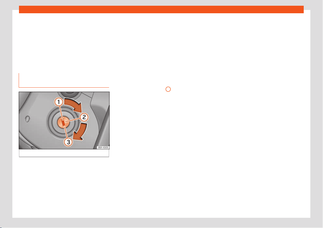
Start and driving
Driving
St
ar
t and driving
St
arting and stopping the
engine
Switching the ignition on and start-
ing the engine with the key
Fig. 240 Ignition key positions.
Read the additional information carefully
›
›
›
page 32
Diesel engines can take a few seconds longer
than usual to start on cold days. Therefore
the clutch pedal (manual gearbox) or the
brake pedal (automatic gearbox) must re-
main pressed until the engine starts up. Dur-
ing preheating, the warning lamp remains
lit.
The preheating time depends on the coolant
and exterior temperatures. With the engine at
operating temperature, or at outside temper-
atures above +8°C, the warning lamp will
light up for about one second. This means
that the engine starts immediately.
If the engine does not immediately start up,
interrupt the starting process and try again
after 30 seconds. To start the engine again,
return the key to position
1
.
St
ar
t
-Stop system*
If the vehicle is stopped and the Start-Stop
system* switches off the engine, the ignition
remains switched on.
Automatic transmission: before leaving the
vehicle, make sure that the ignition is switch-
ed off and the selector lever is in position P.
Driver messages on the instrument panel
display
Press the clutch
This message appears on vehicles with a
manual gearbox if the driver tries to start the
engine without having the clutch pedal
pressed. The engine will only start if you press
the clutch pedal.
Press the brake
This message appears on vehicles with an
automatic gearbox if the driver tries to start
the engine without having the brake pedal
pressed.
Select N or P
This message appears if you try to start or
stop the engine when the selector lever of the
automatic gearbox is not in position P or N.
The engine can only be started and stopped
in those positions.
Engage position P; the vehicle can
move; doors can only close in posi-
tion P.
For safety reasons, this driver message ap-
pears and an audible warning sounds if the
selector lever of the automatic gearbox is not
in position P after you switch off the ignition.
Move the selector lever to the P position, oth-
erwise the vehicle could roll away.
Gear change: selector lever in the
drive position!
This driver message is displayed when the
selector lever is not in the position P when the
driver door is opened. Additionally, a buzzing
sound is emitted. Put the selector lever in po-
sition P, otherwise the vehicle could roll away.
»
239
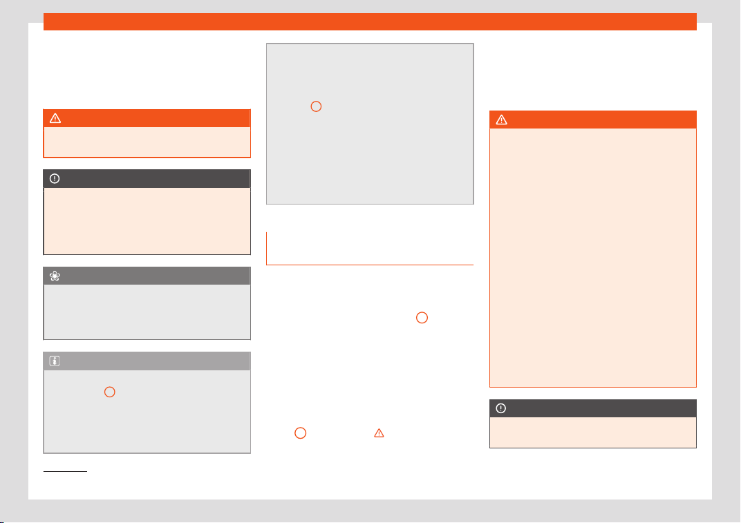
Driving
Ignition is switched on
This driv
er message is displ
ayed and a buz
-
zer is sounded when the driver door is
opened with the ignition switched on.
WARNING
●
Never run the engine in confined spaces,
as the e
xhaust gases are poisonous.
CAUTION
Avoid high engine speeds, full throttle and
extreme l
oad conditions until the engine
has reached its normal operating tempera-
ture, otherwise this can damage the en-
gine.
For the sake of the environment
Do not warm up the engine by idling it. You
should drive off as soon as you st
art the en-
gine. This will help avoid unnecessary ex-
haust emissions.
Note
●
If it is difficult to turn the ignition k
ey to
the position
2
, move the steering wheel to
both sides to rel
ease the steering lock.
●
When starting from cold, the engine may
be a little noisy for the first few seconds un-
til oil pressure has built up in the hydraulic
valve lifters. This is quite normal, and no
cause for concern.
●
If the vehicl
e battery is disconnected and
reconnected, the key must remain in the
position
1
for around 5 seconds before
starting up
.
●
Vehicles with automatic transmission,de-
pending on the country, after switching off
the ignition, you can only remove the igni-
tion key if the selector lever is in position
“P” (parking lock). Next, the selector lever
is locked.
Switching off the engine with the
k
ey
Switching off the engine
–
Stop the vehicle.
–
Turn the ignition key to position
1
›››
Fig. 2
40
.
Engaging the st
eering wheel lock
In vehicles with automatic gearbox, the igni-
tion key can only be removed when the se-
lector lever is in position P
1)
.
–
Remove the key from the ignition in posi-
tion
1
›
›
›
Fig. 240
›››
.
–
T
urn the st
eering wheel until you hear it en-
gage
.
Possible vehicle theft is prevented with the
steering lock engaged.
WARNING
●
Never s
witch the engine off until the vehi-
cle is stationary. The brake servo and pow-
er steering functions will not be completely
covered under warranty. More force may
also be needed to turn the steering wheel
or to brake. As you cannot steer and brake
in the normal manner, there is a greater risk
of accidents and serious injury.
●
Never remove the key from the ignition if
the vehicle is in motion. Otherwise, the
steering could suddenly lock, making it im-
possible to steer the vehicle: risk of acci-
dent!
●
Always take the key with you when you
leave the vehicle. This is particularly impor-
tant if there are children in the vehicle, as
they might otherwise be able to start the
engine or use power-operated equipment
(e.g. the electric windows), which could
cause injuries.
CAUTION
If the engine has been running under high
load for a l
ong time, there is a risk of heat
1)
Depending upon country.
240
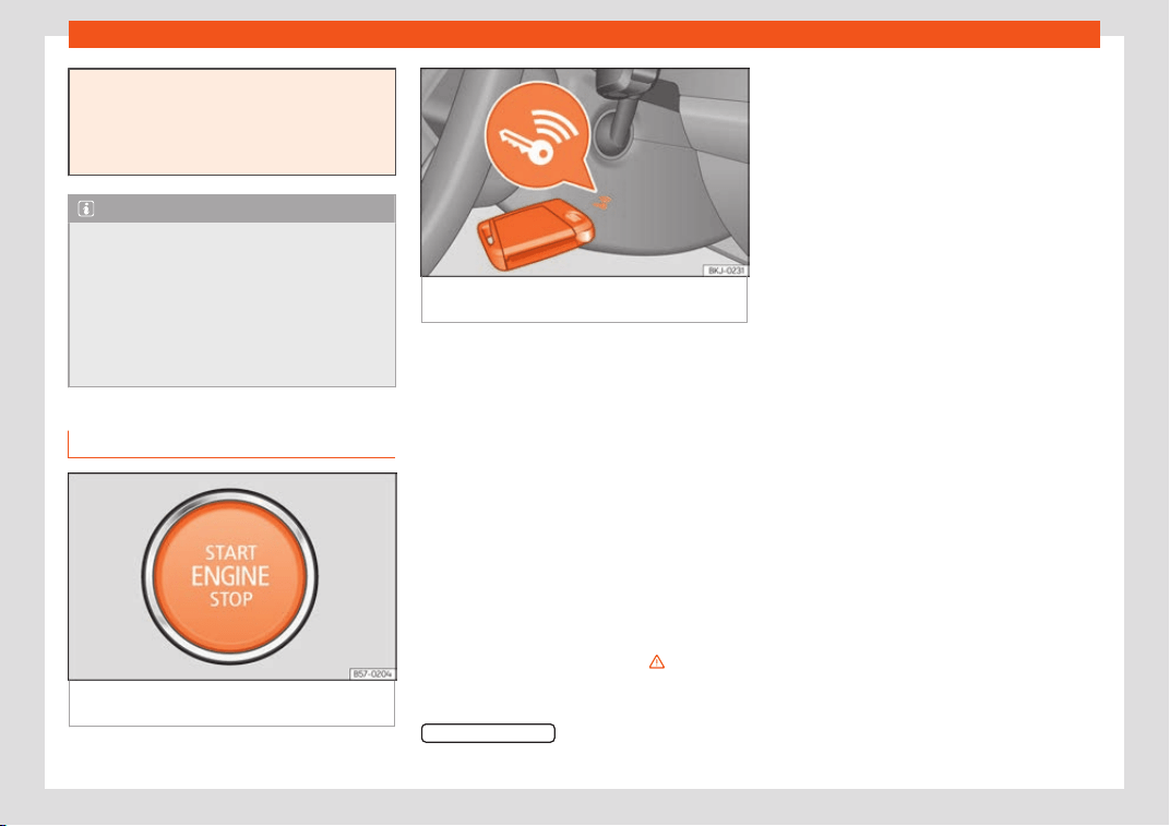
Start and driving
building up in the engine compartment af-
ter it has been swit
ched off; this could
cause engine damage. For this reason, you
should idle the engine for approximately 2
minutes before you switch it off.
Note
After the engine is switched off the radiator
f
an may run on for up t
o 10 minutes, even if
the ignition is switched off. It is also possi-
ble that the fan turns itself on once more if
the coolant temperature increases due to
the heat accumulated in the engine com-
partment or due to its prolonged exposure
to solar radiation.
Starter button*
Fig. 241 In the lower part of the centre con-
sol
e: st
art butt
on.
Fig. 242 On the right of the steering column:
emergency start.
The vehicle engine can be started with a
st
art
er butt
on (Press & Drive). To do so, there
must be a valid key inside the vehicle in the
area of the front or rear seats.
In vehicles with the Keyless Access
›››
page 127 system, the engine can also be
started with the key in the luggage compart-
ment.
Opening the driver's door when exiting the
vehicle activates the electronic lock on the
steering column if the ignition is disabled.
Switching the ignition on/off manually
Briefly push the starter button without touch-
ing the brake or clutch pedal
›››
.
F
or v
ehicl
es with both manual and automatic
transmission, the starter button text
START ENGINE STOP
flashes like a heartbeat
when the system is preset for switching the
ignition on and off
.
Aut
omatic ignition s
witch-off
If the driver leaves the vehicle, taking the ve-
hicle key with them but leaving the ignition on,
the ignition is not switched off automatically.
The ignition is switched off automatically by
pressing the lock button on the remote con-
trol or manually by pressing the sensor sur-
face on the door lever
›››
Fig. 140
Emergency starting function
If no valid key is detected inside the vehicle,
an emergency start-up will be required. The
relevant message will appear in the dash
panel display. This may happen when, for ex-
ample, the battery of the vehicle key button is
very low or flat:
●
Immediately after pushing the starter but-
ton, keep the vehicle key next to the right trim
of the steering column
›››
Fig. 242, as close
as possible to the Kessy logo.
●
The ignition connects and the engine starts
automatically.
Emergency disconnection
If the engine does not switch off after briefly
pressing the starter button, an emergency
disconnect will be required:
»
241
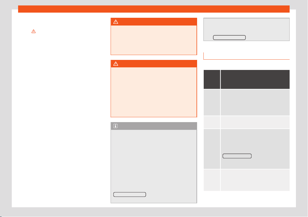
Driving
●
Pr
ess the st
art
er button twice within 3 sec-
onds or press it once for more than 1 sec-
ond
›››
.
●
The engine turns off automatically.
Engine r
est
ar
t feature
If no valid key is detected inside the vehicle
after the engine stops, you will only have 5
seconds to restart it. A warning will display on
the dash panel screen.
After this interval, it will not be possible to
start the engine without a valid key inside the
vehicle.
Automatic deactivation of the ignition on
vehicles with the Start-Stop system
The ignition is switched off automatically
when the vehicle is stopped and the auto-
matic engine shutdown is active, if:
●
The driver's seat belt is not fastened,
●
the driver does not step on any pedal,
●
the driver door is opened.
After automatically turning off the ignition, if
the dipped beam is on, the side light re-
mains on for approx. 30 minutes (if the bat-
tery has enough charge). If the driver locks
the vehicle or manually turns off the light, the
side light goes out.
WARNING
Any accidental movement of the vehicle
could result in serious injury.
●
When s
witching on the ignition, do not
press the brake or clutch pedal, otherwise
the engine could start immediately.
WARNING
If vehicle keys are used negligently or with-
out due care, this may cause accidents and
serious injury.
●
Ne
ver leave any key inside the vehicle
when exiting. Otherwise, a child or unau-
thorised person could lock the vehicle,
start the engine or connect the ignition
and, in this way, operate electronic equip-
ment (e.g. the windows).
Note
●
Before l
eaving the vehicle, always dis-
connect the ignition manually and, if ap-
propriate, take into account the instruc-
tions on the screen of the dash panel.
●
If the vehicle is stationary for a long time
with the ignition on, the vehicle battery
might be discharged and it might not be
possible to start the engine.
●
In diesel vehicles, there may be a delay in
the engine starting if it requires preheating.
●
If during the STOP phase you press the
START ENGINE STOP
button, the ignition is
switched off and the butt
on flashes.
●
If the indication is displayed on the in-
strument panel display “St
art-Stop system
deactivated: Start the engine manually”,
the START ENGINE STOP
button will blink.
Starting the engine
3 Valid for vehicle: with Keyless Access
Step
Starting the engine with the
start
er button
›››
page 241 (Press
& Drive).
1.
Press and hold the brake pedal until
step 5 is performed.
In v
ehicles with a manual gearbox:
press and hold the clutch down until the
engine starts.
2.
Put the gearbox lever in neutral or the se-
lector l
ever in position P or N.
3.
Briefly press the starter button
›››
Fig. 241
without pressing the accelerator. For the
engine to start there must be a valid key in
the vehicle.
After starting the engine, the light of the
START ENGINE STOP button changes to a
fixed light indicating that the engine has
start
ed.
4.
If the engine does not start, stop and wait
for appro
x. 1 minute before trying again. If
necessary, carry out an emergency start
›››
page 241.
242
Start and driving
Step
Starting the engine with the
start
er button
›››
page 241 (Press
& Drive).
5.
Disconnect the electronic parking brake
when you are about to st
art driving
›››
page 244.
WARNING
Never leave the vehicle with the engine
running, especially if a gear or gear range
is engaged. The vehicl
e could then sudden-
ly move or something strange could hap-
pen that would cause damage, fire or seri-
ous injury.
WARNING
Cold start sprays could explode or cause a
sudden increase in the engine speed.
●
Nev
er use sprays to cold start the engine.
CAUTION
●
The start
er motor or the engine may be
damaged if you try to start the engine while
driving or if you restart it immediately after
switching it off.
●
If the engine is cold, avoid high engine
speeds, pushing the engine too hard and
rapid acceleration.
●
Do not start the engine by pushing the
vehicle or towing it. Unburnt fuel could en-
ter the catalytic converter and damage it.
Note
●
Do not wait until the engine warms up
with the v
ehicle stationary; if you have
good visibility through the windows, start
driving immediately. This helps the engine
reach operating temperature faster and re-
duces emissions.
●
Electrical components with a high power
consumption are switched off temporarily
when the engine starts.
●
When starting with a cold engine, noise
levels may briefly increase. This is quite
normal, and no cause for concern.
●
When the outside temperature is below
+5°C (+41°F), if the engine is diesel, some
smoke may appear under the vehicle when
the fuel-operated auxiliary heater is on.
Stopping the engine
3 Valid for vehicle: with Keyless Access
Step
Switch off the engine with the
start
er button
›››
page 241.
1. Stop the vehicle completely
›››
.
2.
Press and hold the brake pedal until the
step 4 is performed.
3.
If you are driving an automatic vehicle,
place the select
or lever in position P.
4.
Connect the electronic parking brake
›››
page 244.
Step
Switch off the engine with the
start
er button
›››
page 241.
5.
Briefly press the start-up button
›››
Fig. 241. The START ENGINE STOP
button
blinks again. If the engine fails to switch
off, perform an emergency disconnect
›››
page 241.
6.
If the vehicle is equipped with a manual
gearbox, put it into 1st or reverse.
WARNING
Never switch off the engine while the vehi-
cle is moving. This coul
d cause loss of con-
trol of the vehicle, accidents and serious in-
jury.
●
The airbags and belt tensioners do not
work when the ignition is switched off.
●
The brake servo does not work with the
engine off. Therefore, you need to press the
break pedal harder to brake the vehicle.
●
Power steering does not work when the
engine is not running. You need more
strength to steer when the engine is switch-
ed off.
●
If the ignition is switched off, the steering
column could be locked, making it impossi-
ble to control the vehicle.
CAUTION
If the engine is made to work hard for a long
time, it may ov
erheat after being switched
off. To prevent damage to the engine
»
243
Driving
before switching it off, leave it idle for ap-
prox. 2 minut
es in neutral.
Note
After switching off the engine, the cooling
f
an may continue to oper
ate in the engine
compartment for a few more minutes, even
with the ignition off. The radiator fan is au-
tomatically switched off.
“My Beat” Function
For vehicles with a convenience key there is
the “My Beat” function. This f
eat
ur
e provides
an additional indication of the vehicle ignition
system.
When accessing the vehicle, e.g. by opening
the doors with the remote control, the
START ENGINE STOP
button flashes, calling at-
t
ention t
o the r
elevant starter system button.
Upon switching the ignition on/off, the light of
the START ENGINE STOP
button flashes. With
the engine s
wit
ched off
, after a few seconds,
the STOP ENGINE START
button stops flashing
and goes out.
With the engine running, the
S
T
AR
T ENGINE STOP
button light stays on, indi-
cating that the engine is running. The time
that l
apses betw
een the moment the user
st
arts the engine with the START ENGINE STOP
button and the lighting changes from flashing
to fixed will depend on specific engine size
char
act
eristics. Upon s
witching the ignition
off with the START ENGINE STOP
button, it starts
fl
ashing again.
In v
ehicl
es with the Start-Stop system, the
“My Beat” function also offers additional in-
formation:
●
When the engine stops during the Stop
phase, the light of the START ENGINE STOP
but-
t
on st
ays on, since
, even though the engine is
off, the Start-Stop system is active.
●
When the engine cannot be stated again
with the Start-Stop system,
›››
page 269, and
needs to be started manually, the
START ENGINE STOP
button flashes to indicate
this f
act.
Br
aking and parking
Inf
ormation on the brakes
New brake pads
F
or the first 400 km (250 mil
es), ne
w brake
pads have not yet reached their maximum
braking capacity, and need to be “run in” first.
However, you can compensate for the slightly
reduced braking effect by applying more
pressure on the brake pedal. Avoid overload-
ing the brakes while running them in.
Wear
The rate of wear on the brake pads depends
a great deal on how you drive and the condi-
tions in which the vehicle is operated. This is a
particular problem in urban traffic and short
stretches, or with very sporty driving.
Depending on the speed, the braking force
and the environmental conditions (for exam-
ple, the temperature, air humidity, etc.) noises
may be produced on braking.
Wet roads or road salt
In certain situations (for example, on driving
through flooded areas, in severe downpours
or after washing the vehicle) the braking ac-
tion could be delayed if the discs and pads
are damp, or frozen in winter. In this case the
brakes should be “dried” by pressing the
brake pedal several times.
At high speed and with the windscreen wipers
activated, the brake pads will briefly touch
the brake discs. This takes place, although
unnoticeable to the driver, at regular intervals
to improve the response time of the brakes
when they are wet.
The effectiveness of the brakes can also be
temporarily reduced if the vehicle is driven for
some distance without using the brakes when
there is a lot of salt on the road in winter. The
layer of salt that accumulates on the discs
and pads can be removed by gently apply-
ing the brakes a few times.
244
Start and driving
Corrosion
Ther
e may be a t
endency f
or corrosion to
form on the discs and dirt to build up on the
brake pads if the vehicle is used infrequently
or the brakes are not used very often.
If the brakes are not used frequently, or if rust
has formed on the disks, it is advisable to
clean off the pads and disks by braking firmly
a few times at a moderately high speed
›››
.
F
ault in the br
ak
e system
If the brake pedal travel should ever increase
suddenly, this may mean that one of the two
brake circuits has failed. Drive immediately to
the nearest specialised workshop and have
the fault repaired. Drive there slowly and re-
member that you will have to apply more
pressure on the brake pedal and allow for
longer stopping distances.
Low brake fluid level
Malfunctions can occur in the brake system if
the brake fluid level is too low. The brake fluid
level is monitored electronically.
Brake servo
The brake servo increases the pressure you
apply to the brake pedal. It works only when
the engine is running.
WARNING
●
Apply the brakes heavily t
o clean the
brake system only in a suitable traffic situa-
tion. Do not put other road users in danger:
there is risk of causing an accident.
●
Ensure the vehicle does not move while in
neutral, when the engine is stopped. Failure
to follow this instruction could result in an
accident.
●
If the brake fluid loses its viscosity and is
subjected to heavy use, vapour bubbles
can form in the brake system. This reduces
the efficiency of the brakes.
CAUTION
●
Never l
et the brakes “drag” by leaving
your foot on the pedal when it is not neces-
sary to brake. This overheats the brakes, re-
sulting in longer stopping distances and
greater wear.
●
Before driving down a long, steep gradi-
ent, it is advisable to reduce speed and se-
lect a lower gear. This makes use of engine
braking and relieves the brakes. If you still
have to use the brakes, it is better to brake
firmly at intervals than to apply the brakes
continuously.
Note
●
If the brake serv
o is out of action, for ex-
ample when the car is being towed, you will
have to press the brake pedal considerably
harder than normal to make up for the lack
of servo assistance
.
●
If you wish to equip the vehicle with ac-
cessories such as a front spoiler or wheel
covers, it is important that the flow of air to
the front wheels is not obstructed, other-
wise the brakes can overheat.
Control lamps
It lights up red
Brake fluid level too low
›››
page 353 or fault in the
brake system.
Do not carry on driving!
It lights up red
Electronic parking brake
›››
page 246.
The warning lamp turns off when the electronic park-
ing brake is released.
It lights up green
Auto Hold function activated
›››
page 272.
It lights up yellow
Front brake pads worn.
WARNING
●
If the brake w
arning lamp does not go out
or if it lights up when driving, the brake fluid
»
245
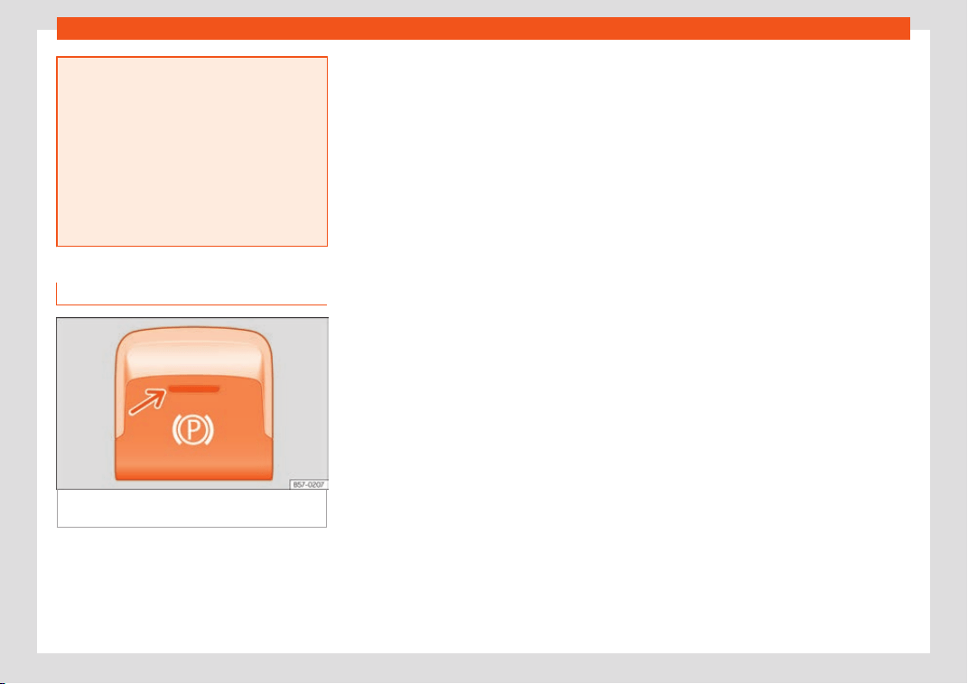
Driving
level in the reservoir is too low so there is a
risk of an accident
›››
page 353, Brake fluid.
Stop the vehicle and do not drive on. Ob-
tain technical assistance.
●
If the brake warning lamp lights up to-
gether with the ABS lamp this could be
due to an ABS fault. This could cause the
rear wheels to lock quickly when you brake.
This could cause the rear to break away.
Risk of skidding. Stop the vehicle and seek
technical assistance.
Electronic parking brake
Fig. 243
Centre console, lower part: electron-
ic parking br
ak
e butt
on.
The electronic parking brake replaces the
handbr
ak
e
.
Activating the electronic parking brake
The electronic parking brake can be activa-
ted whenever the vehicle is at a standstill,
even when the ignition is switched off. Acti-
vate it whenever you leave or park the vehi-
cle.
●
Pull and hold the
›››
Fig. 243 button.
●
The parking brake is activated when the
control light of the
›››
Fig. 243 button (arrow)
and the red control light of the display in
the dash panel are on.
●
Release the button.
Releasing the electronic parking brake
●
Switch the ignition on.
●
Press the button
›››
Fig. 243. At the same
time step hard on the brake pedal or, if the
engine is running, press the accelerator pedal
slightly.
●
The control light of the
›››
Fig. 243 button
(arrow) and the red control light of the dis-
play in the dash panel go out.
Automatic release of the electronic park-
ing brake on starting the engine
The electronic parking brake is automatically
switched off when starting if, after the driver's
door is closed and the driver's seat belt fas-
tened, any of the following situations take
place:
●
In vehicles with automatic transmission: a
gear range is engaged or the vehicle is
switched to another one and the accelerator
pedal is lightly pressed.
●
In vehicles with manual transmission: the
clutch pedal is pressed fully before starting
off and the accelerator is pedal lightly press-
ed.
●
To facilitate certain manoeuvres there are
exceptions that allow the automatic parking
brake to be released without the driver's seat
belt being fastened.
The parking brake can be prevented from be-
ing automatically released by continuously
pulling up the
›››
Fig. 243 switch when
starting off.
The electronic parking brake is not discon-
nected until the button is released. This
can facilitate starting off when a heavy load
is towed
›››
page 329.
Automatic activation of the electronic
parking brake when exiting the vehicle in-
correctly
In vehicles with automatic transmission, the
electronic parking brake is activated auto-
matically when exiting the vehicle incorrectly
if:
●
The selector lever is in the D/S or R position
or in the Tiptronic selector gate.
●
AND: the vehicle is stationary.
246
Start and driving
●
AND: the driv
er door is open.
Emer
gency br
aking function
Only use the emergency brake function if you
are unable to stop the vehicle with the foot
brake
›››
.
●
Pull and hold the
›
›
›
Fig. 243 button in
this position to forcefully stop the vehicle. At
the same time, an acoustic warning can be
heard.
●
To stop the braking process, release the
button or press the accelerator.
WARNING
The improper use of the electronic parking
brake can cause accidents and serious in-
jury.
●
Ne
ver use the electronic parking brake to
stop the vehicle, unless it is an emergency.
Braking distances can be considerably lon-
ger, since, under certain circumstances,
only the rear wheels brake. Always use the
foot brake.
●
Never accelerate from the engine when a
gear range or a gear is engaged and the
engine is running. The vehicle could move,
even if the electronic parking brake is acti-
vated.
CAUTION
To prevent the vehicle from unintentionally
moving when parking it, first apply the
electronic parking brake and then remove
your foot from the br
ake pedal.
Note
●
In v
ehicles with a manual gearbo
x, re-
leasing the clutch and accelerating at the
same time automatically disconnects the
electronic parking brake.
●
If the vehicle battery is flat, it will not be
possible to disconnect the electronic park-
ing brake. Use the jump-start
›››
page 59.
●
When the electronic parking brake is ap-
plied or released, noises may be heard.
●
The system performs automatic and au-
dible tests sporadically in the parked vehi-
cle if some time elapses without the elec-
tronic parking brake being used.
Parking
The electronic parking brake should always
be applied when the v
ehicl
e is park
ed.
Always note the following points when park-
ing the vehicle:
–
Use the brake pedal to stop the vehicle.
–
Apply the electronic parking brake.
–
Put it in 1st gear.
–
Switch the engine off and remove the key
from the ignition. Turn the steering wheel
slightly to engage the steering lock.
–
Never leave a vehicle key in the vehicle.
Additional notes on parking the vehicle on
gradients:
Turn the steering wheel so that the vehicle
rolls against the kerb if it started to roll.
●
If the vehicle is parked facing downhill, turn
the front wheels so that they point towards
the kerb.
●
If the vehicle is parked facing uphill, turn
the front wheels so that they point away from
the kerb.
●
Secure the vehicle as usual by applying the
electronic parking brake firmly and putting it
in 1st gear.
WARNING
●
Take measur
es to reduce the risk of injury
when you leave your vehicle unattended.
●
Never park where the hot exhaust system
could ignite inflammable materials, such as
dry grass, low bushes, spilt fuel etc.
●
Never allow vehicle occupants to remain
in the vehicle when it is locked. They would
be unable to open the vehicle from the in-
side, and could become trapped in the ve-
hicle in an emergency. In the event of an
emergency, locked doors will delay assis-
tance to vehicle occupants.
»
247

Driving
●
Never l
eave children alone in the vehicle.
They could set the vehicle in motion, for ex-
ample, by releasing the electronic parking
brake or the gearshift lever, which would
cause the vehicle to move, but uncontrolla-
bly.
●
Depending on weather conditions, it may
become extremely hot or cold inside the
vehicle. This can be fatal.
Braking and stability sys-
tems
Control l
amps
It lights up
Fault in the ESC or disconnection caused by the sys-
tem.
As the ESC operat
es in conjunction with the ABS, the
ESC light will also come on if a fault should occur in
the ABS.
Flashes
ESC or ASR activated.
It lights up
ASR manually deactivated.
Or: ESC in Sport mode
›››
page 250.
It lights up
ABS faulty or does not work.
The control lamps light up together when the
ignition is switched on and shoul
d turn off af-
ter approximately 2 seconds. This is the time
taken for the function check.
Hydraulic Brake Assist (HBA)
Electronic Stability Control (ESC)
The ESC helps t
o impr
o
ve safety. It reduces
the tendency to skid and improves the stabili-
ty and roadholding of the vehicle. The ESC
detects critical handling situations, such as
vehicle understeer or oversteer, or wheelspin
on the driving wheels. It stabilises the vehicle
by braking individual wheels or by reducing
the engine torque. The warning lamp will
flash on the instrument panel when the ESC is
intervening .
The ESC includes the anti-lock brake system
(ABS), the hydraulic brake assist (HBA), the
traction control system (ASR), electronic dif-
ferential lock (EDS), electronic torque control
(XDS) and tractor-trailer sway mitigation*.
ESC also helps stabilise the vehicle by
changing the torque.
Anti-lock brake system (ABS)
ABS prevents the wheels from locking up un-
der braking until the vehicle has reached a
virtual standstill. You can continue to steer the
vehicle even when the brakes are on full.
Keep your foot on the brake pedal and do not
pump the brakes. You will feel the brake pedal
pulsate while the ABS is working.
Hydraulic Brake Assist (HBA)
The brake assist system can reduce the re-
quired braking distance. The braking force is
automatically boosted if you press the brake
pedal quickly in an emergency. You must
keep pressing the brake pedal until the dan-
ger has passed.
Traction control system (ASR)
In the event of wheelspin, the traction control
system reduces the engine torque to match
the amount of grip available. This helps the
car to start moving, accelerate or climb a
gradient.
Electronic differential lock (EDL)
When the EDL detects wheelspin, it brakes
the spinning wheel and directs the power to
the other driven wheel. This function is active
up to approximately 100 km/h (62 mph).
To prevent the disc brake of the braked wheel
from overheating, the EDL cuts out automati-
cally if subjected to excessive loads. The
248
Start and driving
vehicle can still be driven. The EDL will switch
on again aut
omatically when the br
ak
e has
cooled down.
Tractor-trailer sway mitigation*
If the vehicle is pulling a trailer, it will control
the following: tractor-trailers tend to sway.
When the swaying of the trailer is felt by the
vehicle and detected by the ESC, it will auto-
matically brake the towing vehicle within the
limits of the system and mitigate the sway.
Tractor-trailer sway mitigation is not available
in all countries.
Electronic torque management (XDS)
When taking a curve, the driveshaft differen-
tial mechanism allows the outer wheel to turn
at a higher speed than the inner wheel. In this
way, the wheel that is turning faster (outer
wheel) receives less drive torque than the in-
ner wheel. This may mean that in certain sit-
uations the torque delivered to the inner
wheel is too high, causing the wheels to spin.
On the other hand, the outer wheel is receiv-
ing a lower drive torque than it could transmit.
This causes an overall loss of lateral grip on
the front axle, resulting in understeer or
“lengthening” of the trajectory.
The XDS system can detect and correct this
effect via the sensors and signals of the ESC.
Via the ESC, the XDS will brake the inside
wheel and counter the excess driving torque
of that wheel. This means that the driver's de-
sired trajectory is much more precise.
The XDS system works in combination with
the ESC and is always active, even when ASR
traction control is disconnected, or the ESC in
Sport mode or disconnected.
Multi-collision Brake
In an accident, the multi-collision brake can
help the driver by braking to avoid the risk of
skidding during the accident, which could
lead to further collisions.
The multi-collision brake works for front, side
or rear accidents, when the airbag control
unit records its activation level and the acci-
dent takes place at a speed of over 10 km/h
(6 mph). The ESC automatically brakes the
vehicle, as long as the accident has not dam-
aged the ESC, the brake hydraulics or the on-
board network
The following actions control automatic brak-
ing during the accident:
●
When the driver presses the accelerator,
the automatic braking does not take place.
●
When the braking pressure through press-
ing the brake pedal is greater than the sys-
tem’s braking pressure the vehicle will brake
automatically.
●
Multi-collision braking will not be available
if ESC is malfunctioning.
WARNING
●
The ESC, ABS, ASR, EDS and the electron-
ic t
orque control system cannot exceed the
limits imposed by the laws of physics. Al-
ways bear this in mind, especially on wet or
slippery roads. If you notice the systems
cutting in, you should reduce your speed
immediately to suit the road and traffic
conditions. Do not be encouraged to take
risks by the presence of more safety sys-
tems. If you do, an accident may occur.
●
Please remember that the accident risk
always increases if you drive fast, espe-
cially in corners or on a slippery road, or if
you follow too close behind the vehicle in
front of you. The ESC, ABS, brake assist,
EDS and the electronic torque control sys-
tem cannot prevent accidents: risk of acci-
dents!
●
Accelerate with caution on slippery sur-
faces (for example, icy or snow-covered).
Despite the control systems, the driven
wheels could spin, affecting the stability of
the vehicle: risk of accident!
Note
●
The ABS and ASR will only operate cor
-
rectly if the four wheels have identical
tyres. Any differences in the rolling radius
of the tyres can cause the system to re-
duce engine power when this is not desired.
●
The regulating processes of the systems
can make noises when they intervene.
»
249
Driving
●
If the warning lamp
lights up, or al-
ternatively, there could be a fault
›››
page 122.
Switching on/off the ESC and ASR
The ESC is switched on automatically when
the engine is started, and only w
orks when
the engine is running and includes the ABS,
EDS and ASR systems.
The ASR function should only be switched off
in situations in which traction is insufficient, in-
cluding:
●
When driving in deep snow or on surfaces
that are not very firm.
●
T
o “free” the vehicle if it gets stuck.
Then switch the ASR function back on.
Depending on the finishes and versions, there
is the possibility of disconnecting only the
ASR or activating the ESC Sport mode.
Disable ASR
The Easy Connect system menu is used to
switch off the ASR
›››
page 35. The trac-
tion control system will be disabled.
The control lamp lights up. For vehicles with
a driver information system* the driver will be
informed that ASR is disabled.
Activate ASR
The Easy Connect system menu
›››
page 35 is used to switch on the ASR.
The traction control system will be enabled.
The control lamp switches off. For vehicles
with a driver information system* the driver
will be informed that ASR is enabled.
ESC in “Sport” mode
Sport mode can be connected via the Easy
Connect
›››
page 35 system menu. In
front-wheel drive vehicles, the interventions
by the ESC and the ASR are limited. In four-
wheel drive vehicles, the interventions by the
ESC are limited and the ASR is switched off
completely
›››
.
The contr
ol l
amp
lights up. For vehicles with
a driver information system* the driver will be
informed that:
Electronic Stability Control
(ESC): sport. Warning! Limited
stability
Disable ESC “Sport” mode
Through the Easy Connect system menu
›››
page 35. The warning lamp will
switch off. For vehicles with a driver informa-
tion system* the driver will be informed that:
Electronic Stability Control
(ESC): on
ESC in “Offroad” mode
1)
Turn the Driving Experience button to select
the Offroad mode and connect it
›››
page 304. The interventions of the ESC, as
well as of the ASR, EDS and the ABS, adapt to
irregular terrain.
In the following exceptional situations it may
make sense to activate the Offroad mode to
allow the wheels to spin:
●
When “swinging” the vehicle to get it un-
stuck.
●
Driving in deep snow or on loose surfaces.
●
When driving on rough terrain with much of
the car's weight is lifted off the wheels (axle
articulation).
●
Steep descents with braking on unpaved
terrain.
1)
Only for 4Drive models.
250
Start and driving
For your safety we recommend that you turn
off the Offr
oad mode when it is not absolut
e-
ly necessary.
Disabl
e the ESC Offroad mode
Turn the Driving Experience button to select a
different driving mode
›››
page 304.
ESC in “Snow” mode
1)
Turn the Driving Experience button to select
the “Snow” mode and connect it.
›››
page 304 Traction control system (ASR) in-
terventions adjust to the adhesion of snowy
roads.
Disable the ESC “Snow” mode
Turn the Driving Experience button to select a
different driving mode
›››
page 304.
WARNING
The ESC Sport mode should be activated
only when traffic conditions and the ability
of the driv
er allow it. Danger of skidding!
●
With ESC in Sport mode, the stabilising
function will be limited to allow for a sporti-
er drive. The driving wheels could spin and
the vehicle could skid.
WARNING
You should only activate the Offroad Mode
or disable the ASR if the experience of the
driv
er and traffic conditions allow it. Dan-
ger of skidding!
●
With the Offroad mode activated, the
stabilisation function is limited. In particu-
lar, if the road is too smooth and slippery,
the driving wheels could spin and the vehi-
cle could skid.
Note
If the ASR or the ESC is disconnected or the
Sport mode is select
ed, cruise control* will
be switched off.
Manual gearbox
Changing gear
Read the additional information carefully
›
›
›
page 41
In some countries the clutch pedal must be
fully pressed down for the engine to start.
Selecting reverse gear
●
Engage reverse gear only when the vehicle
is stopped.
Changing down gears
While driving, changing down a gear must al-
ways be done gradually, i.e. to the gear di-
rectly below and when the engine speed is
not too high
›››
. Changing down while by-
passing one or v
arious gears at high speeds
or at high engine speeds can damage the
clut
ch and the gearbo
x, even if the clutch
pedal remains depressed
›››
.
WARNING
When the engine is running, the vehicle will
start t
o move as soon as a gear is engaged
and the clutch released. This is also the
case with the electronic parking brake
switched on.
●
Never engage reverse gear when the ve-
hicle is moving.
WARNING
If the gear is changed down inappropriate-
ly by selecting a gear that is too l
ow, you
may lose control of the vehicle, causing an
accident and serious injuries.
»
1)
Only for 4Drive models.
251
Driving
CAUTION
When travelling at high speeds or at high
engine speeds, selecting a gear that is too
l
ow can cause considerable damage to the
clutch and the gearbox. This can also oc-
cur if the clutch pedal is pressed and held
and it does not engage.
CAUTION
To prevent damage and avoid premature
wear, pl
ease observe the following:
●
Do not rest your hand on the gear lever
while driving. The pressure applied by your
hand is transmitted to the gearbox selector
forks.
●
Always ensure that the vehicle is com-
pletely stopped before engaging the re-
verse gear.
●
Always press the clutch to the floor when
changing gears.
●
Never hold the vehicle “on the clutch” on
hills with the engine on.
Automatic gearbox/DSG au-
t
omatic gearbo
x*
Intr
oduction
Your vehicle is equipped with an electronical-
ly contr
oll
ed manual gearbo
x. Torque be-
tween the engine and the gearbox is trans-
mitted via two independent clutches. They
replace the torque converter found on con-
ventional automatic gearboxes and allow for
smooth, uninterrupted acceleration of the ve-
hicle.
The tiptronic system allows the driver to
change gears manually if desired
›››
page 255, Engaging gears with the tip-
tronic mode*.
Control lamps
It lights up green
The brake pedal is not engaged.
To select a r
ange of gears, press the brake pedal.
Flashes green
The interlock button on the selector lever is not
pressed.
Mov
ement of the vehicle is prevented. Engage the se-
lector lever lock.
Selector lever positions
Read the additional information carefully
›
›
›
page 41
The selector lever position engaged is high-
lighted on the display in the instrument clus-
ter. With the selector lever in the manual
gearbox positions G, D, E and S, the engaged
gear is also indicated on the display.
P – Parking lock
When the selector lever is in this position, the
driven wheels are locked mechanically. The
parking lock must be engaged only when the
vehicle is stationary
›››
.
The int
erl
ock butt
on (the button on the selec-
tor lever handle) must be pressed in and si-
multaneously the brake pedal must be de-
pressed before moving the selector lever ei-
ther in or out of position P.
R – Reverse gear
Reverse gear must be engaged only when
the vehicle is stationary and the engine is
idling
›››
.
T
o mo
v
e the selector lever to position R, the
interlock button must be pressed in and at the
same time the brake pedal must be de-
pressed. The reverse lights come on when the
selector lever is in the R position with the igni-
tion on.
N – Neutral (idling)
With the selector lever in this position, the
gear is in neutral.
252
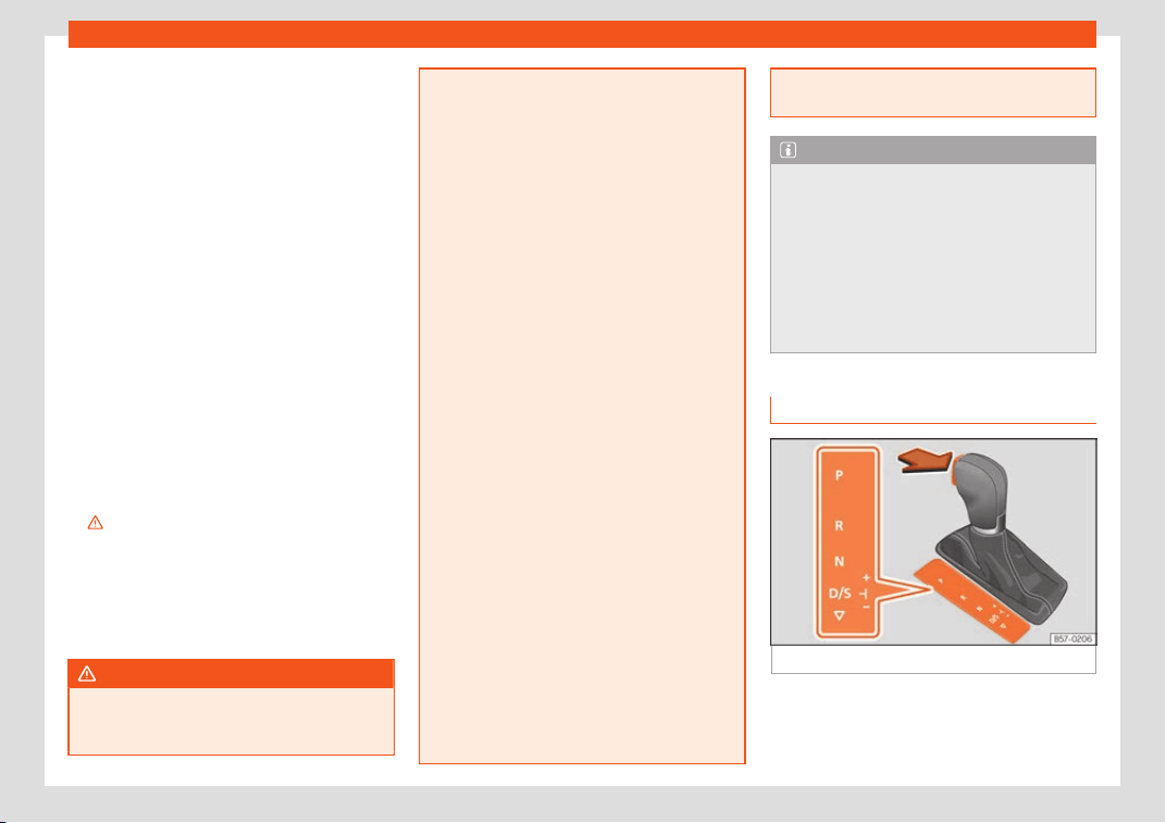
Start and driving
D/S – Permanent drive (forward) position
The sel
ect
or l
ever in the D/S position enables
the gears to be controlled in normal mode
(D) or Sport (S). To select Sport mode (S),
move the selector lever backwards. Moving
the lever again will select normal mode (D).
The selected driving mode is shown on the in-
strument panel display.
In normal mode (D), the gearbox automati-
cally selects the best gear ratio. This de-
pends on the engine load, the road speed
and the dynamic gear control programme
(DCP).
Sport mode (S) must be selected for a sporty
driving style. This setting makes use of the en-
gine's maximum power output. When accel-
erating the gear shifts will be noticeable.
Press the brake pedal to move the selector
lever from N to D/S when the vehicle is sta-
tionary or at speeds below 3 km/h (2 mph)
›››
.
Under cert
ain cir
cumst
ances (e.g. when driv-
ing in mountains) it can be advantageous to
switch temporarily to tiptronic mode
›››
page 255, in order to manually select
gear ratios to suit the driving conditions.
WARNING
●
Take car
e not to accidentally press the
accelerator pedal when the vehicle is stop-
ped. The vehicle could otherwise start
moving immediately (in some cases even if
the parking brake is engaged) r
esulting in
the risk of an accident.
●
Never move the selector lever to R or P
when driving. Failure to follow this instruc-
tion could result in an accident.
●
With selector lever in any position (ex-
cept P) the vehicle must always be held
with the foot brake when the engine is run-
ning. This is because an automatic gearbox
still transmits power even at idling speed,
and the vehicle tends to “creep”. The ac-
celerator pedal must on no account be
pressed inadvertently when a gear is en-
gaged with the vehicle stationary. The ve-
hicle could otherwise start moving immedi-
ately (in some cases even if the parking
brake is engaged) resulting in the risk of an
accident.
●
While you are selecting a gear and the
vehicle is stopped with the engine running,
do not accelerate. Failure to follow this in-
struction could result in an accident.
●
As a driver you should never leave your
vehicle if the engine is running and a gear is
engaged. If you have to leave your vehicle
while the engine is running, apply the elec-
tronic parking brake and engage the park-
ing lock (P).
●
To avoid accidents, apply the electrome-
chanical parking brake and put the selec-
tor lever in position P before opening the
bonnet and working on the vehicle with the
engine running. Please always observe the
important safety warnings
›››
page 347,
Working in the engine compartment.
Note
●
If the sel
ector l
ever is moved accidental-
ly to N when driving, release the accelera-
tor and let the engine speed drop to idling
before selecting gear range D or S again.
●
Should the power supply to the selector
lever be interrupted in position P, the selec-
tor lever will be locked. If this should hap-
pen the manual release can be used
›››
page 41.
Selector lever lock
Fig. 244
Selector lever lock.
The selector lever lock prevents gears from
being engaged inadv
ert
ently, so that the v
e-
hicle is not set in motion unintentionally.
»
253

Driving
The selector lever lock is released as follows:
–
Switch the ignition on.
–
Press the brake pedal and, at the same
time
, hol
d the l
ock button in the direction of
the arrow
›››
Fig. 244.
Automatic selector lever lock
With the ignition switched on, the selector
lever is locked in the positions P and N. The
brake pedal must be pressed to release the
lever while pressing the release button if the
selector lever is in the position P. As a remind-
er for the driver, with the lever in positions P or
N the following message will be shown on the
display:
When stationary, apply footbrake
while selecting a gear.
Level lock only engages with the vehicle sta-
tionary and at speeds of up to 5 km/h
(3 mph). At speeds of over 5 km/h (3 mph) the
lever lock is automatically deactivated in po-
sition N.
The selector lever lock is not engaged if the
selector lever is moved quickly through posi-
tion N (e.g. when shifting from R to D). This
makes it possible, for instance, to rock the ve-
hicle “backwards and forwards” if it is stuck.
The selector lever lock engages automatical-
ly if the brake pedal is not depressed and the
lever is in position N for more than about two
seconds.
Interlock button
The interlock button on the selector lever
handle prevents the driver from inadvertently
engaging certain gears. Press the button in to
disengage the selector lever lock.
Safety interlock for ignition key
Depending on the country, once the ignition
has been turned off, the key may be removed
only if the gear selector is in position P. While
the key is not in the ignition, the selector lever
is locked in position P.
Note
●
If the selector l
ever lock does not en-
gage, there is a fault. The transmission is in-
terrupted to prevent the vehicle from acci-
dentally moving. Follow the procedure be-
low in order for the selector lever lock to
engage again:
–
With a 6-speed gearbox: press the
brake pedal and release it again.
–
With a 7-speed gearbox: press the
brake pedal. Move the selector lever to
position P or N and subsequently en-
gage a gear.
●
Despite a gear being engaged, the vehi-
cle does not move forwards or back. Pro-
ceed to the next mode:
–
When the vehicle does not move in the
required direction, the system may not
have the gear range correctly engag-
ed. Press the brake pedal and engage
the gear range again.
–
If the vehicl
e still does not move in the
required direction, there is a system
malfunction. Seek specialist assistance
and have the system checked.
254
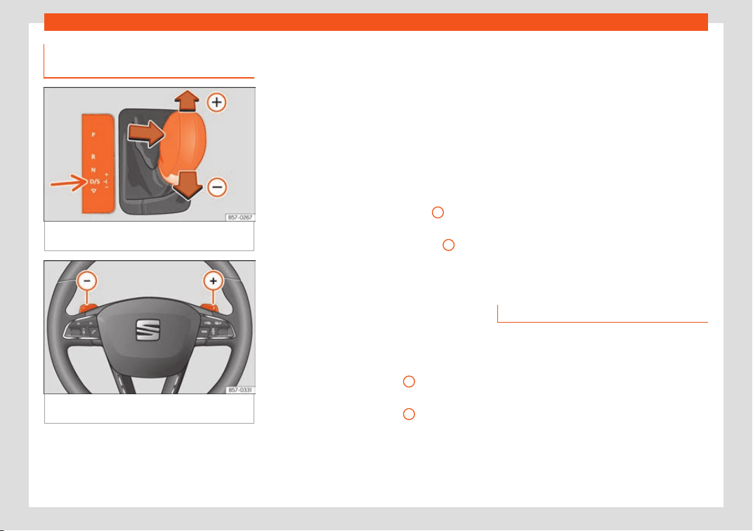
Start and driving
Engaging gears with the tiptronic
mode*
Fig. 245
Centre console: changing gear with
tiptr
onic
Fig. 246
Steering wheel: automatic gearbox
l
e
v
ers
The tiptronic gives the driver the option to
change gears manually.
Changing gear manually with the selector
l
e
v
er
It is possible to change to tiptronic mode,
both when the vehicle is stopped and while
driving.
–
To switch to tiptronic mode, move the selec-
tor lever from position D/S to the right. As
soon as the change is made the selector
level will be shown in the position M on the
instrument panel display (for example M4
means that the fourth gear is engaged).
–
Move the selector lever forwards
+
to se-
l
ect a higher gear
›
›
›
Fig. 245.
–
Move the selector lever backwards
–
to
sel
ect a l
o
wer gear.
–
To exit the Triptonic mode, move the selec-
tor lever to the left.
Changing gear manually with the gear-
shift paddles*
The gearshift paddles can be used when the
selector lever is in the position D/S or M.
–
Press the gearshift paddle
+
to select a
higher gear
›
›
›
Fig. 246.
–
Press the gearshift paddle
–
to select a
l
o
w
er gear.
–
To exit the Triptonic mode, pull the right-
hand lever towards the steering wheel for
approximately 1 second or move the selec-
tor lever to the left.
–
With the selector lever in position D/S, if no
paddle is operated during a short period of
time, the gearbox control system switches
back to automatic mode. To switch to per-
manent manual gear change using the
gearshift paddles, move the selector lever
from position D/S to the right.
When accelerating, the gearbox automati-
cally shifts up into the next gear shortly be-
fore the maximum engine speed is reached.
If you select a lower gear, the automatic
gearbox will not shift down until there is no
risk of over-revving the engine.
When the kick-down feature is used, the
gearbox shifts down to a lower gear, depend-
ing on road speed and engine speed.
Driving tips
The gearbox changes gear ratios automati-
cally as the v
ehicl
e mo
ves.
The engine can only start with the selector
lever in position P or N. At low temperatures,
below -10°C (+14°F), the engine can only
start with the selector lever in position P.
Starting the vehicle
–
Press and hold the brake pedal.
–
Press and hold the interlock button (the
button on the selector lever handle), move
»
255
Driving
the selector lever to the desired position, for
inst
ance
D
›››
page 252, and release the
interlock button.
–
Wait for the gearbox to engage the gear (a
slight movement can be felt).
–
Release the brake and press the accelera-
tor
›››
.
St
opping briefly
–
Apply the f
oot br
ake to hold the vehicle
briefly when stationary (for instance at traf-
fic lights). Do not press the accelerator.
Stopping/Parking
If the driver door is opened and the selector
lever is not in position P, the vehicle could
move. The driver message will be: Gear
change: selector lever in the drive
position!. Additionally, a buzzer will sound.
–
Press and hold the brake pedal
›››
.
–
Apply the electronic parking brake.
–
Move the selector lever to position P.
Hol
ding the car on a hill
–
Al
w
ays apply the brake pedal firmly to pre-
vent the vehicle from “moving backwards; if
necessary, apply the electronic parking
brake”
›››
. Do not try t
o st
op the v
ehicle
“rolling back” by increasing the engine
speed when a gear is engaged (pressing
the accelerator)
›››
.
St
ar
ting off uphill without the Aut
o Hold
function activated
–
Pull on the electronic parking brake button.
–
Once you have engaged a gear, gently
press the accelerator and pull on the elec-
tronic parking brake button.
Starting off uphill with the Auto Hold func-
tion activated
–
Once you have engaged a gear, take your
foot off the brake pedal and gently press
the accelerator.
Driving downhill: in some situations (on
mountain roads or when towing a trailer or
caravan) it can be advantageous to switch
temporarily to the manual gearbox pro-
gramme so that the gear ratios can be selec-
ted manually to suit the driving conditions
›››
.
On l
e
v
el ground it is sufficient to move the se-
lector lever to position P. On slopes, first en-
gage the parking brake and then put the se-
lection lever into the P position. This avoids
overloading the locking mechanism and it will
be easier to move the selector lever from po-
sition P.
WARNING
Observe the safety warnings
›››
in Selec-
tor le
ver positions on page 253.
●
Never allow the brake to rub and do not
use the brake pedal too often or for long
periods. Constant braking causes over-
heating in the brakes. This could signifi-
cantly reduce braking power, increase
braking distance or even result in the total
failure of the brake system.
●
If you have to stop on a hill and to avoid
rolling backwards, always keep the vehicle
braked using the brake pedal or use the
electronic parking brake.
CAUTION
●
If you stop the vehicl
e on a gradient, do
not attempt to stop it from rolling by de-
pressing the accelerator when a gear has
been selected. This could cause overheat-
ing and damage the automatic gearbox.
Apply the electronic parking brake or keep
the brake pedal pressed to prevent the ve-
hicle from rolling backwards.
●
If you allow the car to roll with the selec-
tor lever in position N with the engine
switched off, the automatic gearbox will be
damaged as it will not be lubricated.
●
In certain driving situations or traffic con-
ditions, such as frequently starting, pro-
longed “creeping” of the vehicle or traffic
jams with continuous stoppages, the gear-
box could overheat causing damage! If the
256
Start and driving
warning lamp lights up, stop the v
ehicle
as soon as possible and wait for the gear-
box to cool
›››
page 259.
Kick-down feature
The kick-down feature allows maximum ac-
celeration t
o be reached.
When the accelerator pedal is pressed right
down past the point of resistance at full throt-
tle, the gearbox will shift down to a lower
gear, depending on road speed and engine
speed. The upshift to the next higher gear is
delayed until the engine reaches maximum
rpm.
WARNING
Please note that if the road surface is slip-
pery or wet, the kick-do
wn feature could
cause the driving wheels to spin, which
could result in skidding.
Launch control program
3 Valid for vehicles: with Launch-Control/6-
Speed DSG with diesel engines superior to 125
kW and petr
ol engines superior to 140 kW.
The Launch control programme enables
maximum acceleration.
Condition: the engine must have reached op-
erating temperature and the steering wheel
must not be turned.
The engine speed for launch-control is differ-
ent on petrol and diesel engines. To use the
launch-control you must disconnect the anti-
slip regulation (ASR) through the Easy Con-
nect system menu
›››
page 35. The
warning lamp will stay switched on or will
flash slowly depending on whether or not the
vehicle has a driver information system*.
On vehicles with the driver information sys-
tem, the ESC lamp lights up permanently and
the corresponding text message Stability
control deactivated (temporary) appears
on the instrument panel to indicate the deac-
tivation status.
–
When the engine is running, switch off the
traction control (ASR)
1)
.
–
T
urn the selector lever to the position “S” or
tiptronic, or else select the sport driving
mode from the SEAT Drive Profile*
›››
page 303.
–
Press the brake pedal firmly with your left
foot and hold it down for at least one sec-
ond.
–
With your right foot, press the accelerator
down to the full throttle or kick-down posi-
tion. The engine speed will stabilise at
about 3,200 rpm (petrol engine) or about
2,000 rpm (diesel engine).
–
Take your left foot off the brake pedal.
WARNING
●
Always adapt your driving st
yle to the
traffic conditions.
●
Only use the launch control programme
when road and traffic conditions permit,
and make sure your manner of driving and
accelerating the vehicle does not incon-
venience or endanger other road users.
●
Make sure that the ESC remains switched
on. Please note that when the ASR and ESC
are deactivated, the wheels may start to
spin, causing the vehicle to lose grip. Risk
of accident!
»
1)
Vehicles without driver information system: the
warning lamp fl
ashes slowly/Vehicles with driver
information system: the warning lamp stays on.
257
Driving
●
After putting the vehicl
e into gear, the
“sport” mode of the ESC should be deacti-
vated again by briefly pressing the OFF
button.
Note
●
Aft
er using the Launch contr
ol pro-
gramme, the temperature in the gearbox
may have increased considerably. In this
case, the programme could be disabled for
several minutes. The programme can be
used again after the cooling phase.
●
Accelerating with the Launch control pro-
gramme places a heavy load on all parts of
the vehicle. This can result in increased
wear and tear.
Downhill speed control*
The downhill speed control function helps the
driv
er when driving do
wn st
eep gradients.
Downhill speed control is activated when the
selector lever is in D/S and the driver applies
the foot brake. The automatic gearbox auto-
matically engages a lower gear that is suita-
ble for the slope. The downhill speed control
function attempts to maintain the speed at
which the vehicle was travelling when the
foot brake was applied (subject to the laws of
physics and technical drive limitations). It
may be necessary to adjust the speed again
using the foot brake in certain situations. Giv-
en that the downhill speed control can only
change down to 3rd gear, on very steep de-
scents the tiptronic mode may be required. In
this case, manually reduce the tiptronic to
2nd or 1st gear to use the engine brake and
reduce the charge on the brakes.
Downhill speed control is deactivated as
soon as the road levels out again or you press
the accelerator pedal.
On vehicles with cruise control system*
›››
page 274, downhill speed control is acti-
vated when you set a cruising speed.
WARNING
The downhill speed control cannot defy the
laws of physics. Theref
ore, speed cannot
be maintained constant in all situations. Al-
ways be prepared to use the brakes!
Inertia mode
The inertia mode enables the kinetic energy
of the v
ehicl
e t
o be harnessed enabling cer-
tain stretches to be driven without using the
accelerator. This enables fuel to be saved.
Use the inertia mode to “let the vehicle roll”
before, for example, arriving in a town.
Switching on inertia mode
Condition: selector lever must be in position
D, gradients below 12 %.
–
Select, in SEAT Drive Profile*, Eco mode
›››
page 303.
–
Take your foot off the accelerator.
The driver message Inertia will be dis-
played. At speeds higher than 20 km/h (12
mph), the gearbox will automatically disen-
gage and the vehicle will roll freely, without
the effect of the engine brake. While the vehi-
cle rolls, the engine runs at idling speed.
Stopping inertia mode
–
Press the brake or the accelerator pedal.
To make use of the braking force and switch
off the engine again, simply press the brake
pedal briefly.
Applying both the inertia mode (= prolonged
section with less energy) and the switching
off using inertia (= shorter section without
the need for fuel) facilitates improved fuel
consumption and emission balance.
WARNING
●
If the inertia mode has been swit
ched on,
take into account, when approaching an
obstacle and releasing the accelerator
pedal, that the vehicle will not decelerate
in the usual manner: risk of accident!
●
When using inertia mode while travelling
down hills, the vehicle can increase speed:
risk of accident!
258
Start and driving
●
If other users drive your vehicl
e, warn
them about inertia mode.
Note
●
Iner
tia mode is only avail
able in eco
(SEAT Drive Profile*) driving mode.
●
The driver message Inertia is only dis-
played with the current consumption. In in-
ertia mode the gear will no longer be dis-
played (for example “E” will appear instead
of “E7”).
●
On downhill sections with gradients
above 15 %, the inertia mode will automati-
cally be switched off temporarily.
Emergency program
A backup programme is in place if a fault
shoul
d occur in the contr
ol syst
em.
If all the positions of the selector lever are
shown over a light background on the instru-
ment panel display, there is a system fault
and the automatic gearbox will operate in
with the backup programme. When the back-
up programme is activated, it is possible to
drive the vehicle, however, at low speeds and
within a selected range of gears. In some ca-
ses driving in reverse gear may not be pos-
sible.
CAUTION
If the gearbox operates with the backup
programme
, take the vehicle to a special-
ised workshop and have the fault repaired
without delay.
Indications on the instrument panel
display
Clutch
Clutch overheating! Please stop!
The clutch has ov
erheated and could be
damaged. Stop the vehicle and wait for the
gearbox to cool with the engine at idling
speed and the selector lever in position P.
When the warning lamp and the driver mes-
sage switch off, have the fault corrected by a
specialised workshop without delay. If the
warning lamp and the driver message do not
switch off, do not continue driving. Seek spe-
cialist assistance.
Gearbox malfunctions
Gearbox: Fault! Stop the vehicle
and place the lever in the posi-
tion P.
There is a fault in the gearbox. Stop the vehi-
cle in a safe place and do not continue driv-
ing. Seek specialist assistance.
Gearbox: System fault! You may
continue driving.
Have the fault corr
ected by a specialised
workshop without delay.
Gearbox: System fault! You can
continue driving with restric-
tions. Reverse gear disabled
Take the vehicle to a specialised workshop
and have the fault repaired without delay.
Gearbox: System fault! You can
continue driving in D until
switching off the engine
Stop the vehicle in a safe place well away
from moving traffic. Seek specialist assis-
tance.
Gearbox: too hot. Adapt your
driving accordingly
Continue driving at moderate speeds. When
the warning lamp switches off, you can con-
tinue driving in a normal manner.
Gearbox: press the brake and en-
gage a gear again.
If the fault was caused by a gearbox with a
high temperature, this driver message will be
displayed when the gearbox has cooled
again.
259
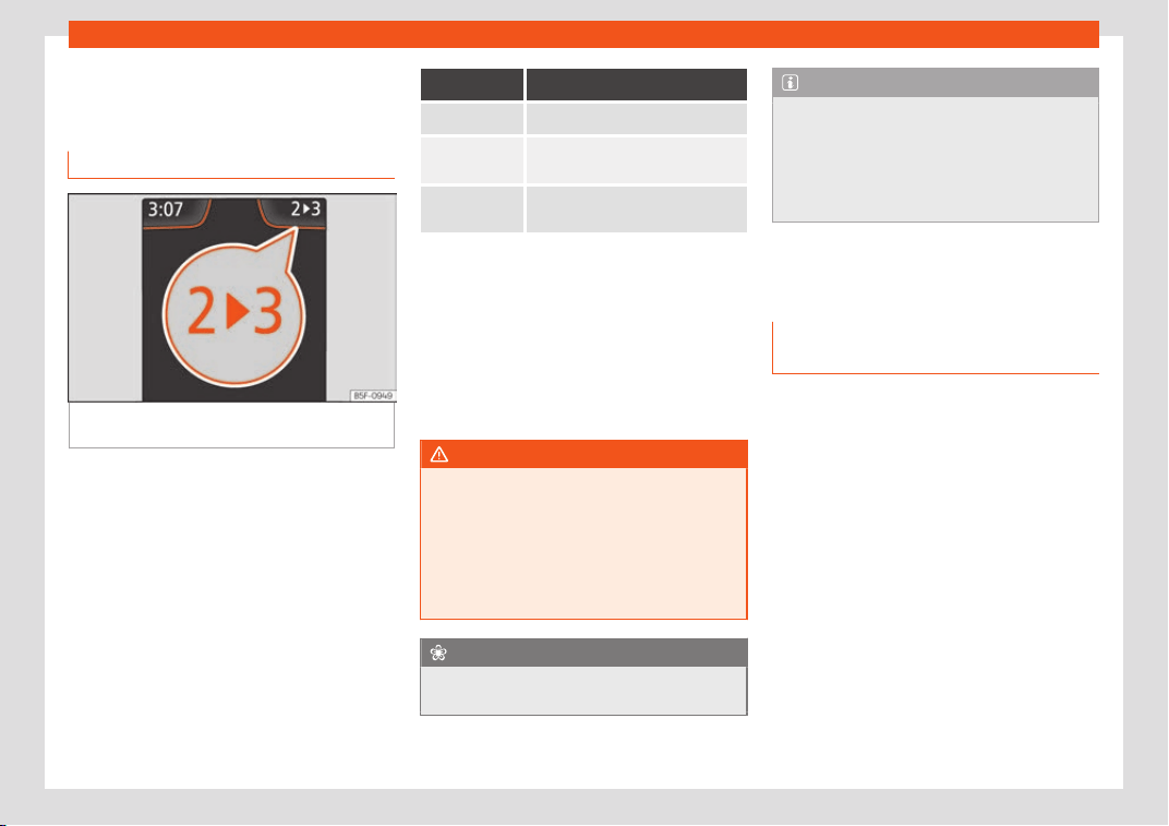
Driving
Gear-change recommenda-
tion
Choosing the ideal gear
Fig. 247
Instrument panel: gear-change indi-
cat
or (manual gearbo
x).
While driving, and depending on vehicle
equipment, the instrument panel displ
ay may
sho
w a r
ecommendation with the gear num-
ber that would be advisable to save fuel.
In vehicles with an automatic gearbox, the
selector lever must be in the tiptronic position
›››
page 255.
No recommendation will appear if the opti-
mal gear is already engaged. The current
gear will be displayed.
Display Meaning
The optimal gear is selected.
Changing to a higher gear is rec-
ommended.
Changing to a lower gear is rec-
ommended.
Information regarding the “cleanliness” of
the particulat
e filter
The exhaust system manager detects that
the particulate filter is nearly saturated and
contributes to self-cleaning by recommend-
ing the optimal gear. For this reason, it might
be necessary to drive for a short time at a
high rpm.
WARNING
The gear change indicator is only an auxili-
ary function and in no case should be a
substitut
e for careful driving.
●
The responsibility of choosing the correct
gear depending on the situation (e.g. over-
taking, driving up or down a slope or towing
a trailer) lies with the driver.
For the sake of the environment
Selecting the correct gear can help to save
fuel.
Note
The recommended gear indication turns off
when the clutch pedal is pressed in v
ehi-
cles with manual gearbox or when the se-
lector lever is removed from the tiptronic
position in vehicles with an automatic gear-
box.
Steering
Information rel
ated to steering the
vehicle
Electro-mechanical power steering assists
the driv
er when st
eering.
El
ectro-mechanical power steering adapts
electronically to the speed of the car, torque
and turning angle.
If the power steering should fail at any time or
the engine is switched off (for instance when
being towed), the car can still be steered, as
long as the key remains in the ignition. How-
ever, more effort than normal will be required
to turn the steering wheel.
Progressive steering
Depending on the vehicle’s features, it may or
may not incorporate a progressive steering
system.
260
Start and driving
In cit
y traffic you do not need to turn so much
on parking, manoeuvring or in v
ery tight t
urns.
On the road or on the motorway, progressive
steering transmits, for example, in bends, a
sportier, more direct and noticeably more dy-
namic driving sensation.
Power-assisted steering
Power-assisted steering helps the driver in
critical situations. It recommends the rotation
direction of the steering wheel to perform a
corrective manoeuvre (counter-steering),
thereby causing a small turn of the wheel in
the correct direction to avoid skidding
›››
.
WARNING
Power-assisted steering, together with the
ESC, helps the driver to contr
ol vehicle
steering in critical situations. However, the
driver is ultimately responsible for steering
the vehicle at all times. Power-assisted
steering does not remove this responsibili-
ty.
Control lamp
It lights up red
The electromechanical steering is damaged.
Do not continue driving. Stop the vehicle safely and
as soon as possible.
Have the steering checked immediately by a special-
ised workshop.
It lights up yellow
The operation of the electromechanical steering is
limited.
See a specialised workshop immediat
ely and have
the steering checked.
If the yellow warning lamp does not light up again af-
ter the engine is restarted and the vehicle has travel-
led a short distance, you do not need to take it to a
specialised workshop.
Or: The 12-volt battery was disconnected and has
been connected again.
Driv
e for a short time at 15-20 km/h (9-12 mph).
It flashes yellow
The steering column is tight.
Turn the wheel a little t
o both sides.
Or: Not unlocked or blocked steering column.
Remo
ve the key from the ignition and then switch the
ignition back on. If necessary, check the messages
displayed on the instrument panel display.
Do not drive on if the steering column remains
locked after the ignition has been switched on. Seek
specialist assistance.
The control lamp should light up for a few
seconds when the ignition is s
wit
ched on. It
shoul
d go out once the engine is started.
WARNING
If the warning lamps and the corresponding
messages are ignored when they light up
,
the vehicle may stall in traffic. It could case
damage to the vehicle and cause acci-
dents and severe injuries.
●
Never ignore the warning lamps or mes-
sages.
●
Stop the vehicle at the next opportunity
and in a safe place.
Run-in and economical driv-
ing
Running in the engine
A new vehicle should be run in over a dis-
t
ance of 1500 km (
1000 mil
es). For the first
1,000 km the engine speed should not ex-
ceed 2/3 of the maximum permissible engine
speed. In doing so, do not accelerate at full
throttle and do not drive with a trailer! From
1000 to 1500 km (600 to 1000 miles) you
can gradually increase the engine rpm and
road speed.
»
261

Driving
During its first few hours of running, the inter-
nal friction in the engine is gr
eat
er than l
ater
on when all the moving parts have bedded
down.
How the vehicle is driven for the first 1,500 km
influences the future engine performance.
Subsequently, also drive at a moderate rate,
especially when the engine is still cold: this
will lead to less engine wear and tear and will
prolong its useful life.
You should also avoid driving with the engine
speed too low. Change down to a lower gear
when the engine no longer runs “smoothly”. If
the engine revs too much, cut fuel injection to
protect the engine.
Environmental compatibility
Environmental protection is a top priority in
the design, choice of mat
erial
s and manuf
ac-
ture of your new SEAT.
Constructive measures to encourage re-
cycling
●
Joints and connections designed for easy
dismantling.
●
Modular construction to facilitate disman-
tling.
●
Increased use of single-grade materials.
●
Plastic parts and elastomers are marked in
accordance with ISO 1043, ISO 11469 and
ISO 1629.
Choice of materials
●
Use of recycled materials.
●
Use of compatible plastics in the same part
if its components are not easily separated.
●
Use of recycled materials and/or materials
originating from renewable sources.
●
Reduction of volatile components, including
odour, in plastic materials.
●
Use of CFC-free coolants.
Ban on heavy metals, with the exceptions
dictated by law (Annex II of ELV Directive
2000/53/EC): cadmium, lead, mercury,
hexavalent chromium.
Manufacturing methods
●
Reduction of the quantity of thinner in the
protective wax for cavities.
●
Use of plastic film as protection during vehi-
cle transport.
●
Use of solvent-free adhesives.
●
Use of CFC-free coolants in cooling sys-
tems.
●
Recycling and energy recovery from resi-
dues (RDF).
●
Improvement in the quality of waste water.
●
Use of systems for the recovery of residual
heat (thermal recovery, enthalpy wheels,
etc.).
●
The use of water-soluble paints.
Economical and environmentally-
friendly driving
Fuel consumption, environmental pollution
and wear to the engine
, brakes and tyres de-
pends largely on driving style. Fuel consump-
tion can be reduced by 10-15% with an eco-
nomical driving style and proper anticipation
of traffic conditions. The following section
gives you some tips on lessening the impact
on the environment and reducing your oper-
ating costs at the same time.
Active cylinder management (ACT
®
)*
Depending on vehicle equipment, the active
cylinder management (ACT
®
) may automati-
cally deactivate some of the engine cylinders
if the driving situation does not require too
much power. When it is switched off, no fuel is
injected into these cylinders, hence total fuel
consumption may be reduced. The number
of active cylinders can be seen on the instru-
ment panel display.
›››
page 108.
262

Start and driving
Foresight when driving
Accel
er
ation causes the v
ehicle to consume
more fuel. If you think ahead when driving,
you will need to brake less and thus acceler-
ate less. Wherever possible, let the car roll
slowly to a stop, with a gear engaged (for in-
stance when you can see that the next traffic
lights are red). This takes advantage of the
engine braking effect, reducing wear on the
brakes and tyres. Emissions and fuel con-
sumption will drop to zero due to the overrun
fuel cut-off.
Changing gear to save energy
An effective way of saving is to change in ad-
vance to a higher gear. Running the engine at
high rpm in the lower gears uses an unneces-
sary amount of fuel.
Manual transmission: shift up from first to
second gear as soon as possible. In any case,
we recommend that you change to a higher
gear upon reaching 2,000 rpm. Choosing the
right gear enables fuel savings. Select the
highest possible gear appropriate for the
driving situation (the engine should continue
functioning with cyclical regularity).
Automatic transmission: accelerate gradu-
ally and without reaching the “kick-down”
position.
Avoid driving at high speed
Avoid travelling at top speed, whenever pos-
sible. Fuel consumption, emission of harmful
gases and noise pollution multiply dispropor-
tionately as speed is increased. Driving at
moderate speeds will help to save fuel.
Reduce idling time
In vehicles with the Start-Stop system idling is
automatically reduced. In vehicles without
the Start-Stop system it is worth switching off
the engine, for example, at level crossings
and at traffic lights that remain red for long
periods of time. When an engine has reached
operating temperature, and depending on
the cylinder capacity, keeping it switched off
for a minimum of about 5 seconds already
saves more than the amount of fuel necessa-
ry for restarting.
The engine takes a long time to warm up
when it is idling. Mechanical wear and pollu-
tant emissions are also especially high during
this initial warm-up phase. It is therefore best
to drive off immediately after starting the en-
gine. Avoid running the engine at high speed.
Regular maintenance
Regular servicing helps in saving fuel even
before the engine is started. A well-serviced
engine gives you the benefit of improved fuel
efficiency as well as maximum reliability and
an enhanced resale value. A badly serviced
engine can consume up to 10% more fuel
than necessary.
Avoid short journeys
The engine and catalytic converter need to
reach their optimal operating temperature
in order to minimise fuel consumption and
emissions.
A cold engine consumes a disproportionate
amount of fuel. The engine reaches its work-
ing temperature after about four kilometres
(2.5 miles), when fuel consumption will return
to a normal level.
Check tyre pressure
Always make sure the tyres are inflated to the
correct pressures
›››
page 358 to save fuel. If
the pressure is below half bar, fuel consump-
tion may increase by 5%. Due to the greater
rolling resistance, under-inflation also increa-
ses tyre wear and impairs handling.
Do not use winter tyres all year round as
they increase fuel consumption by up to 10%.
Avoid carrying unnecessary loads
Given that every kilo of extra weight will in-
crease the fuel consumption, it is advisable to
always check the luggage compartment to
make sure that no unnecessary loads are be-
ing transported.
»
263
Driving
Since the luggage rack increases the aer
o-
dynamic dr
ag
of the vehicle, you should re-
move it when not needed. At speeds of
100-120 km/h (62-75 mph), this will save 12%
of fuel.
Save electrical energy
The engine drives the alternator, thereby
generating electricity. This implies that any
increase in power consumption also increa-
ses fuel consumption! For this reason, switch
off any unneeded electrical devices. Devices
that use a lot of electricity includes the blow-
er at a high setting, the rear window heating
or the seat heating*.
Power management
This system helps to ensure relia-
ble starting
The power management controls the distri-
bution of el
ectrical ener
gy and thus helps t
o
ensure that there is always enough power
available to start the engine.
If a vehicle with a conventional electrical sys-
tem is left parked for a long time, the battery
will gradually lose its charge because certain
electrical devices, such as the electronic
gearbox lock continues to draw current even
when the ignition is off. In some cases there
may not be enough power available to start
the engine.
Your vehicle is equipped with an intelligent
power management system to control the
distribution of electrical energy. This signifi-
cantly improves reliability when starting the
engine, and also prolongs the useful life of the
battery.
The main functions incorporated in the power
management system are battery diagnosis,
residual current management and dynam-
ic power management.
Battery diagnosis
The battery diagnosis function constantly
registers the condition of the battery. Sensors
detect the battery voltage, battery current
and battery temperature. This enables the
system to calculate the current power level
and charge condition of the battery.
Residual current management
The residual current management reduces
power consumption while the vehicle is
parked. It controls the supply of power to the
various electrical devices while the ignition is
switched off. The system takes the battery di-
agnosis data into consideration.
Depending on the power level of the battery,
switch off the individual electrical devices
one after the other to prevent the battery
from losing too much charge and to ensure
that the engine can be started reliably.
Dynamic power management
While the vehicle is moving, this function dis-
tributes the available power to the various
electrical devices and systems according to
their requirements. The power management
ensures that on-board systems do not con-
sume more electrical power than the alterna-
tor can supply, and thus maintains the maxi-
mum possible battery power level.
Note
●
Neither is the power management syst
em
able to overcome the given physical limits.
Please remember that the power and use-
ful life of the battery are limited.
●
When there is a risk that the vehicle will
not start, the alternator power failure or
low battery charge level warning lamp will
be shown
›››
page 122.
Flat battery
Starting ability has first priority.
Short trips, cit
y tr
affic and l
ow temperatures
all place a heavy load on the battery. In
these conditions a large amount of power is
consumed, but only a small amount is sup-
plied. The situation is also critical if electrical
devices are in use when the engine is not
264
Start and driving
running. In this case power is consumed when
none is being gener
at
ed.
In these sit
uations you will be aware that the
power management system is intervening to
control the distribution of electrical power.
When the vehicle is parked for long peri-
ods
If you do not drive your vehicle for a period of
several days or weeks, the power manage-
ment will gradually shut off the electrical de-
vices one by one or reduce the amount of
current they are using. This limits the amount
of power consumed and helps to ensure reli-
able starting even after a long period. Some
convenience functions, such as remote vehi-
cle opening, may not be available under cer-
tain circumstances. These functions will be
restored when you switch on the ignition and
start the engine.
With the engine switched off
For example, if you listen to the sound system
with the engine switched off the battery will
run down.
If the energy consumption means there is a
risk that the engine will not start, a text will
appear in vehicles with a driver information
system*.
This driver indicator tells you that you must
start the engine so that the battery can re-
charge.
When the engine is running
Although the alternator generates electrical
power, the battery can still become dis-
charged while the vehicle is being driven. This
can occur when a lot of power is being con-
sumed but only a small amount supplied, es-
pecially if the battery is not fully charged ini-
tially.
To restore the necessary energy balance, the
system will then temporarily shut off the elec-
trical devices that are using a lot of power, or
reduce the current they are consuming. Heat-
ing systems in particular use a large amount
of electrical power. If you notice, for instance,
that the seat heating* or the rear window
heater is not working, they may have been
temporarily switched off or regulated to a
lower heat output. These systems will be
available again as soon as sufficient electri-
cal power is available.
You may also notice that the engine runs at a
slightly faster idling speed when necessary.
This is quite normal, and no cause for con-
cern. The increased idling speed allows the
alternator to meet the greater power require-
ment and charge the battery at the same
time.
Engine management and
emission control system
Introduction
WARNING
●
Because of the high temperat
ures which
can occur in the exhaust purification sys-
tem (catalytic converter or particulate fil-
ter), do not park the vehicle where the ex-
haust can come into contact with flamma-
ble materials under the car (e.g. on grass or
at the forest edge). Fire hazard!
●
Do not apply wax underneath the vehicle
around the area of the exhaust system: Fire
hazard!
Control lamps
It lights up
Fault in the emission control system. (e.g. faulty
lambda sensor).
Reduce speed and driv
e carefully to the nearest spe-
cialised workshop to have the engine checked.
Flashes
Combustion fault which could damage the catalytic
converter
.
Reduce speed and drive carefully to the nearest spe-
cialised workshop to have the engine checked.
»
265
Driving
It lights up
Particulate filter blocked
›››
page 266.
It lights up
Fault in the management of the petrol engine.
Have the engine checked by a specialised w
orkshop
as soon as possible.
The warning lamp (Electronic P
ower Control)
lights up when the ignition is switched on while sys-
tem operation is being verified. It should go out once
the engine is started.
It lights up
Diesel engine glow plug system.
The engine glow plug syst
em has been activated.
The engine can be started straight away when the
lamp switches off.
Flashes
Fault in the management of the diesel engine.
Have the engine checked by a specialised w
orkshop
as soon as possible.
Note
While the control lamps are on , ,
or there might be faults in the engine
,
fuel consumption may go up and the en-
gine might lose power.
Catalytic converter
To maintain the useful life of the catalytic
convert
er
●
Use only unleaded petrol with petrol en-
gines, as lead damages the catalytic con-
verter.
●
Do not let the fuel get too low in the tank.
●
For engine oil changes, do not replenish
with too much engine oil
›››
page 351, Top-
ping up engine oil.
●
Never tow the vehicle to start it, use jump
leads if necessary
››
›
page 59.
If you notice misfiring, uneven running or loss
of power when the vehicle is moving, reduce
speed immediately and have the vehicle in-
spected at the nearest specialised workshop.
In general, the exhaust warning lamp will
light up when any of the described symptoms
occur. If this happens, unburnt fuel can enter
the exhaust system and escape into the envi-
ronment. The catalytic converter can also be
damaged by overheating.
CAUTION
Never run the fuel tank completely dry be-
cause the irregularit
y of the fuel supply
may cause ignition problems. This allows
unburnt fuel to enter the exhaust system,
which could cause overheating and dam-
age the catalytic converter.
For the sake of the environment
Even when the emission control system is
working perfectly, ther
e may be a smell of
sulphur from the exhaust gas under some
conditions. This depends on the sulphur
content of the fuel used. Quite often the
problem can be solved by changing to an-
other brand of fuel.
Particulate filter
The particulate filter eliminates most of the
soot fr
om the e
xhaust gas syst
em. Under nor-
mal driving conditions, the filter cleans itself.
The particulate filter is cleaned automatically
without need for indication by the warning
lamp . This may be noticed because the
engine idle speed increases and an odour
may be detected.
If automatic filter purification cannot be car-
ried out (because only short trips are taken,
for example), soot will accumulate on the fil-
ter and the particulate filter warning lamp will
switch on.
Facilitate the automatic filter cleaning proc-
ess by driving in the following manner:
●
Drive for approximately 15 minutes at a
minimum speed of 60 km/h (37 mph) in 4th or
5th gear (automatic gearbox: S gear range).
266
Start and driving
●
Maint
ain the engine speed at appr
o
ximate-
ly 2,000 rpm.
The rise in temperature causes the soot on
the filter to burn. On completion of the clean-
ing the warning lamp will switch off. If the
warning lamp does not switch off, go immedi-
ately to a specialised workshop to rectify the
problem.
Driving tips
Driving on flooded roads
To prevent damage to the vehicle when driv-
ing thr
ough w
at
er, for example, along a floo-
ded road, please observe the following:
●
The water should never come above the
lower edge of the bodywork.
●
Drive at pedestrian speed.
WARNING
After driving through water, mud, sludge,
etc., the braking eff
ect can be delayed
slightly due to moisture build-up on the
discs and brake pads. Applying the brakes
carefully several times will remove the
moisture and restore the full braking effect.
CAUTION
●
Driving through flooded ar
eas may se-
verely damage vehicle components such
as the engine, transmission, running gear or
electrical system.
●
Whenever driving through water, the
Start-Stop system* must be switched off
›››
page 269.
Note
●
Check the depth of the water bef
ore en-
tering the flooded zone.
●
Do not stop in the water, drive in reverse,
or stop the engine in any situation.
●
Note that vehicles travelling in the oppo-
site direction may splash water that could
exceed the maximum permitted water
height for your vehicle.
●
Avoid driving through salt water (corro-
sion).
Total traction (4Drive)
3 Valid for vehicles: 4Drive all-wheel drive
On f
our-wheel drive models, the engine pow-
er is distributed to all four wheels
General notes
On four-wheel drive vehicles, the engine
power is distributed to all four wheels. The
distribution of power is controlled automati-
cally according to your driving st
yle and the
road conditions. Also see
›››
page 248.
The four-wheel drive is specially designed to
complement the superior engine power. This
combination gives the vehicle exceptional
handling and performance capabilities, both
on normal roads and in more difficult condi-
tions, such as snow and ice. Even so (or per-
haps especially for this reason), it is important
to observe certain safety points
›››
.
Wint
er t
yr
es
Thanks to four-wheel drive, your vehicle will
have plenty of traction in winter conditions,
even with the standard tyres. Nevertheless,
we still recommend that winter tyres or all-
season tyres be fitted on all four wheels to
give even better braking response.
Snow chains
On roads where snow chains are mandatory,
this also applies to cars with four-wheel drive
›››
page 58.
Changing tyres
On vehicles with four-wheel drive, all four
tyres must have the same rolling circumfer-
ence. Also avoid using tyres with varying
tread depths
›››
page 360.
»
267

Driving
Off-roader?
If your SEAT v
ehicl
e is not an off
-roader: it
does not have enough ground clearance to
be used as such. It is therefore best to avoid
rough tracks and uneven terrain as much as
possible.
WARNING
●
Even with four
-wheel drive, you should al-
ways adjust your speed to suit the condi-
tions. Do not let the extra safety features
tempt you into taking any risks when driv-
ing. Risk of accident!
●
The braking capability of your vehicle is
limited by the tyres' grip. It is therefore no
different from a car without four-wheel
drive. So do not be tempted to drive too fast
on firm or slippery roads just because the
vehicle still has good acceleration in these
conditions. Risk of accident!
●
On wet roads bear in mind that the front
wheels may start to “aquaplane” and lose
contact with the road if the car is driven too
fast. If this should happen, there will be no
sudden increase in engine speed to warn
the driver, as occurs with a front-wheel
drive car. For this reason you should always
choose a driving speed suitable for the
road conditions. Risk of accident!
268
Driver assistance systems
Driver assistance systems
St
ar
t
-Stop system*
Control lamps
It lights up
The Start-Stop system is available, the automatic en-
gine shutdown is active.
It lights up
The Start-Stop system is not available.
Instructions for the driver on the instru-
ment panel displ
ay
Start-Stop system deactivated.
Start the engine manually
This driv
er message is displ
ayed when cer-
tain conditions are not met during the stop-
ping phase and the Start-Stop system can-
not restart the engine. The engine must be
started manually.
Start-Stop system: Fault! Function
not available
There is a fault in the Start-Stop system. Take
the vehicle to a workshop to have the fault re-
paired.
Description and operation
The Start-Stop system helps save fuel and
reduce CO
2
emissions.
In Start
-Stop mode, the engine will automati-
cally switch off when the vehicle stops or is
stopping; for example when stopping at traf-
fic lights. The ignition remains switched on
during the stopping phase. The engine auto-
matically switches back on when required. In
this situation, the light of the
START ENGINE STOP
button stays on
1)
.
As soon as the ignition is switched on, the
St
art-Stop function is automatically activa-
ted.
Further information about the Start-Stop sys-
tem can be found on the Easy Connect sys-
tem: by pressing the button
in the Vehi-
cle status menu.
V
ehicl
es with a manual gearbo
x
●
Before stopping the vehicle or when it is
stopped, put it into neutral and release the
clutch pedal. The engine will switch off. The
warning lamp will appear on the instru-
ment panel display. The engine may stop be-
fore the vehicle comes to a halt in the decel-
eration phase (at 7 km/h).
●
When the clutch pedal is pressed the en-
gine will start up again. The warning lamp will
switch off.
Vehicles with an automatic gearbox
●
Brake the vehicle until it is stopped, and
keep your foot on the brake pedal or activate
the Auto Hold* system so that the vehicle re-
mains braked. The engine will switch off. The
warning lamp will appear in the display.
The engine may stop before the vehicle
comes to a halt in the deceleration phase (at
7 km/h or 2 km/h, depending on the vehicle’s
gearbox).
●
When you take your foot off the brake ped-
al the engine will start up again. The warning
lamp will switch off. In vehicles with the Auto
Hold* system, when the system is active, the
engine will not start if you remove your foot
from the brake pedal. The car starts when
you press the accelerator pedal.
Basic requirements for the Start-Stop
mode
●
The driver door must be closed.
●
The driver must have their seat belt fas-
tened.
●
The bonnet must be closed.
»
1)
Only in vehicles with Keyless Access.
269
Driving
●
The engine must hav
e r
eached a minimum
service t
emperature.
●
The reverse gear must not be engaged.
●
The vehicle must not be on a very steep
slope.
The system can interrupt the Start-Stop
mode frequently for different reasons.
The engine does not switch off
Before the stopping phase, the system verifies
whether certain conditions are met. The en-
gine does not switch off, in the following sit-
uations for example:
●
The engine has not yet reached the mini-
mum required temperature for the Start-Stop
mode.
●
The interior temperature selected for the air
conditioner has not yet been reached.
●
The interior temperature is very high/low.
●
Defrost function button activated
›››
page 42.
●
The parking aid* is switched on.
●
The battery is very low.
●
The steering wheel is overly turned or is be-
ing turned.
●
If there is a danger of misting.
●
After engaging reverse gear.
●
In case of a very steep gradient.
The indication is shown on the instrument
panel display, and in addition, the driver infor-
mation system* shows, .
The engine starts by itself
During a stopping phase the normal Start-
Stop mode can be interrupted in the following
situations: The engine restarts by itself with-
out involvement from the driver.
●
The interior temperature differs from the
value selected on the air conditioner.
●
Defrost function button activated
›››
page 42.
●
The brake has been pressed several times
consecutively.
●
The battery is too low.
●
High power consumption.
Additional information related to the auto-
matic gearbox
The engine stops when the selector lever is in
the positions P, D, N and S, in addition to when
in Triptonic mode. With the selector lever in
position P, the engine will also remain switch-
ed off when you take your foot off the brake
pedal. In order to start the engine up again
the accelerator must be pressed, or another
gear engaged or the brake released.
If the selector lever is placed in position R dur-
ing the stopping phase, the engine will start
up again.
Change from position D to P to prevent the
engine from accidentally starting when
changing and passing by position R.
Additional information about vehicles with
Adaptive Cruise Control (ACC)
In vehicles with ACC function, the engine will
start up again in certain operating conditions
if the radar sensor detects that the vehicle
ahead drives off again.
WARNING
●
Never s
witch the engine off until the vehi-
cle is stationary. The brake servo and pow-
er steering functions will not be completely
covered under warranty. More force may
also be needed to turn the steering wheel
or to brake. As you cannot steer and brake
in the normal manner, there is a greater risk
of accidents and serious injury.
●
Never remove the key from the ignition if
the vehicle is in motion. Otherwise, the
steering could lock making it impossible to
steer the vehicle.
●
To avoid injury, make sure that the Start-
Stop system is switched off when working
in the engine compartment
›››
page 271.
CAUTION
The Start-Stop system must always be
switched off when driving thr
ough flooded
areas
›››
page 271.
270
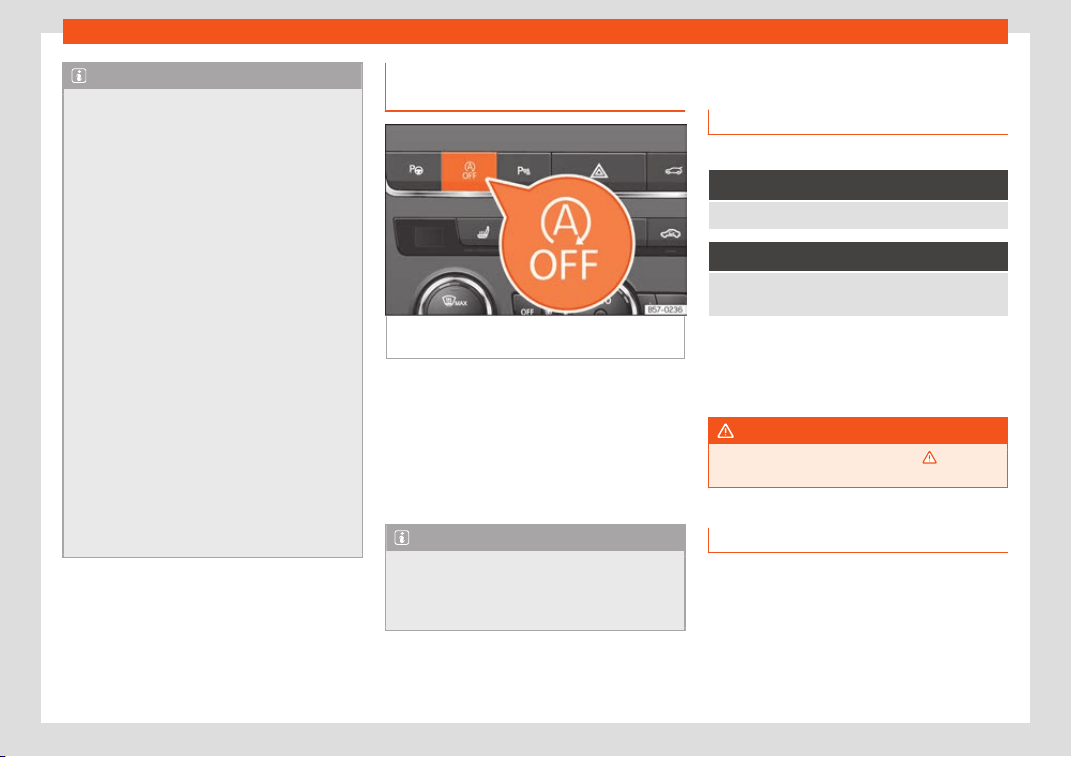
Driver assistance systems
Note
●
In vehicles with an aut
omatic gearbox,
you can control whether the engine should
switch off or not by reducing or increasing
the brake force applied. While the vehicle
remains stopped, the engine will not stop if
the brake pedal is slightly pressed, in traffic
jams with frequent stopping and starting
for example. As soon as strong pressure is
applied to the brake pedal, the engine will
stop.
●
In vehicles with manual gearbox, during
the stopping phases the brake pedal must
remain depressed to prevent the vehicle
from moving.
●
If the engine “stalls” in vehicles with
manual gearbox, it can be directly started
up again by immediately pressing the
clutch pedal.
●
In vehicles with an automatic gearbox, if
the selector lever is placed in position D, N
or S after engaging reverse gear, the vehi-
cle must be driven at a speed faster than 10
km/h (6 mph) for the system to return to
conditions in which the engine can be stop-
ped.
Manually switching on/off the
St
ar
t
-Stop system
Fig. 248
Centre console: Start-Stop system
butt
on.
If you do not wish to use the system, you can
s
wit
ch it off manually.
●
T
o manually switch on/off the Start-Stop
system, press the button
›››
Fig. 248.
The button symbol remains lit up yellow
when the system is switched off.
Note
The system is automatically switched on
each time the engine is deliberately st
op-
ped during a stopping phase. The engine
will start automatically.
Hill Descent Control (HDC)
Contr
ol l
amps
3 Valid for vehicles: 4Drive all-wheel drive
It lights up white
Hill Descent Control is active.
It lights up grey
Hill Descent Control is not active. The system is
switched on, but is not adjusting.
Some control and warning lamps will light up
briefly when the ignition is s
wit
ched on t
o
check certain functions. They will switch off
after a few seconds.
WARNING
Observe the safety warnings
›››
in Con-
trol and warning l
amps on page 123.
Description and operation
Hill Descent Control limits the speed on steep
descents by aut
omatically br
aking all f
our
wheels, both when moving forward and in re-
verse. As the anti-lock brake system remains
active, it prevents the wheels from locking. In
vehicles with manual transmission, the Hill
Descent Control adapts the theoretical
»
271
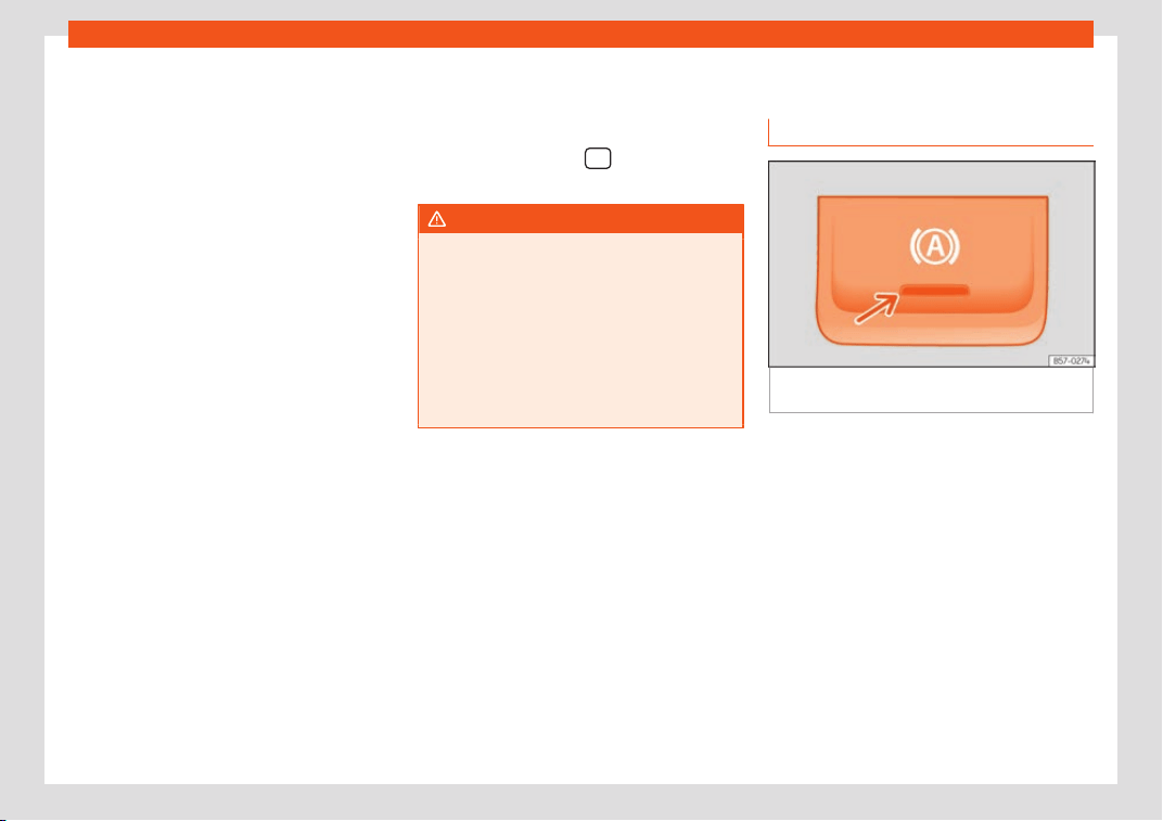
Driving
speed without slowing the engine below its
idling speed.
Aft
er st
arting the descent of a sl
ope below
30 km/h (18 mph), speed is limited to a mini-
mum of 2 km/h (1 mph) and a maximum of
30 km/h (18 mph). When appropriate, the
driver may increase or decrease the speed
within the limit by pressing the accelerator or
the brake. At this point the function is interrup-
ted and, if necessary, it is then reactivated.
Even so, it is imperative that the surface guar-
antees sufficient adhesion. For this reason,
the Hill Descent Control will not fulfil its func-
tion when, for example, descending a slope
with a frozen or slippery surface.
Hill Descent Control is available when the
dash panel display shows the message .
Hill Descent Control automatically intervenes
if the following conditions are met:
●
The vehicle engine is running.
●
The Offroad driving profile has been selec-
ted
›››
page 303. Driving at a speed below 30
km/h (18 mph) (the message is shown on
the dash panel display).
●
The slope of the descent is at least 10%
when driving forward and 9% when driving in
reverse.
●
The brake and the accelerator are not
pressed.
Hill Descent Control is deactivated on press-
ing the brake and the accelerator or if the
slope is below 5%. The function may be dis-
connected manually in the Easy Connect
system by pressing the
button > HDC
function butt
on
›
›
›
Fig. 51.
WARNING
Always be ready to brake. Otherwise, an
accident could occur and cause injury.
●
Hill Descent Control is only an auxiliary
syst
em that in some situations may not suf-
ficiently brake the vehicle when going
down a slope.
●
The speed of the vehicle may increase
despite the intervention of Hill Descent
Control.
Auto Hold Function
Description and oper
ation
Fig. 249 In the lower part of the centre con-
sol
e: Aut
o Hol
d function button.
The control light of the
›
›
›
Fig. 249 button
remains on when the Auto Hold function is
connected.
Once connected, the Auto Hold function as-
sists the driver in keeping the vehicle station-
ary at repeated intervals or for a certain peri-
od of time with the engine running, for exam-
ple, when going up a slope, when stopped at
traffic lights or in heavy traffic with intermit-
tent stops.
When connected, the Auto Hold function au-
tomatically prevents the vehicle from rolling
when stationary without pressing the brake
pedal.
272
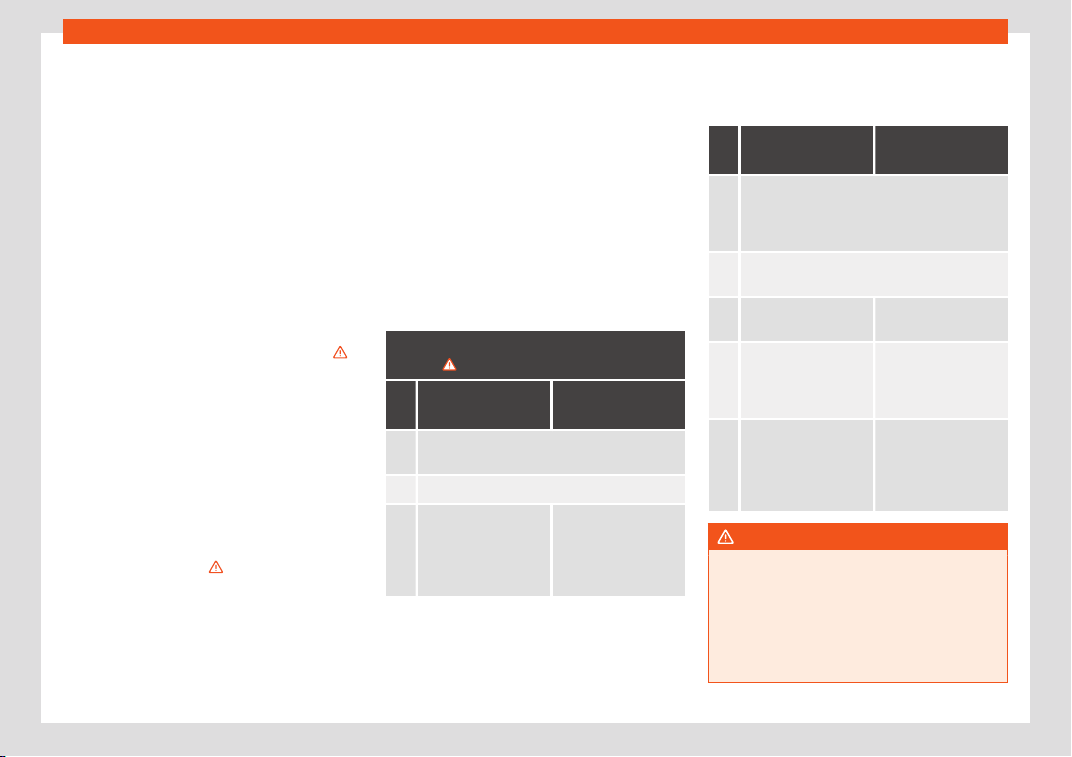
Driver assistance systems
After detecting that the vehicle is stationary
and the br
ak
e pedal has been r
eleased, the
Auto Hold function holds the vehicle. The driv-
er can lift their foot off the brake pedal.
When the driver touches the accelerator
pedal or accelerates slightly to continue driv-
ing, the Auto Hold function releases the brake.
The vehicle moves according to the slope of
the road.
If the vehicle is stationary and one of the con-
ditions required by the Auto Hold function is
impaired, it disconnects itself and the button's
control light goes out
›››
Fig. 249. The elec-
tronic parking brake connects automatically,
if necessary, to park the vehicle safely
›››
.
Conditions f
or k
eeping the v
ehicle station-
ary with the Auto Hold function
●
The driver door must be closed.
●
The driver's seat belt must be fastened.
●
The engine is running.
Switching the Auto Hold function on and
off
Press the button
›››
. The control lamp on
the butt
on goes out when the Aut
o Hol
d func-
tion is switched off.
Automatically engaging and disengaging
the Auto Hold function
If the Auto Hold function was switched on with
the button before disengaging the ignition,
the function will remain on after the ignition is
re-engaged.
If the Auto Hold function was not switched on,
it will automatically remain off next time the
ignition is engaged.
The Auto Hold function is automatically
switched on if the following conditions are
met:
All conditions must be met at the same
time
›››
:
Manual gearbox Automatic gear-
box
1. The v
ehicle is kept stationary with the br
ake
pedal on a flat surface or on a slope.
2. The engine rotates “correctly”.
Upon pressing the
clutch and acceler
-
ating at the same
time, the brake re-
leases gradually.
Upon accelerating,
the brake releases
gradually.
The Auto Hold function is automatically
t
urned off if the f
oll
owing conditions are
met:
Manual gearbox
Automatic gear-
box
1.
If any of the conditions mentioned on
›››
page 273, Conditions for keeping the ve-
hicle stationary with the Auto Hold function
are no longer met.
2.
If the engine is running irregularly or an anom-
aly is detected.
3.
If the engine is t
urned
off or stalls.
If the engine is s
witch-
ed off.
4.
The clutch and the
accelerat
or are
pressed at the same
time.
If the accelerator is
pressed.
5.
If any of the tyr
es has
only minimal cont
act
with the gr
ound, e
.g.
in the case of axle ar-
ticulation.
WARNING
The smart technology incorporated into
the Auto Hold function cannot defy the
l
aws of physics; it only works within the lim-
its of the system. The greater convenience
provided by the Auto Hold function should
never tempt you to take any risk that may
compromise safety.
»
273
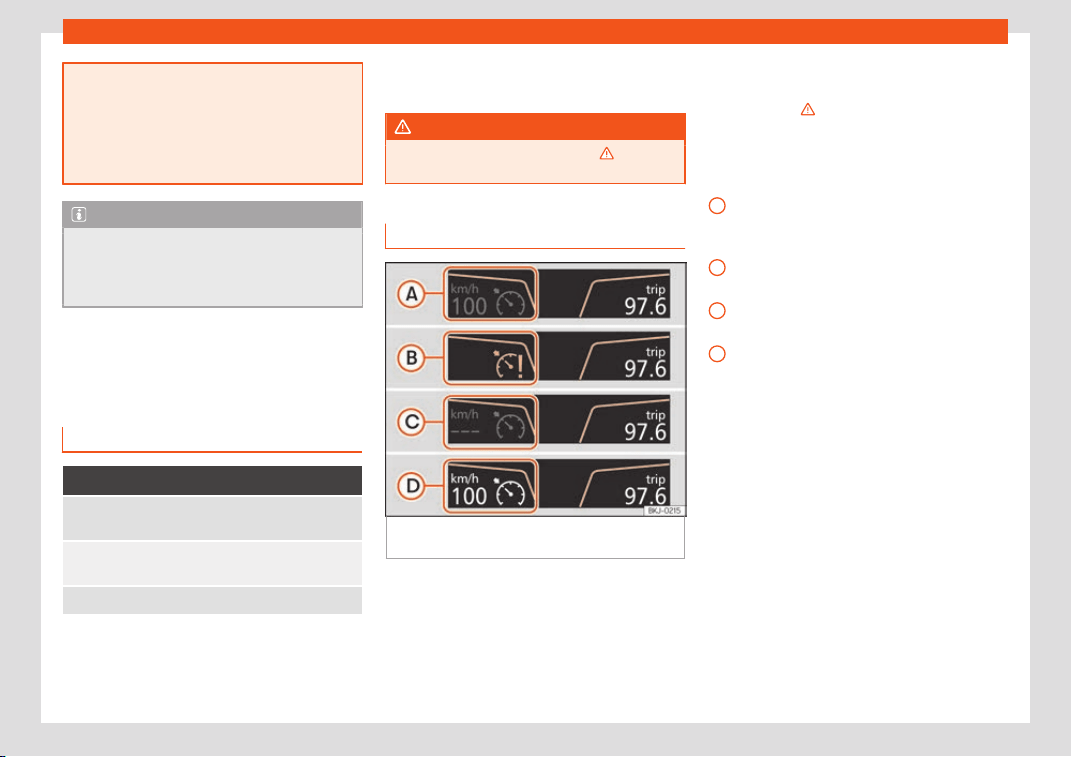
Driving
●
Never l
eave the vehicle running and with
the Auto Hold function switched on.
●
The Auto Hold function cannot always
keep the vehicle stationary uphill or down-
hill or stop it sufficiently, for example, on
slippery or frozen surfaces.
Note
Before entering a car wash, always switch
off the Aut
o Hold function, because if the
el
ectronic parking brake is automatically
connected, it may cause damage.
Cruise control system
(CCS)*
Contr
ol l
amp
It lights up green
The Cruise Control System (GRA) is switched on and
active.
OR:
The Adaptive Cruise Control syst
em (CCS) is
switched on and active.
OR: the speed limiter is swit
ched on and active.
Several warning and control lamps light up
f
or a f
e
w seconds when the ignition is switch-
ed on, signalling that the function is being
verified. They will switch off after a few sec-
onds.
WARNING
Observe the safety warnings
›››
in Con-
trol and warning l
amps on page 123.
Cruise control operation
Fig. 250 Instrument panel display: CCS status
indications.
Read the additional information carefully
›
›
›
page 40
The cruise control system (CCS) is able to
maintain the set speed from 20 km/h (15
mph).
The CSS only reduces vehicle speed by
ceasing to accelerate, not by actively braking
the vehicle
›››
.
Displ
ayed on the CCS scr
een
St
atus Fig. 250:
CCS temporarily switched off. The set
speed is displayed in small or darkened
figures.
System error. Contact a specialised
workshop.
CCS switched on. The speed memory is
empty.
The CCS is switched on. The set speed is
displayed in large figures.
Changing gear in CCS mode
The CCS decelerates as soon as the clutch
pedal is pressed, intervening again automati-
cally after a gear is engaged.
Travelling down hills with the CCS
When travelling down hills the CCS cannot
maintain a constant speed. Slow the vehicle
down using the brake pedal and reduce
gears if required.
Automatic off
The cruise control system (CCS) is switched
off automatically or temporarily:
A
B
C
D
274
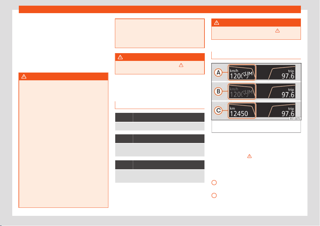
Driver assistance systems
●
If the syst
em det
ects a f
ault that could af-
fect the working order of the CCS.
●
If you press and maintain the accelerator
pedal for a certain time, driving faster than
the stored speed.
●
If the dynamic driving control systems inter-
vene (e.g. ASR or ESC).
●
If the airbag is triggered.
WARNING
Use of the cruise control could cause acci-
dents and sever
e injuries if it is not possible
to drive at a constant speed maintaining
the safety distance.
●
Do not use the cruise control in heavy
traffic, if the distance from the vehicle in
front is insufficient, on steep roads, with
several bends or in slippery circumstances
(snow, ice, rain or loose gravel), or on floo-
ded roads.
●
Never use the CCS when driving off-road
or on unpaved roads.
●
Always adapt your speed and the dis-
tance to the vehicles ahead in line with visi-
bility, weather conditions, the condition of
the road and the traffic situation.
●
To avoid unexpected operation of the
cruise control system, turn it off every time
you finish using it.
●
It is dangerous to use a set speed which is
too high for the prevailing road, traffic or
weather conditions.
●
When travelling do
wn hills, the CCS can-
not maintain a constant speed. The vehicle
tends to accelerate under its own weight.
Select a lower gear or use the foot brake to
slow the vehicle.
WARNING
Observe the safety warnings
›
››
in Con-
trol and warning l
amps on page 123.
Speed limiter
Contr
ol l
amp
It lights up green
The speed limiter is switched on and active.
Flashes green
The speed set by the speed limiter has been excee-
ded.
It lights up
The adaptive cruise control (ACC) or the speed limit-
er is active.
Some warning and control lamps will light up
briefly when the ignition is s
wit
ched on t
o
check certain functions. They will switch off
after a few seconds.
WARNING
Observe the safety warnings
›››
in Con-
trol and warning l
amps on page 123.
Display indications
Fig. 251
On the instrument panel display: indi-
cations of the speed limit
er st
at
us.
The speed limiter helps avoid exceeding a
speed individually pr
ogr
ammed up
wards of
approximately 30 km/h (19 mph) driving in
forwards gears
›››
Display messages on the speed limiter
St
at
us
›››
Fig. 251:
The speed limiter is active. The last speed
set is displayed in large figures.
The speed limiter is not active. The last
speed set is displayed in small or dark-
ened figures.
»
A
B
275
Driving
The speed limiter is switched off. The total
mil
eage is displ
ayed.
WARNING
After use, always switch off the speed limit-
er to pre
vent the speed being regulated
against your wishes.
●
The speed limiter does not relieve the
driver of their responsibility to drive at the
appropriate speed. Do not drive at high
speed if not necessary.
●
Using the speed limiter under adverse
weather conditions is dangerous and can
C
cause serious accidents, e.g. aquaplaning,
snow, ice
, leaves, etc. Only use the speed
limiter when the status of the road and the
weather conditions allow it.
●
When driving downhill, the speed limiter
cannot limit the vehicle speed. Its speed
will increase due to its own weight. In this
case, select a lower gear or use the foot
brake to slow the vehicle.
Note
●
Diff
erent v
ersions of the instrument panel
are available and therefore the versions
and instructions on the display may vary.
●
If when switching the ignition off, the
cruise control system (CCS), the adaptive
cruise control (ACC) or the speed limiter
were switched on, then the cruise control
system or the adaptive cruise contr
ol will
automatically switch themselves on when
the ignition is back on. However, no speed
will be stored. The last set speed of the
speed limiter will be stored.
276
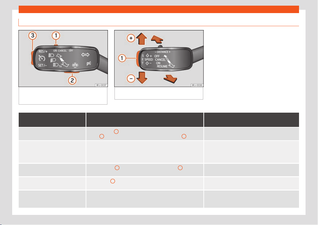
Driver assistance systems
Operate the speed limiter
Fig. 252 On the left of the steering column:
control and buttons t
o operate the speed limit-
er.
Fig. 253 On the left of the steering column:
third le
ver for operating the speed limiter.
Function
Position of the turn signal lever
›››
Fig. 252 or the third
lever
›››
Fig. 253
Effect
Switching on the speed limiter
Move controller
1
of the turn signal lever to the position and press
button
2
or move the third lever forward and press button
2
.
The system switches on. The last set speed of the speed
limiter is stor
ed. It does not take effect yet.
Switching between the speed limiter
and cruise control (CCS) or the adap-
tive cruise contr
ol (ACC) (with the
speed limiter switched on)
Press the button for the driving assistance systems on the turn signal
lever
›››
page 122, then select with the right thumbwheel on the multi-
function steering wheel in the menu of the dashboard and press the
thumbwheel to confirm your selection.
It switches between the speed limiter and the CCS or the
adaptive cruise control (ACC).
Activ
ating the speed limiter
Press the button
3
on the turn signal lever or button
1
on the third
lev
er.
The current speed is stored as the maximum speed and
the limiter is switched on.
Temporarily switching off the speed
limiter limitation
Pl
ace control
1
of the turn signal lever in position or mo
ve the
third lever into position .
The limiter is switched off temporarily. The speed will be
stored.
Temporarily switch off the speed limiter
limitation pressing do
wn the accelera-
tor (kick-down)
Press down on the accelerator beyond the point of resistance (e.g. to
overtake). Surpassing the set speed switches the speed limiter off tem-
porarily.
The limiter is switched off temporarily. The speed will be
stored. The limiter is reactivated automatically after re-
turning to less than the set speed.
»
277
Driving
Function
Position of the turn signal lever
›››
Fig. 252 or the third
lever
›››
Fig. 253
Effect
Switching the speed limiter on again
Press button
3
on the turn signal lever or move the third lever into po-
sition .
The speed is limited to the set speed as soon as the
speed you are driving at is lo
wer than the speed set as
maximum.
Increasing the set speed of the limiter
Briefly press button
3
on the turn signal lever in the area or
move the third lever into position to increase the speed in small
increments of 1 km/h (1 mph) and set it.
The speed is limited to the set value
Press on the third lever to increase the speed in increments of
10 km/h (5 mph) and set it.
Hold do
wn the button
3
on the turn signal lever in the area or
hold do
wn to increase continuously in increments of 10 km/h
(5 mph) and set it.
Reducing the set speed of the limiter
Briefly press button
3
on the turn signal lever in the
area or
press
1
on the third lever to reduce the speed in small increments
of 1 km/h (1 mph) and set it.
The speed is limited t
o the set value
Press on the third lever to reduce the speed in increments of
10 km/h (5 mph) and set it.
Hold do
wn the button
3
on the turn signal lever in the
area or
hold down to continuously decrease the speed in increments of
10 km/h (5 mph), then set it.
Switching off the speed limiter
Move control
1
of the turn signal lever into position or the third le
v-
er into position .
The system switches off
The values shown in the table in brackets, in
mph, ar
e displ
ayed only in instrument panel
s
with indications in miles.
Going down slopes with the speed limiter
If the set speed of the speed limiter is excee-
ded while driving downhill, soon afterwards
the warning and control lamps
›››
page 275 flash and an acoustic warning
may sound. In this case, use the foot brake to
slow the vehicle or, if necessary, select a low-
er gear.
Switching off temporarily
If you wish to temporarily switch off the speed
limiter, e.g. to overtake, move control
›››
Fig. 252
1
of the turn signal lever into po-
sition
or the thir
d lever into pressure
point or press button
2
on any lever.
278
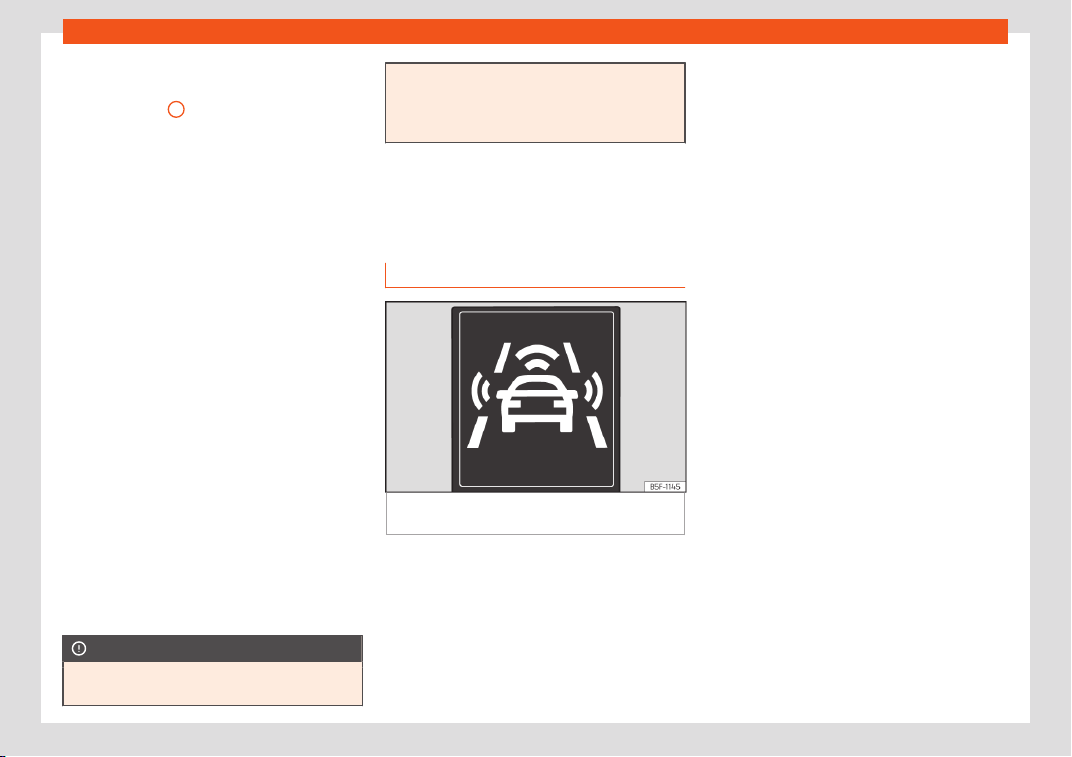
Driver assistance systems
After overtaking, the speed limiter can be
s
wit
ched on with the pr
eviously set speed by
pressing button
3
on the turn signal lever in
the ar
ea
or by moving the third lever into
pressure point .
Switch the speed limiter off temporarily by
pressing down the accelerator (kick-
down)
If the accelerator is pressed right down (kick-
down) and the set speed is exceeded be-
cause driver wishes to do so, the limiter is
temporarily disabled.
To confirm it being switched off an acoustic
signal sound once. While the limiter is off, the
warning and control lamp flashes.
When the accelerator is no longer pressed
down and the speed is reduced below the set
value, the limiter switches on again. The con-
trol lamp will light up and remain lit.
Automatic off
The speed limiter is automatically switched
off:
●
If the system detects a fault that could neg-
atively affect the working order of the limiter.
●
If the airbag is triggered.
CAUTION
For automatic switching off due to system
failures, f
or security reasons, the limiter is
only completely switched off when the
driver stops pr
essing the accelerator at
some point or consciously switches off the
system.
Emergency braking assis-
tance system (Fr
ont Assist)*
Topic introduction
Fig. 254
On the instrument panel display: ad-
v
ance w
arning indications.
The objective of the emergency braking as-
sist
ance syst
em is t
o prevent head-on colli-
sions against objects that may be in the vehi-
cle’s path or minimise the consequences of
such impacts.
Within the limitations imposed by the environ-
mental conditions and by the system itself,
the function acts in staggered fashion, de-
pending on how critical the situation is. Initial-
ly it warns the driver, and if the driver’s reac-
tion does not occur or is insufficient, it acti-
vates an independent emergency braking.
The function is oriented at avoiding the fol-
lowing situations:
●
Collisions with parked vehicles or vehicles
in the same lane travelling in the same direc-
tion.
●
Hitting pedestrians who cross in front of the
vehicle's path or who are walking in the same
lane and direction.
It may fail to activate in other danger situa-
tions.
The Front Assist function is active within a
range of speeds between 4 km/h (2.5 mph)
and 250 km/h (156 mph). Depending on
speed, traffic conditions and driver behaviour,
some of the sub-functions described below
are omitted in order to optimise the system’s
general behaviour.
The Front Assist is a driving assistance
function that can never replace the driv-
er’s attention.
Safety distance warning
If the system detects a situation of danger
because the vehicle is too close to the vehicle
ahead, it will warn the driver by means of an
»
279
Driving
indication on the instrument panel display
.
The timing of the w
arning v
aries depending
on driv
er behaviour and the traffic situation.
Advance warning
If the system detects a possible collision with
the vehicle in front, it may alert the driver by
means of an audible warning and an indica-
tion on the instrument panel display
›››
Fig. 254.
The warning moment varies depending on
the traffic situation and driver behaviour. At
the same time, the vehicle will prepare for a
possible emergency braking
›››
.
Critical w
arning
If the driv
er f
ails to react to the pre-warning
(advance warning), the system may actively
intervene in the brakes and generate a brief
jolt to warn the driver of the imminent danger
of a collision.
Automatic braking
If the driver also fails to react to the critical
warning, the system may initiate independent
emergency braking by progressively increas-
ing the braking effect in accordance with how
critical the situation is.
Driver emergency braking assistance sys-
tem
Faced with an imminent collision, the system
may detect that the driver is not braking hard
enough to avoid the collision. In this case, it
will automatically increase the braking effect.
Due to certain driving circumstances and the
limitations of its operation, there are some
cases in which the system cannot prevent a
collision, although it can significantly mini-
mise the consequences by reducing the
speed and the force of the impact.
WARNING
Observe the safety warnings
›››
in Con-
trol and warning l
amps on page 123.
WARNING
The Front Assist system cannot change the
laws of physics or repl
ace the driver in
terms of keeping control of the vehicle and
reacting to a possible emergency situation.
WARNING
Following a Front Assist emergency warn-
ing, pay immediate attention t
o the situa-
tion and try to avoid the collision by brak-
ing or by dodging the obstacle, as applica-
ble.
●
If the Front Assist does not work as de-
scribed in this chapter (e.g. it repeatedly
intervenes unnecessarily), switch it off.
●
Adapt your speed and safe distance t
o
the vehicle in front of you at all times to suit
visibility, weather, road and traffic condi-
tions.
●
The Front Assist alone cannot avoid acci-
dents and serious injuries.
●
In complex driving situations, occasional-
ly the Front Assist may issue warnings and
intervene in braking unnecessarily, for ex-
ample at traffic islands.
●
If the operation of the Front Assist is im-
paired, for example, by dirt or because the
radar sensor has lost its settings, the sys-
tem may issue unnecessary warnings and
intervene inopportunely in the braking.
●
The Front Assist does not react to animals
or vehicles crossing your path or ap-
proaching head-on down the same lane.
●
The Front Assist does not react to pedes-
trians walking head-on in the same lane.
●
The driver must always be ready to take
over the control of the vehicle.
Note
●
When the Front Assist is connected, the
indications on the instrument panel scr
een
may be concealed by warnings from other
functions, such as an incoming call.
●
When the Front Assist causes a braking,
the brake pedal is “harder”.
●
Automatic interventions by the Front As-
sist on the brakes may be interrupted by
280
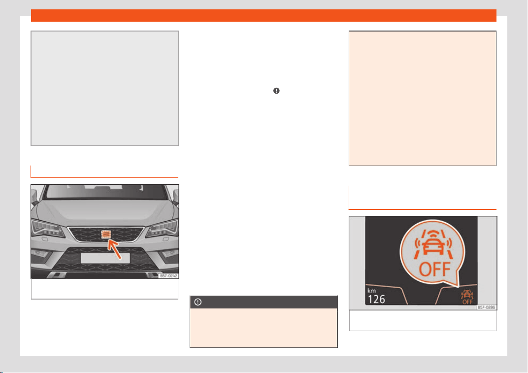
Driver assistance systems
pressing the clutch, accelerator or moving
the wheel.
●
The Front Assist may brake the vehicle
until it stops complet
ely. However, the
brake system does not halt the vehicle per-
manently. Use the foot brake!
●
If the Front Assist does not work as de-
scribed in this chapter (e.g. in intervenes
several times unnecessarily), switch it off.
Have the system checked by a specialised
workshop. SEAT recommends visiting a
SEAT dealership.
Radar sensor
Fig. 255 On the front behind the SEAT badge:
r
adar sensor
.
On the front behind the SEAT badge, a radar
sensor has been inst
all
ed t
o capture the traf-
fic situation
›››
Fig. 255.
The radar sensor's visibility may be impaired
by dirt, mud or snow, or by environmental in-
fluences such as rain or mist. In this case, the
Front Assist does not work. The instrument
panel displays the following message: Front
Assist: No sensor vision! If necessary
clean the radar sensor
›››
.
When the r
adar sensor begins t
o oper
ate
properly again, the Front Assist will automati-
cally be available again. The message will
disappear from the instrument panel display.
Front Assist operation may be affected by a
strong radar reverse reflection. This may oc-
cur, for example, in a closed car park or due
to the presence of metallic objects (e.g. rails
on the road or sheets used in road works).
The area in front of and around the radar
sensor should not be covered with adhesives,
additional or similar headlights, as this may
negatively affect Front Assist operation.
If the front of the vehicle is not properly re-
paired or structural modifications are made
to it, for example if the suspension is lowered,
Front Assist operation may be affected. SEAT
recommends visiting a SEAT dealership for
this purpose.
CAUTION
If you have the sensation that the radar
sensor is damaged or has lost its settings,
disconnect the Front Assist. This will av
oid
possible dangerous situations caused by a
system malfunction. If this occurs have it
adjusted.
●
The sensor may become damaged or
lose its settings when knocked, f
or exam-
ple, during a parking manoeuvre. This may
compromise the system's efficacy or dis-
connect it.
●
Repairs to the radar sensor require spe-
cialist knowledge and special tools. SEAT
recommends visiting a SEAT dealership for
this purpose.
●
Clean away the snow with a brush and
the ice preferably with a solvent-free de-
icer spray.
Operating the Emergency braking
assist
ance syst
em (Fr
ont Assist)
Fig. 256 On the screen of the instrument panel
Fr
ont Assist s
wit
ched off message.
»
281

Driving
The Front Assist is active whenever the igni-
tion is s
wit
ched on.
When the Fr
ont Assist is switched off, so too
are the advance warning function (pre warn-
ing) and the distance warning.
SEAT recommends leaving the Front Assist al-
ways switched on. Exceptions
›››
page 282,
Switching the Front Assist off temporarily
in the following situations.
Switching the Front Assist on and off
With the ignition switched on, the Front Assist
can be switched on and off as follows:
●
Select the corresponding menu option us-
ing the button for the driver assistance sys-
tems
›››
page 122.
●
OR: switch the system on and off in Easy
Connect using the
button SETTINGS >
Driver assistance button
›
›
›
page 35.
When Front Assist is switched off, the instru-
ment panel will inform that it has been
switched off with the following indicator
›››
Fig. 256.
Activating or deactivating the pre-warning
(advance warning)
The pre-warning function (advance warning)
can be switched on or off in the Easy Con-
nect system with the
button > SETTINGS
Driver assistance function butt
on
›
›
›
page 35.
The system will store the setting for the next
time the ignition is switched on.
SEAT recommends keeping the pre-warning
function switched on at all times.
Depending on the infotainment system instal-
led in the vehicle, the advance warning func-
tion may be adjusted as follows:
●
Advance
●
Medium
●
Delayed
●
Deactivated
SEAT recommends driving with the function in
“Medium” mode.
Switching distance warning on and off
If the safe distance with regard to the vehicle
in front is exceeded, the relevant warning will
appear on the instrument panel display
. In this case, increase the safe distance.
The distance warning can be switched on
and off in the Easy Connect system using the
button > SETTINGS > Driver assis-
tance
›
›
›
page 35.
The system will store the setting for the next
time the ignition is switched on.
SEAT recommends keeping the distance
warning switched on at all times.
Switching the Front Assist off tem-
porarily in the following situations
In the following situations the Front Assist
should be deactivat
ed due to the system's
limitations:
●
When the vehicle is to be towed.
●
If the vehicle is on a test bed.
●
When the radar sensor is damaged.
●
If the radar sensor takes a heavy knock, for
exampl
e in a rear collision.
●
If it intervenes several times unnecessarily.
●
If the radar sensor is covered temporarily
with some kind of accessory, such as an ad-
ditional headlight or the like.
●
When the vehicle is to be loaded on a lorry,
ferry or train.
System limitations
The Front Assist has certain physical limita-
tions inher
ent t
o the syst
em. Thus, in certain
circumstances, some of the system's reac-
tions may be inopportune from the driver's
standpoint. So pay attention in order to inter-
vene if necessary.
282
Driver assistance systems
The following conditions may cause the
Fr
ont Assist not t
o r
eact or to do so too
late:
●
In the first few instants of driving after
switching on the ignition, due to the system’s
initial auto-calibration.
●
On taking tight bends or complex paths.
●
Pressing the accelerator all the way down.
●
If the Front Assist is switched off or dam-
aged.
●
If the ASR has been disconnected or the
ESC activated in Sport mode manually
›››
page 250.
●
If the ESC is controlling.
●
If several brake lights of the vehicle or elec-
trically connected trailer are damaged.
●
If the radar sensor is dirty or covered.
●
If there are metal objects, e.g. rails on the
road or sheets used in road works.
●
If the vehicle is reversing.
●
If the vehicle over-accelerates.
●
In case of snow or heavy rain.
●
In case of narrow vehicles, such as motor-
bikes.
●
Misaligned vehicles.
●
Vehicles crossing the other's path.
●
Vehicles approaching in the opposite direc-
tion.
●
Special loads and accessories of other ve-
hicles that jut out over the sides, backwards
or over the top.
Adaptive cruise control
(ACC)*
Introduction
Fig. 257 Related video
Fig. 258
Detection area.
The adaptive cruise control (ACC) is an e
x-
t
ension of the normal cruise contr
ol sys-
tem (CCS)
›››
.
The ACC function allows the driver to pro-
gr
am a cruise speed of betw
een 30 and
2
10 km/h (18 and 130 mph) and to select the
distance required with regard to the vehicle in
front.
The ACC will adapt the vehicle's cruise
speed at all times, maintaining a safe dis-
tance with the vehicle in front based on its
speed.
When driving behind another vehicle, the
ACC function reduces speed until it is the
same as that of the vehicle ahead and main-
tains the set distance between the vehicles. If
the vehicle ahead accelerates, the adaptive
cruise control also accelerates, going no
higher than the target speed programmed.
If the vehicle is equipped with automatic
gearbox, the ACC can brake the vehicle until
it stops completely if a vehicle in front of it
stops.
The distance programmed should be in-
creased when the road surface is wet.
Driver intervention prompt
During driving, the ACC is subject to certain
limitations inherent in the system. In other
words, in certain circumstances the driver will
have to adjust speed him or herself, as well as
the distance from other vehicles.
In this case, the instrument panel screen will
warn you to intervene by applying the brake
»
283
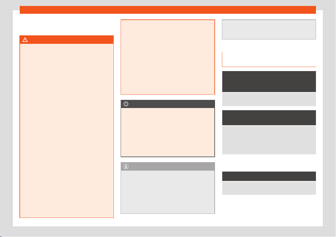
Driving
and a warning tone will be heard
›
›
›
page 284.
WARNING
The intelligent technology in the ACC can-
not over
come the system's inherent limita-
tions or change the laws of physics. If used
negligently or involuntarily, it may cause
serious accidents and injuries. The system
is not a replacement for driver awareness.
●
Adapt your speed and safe distance to
the vehicle in front of you at all times to suit
visibility, weather, road and traffic condi-
tions.
●
Do not use the ACC when visibility is bad,
on steep roads, with several bends or in
slippery circumstances such as snow, ice,
rain or loose gravel, or on flooded roads.
●
Never use the ACC when driving off-road
or on unpaved roads. The ACC has been
designed for use on paved roads only.
●
The ACC does not react on approaching
a fixed obstacle, such as the tail of a traffic
jam, a damaged vehicle or a vehicle stop-
ped at the traffic lights.
●
The ACC only reacts to people if a pe-
destrian monitoring system is available. In
addition, the system does not react to ani-
mals or vehicles crossing your path or ap-
proaching head-on down the same lane.
●
If the ACC does not reduce speed suffi-
ciently, brake the vehicle immediately by
applying the pedal.
●
If you are driving using the spare wheel,
the ACC syst
em could automatically
switch off during the journey. Switch off the
system when starting off.
●
If the vehicle continues to move involun-
tarily after a driver intervention prompt,
brake the vehicle by applying the pedal.
●
If the dash panel displays a driver inter-
vention prompt, adjust the distance your-
self.
●
The driver should be ready to accelerate
or brake by him/herself at all times.
CAUTION
If you have the sensation that the radar
sensor is damaged, disconnect the ACC.
This will avoid possible damage
. If this oc-
curs have it adjusted.
●
Repairs to the radar sensor require spe-
cialist knowledge and special tools. SEAT
recommends visiting a SEAT dealership for
this purpose.
Note
●
If the ACC system does not work as de-
scribed in this chapt
er, do not use it until it
has been checked by a specialised work-
shop. SEAT recommends visiting a SEAT
dealership for this purpose.
●
Maximum speed with the ACC activated
is limited to 210 km/h (130 mph).
●
When the ACC is switched on, str
ange
noises may be heard during automatic
braking cause by the braking system.
Symbols on the instrument panel
display and control l
amps
The speed reduction by the ACC
to maintain the dist
ance from the
vehicle in front is not sufficient.
Brake! apply the foot brak
e! Driver intervention
prompt.
The ACC is not currently availa-
ble.
a)
With the v
ehicle stationary, switch off the engine and
start it up again. Check the SEAT badge area on the
fr
ont
›››
Fig. 260 (in case it is dirty or icy or it has
been hit). If it is still unavailable, refer to a specialised
workshop to have the system inspected.
a)
The symbol on the instrument panels with colour
displ
ay is in col
our
.
The ACC is active.
No vehicle is detected in front. The programmed
speed remains constant.
284
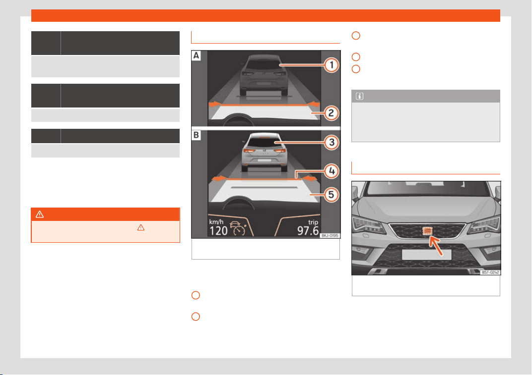
Driver assistance systems
If the symbol is white: the ACC is
active.
A v
ehicle in front has been detected. The ACC ad-
justs speed and distance from the v
ehicle in front.
If the symbol is grey: ACC is inac-
tive (Standby)
The system is switched on, but is not adjusting.
The lamp lights up green
The ACC is active.
Some control and warning lamps will light up
briefly when the ignition is s
wit
ched on t
o
check certain functions. They will switch off
after a few seconds.
WARNING
Observe the safety warnings
›››
in Con-
trol and warning l
amps on page 123.
Indications on the display
Fig. 259
On the instrument panel display: (A)
ACC inactiv
e (St
andby). (B) ACC activ
e.
Status display
Indications on the displ
ay
›
›
›
Fig. 259:
Vehicle ahead detected. ACC is not ac-
tive and is not regulating your speed.
Distance from the vehicle ahead. ACC is
not active and is not regulating your dis-
tance.
1
2
Vehicle ahead detected. ACC is active
and is r
egul
ating your speed.
Dist
ance level 2 set by the driver.
ACC is active and is regulating your dis-
tance based on speed.
Note
When the ACC is connected, the indica-
tions on the instrument panel screen may
be concealed by w
arnings from other func-
tions, such as an incoming call.
Radar sensor
Fig. 260
On the front behind the SEAT badge:
r
adar sensor
.
On the front behind the SEAT badge, a radar
sensor has been inst
all
ed t
o capture the traf-
fic situation
›››
Fig. 260.
»
3
4
5
285
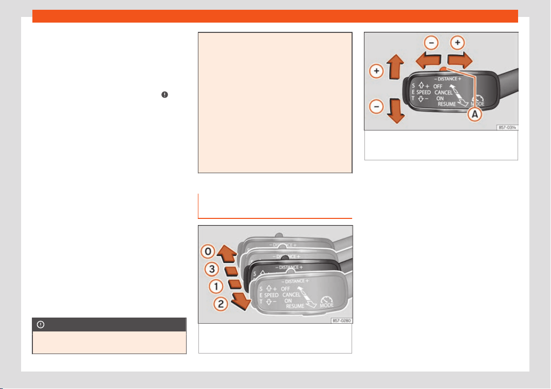
Driving
The radar sensor's visibility may be impaired
by dirt, mud or sno
w
, or by envir
onmental in-
fluences such as rain or mist. In this case the
adaptive cruise control (ACC) does not work.
The instrument panel displays the following
message: ACC: No sensor vision! If nec-
essary, clean the SEAT badge area
›››
.
When the r
adar sensor begins t
o oper
ate
properly again, the ACC will automatically
be available again. The message on the in-
strument panel screen will switch off and the
ACC will be reactivated again.
ACC operation may be affected by a strong
radar reverse reflection. This may occur, for
example, in a closed car park or due to the
presence of metallic objects (e.g. rails on the
road or sheets used in road works).
The area in front of and around the radar
sensor should not be covered with adhesives,
additional or similar headlights, as this may
negatively affect ACC operation.
If the front of the vehicle is not properly re-
paired or structural modifications are made
to it, for example, if the suspension is lowered,
ACC operation may be affected. In this sce-
nario, SEAT recommends visiting a SEAT
dealership.
CAUTION
If you have the sensation that the radar
sensor is damaged or has lost its settings,
disconnect the ACC. This will avoid possi-
ble damage. If this occurs hav
e it adjusted.
●
The sensor may become damaged or
lose its settings when knocked, for exam-
ple, during a parking manoeuvre. This may
compromise the system's efficacy or dis-
connect it.
●
Repairs to the radar sensor require spe-
cialist knowledge and special tools. SEAT
recommends visiting a SEAT dealership for
this purpose.
●
Clean away the snow with a brush and
the ice preferably with a solvent-free de-
icer spray.
Operating the Adaptive Cruise
Contr
ol ACC
Fig. 261 On the left of the steering column:
thir
d l
e
ver for operating the Adaptive Cruise
Control.
Fig. 262 On the left of the steering column:
third le
ver for operating the Adaptive Cruise
Control.
When the Adaptive Cruise Control (ACC) is
connect
ed, the gr
een contr
ol lamp will
light up on the instrument panel, and the pro-
grammed speed and ACC status will be dis-
played
›››
Fig. 259.
What ACC settings are possible?
●
Setting your speed
›››
page 287.
●
Setting your distance
›››
page 287.
●
Connecting and activating the ACC
›››
page 287.
●
Disconnecting and deactivating the ACC
›››
page 287.
●
Adjusting the default distance level at the
start of your journey
›››
page 287.
●
Adjusting the driving profile
›››
page 287.
●
Conditions in which the ACC does not re-
act
›››
page 288.
286

Driver assistance systems
Setting speed
T
o set your speed, mo
v
e the third lever loca-
ted in position
1
upwards or downwards until
the desir
ed speed is sho
wn on the instrument
panel displ
ay. The speed adjustment is made
at 10 km/h (6 mph) intervals.
Once you are driving, if you wish to set the
current speed as the vehicle’s cruise speed
and activate the ACC, press the
›››
Fig. 262 button. If you wish to increase or
reduce speed by intervals of 1 km/h (0.6
mph), move the lever to position
2
›››
Fig. 261 or pr
ess the butt
on, r
espective-
ly.
The set speed can be changed when the ve-
hicle is stopped or during driving, as you like.
Any modification to the programmed speed
will be shown on the bottom left part of the
instrument panel display
›››
Fig. 259.
Setting your distance level
To increase/reduce the distance level, press
the rocker switch towards the left/right
›››
Fig. 262
A
.
The instrument panel displ
ay sho
ws the mod-
ification of the dist
ance level. There are 5 dis-
tance levels to choose from. SEAT recom-
mends level 3. The set distance can be
changed when the vehicle is stopped or dur-
ing driving, as you like
›››
.
Connecting and activating the ACC
T
o connect and activ
at
e the ACC, the posi-
tion of the gearbox selector lever, the vehicle
speed and the position of the third level of the
ACC must all be taken into account.
●
With a manual transmission, the gearbox
selector lever must be in any gear except
first, and the speed must be higher than ap-
proximately 30 km/h. With an automatic
transmission, the gearbox selector lever must
be in position D or S.
●
To activate the ACC, with the third lever in
position
1
press the butt
on or mo
v
e the
third lever of the ACC to position
2
›››
Fig. 261. At this point, the image of the
ACC on the instrument panel displ
ay will
s
wit
ch to Active mode
›››
Fig. 259.
When the ACC function is active, the vehicle
travels at a set speed and distance from the
vehicle ahead. Both speed and distance can
be changed at any time.
Disconnecting and deactivating the ACC
To disconnect the ACC move the lever to the
0
position
›
›
›
Fig. 261 (engaged). An ACC
deactivated message appears and the
function is totally deactivated.
If you do not wish to disconnect the ACC, just
to switch it temporarily to inactive mode
(Standby), move the third lever to position
3
›››
Fig. 261 or pr
ess the br
ak
e pedal.
It will also switch to inactive mode (Standby)
if the vehicle is stopped and the driver door is
opened.
Adjusting the default distance level at the
start of your journey
In wet road conditions, you should always set
a larger distance with regard to the vehicle in
front than when driving in dry conditions.
The following distances can be preselected:
●
Very short
●
Short
●
Media
●
Long
●
Very long
In the Easy Connect system you can adjust
the distance level that will be applied when
the ACC is connected using the
> SET-
TINGS > Driver assistance
›
›
›
page 35.
Changing the driving profile
In vehicles with SEAT Drive Profile, the driving
profile selected can have an influence on the
ACC’s acceleration and braking behaviour
›››
page 303.
In vehicles without SEAT Drive Profile, the be-
haviour of the ACC can also be affected by
selecting any of the following drive profiles in
the Easy Connect system:
»
287

Driving
●
Normal
●
Sport
●
Eco
●
Convenience
In this case
, you shoul
d access the ACC set
-
tings using the
> SETTINGS > Driver
assistance > ACC
›
›
›
page 35.
The following conditions may lead the
ACC not to react:
●
If the accelerator is pressed.
●
If there is no gear engaged.
●
If the ESC is controlling.
●
If the driver is not wearing his/her seat belt.
●
If several brake lights of the vehicle or elec-
trically connected trailer are damaged.
●
If the vehicle is reversing.
●
Driving faster than 210 km/h (130 mph).
Driver messages
ACC not available
The system can no longer continue to guar-
antee safe vehicle detection and will be de-
activated. The sensor has lost its setting or is
damaged. Take the vehicle to a specialised
workshop and have the fault repaired.
ACC and Front Assist: currently
not available. No sensor vision
This message will be displayed to the driver if
the radar sensor's vision is impaired due, for
example, to leaves, snow, heavy fog or dirt.
Clean the SEAT badge
›››
Fig. 260.
ACC: currently not available.
Gradient too steep
The maximum road slope has been excee-
ded, hence safe ACC operation cannot be
guaranteed. The ACC cannot be switched
on.
ACC: only available in D, S or
M
Select the D/S or M position on the selector
lever.
ACC: parking brake applied
The ACC is deactivated if the parking brake is
applied. The ACC is available once again af-
ter the parking brake is released.
ACC: currently not available.
Intervention of stability control
The message for the driver is displayed when
the electronic stability control (ESC) inter-
venes. In this case, the ACC is automatically
switched off.
ACC: Take action!
The message for the driver is displayed if,
when the vehicle starts up on a hill with a mild
slope, the vehicle rolls back even although
the ACC is activated. Apply the brake to stop
the vehicle from moving/colliding with anoth-
er vehicle.
ACC: speed limit
The message for the driver is displayed if, in
vehicles with manual gearbox, the current
speed is too low for the ACC mode.
The speed to be stored must be at least
30 km/h (18 mph). The speed limiter switches
off if the speed falls below 20 km/h (12 mph).
ACC: available as of the 2nd
gear
The ACC is operational as of the 2nd gear
(manual gearbox).
ACC: engine speed
The message for the driver is displayed if,
when the ACC accelerates or brakes, the
driver does not shift up or down a gear in
time, which means exceeding or not reaching
the permissible engine speed. The ACC
switches itself off. A buzzer warning is heard.
ACC: clutch applied
Vehicles with manual transmission: pressing
the clutch pedal for longer abandons control
mode.
Door open
Vehicles with automatic transmission: the
ACC cannot be activated with the vehicle
stationary and the door open.
288
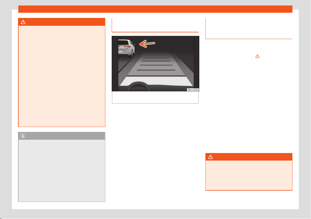
Driver assistance systems
WARNING
There is a danger of rear collision when the
minimum distance to the v
ehicle in front is
exceeded and the speed difference be-
tween both vehicles is so great that a
speed reduction by the ACC will not suf-
fice. In this case the brake pedal should be
applied immediately.
●
The ACC may not be able to detect all
situations properly.
●
“Stepping” on the accelerator may
cause the ACC not to intervene in braking.
Driver braking will have priority over inter-
vention by the speed control or adaptive
cruise control.
●
Always be ready to use the brakes!
●
Observe country-specific provisions gov-
erning obligatory minimum distances be-
tween vehicles.
Note
●
The programmed speed is er
ased once
the ignition or the ACC are switched off.
●
When the traction control system (ASR) is
deactivated during acceleration or else the
ESC is activated in Sport* Mode
(
›››
page 35), the ACC switches off au-
tomatically.
●
In vehicles with the Start-Stop system,
the engine switches off automatically dur-
ing the ACC stopping phase and restarts
automatically to begin driving.
Function for preventing overtaking
in an inside l
ane
Fig. 263
On the instrument panel display:
ACC activ
e
, v
ehicle detected in an outer lane.
The adaptive cruise control (ACC) has a
function that helps av
oid o
v
ertaking while
driving in inside lanes at certain speeds.
If another vehicle is detected travelling at a
slower speed in an outer lane, it is displayed
on the multifunction display
›››
Fig. 263.
To avoid overtaking while driving in an inside
lane the system will gently brake, and in ac-
cordance with the speed will prevent the car
from overtaking. The driver can override this
function at any time by pressing the acceler-
ator pedal. At low speeds the function is inac-
tive, for greater comfort in a traffic jam or in
city traffic.
Deactivating the Adaptive Cruise
Control ACC temporarily in certain
situations
In the following situations the Adaptive Cruise
Control (ACC) should be deactiv
ated due to
the system's limitations
›››
:
●
When changing lanes, on tight bends and
roundabouts, in acceler
ation and decelera-
tion lanes on motorways or in sections with
road works to prevent involuntary accelera-
tion to reach the programmed speed.
●
When going through a tunnel, as operation
could be affect
ed.
●
On roads with several lanes, when other ve-
hicles are driving more slowly in the overtak-
ing lane. In this case, slower vehicles will be
overtaken on the right.
●
In case of heavy rain, snow or spray, as the
vehicle in front might not be detected proper-
ly or, in certain circumstances, might not be
detected at all.
WARNING
If the ACC does not switch off in the situa-
tions described, serious accidents and inju-
ries may occur.
●
Alw
ays switch off the ACC in critical sit-
uations.
»
289
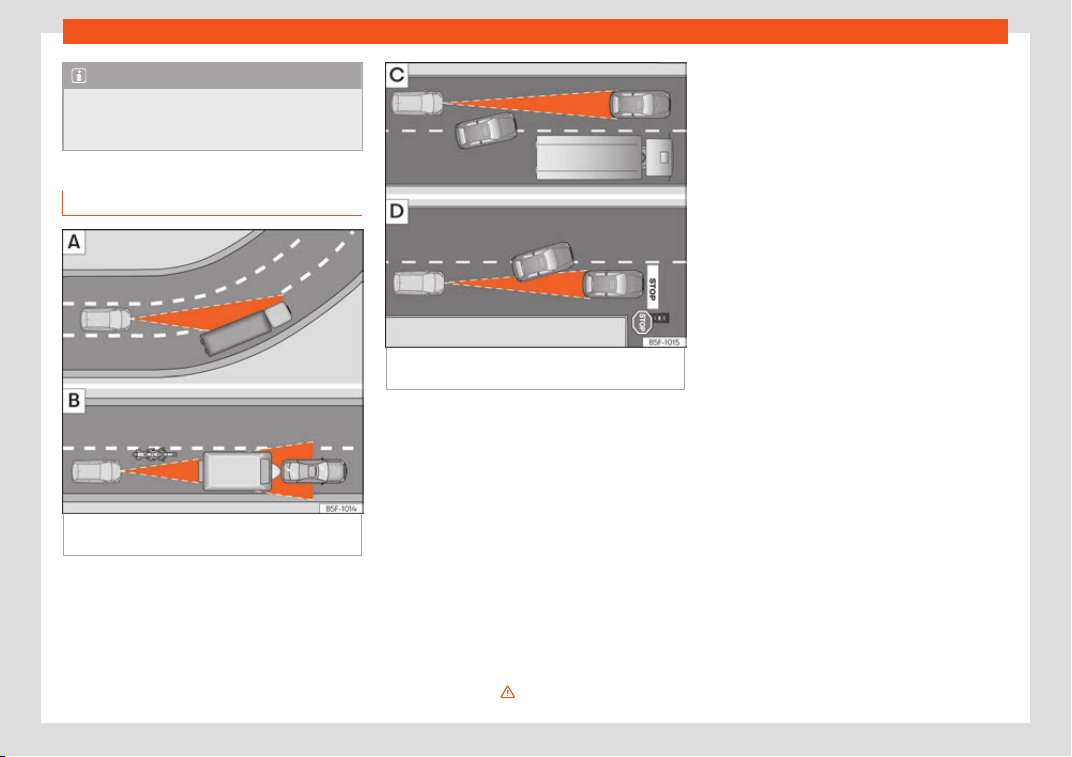
Driving
Note
If you do not switch off the ACC in the
aforementioned sit
uations, you may com-
mit a legal offence.
Special driving situations
Fig. 264
(A) Vehicle on a bend. (B) Motorcy-
clist ahead out of r
ange of the r
adar sensor
.
Fig. 265 (C) Vehicle changing lanes. (D) One
v
ehicl
e t
urning and another stationary.
The adaptive cruise control (ACC) has cer-
t
ain physical limit
ations inher
ent in the sys-
tem. For example, certain reactions of the
ACC, in certain circumstances, may be unex-
pected or come late from the driver's point of
view. So pay attention in order to intervene if
necessary.
For example, the following traffic situations
call for the utmost attention:
Starting driving after a stopping phase
(only vehicles with automatic gearbox)
After a stopping phase, the ACC may begin
driving automatically when the vehicle in
front drives off
›››
.
Overtaking
When the t
urn signal lights up bef
or
e the ve-
hicle begins an overtaking manoeuvre, the
ACC accelerates the vehicle automatically
and thus reduces the distance from the vehi-
cle in front.
When the vehicle enters the overtaking lane,
if the ACC does not detect another vehicle in
front, it accelerates until it reaches the pro-
grammed speed and maintains it.
System acceleration can be interrupted at
any time by pressing the brake or moving the
third lever backwards
›››
page 286.
Driving through a bend
On entering or exiting bends, the radar sensor
may stop detecting the vehicle in front or re-
acting to a vehicle in the adjacent lane
›››
Fig. 264 A In these situations the vehicle
may brake unnecessarily or fail to react to
the vehicle in front. In this case, the driver has
to intervene by accelerating or interrupting
the braking process by applying the brake or
pushing the third lever backwards
›››
page 286.
Driving in tunnels
When driving through tunnels the radar sen-
sor may be limited. Switch off the ACC in tun-
nels.
290

Driver assistance systems
Narrow or misaligned vehicles
The r
adar sensor can only det
ect narr
ow or
misaligned vehicles when they are within
range
›››
Fig. 264 B. This applies particularly
to narrow vehicles such as motorbikes. In
these cases, you should brake as necessary.
Vehicles with special loads and accesso-
ries
Special loads and accessories of other vehi-
cles that jut out over the sides, backwards or
over the top may be out of the ACC's range.
Switch off the ACC when driving behind vehi-
cles with special loads and accessories or
when overtaking them. In these cases, you
should brake as necessary.
Other vehicles changing lanes
Vehicles changing lanes a short distance
away from your own can only be detected
when they are within range of the sensors.
Consequently, the ACC will take longer to re-
act
›››
Fig. 265 C. In these cases, you should
brake as necessary.
Stationary vehicles
The ACC does not detect stationary objects
while driving, such as traffic tails or damaged
vehicles.
If a vehicle detected by the ACC turns or
moves over and there is a stationary vehicle
in front of it, the ACC will not react to it
›››
Fig. 265 D. In these cases, you should
brake as necessary.
Vehicles driving in the opposite direction
and vehicles crossing your path
The ACC does not react to vehicles ap-
proaching from the opposite direction or ve-
hicles crossing your path.
Metal objects
Metal objects, e.g. rails on the road or sheets
used in road works, can confuse the radar
sensor and cause the ACC to react wrongly.
Factors that may affect how the radar
sensor operates
If laser sensor operation is impaired, due to
heavy rain, spray, snow or mud, the ACC is
deactivated temporarily. The relevant text
message will appear in the dash panel dis-
play. If necessary clean the SEAT
badge
›››
Fig. 260.
When the radar sensor begins to operate
properly again, the ACC will automatically
be available again. The message on the in-
strument panel screen will switch off and the
ACC will be reactivated again.
ACC operation may be affected by a strong
radar reverse reflection, for example in a
closed car park.
Trailer mode
When driving with trailer the ACC controls
less dynamically.
Overheated brakes
If the brakes overheat, for example after
abrupt braking or in long and steep slopes,
the ACC may be deactivated temporarily.
The relevant text message will appear in the
dash panel display. In this case, adaptive
cruise control cannot be activated.
Adaptive Cruise Control can be reactivated
once brake temperature has cooled suffi-
ciently. The message will disappear from the
instrument panel display. If the message ACC
not available remains on for quite a long
time it means that there is a fault. Contact a
specialised workshop. SEAT recommends vis-
iting a SEAT dealership.
WARNING
If you do not heed the Press the brake
message, the vehicl
e may initiate an invol-
untary movement and could crash into the
vehicle ahead. In any event, before driving
off, check that the road is clear. The radar
sensor may not detect obstacles on the
road. This could cause an accident and se-
rious injuries. If necessary, apply the brake.
291
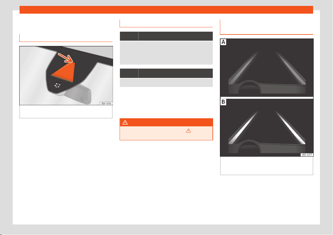
Driving
Lane Assist system*
Intr
oduction
Fig. 266 On the windscreen: field of vision of
the L
ane Assist syst
em camer
a.
Using the camera located in the windscreen,
the L
ane Assist syst
em det
ects the possible
lines dividing the lanes. When the vehicle in-
voluntarily approaches a dividing line it has
detected, the system notifies the driver with a
corrective steering movement. The purpose is
not only to warn the driver, but also to keep
the vehicle inside the lane. This movement
can be over-regulated at any time.
No warning is produced with the turn signals
activated, given that the Lane Assist system
understands that a lane change is required.
Control lamp
It lights up yellow
Lane Assist active but not available.
The system cannot accurately recognise the lane.
Please see page 294, Lane Assist system is not avail-
able (the control lamp is lit up yellow).
It lights up green
Lane Assist system active and available.
Some control and warning lamps will light up
briefly when the ignition is s
wit
ched on t
o
check certain functions. They will switch off
after a few seconds.
WARNING
Observe the safety warnings
›››
in Con-
trol and warning l
amps on page 123.
Indications on the instrument panel
displ
ay
Fig. 267 On the instrument panel display: Indi-
cation on the L
ane Assist syst
em displ
ay (ex-
ample 1).
292
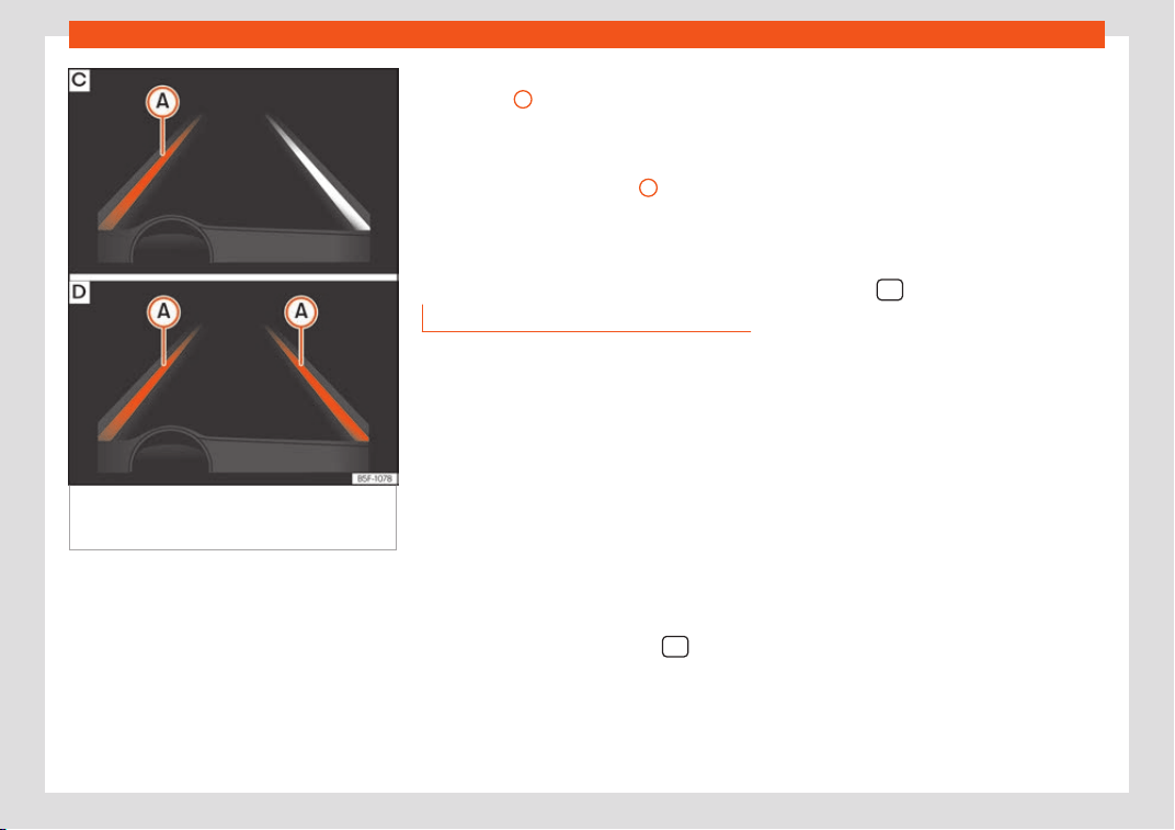
Driver assistance systems
Fig. 268
On the instrument panel display: In-
dication on the L
ane Assist syst
em displ
ay (ex-
ample 2).
Status display
The syst
em is activ
e
, but not available,
either because the minimum speed has
not been reached or because the lane
lines are not recognised
›››
Fig. 267 A.
The system is active and available, both
lane lines are recognised. The steering
angle is not being corrected at this mo-
ment
›››
Fig. 267 B.
–
–
The system is operational, the highligh-
ted line
A
indicates that there was a risk
of inv
olunt
arily cr
ossing the lane line and
that the steering is being adjusted to
correct the angle
›››
Fig. 268 C.
The two highlighted lines
A
light up si-
mult
aneously when both l
ane lines ar
e
recognised and the Lane Assist function
is active
›››
Fig. 268 D.
Operating mode
Steering wheel vibration
The f
oll
o
wing situations can cause vibration
in the steering wheel and require the driver to
take active control of driving:
●
When the steering angle assist value re-
quired to keep the vehicle in the lane is higher
than the system’s maximum operating value.
●
If the system ceases to display the lane
lines while assisting with steering.
Switching the Lane Assist system on or off
Through the Easy Connect system
●
Press the Easy Connect button
●
Press the function button SETTINGS >
Driver assistance t
o open the menu.
Or:
Using the
Driving Assist button on the
turn signal lever*
›››
page 122.
–
–
Lane Assist with lane centring guide
The Lane Centring Guide function is inten-
ded to keep the vehicle in the centre of the
lane.
If the driver has a tendency to veer slightly off
centre in the lane, the system adapts to driver
preferences.
The Lane Centring Guide function is acti-
vated/deactivated in the Easy Connect sys-
tem using the
button > SETTINGS function
butt
on
›
›
›
page 35.
Automatic deactivation: the Lane Assist sys-
tem can be automatically deactivated if
there is a system malfunction. The control
lamp disappears.
Hands-Off Function
In the absence of steering wheel activity the
system alerts the driver with acoustic signals
and a text message on the dash panel asking
to actively take over the steering.
If the driver does not react to this, the system
also alerts the driver with a little shaking mo-
tion through the brakes and, if the vehicle has
it, activates the Emergency Assist function
›››
page 296.
In vehicles without Emergency Assist, the
adaptive lane guidance function will be disa-
bled after the corresponding warnings to the
driver.
»
293
Driving
The lane assist system is active but it is not
av
ail
abl
e (the control lamp is lit up yellow)
●
When driving at speeds below 65 km/h (38
mph).
●
When the Lane Assist system does not de-
tect the dividing lines of the road. For exam-
ple, in the event warnings indicating road
works, and snow, dirt, moisture or reflections.
●
When the radius of a curve is too small.
●
When no road markings can be seen.
●
When the distance to the next marking to
too great.
●
When the system does not detect any clear
and active steering movement during a long
period of time.
●
Temporarily, in the event of very dynamic
driving styles.
●
If a turn signal is activated.
●
With the stability control system (ESC) in
Sport mode or switched off.
BSD Plus (Lane Assist with Blind Spot De-
tector)*
The BSD Plus function is achieved by activat-
ing the Lane Assist and BSD functions
›››
page 298. In this case, the Lane Assist
function expands its functions in the following
way:
If the driver tries to change lane and there is a
vehicle in the blind spot:
●
The lamp flashes in the corresponding
rear-view mirror even though the turn signal
has not been activated.
●
The steering wheel vibrates to warn the
driver of the risk of collision.
●
torque is applied to correct the steering
and return the vehicle to its lane.
Switching off the Lane Assist system in the
following situations
Due to the limits of the Lane Assist system,
switch it off in the following situations:
●
When more attention is required of the driv-
er
●
When driving in a sporty style
●
In unfavourable weather conditions
●
On roads in poor condition
●
In areas of road works
WARNING
The intelligent technology in the Lane As-
sist system cannot change the limits im-
posed by the laws of physics and by the
v
ery nature of the system. Careless or un-
controlled use of the Lane Assist system
may cause accidents and injury. The sys-
tem is not a replacement for driver aware-
ness.
●
Always adapt your speed and the dis-
tance to the vehicles ahead in line with visi-
bility, weather conditions, the condition of
the road and the traffic sit
uation.
●
Always keep your hands on the steering
wheel so it can be turned at any time.
●
The Lane Assist system does not detect
all road markings. The road surfaces, road
structures or objects in poor condition can
be incorrectly detected as road markings
under certain circumstances by the Lane
Assist system. In such situations, switch the
Lane Assist system off immediately.
●
Please observe the indications on the in-
strument panel and act as is necessary.
●
Always pay attention to the vehicle's sur-
roundings.
●
When the area of vision of the camera
becomes dirty, covered or is damaged, the
Lane Assist system function can be affec-
ted.
CAUTION
In order to avoid influencing the operation
of the system, the foll
owing points must be
taken into account:
●
Regularly clean the area of vision of the
camera and keep it in a clean state, without
snow or ice.
●
Do not cover the area of vision of the
camera.
●
Check that the area of vision of the wind-
screen camera is not damaged.
294
Driver assistance systems
Note
●
The lane depart
ure warning system has
been exclusively developed for driving on
paved roads only.
●
If the Lane Assist system does not work as
described in this chapter, do not use it and
contact a specialised workshop.
●
Before starting a journey, verify that the
field of vision of the camera is not covered
›››
Fig. 266.
●
Always keep the field of vision of the
camera clean.
●
If there is a fault in the system, have it
checked by a specialised workshop.
Traffic Jam Assist
Description and oper
ation
Fig. 269 Related video
Traffic Jam Assist helps the driver keep the
car within its l
ane and t
o mo
ve in convoy in
case of traffic congestion or slow traffic.
Traffic Jam Assist is an additional function of
Lane Assist
›››
page 292 and combines Lane
Assist functions with Adaptive Cruise Control
(ACC)
›››
page 283. Therefore, it is essential
that you read these two chapters carefully
and note the limitations of the systems and
the information about them.
Operation of Traffic Jam Assist
At speeds of below 60 km/h (40 mph), Traffic
Jam Assist can maintain a (temporary) dis-
tance preset by the driver with respect to the
vehicle ahead and help stay within the lane
›››
.
T
o do this, the syst
em aut
omatically controls
the accelerator, brakes and steering, and
slows the vehicle, stopping it fully if neces-
sary, when faced with a vehicle in front that
has stopped. It automatically moves off again
when the vehicle ahead moves.
Traffic Jam Assist is designed only for use on
motorways and wide roads. Therefore, never
use it in city traffic.
Technical requirements for using Traffic
Jam Assist
●
Lane departure warning must be activated:
Infotainment button
> SETTINGS >
Driver assistance > Lane departure
warning (Lane Assist) function butt
on
›
›
›
page 35.
●
Adaptive lane guidance must be activated:
Infotainment button
> SETTINGS >
Driver assistance > Lane Assist func-
tion butt
on.
●
Adaptiv
e Cruise Contr
ol (ACC) must be
connected and active
›››
page 286.
●
The speed must be below 60 km/h
(38 mph).
Traffic Jam Assist is not active (the Lane
Assist control light turns yellow)
●
If any of the conditions mentioned on
page 295, Technical requirements for us-
ing Traffic Jam Assist are no longer met.
●
If any of the conditions required for opera-
tion of the Lane Assist are not met
›››
page 292.
●
If any of the conditions necessary for the
adaptive cruise control (ACC) to work are no
longer fulfilled
›››
page 283.
Situations in which Traffic Jam Assist must
be switched off
Due to the limitations of the system, Traffic
Jam Assist must always be switched off in the
following situations:
●
When more attention is required by the
driver.
●
When driving in a very sporty style.
●
In adverse weather conditions, e.g. in case
of snow or heavy rain.
»
295
Driving
●
When driving on r
oads in poor condition.
●
In sections with r
oadw
orks.
●
In city journeys.
WARNING
The smart technology incorporated into
Traffic Jam Assist cannot defy the l
aws of
physics; it only works within the limits of the
system. Accidents and severe injury may
occur if Traffic Jam Assist is used negli-
gently or involuntarily. The system is not a
replacement for driver awareness.
●
Adapt your speed and safe distance to
the vehicle in front of you at all times to suit
the visibility, weather, road and traffic con-
ditions.
●
Do not use Traffic Jam Assist in city jour-
neys.
●
Do not use Traffic Jam Assist if there is
poor visibility, for example, in case of snow,
ice, rain or loose gravel, or on steep or slip-
pery sections or flooded roads.
●
Do not use Traffic Jam Assist offroad or
on roads where the surface is not firm. Traf-
fic Jam Assist has been designed for use on
paved roads only.
●
Traffic Jam Assist does not react to peo-
ple or animals or vehicles crossing your
path or that approach you head-on down
the same lane.
●
If Traffic Jam Assist does not reduce
speed sufficiently, brake the vehicle imme-
diately by applying the pedal.
●
If the vehicle continues t
o move when you
wish it to stop after a driver intervention
prompt, brake the vehicle by applying the
pedal.
●
If driver intervention is requested on the
dash panel display, immediately resume
control of the vehicle.
●
Keep your hands on the wheel at all times
to be ready to intervene in the steering at
any time. The driver is always responsible
for keeping the vehicle in its own lane.
●
Always be prepared to take charge of
driving (accelerating or braking) yourself.
Note
●
If Traffic Jam Assist does not w
ork as de-
scribed in this chapter, stop using it and
contact a specialised workshop.
●
If the system is faulty, take it to a special-
ised workshop and have it checked.
Emergency Assist
Description and oper
ation
Emergency Assist detects whether there is in-
activit
y by the driv
er and can aut
omatically
keep the car within the lane and stop it alto-
gether if necessary. This way the system can
actively help avoid an accident.
Emergency Assist is an additional function of
Lane Assist
›››
page 292 and combines Lane
Assist functions with Adaptive Cruise Control
(ACC)
›››
page 283. Therefore, it is essential
that you read these two chapters carefully
and note the limitations of the systems and
the information about them.
Operation of Emergency Assist
Emergency Assist detects when the driver
ceases to perform any activity and repeated-
ly requests that he/she regain active control
of the vehicle, through the use of optical and
acoustic warnings and by applying the
brakes.
If the driver continues to do nothing, the sys-
tem automatically takes over the accelerator,
brakes and steering in order to brake the ve-
hicle and keep it in its lane
›››
. When the
Emer
gency Assist is activ
ely adjusting, the
haz
ard warning lights come on
›››
page 152
and the vehicle makes slight zigzag move-
ments in the lane in order to warn other driv-
ers.
If the remaining braking distance is sufficient,
if necessary the system slows down the vehi-
cle until it stops completely and automati-
cally switches on the electronic parking
brake
›››
page 246.
296
Driver assistance systems
Switching the Emergency Assist on and off
The Emer
gency Assist is s
wit
ched on auto-
matically when the Lane Assist is switched on
›››
page 292.
Technical requirements for using the Emer-
gency Assist
●
The adaptive cruise control (ACC) must be
switched on
›››
page 283.
●
The Lane Assist must be switched on
›››
page 292.
●
The selector lever must be in the D/S posi-
tion or in the Tiptronic selector gate.
●
The system must have detected a lane
separation line on both sides of the vehicle
›››
Fig. 268.
The following conditions may cause the
Emergency Assist not to react or to switch
off automatically:
●
If the driver accelerates, brakes or moves
the steering wheel.
●
If any of the conditions mentioned in
›››
page 297, Technical requirements for
using the Emergency Assist are not fulfilled.
●
If any of the conditions required for opera-
tion of the Lane Assist are not met
›››
page 292.
●
If any of the conditions necessary for the
adaptive cruise control (ACC) to work are no
longer fulfilled
›››
page 283.
WARNING
The smart technology incorporated into
the Emergency Assist cannot ov
ercome the
limits imposed by the laws of physics; it on-
ly works within the limits of the system. The
driver is responsible for driving the vehicle.
●
Adapt your speed and safe distance to
the vehicle in front of you at all times to suit
the visibility, weather, road and traffic con-
ditions.
●
Keep your hands on the wheel at all times
to be ready to intervene in the steering at
any time.
●
The Emergency Assist alone cannot al-
ways avoid accidents or serious injuries.
●
If the operation of the Emergency Assist
is impaired, for example if the radar sensor
of the adaptive cruise control (ACC) or the
Lane Assist camera are covered or have
lost their settings, the system may inter-
vene inopportunely in braking or in steer-
ing.
●
The Emergency Assist does not react to
people or animal or vehicles crossing your
path or which approach you head-on in the
same lane.
WARNING
If the Emergency Assist Intervenes inoppor-
tunely, serious accidents and injuries may
occur.
●
If the Emergency Assist does not operat
e
properly, switch off the Lane Assist
›››
page 292. Doing so will also switch off
the Emergency Assist.
●
Have the system checked by a special-
ised workshop. SEAT recommends visiting a
SEAT dealership for this.
Note
●
Aut
omatic interv
entions by the Emergen-
cy Assist on the brakes may be interrupted
by pressing the accelerator or brake or by
moving the wheel.
●
Hazard warning lights that come on auto-
matically can be switched off by pressing
the accelerator or the break, moving the
steering wheel or pressing the hazard
warning light switch.
●
If this occurs, the Emergency Assist may
decelerate the vehicle until it comes to a
complete stop.
●
When the Emergency Assist is activated,
it is only available again after the ignition
has been switched off and back on again.
297
Driving
Blind spot detector (BSD)
with parking assist
ance
(RC
T
A)*
Introduction
Fig. 270 Related video
The blind spot detector (BSD) helps to detect
the tr
affic sit
uation behind the v
ehicle.
The integrated parking assistant (RCTA) helps
the driver when backing out of a parallel
parking spot and in manoeuvring.
The blind spot detector has been developed
for driving on paved roads.
WARNING
The smart technology incorporated into
the blind spot detector (BSD) with parking
assist
ance (RCTA) included cannot over-
come the limits imposed by the laws of
physics; it only works within the limits of the
system. Accidents and severe injury may
occur if the blind spot detection system or
the rear cross traffic alert are used negli-
gently or involuntarily. The system is not a
replacement f
or driver awareness.
●
Adapt your speed and safe distance to
the vehicle in front of you at all times to suit
visibility, weather, road and traffic condi-
tions.
●
Keep your hands on the wheel at all times
to be ready to intervene in the steering at
any time.
●
Pay attention to the control lamps that
may come on in the external rear view mir-
rors and on the instrument panel, and fol-
low any instructions they may give.
●
The blind spot assistant could react to
any special constructions that might be
present on the sides of the vehicle: e.g. high
or irregular dividers. This may cause erro-
neous warnings.
●
Never use the blind spot detector with
rear cross traffic alert on unpaved roads.
The blind spot detector with rear cross traf-
fic alert has been designed for use on
paved roads.
●
Always pay attention to the vehicle's sur-
roundings.
●
Never use the blind spot detector or the
parking assistant if the radar sensors are
dirty.
●
The external rear view mirror control
lamps may have limited functionality due
to solar radiation.
CAUTION
●
The radar sensors on the rear bumper
may be damaged or shift
ed in the event of
a collision, for example, when entering or
exiting a parking space. This may result in
the system disconnecting itself, or at least
possibly having its functionality diminished.
●
In order to ensure that the radar sensors
work properly, keep the rear bumper free of
snow and ice and do not cover it.
●
The rear bumper should only be painted
with paint authorised by SEAT. The blind
spot detector's functions may be limited or
work incorrectly if other paints are used.
Note
If the blind spot detector with parking as-
sistant does not work as described in this
chapt
er, do not use it and contact a speci-
alised workshop.
Control lamps
Control lamp in external rear view mirrors:
It lights up
It lights up once briefly: the blind spot detector is ac-
tivated and r
eady to operate.
It lights up: blind spot detector has detected a vehi-
cle in the blind spot.
298
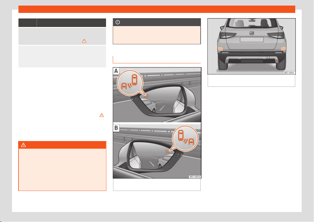
Driver assistance systems
Flashes
The blind spot detector has detected a vehicle in the
blind spot and the turn signal has been turned on in
the dir
ection of the detected vehicle
›››
.
For vehicles that are also equipped with Lane Assist
›››
page 292, a warning to switch lanes will also ap-
pear even though the turn signal has not been en-
gaged (blind spot detector “Plus”).
Some warning and control lamps will light up
briefly when the ignition is switched on t
o
check certain functions. They will switch off
after a few seconds.
If there are no indications from the control
lamp in the external rear view mirror, this
means that the blind spot detector has not
detected any other vehicles in the area
›››
.
If the dipped beam is on, then the contr
ol
l
amps in the e
xternal rear view mirrors will be
dimmed (night mode).
WARNING
If the warning lamps and the corresponding
messages are ignored when they light up
,
the vehicle may stall in traffic and cause
accidents and severe injuries.
●
Never ignore the warning lamps or mes-
sages.
●
Carry out the necessary operations.
CAUTION
Failure to heed the control lamps and cor-
responding te
xt messages when they light
up may result in damage to the vehicle.
Blind spot detector (BSD)
Fig. 271 On external rear-view mirrors: blind
spot det
ect
or displ
ay.
Fig. 272 Rear view of the vehicle: radar sensor
areas.
The blind spot detector uses radar sensors to
monit
or the ar
eas behind the v
ehicle
›››
Fig. 272. The system does this by measur-
ing the vehicle's distance from other vehicles
and its speed differential. The blind spot de-
tector will not work at speeds of less than ap-
prox. 15 km/h (9 mph). The system uses opti-
cal signals in the external rear view mirrors to
notify the driver.
Indication in the external rear view mirrors
The control lamp (expanded view) provides
an indication in the corresponding external
mirror
›››
Fig. 271 regarding the traffic situa-
tion behind the vehicle, if it is deemed to be
critical. The control lamp of the left-hand ex-
ternal mirror indicates the traffic situation to
the left of the vehicle, and the control lamp of
the right-hand external mirror indicates the
traffic situation to the right of the vehicle.
»
299

Driving
In the case of retrofitted tinted windows or
windo
ws with tint
ed film, the indications of the
e
xternal mirrors may not be seen clearly or
correctly.
Keep the external mirrors clean and free of
snow and ice, and do not cover them with ad-
hesives or other similar materials.
Radar sensors
The radar sensors are located on the left and
right of the bumper and are not visible from
the outside
›››
Fig. 272. The sensors monitor
both the blind spot and traffic behind the ve-
hicle
›››
Fig. 273,
›››
Fig. 274. The range to the
sides of the vehicle is a bit larger than the
width of a lane.
The lane width is not detected individually,
but is rather pre-configured in the system.
Thus if you are driving in wide lanes or in be-
tween two lanes, the indications may be in-
correct. Furthermore, the system can detect
vehicles driving in the lane next to you (if
there are any), and can also detect station-
ary objects such as dividers, and thus give an
incorrect indication.
300
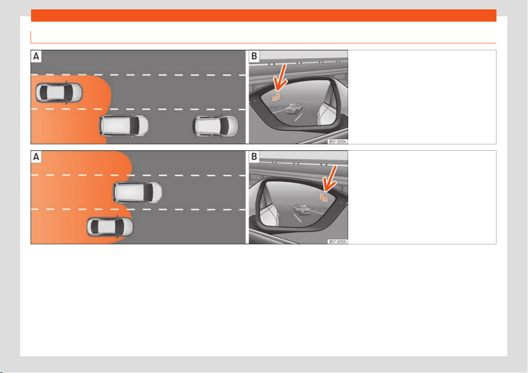
Driver assistance systems
Driving situations
Fig. 273 Schematic diagram: Passing situa-
tion with tr
affic behind the vehicle. Indication
from the blind spot detector in the left-hand ex-
ternal mirror.
Fig. 274 Schematic diagram: Situation of
passing and then moving int
o the right-hand
lane. Indication from the blind spot detector
in the right-hand external mirror.
In the following situations, an indication will
be displ
ayed in the e
xt
ernal mirror
›››
Fig. 273
(arrow) or
›››
Fig. 274 (arrow):
●
When being overtaken by another vehicle
›››
Fig. 273 .
●
When passing another vehicle
›››
Fig. 274
with a speed differential of approx. 10 km/h
(6 mph). If the vehicle is passing at a consid-
erably higher speed, no indication will be dis-
played.
The faster the vehicle approaches, the soon-
er an indication will be displayed in the exter-
nal mirror, because the blind spot detector
takes into account the speed differential with
other vehicles. Thus even though the distance
from the other vehicle is identical, the indica-
tion will appear sooner in some cases and
later in others.
Physical limitations inherent to the system
In some situations the blind spot detector
may not interpret the traffic situation correct-
ly. E.g. in the following situations:
●
on tight bends;
●
in the case of lanes with different widths;
●
at the top of slopes;
●
in adverse weather conditions;
»
301
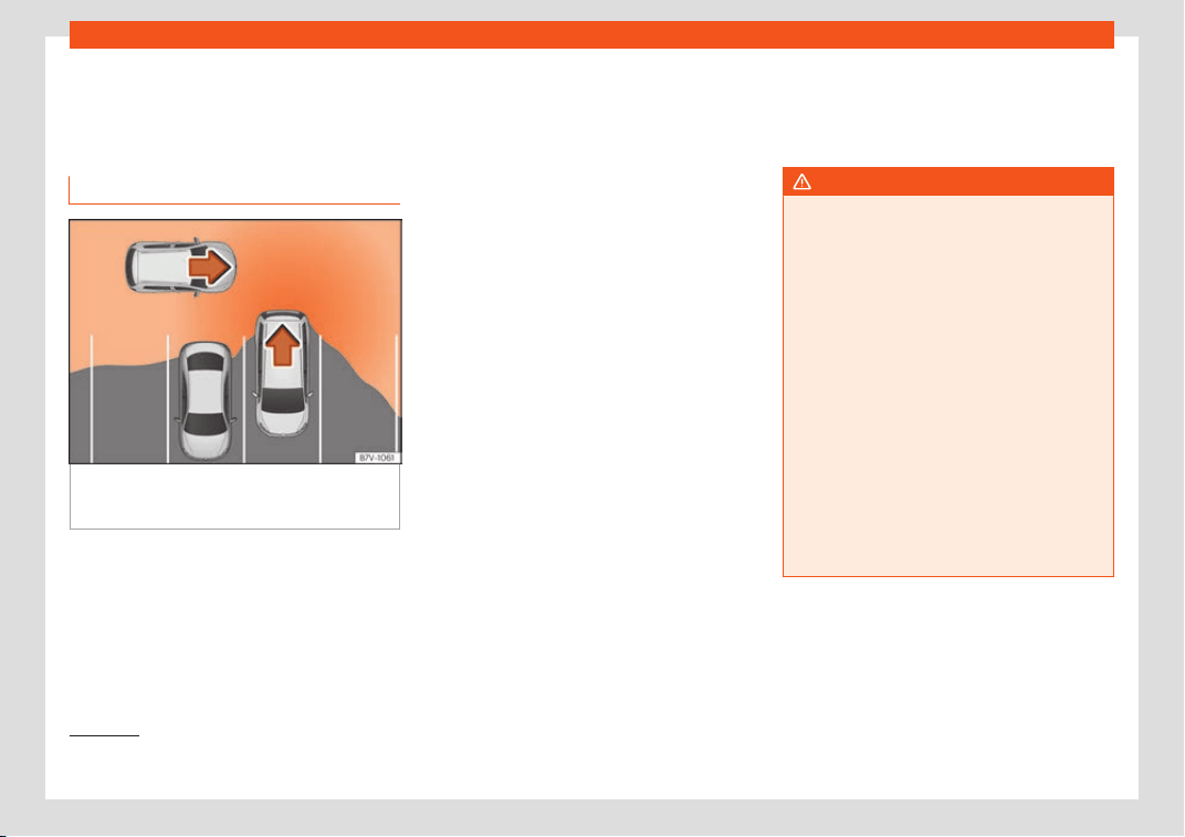
Driving
●
in the case of special constructions t
o the
side of the v
ehicl
e, e.g., high or irregular divid-
ers.
Parking assistant (RCTA)
Fig. 275
Diagram of the parking assistant: de-
t
ect
ed ar
ea around the vehicle that is driving
off.
The parking assistant uses the radar sensors
on the r
ear bumper
›
›
›
Fig. 272 to monitor the
traffic crossing behind the vehicle as it backs
out of a parallel parking space or as it is be-
ing manoeuvred, for example in very low visi-
bility conditions.
If the system detects that someone else on
the road is approaching the rear of the vehi-
cle
›››
Fig. 275, an acoustic alarm is heard.
In addition to the acoustic alarm, the driver is
also informed by means of a visual signal on
infotainment system display. This signal is dis-
played in the form of a red strip at the back of
the image of the vehicle on the infotainment
system screen. This strip displays the side of
the vehicle towards which traffic is approach-
ing.
1)
Automatic braking to reduce damages
If the rear cross traffic alert detects that
someone else on the road is approaching the
rear of the vehicle and the driver does not
step on the brake, the system will engage the
brakes automatically.
The parking system helps the driver by auto-
matically engaging the brakes to reduce any
damage. The automatic intervention on the
brakes takes place when driving in reverse at
approx. 1-12 km/h (1-7 mph. After detecting
that the vehicle is stationary, the system
keeps it that way for around 2 seconds.
After automatically braking to reduce dam-
age, the system will not be able to automati-
cally brake again for approximately 10 sec-
onds.
You can interrupt the automatic braking by
stepping hard on the accelerator pedal or
the brake pedal in order to regain control of
the vehicle.
WARNING
The smart technology incorporated into
the rear cross tr
affic alert cannot over-
come the limits imposed by the laws of
physics; it only works within the limits of the
system. The parking assistant function
should not tempt you into taking any risks.
The system is not a replacement for driver
awareness.
●
The system should never be used in limi-
ted visibility conditions or complicated
traffic, e.g., in high-traffic areas or when
crossing multiple lanes.
●
Be sure to always be aware of the vehi-
cle's surroundings, since the system often
fails to detect things such as bicycles or
pedestrians.
●
The rear cross traffic alert itself will not
brake the vehicle to a complete stop.
1)
It is only displayed if the vehicle is equipped
with a parking system.
302
Driver assistance systems
Using the blind spot detector (BSD)
with parking assist
ant (RC
T
A)
Activating and deactivating the blind spot
detector (BSD) with parking assist
ant
(RCTA)
The blind spot detector with parking assistant
can be switched on and off by accessing the
Assistance systems menu on the dash
panel display using the steering wheel con-
trols. If the vehicle is equipped with a multi-
function camera, it can also be accessed by
means of the driver assistance systems key
located on the main beam headlight lever.
Open the Assistants menu.
●
Blind spot
●
Exit Assist
If the verification box on the contr
ol panel is
checked , the functionality will be automat-
ically activated at ignition.
When the blind spot detector is ready to op-
erate, the indications in the external mirrors
will turn on briefly as confirmation.
When the vehicle is restarted, the last adjust-
ment in the system will remain active.
If the blind spot detector was automatically
deactivated, it will only be possible to restart
the system after turning the vehicle off and
restarting it.
Automatic deactivation of the blind spot
detector (BSD)
The r
adar sensors of the blind spot detector
with rear cross traffic alert will be automati-
cally deactivated when, among other rea-
sons, one of the sensors is detected to be
permanently covered. This may be the case
if, for example, there is a layer of snow or ice
in front of one of the sensors.
The relevant text message will appear in the
dash panel display.
Trailer mode
The Blind spot detector and the rear cross
traffic alert will be automatically deactivated
and it will be impossible to activate them if
the tow hitch is electrically connected to a
trailer or other similar object.
As soon as the driver starts to drive with a
trailer connected electrically to the vehicle, a
message will appear on the instrument panel
display indicating that the blind spot detector
and the rear cross traffic alert are deactiva-
ted. Once the trailer has been unhitched from
the vehicle, if you want to use the blind spot
detector and the rear cross traffic alert, you
will have to reactivate them in the corre-
sponding menu.
If the towing hitch is not factory equipped,
then the blind spot detector and the rear
cross traffic alert will have to be deactivated
manually when driving with a trailer.
SEAT Drive Profile*
Introduction
Fig. 276 Related video
The SEAT Drive Profile enables the driver to
choose betw
een f
our pr
ofiles or modes, Eco,
Normal, Sport and Individual, that modify
the behaviour of various vehicle functions,
providing different driving experiences.
In addition, the 4Drive version features the
Offroad and Snow profiles.
The Individual profile can be configured
according to personal preferences. The other
profiles have a fixed configuration.
Description
Depending on the equipment fitted in the ve-
hicl
e
, SEAT Driv
e Profile can operate on the
following functions:
»
303
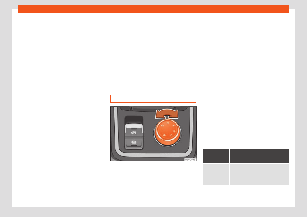
Driving
Engine
Depending on the pr
ofil
e sel
ected, the engine
responds more spontaneously or more in har-
mony with the movements of the accelerator.
Additionally, when the Eco profile is selected,
the Start-Stop function is automatically acti-
vated.
In vehicles with automatic transmission, the
gear change points are modified to position
them in lower or higher engine speed ranges.
Additionally, the Eco profile activates the in-
ertia function, enabling consumption to be
further reduced.
In manual gearbox vehicles, the Eco profile
causes the gear change recommendation in-
dications that appear on the dash panel to
vary, facilitating more efficient driving.
Address
The power steering varies its driving modes
and adapts to the profile selected, thus offer-
ing the best behaviour for each situation.
Air conditioning
In vehicles with Climatronic, this can operate
in eco mode, especially restricting fuel con-
sumption.
Adaptive Cruise Control (ACC)
The acceleration and braking gradient of the
adaptive cruise control varies according to
the active driving profile
›››
page 283.
Electronic Stability Control (ESC)
In the Offroad and Snow driving profiles, the
electronic stability Control (ESC)
›››
page 248 adjusts to adapt to the terrain.
In addition, hill descent control (HDC) is acti-
vated in the Offroad profile
›››
page 271.
Adjusting driving profile
Fig. 277 Centre console: Driving Experience
butt
on.
You can select the Eco, Normal, Sport, Indi-
vidual, Offroad
1)
and Snow
1
)
.
The desir
ed mode can be sel
ected as follows:
●
Turn the Driving Experience button until the
required profile lights up on the Easy Connect
system display as well as on the Driving Ex-
perience button
›››
Fig. 277.
●
OR: select the required profile on the touch-
screen of the Easy Connect system, in the
menu that opens up on turning the Driving
Experience button.
The features of each profile can be seen by
pressing the Profile information button of
the Easy Connect system display.
In the Individual profile it is possible to con-
figure the characteristics of the vehicle using
the Profile setup button of the Easy Connect
system display.
An icon on the Easy Connect system display
provides information about the active profile
if it is different than Normal. The selector
identifies the profile chosen by means of a
red LED light.
Driving
profile
Char
acteristics
Eco
Places the vehicle in a particularly
low state of consumption, facilitat-
ing a fuel-saving driving style that
is respectful to the environment.
1)
Only for 4Drive models.
304
Driver assistance systems
Driving
profile
Char
acteristics
Normal
Offers a balanced driving experi-
ence, suitabl
e for everyday use.
Sport
Provides a complete dynamic per-
formance in the vehicl
e, enabling
the user a more sporty driving style.
Individual
It allows you to personalise the
configuration. The functions that
can be adjusted depend on the
equipment fitt
ed in the vehicle.
Offroad
a)
It adjusts the vehicle's parameters
in order to maint
ain optimal off-
road driving.
Snow
a)
It adjusts the vehicle's behaviour for
driving on slippery road surfaces,
optimising grip and manoeuvrabili-
ty.
a)
Only for 4Drive models.
WARNING
When operating SEAT Drive Profile, pay at-
tention to all tr
affic: doing otherwise could
cause an accident.
Note
●
When the vehicle is s
witched off it will
store the driving profile that was selected
when the ignition key was removed. Never-
theless, when the engine is restarted, the
engine and the gear will start by default in
the Normal setting. For engine and gear to
rev
ert to the desired position, select the
corresponding drive profile again rotating
the thumbwheel (Driving Experience
Button) or on the Easy Connect display.
●
When the vehicle is restarted after using
the Offroad or Snow settings, the system is
always activated in the Normal profile.
●
Your speed and driving style must always
be adjusted to visibility, weather, and traf-
fic conditions.
●
The Eco profile is not recommended when
towing a vehicle.
Park Assist*
Intr
oduction
Fig. 278 Related video
The Park Assist system is an additional func-
tion of P
arkPil
ot
›
››
page 315 and helps the
driver to:
●
find a suitable parking space,
●
select a parking mode,
●
park driving in reverse in suitable perpen-
dicular and parallel spaces,
●
park driving forwards in suitable perpendic-
ular spaces,
●
exit a parking space driving forwards from a
parallel space.
In vehicles with a Park Assist system and fac-
tory infotainment system, the front, rear and
side areas are represented, and the position
of obstacles is shown relative to the vehicle.
The Park Assist system is subject to certain
limitations inherent to the system and its use
requires special attention by the driver
›››
.
WARNING
The technology used in the park assist sys-
tem invol
ves a series of limitations inherent
in the actual system and in the use of ultra-
sonic sensors. The use of Park Assist should
never tempt you to take any risk that may
compromise safety. The system is not a re-
placement for driver awareness.
●
Any accidental movement of the vehicle
could result in serious injury.
●
Adapt your speed and driving style at all
times to suit visibility, weather, road and
traffic conditions.
●
Certain surfaces of objects and gar-
ments do not reflect the ultrasound sen-
sors' signals. The system cannot detect, at
least correctly, these objects or people
wearing such clothes.
»
305
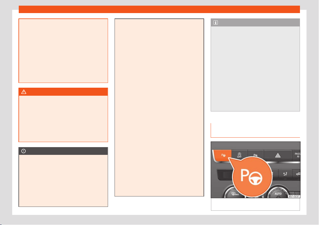
Driving
●
Ultrasound sensor signals may be aff
ec-
ted by external sound sources. In certain
circumstances this may prevent them from
detecting people or objects.
●
The ultrasound sensors have blind spots
in which obstacles and people are not reg-
istered.
●
Monitor the area around the vehicle at all
times, since the ultrasound sensors do not
detect small children, animals or certain
objects in all situations.
WARNING
Quick turns of the steering wheel when
parking or exiting a parking space with
Park Assist can cause serious injury.
●
Do not hol
d the steering wheel during
manoeuvres to park or exit a parking space
until the system requests it. Doing so disa-
bles the system during the manoeuvre, re-
sulting in the parking being cancelled.
CAUTION
●
In certain cir
cumstances, the ultrasonic
sensors do not detect objects such as trail-
er tongues, bars, fences, posts or thin trees,
or an open (or opening) rear lid, which
could damage the vehicle.
●
Retrofitting of certain accessories to the
vehicle, such as a bicycle rack, may inter-
fere with the operation of the Park Assist
system and cause damage.
●
The Park Assist system uses as a r
efer-
ence parked vehicles, curbs and other ob-
jects. Make sure that the tyres and wheels
are not damaged while parking. If necessa-
ry, opportunely interrupt the parking ma-
noeuvre to avoid damaging the vehicle.
●
The ultrasound sensors on the bumper
may be damaged or shifted in the event of
a collision, for example, when entering or
exiting a parking space.
●
If you use high-pressure or vapour equip-
ment to clean the ultrasound sensors, do
not apply it directly unless very briefly and
always from a distance of more than 10 cm.
●
A registration plate or plate holder on the
front with larger than the space for the reg-
istration plate, or a registration plate that is
curved or warped can cause:
–
false detections,
–
loss of sensor visibility.
–
cancellation of the parking manoeuvre
or defective parking.
●
If one of the ultrasonic sensors is dam-
aged, the area corresponding to that group
of sensors (front or rear) is deactivated and
cannot be activated until the fault is cor-
rected. However, you can still use the sen-
sors of the other bumper as per usual. If
there is a fault in the system, consult a spe-
cialist workshop. SEAT recommends visiting
a SEAT dealership for this.
Note
●
In order to guar
antee good system oper-
ation, keep the ultrasound sensors of the
bumper clean, free of snow or ice, and do
not cover them with adhesives or other ob-
jects.
●
Certain sources of noise, such as rough
asphalt or paving stones and the noise of
other vehicles can induce the Park Assist
system or ParkPilot to give erroneous warn-
ings.
●
In order to become familiar with the sys-
tem and its functions, SEAT recommends
that you practice operating the Park Assist
system in an area where there is not too
much traffic or in a car park.
Description of the Park Assist sys-
t
em
Fig. 279 In the centre console, top section:
butt
on t
o s
witch on the Park Assist system.
306

Driver assistance systems
The components of the Park Assist system
ar
e the ultr
asonic sensors l
ocated in the front
and rear bumpers, the button
›››
Fig. 279
to switch the system on and off and the mes-
sages on the instrument panel display.
Prematurely stopping or automatically in-
terrupting the manoeuvres for parking or
exiting a parking space
Park Assist interrupts the manoeuvres for
parking or exiting a parking space in any of
the following cases:
●
Press the button.
●
The speed exceeds approximately 7 km/h
(4 mph).
●
The driver takes hold of the steering wheel.
●
The parking manoeuvre does not end within
6 minutes from the activation of automatic
steering.
●
There is a fault in the system (the system is
temporarily unavailable).
●
ASR is switched off.
●
ASR or ESC intervene with regulation.
●
The driver door is opened.
To restart the manoeuvre it is necessary that
none of these things occur and that the
button is pressed again.
Special characteristics
The Park Assist system is subject to certain
limitations inherent to the system. For exam-
ple, it is therefore not possible to enter or exit
a parking space on sharp bends.
While entering or exiting a parking space, a
brief signal sounds to prompt the driver to
change between forward and reverse gears
(depending on the case). In successive ma-
noeuvres, the assistant tells the driver to
change gears, at the latest, when the contin-
uous audible signal is given (object present at
a distance of ≤30 cm) by Park Pilot.
When the Park Assist system turns the steer-
ing wheel with the vehicle stationary, the in-
strument panel also displays the symbol .
Keep the brake pedal depressed while the
symbol remains on the dash panel display to
turn the wheels with the vehicle stopped. This
way, the system will require fewer manoeu-
vres to complete the parking action.
Trailer mode
The Park Assist system cannot be switched
on if the factory-fitted towing bracket
›››
page 329 is electrically connected to a
trailer.
After changing a wheel
If, after changing a wheel, the vehicle stops
entering and exiting parking spaces correct-
ly, the circumference of the new wheel may
be different and the system may need to
adapt to it. The adaptation is automatic and
takes place during driving. Making turns slow-
ly and in both directions (20 km/h [12 mph])
for a few minutes may contribute to this
adaptation process
›››
in Introduction on
page 305.
307
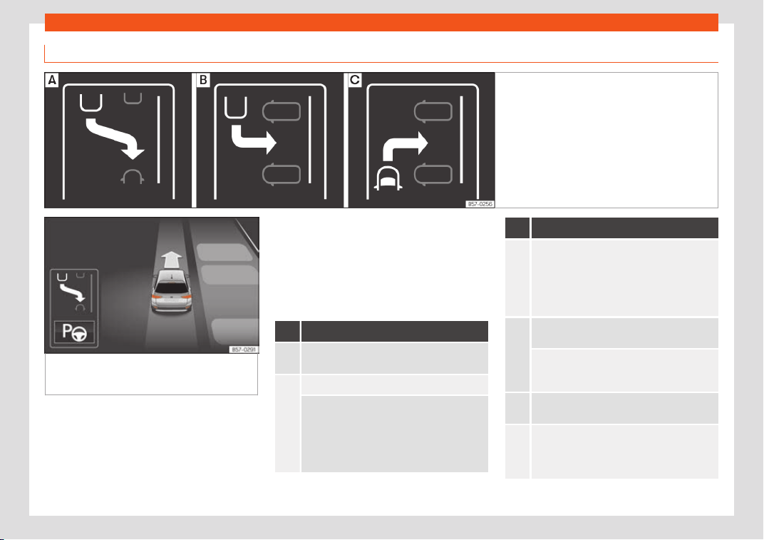
Driving
Selecting a parking mode
Fig. 280 Overview of reduced displays for park-
ing modes: Parall
el parking in reverse. Per-
pendicular parking in reverse. Perpendicular
parking forwards.
Fig. 281 On the instrument panel display: dis-
play of the assisted parking syst
em with de-
creased visibility.
Selecting a parking mode with Park Assist
with prior st
ep in fr
ont of the space
Aft
er activating the Park Assist system and af-
ter detecting a parking space, the display on
the instrument panel proposes a parking
mode. The Park Assist system selects the
parking mode automatically. The selected
mode is shown on the instrument panel dis-
play
›››
Fig. 281. The reduced display of other
possible parking modes is also shown
›››
Fig. 280. If the mode selected by the sys-
tem does not correspond to the desired
mode, you can select another mode by
pressing the button
›››
Fig. 279.
Action
1.
The necessary conditions to park with Park
Assist have to be met
›
››
page 310.
2.
Press the button.
A control l
amp on the button lights up when
the system is s
witched on. Additionally, the
selected parking mode is shown on the instru-
ment panel display and the reduced display
shows another parking mode it can be
changed to.
Action
3.
Turn on the corresponding turn signal towards
the side of the road where you ar
e parking.
The instrument panel displays the side corre-
sponding to the road. By default, if the turn
signal is not on, it parks on the right in the di-
rection of traffic.
4.
If necessary, press the button again to
change t
o the next parking mode.
Once you have switched to all possible park-
ing modes, if the button is pressed again,
the syst
em switches off.
5.
Press the button again to s
witch the system
back on.
6.
Follow the instructions displayed on the in-
strument panel while paying attention to traf-
fic and drive the vehicle past the parking
space.
308

Driver assistance systems
Special case of perpendicular parking
space t
o park f
orw
ards without driving
past first
Action
1.
The necessary conditions to park with Park
Assist have to be met
›
››
page 310.
Action
2.
Drive forward towards the parking space while
paying attention to tr
affic and stop the vehi-
cle.
Action
3.
Press the button once
.
A control lamp on the button lights up when
the system is s
witched on. Additionally, the
selected parking mode is shown on the instru-
ment panel display without reduced display.
4.
Release the steering wheel
›››
in Introduc-
tion on page 306.
309
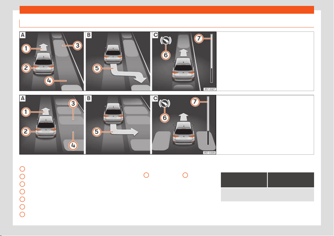
Driving
Park with Park Assist
Fig. 282 On the instrument panel display: per-
pendicular parking.
Finding a parking space.
Parking position. Manoeuvring.
Fig. 283 On the instrument panel display: paral-
lel parking. Finding a parking space.
Park-
ing position. Manoeuvring.
Key to Fig. 282 and Fig. 283:
Message t
o mo
v
e forwards
Your vehicle
Parked vehicle
Parking space detected
Message to park
Message to press the brake pedal
Progress bar
1
2
3
4
5
6
7
Progress bars
The pr
ogr
ess bar
›
››
Fig. 282
7
and
›
›
›
Fig. 283
7
on the
scr
een of the instrument panel displ
ays the
r
elative distance to be covered. The greater
the distance, the fuller the progress bar.
When driving forward, the content of the pro-
gress bar decreases upwards, and when re-
versing, it decreases downwards.
Necessary conditions to park with Park As-
sist
For parallel parking
spaces
For perpendicular
parking spaces
The traction control system (ASR) must be turned on
›››
page 250.
310
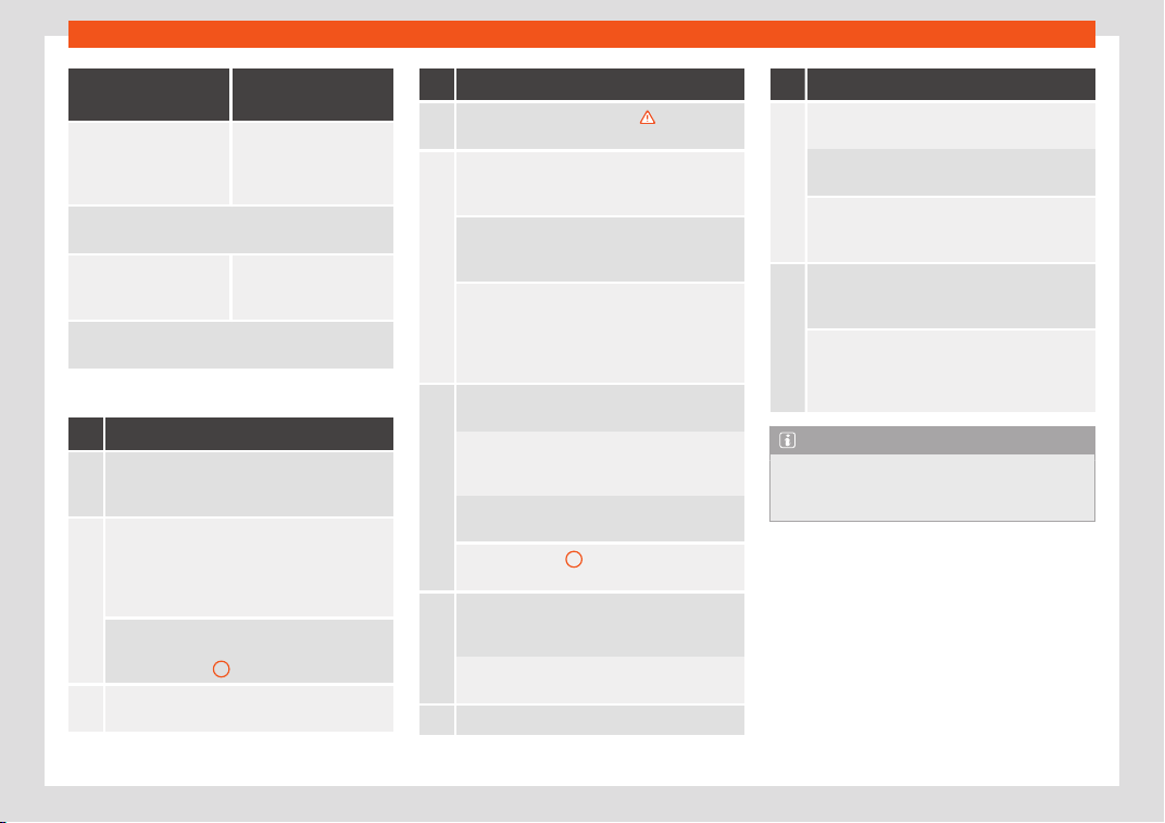
Driver assistance systems
For parallel parking
spaces
For perpendicular
parking spaces
Do not exceed approxi-
mately 40 km/h
(25 mph)
when driving
past the parking space.
Do not exceed approxi-
mately 20 km/h
(12 mph) when driving
past the parking space.
Keep a distance between 0.5 and 2.0 metres
when
driving past the parking space.
Length of the space:
length of the vehicl
e +
0.8 metres
Width of the space:
width of the vehicle +
0.8 metres
Do not exceed approximately 7 km/h (4 mph) when
parking.
Parking
Do the following:
1.
The necessary conditions have to be met to
park with Park Assist
››
›
page 310 and the
parking mode must be selected
›››
page 308.
2.
Look at the display on the instrument panel to
see if the space has been detected as “appr
o-
priate” and if the correct position for parking
has been reached
›››
Fig. 282
or
›››
Fig. 283 .
The space is considered “appropriate” if the
display on the instrument panel shows the
message t
o park
5
.
3.
Stop the vehicle and, after a brief pause, en-
gage the rev
erse gear.
Do the following:
4.
Release the steering wheel
›››
in Introduc-
tion on page 306.
5.
Please note the following message: Auto-
matic steering enabled. Pay at-
tention to your surroundings.
While you keep watch around you, carefully
start acceler
ating up to no more than 7 km/h
(4 mph).
During the parking manoeuvre, the system on-
ly takes char
ge of the steering. You, as the
driver, have to accelerate, engage the
clutch if necessary, change gears and
brake.
6.
Reverse until the ParkPilot continuous signal is
hear
d.
OR: re
verse until the instrument panel displays
the message to go f
orwards
›››
Fig. 282
or
›››
Fig. 283 .
OR: reverse until the instrument panel displays
the message Park Assist finished.
The progress bar
7
indicates the distance to
cover
›
››
page 310.
7.
Press down the brake pedal until the Park As-
sist system has finished turning the steering
wheel.
OR: until the symbol on the instrument pan-
el display switches off.
8. Select first gear.
Do the following:
9.
Go forward until the ParkPilot continuous sig-
nal is heard.
OR: go forw
ard until the instrument panel dis-
play sho
ws the message to reverse.
The Park Assist system steers the vehicle for-
ward and back until it centr
es it in the space
›››
Fig. 282 or
›››
Fig. 283 .
10.
For best results, wait at the end of each ma-
noeuvre until the Park Assist syst
em has finish-
ed turning the steering wheel.
The parking manoeuvre ends when a corre-
sponding message is displayed on the instru-
ment panel and, in some cases, an acoustic
signal sounds.
Note
If the manoeuvre is terminated prematurely
during parking, the result may not be the
best.
311
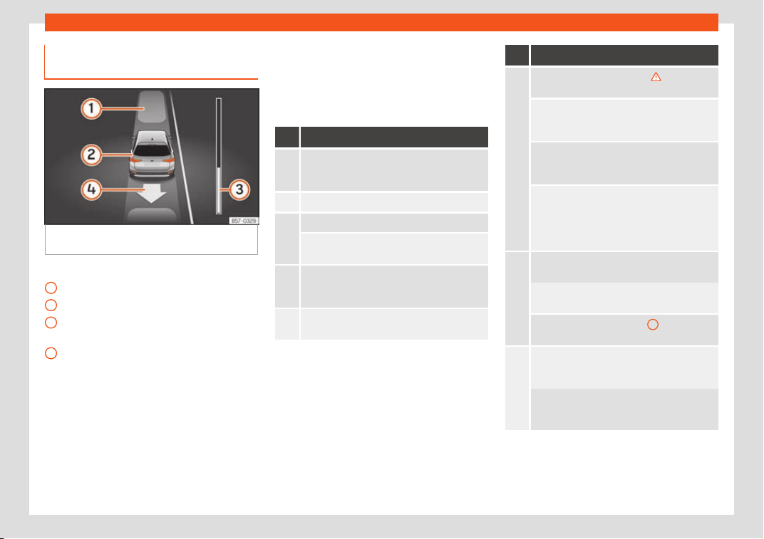
Driving
Exiting a parking space with Park
Assist (only f
or par
all
el spaces)
Fig. 284
On the instrument panel display:
driving off fr
om perpendicul
ar parking.
Key to the Fig. 284:
P
ark
ed v
ehicle
Your vehicle in reverse gear
Progress bar to indicate the distance left
to cover
Message giving the proposed manoeuvre
to exit the parking space
Necessary conditions to exit a parking
space with Park Assist
●
Only for parallel parking spaces
●
The traction control system (ASR) must be
turned on
›››
page 250.
●
Length of the space: length of the vehicle
+ 0.5 metres
1
2
3
4
●
Do not e
x
ceed appr
oximately 7 km/h
(4 mph) when exiting the parking space.
Exiting a parking space
Do the following:
For parallel parking spaces
1.
The necessary conditions to exit a parking
space with Park Assist have t
o be met
›››
page 312.
2. Switch on the engine
›››
page 239.
3.
Press the button
››
›
Fig. 279.
A control lamp on the button lights up when
the system is s
witched on.
4.
Turn on the corresponding turn signal towards
the road you will enter when e
xiting the park-
ing space.
5.
Engage reverse gear or turn the selector lever
t
o position
R
.
For parallel parking spaces
6.
Release the steering wheel
›››
in Introduc-
tion on page 306.
Please note the following message: Auto-
matic steering enabled. Pay at-
tention to your surroundings.
While you keep watch around you, carefully
start acceler
ating up to no more than 7 km/h
(4 mph).
When exiting the parking space, the system
only takes char
ge of the steering. You, as the
driver, have to accelerate, engage the
clutch if necessary, change gears and
brake.
7.
Reverse until the ParkPilot continuous signal is
heard.
OR: go backwards until the instrument panel
displ
ay shows the message to go forward.
The progress bar
›››
Fig. 284
3
indicates the
distance to co
ver
›››
page 310.
8.
Press down the brake pedal until the Park As-
sist syst
em has finished turning the steering
wheel.
OR: press down the brake pedal until the
symbol on the instrument panel display
switches off.
312
Driver assistance systems
For parallel parking spaces
9.
Go forward until the ParkPilot continuous sig-
nal is heard.
OR: go forw
ard until the instrument panel dis-
play sho
ws the message to reverse.
The Park Assist system steers the vehicle for-
ward and back until it can e
xit the space.
10.
The vehicle can exit the space when a corre-
sponding message is displayed on the instru-
ment panel and, in some cases, an acoustic
signal sounds.
Tak
e charge of the steering with the turning
angle set by the Park Assist syst
em.
11.
Paying attention to the traffic, exit the parking
space.
Automatic braking intervention by
P
ark Assist
Park Assist helps the driver by automatically
br
aking in cert
ain sit
uations.
The driver is always responsible for braking in
time
›››
.
Aut
omatic br
aking int
ervention to avoid
exceeding the speed limit
To avoid exceeding the allowed speed of ap-
prox. 7 km/h (4 mph) when entering or leaving
a parking space, the brakes may activate au-
tomatically. After automatically activating
the brakes, the manoeuvres to enter or exit a
parking space may continue.
The brakes are only automatically activated
once for each attempt to enter or exit a park-
ing space. If the speed of approximately
7 km/h (4 mph) is exceeded again, the corre-
sponding operation is halted.
Automatic braking to reduce damages
Depending on certain conditions, the Park
Assist system can automatically brake the
vehicle when faced with an obstacle, briefly
actioning and holding down the brake ped-
al
›››
. Following this the driver must press
the br
ak
e pedal.
Aut
omatic braking intervention to reduce
damage leads to the parking manoeuvre fin-
ishing.
WARNING
The automatic braking intervention by Park
Assist should nev
er tempt you to take any
risk that may compromise safety. The sys-
tem is not a replacement for driver aware-
ness.
●
The Park Assist system is subject to cer-
tain limitations inherent to the system. In
certain situations, the automatic braking
intervention may only work in a limited way
or not work at all.
●
Always be r
eady to use the brakes your-
self!
●
The automatic braking intervention will
end after approximately 1.5 seconds. After-
wards, brake the vehicle yourself.
Parking aid parking and ma-
noeuvring (ParkPilot)
Intr
oduction
Assorted assistance systems – which vary
depending on the equipment fitt
ed in the car
– will help you when parking or manoeuvring:
–
P
arking Syst
em Plus. It assists the driver
by visually and audibly warning them about
obstacles detected in front and behind the
vehicle
›››
page 315.
–
Rear parking aid. It is an audible and visual
assistant that warns about obstacles loca-
ted behind the vehicle
›››
page 319.
WARNING
●
Always pay att
ention, also when looking
straight ahead, to traffic and the vehicle
surroundings. The assistance systems are
not a replacement for driver awareness.
When inserting or removing the vehicle
from a parking space, or when performing
»
313
Driving
similar manoeuvres the driver always as-
sumes the responsibility.
●
Adapt your speed and driving st
yle at all
times to suit visibility, weather, road and
traffic conditions.
●
The ultrasound sensors have blind spots
in which obstacles and people are not reg-
istered. Pay special attention to children
and animals.
●
Always keep visual control of the sur-
roundings: use the mirrors for additional
help.
CAUTION
Parking Aid functions may be negatively af-
fected by diff
erent factors that may lead to
damage to the vehicle or its immediate sur-
rounds:
●
Under certain circumstances, the system
does not detect or display certain objects:
–
Objects such as chains, trailer draw
bars, fences, posts and thin trees.
–
Objects that are located above the
sensors, such as protrusions in a wall.
–
Objects with certain surfaces or struc-
tures, such as wire mesh fences or pow-
der snow.
●
Certain surfaces of objects and gar-
ments do not reflect the ultrasound sen-
sors' signals. The system cannot detect
these objects or people wearing such
clothes correctly.
●
Ultrasound sensor signals may be aff
ec-
ted by external sound sources. In certain
circumstances this may prevent them from
detecting people or objects.
●
Please note that low obstacles detected
by the system may no longer be registered
by the sensors as the car moves closer, so
the system will not give any further warn-
ing. In certain circumstances, objects such
as high kerbs that could damage the bot-
tom of the vehicle are not detected either.
●
If the first warning from the Parking Aid is
ignored, the vehicle could suffer considera-
ble damage.
●
The knocks or damage on the radiator
grille, bumper, wheel arch and vehicle un-
derbody can adjust the orientation of the
sensors. This can affect the parking aid
function. In this case, have the function
checked by a specialised workshop.
●
A registration plate or plate holder on the
front with larger than the space for the reg-
istration plate, or a registration plate that is
curved or warped can cause:
–
false detections,
–
loss of sensor visibility.
Note
●
In certain sit
uations, the system can give
a warning even though there is no obstacle
in the detected area, e.g:
–
with rough or cobbled fl
oors or ground
with long grass;
–
with external ultrasound sources, such
as cleaning vehicles or other vehicles
equipped with ultrasound systems;
–
in downpours, intense snow, hail or
dense exhaust gases,
–
if the number plate is not perfectly se-
cured to the bumper surface,
–
or in locations such as the brow of a
hill.
●
In order to guarantee good system oper-
ation, keep the ultrasound sensors clean,
free of snow or ice, and do not cover them
with adhesives or other objects.
●
If you use high-pressure or vapour equip-
ment to clean the ultrasound sensors, ap-
ply it directly only very briefly and always
from a distance of more than 10 cm.
●
Retrofitting of accessories to the vehicle,
such as a bicycle rack, may interfere with
the operation of the Parking Aid.
●
Fitting certain accessories to the front of
the vehicle, such as a plate holder with ad-
vertising, may interfere with the operation
of the Park Assist.
●
In order to familiarise yourself with the
system, it is advised that you practice park-
ing in an area or car park that is free from
traffic. There must be good weather and
light conditions.
314
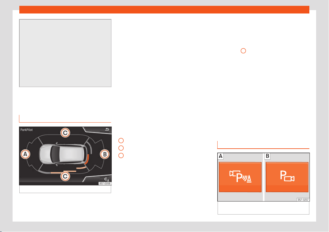
Driver assistance systems
●
The volume and tone of the w
arnings can
be modified, in addition to the indications
›››
page 321.
●
In vehicles without an infotainment sys-
tem, these parameters can be modified in a
SEAT Official Service or in a specialised
workshop.
●
Please observe information on towing a
trailer
›››
page 321.
●
The display on the Easy Connect screen
shows a slight time delay.
Parking System Plus*
Description
Fig. 285
Represented area.
During parking, P
arking Syst
em Plus
assists
the driver by visually and audibly warning
them about obstacles detected in front of
and behind the vehicle.
There are ultrasound sensors integrated in
the front and rear bumpers. When they de-
tect an obstacle, you are alerted by audible
warnings and visually on the Easy Connect
system.
In case of risk of rear or front collision, an au-
dible warning will be emitted. You can tell
whether the risk is in front of or behind the ve-
hicle by choosing different sound frequencies
on Easy Connect.
Make particularly sure that the sensors are
not covered by adhesives, residues and the
like, as this could affect the system's opera-
tion. Cleaning instructions
›››
page 371.
The approximate measurement range of the
sensors is:
1.20 m
1.60 m
0.90 m
As you approach the obstacle, the time inter-
val between the audible warnings will be re-
duced. When you reach around 0.30 m the
warning will be constant: do not continue to
move forward (or backward)!
If you maintain separation from the obstacle,
the volume of the warning begins to reduce
after four seconds (does not affect the tone
of the constant warning).
A
B
C
In order to view the entire periphery of the ve-
hicl
e
, the v
ehicle must be moved a few me-
tres forwards or backwards. Thus, the missing
areas are screened and obstacles at the
sides of the vehicle are displayed
›››
Fig. 285
C
.
Special f
eat
ur
es of ParkPilot with Area
View
In the following situations the screened area
on the side of the vehicle is automatically hid-
den:
●
When a vehicle door is opened.
●
When the ASR is switched off.
●
When there is ASR or ESC regulation.
●
If the vehicle remains stationary for more
than approximately 3 minutes.
Parking Aid operation
Fig. 286
Centre console: parking aid button
(depending on the v
ersion).
»
315
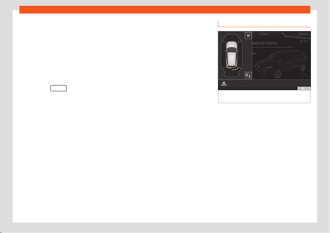
Driving
Manual connection of Parking Aid
●
Press the butt
on
once
.
Manual disconnection of Parking Aid
●
Press the button again.
Manual disconnection of Parking Aid dis-
play (the audible sounds remain active)
●
Press a button on the main menu of the fac-
tory-assembled infotainment system.
●
OR press the BACK
function button.
Aut
omatic connection of P
arking Aid
●
Engage r
everse gear or turn the selector
lever to position R.
●
OR: If the vehicle approaches an obstacle
that is in its forwards path at a speed below
15 km/h (9 mph)
›››
page 316. The obstacle is
detected from a distance of approx. 95 cm if
the automatic connection is activated in the
infotainment system. A reduced display is
shown.
●
OR: if the vehicle moves backwards.
Automatic disconnection of Parking Aid
●
Move the selector lever to position P.
●
OR: accelerate to approx. 15 km/h (9 mph)
or faster.
Temporary suppression of sound in Park-
ing Aid
●
Press the function button.
Change from reduced view to full view
●
Engage reverse gear or turn the selector
lever to position R.
●
OR: press the car icon in reduced view.
If necessary, switch to the rear-assist im-
age (Rear View Camera “RVC”)
●
Engage reverse gear or turn the selector
lever to position R.
●
OR press the RVC function button.
A short confirmation signal will be heard and
the button symbol will light up yellow when
the system is switched on.
Automatic activation
Fig. 287
Miniature indication of automatic ac-
tiv
ation.
When the Plus P
arking Aid
connects aut
o-
matically, a miniature of the vehicle and the
segments will appear on the left of the dis-
play
›››
Fig. 287.
Automatic activation occurs when slowly ap-
proaching an obstacle located in front of the
vehicle. It only operates every time the speed
is reduced below approximately 15 km/h (9
mph) for the first time.
If the parking aid is switched off using the
button, the following actions must be carried
out in order for it to automatically switch on:
●
Switch off the ignition and switch it on
again.
●
OR: accelerate above 15 km/h (9 mph) be-
fore reducing speed below this number again.
316
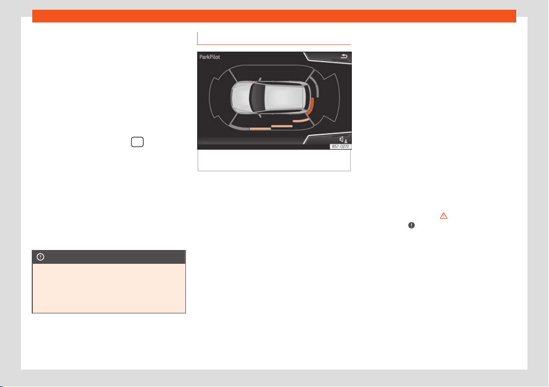
Driver assistance systems
●
OR: pl
ace the sel
ect
or lever in position P
and then move it from this position.
●
OR: switch on and off the automatic activa-
tion in the Easy Connect system menu.
The automatic activation with parking aid
miniature indication can be switched on and
off from the Easy Connect system menu
›››
page 35:
●
Switch the ignition on.
●
Select: Infotainment button
SETTINGS
> Parking and manoeuvring function but
-
t
on.
●
Sel
ect the Automatic activation option.
When the function button check box is activa-
ted , the function is on.
If the system has been activated automati-
cally, an audible sound warning will only be
given when obstacles in front are at a dis-
tance of less than 50 cm.
CAUTION
The automatic connection of the Parking
Aid only works when you are driving sl
owly.
If driving style is not adapted to the circum-
stances, an accident and serious injury or
damage may be caused.
Segments of the visual indication
Fig. 288
Parking Aid display on the Easy Con-
nect syst
em scr
een.
The distance of separation from the obstacle
can be estimat
ed using the segments ar
ound
the v
ehicle.
The optical indication of the segments works
as follows:
they are displayed when
the obstacle 30 cm away from the vehi-
cle or further if it is not within the vehi-
cle's trajectory or the direction of travel
is in the opposite direction to its location,
and also when the electronic parking
brake is activated.
obstacles located in the
vehicle's trajectory and which are more
than 30 cm away from the vehicle are
displayed in yellow.
White segments:
Yellow segments:
obstacles that are less than
30 cm away from the vehicle are dis-
played in red.
Moreover, with the Media System Plus, Navi
System or Navi System Plus systems, a yellow
trail indicates the vehicle's expected trajecto-
ry based on the steering angle.
Whenever the obstacle is located in the vehi-
cle’s direction of travel, the corresponding
audible warning will sound.
As the vehicle approaches an obstacle, the
segments are displayed closer to the vehicle.
When the penultimate segment is displayed,
this means that the vehicle has reached the
collision zone. In the collision zone, the obsta-
cles are represented in red, including those
out of the path. Do not continue to move for-
ward (or backward)
›››
in Introduction on
page 313,
›
›
›
in Introduction on
page 314 !
In the e
v
ent the car is equipped with the T
op
View Camera system, Park Assist visual guid-
ance will appear in accordance with the view
selected in the Top View Camera system.
Red segments:
317
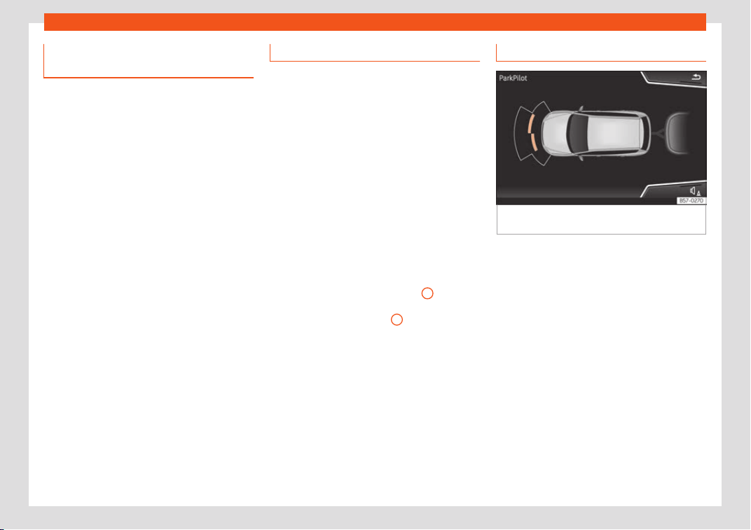
Driving
Adjusting the display and audible
w
arnings
The settings for the display and audible
warnings are contr
olled via the Easy
Connect*.
Automatic activation
on – activates the Automatic activa-
tion option
›››
page 316.
off – deactivates the Automatic acti-
vation option
›››
page 316.
Front volume*
Volume in the front and rear area.
Front sound settings/sharpness*
Frequency (tone) of the sound in the front
area.
Rear volume*
Volume in the rear area.
Rear sound settings/sharpness*
Frequency (tone) of the sound in the rear
area.
Adjust volume
With the parking aid switched on, the active
audio/video source volume will be reduced to
the intensity of the selected setting.
Error messages
When the Parking Aid is activated or when it is
switched on, if a message r
eporting a Parking
aid error is displayed on the instrument panel,
there is a fault in the system.
If the fault does not disappear before discon-
necting the ignition, the next time that the
parking aid is engaged in reverse, no audible
signal of the existence of a fault will be is-
sued.
If there is a fault in the parking aid system a
message will appear on the instrument panel
indicating the error.
If there is a fault in a sensor, the symbol is
displayed on the Easy Connect display in
front of/behind the vehicle. If a rear sensor is
faulty, only the obstacles in area
A
are dis-
pl
ayed
›
›
›
Fig. 285. If a front sensor is faulty,
only the obstacles in area
B
are displayed.
Hav
e the f
ault corr
ected by a specialised
workshop without delay.
Driving with a trailer
Fig. 289
Parking assist display on the screen
with tr
ail
er att
ached.
In vehicles equipped with a towing bracket
de
vice fr
om the f
actory, when the trailer is
connected electrically, the Parking Aid rear
sensors will not be activated when reverse
gear is engaged, when the selector lever is
turned to position R or when the button is
pressed.
The distance to possible obstacles at the rear
of the vehicle and at its sides will not be dis-
played on the screen and will not be indica-
ted by means of audible sound signals.
The Easy Connect system screen will only
display objects detected at the front, and the
vehicle's trajectory will be hidden.
318

Driver assistance systems
Braking while manoeuvring func-
tion*
3 Only valid with Parking System Plus
The emergency br
aking function is used to
minimise damage in the event of a collision.
Depending on the equipment, if the Parking
Aid is active, the braking while manoeuvring
function activates emergency braking when it
detects an obstacle in the vehicle’s path that
could cause a collision, driving forwards or in
reverse.
The function will not brake if the Parking Aid is
activated automatically. For the system to
operate, manoeuvring speed must be be-
tween 2.5 and 10 km/h (between 1.5 and 6
mph) for the front area and between 1.5 and
10 km/h (between 1 and 6 mph) for the rear.
Following an intervention, the braking while
manoeuvring function will be inactive in the
same direction of travel for 5 metres. Once
the gear is changed, or the selector lever’s
position is changed, the function will be ac-
tive again. The Parking Aid’s limitations apply.
The braking while manoeuvring function is
controlled in the Easy Connect system with
the
button and the SETTINGS > Park
and manoeuvre function butt
ons.
●
on – permits the use of the braking whil
e
manoeuvring function.
●
off – does not permit the use of the
braking whil
e manoeuvring function.
Temporary suppression of emergency
braking
●
When the function is deactivated with the
Braking while manoeuvring
button that appears
on the P
arking Syst
em
screen of the Easy
Connect system.
●
Whenever any of the car doors, rear lid or
bonnet are opened.
Rear parking aid*
Description
The r
ear parking aid is an audible and visual
assist
ant that w
arns of obstacles located be-
hind the vehicle.
There are sensors integrated in the rear
bumper. When they detect an obstacle, you
are alerted by audible warnings and visually
on the Easy Connect system.
If the Top View Camera* is installed, the rear
parking aid will issue an audible warning
about objects near the rear of the vehicle,
and the Top View Camera* image will be
available on the Easy Connect screen, giving
a real image of the objects around the car.
Make particularly sure that the sensors are
not covered by adhesives, residues, dirt and
the like, as this could affect the system's op-
eration. Cleaning instructions
›››
page 371.
The approximate measurement range of the
rear sensors is:
0.60 m
1.60 m
Automatic disconnection of Parking Aid
●
Move the selector lever to position P.
●
OR: accelerate to approx. 15 km/h (9 mph)
or faster.
Temporary suppression of sound in Park-
ing Aid
●
Press the function button.
Change from reduced view to full view
●
Engage reverse gear or turn the selector
lever to position R.
●
OR: press the car icon in reduced view.
As you approach the obstacle, the time inter-
val between the audible warnings will be re-
duced. When you reach around 0.30 m the
warning will be constant: Do not continue to
move forward (or backward)
›››
in Intro-
duction on page 313,
›
›
›
in Introduction
on page 314 !
»
Side area:
Central area:
319
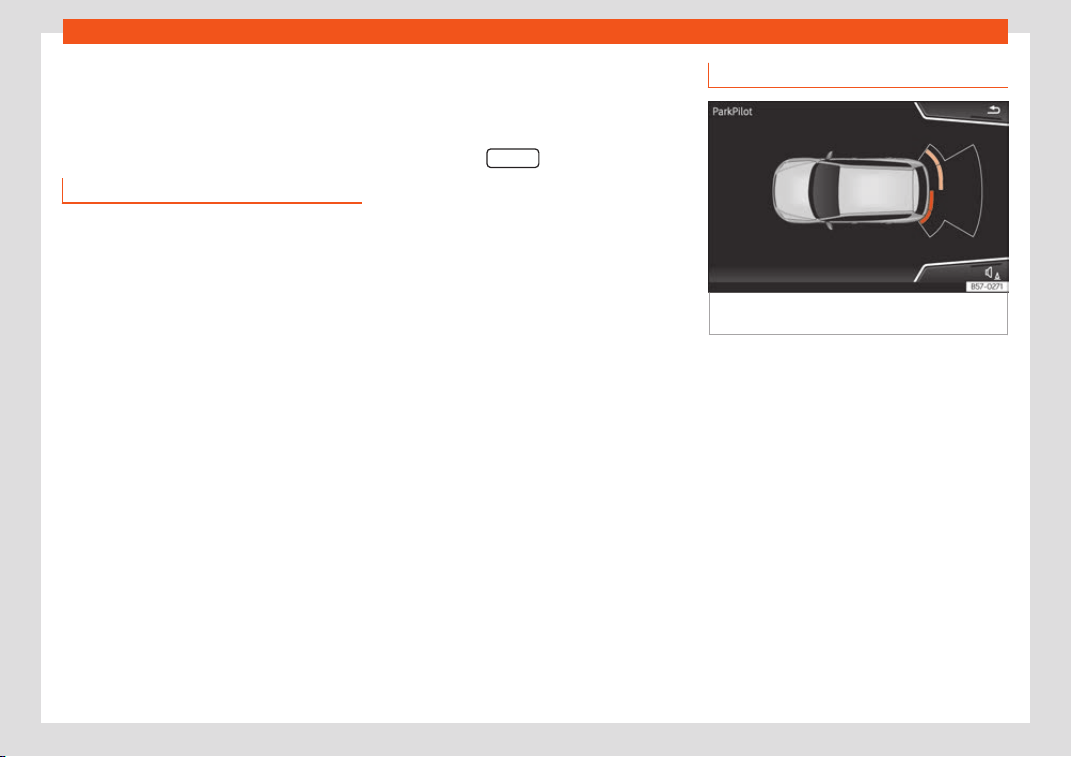
Driving
If you maintain separation from the obstacle,
the v
olume of the w
arning begins t
o reduce
after four seconds (does not affect the tone
of the constant warning).
Parking Aid operation
Parking Aid connection
●
Engage reverse (for manual gears) or set
the selector l
ever to R (for automatic gears).
Parking Aid disconnection
●
Place the selector level in position P, N or D
(for automatic gearbo
xes) or disengage re-
verse (for manual gearboxes).
Set the lever to the N or D position to maintain
the system active for approximately 8 sec-
onds before switching off. During that time,
Parking assist will switch off if:
●
The selector lever is moved to position P.
●
OR: the vehicle accelerates to approx.
15 km/h (9 mph) or faster.
If the Top View Camera* is installed, rear
parking aid will be automatically deactivated
when disengaging reverse gear.
Manual disconnection of Parking Aid dis-
play (the audible sounds remain active)
●
Press a button on the main menu of the fac-
tory-assembled infotainment system.
●
OR press the BACK
function button.
T
empor
ary suppr
ession of sound in Park-
ing Aid
●
Press the function button. If you have the
Top View Camera* system installed, you can-
not use the temporary suppression of sound
in Parking Aid.
Switch from reduced to full-screen view if
the rear assist is fitted (Rear View Camera
“RVC”)
●
Press the car icon in the reduced view.
If necessary, switch to the rear-assist im-
age (Rear View Camera “RVC”)
●
Engage reverse gear or turn the selector
lever to position R.
●
OR: press the RVC function button.
Segments of the visual indication
Fig. 290
Parking Aid display on the Easy Con-
nect syst
em scr
een.
The distance to the obstacles can be estima-
t
ed with the help of the segments at the r
ear
of the v
ehicle.
The optical indication of the segments works
as follows:
they are displayed when
the obstacle 30 cm away from the vehi-
cle or further if the direction of travel is in
the opposite direction to its location, and
also when the electronic parking brake is
activated.
obstacles located in the
vehicle's trajectory and which are more
than 30 cm away from the vehicle are
displayed in yellow.
White segments:
Yellow segments:
320
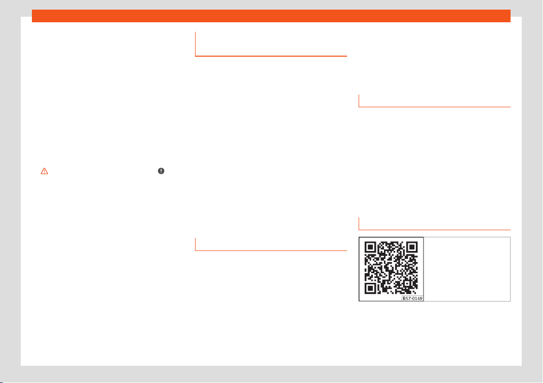
Driver assistance systems
obstacles that are less than
30 cm aw
ay fr
om the v
ehicle are dis-
played in red.
Whenever the obstacle is located in the vehi-
cle’s direction of travel, the corresponding
audible warning will sound.
As the vehicle approaches an obstacle, the
segments are displayed closer to the vehicle.
When the penultimate segment is displayed,
this means that the vehicle has reached the
collision zone. In the collision zone, the obsta-
cles are represented in red (including those
out of the path). Do not continue to reverse
›››
in Introduction on page 313,
›
›
›
in In-
tr
oduction on page 314
!
If you ar
e equipped with the Top View
Camera*
Segments are not displayed when the vehicle
is equipped with Top View Camera*.
The Parking Aid system will issue an audible
warning for objects that are near the rear of
the vehicle, and the Top View Camera* im-
age will be available on the screen, giving a
real image of the objects around the car.
Red segments:
Adjusting the display and audible
warnings
The settings for the display and audible
warnings are contr
olled via the Easy Con-
nect*.
Rear volume*
Volume in the rear area.
Rear sound settings/sharpness*
Frequency (tone) of the sound in the rear
area.
Adjust volume
With the parking aid switched on, the active
audio/video source volume will be reduced to
the intensity of the selected setting.
Error messages
When the Parking Aid is activated or when it is
s
wit
ched on, if a message r
eporting a Parking
aid error is displayed on the instrument panel,
there is a fault in the system.
If the fault disappears before disconnecting
the ignition, the next time that the parking aid
is engaged in reverse, no audible signal of the
existence of a fault will be issued.
If there is a fault in a sensor, the symbol is
displayed on the Easy Connect display.
Have the fault corrected by a specialised
workshop without delay.
Towing bracket
In vehicles equipped with a towing bracket
device from the f
actory, when the trailer is
connected electrically, the Parking Aid will
not be activated when reverse gear is engag-
ed (manual gears) nor when the selector lev-
er is turned to position R (automatic gears).
Top View Camera*
Introduction
Fig. 291 Related video
Using 4 cameras, the system generates a
r
epr
esent
ation that is shown on the infotain-
ment system display. The cameras are loca-
ted on the radiator grille, the exterior mirrors
and the rear lid.
»
321
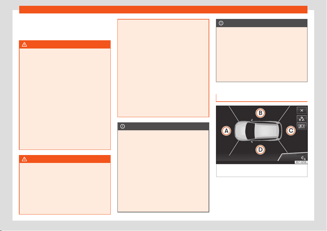
Driving
The functions and representations of the Area
Vie
w syst
em may v
ary depending on whether
or not the vehicle has ParkPilot.
WARNING
The image from the cameras does not
make it possible t
o calculate the distance
to the obstacles (people, vehicles, etc.)
precisely, so using them could cause seri-
ous accidents and injury.
●
The camera lenses augment and distort
the visual field and the objects on the
screen are seen differently and imprecise-
ly.
●
Certain objects may not be shown or may
not be shown very clearly, for example,
posts or thin rails, due to the screen resolu-
tion or if light conditions are insufficient.
●
The cameras have blind spots in which
obstacles and people are not registered.
●
The camera lens must be kept free, with-
out snow or ice, and should not be covered.
WARNING
The smart technology incorporated into
the Top View Camer
a* system cannot over-
come the limits imposed by the laws of
physics and it only works within the limits of
the system. The greater convenience provi-
ded by the Area View system should never
tempt you to take any risk that may com-
promise safety. If used negligently or invol-
untarily, it may cause serious accidents
and injuries. The system is not a replace-
ment for driver aw
areness.
●
Adapt your speed and driving style to suit
visibility, weather, road and traffic condi-
tions.
●
Do not be distracted from the traffic by
looking at the screen.
●
Monitor the area around the vehicle at all
times, since the cameras do not capture
small children, animals and certain objects
in all situations.
●
The use of a number plate may interfere
in the views shown on the screen, since the
cameras' field of vision may be reduced.
●
The system will probably be unable to
represent all areas clearly.
CAUTION
●
The camera images are only tw
o-dimen-
sional. Due to a lack of spatial depth, ob-
jects that jut out or holes on the road, for
example, are more difficult to detect or
may not be seen at all.
●
In certain circumstances, the camera
does not capture objects such as beams,
fences, posts or thin trees, which could
damage the vehicle.
●
The system displays the auxiliary lines
and boxes regardless of the vehicle's envi-
ronment, no objects are detected. The driv-
er is responsible for determining that the
vehicle will fit in the parking space.
CAUTION
In order to guarantee good system opera-
tion, keep the cameras cl
ean, free of snow
or ice, and do not cover them with adhe-
sives or other objects.
●
Never use abrasive cleaning products to
clean the camera lenses.
●
Do not use hot or warm water to remove
ice or snow from the camera lenses. Doing
so could damage the lenses.
Area View system
Fig. 292 Display of the Area View system: aer-
ial vie
w
.
There are four different views to choose from:
322
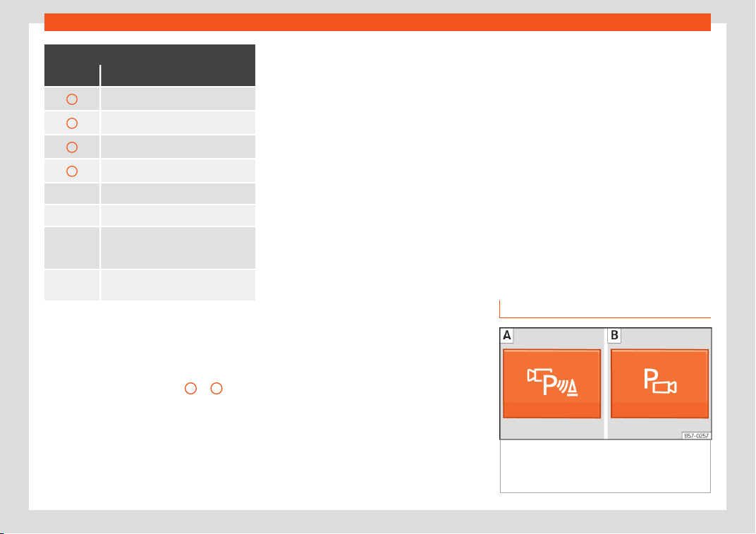
Driver assistance systems
Key to the Fig. 292:
Symbol Meaning
A Front camera area
B Right camera area
C Rear camera area
D Left camera area
Exit the current display.
Three-dimensional views
Depending on the equipment: con-
necting and disconnecting the P
ark-
Pil
ot sound.
Adjust the display: bright, contrast
and colour.
The aerial view is generated by combining
the images fr
om all the camer
as
›››
Fig. 292. The aerial view can be selected
by pressing the vehicle in the area.
Select the corresponding view by pressing
the different areas
›››
Fig. 292
A
to
D
of the
aerial vie
w or the r
educed aerial vie
w.
Conditions necessary for the use of the
Area View system
●
The doors and the rear lid must be closed.
●
The image must be reliable and clear. For
this reason, for example, the camera lens
must be clean.
●
The area around the vehicle must be clear-
ly and totally visible.
●
The area for parking or manoeuvring
should be a flat surface.
●
The vehicle should not be loaded very
heavily at the rear.
●
The driver must be used to the system.
●
There should be no damage to the vehicle
in the camera area. If the position or installa-
tion angle of the cameras have been
changed, e.g. after a rear-end collision, the
system should be checked by a specialised
workshop.
Camera image view
●
Aerial view (bird's eye view): to obtain a
panoramic view of the vehicle , three-di-
mensional views, from different camera posi-
tions.
●
Front camera (front view): to observe traf-
fic ahead of the vehicle (vehicles crossing)
, for front parallel parking , when ap-
proaching an obstacle and in off-road driving
.
●
Side cameras (side view): to view the area
close to the sides of the vehicle, both on the
left and on the right , or a combination of
both sides .
●
Rear camera (rear view): To observe traf-
fic behind the vehicle (vehicles crossing) ,
for reverse perpendicular parking , for re-
verse parallel parking and for hitching a
trailer to the vehicle .
The selected view is displayed on the right
side of the screen. The reduced aerial view
shown on the right side displays the view
framed in yellow. In addition, the right margin
of the screen displays the menu options pos-
sible and the views (the so-called “modes”)
of the camera in question. The active view
(mode) at the time is highlighted.
The reduced aerial view can be hidden by
pressing the symbol to thus display the se-
lected view full-screen.
Instructions for use
Fig. 293
Centre console: button for activat-
ing/deactiv
ating the Ar
ea Vie
w system manual-
ly in combination with the parking aid system
() or else with the rear ParkPilot system ().
»
323
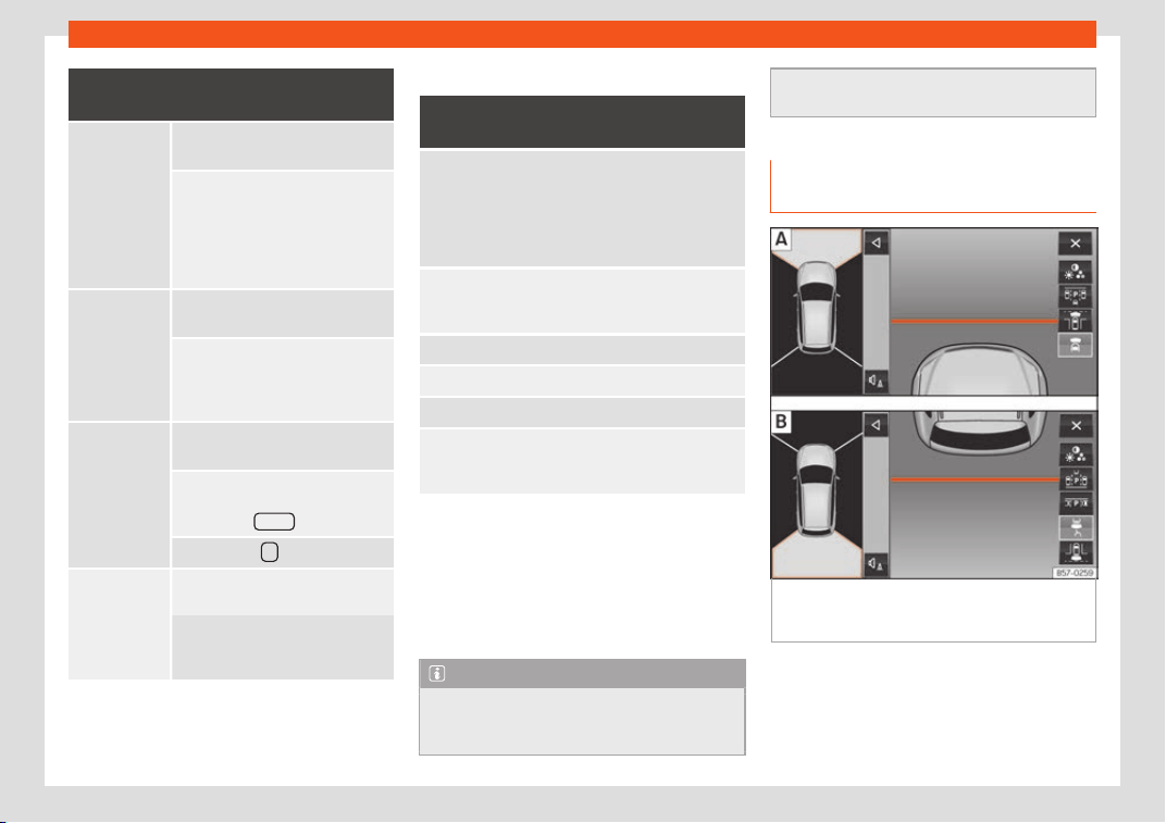
Driving
Connecting and disconnecting the Area
View system
Manual con-
nection of the
display:
Press the
button
››
›
Fig. 293
once.
The infotainment system screen
displays the aerial view
›
››
Fig. 292. If you press the but-
ton when driving above 15 km/h (9
mph), the image will not be dis-
played.
Automatic
connection of
the display:
Engage re
verse gear.
OR: The vehicle mo
ves backwards.
The view of the image of the vehi-
cle's r
ear camera is shown in paral-
lel parking mode with the reduced
aerial view.
Manual dis-
connection of
the display:
Press the
button
››
›
Fig. 293
again.
OR: press a button on the factory-
equipped infotainment system, for
example the RADIO
button.
OR: press the function button.
Automatic dis-
connection of
the displ
ay:
Drive f
orwards at over 15 km/h
(9 mph) approximat
ely.
OR: switch off the ignition. The Area
View system menu disappears im-
mediately.
Special characteristics
Examples of optical illusions caused by
the cameras:
The images on the area vie
w system cameras are on-
ly two-dimensional. Due t
o a lack of spatial depth, it
is difficult or impossible to make out on-screen any
holes there may be on the ground, objects jutting out
from the ground or parts protruding from other vehi-
cles.
Situations in which the objects or other vehicles ap-
pear to be further away or cl
oser than they really
are:
– On moving from a horizontal plane to a slope.
– On moving from a slope to a horizontal plane.
– If the vehicle is heavily loaded at the rear.
– If the vehicle approaches protruding objects. These
objects may be outside the cameras' angl
e of visibili-
ty.
Trailer mode
The Ar
ea Vie
w syst
em conceals, in the rear
camera area, all the auxiliary guiding lines
when the factory-fitted towing bracket is
connected electrically to a trailer
›››
page 329.
Note
In order to become familiar with the system
and its functions, SEAT recommends that
you practice handling the Ar
ea View sys-
tem in an area where there is not too much
traffic or in a car park.
Top View Camera system menus
(modes)
Fig. 294
Display on the Area View system
scr
een: Fr
ont camer
a: off-road view. Rear
camera: off-road view.
324

Driver assistance systems
Key to the Fig. 294:
Symbol Meaning
Depending on the equipment: con-
necting and disconnecting the Park-
Pilot sound.
Showing the reduced display.
Hiding the reduced display.
Exiting the Area View system screen:
Adjust the display: bright, contrast
and col
our.
Aerial views (bird's eye view)
View
On-screen display of all cam-
eras
Main
mode
The vehicl
e and its immediate vicinity
seen from abov
e are shown. Depending
on the equipment, the ParkPilot's path
may also be displayed.
Three-di-
mension-
al views
The vehicl
e and its vicinity
seen from abov
e are shown.
The vehicle and its vicinity
seen from abov
e are shown
obliquely.
The vehicle and its vicinity
seen obliquely are shown.
Swipe the infotainment system display with
your finger in the dir
ection of the arr
o
ws to
change the angle of vision in the three-di-
mensional views of the vehicle and its vicinity.
Front camera views (front view)
View
On-screen display of the front
camera
Cross tr
affic
at the front
Left side of the scr
een: perpendicular
street to the l
eft.
Middle of the screen: area directly in
front of the vehicl
e.
Right side of the screen: perpendicu-
lar street t
o the right.
Parallel
parking
The area in front of the vehicle is
shown. Orientation lines ar
e shown to
give guidance.
Off-road
The area directly in front of the vehi-
cle seen from abo
ve is shown. For ex-
ample, on a slope, in order to see the
area directly in front of the vehicle.
The red line is shown at a distance of
approx. 0.4 m away from the vehicle.
Side camera views (side view)
View
On-screen display of the side
cameras
Right and
left sides
The areas located directly to the side
of the vehicle seen fr
om above are
represented in order to navigate pos-
sible obstacles more precisely. The
orange auxiliary lines are shown at a
distance of approx. 0.4 away from
the vehicle
Left side
The area directly next to the vehicle,
on the driver's or fr
ont passenger's
side, is displayed, and the blind spots
all along the vehicle can be seen. The
auxiliary orange line is shown at a
distance of approx. 0.4 m away from
the vehicle.
Right side
Rear camera views (rear view)
View
On-screen display of the rear
camera
Par
allel
parking
The area behind the vehicle is shown.
Auxiliary lines are shown t
o give guid-
ance.
Perpendicu-
lar parking
The vehicl
e's initial position on initiat-
ing this function will be a decisive
factor in determining the place where
the manoeuvre executed by the as-
sistant will end.
»
325
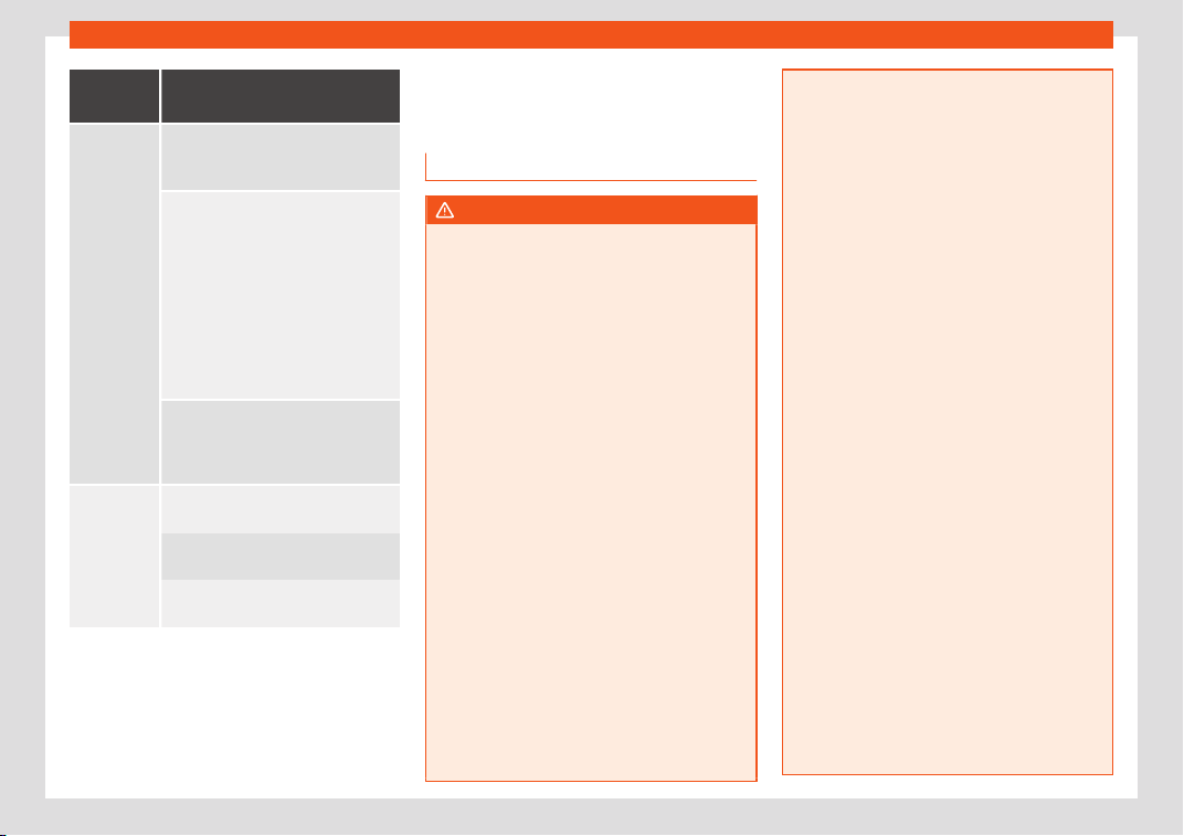
Driving
View
On-screen display of the rear
camera
Off-r
oad or
hitching a
trail
er func-
tion
The vehicle's rear is presented. The
red auxiliary line establishes the saf
e-
ty distance.
Green and red semicircular auxiliary
lines are displayed in v
ehicles with a
factory-fitted towing bracket. The
auxiliary lines indicate the distance
from the towing bracket. The distance
between the auxiliary (green and red)
lines is approximately 0.3 m. The or-
ange auxiliary line indicates, de-
pending on the turn of the steering
wheel, the pre-calculated direction
of the towing bracket.
In vehicles with a factory-fitted tow-
ing bracket, the dist
ance from the red
auxiliary line to the vehicle is approx.
0.4 m. No other lines are shown.
Cross traffic
at the rear
Left side of the scr
een: perpendicular
street to the l
eft.
Middle of the screen: area directly
behind the vehicle.
Right side of the screen: perpendicu-
lar street to the right.
Rear Assist (Rear View Cam-
er
a)*
Oper
ating and saf
ety warnings
WARNING
●
The Rear Assist does not make it possibl
e
to precisely calculate the distance from
obstacles (people, vehicles, etc.) and nor
can it overcome the system's own limits,
hence using it may cause serious accidents
and injuries if used negligently or without
due care. The driver should be aware of
his/her surroundings at all times to ensure
safe driving.
●
The camera lens expands and distorts
the field of vision and displays the objects
on the screen in a different, vague manner.
The perception of distances is also distor-
ted by this effect.
●
Due to the screen resolution or insuffi-
cient light conditions, some items may be
displayed in an unsatisfactory manner or
not at all. Take special care with thin posts,
fences, railings or trees that might not be
displayed on screen and could damage the
vehicle.
●
The rear assist has blind spots where it is
not possible to represent people or objects
(small children, animals and certain ob-
jects cannot be detected in its field of vi-
sion). Monitor the vehicle's surrounding
area at all times.
●
Keep the camera l
ens clean, free of ice
and snow, and do not cover it.
●
The system is not a replacement for driv-
er awareness. Supervise the parking oper-
ation at all times, as well as the vehicle's
surrounding area. Adapt your speed and
driving style at all times to suit visibility,
weather, road and traffic conditions.
●
Do not be distracted from the traffic by
looking at the screen.
●
The images on the rear assist screen are
only two-dimensional. Due to a lack of spa-
tial depth, protruding parts or holes in the
road, for example, are more difficult to de-
tect or may not be seen at all.
●
Vehicle load modifies the representation
of the orientation lines displayed. The
width represented by the lines diminishes
with vehicle load. Pay special attention to
the vehicle's surroundings when the inside
of the vehicle of the luggage compartment
is carrying a heavy load.
●
In the following situations, the objects or
other vehicles shown in the navigation sys-
tem display appear to be further away or
closer than they really are: Pay special at-
tention:
–
On moving from a horizontal plane to a
slope.
–
On moving from a slope to a horizontal
plane.
–
If the vehicle is heavily loaded at the
rear.
326
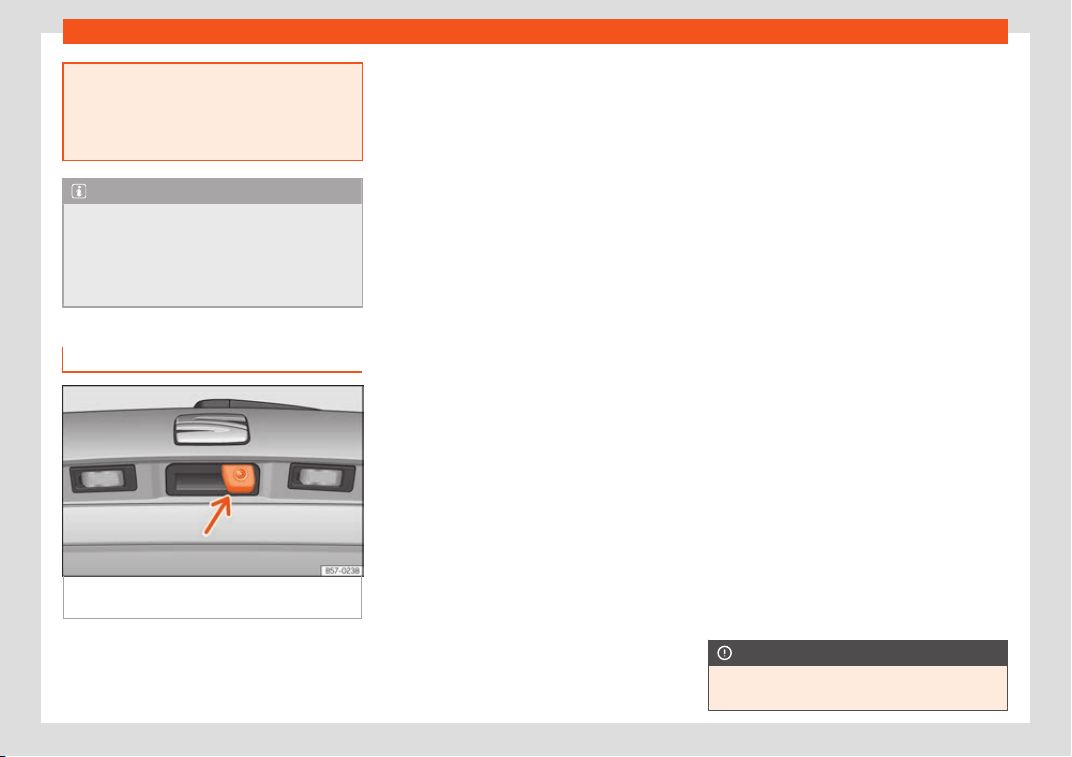
Driver assistance systems
–
When the vehicle appr
oaches objects
that are not on the ground surface or
are jutting out from it. These objects
may also be outside the camera's an-
gle of vision when reversing.
Note
●
It is impor
tant t
o take great care and pay
special attention if you are not yet familiar
with the system.
●
Rear assist will not be available if the ve-
hicle's rear lid is open.
Instructions for use
Fig. 295
On the rear lid handle: location of the
r
ear assist camer
a.
A camera installed in the rear lid handle as-
sists the driv
er in r
e
verse parking or manoeu-
vring
›››
Fig. 295. The camera image is
viewed together with orientation lines projec-
ted by the system on the Easy Connect sys-
tem screen. The bottom of the screen dis-
plays part of the bumper corresponding to
the number plate area that will be used as
reference by the driver.
Rear assist settings
Rear assist offers the user the possibility to
change the image's brightness, contrast and
colour settings.
To change these settings:
●
Park the vehicle in a safe place.
●
Apply the parking brake.
●
Switch the ignition on.
●
If necessary, switch on the Easy Connect
system.
●
Engage reverse gear or turn the selector
lever to position R.
●
Press the function button displayed on
the right of the image.
●
Make the desired adjustments on the menu
by pressing the –/+ function buttons or by
moving the corresponding scroll button.
Necessary conditions for parking and ma-
noeuvring with the rear assist
The system should not be used in the follow-
ing cases:
●
If the image displayed is not very reliable or
is distorted, for example low visibility or dirty
lens.
●
If the area behind the vehicle is not dis-
played very clearly or is incomplete.
●
If the vehicle is heavily loaded at the rear.
●
If the position and installation angle of the
camera have been changed, e.g. after a rear-
end collision. Have the system checked by a
specialised workshop.
Familiarising yourself with the system
To familiarise yourself with the system, the
orientation lines and their function, SEAT rec-
ommends practising parking and manoeu-
vring with the rear assist in a place without
too much traffic or in a car park when there
are good weather and visibility conditions.
Cleaning the camera lens
Keep the camera lens clean and clear of
snow and ice:
●
Moisten the lens using a normal alcohol-
based glass cleaning product and clean the
lens with a dry cloth.
●
Remove snow using a small brush.
●
Use de-icing spray to remove any ice.
CAUTION
●
Never use abr
asive cleaning products to
clean the camera lens.
»
327
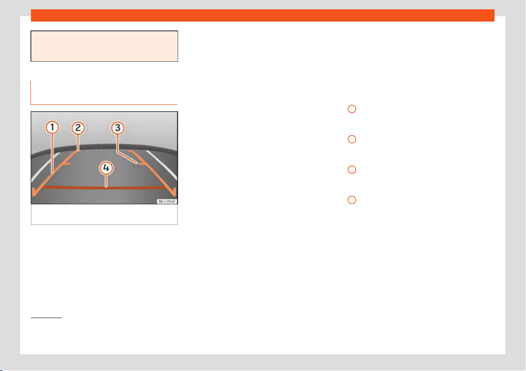
Driving
●
Do not use hot or warm wat
er to remove
ice or snow from the camera lens. Doing so
could damage the camera.
Parking and manoeuvring with the
rear assist
Fig. 296 Display on the Easy Connect system
scr
een: guidance lines.
Switching the system on and off
●
The rear assist will switch on when the igni-
tion is on or the engine running, on engaging
r
e
v
erse gear (manual gearbox) or on chang-
ing the selector lever to the R position (auto-
matic gearbox).
●
The system switches off 8 seconds after
disengaging reverse gear (manual gearbox)
or removing the selector lever from the R po-
sition (automatic gearbox). The system will
also disconnect immediately after the ignition
is switched off.
●
The camera will stop transmitting images
above the speed of 15 km/h (9 mph) with re-
verse engaged.
In combination with the Parking System Plus
›››
page 315, the camera image will cease to
be transmitted immediately when reverse
gear is disengaged or when the selector lever
is moved from the R position, and the optical
information provided by the Parking Aid sys-
tem will be displayed.
Also in combination with the system, the rear
assist image can also be concealed:
●
By pressing one of the Infotainment system
buttons on the display.
●
OR: by pressing the miniature vehicle that
appears on the left of the screen (which
switches to the full-screen mode of the Park-
ing System Plus's optical system).
If you wish to display the rear assist image
again:
●
Disengage reverse, or change the selector
lever's position, engage reverse again or
move the selector lever to position R.
●
OR: Press the RVC function button
1)
Meaning of the orientation lines
›››
Fig. 296
Side lines: extension of the vehicle (the
approximate width of the vehicle plus the
rear view mirrors) on the road surface.
End of the side lines: the area marked in
green ends approximately 2 m behind the
vehicle on the road surface.
Mid line: indicates a distance of approxi-
mately 1 m behind the vehicle on the road
surface.
Horizontal red line: indicates a safe dis-
tance of approximately 40 cm at the rear
of the vehicle on the road surface.
Parking manoeuvre
●
Place the vehicle in front of the parking
space and engage reverse gear (manual
gearbox) or move the selector to the R posi-
tion (automatic gearbox).
1
2
3
4
1)
WARNING: the RVC function button will only be
activat
ed and available when the reverse gear is
engaged or the selector lever is set to position R.
328
Towing bracket device*
●
R
e
v
erse slowly, and turn the steering wheel
so that the side orientation lines lead towards
the parking space.
●
Guide the vehicle into the parking space so
that the side orientation lines run parallel to it.
Towing bracket device*
T
r
ail
er mode
Introduction
Take into account country-specific regula-
tions about driving with a trailer and the use
of a t
owing bracket.
The vehicle has been developed primarily for
carrying people, although it can also be used
to tow a trailer if fitted with the corresponding
technical equipment. This additional load has
an effect on the useful life, fuel consumption
and vehicle performance and in some cases
can reduce the service intervals.
Driving with a trailer requires more force from
the vehicle, and thus more concentration
from the driver.
In winter, winter tyres should be fitted on both
the vehicle and the trailer.
Maximum vertical load technically per-
missible on the coupling
The maximum vertical load technically per-
mitted from the trailer draw bar on the towing
bracket's tow hitch is 80 kg.
Vehicles with the Start-Stop system
If the vehicle has a factory-fitted towing
bracket or one that is retrofitted by SEAT, the
Start-Stop system operates as normal. No
special characteristics need t
o be taken into
account.
If the system does not recognise the trailer or
the trailer bracket has not been retrofitted by
SEAT, the Start-Stop system must be discon-
nected by pressing the corresponding button
in the lower part of the centre console before
driving with the trailer, and it should remain
off for the rest of the journey
›››
.
V
ehicl
es with driving pr
ofile selection
If you are going to be towing a trailer, the use
of the Eco driving profile is not recommen-
ded. You are advised to select another of the
available driving profiles before beginning to
drive with a trailer.
WARNING
Never use the trailer to transport people,
since it would put their lif
e in danger and is
also prohibited.
WARNING
Undue use of the towing bracket may
cause injury and accidents.
●
Only use the towing bracket if it is in a
perfect stat
e of repair and is properly se-
cured.
●
Never modify or repair the towing bracket
in any way.
»
329
Driving
●
In order to r
educe the danger of injury in
the event of rear-end collisions and to
avoid injury to pedestrians and cyclists
when parking the vehicle, cover or remove
the tow hitch when you are not using a trail-
er.
●
Never fit a towing bracket “with weight
distribution” or “load compensation”. The
vehicle has not been designed for this type
of towing bracket. The towing bracket
could fail and the trailer could be released
from the vehicle.
WARNING
Driving with a trailer and transporting
heavy or large ob
jects can affect driving
properties and even cause an accident.
●
Always secure the load properly using
belts or straps that are suitable and in
good condition.
●
Adapt your speed and driving style at all
times to suit visibility, weather, road and
traffic conditions.
●
Trailers with a high centre of gravity are
more likely to overturn than those with a
low one.
●
Avoid sudden braking and manoeuvres.
●
Take great care when overtaking.
●
Reduce speed immediately if you notice
that the trailer is swaying, however slightly.
●
Never drive at more than 80 km/h
(50 mph) when towing a trailer (or at more
than 100 km/h (60 mph) in exceptional cir-
cumstances). This also applies in countries
wher
e driving at higher speeds is permit-
ted. Take into account the speed limit for
vehicles with trailers in the corresponding
country, as it could be less than the speed
limit for vehicles without a trailer.
●
Never attempt to “straighten” the towing
vehicle and trailer while accelerating.
WARNING
If the towing bracket has been retrofitted
by a non-SEAT w
orkshop, the St
art-Stop
system must be disconnected manually
whenever driving with a trailer. Otherwise
the brake system could be damaged and
could consequently cause a serious acci-
dent or injury.
●
Always disconnect the Start-Stop system
manually when using a towing bracket that
has not been fitted by a SEAT workshop.
Note
●
Before hit
ching or unhitching a trailer, al-
ways deactivate the anti-theft alarm
›››
page 127. Otherwise, the tilt sensor
could cause the alarm to go off.
●
Do not drive with a trailer for the engine's
first 1000 km
›››
page 261.
●
SEAT recommends that, if possible, the
tow hitch be disassembled or covered
when it is not going to be used. In the event
of a rear-end collision, the damage to the
vehicle coul
d be greater if the bracket is fit-
ted.
●
Some retrofitted towing brackets cover
the rear towing eye. In these cases, the
towing eye should not be used for tow-
starting or for towing other vehicles. For
this reason, if the vehicle has been retrofit-
ted with a towing bracket, always keep the
tow hitch in the vehicle when you disas-
semble it.
Control lamp
Lamp on button lights up
The tow hitch is not securely locked in position.
Check that the towing br
acket is locked
›››
page 332.
Some warning and control lamps will light up
briefly when the ignition is s
wit
ched on t
o
check certain functions. They will switch off
after a few seconds.
WARNING
If the warning lamps and the corresponding
messages are ignored when they light up
,
the vehicle may stall in traffic and cause
accidents and severe injuries.
●
Never ignore the warning lamps or mes-
sages.
330
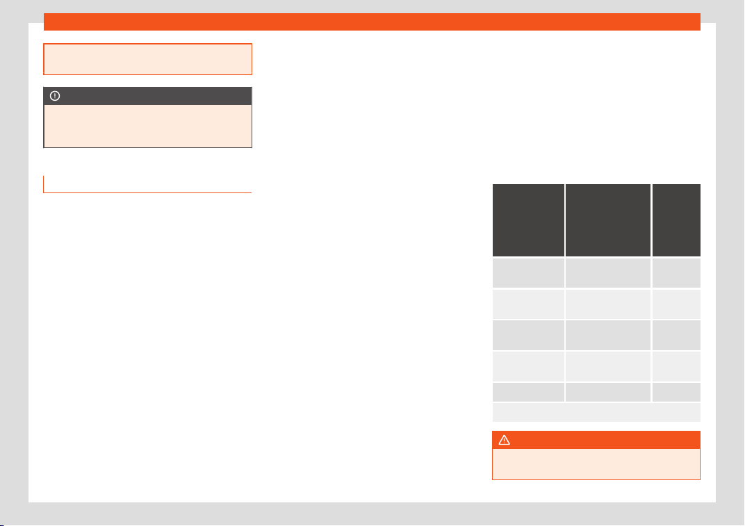
Towing bracket device*
●
Stop the vehicl
e at the next opportunity
and in a safe place.
CAUTION
Failure to heed the control lamps and cor-
r
esponding te
xt messages when they light
up may result in damage to the vehicle.
Technical requirements
Vehicles that are f
act
ory
-equipped with a
towing bracket fulfil all the technical and le-
gal requirements for driving with a trailer.
If the vehicle is retrofitted with a towing
bracket, only a bracket that is authorised for
the maximum authorised load of the trailer
that is to be towed may be fitted. The towing
bracket must be suitable for the vehicle and
the trailer and must be properly secured to
the vehicle's chassis. Only use a towing
bracket that has been authorised by SEAT for
this vehicle. Always check and take into ac-
count the towing bracket manufacturer's in-
structions. Never fit a towing bracket “with
weight distribution” or “load compensation”.
Towing bracket fitted on the bumper
Never fit a towing bracket to the bumper or to
the area where the bumper is mounted. The
towing bracket should not impair the bum-
per's function. Do not make modifications or
repairs to the exhaust system or the brake
system. Make regular checks to ensure that
the towing bracket is secure.
Engine cooling system
Driving with a trailer increases the load on the
engine and cooling system. The cooling sys-
tem should have sufficient coolant and be
prepared for the additional effort involved in
driving with a trailer.
Trailer brakes
If the trailer has its own brake system, please
take the relevant legal requirements into ac-
count. Never connect the trailer's brake sys-
tem to the vehicle's brake system.
Tow rope
Always use a cable between the vehicle and
the trailer
›››
page 333.
Trailer rear lights
The trailer's rear lights should comply with
the statutory safety regulations
›››
page 333.
Never connect the trailer's rear lights directly
to the vehicle's electric system. If you are not
sure that the trailer's electrical connection is
correct, have it checked by a specialised
workshop. SEAT recommends visiting a SEAT
dealership for this.
Exterior mirrors
If you cannot see the area behind the trailer
with the exterior mirrors of the towing vehicle,
additional mirrors will have to be installed in
accordance with the regulations of the coun-
try in question. The exterior mirrors should be
adjusted before you start driving and must
provide a sufficient field of vision at the rear.
Trailer maximum electricity consumption
Consumers Europe, Asia, Af-
rica, South
America and
Central Ameri-
ca
Austral
-
ia
Brake lights (to-
tal)
84 Watts
108 Watts
Turn signal (on
each side)
42 Watts 54 Watts
Side lights (on
each side)
50 Watts 100 Watts
Reverse lights
(in total)
4
2 Watts 54 Watts
Rear fog light 42 Watts 54 Watts
Never exceed the values indicated!
WARNING
If the towing bracket is wrongly fitted or is
not the right one, the trail
er could become
»
331
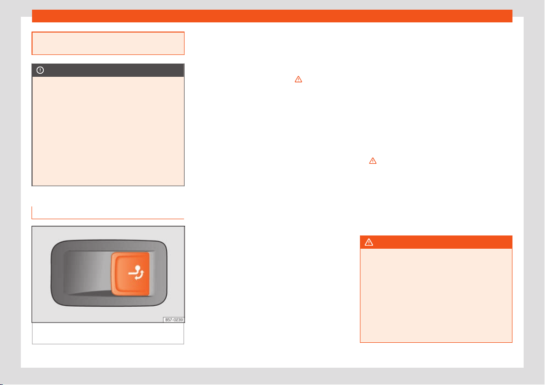
Driving
detached from the vehicle and cause seri-
ous injury.
CAUTION
●
If the r
ear lights of the trail
er are not cor-
rectly connected, the vehicle's electronic
system may be damaged.
●
If the trailer absorbs excessive electric
current, the vehicle's electronic system
may be damaged.
●
Never connect the trailer's electric sys-
tem directly to the electrical connections
of the tail lights or any other power sour-
ces. Only use the connections intended for
providing electric current to the trailer.
Electrical unlocking tow hitch
Fig. 297 Right side of the boot: button to un-
l
ock the t
o
w hitch.
The tow hitch is located in the bumper. The
el
ectrical unl
ocking t
ow hitch cannot be dis-
assembled.
There should be no person, animal or object
in the path of the tow hitch
›››
.
Unl
ock the t
o
w hitch and remove it
●
Stop the vehicle and connect the electronic
parking brake
›››
page 244.
●
Switch off the engine.
●
Open the rear lid.
●
Pull the
›››
Fig. 297 button briefly. The tow
hitch unlocks electrically and automatically
turns outwards. The control lamp in the but-
ton will flash
›››
Fig. 297.
●
Remove the tow hitch with your hand until
you feel and see that it has engaged and the
control lamp on the button stays on.
●
Close the rear lid.
Cover the tow hitch
●
Stop the vehicle and apply the electronic
parking brake.
●
Switch off the engine.
●
Unhook the trailer and interrupt the electri-
cal connection between it and the vehicle. If
you are using an adapter, remove it from the
trailer's power socket.
●
Open the rear lid.
●
Pull the
›››
Fig. 297 button briefly. The tow
hitch unlocks electrically.
●
Turn the tow hitch under the bumper with
your hand until you feel and see that it en-
gages and the control lamp on the
›››
Fig. 297 button stays on.
●
Close the rear lid.
Meaning of control lamp
●
If the warning light of the button
›››
Fig. 297
is flashing, this means that the tow hitch has
not been attached properly or is damaged
›››
.
●
If the warning lamp st
ays on
with the r
ear
lid open, the tow hitch is correctly in place
both when engaged and when covered.
●
The control light of the lamp switches off
approximately 1 minute after closing the read
lid.
WARNING
Undue use of the towing bracket may
cause injury and accidents.
●
Only use the tow hitch if it is properly en-
gaged.
●
Always ensure that no person, animal or
object is to be f
ound in the path of the tow
hitch.
●
Never use a tool or instrument while the
tow hitch is moving.
332
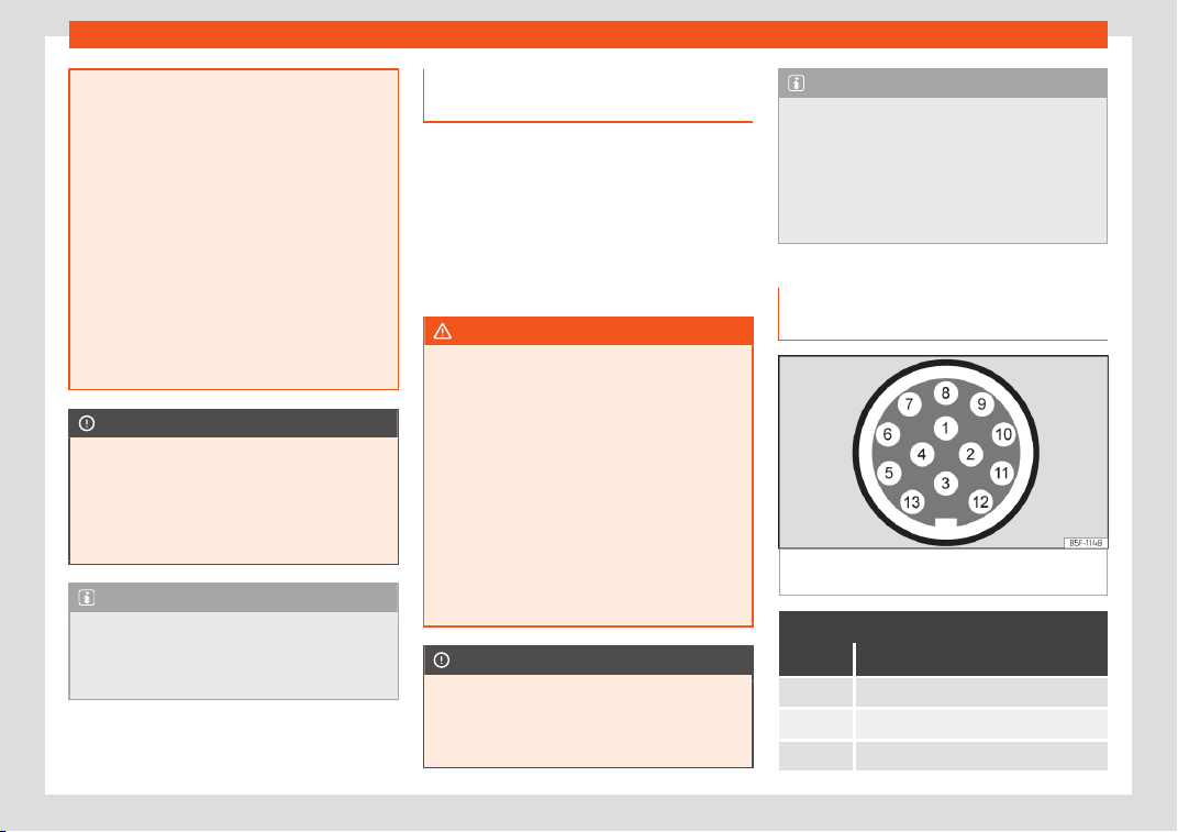
Towing bracket device*
●
Never pr
ess the
›››
Fig. 297 button when
there is a trailer hooked to the vehicle or
when a carrier system or other accessories
are mounted on the tow hitch.
●
If the tow hitch is not attached properly,
do not use it. Instead, go to a specialised
workshop and have the towing bracket
checked.
●
If you detect any fault in the electrical
system or in the towing bracket, contact a
specialised workshop and ask them to
check it.
●
If the ball has a diameter of less than 49
mm at any one point, do not use the towing
bracket under any circumstances.
CAUTION
If you clean the vehicle with high-pressure
or steam devices, do not point the jet di-
r
ectly towards the retractable tow hitch or
the trailer power socket, as this may dam-
age the joints or remove the grease neces-
sary for lubrication.
Note
At extremely low temperatures, the tow
hitch may be impossible t
o use. In this case,
place the vehicle in a warmer location (for
example, a garage).
Fitting a bicycle carrier on the re-
tr
act
abl
e tow hitch
The maximum allowed weight of the carrier
system, including the load, is
75 kg. The carri-
er system should not protrude more than 700
mm backwards from the spherical head. On-
ly carrier systems on which up to 3 bikes can
be mounted are allowed. Heavier bicycles
must be mounted as close to the vehicle as
possible (tow hitch).
WARNING
The incorrect use of the tow hitch with a bi-
cycle rack mount
ed on the tow hitch can
cause accidents and injury.
●
Never exceed the maximum weight or the
limits indicated above.
●
The bicycle rack may not be mounted to
the neck of the hitch below the ball be-
cause, due to the shape of the neck and
depending on the rack model, the rack
could be incorrectly mounted on the vehi-
cle.
●
Always read and take the manufacturer
assembly instructions into account.
CAUTION
If the maximum weight and limits indicated
above ar
e exceeded, the vehicle may suf-
fer considerable damage.
●
Never exceed the values indicated!
Note
SEAT recommends removing, as far as pos-
sible, all r
emovable parts of the bicycles
before setting off. These parts include, for
example, baskets and saddlebags, child
seats or batteries. This improves aerody-
namics and the centre of gravity of the rack
system.
Hooking up and connecting a trail-
er
Fig. 298
Diagram: assignment of the pins of
the tr
ail
er
's electrical socket.
Key to the Fig. 298:
Pin Meaning
1 Left turn signal
2 Rear fog light
3 Earth for pins 1, 2, 4, 5, 6, 7 and 8
»
333

Driving
Key to the Fig. 298:
Pin Meaning
4 Right turn signal
5 Rear light, right
6 Brake lights
7 Rear light, left
8 Reverse lights
9 Permanent live
10 Live charge cable
11 Earth for pin 10
12 Unassigned
13 Earth for pin 9
Trailer power socket
The v
ehicl
e is fitt
ed with a 13-pole power
socket for the electrical connection between
the trailer and the vehicle. With the engine
running, electrical devices on the trailer re-
ceive power from the electrical connection
(pin 9 and pin 10 of the trailer power socket).
If the system detects that a trailer has been
connected electrically, the electrical equip-
ment on the trailer will receive voltage
through this connection (pins 9 and 10). Pin 9
has a permanent live. This powers, for exam-
ple, the trailer's interior lighting. Electrical de-
vices such as a fridge in a caravan only re-
ceive electrical power if the engine is running
(through pin 10).
To avoid overloading the electrical system,
you cannot connect the ground wires of pin 3,
pin 11 or pin 13.
If the trailer has a 7-contact connector, you
will need to use an adapter cable. In this case
the function corresponding to pin 10 will not
be available.
Tow rope
The tow rope must always be securely fixed
to the towing vehicle and loose enough so
that the vehicle can handle turns smoothly.
However, make sure that the cable does not
rub on the ground while driving.
Trailer rear lights
Always check the trailer's rear lights to ensure
they are working correctly and that they
comply with the relevant safety regulations.
Make sure that the maximum permissible
power that can be absorbed by the trailer is
not exceeded
›››
page 331.
Connection to the anti-theft system
The trailer is included in the anti-theft system
if the following conditions are met:
●
If the vehicle is factory-equipped with an
anti-theft alarm and towing bracket.
●
If the trailer is electrically connected to the
towing vehicle through the trailer power sock-
et.
●
If the electrical systems of the vehicle and
trailer are in perfect condition and have no
faults or damage.
●
If the vehicle is locked with the key and the
anti-theft alarm is activated.
When the vehicle is locked, the alarm is trig-
gered if the electrical connection with the
trailer is cut off.
Before hitching or unhitching a trailer, always
turn off the anti-theft alarm. Otherwise, the tilt
sensor could cause the alarm to go off.
Trailers with LED rear lights
For technical reasons, trailers fitted with LED
rear lights cannot be connected to the anti-
theft alarm system.
When the vehicle is locked, the alarm does
not go off when the electrical connection
with the trailer is cut if it has rear lights with
light-emitting diodes.
If the Eco driving profile was selected when
hitching the trailer, this will automatically
switch to the Normal profile. If the system
cannot detect the attached trailer or if the
towing bracket has been retrofitted by an au-
to repair shop other than SEAT, you must
manually select the Normal profile before
you start driving with a trailer attached. To
334
Towing bracket device*
reconnect the Eco pr
ofil
e once the tr
ailer has
been unhitched, switch the ignition off and
back on once.
WARNING
If the cables are improperly or incorrectly
connected, it may lead t
o an excessive
amount of current supplied to the trailer,
which can cause abnormalities in the entire
vehicle electronic system, as well as acci-
dents and serious injuries.
●
Ensure that any repairs that need to be
carried out on the electrical system are
carried out by a specialised workshop.
●
Never connect the trailer's electric sys-
tem directly to the electrical connections
of the tail lights or any other power sour-
ces.
WARNING
Contact between the pins of the trailer
power sock
et can cause short circuits,
overloading of the electrical system or fail-
ure of the lighting system, and consequent-
ly can cause accidents and serious injuries.
●
Never connect the pins of the trailer pow-
er socket to each other.
●
Make sure any work on bent pins is car-
ried out by a specialised workshop.
CAUTION
Do not leave the trailer connected to the
vehicle when park
ed; place it on its support
wheel or its supports. If the vehicle rises or
falls due, for example, to a variation of the
load or a burst tyre, increased pressure will
be placed on the towing bracket and the
trailer, and both the vehicle and the trailer
can be damaged.
Note
●
In case of malfunctioning of the electri-
cal systems of the v
ehicle or trailer, as well
as of the anti-theft system, have these
checked out by a specialised workshop.
●
If the trailer accessories consume energy
through the power socket to the trailer and
the engine is turned off, the battery will dis-
charge.
●
If the vehicle battery is running low, the
electrical connection with the trailer will be
automatically cut.
Loading a trailer
Technically permissible maximum trailer
w
eight and v
er
tical load on the coupling
device
The technically permissible maximum trailer
weight is the weight that the vehicle can tow
›››
. The vertical load on the coupling load
is exerted vertically from above on the tow
hit
ch of the t
o
wing bracket
›››
page 381.
The information on the maximum trailer
weight and vertical load on the coupling de-
vice contained in the type plate of the towing
bracket are experimental values only. The
correct figures for your specific model, which
may be lower than these figures, are given in
the vehicle documentation. The information in
the vehicle documentation takes precedence
at all times.
To promote safety while driving, SEAT recom-
mends making the most of the maximum ver-
tical load technically permissible on the
coupling device
›››
page 329. An insufficient
vertical load has a negative influence on the
behaviour of both the vehicle and trailer.
The vertical load increases the weight on the
rear axle, reducing the vehicle's carrying ca-
pacity.
Gross combination weight of the towing
vehicle and trailer
The gross combination weight is the actual
weight of the loaded vehicle plus the actual
weight of the loaded trailer.
In some countries trailers are classified into
distinct categories. SEAT recommends ob-
taining information from a specialised work-
shop regarding which type of trailer is most
suitable for your vehicle.
»
335

Driving
Trailer loading
The w
eight of the t
o
wing vehicle and trailer
must be balanced. In order to do this, the
load must be as close as possible to the max-
imum vertical load technically permissible on
the coupling point, and it must be evenly dis-
tributed between the back and front of the
trailer:
●
Distribute loads in the trailer so that heavy
objects are as near to the axle as possible or
above it.
●
Secure the trailer load properly.
Tyre pressure
Set the tyre pressure of the trailer tyres in ac-
cordance with the trailer manufacturer's rec-
ommendations.
When towing a trailer, inflate the tyres of the
towing vehicle with the maximum allowable
pressure
›››
page 358.
WARNING
If the maximum permissible axle weight, the
maximum load technically permissibl
e on
the coupling point, the maximum author-
ised vehicle weight or the gross combina-
tion weight of the towing vehicle and trailer
are exceeded, accidents and serious inju-
ries may occur.
●
Nev
er exceed the values indicated!
●
The actual weight on the front and rear
axles must never exceed the maximum per-
missible axle weight. The weight on the
front and rear axles must never exceed the
maximum permissible weight.
WARNING
A shift in weight could jeopardize the stabil-
it
y and security of the t
owing vehicle and
trailer, which could lead to accidents and
serious injuries.
●
Always load the trailer correctly.
●
Always secure the load properly using
belts or straps that are suitable and in
good condition.
Driving with a trailer
Adjusting the headlights
The fr
ont part of the v
ehicl
e may be raised
when the trailer is connected and the light
may dazzle the rest of the traffic.
Adapt the height of the headlights using the
headlight range adjuster
›››
page 154
1)
.
Special characteristics of driving with a
trailer
●
If your trailer has an overrun brake, brake
gently at first and then rapidly. This will pre-
vent the jerking that can be caused by the
locking of trailer wheels.
●
Due to the gross combination weight of the
towing vehicle and trailer, the braking dis-
tance increases.
●
When going down a slope, go into a lower
gear (if using a manual gearbox or the tip-
tronic automatic gearbox mode) to take ad-
vantage of the braking power provided by the
engine. Otherwise, the braking system could
overheat and even fail.
●
The trailer weight, as well as the gross com-
bination weight of the towing vehicle and
trailer, change the centre of gravity and the
properties of the vehicle.
●
If the towing vehicle is empty and the trailer
is loaded, then the load distribution is incor-
rect. Under these conditions, drive slowly and
with extra caution.
Hill starts with a trailer
Depending on the slope of the hill and the
combination weight of the towing vehicle and
trailer, the vehicle might start rolling back-
wards slightly when you first start up.
1)
This does not apply for vehicles with Full LED
xenon headlights.
336

Towing bracket device*
For hill-starting with a trailer, do the following:
●
Press and hold the brake pedal.
●
Press the butt
on t
o disconnect the el
ec-
tronic parking brake
›››
page 244.
●
If the vehicle is equipped with a manual
gearbox, push the clutch pedal all the way
down.
●
Put the vehicle into first gear or turn the se-
lector lever to position D/S
›››
page 251.
●
Pull out the button and hold it in that po-
sition to stop the towing vehicle and trailer
with the electronic parking brake.
●
Release the brake pedal.
●
Start driving slowly. To do this, in the case of
a manual gearbox, slowly release the clutch
pedal.
●
Do not release the button until the en-
gine has sufficient force to start driving.
WARNING
If a trailer is pulled incorrectly, this may
lead to l
oss of control of the vehicle and
serious injury.
●
Driving with a trailer and transporting
heavy or large objects will change the ve-
hicle handling and braking distances.
●
Always drive cautiously and carefully.
Brake earlier than usual.
●
Adapt your speed and driving style at all
times to suit visibility, weather, road and
traffic conditions. Slow down, especially
when driving down hills or sl
opes.
●
Accelerate with particular care and cau-
tion. Avoid sudden braking and manoeu-
vres.
●
Take great care when overtaking. Reduce
speed immediately if you notice that the
trailer is swaying, however slightly.
●
Never attempt to “straighten” the towing
vehicle and trailer while accelerating.
●
Take into account the speed limit for vehi-
cles with a trailer, as it could be lower than
for vehicles without a trailer.
Stabilisation of the towing vehicle
and tr
ail
er
The stabilisation of the towing vehicle and
tr
ail
er t
ogether is an additional function of the
electronic stability control (ESC).
If the system detects that the trailer is sway-
ing, it intervenes automatically with the driver
steering recommendation to reduce the
swaying of the trailer.
Requirements for the stabilisation of the
towing vehicle and trailer
●
The vehicle is factory-equipped with a tow-
ing bracket or has been retro-fitted with a
compatible towing bracket.
●
The ESC and ASR are active. The control
lamp or is not lit up on the instrument
cluster.
●
The trailer is electrically connected to the
towing vehicle through the trailer power sock-
et.
●
The vehicle is travelling at over 60 km/h
(approx. 37 mph).
●
The maximum vertical load technically per-
missible is being utilised on the coupling de-
vice.
●
The trailer has a rigid draw bar.
●
If the trailer has brakes, it must be equipped
with a mechanical overrun brake.
WARNING
The enhanced security provided by the
electric stabilit
y control of the towing vehi-
cle and trailer should not lead you to take
any risks that could compromise your safe-
ty.
●
Adapt your speed and driving style at all
times to suit visibility, weather, road and
traffic conditions.
●
Accelerate with caution when the road is
slippery.
●
When adjusting any settings, stop accel-
erating.
»
337
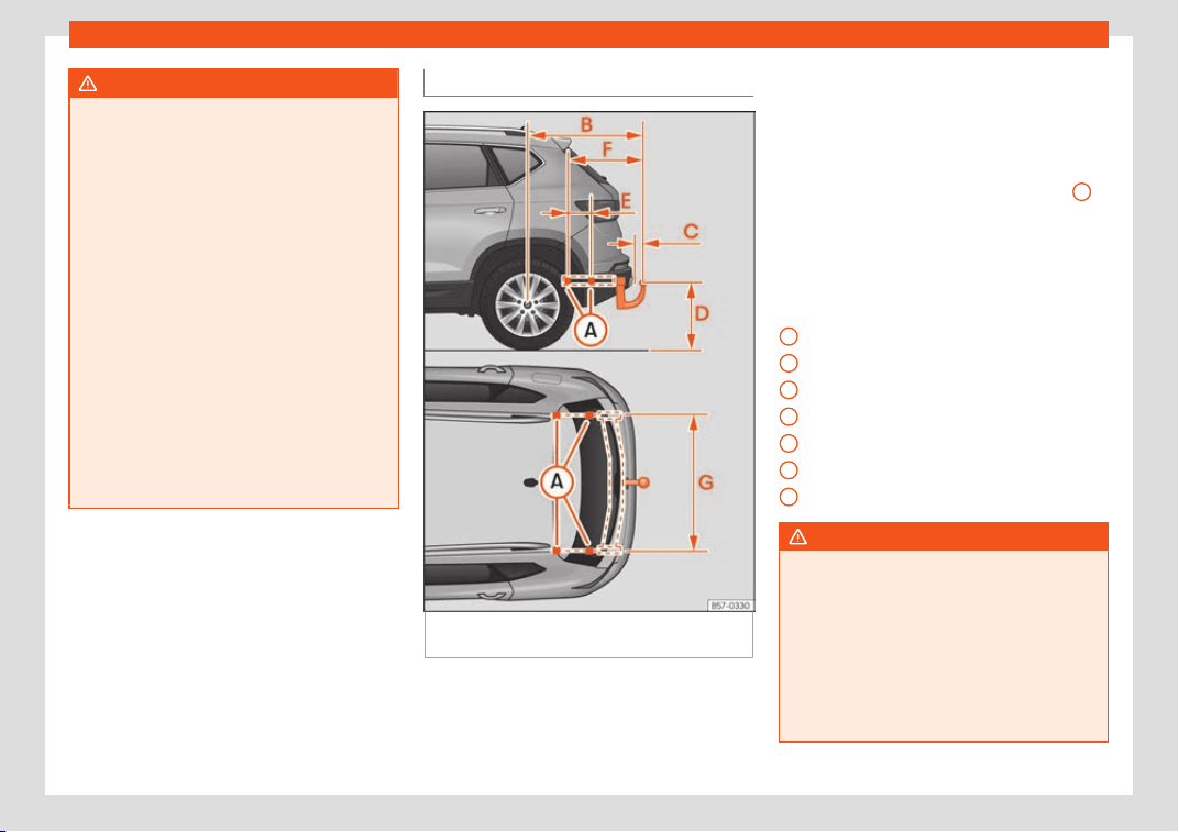
Driving
WARNING
The electric stability control for the towing
vehicle and tr
ailer may not correctly de-
tect all driving conditions.
●
When the ESC is switched off, the stabili-
sation of the towing vehicle and trailer is al-
so switched off.
●
The stability system does not always de-
tect light and unstable trailers, so it may
not stabilise these correctly.
●
When driving on slippery surfaces with
poor grip, the trailer can even interfere with
the stability system.
●
Trailers with a high centre of gravity can
tip even without having previously swayed.
●
If a trailer is not attached, but the trailer
power socket is connected (e.g. installation
of a bicycle rack with lights), repeated au-
tomatic braking may occur in extreme driv-
ing conditions.
Retrofitting a towing bracket
Fig. 299
Limits and attachment points for ret-
r
ofitting a t
o
wing bracket.
SEAT recommends that towing brackets be
r
etr
ofitt
ed at a specialised workshop. For ex-
ample, it may very well be necessary to ad-
just the cooling system or mount thermal pro-
tection plates. SEAT recommends visiting a
SEAT dealership for this.
If a towing bracket is retrofitted, the distance
specifications should always be kept in mind.
The distance between the centre of the
spherical head and the road
›››
Fig. 299
D
must never be less than that indicated. This
al
so applies when the v
ehicl
e is fully loaded,
including the technically permissible maxi-
mum vertical load on the coupling device.
Distance specifications
›››
Fig. 299:
Attachment points
932.5 mm
65 mm min.
350-420 mm
220 mm
615.5 mm
1,043 mm
WARNING
If the cables are improperly or incorrectly
connected, this may lead t
o malfunctions
in the entire vehicle electronic system, as
well as to accidents and serious injuries.
●
Never connect the trailer's electric sys-
tem to the electrical connections of the tail
lights or any other unsuitable power sour-
ces. Only use suitable connectors to con-
nect the trailer.
A
B
C
D
E
F
G
338
Towing bracket device*
●
The towing br
acket should be retrofitted
only at a specialised workshop.
WARNING
If the towing bracket is badly fitted or un-
suit
able
, the trailer may separate from the
vehicle while driving. This could cause seri-
ous accidents and fatal injuries.
Note
Only use towing brackets that have been
approv
ed by SEAT for the model in ques-
tion.
339
Practical tips
Practical tips
Car
e and maint
enance
Accessories and modifica-
tions t
o the vehicle
Accessories, replacement parts
and repair work
Always ask your dealer or specialist retailer
f
or advice bef
or
e purchasing accessories
and replacement parts.
Your vehicle is designed to offer a high stand-
ard of active and passive safety. For this rea-
son, we recommend that you ask a SEAT Offi-
cial Service for advice before fitting accesso-
ries or replacement parts. Your SEAT Official
Service has the latest information from the
manufacturer and can recommend accesso-
ries and replacement parts which are suita-
ble for your requirements. They can also an-
swer any questions you might have regarding
official regulations.
We recommend you to use only SEAT acces-
sories and Genuine SEAT parts
®
. SEAT has
tested these parts and accessories for suita-
bility, reliability and safety. SEAT Official
Services have the necessary experience and
facilities to ensure that the parts are installed
correctly and professionally.
Any retro-fitted equipment which has a di-
rect effect on the vehicle and/or the way it is
driven, such as a cruise control system or
electronically-controlled suspension, must
be approved for use in your vehicle and bear
the e mark (the European Union's authorisa-
tion symbol).
If any additional electrical devices are fit-
ted which do not serve to control the vehicle
itself (for instance a refrigerator box, laptop
or ventilator fan, etc.), they must bear the
sign (manufacturer conformity declaration in
the European Union).
WARNING
Accessories, for example telephone hold-
ers or cup holders, should ne
ver be fitted
on the covers, or within the working range
of the airbags. Otherwise, there is a danger
of injury if the airbag is triggered in an acci-
dent.
Technical modifications
Modifications must always be carried out ac-
cor
ding t
o our specifications.
Unauthorised modifications t
o the electronic
components, software, wiring or data transfer
in the vehicle may cause malfunctioning. Due
to the way the electronic components are
linked together in networks, other indirect
systems may be affected by the faults. This
can seriously impair safety, lead to excessive
wear of components, and also invalidate
your vehicle registration documents.
You will appreciate that your SEAT dealership
cannot be held liable for any damage
caused by modifications and/or work per-
formed incorrectly.
We therefore recommend that all work should
be performed by a SEAT Official Service us-
ing genuine SEAT parts
®
.
WARNING
Incorrectly performed modifications or
other work on your vehicl
e can lead to mal-
functions and cause accidents.
Radio transmitters and office
equipment
Radio transmitters (fixed installation)
Any r
etr
ofit inst
allations of radio transmitters
in the vehicle require prior approval. SEAT
generally authorises in-vehicle installations
of approved types of radio transmitters provi-
ded that:
●
The aerial is installed correctly.
340
Checking and refilling levels
●
The aerial is inst
all
ed on the e
xterior of the
vehicle (and shielded cables are used to-
gether with non-reflective aerial trimming).
●
The effective transmitting power does not
exceed 10 Watts at the aerial base.
A SEAT Official Service and specialised work-
shop will be able to inform you about options
for installing and operating radio transmitters
with a higher transmitting power.
Mobile radio transmitters
Commercial mobile telephones or radio
equipment might interfere with the electron-
ics of your vehicle and cause malfunctions.
This may be due to:
●
No external aerial.
●
External aerial incorrectly installed.
●
Transmitting power more than 10 W.
You must, therefore, do not operate portable
mobile telephones or radio equipment inside
the vehicle without a properly installed exter-
nal aerial
›››
.
Pl
ease not
e al
so that the maximum range of
the equipment can only be achieved with an
external aerial.
Business equipment
Retrofit installation of business or private
equipment in the vehicle is permitted, provi-
ded the equipment cannot interfere with the
driver's immediate control of the vehicle and
that any such equipment carries the mark.
Any retrofit equipment that could influence
the driver's control of the vehicle must have a
type approval for your vehicle and must carry
the e mark.
WARNING
Mobile telephones or radio equipment
which is operated inside the v
ehicle without
a properly installed external aerial can
create excessive magnetic fields that
could cause a health hazard.
Note
●
The posterior fitting of electric and el
ec-
tronic equipment in this vehicle affects its
licence and could lead to the withdrawal of
the vehicle registration document under
certain circumstances.
●
Please use the mobile telephone/radio
operating instructions.
Checking and refilling lev-
el
s
Filling the t
ank
R
efuelling
Read the additional information carefully
›››
page 47
If the automatic filler nozzle is operated cor-
rectly, it will switch itself off as soon as the
fuel tank is “full”. Do not try to put in more fuel
after the nozzle cuts out, as this will fill the ex-
pansion chamber in the fuel tank.
The correct fuel grade for your vehicle is giv-
en on a sticker on the inside of the fuel tank
flap. Further notes on fuel can be found at
›››
page 343.
The capacity of your vehicle's fuel tank is giv-
en in
›››
page 47.
WARNING
Fuel is highly flammable and can cause se-
rious burns and other injuries.
●
When refuelling, turn off the engine, the
auxiliary heater
››
›
page 182 and turn off
the ignition for safety reasons.
●
Do not smoke when filling the fuel tank or
a canister. Naked flames are forbidden in
the vicinity due to the risk of explosion.
»
341
Practical tips
●
Observe legisl
ation governing the use,
storage and carrying of a spare fuel canis-
ter in the vehicle.
●
For safety reasons we do not recommend
carrying a spare fuel canister in the vehi-
cle. In an accident the canister could be
damaged and could leak.
●
If, in exceptional circumstances, you
have to carry a spare fuel canister, please
observe the following points:
–
Never fill fuel into the spare fuel canis-
ter if it is inside or on top of the vehicle.
An electrostatic charge could build up
during filling, causing the fuel vapour to
ignite. Danger of explosion. Always
place the canister on the ground to fill
it.
–
Insert the filling nozzle as far as possi-
ble into the spare fuel canister.
–
If the spare fuel canister is made of
metal, the filling nozzle must be in con-
tact with the canister during filling. This
helps prevent an electrostatic charge
building up.
–
Never spill fuel in the vehicle or in the
luggage compartment. Fuel vapour is
explosive. Risk of fatal accident!
CAUTION
●
If any fuel is spilt onto the vehicl
e, it
should be removed immediately. It could
otherwise damage the paintwork.
●
Never run the tank completely dry. An ir-
regular fuel supply could cause misfiring.
As a result, unburnt fuel could enter the ex-
haust system and damage the catalytic
converter.
●
When filling the fuel tank after having run
it completely dry on a vehicle with a diesel
engine, the ignition must be switched on for
at least 30 seconds before starting the en-
gine. When you then start the engine it may
take longer than normal (up to one minute)
to start firing. This is because air needs to
be bled from the fuel system while starting.
For the sake of the environment
Do not overfill the fuel tank, it may cause
the fuel to ov
erflow if it becomes warm.
Note
There is no emergency mechanism for the
manual release of the fuel t
ank flap. If nec-
essary, request assistance from special-
ised personnel.
Note
Diesel vehicles are fitted with a protective
device that pre
vents the insertion of the
wrong fuel hose
1)
. It is only possible to re-
fuel with Diesel nozzles.
●
If the pump nozzle is worn, damaged, or if
it is very small, it is possible that it will not
be able to open the protective device. Be-
fore trying to insert the pump nozzle by
turning it, try a different pump or request
specialist help.
●
If you fill the tank from a reserve fuel can-
ister, the protective device will not open.
One way to resolve this is to pour the fuel in
very slowly.
1)
Depending on country
342
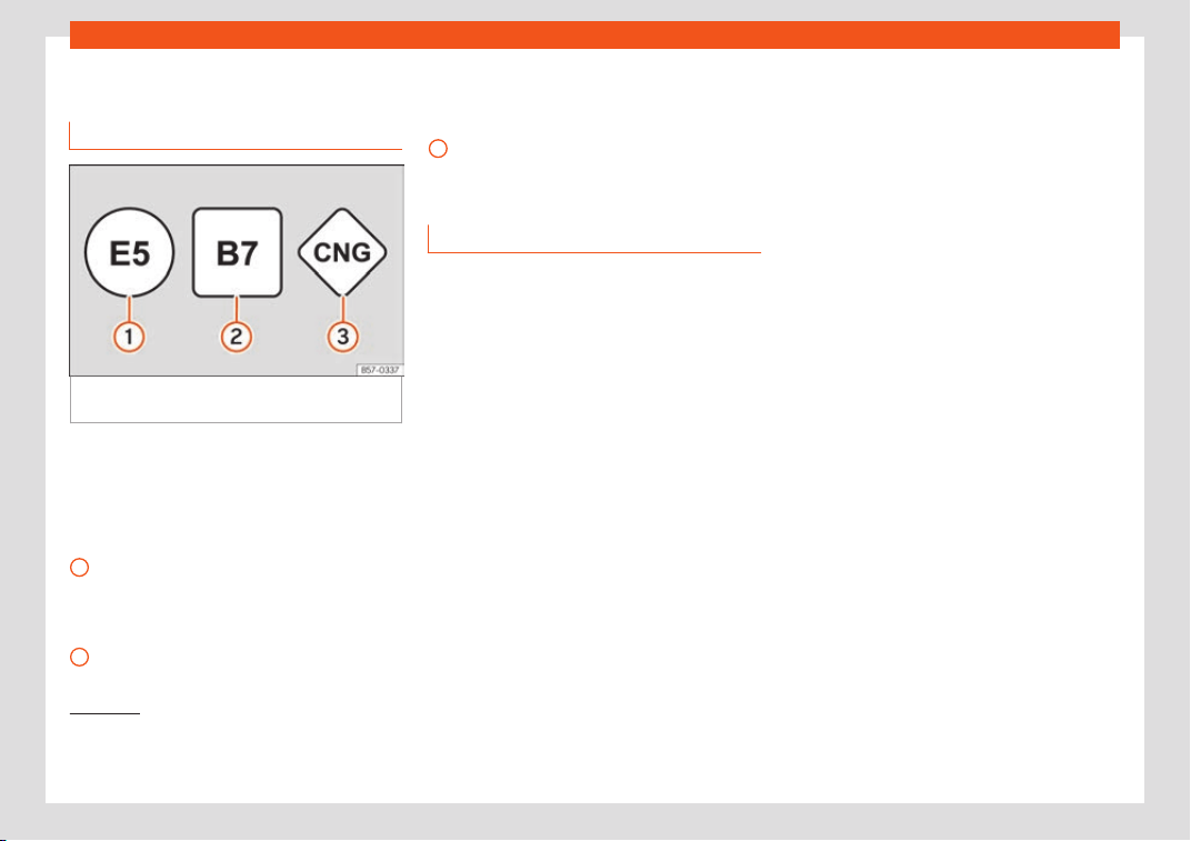
Checking and refilling levels
Fuel
Identification of the fuel
1)
Fig. 300 Identification of fuels according to
Eur
opean Union (EU) Dir
ectiv
e 2014/94/
Fuels are identified with different symbols.
Depending on the fuel, the diff
er
ent symbol
s
are on the pump and the tank lid of your vehi-
cle. The identification serves to prevent con-
fusion when choosing the fuel.
Petrol with ethanol (“E” stands for Etha-
nol). The number indicates the percent-
age of ethanol in the petrol. “E5” means,
for example, an ethanol ratio of 5% max.
Diesel with biodiesel (“B” stands for Bio-
diesel). The number indicates the per-
1
2
centage of biodiesel in the diesel. “B7”
means, f
or e
x
ample, a proportion of bio-
diesel of max. 7%.
Natural gas: “CNG” means Compressed
Natural Gas.
Type of petrol
3 Applies to vehicles: with petrol engine
The correct gr
ade of petrol is listed inside the
fuel tank flap.
The vehicle is equipped with a catalytic con-
verter and must only be run on unleaded
petrol. The petrol must comply with the
standard EN 228 and be sulphur-free. Fuels
with a 10% ethanol ratio can be refuelled
(E10)
2)
. The types of petrol are differentiated
by using the octane numbers (RON) or via
the anti-knock index (AKI).
The following pieces of text show the infor-
mation included in the corresponding stickers
on the tank lid (examples):
3
Super unleaded petrol 95 octane petrol or
normal 91 oct
ane petr
ol at l
east
We recommend refuelling with super 95 oc-
tane petrol (91 AKI). If not available: normal 91
octane petrol (87 AKI) (with a slight power
loss).
Super unleaded petrol, 95 octanes at
least
You should use super 95 octane petrol (91
AKI) at least.
If super is not available, if necessary, use nor-
mal 91 octane petrol (87 AKI). In this case only
use moderate engine speeds and a light
throttle. Refuel with super as soon as possi-
ble.
Unleaded super plus 98 octane petrol or
super 95 octane petrol at least
We recommend refuelling with super plus 98
octane petrol (93 AKI). If not available: super
95 octane petrol (91 AKI) (with a slight power
loss).
If super is not available, if necessary, use nor-
mal 91 octane petrol (87 AKI). In this case only
use moderate engine speeds and a light
»
1)
Depending on country
2)
Follow the regulations of the country you are
driving in.
343
Practical tips
throttle. Refuel with super as soon as possi-
bl
e
.
CAUTION
●
Fuels high percent
age of ethanol, e.g.
E30 - E100 button must not be used. The
fuel system would be damaged. Exception:
vehicles with Totalflex engine
›››
page 344,
Ethanol fuel.
●
A single refuelling with leaded fuel or
other metal additives entails a permanent
deterioration of the effectiveness of the
catalytic converter.
●
Only use fuel additives that have been
approved by SEAT. The products that con-
tain substances to increase the octane rat-
ing or decrease knocking may contain met-
al additives that damage the engine and
catalytic converter. This type of products
must not be used.
●
Do not use fuels shown in the pump as
containing metals. LRP (lead replacement
petrol) fuels contain high concentrations of
metal additives. Risk of engine damage!
●
High engine speed and full throttle can
damage the engine when using petrol with
an octane rating lower than the correct
grade for the engine.
Note
●
Fuel with an octane rating higher than the
one r
equired by the engine can be used.
●
In countries in which there is no sulphur-
free fuel, it is also allowed to use low sul-
phur content fuel.
Ethanol fuel
3 Applies to vehicles: with Totalflex engine
You can r
ecognise vehicles with Totalflex en-
gines
1)
by label on the fuel tank lid with with
the marking “Petrol/ethanol”.
Vehicles with Totalflex engine can run with
unleaded petrol (95 octane / 91 AKI) accord-
ing to ANP No. 57 and with fuels with any high
percentage of ethanol. The vehicle is refuel-
led in the same way as petrol refuelling.
Also consider that
›››
page 343, Type of pet-
rol
Note
SEAT recommends filling the tank exclu-
sively with petrol e
very 10,000 km to de-
crease impurities that using E100 ethanol
fuel might have left in the engine.
Diesel
3 Applies to vehicles: with diesel engine
Please not
e the information on the inside of
the fuel tank flap.
We recommend you use Diesel according to
standard EN 590.
The diesel can thicken at very low tempera-
tures, thus affecting the start or operation of
the engine. To ensure that you can continue
to use your vehicle as usual, the diesel sold in
gas stations is provided -depending on the
station- with fluidity when cold. Ask the em-
ployee of the petrol station whether their die-
sel is suitable for use in winter and if it is suited
for current and future temperatures.
Water in the fuel filter
2)
If your vehicle has a diesel engine and is
equipped with a fuel filter with a water sep-
arator, the instrument panel may display the
following warning:
Water in the fuel
filter. If this is the case, take the vehicle to
a specialised workshop so that they can
drain the fuel filter.
1)
This motor is only available in some markets.
2)
Depending upon country.
344
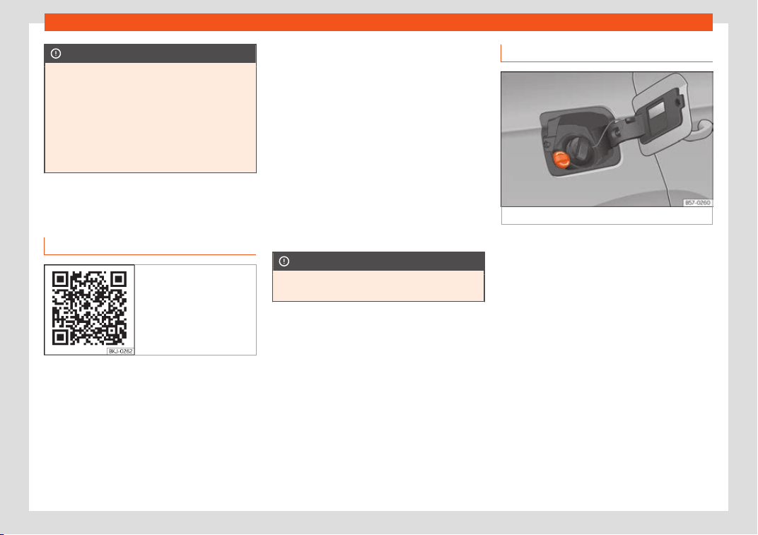
Checking and refilling levels
CAUTION
●
Never use of F
AME (biodiesel), petrol,
heating oil, other fuels or thinning agents
as they can cause severely damage the
fuel system and the engine.
●
If the wrong fuel has been filled, do not
start the engine under any circumstances.
Risk of damaging the fuel system and the
engine! Obtain technical assistance.
AdBlue
®
Inf
ormation on AdBlue
®
Fig. 301 Related video
The consumption of AdBlue
®
depends on
your personal driving st
yl
e
, the temperature
of the system and on the outdoor tempera-
ture when the vehicle is used.
AdBlue
®
freezes at temperatures of -11°C
(+13°F). The system has heating elements
that guarantee its operation even at low tem-
peratures.
The AdBlue
®
tank level capacity is approxi-
mately 11 litres.
The AdBlue
®
tank should never be empty.
When the distance to empty drops below
2400 km, a warning to refill the AdBlue
®
tank
will appear on the dash panel display
›››
page 345. If this information is ignored,
later on it will not be possible to re-start the
engine. If this warning does not appear, it is
not necessary to refill the AdBlue
®
tank.
AdBlue
®
is a registered brand of the German
Association of the Automotive Industry (VDA)
and is also known as AUS32 or DEF (Diesel
Exhaust Fluid).
CAUTION
Filling the AdBlue
®
tank ex
cessively can
cause damage to the tank.
Refilling AdBlue
®
Fig. 302
AdBlue tank cap.
Operations prior to refilling
P
ark the v
ehicl
e on a flat surface. If the vehi-
cle is not parked on a flat surface, but, for ex-
ample, on a slope or on the side of a curb, the
level indicator may not detect the load prop-
erly.
If a warning message about AdBlue
®
levels
appears on the dash panel display, fill at
least the minimum amount required (ap-
prox. 5 litres) Only after adding this amount
will the system detect that AdBlue
®
has been
added and you will be able to start the en-
gine again. The maximum amount that can
be refilled is 11 litres.
Switch the ignition off. If the ignition is not
switched off during refilling, the warning to re-
fill may continue to appear on the instrument
panel display.
»
345
Practical tips
Fill with a refill bottle
Only use AdBlue
®
that complies with ISO
222
41-
1. Only use original cont
ainers.
●
Open the tank cover
›››
Fig. 302.
●
Unscrew the tank cap by turning it in an an-
ti-clockwise direction.
●
Please observe the manufacturer's instruc-
tions, indicated on the refill bottle.
●
Check the expiry date.
●
Remove the cap of the refill bottle.
●
Insert the neck of the bottle in the tank filler
neck vertically and screw the bottle on by
hand, by turning it in a clockwise direction.
●
Press the refill bottle in the direction of the
filler neck and hold it in this position.
●
Wait until the contents of the refill bottle
have been poured into the AdBlue
®
tank. Do
not compress or break the bottle!
●
Turn the bottle in a counter-clockwise di-
rection and gently pull it upwards
›››
.
●
The AdBlue
®
t
ank is full when no mor
e liquid
comes out of the bottl
e.
●
Screw on the tank cap in a clockwise direc-
tion until it is tightly closed.
●
Close the fuel tank flap.
Operations before driving
●
After refilling the tank, only switch on the ig-
nition.
●
Leave the ignition on for at least 30 sec-
onds for the system to detect the fluid load.
●
Make sure you wait for at least 30 seconds
before starting the engine!
Refilling the dispenser with AdBlue
Valid for vehicles with selective catalytic re-
duction.
●
Open the tank cap.
●
Turn the SCR tank cap anti-clockwise
›››
Fig. 302.
●
Add AdBlue until the nozzle stops for the
first time.
●
Close the SCR tube by turning it clockwise
until you hear a click.
WARNING
AdBlue
®
should only be stor
ed in the origi-
nal container, which should be tightly
closed and kept in a safe place.
●
Never keep AdBlue
®
in empty food con-
tainers, bottles or other similar containers.
Other people may confuse it for other
products.
●
Keep AdBlue
®
out of the reach of chil-
dren.
CAUTION
●
When refilling, the nozzl
e grip should be
aligned downward. Otherwise the nozzle
will not connect automatically.
●
Do not try to add any more additive after
the nozzle has stopped for the first time.
The AdBlue tank could overflow and AdBlue
could spill out.
●
Only use AdBlue
®
that complies with ISO
22241-1. Only use original containers.
●
Never mix AdBlue
®
with water, fuel or ad-
ditives. Any type of damage caused by
such a mixture will not be covered by the
warranty.
●
Never pour AdBlue
®
into the fuel tank.
This could result in engine damage.
●
Do not carry the refill bottle inside the
vehicle. If there is a leak (due to tempera-
ture changes or damage to the bottle), the
AdBlue
®
may damage the vehicle.
For the sake of the environment
Dispose of the refill bottle in an environ-
ment-friendly manner.
Note
You can buy refill bottles that are adequate
for AdBlue
®
use at SEAT dealerships.
346
Checking and refilling levels
Engine compartment
W
orking in the engine compar
t
-
ment
Read the additional information carefully
›››
page 18
Always be aware of the danger of injury
and scalding as well as the risk of acci-
dent or fire when working in the engine
compartment (e.g. when checking and re-
filling fluids). Always observe the warnings
listed below and follow all general safety
precautions. The engine compartment of
the vehicle is a potentially hazardous area
›››
.
WARNING
●
Switch the engine off
, remove the key
from the ignition and apply the electronic
parking brake. If the vehicle has a manual
gearbox, place the lever in neutral; if it has
an automatic gearbox, place the selector
lever in position P. Wait for the engine to
cool down.
●
Keep children away from the engine
compartment.
●
Never spill liquids used for vehicle opera-
tion on the engine compartment, as these
may catch fire (e.g. the antifreeze in cool-
ant).
●
Take car
e not to cause short circuits in
the electrical system, especially when
working on the battery.
●
If working inside the engine compart-
ment, remember that, even when the igni-
tion is switched off, the radiator fan may
start up automatically, and therefore there
is a risk of injury.
●
Never cover the engine with additional in-
sulating materials such as a blanket. Risk of
fire!
●
Do not unscrew the cap on the coolant
expansion tank when the engine is hot. The
cooling system is under pressure.
●
Protect face, hands and arms by cover-
ing the cap with a large, thick rag to protect
against escaping coolant and steam.
●
If it is necessary to work in the engine
compartment while the engine is running,
the rotating components (for example,
poly-V belt, alternator, radiator fan) and
the high voltage ignition system are an ad-
ditional hazard.
●
Observe the following additional warn-
ings if work on the fuel system or the elec-
trical system is necessary:
–
Always disconnect the battery from the
on-board network.
–
Do not smoke.
–
Never work near naked flames.
–
Always keep an approved fire extin-
guisher immediately available.
CAUTION
When topping up fluids make sure the cor-
rect fluid is put into the corr
ect filler open-
ing, otherwise this can cause serious mal-
functions or engine damage.
For the sake of the environment
Inspect the ground underneath your vehi-
cle regul
arly so that any leaks are detec-
ted at an early stage. If you find spots of oil
or other fluids in the area where it was
parked, have your vehicle inspected at the
workshop.
Note
In right-hand drive vehicles* some brake
fluid reservoirs ar
e on the other side of the
engine compartment
›››
Fig. 303.
Opening and closing the bonnet
Read the additional information carefully
›
›
›
page 18
WARNING
●
Never open the bonnet if you see st
eam
or drips of coolant being released from the
engine compartment. Failure to comply
could result in burns. Wait until no steam or
coolant can be seen before opening the
bonnet.
»
347

Practical tips
●
For safet
y reasons the bonnet must al-
ways be completely closed when the vehi-
cle is moving. Therefore, after closing the
bonnet, always check that the locking ele-
ment is properly engaged. This is the case
if the bonnet is flush with the adjacent
body panels.
●
Should you notice that the bonnet is not
safely secured when the vehicle is moving,
stop the vehicle immediately and close the
bonnet. Failure to follow this instruction
could result in an accident.
CAUTION
To avoid damage to the bonnet and to the
windscreen wiper arms, only open it when
the windscreen wipers ar
e in place against
the windscreen.
348
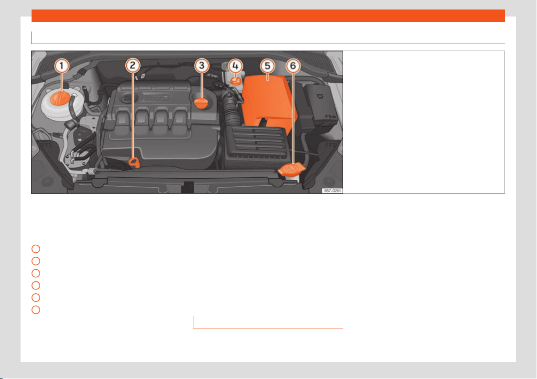
Checking and refilling levels
Checking levels
Fig. 303
Diagram for the location of the various el-
ements.
From time to time, the levels of the different
fluids in the v
ehicl
e must be check
ed. Never
fill with incorrect fluids, otherwise serious
damage to the engine may be caused.
Coolant expansion tank
Engine oil dipstick
Engine oil filler cap
Brake fluid reservoir
Vehicle battery (underneath the cover)
Windscreen washer reservoir
The checking and refilling of service fluids are
carried out on the components mentioned
1
2
3
4
5
6
above. These operations are described in
›
›
›
page 347.
Overview
You will find further explanations, instructions
and restrictions on the technical specifica-
tions as of
›››
page 380.
Engine oil
General notes
The engine comes with a special, multi-grade
oil that can be used all year r
ound.
Because the use of high-qualit
y oil is essen-
tial f
or the correct operation of the engine
and its long useful life, when topping up or
changing oil, use only those oils that comply
with VW standards.
We recommend that the oil change indicated
in the Maintenance Programme, be per-
formed by a technical service or specialised
workshop.
If the engine oil level is too low
You can get information about the correct en-
gine oil for your vehicle at your specialised
shop. If you have to change your engine oil,
use that oil.
»
349
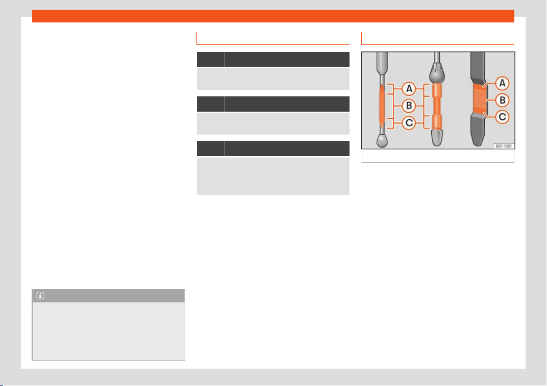
Practical tips
If the recommended engine oil is not availa-
bl
e
, in the e
vent of an emergency you can
add oil once up to a maximum of 0.5 L of the
next oil until the next oil change:
●
Valid for vehicles with petrol engines:
standard VW 504 00, VW 502 00,
VW 508 00, ACEA C or API SN.
Vehicles with diesel particulate filter*
Only VW 507 00 engine oil, with reduced ash
formation, may be used in diesel engines
equipped with particulate filter. Using other
types of oil will cause a higher soot concen-
tration and reduce the life of the DPF. There-
fore:
●
Avoid mixing this oil with other engine oils.
●
Only in exceptional circumstances, if the
engine oil level is too low
›››
page 350 and
you cannot obtain the oil specified for your
vehicle, you can use a small quantity of oil
(once) conforming to the specifications
VW 506 00, VW 506 01, VW 505 00,
VW 505 01 or ACEA B3/ACEA B4 (up to 0.5 l)
›››
page 48.
Note
Before a long trip, we recommend finding
an engine oil that conforms to the corr
e-
sponding VW specifications and recom-
mend keeping it in the vehicle. This way, the
correct engine oil will always be available
for a top-up if needed.
Warning lamp
It lights up red
Do not continue driving!
Engine oil pressure too low.
It lights up yellow
Check the engine oil level as soon as possible.
Top up the oil at the next opport
unity
›››
page 351.
It flashes yellow
Fault in the oil level sensor.
Take the v
ehicle to a specialised workshop to have
the system inspected. Until then it is advisable to
check the oil level every time you refuel.
If this warning symbol st
arts t
o fl
ash, and
is accompanied by three audible warnings,
switch off the engine and check the oil level. If
necessary, add more oil
›››
page 351.
If the warning lamp
flashes although the
oil level is correct, stop driving. Do not even
run the engine at idle speed! Obtain technical
assistance.
Checking engine oil level
Fig. 304
Engine oil dipstick.
Read the additional information carefully
›
›
›
page 47
The engine oil dipstick indicates the level of
the oil.
Checking oil level
–
Park the vehicle in a horizontal position.
–
Briefly run the engine at idle speed until the
operating temperature is reached and then
stop.
–
Wait for about two minutes.
–
Pull out the dipstick. Wipe the dipstick with
a clean cloth and insert it again, pushing it
in as far as it will go.
–
Then pull it out once more and check the oil
level
›››
Fig. 304. Top up with engine oil if
necessary.
350
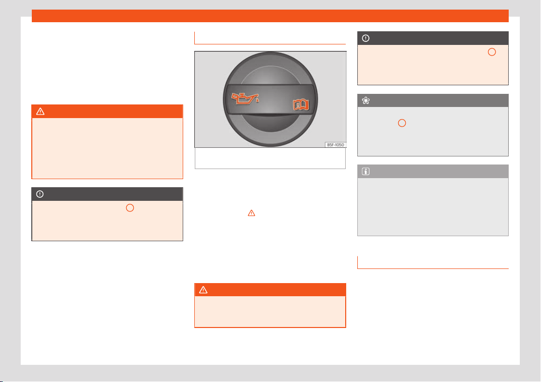
Checking and refilling levels
Depending on how you drive and the condi-
tions in which the v
ehicl
e is used, oil con-
sumption can be up t
o 0.5 l/1000 km. Oil
consumption is likely to be higher for the first
5,000 km. For this reason the engine oil level
must be checked at regular intervals, prefera-
bly when filling the tank and before a journey.
WARNING
Any work carried out in the engine com-
partment or on the engine must be carried
out cautiously.
●
When working in the engine compar
t-
ment, always observe the safety warnings
›››
page 347.
CAUTION
If the oil level is above area
A
, do not start
the engine. This could r
esult in damage to
the engine and catalytic converter. Con-
tact a Technical Service.
Topping up engine oil
Fig. 305
In the engine compartment: Engine
oil fill
er cap
.
Read the additional information carefully
›
›
›
page 47
Before opening the bonnet, read and observe
the warnings
›››
in Working in the engine
compar
tment on page 347
.
The position of the oil fill
er opening is shown
in the corresponding engine compartment il-
lustration
›››
page 349.
Engine oil specification
›››
page 48.
WARNING
Oil is highly inflammable! Ensure that no oil
comes into contact with hot engine compo-
nents when t
opping up.
CAUTION
If the oil level is above area
›››
Fig. 304
A
,
do not start the engine
. This could result in
damage to the engine and catalytic con-
verter. Contact a specialised workshop.
For the sake of the environment
The oil level must never be above zone
›››
Fig. 304
A
. Otherwise oil can be drawn
in through the crank
case breather and leak
into the atmosphere via the exhaust sys-
tem.
Note
Before a long trip, we recommend finding
an engine oil that conforms to the corr
e-
sponding VW specifications and recom-
mend keeping it in the vehicle. This way, the
correct engine oil will always be available
for a top-up if needed.
Changing engine oil
Read the additional information carefully
›
›
›
page 47.
The engine oil must be changed at the inter-
vals given in the service schedule.
We recommend that you have the engine oil
changed by a Technical Service.
»
351
Practical tips
The oil change intervals are shown in the
Maint
enance Pr
ogr
amme.
WARNING
Only change the engine oil yourself if you
have the specialist knowl
edge required!
●
Before opening the bonnet, read and ob-
serve the warnings
›››
page 347.
●
Wait for the engine to cool down. Hot oil
may cause burn injuries.
●
Wear eye protection to avoid injuries,
such as acid burns, caused by splashes of
oil.
●
When removing the oil drain plug with
your fingers, keep your arm horizontal to
help prevent oil from running down your
arm.
●
Wash your skin thoroughly if it comes into
contact with engine oil.
●
Engine oil is poisonous! Used oil must be
stored in a safe place out of the reach of
children.
CAUTION
No additives should be used with engine oil.
This could result in engine damage
. Any
damage caused by the use of such addi-
tives would not be covered by the factory
warranty.
For the sake of the environment
●
Because of disposal problems and the
special t
ools and specialist knowledge re-
quired, we recommend that you have the
engine oil and filter changed by a Techni-
cal Service.
●
Never pour oil down drains or into the
ground.
●
Use a suitable container when draining
the used oil. It must be large enough to hold
all the engine oil.
Cooling system
T
opping up cool
ant
Read the additional information carefully
›
›
›
page 49
Top up coolant when the level is below the
MIN (minimum) mark.
Checking coolant level
–
Park the vehicle in a horizontal position.
–
Switch the ignition off.
–
Read off the coolant level on coolant ex-
pansion tank. When the engine is cold, the
coolant level should be between the marks.
When the engine is hot, it may be slightly
above the upper mark.
Topping up coolant
–
Wait for the engine to cool down.
–
Cover the coolant expansion tank cap with
a cloth and carefully unscrew it to the left
›››
.
–
Top up the coolant only if there is still cool-
ant in the e
xpansion t
ank
, otherwise you
could damage the engine. If there is no
coolant in the expansion tank, do not con-
tinue driving. You should obtain professional
assistance
›››
.
–
If there is still some coolant in the expansion
t
ank
, t
op up to the upper mark.
–
Top up with coolant until the level becomes
stable.
–
Screw the cap back on correctly.
Any loss of coolant fluid normally indicates a
leak in the cooling system. Take the vehicle
straight to a specialised workshop to have
the cooling system examined. If there are no
leaks in the engine cooling system, a loss of
coolant can only occur if the coolant boils
and is forced out of the system as a result of
overheating.
WARNING
●
The cooling system is under pressur
e. Do
not unscrew the cap on the coolant expan-
sion tank when the engine is hot: risk of
burns!
352
Checking and refilling levels
●
The antifreez
e and coolant fluid can be a
health hazard. Therefore, the antifreeze
should be stored in the original container in
a safe place out of reach of children. Fail-
ure to comply could result in poisoning.
●
If working inside the engine compart-
ment, remember that, even when the igni-
tion is switched off, the radiator fan may
start up automatically, and therefore there
is a risk of injury.
WARNING
If there is not enough anti-freeze in the
cool
ant system, the engine may f
ail lead-
ing to serious damage.
●
Please make sure that the percentage of
additive is correct with respect to the low-
est expected ambient temperature in the
zone in which the vehicle is to be used.
●
When the outside temperature is very
low, the coolant could freeze and the vehi-
cle would be immobilised. In this case, the
heating would not work either and inade-
quately dressed passengers could die of
cold.
CAUTION
Do not top up the expansion tank with cool-
ant fluid if it is empty! Air could ent
er the
cooling system. In this case, stop driving.
Seek specialist assistance. Otherwise,
there is a risk of engine damage.
CAUTION
The original additives should never be
mixed with coolants which ar
e not ap-
proved by SEAT. Otherwise, you run the risk
of causing severe damage to the engine
and the engine cooling system.
●
If the fluid in the expansion tank is not
purple but is, for example, brown, this indi-
cates that the G13 additive has been mixed
with an inadequate coolant. The coolant
must be changed as soon as possible if this
is the case! This could result in serious
faults and engine damage.
For the sake of the environment
Coolants and additives can contaminate
the environment. If any fluids are spill
ed,
they should be collected and correctly dis-
posed of, with respect to the environment.
Brake fluid
T
op up br
ak
e fluid
Read the additional information carefully
›
›
›
page 49
Checking the brake fluid level
The brake fluid level must be between the
MIN and MAX markings.
However, if the brake fluid level goes down
noticeably in a short time, or drops below the
MIN mark, there may be a leak in the brake
system. Seek specialist assistance. A warning
light on the instrument panel display monitors
the brake fluid level
›››
page 39.
In right-hand drive vehicles the brake fluid
reservoir is on the other side of the engine
compartment.
Changing brake fluid
The regular intervals at which the brake fluid
should be replaced are listed in the Mainte-
nance Programme. We recommend you have
it replaced at a SEAT Official Service, during
an Inspection Service.
WARNING
●
Brake fluid shoul
d be stored in the closed
original container in a safe place out of
reach of children. Risk of poisoning!
●
If the brake fluid is left in the system for
too long and the brakes are subjected to
heavy use, vapour bubbles may form in the
brake system. This would seriously affect
the efficiency of the brakes and the safety
of the vehicle. This may cause an accident.
CAUTION
Brake fluid should not come into contact
with the vehicle paintw
ork, as it is abrasive.
353
Practical tips
Windscreen washer reservoir
Checking and t
opping up the wind-
scr
een w
asher reservoir
Read the additional information carefully
›››
page 50
Check the water level in the windscreen
washer reservoir regularly and top up as re-
quired.
The container for the windscreen washer
contains the cleaning fluid for the wind-
screen, the rear window and the headlight
washer system*.
●
Open the bonnet
›››
page 347.
●
The windscreen washer reservoir is marked
with the symbol on the cap.
●
Check there is enough windscreen water in
the reservoir.
Recommended windscreen wipers
●
For the hottest seasons we recommend
summer G 052 184 A1 for clear glass. Propor-
tions of the mixture in the washer fluid tank:
1:100 (1 part concentrate per 100 parts wa-
ter).
●
All year round, G 052 164 A2 for clear glass.
Approximate proportion of the winter mixture,
up to -18°C (0°F): 1:2 (1 part concentrate per 2
parts water); otherwise, a 1:4 proportion of
mixture in the washer fluid tank.
Capacity
The reservoir holds approximately 3 litres in
versions without headlight washer and 5 litres
in versions with headlight washer.
WARNING
If the water from the windscreen washer
does not contain enough anti-free
ze, it may
freeze on the windscreen and rear window,
reducing forward and rear visibility.
●
In winter, ensure the windscreen washer
contains enough anti-freeze.
●
In cold conditions, you should not use the
windscreen wiper system unless you have
warmed the windscreen with the ventila-
tion system. The antifreeze could freeze on
the windscreen and reduce visibility.
WARNING
Never mix an unsuitable antifreeze or other
similar additives with the windscr
een wash-
er water. A greasy layer may be formed on
the windscreen which will impair visibility.
●
Use clean water with a window cleaner
recommended by SEAT.
●
If necessary, add a suitable antifreeze to
the water in the reservoir.
CAUTION
●
Do not mix cleaning products r
ecommen-
ded by SEAT with other products. This
could lead to flocculation and may block
the windscreen washer jets.
●
When topping up service fluids, make ab-
solutely certain that you fill the fluids into
the correct reservoirs. Using the wrong flu-
ids could cause serious malfunctions and
engine damage!
●
Not having windscreen wiper fluid re-
duces visibility through the windscreen,
and leads to loss of visibility in headlights
in models with headlight washer.
Battery
Gener
al inf
ormation
Read the additional information carefully
›
›
›
page 50.
The battery is located in the engine compart-
ment and is almost maintenance-free. It is
checked as part of the Inspection Service.
Nevertheless, check the terminals are clean
and have the correct tightening torque, espe-
cially in summer and winter.
Disconnecting the battery
The battery should only be disconnected in
exceptional cases. When the battery is
354
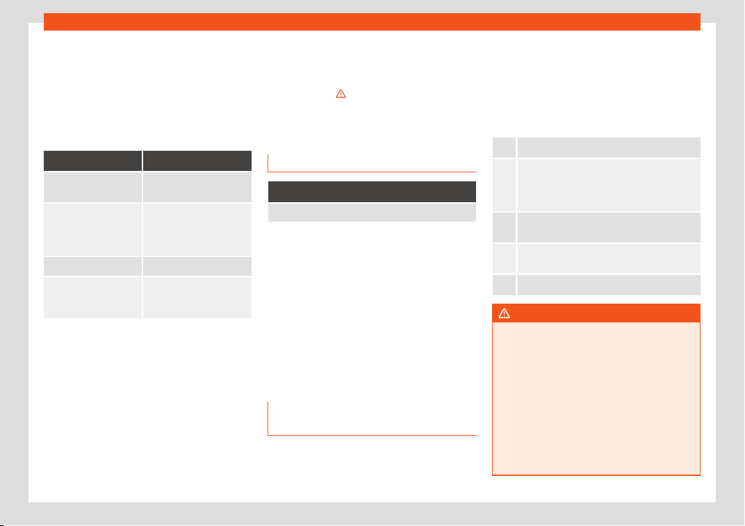
Checking and refilling levels
disconnected, some of the vehicle's functions
ar
e “l
ost” (
›
››
table on page 355). These
functions will require resetting after the bat-
tery is reconnected.
Deactivate the anti-theft alarm* before you
disconnect the battery Otherwise the alarm
will be triggered.
Function Reprogramming
One-touch function of
the electric windows
›
››
page 143, One-touch
opening and closing.
Remote control key
If the vehicle does not re-
spond to the key, they
shoul
d be synchronised
›››
page 136.
Digital clock
›››
page 116.
ESC w
arning lamp
After driving for a few me-
tres, the warning l
amp
goes out again.
If the vehicle is not used for long periods
The v
ehicl
e has a syst
em for monitoring the
current consumption when the engine is left
unused for long periods of time
›››
page 264.
Some functions, such as the interior lights, or
the remote door opening, may be temporarily
disabled to prevent the battery from running
flat. These functions will come back on as
soon as the ignition is switched on and the
engine started.
Winter conditions
During the winter, the starting power may be
reduced, and if necessary, the battery should
be charged
›››
in Important safety warn-
ings f
or handling a v
ehicl
e battery on
page 355
Warning lamp
It lights up
Alternator fault.
The control lamp lights up when the ignition is
s
wit
ched on. It shoul
d go out when the engine
has started running.
If the control lamp lights up while driving,
the alternator is no longer charging the bat-
tery. You should immediately drive to the
nearest specialised workshop.
You should avoid using electrical equipment
that is not absolutely necessary because this
will drain the battery.
Important safety warnings for han-
dling a vehicle battery
All work on batteries requires specialist
kno
wl
edge
. Please refer to a SEAT Official
Service or a workshop specialising in batter-
ies: risk of burns or exploding battery!
The battery must not be opened. Never try
to change the fluid level of the battery. Oth-
erwise explosive gas is released from the bat-
tery that could cause an explosion.
Wear eye protection.
Battery acid is very corrosive and caustic.
Wear prot
ective gloves and eye protection. In
the event of electrolyte splashes, rinse off with
plenty of water.
Fires, sparks, open flames and smoking are
prohibited.
The batt
ery should only be charged in a well-
ventilat
ed zone. Risk of explosion!
Keep children away from acid and batteries!
WARNING
●
When repairing or working on the el
ectri-
cal system, proceed as follows:
–
1. Remove the key from the ignition. The
negative cable on the battery must be
disconnected.
–
2. When the repair is finished, recon-
nect the negative pole of the battery.
●
Switch off all electrical devices before
reconnecting the battery. Reconnect first
the positive cable and then the negative
cable. Never reverse the polarity of the
»
355
Practical tips
connections. This could cause an electrical
fire.
●
Ensur
e that the vent hose is always con-
nected to the battery.
●
Never use damaged batteries. This could
cause an explosion! Replace a damaged
battery immediately.
CAUTION
●
Ne
ver disconnect the batt
ery if the igni-
tion is switched on or if the engine is run-
ning. This could damage the electrical sys-
tem or electronic components.
Charging the battery
Terminals for charging the battery are fitted in
the engine compartment.
–
Note the warnings
›
›
›
in Important safe-
t
y w
arnings f
or handling a vehicle bat-
tery on page 355 and
›››
.
–
Switch off all electrical devices. Remove
the ignition k
ey.
–
R
aise the bonnet
›
››
page 18.
–
Open the battery cover.
–
Connect the charger clamps as described
to the positive pole of the battery (+) and
exclusively to an earth on the bodywork
(–).
–
Only use a charger which is compatible for
use with 12 V nominal voltage batteries. The
charge must not exceed a voltage of 15 V.
–
Now connect the battery charger to the
power socket and switch on.
–
At the end of the charging process: switch
off the battery charger and disconnect the
power socket cable.
–
Finally disconnect the charger cables from
the battery.
–
Replace the battery cover correctly.
–
Close the bonnet
›››
page 18.
Important: Before you charge the battery
make sure you read the manufacturer's in-
structions for using the battery charger.
WARNING
Never charge a battery that has frozen: re-
place it! F
ailure to do so may lead to an ex-
plosion.
Note
Use only the terminals in the engine com-
partment to char
ge the battery.
Replacing the battery
The new battery should have the same speci-
fications (amperage, l
oad and voltage) as
the used battery.
Your vehicle is equipped with an intelligent
power management system to control the
distribution of electrical energy
›››
page 264.
The power management function ensures
that the battery is charged much more effi-
ciently than on vehicles without a power
management system. To maintain this func-
tion after replacing the battery, we recom-
mend that the replacement battery used is of
the same make and type as the original fitted
battery. To make proper use of the power
management function after the battery has
been changed, have the battery coded to the
power management mode at a specialised
workshop.
CAUTION
●
Some vehicles, f
or example those with
the Start-Stop system* are fitted with a
special battery (AGM-type or EFB-type
battery). If any other type of battery is fit-
ted, the Start-Stop function may be consid-
erably reduced and the vehicle may not
stop on repeated occasions.
●
Make sure that the vent hose is always
attached to the original opening on the
side of the battery. Gases or battery acid
356

Wheels
can otherwise escape and possibly cause
damage.
●
The battery hol
der and clamps must al-
ways be correctly secured.
●
Before starting any work on the battery,
always observe the warnings listed under
›››
page 355, Important safety warnings for
handling a vehicle battery.
●
Do not forget to replace the battery cov-
erings, where applicable. It is a protection
for high temperatures. This in turn extends
the vehicle service life.
For the sake of the environment
Batteries contain toxic substances in-
cluding sulphuric acid and lead. They must
be disposed of appr
opriately and must not
be disposed of with ordinary household
waste. Make sure disconnected batteries
cannot tip over. Sulphuric acid could be
spilt!
Wheels
Wheel
s and t
yr
es
General notes
–
When driving with new tyr
es, be especially
careful during the first 500 km (300 miles).
–
If you have to drive over a kerb or similar
obstacle, drive very slowly and as near as
possible at a right angle to the obstacle.
–
Check from time to time if the tyres are
damaged (punctures, cuts, cr
acks or
dents). Remove any foreign objects em-
bedded in the treads.
–
Damaged wheels and tyres must be re-
placed immediately.
–
Keep grease, oil and fuel off the tyres.
–
Replace any missing valve caps as soon as
possible.
–
Mark the wheels before taking them off so
that they rotate in the same direction when
put back.
–
When removed, the wheels or tyres should
be stored in a cool, dry and preferably dark
place.
New tyres
New tyres do not give maximum grip straight
away and should therefore be “run in” by
driving carefully and at moderate speeds for
about the first 500 km (300 miles). This will
also increase the useful life of the tyres.
The tread depth of new tyres may vary, ac-
cording to the type and make of tyre and the
tread pattern.
Low profile tyres
Low profile tyres, compared to other rim and
tyre combinations, offer a broader tread and
a greater rim diameter along with a lower
height of the tyre sidewall. This results in a
more agile driving behaviour. However, on
roads that are in poor condition, this might af-
fect comfort and cause more noise.
Low profile tyres may deteriorate more quick-
ly than standard tyres, for instance due to
strong knocks, potholes, manhole covers and
kerbs. Therefore, maintaining the correct tyre
pressure is particularly important
›››
page 358.
To avoid damage to tyres and wheels, drive
with special care when driving on roads in
poor condition.
Visually inspect your tyres every 3,000 km re-
garding damage, e.g. flattening/cracks on
the tyre sidewall or deformations/cracks on
the rims.
»
357
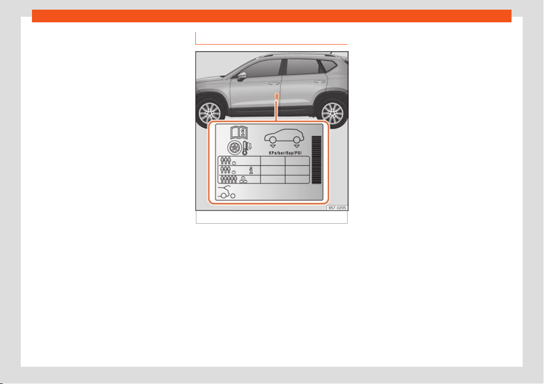
Practical tips
If the rims and tyres have received a heavy
impact or hav
e been damaged, hav
e them
check
ed and, if required, replaced at a speci-
alised workshop.
Low profile tyres may deteriorate more quick-
ly than standard tyres.
Concealed damage
Damage to tyres and rims is often not readily
visible. If you notice unusual vibration or the
car pulling to one side, this may indicate
that one of the tyres is damaged. Reduce
speed immediately if there is any reason to
suspect that damage may have occurred. In-
spect the tyres for damage. If no external
damage is visible, drive slowly and carefully
to the nearest specialised workshop and
have the car inspected.
Tyres with directional tread pattern
An arrow on the tyre sidewall indicates the di-
rection of rotation on single drive tyres. Al-
ways note the direction of rotation indicated
when mounting the wheel. This guarantees
optimum grip and helps to avoid aquaplan-
ing, excessive noise and wear.
Retrofitting accessories
If you wish to change or fit wheels, rims or
wheel trims, we recommend that you consult
with a SEAT Official Service centre for advice
regarding current techniques.
Service life of tyres
Fig. 306 Location of the tyre pressure sticker.
Correct inflation pressures and sensible driv-
ing habits will incr
ease the useful lif
e of your
t
yres.
●
Check tyre pressure at least once a month,
and also prior to any long trip.
●
The tyre pressure should only be checked
when the tyres are cold. Do not reduce the
pressure of warm tyres.
●
Adjust tyre pressure to the load being car-
ried by the vehicle.
●
In vehicles with a tyre pressure indicator,
save the modified pressure of tyres
›››
page 361,
›››
page 358.
●
Avoid fast cornering and hard acceleration.
●
Inspect the tyres for irregular wear from
time to time.
The useful life of your tyres depends on the
following factors:
Tyre pressure
The tyre inflation pressures are listed on a
sticker on the rear of the front left door frame
›››
Fig. 306.
Insufficient or excessive pressure greatly re-
duces the useful life of the tyres and adverse-
ly affects vehicle performance and ride. Cor-
rect inflation pressures are very important,
especially at high speeds.
Depending on the vehicle, tyre pressure can
be adjusted to medium load to improve driv-
ing comfort (tyre pressure ). When driving
with comfort tyre pressure fuel consumption
may increase slightly.
The tyre pressure must be adjusted accord-
ing to the load the vehicle is carrying. If the
vehicle is going to carry the maximum load,
the tyre pressure should be increased to the
maximum value indicated on the sticker
›››
Fig. 306.
358
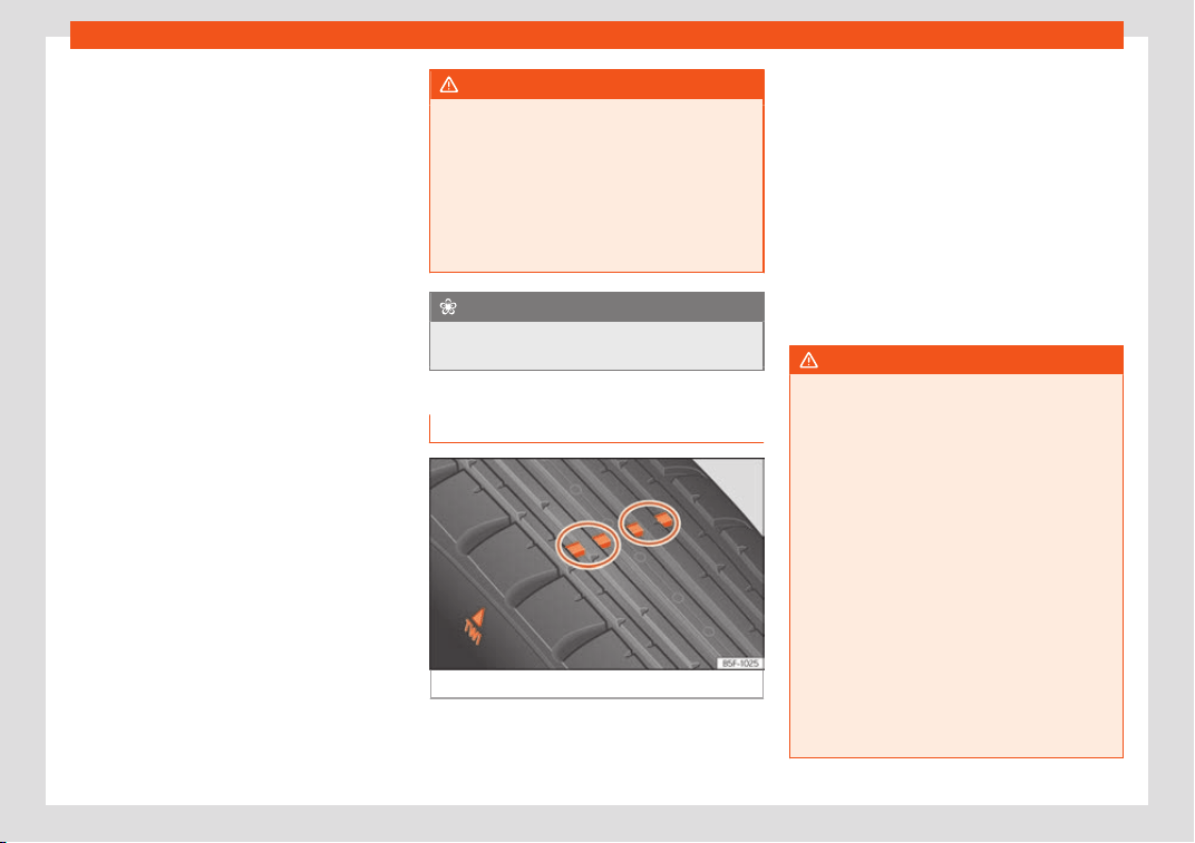
Wheels
Do not forget the spare wheel when checking
the t
yr
e pr
essures: Keep this spare wheel in-
flated to the highest pressure required for the
road wheels.
In the case of a minimised temporary spare
wheel (125/70 R18) inflate to a pressure of 4.2
bar as indicated on the tyre pressure label
›››
Fig. 306.
Driving style
Fast cornering, heavy acceleration and hard
braking (squealing tyres) all increase tyre
wear.
Wheel balance
The wheels on new vehicles are balanced.
However, certain circumstances may lead to
imbalance (run-out), which is detected as vi-
brations in the steering wheel.
Unbalanced wheels should be rebalanced,
as they otherwise cause excessive wear on
steering, suspension and tyres. A wheel must
also be rebalanced when a new tyre is fitted
or if a tyre is repaired.
Incorrect wheel alignment
Incorrect running gear alignment causes ex-
cessive tyre wear, impairing the safety of the
vehicle. If you notice excessive tyre wear, you
should check wheel alignment at a SEAT Of-
ficial Service.
WARNING
●
Always adapt the t
yre pressure accord-
ingly when the vehicle load changes.
●
A tyre with low air pressure has to flex a
lot more when the vehicle is heavily loaded
or at high speeds, therefore causing over-
heating to occur. Under these conditions,
the tyre bead may be released or the tyre
may burst. Risk of accident!
For the sake of the environment
Under-inflated tyres will increase fuel con-
sumption.
Wear indicators
Fig. 307 Tyre profile: tread wear indicators.
Tread wear indicators indicate if a tyre is
w
orn.
The original t
yr
es on your vehicle have
1.6 mm high “tread wear indicators” running
across the tread. Depending on the manu-
facturer, there will be 6 to 8 of them spaced
at equal distances around the tyre. Markings
on the tyre sidewall (for instance the letters
“TWI” or a triangle) indicate the positions of
the tread wear indicators.
The minimum tread depth required by law is
1.6 mm (measured in the tread grooves next
to the tread wear indicators). (Different fig-
ures may apply in other countries.)
WARNING
The tyres must be replaced at the latest
when the tread is worn do
wn to the tread
wear indicators. Failure to follow this in-
struction could result in an accident.
●
Especially in difficult driving conditions
such as wet or icy roads. It is important that
the tyre tread be as deep as possible and
be approximately the same on the tyres of
both the front and the rear axles.
●
The scant driving safety due to insuffi-
cient tread depth is particularly evident in
vehicle handling, when there is a risk of
“aquaplaning” in deep puddles of water
and when driving through corners, and
braking is also adversely affected.
●
The speed has to be adapted according-
ly, otherwise there is a risk of losing control
over the vehicle.
359
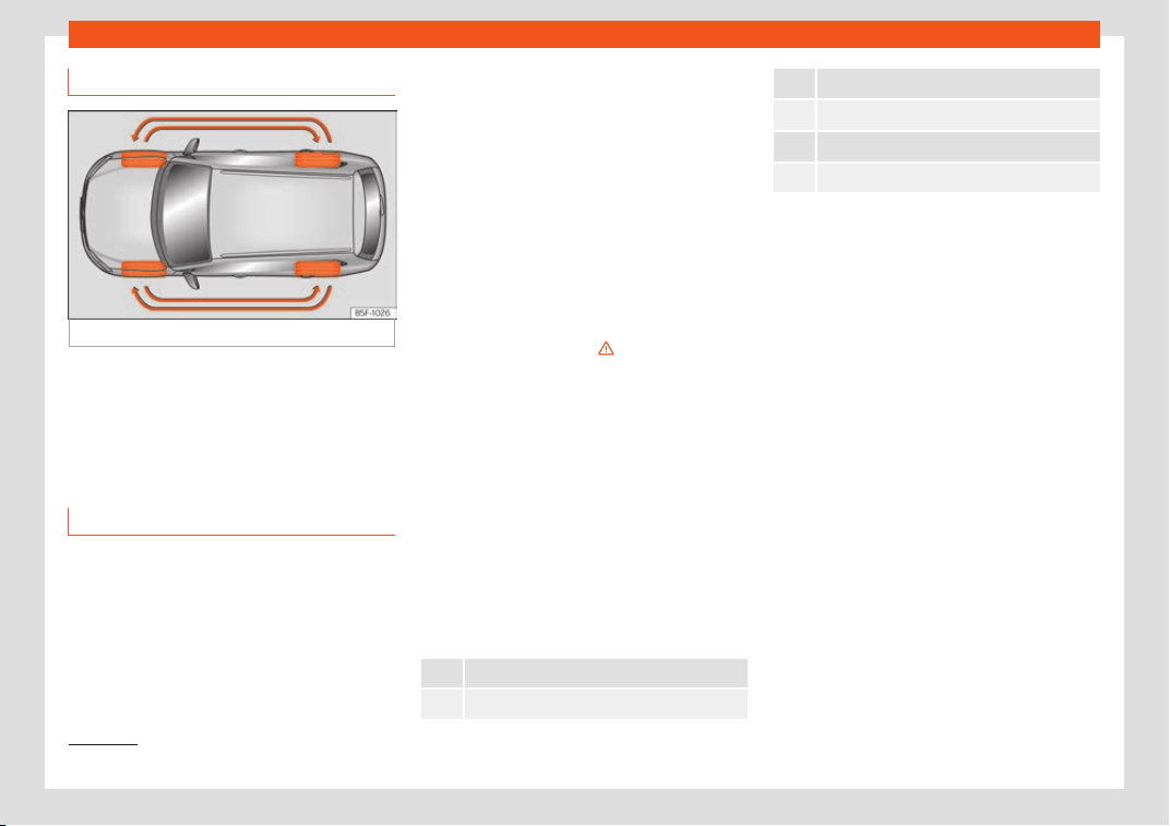
Practical tips
Interchanging tyres
Fig. 308
Interchanging tyres.
To ensure that the wear is equal on all tyres
the wheel
s shoul
d be changed r
ound from
time to time according to the system
›››
Fig. 308. The useful life of all the tyres will
then be about the same time.
New tyres or new wheels
–
All four wheels must be fitted with tyres of
the same t
ype
, siz
e (rolling circumference)
and preferably the same tread pattern.
–
Tyres should be replaced at least in pairs
and not individually (i.e. both front tyres or
both rear tyres together).
–
Do not use tyres whose effective size ex-
ceeds the dimensions of the factory-ap-
proved makes of tyre.
–
If you wish to fit the vehicle with rims or
tyres different to those installed in manu-
facture, it is advisable to consult a SEAT Of-
ficial Service before purchasing them.
The tyres and wheel rims are an essential
part of the vehicle's design. The tyres and
rims approved by SEAT are specially match-
ed to the characteristics of the vehicle and
make a major contribution to good roadhold-
ing and safe handling
›››
.
The siz
es of the rims and t
yr
es approved for
your vehicle are listed in the vehicle docu-
mentation (e.g. EC Certificate of Conformity
or COC document
1)
). The vehicle documen-
tation varies depending on the country of res-
idence.
A knowledge of tyre designations makes it
easier to choose the correct tyres. The fol-
lowing wording can be read on the sides of
the tyre:
215/60 R16 95V
This contains the following information:
215 Tyre width in mm
60 Height/width ratio in %
R Tyre construction: Radial
16 Rim diameter in inches
95 Load rating code
V Speed index
The manufacturing dat
e is also indicated on
the tyre sidewall (possibly only on the outer
part):
DOT ... 2216 ...
it means, for example, that the tyre was man-
ufactured in the 22nd week of 2016.
But note that with some types of tyre, the
actual tyre size can differ from the nomi-
nal size marked on the tyre (for instance
215/60 R16 95 V), and there may be signif-
icant differences in the contours of the
tyres, even though the tyres are marked
with the same nominal size. When replac-
ing the tyres, it is therefore important to
make sure that the actual size of the new
tyres does not exceed the dimensions of
the factory-approved makes of tyre.
Failure to observe this requirement can af-
fect the clearance needed for the tyres. If
the tyres rub against the bodywork, in cer-
tain circumstances the tyres, running gear
or bodywork and pipes may be damaged,
1)
COC = certificate of conformit
y.
360
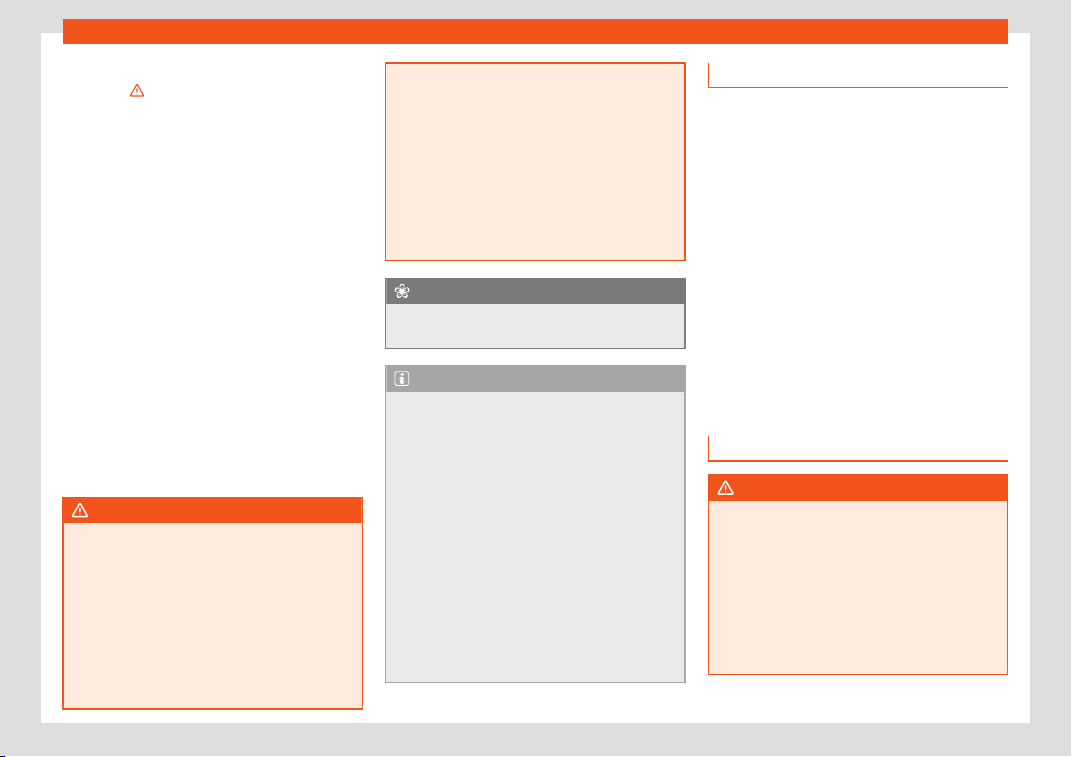
Wheels
and vehicle safety could be severely im-
pair
ed
›
››
.
If you use t
yr
es that ar
e approved by SEAT
you can be sure that the actual tyre di-
mensions will be correct for your vehicle. If
you decide to fit a different type of tyre,
you must obtain the appropriate manufac-
turer's certificate from the tyre retailer to
confirm that the tyres are suitable for your
vehicle. Keep this certificate in a safe
place.
Your SEAT Official Service will be able to
advise you on which tyres may be fitted to
your vehicle.
It is best to have all servicing of wheels and
tyres performed by a specialised workshop.
They are familiar with the procedure and
have the necessary special tools and spare
parts as well as the proper facilities for dis-
posing of the old tyres respecting the envi-
ronment.
WARNING
●
It is very import
ant to ensure that the
tyres you have chosen have adequate
clearance. When selecting replacement
tyres, do not rely entirely on the nominal
tyre size marked on the tyre, since the ef-
fective tyre size can differ significantly de-
pending on the manufacturer. Inadequate
tyre clearance can result in damage to the
tyres or the vehicle, causing a serious safe-
ty risk. Risk of accident! It may also invalid-
ate the vehicle's registration for use on
public roads.
●
Avoid running the v
ehicle on tyres that
are more than 6 years old. If you have no
alternative, you should drive slowly and
with extra care at all times.
●
If wheel trims are fitted after the car is
purchased, ensure that there is an ade-
quate flow of air for cooling the brake sys-
tem.
For the sake of the environment
Old tyres must be disposed of according to
the l
aws in the country concerned.
Note
●
A SEAT Service Centre should be consul
-
ted to find out whether wheels or tyres of
different sizes to those originally fitted by
SEAT can be fitted, and to find out about
the combinations allowed between the
front axle (axle 1) and the rear axle (axle 2).
●
Never mount used tyres if you are not
sure of their “previous history”.
●
For technical reasons, it is not generally
possible to use the wheels from other vehi-
cles. In some cases, this may also be true
for the same model of wheel.
●
When 245/40 R19 tyres are outfitted, the
corresponding reflector must also be in-
stalled.
Wheel bolts
The wheel bolts are matched t
o the rims.
When installing different wheels (for instance
alloy wheels or wheels with winter tyres) it is
important to use the correct wheel bolts with
the right length and correctly shaped bolt
heads. This ensures that wheels are fitted se-
curely and that the brake system functions
correctly.
The wheel bolts must be clean and turn easi-
ly.
A special adapter is required to turn the anti-
theft wheel bolts*
›››
page 55.
Tyre monitoring system
Introduction
WARNING
Unsuitable handling of the wheels and
tyres may l
ead to sudden tyre pressure los-
ses, to tread separation or even to a blow-
out.
●
Check tyre pressures regularly and en-
sure they are maintained at the pressures
indicated. Tyre pressure that is too low
could cause overheating, resulting in tread
detachment or even burst tyres.
»
361
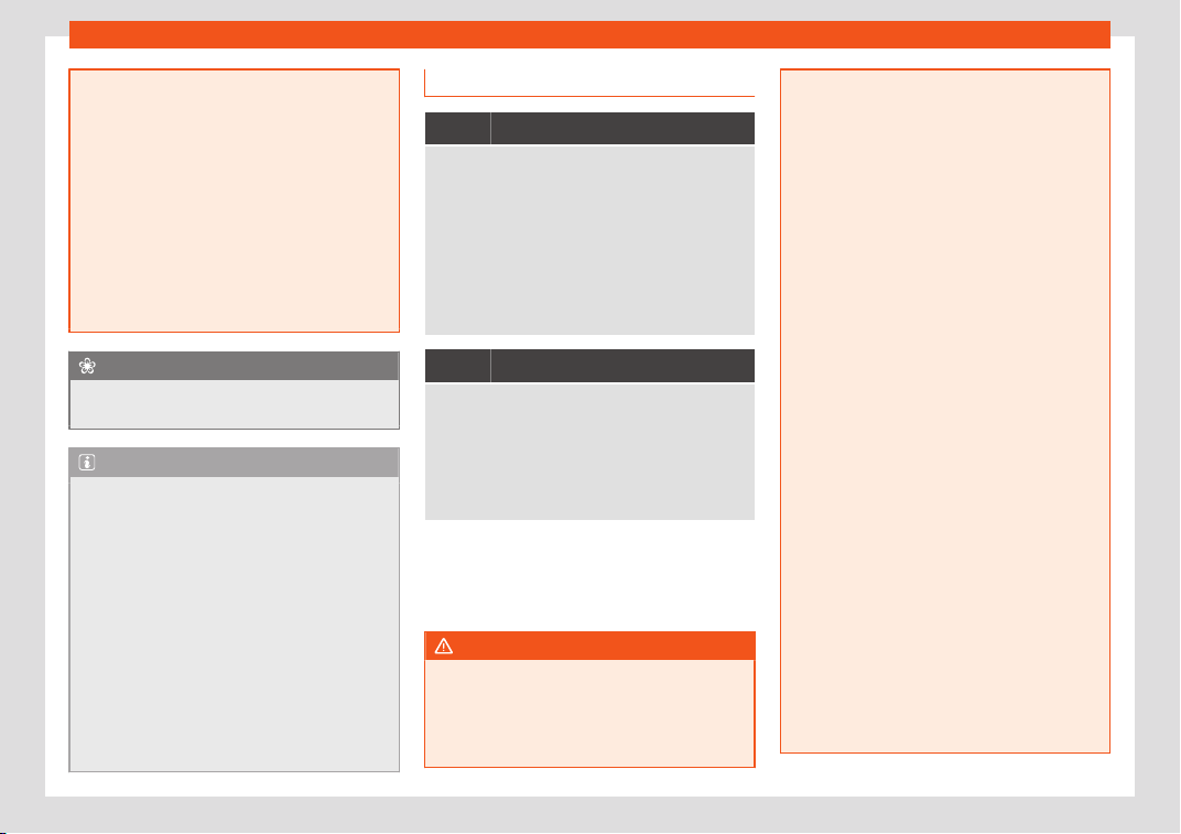
Practical tips
●
Tyre pr
essure should be that indicated on
the label when the tyres are cold at all
times
›››
page 382.
●
Regularly check the cold inflation pres-
sure of the tyres. If necessary, change the
tyre pressure of the vehicle tyres while they
are cold.
●
Regularly check your tyres for damage
and wear.
●
Never exceed the maximum permitted
speed or loads specified for the type of
tyre fitted on your vehicle.
For the sake of the environment
Under-inflated tyres lead to increased fuel
consumption and tyre w
ear.
Note
●
Driving for the first time with new t
yres at
a high speed can cause them to slightly ex-
pand, which could then produce an air
pressure warning.
●
Only replace used tyres with those au-
thorised by SEAT for the corresponding
type vehicle.
●
Do not only rely on the tyre monitoring
system. Regularly check your tyres to en-
sure that the tyre pressure is correct and
that the tyres are not damaged due to
puncture, cuts, tears and impacts/dents.
Remove objects from the tyres only when
they have not pierced the tyres.
Tyre control lamp
It lights up
The tyre pressure in one or more wheels has clearly
gone down from the tyre pressure set by the driver or
the tyre has structural damage.
Additionally, an audible warning can be heard and a
text message is displayed on the instrument panel
display.
Stop the vehicle! Reduce speed immediately!
Stop the vehicle safely as soon as possible. Avoid
sudden manoeuvres and braking! Check all tyres
and pressures. Replace any damaged tyres.
Flashes
Fault in the system.
The control lamp fl
ashes for approximately one mi-
nute and then lights up permanently.
If tyre pressure is correct, switch the ignition off and
on again. If the control lamp remains lit up, the tyre
monitoring indicator can be calibrated. Have the sys-
tem checked by a specialised workshop.
Several control and warning lamps light up
f
or a f
e
w seconds when the ignition is switch-
ed on while the function is verified. They will
switch off after a few seconds.
WARNING
When the tyres are inflated at different
pressures or at a pr
essure that is too low
then a tyre may be damaged resulting in a
loss of control of the vehicle and a serious
or fatal accident.
●
If the warning lamp
lights up, stop im-
mediately and check the tyres.
●
If the tyres are inflated at different pres-
sures or if a tyre pressure is too low, this will
increase tyre wear, negatively affecting ve-
hicle stability and increasing braking dis-
tances.
●
If tyres are inflated at different pressures
or a tyre pressure is too low, a tyre may be
damaged and burst resulting in a loss of
control of the vehicle.
●
The driver is responsible for ensuring that
all of the vehicle tyres are correctly infla-
ted to the right pressure. The recommen-
ded tyre pressure is indicated on the label
›››
page 382.
●
The tyre monitoring system can only op-
erate correctly if all of the tyres are infla-
ted to the correct pressure when cold.
●
Driving with tyres at the wrong pressure
can damage them and result in an acci-
dent. Ensure that the tyre pressures of all
the tyres correspond to the vehicle load.
●
Before starting a journey, always inflate
tyres to the correct pressure.
●
Tyres with insufficient pressure are sub-
jected to more flexing. Due to this, the tyre
could become excessively hot, causing
tread separation and also tyre blow-out.
●
With an overloaded vehicle at high
speed, the tyres can overheat and burst re-
sulting in a loss of vehicle control.
362
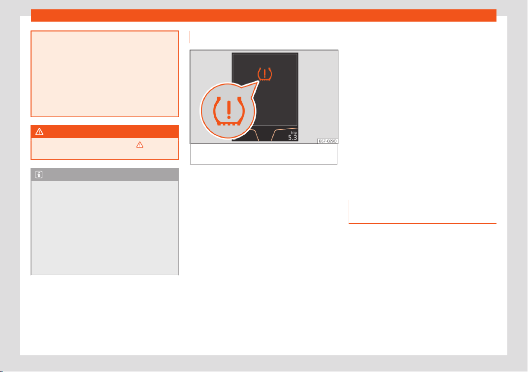
Wheels
●
Tyre pr
essures which are too high or too
low reduce the useful life of the tyre, affect-
ing vehicle performance.
●
If a tyre has not been punctured and it
does not have to be changed immediately,
drive to the nearest specialised workshop
at a moderate speed and have the tyre
checked and inflated to the correct pres-
sure.
WARNING
Observe the safety warnings
›
››
in Con-
trol and warning l
amps on page 123.
Note
●
If excessiv
ely low tyre pressure is detec-
ted with the ignition on, an audible warning
will sound. In the event that there is a fault
in the system, an audible warning will
sound.
●
Driving on dirt tracks for a long period of
time or driving in a sporty style can tempo-
rarily deactivate the TPMS. The control
lamp shows a fault, but disappears when
road conditions or the driving style change.
Tyre monitoring indicator
Fig. 309
Instrument panel: warning of loss of
t
yr
e pr
essure.
The tyre monitor indicator compares wheel
r
e
v
olutions and, with this information, the
tread of each wheel using the ABS sensors. If
the rolling circumference of one or more
wheels has changed, the tyre monitoring indi-
cator will indicate this on the instrument pan-
el through a warning lamp and a warning to
the driver
›››
Fig. 309. When only one specific
tyre is affected, its position within the vehicle
will be indicated.
Loss of pressure: Check left
tyre pressure!
Wheel tread change
The wheel tread changes when:
●
Tyre pressure is manually changed
●
Tyre pressure is insufficient
●
Tyre structure is damaged
●
The vehicle is unbalanced because of a
load
●
The wheels on an axle are subject to a
heavier load (e.g. with a heavy load).
●
The vehicle is fitted with snow chains
●
The temporary spare wheel is fitted
●
The wheel on one axle is changed
There may be a delay in the reaction of the
tyre monitoring indicator or it may not indi-
cate anything under certain circumstances
(e.g. sporty driving, snow-covered or un-
paved roads, or when driving with snow
chains).
Calibrating the tyre monitoring in-
dicator
After changing the tyre pressure or replacing
one or mor
e wheel
s, the t
yre monitoring indi-
cator must be recalibrated. Do the same, for
example, when the front and rear wheels are
swapped.
●
Switch the ignition on.
»
363
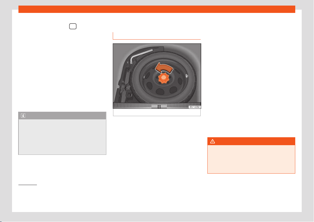
Practical tips
●
St
or
e the ne
w tyre pressure in the Easy
Connect
1)
system with the
> SETTINGS
function butt
on
›
›
›
page 35.
●
In vehicles without a radio: press and hold
down the button , with the ignition on,
until an acoustic signal is heard.
When driving, the system self-calibrates the
tyre pressure provided by the driver and the
wheels fitted. After a long journey with varied
speeds the programmed values are collected
and monitored.
With the wheels under very heavy loads, the
tyre pressure must be increased to the total
recommended tyre pressure before the cali-
bration
›››
page 382.
Note
●
The tyre monit
oring indicator does not
function when there is a fault in the ESC or
ABS
›››
page 248.
●
An erroneous indication may be given
when snow chains are in use because they
increase the tread of the wheel.
Temporary spare wheel
Gener
al inf
ormation
Fig. 310 Spare wheel: floor panel raised.
The temporary spare wheel has been de-
signed t
o be used f
or short periods of time
.
Have the tyres checked and replaced as
soon as possible at a SEAT Official Service or
at a specialised workshop.
Please note the following restrictions when
using the compact temporary spare wheel.
The compact temporary spare wheel is de-
signed specifically for this model. For this rea-
son, do not use a temporary spare wheel
from a different type of vehicle.
Removing the temporary spare wheel
–
Lift and hold up the floor panel to remove
the temporary spare wheel.
–
Turn the thumb wheel anti-clockwise
›››
Fig. 310.
–
Take out the temporary spare wheel.
Chains
For technical reasons, snow chains must not
be used on the temporary spare wheel.
If you have a puncture on one of the front
wheels when using snow chains, fit the tem-
porary spare wheel in place of one of the rear
wheels. Fit the snow chains on the rear wheel
that you have removed and replace the
punctured front wheel with this wheel.
WARNING
●
After fitting the tempor
ary spare wheel,
check the tyre pressures as soon as possi-
ble. Failure to do so may cause an acci-
dent. The tyre pressure is listed on the back
of the left front door frame
›››
Fig. 306.
1)
In vehicles that are not equipped with the Easy
Connect system, the swit
ch for adjusting tyre
pressure is located in the centre console next to
the hazard warning lights.
364
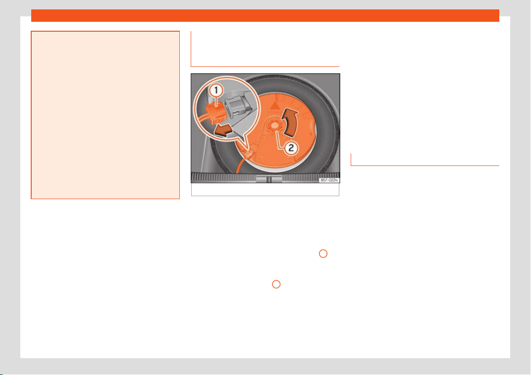
Wheels
●
Do not drive at ov
er 80 km/h (50 mph)
when the temporary spare wheel is fitted
on the vehicle: risk of accident!
●
Never travel more than 200 km using a
temporary spare wheel.
●
Avoid heavy acceleration, hard braking
and fast cornering: risk of accident!
●
Never use more than one temporary
spare wheel at the same time, risk of acci-
dent.
●
No other type of tyre (normal summer or
winter tyre) may be fitted on the compact
temporary spare wheel rim.
●
If you are driving using the spare wheel,
the ACC system could automatically
switch off during the journey. Switch off the
system when starting off.
Getting the spare wheel out of ve-
hicl
es with BEAT
S Audio 10 speak
-
ers (with
subwoofer
)*
Fig. 311
In the boot: remove the subwoofer.
To remove the spare wheel, you must first re-
mo
v
e the sub
woofer.
●
Lift and secure the luggage compartment
floor as described in
›››
page 173.
●
Disconnect the subwoofer
›››
Fig. 311
1
speaker cable.
●
Turn the securing wheel in an anti-clock-
wise dir
ection
›
›
›
Fig. 311
2
.
●
Remove the sub
w
oof
er speaker and the
spare wheel.
●
When re-mounting the spare tyre, place the
subwoofer on the base of the wheel rim with
care. When doing so, the tip of the “FRONT”
arrow on the subwoofer should point forward.
●
Reconnect the speaker cable and firmly ro-
tate the securing wheel clockwise so that the
subwoofer system and wheel are firmly in
place.
Winter service
Winter tyres
–
Winter tyres must be fitted on all f
our
wheel
s.
–
Only use wint
er tyres that are approved for
your vehicle.
–
Please note that the maximum permissible
speed for winter tyres may be lower than
for summer tyres.
–
Also note that winter tyres are no longer ef-
fective when the tread is worn down.
–
After fitting the wheels you must always
check the tyre pressures. When doing so,
take into account the correct tyre pressures
listed on the rear of the front left door frame
›››
page 358.
In winter road conditions winter tyres will con-
siderably improve vehicle handling. The
»
365
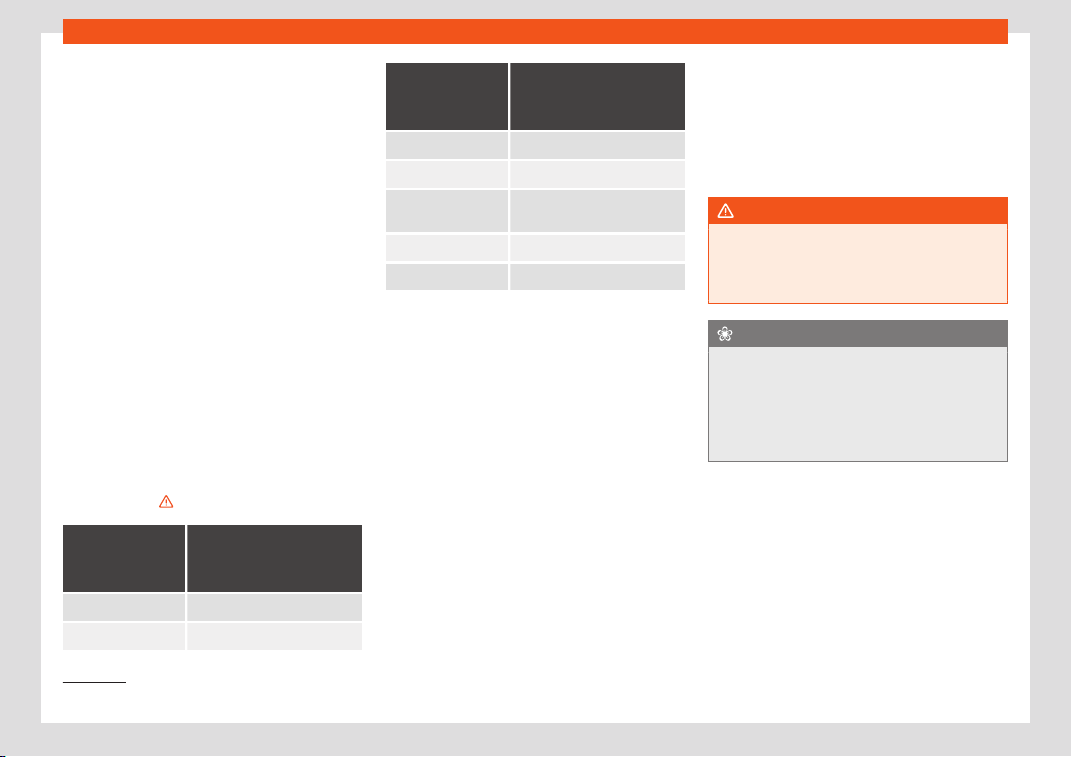
Practical tips
design of summer tyres (width, rubber com-
pound, tr
ead patt
ern) giv
es less grip on ice
and snow. This applies particularly to vehicles
equipped with wide section tyres or with
high speed tyres (code letters H, V or Y on
the sidewall).
Only use winter tyres of the correct type ap-
proved for your vehicle. The sizes of these
tyres are specified in the vehicle's documents
(e.g. EC Certificate of Conformity or COC
1)
).
The vehicle documentation varies depending
on the country of residence. See also
›››
page 360.
Winter tyres lose a great deal of their proper-
ties when the tread is worn down to a depth
of 4 mm.
The performance of winter tyres is also se-
verely impaired by ageing, even if the tread is
still much deeper than 4 mm.
Winter tyres are subject to the following max-
imum speed limits according to speed rating
code letter:
›››
Speed rating
code letter
›
››
page 360
Maximum speed limit
Q 160 km/h (100 mph)
S 180 km/h (112 mph)
Speed rating
code letter
›
››
page 360
Maximum speed limit
T 190 km/h (118 mph)
H 210 km/h (130 mph)
V
240 km/h (149 mph) (please
note rel
evant restrictions)
W 270 km/h (168 mph)
Y 300 km/h (186 mph)
Vehicles capable of exceeding these speeds
must hav
e an appr
opriat
e sticker attached
so that it is visible to the driver. Suitable stick-
ers are available from the SEAT Official Serv-
ice and specialised workshop. Please note
the regulations to this effect in your country.
“All-weather” tyres can also be used instead
of winter tyres.
Using winter tyres with V-rating
Please note that the generally applicable
240 km/h (149 mph) speed for winter tyres
with the letter V is subject to technical re-
strictions; the maximum permissible speed
for your vehicle may be significantly lower.
The maximum speed limit for these tyres de-
pends directly on the maximum axle weights
for your car and on the listed weight rating of
the tyres being used.
It is best to contact a SEAT Official Service to
check the maximum speed which is permissi-
ble for the V-rated tyres fitted on your car on
the basis of this information.
WARNING
Exceeding the maximum speed permitted
for the winter t
yres fitted on your car can
cause tyre failure, resulting in a loss of con-
trol of the vehicle – risk of accident.
For the sake of the environment
Summer tyres should be fitted again as
soon as possible after the wint
er period;
they give better handling on roads which
are free of snow and ice. Summer tyres per-
form with less rolling noise, tyre wear and –
most important – reduce fuel consumption.
1)
COC = certificate of conformit
y.
366
Service
Maintenance
Service
Service int
erv
al
s
Servicing and Digital Maintenance
Plan
Log of services performed (“Digital Main-
tenance Plan”)
The SEAT deal
ership or a specialised work-
shop records Service receipts in a central
system. Thanks to this comprehensive docu-
mentation of the service history, it is possible
to reproduce the services performed any
time. SEAT recommends requesting a Service
receipt after every service carried out con-
taining all the services carried out on the sys-
tem.
Whenever there is a new service the receipt is
replaced with a current one.
The Digital Maintenance Plan is not avail-
able in some markets. In this case, your
SEAT dealer will inform you about the cur-
rent documentation of the work.
Service works
In the Digital Maintenance Pl
an, your SEAT
authorised service or specialised workshop
documents the following information:
●
When each one of the services was carried
out.
●
Whether a specific repair has been sugges-
ted, e.g. changing the brake pads in the near
future.
●
If you have expressed a special request for
the maintenance. Your Service Advisor will
write the work order.
●
The components or fluids that were
changed.
●
The date of the next service.
The Long Life Mobility Warranty is valid until
the next inspection. This information is docu-
mented in all checks performed.
The type and the volume of the service may
vary from one vehicle to another. A special-
ised workshop will be able to provide specific
information on the jobs for your vehicle.
WARNING
If the services are insufficient or not per-
formed and if the service interv
als are not
observed, the vehicle may be immobilised
in traffic cause an accident and severe in-
juries.
●
Make sure that any r
epairs are carried
out by a SEAT authorised service or speci-
alised workshop.
CAUTION
SEAT cannot be held liable for any damage
t
o the vehicl
e due to insufficient work or of
lack of availability of spare parts.
Note
Regular services on the vehicle not only
maintain its value
, but also its correct oper-
ation and road safety. For this reason, con-
duct the services in accordance with SEAT
guidelines.
Fixed Service or Flexible Service
Services are classified as oil change service
and inspection. The service int
erv
al displ
ay
on the instrument panel display serves as a
reminder of the next service.
Depending on the features, the engine and
the conditions of use of the car, either the
Fixed service or the Flexible service will be
applied for an oil change service..
How to know which type of service needs
to his vehicle
●
Check the tables below:
»
367

Maintenance
Oil change service
a)
PR No.
Type of
service
Service interval
QI1
Fixed
Every 5000 km or after
1 year
b)
QI2
Every 7500 km or after
1 year
b)
QI3
Every
10000 km or after
1 year
b)
QI4
Every
15000 km or after
1 year
b)
QI6 Fle
xible
According to the service in-
t
erv
al displ
ay
a)
The data are based on normal conditions of use.
b)
Whatever happens first.
Inspection Service
a)
According to the service interval display
a)
The data are based on normal conditions of use.
Bear in mind the inf
ormation about the speci-
fications of the engine oil accor
ding t
o the
VW standard
›››
page 47.
Particular characteristics of the Flexible
Service
Regarding the Flexible Service, the oil
change service only has to be performed
when the vehicle needs it. To calculate when
you have to carry out this service, take into
account the individual conditions of use and
personal driving style. A major component of
the flexible service the use of LongLife oil in-
stead of conventional engine oil.
Bear in mind the information about the speci-
fications of the engine oil according to the
VW standard
›››
page 47.
If you do not want to the flexible service
you can select the fixed service However,
a fixed service may affect service costs
The Service Advisor will gladly advise you.
Service intervals display
At SEAT, the dates of the services are indica-
ted by the service interval display on the in-
strument panel
›››
page 119 or in the Vehi-
cle settings menu of the infotainment sys-
tem
›››
page 35. The service interval dis-
play gives information for service dates that
involve an engine oil change or an inspection.
When the time for the corresponding service
comes, additional work required, such as the
change of brake fluid and the spark plugs,
can be carried out.
Information on the conditions of
use
The service intervals and groups are usually
based on normal conditions of use.
If, on the other hand, the vehicle is under ad-
v
erse conditions of use
, some of the w
ork
must be carried out before the next service
period or even between service intervals.
Conditions of use adverse include:
●
The use of fuel with a high sulphur content.
●
Frequent short trips.
●
Letting the engine idle for a long period of
time, as in the case of taxis.
●
Using the vehicle in areas with thick dust.
●
Frequent driving with a trailer (depending
on equipment).
●
Using the vehicle mostly in situations with a
lot of traffic and stops (e.g. in a city).
●
Using the vehicle mostly in winter.
This applies especially for the following
parts (depending on equipment):
●
Dust and pollen filter
●
Air Care allergen filter
●
Air filter
●
Toothed chain
●
Particulate filter
●
Engine oil
The Service Advisor of your specialised
workshop will gladly inform you about the
need of performing service work between
368

Service
normal service intervals, always considering
the conditions of use of your v
ehicl
e
.
WARNING
If the services are insufficient or not per-
formed and if the service interv
als are not
observed, the vehicle may be immobilised
in traffic and cause accidents and severe
injuries.
●
Have the services conducted at author-
ised SEAT services or specialised work-
shops.
CAUTION
SEAT cannot be held liable for any damage
to the vehicl
e due to insufficient work or of
lack of availability of spare parts.
Sets of services
Sets of services include all the maint
enance
w
orks
needed to ensure the safety and the
smooth running of the vehicle (depending on
the conditions of use and the features of
the vehicle, such as the engine, gearbox, or
operating fluids). Maintenance services are
divided into inspection and review services.
Consult the details of the jobs required for
your vehicle at:
●
Your SEAT authorised service
●
Your specialised workshop
Due to technical reasons (continuous devel-
opment of components) the sets of services
may vary. Your SEAT authorised service or
specialised workshop is always receiving up-
dates in time.
Additional service offers
Approved spare parts
Original SEAT Spare Parts have been con-
ceiv
ed f
or their v
ehicles and approved by
SEAT, with a special emphasis on safety.
These parts correspond exactly to the manu-
facturer's requirements in terms of design,
accuracy of the measurements and materi-
als. The original SEAT Spare Parts have been
conceived exclusively for your vehicle. For this
reason, we always recommend the use of
Original SEAT Spare Parts. SEAT cannot be
held liable for the safety and suitability of
parts from other manufacturers.
Approved spare parts
Approved spare parts, following the manu-
f
act
ur
er's requirements, are an additional
service to you, offering the possibility of re-
placing complete sets, such as: light engine,
gearboxes, heads, control units, electrical
components, etc.
These parts are, approved parts, and are the
same as the factory parts, which are also ap-
proved spare parts.
Original accessories
We recommend you only use SEAT Original
Accessories and SEAT approv
ed accessories
for your vehicle. The reliability, safety and
suitability of these accessories have been in-
spected specifically for this type of vehicle.
SEAT cannot be held liable for the safety and
suitability of parts from other manufacturers.
SEAT Service Mobility (SEAT
Service Mobility)
Since the moment you purchase your SEAT
v
ehicl
e you will be abl
e to enjoy the benefits
and coverage of the SEAT Mobility Service.
For the first two years after the purchase,
your new SEAT vehicle is automatically cov-
ered by the SEAT Mobility Service without ad-
ditional costs.
If you wish to enjoy this service after this peri-
od, you can extend SEAT Mobility as long as
you carry out the recommended Inspection
and Maintenance Services at a SEAT Author-
ised Service.
»
369
Maintenance
If your SEAT vehicle is immobilised due to a
f
ault or an accident, our assist
ance services
will help you k
eep moving.
Take into account that the SEAT Mobility
Service differs depending on the country in
which the vehicle was purchased. For further
information ask your SEAT dealership or the
SEAT website in your country.
Warranty
Fault-free operation warranty
SEAT Authorised Services ensure the perfect
condition of ne
w v
ehicl
es. Check the pur-
chase agreement or complementary addi-
tional documentation provided by your Tech-
nical Service to see the conditions and the
terms of the warranty. Consult further infor-
mation in this regard in your SEAT Official
Service.
Vehicle maintenance
Maint
enance and cl
eaning
Basic consider
ations
Regular and careful care helps to maintain
the value of your vehicl
e. In addition, it may
become a prerequisite to demand the war-
ranty in the event of corrosion damage and
deficiencies in the paint coat of the body-
work.
Specialised workshops have the necessary
care products. Please follow the instructions
for application on the packaging.
WARNING
●
Cleaning products and other mat
erials
used for car care can be damaging to your
health if misused.
●
Always keep care products in a safe
place, out of the reach of children. Danger
of poisoning!
For the sake of the environment
●
When purchasing car care pr
oducts,
chose products that are compatible with
the environment.
●
The waste from car-care products should
not be disposed of with ordinary household
waste.
Washing the vehicle
The longer you take to clean the tanks, e.g.
remains of insects, bird e
xcrements, tree resin
or anti frost salt adhered to your vehicle, the
more damage it can cause to the surface.
High temperatures, for instance strong sun-
light, further intensify the damage.
Before washing the car, soften the dirt using
plenty of water.
To remove encrusted dirt such as insects, bird
droppings or tree resin, use a lot of water and
a microfibre cloth.
Have the underside of the vehicle washed af-
ter the end of the anti frost salts in winter.
High pressure cleaners
When washing the vehicle with a high-pres-
sure cleaner, always follow the operating in-
structions for the equipment. This applies
particularly to the operating pressure and the
distance between the spraying water. Do not
aim the jet directly to the side window gas-
kets, doors, covers or the panoramic sun-
roof*; the same applies to tyres, rubber ho-
ses, soundproofing material, sensors* or
camera lenses*. Keep a distance of at least
40 cm.
Do not remove snow and ice with a high-
pressure cleaner.
370
Vehicle maintenance
Do not use a nozzle that sprays the water out
in a dir
ect str
eam or one that has a r
otating
jet for forcing off dirt.
The water temperature must not exceed
60°C.
Automatic car wash tunnels
Spray the vehicle before starting the car
wash.
Make sure that the windows and the panor-
amic sunroof* are closed and the windscreen
wipers are deactivated. Bear in mind the in-
structions of the car wash tunnel operator,
especially if your vehicle has detachable
parts.
Use of car washes without brushes if possible.
Washing by hand
Clean your vehicle from top to bottom with a
soft sponge or with a brush. Only use clean-
ing products that do not contain solvents.
Washing vehicles with a matte paint by
hand
To prevent damage to the vehicle when
washing it, first remove the thicker dust and
dirt. To remove traces of insects, grease and
fingerprints, it is best to use a special cleaner
for matte paint.
Apply the product with a microfibre cloth. To
avoid damaging the surface of the paint, do
not apply too much pressure.
Rinse with plenty of water. Then clean it with
a neutral cleaning product and a soft microfi-
bre cloth.
Rinse the vehicle again with plenty of water
and then leave it to dry. Remove traces of
water with a leather cloth.
WARNING
●
Only wash the vehicl
e with the ignition
switched off or according to the specifica-
tions of the car wash tunnel operator. Risk
of accident!
●
When cleaning the underbody or the in-
side of the wheel arches, protect yourself
from sharp or pointy metal parts. Risk of
cut!
●
After cleaning the brakes could act more
slowly due to moisture or, in winter, the ice
on the brake discs and pads. Risk of acci-
dent! In this case the brakes should be
dried by pressing the brake pedal several
times.
CAUTION
●
Before w
ashing the vehicle in an auto-
matic car wash, please make sure to re-
tract the exterior mirrors to prevent them
from being damaged. Electric exterior rear-
view mirrors must always be folded/de-
ployed electrically!
●
Do not w
ash the vehicle in direct sunlight.
Risk of damaging the paint job!
●
Do not use sponges, abrasive household
sponges or similar to clean insect remains.
Risk of damaging the surface!
●
Vehicle parts with matte paint:
–
Do not use polish or hard wax. Risk of
damaging the surface!
–
Never select washing programs that in-
clude the use of wax. This could dam-
age the appearance of matte paint.
–
Do not put stickers or magnets on parts
with matte paint, as removing them
may damage the paint.
For the sake of the environment
The car should only be washed in special
wash bays. These places ar
e prepared to
prevent oily water from getting into the
public drains.
Cleaning and maintenance instruc-
tions
The cleaning and maintenance of individual
components of the v
ehicl
e can be check
ed in
the following tables. The contents should be
understood merely as a recommendation. Go
to your specialised workshop if you have
»
371
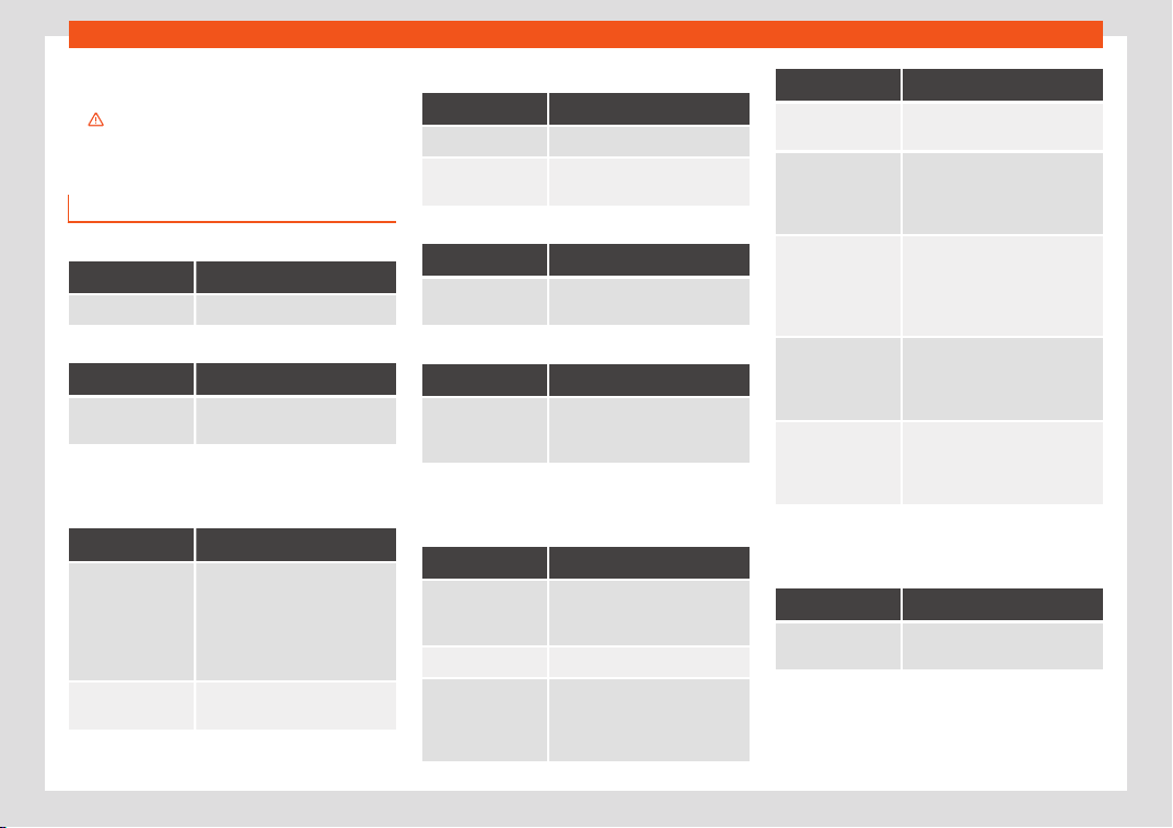
Maintenance
special questions or parts that are not listed.
T
ak
e he gener
al considerations into account
›››
in Take special care with... on
page 375.
Exterior cleaning
Windscreen wipers
Problem Solution
Dirt Soft cloth with wipers
Headlights / Tail lights
Problem Solution
Dirt Soft sponge with neutral soap
solution
a)
a)
Neutral soap solution: two tablespoons maximum in
1 litr
e of w
at
er
Sensors / Camera lenses
Problem Solution
Dirt
Sensors: soft cloth with clean-
ing pr
oduct which does not
contain solvents
Camera lenses - soft cloth with
cleaning product with no alco-
hol content
Snow/ice
Hand brush/Anti frost spray
with no solvents
Wheels
Problem Solution
Anti frost salt Water
Brake abrasion
dust
Acid-free special cleaning
product
End exhausts
Problem Solution
Anti frost salt Water, if a steel cleaning prod-
uct is required
Covers / Trims
Problem Solution
Dirt Neutral soap solution
a)
, if a
steel cleaning pr
oduct is re-
quired
a)
Neutral soap solution: two tablespoons maximum in
1 litr
e of w
at
er
Paint
Problem Solution
Flaws in the paint
Check the paint's colour code
in an authorised service and re-
stor
e with a touch-up pencil
Spilled fuel Immediately rinse with water
Environmental rust
tank
Apply rust remo
ver and then
apply hard wax. Go you your
specialised w
orkshop if you
have any queries
Problem Solution
Corrosion
Have your specialised work-
shop take car
e of this
The water does
not create dr
op-
lets on the clean
paint
Maintain with hard wax (at
least 2 times a year)
No shine de-
spite sober main-
tenance/paint
T
reat with suitable wax and ap-
ply paint preservativ
e after-
wards if the wax used does not
contain preservative ingredi-
ents
Tanks, e.g. insect
remains, bird
dr
oppings, tree
sap, road salt
Immediately soften with water
and remove with a microfibre
cloth
Fat-based dirt,
e.g. cosmetic
products or
sunscreen
Delete immediately with a neu-
tral soap solution
a)
and a soft
cloth
a)
Neutral soap solution: two tablespoons maximum in
1 litr
e of w
at
er
Carbon fibre parts
Problem Solution
Dirt Clean the same way as pain-
ted parts
››
›
page 370
372
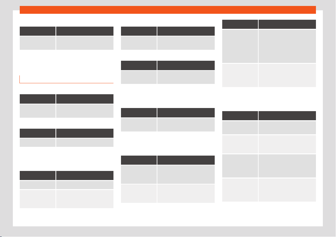
Vehicle maintenance
Decoration slides
Problem Solution
Dirt Soft sponge with neutral soap
solution
a)
a)
Neutral soap solution: two tablespoons maximum in
1 litre of wat
er
Interior cleaning
Windows
Problem Solution
Dirt Apply windscreen cleaner and
then dry with a cloth
Covers / Trims
Problem Solution
Dirt Neutral soap solution
a)
a)
Neutral soap solution: two tablespoons maximum in
1 litr
e of w
at
er
Plastic parts
Problem Solution
Dirt Damp cloth
Encrusted dirt Neutral soap solution
a)
, if pos-
sible solvent-free plastic clean-
er
a)
Neutral soap solution: two tablespoons maximum in
1 litr
e of w
at
er
Displays/instrument panel
Problem Solution
Dirt Soft cloth with a liquid crystal
display cleaner
Control panels
Problem Solution
Dirt Soft brush, then soft cloth with
neutral soap solution
a)
a)
Neutral soap solution: two tablespoons maximum in
1 litre of wat
er
Seat belts
Problem Solution
Dirt Neutral soap solution
a)
, al-
lo
wed to dry before retracting
a)
Neutral soap solution: two tablespoons maximum in
1 litr
e of w
at
er
Fabrics, artificial, Alcantara leather
Problem Solution
Dirt particles ad-
hered to the sur
-
face
Vacuum cleaner
Water-based dirt,
e.g. coffee
, tea,
blood etc.
Absorbent cloth and neutral
soap solution
a)
Problem Solution
Grease-based
dirt, e.g. oil, mak
e-
up, etc.
Apply a neutral soap solution
a)
.
Absorb the dissolved grease
and paint particles drying with
an absorbent cloth, in case you
must treat it with water after-
wards
Special dirt, e.g.
pens, nail polish,
dispersion paint,
shoe cream etc.
Special st
ain remove: dry with
an absorbent cloth, if applica-
ble, apply neutral soap solution
afterwards
a)
a)
Neutral soap solution: two tablespoons maximum in
1 litr
e of w
at
er
Natural leather
Problem Solution
Recent dirt Cotton cloth with neutral soap
solution
a)
Water-based dirt,
e.g. coffee, tea,
blood etc.
Recent stains: absorbent cloth
Dry stains: leather cleaner
Grease-based
dirt, e.g. oil, mak
e-
up, etc.
Recent stains: absorbent cloth
and leather cleaner
Dry stains: grease dissolving
spray
Special dirt, e.g.
pens, nail polish,
dispersion paint,
shoe cream etc.
St
ain remover suitable for
leather
»
373

Maintenance
Problem Solution
Care Apply preservative cream regu-
larly to pr
otect from sunlight.
Use a colour preservative if re-
quired
a)
Neutral soap solution: two tablespoons maximum in
1 litre of wat
er
Carbon fibre parts
Problem Solution
Dirt Clean like plastic parts
Take special care with...
Headlights/tail lights
●
Do not clean the headlights/tail lights with
a dry cl
oth or sponge
.
●
Do not use cl
eaning products that contain
alcohol. Risk of cracks!
Wheels
●
Do not use for paint wax or other abrasive
products.
●
If the protective coating on the paint of the
rim has been damaged due to stone impacts,
scratches, etc., the damage should be re-
paired immediately.
Camera lenses
●
Do not use hot or warm water to remove ice
or snow from the camera lenses. Risk of
cracking the lens!
●
To clean the camera lens, never use abra-
sive cleaning products or products with alco-
hol. Risk of scratches and cracks!
Windows
●
Remove snow and ice from windows and
exterior mirrors with a plastic scraper only. To
avoid scratches, the scraper should only be
pushed in one direction and not moved to
and fro.
●
Never remove snow or ice from windows
and rearview mirrors with warm or hot water.
Risk of cracks on the windows!
●
To prevent damage to the heating of the
rear window, do not put stickers over the
heating elements.
Covers/trims
●
Do not use cleaning products or chrome
based cleaning agents.
Paint
●
The vehicle must be free from dirt and dust
before applying wax or care products. Risk of
scratches!
●
Do not apply wax or care products if the
vehicle is exposed to direct sunlight. Risk of
damaging the paint job!
●
The ambient rust deposits must not be re-
moved through friction. Risk of damaging the
paint job!
●
Remove cosmetic products and sunlight
immediately. Risk of damaging the paint job!
Displays/instrument panel
●
The screens, the instrument panel and the
trim around it must not be cleaned dry. Risk of
scratches!
●
Make sure that the instrument panel is
switched off and cooled down before clean-
ing.
●
Make sure that no liquid leaks between the
instrument panel and the trim. Risk of dam-
age!
Control panels
●
Make sure that no liquid leaks into the con-
trol panels. Risk of damage!
Seat belts
●
Do not remove the seat belts to clean them.
●
Seat belts and their components must nev-
er be cleaned with chemical products, nor
should they be allowed to come into contact
with corrosive liquids, solvents or sharp ob-
jects. Risk of damaging the fabric!
●
If you find any damage to the belt webbing,
belt fittings, the belt retractor or the buckle,
ask your specialised workshop to replace the
belt in question.
374
Vehicle maintenance
Fabrics/artificial leather/Alcantara leath-
er
●
Do not treat artificial leather/Alcantara
l
eather with l
eather cl
eaning products, sol-
vents, wax polish, shoe cream, stain removers
or similar products.
●
If the stain is very hard to remove, take the
vehicle to a specialised workshop to have it
removed there. This will prevent damage.
●
Do not use steam cleaners, brushes, hard
sponges, etc. to clean.
●
Do not turn on seat heating* to dry the
seats.
●
Sharp objects on clothing, such as zips, riv-
ets or belts can damage the surface.
●
Open Velcro, e.g. on clothes can damage
the seat upholstery. Make sure that Velcro
fasteners are closed.
Natural leather
●
Never use solvents, wax polish, shoe cream,
spot removers or similar products on leather.
●
Sharp objects on clothing, such as zips, riv-
ets or belts can damage the surface.
●
Do not use steam cleaners, brushes, hard
sponges, etc. to clean.
●
Do not turn on seat heating* to dry the
seats.
●
Avoid exposing leather to direct sunlight for
long periods, otherwise it may tend to lose
some of its colour. If the car is left for a pro-
longed period in the bright sun, it is best to
cover the leather.
WARNING
Do not use water-repellent coatings on the
windscreen. In bad visibility conditions
such as humid w
eather, darkness or when
the sun is in its lowest point, visibility may
be impacted. Risk of accident! Such coat-
ings can also cause the windscreen wiper
blades to make noise.
Note
●
Remains of insects can be remo
ved much
more easily with previously treated paint.
●
Regular car care treatments can prevent
deposits of ambient rust.
Remove the vehicle from traffic
If you want to leave your vehicle stationary
f
or a l
ong period of time
, contact a qualified
workshop. They will gladly inform you about
the necessary measures, such as anti-corro-
sion protection, Service and storage.
Also take into account instructions regarding
the vehicle's battery
›››
page 354.
375

Information for the user
Information for the user
Inf
ormation f
or the user
Ev
ent Data Recorder
Description and operation
Your vehicle has an event data recorder
(EDR).
The EDR’s function is to r
ecord data in the
event of a mild or serious accident. These da-
ta are used to support the analysis of how dif-
ferent vehicle systems behaved.
The EDR records, over a reduced time range
(normally 10 seconds or less), dynamic driv-
ing data and data from the restraint systems,
such as:
●
How different vehicle systems worked.
●
Whether the driver and the occupants were
wearing their seat belts.
●
How har
d the acceleration or brake pedal
was pressed.
●
Vehicle speed.
These data will provide a better understand-
ing of the circumstances of the accident.
Data from the driving assist systems are also
recorded. This includes data such as whether
the systems were inactive or active and if
such action had an impact on the vehicle’s
dynamic behaviour, changing its path in the
aforementioned situations, accelerating or
decelerating the vehicle.
Depending on vehicle equipment, this in-
cludes data from systems such as:
●
Adaptive Cruise Control (ACC)
●
Emergency braking assistance system
(Front Assist).
●
Park Pilot system
●
Parking aid system (Park Assist).
●
Lane Assist
The EDR data are only recorded in specific
accident situations. No data are recorded in
normal driving conditions.
No audio or video data inside or around the
vehicle are recorded. Under no circumstan-
ces are personal data such as name, age, or
gender recorded. Nevertheless, third parties
(such as criminal proceedings authorities)
may relate the contents of the EDR data to
other data sources and create a personal
reference in the context of an accident inves-
tigation.
In order to read the EDR data it is necessary
to access (if legally permitted to do so) the
vehicle's ODB (“On-Board-Diagnose”) inter-
face while the vehicle is switched on.
SEAT will not have access to EDR data unless
the owner (or, in “Leasing” cases, the lessee
or hirer) gives their consent. There may be ex-
ceptions to this, depending on legal or con-
tractual provisions.
Due to legal requirements in safety-related
products, SEAT may use the EDR data for
field research and in order to improve vehicle
system quality. Any data used for the purpo-
ses of research will be treated anonymously
(in other words, no reference will be made to
the vehicle, their owner or the lessee/hirer).
Other important information
Recycling of electrical or electron-
ic devices
All electrical or electronic devices (EED) that
ar
e not permanently fitt
ed in the v
ehicle must
be marked with the following symbol:
This symbol indicates that EED must not be
discarded as home waste but through selec-
tive waste collection.
376
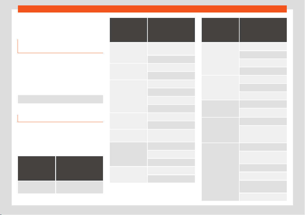
Information for the user
Information about the EU Di-
r
ectiv
e 2014/53/EU
Simplified EU compliance decl
ara-
tion
Your vehicle has different radioelectrical devi-
ces. The manufactur
ers of these devices de-
clare that they comply with Directive
2014/53/EU when legally required.
The full text of the EU compliance declaration
is available online at the following address:
www.seat.com/generalinfo
Table of correspondences
The table of correspondences will help you to
associat
e the name of the de
vice in the dec-
l
aration of compliance with the features of
the vehicle and the terminology used in the
on-board documentation.
Features of the
vehicle
Name of the de
vice
according to the dec-
laration of compli-
ance
Radiofrequency re-
mote control (v
ehicle)
FS09, FS12A, FS12P, FS1477,
FS94
Features of the
vehicle
Name of the de
vice
according to the dec-
laration of compli-
ance
Radio frequency re-
mote control (auxili-
ary heat
er)
Sender STH SEAT -
50000914
Telestart
Auxiliary heating 50000864 / D208L VW
Telestart
Bluetooth MIB2 Entry
MIB Standard 2
MIB2 Main-Unit
A580 / A270
Wireless hotspot MIB2 Main-Unit
A580 / A270
Keyless Access Sys-
t
em
MQB-B B
Radar sensors f
or as-
sistance systems
ARS4-B
MRRevo14F
BSD3.0
Central control unit 5WK50254
5WK50474
Features of the
vehicle
Name of the de
vice
according to the dec-
laration of compli-
ance
Infotainment system MIB2 Entry
MIB Standard 2
MIB2 Main-Unit
A580 / A270
Wireless charging WCH-183
WCH-185
5G0.980.611
Connection to the ex-
t
ernal antenna of the
car
UMTS/GSM-MMC
UMTS/GSM-MMC-AG2
Instrument panel eNSF
Immobilizer integrated in
dashboard module
instrument cluster
Antenna FM/AM Antenna Base
Antennas MQB27 Small/Big
family
Antennas KSA Small Fam III
5Q0.035.507 Roof Antenna
GNSS Antenna VAG
720166002
8S7.035.503.B
»
377
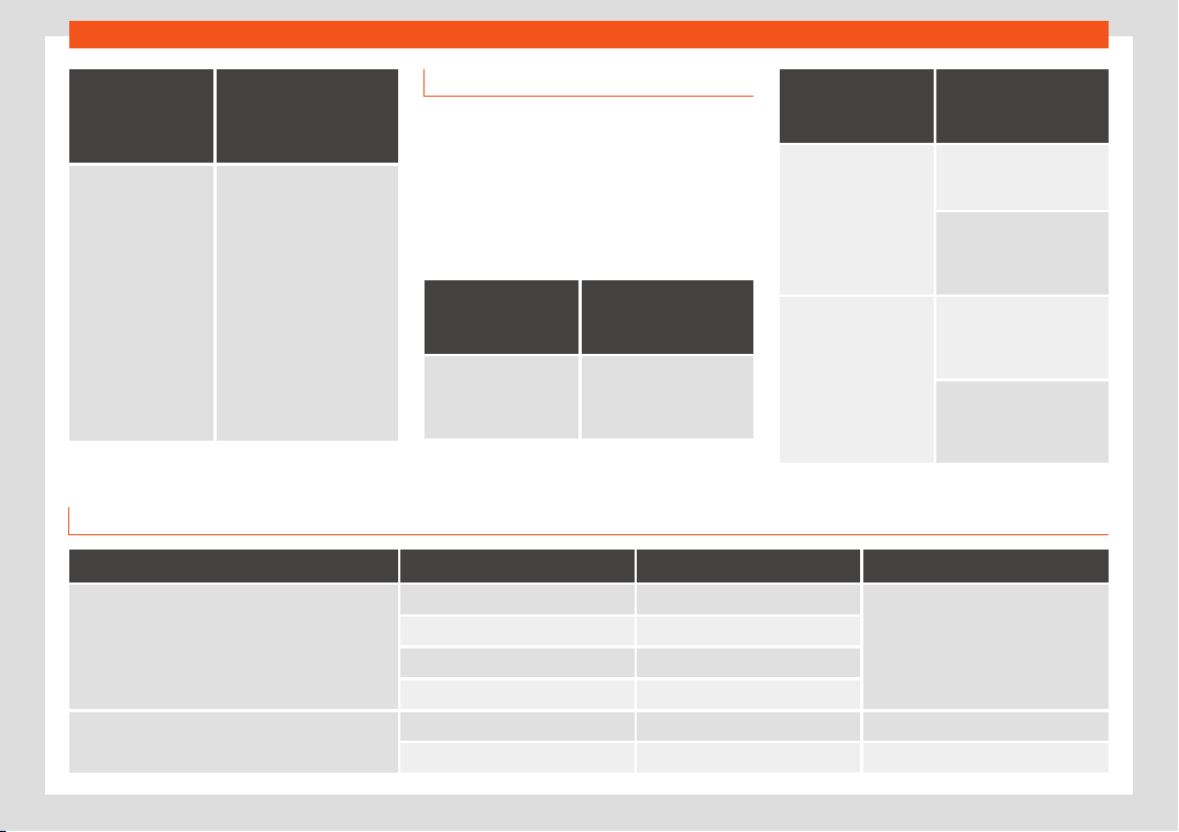
Information for the user
Features of the
vehicle
Name of the de
vice
according to the dec-
laration of compli-
ance
Antenna amplifiers 6F0.035.225
6F9.035.225
3V5.
035.577.A
7N0.035.552.J
7N0.035.552.K
7N0.035.552.Q
5F4.035.225
5F4.035.225.A
5F4.035.225.B
5F9.035.225
5F9.035.225.A
5F9.035.225.B
575.035.225
575.035.225.A
575.035.225.B
Addresses of the manufacturers
According to the Directive 2014/53/EU, all
rele
vant components must include the ad-
dress of the manufacturer.
The address of the manufacturers of compo-
nents that, due to their size or nature, cannot
include a sticker are listed below, as long as it
is legally required:
Radioelectrical
equipment fitted
in the vehicl
e
Addresses of the
manufacturers
Radiofrequency remote
control key
Hell
a KGaA Hueck & Co.
Rixbecker Straße 75
59552 Lippst
adt,
GERMANY
Radioelectrical
equipment fitted
in the vehicl
e
Addresses of the
manufacturers
Radio frequency re-
mote control (auxiliary
heat
er)
Digades gmbH
Äußere Weberstr
aße 20
02763 Zittau, GERMANY
Webasto Thermo &
Comfort SE
Friedrichshafener Str
. 9
82205 Gilching, GERMANY
Radar sensors for as-
sistance systems
ADC Aut
omotive Distance
Control Systems GmbH
P
eter-Dornier-Straße 10
88131 Lindau, GERMANY
Robert Bosch GmbH
Postfach 16 61
7
1226 Leonberg,
GERMANY
Frequency bands, station power
Radioelectrical equipment
a)
Frequency band Max. station power Valid for models
Radiofrequency remote control (vehicle)
433.05-434.78 MHz 10 mW (ERP)
All SEAT models
433.05-434.79 MHz 10 mW
868.0-868.6 MHz 25 mW
434.42 MHz 32 µW
Radio frequency remote control (auxiliary heater)
868.7-869.2 MHz (869.0 MHz) 0.24 mW, / –6.3 dBm e.r.p. Ateca
868.0-868.6 MHz (868.3 MHz) 3.1 mW, / 4.8 dBm e.r.p. Alhambra
378

Information for the user
Radioelectrical equipment
a)
Frequency band Max. station power Valid for models
Auxiliary heating
868.0-868.6 MHz (868.3 MHz) 23.5 mW, / 13.7 dBm e.r.p. Alhambra
868.7-869.2 MHz (869.0 MHz) 23.5 mW, / 13.7 dBm e.r.p. Ateca
Bluethooth
2402-2480 MHz 6 dBm
All SEAT models
2400-2483.5 MHz 10 dBm
Wireless hotspot 2400-2483.5 MHz 10 dBm Leon and Ateca
Connection to the external antenna of the car
GSM 900: 880-915 MHz 33 dBm
Ibiza, Arona, Leon, Ateca and Alhambra
GSM 1800: 1710-1785 MHz 30 dBm
WCDMA FDD I: 1920-1980 MHz 24 dBm
WCDMA FDD lll: 1710-1785 MHz 24 dBm
Keyless Access 434.42 MHz 32 µW Ibiza, Toledo, Arona, Leon and Ateca
Radar sensors for assistance systems
76 GHz-77 GHz
28.2 dBm Toledo, Leon and Alhambra
35.0 dBm Ibiza, Arona and Ateca
24050-24250 MHz 20 dBm Arona, Ateca and Alhambra
Wireless charging 110-120 kHz 10 W Ibiza, Arona, Leon and Ateca
Instrument panel 125 kHz 40 dBµA/m All SEAT models
a)
The commissioning or authorisation of radioelectrical technology may be restricted in some European countries, forbidden or only allowed with additional requirements.
379
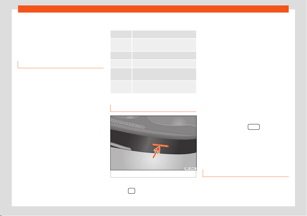
Technical data
Technical data
T
echnical specifications
Impor
t
ant information
Important
The information in the vehicle documentation
always t
akes precedence over the informa-
tion in this Instruction Manual.
All technical specifications provided in this
documentation are valid for the standard
model in Spain.
The figures may be different depending
whether additional equipment is fitted, for dif-
ferent models, for special vehicles and for
other countries.
Abbreviations used in the Technical Speci-
fications section
kW Kilowatt, engine power measurement.
PS
Pferdestärke (horsepower), formerly
used to denote engine po
wer.
rpm, 1/min Revolutions per minute - engine speed.
Nm Newton metres, unit of engine torque.
CZ
Cetane number, indication of the die-
sel combustion power
.
RON
Research octane number, indication of
the knock resistance of petr
ol.
Vehicle identification data
Fig. 312 Chassis number.
VIN in the Easy Connect
●
Select:
button > SETTINGS > Service
> Chassis number.
Chassis number
The VIN is l
ocat
ed in the Easy Connect and
under the windscr
een, on the driver side
›››
Fig. 312. Also the VIN is located in the en-
gine compartment, on the left-hand side in
the direction of travel. The number is en-
graved on the top side rail, and is partially
covered.
Type plate
The type plate is located on the right side
door pillar. Vehicles for certain export coun-
tries do not have a type plate.
Identifying letters
The identifying letters of the engine can be
viewed on the instrument panel when the en-
gine is switched off and the ignition is on.
●
Hold down the button
on the dash
panel f
or mor
e than 15 seconds.
Inf
ormation on fuel con-
sumption
Fuel consumption
Approved consumption values are derived
fr
om measur
ements perf
ormed or supervised
by certified EU laboratories, according to the
legislation in force at the time (for more
380
Technical specifications
information, see the Publications Office of the
Eur
opean Union on the EUR-L
e
x website: ©
European Union, http://eur-lex.europa.eu/)
and apply to the specified vehicle character-
istics.
The values relating to fuel consumption and
CO
2
emissions can be found in the documen-
tation provided to the purchaser of the vehi-
cle at the time of purchase.
Fuel consumption and CO
2
emissions de-
pend on the equipment/features of each indi-
vidual vehicle, as well as on the driving style,
road conditions, traffic conditions, environ-
mental conditions, load or number of passen-
gers.
Note
In practice, and considering all the factors
mentioned here, consumption v
alues can
differ from those calculated in the current
European regulations.
Weights
Kerb weight refers to the basic model with a
fuel t
ank fill
ed t
o 90% capacity and without
optional extras. The figure quoted includes 75
kg to allow for the weight of the driver.
Special versions, optional equipment fittings
or retro-fitting accessories will increase the
weight of the vehicle
›››
.
WARNING
●
Please note that the centr
e of gravity
may shift when transporting heavy objects;
this may affect vehicle handling and lead
to an accident. Always adjust your speed
and driving style to suit road conditions
and requirements.
●
Never exceed the gross axle weight rat-
ing or the gross vehicle weight rating. If the
permissible axle load or the permissible to-
tal weight is exceeded, the driving charac-
teristics of the vehicle may change, which
could lead to accidents, injuries and dam-
age to the vehicle.
Trailer mode
T
r
ail
er weights
Trailer weight
The tr
ail
er w
eights and drawbar loads ap-
proved are selected in intensive trials accord-
ing to precisely defined criteria. The ap-
proved trailer weights are valid for vehicles in
the EU for maximum speeds of 80 km/h (50
mph) (in certain circumstances up to
100 km/h (62 mph)). The figures may be dif-
ferent in other countries. All data in the official
vehicle documentation takes precedence
over these data at all times
›››
.
Drawbar loads
The maximum permitt
ed dr
awbar l
oad on the
ball coupling of the towing bracket must not
exceed 88 kg.
In the interest of road safety, we recommend
that you always tow approaching the maxi-
mum drawbar load. The response of the trail-
er on the road will be poor, if the drawbar
load is too small.
If the maximum permissible drawbar load
cannot be met (e.g. with small, empty and
light-weight single axle trailers or tandem
axle trailers with a wheelbase of less than 1
metre), a minimum of 4% of the actual trailer
weight is legally required for the drawbar
load.
WARNING
●
For safet
y reasons, you should not drive
at speeds above 80 km/h (50 mph) when
towing a trailer. This also applies in coun-
tries where higher speeds are permitted.
●
Never exceed the maximum trailer
weights or the drawbar load. If the permis-
sible axle load or the permissible total
weight is exceeded, the driving character-
istics of the vehicle may change, leading to
accidents, injuries and damage to the vehi-
cle.
381
Technical data
Wheels
T
yr
e pr
essure, snow chains and
wheel bolts
Tyre pressure
The sticker with the tyr
e pressure values can
be found on the back of the left front door
frame. The tyre pressure values given there
are for cold tyres. The slightly raised pres-
sures of warm tyres must not be reduced.
›››
The pressure for wint
er t
yr
es is 0.2 bar
(2.9 psi / 20 kPa) higher than that of summer
tyres.
Snow chains
Snow chains may be fitted only to the front
wheels, and only for the following tyres:
215/60 R16 Chains with links of maximum 15 mm
215/55 R17 Chains with links of maximum 15 mm
215/50 R18 Chains with links of maximum 15 mm
Other dimensions do not allow chains
Wheel bolts
After the wheels hav
e been changed, the
tightening torque of the wheel bolts should
be checked as soon as possible with a torque
wrench
›››
. The tightening torque for steel
and all
oy wheel
s is
140 Nm.
WARNING
●
Check the tyre pr
essure at least once per
month. Checking the tyre pressure is very
important. If the tyre pressure is too high or
too low, there is an increased danger of ac-
cidents - particularly at high speeds.
●
If the tightening torque of the wheel bolts
is too low, they could loosen while the vehi-
cle is in motion. Risk of accident! If the
tightening torque is too high, the wheel
bolts and threads can be damaged.
Note
We recommend that you ask your Techni-
cal Service for information about appr
opri-
ate wheel, tyre and snow chain size.
382

Technical specifications
Engine data
P
etr
ol engines
1.0 TSI Start-Stop 1.4 EcoTSI Start-Stop
Power output in kW (PS) at 1/min 85 (115)/5,000-5,500 110 (150)/5,000-6,000
Maximum torque (Nm at 1/min) 200/2,000-3,500 250/1,500-3,500
No. of cylinders/displacement (cm
3
) 3/999 4/1,395
Fuel Super 95 / Normal 91 (with a slight power loss) ROZ
Gearbox manual DSG DSG 4Drive
Top speed (km/h) 181 (5) 198 (6) 189 (5)
Acceleration from 0-80 km/h (seconds) 7.1 6.0 5.9
Acceleration from 0-100 km/h (seconds) 10.7 8.6 8.9
Maximum authorised weight (kg) 1,850 1,920 2,010
Weight in running order (with driver) (kg) 1,313 1,375 1,476
Maximum authorised weight on front axle (kg) 940 990 1,010
Maximum authorised weight on rear axle (kg) 940 980 1,050
Maximum trailer weight without brakes (kg) 650 680 730
Weight of trailer with brakes on gradients up to 8% (kg) 1,500 1,800 1,950
Weight of trailer with brakes on gradients up to 12% (kg) 1,300 1,600 1,900
383

Technical data
Petrol engines
1.5 TSI Start-Stop 2.0 TSI Start-Stop
Power output in kW (PS) at 1/min 110 (150)/5,000-6,000 140 (190)/4,200-6,000
Maximum torque (Nm at 1/min) 250/1,500-3,500 320/1,450-4,200
No. of cylinders/displacement (cm
3
) 4/1498 4/1,984
Fuel Super 95 / Normal 91 (with a slight power loss) ROZ
Gearbox manual DSG DSG 4Drive DSG 4Drive
Top speed (km/h) 201 (5) 198 (6) 194 (5) 210 (5)
Acceleration from 0-80 km/h (seconds) 5.9 6.0 6.2 4.7
Acceleration from 0-100 km/h (seconds) 8.5 8.6 9.2 7.1
Maximum authorised weight (kg) 1,900 1,920 2,050 2,080
Weight in running order (with driver) (kg) 1,355 1,370 1,502 1,541
Maximum authorised weight on front axle (kg)
a) a) a)
1,070
Maximum authorised weight on rear axle (kg)
a) a) a)
1,060
Maximum trailer weight without brakes (kg) 670 680 750 750
Weight of trailer with brakes on gradients up to 8% (kg) 1,850 1,800 1,950 2,000
Weight of trailer with brakes on gradients up to 12% (kg) 1,800 1,600 1,900 1,900
a)
Data not available as this edition goes to print.
384

Technical specifications
Diesel engines
1.6 TDI CR Start-Stop 2.0 TDI
Power output in kW (PS) at 1/min 85 (115)/3,250-4,000 105 (143)/3,500-4,000
Maximum torque (Nm at 1/min) 250/1,500-3,250 320/1,750-3,000
No. of cylinders/displacement (cm
3
) 4/1,598 4/1,968
Fuel Diesel according to standard EN 590, min. 51 CN
Gearbox manual DSG DSG
Top speed (km/h) 184 (6) 184 (6) 192 (5)
Acceleration from 0-80 km/h (seconds) 8.2 8.2 6.4
Acceleration from 0-100 km/h (seconds) 11.5 11.5 9.2
Maximum authorised weight (kg) 1,970 1,990 1,970
Weight in running order (with driver) (kg) 1,428 1,446 1,435
Maximum authorised weight on front axle (kg) 1,030 1,030 1,080
Maximum authorised weight on rear axle (kg) 930 930 940
Maximum trailer weight without brakes (kg) 710 720 710
Weight of trailer with brakes on gradients up to 8% (kg) 1,700 1,700 1,900
Weight of trailer with brakes on gradients up to 12% (kg) 1,500 1,500 1,800
385

Technical data
Diesel engines
2.0 TDI CR Start-Stop
Power output in kW (PS) at 1/min 110 (150)/3,500-4,000 140 (190)/3,500-4,000
Maximum torque (Nm at 1/min) 340/1,750-3,000 400/1,750-3,250
No. of cylinders/displacement (cm
3
) 4/1,968 4/1,968
Fuel Diesel according to standard EN 590, min. 51 CN
Gearbox manual manual 4Drive DSG DSG 4Drive
Top speed (km/h) 202 (6) 196 (6) 196 (6) 212 (6)
Acceleration from 0-80 km/h (seconds) 6.3 6.0 6.3 4.7
Acceleration from 0-100 km/h (seconds) 8.5 9.0 8.5 7.5
Maximum authorised weight (kg) 1,990 2,120 2,010 2,150
Weight in running order (with driver) (kg) 1,453 1,578 1,483 1,578
Maximum authorised weight on front axle (kg) 1,060 1,080 1,090 1,120
Maximum authorised weight on rear axle (kg) 940 1,070 930 1,060
Maximum trailer weight without brakes (kg) 720 750 740 750
Weight of trailer with brakes on gradients up to 8% (kg) 1,900 2,100 1,900 2,100
Weight of trailer with brakes on gradients up to 12% (kg) 1,900 2,100 1,800 2,100
386
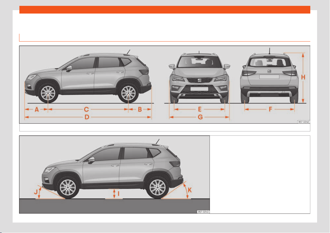
Technical specifications
Vehicle data
Dimensions
Fig. 313
Dimensions.
Fig. 314
Angles and ground clearance
»
387

Technical data
›››
Fig. 313,
›››
Fig. 314 At
eca Ateca 4Drive
A Front projection (mm) 868 868
B Rear projection (mm) 857 865
C Wheelbase (mm) 2,638 2,630
D Length (mm) 4,363
E Front
a)
tr
ack (mm) 1,576 1,57
2
F Back
a)
track (mm) 1,541 1,544
G Width (mm) 1,841
H Height at kerb w
eight (mm)
1,601
b)
1,615
c)
1,61
1
b)
1,625
c)
I Ground clearance between the axles (mm) 176 189
J Front projection angle limited by the bumper maximum 19.4° maximum 20.6°
K Rear projection angle limited by the bumper maximum 27.9° maximum 25.5°
Turning radius (m) 10.8
a)
This data will change depending on the type of wheel rim.
b)
Distance to the roof.
c)
Dimension to the roof bars.
388

Index
Index
Numbers and Symbol
s
4Driv
e . . . . . . . . . . . . . . . . . . . . . . . . . . . . . . . . . . . . . . .
267
A
ABS
see Anti-lock brake system . . . . . . . . . . . . . . . . 248
ACC . . . . . . . . . . . . . . . . . . . . . . . . . . . . . . . . . . . . . . . . 283
radar sensor . . . . . . . . . . . . . . . . . . . . . . . . . . . . . . 285
Accessories . . . . . . . . . . . . . . . . . . . . . . . . . . . . 167, 340
Active cylinder management (ACT)
status indication . . . . . . . . . . . . . . . . . . . . . . . . . . . 108
Adaptive cruise control . . . . . . . . . . . . . . . . . . . . . . 283
Adaptive Cruise Control
control and warning lamps . . . . . . . . . . . . . . . 284
deactivating temporarily . . . . . . . . . . . . . . . . . . 289
function for preventing overtaking in an in-
side lane . . . . . . . . . . . . . . . . . . . . . . . . . . . . . . . . 289
instructions on the screen . . . . . . . . . . . . . . . . . 285
malfunction . . . . . . . . . . . . . . . . . . . . . . . . . . . . . . . 284
operating . . . . . . . . . . . . . . . . . . . . . . . . . . . . . . . . . 286
radar sensor . . . . . . . . . . . . . . . . . . . . . . . . . . . . . . 285
special driving situations . . . . . . . . . . . . . . . . . . 290
AdBlue
information . . . . . . . . . . . . . . . . . . . . . . . . . . . . . . . 345
maximum filling capacity . . . . . . . . . . . . . . . . . 345
refilling . . . . . . . . . . . . . . . . . . . . . . . . . . . . . . . . . . . . 345
specification . . . . . . . . . . . . . . . . . . . . . . . . . . . . . . 345
tank capacity . . . . . . . . . . . . . . . . . . . . . . . . . . . . . 345
Adjust
Vehicle menu . . . . . . . . . . . . . . . . . . . . . . . . . . . . . . . 35
Adjusting
front head restraints . . . . . . . . . . . . . . . . . . . . . . . . 67
front seats . . . . . . . . . . . . . . . . . . . . . . . . . . . . . . . . 160
lights . . . . . . . . . . . . . . . . . . . . . . . . . . . . . . . . . . . . . . 154
rear head restraints . . . . . . . . . . . . . . . . . . . . . . . 160
seats . . . . . . . . . . . . . . . . . . . . . . . . . . . . . . . . . . . . . . . 64
Adjusting the head restraints
front head restraints . . . . . . . . . . . . . . . . . . . . . . . 160
Adjustment
front head restraints . . . . . . . . . . . . . . . . . . . . . . . 160
rear head restraints . . . . . . . . . . . . . . . . . . . . . . . . 68
Airbag covers . . . . . . . . . . . . . . . . . . . . . . . . . . . . . . . . . 22
Airbags . . . . . . . . . . . . . . . . . . . . . . . . . . . . . . . . . . . . . . . 74
Airbag system . . . . . . . . . . . . . . . . . . . . . . . . . . . . . 21, 74
activation . . . . . . . . . . . . . . . . . . . . . . . . . . . . . . . . . . 76
control lamp . . . . . . . . . . . . . . . . . . . . . . . . . . . . . . . 79
deactivation of front airbag . . . . . . . . . . . . . . . . 78
description . . . . . . . . . . . . . . . . . . . . . . . . . . . . . . . . . 75
front airbags . . . . . . . . . . . . . . . . . . . . . . . . . . . . 22, 76
functioning . . . . . . . . . . . . . . . . . . . . . . . . . . . . . . . . . 76
head-protection airbags . . . . . . . . . . . . . . . . . . . 24
knee airbags . . . . . . . . . . . . . . . . . . . . . . . . . . . . . . . 23
side airbags . . . . . . . . . . . . . . . . . . . . . . . . . . . . . . . . 24
Air conditioning
auxiliary heater . . . . . . . . . . . . . . . . . . . . . . . . . . . . 182
Climatronic . . . . . . . . . . . . . . . . . . . . . . . . . . . . 42, 176
heated windscreen . . . . . . . . . . . . . . . . . . . . . . . . 180
manual air conditioning . . . . . . . . . . . . . . . . . . . . 45
user instructions . . . . . . . . . . . . . . . . . . . . . . . . . . . 178
Air outlets . . . . . . . . . . . . . . . . . . . . . . . . . . . . . . . . . . . . 179
Air recirculation . . . . . . . . . . . . . . . . . . . . . . . . . . . . . . 179
Alcantara leather: cleaning . . . . . . . . . . . . . . . . . . 373
Alternator
warning lamp . . . . . . . . . . . . . . . . . . . . . . . . . . . . . 355
AM . . . . . . . . . . . . . . . . . . . . . . . . . . . . . . . . . . . . . . . . . . 205
Ambient lighting . . . . . . . . . . . . . . . . . . . . . . . . . . . . . 155
Android Auto™ . . . . . . . . . . . . . . . . . . . . . . . . . . 198, 200
Anti-freeze . . . . . . . . . . . . . . . . . . . . . . . . . . . . . . . . . . . 49
Anti-lock brake system . . . . . . . . . . . . . . . . . . . . . . 248
Anti-puncture . . . . . . . . . . . . . . . . . . . . . . . . . . . . . 53, 85
Anti-puncture kit . . . . . . . . . . . . . . . . . . . . . . . . . . 53, 85
check after 10 minutes . . . . . . . . . . . . . . . . . . . . . 87
Anti-puncture set . . . . . . . . . . . . . . . . . . . . . . . . . . . . . 85
Anti-slip regulation . . . . . . . . . . . . . . . . . . . . . . . . . . 248
Anti-theft alarm . . . . . . . . . . . . . . . . . . . . . . . . . 127, 137
trailer . . . . . . . . . . . . . . . . . . . . . . . . . . . . . . . . . . . . . 334
vehicle interior monitoring and anti-tow
protection . . . . . . . . . . . . . . . . . . . . . . . . . . . . . . . 139
Anti-theft security system . . . . . . . . . . . . 15, 127, 135
Anti-theft system
trailer . . . . . . . . . . . . . . . . . . . . . . . . . . . . . . . . . . . . . 334
Anti-tow protection . . . . . . . . . . . . . . . . . . . . . . . . . . 139
Anti-trap function
sun blind (sunroof) . . . . . . . . . . . . . . . . . . . . . . . . 146
sunroof . . . . . . . . . . . . . . . . . . . . . . . . . . . . . . . . . . . . 146
App
SEAT Media Control . . . . . . . . . . . . . . . . . . . . . . 202
Apple CarPlay™ . . . . . . . . . . . . . . . . . . . . . . . 198, 200
Area view system (Top View Camera)
special characteristics . . . . . . . . . . . . . . . . . . . . 324
Aspects to note before setting off . . . . . . . . . . . . . 63
Assistance systems
ACC . . . . . . . . . . . . . . . . . . . . . . . . . . . . . . . . . . . . . . 283
Adaptive cruise control . . . . . . . . . . . . . . . . . . . 283
Auto Hold function . . . . . . . . . . . . . . . . . . . . . . . . . 272
blind spot detector (BSD) with parking as-
sistance (RCTA) . . . . . . . . . . . . . . . . . . . . . . . . . 298
cruise control system . . . . . . . . . . . . . . . . . . . . . . 274
disable . . . . . . . . . . . . . . . . . . . . . . . . . . . . . . . . . . . . 122
Emergency Assist . . . . . . . . . . . . . . . . . . . . . . . . . 296
389

Index
emergency braking assistance (Front As-
sist) . . . . . . . . . . . . . . . . . . . . . . . . . . . . . . . . . . . . .
279
enabl
e . . . . . . . . . . . . . . . . . . . . . . . . . . . . . . . . . . . . .
122
fatigue detection . . . . . . . . . . . . . . . . . . . . . . . . . . . 112
Hill Descent Control . . . . . . . . . . . . . . . . . . . . . . . 271
Park Assist . . . . . . . . . . . . . . . . . . . . . . . . . . . . . . . . 305
parking assistant (RCTA) . . . . . . . . . . . . . . . . . . 298
parking system Plus . . . . . . . . . . . . . . . . . . . . . . . 315
rear parking aid . . . . . . . . . . . . . . . . . . . . . . . . . . . 319
speed limiter . . . . . . . . . . . . . . . . . . . . . . . . . . . . . . 275
Top View Camera . . . . . . . . . . . . . . . . . . . . . . . . . 321
traffic jam assist . . . . . . . . . . . . . . . . . . . . . . . . . . 295
traffic sign detection system . . . . . . . . . . . . . . . 114
tyre monitoring . . . . . . . . . . . . . . . . . . . . . . . . . . . . 362
tyre monitoring indicator . . . . . . . . . . . . . . . . . . 363
tyre monitoring system . . . . . . . . . . . . . . . . . . . . 361
Assisted starting . . . . . . . . . . . . . . . . . . . . . . . . . . . . . . 59
Audible warning signal
control and warning lamps . . . . . . . . . . . . . . . . 122
lights . . . . . . . . . . . . . . . . . . . . . . . . . . . . . . . . . . . . . . 147
unfastened safety belt . . . . . . . . . . . . . . . . . . . . . 69
Auto Hold . . . . . . . . . . . . . . . . . . . . . . . . . . . . . . . . . . . . 272
Auto Hold function . . . . . . . . . . . . . . . . . . . . . . . . . . . 272
Auto Lock (central locking) . . . . . . . . . . . . . . . . . . . 127
Automatic car washes
switching the Auto Hold function off . . . . . . . 274
Automatic car wash tunnel . . . . . . . . . . . . . . . . . . 371
Automatic dipped beam control . . . . . . . . . . . . . 149
Automatic gearbox . . . . . . . . . . . . . . . . . . . . . . . . . . 252
downhill speed control . . . . . . . . . . . . . . . . . . . . 258
driving tips . . . . . . . . . . . . . . . . . . . . . . . . . . . . . . . . 255
emergency program . . . . . . . . . . . . . . . . . . . . . . 259
kick-down feature . . . . . . . . . . . . . . . . . . . . . . . . . 257
launch control program . . . . . . . . . . . . . . . . . . . 257
manual release of the selector lever . . . . . . . . 41
safety interlock for ignition key . . . . . . . . . . . . 239
selector lever lock . . . . . . . . . . . . . . . . . . . . . . . . . 253
selector lever positions . . . . . . . . . . . . . . . . . . . . 252
steering wheel with gear shift paddles . . . . 255
tiptronic . . . . . . . . . . . . . . . . . . . . . . . . . . . . . . 252, 255
towing . . . . . . . . . . . . . . . . . . . . . . . . . . . . . . . . . . . . . 89
Automatic transmission
control lamp . . . . . . . . . . . . . . . . . . . . . . . . . . . . . . 252
AUX-IN . . . . . . . . . . . . . . . . . . . . . . . . . . . . . . . . . . . . . . 237
external audio source . . . . . . . . . . . . . . . . . . . . . . 211
Auxiliary heater . . . . . . . . . . . . . . . . . . . . . . . . . . . . . . 182
activating . . . . . . . . . . . . . . . . . . . . . . . . . . . . . . . . . 184
electric consumers . . . . . . . . . . . . . . . . . . . . . . . . 185
operating instructions . . . . . . . . . . . . . . . . . . . . . 185
programming . . . . . . . . . . . . . . . . . . . . . . . . . . . . . 184
remote control . . . . . . . . . . . . . . . . . . . . . . . . . . . . 183
remote control range . . . . . . . . . . . . . . . . . . . . . . 184
special features . . . . . . . . . . . . . . . . . . . . . . . . . . . 183
switching off . . . . . . . . . . . . . . . . . . . . . . . . . . . . . . . 182
switching on . . . . . . . . . . . . . . . . . . . . . . . . . . . . . . . 182
things to note . . . . . . . . . . . . . . . . . . . . . . . . . . . . . . 185
Average consumption . . . . . . . . . . . . . . . . . . . . . . . 106
B
Battery . . . . . . . . . . . . . . . . . . . . . . . . . . . . . . . . . . . . . . 135
replacement in the remote control (auxili-
ary heater) . . . . . . . . . . . . . . . . . . . . . . . . . . . . . . 184
Before setting off . . . . . . . . . . . . . . . . . . . . . . . . . . . . . 63
Belt tensioners
control lamp . . . . . . . . . . . . . . . . . . . . . . . . . . . . . . . 79
Belt tightening . . . . . . . . . . . . . . . . . . . . . . . . . . . . . . . . 73
Bench seat . . . . . . . . . . . . . . . . . . . . . . . . . . . . . . . . . . 163
Bicycle rack
fitting on the retractable tow hitch . . . . . . . . 333
maximum load . . . . . . . . . . . . . . . . . . . . . . . . . . . . 333
Biodiesel . . . . . . . . . . . . . . . . . . . . . . . . . . . . . . . . . . . . 344
Blind spot detector (BSD) . . . . . . . . . . . . . . . . . . . 298
control lamps . . . . . . . . . . . . . . . . . . . . . . . . . . . . . 298
driving situations . . . . . . . . . . . . . . . . . . . . . . . . . . 301
indication in the external rear view mirror . 299
malfunction . . . . . . . . . . . . . . . . . . . . . . . . . . . . . . . 298
operating . . . . . . . . . . . . . . . . . . . . . . . . . . . . . . . . . 299
towing . . . . . . . . . . . . . . . . . . . . . . . . . . . . . . . . . . . . 303
Bluetooth®
connect audio source . . . . . . . . . . . . . . . . . . . . . . 211
Bonnet . . . . . . . . . . . . . . . . . . . . . . . . . . . . . . . . . 347, 349
opening and closing . . . . . . . . . . . . . . . . . . . 18, 347
Boot shelf
store . . . . . . . . . . . . . . . . . . . . . . . . . . . . . . . . . . . . . . 169
store the shelf . . . . . . . . . . . . . . . . . . . . . . . . . . . . . 169
Brake fluid . . . . . . . . . . . . . . . . . . . . . . . . . . . . . . . . . . . . 49
Brakes . . . . . . . . . . . . . . . . . . . . . . . . . . . . . . . . . . . . . . 244
brake fluid . . . . . . . . . . . . . . . . . . . . . . . . . . . . . . . . 353
brake servo . . . . . . . . . . . . . . . . . . . . . . . . . . . . . . . 244
electronic parking brake . . . . . . . . . . . . . . . . . . 246
emergency braking function . . . . . . . . . . . . . . 247
new brake pads . . . . . . . . . . . . . . . . . . . . . . . . . . . 244
Brake system
warning lamp . . . . . . . . . . . . . . . . . . . . . . . . . . . . . 245
Braking
front assist . . . . . . . . . . . . . . . . . . . . . . . . . . . . . . . . 248
BSD
see Blind spot detector (BSD) . . . . . . . . . . . . . 298
BSD Plus . . . . . . . . . . . . . . . . . . . . . . . . . . . . . . . . . . . . 294
C
Camera
cleanliness . . . . . . . . . . . . . . . . . . . . . . . . . . . . . . . . 116
Lane Assist . . . . . . . . . . . . . . . . . . . . . . . . . . . . . . . . 292
390

Index
Capacities . . . . . . . . . . . . . . . . . . . . . . . . . . . . . . . . . . . 47
AdBlue t
ank . . . . . . . . . . . . . . . . . . . . . . . . . . . . . . .
345
windscr
een washer water . . . . . . . . . . . . . . . . . 354
CCS . . . . . . . . . . . . . . . . . . . . . . . . . . . . . . . . . . . . . . . . . 40
CD-ROM player (navigation) . . . . . . . . . . . . . . . . 166
Central locking . . . . . . . . . . . . . . . . . . . . . . . . . . . . . . 127
adjustment . . . . . . . . . . . . . . . . . . . . . . . . . . . . . . . . 130
anti-theft alarm . . . . . . . . . . . . . . . . . . . . . . . . . . . . 137
central locking switch . . . . . . . . . . . . . . . . . . . . . 130
electric windows . . . . . . . . . . . . . . . . . . . . . . . . . . 143
emergency locking . . . . . . . . . . . . . . . . . . . . . . . . . 16
Keyless Access . . . . . . . . . . . . . . . . . . . . . . . . . . . . 131
Panoramic sliding/tilting sunroof . . . . . . . . . . 143
remote control key . . . . . . . . . . . . . . . . . . . . . . . . 129
selective unlocking system . . . . . . . . . . . . . . . . 129
Central wheel trim . . . . . . . . . . . . . . . . . . . . . . . . . . . 55
Centre console . . . . . . . . . . . . . . . . . . . . . . . . . . . . . . . 13
Cetane number (diesel fuel) . . . . . . . . . . . . . . . . 344
Changing a wheel . . . . . . . . . . . . . . . . . . . . . . . . . . . . 54
subsequent work . . . . . . . . . . . . . . . . . . . . . . . . . . . 57
Changing bulbs . . . . . . . . . . . . . . . . . . . . . . . . . . . . . . 96
dipped beam . . . . . . . . . . . . . . . . . . . . . . . . . . . . . . . 97
fog light . . . . . . . . . . . . . . . . . . . . . . . . . . . . . . . . . . . . 98
main beam . . . . . . . . . . . . . . . . . . . . . . . . . . . . . . . . . 97
number plate light . . . . . . . . . . . . . . . . . . . . . . . . 100
rear bulb in the side panel . . . . . . . . . . . . . . . . . . 99
rear light in the rear lid . . . . . . . . . . . . . . . . . . . . 100
turn signal . . . . . . . . . . . . . . . . . . . . . . . . . . . . . . . . . . 97
Changing gear
engaging gears (manual gearbox) . . . . . . . . 251
Changing the blades . . . . . . . . . . . . . . . . . . . . . . . . . 88
Changing the wiper blades . . . . . . . . . . . . . . . . . . . 61
Charging the battery . . . . . . . . . . . . . . . . . . . . . . . 356
Checking levels
engine compartment . . . . . . . . . . . . . . . . . . . . . 349
Child-proof locking
electric windows . . . . . . . . . . . . . . . . . . . . . . . . . . 142
Child seat . . . . . . . . . . . . . . . . . . . . . . . . . . . . . . . . 25, 82
Child seats
categorisation into groups . . . . . . . . . . . . . . . . . 82
ISOFIX system . . . . . . . . . . . . . . . . . . . . . . . . . . . . . . 28
safety instructions . . . . . . . . . . . . . . . . . . . . . . . 25, 81
securing with the seat belt . . . . . . . . . . . . . . . . . 26
Top Tether system . . . . . . . . . . . . . . . . . . . . . . . 28, 31
Cleaning
Alcantara leather . . . . . . . . . . . . . . . . . . . . . . . . . 373
carbon fibre . . . . . . . . . . . . . . . . . . . . . . . . . . 372, 374
control panels . . . . . . . . . . . . . . . . . . . . . . . . . . . . . 373
decorative sheets . . . . . . . . . . . . . . . . . . . . . . . . . 373
exhaust tail pipes . . . . . . . . . . . . . . . . . . . . . . . . . . 372
exterior . . . . . . . . . . . . . . . . . . . . . . . . . . . . . . . . . . . . 372
fabrics . . . . . . . . . . . . . . . . . . . . . . . . . . . . . . . . . . . . 373
headlights / tail lights . . . . . . . . . . . . . . . . . . . . . 372
high pressure cleaners . . . . . . . . . . . . . . . . . . . . 370
Interior . . . . . . . . . . . . . . . . . . . . . . . . . . . . . . . . . . . . 373
leather . . . . . . . . . . . . . . . . . . . . . . . . . . . . . . . . . . . . 373
paint . . . . . . . . . . . . . . . . . . . . . . . . . . . . . . . . . . . . . . 372
plastic parts . . . . . . . . . . . . . . . . . . . . . . . . . . . . . . . 373
seat belts . . . . . . . . . . . . . . . . . . . . . . . . . . . . . . . . . 373
sensors/camera lenses . . . . . . . . . . . . . . . . . . . 372
special care . . . . . . . . . . . . . . . . . . . . . . . . . . . . . . . 374
the radio screen . . . . . . . . . . . . . . . . . . . . . . . . . . . 373
trims/covers . . . . . . . . . . . . . . . . . . . . . . . . . . 372, 373
washing the vehicle . . . . . . . . . . . . . . . . . . . . . . . 370
wheels . . . . . . . . . . . . . . . . . . . . . . . . . . . . . . . . . . . . 372
windows . . . . . . . . . . . . . . . . . . . . . . . . . . . . . . . . . . 373
windscreen wipers . . . . . . . . . . . . . . . . . . . . . . . . 372
Climatronic . . . . . . . . . . . . . . . . . . . . . . . . . . . . . . . . . . 43
Clocks
analogue . . . . . . . . . . . . . . . . . . . . . . . . . . . . . . . . . . 116
digital . . . . . . . . . . . . . . . . . . . . . . . . . . . . . . . . . . . . . . 116
set time . . . . . . . . . . . . . . . . . . . . . . . . . . . . . . . . . . . . 116
Close
sunroof . . . . . . . . . . . . . . . . . . . . . . . . . . . . . . . . . . . . 145
Closing . . . . . . . . . . . . . . . . . . . . . . . . . . . . . . . . . . . . . . 127
bonnet . . . . . . . . . . . . . . . . . . . . . . . . . . . . . . . . . 18, 347
rear lid . . . . . . . . . . . . . . . . . . . . . . . . . . . . . . . . . . . . 139
sun blind (sunroof) . . . . . . . . . . . . . . . . . . . . . . . . . 145
sunroof . . . . . . . . . . . . . . . . . . . . . . . . . . . . . . . . . . . . 145
windows . . . . . . . . . . . . . . . . . . . . . . . . . . . . . . . . . . . 142
Clutch (warning lamp) . . . . . . . . . . . . . . . . . . . . . . 259
Coming Home . . . . . . . . . . . . . . . . . . . . . . . . . . . . . . . 151
Coming Home function . . . . . . . . . . . . . . . . . . . . . . 151
Communication between the Infotainment
system and mobile devices . . . . . . . . . . . . . . . . 195
Connectivity . . . . . . . . . . . . . . . . . . . . . . . . . . . . . . . . . 195
Full Link . . . . . . . . . . . . . . . . . . . . . . . . . . . . . . . . . . . . 195
SEAT Media Control . . . . . . . . . . . . . . . . . . . . . . 202
WLAN point of access . . . . . . . . . . . . . . . . . . . . . 203
Connectivity Box . . . . . . . . . . . . . . . . . . . . . . . . . . . . 237
Control and warning lamps . . . . . . . . . . . . . . 39, 122
ABS anti-blocking system . . . . . . . . . . . . . . . . . 248
adaptive cruise control . . . . . . . . . . . . . . . . . . . 284
airbags . . . . . . . . . . . . . . . . . . . . . . . . . . . . . . . . . . . . . 78
airbag system . . . . . . . . . . . . . . . . . . . . . . . . . . . . . . 79
alternator . . . . . . . . . . . . . . . . . . . . . . . . . . . . . . . . . 355
applying the brake . . . . . . . . . . . . . . . . . . . . . . . . 284
ASR . . . . . . . . . . . . . . . . . . . . . . . . . . . . . . . . . . 248, 250
audible warning signal . . . . . . . . . . . . . . . . . . . . . 122
blind spot detector (BSD) . . . . . . . . . . . . . . . . . 298
blocking of the steering column . . . . . . . . . . . 261
brake systems . . . . . . . . . . . . . . . . . . . . . . . . . . . . 245
cruise control system (CCS) . . . . . . . . . . . . . . 274
391

Index
depress the brake . . . . . . . . . . . . . . . . . . . . . . . . . 279
diesel pr
eheating syst
em . . . . . . . . . . . . . . . . .
265
EDS . . . . . . . . . . . . . . . . . . . . . . . . . . . . . . . . . . . . . . . 248
electromechanical steering . . . . . . . . . . . . . . . 261
electronic parking brake . . . . . . . . . . . . . . . . . . 245
emission control . . . . . . . . . . . . . . . . . . . . . . . . . . 265
engine management . . . . . . . . . . . . . . . . . . . . . 265
engine oil . . . . . . . . . . . . . . . . . . . . . . . . . . . . . . . . . 350
ESC . . . . . . . . . . . . . . . . . . . . . . . . . . . . . . . . . 248, 250
gear change . . . . . . . . . . . . . . . . . . . . . . . . . . . . . . 259
Hill Descent Control . . . . . . . . . . . . . . . . . . . . . . . 271
instrument panel . . . . . . . . . . . . . . . . . . . . . . . . . . . 39
Lane Assist . . . . . . . . . . . . . . . . . . . . . . . . . . . . . . . . 292
lights . . . . . . . . . . . . . . . . . . . . . . . . . . . . . . . . . . . . . . 147
parking assistant (RCTA) . . . . . . . . . . . . . . . . . . 298
particulate filter . . . . . . . . . . . . . . . . . . . . . . 265, 266
refuelling . . . . . . . . . . . . . . . . . . . . . . . . . . . . . . . . . . 341
remote control (auxiliary heater) . . . . . . . . . . 183
seat belt . . . . . . . . . . . . . . . . . . . . . . . . . . . . . . . . . . . 69
speed limiter . . . . . . . . . . . . . . . . . . . . . . . . . . . . . . 275
Start-Stop . . . . . . . . . . . . . . . . . . . . . . . . . . . . . . . . 269
tow hitch . . . . . . . . . . . . . . . . . . . . . . . . . . . . . . . . . . 332
towing bracket . . . . . . . . . . . . . . . . . . . . . . . . . . . . 330
transmission . . . . . . . . . . . . . . . . . . . . . . . . . . . . . . 252
tyre monitoring system . . . . . . . . . . . . . . . . . . . . 362
Control lamps
engine coolant . . . . . . . . . . . . . . . . . . . . . . . . . . . . 118
Fuel reserve . . . . . . . . . . . . . . . . . . . . . . . . . . . . . . . . 117
refuel . . . . . . . . . . . . . . . . . . . . . . . . . . . . . . . . . . . . . . 117
Controls and displays
general instrument panel . . . . . . . . . . . . . . . . . . 103
Controls for the windows . . . . . . . . . . . . . . . . . 18, 142
Controls on the steering wheel . . . . . . . . . . . . . . 123
Coolant
checking level . . . . . . . . . . . . . . . . . . . . . . . . . . . . 352
Cooling system
checking coolant . . . . . . . . . . . . . . . . . . . . . . . . . 352
topping up coolant . . . . . . . . . . . . . . . . . . . . . . . . 352
Copyright . . . . . . . . . . . . . . . . . . . . . . . . . . . . . . . . . . . 207
Correct position . . . . . . . . . . . . . . . . . . . . . . . . . . . . . . 64
Correct sitting position
driver . . . . . . . . . . . . . . . . . . . . . . . . . . . . . . . . . . . . . . 64
front passenger . . . . . . . . . . . . . . . . . . . . . . . . . . . . 65
rear seat passengers . . . . . . . . . . . . . . . . . . . . . . 66
Cruise control . . . . . . . . . . . . . . . . . . . . . . . . . . . 40, 274
control and warning lamps . . . . . . . . . . . . . . . . 274
operation . . . . . . . . . . . . . . . . . . . . . . . . . . . . . . . . . 274
Cruise control system . . . . . . . . . . . . . . . . . . . . . . . 274
Cylinder deactivation
see Active cylinder management (ACT) . . . 108
D
DAB . . . . . . . . . . . . . . . . . . . . . . . . . . . . . . . . . . . . . . . . . 205
Dangers in not using the seat belt . . . . . . . . . . . . . 71
Dashboard . . . . . . . . . . . . . . . . . . . . . . . . . . . . . . . . . . 104
Dash panel . . . . . . . . . . . . . . . . . . . . . . . . . . . . . . . . . . . 39
Data label . . . . . . . . . . . . . . . . . . . . . . . . . . . . . . . . . . 380
Data transfer . . . . . . . . . . . . . . . . . . . . . . . . . . . . . . . . 195
Deactivating the front passenger front airbag . 23
Deactivation of front airbag . . . . . . . . . . . . . . . . . . 78
Defective bulbs
changing bulbs . . . . . . . . . . . . . . . . . . . . . . . . . . . . 96
Diesel
engine oil . . . . . . . . . . . . . . . . . . . . . . . . . . . . . . . . . 349
particulate filter . . . . . . . . . . . . . . . . . . . . . . . . . . . 266
preheating . . . . . . . . . . . . . . . . . . . . . . . . . . . . . . . . 239
refuelling . . . . . . . . . . . . . . . . . . . . . . . . . . . . . . . . . 344
Diesel fuel
particulate filter . . . . . . . . . . . . . . . . . . . . . . . . . . . 266
Digital instrument
panel (SEAT Digital Cockpit) . . . . . . . . . . . . . . 106
Digital SEAT Cockpit
navigation map . . . . . . . . . . . . . . . . . . . . . . . . . . . 107
Dimensions . . . . . . . . . . . . . . . . . . . . . . . . . . . . . . . . . 387
Direction of rotation
tyres . . . . . . . . . . . . . . . . . . . . . . . . . . . . . . . . . . . . . . . . 57
Display . . . . . . . . . . . . . . . . . . . . . . . . . . . . . . . . . . . . . . 105
Display indications
compass indications . . . . . . . . . . . . . . . . . . . . . . 109
driving recommendation . . . . . . . . . . . . . . . . . . 108
instrument panel . . . . . . . . . . . . . . . . . . . . . . . . . . 108
speed limiter . . . . . . . . . . . . . . . . . . . . . . . . . . . . . . 275
status of active cylinder management
(ACT) . . . . . . . . . . . . . . . . . . . . . . . . . . . . . . . . . . . 108
time . . . . . . . . . . . . . . . . . . . . . . . . . . . . . . . . . . . . . . . 116
Display of traffic signs on the instrument
panel
activate . . . . . . . . . . . . . . . . . . . . . . . . . . . . . . . . . . . . 114
deactivate . . . . . . . . . . . . . . . . . . . . . . . . . . . . . . . . . 114
Disposal
belt tensioners . . . . . . . . . . . . . . . . . . . . . . . . . . . . . . 74
Distance control
see Adaptive Cruise Control . . . . . . . . . . . . . . 283
Door cylinder . . . . . . . . . . . . . . . . . . . . . . . . . . . . . . . . . 15
Door handle . . . . . . . . . . . . . . . . . . . . . . . . . . . . . . . . . . 15
Door lock . . . . . . . . . . . . . . . . . . . . . . . . . . . . . . . . . . . . . 15
Door release lever . . . . . . . . . . . . . . . . . . . . . . . . . . . 103
Doors
childproof locks . . . . . . . . . . . . . . . . . . . . . . . . . . . 136
opening and closing . . . . . . . . . . . . . . . . . . . . . . . . 15
Downhill speed control . . . . . . . . . . . . . . . . . . . . . 258
Downhill speed control function . . . . . . . . . . . . . 258
Drawer . . . . . . . . . . . . . . . . . . . . . . . . . . . . . . . . . . . . . . 164
Drink holders . . . . . . . . . . . . . . . . . . . . . . . . . . . . . . . . 165
392

Index
Driver
see Corr
ect sitting position . . . . . . . . .
64, 65, 66
Driv
er-side general instrument panel
left-hand drive . . . . . . . . . . . . . . . . . . . . . . . . . . . . . . . 9
right-hand drive . . . . . . . . . . . . . . . . . . . . . . . . . . . . 10
Driving
driving abroad . . . . . . . . . . . . . . . . . . . . . . . . . . . . 154
driving through water . . . . . . . . . . . . . . . . . . . . . 267
economical . . . . . . . . . . . . . . . . . . . . . . . . . . . . . . . 262
safe . . . . . . . . . . . . . . . . . . . . . . . . . . . . . . . . . . . . . . . . 63
towing . . . . . . . . . . . . . . . . . . . . . . . . . . . . . . . . . . . . . . 92
Driving abroad
headlights . . . . . . . . . . . . . . . . . . . . . . . . . . . . . . . . . 154
Driving data . . . . . . . . . . . . . . . . . . . . . . . . . . . . . . . . . 110
Driving in winter
trailer . . . . . . . . . . . . . . . . . . . . . . . . . . . . . . . . . . . . . 329
Driving mode . . . . . . . . . . . . . . . . . . . . . . . . . . . . . . . 304
Driving on flooded roads . . . . . . . . . . . . . . . . . . . . 267
Driving profile . . . . . . . . . . . . . . . . . . . . . . . . . . . . . . . 304
DSG . . . . . . . . . . . . . . . . . . . . . . . . . . . . . . . . . . . . . . . . . 252
Duplicate keys . . . . . . . . . . . . . . . . . . . . . . . . . . . . . . . 128
Dust and pollen filter . . . . . . . . . . . . . . . . . . . . . . . . 176
DVD
DVD video mode . . . . . . . . . . . . . . . . . . . . . . . . . . 214
Dynamic lights range control . . . . . . . . . . . . . . . . 154
E
E10
see Ethanol (fuel) . . . . . . . . . . . . . . . . . . . . . . . . . 344
Easy Connect . . . . . . . . . . . . . . . . . . . . . . . . . . . . . . . . 35
Easy Open . . . . . . . . . . . . . . . . . . . . . . . . . . . . . . . . . . . 131
things to note . . . . . . . . . . . . . . . . . . . . . . . . . . . . . . 134
EDL
see Electronic differential lock . . . . . . . . . . . . 248
Electrical accessories
see Power socket . . . . . . . . . . . . . . . . . . . . . . . . . . 167
Electric windows . . . . . . . . . . . . . . . . . . . . . . . . . 18, 142
convenience opening and closing . . . . . . . . . 143
Electromechanical steering . . . . . . . . . . . . . . . . . 260
lamp . . . . . . . . . . . . . . . . . . . . . . . . . . . . . . . . . . . . . . 260
Electronic differential lock . . . . . . . . . . . . . . . . . . . 248
Electronic immobiliser . . . . . . . . . . . . . . . . . . . . . . . . . 15
electronic parking brake
lamp . . . . . . . . . . . . . . . . . . . . . . . . . . . . . . . . . . . . . . 245
Electronic parking brake . . . . . . . . . . . . . . . . . . . . 246
Electronic self-locking . . . . . . . . . . . . . . . . . . . . . . 248
Electronic Stability Control (ESC) . . . . . . . . . . . 248
Electronic torque management (XDS) . . . . . . . 249
Emergencies . . . . . . . . . . . . . . . . . . . . . . . . . . . . . . . . . 85
anti-puncture kit . . . . . . . . . . . . . . . . . . . . . . . . . . . 85
automatic gearbox emergency program . . 259
bulbs . . . . . . . . . . . . . . . . . . . . . . . . . . . . . . . . . . . . . . . 52
changing a wheel . . . . . . . . . . . . . . . . . . . . . . . . . . 54
emergency towing of the vehicle . . . . . . . . . . . 58
fuses . . . . . . . . . . . . . . . . . . . . . . . . . . . . . . . . . . . . . . . . 51
hazard warning lights . . . . . . . . . . . . . . . . . . . . . . 152
jump leads . . . . . . . . . . . . . . . . . . . . . . . . . . . . . . . . . 59
manual unlocking and locking . . . . . . . . . . . . . . 87
puncture . . . . . . . . . . . . . . . . . . . . . . . . . . . . . . . . . . . 53
replacing a blown fuse . . . . . . . . . . . . . . . . . . . . . 52
replacing the battery . . . . . . . . . . . . . . . . . . . . . 356
vehicle tool kit . . . . . . . . . . . . . . . . . . . . . . . . . . . . . . 85
Emergency Assist . . . . . . . . . . . . . . . . . . . . . . . . . . . 296
see Emergency Assist . . . . . . . . . . . . . . . . . . . . . 296
switching off . . . . . . . . . . . . . . . . . . . . . . . . . . . . . . 297
switching on . . . . . . . . . . . . . . . . . . . . . . . . . . . . . . 297
Emergency braking assistance system
indications on the display . . . . . . . . . . . . . . . . . 279
malfunction . . . . . . . . . . . . . . . . . . . . . . . . . . . . . . . 281
operating . . . . . . . . . . . . . . . . . . . . . . . . . . . . . . . . . . 281
radar sensor . . . . . . . . . . . . . . . . . . . . . . . . . . . . . . . 281
switching off temporarily . . . . . . . . . . . . . . . . . . 282
system limitations . . . . . . . . . . . . . . . . . . . . . . . . . 282
Emergency braking function . . . . . . . . . . . . . . . . . 247
Emergency braking warning . . . . . . . . . . . . . . . . . 153
Emergency operation
front passenger door . . . . . . . . . . . . . . . . . . . . . . . 16
selector lever . . . . . . . . . . . . . . . . . . . . . . . . . . . . . . . 41
Emission control system
control lamp . . . . . . . . . . . . . . . . . . . . . . . . . . . . . . 265
particulate filter . . . . . . . . . . . . . . . . . . . . . . . . . . . 266
Engine
assisted starting . . . . . . . . . . . . . . . . . . . . . . . . . . . . 59
noises . . . . . . . . . . . . . . . . . . . . . . . . . . . . . . . . . . . . . 243
preheating . . . . . . . . . . . . . . . . . . . . . . . . . . . . . . . . 239
running in . . . . . . . . . . . . . . . . . . . . . . . . . . . . . . . . . . 261
starting . . . . . . . . . . . . . . . . . . . . . . . . . . . . . . . . . . . 239
starting up (driver messages with the me-
chanical contact) . . . . . . . . . . . . . . . . . . . . . . . 239
switching off (key) . . . . . . . . . . . . . . . . . . . . . . . . 240
Engine and ignition
automatic ignition switch-off . . . . . . . . . . . . . . 241
My Beat . . . . . . . . . . . . . . . . . . . . . . . . . . . . . . . . . . . 244
preheating the engine . . . . . . . . . . . . . . . . . . . . . 242
starting the engine . . . . . . . . . . . . . . . . . . . . . . . . 242
starting the engine with Press & Drive . . . . . 242
stopping the engine . . . . . . . . . . . . . . . . . . . . . . . 243
Engine breakdown
Control lamp . . . . . . . . . . . . . . . . . . . . . . . . . . . . . 265
393

Index
Engine compartment . . . . . . . . . . . . . . . . . . 347, 349
batt
ery . . . . . . . . . . . . . . . . . . . . . . . . . . . . . . . .
50, 354
br
ake fluid . . . . . . . . . . . . . . . . . . . . . . . . . . . . . 49, 353
coolant . . . . . . . . . . . . . . . . . . . . . . . . . . . . . . . 49, 352
engine oil . . . . . . . . . . . . . . . . . . . . . . . . . . . . . . 47, 351
opening and closing . . . . . . . . . . . . . . . . . . . 18, 347
safety notes . . . . . . . . . . . . . . . . . . . . . . . . . . . . . . . 347
windscreen washer reservoir . . . . . . . . . . 50, 354
Engine coolant . . . . . . . . . . . . . . . . . . . . . . . . . . . . . . . 49
control lamp . . . . . . . . . . . . . . . . . . . . . . . . . . . . . . . 118
G 12 plus-plus . . . . . . . . . . . . . . . . . . . . . . . . . . . . . . 49
G 13 . . . . . . . . . . . . . . . . . . . . . . . . . . . . . . . . . . . . . . . . 49
specifications . . . . . . . . . . . . . . . . . . . . . . . . . . . . . . 49
temperature display . . . . . . . . . . . . . . . . . . . . . . . 118
warning lamp . . . . . . . . . . . . . . . . . . . . . . . . . . . . . . 118
Engine data . . . . . . . . . . . . . . . . . . . . . . . . . . . . . . . . . 383
Engine management . . . . . . . . . . . . . . . . . . . . . . . . 265
control lamp . . . . . . . . . . . . . . . . . . . . . . . . . . . . . . 265
Engine oil . . . . . . . . . . . . . . . . . . . . . . . . . . . . . . . . 47, 349
changing . . . . . . . . . . . . . . . . . . . . . . . . . . . . . 349, 351
checking oil level . . . . . . . . . . . . . . . . . . . . . . . . . 350
consumption . . . . . . . . . . . . . . . . . . . . . . . . . . . . . 350
dipstick . . . . . . . . . . . . . . . . . . . . . . . . . . . . . . . . . . . 350
inspection service . . . . . . . . . . . . . . . . . . . . . . . . 349
maintenance intervals . . . . . . . . . . . . . . . . . . . . 349
specifications . . . . . . . . . . . . . . . . . . . . . . . . . 48, 349
topping up . . . . . . . . . . . . . . . . . . . . . . . . . . . . . . . . . 351
Engine oil pressure
control lamp . . . . . . . . . . . . . . . . . . . . . . . . . . . . . . 350
Environment
ecological driving . . . . . . . . . . . . . . . . . . . . . . . . . 262
environmental compatibility . . . . . . . . . . . . . . 262
Environmental tips
filling the tank . . . . . . . . . . . . . . . . . . . . . . . . . . . . . 342
refuelling . . . . . . . . . . . . . . . . . . . . . . . . . . . . . . . . . . 341
Equipment . . . . . . . . . . . . . . . . . . . . . . . . . . . . . . 167, 340
ESC
electronic stability control (ESC) . . . . . . . . . . 248
Multi-collision Brake . . . . . . . . . . . . . . . . . . . . . . 249
Sport Mode . . . . . . . . . . . . . . . . . . . . . . . . . . . . . . . 250
Ethanol (fuel) . . . . . . . . . . . . . . . . . . . . . . . . . . . . . . . 344
Event Data Recorder . . . . . . . . . . . . . . . . . . . . . . . . 376
Exhaust purification system for vehicles with
diesel engines . . . . . . . . . . . . . . . . . . . . . . . . . . . . 345
Exiting a parking space with Park Assist . . . . . . 312
Exterior lighting
changing bulbs . . . . . . . . . . . . . . . . . . . . . . . . . . . . 96
Exterior mirrors
adjustment . . . . . . . . . . . . . . . . . . . . . . . . . . . . . . . . . 21
driving with a trailer . . . . . . . . . . . . . . . . . . . . . . . . 331
Exterior rear-view mirrors
adjusting the exterior rear-view mirrors . . . . 159
exterior . . . . . . . . . . . . . . . . . . . . . . . . . . . . . . . . . . . . 159
heated . . . . . . . . . . . . . . . . . . . . . . . . . . . . . . . . . . . . 159
Exterior view . . . . . . . . . . . . . . . . . . . . . . . . . . . . . . . . . 7, 8
External aerial . . . . . . . . . . . . . . . . . . . . . . . . . . . . . . 340
F
Fabrics: cleaning . . . . . . . . . . . . . . . . . . . . . . . . . . . . 373
Fastening rings . . . . . . . . . . . . . . . . . . . . . . . . . . . . . . 170
Fatigue detection . . . . . . . . . . . . . . . . . . . . . . . . . . . . 112
Filling the tank . . . . . . . . . . . . . . . . . . . . . . . . . . . . . . . 341
Floor mats . . . . . . . . . . . . . . . . . . . . . . . . . . . . . . . . . . . . 68
Fluid level control . . . . . . . . . . . . . . . . . . . . . . . . . . . . . 47
FM . . . . . . . . . . . . . . . . . . . . . . . . . . . . . . . . . . . . . . . . . . 205
Fog
lights with cornering light function . . . . . . . . . 151
Fog light bulb . . . . . . . . . . . . . . . . . . . . . . . . . . . . . . . . . 98
Fog lights with cornering light function . . . . . . . 151
Folding table . . . . . . . . . . . . . . . . . . . . . . . . . . . . . . . . 165
Four-wheel drive
snow chains . . . . . . . . . . . . . . . . . . . . . . . . . . . . . . . 267
towing . . . . . . . . . . . . . . . . . . . . . . . . . . . . . . . . . . . . . 89
winter tyres . . . . . . . . . . . . . . . . . . . . . . . . . . . . . . . 267
Frequency band
AM . . . . . . . . . . . . . . . . . . . . . . . . . . . . . . . . . . . . . . . . 205
change . . . . . . . . . . . . . . . . . . . . . . . . . . . . . . . . . . . 205
DAB . . . . . . . . . . . . . . . . . . . . . . . . . . . . . . . . . . . . . . . 205
FM . . . . . . . . . . . . . . . . . . . . . . . . . . . . . . . . . . . . . . . . 205
Front airbags . . . . . . . . . . . . . . . . . . . . . . . . . . . . . . 22, 76
Front armrest . . . . . . . . . . . . . . . . . . . . . . . . . . . . . . . . 162
Front Assist . . . . . . . . . . . . . . . . . . . . . . . . . . . . . . . . . . 248
indications on the display . . . . . . . . . . . . . . . . . 279
Front passenger front airbag
control lamp . . . . . . . . . . . . . . . . . . . . . . . . . . . . . . . 79
deactivation . . . . . . . . . . . . . . . . . . . . . . . . . . . . . . . . 23
Front seats
manual adjustment . . . . . . . . . . . . . . . . . . . . . . . . . 19
Fuel . . . . . . . . . . . . . . . . . . . . . . . . . . . . . . . . . . . . . 47, 343
consumption . . . . . . . . . . . . . . . . . . . . . . . . . . . . . 380
diesel . . . . . . . . . . . . . . . . . . . . . . . . . . . . . . . . . . . . . 344
ethanol . . . . . . . . . . . . . . . . . . . . . . . . . . . . . . . . . . . 344
fuel gauge . . . . . . . . . . . . . . . . . . . . . . . . . . . . . . . . . 117
identification . . . . . . . . . . . . . . . . . . . . . . . . . . . . . . 343
petrol . . . . . . . . . . . . . . . . . . . . . . . . . . . . . . . . . . . . . 343
refuelling . . . . . . . . . . . . . . . . . . . . . . . . . . . . . . . . . . 341
saving . . . . . . . . . . . . . . . . . . . . . . . . . . . . . . . . . . . . . 262
Fuel consumption
engine cut-off due to inertia . . . . . . . . . . . . . . . 262
Why does fuel consumption increase? . . . . 266
Fuel gauge . . . . . . . . . . . . . . . . . . . . . . . . . . . . . . . . . . . 117
control lamp . . . . . . . . . . . . . . . . . . . . . . . . . . . . . . . 117
Fuel tank cap
opening and closing . . . . . . . . . . . . . . . . . . . . . . . . 47
394

Index
Fuel tank flap
opening and cl
osing . . . . . . . . . . . . . . . . . . . . . . . .
47
Full
-LED Headlights . . . . . . . . . . . . . . . . . . . . . . . . . . 96
Full Link . . . . . . . . . . . . . . . . . . . . . . . . . . . . . . . . . . . . . . 195
pairing . . . . . . . . . . . . . . . . . . . . . . . . . . . . . . . . . . . . 198
setup . . . . . . . . . . . . . . . . . . . . . . . . . . . . . . . . . . . . . . 198
Function buttons . . . . . . . . . . . . . . . . . . . . . . . . . . . . . 191
Function Leaving Home . . . . . . . . . . . . . . . . . . . . . . 152
Fuses . . . . . . . . . . . . . . . . . . . . . . . . . . . . . . . . . . . . . . 51, 92
fuse box . . . . . . . . . . . . . . . . . . . . . . . . . . . . . . . . 93, 94
identifying blown fuses . . . . . . . . . . . . . . . . . . . . . 52
identifying by colours . . . . . . . . . . . . . . . . . . . . . . . 51
preparation before replacing . . . . . . . . . . . . . . . 52
replacing . . . . . . . . . . . . . . . . . . . . . . . . . . . . . . . . . . . 52
G
Gear-change indicator . . . . . . . . . . . . . . . . . . . . . 260
Gearbox DSG
see Automatic gearbox . . . . . . . . . . . . . . . . . . . 252
Gearbox lever . . . . . . . . . . . . . . . . . . . . . . . . . . . . . . . . 41
Gear change . . . . . . . . . . . . . . . . . . . . . . . . . . . . . . . . . 41
automatic . . . . . . . . . . . . . . . . . . . . . . . . . . . . . . . . . . 41
manual gearbox . . . . . . . . . . . . . . . . . . . . . . . . . . . 251
manual gear change . . . . . . . . . . . . . . . . . . . . . . . 41
Gear engaged . . . . . . . . . . . . . . . . . . . . . . . . . . . . . . . . 41
Gear recommendation . . . . . . . . . . . . . . . . . . . . . 260
Gear shift paddles (automatic gearbox) . . . . 255
General
instrument panel . . . . . . . . . . . . . . . . . . . . . . . . . . 106
General instrument panel
control and warning lamps . . . . . . . . . . . . . . . . . 39
controls and displays . . . . . . . . . . . . . . . . . . . . . 103
engine compartment . . . . . . . . . . . . . . . . . . . . . 349
Glove compartment . . . . . . . . . . . . . . . . . . . . . . . . . 166
H
Handbrake
see Electronic parking brake . . . . . . . . . . . . . . 246
Hazard warning lights . . . . . . . . . . . . . . . . . . . . 33, 152
HDC
see Hill Descent Control . . . . . . . . . . . . . . . . . . . 271
Head-on collisions and their laws of physics . . 71
Head-protection airbags
description . . . . . . . . . . . . . . . . . . . . . . . . . . . . . . . . . 24
safety instructions . . . . . . . . . . . . . . . . . . . . . . . . . . 78
Headlights
changing bulbs . . . . . . . . . . . . . . . . . . . . . . . . . . . . 96
driving abroad . . . . . . . . . . . . . . . . . . . . . . . . . . . . 154
headlight washers . . . . . . . . . . . . . . . . . . . . . . . . . 157
Head restraints . . . . . . . . . . . . . . . . . . . . . . . . . . . . . . . 20
adjustment . . . . . . . . . . . . . . . . . . . . . . . . . . . . . . . . 160
front head restraints . . . . . . . . . . . . . . . . . . . . . . . . 67
rear head restraints . . . . . . . . . . . . . . . . . . . . . . . . 68
Headrests . . . . . . . . . . . . . . . . . . . . . . . . . . . . . . . . . . . . 20
adjustment . . . . . . . . . . . . . . . . . . . . . . . . . . . . . . . . 160
front . . . . . . . . . . . . . . . . . . . . . . . . . . . . . . . . . . . . . . . . 67
Heated
windscreen . . . . . . . . . . . . . . . . . . . . . . . . . . . . . . . . 180
Heated rear window . . . . . . . . . . . . . . . . . . . . . . 44, 46
Heating and fresh air . . . . . . . . . . . . . . . . . . . . . . . . . 45
Hill Descent Control
control lamp . . . . . . . . . . . . . . . . . . . . . . . . . . . . . . . 271
Horn . . . . . . . . . . . . . . . . . . . . . . . . . . . . . . . . . . . . . . . . . 103
How to jump start . . . . . . . . . . . . . . . . . . . . . . . . . . . . . 59
description . . . . . . . . . . . . . . . . . . . . . . . . . . . . . . . . . 60
I
Identification of the fuel . . . . . . . . . . . . . . . . . . . . . 343
Identifying letters on the engine
show . . . . . . . . . . . . . . . . . . . . . . . . . . . . . . . . . . . . . . 110
Ignition . . . . . . . . . . . . . . . . . . . . . . . . . . . . . . . . . . 32, 239
Ignition lock . . . . . . . . . . . . . . . . . . . . . . . . . . . . . 32, 239
see Starter button . . . . . . . . . . . . . . . . . . . . . . . . . 241
Incorrect position . . . . . . . . . . . . . . . . . . . . . . . . . . . . 66
Indications on the display . . . . . . . . . . . . . . . . . . . . 110
ACT . . . . . . . . . . . . . . . . . . . . . . . . . . . . . . . . . . . . . . . 262
adaptive cruise control . . . . . . . . . . . . . . . . . . . 285
ECO . . . . . . . . . . . . . . . . . . . . . . . . . . . . . . . . . . . . . . 109
Emergency braking assistance system
(Front Assist) . . . . . . . . . . . . . . . . . . . . . . . . . . . . 279
identifying letters of the engine . . . . . . . . . . . . 109
odometer . . . . . . . . . . . . . . . . . . . . . . . . . . . . . . . . . 109
SEAT Drive Profile . . . . . . . . . . . . . . . . . . . . . . . . . 303
selector lever positions . . . . . . . . . . . . . . . . . . . . 252
service intervals . . . . . . . . . . . . . . . . . . . . . . . . . . . 119
traffic signs . . . . . . . . . . . . . . . . . . . . . . . . . . . . . . . . 114
tyre monitoring . . . . . . . . . . . . . . . . . . . . . . . . . . . . 363
warning and information messages . . . . . . . . 112
Indications on the screen
doors, bonnet and rear lid open . . . . . . . . . . . 108
Outside temperature . . . . . . . . . . . . . . . . . . . . . . 108
positions of the selector lever . . . . . . . . . . . . . 108
speed warning . . . . . . . . . . . . . . . . . . . . . . . . . . . . 109
Inertia mode . . . . . . . . . . . . . . . . . . . . . . . . . . . . . . . . 258
Information profiles . . . . . . . . . . . . . . . . . . . . . . . . . . 106
Infotainment knobs . . . . . . . . . . . . . . . . . . . . . . . . . . 190
Infotainment system . . . . . . . . . . . . . . . . . . . . . 35, 186
CD player . . . . . . . . . . . . . . . . . . . . . . . . . . . . . . . . 209
function buttons . . . . . . . . . . . . . . . . . . . . . . . . . . . 191
general instructions for use . . . . . . . . . . . . . . . . 189
general panel of the device . . . . . . . . . . . . . . . 188
input mask . . . . . . . . . . . . . . . . . . . . . . . . . . . . . . . . 193
Jukebox (SSD) . . . . . . . . . . . . . . . . . . . . . . . . . . . . . 212
395

Index
memory card . . . . . . . . . . . . . . . . . . . . . . . . . . . . . . 210
on-scr
een k
eypad . . . . . . . . . . . . . . . . . . . . . . . . .
193
safety instructions . . . . . . . . . . . . . . . . . . . . . . . . . 186
text input . . . . . . . . . . . . . . . . . . . . . . . . . . . . . . . . . . 193
update navigation data . . . . . . . . . . . . . . . . . . . . 217
Wi-Fi Protected Setup (WPS) . . . . . . . . . . . . . 204
Infotainment System
AUX-IN . . . . . . . . . . . . . . . . . . . . . . . . . . . . . . . . . . . . . 211
Bluetooth® audio . . . . . . . . . . . . . . . . . . . . . . . . . . 211
changing the volume . . . . . . . . . . . . . . . . . . . . . . 190
DVD . . . . . . . . . . . . . . . . . . . . . . . . . . . . . . . . . . . . . . . 214
general panel of the device . . . . . . . . . . . . . . . 189
Images main menu . . . . . . . . . . . . . . . . . . . . . . . . 215
infotainment knobs . . . . . . . . . . . . . . . . . . . . . . . . 190
initial configuration . . . . . . . . . . . . . . . . . . . . . . . . 194
Internet access . . . . . . . . . . . . . . . . . . . . . . . . . . . 204
memory buttons . . . . . . . . . . . . . . . . . . . . . . . . . . 206
mute . . . . . . . . . . . . . . . . . . . . . . . . . . . . . . . . . . . . . . 190
navigation . . . . . . . . . . . . . . . . . . . . . . . . . . . . . . . . . 216
Radio mode . . . . . . . . . . . . . . . . . . . . . . . . . . . . . . . 205
rotary knobs . . . . . . . . . . . . . . . . . . . . . . . . . . . . . . 190
scroll knob . . . . . . . . . . . . . . . . . . . . . . . . . . . . . . . . 192
scroll (display) . . . . . . . . . . . . . . . . . . . . . . . . . . . . 192
search in lists . . . . . . . . . . . . . . . . . . . . . . . . . . . . . . 192
sharing a WLAN connection . . . . . . . . . . . . . . . 203
standby . . . . . . . . . . . . . . . . . . . . . . . . . . . . . . . . . . . 190
station logos . . . . . . . . . . . . . . . . . . . . . . . . . . . . . . 206
switch on and off . . . . . . . . . . . . . . . . . . . . . . . . . . 190
Telephone mode . . . . . . . . . . . . . . . . . . . . . . . . . . 230
touchscreen . . . . . . . . . . . . . . . . . . . . . . . . . . . . . . . 191
USB . . . . . . . . . . . . . . . . . . . . . . . . . . . . . . . . . . . . . . . 210
Vehicle menu . . . . . . . . . . . . . . . . . . . . . . . . . . . . . 229
verification boxes . . . . . . . . . . . . . . . . . . . . . . . . . . 191
WLAN . . . . . . . . . . . . . . . . . . . . . . . . . . . . . . . . . . . . . 203
WLAN audio . . . . . . . . . . . . . . . . . . . . . . . . . . . . . . . 214
Inspection . . . . . . . . . . . . . . . . . . . . . . . . . . . . . . 349, 367
Inspection service . . . . . . . . . . . . . . . . . . . . . . . . . . . 349
Instrument panel . . . . . . . . . . . . . . . . . . . . . . . 105, 106
control and warning lamps . . . . . . . . . . . . . . . . 122
display . . . . . . . . . . . . . . . . . . . . . . . . . . . . . . . 105, 106
display indications . . . . . . . . . . . . . . . . . . . . . . . . 108
instructions shown on the screen . . . . . . . . . . 110
instruments . . . . . . . . . . . . . . . . . . . . . . . . . . . 105, 106
service interval indication . . . . . . . . . . . . . . . . . . 119
structure of the menus . . . . . . . . . . . . . . . . . . . . . 110
use with the multifunction steering wheel . . 121
use with the windscreen wiper lever . . . . . . . . 121
Instrument panel display . . . . . . . . . . . . . . . 106, 108
Instruments . . . . . . . . . . . . . . . . . . . . . . . . . . . . . . . . . 106
Interference from a mobile telephone . . . . . . . 190
Interior lights . . . . . . . . . . . . . . . . . . . . . . . . . . . . . . . . . 34
Interior view . . . . . . . . . . . . . . . . . . . . . . . . . . . . . . . . . . . 14
ISOFIX . . . . . . . . . . . . . . . . . . . . . . . . . . . . . . . . . . . . 28, 30
ISOFIX system . . . . . . . . . . . . . . . . . . . . . . . . . . . . 28, 30
J
Jack . . . . . . . . . . . . . . . . . . . . . . . . . . . . . . . . . . . . . . 54, 85
mounting points . . . . . . . . . . . . . . . . . . . . . . . . . . . . 56
Journey data display . . . . . . . . . . . . . . . . . . . . . . . . 110
Jukebox (SSD) . . . . . . . . . . . . . . . . . . . . . . . . . . . . . . . 212
Jump leads . . . . . . . . . . . . . . . . . . . . . . . . . . . . . . . . . . 59
K
Key-operated switch . . . . . . . . . . . . . . . . . . . . . . . . . 78
Keyless-Entry
see Keyless Access . . . . . . . . . . . . . . . . . . . . . . . . 131
Keyless-Exit
see Keyless Access . . . . . . . . . . . . . . . . . . . . . . . . 131
Keyless Access
Easy Open . . . . . . . . . . . . . . . . . . . . . . . . . . . . . . . . . 131
Keyless-Entry . . . . . . . . . . . . . . . . . . . . . . . . . . . . . . 131
Keyless-Exit . . . . . . . . . . . . . . . . . . . . . . . . . . . . . . . . 131
Press & Drive . . . . . . . . . . . . . . . . . . . . . . . . . . . . . . 241
special characteristics . . . . . . . . . . . . . . . . . . . . 134
starting the engine . . . . . . . . . . . . . . . . . . . . . . . . 242
unlocking and locking the vehicle . . . . . . . . . . 131
Keyless Access locking and ignition system
see Keyless Access . . . . . . . . . . . . . . . . . . . . . . . . 131
Keys
assign key . . . . . . . . . . . . . . . . . . . . . . . . . . . . . . . . . 128
car key . . . . . . . . . . . . . . . . . . . . . . . . . . . . . . . . . . . . 128
driver messages (mechanical contact) . . . 239
remote control . . . . . . . . . . . . . . . . . . . . . . . . . . . . 128
replacing the battery . . . . . . . . . . . . . . . . . . . . . . 135
spare key . . . . . . . . . . . . . . . . . . . . . . . . . . . . . . . . . . 128
synchronising . . . . . . . . . . . . . . . . . . . . . . . . . . . . . 136
unlocking and locking . . . . . . . . . . . . . . . . . . 15, 129
Kick-down
automatic gearbox . . . . . . . . . . . . . . . . . . . . . . . . 257
Knee airbag
safety information . . . . . . . . . . . . . . . . . . . . . . . . . . 23
L
Lane Assist . . . . . . . . . . . . . . . . . . . . . . . . . . . . . . . . . . 292
Control and warning lamp . . . . . . . . . . . . . . . . 292
Lane Assist system
see Lane Assist . . . . . . . . . . . . . . . . . . . . . . . . . . . . 292
Launch control (automatic gearbox) . . . . . . . . 257
Leaving Home . . . . . . . . . . . . . . . . . . . . . . . . . . . . . . . 152
Lifting the vehicle . . . . . . . . . . . . . . . . . . . . . . . . . . . . . 56
Light Assist . . . . . . . . . . . . . . . . . . . . . . . . . . . . . . . . . . 149
Lighting of the instrument panel . . . . . . . . . . . . . 155
396

Index
Lights . . . . . . . . . . . . . . . . . . . . . . . . . . . . . . . . . . . . 32, 147
audibl
e signal
s . . . . . . . . . . . . . . . . . . . . . . . . . . . .
147
AUTO . . . . . . . . . . . . . . . . . . . . . . . . . . . . . . . . . . . . . . 149
changing bulbs . . . . . . . . . . . . . . . . . . . . . . . . . . . . 96
coming home . . . . . . . . . . . . . . . . . . . . . . . . . . . . . . 151
control and warning lamps . . . . . . . . . . . . . . . . 147
cornering light . . . . . . . . . . . . . . . . . . . . . . . . . . . . . 151
daytime running lights . . . . . . . . . . . . . . . . . . . . . 148
dipped beam headlight . . . . . . . . . . . . . . . . . . . 147
fog light . . . . . . . . . . . . . . . . . . . . . . . . . . . . . . . . . . . . 151
hazard warning lights . . . . . . . . . . . . . . . . . . . . . . 33
interior lights . . . . . . . . . . . . . . . . . . . . . . . . . . . . . . 155
leaving home . . . . . . . . . . . . . . . . . . . . . . . . . . . . . . 152
light control . . . . . . . . . . . . . . . . . . . . . . . . . . . . . . . 147
lighting of instruments . . . . . . . . . . . . . . . . . . . . . 155
lighting of the controls . . . . . . . . . . . . . . . . . . . . . 155
lights range control . . . . . . . . . . . . . . . . . . . . . . . . 154
main beam lever . . . . . . . . . . . . . . . . . . . . . . . . . . 148
main beam lights . . . . . . . . . . . . . . . . . . . . . . . . . . 147
main beams . . . . . . . . . . . . . . . . . . . . . . . . . . . . . . . . 33
motorway light . . . . . . . . . . . . . . . . . . . . . . . . . . . . 153
parking lights . . . . . . . . . . . . . . . . . . . . . . . . . . . . . . 153
reading lights . . . . . . . . . . . . . . . . . . . . . . . . . . . . . . 155
side lights . . . . . . . . . . . . . . . . . . . . . . . . . . . . . . . . . . 147
switch . . . . . . . . . . . . . . . . . . . . . . . . . . . . . . . . . . . . . . 32
turn signal lever . . . . . . . . . . . . . . . . . . . . . . . . . . . 148
welcome light . . . . . . . . . . . . . . . . . . . . . . . . . . . . . 152
Lights range control . . . . . . . . . . . . . . . . . . . . . . . . . 154
Load compartment in the luggage compart-
ment
see Loading the luggage compartment . . . 168
Loading the luggage compartment . . . . . . . . . 168
Loading the vehicle
fastening rings . . . . . . . . . . . . . . . . . . . . . . . . . . . . . 170
luggage compartment . . . . . . . . . . . . . . . . . . . . . 16
roof carrier system . . . . . . . . . . . . . . . . . . . . . . . . 175
tailboard for transporting long items . . . . . . . 170
trailer . . . . . . . . . . . . . . . . . . . . . . . . . . . . . . . . . . . . . 335
Locking and unlocking
in the door cylinder . . . . . . . . . . . . . . . . . . . . . . . . . 15
Locking the front passenger door manually . . . 16
Luggage . . . . . . . . . . . . . . . . . . . . . . . . . . . . . . . . . . . . 168
Luggage compartment . . . . . . . . . . . . . . . . . . . . . . . 16
automatic locking . . . . . . . . . . . . . . . . . . . . . . . . . . 141
electric opening and closing . . . . . . . . . . . . . . 139
luggage compartment lighting . . . . . . . . . . . . 155
luggage compartment variable floor . . . . . . 172
manual release mechanism . . . . . . . . . . . . . . . . . 17
net bag . . . . . . . . . . . . . . . . . . . . . . . . . . . . . . . . . . . . 171
shelf . . . . . . . . . . . . . . . . . . . . . . . . . . . . . . . . . . . . . . . 169
special characteristics of the electric rear
lid . . . . . . . . . . . . . . . . . . . . . . . . . . . . . . . . . . . . . . . 140
see also Loading the luggage compart-
ment . . . . . . . . . . . . . . . . . . . . . . . . . . . . . . . . . . . . 168
Luggage compartment floor . . . . . . . . . . . . . . . . . 172
Luggage compartment variable floor . . . . . . . . 172
Luggage net
luggage compartment . . . . . . . . . . . . . . . . . . . . . 171
Lumbar support . . . . . . . . . . . . . . . . . . . . . . . . . . . . . 160
M
Main beam assist . . . . . . . . . . . . . . . . . . . . . . . . . . . . 149
Main beam lever . . . . . . . . . . . . . . . . . . . . . . . . . . . . 148
Main panel
turn signal and main beam lever . . . . . . . . . . 148
Maintenance
see Service . . . . . . . . . . . . . . . . . . . . . . . . . . . . . . . 367
Maintenance intervals . . . . . . . . . . . . . . . . . . . . . . 349
Malfunction
adaptive cruise control . . . . . . . . . . . . . . . . . . . 284
clutch . . . . . . . . . . . . . . . . . . . . . . . . . . . . . . . . . . . . . 259
emergency braking assistance system
(Front Assist) . . . . . . . . . . . . . . . . . . . . . . . . . . . . . 281
gearbox . . . . . . . . . . . . . . . . . . . . . . . . . . . . . . . . . . 259
towing bracket . . . . . . . . . . . . . . . . . . . . . . . . . . . . 335
Manual gearbox . . . . . . . . . . . . . . . . . . . . . . . . . . . . . 251
towing . . . . . . . . . . . . . . . . . . . . . . . . . . . . . . . . . . . . . 89
Manual release mechanism
rear lid . . . . . . . . . . . . . . . . . . . . . . . . . . . . . . . . . . . . . . 17
Manual unlocking and locking . . . . . . . . . . . . . . . . 87
Maximum trailer weight
loading the trailer . . . . . . . . . . . . . . . . . . . . . . . . . 335
Media
changing the Media source . . . . . . . . . . . . . . . 209
main menu . . . . . . . . . . . . . . . . . . . . . . . . . . . . . . . . 207
messages and symbols . . . . . . . . . . . . . . . . . . . 208
playback sources . . . . . . . . . . . . . . . . . . . . . . . . . 209
playing modes . . . . . . . . . . . . . . . . . . . . . . . . . . . . 207
MEDIA
copyright . . . . . . . . . . . . . . . . . . . . . . . . . . . . . . . . . 207
Memory card . . . . . . . . . . . . . . . . . . . . . . . . . . . . . . . . 210
Mirror . . . . . . . . . . . . . . . . . . . . . . . . . . . . . . . . . . . . . . . . 158
MirrorLink . . . . . . . . . . . . . . . . . . . . . . . . . . . . . . . . . . . . 199
Mobile . . . . . . . . . . . . . . . . . . . . . . . . . . . . . . . . . . . . . . 340
Mobile Signal Amplifier . . . . . . . . . . . . . . . . . . . . . . 237
Mobile telephones . . . . . . . . . . . . . . . . . . . . . . . . . . 340
Motor
Start-Stop system . . . . . . . . . . . . . . . . . . . . . . . . 269
Multi-collision Brake . . . . . . . . . . . . . . . . . . . . . . . . . 249
Multifunction display . . . . . . . . . . . . . . . . . . . . . . . . . 110
Multifunction steering wheel . . . . . . . . . . . . . . . . . 123
Multimedia . . . . . . . . . . . . . . . . . . . . . . . . . . . . . . . . . . 237
My Beat . . . . . . . . . . . . . . . . . . . . . . . . . . . . . . . . . . . . . 244
397

Index
N
Navigation . . . . . . . . . . . . . . . . . . . . . . . . . . . . . . . . . . .
2
16
change vie
w . . . . . . . . . . . . . . . . . . . . . . . . . . . . . . 223
entering the destination . . . . . . . . . . . . . . . . . . . 219
importing vCards . . . . . . . . . . . . . . . . . . . . . . . . . 226
main menu . . . . . . . . . . . . . . . . . . . . . . . . . . . . . . . . 218
messages and symbols . . . . . . . . . . . . . . . . . . . 218
my destinations . . . . . . . . . . . . . . . . . . . . . . . . . . . . 221
Navigation with images . . . . . . . . . . . . . . . . . . . 226
Offroad navigation . . . . . . . . . . . . . . . . . . . . . . . . 227
points of interest (POI) . . . . . . . . . . . . . . . . . . . . . 222
predictive navigation . . . . . . . . . . . . . . . . . . . . . . 225
route . . . . . . . . . . . . . . . . . . . . . . . . . . . . . . . . . . . . . . 221
select the destination on the map . . . . . . . . . 220
split screen . . . . . . . . . . . . . . . . . . . . . . . . . . . . . . . . 223
traffic reports (TRAFFIC) . . . . . . . . . . . . . . . . . . . 225
updating and installing navigation data . . . 217
Navigation system
CD-ROM player . . . . . . . . . . . . . . . . . . . . . . . . . . 166
Net bag
luggage compartment . . . . . . . . . . . . . . . . . . . . . 171
Noises
adaptive cruise control . . . . . . . . . . . . . . . . . . . 284
auxiliary heater . . . . . . . . . . . . . . . . . . . . . . . . . . . . 185
brakes . . . . . . . . . . . . . . . . . . . . . . . . . . . . . . . . . . . . 244
ESC . . . . . . . . . . . . . . . . . . . . . . . . . . . . . . . . . . . . . . . 249
parking brake . . . . . . . . . . . . . . . . . . . . . . . . . . . . . 247
tyres . . . . . . . . . . . . . . . . . . . . . . . . . . . . . . . . . . 57, 358
Number of seats . . . . . . . . . . . . . . . . . . . . . . . . . . . . . . 69
O
Octane rating (petrol) . . . . . . . . . . . . . . . . . . . . . . . 343
Odometer . . . . . . . . . . . . . . . . . . . . . . . . . . . . . . . . . . . 106
total . . . . . . . . . . . . . . . . . . . . . . . . . . . . . . . . . . 105, 106
trip recorder . . . . . . . . . . . . . . . . . . . . . . . . . . 105, 106
Offroad Navigation . . . . . . . . . . . . . . . . . . . . . . . . . . 227
Oil change . . . . . . . . . . . . . . . . . . . . . . . . . . . . . . . . . . 351
Oil properties . . . . . . . . . . . . . . . . . . . . . . . . . . . . . . . . 48
One-touch opening and closing
electric windows . . . . . . . . . . . . . . . . . . . . . . . . . . 143
Opening . . . . . . . . . . . . . . . . . . . . . . . . . . . . . . . . . . . . . 127
bonnet . . . . . . . . . . . . . . . . . . . . . . . . . . . . . . . . . 18, 347
fuel tank flap . . . . . . . . . . . . . . . . . . . . . . . . . . . . . . 341
rear lid . . . . . . . . . . . . . . . . . . . . . . . . . . . . . . . . . . . . 139
sun blind (sunroof) . . . . . . . . . . . . . . . . . . . . . . . . . 145
sunroof . . . . . . . . . . . . . . . . . . . . . . . . . . . . . . . . . . . . 145
windows . . . . . . . . . . . . . . . . . . . . . . . . . . . . . . . . . . . 142
Opening and closing . . . . . . . . . . . . . . . . . . . . . 15, 127
bonnet . . . . . . . . . . . . . . . . . . . . . . . . . . . . . . . . . 18, 347
by remote control . . . . . . . . . . . . . . . . . . . . . . . . . 129
fuel tank flap . . . . . . . . . . . . . . . . . . . . . . . . . . . . . . 341
in the door cylinder . . . . . . . . . . . . . . . . . . . . . . . . . 15
rear lid . . . . . . . . . . . . . . . . . . . . . . . . . . . . . . . . . . . . . . 16
rear lid with electric opening and closing . . 139
sunroof . . . . . . . . . . . . . . . . . . . . . . . . . . . . . . . . . . . . 145
windows . . . . . . . . . . . . . . . . . . . . . . . . . . . . . . . . . . . 142
with the central locking switch . . . . . . . . . . . . 130
Operating malfunction
Park Assist . . . . . . . . . . . . . . . . . . . . . . . . . . . . . . . . 305
sunroof . . . . . . . . . . . . . . . . . . . . . . . . . . . . . . . . . . . . 144
Original SEAT Spare Parts . . . . . . . . . . . . . . . . . . 369
Outside temperature
display . . . . . . . . . . . . . . . . . . . . . . . . . . . . . . . . . . . . 108
Overview
of the structure of the menus . . . . . . . . . . . . . . 110
P
Panoramic sliding sunroof
convenience opening and closing . . . . . . . . . 143
see also Sunroof . . . . . . . . . . . . . . . . . . . . . . . . . . 144
Park Assist . . . . . . . . . . . . . . . . . . . . . . . . . . . . . . . . . . 305
automatic braking intervention . . . . . . . . . . . . 313
automatic interruption . . . . . . . . . . . . . . . . . . . . 306
conditions for exiting a parking space . . . . . 312
exiting a parking space (only for parallel
spaces) . . . . . . . . . . . . . . . . . . . . . . . . . . . . . . . . . 312
operating malfunction . . . . . . . . . . . . . . . . . . . . 305
parallel parking . . . . . . . . . . . . . . . . . . . . . . . . . . . 310
parking conditions . . . . . . . . . . . . . . . . . . . . . . . . 310
perpendicular parking . . . . . . . . . . . . . . . . . . . . 310
see Park Assist . . . . . . . . . . . . . . . . . . . . . . . . . . . . 305
stopping prematurely . . . . . . . . . . . . . . . . . . . . . 306
Parking . . . . . . . . . . . . . . . . . . . . . . . . . . . . . . . . . 247, 256
with Park Assist . . . . . . . . . . . . . . . . . . . . . . . . . . . . 310
Parking aid
adjusting the display and audible warn-
ings . . . . . . . . . . . . . . . . . . . . . . . . . . . . . . . . . 318, 321
automatic activation . . . . . . . . . . . . . . . . . . . . . . 316
braking while manoeuvring . . . . . . . . . . . . . . . . 319
driving with a trailer . . . . . . . . . . . . . . . . . . . . . . . . 318
malfunction . . . . . . . . . . . . . . . . . . . . . . . . . . . 318, 321
rear parking aid . . . . . . . . . . . . . . . . . . . . . . . . . . . 319
sensors and camera: cleaning . . . . . . . . . . . . 372
towing bracket . . . . . . . . . . . . . . . . . . . . . . . . . . . . 321
visual indication . . . . . . . . . . . . . . . . . . . . . . 317, 320
Parking aid system
see Parking aid . . . . . . . . . . . . . . . . . . . 313, 315, 319
398

Index
Parking assistance
parking syst
em plus . . . . . . . . . . . . . . . . . . . . . . .
315
see P
ark Assist . . . . . . . . . . . . . . . . . . . . . . . . . . . . 305
surroundings warning . . . . . . . . . . . . . . . . . . . . . 315
Parking assistant (RCTA) . . . . . . . . . . . . . . . 298, 302
control lamp . . . . . . . . . . . . . . . . . . . . . . . . . . . . . . 298
Parking brake
activate . . . . . . . . . . . . . . . . . . . . . . . . . . . . . . . . . . . 246
automatic activation . . . . . . . . . . . . . . . . . . . . . . 246
automatic release . . . . . . . . . . . . . . . . . . . . . . . . 246
emergency braking function . . . . . . . . . . . . . . 247
release . . . . . . . . . . . . . . . . . . . . . . . . . . . . . . . . . . . 246
Parking distance warning system
see Parking aid . . . . . . . . . . . . . . . . . . . 313, 315, 319
Parking (automatic gearbox) . . . . . . . . . . . . . . . . 255
ParkPilot
see Parking aid . . . . . . . . . . . . . . . . . . . 313, 315, 319
Particulate filter . . . . . . . . . . . . . . . . . . . . . . . . . . . . . 266
Parts . . . . . . . . . . . . . . . . . . . . . . . . . . . . . . . . . . . . . . . . 340
Passenger
see Correct sitting position . . . . . . . . . 64, 65, 66
Passenger-side instrument panel
left-hand drive . . . . . . . . . . . . . . . . . . . . . . . . . . . . . . 11
right-hand drive . . . . . . . . . . . . . . . . . . . . . . . . . . . . . 12
Pedals . . . . . . . . . . . . . . . . . . . . . . . . . . . . . . . . . . . . . . . 68
Petrol
Petrol . . . . . . . . . . . . . . . . . . . . . . . . . . . . . . . . . . . . . 343
Positioning seat belts
during pregnancy . . . . . . . . . . . . . . . . . . . . . . . . . . 73
seat belts . . . . . . . . . . . . . . . . . . . . . . . . . . . . . . . . . . . 73
Power . . . . . . . . . . . . . . . . . . . . . . . . . . . . . . . . . . . . . . . 167
Power-assisted steering . . . . . . . . . . . . . . . . . . . . . 261
Power management . . . . . . . . . . . . . . . . . . . . . . . . 264
Power socket . . . . . . . . . . . . . . . . . . . . . . . . . . . . . . . . 167
trailer . . . . . . . . . . . . . . . . . . . . . . . . . . . . . . . . . . . . . 334
Power steering
see Electromechanical steering . . . . . . . . . . 260
Preheating . . . . . . . . . . . . . . . . . . . . . . . . . . . . . . . . . . 239
Preheating system
control lamp . . . . . . . . . . . . . . . . . . . . . . . . . . . . . . 265
Preheating the engine . . . . . . . . . . . . . . . . . . . . . . . 242
Press & Drive
starter button . . . . . . . . . . . . . . . . . . . . . . . . . . . . . . 241
starting the engine . . . . . . . . . . . . . . . . . . . . . . . . 242
Products for vehicle maintenance . . . . . . . . . . . 370
Puncture
action . . . . . . . . . . . . . . . . . . . . . . . . . . . . . . . . . . . . . . 53
R
Racks . . . . . . . . . . . . . . . . . . . . . . . . . . . . . . . . . . . . . . . 166
Radar sensor . . . . . . . . . . . . . . . . . . . . . . . . . . . 281, 285
Radio
changing frequencies . . . . . . . . . . . . . . . . . . . . . 205
main menu . . . . . . . . . . . . . . . . . . . . . . . . . . . . . . . . 205
memorise station logos . . . . . . . . . . . . . . . . . . . 206
memory buttons . . . . . . . . . . . . . . . . . . . . . . . . . . 206
RADIO
information and icons . . . . . . . . . . . . . . . . . . . . . 205
Radio-operated remote control
see Keys . . . . . . . . . . . . . . . . . . . . . . . . . . . . . . . . . . . 128
Radio DISPLAY: clean . . . . . . . . . . . . . . . . . . . . . . . . 373
Radio transmitters . . . . . . . . . . . . . . . . . . . . . . . . . . 340
Rain sensor . . . . . . . . . . . . . . . . . . . . . . . . . . . . . . . . . . 157
control of the function . . . . . . . . . . . . . . . . . . . . . 158
Raising the vehicle . . . . . . . . . . . . . . . . . . . . . . . . . . . 56
RCTA . . . . . . . . . . . . . . . . . . . . . . . . . . . . . . . . . . . . . . . . 302
see Parking assistant (RCTA) . . . . . . . . . . . . . . 298
Rear
headrests . . . . . . . . . . . . . . . . . . . . . . . . . . . . . . . . . . 68
Rear-view mirror
anti-dazzle . . . . . . . . . . . . . . . . . . . . . . . . . . . . . . . . 158
interior anti-dazzle . . . . . . . . . . . . . . . . . . . . . . . . 158
Rear Assist . . . . . . . . . . . . . . . . . . . . . . . . . . . . . . . . . . 326
instructions for use . . . . . . . . . . . . . . . . . . . . . . . . 327
parking . . . . . . . . . . . . . . . . . . . . . . . . . . . . . . . . . . . 328
screen . . . . . . . . . . . . . . . . . . . . . . . . . . . . . . . . . . . . 327
special characteristics . . . . . . . . . . . . . . . . . . . . 327
Rear Assist system . . . . . . . . . . . . . . . . . . . . . . . . . . 326
Rear bulbs in the side panel
disassemble the rear light . . . . . . . . . . . . . . . . . . 99
Rear fog light
control lamp . . . . . . . . . . . . . . . . . . . . . . . . . . . . . . . 147
Rear lid . . . . . . . . . . . . . . . . . . . . . . . . . . . . . . . . . . . . 16, 17
see also Luggage compartment . . . . . . . . . . 139
Rear lights in the rear lid
disassemble the bulb holder . . . . . . . . . . . . . . 100
Rear parking aid . . . . . . . . . . . . . . . . . . . . . . . . . . . . . 319
Rear seat backrest
folding down . . . . . . . . . . . . . . . . . . . . . . . . . . . . . . 163
folding down and lifting the backrest . . . . . . 163
lifting . . . . . . . . . . . . . . . . . . . . . . . . . . . . . . . . . . . . . . 163
Rear seat passengers
see Correct sitting position . . . . . . . . . 64, 65, 66
Rear View Camera . . . . . . . . . . . . . . . . . . . . . . . . . . 326
Refuel
control lamp . . . . . . . . . . . . . . . . . . . . . . . . . . . . . . . 117
fuel gauge . . . . . . . . . . . . . . . . . . . . . . . . . . . . . . . . . 117
refuelling
Petrol additives . . . . . . . . . . . . . . . . . . . . . . . . . . . 343
Refuelling
opening fuel tank flap . . . . . . . . . . . . . . . . . . . . . 341
Remote control key
unlocking and locking . . . . . . . . . . . . . . . . . . . . . 129
399

Index
Remote control (auxiliary heater) . . . . . . . . . . . . 183
r
epl
acing the batt
ery . . . . . . . . . . . . . . . . . . . . . . 184
Removing and attaching head restraints . . . . 160
Repair work . . . . . . . . . . . . . . . . . . . . . . . . . . . . . . . . . 340
Replacement
parts . . . . . . . . . . . . . . . . . . . . . . . . . . . . . . . . . . . . . . 340
Replacement parts . . . . . . . . . . . . . . . . . . . . . . . . . 340
Replacing the battery
of the vehicle key . . . . . . . . . . . . . . . . . . . . . . . . . . 135
Retaining hooks . . . . . . . . . . . . . . . . . . . . . . . . . . . . . . 171
Retrofitting
towing bracket . . . . . . . . . . . . . . . . . . . . . . . . . . . . 338
Reverse gear (automatic gearbox) . . . . . . . . . . 252
Revolution counter . . . . . . . . . . . . . . . . . 105, 106, 117
Rims
changing a wheel . . . . . . . . . . . . . . . . . . . . . . . . . . 54
Roll-back function
windows . . . . . . . . . . . . . . . . . . . . . . . . . . . . . . . . . . . 143
Roof carrier . . . . . . . . . . . . . . . . . . . . . . . . . . . . . . . . . . 173
Roof carrier system . . . . . . . . . . . . . . . . . . . . . . . . . . 173
Roof load . . . . . . . . . . . . . . . . . . . . . . . . . . . . . . . . . . . . 175
technical data . . . . . . . . . . . . . . . . . . . . . . . . . . . . . 175
Roof luggage rack
attach the cross bars . . . . . . . . . . . . . . . . . . . . . . 174
Roof rack . . . . . . . . . . . . . . . . . . . . . . . . . . . . . . . . . . . . 173
Rotary knobs . . . . . . . . . . . . . . . . . . . . . . . . . . . . . . . . 190
Running in
new brake pads . . . . . . . . . . . . . . . . . . . . . . . . . . . 244
new engine . . . . . . . . . . . . . . . . . . . . . . . . . . . . . . . . 261
new tyres . . . . . . . . . . . . . . . . . . . . . . . . . . . . . . . . . 357
S
Safe driving . . . . . . . . . . . . . . . . . . . . . . . . . . . . . . . . . . 63
Safelock . . . . . . . . . . . . . . . . . . . . . . . . . . . . . . . . . . . . . 135
see also Anti-theft security system . . . . . . . . . 127
Safety
child safety . . . . . . . . . . . . . . . . . . . . . . . . . . . . . . . . 80
child seats . . . . . . . . . . . . . . . . . . . . . . . . . . . . . . . . . 80
deactivating the front passenger airbag . . . . 23
safe driving . . . . . . . . . . . . . . . . . . . . . . . . . . . . . . . . . 63
Safety equipment . . . . . . . . . . . . . . . . . . . . . . . . . . . . 63
Safety information
knee airbags . . . . . . . . . . . . . . . . . . . . . . . . . . . . . . . 23
Safety instructions
belt tensioners . . . . . . . . . . . . . . . . . . . . . . . . . . . . . . 74
head-protection airbags . . . . . . . . . . . . . . . . . . . 78
side airbags . . . . . . . . . . . . . . . . . . . . . . . . . . . . . . . . 77
use of seat belts . . . . . . . . . . . . . . . . . . . . . . . . . . . . 70
using child seats . . . . . . . . . . . . . . . . . . . . . . . . 25, 81
Safety interlock for ignition key . . . . . . . . . . . . . . 239
Saving fuel
inertia mode . . . . . . . . . . . . . . . . . . . . . . . . . . . . . . 258
Seat belt position
for pregnant women . . . . . . . . . . . . . . . . . . . . . . . 20
seat belts . . . . . . . . . . . . . . . . . . . . . . . . . . . . . . . . . . 20
Seat belts . . . . . . . . . . . . . . . . . . . . . . . . . . . . . . . . . . . . 69
adjustment . . . . . . . . . . . . . . . . . . . . . . . . . . . . . 20, 72
control lamp . . . . . . . . . . . . . . . . . . . . . . . . . . . . . . . 69
protective function . . . . . . . . . . . . . . . . . . . . . . . . . 70
purpose . . . . . . . . . . . . . . . . . . . . . . . . . . . . . . . . 69, 74
safety instructions . . . . . . . . . . . . . . . . . . . . . . . . . . 70
unfastened . . . . . . . . . . . . . . . . . . . . . . . . . . . . . . . . . 71
Seat belt tensioners . . . . . . . . . . . . . . . . . . . . . . . 21, 73
SEAT Digital Cockpit . . . . . . . . . . . . . . . . . . . . . . . . 106
information profiles . . . . . . . . . . . . . . . . . . . . . . . . 106
SEAT Drive Profile . . . . . . . . . . . . . . . . . . . . . . . . . . . 303
Seat heating . . . . . . . . . . . . . . . . . . . . . . . . . . . . . . . . . 161
SEAT Media Control . . . . . . . . . . . . . . . . . . . . . . . . . 202
data transmission and control functions . . 203
Seats
adjustment . . . . . . . . . . . . . . . . . . . . . . . . . . . . . . . . 160
electric seat . . . . . . . . . . . . . . . . . . . . . . . . . . . . . . . . 19
heating . . . . . . . . . . . . . . . . . . . . . . . . . . . . . . . . . . . . 161
rear seat backrest . . . . . . . . . . . . . . . . . . . . . . . . . 163
SEAT Service Mobility . . . . . . . . . . . . . . . . . . . . . . . 369
Selective catalytic reduction
see Exhaust purification system (diesel) . . . 345
Selective unlocking system . . . . . . . . . . . . . . . . . . 129
Selector lever lock . . . . . . . . . . . . . . . . . . . . . . . . . . 253
Selector lever (automatic gearbox)
malfunction . . . . . . . . . . . . . . . . . . . . . . . . . . . . . . . 253
manual release mechanism . . . . . . . . . . . . . . . . 41
positions . . . . . . . . . . . . . . . . . . . . . . . . . . . . . . . . . . 252
Service
conditions of use . . . . . . . . . . . . . . . . . . . . . . . . . . 368
digital maintenance plan . . . . . . . . . . . . . . . . . . 367
fixed service . . . . . . . . . . . . . . . . . . . . . . . . . . . . . . . 367
flexible service . . . . . . . . . . . . . . . . . . . . . . . . . . . . 367
oil change service . . . . . . . . . . . . . . . . . . . . . . . . 367
service . . . . . . . . . . . . . . . . . . . . . . . . . . . . . . . . . . . . 367
Service proof . . . . . . . . . . . . . . . . . . . . . . . . . . . . . 367
services . . . . . . . . . . . . . . . . . . . . . . . . . . . . . . . . . . . 367
servicing . . . . . . . . . . . . . . . . . . . . . . . . . . . . . . . . . . 367
sets of services . . . . . . . . . . . . . . . . . . . . . . . . . . . 369
Service interval indicator . . . . . . . . . . . . . . . . . . . . 110
Service intervals . . . . . . . . . . . . . . . . . . . . . . . . . . . . . 119
Service intervals display . . . . . . . . . . . . . . . . . . . . 368
Service Menu
identifying letters on the engine . . . . . . . . . . . . 110
restart oil service . . . . . . . . . . . . . . . . . . . . . . . . . . 110
restart Trip . . . . . . . . . . . . . . . . . . . . . . . . . . . . . . . . . 110
service interval indicator . . . . . . . . . . . . . . . . . . . 110
time . . . . . . . . . . . . . . . . . . . . . . . . . . . . . . . . . . . . . . . 110
Service warning: check . . . . . . . . . . . . . . . . . . . . . . 120
400

Index
Set
time . . . . . . . . . . . . . . . . . . . . . . . . . . . . . . . . . . . . . . .
1
16
Side airbags
description . . . . . . . . . . . . . . . . . . . . . . . . . . . . . . . . .
24
safety instructions . . . . . . . . . . . . . . . . . . . . . . . . . . 77
Signal lever . . . . . . . . . . . . . . . . . . . . . . . . . . . . . . . . . . . 33
Sliding panoramic sunroof . . . . . . . . . . . . . . . . . . . . 19
Snow chains . . . . . . . . . . . . . . . . . . . . . . . . . . . . . 58, 382
four-wheel drive . . . . . . . . . . . . . . . . . . . . . . . . . . . 267
Spanner symbol . . . . . . . . . . . . . . . . . . . . . . . . . . . . . 119
Special characteristics
area view system (Top View Camera) . . . . . 324
high-pressure cleaning devices . . . . . . . . . . . 333
tow-starting . . . . . . . . . . . . . . . . . . . . . . . . . . . . 88, 89
towing . . . . . . . . . . . . . . . . . . . . . . . . . . . . . . . . . . . . . 88
trailer mode . . . . . . . . . . . . . . . . . . . . . . . . . . . . . . . 336
Special features
Lowering the volume . . . . . . . . . . . . . . . . . . . . . . 190
Speed limiter . . . . . . . . . . . . . . . . . . . . . . . . . . . . . . . . 275
control lamp . . . . . . . . . . . . . . . . . . . . . . . . . . . . . . 275
display indications . . . . . . . . . . . . . . . . . . . . . . . . 275
operate . . . . . . . . . . . . . . . . . . . . . . . . . . . . . . . . . . . 277
Speed warning . . . . . . . . . . . . . . . . . . . . . . . . . . . . . . . 111
Sport Mode . . . . . . . . . . . . . . . . . . . . . . . . . . . . . . . . . 250
SSD
see Jukebox (SSD) . . . . . . . . . . . . . . . . . . . . . . . . 212
Stabilisation of the towing vehicle and trailer . 337
Start-Stop . . . . . . . . . . . . . . . . . . . . . . . . . . . . . . . . . . 269
Start-Stop system
operation . . . . . . . . . . . . . . . . . . . . . . . . . . . . . . . . . 269
switching off and on . . . . . . . . . . . . . . . . . . . . . . . 271
switch the engine off and on . . . . . . . . . . . . . . 269
Start-Stop System
driver instructions . . . . . . . . . . . . . . . . . . . . . . . . . 269
lamps . . . . . . . . . . . . . . . . . . . . . . . . . . . . . . . . . . . . . 269
the engine does not switch off . . . . . . . . . . . . 269
the engine starts by itself . . . . . . . . . . . . . . . . . 269
Starter button . . . . . . . . . . . . . . . . . . . . . . . . . . . . . . . 241
Starting the engine . . . . . . . . . . . . . . . . . . . . . . . . . . 239
Starting the vehicle . . . . . . . . . . . . . . . . . . . . . . . . . . . 32
Steering
control lamp . . . . . . . . . . . . . . . . . . . . . . . . . . . . . . 261
electromechanical steering . . . . . . . . . . . . . . 260
engaging the steering lock . . . . . . . . . . . . . . . . 240
power-assisted steering . . . . . . . . . . . . . . . . . . . 261
Steering wheel
adjustment . . . . . . . . . . . . . . . . . . . . . . . . . . . . . . 21, 65
gear shift paddles (automatic gearbox) . . . 255
Storage area
front seat . . . . . . . . . . . . . . . . . . . . . . . . . . . . . . . . . . 164
Storage compartments . . . . . . . . . . . . . . . . . 164, 166
folding table . . . . . . . . . . . . . . . . . . . . . . . . . . . . . . . 165
glove compartment . . . . . . . . . . . . . . . . . . . . . . . 166
glove compartment lighting . . . . . . . . . . . . . . . 155
Storing objects
trailer . . . . . . . . . . . . . . . . . . . . . . . . . . . . . . . . . . . . . 329
Sun blinds
anti-trap function (sunroof) . . . . . . . . . . . . . . . . 146
sunroof . . . . . . . . . . . . . . . . . . . . . . . . . . . . . . . . . . . . 145
Sun protection . . . . . . . . . . . . . . . . . . . . . . . . . . . . . . . 156
Sunroof . . . . . . . . . . . . . . . . . . . . . . . . . . . . . . . . . . . . . . 144
anti-trap function . . . . . . . . . . . . . . . . . . . . . . . . . 146
closing . . . . . . . . . . . . . . . . . . . . . . . . . . . . . . . . . . . . 145
opening . . . . . . . . . . . . . . . . . . . . . . . . . . . . . . . . . . . 145
operating malfunction . . . . . . . . . . . . . . . . . . . . . 144
sun blind . . . . . . . . . . . . . . . . . . . . . . . . . . . . . . . . . . 145
Sun visors . . . . . . . . . . . . . . . . . . . . . . . . . . . . . . . . . . . 156
Switch
hazard warning lights . . . . . . . . . . . . . . . . . . . . . . 152
Switch-off delay (Infotainment system) . . . . . . 190
Switching off the engine
with the key . . . . . . . . . . . . . . . . . . . . . . . . . . . . . . . 240
Switching off the lights . . . . . . . . . . . . . . . . . . . . . . . 147
Switching on the lights . . . . . . . . . . . . . . . . . . . . . . . 147
Switching the ignition on and off . . . . . . . . . 32, 239
T
Tailboard for transporting long items . . . . . . . . 170
Tail lights
changing bulbs . . . . . . . . . . . . . . . . . . . . . . . . . . . . 96
Technical data
capacity . . . . . . . . . . . . . . . . . . . . . . . . . . . . . . . . . . 354
roof load . . . . . . . . . . . . . . . . . . . . . . . . . . . . . . . . . . 175
vertical load on the coupling . . . . . . . . . . . . . . 329
Technical modifications . . . . . . . . . . . . . . . . . . . . . 340
Technical specifications . . . . . . . . . . . . . . . . . . . . 380
Telephone
Bluetooth® profiles . . . . . . . . . . . . . . . . . . . . . . . . 232
call lists . . . . . . . . . . . . . . . . . . . . . . . . . . . . . . . . . . . 236
display and symbols . . . . . . . . . . . . . . . . . . . . . . 235
enter telephone number . . . . . . . . . . . . . . . . . . 235
general information . . . . . . . . . . . . . . . . . . . . . . . 230
main menu . . . . . . . . . . . . . . . . . . . . . . . . . . . . . . . . 234
pairing a mobile phone . . . . . . . . . . . . . . . . . . . . 232
places with special regulations . . . . . . . . . . . . 231
Temperature display
of the engine coolant . . . . . . . . . . . . . . . . . . . . . . 118
Things to note
towing . . . . . . . . . . . . . . . . . . . . . . . . . . . . . . . . . . . . . 90
Tightening torque of wheel bolts . . . . . . . . . . . . 382
Time
adjust . . . . . . . . . . . . . . . . . . . . . . . . . . . . . . . . . . . . . . 110
set . . . . . . . . . . . . . . . . . . . . . . . . . . . . . . . . . . . . . . . . . 116
Tiptronic (automatic gearbox) . . . . . . . . . . 252, 255
Top Tether . . . . . . . . . . . . . . . . . . . . . . . . . . . . . . . . . 28, 31
401

Index
Top Tether system . . . . . . . . . . . . . . . . . . . . . . . . . 28, 31
T
op Vie
w Camer
a . . . . . . . . . . . . . . . . . . . . . . . . . . . . 321
see Top View Camera system . . . . . . . . . . . . . 321
Top View Camera system
Instructions for use . . . . . . . . . . . . . . . . . . . . . . . . 323
menus . . . . . . . . . . . . . . . . . . . . . . . . . . . . . . . . . . . . 324
modes . . . . . . . . . . . . . . . . . . . . . . . . . . . . . . . . . . . . 324
screen . . . . . . . . . . . . . . . . . . . . . . . . . . . . . . . . . . . . 323
Total traction . . . . . . . . . . . . . . . . . . . . . . . . . . . . . . . . 267
Tow-starting . . . . . . . . . . . . . . . . . . . . . . . . . . . . . . . . . . 59
Tow-starting the engine . . . . . . . . . . . . . . . . . . . . . . 89
special characteristics . . . . . . . . . . . . . . . . . . . . . 88
Tow hitch
control lamp . . . . . . . . . . . . . . . . . . . . . . . . . . . . . . 332
electrical unlocking . . . . . . . . . . . . . . . . . . . . . . . 332
Towing
blind spot detector (BSD) . . . . . . . . . . . . . . . . . 303
special characteristics . . . . . . . . . . . . . . . . . . . . 303
Towing bracket . . . . . . . . . . . . . . . . . . . . . . . . . . . . . . 332
also see Trailer . . . . . . . . . . . . . . . . . . . . . . . . . . . . 332
control lamp . . . . . . . . . . . . . . . . . . . . . . . . . . . . . . 330
electrical unlocking tow hitch . . . . . . . . . . . . . 332
fitting a bicycle rack . . . . . . . . . . . . . . . . . . . . . . 333
malfunction . . . . . . . . . . . . . . . . . . . . . . . . . . . . . . . 335
retrofitting . . . . . . . . . . . . . . . . . . . . . . . . . . . . . . . . 338
Towing the vehicle . . . . . . . . . . . . . . . . . . . . 58, 88, 90
automatic gearbox . . . . . . . . . . . . . . . . . . . . . 89, 90
driving tips . . . . . . . . . . . . . . . . . . . . . . . . . . . . . . . . . 92
four-wheel drive . . . . . . . . . . . . . . . . . . . . . . . . . . . . 89
front towing eye . . . . . . . . . . . . . . . . . . . . . . . . . . . . 90
manual gearbox . . . . . . . . . . . . . . . . . . . . . . . 89, 90
rear towing eye . . . . . . . . . . . . . . . . . . . . . . . . . . . . . 91
special characteristics . . . . . . . . . . . . . . . . . . . . . 88
things to note . . . . . . . . . . . . . . . . . . . . . . . . . . . . . . 90
tow bar . . . . . . . . . . . . . . . . . . . . . . . . . . . . . . . . . . . . 89
towing not allowed . . . . . . . . . . . . . . . . . . . . . . . . . 89
with towing bracket . . . . . . . . . . . . . . . . . . . . . . . . 89
Towline anchorages . . . . . . . . . . . . . . . . . . . . . . 58, 85
Tow rope . . . . . . . . . . . . . . . . . . . . . . . . . . . . . . . 331, 334
Traffic Jam Assist . . . . . . . . . . . . . . . . . . . . . . . . . . . . 295
malfunctions . . . . . . . . . . . . . . . . . . . . . . . . . . . . . . 296
situations in which Traffic Jam Assist must
be switched off . . . . . . . . . . . . . . . . . . . . . . . . . 295
Traffic sign detection system . . . . . . . . . . . . . . . . . 114
indication on the display . . . . . . . . . . . . . . . . . . . 114
limited operation . . . . . . . . . . . . . . . . . . . . . . . . . . . 115
operation . . . . . . . . . . . . . . . . . . . . . . . . . . . . . . . . . . 114
speed warning . . . . . . . . . . . . . . . . . . . . . . . . . . . . . 115
trailer . . . . . . . . . . . . . . . . . . . . . . . . . . . . . . . . . . . . . . 115
windscreen damage . . . . . . . . . . . . . . . . . . . . . . . 116
Traffic signs
indication on the display . . . . . . . . . . . . . . . . . . . 114
Trailer . . . . . . . . . . . . . . . . . . . . . . . . . . . . . . . . . . . . . . . 329
adjusting the headlights . . . . . . . . . . . . . . . . . . 336
anti-theft alarm . . . . . . . . . . . . . . . . . . . . . . . . . . . 334
anti-theft system . . . . . . . . . . . . . . . . . . . . . . . . . . 334
connecting . . . . . . . . . . . . . . . . . . . . . . . . . . . . . . . 333
exterior mirrors . . . . . . . . . . . . . . . . . . . . . . . . . . . . 331
hooking up . . . . . . . . . . . . . . . . . . . . . . . . . . . . . . . . 333
loading . . . . . . . . . . . . . . . . . . . . . . . . . . . . . . . . . . . 335
malfunction . . . . . . . . . . . . . . . . . . . . . . . . . . . . . . . 335
maximum trailer weight . . . . . . . . . . . . . . . . . . . 335
mode . . . . . . . . . . . . . . . . . . . . . . . . . . . . . . . . 336, 381
parking aid . . . . . . . . . . . . . . . . . . . . . . . . . . . . 318, 321
power socket . . . . . . . . . . . . . . . . . . . . . . . . . . . . . 334
rear LED lights . . . . . . . . . . . . . . . . . . . . . . . . 331, 334
rear lights . . . . . . . . . . . . . . . . . . . . . . . . . . . . 331, 334
retrofitting a towing bracket . . . . . . . . . . . . . . . 338
stabilisation of the towing vehicle and trail-
er . . . . . . . . . . . . . . . . . . . . . . . . . . . . . . . . . . . . . . . 337
technical requirements . . . . . . . . . . . . . . . . . . . . 331
tow rope . . . . . . . . . . . . . . . . . . . . . . . . . . . . . . 331, 334
trailer mode . . . . . . . . . . . . . . . . . . . . . . . . . . . . . . . 336
unlocking the electrical unlocking tow
hitch . . . . . . . . . . . . . . . . . . . . . . . . . . . . . . . . . . . . 332
vertical load on the coupling . . . . . . . . . 329, 335
Trailer mode
also see towing bracket . . . . . . . . . . . . . . . . . . . 329
see Driving with a trailer . . . . . . . . . . . . . . . . . . . 329
Trailer weight . . . . . . . . . . . . . . . . . . . . . . . . . . . . . . . . 381
Transporting children . . . . . . . . . . . . . . . . . . . . . . . . . 80
Transporting items
fastening rings . . . . . . . . . . . . . . . . . . . . . . . . . . . . . 170
roof carrier . . . . . . . . . . . . . . . . . . . . . . . . . . . . . . . . 173
roof carrier system . . . . . . . . . . . . . . . . . . . . . . . . 173
Transporting objects
loading the trailer . . . . . . . . . . . . . . . . . . . . . . . . . 335
net bag . . . . . . . . . . . . . . . . . . . . . . . . . . . . . . . . . . . . 171
retaining hooks . . . . . . . . . . . . . . . . . . . . . . . . . . . . . 171
roof carrier system . . . . . . . . . . . . . . . . . . . . . . . . 175
tailboard for transporting long items . . . . . . . 170
trailer mode . . . . . . . . . . . . . . . . . . . . . . . . . . . . . . . 336
Trip odometer . . . . . . . . . . . . . . . . . . . . . . . . . . . . . . . . 110
Turn signal convenience function . . . . . . . . . . . . 148
Turn signal lever . . . . . . . . . . . . . . . . . . . . . . . . . . . . . 148
Tyre Mobility Set . . . . . . . . . . . . . . . . . . . . . . . . . . . . . . 53
components . . . . . . . . . . . . . . . . . . . . . . . . . . . . . . . 86
inflating a tyre . . . . . . . . . . . . . . . . . . . . . . . . . . . . . . 86
sealing a tyre . . . . . . . . . . . . . . . . . . . . . . . . . . . . . . 86
Tyre Mobility System
see Anti-puncture kit . . . . . . . . . . . . . . . . . . . . . . . 85
Tyre monitoring system . . . . . . . . . . . . . . . . . . . . . . 361
tyre monitoring indicator . . . . . . . . . . . . . . . . . . 363
Tyre pressure . . . . . . . . . . . . . . . . . . . . . . . . . . . 358, 382
Tyre profile . . . . . . . . . . . . . . . . . . . . . . . . . . . . . . . . . . 359
402

Index
Tyre repair . . . . . . . . . . . . . . . . . . . . . . . . . . . . . . . . . . . . 85
T
yr
e r
epair kit . . . . . . . . . . . . . . . . . . . . . . . . . . . . . . . . . 85
see also Anti-puncture kit . . . . . . . . . . . . . . . . . . 85
Tyres . . . . . . . . . . . . . . . . . . . . . . . . . . . . . . . . . . . . . . . . 357
accessories . . . . . . . . . . . . . . . . . . . . . . . . . . . . . . . 358
changing . . . . . . . . . . . . . . . . . . . . . . . . . . . . . . . . . . . 54
dimensions . . . . . . . . . . . . . . . . . . . . . . . . . . . . . . . 360
interchanging . . . . . . . . . . . . . . . . . . . . . . . . . . . . . 360
new tyres . . . . . . . . . . . . . . . . . . . . . . . . . . . . . . . . . 360
repair kit . . . . . . . . . . . . . . . . . . . . . . . . . . . . . . . . . . . . 85
service life . . . . . . . . . . . . . . . . . . . . . . . . . . . . . . . . 358
tyre pressure . . . . . . . . . . . . . . . . . . . . . . . . . . . . . . 358
wear indicators . . . . . . . . . . . . . . . . . . . . . . . . . . . 359
with compulsory direction of rotation . . . . . . . 57
with directional tread pattern . . . . . . . . . . . . . 358
Tyre tread depth . . . . . . . . . . . . . . . . . . . . . . . . . . . . 359
Tyre wear . . . . . . . . . . . . . . . . . . . . . . . . . . . . . . . . . . . 359
U
Unfastening your seat belt . . . . . . . . . . . . . . . . . . . . 72
Unfasten the seat belt . . . . . . . . . . . . . . . . . . . . . . . . 20
Unlocking and locking . . . . . . . . . . . . . . . . . . . . . . . . 15
by remote control . . . . . . . . . . . . . . . . . . . . . . . . . 129
with Keyless Access . . . . . . . . . . . . . . . . . . . . . . . . 131
with the central locking switch . . . . . . . . . . . . 130
USB . . . . . . . . . . . . . . . . . . . . . . . . . . . . . . . . . . . . . . . . . 237
connecting an external data storage de-
vice . . . . . . . . . . . . . . . . . . . . . . . . . . . . . . . . . . . . . 210
USB/AUX-IN Port . . . . . . . . . . . . . . . . . . . . . . . . . . . . . 237
V
Vanity mirror . . . . . . . . . . . . . . . . . . . . . . . . . . . . . . . . . 156
Vehicle
data label . . . . . . . . . . . . . . . . . . . . . . . . . . . . . . . . 380
identification data . . . . . . . . . . . . . . . . . . . . . . . . 380
identification number . . . . . . . . . . . . . . . . . . . . . 380
raising . . . . . . . . . . . . . . . . . . . . . . . . . . . . . . . . . . . . . . 56
unlocking and locking the vehicle with Key-
less Access . . . . . . . . . . . . . . . . . . . . . . . . . . . . . . 131
vehicle identification number . . . . . . . . . . . . . 380
Vehicle battery . . . . . . . . . . . . . . . . . . . . . . . . . . 50, 354
assisted starting . . . . . . . . . . . . . . . . . . . . . . . . . . . . 59
charge level . . . . . . . . . . . . . . . . . . . . . . . . . . . . . . 264
charging . . . . . . . . . . . . . . . . . . . . . . . . . . . . . . . . . . 356
connecting and disconnecting . . . . . . . . . . . . 354
disconnect and connect . . . . . . . . . . . . . . . . . . 120
power management . . . . . . . . . . . . . . . . . . . . . . 264
replacing . . . . . . . . . . . . . . . . . . . . . . . . . . . . . . . . . 356
winter conditions . . . . . . . . . . . . . . . . . . . . . . . . . . 354
Vehicle care
windscreen wipers service position . . . . . . . . . 61
Vehicle data . . . . . . . . . . . . . . . . . . . . . . . . . . . . . . . . . 387
Vehicle interior monitoring and anti-tow sys-
tem . . . . . . . . . . . . . . . . . . . . . . . . . . . . . . . . . . . . . . . . 139
activation . . . . . . . . . . . . . . . . . . . . . . . . . . . . . . . . . 138
Vehicle maintenance . . . . . . . . . . . . . . . . . . . . . . . . 370
Vehicle paint
maintenance . . . . . . . . . . . . . . . . . . . . . . . . . . . . . . 372
Vehicle seats . . . . . . . . . . . . . . . . . . . . . . . . . . . . . . . . . 69
Vehicle tool kit . . . . . . . . . . . . . . . . . . . . . . . . . . . . 54, 85
Ventilation slits . . . . . . . . . . . . . . . . . . . . . . . . . . . . . . 168
Vertical load on the coupling . . . . . . . . . . . . . . . . 329
Vertical load on the trailer coupling
loading the trailer . . . . . . . . . . . . . . . . . . . . . . . . . 335
W
Warning lamps
engine coolant . . . . . . . . . . . . . . . . . . . . . . . . . . . . 118
Warning symbols
see Control and warning lamps . . . . . . . . . . . 122
Warning triangle . . . . . . . . . . . . . . . . . . . . . . . . . . . . . 152
Warranty . . . . . . . . . . . . . . . . . . . . . . . . . . . . . . . . . . . . 370
Washing the vehicle
external vehicle maintenance . . . . . . . . . . . . . 370
high pressure cleaners . . . . . . . . . . . . . . . . . . . . 370
sensors . . . . . . . . . . . . . . . . . . . . . . . . . . . . . . . . . . . 305
things to note . . . . . . . . . . . . . . . . . . . . . . . . . . . . . . 134
Weights . . . . . . . . . . . . . . . . . . . . . . . . . . . . . . . . . . . . . 381
Welcome light . . . . . . . . . . . . . . . . . . . . . . . . . . . . . . . 152
What negatively affects driving safety? . . . . . . 63
Wheel balance . . . . . . . . . . . . . . . . . . . . . . . . . . . . . 358
Wheel bolts . . . . . . . . . . . . . . . . . . . . . . . . . . . . . . . . . 382
anti-theft . . . . . . . . . . . . . . . . . . . . . . . . . . . . . . . . . . . 55
caps . . . . . . . . . . . . . . . . . . . . . . . . . . . . . . . . . . . . . . . 55
loosening . . . . . . . . . . . . . . . . . . . . . . . . . . . . . . . . . . 56
tightening torque . . . . . . . . . . . . . . . . . . . . . . . . . . 361
Wheels . . . . . . . . . . . . . . . . . . . . . . . . . . . . . . . . . 357, 382
central wheel trim . . . . . . . . . . . . . . . . . . . . . . . . . . 55
chains . . . . . . . . . . . . . . . . . . . . . . . . . . . . . . . . . . . . 382
changing . . . . . . . . . . . . . . . . . . . . . . . . . . . . . . . 54, 57
new wheels . . . . . . . . . . . . . . . . . . . . . . . . . . . . . . . 360
snow chains . . . . . . . . . . . . . . . . . . . . . . . . . . . . . . . . 58
temporary spare wheel . . . . . . . . . . . . . . . . . . . 364
Wheel spanner . . . . . . . . . . . . . . . . . . . . . . . . . . . . . . . 85
Wheel trim
removing . . . . . . . . . . . . . . . . . . . . . . . . . . . . . . . . . . . 55
Windows
electric . . . . . . . . . . . . . . . . . . . . . . . . . . . . . . . . . 18, 142
Window wiper . . . . . . . . . . . . . . . . . . . . . . . . . . . . . . . 156
403

Index
Window wiper blade . . . . . . . . . . . . . . . . . . . . . . . . . 34
windscr
een and r
ear windo
w wiper blades
changing . . . . . . . . . . . . . . . . . . . . . . . . . . . . . . . . . . . 62
cleaning . . . . . . . . . . . . . . . . . . . . . . . . . . . . . . . . . . . . 62
Windscreen and rear window wiper blades . . . 88
Windscreen heating . . . . . . . . . . . . . . . . . . . . . . . . . 180
Windscreen washer . . . . . . . . . . . . . . . . . . . . . 50, 156
Windscreen washer water
capacity . . . . . . . . . . . . . . . . . . . . . . . . . . . . . . . . . . 354
checking . . . . . . . . . . . . . . . . . . . . . . . . . . . . . . . . . . 354
topping up . . . . . . . . . . . . . . . . . . . . . . . . . . . . . . . . 354
Windscreen wiper and rear window wiper
systems
service position . . . . . . . . . . . . . . . . . . . . . . . . . . . . . 61
Windscreen wipers . . . . . . . . . . . . . . . . . . . . . . 34, 156
cleaning . . . . . . . . . . . . . . . . . . . . . . . . . . . . . . . . . . 372
functions . . . . . . . . . . . . . . . . . . . . . . . . . . . . . . . . . . 157
headlight washer system . . . . . . . . . . . . . . . . . . 157
heated windscreen washer jets . . . . . . . . . . . . 157
lifting the wiper blade . . . . . . . . . . . . . . . . . . . . . . . 61
rain sensor . . . . . . . . . . . . . . . . . . . . . . . . . . . . . . . . . 157
replacing the wiper blades . . . . . . . . . . . . . . . . . 61
service position . . . . . . . . . . . . . . . . . . . . . . . . . . . . . 61
special characteristics . . . . . . . . . . . . . . . . . . . . 156
window wiper lever . . . . . . . . . . . . . . . . . . . . . . . . 156
Winter conditions
battery . . . . . . . . . . . . . . . . . . . . . . . . . . . . . . . . . . . 354
diesel . . . . . . . . . . . . . . . . . . . . . . . . . . . . . . . . . . . . . 344
snow chains . . . . . . . . . . . . . . . . . . . . . . . . . . . . . . . . 58
tyres . . . . . . . . . . . . . . . . . . . . . . . . . . . . . . . . . . . . . . 365
Winter driving
sunroof . . . . . . . . . . . . . . . . . . . . . . . . . . . . . . . . . . . . 144
Winter operation
headlight washers . . . . . . . . . . . . . . . . . . . . . . . . . 157
heated windscreen washer jets . . . . . . . . . . . . 157
salt on the roads . . . . . . . . . . . . . . . . . . . . . . . . . . 158
Winter tyres . . . . . . . . . . . . . . . . . . . . . . . . . . . . . . . . . 365
four-wheel drive . . . . . . . . . . . . . . . . . . . . . . . . . . . 267
Wireless Charger . . . . . . . . . . . . . . . . . . . . . . . . . . . . 237
WLAN . . . . . . . . . . . . . . . . . . . . . . . . . . . . . . . . . . . . . . . 203
connecting an external audio source . . . . . . 214
X
XDS . . . . . . . . . . . . . . . . . . . . . . . . . . . . . . . . . . . . . . . . . 249
404

SEAT S.A. is permanently concerned about continuous development of its types and models. For this reason we ask you to understand,
that at any given time, changes regarding shape, equipment and technique may take place on the car delivered. For this reason no
right at all may derive based on the data, drawings and descriptions in this current handbook.
All texts, illustrations and standards in this handbook are based on the status of information at the time of printing. Except for error or
omission, the information included in the current handbook is valid as of the date of closing print.
Re-printing, copying or translating, whether total or partial is not allowed unless SEAT allows it in written form.
SEAT reserves all rights in accordance with the “Copyright” Act.
All rights on changes are reserved.
❀
This paper has been manufactured using bleached non-chlorine cellulose.
© SEAT S.A. - Reprint: 15.11.18
Vehicle identification data
Model:
Vehicle Registration:
Vehicle identification
number:
Date of vehicle registration
or vehicle delivery:
SEAT Official Service:
Service advisor:
Telephone:
Confirmation of receipt of documentation
and vehicle keys
The following items were delivered
with the vehicle:
YES NO
On-board documentation
First key
Second key
Correct working order of all keys was
checked
Location:
Date:
Signature of owner:
Owner’s manual
SEAT Ateca
575012720BH
Inglés
575012720BH (11.18)
SEAT Ateca Inglés (11.18)