In the COOLING Mode the appliance must be placed close to a window or opening so that the warm exhaust air can be ducted outside.
First position unit on a flat floor and make sure there’s a minimum of 12" clearance around the unit, and is within the vicinity of a single circuit outlet power source.
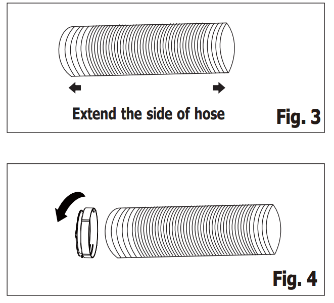
Extend either side of the hose (Fig. 3) and screw the hose to adaptor A (Fig. 4) .
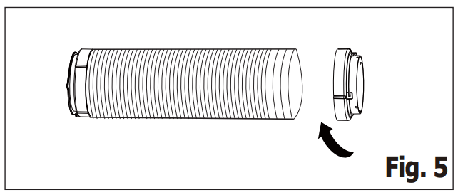
2. Extend the other side of the hose and screw it to adaptor B (Fig. 5).
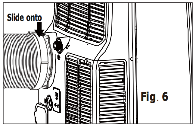
3. Slide the assembly onto unit (Fig. 6).
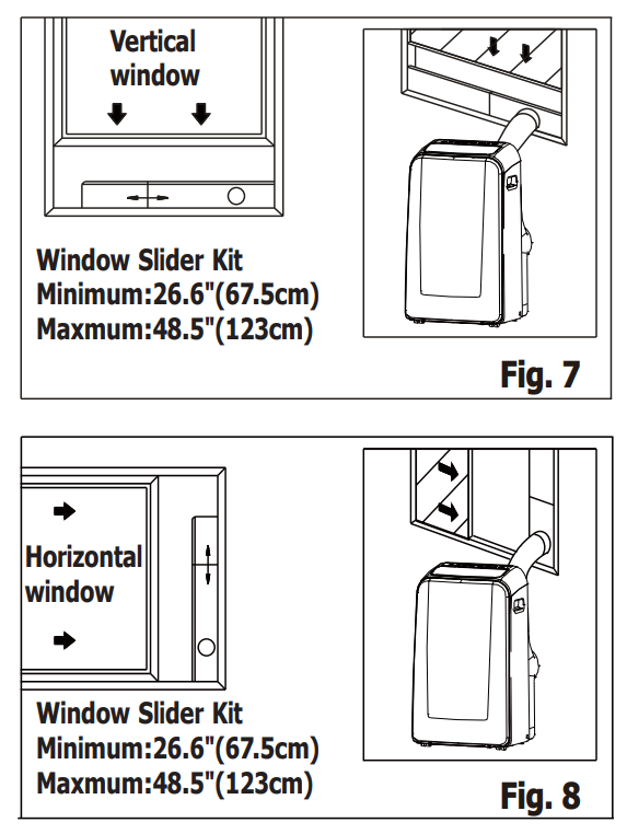
4. Affix the adaptor B into the window slider kit and seal. (Fig. 7&8)
Installation in a double-hung sash Windows
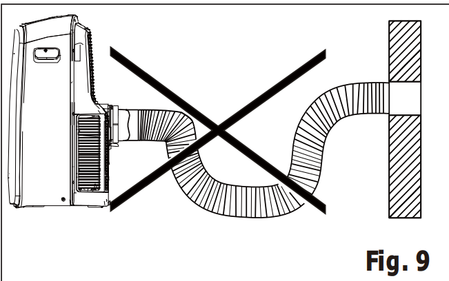
The hose can be extended from its original length of 15" up to 59", but it is the best to keep the length to minimum required. Also make sure that the hose does not have any sharp bends or sags (Fig. 9)
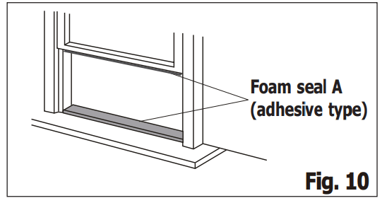
Cut the foam seals(adhesive type) to the proper lengths and attach them to the window and stool. (Fig. 10)
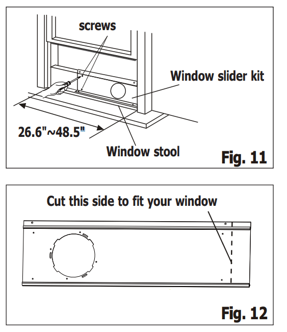
2. Open the window sash and place the window slider kit on the window stool (Fig. 11). Attach the window slider kit to the window stool. Adjust the length of the window slider kit according to the width of window. Screw down the two screws on the window slider kit. See Fig.11. Cut the adjustable window slider kit if the width of window is less than 26.6 inches (Fig. 12)
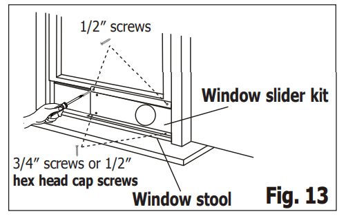
3. Close the window sash securely against the window slider kit. (Fig. 13)
4. . Drive two 1/2" screws to secure the window slider kit to the window sash. (FIG. 13)
5. Secure the window slider kit to the window stool (FIG. 13): A: For wooden windows: Use 3/4" screws for securing. B: For Vinyl-Clad windows: Use 1/2″ hex head cap screws for securing.
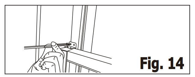
6. To secure lower sash in place, attach right angle sash lock with 1/2″ (12.7mm) screw as shown (FIG. 14).
NOTE: It is difficult to lock the windows with the sash lock for Vinyl-Clad windows, so you can use lock by window itself.
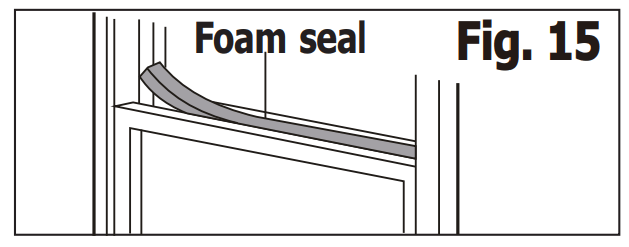
7. Cut the foam seal to an appropriate length and seal the open gap between the top window sash and outer window sash, as shown in Fig.15.
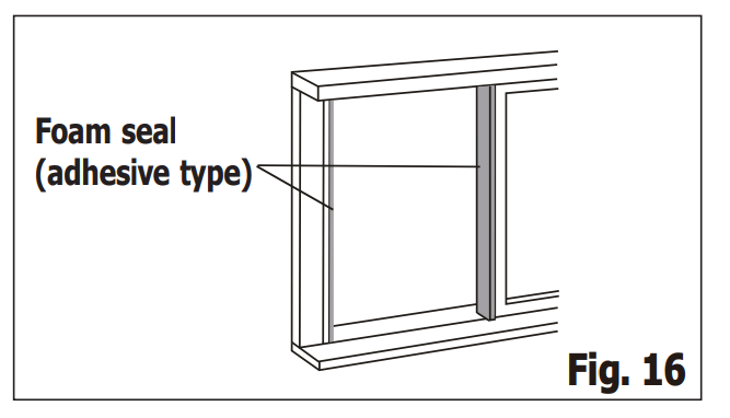
Installation in a sliding sash window
Cut the foam seals(adhesive type) to the proper lengths and attach them to the window frame. See Fig.16.
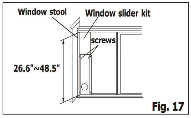
2. Open the window sash and place the window slider kit on the window stool. See Fig.17. Attach the window slider kit to the window stool. Adjust the length of the window slider kit according to the height of window. Screw down the two screws on the window slider kit. See Fig.17. Cut the adjustable window slider kit if the height of window is less than 26.6 inches (Fig. 12).
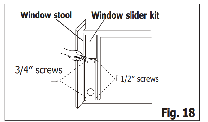
3. Close the sliding sash securely against the window slider kit. (Fig. 18)
4. Drive two 1/2" screws to secure the window slider kit to the window sash. (Fig. 18)
5. Drive two 3/4" screws to secure the window slider kit to the window stool. (Fig. 18)
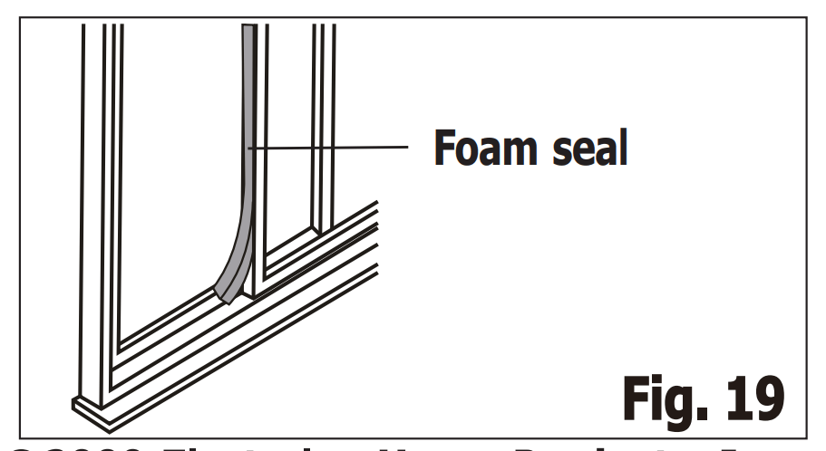
6. Cut the foam seal to an appropriate length and seal the open gap between the sliding sash and outer window sash, as shown in Fig.19.
7. To secure the sliding sash in place, attach right angle sash lock with 1/2" (12.7mm) screw as shown.(Fig.20)
Air Conditioner Features
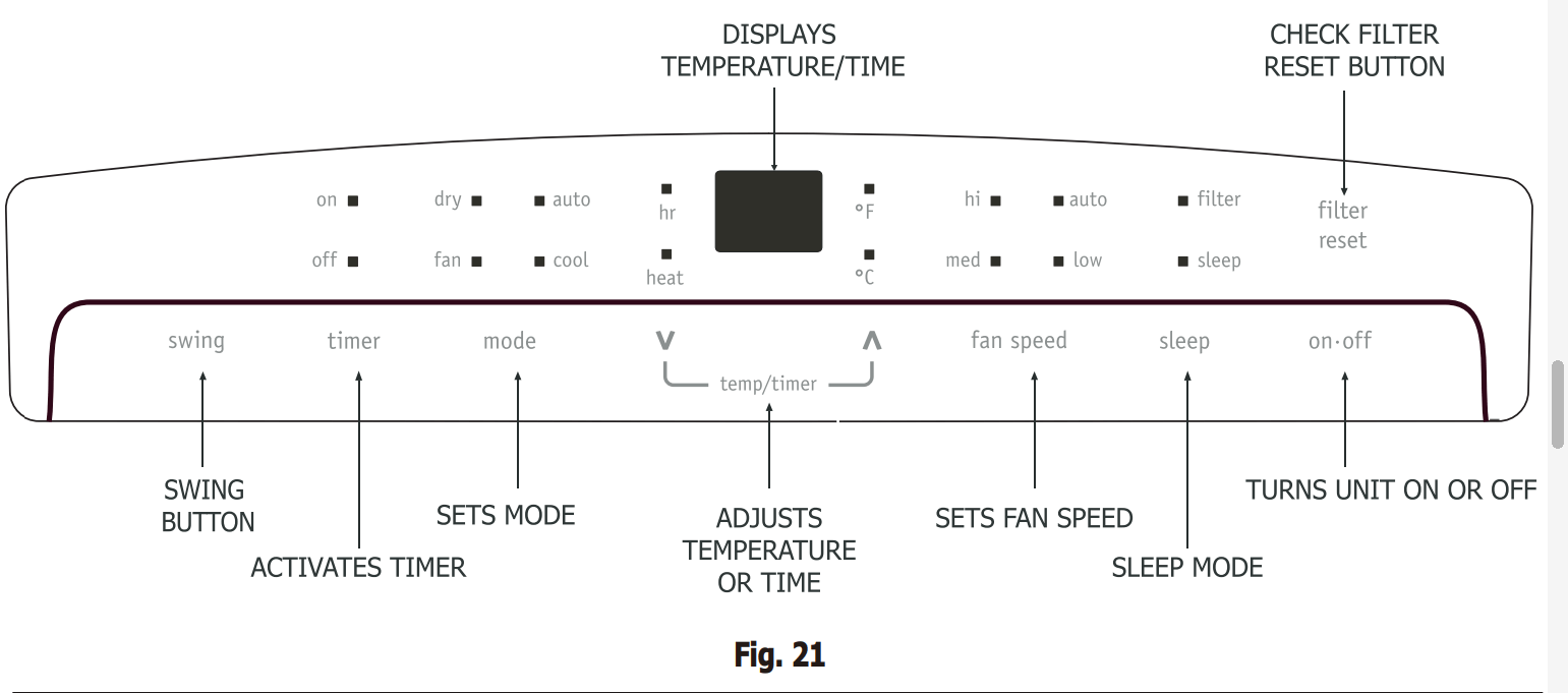
CONTROL PANEL
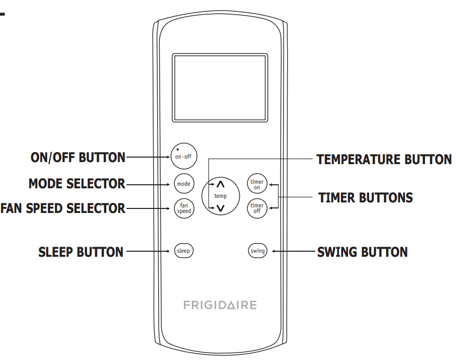
REMOTE CONTROL
Battery Size: AAA
Warning:
Do not mix old and new batteries. Do not mix alkaline, standard (carbon-zinc), or rechargeable (nickel- cadmium) batteries.
This device complies with Part 15 of the FCC Rules. Operation is subject to the following two conditions: (1) This device may not cause harmful interference, and (2) this device must accept any interference received, including interference that may cause undesired operation.
NOTE
The RESET button is depressed when you want to return to the initial factory settings. The LOCK button is depressed to lock the keypad so the settings cannot be changed. The key symbol will appear in the display of the remote control, depress the LOCK button again to release. Use a small pin to depress these buttons.
Heating function is for heating and cooling model only.
Operating Instructions
NOTE
The following instructions represent the Control Panel, the same instructions can be used for the Remote Control. (except timer function)
COOLING MODE:
In this mode the exhaust adaptor hose MUST be used.
Press the MODE button until the "Cool" indicator lights.
Press the " " Temp buttons for desired setting.
Press the FAN button for desired fan speed.
HEATING MODE:(on some models)
In this mode you do not need to use the exhaust adaptor hose.
Press the MODE button until the "Heat" indicator lights.
Press the " " Temp buttons for the desired heat setting. Under Heating mode, you can not select the fan speed.
DRY MODE:
In this mode you do not need to use the exhaust adaptor hose, BUT the water collected must be discharged. See Drainage Section.
Press the MODE button until the "Dry" indicator lights.
The fan will run at low speed and the display will show the room temperature.
Keep doors windows closed for best effect.
AUTO MODE:
Always have the exhaust hose attached in this mode. When you set the air conditioner in AUTO mode, it will automatically select cooling, heating(not applicable for cooling only models), or fan only operation depending on what temperature you have selected and the room temperature. The air conditioner will control room temperature automatically round the temperature point set by you. Under AUTO mode, you can not select the fan speed.
FAN MODE:
In this mode there is no need to use the exhaust hose or drainage hose.
Press the MODE button until the "Fan" indicator lights.
Press the FAN button to choose the desired fan speed.
The fan will run at the selected speed and the display will show the room temperature.
TIMER OPERATION:
You can set both delay stop and delay start while unit is in ON position or OFF position. When unit is in ON position, first press TIMER button to go to delay stop setting, then “timer off” light will illuminate, tap or hold the UP arrow ( ) or the DOWN arrow ( ) to change delay stop timer at 0.5 hour increments up to 10 hours, then at 1 hour increments up to 24 hours. Then press the TIMER button to confirm the setting (the control will confirm the setting automatically after 5 seconds) and go to delay start setting. Use the same way as above to set the delay start timing. If you don’t need to set delay start, press the TIMER button again to exit. After 5 seconds, the control will automatically change the display back to previous temperature display. If you want to check remain timing, press the TIMER button. The delay start operation automatically selects mode, temperature and fan speed the same as last operation you set. When unit is in OFF position, press TIMER button will first go to delay start setting, then “timer on” light will illuminate, set the delay start and delay stop timing the same way as above.
To cancel the timer setting, simply tap ( A ) or ( V ) button to change the timing to 0.0. You can set both delay stop and delay start by using the remote control, while unit is in ON position or OFF position. To set the delay stop timing, first press TIMER OFF button on the remote control to go to delay stop setting, then tap or hold the TIMER OFF button to change delay stop timer at 0.5 hour increments up to 10 hours, then at 1 hour increments up to 24 hours. After the desired setting is reached stop pressing the TIMER OFF button, the control will confirm the setting automatically after 5 seconds and change the display back to previous temperature display. Use the same way as above to set the delay start timing by pressing TIMER ON button. To cancel the timer setting, simply tap TIMER ON or TIMER OFF button to change the timing to 0.0.
SLEEP OPERATION:
In this mode the selected temperature will increase by 2 °F 30 minutes after the mode is selected. The temperature will then increase by another 2 °F after an additional 30 minutes. This new temperature will be maintained for 7 hours before it returns to the originally selected temperature. This ends the "Sleep" mode and the unit will continue to operate as originally programmed. The "Sleep" mode program can be cancelled at any time during operation by again pressing the "Sleep" button.
Note: This feature is unavailabe under FAN or DRY modes.
SWING OPERATION:
When you turn on the unit, the louver will swing and stop at a certain angle. You can press the SWING button to let the louver swing automatically. Press the SWING button again while you want the louver stop at desired angle.
CHECK FILTER FEATURE:
This feature is a reminder to clean the Air Filter (See Care and Cleaning) for more efficient operation. The filter indicator will illuminate after 250 hours of operation. To reset after cleaning the filter, press the "Filter" button and the light will go off.
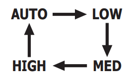
SELECTING FAN SPEED:
You can select the desired fan speed, by pressing the FAN SPEED button. The fan speed will change in the sequence as the drawing on the left. After choosing the fan speed as "AUTO", “LOW”, “MED” or “HIGH”, the corresponding fan speed indicator light will illuminate. Under AUTO, Heat, Dry mode, you can not select the fan speed.
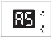
FAULT CODE:
If the display reads "AS" , the room temperature sensor has failed. Contact your Authorized Frigidaire Service Center.
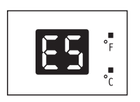
If the display reads "ES" , the evaporator temperature sensor has failed. Contact your Authorized Frigidaire Service Center.
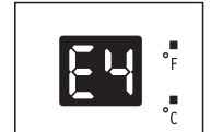
If the display reads "E4" , the display panel communication has failed. Contact your Authorized Frigidaire Service Center.
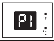
If the display reads "P1" , bottom tray is full. Carefully move the unit to a drain location, remove the bottom drain plug and let the water drain away. Restart the machine until the "P1" symbol disappears. If error repeats, call for service.
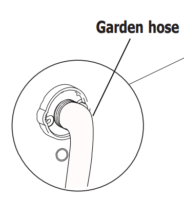
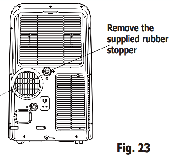
DRAINAGE: : During the dehumidifying mode, you will need a garden hose (sold separately) to drain the condensate from the unit. Remove the rubber stopper from the hose connector, then screw on a garden hose to the connector as shown on fig 23.
The hose may then:
Discharge into a drain that is lower than the unit.
Be connected to a condensate pump (sold separately).
During cooling mode, please replace the rubber stopper to the hose connector to reach the maximum performance.
ADDITIONAL THINGS YOU SHOULD KNOW
Now that you have mastered the operating procedure, here are more features in your control that you should become familiar with.
The "Cool" circuit has an automatic 3 minute time delayed start if the unit is turned off and on quickly. This prevents overheating of the compressor and possible circuit breaker tripping. The fan will continue to run during this time.
Temperature can be set between 62 °F and 86 °F (17 °C and 30 °C).
The control is capable of displaying temperature in degrees Fahrenheit or degrees Celsius. To convert from one to the other and back, press and hold the "TEMP" Up ( ) and Down ( ) buttons together for 3 seconds.
There is a 2-Second delay for the compressor shutting down when selecting FAN ONLY/HEAT. This is to cover the possibility of having to roll through to select another mode.
After a power outage, the unit will memorize the last setting and return the unit to the same setting once power is restored
Indoor operating temperature range for this product is 62 °F to 95 °F (17 °C to 35 °C).
CARE & CLEANING
Clean your air conditioner occasionally to keep it looking new. Be sure to unplug the unit before cleaning to prevent shock or fire hazards.
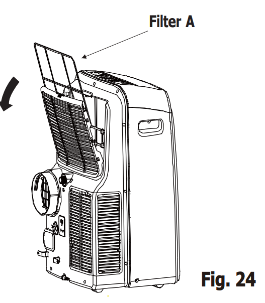
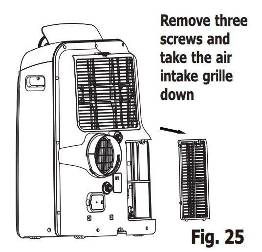
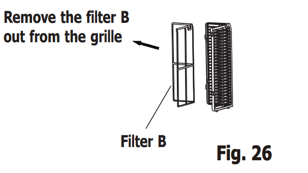
Air Filter Cleaning
This unit has two filters, they are filter A and B. Grasp the upper panel tab and take off the filter A which behind the grill of the back panel (Fig.24). Remove the lower filter B by loosening the screws. Take down the air inlet grille, then remove the air filter as shown in Fig.25 & 26.
Wash the filter using liquid dishwashing detergent and warm water. Rinse filter thoroughly. Gently shake excess water from the filter. Be sure filter is thoroughly dry before replacing.
Or, instead of washing you may vacuum the filter clean.
Replace the filter after the filter is dry.
Cabinet Cleaning
Be sure to unplug the air conditioner to prevent shock or fire hazard. The cabinet and front may be dusted with an oil-free cloth or washed with a cloth dampened in a solution of warm water and mild liquid dishwashing detergent. Rinse thoroughly and wipe dry
Never use harsh cleaners, wax or polish on the cabinet front.
Be sure to wring excess water from the cloth before wiping around the controls. Excess water in or around the controls may cause damage to the air conditioner
Winter Storage
If you plan to store the appliance during the winter, cover it with plastic or return it to its carton.
Before You Call
OCCURRENCE
SOLUTION
Air conditioner will not operate.
Wall plug disconnected. Push plug firmly into wall outlet.
Plug Current Device Tripped. Press the RESET button.
House fuse blown or circuit breaker tripped. Replace fuse with time delay type or reset circuit breaker.
Control is OFF. Turn Control ON and set to desired setting.
P1 appears in the display window. Drain water as described in Drainage Section
Shut off in Heat mode. When the air outlet exceeds 158 °F (70 °C), the automatic heat protection engages. Romove any blockages and let appliance cool down.
Room Temperature lower than the set temperature (Cool Mode). Reset the temperature
Room Temperature higher than the set temperature (Heat Mode). Reset the temperature
Air from unit does not feel cold enough.
Room temperature below 60°F (16°C). Cooling may not occur until room temperature rises above 60°F (16°C).
Reset to a lower temperature
Compressor shut-off by changing modes. Wait approximately 3 minutes and listen for compressor to restart when set in the COOL mode.
Air conditioner cooling, but room is too warm - ice forming on cooling coil behind decorative front
Outdoor temperature below 60 F (16 C). To defrost the coil, set FAN ONLY mode
Air filter may be dirty. Clean filter. Refer to Care and Cleaning section. To defrost, set to FAN ONLY mode.
Temperature is set too low for night-time cooling. To defrost the coil, set to FAN ONLY mode. Then, set temperature to a higher setting
Exhaust duct not connected or blocked. See EXHAUSTING HOT AIR Section.
Air conditioner cooling, but room is too warm - NO ice forming on cooling coil behind decorative front.
Dirty air filter - air restricted. Clean air filter. Refer to Care and Cleaning section
Temperature is set too high. Set temperature to a lower setting
Air directional louvers positioned improperly. Position louvers for better air distribution
Front of unit is blocked by drapes, blinds, furniture, etc. - restricts air distribution. Clear blockage in front of unit.
Doors, windows, registers, etc. open - cool air escapes. Close doors, windows, registers, etc
Unit recently turned on in hot room. Allow additional time to remove “stored heat” from walls, ceiling, floor and furniture.
Air conditioner turns on and off rapidly
Dirty air filter - air restricted. Clean air filter.
Outside temperature extremely hot. Set FAN speed to a faster setting to bring air through cooling coils more frequently.
Noise when unit is cooling.
Air movement sound. This is normal. If too loud, set to lower FAN setting.
Vibraion from uneven floor. Move or support appliance correctly on even surface.
Room too cold.
Set temperature too low. lncrease set temperature.

 NOTE
NOTE " Temp buttons for desired setting.
 " Temp buttons for the desired heat setting. Under Heating mode, you can not select the fan speed.