Loading ...
Loading ...
Loading ...
6
DECLARATION OF CONFORMITY
• This appliance has been designed, manufactured and marketed in conformity with the safety requirements of “Low Voltage” Directive 2006/95/EC (replacing
73/23/EEC as amended) and protection requirements of “EMC” Directive 2004/108/EC.
• This appliance meets the eco design requirements of european regulation N. 66/2014, in conformity to the european standard EN 60350-2.
BEFORE USE
IMPORTANT: The cooking zones will not switch on if pots are not the right size. Only use pots bearing the symbol
“INDUCTION SYSTEM” (Figure opposite). Place the pot on the required cooking zone before switching the hob on.
EXISTING POTS AND PANS
NOOK
Use a magnet to check if the pot is suitable for the induction hob: pots and pans are unsuitable if not
magnetically detectable.
• Make sure pots have a smooth bottom, otherwise they could scratch the hob. Check dishes.
• Never place hot pots or pans on the surface of the hob’s control panel. This could result in damage.
RECOMMENDED POT BOTTOM WIDTHS
Ø
28 cm
XL
Ø
17 cm min. 28 cm max.
Ø
21 cm
L
Ø
15 cm min. 21 cm max.
Ø
18 cm
M
Ø
14,5 cm
S
Ø
12 cm min. 18 cm max.
Ø
10 cm min. 14,5 cm max.
INSTALLATION
After unpacking the product, check for any damage during transport. In case of problems, contact the dealer or the After-Sales Service.
For built-in dimensions and installation instruction, see the pictures in page 2.
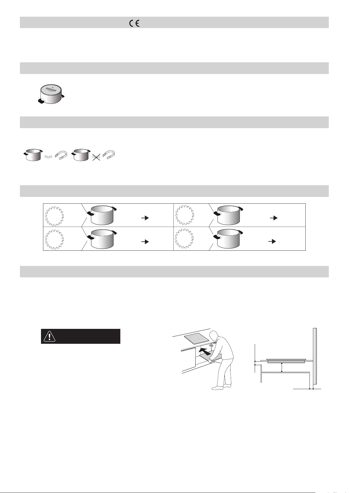
PREPARING THE CABINET FOR FITTING
WARNING
• Install a separator panel under the hob.
• The lower part of the product must not be accessible
after installation.
• Do not t the separator panel if an undertop oven is
installed.
• The distance between the underside of the appliance and the separator panel must respect the dimensions given in the gure.
• In order to ensure the correct operation of the product, do not obstruct the minimum required clearance between the hob and the top of the unit (min. 5 mm).
• If an undertop oven is installed, make sure the oven is equipped with a cooling system.
• Do not install the hob above a dishwasher or washing-machine, so that the electronic circuits do not come into contact with steam or moisture which could
damage them.
• In the case of ush-mounted installation, call the After-Sales Service to request assembly of screws kit 4801 211 00112.
• To remove the hob, use a screwdriver (not provided) to prise off the perimeter clips on the underside of the appliance.
Min. 5 mm
Min. 20 mm
Min. 5 mm
Loading ...
Loading ...
Loading ...