
En
2
Contents
How to read this manual
! Thank you for purchasing this Pioneer DJ product.
Be sure to read this manual and the “Operating Instructions (Quick
Start Guide)” included with the unit. Both documents include
important information that you should understand before using this
product.
! In this manual, buttons, terminals, names of screens and menus
displayed on the product and computer screen, etc., are enclosed
in square brackets ([ ]). (e.g.: [CUE] button, [Files] panel, [MIC1]
terminal)
! Screens, external appearance, and software and hardware specifica-
tions described in this manual are based on the product that is still
under development and may differ from the final specifications.
! Depending on your operating system, the web browser settings,
etc., the procedures described in this manual may differ from actual
operations.
Before start
Features ....................................................................................................... 3
Accessories ................................................................................................. 3
Supported media ........................................................................................ 3
Connections and part names
Connections ................................................................................................ 4
Part names and functions ......................................................................... 6
Project structure
Basic operation
Starting the system ................................................................................... 10
Loading a project ...................................................................................... 10
Playing and stopping a pattern ............................................................... 10
Adjusting the playing speed (Tempo Control)
....................................... 10
Switching the pattern ............................................................................... 11
Switching the scene
................................................................................. 11
Changing the length of a pattern ............................................................ 11
Loading a sample to a track ..................................................................... 11
Using the performance pads ................................................................... 12
Using the step keys parameter adjustment knobs ................................ 13
Using the touch strip function................................................................. 13
Saving a project ........................................................................................ 14
Turning off the system .............................................................................. 14
Advanced operation
Making overall settings, adjustments, and checks (HOME) ................ 15
Track display content................................................................................ 16
Managing project files (PROJECT) .......................................................... 16
Adjusting the volume of each track (MIXER)
......................................... 18
Checking sequences (SEQ.) .................................................................... 18
Setting BPM (BPM) .................................................................................. 19
Setting quantize (QUANTIZE)
................................................................. 19
Setting synchronization with externally connected device (SYNC) ..... 20
Managing scenes and patterns (SCENE MANAGER) .......................... 21
Audio rendering (RENDER AUDIO)
........................................................ 25
Sampling (LIVE SAMPLING) ................................................................... 25
Using effects ............................................................................................. 26
Adjusting track parameters (TRACK MENU)
Setting the track attributes ...................................................................... 28
Selecting a module ................................................................................... 28
Setting bypass ........................................................................................... 28
Sample track ............................................................................................. 29
Through track ............................................................................................ 43
MIDI tracks ................................................................................................ 43
TORAIZ AS-1 tracks
.................................................................................. 46
Changing the settings (UTILITY)
Setting preferences .................................................................................. 47
Setting the USER mode of the touch strip
(
TOUCH STRIP SETTING) ........................................................................ 49
Auto standby function .............................................................................. 50
Adjusting the touch panel (TOUCH PANEL CALIBRATION) ............... 51
MIDI implementation chart
Connections .............................................................................................. 52
Notes .......................................................................................................... 52
Control changes ....................................................................................... 53
Pitch bend ................................................................................................. 54
Mode message .......................................................................................... 54
Additional information
Troubleshooting ........................................................................................ 55
Liquid crystal display ................................................................................ 55
Cleaning the touch display ...................................................................... 55
Signal flow ................................................................................................. 56
Trademarks and registered trademarks ................................................. 56
Cautions on copyrights ............................................................................ 56

En
3
Before start
Before start
Features
This unit is a standalone hardware sampler and sequencer for DJs that
enables intuitive performances. It functions as a new kind of musical
instrument that can also be used for DJ performances and live perfor-
mances and is equipped with a user interface providing high operability
and numerous performance functions, so a wide range of musical
expression is possible on stage.
Step sequencer
Large multicolored step input keys that can be tapped while looking at
the sequence information on each track and the track colors are pro-
vided to allow you to easily create a new groove.
Large performance pads
The unit is equipped with large rubber pads that increase or decrease
the volume depending on the strength with which they are tapped by
employing highly accurate velocity detection. Each pad has built-in
multi-color illumination so you can instantaneously understand the
information required for your performance from the color and lighting
state of the pad.
Real-time processing engine
A time stretch engine that runs for all 16 tracks in real-time, an ampli-
fier envelope, effects, etc. are available, and samples can be assigned
to tracks to suit applications such as loop, one shot, and SFX (effect
sounds) and can be easily synchronized with the sequencer and played
with high sound quality.
7-inch touch display
The display unit is equipped with a full-color LCD touch display. It
displays the information required for performances in an easy to under-
stand manner, such as the HOME screen to view the information on the
sample sound source assigned to each track that uses instrument icons
and color representations linked to the pads and the SEQUENCE screen
to understand the sequencer performance status.
Functions to synchronize performances
with external devices
This unit is of course capable of clock synchronization with MIDI-
compliant devices, but it also has the BEAT SYNC function which can
synchronize a performance with the track being played by a PRO DJ
LINK-compatible Pioneer DJ multi player such as the CDJ-2000NXS2.
Furthermore, performances can be synchronized with any equipment
manually if you use the tempo slider, which allows you to control the
tempo just like with DJ equipment, and the NUDGE button.
! Operates with compatible DJ systems when playing tracks whose
beats have been analyzed by rekordbox TM.
LIVE SAMPLING
The LIVE SAMPLING function is provided to enable the sounds input to
the unit to be sampled with a simple operation so that they can be used
as tracks. Since the sampled sounds are automatically synchronized
with sequences to play in a loop, they can be used immediately for remix
performances.
Other features
FX
! An audio effect that enables dynamically changing any track tone
with a simple operation is available.
Touch strip
! In addition to the pitch bend and note repeat functions, the "touch
strip" function, which allows you to customize operation parameters,
is supported
Support for USB storage devices
! There is support for USB storage devices which are useful for man-
aging sound sources and projects.
Preset sound sources
! Samples (from Loopmasters) that allow you to start performing right
away out of the box are available.
Accessories
! Power cord
! USB cable
! LAN cable
! RCA pin cable
! Warranty (for some regions)
1
! Operating Instructions (Quick Start Guide)
1 The warranty is included for European region only.
— For the Japanese region, the corresponding information is pro-
vided on the back cover of the “Operating Instructions (Quick
Start Guide)”.
— For the North American region, the corresponding information is
provided on the last page of both the English and French versions
of the “Operating Instructions (Quick Start Guide)”.
Supported media
This unit is compatible with USB mass storage class devices such as
USB flash drives and digital audio players.
File systems FAT, FAT32 and HFS+
! Samples (wav and aiff with a sampling frequency of 44.1 kHz) on a
USB device can be used with this unit.
! Depending on the USB device you are using, you may not achieve
the expected performance.
! There is no guarantee that all USB devices will operate with this unit.

En
4
Connections and part names
Connections
Turn off this unit and disconnect the power cord from the power outlet
before connecting components or changing the connections.
Connect the power cord to a power outlet after all the connections are
completed.
Be sure to use the power cord, USB cable, and LAN cable included with
this product.
Refer to the operating instructions for the components to be connected.
! When using a LAN cable to connect the components, be sure to
use either the LAN cable included with this product or an STP
(shielded twisted pair) cable.
! Do not disconnect the LAN cable when information is being
shared with PRO DJ LINK.
! A switching hub (commercially available) may be necessary
depending on the models to be combined. Use a switching hub
of 100 Mbps or greater. Correct operation may not be possible
depending on the switching hub.
!
A switching hub (commercially available) is necessary when con-
necting with a mixer that has only one LAN port. In the case of a
mixer with enough LAN ports for all the DJ players and computers
in the system, connect directly to a LAN port on the mixer’s rear
panel without using a hub.
System expansion
When importing samples from a USB device
When a USB device is inserted into the unit, the [PIONEER DJ
SAMPLER] folder is created automatically. Only samples placed in the
[Samples] folder in this [PIONEER DJ SAMPLER] folder can be read by
the BROWSE function (p. 29 ).
USB device
s
En
5
Connections and part names
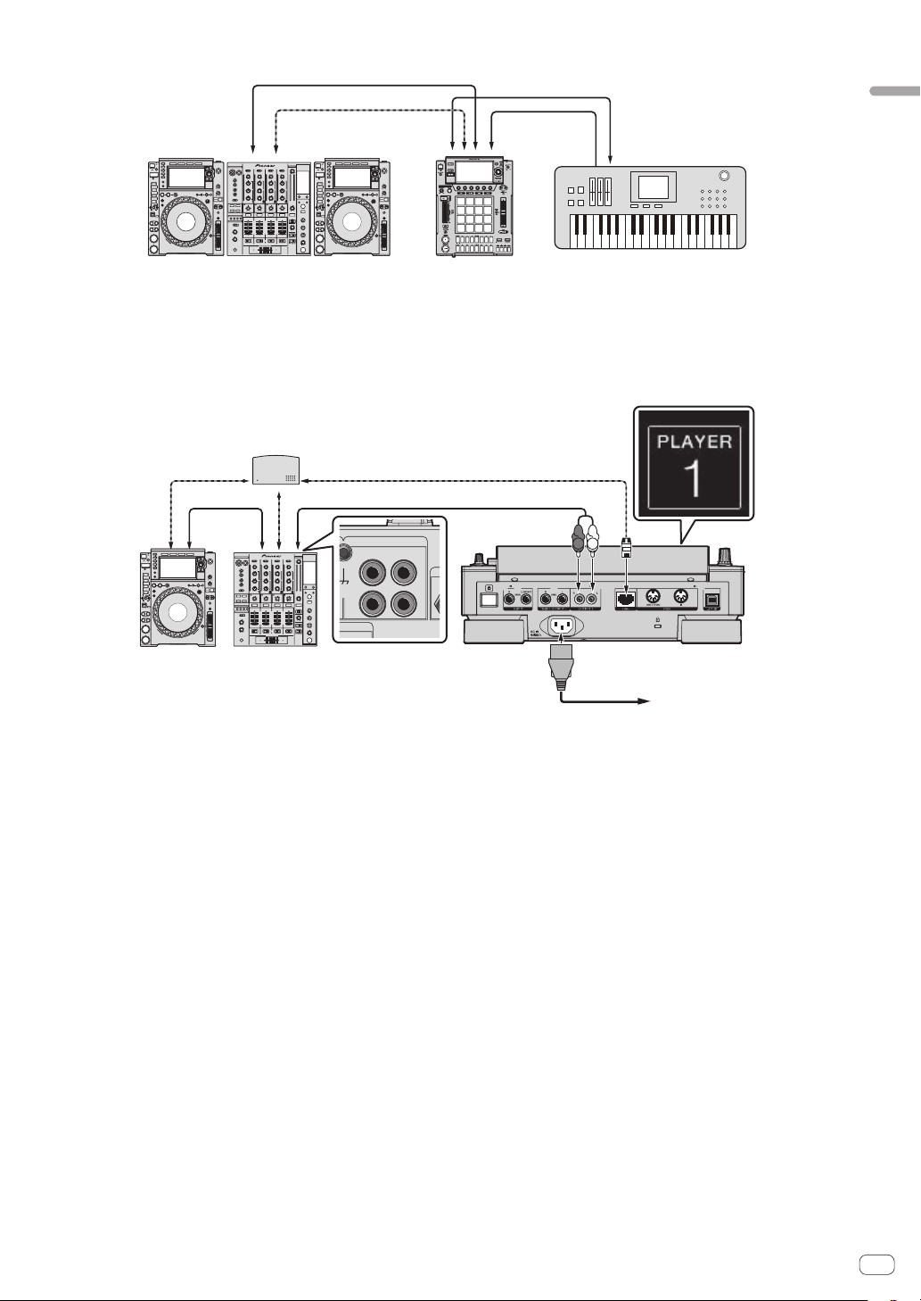
When using with external devices
Audio cable
MIDI cable
LAN cable
Audio cable
PRO DJ LINK compatible DJ system
Synthesizer, etc.
Connecting to a mixer with one LAN port
When connecting to a mixer with only one LAN port using a switching hub, set the channel number of the mixer to which the audio or digital audio
cable is connected and the player number displayed at the bottom left of the main unit display to the same number.
(Ex.: When an audio cable is connected to channel 1)
CH 1
L
R
PHONO
CH 1
CD/ LINE
N
AL GND
L
R
PLAYER 1
DJ player
LAN cable
LAN cable
Switching hub
LAN cable
Audio cable
Audio
cable
DJ mixer
Rear panel
Power cord
To power outlet
To change the player number, follow the procedure below.
1 Disconnect the USB device and LAN cable.
2 Press the [HOME/UTILITY/WAKE UP] button for over 1 second to display the [UTILITY] screen.
3
Turn the rotary selector to select [PLAYER No.], and press the rotary selector.
4 Turn the rotary selector to select a player number, and press the rotary selector.
5 Press the [HOME/UTILITY/WAKE UP] button to complete the setting.
En
6
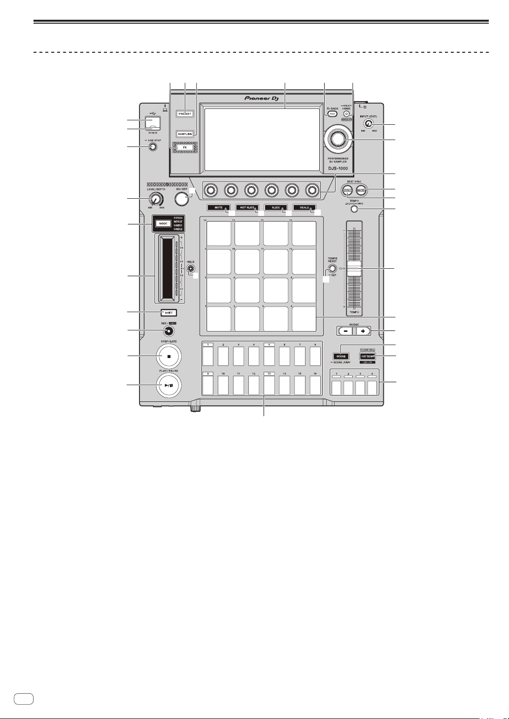
Part names and functions
Top panel
9
h
d
e
i
j
o
n
m
l
k
p
q
s
w
x
1
2
3
4
5
6
7
8
a
c
b
f
y
z
A
t
g
r
u
v
1 PLAY/PAUSE f button
Plays or pauses a pattern. This is lit when playing a pattern and
flashes when in the pause mode.
=
Playing and stopping a pattern (p. 10 )
2 STOP/GATE button
Stops a pattern. Pressing the [STOP] button while a pattern is
stopped plays the pattern only while the button is pressed.
3 REC/UNDO button
Records a pad performance. Pressing the [REC/UNDO] button while
pressing the [SHIFT] button returns to the state before recording.
4 SHIFT button
Calls out another function if this button is pressed while another
button is pressed.
5 Touch strip
Adjusts the effect of each mode of the touch strip.
= Using the touch strip function (p. 13 )
6 HOLD button
Holds the effect of the touch strip.
= Using the touch strip function (p. 13 )
7 MODE selection button and MODE indicators
The MODE indicator displays the selected touch strip mode.
Each press of the MODE selection button switches the touch strip
mode.
= Using the touch strip function (p. 13 )
8 FX LEVEL DEPTH control
Adjusts the quantitative parameter of the effect.
9 FX ON/OFF button
Turns the effect on/off.
a USB STOP button
Press for at least 2 seconds before disconnecting the USB device.
b USB indicator
Lights up or flashes when this unit is communicating with the USB
device.
c USB device insertion slot
Connect a USB device.
d FX button
Displays the PERFORMANCE FX screen on the touch display.
e PROJECT button
Displays the PROJECT screen on the touch display.
f SAMPLING button
Displays the LIVE SAMPLING screen on the touch display.
g Touch display
Displays various information.
h BACK button
The screen returns to the layer above.

En
7
Connections and part names
i HOME/UTILITY/WAKE UP button and STANDBY
indicator
HOME: Displays the HOME screen on the touch display.
UTILITY: Pressing and holding the [HOME/UTILITY/WAKE UP] but-
ton displays the UTILITY screen on the touch display.
WAKE UP: Setting AUTO STANDBY to ON in the UTILITY screen and
then pressing the [HOME/UTILITY/WAKE UP] button cancels the
auto standby state.
=
Auto standby function (p. 50 )
j INPUT LEVEL control
Adjusts the level of sound input to the [INPUT] terminals.
k Rotary selector
Turning the rotary selector when selecting a project, track, setting
item, etc. moves the focus. Pressing the rotary selector selects the
focused item.
l Parameter adjustment knobs
Adjusts the parameters assigned to each parameter adjustment
knob.
The leftmost parameter adjustment knob is the parameter 1 adjust-
ment knob, and the knobs are arranged from the left in order of the
parameter 1 adjustment knob to parameter 6 adjustment knob.
= Using the step keys parameter adjustment knobs (p. 13 )
m BEAT SYNC MASTER button
Sets this unit as the master for the beat sync function.
= Setting synchronization with externally connected device (SYNC)
(p. 20 )
n BEAT SYNC button
Turns the beat sync function on.
= Setting synchronization with externally connected device (SYNC)
(p. 20 )
o MUTE button
Switches the pad mode to the mute function.
= Muting a track (MUTE mode) (p. 12 )
p HOT SLICE button
Switches the pad mode to the hot slice performance function.
= Playing a hot slice performance (HOT SLICE mode) (p. 12 )
q SLICE button
Switches the pad mode to the slice performance function.
= Playing a slice performance (SLICE mode) (p. 12 )
r SCALE button
Switches the pad mode to the scale performance function.
= Playing a scale performance (SCALE mode) (p. 12 )
s TEMPO ±6/±10/±16/WIDE button
Switches the playing speed adjustment range (±6/±10/±16/WIDE).
t TEMPO slider
Adjusts the playing speed of tracks.
u TEMPO RESET/SET button and TEMPO RESET indicator
Plays the pattern using the BPM value set for the project regardless
of the position of the TEMPO slider.
! Pressing and holding the [TEMPO RESET/SET] button sets the
currently playing BPM as the BPM of the project.
v Performance pads
Use these pads to achieve various performances.
When using with the sample performance function
= Playing a sample sound (p. 12 )
When using with the mute function
= Muting a track (MUTE mode) (p. 12 )
When using with the hot slice performance function
=
Playing a hot slice performance (HOT SLICE mode) (p. 12 )
When using with the slice performance function
= Playing a slice performance (SLICE mode) (p. 12 )
When using with the scale performance function
=
Playing a scale performance (SCALE mode) (p. 12 )
w NUDGE button
Enables the offset from a sample for which a synchronized per-
formance is being performed to be corrected manually by slightly
advancing or delaying the BPM of the playing pattern.
x SCENE/SCENE JUMP button
Turns the scene switching mode on or off.
= Switching the scene (p. 11 )
y PATTERN/LENGTH/CLEAR SEQ. button
Turns the pattern switching mode on or off.
! Tapping a performance pad while pressing the [PATTERN/
LENGTH/CLEAR SEQ.] button clears the corresponding track
trigger.
=
Switching the pattern (p. 11 )
z Bar selection keys
Selects bars to display for the 16 step keys.
A 16-step keys
Used for functions such as inputting a programming trigger, scene/
pattern switching, step recording, and step modulation.
When using with the pattern switching function
= Switching the pattern (p. 11 )
When using with the scene switching function
=
Switching the scene (p. 11 )
When using with the step recording function
=
Programming triggers (step recording) (p. 13 )
When using with the step modulation function
= Changing parameters by step (step modulation) (p. 13 )

En
8
Rear panel
1
6 7 9
2
3
45
8 a
1 u switch
Turns this unit on and off.
= Starting the system (p. 10 )
2 INPUT terminals
Connect to the output terminals of another mixer or a line level out-
put component. If a cable is connected to the [L] terminal only, the
input to the [L] terminal is also input to the [R] channel.
3 THRU/OUTPUT2 terminals
4 OUTPUT1 terminals
5 AC IN
Connect to a power outlet.
! Connect the power cord to a power outlet after all the connec-
tions are completed.
! Be sure to use the supplied power cord.
6 LINK terminal
Connect a PRO DJ LINK compatible device with the LAN cable
(included).
7 Kensington security slot
8 MIDI OUT/THRU terminal
Connect a MIDI device to this DIN type terminal.
9 MIDI IN terminal
Connect a MIDI device to this DIN type terminal.
a USB-B terminal
Connect to a computer.
! A USB hub cannot be used.
! To maintain the performance, connect this unit and computer
directly using a USB cable that conforms to USB 2.0.
Front panel
2
1
1 PHONES terminals
Connect headphones. 1/4” stereo phone plugs are supported.
2 LEVEL control
Adjusts the level of sound output from the headphones.
En
9
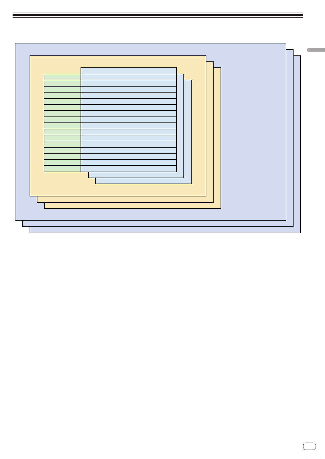
Project structure
Project structure
The figure below shows the data structure of this unit.
PROJECT
SCENE
TRACK1
TRACK2
TRACK3
TRACK4
TRACK5
TRACK6
TRACK7
TRACK8
TRACK9
TRACK10
TRACK11
TRACK12
TRACK13
TRACK14
TRACK15
TRACK16
TRACK1 Sequence
TRACK2Sequence
TRACK3Sequence
TRACK4Sequence
TRACK5Sequence
TRACK6Sequence
TRACK7Sequence
TRACK8Sequence
TRACK9Sequence
TRACK10Sequence
TRACK11Sequence
TRACK12Sequence
TRACK13Sequence
TRACK14Sequence
TRACK15Sequence
TRACK16Sequence
PATTERN
PROJECT
A project represents one work unit for the user. 16 scenes can be stored in one project.
SCENE
16 patterns and sample assignment information for tracks are stored in scenes.
Since the samples to assign to tracks can be changed for each scene, the tune can be greatly changed by changing the scene.
PATTERN
A pattern combines the sequences to create in the 16 tracks and is one finished section of a performance. A pattern length can be set on a step level
from a minimum of 1 step to a maximum of 64 steps (4 bars).
TRACK
Tracks consist of modules such as sample players, amplifier envelopes, insert effects, LFO, sequences, MIDI NOTE, and MIDI CC.
There are the following three track types.
! Sample track: Used when setting a sample in internal memory as the sound source.
! Through track: Used when setting an external input as the sound source.
! MIDI track: Used when performing using an external MIDI sound source.
Sound sources can be assigned as follows: a bass drum to track 1, a snare drum to track 2, and a synthesizer connected to an external input to track 3.
En
10
Basic operation
Starting the system
1 Plug the power cord into a power outlet after all the
connections between devices are completed.
= Connections (p. 4 )
2 Press the [u] switch on the rear panel of the unit.
The indicators light up and this unit turns on.
Connecting a USB device
1 Press the [u] switch to turn this unit on.
2 Connect a USB device to the USB device insertion slot.
Disconnecting a USB device
1 Press and hold the [USB STOP] button until the USB
indicator turns off.
Do not disconnect the USB device or turn this unit off while the USB
indicator is flashing. Failure to do so may result in losing the manage-
ment data and the USB device becoming unreadable.
USB indicato
r
USB STOP butto
n
2 Disconnect the USB device.
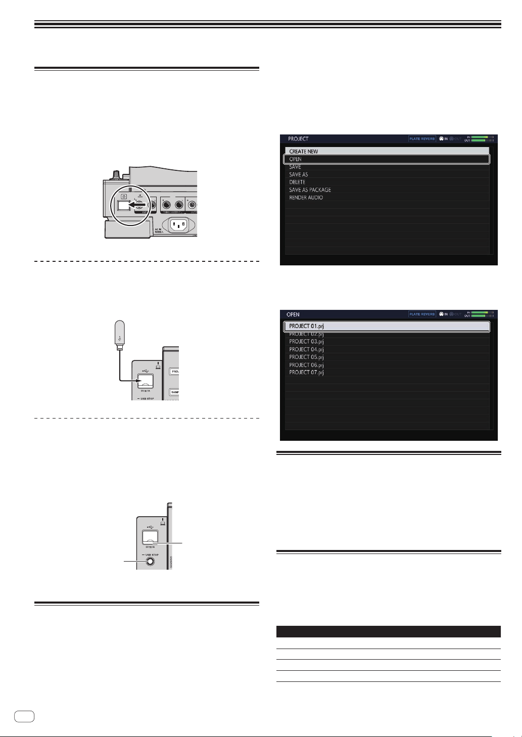
Loading a project
Start each procedure in the following sections from the home screen.
Press the [HOME] button to display the home screen.
1 Press the [PROJECT] button.
The PROJECT screen appears. You can perform operations such as load-
ing and saving projects on the PROJECT screen.
2 Turn the rotary selector to select [OPEN] and then
press the rotary selector.
The media connected to the unit appears.
If you select the media containing the project you wish to use and then
press the rotary selector, the project list is displayed.
! Press the [BACK] button to return to the previous screen.
3 Turn the rotary selector to select a demo project and
then press the rotary selector.
A confirmation pop-up screen appears.
Playing and stopping a pattern
Press the [PLAY/PAUSE f] button.
The pattern currently selected for the demo project plays back. During
playback, the [PLAY/PAUSEf] button lights up in green.
! Pressing the [PLAY/PAUSEf] button during playback pauses
playback.
! Pressing the [STOP] button during playback stops playback and
returns to the beginning of the pattern.
Adjusting the playing speed (Tempo
Control)
Press the [TEMPO ±6/±10/±16/WIDE] button.
The [TEMPO] slider’s adjustment range switches each time the button is
pressed. The adjustment range setting is displayed on the screen.
Options Units of adjustment
±6
0.02 %
±10
0.05 %
±16
0.05 %
WIDE
0.5 %
The [WIDE] adjustment range is ±100 %. When set to –100 %, playback
stops.
En
11
Basic operation
Move the [TEMPO] slider forward or backward.
The tempo increases when the slider is moved to the [+] side (back-
ward), and decreases when the slider is moved to the [–] side (forward).
The rate at which the playing speed is changed is displayed on the play-
ing speed display.
To set the BPM value of the project, refer to Setting BPM (BPM) on
page 19 .
Switching the pattern
1 Press the [PATTERN] button.
The unit enters the pattern switching mode and the [PATTERN] button
lights up in white. The 16 step keys are lit in the currently selected scene
colors during pattern switching mode.
! 16 patterns can be assigned to each scene. One pattern is
assigned to each step key.
! Scenes with recorded sequences are dimly lit, scenes with no
sequences recorded are not lit, and currently selected sequences
are fully lit.
2 Press a 16-step key set with a sequence.
The pattern assigned to the button is played.
! The timing that the pattern is switched is in accordance with the
PATTERN QUANTIZE setting value set on the QUANTIZE screen.
!
The pressed step key flashes while the pattern is switched.
! Press the [PATTERN] button to exit pattern switching mode.
Switching the scene
1 Press the [SCENE] button.
The unit enters the scene switching mode and the [SCENE] button lights
up in white. The 16-step keys light up in the color set for the current
scene in scene switching mode..
! 16 scenes can be assigned to each project. One scene is
assigned to one of the 16 step keys.
! Scenes with recorded sequences are dimly lit, scenes with no
sequences recorded are not lit, and currently selected sequences
are fully lit.
2 Press a 16-step key set with a sequence.
The scene is selected, and the unit switches to the state for selecting a
pattern in that scene.
! For details on switching the pattern, refer to Switching the
pattern.
! Press the [SCENE] button to exit scene switching mode.
! The display returns to the previous scene if the mode is exited
without switching the pattern.
! Pressing and holding the [SCENE] button sets the SCENE JUMP
mode to continue the scene switching mode even if the scene
is switched. The [SCENE] button flashes in white while in the
SCENE JUMP mode.
Changing the length of a pattern
1 Press the [PATTERN] button while pressing the [SHIFT]
button.
The unit switches to pattern length setting mode, and the [PATTERN]
button blinks white. During pattern length setting mode, the 16-step key
lights white, and the measure selection key lights blue.
!
A pattern length from a minimum of 1 step to a maximum of 64
steps can be set.
2 Press a bar selection key.
Set the length of the pattern using bar units. The bar selection keys from
bar selection key [1] to the pressed bar selection key light in blue.
3 Press the 16-step keys.
Set the length of the pattern on a step level. The 16-step keys pressed
from 16-step key [1] to 16-step key [16] light in white.
! Press the [PATTERN] button to exit pattern length setting mode.
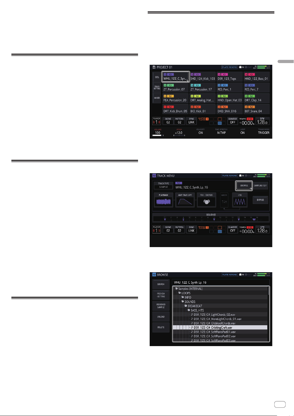
Loading a sample to a track
1 Tap the track to which you wish to load the sample
on the home screen and then tap again in the selected
state.
The track menu screen appears.
! The track menu can also be displayed by turning the rotary selector
to select a track and then pressing the rotary selector.
2 Tap [BROWSE].
The browse screen appears. You can search for samples and load sam-
ples to tracks on the browse screen.
! The browse screen can also be displayed by turning the rotary selec-
tor to select [BROWSE] and then pressing the rotary selector.
3 Turn the rotary selector to select a sample and then
press the rotary selector.
The sample is loaded to the track, and loaded on the screen.
! Select a folder and press the rotary selector to open or close the
folder.
! Turn the rotary selector while pressing the [SHIFT] button to move
the focus between folders (sample files are skipped).

En
12
Using the performance pads
Playing a sample sound
1 Set all of the [MUTE] button, [HOT SLICE] button,
[SLICE] button, and [SCALE] button to OFF.
All of the buttons are set to the off state.
2 Tap the performance pads.
The sample assigned to each performance pad plays.
Recording a performance (dynamic
recording)
1 Press the [REC] button.
The [REC] button lights up in red and the unit enters the recording state.
2 Press the [PLAY/PAUSE f] button.
The [PLAY/PAUSEf] button lights up in green and the sequence
plays while the unit is in the recording state.
3 Tap the performance pads to set triggers.
A trigger is set when the pad is tapped. The step key to which the trigger
was input lights or flashes in the track color.
Using the operation modes of the
performance pads
Four operation modes are available.
Muting a track (MUTE mode)
Tracks assigned to performance pads can be muted by pressing the
[MUTE] button.
1 Press the [MUTE] button.
The [MUTE] button lights up in white.
2 Press the performance pad to mute the assigned
track.
The performance pad whose track is muted turns off.
!
You can mute multiple tracks at the same time.
! To cancel mute, press the performance pad corresponding to the
muted track again.
!
If a performance pad is pressed while pressing the [SHIFT] button in
the mute mode, the sound plays only for the track corresponding to
the performance pad. (SOLO mode)
—
Solo can be set for multiple tracks at the same time.
— To cancel solo, press the performance pad for which the sound is
playing again while pressing the [SHIFT] button.
—
When all solo states are canceled, the previous mute state is
restored.
! Pressing the [MUTE] button while pressing the [SHIFT] button can-
cels all mute states and solo states.
3 Press the [MUTE] button again.
The [MUTE] button turns off and the MUTE mode ends.
!
Mute can also be set by pressing a performance pad while pressing
the [MUTE] button. In that case, the MUTE mode ends once you
release the [MUTE] button.
Playing a hot slice performance (HOT SLICE
mode)
Sliced sample sounds assigned to performance pads can be played
from the sliced sample position to the end of the sample by pressing the
[HOT SLICE] button.
1 Select the track for which you wish to play a hot slice
performance of the sample assigned to it.
2 Press the [HOT SLICE] button.
The [HOT SLICE] button lights in white.
! The sample is sliced equally into 16 and the slices are assigned to
the performance pads in order.
! Press and hold down the [HOT SLICE] button to display the
SET SLICE screen and enter the HOT SLICE mode.
3 Tap the performance pads.
The sample assigned to each performance pad plays.
4 Press the [HOT SLICE] button again.
The [HOT SLICE] button turns off and the HOT SLICE mode ends.
Playing a slice performance (SLICE mode)
Sliced sample sounds assigned to performance pads can be played by
pressing the [SLICE] button.
1 Select a track to play a slice performance of the
sample assigned to it.
2 Press the [SLICE] button.
The [SLICE] button lights up in white.
! The sample is sliced equally into 16 and the slices are assigned to
the performance pads in order.
! Press and hold down the [SLICE] button to display the SET SLICE
screen and enter the SLICE mode.
3 Tap the performance pads.
The sample assigned to each performance pad plays.
4 Press the [SLICE] button again.
The [SLICE] button turns off and the unit exits slice performance mode..
Playing a scale performance (SCALE mode)
Samples of scales assigned to performance pads can be played by
pressing the [SCALE] button.
1 Select a track to play a scale performance of the
sample assigned to it.
2 Press the [SCALE] button.
The [SCALE] button lights up in white.
! A sample can be played using the scale set on the SET SCALE
screen, treating the bottom left performance pad as the root key.
! Press and hold down the [SCALE] button to display the SET SCALE
screen and enter the SCALE mode.
3 Tap the performance pads.
Samples are played in the scale assigned to each performance pad.
4 Press the [SCALE] button again.
The [SCALE] button turns off and the SCALE mode ends.
! Trigger step input is possible using one of the following two methods
for a HOT SLICE mode performance, SLICE mode performance, and
SCALE mode performance.
— Tap the pad you wish to play and then press the 16-step key of the
step you wish to input.
— While pressing the 16-step key of the step you wish to input, tap
the pad you wish to input for that step.
En
13
Basic operation
Using the step keys parameter
adjustment knobs
Programming triggers (step recording)
1 Tap the track for step recording on the home screen.
The sequence of the selected track is displayed on the 16-step keys.
!
A track can also be selected by turning the rotary selector.
! A track can also be selected by tapping a performance pad.
2 Press the 16-step keys to input triggers.
The step keys corresponding to the programmed sequence light up in
the track color.
Changing track parameters
1 Press the [HOME] button.
The HOME screen appears.
2 Select a track to change the parameters of the
samples assigned to it.
3 Turn the parameter adjustment knobs.
The parameter corresponding to each parameter adjustment knob
changes. The parameter values are displayed at the bottom of the touch
display.
! Turn the parameter 1 adjustment knob (changes the volume).
The volume of the track changes. Turning the parameter adjustment
knob while pressing the [SHIFT] button changes the parameter one
level at a time.
! Turn the parameter 2 adjustment knob (changes the pitch of the
sound).
The sound pitch of the track changes.
! Turn the parameter 3 adjustment knob (enables or disables
[VELOCITY] of the pads).
Enable or disable the velocity for when tapping pads.
! Turn the parameter 4 adjustment knob (sets the time stretch).
The sample is stretched to synchronize with the BPM (time stretch is
set).
! Turn the parameter 5 adjustment knob (sets loop playback).
Sample loop playback is switched.
! Turn the parameter 6 adjustment knob (sets the sample playback
method).
Sample playback method for triggers is switched.
! For details on the adjustment knob operations, refer to Making overall
settings, adjustments, and checks (HOME) (p. 15 ).
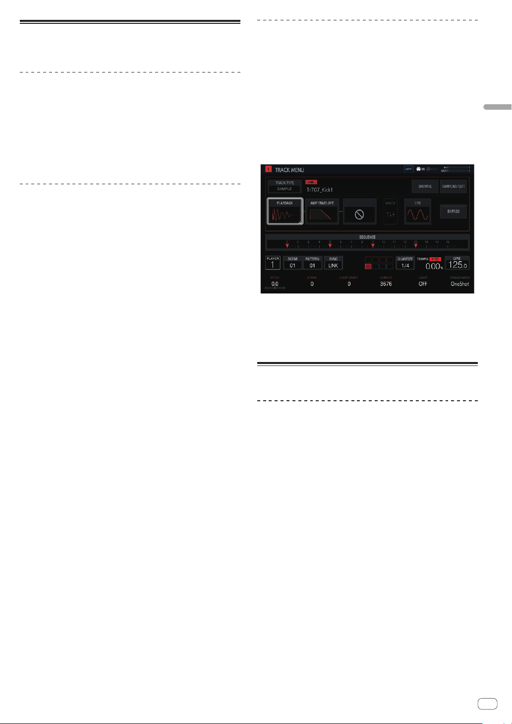
Changing parameters by step (step
modulation)
1 Tap the track for which you wish to change the sound
on the home screen and then tap again in the selected
state.
The track menu screen appears.
! The track menu can also be displayed by turning the rotary selector
to select a track and then pressing the rotary selector.
2 Tap [PLAYBACK] and tap again in the selected state.
The PLAYBACK screen appears.
! You can also go to the PLAYBACK screen by turning the rotary selec-
tor to select [PLAYBACK] and then pressing the rotary selector.
3 Turn the parameter adjustment knob while pressing a
16-step key to change the parameter for that step.
The parameter changes.
! The name of the parameter to which step modulation is applied is
displayed in red.
Using the touch strip function
Using PITCH
1 Press the [MODE] button to select [PITCH].
The [PITCH] indicator to the right of the [MODE] button lights up.
! Each press of the [MODE] button changes the [MODE] indicator in
the order of [PITCH] l [REPEAT] l [USER1] l [USER2] l and so
on.
2 Press and hold the performance pad to change the
pitch of the sample assigned to it.
The sample sound assigned to the performance pad plays.
3 Touch the touch strip to change the parameter.
The pitch of the sample sound changes according to the position
touched on the touch strip. The touch strip indicator of the position
touched on the touch strip lights up.
! The range for changing the pitch using the touch strip can be set in
[TOUCH STRIP SETTING (PITCH RANGE)] of UTILITY.
! The pitch can also be changed by pressing the performance pad
while touching the touch strip.
! The effect of the touch strip only continues while a performance pad
is pressed. It cannot be used in a sequence.

En
14
Using REPEAT
1 Press the [MODE] button to select [REPEAT].
The [REPEAT] indicator to the right of the [MODE] button lights up.
! Each press of the [MODE] button changes the [MODE] indicator in
the order of [PITCH] l [REPEAT] l [USER1] l [USER2] l and so
on.
2 Press and hold the performance pad to repeatedly
play the sample assigned to it.
The sample sound assigned to the performance pad plays.
3 Touch the touch strip to change the parameter.
The sample sound is played repeatedly according to the position
touched on the touch strip. Also, the touch strip indicator of the position
touched on the touch strip lights up.
! The range for the repeat interval using the touch strip is as follows.
1/8 beat l 1/4 beat l 1/2 beat l 1/1 beat
! The sample sound can also be played back repeatedly by pressing
the performance pad while touching the touch strip.
! The effect of the touch strip only continues while a performance pad
is pressed. It cannot be used in a sequence.
4 Change the force applied to the performance pad.
The sample volume changes according to the increase or decrease in
force applied to the performance pad. Pressing down with a stronger
force increases the volume and pressing with a weaker force decreases
the volume.
Using with USER setting
1 Press the [MODE] button to select [USER1] or [USER2].
The [USER1] or [USER2] indicator to the right of the [MODE] button
lights up.
!
Each press of the [MODE] button changes the [MODE] indicator in
the order of [PITCH] l [REPEAT] l [USER1] l [USER2] l and so
on.
2 Set the parameters to be changed with [USER1] or
[USER2].
Configure the settings of the parameters on the TOUCH STRIP SETTING
(USER1) screen or TOUCH STRIP SETTING (USER2) screen.
3 Press and hold the performance pad to change the
parameters of the sample assigned to it.
The sample sound assigned to the performance pad plays.
4 Touch the touch strip to change the parameter.
The sample sound changes according to the position touched on the
touch strip. Also, the touch strip indicator of the position touched on the
touch strip lights up.
! The effect of the touch strip only continues while a performance pad
is pressed. It cannot be used in a sequence.
Using HOLD
1 Press the [HOLD] button.
The [HOLD] button lights up.
2 Touch the touch strip.
The sample sound is put on hold at the last-touched position and the
touch strip indicator lights up.
!
If the mode is switched, the hold function is canceled and the
[HOLD] button turns off.
Saving a project
A project can be saved to a USB device. When saving a project, connect
a USB device to the unit.
1 Press the [PROJECT] button.
The PROJECT screen appears. You can perform operations such as load-
ing and saving projects on the PROJECT screen.
2 Turn the rotary selector to select [SAVE] and then
press the rotary selector.
If the project name has already been entered, a saving pop-up screen
appears. The progress is indicated by a progress bar in the pop-up
screen.
If the project name has not been entered, a pop-up screen and software
keyboard for setting the project name appear.
! The pop-up window disappears and the PROJECT screen appears
when the saving process is completed.
!
To change the project name select [SAVE AS], enter a project name,
and then save the project.
Turning off the system
Press the [u] switch on the rear panel of the unit.
! Do not disconnect the USB device or turn off this unit while the USB
indicator is lit or flashing. Doing so could delete the management
data of this unit and damage the USB device, resulting in unreadable
data.
En
15
Advanced operation
Advanced operation
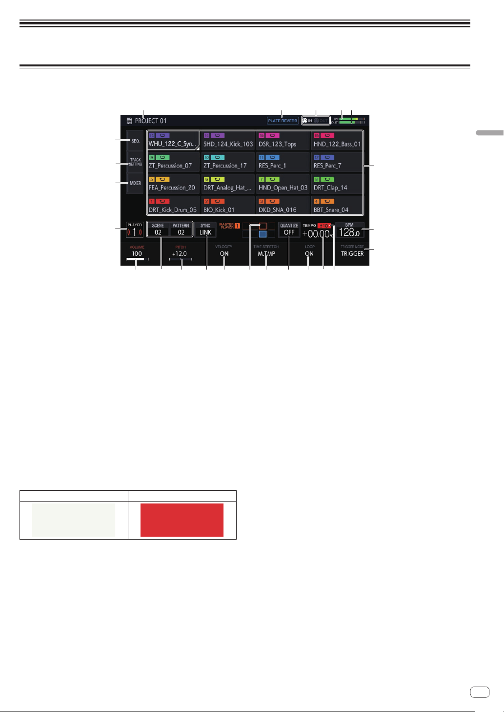
Making overall settings, adjustments, and checks (HOME)
This screen serves as the base of all screens. It allows you to check the assignment status of the performance pads and the status of each track.
1
2 3 4 5
6
7
l
m
n
8
9a
g
bcdf
hj i
e
k
1 Project name
Displays the name of the loaded project.
2 Effect name
The name of the selected effect is displayed.
3 Status display
Displays the status of the connection with an external device.
4 Input sound level meter
Displays the level meter for the sound input to the [INPUT] terminals.
The level can be adjusted with the [INPUT LEVEL] control.
5 MASTER level meter
Displays the MASTER level meter.
When operating [VOLUME] of each track in the touch display, adjust
the volume so that the peak becomes close to 0 dB.
! A peak hold display function is provided, and the detected maxi-
mum level position is displayed. After that, the indication disap-
pears if an even larger signal is not detected within a certain
period of time (about 500 ms).
6 Track display
Track selection
Selected state Unselected state
One of the tracks is always selected. Track 1 is selected by default.
A track can be selected by tapping it. Tapping the selected track
again (or pressing the rotary selector) displays the track menu
screen.
If you turn the rotary selector, the track selection position moves.
Turn it clockwise to move the position in ascending order from track
1 to 16, and then from 16 back to 1. Turn it counterclockwise to move
the position in the reverse direction.
! For details on the displayed content in a track, refer to Track
display content.
7 BPM
Displays the BPM of the pattern being played. Tap this to display the
BPM screen.
= Setting BPM (BPM) (p. 19 )
8 TRIGGER MODE
Switches the method in which a sample is displayed in response to
a trigger.
OneShot:
When the performance pad is tapped, the sample is played to the
end.
GATE:
The sample is played only while the performance pad is pressed.
9 Playing speed adjustment range display
Displays the range in which the playing speed can be adjusted with
respect to the original playing speed recorded for the project or
scene.
a Playing speed display
The value changes according to the position of the [TEMPO] slider.
b LOOP
Switches loop playback on/off.
c QUANTIZE
Tap this to display the QUANTIZE screen.
= Setting quantize (QUANTIZE) (p. 19 )
d TIME STRETCH
Sets the method of stretching a sample to synchronize the BPM.
OFF:
Plays the sample in its current state without synchronizing it to the
BPM. This is suitable for one shot of a drum, etc.
RESMPL (RESAMPLE):
Synchronizes the sample to the BPM, but changes the pitch (variable
speed playback). This is suitable for a drum loop, etc.
M.TMP (MASTER TEMPO):
Synchronizes the sample to the BPM, but does not change the pitch
(MASTER TEMPO playback). This is suitable for a melody loop, etc.
e PHASE METER
Indicates the amount of divergence of the bars and beats from the
master player when using the beat sync function.
f VELOCITY
The [VELOCITY] of a pad can be enabled or disabled.
When this is ON, the playback volume of the sound source changes
according to the strength that the pad is tapped.
When this is OFF, the sound source plays at a fixed volume which is
dependent on the [VELOCITY] set in [AMP ENVELOPE].
En
16
g SYNC
Tap this to display the SYNC screen.
= Setting synchronization with externally connected device (SYNC)
(p. 20 )
h PITCH
Sets the sound pitch for sample playback.
i SCENE/PATTERN button
Displays the current scene number and pattern number.
Tap this to display the SCENE MANAGER screen.
= Managing scenes and patterns (SCENE MANAGER) (p. 21 )
j VOLUME
Sets the volume of the track.
k Player number
Displays the player number assigned to this unit.
l MIXER
Tap this to display the mixer screen.
= Adjusting the volume of each track (MIXER) (p. 18 )
m TRACK SETTING
Tap this to display the TRACK SETTING screen.
= Changing the settings of the entire track (TRACK SETTING)
(p. 17 )
n SEQ.
Tap this to display the sequence screen.
= Checking sequences (SEQ.) (p. 18 )
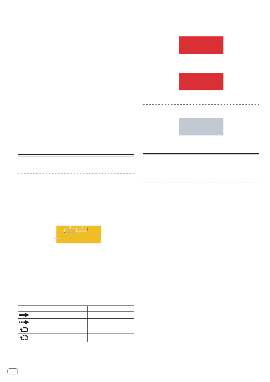
Track display content
Track attributes
The display content differs for each track attribute.
The attribute can be switched in TRACK MENU of each track.
SAMPLE track
The display content differs for each track attribute.
The attribute can be switched in TRACK MENU of each track.
1
2 3
This track plays a sample.
1 Name of the assigned sample
If a sample is assigned to a track, the name of the assigned sample
is displayed.
If the sample name will not fit within the field, part of it is omitted and
the omitted part is replaced with “...”
2 TRIGGER MODE and LOOP
Indicates the state of how the assigned sound is played.
Turning LOOP on and off affects both pad performances and
sequence performances, but TRIGGER MODE only affects pad
performances.
LOOP
TRIGGER MODE
OFF OneShot
OFF GATE
ON OneShot
ON GATE
!
This can be switched with the parameter adjustment knobs at the bottom of the
touch display.
!
In the case of GATE, the sample is played only while the pad is pressed.
! In the case of OneShot, the sample is triggered the instant the performance pad
is pressed, and is played only for the specified time.
3 Level meter display
Displays the audio level meter while a sample is playing.
THRU track
MIDI/TORAIZ AS-1 track
The number of the MIDI channel is displayed.
ACTIVE/MUTE
If [MUTE] is performed by pad operation, the indicators in the area
indicating the track number are all grayed out.
Managing project files (PROJECT)
Operations such as configuration, loading, and saving can be performed
on a project basis.
Creating a new project
1 Press the [PROJECT] button.
The PROJECT screen appears. You can perform operations such as load-
ing and saving projects on the PROJECT screen.
2 Turn the rotary selector to select [CREATE NEW] and
then press the rotary selector.
A new project is created and the main screen appears.
! A confirmation pop-up screen appears.
! If a new project is created without saving an existing project after the
project is changed, the unsaved project will be lost.
Deleting a project
Turn the rotary selector to select [DELETE] and then
press the rotary selector.
An existing project can be deleted.
En
17
Advanced operation
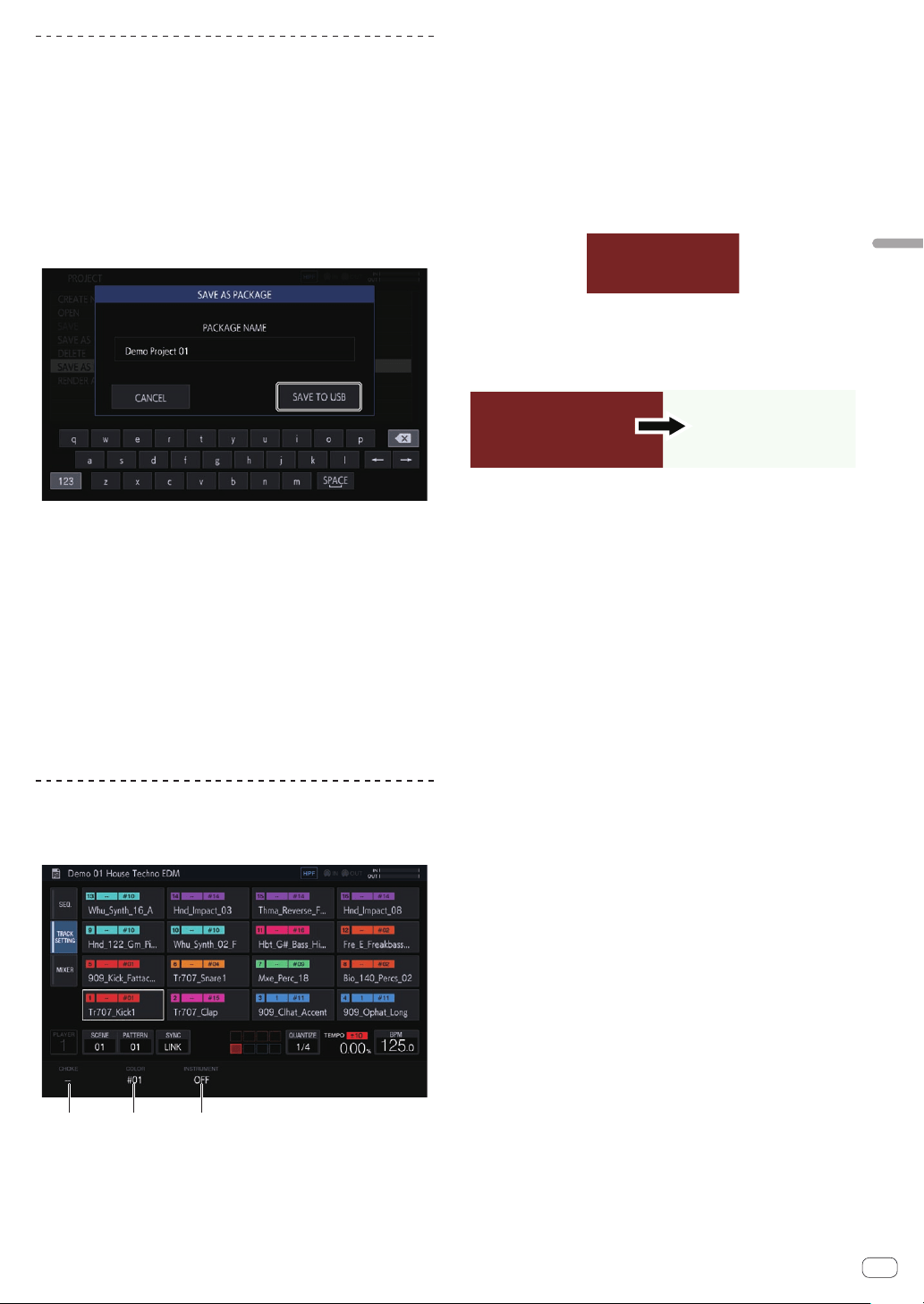
Saving a project as a package
A project can be saved as a package. The ability to convert a project file
and the samples used in that project to a single file enables users to
exchange projects among each other.
1 Select [SAVE AS PACKAGE] in the project screen.
A pop-up screen for entering the package name appears.
2 Enter the package name and then tap [SAVE TO USB].
The PACKAGE_NAME.tpkg file is saved to the /PIONEER DJ SAMPLER/
Projects/ folder.
! If a package file with the same name already exists, an overwrite
confirmation pop-up screen appears.
Importing a package
1 Place the package file in the folder.
Copy the package file (extension: .tpkg) to the /PIONEER DJ SAMPLER/
Projects/ folder of the USB device.
2 Tap [OPEN] in the project screen.
The project and package list appears.
3 Open the .tpkg file you placed.
A confirmation pop-up appears. Tap [OK] to import the package.
!
When the loaded package is saved as a project, the samples
included in the package are copied to the /PIONEER DJ SAMPLER/
Samples/[Imported]/Project Name/ folder.
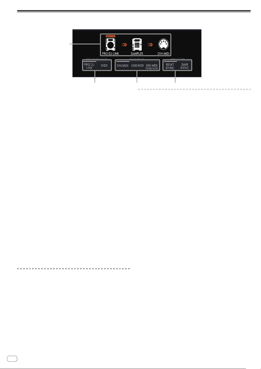
Changing the settings of the entire track
(TRACK SETTING)
The settings of each pad can be configured.
1 2 3
1 CHOKE
Tracks set to the same CHOKE No. can be set to not be played at the
same time.
!
“--” (none), [1], [2], [3], [4], [5], [6], [7], or [8] can be selected.
! The default is “--” (none).
2 PAD COLOR
The track color can be set to any of 16 colors.
3 INSTRUMENT
The instrument icons can be set.
Swapping tracks
1 Turn the rotary selector to select a track you wish to
swap and then press the rotary selector.
[SWAP FROM] appears.
2 Turn the rotary selector to move [SWAP TO] to the
track of the swap destination and then press the rotary
selector.
The tracks are swapped.

En
18
Adjusting the volume of each track (MIXER)
The volume levels can be adjusted at the same time while looking at the volume levels and panning positions of multiple tracks.
1
2 3 4 5 6
! The selected track is indicated by the white frame.
! Turning the rotary selector moves the frame to change the selected track.
! The frame moves between tracks 1 to 16, and the selected track is linked to the selection in the HOME screen.
! The [MASTER] parameter is a setting value that is common to that in the MIXER screen.
1 Track display
! PAN position
! Level meter
! Volume fader position
! Track number and track color
2 VOLUME
Sets the volume of the track.
3 PITCH
Sets the sound pitch for sample playback.
4 VELOCITY
The [VELOCITY] of a pad can be enabled or disabled.
5 PAN
Sets the panning position of the track.
6 MASTER
Adjusts the MASTER volume.
The setting value is common to that in the MIXER screen. The value
is displayed regardless of the position of the frame.
Checking sequences (SEQ.)
Display the currently playing sequence.
% Press a 16-step key while pressing the [SHIFT] button
in the pattern switching mode.
You can check the sequence set for the selected pattern only while the
16-step key is being pressed.

En
19
Advanced operation
Setting BPM (BPM)
BPM setting and other operations related to playing sequences can be performed.
2
1
4
3
1 TAP
Tapping this multiple times to match the beat sets the BPM value to
match that interval.
2 BPM
This is the BPM value set for the project. The BPM when the playing
speed is 0% also becomes this value.
It can be changed by turning the rotary selector.
! Pressing [SHIFT] + turning the rotary selector changes the frac-
tional value.
3 SWING
The [SWING] value can be set.
4 AUDIO INPUT BPM
The BPM of the sound input to the [INPUT] terminals is automati-
cally analyzed and then displayed.
The BPM measurement range is BPM = 70 to 180.
For some tracks, correct measurement may not be possible. When
the BPM cannot be detected, the previously detected BPM value is
displayed and flashes.
Setting quantize (QUANTIZE)
The operation of the performance pads and 16-step keys can be set.
1
2 3
1 QUANTIZE
Sets the quantize values for when a performance pad is tapped dur-
ing sequencer playback.
2 PATTERN QUANTIZE
Sets the timing for switching when a pattern is switched.
3 PAD SEQUENCE START
Sets whether or not to play the sequencer when a performance pad
is tapped while the sequencer is stopped.
En
20
Setting synchronization with externally connected device (SYNC)
The settings for synchronization with a PRO DJ LINK compatible DJ player or external MIDI device can be configured.
123
4
1 SYNC SETTING
Sets the synchronization method for playback synchronized with a
PRO DJ LINK compatible DJ player.
! BEAT SYNC: Synchronizes with the DJ player that will be the
master on the beat level.
! BAR SYNC: Synchronizes with the DJ player that will be the
master on the bar level.
2 MIDI I/F SELECT
Selects the interface for exchanging MIDI messages.
! DIN MIDI: Exchanges MIDI messages with the [MIDI IN] and
[MIDI OUT/THRU] terminals.
! USB MIDI: Exchanges MIDI messages with the [USB-B] terminal.
! DIN MIDI(THRU H/W): Outputs the signal input to the [MIDI
IN] terminal through the hardware from the [MIDI OUT/THRU]
terminal.
3 SYNC SOURCE SELECT
Sets the target with which the unit will synchronize.
! PRO DJ LINK
If the unit and a PRO DJ LINK compatible DJ player are con-
nected with a LAN cable, the sequence of the unit can be played
matched to the playback tempo, beat, or bar of the DJ player.
The tracks played with the DJ player need to have been analyzed
by rekordbox in advance.
! MIDI
If the unit and an external MIDI device are connected by DIN
or USB, the sequence of the unit can be played matched to the
playback tempo of the external MIDI device.
When MIDI is selected, the [BEAT SYNC] button,
[TEMPO RESET/SET] button, [NUDGE] button, and TEMPO slider
cannot be operated.
4 Synchronization status display
Displays the status for synchronization with an external device
according to the setting states of SYNC SOURCE SELECT,
MIDI I/F SELECT, [BEAT SYNC MASTER] button, and [BEAT SYNC]
button.
Playback synchronized with a PRO DJ
LINK compatible DJ player.
1 Press the [BEAT SYNC MASTER] button of the DJ
player you wish to set as the sync master.
Select the DJ player to be set as the sync master.
2 Press the [BEAT SYNC] button.
The BPM and beat position of the currently playing track are synchro-
nized to the sync master.
! During synchronization, tempo control with the TEMPO slider is
disabled. Also, the playing speed display changes to the BPM display
of the TEMPO slider position, and is displayed in gray.
Canceling synchronization
Press the [BEAT SYNC] button.
Synchronization is canceled.
! If the synchronized playback tempo (BPM) and the TEMPO slider
position’s tempo (BPM) do not match, the synchronized playback
tempo is maintained and tempo control with the TEMPO slider
remains disabled. Normal operation is restored when the position
of the TEMPO slider is moved to the synchronized playback tempo
position.
! Operating the [NUDGE] button also cancels synchronization, and
switches to the BPM sync state. At that time, the [SYNC] button
flashes.
En
21
Advanced operation
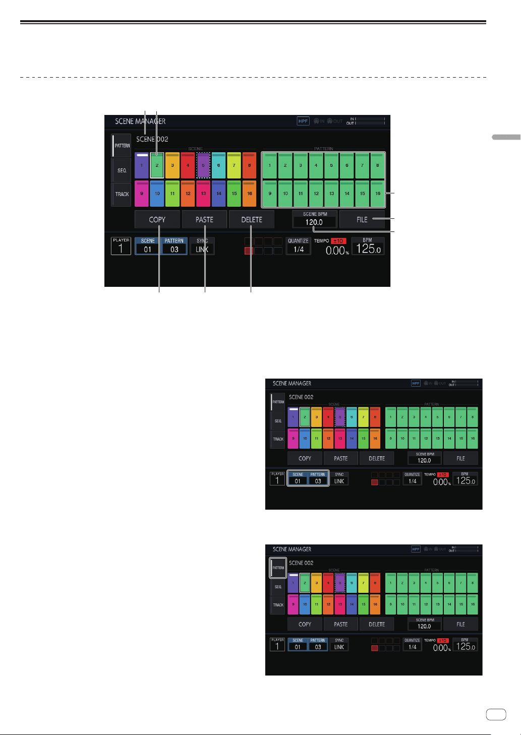
Managing scenes and patterns (SCENE MANAGER)
If you tap [SCENE/PATTERN], the SCENE MANAGER screen appears.
Scenes, patterns, sequences, and tracks can be copied or deleted in the SCENE MANAGER screen.
Copying and deleting scenes and patterns
5
6
7
8
1
2
3 4
1 Scene display area
Turn the rotary selector to select a scene, and move the focus to the
pattern display area by pressing the rotary selector.
The operation can also be performed by tapping a touch key on the
touch display.
The indicator at the top of the touch key is lit in white for the currently
set scene.
2 Scene name
Displays the selected scene name.
This is not displayed if a scene name has not been set.
3 COPY
Copies the selected scene or pattern.
The scene or pattern that is copied has an indicator (dotted-line
frame) to indicate that it is copied.
4 PASTE
Pastes the copied scene or pattern to the selected location.
This cannot be pressed if nothing is copied. In that case, [PASTE] is
grayed out. Furthermore, [PASTE] can also not be tapped when the
focus is on a pattern while a scene is in a copied state or vice versa.
In that case too, [PASTE] is grayed out.
5 DELETE
Deletes the selected scene or pattern.
A confirmation pop-up is displayed when deleting a scene or pattern.
6 SCENE BPM
Sets the BPM of the selected scene.
=
Setting the BPM of a scene (p. 22 )
7 FILE
Imports or exports a scene file.
= Importing a scene file (p. 22 )
= Exporting a scene file (p. 22 )
8 Pattern display area
Turn the rotary selector to select a pattern, and enter the pattern by
pressing the rotary selector.
The operation can also be performed by tapping a touch key on the
touch display.
The indicator at the top of the touch key is lit in white for the currently
set pattern.
If the pattern is switched during playback, the switching timing will
be in accordance with the
PATTERN QUANTIZE setting value set in
the QUANTIZE screen. At that time, the indicator flashes in white for
the touch key while waiting for the pattern to change.
1 Tap [SCENE/PATTERN] to display the SCENE
MANAGER screen.
2 Tap the [PATTERN] tab to display the scene/pattern
editing screen.
En
22
Exporting a scene file
Collect all the samples used in the currently selected scene and export
them in a file format that allows the same scene to be imported by
another project or unit.
1 Select the scene you wish to export in the SCENE
MANAGER screen and then tap [FILE].
A pop-up screen appears.
2 Turn the rotary selector to select [EXPORT] and then
press the rotary selector.
The keyboard screen for entering the scene name appears.
3 Use the screen keyboard to enter the scene name.
! When saving to a USB memory device, tap [SAVE TO USB].
The scene file is a file with the .scn extension in the Scenes folder.
The save destination is under PIONEER DJ SAMPLER/Scenes.
Importing a scene file
Import a file with the .scn extension in the Scenes folder of a USB
memory device.
1 Select the scene you wish to import in the SCENE
MANAGER screen and then tap [FILE].
A pop-up screen appears.
2 Turn the rotary selector to select [IMPORT] and then
press the rotary selector.
The file list appears.
3 Turn the rotary selector to select the scene you wish
to import and then press the rotary selector.
! Importing of the file begins.
Deleting a scene file
Delete a file with the .scn extension in the Scenes folder of a USB
memory device.
1 Select the scene you wish to delete in the SCENE
MANAGER screen and then tap [FILE].
A pop-up screen appears.
2 Turn the rotary selector to select [DELETE] and then
press the rotary selector.
The file list appears.
3 Turn the rotary selector to select the scene you wish
to delete and then press the rotary selector.
! Deleting of the file begins.
Setting the BPM of a scene
A BPM value can be set for each scene. This BPM value is common for
all patterns in the scene as a BPM value cannot be set for each pattern.
!
When the pattern is switched to a pattern in a scene with the BPM
set, the BPM value in the BPM screen also becomes the BPM value
of the scene and the scene is played at that tempo. When a BPM
value is not set for a scene, “---” is displayed and the scene is played
using the BPM value set in the BPM screen.
! During playback of a pattern in a scene with the BPM set, the tempo
can be adjusted by changing the BPM value in the BPM screen.
However, that BPM value is not reflected as the BPM value of the
scene. Set the BPM value of a scene in the BPM setting in SCENE
MANAGER.
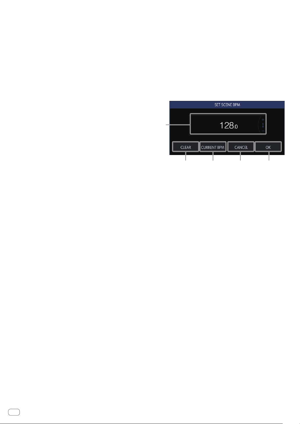
If you tap [SCENE BPM] in the SCENE MANAGER screen, the SET
SCENE BPM screen appears.
1
2 3 4 5
1 BPM
Change the BPM value of a scene using the rotary selector.
2 CLEAR
Tap this to reset the BPM value of the set scene. The indication
becomes “---” and when a pattern of this scene is played, it is played
using the BPM value set in the BPM screen. When this scene is
output, the BPM value set in the BPM screen is output as the BPM
value of the scene.
3 CURRENT BPM
Sets the currently playing BPM as the BPM value of the scene.
4 CANCEL
Closes the pop-up. At this time, the BPM value of the scene returns
to the value when the pop-up was opened.
5 OK
Enters the BPM value of the scene and closes the pop-up.
En
23
Advanced operation
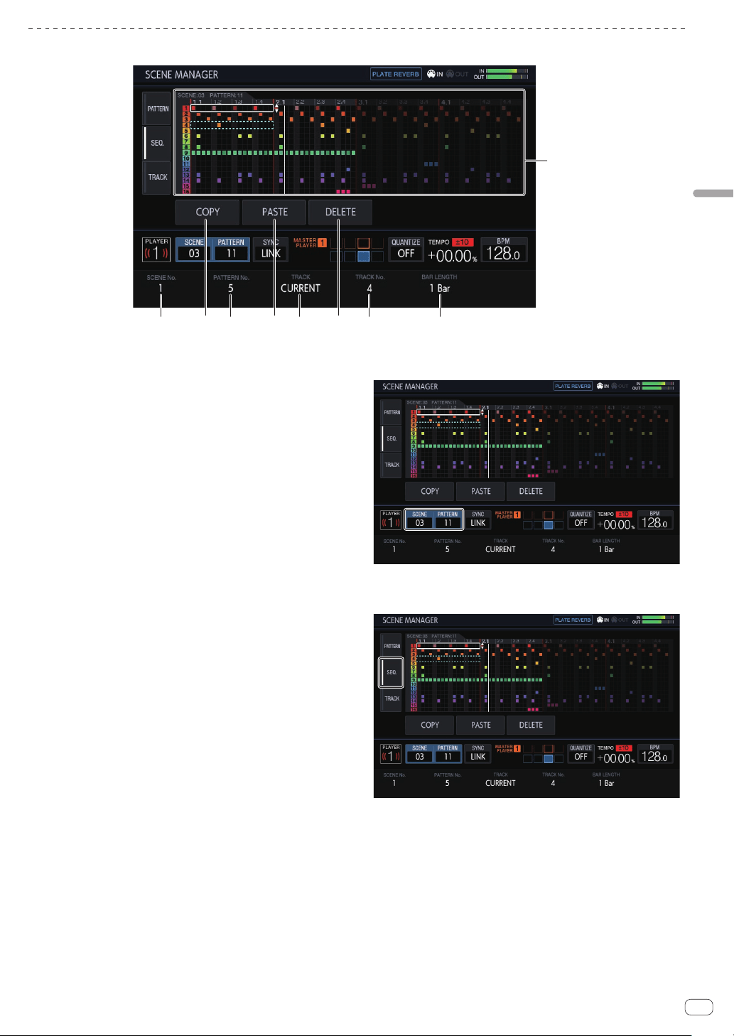
Copying and deleting sequences
1
23457 689
1 Sequence display area
Turn the rotary selector to select a sequence.
You can switch between the horizontal direction and vertical direc-
tion by pressing the rotary selector.
2 BAR LENGTH
Selects the range of the sequence to copy or delete from 1 bar and
4 bars.
3 TRACK No.
Selects a track.
4 DELETE
Deletes the selected sequence.
5 TRACK
Selects the range of the sequence to copy or delete from 1 track and
all (16 tracks).
6 PASTE
Pastes the copied sequence to the selected location.
This cannot be pressed if nothing is copied. In that case, the [PASTE]
button is grayed out.
7 PATTERN No.
Selects the pattern.
8 COPY
Copies the selected sequence.
The sequence that is copied has an indicator (dotted-line frame) to
indicate that it is copied.
9 SCENE No.
Selects the scene.
1 Tap [SCENE/PATTERN] to display the SCENE
MANAGER screen.
2 Tap the [SEQ.] tab to display the sequence editing
screen.
En
24
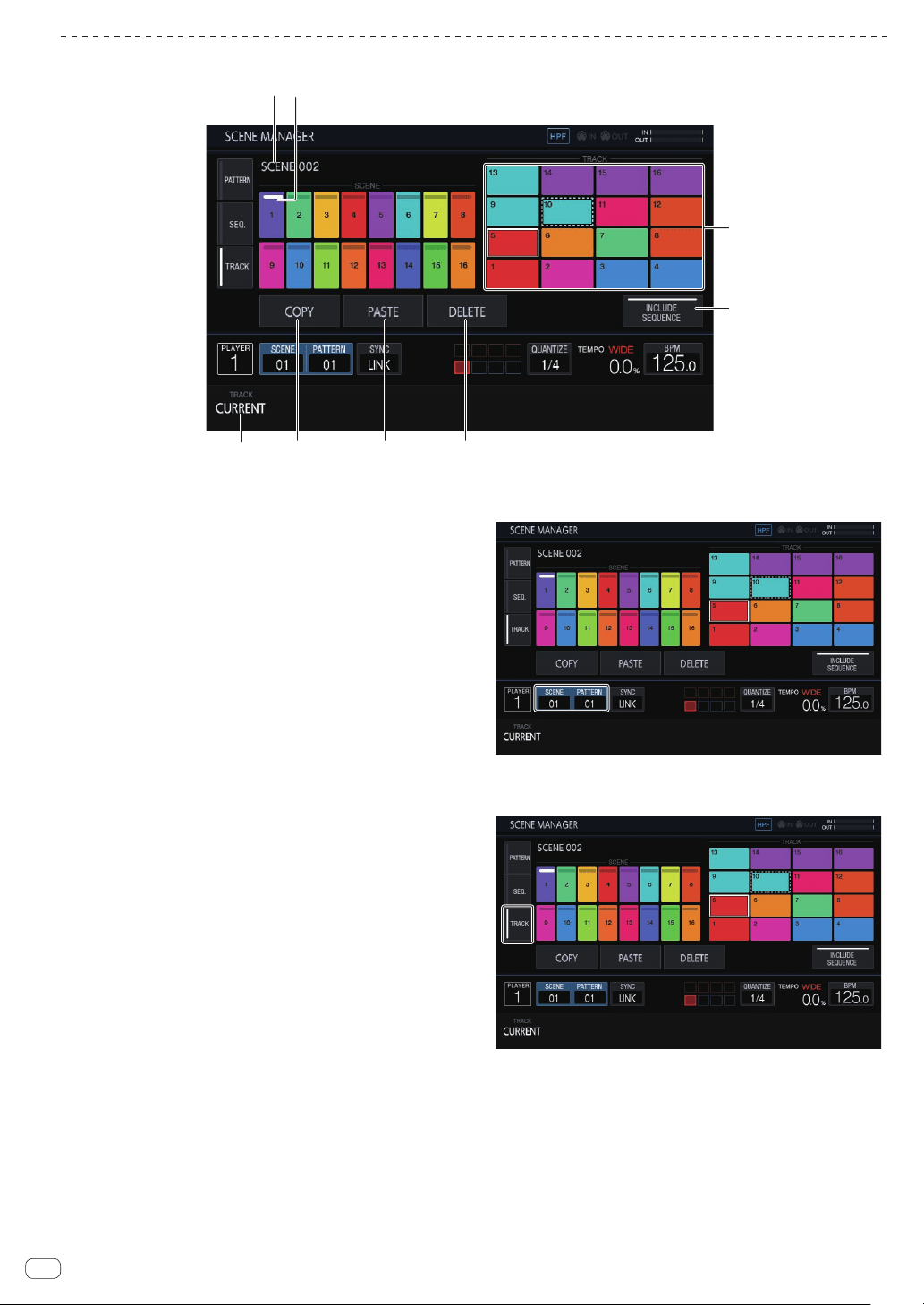
Copying and deleting tracks
5 6
12
3 4
7
8
1 Scene display area
Turn the rotary selector to select a scene, and move the focus to the
track display area by pressing the rotary selector.
The operation can also be performed by tapping a touch key on the
touch display.
The indicator at the top of the touch key is lit in white for the currently
set scene.
2 Scene name
Displays the selected scene name.
This is not displayed if a scene name has not been set.
3 TRACK
Selects the range of the sequence to copy or delete from 1 track and
all (16 tracks).
4 COPY
Copies the selected track.
The track that is copied has an indicator (dotted-line frame) to indi-
cate that it is copied.
5 PASTE
Pastes the copied track to the selected location.
This cannot be pressed if nothing is copied. In that case, [PASTE] is
grayed out. Furthermore, [PASTE] can also not be tapped when the
focus is on a scene while a track is in a copied state. In that case too,
[PASTE] is grayed out.
6 DELETE
Deletes the selected track.
A confirmation pop-up is displayed when deleting a track.
7 INCLUDE SEQUENCE
If [INCLUDE SEQUENCE] is tapped to switch it on, the sequence will
also be included when copying.
= Checking sequences (SEQ.) (p. 18 )
8 Track display area
Enter a track by turning the rotary selector to select the track and
then pressing the rotary selector.
The operation can also be performed by tapping a touch key on the
touch display.
1 Tap [SCENE/PATTERN] to display the SCENE
MANAGER screen.
2 Tap the [TRACK] tab to display the track editing
screen.
En
25
Advanced operation
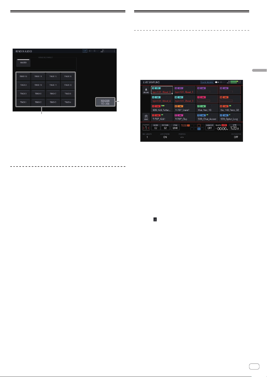
Audio rendering (RENDER AUDIO)
A created pattern can be exported as a WAV file (44.1 kHz, 24-bit).
Press the [PROJECT] button and select [RENDER AUDIO] from the
PROJECT menu to switch to the page for audio rendering.
! The sequencer and sound output of the unit are stopped during
rendering execution.
1
2
1 RENDER TO USB
Starts rendering. A rendered track is saved to the USB memory
device.
! If a USB memory device is not connected, the button is displayed
grayed out and cannot be operated.
2 RENDERED TARGET
Selects the track to be the rendering target.
Rendering audio
1 Tap [RENDER TO USB].
Rendering starts. When audio rendering finishes, a pop-up screen notify-
ing you that rendering was successful appears.
The progress is indicated by a progress bar in a pop-up during audio
rendering.
!
To cancel audio rendering part way through, tap [CANCEL].
2 Tap [OK].
A rendered audio file cannot be accessed from the browse screen of the
unit. Import it to a computer and then use it for editing and mastering.
!
The save destination of a WAV file is PIONEER DJ SAMPLER/
Rendered Audio/[Project Name]/Pattern.
! Rendering results with the same conditions are always overwritten.
When rendering is performed, be sure to move or copy the file to a
computer.
!
The file name will be [Scene No.][Pattern No.]_[Rendering Target
Name].wav.
Sampling (LIVE SAMPLING)
Sampling
The sound input to the [INPUT] terminals can be sampled and then used
for a performance immediately.
1 Press the [SAMPLING] button.
The performance pads switch to the LIVE SAMPLING mode and live
sampling becomes possible.
! The [SAMPLING] button lights.
! The LIVE SAMPLING screen is displayed on the touch display.
! Adjust the level of sound with the [INPUT LEVEL] control before
sampling. At that time, you can switch whether or not to output
the sound input to the [INPUT] terminals by MONITOR to the
headphones.
2 Tap a performance pad without a sample loaded.
Sampling starts.
! A sampled sample is indicated with red characters.
! Some functions such as unloading and saving are restricted during
sampling.
If another sample is already loaded in the performance pad for which
you wish to perform sampling, unload it as described below.
1 Tap the track you wish to unload.
Multiple tracks can be selected by tapping tracks while pressing
the [SHIFT] button.
2 Tap [ (UNLOAD)] to execute unloading.
! The length for sampling can be set in REC LENGTH.
— The values that can be set are 1/4, 1/2, 1, 2, 4, 8, 16, and
MANUAL. (They are all set on a beat level.)
— If [MANUAL] is selected, tapping the same performance pad
again finishes sampling. If the performance pad is not tapped,
sampling up to the maximum of 32 seconds is performed.
! You can set in LOOP AFTER REC whether or not to play a loop imme-
diately after sampling.
— ON: Plays automatically from the beginning of the sample after
sampling finishes.
— OFF: Stops after sampling finishes.
! When the length set in REC LENGTH is reached or the same perfor-
mance pad is tapped again while MANUAL is selected, sampling
finishes.
3 When sampling is finished, press the [SAMPLING]
button.
Sampling mode ends.
En
26
Adjusting the play start position of a
sample
If a sampled sound is offset, the play start position can be adjusted.
1 Press the [SAMPLING] button.
The performance pads switch to the LIVE SAMPLING mode and live
sampling becomes possible.
! The [SAMPLING] button lights.
! The LIVE SAMPLING screen is displayed on the touch display.
2 Tap the track you wish to adjust and then tap again in
the selected state.
The adjustment screen appears.
! You can also go to the adjustment screen by turning the rotary selec-
tor to select a track and then pressing the rotary selector.
3 Turn the parameter 3 adjustment knob.
The play start position of the sample changes.
! If you wish to adjust another sample, you can turn the rotary selector
to select another track.
4 When adjustment is finished, press the [SAMPLING]
button.
Sampling mode ends.
Saving a sample
A sampled sample can be saved to a USB memory device.
If another project is loaded or the power is switched off without saving,
the sampled sample will be deleted.
1 Press the [SAMPLING] button.
The performance pads switch to the LIVE SAMPLING mode and live
sampling becomes possible.
!
The [SAMPLING] button lights.
! The LIVE SAMPLING screen is displayed on the touch display.
2 Tap the track with the sample you wish to save
loaded.
Multiple tracks can be selected by tapping tracks while pressing the
[SHIFT] button.
3 Tap [ ] (Save).
Saving is executed. The [SAVING...] message is displayed during saving.
When saving completes, the sample name that was indicated by red
characters is displayed in white.
The save destination is under PIONEER DJ SAMPLER/Samples/Saved/
[Project name].
! Some functions are restricted during saving.
! If a USB memory device is not connected, the button is displayed
grayed out and cannot be operated.
4 After saving, press the [SAMPLING] button.
Sampling mode ends.
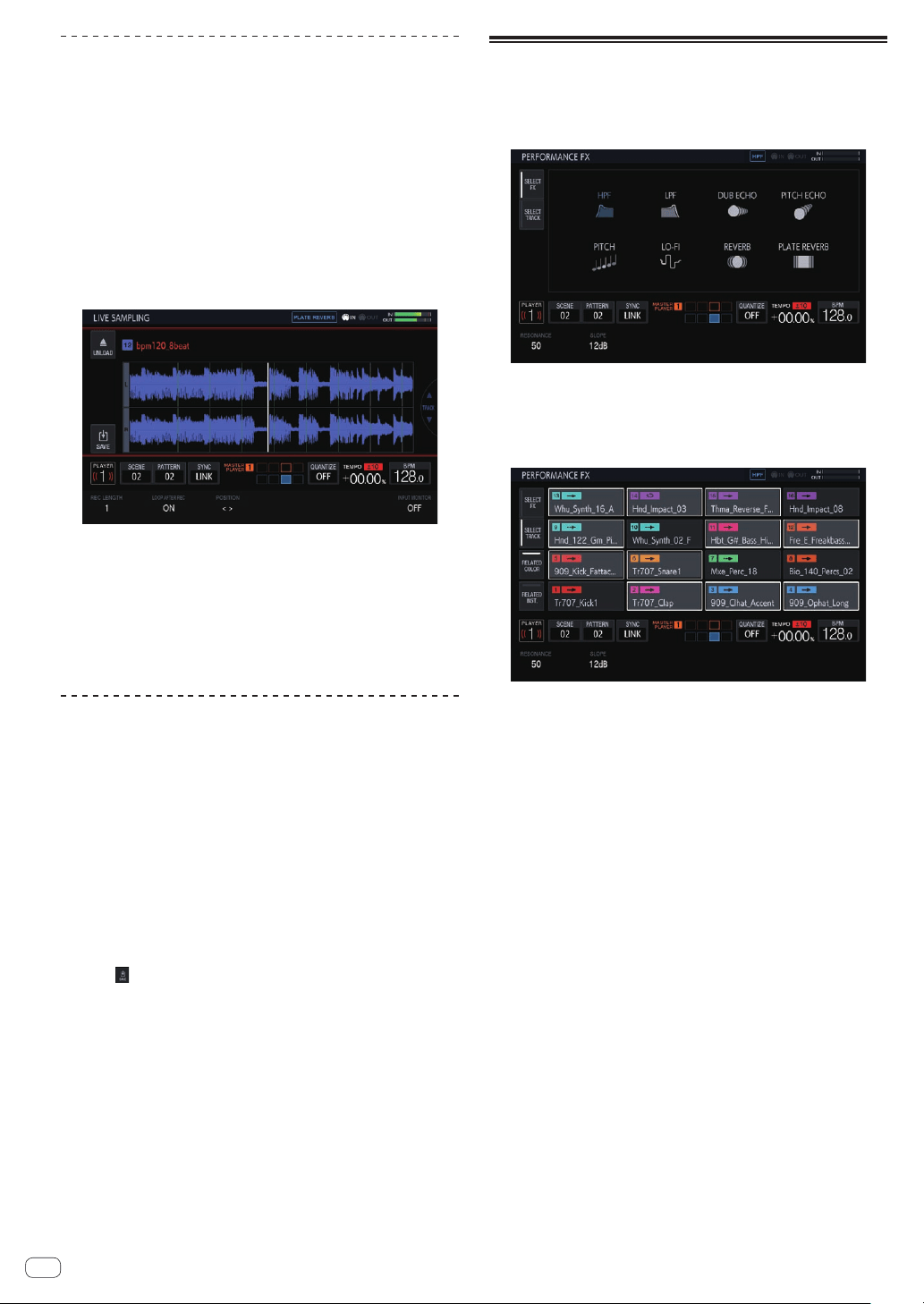
Using effects
1 Press the [FX] button.
The [FX] button lights.
The PERFORMANCE FX effect selection screen appears.
2 Tap the effect you wish to use.
For the effect types, refer to “PERFORMANCE FX Types”.
3 Tap the [SELECT TRACK] tab.
The PERFORMANCE FX track selection screen appears.
4 Tap the track for which you wish to apply the effect.
Multiple tracks can be selected by tapping tracks while pressing the
[SHIFT] button.
! If you switch RELATED COLOR on and then tap a track, the tracks
with the same color set are selected or deselected at the same time.
! If you switch RELATED INST. on and then tap a track, the tracks with
the same instrument icon set are selected or deselected at the same
time.
5 Press the [FX ON/OFF] button.
The effect is applied to the sound.
! If you turn the [FX LEVEL DEPTH] control or a parameter adjustment
knob, the parameter is adjusted.
!
The [FX ON/OFF] button flashes when the effect is on.
!
When the [FX ON/OFF] button is pressed again, the effect turns off.

En
27
Advanced operation
PERFORMANCE FX Types
Effect name Descriptions
FX LEVEL DEPTH
control
Parameter
adjustment
knobs
HPF
Outputs sound that
has passed through a
high-pass filter.
Changes the cutoff
frequency of the
high-pass filter.
Rotating counter-
clockwise: Decreases
Rotating clockwise:
Increases
1
RESONANCE: 0
to 100
2 SLOPE: 12 dB
and 24 dB
LPF
Outputs sound that
has passed through a
low-pass filter.
Changes the cutoff
frequency of the low-
pass filter.
Rotating counter-
clockwise: Increases
Rotating clockwise:
Decreases
1
RESONANCE: 0
to 100
2 SLOPE: 12 dB
and 24 dB
DUB ECHO
Outputs delayed
sounds repeatedly
after the original
sound and gradu-
ally attenuates the
delayed sounds to
achieve an echo
effect.
Changes the volume
and reverberation
time of the reverbera-
tion component.
Rotating counter-
clockwise: Decreases
Rotating clockwise:
Increases
1
TIME: 0 to 100
2 FREQUENCY: 0
to 100
3 FEEDBACK: 0 to
100
PITCH ECHO
Outputs delayed
sounds repeatedly
after the original
sound and changes
the key and volume of
the delayed sounds
to achieve a rever-
beration effect.
Changes the volume
of the reverberation
component.
Rotating counter-
clockwise: Decreases
Rotating clockwise:
Increases
1
TIME: 10
to 4,000 ms
2 BEAT: 1/32, 1/16,
1/8, 1/4, 1/2, 3/4,
1/1, 2/1, and 4/1
3 PITCH: -3.0 to 0.0
to +3.0
4 FEEDBACK: 0
to 90
PITCH
Changes the pitch of
the source sound.
Changes the key
change amount.
Rotating counter-
clockwise: Decreases
Rotating clockwise:
Increases
1
PITCH: UP and
DOWN
LO-FI
Changes the original
sound to a crushed-
like sound for output.
Changes the crush-
ing state of sound
and cutoff frequency
of the filter.
Rotating counter-
clockwise: Decreases
Rotating clockwise:
Increases
1
REDUCTION: 0
to 100
2 CUT OFF: 0 to
100
3 RESONANCE: 0
to 100
REVERB
Applies a rever-
beration effect to the
input sound.
Changes the volume
and reverberation
time of the reverbera-
tion component.
Rotating counter-
clockwise: Decreases
Rotating clockwise:
Increases
1
ROOM SIZE: 1 to
100
2 DAMPING: 0 to
100
PLATE
REVERB
Applies a reverbera-
tion effect similar to
the vibrating of an
iron plate to the input
sound.
Increases the volume
and reverberation
time of the reverbera-
tion component.
Rotating counter-
clockwise: Decreases
Rotating clockwise:
Increases
1
ROOM SIZE: 1 to
100
2 DAMPING: 0 to
100
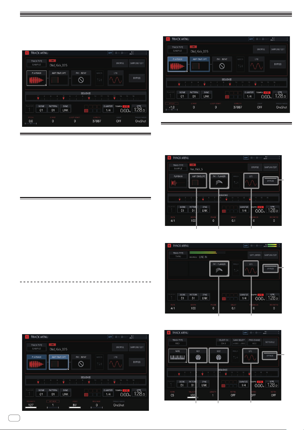
En
28
Adjusting track parameters (TRACK MENU)
You can switch the screen to display the selected track or the details of
each setting from the TRACK MENU screen.
Setting the track attributes
The track attributes can be set.
If you tap [TRACK TYPE], a pop-up screen appears and you can set one
track attribute from four types: [SAMPLE], [THRU], [MIDI], and [TORAIZ
AS-1].
For details on each of them, refer to the following.
! SAMPLE (Sample track on page 29 )
! THRU (Through track on page 43 )
! MIDI (MIDI tracks on page 43 )
! TORAIZ AS-1 (TORAIZ AS-1 tracks on page 46 )
Selecting a module
Any one of the modules can be selected.
The focus is displayed on the selected module. If you tap or turn the
rotary selector, the focus moves.
! The parameters in the module with the focus on it can be oper-
ated with the parameter adjustment knobs. When the focus is on
[BROWSE], [SAMPLING/EDIT], and [SET SCALE], the parameters
and parameter flags disappears.
These touch key groups are arranged to make it easy for the user to
visualize the flow of sound. Furthermore, the number and types of touch
keys displayed here differ depending on the track attribute.
For details on track attributes, refer to Setting the track attributes on
page 28 .
About display of modulated items
Items such as [PLAYBACK] are displayed highlighted while a 16-step key
of a step including modulated parameters is pressed.
1 The following is an example of when step modulation is performed
for [PITCH] (in PLAYBACK) and [ATTACK] (in AMP ENVELOPE).
2 Press and hold a 16-step key of a step with a parameter modulated.
3 [PLAYBACK] and [AMP ENVELOPE] are highlighted and the param-
eter name is enclosed with a frame while the key is held down.
Setting bypass
When you tap [BYPASS], the unit switches to the BYPASS setting mode
and the modules in TRACK MENU can be bypassed individually.
! TRACK MENU screen of SAMPLE track
1
2
34
! TRACK MENU screen of THRU track
1
2
3
! TRACK MENU screen of MIDI track / TORAIZ AS-1 track
1
2
65
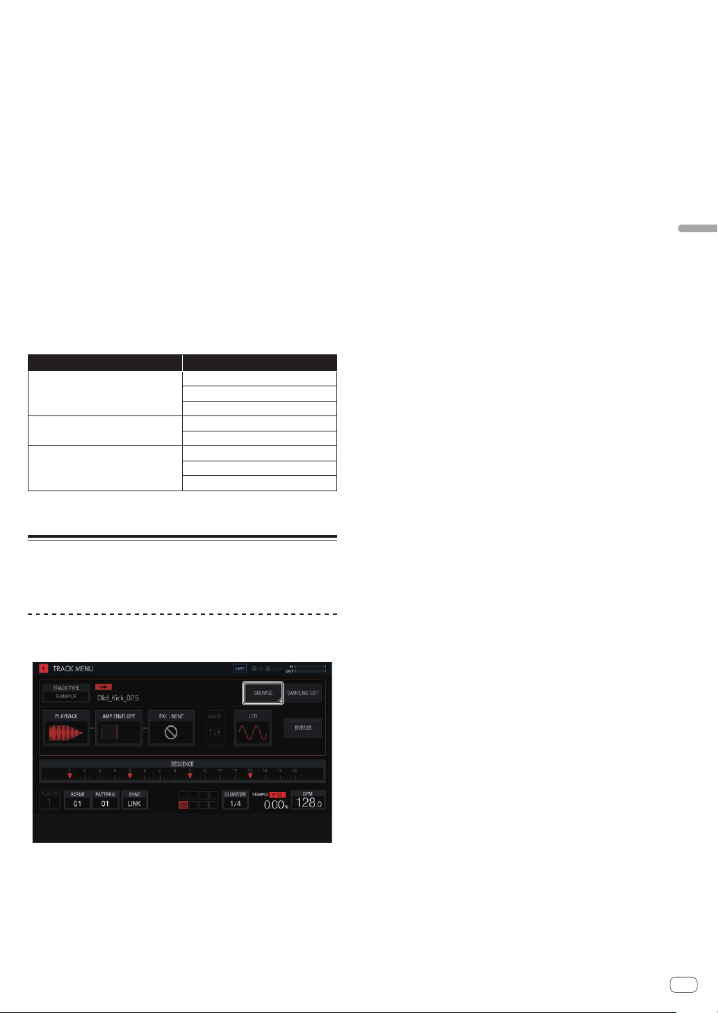
En
29
Adjusting track parameters (TRACK MENU)
1 BYPASS
Each button will function as follows by switching this ON/OFF.
ON: Switches whether or not to bypass the following (LFO
2
to CC2
6
)
modules.
OFF: Tapping any of the following (LFO
2
to CC2
6
) module buttons
switches to the corresponding setting screen. However, the screen
does not switch to a setting screen of a module that is set to be
bypassed.
The following explanation is when this is set to ON.
2 LFO
Switches whether or not to bypass the LFO module settings.
3 FX1
Switches whether or not to bypass the FX1 module settings.
4 AMP ENVELOPE
Switches whether or not to bypass the AMP ENVELOPE module
settings.
5 CC1
Switches whether or not to bypass the CC1 module settings.
6 CC2
Switches whether or not to bypass the CC2 module settings.
The following modules can be bypassed individually.
Track attributes Modules that can be bypassed
SAMPLE track
AMP ENVELOPE
FX1
LFO
THRU track
FX1
LFO
MIDI track / AS-1 track
CC1
CC2
LFO
!
The process is being bypassed for a module whose thumbnail image in the
touch key is grayed out. Tapping switches whether or not to bypass.
Sample track
A sample or sampled sound source can be played. If a sound source is
not assigned to a track, nothing is displayed in the sample name field.
Selecting and loading a sample (BROWSE)
You can search for sound sources and assign them to tracks.
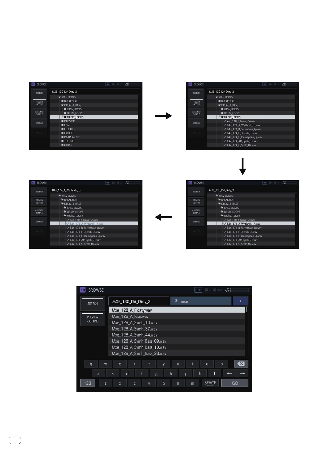
En
30
SEARCH
If you tap [SEARCH], you can select the filtering method for browsing. Selecting ON/OFF here changes the display content in the right column.
When set to OFF:
Samples can be filtered by folder level.
1 Turn the rotary selector to move the focus.
The focus can be moved on a folder basis by pressing [SHIFT] + turning the rotary selector. (Lines for sample files are skipped.)
2
Pressing the rotary selector when a folder is selected opens or closes the folder.
3 Select a sample file in a folder while turning the rotary selector.
4 Pressing the rotary selector when a sample file is selected assigns the selected sample to the current track.
①
②
④
③
When set to ON:
A software keyboard is displayed so that you can search for a sample with a character string.
If you enter characters and then press the [GO] button, the search results are displayed. Only samples containing the entered character string are
displayed in the list.
A search is always performed within all folders. If you tap [a] or [b], the search results are sorted in alphabetical ascending order or descending order.
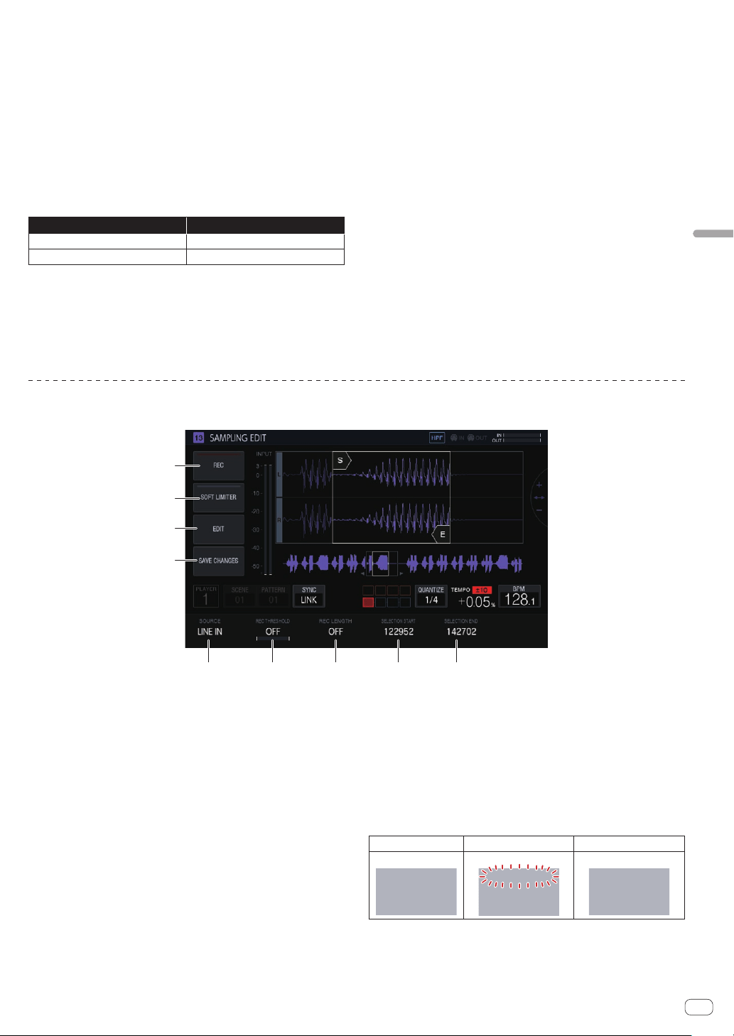
En
31
Adjusting track parameters (TRACK MENU)
PREVIEW (SETTING)
Automatically begins a preview when a sample is selected during brows-
ing. This can be switched ON/OFF by tapping.
When set to ON:
When the rotary selector is turned to move the focus, a selected sample
is played only once.
When set to OFF:
Even if the rotary selector is turned to move the focus, samples are not
played.
!
The default is ON.
! If a sample is selected when this is switched from OFF to ON, it is
played only once.
If you press and hold [PREVIEW], you can set various preview settings
for browsing.
Option settings Options
PREVIEW MONITOR
Master + Headphones,Headphones
PREVIEW VOLUME
0-127
!
PREVIEW MONITOR: Sound output destination for sample preview
!
PREVIEW VOLUME: Sound volume for sample preview
ASSIGNED SAMPLE
Tapping this jumps to the location of the sample assigned to the cor-
responding track.
!
This is not displayed when [SEARCH] is ON.
UNLOAD
Unloads the sample that is loaded to the track.
! This is not displayed when [SEARCH] is ON.
% Tap [UNLOAD].
The sample is unloaded. When it is unloaded, the sample name dis-
played at the upper right of the browse screen disappears.
DELETE
Deletes a sample.
! This is not displayed when [SEARCH] is ON.
1 Turn the rotary selector to select the sample you wish
to delete.
2 Tap [DELETE].
A confirmation pop-up screen appears.
3 Press [OK].
Recording an external input sound and editing a sample (SAMPLING/EDIT)
You can record an external input sound or a sound output from the unit and edit the waveform of a sample.
1 2 3 4 5
6
7
8
9
1 SOURCE
Selects the target for sampling.
The target can be selected from [LINE IN] and [RSMPL].
!
This cannot be operated while recording.
2 REC THRESHOLD
Sets the volume of an input signal for which recording starts
automatically.
!
This cannot be operated while recording.
! When this is OFF, recording starts instantly.
! When PLAY, recording starts at the same time as when the
sequencer is started with the [PLAY] button.
3 REC LENGTH
Sets the length of time (on a BAR level) to continue recording
from the start of recording. This is dependent on the BPM of the
sequencer. When the specified length is reached, recording stops
automatically.
!
This cannot be operated while recording.
! If this is OFF, recording stops automatically when 32 seconds are
exceeded after the start of recording.
4 SELECTION START
Sets the start point of the selection range.
!
This cannot be operated while recording.
5 SELECTION END
Sets the end point of the selection range.
!
This cannot be operated while recording.
6 REC
Enters standby mode for input recording.
Tapping this starts standby, and recording starts if the input signal
exceeds [REC THRESHOLD].
! When [REC THRESHOLD] is OFF, the status switches to record-
ing (lit) the moment this button is tapped.
Not standby (off) Standing by (flashing) Recording (lit)
If recording is performed in the state in which a sample is already
assigned, the waveform is overwritten.
7 SOFT LIMITER
A limiter can be applied to the input sound.
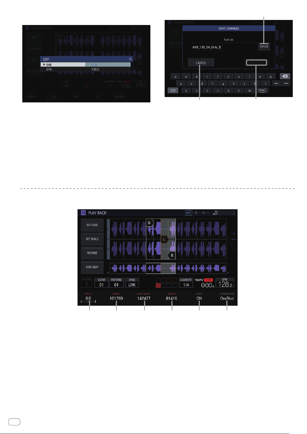
En
32
8 EDIT
Tapping this displays the EDIT list.
BAR:
Sets the length (number of bars) of the sample. The value of BPM
varies depending on the value that is set here.
BPM:
Sets the BPM of the sample. The value of BAR varies depending on
the value that is set here.
9 SAVE CHANGES
Saves the selected range as a sample.
A pop-up window with a name and a consecutive number entered,
and a software keyboard appear to enable you to assign a name.
The save destination is under PIONEER DJ SAMPLER/Samples/
Saved/[Project name].
a
c
b
a CANCEL
Closes the pop-up window without saving anything.
b SAVE TO USB
Saves the sample to a USB device and closes the pop-up screen. If a
USB device is not connected to the unit, this is grayed out.
c REPLACE
Sets the sample save method.
! When set to ON: Replaces the sample assigned to the track.
Select this if you wish to use the saved sample immediately.
! When set to OFF: Keeps the sample assigned to the track. Select
this if you wish to cut multiple samples from the same sample
and then save them.
Setting the playback method of a sample (PLAYBACK)
The playback method of the sample assigned to a track can be set.
1 2 3 4 5 6
1 PITCH
Sets the sound pitch for sample playback.
The default is 0.
The setting range varies depending on the TIME STRETCH mode.
! OFF: -24 to 0 to +24
! RESMPL: [PITCH] is disabled, and depends on BPM.
! M.TMP: -12 to 0 to +12
2 START
Sets the start point of the sample playback range. This is set on the
level of the number of Sample.
3 LOOP START
When LOOP is ON, the loop start point can be set. This can be set
only between [START] and [END].
This is set on the level of the number of Sample.
4 LENGTH
Sets the length of the sample playback range.
This is set on the level of the number of Sample.
5 LOOP
Switches LOOP playback ON/OFF.
! ON: When the playback position reaches [END], playback starts
again from the position of [LOOP START] set in the same screen.
! OFF: When the playback position reaches [END], playback ends
at the same time.
6 TRIGGER MODE
Switches the method with which a sample is played in response to
a trigger.
! OneShot: When the performance pad is tapped, the sample is
played to the end.
! GATE: The sample is played only while the performance pad is
pressed.
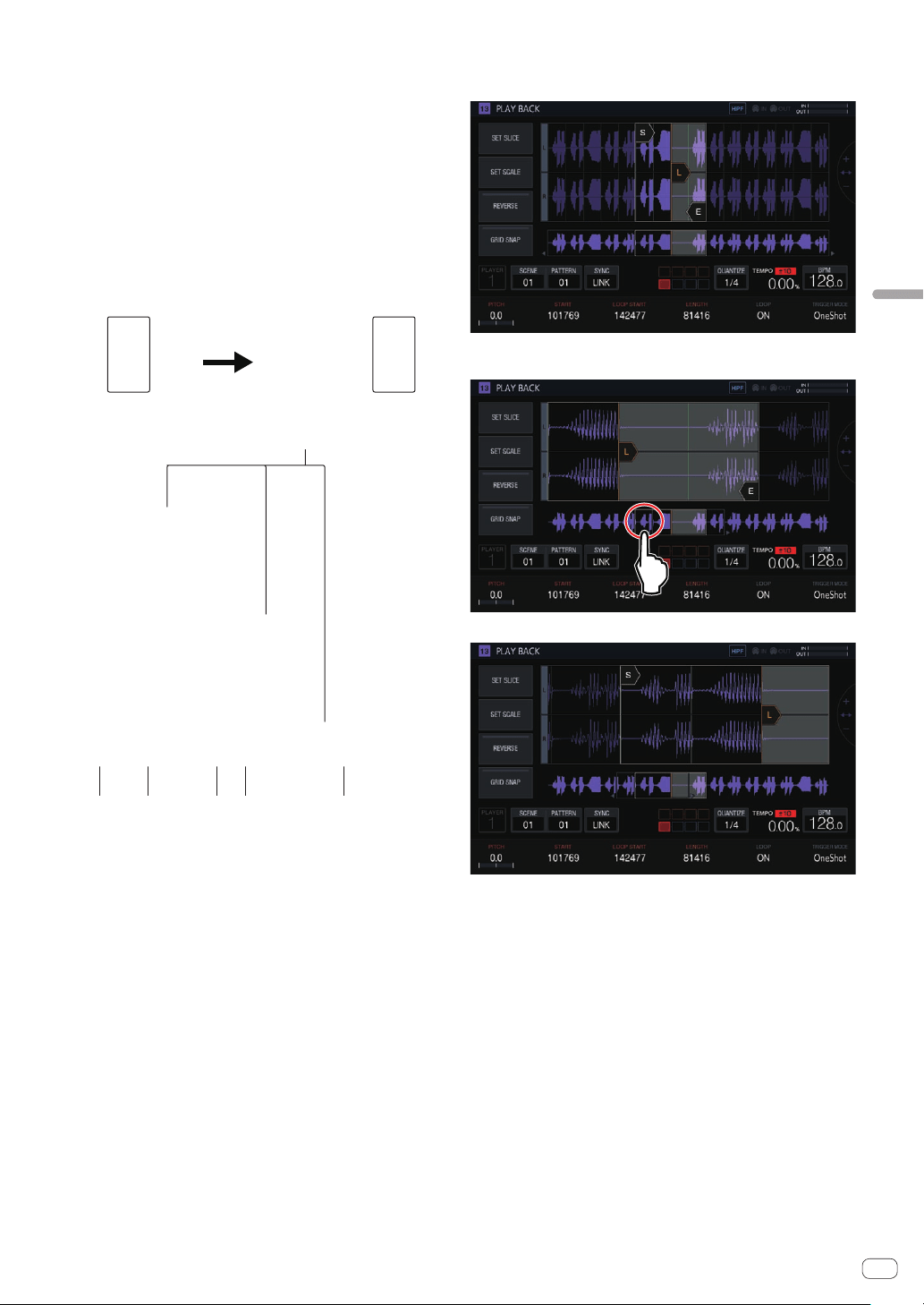
En
33
Adjusting track parameters (TRACK MENU)
Waveform display area
Display range
The waveform can be enlarged or reduced horizontally by turning the
rotary selector.
!
When the START cursor or END cursor is tapped to switch it to the
selected state, enlarge or reduce the waveform using the selected
cursor as the reference.
!
If the selected cursor is tapped again, the selection is canceled.
When one of the cursors is selected, tapping the other cursor moves
the selection state to the tapped cursor.
! When none of the cursors are selected, enlarge or reduce the wave-
form using the center of the waveform display area as the reference.
Furthermore, the waveform can be enlarged or reduced vertically by
pressing [SHIFT] + turning the rotary selector.
Press SHIFT
1 2 3 4 2
5
1 SLICE GRID
Displays the SLICE GRID in the background.
2 START/END POINT
Sets the range played when a performance pad is tapped.
3 Playback position
Displays the current playback position.
4 LOOP START POINT
Sets the range that is played repeatedly when LOOP of the track is
[ON].
The loop range is highlighted.
5 START/LOOP START/END cursors
When [GRID SNAP] is ON, the range snaps to the GRID.
The playback range can be finely set with the parameter adjustment
knobs.
Overall waveform display area
Displays the overall waveform of the assigned sample. The playback
range is enclosed in a frame and the loop range is highlighted.
When the area is zoomed in and tapped, the display position jumps to
the tapped position.
The range displayed changes.
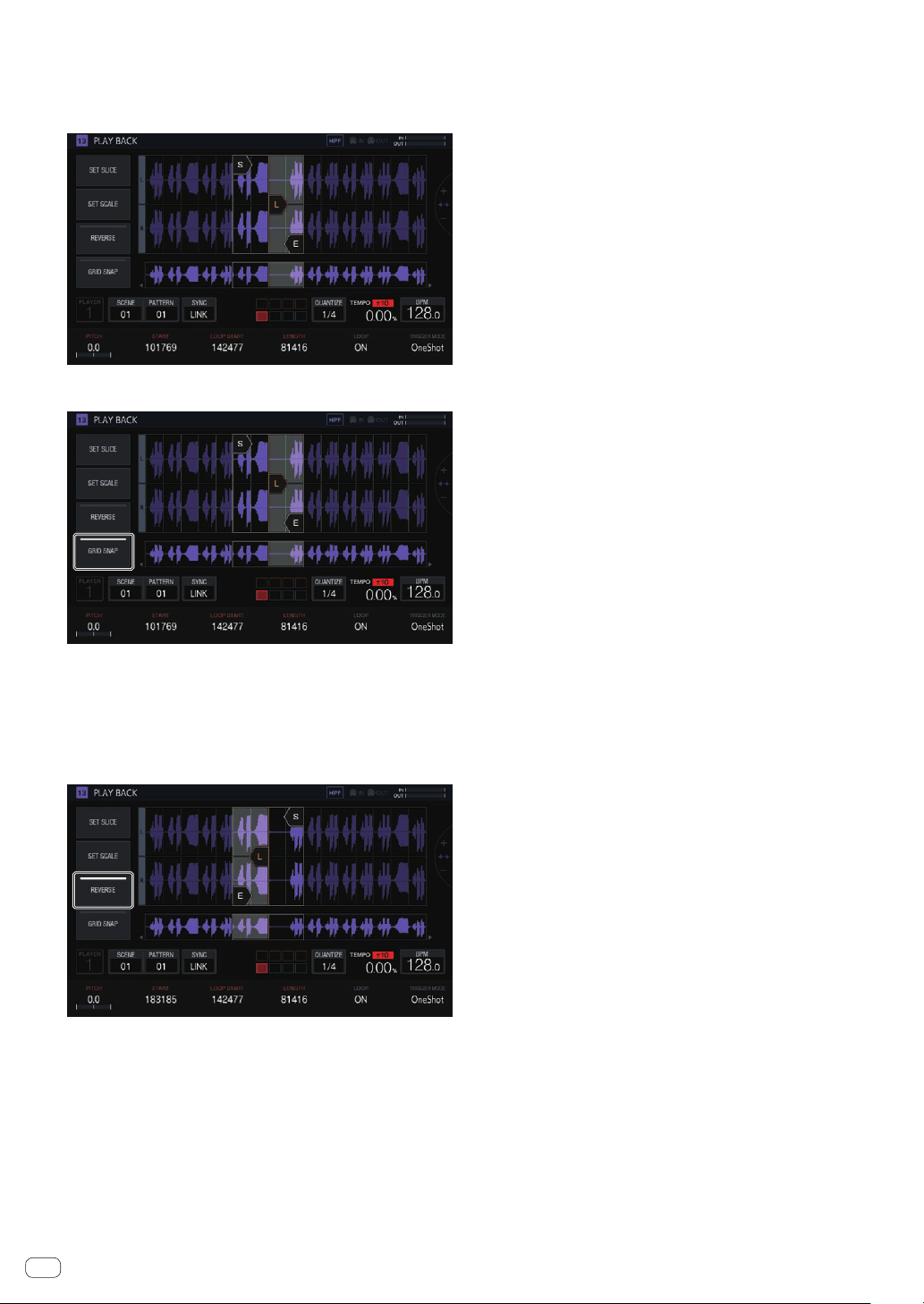
En
34
GRID SNAP
When [GRID SNAP] is ON, the position of [START], [END], etc. can be
set using the GRID position unit specified in [SET SLICE].
When [
GRID SNAP] is OFF, the GRID appears thin.
When [GRID SNAP] is ON, the GRID appears thick.
REVERSE
Switches reverse playback ON/OFF.
Reverses the playback direction when this button is ON.
Tap [REVERSE].
Reverse playback is performed.
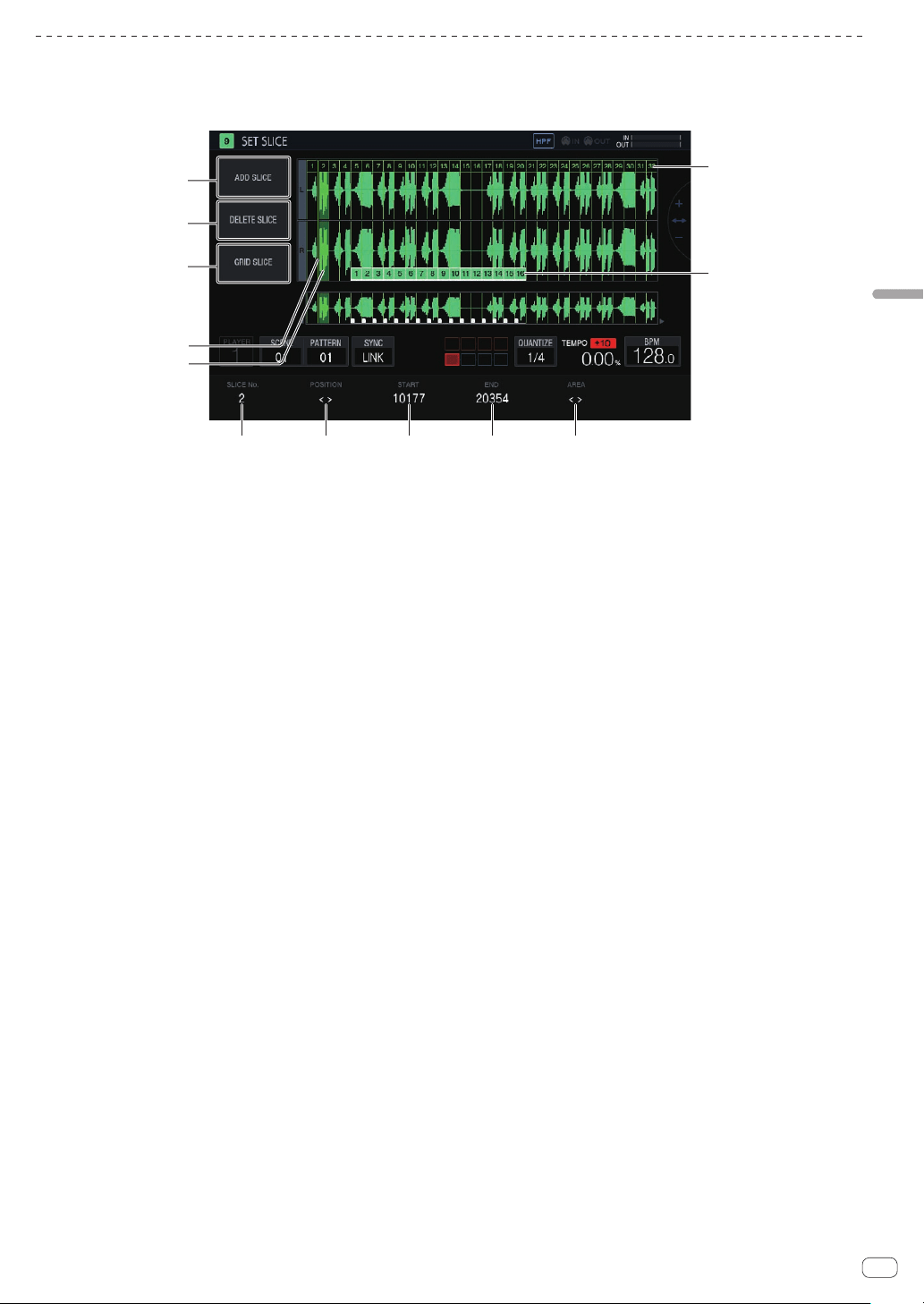
En
35
Adjusting track parameters (TRACK MENU)
Setting parameters for slice performances (SET SLICE)
You can add and delete slices, equally slice into a specified number of slices, change the size of each slice, and set the range of the slice to assign to a
performance pad.
If you tap [SET SLICE] in the PLAYBACK screen, the unit switches to the SET SLICE screen.
4
5
6 7 8 9 a
b
c
1
2
3
1 ADD SLICE
Adds a new slice.
2 DELETE SLICE
Deletes the selected slice.
3 GRID SLICE
Equally slices into a specified number of slices.
4 POSITION display cursor
A green cursor indicates the position selected by [POSITION].
5 Selected slice indication
Transparent green on a slice indicates that the slice is selected.
6 SLICE No.
Selects a slice.
7 POSITION
Moves the selection position.
8 START
Sets the start position of the selected slice.
9 END
Sets the end position of the selected slice.
a AREA
Sets the start position of the selected slice.
b Pad markers
Pad colors on the slices indicate that the slices are assigned to
performance pads.
c Slice markers
A number is assigned and displayed for each slice.
Adding a slice
%
Tap [ADD SLICE].
A new slice is added.
The slice is added with its POSITION display cursor as the slice start
position. When the slice is added, the SLICE marker numbers are reas-
signed in order from the beginning.
! When the maximum number of slices (64) has been reached,
[ADD SLICE] is grayed out and a new slice cannot be added.
Deleting a slice
%
Tap [DELETE SLICE].
The selected slice is deleted.
! When the beginning slice is selected or there is only one slice,
[DELETE SLICE] is grayed out and the slice cannot be deleted.
Equally slicing a sample
1 Tap [GRID SLICE].
A pop-up screen for specifying the number of slices appears.
2 Turn the rotary selector to select the number of slices
and then tap [OK].
The sample is sliced equally with the specified number of slices.
Numbers are assigned to the divided slices in order from the beginning
slice, and then displayed on the slice markers.
Selecting a slice
%
Turn the parameter 1 adjustment knob to select a
slice.
The number assigned to the slice marker is displayed in [SLICE No.]. The
selected slice is indicated by transparent green.
Setting the slice position
%
Turn the parameter 2 adjustment knob to move the
POSITION display cursor.
The slice where the POSITION display cursor is located is indicated by
transparent green, and its number is displayed in [SLICE No.].
Adjusting the slice start position
%
Turn the parameter 3 adjustment knob to adjust the
start position of the selected slice.
This cannot be adjusted for the beginning slice.
Adjusting the slice end position
%
Turn the parameter 4 adjustment knob to adjust the
end position of the selected slice.
! This cannot be adjusted for the last slice.
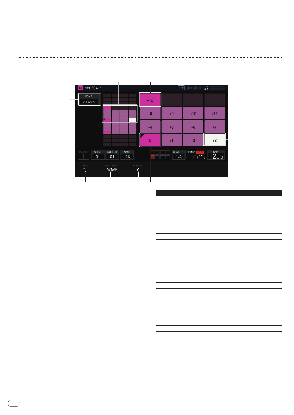
En
36
Assigning slices to performance pads
%
Turn the parameter 5 adjustment knob to select the
range of the slice to assign to a performance pad.
! The slices assigned to performance pads are indicated with 16 pad
markers that have the same color as the track color. The pad markers
can specify up to 16 consecutive slices.
Setting parameters for scale performances (SET SCALE)
If you tap [SET SCALE] in the PLAYBACK screen, the unit switches to the SET SCALE screen.
2 1
3
4 5 6 7
8
1 Octave key
Greater color intensity is used for a key that differs by one octave
from the root key. The color differs depending on the track color.
2 Pad placement range
Displays the area with sound assigned to the pads.
3 SCALE
Sets the scale.
4 AREA
Sets the area of the keys assigned to the pads.
5 TIME STRETCH
Sets the method of stretching a sample to synchronize with the BPM.
This setting is used only when SAMPLE tracks.
6 KEY SHIFT
Adjusts the pitch that will be the root key of the scale.
7 Root key
Displays the key that will be the root. A triangular mark is added to
the top left.
The playback pitch of the root key becomes a key that is the sum of
the pitch value set on the PLAYBACK screen and the value set in
[
KEY SHIFT].
8 Selected key
Indicates the key selected last with a pad. The key is lit in white.
Pressing a 16-step key will input a trigger producing a sound of the
same pitch as the sound of the selected key.
Selecting a scale
1 Tap [SCALE].
2 Turn the rotary selector to select the scale you wish to
use and then press the rotary selector.
You can select from the following scales. When a scale is selected, only
the sounds of that scale are assigned to the pads.
Scale name Abbreviation
Chromatic CHROMA
Ionian IONIAN
Dorian DORIAN
Phrygian PHRYGIAN
Lydian LYDIAN
Mixolydian MIXOLYDN
Aeolian AEOLIAN
Locrian LOCRIAN
Major Pentatonic M. PENTA
Minor Pentatonic m. PENTA
Whole Tone WHOLE T.
Diminish DIMINISH
Combination Diminish COMBO D
Altered ALTERED
Major Blues M. BLUES
Minor Blues m. BLUES
Raga Bhairav RAGA B.
Raga Gamanasrama RAGA G.
Raga Todi RAGA T.
Hawaiian HAWAIIAN
Ryukyu RYUKYU
Japanese Miyakobushi JP MIYAKO
Setting an area
%
Turn the parameter 1 adjustment knob.
An area of the pitch of the sounds assigned to the pads can be set. The
assigned area can be checked in the pad placement range.
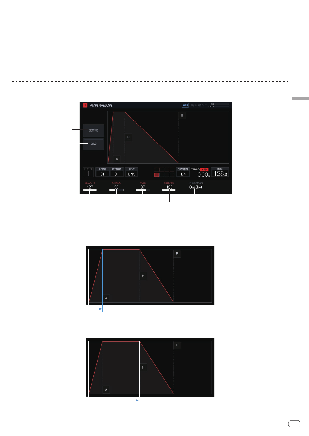
En
37
Adjusting track parameters (TRACK MENU)
Changing KEY SHIFT
[KEY SHIFT] can be changed. The pitch changed by the changed shift
amount becomes the root key. The pitch set in [PITCH] of the PLAYBACK
screen is treated as the 0 state for [
KEY SHIFT], and changing
[KEY SHIFT] shifts the key with respect to that pitch.
% Turn the parameter 3 adjustment knob.
Changing TIME STRETCH
Set the method of stretching a sample to synchronize with the BPM. The
range that the pitch can be changed in the SCALE mode varies depend-
ing on this setting.
% Turn the parameter 2 adjustment knob.
! When OFF: Enables a scale performance with a pitch of up to ±24
halftones.
!
When RESMPL: Enables a performance only with the root key.
! When M.TMP: Enables a scale performance with a pitch of up to
±12 halftones.
Adjusting the change in volume for sample playback (AMP ENVELOPE)
The change in volume can be set for a sample that is played when a performance pad is tapped, a sequence is played, or a trigger is received.
1 2 3 54
7
6
1 VELOCITY
Sets the maximum value for the sample playback volume.
2 ATTACK
Sets the time from when an on trigger is received to when the volume level becomes the maximum (HOLD is reached).
The default is 0. The minimum value is 0 and the maximum value is 32 seconds.
3 HOLD
Sets the time from when an on trigger is received to when the volume begins to be attenuated (RELEASE is reached).
The default is [INF].
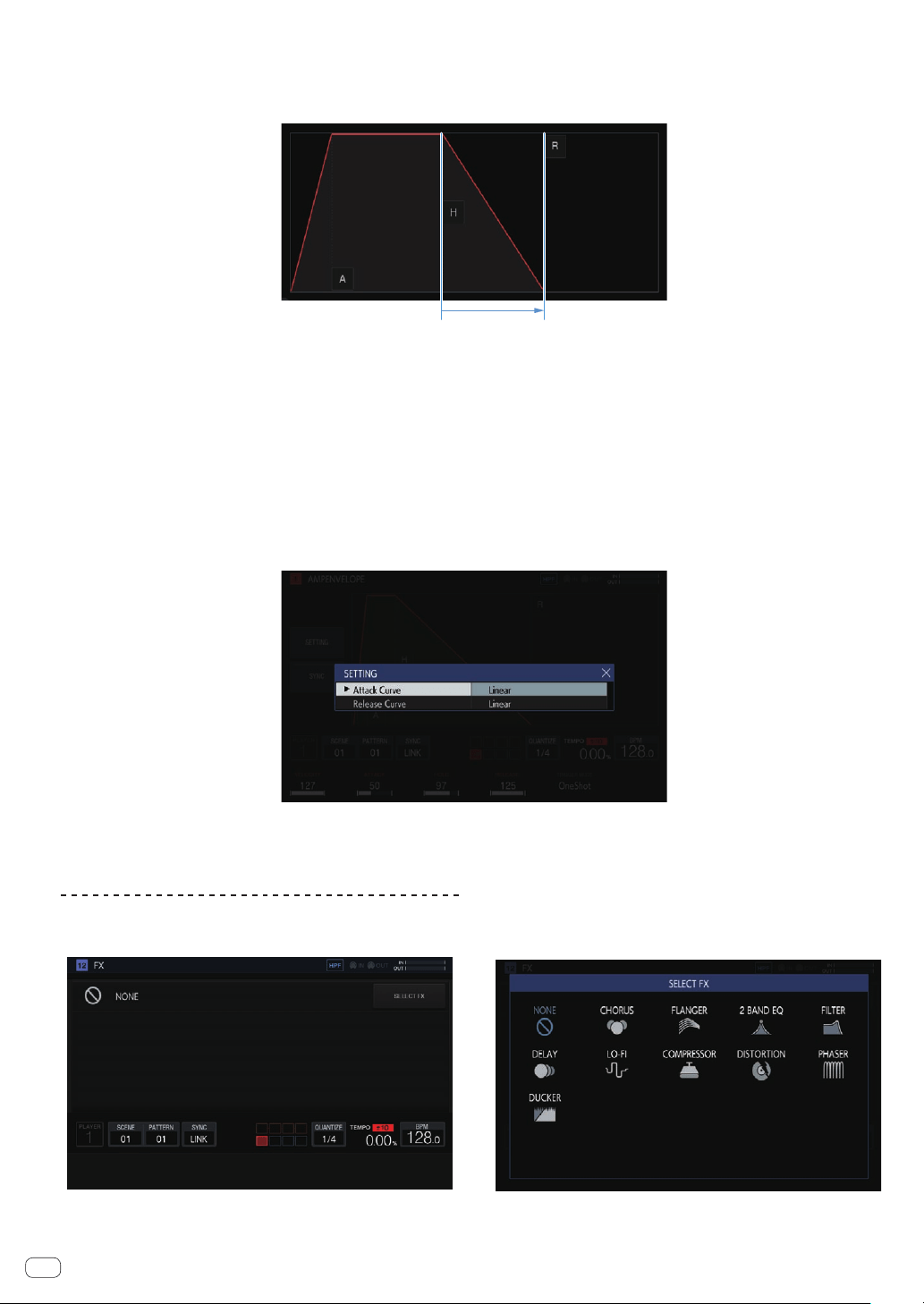
En
38
4 RELEASE
Sets the time from when HOLD is passed to when the volume level becomes 0.
The minimum value is 0. The maximum value is 127. When the parameter 4 adjustment knob is turned clockwise even further from the maximum
value, the value becomes [INF].
The default is 0.
5 TRIGGER MODE
How the envelope operates in response to a trigger can be set. This can be selected from the two options, [OneShot] and [GATE].
OneShot:
[A] l [H] l [R] are passed with the on trigger, regardless of the length of time that the performance pad is pressed.
GATE:
[A] l [H] l [R] are passed while the performance pad is pressed. When [H] is [INF], moves to [R] with the off trigger.
This is suitable for synthesizer sounds and other sounds that are sustained.
6 SETTING
The AMP ENVELOPE settings can be changed.
[Attack Curve]:
The curve for ATTACK can be changed. It can be switched to [Linear] or [Curve].
[Release Curve]:
The curve for RELEASE can be changed. It can be switched to [Linear] or [Curve].
7 SYNC
Whether or not to link the operation of ENVELOPE with the BPM can be set.
The default is OFF.
Applying effects to tracks (FX1)
Effects can be inserted in tracks.
SELECT FX button
If you tap the [SELECT FX] button, the SELECT FX pop-up screen appears.
Tap the icon of the effect you wish to apply to enter the effect.
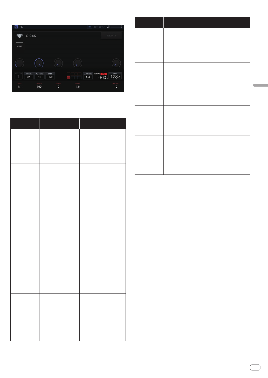
En
39
Adjusting track parameters (TRACK MENU)
Effect display panel
The controls of each FX are displayed in this panel. (Example: CHORUS)
About included FX
The following table shows the included FX and the corresponding
parameters.
Effect name
Parameter
adjustment knobs
Button
2 BAND EQ
(1) B1 Q: 0.1 to 10.0
(2) B1 FREQUENCY: 20 to
20,000 Hz
(3) B1 GAIN: -30 to 15 dB
(4) B2 Q: 0.1 to 10.0
(5) B2 FREQUENCY: 20 to
20,000 Hz
(6) B2 GAIN: -30 to 15 dB
BAND1 TYPE: HPF, LPF, PEAK,
HI-SHELF, and LO-SHELF
BAND2 TYPE: HPF, LPF, PEAK,
HI-SHELF, and LO-SHELF
CHORUS
(1) RATE: 0.1 to 10.0 Hz
(When SYNC is ON, 16/1 to
1/16 BEAT)
(2) WIDTH: 0 to 100%
(3) PHASE: 0 to 180°
(4) DELAY: 1.0 to 10.0 ms
(6) MIX RATIO: 0 to 100%
SYNC: ON and OFF
COMPRESSOR
(1) RATIO: 1.0:1 to 30.0:1
(2) ATTACK: 0.05
to 1,000 ms
(3) RELEASE: 10
to 4,000 ms
(4) THRESHOLD: -52 to
0 dB
(5) GAIN: 0 to 50 dB
(6) MIX RATIO: 0 to 100%
PEAK/RMS: PEAK and RMS
SOFT KNEE: ON and OFF
DELAY
(1) TIME: 10 to 1,000 ms
(When SYNC is ON, 1/8 to
2/1 BEAT)
(2) FEEDBACK: 0 to 100%
(3) HI CUT: 0 to 100
(6) MIX RATIO: 0 to 100%
SYNC: ON and OFF
DISTORTION
(1) DRIVE: 0.0 to 40.0
(2) LO FREQ: 20 to
20,000 Hz
(3) HI FREQ: 20 to
20,000 Hz
(4) DYNAMICS: 0 to 100%
(5) TONE: 20 to 20,000 Hz
(6) MIX RATIO: 0 to 100%
-
DUCKER
(1) ATTACK: 0 to 1,000 ms
(When SYNC is ON: 0.00 to
4.00 steps)
(2) CURVE (ATTACK): -100
to 100%
(3) RELEASE: 0.1 to 8,000.0
ms (When SYNC is ON,
0.25 to 32.00 steps)
(4) CURVE (RELEASE): -100
to 100%
(6) DEPTH: 0 to 100%
SYNC: ON and OFF
SOURCE: From
TRACK1TRACK16
Effect name
Parameter
adjustment knobs
Button
FLANGER
(1) RATE: 0.01 to 1.00 Hz
(When SYNC is ON, 64/1 to
1/1 BEAT)
(2) WIDTH: 0 to 100%
(3) PHASE: 0 to 180°
(4) DELAY: 0.1 to 7.0 ms
(5) FEEDBACK: 0 to 99%
(6) MIX RATIO: 0 to 100%
SYNC: ON and OFF
LO-FI
(1) PREAMP: 0 to +42 dB
(2) REDUCTION: 44 to
44,100 Hz
(3) BIT DEPTH: 1 to 16, 24,
and OFF
(4) CUT OFF: 20 to
20,000 Hz
(5) RESONANCE: 0.2 to
10.0
(6) MIX RATIO: 0 to 100%
TYPE: HPF, LPF, BPF, and OFF
PRE/POST: PRE and POST
MULTI MODE
FILTER
(1) CUT OFF: 20 to
20,000 Hz
(2) GAIN: -30 to 15 dB
(3) RESONANCE: 0.2 to
10.0
(4) GLIDE: 0 to 100
(6) MIX RATIO: 0 to 100%
TYPE: HPF, LPF, and BPF
SLOPE: 12 dB/oct, 24 dB/oct
PHASER
(1) RATE: 0.01 to 1.00 Hz
(When SYNC is ON, 64/1 to
1/1 BEAT)
(2) WIDTH: 0 to 100%
(3) PHASE: 0 to 180°
(4) FREQUENCY: 300.0 to
18,000 Hz
(5) FEEDBACK: 0 to 99%
(6) MIX RATIO: 0 to 100%
SYNC: ON and OFF
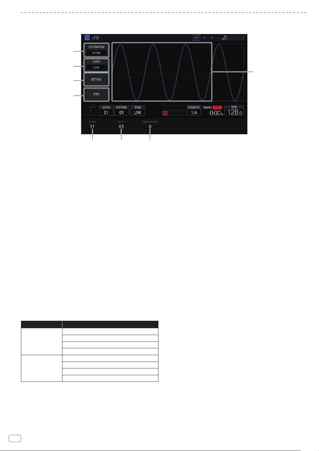
En
40
Setting LFO (LFO)
Apply changes to the pitch and tone with LFO for a parameter of each track to enable a performance with a modulation effect.
5
1
2
3
8
4
6 7
1 DESTINATION
Selects the parameter for which to apply the modulation effect with
LFO.
2 SHAPE
Selects the shape of LFO.
3 SETTING
Sets the detailed operation of LFO.
4 SYNC
Selects ON/OFF for STEP sync of the SPEED parameter.
5 SPEED
Sets the frequency of LFO.
6 DEPTH
Sets the application amount that LFO applies to the parameter.
7 PHASE OFFSET
Sets the start phase of the waveform of LFO.
8 LFO waveform display
Displays an LFO waveform in accordance with the [SHAPE],
[DEPTH], and [PHASE OFFSET] setting values.
Selecting the target parameter
%
Tap [DESTINATION].
Select the parameter for modulation with LFO. One parameter can be
selected per track.
Category name Parameter name
PLAYBACK
PITCH
START
LOOP START
LENGTH
AMP ENVELOPE
VELOCITY
ATTACK
HOLD
RELEASE
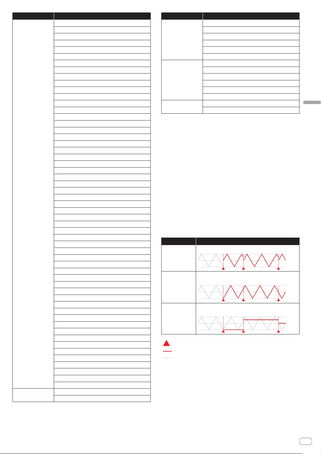
En
41
Adjusting track parameters (TRACK MENU)
Category name Parameter name
FX1
2 BAND EQ B1 Q
2 BAND EQ B1 FREQUENCY
2 BAND EQ B1 GAIN
2 BAND EQ B2 Q
2 BAND EQ B2 FREQUENCY
2 BAND EQ B2 GAIN
CHORUS RATE
CHORUS WIDTH
CHORUS PHASE
CHORUS DELAY
CHORUS MIX RATIO
COMPRESSOR RATIO
COMPRESSOR ATTACK
COMPRESSOR RELEASE
COMPRESSOR THRESHOLD
COMPRESSOR OUTPUT GAIN
COMPRESSOR MIX RATIO
DELAY TIME
DELAY FEEDBACK
DELAY HI CUT
DELAY MIX RATIO
DISTORTION DRIVE
DISTORTION LO FREQ
DISTORTION HI FREQ
DISTORTION DYNAMICS
DISTORTION TONE
DISTORTION MIX RATIO
DUCKER ATTACK
DUCKER CURVE (ATTACK)
DUCKER RELEASE
DUCKER CURVE (RELEASE)
DUCKER DEPTH
FLANGER RATE
FLANGER WIDTH
FLANGER PHASE
FLANGER DELAY
FLANGER FEEDBACK
FLANGER MIX RATIO
LO-FI PREAMP
LO-FI REDUCTION
LO-FI BIT DEPTH
LO-FI CUTOFF
LO-FI RESONANCE
LO-FI MIX RATIO
MULTI MODE FILTER CUTOFF
MULTI MODE FILTER GAIN
MULTI MODE FILTER RESONANCE
MULTI MODE FILTER GLIDE
MULTI MODE FILTER MIX RATIO
PHASER RATE
PHASER WIDTH
PHASER PHASE
PHASER FREQUENCY
PHASER FEEDBACK
PHASER MIX RATIO
MIDI NOTE
VELOCITY
LENGTH
Category name Parameter name
MIDI CC1
PARAMETER 1 PITCH BEND
PARAMETER 2 AFTER TOUCH
PARAMETER 3
PARAMETER 4
PARAMETER 5
PARAMETER 6
MIDI CC2
PARAMETER 1
PARAMETER 2
PARAMETER 3
PARAMETER 4
PARAMETER 5
PARAMETER 6
MIXER
VOLUME
PAN
!
Even if a target parameter is selected, the LFO effect will not be applied if an
effect, MIDI track, etc. including that parameter is not assigned.
Selecting the LFO waveform shape
%
Tap [SHAPE] and select the LFO waveform shape.
There are seven LFO waveform shape types: [SINE], [TRIANGLE], [SAW],
[SQUARE], [PULSE25], [PULSE12], and [RANDOM]. A waveform of the
selected shape is displayed in the LFO waveform display section.
! [RANDOM] generates a new RANDOM shape each time the shape is
switched from a different shape.
Setting the detailed operation of LFO
If you tap [SETTING], the detailed operation setting pop-up screen
appears. Set Mode and Trigger On in this screen.
Mode
Select the LFO operation for a trigger. Three types of Mode are available:
Trigger, Free, and Sample & Hold. The operation is as follows when
each of them is selected.
Mode
Operation
Trigger
LFO restarts with each trigger.
Free
Oscillation always occurs in the background regardless of
triggers.
Sample & Hold
Oscillation always occurs in the background but the value at
the time of a trigger is retained.
Trigger
Applied parameter
LFO oscillating in the background
Trigger On
In the Mode setting, select the type of trigger of the sequencer for which
the LFO trigger operates.
! Full: The LFO trigger operates only for a Full trigger.
! Full & Half: The LFO trigger operates for a Full trigger or a Half
trigger.
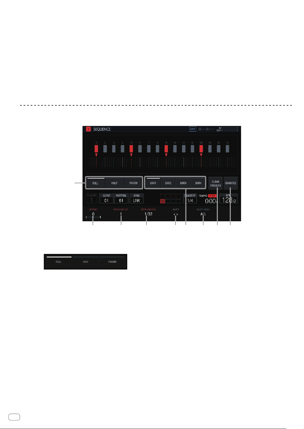
En
42
Setting the various parameters of LFO
Turn the parameter adjustment knobs to set the values of [SPEED],
[DEPTH], and [PAHSE OFFSET]. An explanation and the setting range of
each parameter are provided below.
SPEED
Turn the parameter 1 adjustment knob to set the frequency of LFO. The
setting range will vary as follows depending on whether the [SYNC] but-
ton is ON or OFF.
!
SYNC When OFF: 0 to 127
! SYNC When ON: 1/2, ,1, 2, 3, 4, 8, 12, 16, 32, 48, 64, 128 (unit: STEP)
DEPTH
Turn the parameter 2 adjustment knob to set the application amount to
apply to the parameter selected in [DESTINATION]. The range is -64 to
0 to 63.
!
When the DEPTH value is a minus value, the top and bottom of the
waveform will be inverted.
! A waveform is displayed in the LFO waveform display section in
accordance with the DEPTH value.
PHASE OFFSET
Turn the parameter 3 adjustment knob to set the initial position of LFO.
The range is 0% to 99%.
! The initial position of LFO at 99% will be delayed by about 1 cycle.
! A waveform is displayed in the LFO waveform display section in
accordance with the PHASE OFFSET value.
Adjusting various trigger sequences (SEQUENCE)
The trigger sequence of each track can be offset and otherwise adjusted with a unit smaller than steps.
2 3 4 5
7 8 9
1
6
1 Trigger type selection
Selects the type of triggers to input.
The default is [Full].
1 Full trigger (Full)
SAMPLE, ENVELOPE, and all modulated parameters are
triggered.
2
Half trigger (HALF)
ENVELOPE and modulated parameters are triggered.
3 Parameter trigger (PARAM)
Only modulated parameters are triggered.
2 OFFSET
A trigger can be finely adjusted forward or backward. It can be
adjusted up to ±1 step (indicating line is directly below the adjacent
step).
Move the trigger position [b] on the touch display a very small
amount by operating this parameter.
!
The default is 0.
3 RETRIGGER CNT
Sets the number of times to input triggers repeatedly over a short
period.
!
The default is 1.
! When [RETRIGGER CNT] is two or more, the [b] mark on the
screen is changed to the mark for indicating repeated input (two
[b] marks arranged vertically).
4 RETRIGGER SPD
Sets the speed for re-triggering.
!
The default is 1/32 (BAR).
! When [RETRIGGER CNT] is two or more, the [b] mark on the
screen is changed to the mark for indicating repeated input (two
[b] marks arranged vertically).
5 SHIFT
An input trigger can be offset by step (circle shift) within the range
set in [SHIFT AREA].
6 BAR
This is linked to the bar selection button and the bar to be displayed
can be selected. It also indicates the bar currently displayed.
7 SHIFT AREA
Sets the range to apply [SHIFT].
This can be selected from the two types, [BAR] and [ALL].
! Specify the operation target step with the hardware buttons.
When no step has been specified, all steps become targets. For
example, all steps are uniformly offset in the case of an offset.
When an individual step is selected by pressing a step key, the
corresponding vertically long [g] and [b] on the touch display
flash.
8 CLEAR TRIGGERS
Clears all of the triggers input to the currently selected pattern.
9 QUANTIZE
Snaps the triggers input to the currently selected pattern on a 1/16
level.
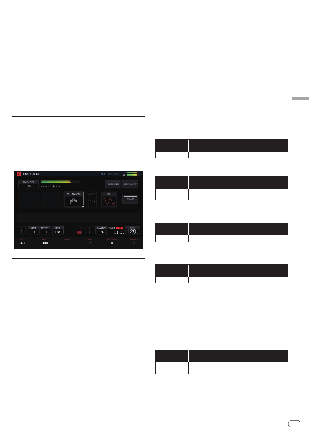
En
43
Adjusting track parameters (TRACK MENU)
Clearing all triggers
1 Tap [CLEAR TRIGGERS].
A confirmation message appears.
2 Tap [OK].
Clears all of the triggers input to the currently selected pattern.
! If you tap [CANCEL], the pop-up screen closes without clearing and
the sequence screen reappears.
Quantize
This feature can be used when aligning triggers that were input with, for
example, dynamic recording to steps.
% Tap [QUANTIZE].
Any input triggers that are offset from steps are quantized to a step in
the vicinity on a 1/16 level.
Through track
The [LINE IN] external input can be assigned to a track to apply an effect.
Select the input source with the parameter adjustment knobs below the
touch display and adjust [INPUT LEVEL] on the top panel of the unit or
the volume level of the source device while looking at INPUT MONITOR.
At that time, if [SOFT LIMIT] (ON/OFF toggle operation) is tapped, the
analog limiter at the input stage is enabled to reduce unnecessary
clipping.
MIDI tracks
Performances with the unit and using external MIDI sound sources
according to the MIDI sequence are possible.
Connections
Connecting with DIN MIDI
1 Connect the MIDI IN terminal of the external MIDI
device and the MIDI OUT/THRU terminal of this unit with
a MIDI cable.
2 Tap [SYNC] in the HOME screen, etc. to display the
SYNC screen.
3 Tap [DIN MIDI] in MIDI I/F SELECT.
After configuring the above setting, tap [TRACK TYPE] in the TRACK
MENU screen of the track you wish to use for the MIDI performance and
then use the rotary selector to select [MIDI].
Connecting with USB MIDI
1 Connect your computer and the USB-B terminal of
this unit with a USB cable.
2 Tap [SYNC] in the HOME screen, etc. to display the
SYNC screen.
3 Tap [USB MIDI] in MIDI I/F SELECT.
After configuring the above setting, tap [TRACK TYPE] in the TRACK
MENU screen of the track you wish to use for the MIDI performance and
then use the rotary selector to select [MIDI].
! For the detailed settings of the MIDI notes and MIDI control changes
to be transmitted with MIDI tracks, refer to Setting MIDI NOTE
(MIDI NOTE) on page 46 and Setting MIDI CC (MIDI CC1/CC2) on
page 44 .
Setting whether or not to transmit various MIDI
messages
Configure the settings for whether or not to transmit various MIDI mes-
sages in the PROJECT SETTING (MIDI OUT) category of the UTILITY
screen. The setting items and setting values are as follows.
Option
settings
Options
CLOCK
ENABLE/DISABLE
!
ENABLE: Transmits MIDI CLOCK to the external MIDI device based on the BPM
of the unit’s sequencer.
! DISABLE: Does not transmit MIDI CLOCK to the external MIDI device.
Option
settings
Options
START/STOP/
CONTINUE
ENABLE/DISABLE
!
ENABLE: Transmits the START, STOP, and CONTINUE messages to the external
MIDI device.
! DISABLE: Does not transmit the START, STOP, and CONTINUE messages to the
external MIDI device.
Option
settings
Options
NOTE/CC ENABLE/DISABLE
!
ENABLE: Transmits NOTE and CC (including Pitch Bend and After Touch) to
the external MIDI device.
! DISABLE: Does not transmit NOTE and CC (including Pitch Bend and After
Touch) to the external MIDI device.
Option
settings
Options
SONG POSITION
ENABLE/DISABLE
!
ENABLE: Transmits the song position pointer to the external MIDI device.
! DISABLE: Does not transmit the song position pointer to the external MIDI
device.
Setting the MIDI OUT channel
To set the MIDI OUT channel setting, tap [SELECT CH] in the TRACK
MENU screen of the MIDI track to be transmitted to the MIDI. Then, set
CH from the displayed pop-up screen.
To reset the set MIDI OUT channel, execute [CHANNEL MAPPING
RESET] in the PROJECT SETTING (MIDI OUT) category of the UTILITY
screen.
Option
settings
Options
CHANNEL
MAPPING RESET
None (Executes RESET.)
The MIDI CH set in the TRACK MENU screen is reset. When a reset is
performed, the track number and MIDI CH are restored to the initial
values of the same number.
! TRACK1 to TRACK16: CH.1 to CH.16
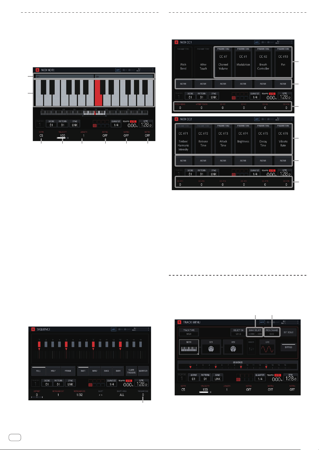
En
44
Setting MIDI NOTE (MIDI NOTE)
Set the MIDI notes to transmit when the pads of a MIDI track are pressed
or when triggered in a sequence. Up to four MIDI notes can be triggered
by setting a harmony in addition to a base note.
You can input MIDI note triggers to the step sequencer in the same
manner as a sample track or you can perform dynamic recording of your
pad performance.
! The SLICE mode cannot be used with a MIDI track.
3 4 5 6
7 8
1
2
1 Octave number display
Displays the octave number. Displays from C0 to C9.
2 Keyboard display
Indicates the notes set in [NOTE] with the track color. Indicates the
notes set in [NOTE2], [NOTE3], and [NOTE4] with a lighter version of
the track color.
3 NOTE
Changes the note number. The range is C0 to B9.
4 VELOCITY
Change the velocity. The range is OFF and 1 to 127.
5 LENGTH
Changes the length. The range is 0.25 step to 64 steps.
6 NOTE2
Changes a note of chords based on the note number set in [NOTE].
The range is -127 to OFF to +127.
7 NOTE3
Changes a note of chords based on the note number set in [NOTE].
The range is -127 to OFF to +127.
8 NOTE4
Changes a note of chords based on the note number set in [NOTE].
The range is -127 to OFF to +127.
If you use the TRANSPOSE function of HOME > TRACK MENU >
SEQUENCE, you can shift an entire note output from a MIDI track in half-
tones. Turn the parameter 6 adjustment knob to change [TRANSPOSE]
in the SEQUENCE screen.
1
1 TRANSPOSE
Changes the transpose value. The range is -24 to +24.
Setting MIDI CC (MIDI CC1/CC2)
Set the MIDI control changes to transmit when the pads of a MIDI track
are pressed or when triggered in a sequence.
1
2
3
1
2
3
1 CC number selection
Changes the control change numbers of [PARAMETER 1] to
[PARAMETER 6].
! [PITCH BEND] of [PARAMETER 1] and [AFTER TOUCH] of
[PARAMETER 2] cannot be changed in the CC1 setting screen.
2 ACTIVE
Switches [PARAMETER 1] to [PARAMETER 6] between active and
non-active.
3 CC values
Changes the control change values of [PARAMETER 1] to
[PARAMETER 6].
Setting bank selection and program
change
Bank selection and program change messages can be transmitted when
using MIDI tracks (or TORAIZ AS-1 tracks).
1
2
1 BANK SELECT
Changes the bank value to transmit.
2 PROG CHANGE
Changes the program change value to transmit.
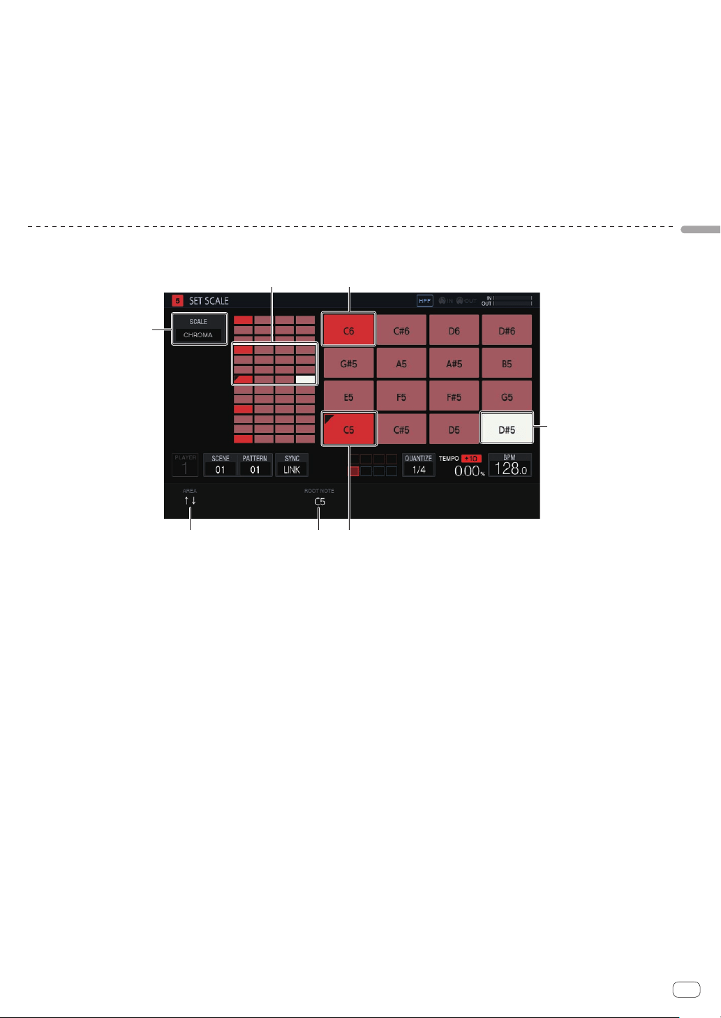
En
45
Adjusting track parameters (TRACK MENU)
Transmitting the bank selection
1 Tap [BANK SELECT] in the TRACK MENU screen of the
MIDI track.
Tap the MSB area if you wish to change MSB (M), and the LSB area if
you wish to change LSB (L).
2 Turn the rotary selector to set the value you wish to
set.
3 Tap [OK].
The value is entered and the pop-up screen closes. The set value is dis-
played in [BANK SELECT].
Transmitting the program change
1 Tap [PROG CHANGE] in the TRACK MENU screen of
the MIDI track.
2 Turn the rotary selector to set the value you wish to
set.
3 Tap [OK].
The value is entered and the pop-up screen closes. The set value is dis-
played in [PROG CHANGE].
! The bank selection and program change values can be set for each
SCENE. The program of the external MIDI device can be changed in
conjunction with the SCENE switching operation.
Setting parameters for scale performances (SET SCALE)
If you tap the [SET SCALE] button in the TRACK MENU screen, the unit switches to the SET SCALE screen.
2 1
3
4 5 6
7
1 Octave key
Greater color intensity is used for a key that differs by one octave
from the root key. The color differs depending on the track color.
2 Pad placement range
Displays the area with sound assigned to the pads.
3 SCALE
Sets the scale.
4 AREA
Sets the area of the keys assigned to the pads.
5 ROOT NOTE
Adjusts the pitch that will be the root key of the scale.
6 Root key
Displays the key that will be the root. A triangular mark is added to
the top left.
The name of the sound set in [ROOT NOTE] is displayed.
7 Selected key
Indicates the key selected last with a pad. The key is lit in white.
Pressing a 16-step key will input a trigger producing a sound of the
same pitch as the sound of the selected key.
Selecting a scale
1 Tap [SCALE].
2 Turn the rotary selector to select the scale you wish to
use and then press the rotary selector.
For the scales that can be selected, refer to the table in Selecting a scale
on page 36 .
Setting an area
%
Turn the parameter 1 adjustment knob.
An area of the pitch of the sounds assigned to the pads can be set. The
assigned area can be checked in the pad placement range.
Changing ROOT NOTE
% Turn the parameter 3 adjustment knob.
[ROOT NOTE] can be changed. The changed sound becomes the root
key, and is indicated at the top of the parameter 3 adjustment knob.
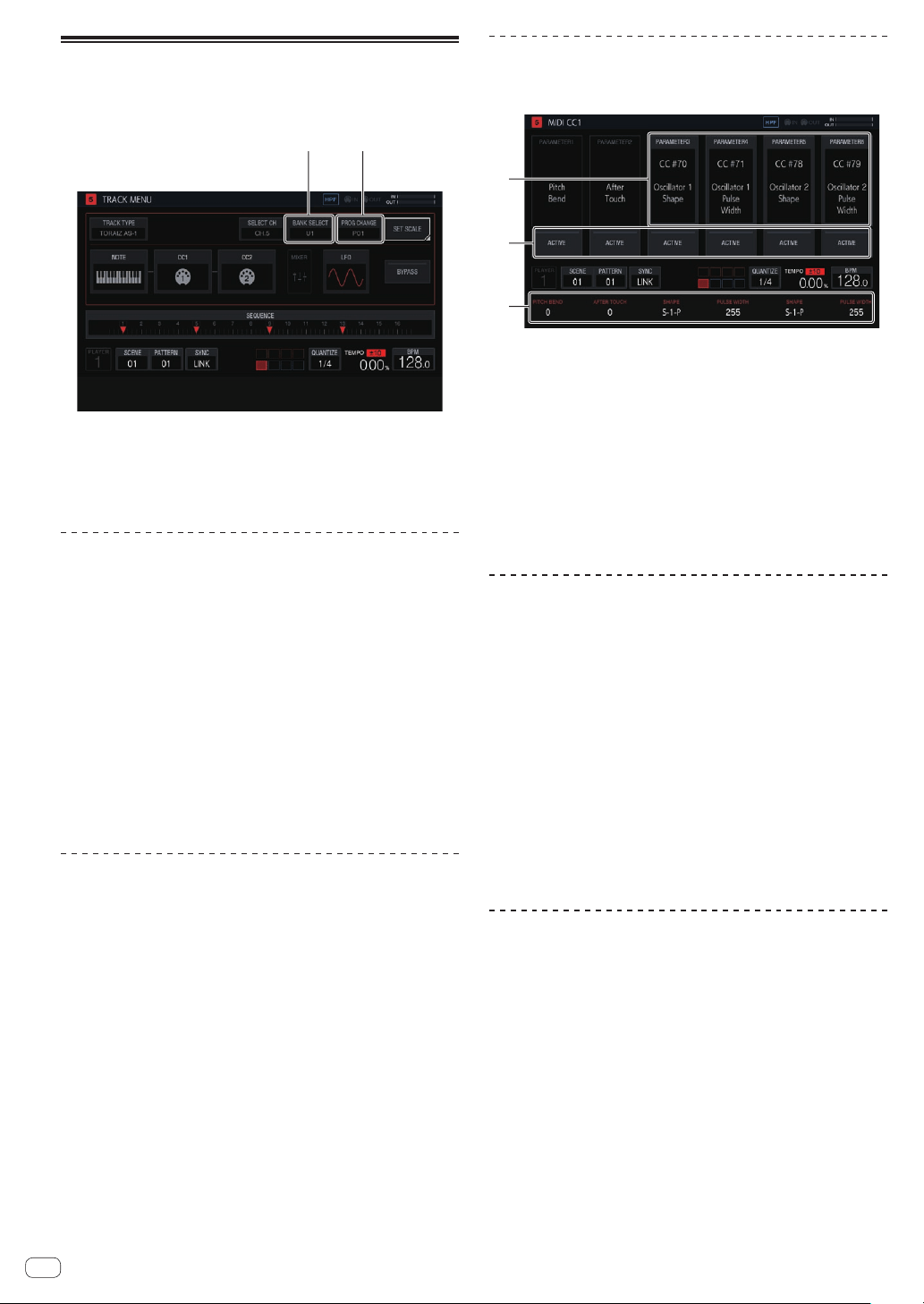
En
46
TORAIZ AS-1 tracks
These are dedicated track attributes that are convenient for perfor-
mances with a TORAIZ AS-1 analog synthesizer connected to [MIDI
OUT].
1
2
1 BANK SELECT
Changes the bank value stored in the preset.
2 PROG CHANGE
Changes the program change value to transmit.
Connections
1 Connect the MIDI IN terminal of the TORAIZ AS-1 and
the MIDI OUT/THRU terminal of this unit with a MIDI
cable.
2 Tap [SYNC] in the HOME screen, etc. to display the
SYNC screen.
3 Tap [DIN MIDI] in MIDI I/F SELECT.
4 Set MIDI Channel to ALL or any channel, MIDI
Param Rcv to CC, and MIDI Control Enable to On in
[GLOBAL SETTING] of the TORAIZ AS-1 unit.
After configuring the above settings, tap [TRACK TYPE] in the TRACK
MENU screen of the track you wish to use for the MIDI performance and
then use the rotary selector to select [TORAIZ AS-1].
Setting MIDI NOTE (MIDI NOTE)
[MIDI NOTE] can be set in the same way as with a MIDI track. However,
[NOTE2], [NOTE3], and [NOTE4] cannot be set because the TORAIZ
AS-1 does not support chords.
Setting MIDI CC (MIDI CC1/CC2)
If you tap [CC1] or [CC2], the unit switches to the screen for setting the
MIDI CC compatible parameters of the TORAIZ AS-1.
1
2
3
1 CC number selection
Changes the control change numbers of [PARAMETER 1] to
[PARAMETER 6].
! [PITCH BEND] of [PARAMETER 1] and [AFTER TOUCH] of
[PARAMETER 2] cannot be changed in the CC1 setting screen.
2 ACTIVE
Switches [PARAMETER 1] to [PARAMETER 6] between active and
non-active.
3 CC values
Changes the control change values of [PARAMETER 1] to
[PARAMETER 6].
Switching the preset
Bank selection and program change can be used to select the program
of the AS-1.
1 Tap [BANK SELECT].
! When using program change, tap [PROG CHANGE].
2 Turn the rotary selector to select the bank containing
the preset you wish to call out and then press the rotary
selector.
The bank is entered. Select a bank from the following.
! [U1] to [U5]: User banks
! [F1] to [F5]: User banks
! When using program change, use the rotary selector to select the
program you wish to call out and then press the rotary selector to
enter the program.
!
The bank selection and program change values can be set for each
scene.
Setting parameters for scale
performances (SET SCALE)
Refer to Setting parameters for scale performances (SET SCALE) on
page 45 .
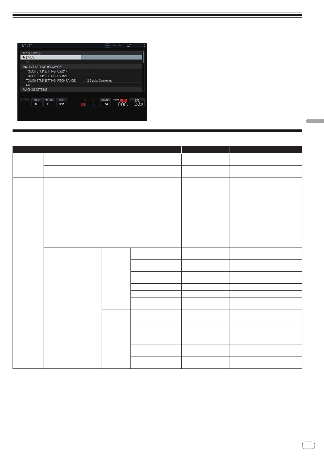
En
47
Changing the settings (UTILITY)
Changing the settings (UTILITY)
Various settings of the unit can be configured.
1 Press and hold the [HOME/UTILITY/WAKE UP] button.
The UTILITY screen appears.
2 Turn the rotary selector to select the item to set.
The focus moves.
3 Press the rotary selector to enable changing the
settings.
The focus moves to the setting value.
4 Turn the rotary selector to change the setting value.
5 Press the rotary selector to enter the setting value.
The focus moves to the setting item.
!
If the [BACK] button is pressed during the process, the setting value
will not be changed.
Setting preferences
Option settings Setting ranges Descriptions
MY SETTINGS
LOAD
-
Calls setting details recorded on record-
ing media.
SAVE
-
Records the setting details on recording
media.
PROJECT
SETTING
TOUCH STRIP SETTING (USER1) -
Configure the settings of touch strip
mode [USER1].
= Setting the USER mode of the touch
strip (
TOUCH STRIP SETTING)
(p. 49 )
TOUCH STRIP SETTING (USER2) -
Configure the settings of touch strip
mode [USER2].
= Setting the USER mode of the touch
strip (TOUCH STRIP SETTING)
(p. 49 )
TOUCH STRIP SETTING (PITCH RANGE)
2 Bipolar Semitones*, 4
Bipolar Semitones, 12
Bipolar Semitones
Configure the range of the PITCH mode of
the touch strip.
MIDI
MIDI IN
CLOCK
ENABLE*/DISABLE
=
Setting whether or not to receive vari-
ous MIDI messages (p. 52 )
START/STOP/CONTINUE ENABLE*/DISABLE
=
Setting whether or not to receive vari-
ous MIDI messages (p. 52 )
NOTE/CC ENABLE*/DISABLE
=
Setting whether or not to receive vari-
ous MIDI messages (p. 52 )
CHANNEL MAPPING
-
=
Setting the MIDI IN channel (p. 52 )
CHANNEL MAPPING RESET
-
=
Setting the MIDI IN channel (p. 52 )
SONG POSITION
ENABLE*/DISABLE
=
Setting whether or not to receive vari-
ous MIDI messages (p. 52 )
MIDI OUT
CLOCK
ENABLE*/DISABLE
=
Setting whether or not to transmit
various MIDI messages (p. 43 )
START/STOP/CONTINUE ENABLE*/DISABLE
=
Setting whether or not to transmit
various MIDI messages (p. 43 )
NOTE/CC ENABLE*/DISABLE
=
Setting whether or not to transmit
various MIDI messages (p. 43 )
CHANNEL MAPPING RESET
-
=
Setting the MIDI OUT channel
(p. 43 )
SONG POSITION
ENABLE*/DISABLE
=
Setting whether or not to transmit
various MIDI messages (p. 43 )
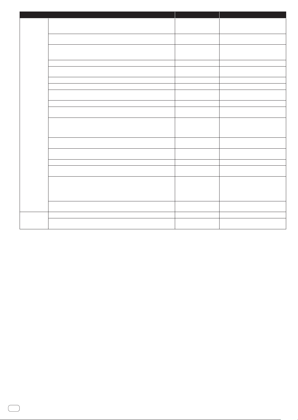
En
48
Option settings Setting ranges Descriptions
MACHINE
SETTING
PAD CURVE
Hard 3, Hard 2, Hard 1,
Linear*, Soft 1, Soft 2,
Soft 3
Set the volume curve characteristics
(velocity curve) in response to the
strength that a pad is pressed.
PAD THRESHOLD
1(Low) to 5(Default)* to
16(High)
Set the strength at which the pad must be
pressed to start outputting sound.
PAD SENCITIVITY
1(Heavy) to 5(Default)* to
16(Light)
Set the strength at which the pad must be
pressed to output sound at the maximum
volume level.
METRONOME
ON, OFF* Switch the metronome function ON/OFF.
METRONOME MONITOR
Master + Headphones*,
Headphones
Set the output destination of metronome
sound.
METRONOME VOLUME
0 to 100* to 127 Set the metronome volume.
COUNT IN
OFF*, 1 BAR, 2 BAR Set the number of bars for the count in.
ON AIR DISPLAY
ON*, OFF
Switch the on air display function ON/
OFF.
LCD BRIGHTNESS
1 (dark), 2, 3*, 4, 5 (bright) Set the brightness of the touch display.
PAD/BUTTON BRIGHTNESS
DIMMED 3, DIMMED 2,
DIMMED 1, NORMAL*
Set the brightness of the performance
pads and 16-step keys.
SCREEN SAVER
ON*, OFF
When this is set to [ON], the screensaver
starts if the unit is stopped, paused, or
no operation is performed for at least 5
minutes.
OUTPUT (AUDIO 2)
INPUT THRU*, MASTER
Set the sound to output from the THRU/
OUTPUT2 terminals.
PLAYER No.
AUTO*, PLAYER1,
PLAYER2, ..., PARAMETER 4
Set this unit’s player number.
AUTO STANDBY
ON*, OFF
=
Auto standby function (p. 50 )
TOUCH PANEL CALIBRATION
-
=
Adjusting the touch panel (TOUCH
PANEL CALIBRATION) (p. 51 )
CHARACTER PRIORITY
Default*,
Chinese(simplified char-
acters),
Chinese(traditional char-
acters), Korean
Set the display language to which to give
priority on this unit.
DEFAULT
-
Return the setting values to the initial
values.
INFORMATIONS
Version No.
- Displays this unit’s software version.
LICENSE
-
Display information related to the license
of the unit.
!
*: Setting upon purchase
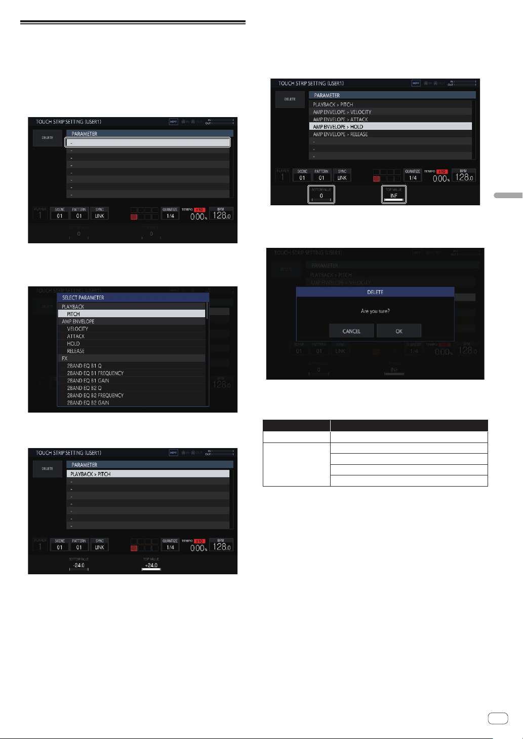
En
49
Changing the settings (UTILITY)
Setting the USER mode of the touch
strip (TOUCH STRIP SETTING)
The parameters that operate with USER1 and USER2 of the touch strip
can be assigned.
Initial state
Turn the rotary selector to move the focus and select a target of
assignment.
Assigning
If the rotary selector is pressed, a parameter selection pop-up window
appears.
If the parameter to be assigned is selected with the rotary selector and
then the rotary selector is pressed, the parameter is assigned.
The assigned parameter is displayed.
When this procedure is repeated in the same way to assign multiple
parameters, the parameter names are added to the list.
When the touch strip is touched, the parameters change in accordance
with the custom set values.
! Up to eight parameters can be assigned.
Customizing
The [BOTTOM VALUE] value for the bottom and the [TOP VALUE] value
for the top of the touch strip can be set using the parameter adjustment
knobs.
The setting value for each assigned parameter can be set, and the
focused value is displayed.
Deleting
If [DELETE] is tapped while the focus is on a parameter to be deleted, the
confirmation dialog box appears.
If [OK] is tapped, the assignment is deleted.
Parameter
The parameters that can be assigned are as follows.
Category name Parameter name
PLAYBACK PITCH
AMP ENVELOPE
VELOCITY
ATTACK
HOLD
RELEASE
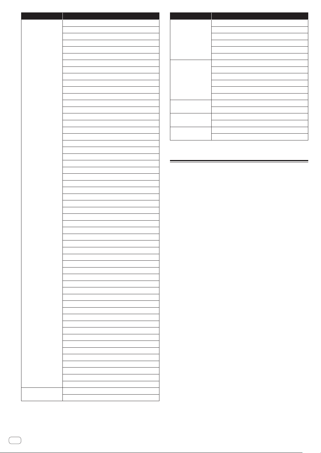
En
50
Category name Parameter name
FX1
2 BAND EQ B1 Q
2 BAND EQ B1 FREQUENCY
2 BAND EQ B1 GAIN
2 BAND EQ B2 Q
2 BAND EQ B2 FREQUENCY
2 BAND EQ B2 GAIN
CHORUS RATE
CHORUS WIDTH
CHORUS PHASE
CHORUS DELAY
CHORUS MIX RATIO
COMPRESSOR RATIO
COMPRESSOR ATTACK
COMPRESSOR RELEASE
COMPRESSOR THRESHOLD
COMPRESSOR GAIN
COMPRESSOR MIX RATIO
DELAY TIME
DELAY FEEDBACK
DELAY HI CUT
DELAY MIX RATIO
DISTORTION DRIVE
DISTORTION LO FREQ
DISTORTION HI FREQ
DISTORTION DYNAMICS
DISTORTION TONE
DISTORTION MIX RATIO
DUCKER ATTACK
DUCKER ATTACK CURVE
DUCKER RELEASE
DUCKER RELEASE CURVE
DUCKER DEPTH
FLANGER RATE
FLANGER WIDTH
FLANGER PHASE
FLANGER DELAY
FLANGER FEEDBACK
FLANGER MIX RATIO
LO-FI PREAMP
LO-FI REDUCTION
LO-FI BIT DEPTH
LO-FI CUTOFF
LO-FI RESONANCE
LO-FI MIX RATIO
MULTI MODE FILTER CUTOFF
MULTI MODE FILTER GAIN
MULTI MODE FILTER RESONANCE
MULTI MODE FILTER GLIDE
MULTI MODE FILTER MIX RATIO
PHASER RATE
PHASER WIDTH
PHASER PHASE
PHASER FREQUENCY
PHASER FEEDBACK
PHASER MIX RATIO
MIDI NOTE
VELOCITY
LENGTH
Category name Parameter name
MIDI CC1
PARAMETER 1 PITCH BEND
PARAMETER 2 AFTER TOUCH
PARAMETER 3
PARAMETER 4
PARAMETER 5
PARAMETER 6
MIDI CC2
PARAMETER 1
PARAMETER 2
PARAMETER 3
PARAMETER 4
PARAMETER 5
PARAMETER 6
MIXER
VOLUME
PAN
LFO
SPEED
DEPTH
SEQUENCE
RETRIGGER CNT
RETRIGGER SPD
! Even if a target parameter is selected, the LFO effect will not be applied if an
effect, MIDI track, etc. including that parameter is not assigned.
Auto standby function
When the auto standby function is turned on, the power is automatically
set to standby mode after four hours have passed with all of the follow-
ing conditions met.
— None of this unit’s buttons or controls are operated.
— The track level indicators are not lit.
— The playback function is not operating.
— No PRO DJ LINK connections are made.
— A USB device is not connected to the USB device insertion slot (Type
A terminal) on the top panel of the unit.
! The indicator of the [HOME/UTILITY/WAKE UP] button is lit during
auto standby.
!
When the [HOME/UTILITY/WAKE UP] button is pressed, the
standby status is canceled.
!
This unit is shipped with the auto standby function turned on. If you
do not want to use the auto standby function, set [AUTO STANDBY]
to [OFF].
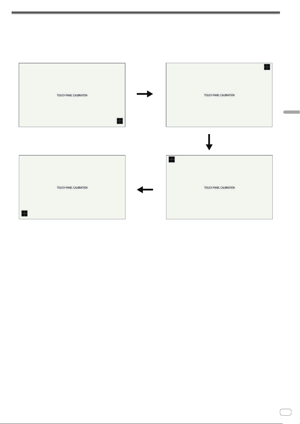
En
51
Changing the settings (UTILITY)
Adjusting the touch panel (TOUCH PANEL CALIBRATION)
This function is for making adjustments when the touch panel of this unit is not working properly.
Display the TOUCH PANEL CALIBRATION screen from the UTILITY screen.
Tap the cross marks on the screen in the order of bottom right l top right l top left l bottom left.
When adjustment is finished, the TOUCH PANEL CALIBRATION screen closes.
①
②
④
③
En
52
MIDI implementation
chart
The following describes the correspondence between the functions and
MIDI messages when the unit receives MIDI messages to perform opera-
tions from an external MIDI device.
Connections
Connecting with DIN MIDI
1 Connect the MIDI OUT terminal of the external MIDI
device and the MIDI IN terminal of this unit with a MIDI
cable.
2 Tap [SYNC] in the HOME screen, etc. to display the
SYNC screen.
3 Tap [DIN MIDI] or [DIN MIDI(THRU H/W)] in
MIDI I/F SELECT.
Connecting with USB MIDI
1 Connect your computer and the USB-B terminal of
this unit with a USB cable.
2 Tap [SYNC] in the HOME screen, etc. to display the
SYNC screen.
3 Tap [USB MIDI] in MIDI I/F SELECT.
Setting whether or not to receive various
MIDI messages
Configure the settings for whether or not to receive various MIDI mes-
sages in the PROJECT SETTING (MIDI IN) category of the UTILITY
screen. The setting items and setting values are as follows.
Option
settings
Options
CLOCK
ENABLE/DISABLE
!
ENABLE: Synchronizes the BPM of the sequence of the unit to MIDI CLOCK
from the external MIDI device.
! DISABLE: Does not receive MIDI CLOCK from the external MIDI device.
Option
settings
Options
START/STOP/
CONTINUE
ENABLE/DISABLE
!
ENABLE: Synchronizes to sequence play/stop and other operations of the exter-
nal MIDI device.
! DISABLE: Does not receive the START, STOP, and CONTINUE messages from
the external MIDI device.
Option
settings
Options
NOTE/CC ENABLE/DISABLE
!
ENABLE: Enables operation of the device in accordance with NOTE and CC
(including Pitch Bend) from the external MIDI device.
! DISABLE: Does not receive the NOTE and CC (including Pitch Bend) messages
from the external MIDI device.
1 In addition to the setting values, NOTE is received only when
TRACK TYPE is SAMPLE.
1 In addition to the setting values, CC is received only when
TRACK TYPE is SAMPLE or THRU.
Option
settings
Options
SONG POSITION
ENABLE/DISABLE
!
ENABLE: Determines the playback position from the song position pointer from
the external MIDI device.
!
DISABLE: Does not receive the song position pointer from the external MIDI
device.
Setting the MIDI IN channel
Configure the MIDI IN channel setting in the PROJECT SETTING (MIDI
IN) category of the UTILITY screen. The setting items and setting values
are as follows.
Option
settings
Options
CHANNEL
MAPPING
None (The CH setting pop-up screen appears.)
Any MIDI CH (CH.1 to CH.16) can be set for each track (TRACK1 to
TRACK16). Set OFF for any track for which you do not wish to receive
MIDI messages.
! The same MIDI CH cannot be set for multiple tracks. One MIDI CH can be set for
only one track.
Option
settings
Options
CHANNEL
MAPPING RESET
None (Executes RESET.)
The MIDI CH set in [CHANNEL MAPPING] is reset. When a reset is per-
formed, the track number and MIDI CH are restored to the initial values
of the same number.
! TRACK1 to TRACK16: CH.1 to CH.16
Notes
Trigger the sample of each track. A sample is triggered no matter which
MIDI channel.
Function NOTE number
TRACK1 trigger 0
TRACK2 trigger 1
TRACK3 trigger 2
TRACK4 trigger 3
TRACK5 trigger 4
TRACK6 trigger 5
TRACK7 trigger 6
TRACK8 trigger 7
TRACK9 trigger 8
TRACK10 trigger 9
TRACK11 trigger 10
TRACK12 trigger 11
TRACK13 trigger 12
TRACK14 trigger 13
TRACK15 trigger 14
TRACK16 trigger 15
The track corresponding to the MIDI channel set in [CHANNEL
MAPPING] of UTILITY is triggered along with PITCH. When the
TIME STRETCH setting of the track is [M.TMP], PITCH is restricted to the
range of ±12.
TIME STRETCH: OFF, RESMPL
Function NOTE number
Sample trigger (PITCH: -24) 24
Sample trigger (PITCH: -23) 25
Sample trigger (PITCH: -22) 26
Sample trigger (PITCH: -21) 27
Sample trigger (PITCH: -20) 28
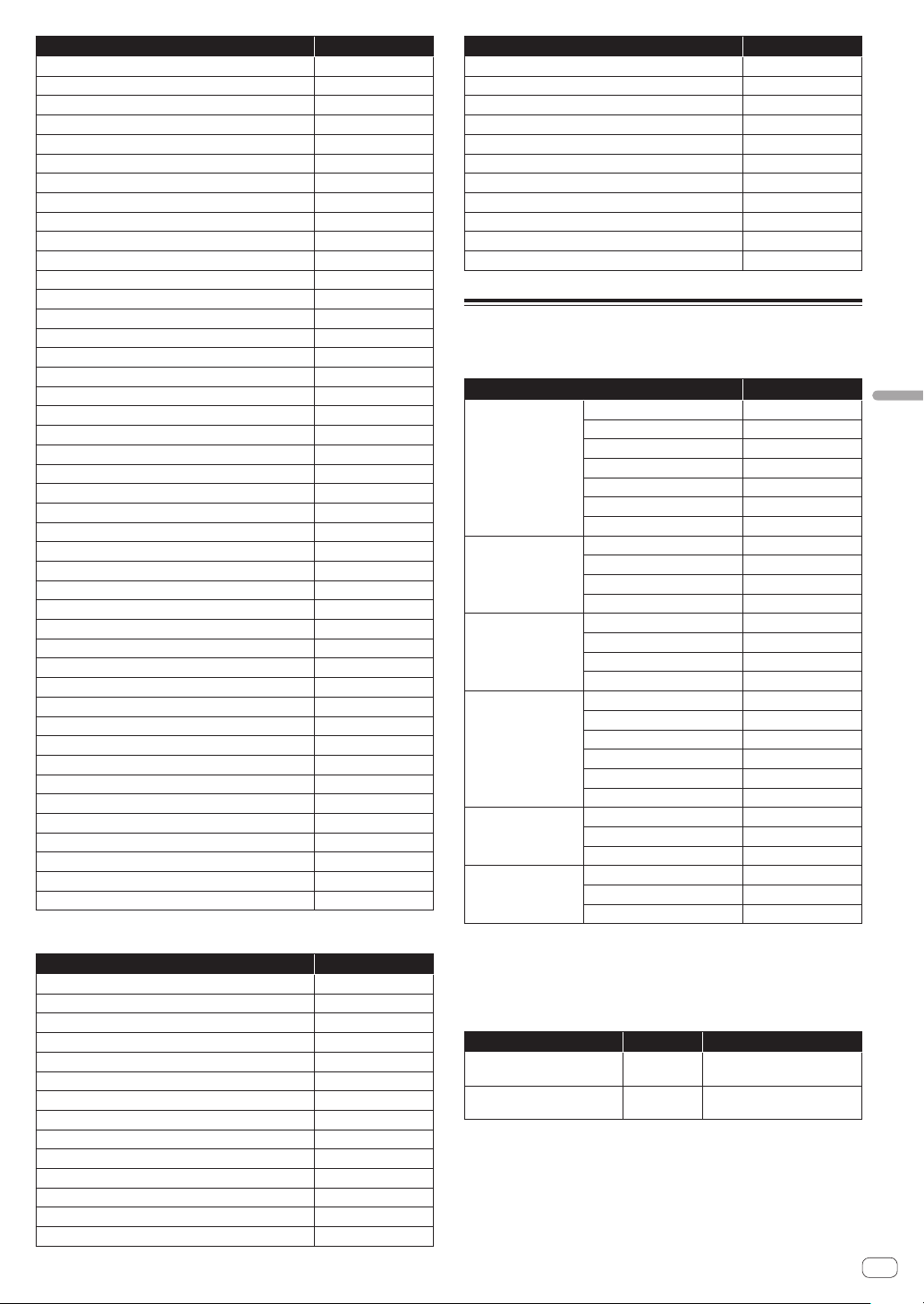
En
53
MIDI implementation chart
Function NOTE number
Sample trigger (PITCH: -19) 29
Sample trigger (PITCH: -18) 30
Sample trigger (PITCH: -17) 31
Sample trigger (PITCH: -16) 32
Sample trigger (PITCH: -15) 33
Sample trigger (PITCH: -14) 34
Sample trigger (PITCH: -13) 35
Sample trigger (PITCH: -12) 36
Sample trigger (PITCH: -11) 37
Sample trigger (PITCH: -10) 38
Sample trigger (PITCH: -9) 39
Sample trigger (PITCH: -8) 40
Sample trigger (PITCH: -7) 41
Sample trigger (PITCH: -6) 42
Sample trigger (PITCH: -5) 43
Sample trigger (PITCH: -4) 44
Sample trigger (PITCH: -3) 45
Sample trigger (PITCH: -2) 46
Sample trigger (PITCH: -1) 47
Sample trigger (PITCH: ±0) 48
Sample trigger (PITCH: +1) 49
Sample trigger (PITCH: +2) 50
Sample trigger (PITCH: +3) 51
Sample trigger (PITCH: +4) 52
Sample trigger (PITCH: +5) 53
Sample trigger (PITCH: +6) 54
Sample trigger (PITCH: +7) 55
Sample trigger (PITCH: +8) 56
Sample trigger (PITCH: +9) 57
Sample trigger (PITCH: +10) 58
Sample trigger (PITCH: +11) 59
Sample trigger (PITCH: +12) 60
Sample trigger (PITCH: +13) 61
Sample trigger (PITCH: +14) 62
Sample trigger (PITCH: +15) 63
Sample trigger (PITCH: +16) 64
Sample trigger (PITCH: +17) 65
Sample trigger (PITCH: +18) 66
Sample trigger (PITCH: +19) 67
Sample trigger (PITCH: +20) 68
Sample trigger (PITCH: +21) 69
Sample trigger (PITCH: +22) 70
Sample trigger (PITCH: +23) 71
Sample trigger (PITCH: +24) 72
TIME STRETCH:M.TMP
Function NOTE number
Sample trigger (PITCH: -12) 24 to 36
Sample trigger (PITCH: -11) 37
Sample trigger (PITCH: -10) 38
Sample trigger (PITCH: -9) 39
Sample trigger (PITCH: -8) 40
Sample trigger (PITCH: -7) 41
Sample trigger (PITCH: -6) 42
Sample trigger (PITCH: -5) 43
Sample trigger (PITCH: -4) 44
Sample trigger (PITCH: -3) 45
Sample trigger (PITCH: -2) 46
Sample trigger (PITCH: -1) 47
Sample trigger (PITCH: ±0) 48
Sample trigger (PITCH: +1) 49
Function NOTE number
Sample trigger (PITCH: +2) 50
Sample trigger (PITCH: +3) 51
Sample trigger (PITCH: +4) 52
Sample trigger (PITCH: +5) 53
Sample trigger (PITCH: +6) 54
Sample trigger (PITCH: +7) 55
Sample trigger (PITCH: +8) 56
Sample trigger (PITCH: +9) 57
Sample trigger (PITCH: +10) 58
Sample trigger (PITCH: +11) 59
Sample trigger (PITCH: +12) 60 to 72
Control changes
Receive MIDI control changes from an external MIDI device to operate
various functions of the unit.
Option settings CC number
TRACK
VOLUME
7
PAN
10
TIME STRETCH
14
LOOP
15
TRIGGER MODE
16
SEND AMOUNT
17
MUTE
18
PLAYBACK
PITCH
20
START
21
LOOP START
22
LENGTH
23
AMP ENVELOPE
VELOCITY
26
ATTACK
27
HOLD
28
RELEASE
29
FX1
Param1
46
Param2
47
Param3
48
Param4
49
Param5
50
Param6
51
SEQUENCE
OFFSET
54
RETRIGGER CNT
55
RETRIGGER SPD
56
LFO
SPEED
60
DEPTH
61
PHASE OFFSET
62
Switch the scene or pattern. A pattern is received and entered for scene
switching just like when performing the operation on the unit. Switching
of the scene and pattern is disabled when the SAMPLING/EDIT screen
is displayed. Other MIDI messages that are received during scene and
pattern switching are ignored.
Function CC number Notes
SCENE selection 0
CC values 16 and higher are
handled as SCENE16.
PATTERN selection 32
CC values 16 and higher are
handled as PATTERN16.

En
54
Pitch bend
Pitch bending is performed for the sample of the track corresponding
to the MIDI channel set in [CHANNEL MAPPING] of UTILITY. This is
enabled only when the mode of the touch strip is [PITCH].
Mode message
This message is received with the track corresponding to the MIDI
channel set in [CHANNEL MAPPING] of UTILITY. [ALL NOTE OFF] is
supported, and the sound currently being produced stops with the mode
message.
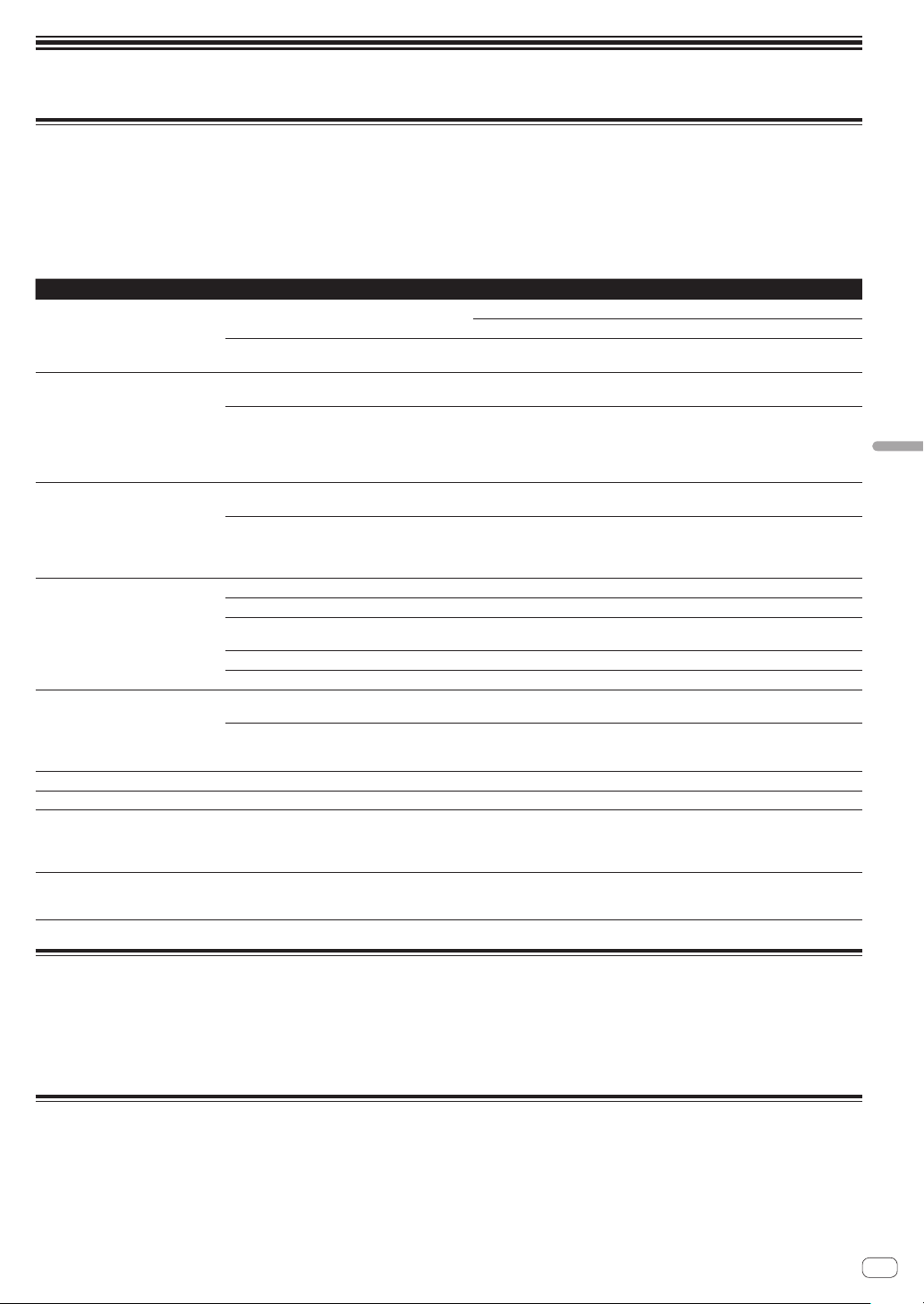
En
55
Additional information
Additional information
Troubleshooting
! Improper operation is often mistaken for trouble or a malfunction that occurred in the device. If something is wrong with this unit, check the follow-
ing issues, and also access the following Pioneer DJ support site and check [FAQ] for [DJS-1000].
pioneerdj.com
Some problems occur due to the connected components. If the problem cannot be resolved after checking the connected components, ask the
service center or your dealer for repairs.
! The unit may not operate properly due to static electricity or other external influences. In such cases, disconnect the power cord and connect it
again to restore normal operation.
Problem Check Remedy
The unit does not turn on.
The indicators do not light up.
Is the power cord properly connected? Connect the power cord to an AC outlet. (page 4 )
Properly connect the included power cord to a power outlet.
Is the [u] switch of the power on the rear panel of
the unit on?
Turn on the [u] switch.
Sound is not output, or sound is too
small.
Are the various parameter volumes on the touch
display set to the correct positions or values?
Adjust the various parameter volumes on the touch display to the appropriate
positions or values.
In the case of an external sound source input, is
the [INPUT LEVEL] control on the top panel of the
unit set to the correct position?
Is the output level of the external sound source
input device too low?
Adjust the [INPUT LEVEL] control on the top panel of the unit or the output level
of the external sound source input device while referring to INPUT MONITOR.
Sound is distorted. Are the various parameter volumes on the touch
display set to the correct positions or values?
Adjust the various parameter volumes in the graphical user interface to appro-
priate levels so that the peak level of the master level meter lights near 0 dB.
Is the [INPUT LEVEL] control set to the proper
position?
Is the output level of the external sound source
input device too high?
Adjust the [INPUT LEVEL] control on the rear panel of the unit or the output level
of the external sound source input device while referring to INPUT MONITOR.
USB device is not recognized. Is the USB device properly connected? Connect the USB device securely (all the way in).
Is the USB device connected via a USB hub? Do not use a USB hub.
Is the USB device supported by this unit? This unit supports such USB mass storage class USB devices as external hard
disks and portable flash memory devices.
Is the file format supported by this unit? Check that the file format of the connected USB device is supported by the unit.
— Turn the unit off, wait for 1 minute, and then turn the unit on.
It takes time to read USB devices
(flash memory drives and hard discs).
Are many folders and files stored on the USB
device?
It takes time to read a connected USB device if the device contains many folders
and files.
Are files other than music files stored on the USB
device?
It takes time to read a connected USB device if files other than music files are
stored in folders. Do not store files or folders other than music files on the USB
device.
Files cannot be played. Is the file copyright-protected (by DRM)? Copyright-protected files cannot be played.
Music files cannot be played. Are the music files damaged? Play music files that are not damaged.
The unit does not respond when the
screen is touch, or the response is
poor. The detected position is different
from the position actually touched.
Deviation in touch display calibration. Adjust touch screen detection with the [TOUCH PANEL CALIBRATION] settings
on the [UTILITY] screen.
Nothing is displayed. Is the auto standby function activated? This unit is shipped with the auto standby function set to on. If you do not want
to use the auto standby function, set [AUTO STANDBY] on the [UTILITY] menu
to [OFF
]. (page 50 )
Liquid crystal display
! Small black or shining points may appear on the liquid crystal display. This is a phenomenon inherent to liquid crystal displays; this is not a
malfunction.
! When using in cold places, the liquid crystal display may be dark for a while after this unit’s power is turned on. It will reach the normal brightness
after a while.
! When the liquid crystal display is exposed to direct sunlight, the light will reflect off it, making it difficult to see. Block the direct sunlight.
Cleaning the touch display
Do not use organic solvents, acids or alkalis for cleaning the surface of the touch display. Wipe clean with a dry soft cloth or a cloth immersed in neu-
tral detergent and properly wrung.
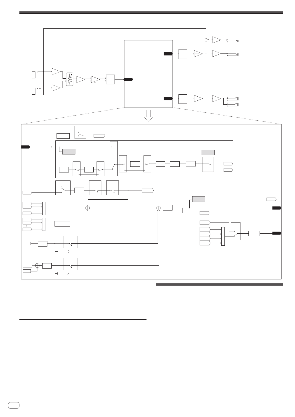
En
56
Signal flow
HEAD
PHONES
OUTPUT1
OUTPUT1
PHONES
D/A
SAMPLING/EDIT
SOURCE
BROWS
PREVIEW MONITOR
+MASTER
SAMPLING/EDIT SAMPLING/EDIT
SOURCE
LINE IN
MASTER
VOLUME
PERFORMANCE FX
TRACK n [ n = 1 , 2 , ... , 16]
INSERT FX1 PAN MUTE VOLUME
AMP
ENVELOPE
PLAYER
INPUT
LEVEL METER
LIVE SAMPLING
INPUT L
(MONO)
INPUT R
INPUT LEVEL
THRU ON
THRU / OUT PUT2
(L/R)
OUT PUT1
(L/R)
1/4 inch stereo phone jack
(L/R)
3.5 mm stereo mini jack
(L/R)
THRU OFF
SOFT LIMIT
ON/OFF
LIVE SAMPLING
LIVE
SAMPLING
MONITOR
RSMPL
OFF
ON
OFF
ON
OFF
ON
RSMPL
LINE IN
PERFORMANCE
FX
OFF
ON
ON
OFF
BYPASS
OFF
ON
OFF
ON
BYPASS
OFF
ON
BYPASSBYPASS
THRU
SAMPLE
TRACK
TYPE
A/D
D/A
DSP
DSP
INPUT
INPUT
INTERNAL
MIXER 1
PFX OFF
MIXER 2
PFX OFF
+
・
・
MIXER 16
PFX OFF
+
BROWS
BROWS
MONITOR
LIVE SAMPLING
MONITOR
MASTER
SAMPLING/EDIT
MONITOR
RESAMPLE
SAMPLING/EDIT
MONITOR
MASTER
INTERNAL
RESAMPLE
HEAD PHONES
VOLUME
SAMPLING/
EDIT
PREVIEW
VOLUME
METRONOME
MONITOR
+MASTER
METRONOME
MONITOR
METRONOME
VOLUME
LIVE SAMPLING
MONITOR
MIXER n
PFX OFF
MIXER n
PFX ON
TRACK
LEVEL METER
MASTER
LEVEL METER
MIXER 1
PFX ON
MIXER 2
PFX ON
MIXER 16
PFX ON
COUNT IN
METRONOME
+
BROWS
MONITOR
METRONOME
MONITOR
This unit is manufactured for general household purposes. Note that
charges will apply for repairs even during the warranty period in the
event of failures that occur during use in situations other than for house-
hold purposes (such as long-term use for business purposes in a restau-
rant or other establishment or use in a car or ship).
Trademarks and registered
trademarks
! “Pioneer DJ” is a trademark of PIONEER CORPORATION, and is
used under license.
! This software is based in part on the work of the Independent JPEG
Group.
! Loopmasters is a registered trademark of Loopmasters Ltd.
Cautions on copyrights
When playing music files you have acquired on this unit, we kindly ask
you to respect copyrights.
Recordings you have made are for your personal enjoyment and accord-
ing to copyright laws may not be used without the consent of the copy-
right holder.
! When handling music downloaded from the Internet, etc., it is the
full responsibility of the person who has downloaded the music to
ensure that it is used in accordance with the contract concluded
with the download site.
—
The specifications and design of this product are subject to change
without notice.
© 2017 Pioneer DJ Corporation. All rights reserved.
<DRI1489-A>