Be sure to read this document before using the machine.
Operation Manual
Cutting Machine
Product Code: 891-Z08
1
Thank you for purchasing this machine.
Before using this machine or attempting any maintenance, carefully read the “IMPORTANT SAFETY
INSTRUCTIONS” on the Product Safety Guide, and then study the Operation Manual for the correct operation
of the various functions. In addition, after you have finished reading this manual, store it where it can quickly be
accessed for future reference. Failure to follow these instructions may result in an increased risk of personal
injury or damage to property, including through fire, electrical shock, burns or suffocation.
●
This machine is intended for household use.
● This machine is approved for use in the country of purchase only.
● Due to product quality improvements, the specifications or appearance of this machine may change without notice.
● The contents of this document are subject to change without notice.
● The actual operations and screens may differ, for example, after the application has been upgraded.
● The contents of this document may not be duplicated or reproduced, partially or in full, without permission.
● We assume no responsibility for damages arising from earthquakes, fire, other disasters, actions of third parties, the user’s
intentional or negligent operation, misuse or operation under other special conditions.
● For additional product information, visit our website at www.brother.com
Symbols Used in This Document
The following symbols are used in this document.
IBM is a registered trademark or a trademark of International Business Machines Corporation.
Microsoft and Windows are registered trademarks or trademarks of Microsoft Corporation.
Wi-Fi Protected Setup(WPS) is a trademark of Wi-Fi Alliance.
WPA™ and WPA2™ are trademarks of Wi-Fi Alliance®.
Mac, OSX, and Apple are trademarks of Apple Inc., registered in the United States and other countries.
App Store is a service mark of Apple Inc., registered in the United States and other countries.
Each company whose software title is mentioned in this manual has a Software License Agreement specific to its
proprietary programs.
All other brands and product names mentioned in this manual are registered trademarks of their respective
companies. However, the explanations for markings such as ® and ™ are not described within the text.
INTRODUCTION
IMPORTANT NOTICE
IMPORTANT SAFETY INSTRUCTIONS
CAUTION
Failure to observe instructions with this marking may result in serious
injuries.
TRADEMARKS

2
INTRODUCTION .......................................... 1
IMPORTANT NOTICE ................................... 1
IMPORTANT SAFETY INSTRUCTIONS ......... 1
Symbols Used in This Document........................... 1
TRADEMARKS ............................................... 1
MACHINE FEATURES .................................... 3
Devices That Can Connect to This Machine.......... 3
About This Manual ................................................. 3
1 GETTING STARTED............4
PARTS AND FUNCTIONS ............................. 4
Unit Descriptions - Front........................................ 4
Unit Descriptions - Rear......................................... 4
Unit Descriptions - Operation Panel ...................... 5
Included Accessories ............................................. 5
TURN ON THE MACHINE ............................ 6
Removing the Transport Packing Materials ........... 6
Turning On/Off the Machine................................... 6
DesignNCut Manager WINDOWS ................ 7
SETTINGS SCREENS ...................................... 9
Machine Settings.................................................... 9
Auto Shut Down ..................................................... 9
DesignNCut Manager Settings............................. 10
CONNECTING THE MACHINE AND
COMPUTER................................................. 12
Selecting the Connection Method........................ 12
Wireless Connection ............................................ 12
Direct PC Connection Using USB Cable (Windows
Only) ..................................................................... 18
Resetting the Wireless Connection Setup ........... 20
Checking the Wireless LAN Settings/Connection
Status ................................................................... 20
Setting Up Manually............................................. 21
REGISTER DesignNCut ON
ScanNCutCanvas ......................................... 22
FIRST STEPS................................................. 24
Mat and Material Combinations........................... 24
Attaching the material to the mat......................... 26
Adjusting the Blade Extension ............................. 32
Installing and Uninstalling the Holder................... 34
2 BASIC OPERATIONS........35
PATTERN CUTTING .................................... 35
Tutorial 1 - Cutting Patterns................................. 35
3 ADVANCED OPERATIONS
.........................................41
DRAWING FUNCTIONS............................. 41
Drawing ................................................................ 41
Using Drawing Functions to Fill Patterns/Make
Outlines Thicker ................................................... 43
Cutting Around Drawings..................................... 45
CaptureMat FUNCTION ..............................48
Tutorial 2 - Cutting Photographed Material ......... 48
4 APPENDIX ....................... 51
CONSUMABLES...........................................51
Replacement Criteria............................................ 51
Replacing the Blade ............................................. 51
CARE AND MAINTENANCE ........................ 53
Cleaning ............................................................... 53
Adjusting the Mark Sensors................................. 55
TROUBLESHOOTING .................................56
Finding the Wireless LAN Security Information
(Network Name (SSID) and Network Password
(Key)) .................................................................... 56
If the Machine Stops Operating Correctly............ 56
ERROR MESSAGES.......................................59
Cutting Machine Error .......................................... 59
DesignNCut Manager Error.................................. 61
UPDATING THE SOFTWARE.......................66
Update Procedure Using DesignNCut Manager
.... 66
Update Procedure Using Computer .................... 66
OPTIONAL ACCESSORIES...........................67
PRODUCT SPECIFICATIONS.......................67
INDEX..........................................................68
CONTENTS
3
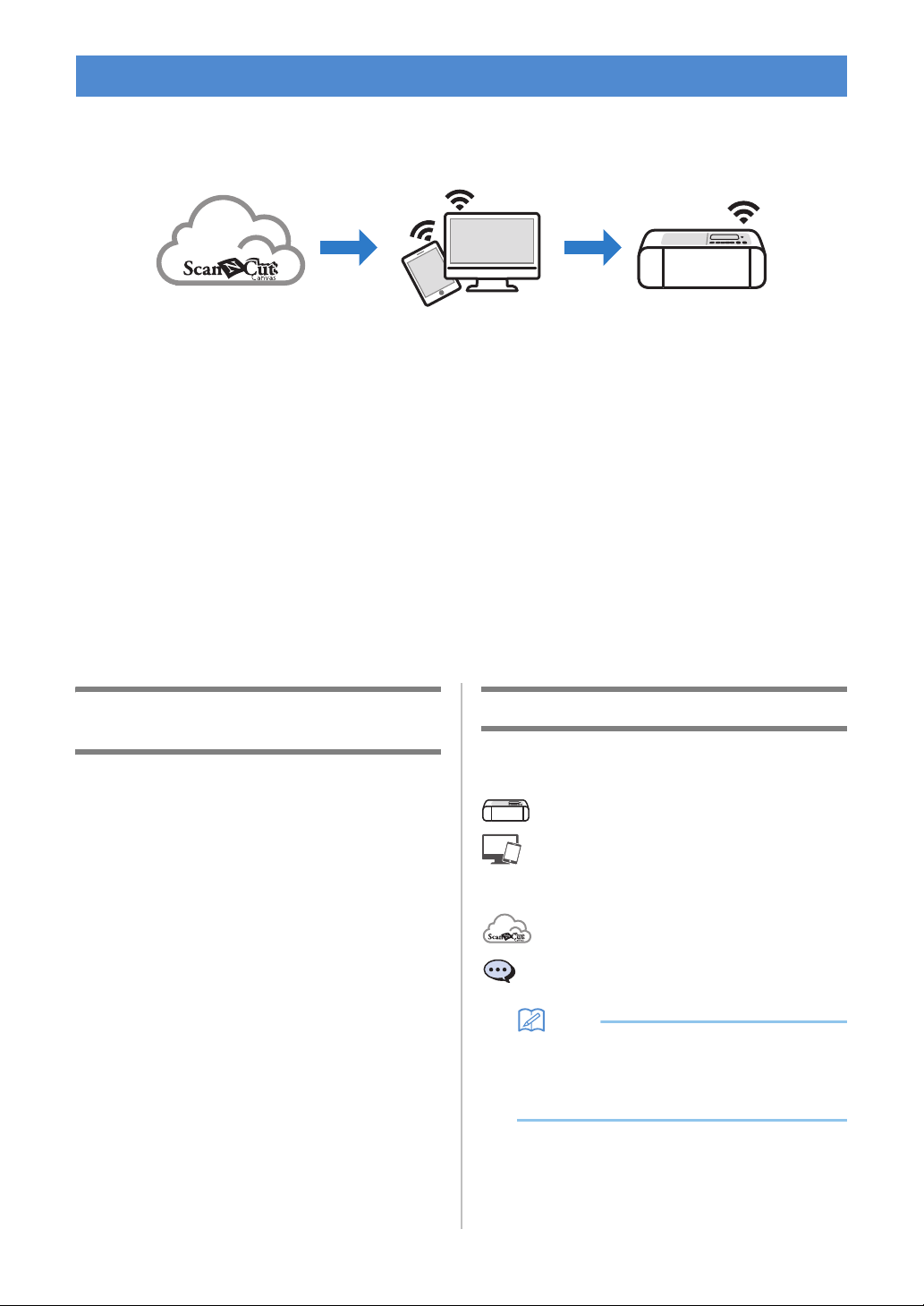
With this machine, you can cut out or draw patterns created in ScanNCutCanvas and sent to it using
DesignNCut Manager (DesignNCut application for operation options). ScanNCutCanvas is an online service
that allows you to use a Web browser to download, edit and create cutting or drawing pattern data for the
ScanNCut and DesignNCut cutting machines.
1. Install DesignNCut Manager (DesignNCut application for operation options).
If you haven’t downloaded the DesignNCut Manager application please go to:
Windows, OS X (Mac): http://s.brother/caqaa/
iOS (App Store): http://s.brother/caqab/
Android (Google Play): http://s.brother/caqac/
2. Machine network settings
Wireless network connection.....P. 12
USB cable connection.....P. 18
3. Register the cutting machine with ScanNCutCanvas......P. 22
* You must register with ScanNCutCanvas first.
4. Send patterns to the machine and cut them out......P. 35
ScanNCutCanvas website: http://ScanNCutCanvas.Brother.com/
Devices That Can Connect to This
Machine
■ Computers
• Compatible operating systems:
Windows 7 SP1, Windows 8.1, Windows 10
OS X 10.10 or later
* For additional operating system information, visit
our website (http://s.brother/cpqaa/).
• Compatible models:
IBM PC or compatible computer that is wireless
LAN-compatible or originally equipped with a USB
port
■ Mobile Devices
Compatible operating systems:
iPhone, iPad : iOS 9 or later
Android : 5 or later
* For additional operating system information, visit our
website (http://s.brother/cpqaa/).
About This Manual
The icons at the beginning of each step indicate the
following operation information.
: Operation performed on the machine
: Operation performed in DesignNCut
Manager (DesignNCut application for
operation options)
: Operation performed in ScanNCutCanvas
: Message displayed on the machine
Memo
• The machine and screens shown in this manual
may differ from the actual ones.
• This manual provides descriptions for using the
computer version of the application.
MACHINE FEATURES
4
Chapter 1 GETTING STARTED
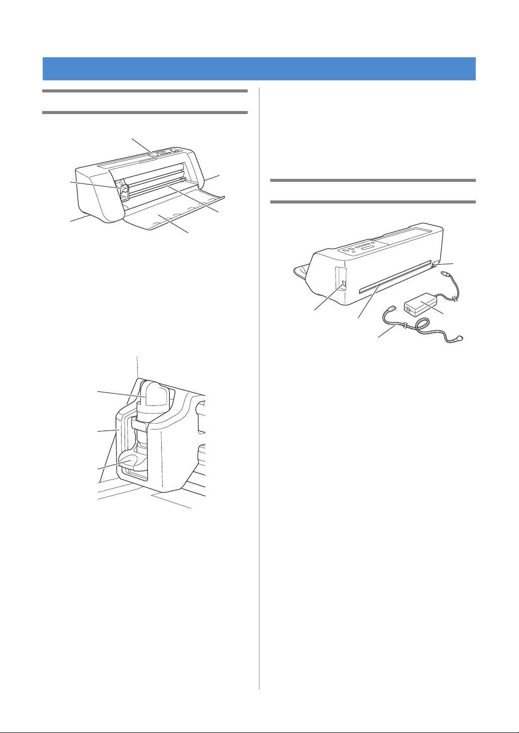
Unit Descriptions - Front
a Operation Panel
Allows you to view the current status of the machine
and the various menus. Press a button on the
operation panel to change the information displayed
in the LCD panel. In addition, if there are problems
with this machine, the error message relating to the
problem is displayed. For details on the error
messages, see “ERROR MESSAGES” on page 59.
b Carriage
Moves the installed holder for cutting or drawing.
1 Holder
Installs in the carriage to cut or draw on craft paper
or fabric. Use the holder designed specifically for
cutting or drawing.
2 Holder Guide
The guide secures the holder.
3 Holder Lock Lever
Releases the holder when the lever is raised. Locks
the holder when the lever is lowered.
c Grips
Grasped when moving the machine.
d Feed Slot Roller
Feeds in or out a mat. The mat is fed by the feed
rollers on both sides.
e Front Tray Cover
Protects the feed rollers, carriage and holder. Open
the cover while the machine is operating.
Unit Descriptions - Rear
a USB port (for PC Connectivity)
When a wireless network is not available, use a USB
cable to connect the machine to the computer. For
Computers and Operating Systems, see “Devices
That Can Connect to This Machine” on page 3.
b Slot
Allows a mat to be fed back and forth during an
operation. Do not place any objects near the slot that
would prevent the mat from being fed out.
c DC Power Jack
d AC Adapter
e AC Power Cord
PARTS AND FUNCTIONS
d
e
a
b
c
c
1
2
3
a
b
c
d
e
5
1
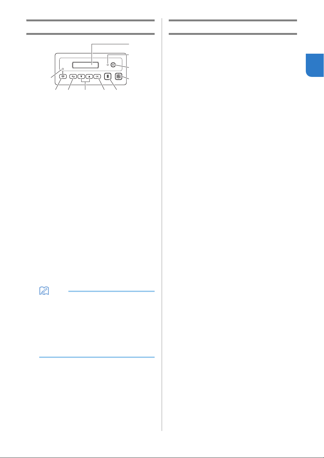
Unit Descriptions - Operation Panel
a LCD Panel
Displays the current settings, instructions for
performing operations and error messages.
Long messages scroll in the LCD.
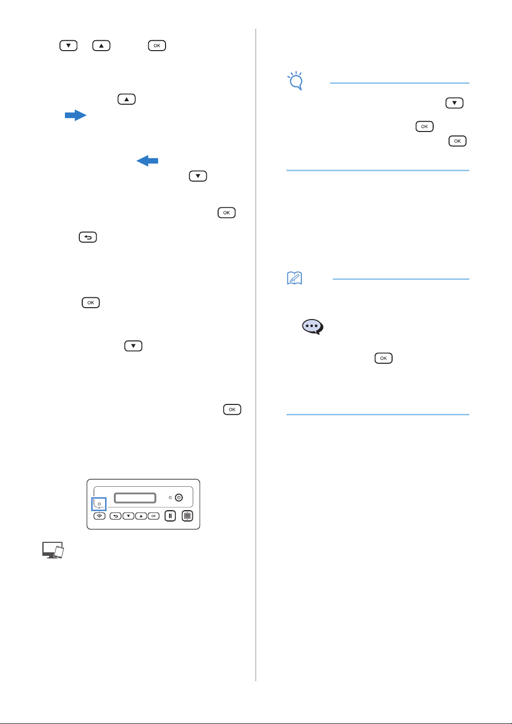
b Power indicator
Lights up when the machine is turned on, and flashes
when the machine enters the sleep mode (power-
saving mode).
c Power Button
Turns the machine on/off.
d Feed Button
Feeds the loaded mat in to or out from the feed slot.
Be sure to press this button to feed the mat when
loading or unloading it.
e Pause/Stop Button
Stops cutting, drawing and other operations.
f OK Button
Applies the displayed setting or finishes the operation.
g Select Button
Display a menu or make a selection.
h Back Button
Cancels the changes made to a setting or returns to
the previous screen.
i Wireless LAN Connect Button
Used to connect to a wireless network when using the
push button method.
j Wireless LAN Connect light
Lights up when connected to a wireless network.
Memo
• For Wireless LAN Connection, once the
machine has an established wireless network
connection, the machine will automatically
reconnect to the same access point/router that
has been established. It will take about few
seconds to few minutes depending on network
environment before the wireless LAN connect
light turns on.
Please wait until the connect light turns on
without pressing any buttons on the machine.
Included Accessories
For details on the included accessories, refer to the
“Included Accessories” insertion.
2
a
3
4
56789
0
6
Removing the Transport Packing
Materials
Before turning on the machine, remove the shipping
tape and the cardboard shock-absorbing material.
a Shipping tape
b Cardboard shock-absorbing material
Note
• If the packing materials were removed after the
machine was turned on, turn the machine off,
then on again. Continuing to use the machine
without restarting it may result in incorrect
operation.
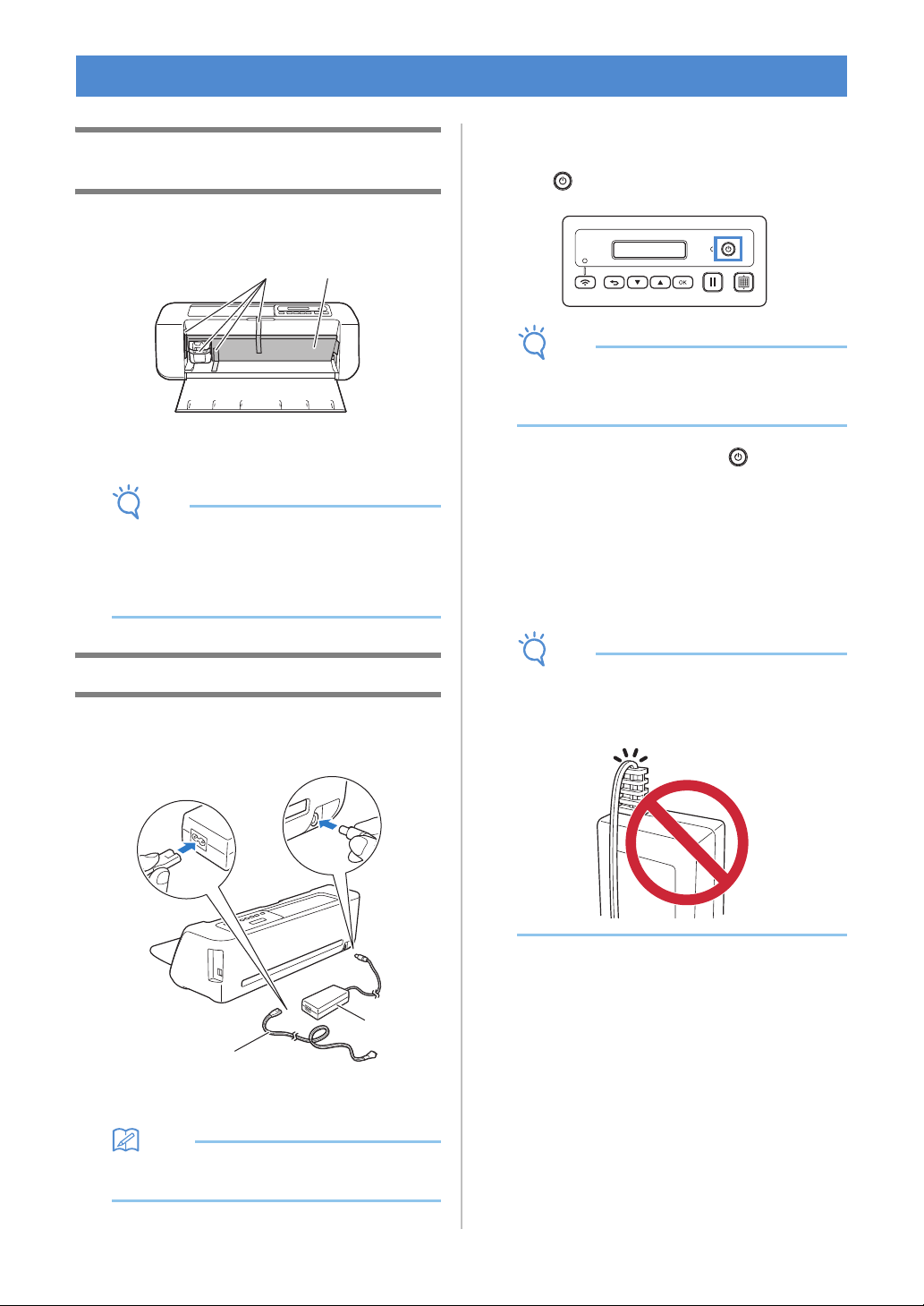
Turning On/Off the Machine
a Connect the power cord to the AC adapter, and
then connect the AC adapter to the machine.
a Power cord
b AC adapter
Memo
• When using the AC adapter, untie the bundled
cord.
b Plug the power cord into an electrical outlet.
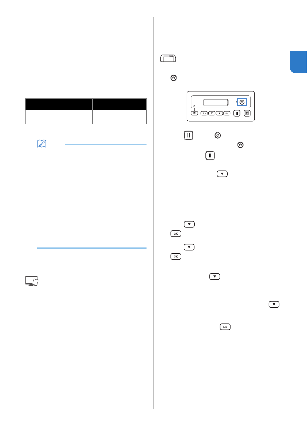
c Press in the operation panel.
Note
• The carriage and mat move to their initial
positions. Be sure to keep your hands away
from the carriage.
d To turn off the machine, press in the
operation panel.
e Unplug the power cord from the electrical
outlet.
f Disconnect the AC adapter from the machine,
and then disconnect the power cord from the
AC adapter.
Note
• Do not wind the AC adapter cable around the
adapter or bend the cable, otherwise the cable
may be damaged.
TURN ON THE MACHINE
a b
b
a

7
1
This section describes the windows of the dedicated
control application used to cut out or draw patterns.
■ Main Window
Computer
Mobile device
1. No.
Displays the machine number of the connected
machine.
2. Search
Searches for connected machines.
* With the mobile device version, tap [No.] (1) to
search for a machine.
3. Login ID
Displays the ScanNCutCanvas user ID used for
connecting to ScanNCutCanvas.
4. ScanNCutCanvas
Displays the window for registering with
ScanNCutCanvas.
5. Load data
Selects the method for importing pattern data. Click
to display a window for selecting how to import the
data.
* With the mobile device version, a preview screen
for the pattern sent to ScanNCutCanvas appears.
6. CaptureMat
Using ScanNCutCanvas create pattern data from an
image taken with a camera.
DesignNCut Manager WINDOWS
1
3
2
4
5
6
5
1
5
3
6
8
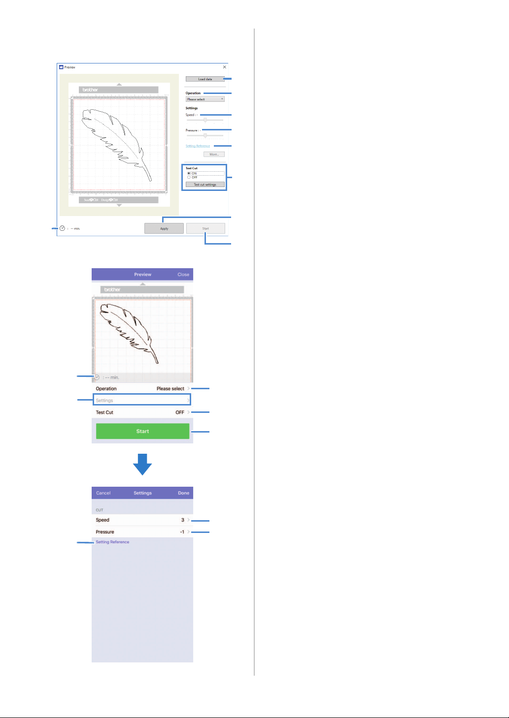
■ Preview Window
Computer
Mobile device
1. Load data
Imports cutting/drawing patterns from
ScanNCutCanvas or a computer.
2. Operation
Select [Cut] or [Draw] from the drop-down list.
* Other settings may appear in the drop-down list if
a separately sold accessory kit is detected.
* With the mobile device version, tap [Operation] to
display a screen for selecting [Cut] or [Draw].
3. Speed
With the slider, adjust the speed for cutting or
drawing.
* With the mobile device version, tap [Settings] to
display a settings screen.
4. Pressure
With the slider, adjust the pressure for cutting or
drawing.
* With the mobile device version, tap [Settings] to
display a settings screen.
5. Setting Reference
Displays a list of various settings. Refer to this table
before changing the settings.
6. Test Cut
Select [ON] or [OFF].
If [ON] is selected, [Test cut settings] will be available
and can be clicked to display a window allowing
detailed settings for trial cutting to be selected. For
details on displaying the window, see “Trial Cutting”
on page 37.
* With the mobile device version, tap [Test Cut] to
display a settings screen.
7. Apply
Applies the settings that were either selected or
changed.
8. Start
Starts cutting or drawing. To stop the operation, see
“Cutting the Pattern” on page 39.
9. min.
Displays the cutting/drawing time.
9
1
2
3
4
5
6
7
8
9
2
6
8
3,4
5
3
4

9
1
Settings for various functions can be selected or
changed.
Machine Settings
Press or in the operation panel to display
the settings screen. After changing the settings, press
to apply.
■ 1. Network
1. WLAN Enable
Select whether or not to connect to the wireless
network.
2. Setup Wizard
Uses a wizard for manually entering the network
password (key) for the detected network name (SSID)
to connect to the wireless network from this machine.
3. WAW
Uses the dedicated application “WLAN Assistant
Wizard” to connect to the wireless network from a
computer.
4. WAW <USB>
Uses the dedicated application “WLAN Assistant
Wizard” to retrieve the wireless LAN settings file from
the computer connected by the USB cable, then
connect to the wireless network.
5. Others
Displays the following parameters for other wireless
network settings.
1. TCP/IP: TCP/IP settings can be manually entered.
2. MAC Address: Displays the MAC address.
3. SSID: Displays the network SSID when a wireless
network connection is established.
4. Network Reset: Resets all network settings to their
defaults. When the following message appears, press
to select [Yes], and then turn the machine off,
then on again.
■ 2. Machine Info
1. No.
Displays the machine number for this machine.
2. Ver.
Displays the version of this machine’s software.
3. Name
Displays the name that was specified for the machine
connected to DesignNCut Manager (DesignNCut
application for operation options).
■ 3.Basic Setup
1. Language
Select the machine’s display language.
2. Panel Contrast
Adjust the brightness of the LCD.
3. Mark Sensor
In CaptureMat function, the cutting position can be
manually adjusted if it has shifted.
Memo
• “*” appears to the right of the selected item.
■ 4. Machine No.
Displays the machine number for this machine.
Auto Shut Down
If the machine is not used for a specified length of
time, it will automatically turn off. The length of time
until the machine turns off can be specified in the
Settings dialog box of DesignNCut Manager
(DesignNCut application for operation options).
For details on specifying the settings, see
“DesignNCut Manager Settings” on page 10.
SETTINGS SCREENS
Reset Network?
▼Yes ▲No
10
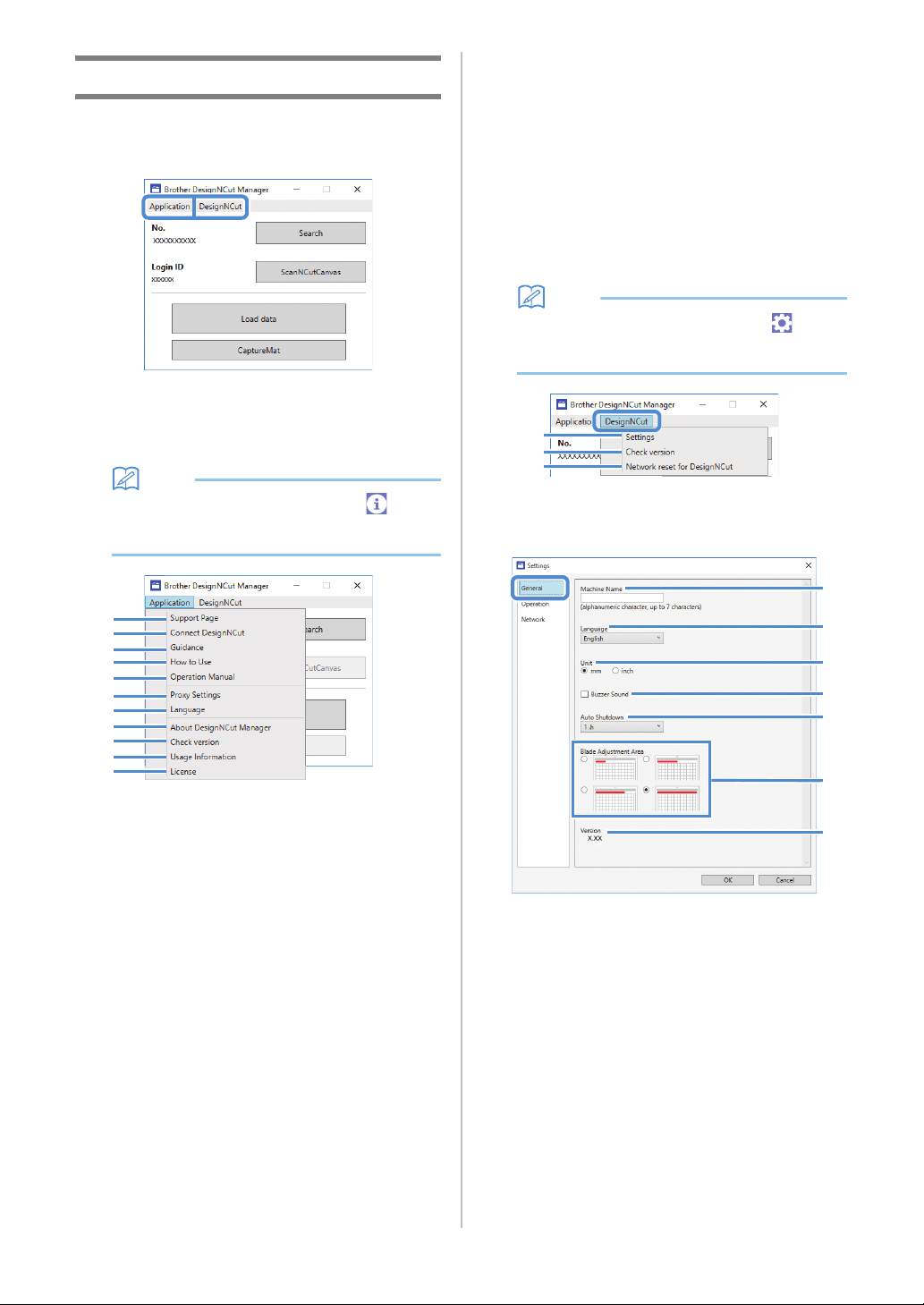
DesignNCut Manager Settings
Click [Application] or [DesignNCut] in the main
window to display the corresponding menu.
■ [Application] Menu
Settings for displaying DesignNCut Manager can be
specified.
Memo
• With the mobile device version, tap in the
upper-right corner of the screen to display the
menu.
1. Support Page
Displays the website for the Brother Solutions Center.
2. Connect DesignNCut
Displays the connection procedures.
3. Guidance
Displays the setup procedures, from specifying
network connection settings to registering with
ScanNCutCanvas.
4. How to Use
Displays overview how to use DesignNCut Manager
and the machine.
5. Operation Manual (PC only)
Displays the Operation Manual.
6. Proxy Settings (PC only)
Manually specify the proxy settings.
7. Language (PC only)
Displays the application's language selections.
8. About DesignNCut Manager (PC only)
Displays information on the control application.
9. Check version
Displays the version information.
10.Usage Information
Displays the usage information.
11.License
Displays information on the software license.
■ [DesignNCut] Menu
Settings can be specified for the various operations
available when DesignNCut Manager and the machine
are connected.
Memo
• With the mobile device version, tap in the
upper-left corner of the screen to display the
menu.
1. Settings (General)
Click [Settings], then [General]. After specifying the
desired settings, click [OK] to apply the settings.
a You can specify a name for the connected
machine.
b Select the machine’s display language.
c Select the measurement units displayed in the
windows.
d Select whether or not an operation sound is
produced, for example, when a button on the
machine is pressed.
e Select the length of time that the machine is not
used until it automatically turns off. If the
machine is not used for 20 minutes, regardless
of the specified length of time, it will enter the
sleep mode, and the power indicator flashes.
1
2
3
4
5
6
7
8
9
10
11
1
2
3
a
b
c
d
e
f
g
11
1
f Select from 1/4, 2/4, 3/4 or all of the cutting
area to be used for blade adjustment.
Before cutting out a pattern, this machine
performs an automatic blade adjustment, which
adjusts the direction of the blade outside of the
adhesive area of the mat.
g Displays the version of this machine’s software.
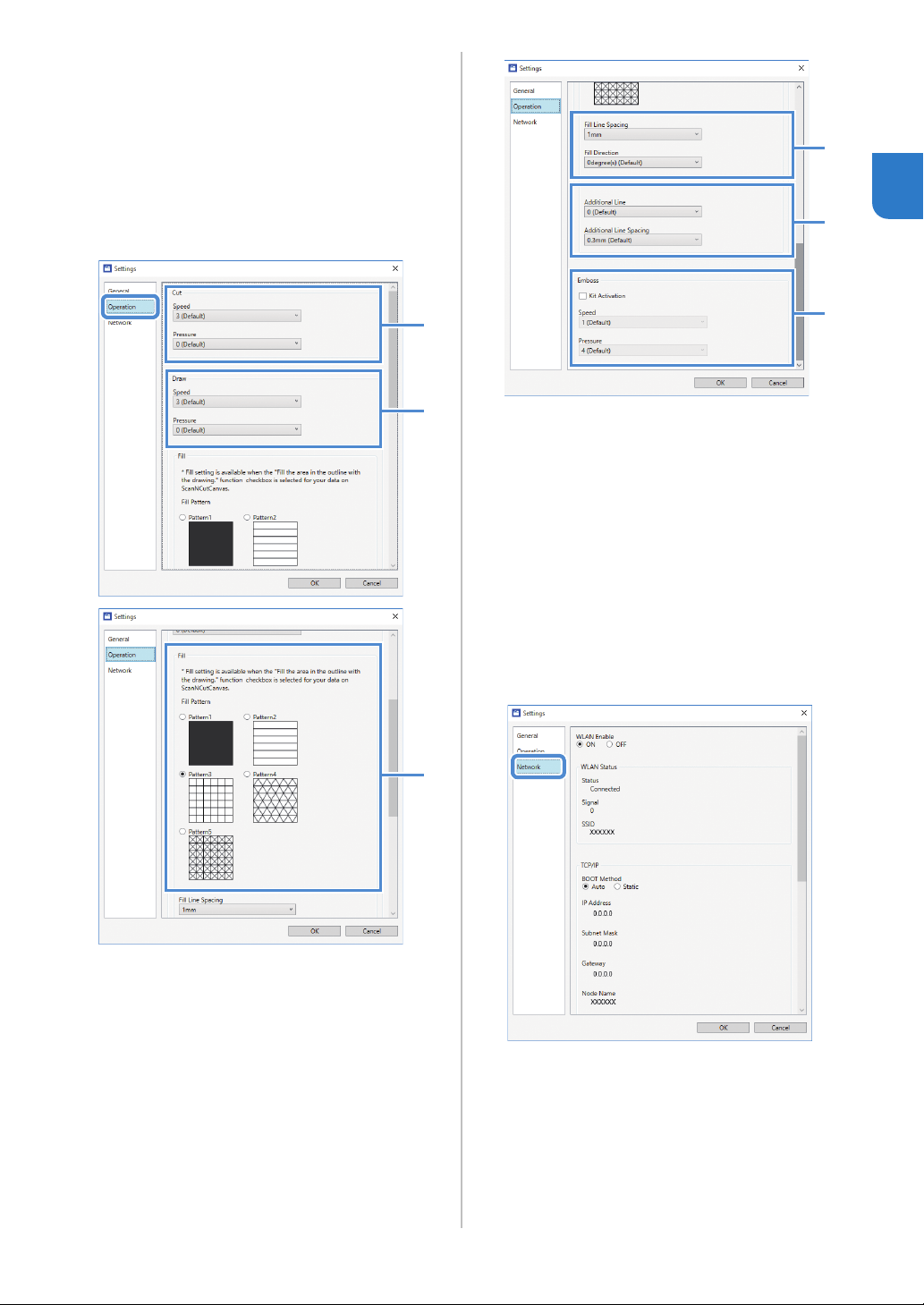
1. Settings (Operation)
Click [Settings], then [Operation].
After specifying the desired settings, click [OK] to
apply the settings.
a Adjust the speed and pressure for cutting. For
details on the appropriate cutting pressure, see
“Cutting Settings” on page 32.
b Adjust the speed and pressure for drawing. For
best results, adjust the drawing pressure to the
appropriate setting. Drawing with pressure that
is too strong may damage the pen tip.
c Select the design that will be used to fill
patterns. For details, see “Using Drawing
Functions to Fill Patterns/Make Outlines
Thicker” on page 43.
d With [Fill Line Spacing], adjust the spacing of
the lines filling the pattern. With [Fill Direction],
adjust the direction of the lines filling the
pattern.
e With [Additional Line], specify the number of
lines to be added. With [Additional Line
Spacing], specify the spacing of the lines to be
added.
f When a separately sold accessory kit is used,
select this check box to enable its functions.
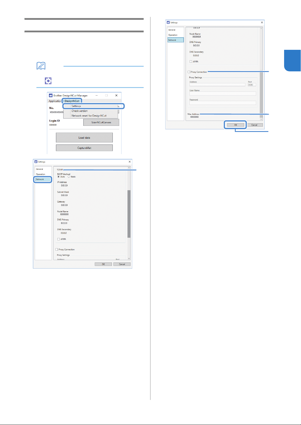
1. Settings (Network)
Click [Settings], then [Network].
After specifying the desired settings, click [OK] to
apply the settings. For details on the network settings,
see “Setting Up Manually” on page 21.
2. Check version
Displays the status of the machine’s software.
* This does not appear when the machine is
connected with a USB cable.
3. Network reset for DesignNCut
Initializes the wireless network settings. For details on
specifying the settings, see “Resetting the Wireless
Connection Setup” on page 20.
a
b
c
d
e
f
12
Selecting the Connection Method
■ Step 1
Open DesignNCut Manager (DesignNCut
application for operation options), installed on the
computer.
■ Step 2
Connect the machine and the computer with the
DesignNCut Manager (DesignNCut application for
operation options).
When using a wireless connection
Continue to “Wireless Connection” on
page 12.
When using a USB cable
Continue to “Direct PC Connection Using
USB Cable (Windows Only)” on page 18.
Memo
• For the mobile device version, follow the on-
screen instructions to specify the settings.
Wireless Connection
Select the connection method to the wireless
network.
• Using Wireless Network Name (SSID) & Network
Password (Key).....13
• Using Router's WPS button.....15
• Using WLAN Assistant Wizard.....16
• Using WLAN Assistant Wizard with USB
Cable.....17
■ Wireless Connection Conditions
The wireless network connection complies with IEEE
802.11 n/g/b standards and uses the 2.4 GHz frequency.
Memo
• A wireless network cannot be set up with WPA/
WPA2 Enterprise. For the authentication
methods that this machine is compatible with,
refer to “Err-03” on P. 60.
CONNECTING THE MACHINE AND COMPUTER
13
1
■ Using Wireless Network Name
(SSID) & Network Password (Key)
Select your Wireless Network Name (SSID) and input
the Network Password (Key) of your wireless LAN
access point/router on your DesignNCut machine.
In order to connect the machine to a wireless network,
the security information (SSID and network password)
for your wireless LAN access point/router will be
required. The network password may also be called a
network key, security key or encryption key. First, find
your security information and note it below.
Memo
• The wireless connection cannot be set up if you
do not have the security information.
• Where to find the security information:
1) Check your wireless LAN manual for your
wireless LAN access point/router.
2) The default SSID may be the manufacturer’s
name or the model name.
3) If you cannot find the security information,
contact the manufacturer of the router, your
network administrator or your Internet
provider.
4) Some Wireless Network Name (SSID) and
Network Password (Key) are case (upper
case and lower case) sensitive. Please
properly record your information.
If you have already selected the
connection method, please go to step
e
: Operation performed in DesignNCut
Manager
a Click [Start Setup].
b Click [Connect].
c Select [Wireless LAN], and then click [Next].
* Skip this step for mobile and Mac version.
d Select [Use Wireless Network Name (SSID) &
Network Password (Key)], and then click
[Next].
* Mobile version will automatically go to the next
screen.
: Operation performed on the machine
e Turn off the DesignNCut machine, by pressing
.
f Press and the at the same time, once
the power comes on release while still
pressing down .
g When the message [Machine mode?] appears
on your LCD, press
to select [WLAN].
hThe message, [Turn the machine off, then on
again.] will appear on your LCD.
Follow the machine's instruction.
Once your machine is back on, the text [Standby
(WLAN)] should display on your LCD.
i Press to go to [1. Network] and press
.
j Press to go to [2. Setup Wizard] and press
.
k When the message [Enable WLAN?] appears on
your LCD, press to select [Yes].
The machine will search for SSID.
* Give your machine time to search for SSID.
l If you have multiple network names press
to select the SSID (network name) of the
wireless network that your PC/Mobile is
connected and press .
* Your network name selection should match the
wireless network that your PC is connected.
Network Name (SSID)
Network Password
(Network Key)
14
m Enter your network password (key) using the
or pressing after each
character. The characters on the DesignNCut
LCD are listed in the order below.
You must go through each one of these until your
desired character shows up on the LCD. Press
after each character. To erase an entered character,
press .
Make sure that you have the right password and note
some password are case (upper case & lower case)
sensitive.
Your DesignNCut machine and PC connection must
be on the same network.
n Press once you completed entering your
password.
o When the message [Apply Settings?] appears on
your LCD, press
to select [Yes]. Your
machine will connect to WLAN.
* Give your machine time to connect to your
wireless network.
p When the message [Connected to WLAN. Press
[OK] button.] appears on your LCD, press
button on your machine.
q The Wireless LAN Connect light will turn on.
* Give the Wireless LAN Connect light time to turn
on.
: Operation performed in DesignNCut
Manager
r Go back to DesignNCut Manager and click
[Connect].
s Select the machine number and then click
[OK].
* For mobile version, tap [Done].
Note
• To check your machine's number, press
to display the [2. Machine Info] on the
machine's LCD, and then press
.
When [1. No.] appears on the LCD, press .
Your machine's number will be displayed on the
machine's LCD.
t When [DesignNCut connection is successful.]
appears in the dialog box, click [OK].
* For mobile version, this dialog box will not appear.
Continue the guidance instruction to register a
new account on ScanNCutCanvas.
Go to “REGISTER DesignNCut ON
ScanNCutCanvas” on page 22 to connect your
machine to ScanNCutCanvas.
Memo
• If Wireless LAN connection failed and the
following message appears:
an incorrect network password (key) may have
been entered. Press , and then perform
the procedure again starting with step
i of
“Using Wireless Network Name (SSID) &
Network Password (Key)” on page 13.
- For details on other causes, see “ERROR
MESSAGES” on page 59.
When pressing
0123456789abcdefghijklmnopqrstuvwxyz
ABCDEFGHIJKLMNOPQRSTUVWXYZ
!"#$%&'()*+,-./:;<=>?@[]^_
When pressing
Network Password (Key) error
(Err-04). Press [OK] button.
15
1
■ Using Router's WPS button
Use this connection method if your wireless LAN access
point/router has a WPS button.
Memo
• For details on the WPS button, check your
wireless LAN manual for your wireless LAN
access point/router.
If you have already selected the
connection method, please go to step
e
: Operation performed in DesignNCut
Manager
a Click [Start Setup].
b Click [Connect].
c Select [Wireless LAN], and then click [Next].
* Skip this step for mobile and Mac version.
d Select [Use Router's WPS button], and then
click [Next].
* Mobile version will automatically go to the next
screen.
: Operation performed on the machine
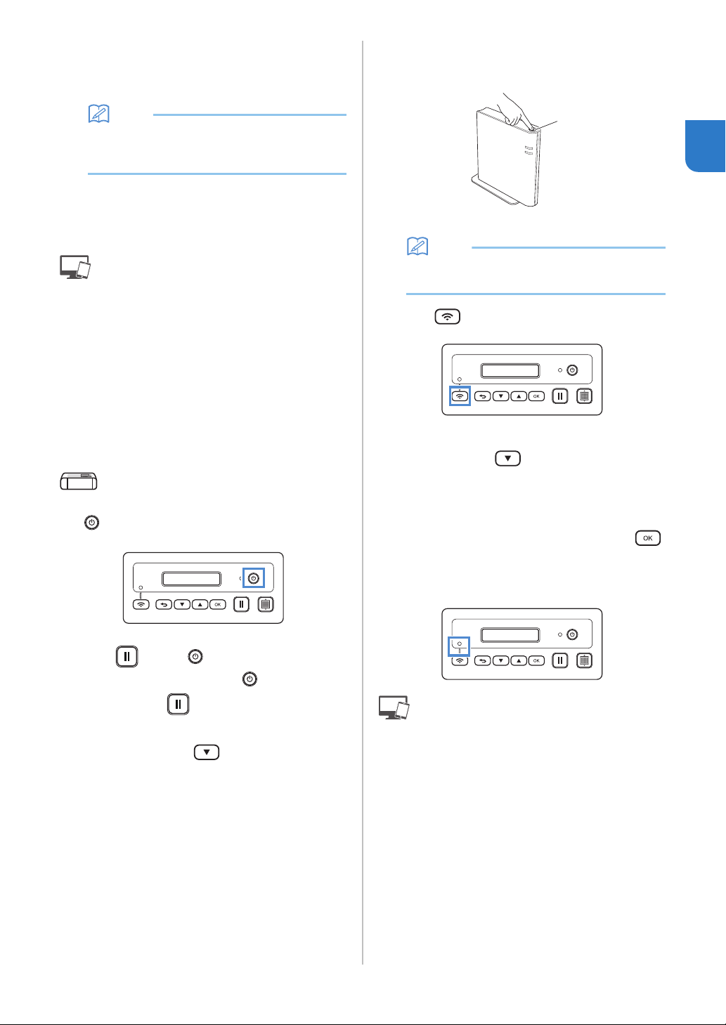
e Turn off the DesignNCut machine, by pressing
.
f Press and the at the same time, once
the power comes on release while still
pressing down .
g When the message [Machine mode?] appears
on your LCD, press
to select [WLAN].
hThe message, [Turn the machine off, then on
again.] will appear on your LCD.
Follow the machine's instruction.
Once your machine is back on, the text [Standby
(WLAN)] should display on your LCD.
i Press your router's WPS button.
Make sure your DesignNCut machine and PC
connection are on the same network.
a WPS button
Memo
• The location of the WPS button differs
depending on your device.
j Press on your DesignNCut machine.
k When the message [Enable WLAN?] appears on
your LCD, press
to select [Yes].
* Give your machine time to connect to your
wireless network.
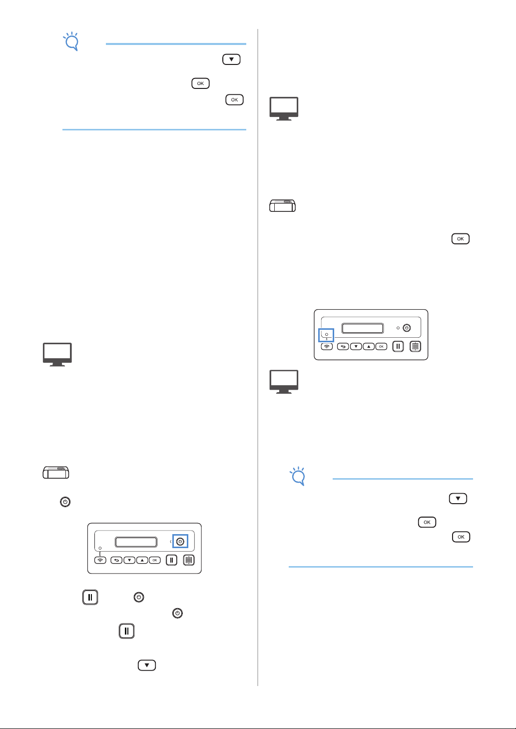
l When the message [Connected to WLAN. Press
[OK] button.] appears on your LCD, press
button on your machine.
m The Wireless LAN Connect light will turn on.
: Operation performed in DesignNCut
Manager
n Go back to DesignNCut Manager and click
[Connect].
o Select the machine number and then click
[OK].
* For mobile version, tap [Done].
a
16
Note
• To check your machine's number, press
to display the [2. Machine Info] on the
machine's LCD, and then press .
When [1. No.] appears on the LCD, press .
Your machine's number will be displayed on the
machine's LCD.
p When [DesignNCut connection is successful.]
appears in the dialog box, click [OK].
* For mobile version, this dialog box will not appear.
After completing the network connection, see
“REGISTER DesignNCut ON ScanNCutCanvas”
on page 22 to connect your machine to
ScanNCutCanvas.
■ Using WLAN Assistant Wizard
Apply wireless LAN settings of your computer to
DesignNCut machine by using the wizard to connect
your computer to WLAN.
If you have already selected the
connection method, please go to step
e
To perform this setting, your computer's firewall
must be turned off.
: Operation performed in DesignNCut
Manager
a Click [Start Setup].
b Click [Connect].
c Select [Wireless LAN], and then click [Next].
d Select [Use WLAN Assistant Wizard], and then
click [Next].
: Operation performed on the machine
e Turn off the DesignNCut machine, by pressing
.
f Press and the at the same time, once
the power comes on release
while still
pressing down .
g When the message [Machine mode?] appears
on your LCD, press to select [WLAN].
hThe message, [Turn the machine off, then on
again.] will appear on your LCD.
Follow the machine's instruction.
Once your machine is back on, the text [Standby
(WLAN)] should display on your LCD.
: Operation performed in DesignNCut
Manager
i Go back to DesignNCut Manager and click
[Wizard] and how to use WLAN Assistant
Wizard dialog box appears.
Follow the on-screen instruction to complete
the setup.
: Operation performed on the machine
j When the message [Connected to WLAN. Press
[OK] button.] appears on your LCD, press
button on your machine.
k The Wireless LAN Connect light will turn on.
* Give the Wireless LAN Connect light time to turn
on.
: Operation performed in DesignNCut
Manager
l Go back to your PC and then click [OK] to
complete the setup.
m Select the machine number and then click
[OK].
Note
• To check your machine's number, press
to display the [2. Machine Info] on the
machine's LCD, and then press .
When [1. No.] appears on the LCD, press .
Your machine's number will be displayed on the
machine's LCD.
17
1
n When [DesignNCut connection is successful.]
appears in the dialog box, click [OK].
After completing the network connection, see
“REGISTER DesignNCut ON ScanNCutCanvas”
on page 22 to connect your machine to
ScanNCutCanvas.
■ Using WLAN Assistant Wizard with
USB Cable
Apply wireless LAN setting to DesignNCut machine
with the wizard by temporarily connecting your
machine and your computer with a USB cable*.
* USB cable (sold separately)
• We recommend using a USB 2.0 cable (Type A/B)
of 2.0 m or less.
Note
• The connectors on the USB cable can only be
inserted into a port in one direction. If it is
difficult to insert the cable connector, do not
insert it with force and check the orientation of
the connector.
If you have already selected the
connection method, please go to step
e
: Operation performed in DesignNCut
Manager
a Click [Start Setup].
b Click [Connect].
c Select [Wireless LAN], and then click [Next].
d Select [Use WLAN Assistant Wizard (USB)],
and then click [Next].
: Operation performed on the machine
e Turn off the DesignNCut machine, by pressing
.
f Press and the at the same time, once
the power comes on release
while still
pressing down .
g When the message [Machine mode?] appears
on your LCD, press
to select [WLAN].
hThe message, [Turn the machine off, then on
again.] will appear on your LCD.
Follow the machine's instruction.
Once your machine is back on, the text [Standby
(WLAN)] should display on your LCD.
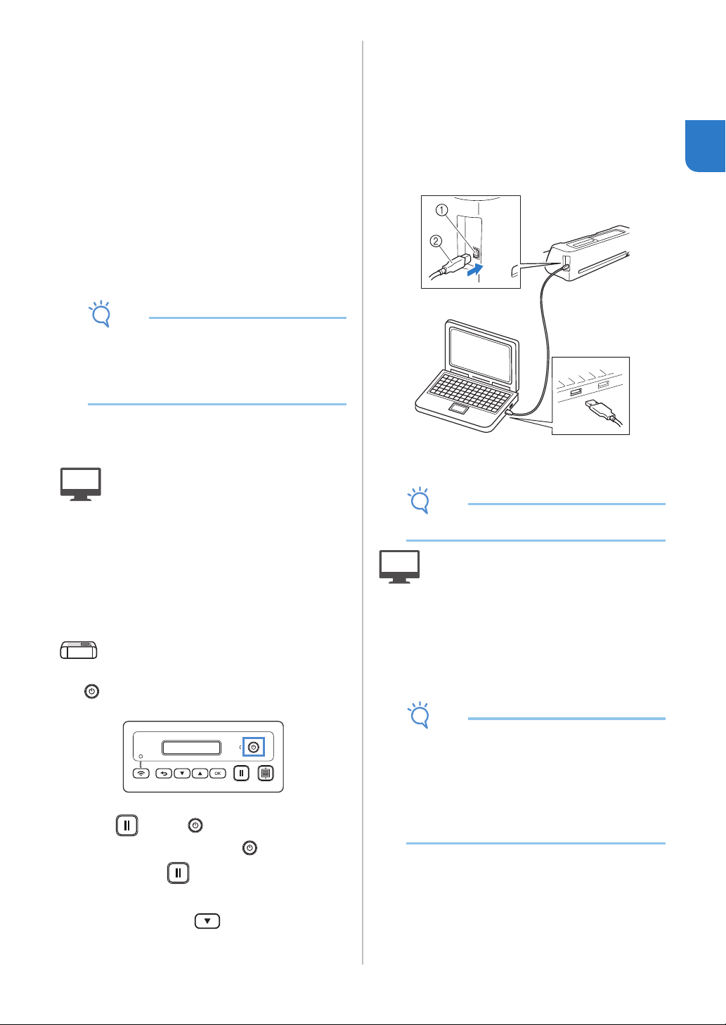
i Plug the USB cable connector into the
corresponding USB ports on the computer and
on the machine.
a USB port for a computer
b USB cable
Note
• USB Cable is sold separately.
: Operation performed in DesignNCut
Manager
j Go back to DesignNCut Manager and click
[Wizard].
k The WLAN Assistant Wizard starts up. Follow
the on-screen instructions to complete the
setup.
Note
• The default settings for Authentication/
Encryption methods are as follows:
Authentication methods: WPA/WPA2-PSK
Encryption Mode: AES
To select the correct method, please check the
wireless security information of your wireless
access point/router.
18
: Operation performed on the machine
l When the message [Connected to WLAN. Press
[OK] button.] appears on your LCD, press
button on your machine.
m The Wireless LAN Connect light will turn on.
* Give the Wireless LAN Connect light time to turn
on.
: Operation performed in DesignNCut
Manager
n Go back to your PC and then click [OK] to
complete the setup.
o Select the machine number and then click
[OK].
Note
• To check your machine's number, press
to display the [2. Machine Info] on the
machine's LCD, and then press .
When [1. No.] appears on the LCD, press .
Your machine's number will be displayed on the
machine's LCD.
p When [DesignNCut connection is successful.]
appears in the dialog box, click [OK].
After completing the network connection, see
“REGISTER DesignNCut ON ScanNCutCanvas”
on page 22 to connect your machine to
ScanNCutCanvas.
Direct PC Connection Using USB
Cable (Windows Only)
With a USB cable, directly connect the machine and
the computer with DesignNCut Manager
(DesignNCut application for operation options).
If you have already selected the
connection method, please go to step
d
: Operation performed in DesignNCut
Manager
a Click [Start Setup].
b Click [Connect].
c Select [USB Cable], and then click [Next].
: Operation performed on the machine
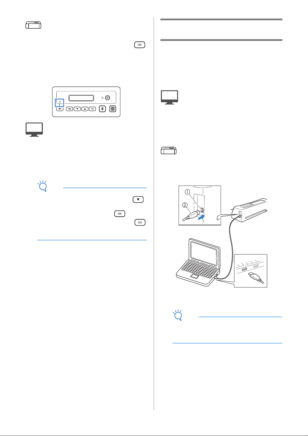
d Plug the USB cable connectors into the
corresponding USB ports on the computer and
on the machine.
a USB port for a computer
b USB cable
Note
• USB Cable is sold separately.
• This connection is for Windows PC only and not
available for Mac computers.
19
1
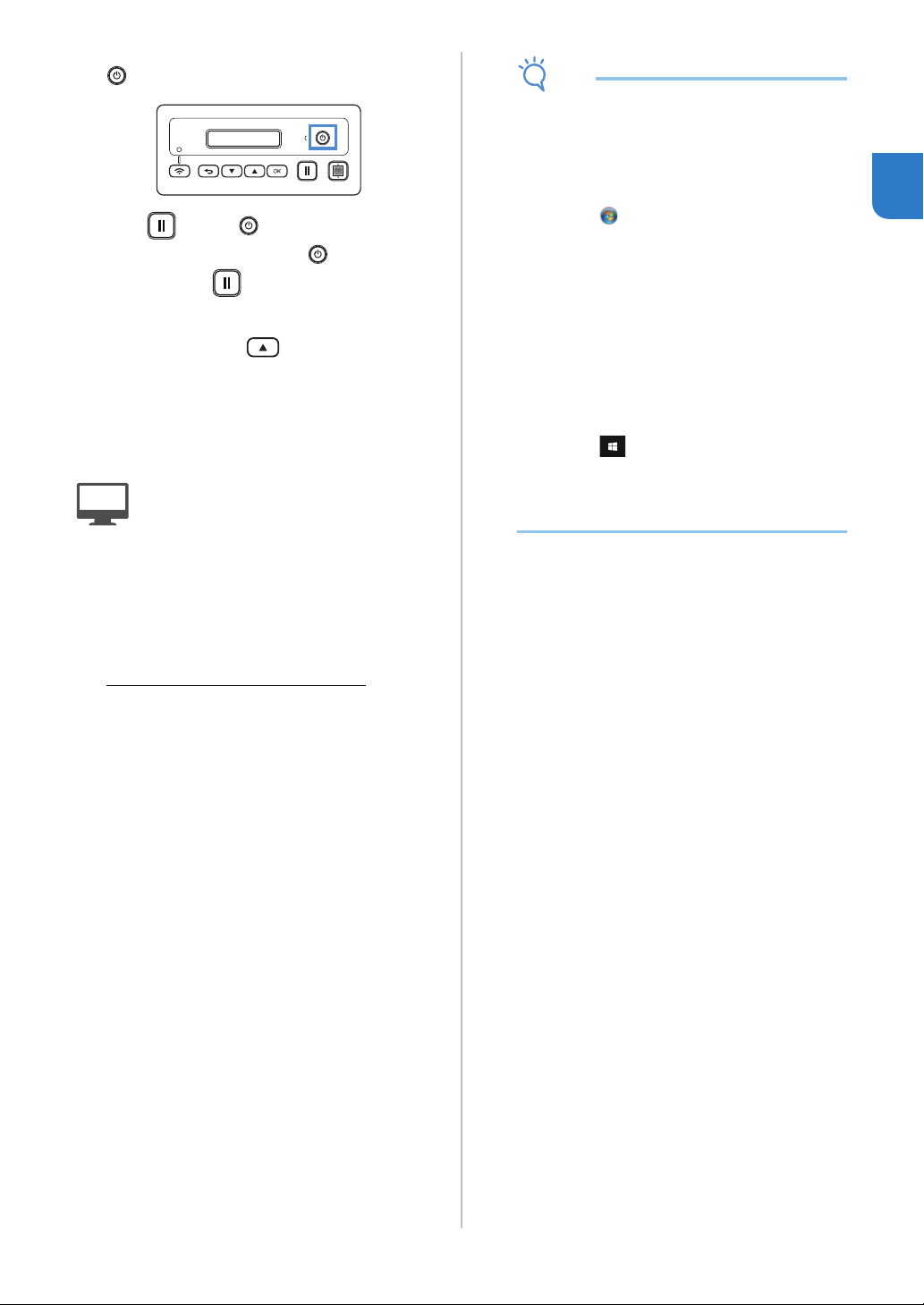
e Turn off the DesignNCut machine, by pressing
.
f Press and the at the same time, once
the power comes on release while still
pressing down .
g When the message [Machine mode?] appears
on your LCD, press to select [USB].
hThe message, [Turn the machine off, then on
again.] will appear on your LCD.
Follow the machine's instruction.
Once your machine is back on, the text [Standby
(USB)] should display on your LCD.
: Operation performed in DesignNCut
Manager
i Go back to DesignNCut Manager and click
[Connect].
j When [DesignNCut connection is successful.]
appears in the dialog box, click [OK].
k Click [ScanNCutCanvas] to access to
http://ScanNCutCanvas.Brother.com
to register
a new account.
l After registering, click [Next].
All settings have been completed.
Click [How to Use] on the DesignNCut Manager
to see tutorial for the basic usage.
m Click [Close].
Note
• When connecting the machine and computer
with a USB cable, the AutoPlay dialog box may
appear repeatedly. To not display the dialog
box, change the AutoPlay settings as described
below.
-Windows 7
Click > [Control Panel] > [Hardware and
Sound] > [AutoPlay]. Uncheck [Use AutoPlay
for all media and devices], then click [Save]
to apply the settings.
- Windows 8.1
Move your mouse to the lower right corner
of your desktop. When the menu bar
appears, click [Settings] > [Control Panel] >
[Hardware and Sound] > [AutoPlay]. Select
[Take no action] from the [Removable drive]
drop-down list, then click [Save] to apply the
settings.
- Windows 10
Click > [Windows System] > [Control
Panel] > [Hardware and Sound] > [AutoPlay].
Select [Take no action] from the [Removable
drive] drop-down list, then click [Save] to
apply the settings.
20
Resetting the Wireless Connection
Setup
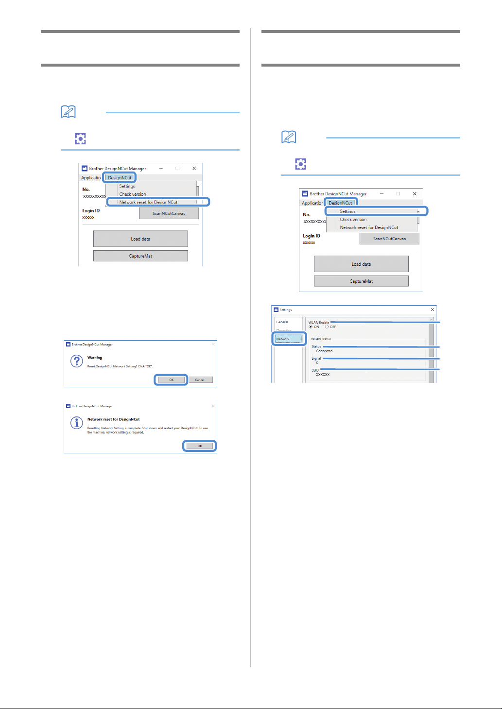
a From the [DesignNCut] menu, click [Network
reset for DesignNCut].
Memo
• With the mobile device version:
→[Network reset for DesignNCut].
b Click [OK] to begin initializing.
• Follow the on-screen instructions to complete the
operation.
• See “Wireless Connection” on page 12 to connect
to a wireless network.
Checking the Wireless LAN Settings/
Connection Status
When a connection to the wireless network cannot
be established.
a Click [DesignNCut], then [Settings], and then
select [Network].
Memo
• With the mobile device version:
→[Settings]→[Network]
a Select whether or not the machine will connect
to the wireless network.
b Displays the connection status.
c Displays the machine’s signal strength as one
of four levels.
The signal strength is indicated by a number.
0 : No connected (*When the USB cable
connected)
1 : Weak signal
2 : Medium signal
3 : Strong signal
d Displays the SSID of the wireless router that the
machine is connected to.
a
b
c
d
21
1
Setting Up Manually
a Click [DesignNCut] in the main window of
DesignNCut Manager, click [Settings], and then
select [Network].
Memo
• With the mobile device version:
→[Settings]→[Network]
a If [Static] is selected, TCP/IP settings can be
manually entered.
b Use when proxy settings are required.
c Displays the MAC address.
b After specifying the settings, click [OK].
a
b
b
c

22
After the machine is registered with ScanNCutCanvas
(http://ScanNCutCanvas.Brother.com/), various
editing operations can be performed and data can be
transferred.
This section describes the procedure for linking a
machine with a specific number to a login ID.
If setup is not completed correctly or an error
message appears, see “ERROR MESSAGES” on
page 59.
Note
• A computer or mobile device that can run
ScanNCutCanvas and connect to the network
is required.
• Before continuing with this procedure, the
machine must be connected to the wireless
network. If not, see “Wireless Connection” on
page 12, and perform the setup.
: Operation performed in DesignNCut
Manager
a Click [ScanNCutCanvas] to access to
http://ScanNCutCanvas.Brother.com
to register
a new account.
Note
• If you have a ScanNCutCanvas account for
your ScanNCut we recommend creating a new
account for DesignNCut.
b After registering, click [Next].
* For mobile version, tap .
c Click [Connect].
d Register dialog box will appear.
Type in the login ID and password registered
with ScanNCutCanvas, and then click
[Register].
e When the [ScanNCut Online Settings has been
completed.] dialog box appears, click [OK].
f Click [Next].
* For mobile version, tap .
Click [How to Use] on the DesignNCut Manager
to see tutorial for the basic usage.
g Click [Close].
Note
• After the settings have been completed, your
machine number and your ScanNCutCanvas
login ID will be shown in the DesignNCut
Manager's main window.
• First-time users must create a
ScanNCutCanvas account.
• If an error occurs while sending or receiving
data, see “ERROR MESSAGES” on page 59.
Memo
• If you registered a new ScanNCutCanvas
account for DesignNCut, you can also click
[ScanNCutCanvas] in the main window of
DesignNCut Manager to display the register
dialog box.
REGISTER DesignNCut ON ScanNCutCanvas
23
1
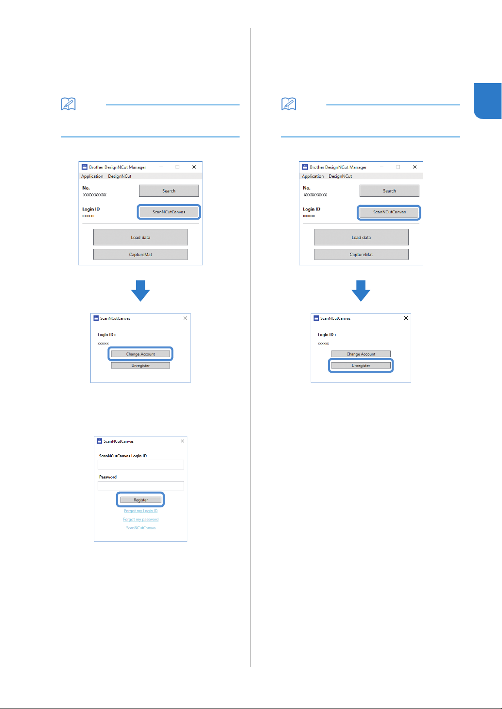
■ Changing to a Different
ScanNCutCanvas Login ID
a Click [ScanNCutCanvas] in the main window of
DesignNCut Manager, and then click [Change
Account].
Memo
• With the mobile device version:
Main Window→[Login ID]→[Change Account]
b Type in the login ID and password registered
with ScanNCutCanvas, and then click
[Register].
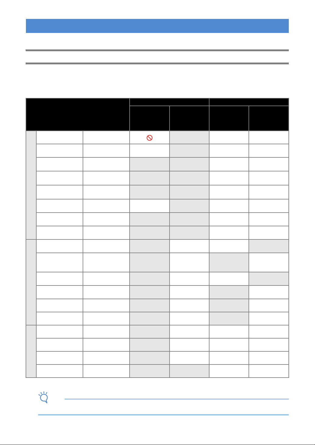
■ Deleting a Registered
ScanNCutCanvas Login ID
a Click [ScanNCutCanvas] in the main window of
DesignNCut Manager, and then click
[Unregister].
Memo
• With the mobile device version:
Main Window→[Login ID]→[Unregister]
24
The following procedures describe basic operations, from preparing the materials to cutting.
Mat and Material Combinations
The recommended material thickness is 0.1 mm to 0.3 mm for paper and 0.2 mm to 1.5 mm for fabric. Refer to
the following table for the appropriate mat and sheet for fabric cutting according to the material to be used for
cutting or drawing. Depending on the machine model, some accessories listed in the chart may not be included.
In that case, they must be purchased separately.
*
When cutting smooth paper
Note
• This chart is only a guide, always test material and mat strength prior to beginning project.
FIRST STEPS
Material and its thickness
Mat
Sheet for fabric cutting
Standard mat
Low tack
adhesive
mat
Iron-on fabric
appliqué contact
sheet (white
backing)
High tack
adhesive
fabric support
sheet
Paper
Printer paper 80 g/m² (0.1 mm)
Scrapbook paper
(thin)
120 g/m²
(0.15 mm)
Scrapbook paper
(medium-thick)
200 g/m²
(0.25 mm)
*
Cardstock (thin)
200 g/m²
(0.25 mm)
*
Cardstock (medium-
thick)
280 g/m²
(0.35 mm)
*
Vellum, tracing
paper
0.07 mm
Poster board (thin)
280 g/m²
(0.35 mm)
Poster board (thick)
400 g/m²
(0.5 mm)
Fabric
Thin cotton fabric
(for quilt piece)
0.25 mm
Thin cotton fabric
(except for quilt
piece)
0.25 mm
Flannel (for quilt
piece)
0.6 mm
Flannel (except for
quilt piece)
0.6 mm
Felt 1 mm
Denim 14 oz 0.75 mm
Others
Plastic sheet (PP) 0.2 mm
Vinyl 0.2 mm
Magnet 0.3 mm
Sticker or seal 0.2 mm
25
1
Note
• Avoid using materials covered with a decorative layer that can easily peel off, such as lamé or foil. Otherwise,
the peeled-off layer may attach to rollers or sensors during operation, resulting in damage to the machine or to
the cutting blade.
• Do not affix masking tape, etc., over the scanning marks. Otherwise, the mat may not be correctly recognized or
images may not be correctly scanned.
aScanning marks
Memo
• When using a 12" × 12" (305 mm × 305 mm) mat, the maximum work area for cutting/drawing is
11 3/4" × 11 3/4" (296 mm × 298mm).
• When using an optional 12" × 24" (305 mm × 610 mm) mat, the maximum work area for cutting/drawing is
11 3/4" × 23 3/4" (296mm × 603 mm).
• Some fabrics with uneven surfaces can be cut if turned upside down.
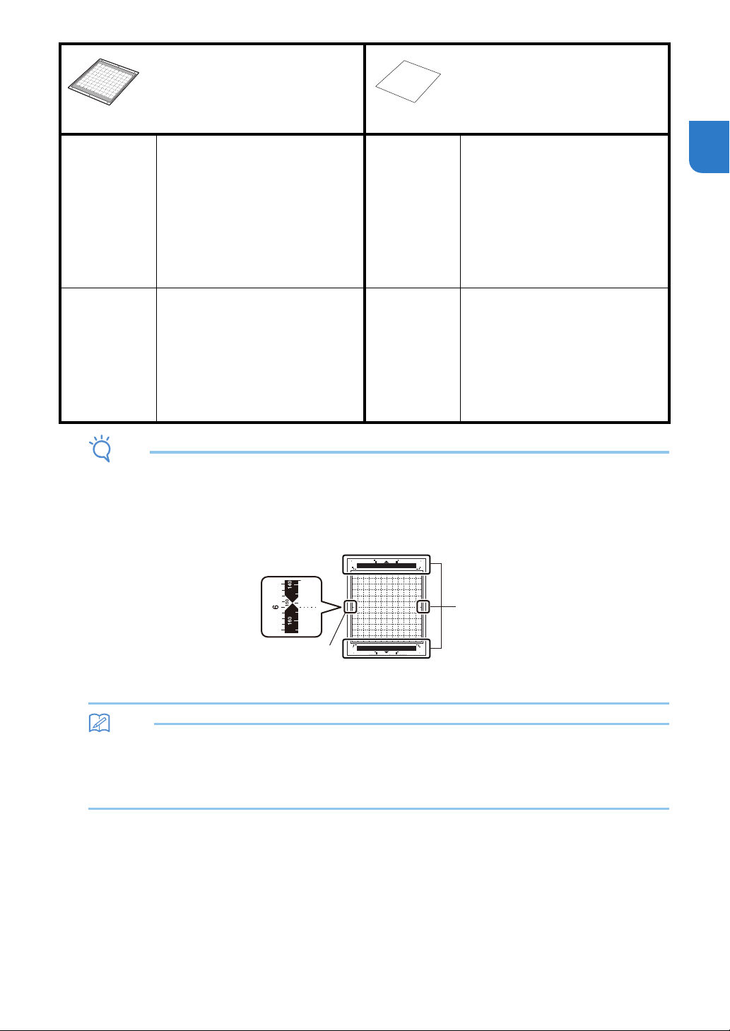
Mat
Sheet for fabric cutting
Use one of the following two sheets
for fabric cutting when cutting
fabric.
Standard mat High adhesive strength mat; use with
cutting fabric.
* Use the low tack adhesive mat with
copy paper and smooth paper.
Since the standard mat has a high
adhesive strength, materials may
remain stuck to the mat, causing the
mat to become unusable.
Iron-on fabric
appliqué
contact sheet
(white backing)
(See page 27)
• Reinforces the fabric so that various
patterns can be cut out.
• The original texture may change
because it remains attached to the
back of fabric.
* For use with the standard mat.
* Do not place fabric backed with
iron-on contact sheet directly onto a
mat with high tack fabric support
sheet.
Low tack
adhesive mat
Low adhesive mat; suitable for copy
paper and smooth paper.
High tack
adhesive fabric
support sheet
(See page 29)
• For best results when cutting fabric,
attach the high tack adhesive fabric
support sheet to the standard mat in
order to increase the strength of the
adhesive.
• Depending on the shape, the pattern
may not be cleanly cut.
• We recommend attaching it to a
new cutting mat.
a
a
26
Attaching the material to the mat
After preparing the mat and sheet (when cutting
fabric) appropriate for the material, attach the
material to the mat. For the mat and sheet
appropriate for the material, see “Mat and Material
Combinations” on page 24.
Note
• Do not discard the protective sheet peeled off
the mat; save it for later use.
• To maintain the adhesive strength, attach the
protective sheet to the adhesive side of the mat
after use.
• When the mat is not being used, clean the
adhesive side and affix the protective sheet
before storing it. For details, see “Cleaning the
Mat” on page 53.
■ Paper
a Mat suitable for the material
Attaching the Material (Paper)
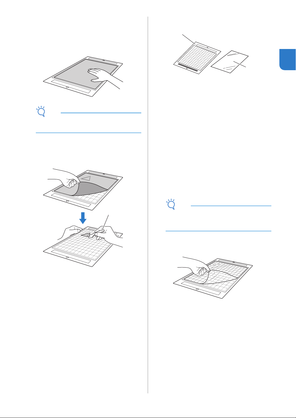
a Peel off the protective sheet from the adhesive
side of the mat.
b Test attaching the material.
Before attaching the material to the mat, use a corner
of the adhesive side of the mat to test attaching it.
Check for the following when testing attaching the
material.
• The color does not come off the material when it is
peeled off.
• The material is not torn or deformed when it is
peeled off.
If any problems occur when testing attaching, use
different material.
Note
• Use the low tack adhesive mat with copy paper
and smooth paper. Since the standard mat has
a high adhesive strength, materials may remain
stuck to the mat, causing the mat to become
unusable.
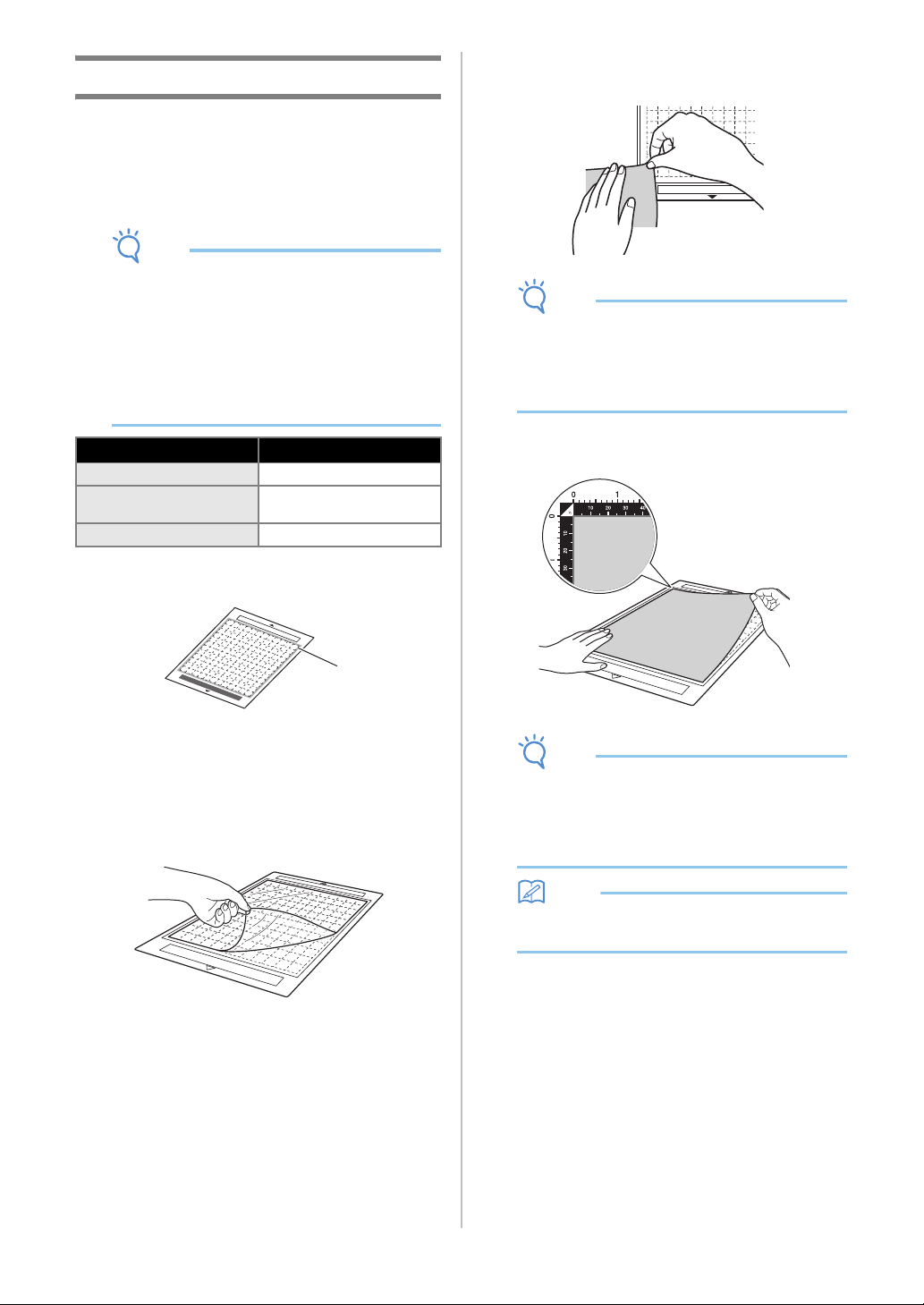
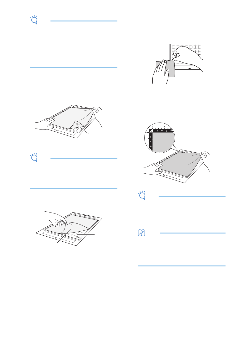
c Attach the material to the mat’s adhesive side.
Note
• Place the material within the attaching area
(grid area) on the adhesive side. If the material
extends from the attaching area, it may be
damaged by the feed rollers when the mat is
fed.
Memo
• The mat does not have a top and bottom. It can
be inserted into the feed slot from either end.
Material Page
Paper Page 26
Fabric (Other Than for
Quilt Piecing)
Page 27
Fabric (for Quilt Piecing) Page 29
a
27
1
d Firmly attach all of the material to the mat so
that there are no wrinkles and no part can curl
off.
• Otherwise, curls in the material may become
caught when the mat is inserted.
Note
• If the mat is dirty, clean it. For details, see
“Cleaning the Mat” on page 53.
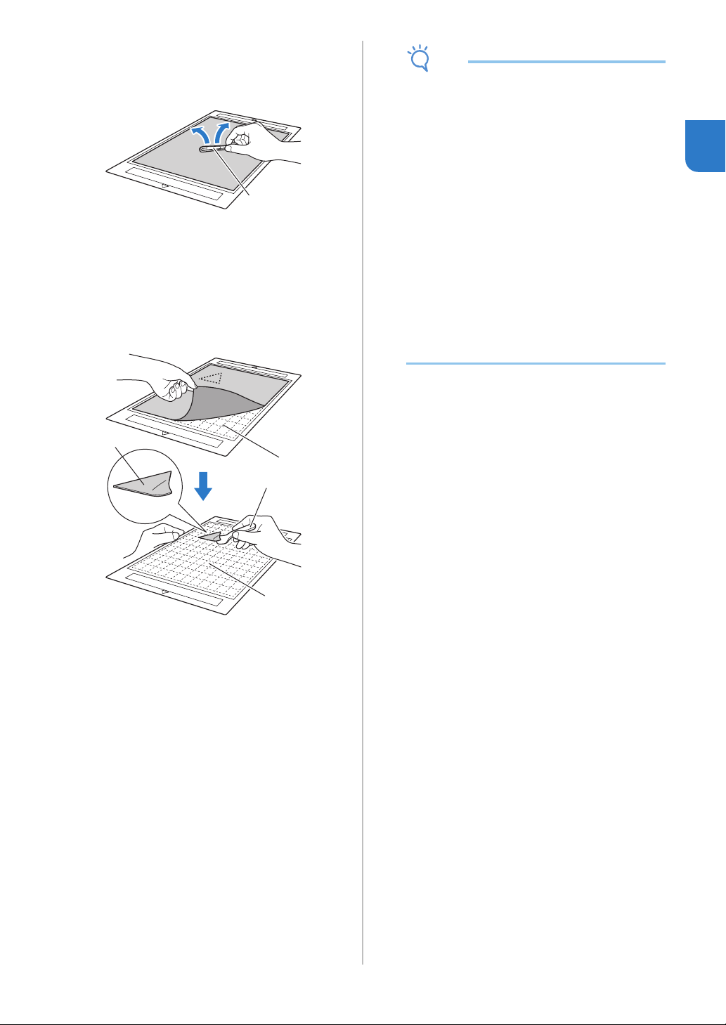
Peeling Off the Material (Paper)
After cutting the material, use a spatula to slowly
peel off the paper.
a Spatula
■ Fabric (Other Than for Quilt Piecing)
a Standard mat
b Iron-on fabric appliqué contact sheet (white
backing)
Attaching Fabric Material (Excluding
Quilt Piecing)
Iron the specially designed contact sheet to the
back of fabrics (excluding quilt piecing) and then
attach them to the standard mat.
The double-faced adhesive type of the iron-on
fabric appliqué contact sheet reinforces the fabric
and enables any pattern to be cut easily,
including appliqués.
The sheet cannot be removed once it has been
attached to the back of fabrics.
For Quilt Piecing, use the high tack adhesive
fabric support sheet and avoid using the iron-on
fabric appliqué contact sheet.
Note
• The contact sheet may not adhere to a fabric
surface that is rough that the two surfaces
cannot be heat-set to adhere to each other.
a Peel off the protective sheet from the adhesive
side of the standard mat.
a
a
b
28
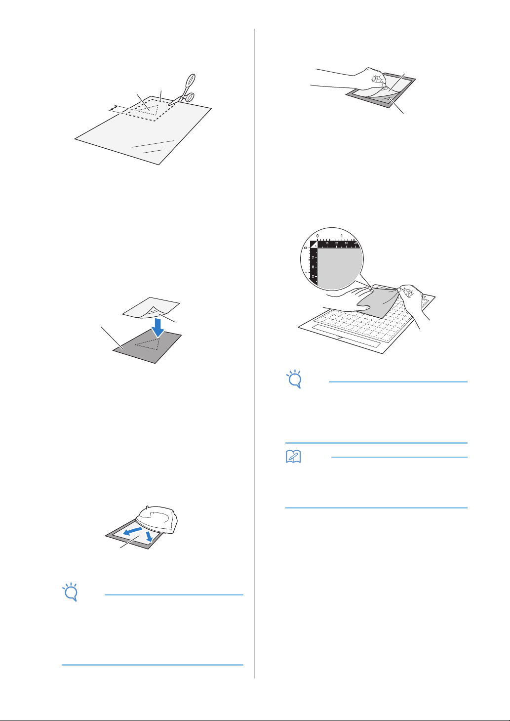
b Cut the iron-on fabric appliqué contact sheet to
a size 2 cm (3/4") or more larger than the
outline of the pattern to be cut.
a Pattern to be cut
b Cutting line of sheet
c Margin of 2 cm (3/4") or more
c With the glossy side of the contact sheet facing
down, place it on the wrong side of the fabric.
Be sure first to iron the fabric to remove any wrinkles.
Before placing the contact sheet on the fabric, make
sure that the fabric has been allowed to cool after
ironing.
a Glossy side of contact sheet
b Wrong side of fabric
d Evenly iron the entire contact sheet to affix it to
the wrong side of the fabric.
With the iron on a medium temperature setting
(140 °C to 160 °C (284 °F to 320 °F)), press each part
of the sheet for about 20 seconds (the length of time
differs depending on the material).
Be sure to apply pressure on the top of the backing
and push out any air between the sheet and fabric.
a Backing
Note
• Before attaching the contact sheet to the fabric,
use a piece of the sheet to test attaching it. If
any problems occur when testing attaching,
use different material.
• Leaving the iron in the same place for too long
may scorch or melt the material.
e Peel off the backing from the contact sheet.
Before peeling off the backing, allow all parts to cool.
a Contact sheet
b Backing
f With the side of the fabric that the contact
sheet is attached to facing down, attach the
material to the mat from its edges.
Slowly attach the material from its edges so that no air
is trapped between it and the mat.
Note
• Place the material within the attaching area
(grid area) on the adhesive side. If the material
extends from the attaching area, it may be
damaged by the feed rollers when the mat is
fed.
Memo
• The mat does not have a top and bottom. It can
be inserted into the feed slot from either end.
• Be sure that the vertical grain of the attached
fabric runs straight up and down.
g Firmly attach all of the material to the mat so
that there are no wrinkles and no part can curl
off.
• Otherwise, curls in the material may become
caught when the mat is inserted.
a
c
b
a
b
a
a
b
29
1
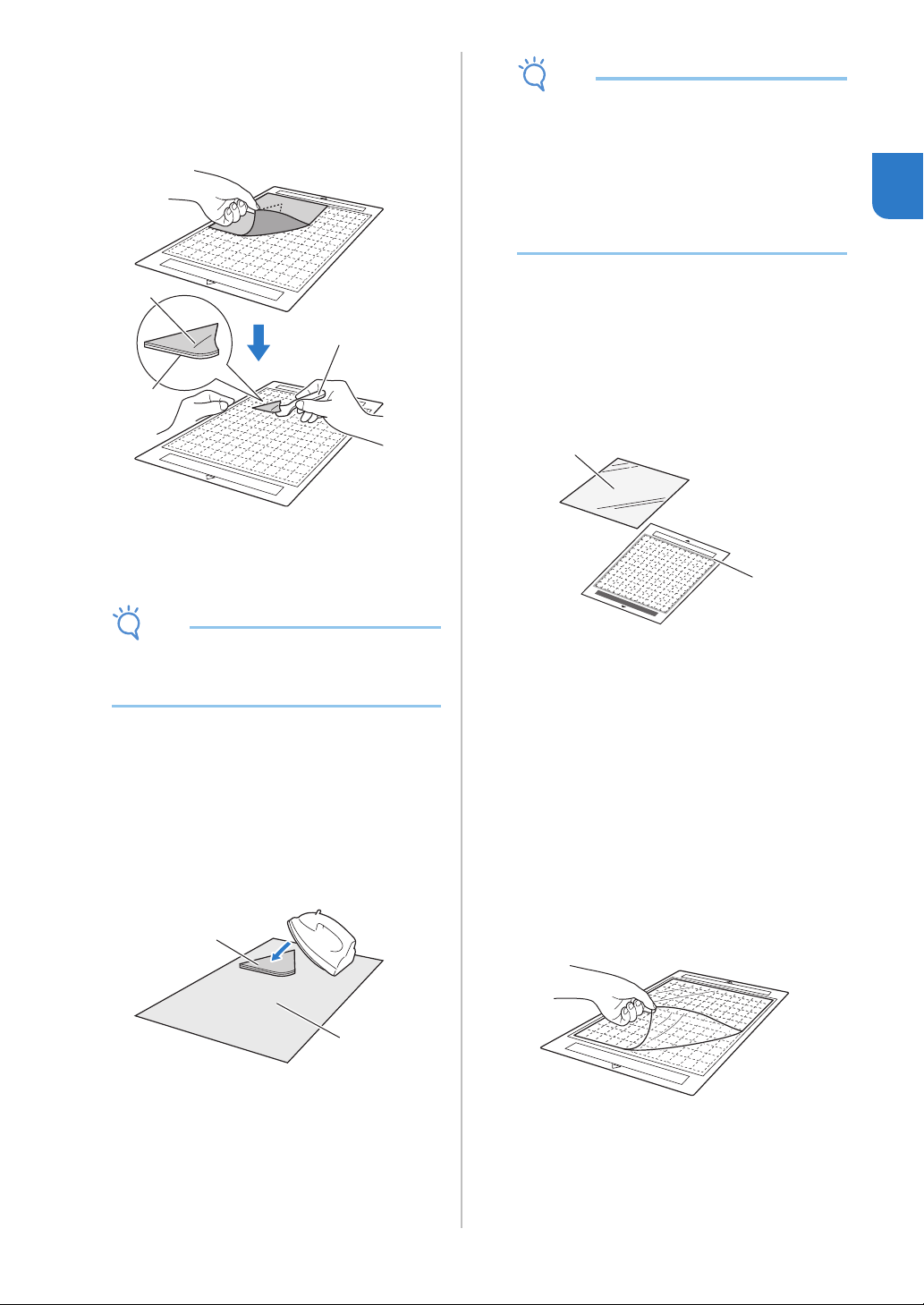
Peeling Off the Material (Excluding Quilt
Piecing)
After cutting the material, use a spatula to peel off
the fabric together with the attached contact
sheet.
a Pattern that was cut out
b Contact sheet
c Spatula
Note
• Do not place anything heated on the fabric
attached to a contact sheet. The adhesive will
permeate any other pieces of fabric around.
Attaching Fabrics With the Double-
Sided Adhesive
Place a cutout on a base fabric and apply pressure
on the top of the cutout using an iron. (The
contact sheet may not adhere well to some
fabrics.) Hand or machine stitch to ensure that the
cutout stays in place.
a Base fabric
b Cutout with a contact sheet
Note
• Do not wash fabrics attached with a double-
sided adhesive contact sheet.
• When attaching fabrics with the double-sided
adhesive, iron carefully, being sure that the
material and adhesive surfaces are properly
heat-set.
• When attaching fabrics of different weights with
the double-sided adhesive, first iron the lighter-
weight fabric to affix the contact sheet.
Notice on Use of Iron-on Fabric
Appliqué Contact Sheet
• Store the contact sheet at room temperature
and in a location not exposed to high
temperatures, high humidity or direct sunlight.
■ Fabric (for Quilt Piecing)
a Standard mat
b High tack adhesive fabric support sheet
Attaching the Material (for Quilt Piecing)
Use the high tack adhesive fabric support sheet to
attach fabrics for quilt piecing to the standard
mat. These sheets should only be used with
patterns that have a seam allowance. The high
tack adhesive fabric support sheet can be
repeatedly used until their adhesive strength has
decreased. (Once the support sheet has been
peeled off the mat, it can no longer be used.)
a Peel off the protective sheet from the adhesive
side of the standard mat.
a
b
c
a
b
b
a
30
Note
• Do not discard the protective sheet peeled off
the mat; save it for later use.
• To maintain the adhesive strength, attach the
protective sheet to the adhesive side of the mat
after use.
• When the mat is not being used, clean the
adhesive side and affix the protective sheet
before storing it. For details, see “Cleaning the
Mat” on page 53.
b With the glossy side of the high tack adhesive
fabric support sheet facing down, attach it to
the mat’s adhesive side.
Slowly attach the support sheet from its edges so that
no air is trapped between the mat and the sheet.
a Glossy side of support sheet
Note
• Place the support sheet within the attaching
area (grid area) on the adhesive side of the mat.
If the sheet extends from the attaching area, it
may be damaged by the feed rollers when the
mat is fed.
c Peel off the backing from the top of the support
sheet.
a Backing
b Adhesive
d Test attaching the material.
Before attaching the material to the mat, use a corner
of the adhesive side of the mat to test attaching it. If
any problems occur when testing attaching, use
different material.
e From its edges, attach the material to the
adhesive side of the mat so that there are no
wrinkles in the material.
To remove wrinkles be sure to iron the fabric before
attaching it to the mat.
Note
• Place the material within the attaching area
(grid area) on the adhesive side. If the material
extends from the attaching area, it may be
damaged by the feed rollers when the mat is
fed.
Memo
• The mat does not have a top and bottom. It can
be inserted into the feed slot from either end.
• Be sure that the vertical grain of the attached
fabric runs straight up and down.
• When drawing a seam allowance, attach the
fabric to the mat with its wrong side facing up.
a
a
b
31
1
f Firmly move the spatula handle across the
surface of the fabric to remove any wrinkles
and firmly attach the fabric to the mat.
a Spatula
Peeling Off the Material (Fabric for Quilt
Piecing)
After cutting the material, use a spatula to slowly
peel off just the fabric. Try not to peel off the
support sheet.
a Fabric cut out
b Support sheet remaining on the mat
c Spatula
Note
• The support sheet may be unintentionally
peeled off while you are removing the fabric
from the mat under the following conditions:
- The adhesive between the mat and the
support sheet is becoming weak after
repeated uses.
- The support sheet tends to be strongly
attached to a certain type of fabrics.
In this case, use the included spatula to hold
the support sheet on the mat and remove the
fabric using your hand.
• After cutting, carefully remove any fibers
remaining on the support sheet.
• When attaching fabric with an iron-on sheet
attached or paper to the mat, cleanly peel off
the support sheet from the mat, or attach the
material to a different standard mat without a
support sheet attached.
• Do not leave material attached to a mat with a
support sheet attached for a long period of
time; otherwise, the adhesive will permeate the
material.
Notice on Use of High Tack Adhesive
Fabric Support Sheet
• When the sheet’s adhesive strength decreases
or fabric becomes twisted while being cut,
replace the sheet with a new one.
• When peeling the sheet off the mat or replacing
the sheet, use the spatula to carefully remove
the old sheet.
• Store the mat in between uses with the
protective sheet affixed to the support sheet.
• If a mat with a support sheet attached is not to
be used for a certain length of time, peel the
support sheet off the mat and affix the
protective sheet on the adhesive side of the mat
before storing it.
• Do not reuse a support sheet that has been
attached to the mat.
• Store the support sheet at room temperature
and in a location not exposed to high
temperatures, high humidity or direct sunlight.
• Do not bend the support sheet to store it.
• We recommend attaching it to a new cutting
mat.
a
a
b
b
c
32
Adjusting the Blade Extension
The appropriate blade extension differs depending on the material type and thickness. Before installing the
holder in the carriage, turn the holder cap to adjust the blade extension, and then perform trial cutting. For
details on trial cutting, see “Trial Cutting” on page 37.
■ Cutting Settings
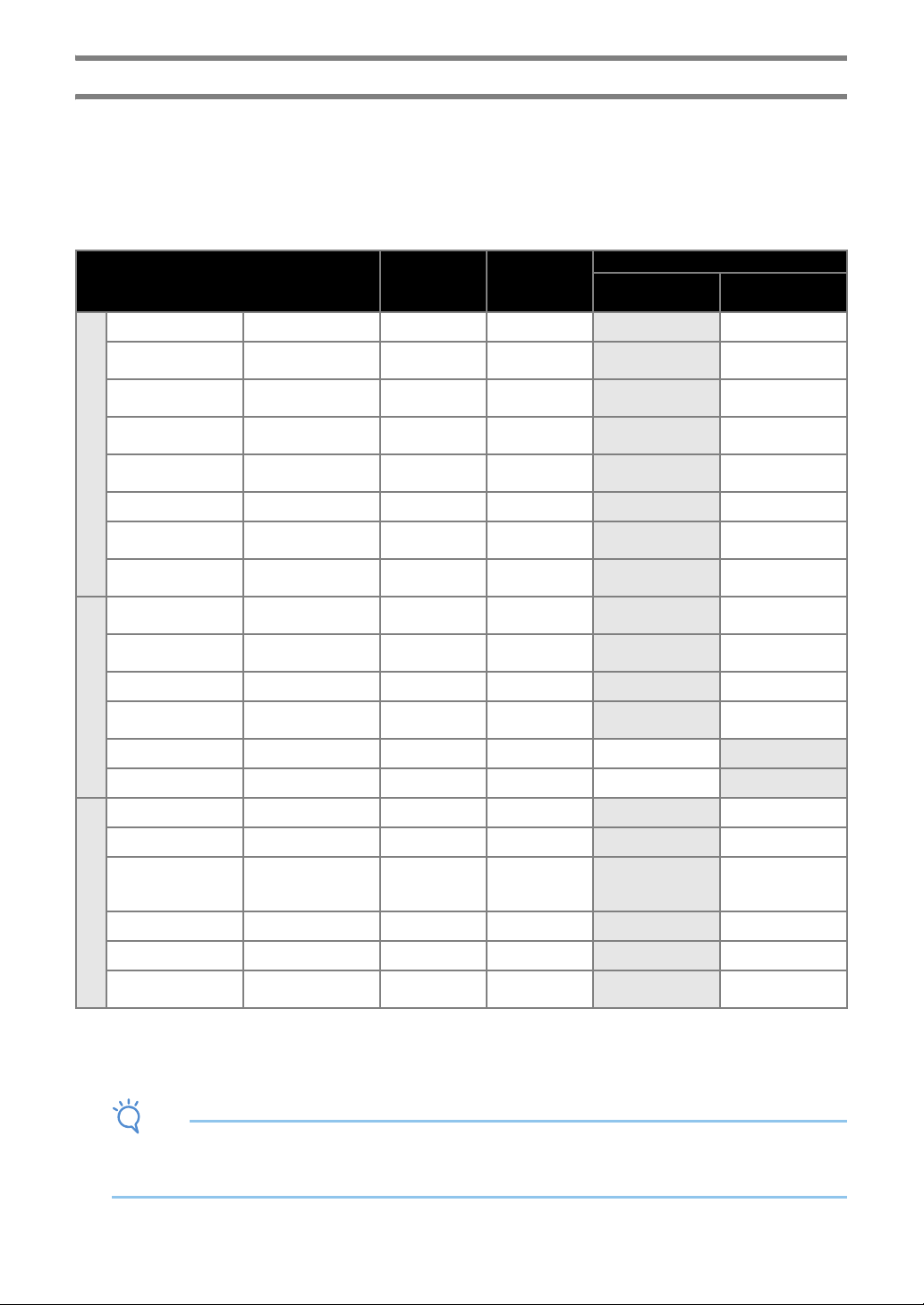
Use the following table to select the appropriate settings according to the material that will be cut.
• Adjust the cutting pressure from the settings screen in DesignNCut Manager. (→ See page 11)
• Use a high tack adhesive fabric support sheet or an iron-on fabric appliqué contact sheet when you cut a piece of
fabric out.
For details, see “Mat and Material Combinations” on page 24.
Note
• The settings indicated in the table are approximations. The setting will differ depending on the type and the
thickness of the material to be cut.
Be sure to perform a trial cutting first.
Material and its thickness
Blade scale
setting
*Half cut
Cut pressure
setting
Cutting blade
Standard cut blade
(turquoise)
Deep cut blade
(purple)
Paper
Printer paper 80 g/m² (0.1 mm) 3 -1
Scrapbook paper (thin)
120 g/m²
(0.15 mm)
3.5 0
Scrapbook paper
(medium-thick)
200 g/m²
(0.25 mm)
4 0
Cardstock (thin)
200 g/m²
(0.25 mm)
4 0
Cardstock (medium-
thick)
280 g/m²
(0.35 mm)
5 0
Vellum, tracing paper 0.07 mm 3 0
Poster board (thin)
280 g/m²
(0.35 mm)
5.5 0
Poster board (thick)
400 g/m²
(0.5 mm)
7.5 4
Fabric
Thin cotton fabric (for
quilt piece)
0.25 mm 4 4
Thin cotton fabric
(except for quilt piece)
0.25 mm 4 4
Flannel (for quilt piece) 0.6 mm 6.5 4
Flannel (except for quilt
piece)
0.6 mm 6.5 4
Felt 1 mm 5 5
Denim 14 oz 0.75 mm 5.5 6
Others
Plastic sheet (PP) 0.2 mm 4 0
Vinyl 0.2 mm 4 0
Adhesive Craft Vinyl
(backing sheet :
0.1 mm)
0.07 mm 1.5 * -1
Magnet 0.3 mm 5.5 0
Sticker or seal 0.2 mm 4 0
Sticker Sheet (backing
sheet : 0.15 mm)
0.15 mm 2 * -1
33
1
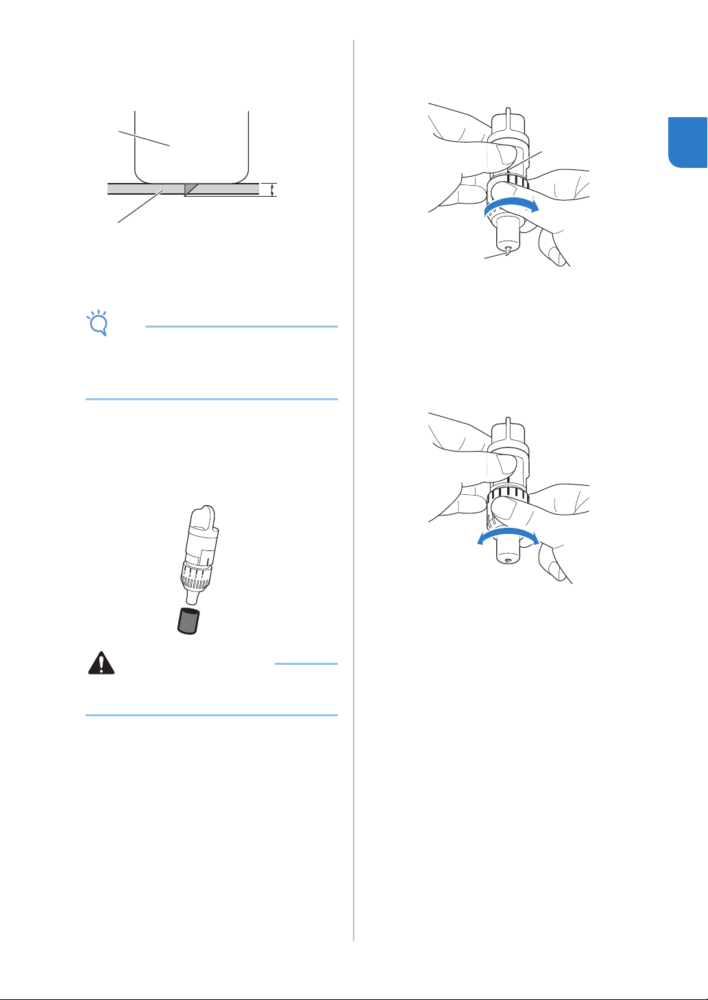
Appropriate Blade Extension
Adjust the blade extension to slightly exceed the
thickness of the material that will be cut. Use the
markings on the holder to make the adjustment.
a End of holder cap
b Material that will be cut
c Length of blade tip
Note
• Be careful that the blade does not extend too
much. The blade can cut even though it only
slightly extends from the holder. If too much of
the blade extends, it may break.
■ Adjusting the Cutting Blade
a Remove the protective cap.
• After use, be sure to retract the blade into the
holder and attach the protective cap.
CAUTION
• Do not allow infants/children to put the
protective caps in their mouths.
b With the reference line on the holder facing
toward you, fully turn the cap to the right to
extend the blade tip to its maximum.
a Reference line
b Extend the blade tip to its maximum.
c Check the thickness of the material, and then
adjust the blade extension. See “Cutting
Settings” on page 32.
The larger the holder scale setting, the further the
blade extends.
a Turn to the left to decrease the blade extension.
b Turn to the right to increase the blade
extension.
a
b
c
a
b
a b
34
Installing and Uninstalling the Holder
After adjusting the blade extension, install the holder
in the machine. For the blade extension appropriate
for the material, see “Adjusting the Blade Extension”
on page 32.
a Press in the operation panel to turn on the
machine.
For details, see “Turning On/Off the Machine” on
page 6.
Note
• Be sure to turn on the machine before installing
the holder.
• If the holder is installed while the machine is off,
the blade may break and material may not be
cut cleanly.
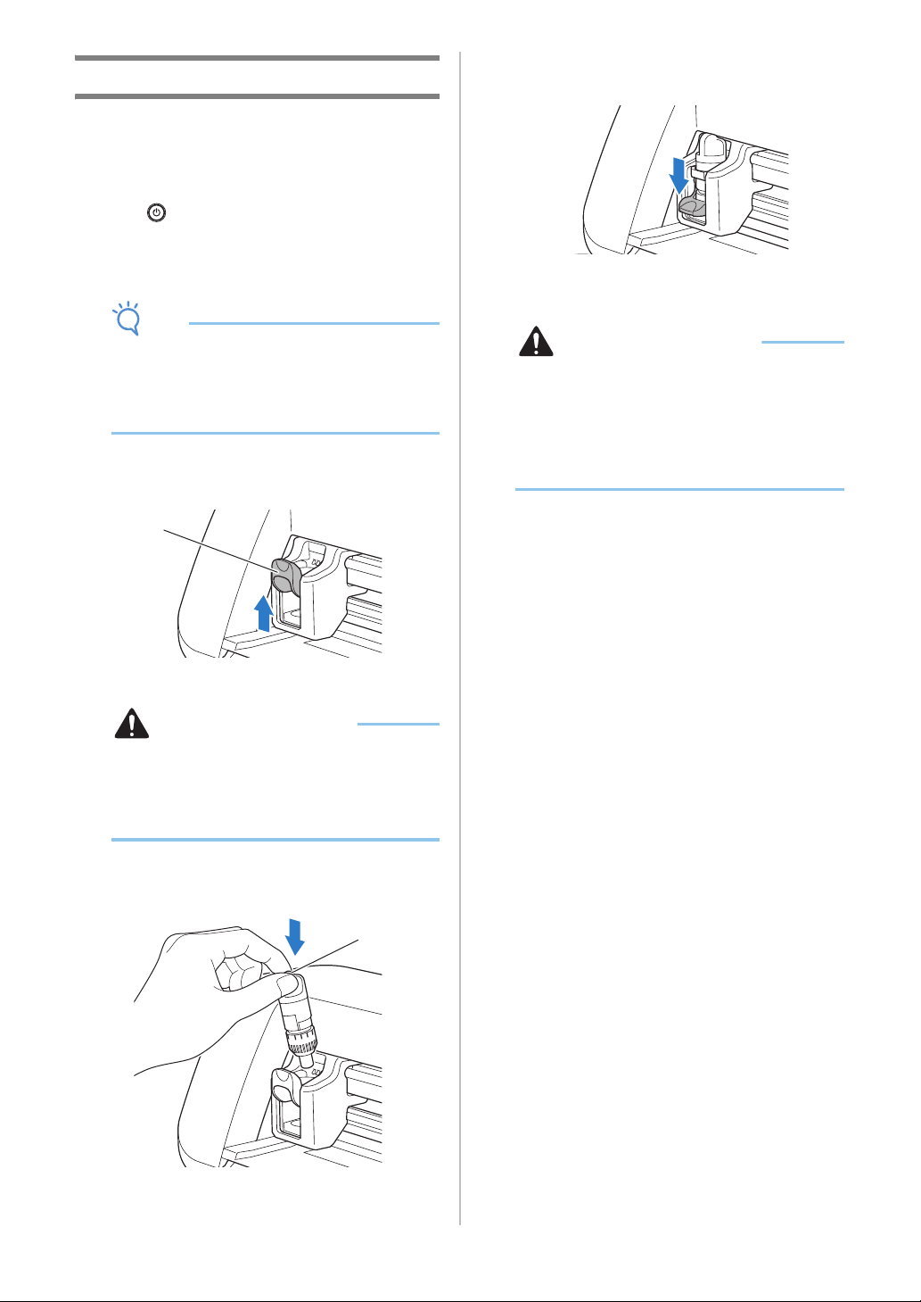
b If the holder lock lever is not raised, raise it.
The holder cannot be installed if the lever is lowered.
a Holder lock lever
CAUTION
• Please remove protective cap from blade
holder before placing it into the machine
carriage.
• Do not allow infants/children to put the
protective caps in their mouths.
c Grasp the holder grip, and then insert the
holder into the carriage.
a Grip
d Push down on the holder lock lever.
Firmly push down until the holder is locked in place.
e Reverse the installation procedure to uninstall
the holder.
CAUTION
• After removing the blade holder from the
machine, be sure to retract the blade into the
holder and attach the protective cap.
• Do not leave the blade extended. Otherwise,
injuries may result.
• Do not allow infants/children to put the
protective caps in their mouths.
a
a
35
2
Chapter 2
BASIC OPERATIONS
The following procedures use patterns to describe
the entire series of operations, from selecting a
pattern and editing it to cutting.
Tutorial 1 - Cutting Patterns
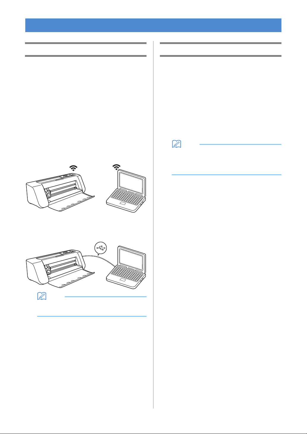
■ Connecting the Machine and
Computer
This machine and a computer installed with
DesignNCut Manager (DesignNCut application for
operation options) can be connected either wirelessly or
with a USB cable.
• For details on the connection methods, see
“CONNECTING THE MACHINE AND
COMPUTER” on page 12.
■ Turning On the Machine
Press to turn on the machine.
• For details, see “Turning On/Off the Machine” on
page 6.
■ Setting the Holder
Install the cutting blade holder into the carriage of the
machine.
• For details, see “Installing and Uninstalling the
Holder” on page 34.
■ Loading the Mat
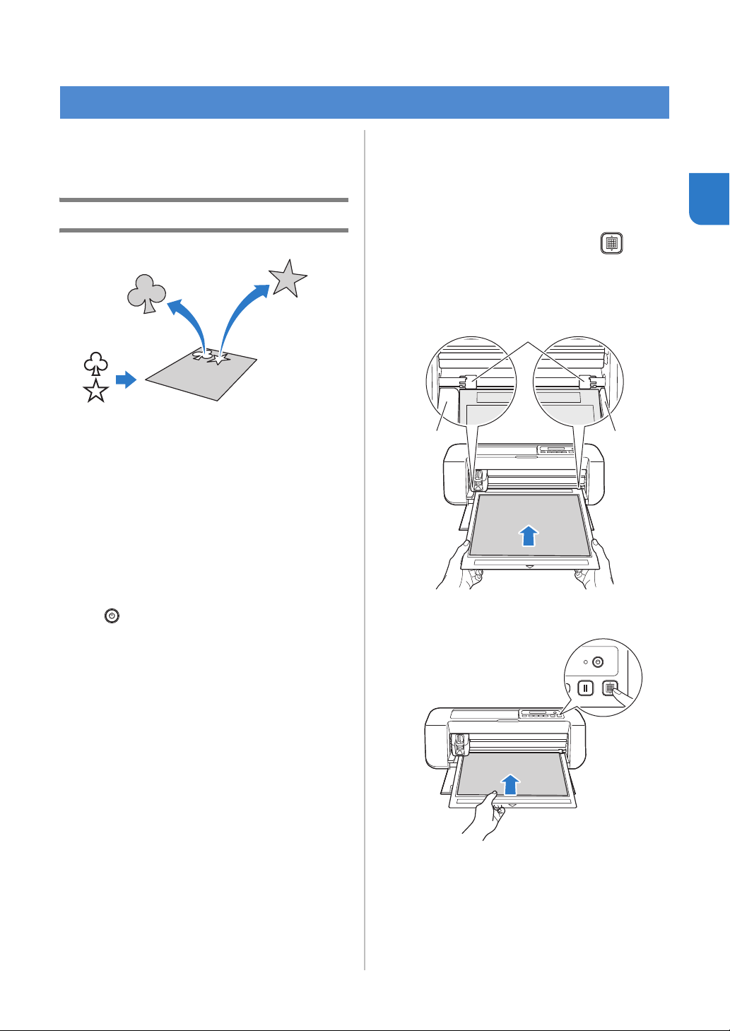
a Attach the material that will be cut to the mat.
• For details on attaching material to the mat, see
“Attaching the material to the mat” on page 26.
b While holding the mat level and lightly
inserting it into the feed slot, press in the
operation panel.
Lightly insert the mat so that it aligns with the guides
on the left and right sides of the feed slot and is tucked
under the feed rollers.
a Guides
b Feed rollers
The mat is fed in to complete the preparations for
cutting.
PATTERN CUTTING
aa
b
36
■ Sending Patterns to the Machine
a Start up DesignNCut Manager.
b Log in to ScanNCutCanvas, and edit the
pattern.
Note
• Make sure that the pattern to be cut fits the size
of the material and fits within the cutting area. If
the pattern does not fit within the cutting area,
adjust the location of the pattern and/or the
pattern size in ScanNCutCanvas.
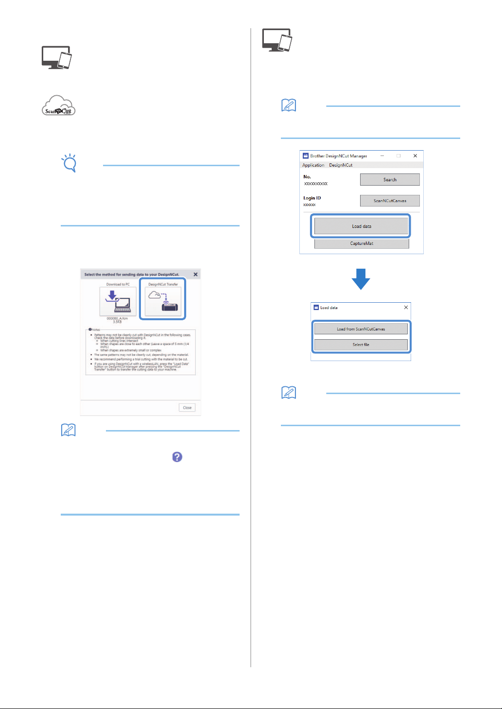
c Click [Download], then [DesignNCut Transfer]
to send the pattern to the machine.
Memo
• For details on editing, transferring or
downloading patterns, click in
ScanNCutCanvas, and then refer to
“Downloading a Project” in the Help.
• When downloading a pattern using a USB cable
(computer only), click [Download to PC] to send
the pattern.
d Click [Load data] in the main window of
DesignNCut Manager, and then click [Load
from ScanNCutCanvas] to import the pattern.
Memo
• With the mobile device version, tap [Load data]
in the main screen. A preview screen appears.
The pattern preview window appears.
Memo
• To open a pattern saved on the computer, click
[Select file].
37
2
■ Trial Cutting
Adjust the blade extension according to the material,
and then use the same material to be used in your
project to perform trial cutting.
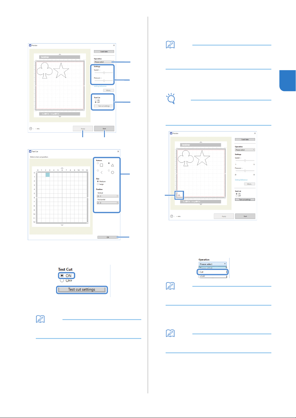
a Set [Test Cut] to [ON], and then click [Test cut
settings].
A window for specifying detailed settings
appears.
Memo
• With the mobile device version:
Preview window→[Test Cut].
b Select the desired shape under [Pattern], and
then select settings for [Size] and [Position].
Refer to the grid references on the mat, and select the
location of the trial cutting shape from the drop-down
lists.
Example: Settings when positioned in the lower-left
corner of the mat
Vertical: 11-12
Horizontal: 0-1
Memo
• The trial cutting shape can also be positioned
by clicking a cell (block) in the mat shown in the
test cut setting window.
c Click [OK], and then position the trial cutting
shape.
Note
• Make sure that the location for the trial cutting
shape does not overlap the location for the
pattern and does not extend from the material.
a Trial cutting shape at the location specified in
step
b
d In DesignNCut Manager, select [Cut] from the
[Operation] drop-down list.
Memo
• With the mobile device version:
Preview window→[Operation]→[Cut]
e With the sliders, specify settings for [Speed]
and [Pressure] for cutting.
Memo
•
With the mobile device version:
Preview window
→
[Settings]
→
[Speed]/[Pressure]
d
e
a
g
f
b
c
a
38
Note
• Depending on the material being used, it may
not be cut cleanly if the cutting pressure is not
correctly adjusted. For details on the
appropriate cutting pressure, see “Cutting
Settings” on page 32.
f Click [Apply].
g Click [Start].
The following window appears.
Memo
• If any machine button other than the power
button is pressed, the machine pauses cutting.
• The following message appears on the
machine’s screen when cutting is paused. You
can stop or resume cutting from the machine.
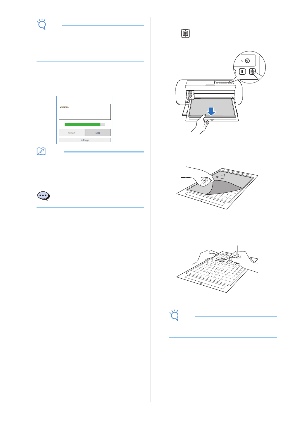
■ Unloading the Mat
a Press on the operation panel to feed out
the mat.
b Peel off the material from an area that is easily
removable, such as a corner, and then slowly
peel while maintaining an even pressure.
c Holding the mat with your hand, use the
included spatula to peel off the cutout patterns
carefully.
a Spatula
Note
• For instructions on how to peel off the material,
see page 27, 29, 31.
Cutting paused. Resume: [OK]
Stop: [STOP]
a
39
2
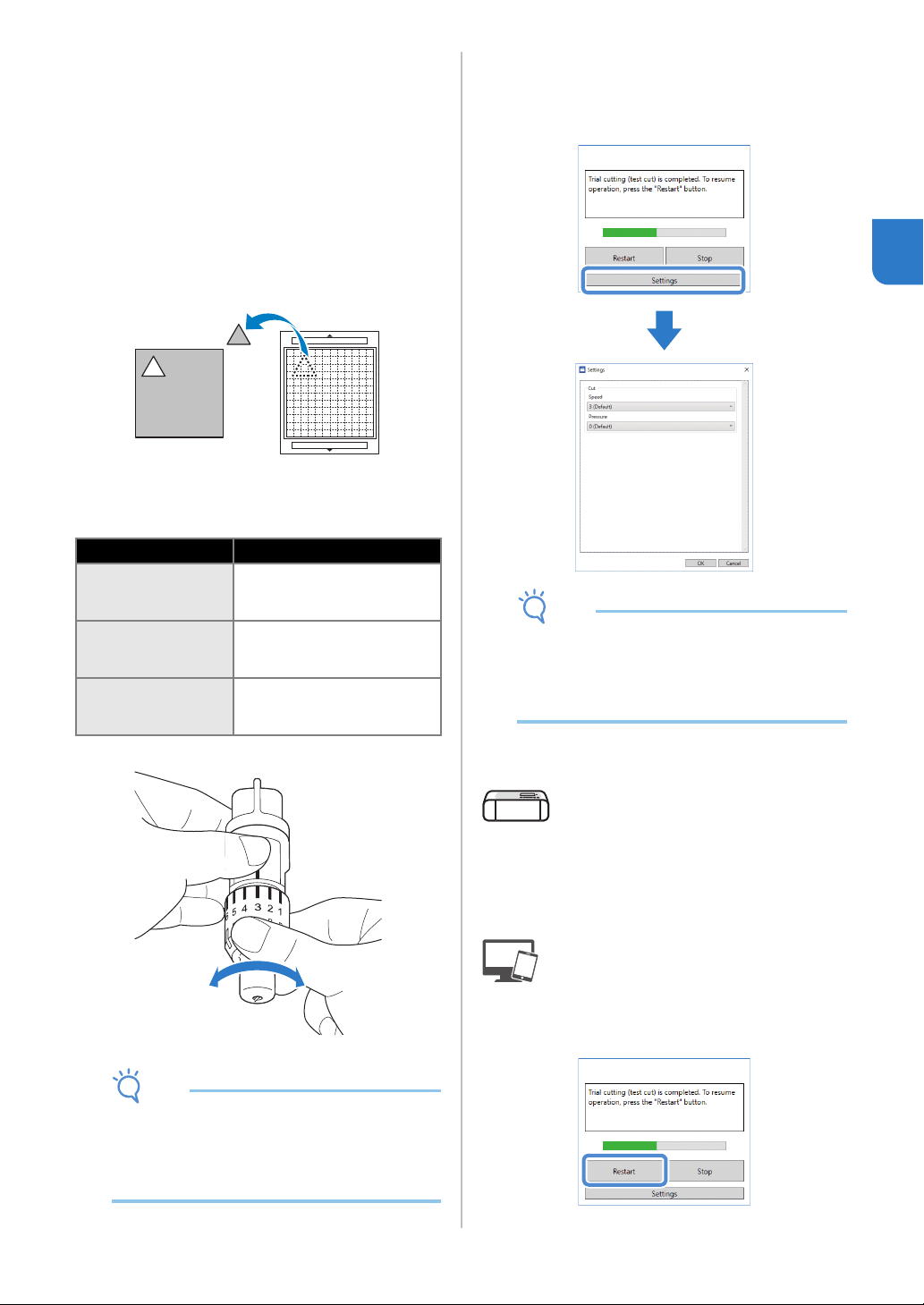
■ Checking the Trial Cutting Results
● Adjust the blade extension according to the trial
cutting results.
● Repeatedly perform trial cutting and adjust the
blade extension until the material is cut cleanly.
● Make sure that the location for the new trial
cutting shape does not overlap the location for the
previous trial cutting patterns.
With an Appropriate Blade Extension
When the material is peeled off, a faint trace of
the cut remains on the mat surface.
With a Blade Extension That Needs to be
Adjusted
Note
• Be careful that the blade does not extend too
much. Otherwise, the blade may break. If there
is too much of a blade extension, some material
may not be cut cleanly. In addition, the mat will
deteriorate quicker.
Adjusting the Cutting Speed/Pressure
Click [Settings] in the DesignNCut Manager
window that appears when cutting to display a
window where settings can be adjusted.
Note
• After adjusting the setting, it will begin cutting
the pattern when clicking [Restart]. To perform
the trial cutting again, click [Stop] and then
follow the procedure in “Trial Cutting” on
page 37.
■ Cutting the Pattern
a If there is no problem with the trial cutting,
load the mat with the material attached.
• For details, see “Loading the Mat” on page 35.
b Click [Restart] in the DesignNCut Manager
window.
Trial cutting results Tips for adjustment
Part of the cut
material remains
when it is peeled off.
Too Little of a Blade Extension:
Turn the holder cap half a
marking to the right. (
b
)
The material is not
clearly cut.
Too Little of a Blade Extension:
Turn the holder cap one marking
to the right. (
b
)
There are deep cuts
completely through
the mat.
Too Much of a Blade Extension:
Turn the holder cap one marking
to the left. (
a
)
a b

40
• To stop cutting, click [Stop]. If it is clicked again,
the blade and the mat will return to their original
positions.
• When cutting is finished, press to feed out the
mat.
41
3
Chapter 3
ADVANCED OPERATIONS
With a pen and pen holder, you can draw patterns
on material. Using the seam allowance settings also
allows you to draw patterns with seam allowances
on material and then cut them out. These drawing
functions can be used to create quilt pieces.
■ Preparation
Prepare the following accessories for drawing. An
additional purchase may be required depending on the
machine model.
- Pen holder
- Erasable pen set or color pen set
- Mat appropriate for the material that will be drawn
on.
- Blade and blade holder appropriate for the material
that will be cut.
- Iron-on fabric appliqué contact sheet or high tack
adhesive fabric support sheet appropriate for fabrics
that will be cut or drawn on.
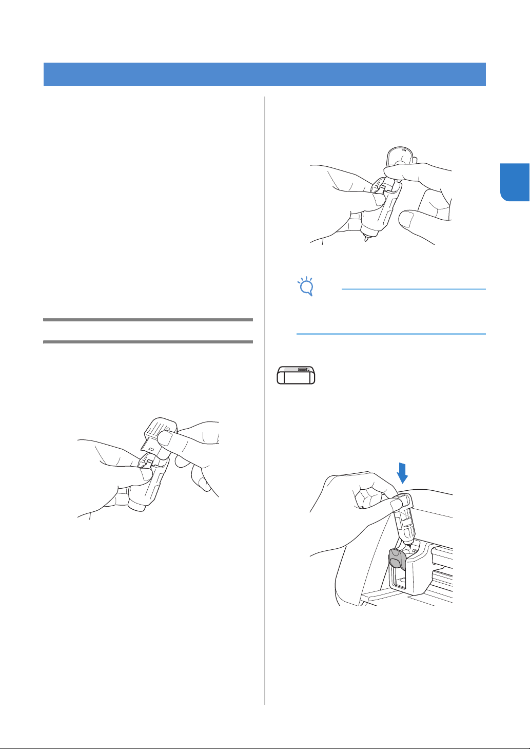
Drawing
■ Preparing the Pen Holder
a Press the button at the center of the pen holder
to unhook the lid and open it.
b Remove the cap from the pen, and then insert
the pen into the pen holder with the point
down.
c Close the lid of the pen holder.
Note
• After use, remove the pen from the pen holder,
and then attach the cap to the pen before
storing it.
■ Drawing
a Grasp the holder grip, and then install the pen
holder in the carriage with its lid opening
button facing against you.
• For details, see “Installing and Uninstalling the
Holder” on page 34.
DRAWING FUNCTIONS
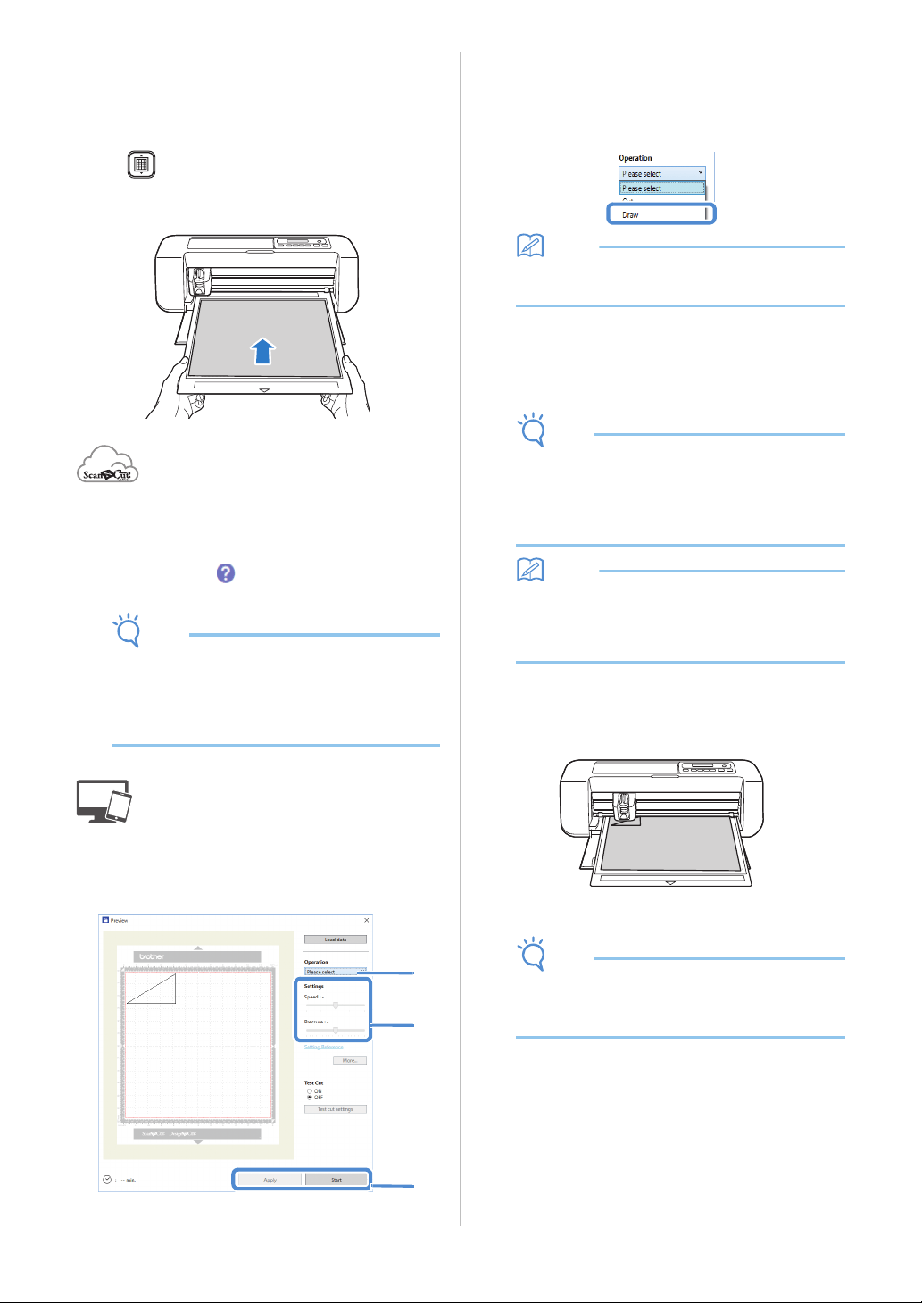
42
b Load the mat with the material for drawing
(cutting) attached.
• For details on attaching material to the mat, see
“Mat and Material Combinations” on page 24.
• Lightly insert the mat into the feed slot, and press
in the operation panel.
• For details on inserting the mat, see “Loading the
Mat” on page 35.
c In ScanNCutCanvas, create the pattern to be
drawn, and then send it to the machine.
• For details on editing, transferring or downloading
patterns, click in ScanNCutCanvas, and then
refer to the Help.
Note
• Make sure that the pattern to be drawn fits the
size of the material and fits within the drawing
area. If the pattern does not fit within the
drawing area, adjust the location of the pattern
and/or the pattern size in ScanNCutCanvas.
d Open the pattern in DesignNCut Manager.
• For details on opening pattern data, see “Sending
Patterns to the Machine” on page 36.
The pattern appears in the drawing/cutting
settings window of DesignNCut Manager.
e Select [Draw] from the [Operation] drop-down
list.
Memo
• With the mobile device version:
Preview windows→[Operation]→[Draw]
f With the sliders, specify settings for [Speed]
and [Pressure] for drawing.
Before drawing a pattern, specify the drawing speed
and pressure.
Note
• If the drawing pressure is too high, the pen tip
may be damaged. Adjust it to an appropriate
setting.
• We recommend setting the drawing pressure to
“0”.
Memo
• Adjustments to the drawing pressure will affect
the finished product. Use the same material
that the pattern will be drawn on to make the
adjustments.
g After clicking [Apply], click [Start] to begin
drawing.
• To perform trial drawing in order to adjust the
drawing pressure, repeat steps
e through g.
Note
• After use, remove the pen from the pen holder,
and then attach the cap to the pen before
storing it.
e
f
g
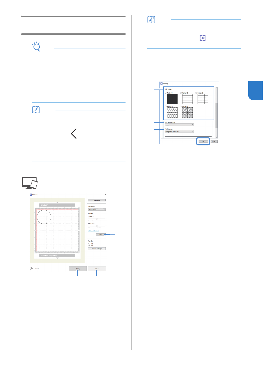
43
3
Using Drawing Functions to Fill
Patterns/Make Outlines Thicker
Note
• Depending on the material and pen being used,
material drawn with a filled pattern may be
difficult to peel off or may tear. Perform trial
drawing with the pattern to be used in your
project.
• To fill in the pattern, select the [Fill the area in
the outline with the drawing function] check box
in the [Properties] dialog box in
ScanNCutCanvas, and then send the pattern to
the machine.
Memo
• An open pattern cannot be filled.
Example:
• The fill settings will be applied to all patterns in
the pattern preview window.
• Fill and outline settings cannot both be
specified for the same pattern.
■ Filling Patterns
a See steps c through e in “Drawing” on
page 41 to specify the drawing settings.
b Click [Apply].
Various fill settings can be specified.
c Click the [More…] to display the fill settings
screen.
The settings can also be changed by clicking [Settings]
in the [DesignNCut] menu of the main window.
Memo
• With the mobile device version: Preview
Window →[Settings] → [FILL / ADDITIONAL
LINE] or Main window→
→[Settings] →
[Operation]
d After selecting a design under [Fill Pattern],
specify settings for [Fill Line Spacing] and [Fill
Direction], and then click [OK].
a Fill Pattern
Select the fill pattern.
b Fill Line Spacing
Adjust the spacing of the lines filling the pattern.
c Fill Direction
Adjust the direction of the fill pattern.
e Click [Start] to begin drawing.
c
b
e
a
b
c
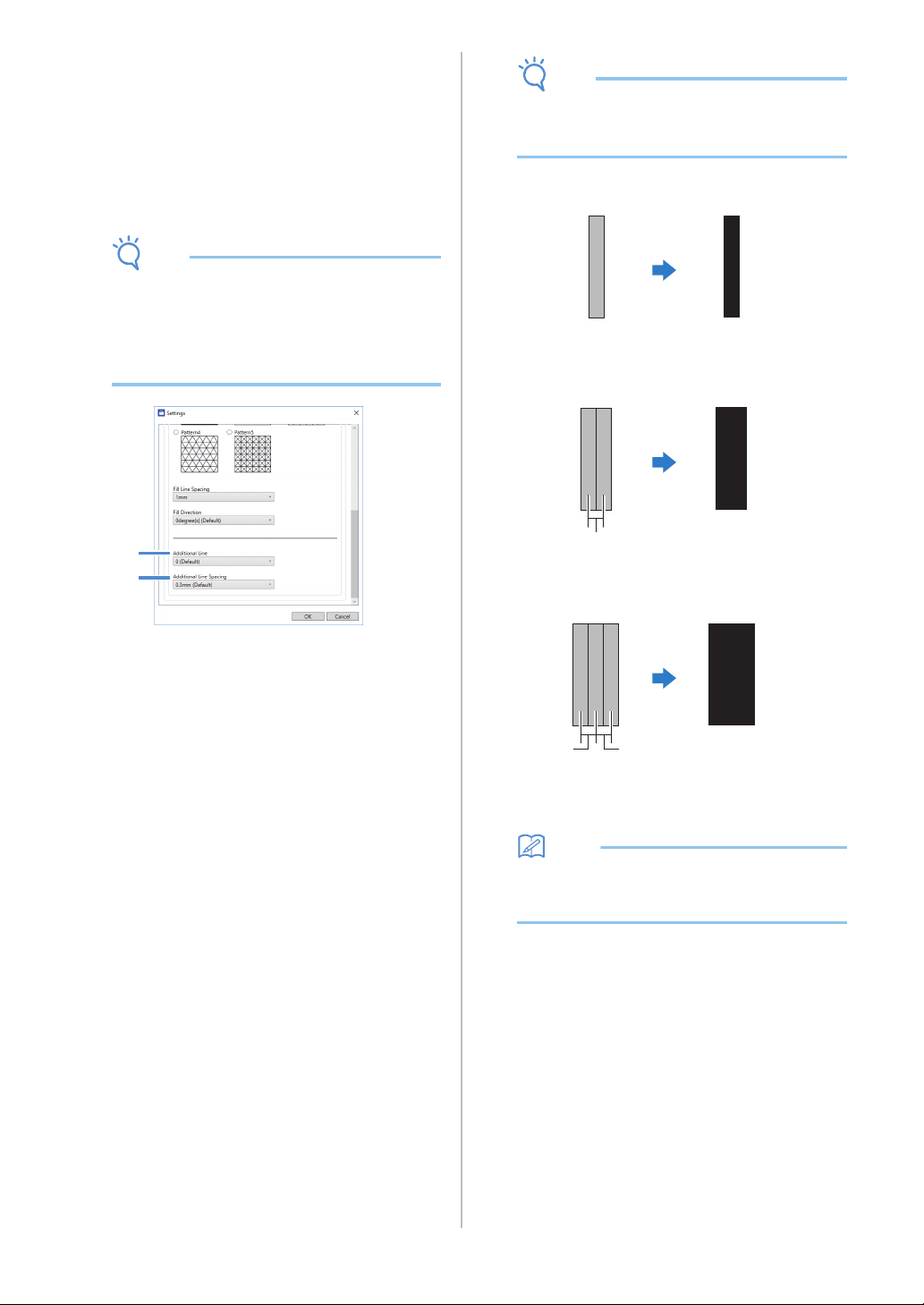
44
■ Making Pattern Outlines Thicker
Additional lines can be drawn to make pattern outlines
appear thicker.
a See steps b through c in “Filling Patterns” on
page 43 to specify the drawing settings.
b After specifying settings for [Additional Line]
and [Additional Line Spacing], click [OK].
Note
• The settings for “Additional Line” and
“Additional Line Spacing” will not be applied to
patterns with fill settings applied. For details on
the fill settings, see “Using Drawing Functions
to Fill Patterns/Make Outlines Thicker” on
page 43.
a Additional Line
Specify the number of lines to be added.
b Additional Line Spacing
Specify the spacing of the lines to be added.
Note
• Refer to the following examples when
specifying settings for “Additional Line” and
“Additional Line Spacing”.
a Additional Line 0: No lines added.
b Additional Line 1: One line added.
c Additional Line 2: Two lines added.
d Additional Line Spacing: Adjusts the line
spacing. Increasing the line spacing creates a
space between the lines.
Memo
• The drawing result differs depending on the
thickness of the pen that is used. Make
adjustments according to the pen thickness.
a
b
d
d
d
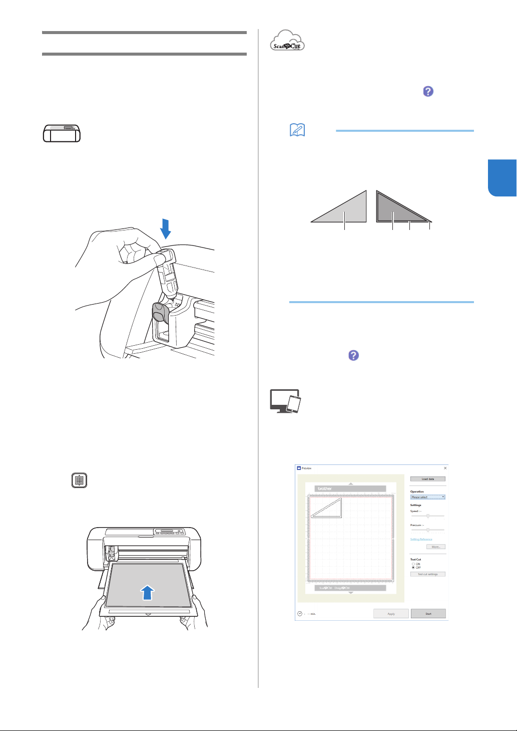
45
3
Cutting Around Drawings
In this example, we will specify a seam allowance
for a pattern and draw the pattern, then cut an
outline around it.
■ Specifying the Seam Allowance
a Grasp the holder grip, and then install the pen
holder in the carriage with its lid opening
button facing against you.
• For details, see “Installing and Uninstalling the
Holder” on page 34.
b Load the mat with the material for drawing
(cutting) attached.
When drawing the seam allowance on the wrong side
of the fabric, attach the material to the mat with its
wrong side facing up.
• For details on attaching material to the mat, see
“Mat and Material Combinations” on page 24.
• Lightly insert the mat into the feed slot, and press
in the operation panel.
• For details on inserting the mat, see “Loading the
Mat” on page 35.
c In ScanNCutCanvas, select the pattern to be
drawn, and then specify the seam allowance.
• For details on editing patterns, click in
ScanNCutCanvas, and then refer to “Creating
Offset Lines” in the Help.
Memo
• To draw the seam allowance on the wrong side
of the fabric, flip the pattern.
Image of Pattern Piece to be Created
a Right side of the fabric
b Wrong side of the fabric
c Drawing line (stitching line)
d Seam allowance line
d Send the pattern with the seam allowance
specified to the machine.
• For details on editing, transferring or downloading
patterns, click in ScanNCutCanvas, and then
refer to the Help.
e Open the pattern in DesignNCut Manager.
• For details on opening pattern data, see “Sending
Patterns to the Machine” on page 36.
The pattern appears in the drawing/cutting
settings window of DesignNCut Manager.
acb d
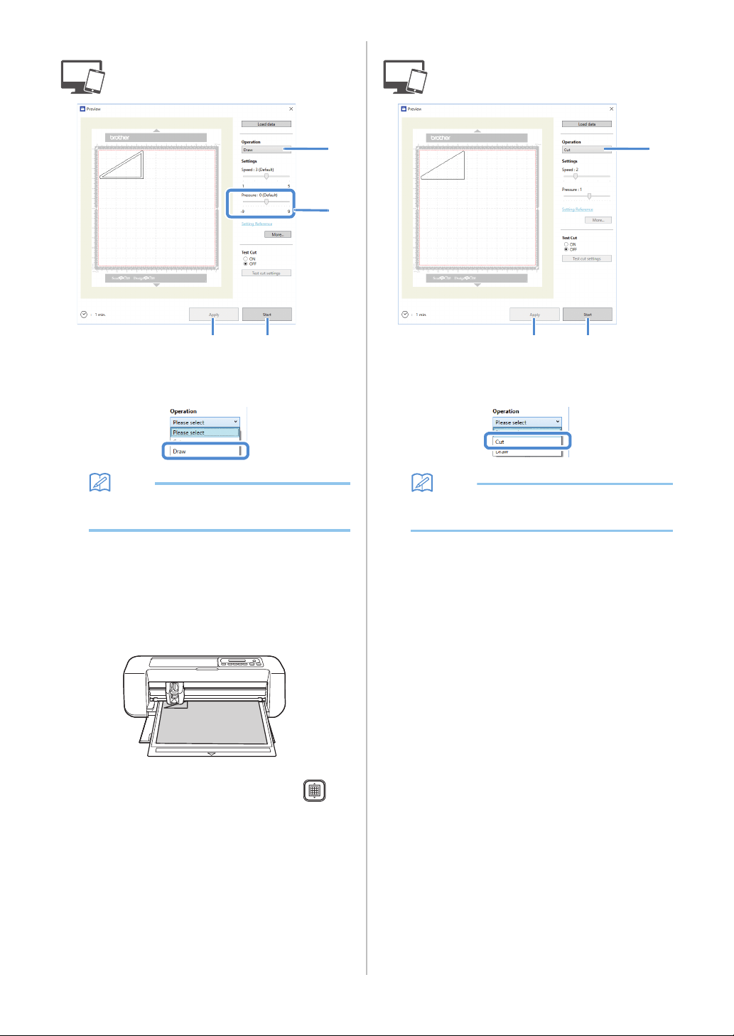
46
■ Drawing
a Select [Draw] from the [Operation] drop-down
list.
Memo
• With the mobile device version:
Preview window→[Operation]→[Draw]
b Adjust the drawing pressure.
For details on adjusting the drawing pressure, see step
f in “Drawing” on page 41.
c Click [Apply].
d Click [Start] to begin drawing.
• To cut around the drawn patterns, keep the mat
inserted into the slot without pressing ,
and continue with the following cutting
procedure.
■ Cutting
a Select [Cut] from the [Operation] drop-down
list.
Memo
• With the mobile device version:
Preview window→[Operation]→[Cut]
b Click [Apply].
A preview of the lines to be cut appears.
a
b
d
c
a
d
b
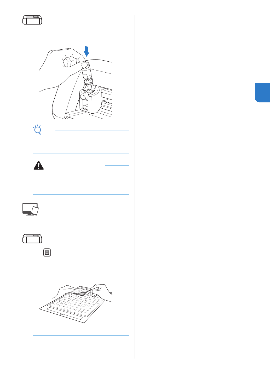
47
3
c Remove the pen holder, and then install the
blade holder.
Note
• After use, remove the pen from the pen holder,
and then attach the cap to the pen before
storing it.
CAUTION
• Before installing the blade holder in the
machine, remove the protective cap.
• Do not allow infants/children to put the
protective caps in their mouths.
d Click [Start] to begin cutting.
e Press in the operation panel to feed out the
mat.
f Peel the patterns off the mat.
• For details, see “Unloading the Mat” on page 38.
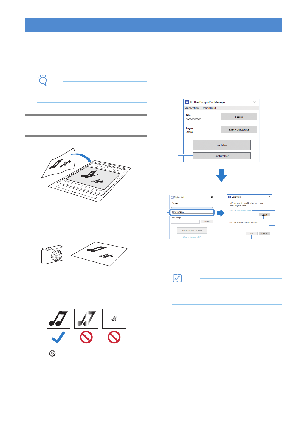
48
A printed image (paper or sticker), as stamped page
or an original hand-drawn illustration can be
captured and its outline can be cut out or drawn.
This is useful for capturing images for paper crafts,
then cutting them out.
Note
• Connect the machine and computer with
Wireless Mode to use this function.
Tutorial 2 - Cutting Photographed
Material
■ Preparation
a Prepare the material and a camera.
When using “CaptureMat” function, prepare the
following types of material.
• Patterns that are clearly drawn, with no gradation,
fading or blurriness
• Not using an extremely intricate design
b Press to turn on the machine.
• For details, see “Turning On/Off the Machine” on
page 6.
c Install the cutting blade holder into the carriage
of the machine.
• For details, see “Installing and Uninstalling the
Holder” on page 34.
■ Photographing Material and
Importing the Data
Registering the Calibration Data of the
Camera Used for Photographing
Data for adjusting the distortion, etc., of the
camera used for photographing must first be
registered with DesignNCut Manager.
a Click [CaptureMat].
A window appears, allowing you to register
photos and the camera to be used.
Memo
• With the mobile device version: Tap
[CaptureMat], and then go to step
c to
photograph the calibration sheet.
b Select [New Camera…] from the [Camera]
drop-down list.
The window for registering calibration data
appears.
CaptureMat FUNCTION
a
b
c
d
e
f
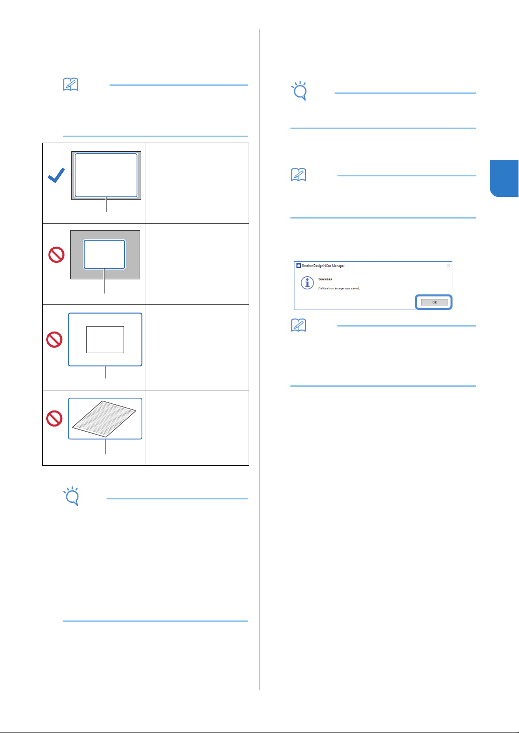
49
3
c Place the included calibration sheet on a flat
surface, and then photograph it from directly
above.
Save the photo to the computer.
Memo
• You can print the calibration sheet with your
printer by clicking [Print the calibration sheet.].
• With the mobile device version; tap [Calibration]
and photograph the calibration sheet.
*1 Photographed area
Note
• Take the photo in a well-lit location.
• Before taking the photo, wipe the camera lens
with a soft dry cloth, and make sure that the
lens is not dirty.
• When photographing, make sure that there are
no objects or shadows on the paper.
• If the calibration sheet is dirty or folded, print a
new copy of the calibration sheet and take a
photo of the new sheet.
• When photographing, do not zoom or use a
flash.
d Click [Select], and then select the image saved
in step
c.
The name of the imported image appears in the
box.
Note
• The only image files that can be used are JPG
files.
e Under [2.Please input your camera name.],
type in the name of the camera.
Memo
• Depending on your camera, its name may
automatically be entered when the image is
selected in step
d.
f Click [OK].
The following message appears.
Memo
• The next time “CaptureMat” function is used,
repeat steps
b through f to register new
camera (if the image that will be used was
photographed with a camera different from the
one that was registered).
■ Image correctly
photographed
Make sure to capture all of
the dots in the calibration
sheet and only capture the
dots in the calibration
sheets.
■ Camera too close to
paper
If the camera is too close
to the paper, calibration
will not be performed
correctly.
■ Camera too far from
paper
If the camera is too far
away from the paper,
calibration will not be
performed correctly.
■ Paper at an angle
If the camera and paper
are misaligned, calibration
will not be performed
correctly.
a
a
a
a
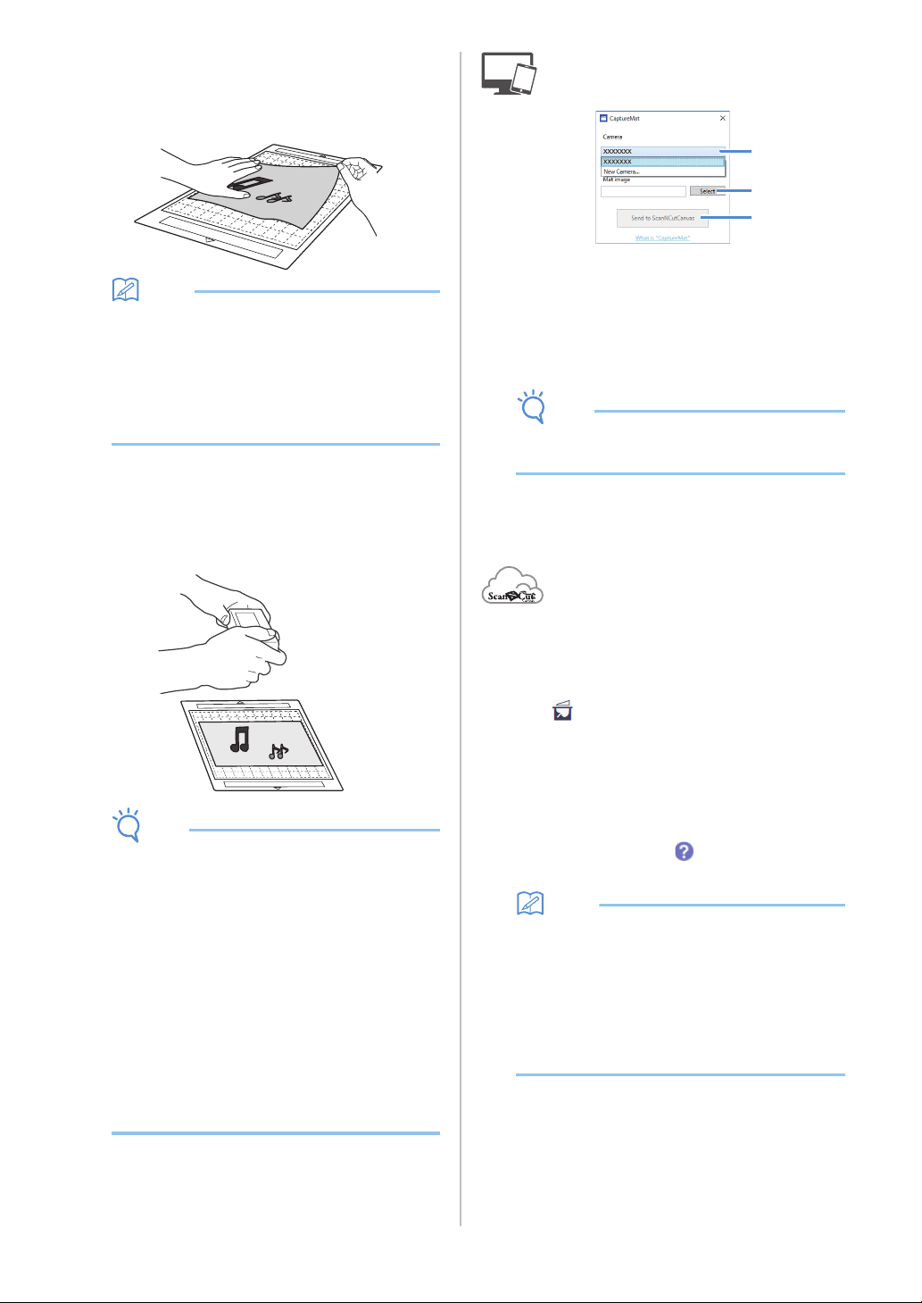
50
Importing an Image of Material
a Attach the material to be photographed to the
mat.
Memo
• The 12" × 24" (305 mm × 610 mm) mat cannot
be used.
• Before attaching the material to the mat, test
attaching an edge of the material to the
adhesive side of the mat.
• Try to attach the part to be cut toward the
middle of the mat.
b Place the material on a flat surface, and then
photograph it from directly above so that the
entire mat completely fills the camera screen.
Save the photo to the computer.
Note
• Before photographing, attach the material so it
does not cover any area outside of the adhesive
area of the mat.
• Hold the camera as level as possible when
taking the photo.
• When photographing, do not zoom or use a
flash.
• Take the photo so that the entire mat
completely fills the camera screen. If the entire
mat does not completely fill the camera screen,
cutting data cannot be created.
• Make sure that your mat fills the camera screen,
and that surrounding area is not on your screen.
• When photographing, make sure that there are
no other objects or shadows on the mat.
• When photographing a white solid object use a
dark background.
c Select the name of the registered camera from
the [Camera] drop-down list.
d Click [Select] beside [Mat Image].
When the dialog box for selecting the image appears,
select the photo, and then click [Open].
Note
• The only image files that can be used are JPG
files.
e Click [Send to ScanNCutCanvas].
The image is imported into ScanNCutCanvas.
■ Creating Cutting Data
Cutting data can be created using the Image Tracing
functions in ScanNCutCanvas.
a Click in the ScanNCutCanvas toolbar to
display the [Image Tracing] dialog box.
b Click [Select the image snapped by
CaptureMat], and then import an image sent
from DesignNCut Manager.
• For details on creating cutting data using the
tracing functions, click in ScanNCutCanvas,
and then refer to “Tracing Images” in the Help.
Memo
• For the criteria on replacing a worn mat when
the cutting position is greatly misaligned, see
“Replacing the Blade” on page 51.
• If the cutting position is misaligned, see
“Adjusting the Mark Sensors” on page 55, and
change the machine settings.
• Cut with the machine on a level desk, and do
not allow the mat to hit any objects.
c After creating the cutting data, click
[Download], then [DesignNCut Transfer] to
send the cutting data to the machine.
c
d
e
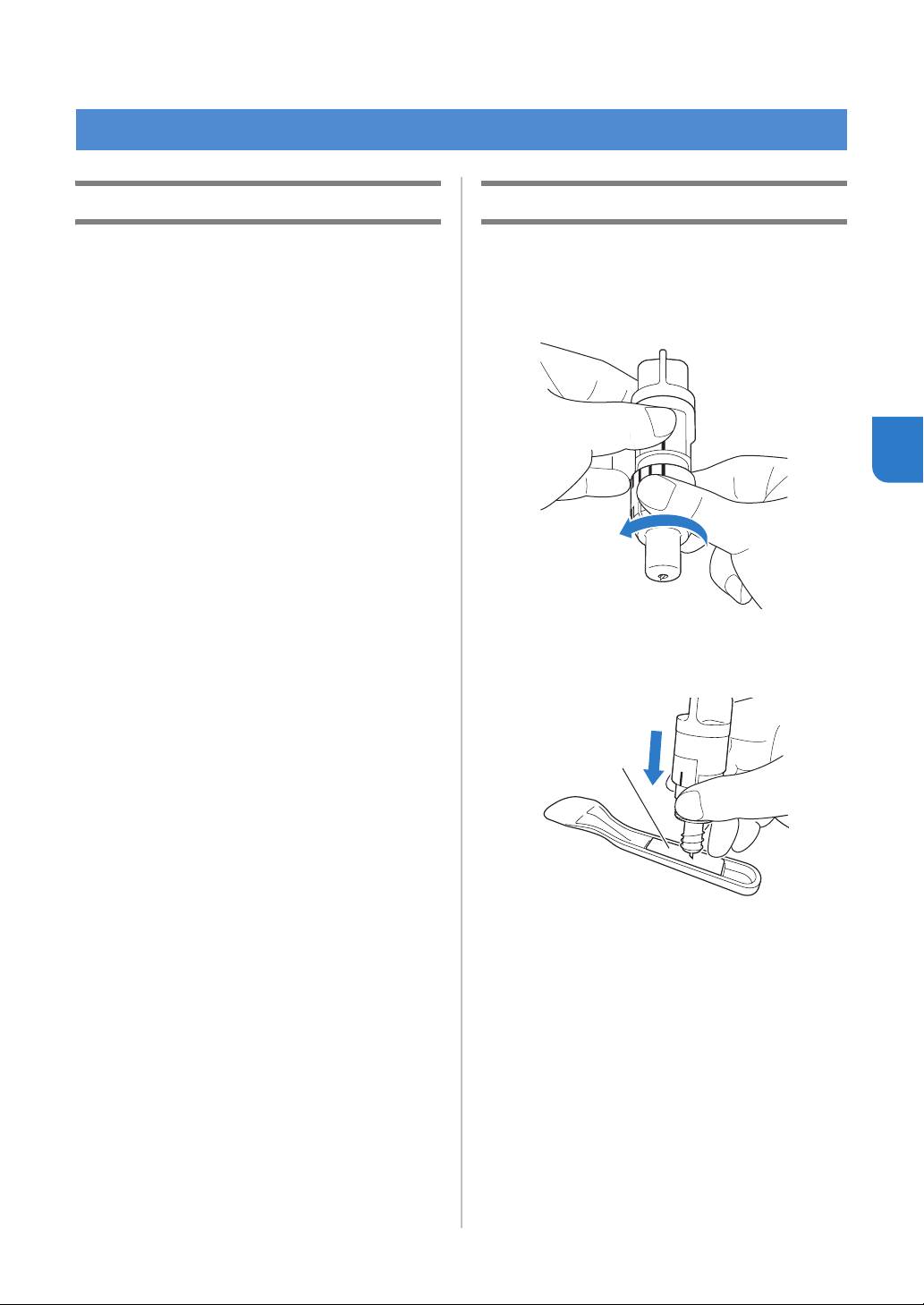
51
4
Chapter 4
APPENDIX
Replacement Criteria
For the safe operation of this machine, replace the
following consumables according to the replacement
criteria. To purchase parts, contact the retailer who
sold you this machine or the nearest authorized
service center. For details on the optional
accessories, see “OPTIONAL ACCESSORIES” on
page 67.
Mat
• When the mat’s adhesive strength decreases
• When there are many cutting traces in the mat
Cutting blade
• When the cuts in the material become rough,
reducing the quality of the finished product
• When the cutting edge becomes blunt
• When the blade is chipped (If it cannot cut even
though the blade extension or cutting pressure is
set higher than necessary, the blade may be
chipped.)
High tack adhesive fabric support sheet
• When the sheet’s adhesive strength decreases
• When fabric attached becomes twisted while being
cut
Erasable pen
• When the ink is dry and not marking the fabric
properly
• When the ink is used completely
Color pen
• When the ink is dry and not marking the paper or
material properly
• When the ink is used completely
Replacing the Blade
■ Removing
a Twist off the holder cap to remove it.
b Stick the blade straight into the rubber area on
the back of the included spatula.
a Rubber area
CONSUMABLES
a
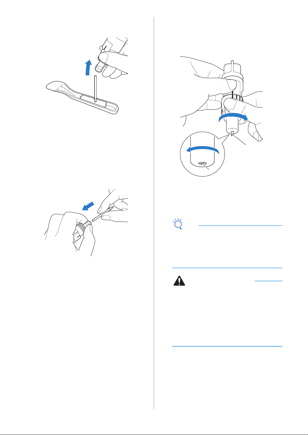
52
c Pull up the holder to leave the blade in the
rubber area.
■ Installing
a Grasp the shaft of the new blade, and then
insert it into the blade slot at the end of the
holder.
The blade shaft is held in place by a magnet in the
holder. Slowly insert the blade shaft, and then slowly
release it after the shaft snaps into place against the
magnet.
b Twist on the holder cap to attach it to the
holder.
Fully tighten the cap until the blade extension reaches
its maximum, and then loosen the cap until the blade
is no longer visible.
a Tighten the cap until the blade extension
reaches its maximum.
b Loosen the cap until the blade becomes
invisible from the cap end.
Note
• Loosen the holder cap until the blade tip is no
longer visible. The blade extension scale on the
holder applies when the blade begins to be
extended from the cap end. For details on the
blade extension, see “Adjusting the Blade
Extension” on page 32.
CAUTION
• After removing the blade holder from the
machine, be sure to retract the blade into the
holder and attach the protective cap.
• Do not leave the blade extended. Otherwise,
injuries may result.
• Please remove the protective cap from blade
holder before placing it into the machine
carriage.
• Do not allow infants/children to put the
protective caps in their mouths.
b
a
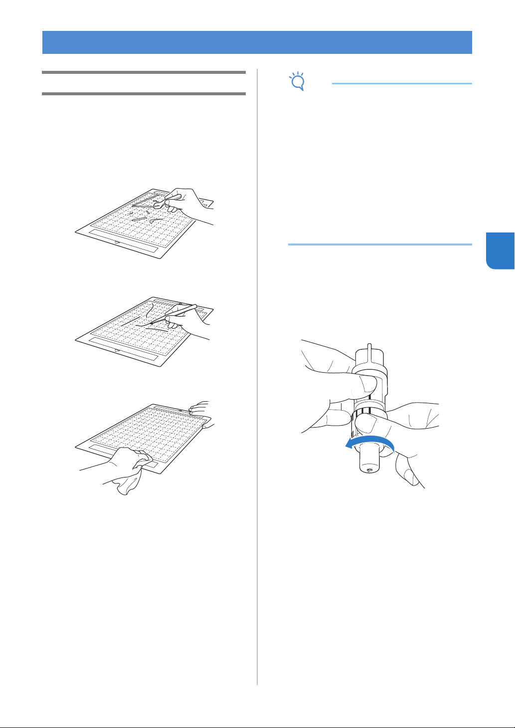
53
4
Cleaning
■ Cleaning the Mat
Cuttings and cut edges of patterns attached to the mat
may reduce the mat’s adhesive strength and prevent
correct operation. Periodically clean the mat. Using the
included spatula, lightly scrape off any cuttings attached
to the mat.
Use commercially available tweezers to remove any
fabric threads attached to the mat.
Clean the dotted marks on the mat and there
surrounding area with a dry cloth.
Note
• Do not use alcohol or water to clean the mat.
• When the mat is not being used, clean it, and
then store it with the protective sheet affixed. If
the protective sheet is not affixed, the mat’s
adhesive strength will decrease. At that time,
do not affix the protective sheet while the mat is
damp. Otherwise, the mat’s adhesive strength
will decrease.
• Do not fold or bend the mat to store it.
• Store the mat at room temperature and in a
location not exposed to high temperatures, high
humidity or direct sunlight.
• If the mat no longer has any adhesive strength,
replace it with a new one. For details on
optional mats, see “OPTIONAL
ACCESSORIES” on page 67.
■ Cleaning the Holder
If material cuttings, lint or dust accumulate in the
holder, it may not operate correctly. Clean the holder
after every use.
a Twist off the holder cap to remove it.
CARE AND MAINTENANCE
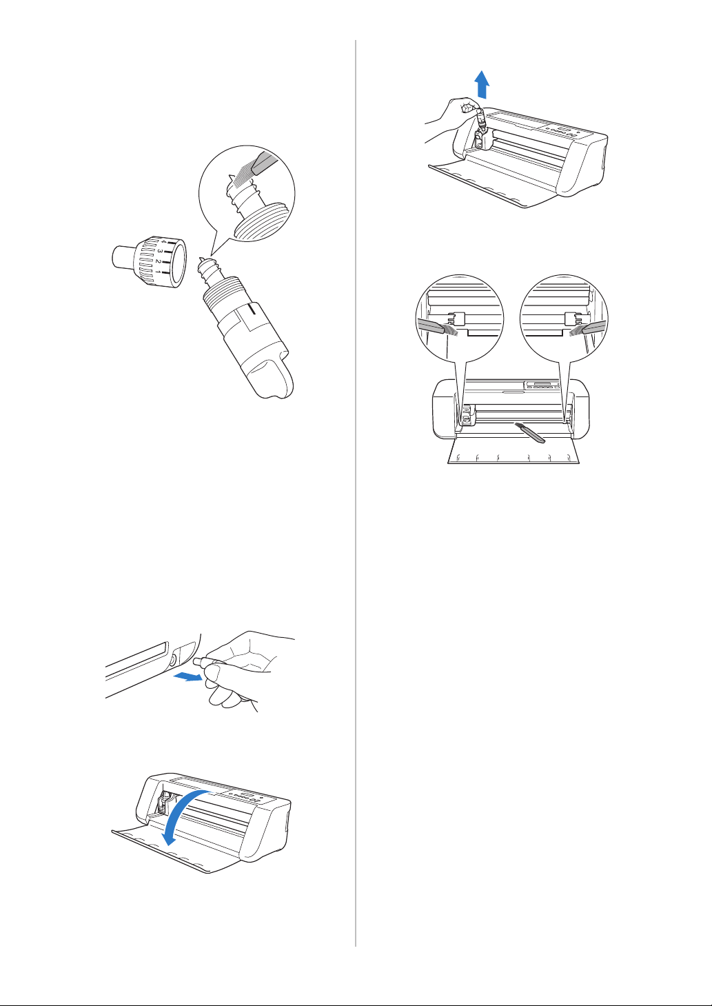
54
b Using a commercially available brush, clean off
cuttings, lint, and dust.
Specifically clean off lint and dust around the blade. If
lint and dust accumulate between the blade and
holder, the blade may no longer rotate or the cutting
quality may become poor.
c Attach the holder cap to the holder.
For details on attaching the holder cap, see “Installing”
on page 52.
■ Cleaning Inside the Machine
The Lint may also attach to the surface of the feed
rollers, preventing a mat to be loaded or unloaded
correctly. Use a soft brush to clean it.
a Turn off the machine and disconnect the power
cord plug, and then disconnect the AC adapter
plug from the DC power jack on the back of the
machine.
b Open the cover on the front of the machine.
c Remove the holder from the carriage.
d Use a commercially available brush to clean
around the feed slot and the carriage.
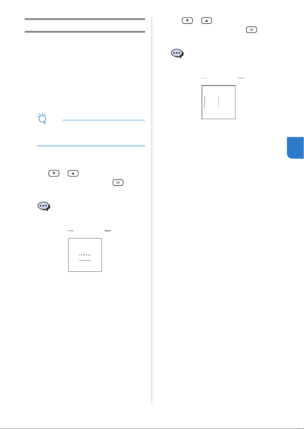
55
4
Adjusting the Mark Sensors
If the cutting position is misaligned when cutting
using the “CaptureMat” function, the machine can
be manually adjusted.
● If the cutting position is shifted upward or
downward from the actual pattern:
Refer to step
b.
● If the cutting position is shifted right or left from
the actual pattern:
Refer to step
c.
Note
• Check the shift of the cutting position with the
mat in the same orientation as when it was fed
out.
a From the machine’s settings screen, select
[3.Basic Setup], then [3.Mark Sensor].
b Press or to select the vertical
adjustment value, and then press .
The following message appears.
Example: If the vertical adjustment value was changed
from 0 to 2
(Before change After change )
• If the cutting position is shifted upward, increase
the value. If the cutting position is shifted
downward, decrease the value.
c Press or to select the horizontal
adjustment value, and then press .
The following message appears.
Example: If the horizontal adjustment value was
changed from 0 to -5
(Before change After change )
• If the cutting position is shifted to the left, increase
the value. If the cutting position is shifted to the
right, decrease the value.
Vertical 0
Horizontal 0
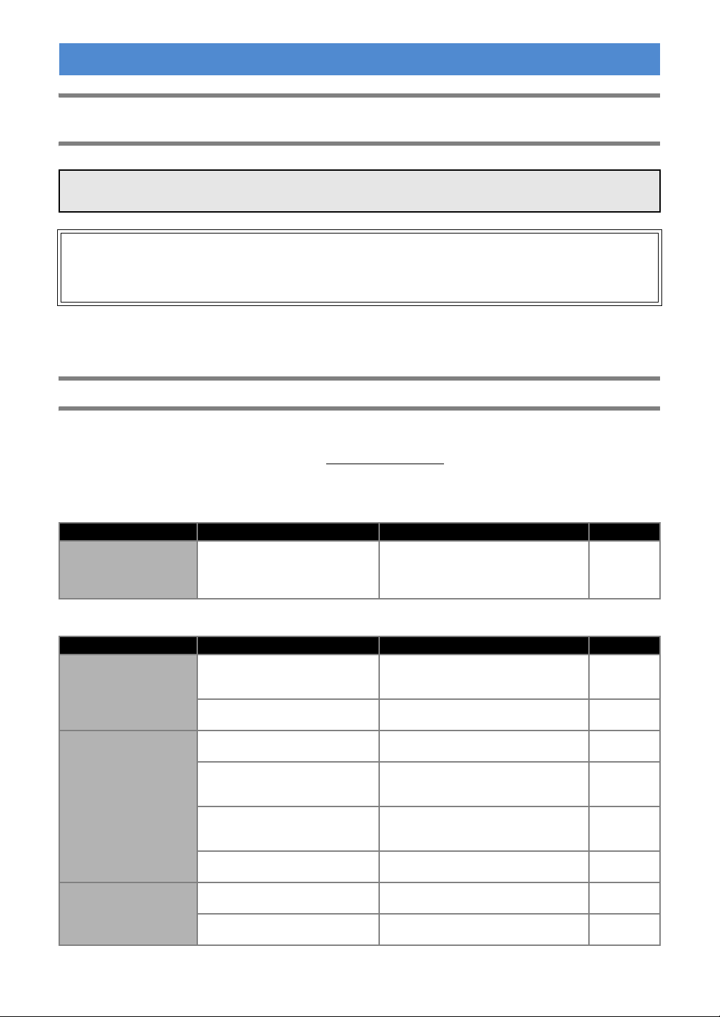
56
Finding the Wireless LAN Security Information (Network Name (SSID) and Network
Password (Key))
* The Network Password may also be described as the Network Key, Security Key or Encryption Key.
* If the wireless access point/router is not broadcasting the SSID, the SSID will not automatically be detected. You
will have to manually enter the SSID name.
If the Machine Stops Operating Correctly
If the machine stops operating correctly, check the following possible problems before requesting service.
You can solve most problems by yourself. If you need additional help, the Brother Solutions Center offers the
latest FAQs and troubleshooting tips. Visit us at “ http://s.brother/cpqaa/
”.
If the problem persists, contact the retailer who sold you this machine or the nearest authorized service center.
Power Supply
Mat
TROUBLESHOOTING
Please do not contact Brother Customer Service for assistance without the wireless security information. We
cannot assist you in locating your network security settings.
1) You should see the documentation provided with your wireless access point/router.
2) The default SSID could be the manufacturer’s name or the model name.
3) If you do not know the security information, please consult the router manufacturer, your system
administrator, or internet provider.
Symptom Possible Causes (or Results) Solutions Reference
The machine cannot be
turned on.
The AC adapter is not correctly
connected to the machine.
Check that the AC adapter is connected
to the machine and that the power cord
is connected to the AC adapter and
electrical outlet.
page 6
Symptom Possible Causes (or Results) Solutions Reference
The mat cannot be
inserted.
When the mat was inserted, it was
not placed under the feed rollers.
Insert the mat so that it is placed under
the feed rollers on the left and right sides
of the feed slot.
page 35
The mat was not loaded using the
“Feed” button.
Lightly insert the mat into the feed slot,
and then press the “Feed” button.
page 35
The mat cannot be
recognized.
The dotted marks on the part of the
mat that is inserted are dirty.
Clean the dotted marks on the mat and
their surrounding area.
page 53
The dotted marks on the part of the
mat that is inserted are hidden by
material that was attached.
Attach the material while keeping it
within the adhesive area of the mat.
page 26
The mat was inserted so that the
side with the material attached is
facing down.
Insert the mat so that the side with the
material attached is facing up.
page 35
A mat designed specifically for
DesignNCut is not being used.
Replace the mat with one designed
specifically for DesignNCut.
—
The mat is fed in at an
angle.
The mat was inserted into the feed
slot at an angle.
Press the “Feed” button to feed out the
mat, and then re-insert it straight in.
page 35
page 38
The corners of the mat are
deformed (bent).
Replace the mat with a new one. page 51
57
4
Paper/Fabric Jam
Cutting
The material to be cut/
drawn cannot be
attached to the mat.
The material extends from the
adhesive area of the mat.
Attach the material while keeping it
within the adhesive area of the mat.
page 26
The mat’s adhesive strength has
decreased.
Replace the mat with a new one. page 51
The mat cannot be fed
out.
The material to be cut/drawn is
jammed in the feeding mechanism
in the machine.
Press the “Feed” button while the mat is
being inserted to feed it out.
If the mat does not feed out, turn off the
machine, and then carefully pull out the mat.
page 38
When the mat is
inserted, the attached
material peels off.
The mat is not level due to the
weight of the material.
With your hands, hold the mat level when
inserting it.
page 35
The mat’s adhesive strength has
decreased.
Replace the mat with a new one. page 51
Symptom Possible Causes (or Results) Solutions Reference
The mat cannot be fed.
There is an obstruction around the
slot at the back of the machine.
Maintain space around the slot at the
back of the machine so that the mat can
be fed out.
page 4
The surface where the machine is
installed is uneven.
Place the machine on a flat, even
surface.
—
The mat or the material
catches on a feed roller
when the mat is being
inserted.
The mat’s adhesive strength has
decreased, or the material is not
secured.
Press the “Feed” button to feed out the
mat, and then replace the mat with a new
one.
page 38
page 51
The material extends from the
adhesive area of the mat.
Press the “Feed” button to feed out the
mat, and then attach the material while
keeping it within the adhesive area of the
mat.
page 26
page 38
The mat or the material
catches on a feed roller
during cutting/drawing.
- The mat’s adhesive strength has
decreased, or the material is not
secured.
- The material extends from the
adhesive area of the mat.
Press the “Pause/Stop” button to stop
the operation. Follow the instructions on
the screen, and press the “Feed” button
to feed out the mat.
If the mat does not feed out, turn off the
machine, remove the holder, and then
manually feed out the mat.
After feeding out the mat, replace it with
a new one or attach the material while
keeping it within the adhesive area of the
mat.
page 26
page 38
page 51
The mat is fed in at an
angle and is not fed
during cutting/drawing.
The material to be cut/
drawn peels off during
cutting/drawing.
Symptom Possible Causes (or Results) Solutions Reference
The material being cut
catches on the tip of the
cutting blade.
Dust or lint has accumulated in the
holder.
Clean the holder. page 53
The blade is worn. Replace the blade with a new one. page 51
The material being cut is
incompatible with this machine.
Replace the material with one
compatible with this machine.
page 24
The machine stopped
while an operation is
being performed.
For safety, the machine stops
operating if a button in the
operation panel is pressed while
cutting or drawing.
Check that either of the following
messages appear, and then press
to return the carriage to its original
position. Insert the mat, and then try
performing the operation again.
-When cutting
Cutting paused. Resume: [OK] Stop:
[STOP]
-When drawing
Drawing paused. Resume: [OK] Stop:
[STOP]
—
Symptom Possible Causes (or Results) Solutions Reference
58
Drawing
Not all of the material to
be cut is cut. Some
areas remain uncut.
A blade appropriate for the material
being cut is not used.
Use a blade appropriate for the material
being cut.
page 32
The blade extension from the blade
holder is too little.
Remove the holder from the carriage,
and then adjust the blade extension.
page 33
If cutting is not possible even
though the blade extension or
cutting pressure is set higher than
necessary, the blade may be
chipped.
Replace the blade with a new one.
page 51
The mat’s adhesive strength has
decreased, or the material is not
secured.
Replace the mat with a new one.
page 51
The blade is worn. Replace the blade with a new one.
page 51
The material is incompatible with
this machine.
Replace the material with one
compatible with this machine.
page 24
The cutting pressure is incorrect.
Adjust the setting for cut pressure in the
settings screen.
page 32
page 37
Dust or lint has accumulated in the
holder.
Clean the holder. page 53
The spacing between arranged
patterns is too small.
Rearrange the patterns to slightly
separate them.
—
Neither a high tack adhesive fabric
support sheet or iron-on fabric
appliqué contact sheet is used for
fabric cutting.
Attach a high tack adhesive fabric
support sheet to a mat or affix an iron-on
fabric appliqué contact sheet to a fabric
before cutting it.
page 27
page 29
A fabric is not firmly attached to a
mat that has a high tack adhesive
fabric support sheet on its
adhesive side.
Firmly attach the fabric to the mat
pressing the handle of the included
spatula across the surface of the fabric.
page 31
An iron-on fabric appliqué contact
sheet is not firmly attached to a
fabric.
Iron the entire contact sheet to affix it
firmly to the wrong side of the fabric.
page 28
There are deep cuts
completely through the
mat.
The blade extension from the blade
holder is too much.
Remove the holder from the carriage,
and then adjust the blade extension.
page 33
The cutting pressure is incorrect. Adjust the setting for cut pressure.
page 32
page 37
Symptom Possible Causes (or Results) Solutions Reference
The drawn line is thicker
(thinner) than intended.
The drawing speed or drawing
pressure is incorrect.
Adjust the settings of DesignNCut
Manager for draw speed and draw
pressure.
To draw thicker lines, increase the
drawing pressure. To draw thinner lines,
decrease the drawing pressure.
To draw thicker lines, reduce the drawing
speed. To draw thinner lines, increase
the drawing speed.
After adjusting the settings, perform a
trial drawing operation.
page 42
Symptom Possible Causes (or Results) Solutions Reference
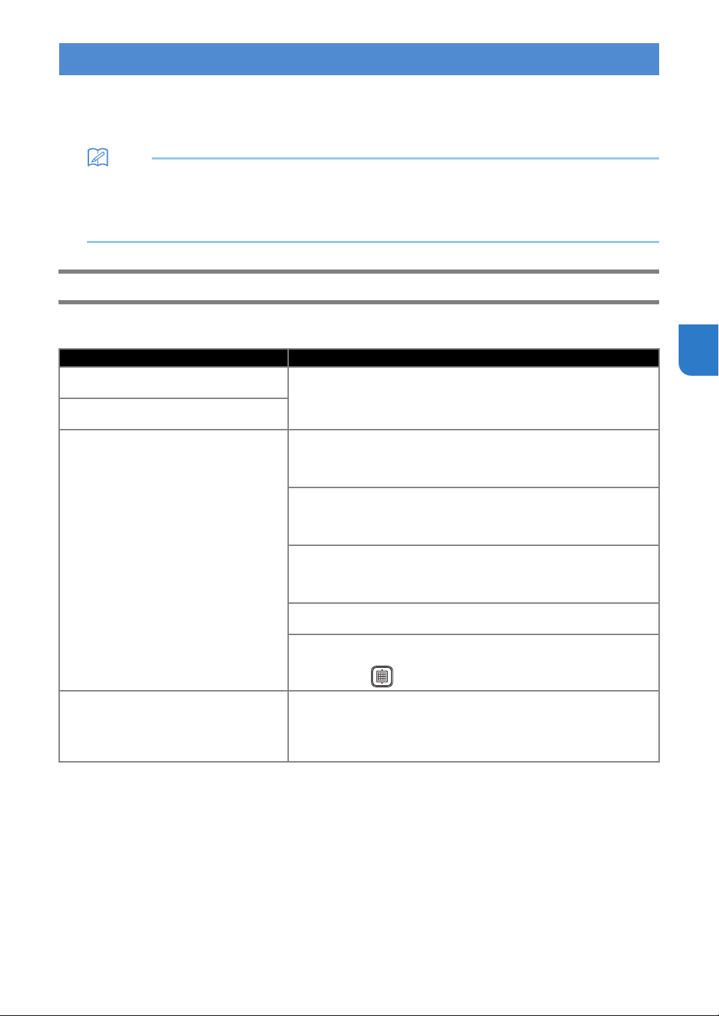
59
4
The following table lists some of the messages that may appear while the machine is operating as well as their
corresponding solutions.
Perform the necessary operation according to the instructions in the message or the solution described here.
If the problem persists, contact the retailer who sold you this machine or the nearest authorized service center.
Memo
• If an error occurred, either an error message or an error code will appear on the machine in the following cases.
- Error message: An error occurred while only the machine is being operated (Example: Pressing the “Feed”
button to insert the mat failed, establishing a wireless network connection failed, etc.)
- Error code: An error occurred while DesignNCut Manager was being used, (Example: Retrieving cutting data
failed, beginning to cut/draw failed, etc.)
Cutting Machine Error
When Operating the Machine
ERROR MESSAGES
Error Messages (Cutting Machine) Causes / Solutions
Blade initialization error. Turn off the
machine.
Turn the machine off, then on again.
Head initialization error. Turn off the
machine.
Mat recognition error. Press [OK] button.
Possible Causes1: The dotted marks on the part of the mat that is
inserted are dirty.
Solutions1:Clean the dotted marks on the mat and their surrounding
area. If the mat is still not recognized, replace the mat with a new one.
Possible Causes2: The dotted marks on the part of the mat that is
inserted are hidden by material that was attached.
Solutions2: Attach the material while keeping it within the adhesive area
of the mat.
Possible Causes3: The mat was inserted so that the side with the
material attached is facing down.
Solutions3: Insert the mat so that the side with the material attached is
facing up.
Possible Causes4: A mat that cannot be recognized has been inserted.
Solutions4: Use the specially designed mat for this machine.
Possible Causes5: A mat was not inserted straight into the machine.
Solutions5: While holding the mat level and lightly inserting it into the
feed slot, press in the operation panel.
Failed to unload mat. Turn off the machine.
The material to be cut/drawn is jammed in the feeding mechanism in the
machine.
Press the “Feed” button while the mat is being inserted to feed it out.
If the mat does not feed out, turn off the machine, and then carefully pull
out the mat.
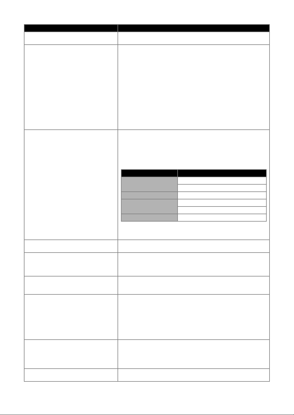
60
When Setting Up the Wireless Network
Error Messages (Cutting Machine) Cause/Solution
Connection failed (Err-01). Press [OK] button.
The wireless network setting is not activated.
Activate the wireless network.
Connection failed (Err-02). Press [OK] button.
The wireless access point/router cannot be detected.
1. Check the following 4 points.
- Make sure that the wireless access point/ router is powered on.
- Move your machine to an area with no items which obstruct the wireless
network signal, such as metal doors or walls, or closer to the wireless
access point/router.
- Temporarily place your machine within about 1 m (3.3 feet) from the
wireless access point when you are configuring the wireless settings.
- If your wireless access point/router is using MAC address filtering,
confirm the MAC address of this machine is allowed in the filter.
2. If you manually entered the SSID and security information (SSID/
authentication method/encryption method/Network Password (Key)),
the information may be incorrect. Reconfirm the SSID and security
information and re-enter the correct information as necessary.
Connection failed (Err-03). Press [OK] button.
The Authentication/Encryption methods used by the selected wireless
access point/router are not supported by your machine.
For infrastructure mode, change the authentication and encryption
methods of the wireless access point/router.
Your machine supports the following authentication methods:
If your problem is not solved, the SSID or network settings you entered
may be incorrect. Reconfirm the wireless network settings.
Network Password (Key) error (Err-04). Press
[OK] button.
The security information (SSID/Network Password (Key)) is incorrect.
Reconfirm the SSID and security information (Network Password (Key)).
Connection failed (Err-05). Press [OK] button.
The wireless security information (Authentication method/Encryption
method/Network Password (Key)) is incorrect.
Reconfirm the wireless security information (Authentication method/
Encryption method/Network Password (Key)) in the table of Err-03.
Connection failed (Err-20). Press [OK] button.
This machine is still trying to establish a connection with the wireless
network.
Wait a while, and then check the wireless LAN connection status.
Connection failed (Err-06). Press [OK] button.
This machine cannot detect a wireless LAN access point/router with WPS
enabled.
Operations must be performed on both this machine and the wireless
LAN access point/router in order to use WPS to set up the wireless
connection.
For details on using WPS with your wireless LAN access point/router,
refer to its manual, or contact its manufacturer or your network
administrator.
Connection failed (Err-07). Press [OK] button.
Two or more wireless LAN access points/routers with WPS enabled have
been detected.
Make sure that there is only one wireless LAN access point/router with
WPS enabled within the signal range, and then try performing setup
again.
Connection failed. Press [OK] button.
Turn off your wireless LAN router, and then turn it on again.
Then, try again to set up the wireless connection.
Authentication method Encryption method
WPA-Personal
TKIP
AES
WPA2-Personal AES
Open
WEP
None (without encryption)
Shared key WEP
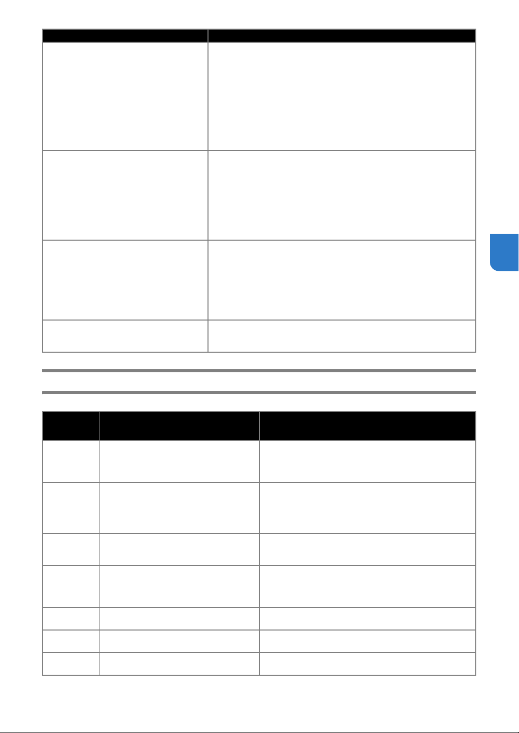
61
4
DesignNCut Manager Error
Cannot find SSID. Press [OK] button.
As shown below, the cause and solution differ depending on when this
message appeared.
- Appeared after running [2.Setup Wizard] to search for an SSID
Possible Cause: Failed to detect an SSID
Solution: Check the information described for 1. of (Err-02).
- Appeared when [Saved SSID] is selected in the window listing the
detected SSIDs
Possible Cause: There is no SSID previously connected to the wireless
network.
Solution: Select an SSID that appeared in the window, and then set up a
wireless connection.
PC connection error. Press [OK] button.
Failed to connect to the computer when setting up the wireless
connection using the dedicated application “WLAN Assistant Wizard”
(WAW).
Check the following, and then try performing the operation again.
- Start up WAW on the computer, and then follow the on-screen
instructions to complete the procedure.
- Check that a wireless network connection has been established between
the computer running WAW and the access point/router.
WLAN connection failed. Press [OK] button.
Failed to set up the wireless connection using the dedicated application
“WLAN Assistant Wizard” (WAW <USB>).
Check the following, and then try performing the operation again.
- Start up WAW <USB> on the computer, and then follow the on-screen
instructions to complete the procedure.
- Check that the machine and computer are connected with a USB cable.
- Check the possible causes and solutions for (Err-01) to (Err-05) and for
(Err-20).
Network error. Turn the machine off, then on
again.
An internal malfunction occurred.
Contact the retailer where you purchased this machine or the nearest
authorized service center.
Error Code
(Cutting
Machine)
Error Messages (DesignNCut Manager) Causes / Solutions
E002
DesignNCut is unavailable while it is
connecting to another DesignNCut
Manager. To cancel the connection, restart
DesignNCut.
Turn off the machine, turn it on again, and then make the
connection again.
E003
Cannot connect to machine.
Select an appropriate connection mode for
the settings on DesignNCut.
Select the same connection method as that selected on the
machine.
For details on selecting the same connection method as
that on the machine, see “CONNECTING THE MACHINE
AND COMPUTER” on page 12.
E004
The version of machine and DesignNCut
Manager doesn’t match.
Confirm the versions and update.
DesignNCut Manager and the machine’s software must be
updated. (P. 66)
E204 No pattern in the effective area.
There is no pattern(s) to be cut out or drawn within the
cutting area.
Edit the pattern in ScanNCutCanvas to position it within the
cutting/drawing area.
E207 Attach an appropriate holder.
A holder incompatible with the mode has been installed.
Install a compatible holder. (P. 34)
E217
Data cannot be read on DesignNCut.
The file size is too big.
The data file is too large. Simplify the pattern in
ScanNCutCanvas to reduce the data to 1 MB or less.
E218
Cannot continue as the data has too many
objects.
There are too many patterns. Reduce the number of
patterns in ScanNCutCanvas to 300 or less.
Error Messages (Cutting Machine) Cause/Solution

62
E221
This data is too intricate to be converted to
a filling pattern.
Try the following.
- Ungroup the pattern.
- Change the fill settings.
- Reduce the number of fill patterns.
Complex patterns cannot be filled. Simplify the pattern in
ScanNCutCanvas.
E225
This pattern cannot be used on your
DesignNCut.
Select a different pattern.
E227
Cannot recognize the mark of a mat.
Clean the mat.
Possible Cause 1: The part of the mat that is inserted is
dirty.
Solution 1: Clean the part of the mat that is inserted and
its surrounding area.
Possible Cause 2: Material or masking tape has been
attached outside of the adhesive area of the mat,
preventing it from being recognized.
Solution 2: Attach the material while keeping it within the
adhesive area of the mat.
E304
DesignNCut could not read the data.
Register the login ID for ScanNCutCanvas
again.
- This message appears when you try to send data to a
cutting machine not registered with ScanNCutCanvas.
- Registration of your machine has been deleted from
ScanNCutCanvas. Register the machine again.
E306
DesignNCut is not connected to a network.
Confirm wireless LAN settings on
DesignNCut.
When the SSID and security information (SSID/
authentication method/encryption method/network
password (key)) was manually entered, incorrect
information may have been entered.
Check the SSID and security information again, and then
enter the correct information if necessary.
E307
DesignNCut is not connected to a network.
Confirm network connection status.
The machine is not connected to the network.
- Check the network connection status.
- A network connection may not yet be established. Wait a
while, and then try again.
E308 A network error occurred on DesignNCut.
A network error occurred during communication.
Check the following.
- Check that your wireless access point/router is turned on.
- Check that the network cable of your wireless access
point/router is plugged in.
E309
Connection from DesignNCut to a server
failed.
Confirm proxy settings.
The proxy settings are incorrect.
Check the proxy settings of your wireless network and your
machine.
E313 Failed to connect to the server.
A network error occurred during communication.
- Check the DNS server settings.
- Wait a while, and then try connecting again.
E500 Failed to connect to DesignNCut.
- Make sure that the wireless LAN access point/router has
been turned on.
- Move the machine or computer installed with DesignNCut
Manager so that no objects block the signals between
them, or move them closer to the wireless LAN access
point/router.
- If the wireless LAN access point/router is filtering, check
the settings.
E501
Communication error.
Confirm proxy and other settings.
The proxy settings are incorrect.
Check the proxy settings of your wireless network and
DesignNCut Manager.
E502 Failed to connect to DesignNCut.
- Make sure that the machine has been turned on.
- Check that the wireless LAN connection indicator is lit.
- Check the status of the network connection. A connection
may not be possible because of the communication
environment such as a poor signal or network congestion
from crosstalk.
Error Code
(Cutting
Machine)
Error Messages (DesignNCut Manager) Causes / Solutions

63
4
E507 Not connected to a network.
Check the following.
- Check that your wireless access point/router is turned on.
- Check that the network cable of your wireless access
point/router is plugged in.
E508 Wireless LAN connection failed.
The wireless connection was incorrectly set up.
Check the settings for the SSID and security information
(SSID/authentication method/encryption method/network
password (key)).
E510
DesignNCut machine is not connected to
your device.
If the Wireless LAN connect light is turned
on (green) on your machine, please click
"Retry".
If the Wireless LAN connect light is off,
please click "Connect".
Firstly, check the wireless LAN connection indicator on
your machine.
• When the wireless LAN connection indicator is off:
Wait a while until it is turned on (green).
If it is still off after waiting for a while, click [Connect] to
make the connection.
Make sure that the machine and PC connection must be on
the same network.
• When the wireless LAN connection indicator is on (green):
Click [Retry] on the screen to search your machine again.
If this error message is repeatedly displayed, the machine
and PC may be on different networks.
Check the SSID of the machine and PC respectively as
follows.
- To check the machine's SSID:
From the machine's settings screen, select [1.Network],
[5.Others], and then select [3.SSID].
The machine's SSID is displayed.
- To check the computer's SSID:
Mouse over the wireless LAN signal icon on the desktop.
If the SSIDs are different, click [Connect] on the screen to
make the connection again.
Make sure that the machine and PC connection must be on
the same network.
The software version of your access point/router may be
outdated.
Please check your router’s manufacturer’s website for the
latest software version, and update your router.
After completing the update, try to set up the wireless
connection.
E512 Failed to connect to server.
Check the following.
- Check that the settings for the SSID and security
information (SSID/authentication method/encryption
method/network password (key)) have been correctly
specified.
- Check the status of the network connection.
- A network connection has not yet been established. Wait a
while, and then try connecting again.
E513
Failed to connect to server.
Confirm proxy settings.
The proxy settings are incorrect.
Check the proxy settings of your wireless network and your
machine.
E514
An error occurred while connecting to
ScanNCutCanvas. Please check your
network settings or network condition.
Make sure you are connected to the
Internet.
A network error occurred during communication.
Check the following.
- Check that your wireless access point/router is turned on.
- Check that the network cable of your wireless access
point/router is plugged in.
E518
Connecting to ScanNCutCanvas failed.
Register the login ID for ScanNCutCanvas
again.
This message appears when you try to transfer data with a
machine different than the one registered with
ScanNCutCanvas. Register the machine again.
Error Code
(Cutting
Machine)
Error Messages (DesignNCut Manager) Causes / Solutions

64
E519
Connecting to ScanNCutCanvas failed.
Register the login ID for ScanNCutCanvas
again.
Registration of your machine has been deleted from
ScanNCutCanvas. Register the machine again.
E527
Cannot connect to machine.
Select an appropriate connecting mode for
the settings on DesignNCut.
Select the same connection method as that selected on the
machine.
For details on selecting the same connection method as
that on the machine, see “CONNECTING THE MACHINE
AND COMPUTER” on page 12.
E529 Communication error.
Check the following.
- The machine must be turned on.
- The USB cable must be correctly plugged in.
E535
Cannot read the data.
The data may be corrupted.
The selected photo cannot be used.
Select an image photographed under the specified
conditions.
E538
Loading the image file has been failed.
This file cannot be used.
The file may be corrupted.
Select a different image file.
E540 Failed to load the captured image. Make sure enough space is available on the device.
E543
Failed to register calibration data. The
calibration sheet was photographed too
close. Without zooming in capture the
calibration sheet again. The camera frame
should be filled with calibration sheet dots.
The calibration data cannot be registered.
The calibration sheet was photographed too close.
Select an image photographed under the specified
conditions.
E544
Failed to register calibration data. The
calibration sheet was photographed too
far. Capture the calibration sheet again.
The camera frame should be filled with
calibration sheet dots.
The calibration data cannot be registered.
The calibration sheet was photographed too far.
Select an image photographed under the specified
conditions.
E548
Failed to load the captured image. The
entire mat was not photographed. Please
click on "Watch Video" for solution
reference, then, without zooming in capture
the entire mat with the image and make
sure the entire mat is within the camera
frame.
The entire mat was not photographed.
Take the photo without zooming and so the entire mat
completely fills the camera screen.
E549
Failed to load the captured image. The
photo is too small. Please click on "Watch
Video" for solution reference, then, without
zooming in capture the entire mat with the
image and make sure the entire mat is
within the camera frame.
The photo is too small.
Take the photo without zooming and so the entire mat
completely fills the camera screen.
E550
Failed to load the captured image. Please
click on "Watch Video" for guidelines, then,
capture the image again according to
guidelines.
Possible Cause 1: There is a reflection on the mat
scanning marks (dots) in the part of the mat that is inserted,
causing the marks not to appear in the photo.
Solution 1: Take the photo so there is no reflection.
Possible Cause 2: An object outside of the mat appears in
the photo.
Solution 2: Take the photo so no objects appear outside of
the mat.
Possible Cause 3: The dotted marks on the part of the mat
that is inserted are dirty.
Solution 3: Clean the mat scanning marks (dots) and their
surrounding areas. If the mat is still not recognized, replace
it with a new one.
E551
Failed to load the captured image. The
angle of the image is incorrect. Please click
on "Watch Video" for guidelines, then,
capture the image again according to
guidelines.
The mat is at an angle.
Hold the camera level when taking the photo.
Error Code
(Cutting
Machine)
Error Messages (DesignNCut Manager) Causes / Solutions

65
4
E552 Failed to load the captured image.
The selected photo cannot be used.
Select an image photographed under the specified
conditions.
E553 Failed to save the captured image.
The camera may be set so that photographed images are
not saved. Check the camera’s settings.
If the camera settings are correct, delete some
unnecessary files since there may be no space available.
E560
DesignNCut machine is not connected to
your device.
Click on "Connect" to connect your
DesignNCut machine.
The network connection has not been completed yet.
Click [Connect] on the screen to make the connection.
E561
DesignNCut machine is not connected to
your device.
Please check if DesignNCut and your
computer is connected with USB cable. If
you connect by Wireless LAN, please click
"Change the connection method" and
change connection method.
- Check that the machine and computer are connected with
a USB cable.
- Check that the machine is in USB mode.
For details, see “Direct PC Connection Using USB Cable
(Windows Only)” on page 18.
E562
DesignNCut machine is not connected to
your device. Retry the connection and refer
to the Connection Guide for instructions.
You tried to connect the machine to your device without
the necessary procedures.
Make the connection again referring to the Connection
Guide or “CONNECTING THE MACHINE AND
COMPUTER” on page 12.
Error Code
(Cutting
Machine)
Error Messages (DesignNCut Manager) Causes / Solutions
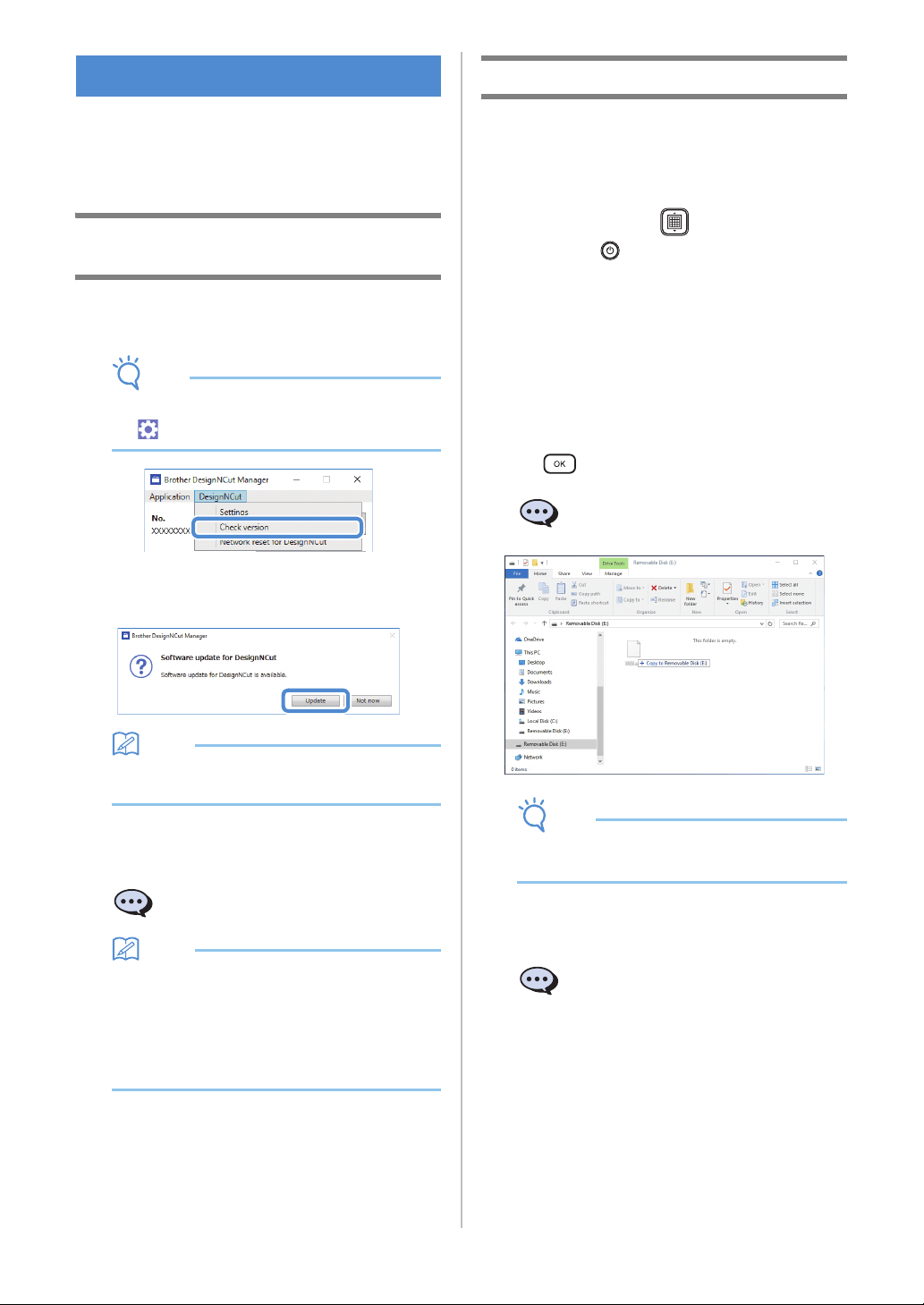
66
The machine’s software can be updated using either
an Internet connection or a USB cable. For update
information, refer to details posted on the Brother
Solutions Center (http://s.brother/cpqaa/).
Update Procedure Using DesignNCut
Manager
a Click [DesignNCut] in the main window, and
then click [Check version].
Note
• With the mobile device version:
→ [Check version]
b When the following message appears, click
[Update] to retrieve the software.
Memo
• Do not turn off the machine while it is being
updated.
c When the following message appears on the
machine, turn the machine off, then on again.
Memo
• If the update confirmation window appears
when DesignNCut Manager is started up,
update DesignNCut Manager and the machine
according to the instructions that appear. If
either is not updated to their most recent
version, it will not be possible for DesignNCut
Manager and the machine to communicate.
Update Procedure Using Computer
If an upgrade file is posted on the Brother Solutions
Center (http://s.brother/cpqaa/), download the file,
and then update the machine according to the
following procedure.
a While holding down in the operation
panel, press to turn on the machine.
b Plug the USB cable connectors into the
corresponding USB ports on the computer and
the machine.
Open the [This PC] folder on the computer, and
then select [Removable Disk].
c Copy the upgrade file to [Removable Disk], and
then start it.
When the following message appears, press
.
Note
• Do not turn off the machine while it is being
updated.
d When the following message appears on the
machine, turn the machine off, then on again.
UPDATING THE SOFTWARE
The update is finished. Turn
the machine off, then on again.
Prepare firmware upgrade, then
press [OK] button.
The update is finished. Turn
the machine off, then on again.
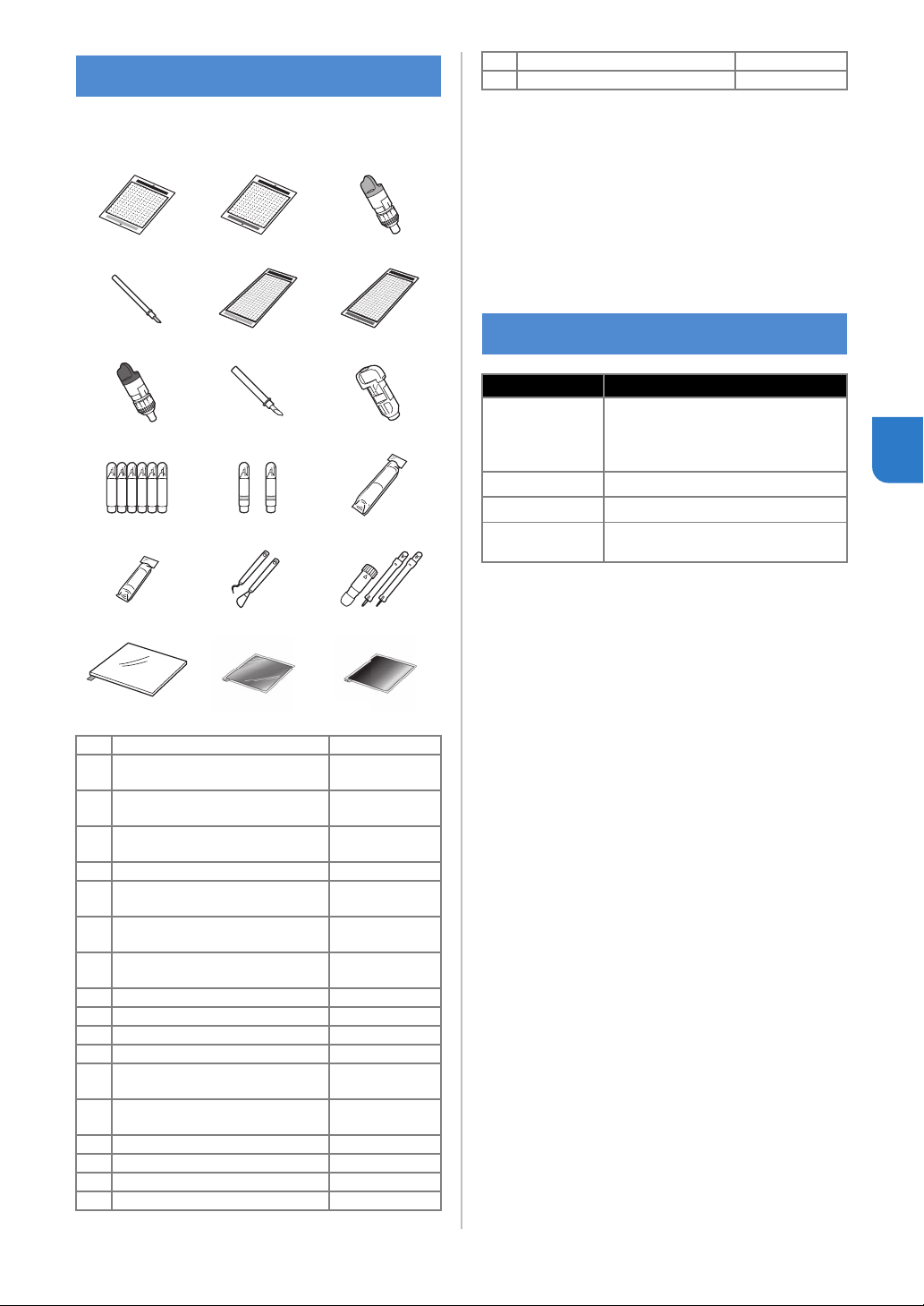
67
4
The following are available as optional accessories
to be purchased separately.
* Contact the retailer who sold you this machine or
the nearest authorized service center.
* Use a mat designed specifically for this machine
which has a “DesignNCut” logo. The machine will
not operate correctly if any other mat is used.
* This product is only compatible with line
embossing.
* For the complete list and newest information on
optional accessories, refer to the Brother Solutions
Center (http://s.brother/cpqaa/).
OPTIONAL ACCESSORIES
1. 2. 3.
4. 5. 6.
7. 8. 9.
10. 11. 12.
13. 14. 15.
16. 17. 18.
No. Part Name Part Code
1
Low tack adhesive mat 12" × 12"
(305 mm × 305 mm)
CAMATLOW12
2
Standard mat 12" × 12"
(305 mm × 305 mm)
CAMATSTD12
3
Standard cut blade holder
(turquoise) (with no blade)
CAHLP1
4 Standard cut blade CABLDP1
5
Low tack adhesive mat 12" × 24"
(305 mm × 610 mm)
CAMATLOW24
6
Standard mat 12" × 24"
(305 mm × 610 mm)
CAMATSTD24
7
Deep cut blade holder (purple)
(with no blade)
CAHLF1
8 Deep cut blade CABLDF1
9 Pen holder CAPENHL1
10 Color pen set CAPEN1
11 Erasable pen set CAPEN2
12
Iron-on fabric appliqué contact
sheet (white backing)
CASTBL1
13
High tack adhesive fabric
support sheet
CASTBL2
14 Spatula and Hook Set CASPHK1
15 Embossing Tool Set CAEBSTLS1
16 Embossing Mat CAEBSMAT1
17 Embossing Silver Metal Sheets CAEBSSMS1
18 Embossing Brass Metal Sheets CAEBSBMS1
PRODUCT SPECIFICATIONS
Items Specifications
Dimensions
Approx. 497 mm (W) × 178 mm (D) ×
146 mm (H)
(Approx. 19.5 inches (W) × 7.0 inches
(D) × 5.7 inches (H))
Weight Approx. 3.3 kg (Approx. 7.3 lb)
Power Supply AC100V 50/60Hz (AC adapter)
Maximum power
consumption
30 W (When cutting)
No. Part Name Part Code

68
A
Adjusting the cut position (CaptureMat) ......................55
Auto shut down
.............................................................9
B
Basic pattern cutting ...................................................35
Blade extension
....................................................32, 39
C
CaptureMat ..................................................................48
Carriage
..................................................................4, 34
Cleaning
.......................................................................53
Cut pressure
................................................................32
Cutting around drawings
.............................................45
Cutting blade replacement
..........................................51
D
DC power jack ........................................................4, 54
Deep cut blade
............................................................32
DesignNCut Manager
....................................................3
Operations
.............................................................7
Settings
................................................................10
Drawing functions
........................................................41
E
Error messages ............................................................59
F
Feed slot .................................................................4, 35
Fill pattern
....................................................................43
H
High tack adhesive fabric support sheet ..............25, 29
Holder lock lever
.....................................................4, 34
Holder setting
..............................................................34
I
Iron-on fabric appliqué contact sheet ..................25, 27
L
Load Data ...............................................................7, 36
Low tack adhesive mat
................................................25
M
Main power on/off .........................................................6
Main power switch
.............................................5, 6, 35
Main window
..................................................................7
Mat and material combinations
...................................24
Mat loading
..................................................................35
Mat unloading
..............................................................38
O
Operation panel .............................................................5
Optional accessories
...................................................67
P
Parts and functions ........................................................4
Pressure (Cutting/Drawing)
............................11, 32, 37
Preview window
.............................................................8
R
Replacement criteria ....................................................51
Required material condition (capturing)
......................48
S
ScanNCutCanvas ..........................................................3
Registering/Changing/Deleting
............................22
Seam allowance
..........................................................45
Settings
DesignNCut Manager
..........................................10
Machine
.................................................................9
Software update
..........................................................66
Speed (Cutting/Drawing)
......................................11, 37
Standard cut blade
......................................................32
Standard mat
...............................................................25
Standard scale settings
...............................................32
T
Test Cutting .................................................................37
Troubleshooting
...........................................................56
U
USB cable connection ..........................................12, 18
USB port
......................................................................66
W
Wireless LAN
Manual connection
..............................................13
Resetting
.............................................................20
WAW (USB cable) connection
.............................17
WAW connection
.................................................16
WPS connection
..................................................15
Wireless network
....................................................3, 12
INDEX

English
891-Z08
Version A
Please visit us at http://s.brother/cpqaa/ where you can get
product support and answers to frequently asked questions (FAQs).
This machine is approved for use in the country of purchase only. Local Brother
companies or their dealers will only support machines purchased in their own countries.