Loading ...
Loading ...
Loading ...
12 INSTALLATION
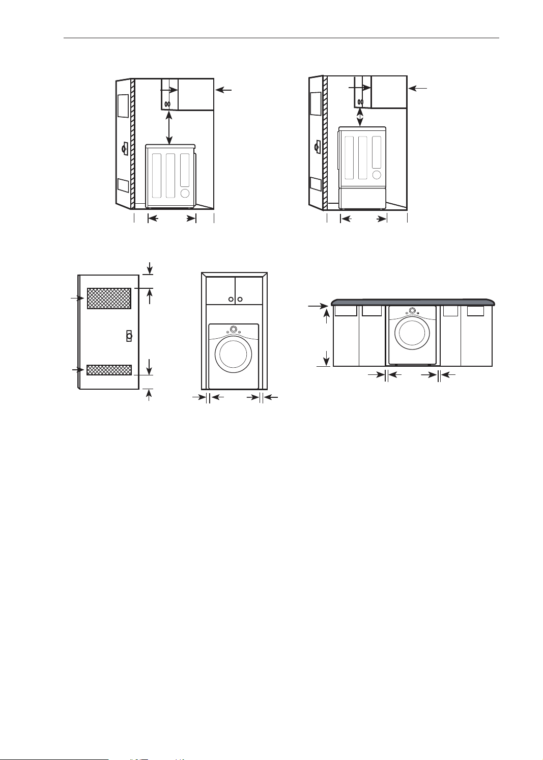
Clearances
1"*
(25 mm)
14" max.*
(356 mm)
18" min.*
(457 mm)
14" max.*
(356 mm)
18" min.*
(457 mm)
30"
(761mm)
5"**
(127 mm)
1"*
(25 mm)
30"
(761mm)
5"**
(127 mm)
24 in.
2*
(155 cm
2
)
2*
(310 cm
2
)
3"
*
(76 mm)
48 in.
3"
*
(76 mm)
1"
(25 mm)
1"
(25 mm)
27"
(686 mm)
0"
(0 mm)
39"
(991 mm)
1"
(25 mm)
1"
(25 mm)
27"
(686 mm)
Closet Door
Vent Requirements
Installation Spacing for Recessed Area or Closet Installation
The following clearances are recommended for this dryer. This dryer has been tested for clearances of 1 inch
(2.5 cm) on the sides and rear. Recommended clearances should be considered for the following reasons:
• Additional clearances should be considered for ease of installation and servicing.
• Additional clearances should be considered on all sides of the dryer to reduce noise transfer. For closet
installation, with a door, minimum ventilation openings in the top and bottom of the door are required. Louvered
doors with equivalent ventilation openings are acceptable.
Closet Ventilation Requirements
Closets with doors must have both an upper and lower vent to prevent heat and moisture buildup in the closet.
One upper vent opening with a minimum opening of 48 sq. in. (310 cm
2
) must be installed no lower than 6 feet
above the oor. One lower vent opening with a minimum opening of 24 sq. in. (155 cm
2
) must be installed no
more than one foot above the oor. Install vent grills in the door or cut down the door at the top and bottom to
form openings. Louvered doors with equivalent ventilation openings are also acceptable.
NOTE
• There should be at least a little space around the dryer (or any other appliance) to eliminate the transfer of
vibration from one appliance to another. If there is enough vibration, it could cause appliances to make noise or
come into contact, causing paint damage and further increasing noise.
Loading ...
Loading ...
Loading ...