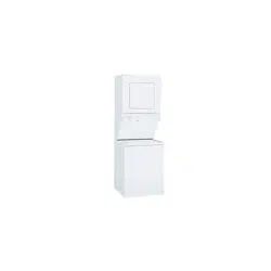
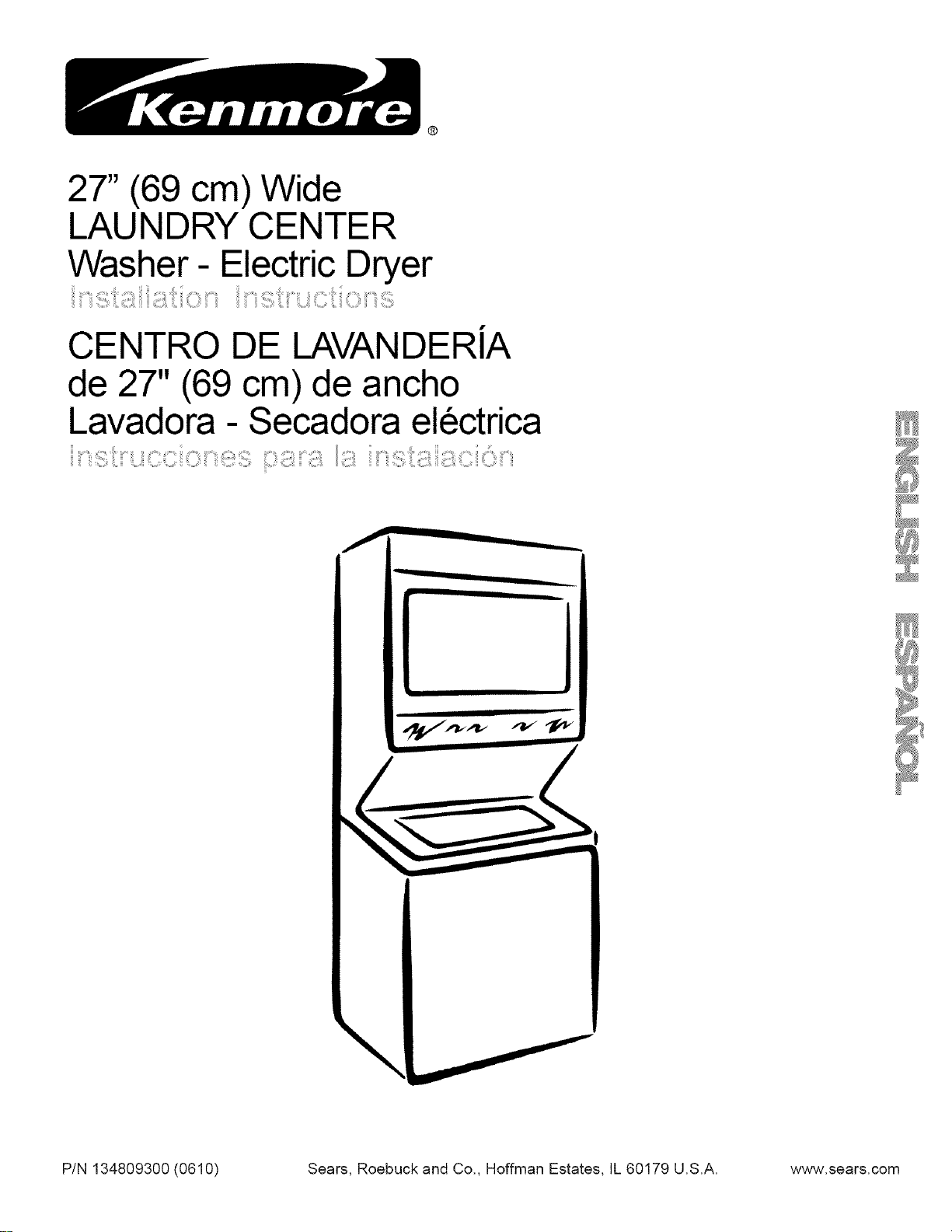
27" (69 cm) Wide
LAUNDRY CENTER
Washer- Electric Dryer
CENTRO DE LAVANDERiA
de 27" (69 cm) de ancho
Lavadora - Secadora electrica
iii
\
P/N 134809300 (0610) Sears, Roebuck and Co., Hoffman Estates, IL 60179 U.S.A. www.sears.com
Contents
SUBJECT PA GE
Pre-lnstallation Requirements .......................................... 2
Electrical Requirements ................................................... 2
Water Supply Requirements ........................................... 2
Drain Requirements .......................................................... 3
Exhaust System Requirements .................................. 3-4
Gas Supply Requirements ................................................ 4
Location ............................................................................ 4
Rough-In Dimensions ....................................................... 4
Mobile Home Installation ................................................. 5
Unpacking ......................................................................... 5
Electrical Installation ........................................................ 6
Grounding Requirements ................................................ 6
3 & 4-Wire Connections ........................................... 6-7
Installation .................................................................... 7-8
Replacement Parts........................................................... 8
Before beginning installation, carefully read these instructions.
This will simplify the installation
and ensure the laundry center is installed correctly and safely.
Leave these instructions near the
laundry center after installation for future reference.
NOTE: The electrical service to the laundry center must con-
form with local codes and ordinances and the latest edition of
the National Electrical Code, ANSI/NFPA 70, or in Canada, the
Canadian Electrical Code, CSA C22.1
NOTE: The gas service to the laundry center must conform with
local codes and ordinances and the latest edition of the National
Fuel Gas Code ANSIZ223. I/NFPA 54, or in Canada, the Canadian
Natural Gas andPropane Installation Code, CSA B149. 1.
NOTE: The laundry center is designed under ANSI Z21.5.1 or
ANSI/UL 2158- CAN/CSA C22.2 No. 112 (latest edition) for HOME
USE only. This laundry center is not recommended for commer-
cial applications such as restaurants or beauty salons, etc.
For your safety the information in this manual must
be followed to minimize the risk of fire or explosion or to prevent
property damage, personal injury or loss of life.
- Do not store or use gasoline or other flammable vapors and
liquid in the vicinity of this or any
other appliance.
- WHAT TO DO IF YOU SMELL GAS
Do not try to light any appliance.
Do not touch any electrical switch; do not use any phone in
your building.
Clear the room, building or area of all occupants.
Immediately call your gas supplier from a neighbor's phone.
Follow the gas supplier's instructions.
If you cannot reach your gas supplier, call the fire
department.
Installation and service must be preformed by a qualified installer,
service agency or the gas supplier.
ELECTRICAL REQUIREMENTS
ELECYRICLaundry Center
Circuit- Individual 30 amp branch circuit fused with 30 amp minimum
time delay fuses or circuit breakers.
POWER SUPPLY - 3-wire or 4-wire, 240 volt, single phase, 60 Hz,
Alternating Current.
POWER SUPPLY CORD KIT- The laundry center MUST employ a 3-
condutor power supply cord NEMA 10-30 type SRDT rated at 240
volt AC minimum, 30 amp, with 3 open end spade lug connectors
with upturned ends or closed loop connector OR a 4-condutor power
supply cord NEMA 14-30 type SRDT or ST (as required) rated at 240
volt AC minimum, 30 amp, with 4 open end spade lug connectors
with upturned ends or closed loop connectors and marked for use
with clothes dryers. If being installed in a new branch circuit
installation, manufactured (mobile) home, recreational vehicle or area
which prohibits grounding through the neutral conductor, the laundry
center MUST employ a 4-condutor power supply cord NEMA 14- 30
type SRDT or ST (as required) rated at 240 volt AC minimum, 30 amp,
with 4 open end spade lug connectors with upturned ends or closed
loop connectors and marked for use with clothes dryers. See
ELECTRICAL CONNECTIONS. (Canada - 4-wire power supply cord is
installed on laundry center.)
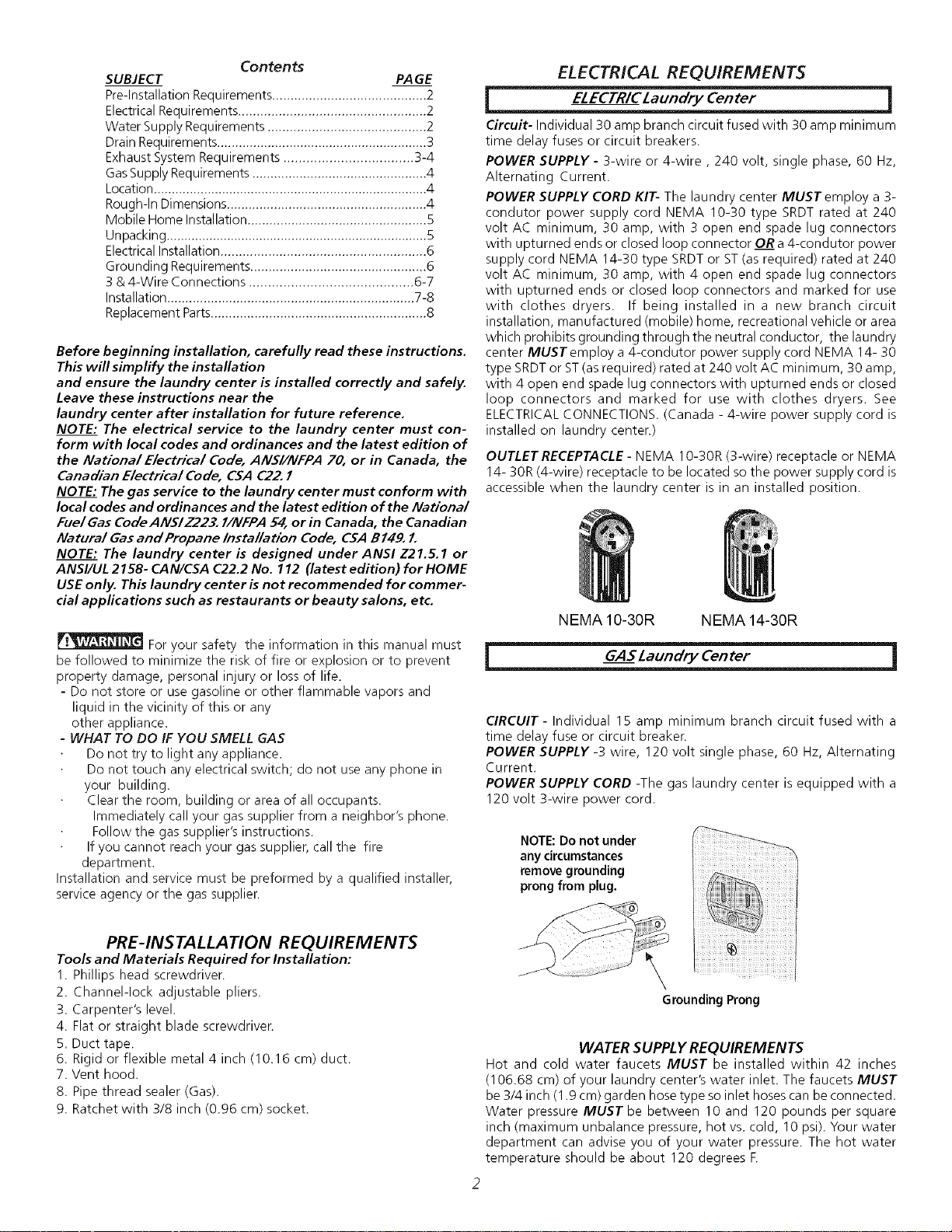
OUTLET RECEPTACLE- NEMA 10-30R (3-wire) receptacle or NEMA
14- 30R (4-wire) receptacle to be located so the power supply cord is
accessible when the laundry center is in an installed position.
NEMA 10-30R NEMA 14-30R
GAS Laundry Center
CIRCUIT - Individual 15 amp minimum branch circuit fused with a
time delay fuse or circuit breaker.
POWER SUPPLY -3 wire, 120 volt single phase, 60 Hz, Alternating
Current.
POWER SUPPLY CORD -The gas laundry center is equipped with a
120 volt 3-wire power cord.
NOTE: Do not under
any circumstances
remove grounding
prong from plug.
PRE-INSTALLATION REQUIREMENTS
Tools and Materials Required for Installation:
1. Phillips head screwdriver.
2. Channel-lock adjustable pliers.
3. Carpenter's level.
4. Flat or straight blade screwdriven
5. Duct tape.
6. Rigid or flexible metal 4 inch (10.16 cm) duct.
7. Vent hood.
8. Pipe thread sealer (Gas).
9. Ratchet with 3/8 inch (0.96 cm) socket.
Grounding Prong
WATER SUPPLY REQUIREMENTS
Hot and cold water faucets MUST be installed within 42 inches
(106.68 cm) of your laundry center's water inlet. The faucets MUST
be 3/4 inch (1.9 cm) garden hose type so inlet hoses can be connected.
Water pressure MUST be between 10 and 120 pounds per square
inch (maximum unbalance pressure, hot vs. cold, 10 psi). Your water
department can advise you of your water pressure. The hot water
temperature should be about 120 degrees E
DRAIN REQUIREMENTS
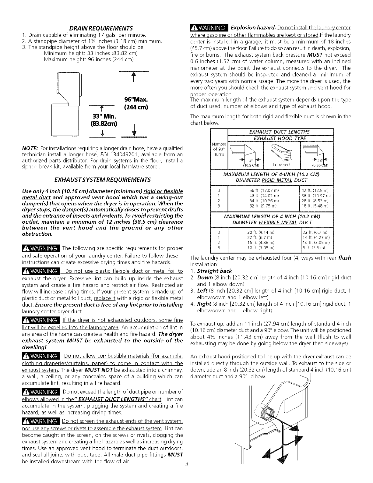
1. Drain capable of eliminating 17 gals. per minute.
2. A standpipe diameter of 1¼ inches (3.18 cm) minimum.
3. The standpipe height above the floor should be:
Minimum height: 33 inches (83.82 cm)
Maximum height: 96 inches (244 cm)
--T--
33" Min.
(83.82cm)
f
96"Max.
(244 cm)
NOTE: For installations requiring a longer drain hose, have a qualified
technician install a longer hose, PIN 134049201, available from an
authorized parts distributor. For drain systems in the floor, install a
siphon break kit, available from your local hardware store.
EXHAUST SYSTEM REQUIREMENTS
Use only 4 inch (10.16 cm) diameter (minimum) rigid or flexible
metal duct and approved vent hood which has a swing-out
damper(s) that opens when the dryer is in operation. When the
dryer stops, the damper(s) automatically closes to prevent drafts
and the entrance of insects and rodents. To avoid restricting the
outlet, maintain a minimum of 12 inches (38,5 cm) clearance
between the vent hood and the ground or any other
obstruction.
The following are specific requirements for proper
and safe operation of your laundry center. Failure to follow these
instructions can create excessive drying times and fire hazards.
Do not use plastic flexible duct or metal foil to
exhaust the dryer. Excessive lint can build up inside the exhaust
system and create a fire hazard and restrict air flow. Restricted air
flow will increase drying times. If your present system is made up of
plastic duct or metal foil duct, _lace it with a rigid or flexible metal
duct. Ensure the present duct is free of any lint prior to installing
laundry center dryer duct.
If the dryer is not exhausted outdoors some fine
lint will be expelled into the laundry area. An accumulation of lint in
any area of the home can create a health and fire hazard. The dryer
exhaust system MUST be exhausted to the outside of the
dwelling!
Do not allow combustible materials (for example:
clothing,draperies/curtains, paper) to come in contact with the
exhaust system. The dryer MUST NOT be exhausted into a chimney,
a wall, a ceiling, or any concealed space of a building which can
accumulate lint, resulting in a fire hazard.
Do not exceed the length of duct pipe or number of
elbows allowed in the" EXHAUST DUCT LENGTHS" chart. Lint can
accumulate in the system, plugging the system and creating a fire
hazard, as well as increasing drying times.
_Do not the exhaust ends of the vent
screen
system,
nor use any screws or rivets to assemble the exhaust system. Lint can
become caught in the screen, on the screws or rivets, clogging the
exhaust system and creating a fire hazard as well as increasing drying
times. Use an approved vent hood to terminate the duct outdoors,
and seal all joints with duct tape. All male duct pipe fittings MUST
be installed downstream with the flow of air. 3
Explosion hazard, Do not install the laundry center
where gasoline or other flammables are kept or stored.If the laundry
center is installed in a garage, it must be a minimum of 18 inches
(45.7 cm) above the floor. Failureto do socan result in death, explosion,
fire or burns. The exhaust system back pressure MUST not exceed
0.6 inches (1.52 cm) of water column, measured with an inclined
manometer at the point the exhaust connects to the dryer. The
exhaust system should be inspected and cleaned a minimum of
every two years with normal usage. The more the dryer is used, the
more often you should check the exhaust system and vent hood for
proper operation.
The maximum length of the exhaust system depends upon the type
of duct used, number of elbows and type of exhaust hood.
The maximum length for both rigid and flexible duct is shown in the
chart below.
Number
of 90°
Turns
0
1
2
3
0
1
2
3
EXHAUST DUCT LENGTHS
EXHAUST HOOD TYPE
(10.2 CM) Louvered (635 CM)
MAXIMUM LENGTH OF 4-INCH (10.2 CM)
DIAMETER RIGID METAL DUCT
56 ft. (17.07 m) 42 ft. (12.8 m)
46 ft. (14.02 m) 36 ft. (10.97 m)
34 ft. (10.36 m) 28 ft. (8.53 m)
32 ft. (9.75 rn) 18 ft. (5.48 m)
MAXIMUM LENGTH OF 4-INCH (10.2 CM)
DIAMETER FLEXIBLE METAL DUCT
30 ft. (9.14 m)
22 ft. (6.7 rn)
16 ft. (4.88 m)
10 ft. (3.05 m)
22 ft. (6.7 m)
14 ft. (4.27 rn)
10 ft. (3.05 m)
5 ft. (1.5 m)
The laundry center may be exhausted four (4) ways with rear flush
installation:
1. Straight back
2. Down (8 inch [20.32 cm] length of 4 inch [10.16 cm] rigid duct
and 1 elbow down)
3. Left (8 inch [20.32 cm] length of 4 inch [10.16 cm] rigid duct, 1
elbowdown and 1 elbow left)
4. Right (8 inch [20.32 cm] length of 4 inch [10.16 cm] rigid duct, 1
elbowdown and 1 elbow right)
To exhaust up, add an 11 inch (27.94 cm) length of standard 4 inch
(10.16 cm) diameter duct and a 90 ° elbow. The unit will be positioned
about 41/2 inches (11.43 cm) away from the wall (flush to wall
exhausting may be done by going below the dryer then sideways).
An exhaust hood positioned to line up with the dryer exhaust can be
installed directly through the outside wall. To exhaust to the side or
down, add an 8 inch (20.32 cm) length of standard 4 inch (10.16 cm)
diameter duct and a 90 ° elbow.
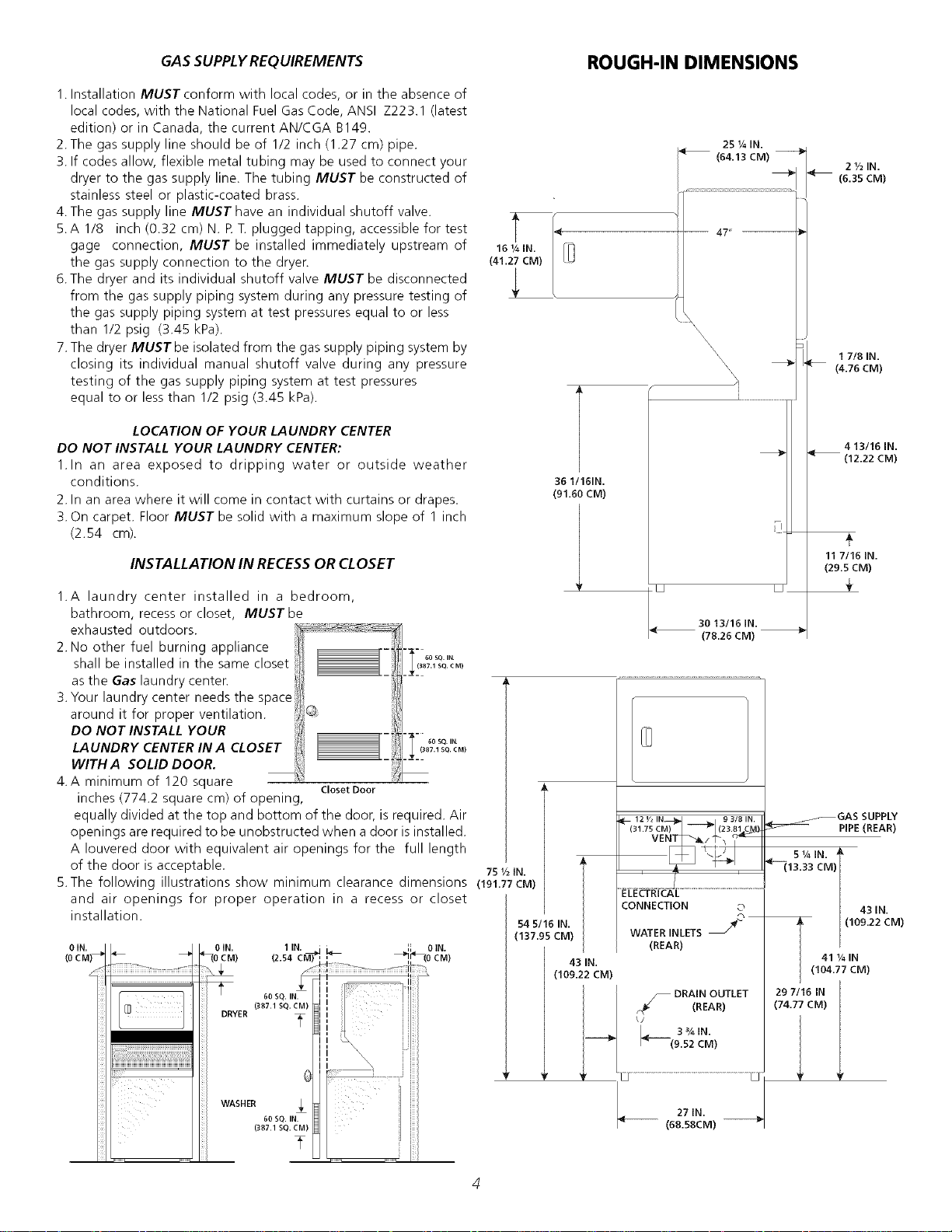
GASSUPPLYREQUIREMENTS ROUGH-IN DIMENSIONS
1. Installation MUST conform with local codes, or in the absence of
local codes, with the National Fuel Gas Code, ANSI Z223.1 (latest
edition) or in Canada, the current AN/CGA B149.
2.The gas supply line should be of 1/2 inch (1.27 cm) pipe.
3. If codes allow, flexible metal tubing may be used to connect your
dryer to the gas supply line. The tubing MUST be constructed of
stainless steel or plastic-coated brass.
4. The gas supply line MUST have an individual shutoff valve.
5. A 1/8 inch (0.32 cm) N. R T. plugged tapping, accessible for test
gage connection, MUST be installed immediately upstream of
the gas supply connection to the dryen
6.The dryer and its individual shutoff valve MUST be disconnected
from the gas supply piping system during any pressure testing of
the gas supply piping system at test pressures equal to or less
than 1/2 psig (3.45 kPa).
7.The dryer MUSTbe isolated from the gas supply piping system by
closing its individual manual shutoff valve during any pressure
testing of the gas supply piping system at test pressures
equal to or less than 1/2 psig (3.45 kPa).
16 I/4 IN.
(41.27 CM)
LOCATION OF YOUR LAUNDRY CENTER
DO NOT INSTALL YOUR LAUNDRY CENTER:
1.In an area exposed to dripping water or outside weather
conditions.
2. In an area where it will come in contact with curtains or drapes.
3. On carpet. Floor MUST be solid with a maximum slope of 1 inch
(2.54 cm).
INSTALLATION IN RECESSOR CLOSET
1.A laundry center installed in a bedroom,
bathroom, recess or closet, MUST be
exhausted outdoors.
2. No other fuel burning appliance
shall be installed in the same closet
as the Gas laundry centen
3. Your laundry center needs the space
around it for proper ventilation.
DO NOT INSTALL YOUR
LAUNDRY CENTER IN A CLOSET
WITH A SOLID DOOR.
4. A minimum of 120 square
inches (774.2 square cm) of opening,
Closet Door
60 SQ. IN.
(387.1 SQ. CM)
60 SQ. IN.
(387.1 SQ. CM)
equally divided at the top and bottom of the door, is required. Air
openings are required to be unobstructed when a door is installed.
A louvered door with equivalent air openings for the full length
of the door is acceptable. 751/2(N.
5.The following illustrations show minimum clearance dimensions (191.77CM)
and air openings for proper operation in a recess or closet
installation.
36 1!161N.
(91.60 CM)
25 ¼IN.
i (64.13 CM)
_\\\\\\\
30 13/16 IN.
(78.26 CM)
2½IN.
(6.3SCM)
17/8 IN.
[_ (4.76CM)
(
+
11 7116 IN.
(29.5 CM)
4 13/16 iN.
(12.22 CM)
54 5/16 IN.
(137.95 CM)
12 I/2 IN._ 9 3/8 IN.
(31.75 CM_ (23.81 C_4)
VENT_.._ / -1_\ _,_
ELECTRICAL
CONNECTION ©
WATERINLETS _2_
(REAR)
43 IN.
(109.22 CM)
,m_ _ DRAINOUTLET
._,_ (REAR)
\J
3%1N.
_:---(9.52 CM)
27 IN.
(68.58CM)
f--GAS SUPPLY
PIPE (REAR)
s 1/4mN.
_13.33 CM)
1 43 IN.
/(109.22 CM)
411/4IN
I (104.77 CM)
29 7116 IN
(74.77CM)
"!

MOBILE HOME INSTALLATION
1.Dryer MUST be exhausted outside (outdoors, not beneath the mobile
home) using metal ducting that will not support combustion. Metal
ducting must be 4 inches (10.16 cm) in diameter with no obstructions.
Rigid metal duct is preferred.
2.If dryer isexhausted through the floor and area beneath the mobile
home isenclosed, the exhaust system MUSTterminate outside
the enclosure with the termination securely fastened to the mobile
home structure.
3.Refer to page 3 for other important venting requirements.
4.When installing a gas dryer into a mobile home, a provision must be
made for outside make up air. This provision isto be not lessthan twice
the area of the dryer exhaust outlet.
5.Installation MUSTconform to current Manufactured Home Construction
& Safety Standard (which is a Federal Regulation Title 24 CFR-Part 32-
80) or when such standard is not applicable, with American National
Standard for Mobile Homes. In Canada, the CSA Z240 is applicable.
ii i
_iiiiiiiiiiiiiiiiiiiiiiiiiiiiiiiiiiiiiiiiiiiiiiiiiiiiiiiiiiiiiiiiiiiiiiiiiiiiiiiii
iiiiiiiiiiiiiiiiiiiiiiiiiiiiiiiiiiiiiiiiiiiiiiiiiiiiiiiiiiiiiiiiiiiiii
_1__ The laundry center is designed under ANSI Z 21.5.1for HOME USE only.
UNPACKING
1. Using the four shipping carton corner posts (two on each
side), carefully lay the laundry center on its left side and
remove foam shipping base.
Excessive weight. Use two or more people
to move Laundry Center.
2. Using a ratchet with 3/8 inch (0.96 cm) socket, remove the
mechanism shipping bolt and plastic spacer block from the
center of the base.
NOTE: If the laundry center is to be transported at a later
date, the tub blocking pad, shipping bolt, and plastic
spacer block should be retained.
3. Return laundry center to an upright position.
4. Remove:
(a) foam tub blocking pad.
(b) foam shipping blocks from rear of unit.
(c) tape from dryer door.
(d) foam dryer support pads.
(e) inlet hoses.
(f) enclosure package.
5. From the back of the washer, remove the wire shipping
clips securing the drain hose and power cord (if equipped).
Plastic clamps secure the drain hose to the right side of
the washer backsheet. These clamps form a standpipe to
prevent water syphoning. DO NOT REMOVE THESE
CLAMPS.
6. Carefully move the laundry center to within 4 feet (1.22 m)
of the final location to begin the installation.
PLASTIC SPACER
MECHANL €
SHIPPING
BOLT
CARTON CORNER POSTS
FOAM
SHIPPING
PAD
POWER CORD
(IF EQUIPPED)
DRAIN HOSE
ELECTRICAL INSTALLATION
i ALLELECTRICLaundryCenters ]
The following are specific requirements for
proper and safe electrical installation of your laundry center.
Failure to follow these instructions can create electrical shock
and/or a fire hazard.
This appliance MUST be properly grounded.
Electrical shock can result if the laundry center isnot properly
grounded. Follow the instructions in this manual for proper
grounding.
Do not use an extension cord with this
laundry center. Some extension cords are not designed to
withstand the amounts of electrical current this laundry center
utilizes and can melt, creating electrical shock and/or fire hazard.
Locate the laundry center within reach of the receptacle for the
length power cord to be purchased, allowing some slack in the
cord. Refer to the prednstallation requirements in this manual
for the proper power cord to be purchased.
A U.L.approved strain relief must be installed
onto power cord. If the strain relief isnot attached, the cord can
be pulled out of the laundry center and can be cut by any
movement of the cord, resulting in electrical shock.
I Canadian ELECTRICLaundry Center 1
I__lmproper connection of the equipment
grounding conductor can result in a risk of electrical shock,
Check with a licensed electrician if you are in doubt as to
whether the appliance is properly grounded.
Fora grounded cord connected laundry center:
1. The laundry center MUST be grounded. In the event of
malfunction or breakdown, grounding will reduce the risk of
electrical shock by providing a path of least resistance for
the electrical current.
2. Since your laundry center is equipped with a power supply
cord having an equipment-grounding conductor and a
grounding plug, the plug MUST be plugged into an
appropriate outlet that isproperly installed and grounded in
accordance with all codes and ordinances. If in doubt, call
a licensed electrician.
i
Do not use an aluminum wired receptacle
with a copper Wired power cord and plug (or vice versa). A
chemical reaction occurs between copper and aluminum and 2.
can cause electrical shorts. The proper wiring and receptacle
is a copper wired power cord with a copper wired
receptacle OR aluminum wired power cord with an 3.
aluminum wired receptacle.
NOTE: Laundry centers operating on a 208 volt power supply 4.
will have longer drying times than laundry centers operating on
a 240 volt power supply.
GROUNDING REQUIREMENTS
ALL GAS Laundry Centers
1
1.The laundry center isequipped with a three-prong (grounding)
plug for your protection against shock hazard and should
be plugged directly into a properly grounded three-prong
receptacle. Do not cut or remove the grounding prong from
the plug.
Non-Canadian ELECTRICl.aundry Center ]
Improper connection of the equipment
grounding conductor car/ result in a risk of electrical shock.
Check with a licensed electrician ifyou are in doubt asto whether
the appliance isproperly grounded.
For a qrounded, cord-connected laundry center:
1. The laundry center MUST be grounded. In the event of
malfunction or breakdown, grounding will reduce the risk of
electrical shock by a path of least resistance for electrical
current.
2. If your laundry center isequipped with a power supply cord
having an equipment-grounding conductor and a grounding
plug, the plug MUST be plugged into an appropriate, copper
wired receptacle that is properly installed and grounded in
accordance with all local codes and ordinances. If in doubt,
call a licensed electrician. Do not modify plug provided
with the appliance.
For a permanently connected laundry center:
The laundry center MUST be connected to a grounded metal,
permanent wiring system; or an equipment grounding conductor
MUST be run with the circuit conductors and connected to the
equipment-grounding terminal or lead on the appliance.
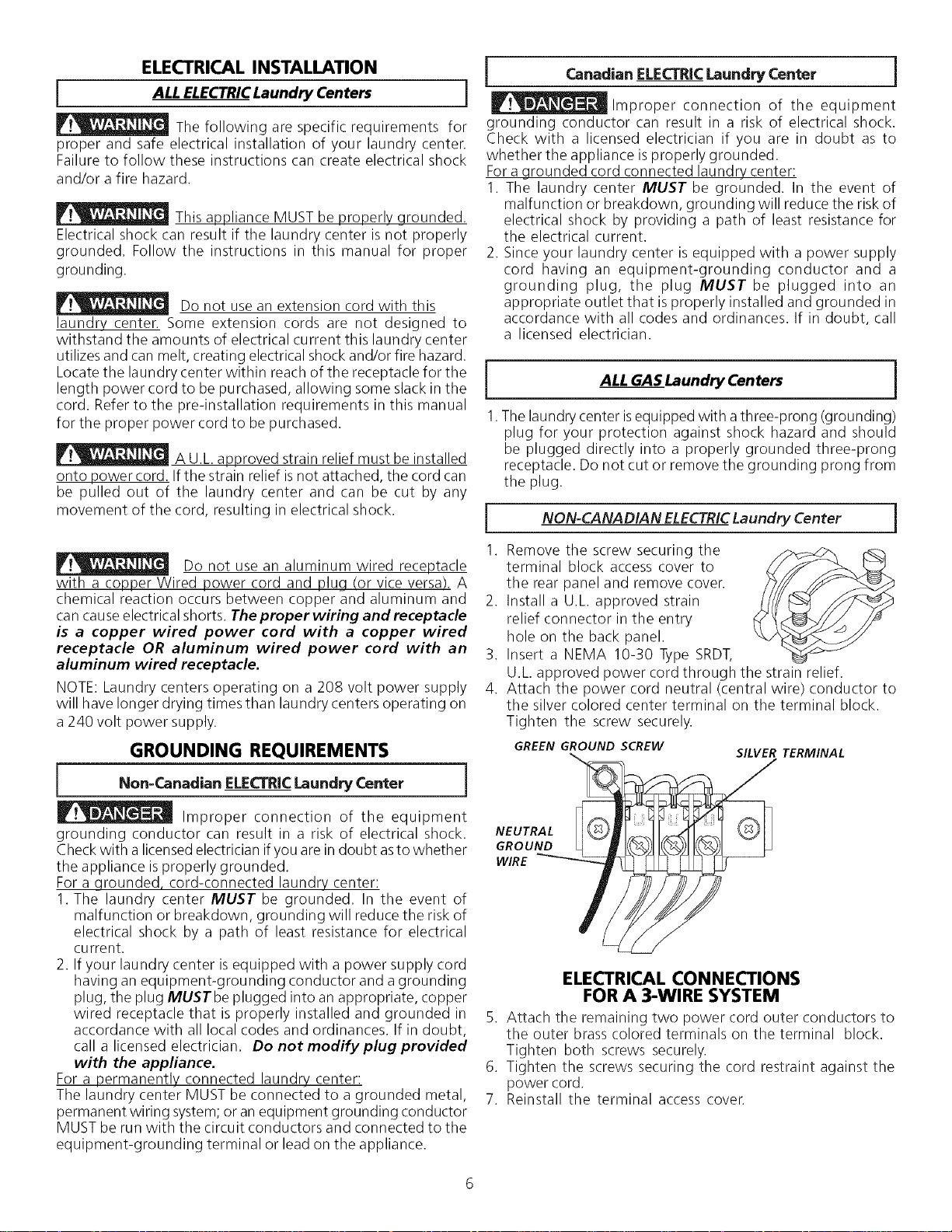
NON-CANADIAN ELECTRICLaundry Center j
Remove the screw securing the
terminal block access cover to
the rear panel and remove cover.
Install a U.L approved strain
relief connector in the entry
hole on the back panel.
Insert a NEMA 10-30 Type SRDT,
U.L approved power cord through the strain relief.
Attach the power cord neutral (central wire) conductor to
the silver colored center terminal on the terminal block.
Tighten the screw securely.
GREEN GROUND SCREW
SILVER TERMINAL
NEUTRAL
GROUND
WIRE
ELECTRICAL CONNECTIONS
FOR A 3-WIRE SYSTEM
5. Attach the remaining two power cord outer conductors to
the outer brass colored terminals on the terminal block.
Tighten both screws securely.
6. Tighten the screws securing the cord restraint against the
power cord.
7. Reinstall the terminal access cover.
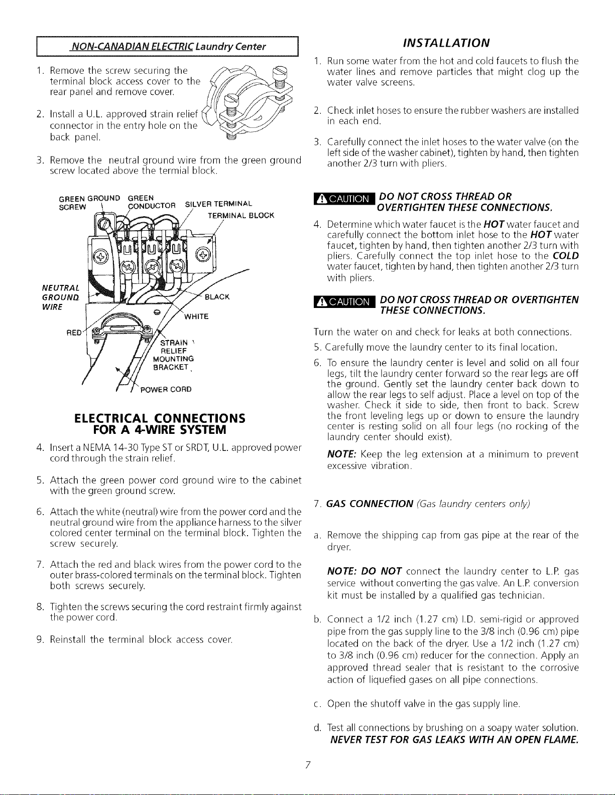
NON-CANADIAN ELECTRICLaundry Center
1. Remove the screw securing the
terminal block access cover to the
rear panel and remove cover.
2. Install a U.L approved strain relief
connector in the entry hole on the
back panel.
J
3. Remove the neutral ground wire from the green ground
screw located above the termial block.
INSTALLATION
Run some water from the hot and cold faucets to flush the
water lines and remove particles that might clog up the
water valve screens.
.
3.
Check inlet hoses to ensure the rubber washers are installed
in each end.
Carefully connect the inlet hoses to the water valve (on the
left sideof the washer cabinet), tighten byhand, then tighten
another 2/3 turn with pliers.
GREEN GROUND GREEN
SCREW CONDUCTOR SILVER TERMINAL
TERMINAL BLOCK
NEUTRAL
GROUNQ
WIRE
BLACK
WHITE
STRAIN
RELIEF
MOUNTING
BRACKET,
POWER CORD
ELECTRICAL CONNECTIONS
FOR A 4-WIRE SYSTEM
4. Insert a NEMA 14-30 TypeSTor SRDT,U.L approved power
cord through the strain relief.
5. Attach the green power cord ground wire to the cabinet
with the green ground screw.
6. Attach the white (neutral) wire from the power cord and the
neutral ground wire from the appliance harnessto the silver
colored center terminal on the terminal block. Tighten the
screw securely.
7. Attach the red and black wires from the power cord to the
outer brass-colored terminals on the terminal block. Tighten
both screws securely.
8. Tighten the screws securing the cord restraint firmly against
the power cord.
9. Reinstall the terminal block access cover.
_ DO NOT CROSS THREAD OR
OVERTIGHTEN THESE CONNECTIONS.
4. Determine which water faucet isthe HOTwater faucet and
carefully connect the bottom inlet hose to the HOTwater
faucet, tighten by hand, then tighten another 2/3 turn with
pliers. Carefully connect the top inlet hose to the COLD
water faucet, tighten by hand, then tighten another 2/3 turn
with pliers.
DO NOT CROSS THREAD OR OVERTIGHTEN
THESE CONNECTIONS.
Turn the water on and check for leaks at both connections.
.
6.
Carefully move the laundry center to its final location.
To ensure the laundry center is level and solid on all four
legs, tilt the laundry center forward so the rear legs are off
the ground. Gently set the laundry center back down to
allow the rear legs to self adjust. Placea level on top of the
washer. Check it side to side, then front to back. Screw
the front leveling legs up or down to ensure the laundry
center is resting solid on all four legs (no rocking of the
laundry center should exist).
NOTE: Keep the leg extension at a minimum to prevent
excessive vibration.
7. GAS CONNECTION (Gas laundry centers only)
a.
b.
c.
d.
Remove the shipping cap from gas pipe at the rear of the
dryer.
NOTE: DO NOT connect the laundry center to L.R gas
service without converting the gas valve. An LR conversion
kit must be installed by a qualified gas technician.
Connect a 1/2 inch (1.27 cm) I.D. semi-rigid or approved
pipe from the gas supply line to the 3/8 inch (0.96 cm) pipe
located on the back of the dryer. Use a 1/2 inch (1.27 cm)
to 3/8 inch (0.96 cm) reducer for the connection. Apply an
approved thread sealer that is resistant to the corrosive
action of liquefied gases on all pipe connections.
Open the shutoff valve in the gas supply line.
Test all connections by brushing on a soapy water solution.
NEVER TEST FOR GAS LEAKS WITH AN OPEN FLAME.
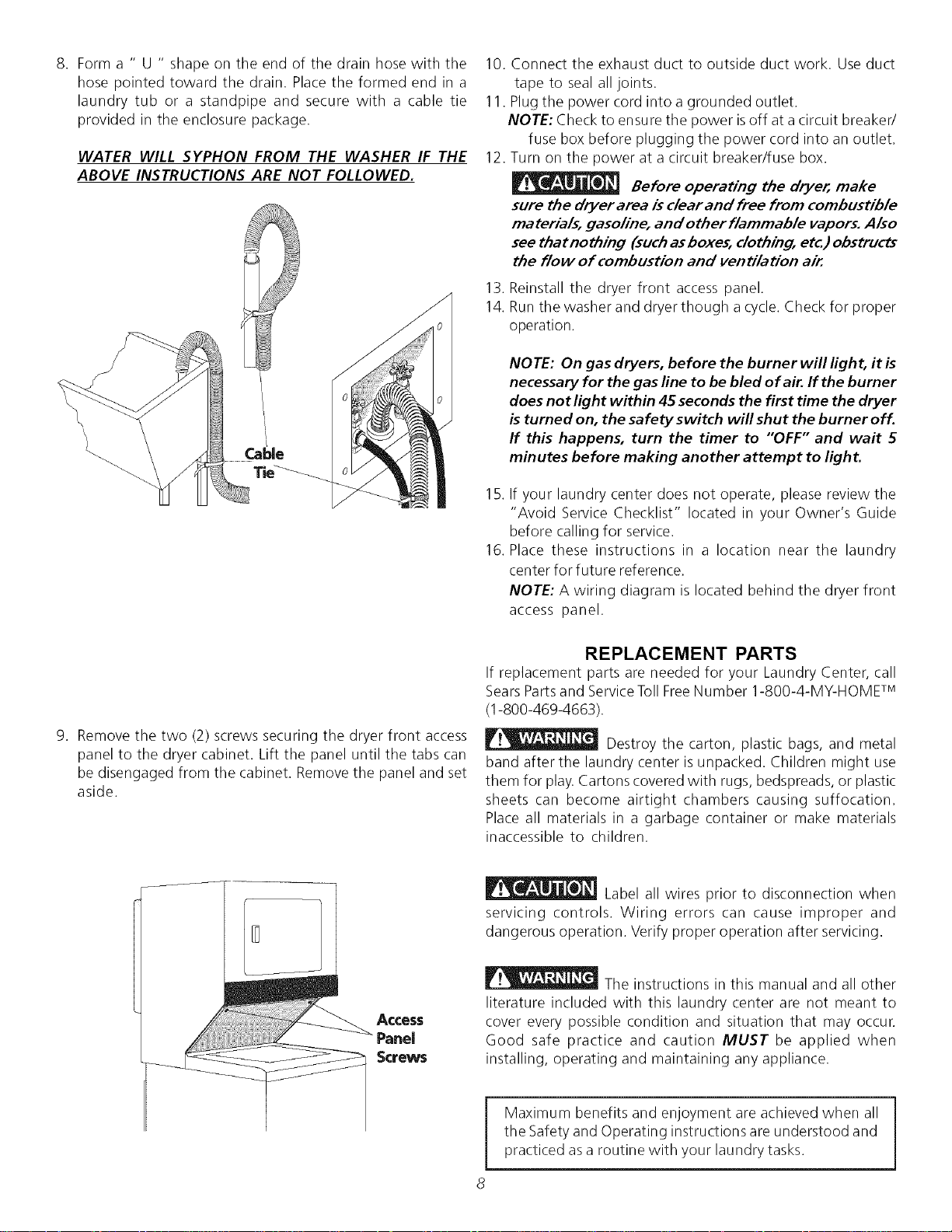
8. Form a " U " shape on the end of the drain hose with the
hose pointed toward the drain. Place the formed end in a
laundry tub or a standpipe and secure with a cable tie
provided in the enclosure package.
WATER WILL SYPHON FROM THE WASHER IF THE
ABOVE INSTRUCTIONS ARE NOT FOLLOWED.
9. Remove the two (2) screws securing the dryer front access
panel to the dryer cabinet. Lift the panel until the tabs can
be disengaged from the cabinet. Removethe panel and set
aside.
10. Connect the exhaust duct to outside duct work. Use duct
tape to seal all joints.
11. Plug the power cord into a grounded outlet.
NOTE: Check to ensure the power isoff at a circuit breaker/
fuse box before plugging the power cord into an outlet.
12. Turn on the power at a circuit breaker/fuse box.
Before operating the dryer, make
sure the dryer area is clear and free from combustible
materials, gasoline, and other flammable vapors. Also
see thatnothing (suchasboxes, clothing, etc.) obstructs
the How of combustion and ventilation air.
13. Reinstall the dryer front access panel.
14. Runthe washer and dryer though a cycle. Check for proper
operation.
NOTE: On gas dryers, before the burner will light, it is
necessary for the gas line to be bled of air. If the burner
does not lightwithin 45 seconds the first time the dryer
b turned on, the safety switch will shut the burner off.
If this happens, turn the timer to "OFF" and wait 5
minutes before making another attempt to light.
15. If your laundry center does not operate, please review the
"Avoid Service Checklist" located in your Owner's Guide
before calling for service.
16. Place these instructions in a location near the laundry
center for future reference.
NOTE: A wiring diagram is located behind the dryer front
access panel.
REPLACEMENT PARTS
If replacement parts are needed for your Laundry Center, call
SearsParts and ServiceToll FreeNumber 1-800-4-MY-HOMF M
(1-800-469-4663).
Destroy the carton, plastic bags, and metal
band after the laundry center isunpacked. Children might use
them for play. Cartons covered with rugs, bedspreads, or plastic
sheets can become airtight chambers causing suffocation.
Place all materials in a garbage container or make materials
inaccessible to children.
Access
Panel
Screws
Label all wires prior to disconnection when
servicing controls. Wiring errors can cause improper and
dangerous operation. Verify proper operation after servicing.
I__ The instructions in this manual and all other
literature included with this laundry center are not meant to
cover every possible condition and situation that may occur.
Good safe practice and caution MUST be applied when
installing, operating and maintaining any appliance.
Maximum benefits and enjoyment are achieved when all
the Safety and Operating instructions are understood and
practiced asa routine with your laundry tasks.
#ndice
MATER#A
Requerimientos de instalaci6n preliminares
Requerimientos electricos
Requerimientos del suministro de agua
Requerimientos de desagOe
Requerimientos del sistema de escape
Requerimientos del suministro de gas
Ubicacion
Instalacion en casasmOviles
Dimensiones para la instalacion
Desembalaje
Instalacion electrica
Requerimientos para lapuesta atierra
Conexi6nes el_ctricas - trifilares y tetrafilares
Instalacion
Repuestos
PAGINA
9
9
9
9
10
11
11
11
12
12
13
13
14
14-15
15
REQUERIM#ENTOS DE INSTALA CION
PREL#MINA RES
Herramientas y materiales necesarios para la instalacion:
1. Destornillador Phillips
2. Alicates universales
3. Nivel de carpintero
4. Destornillador para tornillo de cabeza plana o recta
5. Cinta para ductos
6. Ducto metalico rigido o flexible de 4"(10,2 cm)
7. Caperuza de salida
8. Sellador de tuberias (gas)
9. LLavede tubo de 3/8 de pulgada (0,96 cm).
Parasuseguridad, sigalasinstruccionescontenidas en
estemanual afin de reduciraunminimo losriesgosde incendiooexplosi6n
opara evitardar]os materiales, lesionespersonaleso lamuerte,
Noalmaceneni utilice gasolinauotrosvaporesy Nquidosinfiamables
en laproximidad de6ste odecualquier otro artefacto el6ctrico.
QUEDEBEHACERSIPERCIBEOLORA GAS
o Notrate de encender ningon artefacto el_ctrico.
• Notoque ningon interruptor el6ctrico; nouseningOntel(_fonoen
suedificio.
• HagasaNratodos losocupantes dela habitacion, del edificio ydel
lugar.
• Llamea su proveedor de gasdesdeeltel6fono de un vecino.Siga
las instruccionesdel proveedor degas.
• Sino Iogra comunicarse con suproveedor de gas,Ilameal
departamento de bomberos.
Lainstalaciony elserviciode mantenimiento debede realizarlosun
instalador caNficado,laagenciade serviciosoel proveedor degas.
REQUERIMIENTOS ELL'CTRICOS
[ Centro de/avanderia ELECTRICAS ]
CIRCUITO - Circuito derivado individual de 30 amperes, con fusibles
de 30 amp. del tipo de retardo minimo o disyuntores.
ALIMENTACIONELECTRICA - Corriente alterna, monof_qsica,60 Hz,
240 voltios; trifilar. (Canada1-240 voltios, monof_isico, 60 Hz,corrienta
alterna.)
CORDONELECTRICO - Enlasecadora seDEBEusar un cordon electrico
trifilar NEMA 10-30 tipo SRDTpara un voltaje nominal mfnimo de 240
voltios CA, 30 amp, con 3 conectores de horquillas con terminales
abiertosy extremos dirigidos haciaarriba oconectores de anillo cerrado
y marcados para uso en secadoras de ropa. Sisiendo instalado en una
nueva instalaciOn delcircuito delrama, unvehiculo casero, recreacional
(m6vil) manufacturado o un _ireaque prohiben el poner atierra atrav_s
del conductor neutral, se DEBE utilizar un cordon electrico tetrafilar
NEMA 14-30 tipo SRDToST(como seanecesario)para unvoltaje nominal
mfnimo de 240 voltios CA, 30 amp con 4 conectores de horquillas con
terminales abiertos y extremos dirigidos hacia arriba o conectores de
anillo cerrado y marcados para uso en secadoras de ropa.
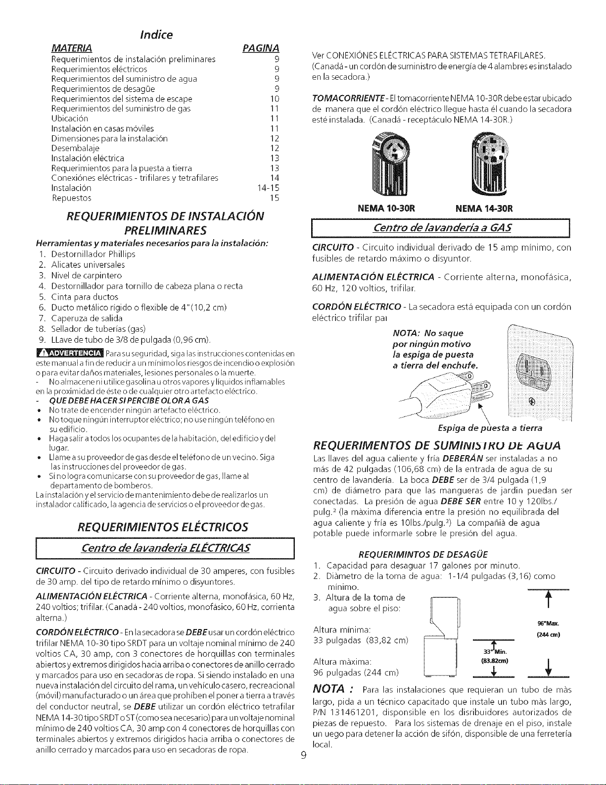
Ver CONEXIONES ELI_CTRICAS PARA SlSTEMAS TETRAFILARES.
(Ca nad_i - un cord6n de suministro de energia de 4 alambres es instalado
en la secadora.)
TOMACORRIENTE- Eltomacorriente NEMA 10-30Rdebe estar ubicado
de manera que el cordon electrico Ilegue hasta el cuando la secadora
este instalada. (Canada1- recept_iculo NEMA 14-30R.)
NEMA 10-30R NEMA 14-30R
I Centro de/avanderia a GAS 1
CIRCUITO - Circuito individual derivado de 15 amp minimo, con
fusibles de retardo m_iximo o disyuntor.
ALIMENTACION ELECTRICA - Corriente alterna, monof_isica,
60 Hz, 120 voltios, trifilar.
CORDONELECTRICO - La secadora est,1 equipada con un cord6n
electrico trifilar pal
NOTA: No saque
por ning,_n motivo
la espiga de puesta
a tierra del enchufe,
Espiga
REQUERIMENTOS DE SUMINI5 IHU Dk A(JUA
LasIlaves del agua caliente y fria DEBERAN set instaladas a no
m_is de 42 pulgadas (106,68 cm) de la entrada de agua de su
centro de lavanderfa. La boca DEBE ser de 3/4 pulgada (1,9
cm) de di_imetro para que las mangueras de jardin puedan ser
conectadas. La presion de agua DEBE SERentre 10 y 1201bs./
pulg. 2(la maxima diferencia entre la presion no equilibrada del
agua caliente y frfa es 101bs./pulg.2) La compania de agua
potable puede informarle sobre le presi6n del agua.
REQUERIMINTOS DE DESAGUE
1. Capacidad para desaguar 17 galones por minuto.
2. Di_metrodelatomadeagua: 1-1/4 pulgadas (3,16) como
minimo.
3. Altura de la toma de
agua sobre el piso:
/
g6"MaX,
Altura minima: 1244cm)
33 pulgadas (83,82 cm)
Altura maxima: (8_.82cm)
96 pulgadas (244 cm)
NOTA : Para las instalaciones que requieran un tubo de m_s
largo, pida a un tecnico capacitado que instale un tubo m_s largo,
P/N 131461201, disponsible en los disribuidores autorizados de
piezas de repuesto. Para los sistemas de drenaje en el piso, instale
un uego para detener laaccion de sifon, disponsible de una ferreteria
local.
REQUERIMIENTOS DEL SISTEMA DE ESCAPE
Utilice solamente ductos met_ilicos, rigidoso flexibles de 4"
(10,2 cm) de di_imetro (minimo) y una caperuza de salida de uso
aprobado, con registros que giren hacia afuera que se abren cuando la
secadora se encuentra en funcionamiento. Cuando la secadora se
detiene, los registros se cierran autom_fticamente para evitar las
corrientes de airey la entrada de insectosy roedores. Para evita r obstruir
la salida, mantenga una altura libre minima de 12 "(30,5 cm) entre la
caperuza de salida y el piso o entre cualquier otra obstruccion.
Los siguientes requerimientos son
especificos para el funcionamiento correcto y seguro de su
secadora, El incumplimien to de estas instrucciones puede causar
prolongaci6n excesiva de! tiempo de secado y riesgos de incendio.
I_No use carlo flexible de pkqstico ni papel metalizado para desagotar
la secadora.
Sepuede acumular un exceso de pelusas en el sistema de escape, crear
un riesgo y obstruir el flujo de aire. La restricci6n del flujo del aire
prolongara el tiempo de secado. Si su sistema de escape actual tiene
ductos de pkqstico o de I_iminas met_ilicas delgadas, reempl_icelo con
un ducto met_ilico rigido o flexible. Asegurese de que los ductos
existentes no tengan pelusas antes de instalar el ducto de la
secadora.
P_Si el escape de la secadora no se dirige al exterior, algunas pelusas
finas set,fin sopladas hacia el recinto donde se efect0a el lavado. La
acumulaci6n de pelusas en cualquier lugar de la casa, puede treat un
peligro para la salud y un riesgo de incendio, iEIsistema de escape de
la secaclora DEBE estar dirig ido hacia el exterior de la vivienda !
_No permita que los materiales combustibles (pot ejemplo: la ropa.
cortinas/cortinajes, papel) tengan contacto con los ductos. El escape
de la secadora NO DEBE dirigirse hacia el interior de una chimenea,
hacia una pared, hacia el cielo raso o hacia cualquier otro espacio
reducido del edificio, donde puede ocurrir acumulacion de pelusas y
constituir un peligro de incendio.
_ Exceder la Iongitud del conducto rigido o los n0meros de codos
permitidos en los diagramas "LARGO MAXlMO" puede disminuir la
capacidad de exhaustacion del sistema. Obstruir el conducto puede
provocar peligro de incendio, asi como aumentar el tiempo de secado.
_No coloque un filtro en el extremo del escape del sistema ni emplee
tomillos o remaches para ensamblar el sistema de escape. Las pelusas
podrian quedar atrapadas en los filtros, en los tomillos o en los
remaches, Io cual obstruiria el sistema de escape y crearia un riesgo de
incendio, asi como tambi_n prolongaria el tiempo de secado. Use una
caperuza de salida adecuada para el extremo del ducto que salga al
exterior de la vivienda y selle todas las juntas con cinta adhesiva para
ductos. Todos los accesorios de tuberia machos, DEBEN set instalados
aguas abajo del flujo de aire.
Riesgo de explosi6n. No instale la secadora
donde se quarda qasolina u otros materiales inflamables. Si la secadora
se instala en un garage, ella debe estar por Io menos 18 pulgadas (45,7
cm) por encima del suelo. El incumplimiento puede resultar en la
muerte, explosi6n, incendio, o quemaduras.
1. La constrapresion del sistema de escape NO DEBE exceder
0,6 pulgadas (1,52 cm) de columna de agua, medida con un
man6metro inclinado en la conexiOn del ducto de escape a
la secadora.
2. El sistema de escape debe set inspeccionado y limpiado
cada 2 anos como minimo, bajo condiciones de uso normal.
Mientras masse use la secadora, con mayor frecuencia
deben inspeccionarse el sistema de escape y la caperuza
de salida para verificar su buen funcionamiento.
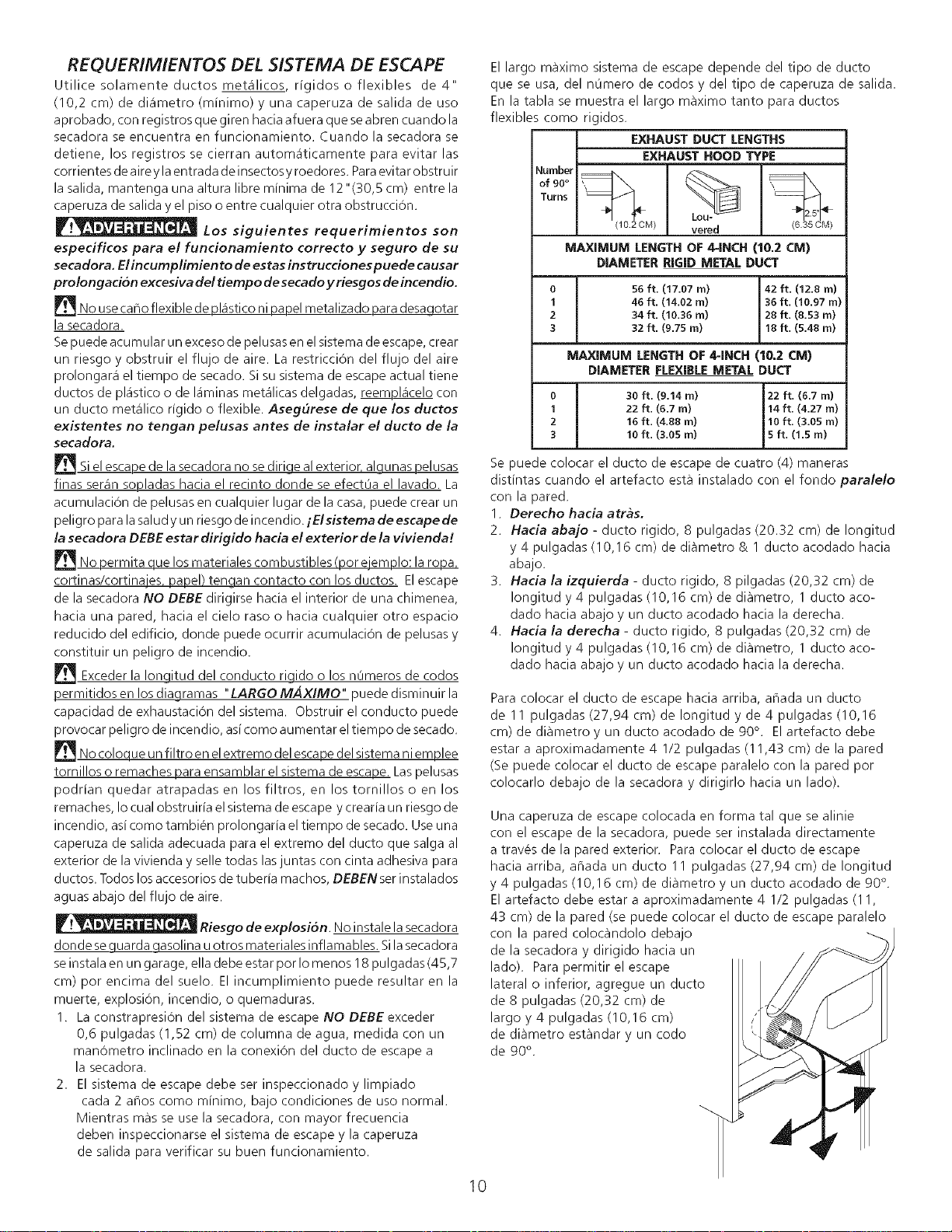
El largo maximo sistema de escape depende del tipo de ducto
que se usa, del nOmero de codos y del tipo de caperuza de salida.
En la tabla se muestra el largo m_ximo tanto para ductos
flexibles como rigidos.
EXHAUST DUCT LENGTHS
EXHAUST HOOD TYPE
of 90° __ J_
Turns _'_
(102CM) vered (6.u5CM)
MAXIMUM LENGTH OF 4-INCH {10.2 CM)
DIAMETER RIGID METAL DUCT
0
1
2
3
o
1
2
3
56 ft. (17.07 m) 42 ft. (12.8 m)
46 ft. (14.02 m) 36 ft. (10.97 m)
34 ft. (10.36 m) 28 ft. (8.53 m)
32 ft. (9.75 m) 18 ft. (5.48 m)
MAXIMUM LENGTH OF 4=INCH (10.2 CM)
DIAMETER FLEXIBLE METAL DUCT
30 ft. (9.14 m) 22 ft. (6.7 m)
22 ft. (6.7 m) 14ft. (4.27 m)
16 ft. (4.88 m) 10 ft. (3.05 rn)
10 ft. (3.05 rn) 5 ft. (1.5 rn)
Se puede colocar el ducto de escape de cuatro (4) maneras
distintas cuando el artefacto est_ instalado con el fondo paralelo
con la pared.
1. Derecho hacia arras.
2. Hacia abajo - ducto rigido, 8 pulgadas (20.32 cm) de Iongitud
y 4 pulgadas (10,16 cm) de diametro & 1 ducto acodado hacia
abajo.
3. Hacia la izquierda - ducto rigido, 8 pilgadas (20,32 cm) de
Iongitud y 4 pulgadas (10,16 cm) de diametro, 1 ducto aco-
dado hacia abajo y un ducto acodado hacia la derecha.
4. Hacia la derecha - ducto rigido, 8 pulgadas (20,32 cm) de
Iongitud y 4 pulgadas (10,16 cm) de diametro, 1 ducto aco-
dado hacia abajo y un ducto acodado hacia la derecha.
Para colocar el ducto de escape hacia arriba, anada un ducto
de 11 pulgadas (27,94 cm) de Iongitud y de 4 pulgadas (10,16
cm) dediametroyunductoacodadode90 ° . Elartefactodebe
estar a aproximadamente 4 1/2 pulgadas (11,43 cm) de la pared
(Se puede colocar el ducto de escape paralelo con la pared por
colocarlo debajo de la secadora y dirigirlo hacia un lado).
Una caperuza de escape colocada en forma tal que se alinie
con el escape de la secadora, puede ser instalada directamente
a traves de la pared exterior. Para colocar el ducto de escape
hacia arriba, anada un ducto 11 pulgadas (27,94 cm) de Iongitud
y 4 pulgadas (10,16 cm) de diametro y un ducto acodado de 90 °.
El artefacto debe estar a aproximadamente 4 1/2 pulgadas (11,
43 cm) de la pared (se puede colocar el ducto de escape paralelo
con la pared colocandolo debajo
de la secadora y dirigido hacia un
lado). Para permitir el escape
lateral o inferior, agregue un ducto
de 8 pulgadas (20,32 cm) de
largo y 4 pulgadas (10,16 cm)
de diametro est_ndar y un codo
de 90 °.
10
REQUERIMIENTOS DEL SUMINISTRO DE GAS
1. La instalacion DEBE hacerse cumplir con los codigos locales o en
ausencia de los mismos, de acuerdo con los estandares del National
Fuel Gas Code (Codigo Nacional para Gases Combustibles), ANSI
Z223.1 (la ultima editi6n). Para Canada, el Estandar CAN/C GA B149
que este en vigor. 0IN.
2. Latuberia dealimentaci6n de gas debeser de 1/2 pulgada (1,27 cm) (0cM)_
de diametro.
3. Si est,1 permitido por los cOdigos locales, se puede usar tubefia
de metal para conectar su secadora a la linea de suministro
de gas. La tuberia DEBE set fabricada de acero inoxidable o
cobre recubierto de pl_istico.
4. La tuberia de alimentaciOn de gas DEBE tener una Ilave de cierre
individual.
5. Una toma de 1/8 de pulgada (0,32 cm) N RT.accesible para conexion
del manometro de prueba, DEBE ser instalada inmediatamente
aguas arriba de la conexion de la tuberia de alimentaci6n de gas a la
secadora.
6. La secadora DEBE set desconectada del sistema de tuberias de
alimentaci6n de gas du rante cualquier ensayo de presion del sistema
de tuberias de alimentacion de gas realizado a presiones de prueba
de mas de 1/2 Ibs/pulg? (3,45 kPa).
7. La secadora DEBE aislarse del sistema de tuberias de alimentacion
de gas durante cualquier ensayo de presion del sistema de tuberias
de alimentacion de gas realizado en ensayos de presion iguales o 1.
inferiores a 1/2 Ibs/pulg. 2(3,45 kPa).
UBICACION DE SU LAVANDERiA
NO INSTALESULA VANDERL"
1. En un lugar donde puede haber goteosdeagua oquedeexpuesta
alas inclemencias del tiempo.
2. En un area donde pueda entrar en contacto con cortinas, cortinajes
o cualquier otra cosa que obstruya el flujo de combusti6n y
ventilaci6n de aire.
3. Sobrealfombras. Elpiso DEBEserfirmecon un desnivel maximode
1 pulgada (2,54 cm).
INSTALACION DENTRO DE UN NICHO O ARMARIO
1. Si lasecadora es instalada en un dormitorio, cuarto de baflo, nicho
o armario, el tubo del escape DEBEser instalado hacia el exterior.
2. No se debe instalar ning0n otro artefacto que queme combustible
en el mismo armario en que esta instalada la secadora a Gas.
3. La secadora necesita espacio a su alrededor para una ventilaci6n
adecuada.
NO INSTALE LA SECADORA EN UN ARMARIO CON PUERTA
MA CIZA.
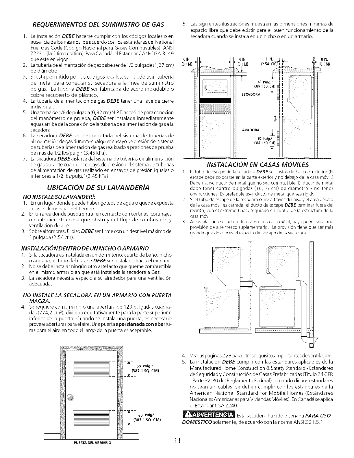
4. Se requiere corno minimo una abertura de 120 pulgadas cuadra-
das (774,2 cm2), dividida equitativamente para la parte superior e
inferior de la puerta. Cuando se instala una puerta, es necesario
proveer abertu ras para el aire. Una puerta apersianada con abertu-
ras para el aire en todo el largo de la puerta es aceptable.
60 Pulg.z
(387.1 SQ. CM)
60 Pulg.2
(387.1 SQ. CM)
5. Las siguientes ilustraciOnes muestran las dimensi6nes minimas de
espacio libre que debe existir para el buen funcionamiento de la
secadora cuando se instala en un nicho o en un armario.
3.
0 IN. I IN.; -- ',I 0 IN.
HIt, iE
60Po_g._
I I I I
INSTALACION EN CASAS MOVILES
Eltubo de escape de la secadora DEBE ser instalado hacia el exterior (El
escape debe colocarse en la parte exterior y no debajo de la casa movil.)
Debe usarse ducto de metal que no sea combustible. El ducto de metal
debe tener cuatro pulgadas (10,16 cm) de diametro y no tener
obstrucciones. Espreferible usar ducto de metal que sea rigido.
Si eltubo de escape de la secadora corre a traves del piso yel area debajo
de la casa m0vil es cerrada, el ducto de escape DEBEterminar fuera del
recinto, con el extremo final asegurado en contra de la estructura de la
casa movik
AI instalar una secadora de gas en una casa movil, hay que instalar una
provision de aire fresco suplementario. La provision tiene que ser mas
grande que dos veces el espacio del escape de la secadora.
4. Vealaspaginas2 y3 paraotros requisitos importantes deventilacion.
5. La instalacion DEBE cumplir con las estandares aplicables de la
Manufactured Home Construction & Safety Standard - Estandares
de Seguridad y ConstrucciOn de CasasPrefabricadas (Titulo 24 CFR
- Parte 32-80 del Reglamento Federal)o cuando dichos estandares
no sean aplicables, se deben complir con los estandares de la
American National Standard for Mobile Homes (Estandares
NacionalesAmericanas paraViviendas MOviles).EnCanada seaplica
el Estandar CSA Z240.
Estasecadora ha sido diseflada PARA USO
DOMESTICO solamente, de acuerdo con la norma ANSIZ21.5.1.
PUIEITI'ADELARMAmO 1 1
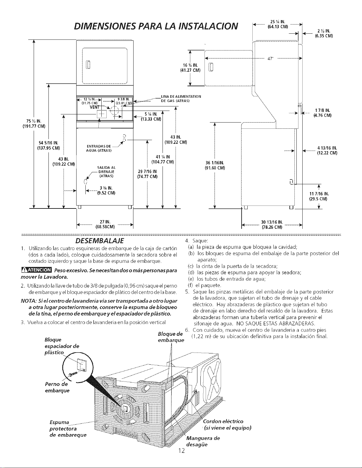
DIMENSIONE5 PARA LA INSTALACION
75 _/2IN,
(19137 £M)
54 5/16IN,
(137.95CM)
43 IN.
(109.22 CM)
\ .....................................................................................................................
121/2 IN, _,_ , 9 3/8 IN,
(31.TsCM)_'1 ------_1C2381,c_)
©
ENTRADAS DE J-
AGUA (ATRAS)
SALiDA AL
3%1N.
_ (9.52 CM)
25¼ IN.
-- (64.13CM)_
47" --
LINA DE ALIMENTATiON
_DE GAS (ATRAS)
X\
27IN.
(68.58CM)
51AIN' _ l
"_13.33CM)
43 IN.
I( (109.22CM)
41 V4IN
104.77 CM)
29 7/16IN
('/4.77 CM)
! r r
\
36 1/161N.
(91.60CM)
1
_ 30 13/16 IN. U
(78.26 CM)
21/2 IN.
(6.35 CM)
17/8 IN.
(................(4.76CM)
4 13/16 IN.
(12.22CM)
117116IN.
(29.SCM)
DESEMBALAJE
1. Utilizando las cuatro esquineras de embarque de la caja de cart6n
(dos a cada lado), coloque cuidadosamente la secadora sobre el
costado izquierdo y saque la base de espuma de embarque.
Peso ex cesivo. Se necesitan dos o mas personas para
mover la Lavadora.
2. Utilizando la Ilave de tubo de 3/8 de pulgada (0,96 cm) saque el perno
de embarque y el bloque espaciador de platico del centro de la base.
NO TA: Si el cen tro de lavanderia via ser tra nsportada a otto lugar
a otra lugarposteriormente, conserve la espuma de bloqueo
de la tina, e/ pemo de embarque y el espaciador de p/astico.
3. Vuelva a colocar el centro de lavanderia en la posicion vertical
4. Saque:
(a) la pieza de espuma que bloquea la cavidad;
(b) los bloques de espuma del embalaje de la parte posterior del
aparato;
(c) la cinta de la puerta de la secadora;
(d) las piezas de espuma para apoyar la seadora;
(e) los tubos de entrada de agua;
(f) el paquete.
5. Saque las pinzas metalicas del embalaje de la parte posterior
de la lavadora, que sujetan el tubo de drenaje y el cable
electrico. Hay abrazaderas de plastico que sujetan el tubo
de drenaje en labo derecho del resaldo de la lavadora. Estas
abrazaderas forman una tubeda vertical para prevenir el
sifonaje de agua. NO SAQUE ESTAS ABRAZADERAS.
6. Con cuidado, mueva el centro de lavanderia a cuatro pies
(1,22 m) de su ubicaci6n definitiva para la instalaci6n final.
Bloque de
Bloque embarque
espaciador de t
pl_stico
Perno de
embarque
Espuma
protectora
de embareque
' (si viene el equipo)
Manguera de
desag6e
12
INS TALA C!ON ELECTRICA
[
TODAS /os centre/avandoria ELECTR/CAS
]
Los siguientes requerimientos son especificos para
el funcionamiento correcto y seguro de su secadora. El
incumplimiento de estas instrucciones puede causar prolongaciOn
excesiva del tiempo de secado y riesgos de incendio.
Este artefacto DEBE ser puesto a tierra de manera
correcta. Si la lavanderia no esta debidamente puesta a tierra se puede
producir un cheque electrico. Siga las instrucciones indicadas en este
manual para la puesta a tierra en forma correcta.
r__ No use un cordon de extension con esta lavanderia.
Algunos cordones de extension no pueden soportar la cantidad de
corriente el_ctrica que utiliza esta secadora y pueden fundirse, creando
un peligro de cheque electrico y/o incendio. Ubique la lavanderia de
manera que el cordon electrico Ilegue hasta el tomacorriente que seva
a usar, dejandoun pocode holgura paraelcord0n. Consultelos
requerimientos de instalaciOn preliminares indicados en este manual
para el cordon electrico que debe ser adquirido.
Se debe instalar un anclaje aprobado porel U.L para
el cordon el_ctrico. Si no se utiliza un anclaje para sujetar el cordon
electrico, este puede salirse de la lavanderia y cortarse con cualquier
movimiento, resultando en un cheque electrico.
No utilice un tomacorriente con cables de aluminio
con un cordon y un enchufe de cobre (o viceversa). Se produce una
reacciOn quimica entre el cobre y el aluminio que puede causar
cortaci rcu itos. El cableado y tomacorrien te apropiado es un cordon
electrico equipado con conductores de cobre con un tomacorriente
con conductores de cobre.
NOTA: Laslavanderia que operan con un suministro de energia de 208
voltios usaran mas tiempo de secado que aquellas que operan con un
suministro de energia de 240 voltios.
Para una lavanderia conectada permanentemente:
1. Lalavanderia DEBEser conectada aun sistemade cableado metalico
permanente, puesto a tierra; o se debe instalar un conductor de
puesta a tierra de equipo junto con los conductores del circuito y
conectarse al borne de puesta a tierra del equipo o al cable del
artefacto.
i Centrode/avanderiaEZECTR/CAScanadienses ]
Laconexi6n indebida delconductor de puesta atierra
del equipo puede ocasionar un riesgo de cheque electrico. Consulte
con un electricista profesional sitiene alguna duda respecto a la puesta
atierra correcta del artefacto.
Parauna lavanderia puesta atierra con cordon electrico:
1. Lalavanderia DEBEser puesta atierra. Encasedemalfu ncionamiento
o falla, la puesta a tierra reducira el riesgo de cheque electrico
proporcionando un trayecto de menor resistencia a la corriente
el_ctrica.
2. Si su lavanderia esta equipada con un cordon electrico que posee
un conductor de puesta a tierra del equipo y un enchufe de puesta
a tierra, dicho enchufe DEBE set conectado a un tomacorriente
adecuado, debidamente instalado y puesto a tierra de acuerdo con
todos los cOdigos y reglamentos locales. Si tiene alguna duda
consulte a un electricista profesional. No modifique el enchufe
proporcionado la aplicaci6n.
I TODOSlescentreslavander/aaGAS 1
Esta lavenderia esta equipada con un enchufe de tres espigas (de puesta
a tierra) para protecciOn en contra de cheques electricos y debe set
conectada directamenta en un receptaculo para tres espigas el cual
debe estar puesto a tierra. No corte ni elimine la espiga de puesta a
tierra de este enchufe.
REQUERIMIENTOS PARA LA PUESTA A TIERRA
i Centre de/avanderia ELECTRICASNo canadienses I
La conexion indebida del conductor de puesta a tierra
del equipo puede ocasionar un riesgo de cheque electrico. Consulte con
un electricista profesional si tiene alguna duda respecto a la puesta a
tierra correcta del artefacto.
Parauna secadora puesta a tierra con cordon el_ctrico:
1. Lalavanderia DEBEser puesta atierra. Encasede malfuncionamiento
o falla, la puesta a tierra reducira el riesgo de cheque electrico
proporcionando un trayecto de menor resistencia a la corriente
el_ctrica.
Si su lavanderia esta equipada con un cordon electrico que posee un
conductor de puesta a tierra del equipo y un enchufe de puesta a
tierra, dicho enchufe DEBE set conectado a un tomacorriente
adecuado, debidamente instalado y puesto a tierra de acuerdo con
todos los cOdigos y reglamentos locales. Si tiene alguna duda
consulte a un electricista profesional. No modifique el enchufe
proporcionado la aplicaci6n.
13
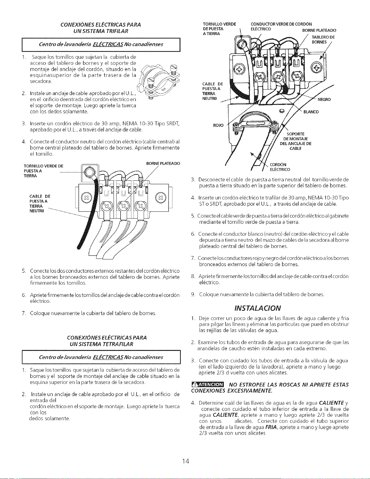
CONEXIONES ELE-CTRICAS PARA
UN SISTEMA TRIFILAR
[ Centrode/avanderiaELECTR/CASNocanadienses ]
1. Saque los tornillos que sujetan la cubierta de
acceso del tablero de bornes y el soporte de ._
montaje del anclaje del cord6n, situado en la _'_
esquinasuperior de la parte trasera de la _/J__::_,_
2, Instale un anclaje de cable aprobado por el U.L,, "_
en el orificio deentrada del cordon electrico en_
el soporte de montaje. Luego apriete la tuerca
con los dedos solamente.
3. Inserte un cordon electrico de 30 amp, NEMA 10-30 Tipo SRDT,
aprobado pot el U.L, a traves del anclaje de cable.
4. Conecte el conductor neutro del cord6n electrico (cable central) al
borne central plateado del tablero de bornes. Apriete firmemente
el tornillo.
TORNILLO VERDE DE
PUESTAA
TIERRA
BORNE PLATEADO
CABLE DE
PUESTAA
TERRA
NEUTRO
5. Conecte los dos conductores externos restantes del cordon electrico
a los bomes bronceados externos del tablero de homes. Apriete
firmemente los tornillos.
6. Apriete firmemente Iostornillos delanclaje decable contra el cord6n
el@ctrico.
7. Coloque nuevamente la cubierta del tablero de bomes.
CONEXIONES EL_'CTRICAS PARA
UN SISTEMA TETRAFILAR
Cen tro de/avanderia No canad/enses
ELECTR/CAS
1. Saque los tornillos que sujetan la cubierta de acceso del tablero de
bornes y el soporte de montaje del anclaje de cable situado en la
esquina superior en la parte trasera de la secadora.
2.
Instale un anclaje de cable aprobado por el U.L, en el orificio de
entrada del
cordon electrico en el soporte de montaje. Luego apriete la tuerca
con los
dedos solamente.
TORNILLO VERDE
DE PUESTA
A TIERRA
CONDUCTOR VERDE DE CORDON
ELIecTRICO BORNE PLATEADO
TABLERO DE
BORNES
CABLE DE
PUESTAA
TIERRA
NEUTRO
NEGRO
BLANCO
ROJO
SOPORTE
DE MONTAJE
DEL ANCLAJE DE
CABLE
CORDON
ELECTREO
3. Desconecte el cable de puesta a tierra neutral del tornillo verde de
puesta a tierra situado en la parte superior del tablero de bornes.
4. Inserte un cordon electrico te trafilar de 30 amp, NEMA 10-30 Tipo
STo SRDT, aprobado pot el U.L, a traves del anclaje de cable.
5. Conecte el cableverde de puesta atierra del cord6n el_ctricoal gabinete
mediante el tornillo verde de puesta a tierra.
6. Conecte el conductor blanco (neutro) del cordon el_ctrico y el cable
depuesta atierra neutro del mazo de cables de la secadora al borne
plateado central del tablero de bornes.
7. Conecte losconductores rojoy negro delcordon electrico alos bornes
bronceados externos del tablero de bornes.
8. Apriete firmemente Iostornillos del anclajede cable contra el cordon
electrico.
9. Coloque nuevamente la cubierta del tablero de bornes.
INS TALA C!ON
Deje correr un poco de agua de las Ilaves de agua caliente y fria
para pilgar las Iineasy eliminar las particulas que pued en obstriur
las rejillas de las valvulas de agua.
2. Examine Iostubos de entrada de agua para asegurarse de que las
arandelas de caucho esten instaladas en cada extremo.
3. Conecte con cuidado los tubos de entrada a la v_lvula de agua
(en el lado izquierdo de la lavadora), apriete a mano y luego
apriete 2/3 d vuelta con unos alicates.
NO ESTROPEE LA5 ROSCAS N! APRIETE ESTAS
CONEXIONES EXCESIVAMENTE.
Determine cual de las Ilaves de agua es la de agua CALIENTE y
conecte con cuidado el tubo inferior de entrada a la Ilave de
agua CALIENTE, apriete a mano y luego apriete 2/3 de vuelta
con unos alicates. Conecte con cuidado el tubo superior
de entrada a la Ilave de agua FRIA, apriete a mano y luege apriete
2/3 vuelta con unos alicates
14
NO ESTROPEE LAS ROSCAS NI APRIETE ESTAS
CONEXIONES EXCESIVAMENTE. Abra la Ilave del agua y compuebe
que no haya fugas en ninguna de lasdos conexiones.
5. Con cuidado, mueve el centro de lavanderia hasta su ubicaci6n
definitiva para instalaciOn final,
6. Paraverificar si el centro de lavanderia est_i nivelado y firmemente
asentado sobre las cuatro patas, inclinelo haciaadelante de modo
que las patas posteriors queden en el aire. Luego vuelva a
depositar cuidadosamente la maquina para permitir que las patas
posteriores se ajusten. Coloque un nivel de carpintero encima
de la lavadora.
Atornille o destornille los tornillos nivel de posteriores de la
lavadora
segun sea necesario para que el centro de lavanderia quede
firmemente asentado sobre sus cuatro patas (no debe haber
movimiento de vaiven.
NOTA: Mantenga las patas de nivelacion al minimo para prevenir
excesiva vibraci6n.
7. CONEXION DEL GAS (Secadoras a gas so/amente)
a. Saquela tapa deembarquedelatuberia de gas dela secadora
situada en la parte trasera.
NOTA: NO conecte la lavanderia al suministro de propano, sin primero
instalar el juego de conversion a propano. Eljuego de conversion a
propano debe set instalado por un tecnico de gas calificado.
b. Conecte una tuberia semirigida de 1/2" (1,27 cm) D.I. o una
tuberia aprobada, desde la linea de suministro de gas ala
tuberia de 3/8" (0,96 cm) ubicada en la parte trasera de la
secadora. Utilice un reductor de 1/2" (1,27 cm) a 3/8"
(0,96 cm) para la conexion. Aplique un sellador de roscas de
uso aprobado, resistente a lacorrosion de los gaseslicuados,
en todas las uniones de la tuberia.
c. Abra la wqlvula de cierre en la tuberia de suministro de gas.
d. Pruebe todas las conexiones aplicando con una escobilla una
soluciOn jabonosa.
NUNCA UTILICE UNA LLAMA ABIERTA PARA DETECTAR
FUGAS DE GAS.
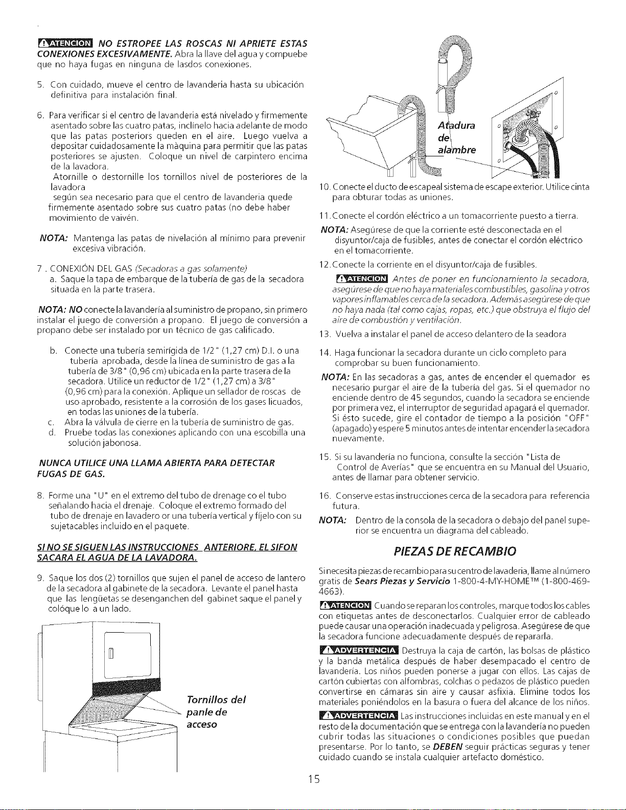
10. Conecte el ducto de escapeal sistema de escape exterion Utilice cinta
para obturar todas as uniones.
11.Conecte el cordon electrico a un tomacorriente puesto atierra.
NOTA: Aseg0rese de que la corriente este desconectada en el
disyuntor/caja de fusibles, antes de conectar el cord6n electrico
en el tomacorriente.
12. Conecte la corriente en el disyuntor/caja de fusibles.
Antes de poner en funcionamiento la secadora,
asegOresede queno haya ma teriales combustibles, gaso/ina y otros
vaporesin f/amables cercade/a secadora. Ademas asegOresede que
no haya nada (tal como cajas, ropas, etc.) que obstruya el flujo de/
aire de combusti6n y venti/aci6n.
13. Vuelva a instalar el panel de acceso delantero de la seadora
14. Haga funcionar la secadora durante un ciclo completo para
comprobar su buen funcionamiento.
NOTA: En las secadoras a gas, antes de encender el quemador es
necesario purgar el aire de la tuberia del gas. Si el quemador no
enciende dentro de 45 segundos, cuando la secadora seenciende
por primera vez, el interruptor de seguridad apagar_i el quemador.
Si esto sucede, gire el contador de tiempo a la posicion "OFF"
(apagado)y espere5minutos antes de intentar encender lasecadora
nuevamente.
15. Si su lavanderia no funciona, consulte la seccion "Lista de
Control de Averias" que se encuentra en su Manual del Usuario,
antes de Ilamar para obtener servicio.
8. Forme una "U" en el extremo del tubo de drenage co el tubo
ser_alando hacia el drenaje. Coloque el extremo formado del
tubo de drenaje en lavadero or una tuberia vertical y fijelo con su
sujetacables incluido en el paquete.
SI NO SE SIGUEN LAS INSTRUCCIONES ANTERIORE, EL SIFON
SACARA EL A GUA DE LA LAVADORA.
9. Saque los dos (2) tornillos que sujen el panel de acceso de lantero
de la secadora al gabinete de la secadora. Levante el panel hasta
que las leng0etasse desenganchen del gabinet saque el panely
coloque Io a un lado.
Tornillos del
panle de
acceso
16. Conserve estas instrucciones cerca de la secadora para referencia
futura.
NOTA: Dentro de la consola de la secadora o debajo del panel supe-
rior se encuentra un diagrama del cableado.
PIEZAS DE RECAMB!O
Si necesita piezas de recambio para su centro de lavaderia, Ilame al n0mero
gratis de Sears Piezas y Servicio 1-800-4-MY-HOME TM (1-800-469-
4663).
Cuandose reparan los controles, rnarque todos los cables
con etiquetas antes de desconectarlos. Cualquier error de cableado
puede causar una operacion inadecuada y peligrosa. Aseg0rese de que
la secadora funcione adecuadamente despues de repararla.
Destruya la caja de carton, las bolsas de pl_istico
y la banda met_ilica despues de haber desempacado el centro de
lavanderia. Los ninos pueden ponerse a jugar con ellos. Las cajas de
cart6n cubiertas con alfombras, colchas o pedazos de pkistico pueden
convertirse en c_imaras sin aire y causar asfixia. Elimine todos los
materiales poniendolos en la basura o fuera del alcance de los ninos.
Las instrucciones incluidas en este manual yen el
resto de la documentacion que se entrega con la lavanderia no pueden
cubrir todas las situaciones o condiciones posibles que puedan
presentarse. Por Io tanto, se DEBEN seguir pr_icticas seguras y tenet
cuidado cuando se instala cualquier artefacto domestico.
15
Your Home
For repair-in your home-of all major brand appliances,
lawn and garden equipment, or heating and cooling systems,
no matter who made it, no matter who sold it!
For the replacement parts, accessories and
owner's manuals that you need to do-it-yourself.
For Sears professional installation of home appliances
and items like garage door openers and water heaters.
1-800-4-MY-HOME ® (1-800-469-4663)
Call anytime, day or night (U.S.A. and Canada)
www,sears,com www.sears.ca
Our Home
For repair of carry-in items like vacuums, lawn equipment,
and electronics, call or go on-line for the location of your nearest
Sears Parts & Repair Center.
1-800-488-1222
Call anytime, day or night (U.S.A. only)
www.sears.com
To purchase a protection agreement (U.S.A.)
or maintenance agreement (Canada) on a product serviced by Sears:
1-800-827-6655 (U.S.A.) 1-800-361-6665 (Canada)
Para pedir servicio de reparaci6n
a domicilio, y para ordenar piezas:
1-888-SU-HOGAR sM
(1-888-784-6427)
Au Canada pour service en frangais:
1-800-LE-FOYER Mc
(1-800-533-6937)
www.sears.ca
Ses./rs
TM SM
® Registered Trademark / Trademark / Service Mark of Sears, Roebuck and Co.
® Marca Registrada / TMMarca de F&brica / s_4Marca de Servicio de Sears, Roebuck and Co.
MD
MCMarque de commerce / Marque dCpos_e de Sears, Roebuck and Co. ® Sears, Roebuck and Co.